Document ref: 11001-12280

Welcome message from author
This document is posted to help you gain knowledge. Please leave a comment to let me know what you think about it! Share it to your friends and learn new things together.
Transcript

Document ref: 11001-12280

Doc. No. 11001-12280 Rev 2 Page 1
©Honeywell International Inc. Do not copy without express permission of Honeywell.
Skyforce Avionics Ltd. A Honeywell Company 5 The Old Granary Boxgrove, Chichester West Sussex PO18 0ES Telephone: (+44) (0) 1243 783763 Fax: (+44) (0) 1243 783992
Honeywell Honeywell International Inc. 21111 N. 19th Ave. Phoenix, Arizona 85027-2708 U.S.A. CAGE: 55939 Telephone: (+1) 800 601-3099 (U.S. A.) Telephone: (+1) 602 365-3099 (International)
Sentinel
Multifunction Display
(MFD)
Pilot’s Guide
Document Revision History
Revision By Description Controlling Doc Ref Date A DDI Initial complete draft OB3Log_178 30 Oct 07 1 D Allen Revised & released DOI 177 7 Dec 07
2 A Ball Revised for Sentinel 01.02 & 1.03 release
DOI 188 5 Aug 09
Sentinel Series Sentinel Multifunction Display (MFD)
Doc No 11001-12280 Rev 2 Page 2
©Honeywell International Inc. Do not copy without express permission of Honeywell.
Honeywell-Confidential
THIS COPYRIGHTED WORK AND ALL INFORMATION ARE THE PROPERTY OF HONEYWELL INTERNATIONAL INC, CONTAIN TRADE SECRETS AND CAN NOT, IN WHOLE OR IN PART, BE USED, DUPLICATED, OR DISCLOSED FOR ANY PURPOSE WITHOUT PRIOR WRITTEN PERMISSION OF HONEYWELL INTERNATIONAL INC. ALL RIGHTS RESERVED.
Honeywell Materials License Agreement
The documents and information contained herein (“the Materials”) are the proprietary data of Honeywell International Inc. and Honeywell Intellectual Properties Inc (collectively Honeywell.). These Materials are provided for the exclusive use of Honeywell Service Centers; Honeywell--authorized repair facilities; operators of Honeywell aerospace products subject to an applicable product support agreement, their wholly owned--subsidiaries or a formally designated third party service provider; and direct recipients of Materials from Honeywell’s Aerospace Technical Publication Distribution. The terms and conditions of this License Agreement govern your use of these Materials, except to the extent that any terms and conditions of another applicable agreement with Honeywell regarding the operation, maintenance, or repair of Honeywell aerospace products conflict with the terms and conditions of this License Agreement, in which case the terms and conditions of the other agreement will govern. However, this License Agreement will govern in the event of a conflict between its terms and conditions and those of a purchase order or acknowledgement.
1. License Grant - If you are a party to an applicable product support agreement, a Honeywell Service Center agreement, or an authorized repair facility agreement, Honeywell hereby grants you a limited, non--exclusive license to use these Materials to operate, maintain, or repair Honeywell aerospace products only in accordance with that agreement.
If you are a direct recipient of these Materials from Honeywell’s Aerospace Technical Publication Distribution and are not a party to an agreement related to the operation, maintenance or repair of Honeywell aerospace products, Honeywell hereby grants you a limited, non--exclusive license to use these Materials to maintain or repair the subject Honeywell aerospace products only at the facility to which these Materials have been shipped (.the Licensed Facility.). Transfer of the Materials to another facility owned by you is permitted only when the original Licensed Facility retains no copies of the Materials and you provide prior written notice to Honeywell.
2. Rights In Materials -- Honeywell retains all rights in these Materials and in any copies thereof that are not expressly granted to you, including all rights in patents, copyrights, trademarks, and trade secrets. No license to use any Honeywell trademarks or patents is granted under this License Agreement.
3. Confidentiality - You acknowledge that these Materials contain information that is confidential and proprietary to Honeywell. You agree to take all reasonable efforts to maintain the confidentiality of these Materials.
4. Assignment And Transfer - This License Agreement may be assigned to a formally designated service designee or transferred to a subsequent owner or operator of an aircraft containing the subject Honeywell aerospace products. However, the recipient of any such assignment or transfer must assume all of your obligations under this License Agreement. No assignment or transfer shall relieve any party of any obligation that such party then has hereunder.
5. Copies of Materials - Unless you have the express written permission of Honeywell, you may not make or permit making of copies of the Materials. Notwithstanding the foregoing, you may make copies of only portions of the Material for your internal use. You agree to return the Materials and any copies thereof to Honeywell upon the request of Honeywell.

Sentinel Series Sentinel Multifunction Display (MFD)
Doc. No. 11001-12280 Rev 2 Page 3
©Honeywell International Inc. Do not copy without express permission of Honeywell.
6. Term - This License Agreement is effective until terminated as set forth herein. This License Agreement will terminate immediately, without notice from Honeywell, when you fail to comply with any provision of this License Agreement or will terminate simultaneously with the termination or expiration of your applicable product support agreement, authorized repair facility agreement, or your formal designation as a third party service provider. Upon termination of this License Agreement, you will return these Materials to Honeywell without retaining any copies and will have one of your authorized officers certify that all Materials have been returned with no copies retained.
7. Remedies - Honeywell reserves the right to pursue all available remedies and damages resulting from a breach of this License Agreement.
8. Limitation of Liability -- Honeywell does not make any representation regarding the use or sufficiency of the Materials. THERE ARE NO OTHER WARRANTIES, WHETHER WRITTEN OR ORAL, EXPRESS, IMPLIED OR STATUTORY, INCLUDING, BUT NOT LIMITED TO, (i) WARRANTIES ARISING FROM COURSE OF PERFORMANCE, DEALING, USAGE, OR TRADE, WHICH ARE HEREBY EXPRESSLY DISCLAIMED, OR (ii) WARRANTIES AGAINST INFRINGEMENT OF INTELLECTUAL PROPERTY RIGHTS OF THIRD PARTIES, EVEN IF HONEYWELL HAS BEEN ADVISED OF ANY SUCH INFRINGEMENT. IN NO EVENT WILL HONEYWELL BE LIABLE FOR ANY INCIDENTAL DAMAGES, CONSEQUENTIAL DAMAGES, SPECIAL DAMAGES, INDIRECT DAMAGES, LOSS OF PROFITS, LOSS OF REVENUES, OR LOSS OF USE, EVEN IF INFORMED OF THE POSSIBILITY OF SUCH DAMAGES. TO THE EXTENT PERMITTED BY APPLICABLE LAW, THESE LIMITATIONS AND EXCLUSIONS WILL APPLY REGARDLESS OF WHETHER LIABILITY ARISES FROM BREACH OF CONTRACT, WARRANTY, TORT (INCLUDING BUT NOT LIMITED TO NEGLIGENCE), BY OPERATION OF LAW, OR OTHERWISE.
9. Controlling Law -- This License shall be governed and construed in accordance with the laws of the State of New York without regard to the conflicts of laws provisions thereof. This license sets forth the entire agreement between you and Honeywell and may only be modified by a writing duly executed by the duly authorized representatives of the parties.
Copyright – Notice
Copyright 2007 - 2009, Honeywell International Inc and Skyforce Avionics Ltd. All rights reserved.
Honeywell, SPEC are registered trademark’s of Honeywell International Inc. All other marks are owned by their respective companies.
Sentinel Series Sentinel Multifunction Display (MFD)
Doc. No. 11001-12280 Rev 2 Table of Contents Page 4
©Honeywell International Inc. Do not copy without express permission of Honeywell.
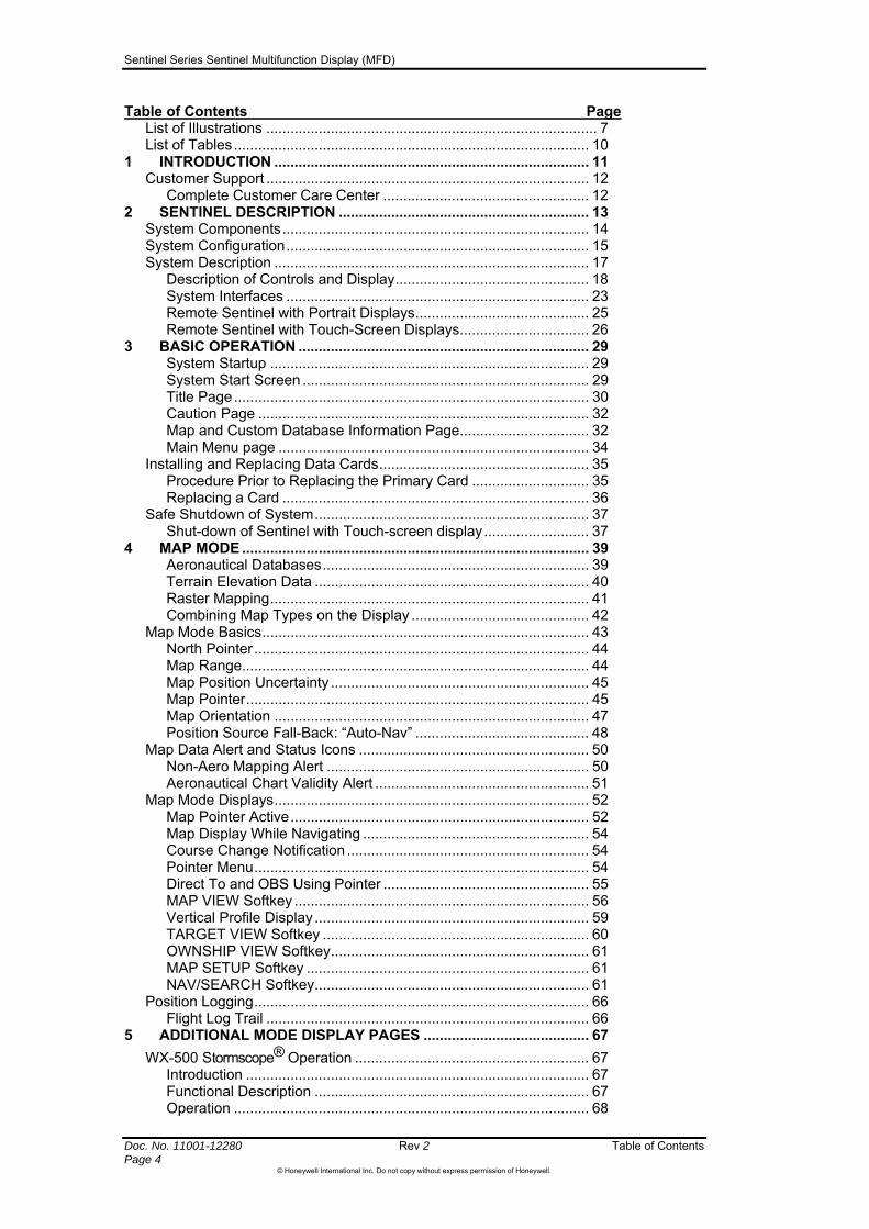
Table of Contents Page List of Illustrations .................................................................................. 7 List of Tables........................................................................................ 10
1 INTRODUCTION .............................................................................. 11 Customer Support ................................................................................ 12
Complete Customer Care Center ................................................... 12 2 SENTINEL DESCRIPTION .............................................................. 13
System Components............................................................................ 14 System Configuration........................................................................... 15 System Description .............................................................................. 17
Description of Controls and Display................................................ 18 System Interfaces ........................................................................... 23 Remote Sentinel with Portrait Displays........................................... 25 Remote Sentinel with Touch-Screen Displays................................ 26
3 BASIC OPERATION ........................................................................ 29 System Startup ............................................................................... 29 System Start Screen ....................................................................... 29 Title Page........................................................................................ 30 Caution Page .................................................................................. 32 Map and Custom Database Information Page................................ 32 Main Menu page ............................................................................. 34
Installing and Replacing Data Cards.................................................... 35 Procedure Prior to Replacing the Primary Card ............................. 35 Replacing a Card ............................................................................ 36
Safe Shutdown of System.................................................................... 37 Shut-down of Sentinel with Touch-screen display.......................... 37
4 MAP MODE ...................................................................................... 39 Aeronautical Databases.................................................................. 39 Terrain Elevation Data .................................................................... 40 Raster Mapping............................................................................... 41 Combining Map Types on the Display ............................................ 42
Map Mode Basics................................................................................. 43 North Pointer ................................................................................... 44 Map Range...................................................................................... 44 Map Position Uncertainty ................................................................ 45 Map Pointer..................................................................................... 45 Map Orientation .............................................................................. 47 Position Source Fall-Back: “Auto-Nav” ........................................... 48
Map Data Alert and Status Icons ......................................................... 50 Non-Aero Mapping Alert ................................................................. 50 Aeronautical Chart Validity Alert ..................................................... 51
Map Mode Displays.............................................................................. 52 Map Pointer Active.......................................................................... 52 Map Display While Navigating ........................................................ 54 Course Change Notification ............................................................ 54 Pointer Menu................................................................................... 54 Direct To and OBS Using Pointer ................................................... 55 MAP VIEW Softkey ......................................................................... 56 Vertical Profile Display .................................................................... 59 TARGET VIEW Softkey .................................................................. 60 OWNSHIP VIEW Softkey................................................................ 61 MAP SETUP Softkey ...................................................................... 61 NAV/SEARCH Softkey.................................................................... 61
Position Logging................................................................................... 66 Flight Log Trail ................................................................................ 66
5 ADDITIONAL MODE DISPLAY PAGES ......................................... 67 WX-500 Stormscope® Operation .......................................................... 67
Introduction ..................................................................................... 67 Functional Description .................................................................... 67 Operation ........................................................................................ 68
Sentinel Series Sentinel Multifunction Display (MFD)
Doc. No. 11001-12280 Rev 2 Table of Contents Page 5
©Honeywell International Inc. Do not copy without express permission of Honeywell.
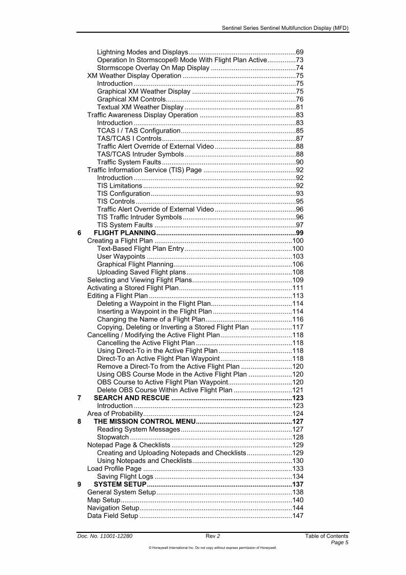
Lightning Modes and Displays.........................................................69 Operation In Stormscope® Mode With Flight Plan Active...............73 Stormscope Overlay On Map Display .............................................74
XM Weather Display Operation ............................................................75 Introduction ......................................................................................75 Graphical XM Weather Display .......................................................75 Graphical XM Controls.....................................................................76 Textual XM Weather Display ...........................................................81
Traffic Awareness Display Operation ...................................................83 Introduction ......................................................................................83 TCAS I / TAS Configuration.............................................................85 TAS/TCAS I Controls.......................................................................87 Traffic Alert Override of External Video...........................................88 TAS/TCAS Intruder Symbols...........................................................88 Traffic System Faults .......................................................................90
Traffic Information Service (TIS) Page .................................................92 Introduction ......................................................................................92 TIS Limitations .................................................................................92 TIS Configuration.............................................................................93 TIS Controls.....................................................................................95 Traffic Alert Override of External Video...........................................96 TIS Traffic Intruder Symbols............................................................96 TIS System Faults ...........................................................................97
6 FLIGHT PLANNING..........................................................................99 Creating a Flight Plan .........................................................................100
Text-Based Flight Plan Entry.........................................................100 User Waypoints .............................................................................103 Graphical Flight Planning...............................................................106 Uploading Saved Flight plans........................................................108
Selecting and Viewing Flight Plans.....................................................109 Activating a Stored Flight Plan............................................................111 Editing a Flight Plan ............................................................................113
Deleting a Waypoint in the Flight Plan...........................................114 Inserting a Waypoint in the Flight Plan ..........................................114 Changing the Name of a Flight Plan..............................................116 Copying, Deleting or Inverting a Stored Flight Plan ......................117
Cancelling / Modifying the Active Flight Plan......................................118 Cancelling the Active Flight Plan ...................................................118 Using Direct-To in the Active Flight Plan .......................................118 Direct-To an Active Flight Plan Waypoint ......................................118 Remove a Direct-To from the Active Flight Plan ...........................120 Using OBS Course Mode in the Active Flight Plan .......................120 OBS Course to Active Flight Plan Waypoint..................................120 Delete OBS Course Within Active Flight Plan ...............................121
7 SEARCH AND RESCUE ................................................................123 Introduction ....................................................................................123
Area of Probability...............................................................................124 8 THE MISSION CONTROL MENU...................................................127
Reading System Messages...........................................................127 Stopwatch ......................................................................................128
Notepad Page & Checklists ................................................................129 Creating and Uploading Notepads and Checklists........................129 Using Notepads and Checklists.....................................................130
Load Profile Page ...............................................................................133 Saving Flight Logs .........................................................................134
9 SYSTEM SETUP.............................................................................137 General System Setup........................................................................138 Map Setup...........................................................................................140 Navigation Setup.................................................................................144 Data Field Setup .................................................................................147

Sentinel Series Sentinel Multifunction Display (MFD)
Doc. No. 11001-12280 Rev 2 Table of Contents Page 6
©Honeywell International Inc. Do not copy without express permission of Honeywell.
Flight Plan Data Setup ....................................................................... 151 Load Profile Settings .......................................................................... 152 Save Profile Page .............................................................................. 154 Demo Mode Setup ............................................................................. 155 Status Pages...................................................................................... 156
Altitude Status............................................................................... 156 Heading Sources Status ............................................................... 157 Internal GPS Status ...................................................................... 157 External Position Source Status ................................................... 157 Map Information ............................................................................ 157 Software and Databases Version Status ...................................... 157 System Information ....................................................................... 158 XM Weather Status....................................................................... 158
Install Menu........................................................................................ 159 Port Setup ..................................................................................... 159 Device Setup................................................................................. 159
APPENDIX: DATABASE REGION AREAS........................................... 161 APPENDIX: FLIGHT LOG FILE FORMATS .......................................... 163
Google EarthTM Flight Log Files.................................................... 163 Jeppesen FliteStarTM Flight Log Files ........................................... 163 Simple Text Flight Log Files.......................................................... 163 Aircraft Position Information Part of Flight Log Entry.................... 163 Traffic Log Information Part of Flight Log Entry ............................ 163
APPENDIX: SOFTWARE VERSIONS & FEATURES ........................... 165 ACRONYMS AND ABBREVIATIONS.................................................... 167 INDEX...................................................................................................... 169
Sentinel Series Sentinel Multifunction Display (MFD)
Doc. No. 11001-12280 Rev 2 Table of Contents Page 7
©Honeywell International Inc. Do not copy without express permission of Honeywell.
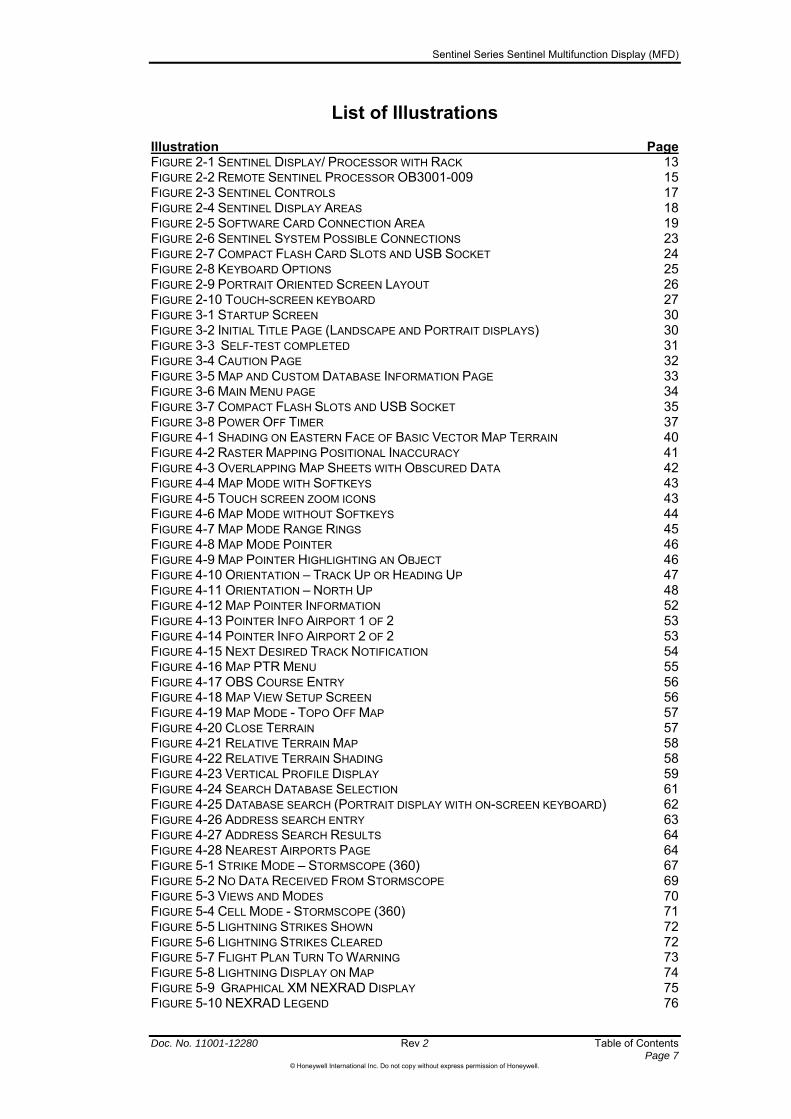
List of Illustrations
Illustration Page FIGURE 2-1 SENTINEL DISPLAY/ PROCESSOR WITH RACK 13 FIGURE 2-2 REMOTE SENTINEL PROCESSOR OB3001-009 15 FIGURE 2-3 SENTINEL CONTROLS 17 FIGURE 2-4 SENTINEL DISPLAY AREAS 18 FIGURE 2-5 SOFTWARE CARD CONNECTION AREA 19 FIGURE 2-6 SENTINEL SYSTEM POSSIBLE CONNECTIONS 23 FIGURE 2-7 COMPACT FLASH CARD SLOTS AND USB SOCKET 24 FIGURE 2-8 KEYBOARD OPTIONS 25 FIGURE 2-9 PORTRAIT ORIENTED SCREEN LAYOUT 26 FIGURE 2-10 TOUCH-SCREEN KEYBOARD 27 FIGURE 3-1 STARTUP SCREEN 30 FIGURE 3-2 INITIAL TITLE PAGE (LANDSCAPE AND PORTRAIT DISPLAYS) 30 FIGURE 3-3 SELF-TEST COMPLETED 31 FIGURE 3-4 CAUTION PAGE 32 FIGURE 3-5 MAP AND CUSTOM DATABASE INFORMATION PAGE 33 FIGURE 3-6 MAIN MENU PAGE 34 FIGURE 3-7 COMPACT FLASH SLOTS AND USB SOCKET 35 FIGURE 3-8 POWER OFF TIMER 37 FIGURE 4-1 SHADING ON EASTERN FACE OF BASIC VECTOR MAP TERRAIN 40 FIGURE 4-2 RASTER MAPPING POSITIONAL INACCURACY 41 FIGURE 4-3 OVERLAPPING MAP SHEETS WITH OBSCURED DATA 42 FIGURE 4-4 MAP MODE WITH SOFTKEYS 43 FIGURE 4-5 TOUCH SCREEN ZOOM ICONS 43 FIGURE 4-6 MAP MODE WITHOUT SOFTKEYS 44 FIGURE 4-7 MAP MODE RANGE RINGS 45 FIGURE 4-8 MAP MODE POINTER 46 FIGURE 4-9 MAP POINTER HIGHLIGHTING AN OBJECT 46 FIGURE 4-10 ORIENTATION – TRACK UP OR HEADING UP 47 FIGURE 4-11 ORIENTATION – NORTH UP 48 FIGURE 4-12 MAP POINTER INFORMATION 52 FIGURE 4-13 POINTER INFO AIRPORT 1 OF 2 53 FIGURE 4-14 POINTER INFO AIRPORT 2 OF 2 53 FIGURE 4-15 NEXT DESIRED TRACK NOTIFICATION 54 FIGURE 4-16 MAP PTR MENU 55 FIGURE 4-17 OBS COURSE ENTRY 56 FIGURE 4-18 MAP VIEW SETUP SCREEN 56 FIGURE 4-19 MAP MODE - TOPO OFF MAP 57 FIGURE 4-20 CLOSE TERRAIN 57 FIGURE 4-21 RELATIVE TERRAIN MAP 58 FIGURE 4-22 RELATIVE TERRAIN SHADING 58 FIGURE 4-23 VERTICAL PROFILE DISPLAY 59 FIGURE 4-24 SEARCH DATABASE SELECTION 61 FIGURE 4-25 DATABASE SEARCH (PORTRAIT DISPLAY WITH ON-SCREEN KEYBOARD) 62 FIGURE 4-26 ADDRESS SEARCH ENTRY 63 FIGURE 4-27 ADDRESS SEARCH RESULTS 64 FIGURE 4-28 NEAREST AIRPORTS PAGE 64 FIGURE 5-1 STRIKE MODE – STORMSCOPE (360) 67 FIGURE 5-2 NO DATA RECEIVED FROM STORMSCOPE 69 FIGURE 5-3 VIEWS AND MODES 70 FIGURE 5-4 CELL MODE - STORMSCOPE (360) 71 FIGURE 5-5 LIGHTNING STRIKES SHOWN 72 FIGURE 5-6 LIGHTNING STRIKES CLEARED 72 FIGURE 5-7 FLIGHT PLAN TURN TO WARNING 73 FIGURE 5-8 LIGHTNING DISPLAY ON MAP 74 FIGURE 5-9 GRAPHICAL XM NEXRAD DISPLAY 75 FIGURE 5-10 NEXRAD LEGEND 76

Sentinel Series Sentinel Multifunction Display (MFD)
Doc. No. 11001-12280 Rev 2 Table of Contents Page 8
©Honeywell International Inc. Do not copy without express permission of Honeywell.
FIGURE 5-11 GRAPHICAL XM PAGE WITH CHOOSE PRODUCT MENU 76 FIGURE 5-12 GRAPHICAL METARS DISPLAY 77 FIGURE 5-13 GRAPHICAL METAR LEGEND 78 FIGURE 5-14 GRAPHICAL AIRMETS DISPLAY 78 FIGURE 5-15 XM AIRMET LEGEND 79 FIGURE 5-16 GRAPHICAL SIGMETS DISPLAY 79 FIGURE 5-17 XM SIGMET LEGEND 80 FIGURE 5-18 GRAPHICAL CONVECTIVE SIGMETS DISPLAY 80 FIGURE 5-19 XM CONVECTIVE SIGMET LEGEND 81 FIGURE 5-20 TEXTUAL XM WEATHER DISPLAY 81 FIGURE 5-21 TAS TRAFFIC PAGE 84 FIGURE 5-22 TIS TRAFFIC PAGE 84 FIGURE 5-23 TRAFFIC PAGE (TAS CONFIGURATION) 85 FIGURE 5-24 TRAFFIC SETUP PAGE (TAS CONFIGURATION) 87 FIGURE 5-25 TAS TRAFFIC PAGE – NO DATA RECEIVED 91 FIGURE 5-26 TRAFFIC PAGE (TIS CONFIGURATION) 93 FIGURE 5-27 TIS TRAFFIC SETUP 95 FIGURE 6-1 FLIGHT PLAN INDEX PAGE WITH NO FLIGHT PLANS 100 FIGURE 6-2 STORED FLIGHT PLAN WITH NO WAYPOINT 101 FIGURE 6-3 STORED FLIGHT PLAN WITH NEW WAYPOINT 101 FIGURE 6-4 STORED FLIGHT PLAN WITH A WAYPOINT 102 FIGURE 6-5 SELECTING AIRWAY FOR INSERTION 102 FIGURE 6-6 SELECTING AIRWAY SEGMENT FOR INSERTION 103 FIGURE 6-7 NEW FLIGHT PLAN IN THE FLIGHT PLAN INDEX PAGE 103 FIGURE 6-8 USER WAYPOINTS PAGE 104 FIGURE 6-9 USER WAYPOINT EDIT PAGE 104 FIGURE 6-10 USER DEFINED AIRPORT EDIT PAGE 105 FIGURE 6-11 GRAPHICAL REPRESENTATION OF FLIGHT PLAN 106 FIGURE 6-12 POINTER SELECTING A FLIGHT PLAN LINE 107 FIGURE 6-13 USING GRAB LINE TO ADJUST FLIGHT PLAN 107 FIGURE 6-14 ACTIVE FLIGHT PLAN 109 FIGURE 6-15 FLIGHT PLAN INDEX PAGE 110 FIGURE 6-16 FLIGHT PLAN INDEX WITH NEW SELECTED FLIGHT PLAN 111 FIGURE 6-17 SELECTED FLIGHT PLAN IN ACTIVE FLIGHT PLAN 112 FIGURE 6-18 FLIGHT PLAN INDEX WITH ADMIN MENU 113 FIGURE 6-19 STORED FLIGHT PLAN 113 FIGURE 6-20 WAYPOINT TO BE DELETED FROM FLIGHT PLAN 114 FIGURE 6-21 PLACEMENT OF NEW WAYPOINT IN ACTIVE FLIGHT PLAN 115 FIGURE 6-22 WAYPOINT ENTRY WINDOW WITH NEW WAYPOINT 115 FIGURE 6-23 MAP OF NEW WAYPOINT 116 FIGURE 6-24 SELECTION OF NAME IN STORED FLIGHT PLAN 116 FIGURE 6-25 FLIGHT PLAN ADMIN MENU 117 FIGURE 6-26 ACTIVE FLIGHT PLAN PAGE WITH FPLAN OFF SOFTKEY 118 FIGURE 6-27 MAP DISPLAY WITH DIRECT TO SOFTKEY 119 FIGURE 6-28 ACTIVE FLIGHT PLAN PAGE WITH DIRECT TO WAYPOINT 119 FIGURE 6-29 MAP DISPLAY WITH DIRECT TO OFF SOFTKEY 120 FIGURE 6-30 MAP DISPLAY WITH DESIRED WAYPOINT ENTRY 121 FIGURE 6-31 MAP DISPLAY WITH OBS COURSE SELECTED 121 FIGURE 7-1 AREA OF PROBABILITY INITIATE FROM POINTER MENU 124 FIGURE 7-2 AREA OF PROBABILITY ENTRY PAGE 125 FIGURE 7-3 MAP DISPLAY WITH AOP SYMBOL 125 FIGURE 8-1 FLASHING NEW MSG STATUS ICON 127 FIGURE 8-2 MISSION MENU PAGE 127 FIGURE 8-3 MISSION MENU PAGE 129 FIGURE 8-4 NOTEPAD PAGE WITH USB UPLOAD AVAILABLE 130 FIGURE 8-5 NOTEPAD PAGE WITH FIRST CHECKLIST ITEM 131 FIGURE 8-6 NOTEPAD PAGE WITH COMPLETE CHECKLIST 131 FIGURE 8-7 LOAD PROFILE PAGE 133 FIGURE 8-8 LOAD PROFILE PAGE WITH MERGE DATA SOFTKEY 134 FIGURE 8-9 LOAD PROFILE PAGE WITH DELETE ACTION 134

Sentinel Series Sentinel Multifunction Display (MFD)
Doc. No. 11001-12280 Rev 2 Table of Contents Page 9
©Honeywell International Inc. Do not copy without express permission of Honeywell.
FIGURE 8-10 MISSION MENU WITH USB (SAVE FLIGHT AVAILABLE) 135 FIGURE 9-1 SYSTEM SETUP MENU 137 FIGURE 9-2 GENERAL SYSTEM SETUP PAGE 138 FIGURE 9-3 MAP SYSTEM SETUP PAGE 140 FIGURE 9-4 POINT FEATURE SETUP PAGE 141 FIGURE 9-5 LINE FEATURE SETUP SCREEN 142 FIGURE 9-6 MAP AIRSPACE SETUP SCREEN 142 FIGURE 9-7 MAP OVERLAY SETUP SCREEN 143 FIGURE 9-8 NAVIGATION SETUP PAGE 144 FIGURE 9-9 DATA FIELD SETUP PAGE 147 FIGURE 9-10 FLIGHT PLAN DATA SETUP PAGE 151 FIGURE 9-11 LOAD PROFILE PAGE 152 FIGURE 9-12 DEFAULT, RESET PROFILE 152 FIGURE 9-13 SAVE PROFILE PAGE 154 FIGURE 9-14 DEMO MODE SETUP 155 FIGURE 9-15 SYSTEMS STATUS MENU 156 FIGURE 9-16 ALTITUDE SOURCE STATUS PAGE 156 FIGURE 9-17 HEADING SOURCE STATUS PAGE 157 FIGURE 9-18 INSTALLATION PAGE, PORTS SETUP 159 FIGURE 9-19 INSTALLATION PAGE, DEVICE SETUP 160 FIGURE 0-10- AMR DATABASE REGION COVERAGE 161 FIGURE 0-2 ATI (EMEA) DATABASE REGION COVERAGE 161 FIGURE 0-3 PAI DATABASE REGION COVERAGE 162

Sentinel Series Sentinel Multifunction Display (MFD)
Doc. No. 11001-12280 Rev 2 Table of Contents Page 10
©Honeywell International Inc. Do not copy without express permission of Honeywell.
List of Tables
Table Page TABLE 2-1 SYSTEM COMPONENTS 14 TABLE 2-2 FUNCTION STATUS ICONS 21 TABLE 5-1 STORMSCOPE STATUS ICONS 68 TABLE 5-2 AVAILABLE XM PRODUCT DISPLAYS 77 TABLE 5-3 TRAFFIC FUNCTION STATUS ICONS 84 TABLE 5-4 TRAFFIC SYSTEM FAULTS 90 TABLE 5-5 TIS FAULTS 98 TABLE 6-1 WAYPOINT INFORMATION 105 TABLE 8-1 SYSTEM MESSAGES 128 TABLE 9-1 DATA FIELD ICONS 147
Sentinel Series Sentinel Multifunction Display (MFD)
Doc. No. 11001-12280 Rev 2 Introduction Page 11
©Honeywell International Inc. Do not copy without express permission of Honeywell.
1 Introduction
This guide describes the Honeywell Sentinel Multifunction Display (MFD).
This guide is divided into the following sections:
Section 1 – Introduction - This section describes the structure of this guide and gives the product support and publications ordering information.
Section 2 – Sentinel Description – This section lists the components of the Sentinel System and describes how they operate. This section includes the following:
o System components
o System configuration
o System description
o System Interfaces.
Section 3 – Basic Operation – This section describes the basic operation of the Sentinel System.
Section 4 – Map Mode – This section describes the Map Mode for the Sentinel system. The Map Mode is the mode the system will normally operate in.
Section 5. – Additional Mode Display Pages – This section describes the operation of the loadable overlays for the traffic display and lightning display.
Section 6 – Flight Planning – This section describes how to create, save and use stored flight plans.
Section 7 – Search and Rescue – This section describes the Area of Probability (AOP) function in the Sentinel system.
Section 8 – The Mission Control Menu – This section describes how to use the mission control page to perform the following operations.
o Edit the Mission Notepad
o Load User Profiles.
Section 9 – System Setup – This section describes how to setup the Sentinel System.

Sentinel Series Sentinel Multifunction Display (MFD)
Introduction Rev 2 Doc. No. 11001-12280 Page 12
©Honeywell International Inc. Do not copy without express permission of Honeywell.
CUSTOMER SUPPORT
Complete Customer Care Center
For all aerospace inquiries including:
Technical assistance
Aircraft on ground (AOG)
Sales: New and exchange
Repair and overhaul
Supply chain optimization
Rentals
Return material authorization (RMA)
Use the following CCCC contact numbers:
Fax: (+1) 602-822-7272
Phone: (+1) 800-601-3099 (U.S.A.)
Phone: (+1) 602-365-3099 (Outside USA).
Also, the complete customer care center is available when you need to:
Identify a change of address, telephone number, or e--mail address
Register for revisions of this Pilot’s Guide.
For European customer care related to Sentinel, please contact
Phone +44 (0)1243 783 763 during business hours
Email [email protected]

Sentinel Series Sentinel Multifunction Display (MFD)
Sentinel Description
2 Sentinel Description
Rev 2 Doc. No. 11001-12280 Page 13
©Honeywell International Inc. Do not copy without express permission of Honeywell.
This section lists the components of the Sentinel System and describes how they operate. This section includes the following:
System components
System configuration
System description
System Interfaces.
Figure 2-1 Sentinel Display/ Processor with Rack
Sentinel Series Sentinel Multifunction Display (MFD)
Doc. No. 11001-12280 Rev 2 Sentinel Description Page 14
©Honeywell International Inc. Do not copy without express permission of Honeywell.
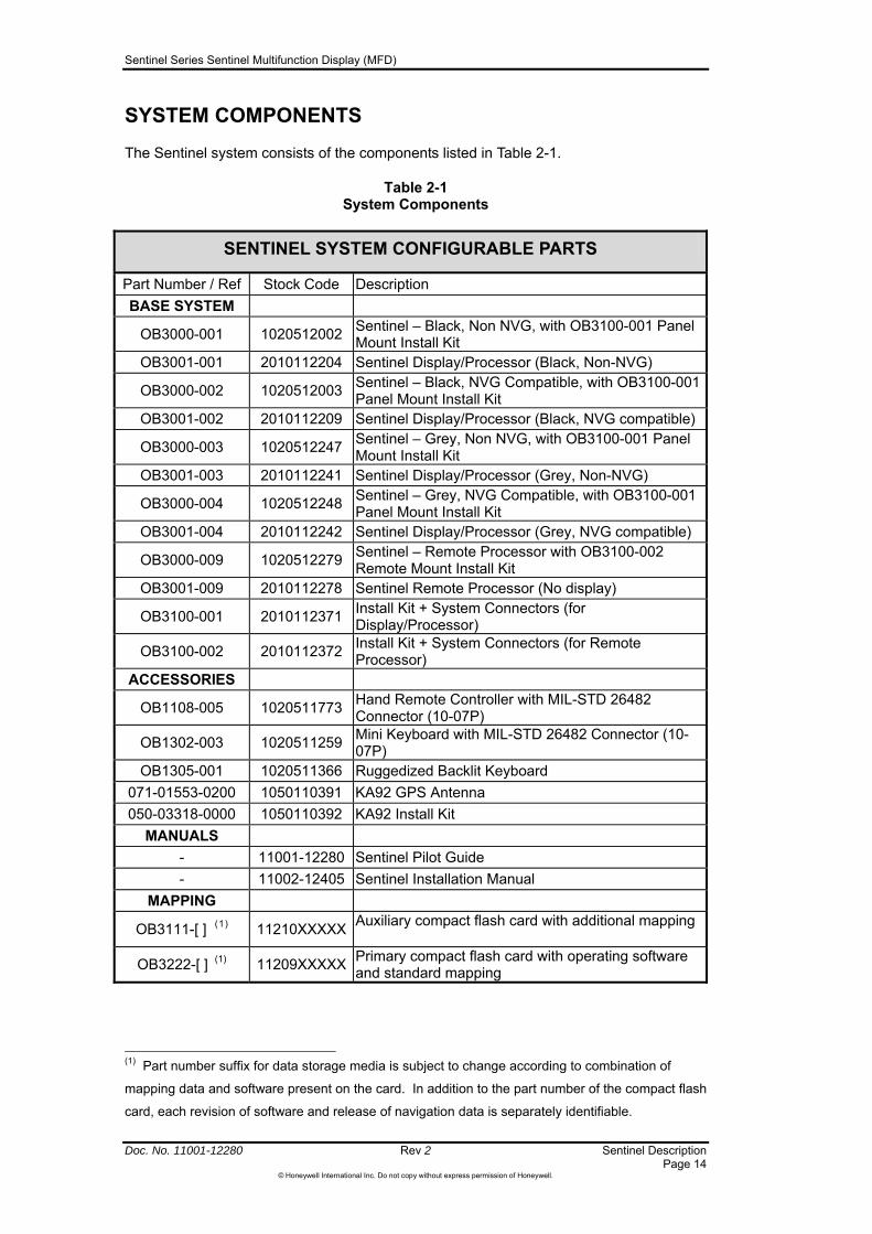
SYSTEM COMPONENTS
The Sentinel system consists of the components listed in Table 2-1.
Table 2-1 System Components
SENTINEL SYSTEM CONFIGURABLE PARTS
Part Number / Ref Stock Code Description
BASE SYSTEM
OB3000-001 1020512002 Sentinel – Black, Non NVG, with OB3100-001 Panel Mount Install Kit
OB3001-001 2010112204 Sentinel Display/Processor (Black, Non-NVG)
OB3000-002 1020512003 Sentinel – Black, NVG Compatible, with OB3100-001 Panel Mount Install Kit
OB3001-002 2010112209 Sentinel Display/Processor (Black, NVG compatible)
OB3000-003 1020512247 Sentinel – Grey, Non NVG, with OB3100-001 Panel Mount Install Kit
OB3001-003 2010112241 Sentinel Display/Processor (Grey, Non-NVG)
OB3000-004 1020512248 Sentinel – Grey, NVG Compatible, with OB3100-001 Panel Mount Install Kit
OB3001-004 2010112242 Sentinel Display/Processor (Grey, NVG compatible)
OB3000-009 1020512279 Sentinel – Remote Processor with OB3100-002 Remote Mount Install Kit
OB3001-009 2010112278 Sentinel Remote Processor (No display)
OB3100-001 2010112371 Install Kit + System Connectors (for Display/Processor)
OB3100-002 2010112372 Install Kit + System Connectors (for Remote Processor)
ACCESSORIES
OB1108-005 1020511773 Hand Remote Controller with MIL-STD 26482 Connector (10-07P)
OB1302-003 1020511259 Mini Keyboard with MIL-STD 26482 Connector (10-07P)
OB1305-001 1020511366 Ruggedized Backlit Keyboard
071-01553-0200 1050110391 KA92 GPS Antenna
050-03318-0000 1050110392 KA92 Install Kit
MANUALS
- 11001-12280 Sentinel Pilot Guide
- 11002-12405 Sentinel Installation Manual
MAPPING
OB3111-[ ] (1) 11210XXXXX Auxiliary compact flash card with additional mapping
OB3222-[ ] (1) 11209XXXXX Primary compact flash card with operating software and standard mapping
(1) Part number suffix for data storage media is subject to change according to combination of
mapping data and software present on the card. In addition to the part number of the compact flash
card, each revision of software and release of navigation data is separately identifiable.

Sentinel Series Sentinel Multifunction Display (MFD)
Sentinel Description Rev 2 Doc. No. 11001-12280 Page 15
©Honeywell International Inc. Do not copy without express permission of Honeywell.
SYSTEM CONFIGURATION
The Sentinel is available as either a panel-mounted multifunction display or as a remote-mounted symbol generator for use with third party displays. Both types have internal VFR GPS capabilities and are members of the Honeywell Integrated Hazard Avoidance System (IHAS) family of products that are designed to improve the pilot's ability to manage four major safety hazards: situational awareness (moving maps), weather, traffic, and terrain awareness.
Figure 2-2 Remote Sentinel Processor OB3001-009
Sentinel uses two types of high capacity Compact Flash data card for storing software and data. These data cards are stored in slots behind the door on the front of the unit. “Primary” cards hold the system software as well as Jeppesen® aviation data and basic cartographic map data (including terrain elevation, major roads, lakes, rivers, railroads, obstacles, political boundaries, cities, and urban areas). Honeywell makes new versions of the Primary card available every 28 days in order to support customers who wish to renew their aeronautical data. The Auxiliary card contains additional map data such as raster charts and may vary according to customer needs.
The panel-mounted Sentinel variants feature a large colour Liquid Crystal Display (LCD). These variants can be used to display imagery from another device such as an Observer system when properly connected and selected using the INT/EXT switch. If a high-priority condition (eg: a traffic alert) arises on a unit that incorporates Mod 1 hardware with software version 1.02 or above, then the software can override the INT/EXT switch temporarily to show the alert data even if the switch is set to EXT. If this happens the INT and EXT enunciators will flash while the alert is active and the display will revert to the external imagery once the alert condition has been cleared.
CAUTION: On units without Mod 1 hardware and with version 1.01 software, the INT/EXT switch is completely under user control and internally generated Sentinel information is NOT displayed when the INT/EXT switch is in the EXT position,. This means that traffic, airspace, or terrain information will not be shown at any time when the Sentinel is switched to show imagery from an external source.
Sentinel Series Sentinel Multifunction Display (MFD)
Doc. No. 11001-12280 Rev 2 Sentinel Description Page 16
©Honeywell International Inc. Do not copy without express permission of Honeywell.
Sentinel is available in a version adapted for use with Night-Vision Goggles (NVG). These variants use NVIS filters to remove light wavelengths that are incompatible with NVG. They do not otherwise change the colours or behavior of the equipment. The colours of the displayed imagery are necessarily slightly changed by the addition of these filters. For example the filter removes certain shades of brown and orange used by some map publishers for grid lines or contour lines, so these may not be visible on NVIS variants of Sentinel. Of course, when the remaining colours are processed by Night Vision Goggles for viewing, the resultant monochrome picture may be completely lacking in information at certain wavelengths and color-coded information will not be usable.
CAUTION: Users of NVIS must carry out adequate ground checks to ensure that all information that they intend to use in flight is visible through their NVIS equipment before attempting to use the equipment while airborne.
The remote mounted variant of Sentinel is intended for installations where panel space is not available. The remote mounted unit requires a general-purpose external display with function keys, joystick, and rotary controls. The functionality of the remote processor is the same as the Sentinel unit with the display, though the performance of the display and controlling device will of course depend on the third party equipment fitted by your installer. With the obvious exception of the LCD display, the functions discussed in this pilot’s guide are applicable to both variants. In some installations the external display is oriented for portrait viewing (longest edge is vertical). Sentinel 1.02 software or above can provide imagery suitable for a portrait-oriented screen – see “Remote Sentinel with Portrait Displays”, page 25.

Sentinel Series Sentinel Multifunction Display (MFD)
Sentinel Description Rev 2 Doc. No. 11001-12280 Page 17
©Honeywell International Inc. Do not copy without express permission of Honeywell.
SYSTEM DESCRIPTION
This portion of the guide provides an overview of the user interface controls and general display presentations of the Sentinel MFD. This guide also provides an explanation of each of the individual screens that the Sentinel MFD can present.
The operating system keeps to a minimum the number of key pushes necessary to activate the various functions, especially those most frequently used in the air. The provision of a joystick and rotary control makes it considerably easier to operate the unit and permits fast and efficient access to most functions. The option for the keyboard eases the use of data entry even further.
Figure 2-3 shows the location of the controls on the face of the Sentinel MFD.
Figure 2-3 Sentinel Controls
The Sentinel controls, as shown in Figure 2-3, are as follows:
1. EXT/INT Select Knob
2. Softkey Buttons
3. View Mode Button
4. Joystick
5. Rotary Knob
6. Data Card Access Door
7. On/Off/Brightness Control
Figure 2-4 shows the location of the display areas on the face of the Sentinel MFD.

Sentinel Series Sentinel Multifunction Display (MFD)
Doc. No. 11001-12280 Rev 2 Sentinel Description Page 18
©Honeywell International Inc. Do not copy without express permission of Honeywell.
Figure 2-4 Sentinel Display Areas
The Sentinel display areas, as shown in Figure 2-4, are as follows:
8. Map Status Icons
9. Softkey Labels
10. Current Display Type (“mode”) Selection (Rotary Knob Control)
11. Own Ship Icon
12. Current Page Name
13. Map Range
14. System Status and Alerts
15. Configurable Data Fields
16. Main Display Area
Description of Controls and Display
A general description of each of the hardware controls and general display areas is listed as follows:
1 - EXT/INT SELECT KNOB: This knob selects either the INT (internal) or EXT (external) display source. In the EXT mode, the unit is used as a monitor to display data from another system. If an external source is not used and the EXT/INT Select knob is set to EXT, a blue screen is displayed. If a high-priority condition (eg: a traffic alert) arises on a unit that incorporates Mod 1 hardware with software version 1.02 or above, then the software can override the INT/EXT switch temporarily to show the alert data even if the switch is set to EXT. If this happens the INT and EXT enunciators will flash while the alert is active and the display will revert to the external imagery once the alert condition has been cleared.

Sentinel Series Sentinel Multifunction Display (MFD)
Sentinel Description Rev 2 Doc. No. 11001-12280 Page 19
©Honeywell International Inc. Do not copy without express permission of Honeywell.
CAUTION: On units without Mod 1 hardware and with version 1.01 software, the INT/EXT switch is completely under user control and internally generated Sentinel information is NOT displayed when the INT/EXT switch is in the EXT position,. This means that traffic, airspace, or terrain information will not be shown at any time when the Sentinel is switched to show imagery from an external source.
2 - SOFTKEY BUTTONS: The five hardware buttons perform the action implied by the
softkey label definitions to the left of it. The keys are backlit for use at night, and the key backlighting remains active under the control aircraft’s cockpit dimmer control even while Sentinel is switched off, so that you can find Sentinel easily in a darkened cockpit.
3 – VIEW MODE BUTTON: This button provides a quick way to swap between different presentations of the information on the screen. For example, on the map pages it provides an easy way to changes between the types of map data being shown; and on the Stormscope display it changes between 120° and 360° views. The current selection is displayed in the bar at the bottom of the page.
4 - JOYSTICK: The joystick can be used to select a menu entry by moving a highlighting bar up or down through the list of available selection. It can be used to adjust settings by moving the highlighting bar onto the field to be adjusted and then moving the joystick up or down to adjust the setting. It can also be used to control the position of a pointer around the displayed map image, allowing movement up, down, left, right and diagonally. While the pointer is active on a map image, a window shall be displayed showing the current range and bearing from the aircraft (or other reference point) to the current pointer position
5 - ROTARY KNOB: The Rotary Knob is located around the joystick in the lower right of the unit. It has various functions as indicated by an on-screen label when active. It is most frequently used to switch quickly between display modes such as Map, Flight Planning, or Traffic (if enabled). It is also used to move through menu lists and change data within highlighted data fields. In data entry, rotating the knob can scan through the alphabet and numbers.
6 - DATA CARD ACCESS DOOR: Behind the door shown in Figure 2-5 are the receptacles for Primary and Auxiliary Compact Flash cards (see page 32), and a Universal Serial Bus (USB) socket (see pages 103,, 129 and 133).
Figure 2-5 Software Card Connection Area
7 - ON/OFF BRIGHTNESS KNOB: This knob controls power to the unit and the screen brightness. The knob is pushed in to turn the unit on. When the knob is pulled out, the unit starts a 5-second displayed countdown and then is turned off. This is the preferred power control method. The screen brightness is dimmed when the knob is rotated to the left (counter-clockwise) and brightened when the knob is rotated to the right (clockwise).
8 – MAP STATUS ICONS: These icons provide information about the quality of the map data currently on the screen. They can indicate whether high-resolution terrain data is available, whether the map is known to be out of date, or whether the map is known to be of a non-aviation type and therefore needs to be treated with additional caution - see “Map Data Alert and Status Icons”, page 50.

Sentinel Series Sentinel Multifunction Display (MFD)
Doc. No. 11001-12280 Rev 2 Sentinel Description Page 20
©Honeywell International Inc. Do not copy without express permission of Honeywell.
9 - SOFTKEY LABELS: When active, the description indicated in the onscreen label describes the softkey button’s present function related to the current display page. When a new option or page is selected, the softkey labels will change to indicate the available functions.
10 – CURRENT MODE SELECTION: Sentinel has several operating modes such as flight planning, moving map, or traffic (if installed) and the currently selected operating mode is indicated by the highlighted option in this area. On most pages rotating the nearby rotary control changes the active mode. Users without access to a rotary control (some remote processor installations, dependent on installed options) can change mode by navigating to the Main Menu, from where each of the main modes are accessible.
11 - OWN SHIP ICON: The Own ship icon represents the position the aircraft on the moving map. Your installer should have set the own ship icon to be either a helicopter or fixed wing aircraft icon, as appropriate. .
12 – CURRENT PAGE NAME: The page name indicates which type of data is being displayed. It is shown at the bottom center of the display.
13 – MAP RANGE: The range window shows the distance from the own ship icon (item 11) to the outer range ring on the map display. Use the Zoom In/Out buttons to adjust the range and select mapping at higher or lower scales.
14 – SYSTEM STATUS and ALERTS: The status area, located in the lower left corner of the display, contains icons showing the current status of
Traffic Awareness functions (see page 84)
Stormscope functions (see page 68)
XM Weather functions (see page 75)
System messages (see page 127).
When a function is not enabled or is not installed, that function icon is not displayed. In general, when a status icon has a grey background, the function is not being displayed on the current display. This is controlled by the setting on the Map Setup (Overlays) menu (see page 140). When the map display range is beyond the range that is set on the Map Setup Overlays Group Page, then the status icon background is a grey colour because that function is not displayed at that range setting.
When a status icon has a light blue (cyan) background, the function is currently being displayed. This does not necessarily mean that data is visible because there may be nothing to view.
The following table summarizes the function status icons and their meanings.

Sentinel Series Sentinel Multifunction Display (MFD)
Sentinel Description Rev 2 Doc. No. 11001-12280 Page 21
©Honeywell International Inc. Do not copy without express permission of Honeywell.
Table 2-2 Function Status Icons
Icon Colours Text Description
Black on cyan LTNG <MODE>
Stormscope information being received and displayed.
<MODE> shall be either STRK or CELL depending on mode selected on
Stormscope page. Strikes have not occurred within 25 nm.
Yellow on cyan
LTNG NEAR
Stormscope information being received and displayed. Strikes have occurred
within 25 nm.
Black on grey. LTNG
Stormscope information being received but not displayed.
Yellow on grey
LTNG NEAR
Stormscope information being received but not displayed. Strikes have occurred
within 25 nm
Black on grey with
red slash LTNG FAIL
Stormscope information not being received / data invalid.
Black on cyan
TRFC
Active Traffic information being displayed.
Black on cyan TRFC STBY
The traffic page is currently being displayed and the traffic unit is off or in
standby mode.
Black on grey TRFC STBY
Traffic Sensor in standby mode, not being displayed.
Black on grey
TRFC
Traffic Sensor active; not being displayed.
Black on Yellow TRFC
N/A TIS traffic is not available, the transponder is not receiving the TIS uplink information.
Flashing Black on
Yellow TRFC ALRT
A TA Traffic Alert is active. The icon will be flashing.
Black on grey with
red slash TRFC FAIL
Traffic Sensor data invalid / not being displayed.
Black on grey – 1 bars
WX Weather information is being received but not displayed.
Indicates a signal strength from XM weather
Black on grey – 2 bars
WX Weather information is being received but not displayed.
Indicates a signal strength from XM weather
Black on grey – 3 bars
WX Weather information is being received but not displayed.
Indicates a signal strength from XM weather
Black on grey – 4 bars
WX Weather information is being received but not displayed.
Indicates a signal strength from XM weather
Black on grey – 1 bars
WX Weather information is being received and displayed.
Indicates a signal strength from XM weather

Sentinel Series Sentinel Multifunction Display (MFD)
Doc. No. 11001-12280 Rev 2 Sentinel Description Page 22
©Honeywell International Inc. Do not copy without express permission of Honeywell.
Icon Colours Text Description
Black on grey – 2 bars
WX Weather information is being received and displayed.
Indicates a signal strength from XM weather
Black on grey – 2 bars
WX Weather information is being received and displayed.
Indicates a signal strength from XM weather
Black on cyan – 4 bars
WX Weather information is being received and displayed.
Indicates a signal strength from XM weather
Black on grey with
red slash WX
FAIL Weather data invalid and not being
displayed.
Black/White with Flashing Yellow
Background
NEW
The are one or more messages that have not been viewed yet (see page 127) This
icon will be flashing
15 – CONFIGURABLE DATA FIELDS: The windows shown along the left side of the screen are user-configurable and can be set to display up to nine different pieces of information at one time on the screen. See Section 9, System Setup – “Data Field Setup” (page 147) for a list of the available window types and instructions on how to set up the data fields on the screen.
16 – DISPLAY AREA: The display area is used to display maps, menus, control tables,
data, and softkey label definitions. Page names, when used, are located at the bottom and status information is in the lower left corner.
The following additional items can also be shown.
POINTER WINDOW: The pointer window is shown while the pointer is active, and shows the pointer position in the currently selected coordinate system. Below the pointer position text, the bearing and distance of the pointer relative to the aircraft position is shown. The bearing is magnetic and the distance is in the currently selected system units for distance.
ROTARY CONTROL WINDOW: The rotary control tag window shows the current rotary position and the available rotary control options for the Stormscope page. The page name window (item 12) is automatically disabled when the rotary control window is enabled.
NOTE: The use of the controls as they are described in the remainder of this guide is
explained below:
Sentinel Series Sentinel Multifunction Display (MFD)
Sentinel Description Rev 2 Doc. No. 11001-12280 Page 23
©Honeywell International Inc. Do not copy without express permission of Honeywell. py without express permission of Honeywell.
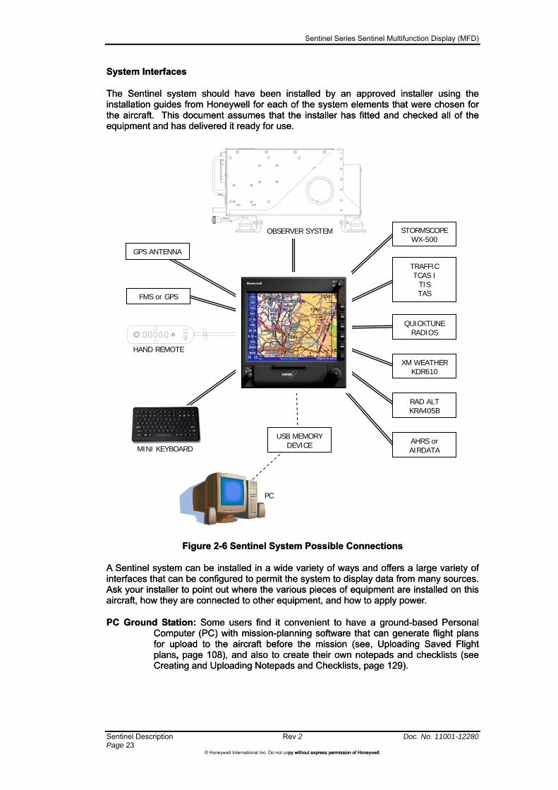
System Interfaces System Interfaces
The Sentinel system should have been installed by an approved installer using the installation guides from Honeywell for each of the system elements that were chosen for the aircraft. This document assumes that the installer has fitted and checked all of the equipment and has delivered it ready for use.
The Sentinel system should have been installed by an approved installer using the installation guides from Honeywell for each of the system elements that were chosen for the aircraft. This document assumes that the installer has fitted and checked all of the equipment and has delivered it ready for use.
Figure 2-6 Sentinel System Possible Connections Figure 2-6 Sentinel System Possible Connections
A Sentinel system can be installed in a wide variety of ways and offers a large variety of interfaces that can be configured to permit the system to display data from many sources. Ask your installer to point out where the various pieces of equipment are installed on this aircraft, how they are connected to other equipment, and how to apply power.
A Sentinel system can be installed in a wide variety of ways and offers a large variety of interfaces that can be configured to permit the system to display data from many sources. Ask your installer to point out where the various pieces of equipment are installed on this aircraft, how they are connected to other equipment, and how to apply power.
PC Ground Station: Some users find it convenient to have a ground-based Personal Computer (PC) with mission-planning software that can generate flight plans for upload to the aircraft before the mission (see, Uploading Saved Flight plans, page 108), and also to create their own notepads and checklists (see Creating and Uploading Notepads and Checklists, page 129).
PC Ground Station: Some users find it convenient to have a ground-based Personal Computer (PC) with mission-planning software that can generate flight plans for upload to the aircraft before the mission (see, Uploading Saved Flight plans, page 108), and also to create their own notepads and checklists (see Creating and Uploading Notepads and Checklists, page 129).
GPS ANTENNA
STORMSCOPE WX-500
TRAFFIC TCAS I
TIS TAS
QUICKTUNE RADIOS
XM WEATHER KDR610
RAD ALT KRA405B
FMS or GPS
AHRS or AIRDATA
OBSERVER SYSTEM
USB MEMORY DEVICE
PC
HAND REMOTE
MINI KEYBOARD
Sentinel Series Sentinel Multifunction Display (MFD)
Doc. No. 11001-12280 Rev 2 Sentinel Description Page 24
©Honeywell International Inc. Do not copy without express permission of Honeywell.
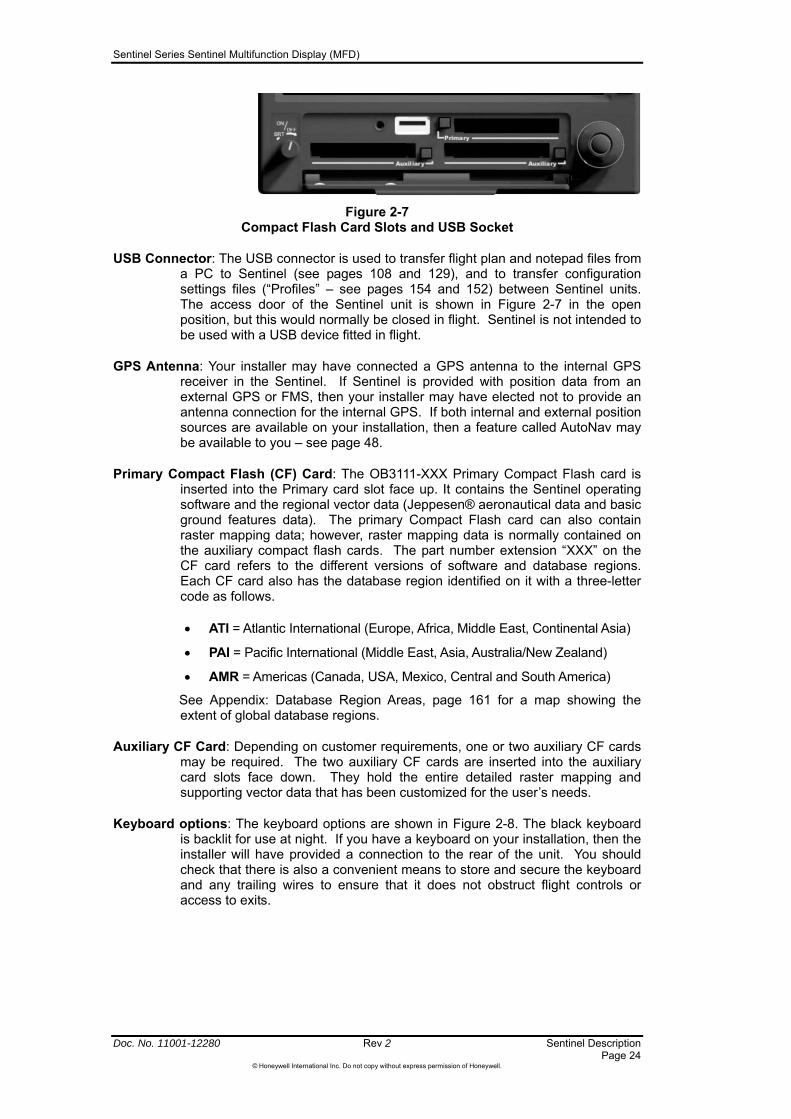
Figure 2-7 Compact Flash Card Slots and USB Socket
USB Connector: The USB connector is used to transfer flight plan and notepad files from a PC to Sentinel (see pages 108 and 129), and to transfer configuration settings files (“Profiles” – see pages 154 and 152) between Sentinel units. The access door of the Sentinel unit is shown in Figure 2-7 in the open position, but this would normally be closed in flight. Sentinel is not intended to be used with a USB device fitted in flight.
GPS Antenna: Your installer may have connected a GPS antenna to the internal GPS receiver in the Sentinel. If Sentinel is provided with position data from an external GPS or FMS, then your installer may have elected not to provide an antenna connection for the internal GPS. If both internal and external position sources are available on your installation, then a feature called AutoNav may be available to you – see page 48.
Primary Compact Flash (CF) Card: The OB3111-XXX Primary Compact Flash card is inserted into the Primary card slot face up. It contains the Sentinel operating software and the regional vector data (Jeppesen® aeronautical data and basic ground features data). The primary Compact Flash card can also contain raster mapping data; however, raster mapping data is normally contained on the auxiliary compact flash cards. The part number extension “XXX” on the CF card refers to the different versions of software and database regions. Each CF card also has the database region identified on it with a three-letter code as follows.
ATI = Atlantic International (Europe, Africa, Middle East, Continental Asia)
PAI = Pacific International (Middle East, Asia, Australia/New Zealand)
AMR = Americas (Canada, USA, Mexico, Central and South America)
See Appendix: Database Region Areas, page 161 for a map showing the extent of global database regions.
Auxiliary CF Card: Depending on customer requirements, one or two auxiliary CF cards may be required. The two auxiliary CF cards are inserted into the auxiliary card slots face down. They hold the entire detailed raster mapping and supporting vector data that has been customized for the user’s needs.
Keyboard options: The keyboard options are shown in Figure 2-8. The black keyboard is backlit for use at night. If you have a keyboard on your installation, then the installer will have provided a connection to the rear of the unit. You should check that there is also a convenient means to store and secure the keyboard and any trailing wires to ensure that it does not obstruct flight controls or access to exits.

Sentinel Series Sentinel Multifunction Display (MFD)
Sentinel Description Rev 2 Doc. No. 11001-12280 Page 25
©Honeywell International Inc. Do not copy without express permission of Honeywell.
OR
Figure 2-8 Keyboard Options
The F1 to F6 keys (upper left side of the keyboard) on the keyboard replicate the functions of the six softkey buttons on the Sentinel bezel, and the four arrow keys (lower right) replicate the joystick. The ‘,’ (Comma) and ‘.’ (Period) replicate the rotary knob inputs.
Hand Remote Controller: A hand remote controller can be used to remotely control the Sentinel system The hand remote controller replicates the functions of the six softkey buttons and joystick on the Sentinel bezel. If you have a hand remote controller on your installation, then the installer will have provided a connection to the rear of the unit. You should check that there is also a convenient means to store and secure the controller and any trailing wires to ensure that it does not obstruct flight controls or access to exits.
Sentinel as a Controlling Device for Observer: If the INT/EXT switch is set to EXT, then the Sentinel display can display the video image sent by an OB2101-003 Mk III Observer processor and can also control the connected Observer processor through the Sentinel keys and Joystick. Refer to the Observer Pilot Guide for instructions on how to use the Observer system.
NOTE: Version 1.31 or earlier firmware in the Observer Control Panel (OB2106-00X) will not recognize the presence of a Sentinel unless the Sentinel is switched on and in “EXT” mode when the Control Panel is powering up. Later versions of Observer Control Panel firmware allow the Control Panel to recognize the Sentinel even if it is switched on after the Observer system.
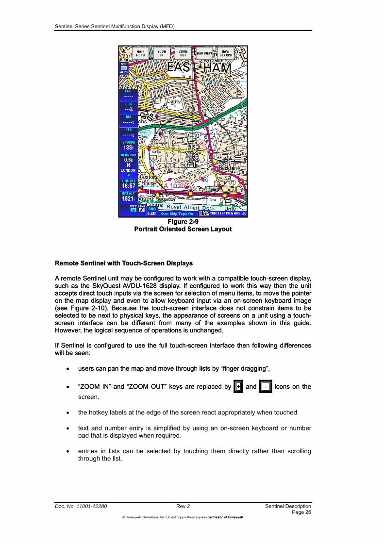
Remote Sentinel with Portrait Displays
A remote Sentinel unit may be configured to drive a portrait-oriented display – for example, see . If operated this way the information on the screen is rearranged to fit onto the different screen layout (for example see Figure 2-9) but the information itself is unchanged. For simplicity, example screen images in this document are only displayed in landscape orientation but there are always equivalent screens when the unit is configured to use a portrait – oriented display.
Sentinel Series Sentinel Multifunction Display (MFD)
Doc. No. 11001-12280 Rev 2 Sentinel Description Page 26
©Honeywell International Inc. Do not copy without express permission of Honeywell. permission of Honeywell.
Figure 2-9
Portrait Oriented Screen Layout Figure 2-9
Portrait Oriented Screen Layout
Remote Sentinel with Touch-Screen Displays Remote Sentinel with Touch-Screen Displays
A remote Sentinel unit may be configured to work with a compatible touch-screen display, such as the SkyQuest AVDU-1628 display. If configured to work this way then the unit accepts direct touch inputs via the screen for selection of menu items, to move the pointer on the map display and even to allow keyboard input via an on-screen keyboard image (see Figure 2-10). Because the touch-screen interface does not constrain items to be selected to be next to physical keys, the appearance of screens on a unit using a touch-screen interface can be different from many of the examples shown in this guide. However, the logical sequence of operations is unchanged.
A remote Sentinel unit may be configured to work with a compatible touch-screen display, such as the SkyQuest AVDU-1628 display. If configured to work this way then the unit accepts direct touch inputs via the screen for selection of menu items, to move the pointer on the map display and even to allow keyboard input via an on-screen keyboard image (see
If Sentinel is configured to use the full touch-screen interface then following differences will be seen: If Sentinel is configured to use the full touch-screen interface then following differences will be seen:
users can pan the map and move through lists by “finger dragging”, users can pan the map and move through lists by “finger dragging”,
“ZOOM IN” and “ZOOM OUT” keys are replaced by + and - icons on the “ZOOM IN” and “ZOOM OUT” keys are replaced by + and - icons on the
Figure 2-10). Because the touch-screen interface does not constrain items to be selected to be next to physical keys, the appearance of screens on a unit using a touch-screen interface can be different from many of the examples shown in this guide. However, the logical sequence of operations is unchanged.
screen.
the hotkey labels at the edge of the screen react appropriately when touched
text and number entry is simplified by using an on-screen keyboard or number pad that is displayed when required.
entries in lists can be selected by touching them directly rather than scrolling through the list.

Sentinel Series Sentinel Multifunction Display (MFD)
Figure 2-10
Touch-screen keyboard
Sentinel Description Rev 2 Doc. No. 11001-12280 Page 27
©Honeywell International Inc. Do not copy without express permission of Honeywell.

Sentinel Series Sentinel Multifunction Display (MFD)
Basic Operation Rev 2 Doc. No. 11001-12280 Page 29
©Honeywell International Inc. Do not copy without express permission of Honeywell.
3 Basic Operation
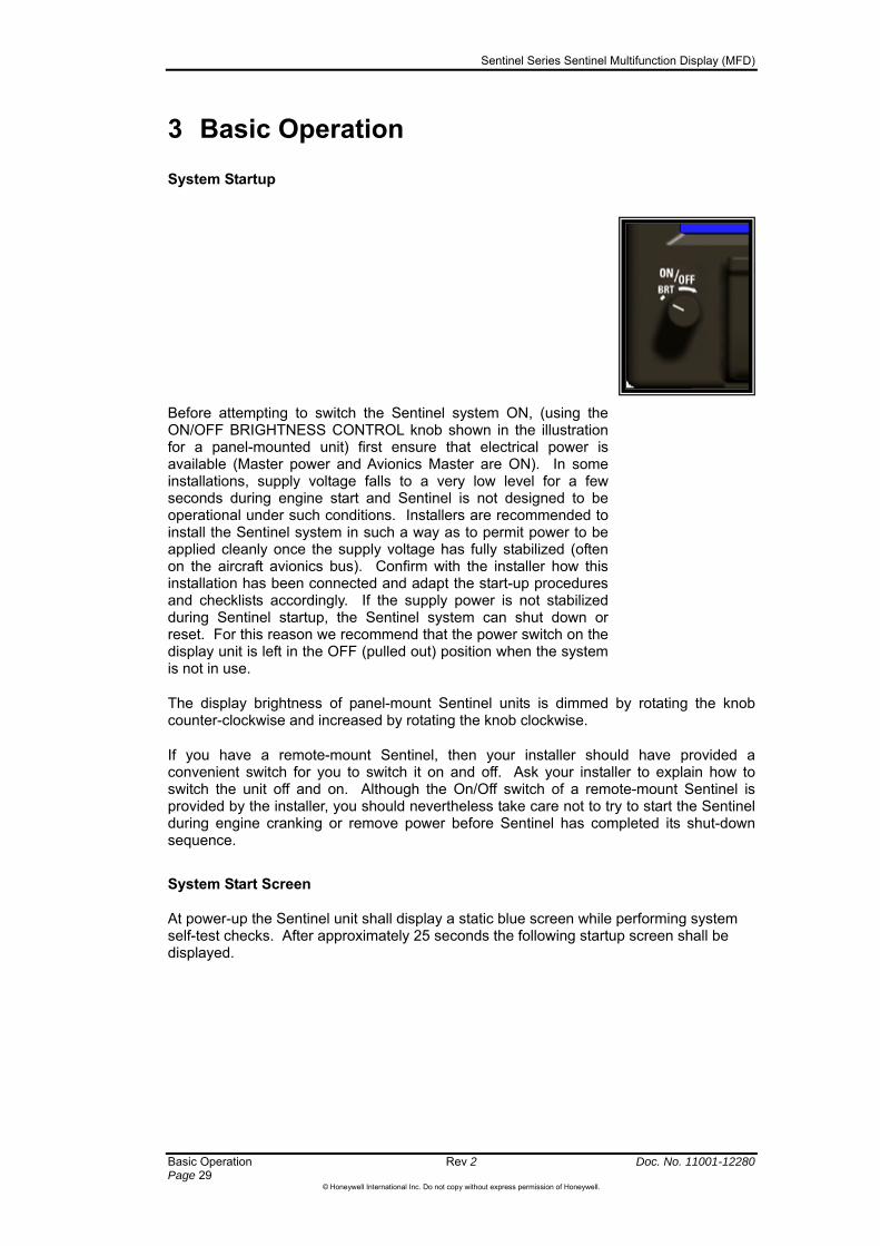
System Startup
Before attempting to switch the Sentinel system ON, (using the ON/OFF BRIGHTNESS CONTROL knob shown in the illustration for a panel-mounted unit) first ensure that electrical power is available (Master power and Avionics Master are ON). In some installations, supply voltage falls to a very low level for a few seconds during engine start and Sentinel is not designed to be operational under such conditions. Installers are recommended to install the Sentinel system in such a way as to permit power to be applied cleanly once the supply voltage has fully stabilized (often on the aircraft avionics bus). Confirm with the installer how this installation has been connected and adapt the start-up procedures and checklists accordingly. If the supply power is not stabilized during Sentinel startup, the Sentinel system can shut down or reset. For this reason we recommend that the power switch on the display unit is left in the OFF (pulled out) position when the system is not in use.
d by rotating the knob counter-clockwise and increased by rotating the knob clockwise.
e cranking or remove power before Sentinel has completed its shut-down sequence.
System Start Screen
s. After approximately 25 seconds the following startup screen shall be
displayed.
The display brightness of panel-mount Sentinel units is dimme
If you have a remote-mount Sentinel, then your installer should have provided a convenient switch for you to switch it on and off. Ask your installer to explain how to switch the unit off and on. Although the On/Off switch of a remote-mount Sentinel is provided by the installer, you should nevertheless take care not to try to start the Sentinel during engin
At power-up the Sentinel unit shall display a static blue screen while performing systemself-test check

Sentinel Series Sentinel Multifunction Display (MFD)
Doc. No. 11001-12280 Rev 2 Basic Operation Page 30
©Honeywell International Inc. Do not copy without express permission of Honeywell.
Figure 3-1 Startup Screen
Title Page
After a few seconds, the Initial Title page is displayed, as shown in Figure 3-2.
Figure 3-2 Initial Title Page (Landscape and Portrait displays)
A sequence of self-test checks are performed to ensure that the Sentinel unit is operating correctly and to ensure that the databases supplied on the data cards are correct. As each test is performed, a description of the test shall be displayed along with a green tick or a red cross, to indicate success or failure of the test.
If any of the self-tests fails, resulting in a red cross being displayed against the test, then softkey 1 shall be labelled HELP. Pressing the HELP softkey shall display a window giving more details regarding the problem.

Sentinel Series Sentinel Multifunction Display (MFD)
Basic Operation Rev 2 Doc. No. 11001-12280 Page 31
©Honeywell International Inc. Do not copy without express permission of Honeywell.
Upon completion of the self-test the message SELF TEST COMPLETED is displayed within a green box.
Figure 3-3 Self-test completed
NOTE: The unit normally contains at least three terrain databases to support the terrain display at coarse, medium and fine map scales. The fine terrain database is very large and can take a couple of minutes to check completely. The unit operates with the medium terrain database for the first couple of minutes, and during this time a “TERR LOAD” icon is displayed on the screen. Under normal circumstances the fine terrain database will be available for use by the time the aircraft has got airborne.
Pressing the OK softkey continues the start-up sequence, showing the Caution Page (see page ).
Pressing the DEMO MODE softkey puts the unit into demo mode. A window is displayed with the message “CAUTION Unit is in Demo Mode. DO NOT USE FOR NAVIGATION”. Pressing the OK softkey continues the start-up sequence, showing the Caution Page. Once the unit has been put into Demo Mode it can run simulated flights with simulated sensor data, using the parameters on the Demo Mode Setup menu.
Pressing the INSTALL MODE softkey prompts the user to enter a PIN code to enable installation and system configuration functions. Users should not usually need to access the Install Menu since the necessary settings should already have been set by your installer using the Sentinel Installation Manual. For convenience, an abbreviated summary of the install options is included in Section 9 System Setup: Install Menu.

Sentinel Series Sentinel Multifunction Display (MFD)
Doc. No. 11001-12280 Rev 2 Basic Operation Page 32
©Honeywell International Inc. Do not copy without express permission of Honeywell.
Caution Page
Figure 3-4 Caution Page
The CAUTION window advises that the GPS is limited to VFR use only. At the bottom of the window is the expiration date of the Jeppesen® aeronautical navigation data.
CAUTION: Sometimes, changes in aeronautical data are published in between scheduled 28-day cycle dates. This can happen when national regulators impose sudden changes or when errors are found in the data. Pilots should check the NOTAMs published by the relevant national body and by Jeppesen®.
Use the Sentinel unit as an aid to situation awareness only when the database is current. You may choose to continue to use Sentinel after the expiry of this data (for example if you intend to use the system only for mission purposes because other equipment will be used for aeronautical navigation), but you should treat any displayed aeronautical information with extra caution: the Jeppesen® database is available in updated form every 28 days because aeronautical data is subject to continuous change. Obtain updates for the Jeppesen® aeronautical navigation data from Honeywell.
The MAP INFO softkey is displayed with a yellow background if any raster aeronautical chart or custom database has expired, otherwise it is displayed with a white background.
The SET TIME softkey is only displayed if the time has not been received from the internal GPS module. Pressing the SET TIME softkey allows the date and time of the unit to be adjusted.
Pressing the OK softkey takes you to the Main Menu page (see page 34).
Pressing the MAP INFO softkey displays the Map and Custom Database Information page (see below).
Map and Custom Database Information Page
The Map and Custom Database Information page shows a series of windows, one for each type of map and custom database found on your compact flash cards.
Use the NEXT MAP and PREV MAP softkeys to move through the information windows, for each of the map types and custom databases.
Sentinel Series Sentinel Multifunction Display (MFD)
Basic Operation Rev 2 Doc. No. 11001-12280 Page 33
©Honeywell International Inc. Do not copy without express permission of Honeywell. on of Honeywell.
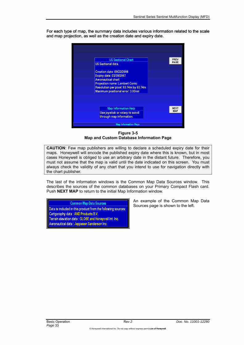
For each type of map, the summary data includes various information related to the scale and map projection, as well as the creation date and expiry date. For each type of map, the summary data includes various information related to the scale and map projection, as well as the creation date and expiry date.
Figure 3-5 Map and Custom Database Information Page
CAUTION: Few map publishers are willing to declare a scheduled expiry date for their maps. Honeywell will encode the published expiry date where this is known, but in most cases Honeywell is obliged to use an arbitrary date in the distant future. Therefore, you must not assume that the map is valid until the date indicated on this screen. You must always check the validity of any chart that you intend to use for navigation directly with the chart publisher.
The last of the information windows is the Common Map Data Sources window. This describes the sources of the common databases on your Primary Compact Flash card. Push NEXT MAP to return to the initial Map Information window.
An example of the Common Map Data Sources page is shown to the left.

Sentinel Series Sentinel Multifunction Display (MFD)
Doc. No. 11001-12280 Rev 2 Basic Operation Page 34
©Honeywell International Inc. Do not copy without express permission of Honeywell.
Main Menu page
Figure 3-6 Main Menu page
The Main Menu page is the page from which all primary functions can be accessed. The pages within Sentinel are organized in a tree structure, with each page usually having up to 5 branches (via the softkeys) to other pages. The main menu page is the page at the base of the tree structure.
On the Main Menu page the softkeys are as follows:
MAP: Displays a map image centered about the current aircraft position. Refer to Section 4 Map Mode
FLIGHT PLAN: Displays information regarding the current active flight plan and allows the user to create and edit flight plans and user waypoints. Refer to Section 6 Flight Planning.
MISSION CONTROL: Accesses the mission control page and system messages. Refer to Section 8 The Mission Control Menu.
SYSTEM SETUP: Accesses pages to set up the map image display, navigation display preferences, data display preferences and to load and save profile information. Refer to Section 9 System Setup.
The remaining softkey provides access to the primary display pages for any configured additional data sources, such as Traffic, Stormscope or XM Weather. If there are no such additional data sources then the softkey is inactive (as in the above image). If there is only a single additional data source then the softkey shall be labelled with the name of that data source (TRAFFIC, STORM SCOPE, or WEATHER). If there are more than one configured additional data source then the softkey shall be labelled MODE. Pressing the MODE softkey shall display the Additional Mode Help page allowing access to the primary display pages for the additional data sources.
The rotary control may be used while on the Main Menu page, Map page, Flight Plan page, Mission page, or any primary display page for the additional configured data source, to switch between the pages without navigating through the Main Menu page.
Sentinel Series Sentinel Multifunction Display (MFD)
Basic Operation Rev 2 Doc. No. 11001-12280 Page 35
©Honeywell International Inc. Do not copy without express permission of Honeywell.
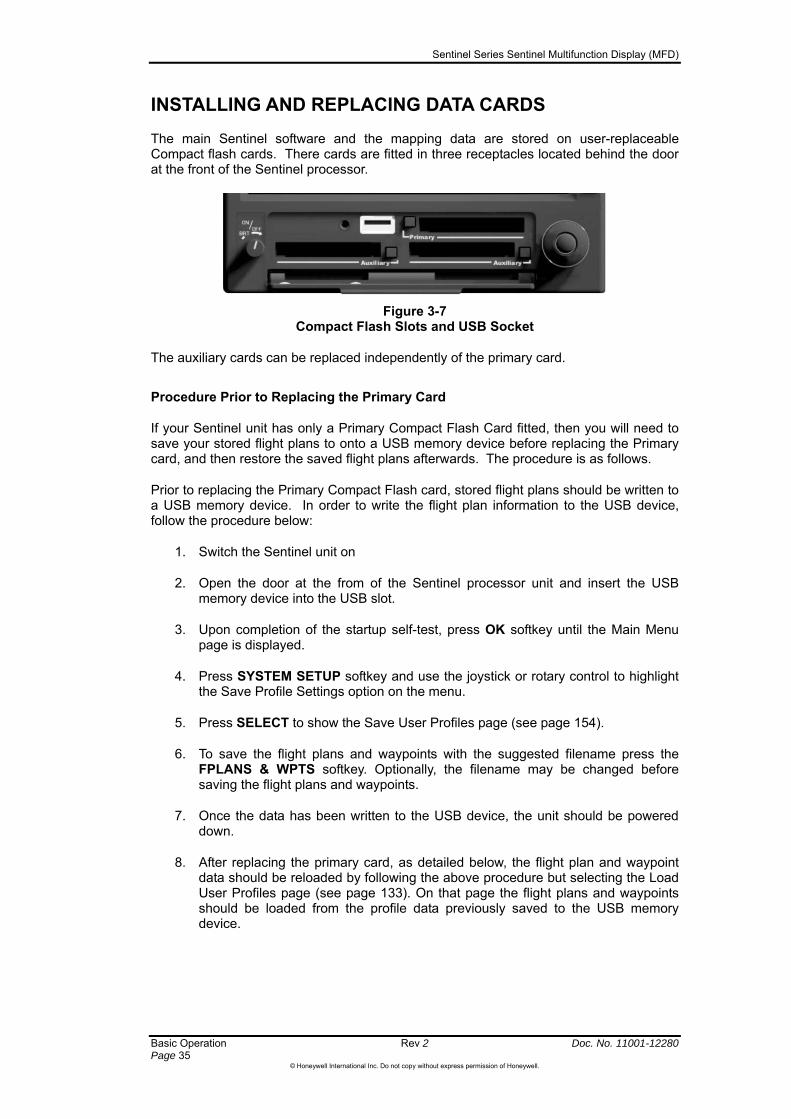
INSTALLING AND REPLACING DATA CARDS
The main Sentinel software and the mapping data are stored on user-replaceable Compact flash cards. There cards are fitted in three receptacles located behind the door at the front of the Sentinel processor.
Figure 3-7 Compact Flash Slots and USB Socket
The auxiliary cards can be replaced independently of the primary card.
Procedure Prior to Replacing the Primary Card
If your Sentinel unit has only a Primary Compact Flash Card fitted, then you will need to save your stored flight plans to onto a USB memory device before replacing the Primary card, and then restore the saved flight plans afterwards. The procedure is as follows.
Prior to replacing the Primary Compact Flash card, stored flight plans should be written to a USB memory device. In order to write the flight plan information to the USB device, follow the procedure below:
1. Switch the Sentinel unit on
2. Open the door at the from of the Sentinel processor unit and insert the USB memory device into the USB slot.
3. Upon completion of the startup self-test, press OK softkey until the Main Menu page is displayed.
4. Press SYSTEM SETUP softkey and use the joystick or rotary control to highlight the Save Profile Settings option on the menu.
5. Press SELECT to show the Save User Profiles page (see page 154).
6. To save the flight plans and waypoints with the suggested filename press the FPLANS & WPTS softkey. Optionally, the filename may be changed before saving the flight plans and waypoints.
7. Once the data has been written to the USB device, the unit should be powered down.
8. After replacing the primary card, as detailed below, the flight plan and waypoint data should be reloaded by following the above procedure but selecting the Load User Profiles page (see page 133). On that page the flight plans and waypoints should be loaded from the profile data previously saved to the USB memory device.

Sentinel Series Sentinel Multifunction Display (MFD)
Doc. No. 11001-12280 Rev 2 Basic Operation Page 36
©Honeywell International Inc. Do not copy without express permission of Honeywell.
If the Sentinel system is fitted with auxiliary compact flash cards then the flight plan information will automatically be copied to these cards whenever a change is made to the flight plans or user waypoints. The flight plan information on these auxiliary data cards will be used automatically when updating the data on the primary card. In a system with auxiliary data cards, step 8 of the above procedure will be performed automatically at startup after changing the primary data card. The data will be loaded from the auxiliary data cards instead of from the USB device.
Replacing a Card
1. Switch off the Sentinel using the procedure described on page 37 below.
2. Open the door at the front of the Sentinel processor unit, and identify the relevant card slots. The lower two slots are used for Auxiliary cards and are each marked “Auxiliary”, while the upper slot is used for Primary cards and is marked “Primary”.
3. Press and release the card eject button next to the card that you wish to replace. The button will extend slightly. Pressing the button a second time will cause the card to be released from its retention inside the unit. Remove the card.
4. Slide the new card into one of the slots, taking care to make sure that it is oriented as indicated on the card (“This side up”). The cards are keyed so that they can only be inserted the right way up: if you feel resistance, take the card out and try again the other way up.
NOTE: Each card has a raised ridge to help you to grip the card when you are removing it from the unit. The Primary card has its ridge on its lower edge, whereas the Auxiliary cards have theirs on their upper edge.
NOTE: Determined abuse can break the anti-insertion features that prevent a card from being fitted inverted. If power is applied with the card inverted then the card and unit could be permanently damaged, requiring factory repair. Such repairs would not be covered by your warranty.
5. Press the card eject button back into its storage position.
6. Repeat as necessary for the other card(s).
7. Power up the unit and check that it functions as expected.
Sentinel Series Sentinel Multifunction Display (MFD)
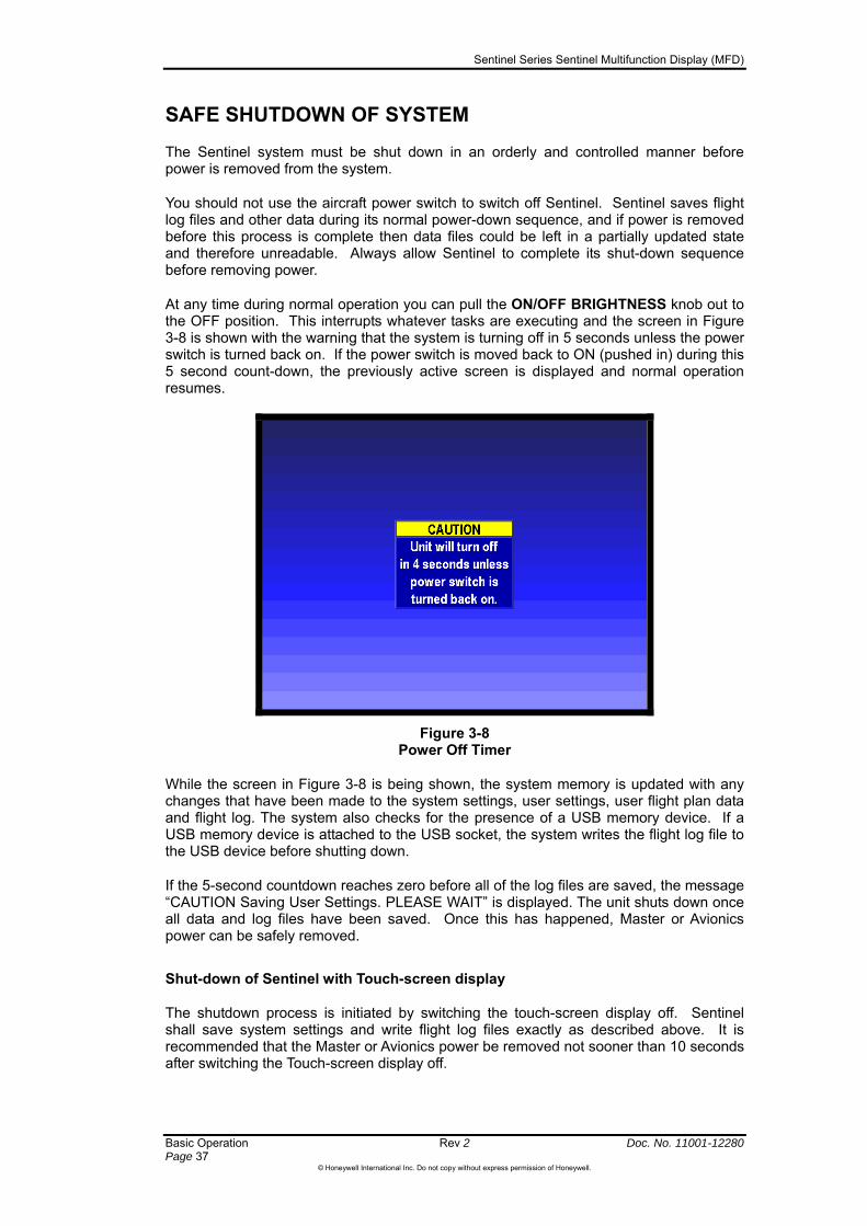
SAFE SHUTDOWN OF SYSTEM
The Sentinel system must be shut down in an orderly and controlled manner before power is removed from the system.
You should not use the aircraft power switch to switch off Sentinel. Sentinel saves flight log files and other data during its normal power-down sequence, and if power is removed before this process is complete then data files could be left in a partially updated state and therefore unreadable. Always allow Sentinel to complete its shut-down sequence before removing power.
At any time during normal operation you can pull the ON/OFF BRIGHTNESS knob out to the OFF position. This interrupts whatever tasks are executing and the screen in Figure 3-8 is shown with the warning that the system is turning off in 5 seconds unless the power switch is turned back on. If the power switch is moved back to ON (pushed in) during this 5 second count-down, the previously active screen is displayed and normal operation resumes.
Figure 3-8 Power Off Timer
While the screen in Figure 3-8 is being shown, the system memory is updated with any changes that have been made to the system settings, user settings, user flight plan data and flight log. The system also checks for the presence of a USB memory device. If a USB memory device is attached to the USB socket, the system writes the flight log file to the USB device before shutting down.
If the 5-second countdown reaches zero before all of the log files are saved, the message “CAUTION Saving User Settings. PLEASE WAIT” is displayed. The unit shuts down once all data and log files have been saved. Once this has happened, Master or Avionics power can be safely removed.
Shut-down of Sentinel with Touch-screen display
The shutdown process is initiated by switching the touch-screen display off. Sentinel shall save system settings and write flight log files exactly as described above. It is recommended that the Master or Avionics power be removed not sooner than 10 seconds after switching the Touch-screen display off.
Basic Operation Rev 2 Doc. No. 11001-12280 Page 37
©Honeywell International Inc. Do not copy without express permission of Honeywell.

Sentinel Series Sentinel Multifunction Display (MFD)
Map Mode Rev 2 Doc. No. 11001-12280 Page 39
©Honeywell International Inc. Do not copy without express permission of Honeywell.
4 Map Mode
The Sentinel Primary Compact Flash card has regional vector-type ground feature mapping available covering one of the three database regions (either ATI, AMR or PAI ) that together cover the globe. See the Appendix: Database Region Areas (Page 161) for summary maps of the areas covered by each of the three cards. This regional vectored data includes features such as coastlines, towns, major roads, railways, rivers, and terrain elevation data. The regional vectored ground feature data is only intended for use as an aid for VFR navigation. The level of detail available on the basic vector mapping varies from country to county, depending on the quality of commercially available data. In some countries the coverage includes most roads and streets, whereas in others there may be very few roads shown. If your mission requires you to have more detailed mapping than is provided in the standard Sentinel database for your country, then please contact Honeywell to discuss options for the supply of a map set to customized to suit your needs.
Most vector-type data is displayed in the form of icons or lines on the map. For some types of data, the user can select the colour of the line or the shape of the icon, and the map scale at which the line and its associated text label will be shown. Refer to Section 9 System Setup: Map Setup for a detailed explanation.
Aeronautical Databases
The Primary Compact Flash Card holds a database of aeronautical data such as controlled airspace, airfields, and navaids within the region covered by the vector-type ground feature data. This aeronautical vectored data is not filtered and is as accurate as the Jeppesen source data. This database is revised every 28 days in accordance with the ICAO aeronautical data cycle, and Honeywell can supply current cards with updated aeronautical data as required. You will be warned on the system startup screen if your Jeppesen ® database is out of date. You may choose to continue to use Sentinel after the expiry of this data (for example if you intend to use the system only for mission purposes because other equipment will be used for aeronautical navigation), but you should treat any displayed aeronautical information with extra caution: aeronautical data changes continuously and you should always be fully aware of any changes that affect your area of operations. Please check all available NOTAMs for notifications of changes to airport, terminal and enroute data.
In some countries, Honeywell has been able to compile additional databases of helipads and private airfields using information from public sources or from the operators themselves. This information is provided for your convenience since you may find it helpful to be aware of the possibility of aircraft operations from locations not normally marked on other charts, but you must not rely on the helipad and private airfield data in the same way as the Jeppesen® data for public airfields.
CAUTION: The data for small helipads and private airports is often provided voluntarily by the facility operators, and Honeywell cannot guarantee that the data is current or correct. If you intend to land at one of these facilities, then you should always obtain current information from the facility operator beforehand.
The obstacle data displayed on Sentinel has been complied by Honeywell from the en-route navigation obstacles section of the AIP published by selected countries. The list of countries included is being continuously enhanced.

Sentinel Series Sentinel Multifunction Display (MFD)
Doc. No. 11001-12280 Rev 2 Map Mode Page 40
©Honeywell International Inc. Do not copy without express permission of Honeywell.
CAUTION:
The obstacles data are provided as an aid to VFR navigation only and are intended to direct the pilot’s attention towards objects that should be visible outside the aircraft. You must not assume that the absence of obstacle icons means that low-altitude operations are safe.
Some countries do not publish regular updates and corrections, and those that do always make clear that they do not guarantee that the AIP details are correct or that the list is complete. Therefore, Honeywell cannot guarantee that obstacles will be shown in your area of operations, or that those that are shown are correct.
Terrain Elevation Data
The Primary compact flash card contains terrain elevation databases covering the vector database mapping region, with the exception that the detailed terrain elevation database for the ATI region ends at longitude East 80°. These databases are used to generate a representation of the shape of the land so that features such as valleys and hills can be identified and used as aids to VFR navigation, along with other visually identifiable features such as major roads, town, lakes and so on.
Sentinel uses terrain data with a horizontal resolution of as little as 6 arc seconds (about 185 meters), and if you zoom in close enough to the lower map scales then you will see individual squares of terrain of this size. Sentinel uses lower resolution terrain databases when the selected map scale is higher.
Figure 4-1 Shading on Eastern Face of Basic Vector Map Terrain
You should not attempt to compare the colouring of individual areas of the vector map in order to estimate terrain elevation. Sentinel uses many subtly different shades to build up images of the land and you should not rely on your ability to identify any individual shade. The shading that helps to highlight the slopes of hills and valleys also means that similarly colored points are not necessarily at the same height.
You can adjust the way that terrain is displayed if you want to have finer graduations of terrain elevations within a particular range of altitudes, for example if your area of operations never includes terrain above a certain height. This is done by adjusting the upper and lower limits of terrain display via the Map System Setup page. By default, the terrain display covers elevations from sea level up to 15000 feet and above.

Sentinel Series Sentinel Multifunction Display (MFD)
Map Mode Rev 2 Doc. No. 11001-12280 Page 41
©Honeywell International Inc. Do not copy without express permission of Honeywell.
Sentinel can also use the terrain elevation data to identify terrain that is close to the aircraft and display this either as a separate “close terrain” display (see page 58) or as an overlay on another map.
Raster Mapping
Raster mapping is easiest to describe as maps in the form of pictures such as photographs or scanned images of paper charts. Usually raster mapping is generated from images of paper charts (either scanned or electronic), but can also be from aerial photography of a particular area. Raster mapping files are normally stored on one or both of the Auxiliary Compact Flash cards.
Raster maps are usually stored on the Auxiliary compact flash cards. You do not need to have any raster maps present in order to use Sentinel, but most users prefer to have some. A wide range of available raster maps is available, limited only by availability of data, copyright terms, and customization costs if the map is non-standard.
Raster maps are drawn by cartographers using a combination of survey data and aerial photography. By convention, cartographers adjust the size and position of features in order to improve legibility and clarity, and this means that many features on raster maps are slightly out of position. For example, roads and railway lines that run only a few meters apart would merge into a single line if that distance was drawn perfectly to scale on most maps. In order to make the map more easily readable cartographers would draw the road and the railway as distinct lines. This improves the usefulness of the map but one or other of the features may be significantly out of position. Hence you may sometimes notice that a feature depicted on a raster map is not exactly aligned with its published LAT/LONG position. This is usually a deliberate choice of the cartographer that improves readability and it is not a malfunction.
CAUTION: You should be aware that discrepancies in the placement of airport and navigational aid symbols are known to exist in raster mapping sources. Features on raster maps may be drawn some distance from their true position, and for this reason you should not use the depicted position for navigation guidance.
CAUTION: Features drawn on a raster map often have their size or position adjusted slightly to improve legibility and clarity of the map. The sum of all the positional inaccuracies occurring in the raster map image display are used to plot a dotted line around the ownship icon (if larger than the icon itself) – see Figure 4-2.
Figure 4-2 Raster Mapping Positional Inaccuracy
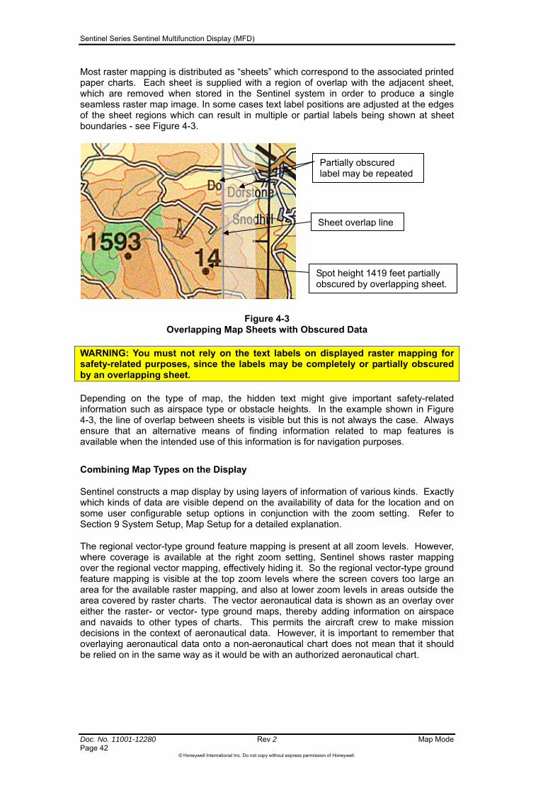
Sentinel Series Sentinel Multifunction Display (MFD)
Doc. No. 11001-12280 Rev 2 Map Mode Page 42
©Honeywell International Inc. Do not copy without express permission of Honeywell.
Most raster mapping is distributed as “sheets” which correspond to the associated printed paper charts. Each sheet is supplied with a region of overlap with the adjacent sheet, which are removed when stored in the Sentinel system in order to produce a single seamless raster map image. In some cases text label positions are adjusted at the edges of the sheet regions which can result in multiple or partial labels being shown at sheet boundaries - see Figure 4-3.
Figure 4-3 Overlapping Map Sheets with Obscured Data
WARNING: You must not rely on the text labels on displayed raster mapping for safety-related purposes, since the labels may be completely or partially obscured by an overlapping sheet.
Depending on the type of map, the hidden text might give important safety-related information such as airspace type or obstacle heights. In the example shown in Figure 4-3, the line of overlap between sheets is visible but this is not always the case. Always ensure that an alternative means of finding information related to map features is available when the intended use of this information is for navigation purposes.
Combining Map Types on the Display
Sentinel constructs a map display by using layers of information of various kinds. Exactly which kinds of data are visible depend on the availability of data for the location and on some user configurable setup options in conjunction with the zoom setting. Refer to Section 9 System Setup, Map Setup for a detailed explanation.
The regional vector-type ground feature mapping is present at all zoom levels. However, where coverage is available at the right zoom setting, Sentinel shows raster mapping over the regional vector mapping, effectively hiding it. So the regional vector-type ground feature mapping is visible at the top zoom levels where the screen covers too large an area for the available raster mapping, and also at lower zoom levels in areas outside the area covered by raster charts. The vector aeronautical data is shown as an overlay over either the raster- or vector- type ground maps, thereby adding information on airspace and navaids to other types of charts. This permits the aircraft crew to make mission decisions in the context of aeronautical data. However, it is important to remember that overlaying aeronautical data onto a non-aeronautical chart does not mean that it should be relied on in the same way as it would be with an authorized aeronautical chart.
Partially obscured label may be repeated
Sheet overlap line
Spot height 1419 feet partially obscured by overlapping sheet.
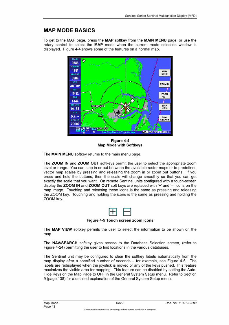
Sentinel Series Sentinel Multifunction Display (MFD)
Map Mode Rev 2 Doc. No. 11001-12280 Page 43
©Honeywell International Inc. Do not copy without express permission of Honeywell.
MAP MODE BASICS
To get to the MAP page, press the MAP softkey from the MAIN MENU page, or use the rotary control to select the MAP mode when the current mode selection window is displayed. Figure 4-4 shows some of the features on a normal map.
Figure 4-4 Map Mode with Softkeys
The MAIN MENU softkey returns to the main menu page.
The ZOOM IN and ZOOM OUT softkeys permit the user to select the appropriate zoom level or range. You can step in or out between the available raster maps or to predefined vector map scales by pressing and releasing the zoom in or zoom out buttons. If you press and hold the buttons, then the scale will change smoothly so that you can get exactly the scale that you want. On remote Sentinel units configured with a touch-screen display the ZOOM IN and ZOOM OUT soft keys are replaced with ‘+’ and ‘–‘ icons on the map image. Touching and releasing these icons is the same as pressing and releasing the ZOOM key. Touching and holding the icons is the same as pressing and holding the ZOOM key.
Figure 4-5 Touch screen zoom icons
The MAP VIEW softkey permits the user to select the information to be shown on the map.
The NAV/SEARCH softkey gives access to the Database Selection screen, (refer to Figure 4-24) permitting the user to find locations in the various databases.
The Sentinel unit may be configured to clear the softkey labels automatically from the map display after a specified number of seconds – for example, see Figure 4-6. The labels are redisplayed when the joystick is moved or any of the keys pushed. This feature maximizes the visible area for mapping. This feature can be disabled by setting the Auto-Hide Keys on the Map Page to OFF in the General System Setup menu. Refer to Section 9 (page 138) for a detailed explanation of the General System Setup menu.
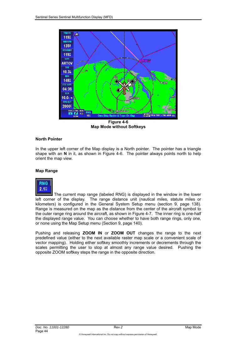
Sentinel Series Sentinel Multifunction Display (MFD)
Doc. No. 11001-12280 Rev 2 Map Mode Page 44
©Honeywell International Inc. Do not copy without express permission of Honeywell.
Figure 4-6
Map Mode without Softkeys
North Pointer
In the upper left corner of the Map display is a North pointer. The pointer has a triangle shape with an N in it, as shown in Figure 4-6. The pointer always points north to help orient the map view.
Map Range
The current map range (labeled RNG) is displayed in the window in the lower left corner of the display. The range distance unit (nautical miles, statute miles or kilometers) is configured in the General System Setup menu (section 9, page 138). Range is measured on the map as the distance from the center of the aircraft symbol to the outer range ring around the aircraft, as shown in Figure 4-7. The inner ring is one-half the displayed range value. You can choose whether to have both range rings, only one, or none using the Map Setup menu (Section 9, page 140).
Pushing and releasing ZOOM IN or ZOOM OUT changes the range to the next predefined value (either to the next available raster map scale or a convenient scale of vector mapping). Holding either softkey smoothly increments or decrements through the scales permitting the user to stop at almost any range value desired. Pushing the opposite ZOOM softkey steps the range in the opposite direction.

Sentinel Series Sentinel Multifunction Display (MFD)
Map Mode Rev 2 Doc. No. 11001-12280 Page 45
©Honeywell International Inc. Do not copy without express permission of Honeywell.
Figure 4-7 Map Mode Range Rings
The lower range values are determined by how the different map layers align with each other at a given range. Sentinel adjusts the range slightly in or out to get a better overlay match for more accurate display of all the involved data. This can cause displayed range values to show differently when zooming in our out. Range values above 10 are normally constant and repeatable.
Map Position Uncertainty
Sentinel displays a “Circle of Uncertainty” on raster maps. This is shown as a dotted circle centered on the aircraft icon, as shown on Figure 4-2. This is intended to give the user an indication of the likely range of the true position of the aircraft over the displayed map. The radius of the displayed circle of uncertainty reflects the sum of the estimated errors in the mapping and position source accuracy. It is not an absolute limit on the possible errors, and for most charts the chart publishers do not publish firm accuracy figures. However, the size of the circle should help to remind you that your aircraft could be in a different position than that displayed on the map.
CAUTION: Sentinel can display mapping down to a scale where the screen represents an area of only a few tens of meters. You must not try to use the ownship icon to maneuver the aircraft with respect to features displayed on the map. Maps shown at these scales are almost never intended for pilots, and at these scales, normally insignificant errors (for example whether the GPS antenna is mounted at the nose or the tail of the aircraft) become much more important.
Map Pointer
Once the pointer has been activated by moving the joystick, it remains active for 30 seconds. The black pointer is initially shown over the aircraft, as shown in Figure 4-8. When there is no pointer movement for more than 30 second the pointer and any associated information windows are automatically removed (reset). Pushing the RESET STICK softkey also resets the windows and pointer.
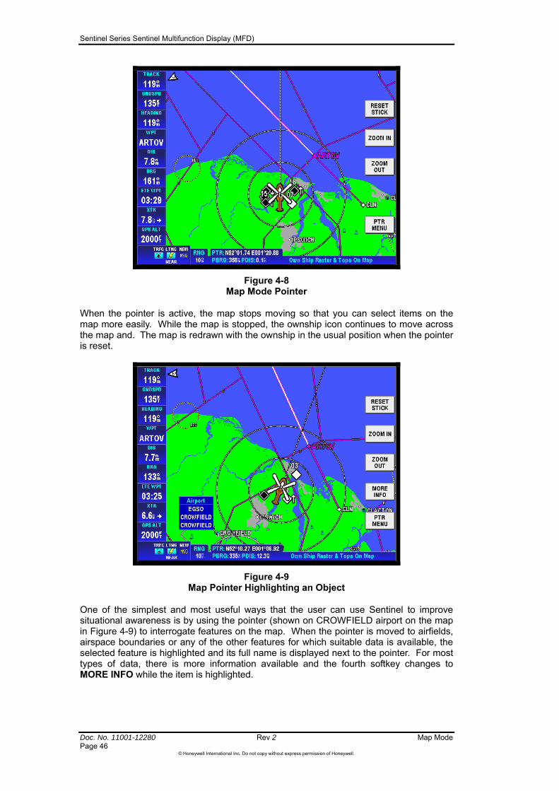
Sentinel Series Sentinel Multifunction Display (MFD)
Doc. No. 11001-12280 Rev 2 Map Mode Page 46
©Honeywell International Inc. Do not copy without express permission of Honeywell.
Figure 4-8 Map Mode Pointer
When the pointer is active, the map stops moving so that you can select items on the map more easily. While the map is stopped, the ownship icon continues to move across the map and. The map is redrawn with the ownship in the usual position when the pointer is reset.
Figure 4-9 Map Pointer Highlighting an Object
One of the simplest and most useful ways that the user can use Sentinel to improve situational awareness is by using the pointer (shown on CROWFIELD airport on the map in Figure 4-9) to interrogate features on the map. When the pointer is moved to airfields, airspace boundaries or any of the other features for which suitable data is available, the selected feature is highlighted and its full name is displayed next to the pointer. For most types of data, there is more information available and the fourth softkey changes to MORE INFO while the item is highlighted.
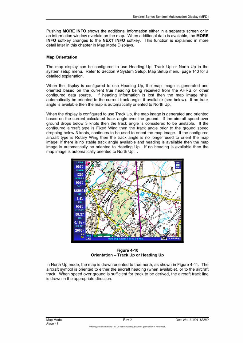
Sentinel Series Sentinel Multifunction Display (MFD)
Map Mode Rev 2 Doc. No. 11001-12280 Page 47
©Honeywell International Inc. Do not copy without express permission of Honeywell.
Pushing MORE INFO shows the additional information either in a separate screen or in an information window overlaid on the map. When additional data is available, the MORE INFO softkey changes to the NEXT INFO softkey. This function is explained in more detail later in this chapter in Map Mode Displays.
Map Orientation
The map display can be configured to use Heading Up, Track Up or North Up in the system setup menu. Refer to Section 9 System Setup, Map Setup menu, page 140 for a detailed explanation.
When the display is configured to use Heading Up, the map image is generated and oriented based on the current true heading being received from the AHRS or other configured data source. If heading information is lost then the map image shall automatically be oriented to the current track angle, if available (see below). If no track angle is available then the map is automatically oriented to North Up.
When the display is configured to use Track Up, the map image is generated and oriented based on the current calculated track angle over the ground. If the aircraft speed over ground drops below 3 knots then the track angle is considered to be unstable. If the configured aircraft type is Fixed Wing then the track angle prior to the ground speed dropping below 3 knots, continues to be used to orient the map image. If the configured aircraft type is Rotary Wing then the track angle is no longer used to orient the map image. If there is no stable track angle available and heading is available then the map image is automatically be oriented to Heading Up. If no heading is available then the map image is automatically oriented to North Up. .
Figure 4-10 Orientation – Track Up or Heading Up
In North Up mode, the map is drawn oriented to true north, as shown in Figure 4-11. The aircraft symbol is oriented to either the aircraft heading (when available), or to the aircraft track. When speed over ground is sufficient for track to be derived, the aircraft track line is drawn in the appropriate direction.
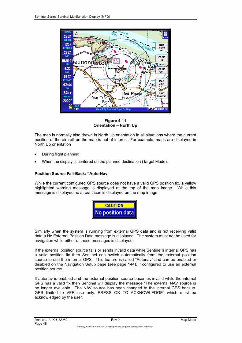
Sentinel Series Sentinel Multifunction Display (MFD)
Doc. No. 11001-12280 Rev 2 Map Mode Page 48
©Honeywell International Inc. Do not copy without express permission of Honeywell.
Figure 4-11 Orientation – North Up
The map is normally also drawn in North Up orientation in all situations where the current position of the aircraft on the map is not of interest. For example, maps are displayed in North Up orientation
During flight planning
When the display is centered on the planned destination (Target Mode).
Position Source Fall-Back: “Auto-Nav”
While the current configured GPS source does not have a valid GPS position fix, a yellow highlighted warning message is displayed at the top of the map image. While this message is displayed no aircraft icon is displayed on the map image
Similarly when the system is running from external GPS data and is not receiving valid data a No External Position Data message is displayed. The system must not be used for navigation while either of these messages is displayed.
If the external position source fails or sends invalid data while Sentinel’s internal GPS has a valid position fix then Sentinel can switch automatically from the external position source to use the internal GPS. This feature is called “Autonav” and can be enabled or disabled on the Navigation Setup page (see page 144), if configured to use an external position source.
If autonav is enabled and the external position source becomes invalid while the internal GPS has a valid fix then Sentinel will display the message “The external NAV source is no longer available. The NAV source has been changed to the internal GPS backup. GPS limited to VFR use only. PRESS OK TO ACKNOWLEDGE” which must be acknowledged by the user.
Sentinel Series Sentinel Multifunction Display (MFD)
Map Mode Rev 2 Doc. No. 11001-12280 Page 49
©Honeywell International Inc. Do not copy without express permission of Honeywell.
If Sentinel is also configured to receive its flight plan from the external position source, and a flight plan is being received at the time when the external position source fails, then Sentinel will capture the flight plan points allowing the user to edit and copy the flight plan.
While the Autonav feature is active and the internal GPS position source is being used a window shall be displayed on the map image with the text “INTERNAL VFR GPS” shown in black on a yellow background.
If Sentinel receives a valid position fix from the external position source, while autonav is enabled, then it will automatically revert back to the external position source (and flight plan source if configured to do so). Sentinel shall display the message “The external NAV source is now available. The NAV source has been changed to the external NAV source. PRESS OK TO ACKNOWLEDGE” which again must be acknowledged by the user.
CAUTION: Sentinel’s internal GPS engine is only suitable for use as an aid to VFR navigation. If the aircraft’s principal navigation equipment allows IFR operations but suffers a failure, then Sentinel’s ability to revert to the use of the internal GPS does not necessarily allow continued safe operation under instrument flight rules. You must ensure that you understand what other back-up navigation equipment is available on your aircraft so that you can respond appropriately if the principal navigation system fails.

Sentinel Series Sentinel Multifunction Display (MFD)
Doc. No. 11001-12280 Rev 2 Map Mode Page 50
©Honeywell International Inc. Do not copy without express permission of Honeywell.
MAP DATA ALERT AND STATUS ICONS
While displaying a map image, Sentinel can display up to 4 ‘map data alert and status icons’. These icons are listed below with a description of their meaning.
Icon Brief Description
This icon is shown if the map validity date in the file shows that the raster map that is being shown is out of date.
This icon is shown if the map that is currently being shown has not been classified as being of aeronautical grade.
Area-of-Probability mode is active: circles centered on a point of interest and expanding with estimated ground speed of a target – see Area of Probability, page 124.
This icon is shown while the fine detail terrain is being checked prior to initial use. The purpose is to show that the current terrain is not in fine detail.
Non-Aero Mapping Alert
Pilots flying under VFR can supplement their aeronautical chart with any information that they deem fit for purpose, but Sentinel mapping identified with the “Non-Aero” icon should be interpreted with additional caution when it is used at all for aeronautical navigation. When this icon is displayed on the screen it indicates that some or all of the visible data is not known to be suitable for use for aeronautical navigation. The most common reason for this is that the data itself was produced for another purpose – for example detailed street mapping. Such data could be essential to completing the intended mission and should be use for mission purposes, but it must not be used in the same way as an approved aeronautical chart for positioning the aircraft. Road maps for example can still be helpful for the mission when they contain information that is several years out of date or when they omit or distort some features for clarity, but this can make them too inaccurate to be safe for flying. So it could be quite safe to use some mapping while looking down on a scene from a safe standoff altitude (mission use), but unsafe to use the same mapping for positioning the aircraft (aeronautical navigation).
The highly detailed maps that are displayed on Sentinel sometimes contain information that could be of direct interest to pilots. This could include obstacles such as power lines, or even airfields shown in sufficient detail for runways and taxiways to be visible. It is important to remember that “Non-Aero” maps have generally not been produced for use by pilots and therefore features relevant to the pilot may be omitted or repositioned to improve image clarity.. The ground-based buyers of these maps do not normally mind when power lines are omitted for clarity in some areas, or when disused runways are depicted in the same way as active ones. Data displayed on Sentinel does not become aviation-grade when it did not meet this standard originally, and the icon serves as a reminder not to use non-aviation data inappropriately. Even aviation-type charts must sometimes be designated as being only suitable for mission use when they are not known to come from an approved source. As a safety feature to prevent confusion, the icon is displayed when non-aviation data is visible even when aviation-grade data is also visible at the same time. The icon will be displayed most of the time if your operations require you to spend large proportion of your time working at the detailed mapping levels.

Sentinel Series Sentinel Multifunction Display (MFD)
Map Mode Rev 2 Doc. No. 11001-12280 Page 51
©Honeywell International Inc. Do not copy without express permission of Honeywell.
Aeronautical Chart Validity Alert
One of the important characteristics of aeronautical mapping data is that it is periodically updated to reflect changes in real-world circumstances. Some map publishers work to a published timetable so that each chart has a predefined validity period beyond which it should be replaced with current charts. It is common for the charts covering most countries to be replaced on a rolling schedule rather than all being updated simultaneously, and when the Sentinel system contains data from several different charts it is likely that different parts of the map set have different expiration dates. Sentinel copes with this by displaying an icon to denote when some or all of the raster aeronautical charts currently visible are known to be out of date. When the flight is across several sheets of mapping then the icon can appear and disappear at various points along the route. Remember that charts with no published replacement timetable cannot be tagged with meaningful date validity information and so Sentinel will not display the date icon. Sentinel can be used after the expiration of the raster aeronautical chart data by continuing to refer to valid paper charts (maps) that should be maintained current at all times.
Note that not all aeronautical chart data has the associated date tags that permit this function to operate. Therefore, do not rely on this function for notification of the expiration of mapping data. You must not assume that the absence of “Map Date” icon means that the displayed chart is valid.
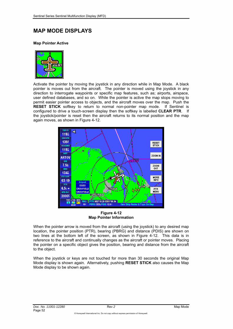
Sentinel Series Sentinel Multifunction Display (MFD)
Doc. No. 11001-12280 Rev 2 Map Mode Page 52
©Honeywell International Inc. Do not copy without express permission of Honeywell.
MAP MODE DISPLAYS
Map Pointer Active
Activate the pointer by moving the joystick in any direction while in Map Mode. A black pointer is moves out from the aircraft. The pointer is moved using the joystick in any direction to interrogate waypoints or specific map features, such as; airports, airspace, user defined databases, and so on. While the pointer is active the map stops moving to permit easier pointer access to objects, and the aircraft moves over the map. Push the RESET STICK softkey to return to normal non-pointer map mode. If Sentinel is configured to drive a touch-screen display then the softkey is labelled CLEAR PTR. If the joystick/pointer is reset then the aircraft returns to its normal position and the map again moves, as shown in Figure 4-12.
Figure 4-12 Map Pointer Information
When the pointer arrow is moved from the aircraft (using the joystick) to any desired map location, the pointer position (PTR), bearing (PBRG) and distance (PDIS) are shown on two lines at the bottom left of the screen, as shown in Figure 4-12. This data is in reference to the aircraft and continually changes as the aircraft or pointer moves. Placing the pointer on a specific object gives the position, bearing and distance from the aircraft to the object.
When the joystick or keys are not touched for more than 30 seconds the original Map Mode display is shown again. Alternatively, pushing RESET STICK also causes the Map Mode display to be shown again.
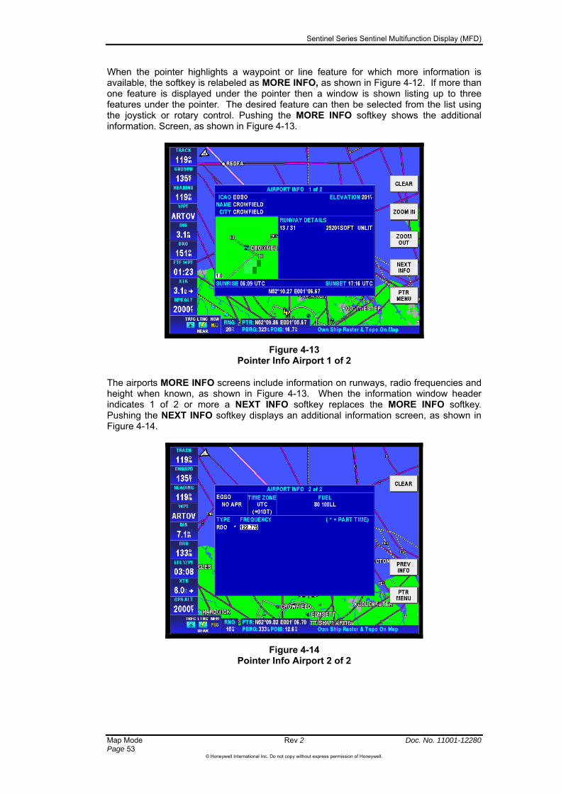
Sentinel Series Sentinel Multifunction Display (MFD)
Map Mode Rev 2 Doc. No. 11001-12280 Page 53
©Honeywell International Inc. Do not copy without express permission of Honeywell.
When the pointer highlights a waypoint or line feature for which more information is available, the softkey is relabeled as MORE INFO, as shown in Figure 4-12. If more than one feature is displayed under the pointer then a window is shown listing up to three features under the pointer. The desired feature can then be selected from the list using the joystick or rotary control. Pushing the MORE INFO softkey shows the additional information. Screen, as shown in Figure 4-13.
Figure 4-13 Pointer Info Airport 1 of 2
The airports MORE INFO screens include information on runways, radio frequencies and height when known, as shown in Figure 4-13. When the information window header indicates 1 of 2 or more a NEXT INFO softkey replaces the MORE INFO softkey. Pushing the NEXT INFO softkey displays an additional information screen, as shown in Figure 4-14.
Figure 4-14 Pointer Info Airport 2 of 2

Sentinel Series Sentinel Multifunction Display (MFD)
Doc. No. 11001-12280 Rev 2 Map Mode Page 54
©Honeywell International Inc. Do not copy without express permission of Honeywell.
Map Display While Navigating
as an overlay on the map image and the data windows shall display any configured navigation information
tification
Sentinel will show an alert to the pilot when the aircraft is within one minute of arriving a the final destination of a flight plan or Direct-To, or at a turning point within a flight plan. It can also be configured to plot a curve on the map to give guidance on when a turn is to be started assuming a rate one turn is to be made to the new course (see section Navigation Setup on page 144 for details of Turn Anticipation).
Sentinel displays a warning indicating that the aircraft is approaching the NEXT DTK (Desired Track) change and, if Turn Anticipation is enabled, the optimum rate one turn path is also displayed as a dotted track line. See Figure 4-15 Next Desired Track Notification below.
Depending on the configuration of the Sentinel system, it will either receive flight plan or Direct To navigation from an external source, or it will allow the user to program a desired flight plan or Direct-To navigation (see Section 6 Flight Planning for further details).
Unless specifically turned off, Sentinel will display the flight plan
available. The contents of the data windows can be tailored to the needs of the operator (see Data Field Setup, page 147).
Course Change No
nly if Turn Anticipation is enabled).
These course change notification alerts shall be displayed on Sentinel, regardless of the currently selected display and shall automatically clear once the next leg has been activated.
Pointer Menu
The Pointer Menu is an easy way to initiate various actions associated with the pointer’s location. The Pointer Menu is available on the bottom softkey when the pointer is active (for example, see Figure 4-16). Push the PTR MENU button to display the Pointer Menu next to the pointer on the screen.
Figure 4-15 Next Desired Track Notification
At the start point for the rate one turn, the course change notification shall change to TURN TO the desired track angle (o
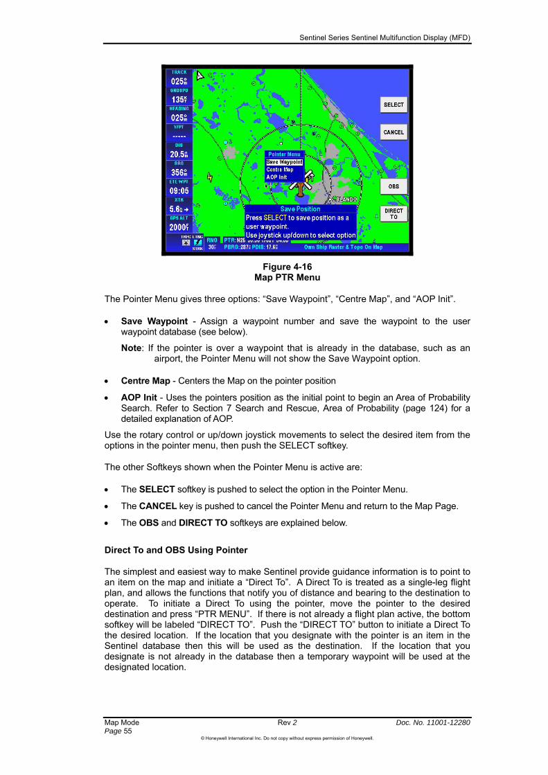
Sentinel Series Sentinel Multifunction Display (MFD)
Map Mode Rev 2 Doc. No. 11001-12280 Page 55
©Honeywell International Inc. Do not copy without express permission of Honeywell.
Figure 4-16 Map PTR Menu
The Pointer Menu gives three options: “Save Waypoint”, “Centre Map”, and “AOP Init”.
Save Waypoint - Assign a waypoint number and save the waypoint to the user waypoint database (see below).
Note: If the pointer is over a waypoint that is already in the database, such as an airport, the Pointer Menu will not show the Save Waypoint option.
Centre Map - Centers the Map on the pointer position
AOP Init - Uses the pointers position as the initial point to begin an Area of Probability Search. Refer to Section 7 Search and Rescue, Area of Probability (page 124) for a detailed explanation of AOP.
Use the rotary control or up/down joystick movements to select the desired item from the options in the pointer menu, then push the SELECT softkey.
The other Softkeys shown when the Pointer Menu is active are:
The SELECT softkey is pushed to select the option in the Pointer Menu.
The CANCEL key is pushed to cancel the Pointer Menu and return to the Map Page.
The OBS and DIRECT TO softkeys are explained below.
Direct To and OBS Using Pointer
The simplest and easiest way to make Sentinel provide guidance information is to point to an item on the map and initiate a “Direct To”. A Direct To is treated as a single-leg flight plan, and allows the functions that notify you of distance and bearing to the destination to operate. To initiate a Direct To using the pointer, move the pointer to the desired destination and press “PTR MENU”. If there is not already a flight plan active, the bottom softkey will be labeled “DIRECT TO”. Push the “DIRECT TO” button to initiate a Direct To the desired location. If the location that you designate with the pointer is an item in the Sentinel database then this will be used as the destination. If the location that you designate is not already in the database then a temporary waypoint will be used at the designated location.
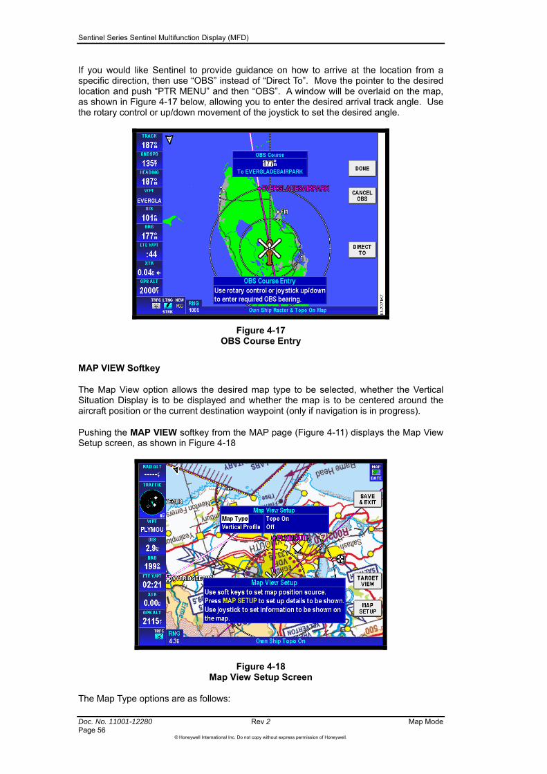
Sentinel Series Sentinel Multifunction Display (MFD)
Doc. No. 11001-12280 Rev 2 Map Mode Page 56
©Honeywell International Inc. Do not copy without express permission of Honeywell.
If you would like Sentinel to provide guidance on how to arrive at the location from a specific direction, then use “OBS” instead of “Direct To”. Move the pointer to the desired location and push “PTR MENU” and then “OBS”. A window will be overlaid on the map, as shown in Figure 4-17 below, allowing you to enter the desired arrival track angle. Use the rotary control or up/down movement of the joystick to set the desired angle.
Figure 4-17 OBS Course Entry
MAP VIEW Softkey
The Map View option allows the desired map type to be selected, whether the Vertical Situation Display is to be displayed and whether the map is to be centered around the aircraft position or the current destination waypoint (only if navigation is in progress).
Pushing the MAP VIEW softkey from the MAP page (Figure 4-11) displays the Map View Setup screen, as shown in Figure 4-18
Figure 4-18 Map View Setup Screen
The Map Type options are as follows:
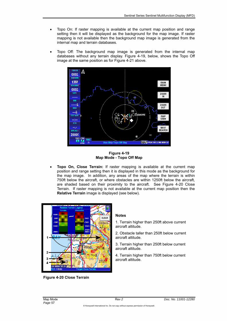
Sentinel Series Sentinel Multifunction Display (MFD)
Map Mode Rev 2 Doc. No. 11001-12280 Page 57
©Honeywell International Inc. Do not copy without express permission of Honeywell.
Topo On: If raster mapping is available at the current map position and range setting then it will be displayed as the background for the map image. If raster mapping is not available then the background map image is generated from the internal map and terrain databases.
Topo Off: The background map image is generated from the internal map databases without any terrain display. Figure 4-19, below, shows the Topo Off image at the same position as for Figure 4-21 above.
Figure 4-19 Map Mode - Topo Off Map
Topo On, Close Terrain: If raster mapping is available at the current map position and range setting then it is displayed in this mode as the background for the map image. In addition, any areas of the map where the terrain is within 750ft below the aircraft, or where obstacles are within 1250ft below the aircraft, are shaded based on their proximity to the aircraft. See Figure 4-20 Close Terrain. If raster mapping is not available at the current map position then the Relative Terrain image is displayed (see below).
Notes
1. Terrain higher than 250ft above current aircraft altitude.
2. Obstacle taller than 250ft below current aircraft altitude.
3. Terrain higher than 250ft below current aircraft altitude.
4. Terrain higher than 750ft below current aircraft altitude.
Figure 4-20 Close Terrain

Sentinel Series Sentinel Multifunction Display (MFD)
Doc. No. 11001-12280 Rev 2 Map Mode Page 58
©Honeywell International Inc. Do not copy without express permission of Honeywell.
CAUTION: The close terrain display feature is provided as an aid to VFR navigation only. It is intended to help direct the pilot’s attention towards terrain that should be visible outside the aircraft. It is not an EGPWS and it does not provide ground proximity warnings. It only highlights high terrain if the crew choose to engage the close terrain mode: it will not otherwise provide any information about surrounding terrain. The terrain database is regarded as fit for the purpose of providing assistance to “see and avoid” VFR navigation, but it must not be relied upon for terrain avoidance.
Relative Terrain: The background map image is generated from the internal map and terrain databases but the terrain is shaded based on its altitude relative to the current aircraft altitude.
Figure 4-21 Relative Terrain Map
Figure 4-22 Relative Terrain Shading (below) shows the colour selections used when shading the terrain. The terrain shading around obstacles is drawn as a circle of 0.5nm radius.
Figure 4-22 Relative Terrain Shading

Sentinel Series Sentinel Multifunction Display (MFD)
Map Mode Rev 2 Doc. No. 11001-12280 Page 59
©Honeywell International Inc. Do not copy without express permission of Honeywell.
CAUTION: The relative terrain display feature is provided as an aid to VFR navigation only. It is intended to help direct the pilot’s attention towards terrain that should be visible outside the aircraft. It is not a Ground Proximity Warning System (EGPWS) and it does not provide ground proximity warnings. It only highlights high terrain if the crew choose to engage the relative terrain mode: it will not otherwise provide any information about surrounding terrain. The terrain database is regarded as fit for the purpose of providing assistance to “see and avoid” VFR navigation, but it must not be relied upon for terrain avoidance.
Sentinel calculates the relative altitude of the aircraft with respect to the terrain using altitude data from a variety of sources: high integrity sources are used in preference. Possible altitude sources are:
Corrected Barometric Altitude from FMS or AHRS (preferred)
Pressure Altitude from FMS or Airdata unit
External GPS Altitude (assumed to come from FMS)
Internal GPS Altitude
The altitude value currently in use can be continuously displayed on the user-configurable on-screen data windows.
Vertical Profile Display
The Vertical Profile Display (also commonly referred to as “Vertical Situation Display”) is enabled by pressing the MAP VIEW softkey from the Map Page and setting the Vertical Profile option to On.
When enabled, the map image is reduced to allow for a vertical profile display at the bottom of the map display. See Figure 4-23 below.
Figure 4-23 Vertical Profile Display

Sentinel Series Sentinel Multifunction Display (MFD)
Doc. No. 11001-12280 Rev 2 Map Mode Page 60
©Honeywell International Inc. Do not copy without express permission of Honeywell.
The vertical profile display shows terrain, obstacles and airspace (where data is available) relative to the current altitude of the aircraft. The vertical profile window shows terrain and obstacles within an expanding corridor (“swath”) aligned with the aircraft’s current track. The main map image shows the expanding corridor as a dotted region indicating the area included in the vertical profile display database searches. If you are flying straight, the swath is centred so that it covers equal areas either side of your projected track. If you are turning then the swath is extended to include more area on the inside of the turn. The vertical profile display shows the highest terrain found within the searched area at each point along the horizontal distance scale.
If any obstacles are present within the dotted search region on the main map image then are drawn in the vertical profile window at the appropriate horizontal scale distance. Obstacles are drawn as vertical cyan lines with the upper and lower limits of the line corresponding to the base and top of the obstacle. Obstacles are drawn within the vertical profile window irrespective of whether they are enabled for display on the main map image.
CAUTION: The Vertical Situation Display window is provided as an aid to VFR “see and avoid” operations only. You must not use the Vertical Situation Display directly to guide the aircraft. The databases used for the Vertical Situation Display are good enough to draw your attention to terrain ahead of you that should be visible under VMC, but you must not rely on the data to avoid terrain that you cannot see. The Vertical Situation Display does not provide any predictive warnings.
If any airspace intersects the central line of the vertical profile path, as indicated on the main map image, then it is displayed in the vertical profile display window using the appropriate line style and colour. The airspace is positioned vertically based on the upper and lower limits of the airspace relative to the current aircraft altitude. If the upper limit of the airspace is above the upper altitude limit of the vertical profile display then a dotted line is displayed to help you to determine whether the aircraft is outside or within the airspace.
The vertical profile window does not show traffic.
The horizontal range of the vertical profile display follows that of the main map image, with a minimum range of 10nm and a maximum range of 100nm. When the main map range is less than 10nm then the vertical profile display range is FIXED at 10nm. When the main map range is greater than 100nm then the vertical profile display range is FIXED at 100nm. In both cases when the vertical profile scale is not the same as the main map scale, a bold yellow caution message is displayed within the vertical profile window reading “PROFILE NOT TO MAP SCALE”.
The vertical profile display colours the top of any terrain which is 250ft or more above the current aircraft altitude red. The top of any terrain higher than 250ft below the current aircraft altitude is be coloured bright yellow. Any terrain higher than 750ft below the current aircraft altitude is coloured dark yellow at the top.
If the aircraft is outside the region covered by the detailed terrain database then the vertical profile window will be filled grey to indicate that there is no usable terrain data for the area.
TARGET VIEW Softkey
The TARGET VIEW softkey is displayed only if navigation is in progress (either an active flight plan or a Direct-To or OBS), and if the map is currently centered about the aircraft’s position. Pressing TARGET VIEW causes the map image to be redrawn centered about the currently active waypoint. The map will be oriented using the desired track to the destination, with the destination waypoint positioned towards the top of the map image.
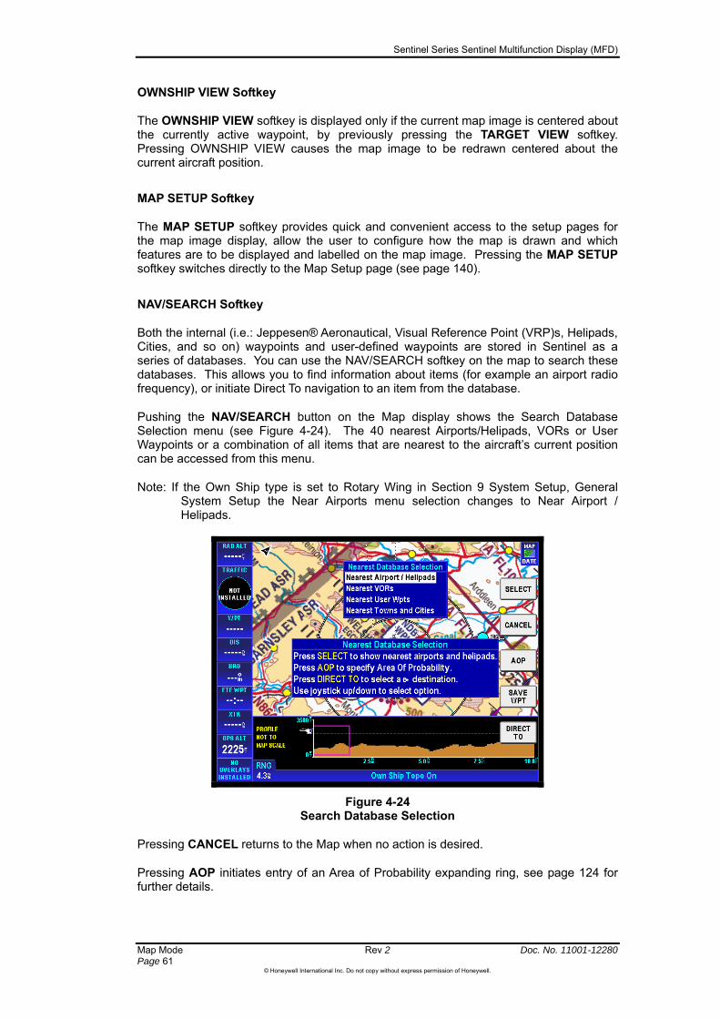
Sentinel Series Sentinel Multifunction Display (MFD)
Map Mode Rev 2 Doc. No. 11001-12280 Page 61
©Honeywell International Inc. Do not copy without express permission of Honeywell.
OWNSHIP VIEW Softkey
The OWNSHIP VIEW softkey is displayed only if the current map image is centered about the currently active waypoint, by previously pressing the TARGET VIEW softkey. Pressing OWNSHIP VIEW causes the map image to be redrawn centered about the current aircraft position.
MAP SETUP Softkey
The MAP SETUP softkey provides quick and convenient access to the setup pages for the map image display, allow the user to configure how the map is drawn and which features are to be displayed and labelled on the map image. Pressing the MAP SETUP softkey switches directly to the Map Setup page (see page 140).
NAV/SEARCH Softkey
Both the internal (i.e.: Jeppesen® Aeronautical, Visual Reference Point (VRP)s, Helipads, Cities, and so on) waypoints and user-defined waypoints are stored in Sentinel as a series of databases. You can use the NAV/SEARCH softkey on the map to search these databases. This allows you to find information about items (for example an airport radio frequency), or initiate Direct To navigation to an item from the database.
Pushing the NAV/SEARCH button on the Map display shows the Search Database Selection menu (see Figure 4-24). The 40 nearest Airports/Helipads, VORs or User Waypoints or a combination of all items that are nearest to the aircraft’s current position can be accessed from this menu.
Note: If the Own Ship type is set to Rotary Wing in Section 9 System Setup, General System Setup the Near Airports menu selection changes to Near Airport / Helipads.
Figure 4-24 Search Database Selection
Pressing CANCEL returns to the Map when no action is desired.
Pressing AOP initiates entry of an Area of Probability expanding ring, see page 124 for further details.

Sentinel Series Sentinel Multifunction Display (MFD)
Doc. No. 11001-12280 Rev 2 Map Mode Page 62
©Honeywell International Inc. Do not copy without express permission of Honeywell.
Pressing SAVE WPT creates a user waypoint at the current aircraft position. The User Waypoint Edit page is displayed (see page 103) allowing details to be added against the newly created user waypoint.
Figure 4-25 Database search (Portrait display with on-screen keyboard)
If there is a currently active flight plan then pressing DIRECT TO switches to the Active Flight Plan page so that you can modify the currently active leg of the flight plan, or to enter the destination for an off-route Direct-To. If there is no currently active flight plan then pressing DIRECT TO displays the Waypoint Entry window, allowing you to enter the ident, name or location as the destination for a Direct-To or OBS.
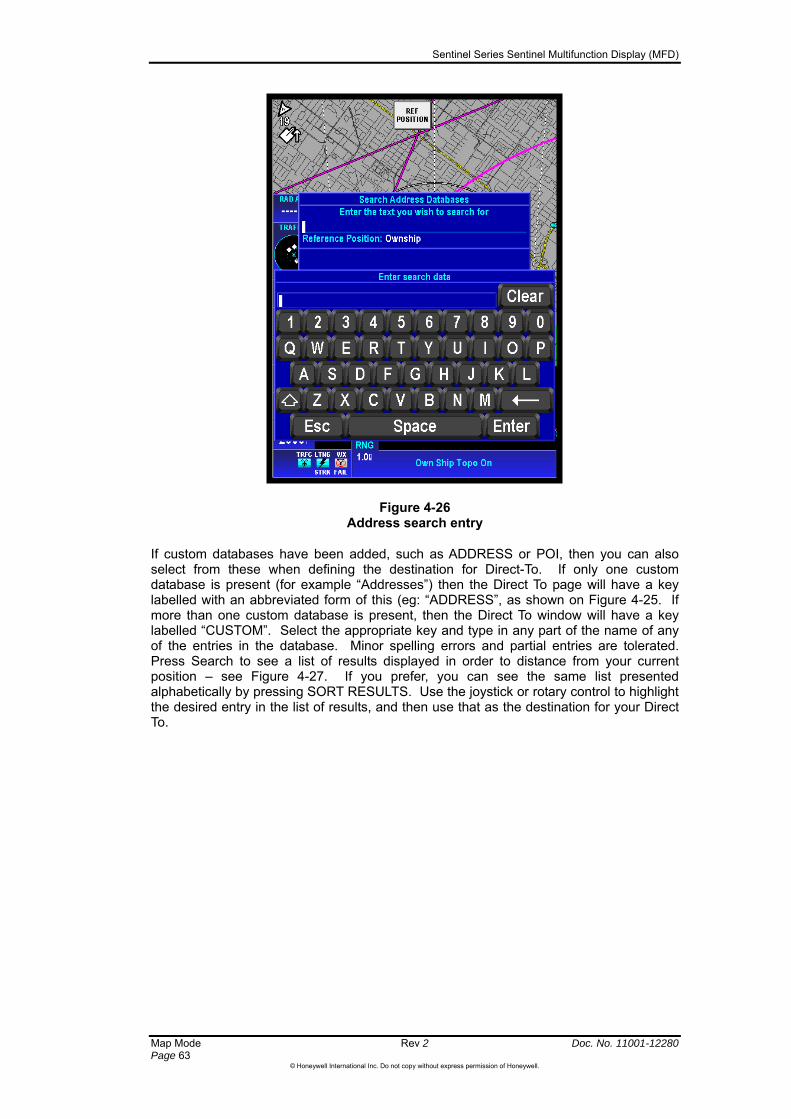
Sentinel Series Sentinel Multifunction Display (MFD)
Map Mode Rev 2 Doc. No. 11001-12280 Page 63
©Honeywell International Inc. Do not copy without express permission of Honeywell.
Figure 4-26 Address search entry
If custom databases have been added, such as ADDRESS or POI, then you can also select from these when defining the destination for Direct-To. If only one custom database is present (for example “Addresses”) then the Direct To page will have a key labelled with an abbreviated form of this (eg: “ADDRESS”, as shown on Figure 4-25. If more than one custom database is present, then the Direct To window will have a key labelled “CUSTOM”. Select the appropriate key and type in any part of the name of any of the entries in the database. Minor spelling errors and partial entries are tolerated. Press Search to see a list of results displayed in order to distance from your current position – see Figure 4-27. If you prefer, you can see the same list presented alphabetically by pressing SORT RESULTS. Use the joystick or rotary control to highlight the desired entry in the list of results, and then use that as the destination for your Direct To.

Sentinel Series Sentinel Multifunction Display (MFD)
Doc. No. 11001-12280 Rev 2 Map Mode Page 64
©Honeywell International Inc. Do not copy without express permission of Honeywell.
Figure 4-27 Address Search Results
The database searches normally look for database entries close to your current position, but you can also center your searches around a different location such as the center of a distant town. To do this, press “REF POSITION” on the search page (see Figure 4-26) and type in the name of any feature in the standard databases (eg: town, airport, navaid) that you know is in the vicinity of the item you are trying to find. Then search the custom databases in the same way as described above, and the results will be listed according to their distance from your chosen reference point.
NEAREST AIRPORTS / NEAREST AIRPORTS AND HELIPADS
Highlighting Near Airports in the Search Database Selection and pushing SELECT displays the Nearest Airports screen, as shown in Figure 4-28.
Figure 4-28 Nearest Airports Page

Sentinel Series Sentinel Multifunction Display (MFD)
Map Mode Rev 2 Doc. No. 11001-12280 Page 65
©Honeywell International Inc. Do not copy without express permission of Honeywell.
The display initially shows a list of the nearest airports (or airports and helipads) to the current aircraft position, sorted in increasing order of distance from your current position.
ages, you can select a different nearest item without returning the initial NAV/SEARCH page.
On the Nearest Airports Page, airports are only usually shown in the list when they satisfy iteria that have been previously defined in Section 9
System Setup, General System Setup (page 138). If you wish to view airports with a
y creates a course from the present aircraft position to the selected Nearest point’s location and returns to the Map display.
NEAREST VORS
Selection of the Nearest VORs from the Search Database Selection displays the Nearest VORs screen, showing the range, bearing and frequency of the nearest VORS. The list of VORs is sorted in increasing order of distance from the current aircraft position.
NEAREST USER WPTS
Selection of the Nearest User Waypoints from the Search Database Selection displays the Nearest User Waypoints screen, showing the ident of the user waypoint and its range and bearing. The list of user waypoints is sorted in increasing order of distance from the current aircraft position.
NEAREST TOWNS AND CITIES
Selection of the Nearest Towns and Cities from the Search Database Selection displays the Nearest Towns and Cities screen, showing the name of the city and its range and bearing. The list of towns and cities is sorted in increasing order of distance from the current aircraft position.
A scroll bar is also shown if the list of items found is larger than can be shown in the window. The rotary knob or joystick can be used to scroll up and down through the list and highlight the chosen item.
From any of the Nearest p
The MORE INFO softkey shows additional information on whichever item is selected in the Nearest window.
the runway surface and length cr
different minimum runway length or type of runway, then you can use the AIRPORT FILTER to set a temporary airport filter.
The DIRECT TO softke

Sentinel Series Sentinel Multifunction Display (MFD)
Doc. No. 11001-12280 Rev 2 Map Mode Page 66
©Honeywell International Inc. Do not copy without express permission of Honeywell.
POSITION LOGGING
While the aircraft is in flight, the current aircraft position is automatically recorded at preset intervals into a log file that can be used for post-flight analysis and for displaying the aircraft track.
The logging interval is user configured from 1 to 99 seconds. Refer to Section 9 General System Setup, page 138 for information on how to set the logging rate
Each log file entry includes the following information: date, time, latitude, longitude, heading, altitude, course-over-ground, speed-over-ground and details of the two nearest traffic targets (if configured and available). While in flight, each log file entry is added to a cyclic memory area that will store a minimum of 2000 log entries. Once the log file is full, the oldest entries are overwritten with new entries.
If a USB memory device is present when the Sentinel is switched off, then flight log information is automatically written to the USB device as part of the shut-down process. (Refer to Section 3, Basic operation - Safe Shutdown of System). Alternatively, you can save the flight log file to a USB device from the Mission Control Menu – see page 134.
Sentinel saves flight log files in three different formats:
1. A simple text file that can be replayed in a Sentinel or viewed on a standard PC.
2. A format that can be read by the popular Jeppesen FliteStarTM package,
3. A format that can be imported into Google EarthTM for 3D fly-through recreations of your flight.
Please see Appendix: Flight Log File Formats (page 163) for a detailed explanation of flight log files.
Flight Log Trail
With Flight Log trail turned on, a series of coloured dots is drawn on the map plotting the logged positions of the aircraft to give a visual indication of the flight path that the Aircraft has covered. This function is useful for Search and Rescue applications. To enable the flight log trail, push MAP VIEW from the map page, then push MAP SETUP, then use NEXT to step to the last page called Overlay Setup and select Flight Log Trail from the menu selection.

Sentinel Series Sentinel Multifunction Display (MFD)
Doc. No. 11001-12280 Rev 2 Additional Mode Display Pages Page 67
©Honeywell International Inc. Do not copy without express permission of Honeywell.
5 Additional Mode Display Pages
WX-500 STORMSCOPE® OPERATION
For a detailed description of the WX-500 Stormscope and how to interpret the lightning screens and a list of error codes, please refer to the WX-500 Stormscope® User’s Guide.
Introduction
The Sentinel can receive data from a L-3 WX-500 Stormscope® Series II Weather Mapping Sensor. The WX-500 detects electrical discharges associated with thunderstorms within a 200 NM radius of the aircraft. The information is then sent to the Sentinel and shows the location of the electrical discharges both on the map screen and on a dedicated Stormscope® display. Strikes and Cells can also be shown overlaid on the MAP display.
Pushing the STORM SCOPE softkey on the Main Menu Page shows the Stormscope display. The Stormscope display can also be selected using the rotary knob to highlight LTNG (lightning) in the Current Mode Selection area in the lower right corner of the screen, as shown in Figure 5-1.
Figure 5-1 Strike Mode – Stormscope (360)
Functional Description
The antenna detects the electric and magnetic fields generated by intra- cloud, inter-cloud, or cloud-to-ground electrical discharges that occur within a 200 NM radius of the aircraft and it sends the resulting discharge signals to the Stormscope processor. The processor digitizes, analyzes, and converts the discharge signals into range and bearing data then stores the data in memory. The WX-500 processor then communicates this information to Sentinel as strikes and cells. The WX-500 updates Sentinel every two seconds.
SENTINEL STORMSCOPE SETUP
Your installer should have configured Sentinel to work with the Stormscope sensor if installed. Refer to the installation manual for the Stormscope setup.
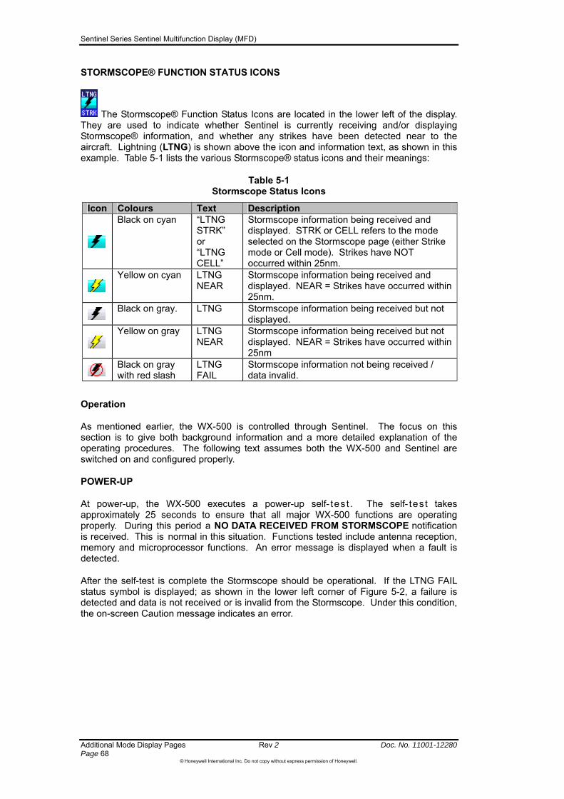
Sentinel Series Sentinel Multifunction Display (MFD)
Additional Mode Display Pages Rev 2 Doc. No. 11001-12280 Page 68
©Honeywell International Inc. Do not copy without express permission of Honeywell.
STORMSCOPE® FUNCTION STATUS ICONS
The Stormscope® Function Status Icons are located in the lower left of the display. They are used to indicate whether Sentinel is currently receiving and/or displaying Stormscope® information, and whether any strikes have been detected near to the aircraft. Lightning (LTNG) is shown above the icon and information text, as shown in this example. Table 5-1 lists the various Stormscope® status icons and their meanings:
Table 5-1 Stormscope Status Icons
Icon Colours Text Description
Black on cyan “LTNG STRK” or “LTNG CELL”
Stormscope information being received and displayed. STRK or CELL refers to the mode selected on the Stormscope page (either Strike mode or Cell mode). Strikes have NOT occurred within 25nm.
Yellow on cyan
LTNG NEAR
Stormscope information being received and displayed. NEAR = Strikes have occurred within 25nm.
Black on gray. LTNG
Stormscope information being received but not displayed.
Yellow on gray
LTNG NEAR
Stormscope information being received but not displayed. NEAR = Strikes have occurred within 25nm
Black on gray with red slash
LTNG FAIL
Stormscope information not being received / data invalid.
Operation
As mentioned earlier, the WX-500 is controlled through Sentinel. The focus on this section is to give both background information and a more detailed explanation of the operating procedures. The following text assumes both the WX-500 and Sentinel are switched on and configured properly.
POWER-UP
At power-up, the WX-500 executes a power-up self- tes t . The self- tes t takes approximately 25 seconds to ensure that all major WX-500 functions are operating properly. During this period a NO DATA RECEIVED FROM STORMSCOPE notification is received. This is normal in this situation. Functions tested include antenna reception, memory and microprocessor functions. An error message is displayed when a fault is detected.
After the self-test is complete the Stormscope should be operational. If the LTNG FAIL status symbol is displayed; as shown in the lower left corner of Figure 5-2, a failure is detected and data is not received or is invalid from the Stormscope. Under this condition, the on-screen Caution message indicates an error.

Sentinel Series Sentinel Multifunction Display (MFD)
Doc. No. 11001-12280 Rev 2 Additional Mode Display Pages Page 69
©Honeywell International Inc. Do not copy without express permission of Honeywell.
Figure 5-2 No Data Received From Stormscope
HEADING STABILIZATION
Some aircraft are equipped with a remote heading reference, such as a Horizontal Situation Indicator (HSI) with a slaved directional gyro. This permits the heading stabilization feature to adjust the position of the discharge points on the display automatically when the aircraft changes heading. The heading information comes from a remote heading source installed in the aircraft that has been connected to the WX-500. When this heading information is valid, the WX-500 and SENTINEL use it. In the absence of an external heading reference, such as an aircraft with only a directional gyro, or the failure of the heading reference, Sentinel does not permit Stormscope strikes to be overlaid on the Map Display. When no heading is available it is the responsibility of the user to manually clear strikes after executing a change in heading for reasons discussed in the next section.
HEADING DISPLAY
The Heading is displayed in the top center of the screen when heading data is being received, as shown in Figure 5-1. When heading data is not available but track over ground is available, then the window shows track. When neither heading nor track data is available, NO HDG/TRK is displayed.
Lightning Modes and Displays
Lightning data can be displayed in two modes, strike mode or cell mode.
Strike mode shows strike locations using an X symbol. The status symbol in the lower left corner indicates STRK (Strike) under the lightning symbol and STRIKE MODE is shown in the upper left corner of the display screen.
Cell mode shows strike locations using a + symbol. The status symbol in the lower left corner indicates CELL under the lightning symbol and CELL MODE is shown in the upper left corner of the display screen.
Two views are also selectable: The all around (360 degree) view or the forward looking (120 degree) view, as shown in Figure 5-3.

Sentinel Series Sentinel Multifunction Display (MFD)
Additional Mode Display Pages Rev 2 Doc. No. 11001-12280 Page 70
©Honeywell International Inc. Do not copy without express permission of Honeywell.
SWITCHING BETWEEN DISPLAY MODES
When the Stormscope® display screen is selected, Sentinel displays strikes in strike or cell mode and in either all round (360°) or forward looking only (120°).
Figure 5-3 Views and Modes
Figure 5-3 shows examples of the all round view and the forward looking view for both Strike and Cell modes. When first displayed, a notification window identifying the Mode and View is displayed. After a few seconds, the notification window is removed.
Pushing the MODE & VIEW softkey selects the desired view and mode. The display steps through this sequence: Strike Mode 360 Strike Mode 120 Cell Mode 360 Cell Mode 120 and over again, as shown in Figure 5-3. The mode selected remains in effect until you change it, unless the unit is turned off and back on. To switch between 360 and 120 views and remain in either Strike or Cell modes, use the Mode softkey (6th key on the bezel).
STRIKE DISPLAY MODE
Sentinel will plot an X symbol on the display for each individual discharge detected by the Stormscope unit. The strike will be positioned based on the bearing and distance reported by the Stormscope unit. Each strike will be automatically cleared after 3 minutes or if the CLEAR STRIKES softkey is pressed.
The strike display mode is most useful during periods of light electrical activity because it can plot discharges associated with a building thunderstorm sooner than the cell display mode would. When discharges are detected within 25 NM of the aircraft, the
storm- scope icon in the status area is displayed with a yellow highlight, as listed in Table 5-1.
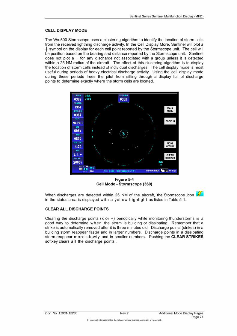
Sentinel Series Sentinel Multifunction Display (MFD)
Doc. No. 11001-12280 Rev 2 Additional Mode Display Pages Page 71
©Honeywell International Inc. Do not copy without express permission of Honeywell.
CELL DISPLAY MODE
The Wx-500 Stormscope uses a clustering algorithm to identify the location of storm cells from the received lightning discharge activity. In the Cell Display More, Sentinel will plot a ┼ symbol on the display for each cell point reported by the Stormscope unit. The cell will be position based on the bearing and distance reported by the Stormscope unit. Sentinel does not plot a + for any discharge not associated with a group unless it is detected within a 25 NM radius of the aircraft. The effect of this clustering algorithm is to display the location of storm cells instead of individual discharges. The cell display mode is most useful during periods of heavy electrical discharge activity. Using the cell display mode during these periods frees the pilot from sifting through a display full of discharge points to determine exactly where the storm cells are located.
Figure 5-4 Cell Mode - Stormscope (360)
When discharges are detected within 25 NM of the aircraft, the Stormscope icon in the status area is displayed with a yel low highl ight as listed in Table 5-1.
CLEAR ALL DISCHARGE POINTS
Clearing the discharge points (x or +) periodically while monitoring thunderstorms is a good way to determine when the storm is building or dissipating. Remember that a strike is automatically removed after it is three minutes old. Discharge points (strikes) in a building storm reappear faster and in larger numbers. Discharge points in a dissipating storm reappear more s lowly and in smaller numbers. Pushing the CLEAR STRIKES softkey clears a l l the discharge points..

Sentinel Series Sentinel Multifunction Display (MFD)
Additional Mode Display Pages Rev 2 Doc. No. 11001-12280 Page 72
©Honeywell International Inc. Do not copy without express permission of Honeywell.
Figure 5-5 Lightning Strikes Shown
Figure 5-6 Lightning Strikes Cleared
Clearing the display is especially important when an external heading reference is not used or has failed. The display should be cleared after changes in heading in order to make the displayed strikes reflect their true position in relation to the aircraft. This is why the heading is displayed at the top center of the screen.
RATE DISPLAY

Sentinel Series Sentinel Multifunction Display (MFD)
Doc. No. 11001-12280 Rev 2 Additional Mode Display Pages Page 73
©Honeywell International Inc. Do not copy without express permission of Honeywell.
The rate of lightning activity is shown in the lower right area of the screen. This is the number of detected strikes in the last minute. Rate is calculated based on the strikes that get displayed on the selected view. It is only calculated using the strike information. When a 120 degree view at 50 NM is selected then the displayed strike rate would be calculated using only strikes received within the 50 NM range and bearing within +/- 60 degrees. The calculation is updated every 20
seconds. This same calculation is used in Cell mode.
CHANGING DISPLAY RANGE
This lightning range corresponds to the distance from the aircraft to the outer range ring on the display. Sentinel stores electrical discharge information for all ranges simultaneously to give an instant, up-to-date display of electrical discharge activity when a new range is selected. The range measurement unit is what is configured in the General System Setup menu.
When moving from one range to the next, the 25nmrange is always shown by the solid inner ring (shown with a small 25 in the arc) to advise of close proximity to thunder- storms. Also, notice that the discharge points (the x or + symbols) are progressively larger on the shorter ranges and smaller on the longer ranges.
Pushing the ZOOM IN or ZOOM OUT softkeys changes the displayed range of the Stormscope® display. With each push of the keys, the display changes to display the electrical discharge activity detected within the new range. The range indicator also changes to display the numerical value of the new range (25, 50, 100, or 200 NM).
Operation In Stormscope® Mode With Flight Plan Active
When Sentinel is receiving Flight Plan information from the GPS and a valid heading input is available, the Flight Plan lines and waypoints are displayed on the Stormscope® screen, as shown in Figure 5-7.
Figure 5-7 Flight Plan Turn To Warning
NOTE: In order to align the lightning strikes correctly to the flight plan lines, heading information is necessary.

Sentinel Series Sentinel Multifunction Display (MFD)
Additional Mode Display Pages Rev 2 Doc. No. 11001-12280 Page 74
©Honeywell International Inc. Do not copy without express permission of Honeywell.
Sentinel shows a warning message on the Stormscope display page when the aircraft is nearing a heading change. In Figure 5-7 the blue warning window indicates a TURN TO 055.
Stormscope Overlay On Map Display
Strike data or thunderstorms cells can be displayed on the main map display, as shown in Figure 5-8, providing that a heading reference is available and that the current aircraft position is valid. The Map Setup page (see section Map Setup on page 140) also controls the map ranges at which lightning shall be displayed. The status symbol in the lower left corner indicates whether the displayed lightning is strike data (STRK) or thunderstorm cells (CELL).
Figure 5-8 Lightning Display on Map
Any settings made while in the Stormscope® screen (i.e. cell/strike mode, clear, and so on.) are carried over into the Map display. Lightning icons are shown here as they appear on the Map display. The range at which lightning icons are displayed is the range selected on the Map page. Also, strike or cell data are not displayed at or above the maximum range value configured in the Overlay Setup table on the Map Setup Page.
CAUTION: Because the accuracy of the Stormscope sensor is limited, do not rely on the placement of lightning icons for map range settings of less than 25nm.
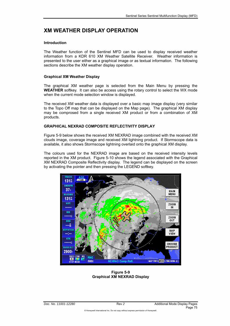
Sentinel Series Sentinel Multifunction Display (MFD)
Doc. No. 11001-12280 Rev 2 Additional Mode Display Pages Page 75
©Honeywell International Inc. Do not copy without express permission of Honeywell.
XM WEATHER DISPLAY OPERATION
Introduction
The Weather function of the Sentinel MFD can be used to display received weather information from a KDR 610 XM Weather Satellite Receiver. Weather information is presented to the user either as a graphical image or as textual information. The following sections describe the XM weather display operation.
Graphical XM Weather Display
The graphical XM weather page is selected from the Main Menu by pressing the WEATHER softkey. It can also be access using the rotary control to select the WX mode when the current mode selection window is displayed.
The received XM weather data is displayed over a basic map image display (very similar to the Topo Off map that can be displayed on the Map page). The graphical XM display may be comprosed from a single received XM product or from a combination of XM products.
GRAPHICAL NEXRAD COMPOSITE REFLECTIVITY DISPLAY
Figure 5-9 below shows the received XM NEXRAD image combined with the received XM clouds image, coverage image and received XM lightning product. If Stormscope data is available, it also shows Stormscope lightning overlaid onto the graphical XM display.
The colours used for the NEXRAD image are based on the received intensity levels reported in the XM product. Figure 5-10 shows the legend associated with the Graphical XM NEXRAD Composite Reflectivity display. The legend can be displayed on the screen by activating the pointer and then pressing the LEGEND softkey.
Figure 5-9 Graphical XM NEXRAD Display

Sentinel Series Sentinel Multifunction Display (MFD)
Additional Mode Display Pages Rev 2 Doc. No. 11001-12280 Page 76
©Honeywell International Inc. Do not copy without express permission of Honeywell.
Figure 5-10 NEXRAD Legend
Graphical XM Controls
The methods for panning, zooming and interrogating the graphical XM image are essentially the same as for the Map page. Please refer to Section 4 Map Mode for details. To follow is a description of the controls specific to the Graphical XM page.
The age of the received XM product used to generate the NEXRAD image is displayed at the top left of the screen. If a product reaches the maximum age limit, shown within the age window, then it is automatically discarded.
Pressing CHOOSE PRODUCT softkey allows the selection of the primary XM product display. The CHOOSE PRODUCT softkey is only displayed if more than one weather product is available for display. Figure 5-11 below shows the menu shown when the CHOOSE PRODUCT softkey is pressed. The list of products depends on which XM products have been received.
Figure 5-11 Graphical XM page with Choose Product Menu
Use the joystick up / down or rotary control to highlight the desired XM product and press SELECT. Selecting a Textual product shows the Textual XM Weather Display (see page 81).
Table 5-2 below is the list of all possible XM products. Only the products actually received will be visible in the displayed list.
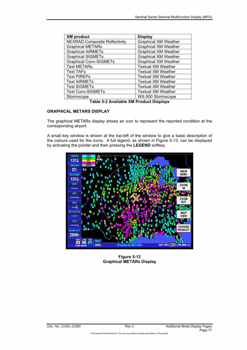
Sentinel Series Sentinel Multifunction Display (MFD)
Doc. No. 11001-12280 Rev 2 Additional Mode Display Pages Page 77
©Honeywell International Inc. Do not copy without express permission of Honeywell.
XM product Display NEXRAD Composite Reflectivity Graphical XM Weather Graphical METARs Graphical XM Weather Graphical AIRMETs Graphical XM Weather Graphical SIGMETs Graphical XM Weather Graphical Conv-SIGMETs Graphical XM Weather Text METARs Textual XM Weather Text TAFs Textual XM Weather Text PIREPs Textual XM Weather Text AIRMETs Textual XM Weather Text SIGMETs Textual XM Weather Text Conv-SIGMETs Textual XM Weather Stormscope WX-500 Stormscope
Table 5-2 Available XM Product Displays
GRAPHICAL METARS DISPLAY
The graphical METARs display shows an icon to represent the reported condition at the corresponding airport.
A small key window is shown at the top-left of the window to give a basic description of the colours used for the icons. A full legend, as shown in Figure 5-13, can be displayed by activating the pointer and then pressing the LEGEND softkey.
Figure 5-12 Graphical METARs Display

Sentinel Series Sentinel Multifunction Display (MFD)
Additional Mode Display Pages Rev 2 Doc. No. 11001-12280 Page 78
©Honeywell International Inc. Do not copy without express permission of Honeywell.
Figure 5-13 Graphical METAR Legend
GRAPHICAL AIRMETS DISPLAY
An AIRMET is a weather advisory, issued by the meteorological office, indicating that there is potentially hazardous weather to low-level aircraft within a specified area.
The Graphical AIRMETs display shows enclosed areas on the map corresponding to the areas described within the received textual AIRMET reports.
A small key window is shown at the top-left of the screen giving a basic description of the colors used. A larger legend window can be displayed by activating the pointer and pressing the LEGEND softkey. Figure 5-15 shows the XM AIRMET legend.
The small key legend also includes an indication of whether the aircraft is within any region of the specified type. As an example, the small key legend in Figure 5-14 shows that the aircraft is within a region of turbulence, and a region of icing and a region with IFR conditions.
The pointer can be used to select an AIRMET and switch directly to the corresponding Textual AIRMET record display by pressing the MORE INFO softkey.
Figure 5-14 Graphical AIRMETs Display
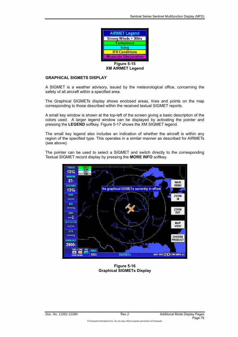
Sentinel Series Sentinel Multifunction Display (MFD)
Doc. No. 11001-12280 Rev 2 Additional Mode Display Pages Page 79
©Honeywell International Inc. Do not copy without express permission of Honeywell.
Figure 5-15
XM AIRMET Legend
GRAPHICAL SIGMETS DISPLAY
A SIGMET is a weather advisory, issued by the meteorological office, concerning the safety of all aircraft within a specified area.
The Graphical SIGMETs display shows enclosed areas, lines and points on the map corresponding to those described within the received textual SIGMET reports.
A small key window is shown at the top-left of the screen giving a basic description of the colors used. A larger legend window can be displayed by activating the pointer and pressing the LEGEND softkey. Figure 5-17 shows the XM SIGMET legend.
The small key legend also includes an indication of whether the aircraft is within any region of the specified type. This operates in a similar manner as described for AIRMETs (see above).
The pointer can be used to select a SIGMET and switch directly to the corresponding Textual SIGMET record display by pressing the MORE INFO softkey.
Figure 5-16 Graphical SIGMETs Display

Sentinel Series Sentinel Multifunction Display (MFD)
Additional Mode Display Pages Rev 2 Doc. No. 11001-12280 Page 80
©Honeywell International Inc. Do not copy without express permission of Honeywell.
Figure 5-17 XM SIGMET Legend
GRAPHICAL CONVECTIVE SIGMETS DISPLAY
A Convective SIGMET is a weather advisory, issued by the meteorological office, concerning the safety of all aircraft within a specified area. Convective SIGMETs refer to areas, lines or points with thunderstorms.
The Graphical Convective SIGMETs display shows enclosed areas, lines and points on the map corresponding to those described within the received textual Convective SIGMET reports.
A small key window is shown at the top-left of the screen giving a basic description of the colors used. A larger legend window can be displayed by activating the pointer and pressing the LEGEND softkey. Figure 5-17 shows the XM Convective SIGMET legend.
The small key legend also includes an indication of whether the aircraft is within any region of the specified type. This operates in a similar manner as described for AIRMETs (see above).
The pointer can be used to select a Convective SIGMET and switch directly to the corresponding Textual Convective SIGMET record display by pressing the MORE INFO softkey.
Figure 5-18 Graphical Convective SIGMETs Display
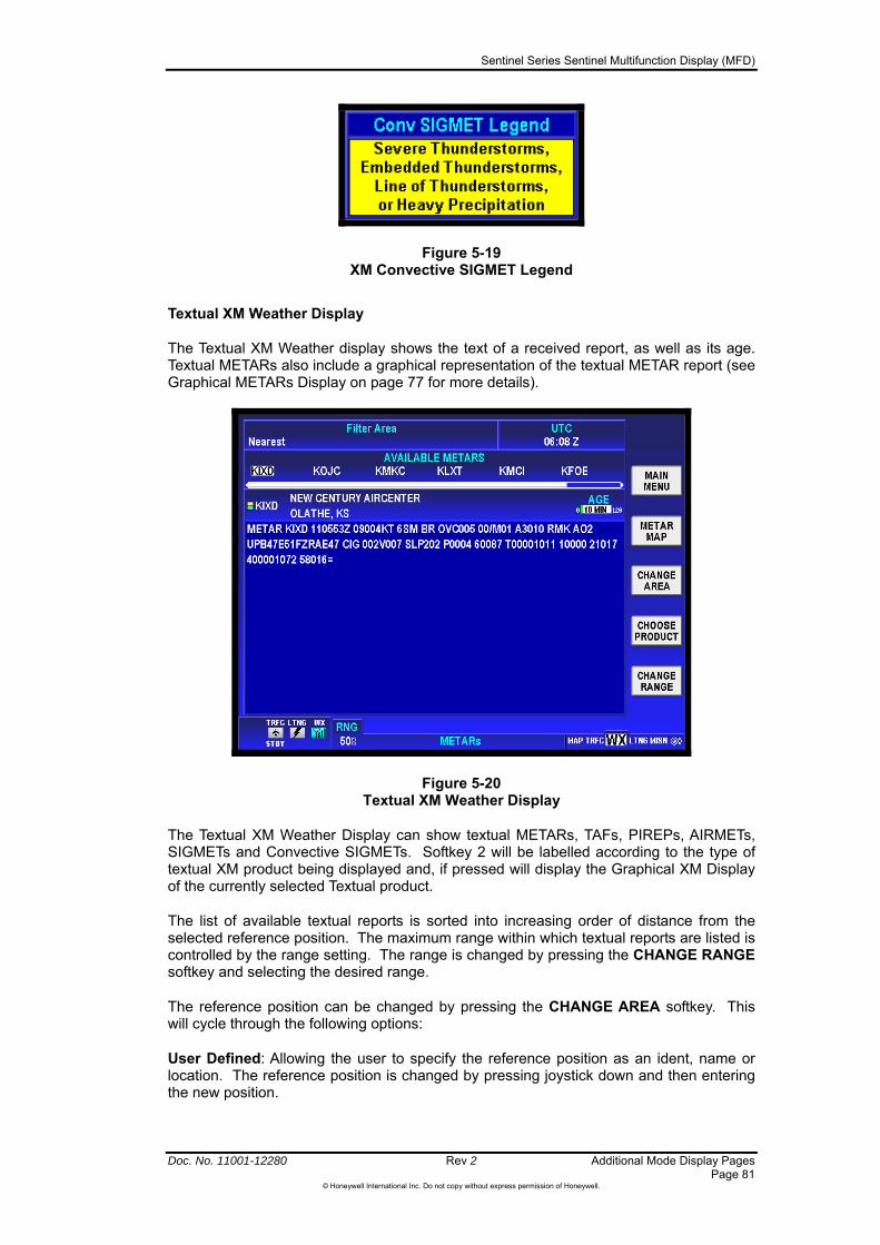
Sentinel Series Sentinel Multifunction Display (MFD)
Doc. No. 11001-12280 Rev 2 Additional Mode Display Pages Page 81
©Honeywell International Inc. Do not copy without express permission of Honeywell.
Figure 5-19 XM Convective SIGMET Legend
Textual XM Weather Display
The Textual XM Weather display shows the text of a received report, as well as its age. Textual METARs also include a graphical representation of the textual METAR report (see Graphical METARs Display on page 77 for more details).
Figure 5-20 Textual XM Weather Display
The Textual XM Weather Display can show textual METARs, TAFs, PIREPs, AIRMETs, SIGMETs and Convective SIGMETs. Softkey 2 will be labelled according to the type of textual XM product being displayed and, if pressed will display the Graphical XM Display of the currently selected Textual product.
The list of available textual reports is sorted into increasing order of distance from the selected reference position. The maximum range within which textual reports are listed is controlled by the range setting. The range is changed by pressing the CHANGE RANGE softkey and selecting the desired range.
The reference position can be changed by pressing the CHANGE AREA softkey. This will cycle through the following options:
User Defined: Allowing the user to specify the reference position as an ident, name or location. The reference position is changed by pressing joystick down and then entering the new position.

Sentinel Series Sentinel Multifunction Display (MFD)
Additional Mode Display Pages Rev 2 Doc. No. 11001-12280 Page 82
©Honeywell International Inc. Do not copy without express permission of Honeywell.
Nearest: The current aircraft position is used as the reference position for the search for textual reports.
Destination: The final destination of the active flight plan is used as the reference position for the search for textual reports.
Flight plan Waypoint: The user is able to select any waypoint within the currently active flight plan as the reference position for the search for textual reports. The waypoint is selected using joystick up and down.
Sentinel Series Sentinel Multifunction Display (MFD)
Doc. No. 11001-12280 Rev 2 Additional Mode Display Pages Page 83
©Honeywell International Inc. Do not copy without express permission of Honeywell.
TRAFFIC AWARENESS DISPLAY OPERATION
Introduction
The traffic function of the Sentinel MFD can be used for the display and control of one of several models of traffic awareness advisory systems. These are TCAS I (Traffic Alert and Collision Avoidance System), TAS (Traffic Avisory System) and TIS (Traffic Information Service). The primary means used by TCAS I and TAS to alert the pilot to other traffic is by an aural alert. No avoidance maneuvers are provided or recommended.
CAUTION: ATC procedures and the “see and avoid concept” are the primary means of ensuring aircraft separation. You must not rely on Sentinel for traffic avoidance. The traffic information display on Sentinel is only intended to help direct your attention towards other aircraft that should be visible from your cockpit.
This section describes the operation of the Sentinel display for controlling the display of traffic. For detailed information on the proper use and interpretation of the displayed traffic data when using TCAS I and TAS systems, please reference the pilot’s guide that is provided with the traffic awareness system.
An active traffic awareness system (TCAS I, or TAS) is used for detecting and tracking aircraft near your own aircraft. Aircraft detected, tracked, and displayed are referred to as Intruders. Intruders are shown as symbols on the traffic display. The system identifies the relative threat of each Intruder by using various symbols and colours. The intruder’s altitude, relative to your own aircraft’s altitude, is annunciated if the Intruder is reporting altitude. A trend arrow is used to indicate if the Intruder is climbing or descending more than 500 feet per minute.
The passive Traffic Information Service (TIS) is a data link service that provides information similar to VFR radar traffic advisories normally received over voice radio. The data is received from the terminal Mode S radar system through a TIS capable Mode S transponder to the Sentinel display once per radar scan (approximately every 5 seconds).
TIS gives the relative position, relative altitude, altitude trend, and estimated ground track angle for as many as 8 intruders that are within 7 NM horizontally and +3,500/-3000 feet vertically of the aircraft receiving TIS. Only aircraft with operating transponders that are within the surveillance volume of a TIS Mode S radar are visible to TIS. Terminal Mode S radars equipped with TIS provide the service to 55 NM (or possibly greater) of the radar location, and as low as the "line of site" limitation inherent to radar surveillance.
Figure 5-21 shows the traffic page for TAS/TCAS selected.

Sentinel Series Sentinel Multifunction Display (MFD)
Additional Mode Display Pages Rev 2 Doc. No. 11001-12280 Page 84
©Honeywell International Inc. Do not copy without express permission of Honeywell.
Figure 5-21 TAS Traffic Page
Figure 5-22 shows the traffic page for TIS selected.
Figure 5-22 TIS Traffic Page
Table 5-3 below lists the different traffic icons that may be displayed in the status area in the lower left corner of the screen.
Table 5-3 Traffic Function Status Icons
Icon Colours Text Description
Black on cyan
TRFC Active Traffic information is displayed.
Black on cyan TRFC STBY (Standby)
The traffic page is currently displayed and the traffic unit is off or in standby mode.
Black on gray TRFC
STBY Traffic Sensor in standby mode and is not displayed.

Sentinel Series Sentinel Multifunction Display (MFD)
Doc. No. 11001-12280 Rev 2 Additional Mode Display Pages Page 85
©Honeywell International Inc. Do not copy without express permission of Honeywell.
Icon Colours Text Description
Black on gray
TRFC
Traffic Sensor active; not being displayed.
Black on Yellow TRFC
N/A TIS traffic is not available; the transponder is not receiving the TIS uplink information.
Flashing Black on Yellow
TRFC ALRT
A TA Traffic Alert is active. The icon flashes.
Black on gray with red slash
TRFC FAIL
Traffic Sensor data invalid / not being displayed.
TCAS I / TAS Configuration
When the traffic function is configured for TCAS I, or TAS, then the TAS Traffic page is displayed, as shown in Figure 5-23.
Figure 5-23 Traffic Page (TAS configuration)
1. Altitude Volume Indication The altitude volume indication is NORMAL, ABOVE, BELOW or UNRESTRICTED according to the active view selected as described in the TAS/TCAS I Operating Modes section for the Altitude Volume Control.
2. Current Flight Level The current own ship flight level is displayed in the format FL### where ### is the own ship altitude in multiples of 100 feet, rounded to the nearest multiple of 100 feet.
3. Main Menu Pushing the MAIN MENU softkey returns the user back to the Main Menu Page.
4. Range Control Pushing the ZOOM IN or ZOOM OUT softkeys changes the range for the display. Refer to the TAS/TCAS I Controls section below for more details.
5. Altitude Volume softkey Pushing the ALTITUDE VOLUME softkey changes the altitude volume indication to one of the volumes that follow:
Sentinel Series Sentinel Multifunction Display (MFD)
Additional Mode Display Pages Rev 2 Doc. No. 11001-12280 Page 86
©Honeywell International Inc. Do not copy without express permission of Honeywell.
NORMAL
ABOVE
BELOW
UNRESTRICTED
Refer to TAS/TCAS I Operating Modes (page 87) for a detail explanation of Altitude Volume Control.
6. Traffic Setup Pushing the TRAFFIC SETUP softkey changes the display to the choice of softkeys that follow:
DONE
DISABLE or ENABLE POP-UP
FLIGHT LEVEL
Refer to TAS/TCAS I Controls (page 87) for a detail explanation of Traffic Setup.
7. Display Mode Selection The selection is shown as TRFC.
8. Traffic Advisory (TA) Symbol The intruder symbol shows a solid circle in yellow because the traffic sensor has identified it as a high threat because of its close proximity or projected path.
9. Inner Range Ring The inner range ring is drawn at a radius corresponding to 2Nm from the aircraft position.
10. Proximate traffic symbol The intruder symbol is shown as a solid white diamond along with the altitude tag.
11. Page Name The name of the type of traffic sensor is displayed in the title window. 12. No Threat traffic symbol (no alt reporting) The intruder symbol shows an open white diamond along with no altitude reporting.
13. Selected Range The selected range is displayed in the lower left corner of the display with the label RNG in cyan and the selected range in white.
14. Status Icon Bar The status icon bar shows the status of configured devices and whether new messages are available.
15. Data Field Windows The data field windows show different display information to the user. Refer to section 9 Data Field Setup (page 147) for a detailed explanation of the windows.
16. TAS/TCAS Operating Mode The operating mode of the TAS/TCAS unit shows in the top left corner of the screen.
17. Outer Range Ring The outer range ring represents the selected range distance from the aircraft.
18. Own Ship Symbol The own ship symbol is the same as the currently selected own ship symbol for the map pages. Refer to Section 9 General System Setup (page 138) for a detailed explanation.

Sentinel Series Sentinel Multifunction Display (MFD)
Doc. No. 11001-12280 Rev 2 Additional Mode Display Pages Page 87
©Honeywell International Inc. Do not copy without express permission of Honeywell.
19. Flight Plan Overlay If a flight plan is running, then it is overlaid on the traffic screen.
20. No Threat Traffic Symbol The intruder symbol shows an open white diamond along with altitude reporting.
TAS/TCAS I Controls
The MAIN MENU softkey goes to the Main Menu page.
The ZOOM IN and ZOOM OUT allow the range to be adjusted within the limits for the selected traffic device. If a TA is active when the traffic page is selected then the range will automatically be set to 7nm (or equivalent for the selected units).
The ALTITUDE VOLUME softkey is enabled only if Altitude Volume control is set to On in the Traffic Installation and Setup page. (Refer to the Sentinel Installation Manual for a detailed explanation of the Traffic Installation and Status Page). Pressing ALTITUDE VOLUME softkey steps through the NORMAL, ABOVE, BELOW and UNRESTRICTED altitude views.
When NORMAL is selected, the altitude volume for the traffic display is +2700 to -2700 feet relative to own ship altitude.
When ABOVE is selected, the altitude volume for the traffic display is +9000 to -2700 feet relative to own ship altitude.
When BELOW is selected, the altitude volume for the traffic display is +2700 to -9000 feet relative to own ship altitude.
When UNRESTRICTED is selected, the altitude volume for the traffic display is +9000 to -9000 feet relative to own ship altitude.
Pressing TRAFFIC SETUP enters the Traffic Setup mode. TRAFFIC SETUP
Figure 5-24 Traffic Setup Page (TAS configuration)
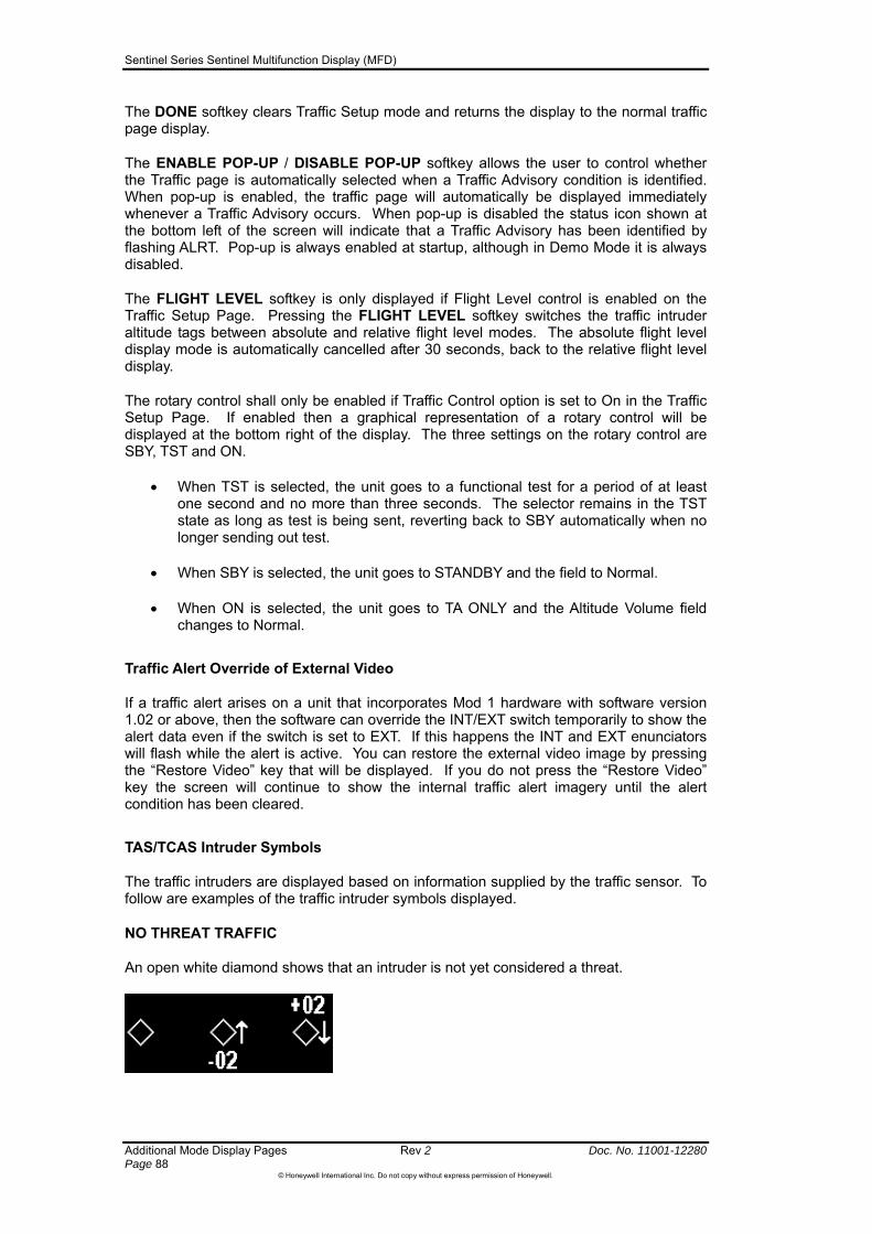
Sentinel Series Sentinel Multifunction Display (MFD)
Additional Mode Display Pages Rev 2 Doc. No. 11001-12280 Page 88
©Honeywell International Inc. Do not copy without express permission of Honeywell.
The DONE softkey clears Traffic Setup mode and returns the display to the normal traffic page display.
The ENABLE POP-UP / DISABLE POP-UP softkey allows the user to control whether the Traffic page is automatically selected when a Traffic Advisory condition is identified. When pop-up is enabled, the traffic page will automatically be displayed immediately whenever a Traffic Advisory occurs. When pop-up is disabled the status icon shown at the bottom left of the screen will indicate that a Traffic Advisory has been identified by flashing ALRT. Pop-up is always enabled at startup, although in Demo Mode it is always disabled.
The FLIGHT LEVEL softkey is only displayed if Flight Level control is enabled on the Traffic Setup Page. Pressing the FLIGHT LEVEL softkey switches the traffic intruder altitude tags between absolute and relative flight level modes. The absolute flight level display mode is automatically cancelled after 30 seconds, back to the relative flight level display.
The rotary control shall only be enabled if Traffic Control option is set to On in the Traffic Setup Page. If enabled then a graphical representation of a rotary control will be displayed at the bottom right of the display. The three settings on the rotary control are SBY, TST and ON.
When TST is selected, the unit goes to a functional test for a period of at least one second and no more than three seconds. The selector remains in the TST state as long as test is being sent, reverting back to SBY automatically when no longer sending out test.
When SBY is selected, the unit goes to STANDBY and the field to Normal.
When ON is selected, the unit goes to TA ONLY and the Altitude Volume field changes to Normal.
Traffic Alert Override of External Video
If a traffic alert arises on a unit that incorporates Mod 1 hardware with software version 1.02 or above, then the software can override the INT/EXT switch temporarily to show the alert data even if the switch is set to EXT. If this happens the INT and EXT enunciators will flash while the alert is active. You can restore the external video image by pressing the “Restore Video” key that will be displayed. If you do not press the “Restore Video” key the screen will continue to show the internal traffic alert imagery until the alert condition has been cleared.
TAS/TCAS Intruder Symbols
The traffic intruders are displayed based on information supplied by the traffic sensor. To follow are examples of the traffic intruder symbols displayed.
NO THREAT TRAFFIC
An open white diamond shows that an intruder is not yet considered a threat.
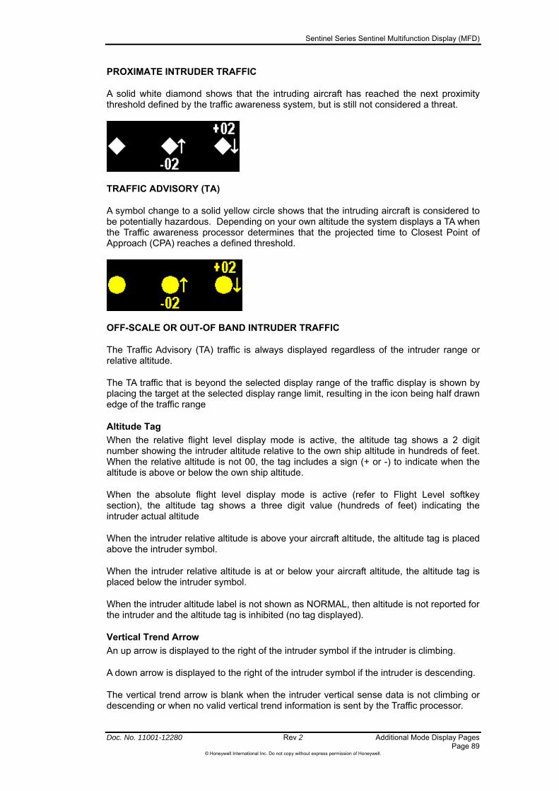
Sentinel Series Sentinel Multifunction Display (MFD)
Doc. No. 11001-12280 Rev 2 Additional Mode Display Pages Page 89
©Honeywell International Inc. Do not copy without express permission of Honeywell.
PROXIMATE INTRUDER TRAFFIC
A solid white diamond shows that the intruding aircraft has reached the next proximity threshold defined by the traffic awareness system, but is still not considered a threat.
TRAFFIC ADVISORY (TA)
A symbol change to a solid yellow circle shows that the intruding aircraft is considered to be potentially hazardous. Depending on your own altitude the system displays a TA when the Traffic awareness processor determines that the projected time to Closest Point of Approach (CPA) reaches a defined threshold.
OFF-SCALE OR OUT-OF BAND INTRUDER TRAFFIC
The Traffic Advisory (TA) traffic is always displayed regardless of the intruder range or relative altitude.
The TA traffic that is beyond the selected display range of the traffic display is shown by placing the target at the selected display range limit, resulting in the icon being half drawn edge of the traffic range
Altitude Tag
When the relative flight level display mode is active, the altitude tag shows a 2 digit number showing the intruder altitude relative to the own ship altitude in hundreds of feet. When the relative altitude is not 00, the tag includes a sign (+ or -) to indicate when the altitude is above or below the own ship altitude.
When the absolute flight level display mode is active (refer to Flight Level softkey section), the altitude tag shows a three digit value (hundreds of feet) indicating the intruder actual altitude
When the intruder relative altitude is above your aircraft altitude, the altitude tag is placed above the intruder symbol.
When the intruder relative altitude is at or below your aircraft altitude, the altitude tag is placed below the intruder symbol.
When the intruder altitude label is not shown as NORMAL, then altitude is not reported for the intruder and the altitude tag is inhibited (no tag displayed).
Vertical Trend Arrow
An up arrow is displayed to the right of the intruder symbol if the intruder is climbing.
A down arrow is displayed to the right of the intruder symbol if the intruder is descending.
The vertical trend arrow is blank when the intruder vertical sense data is not climbing or descending or when no valid vertical trend information is sent by the Traffic processor.

Sentinel Series Sentinel Multifunction Display (MFD)
Additional Mode Display Pages Rev 2 Doc. No. 11001-12280 Page 90
©Honeywell International Inc. Do not copy without express permission of Honeywell.
Overlapping Symbols
When two symbols occupy the same area of the display, the symbol with greatest priority overwrites whatever portion of the symbol of lesser priority that is required.
No-bearing TA
If the Traffic Sensor sends information on an intruder but no bearing information is sent, then the icon cannot be plotted on the map. Under these circumstances Sentinel can display up to two textual “No-bearing advisories” in the bottom center of the traffic page.
The No-Bearing Advisory presents the following information: Advisory Type (TA etc); range in selected units; relative altitude (hundreds of feet); and the intruder vertical trend arrow. The alphanumeric string is written in the colour corresponding to the level of the threat, i.e. yellow for a TA.
When a No-Bearing advisory is issued for an intruder that is not reporting altitude, the altitude field of the message and the intruder vertical trend arrow is blank.
Traffic System Faults
When faults are detected in the traffic system, they are shown in a caution window.
The format of the text window consists of a header describing the general nature of the faults followed by a bulleted list of individual faults, as shown in Table 5-4.
Table 5-4 Traffic System Faults
REPORTED TRAFFIC SYSTEM FAILURES
Meaning
TRFC PROCESSOR TAS or TCAS Processor has a fault TRFC UPPER ANT Traffic Unit Upper Antenna has a fault TRFC LOWER ANT Traffic Unit Lower Antenna has a fault RADIO ALT #1 Radio Altimeter #1 has a fault RADIO ALT #2 Radio Altimeter #2 has a fault RADIO ALT #1 & #2 Radio Altimeter #1 and #2 has a fault BARO ALT #1 Barometric Altimeter #1 has a fault BARO ALT #2 Barometric Altimeter #2 has a fault BARO ALT #1 & #2 Barometric Altimeter #1 and #2 has a fault ATTITUDE Attitude fault HEADING Heading fault TA DISPLAY #1 Traffic Display #1 has a fault TA DISPLAY #2 Traffic Display #2 has a fault TA DISPLAY #1 & #2 Traffic Display #1 and Display #2 has a fault CONTROL DATA Control Data has a fault
NO DATA RECEIVED FROM TRAFFIC SYSTEM
When the unit is not receiving data from the Traffic System, a caution window is displayed in the center of the traffic window with body text of “No data received from Traffic unit”, as shown in Figure 5-25.
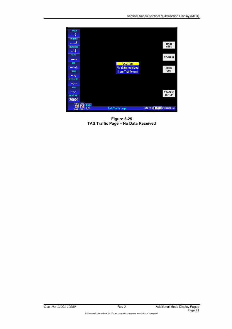
Sentinel Series Sentinel Multifunction Display (MFD)
Doc. No. 11001-12280 Rev 2 Additional Mode Display Pages Page 91
©Honeywell International Inc. Do not copy without express permission of Honeywell.
Figure 5-25 TAS Traffic Page – No Data Received

Sentinel Series Sentinel Multifunction Display (MFD)
Additional Mode Display Pages Rev 2 Doc. No. 11001-12280 Page 92
©Honeywell International Inc. Do not copy without express permission of Honeywell.
TRAFFIC INFORMATION SERVICE (TIS) PAGE
Introduction
This section applies only to TIS systems. TIS is an alerting system that enhances awareness of nearby traffic as an aid to “see and avoid” collision avoidance. Its purpose is to increase situational awareness by supplying information to assist in visually acquiring nearby aircraft. TIS does not relieve the pilot of “see and avoid” responsibility. No avoidance maneuvers are provided or recommended by TIS.
The service is offered through the Federal Aviation Administration’s Mode S terminal sensors and uses the same surveillance information provided to ATC. Estimated bearing, distance, altitude and heading information for aircraft within 7 NM and +3,500/-3,000 feet altitude of your aircraft is sent over the Mode S datalink to the TIS display. The pilot is also alerted to aircraft that are predicted to be within 30 seconds of a potential collision, no matter the distance or altitude.
Target aircraft are displayed only if operating a Mode A, C or S transponder. TIS operation is transparent to ATC and requires no controller intervention.
When the onboard TIS system makes a request for TIS, the request is sent via the Mode S transponder through the datalink. The first available Mode S sensor capable of supporting TIS for your aircraft responds by sending data back through the datalink on every scan of the sensor (approximately every 5 seconds). TIS will be provided by the sensor as long as the aircraft is within coverage range of that sensor. When entering the coverage range of another sensor, TIS will continue if the next sensor is TIS capable. The transfer of service is automatic. In addition to traffic data, the aircraft receives status messages that advise the pilot when TIS service has been initiated, is continuing, or has been terminated.
While coverage varies with terrain and local site parameters, “line-of sight” coverage is to be expected within 55 NM of a TIS capable Mode S sensor. Terrain and obstacles can cause areas without radar coverage.
TIS Limitations
CAUTION: It is important to understand that no display or aural warning of traffic information shows the location of all traffic in the vicinity. Whenever in VMC conditions, continue to scan visually for traffic.
Traffic may not be displayed for one or more of the following reasons:
1. Radar site is out of service. If a TIS capable Mode S sensor is not in service for any reason, TIS is not available.
2. Your aircraft is beyond maximum range of a TIS capable Mode S site. Maximum range can extend beyond 55 NM up to 100 NM, but this is not always the case.
3. Your aircraft is inside the “Cone of Silence”. When near or above (depending on altitude) the TIS radar site, and out of range of another TIS radar site, TIS data cannot be received.
4. The other aircraft is within the “Cone of Silence”. So, remember that there may be aircraft within your alert area, but if they are not seen by the radar site they will not be shown on your display.
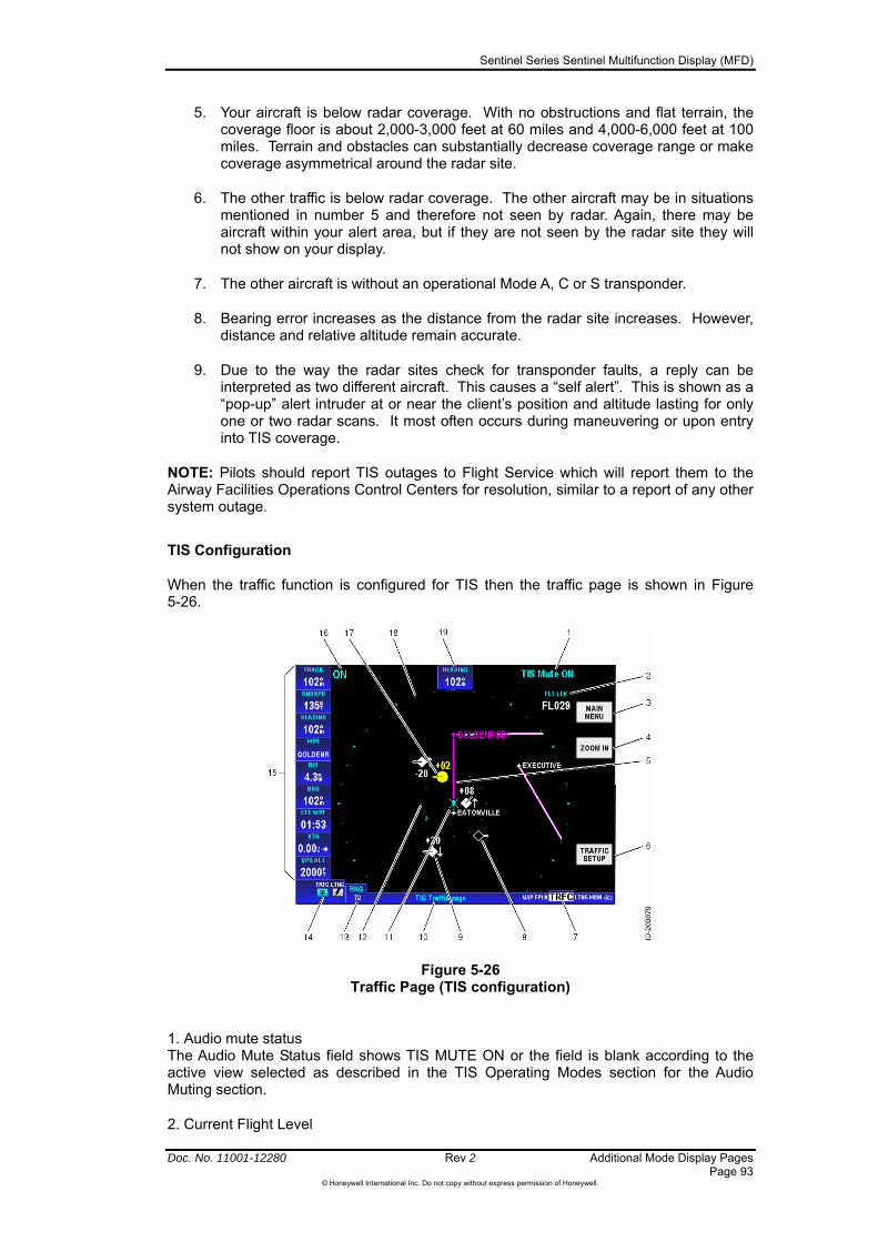
Sentinel Series Sentinel Multifunction Display (MFD)
Doc. No. 11001-12280 Rev 2 Additional Mode Display Pages Page 93
©Honeywell International Inc. Do not copy without express permission of Honeywell.
5. Your aircraft is below radar coverage. With no obstructions and flat terrain, the coverage floor is about 2,000-3,000 feet at 60 miles and 4,000-6,000 feet at 100 miles. Terrain and obstacles can substantially decrease coverage range or make coverage asymmetrical around the radar site.
6. The other traffic is below radar coverage. The other aircraft may be in situations mentioned in number 5 and therefore not seen by radar. Again, there may be aircraft within your alert area, but if they are not seen by the radar site they will not show on your display.
7. The other aircraft is without an operational Mode A, C or S transponder.
8. Bearing error increases as the distance from the radar site increases. However, distance and relative altitude remain accurate.
9. Due to the way the radar sites check for transponder faults, a reply can be interpreted as two different aircraft. This causes a “self alert”. This is shown as a “pop-up” alert intruder at or near the client’s position and altitude lasting for only one or two radar scans. It most often occurs during maneuvering or upon entry into TIS coverage.
NOTE: Pilots should report TIS outages to Flight Service which will report them to the Airway Facilities Operations Control Centers for resolution, similar to a report of any other system outage.
TIS Configuration
When the traffic function is configured for TIS then the traffic page is shown in Figure 5-26.
Figure 5-26 Traffic Page (TIS configuration)
1. Audio mute status The Audio Mute Status field shows TIS MUTE ON or the field is blank according to the active view selected as described in the TIS Operating Modes section for the Audio Muting section.
2. Current Flight Level

Sentinel Series Sentinel Multifunction Display (MFD)
Additional Mode Display Pages Rev 2 Doc. No. 11001-12280 Page 94
©Honeywell International Inc. Do not copy without express permission of Honeywell.
The current own ship flight level is displayed in the format FL### where ### is the own ship altitude in multiples of 100 feet, rounded to the nearest multiple of 100 feet.
3. Main Menu Pushing the MAIN MENU softkey returns the user back to the Main Menu Page.
4. Range Control Pushing the ZOOM IN or ZOOM OUT softkeys changes the range for the display.
5. Flight Plan Overlay The flight plan overlay shows the current flight plan path if defined.
6. TRAFFIC SETUP Refer to TIS Controls (page 95) for a detail explanation of TIS Traffic Setup.
7. Display Mode Selection The current selection is shown as TRFC.
8. PROXIMATE traffic symbol (no alt reporting) An open white diamond along with a track pointer shows proximity traffic with no altitude reporting.
9. Proximate traffic symbol (Alt reporting) A solid white diamond along with a track pointer shows proximity traffic with the altitude tag.
10. Page Name The traffic unit type (TIS) is displayed centered in the title window.
11. Own Ship Symbol The own ship symbol is the same as the currently selected own ship symbol for the map pages.
12. Inner Range Ring The inner range ring is drawn with a radius representing 2nm on the display, based on the currently selected range.
13. Selected Range The selected range is displayed in the lower left corner of the display with the label RNG in cyan and the selected range in white.
14. Status Icon Bar The status icon bar shows the status of configured devices and whether new messages are available.
15. Data Field Windows The data field windows show different display information to the user. Refer to Section 9, Data Field Setup (page 147) for a detailed explanation of the windows.
16. TIS Operating Mode The operating mode of the TIS unit shows in the top left corner of the display. 17. Traffic Advisory Symbol A solid circle in yellow along with a track pointer and is potentially hazardous because of the close proximity.
18. Outer Range Ring The outer range ring represents the selected range distance from the aircraft.
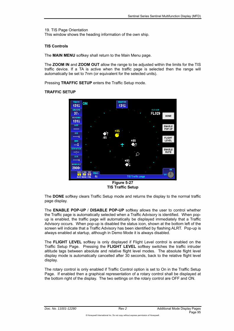
Sentinel Series Sentinel Multifunction Display (MFD)
Doc. No. 11001-12280 Rev 2 Additional Mode Display Pages Page 95
©Honeywell International Inc. Do not copy without express permission of Honeywell.
19. TIS Page Orientation This window shows the heading information of the own ship.
TIS Controls
The MAIN MENU softkey shall return to the Main Menu page.
The ZOOM IN and ZOOM OUT allow the range to be adjusted within the limits for the TIS traffic device. If a TA is active when the traffic page is selected then the range will automatically be set to 7nm (or equivalent for the selected units).
Pressing TRAFFIC SETUP enters the Traffic Setup mode. TRAFFIC SETUP
Figure 5-27
TIS Traffic Setup
The DONE softkey clears Traffic Setup mode and returns the display to the normal traffic page display.
The ENABLE POP-UP / DISABLE POP-UP softkey allows the user to control whether the Traffic page is automatically selected when a Traffic Advisory is identified. When pop-up is enabled, the traffic page will automatically be displayed immediately that a Traffic Advisory occurs. When pop-up is disabled the status icon, shown at the bottom left of the screen will indicate that a Traffic Advisory has been identified by flashing ALRT. Pop-up is always enabled at startup, although in Demo Mode it is always disabled.
The FLIGHT LEVEL softkey is only displayed if Flight Level control is enabled on the Traffic Setup Page. Pressing the FLIGHT LEVEL softkey switches the traffic intruder altitude tags between absolute and relative flight level modes. The absolute flight level display mode is automatically cancelled after 30 seconds, back to the relative flight level display.
The rotary control is only enabled if Traffic Control option is set to On in the Traffic Setup Page. If enabled then a graphical representation of a rotary control shall be displayed at the bottom right of the display. The two settings on the rotary control are OFF and ON.

Sentinel Series Sentinel Multifunction Display (MFD)
Additional Mode Display Pages Rev 2 Doc. No. 11001-12280 Page 96
©Honeywell International Inc. Do not copy without express permission of Honeywell.
When OFF is selected, the unit goes to TIS Off. The TIS Traffic page display shows OFF for approximately one second in the upper left corner, then goes to a display that shows a CAUTION window that states, TIS is not enabled. Press TRAFFIC SETUP and turn knob to ON to enable TIS.
When ON is selected, the unit goes to TIS On. The TIS Traffic page display shows ON in the upper left corner of the display.
Traffic Alert Override of External Video
If a traffic alert arises on a unit that incorporates Mod 1 hardware with software version 1.02 or above, then the software can override the INT/EXT switch temporarily to show the alert data even if the switch is set to EXT. If this happens the INT and EXT enunciators will flash while the alert is active. You can restore the external video image by pressing the “Restore Video” key that will be displayed. If you do not press the “Restore Video” key the screen will continue to show the internal traffic alert imagery until the alert condition has been cleared.
TIS Traffic Intruder Symbols
The TIS traffic intruders are displayed based on bearing and altitude information supplied in by your traffic receiver unit. Note that the data reported by the TIS system does not allow the icons to be precisely oriented to the direction of travel of other aircraft.
NO THREAT TRAFFIC (NO ALT REPORTING)
An open white diamond shows proximity traffic with no altitude reporting. In this example the symbol shows that the intruder’s ground track is approximately 90° to your current track or heading.
PROXIMATE TRAFFIC (ALT OR NO ALT REPORTING)
A solid white diamond shows the intruding aircraft has reached the proximity traffic threshold as defined by the TIS system, but is still not considered a threat. The track pointer on the diamond indicates the direction of the intruder’s ground track. The arrow shows the intruder is descending. Here the intruder is moving approximately 45° to your current track or heading.
TRAFFIC ADVISORY (TA)
A symbol change to a solid yellow circle shows that the intruding aircraft is considered to be potentially hazardous. Depending on your own altitude the system displays a TA when the time to Closest Point of Approach (CPA) reaches a threshold defined by the TIS system. The track pointer on the circle shows the direction of the intruder’s ground track. The arrow indicates the intruder is descending.
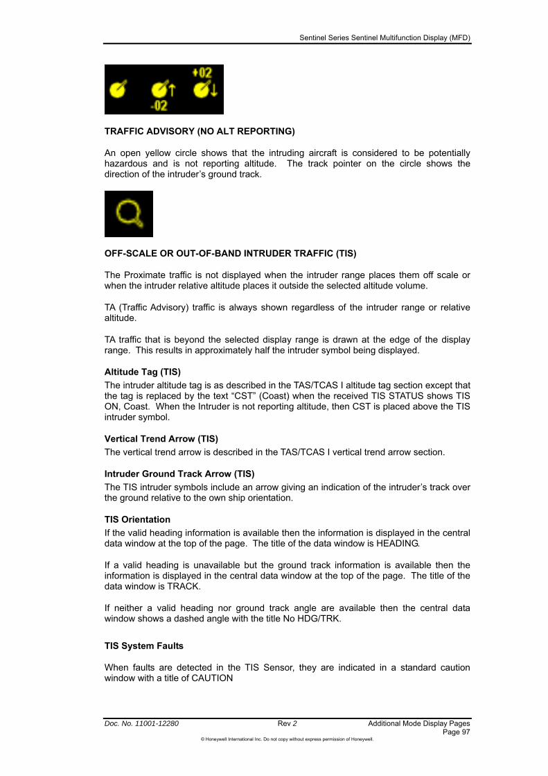
Sentinel Series Sentinel Multifunction Display (MFD)
Doc. No. 11001-12280 Rev 2 Additional Mode Display Pages Page 97
©Honeywell International Inc. Do not copy without express permission of Honeywell.
TRAFFIC ADVISORY (NO ALT REPORTING)
An open yellow circle shows that the intruding aircraft is considered to be potentially hazardous and is not reporting altitude. The track pointer on the circle shows the direction of the intruder’s ground track.
OFF-SCALE OR OUT-OF-BAND INTRUDER TRAFFIC (TIS)
The Proximate traffic is not displayed when the intruder range places them off scale or when the intruder relative altitude places it outside the selected altitude volume.
TA (Traffic Advisory) traffic is always shown regardless of the intruder range or relative altitude.
TA traffic that is beyond the selected display range is drawn at the edge of the display range. This results in approximately half the intruder symbol being displayed.
Altitude Tag (TIS)
The intruder altitude tag is as described in the TAS/TCAS I altitude tag section except that the tag is replaced by the text “CST” (Coast) when the received TIS STATUS shows TIS ON, Coast. When the Intruder is not reporting altitude, then CST is placed above the TIS intruder symbol.
Vertical Trend Arrow (TIS)
The vertical trend arrow is described in the TAS/TCAS I vertical trend arrow section.
Intruder Ground Track Arrow (TIS)
The TIS intruder symbols include an arrow giving an indication of the intruder’s track over the ground relative to the own ship orientation.
TIS Orientation
If the valid heading information is available then the information is displayed in the central data window at the top of the page. The title of the data window is HEADING.
If a valid heading is unavailable but the ground track information is available then the information is displayed in the central data window at the top of the page. The title of the data window is TRACK.
If neither a valid heading nor ground track angle are available then the central data window shows a dashed angle with the title No HDG/TRK.
TIS System Faults
When faults are detected in the TIS Sensor, they are indicated in a standard caution window with a title of CAUTION

Sentinel Series Sentinel Multifunction Display (MFD)
Additional Mode Display Pages Rev 2 Doc. No. 11001-12280 Page 98
©Honeywell International Inc. Do not copy without express permission of Honeywell.
The caution window body text consists of a Header describing the general nature of the faults followed by a bulleted list of individual faults, as shown in Table 5-5. The table contains the explanation of the failure text.
Table 5-5 TIS Faults
REPORTED TRAFFIC SYSTEM FAILURES
Meaning
TIS CONTROL TIS Control has a fault TIS PROCESSOR TIS Processor has a fault
TRANSPONDER NOT REPORTING ALTITUDE
When the received TIS status shows TIS ON, Not Reporting Altitude, a caution window is shown with a title of CAUTION and body text of “TIS is not enabled. The transponder is not reporting altitude”.
NO DATA RECEIVED FROM TIS SENSOR
When the unit is not receiving data from the TIS sensor, then a caution window is shown in the center of the traffic window with body text of “No data received from Traffic unit” (similar to Figure 5-25).
Sentinel Series Sentinel Multifunction Display (MFD)
Doc. No. 11001-12280 Rev 2 Flight Planning Page 99
©Honeywell International Inc. Do not copy without express permission of Honeywell.
6 Flight Planning
VFR flight plans can be created in the Sentinel if its flight plan source has been set to “Internal”. If your installer has configured the Sentinel to receive position and flight plan data from an external source (see Install Menu) and you wish to use the Sentinel flight planning features then you will need to set the Navigation Source to “Internal” on the Navigation Setup menu (page 144).
If your unit has been configured to receive flight plans sent by external equipment and the Navigation Source option on the Navigation Setup menu is set to “External”, then Sentinel should display the flight plan from the external source overlaid on the map. You cannot edit externally received flight plans in Sentinel – refer to the user documentation for the external equipment for instructions on flight planning using that equipment.
If your Sentinel has been installed to use its internal GPS then you will be able to define and display internal flight plans.
CAUTION: Sentinel is not approved for primary navigation under Instrument Flight Rule (IFR) usage regardless of the GPS source.
The FLIGHT PLAN mode is selected through the Main Menu Page, shown in Figure 3-6 Main Menu page. Push the FLIGHT PLAN softkey. Alternatively, use the rotary control from any page where the mode selection are is displayed to select the “FPLN” mode.
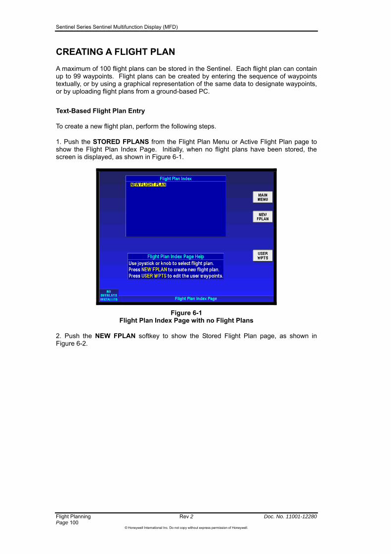
Sentinel Series Sentinel Multifunction Display (MFD)
Flight Planning Rev 2 Doc. No. 11001-12280 Page 100
©Honeywell International Inc. Do not copy without express permission of Honeywell.
CREATING A FLIGHT PLAN
A maximum of 100 flight plans can be stored in the Sentinel. Each flight plan can contain up to 99 waypoints. Flight plans can be created by entering the sequence of waypoints textually, or by using a graphical representation of the same data to designate waypoints, or by uploading flight plans from a ground-based PC.
Text-Based Flight Plan Entry
To create a new flight plan, perform the following steps.
1. Push the STORED FPLANS from the Flight Plan Menu or Active Flight Plan page to show the Flight Plan Index Page. Initially, when no flight plans have been stored, the screen is displayed, as shown in Figure 6-1.
Figure 6-1 Flight Plan Index Page with no Flight Plans
2. Push the NEW FPLAN softkey to show the Stored Flight Plan page, as shown in Figure 6-2.

Sentinel Series Sentinel Multifunction Display (MFD)
Doc. No. 11001-12280 Rev 2 Flight Planning Page 101
©Honeywell International Inc. Do not copy without express permission of Honeywell.
Figure 6-2 Stored Flight Plan with no Waypoint
To enter a waypoint, push the INSERT softkey. The Waypoint Entry window is displayed, as shown in Figure 6-3. Use the rotary knob to enter first character of the name or IDENT for the desired waypoint. Use the joystick to move the data entry position along to the second character, and use the rotary control to enter that. As you enter more characters, Sentinel will either identify a single database item that corresponds to the text that you are entering, or it will offer you a list of possible items from which to choose. If you see the item that you want on the list, press OK and move the highlighted line to the desired item before pressing OK again to select it.
Figure 6-3 Stored Flight Plan with new Waypoint
If you want to browse through all of the waypoints that start with a certain combination of characters, enter the desired characters and then press “KNOB SCAN”. This allows you to use the rotary control to browse the summary information on each of the database items found that start with the defined characters in turn. Press OK once you have identified the right waypoint, or “KNOB DATA” to reduce the length of the list by putting in more characters.
Push the OK softkey and the first waypoint is entered in the list, as shown in Figure 6-4.

Sentinel Series Sentinel Multifunction Display (MFD)
Flight Planning Rev 2 Doc. No. 11001-12280 Page 102
©Honeywell International Inc. Do not copy without express permission of Honeywell.
Figure 6-4 Stored Flight Plan with a Waypoint
3. Continue entering waypoints until the flight plan is complete.
You can insert additional waypoints between those already defined by moving the cursor up to the desired point in the waypoint list and pushing OK.
You can include previously defined User Waypoints in your flight plan. Select the Waypoint IDENT that you defined (see User Waypoints, page 103) and press OK..
You can insert published airways into your flight plan using the INSERT button. Use the rotary knob and joystick to specify the required airway (see Figure 6-5), and then press SELECT SEGMENT to specify the entry and exit points (see Figure 6-6). Press INSERT to add the selected legs to the flight plan.
Figure 6-5 Selecting Airway for Insertion
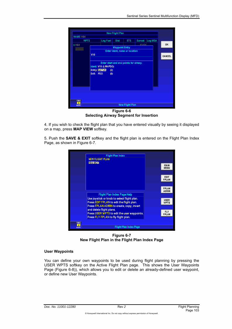
Sentinel Series Sentinel Multifunction Display (MFD)
Doc. No. 11001-12280 Rev 2 Flight Planning Page 103
©Honeywell International Inc. Do not copy without express permission of Honeywell.
Figure 6-6
Selecting Airway Segment for Insertion
4. If you wish to check the flight plan that you have entered visually by seeing it displayed on a map, press MAP VIEW softkey.
5. Push the SAVE & EXIT softkey and the flight plan is entered on the Flight Plan Index Page, as shown in Figure 6-7.
Figure 6-7 New Flight Plan in the Flight Plan Index Page
User Waypoints
You can define your own waypoints to be used during flight planning by pressing the USER WPTS softkey on the Active Flight Plan page. This shows the User Waypoints Page (Figure 6-8)), which allows you to edit or delete an already-defined user waypoint, or define new User Waypoints.

Sentinel Series Sentinel Multifunction Display (MFD)
Flight Planning Rev 2 Doc. No. 11001-12280 Page 104
©Honeywell International Inc. Do not copy without express permission of Honeywell.
Figure 6-8 User Waypoints Page
To delete a previously-defined waypoint, move the highlight to the desired line using the rotary control or joystick, and press DELETE. If the waypoint is used within one of your stored flight plans then you will not be able to delete it. A waypoint used within a flight plan is displayed with a ‘locked’ symbol next to the user waypoint icon.
To edit a previously defined waypoint, highlight its entry in the list and press EDIT. To create a new waypoint, press NEW WPT. The User Waypoint Edit page will be displayed, as shown in Figure 6-9.
Figure 6-9 User Waypoint Edit Page
Use up/down movements of the joystick to select the fields that you wish to edit. For normal waypoints you can define the ident (name), the icon that will be displayed, and the position. Use left/right movements of the joystick to move the highlight to the relevant area, and then use the rotary control to select the desired value.
The Ident can be any sequence of characters – but for obvious reasons you should avoid re-using idents from published database items.

Sentinel Series Sentinel Multifunction Display (MFD)
Doc. No. 11001-12280 Rev 2 Flight Planning Page 105
©Honeywell International Inc. Do not copy without express permission of Honeywell.
The icon is selectable using the rotary control – but if you select the VFR airport icon, then additional data can be entered as described below.
The position can be defined directly using the grid/coordinate system that has been configured on the General System Setup menu (page 138). Alternatively, you can define the position of the user waypoint as a range and bearing from another database item: press RNG & BRG to select the Range and Bearing area of the screen, and then select the place as either Present Position or some other known item in the database. Then move the cursor down and across to enter the bearing value and range. Press USER WPT again when you are done.
The two lines of comments can be any desired text. By default, they are the date and time of the waypoint creation.
If you select the VFR airport icon, then the second softkey will show “NEXT”. Press NEXT to enter the additional information for the airport – see Figure 6-10. This allows you to define the following information:
runway orientation (using the standard notation)
surface type (hard or soft),
runway length in the currently-selected units
field elevation
two comm. frequencies
Figure 6-10 User Defined Airport Edit Page
Up to user 1000 waypoints can be saved in memory. The table that follows lists the information that is saved with each user waypoint:
Table 6-1 Waypoint Information
Item Details Name User entered waypoint name. Up to 19 characters. Position Waypoint position Type Code indicating the waypoint type. Comments Free text. Two lines of 27 characters. The following entries are used to record additional information if
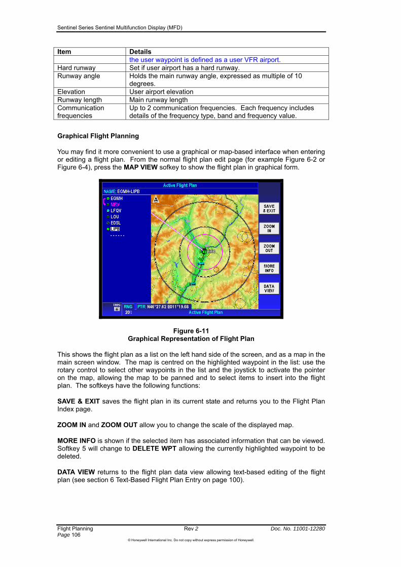
Sentinel Series Sentinel Multifunction Display (MFD)
Flight Planning Rev 2 Doc. No. 11001-12280 Page 106
©Honeywell International Inc. Do not copy without express permission of Honeywell.
Item Details the user waypoint is defined as a user VFR airport.
Hard runway Set if user airport has a hard runway. Runway angle Holds the main runway angle, expressed as multiple of 10
degrees. Elevation User airport elevation Runway length Main runway length Communication frequencies
Up to 2 communication frequencies. Each frequency includes details of the frequency type, band and frequency value.
Graphical Flight Planning
You may find it more convenient to use a graphical or map-based interface when entering or editing a flight plan. From the normal flight plan edit page (for example Figure 6-2 or Figure 6-4), press the MAP VIEW sofkey to show the flight plan in graphical form.
Figure 6-11 Graphical Representation of Flight Plan
This shows the flight plan as a list on the left hand side of the screen, and as a map in the main screen window. The map is centred on the highlighted waypoint in the list: use the rotary control to select other waypoints in the list and the joystick to activate the pointer on the map, allowing the map to be panned and to select items to insert into the flight plan. The softkeys have the following functions:
SAVE & EXIT saves the flight plan in its current state and returns you to the Flight Plan Index page.
ZOOM IN and ZOOM OUT allow you to change the scale of the displayed map.
MORE INFO is shown if the selected item has associated information that can be viewed. Softkey 5 will change to DELETE WPT allowing the currently highlighted waypoint to be deleted.
DATA VIEW returns to the flight plan data view allowing text-based editing of the flight plan (see section 6 Text-Based Flight Plan Entry on page 100).
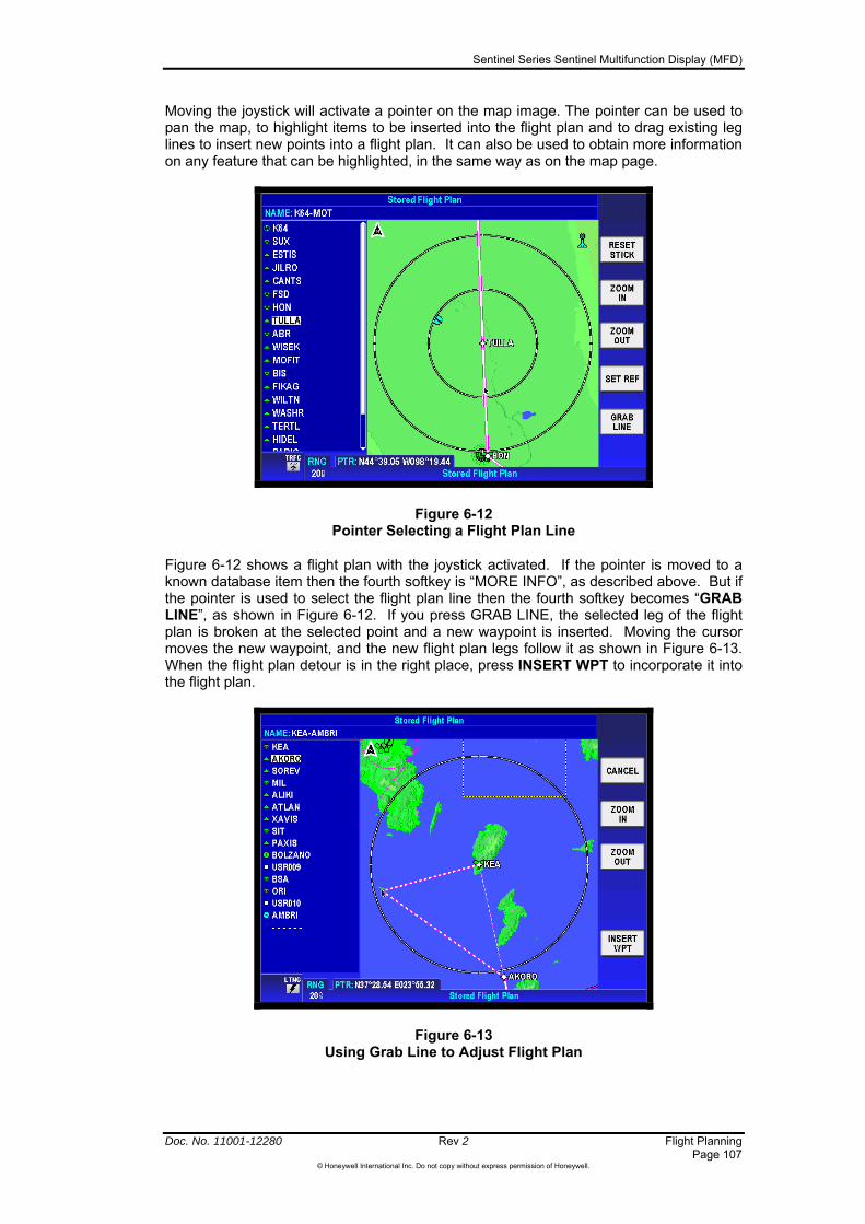
Sentinel Series Sentinel Multifunction Display (MFD)
Doc. No. 11001-12280 Rev 2 Flight Planning Page 107
©Honeywell International Inc. Do not copy without express permission of Honeywell.
Moving the joystick will activate a pointer on the map image. The pointer can be used to pan the map, to highlight items to be inserted into the flight plan and to drag existing leg lines to insert new points into a flight plan. It can also be used to obtain more information on any feature that can be highlighted, in the same way as on the map page.
Figure 6-12 Pointer Selecting a Flight Plan Line
Figure 6-12 shows a flight plan with the joystick activated. If the pointer is moved to a known database item then the fourth softkey is “MORE INFO”, as described above. But if the pointer is used to select the flight plan line then the fourth softkey becomes “GRAB LINE”, as shown in Figure 6-12. If you press GRAB LINE, the selected leg of the flight plan is broken at the selected point and a new waypoint is inserted. Moving the cursor moves the new waypoint, and the new flight plan legs follow it as shown in Figure 6-13. When the flight plan detour is in the right place, press INSERT WPT to incorporate it into the flight plan.
Figure 6-13 Using Grab Line to Adjust Flight Plan

Sentinel Series Sentinel Multifunction Display (MFD)
Flight Planning Rev 2 Doc. No. 11001-12280 Page 108
©Honeywell International Inc. Do not copy without express permission of Honeywell.
Uploading Saved Flight plans
Sentinel can import flight plans generated by Jeppesen’s popular FliteStar® VFR flight planning software package, as follows:
1. Create your flight plan as normal using FliteStar® to define a “routepack”.
2. Under the File menu, choose “Export to Generic Text Format”
3. On the following popup window, save the file with the name “route” as a text file. You can either save the file directly to the USB memory device, or save it to some other location and copy it to the USB memory device at a later time. The route.txt file should be put onto the topmost level of the directory structure of the USB device (ie: not inside any folders).
4. Remove the USB memory device from your computer in the usual way.
5. Ensure that the Sentinel unit it switched off. Open the door on the front bezel, and insert the USB memory device into the USB socket on the Sentinel.
6. Switch on the Sentinel unit, and allow it to complete its power-up checks. While the power-up checks are under way, Sentinel will copy the “route” file from the USB memory device and incorporate the flight plan into its internal flight plan list.
7. Once Sentinel has reached the first “OK” acknowledgement screen, remove the USB memory device and close the access door.
8. Navigate to the flight planning menu and select STORED FPLANS. The uploaded flight plan will be identified on the list using its beginning and end waypoints.
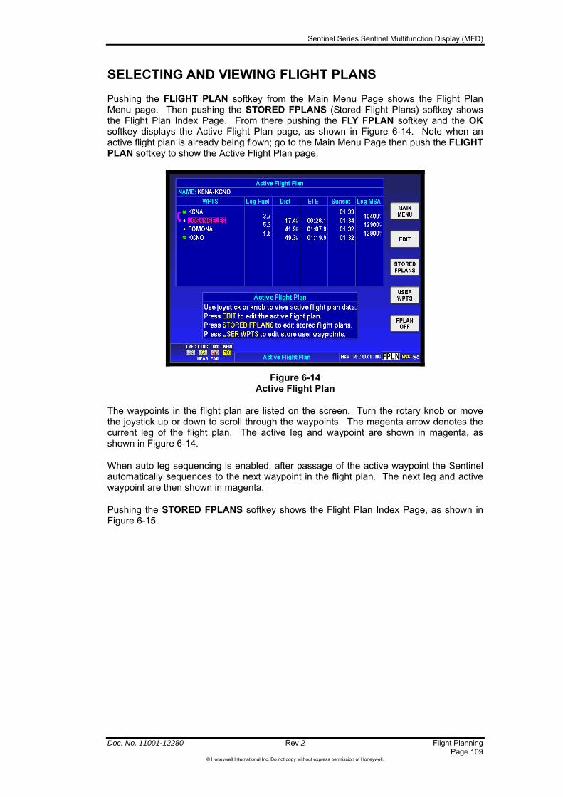
Sentinel Series Sentinel Multifunction Display (MFD)
Doc. No. 11001-12280 Rev 2 Flight Planning Page 109
©Honeywell International Inc. Do not copy without express permission of Honeywell.
SELECTING AND VIEWING FLIGHT PLANS
Pushing the FLIGHT PLAN softkey from the Main Menu Page shows the Flight Plan Menu page. Then pushing the STORED FPLANS (Stored Flight Plans) softkey shows the Flight Plan Index Page. From there pushing the FLY FPLAN softkey and the OK softkey displays the Active Flight Plan page, as shown in Figure 6-14. Note when an active flight plan is already being flown; go to the Main Menu Page then push the FLIGHT PLAN softkey to show the Active Flight Plan page.
Figure 6-14 Active Flight Plan
The waypoints in the flight plan are listed on the screen. Turn the rotary knob or move the joystick up or down to scroll through the waypoints. The magenta arrow denotes the current leg of the flight plan. The active leg and waypoint are shown in magenta, as shown in Figure 6-14.
When auto leg sequencing is enabled, after passage of the active waypoint the Sentinel automatically sequences to the next waypoint in the flight plan. The next leg and active waypoint are then shown in magenta.
Pushing the STORED FPLANS softkey shows the Flight Plan Index Page, as shown in Figure 6-15.

Sentinel Series Sentinel Multifunction Display (MFD)
Flight Planning Rev 2 Doc. No. 11001-12280 Page 110
©Honeywell International Inc. Do not copy without express permission of Honeywell.
Figure 6-15 Flight Plan Index Page
While the highlighted entry is on “NEW FLIGHT PLAN” softkey 2 will be labelled NEW FPLAN.
While the highlighted entry is on the currently active flight plan softkey 5 will be labelled FPLAN OFF.
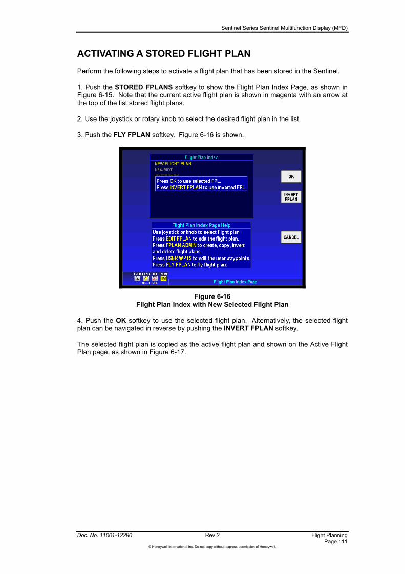
Sentinel Series Sentinel Multifunction Display (MFD)
Doc. No. 11001-12280 Rev 2 Flight Planning Page 111
©Honeywell International Inc. Do not copy without express permission of Honeywell.
ACTIVATING A STORED FLIGHT PLAN
Perform the following steps to activate a flight plan that has been stored in the Sentinel.
1. Push the STORED FPLANS softkey to show the Flight Plan Index Page, as shown in Figure 6-15. Note that the current active flight plan is shown in magenta with an arrow at the top of the list stored flight plans.
2. Use the joystick or rotary knob to select the desired flight plan in the list.
3. Push the FLY FPLAN softkey. Figure 6-16 is shown.
Figure 6-16 Flight Plan Index with New Selected Flight Plan
4. Push the OK softkey to use the selected flight plan. Alternatively, the selected flight plan can be navigated in reverse by pushing the INVERT FPLAN softkey.
The selected flight plan is copied as the active flight plan and shown on the Active Flight Plan page, as shown in Figure 6-17.

Sentinel Series Sentinel Multifunction Display (MFD)
Flight Planning Rev 2 Doc. No. 11001-12280 Page 112
©Honeywell International Inc. Do not copy without express permission of Honeywell.
Figure 6-17 Selected Flight Plan in Active Flight Plan

Sentinel Series Sentinel Multifunction Display (MFD)
Doc. No. 11001-12280 Rev 2 Flight Planning Page 113
©Honeywell International Inc. Do not copy without express permission of Honeywell.
EDITING A FLIGHT PLAN
To edit the active or a stored flight plane, begin by pushing the STORED FPLANS softkey to show the Flight Plan Index Page, as shown in Figure 6-15.
Pushing the FPLAN ADMIN softkey shows the Flight Plan Index Page, as shown in Figure 6-18.
Figure 6-18 Flight Plan Index with Admin Menu
Pushing the COPY FPLAN softkey permits the selected flight plan to be copied for editing while not changing the original.
Push the EDIT FPLAN softkey to show Figure 6-19.
Figure 6-19 Stored Flight Plan
You can view and edit the flight plan as a map (see Graphical Flight Planning, page 106) by pushing the MAP VIEW softkey.
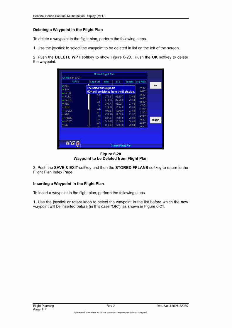
Sentinel Series Sentinel Multifunction Display (MFD)
Flight Planning Rev 2 Doc. No. 11001-12280 Page 114
©Honeywell International Inc. Do not copy without express permission of Honeywell.
Deleting a Waypoint in the Flight Plan
To delete a waypoint in the flight plan, perform the following steps.
1. Use the joystick to select the waypoint to be deleted in list on the left of the screen.
2. Push the DELETE WPT softkey to show Figure 6-20. Push the OK softkey to delete the waypoint.
Figure 6-20 Waypoint to be Deleted from Flight Plan
3. Push the SAVE & EXIT softkey and then the STORED FPLANS softkey to return to the Flight Plan Index Page.
Inserting a Waypoint in the Flight Plan
To insert a waypoint in the flight plan, perform the following steps.
1. Use the joystick or rotary knob to select the waypoint in the list before which the new waypoint will be inserted before (in this case “OR”), as shown in Figure 6-21.
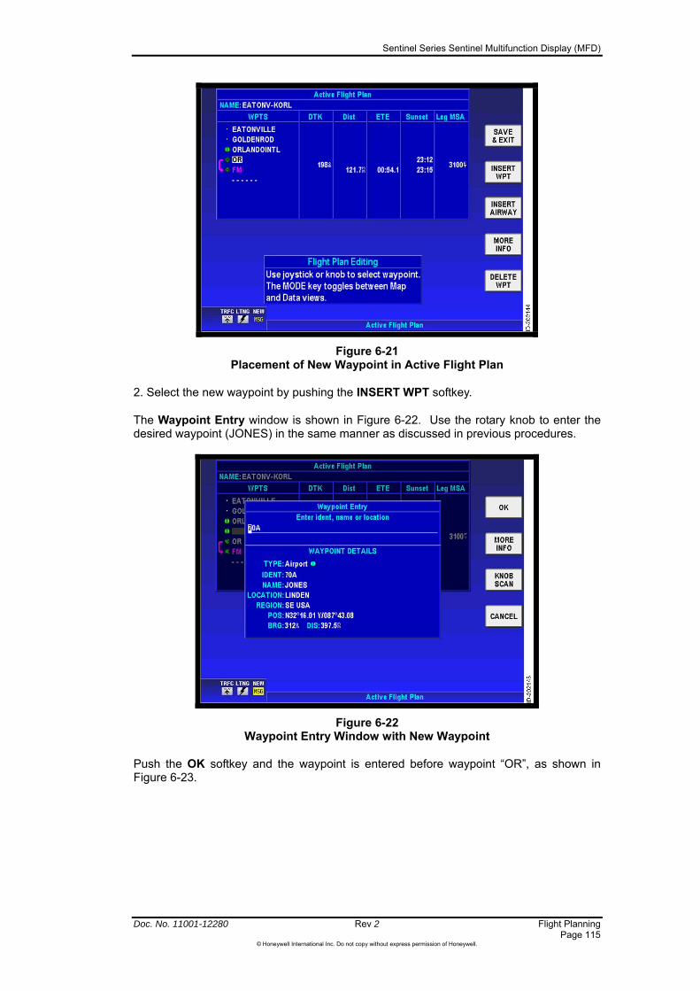
Sentinel Series Sentinel Multifunction Display (MFD)
Doc. No. 11001-12280 Rev 2 Flight Planning Page 115
©Honeywell International Inc. Do not copy without express permission of Honeywell.
Figure 6-21 Placement of New Waypoint in Active Flight Plan
2. Select the new waypoint by pushing the INSERT WPT softkey.
The Waypoint Entry window is shown in Figure 6-22. Use the rotary knob to enter the desired waypoint (JONES) in the same manner as discussed in previous procedures.
Figure 6-22 Waypoint Entry Window with New Waypoint
Push the OK softkey and the waypoint is entered before waypoint “OR”, as shown in Figure 6-23.

Sentinel Series Sentinel Multifunction Display (MFD)
Flight Planning Rev 2 Doc. No. 11001-12280 Page 116
©Honeywell International Inc. Do not copy without express permission of Honeywell.
Figure 6-23 Map of New Waypoint
4. Push the SAVE & EXIT softkey and then the STORED FPLANS softkey to return to the Flight Plan Index Page.
Changing the Name of a Flight Plan
The name of the flight plan is changed from the Stored Flight Plan page.
Use the joystick or rotary knob to select the flight plan name, and then move the joystick right so as to begin editing the name.
Figure 6-24 Selection of NAME in Stored Flight Plan
Use the rotary and joystick to enter the characters for the flight plan name. Press the DEFAULT NAME softkey to set the default name for the flight plan. The default name is the name of the first waypoint in the flight plan, followed by a ‘-‘, followed by the name of the last waypoint in the flight plan. Press CLEAR NAME to clear out the existing flight plan name.
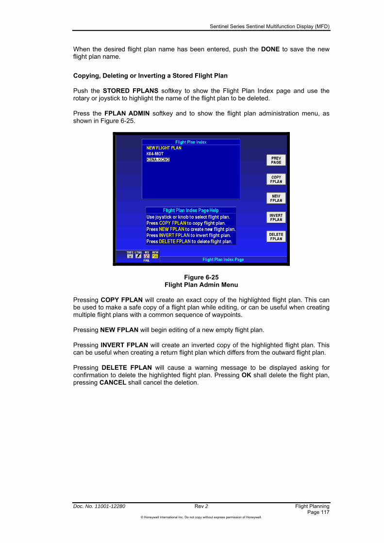
Sentinel Series Sentinel Multifunction Display (MFD)
Doc. No. 11001-12280 Rev 2 Flight Planning Page 117
©Honeywell International Inc. Do not copy without express permission of Honeywell.
When the desired flight plan name has been entered, push the DONE to save the new flight plan name.
Copying, Deleting or Inverting a Stored Flight Plan
Push the STORED FPLANS softkey to show the Flight Plan Index page and use the rotary or joystick to highlight the name of the flight plan to be deleted.
Press the FPLAN ADMIN softkey and to show the flight plan administration menu, as shown in Figure 6-25.
Figure 6-25 Flight Plan Admin Menu
Pressing COPY FPLAN will create an exact copy of the highlighted flight plan. This can be used to make a safe copy of a flight plan while editing, or can be useful when creating multiple flight plans with a common sequence of waypoints.
Pressing NEW FPLAN will begin editing of a new empty flight plan.
Pressing INVERT FPLAN will create an inverted copy of the highlighted flight plan. This can be useful when creating a return flight plan which differs from the outward flight plan.
Pressing DELETE FPLAN will cause a warning message to be displayed asking for confirmation to delete the highlighted flight plan. Pressing OK shall delete the flight plan, pressing CANCEL shall cancel the deletion.

Sentinel Series Sentinel Multifunction Display (MFD)
Flight Planning Rev 2 Doc. No. 11001-12280 Page 118
©Honeywell International Inc. Do not copy without express permission of Honeywell.
CANCELLING / MODIFYING THE ACTIVE FLIGHT PLAN
Cancelling the Active Flight Plan
Pushing the FPLAN OFF softkey in the Active Flight Plan page, as shown in Figure 6-26, turns the active flight plan off.
Figure 6-26 Active Flight Plan Page with FPLAN OFF Softkey
Using Direct-To in the Active Flight Plan
Sometimes it is desirable to proceed directly to a waypoint in a flight plan or a specific leg in a flight plan without passing through the intermediate legs. For example, after takeoff in a terminal area, vectors are given followed by a clearance directly to the first waypoint in the filed flight plan or to intercept a particular leg in the filed flight plan. A Direct-To is performed to the waypoint or to the flight plan leg. After reaching the waypoint or leg the Sentinel automatically begins navigating the active flight plan. When waypoints exist in the flight plan prior to that used at the end point of the Direct-To, these waypoints are bypassed. When a Direct-To is established to a waypoint not in the flight plan, the navigation of the active flight plan does not resume after the Direct-To waypoint is reached.
NOTE: Remember, the internal GPS of the Sentinel is not certified for Instrument Flight Rules (IFR) operation. Navigation using Air Traffic Control (ATC) clearances on the Sentinel can only be done as a backup to the primary navigation system.
Direct-To an Active Flight Plan Waypoint
To do a Direct-To to a waypoint within an active flight plan perform the following steps.
1. Push the NAV/SEARCH softkey from the MAP display page to show the DIRECT TO softkey, as shown in Figure 6-27.
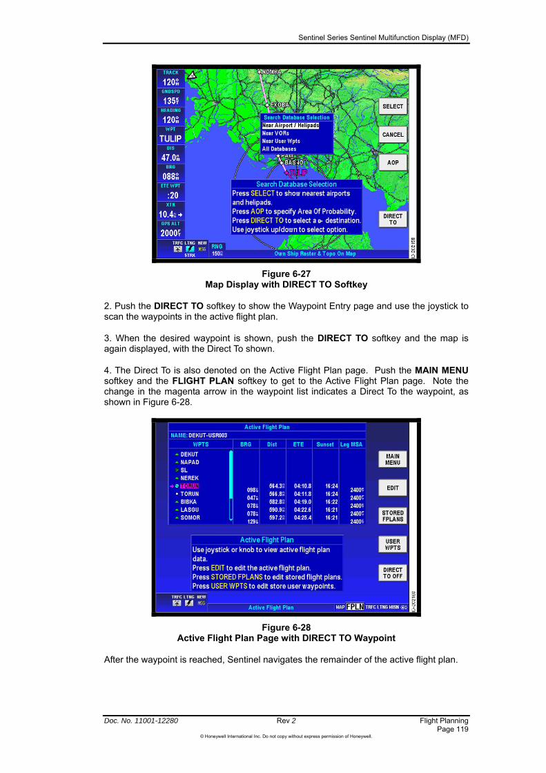
Sentinel Series Sentinel Multifunction Display (MFD)
Doc. No. 11001-12280 Rev 2 Flight Planning Page 119
©Honeywell International Inc. Do not copy without express permission of Honeywell.
Figure 6-27 Map Display with DIRECT TO Softkey
2. Push the DIRECT TO softkey to show the Waypoint Entry page and use the joystick to scan the waypoints in the active flight plan.
3. When the desired waypoint is shown, push the DIRECT TO softkey and the map is again displayed, with the Direct To shown.
4. The Direct To is also denoted on the Active Flight Plan page. Push the MAIN MENU softkey and the FLIGHT PLAN softkey to get to the Active Flight Plan page. Note the change in the magenta arrow in the waypoint list indicates a Direct To the waypoint, as shown in Figure 6-28.
Figure 6-28 Active Flight Plan Page with DIRECT TO Waypoint
After the waypoint is reached, Sentinel navigates the remainder of the active flight plan.

Sentinel Series Sentinel Multifunction Display (MFD)
Flight Planning Rev 2 Doc. No. 11001-12280 Page 120
©Honeywell International Inc. Do not copy without express permission of Honeywell.
Remove a Direct-To from the Active Flight Plan
When it becomes necessary to delete a Direct-To in an active flight plan, perform the following steps:
1. Push the NAV/SEARCH softkey to show Figure 6-29 and press the DIRECT TO OFF softkey.
Figure 6-29 Map Display with DIRECT TO OFF Softkey
Using OBS Course Mode in the Active Flight Plan
It can also be desirable to proceed directly to a waypoint in a flight plan on a specific bearing. An Omni-directional Bearing Selector (OBS) Course is set to the waypoint. When waypoints exist in the flight plan prior to that which the OBS Course is established, these waypoints are bypassed. When an OBS Course is established to a waypoint not in the flight plan, the navigation of the active flight plan does not resume after the waypoint is reached.
OBS Course to Active Flight Plan Waypoint
To set an OBS Course to a waypoint within an active flight plan, perform the following steps.
1. Push the NAV/SEARCH softkey and then press DIRECT TO to begin entry of the desired position.
2. Use the joystick or the rotary knob to find the desired waypoint on the active flight plan, as shown in Figure 6-30.
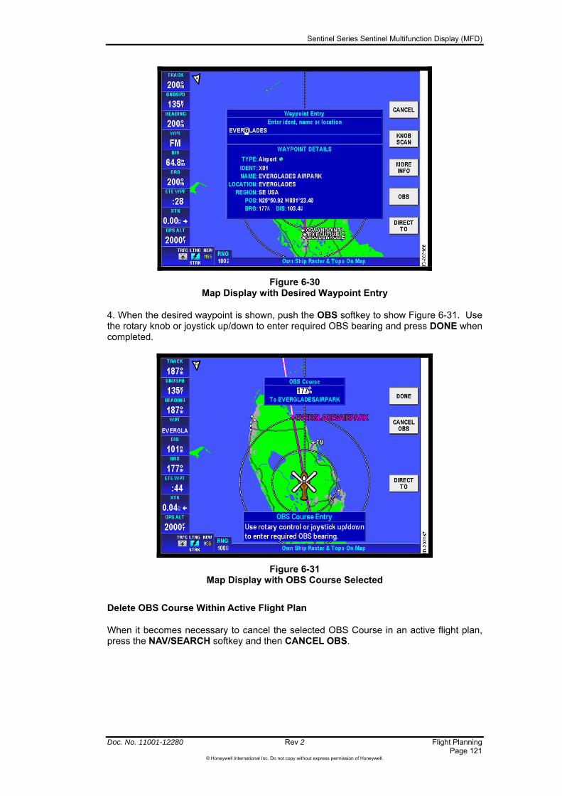
Sentinel Series Sentinel Multifunction Display (MFD)
Figure 6-30 Map Display with Desired Waypoint Entry
4. When the desired waypoint is shown, push the OBS softkey to show Figure 6-31. Use the rotary knob or joystick up/down to enter required OBS bearing and press DONE when completed.
Figure 6-31 Map Display with OBS Course Selected
Delete OBS Course Within Active Flight Plan
When it becomes necessary to cancel the selected OBS Course in an active flight plan, press the NAV/SEARCH softkey and then CANCEL OBS.
Doc. No. 11001-12280 Rev 2 Flight Planning Page 121
©Honeywell International Inc. Do not copy without express permission of Honeywell.

Sentinel Series Sentinel Multifunction Display (MFD)
Doc. No. 11001-12280 Rev 2 Search and Rescue Page 123
©Honeywell International Inc. Do not copy without express permission of Honeywell.
7 Search and Rescue
Introduction
Sentinel can display Area of Probability (AOP) rings on the map as an aid to Search and Rescue operations. The AOP is a circle centered on a predefined point that expands at a rate set by the time of the incident and the likely speed of a target. This defines the most beneficial approximate search area for the search aircraft once it arrives on scene.
The AOP functions are accessed by the pushing of the NAV/SEARCH softkey in the Map mode and then the pushing of the AOP softkey.

Sentinel Series Sentinel Multifunction Display (MFD)
Search and Rescue Rev 2 Doc. No. 11001-12280 Page 124
©Honeywell International Inc. Do not copy without express permission of Honeywell.
AREA OF PROBABILITY
The areas of probability are useful during rescue or law enforcement missions when searching for a ground target. A circle is placed at the last known position of the target: the radius of the circle grows at the estimated target ground speed. This gives an expanding boundary within which to concentrate the search.
You can set up an AOP from the Map page either by pressing the NAV/SEARCH softkey or by moving the pointer to a location and pressing the PTR MENU key, then selecting Init AOP as shown in Figure 7-1.
Figure 7-1 Area of Probability Initiate from Pointer Menu
Selecting AOP from the NAV/SEARCH menu leads to Figure 7-2.
You need to enter three pieces of information in order to create an AOP pattern: position, speed and time.
Position can be set to Current Position, or use the DBASE POS (Database position) softkey to enter an ident, name or location of an AOP position in the Waypoint Entry window. If the last known position of the target is in the form of a lat/long position or grid reference, you can enter this information directly in the currently selected coordinate system.
The Speed is the estimated speed of the target that is to be found. Speed units are the general units selected for the system (knots, statute miles per hour, or km/h).

Sentinel Series Sentinel Multifunction Display (MFD)
Figure 7-2 Area of Probability Entry Page
The Time is the reported time that the target was at the initial position. Pushing the TIME NOW softkey sets the current time in the Time field. Alternatively, use the joystick to select a specific time in 24-hour clock format.
If you know the estimated direction of travel or drift of the target then you can also put this into the AOP calculation.
Once the AOP details have been entered push START AOP. This returns to the Map mode with an expanding circle around the initial position, showing the area of probability that the target should be within.
Figure 7-3 Map Display with AOP Symbol
The AOP icon is visible on the upper right corner of the Map display when an AOP is running, as shown in Figure 7-3, even when the pattern itself is not visible on the screen at the time.
To cancel an AOP and return to the Search Database Selection page push AOP OFF. Alternatively the AOP is reset when the system is shut down.
Doc. No. 11001-12280 Rev 2 Search and Rescue Page 125
©Honeywell International Inc. Do not copy without express permission of Honeywell.

Sentinel Series Sentinel Multifunction Display (MFD)
Doc. No. 11001-12280 Rev 2 The Mission Control Menu Page 127
©Honeywell International Inc. Do not copy without express permission of Honeywell.
8 The Mission Control Menu
The Mission Control Menu is your interface to mission-related features and information. It is accessed from the Main Menu Page, or directly from the map page by turning the rotary control (if available).
From the mission menu page the following operations can be performed:
View System Messages
View Mission Notepads and Checklists
Load User Profiles (settings)
Save current flight log to a USB memory device.
Control the stopwatch, if enabled as a data window display.
Reading System Messages
Figure 8-1 Flashing NEW MSG Status Icon
Sentinel provides you with additional information about events such as detected faults or significant changes in settings by using System Messages. When there are unread system messages, the “NEW MSG” icon will flash in the system status area in the lower left corner of the screen, and the “MISN” text in the Display Mode selection area in the lower right corner of the screen will change to “MSG”. System messages can be read on the Mission Menu page, as shown in Figure 8-2. Once you access the Mission Menu screen, the flashing NEW MSG icon goes out of view from the lower left corner of the screen. The latest system message always shows at the top of the Messages window. A list of messages and causes show in Table 8-1.
Figure 8-2 Mission Menu Page
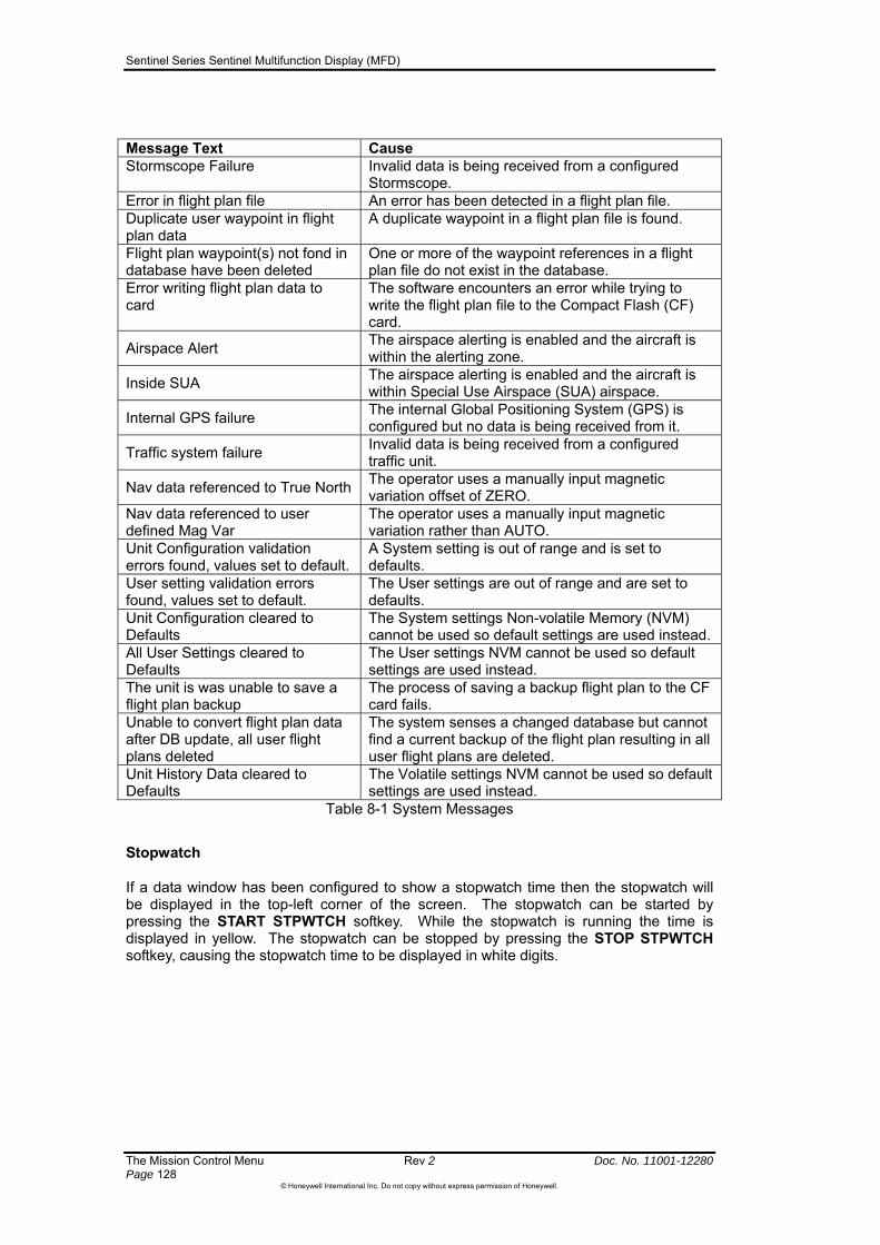
Sentinel Series Sentinel Multifunction Display (MFD)
The Mission Control Menu Rev 2 Doc. No. 11001-12280 Page 128
©Honeywell International Inc. Do not copy without express permission of Honeywell.
Message Text Cause Stormscope Failure Invalid data is being received from a configured
Stormscope. Error in flight plan file An error has been detected in a flight plan file. Duplicate user waypoint in flight plan data
A duplicate waypoint in a flight plan file is found.
Flight plan waypoint(s) not fond in database have been deleted
One or more of the waypoint references in a flight plan file do not exist in the database.
Error writing flight plan data to card
The software encounters an error while trying to write the flight plan file to the Compact Flash (CF) card.
Airspace Alert The airspace alerting is enabled and the aircraft is within the alerting zone.
Inside SUA The airspace alerting is enabled and the aircraft is within Special Use Airspace (SUA) airspace.
Internal GPS failure The internal Global Positioning System (GPS) is configured but no data is being received from it.
Traffic system failure Invalid data is being received from a configured traffic unit.
Nav data referenced to True North The operator uses a manually input magnetic variation offset of ZERO.
Nav data referenced to user defined Mag Var
The operator uses a manually input magnetic variation rather than AUTO.
Unit Configuration validation errors found, values set to default.
A System setting is out of range and is set to defaults.
User setting validation errors found, values set to default.
The User settings are out of range and are set to defaults.
Unit Configuration cleared to Defaults
The System settings Non-volatile Memory (NVM) cannot be used so default settings are used instead.
All User Settings cleared to Defaults
The User settings NVM cannot be used so default settings are used instead.
The unit is was unable to save a flight plan backup
The process of saving a backup flight plan to the CF card fails.
Unable to convert flight plan data after DB update, all user flight plans deleted
The system senses a changed database but cannot find a current backup of the flight plan resulting in all user flight plans are deleted.
Unit History Data cleared to Defaults
The Volatile settings NVM cannot be used so default settings are used instead.
Table 8-1 System Messages
Stopwatch
If a data window has been configured to show a stopwatch time then the stopwatch will be displayed in the top-left corner of the screen. The stopwatch can be started by pressing the START STPWTCH softkey. While the stopwatch is running the time is displayed in yellow. The stopwatch can be stopped by pressing the STOP STPWTCH softkey, causing the stopwatch time to be displayed in white digits.
Sentinel Series Sentinel Multifunction Display (MFD)
Doc. No. 11001-12280 Rev 2 The Mission Control Menu Page 129
©Honeywell International Inc. Do not copy without express permission of Honeywell.
NOTEPAD PAGE & CHECKLISTS
The notepad page is selected from the Mission Menu Page, shown in Figure 8-3, by pressing the NOTE PAD softkey. The notepad gives you a way to upload text that you might want to have available in the course of a mission. If the text files that you create contain the right information, then you can use this feature to set up your own checklists.
Figure 8-3 Mission Menu Page
The notepad page shows user generated text files that are stored on the Compact Flash cards. When no user generated text files are available the default notepad text is shown. You can upload the files that you have created from a USB memory device, as detailed in the following section.
Creating and Uploading Notepads and Checklists
Use a PC to create a simple text file for each notepad or checklist that you want to have available, and save it on the top level of you USB memory device (not inside any folders). Enter whatever text you with to appear in the notepad into the file, and save it using a meaningful name with the “.txt” file extension. You can create several notepad files with different names and store them all on the top level of the USB memory device (not inside any folders).
Note that you should avoid the name “route.txt” since Sentinel will assume that files with this name contain flight plans generated by Jeppesen ® FliteStar (see Uploading Saved Flight plans, page 108).
You can use a notepad file as a checklist by using the square brackets symbol in your file. Wherever your text includes a pair of square brackets adjacent to each other (“[]”), Sentinel will interpret this as a check box as explained below.
To upload your notepad and checklist files to Sentinel, select the Mission Menu (Figure 8-3) from the Main Menu. Open the door on the front of the Sentinel and insert your USB memory device into the USB socket. Push NOTE PAD softkey to display the Notepad page.
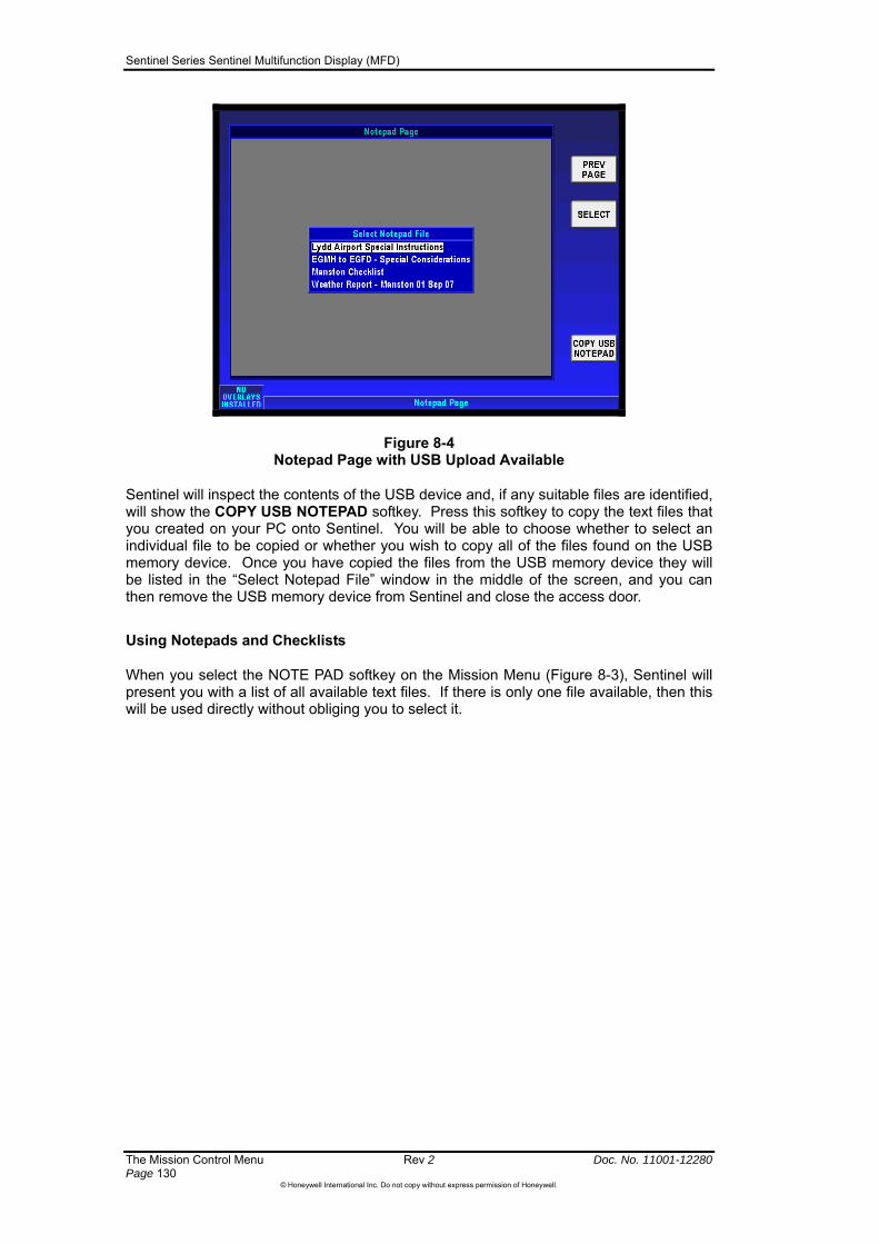
Sentinel Series Sentinel Multifunction Display (MFD)
The Mission Control Menu Rev 2 Doc. No. 11001-12280 Page 130
©Honeywell International Inc. Do not copy without express permission of Honeywell.
Figure 8-4 Notepad Page with USB Upload Available
Sentinel will inspect the contents of the USB device and, if any suitable files are identified, will show the COPY USB NOTEPAD softkey. Press this softkey to copy the text files that you created on your PC onto Sentinel. You will be able to choose whether to select an individual file to be copied or whether you wish to copy all of the files found on the USB memory device. Once you have copied the files from the USB memory device they will be listed in the “Select Notepad File” window in the middle of the screen, and you can then remove the USB memory device from Sentinel and close the access door.
Using Notepads and Checklists
When you select the NOTE PAD softkey on the Mission Menu (Figure 8-3), Sentinel will present you with a list of all available text files. If there is only one file available, then this will be used directly without obliging you to select it.

Sentinel Series Sentinel Multifunction Display (MFD)
Doc. No. 11001-12280 Rev 2 The Mission Control Menu Page 131
©Honeywell International Inc. Do not copy without express permission of Honeywell.
Use the joystick or rotary knob to select the appropriate notepad file. Pushing the SELECT softkey shows the highlighted notepad text file, as shown in Figure 8-5.
Figure 8-5 Notepad Page with First Checklist Item
If the notepad text file contains the character sequence ‘[‘ followed immediately by ‘]’, then this is interpreted as a checkbox indication. When identified, Sentinel will display the text up to and including the line containing the checkbox sequence in black and the remaining text in grey, as shown in Figure 8-5. If you push “CHECK BOX” then a check mark is placed in the check box, and the text as far as the next check box is displayed. This allows you to acknowledge each checklist item individually. If you do not wish to acknowledge any of the check boxes, then use SKIP CHECK instead of CHECK BOX. Figure 8-6 shows a checklist with several checks confirmed.
The CHECK BOX and SKIP CHECK softkeys are only shown if the check box characters (“[]”) are found in the file.
Pushing CHANGE NOTEPAD allows you to select a different notepad file from the list of available files.
Figure 8-6 Notepad Page with Complete Checklist

Sentinel Series Sentinel Multifunction Display (MFD)
The Mission Control Menu Rev 2 Doc. No. 11001-12280 Page 132
©Honeywell International Inc. Do not copy without express permission of Honeywell.
Sentinel does not record which checklist items you checked. Every time you use a checklist, it will be presented without any items already checked.
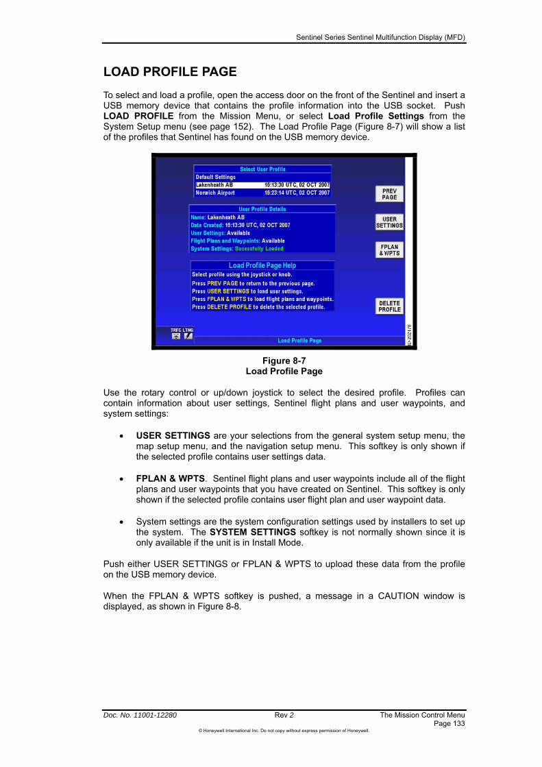
Sentinel Series Sentinel Multifunction Display (MFD)
Doc. No. 11001-12280 Rev 2 The Mission Control Menu Page 133
©Honeywell International Inc. Do not copy without express permission of Honeywell.
LOAD PROFILE PAGE
To select and load a profile, open the access door on the front of the Sentinel and insert a USB memory device that contains the profile information into the USB socket. Push LOAD PROFILE from the Mission Menu, or select Load Profile Settings from the System Setup menu (see page 152). The Load Profile Page (Figure 8-7) will show a list of the profiles that Sentinel has found on the USB memory device.
Figure 8-7 Load Profile Page
Use the rotary control or up/down joystick to select the desired profile. Profiles can contain information about user settings, Sentinel flight plans and user waypoints, and system settings:
USER SETTINGS are your selections from the general system setup menu, the map setup menu, and the navigation setup menu. This softkey is only shown if the selected profile contains user settings data.
FPLAN & WPTS. Sentinel flight plans and user waypoints include all of the flight plans and user waypoints that you have created on Sentinel. This softkey is only shown if the selected profile contains user flight plan and user waypoint data.
System settings are the system configuration settings used by installers to set up the system. The SYSTEM SETTINGS softkey is not normally shown since it is only available if the unit is in Install Mode.
Push either USER SETTINGS or FPLAN & WPTS to upload these data from the profile on the USB memory device.
When the FPLAN & WPTS softkey is pushed, a message in a CAUTION window is displayed, as shown in Figure 8-8.

Sentinel Series Sentinel Multifunction Display (MFD)
The Mission Control Menu Rev 2 Doc. No. 11001-12280 Page 134
©Honeywell International Inc. Do not copy without express permission of Honeywell.
Figure 8-8 Load Profile Page with MERGE DATA Softkey
Any profile visible on the Select User Profile window other than the Default Settings can be deleted. Pushing the DELETE PROFILE softkey displays Figure 8-9. If the OK softkey is pushed the selected profile is deleted from the Select User Profile window and the profile cannot be recovered.
Figure 8-9 Load Profile Page with Delete Action
Saving Flight Logs
Sentinel can maintain a record of the aircraft position at predetermined intervals. You can set the desired intervals on the General System Setup menu (page 138). The record of your flight is automatically saved to a USB memory device if it is present when you shut Sentinel down. Alternatively, you can save the flight log data from the Mission Menu. The SAVE FLIGHT softkey is shown on the Mission Menu if there is a USB memory device present in the USB socket – see Figure 8-10.
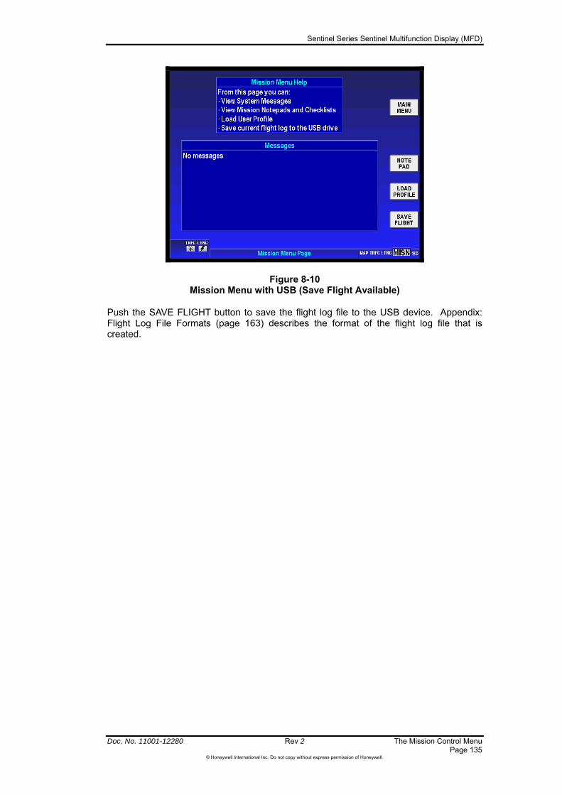
Sentinel Series Sentinel Multifunction Display (MFD)
Figure 8-10 Mission Menu with USB (Save Flight Available)
Push the SAVE FLIGHT button to save the flight log file to the USB device. Appendix: Flight Log File Formats (page 163) describes the format of the flight log file that is created.
Doc. No. 11001-12280 Rev 2 The Mission Control Menu Page 135
©Honeywell International Inc. Do not copy without express permission of Honeywell.

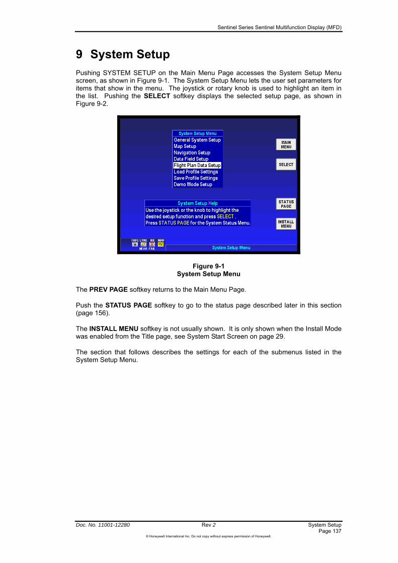
Sentinel Series Sentinel Multifunction Display (MFD)
Doc. No. 11001-12280 Rev 2 System Setup Page 137
©Honeywell International Inc. Do not copy without express permission of Honeywell.
9 System Setup
Pushing SYSTEM SETUP on the Main Menu Page accesses the System Setup Menu screen, as shown in Figure 9-1. The System Setup Menu lets the user set parameters for items that show in the menu. The joystick or rotary knob is used to highlight an item in the list. Pushing the SELECT softkey displays the selected setup page, as shown in Figure 9-2.
Figure 9-1 System Setup Menu
The PREV PAGE softkey returns to the Main Menu Page.
Push the STATUS PAGE softkey to go to the status page described later in this section (page 156).
The INSTALL MENU softkey is not usually shown. It is only shown when the Install Mode was enabled from the Title page, see System Start Screen on page 29.
The section that follows describes the settings for each of the submenus listed in the System Setup Menu.
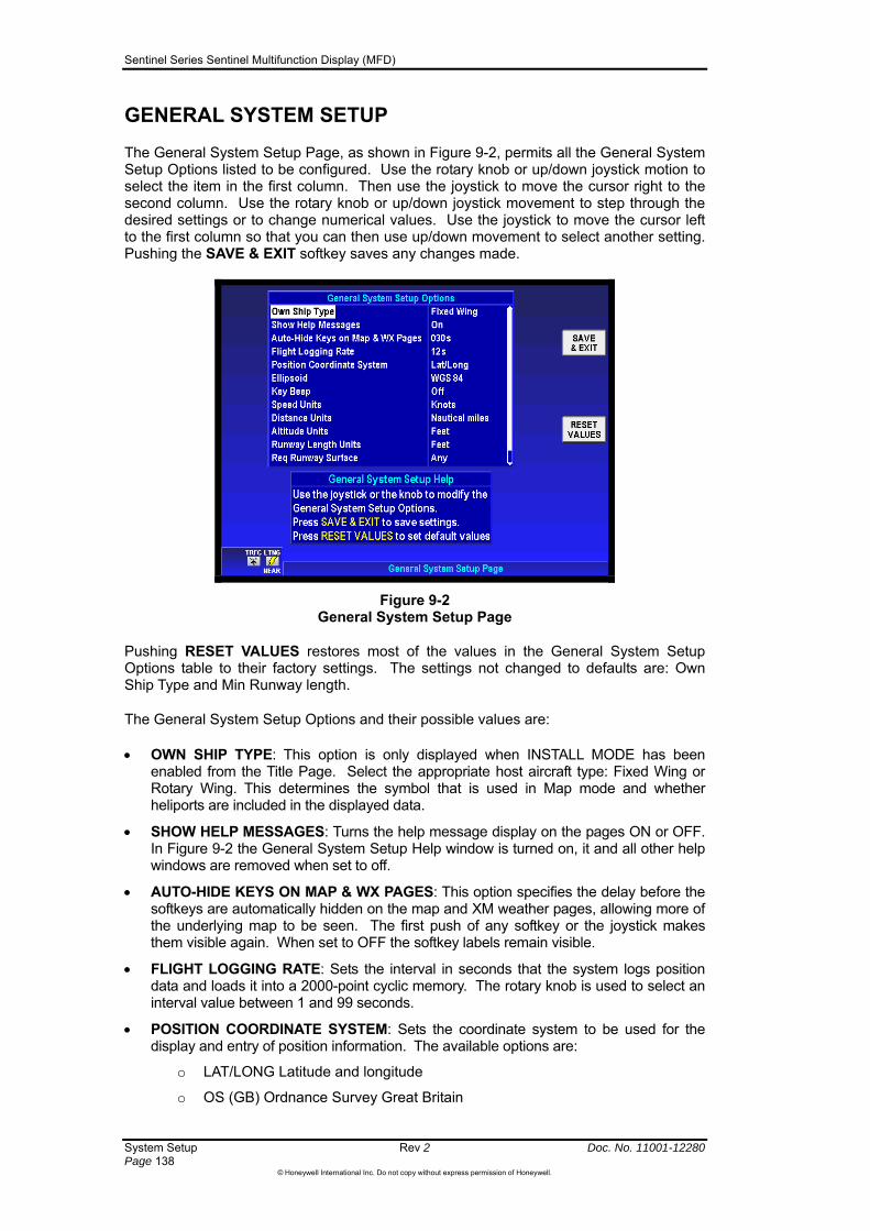
Sentinel Series Sentinel Multifunction Display (MFD)
System Setup Rev 2 Doc. No. 11001-12280 Page 138
©Honeywell International Inc. Do not copy without express permission of Honeywell.
GENERAL SYSTEM SETUP
The General System Setup Page, as shown in Figure 9-2, permits all the General System Setup Options listed to be configured. Use the rotary knob or up/down joystick motion to select the item in the first column. Then use the joystick to move the cursor right to the second column. Use the rotary knob or up/down joystick movement to step through the desired settings or to change numerical values. Use the joystick to move the cursor left to the first column so that you can then use up/down movement to select another setting. Pushing the SAVE & EXIT softkey saves any changes made.
Figure 9-2 General System Setup Page
Pushing RESET VALUES restores most of the values in the General System Setup Options table to their factory settings. The settings not changed to defaults are: Own Ship Type and Min Runway length.
The General System Setup Options and their possible values are:
OWN SHIP TYPE: This option is only displayed when INSTALL MODE has been enabled from the Title Page. Select the appropriate host aircraft type: Fixed Wing or Rotary Wing. This determines the symbol that is used in Map mode and whether heliports are included in the displayed data.
SHOW HELP MESSAGES: Turns the help message display on the pages ON or OFF. In Figure 9-2 the General System Setup Help window is turned on, it and all other help windows are removed when set to off.
AUTO-HIDE KEYS ON MAP & WX PAGES: This option specifies the delay before the softkeys are automatically hidden on the map and XM weather pages, allowing more of the underlying map to be seen. The first push of any softkey or the joystick makes them visible again. When set to OFF the softkey labels remain visible.
FLIGHT LOGGING RATE: Sets the interval in seconds that the system logs position data and loads it into a 2000-point cyclic memory. The rotary knob is used to select an interval value between 1 and 99 seconds.
POSITION COORDINATE SYSTEM: Sets the coordinate system to be used for the display and entry of position information. The available options are:
o LAT/LONG Latitude and longitude
o OS (GB) Ordnance Survey Great Britain
Sentinel Series Sentinel Multifunction Display (MFD)
Doc. No. 11001-12280 Rev 2 System Setup Page 139
©Honeywell International Inc. Do not copy without express permission of Honeywell.
o OS (Ireland) Ordnance Survey Ireland
o UTM Universal Transverse Mercator
o MGRS Military Grid Reference System.
ELLIPSIOD: Sets the datum to be used for the display and entry of position information. The available options are:
o WGS84 the WGS84 datum
o OS (GB) Ordnance Survey Great Britain
o OS (Ireland) Ordnance Survey Ireland
o ED50 (Euro Mean) the ED50 datum
o NAD27 (CONUS) the NAD27 (CONUS) datum.
KEY BEEP: Turns the key beep tone ON or OFF.
SPEED UNITS: Sets speed units to KNOTS (nautical miles per hour), MPH (statute miles per hour) or KMH (Kilometers per hour).
DISTANCE UNITS: Sets distance units to NAUTICAL MILES, STATUTE MILES or KILOMETERS.
ALTITUDE UNITS: Sets altitude units to FEET or METERS. When feet are selected, all altitudes are reported in feet. When meters are selected, all altitudes are reported in meters.
RUNWAY LENGTH UNITS: Sets runway length units to FEET or METERS. When feet are selected, runway lengths are reported in feet. When meters are selected, runway lengths are reported in meters.
REQ RUNWAY SURFACE: The options are ANY and HARD ONLY. The Required Runway Surface type is also used when using the NAV/SEARCH softkey to search for the nearest airports in map mode. When runway surface is set to ANY, airports with either hard or soft runways are displayed. When surface is set to HARD ONLY, only airports with hard surface runways are displayed and soft-runway airports are ignored.
MIN R/W LENGTH: This field contains the minimum length of the main runway at those airports that are included when the ten nearest airports are shown. Select the length field and use the rotary knob to set the minimum length value. The available values are specified in steps of 100 feet from 0 to 15,000 feet or in steps of 50 meters from 0 to 5000 meters when the runway length units are set to meters. By setting a minimum length, airports with shorter runway lengths are not included in the search for the closest airport. To disable this filter set the minimum runway length to 00000 feet.

Sentinel Series Sentinel Multifunction Display (MFD)
System Setup Rev 2 Doc. No. 11001-12280 Page 140
©Honeywell International Inc. Do not copy without express permission of Honeywell.
MAP SETUP
The initial Map Systems Setup page, as shown in Figure 9-3, permits different mapping options to be configured. On the initial Map System Setup Page, each of the displayed features is configured using the joystick and rotary knob. Select the option to change and then move the highlight to the right column and cycle through the possible settings. Push the NEXT softkey to move on to the next screen or the SAVE & EXIT softkey to save the choices and go back to the previous menu. Push the RESET VALUES softkey to set all option to their factory default values except Minimum Elevation when it is currently set to a valid value.
Figure 9-3 Map System Setup Page
Map System Setup Options descriptions:
ORIENTATION: Sets the Map Mode presentation to either a HEADING UP, TRACK UP or NORTH UP orientation.
EXTENDED TRACK LINE: Turns the extended track line ON or OFF. The extended track line is drawn ahead of the aircrafts present position in the direction of the present track.
RANGE RINGS ON MAP: Controls the display of the range rings shown around the aircraft. OFF removes the rings. OUTER RING shows only the outer ring. OUTER AND INNER RING shows both rings.
AIRPORT LABEL FORMAT: Labels airports in Map Mode either with their ICAO CODE, their FULL NAME (given airport name) or CITY NAME (local city name).
AUTO ZOOM: Turns the auto zoom function ON or OFF. When flying the last leg of a Flight Plan or when flying a Direct To, the system automatically zooms to a screen range that keeps the destination waypoint within the display area. The system continues to zoom in to the lowest zoom level. When the lowest zoom has been reached and the aircraft begins to fly away from the destination waypoint, then the system zooms out automatically to keep the waypoint within the display area. When auto zoom is in operation AUTO (Automatic) is shown in the RNG (Range) display field. Pushing either the ZOOM IN or ZOOM OUT softkey cancels the auto zoom capability. Auto zoom is re-activated in this menu.
MINIMUM ELEVATION: Controls the high definition terrain contours minimum level elevation.

Sentinel Series Sentinel Multifunction Display (MFD)
Doc. No. 11001-12280 Rev 2 System Setup Page 141
©Honeywell International Inc. Do not copy without express permission of Honeywell.
MAXIMUM ELEVATION: Controls the high definition terrain contours maximum level elevation.
The minimum and maximum
high definition terrain contour elevation values are controlled by these options. When either is selected a HELP softkey is added to the Map System Setup Page to explain these values. Push HELP to show the help window shown here.
There are four groups of features for each of the map layers. They are: Point Features, Line Features, Airspace and Overlay.
Pushing NEXT displays the Map Features Setup Page with the Point Feature Setup screen, as shown in Figure 9-4.
Figure 9-4 Point Feature Setup Page
Push CHANGE MAP to display the list of map layers. Select the desired map or chart and then push SELECT to select that map layer and return to the Map Features page. The next three screens are each accessed in sequence by repeatedly pushing the NEXT softkey. The Next softkey on the last page loops back to the first page.

Sentinel Series Sentinel Multifunction Display (MFD)
System Setup Rev 2 Doc. No. 11001-12280 Page 142
©Honeywell International Inc. Do not copy without express permission of Honeywell.
On the Point Feature Setup screen, as shown in Figure 9-4, the ICON column defines the style of icon. The icon style is configurable for some but not all of the map features. The MAX column defines the maximum zoom level (range, identified by the RNG window in Map Mode) that the icon is shown, in this case 50nm. In this example the icon therefore does not appear above 50nm, but only is displayed at 50 NM level and all lower levels. The Label column defines the maximum zoom level (Range) that the identifying label for the icon automatically is shown at. In this example the airport label is shown at the 15 NM and below zoom level. To adjust the icon style of map ranges, use the joystick to highlight the appropriate field for adjustment and then use the rotary, or joystick up / down to adjust the setting.
Pressing NEXT softkey will show the Map Line Feature Setup screen, as in Figure 9-5.
Figure 9-5 Line Feature Setup Screen
Pressing NEXT softkey will show the Map Airspace Feature Setup screen, as in Figure 9-6.
Figure 9-6 Map Airspace Setup Screen

Sentinel Series Sentinel Multifunction Display (MFD)
Doc. No. 11001-12280 Rev 2 System Setup Page 143
©Honeywell International Inc. Do not copy without express permission of Honeywell.
Pressing NEXT softkey will show the Map Overlay Feature Setup screen, as in Figure 9-7.
Figure 9-7 Map Overlay Setup Screen
CAUTION: Please think carefully before altering any of the settings on these screens, since you might inadvertently switch a class of data that is important for situational awareness and thereby degrade safety.
Pushing SAVE & EXIT saves any changes made on these screens and returns to Map Mode. Pushing RESET VALUES resets the changeable values to their factory defaults. The NEXT softkey steps through the available setup pages. Pushing CHANGE MAP selects each map the user wishes to change. Pushing ALL MAPS applies these setting to all maps.
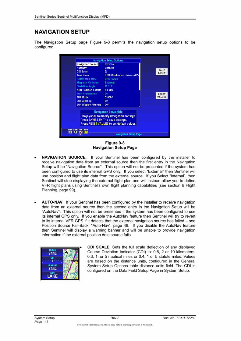
Sentinel Series Sentinel Multifunction Display (MFD)
System Setup Rev 2 Doc. No. 11001-12280 Page 144
©Honeywell International Inc. Do not copy without express permission of Honeywell.
NAVIGATION SETUP
The Navigation Setup page Figure 9-8 permits the navigation setup options to be configured.
Figure 9-8 Navigation Setup Page
NAVIGATION SOURCE. If your Sentinel has been configured by the installer to receive navigation data from an external source then the first entry in the Navigation Setup will be “Navigation Source”. This option will not be presented if the system has been configured to use its internal GPS only. If you select “External” then Sentinel will use position and flight plan data from the external source. If you Select “Internal”, then Sentinel will stop displaying the external flight plan and will instead allow you to define VFR flight plans using Sentinel’s own flight planning capabilities (see section 6 Flight Planning, page 99).
AUTO-NAV. If your Sentinel has been configured by the installer to receive navigation data from an external source then the second entry in the Navigation Setup will be “AutoNav”. This option will not be presented if the system has been configured to use its internal GPS only. If you enable the AutoNav feature then Sentinel will try to revert to its internal VFR GPS if it detects that the external navigation source has failed – see Position Source Fall-Back: “Auto-Nav”, page 48. If you disable the AutoNav feature then Sentinel will display a warning banner and will be unable to provide navigation information if the external position data source fails.
CDI SCALE: Sets the full scale deflection of any displayed Course Deviation Indicator (CDI) to: 0.6, 2 or 10 kilometers, 0.3, 1, or 5 nautical miles or 0.4, 1 or 5 statute miles. Values are based on the distance units, configured in the General System Setup Options table distance units field. The CDI is configured on the Data Field Setup Page in System Setup.

Sentinel Series Sentinel Multifunction Display (MFD)
Doc. No. 11001-12280 Rev 2 System Setup Page 145
©Honeywell International Inc. Do not copy without express permission of Honeywell.
TIME ZONE: Sentinel can receive time information either from its own internal GPS, an external GPS (if configured) or from the XM weather source (if configured). This time is provided without local timezone offset information (called Universal Coordinated Time, or UTC). This option allows a local timezone offset to be applied to make the received time agree with your local time. To adjust the timezone, move the cursor to highlight the field and then use the rotary or joystick up / down to select the desired timezone name.
The user can also select Local from the time zone list and then input the offset directly using the joystick or rotary knob. The line Offset from UTC changes from blue to white permitting the change.
This method permits offsets of hours 30-minute increments.
and
MAGNETIC VARIATION: Settings are Auto or Manual. When set to auto the magnetic variation is derived form the GPS location. When set to manual the variation angle is entered in the line below by moving the cursor to the left, then down and then to the right to highlight the angle value field. Use the joystick or rotary knob to change the value. The angle range is from 0 to 180 degrees.
NEAR POSITION FORMAT: All Data, Airports / VORs, or VORs Only.
TURN ANTICIPATION: Turns ON or OFF. Turn Anticipation assists navigation for a fixed wing aircraft along a curved path segment to ensure a smooth transition between two adjacent legs in the flight plan at a rate one turn.
SUA BUFFER: The SUA altitude buffer is set from 500 to 16000 feet in 100-foot increments. Specifies the buffer around the current aircraft altitude within which Special Use Airspace shall be processed. See the next two options for more details.
SUA ALERTING: Special Use Airspace (SUA) Alerting is turned ON or OFF. If ON then notification messages shall be generated before entering Special Use Airspace within the range of altitudes defined by the current aircraft altitude combined with the buffer limits defined above.
SUA DISPLAY FILTERING: Special Use Airspace (SUA) Display Filtering is turned ON or OFF. If ON then only Special Use Airspace within the buffer altitude of the current aircraft altitude shall be displayed on the map images.
INITIAL WAYPOINT CHAR.: Characters available 0 to 9, A to Z, K is the default character for the AMR (Americas) Sentinel version. E is the default character for the ATI (Atlantic) Sentinel version. P is the default character for the PAI (Pacific) Sentinel version.
VSD SWATH DISTANCE: Specifies the minimum distance to the left and right of your current track to be searched for terrain and obstacles, when generating the Vertical Profile Display (also referred to as the Vertical Situation Display or VSD). The highest terrain found within the VSD Swath Distance is used to drawn the terrain in the Vertical Profile Display (VSD), see section Vertical Profile Display on page 59 for more details.
VSD ABOVE ALTITUDE: Specifies the upper limit for the Vertical Situation Display (VSD) as the altitude above the current aircraft altitude.
VSD BELOW ALTITUDE: Specifies the lower limit for the Vertical Situation Display (VSD) as the altitude below the current aircraft altitude.

Sentinel Series Sentinel Multifunction Display (MFD)
System Setup Rev 2 Doc. No. 11001-12280 Page 146
©Honeywell International Inc. Do not copy without express permission of Honeywell.
DIRECT-TO MODE: Leg or Target. In target mode, the origin of the Direct-To is continuously updated to be the current aircraft position. In leg mode, the origin of the Direct-To is the position at which the Direct-To was engaged.
DEFAULT GROUND SPEED: Allows the user to specify the ground speed to be used in all calculations, if the current aircraft ground speed is unavailable. This option is not adjustable while a valid ground speed is available.
DEFAULT FUEL FLOW: Allows the user to specify the fuel flow rate to be used in all fuel calculations, if the current aircraft fuel flow rateis unavailable. This option is not adjustable while a valid fuel flow rate is available.

Sentinel Series Sentinel Multifunction Display (MFD)
Doc. No. 11001-12280 Rev 2 System Setup Page 147
©Honeywell International Inc. Do not copy without express permission of Honeywell.
DATA FIELD SETUP
This setup permits the user to arrange the data windows along the left edge of the display Figure 9-9 in any order.
Figure 9-9 Data Field Setup Page
Move the joystick up or down to highlight the data window to be configured. Move the joystick right to begin selection of the desired data to be displayed. Use the joystick or rotary control to select the desired display for the data window and move the joystick left to complete its setup. Repeat this process for all the data windows. If you do not want to use any of the data windows then you can select “none” as one of the display options.
Table 9-1 lists the possible windows that can be configured.
Table 9-1 Data Field Icons
Display Description
Displays the altitude from the current highest priority source available to Sentinel. This is labelled either “BARO ALT”, if barometric corrected altitude or “GPS ALT” otherwise. The altitude is displayed using the currently selected units. CAUTION: The altitude display on Sentinel is intended for use as a convenient secondary display only. Sentinel is not intended for use as a primary altitude display.
Displays the bearing to the destination waypoint from the current own ship position. The bearing shall be displayed in degrees relative to magnetic north.
Displays the course deviation indicator. The full scale of the CDI is configured on the Navigation Setup page.
Displays the time at which the in-flight condition was first identified. The time display is in hours and minutes.

Sentinel Series Sentinel Multifunction Display (MFD)
System Setup Rev 2 Doc. No. 11001-12280 Page 148
©Honeywell International Inc. Do not copy without express permission of Honeywell.
Display Description
Displays the distance to the destination waypoint, in the currently selected units
“Desired TracK”: Displays the magnetic angle from the start waypoint to the destination waypoint.
Displays the Enroute Safe Altitude, in the currently selected altitude units. Enroute Safe Altitude is determined from the highest of the published Minimum Of-Route Altitudes in the vicinity. CAUTION: The ESA value is advisory in nature only. They should not be relied upon as a source of obstacle and terrain avoidance information. Always refer to a current aeronautical chart for appropriate minimum clearance altitudes.
Displays the estimated time of arrival at the current destination waypoint. The time display shall be in the local time and shown as hours and minutes.
Displays the estimated time en route. If the ETE is greater then 10 minutes then the format will be in hours and minutes. Otherwise the format will be in minutes and seconds.
Displays the current flight duration in hours and minutes.
Displays the current own ship ground speed in the currently selected units.
Displays the current own ship heading in degrees relative to magnetic north.
Displays the current minimum safe altitude, in the currently selected altitude units. Minimum safe altitude is determined from the highest of the published Minimum Of-Route Altitudes in the vicinity. CAUTION: The MSA value is advisory in nature only. They should not be relied upon as a source of obstacle and terrain avoidance information. Always refer to a current aeronautical chart for appropriate minimum clearance altitudes.
Displays the range, bearing and ident of the nearest identified feature to the current own ship position. The range shall be displayed in the currently selected distance units.

Sentinel Series Sentinel Multifunction Display (MFD)
Doc. No. 11001-12280 Rev 2 System Setup Page 149
©Honeywell International Inc. Do not copy without express permission of Honeywell.
Display Description
“Present POSition”: Displays the current own ship position in the currently selected coordinate system.
Displays the received radar altitude. The Radar Altitude device must be configured for this option to be selectable. CAUTION: The Rad Alt display on Sentinel is intended for use as a convenient secondary display only. Sentinel is not intended for use as a primary altitude display.
Displays the stopwatch time. The time shall be displayed in hours and minutes if the stopwatch time is greater than 59 mins 59 seconds. The stopwatch shall be displayed with yellow digits while it is running. The stopwatch is started and stopped from the Mission Control page (see page 127).
Displays the time in the currently selected timezone. The title of the window shows the timezone used for the time display.
“Track Error”: Displays the difference between the current own ship track and the desired track from the start waypoint to the destination waypoint. The difference is displayed in degrees, with the arrow indicating the direction to turn to reduce the track error.
Displays the current own ship track over ground in degrees relative to magnetic north.
The traffic data window shows a simplified display of the traffic targets within a fixed distance from the own ship. The distance is 6nm, 7sm or 10km, depending on the selected units. The data window only displays traffic information if the traffic unit has been configured.
“Track to Steer”: Displays the calculated track angle to steer to bring the aircraft on to track. The angle is displayed in degrees relative to magnetic north.
Displays the magnitude and direction of the wind. The magnitude and direction of the window must be received from an external Airdata device.
Displays the ident of the current destination waypoint. The ident is truncated to fit into the current data window width.

Sentinel Series Sentinel Multifunction Display (MFD)
System Setup Rev 2 Doc. No. 11001-12280 Page 150
©Honeywell International Inc. Do not copy without express permission of Honeywell.
Display Description
“Cross-Track”: Displays the distance from the current aircraft position to the desired track line. The arrow indicates the direction to steer to reduce the distance. The distance is displayed in the currently selected units.
The WIDE WINDOWS softkey can make long labels in the windows more readable. When the windows are wide, then the softkey is labeled. NARROW WINDOWS.
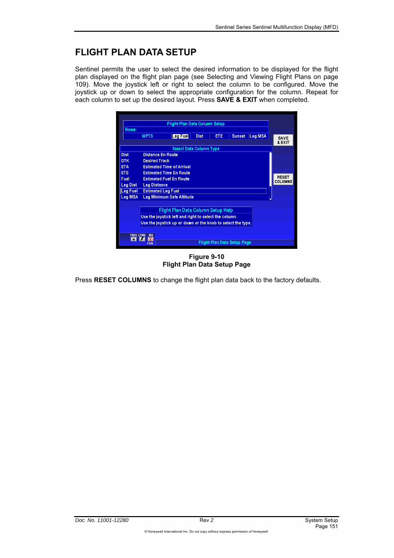
Sentinel Series Sentinel Multifunction Display (MFD)
Doc. No. 11001-12280 Rev 2 System Setup Page 151
©Honeywell International Inc. Do not copy without express permission of Honeywell.
FLIGHT PLAN DATA SETUP
Sentinel permits the user to select the desired information to be displayed for the flight plan displayed on the flight plan page (see Selecting and Viewing Flight Plans on page 109). Move the joystick left or right to select the column to be configured. Move the joystick up or down to select the appropriate configuration for the column. Repeat for each column to set up the desired layout. Press SAVE & EXIT when completed.
Figure 9-10 Flight Plan Data Setup Page
Press RESET COLUMNS to change the flight plan data back to the factory defaults.
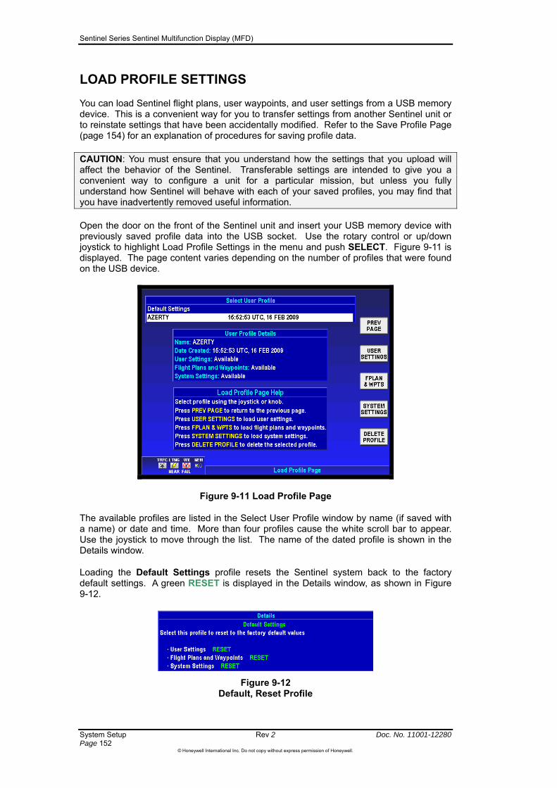
Sentinel Series Sentinel Multifunction Display (MFD)
System Setup Rev 2 Doc. No. 11001-12280 Page 152
©Honeywell International Inc. Do not copy without express permission of Honeywell.
LOAD PROFILE SETTINGS
You can load Sentinel flight plans, user waypoints, and user settings from a USB memory device. This is a convenient way for you to transfer settings from another Sentinel unit or to reinstate settings that have been accidentally modified. Refer to the Save Profile Page (page 154) for an explanation of procedures for saving profile data.
CAUTION: You must ensure that you understand how the settings that you upload will affect the behavior of the Sentinel. Transferable settings are intended to give you a convenient way to configure a unit for a particular mission, but unless you fully understand how Sentinel will behave with each of your saved profiles, you may find that you have inadvertently removed useful information.
Open the door on the front of the Sentinel unit and insert your USB memory device with previously saved profile data into the USB socket. Use the rotary control or up/down joystick to highlight Load Profile Settings in the menu and push SELECT. Figure 9-11 is displayed. The page content varies depending on the number of profiles that were found on the USB device.
Figure 9-11 Load Profile Page
The available profiles are listed in the Select User Profile window by name (if saved with a name) or date and time. More than four profiles cause the white scroll bar to appear. Use the joystick to move through the list. The name of the dated profile is shown in the Details window.
Loading the Default Settings profile resets the Sentinel system back to the factory default settings. A green RESET is displayed in the Details window, as shown in Figure 9-12.
Figure 9-12 Default, Reset Profile

Sentinel Series Sentinel Multifunction Display (MFD)
Doc. No. 11001-12280 Rev 2 System Setup Page 153
©Honeywell International Inc. Do not copy without express permission of Honeywell.
PREV PAGE - Returns to the Systems Setup Menu Screen.
USER SETTINGS - Push to load only the user-configurable system settings from the displayed Profile. User settings include your choices from the map setup, navigation setup, and general system setup menus. If the highlighted profile does not include any User Settings components, then the USER SETTINGS softkey is not displayed.
FPLAN & WPTS - Push to load only the Sentinel flight plans and user waypoints from the selected Profile.
SYSTEM SETTING – This option is not normally shown. It is available if the unit is put into “Install Mode”, and it allows an installer to upload device setup and connection configuration settings.
DELETE PROFILE – Push this softkey to delete the selected Profile. A Caution message will be displayed, requiring your acknowledgement before the selected profile is deleted.

Sentinel Series Sentinel Multifunction Display (MFD)
System Setup Rev 2 Doc. No. 11001-12280 Page 154
©Honeywell International Inc. Do not copy without express permission of Honeywell.
SAVE PROFILE PAGE
You can save flight plans, user waypoints, and user settings to a USB memory device for transfer to another Sentinel unit or to keep a backup in case they are accidentally deleted. These kinds of data make up your “profile” for your Sentinel, and you can use the Save Profile and Load Profile capabilities as a convenient way to reconfigure your Sentinel for different missions. Refer to Load Profile Settings (page 152) or Load Profile Page (page 133) for an explanation of procedures for loading a saved profile.
To save a profile. push SYSTEM SETUP from the Main Menu page. Open the door on the front of the Sentinel unit and insert a USB memory device into the USB socket (see Figure 2-5). Use the rotary control or up/down joystick to highlight Save Profile Settings and push the SELECT softkey. Figure 9-13 is displayed. Note that the Save Profile Settings option will not be offered on the System Setup menu unless there is a USB memory device present in the USB socket.
Figure 9-13 Save Profile Page
The Profile Name will automatically be set to the current date and time but can be modified by pressing the CLEAR TEXT softkey and entering the desired name.
PREV PAGE - Returns to the Systems Setup Menu Screen.
CLEAR TEXT - Removes all data from the data entry window.
SAVE ALL - Saves the, flight plans, user waypoints, and Sentinel user settings to the USB memory device, with the profile name defined above.
SETTINGS - Saves only your user settings to the USB memory device, with the profile name defined above. User settings are your preferences from the general system setup, map setup, and navigation setup menus.
FPLANS & WPTS - Saves only your stored flight plans and user waypoints to the USB memory device, with the profile name defined above.
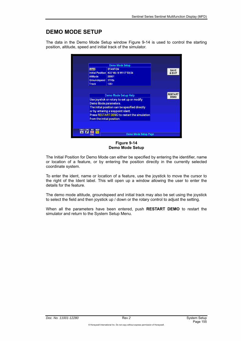
Sentinel Series Sentinel Multifunction Display (MFD)
Doc. No. 11001-12280 Rev 2 System Setup Page 155
©Honeywell International Inc. Do not copy without express permission of Honeywell.
DEMO MODE SETUP
The data in the Demo Mode Setup window Figure 9-14 is used to control the starting position, altitude, speed and initial track of the simulator.
Figure 9-14 Demo Mode Setup
The Initial Position for Demo Mode can either be specified by entering the identifier, name or location of a feature, or by entering the position directly in the currently selected coordinate system.
To enter the ident, name or location of a feature, use the joystick to move the cursor to the right of the Ident label. This will open up a window allowing the user to enter the details for the feature.
The demo mode altitude, groundspeed and initial track may also be set using the joystick to select the field and then joystick up / down or the rotary control to adjust the setting.
When all the parameters have been entered, push RESTART DEMO to restart the simulator and return to the System Setup Menu.

Sentinel Series Sentinel Multifunction Display (MFD)
System Setup Rev 2 Doc. No. 11001-12280 Page 156
©Honeywell International Inc. Do not copy without express permission of Honeywell.
STATUS PAGES
The System Status Menu Figure 9-15 is accessed by the STATUS PAGE softkey on the System Setup Menu page (Figure 9-1). The options available depend on the configuration of the unit. Use the joystick to highlight the desired line and press the SELECT softkey.
Figure 9-15 Systems Status Menu
Altitude Status
Figure 9-16 shows the status of the units that gives altitude information to Sentinel for use in displaying altitude data. The currently active source for altitude shall display “Used”. All other available sources for altitude shall show “Valid” or “Disabled”. To disable the currently used altitude source, move the highlight over the word “Used” and then use the joystick up / down or rotary to change the entry to “Disabled”. The next valid altitude source will automatically be selected and labelled as “Used”.
Figure 9-16 Altitude Source Status Page

Sentinel Series Sentinel Multifunction Display (MFD)
Doc. No. 11001-12280 Rev 2 System Setup Page 157
©Honeywell International Inc. Do not copy without express permission of Honeywell.
Heading Sources Status
This page Figure 9-17 shows the status of the units that gives heading information to Sentinel for use in orienting the map displays. The currently active heading source shall display “Used”. All other available sources for heading shall show “Valid” or “Disabled”. To disable the currently used heading source, move the highlight over the word “Used” and then use the joystick up / down or rotary to change the entry to “Disabled”. The next valid heading source will automatically be selected and labelled as “Used”.
Figure 9-17 Heading Source Status Page
Internal GPS Status
Displays the current status of the internal GPS, including the position, altitude, time and dilution of precision (DOP).
External Position Source Status
The External Position Source Status option is only available if Sentinel has been configured with an external GPS as its position source. Displays the extracted position, track and groundspeed values, and an indication of whether valid data is being received.
Map Information
Displays details of the maps and custom databases found on the data cards. See Map and Custom Database Information Page on page 32 for more details.
Software and Databases Version Status
Displays information on the version of the Sentinel software, and the standard databases found on the primary data card. Also lists all of the additional raster mapping along with the first expiry date for any part of the map.

Sentinel Series Sentinel Multifunction Display (MFD)
System Setup Rev 2 Doc. No. 11001-12280 Page 158
©Honeywell International Inc. Do not copy without express permission of Honeywell.
System Information
Displays the start and end times of the last flight log recording, the total run time for the unit and a count of the system power cycles. It also shows a list of event codes and the run-time of the unit when they occurred. The event codes do not necessarily indicate any problems with the unit.
XM Weather Status
The XM Weather Status option is only available is Sentinel has been configured with an XM Weather device. Displays details regarding the quality of the received XM signal and an indication of whether valid XM data is being received.
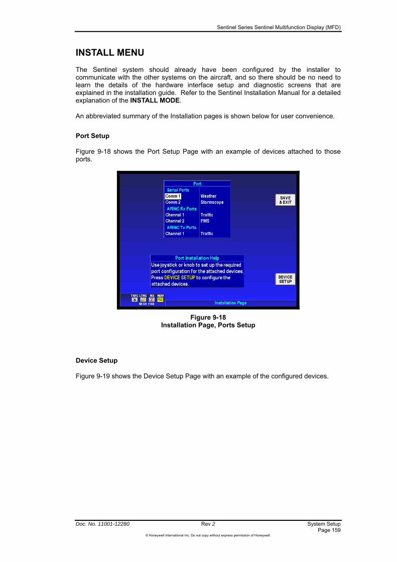
Sentinel Series Sentinel Multifunction Display (MFD)
Doc. No. 11001-12280 Rev 2 System Setup Page 159
©Honeywell International Inc. Do not copy without express permission of Honeywell.
INSTALL MENU
The Sentinel system should already have been configured by the installer to communicate with the other systems on the aircraft, and so there should be no need to learn the details of the hardware interface setup and diagnostic screens that are explained in the installation guide. Refer to the Sentinel Installation Manual for a detailed explanation of the INSTALL MODE.
An abbreviated summary of the Installation pages is shown below for user convenience.
Port Setup
Figure 9-18 shows the Port Setup Page with an example of devices attached to those ports.
Figure 9-18 Installation Page, Ports Setup
Device Setup
Figure 9-19 shows the Device Setup Page with an example of the configured devices.
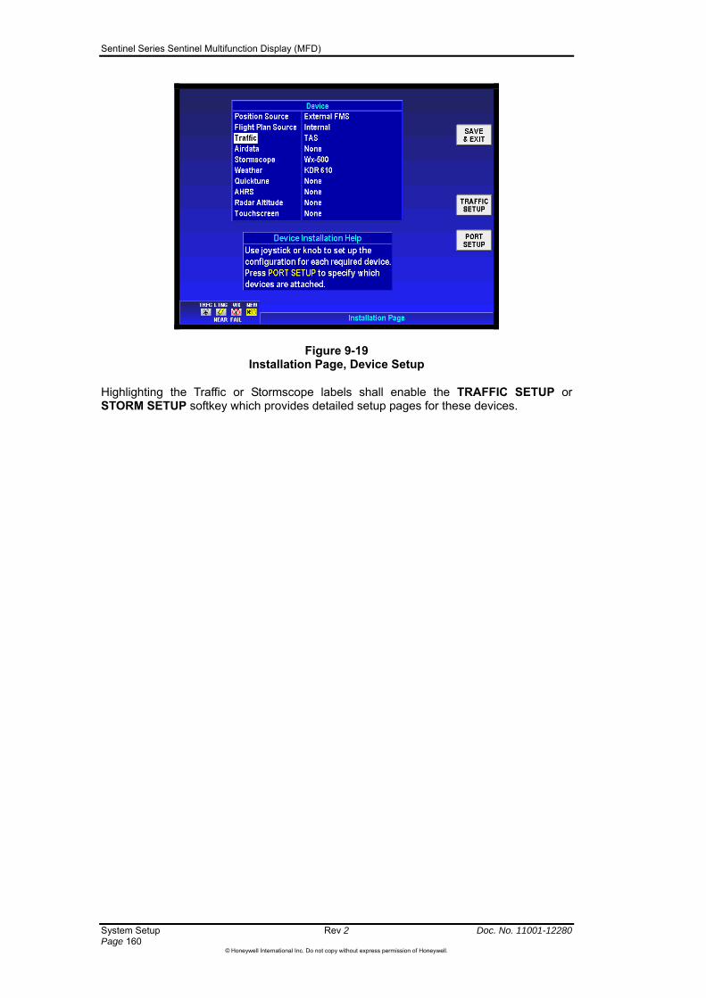
Sentinel Series Sentinel Multifunction Display (MFD)
Figure 9-19 Installation Page, Device Setup
Highlighting the Traffic or Stormscope labels shall enable the TRAFFIC SETUP or STORM SETUP softkey which provides detailed setup pages for these devices.
System Setup Rev 2 Doc. No. 11001-12280 Page 160
©Honeywell International Inc. Do not copy without express permission of Honeywell.

Sentinel Series Sentinel Multifunction Display (MFD)
Doc. No. 11001-12280 Rev 2 Appendix: Database Region Areas Page 161
©Honeywell International Inc. Do not copy without express permission of Honeywell.
Appendix: Database Region Areas
The core capability of Sentinel is its intuitive mapping and navigation function, which is capable of displaying highly detailed vectored (point and line) and raster (scanned) area maps. Because of the amount of data required, raster mapping is normally only provided for the known area of operations of an aircraft.
The AMR Database Region covers Canada, North America, Latin America and South America.
Figure 0-10- AMR Database Region Coverage
The ATI Database Region covers Europe, Africa, the Middle East and Asia.
Figure 0-2 ATI (EMEA) Database Region Coverage
The PAI Database Region covers Asia, the Middle East, Australia and the Pacific Islands.
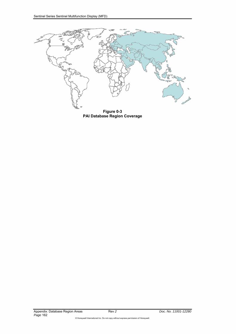
Sentinel Series Sentinel Multifunction Display (MFD)
Appendix: Database Region Areas Rev 2 Doc. No. 11001-12280 Page 162
©Honeywell International Inc. Do not copy without express permission of Honeywell.
Figure 0-3
PAI Database Region Coverage

Sentinel Series Sentinel Multifunction Display (MFD)
Doc. No. 11001-12280 Rev 2 Appendix: Flight Log File Formats Page 163
©Honeywell International Inc. Do not copy without express permission of Honeywell.
Appendix: Flight Log File Formats
Flight logs are saved to the USB memory device as ASCII files in three different formats; standard text format, Google EarthTM format and Jeppesen FliteStarTM format.
Google EarthTM Flight Log Files
The Google Earth flight log files are saved with the KML file extension. If your PC has Google Earth installed then double-clicking the KML file will startup Google Earth and graphically display the path of the flight log. The flight log can then be played back allowing you to study your flight path in detail.
Jeppesen FliteStarTM Flight Log Files
The FliteStar flight log files are saved with the TXT file extension. If your PC has Jeppesen FliteStar installed then you can load the flight log into FliteStar and study your flight path in detail as an overlay on the FliteStar map.
Simple Text Flight Log Files
The standard text file format flight log files are also saved with the TXT file extension. Using any word processing package or text editor you can view the flight log file on your PC. The Flight log file saved to the USB memory device is an ASCII text file. Each flight log point is saved as two lines of data. The first line contains information about the aircraft position, and the second line contains information about the two nearest traffic targets. Each line is terminated by a carriage return and a line feed.
Aircraft Position Information Part of Flight Log Entry
This line of data contains the following information
Data Type Format Date DD/MM/YYYY, (MM/DD/YYYY, for AMR) Time HH:MM:SS, Aircraft Position XDD°MM.MM XDDD°MM.MM , (with leading zeros) Aircraft Altitude ALT NNNNNft, (with leading zeros) Aircraft Heading HDG DDD°, (with leading zeros) Aircraft Course over ground COG DDD° (with leading zeros) Aircraft Speed over ground SOG nnkts (No leading zeros)
Example of a line of Aircraft position information:
19/09/2007,11:54:20,N51°45.21 E000°51.27,Hdg 225°,Alt 02000ft,COG 222°,SOG 14kts
Traffic Log Information Part of Flight Log Entry
This line of data contains the following information:
Data Type Format Traffic Status Traffic, or No Traffic Traffic #1 Bearing from aircraft DDD°, (with leading zeros) Traffic #1 Range from aircraft N.NNnm, (with leading zeros) Traffic #2 Bearing from aircraft DDD°, or ---°, (with leading zeros) Traffic #2 Range from aircraft N.NNnm or -.—nm (with leading zeros)

Sentinel Series Sentinel Multifunction Display (MFD)
Appendix: Flight Log File Formats Rev 2 Doc. No. 11001-12280 Page 164
©Honeywell International Inc. Do not copy without express permission of Honeywell.
Example of a traffic information sentence when traffic data is available:
Traffic,206°,0.13nm,---°,-.--nm
Example of a traffic information sentence when no traffic is available:
No Traffic
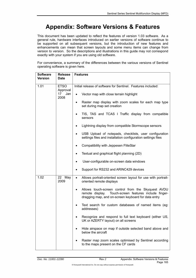
Sentinel Series Sentinel Multifunction Display (MFD)
Doc. No. 11001-12280 Rev 2 Appendix: Software Versions & Features Page 165
©Honeywell International Inc. Do not copy without express permission of Honeywell.
Appendix: Software Versions & Features
This document has been updated to reflect the features of version 1.03 software. As a general rule, hardware interfaces introduced on earlier versions of software continue to be supported on all subsequent versions, but the introduction of new features and enhancements can mean that screen layouts and some menu items can change from version to version. So the descriptions and illustrations in this guide may not correspond exactly with your system if you are using old software.
For convenience, a summary of the differences between the various versions of Sentinel operating software is given here.
Software Version
Release Date
Features
1.01 ETSO Approval 17 Jan 2008
Initial release of software for Sentinel. Features included:
Vector map with close terrain highlight
Raster map display with zoom scales for each map type set during map set creation
TIS, TAS and TCAS I Traffic display from compatible sensors
Lightning display from compatible Stormscope sensors
USB Upload of notepads, checklists, user configuration settings files and installation configuration settings files
Compatibility with Jeppesen FliteStar
Textual and graphical flight planning (2D)
User-configurable on-screen data windows
Support for RS232 and ARINC429 devices
1.02 22 May 2009
Allows portrait-oriented screen layout for use with portrait-oriented remote displays
Allows touch-screen control from the Skyquest AVDU remote display. Touch-screen features include finger-dragging map, and on-screen keyboard for data entry
Text search for custom databases of named items (eg: addresses)
Recognize and respond to full text keyboard (either US, UK or AZERTY layout) on all screens
Hide airspace on map if outside selected band above and below the aircraft
Raster map zoom scales optimised by Sentinel according to the maps present on the CF cards
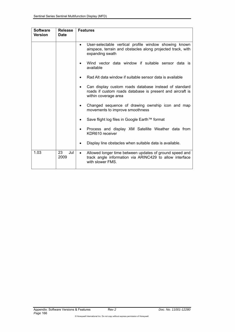
Sentinel Series Sentinel Multifunction Display (MFD)
Appendix: Software Versions & Features Rev 2 Doc. No. 11001-12280 Page 166
©Honeywell International Inc. Do not copy without express permission of Honeywell.
Software Version
Release Date
Features
User-selectable vertical profile window showing known airspace, terrain and obstacles along projected track, with expanding swath
Wind vector data window if suitable sensor data is available
Rad Alt data window if suitable sensor data is available
Can display custom roads database instead of standard roads if custom roads database is present and aircraft is within coverage area
Changed sequence of drawing ownship icon and map movements to improve smoothness
Save flight log files in Google Earth™ format
Process and display XM Satellite Weather data from KDR610 receiver
Display line obstacles when suitable data is available.
1.03 23 Jul 2009
Allowed longer time between updates of ground speed and track angle information via ARINC429 to allow interface with slower FMS.
Sentinel Series Sentinel Multifunction Display (MFD)
Doc. No. 11001-12280 Rev 2 Acronyms and Abbreviations Page 167
©Honeywell International Inc. Do not copy without express permission of Honeywell.
Acronyms and Abbreviations
Acronyms and abbreviations used in this guide are defined as follows:
TERMS DEFINITION A AHRS attitude and heading reference system AIP Aeronautical Information Publication ALT Altitude AOG aircraft on ground AOP area of probability ARINC Aeronautical Radio, Inc. ATC air traffic control AUTO Automatic B BRG Bearing C CDI course deviation indicator COM Communication CPA closest point of approach CRC Customer Response Center CST TCAS label meaning to coast D DIS Distance DOP dilution of precision DTK desired track E EGPWS Enhanced Ground Proximity Warning System ELEV Elevation ESA en route safe altitude ETA estimated time of arrival ETE estimated time en route ETT-WPT estimated time to waypoint EXT External F FMS flight management system FPLAN Flightplan ft Feet G GND Ground GNDSPD Groundspeed GPS global positioning system GPS-ALT GPS determined altitude GS ground speed H HSI Horizontal situation indicator I ICAO International Civil Aviation Organization ID Identification IFR instrument flight rules IHAS Honeywell Integrated Hazard Avoidance System INT Internal K KMH kilometers per hour L LAT Latitude LCD liquid crystal display LON Longitude LONG Longitude LTNG Lightning M M Meters
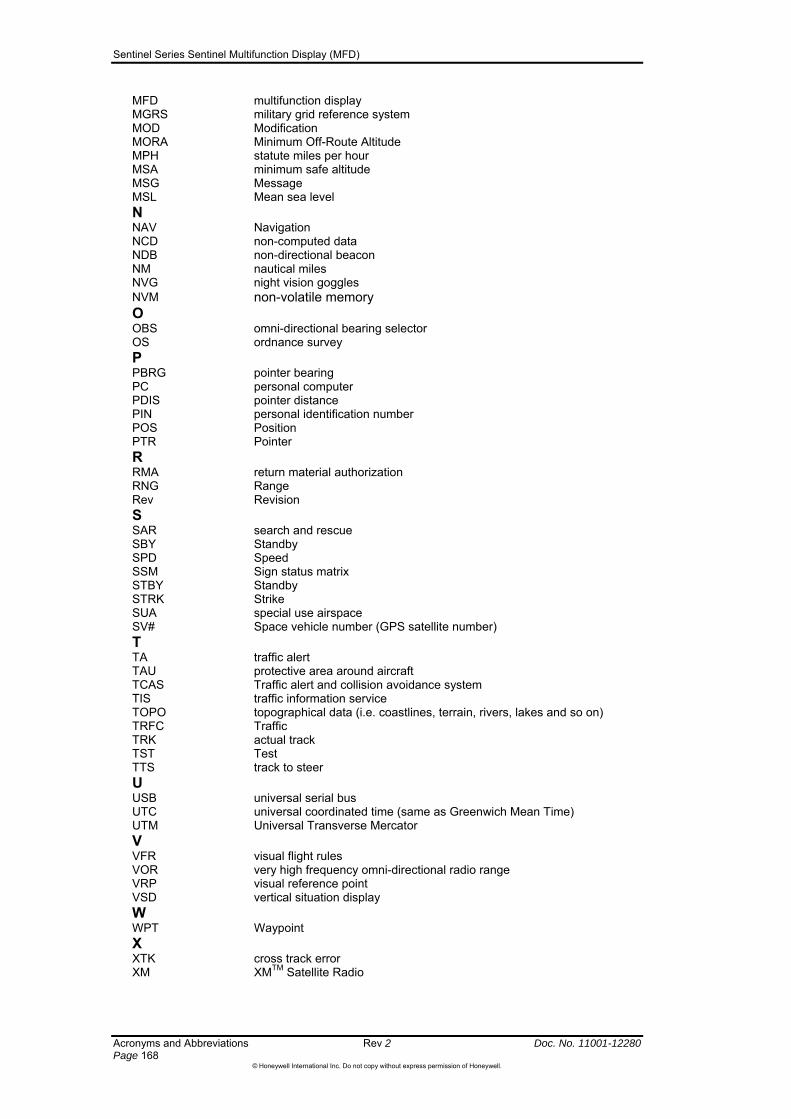
Sentinel Series Sentinel Multifunction Display (MFD)
Acronyms and Abbreviations Rev 2 Doc. No. 11001-12280 Page 168
©Honeywell International Inc. Do not copy without express permission of Honeywell.
MFD multifunction display MGRS military grid reference system MOD Modification MORA Minimum Off-Route Altitude MPH statute miles per hour MSA minimum safe altitude MSG Message MSL Mean sea level N NAV Navigation NCD non-computed data NDB non-directional beacon NM nautical miles NVG night vision goggles NVM non-volatile memory O OBS omni-directional bearing selector OS ordnance survey P PBRG pointer bearing PC personal computer PDIS pointer distance PIN personal identification number POS Position PTR Pointer R RMA return material authorization RNG Range Rev Revision S SAR search and rescue SBY Standby SPD Speed SSM Sign status matrix STBY Standby STRK Strike SUA special use airspace SV# Space vehicle number (GPS satellite number) T TA traffic alert TAU protective area around aircraft TCAS Traffic alert and collision avoidance system TIS traffic information service TOPO topographical data (i.e. coastlines, terrain, rivers, lakes and so on) TRFC Traffic TRK actual track TST Test TTS track to steer U USB universal serial bus UTC universal coordinated time (same as Greenwich Mean Time) UTM Universal Transverse Mercator V VFR visual flight rules VOR very high frequency omni-directional radio range VRP visual reference point VSD vertical situation display W WPT Waypoint X XTK cross track error XM XMTM Satellite Radio

Sentinel Series Sentinel Multifunction Display (MFD)
Doc. No. 11001-12280 Rev 2 Index Page 169
©Honeywell International Inc. Do not copy without express permission of Honeywell.
Index Address search.......................................... 63 AIRMET ..................................................... 81 Airmets ...................................................... 78 airport filter................................................. 65 Airways .................................................... 102 Alerts ......................................................... 18 Altitude Source Status Page.................... 156 altitude tag ................................................. 90 altitude volume .......................................... 85 altitude volume indication .......................... 85 AMR................................................... 24, 161 AOP......................................................... 123
Cancel AOP ........................................ 125 Database Position............................... 124
AOP Init ..................................................... 55 ATI ..................................................... 24, 161 AutoNav................................................... 144 Auto-Nav.................................................... 48 Auxiliary CF Card....................................... 24 Avionics power .......................................... 37 Browse waypoints.................................... 101 Card
Replacing.............................................. 35 CAUTION
Altitude display.................................... 147 Auto-Nav............................................... 49 Changes to map settings .................... 143 Chart expiry schedule ........................... 33 close terrain display ........................ 58, 59 Delete profile....................................... 153 Enroute Safe Altitude .......................... 148 expired data .......................................... 32 EXT video ....................................... 15, 19 IFR primary navigation.......................... 99 inaccuracy............................................. 41 Load Profile......................................... 152 Map status icons ................................... 19 Minimum Safe Altitude ........................ 148 non-aeronautical maps ......................... 50 NVIS Colors .......................................... 16 Obstacle data........................................ 40 Position error......................................... 45 Private airfields & helipads data............ 39 Rad Alt ................................................ 149 Raster mapping inaccuracy .................. 41 Stormscope accuracy ........................... 74 stormscope failure................................. 68 TIS sensor errors .................................. 97 Traffic system faults .............................. 90 Uploading data.................................... 133 Vertical situation display ....................... 60
CDI .......................................................... 147 CDI SCALE.............................................. 144 Centre map................................................ 55 CHANGE MAP......................................... 141 Checklist
creating ............................................... 129 Upload from USB................................ 129
checklists ................................................. 129 Circle of Uncertainty .................................. 45 Close terrain .............................................. 57 controls ...................................................... 17 Convective sigmets.................................... 80 Current Flight Level................................. 85
Current Mode.............................................18 customer care ............................................12 Customer Care Center.............................12 Data Card Access Door .............................17 DATA FIELD AREA: ..................................22 Data Fields.................................................18 Flight Plan................................................114 Demo Mode ....................................... 31, 155 Direct To
Using pointer.........................................55 Display Area ..............................................18 Display type ...............................................18 Flight Plan................................................113 EXT/INT Select Knob.................................17 Flight log ....................................................66
FliteStar.................................................66 Google Earth.........................................66
Flight log information .................................66 Flight log trail .............................................66 Flight plan
External...............................................144 Load from USB ...................................152 Save to USB .......................................154
Flight Plan Activate a Flight Plan ..........................111 Insert Airway .......................................102 Internal ................................................144 Remove Direct To from active flight plan
.......................................................120 FliteStar ...................................................108 Function Status Icons .............................21 Google Earth...................................... 66, 163 GPS Antenna.............................................24 Grab Line.................................................107 Ground Station.........................................23 Hand Remote Controller ............................25 helipads .....................................................39 Icons
AOP ....................................................125 IDENT......................................................101 IFR.............................................................99 Flight Plan................................................114 INSTALL MENU.......................................137 INSTALL MODE ......................................159 intruder symbol ..........................................86 Jeppesen
Flight logs for FliteStar ..........................66 FliteStar...............................................163
Jeppesen database ...................................32 Jeppesen® database.................................39 Joystick ................................................17, 19 key backlighting .........................................19 Keyboard
on-screen ..............................................26 Keyboard options:......................................24 Knob Data................................................101 Knob Scan ...............................................101 Log interval ................................................66 MAGNETIC VARIATION..........................145 MAIN MENU ........................................43, 75 Map modes
Close terrain..........................................57 Relative terrain......................................58 Topo Off ................................................57
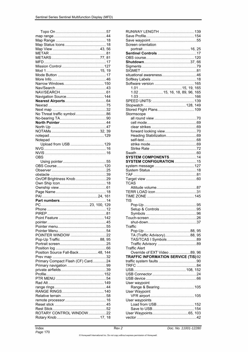
Sentinel Series Sentinel Multifunction Display (MFD)
Index Rev 2 Doc. No. 11001-12280 Page 170
©Honeywell International Inc. Do not copy without express permission of Honeywell.
Topo On ................................................57 map range..................................................44 Map Range ................................................18 Map Status Icons .......................................18 Map View .............................................43, 56 METAR ......................................................81 METARS..............................................77, 81 MFD...........................................................17 Mission Control ........................................127 Mod 1...................................................15, 19 Mode Button ..............................................17 More Info....................................................46 Narrow Windows......................................150 Nav/Search ................................................43 NAV/SEARCH............................................61 Navigation Source....................................144 Nearest Airports.......................................64 Nexrad .......................................................75 Next map ...................................................32 No Threat traffic symbol.............................86 No-bearing TA............................................90 North Pointer ............................................44 North Up ....................................................47 NOTAMs ..............................................32, 39 notepad....................................................129 Notepad
Upload from USB ................................129 NVG ...........................................................16 NVIS ..........................................................16 OBS
Using pointer .........................................55 OBS Course.............................................120 Observer ....................................................25 obstacle .....................................................39 On/Off Brightness Knob .............................29 Own Ship Icon............................................18 Ownship view.............................................61 Page Name................................................18 PAI .....................................................24, 161 Part numbers............................................14 PC..............................................23, 100, 129 Phone ........................................................12 PIREP ........................................................81 Point Feature ...........................................142 pointer........................................................45 Pointer menu..............................................55 Pointer Menu..............................................54 POINTER WINDOW ..................................22 Pop-Up Traffic......................................88, 95 Portrait screen............................................25 Position log ................................................66 Position Source Fall-Back..................48, 144 Prev map ...................................................32 Primary Compact Flash (CF) Card.............24 Primary navigation .....................................99 private airfields...........................................39 Profile.......................................................152 PTR MENU ................................................54 Rad Alt .....................................................149 range rings.................................................44 RANGE RINGS........................................140 Relative terrain...........................................58 remote processor .......................................16 Reset stick .................................................45 Rest Stick...................................................52 ROTARY CONTROL WINDOW.................22 Rotary Knob.........................................17, 18
RUNWAY LENGTH .................................139 Save Profile..............................................154 Save waypoint............................................55 Screen orientation
portrait .............................................16, 25 Sentinel Controls .....................................17 OBS course..............................................120 Shutdown............................................37, 66 Sigments ....................................................79 SIGMET .....................................................81 situational awareness.................................46 Softkey Labels ...........................................18 Software version ......................................165
1.01 .........................................15, 19, 165 1.02 .......................15, 16, 18, 89, 96, 165 1.03 .....................................................166
SPEED UNITS: ........................................139 Stopwatch ........................................128, 149 Stored Flight Plans...................................109 Stormscope
all round view ........................................70 cell mode...............................................69 clear strikes ...........................................69 forward looking view..............................70 Heading Stabilization.............................69 self-test..................................................68 strike mode............................................69 Strike Rate ............................................72
Swath .........................................................60 SYSTEM COMPONENTS..........................14 SYSTEM CONFIGURATION .....................15 system message ......................................127 System Status............................................18 TAF ............................................................81 Target view ................................................60 TCAS
Altitude volume......................................87 TERR LOAD icon.......................................31 TIME ZONE .............................................145 TIS
Pop-Up ..................................................95 Setup & Controls ...................................95 Symbols ................................................96
Touch-screen .............................................26 shut-down..............................................37
Traffic Pop-Up ............................................88, 95 TA (Traffic Advisory)........................88, 95 TAS/TCAS I Symbols ............................89 Traffic Advisory .....................................89
Traffic Alert Override of EXT Video ....................89, 96
TRAFFIC INFORMATION SERVICE (TIS)92 traffic system faults ....................................90 TRFC .........................................................84 USB..................................................108, 152 USB Connector ..........................................24 USB device ................................................66 User waypoint
Range & Bearing.................................105 User Waypoint
VFR airport ..........................................105 User waypoints
Load from USB....................................152 Save to USB........................................154
User Waypoints..................................65, 103 vector .........................................................42

Sentinel Series Sentinel Multifunction Display (MFD)
Doc. No. 11001-12280 Rev 2 Index Page 171
©Honeywell International Inc. Do not copy without express permission of Honeywell.
Vertical profile display................................ 59 airspace ................................................ 60 obstacles............................................... 60 range..................................................... 60 swath .................................................... 60
Vertical Trend Arrow.................................. 90 VORs
Nearest ................................................. 65 Wide Windows......................................... 150 Wind vector display.................................. 149 WX-500...................................................... 67 WX-500 Stormscope.................................. 67 XM
AIRMET ................................................ 81 Graphical Airmets ................................. 78 Graphical convective sigmets ............... 80
Graphical METARS.........................77, 81 Graphical sigmets .................................79 METAR .................................................81 Nexrad ..................................................75 PIREP ...................................................81 Selection of product ..............................76 SIGMET ................................................81 TAF .......................................................81 Textual products .............................76, 81
XM Weather...............................................75 Zoom
In / Out ..................................................43 Touch-screen icons...............................43
zoom in ......................................................44 zoom out ....................................................44
Related Documents