Selection Guide . . . . . . . . . . . . . . . . . . . . . 2 Full Colour Recognition • SA1J, SA1J-F . . . . . . . . . . . . . . . . . . . . 4 Analogue Laser Colour Mark • SA1M. . . . . . . . . . . . . . . . . . . . . . . . . . 10 Water Detection • SA1W . . . . . . . . . . . . . . . . . . . . . . . . . 15 Self-Contained Laser • MX1C . . . . . . . . . . . . . . . . . . . . . . . . . 23 Ultrasonic Analogue • SA6A . . . . . . . . . . . . . . . . . . . . . . . . . . 27 Analogue Distance • SA1D . . . . . . . . . . . . . . . . . . . . . . . . . . 30 Photoelectric • SA1E . . . . . . . . . . . . . . . . . . . . . . . . . . 32 Fiber Optic Photoelectric • SA1C-FK . . . . . . . . . . . . . . . . . . . . . . . 37 • SA1C-F . . . . . . . . . . . . . . . . . . . . . . . . 43 Heavy Duty Photoelectric • ISF . . . . . . . . . . . . . . . . . . . . . . . . . . . . 50 Magnetic Proximity • DPRI . . . . . . . . . . . . . . . . . . . . . . . . . . 53 General Information . . . . . . . . . . . . . . . 55 Part Number Index . . . . . . . . . . . . . . . . 57 Sensors

Welcome message from author
This document is posted to help you gain knowledge. Please leave a comment to let me know what you think about it! Share it to your friends and learn new things together.
Transcript

Selection Guide . . . . . . . . . . . . . . . . . . . . .2Full Colour Recognition
• SA1J, SA1J-F . . . . . . . . . . . . . . . . . . . .4
Analogue Laser Colour Mark
• SA1M. . . . . . . . . . . . . . . . . . . . . . . . . .10
Water Detection
• SA1W . . . . . . . . . . . . . . . . . . . . . . . . .15
Self-Contained Laser
• MX1C . . . . . . . . . . . . . . . . . . . . . . . . .23
Ultrasonic Analogue
• SA6A . . . . . . . . . . . . . . . . . . . . . . . . . .27
Analogue Distance
• SA1D . . . . . . . . . . . . . . . . . . . . . . . . . .30
Photoelectric
• SA1E . . . . . . . . . . . . . . . . . . . . . . . . . .32
Fiber Optic Photoelectric
• SA1C-FK. . . . . . . . . . . . . . . . . . . . . . .37• SA1C-F . . . . . . . . . . . . . . . . . . . . . . . .43
Heavy Duty Photoelectric
• ISF . . . . . . . . . . . . . . . . . . . . . . . . . . . .50
Magnetic Proximity
• DPRI . . . . . . . . . . . . . . . . . . . . . . . . . .53
General Information . . . . . . . . . . . . . . .55Part Number Index . . . . . . . . . . . . . . . .57
Sensors
o r 2004!

Selection Guide
Sensors
2
www.idec.com
Sensor Type Series Page Appearance Advantages Considerations
Full Colour Recognition Sensors
SA1JSA1J-F
4
• Use to detect registration marks (regard-less of similarity of colour) at high-speed (0.3ms).
• Use to distinguish between different shades of the same colour.
• 3 LEDs (red, green, and blue) provide a long life — no need to replace lamps.
• Use in wash-down environments.• Use when long distance range, high-
speed, and small sensing spots are required for colour sensing applications.
• Use the 3-colour sensor for multiple outputs for sorting applications.
• Use the small spot version to detect small objects.
• Replace conventional contrasting sen-sors with the SA1J for reliable colour sensing.
• Use the auto-select mode to sort objects, to differentiate fine shades of the same colour, or to detect objects moving to and from the sensor.
Analogue Laser Colour Mark Sensors
SA1M
10
• Uses visible red laser for colour detec-tion.
• Compensates for fluctuations of objects.• Long range: 2.75" to 5.9".• Available in small spot or parallel beam.• Dual analogue and digital output.
IMPORTANT:
Always consider safety when using laser sensors. Make sure laser beam cannot inadvertently shine into the eyes of people passing by or working in the vicinity. See safety infor-mation on page Q-25.
Water Detection Sensors
SA1W
15
• Fastest (response time 0.5ms), most reli-able light detection photoelectric sensor.
• Use to detect any liquid containing water in any translucent, coloured con-tainer—even clear or dark containers at high-speed.
• Eliminate many of the problems associ-ated with other photoelectric sensors, capacitive sensors, ultrasonic sensors, vision systems, or moisture sensors.
• Use diffuse reflective fiber optic cables to detect a drop of water, glue, wet tis-sue, toothpaste, ice cream, chemicals, or any type of liquid containing water molecules.
• Use through-beam fiber optic cables to sense precise liquid levels through clear or translucent, coloured containers.
• For increased precise liquid level detec-tion, use the lens attachment with a through-beam fiber optic cable.
• When long sensing ranges (up to 31") are required, use the lens attachment.
Self-Contained Laser Sensors
MX1C
23
• Use in the most precise sensor applica-tions, because of the minute size of the laser beam.
• Use the MX1C to achieve precise posi-tioning or alignment, because the visible beam is easy to aim.
• All laser sensors provide analogue and digital output.
IMPORTANT:
Always consider safety when using laser sensors. Make sure laser beam cannot inadvertently shine into the eyes of people passing by or working in the vicinity. See safety infor-mation on page Q-25.
Ultrasonic Analogue Sensors
SA6A
27
• Ultrasonic sensing (using sound waves) is perfect for sensing applications which cannot be accomplished through the use of light, such as when detecting trans-parent items, films, and liquid levels.
• Ultrasonic sensing is normally disrupted by wave interference, but the SA6A fea-tures adjustments for optimal perfor-mance, despite the effects of surface turbulence (liquid level sensing), heat waves (blowing hot air), or inductive noise interference.
• Adjustments for tolerating wave interfer-ence are not selected simultaneously. One mode is selected when encounter-ing surface turbulence (liquid level sensing) and another mode is used when sensing under the influence of blowing hot air.
Selection Guide

Sensors
Selection Guide
www.idec.com
3
Analogue DistanceSensors
SA1D
30
• The most reliable distance sensing, cal-culated using the optical triangle between two points and the sensor.
• Analogue output and digital output pro-vided.
• Maximum analogue output value corre-sponds to minimum sensing distance and minimum analogue value corre-sponds to maximum distance.
Photoelectric SA1E
32
• Through-beam. Long sensing range of 10m max.
• Diffuse-reflective can detect light-reflecting transparent objects as well as white matt paper at a distance of 700mm.
• Polarized retroreflective mirror-like objects can also be detected easily.
• Small-beam reflective. Ideal for detect-ing small objects with easy recognition of a red LED beam.
• Long sensing ranges.• High-speed response of 1msec max.• Interference prevention allows close
mounting of two switches (except for the through-beam type).
Fiber Optic Photoelectric Sensors
SA1C-FK
37
• Optimum performance under adverse conditions including high temperatures, inductive noise, and corrosive exposure.
• Maintain integrity of sensing signal over long distances.
• Perfect for areas with minimal clear-ance. Fiber optic leads capable of great flexibility for tight installations.
• It is necessary to consider reduced maintenance expenses when evaluating cost effectiveness.
• Fiber optics do not withstand impact well (may shatter).
SA1C-F
43
Heavy Duty Photoelectric Sensors
ISF
50
• Universal voltage type (24 to 240V AC/DC).• Built-in 0.1 to 5 second time delay.• Selectable Light ON or Dark ON.• Touch-down terminals.
• Available in various modes:Through-beamDiffuse-reflectedRetro-reflectedPolarized retro-reflected
Magnetic Proximity Switches
DPRI
53
• Lightweight, compact design reduces mounting space requirements.
• Sealed reed contact.• Long life and high reliability.
• Operating distance range: 0 to 4mm
Sensor Type Series Page Appearance Advantages Considerations
Selection Guide con’t

SA1J : Full Colour Recognition
Sensors
4
www.idec.com
Introducing a cost-effective solution for full colour sensing applications—IDEC’s SA1J full colour recognition sensor. Outstanding benefits of the SA1J include an extremely high response speed (0.3ms), high resolution, and a very low cost.Key features of the SA1J colour sensor include:
• Choice of a 3-colour version or a 1-colour version• Fast response (0.3ms) — perfect for sensing complex colour marks
at high speed• Three LEDs (Red, Green, and Blue) provide a long sensing life• Easy alignment and targeting using a visible spot• Set sensor with the touch of a button• Highly sensitive to variations in colour; can distinguish between
subtle shades of the same colour• Up to 60mm sensing distance• IP67 rated
1-Colour Version 3-Colour Version
Gen
eral
Spe
cific
atio
ns
Power Voltage
12 to 24V DC (ripple 10% maximum)Operating voltage: 10 to 30V DC
Current Draw
150mA maximum
Dielectric Strength
Between live and dead parts: 1,000V AC, 1 minute
Insulation Resistance
Between live and dead parts: 20M
Ω
minimum (500V DC megger)
Operating Temperature
–10 to +50˚C (performance will be adversely affected if the sensor becomes coated with ice)
Operating Humidity
35 to 85% RH (avoid condensation)
Storage Temperature
–30 to +70˚C
Vibration Resistance
Damage limits: 10 to 55HzSingle amplitude: 0.75mm2 hours in each of 3 axes
Shock Resistance
Damage limits: 500m/s
2
(approximately 50G)5 shocks in each of 3 axes
Extraneous Light Immunity
Sunlight: 10,000 lux maximumHalogen lamp: 3,000 lux maximum
Material
Housing: AluminiumLens: GlassCover: Polyarylate
Degree of Protection
IP67 — IEC Pub 529
Cable
Cable type: ø5.4mm 5-core oiltight vinyl cabtyre cable (0.2mm
2
) 2m long Cable type: ø5.4mm 7-core oiltight vinyl cabtyre cable (0.2mm
2
) 2m long
Weight
Approximately 250g
Dimensions (HxWxD)
1.97" x 1.18" x 3.15" (50 x 30 x 80mm)
Accessories
Adjusting screwdriver
SA1J: Full Colour Recognition Sensors

Sensors
SA1J : Full Colour Recognition
www.idec.com
5
Part Numbers: SA1J Sensors
1-Colour Version 3-Colour Version Output Spot Diameter Sensing Distance Inspection Spot
SA1J-C1N1 SA1J-C1N3 NPN ø 0.157" (ø 4mm)ø 0.236" (ø 6mm)ø 0.315" (ø 8mm)
1.575" (40mm)1.969" (50mm)2.362" (60mm)
StandardSA1J-C1P1 SA1J-C1P3 PNP
SA1J-C2N1 SA1J-C2N3 NPN ø 0.098" (ø 2.5mm)ø 0.118" (ø 3mm)ø 0.177" (ø 4.5mm)
0.591" (15mm)0.787" (20mm)0.984" (25mm)
SmallSA1J-C2P1 SA1J-C2P3 PNP
1-Colour Version 3-Colour Version
Fu
ncti
on
Sp
ecifi
cati
on
s
Reference Colour Registration
Push SET button (sensor aimed at colour target); sensor records reference colour in EEPROM memory
Set dial to A:
Push SET button (sensor aimed at colour target A); sensor records reference colour A in EEPROM memory
Set dial to B:
Push SET button (sensor aimed at colour target B); sensor records reference colour B in EEPROM memory
Set dial to C:
Push SET button (sensor aimed at colour target C); sensor records reference colour C in EEPROM memory
Tolerance
Digital setting for 5 degrees of inspection sensitivity
Digital setting for 5 degrees of inspection sensitivity (normal run mode only)
Inspection Mode
Selectable: Colour component only (C) or colour component plus intensity (C+I) (depth of colour)
Operation Mode
—
Selectable
:
S run:
Auto select, sensor determines tolerance (no need to set tolerance)
Normal run mode:
Manually select tolerance (1–5) for each reference colour
Synchronous Mode
Selectable: Internal response mode or synchronized with an external signal
Response Mode
High-speed (F): 0.3msNormal speed (N): 1msSlow speed (S): 5ms
High-speed (F): 0.8msNormal speed (N): 1.5msSlow speed (S): 6ms
Control Output
On
:
Detected colour matches target colour
NPN or PNP transistor open collector30V DC, 100mA maximum
Residual: 1.5V maximum, short circuit protection
Control output A on:
Detected colour corresponds to target colour A*
Control output B on:
Detected colour corresponds to target colour B*
Control output C on:
Detected colour corresponds to target colour C*NPN or PNP transistor open collector30V DC, 100mA maximumResidual: 1.5V maximum, short circuit protection
Operation LED
On: When control output is on (yellow LED)
Off-Delay Timer
Selectable: Timer ON (T-ON) or Timer OFF (T-OFF)
Timer
OFF delay timer 40ms
SET Input
NPN
:30V DC maximum/3.6mA(when connected to 0V)Typical operating voltage:(0V) +4V maximum
PNP
:30V DC maximum/3mA(when connected to 24V)Typical operating voltage:(+V) –4V maximum
NPN
:30V DC maximum/3.6mA(when connected to 0V)Typical operating voltage:(0V) +4V maximum
PNP
:30V DC maximum/3mA(when connected to 24V)Typical operating voltage:(+V) –4V maximum
External Synchronous Input
Light Source
3 LEDs (Red, Green, Blue)
1. Each channel has its own independent short circuit protection.2. * The target colour is defined by the operation mode setting.

SA1J : Full Colour Recognition
Sensors
6
www.idec.com
This new line of full colour sensors offers IDEC’s proven colour sensing technology in a fiber optic version. The SA1J-F is ideal for colour sorting and quality control applications where space is limited. The SA1J-F utilizes a wide assortment of fiber optic heads to fit in the smallest of mounting areas. This product line offers both 1 and 3-colour program-mable sensors for multiple colour sorting applications. With the touch of a button, the SA1J-F is programmed and ready to work. The SA1J-F also has a remote lead for pro-gramming by a remote PLC or switch.Key features of the SA1J-F colour sensor include:
• Choice of a 3-colour version or a 1-colour version• Wide assortment of fiber optic heads fit in tight mounting areas• Three LEDs (Red, Green, and Blue) provide a long sensing life• High speed response time (0.3 msec)• Simple one touch button and remote colour teach functions• IP67 rating for use in harsh wet environments
1-Colour Version 3-Colour Version
Gen
eral
Spe
cific
atio
ns
Power Voltage
12 to 24V DC (ripple 10% maximum)Operating voltage: 10 to 30V DC
Current Draw
150mA maximum
Dielectric Strength
Between live and dead parts: 1,000V AC, 1 minute
Insulation Resistance
Between live and dead parts: 20M
Ω
minimum (500V DC megger)
Operating Temperature
–10 to +50˚C (no freezing)
Operating Humidity
35 to 85% RH (avoid condensation)
Storage Temperature
–30 to +70˚C
Vibration Resistance
Damage limits: 10 to 55HzSingle amplitude: 0.75mm2 hours in each of 3 axes
Shock Resistance
Damage limits: 500m/s
2
(approximately 50G)5 shocks in each of 3 axes
Extraneous Light Immunity
Sunlight: 10,000 lux maximumIncandescent lamp: 3,000 lux maximum
Material
Housing: AluminiumLens: GlassCover: Polyarylate
Degree of Protection
IP65 (when inserting the fiber unit and tightening the cover)
Cable
0.2mm
2
ø5.4mm 5-core vinyl cabtyre cable, 2m long
0.2mm
2
ø5.4mm 7-core vinyl cabtyre cable, 2m long
Weight
Approximately 190g
Dimensions (HxWxD)
47H x 25W x 82.4D mm
Accessories
Mounting bracketAdjusting screwdriver
SA1J-F: Full Colour Fiber Optic Sensors

Sensors
SA1J : Full Colour Recognition
www.idec.com
7
Subassembled Part Numbers: SA1J-F Sensors
Amplifiers
Lens Attachments
Part No. Type Output Type
SA1J-F1N1 1-colour NPN open collector30V DC, 100mASA1J-F1N3 3-colour
SA1J-F1P1 1-colour PNP open collector30V DC, 100mASA1J-F1P3 3-colour
Part No. Description Used With Sensing Range
SA9Z-F11 For long range detection of opaque objects
SA9F-TS21 300 mm
SA9F-TC21 200 mm
SA9F-TM21 150 mm
SA9Z-F12 Sideview attachment
SA9F-TS21 25 mm
SA9F-TC21 20 mm
SA9F-TM21 20 mm
SA1J-F1N1 SA1J-F1N3 SA1J-F1P1 SA1J-F1P3
Fu
ncti
on
Sp
ecifi
cati
on
s
Reference Colour Set
Teaching system, 1-colour Teaching system, 3-colours Teaching system, 1-colour Teaching system, 3-colours
Inspection Tolerance
5-step digital setting
Inspection Mode
Colour (C) / Colour + Intensity (C+1)
Operation Mode
Normal Run Mode (1 to 5) Normal Run Mode (1 to 5) /Select Run Mode Normal Run Mode (1 to 5) Normal Run Mode (1 to 5) /
Select Run Mode
Synchronous Mode
Internal Synchronous Mode (INT) / External Synchronous Mode (EXT)
Response Mode
Fast (F) / Normal (N) / Slow (S)
OFF-delay Timer
Timer On (T-ON) / Timer Off (T-OFF)
Control Output
NPN open collector 30V DC, 100mA maximumVoltage Drop 1.5V maximumProtected against short circuit
PNP open collector 30V DC, 100mA maximumVoltage Drop 1.5V maximumProtected against short circuit
SET input
30V DC maximum / 3.6mA (when connected to 0V)Typical Operating Voltage: (0V) + 4V maximum
30V DC maximum / 3.0mA (when connected to 24V)Typical Operating Voltage: (+V) - 4V maximum
External Synchronous Input
Operation Indicator
Yellow LED Yellow LED(3-colour individual display) Yellow LED Yellow LED
(3-colour individual display)
Timer
OFF-delay timer 40 msec
Output Operation
Equivalent Output
Response TimeFAST (0.3 msec),NORMAL (1 msec),SLOW (5 msec) selectable
FAST (0.8 msec)NORMAL (1.5 msec)SLOW (6 msec) selectable
FAST (0.3 msec),NORMAL (1 msec),SLOW (5 msec) selectable
FAST (0.8 msec)NORMAL (1.5 msec)SLOW (6 msec) selectable
Light Source Three LEDs (red, green, blue)
Diffuse-Reflected Light Fiber Optic Unit
Part No. Inspection Spot Sensing Range
SA9F-DA11 ø 2.5 mm 10 mm
SA9F-DA12 ø 5 mm 20 mm
SA9F-DA13 ø 8 mm 30 mm
Accessories
Part No. Description
SA9Z-F01 Fiber Cutter

SA1J : Full Colour Recognition Sensors
8 www.idec.com
Fiber Optic Units
The following fiber optic units for the SA1C-F photoelectric switches can also be used with the SA1J-F:
Through Beam Fiber Optic Units
Diffuse-Reflected Light Fiber Optic Unit
SA9F-DA11 SA9F-DA12 SA9F-DA13
Sp
ecifi
cati
on
s
Type Spot-detection Standard Long-Range
Sensing Diffuse reflex
Amplifier Unit SA1J-F1N1, -F1N3, -F1P1, -F1P3
Sensing Range 10 mm 20 mm 30 mm
Sport Diameter ø 2.5 mm ø 5 mm ø 8 mm
MaterialSensing Head Body: PA66, Front Core: PC
Fiber Optic Surface: PE, Core: PMMA
Fiber Optic Length 2 m
Degree of Protection IP65
Operating Temperature -10° C to +55° C (no freezing)
Operating Humidity 35 to 85% RH (no condensation)
Allowable Bending Radius R40mm minimum
Part No. Type Sensing Range
SA9F-TS21 M4 • Straight No Sleeve 30 mm
SA9F-TS22 M4 • Straight 90 mm Sleeve 30 mm
SA9F-TS23 M4 • Straight 45 mm Sleeve 30 mm
SA9F-TC21 M6 • Coiled No Sleeve 25 mm
SA9F-TC22 M6 • Coiled 90 mm Sleeve 25 mm
SA9F-TC23 M6 • Coiled 45 mm Sleeve 25 mm
SA9F-TM21 M4 • Multicore 25 mm
SA9F-TM22 M4 • Multicore 90 mm Sleeve 25 mm
SA9F-TM23 M4 • Multicore 45 mm Sleeve 25 mm
SA9FTM74 Multicore 16 fibers in 1 row 25 mm
Part No. Type Sensing Range
SA9F-DS31 M6 • Straight No Sleeve 6 mm
SA9F-DS32 M6 • Straight 90 mm Sleeve 6 mm
SA9F-DS33 M6 • Straight 45 mm Sleeve 6 mm
SA9F-DD31 M6 • Coaxial 5 mm
SA9F-DM74 1 row = 32 fibers Multicore 2 mm
SA9F-DM75 2 rows = 16 each Multicore 5 mm

Sensors SA1J : Full Colour Recognition
www.idec.com 9
Sorting objects by cap or lid colour
Detecting objects that are the incorrect shape or colour
Checking packaging labels for correct position, colour, and content
R
G
Y
R
G GY G G
Upside Down
Normal
Broken Abnormal
Normal Normal
SA
1J
SA1J
Product A
Label is marked incorrectly
Warning WarningWarning Warning Warning Warning Wa
Label coloris incorrect
Label positionis incorrect
Label is marked incorrectly
Label colouris incorrect
Label positionis incorrect
Detecting plastic bagging materials on a web
Detecting presence or absence of a logo on a cap or lid
1-touch programming
High-speed response rate
Detects marks—regardless
Choose between a small spot (2.5mm) or a standard spot (8mm)
with a long distance range
of similarity of colour
Cap Liner
SA
1J
SA
1J
IDEC IDEC
Applications
Dimensions
2.59" (65.7mm)
0.69
"
2-ø 0.21" (5.4mm)
3.15" (80mm)
2.68" (68mm)2-M5 (Depth:10)
D1
1.65
" (4
2mm
)
1.97
" (5
0mm
)
(22mm)0.87"
ø 0
.21"
(5.
4mm
)
0.28" (7mm)
D1 = SA1J-C1 model = ø 0.99" (25.2mm) [SA1J-C2 model = ø 1.06" (27mm)]
D2 = SA1J-C1 model = ø 0.26" (7mm) [SA1J-C2 model = ø 0.50" (12.8mm)]
(17.
6mm
)
D2
1.1
8" (
30m
m)

SA1M: Analogue Laser Colour Mark Sensors Sensors
10 www.idec.com
Using a visible red laser (670nm), the SA1M Laser Mark sensor is excellent for detect-ing label alignment and different kinds of objects. The small spot version can easily detect tiny objects. The parallel beam version keeps the detection spot size unchanged , regardless of the distance between the sensor and the object. Both ver-sions ensure stable sensing without being influenced by changes in the sensing range and are ideal for use in varying environmental conditions.
Key features of the SA1M include:• Stable output over a wide sensing range: 2.755" to 5.906" (70 to 150mm)• Small visible beam enables detection of tiny objects (such as a spot) and thin materials• High tolerance of fluctuating surface levels — ignores movement
while sensing• Insensitive to vertical movement of material to and from the sensor, as in the case of
web flutter• Ideal for use in industrial environments• Dual analogue output (light intensity and distance) and digital output• IP65 protection rating
Gen
eral
Spe
cific
atio
ns
Power Voltage 24V DC (ripple 10% maximum)
Current Draw 200mA maximum
Light Source Element Laser diode (670nm)
Receiver Element PSD (position sensitive device)
Dielectric Strength Between live and dead parts: 500V AC, 1 minute
Insulation Resistance Between live and dead parts: 20MΩ minimum (500V DC megger)
Operating Temperature 0 to +45˚C (performance will be adversely affected if the sensor becomes coated with ice)
Storage Temperature –20 to +70˚C
Operating Humidity 35 to 85% RH (avoid condensation)
Vibration ResistanceDamage limits: 10 to 55HzSingle amplitude: 0.75mm2 hours in each of 3 axes (de-energized)
Shock Resistance Damage limits: 100 m/s2 (approximately 10G)5 times in each of 3 axes (when de-energized)
Extraneous Light Immunity Incandescent light, 3,000 lux maximum
Operating Atmosphere Free from corrosive gasses
MaterialHousing: Zinc diecastCoverplate: PolyarylateFilter: Glass
Degree of Protection IP65 IEC Pub 529
Cable Cable type: 6-core vinyl cabtyre cable 0.19mm2: 6' – 6-3/4' (2m) long
Weight Approximately 400g
Dimensions (HxWxD) 1.97" x 0.83" x 3.07" (50 x 21 x 78mm)
SA1M: Analogue Laser Colour Mark Sensors

Sensors SA1M: Analogue Laser Colour Mark Sensors
www.idec.com 11
Part Numbers: SA1M Sensors
Part Number Spot Type Sensing Range Digital Output Analogue Output for Light Intensity (colour mark)
Analogue Output for Sensing Distance
SA1M-CK4-AC Small spot
2.755" to 5.906" (70mm to 150mm)
NPN open collector4 to 20mA5V maximum
20 to 4mA5V maximum
SA1M-CK4-BC Parallel beam
SA1M-CL4-AC Small spotPNP open collector
SA1M-CL4-BC Parallel beam
Func
tion
Spec
ifica
tions
Sensing Range 2.755" to 5.906" (70 to 150mm)
Digital Output
Output style: NPN open collector: (SA1M-CK4-AC/BC)PNP open collector: (SA1M-CL4-AC/BC)with short circuit protection
Output type: Window comparator output (in-window ON)Response time: 1ms maximumHysteresis: 5% (0.8mA) maximum (over the entire sensing range)Applied voltage: 30V DC maximumLoad current: 100mA maximumVoltage drop: 1.0V maximum (SA1M-CK4-AC/BC)
1.5V maximum (SA1M-CL4-AC/BC)
Analogue Output for Light Intensity (colour mark detection)
Analogue current output: 4 to 20mA, 5V maximumReference output current (Note 1): 19.0+/-0.4mAOutput stability (Note 2):
±5% (±0.8mA) maximum(against reference output current over the entire sensing range)
Temperature drift (Note 3): ±5% (±0.8mA) maximum(against reference output current over the entire operating temperature)
Response time: 1ms maximum (10 to 90% response)Additional noise (Note 2):
0.4mA maximum p-p (Position: 70mm)
Auxiliary Output (Note 4)(analogue output for distance)
Analogue current output: 20 to 4mA, 5V maximumLinearity error (Note 2):
±1.5% FS (±1.2mm)(over the entire sensing range)
Resolution (Note 2): 0.008" (200µm); Position: 70mmTemperature drift (Note 3):
5µA/˚C maximum (against the entire operating temperature)
Response time 1ms maximum (10 to 90% response)
Sensitivity SelectionsSelection using the sensitivity selector:L: Low (low sensitivity, 35% of standard sensitivity)M: Middle (Standard sensitivity)H: High (high sensitivity, 3.5 times standard sensitivity)
Indicators
Analogue output for light intensity:Red LED (10-dot level metre, Mode selector: RUN)
Digital output setting monitor:Red LED (10-dot level metre, Mode selector: SET1, SET2)
Digital output:Red LED (turns on when output is on)
Laser diode emission:Green LED (turns on while laser is emitted), laser emits approximately 1 second after power-up
Accessories Adjusting screwdriver, resistor (249Ω), operating instructions, warning label, precaution label
Measuring conditions:1. Temperature: 25˚C, Object: White ceramic (0.6mm thickness), Sensitivity: Middle, Position: 110mm2. Temperature: 25˚C, Object: White ceramic (0.6mm thickness), Sensitivity: Middle3. Object: White ceramic (0.6mm thickness), Sensitivity: Middle, Position: 110mm4. Auxiliary output should be used only to monitor distance

SA1M: Analogue Laser Colour Mark Sensors Sensors
12 www.idec.com
Stable output response over a wide sensing range,detecting the presence of package markings
Counting the number of packages in a box
Compensating for fluctuating objects(parallel beam type) (±40mm)
Long sensing distance (150mm maximum)
Small beam spot (0.5 x 1mm) (small spot type)
Parallel beam type (beam size: 2 X 4mm)
Applications
When the distance between the sensor and object varies significantly in positioning and edge sensing, the spot size remains unchanged, thus ensuring stable sensing.
When the output should not be influenced by blurs, taints, fine patterns, or lines in the object surface, stable sens-ing is ensured by the rela-tively large spot size.

Sensors SA1M: Analogue Laser Colour Mark Sensors
www.idec.com 13
Connection Example (SA1M-CK4-AC/BC (NPN) Output)
Analogue Output for Distance vs. Distance Characteristics
Analogue Output for Distance
Schematics
2.755" (70mm) 5.906" (150mm)
1. When the auxiliary output (analogue output for dis-tance) is used, the sensing distance should range from 70 to 150mm. If the sensing distance exceeds this range, an unstable output occurs.
2. IDEC’s laser displacement sensor is ideal when highly accurate distance measurement is required. (Sensing range is 60 to 160mm.) Refer to the MX1C section on page M-23.
Connection Example (SA1M-CL4-AC/BC (PNP) Output)
2.756" 4.331" 5.906"
(150mm)(110mm)(70mm)
0.157"4mm
0.157"4mm
0.157"4mm
0.05
9"1.
5mm
0.03
9"1m
m
0.02
"0.
5mm
0.07
9"(2
mm
)
0.07
9"(2
mm
)
0.07
9"(2
mm
)
0.118"(3mm)
0.079"(2mm)
0.039"(1mm)
0.827"(21mm)
1.96
9" (
50m
m)
1.29
9" (
33m
m)
1.63
4" (
41.5
mm
)0.
177"
(4.5
mm
)
0.138"(3.5mm)
2.815" (71.5mm)
3.071" (78mm)
78.74"
(2000mm
)
0.21
3"
(ø 5
.4m
m)
Auxiliary Output Sensing Distance and Beam Distance
Linearity Error for Auxiliary Output
Dimensions

SA1M: Analogue Laser Colour Mark Sensors Sensors
14 www.idec.com
Labelling: IDEC laser sensors include CDRH-approved safety warnings shown on theright and below, in compliance with federal regulations of the Center for Devices andRadiological Health.
Installation: If a sensor is installed so that the laser beam may shine or reflect into the eyes of aperson passing by or working in the vicinity, place an opaque sheet of material in front of the beamto prevent potential eye injury. For people working near a laser sensor, protective glasses whichscreen out a significant amount of the harmful radiation are recommended at all times.
All SA1M laser sensors also include a remote interlock terminal which can be used to turn the laseron or off with an external switch, as required, to operate the sensor safely from a remote location. To avoid exposure to harmful radiation, never disassemble a laser sensor.
WARNING: Do not allow class IIIa beams to shine directly into the eyes. Do not allow lasers toreflect from a glossy, shiny, or reflective surface into the eyes.
L a s e r S a f e t y I n f o r m a t i o n
SA1M Laser Mark Sensor:Class IIIa Laser (670Nm) Visible Beam
LASER LIGHT – AVOIDDIRECT EYE EXPOSURE
5mW at 670 nmCLASS IIIa LASER PRODUCT
DANGER
!
!
!
!
!
!
!
!
!
!
!
!
!
!
!
!AVOID EXPOSURE Laser light is emittedfrom this aperture.
All Laser Sensors:Identification and Certification
SA1M Visible Laser:Aperture Warning
Warning Label (common)
Precaution Labelmfd.: FEBRUARY 1997Product conforms to 21 CFR1040
Sensors SA1W: Water Detection Sensors
www.idec.com 15
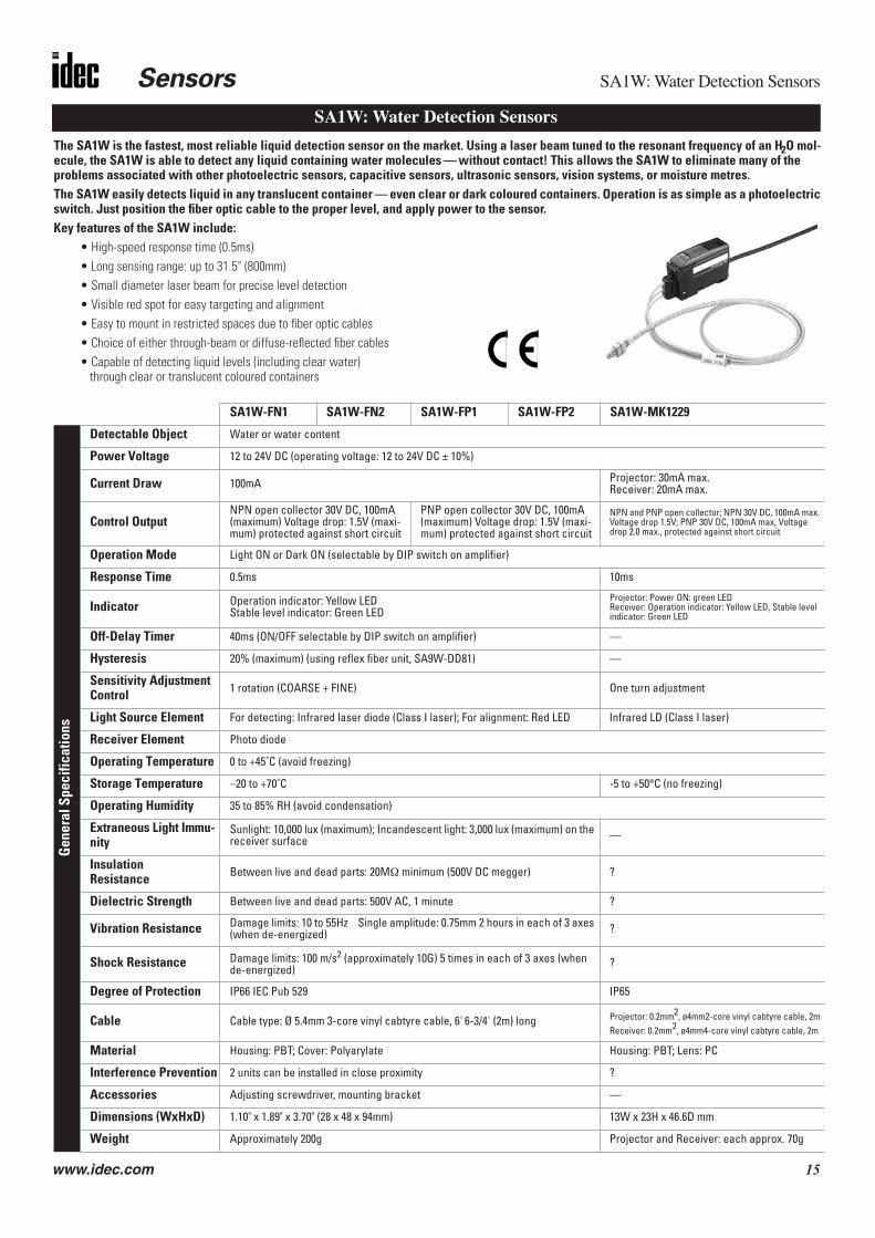
The SA1W is the fastest, most reliable liquid detection sensor on the market. Using a laser beam tuned to the resonant frequency of an H2O mol-ecule, the SA1W is able to detect any liquid containing water molecules — without contact! This allows the SA1W to eliminate many of the problems associated with other photoelectric sensors, capacitive sensors, ultrasonic sensors, vision systems, or moisture metres.The SA1W easily detects liquid in any translucent container — even clear or dark coloured containers. Operation is as simple as a photoelectric switch. Just position the fiber optic cable to the proper level, and apply power to the sensor.Key features of the SA1W include:
• High-speed response time (0.5ms)• Long sensing range: up to 31.5" (800mm)• Small diameter laser beam for precise level detection• Visible red spot for easy targeting and alignment• Easy to mount in restricted spaces due to fiber optic cables• Choice of either through-beam or diffuse-reflected fiber cables• Capable of detecting liquid levels (including clear water)
through clear or translucent coloured containers
SA1W-FN1 SA1W-FN2 SA1W-FP1 SA1W-FP2 SA1W-MK1229
Gen
eral
Spe
cific
atio
ns
Detectable Object Water or water content
Power Voltage 12 to 24V DC (operating voltage: 12 to 24V DC ± 10%)
Current Draw 100mA Projector: 30mA max.Receiver: 20mA max.
Control OutputNPN open collector 30V DC, 100mA (maximum) Voltage drop: 1.5V (maxi-mum) protected against short circuit
PNP open collector 30V DC, 100mA (maximum) Voltage drop: 1.5V (maxi-mum) protected against short circuit
NPN and PNP open collector; NPN 30V DC, 100mA max. Voltage drop 1.5V; PNP 30V DC, 100mA max, Voltage drop 2.0 max., protected against short circuit
Operation Mode Light ON or Dark ON (selectable by DIP switch on amplifier)
Response Time 0.5ms 10ms
Indicator Operation indicator: Yellow LEDStable level indicator: Green LED
Projector: Power ON: green LEDReceiver: Operation indicator: Yellow LED, Stable level indicator: Green LED
Off-Delay Timer 40ms (ON/OFF selectable by DIP switch on amplifier) —
Hysteresis 20% (maximum) (using reflex fiber unit, SA9W-DD81) —
Sensitivity Adjustment Control 1 rotation (COARSE + FINE) One turn adjustment
Light Source Element For detecting: Infrared laser diode (Class I laser); For alignment: Red LED Infrared LD (Class I laser)
Receiver Element Photo diode
Operating Temperature 0 to +45˚C (avoid freezing)
Storage Temperature –20 to +70˚C -5 to +50°C (no freezing)
Operating Humidity 35 to 85% RH (avoid condensation)
Extraneous Light Immu-nity
Sunlight: 10,000 lux (maximum); Incandescent light: 3,000 lux (maximum) on the receiver surface —
Insulation Resistance Between live and dead parts: 20MΩ minimum (500V DC megger) ?
Dielectric Strength Between live and dead parts: 500V AC, 1 minute ?
Vibration Resistance Damage limits: 10 to 55Hz Single amplitude: 0.75mm 2 hours in each of 3 axes (when de-energized) ?
Shock Resistance Damage limits: 100 m/s2 (approximately 10G) 5 times in each of 3 axes (when de-energized)
?
Degree of Protection IP66 IEC Pub 529 IP65
Cable Cable type: Ø 5.4mm 3-core vinyl cabtyre cable, 6' 6-3/4' (2m) long Projector: 0.2mm2, ø4mm2-core vinyl cabtyre cable, 2mReceiver: 0.2mm2, ø4mm4-core vinyl cabtyre cable, 2m
Material Housing: PBT; Cover: Polyarylate Housing: PBT; Lens: PC
Interference Prevention 2 units can be installed in close proximity ?
Accessories Adjusting screwdriver, mounting bracket —
Dimensions (WxHxD) 1.10" x 1.89" x 3.70" (28 x 48 x 94mm) 13W x 23H x 46.6D mm
Weight Approximately 200g Projector and Receiver: each approx. 70g
SA1W: Water Detection Sensors

SA1W: Water Detection Sensors Sensors
16 www.idec.com
Part Numbers: Assembled Units
Part Numbers: Fiber Optic Units
Part Numbers: Amplifier Units
Fiber Optic Units
Lens Attachments (for through-beam type fiber units)
Part Number Control Output Description
SA1W-FN1 NPN open collector amplifier + Diffuse-reflex
SA1W-FN2 NPN open collector amplifier + Through-beam
SA1W-FP1 PNP open collector amplifier + Diffuse-reflex
SA1W-FP2 PNP open collector amplifier + Through-beam
Part Number Description Sensing Distance
SA9W-TS31 Through-beam 3.94" (100 mm)
SA9W-DD81 Diffuse-Reflex 1.18" (30 mm)
SA9Z-F21 Lens attachment 31.50" (800 mm)
Part Number Control Output
SA1W-FN3F NPN open collector: 30V DC
SA1W-FP3F PNP open collector: 30V DC
SA9W-TS31 SA9W-DD81
Spec
ifica
tions
Detection Method Through-beam Diffuse reflex
Sensing Range 3.94" (100mm) 1.18" (30mm)*
Material Fiber head: Stainless steel; Fiber: Glass fiber; Housing: Stainless steel
Operating Temperature –30 to +80˚C (avoid freezing)
Operating Humidity 35 to 85% RH (avoid condensation)
Allowable Bending Radius Armored tube: R25 or more
Weight Approximately 200g Approximately 100g
SA9Z-F21
Spec
ifica
tions
Applicable Fiber Optics SA9W-TS31 (through-beam type)
Sensing Range 31.50" (800mm)
Material Housing: Aluminium; Lens: Optical glass
Operating Temperature –30 to +80˚C (avoid freezing)
Operating Humidity 35 to 85% RH (avoid condensation)
Weight Approximately 2g
Assembled Part Number List
Sub-Assembled Part Number List
Lens attachment is for through-beam type only.
Specifications
*1.97" (50 mm) square white mat paper is used for sensing range.

Sensors SA1W: Water Detection Sensors
www.idec.com 17
Applications

SA1W: Water Detection Sensors Sensors
18 www.idec.com
Operation Principle
Operation
Operation LED (Yellow)
Stable Level Indicator (Green)
Sensitivity Adjectment Dial (COARSE)
Sensitivity Adjustment Dial (FINE)
Operation Mode Switch (Dark ON/Light ON)
OFF-Delay Timer Switch
Only certain liquids can be detected(depends upon the colour and viscosity)
Emits a laser beam whose wavelength is tuned to the resonant frequency
Light Source ofConventionalPhotoelectric
Sensors
Light Source of SA1W Water
DetectionSensors
Detection
Light Intensity
Light Intensity
of the water molecule
Receiver
Emits a laser beam whose wavelength is not tuned to the resonant frequency of the water molecule
Receiver
Operation LED (yellow) and stable level indicator (green): The opera-tional indicator and stable level indicator operate according to theintensity level of received light described below. Use the sensor in thestable incident or stable interruption mode.
Sensitivity adjustment dial (COARSE and FINE): When the reflex typeis affected by the background or when the through-beam type detectswater in a thin container, adjust the sensitivity using the COARSE con-trol. If the detection is still unstable, adjust the sensitivity using theFINE control. When sensitivity adjustment is not required, set theadjustment control to Max. The adjustment procedures describedbelow are for Light ON. For Dark ON, the lighting status of the opera-tional indicator is reversed.
Operation mode switch (Dark ON/Light ON): This switch is used toselect Light ON or Dark ON.
OFF-delay timer switch: This switch is used to select the off-delaytimer (40ms).
Sensitivity Adjustment Procedures
Sensor Status Sensitivity Adjustment Control Adjustment Procedures Remarks
Cour
se A
djus
tmen
t
Incident conditionThrough-beam:
without detected object (water)Reflex:
without detected object (water)
CoarseFirst, at incident condition, turn the COARSE control from the Min. position to the Max. position until the operational indicator (yel-low) turns ON (Point A).
• When the operational indica-tor (yellow) turns ON at the Min. position, the Min. posi-tion is regarded as Point A.
Interrupt conditionThrough-beam:
with detected object (water)Reflex:
with detected object (water)
Coarse
Second, at interrupt condition (operational indicator is OFF), turn the COARSE control to the Max. position until the operational indica-tor (yellow) turns ON again (Point B). Then set the COARSE control to the middle between Point A and Point B.
• When the operational indicator (yellow) does not turn ON, the Max. position is regarded as Point B.
• When there is not enough adjustment range, use the FINE control.
Fine
Adj
ustm
ent
Incident conditionThrough-beam:
without detected object (water) Reflex:
without detected object (water)
FineFirst, at incident condition, turn the FINE con-trol from the Min. position to the Max. posi-tion until the operational indicator (yellow) turns ON (Point A).
• When the operational indicator (yellow) does not turn OFF, the Min. position is regarded as Point A.
Interrupt conditionThrough-beam:
with detected object (water)Reflex:
with detected object (water)
Fine
Second, at interrupt condition (operational indicator is OFF), turn the FINE control to the Max. position until the operational indicator (yellow) turns ON again (Point B). Then set the COARSE control to the middle between Point A and Point B.
• When the operational indicator (yellow) does not turn ON, the Max. position is regarded as Point B.

Sensors SA1W: Water Detection Sensors
www.idec.com 19
1. Relative Receiving Light Intensity vs. Setting Distance
SA9W-TS31 (through-beam type)
SA9W-DD81 (reflex type)
SA9W-TS31 (through-beam type) and SA9Z-F21 (lens attachment)
2. Sensing Range Characteristics
SA9W-DD81 (reflex type)
3. Horizontal Transfer Characteristics
SA9W-TS31 (through-beam type)
SA9W-TS31 (through-beam type) and SA9Z-F21 (lens attachment)
Sensing Characteristics
Operation and Stable Level IndicatorLight ON Dark On
Receiving Light Intensity Level Mode Stable Operation (Green) Operational (Yellow)
Light ON Level
1.15
1.00 0.75
Stable incident ONON OFF
Unstable incidentOFF
Unstable interruptionOFF ON
Stable interruption ON
1.99" (50mm) 3.94" (100mm) 7.87" (200mm)5.91" (150mm)
0.79" (20mm) 1.57" (40mm) 3.15" (80mm)2.36" (60mm)
19.69" (500mm) 39.37" (1000mm) 6'–6-3/4' (2000mm)59.06" (1500mm) 19.69" (500mm) 39.37" (1000mm) 6'–6-3/4' (2000mm)59.06" (1500mm)
1.99" (50mm) 3.94" (100mm) 7.87" (200mm)5.91" (150mm)
0.79" (20mm) 1.57" (40mm) 2.36" (60mm)
1.59" (40mm)
0.79" (20mm)
0
1.59" (40mm)
0.79" (20mm)
0.24" (6mm)
0.16" (4mm)
0.08" (2mm)
0
0.24" (6mm)
0.16" (4mm)
0.08" (2mm)
4.72" (120mm)
2.36" (60mm)
0
4.72" (120mm)
2.36" (60mm)

SA1W: Water Detection Sensors Sensors
20 www.idec.com
See page M-56 for general instructions. The informationbelow is specific to the SA1W sensors.
Operation at power ON: The light source does not go onimmediately when the power is turned on. The sensor con-tains a circuit to keep the output off for 20ms.
To ensure stable sensing, run a test operation for approxi-mately 15 minutes.
Operation Charts
Connecting fibers to the amplifier: Insert the fibers intothe amplifier with the key connector facing up until the headclicks into the body.
For removal, pinch the latches on both sides of the fiber con-nector and pull the connector toward you.
Installing the fiber optics: Tighten the fibers with tighten-ing torque less than 2N·m (20kgf·cm) by using the nut on thetip of the fiber cable.
When using the reflex fiber cable,mount the sensing head with theoptical axis angled at 20˚ from thesensing surface to avoid directreflective light.
When the surface of the object isnot glossy, the mounting angle maybe less than 20˚.
When the surface of the object isglossy and the changes in the sens-ing angle are significant, increasethe mounting angle to reduce theinfluence of the changes in thesensing angle.
Connecting the Lens AttachmentFasten the lens attachment securely to the screw on the tipof the fiber cable. The tightening torque should not exceed1N·m (10kgf·cm).
Installing the Amplifier UnitAmplifier units can be snap-mounted onto a 35mm-wide DINrail or mounted using an attached mounting bracket.
Installation1. Insert the front of the sensor unit onto the DIN rail or
attached mounting bracket.
2. Press the rear of the sensor unit down onto the DIN railor attached mounting bracket.
Removal: Insert a screwdriver into the hole on the hookand pull the screwdriver toward you. When using a holefor screw mounting, the tightening torque should rangefrom 0.5 to 0.8N·m (5 to 8kgf·cm).
Cover Opening and ClosingOpening: As shown in the figure at right, insert a screw-driver into the clearance between the cover and the sen-sor unit. Press the screwdriver toward the sensor unit, andturn the screwdriver clockwise. The cover then can beeasily opened.
Caution: To avoid injury, do not use your fingernail to openthe cover.
Closing: Press the cover onto the sensor unit until itsnaps into place.
Optical alignment: The optical alignment described belowis for the Light ON mode..Through-beam type: Face the projector and receiver fiberoptics toward each other. Move the emitter or receiver up,down, left, and right. Then mount them in the middle of therange where the operational indicator (yellow) turns ON.Make sure that the stable level indicator (green) turns on atthe incident or interruption.
For Dark ON mode, ON and OFF described above are reversed.
1.Do not reverse the above procedures.2.Do not install the fiber optics onto the amplifier unit
before the amplifier is installed onto the DIN rail.
Installation
InstallationSee page M-56 for generalinstructions. The informationbelow is specific to the SA1Wsensors.
Do not use sensors near aninductive heat source or wherethey are subject to strongshocks or vibrations, largeamounts of dust, corrosive gas-ses, water for long periods oftime, oil, or chemicals.
When the lens of the fiber cableis dusty, dirty, or wet, clean itwith a soft cloth dipped in alco-hol.
Note that the temperature ofthe sensor unit may risedepending on the operatingenvironment.
Do not expose the lens to exces-sive extraneous light.
Do not extend the fiber unitcable.
Do not apply excessive tensilestrength to the fiber unit cable;otherwise, malfunction or dam-age may occur.
Wiring and Power Sup-pliesConnect according to the outputcircuit diagram, as mis-wiring willcause damage.
The power voltage should notexceed the rated range.
When using a switching powersupply, be sure to ground the FG(frame ground) terminal.
Do not install high-voltages andpower lines in the same conduitwith input and output lines. Useseparate conduits.
When wiring is long or when theinfluence of the power line andelectromagnetic equipment mayoccur, use a separate conduit forwiring.
Power cable extension isallowed up to 327' (100m) usinga cabtyre cable with core wiresof #22 AWG (0.3mm2) or more.
Notes
Correct Incorrect
Sensors SA1W: Water Detection Sensors
www.idec.com 21
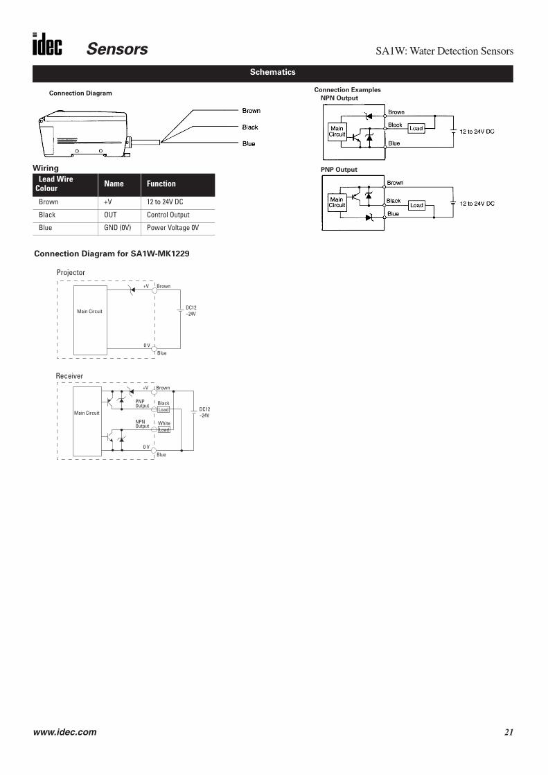
Schematics
Connection DiagramConnection Examples
PNP OutputWiring
Lead Wire Colour Name Function
Brown +V 12 to 24V DC
Black OUT Control Output
Blue GND (0V) Power Voltage 0V
NPN Output
Connection Diagram for SA1W-MK1229
Main Circuit
Brown
DC12~24V
0 V
+V
Blue
Main Circuit
Brown
DC12~24V
0 V
+V
Blue
Projector
Receiver
Load
Load
Black
White
PNPOutput
NPNOutput

SA1W: Water Detection Sensors Sensors
22 www.idec.com
Dimensions
0.24" 0.98" (25mm)39.37" (1000mm)31.50" (800mm)
1.57" (40mm)0.98" (25mm)0.24" (6mm)
2-M6 X P0.752-M8 X P0.75
3’7" (94mm) 0.17"(4.4mm)
* 0.51" (13mm)
1" (25.4mm) 1.1" (28mm)Laser projector mark 2- Ø 0.13" (3.2mm) holes
1.89
" (48
mm
)
Ø 0.
21" (
5.4m
m)
0.2
4"
0.35
" (9m
m)
(6m
m)
1" (25.4mm) 0.63" (16mm)
2-M3 2-M3
0.2"
(5.2
mm
)0.
04" (
1mm
)
1.1"
(28m
m)
1.46" (37mm)1.38" (35mm)
0.47" (3.4mm)0.62"
(16mm)
0.08" (2mm)
0.47
"(12m
m) 0.08
" (2m
m)
0.13
" (3.
4mm
)
Amplifier Unit
Lens Attachment
Through-BeamPart No. SA9Z-F21
Fiber Optic Unit
Diffuse ReflexPart No. SA9W-DD81
0.98" (25mm)78.74" (2000mm)70.78" (1800mm)
1.26" (32mm)
0.67" (17mm)0.20" (5mm)
2-M4 X P0.72-M6 X P0.75
Fiber Optic Unit
Through-BeamPart No. SA9W-TS31
0.24" (6mm)
(6mm)
M4 X P0.275" (0.7mm)
0.71" (18mm)
Ø 0.
35" (
9mm
)

Sensors MX1C: Self-Contained Laser Displacement Sensors
www.idec.com 23
• Analogue output (20 to 4mA) can be selected for continuous values;digital output (on/off) can be used; or both can be used together
• Miniature sensor head is compact for high-density installations• Visible beam is easy to align with target• Adjustable response speed• Shape, size, colour, and material do not detract from accurate measurement (see note)• Wide sensing range: 2.36" to 6.30" (60mm to 160mm)• A ten-dot dynamic display shows detected positions• Alarm output indicates when sensing conditions may result in inaccurate results
Gen
eral
Spe
cific
atio
ns
Power Voltage 24V DC (ripple 10% maximum)
Current Draw 200mA (maximum)
Dielectric Strength Between live and dead parts: 500V AC, 1 minute
Insulation Resistance Between live and dead parts: 100MΩ (minimum), with 500V DC megger
Operating Temperature 0 to +45°C (performance will be adversely affected if the sensor becomes coated with ice)
Storage Temperature –20°C to +70°C
Operating Humidity 35% to 85% RH (avoid condensation)
Vibration Resistance Damage limits: 10 to 55Hz, amplitude 1.5mm p-p, 2 hours in each of 3 axes (when de-energized)
Shock Resistance Damage limits: 100m/sec2 (approximately 10G), 5 shocks in each of 3 axes
Extraneous Light Immunity
Incandescent light: 3,000 lux (maximum) — defined as incident or unwanted light received by a sensor, unrelated to the presence or absence of intended object
Material Housing: diecast zinc; Filter: glass; Lens: acrylic; Rear cover: polyarylate
Degree of Protection IP65 — IEC Pub 529; Sensors rated IP65 are dust-tight, water-resistant, and perform best when not subjected to heavy particle or water blasts
Cable Cable type: 6-core cabtyre cable 0.3mm2, 6' 6 3/4" (2m) long
Weight Approximately 400g
Dimensions 1.97"D x 0.83"W x 3.07"D (50mm H x 21mm W x 78mm D)
Func
tion
Spec
ifica
tions
Resolution 0.002" (50 µm) — measuring conditions: sensing a white ceramic object at the reference sensing distance (60mm) using the normal response speed (50ms) at 25˚C
Analogue Output 20 to 4mA, 5V (maximum), fixed range
Digital Output NPN or PNP transistor open collector: 30V DC, 100mA (maximum); Residual: 1V (NPN), 2V (PNP)
Alarm Output NPN or PNP transistor open collector: 30V DC, 100mA (maximum); Residual: 1V (NPN), 2V (PNP)
Level Metre (ten-dot LED) Analogue: Represents analogue output level according to the object distanceDigital: Indicates preset position for near limit
Out LED On: When digital output on
Laser Diode LED On: While laser is emitted (LD ON), laser emits approximately 1 second after power-up
Alarm LED On: When reflected light is insufficient
Digital Output On: When object is within the near limit setting and beyond the close end of the sensing range (≥ 2.36" or 60mm from the sensor)
Digital Output Setting Fine-tuning dial for near limit setting
Response Time High-speed (F): 5ms (maximum); Normal speed (S): 50ms (maximum)
Detectable Object Non-mirror-like surfaces
Analogue Adjustment 0.20" (5mm) = 0.8mA using multi-turn dial
Linearity ±100 µm ±1% of displacement value, defined as how linear (i.e. accurate) the actual analogue out-put is, with respect to distance
Hysteresis 0.039" (1mm), defined as the difference between the operating point and the release point
Temperature Drift 5 µA per °C with 1.97" (50mm) square white ceramic
Light Source Element Visible laser diode (670nm), 5 mW laser
Receiver Element PSD (position sensitive device)
1. Laser sensing of mirror-like surfaces is not recommended. For best results detecting reflective surfaces, tilt the sensor to reduce direct laser reflection. Sensing at a small angle (approximately ±10°) does not significantly reduce sensing accuracy or linearity of resulting analogue output.
2. WARNING: Class IIIa laser. Do not allow the laser to shine directly into the eyes. Always consider eye safety when installing a laser sensor. Make sure that the laser beam cannot inadvertently shine into the eyes of people passing by or working in the vicinity. See laser safety information on page Q-25.
MX1C: Self-Contained Laser Displacement Sensors

MX1C: Self-Contained Laser Displacement Sensors Sensors
24 www.idec.com
Part Numbers: MX1C Sensors
Part Number Output Sensing Range ResolutionMX1C-AK1MX1C-AL1
NPNPNP
2.36" to 6.30"(60mm to 160mm) 0.002" (50µm)
Applications
Checking for warped boards
Detecting the height and width of wood or blocks
Positioning a robot or actuator
Sensing the roundness of a roller
Detecting overlapping sheets
Sensing loose caps
Counting sheets of paper
Detecting the thickness
of lumber

Sensors MX1C: Self-Contained Laser Displacement Sensors
www.idec.com 25
See page Q-56 for general sensor instructions. Below are considerationsspecific to the MX1C miniature laser sensors.
When installing multiple sensors, provide the recommended clearance asshown below, to prevent the interference of signals.
Laser sensing of mirror-likesurfaces is not recommended,as the sensor receiver isdesigned for detectingdiffuse-reflected light. Directlaser reflection may resultin unreliable results.
For best results detectingreflective surfaces, tilt thesensor to reduce direct laserreflection. Sensing at a smallangle (approximately ±10°)does not significantly reducethe sensing accuracy or linearityof the resulting analogue output.
WARNING: Class IIIa laser. Do not allow the laser to shine directly into theeyes. Always consider eye safety when installing a laser sensor. Make surelaser beam cannot inadvertently shine into the eyes of people passing by orworking in the vicinity. See laser safety information on page Q-25.
Due to the focusing characteristics of the lens, the projected beam of alaser sensor gets smaller (converges) from the near end to the far end ofthe sensing range. The beam gets larger (diverges) beyond the far end ofthe sensing range.
L A B C2.36" (60mm) 0 0 04.33" (110mm) 0 0.79" (20mm) 1.97" (50mm)6.30" (160mm) 0.79" (20mm) 2.36" (60mm) 3.94" (100mm)
A
B
C
L
Note: “L” is the distancebetween the sensor headsurface and the object.
±10°
±10°
(1mm)0.04"
(3mm)0.12"
(160mm)6.30"
(110mm)4.33"
(60mm)2.36"
(1.5mm)0.06"
(1mm)0.04"
(2mm)0.08"
(0.5mm)0.02"
Note: The beam spot is magnified forthe purpose of the dimensions only.
17.1˚
9.9˚
6.9˚
Wiring
Wire Colour Name FunctionBrown +V 24V DC, 200mA (maximum)Black OUT Digital Output, 30V DC, 100mAOrange ALM Alarm Output, 30V DC, 100mABlue GND Power Ground (0 V)White ANALOGUE Analogue Output, 20 to 4mAPeach LD RMT Remote Interlock On/Off SwitchShield A. GND Analogue Ground
+ V
OUT
ALM
GND
ANALOGUE
Shield
Load
MainCircuit
24V DC
+ V
AnalogueInput
OUT
ALM
GND
ANALOGUE
Shield
24V DC
20 to 4mA
PNP (MX1C-AL1)REMOTE
Load
MainCircuit
Switch: OnLaser: Locked
Out
AnalogueInput20 to 4mA
REMOTE
Switch: OnLaser: Locked
Out
NPN (MX1C-AK1)
2.81" (71.5mm)
1.97"(50mm)
1.63"(41.5mm)
0.14"(3.5mm)
0.18"(4.5mm)
0.83"(21mm)
3.07" (78mm) Ø 0.157"(M4)TappedTwo Places
6' – 6-3/4"x Ø 0.21"(2m x Ø 5.4mm)
0.37" ±0.012"(9.5 ± 0.3 mm)
Center ofProjection
The analogue output line may be extended up to 33' (10m), as long as the cable used is equal to or superior to the cable provided. Other lines
may be extended up to 164' (50m), using #22 AWG (0.3mm2) wire.
Installation
Projected Beam Characteristics
Schematics
Dimensions

MX1C: Self-Contained Laser Displacement Sensors Sensors
26 www.idec.com
Labelling: IDEC laser sensors include CDRH-approved safety warnings shown on theright and below, in compliance with federal regulations of the Center for Devices andRadiological Health.
Installation: If a sensor is installed so that the laser beam may shine or reflect into the eyes of aperson passing by or working in the vicinity, place an opaque sheet of material in front of the beamto prevent potential eye injury. For people working near a laser sensor, protective glasses whichscreen out a significant amount of the harmful radiation are recommended at all times.
All SA1M laser sensors also include a remote interlock terminal which can be used to turn the laseron or off with an external switch, as required, to operate the sensor safely from a remote location. To avoid exposure to harmful radiation, never disassemble a laser sensor.
WARNING: Do not allow class IIIa beams to shine directly into the eyes. Do not allow lasers toreflect from a glossy, shiny, or reflective surface into the eyes.
L a s e r S a f e t y I n f o r m a t i o n
SA1M Laser Mark Sensor:Class IIIa Laser (670Nm) Visible Beam
LASER LIGHT – AVOIDDIRECT EYE EXPOSURE
5mW at 670 nmCLASS IIIa LASER PRODUCT
DANGER
!
!
!
!
!
!
!
!
!
!
!
!
!
!
!
!AVOID EXPOSURE Laser light is emittedfrom this aperture.
All Laser Sensors:Identification and Certification
SA1M Visible Laser:Aperture Warning
Warning Label (common)
Precaution Labelmfd.: FEBRUARY 1997Product conforms to 21 CFR1040

Sensors SA6A: Ultrasonic Analogue Distance Detection Sensors
www.idec.com 27
Key features of the SA6A include:• Noise protection is available in two modes of operation• Fuzzy logic eliminates the adverse effects of temperature fluctuation and
air turbulence• Hold mode is ideal for sensing liquid levels without the chatter often caused by
surface ripples• Three sensing ranges optimize resolution:
Short range: 1.97" to 11.81" (± 0.04")Medium range:3.94" to 39.37" (± 0.08")Long range:7.87" to 78.74" (± 0.19")
• Shape, size, colour, and material do not impair high-precision measurement• Select analogue output (4 to 20mA) for continuous values; use digital output
(on/off); or use both • An eight-dot LED metre provides a dynamic display of detected positions
Gen
eral
Spe
cific
atio
ns
Power Voltage 12 to 24V DC (ripple 10% maximum)
Current Draw 100mA (maximum)
Dielectric Strength Between live and dead parts: 1000V, 50/60Hz, 1 minute
Insulation Resistance Between live and dead parts: 100MΩ (minimum) with 500V DC megger
Operating Temperature –10° to +60°C (performance will be adversely affected if the sensor becomes coated with ice)
Storage Temperature –30°C to +70°C
Operating Humidity 35 to 70% RH (avoid condensation)
Vibration Resistance Damage limits: 10 to 55Hz, amplitude 1.5mm p-p, 2 hours in each of 3 axes (when de-energized)
Shock Resistance Damage limits: 500m/sec2 (approximately 50G) 3 shocks in each of 3 axes
Noise Resistance Power line: 500V; Pulse width: 1µsec, 50/60Hz (using a noise simulator)
Material Housing: diecast zinc; Coverplate: polyarylate
Degree of Protection IP65 — IEC Pub 529: Sensors rated IP65 are dust-tight, water-resistant, and perform best when not subjected to heavy particle or water blasts
Cable Cable type: 6-core cabtyre cable 0.2mm2, 6'–6-3/4" (2m) long
Weight Short and medium range: 260g; Long range: 270g
Dimensions Short and medium range: 1.96"H x 0.82"W x 3.19"D (50mm H x 21mm W x 81mm D)Long range: 3.19"H x 1.14"W x 3.33"D (50mm H x 29mm W x 84.5mm D)
SA6A: Ultrasonic Analogue Distance Detection Sensors

SA6A: Ultrasonic Analogue Distance Detection Sensors Sensors
28 www.idec.com
Part Numbers: Short Sensing Range
Part Numbers: Medium Sensing Range
Part Numbers: Long Sensing Range
Part Number Output Sensing Range (A Mode) Sensing Range (B Mode) Linearity/Resolution
SA6A-L1K4SSA6A-L1L4S
NPNPNP
3.94" to 11.81" ± 0.4"(100mm to 300mm ± 10mm)
1.97" to 11.81" ± 0.4"(50mm to 300mm ± 10mm) ± 0.04" (1mm)
Part Number Output Sensing Range (A Mode) Sensing Range (B Mode) Linearity/Resolution
SA6A-LK4SSA6A-LL4S
NPNPNP
7.87" to 39.37" ± 0.8"(200mm to 1m ± 20mm)
3.94" to 39.37" ± 0.8"(100mm to 1m ± 20mm) ± 0.08" (2mm)
Part Number Output Sensing Range (A Mode) Sensing Range (B Mode) Linearity/Resolution
SA6A-L2K4SSA6A-L2L4S
NPNPNP
15.75" to 78.74" ± 1.6"(400mm to 2m ± 40mm)
7.87” to 78.74" ± 1.6"(200mm to 2m ± 40mm) ± 0.19" (5mm)
SA6A-L1K4S, -L1L4S SA6A-LK4S, -LL4S SA6A-L2K4S, -L2L4S
Fu
ncti
on
Sp
ecifi
cati
on
s
Analogue Output 4 to 20mA (fixed range) 4 to 20mA (fixed range) 4 to 20mA (fixed range)
Error± 0.08mA ± 0.04mA ± 0.05mA
Defined as how accurate the actual analogue output is, with respect to distance
Resolution± 0.04" (1mm) ± 0.08" (2mm) ± 0.19" (5mm)
Defined as the smallest object or the shortest distance that can be detected with reliability
Digital Output NPN or PNP transistor open collector, 100mA, 30V DC (maximum); Residual: 1.5V (NPN), 2.5V (PNP)
Alarm Output NPN or PNP transistor open collector, 100mA, 30V DC (maximum); Residual: 1.5V (NPN), 2.5V (PNP)
Level Metre A or B mode: Represents analogue output level on an 8-dot LED display, corresponding to object distance
Out LED On: When digital output is on (red LED)
Power LED On: When power is on (red LED)
Alarm LED On: When environment change occurs (red LED)
Stable LED On: When stable operation is ensured (green LED)
Response:Normal Mode
Analogue: 12HzDigital (A mode): 22HzDigital (B mode): 15Hz
Analogue: 8HzDigital (A mode): 15HzDigital (B mode): 10Hz
Analogue: 5HzDigital (A mode): 10HzDigital (B mode): 7Hz
Response: Fuzzy Mode Analogue/Digital: 4Hz Analogue/Digital: 3Hz Analogue/Digital: 2Hz
Response: Hold Mode Analogue/Digital: 4Hz Analogue/Digital: 3Hz Analogue/Digital: 2Hz
Response TimeAnalogue: 48msDigital (A mode): 16msDigital (B mode): 24ms
Analogue: 70msDigital (A mode): 24msDigital (B mode): 36ms
Analogue: 90msDigital (A mode): 30msDigital (B mode): 45ms
InternalSynchronous Mode Two sensors synchronized, alternate oscillations prevent interference; response time is doubled
ExternalSynchronous Mode
Three or more sensors synchronized with timing pulse signal:
On/Off (A mode) ≥ 15msOn/Off (B mode) ≥ 20ms
On/Off (A mode) ≥ 20msOn/Off (B mode) ≥ 30ms
On/Off (A mode) ≥ 30msOn/Off (B mode) ≥ 45ms
Oscillation Frequency Approximately 290kHz Approximately 200kHz Approximately 130kHz
Directivity ± 10° (half wave: -6 dB) ± 7° (half wave: -6 dB) ± 7° (half wave: -6 dB)
TemperatureCharacteristics ± 0.06% per °C (± 12 µA per °C)
Hysteresis0.24" (6mm) 0.39" (10mm) 0.79" (20mm)
Defined as the difference between the operating point and the release point

Sensors SA6A: Ultrasonic Analogue Distance Detection Sensors
www.idec.com 29
3.19" (81mm)
2.44" (62mm)
1.97"(50mm)
1.57"(40mm)
0.12"(3mm)
0.24”(6mm)
0.65" (16.5mm)
0.77"(19.5mm)
0.87"(22mm)
0.12"(3mm)
0.55"(14mm)
0.83" (21mm)
0.87"(22mm) 2.68"(68mm)
Ø 0.157"(M4)TappedTwo Places
6'– 6-3/4"x Ø 0.21"(2m x Ø 5.4mm)
0.51"(13mm)Short and Medium Range
Long Range
1.14"(29mm)
1.30"(33mm)
1.30"(33mm)
Short Range andMedium Range
Long Range
All Three Styles
0.12"(3mm)
3.33" (84.5mm)
Short and Medium Range
Long Range
All Three
Dimensions
Styles

SA1D: Analogue Distance Detection Sensors Sensors
30 www.idec.com
Key features of the SA1D include:• Triangulation ensures high-precision when sensing the presence or position of objects• Wide sensing range: 7.87" to 19.69" (200 to 500mm)• Select analogue output (20 to 4mA) for continuous values; use digital output (on/off);
or use both together• Far and near limits can be defined for detecting objects within a specified zone• A ten-dot LED level metre provides a dynamic display of detected positions and also shows near and far
settings• Alarm output indicates when sensing conditions may result in inaccurate results
SA1D: Analogue Distance Detection Sensors
Gen
eral
Spe
cific
atio
ns
Power Voltage 12 to 24V DC ± 10% (ripple 10% maximum)
Current Draw 100mA (maximum)
Dielectric Strength Not specified due to capacitor grounding
Insulation Resistance Not specified due to capacitor grounding
Operating Temperature 0° to +55°C (performance will be adversely affected if the sensor becomes coated with ice)
Operating Humidity 35 to 85% RH (avoid condensation)
Storage Temperature –20° to +70°C
Vibration Resistance Damage limits: 10 to 55Hz, amplitude 1.5mm p-p, 2 hours in each of 3 axes (power off)
Shock Resistance Damage limits: 500m/sec2 (approximately 50G), 5 shocks in each of 3 axes
Extraneous Light Immu-nity
Sunlight: 10,000 lux; Incandescent light: 3,000 lux (maximum) — defined as the incident or unwanted light received by a sensor, unrelated to the presence or absence of the intended object
Material Housing: Diecast zinc; Filter and lens: Acrylic
Degree of Protection IP65 — IEC Pub 529; sensors rated IP65 are dust-tight, water-resistant, and perform best when not subjected to heavy particle or water blasts
Cable Cable type: 5-core cabtyre cable 0.2mm2, 6'–6-3/4" (2m) long
Weight Approximately 350g
Dimensions 2.68"H x 0.83"W x 1.97"D (68mm H x 21mm W x 50mm D)
Func
tion
Spec
ifica
tions
Analogue Output 20 to 4mA, 5V (maximum), fixed range
Digital Output NPN or PNP transistor open collector, 30V DC, 100mA (maximum),Residual: 1V (NPN), 2V (PNP)
Alarm Output NPN or PNP transistor open collector, 30V DC, 100mA (maximum),Residual: 1V (NPN), 2V (PNP)
Level Metre(10-dot LED display)
Analogue: Represents object distance corresponding to analogue output on a 10-dot LED displayDigital: Indicates near or far limit settings
Out LED On: When digital output is on
Power LED On: When power is on
Alarm LED On: When reflected light is excessive or insufficient
Digital Output Digital output and OUT LED turns on when object is within near and far limits
Digital Output Setting 14-turn control for far/near setting (far and near limits can be set separately)
Response Time High-speed (F): 5ms (maximum)Normal speed (S): 50ms (maximum)
Repeat Error High-speed: 4% (maximum)Normal speed: 2% (maximum)
Hysteresis 10% (maximum), defined as the difference between the operating point and the release point
Light Source Element Infrared LED (modulation mode)
Wavelength 880 nm (infrared LED)
Receiver Element Position sensitive device (PSD)
Detectable Object Opaque

Sensors SA1D: Analogue Distance Detection Sensors
www.idec.com 31
Part Numbers: SA1D Sensors
Part Number Output Sensing Range Reference ObjectSA1D-LK4 NPN 7.87" to 19.69" (200mm to 500mm)
White: 2.95" x 2.95" (75mm x 75mm)SA1D-LL4 PNP 7.87" to 19.69" (200mm to 500mm)
2.44" (62mm)
1.97"(50mm)
1.57"(40mm)
0.12"(3mm)
0.24"(6mm)
0.55"(14mm)
0.83"(21mm)
2.68" (68mm) Ø 0.157"(M4)TappedTwo Places
6' – 6-3/4"x Ø 0.2"(2m x Ø 5mm)
0.41"(10.5mm)
Center ofProjection Wiring
Wire Colour Name FunctionBrown +V 12 to 24V DC, 100mA (maximum)Black OUT Digital Output, 30V DC, 100mAOrange ALM Alarm Output, 30V DC, 100mABlue GND Power Ground (0 V)White ANALOGUE Analogue Output, 20 to 4mAShield GND Shield
An analogue output line may be extended up to 33' (10m), as long as the cable used is equal to or superior to the cable provided. Other
lines may be extended up to 164' (50m), using #22 AWG (0.3mm2) wire.
Applications
Analogue output: Controlling tensionComparison output: Detecting overlap
Analogue output: Comparison or analogue output:Identifying box size Sensing object zone
Dimensions

SA1E: Photoelectric Sensors
32 www.idec.com
Simple, compact design for world-wide usage.Key features of the SA1E photoelectric sensor include:
• Four sensing methods• Cable types and M8 connector types available• NPN output, PNP output, light ON, dark ON options• Long sensing ranges, high speed response• CE marked
Through-beam Type
PolarizedRetroreflective Type
Diffuse-reflective Type
Small-beamReflective Type
Gen
eral
Spe
cific
atio
ns
Cable Type
NPN outputLight ON SA1E-TN1 SA1E-PN1 SA1E-DN1 SA1E-NN1
Dark ON SA1E-TN2 SA1E-PN2 SA1E-DN2 SA1E-NN2
PNP outputLight ON SA1E-TP1 SA1E-PP1 SA1E-DP1 SA1E-NP1
Dark ON SA1E-TP2 SA1E-PP2 SA1E-DP2 SA1E-NP2
Connector Type
NPN outputLight ON SA1E-TN1C SA1E-PN1C SA1E-DN1C SA1E-NN1C
Dark ON SA1E-TN2C SA1E-PN2C SA1E-DN2C SA1E-NN2C
PNP outputLight ON SA1E-TP1C SA1E-PP1C SA1E-DP1C SA1E-NP1C
Dark ON SA1E-TP2C SA1E-PP2C SA1E-DP2C SA1E-NP2C
Applicable Standard IEC606947-5-2
Rated Operational Voltage 12 to 24V DC
Operating Limits 10 to 30V DC
Rated Insulation Voltage 30V DC
Power Consumption / Current Draw Emitter: 15 mAReceiver: 20 mA 30 mA
Sensing Range 10 m2.5 m (IAC-R5)1.5 m (IAC-R6) (Note)1 m (IAC-RS1)
700 mm(using 200 × 200 mm white matt paper)
50 to 150 mm(using 100 × 100 mm white matt paper)
Detectable Object Opaque Opaque/Transparent
Hysteresis — 20% maximum
Response Time 1 ms maximum
Sensitivity Control Adjustable using a potentiometer (approx. 260°)
Light Source Element Infrared LED Red LED Infrared LED Red LED
Operation Mode Light ON/Dark ON
Control OutputNPN open collector/PNP open collector30V DC, 100 mA maximumVoltage drop: 1.2V maximumShort-circuit protection
LED IndicatorsOperation LED: YellowStable LED: GreenPower LED: Green (Through-beam type emitter)
Interference Prevention — Two units can be mounted close together
Degree of Protection IP67 (IEC60529)
SA1E: Photoelectric Switches
1. Maintain at least 100 mm clearance between the SA1E photoelectric switch and reflector. Reflectors are not attached to the photoelectric switch and must be ordered separately.2. Standard cable length for cable type is 1 metre. Contact IDEC for longer cable lengths.

Sensors SA1E: Photoelectric
www.idec.com 33
Mounting Brackets
Reflectors for polarized retroreflective type
Slits for through-beam type
Gen
eral
Spe
cific
atio
ns c
on’t
Extraneous Light Immunity Sunlight: 10,000 lux maximum, Incandescent lamp: 3,000 lux maximum (at receiver)
Operating Temperature –25 to + 55°C (no freezing)
Operating Humidity 35 to 85% RH (no condensation)
Storage Temperature –40 to +70°C (no freezing)
Insulation Resistance Between live and dead parts: 20 MΩ maximum (500V DC megger)
Dielectric Strength Between live and dead parts: 1000V AC, 50/60 Hz, 1 minute
Vibration Resistance Damage limits: 10 to 55 Hz, Amplitude 0.75 mm p-p, 20 cycles in each of 3 axes
Shock Resistance Damage limits: 500 m/s2, 10 shocks in each of 3 axes
Material Housing: PC/PBT, Lens: PC (Polarized retroreflective type: PMMA), Indicator cover: PC
Accessories Included Instruction sheet, Sensitivity control screwdriver
Weight (approx)
Cable Type Emitter: 30g Receiver: 30g 30 g
Connector Type Emitter: 10g Receiver: 10g 10 g
Connection Method
Cable Type ø3.5 mm, 3-core, 0.2 mm2, 1-m vinyl cabtyre cable (2-core for the emitter of through-beam type)
Connector Type M8 connector (4-pin)
Part Number Type Package Quantity
SA9Z-K01 Vertical1
SA9Z-K02 Horizontal
Part Number Type Package Quantity Type & Length Applicable Mounting
Bracket
IAC-R5 Standard
1
Straight, 2m IAC-L2
IAC-R6 Small Right angle, 2m IAC-L3
IAC-RS1 Tape type Straight, 5m —
Part Number Slit Width Package Quantity
Sensing Range (m) Maximum Detectable Object Width (mm)
One side Both sides One side Both sides
SA9Z-S06 0.5 mm
2
2.5 1.0 7.0 0.5
SA9Z-S07 1.0 mm 3.5 1.5 7.0 1.0
SA9Z-S08 2.0 mm 6.0 3.5 7.0 2.0
Through-beam Type
PolarizedRetroreflective Type
Diffuse-reflective Type
Small-beamReflective Type
SA1E Accessories
Connector Cable for connector type
Part Number Core Wires Type & Length Package
Quantity
SA9Z-CM8K-4S2
4
Straight, 2m
1SA9Z-CM8K-4L2 Right angle, 2m
SA9Z-CM8K-4S5 Straight, 5m
SA9Z-CM8K-4L5 Right angle, 5m
Slit (Stainless Steel)
The slit can be pressed to fit on the front easily in one touch.
18
8.2
32.1
A 6.1
0.3
Dimensions

SA1E: Photoelectric Sensors
34 www.idec.com
Cable Type
Connector Type
Output Circuit and Wiring Diagram
Dimensions
2-M3
o3.5
-1 m
3.419.5
1.2
25.4
31.5
17.4
13.49.0
2.9
10.8
17.4
4.0
17.1
7.1
12.7
8.8
Operation LED (yellow) (Note 1)
Sensitivity Control (Note 2)
Receiver
Emitter
Emitteror
Receiver
Through Beam Polarized retroreflectiveDiffuse-reflective
Small-beam reflective
2-M3
×1
6.3
10.8
2.9
9.0
13.4
31.5
25.4
1.2
4.5
19.53.4
17.1
4.0
6.510.8
17.4
12.7
7.1
17.4
10.86.5
8.8
(Note 4)
Stable LED (green) (Note 2) Sensitivity Control (Note 2)
Operation LED (yellow) (Note 1)
Receiver
Projector
Projectoror
Receiver
Through Beam Polarized retroreflectiveDiffuse-reflective
Small-beam reflective
See notes 1 through 4 above.
Ma
in C
ircu
it
Ma
in C
ircu
it
Ma
in C
ircu
it
Lo
ad
Lo
ad
Brown
Brown
Brown
Black
Black
Blue Blue
Blue
+V +V
+V
0V 0V
0V
OUT
OUT
12 to 24V DC
12 to 24V DC
12 to 24V DC
1
1
1
4 4
3
3
3
• NPN Output • PNP Output
• Through-beam Type Emitter
Connector Pin Assignment
Connector Pin Assignment
➃ (OUT)
➁ (NC) ➀ (+V)
➂ (0V)
➃ (NC)
➁ (NC) ➀ (+V)
➂ (0V)
Notes:1. Power ON LED (green) for through-beam emit-
ter.2. No sensitivity control and stable LED are
attached on the through-beam emitter.3. 5.2mm for polarized retroreflective type.4. The connector length is 18mm when a right-
angle connector cable (SA9Z-CM8K-4L) is attached.

Sensors SA1E: Photoelectric
www.idec.com 35
Mounting Bracket
SA9Z-K01 With Mounting Bracket
SA9Z-K02 With Mounting Bracket
Dimensions, continued
1.2
42.5
21.5
°13.7
14° 3.4
R12.0
3.4
3.2
12.3
25.4
8.0
31.5
10.8
1.2
25.0
25.4
13.4
21.5
19.5
42.5
7°
13.7
9.3
0.5
14°
3.4
R12.0
24.8
6.0
3.4
(3.2)
(Note 2)
14(
Note 1: Center of optical axis (through-beam type)Note 2: Center of optical axis (polarized retroreflective, diffuse reflective, and small-beam reflective type)
15.3
25.4
21.512.7
1.2
14.6
8.4
34.8
55.0
10.6
14° R12.04.5
12.0 5.0
4.5
ˆø3.4
6.0
17.6
1.5
31.5
15.3
25.4
21.512.7
1.0
1.28.014.6 (3.2)
8.4
28.0
12.7
17.1
34.8
55.0
10.6
14° R12.04.5
12.0 5.0
4.5
(Material: Stainless Steel) Note 2: Center of optical axis (polarized retroreflective, diffuse reflective, and small-beam reflective type)
SA1E: Photoelectric Sensors
36 www.idec.com
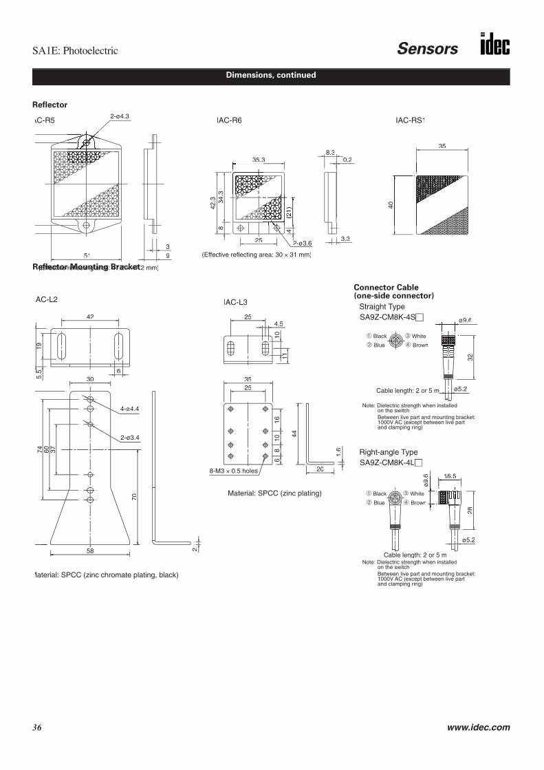
Reflector
Dimensions, continued
5139
2-ø3.63.3
8.30.235.3
34.3
42.3
8
25
4
35
40
IAC-RS1IAC-R6AC-R5
(Effective reflecting area: 47.2 × 47.2 mm)
(Effective reflecting area: 30 × 31 mm)
2-ø4.3
3228
ø9.
6
ø5.2
16 5
Straight TypeSA9Z-CM8K-4S
Right-angle TypeSA9Z-CM8K-4L
ø5.2
Note: Dielectric strength when installed on the switch
Between live part and mounting bracket:1000V AC (except between live part and clamping ring)
Note: Dielectric strength when installed on the switch
Between live part and mounting bracket:1000V AC (except between live part and clamping ring)
Material: SPCC (zinc chromate plating, black)
42
5.5
19
6
58
70
376074
30
2
AC-L2
2-ø3.4
4-ø4.4
254.5
1110
44
20
1.6
3525
1610
86
IAC-L3
Material: SPCC (zinc plating)
8-M3 × 0.5 holes
ø9.6
➀ Black ➂ White
➁ Blue ➃ Brown
➀ Black ➂
➁ Blue Brown
Cable length: 2 or 5 m
Cable length: 2 or 5 m
Connector Cable (one-side connector)
Reflector Mounting Bracket

Sensors SA1C-FK: Fiber Optic Analogue Photoelectric Sensors
www.idec.com 37
• High-speed, miniature photoelectric sensors with analogue (4mA to 20mA) and digital output• Senses gradual colour changes• Available in both red and green LEDs• Through-beam and reflected-light sensing available• Ideal for either colour mark applications or simple presence and absence applications requir-
ing analogue output• Compact size allows for DIN rail mounting• Dozens of coordinating fiber optic units available to address specific
application needs• Simple to install and program• IP66 protection rating
SA1C-FK3 SA1C-FK3G
Gen
eral
Spe
cific
atio
ns
Light Source Element Red LED Green LED
Sensing Distance Depends on the fiber unit (see pages 38–40)
Power Voltage 12 to 24V DC (Operating voltage: 10 to 30V DC) ripple 10% maximum
Current Draw 80mA maximum
Analogue Current Output 4 to 20mA, 5V DC maximum
Digital Output NPN open collector 30V DC, 100mA maximum,1.5V maximum with short circuit protection
Operation Mode Dark ON (connect MODE line to GND line); Light ON (connect MODE line to power line)
Response 0.5ms maximum
Indicator Operation LED: Red, Stable LED: Green
Detectable Object Translucent object, opaque object
Hysteresis 20% maximum (using reflex fiber unit)
Sensitivity 4-turn adjustment
Operation Point Control 1 turn
Receiver Element Photo diode
Operating Temperature –25 to +55˚C (performance will be adversely affected if the sensor becomes coated with ice)
Storage Temperature –30 to +70˚C (performance will be adversely affected if the sensor becomes coated with ice)
Operating Humidity 35 to 85% RH (avoid condensation)
Extraneous Light Immu-nity Sunlight: 10,000 lux maximum; Incandescent light: 3,000 lux (at the receiver)
Noise Resistance Normal mode: 500V (50ns to 1µs, 100Hz: Using a noise simulator)Common mode: 300V (50ns to 1µs, 100Hz: Using a noise simulator)
Insulation Resistance Between live and dead parts: 20MΩ minimum, with 500V DC megger
Dielectric Strength Between live and dead parts: 1,000V, 1 minute
Vibration Resistance Damage limits: 10 to 55Hz; Single amplitude: 0.75mm 20 cycles in each of 3 axes
Shock Resistance Damage limits: 500 m/sec2 10 cycles in each of 3 axes
Degree of Protection IP66 — IEC Pub 529
Cable Cable type: Ø4.4mm 5-core vinyl cabtyre cable 0.2mm2, 6'–6-3/4" (2m) long
Material Housing: Polybuthylenterephtalate (PBT)
Accessories Mounting bracket, adjusting screwdriver, load resistor (249Ω) for converting analogue amperage to voltage (1 to 5V)
Interference Prevention Up to 2 units can be installed in close proximity. For analogue output, interference prevention is not possi-ble.
Weight Approximately 75g
SA1C-FK: Fiber Optic Analogue Photoelectric Sensors
1. Analogue current output specification is based on the power voltage range from 12 to 24V DC (±10%).2. Use the attached resistor (249Ω, 1/4W) as a load resistance for converting analogue output to voltage.3. Response time for analogue current output is between 10% and 90% of the rise or fall of the voltage signal when using a 249Ω resistor.

SA1C-FK: Fiber Optic Analogue Photoelectric Sensors Sensors
38 www.idec.com
Part Numbers: SA1C-FK Sensors
Part Number Light Source Element Output
SA1C-FK3 Red LEDAnalogue output + NPN output (with short-circuit)
SA1C-FK3G Green LED
The SA1C-FK series consists of the amplifier/receiver only. Fiber optic units must be ordered separately using part numbersbeginning with SA9F. SA1C-FK amplifier/receivers can be used with either through-beam or diffuse-reflected fiber optic units.
The fiber optic cord is 6'–6-3/4" (2m) long. Fiber optic cords can be cut to the desired length using a fiber cutter, except forheat-resistant glass fiber cords. A fiber cutter is included with fiber optic units (order SA9Z-F01 separately for replace-ment). A set of two easy-insert adaptors is included with the following fiber optic units: SA9F-TT, SA9F-TL, SA9F-DT, andSA9F-DL (order SA9Z-F02 for replacement set).
Ordering Details
Part Numbers: SA9F Diffuse-Reflected Light Fiber Optic Units
(continued on following page)
Part Number Description Amplifier Range Dimensions
SA9F-DS31No sleeveSA9F-DS323.54" (90mm) sleeveSA9F-DS331.77" (45mm) sleeve
Straight: Two fibersØ 0.04" (1mm)
Threaded mount:Ø 0.24" (M6)Detects:Ø 0.0012" (0.03mm)minimum object
SA1C-FK3SA1C-FK3G
2.36" (60mm)0.28" (7mm)
SA9F-DC31No sleeveSA9F-DC323.54" (90mm) sleeveSA9F-DC331.77" (45mm) sleeve(All three not compatiblewith green LED)
Coiled: Two fibersØ 0.04" (1mm)
Threaded mount:Ø 0.24" (M6)Detects:Ø 0.0012" (0.03mm)minimum object
SA1C-FK3SA1C-FK3G
0.98" (25mm)—
SA9F-DT11No sleeveSA9F-DT123.54" (90mm) sleeveSA9F-DT131.77" (45mm) sleeve(All three not compatiblewith green LED)
Straight: Two fibersØ 0.02" (0.5mm)
Threaded mount:Ø 0.12" (M3)Detects:Ø 0.0012" (0.03mm)minimum object
SA1C-FK3SA1C-FK3G
0.78" (20mm)—
SA9F-DD31
Coaxial: CoreØ 0.04" (1mm) +16 fibers: Ø 0.01" (0.26mm)
Threaded mount:Ø 0.24" (M6)Detects:Ø 0.0012" (0.03mm)minimum object
SA1C-FK3SA1C-FK3G
2.36" (60mm)0.28" (7mm)
0.09"(2.4mm)
Ø 0.24"(M6)
Ø 0.04"(1mm)
0.20"(5.2mm)
Ø 0.45"(11.5mm)
0.40"(10mm) Ø 0.16"
(4mm)
0.12"(3mm)
Ø 0.10"(2.5mm)
DS32: 3.54" (90mm)DS33: 1.77" (45mm)
6' – 6-3/4"(2m)0.59"
(15mm)
Ø 0.087"(2.2mm)Two Fibers
Ø 0.10"(2.5mm)
DC32: 3.54" (90mm)
3.54"(90mm)
6' – 6-3/4"(2m) 15.75"
(400mm)
Note: All dimensions, exceptthose shown, are the same asstraight fiber (DS31/32/33, above)
DC33: 1.77" (45mm)
Ø 0.04"(1mm)
0.20"(5.2mm)
Ø 0.45"(11.5mm)
0.40"(10mm)
Two Fibers
Ø 0.24"(M6)
0.39"(10mm)
0.07"(1.8mm)
Ø 0.12"(M3)
Ø 0.09"(2.3mm)
0.12"(3mm)
Ø 0.04"(1.0mm)
0.20"(5mm)
6' – 6-3/4"(2m)
Ø 0.02"(0.5mm)
0.10"(2.5mm)
Ø 0.25"(6.4mm)
0.22"(5.5mm)
Ø 0.06"(1.5mm)
DT12: 3.54" (90mm)DT13: 1.77" (45mm)
Two Fibers
Ø 0.010"(0.26mm)16 Fibers
Ø 0.04"(1mm)One Fiber
0.09"(2.4mm)
Ø 0.24"(M6)
0.20"(5.2mm)
Ø 0.45"(11.5mm)
0.40"(10mm) Ø 0.16"
(4mm)
0.12"(3mm)
Ø 0.10"(2.5mm)
DS32: 3.54" (90mm)DS33: 1.77" (45mm)
6' – 6-3/4"(2m)0.59"
(15mm)
Ø 0.087"(2.2mm)

Sensors SA1C-FK: Fiber Optic Analogue Photoelectric Sensors
www.idec.com 39
Part Numbers: SA9F Diffuse-Reflected Light Fiber Optic Units, continued
Part Number Description Amplifier Range Dimensions
SA9F-DM741 row = 32 fibersSA9F-DM752 rows = 16 each(Not compatible
with green LED)
SA9F-DM763 rows = 16 center+ 8 fibers each side(Not compatible
with green LED)
Multicore:32 fibersØ 0.010" (0.26mm)
Detects:Ø 0.0024" (0.06mm)minimum object
SA1C-FKSA1C-FK3G(not compatible with SA9F-DM75, SA9F-DM76)
2.36" (60mm)0.16" (4mm)
SA9F-DH21No sleeveSA9F-DH223.54" (90mm) sleeve(Both not compatiblewith green LED)
Heat-resistant glass: Two fibersØ 0.03" (0.7mm)
Threaded mount:Ø 0.16" (M4)Detects:Ø 0.0012" (0.03mm)minimum object
SA1C-FK3SA1C-FK3G
1.06" (27mm)—
0.20"(5mm)
6' – 6-3/4"(2m)0.98"
(25mm)0.21"(5.25mm) 0.39"
(10mm)
0.75"(19mm)
0.43"(10.9mm)
0.20"(5mm)0.04"
(1mm)
One Row (DM74)
Two and Three Rows (DM75/76)
0.59"(15mm)
0.20"(5mm)
Ø 0.087"(2.2mm)
6' – 6-3/4"(2m)
Ø 0.126"(3.2mm)
Two Places
0.20"(5mm)0.39"
(10mm)
0.16"(4mm)
0.98"(25mm)
0.16"(4mm)
Ø 0.126"(3.2mm)
Two Places
Ø 0.087"(2.2mm)
Ø 0.102"(2.6mm)
3.54" (90mm) SleeveØ 0.083"(2.11mm)
Ø 0.16"(M4)
Ø 0.16"(4mm)
1.38"(35mm)
6' – 6-3/4"(2m)
0.79"(20mm)
0.63"(16mm) 0.55"
(14mm)
0.55"(14mm)
0.24"(6mm)
Ø 0.087"(2.2mm)
0.20"(5mm)
0.12"(3mm)
Measuring Conditions
Amplifier = Applicable Amplifier
Range = Sensing RangeSensing a 50 x 50mm piece of white paper
Minimum detectable object: Sensing a copper-stranded wire with the SA1C-FK3
The sensing range varies depending upon the sensing conditions.

SA1C-FK: Fiber Optic Analogue Photoelectric Sensors Sensors
40 www.idec.com
Part Numbers: SA9F Through-Beam Fiber Optic Units
Part Number Description Amplifier Range Dimensions
SA9F-TS21No sleeveSA9F-TS223.54" (90mm) sleeveSA9F-TS231.77" (45mm) sleeve
Straight fiber:Ø 0.04" (1mm)
Threaded mount:Ø 0.16" (M4)Detects:Ø 0.012" (0.3mm)minimum object
SA1C-FK3SA1C-FK3G
7.09" (180mm)0.63" (16mm)
SA9F-TC21No sleeveSA9F-TC223.54" (90mm) sleeveSA9F-TC231.77" (45mm) sleeve
Coiled fiber:Ø 0.04" (1mm)
Threaded mount:Ø 0.16" (M4)Detects:Ø 0.012" (0.3mm)minimum object
SA1C-FK3SA1C-FK3G
5.91" (150mm)0.55" (14mm)
SA9F-TT11No sleeveSA9F-TT123.54" (90mm) sleeveSA9F-TT131.77" (45mm) sleeve
Straight fiber:Ø 0.02" (0.5mm)
Threaded mount:Ø 0.12" (M3)Detects:Ø 0.006" (0.15mm)minimum object
SA1C-FK3SA1C-FK3G
1.97" (50mm)0.2" (5mm)
SA9F-TM21No sleeveSA9F-TM223.54" (90mm) sleeveSA9F-TM231.77" (45mm) sleeve
Multicore:16 fibers (cluster)Ø 0.010" (0.26mm)
Threaded mount:Ø 0.16" (M4)Detects:Ø 0.012" (0.3mm)minimum object
SA1C-FK3SA1C-FK3G
5.91" (150mm)0.55" (14mm)
SA9F-TM7416 fibers in one row
Multicore:16 fibers (one row)Ø 0.010" (0.26mm)
Detects:Ø 0.0024" (0.06mm)minimum object
SA1C-FK3SA1C-FK3G
5.91" (150mm)0.55" (14mm)
SA9F-TH21No sleeveSA9F-TH223.54" (90mm) sleeve
Heat-resistant glass fiber:Ø 0.04" (1mm)
Threaded mount:Ø 0.16" (M4)
Detects:Ø 0.012" (0.3mm)minimum object
SA1C-FK3SA1C-FK3G
3.94" (100mm)0.31" (8mm)
SA9F-TL53(Not compatible with green LED)
Side view: one fiber 0.02" (0.5mm)Optical axis at 90°Detects:Ø 0.0024" (0.06mm)minimum object
SA1C-FK3SA1C-FK3G
1.57" (40mm)—
Ø 0.087"(2.2mm)
0.09"(2.4mm)
Ø 0.16"(M4)
Ø 0.04"(1mm)
0.12"(3mm)
Ø 0.32"(8.1mm)
0.28"(7mm) Ø 0.10"
(M2.6)
0.12"(3mm)
Ø 0.06"(1.5mm)
TS22: 3.54" (90mm)TS23: 1.77" (45mm)
6' – 6-3/4"(2m)0.47"
(12mm)
Ø 0.06"(1.5mm)
TC22: 3.54" (90mm)
3.54"(90mm)
6' – 6-3/4"(2m) 15.75"
(400mm)
Note: All dimensions, exceptthose shown, are the same asstraight fiber (TS21/22/23, above).
TC23: 1.77" (45mm)
Ø 0.04"(1mm)
0.12"(3mm)
Ø 0.32"(8.1mm)
0.28"(7mm)
Ø 0.16"(M4)
Ø 0.04"(1mm)
0.07"(1.8mm)
Ø 0.12"(M3)
Ø 0.02"(0.5mm)
0.10"(2.5mm)
Ø 0.25"(6.4mm)
0.22"(5.5mm) Ø 0.09"
(M2.2)
0.12"(3mm)
Ø 0.035"(0.9mm)
TT12: 3.54" (90mm)TT13: 1.77" (45mm)
6' – 6-3/4"(2m)0.47"
(12mm)
Ø 0.087"(2.2mm)
0.09"(2.4mm)
Ø 0.16"(M4)
Ø 0.010"(0.26mm)
0.12"(3mm)
Ø 0.32"(8.1mm)
0.28"(7mm) Ø 0.10"
(M2.6)
0.12"(3mm)
Ø 0.06"(1.5mm)
TM22: 3.54" (90mm)TM23: 1.77" (45mm)
6' – 6-3/4"(2m)0.47"
(12mm)
16 Fibers
Ø 0.09"(2.2mm)
0.12"(3mm)
0.16"(4mm)
0.39"(10mm)
6' – 6-3/4"(2m)
0.79"(20mm)
0.20"(5mm) 0.59"
(15mm)
Ø 0.126"(3.2mm)
0.04"(1mm)
Two Places
0.20"(5mm)
0.21"(5.25mm)
Ø 0.102"(M2.6)
TH22: 3.54"
Ø 0.083"(2.11mm)
Ø 0.16"(M4)
Ø 0.16"(4mm)
0.79"(20mm)
0.63"(16mm)
0.55"(14mm)
Ø 0.086"(2.2mm)
0.12"(3mm)
0.12"(3mm)
0.43"(11mm)
Ø 0.24"(6mm)
1.30"(33mm)
6' – 6-3/4"(2m)
(90mm)
6' – 6-3/4"(2m)
Ø 0.04"(1mm)
0.59"(15mm)
Ø 0.08"(2mm)
1.77"(45mm)
0.033"(0.85mm)
0.04"(1mm)
0.02"(0.5mm)
Refer to page Q-39 for the measuring conditions.
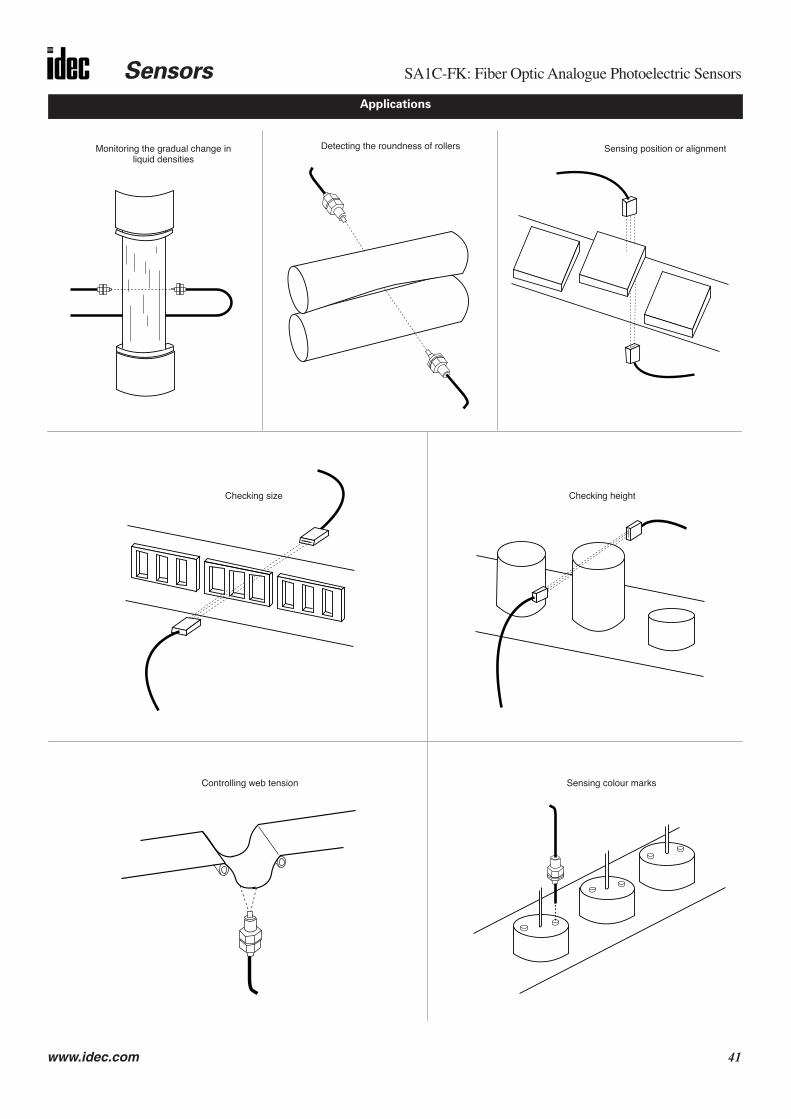
Sensors SA1C-FK: Fiber Optic Analogue Photoelectric Sensors
www.idec.com 41
Monitoring the gradual change in liquid densities
Sensing colour marks
Detecting the roundness of rollers Sensing position or alignment
Controlling web tension
Applications
Checking size Checking height

SA1C-FK: Fiber Optic Analogue Photoelectric Sensors Sensors
42 www.idec.com
Dimensions
2.36" (60mm)
1" (25.4mm) 1" (25.4mm) 0.51"(13mm)
1.43"(36.3mm) 0.58"(14.7mm)
2-Ø3.2 Holes
Receiver
Emitter
0.22"(5.6mm)
2-Ø2.6
0.42
" 0
.24"
(6.2
mm
) (
10.7
mm
)
Ø 0
.16"
(4m
m)
x 0.
47"
(12m
m)
0.22
"(5.
5mm
)0.
12"
(3m
m)
1.02
" (2
6mm
)
78.7
4" (
2m)
Mounting Hole LayoutMounting Bracket (attachment)
Not Required for DIN Rail Mounting
(when using amounting bracket)
1.46" (37mm)1.38" (35mm)
0.07
9" (
2mm
)
0.47
" (1
2mm
)
0.13" (3.4mm) 0.08" (2mm)0.63"
(16mm)
0.13
" (3
.4m
m)
0.20
" (5
.2m
m)
0.04
" (1
mm
)
1" (25.4mm)0.63"
(16mm)

Sensors SA1C-F: High-Speed, Miniature Photoelectric Sensors with Fiber Optics
www.idec.com 43
• Ideal for remote sensing applications• Featuring quick-connect cable and easy-insert fiber optic units for simple installation• Through-beam and reflected-light sensing available• Sensing range up to 7.09" (180mm) for through-beam sensors• Dual outputs: Select NPN and PNP transistor outputs or NPN transistor output
combined with a self-diagnostic output• Outputs selectable for light on or dark on• High-speed, 50µs response time• Featuring variable off-delay (0 to 100 ms) and fine-tune sensitivity adjustment• Stable LED makes alignment easy• Red or green LEDs available for detecting colour marks• Mount on a 1.378" (35mm) DIN rail• Protection rated IP66
SA1C-F: High-Speed, Miniature Photoelectric Sensors with Fiber Optics
Gen
eral
Spe
cific
atio
ns
Power Voltage 12V to 24V DC
Operating Voltage 10V to 30V DC, ripple 10% (maximum)
Current Draw Standard speed: 30mA (maximum)High-speed: 40mA (maximum)
Operating TemperatureAmplifier only: –25° to +55°CFiber optic cords (except heat-resistant types): –40° to +70°CHeat-resistant fiber optic cords: –40°C to +350°C(avoid ice coating)
Operating Humidity 35 to 85% RH (avoid condensation)
Extraneous Light Immu-nity
Sunlight: 10,000 lux (maximum); Incandescent light: 3,000 lux (maximum) on receiver surface— defined as incident or unwanted light received by a sensor, unrelated to the presence or absence of the intended object
Material
Amplifier only: PBT resin (housing) with polycarbonate lensFiber optic cords (except heat-resistant types): Nickel-plated brass (sensing head), polyethylene-covered PMMA (cord), and SUS304 stainless (sleeve)Heat-resistant fiber optic cords: SUS 304 stainless (sensing head) and SUS spiral tube around glass fiber cord
Degree of Protection
IP66 — IEC Pub 529, sensors rated IP66 are dust-tight, water-resistant, and perform best when not subjected to heavy particle or water blasts
CableCable type: 0.2mm2; Vinyl cabtyre cable #24 AWG, 6'–6-3/4' (2m) longConnector type: Ø 0.31" (8mm) 3- or 4-pin connector(cable ordered separately for quick connect sensors)
Light Source Red or green LED (pulse-modulated)
OutputNPN transistor: 30V DC (1.2V residual), 100mA (maximum)PNP transistor: 30V DC (2.0V residual), 200mA (maximum)Self-diagnostic: 30V DC (1.2V residual), 50mA (maximum)
Response Standard-speed: 0.5ms (maximum)High-speed: 50µs (maximum)
Off Delay 0 to 100 ms (adjustable)
Sensitivity 4-turn adjustment
MinimumBending Radius
Fiber optic cord (except SA9F-TT, -DT, -TL, and -DL): 1"R (25mm); Sleeve: 0.39"R (10mm)SA9F-TT and -DT: 0.59"R (15mm); Sleeve: 0.39"R (10mm)SA9F-TL and DL: 0.59"R (15mm); Sleeve: Unbendable
SA1C-FN, -FD (standard speed) SA1C-F1N, -F1D (high-speed)
Func
tion
Spec
ifica
tions
Operation Mode Light on or dark on (selectable by switch on amplifier)
Indicator Operation indicator: Red LED (out)Stable level indicator: Green LED (stable)
Noise ResistanceNormal mode: 500VCommon mode: 300VPulse width: 50ns –1us, 100Hz (using a noise simulator)
Normal mode: 300VCommon mode: 150VPulse width: 50ns –1us, 100Hz (using a noise simulator)
Storage Temperature –30 to +70°C (avoid freezing)
Insulation Resistance 20M minimum with 500V DC megger (between live and dead parts)
Dielectric Strength 1000V, 1 minute (between live and dead parts)
Vibration Resistance Damage limits: 10 – 55HzAmplitude: 1.5mm p-p, 20 cycles in each of 3 axes crossed (one cycle = 5 minutes)
Shock Resistance Damage limits: 500m/S2 (approximately 49G), 10 shocks in each of 3 axes
Weight Cable type: Approximately 75gQuick-connect type: Approximately 30g

SA1C-F: High-Speed, Miniature Photoelectric Sensors with Fiber Optics Sensors
44 www.idec.com
Part Numbers: SA1C-F Fiber Optic Sensors
AmplifierPart Number Output Light
Source Response Through-Beam UnitsPart Number Range Diffuse-Reflected Units
Part Number Range
SA1C-FN3E(Cable)SA1C-FN3EC(Quick-Connect)
30V DCNPN transistor: 100mA (maximum)Self-diagnostic: 50mA (maximum)
Red LED
Standard speed:0.5 ms
SA9F-TS: Ø 0.16" (M4) StraightSA9F-TC: Ø 0.16" (M4) CoiledSA9F-TT: Ø 0.12" (M3) StraightSA9F-TM: Ø 0.16" (M4) MulticoreSA9F-TH: Heat-resistant glass fiberSA9F-TL: Side view
7.09" (180mm)
5.91" (150mm)
1.97" (50mm)
5.91" (150mm)
3.94" (100mm)
1.57" (40mm)
SA9F-DS: Ø 0.24" (M6) StraightSA9F-DC: Ø 0.24" (M6) CoiledSA9F-DD: Ø 0.24" (M6) CoaxialSA9F-DT: Ø 0.12" (M3) StraightSA9F-DM: Ø 0.01" (0.26mm) MulticoreSA9F-DH: Heat-resistant glass fiberSA9F-DL: Side view
2.36" (60mm)
0.98" (25mm)
2.36" (60mm)
0.79" (20mm)
2.36" (60mm)
1.06" (27mm)
0.39" (10mm)
SA1C-FD3F(Cable)SA1C-FD3FC(Quick-Connect)
30V DCNPN transistor: 100mA (maximum)PNP transistor: 200mA (maximum)
SA1C-FN3EG(Cable)SA1C-FN3EGC(Quick-Connect)
30V DCNPN transistor: 100mA (maximum)Self-diagnostic: 50mA (maximum)
Standard speed:0.5 ms
SA9F-TS: Ø 0.16" (M4) StraightSA9F-TC: Ø 0.16" (M4) CoiledSA9F-TT: Ø 0.12" (M3) StraightSA9F-TM: Ø 0.16" (M4) MulticoreSA9F-TH: Heat-resistant glass fiberSA9F-TL: Incompatible with green LED
0.63" (16mm)
0.55" (14mm)
0.20" (5mm)
0.55" (14mm)
0.31" (8mm)
N/A
SA9F-DS: Ø 0.24" (M6) StraightSA9F-DC: Incompatible with green LEDSA9F-DD: Ø 0.24" (M6) CoaxialSA9F-DT: Incompatible with green LEDSA9F-DM: Ø 0.01" (0.26mm) MulticoreSA9F-DH: Incompatible with green LEDSA9F-DL: Incompatible with green LED
0.28" (7mm)
N/A
0.28" (7mm)
N/A
0.16" (4mm)
N/A
N/A
Green LED
SA1C-FD3FG(Cable)SA1C-FD3FGC(Quick-Connect)
30V DCNPN transistor: 100mA (maximum)PNP transistor: 200mA (maximum)
SA1C-F1N3E(Cable)SA1C-F1N3EC(Quick-Connect)
30V DCNPN transistor: 100mA (maximum)Self-diagnostic: 50mA (maximum)
High-speed:50 µs
SA9F-TS: Ø 0.16" (M4) StraightSA9F-TC: Ø 0.16" (M4) CoiledSA9F-TT: Ø 0.12" (M3) StraightSA9F-TM: Ø 0.16" (M4) MulticoreSA9F-TH: Heat-resistant glass fiberSA9F-TL: Side view
1.97" (50mm)
1.57" (40mm)
0.59" (15mm)
1.57" (40mm)
1.18" (30mm)
0.51" (13mm)
SA9F-DS: Ø 0.24" (M6) StraightSA9F-DC: Ø 0.24" (M6) CoiledSA9F-DD: Ø 0.24" (M6) CoaxialSA9F-DT: Ø 0.12" (M3) StraightSA9F-DM: Ø 0.01" (0.26mm) MulticoreSA9F-DH: Heat-resistant glass fiberSA9F-DL: Side view
0.79" (20mm)
0.28" (7mm)
0.79" (20mm)
0.24" (6mm)
0.71" (18mm)
0.28" (7mm)
0.12" (3mm)
Red LED
SA1C-F1D3F(Cable)SA1C-F1D3FC(Quick-Connect)
30V DCNPN transistor: 100mA (maximum)PNP transistor: 200mA (maximum)
The SA1C-F series consists of the amplifier/receiver only. Fiber optic units must be ordered separately using part numbers beginning with SA9F. SA1C-F amplifier/receivers can be used with either the through-beam or diffuse-reflected fiber optic units.
Amplifier/receiver units include a mounting bracket, screws, and a screwdriver. Cables for quick-connect sensors are ordered separately. Optional attachments,available for modifying beam size of through-beam sensors, are also ordered separately (see pages Q-47 through Q-48).
The fiber optic cord is 6' – 6-3/4" (2m) long. The fiber optic cord can be cut to desired length using a fiber cutter, except for the heat-resistant glass fiber. A fibercutter is included with fiber optic units (order SA9Z-F01 separately for replacement). A set of two easy-insert adaptors is included with the following fiber opticunits: SA9F-TT, SA9F-TL, SA9F-DT, and SA9F-DL (order SA9Z-F02 for replacement set).
Ordering Details

Sensors SA1C-F: High-Speed, Miniature Photoelectric Sensors with Fiber Optics
www.idec.com 45
Part Numbers: SA9F Through-Beam Fiber Optic Units
Part Number Description Dimensions Appearance
SA9F-TS21No sleeveSA9F-TS223.54" (90mm) sleeveSA9F-TS231.77" (45mm) sleeve
Straight fiber:Ø 0.04" (1mm)
Threaded mount:Ø 0.16" (M4)
Detects:Ø 0.012" (0.3mm)minimum object
SA9F-TC21No sleeveSA9F-TC223.54" (90mm) sleeveSA9F-TC231.77" (45mm) sleeve
Coiled fiber:Ø 0.04" (1mm)
Threaded mount:Ø 0.16" (M4)
Detects:Ø 0.012" (0.3mm)minimum object
SA9F-TT11No sleeveSA9F-TT123.54" (90mm) sleeveSA9F-TT131.77" (45mm) sleeve
Straight fiber:Ø 0.02" (0.5mm)
Threaded mount:Ø 0.12" (M3)
Detects:Ø 0.006" (0.15mm)minimum object
SA9F-TM21No sleeveSA9F-TM223.54" (90mm) sleeveSA9F-TM231.77" (45mm) sleeve
Multicore:16 fibers (cluster)Ø 0.010" (0.26mm)
Threaded mount:Ø 0.16" (M4)
Detects:Ø 0.012" (0.3mm)minimum object
SA9F-TM7416 fibers in one row
Multicore:16 fibers (one row)Ø 0.010" (0.26mm)
Detects:Ø 0.0024" (0.06mm)minimum object
SA9F-TH21No sleeveSA9F-TH223.54" (90mm) sleeve
Heat-resistant glass fiber:Ø 0.04" (1mm)
Threaded mount:Ø 0.16" (M4)
Detects:Ø 0.012" (0.3mm)minimum object
SA9F-TL53(not compatible with green LED)
Side view: One fiber 0.02" (0.5mm)Optical axis at 90°
Detects:Ø 0.0024" (0.06mm)minimum object
Ø 0.087"(2.2mm)
0.09"(2.4mm)
Ø 0.16"(M4)
Ø 0.04"(1mm)
0.12"(3mm)
Ø 0.32"(8.1mm)
0.28"(7mm) Ø 0.10"
(M2.6)
0.12"(3mm)
Ø 0.06"(1.5mm)
TS22: 3.54" (90mm)TS23: 1.77" (45mm)
6' – 6-3/4"(2m)0.47"
(12mm)
Ø 0.06"(1.5mm)
TC22: 3.54" (90mm)
3.54"(90mm)
6' – 6-3/4"(2m) 15.75"
(400mm)
All dimensions, except thoseshown, are the same as straightfiber (TS21/22/23, above).
TC23: 1.77" (45mm)
Ø 0.04"(1mm)
0.12"(3mm)
Ø 0.32"(8.1mm)
0.28"(7mm)
Ø 0.16"(M4)
Ø 0.04"(1mm)
0.07"(1.8mm)
Ø 0.12"(M3)
Ø 0.02"(0.5mm)
0.10"(2.5mm)
Ø 0.25"(6.4mm)
0.22"(5.5mm) Ø 0.09"
(M2.2)
0.12"(3mm)
Ø 0.035"(0.9mm)
TT12: 3.54" (90mm)TT13: 1.77" (45mm)
6' – 6-3/4"(2m)0.47"
(12mm)
Ø 0.087"(2.2mm)
0.09"(2.4mm)
Ø 0.16"(M4)
Ø 0.010"(0.26mm)
0.12"(3mm)
Ø 0.32"(8.1mm)
0.28"(7mm) Ø 0.10"
(M2.6)
0.12"(3mm)
Ø 0.06"(1.5mm)
TM22: 3.54" (90mm)TM23: 1.77" (45mm)
6' – 6-3/4"(2m)0.47"
(12mm)
16 fibers
Ø 0.09"(2.2mm)
0.12"(3mm)
0.16"(4mm)
0.39"(10mm)
6' – 6-3/4"(2m)
0.79"(20mm)
0.20"(5mm) 0.59"
(15mm)
Ø 0.126"(3.2mm)
0.04"(1mm)
two places
0.20"(5mm)
0.21"(5.25mm)
Ø 0.102"(M2.6)
TH22: 3.54" (90mm)
Ø 0.083"(2.11mm)
Ø 0.16"(M4)
Ø 0.16"(4mm)
0.79"(20mm)
0.63"(16mm)
0.55"(14mm)
Ø 0.086"(2.2mm)
0.12"(3mm)
0.12"(3mm)
0.43"(11mm)
Ø 0.24"(6mm)
1.30"(33mm)
6' – 6-3/4"(2m)
6' – 6-3/4"(2m)
Ø 0.04"(1mm)
0.59"(15mm)
Ø 0.08"(2mm)
1.77"(45mm)
0.033"(0.85mm)
0.04"(1mm)
0.02"(0.5mm)

SA1C-F: High-Speed, Miniature Photoelectric Sensors with Fiber Optics Sensors
46 www.idec.com
Part Numbers: SA9F Diffuse-Reflected Light Fiber Optic Units
(continued on following page)
Part Number DESCRIPTION Dimensions Appearance
SA9F-DS31No sleeveSA9F-DS323.54" (90mm) sleeveSA9F-DS331.77" (45mm) sleeve
Straight: Two fibersØ 0.04" (1mm)Threaded mount:Ø 0.24" (M6)Detects:Ø 0.0012" (0.03mm)minimum object
SA9F-DC31No sleeveSA9F-DC323.54" (90mm) sleeveSA9F-DC331.77" (45mm) sleeve(all three not com-patible with green LED)
Coiled: Two fibersØ 0.04" (1mm)Threaded mount:Ø 0.24" (M6)Detects:Ø 0.0012" (0.03mm)minimum object
SA9F-DT11No sleeveSA9F-DT123.54" (90mm) sleeveSA9F-DT131.77" (45mm) sleeve(all three not com-patible with green LED)
Straight: Two fibersØ 0.02" (0.5mm)Threaded mount:Ø 0.12" (M3)Detects:Ø 0.0012" (0.03mm)minimum object
SA9F-DD31
Coaxial: CoreØ 0.04" (1mm) +16 fibers: Ø 0.01" (0.26mm)Threaded mount:Ø 0.24" (M6)Detects:Ø 0.0012" (0.03mm)minimum object
SA9F-DM741 row = 32 fibersSA9F-DM752 rows = 16 each(Not compatiblewith green LED)SA9F-DM763 rows = 16 center+ 8 fibers each side(not compatible with green LED)
Multicore:32 fibersØ 0.010" (0.26mm)Detects:Ø 0.0024" (0.06mm)minimum object
0.09"(2.4mm)
Ø 0.24"(M6)
Ø 0.04"(1mm)
0.20"(5.2mm)
Ø 0.45"(11.5mm)
0.40"(10mm) Ø 0.16"
(4mm)
0.12"(3mm)
Ø 0.10"(2.5mm)
DS32: 3.54" (90mm)DS33: 1.77" (45mm)
6' – 6-3/4"(2m)0.59"
(15mm)
Ø 0.087"(2.2mm)two fibers
Ø 0.10"(2.5mm)
DC32: 3.54" (90mm)
3.54"(90mm)
6' – 6-3/4"(2m) 15.75"
(400mm)
All dimensions, except thoseshown, are the same as straightfiber (DS31/32/33, above).
DC33: 1.77" (45mm)
Ø 0.04"(1mm)
0.20"(5.2mm)
Ø 0.45"(11.5mm)
0.40"(10mm)
two fibers
Ø 0.24"(M6)
0.39"(10mm)
0.07"(1.8mm)
Ø 0.12"(M3)
Ø 0.09"(2.3mm)
0.12"(3mm)
Ø 0.04"(1.0mm)
0.20"(5mm)
6' – 6-3/4"(2m)
Ø 0.02"(0.5mm)
0.10"(2.5mm)
Ø 0.25"(6.4mm)
0.22"(5.5mm)
Ø 0.06"(1.5mm)
DT12: 3.54" (90mm)DT13: 1.77" (45mm)
Two Fibers
Ø 0.010"(0.26mm)16 Fibers
Ø 0.04"(1mm)One Fiber
0.09"(2.4mm)
Ø 0.24"(M6)
0.20"(5.2mm)
Ø 0.45"(11.5mm)
0.40"(10mm) Ø 0.16"
(4mm)
0.12"(3mm)
Ø 0.10"(2.5mm)
DS32: 3.54" (90mm)DS33: 1.77" (45mm)
6' – 6-3/4"(2m)0.59"
(15mm)
Ø 0.087"(2.2mm)
0.20"(5mm)
6' – 6-3/4"(2m)0.98"
(25mm)0.21"(5.25mm) 0.39"
(10mm)
0.75"(19mm)
0.43"(10.9mm)
0.20"(5mm)0.04"
(1mm)
One Row (DM74)
Two and Three Rows (DM75/76)
0.59"(15mm)
0.20"(5mm)
Ø 0.087"(2.2mm)
6' – 6-3/4"(2m)
Ø 0.126"(3.2mm)
Two Places
0.20"(5mm)0.39"
(10mm)
0.16"(4mm)
0.98"(25mm)
0.16"(4mm)
Ø 0.126"(3.2mm)
two places
Ø 0.087"(2.2mm)

Sensors SA1C-F: High-Speed, Miniature Photoelectric Sensors with Fiber Optics
www.idec.com 47
Part Numbers: SA9F Diffuse-Reflected Light Fiber Optic Units, continued
Part Numbers: Accessories
(continued on following page)
Part Number Description Dimensions Appearance
SA9F-DH21No sleeveSA9F-DH223.54" (90mm) sleeve(both not compatible with green LED)
Heat-resistant glass: Two fibersØ 0.03" (0.7mm)Threaded mount:Ø 0.16" (M4)Detects:Ø 0.0012" (0.03mm)minimum object
SA9F-DL63(not compatible with green LED)
Side view: Two fibers Ø 0.02" (0.5mm)Optical axis at 90°
Detects:Ø 0.0012" (0.03mm)minimum object
Part Number Description Used With Dimensions
SA9C-CA4D2 4-core cable with connector6'–6-3/4" (2m)
SA1C-F quick-connect only,NPN andPNP outputsSA9C-CA4D5 4-core cable with connector
16'–4-7/8" (5m)
SA9C-CA4D2S 4-core cable with connector6'–6-3/4" (2m)
SA1C-F quick-connect only,NPN and self-diagnostic outputsSA9C-CA4D5S 4-core cable with connector
16'–4-7/8" (5m)
SA9Z-F01 Fiber cutter All fiber units exceptheat resistant
HxLxD: 0.91" x 1.77" x 0.31" (23x 45 x 8Dmm)Included with fiber units; order replacement only
SA9Z-F02 Set of 2 easy-insert adaptors SA9F-TT, SA9F-TL,SA9F-DT, and SA9F-DL
Ø 0.087" (OD) x 0.945" long (Ø 2.2mm x 24mm)Included with applicable fiber optic units; order replacement set only
Ø 0.102"(2.6mm)
3.54" (90mm) SleeveØ 0.083"(2.11mm)
Ø 0.16"(M4)
Ø 0.16"(4mm)
1.38"(35mm)
6' – 6-3/4"(2m)
0.79"(20mm)
0.63"(16mm) 0.55"
(14mm)
0.55"(14mm)
0.24"(6mm)
Ø 0.087"(2.2mm)
0.20"(5mm)
0.12"(3mm)
6' – 6-3/4"(2m)
Ø 0.04"(1mm)
0.59"(15mm)
Ø 0.12"(3mm)
1.77"(45mm)
0.065"(1.65mm)
0.08"(2mm)
0.02"(0.5mm)
22AWG (0.25mm2)Four Wires
2.48"(63mm)
Ø 0.18"(4.5mm)
1.18"(30mm)
0.52"(13.3mm)
Ø 0.22"(5.7mm)
Ø 0.40"(10.2mm)
6' – 6-3/4" (2m)or
16' – 4-7/8" (5m)
1
3
2
4
22AWG (0.25mm2)Four Wires
2.48"(63mm)
Ø 0.18"(4.5mm)
1.18"(30mm)
0.52"(13.3mm)
Ø 0.22"(5.7mm)
Ø 0.40"(10.2mm)
6' – 6-3/4" (2m)or
16' – 4-7/8" (5m)
1
3
2
4

SA1C-F: High-Speed, Miniature Photoelectric Sensors with Fiber Optics Sensors
48 www.idec.com
Part Numbers: Accessories, continued
Detecting Colour Marks
Part Number Description Used With Dimensions
SA9Z-F11Lens attachmentfor long-range detection ofopaque objects, minimumsize: Ø 0.14” (3.5mm)
SA1C-F through-beam fiber unit onlySensing ranges: Standard speed red LED:SA9F-TS21: 4' – 3-3/16" (1.3m) 5.31" (0.135m)SA9F-TC21: 3' – 3-3/8" (1m) 3.94" (0.1m)SA9F-TM21: 3' – 5-3/8" (1.05m) 5.12" (0.13m)
Sensing ranges: Standard speed green LED:SA9F-TS21: 5.31" (0.135m)SA9F-TC21: 3.94" (0.1m) SA9F-TM21: 5.12" (0.13m) Sensing ranges:High-speed red LED:SA9F-TS21: 5.75" (0.4m)SA9F-TC21: 1.81" (0.3m)SA9F-TM21: 4.96" (0.38m)
SA9Z-F12Side view attachmentto rotate axis by 90° fordetection of opaque objects,minimum size: Ø 0.14" (3.5mm)
SA1C-F through-beam fiber unit onlySensing ranges: Standard speed red LED:SA9F-TS21: 7.87" (200mm)SA9F-TC21: 5.12" (130mm)SA9F-TM21: 6.30" (160mm)Sensing ranges: High-speed red LED:SA9F-TS21: 1.97" (50mm)SA9F-TC21: 1.38" (35mm)SA9F-TM21: 1.57" (40mm)
SA9Z-F13
Side-on attachmentfor narrow clearance,Range: 1.26" (32mm),for detection of transparentor opaque objects
SA1C-F diffuse-reflectedlight fiber unit only
Sensing ranges: Standard speed red LED:SA9F-TS21: 1.38" (35mm)SA9F-TC21: 1.81" (30mm)SA9F-TM21: 1.38" (35mm)
SA9Z-F14Attachment for high-accuracy:Range: 0.4" ± 0.04" (10mm ± 1mm), for detection of transparent or opaque objects
SA1C-F through-beamfiber unit only
Sensing ranges: Standard speed red LED:SA9F-TS21: SA9F-TC21: SA9F-TM21:
Colour of Mark Background Colour
= Use Red LED = Use Green LED = Use Red or Green LED— = Not Detectable W
hite
Yello
w
Char
treus
e
Oran
ge
Red
Mag
enta
Turq
uois
e
Blue
Viol
et
Gree
n
Blac
k
White —
Yellow —
Chartreuse —
Orange — —
Red — —
Magenta — —
Turquoise —
Blue —
Violet — —
Green —
Black —
0.39"(10mm)
Ø 0.20"(5mm)
Ø 0.14"(3.5mm)
0.098"(2.5mm)
Ø 0.102"(M2.6)
0.35"(9mm)
Ø 0.20"(5mm)
0.108"(2.75mm)
Ø 0.102"(M2.6)
Ø 0.12"(3mm)
0.39"(10mm)
0.16"(4mm)
0.098"(2.5mm)
Ø 0.12"(3mm)
0.26"(6.5mm)
0.71"(18mm)0.53"
(13.5mm)
0.098"(2.5mm)
0.18"(4.5mm)
Ø 0.16"(M4)
Ø 0.12"(M3)
0.20"(5mm)
0.47"(12mm)
1.28"(32.5mm)
1.38"(35mm)
0.79"(20mm)
0.20"(5mm)
0.98"(25mm)
0.63"(16mm)Ø 0.14"
(3.5mm)(10mm ± 1mm)0.394" ± 0.039"

Sensors SA1C-F: High-Speed, Miniature Photoelectric Sensors with Fiber Optics
www.idec.com 49
SA1C-F Series
Off DelaySelector
0.51"(13mm)
0.22"(5.6mm)
Ø 0.27"(6.9mm)
0.47"(12mm)
Quick-Connect
Ø 0.126"(3.2mm)Two Places
2.36" (60mm)
2.86" (72.7mm)
0.93"(23.7mm)
1.00"(25.4mm)
1.43"(36.3mm)
0.50"(12.7mm)
0.22"(5.5mm)
0.10"(2.5mm)
0.06"(1.5mm)
ProjectorPort
ReceiverPort
0.42"(10.7mm)
0.67"(16.9mm)
Ø 0.16" x 6' – 6-3/4" long(4mm x 2m)
Cable Style
1.02"(26mm)
Amplifier UnitOperation
LED
StableLED
OperationMode Selector
SensitivityAdjustment
0.12"(3mm)
Ø 0.102" (2.6mm)Two Places
For dimensions on fiber optic units, see page Q-45 (through-beam)or pages Q-46 through Q-47 (diffuse-reflected light).
Dimensions

ISF: Heavy Duty Photoelectric Sensors Sensors
50 www.idec.com
Gen
eral
Spe
cific
atio
ns
Power Voltage Universal voltage type: 24V to 240V AC (24V to 240V DC compatible)DC type: 10V to 30V DC (ripple 10% maximum)
Operating Voltage Universal voltage: 21.6V to 264V AC, 50/60Hz (21.6V to 264V DC compatible)
Dielectric StrengthBetween power and output terminals: 1,500V AC, 1 minute (universal-voltage type)Between output terminals: 1,000V AC, 1 minute (universal-voltage type)Between live and dead parts: 1,000V AC, 1 minute (DC type)
Insulation ResistanceBetween power and output terminals: 20 MΩ (minimum) with 500V DC megger (universal-voltage)Between live and dead parts: 20 MΩ (minimum) with 500V DC megger (DC type)
Operating Temperature –10° to +60°C (avoid freezing)
Operating Humidity 35 to 85% RH (avoid condensation)
Storage Temperature –20° to +70°C
Vibration Resistance Damage limits: 10 to 55Hz, amplitude 1.5mm p-p, 2 hours in each of 3 axes
Shock Resistance Damage limits: 500m/s2 (approximately 50G), 3 shocks in each of 3 axes
Extraneous Light Immu-nity
Sunlight: 10,000 lux at receiver, Incandescent light: 3,000 lux at receiver — defined as incident or unwanted light received by a sensor, unrelated to the presence or absence of the intended object
Material Housing: PBT; Lens: acrylic resin; Cover: polycarbonate
Degree of Protection IP66 — IEC Pub 529, sensors rated IP66 are dust-tight, water-resistant, and perform best when not subjected to heavy particle or water blasts (JIS C 0920 watertight)
Applicable Cable (not included)
Cable: Ø 0.31" to 0.39" (8 to 10mm), Core: #18 to #24 AWG (0.25 to 0.75mm2);Extension: 328' (100m) maximum using #22 AWG (0.3mm2) cabtyre cable or better (not included or offered by IDEC – must be purchased separately)
Weight Through-beam: 75g (projector), 100g (universal voltage receiver), 90g (DC receiver)Reflected light: 100g (universal voltage), 90g (DC)
Dimensions (HxWxD) 2.66" x 1.02" x 3.62" (67.5 x 26 x 92mm)
Key features of the ISF include:• Rugged, waterproof photoelectric sensors with universal voltages
• 24– 240V AC/24– 240V DC or 10–30V DC; both available with time delay• Featuring through-beam sensing between the projector and receiver,
with sensing range of 32' – 9-3/4" (10m)• Diffuse-reflected light sensing, as well as retro-reflected — with or
without polarization• All sensors are available with three time delay modes (one-shot,
on-delay, or off-delay) selectable from 0.1 to 5 seconds• DC sensors have dual NPN/PNP transistor outputs• Universal-voltage sensors have one NO relay contact• Diffuse-reflected light sensors feature a sensitivity adjustment control• All units are selectable: light on or dark on• Unique touch-down terminals reduce wiring time• Protection rated IP66
UL RecognizedFile No. E55996
CSA CertifiedFile No. LR21451
ISF: Heavy Duty Photoelectric Sensors

Sensors ISF: Heavy Duty Photoelectric Sensors
www.idec.com 51
Part Numbers: Universal Voltage Types
Part Numbers: DC Types
Part Number Time Delay Detects by Sensing Range Detects Power VoltageISF-T10MU No
Through-Beam 32' – 9-3/4" (10m) Opaque ObjectsØ 0.63" (16mm) Minimum
24 to 240V AC(50/60Hz), 24 to 240V DCCompatible
ISF-T10MTU Yes
ISF-R05MU NoRetro-Reflected Light 16' – 4-7/8" (5m) Opaque Objects
Ø 2.36" (60mm) MinimumISF-R05MTU Yes
ISF-P03MU No Polarized Retro-Reflected Light 9' – 10-1/8" (3m)
Opaque orMirror-Like ObjectsØ 2.36" (60mm) MinimumISF-P03MTU Yes
ISF-D500U No Diffuse-Reflected Lightwith Sensitivity Adjustment 19.69" (0.5m) Opaque or
Transparent ObjectsISF-D500TU Yes
Part Number Time Delay Detects by Sensing Range Detects Power VoltageISF-T10MW No
Through-Beam 32' – 9-3/4" (10m) Opaque ObjectsØ 0.63" (16mm) Minimum
10 to 30V DCwith 10% ripple (maximum)
ISF-T10MWT Yes
ISF-R05MW NoRetro-Reflected Light 16' – 4-7/8" (5m) Opaque Objects
Ø 2.36" (60mm) MinimumISF-R05MWT Yes
ISF-P03MW No Polarized Retro-Reflected Light 9' – 10-1/8" (3m)
Opaque orMirror-Like ObjectsØ 2.36" (60mm) MinimumISF-P03MWT Yes
ISF-D500W No Diffuse-Reflected Lightwith Sensitivity Adjustment 19.69" (0.5m) Opaque or
Transparent ObjectsISF-D500WT Yes
Func
tion
Spec
ifica
tions
OutputUniversal voltage: One NO contact, electromechanical relay, 250V AC/1A, 30V DC/2A (resistive load)DC: NPN/PNP transistor open collector, 100mA (maximum) with short circuit protectionMaximum residual voltage: 1.0V (NPN), 2.4V (PNP)
Light Source Diffuse and retro-reflected sensors: Infrared LEDPolarized retro-reflected sensors: Red LED
Indicator On: Turns on when output is on (red LED)
Response Universal voltage: 20ms (maximum); DC: 3ms (maximum)
Hysteresis Universal voltage and DC diffuse-reflected sensors: 15% at 19.69" (0.5m)
Power Consumption Universal voltage: 3VA (maximum); Through-beam: 3VA each for the projector and the receiverDC: 30 mA (maximum); Through-beam: 15 mA (projector), 20 mA (receiver)
Time Delay 0.1 to 5.0 seconds (adjustable)
Time Delay Modes Selectable: One-shot, on-delay, or off-delay, using DIP switches
Temperature Error ±10% (maximum) over –10 to +60°C (reference temperature: +20°C)
Repeat Error ±1.0% (maximum) for repeat inputs at intervals of 10 seconds or more
1. All sensors come with mounting brackets. Retro-reflected light sensors (with or without polarization) come with a rectangular reflective backplate. Diffuse-reflected light sensors and sensors with time delay include a screwdriver for the adjustment dial.
2. Delay time is decreased by 5% when another object is detected during timedown.

ISF: Heavy Duty Photoelectric Sensors Sensors
52 www.idec.com
1.06"(27mm)
1.02"(26mm)
2.09"(53mm)
2.95" (75mm)2.17" (55mm)1.87" (47.5mm)
0.59" (15mm)0.30" (7.5mm)
0.67"(17mm)0.10" (2.5mm)
1.48"(37.5mm)
0.69"(17.5mm)
0.14" (3.5mm)2.30" (58.5mm)
1.38"(35mm)
0.08"(2mm)
2.66"(67.5mm)
0.39"(10mm)
1.67"(42.5mm)
2.17" (55mm)2.56" (65mm)
0.22"(5.5mm)
0.57"(14.5mm)
1.38"(35mm)
OperationLED
Through-Beam0.02" (0.5mm)
Polarized
0.02" (0.5mm)Retro-Reflected
Does not protrudeNote:
Ø 0.20" (M5), nuts on sensor side, two mounting screws
Ø 0.24" x 0.67" long
Ø 0.24" x 0.83" long
Centerline for Through-Beam(Projector and Receiver)
on the diffuse-reflectedand retro-reflected.
1.02"(26mm)
0.65"(16.5mm)
(option) Part Number IAC-S1Slit for Through-Beam
1.08"(27.5mm)
1.18"(30mm)
2.76"(70mm)
4.45"(113mm)
2.28"(58mm)
1.65"(42mm)
2.36"(60mm)
1.46"(37mm)
0.31"(8mm)
1.65"(42mm)
1.10"(28mm)
0.59"(15mm)
Ø 0.24"x 0.75" long
Two Slots
(6mm x 19mm)
Reflector Bracket
2.83"
2.36"
(72mm)
(60mm)
2.01"(51mm)
0.35"(9mm)
Square Reflective Backplate(replacement) Part Number IAC–R5
Ø 0.177"(Ø 4.5mm)Two Places
(option) Part Number IAC-L2
Ø 0.12" wide x0.39" long (3 mm x 10mm)
(6 x 21mm), One Mounting Slot
(6 x 17mm), Two Mounting Slots
Ø 0.13"(3.4mm) Four Places
Ø 0.17"(4.4mm) Two Places
2.91"(74mm)
Dimensions
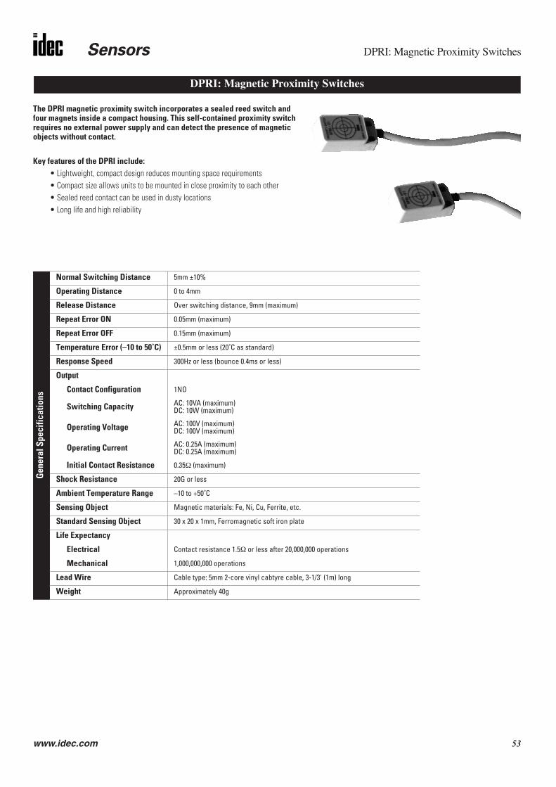
Sensors DPRI: Magnetic Proximity Switches
www.idec.com 53
The DPRI magnetic proximity switch incorporates a sealed reed switch and four magnets inside a compact housing. This self-contained proximity switch requires no external power supply and can detect the presence of magnetic objects without contact.
Key features of the DPRI include:• Lightweight, compact design reduces mounting space requirements• Compact size allows units to be mounted in close proximity to each other• Sealed reed contact can be used in dusty locations• Long life and high reliability
Gen
eral
Spe
cific
atio
ns
Normal Switching Distance 5mm ±10%
Operating Distance 0 to 4mm
Release Distance Over switching distance, 9mm (maximum)
Repeat Error ON 0.05mm (maximum)
Repeat Error OFF 0.15mm (maximum)
Temperature Error (–10 to 50˚C) ±0.5mm or less (20˚C as standard)
Response Speed 300Hz or less (bounce 0.4ms or less)
Output
Contact Configuration 1NO
Switching Capacity AC: 10VA (maximum)DC: 10W (maximum)
Operating Voltage AC: 100V (maximum)DC: 100V (maximum)
Operating Current AC: 0.25A (maximum)DC: 0.25A (maximum)
Initial Contact Resistance 0.35Ω (maximum)
Shock Resistance 20G or less
Ambient Temperature Range –10 to +50˚C
Sensing Object Magnetic materials: Fe, Ni, Cu, Ferrite, etc.
Standard Sensing Object 30 x 20 x 1mm, Ferromagnetic soft iron plate
Life Expectancy
Electrical Contact resistance 1.5Ω or less after 20,000,000 operations
Mechanical 1,000,000,000 operations
Lead Wire Cable type: 5mm 2-core vinyl cabtyre cable, 3-1/3' (1m) long
Weight Approximately 40g
DPRI: Magnetic Proximity Switches

DPRI: Magnetic Proximity Switches Sensors
54 www.idec.com
0.24"(6mm)
0.47"(12mm)
0.39"(10mm)
0.73" (18.5mm)
0.7"
(18m
m)
0.2"
(5m
m)
39.3
7"(1
000m
m)
1.46
"(3
7mm
)
1.12
"(2
8.5m
m)
Close Mounting
Single Mounting
M3 or 3, 2-3, 6 dia
0.39"
(10mm)
P = 0.75" (19mm)
P
0.39"(10mm)
0.39"(10mm)
0.35"(9mm)
Operation Principle
Dimensions
Part Number: DPRI Switches
Part Number DescriptionDPRI-01 Magnetic Proximity Switch
The DPRI incorporates four magnets and a sealed reed switch. The contacts of thereed switch are held normally open by the magnetic field of the four magnets.When a metallic object is within the sensing range, the magnetic field is neutral-ized, closing the contacts of the reed switch. When the object is removed beyondthe sensing distance, the magnetic field is restored and the contacts of the reedswitch open.

Sensors General Information
www.idec.com 55
Do not operate a sensor under any conditions exceeding these specifica-tions.
Do not operate a sensor under current and voltage conditions other thanthose for which the individual sensor is rated.
Do not exceed the recommended operating temperature and humidity.Although sensors are rated for operation below 0°C, this specificationdoes not imply that performance characteristics will remain constantunder prolonged freezing conditions. Continued exposure and the accom-panying frost, ice, dew, and condensation which accumulate on the opti-cal surface will adversely affect sensor performance.
To maintain superior performance characteristics, do not exceed vibrationand shock resistance ratings while operating a sensor. In addition, avoidisolated impacts to the sensor housing which are severe enough toadversely affect the waterproof characteristics.
Sensors rated IP67 are resistant to moisture when occasionally immersedin still water. Sensors rated IP64 through IP66 are resistant to moisturewhen occasionally subjected to splashing or when located in the vicinityof turbulent waters. These ratings do not imply that a sensor is intendedfor use under continual high-pressure water spray. Avoid such applica-tions to maintain optimal sensor performance.
Sensors rated IP64 through IP67 are dust-tight and water-tight. For bestperformance, avoid using any sensor in an area where it will be subjectedto heavy particle blasts and where dust, water, or steam will accumulateon the optical surface.
Do not test the housing for dielectric strength and insulation resistance,since the housing is connected to the electronic circuit ground of a sensor.Do not perform dielectric strength and insulation resistance tests on elec-trical systems without disconnecting photoelectric sensors, as such test-ing may result in damage to the sensor.
Several lines of sensors, as noted in the individual operation sections, areprovided with an internal circuit to turn an output off for a specifiedamount of time upon power-up. This delay is normal; it prevents a tran-sient state when turning power on.
The optical surface of each sensor must be cleaned on a regular basis forcontinual superior performance. Use a soft cloth dipped in isopropyl alco-hol to remove dust and moisture build-up.
IMPORTANT: Do not use organic solvents (such as thinner, ammonia,caustic soda, or benzene) to clean any part of a sensor.
All sensors experience signal inconsistencies under the influence ofinductive noise. Do not use sensors in close proximity to transformers,large inductive motors, or generators. Avoid using sensors in direct con-tact with sources of excessive heat. Also avoid operation in close proxim-ity to welding equipment.
Specifications
IEC (International Electrotechnical Commission) Ratings
Start-up
Optimum Performance
Bright, extraneous light such as sunlight, incandescent lights, or fluorescentlights may impair the performance of sensors in detecting colour or light.
Make sure that extraneous light does not exceed recommended levels foundin the individual specifications sections. When 500 lux is specified, this isequal to 50 footcandles. The average factory illumination is ordinarily belowthis level, except in areas where visual inspection is being performed. Only insuch brightly lit areas is incident light of particular concern.
Unwanted light interference can often be avoided simply by making sure thatthe optical receiver is not aimed directly toward a strong light source. Whenmounting direction cannot be adjusted, place a light barrier between allnearby light sources and the receiver.
When installing sensors which detect reflected light, make sure thatunwanted light reflections from nearby surfaces, such as the floor, walls,reflective machinery, or stainless steel, do not reach the optical receiver.
Also, make sure that reflected-light sensors mounted in close proximity do notcause interfering reflections. When it is not possible to maintain the recom-mended clearance between sensors, as noted in the individual installationsections, provide light barriers between sensors.
A slit attachment is available to modify the beam size of through-beam sen-sors. This option is recommended for detecting very small objects (near thesize of the smallest object which a sensor can detect) or for eliminating lightinterference when sensors are mounted in close proximity.
IMPORTANT: Always consider safety when installing a laser sensor of any kind.Make sure that the laser beam cannot inadvertently shine into the eyes of peoplepassing by or working in the vicinity. See safety information on page Q-25.
The mounting bracket and hardware are included with sensors, where appli-cable. Use the appropriate hardware for mounting, along with washers andspring washers or lock nuts. Do not overtighten attachment hardware. Over-tightening causes damage to the housing and will adversely affect the water-proof characteristics of the sensor.
Best results can be obtained when the sensor is mounted so that the objectsensed is in the center of the beam, rather than when the object is locatednear the edges of the sensing window. In addition, the most reliable sensingoccurs when the majority of the objects being sensed are well within thesensing range, rather than at the extreme near and far limits.
3. SA6A ultrasonic sensors are not affected by extraneous light.
Mounting
Reflected-Light Sensors
Through-Beam Sensors
Laser Sensors
Extraneous Light
General Information
1. Even though the SA6A ultrasonic sensor features protection against noise, there may be adverse effects from strong noise.2. It is strongly recommended to avoid using any sensor where it will be continually subjected to elements which impair performance or cause cor-
rosive damage to the sensor. In particular, avoid strong vibrations and shocks, corrosive gases, oils, and chemicals, as well as blasts of water, steam, dust, or other particles.

General Information Sensors
56 www.idec.com
Avoid running high-voltages or power lines in the same conduit with sensorsignal lines. This prevents inaccurate results or damage from induced noise.Use a separate conduit when the influence of power lines or electromagneticequipment may occur, particularly when the distance of the wiring is extended.
IMPORTANT: Connect the sensor cables and wires as noted in the individualWiring sections. Failure to connect as shown in wiring diagrams will result indamage to the internal circuit.
When extending sensor cables and wires, make sure to use cables equal orsuperior to that recommended in the individual specifications sections.
When wiring terminals, be sure to prevent contact between adjoining termi-nals. When using ring or fork lug terminals, use the insulated sleeve styleonly. Each sensor terminal can accept only one ring of fork lug terminal.
On ISF series photoelectric sensors, use recommended cable, along with theattached packing gland and washer, when wiring the terminals. This ensureswaterproof and dustproof characteristics.
Noise resistance characteristics are improved when a sensor is grounded tothe 0V power terminal. If the 0V power terminal is not at ground potential, usea ceramic 0.01µF capacitor which can withstand 250V AC minimum.
When using a switching power supply, be sure to ground the FG terminal toeliminate high-frequency noise. The power supply should include an insulat-ing transformer, not an autotransformer.
On ISF series photoelectric sensors, the power supply should be sized accord-ing to the voltage drop through the lead wire when using a long extension forthe DC type (328' or 100m maximum extension).
The compact PS5R-A power supply is the perfect companion item for mostIDEC sensors. This power supply is only 1.77" (45mm) wide, 3.15" (80mm) tall,and 2.76" (70mm) deep. Call an IDEC representative for more details.
Strong magnetic fields may detract from the accuracy of the sensing measure-ment. Avoid mounting a sensor directly to machinery, since the housing is con-nected to the electronic circuit ground of the sensor. If it is necessary to mounta sensor on machinery, use the insulating plate and sleeve provided.
Part Number Output Ratings
PS5R-A12 12V DC, 0.62A
PS5R-A24 24V DC, 0.32A
Attenuation: Reduction of beam intensity as a result of environmental factorssuch as dust, humidity, steam, etc.
Dark on: Output energized when light is not detected by the receiving element.For through-beam sensors, light from the projector is not detected by thereceiver when an object is present. For reflected light sensors, light is notdetected when it is not reflected from an object surface.
Diffuse-reflected light sensors: Sensors that detect all scattered, reflectedlight. Light reflected from nearby surfaces, as well as intended object surface,is detected. Diffuse-reflected light sensors are often called “proximityswitches,” since they switch when any object is near. Also use to detect colourcontrast when colours reflect light intensity differently (green LED recom-mended for this application).
EEPROM: Acronym which stands for electronically erasable, programmable,read only memory.
Excess gain: Ratio of optical power available at a given projector-to-receiverrange divided by the minimum optical power required to trigger the receiver.
Extraneous light: Incident light received by a sensor, irrelated to the presenceor absence of object being detected. Extraneous light is usually unwanted back-ground light such as sunlight and incandescent lamps in close proximity.
∆E: The measurement of colour difference as a three-variable function, locatedon an XYZ axis of light, hue, and chroma values.
Hysteresis: Operating point and release point at different levels. For solidstate sensors, this is accomplished electrically. For mechanical switches, itresults from storing potential energy before the transition occurs.
Light on: Output energized when light is detected by receiving element. Forthrough-beam sensors, light from the projector is detected by the receiverwhen an object is not present. For reflected light sensors, light is detectedwhen it is reflected from an object surface.
Linearity: Measurement of how nearly linear, that is, how accurate actual ana-logue output is, with respect to distance.
NPN/PNP: Types of open collector transistors. NPN is a sink transistor; outputon establishes negative potential difference. PNP is a source transistor; outputon establishes positive potential difference.
Polarizing: Filtering out all reflected light except that which is projected in oneplane only. Polarized retro-reflected light sensors detect the light from corner-cube type reflectors when an object is not present.
Reflected-light sensors: Sensors with the projector and receiver in one hous-ing. Light is projected by the light source, and reflected light is received by theoptical surface. Includes diffuse-reflected, retro-reflected, limited-reflected,and spot-reflected sensors.
Repeatability: Ability of a sensor to reproduce output readings consistentlywhen the same value is applied consecutively, in the same direction, for a spec-ified number of cycles, or for a specified time duration.
Resolution: Overall dimension of the smallest object which can be detected(when sensing the presence of an object) or smallest increment of distancewhich can be distinguished with reliable results (when sensing the position ofan object).
Response time: Time elapsed between input and output. Total response timeis the sum of object detection, amplifier response, and output response times.
Retro-reflective scan: This type of reflected light sensor uses a specialreflector to return projected light when an object is not present. Sensor detectsthe presence of an object when the light is reflected differently.
Through-beam sensors: Sensors with a separate projector and receiver. Thelight source from the projector is detected by the receiver, except when anobject is present.
Transient: Undesirable surge of current (many times larger than normal cur-rent) for a very short period, such as during the start-up of an inductive motor.
Glossary
Power Supply
Wiring
Power Supply
Miscellaneous

Sensors Part Number Index
www.idec.com 57
Part Number Index
DDPRI- 54
IIAC- 33ISF- 51
MMX1C- 24
SSA1C-F 44SA1C-FK 38SA1D- 31SA1E-D 32SA1E-N 32SA1E-P 32SA1E-T 32SA1J-C 5SA1J-F 7SA1M- 11SA1W- 16SA6A- 28SA9C-CA 47SA9F 40SA9F-DA 7SA9F-DC 38, 44, 46SA9F-DD 44, 46SA9F-DH 39, 44, 47SA9F-DL 44, 47SA9F-DM 39, 44, 46SA9F-DS 38, 44, 46SA9F-DT 38, 44, 46SA9F-TC 40, 44, 45SA9F-TH 40, 44, 45SA9F-TL 40, 44, 45SA9F-TM 40, 44, 45SA9F-TS 40, 44, 45SA9F-TT 40, 44, 45SA9W- 16SA9Z- 33SA9Z-F 7, 16, 47, 48SA9Z-F0 47

Sensors
58 www.idec.com
Related Documents