1 SENSORS AND ACTUATORS PREPARED BY Dr. T.LAKSHMIBAI, A.P/EIE DEPARTMENT OF ELECTRONICS & INSTRUMENTATION ENGINEERING SCSVMV

Welcome message from author
This document is posted to help you gain knowledge. Please leave a comment to let me know what you think about it! Share it to your friends and learn new things together.
Transcript
1
SENSORS AND ACTUATORS
PREPARED BY
Dr. T.LAKSHMIBAI, A.P/EIE
DEPARTMENT OF ELECTRONICS & INSTRUMENTATION
ENGINEERING
SCSVMV
2
Lecture notes on Sensors and Actuators
Prepared by: Dr.T.Lakshmibai, Assistant Professor/EIE, SCSVMV.
INDEX
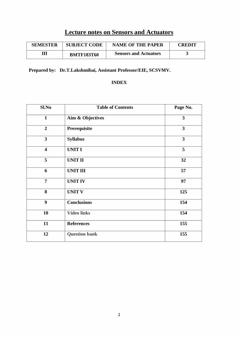
Sl.No Table of Contents Page No.
1 Aim & Objectives 3
2 Prerequisite 3
3 Syllabus 3
4 UNIT I 5
5 UNIT II 32
6 UNIT III 57
7 UNIT IV 97
8 UNIT V 125
9 Conclusions 154
10 Video links 154
11 References 155
12 Question bank 155
SEMESTER SUBJECT CODE NAME OF THE PAPER CREDIT
III BMTF183T60 Sensors and Actuators 3
3
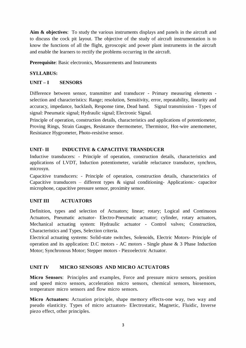
Aim & objectives: To study the various instruments displays and panels in the aircraft and
to discuss the cock pit layout. The objective of the study of aircraft instrumentation is to
know the functions of all the flight, gyroscopic and power plant instruments in the aircraft
and enable the learners to rectify the problems occurring in the aircraft.
Prerequisite: Basic electronics, Measurements and Instruments
SYLLABUS:
UNIT – I SENSORS
Difference between sensor, transmitter and transducer - Primary measuring elements -
selection and characteristics: Range; resolution, Sensitivity, error, repeatability, linearity and
accuracy, impedance, backlash, Response time, Dead band. Signal transmission - Types of
signal: Pneumatic signal; Hydraulic signal; Electronic Signal.
Principle of operation, construction details, characteristics and applications of potentiometer,
Proving Rings, Strain Gauges, Resistance thermometer, Thermistor, Hot-wire anemometer,
Resistance Hygrometer, Photo-resistive sensor.
UNIT- II INDUCTIVE & CAPACITIVE TRANSDUCER
Inductive transducers: - Principle of operation, construction details, characteristics and
applications of LVDT, Induction potentiometer, variable reluctance transducer, synchros,
microsyn.
Capacitive transducers: - Principle of operation, construction details, characteristics of
Capacitive transducers – different types & signal conditioning- Applications:- capacitor
microphone, capacitive pressure sensor, proximity sensor.
UNIT III ACTUATORS Definition, types and selection of Actuators; linear; rotary; Logical and Continuous
Actuators, Pneumatic actuator- Electro-Pneumatic actuator; cylinder, rotary actuators,
Mechanical actuating system: Hydraulic actuator - Control valves; Construction,
Characteristics and Types, Selection criteria.
Electrical actuating systems: Solid-state switches, Solenoids, Electric Motors- Principle of
operation and its application: D.C motors - AC motors - Single phase & 3 Phase Induction
Motor; Synchronous Motor; Stepper motors - Piezoelectric Actuator.
UNIT IV MICRO SENSORS AND MICRO ACTUATORS Micro Sensors: Principles and examples, Force and pressure micro sensors, position
and speed micro sensors, acceleration micro sensors, chemical sensors, biosensors,
temperature micro sensors and flow micro sensors.
Micro Actuators: Actuation principle, shape memory effects-one way, two way and
pseudo elasticity. Types of micro actuators- Electrostatic, Magnetic, Fluidic, Inverse
piezo effect, other principles.
4
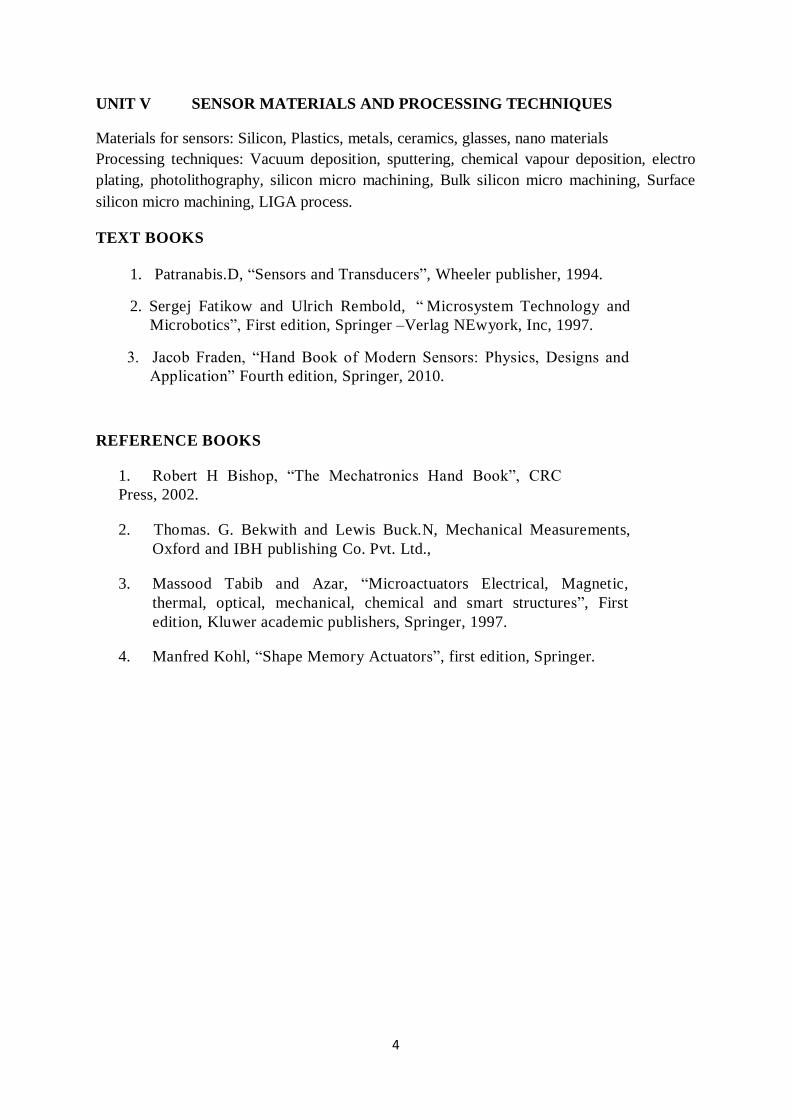
UNIT V SENSOR MATERIALS AND PROCESSING TECHNIQUES
Materials for sensors: Silicon, Plastics, metals, ceramics, glasses, nano materials
Processing techniques: Vacuum deposition, sputtering, chemical vapour deposition, electro
plating, photolithography, silicon micro machining, Bulk silicon micro machining, Surface
silicon micro machining, LIGA process.
TEXT BOOKS
1. Patranabis.D, “Sensors and Transducers”, Wheeler publisher, 1994.
2. Sergej Fatikow and Ulrich Rembold, “ Microsystem Technology and
Microbotics”, First edition, Springer –Verlag NEwyork, Inc, 1997.
3. Jacob Fraden, “Hand Book of Modern Sensors: Physics, Designs and
Application” Fourth edition, Springer, 2010.
REFERENCE BOOKS
1. Robert H Bishop, “The Mechatronics Hand Book”, CRC
Press, 2002.
2. Thomas. G. Bekwith and Lewis Buck.N, Mechanical Measurements,
Oxford and IBH publishing Co. Pvt. Ltd.,
3. Massood Tabib and Azar, “Microactuators Electrical, Magnetic,
thermal, optical, mechanical, chemical and smart structures”, First
edition, Kluwer academic publishers, Springer, 1997.
4. Manfred Kohl, “Shape Memory Actuators”, first edition, Springer.
5
UNIT – I SENSORS
Difference between sensor, transmitter and transducer - Primary measuring elements -
selection and characteristics: Range; resolution, Sensitivity, error, repeatability, linearity and
accuracy, impedance, backlash, Response time, Dead band. Signal transmission - Types of
signal: Pneumatic signal; Hydraulic signal; Electronic Signal.
Principle of operation, construction details, characteristics and applications of potentiometer,
Proving Rings, Strain Gauges, Resistance thermometer, Thermistor, Hot-wire anemometer,
Resistance Hygrometer, Photo-resistive sensor.
THEORY
1. BASICS – MEASUREMENT DEVICES
Measurement devices perform a complete measuring function, from initial detection to final
indication. The important aspects of measurement system are
i) Sensor – Primary sensing element
ii) Transducer – changes one form of energy to another form energy
iii) Transmitter – Contains the transducer and produces an amplified, standardized
energy signal.
INTRODUCTION – SENSORS
A device which provides a usable output in response to a specified measurand.
Sensor is a device that detects and responds to some type of input from the physical
environment
Input could be light, heat, motion, moisture, force, pressure, displacement, etc.
It produces a proportional output signal (electrical, mechanical, magnetic, etc.).
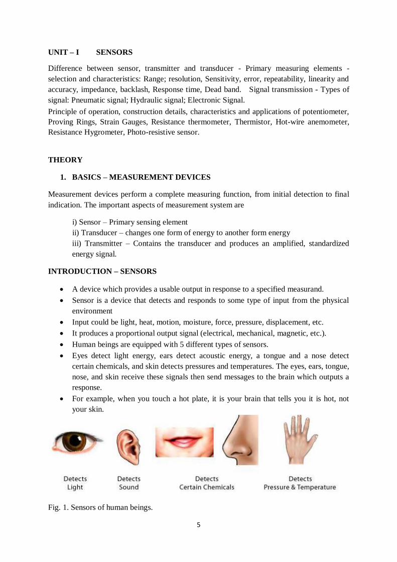
Human beings are equipped with 5 different types of sensors.
Eyes detect light energy, ears detect acoustic energy, a tongue and a nose detect
certain chemicals, and skin detects pressures and temperatures. The eyes, ears, tongue,
nose, and skin receive these signals then send messages to the brain which outputs a
response.
For example, when you touch a hot plate, it is your brain that tells you it is hot, not
your skin.
Fig. 1. Sensors of human beings.
6
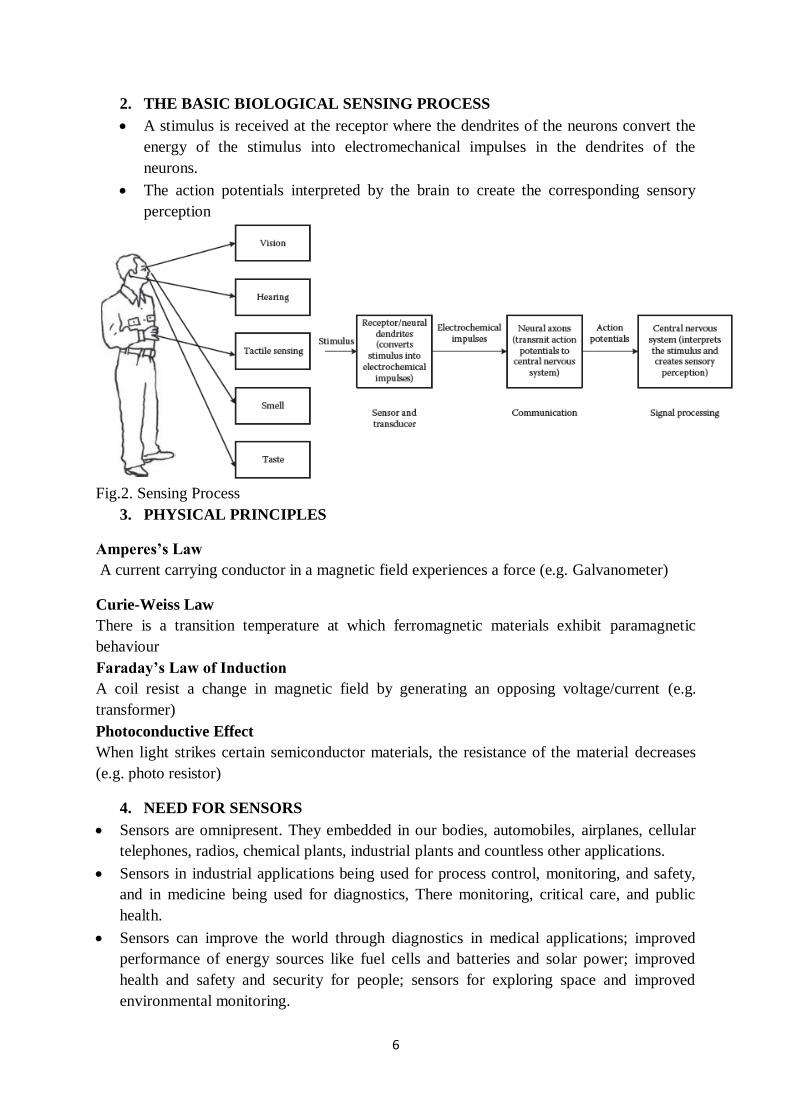
2. THE BASIC BIOLOGICAL SENSING PROCESS
A stimulus is received at the receptor where the dendrites of the neurons convert the
energy of the stimulus into electromechanical impulses in the dendrites of the
neurons.
The action potentials interpreted by the brain to create the corresponding sensory
perception
Fig.2. Sensing Process
3. PHYSICAL PRINCIPLES
Amperes’s Law
A current carrying conductor in a magnetic field experiences a force (e.g. Galvanometer)
Curie-Weiss Law
There is a transition temperature at which ferromagnetic materials exhibit paramagnetic
behaviour
Faraday’s Law of Induction
A coil resist a change in magnetic field by generating an opposing voltage/current (e.g.
transformer)
Photoconductive Effect
When light strikes certain semiconductor materials, the resistance of the material decreases
(e.g. photo resistor)
4. NEED FOR SENSORS
Sensors are omnipresent. They embedded in our bodies, automobiles, airplanes, cellular
telephones, radios, chemical plants, industrial plants and countless other applications.
Sensors in industrial applications being used for process control, monitoring, and safety,
and in medicine being used for diagnostics, There monitoring, critical care, and public
health.
Sensors can improve the world through diagnostics in medical applications; improved
performance of energy sources like fuel cells and batteries and solar power; improved
health and safety and security for people; sensors for exploring space and improved
environmental monitoring.
7
Without the use of sensors, there would be no automation!
We live in the World of Sensors.
In our day-to-day life we frequently use different types of sensors in several applications
We can find different types of Sensors in our homes, offices, cars etc. Working to make
our lives easier by turning on the lights by detecting our presence, adjusting the room
temperature, detect smoke or fire, make us delicious coffee and open garage doors as
soon as our car is near the door and many other tasks.
5. CHARACTERISTICS
1. Range
It is the difference between the maximum and minimum value of the sensed parameter.
Temperature range of a thermocouple is 25-225°C.
2. Resolution
The smallest change the sensor can differentiate. It is also frequently known as the least count
of the sensor. Resolution of an digital sensor is easily determined.
3. Sensitivity
It is the ratio of change in output to a unit change of the input. The sensitivity of digital
sensors is closely related to the resolution. The sensitivity of an analog sensor is the slope of
the output vs input line, or sensor exhibiting truly linear behaviour has a constant sensitivity
over the entire input range.
4. Error
Error is the difference between the result of the measurement and the true value of the
quantity being measured. The classification of errors are as follows:
Bias errors (systematic errors)
Precision (Random errors)
Bias errors are present in all measurement made with a given sensor and cannot be detected
(or) removed by statically means.
5. Accuracy
It is the difference between measured value and true value.
The accuracy defines the closeness between the actual measured value and a true value.
6. Precision
Precision is the ability to reproduce repeatedly with a given accuracy.
7. Repeatability
The ability of a sensor to give same output for repeated applications of same input value.
Repeatability = (maximum – minimum values given) X 100 ⁄ full range
8
8. Impedance
It is the ratio of voltage and current flow for sensor. For a resistive sensor, the impedance Z is
same as the resistance R& its unit is ohms.
ZR = V/I = R
9. Response time
Response time is the amount of time required for a sensor to respond completely to a change
in input. It describes the speed of change in the output on a step-wise change of the
measurand.
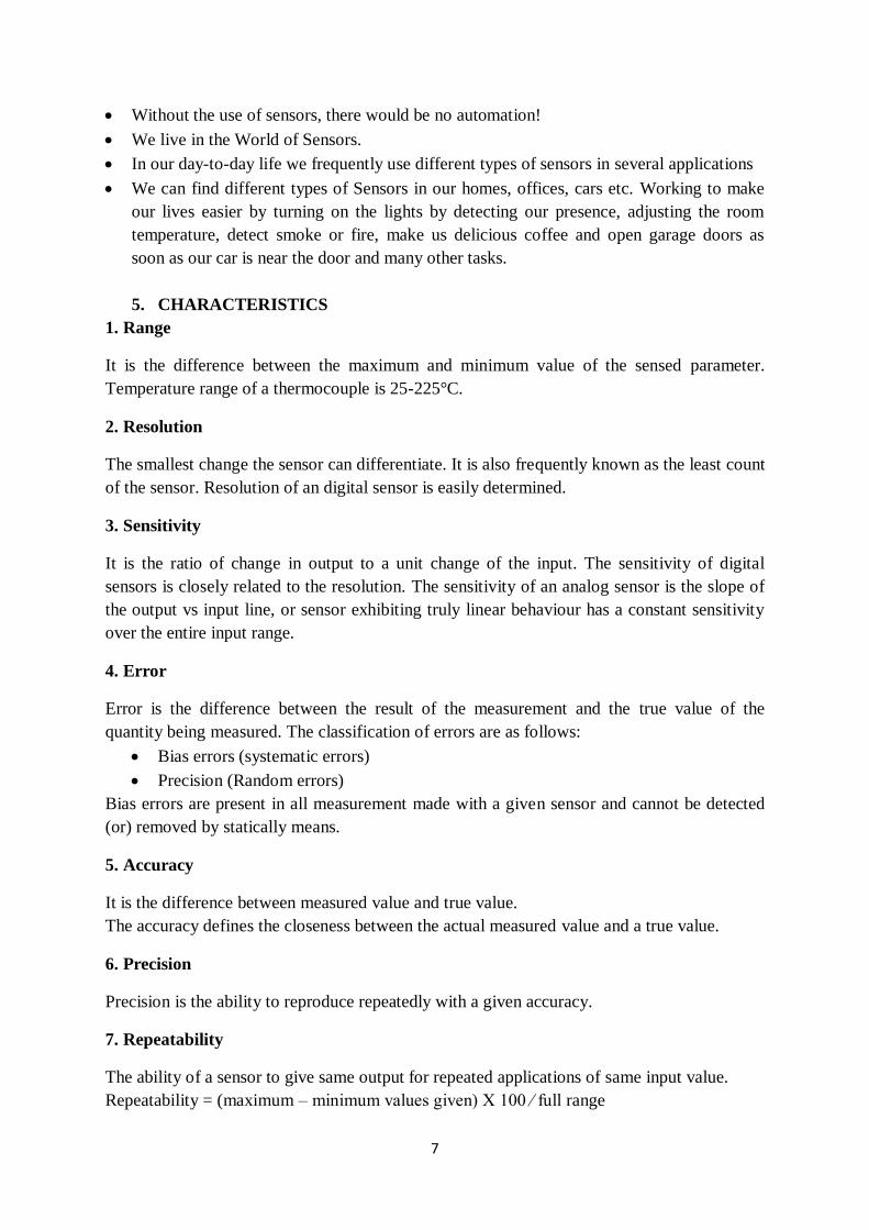
10. Linearity
Percentage of deviation from the best fit linear calibration curve
Non-Linearity
Fig. 3. Non linearity
The nonlinearity indicates the maximum deviation of the actual measured curve of a sensor
from the ideal curve.
Nonlinearity (%) = Maximum deviation in input ⁄ Maximum full scale input
11. Dead band/time
The dead band or dead space of a transducer is the range of input values for which there is no
output. The dead time of a sensor device is the time duration from the application of an input
until the output begins to respond or change.
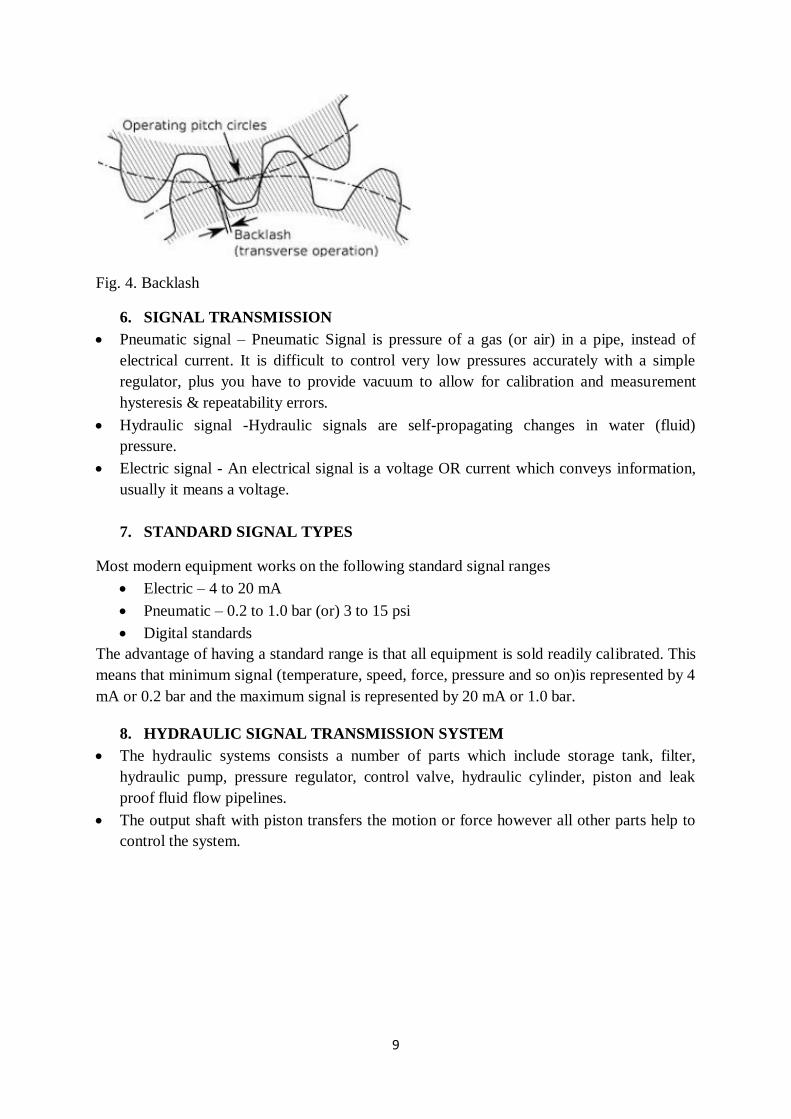
12. Backlash
In engineering, backlash, sometimes called lash or play, is a clearance or lost motion in a
mechanism caused by gaps between the parts.
9
Fig. 4. Backlash
6. SIGNAL TRANSMISSION
Pneumatic signal – Pneumatic Signal is pressure of a gas (or air) in a pipe, instead of
electrical current. It is difficult to control very low pressures accurately with a simple
regulator, plus you have to provide vacuum to allow for calibration and measurement
hysteresis & repeatability errors.
Hydraulic signal -Hydraulic signals are self-propagating changes in water (fluid)
pressure.
Electric signal - An electrical signal is a voltage OR current which conveys information,
usually it means a voltage.
7. STANDARD SIGNAL TYPES
Most modern equipment works on the following standard signal ranges
Electric – 4 to 20 mA
Pneumatic – 0.2 to 1.0 bar (or) 3 to 15 psi
Digital standards
The advantage of having a standard range is that all equipment is sold readily calibrated. This
means that minimum signal (temperature, speed, force, pressure and so on)is represented by 4
mA or 0.2 bar and the maximum signal is represented by 20 mA or 1.0 bar.
8. HYDRAULIC SIGNAL TRANSMISSION SYSTEM
The hydraulic systems consists a number of parts which include storage tank, filter,
hydraulic pump, pressure regulator, control valve, hydraulic cylinder, piston and leak
proof fluid flow pipelines.
The output shaft with piston transfers the motion or force however all other parts help to
control the system.
10
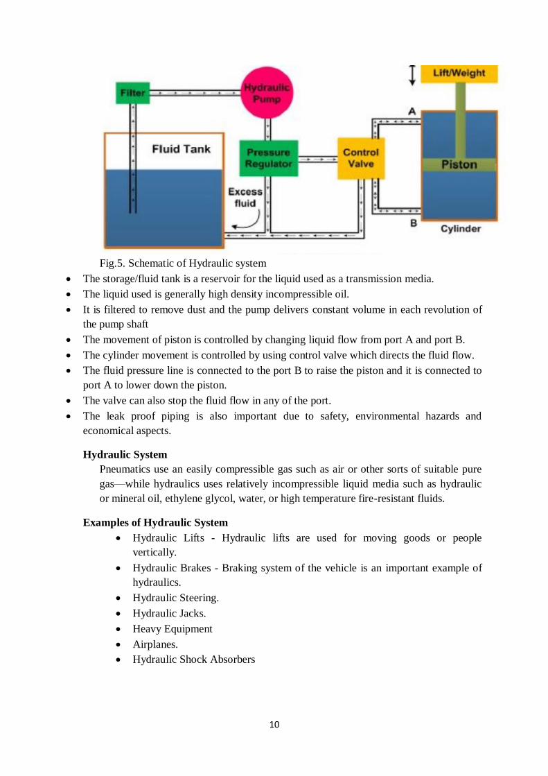
Fig.5. Schematic of Hydraulic system
The storage/fluid tank is a reservoir for the liquid used as a transmission media.
The liquid used is generally high density incompressible oil.
It is filtered to remove dust and the pump delivers constant volume in each revolution of
the pump shaft
The movement of piston is controlled by changing liquid flow from port A and port B.
The cylinder movement is controlled by using control valve which directs the fluid flow.
The fluid pressure line is connected to the port B to raise the piston and it is connected to
port A to lower down the piston.
The valve can also stop the fluid flow in any of the port.
The leak proof piping is also important due to safety, environmental hazards and
economical aspects.
Hydraulic System
Pneumatics use an easily compressible gas such as air or other sorts of suitable pure
gas—while hydraulics uses relatively incompressible liquid media such as hydraulic
or mineral oil, ethylene glycol, water, or high temperature fire-resistant fluids.
Examples of Hydraulic System
Hydraulic Lifts - Hydraulic lifts are used for moving goods or people
vertically.
Hydraulic Brakes - Braking system of the vehicle is an important example of
hydraulics.
Hydraulic Steering.
Hydraulic Jacks.
Heavy Equipment
Airplanes.
Hydraulic Shock Absorbers
11
9. PNEUMATIC SIGNAL TRANSMISSION SYSTEM
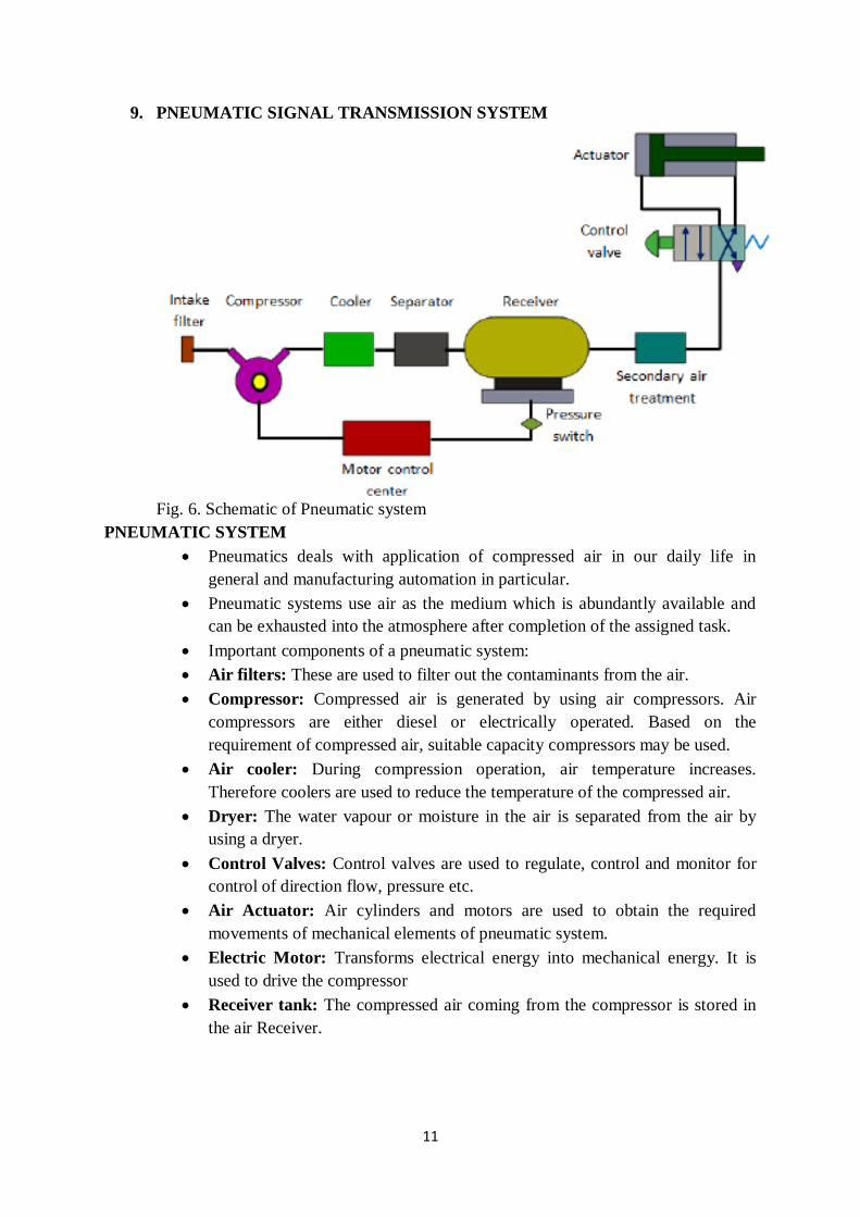
Fig. 6. Schematic of Pneumatic system
PNEUMATIC SYSTEM
Pneumatics deals with application of compressed air in our daily life in
general and manufacturing automation in particular.
Pneumatic systems use air as the medium which is abundantly available and
can be exhausted into the atmosphere after completion of the assigned task.
Important components of a pneumatic system:
Air filters: These are used to filter out the contaminants from the air.
Compressor: Compressed air is generated by using air compressors. Air
compressors are either diesel or electrically operated. Based on the
requirement of compressed air, suitable capacity compressors may be used.
Air cooler: During compression operation, air temperature increases.
Therefore coolers are used to reduce the temperature of the compressed air.
Dryer: The water vapour or moisture in the air is separated from the air by
using a dryer.
Control Valves: Control valves are used to regulate, control and monitor for
control of direction flow, pressure etc.
Air Actuator: Air cylinders and motors are used to obtain the required
movements of mechanical elements of pneumatic system.
Electric Motor: Transforms electrical energy into mechanical energy. It is
used to drive the compressor
Receiver tank: The compressed air coming from the compressor is stored in
the air Receiver.
12
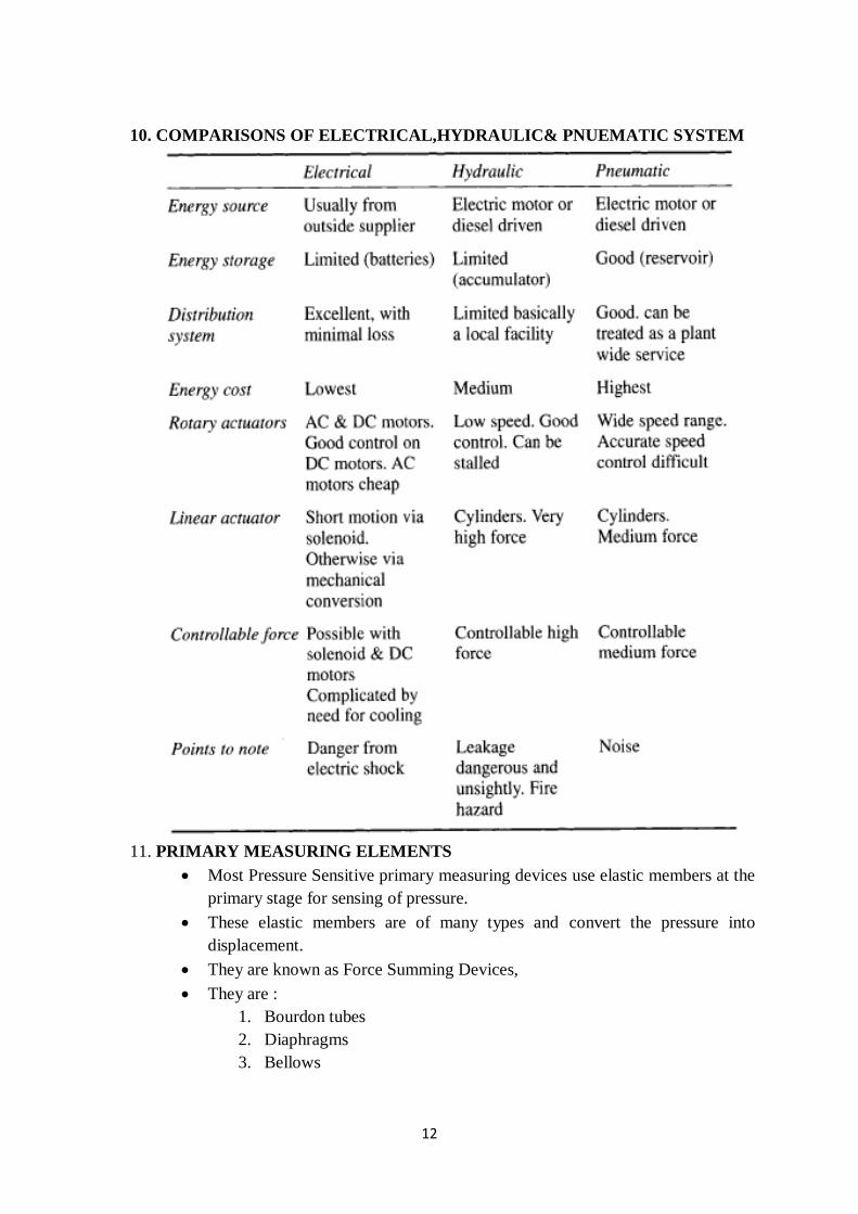
10. COMPARISONS OF ELECTRICAL,HYDRAULIC& PNUEMATIC SYSTEM
11. PRIMARY MEASURING ELEMENTS
Most Pressure Sensitive primary measuring devices use elastic members at the
primary stage for sensing of pressure.
These elastic members are of many types and convert the pressure into
displacement.
They are known as Force Summing Devices,
They are :
1. Bourdon tubes
2. Diaphragms
3. Bellows
13
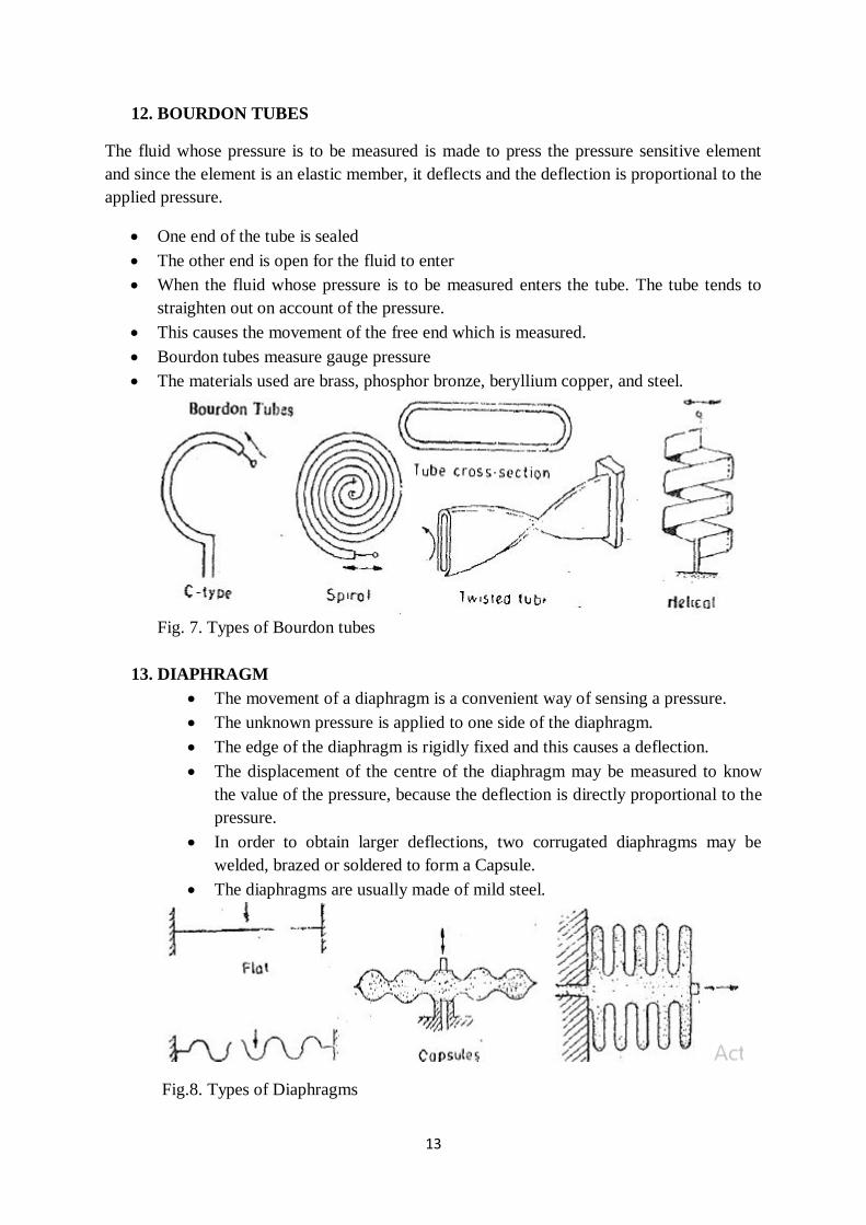
12. BOURDON TUBES
The fluid whose pressure is to be measured is made to press the pressure sensitive element
and since the element is an elastic member, it deflects and the deflection is proportional to the
applied pressure.
One end of the tube is sealed
The other end is open for the fluid to enter
When the fluid whose pressure is to be measured enters the tube. The tube tends to
straighten out on account of the pressure.
This causes the movement of the free end which is measured.
Bourdon tubes measure gauge pressure
The materials used are brass, phosphor bronze, beryllium copper, and steel.
Fig. 7. Types of Bourdon tubes
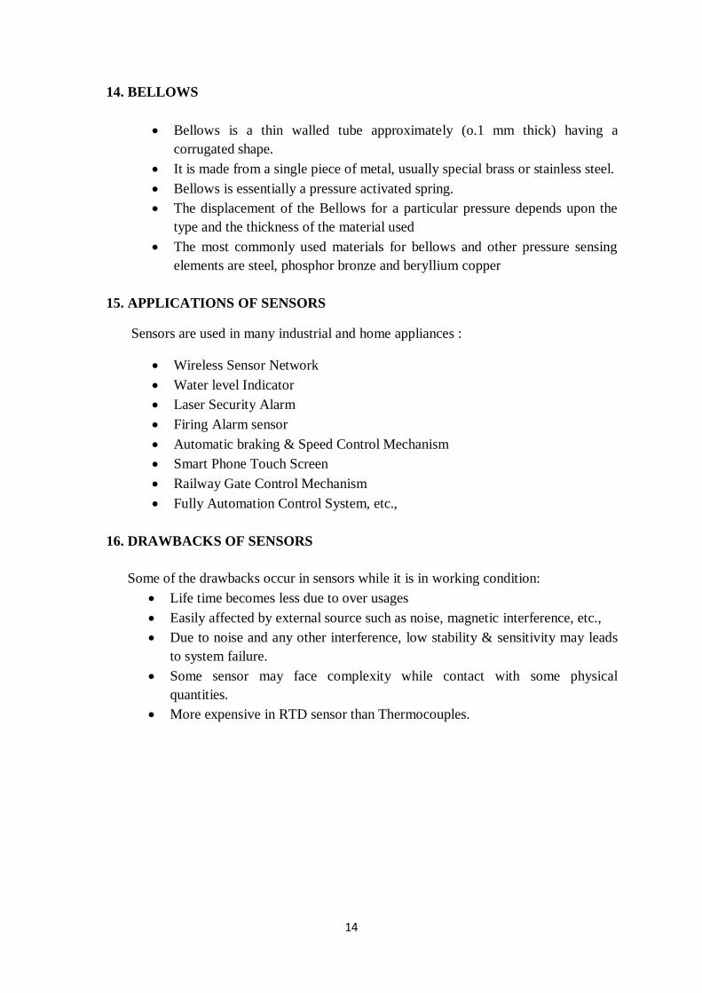
13. DIAPHRAGM
The movement of a diaphragm is a convenient way of sensing a pressure.
The unknown pressure is applied to one side of the diaphragm.
The edge of the diaphragm is rigidly fixed and this causes a deflection.
The displacement of the centre of the diaphragm may be measured to know
the value of the pressure, because the deflection is directly proportional to the
pressure.
In order to obtain larger deflections, two corrugated diaphragms may be
welded, brazed or soldered to form a Capsule.
The diaphragms are usually made of mild steel.
Fig.8. Types of Diaphragms
14
14. BELLOWS
Bellows is a thin walled tube approximately (o.1 mm thick) having a
corrugated shape.
It is made from a single piece of metal, usually special brass or stainless steel.
Bellows is essentially a pressure activated spring.
The displacement of the Bellows for a particular pressure depends upon the
type and the thickness of the material used
The most commonly used materials for bellows and other pressure sensing
elements are steel, phosphor bronze and beryllium copper
15. APPLICATIONS OF SENSORS
Sensors are used in many industrial and home appliances :
Wireless Sensor Network
Water level Indicator
Laser Security Alarm
Firing Alarm sensor
Automatic braking & Speed Control Mechanism
Smart Phone Touch Screen
Railway Gate Control Mechanism
Fully Automation Control System, etc.,
16. DRAWBACKS OF SENSORS
Some of the drawbacks occur in sensors while it is in working condition:
Life time becomes less due to over usages
Easily affected by external source such as noise, magnetic interference, etc.,
Due to noise and any other interference, low stability & sensitivity may leads
to system failure.
Some sensor may face complexity while contact with some physical
quantities.
More expensive in RTD sensor than Thermocouples.
15
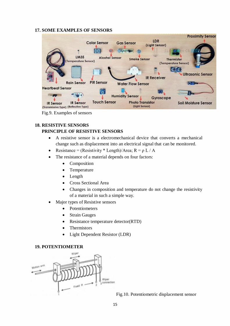
17. SOME EXAMPLES OF SENSORS
Fig.9. Examples of sensors
18. RESISTIVE SENSORS
PRINCIPLE OF RESISTIVE SENSORS
A resistive sensor is a electromechanical device that converts a mechanical
change such as displacement into an electrical signal that can be monitored.
Resistance = (Resistivity * Length)/Area; R = ρ L / A
The resistance of a material depends on four factors:
Composition
Temperature
Length
Cross Sectional Area
Changes in composition and temperature do not change the resistivity
of a material in such a simple way.
Major types of Resistive sensors
Potentiometers
Strain Gauges
Resistance temperature detector(RTD)
Thermistors
Light Dependent Resistor (LDR)
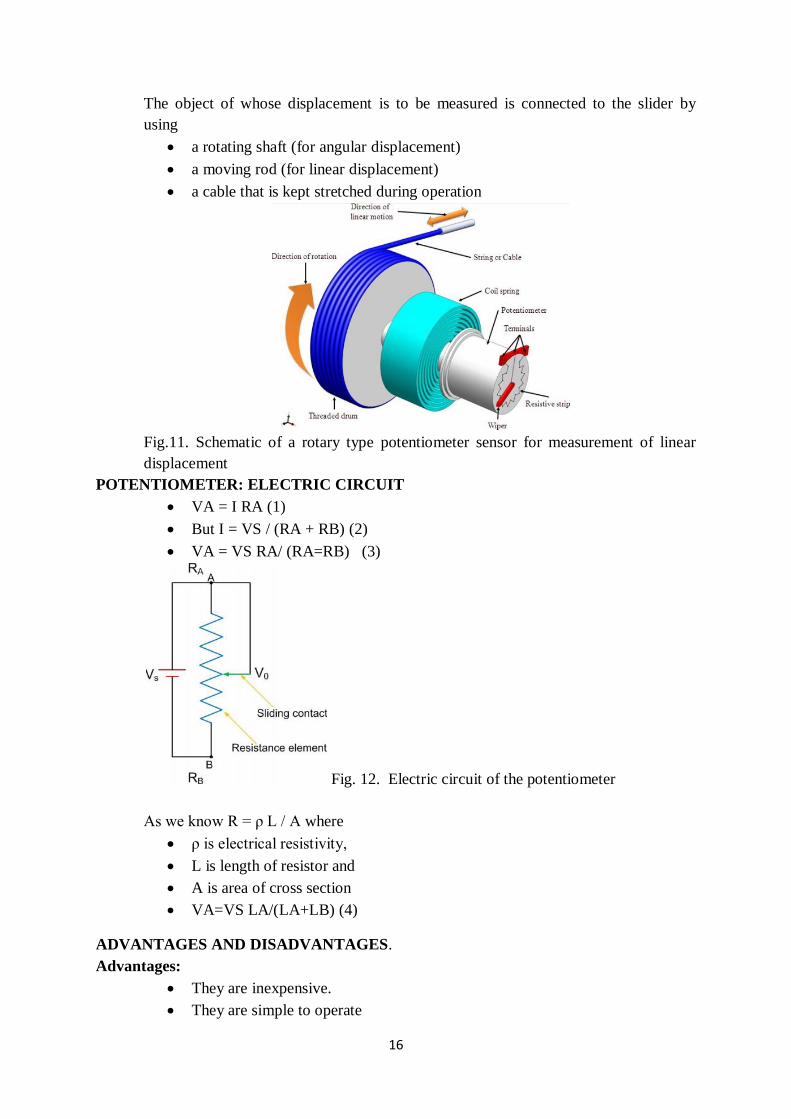
19. POTENTIOMETER
Fig.10. Potentiometric displacement sensor
16
The object of whose displacement is to be measured is connected to the slider by
using
a rotating shaft (for angular displacement)
a moving rod (for linear displacement)
a cable that is kept stretched during operation
Fig.11. Schematic of a rotary type potentiometer sensor for measurement of linear
displacement
POTENTIOMETER: ELECTRIC CIRCUIT
VA = I RA (1)
But I = VS / (RA + RB) (2)
VA = VS RA/ (RA=RB) (3)
Fig. 12. Electric circuit of the potentiometer
As we know R = ρ L / A where
ρ is electrical resistivity,
L is length of resistor and
A is area of cross section
VA=VS LA/(LA+LB) (4)
ADVANTAGES AND DISADVANTAGES.
Advantages:
They are inexpensive.
They are simple to operate
17
They are very useful for measurement of large amplitudes of displacement.
Their electrical efficiency is very high
It should be understood that while the frequency response of wire wound
potentiometers is limited, the other types of potentiometers are free from this
problem.
In wire wound potentiometers the resolution is limited while in Cermet and
metal film potentiometers, the resolution is infinite.
Disadvantages:
Using a linear potentiometer requires a large force to move their sliding contacts
(wipers). The other problems with sliding contacts are that they can be contaminated,
can wear out, become misaligned and generate noise. So the life of limited
APPLICATIONS
These sensors are primarily used in the control systems with a feedback loop to ensure
that the moving member or component reaches its commanded position. used on
machine-tool controls, elevators, liquid-level assemblies, forklift trucks, automobile
throttle controls In manufacturing, these are used in control of injection molding
machines, woodworking machinery, printing, spraying, robotics, etc. used in
computer-controlled monitoring of sports equipment.
20. PROVING RINGS
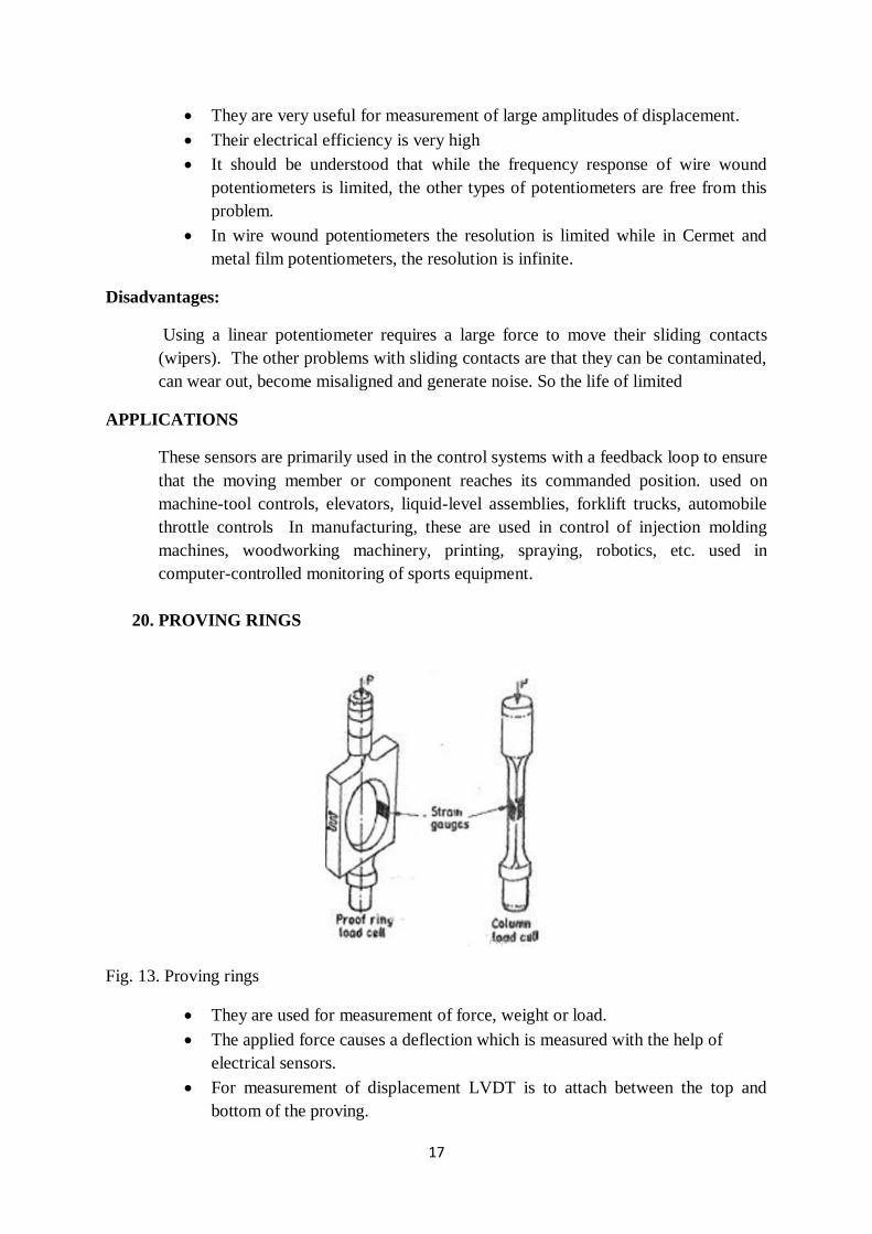
Fig. 13. Proving rings
They are used for measurement of force, weight or load.
The applied force causes a deflection which is measured with the help of
electrical sensors.
For measurement of displacement LVDT is to attach between the top and
bottom of the proving.
18
When the force is applied, the relative displacement can be measured. An LVDT is normally
used for measurement of deflection which is of the order of I mm or so. Another method is to
use strain gauges for measurement of strain in a ring or a column type of element. This is
called a Load Cell. Both compressive as well as tensile stresses can be measured with the
help of load cells.
21. STRAIN GAUGE – PRINCIPLE
If a metal conductor is stretched or compressed, its resistance changes on account of the
fact that both length and diameter of conductor change.
Also there is a change in the value of resistivity of the conductor when it is strained and
this property is called piezo resistive effect.
Therefore, resistance strain gauges are also known as piezo resistive gauges.
The strain gauges are used for measurement of strain and in many detectors notably the
load cells, Torque meters, diaphragm type pressure gauges, temperature sensors,
accelerometers and flow meters, they employ strain gauges as secondary sensors
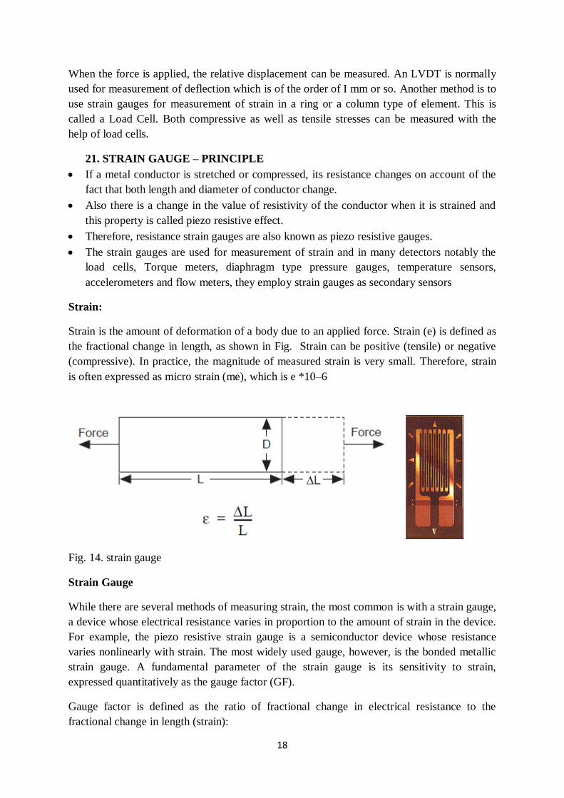
Strain:
Strain is the amount of deformation of a body due to an applied force. Strain (e) is defined as
the fractional change in length, as shown in Fig. Strain can be positive (tensile) or negative
(compressive). In practice, the magnitude of measured strain is very small. Therefore, strain
is often expressed as micro strain (me), which is e *10–6
Fig. 14. strain gauge
Strain Gauge
While there are several methods of measuring strain, the most common is with a strain gauge,
a device whose electrical resistance varies in proportion to the amount of strain in the device.
For example, the piezo resistive strain gauge is a semiconductor device whose resistance
varies nonlinearly with strain. The most widely used gauge, however, is the bonded metallic
strain gauge. A fundamental parameter of the strain gauge is its sensitivity to strain,
expressed quantitatively as the gauge factor (GF).
Gauge factor is defined as the ratio of fractional change in electrical resistance to the
fractional change in length (strain):
19
The Gauge Factor for metallic strain gauges is typically around 2.
SEMICONDUCTOR STRAIN GAUGE
To have a high sensitivity, a high value of gauge factor is desirable. A high gauge factor
means a relatively higher change in resistance which can be easily measured with a good
degree of accuracy.
Semiconductor strain gauges are used where a very high gauge factor and a small envelope
are required.
The resistance of the semi-conductors changes with change in applied strain.
Unlike in the case of metallic gauges where the change in resistance is mainly due to change
in dimensions when strained, the semi-conductor strain gauges depend for the action upon
piezoresistlve effect i.e. the Change in the value of the resistance due to change in resistivity
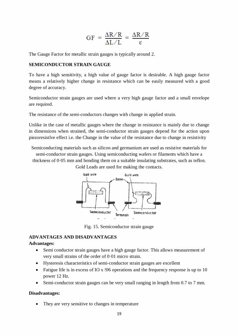
Semiconducting materials such as silicon and germanium are used as resistive materials for
semi-conductor strain gauges. Using semiconducting wafers or filaments which have a
thickness of 0·05 mm and bonding them on a suitable insulating substrates, such as teflon.
Gold Leads are used for making the contacts.
Fig. 15. Semiconductor strain gauge
ADVANTAGES AND DISADVANTAGES
Advantages:
Semi conductor strain gauges have a high gauge factor. This allows measurement of
very small strains of the order of 0·01 micro strain.
Hysteresis characteristics of semi-conductor strain gauges are excellent
Fatigue life is in excess of IO x !06 operations and the frequency response is up to 10
power 12 Hz.
Semi-conductor strain gauges can be very small ranging in length from 0.7 to 7 mm.
Disadvantages:
They are very sensitive to changes in temperature
20
Linearity of the semi-conductor strain gauges is poor.
Semi-conductor strain gauges are more expensive and difficult to attach to the object
under study.
To measure small changes in resistance, and compensate for the temperature
sensitivity, strain gauges are almost always used in a bridge configuration with a
voltage or current excitation source.
Wheatstone bridge, consists of four resistive arms with an excitation voltage, VEX,
that is applied across the bridge
Fig. 16. Basic Wheatstone bridge
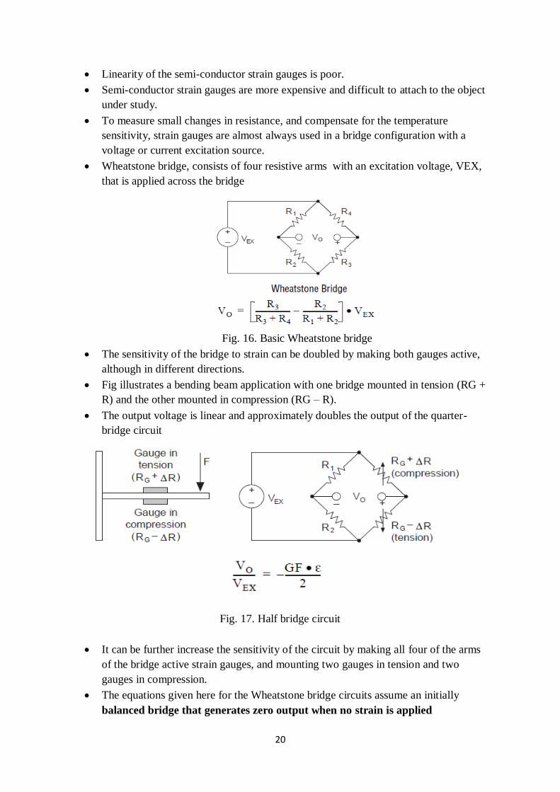
The sensitivity of the bridge to strain can be doubled by making both gauges active,
although in different directions.
Fig illustrates a bending beam application with one bridge mounted in tension (RG +
R) and the other mounted in compression (RG – R).
The output voltage is linear and approximately doubles the output of the quarter-
bridge circuit
Fig. 17. Half bridge circuit
It can be further increase the sensitivity of the circuit by making all four of the arms
of the bridge active strain gauges, and mounting two gauges in tension and two
gauges in compression.
The equations given here for the Wheatstone bridge circuits assume an initially
balanced bridge that generates zero output when no strain is applied
21
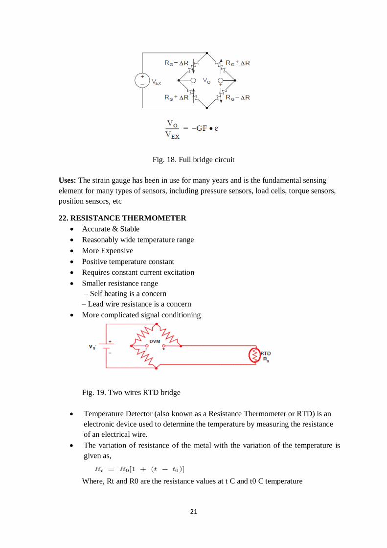
Fig. 18. Full bridge circuit
Uses: The strain gauge has been in use for many years and is the fundamental sensing
element for many types of sensors, including pressure sensors, load cells, torque sensors,
position sensors, etc
22. RESISTANCE THERMOMETER
Accurate & Stable
Reasonably wide temperature range
More Expensive
Positive temperature constant
Requires constant current excitation
Smaller resistance range
– Self heating is a concern
– Lead wire resistance is a concern
More complicated signal conditioning
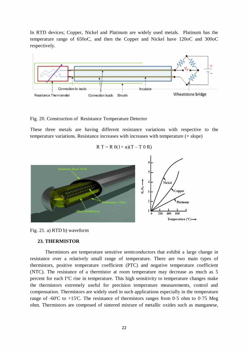
Fig. 19. Two wires RTD bridge
Temperature Detector (also known as a Resistance Thermometer or RTD) is an
electronic device used to determine the temperature by measuring the resistance
of an electrical wire.
The variation of resistance of the metal with the variation of the temperature is
given as,
Where, Rt and R0 are the resistance values at t C and t0 C temperature
22
In RTD devices; Copper, Nickel and Platinum are widely used metals. Platinum has the
temperature range of 650oC, and then the Copper and Nickel have 120oC and 300oC
respectively.
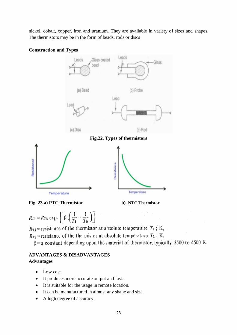
Fig. 20. Construction of Resistance Temperature Detector
These three metals are having different resistance variations with respective to the
temperature variations. Resistance increases with increases with temperature (+ slope)
R T = R 0(1+ α)(T – T 0 R)
Fig. 21. a) RTD b) waveform
23. THERMISTOR
Thermistors are temperature sensitive semiconductors that exhibit a large change in
resistance over a relatively small range of temperature. There are two main types of
thermistors, positive temperature coefficient (PTC) and negative temperature coefficient
(NTC). The resistance of a thermistor at room temperature may decrease as much as 5
percent for each I°C rise in temperature. This high sensitivity to temperature changes make
the thermistors extremely useful for precision temperature measurements, control and
compensation. Thermistors are widely used in such applications especially in the temperature
range of -60'C to +15'C. The resistance of thermistors ranges from 0·5 ohm to 0·75 Meg
ohm. Thermistors are composed of sintered mixture of metallic oxides such as manganese,
23
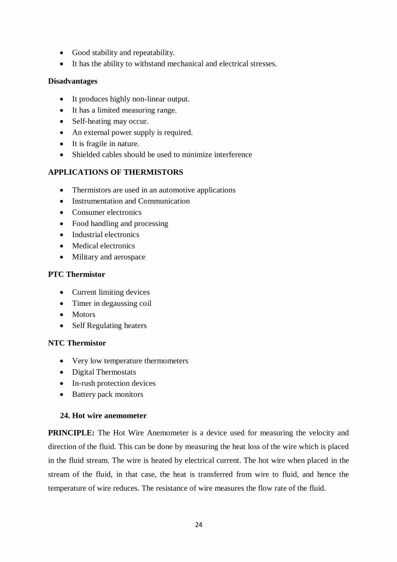
nickel, cobalt, copper, iron and uranium. They are available in variety of sizes and shapes.
The thermistors may be in the form of beads, rods or discs
Construction and Types
Fig.22. Types of thermistors
Fig. 23.a) PTC Thermistor b) NTC Thermistor
ADVANTAGES & DISADVANTAGES
Advantages
Low cost.
It produces more accurate output and fast.
It is suitable for the usage in remote location.
It can be manufactured in almost any shape and size.
A high degree of accuracy.
24
Good stability and repeatability.
It has the ability to withstand mechanical and electrical stresses.
Disadvantages
It produces highly non-linear output.
It has a limited measuring range.
Self-heating may occur.
An external power supply is required.
It is fragile in nature.
Shielded cables should be used to minimize interference
APPLICATIONS OF THERMISTORS
Thermistors are used in an automotive applications
Instrumentation and Communication
Consumer electronics
Food handling and processing
Industrial electronics
Medical electronics
Military and aerospace
PTC Thermistor
Current limiting devices
Timer in degaussing coil
Motors
Self Regulating heaters
NTC Thermistor
Very low temperature thermometers
Digital Thermostats
In-rush protection devices
Battery pack monitors
24. Hot wire anemometer
PRINCIPLE: The Hot Wire Anemometer is a device used for measuring the velocity and
direction of the fluid. This can be done by measuring the heat loss of the wire which is placed
in the fluid stream. The wire is heated by electrical current. The hot wire when placed in the
stream of the fluid, in that case, the heat is transferred from wire to fluid, and hence the
temperature of wire reduces. The resistance of wire measures the flow rate of the fluid.
25
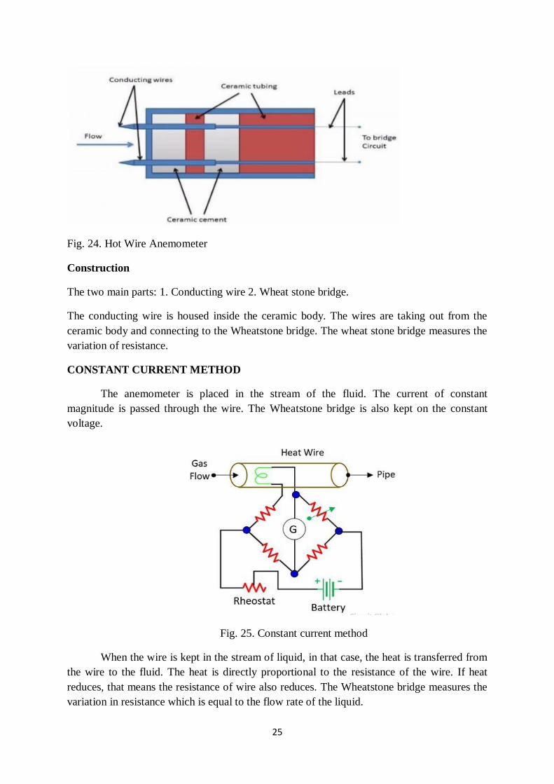
Fig. 24. Hot Wire Anemometer
Construction
The two main parts: 1. Conducting wire 2. Wheat stone bridge.
The conducting wire is housed inside the ceramic body. The wires are taking out from the
ceramic body and connecting to the Wheatstone bridge. The wheat stone bridge measures the
variation of resistance.
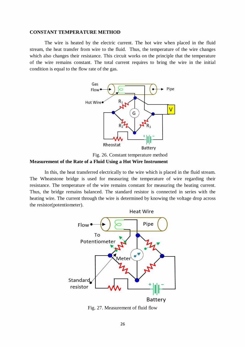
CONSTANT CURRENT METHOD
The anemometer is placed in the stream of the fluid. The current of constant
magnitude is passed through the wire. The Wheatstone bridge is also kept on the constant
voltage.
Fig. 25. Constant current method
When the wire is kept in the stream of liquid, in that case, the heat is transferred from
the wire to the fluid. The heat is directly proportional to the resistance of the wire. If heat
reduces, that means the resistance of wire also reduces. The Wheatstone bridge measures the
variation in resistance which is equal to the flow rate of the liquid.
26
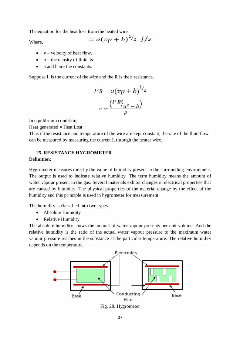
CONSTANT TEMPERATURE METHOD
The wire is heated by the electric current. The hot wire when placed in the fluid
stream, the heat transfer from wire to the fluid. Thus, the temperature of the wire changes
which also changes their resistance. This circuit works on the principle that the temperature
of the wire remains constant. The total current requires to bring the wire in the initial
condition is equal to the flow rate of the gas.
Fig. 26. Constant temperature method
Measurement of the Rate of a Fluid Using a Hot Wire Instrument
In this, the heat transferred electrically to the wire which is placed in the fluid stream.
The Wheatstone bridge is used for measuring the temperature of wire regarding their
resistance. The temperature of the wire remains constant for measuring the heating current.
Thus, the bridge remains balanced. The standard resistor is connected in series with the
heating wire. The current through the wire is determined by knowing the voltage drop across
the resistor(potentiometer).
Fig. 27. Measurement of fluid flow
27
The equation for the heat loss from the heated wire
Where,
v – velocity of heat flow,
ρ – the density of fluid, &
a and b are the constants.
Suppose I, is the current of the wire and the R is their resistance.
In equilibrium condition,
Heat generated = Heat Lost
Thus if the resistance and temperature of the wire are kept constant, the rate of the fluid flow
can be measured by measuring the current I, through the heater wire.
25. RESISTANCE HYGROMETER
Definition:
Hygrometer measures directly the value of humidity present in the surrounding environment.
The output is used to indicate relative humidity. The term humidity means the amount of
water vapour present in the gas. Several materials exhibit changes in electrical properties that
are caused by humidity. The physical properties of the material change by the effect of the
humidity and this principle is used in hygrometer for measurement.
The humidity is classified into two types.
Absolute Humidity
Relative Humidity
The absolute humidity shows the amount of water vapour presents per unit volume. And the
relative humidity is the ratio of the actual water vapour pressure to the maximum water
vapour pressure reaches in the substance at the particular temperature. The relative humidity
depends on the temperature.
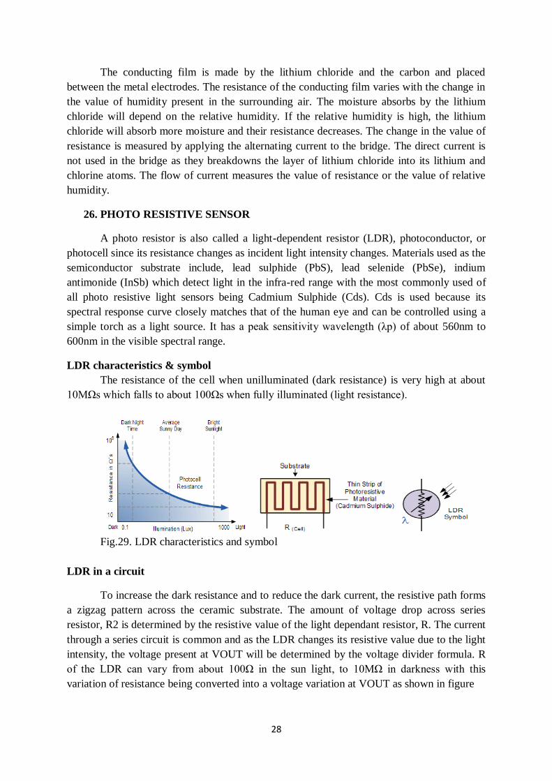
Fig. 28. Hygrometer
28
The conducting film is made by the lithium chloride and the carbon and placed
between the metal electrodes. The resistance of the conducting film varies with the change in
the value of humidity present in the surrounding air. The moisture absorbs by the lithium
chloride will depend on the relative humidity. If the relative humidity is high, the lithium
chloride will absorb more moisture and their resistance decreases. The change in the value of
resistance is measured by applying the alternating current to the bridge. The direct current is
not used in the bridge as they breakdowns the layer of lithium chloride into its lithium and
chlorine atoms. The flow of current measures the value of resistance or the value of relative
humidity.
26. PHOTO RESISTIVE SENSOR
A photo resistor is also called a light-dependent resistor (LDR), photoconductor, or
photocell since its resistance changes as incident light intensity changes. Materials used as the
semiconductor substrate include, lead sulphide (PbS), lead selenide (PbSe), indium
antimonide (InSb) which detect light in the infra-red range with the most commonly used of
all photo resistive light sensors being Cadmium Sulphide (Cds). Cds is used because its
spectral response curve closely matches that of the human eye and can be controlled using a
simple torch as a light source. It has a peak sensitivity wavelength (λp) of about 560nm to
600nm in the visible spectral range.
LDR characteristics & symbol
The resistance of the cell when unilluminated (dark resistance) is very high at about
10MΩs which falls to about 100Ωs when fully illuminated (light resistance).
Fig.29. LDR characteristics and symbol
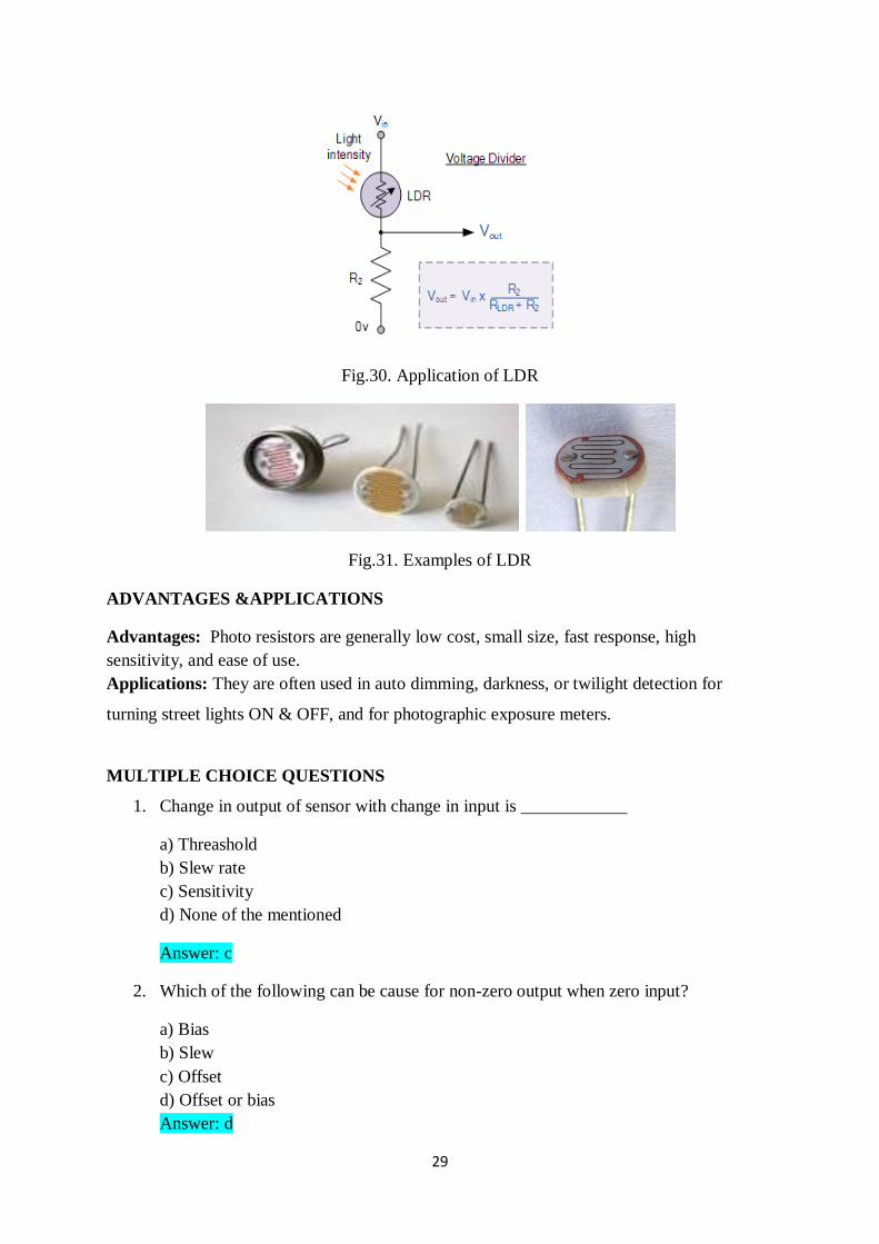
LDR in a circuit
To increase the dark resistance and to reduce the dark current, the resistive path forms
a zigzag pattern across the ceramic substrate. The amount of voltage drop across series
resistor, R2 is determined by the resistive value of the light dependant resistor, R. The current
through a series circuit is common and as the LDR changes its resistive value due to the light
intensity, the voltage present at VOUT will be determined by the voltage divider formula. R
of the LDR can vary from about 100Ω in the sun light, to 10MΩ in darkness with this
variation of resistance being converted into a voltage variation at VOUT as shown in figure
29
Fig.30. Application of LDR
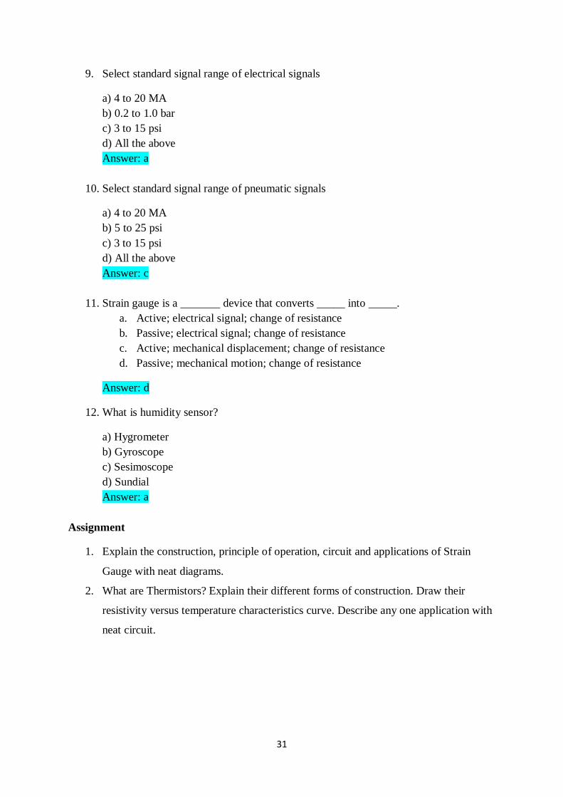
Fig.31. Examples of LDR
ADVANTAGES &APPLICATIONS
Advantages: Photo resistors are generally low cost, small size, fast response, high
sensitivity, and ease of use.
Applications: They are often used in auto dimming, darkness, or twilight detection for
turning street lights ON & OFF, and for photographic exposure meters.
MULTIPLE CHOICE QUESTIONS
1. Change in output of sensor with change in input is ____________
a) Threashold
b) Slew rate
c) Sensitivity
d) None of the mentioned
Answer: c
2. Which of the following can be cause for non-zero output when zero input?
a) Bias
b) Slew
c) Offset
d) Offset or bias
Answer: d

30
3. Smallest change which a sensor can detect is ____________
a) Resolution
b) Accuracy
c) Precision
d) Scale
Answer: a
4. A device that converts one form of energy into other form of energy is called _______
a) Transmitters
b) Transducers
c) Receivers
d) None of the above
Answer: b
5. Ability to reproduce consistent readings is called ____________
a) Resolution
b) Accuracy
c) Precision
d) Scale
Answer: c
6. Which of the following can be used for measuring temperature?
a) Metallic diaphragm
b) Thermometer
c) Capsule
d) Bourdon tube
View Answer
Answer: b
7. Other name of RTD is _________
a) Thermister
b)Thermocouple
c) Resistance thermometer
d) All the above
Answer: c
8. What is PTC thermistor?
a) Positive temperature coefficient thermistor
b) Positive transient coefficient thermistor
c) Pulse transmit coefficient thermistor
d) All the above
Answer: a
31
9. Select standard signal range of electrical signals
a) 4 to 20 MA
b) 0.2 to 1.0 bar
c) 3 to 15 psi
d) All the above
Answer: a
10. Select standard signal range of pneumatic signals
a) 4 to 20 MA
b) 5 to 25 psi
c) 3 to 15 psi
d) All the above
Answer: c
11. Strain gauge is a _______ device that converts _____ into _____.
a. Active; electrical signal; change of resistance
b. Passive; electrical signal; change of resistance
c. Active; mechanical displacement; change of resistance
d. Passive; mechanical motion; change of resistance
Answer: d
12. What is humidity sensor?
a) Hygrometer
b) Gyroscope
c) Sesimoscope
d) Sundial
Answer: a
Assignment
1. Explain the construction, principle of operation, circuit and applications of Strain
Gauge with neat diagrams.
2. What are Thermistors? Explain their different forms of construction. Draw their
resistivity versus temperature characteristics curve. Describe any one application with
neat circuit.
32
UNIT- II INDUCTIVE & CAPACITIVE TRANSDUCER
Inductive transducers: - Principle of operation, construction details, characteristics and
applications of LVDT, Induction potentiometer, variable reluctance transducer, synchros,
microsyn.
Capacitive transducers: - Principle of operation, construction details, characteristics of
Capacitive transducers – different types & signal conditioning- Applications:- capacitor
microphone, capacitive pressure sensor, proximity sensor.
1. INTRODUCTION
Definition:
The transducer is a device which converts one form of energy into another form.
2. Advantages of Electrical Transducer
1. Electrical output can be amplified to any desired level.
2. Low power requirement.
3. Easy transmission.
4. Suitable with digital control.
5. Low cost.
6. Small size.
7. Reduced friction effect.
8. The output can be modified as per requirements of the indicating or controlling
equipments.
9.
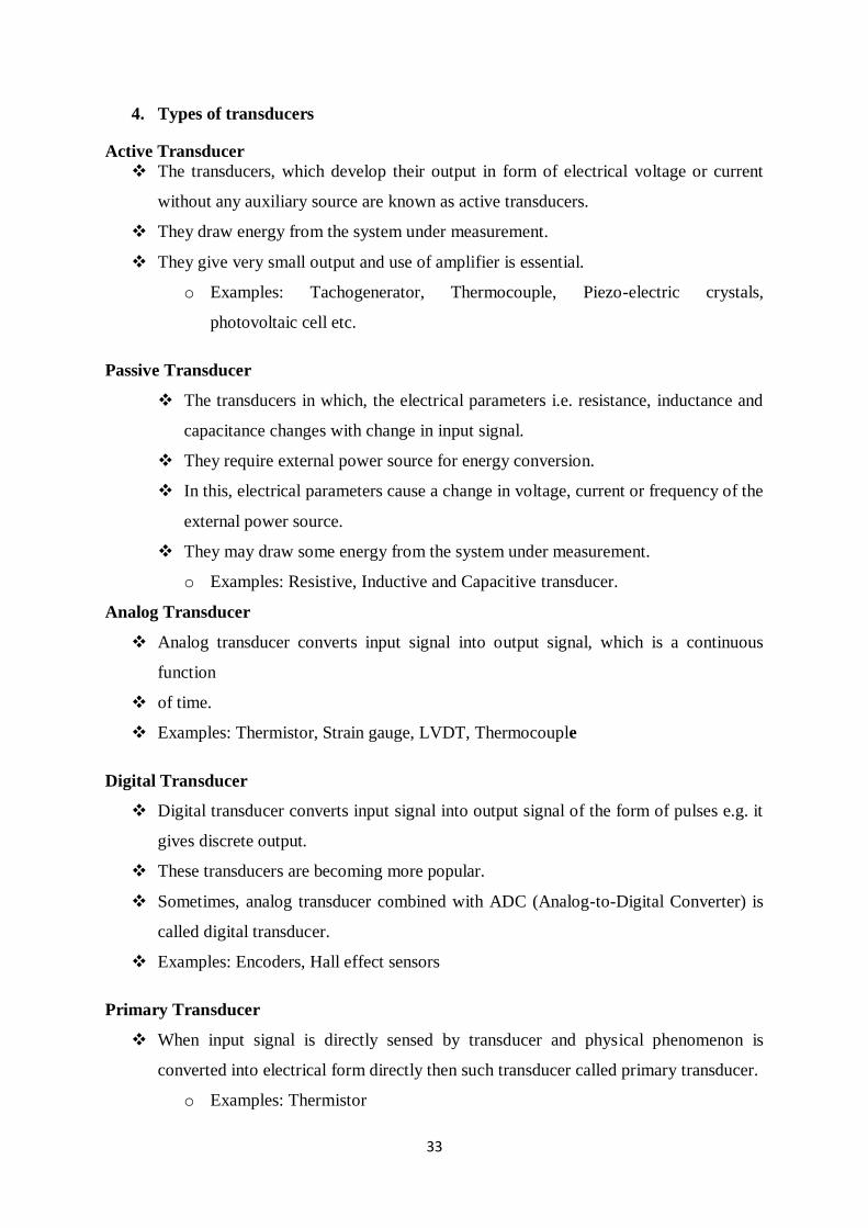
3. CLASSIFICATION – TRANSDUCERS
33
4. Types of transducers
Active Transducer
The transducers, which develop their output in form of electrical voltage or current
without any auxiliary source are known as active transducers.
They draw energy from the system under measurement.
They give very small output and use of amplifier is essential.
o Examples: Tachogenerator, Thermocouple, Piezo-electric crystals,
photovoltaic cell etc.
Passive Transducer
The transducers in which, the electrical parameters i.e. resistance, inductance and
capacitance changes with change in input signal.
They require external power source for energy conversion.
In this, electrical parameters cause a change in voltage, current or frequency of the
external power source.
They may draw some energy from the system under measurement.
o Examples: Resistive, Inductive and Capacitive transducer.
Analog Transducer
Analog transducer converts input signal into output signal, which is a continuous
function
of time.
Examples: Thermistor, Strain gauge, LVDT, Thermocouple
Digital Transducer
Digital transducer converts input signal into output signal of the form of pulses e.g. it
gives discrete output.
These transducers are becoming more popular.
Sometimes, analog transducer combined with ADC (Analog-to-Digital Converter) is
called digital transducer.
Examples: Encoders, Hall effect sensors
Primary Transducer
When input signal is directly sensed by transducer and physical phenomenon is
converted into electrical form directly then such transducer called primary transducer.
o Examples: Thermistor
34
Secondary Transducer
When input signal is directly sensed first by some sensor and then its output being of
some form other than input signal I given as input to a transducer for conversion into
electrical form, then it’s called secondary transducer.
o Examples: LVDT for used pressure measurement by using bourdon tube
Transducer (Electrical)
It is a device that converts a non-electrical quantity into an electrical quantity.
o Examples: Thermocouple, Pressure gauge, Strain gauge, Photovoltaic cell
Inverse Transducer
It is a device that converts an electrical quantity into non-electrical quantity.
It is a precision actuator having an electrical input and low-power non-electrical
output.
A most useful application of inverse transducer is in feedback measurement systems.
Examples: Piezo-electric crystal
5. LVDT
Linear Variable Differential Transformer (LVDT)
LVDT is an inductive type passive transducer.
It measures force in terms of displacement of ferromagnetic core of a transformer.
It converts translational or linear displacement into electrical voltage.
It is also known as Linear Variable Differential Transducer.
Principle
It is based on the principle of electro-magnetic induction.
Construction
LVDT consist of cylindrical transformer where it is surrounded by one primary
winding in the centre of the former and two secondary windings at the sides.
The numbers of turns in both the secondary windings are equal, but they are opposite
to each other.
35
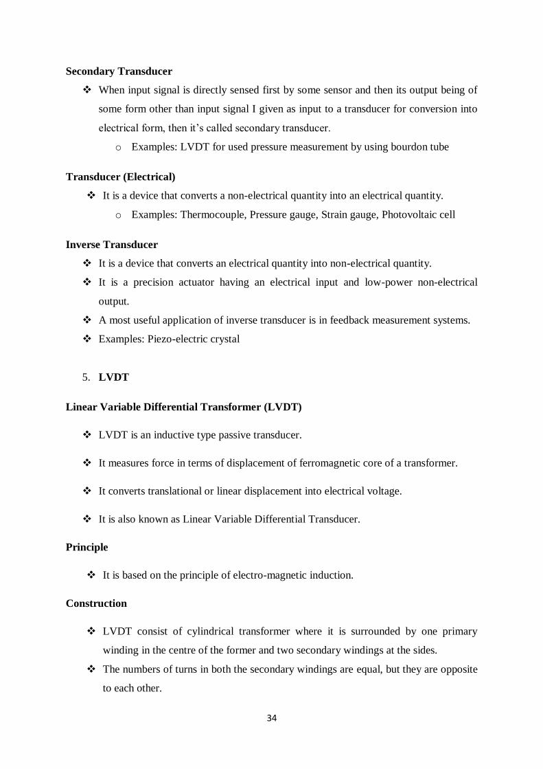
The primary winding is connected to the ac source.
A movable soft iron core slides within hollow former and therefore affects magnetic
coupling between primary and two secondary.
Operation
Fig.1. Construction of LVDT
When the iron core lies at the centre of both secondary, the output differential voltage
remains unaffected and has zero magnitude.
When the core moves towards secondary-1, it induces more emf across it and less emf
across secondary-2. Let’s assume that it is positive displacement.
This is due to more flux links with the secondary-1 than secondary-2.
When the core moves towards secondary-2, it induces more emf across it and less emf
across secondary-1. Let’s assume that it is negative displacement.
This is due to more flux links with the secondary-2 than secondary-1.
The output differential voltage is proportional to the displacement of the iron core.
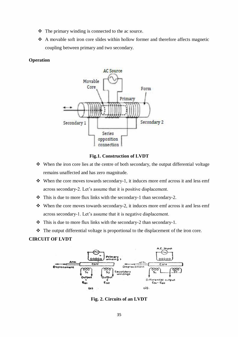
CIRCUIT OF LVDT
Fig. 2. Circuits of an LVDT

36
OUTPUT VOLTAGE
Differential output voltage Eo = Es1 - Es2
When the core is at its normal (NULL) position, the flux Jinking with both the secondary
windings is equal and hence equal emfs are induced in them. Thus at null position E11 =Es2.
Since the output voltage of the transducer is the difference of the two voltages, the output
voltage Eo is zero at null position.
Fig.3. Variation in output voltage with linear displacement for an LVDT
Working
Now if the core is moved to the left of the NULL position, more flux links with
winding S1 and less with winding S2.
Accordingly output voltage Es1, of the secondary winding S1, is more than Es2,
the output voltage of secondary winding S2.
The magnitude of output voltage is, thus, Es1- Es2 and the output voltage is in
phase with Es1 i.e. the output voltage of secondary winding s1.
Similarly, if the core is moved to the right of the null position, the flux linking
with winding s2 becomes. larger than that linking with winding S1.
This result in Es2 becoming larger than Es1.
The output voltage in this case is Eo= Es2 - Es1 and is in phase with Es2 ie. the
output voltage of secondary winding S2.
Advantages
High range (1.25 mm to 250 mm)
No frictional losses
High input and high sensitivity
Low hysteresis
Low power consumption
Direct conversion to electrical signals
Dis-advantages
LVDT is sensitive to stray magnetic fields so they always require a setup to
protect them from stray magnetic fields.
They are affected by vibrations and temperature.
37
Applications
It is used where displacements ranging from fraction of mm to few cm are to be
measured.
It act as primary transducer.
They can also act as secondary transducer. E.g. the bourdon tube which acts as
primary transducer and convert pressure into linear displacement then LVDT
converts it into electrical signal.
6. INDUCTIVE TRANSDUCER
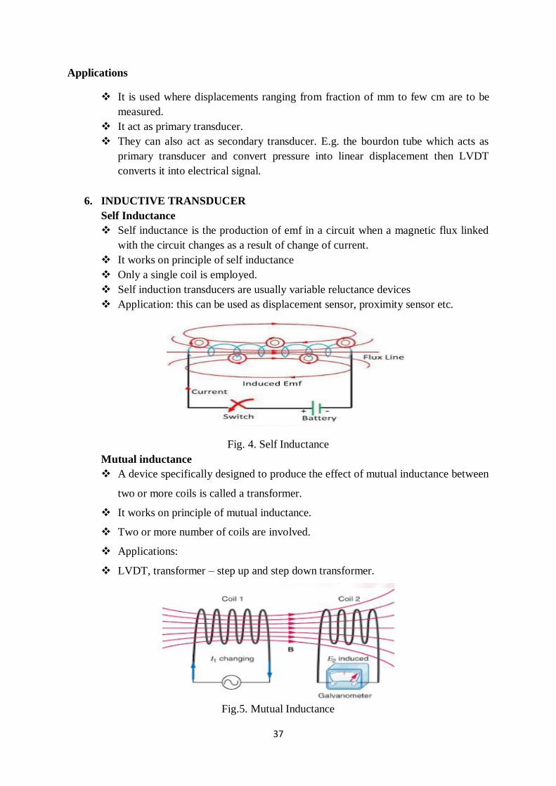
Self Inductance
Self inductance is the production of emf in a circuit when a magnetic flux linked
with the circuit changes as a result of change of current.
It works on principle of self inductance
Only a single coil is employed.
Self induction transducers are usually variable reluctance devices
Application: this can be used as displacement sensor, proximity sensor etc.
Fig. 4. Self Inductance
Mutual inductance
A device specifically designed to produce the effect of mutual inductance between
two or more coils is called a transformer.
It works on principle of mutual inductance.
Two or more number of coils are involved.
Applications:
LVDT, transformer – step up and step down transformer.
Fig.5. Mutual Inductance
38
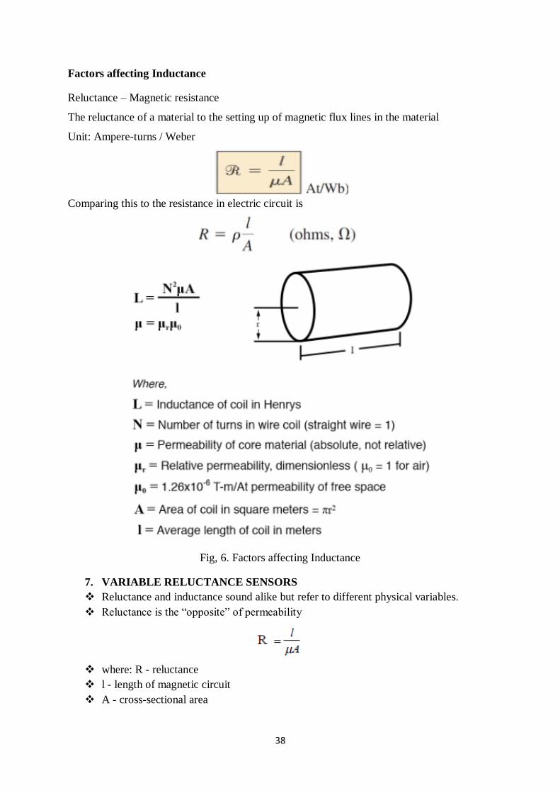
Factors affecting Inductance
Reluctance – Magnetic resistance
The reluctance of a material to the setting up of magnetic flux lines in the material
Unit: Ampere-turns / Weber
Comparing this to the resistance in electric circuit is
Fig, 6. Factors affecting Inductance
7. VARIABLE RELUCTANCE SENSORS
Reluctance and inductance sound alike but refer to different physical variables.
Reluctance is the “opposite” of permeability
where: R - reluctance
l - length of magnetic circuit
A - cross-sectional area
39
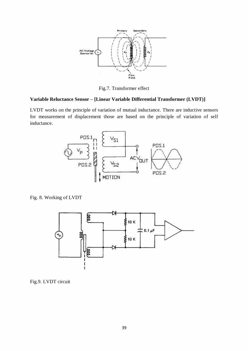
Fig.7. Transformer effect
Variable Reluctance Sensor – [Linear Variable Differential Transformer (LVDT)]
LVDT works on the principle of variation of mutual inductance. There are inductive sensors
for measurement of displacement those are based on the principle of variation of self
inductance.
Fig. 8. Working of LVDT
Fig.9. LVDT circuit
40
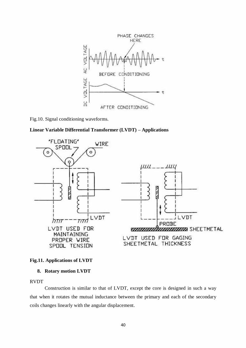
Fig.10. Signal conditioning waveforms.
Linear Variable Differential Transformer (LVDT) – Applications
Fig.11. Applications of LVDT
8. Rotary motion LVDT
RVDT
Construction is similar to that of LVDT, except the core is designed in such a way
that when it rotates the mutual inductance between the primary and each of the secondary
coils changes linearly with the angular displacement.
41
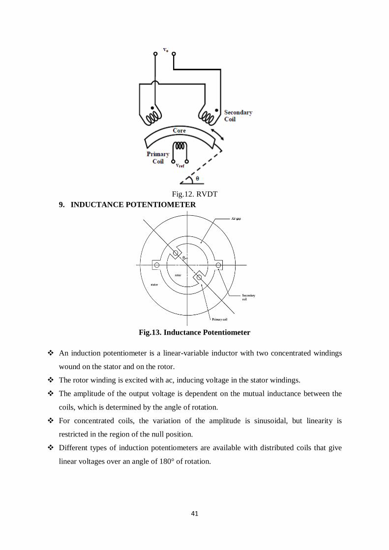
Fig.12. RVDT
9. INDUCTANCE POTENTIOMETER
Fig.13. Inductance Potentiometer
An induction potentiometer is a linear-variable inductor with two concentrated windings
wound on the stator and on the rotor.
The rotor winding is excited with ac, inducing voltage in the stator windings.
The amplitude of the output voltage is dependent on the mutual inductance between the
coils, which is determined by the angle of rotation.
For concentrated coils, the variation of the amplitude is sinusoidal, but linearity is
restricted in the region of the null position.
Different types of induction potentiometers are available with distributed coils that give
linear voltages over an angle of 180° of rotation.
42
Standard commercial induction pots operate in a 50 to 400 Hz frequency range. They are
small in size, from 1 cm to 6 cm, and their sensitivity can be on the order of 1 V/deg
rotation.
Although the ranges of induction pots are limited to less than 60° of rotation, it is possible
to measure displacements in angles from 0° to full rotation by suitable arrangement of a
number of induction pots.
As in the case of most inductive sensors, the output of an induction pot may need phase-
sensitive demodulators and suitable filters.
In many cases, additional dummy coils are used to improve linearity and accuracy.
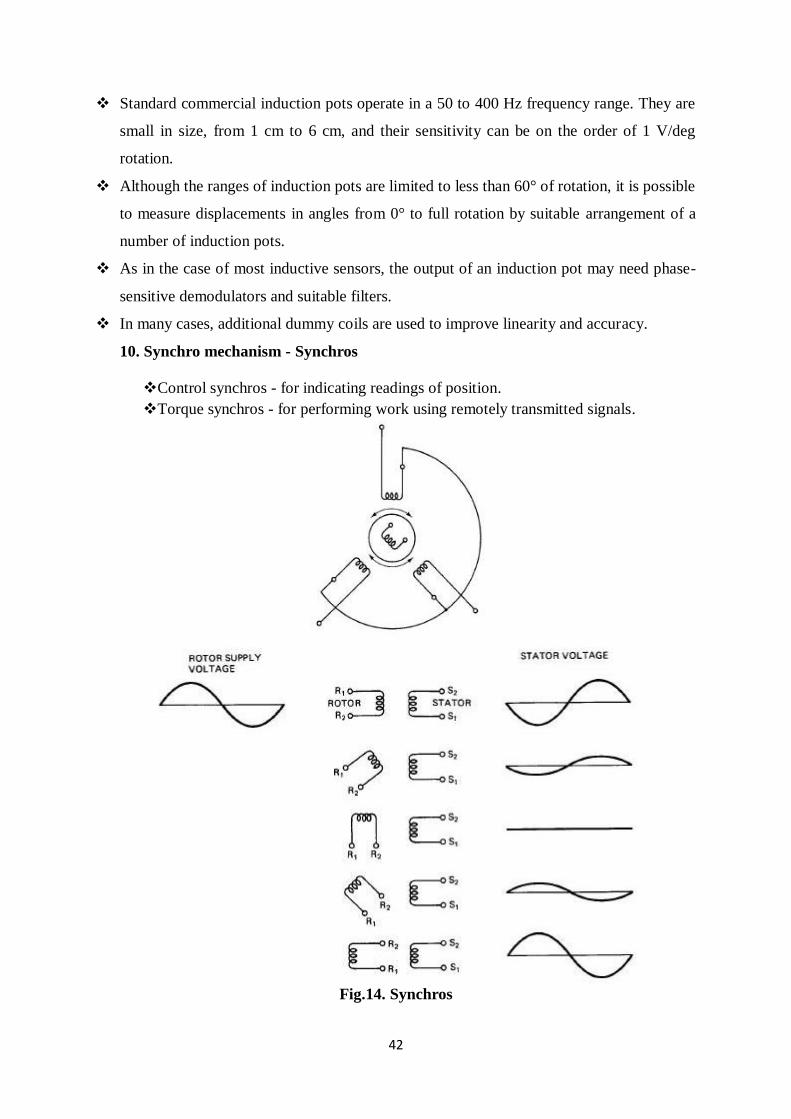
10. Synchro mechanism - Synchros
Control synchros - for indicating readings of position.
Torque synchros - for performing work using remotely transmitted signals.
Fig.14. Synchros
43
A synchro is similar to a wound-rotor induction motor.
The rotation of the rotor changes the mutual inductance between the rotor coil and
the stator coils. The voltages from these coils define the angular position of the
rotor.
They are primarily used in angle measurements and are commonly applied in
control engineering as parts of servomechanisms, machine tools, antennas, etc.
Synchros were used in analog positioning systems to provide data and to control
the physical position of mechanical devices such as radar antennae, indicator
needles on instrumentation, and fire control mechanisms in military equipment.
The term “synchro” defines an electromagnetic position transducer that has a set
of three phase output windings that are electrically and mechanically spaced by
120° instead of the 90° spacing found in a resolver.
In the rotor primary mode, the synchro is excited by a single-phase ac signal on
the rotor.
As the rotor moves 360°, the three amplitude
modulated sine waves on the three phases of the output have a discrete set of
amplitudes for each angular
position.
By interpreting these amplitudes, a table can be established to decode the exact
rotary position.
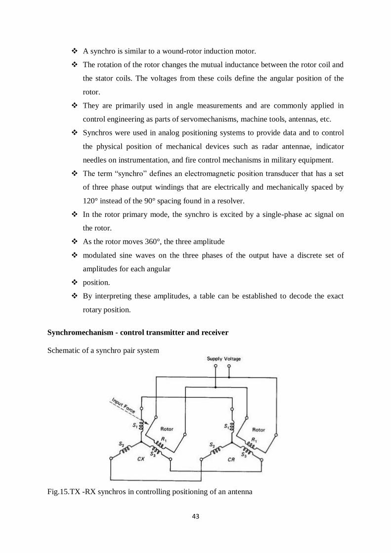
Synchromechanism - control transmitter and receiver
Schematic of a synchro pair system
Fig.15.TX -RX synchros in controlling positioning of an antenna
44
Fig. 16.Application
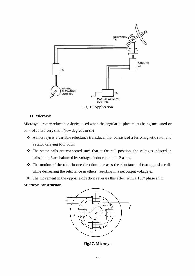
11. Microsyn
Microsyn - rotary reluctance device used when the angular displacements being measured or
controlled are very small (few degrees or so)
A microsyn is a variable reluctance transducer that consists of a ferromagnetic rotor and
a stator carrying four coils.
The stator coils are connected such that at the null position, the voltages induced in
coils 1 and 3 are balanced by voltages induced in coils 2 and 4.
The motion of the rotor in one direction increases the reluctance of two opposite coils
while decreasing the reluctance in others, resulting in a net output voltage eo.
The movement in the opposite direction reverses this effect with a 180° phase shift.
Microsyn construction
Fig.17. Microsyn
45
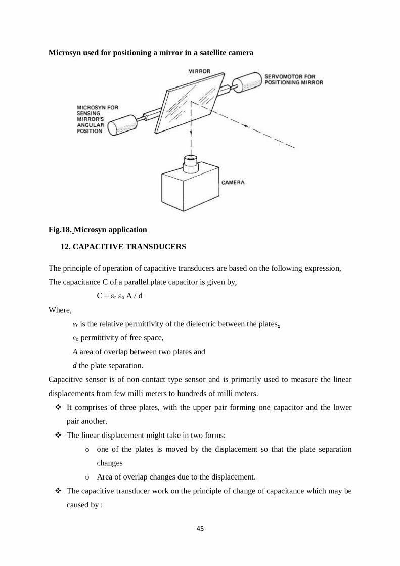
Microsyn used for positioning a mirror in a satellite camera
Fig.18. Microsyn application
12. CAPACITIVE TRANSDUCERS
The principle of operation of capacitive transducers are based on the following expression,
The capacitance C of a parallel plate capacitor is given by,
C = εr εo A / d
Where,
εr is the relative permittivity of the dielectric between the plates,
εo permittivity of free space,
A area of overlap between two plates and
d the plate separation.
Capacitive sensor is of non-contact type sensor and is primarily used to measure the linear
displacements from few milli meters to hundreds of milli meters.
It comprises of three plates, with the upper pair forming one capacitor and the lower
pair another.
The linear displacement might take in two forms:
o one of the plates is moved by the displacement so that the plate separation
changes
o Area of overlap changes due to the displacement.
The capacitive transducer work on the principle of change of capacitance which may be
caused by :
46
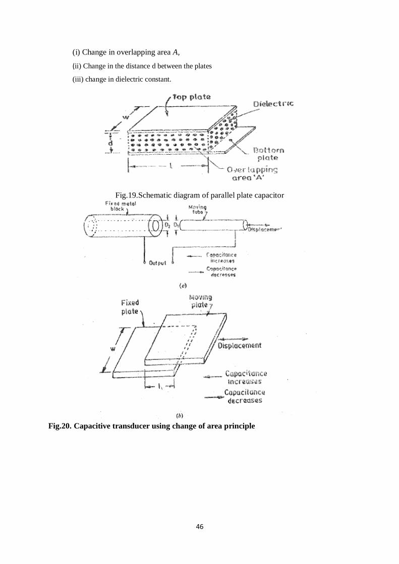
(i) Change in overlapping area A,
(ii) Change in the distance d between the plates
(iii) change in dielectric constant.
Fig.19.Schematic diagram of parallel plate capacitor
Fig.20. Capacitive transducer using change of area principle
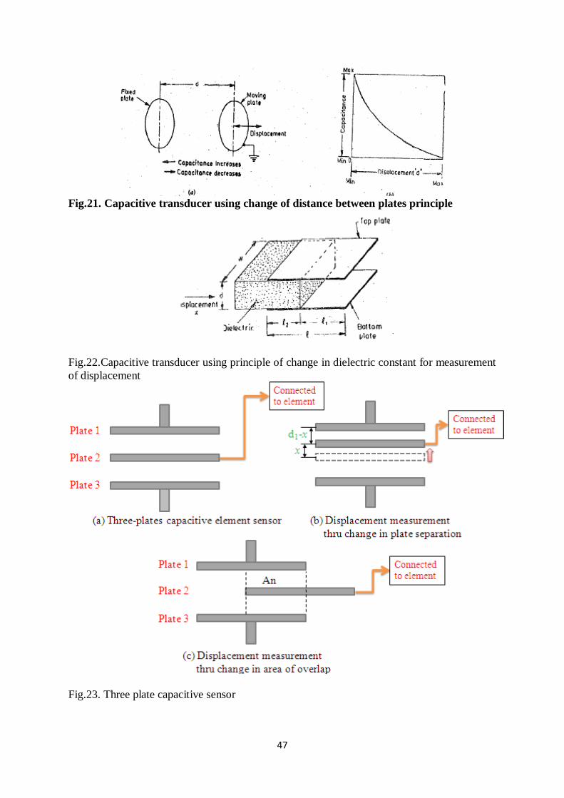
47
Fig.21. Capacitive transducer using change of distance between plates principle
Fig.22.Capacitive transducer using principle of change in dielectric constant for measurement
of displacement
Fig.23. Three plate capacitive sensor
48
C1 = (εr εo A) / (d + x)
C2 = (εr εo A) / (d – x)
When C1 and C2 are connected to a Wheatstone’s bridge, then the resulting out-of- balance
voltage would be in proportional to displacement x.
As the central plate moves near to top plate or bottom one due to the movement of the
element/work piece of which displacement is to be measured, separation in between
the plate changes.
Capacitive elements can also be used as proximity sensor. The approach of the object
towards the sensor plate is used for induction of change in plate separation. This
changes the capacitance which is used to detect the object.
Advantages of Capacitive Transducers.
They require extremely small forces to operate them and hence are very useful for use
in small systems. ·
They are extremely sensitive.
They have a good frequency response.
They have a high input impedance and therefore the loading effects are minimum.
A resolution of the order of 2.5X10⁻³ mm can be obtained with these transducers.
The capacitive transducers can be· used for applications where stray magnetic fields
renter the inductive transducers useless. · .
The force requirement of capacitive transducers is very small and therefore they
require small power to operate them.
Disadvantages of Capacitive Transducers.
The metallic parts of the capacitive transducers must be insulated from each other. In
order to reduce the effects of stray capacitances, the frames must be earthed.
The capacitive transducers show non-linear behaviour many a times on account of
edge effects. Therefore guard rings must be used to eliminate this effect. Guard rings
are also a must in order to eliminate the effect of stray electric fields, especially when
the transducers have a low value of capacitance of the order of pF.
The output impedance of capacitive transducers tends to be high on account of their
small capacitance value.
The cable connecting the transducer to the measuring point is also a source of error.
The cable may be source of loading resulting loss of sensitivity. Also loading makes
the low frequency response poor.
Applications of capacitive transducers:-
1. Feed hopper level monitoring
49
2. Small vessel pump control
3. Grease level monitoring
4. Level control of liquids
5. Metrology applications
1. to measure shape errors in the part being produced
2. to analyze and optimize the rotation of spindles in various machine tools such as
surface grinders, lathes, milling machines, and air bearing spindles by measuring
errors in the machine tools themselves
6. Assembly line testing
1. To test assembled parts for uniformity, thickness or other design features
2. To detect the presence or absence of a certain component, such as glue etc.
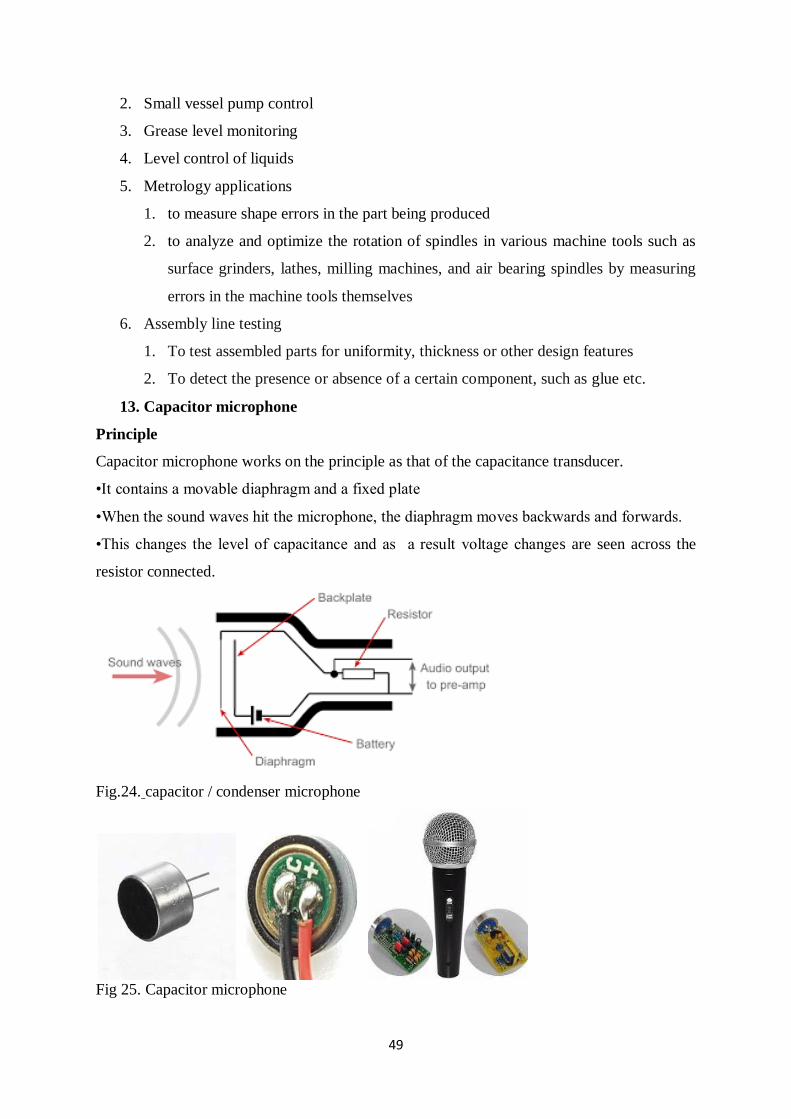
13. Capacitor microphone
Principle
Capacitor microphone works on the principle as that of the capacitance transducer.
•It contains a movable diaphragm and a fixed plate
•When the sound waves hit the microphone, the diaphragm moves backwards and forwards.
•This changes the level of capacitance and as a result voltage changes are seen across the
resistor connected.
Fig.24. capacitor / condenser microphone
Fig 25. Capacitor microphone
50
Advantages & Disadvantages
Advantages
Typical output impedance is around 200 ohm or less.
Frequency ranges from 20Hz to 20KHz and more.
High quality sound recording.
It is less robust.
Disadvantages
High sensitivity, which causes overload due to loud noise.
Internal construction is delicate.
Sensitive to humid environment.
They are damaged more easily than dynamic microphones
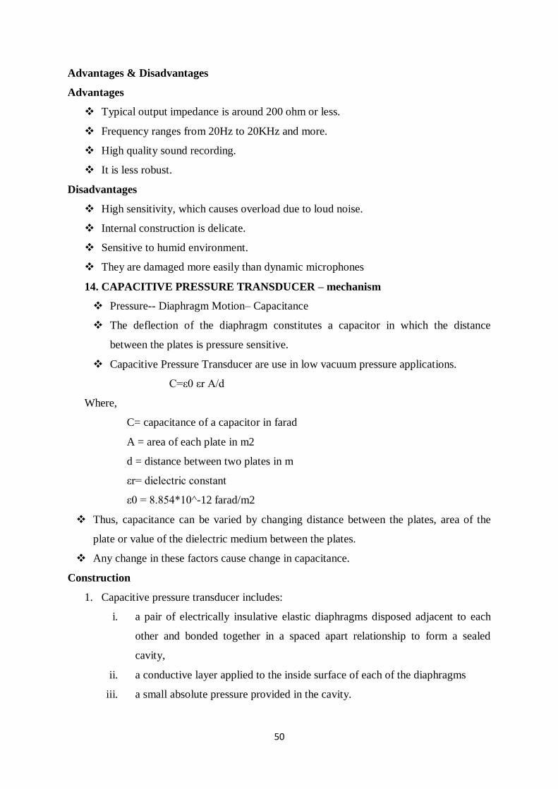
14. CAPACITIVE PRESSURE TRANSDUCER – mechanism
Pressure-- Diaphragm Motion– Capacitance
The deflection of the diaphragm constitutes a capacitor in which the distance
between the plates is pressure sensitive.
Capacitive Pressure Transducer are use in low vacuum pressure applications.
C=ε0 εr A/d
Where,
C= capacitance of a capacitor in farad
A = area of each plate in m2
d = distance between two plates in m
εr= dielectric constant
ε0 = 8.854*10^-12 farad/m2
Thus, capacitance can be varied by changing distance between the plates, area of the
plate or value of the dielectric medium between the plates.
Any change in these factors cause change in capacitance.
Construction
1. Capacitive pressure transducer includes:
i. a pair of electrically insulative elastic diaphragms disposed adjacent to each
other and bonded together in a spaced apart relationship to form a sealed
cavity,
ii. a conductive layer applied to the inside surface of each of the diaphragms
iii. a small absolute pressure provided in the cavity.
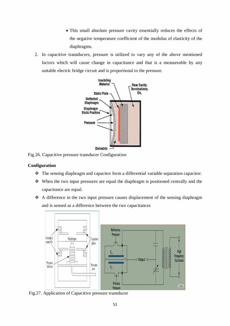
51
This small absolute pressure cavity essentially reduces the effects of
the negative temperature coefficient of the modulus of elasticity of the
diaphragms.
2. In capacitive transducers, pressure is utilized to vary any of the above mentioned
factors which will cause change in capacitance and that is a measureable by any
suitable electric bridge circuit and is proportional to the pressure.
Fig.26. Capacitive pressure transducer Configuration
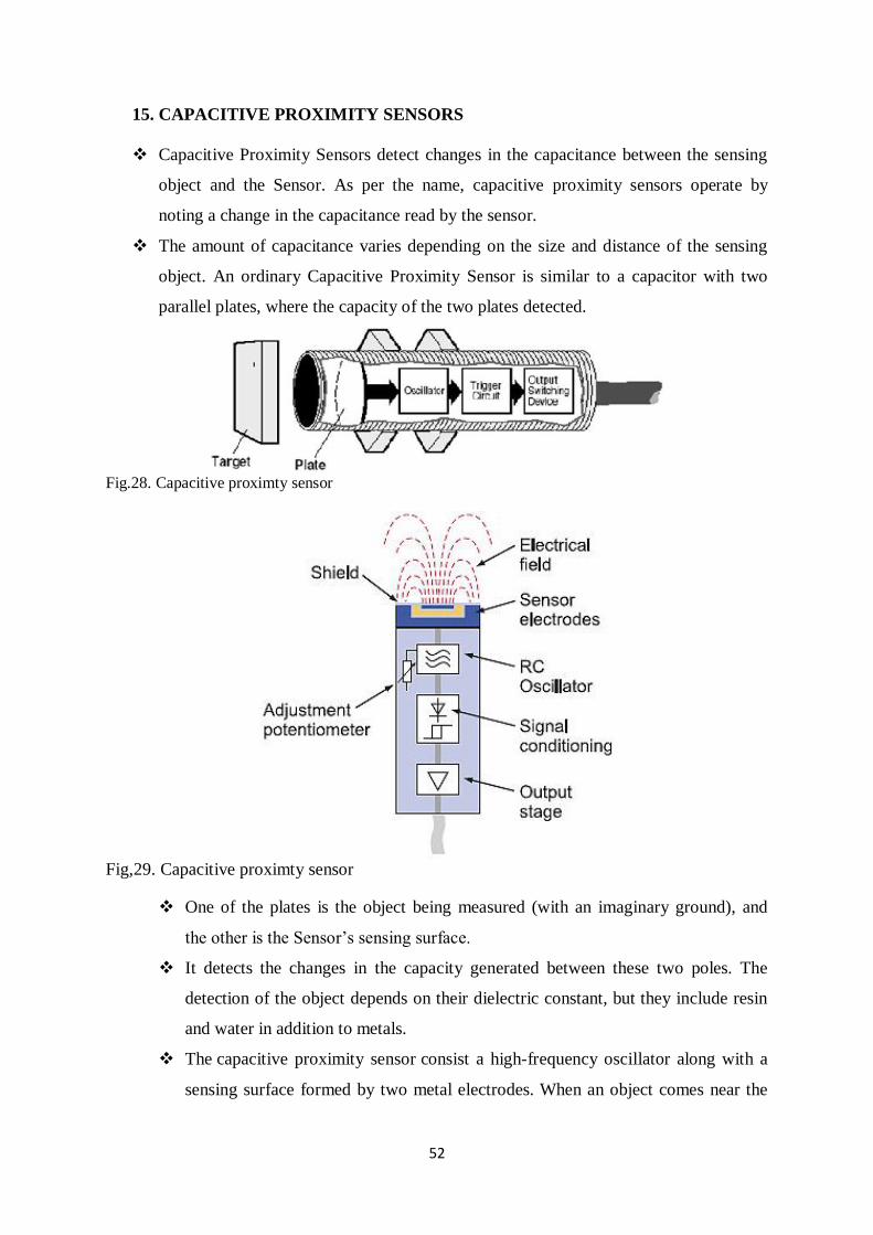
Configuration
The sensing diaphragm and capacitor form a differential variable separation capacitor.
When the two input pressures are equal the diaphragm is positioned centrally and the
capacitance are equal.
A difference in the two input pressure causes displacement of the sensing diaphragm
and is sensed as a difference between the two capacitances
Fig.27. Application of Capacitive pressure transducer
52
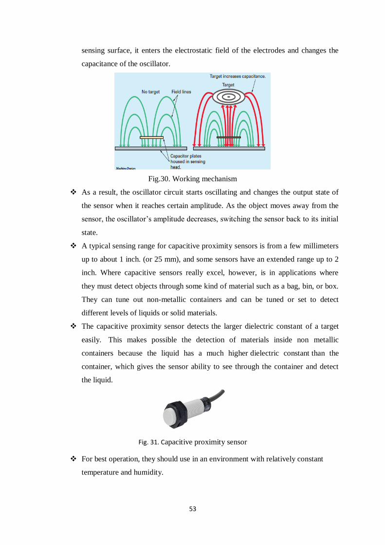
15. CAPACITIVE PROXIMITY SENSORS
Capacitive Proximity Sensors detect changes in the capacitance between the sensing
object and the Sensor. As per the name, capacitive proximity sensors operate by
noting a change in the capacitance read by the sensor.
The amount of capacitance varies depending on the size and distance of the sensing
object. An ordinary Capacitive Proximity Sensor is similar to a capacitor with two
parallel plates, where the capacity of the two plates detected.
Fig.28. Capacitive proximty sensor
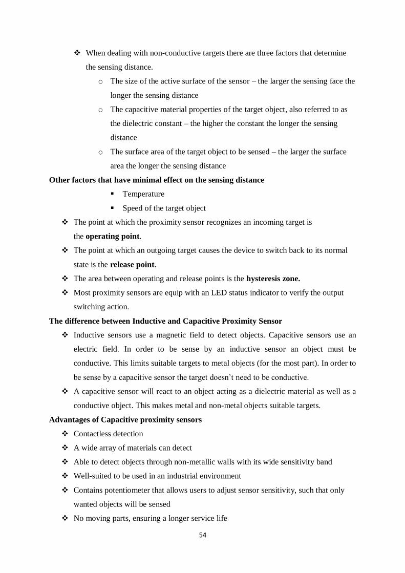
Fig,29. Capacitive proximty sensor
One of the plates is the object being measured (with an imaginary ground), and
the other is the Sensor’s sensing surface.
It detects the changes in the capacity generated between these two poles. The
detection of the object depends on their dielectric constant, but they include resin
and water in addition to metals.
The capacitive proximity sensor consist a high-frequency oscillator along with a
sensing surface formed by two metal electrodes. When an object comes near the
53
sensing surface, it enters the electrostatic field of the electrodes and changes the
capacitance of the oscillator.
Fig.30. Working mechanism
As a result, the oscillator circuit starts oscillating and changes the output state of
the sensor when it reaches certain amplitude. As the object moves away from the
sensor, the oscillator’s amplitude decreases, switching the sensor back to its initial
state.
A typical sensing range for capacitive proximity sensors is from a few millimeters
up to about 1 inch. (or 25 mm), and some sensors have an extended range up to 2
inch. Where capacitive sensors really excel, however, is in applications where
they must detect objects through some kind of material such as a bag, bin, or box.
They can tune out non-metallic containers and can be tuned or set to detect
different levels of liquids or solid materials.
The capacitive proximity sensor detects the larger dielectric constant of a target
easily. This makes possible the detection of materials inside non metallic
containers because the liquid has a much higher dielectric constant than the
container, which gives the sensor ability to see through the container and detect
the liquid.
Fig. 31. Capacitive proximity sensor
For best operation, they should use in an environment with relatively constant
temperature and humidity.
54
When dealing with non-conductive targets there are three factors that determine
the sensing distance.
o The size of the active surface of the sensor – the larger the sensing face the
longer the sensing distance
o The capacitive material properties of the target object, also referred to as
the dielectric constant – the higher the constant the longer the sensing
distance
o The surface area of the target object to be sensed – the larger the surface
area the longer the sensing distance
Other factors that have minimal effect on the sensing distance
Temperature
Speed of the target object
The point at which the proximity sensor recognizes an incoming target is
the operating point.
The point at which an outgoing target causes the device to switch back to its normal
state is the release point.
The area between operating and release points is the hysteresis zone.
Most proximity sensors are equip with an LED status indicator to verify the output
switching action.
The difference between Inductive and Capacitive Proximity Sensor
Inductive sensors use a magnetic field to detect objects. Capacitive sensors use an
electric field. In order to be sense by an inductive sensor an object must be
conductive. This limits suitable targets to metal objects (for the most part). In order to
be sense by a capacitive sensor the target doesn’t need to be conductive.
A capacitive sensor will react to an object acting as a dielectric material as well as a
conductive object. This makes metal and non-metal objects suitable targets.
Advantages of Capacitive proximity sensors
Contactless detection
A wide array of materials can detect
Able to detect objects through non-metallic walls with its wide sensitivity band
Well-suited to be used in an industrial environment
Contains potentiometer that allows users to adjust sensor sensitivity, such that only
wanted objects will be sensed
No moving parts, ensuring a longer service life

55
Disadvantages of Capacitive proximity sensors:-
Relative low range, though incremental increase from inductive sensors
Higher price as compared to inductive sensors
MULTIPLE CHOICE QUESTIONS
1. In a LVDT, the two secondary voltages
a) Are independent of the core position
b) Vary unequally depending on the core position
c) Vary equally depending on the core position
d) Are always in phase quadrature
Answer b
2. Which of the following devices is used for conversion of coordinates?
A. Synchros
B. Microsyn
C. Synchros resolver
D. Synchro transformer
Answer C
3. Which of the following terms accurately describes a synchro?
a. Electromechanical
b. Position-sensing
c. Rotary
d. All the above
Answer D
4. Microsyn is based on the principle of
A. DC motor
B. Resolver
C. Saturable reactor
D. Rotating differential transformer
Answer D.
5. Which type of proximity sensor can be used as touch sensor?
a) Inductive proximity sensor
b) Capacitive proximity sensor
c) Ultrasonic proximity sensor
d) Photoelectric proximity sensor
Answer b

56
6. What is the relation between the self-inductance and the reluctance of a coil?
a) Directly proportional
b) Inversely proportional
c) No relation
d) Constant
Answer: b
7. Capacitance of a parallel plate capacitor is ________
a) C = A∈⁄d
b) C = ∈⁄d
c) C = A⁄d
d) C = A
Answer: a
8. Which of the following device can be used for displacement measurement?
a) LVDT
b) Bellows
c) Capsule
d) Bourdon tube
Answer: a
9. Which proximity sensor can detect both metal and non metal objects
a) Ultrasonic sensor
b) Inductive proximity sensor
c) Capacitive proximity sensor
d) None of these
Answer (c)
10. The principle of operation of LVDT is based on the variation of
a) Self inductance
b) Mutual inductance
c) Reluctance
d) Permanence
Answer (b)
ASSIGNMENT
1. Describe the construction of LVDT and explain its principle of operation with the aid
of diagram, list the advantages, disadvantages and applications of LVDT.
2. Elaborate the working principle of proximitysensors with neat diagram in detail. List
its applications.
57
UNIT III ACTUATORS
Definition, types and selection of Actuators; linear; rotary; Logical and Continuous
Actuators, Pneumatic actuator- Electro-Pneumatic actuator; cylinder, rotary actuators,
Mechanical actuating system: Hydraulic actuator - Control valves; Construction,
Characteristics and Types, Selection criteria.
Electrical actuating systems: Solid-state switches, Solenoids, Electric Motors- Principle of
operation and its application: D.C motors - AC motors - Single phase & 3 Phase Induction
Motor; Synchronous Motor; Stepper motors - Piezoelectric Actuator.
PNEUMATICS ACTUATORS
1. PNEUMATICS ACTUATORS
Pneumatic actuators are the devices used for converting pressure energy of compressed air
into the mechanical energy to perform useful work. In other words, Actuators are used to
perform the task of exerting the required force at the end of the stroke or used to create
displacement by the movement of the piston. The pressurised air from the compressor is
supplied to reservoir. The pressurised air from storage is supplied to pneumatic actuator to do
work.
The air cylinder is a simple and efficient device for providing linear thrust or straight line
motions with a rapid speed of response. Friction losses are low, seldom exceeds 5 % with a
cylinder in good condition, and cylinders are particularly suitable for single purpose
applications and /or where rapid movement is required. They are also suitable for use under
conditions which preclude the employment of hydraulic cylinders that is at high ambient
temperature of up to 200 to 250 .
Their chief limitation is that the elastic nature of the compressed air makes them unsuitable
for powering movement where absolutely steady forces or motions are required applied
against a fluctuating load, or where extreme accuracy of feed is necessary. The air cylinder is
also inherently limited in thrust output by the relatively low supply pressure so that
production of high output forces can only be achieved by a large size of the cylinders.
2. TYPES OF PNEUMATICS ACTUATORS
Pneumatic cylinders can be used to get linear, rotary and oscillatory motion. There are three
types of pneumatic actuator: they are
i) Linear Actuator or Pneumatic cylinders
ii) Rotary Actuator or Air motors
iii) Limited angle Actuators
58
Types of Pneumatic cylinders / Linear actuators
Pneumatic cylinders are devices for converting the air pressure into linear mechanical force
and motion. The pneumatic cylinders are basically used for single purpose application such as
clamping, stamping, transferring, branching, allocating, ejecting, metering, tilting, bending,
turning and many other applications.
The different classification scheme of the pneumatic cylinders are given below
A. Based on application for which air cylinders are used
i) Light duty air cylinders
ii) Medium duty air cylinders
iii) Heavy duty air cylinders
B. Based on the cylinder action
i) Single acting cylinder
ii) Double acting cylinder
• Single rod type double acting cylinder
• Double rod type double acting cylinder
C. Based on cylinder’s movement
i) Rotating type air cylinder
ii) Non rotating type air cylinder
D. Based on the cylinder’s design
i) Telescopic cylinder
ii) Tandem cylinder
iii) Rod less cylinder
• Cable cylinder,
• Sealing band Cylinder with slotted cylinder barrel
• Cylinder with Magnetically Coupled Slide
iv) Impact cylinder
v) Duplex cylinders
vi) Cylinders with sensors
3. Based on application for which air cylinders are used
Air cylinders can be classified according to their intended use, as light duty, medium duty
or heavy duty types. In the main this merely governs the strength of the cylinder, and thus
typical choice of material of construction and the form of construction. Comparison is given
in Table 1. It should be noted that classification by duty does not necessarily affect the output
59
performance of the cylinder, as bore size for bore size; identical cylinder diameter will give
the same thrust on the same line pressure, regardless of whether the cylinder is rated for light,
medium or heavy duty. This form of rating, however, normally precludes the use of light
classification for cylinders of large size (and thus high thrust); and medium classification for
cylinders of even large size and very high thrust outputs.
All plastic construction has the advantage of being inherently free from corrosion and
similar troubles but, in general is limited to smaller cylinder sizes and light duty applications.
As originally introduced they were intended to provide low cost cylinders for light duty work,
and where rigidity of the unit was not an important factor. The development of all-plastic
cylinders for higher duties tends to nullify any cost advantage and the types have not, as yet,
achieved any particular prominence, although the potentialities remain for corrosion- resistant
duties.
Force limitation with air cylinders are purely matter of size and cost. Since line pressures
available are usually very much lower than pressure common in hydraulic circuits, air
cylinder must be very much larger in diameter than the hydraulic cylinders for the same thrust
performance. Where a very high force is required the cost of the suitable size of air cylinder
may work out at more than the cost of a complete hydraulic system to do the same job. In
addition the cost of the compressed air feed such cylinders could also be prohibitive.
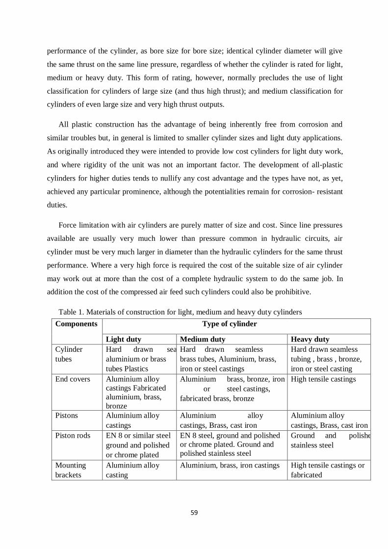
Table 1. Materials of construction for light, medium and heavy duty cylinders
Components Type of cylinder
Light duty Medium duty Heavy duty
Cylinder
tubes
Hard drawn seamless
aluminium or brass
tubes Plastics
Hard drawn seamless
brass tubes, Aluminium, brass,
iron or steel castings
Hard drawn seamless
tubing , brass , bronze,
iron or steel casting
End covers Aluminium alloy
castings Fabricated
aluminium, brass,
bronze
Aluminium brass, bronze, iron
or steel castings,
fabricated brass, bronze
High tensile castings
Pistons Aluminium alloy
castings
Aluminium alloy
castings, Brass, cast iron
Aluminium alloy
castings, Brass, cast iron
Piston rods EN 8 or similar steel
ground and polished
or chrome plated
EN 8 steel, ground and polished
or chrome plated. Ground and
polished stainless steel
Ground and polished
stainless steel
Mounting
brackets
Aluminium alloy
casting
Aluminium, brass, iron castings High tensile castings or
fabricated
60
4. Based on the cylinder action
Based on cylinder action we can classify the cylinders as single acting and double acting.
Single acting cylinders have single air inlet line. Double acting cylinders have two air inlet
lines. Advantages of double acting cylinders over single acting cylinders are
1. In single acting cylinder, compressed air is fed only on one side. Hence this cylinder
can produce work only in one direction. But the compressed air moves the piston in two
directions in double acting cylinder, so they work in both directions
2. In a single acting cylinder, the stroke length is limited by the compressed length of the
spring. But in principle, the stroke length is unlimited in a double acting cylinder
3. While the piston moves forward in a single acting cylinder, air has to overcome the
pressure of the spring and hence some power is lost before the actual stroke of the piston
starts. But this problem is not present in a double acting cylinder.
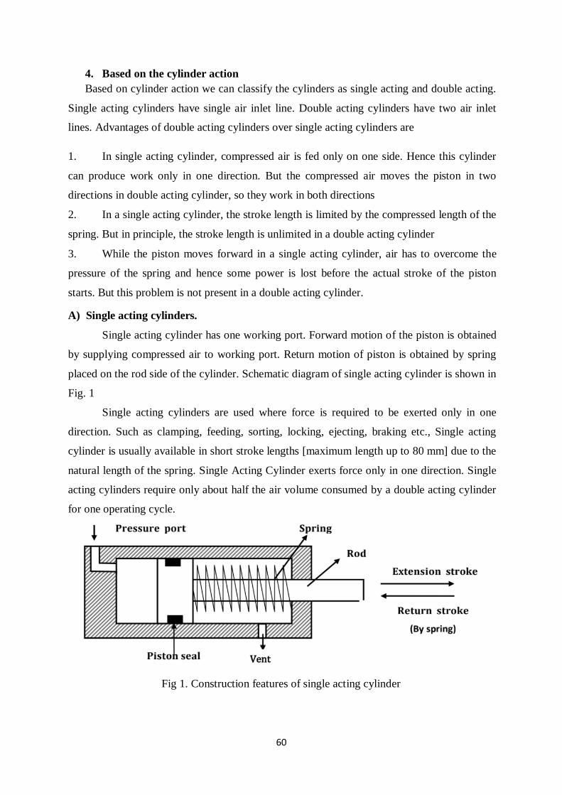
A) Single acting cylinders.
Single acting cylinder has one working port. Forward motion of the piston is obtained
by supplying compressed air to working port. Return motion of piston is obtained by spring
placed on the rod side of the cylinder. Schematic diagram of single acting cylinder is shown in
Fig. 1
Single acting cylinders are used where force is required to be exerted only in one
direction. Such as clamping, feeding, sorting, locking, ejecting, braking etc., Single acting
cylinder is usually available in short stroke lengths [maximum length up to 80 mm] due to the
natural length of the spring. Single Acting Cylinder exerts force only in one direction. Single
acting cylinders require only about half the air volume consumed by a double acting cylinder
for one operating cycle.
Fig 1. Construction features of single acting cylinder
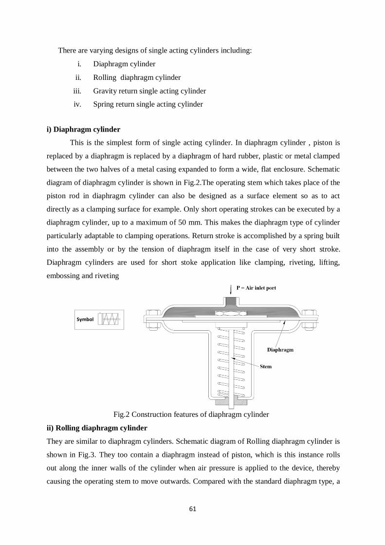
61
There are varying designs of single acting cylinders including:
i. Diaphragm cylinder
ii. Rolling diaphragm cylinder
iii. Gravity return single acting cylinder
iv. Spring return single acting cylinder
i) Diaphragm cylinder
This is the simplest form of single acting cylinder. In diaphragm cylinder , piston is
replaced by a diaphragm is replaced by a diaphragm of hard rubber, plastic or metal clamped
between the two halves of a metal casing expanded to form a wide, flat enclosure. Schematic
diagram of diaphragm cylinder is shown in Fig.2.The operating stem which takes place of the
piston rod in diaphragm cylinder can also be designed as a surface element so as to act
directly as a clamping surface for example. Only short operating strokes can be executed by a
diaphragm cylinder, up to a maximum of 50 mm. This makes the diaphragm type of cylinder
particularly adaptable to clamping operations. Return stroke is accomplished by a spring built
into the assembly or by the tension of diaphragm itself in the case of very short stroke.
Diaphragm cylinders are used for short stoke application like clamping, riveting, lifting,
embossing and riveting
Fig.2 Construction features of diaphragm cylinder
ii) Rolling diaphragm cylinder
They are similar to diaphragm cylinders. Schematic diagram of Rolling diaphragm cylinder is
shown in Fig.3. They too contain a diaphragm instead of piston, which is this instance rolls
out along the inner walls of the cylinder when air pressure is applied to the device, thereby
causing the operating stem to move outwards. Compared with the standard diaphragm type, a
Symbol
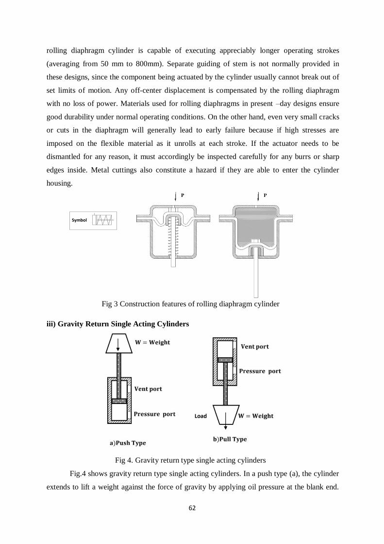
62
rolling diaphragm cylinder is capable of executing appreciably longer operating strokes
(averaging from 50 mm to 800mm). Separate guiding of stem is not normally provided in
these designs, since the component being actuated by the cylinder usually cannot break out of
set limits of motion. Any off-center displacement is compensated by the rolling diaphragm
with no loss of power. Materials used for rolling diaphragms in present –day designs ensure
good durability under normal operating conditions. On the other hand, even very small cracks
or cuts in the diaphragm will generally lead to early failure because if high stresses are
imposed on the flexible material as it unrolls at each stroke. If the actuator needs to be
dismantled for any reason, it must accordingly be inspected carefully for any burrs or sharp
edges inside. Metal cuttings also constitute a hazard if they are able to enter the cylinder
housing.
Fig 3 Construction features of rolling diaphragm cylinder
iii) Gravity Return Single Acting Cylinders
Fig 4. Gravity return type single acting cylinders
Fig.4 shows gravity return type single acting cylinders. In a push type (a), the cylinder
extends to lift a weight against the force of gravity by applying oil pressure at the blank end.
Symbol
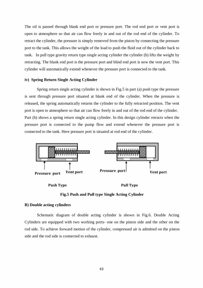
63
The oil is passed through blank end port or pressure port. The rod end port or vent port is
open to atmosphere so that air can flow freely in and out of the rod end of the cylinder. To
retract the cylinder, the pressure is simply removed from the piston by connecting the pressure
port to the tank. This allows the weight of the load to push the fluid out of the cylinder back to
tank. In pull type gravity return type single acting cylinder the cylinder (b) lifts the weight by
retracting. The blank end port is the pressure port and blind end port is now the vent port. This
cylinder will automatically extend whenever the pressure port is connected to the tank.
iv) Spring Return Single Acting Cylinder
Spring return single acting cylinder is shown in Fig.5 in part (a) push type the pressure
is sent through pressure port situated at blank end of the cylinder. When the pressure is
released, the spring automatically returns the cylinder to the fully retracted position. The vent
port is open to atmosphere so that air can flow freely in and out of the rod end of the cylinder.
Part (b) shows a spring return single acting cylinder. In this design cylinder retracts when the
pressure port is connected to the pump flow and extend whenever the pressure port is
connected to the tank. Here pressure port is situated at rod end of the cylinder.
Fig.5 Push and Pull type Single Acting Cylinder
B) Double acting cylinders
Schematic diagram of double acting cylinder is shown in Fig.6. Double Acting
Cylinders are equipped with two working ports- one on the piston side and the other on the
rod side. To achieve forward motion of the cylinder, compressed air is admitted on the piston
side and the rod side is connected to exhaust.
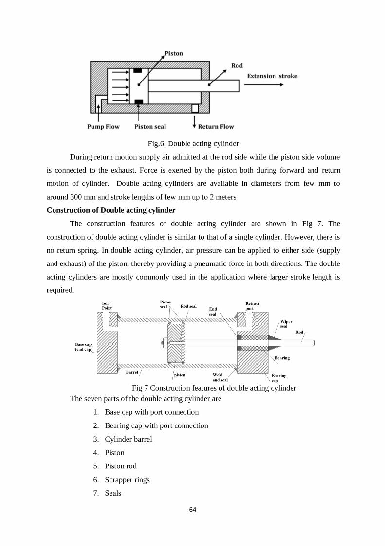
64
Fig.6. Double acting cylinder
During return motion supply air admitted at the rod side while the piston side volume
is connected to the exhaust. Force is exerted by the piston both during forward and return
motion of cylinder. Double acting cylinders are available in diameters from few mm to
around 300 mm and stroke lengths of few mm up to 2 meters
Construction of Double acting cylinder
The construction features of double acting cylinder are shown in Fig 7. The
construction of double acting cylinder is similar to that of a single cylinder. However, there is
no return spring. In double acting cylinder, air pressure can be applied to either side (supply
and exhaust) of the piston, thereby providing a pneumatic force in both directions. The double
acting cylinders are mostly commonly used in the application where larger stroke length is
required.
Fig 7 Construction features of double acting cylinder
The seven parts of the double acting cylinder are
1. Base cap with port connection
2. Bearing cap with port connection
3. Cylinder barrel
4. Piston
5. Piston rod
6. Scrapper rings
7. Seals
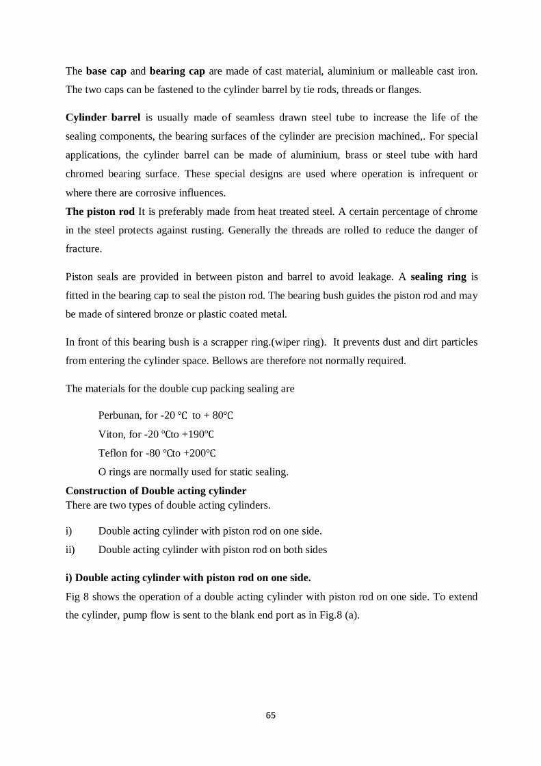
65
The base cap and bearing cap are made of cast material, aluminium or malleable cast iron.
The two caps can be fastened to the cylinder barrel by tie rods, threads or flanges.
Cylinder barrel is usually made of seamless drawn steel tube to increase the life of the
sealing components, the bearing surfaces of the cylinder are precision machined,. For special
applications, the cylinder barrel can be made of aluminium, brass or steel tube with hard
chromed bearing surface. These special designs are used where operation is infrequent or
where there are corrosive influences.
The piston rod It is preferably made from heat treated steel. A certain percentage of chrome
in the steel protects against rusting. Generally the threads are rolled to reduce the danger of
fracture.
Piston seals are provided in between piston and barrel to avoid leakage. A sealing ring is
fitted in the bearing cap to seal the piston rod. The bearing bush guides the piston rod and may
be made of sintered bronze or plastic coated metal.
In front of this bearing bush is a scrapper ring.(wiper ring). It prevents dust and dirt particles
from entering the cylinder space. Bellows are therefore not normally required.
The materials for the double cup packing sealing are
Perbunan, for -20 to + 80
Viton, for -20 to +190
Teflon for -80 to +200
O rings are normally used for static sealing.
Construction of Double acting cylinder
There are two types of double acting cylinders.
i) Double acting cylinder with piston rod on one side.
ii) Double acting cylinder with piston rod on both sides
i) Double acting cylinder with piston rod on one side.
Fig 8 shows the operation of a double acting cylinder with piston rod on one side. To extend
the cylinder, pump flow is sent to the blank end port as in Fig.8 (a).
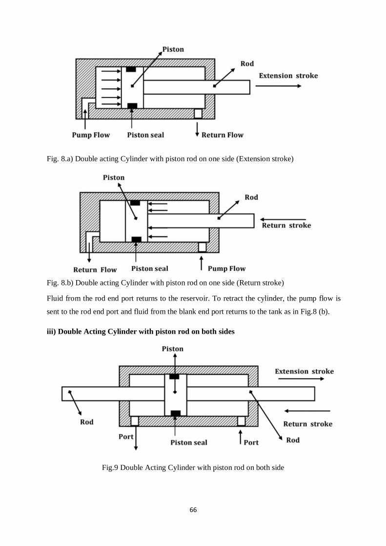
66
Fig. 8.a) Double acting Cylinder with piston rod on one side (Extension stroke)
Fig. 8.b) Double acting Cylinder with piston rod on one side (Return stroke)
Fluid from the rod end port returns to the reservoir. To retract the cylinder, the pump flow is
sent to the rod end port and fluid from the blank end port returns to the tank as in Fig.8 (b).
iii) Double Acting Cylinder with piston rod on both sides
Fig.9 Double Acting Cylinder with piston rod on both side
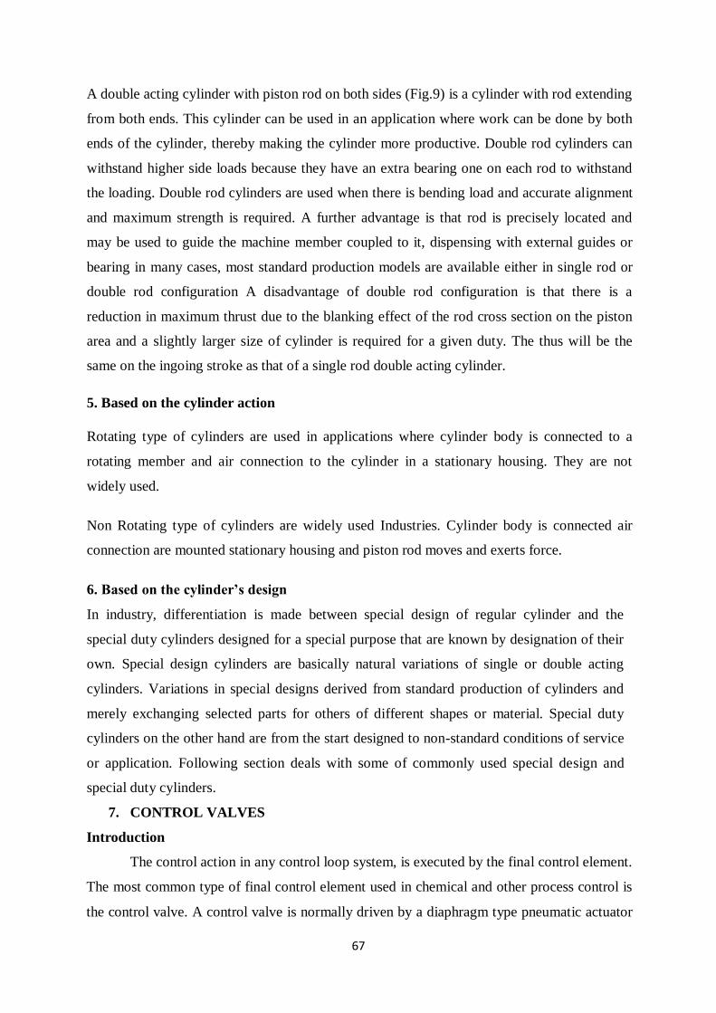
67
A double acting cylinder with piston rod on both sides (Fig.9) is a cylinder with rod extending
from both ends. This cylinder can be used in an application where work can be done by both
ends of the cylinder, thereby making the cylinder more productive. Double rod cylinders can
withstand higher side loads because they have an extra bearing one on each rod to withstand
the loading. Double rod cylinders are used when there is bending load and accurate alignment
and maximum strength is required. A further advantage is that rod is precisely located and
may be used to guide the machine member coupled to it, dispensing with external guides or
bearing in many cases, most standard production models are available either in single rod or
double rod configuration A disadvantage of double rod configuration is that there is a
reduction in maximum thrust due to the blanking effect of the rod cross section on the piston
area and a slightly larger size of cylinder is required for a given duty. The thus will be the
same on the ingoing stroke as that of a single rod double acting cylinder.
5. Based on the cylinder action
Rotating type of cylinders are used in applications where cylinder body is connected to a
rotating member and air connection to the cylinder in a stationary housing. They are not
widely used.
Non Rotating type of cylinders are widely used Industries. Cylinder body is connected air
connection are mounted stationary housing and piston rod moves and exerts force.
6. Based on the cylinder’s design
In industry, differentiation is made between special design of regular cylinder and the
special duty cylinders designed for a special purpose that are known by designation of their
own. Special design cylinders are basically natural variations of single or double acting
cylinders. Variations in special designs derived from standard production of cylinders and
merely exchanging selected parts for others of different shapes or material. Special duty
cylinders on the other hand are from the start designed to non-standard conditions of service
or application. Following section deals with some of commonly used special design and
special duty cylinders.
7. CONTROL VALVES
Introduction
The control action in any control loop system, is executed by the final control element.
The most common type of final control element used in chemical and other process control is
the control valve. A control valve is normally driven by a diaphragm type pneumatic actuator
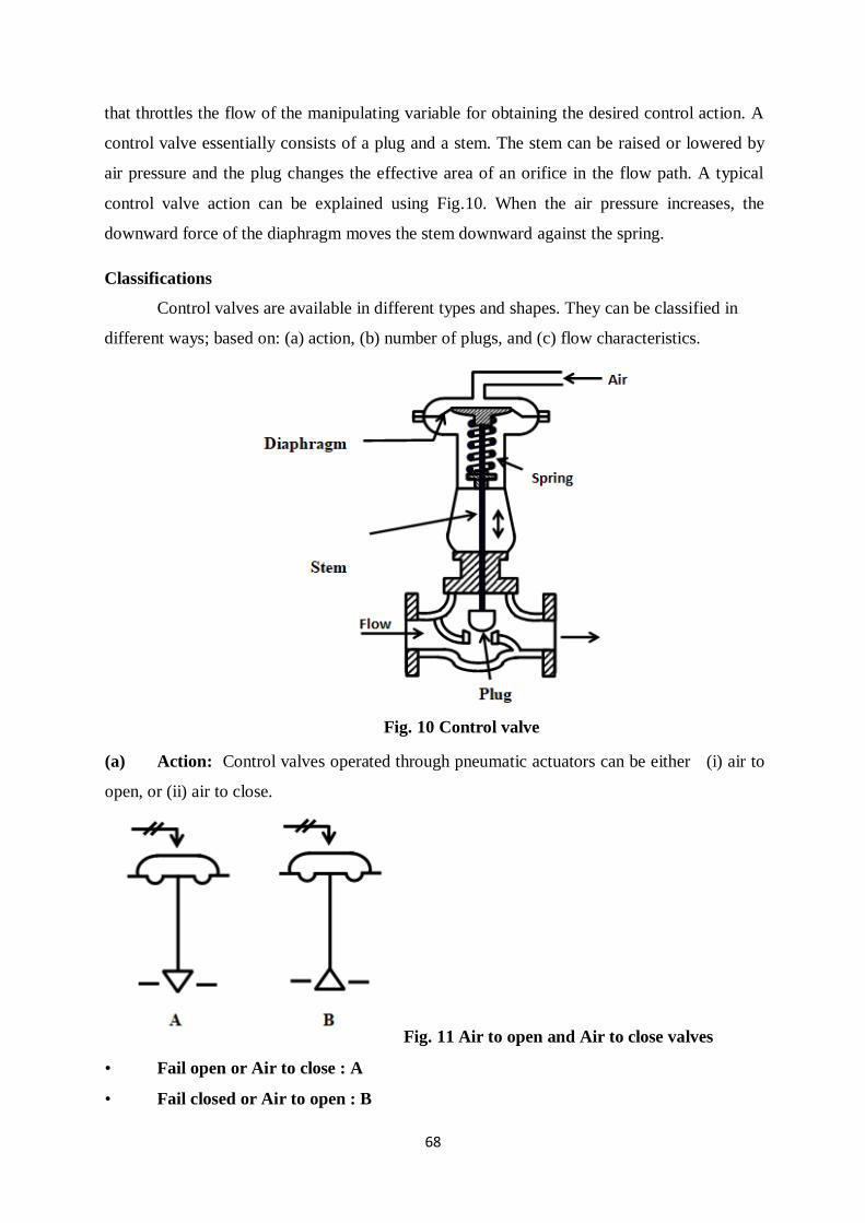
68
that throttles the flow of the manipulating variable for obtaining the desired control action. A
control valve essentially consists of a plug and a stem. The stem can be raised or lowered by
air pressure and the plug changes the effective area of an orifice in the flow path. A typical
control valve action can be explained using Fig.10. When the air pressure increases, the
downward force of the diaphragm moves the stem downward against the spring.
Classifications
Control valves are available in different types and shapes. They can be classified in
different ways; based on: (a) action, (b) number of plugs, and (c) flow characteristics.
Fig. 10 Control valve
(a) Action: Control valves operated through pneumatic actuators can be either (i) air to
open, or (ii) air to close.
Fig. 11 Air to open and Air to close valves
• Fail open or Air to close : A
• Fail closed or Air to open : B
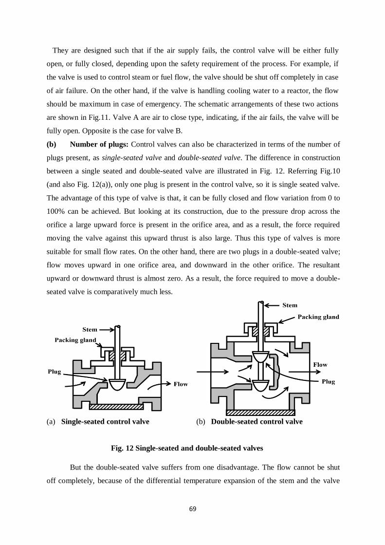
69
They are designed such that if the air supply fails, the control valve will be either fully
open, or fully closed, depending upon the safety requirement of the process. For example, if
the valve is used to control steam or fuel flow, the valve should be shut off completely in case
of air failure. On the other hand, if the valve is handling cooling water to a reactor, the flow
should be maximum in case of emergency. The schematic arrangements of these two actions
are shown in Fig.11. Valve A are air to close type, indicating, if the air fails, the valve will be
fully open. Opposite is the case for valve B.
(b) Number of plugs: Control valves can also be characterized in terms of the number of
plugs present, as single-seated valve and double-seated valve. The difference in construction
between a single seated and double-seated valve are illustrated in Fig. 12. Referring Fig.10
(and also Fig. 12(a)), only one plug is present in the control valve, so it is single seated valve.
The advantage of this type of valve is that, it can be fully closed and flow variation from 0 to
100% can be achieved. But looking at its construction, due to the pressure drop across the
orifice a large upward force is present in the orifice area, and as a result, the force required
moving the valve against this upward thrust is also large. Thus this type of valves is more
suitable for small flow rates. On the other hand, there are two plugs in a double-seated valve;
flow moves upward in one orifice area, and downward in the other orifice. The resultant
upward or downward thrust is almost zero. As a result, the force required to move a double-
seated valve is comparatively much less.
(a) Single-seated control valve (b) Double-seated control valve
Fig. 12 Single-seated and double-seated valves
But the double-seated valve suffers from one disadvantage. The flow cannot be shut
off completely, because of the differential temperature expansion of the stem and the valve
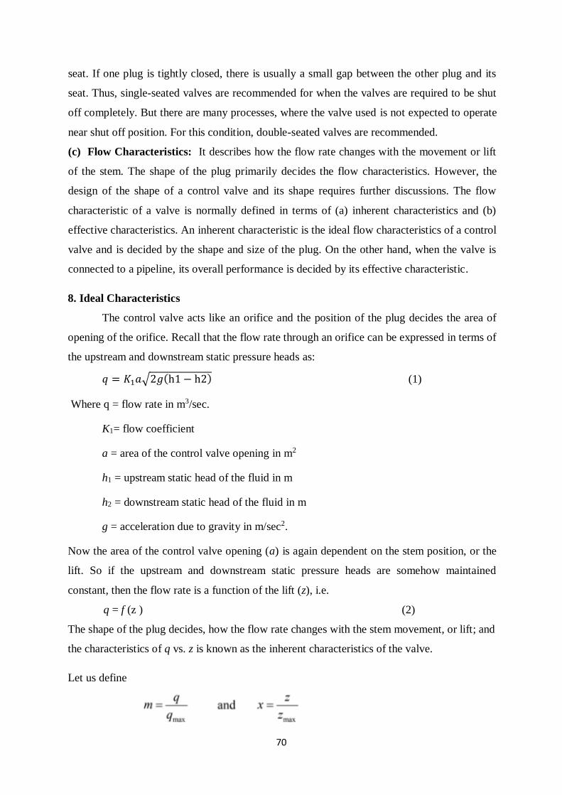
70
seat. If one plug is tightly closed, there is usually a small gap between the other plug and its
seat. Thus, single-seated valves are recommended for when the valves are required to be shut
off completely. But there are many processes, where the valve used is not expected to operate
near shut off position. For this condition, double-seated valves are recommended.
(c) Flow Characteristics: It describes how the flow rate changes with the movement or lift
of the stem. The shape of the plug primarily decides the flow characteristics. However, the
design of the shape of a control valve and its shape requires further discussions. The flow
characteristic of a valve is normally defined in terms of (a) inherent characteristics and (b)
effective characteristics. An inherent characteristic is the ideal flow characteristics of a control
valve and is decided by the shape and size of the plug. On the other hand, when the valve is
connected to a pipeline, its overall performance is decided by its effective characteristic.
8. Ideal Characteristics
The control valve acts like an orifice and the position of the plug decides the area of
opening of the orifice. Recall that the flow rate through an orifice can be expressed in terms of
the upstream and downstream static pressure heads as:
𝑞 = 𝐾1𝑎√2𝑔(h1 − h2) (1)
Where q = flow rate in m3/sec.
K1= flow coefficient
a = area of the control valve opening in m2
h1 = upstream static head of the fluid in m
h2 = downstream static head of the fluid in m
g = acceleration due to gravity in m/sec2.
Now the area of the control valve opening (a) is again dependent on the stem position, or the
lift. So if the upstream and downstream static pressure heads are somehow maintained
constant, then the flow rate is a function of the lift (z), i.e.
q = f (z ) (2)
The shape of the plug decides, how the flow rate changes with the stem movement, or lift; and
the characteristics of q vs. z is known as the inherent characteristics of the valve.
Let us define
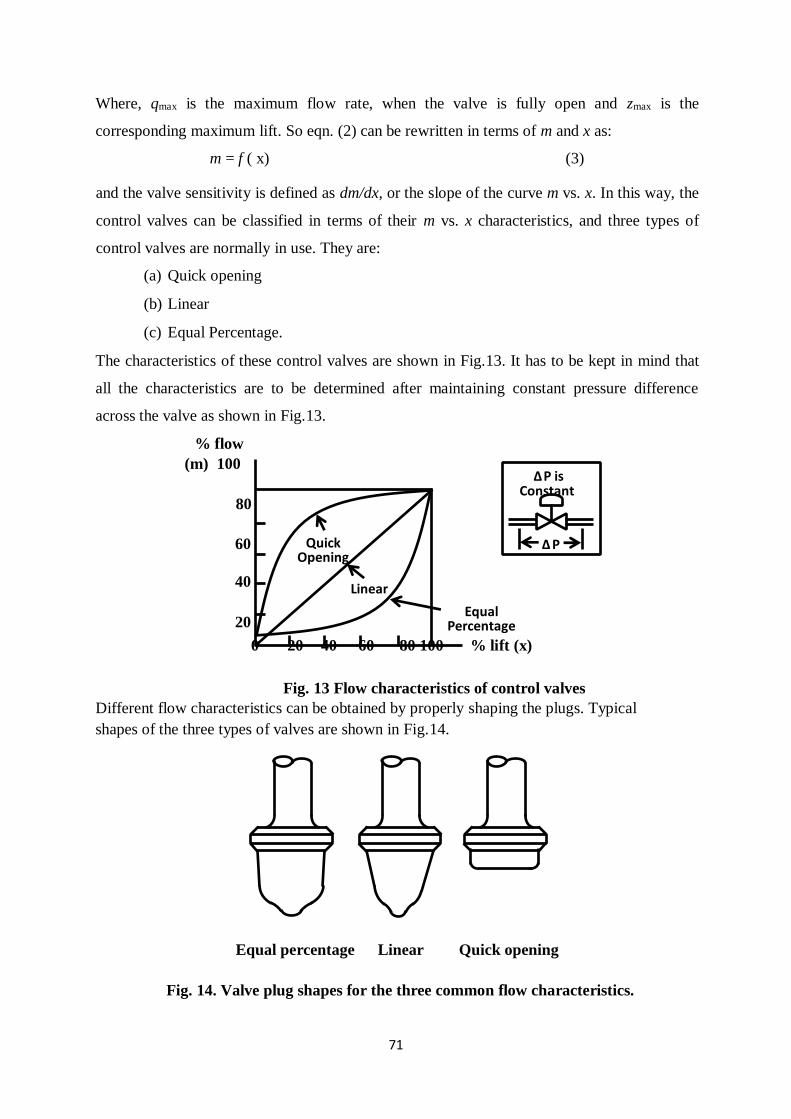
71
Where, qmax is the maximum flow rate, when the valve is fully open and zmax is the
corresponding maximum lift. So eqn. (2) can be rewritten in terms of m and x as:
m = f ( x) (3)
and the valve sensitivity is defined as dm/dx, or the slope of the curve m vs. x. In this way, the
control valves can be classified in terms of their m vs. x characteristics, and three types of
control valves are normally in use. They are:
(a) Quick opening
(b) Linear
(c) Equal Percentage.
The characteristics of these control valves are shown in Fig.13. It has to be kept in mind that
all the characteristics are to be determined after maintaining constant pressure difference
across the valve as shown in Fig.13.
% flow
(m) 100
80
60
40
20
0 20 40 60 80 100 % lift (x)
Fig. 13 Flow characteristics of control valves
Different flow characteristics can be obtained by properly shaping the plugs. Typical
shapes of the three types of valves are shown in Fig.14.
Equal percentage Linear Quick opening
Fig. 14. Valve plug shapes for the three common flow characteristics.
Linear
Quick Opening
Equal Percentage
Δ P is Constant
Δ P
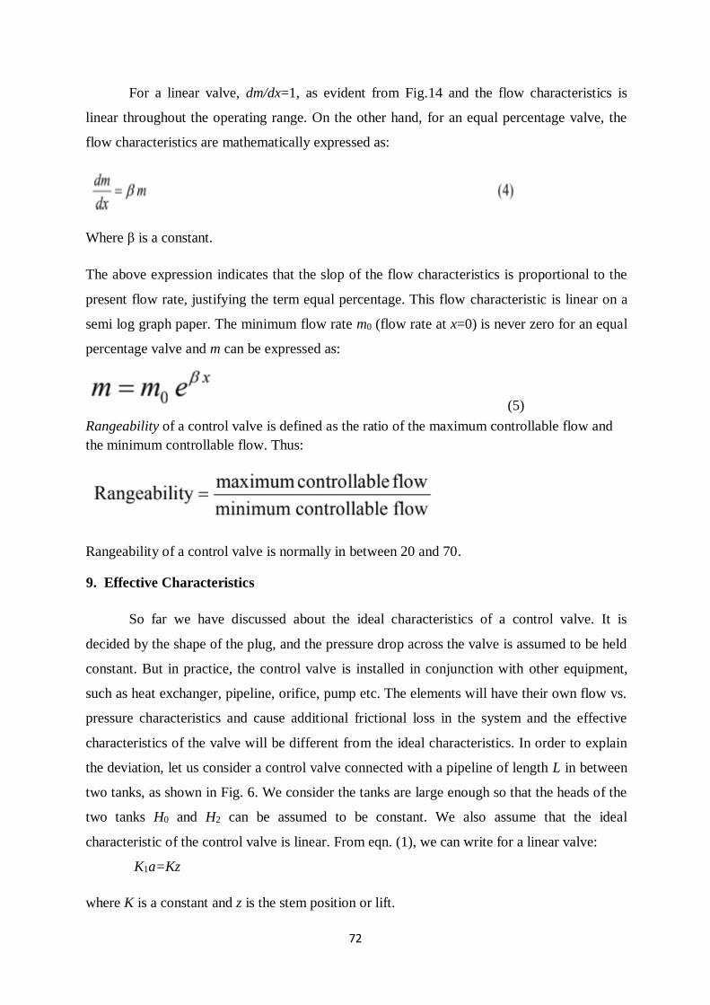
72
For a linear valve, dm/dx=1, as evident from Fig.14 and the flow characteristics is
linear throughout the operating range. On the other hand, for an equal percentage valve, the
flow characteristics are mathematically expressed as:
Where β is a constant.
The above expression indicates that the slop of the flow characteristics is proportional to the
present flow rate, justifying the term equal percentage. This flow characteristic is linear on a
semi log graph paper. The minimum flow rate m0 (flow rate at x=0) is never zero for an equal
percentage valve and m can be expressed as:
(5)
Rangeability of a control valve is defined as the ratio of the maximum controllable flow and
the minimum controllable flow. Thus:
Rangeability of a control valve is normally in between 20 and 70.
9. Effective Characteristics
So far we have discussed about the ideal characteristics of a control valve. It is
decided by the shape of the plug, and the pressure drop across the valve is assumed to be held
constant. But in practice, the control valve is installed in conjunction with other equipment,
such as heat exchanger, pipeline, orifice, pump etc. The elements will have their own flow vs.
pressure characteristics and cause additional frictional loss in the system and the effective
characteristics of the valve will be different from the ideal characteristics. In order to explain
the deviation, let us consider a control valve connected with a pipeline of length L in between
two tanks, as shown in Fig. 6. We consider the tanks are large enough so that the heads of the
two tanks H0 and H2 can be assumed to be constant. We also assume that the ideal
characteristic of the control valve is linear. From eqn. (1), we can write for a linear valve:
K1a=Kz
where K is a constant and z is the stem position or lift.
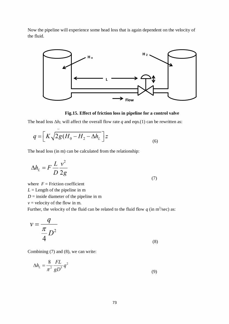
73
Now the pipeline will experience some head loss that is again dependent on the velocity of
the fluid.
Fig.15. Effect of friction loss in pipeline for a control valve
The head loss ΔhL will affect the overall flow rate q and eqn.(1) can be rewritten as:
(6)
The head loss (in m) can be calculated from the relationship:
(7)
where F = Friction coefficient
L = Length of the pipeline in m
D = inside diameter of the pipeline in m
v = velocity of the flow in m.
Further, the velocity of the fluid can be related to the fluid flow q (in m3/sec) as:
(8)
Combining (7) and (8), we can write:
(9)
H o H 2
L
Flow
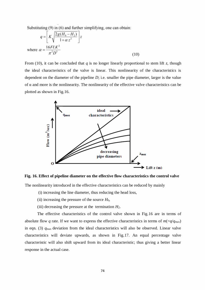
74
(10)
From (10), it can be concluded that q is no longer linearly proportional to stem lift z, though
the ideal characteristics of the valve is linear. This nonlinearity of the characteristics is
dependent on the diameter of the pipeline D; i.e. smaller the pipe diameter, larger is the value
of α and more is the nonlinearity. The nonlinearity of the effective valve characteristics can be
plotted as shown in Fig.16.
Fig. 16. Effect of pipeline diameter on the effective flow characteristics the control valve
The nonlinearity introduced in the effective characteristics can be reduced by mainly
(i) increasing the line diameter, thus reducing the head loss,
(ii) increasing the pressure of the source H0,
(iii) decreasing the pressure at the termination H2.
The effective characteristics of the control valve shown in Fig.16 are in terms of
absolute flow q rate. If we want to express the effective characteristics in terms of m(=q/qmax)
in eqn. (3) qmax deviation from the ideal characteristics will also be observed. Linear valve
characteristics will deviate upwards, as shown in Fig.17. An equal percentage valve
characteristic will also shift upward from its ideal characteristic; thus giving a better linear
response in the actual case.
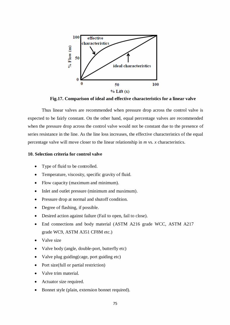
75
Fig.17. Comparison of ideal and effective characteristics for a linear valve
Thus linear valves are recommended when pressure drop across the control valve is
expected to be fairly constant. On the other hand, equal percentage valves are recommended
when the pressure drop across the control valve would not be constant due to the presence of
series resistance in the line. As the line loss increases, the effective characteristics of the equal
percentage valve will move closer to the linear relationship in m vs. x characteristics.
10. Selection criteria for control valve
Type of fluid to be controlled.
Temperature, viscosity, specific gravity of fluid.
Flow capacity (maximum and minimum).
Inlet and outlet pressure (minimum and maximum).
Pressure drop at normal and shutoff condition.
Degree of flashing, if possible.
Desired action against failure (Fail to open, fail to close).
End connections and body material (ASTM A216 grade WCC, ASTM A217
grade WC9, ASTM A351 CF8M etc.)
Valve size
Valve body (angle, double-port, butterfly etc)
Valve plug guiding(cage, port guiding etc)
Port size(full or partial restriction)
Valve trim material.
Actuator size required.
Bonnet style (plain, extension bonnet required).
76
Stem travel versus flow characteristics.
Range-ability.
Ability to cope with high pressure.
Valve sizing (valve must operate between 40% to 70% of full operating range).
Rule of thumb:
1) Equal percentage:
Used where large changes in process drop is expected.
Used where small % of total pressure drop is permitted.
Used in temperature & pressure control loops.
2) Linear:
Used in Level or flow loops.
Used in system where pressure drop across valve remains constant.
3) Quick opening:
Used for ON/OFF services.
Used where instantly “large flow “is needed (safety or cooling system).
Electrical Actuating Systems
1. Solid-State Switches
1.1 P-N Junction Diode
P-N junction diode is two-terminal or two-electrode semiconductor device, which
allows the electric current in only one direction while blocks the electric current in opposite
or reverse direction. If the diode is forward biased, it allows the electric current flow. On the
other hand, if the diode is reverse biased, it blocks the electric current flow. Thus the P-N
diode acts as a switch. It will be acts as ON switch when it is forward biased and acts as OFF
switch during reverse biased.
The p-n junction diode is made from the semiconductor materials such as silicon,
germanium, and gallium arsenide. For designing the diodes, silicon is more preferred over
germanium. The p-n junction diodes made from silicon semiconductors work at higher
temperature when compared with the p-n junction diodes made from germanium semi-
conductors.
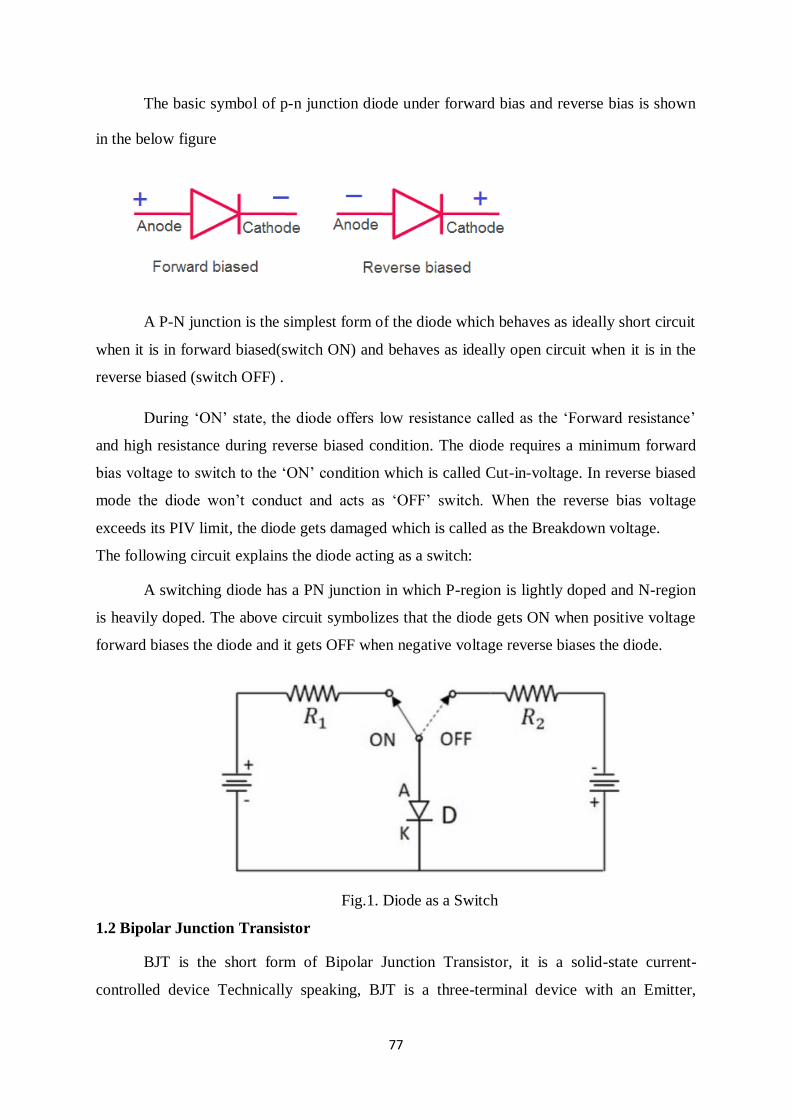
77
The basic symbol of p-n junction diode under forward bias and reverse bias is shown
in the below figure
A P-N junction is the simplest form of the diode which behaves as ideally short circuit
when it is in forward biased(switch ON) and behaves as ideally open circuit when it is in the
reverse biased (switch OFF) .
During ‘ON’ state, the diode offers low resistance called as the ‘Forward resistance’
and high resistance during reverse biased condition. The diode requires a minimum forward
bias voltage to switch to the ‘ON’ condition which is called Cut-in-voltage. In reverse biased
mode the diode won’t conduct and acts as ‘OFF’ switch. When the reverse bias voltage
exceeds its PIV limit, the diode gets damaged which is called as the Breakdown voltage.
The following circuit explains the diode acting as a switch:
A switching diode has a PN junction in which P-region is lightly doped and N-region
is heavily doped. The above circuit symbolizes that the diode gets ON when positive voltage
forward biases the diode and it gets OFF when negative voltage reverse biases the diode.
Fig.1. Diode as a Switch
1.2 Bipolar Junction Transistor
BJT is the short form of Bipolar Junction Transistor, it is a solid-state current-
controlled device Technically speaking, BJT is a three-terminal device with an Emitter,
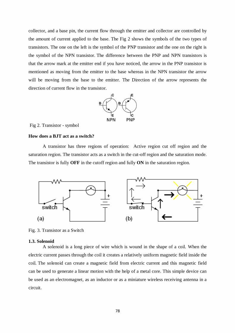
78
collector, and a base pin, the current flow through the emitter and collector are controlled by
the amount of current applied to the base. The Fig 2 shows the symbols of the two types of
transistors. The one on the left is the symbol of the PNP transistor and the one on the right is
the symbol of the NPN transistor. The difference between the PNP and NPN transistors is
that the arrow mark at the emitter end if you have noticed, the arrow in the PNP transistor is
mentioned as moving from the emitter to the base whereas in the NPN transistor the arrow
will be moving from the base to the emitter. The Direction of the arrow represents the
direction of current flow in the transistor.
Fig 2. Transistor - symbol
How does a BJT act as a switch?
A transistor has three regions of operation: Active region cut off region and the
saturation region. The transistor acts as a switch in the cut-off region and the saturation mode.
The transistor is fully OFF in the cutoff region and fully ON in the saturation region.
Fig. 3. Transistor as a Switch
1.3. Solenoid
A solenoid is a long piece of wire which is wound in the shape of a coil. When the
electric current passes through the coil it creates a relatively uniform magnetic field inside the
coil. The solenoid can create a magnetic field from electric current and this magnetic field
can be used to generate a linear motion with the help of a metal core. This simple device can
be used as an electromagnet, as an inductor or as a miniature wireless receiving antenna in a
circuit.
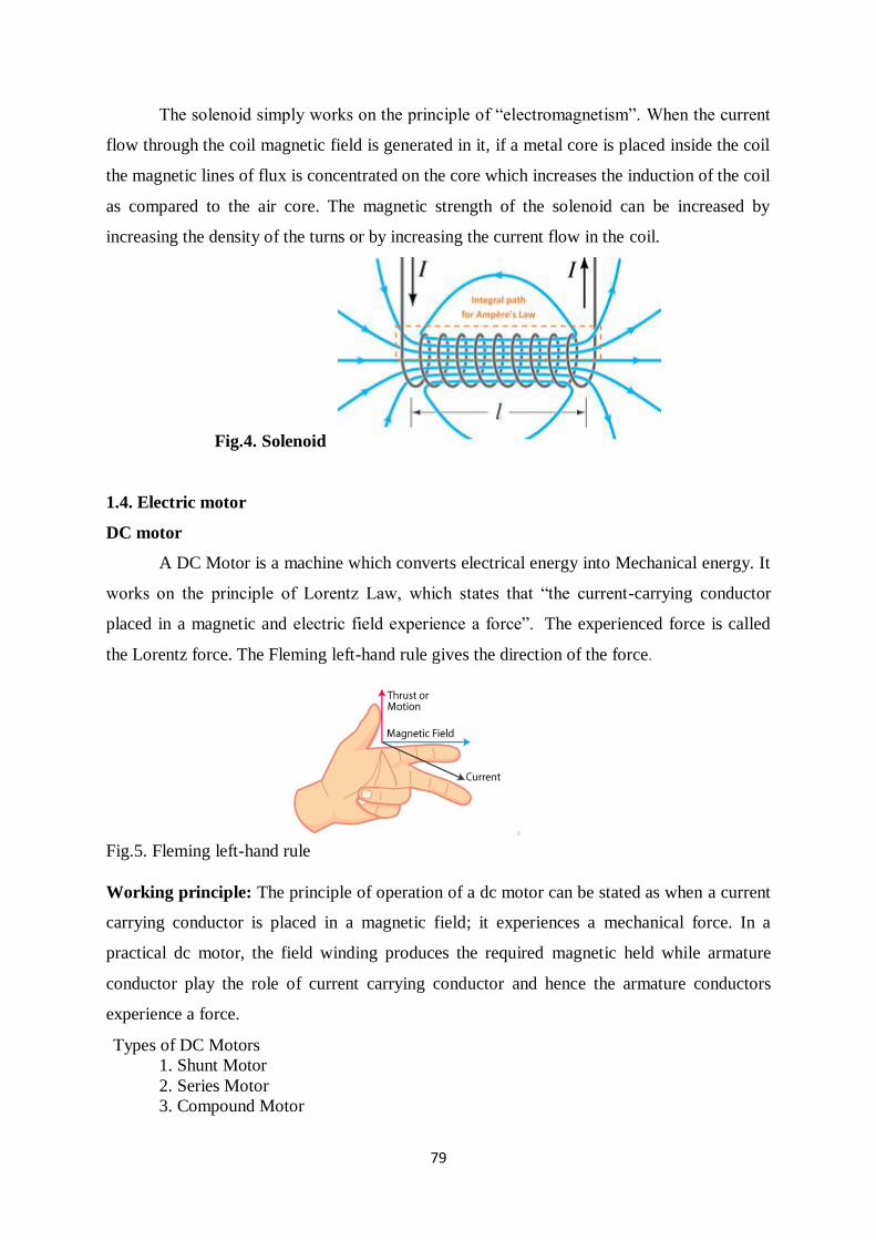
79
The solenoid simply works on the principle of “electromagnetism”. When the current
flow through the coil magnetic field is generated in it, if a metal core is placed inside the coil
the magnetic lines of flux is concentrated on the core which increases the induction of the coil
as compared to the air core. The magnetic strength of the solenoid can be increased by
increasing the density of the turns or by increasing the current flow in the coil.
Fig.4. Solenoid
1.4. Electric motor
DC motor
A DC Motor is a machine which converts electrical energy into Mechanical energy. It
works on the principle of Lorentz Law, which states that “the current-carrying conductor
placed in a magnetic and electric field experience a force”. The experienced force is called
the Lorentz force. The Fleming left-hand rule gives the direction of the force.
Fig.5. Fleming left-hand rule
Working principle: The principle of operation of a dc motor can be stated as when a current
carrying conductor is placed in a magnetic field; it experiences a mechanical force. In a
practical dc motor, the field winding produces the required magnetic held while armature
conductor play the role of current carrying conductor and hence the armature conductors
experience a force.
Types of DC Motors
1. Shunt Motor
2. Series Motor
3. Compound Motor
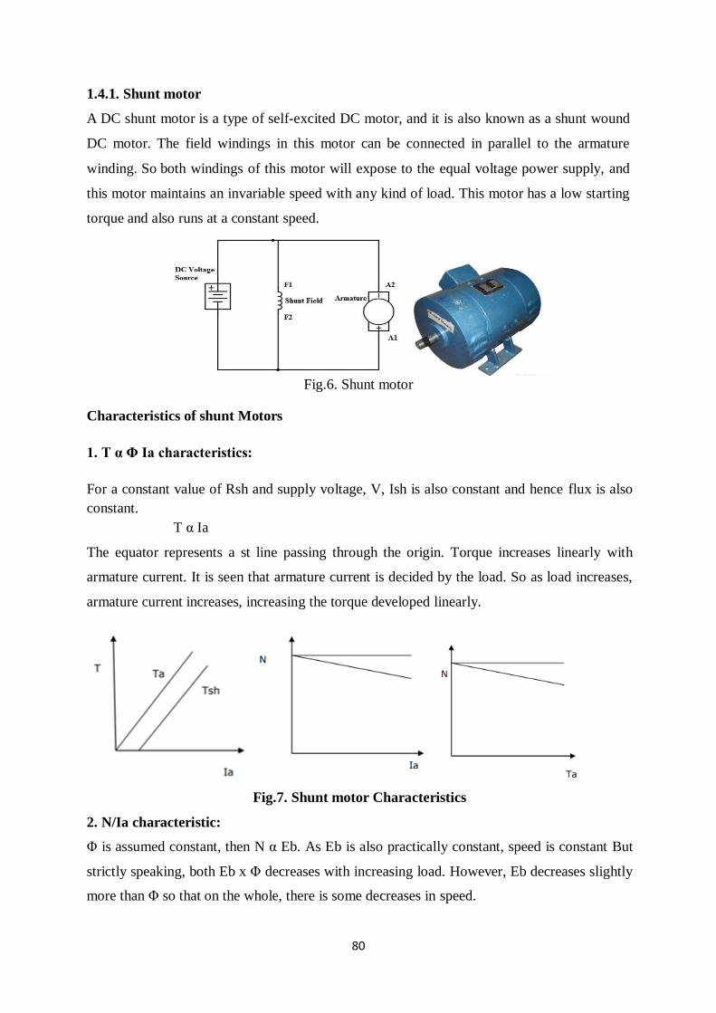
80
1.4.1. Shunt motor
A DC shunt motor is a type of self-excited DC motor, and it is also known as a shunt wound
DC motor. The field windings in this motor can be connected in parallel to the armature
winding. So both windings of this motor will expose to the equal voltage power supply, and
this motor maintains an invariable speed with any kind of load. This motor has a low starting
torque and also runs at a constant speed.
Fig.6. Shunt motor
Characteristics of shunt Motors
1. T α Φ Ia characteristics:
For a constant value of Rsh and supply voltage, V, Ish is also constant and hence flux is also
constant.
T α Ia
The equator represents a st line passing through the origin. Torque increases linearly with
armature current. It is seen that armature current is decided by the load. So as load increases,
armature current increases, increasing the torque developed linearly.
Fig.7. Shunt motor Characteristics
2. N/Ia characteristic:
Φ is assumed constant, then N α Eb. As Eb is also practically constant, speed is constant But
strictly speaking, both Eb x Φ decreases with increasing load. However, Eb decreases slightly
more than Φ so that on the whole, there is some decreases in speed.
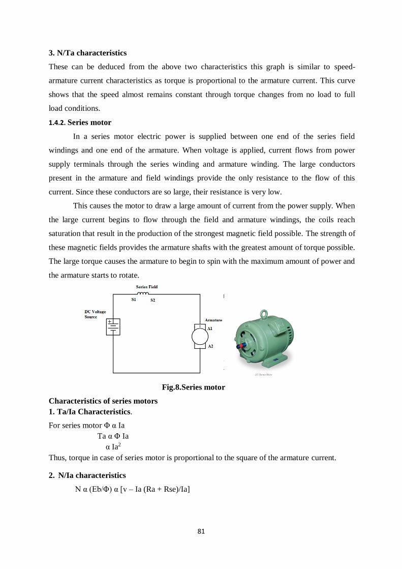
81
3. N/Ta characteristics
These can be deduced from the above two characteristics this graph is similar to speed-
armature current characteristics as torque is proportional to the armature current. This curve
shows that the speed almost remains constant through torque changes from no load to full
load conditions.
1.4.2. Series motor
In a series motor electric power is supplied between one end of the series field
windings and one end of the armature. When voltage is applied, current flows from power
supply terminals through the series winding and armature winding. The large conductors
present in the armature and field windings provide the only resistance to the flow of this
current. Since these conductors are so large, their resistance is very low.
This causes the motor to draw a large amount of current from the power supply. When
the large current begins to flow through the field and armature windings, the coils reach
saturation that result in the production of the strongest magnetic field possible. The strength of
these magnetic fields provides the armature shafts with the greatest amount of torque possible.
The large torque causes the armature to begin to spin with the maximum amount of power and
the armature starts to rotate.
Fig.8.Series motor
Characteristics of series motors
1. Ta/Ia Characteristics.
For series motor Φ α Ia
Ta α Φ Ia
α Ia2
Thus, torque in case of series motor is proportional to the square of the armature current.
2. N/Ia characteristics
N α (Eb/Φ) α [v – Ia (Ra + Rse)/Ia]
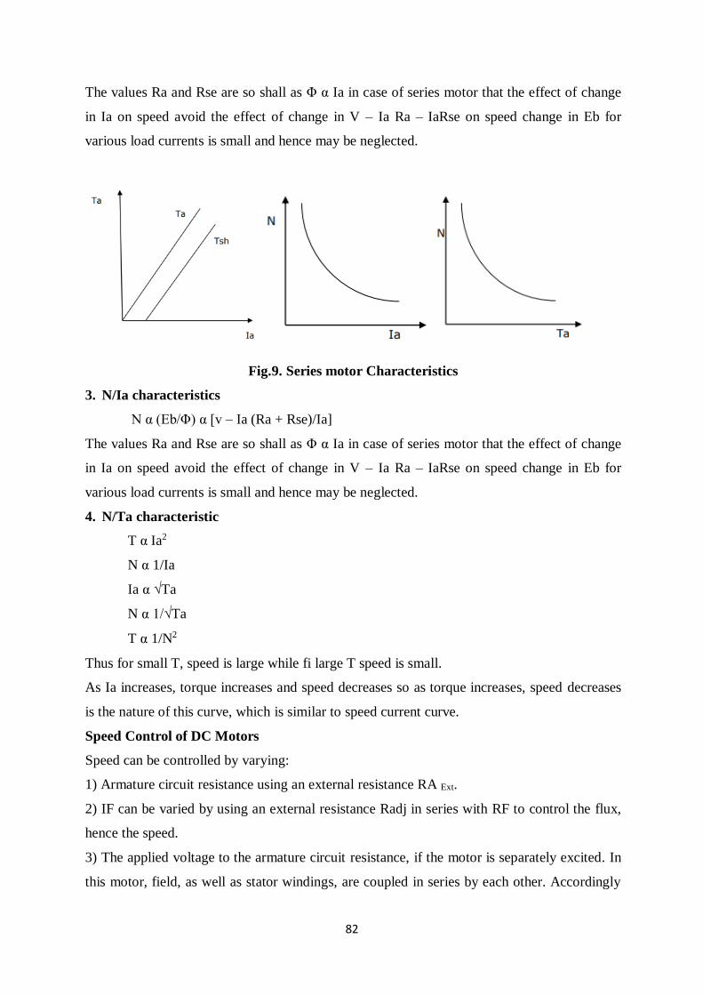
82
The values Ra and Rse are so shall as Φ α Ia in case of series motor that the effect of change
in Ia on speed avoid the effect of change in V – Ia Ra – IaRse on speed change in Eb for
various load currents is small and hence may be neglected.
Fig.9. Series motor Characteristics
3. N/Ia characteristics
N α (Eb/Φ) α [v – Ia (Ra + Rse)/Ia]
The values Ra and Rse are so shall as Φ α Ia in case of series motor that the effect of change
in Ia on speed avoid the effect of change in V – Ia Ra – IaRse on speed change in Eb for
various load currents is small and hence may be neglected.
4. N/Ta characteristic
T α Ia2
N α 1/Ia
Ia α √Ta
N α 1/√Ta
T α 1/N2
Thus for small T, speed is large while fi large T speed is small.
As Ia increases, torque increases and speed decreases so as torque increases, speed decreases
is the nature of this curve, which is similar to speed current curve.
Speed Control of DC Motors
Speed can be controlled by varying:
1) Armature circuit resistance using an external resistance RA Ext.
2) IF can be varied by using an external resistance Radj in series with RF to control the flux,
hence the speed.
3) The applied voltage to the armature circuit resistance, if the motor is separately excited. In
this motor, field, as well as stator windings, are coupled in series by each other. Accordingly
83
the armature and field current are equivalent. uge current supply straightly from the supply
toward the field windings.
Comparison of DC Motors
Shunt Motors: “Constant speed” motor (speed regulation is very good). Adjustable speed,
medium starting torque. (Start = 1.4 × TFL)
Applications: centrifugal pump, machine tools, blowers, fans, reciprocating pumps, etc.
Series Motors: Variable speed motor which changes speed drastically from one load
condition to another. It has a high starting torque.
Applications: hoists, electric trains, conveyors, elevators, electric cars, etc.
AC MOTOR
The motor that converts the alternating current into mechanical power by using an
electromagnetic induction phenomenon is called an AC motor.
Types of Ac motors:
1) Three Phase Induction Motor
2) Single Phase Induction Motor
1) Three Phase Induction Motor:
An electrical motor is an electromechanical device that converts electrical energy into
mechanical energy. In the case of three-phase AC (Alternating Current) operation, the most
widely used motor is a 3 phase induction motor, as this type of motor does not require an
additional starting device. These types of motors are known as self-starting induction motors.
A 3 phase induction motor consists of two major parts:
1. A stator
2. A rotor
Stator
The stator of three phase induction motor is made up of numbers of slots to construct a 3
phase winding circuit which we connect with 3 phase AC source. We arrange the three-phase
winding in such a manner in the slots that they produce one rotating magnetic field when we
switch on the three-phase AC supply source
Rotor
The rotor of three phase induction motor consists of a cylindrical laminated core with parallel
slots that can carry conductors. The conductors are heavy copper or aluminum bars fitted in
each slot and short-circuited by the end rings. The slots are not exactly made parallel to the
84
axis of the shaft but are slotted a little skewed because this arrangement reduces magnetic
humming noise and can avoid stalling of the motor.
PRINCIPLE OF OPERATION
An AC current is applied in the stator armature which generates a flux in the stator
magnetic circuit.
This flux induces an emf in the conducting bars of rotor as they are “cut” by the flux
while the magnet is being moved (E = BVL (Faraday’s Law))
A current flows in the rotor circuit due to the induced emf, which in term produces a
force, (F = BIL) can be changed to the torque as the output.
In a 3-phase induction motor, the three-phase currents ia, ib and ic, each of equal
magnitude, but differing in phase by 120°. Each phase current produces a magnetic flux and
there is physical 120 °shift between each flux. The total flux in the machine is the sum of the
three fluxes. The summation of the three ac fluxes results in a rotating flux, which turns with
constant speed and has constant amplitude. Such a magnetic flux produced by balanced three
phase currents flowing in thee-phase windings is called a rotating magnetic flux or rotating
magnetic field (RMF). RMF rotates with a constant speed (Synchronous Speed). Existence
of a RFM is an essential condition for the operation of an induction motor.
If stator is energized by an ac current, RMF is generated due to the applied current to
the stator winding. This flux produces magnetic field and the field revolves in the air gap
between stator and rotor. So, the magnetic field induces a voltage in the short-circuited bars
of the rotor. This voltage drives current through the bars. The interaction of the rotating flux
and the rotor current generates a force that drives the motor and a torque is developed
consequently. The torque is proportional with the flux density and the rotor bar current
(F=BLI). The motor speed is less than the synchronous speed. The direction of the rotation of
the rotor is the same as the direction of the rotation of the revolving magnetic field in the air
gap.
However, for these currents to be induced, the speed of the physical rotor and the
speed of the rotating magnetic field in the stator must be different, or else the magnetic field
will not be moving relative to the rotor conductors and no currents will be induced. If by
some chance this happens, the rotor typically slows slightly until a current is re-induced and
then the rotor continues as before. This difference between the speed of the rotor and speed of
the rotating magnetic field in the stator is called slip. It is unit less and is the ratio between the
relative speed of the magnetic field as seen by the rotor the (slip speed) to the speed of the
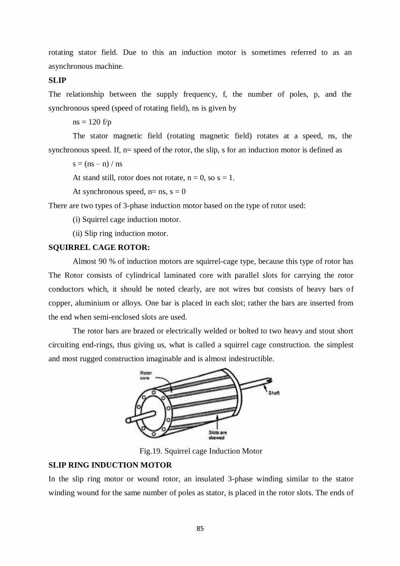
85
rotating stator field. Due to this an induction motor is sometimes referred to as an
asynchronous machine.
SLIP
The relationship between the supply frequency, f, the number of poles, p, and the
synchronous speed (speed of rotating field), ns is given by
ns = 120 f/p
The stator magnetic field (rotating magnetic field) rotates at a speed, ns, the
synchronous speed. If, n= speed of the rotor, the slip, s for an induction motor is defined as
s = (ns – n) / ns
At stand still, rotor does not rotate, n = 0, so s = 1.
At synchronous speed, n= ns, s = 0
There are two types of 3-phase induction motor based on the type of rotor used:
(i) Squirrel cage induction motor.
(ii) Slip ring induction motor.
SQUIRREL CAGE ROTOR:
Almost 90 % of induction motors are squirrel-cage type, because this type of rotor has
The Rotor consists of cylindrical laminated core with parallel slots for carrying the rotor
conductors which, it should be noted clearly, are not wires but consists of heavy bars of
copper, aluminium or alloys. One bar is placed in each slot; rather the bars are inserted from
the end when semi-enclosed slots are used.
The rotor bars are brazed or electrically welded or bolted to two heavy and stout short
circuiting end-rings, thus giving us, what is called a squirrel cage construction. the simplest
and most rugged construction imaginable and is almost indestructible.
Fig.19. Squirrel cage Induction Motor
SLIP RING INDUCTION MOTOR
In the slip ring motor or wound rotor, an insulated 3-phase winding similar to the stator
winding wound for the same number of poles as stator, is placed in the rotor slots. The ends of
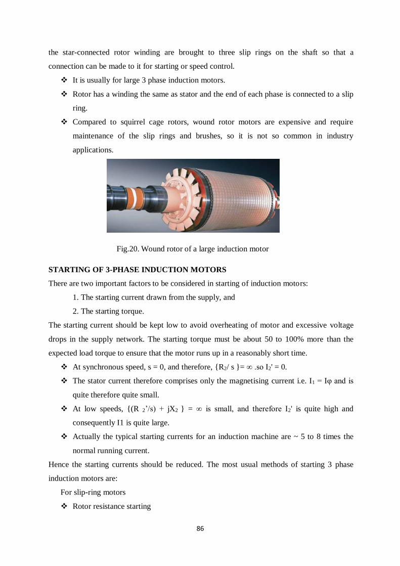
86
the star-connected rotor winding are brought to three slip rings on the shaft so that a
connection can be made to it for starting or speed control.
It is usually for large 3 phase induction motors.
Rotor has a winding the same as stator and the end of each phase is connected to a slip
ring.
Compared to squirrel cage rotors, wound rotor motors are expensive and require
maintenance of the slip rings and brushes, so it is not so common in industry
applications.
Fig.20. Wound rotor of a large induction motor
STARTING OF 3-PHASE INDUCTION MOTORS
There are two important factors to be considered in starting of induction motors:
1. The starting current drawn from the supply, and
2. The starting torque.
The starting current should be kept low to avoid overheating of motor and excessive voltage
drops in the supply network. The starting torque must be about 50 to 100% more than the
expected load torque to ensure that the motor runs up in a reasonably short time.
At synchronous speed, s = 0, and therefore, {R2/ s }= ∞ .so I2' = 0.
The stator current therefore comprises only the magnetising current i.e. I1 = Iφ and is
quite therefore quite small.
At low speeds, {(R 2’/s) + jX2 } = ∞ is small, and therefore I2' is quite high and
consequently I1 is quite large.
Actually the typical starting currents for an induction machine are ~ 5 to 8 times the
normal running current.
Hence the starting currents should be reduced. The most usual methods of starting 3 phase
induction motors are:
For slip-ring motors
Rotor resistance starting
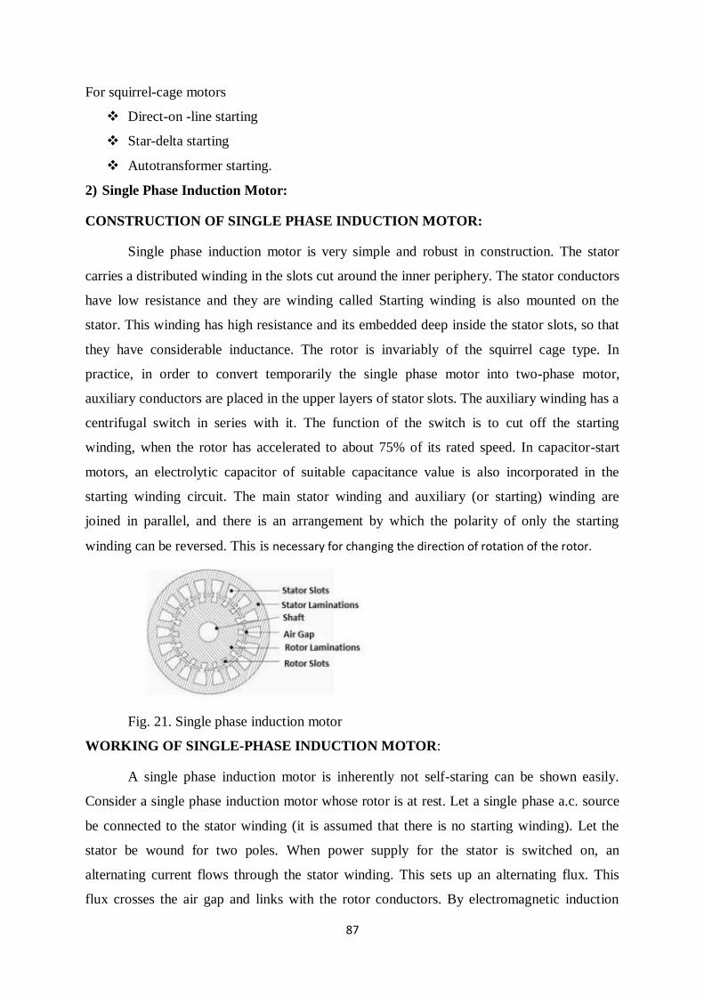
87
For squirrel-cage motors
Direct-on -line starting
Star-delta starting
Autotransformer starting.
2) Single Phase Induction Motor:
CONSTRUCTION OF SINGLE PHASE INDUCTION MOTOR:
Single phase induction motor is very simple and robust in construction. The stator
carries a distributed winding in the slots cut around the inner periphery. The stator conductors
have low resistance and they are winding called Starting winding is also mounted on the
stator. This winding has high resistance and its embedded deep inside the stator slots, so that
they have considerable inductance. The rotor is invariably of the squirrel cage type. In
practice, in order to convert temporarily the single phase motor into two-phase motor,
auxiliary conductors are placed in the upper layers of stator slots. The auxiliary winding has a
centrifugal switch in series with it. The function of the switch is to cut off the starting
winding, when the rotor has accelerated to about 75% of its rated speed. In capacitor-start
motors, an electrolytic capacitor of suitable capacitance value is also incorporated in the
starting winding circuit. The main stator winding and auxiliary (or starting) winding are
joined in parallel, and there is an arrangement by which the polarity of only the starting
winding can be reversed. This is necessary for changing the direction of rotation of the rotor.
Fig. 21. Single phase induction motor
WORKING OF SINGLE-PHASE INDUCTION MOTOR:
A single phase induction motor is inherently not self-staring can be shown easily.
Consider a single phase induction motor whose rotor is at rest. Let a single phase a.c. source
be connected to the stator winding (it is assumed that there is no starting winding). Let the
stator be wound for two poles. When power supply for the stator is switched on, an
alternating current flows through the stator winding. This sets up an alternating flux. This
flux crosses the air gap and links with the rotor conductors. By electromagnetic induction
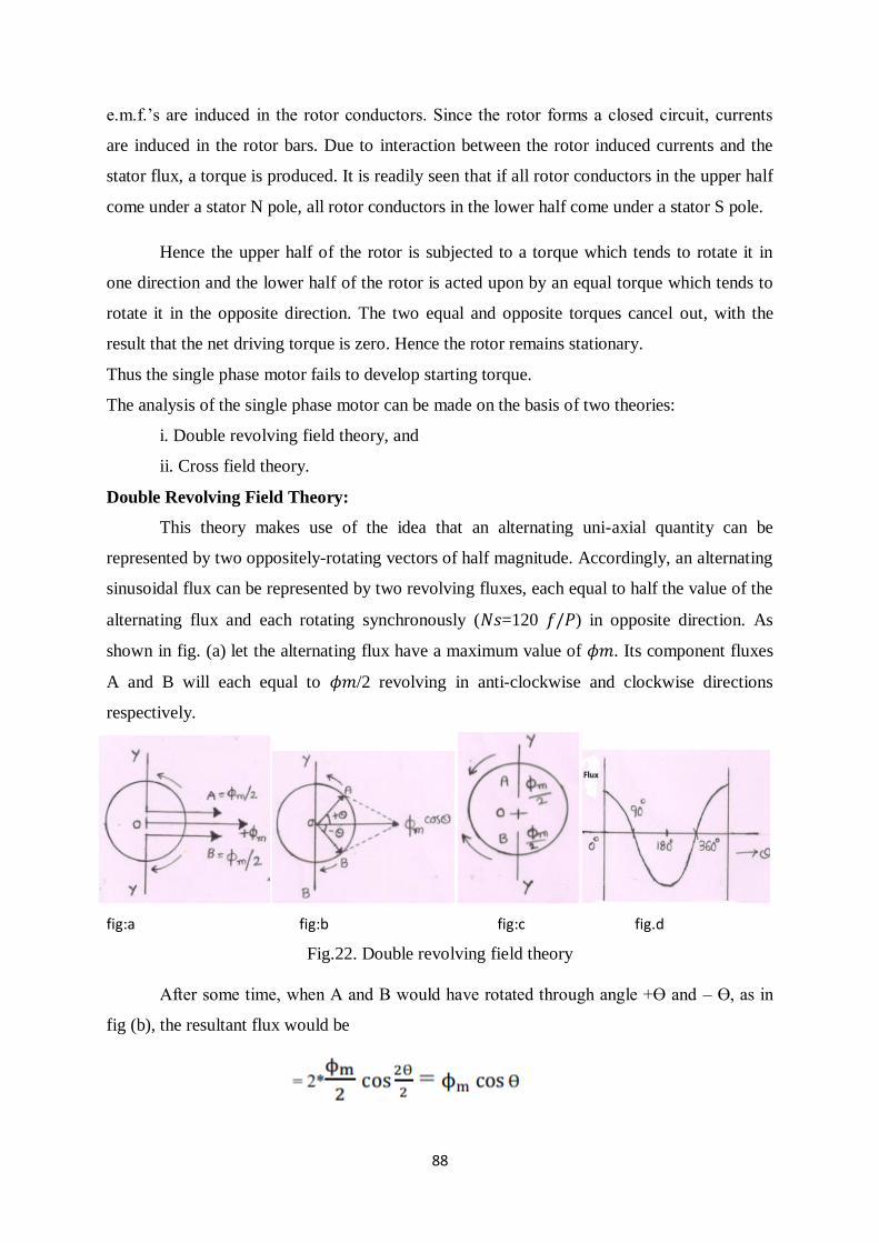
88
e.m.f.’s are induced in the rotor conductors. Since the rotor forms a closed circuit, currents
are induced in the rotor bars. Due to interaction between the rotor induced currents and the
stator flux, a torque is produced. It is readily seen that if all rotor conductors in the upper half
come under a stator N pole, all rotor conductors in the lower half come under a stator S pole.
Hence the upper half of the rotor is subjected to a torque which tends to rotate it in
one direction and the lower half of the rotor is acted upon by an equal torque which tends to
rotate it in the opposite direction. The two equal and opposite torques cancel out, with the
result that the net driving torque is zero. Hence the rotor remains stationary.
Thus the single phase motor fails to develop starting torque.
The analysis of the single phase motor can be made on the basis of two theories:
i. Double revolving field theory, and
ii. Cross field theory.
Double Revolving Field Theory:
This theory makes use of the idea that an alternating uni-axial quantity can be
represented by two oppositely-rotating vectors of half magnitude. Accordingly, an alternating
sinusoidal flux can be represented by two revolving fluxes, each equal to half the value of the
alternating flux and each rotating synchronously (𝑁𝑠=120 𝑓/𝑃) in opposite direction. As
shown in fig. (a) let the alternating flux have a maximum value of 𝜙𝑚. Its component fluxes
A and B will each equal to 𝜙𝑚/2 revolving in anti-clockwise and clockwise directions
respectively.
fig:a fig:b fig:c fig.d
Fig.22. Double revolving field theory
After some time, when A and B would have rotated through angle +Ɵ and – Ɵ, as in
fig (b), the resultant flux would be
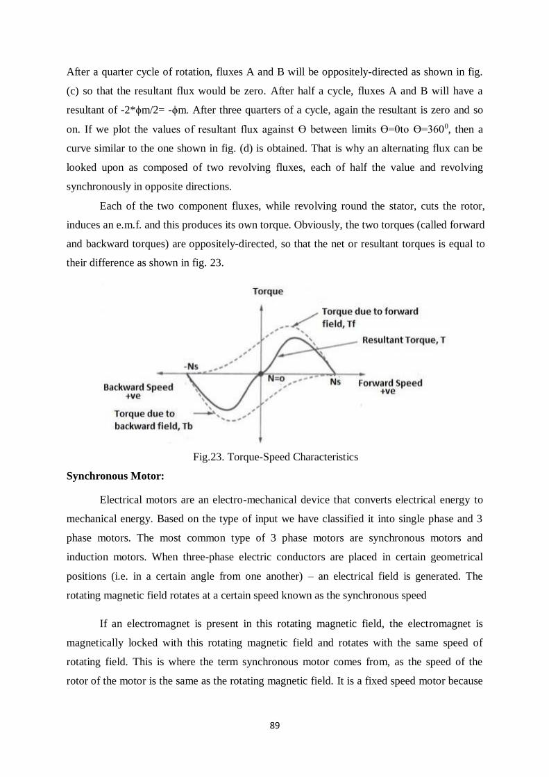
89
After a quarter cycle of rotation, fluxes A and B will be oppositely-directed as shown in fig.
(c) so that the resultant flux would be zero. After half a cycle, fluxes A and B will have a
resultant of -2*ϕm/2= -ϕm. After three quarters of a cycle, again the resultant is zero and so
on. If we plot the values of resultant flux against Ɵ between limits Ɵ=0to Ɵ=3600, then a
curve similar to the one shown in fig. (d) is obtained. That is why an alternating flux can be
looked upon as composed of two revolving fluxes, each of half the value and revolving
synchronously in opposite directions.
Each of the two component fluxes, while revolving round the stator, cuts the rotor,
induces an e.m.f. and this produces its own torque. Obviously, the two torques (called forward
and backward torques) are oppositely-directed, so that the net or resultant torques is equal to
their difference as shown in fig. 23.
Fig.23. Torque-Speed Characteristics
Synchronous Motor:
Electrical motors are an electro-mechanical device that converts electrical energy to
mechanical energy. Based on the type of input we have classified it into single phase and 3
phase motors. The most common type of 3 phase motors are synchronous motors and
induction motors. When three-phase electric conductors are placed in certain geometrical
positions (i.e. in a certain angle from one another) – an electrical field is generated. The
rotating magnetic field rotates at a certain speed known as the synchronous speed
If an electromagnet is present in this rotating magnetic field, the electromagnet is
magnetically locked with this rotating magnetic field and rotates with the same speed of
rotating field. This is where the term synchronous motor comes from, as the speed of the
rotor of the motor is the same as the rotating magnetic field. It is a fixed speed motor because
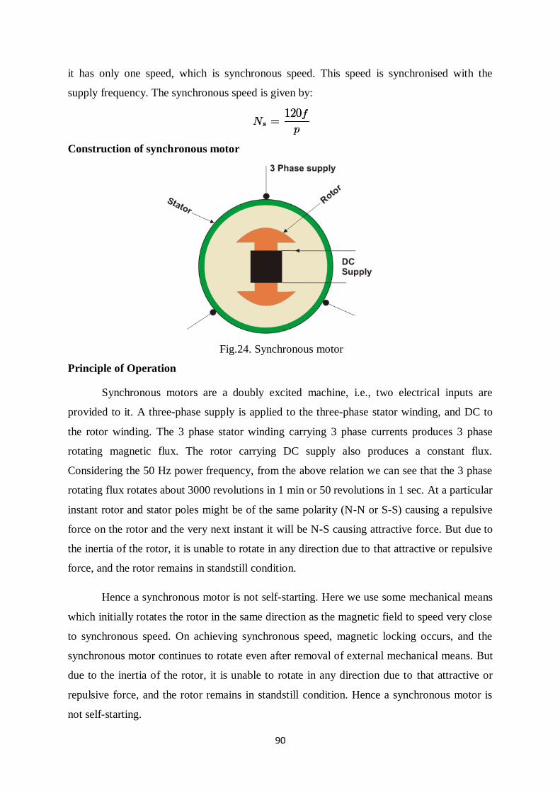
90
it has only one speed, which is synchronous speed. This speed is synchronised with the
supply frequency. The synchronous speed is given by:
Construction of synchronous motor
Fig.24. Synchronous motor
Principle of Operation
Synchronous motors are a doubly excited machine, i.e., two electrical inputs are
provided to it. A three-phase supply is applied to the three-phase stator winding, and DC to
the rotor winding. The 3 phase stator winding carrying 3 phase currents produces 3 phase
rotating magnetic flux. The rotor carrying DC supply also produces a constant flux.
Considering the 50 Hz power frequency, from the above relation we can see that the 3 phase
rotating flux rotates about 3000 revolutions in 1 min or 50 revolutions in 1 sec. At a particular
instant rotor and stator poles might be of the same polarity (N-N or S-S) causing a repulsive
force on the rotor and the very next instant it will be N-S causing attractive force. But due to
the inertia of the rotor, it is unable to rotate in any direction due to that attractive or repulsive
force, and the rotor remains in standstill condition.
Hence a synchronous motor is not self-starting. Here we use some mechanical means
which initially rotates the rotor in the same direction as the magnetic field to speed very close
to synchronous speed. On achieving synchronous speed, magnetic locking occurs, and the
synchronous motor continues to rotate even after removal of external mechanical means. But
due to the inertia of the rotor, it is unable to rotate in any direction due to that attractive or
repulsive force, and the rotor remains in standstill condition. Hence a synchronous motor is
not self-starting.
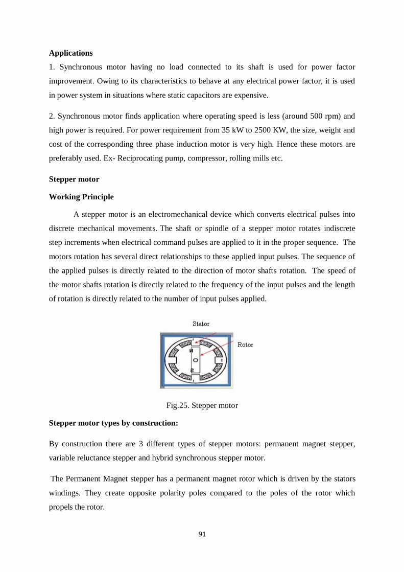
91
Applications
1. Synchronous motor having no load connected to its shaft is used for power factor
improvement. Owing to its characteristics to behave at any electrical power factor, it is used
in power system in situations where static capacitors are expensive.
2. Synchronous motor finds application where operating speed is less (around 500 rpm) and
high power is required. For power requirement from 35 kW to 2500 KW, the size, weight and
cost of the corresponding three phase induction motor is very high. Hence these motors are
preferably used. Ex- Reciprocating pump, compressor, rolling mills etc.
Stepper motor
Working Principle
A stepper motor is an electromechanical device which converts electrical pulses into
discrete mechanical movements. The shaft or spindle of a stepper motor rotates indiscrete
step increments when electrical command pulses are applied to it in the proper sequence. The
motors rotation has several direct relationships to these applied input pulses. The sequence of
the applied pulses is directly related to the direction of motor shafts rotation. The speed of
the motor shafts rotation is directly related to the frequency of the input pulses and the length
of rotation is directly related to the number of input pulses applied.
Fig.25. Stepper motor
Stepper motor types by construction:
By construction there are 3 different types of stepper motors: permanent magnet stepper,
variable reluctance stepper and hybrid synchronous stepper motor.
The Permanent Magnet stepper has a permanent magnet rotor which is driven by the stators
windings. They create opposite polarity poles compared to the poles of the rotor which
propels the rotor.
92
The next type, the Variable Reluctant stepper motor uses a non-magnetizes soft iron rotor.
The rotor has teeth that are offset from the stator and as we active the windings in a particular
order the rotor moves respectively so that it has minimum gab between the stator and the
teeth of the rotor
The Hybrid Synchronous motor is combinations of the previous two steppers. It has
permanent magnet toothed rotor and also a toothed stator. The rotor has two sections, which
are opposite in polarity and their teeth are offset
Operating modes
Stepper motor is a brushless DC motor that rotates in steps. This is very useful
because it can be precisely positioned without any feedback sensor, which represents an
open-loop controller. The stepper motor consists of a rotor that is generally a permanent
magnet and it is surrounded by the windings of the stator. As we activate the windings step
by step in a particular order and let a current flow through them they will magnetize the stator
and make electromagnetic poles respectively that will cause propulsion to the motor.
The following are the operating modes of a stepper motoe
a) Full step
b) Half step
c) Micro stepping
The magnitude of the step angle of the variable reluctance motor is given as
Where, α (alpha) is the step angle, ms is the number of stator phases, Nr is the
number of rotor teeth
The step angle is expressed as shown below.
NS is the number of stator poles, Nr is the number of rotor poles
Full step mode
The motor is operated with both phases energized at the same time. Two-phase on provides
about 30% to 40% more torque than one phase on, however it requires twice as much power
from the driver.
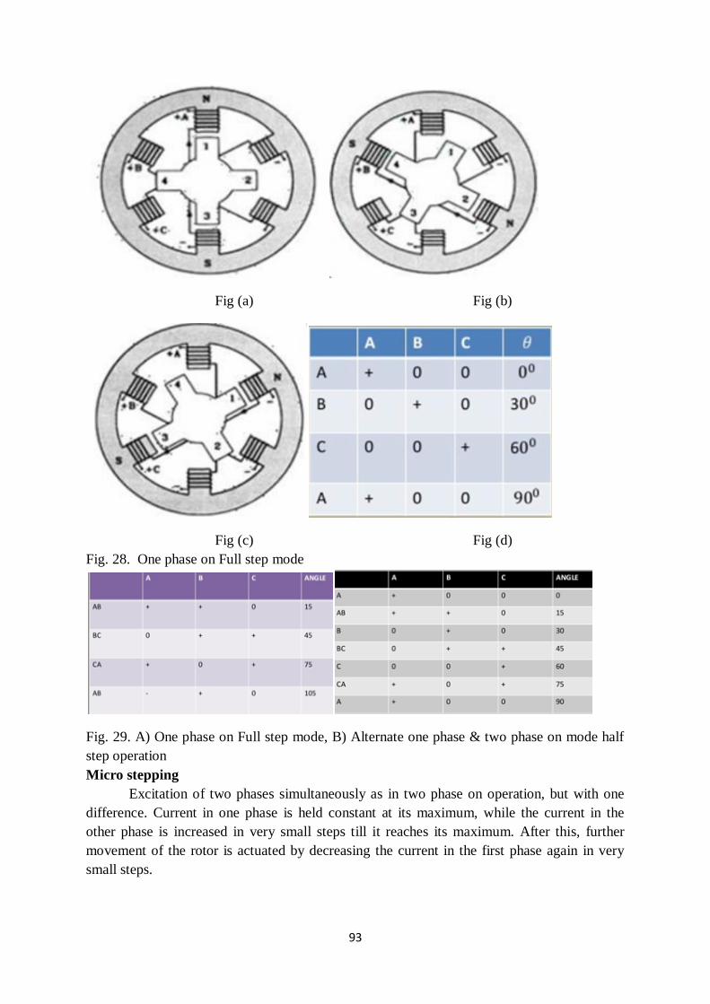
93
Fig (a) Fig (b)
Fig (c) Fig (d)
Fig. 28. One phase on Full step mode
Fig. 29. A) One phase on Full step mode, B) Alternate one phase & two phase on mode half
step operation
Micro stepping
Excitation of two phases simultaneously as in two phase on operation, but with one
difference. Current in one phase is held constant at its maximum, while the current in the
other phase is increased in very small steps till it reaches its maximum. After this, further
movement of the rotor is actuated by decreasing the current in the first phase again in very
small steps.
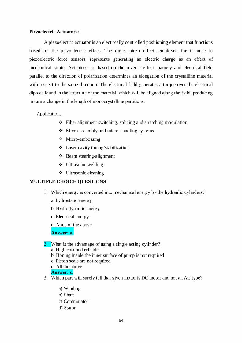
94
Piezoelectric Actuators:
A piezoelectric actuator is an electrically controlled positioning element that functions
based on the piezoelectric effect. The direct piezo effect, employed for instance in
piezoelectric force sensors, represents generating an electric charge as an effect of
mechanical strain. Actuators are based on the reverse effect, namely and electrical field
parallel to the direction of polarization determines an elongation of the crystalline material
with respect to the same direction. The electrical field generates a torque over the electrical
dipoles found in the structure of the material, which will be aligned along the field, producing
in turn a change in the length of monocrystalline partitions.
Applications:
Fiber alignment switching, splicing and stretching modulation
Micro-assembly and micro-handling systems
Micro-embossing
Laser cavity tuning/stabilization
Beam steering/alignment
Ultrasonic welding
Ultrasonic cleaning
MULTIPLE CHOICE QUESTIONS
1. Which energy is converted into mechanical energy by the hydraulic cylinders?
a. hydrostatic energy
b. Hydrodynamic energy
c. Electrical energy
d. None of the above
Answer: a.
2. What is the advantage of using a single acting cylinder?
a. High cost and reliable
b. Honing inside the inner surface of pump is not required
c. Piston seals are not required
d. All the above
Answer: c.
3. Which part will surely tell that given motor is DC motor and not an AC type?
a) Winding
b) Shaft
c) Commutator
d) Stator
95
Answer: c
4. Direction of rotation of motor is determined by ____________
a) Faraday’s law
b) Lenz’s law
c) Coulomb’s law
d) Fleming’s left-hand rule
Answer: d
5. Starters are used in induction motor because
a) Its starting torque is high
b) It is run against heavy load
c) It cannot run in reverse direction
d) Its starting current is five times or more than its rated current
Answer d
6. In an induction motor, rotor runs at a speed
a) Equal to the speed of stator field
b) Lower than the speed of stator field
c) Higher than the speed of stator field
d) Having no relation with the speed of stator field
Answer b
7. The main purpose of a control valve positioner is to:
(A) Alter the fail-safe status of the valve
(B) Improve the precision of the valve
(C) Eliminate cavitations in the valve
(D) Increase transmitter accuracy
Answer : B
8. What happens to the magnetic field in the solenoid when the current increases?
a) Increases
b) Decreases
c) Remains constant
d) Becomes zero
Answer: a

96
9. Rotor resistance speed control method is not applicable in
a) Slip Ring induction motor
b) Squirrel cage induction motor
c) Synchronous motor
d) None of the above
Answer b.
10. What is the ratio of rotor input power to rotor copper loss in an induction motor?
a) 1/(1 – S)
b) 1 – S
c) 1/S
d) S
Answer c.
11. Which of these actions does a hydraulic cylinder perform?
a. Pushing
b. Lifting
c. Both a and b
d. None of the above
Answer: c.
Assignment
1) How do hydraulic actuators differ from pneumatic actuators?
2) What is the function of a pneumatic cylinder?
3) Explain the working of double acting double rod cylinder with a neat sketch
4) Discuss the construction, advantages and disadvantages of a double-seated control
valve.
5) Distinguish between the terms- ideal characteristics and effective characteristics.
6) Write short notes on a) DC motor b) AC motor
7) Describe stepper motor with neat diagrams
97
UNIT IV MICRO SENSORS AND MICRO ACTUATORS Micro Sensors: Principles and examples, Force and pressure micro sensors, position
and speed micro sensors, acceleration micro sensors, chemical sensors, biosensors,
temperature micro sensors and flow micro sensors.
Micro Actuators: Actuation principle, shape memory effects-one way, two way and
pseudo elasticity. Types of micro actuators- Electrostatic, Magnetic, Fluidic, Inverse
piezo effect, other principles
Micro sensors - Introduction
Presently, there is a trend to make sensors smaller and smaller. Initial stages show an
evolution from a single sensor element to an intelligent sensor system with extremely small
dimensions by MST. The so-called smart (or integrated) sensing devices can be developed by
integrating sensor components with those for signal processing. This integration also
decreases the noise that is often created by the transmission of signals to an external data
processing unit. Thus it will be possible to measure and evaluate for a certain task all
interesting parameters at one place and at one time. An important step toward the further
development of micro sensors is the conception and design of intelligent electronic signal
processors. This will lead to advanced distributed sensor systems in which noisy sensor
signals, resulting from cross-talk or insufficient selectivity, can be successfully evaluated.
The signal processing system of humans is very advanced; sensor signals are received over
the nervous system and transferred to the brain which reliably evaluates them by a natural
parallel computing system
Force and Pressure Micro sensors
Due to their simple construction and wide applicability, mechanical sensors play the
most important part in MST. Pressure micro sensors were the first ones developed and used
by industry. Miniaturized pressure sensors must be inexpensive and have a high resolution,
accuracy, linearity and stability. Presently, silicon-based pressure sensors are most often
used; they can easily be integrated with their signal processing electronics on one chip. Their
advantages include low production costs, high sensitivity and low hysteresis.
Pressure is most often measured via a thin membrane which deflects when pressure is
applied. Either the deflection of the membrane or its change in resonance frequency is
measured; both of these values are proportional to the pressure applied. These mechanical
changes are transformed into electric signals. Membranes can be manufactured by bulk
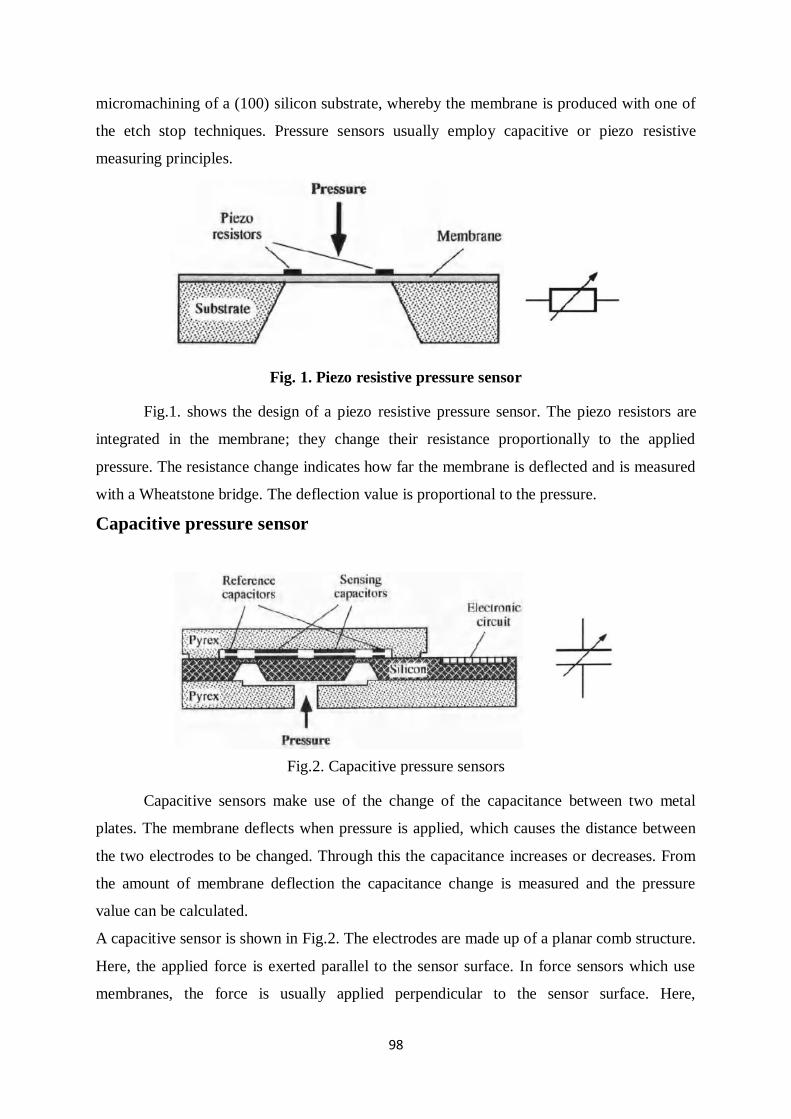
98
micromachining of a (100) silicon substrate, whereby the membrane is produced with one of
the etch stop techniques. Pressure sensors usually employ capacitive or piezo resistive
measuring principles.
Fig. 1. Piezo resistive pressure sensor
Fig.1. shows the design of a piezo resistive pressure sensor. The piezo resistors are
integrated in the membrane; they change their resistance proportionally to the applied
pressure. The resistance change indicates how far the membrane is deflected and is measured
with a Wheatstone bridge. The deflection value is proportional to the pressure.
Capacitive pressure sensor
Fig.2. Capacitive pressure sensors
Capacitive sensors make use of the change of the capacitance between two metal
plates. The membrane deflects when pressure is applied, which causes the distance between
the two electrodes to be changed. Through this the capacitance increases or decreases. From
the amount of membrane deflection the capacitance change is measured and the pressure
value can be calculated.
A capacitive sensor is shown in Fig.2. The electrodes are made up of a planar comb structure.
Here, the applied force is exerted parallel to the sensor surface. In force sensors which use
membranes, the force is usually applied perpendicular to the sensor surface. Here,
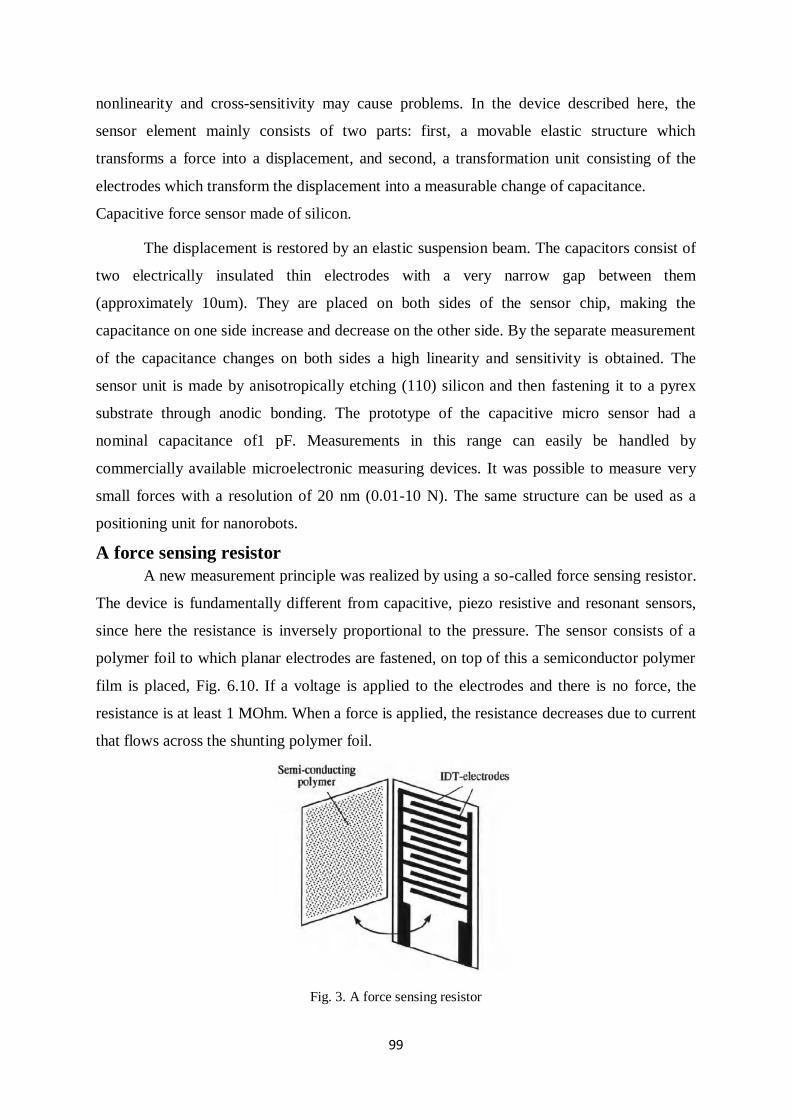
99
nonlinearity and cross-sensitivity may cause problems. In the device described here, the
sensor element mainly consists of two parts: first, a movable elastic structure which
transforms a force into a displacement, and second, a transformation unit consisting of the
electrodes which transform the displacement into a measurable change of capacitance.
Capacitive force sensor made of silicon.
The displacement is restored by an elastic suspension beam. The capacitors consist of
two electrically insulated thin electrodes with a very narrow gap between them
(approximately 10um). They are placed on both sides of the sensor chip, making the
capacitance on one side increase and decrease on the other side. By the separate measurement
of the capacitance changes on both sides a high linearity and sensitivity is obtained. The
sensor unit is made by anisotropically etching (110) silicon and then fastening it to a pyrex
substrate through anodic bonding. The prototype of the capacitive micro sensor had a
nominal capacitance of1 pF. Measurements in this range can easily be handled by
commercially available microelectronic measuring devices. It was possible to measure very
small forces with a resolution of 20 nm (0.01-10 N). The same structure can be used as a
positioning unit for nanorobots.
A force sensing resistor
A new measurement principle was realized by using a so-called force sensing resistor.
The device is fundamentally different from capacitive, piezo resistive and resonant sensors,
since here the resistance is inversely proportional to the pressure. The sensor consists of a
polymer foil to which planar electrodes are fastened, on top of this a semiconductor polymer
film is placed, Fig. 6.10. If a voltage is applied to the electrodes and there is no force, the
resistance is at least 1 MOhm. When a force is applied, the resistance decreases due to current
that flows across the shunting polymer foil.
Fig. 3. A force sensing resistor
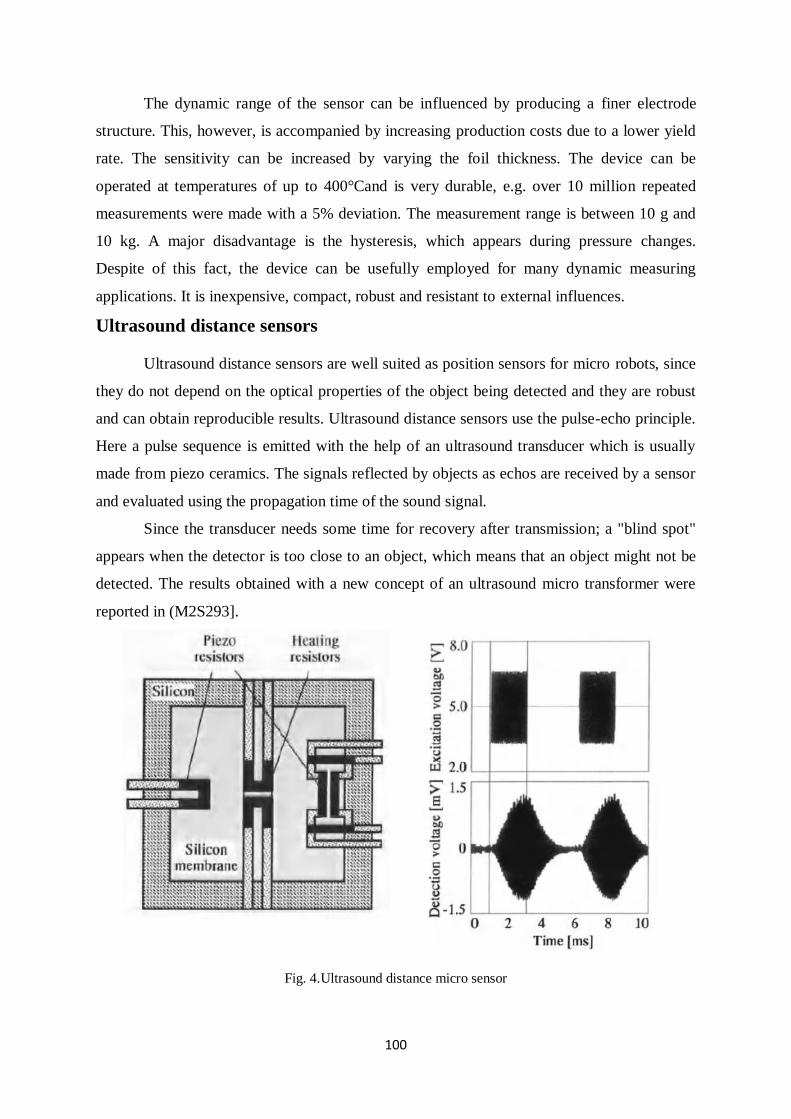
100
The dynamic range of the sensor can be influenced by producing a finer electrode
structure. This, however, is accompanied by increasing production costs due to a lower yield
rate. The sensitivity can be increased by varying the foil thickness. The device can be
operated at temperatures of up to 400°Cand is very durable, e.g. over 10 million repeated
measurements were made with a 5% deviation. The measurement range is between 10 g and
10 kg. A major disadvantage is the hysteresis, which appears during pressure changes.
Despite of this fact, the device can be usefully employed for many dynamic measuring
applications. It is inexpensive, compact, robust and resistant to external influences.
Ultrasound distance sensors
Ultrasound distance sensors are well suited as position sensors for micro robots, since
they do not depend on the optical properties of the object being detected and they are robust
and can obtain reproducible results. Ultrasound distance sensors use the pulse-echo principle.
Here a pulse sequence is emitted with the help of an ultrasound transducer which is usually
made from piezo ceramics. The signals reflected by objects as echos are received by a sensor
and evaluated using the propagation time of the sound signal.
Since the transducer needs some time for recovery after transmission; a "blind spot"
appears when the detector is too close to an object, which means that an object might not be
detected. The results obtained with a new concept of an ultrasound micro transformer were
reported in (M2S293].
Fig. 4.Ultrasound distance micro sensor
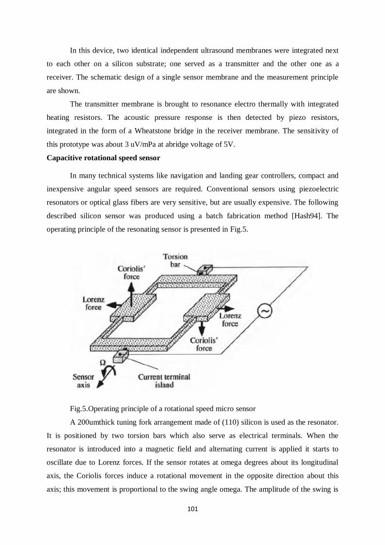
101
In this device, two identical independent ultrasound membranes were integrated next
to each other on a silicon substrate; one served as a transmitter and the other one as a
receiver. The schematic design of a single sensor membrane and the measurement principle
are shown.
The transmitter membrane is brought to resonance electro thermally with integrated
heating resistors. The acoustic pressure response is then detected by piezo resistors,
integrated in the form of a Wheatstone bridge in the receiver membrane. The sensitivity of
this prototype was about 3 uV/mPa at abridge voltage of 5V.
Capacitive rotational speed sensor
In many technical systems like navigation and landing gear controllers, compact and
inexpensive angular speed sensors are required. Conventional sensors using piezoelectric
resonators or optical glass fibers are very sensitive, but are usually expensive. The following
described silicon sensor was produced using a batch fabrication method [Hash94]. The
operating principle of the resonating sensor is presented in Fig.5.
Fig.5.Operating principle of a rotational speed micro sensor
A 200umthick tuning fork arrangement made of (110) silicon is used as the resonator.
It is positioned by two torsion bars which also serve as electrical terminals. When the
resonator is introduced into a magnetic field and alternating current is applied it starts to
oscillate due to Lorenz forces. If the sensor rotates at omega degrees about its longitudinal
axis, the Coriolis forces induce a rotational movement in the opposite direction about this
axis; this movement is proportional to the swing angle omega. The amplitude of the swing is
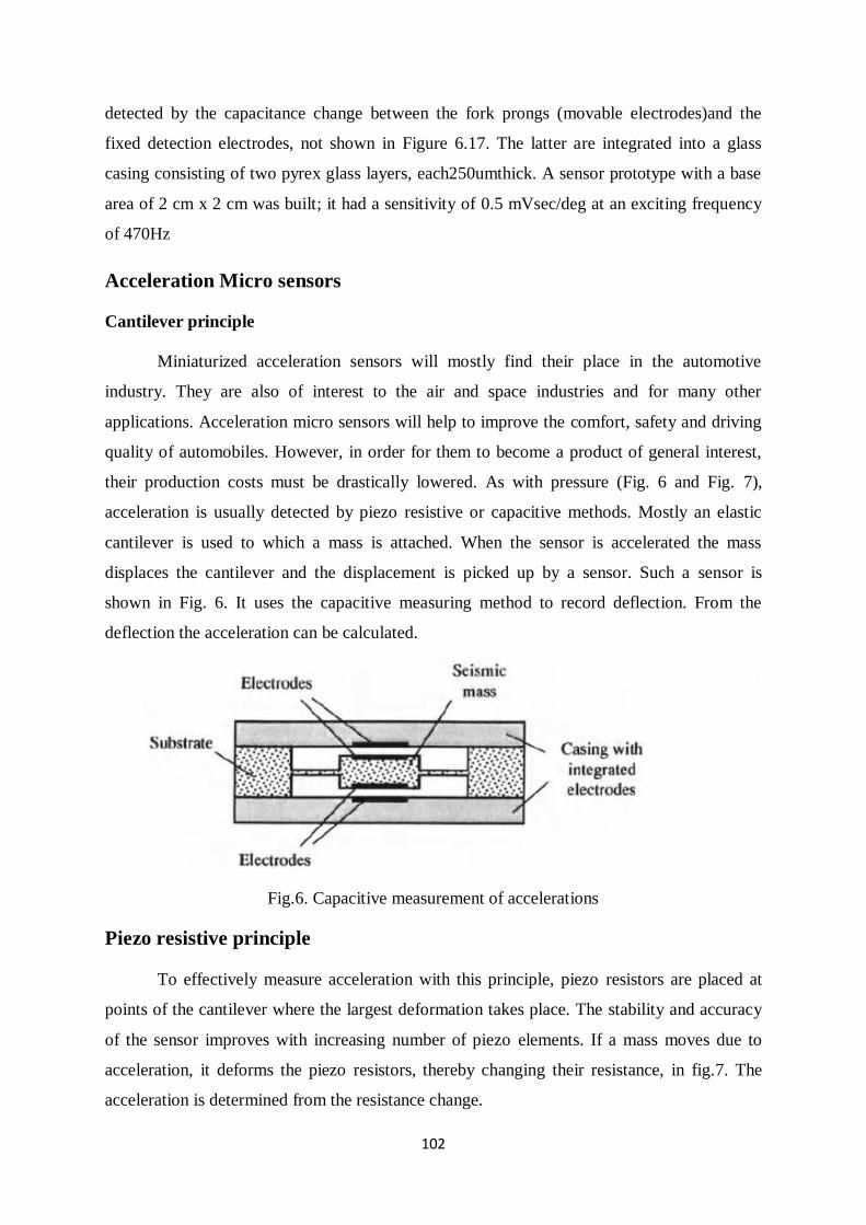
102
detected by the capacitance change between the fork prongs (movable electrodes)and the
fixed detection electrodes, not shown in Figure 6.17. The latter are integrated into a glass
casing consisting of two pyrex glass layers, each250umthick. A sensor prototype with a base
area of 2 cm x 2 cm was built; it had a sensitivity of 0.5 mVsec/deg at an exciting frequency
of 470Hz
Acceleration Micro sensors
Cantilever principle
Miniaturized acceleration sensors will mostly find their place in the automotive
industry. They are also of interest to the air and space industries and for many other
applications. Acceleration micro sensors will help to improve the comfort, safety and driving
quality of automobiles. However, in order for them to become a product of general interest,
their production costs must be drastically lowered. As with pressure (Fig. 6 and Fig. 7),
acceleration is usually detected by piezo resistive or capacitive methods. Mostly an elastic
cantilever is used to which a mass is attached. When the sensor is accelerated the mass
displaces the cantilever and the displacement is picked up by a sensor. Such a sensor is
shown in Fig. 6. It uses the capacitive measuring method to record deflection. From the
deflection the acceleration can be calculated.
Fig.6. Capacitive measurement of accelerations
Piezo resistive principle
To effectively measure acceleration with this principle, piezo resistors are placed at
points of the cantilever where the largest deformation takes place. The stability and accuracy
of the sensor improves with increasing number of piezo elements. If a mass moves due to
acceleration, it deforms the piezo resistors, thereby changing their resistance, in fig.7. The
acceleration is determined from the resistance change.
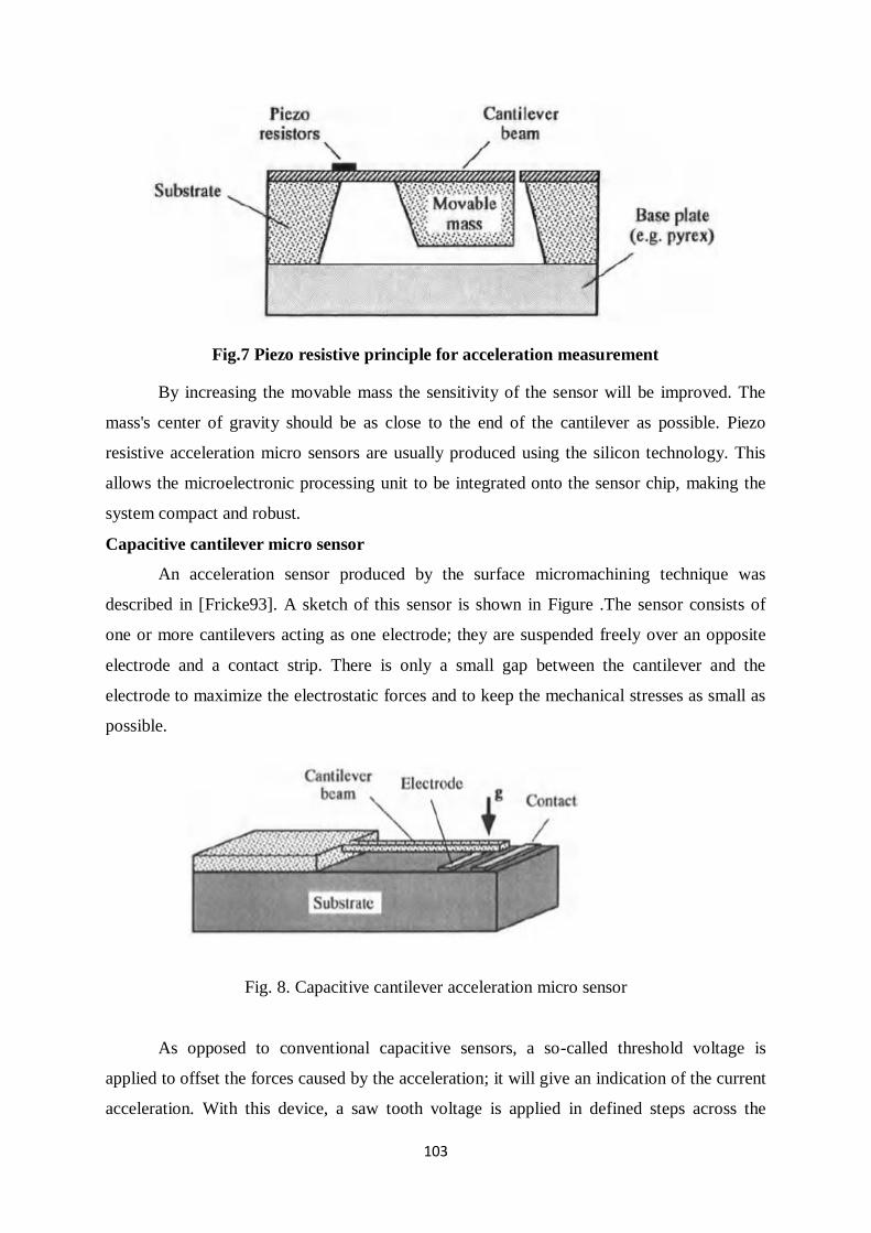
103
Fig.7 Piezo resistive principle for acceleration measurement
By increasing the movable mass the sensitivity of the sensor will be improved. The
mass's center of gravity should be as close to the end of the cantilever as possible. Piezo
resistive acceleration micro sensors are usually produced using the silicon technology. This
allows the microelectronic processing unit to be integrated onto the sensor chip, making the
system compact and robust.
Capacitive cantilever micro sensor
An acceleration sensor produced by the surface micromachining technique was
described in [Fricke93]. A sketch of this sensor is shown in Figure .The sensor consists of
one or more cantilevers acting as one electrode; they are suspended freely over an opposite
electrode and a contact strip. There is only a small gap between the cantilever and the
electrode to maximize the electrostatic forces and to keep the mechanical stresses as small as
possible.
Fig. 8. Capacitive cantilever acceleration micro sensor
As opposed to conventional capacitive sensors, a so-called threshold voltage is
applied to offset the forces caused by the acceleration; it will give an indication of the current
acceleration. With this device, a saw tooth voltage is applied in defined steps across the
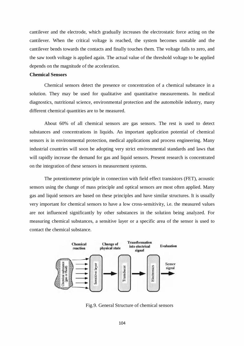
104
cantilever and the electrode, which gradually increases the electrostatic force acting on the
cantilever. When the critical voltage is reached, the system becomes unstable and the
cantilever bends towards the contacts and finally touches them. The voltage falls to zero, and
the saw tooth voltage is applied again. The actual value of the threshold voltage to be applied
depends on the magnitude of the acceleration.
Chemical Sensors
Chemical sensors detect the presence or concentration of a chemical substance in a
solution. They may be used for qualitative and quantitative measurements. In medical
diagnostics, nutritional science, environmental protection and the automobile industry, many
different chemical quantities are to be measured.
About 60% of all chemical sensors are gas sensors. The rest is used to detect
substances and concentrations in liquids. An important application potential of chemical
sensors is in environmental protection, medical applications and process engineering. Many
industrial countries will soon be adopting very strict environmental standards and laws that
will rapidly increase the demand for gas and liquid sensors. Present research is concentrated
on the integration of these sensors in measurement systems.
The potentiometer principle in connection with field effect transistors (FET), acoustic
sensors using the change of mass principle and optical sensors are most often applied. Many
gas and liquid sensors are based on these principles and have similar structures. It is usually
very important for chemical sensors to have a low cross-sensitivity, i.e. the measured values
are not influenced significantly by other substances in the solution being analyzed. For
measuring chemical substances, a sensitive layer or a specific area of the sensor is used to
contact the chemical substance.
Fig.9. General Structure of chemical sensors
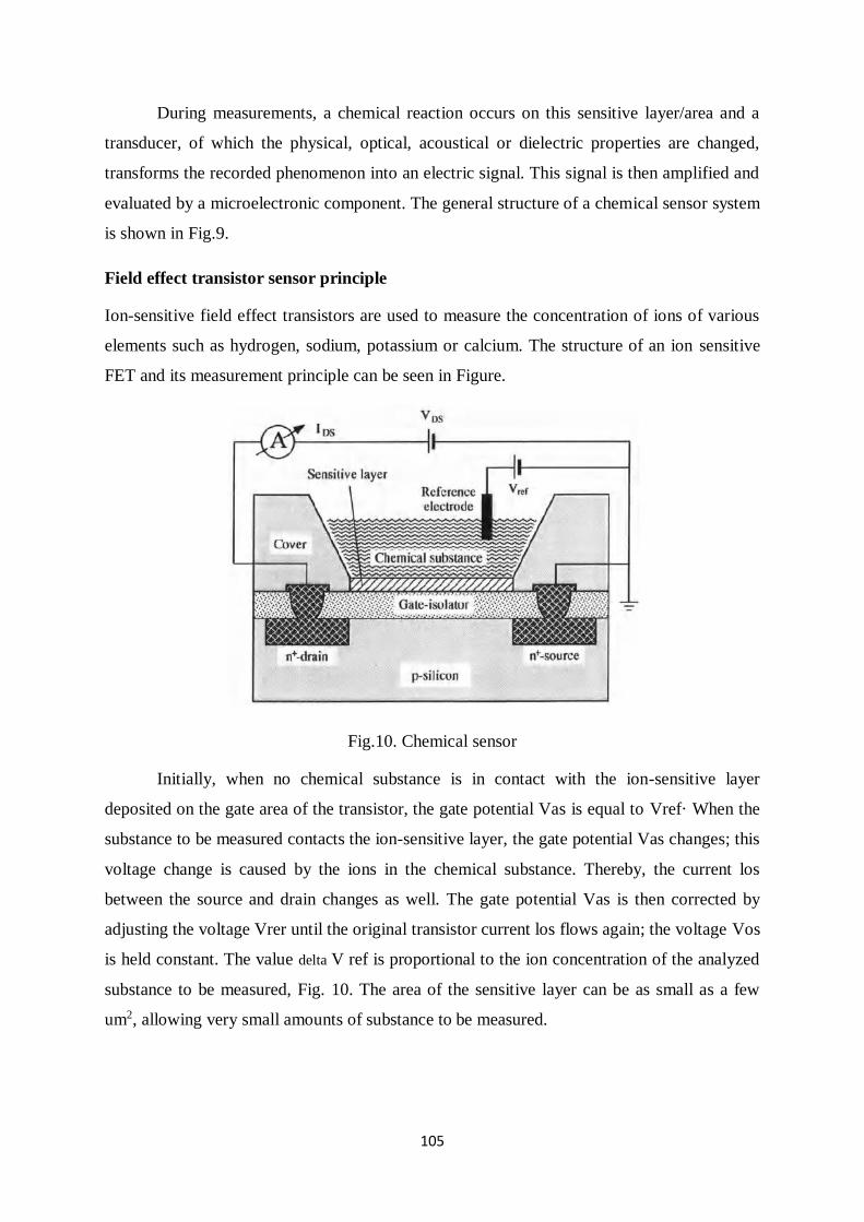
105
During measurements, a chemical reaction occurs on this sensitive layer/area and a
transducer, of which the physical, optical, acoustical or dielectric properties are changed,
transforms the recorded phenomenon into an electric signal. This signal is then amplified and
evaluated by a microelectronic component. The general structure of a chemical sensor system
is shown in Fig.9.
Field effect transistor sensor principle
Ion-sensitive field effect transistors are used to measure the concentration of ions of various
elements such as hydrogen, sodium, potassium or calcium. The structure of an ion sensitive
FET and its measurement principle can be seen in Figure.
Fig.10. Chemical sensor
Initially, when no chemical substance is in contact with the ion-sensitive layer
deposited on the gate area of the transistor, the gate potential Vas is equal to Vref· When the
substance to be measured contacts the ion-sensitive layer, the gate potential Vas changes; this
voltage change is caused by the ions in the chemical substance. Thereby, the current los
between the source and drain changes as well. The gate potential Vas is then corrected by
adjusting the voltage Vrer until the original transistor current los flows again; the voltage Vos
is held constant. The value delta V ref is proportional to the ion concentration of the analyzed
substance to be measured, Fig. 10. The area of the sensitive layer can be as small as a few
um2, allowing very small amounts of substance to be measured.
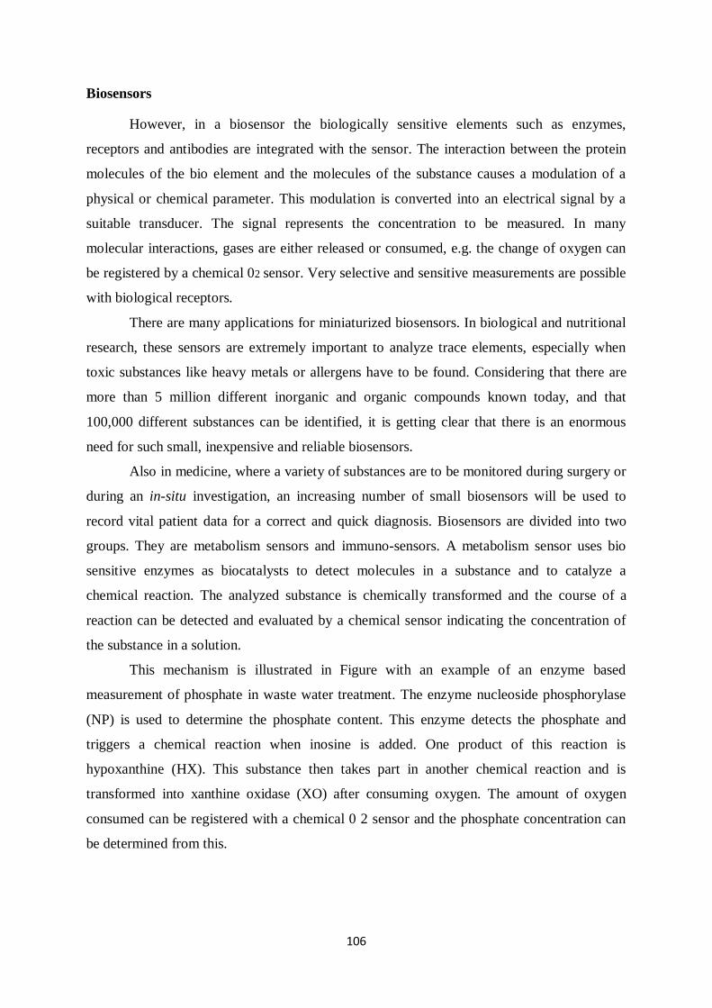
106
Biosensors
However, in a biosensor the biologically sensitive elements such as enzymes,
receptors and antibodies are integrated with the sensor. The interaction between the protein
molecules of the bio element and the molecules of the substance causes a modulation of a
physical or chemical parameter. This modulation is converted into an electrical signal by a
suitable transducer. The signal represents the concentration to be measured. In many
molecular interactions, gases are either released or consumed, e.g. the change of oxygen can
be registered by a chemical 02 sensor. Very selective and sensitive measurements are possible
with biological receptors.
There are many applications for miniaturized biosensors. In biological and nutritional
research, these sensors are extremely important to analyze trace elements, especially when
toxic substances like heavy metals or allergens have to be found. Considering that there are
more than 5 million different inorganic and organic compounds known today, and that
100,000 different substances can be identified, it is getting clear that there is an enormous
need for such small, inexpensive and reliable biosensors.
Also in medicine, where a variety of substances are to be monitored during surgery or
during an in-situ investigation, an increasing number of small biosensors will be used to
record vital patient data for a correct and quick diagnosis. Biosensors are divided into two
groups. They are metabolism sensors and immuno-sensors. A metabolism sensor uses bio
sensitive enzymes as biocatalysts to detect molecules in a substance and to catalyze a
chemical reaction. The analyzed substance is chemically transformed and the course of a
reaction can be detected and evaluated by a chemical sensor indicating the concentration of
the substance in a solution.
This mechanism is illustrated in Figure with an example of an enzyme based
measurement of phosphate in waste water treatment. The enzyme nucleoside phosphorylase
(NP) is used to determine the phosphate content. This enzyme detects the phosphate and
triggers a chemical reaction when inosine is added. One product of this reaction is
hypoxanthine (HX). This substance then takes part in another chemical reaction and is
transformed into xanthine oxidase (XO) after consuming oxygen. The amount of oxygen
consumed can be registered with a chemical 0 2 sensor and the phosphate concentration can
be determined from this.
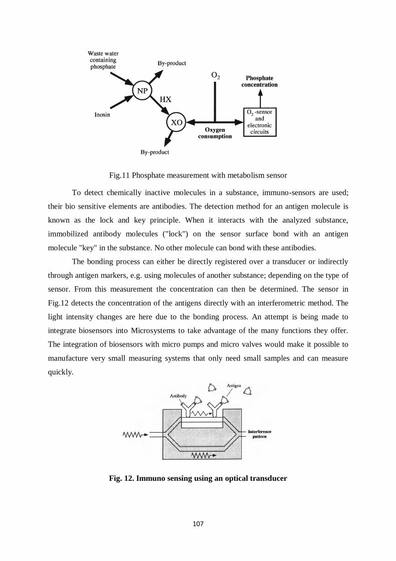
107
Fig.11 Phosphate measurement with metabolism sensor
To detect chemically inactive molecules in a substance, immuno-sensors are used;
their bio sensitive elements are antibodies. The detection method for an antigen molecule is
known as the lock and key principle. When it interacts with the analyzed substance,
immobilized antibody molecules ("lock") on the sensor surface bond with an antigen
molecule "key" in the substance. No other molecule can bond with these antibodies.
The bonding process can either be directly registered over a transducer or indirectly
through antigen markers, e.g. using molecules of another substance; depending on the type of
sensor. From this measurement the concentration can then be determined. The sensor in
Fig.12 detects the concentration of the antigens directly with an interferometric method. The
light intensity changes are here due to the bonding process. An attempt is being made to
integrate biosensors into Microsystems to take advantage of the many functions they offer.
The integration of biosensors with micro pumps and micro valves would make it possible to
manufacture very small measuring systems that only need small samples and can measure
quickly.
Fig. 12. Immuno sensing using an optical transducer
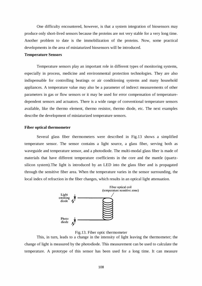
108
One difficulty encountered, however, is that a system integration of biosensors may
produce only short-lived sensors because the proteins are not very stable for a very long time.
Another problem to date is the immobilization of the proteins. Now, some practical
developments in the area of miniaturized biosensors will be introduced.
Temperature Sensors
Temperature sensors play an important role in different types of monitoring systems,
especially in process, medicine and environmental protection technologies. They are also
indispensable for controlling beatings or air conditioning systems and many household
appliances. A temperature value may also be a parameter of indirect measurements of other
parameters in gas or flow sensors or it may be used for error compensation of temperature-
dependent sensors and actuators. There is a wide range of conventional temperature sensors
available, like the thermo element, thermo resistor, thermo diode, etc. The next examples
describe the development of miniaturized temperature sensors.
Fiber optical thermometer
Several glass fiber thermometers were described in Fig.13 shows a simplified
temperature sensor. The sensor contains a light source, a glass fiber, serving both as
waveguide and temperature sensor, and a photodiode. The multi-modal glass fiber is made of
materials that have different temperature coefficients in the core and the mantle (quartz-
silicon system).The light is introduced by an LED into the glass fiber and is propagated
through the sensitive fiber area. When the temperature varies in the sensor surrounding, the
local index of refraction in the fiber changes, which results in an optical light attenuation.
Fig.13. Fiber optic thermometer
This, in turn, leads to a change in the intensity of light leaving the thermometer; the
change of light is measured by the photodiode. This measurement can be used to calculate the
temperature. A prototype of this sensor has been used for a long time. It can measure
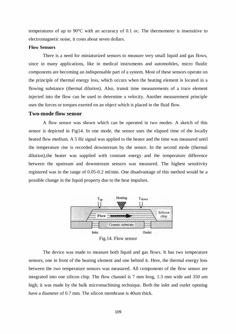
109
temperatures of up to 90°C with an accuracy of 0.1 oc. The thermometer is insensitive to
electromagnetic noise, it costs about seven dollars.
Flow Sensors
There is a need for miniaturized sensors to measure very small liquid and gas flows,
since in many applications, like in medical instruments and automobiles, micro fluidic
components are becoming an indispensable part of a system. Most of these sensors operate on
the principle of thermal energy loss, which occurs when the heating element is located in a
flowing substance (thermal dilution). Also, transit time measurements of a trace element
injected into the flow can be used to determine a velocity. Another measurement principle
uses the forces or torques exerted on an object which is placed in the fluid flow.
Two-mode flow sensor
A flow sensor was shown which can be operated in two modes. A sketch of this
sensor is depicted in Fig14. In one mode, the sensor uses the elapsed time of the locally
heated flow medium. A 5 Hz signal was applied to the heater and the time was measured until
the temperature rise is recorded downstream by the sensor. In the second mode (thermal
dilution),the heater was supplied with constant energy and the temperature difference
between the upstream and downstream sensors was measured. The highest sensitivity
registered was in the range of 0.05-0.2 ml/min. One disadvantage of this method would be a
possible change in the liquid property due to the heat impulses.
Fig.14. Flow sensor
The device was made to measure both liquid and gas flows. It has two temperature
sensors, one in front of the heating element and one behind it. Here, the thermal energy loss
between the two temperature sensors was measured. All components of the flow sensor are
integrated into one silicon chip. The flow channel is 7 mm long, 1.3 mm wide and 350 um
high; it was made by the bulk micromachining technique. Both the inlet and outlet opening
have a diameter of 0.7 mm. The silicon membrane is 40um thick.
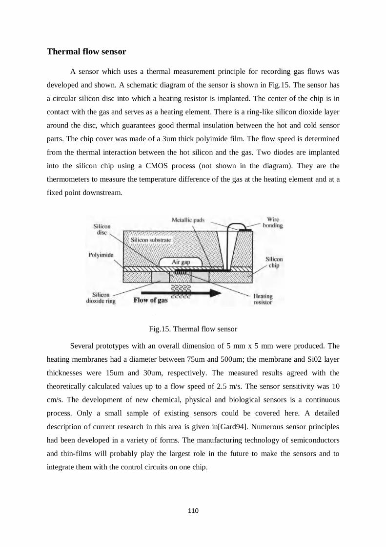
110
Thermal flow sensor
A sensor which uses a thermal measurement principle for recording gas flows was
developed and shown. A schematic diagram of the sensor is shown in Fig.15. The sensor has
a circular silicon disc into which a heating resistor is implanted. The center of the chip is in
contact with the gas and serves as a heating element. There is a ring-like silicon dioxide layer
around the disc, which guarantees good thermal insulation between the hot and cold sensor
parts. The chip cover was made of a 3um thick polyimide film. The flow speed is determined
from the thermal interaction between the hot silicon and the gas. Two diodes are implanted
into the silicon chip using a CMOS process (not shown in the diagram). They are the
thermometers to measure the temperature difference of the gas at the heating element and at a
fixed point downstream.
Fig.15. Thermal flow sensor
Several prototypes with an overall dimension of 5 mm x 5 mm were produced. The
heating membranes had a diameter between 75um and 500um; the membrane and Si02 layer
thicknesses were 15um and 30um, respectively. The measured results agreed with the
theoretically calculated values up to a flow speed of 2.5 m/s. The sensor sensitivity was 10
cm/s. The development of new chemical, physical and biological sensors is a continuous
process. Only a small sample of existing sensors could be covered here. A detailed
description of current research in this area is given in[Gard94]. Numerous sensor principles
had been developed in a variety of forms. The manufacturing technology of semiconductors
and thin-films will probably play the largest role in the future to make the sensors and to
integrate them with the control circuits on one chip.
111
Micro actuators:
Principles and Examples
Introduction
The MST applications suggest the use of new micro actuator systems which allow motions to
be realized with micrometer accuracy. Conventional motion concepts or manufacturing
methods are no longer able to fulfil the demands concerning miniaturization and all questions
connected with it. Microsystems, and in particular future micro robots, require the
development of new advanced actuators with very small dimensions, simple mechanical
construction and high reliability.
It is rather difficult to determine exactly what the name "micro actuator" implies. In the
literature, the term "micro actuators" is used for devices ranging in size from micrometers to
several decimeters, proving the typical classification difficulties of this young scientific field.
This book considers a micro actuator as a device of a few micrometers to a few centimetres in
size having a functional principle applicable in the micro world.
In addition to the miniaturization, mechanical micro devices having components such
as pumps, valves, robot grippers, linear and rotational positioning elements, simple cantilever
actuators and complex artificial muscle systems, must be functional to provide a micro
system with task-dependent capabilities. Micro pumps and -valves for treating liquids and
gasses at the micro level can be applied in medicine, where implantable, highly accurate
micro systems are needed for the dosing of medication or for chemical and biotechnological
analysis where minute volumes of liquid must be transported and measured. They can also be
applied for technical devices such as ink jet printers.
Micro actuators using the cantilever principle can be applied for various applications
to generate minute motions. In optics such micro actuators can serve as electronically
tuneable mirrors, in fluid dynamics as valves, and in micro robotics as grippers. Micro motors
also have a great potential for MST applications.
Actuation Principles
Functional properties of actuators are determined above all by the underlying
actuation principles. The forces and displacements that can actually be reached for a certain
component size depend on the scaling behaviour, actuator design, and technical limits.
Therefore, the total dimensions of an actuator determine which actuation principle is best
112
suited for a given application. The scaling behaviour of the forces is derived from the force
laws by introducing a scaling variable r, which describes the component size in any spatial
direction. In analogy, the scaling behaviour of work and power density can be determined.
Electrostatic Principles
Electrostatic actuators make use of Coulomb’s attraction force between oppositely
charged bodies. In the simplest case, two charged plates oriented in parallel are available.
Apart from the force component F z that acts vertically between the plates, lateral-plate offset
additionally causes a force F x acting in the lateral direction.
Magnetic Principles
The magnetic principles of force and movement generation can be classified in electro
dynamic, reluctance, and electromagnetic principles. Electro dynamic micro actuators make
use of the Lorentz force on a conductor passed by a current in a magnetic field. So far, such
actuators have hardly been noticed due to their difficult-to-achieve three-dimensional
geometry. Contrary to this, the reluctance principle is the most frequently applied magnetic
actuation principle in micro technology. Micro technical implementation requires an
acceptable effort, since only a single field source and no hard magnetic materials are needed.
Fluidic Principles
Fluidically driven micro pistons allow high testing forces and large displacements to
be reached in, e.g., micro tensile testing machines. The force-displacement characteristics
exhibit a constant behaviour. The principle of pressure-dependent membrane deflection is
applied in a number of micro valve versions. Other fluidic arrangements are based on fluid
dynamics principles or electro rheological and magneto rheological principles.
Inverse Piezo effect
Piezoelectric actuators make use of the coupling of mechanical deformation and
electric polarization in ferroelectric crystals, in crystals with a triad axis, or in certain
polymers. A major class of materials is made up of Pb(ZrxTi1_x)03 (PZT) crystals due to
their high coupling factors of about 0.7 and piezoelectric coefficients du of about 0.5 nm/V.
Shape Memory Effects
The term "shape memory" describes the unusual ability to remember shape, which
can be initiated in certain materials either thermally or mechanically. Even after heavy
deformation, materials with shape memory are able to recover a previously memorized shape.
This phenomenon was discovered in brass alloys as early as the late thirties. However, the
real importance of the effect has become obvious only since its discovery in a NiTi alloy,
where it is particularly pronounced.
113
The most important materials of commercial significance can be classified either as
metal alloys or as polymers. Furthermore, there are ceramics and biological systems in which
shape memory properties are observed as well. An example to be mentioned in this respect is
bacteriophages, which use a shape memory mechanism when entering host cells. SMAs are
currently the focus of interest, as they have proved to function in a number of applications
and show an unforeseeable potential for future applications.
In contrast to conventional structural materials, in which shape changes are made up
of elastic, plastic or thermal contributions, SMAs show three additional types of shape
changes that are associated with shape memory characteristics. These effects are illustrated in
Fig. by the example of a helical spring:
(a) One-way effect: After removal of the load F, the helical spring shows permanent
deformation. This seemingly plastic deformation recedes completely upon heating.
(b) Two-way effect: In addition to the one-way effect, there is also a defined shape change
upon cooling.
(c) Pseudo elasticity: Mechanical loading, F, expands the helical spring to a large extent.
When the load is removed, the spring still returns to its initial shape.
One-Way Effect
In the martensitic state (Fig.1, T<Mf), the material exhibits a very low elastic limit.
Elastic straining is followed by a pseudo plastic strain range in which the component can be
strained reversibly by up to several percent. Further strain behaviour is characterized by
plastic deformation up to fracture. After relaxation in the pseudo-plastic range, an apparent
deformation, CIW, is retained. By heating the deformed component above the austenite finish
temperature, Af , a complete shape recovery is possible. The maximum reversible strain, for
instance of NiTi single crystals in the direction, is 10.7%. As this effect only occurs upon
heating, i.e., only in one direction, it is referred to as a one-way effect. Renewed cooling and
heating no longer changes the shape. The original memorized shape is imprinted upon the
component prior to loading by heat treatment. If the shape recovery during reverse
transformation to austenite is hindered, high forces occur that can be used to perform work.
This is the basis of SMA actuators.
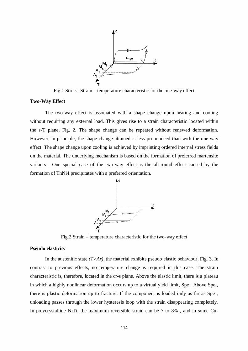
114
Fig.1 Stress- Strain – temperature characteristic for the one-way effect
Two-Way Effect
The two-way effect is associated with a shape change upon heating and cooling
without requiring any external load. This gives rise to a strain characteristic located within
the s-T plane, Fig. 2. The shape change can be repeated without renewed deformation.
However, in principle, the shape change attained is less pronounced than with the one-way
effect. The shape change upon cooling is achieved by imprinting ordered internal stress fields
on the material. The underlying mechanism is based on the formation of preferred martensite
variants . One special case of the two-way effect is the all-round effect caused by the
formation of ThNi4 precipitates with a preferred orientation.
Fig.2 Strain – temperature characteristic for the two-way effect
Pseudo elasticity
In the austenitic state (T>Ar), the material exhibits pseudo elastic behaviour, Fig. 3. In
contrast to previous effects, no temperature change is required in this case. The strain
characteristic is, therefore, located in the cr-s plane. Above the elastic limit, there is a plateau
in which a highly nonlinear deformation occurs up to a virtual yield limit, Spe . Above Spe ,
there is plastic deformation up to fracture. If the component is loaded only as far as Spe ,
unloading passes through the lower hysteresis loop with the strain disappearing completely.
In polycrystalline NiTi, the maximum reversible strain can be 7 to 8% , and in some Cu-
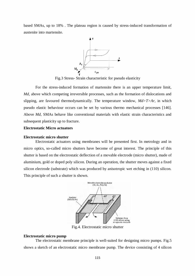
115
based SMAs, up to 18% . The plateau region is caused by stress-induced transformation of
austenite into martensite.
Fig.3 Stress- Strain characteristic for pseudo elasticity
For the stress-induced formation of martensite there is an upper temperature limit,
Md, above which competing irreversible processes, such as the formation of dislocations and
slipping, are favoured thermodynamically. The temperature window, Md>T>Ar, in which
pseudo elastic behaviour occurs can be set by various thermo mechanical processes [146].
Above Md, SMAs behave like conventional materials with elastic strain characteristics and
subsequent plasticity up to fracture.
Electrostatic Micro actuators
Electrostatic micro shutter
Electrostatic actuators using membranes will be presented first. In metrology and in
micro optics, so-called micro shutters have become of great interest. The principle of this
shutter is based on the electrostatic deflection of a movable electrode (micro shutter), made of
aluminium, gold or doped poly silicon. During an operation, the shutter moves against a fixed
silicon electrode (substrate) which was produced by anisotropic wet etching in (110) silicon.
This principle of such a shutter is shown.
Fig.4. Electrostatic micro shutter
Electrostatic micro pump
The electrostatic membrane principle is well-suited for designing micro pumps. Fig.5
shows a sketch of an electrostatic micro membrane pump. The device consisting of 4 silicon
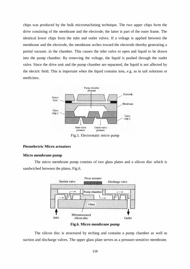
116
chips was produced by the bulk micromachining technique. The two upper chips form the
drive consisting of the membrane and the electrode; the latter is part of the outer frame. The
identical lower chips form the inlet and outlet valves. If a voltage is applied between the
membrane and the electrode, the membrane arches toward the electrode thereby generating a
partial vacuum .in the chamber. This causes the inlet valve to open and liquid to be drawn
into the pump chamber. By removing the voltage, the liquid is pushed through the outlet
valve. Since the drive unit and the pump chamber are separated, the liquid is not affected by
the electric field. This is important when the liquid contains ions, e.g. as in salt solutions or
medicines.
Fig.5. Electrostatic micro pump
Piezoelectric Micro actuators
Micro membrane pump
The micro membrane pump consists of two glass plates and a silicon disc which is
sandwiched between the plates, Fig.6.
Fig.6. Micro membrane pump
The silicon disc is structured by etching and contains a pump chamber as well as
suction and discharge valves. The upper glass plate serves as a pressure-sensitive membrane.
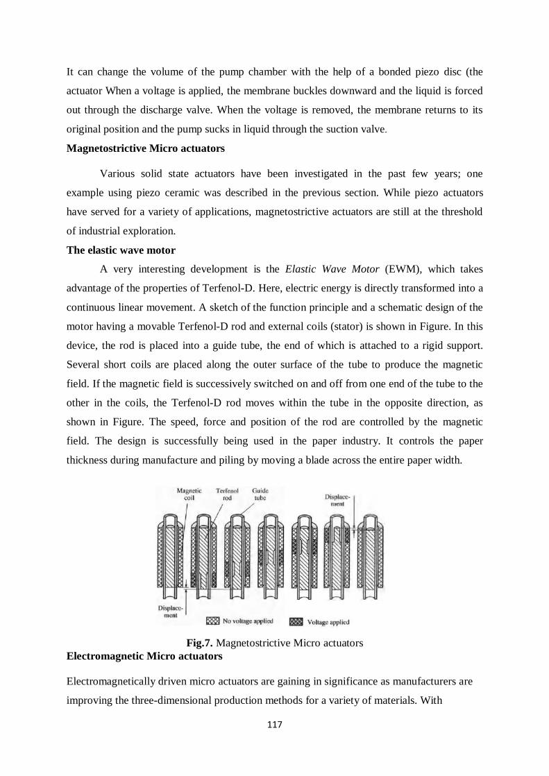
117
It can change the volume of the pump chamber with the help of a bonded piezo disc (the
actuator When a voltage is applied, the membrane buckles downward and the liquid is forced
out through the discharge valve. When the voltage is removed, the membrane returns to its
original position and the pump sucks in liquid through the suction valve.
Magnetostrictive Micro actuators
Various solid state actuators have been investigated in the past few years; one
example using piezo ceramic was described in the previous section. While piezo actuators
have served for a variety of applications, magnetostrictive actuators are still at the threshold
of industrial exploration.
The elastic wave motor
A very interesting development is the Elastic Wave Motor (EWM), which takes
advantage of the properties of Terfenol-D. Here, electric energy is directly transformed into a
continuous linear movement. A sketch of the function principle and a schematic design of the
motor having a movable Terfenol-D rod and external coils (stator) is shown in Figure. In this
device, the rod is placed into a guide tube, the end of which is attached to a rigid support.
Several short coils are placed along the outer surface of the tube to produce the magnetic
field. If the magnetic field is successively switched on and off from one end of the tube to the
other in the coils, the Terfenol-D rod moves within the tube in the opposite direction, as
shown in Figure. The speed, force and position of the rod are controlled by the magnetic
field. The design is successfully being used in the paper industry. It controls the paper
thickness during manufacture and piling by moving a blade across the entire paper width.
Fig.7. Magnetostrictive Micro actuators
Electromagnetic Micro actuators
Electromagnetically driven micro actuators are gaining in significance as manufacturers are
improving the three-dimensional production methods for a variety of materials. With
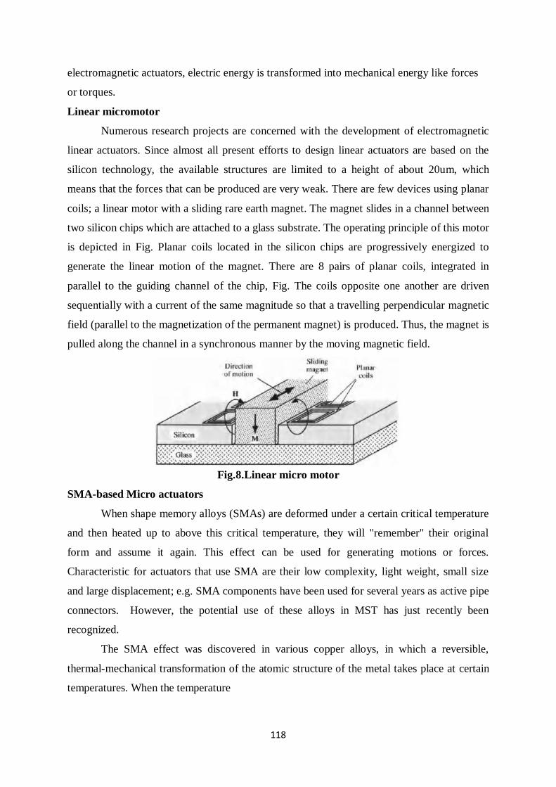
118
electromagnetic actuators, electric energy is transformed into mechanical energy like forces
or torques.
Linear micromotor
Numerous research projects are concerned with the development of electromagnetic
linear actuators. Since almost all present efforts to design linear actuators are based on the
silicon technology, the available structures are limited to a height of about 20um, which
means that the forces that can be produced are very weak. There are few devices using planar
coils; a linear motor with a sliding rare earth magnet. The magnet slides in a channel between
two silicon chips which are attached to a glass substrate. The operating principle of this motor
is depicted in Fig. Planar coils located in the silicon chips are progressively energized to
generate the linear motion of the magnet. There are 8 pairs of planar coils, integrated in
parallel to the guiding channel of the chip, Fig. The coils opposite one another are driven
sequentially with a current of the same magnitude so that a travelling perpendicular magnetic
field (parallel to the magnetization of the permanent magnet) is produced. Thus, the magnet is
pulled along the channel in a synchronous manner by the moving magnetic field.
Fig.8.Linear micro motor
SMA-based Micro actuators
When shape memory alloys (SMAs) are deformed under a certain critical temperature
and then heated up to above this critical temperature, they will "remember" their original
form and assume it again. This effect can be used for generating motions or forces.
Characteristic for actuators that use SMA are their low complexity, light weight, small size
and large displacement; e.g. SMA components have been used for several years as active pipe
connectors. However, the potential use of these alloys in MST has just recently been
recognized.
The SMA effect was discovered in various copper alloys, in which a reversible,
thermal-mechanical transformation of the atomic structure of the metal takes place at certain
temperatures. When the temperature
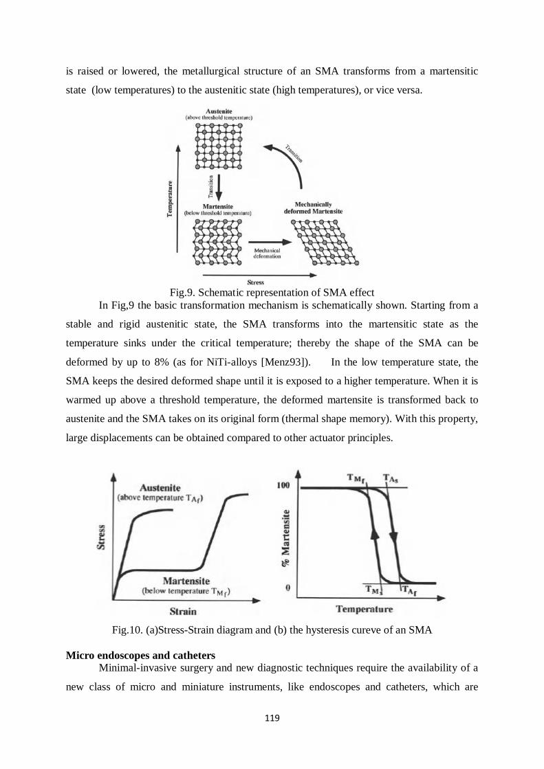
119
is raised or lowered, the metallurgical structure of an SMA transforms from a martensitic
state (low temperatures) to the austenitic state (high temperatures), or vice versa.
Fig.9. Schematic representation of SMA effect
In Fig,9 the basic transformation mechanism is schematically shown. Starting from a
stable and rigid austenitic state, the SMA transforms into the martensitic state as the
temperature sinks under the critical temperature; thereby the shape of the SMA can be
deformed by up to 8% (as for NiTi-alloys [Menz93]). In the low temperature state, the
SMA keeps the desired deformed shape until it is exposed to a higher temperature. When it is
warmed up above a threshold temperature, the deformed martensite is transformed back to
austenite and the SMA takes on its original form (thermal shape memory). With this property,
large displacements can be obtained compared to other actuator principles.
Fig.10. (a)Stress-Strain diagram and (b) the hysteresis cureve of an SMA
Micro endoscopes and catheters
Minimal-invasive surgery and new diagnostic techniques require the availability of a
new class of micro and miniature instruments, like endoscopes and catheters, which are
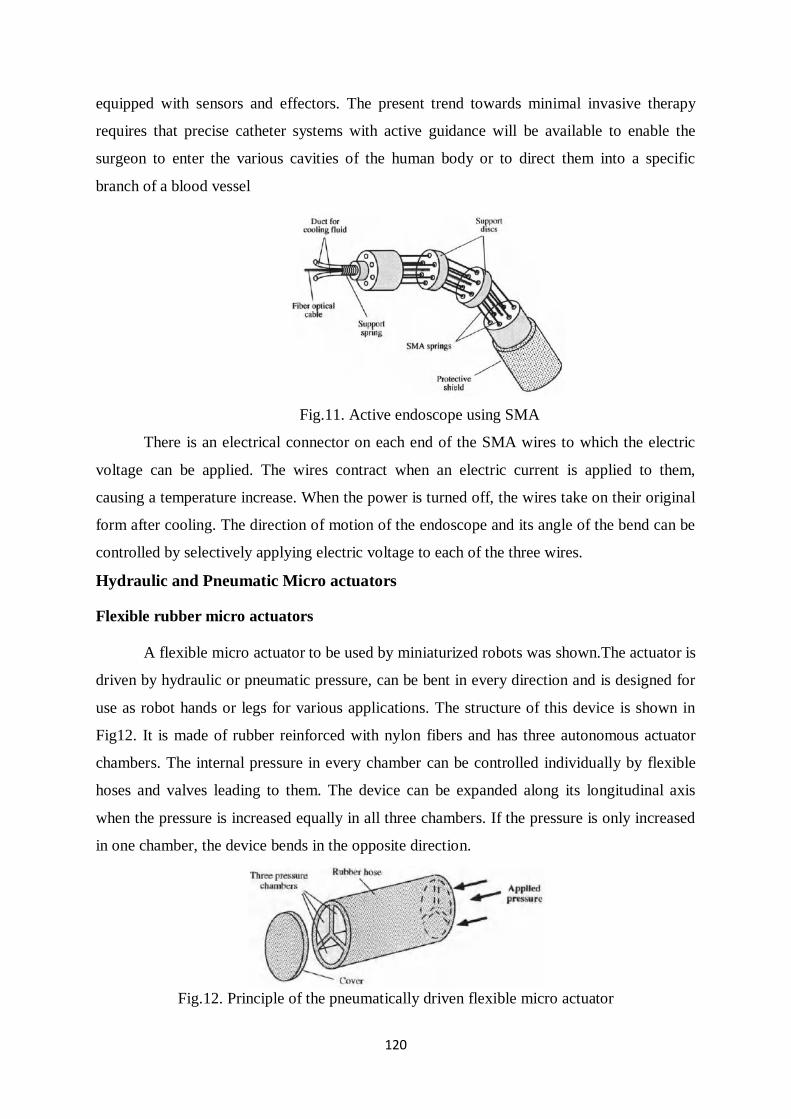
120
equipped with sensors and effectors. The present trend towards minimal invasive therapy
requires that precise catheter systems with active guidance will be available to enable the
surgeon to enter the various cavities of the human body or to direct them into a specific
branch of a blood vessel
Fig.11. Active endoscope using SMA
There is an electrical connector on each end of the SMA wires to which the electric
voltage can be applied. The wires contract when an electric current is applied to them,
causing a temperature increase. When the power is turned off, the wires take on their original
form after cooling. The direction of motion of the endoscope and its angle of the bend can be
controlled by selectively applying electric voltage to each of the three wires.
Hydraulic and Pneumatic Micro actuators
Flexible rubber micro actuators
A flexible micro actuator to be used by miniaturized robots was shown.The actuator is
driven by hydraulic or pneumatic pressure, can be bent in every direction and is designed for
use as robot hands or legs for various applications. The structure of this device is shown in
Fig12. It is made of rubber reinforced with nylon fibers and has three autonomous actuator
chambers. The internal pressure in every chamber can be controlled individually by flexible
hoses and valves leading to them. The device can be expanded along its longitudinal axis
when the pressure is increased equally in all three chambers. If the pressure is only increased
in one chamber, the device bends in the opposite direction.
Fig.12. Principle of the pneumatically driven flexible micro actuator
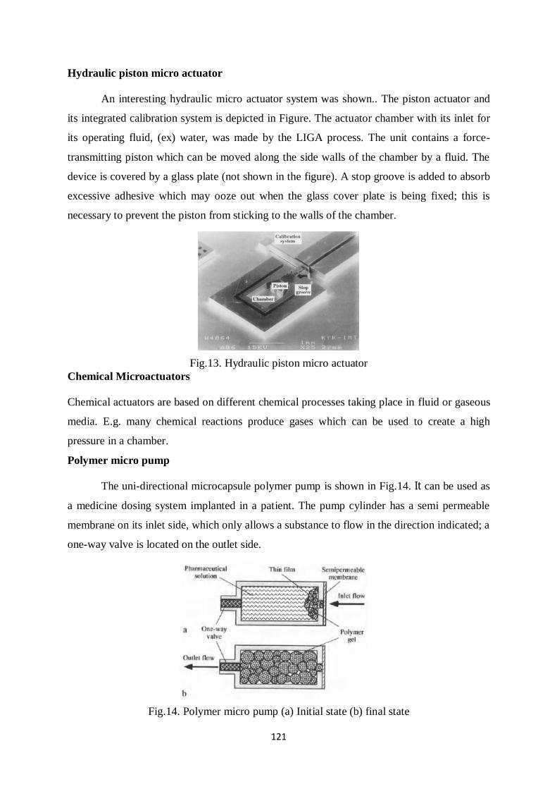
121
Hydraulic piston micro actuator
An interesting hydraulic micro actuator system was shown.. The piston actuator and
its integrated calibration system is depicted in Figure. The actuator chamber with its inlet for
its operating fluid, (ex) water, was made by the LIGA process. The unit contains a force-
transmitting piston which can be moved along the side walls of the chamber by a fluid. The
device is covered by a glass plate (not shown in the figure). A stop groove is added to absorb
excessive adhesive which may ooze out when the glass cover plate is being fixed; this is
necessary to prevent the piston from sticking to the walls of the chamber.
Fig.13. Hydraulic piston micro actuator
Chemical Microactuators
Chemical actuators are based on different chemical processes taking place in fluid or gaseous
media. E.g. many chemical reactions produce gases which can be used to create a high
pressure in a chamber.
Polymer micro pump
The uni-directional microcapsule polymer pump is shown in Fig.14. It can be used as
a medicine dosing system implanted in a patient. The pump cylinder has a semi permeable
membrane on its inlet side, which only allows a substance to flow in the direction indicated; a
one-way valve is located on the outlet side.
Fig.14. Polymer micro pump (a) Initial state (b) final state

122
The pump is separated by a thin film and filled with a pharmaceutical solution which
is on the left side of the chamber. On the right side of the chamber a highly concentrated
water-absorbing polyacrylamide gel is located.
The work cycle of the pump is as follows: the osmotic pressure difference across the
membrane takes water from the ambient solution, i.e. from the patient’s blood, and drives it
through the membrane into the right side of the pump chamber, causing the polymer gel to
swell. The pharmaceutical in the microcapsule is pushed out due to the volume increase of
the polymer gel. When the pump space is completely occupied by the gel, the medicine is
fully injected and the cycle is completed. The duration of the cycle depends on the
concentration difference between the polymer gel solution and the ambient solution.
MULTIPLE CHOICE QUESTIONS
1. Pressure is the _________
a) Force per unit area
b) Mass per unit area
c) Force per unit volume
d) Mass per unit volume
Answer: a
2. Barometer is which type of sensor?
a) Pressure sensor
b) Touch sensor
c) Temperature sensor
d) Humidity sensor
View Answer
Answer: a
3. Chemiresistor sensors are used for test gases in _______________
a) Solid form
b) Liquid form
c) Vapour form
d) All of the mentioned

123
Answer: c
4. Which of the following change electrical conductivity on the absorption of a gas
molecule?
a) Tin
b) Zinc
c) Nickel
d) All of the mentioned
Answer: d
5. Training of SMA material done by --------
a) Joule heating
b) Sputtering
c) Faraday’s law
d) None of the mentioned
Answer: a
6. Gauge pressure is also known as:
a. Manometric pressure
b. Barometric pressure
c. Absolute pressure
d. None of the above
Answer a
7. Atmospheric pressure is also known as:
a. manometric pressure
b. barometric pressure
c. absolute pressure
d. None of the above
Answer b
8. Pseudoelasticity, sometimes called superelasticity exhibits in
a. SMA
b. Micro biosensor
c. fiber

124
d. None of the above
Answer a
9. Which are the two basic states of shape memory alloys?
a. Austenite Phase and Martensitic Phase
b. Austenite Phase and Soft Bake
c. Soft Bake and Martensitic Phase
d. None of the above
Answers: a
10. Which alloy (smart material) was used in lab experiment for Shape Memory Alloy?
a. HMDS
b. Nitinol
c. Nichrome
d. Alnico
Answers: b
1. The metals nickel and titanium combined to form SMA is -------
a. HMDS
b. Nitinol
c. Nichrome
d. Alnico
Answers: b
Assignment.
1. Draw the schematic design of a micro biosensor and explain. Also draw the sensor
response curve and explain.
2. What is a shape memory alloy? Discuss one way and two way shape memory effect
with diagrams
125
UNIT V SENSOR MATERIALS AND PROCESSING TECHNIQUES
Materials for sensors: Silicon, Plastics, metals, ceramics, glasses, nano materials
Processing techniques: Vacuum deposition, sputtering, chemical vapour deposition, electro
plating, photolithography, silicon micro machining: Bulk silicon micromachining, Surface
silicon micromachining, LIGA process.
THEORY
Materials for Sensors
Sensor Materials:
Methods of sensor fabrication are numerous and specific for each particular
design.They comprise processing of semiconductors, optical components, metals,
ceramics,and plastics. Here, we briefly describe some materials and the most often used
techniques.
The below mentioned Materials are used to make the sensors:
Silicon.
Plastics
Metals.
Ceramics.
Glasses.
Silicon as a Sensing Material:
Silicon is present in the Sun and stars and is a principle component of a class of
meteorites known as aerolites. Silicon is the second most abundant material on Earth, being
exceeded only by oxygen; it makes up to 25.7% of the Earth’s crust, by weight. Silicon is not
found free in nature, but occurs chiefly as the oxide and as silicates. Some oxides are sand,
quartz, rock crystal, amethyst, clay, mica, and so forth. Silicon is prepared by heating silica
and carbon in an electric furnace, using carbon electrodes.
There are also several other methods for preparing the element. Crystalline silicon has
a metallic luster and grayish color1. The Czochralski process is commonly used to produce
single crystals of silicon used for the solid-state semiconductors and micro machined sensors.
Silicon is a relatively inert element, but it is attacked by halogen sand dilute alkali. Most
acids, except hydrofluoric, do not affect it. Elemental silicon transmits infrared radiation and
is commonly used as windows in far-infrared sensors.
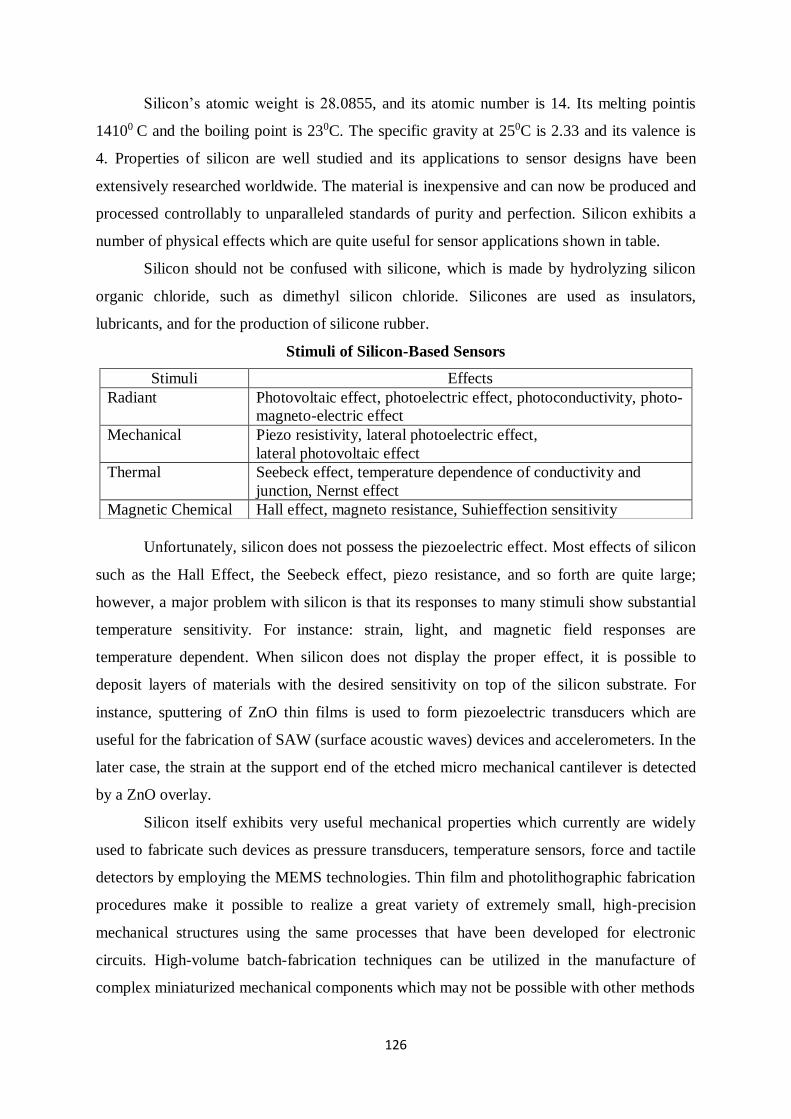
126
Silicon’s atomic weight is 28.0855, and its atomic number is 14. Its melting pointis
14100 C and the boiling point is 230C. The specific gravity at 250C is 2.33 and its valence is
4. Properties of silicon are well studied and its applications to sensor designs have been
extensively researched worldwide. The material is inexpensive and can now be produced and
processed controllably to unparalleled standards of purity and perfection. Silicon exhibits a
number of physical effects which are quite useful for sensor applications shown in table.
Silicon should not be confused with silicone, which is made by hydrolyzing silicon
organic chloride, such as dimethyl silicon chloride. Silicones are used as insulators,
lubricants, and for the production of silicone rubber.
Stimuli of Silicon-Based Sensors
Unfortunately, silicon does not possess the piezoelectric effect. Most effects of silicon
such as the Hall Effect, the Seebeck effect, piezo resistance, and so forth are quite large;
however, a major problem with silicon is that its responses to many stimuli show substantial
temperature sensitivity. For instance: strain, light, and magnetic field responses are
temperature dependent. When silicon does not display the proper effect, it is possible to
deposit layers of materials with the desired sensitivity on top of the silicon substrate. For
instance, sputtering of ZnO thin films is used to form piezoelectric transducers which are
useful for the fabrication of SAW (surface acoustic waves) devices and accelerometers. In the
later case, the strain at the support end of the etched micro mechanical cantilever is detected
by a ZnO overlay.
Silicon itself exhibits very useful mechanical properties which currently are widely
used to fabricate such devices as pressure transducers, temperature sensors, force and tactile
detectors by employing the MEMS technologies. Thin film and photolithographic fabrication
procedures make it possible to realize a great variety of extremely small, high-precision
mechanical structures using the same processes that have been developed for electronic
circuits. High-volume batch-fabrication techniques can be utilized in the manufacture of
complex miniaturized mechanical components which may not be possible with other methods
Stimuli Effects
Radiant Photovoltaic effect, photoelectric effect, photoconductivity, photo-
magneto-electric effect
Mechanical Piezo resistivity, lateral photoelectric effect,
lateral photovoltaic effect
Thermal Seebeck effect, temperature dependence of conductivity and
junction, Nernst effect
Magnetic Chemical Hall effect, magneto resistance, Suhieffection sensitivity
127
Although single-crystal silicon (SCS) is a brittle material, yielding catastrophically
(not unlike most oxide-based glasses) rather than deforming plastically (like most metals), it
certainly is not as fragile as is often believed. Young’s modulus of silicon (1.9×10¹² dyn/cm
or 27×106 psi), for example, has a value of that approaching stainless steel and is well above
that of quartz and of most glasses. The misconception that silicon is extremely fragile is
based on the fact that it is often obtained in thin slices (5–13-cm-diameter wafers) which are
only 250–500 μm thick. Even stainless steel at these dimensions is very easy to deform in
elastically.
As mentioned earlier, many of the structural and mechanical disadvantages of SCS
can be alleviated by the deposition of thin films. Sputtered quartz, for example, is utilized
routinely by industry to passivate integrated circuit chips against airborne impurities and mild
atmospheric corrosion effects. Another example is a deposition of silicon nitrate which has
hardness second only to diamond. Anisotropic etching is a key technology for the
micromachining of miniature three-dimensional structures in silicon. Two etching systems
are of practical interest. One is based on ethylenediamine and water with some additives. The
other consists of purely inorganic alkaline solutions like KOH, NaOH, or LiOH.
Forming the so-called polysilicon (PS) materials allows one to develop sensors with
unique characteristics. Polysilicon layers (on the order of 0.5 μm) may be formed by vacuum
deposition onto oxide silicon wafer with an oxide thickness of about 0.1 μm. Polysilicon
structures are doped with boron by a technique known in the semiconductor industry as
LPCVD (low-pressure chemical vapor deposition).
Fig.1A shows the resistivity of boron-doped LPCVD polysilicon in a comparison with
SCS. The resistivity of PS layers is always higher than that of a single crystal material, even
when the boron concentration is very high. At low doping concentrations, the resistivity
climbs rapidly, so that only the impurity concentration range is of interest to a sensor
fabrication. The resistance change of PS with temperature is not linear. The temperature
coefficient of resistance may be selected over a wide range, both positive and negative,
through selected doping (Fig.1B). Generally, the temperature coefficient of resistance
increases with decreased doping concentration. The resistance at any given temperature of a
PS layer may be found from
R(T )=R20eαR(T−T0), (18.1)
Where,
αR =1
R20
dR(T0)
dT
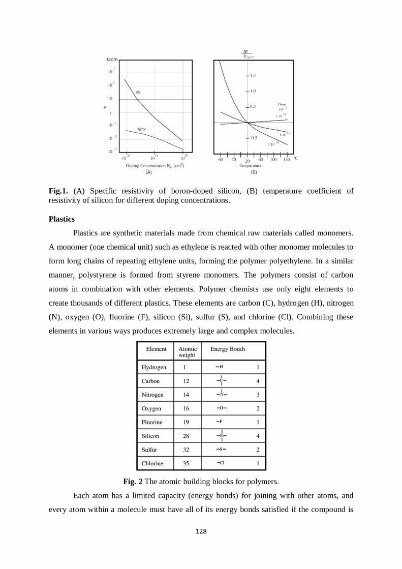
128
Fig.1. (A) Specific resistivity of boron-doped silicon, (B) temperature coefficient of
resistivity of silicon for different doping concentrations.
Plastics
Plastics are synthetic materials made from chemical raw materials called monomers.
A monomer (one chemical unit) such as ethylene is reacted with other monomer molecules to
form long chains of repeating ethylene units, forming the polymer polyethylene. In a similar
manner, polystyrene is formed from styrene monomers. The polymers consist of carbon
atoms in combination with other elements. Polymer chemists use only eight elements to
create thousands of different plastics. These elements are carbon (C), hydrogen (H), nitrogen
(N), oxygen (O), fluorine (F), silicon (Si), sulfur (S), and chlorine (Cl). Combining these
elements in various ways produces extremely large and complex molecules.
Fig. 2 The atomic building blocks for polymers.
Each atom has a limited capacity (energy bonds) for joining with other atoms, and
every atom within a molecule must have all of its energy bonds satisfied if the compound is
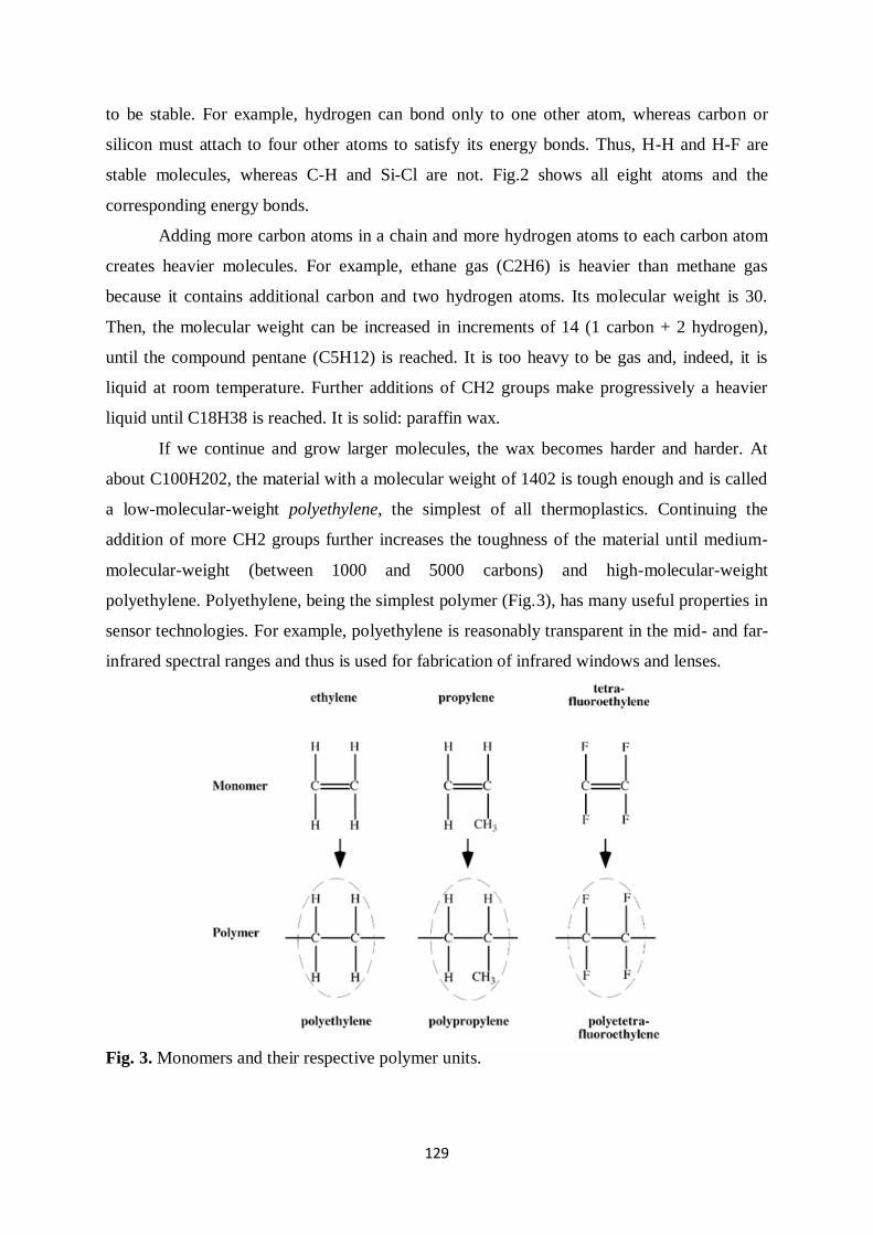
129
to be stable. For example, hydrogen can bond only to one other atom, whereas carbon or
silicon must attach to four other atoms to satisfy its energy bonds. Thus, H-H and H-F are
stable molecules, whereas C-H and Si-Cl are not. Fig.2 shows all eight atoms and the
corresponding energy bonds.
Adding more carbon atoms in a chain and more hydrogen atoms to each carbon atom
creates heavier molecules. For example, ethane gas (C2H6) is heavier than methane gas
because it contains additional carbon and two hydrogen atoms. Its molecular weight is 30.
Then, the molecular weight can be increased in increments of 14 (1 carbon + 2 hydrogen),
until the compound pentane (C5H12) is reached. It is too heavy to be gas and, indeed, it is
liquid at room temperature. Further additions of CH2 groups make progressively a heavier
liquid until C18H38 is reached. It is solid: paraffin wax.
If we continue and grow larger molecules, the wax becomes harder and harder. At
about C100H202, the material with a molecular weight of 1402 is tough enough and is called
a low-molecular-weight polyethylene, the simplest of all thermoplastics. Continuing the
addition of more CH2 groups further increases the toughness of the material until medium-
molecular-weight (between 1000 and 5000 carbons) and high-molecular-weight
polyethylene. Polyethylene, being the simplest polymer (Fig.3), has many useful properties in
sensor technologies. For example, polyethylene is reasonably transparent in the mid- and far-
infrared spectral ranges and thus is used for fabrication of infrared windows and lenses.
Fig. 3. Monomers and their respective polymer units.
130
By applying heat, pressure, and catalysts, monomers are grown into long chains. The
process is called polymerization. Chain length (molecular weight) is important because it
determines many properties of a plastic. The major effect of increased length is increased
toughness, creep resistance, stress-crack resistance, melt temperature, melt viscosity, and
difficulty of processing. After polymerization is completed, the finished polymer chains
resemble long intertwined bundles of spaghetti with no physical connections between chains.
Such a polymer is called thermoplastic (heat-moldable) polymer.
If chains are packed closer to one another, a denser polyethylene is formed which, in
effect, results in the formation of crystals. Crystallized areas are stiffer and stronger. Such
polymers are more difficult to process because they have higher and sharper melt
temperatures; that is, instead of softening, they quickly transform into low viscosity liquids.
On the other hand, amorphous thermoplastics soften gradually, but they do not flow as easily
as crystalline plastics. The examples of amorphous polymers are acrylonitrile–butadiene–
styrene, polystyrene, polycarbonate, polysulfone, and polyetherimide. Crystalline plastics
include polyethylene, polypropylene, nylon, polyvinylidene fluoride (PVDF), acetal, and
others.
The following is a non-exhaustive list of thermoplastics:
ABS (acrylonitrile–butadiene–styrene) is very tough, yet hard and rigid. It has fair
chemical resistance, low water absorption, and good dimensional stability. Some grades may
be electroplated.
Acrylichas is high optical clarity and excellent resistance to outdoor weathering. This
is a hard, glossy material with good electrical properties. It is available in a variety of colors.
Fluoroplastics comprise a large family of materials (PTFE, FEP, PFA, CTFE,
ECTFE, ETFE, and PFDF) with excellent electrical properties and chemical resistance, low
friction, and outstanding stability at high temperatures. However, their strength is moderate
and the cost is high.
Nylon (polyimide) has outstanding toughness and wears resistance with a low
coefficient of friction. It has good electrical and chemical properties. However, it is
hygroscopic and dimensional stability is worst than in most other plastics.
Polycarbonatehas is the highest impact resistance. It is transparent with excellent
outdoor stability and resistance to creep under load. It may have some problems with
chemicals.
Polyesterhas excellent dimensional stability but is not suitable for outdoor use or for
service in hot water.
131
Polyethylene is lightweight and inexpensive with excellent chemical stability and
good electrical properties. It has moderate transparency in the broad spectral range from
visible to far infrared; it has poor dimensional and thermal stability.
Polypropylenehas has outstanding resistance to flex and stress cracking with excellent
chemical and electrical properties with good thermal stability. It is lightweight and
inexpensive. Optical transparency is good down to the far-infrared spectral range. However,
absorption and scattering of photons in the mid-infrared range
is higher than in polyethylene.
Polyurethane is tough, extremely abrasion, and impact resistant. It can be made into
films and foams. It has good chemical and electrical properties; however, UV exposure
degrades its quality.
Another type of plastic is called thermoset, in which polymerization (curing) is done
in two stages: one by the material manufacturer and the other by the molder. An example is
phenolic, which during the molding process is liquefied under pressure, producing a cross-
linking reaction between molecular chains. After it has been molded, a thermoset plastic has
virtually all of its molecules interconnected with strong physical bonds, which are not heat
reversible. In effect, curing, a thermoset is like cooking an egg. Once it is cooked, it will
remain hard. In general, thermoset plastics resist higher temperatures and provide greater
dimensional stability. This is the reason why such thermoset plastics such as polyester
(reinforced) is used to make boat hulls and circuit-breaker components, epoxy is used to
make printed circuit boards, and melamine is used to make dinnerware. On the other hand,
thermoplastics offer higher impact strength, easier processing, and better adaptability to
complex designs than do thermosets.
The thermoplastics that are most useful in sensor-related applications are the
following.
Alkyd has excellent electrical properties and very low moisture absorption.
Allyl(diallyl phtalate) has outstanding dimensional stability and high heat and
chemical resistance.
Epoxy has exceptional mechanical strength, electrical properties, and adhesion to
most of materials.
Phenolic is a low-cost material. The color is limited to black and brown.
Polyester (thermoplastic version) has a great variety of colors and may be transparent
or opaque. Shrinkage is high.
132
If two different monomers (A and B) are combined in a polymerization reaction, such
a polymer is called copolymer. The final properties of a copolymer depend on the ratio of
components A and B. Polymer mechanical properties can be modified by providing additives,
such as fibers to increase strength and stiffness, plasticisers for flexibility, lubricants for
easier molding, or UV stabilizers for better performance in sunlight.
Another good way to control properties of plastics is to make polymer alloys or
blends. Primarily this is done to retain properties of each component.
Conductive plastic: Being wonderful electrical isolators, plastic materials often
require lamination with metal foil, painting with conductive paint, or metallization to give
them electrical conductive properties, required for shielding. Another way of providing
electrical conductivity is mixing plastics with conductive additives (e.g., graphite or metal
fibers) or building composite plastic parts incorporating metal mesh.
Piezoelectric plastics: These are made from PVF2, PVDF, and copolymers which are
crystalline materials. Initially, they do not possess piezoelectric properties and must be poled
either in high voltage or by corona discharge. Metal electrodes are deposited on both sides of
the film either by silk-screening or vacuum metallization. These films, in some applications
are used instead of ceramics, because of their flexibility and stability against mechanical
stress. Another advantage of the piezoelectric plastics is their ability to be formed into any
desirable shape.
METALS
From the sensor designer stand point, there are two classes of metal: nonferrous and
ferrous. Ferrous metals, like steel, are often used in combination with magnetic sensors to
measure motion, distance, magnetic field strength, and so forth. Also, they are quite useful as
magnetic shields. Nonferrous metals, on the other hand, are permeable to magnetic fields and
used whenever these fields are of no concern.
Nonferrous metals offer a wide variety of mechanical and electrical properties. When
selecting a metal, one must consider not only its physical properties but also ease of
mechanical processing. For example, copper has excellent thermal and electrical properties,
yet it is difficult to machine; therefore, in many instances, aluminum should be considered as
a compromise alternative. Aluminum has a high strength-to weigh ratio and possesses its own
anticorrosion mechanism. When exposed to air, aluminum does not oxide progressively, like
iron would do. The protection is provided by a microscopic oxide coating which forms on the
surface and seals the bare metal from the environment.
133
There are hundreds of aluminum alloys. They can be processed in many ways, such as
drawing, casting, and stamping. Some alloys can be soldered and welded. In addition to
excellent electrical properties, aluminum is a superb reflector of light over nearly the entire
spectrum from UV to radio waves. Aluminum coatings are widely used for mirrors and
waveguides. In the mid- and far-infrared range, the only superior to aluminum reflector is
gold.
Beryllium has several remarkable properties. Its low density (two-thirds that of
aluminum) is combined with a high modulus per weight (five times that of steel), high
specific heat, excellent dimensional stability, and transparency to X-rays. However, this is an
expensive metal. Like aluminum, beryllium forms a protective coating on its surface, thus
resisting corrosion. It may be processed by many conventional methods, including powder
cold pressing. The metal is used as X-ray windows, optical platforms, mirror substrates, and
satellite structures.
Magnesium is a very light metal with a high strength-to-weight ratio. Due to its low
modulus of elasticity, it can absorb energy elastically, which gives its good damping
characteristics. The material is very easy to process by most of metal-working techniques.
Nickel allows the design of very tough structures which are also resistant to corrosion.
When compared with steel, the nickel alloys have ultrahigh strength and a high modulus of
elasticity. Its alloys include binary systems with copper, silicon, and molybdenum. Nickel
and its alloys preserve their mechanical properties down to cryogenic temperatures and at
high temperatures up to 1200◦C. Nickels is used in high-performance superalloys such as
Inconell, Monel (Ni–Cu), Ni–Cr, and Ni–Cr–Fe alloys.
Copper combines very good thermal and electrical conductivity properties (second
only to pure silver) with corrosion resistance and relative ease of processing. However, its
strength-to-weight ratio is relatively poor. Copper is also difficult to machine. Copper and its
alloys—the brasses and bronzes—come in variety of forms, including films. Brasses are
alloys which contain zinc and other designated elements. Bronzes comprise several main
groups: copper–tin–phosphorus (phosphor bronze), copper–tin–lead–phosphorus (lead
phosphor bronzes), and copper–silicon (silicon bronzes) alloys. Under outdoor condition,
copper develops a blue-green patina. This can be prevented by applying an acrylic coating. A
copper alloy with beryllium has excellent mechanical properties and used to make springs.
Lead is the most impervious of all common metals to X-rays and γ - radiation. It
resists attack by many corrosive chemicals, most types of soil, and marine and industrial
environments. It has a low melting temperature, ease of casting and forming, and good sound
134
and vibration absorption. It possesses natural lubricity and wear resistance. Lead is rarely
used in pure form. Its most common alloys are “hard lead” (1–13% of antimony), calcium,
and tin alloys which have better strength and hardness.
Platinum is a silver-white precious metal which is extremely malleable, ductile, and
corrosion resistant. Its positive temperature coefficient of resistance is very stable and
reproducible, which allows its use in temperature sensing.
Gold is extremely soft and chemically inert metal. It can only be attacked by
aquaregia and by sodium and potassium in the presence of oxygen. One gram of pure gold
can be worked into a leaf covering 5000 cm2 and only less than 0.1 μm thick. Mainly, it is
used for plating and is alloyed with other metals like copper, nickel, and silver. In sensor
applications, gold is used for fabricating electrical contacts and plating mirrors and
waveguides operating in the mid- and far-infrared spectral ranges.
Silver is the least costly of all precious metals. It is very malleable and corrosion
resistant. It has the highest electrical and thermal conductivity of all metals.
Palladium, iridium, and rhodium resemble and behave like platinum. They are used
as electrical coatings to produce hybrid and printed circuit boards and various ceramic
substrates with electrical conductors. Another application is in the fabrication of high-quality
reflectors operating in a broad spectral range, especially at elevated temperatures or highly
corrosive environments. Iridium has the best corrosion resistance of all metals and thus used
in the most critical applications.
Molybdenum maintains its strength and rigidity up to 1600◦C. The metal and its
alloys are readily machinable by conventional tools. In non oxidizing environments, it resists
attacks by most acids. Its prime application is for high-temperature devices, such as heating
elements and reflectors of intense infrared radiation for high temperature furnaces.
Molybdenum has a low coefficient of thermal expansion and resists erosion by molten
metals.
Tungsten is many respects is similar to molybdenum, but can operate even at higher
temperatures. A thermocouple sensor fabricated of tungsten is alloyed with25% rhenium with
another wire, in a thermocouple with 5% rhenium.
Zinc is seldom used alone, except for coating; it is mainly used as an additive in many
alloys.
135
Ceramics:
In sensor technologies, ceramics are very useful crystalline materials because of their
structural strength, thermal stability, light weight, resistance to many chemicals, ability to
bond with other materials, and excellent electrical properties. Although most metals form at
least one chemical compound with oxygen, only a handful of oxides are useful as the
principal constituent of ceramics. Examples are alumina and beryllia. The natural alloying
element in alumina is silica; however, alumina can be alloyed with chromium, magnesium,
calcium, and other elements.
Several metal carbides and nitrades qualify as ceramics. The most commonly used are
boron carbide and nitrate and aluminium nitrade. Whenever fast heat transfer is of
importance, aluminium nitrade should be considered, whereas silicon carbide has high
dielectric constant, which makes it attractive for designing capacitive sensors. Due to their
hardness, most ceramics require special processing. A precise and cost-effective method of
cutting various shapes of ceramic substrates is scribing, machining, and drilling by use of
computer-controlled CO2 laser. Ceramics for the sensor substrates are available from many
manufacturers in thicknesses ranging from 0.1 to 10 mm.
Glasses:
Glass is an amorphous solid material made by fusing silica with a basic oxide.
Although its atoms never arrange themselves into crystalline structure, the atomic spacing in
glass is quite tight. Glass is characterized by transparency, availability in many colors,
hardness, and resistance to most chemicals except hydrofluoric acid. Most glasses are based
on the silicate system and is made from three major components: silica (SiO), lime (CaCO3),
and sodium carbonite (NaCO3). Nonsilicate glasses include phosphate glass (which resists
hydrofluoric acid), heat-absorbing glasses (made with FeO), and systems based on oxides of
aluminum, vanadium, germanium, and other metals. An example of such specialty glass is
arsenictrisulfate (As2S3) known as AMTIR, which is substantially transparent in mid- and
far-infrared spectral ranges and is used for fabricating infrared optical devices.
Borosilicate glass is the oldest type of glass which is substantially resistant to thermal
shock. Under the trademark Pyrex®, some of the SiO2 molecules are replaced by boric
oxide. The glass has a low coefficient of thermal expansion and thus is used for the
fabrication optical mirrors (such as in telescopes).
Lead–alkali glass (lead glass) contains lead monoxide (PbO) which increases its
index of refraction. Also, it is a better electrical insulator. In the sensor technologies, it is
used for fabricating optical windows and prisms and as a shield against nuclear radiation.
136
Other glasses include alumosilicate glass (in which Al2O3 replaces some silica), 96% silica,
and fused silica.
Another class of glass is light-sensitive glasses which are available in three grades.
Photo chromatic glass darkens when exposed to UV radiation and clears when the UV
radiation is removed or glass is heated. Some photo chromatic compositions remain darkened
for a week or longer. Others fade within few minutes when UV radiation is removed. The
photosensitive glass reacts to UV radiation in a different manner. If it is heated after
exposure, it changes from clear to opal. This allows the creation of some patterns within the
glass structure. Moreover, the exposed opalized glass is much more soluble in hydrofluoric
acid, which allows for an efficient etching technique.
LIST OF NANO MATERIALS PROCESSING TECHNIQUES
Vacuum deposition.
Sputtering.
Chemical vapour deposition.
Electroplating.
Photolithography.
Vacuum deposition
A metal can be converted into gaseous form and then deposited on the surface of the
sample. The evaporation system consists of a vacuum chamber (Fig.4) where a diffuse pump
evacuates air down to 10−6−10−7torr of pressure. A deposited material is placed into a
ceramic crucible which is heated by a tungsten filament above the metal melting point. An
alternative method of heating is the use of an electron beam.
On a command from the control device, the shutter opens and allows the metal atoms
emanated from the molten metal to deposit on the sample. Parts of the sample which remain
free of the film are protected by the mask. The film thickness is determined by the
evaporation time and the vapor pressure of the metal. Hence, materials with a low melting
point are easy to deposit (e.g., aluminum). In general, vacuum deposited films have large
residual stress and thus this technique is used mainly for depositing only thin layers.
Because the molten material is virtually a point source of atoms, it may cause both
non uniform distribution of the deposited film and the so-called shadowing effect where the
edges of the masked pattern appear blurry. Two methods may help to alleviate this problem.
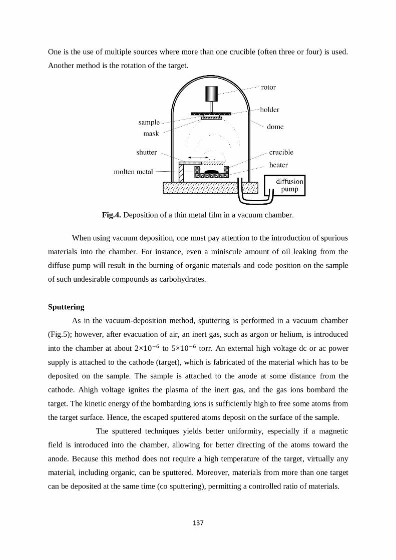
137
One is the use of multiple sources where more than one crucible (often three or four) is used.
Another method is the rotation of the target.
Fig.4. Deposition of a thin metal film in a vacuum chamber.
When using vacuum deposition, one must pay attention to the introduction of spurious
materials into the chamber. For instance, even a miniscule amount of oil leaking from the
diffuse pump will result in the burning of organic materials and code position on the sample
of such undesirable compounds as carbohydrates.
Sputtering
As in the vacuum-deposition method, sputtering is performed in a vacuum chamber
(Fig.5); however, after evacuation of air, an inert gas, such as argon or helium, is introduced
into the chamber at about 2×10⁻⁶ to 5×10⁻⁶ torr. An external high voltage dc or ac power
supply is attached to the cathode (target), which is fabricated of the material which has to be
deposited on the sample. The sample is attached to the anode at some distance from the
cathode. Ahigh voltage ignites the plasma of the inert gas, and the gas ions bombard the
target. The kinetic energy of the bombarding ions is sufficiently high to free some atoms from
the target surface. Hence, the escaped sputtered atoms deposit on the surface of the sample.
The sputtered techniques yields better uniformity, especially if a magnetic
field is introduced into the chamber, allowing for better directing of the atoms toward the
anode. Because this method does not require a high temperature of the target, virtually any
material, including organic, can be sputtered. Moreover, materials from more than one target
can be deposited at the same time (co sputtering), permitting a controlled ratio of materials.
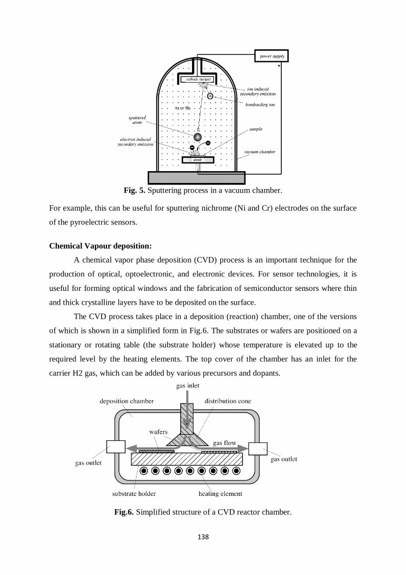
138
Fig. 5. Sputtering process in a vacuum chamber.
For example, this can be useful for sputtering nichrome (Ni and Cr) electrodes on the surface
of the pyroelectric sensors.
Chemical Vapour deposition:
A chemical vapor phase deposition (CVD) process is an important technique for the
production of optical, optoelectronic, and electronic devices. For sensor technologies, it is
useful for forming optical windows and the fabrication of semiconductor sensors where thin
and thick crystalline layers have to be deposited on the surface.
The CVD process takes place in a deposition (reaction) chamber, one of the versions
of which is shown in a simplified form in Fig.6. The substrates or wafers are positioned on a
stationary or rotating table (the substrate holder) whose temperature is elevated up to the
required level by the heating elements. The top cover of the chamber has an inlet for the
carrier H2 gas, which can be added by various precursors and dopants.
Fig.6. Simplified structure of a CVD reactor chamber.
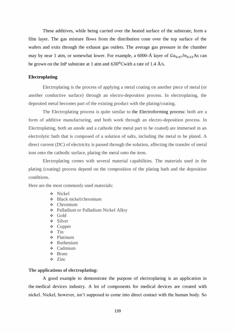
139
These additives, while being carried over the heated surface of the substrate, form a
film layer. The gas mixture flows from the distribution cone over the top surface of the
wafers and exits through the exhaust gas outlets. The average gas pressure in the chamber
may by near 1 atm, or somewhat lower. For example, a 6000-Å layer of 𝐺𝑎0.47𝐼𝑛0.53As can
be grown on the InP substrate at 1 atm and 6300Cwith a rate of 1.4 Å/s.
Electroplating
Electroplating is the process of applying a metal coating on another piece of metal (or
another conductive surface) through an electro-deposition process. In electroplating, the
deposited metal becomes part of the existing product with the plating/coating.
The Electroplating process is quite similar to the Electroforming process: both are a
form of additive manufacturing, and both work through an electro-deposition process. In
Electroplating, both an anode and a cathode (the metal part to be coated) are immersed in an
electrolytic bath that is composed of a solution of salts, including the metal to be plated. A
direct current (DC) of electricity is passed through the solution, affecting the transfer of metal
ions onto the cathodic surface, plating the metal onto the item.
Electroplating comes with several material capabilities. The materials used in the
plating (coating) process depend on the composition of the plating bath and the deposition
conditions.
Here are the most commonly used materials:
Nickel
Black nickel/chromium
Chromium
Palladium or Palladium Nickel Alloy
Gold
Silver
Copper
Tin
Platinum
Ruthenium
Cadmium
Brass
Zinc
The applications of electroplating:
A good example to demonstrate the purpose of electroplating is an application in
the medical devices industry. A lot of components for medical devices are created with
nickel. Nickel, however, isn’t supposed to come into direct contact with the human body. So
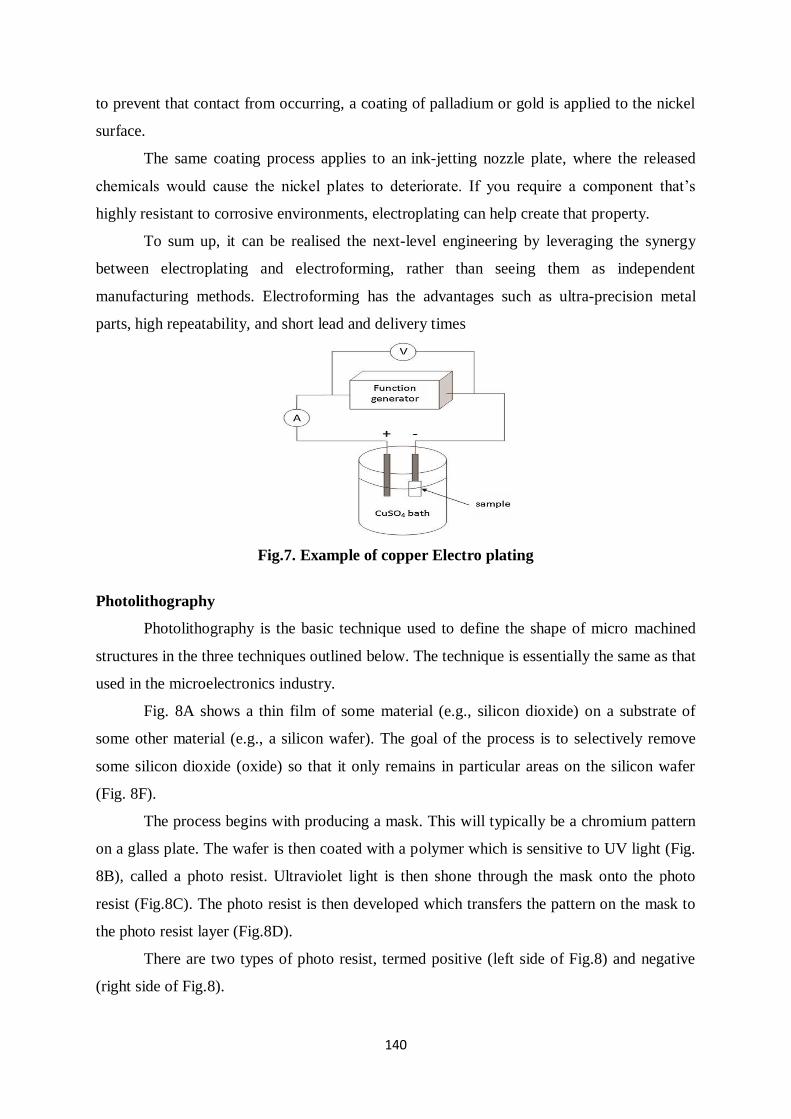
140
to prevent that contact from occurring, a coating of palladium or gold is applied to the nickel
surface.
The same coating process applies to an ink-jetting nozzle plate, where the released
chemicals would cause the nickel plates to deteriorate. If you require a component that’s
highly resistant to corrosive environments, electroplating can help create that property.
To sum up, it can be realised the next-level engineering by leveraging the synergy
between electroplating and electroforming, rather than seeing them as independent
manufacturing methods. Electroforming has the advantages such as ultra-precision metal
parts, high repeatability, and short lead and delivery times
Fig.7. Example of copper Electro plating
Photolithography
Photolithography is the basic technique used to define the shape of micro machined
structures in the three techniques outlined below. The technique is essentially the same as that
used in the microelectronics industry.
Fig. 8A shows a thin film of some material (e.g., silicon dioxide) on a substrate of
some other material (e.g., a silicon wafer). The goal of the process is to selectively remove
some silicon dioxide (oxide) so that it only remains in particular areas on the silicon wafer
(Fig. 8F).
The process begins with producing a mask. This will typically be a chromium pattern
on a glass plate. The wafer is then coated with a polymer which is sensitive to UV light (Fig.
8B), called a photo resist. Ultraviolet light is then shone through the mask onto the photo
resist (Fig.8C). The photo resist is then developed which transfers the pattern on the mask to
the photo resist layer (Fig.8D).
There are two types of photo resist, termed positive (left side of Fig.8) and negative
(right side of Fig.8).
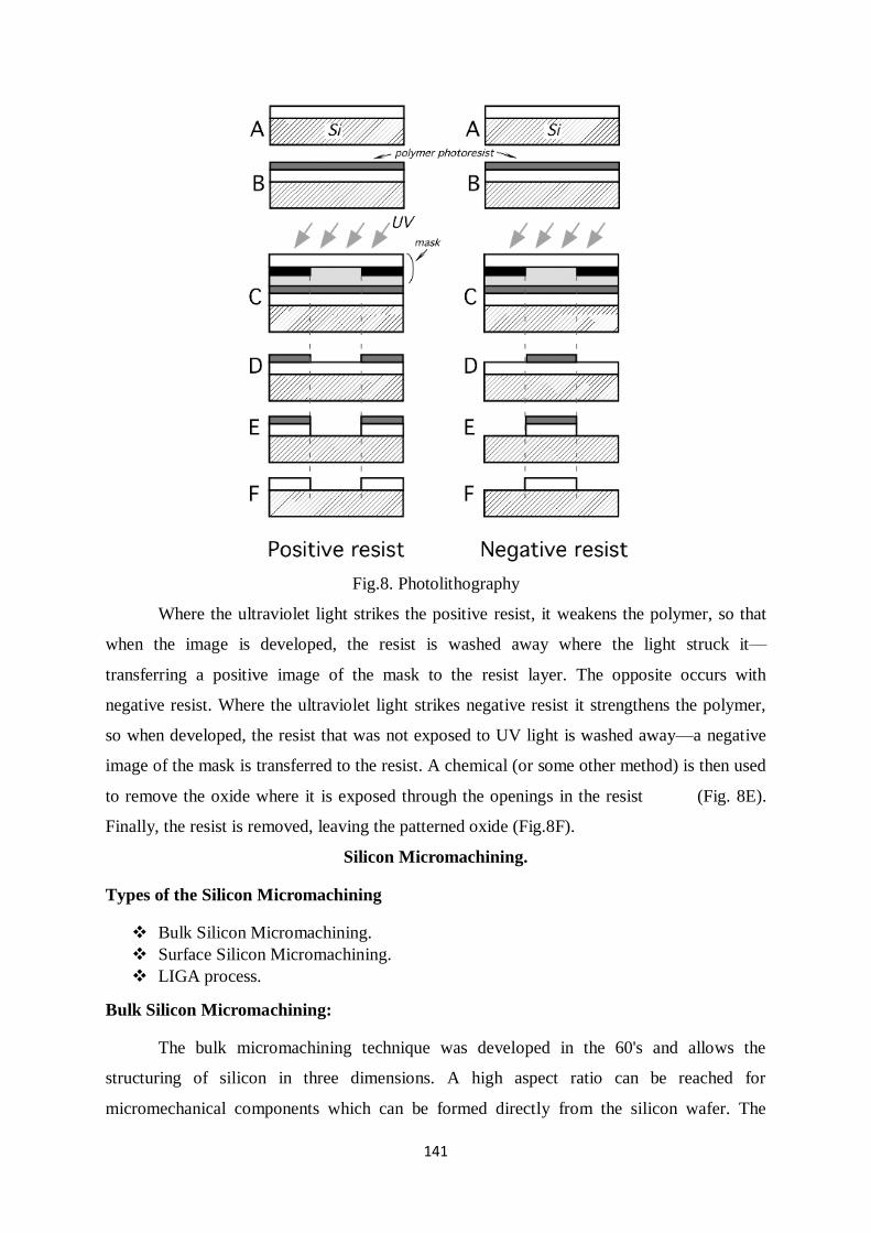
141
Fig.8. Photolithography
Where the ultraviolet light strikes the positive resist, it weakens the polymer, so that
when the image is developed, the resist is washed away where the light struck it—
transferring a positive image of the mask to the resist layer. The opposite occurs with
negative resist. Where the ultraviolet light strikes negative resist it strengthens the polymer,
so when developed, the resist that was not exposed to UV light is washed away—a negative
image of the mask is transferred to the resist. A chemical (or some other method) is then used
to remove the oxide where it is exposed through the openings in the resist (Fig. 8E).
Finally, the resist is removed, leaving the patterned oxide (Fig.8F).
Silicon Micromachining.
Types of the Silicon Micromachining
Bulk Silicon Micromachining.
Surface Silicon Micromachining.
LIGA process.
Bulk Silicon Micromachining:
The bulk micromachining technique was developed in the 60's and allows the
structuring of silicon in three dimensions. A high aspect ratio can be reached for
micromechanical components which can be formed directly from the silicon wafer. The
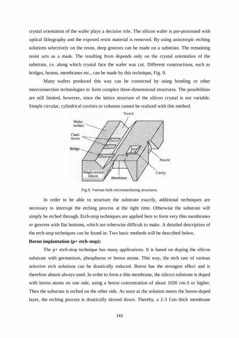
142
crystal orientation of the wafer plays a decisive role. The silicon wafer is pre-processed with
optical lithography and the exposed resist material is removed. By using anisotropic etching
solutions selectively on the resist, deep grooves can be made on a substrate. The remaining
resist acts as a mask. The resulting from depends only on the crystal orientation of the
substrate, i.e. along which crystal face the wafer was cut. Different constructions, such as
bridges, beams, membranes etc., can be made by this technique, Fig. 9.
Many wafers produced this way can be connected by using bonding or other
interconnection technologies to form complex three-dimensional structures. The possibilities
are still limited, however, since the lattice structure of the silicon crystal is not variable.
Simple circular, cylindrical cavities or columns cannot be realized with this method.
Fig.9. Various bulk micromachining structures.
In order to be able to structure the substrate exactly, additional techniques are
necessary to interrupt the etching process at the right time. Otherwise the substrate will
simply be etched through. Etch-stop techniques are applied here to form very thin membranes
or grooves with flat bottoms, which are otherwise difficult to make. A detailed description of
the etch-stop techniques can be found in. Two basic methods will be described below.
Boron implantation (p+ etch-stop):
The p+ etch-stop technique has many applications. It is based on doping the silicon
substrate with germanium, phosphorus or boron atoms. This way, the etch rate of various
selective etch solutions can be drastically reduced. Boron has the strongest effect and is
therefore almost always used. In order to form a thin membrane, the silicon substrate is doped
with boron atoms on one side, using a boron concentration of about 1020 cm-3 or higher.
Then the substrate is etched on the other side. As soon as the solution meets the boron-doped
layer, the etching process is drastically slowed down. Thereby, a 2-3 f.tm thick membrane
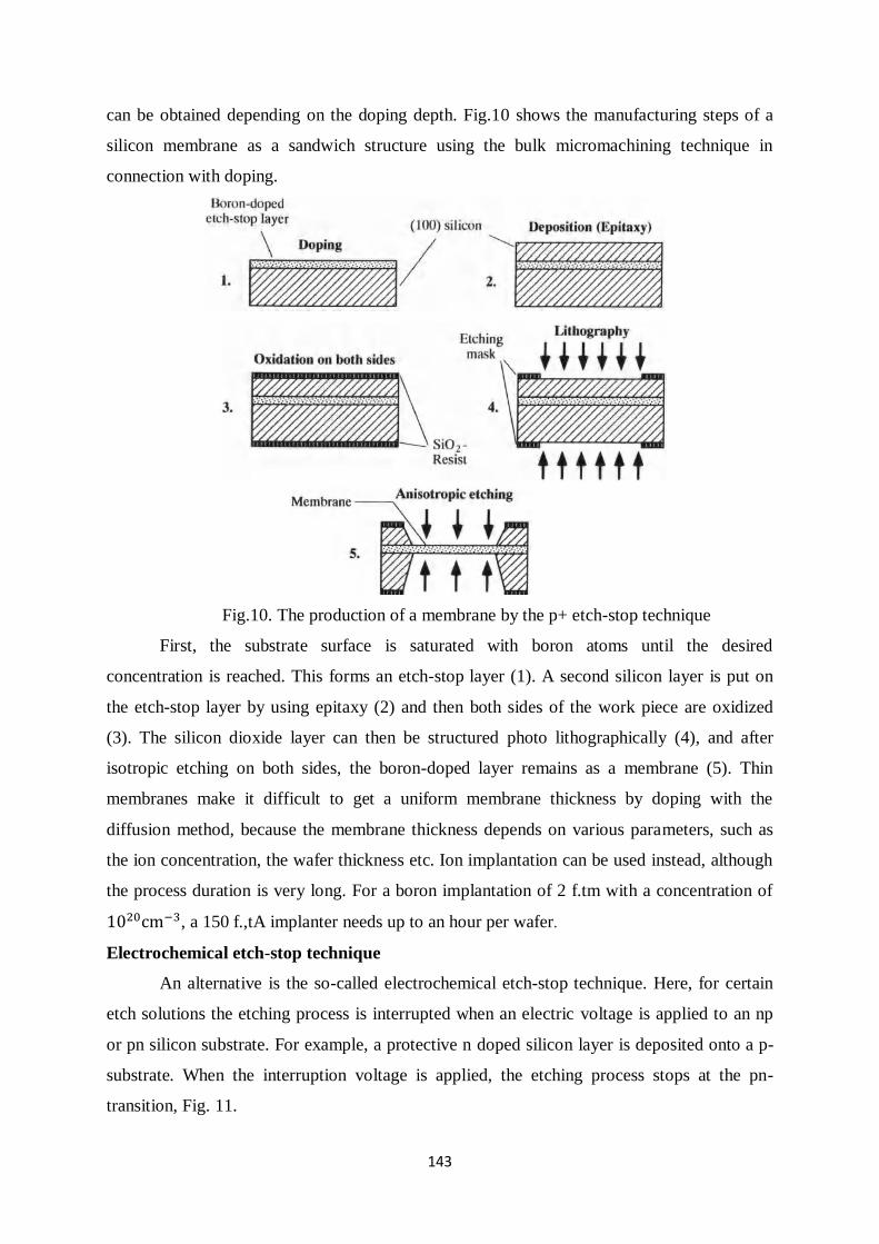
143
can be obtained depending on the doping depth. Fig.10 shows the manufacturing steps of a
silicon membrane as a sandwich structure using the bulk micromachining technique in
connection with doping.
Fig.10. The production of a membrane by the p+ etch-stop technique
First, the substrate surface is saturated with boron atoms until the desired
concentration is reached. This forms an etch-stop layer (1). A second silicon layer is put on
the etch-stop layer by using epitaxy (2) and then both sides of the work piece are oxidized
(3). The silicon dioxide layer can then be structured photo lithographically (4), and after
isotropic etching on both sides, the boron-doped layer remains as a membrane (5). Thin
membranes make it difficult to get a uniform membrane thickness by doping with the
diffusion method, because the membrane thickness depends on various parameters, such as
the ion concentration, the wafer thickness etc. Ion implantation can be used instead, although
the process duration is very long. For a boron implantation of 2 f.tm with a concentration of
1020cm−3, a 150 f.,tA implanter needs up to an hour per wafer.
Electrochemical etch-stop technique
An alternative is the so-called electrochemical etch-stop technique. Here, for certain
etch solutions the etching process is interrupted when an electric voltage is applied to an np
or pn silicon substrate. For example, a protective n doped silicon layer is deposited onto a p-
substrate. When the interruption voltage is applied, the etching process stops at the pn-
transition, Fig. 11.
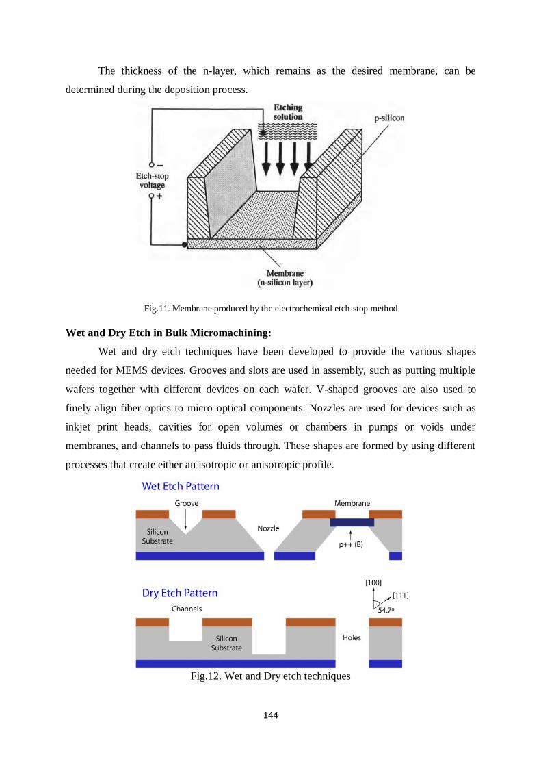
144
The thickness of the n-layer, which remains as the desired membrane, can be
determined during the deposition process.
Fig.11. Membrane produced by the electrochemical etch-stop method
Wet and Dry Etch in Bulk Micromachining:
Wet and dry etch techniques have been developed to provide the various shapes
needed for MEMS devices. Grooves and slots are used in assembly, such as putting multiple
wafers together with different devices on each wafer. V-shaped grooves are also used to
finely align fiber optics to micro optical components. Nozzles are used for devices such as
inkjet print heads, cavities for open volumes or chambers in pumps or voids under
membranes, and channels to pass fluids through. These shapes are formed by using different
processes that create either an isotropic or anisotropic profile.
Fig.12. Wet and Dry etch techniques
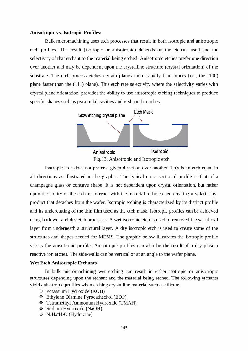
145
Anisotropic vs. Isotropic Profiles:
Bulk micromachining uses etch processes that result in both isotropic and anisotropic
etch profiles. The result (isotropic or anisotropic) depends on the etchant used and the
selectivity of that etchant to the material being etched. Anisotropic etches prefer one direction
over another and may be dependent upon the crystalline structure (crystal orientation) of the
substrate. The etch process etches certain planes more rapidly than others (i.e., the (100)
plane faster than the (111) plane). This etch rate selectivity where the selectivity varies with
crystal plane orientation, provides the ability to use anisotropic etching techniques to produce
specific shapes such as pyramidal cavities and v-shaped trenches.
Fig.13. Anisotropic and Isotropic etch
Isotropic etch does not prefer a given direction over another. This is an etch equal in
all directions as illustrated in the graphic. The typical cross sectional profile is that of a
champagne glass or concave shape. It is not dependent upon crystal orientation, but rather
upon the ability of the etchant to react with the material to be etched creating a volatile by-
product that detaches from the wafer. Isotropic etching is characterized by its distinct profile
and its undercutting of the thin film used as the etch mask. Isotropic profiles can be achieved
using both wet and dry etch processes. A wet isotropic etch is used to removed the sacrificial
layer from underneath a structural layer. A dry isotropic etch is used to create some of the
structures and shapes needed for MEMS. The graphic below illustrates the isotropic profile
versus the anisotropic profile. Anisotropic profiles can also be the result of a dry plasma
reactive ion etches. The side-walls can be vertical or at an angle to the wafer plane.
Wet Etch Anisotropic Etchants
In bulk micromachining wet etching can result in either isotropic or anisotropic
structures depending upon the etchant and the material being etched. The following etchants
yield anisotropic profiles when etching crystalline material such as silicon:
Potassium Hydroxide (KOH)
Ethylene Diamine Pyrocathechol (EDP)
Tetramethyl Ammonum Hydroxide (TMAH)
Sodium Hydroxide (NaOH)
N2H4¯H2O (Hydrazine)
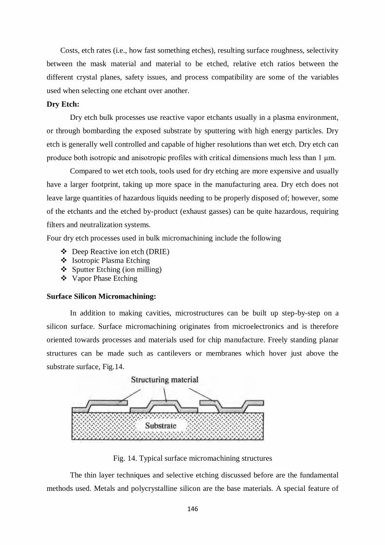
146
Costs, etch rates (i.e., how fast something etches), resulting surface roughness, selectivity
between the mask material and material to be etched, relative etch ratios between the
different crystal planes, safety issues, and process compatibility are some of the variables
used when selecting one etchant over another.
Dry Etch:
Dry etch bulk processes use reactive vapor etchants usually in a plasma environment,
or through bombarding the exposed substrate by sputtering with high energy particles. Dry
etch is generally well controlled and capable of higher resolutions than wet etch. Dry etch can
produce both isotropic and anisotropic profiles with critical dimensions much less than 1 μm.
Compared to wet etch tools, tools used for dry etching are more expensive and usually
have a larger footprint, taking up more space in the manufacturing area. Dry etch does not
leave large quantities of hazardous liquids needing to be properly disposed of; however, some
of the etchants and the etched by-product (exhaust gasses) can be quite hazardous, requiring
filters and neutralization systems.
Four dry etch processes used in bulk micromachining include the following
Deep Reactive ion etch (DRIE)
Isotropic Plasma Etching
Sputter Etching (ion milling)
Vapor Phase Etching
Surface Silicon Micromachining:
In addition to making cavities, microstructures can be built up step-by-step on a
silicon surface. Surface micromachining originates from microelectronics and is therefore
oriented towards processes and materials used for chip manufacture. Freely standing planar
structures can be made such as cantilevers or membranes which hover just above the
substrate surface, Fig.14.
Fig. 14. Typical surface micromachining structures
The thin layer techniques and selective etching discussed before are the fundamental
methods used. Metals and polycrystalline silicon are the base materials. A special feature of
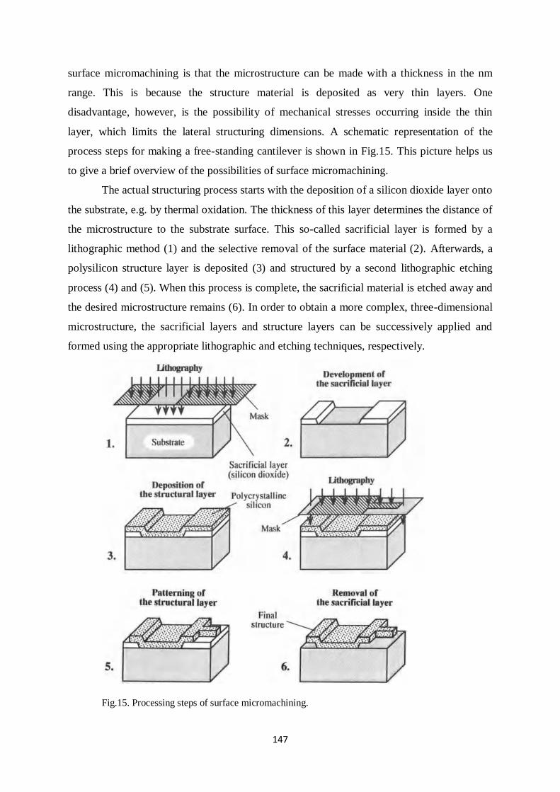
147
surface micromachining is that the microstructure can be made with a thickness in the nm
range. This is because the structure material is deposited as very thin layers. One
disadvantage, however, is the possibility of mechanical stresses occurring inside the thin
layer, which limits the lateral structuring dimensions. A schematic representation of the
process steps for making a free-standing cantilever is shown in Fig.15. This picture helps us
to give a brief overview of the possibilities of surface micromachining.
The actual structuring process starts with the deposition of a silicon dioxide layer onto
the substrate, e.g. by thermal oxidation. The thickness of this layer determines the distance of
the microstructure to the substrate surface. This so-called sacrificial layer is formed by a
lithographic method (1) and the selective removal of the surface material (2). Afterwards, a
polysilicon structure layer is deposited (3) and structured by a second lithographic etching
process (4) and (5). When this process is complete, the sacrificial material is etched away and
the desired microstructure remains (6). In order to obtain a more complex, three-dimensional
microstructure, the sacrificial layers and structure layers can be successively applied and
formed using the appropriate lithographic and etching techniques, respectively.
Fig.15. Processing steps of surface micromachining.
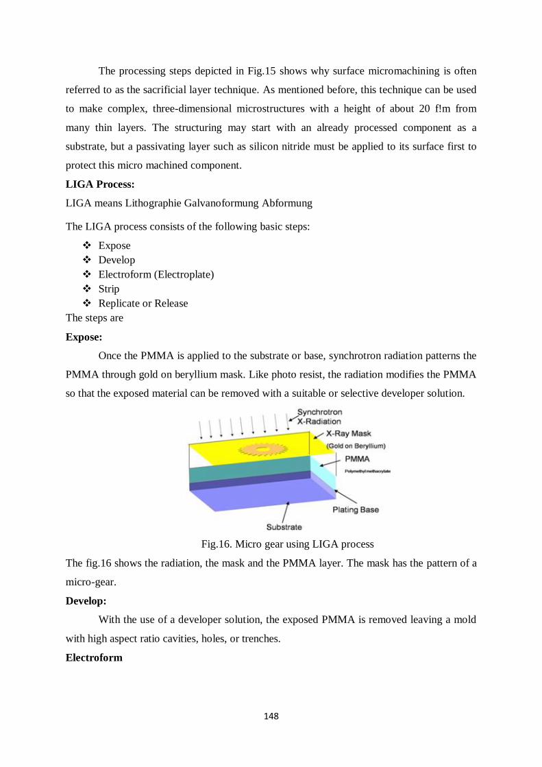
148
The processing steps depicted in Fig.15 shows why surface micromachining is often
referred to as the sacrificial layer technique. As mentioned before, this technique can be used
to make complex, three-dimensional microstructures with a height of about 20 f!m from
many thin layers. The structuring may start with an already processed component as a
substrate, but a passivating layer such as silicon nitride must be applied to its surface first to
protect this micro machined component.
LIGA Process:
LIGA means Lithographie Galvanoformung Abformung
The LIGA process consists of the following basic steps:
Expose
Develop
Electroform (Electroplate)
Strip
Replicate or Release
The steps are
Expose:
Once the PMMA is applied to the substrate or base, synchrotron radiation patterns the
PMMA through gold on beryllium mask. Like photo resist, the radiation modifies the PMMA
so that the exposed material can be removed with a suitable or selective developer solution.
Fig.16. Micro gear using LIGA process
The fig.16 shows the radiation, the mask and the PMMA layer. The mask has the pattern of a
micro-gear.
Develop:
With the use of a developer solution, the exposed PMMA is removed leaving a mold
with high aspect ratio cavities, holes, or trenches.
Electroform
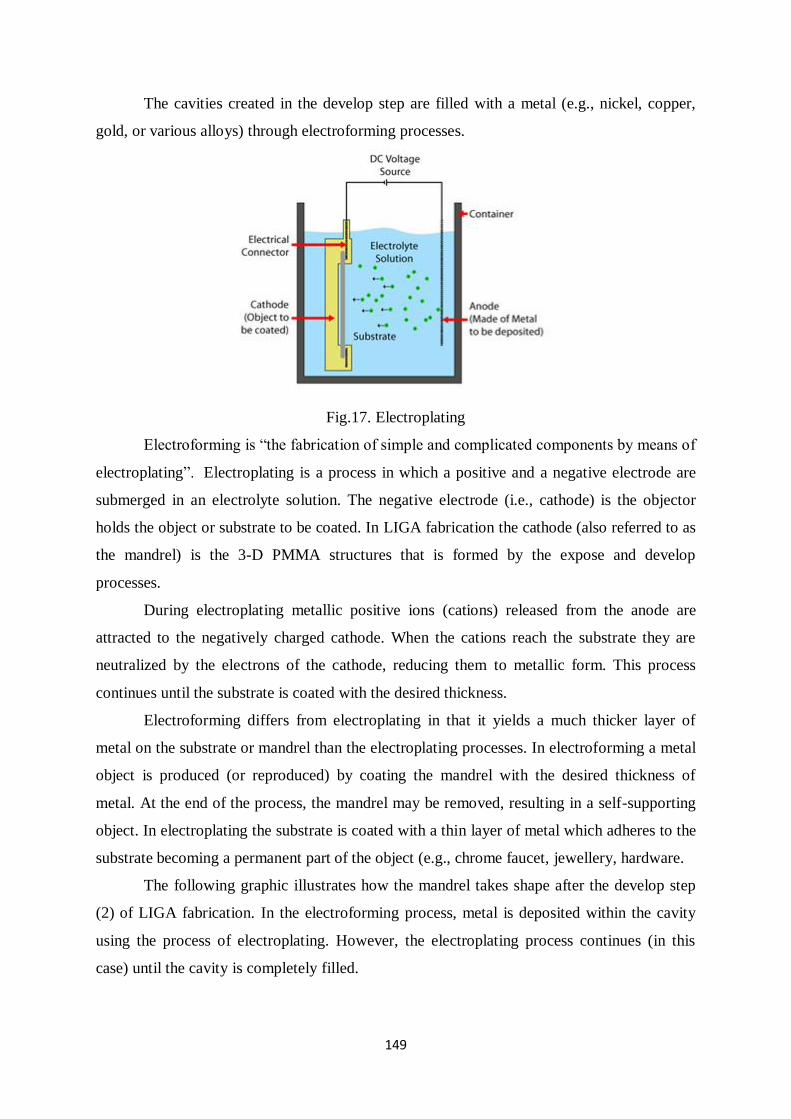
149
The cavities created in the develop step are filled with a metal (e.g., nickel, copper,
gold, or various alloys) through electroforming processes.
Fig.17. Electroplating
Electroforming is “the fabrication of simple and complicated components by means of
electroplating”. Electroplating is a process in which a positive and a negative electrode are
submerged in an electrolyte solution. The negative electrode (i.e., cathode) is the objector
holds the object or substrate to be coated. In LIGA fabrication the cathode (also referred to as
the mandrel) is the 3-D PMMA structures that is formed by the expose and develop
processes.
During electroplating metallic positive ions (cations) released from the anode are
attracted to the negatively charged cathode. When the cations reach the substrate they are
neutralized by the electrons of the cathode, reducing them to metallic form. This process
continues until the substrate is coated with the desired thickness.
Electroforming differs from electroplating in that it yields a much thicker layer of
metal on the substrate or mandrel than the electroplating processes. In electroforming a metal
object is produced (or reproduced) by coating the mandrel with the desired thickness of
metal. At the end of the process, the mandrel may be removed, resulting in a self-supporting
object. In electroplating the substrate is coated with a thin layer of metal which adheres to the
substrate becoming a permanent part of the object (e.g., chrome faucet, jewellery, hardware.
The following graphic illustrates how the mandrel takes shape after the develop step
(2) of LIGA fabrication. In the electroforming process, metal is deposited within the cavity
using the process of electroplating. However, the electroplating process continues (in this
case) until the cavity is completely filled.
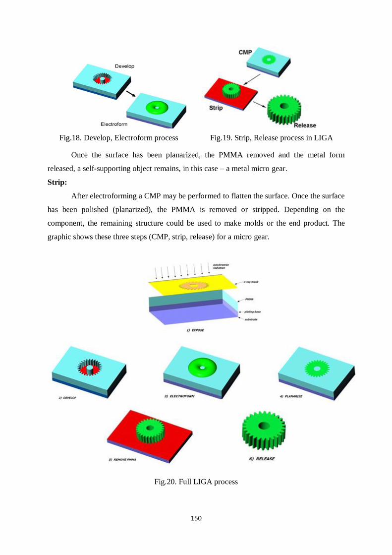
150
Fig.18. Develop, Electroform process Fig.19. Strip, Release process in LIGA
Once the surface has been planarized, the PMMA removed and the metal form
released, a self-supporting object remains, in this case – a metal micro gear.
Strip:
After electroforming a CMP may be performed to flatten the surface. Once the surface
has been polished (planarized), the PMMA is removed or stripped. Depending on the
component, the remaining structure could be used to make molds or the end product. The
graphic shows these three steps (CMP, strip, release) for a micro gear.
Fig.20. Full LIGA process
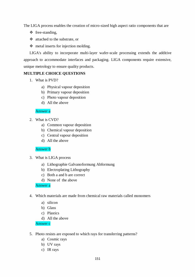
151
The LIGA process enables the creation of micro-sized high aspect ratio components that are
free-standing,
attached to the substrate, or
metal inserts for injection molding.
LIGA's ability to incorporate multi-layer wafer-scale processing extends the additive
approach to accommodate interfaces and packaging. LIGA components require extensive,
unique metrology to ensure quality products.
MULTIPLE CHOICE QUESTIONS
1. What is PVD?
a) Physical vapour deposition
b) Primary vapour deposition
c) Photo vapour deposition
d) All the above
Answer a
2. What is CVD?
a) Common vapour deposition
b) Chemical vapour deposition
c) Central vapour deposition
d) All the above
Answer b
3. What is LIGA process
a) Lithographie Galvanoformung Abformung
b) Electroplating Lithography
c) Both a and b are correct
d) None of the above
Answer a
4. Which materials are made from chemical raw materials called monomers
a) silicon
b) Glass
c) Plastics
d) All the above
Answer c
5. Photo resists are exposed to which rays for transferring patterns?
a) Cosmic rays
b) UV rays
c) IR rays
152
d) None of the above
Answer b
6. A deposition technique based on formation of vapour of a material either heated until
evaporation or sputtered by ions is called
a) PVD
b) CVD
c) PECVD
d) None
Answer a
7. Micro Fluidics system is used for
a) Drug screening
b) Breast Cancer diagnosis
c) Bacterial infection test
d) All the above
Answer d
8. Crucible and boats are the holders used for which type of vapour deposition method?
a) PVD
b) CVD
c) PECVD
d) None
Answer a
9. The process of dipping substrate into chemical solution that selectively removes
material is called
a) Wet etching
b) Dry etching
c) Gas etching
d) None
Answer a
10. Isotropic and Anisotropic are the types of ---------
a) Dry etching
b) Machining
c) Wet etching
d) All the above
Answer c
11. Piezo electric sensors can be fabricated using micro fabrication techniques. The
property of piezoelectric material is
153
a) To accumulate electric charge w.r.t the mechanical stress applied
b) To accumulate electric charge in response to the potential gradient
c) To accumulate electric charge when placed in magnetic field
d) To generate mechanical stress in electric field
Answers: a
12. Photolithography is an important step in micro fabrication, what do you understand by
“Lithography”?
a) Transferring pattern on a mask.
b) Transferring pattern on to a substrate.
c) Slicing wafer by LASER or by UV.
d) Deposition of any material on a substrate
Answers: b
13. ------- is the most abundant and easily available sensing material.
a) Gold
b) Silicon
c) Ceramics
d) All the above
Answer b
14. What is nano technology?
a) Technology conducted at micro scale
b) Technology conducted at pico scale
c) Technology conducted at nanoscale
d) None
Answer c
15. A micromachining defines structures by selectively etching inside a substrate is called
a) Bulk micromachining
b) Surface micromachining
c) LIGA process
d) All the above
Answer a
ASSIGNMENT
1. Explain in detail about the following materials used in sensors.
a) Silicon b) Metals c) Glasses
2. Explain in detail about the working principles of Vacuum deposition with diagram.

154
CONCLUSIONS
The basic principle of working of resistive, capacitive and inductive sensors and
transducers were discussed and its applications were elaborated in this material. In the third
unit Hydraulic, pneumatic and electric actuators were thoroughly mentioned. Miniaturized
sensors and actuators working principle and applications were seen.
Surface properties of the material can affect the efficiency and behaviour of the
material when in service. Modifying and tuning these surface properties to meet the specific
demand for better performance is feasible and has been vastly employed in a different aspect
of life. This can be achieved by coating the surface via deposition of the thin film. The fifth
unit of this study material provides a review of the existing physical vapour deposition
techniques used for surface modification and coating. The area of applications of surface
coating was briefly highlighted in this note. The sputtering and LIGA technique is discussed
and the comparison between evaporation techniques was explained.
Sensors and actuators are increasingly being used for many technical applications. A
sensor is a vital organ of an artificial system, forming the interface between the controller and
the environment. Sensors can smell, taste, see and feel by measuring mechanical,
biochemical, thermal, magnetic and radiation parameters. Actuators are mainly used in
medical and industrial purpose. Using MST technology, sensors and actuators are
manufactured in miniaturized size well suited for various applications. Micro sensors have
high reliability, low weight and volume, and low mass-production cost makes it suitable for
smart applications in enormous fields. The rapid development of micro sensors and micro
actuators will play a major role in the future world.
VIDEO LINKS
1. https://www.slideshare.net/saaz1425/dc-motor-23906628 DC Motor principles
2. https://www.electricaleasy.com/2014/01/basic-working-of-dc-motor.html Motor working
animation
3. https://www.youtube.com/watch?v=hmP5CSIendo Variable reluctance stepper motor
4. https://www.youtube.com/watch?v=uxXg1RxElY8 Thermal evaporation
5. https://www.youtube.com/watch?v=T2FXGL-d0sQ - E beam Evaporation
6. https://www.youtube.com/watch?v=O63R9qRglnY sputerring
155
REFERENCE BOOKS
1. Patranabis.D, Sensors and Transducers, Wheeler publisher, 1994.
2. Sergej Fatikow and Ulrich Rembold, “ Microsystem Technology and Macrobiotics”
First edition, Springer –Verlag NEwyork, Inc, 1997.
3. Jacob Fraden, “Hand Book of Modern Sensors: Physics, Designs and Application”
Fourth edition, Springer, 2010.
4. Robert H Bishop, “The Mechatronics Hand Book”, CRC Press, 2002.
5. Thomas. G. Bekwith and Lewis Buck.N, “Mechanical Measurements”, Oxford and
IBH publishing Co. Pvt. Ltd.,
6. Massood Tabib and Azar, “Microactuators Electrical, Magnetic, thermal, optical,
mechanical, chemical and smart structures”, First edition, Kluwer academic
publishers, Springer,1997.
7. Manfred Kohl, Shape Memory Actuators, first edition, Springer.
8. "Surface Engineering for Corrosion and Wear Resistance Application," Nptel Course
material.
QUESTION BANK
UNIT-I - SENSORS
PART-A
1. Differentiate sensors and transducers.
2. Distinguish between static and dynamic characteristics.
3. Give the factors responsible in selection of a sensor or actuator.
4. What is meant by repeatability?
5. Define Accuracy and Precision.
6. What is mean by smart transmitter?
7. Explain transmitter gain.
8. List the types of signals.
9. What is backlash?
10. Define gauge factor
11. List the applications of thermistors
12. Give the advantages and disadvantages of LVDT
13. What is RTD?
14. What is photo resistive sensor?
15. Explain the principle of resistance hygrometer
UNIT-II - INDUCTIVE & CAPACITIVE TRANSDUCER
PART-A
1. List any two inductive sensors.
2. Explain the principle of inductive transducers
156
3. Explain the principle of capacitive transducers
4. Give the application of synchros.
5. What are the types of proximity sensors?
6. Mention any four capacitive sensors.
7. Mention the applications of capacitive pressure sensor?
8. State the need of sensors in robotics.
9. Explain the principle of capacitive microphone.
10. Draw the diagram of LVDT
UNIT-III - ACTUATORS
PART-A
1. Define actuator.
2. Classify the types of actuators.
3. Define valve co-efficient.
4. Define stepper motor.
5. Explain the principle of Induction motor.
6. Mention the applications of Synchronous motor.
7. How a transistor can be operated as a solid state switch.
UNIT-IV - MICRO SENSORS AND MICRO ACTUATORS
PART-A
1. Define Microrobots.
2. What is inverse piezo effect?
3. What is micro sensor? Give an example.
4. Explain the principle of a piezo resistive pressure sensor
5. Why we need micro flow sensor?
6. Mention the application of bio sensor.
7. Define Shape memory effect.
UNIT-V - SENSOR MATERIALS AND PROCESSING TECHNIQUES
PART-A
1. What is the Nano particle? List any two uses of it.
2. Define sputtering.
3. List out the sensor materials.
4. What is LIGA process?
5. Give the application of vacuum deposition.
6. Define electroplating.
7. Explain the principle of photolithography.
157
PART B
UNIT-I - SENSORS
1. Discuss the following static characteristics: Accuracy, Precision, Resolution,
Sensitivity, backlash and Response time.
2. Write short notes on (i) Bellows (ii) Diaphragm
3. What are primary sensing elements? Explain the construction and working of
Bourdon tube with neat diagrams.
4. Explain in detail about the following
a) Pneumatic Signal (6)
b) Hydraulic Signal (5)
c) Electronic Signal (5)
5. Elaborate the working of Strain gauge with neat diagram.
6. What is RTD? What are its types? Explain its working with neat diagram.
7. Discuss the working of Hot wire Anemometer
8. Explain the working of Hygrometer.
9. What are Thermistors? Explain their different forms of construction. Draw their
resistivity versus temperature characteristics curve. Describe any one application with
neat circuit.
UNIT-II - INDUCTIVE & CAPACITIVE TRANSDUCER
PART-B
1. Explain the construction, principle of operation, circuit and applications of Variable
reluctance transducer with neat diagrams.
2. Describe the construction of LVDT and explain its principle of operation with the aid
of diagram, list the advantages, disadvantages and applications of LVDT.
3. Elaborate the working principle of proximity sensors with neat diagram in detail. List
its applications.
4. Write short notes on a) Microsyn (8)
b) Capacitor microphone (8)
5. Discuss the working principle, operation and applications of Capacitor pressure
sensor.
UNIT-III - ACTUATORS
PART-B
1. Explain the working principle and operation of piezoelectric actuators.
158
2. Explain the following:
a) Single and double acting cylinders (8)
b) Hydraulic Systems (8)
3. Explain the working principle and characteristics of DC Motor.
4. Discuss the Construction and characteristics of control valves used in Hydraulic
actuators.
5. Explain the working principle and characteristics of three phase Induction Motor.
6. What is stepper motor? Explain the working of full stepping, half stepping and micro
stepping of variable reluctance stepper motor with relevant diagrams.
UNIT-IV – MICRO SENSORS AND MICRO ACTUATORS
PART-B
1. Draw the schematic of micro pressure sensor and explain briefly.
2. Explain the working of Hydraulic piston micro actuator with relevant diagrams
3. Explain the working of Electrostatic micro pump with diagrams
4. Draw the schematic design of a micro biosensor and explain. Also draw the sensor
response curve and explain.
5. What is a shape memory alloy? Discuss one way and two way shape memory effect
with diagrams.
6. Describe the Motion Principle of Electrostatic Micro actuators. Explain the Working
principle of an electrostatic micro valve with neat diagram.
7. Discuss
UNIT V-SENSOR MATERIALS AND PROCESSING TECHNIQUES
PART-B
1. Elaborate the various steps involved in photolithography.
2. Explain in detail about the working principles of Vacuum deposition with diagram.
3. Describe sputtering technique for deposition of thin and thick films on sensing
surface.
4. Explain in detail about the following materials used in sensors.
b) Silicon b) Metals c) Glasses
5. Explain in detail about the LIGA process.
6. Describe about the Chemical vapour deposition with appropriate diagrams.
Related Documents