2017 Microchip Technology Inc. DS00002520B-page 1 AN2520 INTRODUCTION Current industry trends suggest that the Permanent Magnet Synchronous Motor (PMSM) is one of the most preferred motors by motor control application designers. Its strengths, such as high power density, fast dynamic response and high efficiency in comparison with other motors in its category, coupled with decreased manufacturing costs and improved magnetic properties, make the PMSM a good recommendation for large-scale product implementation. Microchip Technology Inc. produces a wide range of 16-bit and 32-bit microcontrollers (MCUs) for enabling efficient, robust and versatile control of all types of motors, along with reference designs of the necessary tool sets, resulting in a fast learning curve and a shortened development cycle for new products. Refer to “Architectural Highlights of 32-bit MCUs for Motor Control Applications” for additional information on 32-bit MCUs for Motor Control. FIELD ORIENTED CONTROL (FOC) In case of the PMSM, the rotor field speed must be equal to the stator (armature) field speed (i.e., synchronous). The loss of synchronization between the rotor and stator fields causes the motor to halt. Field Oriented Control (FOC) represents the method by which one of the fluxes (rotor, stator or air gap) is considered as a basis for creating a reference frame for one of the other fluxes with the purpose of decoupling the torque and flux-producing components of the stator current. The decoupling assures the ease of control for complex three-phase motors in the same manner as DC motors with separate excitation. This means the armature current is responsible for the torque generation, and the excitation current (for a PMSM motor, permanent magnet) is responsible for the flux generation. In this application note, the rotor flux is considered as a reference frame for the stator and air gap flux. Several application notes from Microchip explain the principles behind FOC. Two such examples are: AN1078 “Sensorless Field Oriented Control of PMSM Motors using dsPIC30F or dsPIC33F Digital Signal Controllers” and AN908 “Using the dsPIC30F for Vector Control of an ACIM” (see “References”). It is beyond the scope of this application note to explain the FOC details; however, the particulars of the new implementation will be covered with respect to the previously indicated application notes. The control scheme for FOC is presented in Figure 1. This scheme was implemented and tested using the dsPICDEM™ MCLV-2 Development Board (DM330021-2), which can drive a PMSM motor using different control techniques without requiring any additional hardware. The control scheme is similar to the one presented in application note AN1292 “Sensorless Field Oriented Control (FOC) for a Permanent Magnet Synchronous Motor (PMSM) Using a PLL Estimator and Field Weakening (FW)” (see “References”), except for the flux weakening. Sensorless Field Oriented Control (FOC) for a Permanent Magnet Synchronous Motor (PMSM) Using a PLL Estimator and Equation-based Flux Weakening (FW)

Welcome message from author
This document is posted to help you gain knowledge. Please leave a comment to let me know what you think about it! Share it to your friends and learn new things together.
Transcript
AN2520Sensorless Field Oriented Control (FOC) for a Permanent
Magnet Synchronous Motor (PMSM) Using a PLL Estimator and Equation-based Flux Weakening (FW)
INTRODUCTION
Current industry trends suggest that the PermanentMagnet Synchronous Motor (PMSM) is one of the mostpreferred motors by motor control applicationdesigners. Its strengths, such as high power density,fast dynamic response and high efficiency incomparison with other motors in its category, coupledwith decreased manufacturing costs and improvedmagnetic properties, make the PMSM a goodrecommendation for large-scale productimplementation.
Microchip Technology Inc. produces a wide range of16-bit and 32-bit microcontrollers (MCUs) for enablingefficient, robust and versatile control of all types ofmotors, along with reference designs of the necessarytool sets, resulting in a fast learning curve and ashortened development cycle for new products. Referto “Architectural Highlights of 32-bit MCUs forMotor Control Applications” for additionalinformation on 32-bit MCUs for Motor Control.
FIELD ORIENTED CONTROL (FOC)
In case of the PMSM, the rotor field speed must beequal to the stator (armature) field speed (i.e.,synchronous). The loss of synchronization between therotor and stator fields causes the motor to halt.
Field Oriented Control (FOC) represents the method bywhich one of the fluxes (rotor, stator or air gap) isconsidered as a basis for creating a reference frame forone of the other fluxes with the purpose of decouplingthe torque and flux-producing components of the statorcurrent. The decoupling assures the ease of control forcomplex three-phase motors in the same manner asDC motors with separate excitation. This means thearmature current is responsible for the torquegeneration, and the excitation current (for a PMSMmotor, permanent magnet) is responsible for the fluxgeneration. In this application note, the rotor flux isconsidered as a reference frame for the stator and airgap flux.
Several application notes from Microchip explain theprinciples behind FOC. Two such examples are:AN1078 “Sensorless Field Oriented Control of PMSMMotors using dsPIC30F or dsPIC33F Digital SignalControllers” and AN908 “Using the dsPIC30F forVector Control of an ACIM” (see “References”). It isbeyond the scope of this application note to explain theFOC details; however, the particulars of the newimplementation will be covered with respect to thepreviously indicated application notes.
The control scheme for FOC is presented in Figure 1.This scheme was implemented and tested using thedsPICDEM™ MCLV-2 Development Board(DM330021-2), which can drive a PMSM motor usingdifferent control techniques without requiring anyadditional hardware.
The control scheme is similar to the one presented inapplication note AN1292 “Sensorless Field OrientedControl (FOC) for a Permanent Magnet SynchronousMotor (PMSM) Using a PLL Estimator and FieldWeakening (FW)” (see “References”), except for theflux weakening.
2017 Microchip Technology Inc. DS00002520B-page 1

AN
2520
DS
00002520B
-page 2
2017 Microchip T
echnology Inc.
3-PhaseBridge
PMSM
Hardware
12
A
B
C
FIGURE 1: SENSORLESS FOC FOR PMSM BLOCK DIAGRAM
Hardware Blocks
1. Permanent Magnet Synchronous Motor.2. 3-Phase Bridge – rectifier, inverter and acquisition and protection circuitry.
software (run by the device).3. Clarke forward transform.4. Park forward and inverse transform.5. Angle and speed estimator.6. Proportional integral controller.7. Flux weakening.8. Space vector modulation.
d,q
A,B
d,q
Estimator
ref
Idref
PI PI
PIFluxWeakening
Vq
Vd
V
V
SVM
Angle Estimation
Speed Estimation
Software
-
-
-
estimmech
V
V
+
++
Iq
Id
3
4
5
6
7
8
Iqref
,
,
,

AN2520
The particularity of the FOC in the PMSM is that thestator’s d-axis current reference Idref (corresponding tothe armature reaction flux on d-axis) is set to zero. Therotor’s magnets produce the rotor flux linkage, PM,unlike ACIM, which needs a constant reference value,Idref, for the magnetizing current, thereby producing therotor flux linkage.
The air gap flux is equal to the sum of the rotor’s fluxlinkage, which is generated by the permanent magnetsplus the armature reaction flux linkage generated bythe stator current. For the constant torque mode inFOC, the d-axis air gap flux is solely equal to PM, andthe d-axis armature reaction flux is zero.
On the contrary, in constant power operation, the fluxgenerating component of the stator current, Id, is usedfor air gap flux weakening to achieve higher speed.
In sensorless control, where no position or speedsensors are needed, the challenge is to implement arobust speed estimator that is able to rejectperturbations, such as temperature, electromagneticnoise and so on. Sensorless control is usually requiredwhen applications are cost sensitive, where movingparts are not allowed, such as position sensors or whenthe motor is operated in an electrically hostileenvironment. However, requests for precision control,especially at low speeds, should not be considered acritical matter for the given application.
The position and speed estimation is based on themathematical model of the motor. Therefore, the closerthe model is to the real hardware, the better theestimator will perform. The PMSM mathematicalmodeling depends on its topology, differentiatingmainly two rotor types: surface-mounted and interiorpermanent magnet. Each type has its own advantagesand disadvantages with respect to the applicationneeds. The proposed control scheme has beendeveloped around a surface-mounted permanentmagnet synchronous motor, see Figure 2, which hasthe advantage of low torque ripple and lower price incomparison with other types of PMSMs. The air gapflux for the motor type considered is smooth so that thestator’s inductance value, Ld = Lq (non-salient PMSM),and the Back Electromotive Force (BEMF) issinusoidal.
The fact that the air gap is large (it includes the surfacemounted magnets, being placed between the statorteeth and the rotor core), implies a smaller inductancefor this kind of PMSM with respect to the other types ofmotors with the same dimension and nominal powervalues. These motor characteristics enable somesimplification of the mathematical model used in thespeed and position estimator, while at the same timeenabling the efficient use of FOC.
When using a surface PMSM, the FOC maximumtorque per ampere is obtained by keeping the motor’srotor flux linkage situated at 90 degrees behind thearmature generated flux linkage, see Figure 3.
FIGURE 2: SURFACE MOUNTED PM PMSM TRANSVERSAL SECTION
1 2
3
4
5
6
Motor’s Transversal Section
1. Rotor shaft
2. Rotor core
3. Armature (stator)
4. Armature slots with armature windings
5. Rotor’s permanent magnets
6. Air gap
2017 Microchip Technology Inc. DS00002520B-page 3
AN2520
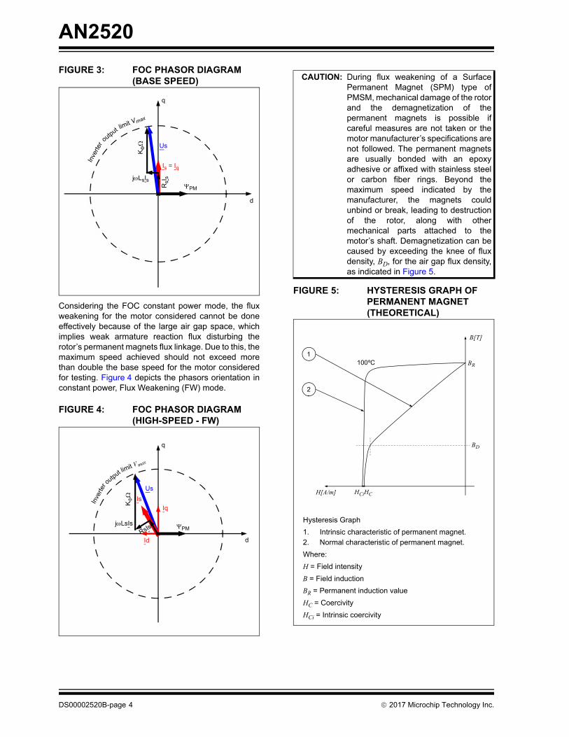
FIGURE 3: FOC PHASOR DIAGRAM (BASE SPEED)
Considering the FOC constant power mode, the fluxweakening for the motor considered cannot be doneeffectively because of the large air gap space, whichimplies weak armature reaction flux disturbing therotor’s permanent magnets flux linkage. Due to this, themaximum speed achieved should not exceed morethan double the base speed for the motor consideredfor testing. Figure 4 depicts the phasors orientation inconstant power, Flux Weakening (FW) mode.
FIGURE 4: FOC PHASOR DIAGRAM (HIGH-SPEED - FW)
FIGURE 5: HYSTERESIS GRAPH OF PERMANENT MAGNET (THEORETICAL)
Inve
rter
output limit Vmax
d
q
K
PM
Is = Iq
Us
RsI
sjLsIs
Inve
rter o
utput limit V max
d
q
K
PM
Is
Iq
Id
Us
jLsIs
RsIs
CAUTION: During flux weakening of a SurfacePermanent Magnet (SPM) type ofPMSM, mechanical damage of the rotorand the demagnetization of thepermanent magnets is possible ifcareful measures are not taken or themotor manufacturer’s specifications arenot followed. The permanent magnetsare usually bonded with an epoxyadhesive or affixed with stainless steelor carbon fiber rings. Beyond themaximum speed indicated by themanufacturer, the magnets couldunbind or break, leading to destructionof the rotor, along with othermechanical parts attached to themotor’s shaft. Demagnetization can becaused by exceeding the knee of fluxdensity, BD, for the air gap flux density,as indicated in Figure 5.
Hysteresis Graph
1. Intrinsic characteristic of permanent magnet.2. Normal characteristic of permanent magnet.
Where:
H = Field intensity
B = Field induction
BR = Permanent induction value
HC = Coercivity
HCi = Intrinsic coercivity
100ºC1
2
BD
H[A/m] HCiHC
BR
B[T]
DS00002520B-page 4 2017 Microchip Technology Inc.
AN2520
PLL TYPE ESTIMATOR
The estimator used in this application note is anadaptation of the one presented in AN1162“Sensorless Field Oriented Control (FOC) of an ACInduction Motor (ACIM)”, (see section References),but applied to PMSM motor particularities.
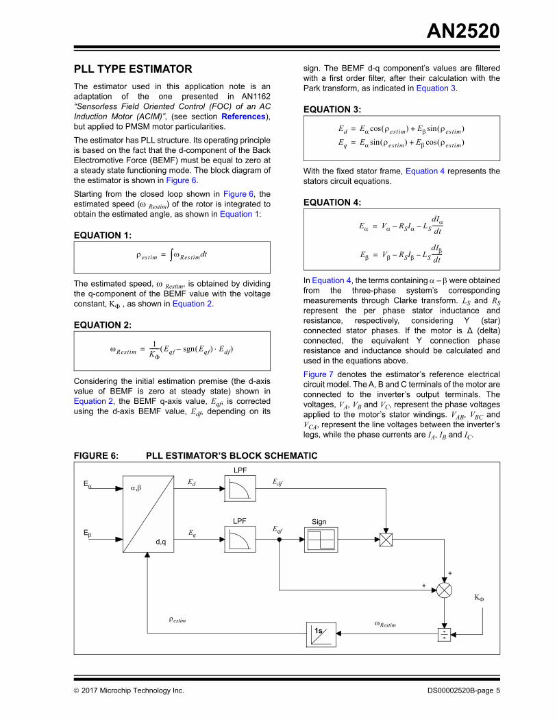
The estimator has PLL structure. Its operating principleis based on the fact that the d-component of the BackElectromotive Force (BEMF) must be equal to zero ata steady state functioning mode. The block diagram ofthe estimator is shown in Figure 6.
Starting from the closed loop shown in Figure 6, theestimated speed ( Restim) of the rotor is integrated toobtain the estimated angle, as shown in Equation 1:
EQUATION 1:
The estimated speed, Restim, is obtained by dividingthe q-component of the BEMF value with the voltageconstant, , as shown in Equation 2.
EQUATION 2:
Considering the initial estimation premise (the d-axisvalue of BEMF is zero at steady state) shown inEquation 2, the BEMF q-axis value, Eqf, is correctedusing the d-axis BEMF value, Edf, depending on its
sign. The BEMF d-q component’s values are filteredwith a first order filter, after their calculation with thePark transform, as indicated in Equation 3.
EQUATION 3:
With the fixed stator frame, Equation 4 represents thestators circuit equations.
EQUATION 4:
In Equation 4, the terms containing – were obtainedfrom the three-phase system’s correspondingmeasurements through Clarke transform. LS and RSrepresent the per phase stator inductance andresistance, respectively, considering Y (star)connected stator phases. If the motor is ∆ (delta)connected, the equivalent Y connection phaseresistance and inductance should be calculated andused in the equations above.
Figure 7 denotes the estimator’s reference electricalcircuit model. The A, B and C terminals of the motor areconnected to the inverter’s output terminals. Thevoltages, VA, VB and VC, represent the phase voltagesapplied to the motor’s stator windings. VAB, VBC andVCA, represent the line voltages between the inverter’slegs, while the phase currents are IA, IB and IC.
FIGURE 6: PLL ESTIMATOR’S BLOCK SCHEMATIC
estim Restim td=
Restim1
K------- Eqf Eqf sgn Edf– =
Ed E estim cos E estim sin+=
Eq E estim sin E estim cos+=
E V RSI LSdIdt--------––=
E V RSI LSdIdt--------––=
d,q
1s
E
E
Ed
Eq
Edf
Eqf
Restim
LPF
LPF Sign
+
+
estim
,
2017 Microchip Technology Inc. DS00002520B-page 5

AN2520
FIGURE 7: ELECTRICAL CIRCUIT MODEL FOR PLL ESTIMATOR
Taking one step forward concerning the equationsimplementation in the control system, the voltages Vand V, implied in estimator’s Equation 4 are aprevious cycle calculation of the FOC, being fed to theSpace Vector Modulation (SVM) block on the previousstep of control, but also to the estimator block currentstep. I and I are Clarke transform results from thephase currents, which are read every estimator cycle.
The resulting E and E values of BEMF are translatedto the rotating reference frame of the rotor flux throughthe Park transform resulting in Ed and Eq values, whichconform to Equation 3. The angle estim, used in Parktransformation is calculated on the previous executioncycle of the estimator. The d-q values of BEMF are thenfiltered using first order filters, entering the maincondition of the estimator, based on Ed being equalto ‘0’.
Equation 2 reflects the calculation of Restim, which isthe resulting electrical speed. The integrated electricalspeed provides the angle (estim) between the rotor fluxand the – fixed stator frame. In Equation 2, denotes the voltage constant as indicated in Table 1.The used in the electrical speed computation, isshown in Equation 5.
EQUATION 5:
The speed feedback is filtered using a first order filteridentical with the one used in the BEMF case. Thefilter’s generic form is shown in Equation 6:
EQUATION 6:
The DC type values at the filter’s output should be freeof noise from the ADC acquisition or high-frequencyvariations introduced by the software calculations. Thefilter’s tuning depends on how fast the filtered values(BEMF d-q components and electrical speed) can vary,allowing for sufficient bandwidth, which reduces thepossibility of useful signal loss. In the case of BEMF d-q components, two situations can be identified: (1) highspeed, in the Flux Weakening mode, where theirvariation is slow due to the lack of sudden torquechange or high acceleration ramp, and (2) low speed.The speed variation depends on the mechanicalconstant of the motor (and the load coupled on themotor’s shaft) and the slope of the ramp-up or ramp-down limits on the speed reference, whichever is faster.
RS
LSRS
RS
LS
LS
VAB
VBC
VCA
VA
VC
VB IA
IC
IB
MotorEstimParm.qInvKFi represents:
1K_Electrical---------------------------- 3 2 1000
60 K------------------ P =
Where:P = Number of pole pairs and the other inputs indicated
previously
Where:y(n) = Current cycle filter outputy(n – 1) = Previous cycle filter outputx(n) = Current cycle filter inputKfilter = Filter constant
y(n) = y(n – 1) + Kfilter · (x(n) – y(n – 1))
DS00002520B-page 6 2017 Microchip Technology Inc.

AN2520
TUNING AND EXPERIMENTAL RESULTS
The algorithm tuning is very straight forward for speedsbelow the base speed, where the maximum torquemode is applied. Basically, the motor’s parameters,measured or indicated by the manufacturer, are addedto the configuration file, mc_app.h.
The measurement of parameters comprises the rotor’sresistance, RS, and inductance, LS, and the voltageconstant, .
The stator resistance and inductance can be measuredat the motor’s terminals using a precision LCR meter.For Star connected motors: the stator phase resistance(RS) and inductance (LS) values are obtained bydividing the measured resistance and inductancevalues at the motor terminals by a factor of 2. For Deltaconnected motors, the stator phase resistance andinductance values are obtained by multiplying themeasured resistance and inductance values at themotor terminals by a factor 1.5.
Dividing the stator phase resistance and inductancevalues of a Delta connected motor by a factor of 3results in their Star connected motor equivalent phaseresistance (RS) and inductance (LS).
This voltage constant, , is indicated by all motormanufacturers; however, it can be measured using avery simple procedure, by rotating the rotor shaft with aconstant speed, while measuring the output voltage atthe motor’s terminals. If the reading is done at 1000RPM, the alternative voltage measure is a typical RMSvalue. Multiplying the reading value by the square rootof 2 will return the value in Vpeak/KRPM.
For the tested motor parameters, the data provided inTable 1 was measured with the procedures describedabove.
TABLE 1:
The two necessary phase currents are read on the twoshunts available on the dsPICDEM MCLV-2Development Board and their values are scaled to theacceptable input range of the ADC module. The overallcurrent scaling factor depends on the gain of thedifferential Op amp reading the shunt and themaximum value of the current passing through the
motor. For example, having a phase current of 4.4Apeak and a gain of 75, for a 0.005 Ohms shunt resistor,results in 3.3V present at the ADC input.
With respect to the initial calibration, the startup may bedone with load, in which case the open loop rampparameters need to be tuned.
The open loop tuning parameters include the lock time,the end acceleration speed, and the current referencevalue. The lock time represents the time necessary forrotor alignment, which depends on the load initialtorque and moment of inertia (the larger they are, thelarger the lock time value). The end speed of the initialramp in RPM should be set sufficiently high for theestimator’s calculated BEMF to have enough precision,while the time to reach that speed depends on the openloop q-axis current and resistant load attached on themotor’s shaft; the larger the load, the longer the timeneeded for reaching the end reference speed.
The open loop is implemented as a simplification of theclosed loop control, where the estimated anglebetween the rotor flux and the fixed reference frame isreplaced by the forced angle used in open loop speed-up. The forced angle does not care about the rotor'sposition, but rather imposing its position, beingcalculated as a continuous increment fraction. Anadditional simplification from the control loop presentedin Figure 1, is the lack of the speed controller and thecurrent reference for the q-axis being hard-coded.
The q-axis current reference is responsible for thecurrent forced through the motor in the open loop ramp-up; the higher the initial load, the higher the currentneeded, which acts as a torque reference overall.
To keep the algorithm functioning in open loop, thusdisabling the closed loop transition for initial tuningpurposes, enable the specific code macro definition, asshown in Example 1.
EXAMPLE 1:
This is particularly useful for the potential PI controller’srecalibration or even some initial transition conditionsverifications (such as angle error between the imposedangle and the estimated one, current scaling constantexperimental determination), and initial open loop rampup parameters fine tuning, previous to the closed loopactivation.
Motor TypeHurst Motor
DMB00224C10002Units
Connection type Y —
L-L Resistance 2.1 · 2 Ohms
L-L Inductance – 1 kHz 1.92 · 2 mH
Voltage constant 7.24 Vpeak/KRPM
Ambient temperature 22.7 ºC
#define OPEN_LOOP_FUNCTIONING
2017 Microchip Technology Inc. DS00002520B-page 7
AN2520
EQUATION-BASED FLUX WEAKENING
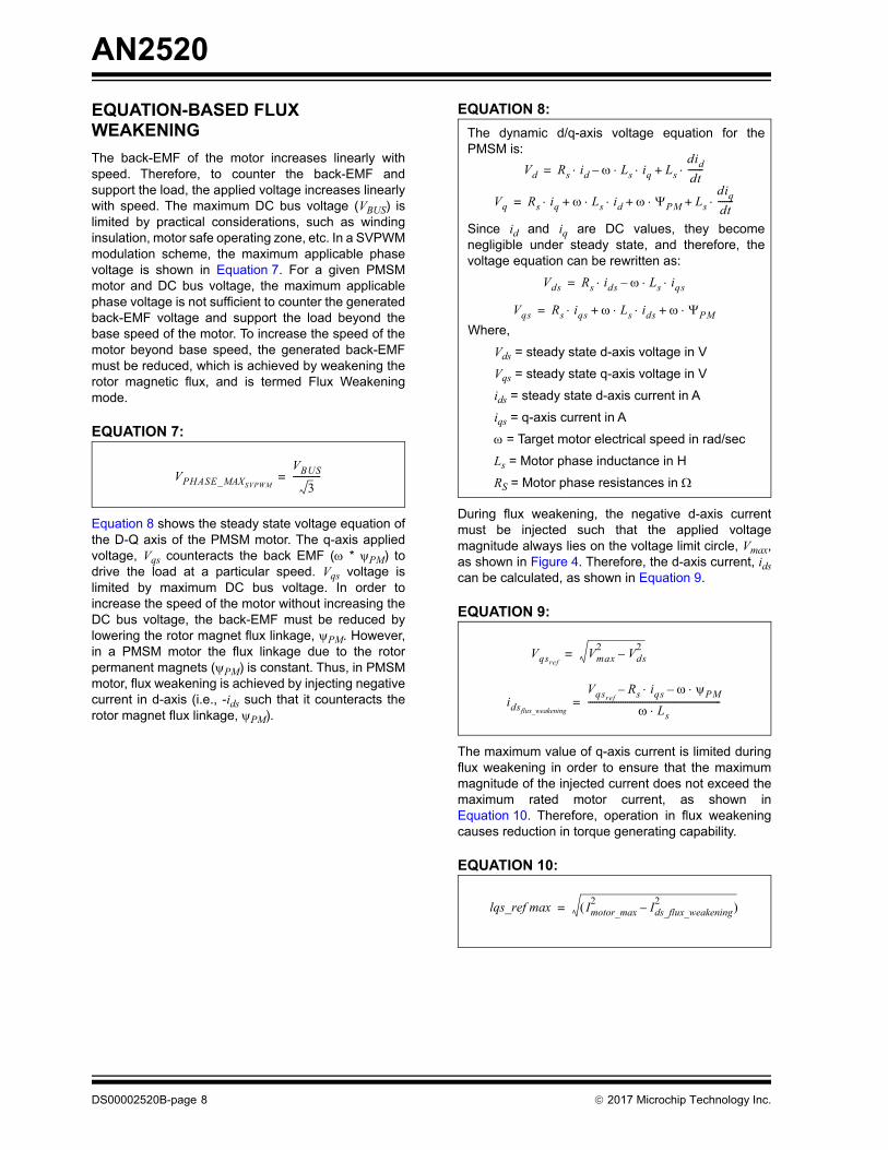
The back-EMF of the motor increases linearly withspeed. Therefore, to counter the back-EMF andsupport the load, the applied voltage increases linearlywith speed. The maximum DC bus voltage (VBUS) islimited by practical considerations, such as windinginsulation, motor safe operating zone, etc. In a SVPWMmodulation scheme, the maximum applicable phasevoltage is shown in Equation 7. For a given PMSMmotor and DC bus voltage, the maximum applicablephase voltage is not sufficient to counter the generatedback-EMF voltage and support the load beyond thebase speed of the motor. To increase the speed of themotor beyond base speed, the generated back-EMFmust be reduced, which is achieved by weakening therotor magnetic flux, and is termed Flux Weakeningmode.
EQUATION 7:
Equation 8 shows the steady state voltage equation ofthe D-Q axis of the PMSM motor. The q-axis appliedvoltage, Vqs counteracts the back EMF ( * PM) todrive the load at a particular speed. Vqs voltage islimited by maximum DC bus voltage. In order toincrease the speed of the motor without increasing theDC bus voltage, the back-EMF must be reduced bylowering the rotor magnet flux linkage, PM. However,in a PMSM motor the flux linkage due to the rotorpermanent magnets (PM) is constant. Thus, in PMSMmotor, flux weakening is achieved by injecting negativecurrent in d-axis (i.e., -ids such that it counteracts therotor magnet flux linkage, PM).
EQUATION 8:
During flux weakening, the negative d-axis currentmust be injected such that the applied voltagemagnitude always lies on the voltage limit circle, Vmax,as shown in Figure 4. Therefore, the d-axis current, idscan be calculated, as shown in Equation 9.
EQUATION 9:
The maximum value of q-axis current is limited duringflux weakening in order to ensure that the maximummagnitude of the injected current does not exceed themaximum rated motor current, as shown inEquation 10. Therefore, operation in flux weakeningcauses reduction in torque generating capability.
EQUATION 10:
VPHASE_MAXSVPWM
VBUS
3-------------=
Vds Rs ids Ls iqs –=
Vqs Rs iqs Ls ids PM+ +=
Where,
Vds = steady state d-axis voltage in V
Vqs = steady state q-axis voltage in V
ids = steady state d-axis current in A
iqs = q-axis current in A
= Target motor electrical speed in rad/sec
Ls = Motor phase inductance in H
RS = Motor phase resistances in
The dynamic d/q-axis voltage equation for thePMSM is:
Since id and iq are DC values, they becomenegligible under steady state, and therefore, thevoltage equation can be rewritten as:
Vd Rs id Ls iq Lsdiddt-------+ –=
Vq Rs iq Ls id PM Lsdiqdt-------++ +=
VqsrefVmax2 Vds
2–=
idsflux_weakening
VqsrefRs iqs– PM–
Ls-------------------------------------------------------------=
lqs_ref max Imotor_max2 Ids_flux_weakening
2– =
DS00002520B-page 8 2017 Microchip Technology Inc.
AN2520
The PLL-based rotor speed estimator uses back-EMF,BEMF = * K, to estimate the rotor speed. Whileoperating below the base speed, the back-EMF linearlyincreases with speed, and therefore, the 1/K isconstant and is derived from the motor’s back-EMFconstant, as shown in Equation 5. However, during fluxweakening, the back-EMF is maintained constant bycounteracting rotor magnet flux linkage using negatived-axis current injection. Thus, maintaining constantback-EMF above the base speed would result in avariation in 1/K, which is shown in Equation 11. Thevariation in 1/K becomes more significant for highinductance motors or during deep field weakening (i.e.,high negative d-axis current). Ls ids (expressed in V-sec) is divided by 2 to match with the units ofK_Electrical (expressed in V-sec/rad).
EQUATION 11:
Another concern during the Flux Weakening mode isvoltage limitation of the inverter. This voltage limitationis translated to the maximum achievable values for d-qcurrent components. If both components would havefollowed their reference values, their resulting scalarsummation value would overlap the maximum value of‘1’. Therefore, the maximum current permitted for q-component of the current (the torque component of thecurrent) will result from prioritizing the d-component ofthe current responsible flux weakening, which is moreimportant due to air gap flux weakening purposes.Figure 8 presents this dynamic adjustment translatedto the d-q component of the voltages (d-component ofvoltage prioritizing).
Because estimator performance depends drasticallyon the parameters of the motor, the experimentalresults keep this premise for the conditions of the
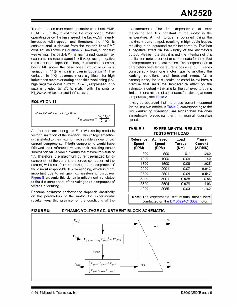
measurements. The first dependence of rotorresistance and flux constant of the motor is thetemperature. A high torque is obtained using themaximum current input, resulting in high Joule losses,resulting in an increased motor temperature. This hasa negative effect on the validity of the estimator’soutput. Please note that it is not the intention of thisapplication note to correct or compensate for the effectof temperature on the estimation. The compensation ofparameters with temperature is possible, but it variesconsiderably from one motor type to another, theworking conditions and functional mode. As aconsequence, the test results indicated below have apremise that limits the temperature effect on theestimator’s output – the time for the achieved torque islimited to one minute of continuous functioning at roomtemperature, see Table 2.
It may be observed that the phase current measuredfor the last two entries in Table 2, corresponding to theflux weakening operation, are higher than the onesimmediately preceding them, in normal operationspeed.
TABLE 2: EXPERIMENTAL RESULTS TESTS WITH LOAD
FIGURE 8: DYNAMIC VOLTAGE ADJUSTMENT BLOCK SCHEMATIC
MotorEstimParm.InvKFI_FW 1
K_ElectricalLs ids2 ---------------- +
--------------------------------------------------------=
Reference Speed (RPM)
Achieved Speed (RPM)
Load Torque (Nm)
Phase Current (A RMS)
500 500 0.1 1.280
1000 1000 0.09 1.140
1500 1500 0.08 1.035
2000 2001 0.07 0.943
2500 2501 0.04 0.542
3000 3001 0.025 0.56
3500 3504 0.029 1.06
4000 3985 0.03 1.462
Note: The experimental test results shown wereconducted on the DMB0224C10002 motor.
Vdref
Vmax
Vqref d,q
,
V
V
Vqmax
Vqmax Vmax2 V 2dref–=
Vqmax,Vqmax < Vqref
Vqref,Vqmax > Vqref
2017 Microchip Technology Inc. DS00002520B-page 9

AN2520
ARCHITECTURAL HIGHLIGHTS OF 32-BIT MCUS FOR MOTOR CONTROL APPLICATIONS
SAME70 Family
CPU
• 32-bit ARM® Cortex®-M7 Core - 300 MHz (2.14 DMIPS/MHz)
• DSP instruction support (2x DSP performance of Cortex-M4)
• Double-precision Floating Point Unit (FPU) - IEEE 754 Compliant
• Tightly Coupled Memory (TCM) - High-speed, Low latency, and deterministic access for time-critical code and data
ANALOG FEATURES
• Two dedicated 12-bit ADC modules with dual Sample and Hold (S&H) (i.e., capable of simultaneous sampling of four channels)
• One on-chip Analog Comparator
• Two on-chip DAC modules
PWM
• Up to eight PWM channels capable of generating complimentary PWM with dead-time in Edge/Center-Aligned modes
• Two 2-bit gray up/down channels for stepper motor control
• Independent output override for each channel - useful for Trapezoidal control
• Two independent programmable events lines capable of generating precise and synchronized ADC triggers without any software intervention
• Asynchronous Fault inputs allow fast response PWM shutdown under Fault condition without any software intervention
• Spread Spectrum Counter - reduces acoustic noise/electromagnetic interference of a PWM-driven motor
POSITION SENSING
On-chip Quadrature Decoder (QDEC) - input linesfiltering, decoding, timer/counters to read rotorposition and speed
PIC32MK Family
CPU
• 32-bit MIPS32® microAptiv™ MCU core - 120 MHz (198 DMIPS)
• DSP-enhanced core
• Double-precision Floating Point Unit (FPU) - IEEE 754 Compliant
ANALOG FEATURES
• Up to six dedicated 12-bit ADC channels plus one shared 12-bit ADC channel
• Up to four on-chip Op amp modules
• Up to five on-chip Analog Comparator modules
• Up to three on-chip DAC modules
PWM
• Up to 12 PWM pairs capable of generating complimentary PWM with dead-time in Edge-Aligned and symmetric/asymmetric Center-Aligned modes
• PWM channels capable of generating precise and synchronized ADC triggers without any software intervention
• Asynchronous Fault inputs allows fast response PWM shutdown under Fault condition without any software intervention
POSITION SENSING
On-chip QEI interfaces with incremental encoders toobtain rotor mechanical position
DS00002520B-page 10 2017 Microchip Technology Inc.

AN2520
CONCLUSION
This application note describes a method of flux angleand speed estimation for Permanent MagnetSynchronous Motors (PMSM). This application notefurther describes the equation-based closed loop fluxweakening.
The main theoretical ideas behind the estimator,equation-based closed loop flux weakening, and thetuning directions are also discussed. The applicationdescribed in this document uses support files for theease of adapting it to other motors. Additionally, usingthe indicated development hardware platform offeredby Microchip for your application can significantlyshorten time-to-market.
REFERENCES
“Speed Estimators, Flux Weakening and Efficient Useof SPMSM and IPMSM” - Prasad Kulkarni, 20089MC7, Microchip MASTERs Conference 2016
The following application notes, which are referencedin this document, are available for download from theMicrochip Web site (www.microchip.com):
• AN1292 “Sensorless Field Oriented Control (FOC) for a Permanent Magnet Synchronous Motor (PMSM) Using a PLL Estimator and Field Weakening (FW)”
• AN908 “Using the dsPIC30F for Vector Control of an ACIM”
• AN1078 “Sensorless Field Oriented Control of PMSM Motors using dsPIC30F or dsPIC33F Digital Signal Controllers”
• AN1162 “Sensorless Field Oriented Control (FOC) of an AC Induction Motor (ACIM)”
2017 Microchip Technology Inc. DS00002520B-page 11

AN2520
APPENDIX A: SOURCE CODE
All of the software covered in this application note isavailable as a MPLAB Harmony application. This appli-cation can be found with the <install-dir>\apps\motor_control folder of your MPLABHarmony installation. The MPLAB Harmony IntegratedSoftware framework can be downloaded from:
www.microchip.com/mplab/mplab-harmony.
Software License Agreement
The software supplied herewith by Microchip Technology Incorporated (the “Company”) is intended and supplied to you, theCompany’s customer, for use solely and exclusively with products manufactured by the Company.The software is owned by the Company and/or its supplier, and is protected under applicable copyright laws. All rights are reserved.Any use in violation of the foregoing restrictions may subject the user to criminal sanctions under applicable laws, as well as to civilliability for the breach of the terms and conditions of this license.THIS SOFTWARE IS PROVIDED IN AN “AS IS” CONDITION. NO WARRANTIES, WHETHER EXPRESS, IMPLIED ORSTATUTORY, INCLUDING, BUT NOT LIMITED TO, IMPLIED WARRANTIES OF MERCHANTABILITY AND FITNESS FOR APARTICULAR PURPOSE APPLY TO THIS SOFTWARE. THE COMPANY SHALL NOT, IN ANY CIRCUMSTANCES, BE LIABLEFOR SPECIAL, INCIDENTAL OR CONSEQUENTIAL DAMAGES, FOR ANY REASON WHATSOEVER.
DS00002520B-page 12 2017 Microchip Technology Inc.

AN2520
APPENDIX B: REVISION HISTORY
Revision A (August 2017)
This is the initial released version of this document.
Revision B (September 2017)
This revision includes the following updates:
• The application note reference on the first page was changed to AN1292 “Sensorless Field Oriented Control (FOC) for a Permanent Magnet Synchronous Motor (PMSM) Using a PLL Estimator and Field Weakening (FW)”
• TABLE 2: “EXPERIMENTAL RESULTS TESTS WITH LOAD” was updated
• In addition, minor updates to text were implemented on page 3
2017 Microchip Technology Inc. DS00002520B-page 13

AN2520
NOTES:
DS00002520B-page 14 2017 Microchip Technology Inc.
Note the following details of the code protection feature on Microchip devices:
• Microchip products meet the specification contained in their particular Microchip Data Sheet.
• Microchip believes that its family of products is one of the most secure families of its kind on the market today, when used in the intended manner and under normal conditions.
• There are dishonest and possibly illegal methods used to breach the code protection feature. All of these methods, to our knowledge, require using the Microchip products in a manner outside the operating specifications contained in Microchip’s Data Sheets. Most likely, the person doing so is engaged in theft of intellectual property.
• Microchip is willing to work with the customer who is concerned about the integrity of their code.
• Neither Microchip nor any other semiconductor manufacturer can guarantee the security of their code. Code protection does not mean that we are guaranteeing the product as “unbreakable.”
Code protection is constantly evolving. We at Microchip are committed to continuously improving the code protection features of ourproducts. Attempts to break Microchip’s code protection feature may be a violation of the Digital Millennium Copyright Act. If such actsallow unauthorized access to your software or other copyrighted work, you may have a right to sue for relief under that Act.
Information contained in this publication regarding deviceapplications and the like is provided only for your convenienceand may be superseded by updates. It is your responsibility toensure that your application meets with your specifications.MICROCHIP MAKES NO REPRESENTATIONS ORWARRANTIES OF ANY KIND WHETHER EXPRESS ORIMPLIED, WRITTEN OR ORAL, STATUTORY OROTHERWISE, RELATED TO THE INFORMATION,INCLUDING BUT NOT LIMITED TO ITS CONDITION,QUALITY, PERFORMANCE, MERCHANTABILITY ORFITNESS FOR PURPOSE. Microchip disclaims all liabilityarising from this information and its use. Use of Microchipdevices in life support and/or safety applications is entirely atthe buyer’s risk, and the buyer agrees to defend, indemnify andhold harmless Microchip from any and all damages, claims,suits, or expenses resulting from such use. No licenses areconveyed, implicitly or otherwise, under any Microchipintellectual property rights unless otherwise stated.
2017 Microchip Technology Inc.
Microchip received ISO/TS-16949:2009 certification for its worldwide headquarters, design and wafer fabrication facilities in Chandler and Tempe, Arizona; Gresham, Oregon and design centers in California and India. The Company’s quality system processes and procedures are for its PIC® MCUs and dsPIC® DSCs, KEELOQ® code hopping devices, Serial EEPROMs, microperipherals, nonvolatile memory and analog products. In addition, Microchip’s quality system for the design and manufacture of development systems is ISO 9001:2000 certified.
QUALITYMANAGEMENTSYSTEMCERTIFIEDBYDNV
== ISO/TS16949==
Trademarks
The Microchip name and logo, the Microchip logo, AnyRate, AVR, AVR logo, AVR Freaks, BeaconThings, BitCloud, CryptoMemory, CryptoRF, dsPIC, FlashFlex, flexPWR, Heldo, JukeBlox, KEELOQ, KEELOQ logo, Kleer, LANCheck, LINK MD, maXStylus, maXTouch, MediaLB, megaAVR, MOST, MOST logo, MPLAB, OptoLyzer, PIC, picoPower, PICSTART, PIC32 logo, Prochip Designer, QTouch, RightTouch, SAM-BA, SpyNIC, SST, SST Logo, SuperFlash, tinyAVR, UNI/O, and XMEGA are registered trademarks of Microchip Technology Incorporated in the U.S.A. and other countries.
ClockWorks, The Embedded Control Solutions Company, EtherSynch, Hyper Speed Control, HyperLight Load, IntelliMOS, mTouch, Precision Edge, and Quiet-Wire are registered trademarks of Microchip Technology Incorporated in the U.S.A.
Adjacent Key Suppression, AKS, Analog-for-the-Digital Age, Any Capacitor, AnyIn, AnyOut, BodyCom, chipKIT, chipKIT logo, CodeGuard, CryptoAuthentication, CryptoCompanion, CryptoController, dsPICDEM, dsPICDEM.net, Dynamic Average Matching, DAM, ECAN, EtherGREEN, In-Circuit Serial Programming, ICSP, Inter-Chip Connectivity, JitterBlocker, KleerNet, KleerNet logo, Mindi, MiWi, motorBench, MPASM, MPF, MPLAB Certified logo, MPLIB, MPLINK, MultiTRAK, NetDetach, Omniscient Code Generation, PICDEM, PICDEM.net, PICkit, PICtail, PureSilicon, QMatrix, RightTouch logo, REAL ICE, Ripple Blocker, SAM-ICE, Serial Quad I/O, SMART-I.S., SQI, SuperSwitcher, SuperSwitcher II, Total Endurance, TSHARC, USBCheck, VariSense, ViewSpan, WiperLock, Wireless DNA, and ZENA are trademarks of Microchip Technology Incorporated in the U.S.A. and other countries.
SQTP is a service mark of Microchip Technology Incorporated in the U.S.A.
Silicon Storage Technology is a registered trademark of Microchip Technology Inc. in other countries.
GestIC is a registered trademark of Microchip Technology Germany II GmbH & Co. KG, a subsidiary of Microchip Technology Inc., in other countries.
All other trademarks mentioned herein are property of their respective companies.
© 2017, Microchip Technology Incorporated, All Rights Reserved.
ISBN: 978-1-5224-2177-1
DS00002520B-page 15

DS00002520B-page 16 2017 Microchip Technology Inc.
AMERICASCorporate Office2355 West Chandler Blvd.Chandler, AZ 85224-6199Tel: 480-792-7200 Fax: 480-792-7277Technical Support: http://www.microchip.com/supportWeb Address: www.microchip.com
AtlantaDuluth, GA Tel: 678-957-9614 Fax: 678-957-1455
Austin, TXTel: 512-257-3370
BostonWestborough, MA Tel: 774-760-0087 Fax: 774-760-0088
ChicagoItasca, IL Tel: 630-285-0071 Fax: 630-285-0075
DallasAddison, TX Tel: 972-818-7423 Fax: 972-818-2924
DetroitNovi, MI Tel: 248-848-4000
Houston, TX Tel: 281-894-5983
IndianapolisNoblesville, IN Tel: 317-773-8323Fax: 317-773-5453Tel: 317-536-2380
Los AngelesMission Viejo, CA Tel: 949-462-9523Fax: 949-462-9608Tel: 951-273-7800
Raleigh, NC Tel: 919-844-7510
New York, NY Tel: 631-435-6000
San Jose, CA Tel: 408-735-9110Tel: 408-436-4270
Canada - TorontoTel: 905-695-1980 Fax: 905-695-2078
ASIA/PACIFICAsia Pacific OfficeSuites 3707-14, 37th FloorTower 6, The GatewayHarbour City, Kowloon
Hong KongTel: 852-2943-5100Fax: 852-2401-3431
Australia - SydneyTel: 61-2-9868-6733Fax: 61-2-9868-6755
China - BeijingTel: 86-10-8569-7000 Fax: 86-10-8528-2104
China - ChengduTel: 86-28-8665-5511Fax: 86-28-8665-7889
China - ChongqingTel: 86-23-8980-9588Fax: 86-23-8980-9500
China - DongguanTel: 86-769-8702-9880
China - GuangzhouTel: 86-20-8755-8029
China - HangzhouTel: 86-571-8792-8115 Fax: 86-571-8792-8116
China - Hong Kong SARTel: 852-2943-5100 Fax: 852-2401-3431
China - NanjingTel: 86-25-8473-2460Fax: 86-25-8473-2470
China - QingdaoTel: 86-532-8502-7355Fax: 86-532-8502-7205
China - ShanghaiTel: 86-21-3326-8000 Fax: 86-21-3326-8021
China - ShenyangTel: 86-24-2334-2829Fax: 86-24-2334-2393
China - ShenzhenTel: 86-755-8864-2200 Fax: 86-755-8203-1760
China - WuhanTel: 86-27-5980-5300Fax: 86-27-5980-5118
China - XianTel: 86-29-8833-7252Fax: 86-29-8833-7256
ASIA/PACIFICChina - XiamenTel: 86-592-2388138 Fax: 86-592-2388130
China - ZhuhaiTel: 86-756-3210040 Fax: 86-756-3210049
India - BangaloreTel: 91-80-3090-4444 Fax: 91-80-3090-4123
India - New DelhiTel: 91-11-4160-8631Fax: 91-11-4160-8632
India - PuneTel: 91-20-3019-1500
Japan - OsakaTel: 81-6-6152-7160 Fax: 81-6-6152-9310
Japan - TokyoTel: 81-3-6880- 3770 Fax: 81-3-6880-3771
Korea - DaeguTel: 82-53-744-4301Fax: 82-53-744-4302
Korea - SeoulTel: 82-2-554-7200Fax: 82-2-558-5932 or 82-2-558-5934
Malaysia - Kuala LumpurTel: 60-3-6201-9857Fax: 60-3-6201-9859
Malaysia - PenangTel: 60-4-227-8870Fax: 60-4-227-4068
Philippines - ManilaTel: 63-2-634-9065Fax: 63-2-634-9069
SingaporeTel: 65-6334-8870Fax: 65-6334-8850
Taiwan - Hsin ChuTel: 886-3-5778-366Fax: 886-3-5770-955
Taiwan - KaohsiungTel: 886-7-213-7830
Taiwan - TaipeiTel: 886-2-2508-8600 Fax: 886-2-2508-0102
Thailand - BangkokTel: 66-2-694-1351Fax: 66-2-694-1350
EUROPEAustria - WelsTel: 43-7242-2244-39Fax: 43-7242-2244-393
Denmark - CopenhagenTel: 45-4450-2828 Fax: 45-4485-2829
Finland - EspooTel: 358-9-4520-820
France - ParisTel: 33-1-69-53-63-20 Fax: 33-1-69-30-90-79
France - Saint CloudTel: 33-1-30-60-70-00
Germany - GarchingTel: 49-8931-9700Germany - HaanTel: 49-2129-3766400
Germany - HeilbronnTel: 49-7131-67-3636
Germany - KarlsruheTel: 49-721-625370
Germany - MunichTel: 49-89-627-144-0 Fax: 49-89-627-144-44
Germany - RosenheimTel: 49-8031-354-560
Israel - Ra’anana Tel: 972-9-744-7705
Italy - Milan Tel: 39-0331-742611 Fax: 39-0331-466781
Italy - PadovaTel: 39-049-7625286
Netherlands - DrunenTel: 31-416-690399 Fax: 31-416-690340
Norway - TrondheimTel: 47-7289-7561
Poland - WarsawTel: 48-22-3325737
Romania - BucharestTel: 40-21-407-87-50
Spain - MadridTel: 34-91-708-08-90Fax: 34-91-708-08-91
Sweden - GothenbergTel: 46-31-704-60-40
Sweden - StockholmTel: 46-8-5090-4654
UK - WokinghamTel: 44-118-921-5800Fax: 44-118-921-5820
Worldwide Sales and Service
11/07/16
Related Documents