ni.com Sensor Measurement Fundamentals Series

Welcome message from author
This document is posted to help you gain knowledge. Please leave a comment to let me know what you think about it! Share it to your friends and learn new things together.
Transcript

ni.com
Sensor Measurement Fundamentals Series

ni.com
How to Build Better Test Systems for Load,
Pressure, and Torque
Aaron Ortbals
Product Manager
National Instruments

ni.com
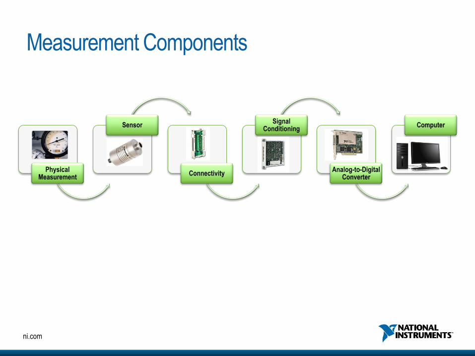
Physical Measurement
Sensor
Connectivity
Signal Conditioning
Analog-to-Digital Converter
Computer
Measurement Components
ni.com
Physical Measurement
Sensor
Connectivity
Signal Conditioning
Analog-to-Digital Converter
Computer
Measurement Components

ni.com
Wheatstone Bridge
DBout VVV
+ increased resistance = increased output
- Decreased resistance = increased output
Vin
Vout
Ohms
Gage Factor (K)
Resistance of a Conductor
Strain-Gage Energy Transformation
where: = Resistance change= Gage Resistance= Strain
K =
R
R
L
L
G
R
R
G
R = L
A
where: R
LA
= Resistance= Resistivity= Length= Area (x Section)
• The gage resistance changes as strain is induced.
• Gage factor is the ratio of resistance change to strain change. A specific DR in the gage =
specific DL on the base material.
RFRR
R
L
LR
R
FFactorGage
_
R
R
L
LStrain

ni.com
Understanding Pressure Sensors • Pressure is defined as force per unit area
• All pressure sensors use a force-summing device to convert the pressure into a stress or displacement
proportional to the pressure
• The stress or displacement is then applied to an electrical transduction element to generate the required
signal
• The examples below are generally related to silicon piezo resistive pressure
RB+∆R
RB+∆R RB-∆R
RB-∆R
Pressure
(force/area) Deformation of Sense
Element
Change in
Electrical
Properties
Change in
Output
Examples…

ni.com
Piezoresistive Pressure Sensors • In piezoresistive pressure sensors, the transduction elements that convert the stress from the diaphragm
deflection into an electrical signal are piezoresistors
• Piezoresistance = changing electrical resistance due to mechanical stress
• As shown here, typically 4 piezoresistors are used—connected in a Wheatstone bridge circuit—to provide an output that changes primarily with pressure
Top View
Piezoresistors

ni.com
Foil-Based Pressure Sensors Two basic types of foil-based pressure sensors
•Diaphragm
•Force Sensor-based
Gaged Diaphragm Gaged Force Sensor With Mechanical Transmitter
Fluid Under Pressure
Strain Gages
Single Diaphragm
Fluid Under Pressure
Pipe
Strain Gages
Mechanical
Transmitter
Gaged Element
Pressure Port

ni.com
Understanding Load Cells • Load cells measure direct force
• Strain gage technology is a key function of load cells
• The structure (spring element) is the most critical component -Multiple-bending beam design
-Multiple-column design
-Shear-web design
•Load cells feature duty cycle ratings -Fatigue resistant
-General purpose
Shear Web Design
Capacity: 2K – 1M N
Strain Gage
(Wheatstone Bridge or Electrical Circuits)
T
P
T
TT
C
C
C
C
Wheel-shaped spring element,adaptable to low profile trasducers.
Four active gages withpairs subjected to equaland oposite strains(beam in bending orshaft in torsion).
Low Capacity: 5 to 5,000 Lbs.
Multiple Bending Beam
Load Cells
Multi-column load cell for
increased capacity.
v
v
Four active gages in
uniaxial stress field two aligned with maximumprincipal strain, two"Poisson" gages (column).
High Capacity: 25 KLbs. to 2000 kLbs.
Multiple-Column Load Cells
C
C
CTT
T
P
Spring element in wheel form, with
radial webs subject to direct shear.
Four active gages withpairs subjected to equaland oposite strains(beam in bending orshaft in torsion).
Capacity: 500 to 200 kLbs.
Shear-Web Load Cells
C
C
C
CT
T
T
T
P
Low capacity: 20 – 20K N High capacity: 110K – 9M N
Multiple-Bending Beam
Design
Multiple-Column Design
4 active arms with pairs subjected to
equal and opposite strains
4 active arms in uniaxial stress
field—2 aligned with maximum
strain, 2 “Poisson” gages
4 active arms with pairs subjected
to equal and opposite strains
Vin
Vout

ni.com
Types of Load Cells
3 Main Categories of Load Cells
•Bending beam
•Shear beam
•Column

ni.com
Understanding Torque What is torque?
Torque = Force * Distance
T Radial Spoke
Tr
Radial
Spoke
Hollow
Tubular
HollowCruciform
T
Tr
SolidSquareShaft
T
Tr
45°
Solid
Square
Shaft
Hollow
Cruciform
4 Main Torque Sensor Designs
•Hollow cruciform
•Solid square shaft
•Radial spoke
•Hollow tubular
What is a torque sensor?
A torque sensor measures the twist or windup between a rotating
drive source and load source such as an engine crankshaft or a
bicycle pedal.

ni.com
Types of Torque Sensors Reaction Torque Sensors
Rotary Torque Sensors • Slip ring
• Rotary transformer
• Telemetry

ni.com
Rotary Torque Sensors: Slip Ring

ni.com
Rotary Torque Sensors: Rotary Transformer
STRAIN GAGEDAREA
MAGNETICSTRUCTURE
SIGNALTRANSFORMER
EXCITATIONTRANSFORMER
STATIONARY PRIMARYWINDING (TYP)
ROTATING SECONDARYWINDING (TYP)

ni.com
Rotary Torque Sensors: Telemetry
14
Digital Telemetry As a System
Increase ….
• Performance
• Flexibility
• Scope of application
Reduce ….
• Installation time
• Product weight and size
• Initial cost and the cost of
ownership
ni.com
Physical Measurement
Sensor
Connectivity
Signal Conditioning
Analog-to-Digital Converter
Computer
Measurement Components

ni.com
Physical Measurement
Sensor
Connectivity
Signal Conditioning
Analog-to-Digital Converter
Computer
Measurement Components

ni.com
NI 9237 TEDS-Enabled Cable Assembly
(from Honeywell) Honeywell Sensors
Honeywell NI Connectivity

ni.com
TEDS Technology
• IEEE standardized template
• Stores sensor-specific information in EPROM onboard
sensor
• Instrumentation must be able to read TEDS chip

ni.com
TEDS Advantages
• Sensor tracking
• Calibration periods
• Tie data back to a specific sensor
• Reduce system configuration time
• Scale and calibration information automatically loaded into
software
• Plug any sensor cable into any instrument channel
• Store sensor location in “user data”
• Eg. “hydraulic press feedback sensor,” “left wingtip force”

ni.com
Physical Measurement
Sensor
Connectivity
Signal Conditioning
Analog-to-Digital Converter
Computer
Measurement Components

ni.com
Physical Measurement
Sensor
Connectivity
Signal Conditioning
Analog-to-Digital Converter
Computer
Measurement Components

ni.com
Physical Measurement
Sensor
Connectivity
Signal Conditioning
Analog-to-Digital Converter
Computer
Measurement Components
NI 9237

ni.com
Measuring Bridge-Based Sensors
• Excitation to power the bridge
• ADC to measure signal
• Remote sense (optional)
• Shunt calibration (optional)
ni.com
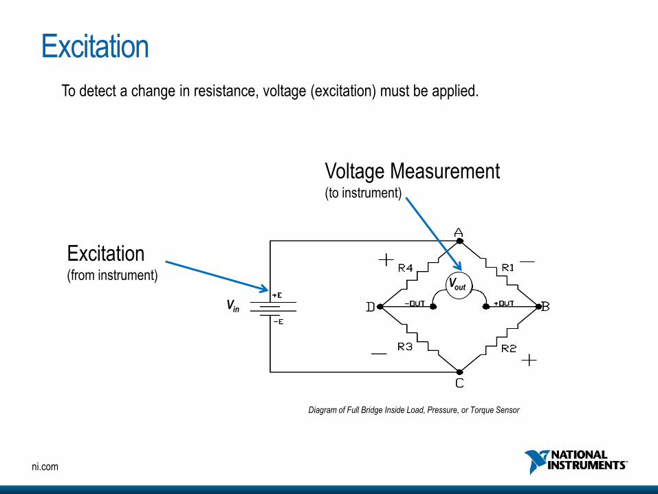
Excitation
Vin
Vout
To detect a change in resistance, voltage (excitation) must be applied.
Excitation (from instrument)
Voltage Measurement (to instrument)
Diagram of Full Bridge Inside Load, Pressure, or Torque Sensor
ni.com
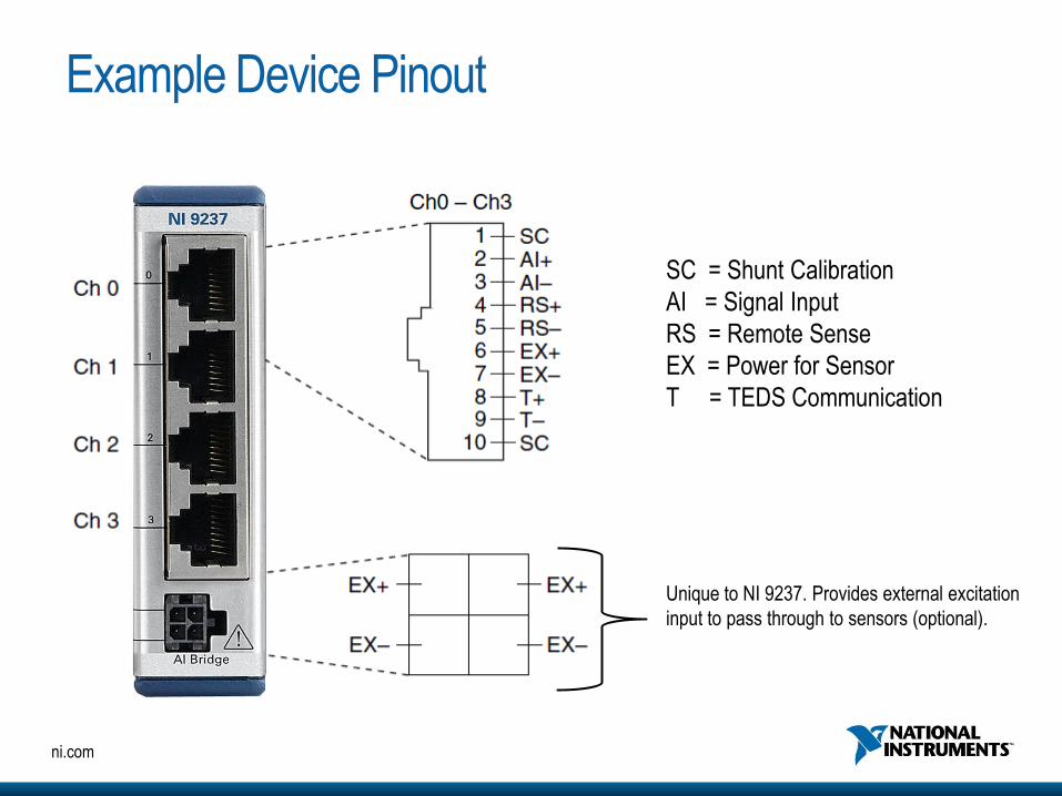
Example Device Pinout
SC = Shunt Calibration
AI = Signal Input
RS = Remote Sense
EX = Power for Sensor
T = TEDS Communication
Unique to NI 9237. Provides external excitation
input to pass through to sensors (optional).

ni.com
Ratiometric Bridge Measurements
Advantages
• High accuracy and low susceptibility to excitation temperature drift
• Reduced regulation design requirements allowing for increased channel count
Traditional Approach Ratiometric Approach

High Resolution ADC Weighing nickels with a load cell

ni.com
Hardware Demonstration

ni.com
Software Demonstration

ni.com
PXI
• NI PXIe-4330 universal strain module
• Best accuracy
• Best synchronization
• Highest bandwidth
NI Solutions for Bridge Measurement
NI CompactDAQ
• NI 9237 universal strain module
• NI 9235/36 high-density quarter-bridge
modules
• Rugged, compact
• USB, wireless, Ethernet
• Synchronized

ni.com
ni.com/data-acquisition
Related Documents