Sensor Fusion for Intuitive Robot Programming Teck Chew Ng, Lye Seng Wong and Guilin Yang Singapore Institute of Manufacturing Technology Industrial Robotics Team, Mechatronics Group 71 Nanyang Drive, Singapore 638075 {tcng,lswong,glyang}@SIMTech.a-star.edu.sg Abstract—Fusion of information from multiple sensors can greatly enhance the performance of human-machine interaction, especially in the intuitive robot programming. The methods aim to allow rapid teaching of robotic tasks in a safe and efficient manner. The techniques can reduce the setup time of a robotic system. This is crucial for SMEs (Small and Medium Enterprize) where the products in the manufacturing area are in small lot size but with high batch mix. The objective of this research is to fuse the information from a range sensor and a camera. An unique method using the surface constraint has been adopted for the calibration of the sensor fusion system. By taking the surface normal of a calibration board as the common feature, the transformation between the two coordinate systems can be formulated. The end result is a fused scene with both range and texture (color in this case) information. The range information will be used for the path generation for robotic tasks. On the other hand, the images captured by the camera together with the graphical user interface provide an user friendly interface platform for the user. As the two images have been fused, the operator can program a path for a robot to execute by ’point-and-click’ on the user interface screen. Experimental results have shown that the new method of robot programming, with sensor fusion information, has improved the robotic teaching process by at least 90% as compared to the manual programming method using teaching pendant. I. I NTRODUCTION Unlike in the manufacturing floor, for aerospace Mainte- nance Repair and Overhaul (MRO) industry, the workpieces are normally high mix and in low volume. Because of the above unique characteristics, it is very difficult to have a fully automated robotic system that can handle those large dimensional variation workpieces. Moreover, as the operations of robots are complex, convention methods for robot pro- gramming, using teaching pendants, are very tedious for an average operator. Various precaution steps, such as checking of collision of robot with the obstacles in the environment, have to be taken care off. Hence, highly skilled workers are required for these tasks. Furthermore, for MRO applications, it is not cost effective to have a dedicated robotic workcell for a specific type of workpiece. To be economical, the robotic workcell must be flexible enough to cater for high mixed and low volume type of operations. Also, only minimal training should be required for operator handling the programming of robotic tasks. Hence, there is a need to improve the technique for robot programming. Industrial robot suppliers such as FANUC and ABB have worked out solutions for such a production problem. Software tools such as ROBOGUIDE from FANUC [1] and RoboStudio from ABB [2] are some commercial solutions. For these systems, however, Computer Aided Design (CAD) drawings, precise workpiece handling tools, and reliable calibration soft- ware are needed. In real life, especially in the aerospace industry, CAD drawings may not be available to the MRO companies due to protected sensitivity of the information from the designer. Furthermore, even if the CAD drawings are available, there may exist large discrepancies between the used workpieces and their original drawings. To tackle the above issues, we propose a method named intuitive robot programming. The main purpose of this method is to allow a cooperation between robot and human operator, so as to enhance the productivity of the operator and at the same time creating a safe environment for robot teaching tasks. To achieve this, perception issues have to be resolved. For the robot, the pose information of the workpiece is important. The range and bearing information of a workpiece relative to the robot can be used for collision avoidance and path planning purposes. On the other hand, for an operator, the texture information on the workpiece is useful for off line programming. Hence, sensor fusion of these two pieces of information is needed to provide these two information to the operator and the robot. A. Intuitive Robot Programming Intuitive robot programming concept has been researched in the robotic community. The main purpose is to relieve the burden of tedious robot teaching tasks, using a teaching pendant, from the operator. To achieve this goal, various techniques have been proposed. Colombo et. al. [3] has implemented a teaching by demon- stration method based on the information from the force torque sensor and the feedback of motor currents from a robotic arm. With this method, the human tasks can be transferred to the robot controller. In that, the robotic arm was guided by the human operator through the desired path with the aid of a force torque sensor. The joint coordinates of the robotic arms were recorded throughout the teaching process. The recorded paths were then palyed back during the execution of the tasks. Ehrenmann et. al. [4] have proposed another concept of teaching by demonstration for a robotic task. The hand actions of an operator working on a dedicated task were tracked by a camera. Beside tracking the posture and position of the hand, the amount of force exerted onto the workpiece by the operator was also captured by a force torque sensor. The 978–1–4244–1676–9/08/$25.00 c 2008 IEEE RAM 2008

Welcome message from author
This document is posted to help you gain knowledge. Please leave a comment to let me know what you think about it! Share it to your friends and learn new things together.
Transcript

Sensor Fusion for Intuitive Robot Programming
Teck Chew Ng, Lye Seng Wong and Guilin YangSingapore Institute of Manufacturing Technology
Industrial Robotics Team, Mechatronics Group
71 Nanyang Drive, Singapore 638075
{tcng,lswong,glyang}@SIMTech.a-star.edu.sg
Abstract—Fusion of information from multiple sensors cangreatly enhance the performance of human-machine interaction,especially in the intuitive robot programming. The methods aimto allow rapid teaching of robotic tasks in a safe and efficientmanner. The techniques can reduce the setup time of a roboticsystem. This is crucial for SMEs (Small and Medium Enterprize)where the products in the manufacturing area are in small lotsize but with high batch mix.
The objective of this research is to fuse the information from arange sensor and a camera. An unique method using the surfaceconstraint has been adopted for the calibration of the sensorfusion system. By taking the surface normal of a calibrationboard as the common feature, the transformation between the twocoordinate systems can be formulated. The end result is a fusedscene with both range and texture (color in this case) information.The range information will be used for the path generation forrobotic tasks. On the other hand, the images captured by thecamera together with the graphical user interface provide an userfriendly interface platform for the user. As the two images havebeen fused, the operator can program a path for a robot to executeby ’point-and-click’ on the user interface screen. Experimentalresults have shown that the new method of robot programming,with sensor fusion information, has improved the robotic teachingprocess by at least 90% as compared to the manual programmingmethod using teaching pendant.
I. INTRODUCTION
Unlike in the manufacturing floor, for aerospace Mainte-
nance Repair and Overhaul (MRO) industry, the workpieces
are normally high mix and in low volume. Because of the
above unique characteristics, it is very difficult to have a
fully automated robotic system that can handle those large
dimensional variation workpieces. Moreover, as the operations
of robots are complex, convention methods for robot pro-
gramming, using teaching pendants, are very tedious for an
average operator. Various precaution steps, such as checking
of collision of robot with the obstacles in the environment,
have to be taken care off. Hence, highly skilled workers are
required for these tasks. Furthermore, for MRO applications,
it is not cost effective to have a dedicated robotic workcell for
a specific type of workpiece. To be economical, the robotic
workcell must be flexible enough to cater for high mixed and
low volume type of operations. Also, only minimal training
should be required for operator handling the programming of
robotic tasks. Hence, there is a need to improve the technique
for robot programming.
Industrial robot suppliers such as FANUC and ABB have
worked out solutions for such a production problem. Software
tools such as ROBOGUIDE from FANUC [1] and RoboStudio
from ABB [2] are some commercial solutions. For these
systems, however, Computer Aided Design (CAD) drawings,
precise workpiece handling tools, and reliable calibration soft-
ware are needed. In real life, especially in the aerospace
industry, CAD drawings may not be available to the MRO
companies due to protected sensitivity of the information from
the designer. Furthermore, even if the CAD drawings are
available, there may exist large discrepancies between the used
workpieces and their original drawings.
To tackle the above issues, we propose a method named
intuitive robot programming. The main purpose of this method
is to allow a cooperation between robot and human operator,
so as to enhance the productivity of the operator and at the
same time creating a safe environment for robot teaching tasks.
To achieve this, perception issues have to be resolved. For
the robot, the pose information of the workpiece is important.
The range and bearing information of a workpiece relative
to the robot can be used for collision avoidance and path
planning purposes. On the other hand, for an operator, the
texture information on the workpiece is useful for off line
programming. Hence, sensor fusion of these two pieces of
information is needed to provide these two information to the
operator and the robot.
A. Intuitive Robot Programming
Intuitive robot programming concept has been researched
in the robotic community. The main purpose is to relieve
the burden of tedious robot teaching tasks, using a teaching
pendant, from the operator. To achieve this goal, various
techniques have been proposed.
Colombo et. al. [3] has implemented a teaching by demon-
stration method based on the information from the force torque
sensor and the feedback of motor currents from a robotic
arm. With this method, the human tasks can be transferred
to the robot controller. In that, the robotic arm was guided
by the human operator through the desired path with the
aid of a force torque sensor. The joint coordinates of the
robotic arms were recorded throughout the teaching process.
The recorded paths were then palyed back during the execution
of the tasks. Ehrenmann et. al. [4] have proposed another
concept of teaching by demonstration for a robotic task. The
hand actions of an operator working on a dedicated task were
tracked by a camera. Beside tracking the posture and position
of the hand, the amount of force exerted onto the workpiece by
the operator was also captured by a force torque sensor. The
978–1–4244–1676–9/08/$25.00 c© 2008 IEEE RAM 2008

system required a data glove with force sensors. The recorded
data are then processed and mapped to a manipulator. On
the other hand, Strobel [5] proposed a gesture based intuitive
method for a mobile manipulator system that perform cleaning
tasks in home enviornment. Hand gestures by the operator were
pre-taught and stored into the database of the system. Upon
detecting a pre-defined hand gesture, a specific task will be
carried out by the manipulator.
The above systems involved an operator interacting with
the robot directly. There are contacts between the robot and
the operator, or the operator is working within the vicinity of
the robot working envelop. These may not be desirable for
safety reasons. Also, for demonstration by teaching method,
the operator has to physically guide the robot through the
whole process and this may not be easy depending on the
reliability and ease of use of the system. Here, we propose a
safer and easy robot programming technique. Instead of having
an operator guiding the robot through contact method, we
digitize the workpiece and project the image onto a monitor
screen. The operator can then teach the robot by ’point and
click’ method. That is, by generating a trajectory for the robot
to play back during the execution of task. No teaching pendant
(for easy to use) is required and no contact (for safety) between
human and robot is required.
B. Sensor Fusion
Machine perception is a major research topic for robotic
applications such as unmanned vehicles and robotic assembly
systems. Two popular sensors, laser scanner and camera, are
used to perceive the environment around the area of interest
of the robotic working envelop. Laser scanners provide range
information of the environment. Although the scan rate of a
laser scanner is typically slow (about 5 frames per second, 90
degree by 90 degree or larger field of view), however, it has
good range resolution (up to mm scale). On the other hand,
the frame rate of a camera is fast (30fps or higher). However,
the range resolution and accuracy of a vision camera are poor.
By fusing these two pieces of information, higher resolution
range images can be obtained.
Karsten [6] fused the 3D laser data and a rotating line
camera image with mechanical fixes. The 3D scanner and the
camera images were acquired in sequential steps. Both the 3D
scanner and camera were mounted on the same tripod. An
assumption that the optical center of the camera is identical
to that of the laser scanner was made. The optical alignment
was assumed to be guaranteed by an adaptor mounted onto
the tripod. This method is tedious, time consuming and not
flexible. Also, the assumption made may not be valid as
mounting and dismounting of the camera and scanner were
needed. Dorian [7] fused the data from a laser range finder
and a monocular camera, both mounted on a pan-tilt unit. For
this system, the camera was attached to the laser scanner and
alignment of the two optical axis was done mechanically. A
specially made calibration tool was used. The fusion process
involved registering a laser range data with an intensity value
from the camera image. The image selection was based on
finding the closest matched images between the laser and
camera data. However, the assumption regarding the alignment
of the optical axes is sceptical. Forkuo [8] has provided a
better solution for fusion of the 3D laser data and the camera
image by establishing the correspondences between the two
images. Corners in the images were used as the features for
data association.
Despite fruitful results obtained in the area of sensor fusion,
however, there are some challenges remain unsolved. Fusion
methods relying on the mechanical means to align the optical
axes of the two sensors are tedious and the results obtained
can be affected by the accuracy of the mechanical structures.
Fusion methods that used the corner as features for data
correspondence may not be reliable due to sensor noises and
limitation on the sensor resolution.
The motivation for this research stems from the accep-
tance that despite numerous technological breakthroughs and
demonstrations of advanced robotics −− there is unfulfilled
potential in mainstream manufacturing. In particular, there
is little take-up within SMEs where batch sizes are small
and product mix is high. This is because the conventional
robotic systems are not flexible and hence difficult to use. The
challenge, therefore, is to create technology that will allow
rapid and easy set-up of robots to achieve fast turn around
times. The approach is to focus on intuitive programming,
which involves creating a programming environment so that a
typical production worker is able to command a machine based
on intuitive concepts such as images or physical interaction.
In view of the need of a reliable sensor fusion technique for
intuitive robot programming, the main objective of our work
is to perform fusion of laser range data with the images from
a camera so as to provide an easy to use environment for the
robot operator. A calibration method will be investigated for
data association of the laser points and the image pixels. The
end result is a fused image to aid the operator in the robot
programming task. Also, an improvement of 90% in robot
programming time is expected.
CW rotation
Camera
Stepper Motor
Laser Scanner
Fig. 1. System setup. A 2D laser scanner is mounted onto a rotating platformdriven by a stepper motor. The combination of the 2D scanning and theadditional rotating axis provide a 3D scanning effect. A camera is mountedbehind the scanning mechanism.
II. SYSTEM SETUP
A. 3D Laser Scanner
In order to achieve a 3D scanning effect, a 2D laser scanner
[9] is mounted onto a rotating platform. The platform is driven
by a stepper motor. The laser system provides a vertical line
scan, scanning from top to bottom. As the platform rotates,
the laser scanner rotates accordingly. The result of the 2D
laser scanner rotating about a vertical axis will generate a
3D scan of the environment. However, as the laser is a free
running system, synchronization of the laser and the platform
is required. The output signal from the laser scanner is used as
the synchronization pulse to command the stepper to advance
to the next step [10]. Two limit switches are used to limit the
field of view of the 3D scanner. Figure 1 shows the setup of the
3D scanner. The horizontal and vertical field of views (FOV) of
the final system are 90 degree and 60 degree respectively. The
vertical and horizontal angle resolution for the 3D scanner are
0.25 degree and 0.18 degree respectively. The range resolution
of the system is 1mm.
B. Camera System
A firewire camera is mounted behind the 3D laser scanner
system as shown in figure 1. The resolution of the image
capture is 640 × 480. The position and height of the camera
mounting is not critical at this stage and a calibration process is
needed. This is an added advantage as the setup of our system
is simplified.
C. Problem Definition
Fig. 2. The result of a 3D laser scanning. Although the laser can provide adense range and bearing data, however, the texture information, of the objectsscanned, are lacking.
Figures 2 and 3 show the 3D laser scanning result and the
corresponding camera image respectively. These two images
were obtained in one data acquisition cycle. The laser scanner
provides range information and on the other hand, the camera
provides the textures information about the scene. From figure
2, it is possible to identify the shape of an object using standard
edge detection algorithm. Also, it is possible to obtain the
poses of the objects with respect to the scanner. However, there
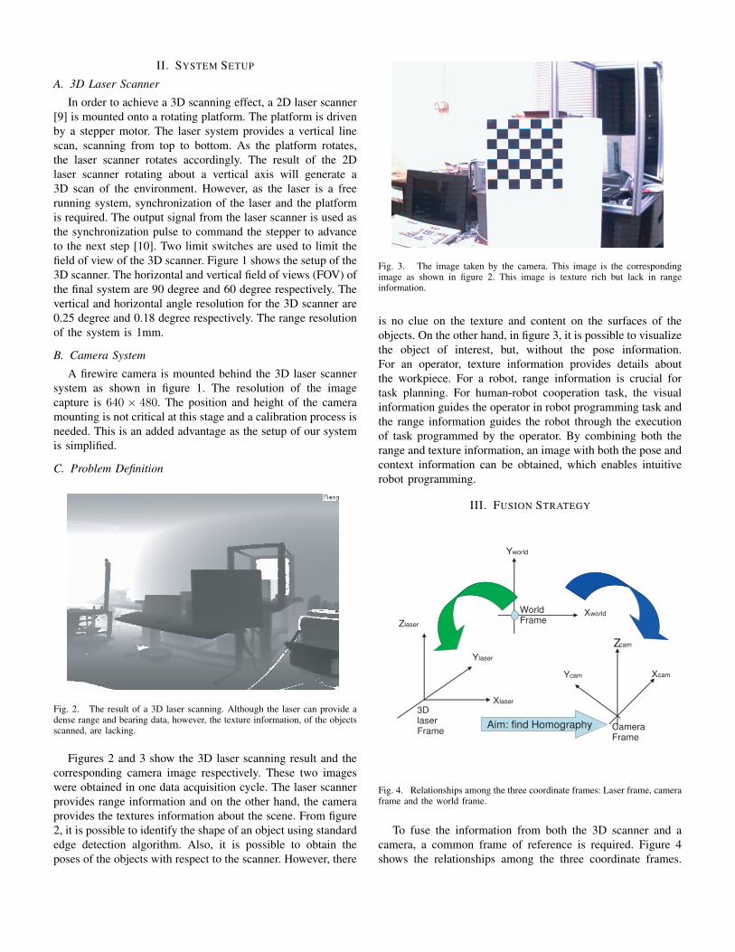
Fig. 3. The image taken by the camera. This image is the correspondingimage as shown in figure 2. This image is texture rich but lack in rangeinformation.
is no clue on the texture and content on the surfaces of the
objects. On the other hand, in figure 3, it is possible to visualize
the object of interest, but, without the pose information.
For an operator, texture information provides details about
the workpiece. For a robot, range information is crucial for
task planning. For human-robot cooperation task, the visual
information guides the operator in robot programming task and
the range information guides the robot through the execution
of task programmed by the operator. By combining both the
range and texture information, an image with both the pose and
context information can be obtained, which enables intuitive
robot programming.
III. FUSION STRATEGY
Xcam
Zcam
3D laser Frame Camera
Frame
World Frame Zlaser
Ylaser
Xlaser
Yworld
Xworld
Aim: find Homography
Ycam
Fig. 4. Relationships among the three coordinate frames: Laser frame, cameraframe and the world frame.
To fuse the information from both the 3D scanner and a
camera, a common frame of reference is required. Figure 4
shows the relationships among the three coordinate frames.

The world coordinate frame can be taken as the common
frame of reference for the two sensors. With the reference
frame, calibration of the camera is done to compute both the
extrinsic and intrinsic parameters of the camera and scene.
By identifying the surface normal of a common calibration
board as the common feature for the perception system, sensor
fusion is formulated from the homography between the laser
and camera frames.
A. Sensor Fusion with Surface Constraints
A common feature is essential for the success of sensor
fusion. Intuitively, the edges and lines are the most common
features for calibration. However, there are correspondence
issues if these features are used. As the two sensors are of
different resolution, based on the characteristics and physics
of the 3D laser scanner and the camera imaging, a line or an
edge that is detected by the 3D laser scanner may not match
perfectly to the camera image. It may be possible to match
these features by brute force, however, the accuracy of the
fusion process will be compromised.
For camera calibration, a well known checker box calibra-
tion board has been used extensively in the literature [11].
We have adopted this similar method for calibration of the
two sensors. As a board (planar surface) is used, a unique
feature, surface normal of the plane, has been identified for
calibration between the 3D laser and the vision image. There
is an advantage in using surface normal of a plane for the
calibration. The surface normal of a plane is view invariant
when viewed by either the 3D laser scanner or the camera. That
is, the surface normal of a plane remain the same ir-regardless
of viewing by the 3D laser scanner or a camera. Thus, there
will be no feature association issues in the calibration process.
Fig. 5. Calibration procedures for camera. Images of a checker board canbe captured by placing the checker board at various positions and orientationswithin the field of view of both laser scanner and camera.
Having identified a common feature for system calibration,
three steps are necessary for the fusion of the information from
the two sensors, namely:
• Camera calibration.
• Data transformation for 3D scanner
• Frame transformation/Homography
B. Camera Calibration
The calibration procedure for a camera is a solved problem
[11]. A checker board (as shown in figure 3)is used. The in-
trinsic and extrinsic parameters of the camera can be obtained
from the standard camera calibration procedures available in
the literature.
C. Data transformation for 3D scanner
This involves the conversion of the polar information from
the laser scanner to world coordinate. For the system setup as
shown in figure 1, the laser is scanning horizontally from -45
degree to 45 degree and -30 degree to 30 degree vertically.
The world coordinate of a laser point with respect to the laser
frame can be computed using the sine and cosine rules.
D. Frame Transformation/Homography
To find the homography between the two frames of different
sensors, the following steps are carried out.
The checker box images are captured by the two sensors.
For best results, the calibration board has to be placed at
different locations and at various orientations within the field
of view of the two sensors as shown in figure 5.
By using the camera calibration procedures outlined in
[11], the intrinsic parameters of the camera can be obtained.
For each of the poses of the calibration board, the extrinsic
parameters (ie rotation and translation matrices) of the board
can be obtained.
The projection of a point P in the world frame to a point
p in the image frame is represented as:
p = CI(RP + t) (1)
where CI is the 3 × 3 intrinsic matrix for the camera, R is a
3×3 orthonormal (rotation) matrix representing the orientation
of the camera with respect to the world frame and t is a 3 ×1 vector (translation) representing the relative position of the
camera frame from the world frame.
The surface normal of the calibration board is
Nc = [R3 − RT
3t] (2)
where R3 is the 3rd column of rotation matrix R.
Similarly, for each of the poses of the calibration board,
the surface normal of the calibration board (ie a plane) with
respect to the laser scanner can be obtained by using RANSAC
[12] plane fitting algorithm.
Now, in laser coordinate system, consider a point, X , in 3D
space lying on a plane, π. Based on the equation of a plane,
πX = 0 (3)
For the same point X , its corresponding coordinate, Xc in
the camera frame is
Xc = HX (4)
where H is the transformation from laser frame to camera
frame.
The aim of the calibration process is to find a solution for
this transformation, H .

Mathematically,
if πX = 0, then
πT H−1HX = 0(5)
Hence,
(H−T πT )T HX = 0 (6)
From equations 4 and 6, we have
(H−T πT )T Xc = 0 (7)
Note that equation 7 is another plane equation. Hence, we
can conclude that the point Xc is a point on the plane H−T πT
(figure 6).
H can be solved through the above calibration procedures
using multiple planes data obtained from both laser and
camera.
Xcam
Zcam
Ycam
Z laser
Ylaser
Xlaser
Yworld
Xworld
Surface normal
Shortest
dist
to norm
al
Shortest dist to normal
Fig. 6. Representation of surface normal of a plane as common feature toboth the scanner and the camera.
Fig. 7. Fusion result of figures 2 and 3.
IV. INITIAL RESULTS
For verification of the new fusion concept, a MATLAB
program was written to implement the algorithm as outlined in
section III. For demonstration of the intuitive robot program-
ming concept, a modular robot was setup for this purpose. The
3D laser system was mounted side-by-side with the modular
robot. Another program for 3D rendering and modular robot
control was written in ’C’ together with OPENGL library.
A calibration process between the robotic arm and the
fusion system is needed. This is carried out by mounting a flat
calibration board onto the robotic arm. The pose of the board
can be obtained from the encoder readings of the arm. Also, the
surface normal of the calibration board can be computed off the
3D laser data. With these two information, the transformation
matrix between the robot frame and the fusion system frame
can be computed.
Figure 7 shows the initial fusion result of figures 2 and
3. Both the range and texture contents were plotted in a 3D
environment. From figure 7, it was observed that some texture
information in the check-box board were missing. The missing
data are due to the over-range readings from the scanner.
The laser scanner will report over range value if there is no
laser signal reflected back from a surface. For this particular
checker-box board, the checker-box is colored black and hence,
no laser is reflected back to the laser receiver.
Figure 8 shows the result of fusion for a cabinet. Observed
that the edges of the cabinet is clearly displayed in the fused
data. Also, the fused imaged shows as much information as the
actual 2D image. If only 3D range is presented, it is impossible
to visualize every small detail in the scan. Alternatively, if only
camera image is being used, there will be no range information
for the robot to work on the workpiece.
A modular robot was used to demonstrate the intuitive robot
programming concept. Figure 9 shows the 3D laser scan and
the robot. The image in the middle shows the fused image. This
image will be shown during the intuitive robot path teaching
process. A path can be created by clicking onto the surface of
the scanned workpiece via this user interface. A path is then
converted to the robot coordinates for execution.
Initial testing run of the algorithm is satisfactory. The inset
images in figure 9 show the robot executed position of the
robot at various location along the taught path.
To further quantify the setup time improvement of the new
method, a Motorman robot was used as shown in figure 10. The
time taken for an operator to teach, using a teaching pendant,
a robot path of 5 teaching points took about 5 minutes. By
using the new intuitive method, it took about 20 seconds for
the perception system to scan and fuse the information of the
workpiece and less than 10 seconds for an operator to create a
path of 5 intermediate points. Hence, the setup time for robot
teaching is improved using the intuitive robot programming
method with sensor fusion data.
V. CONCLUSION
Sensor fusion of the 3D laser data and the camera image
has been achieved. A checker-box calibration board has been
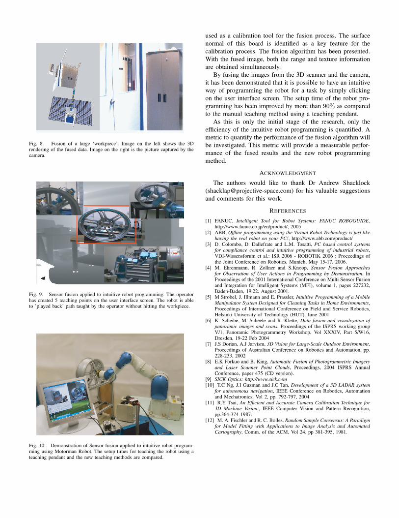
Fig. 8. Fusion of a large ‘workpiece’. Image on the left shows the 3Drendering of the fused data. Image on the right is the picture captured by thecamera.
Fig. 9. Sensor fusion applied to intuitive robot programming. The operatorhas created 5 teaching points on the user interface screen. The robot is ableto ’played back’ path taught by the operator without hitting the workpiece.
Fig. 10. Demonstration of Sensor fusion applied to intuitive robot program-ming using Motorman Robot. The setup times for teaching the robot using ateaching pendant and the new teaching methods are compared.
used as a calibration tool for the fusion process. The surface
normal of this board is identified as a key feature for the
calibration process. The fusion algorithm has been presented.
With the fused image, both the range and texture information
are obtained simultaneously.
By fusing the images from the 3D scanner and the camera,
it has been demonstrated that it is possible to have an intuitive
way of programming the robot for a task by simply clicking
on the user interface screen. The setup time of the robot pro-
gramming has been improved by more than 90% as compared
to the manual teaching method using a teaching pendant.
As this is only the initial stage of the research, only the
efficiency of the intuitive robot programming is quantified. A
metric to quantify the performance of the fusion algorithm will
be investigated. This metric will provide a measurable perfor-
mance of the fused results and the new robot programming
method.
ACKNOWLEDGMENT
The authors would like to thank Dr Andrew Shacklock
([email protected]) for his valuable suggestions
and comments for this work.
REFERENCES
[1] FANUC, Intelligent Tool for Robot Systems: FANUC ROBOGUIDE,http://www.fanuc.co.jp/en/product/, 2005
[2] ABB, Offline programming using the Virtual Robot Technology is just like
having the real robot on your PC!, http://www.abb.com/product/[3] D. Colombo, D. Dallefrate and L.M. Tosatti, PC based control systems
for compliance control and intuitive programming of industrial robots,VDI-Wissensforum et al.: ISR 2006 - ROBOTIK 2006 : Proceedings ofthe Joint Conference on Robotics, Munich, May 15-17, 2006.
[4] M. Ehrenmann, R. Zollner and S.Knoop, Sensor Fusion Approaches
for Observation of User Actions in Programming by Demonstration, InProceedings of the 2001 International Conference on Multi Sensor Fusionand Integration for Intelligent Systems (MFI), volume 1, pages 227232,Baden-Baden, 19.22. August 2001.
[5] M Strobel, J. Illmann and E. Prassler, Intuitive Programming of a Mobile
Manipulator System Designed for Cleaning Tasks in Home Environments,Proceedings of International Conference on Field and Service Robotics,Helsinki University of Technology (HUT), June 2001
[6] K. Scheibe, M. Scheele and R. Klette, Data fusion and visualization of
panoramic images and scans, Proceedings of the ISPRS working groupV/1, Panoramic Photogrammetry Workshop, Vol XXXIV, Part 5/W16,Dresden, 19-22 Feb 2004
[7] J.S Dorian, A.J Jarvism, 3D Vision for Large-Scale Outdoor Environment,Proceedings of Australian Conference on Robotics and Automation, pp.228-233, 2002
[8] E.K Forkuo and B. King, Automatic Fusion of Photogrammetric Imagery
and Laser Scanner Point Clouds, Proceedings, 2004 ISPRS AnnualConference, paper 475 (CD version).
[9] SICK Optics: http://www.sick.com
[10] T.C Ng, J.I Guzman and J.C Tan, Development of a 3D LADAR system
for autonomous navigation, IEEE Conference on Robotics, Automationand Mechatronics, Vol 2, pp. 792-797, 2004
[11] R.Y Tsai, An Efficient and Accurate Camera Calibration Technique for
3D Machine Vision., IEEE Computer Vision and Pattern Recognition,pp.364-374 1987.
[12] M. A. Fischler and R. C. Bolles. Random Sample Consensus: A Paradigm
for Model Fitting with Applications to Image Analysis and Automated
Cartography, Comm. of the ACM, Vol 24, pp 381-395, 1981.
Related Documents