1 Scope of Services Sensor Deployment Phase II Document version Issued Date 02‐02‐2018

Welcome message from author
This document is posted to help you gain knowledge. Please leave a comment to let me know what you think about it! Share it to your friends and learn new things together.
Transcript
1
Scope of Services
Sensor Deployment Phase II
Document version Issued
Date 02‐02‐2018
2
TABLE OF CONTENTS
CONTEXT & OVERVIEW ......................................................................................................................... 4
SCOPE OF SERVICES .............................................................................................................................. 5
2.1 Objectives ...................................................................................................................................... 5
2.2 Success Criteria ............................................................................................................................. 5
2.3 Locations ....................................................................................................................................... 6
2.4 Contractor Scope of Services ........................................................................................................ 8
2.4.1 Functional Requirements of Sensor Deployment Phase II ..................................................... 8
2.4.2 Site Assessment & Planning Visit ........................................................................................... 9
2.4.3 Design ................................................................................................................................... 10
2.4.4 Networking ........................................................................................................................... 15
2.4.5 Vibration Monitoring System ............................................................................................... 16
2.4.6 Outage Planning ................................................................................................................... 17
2.4.7 Pilot Program ....................................................................................................................... 17
2.4.8 Commissioning ..................................................................................................................... 17
2.4.9 Site Personnel ...................................................................................................................... 18
2.4.10 Major Task/Deliverables Work Plan ..................................................................................... 19
2.5 Authority Scope of Services ........................................................................................................ 22
2.6 Warranty ..................................................................................................................................... 22
RFP PROCESS & SUBMITTALS REQUIRED WITH BID PROPOSAL ......................................................... 22
3.1 Pre‐Bid Meeting and Site Walk ................................................................................................... 22
3.2 Submittals Required with Bid Proposal ...................................................................................... 22
3.3 Proposal Evaluation Criteria ........................................................................................................ 23
SCHEDULE OF DELIVERABLES .............................................................................................................. 24
ATTACHMENT A – DIVISION 01 SPECIFICATIONS ................................................................................ 25
ATTACHMENT B – SITE LIST ................................................................................................................. 26
ATTACHMENT C – TECHNICAL SPECIFICATION FOR EQUIPMENT SENSORS ....................................... 27
ATTACHMENT D – OSI PI NAMING CONVENTION .............................................................................. 28
3
ATTACHMENT E – ELECTRICAL DESIGN CRITERIA ............................................................................... 29
ATTACHMENT F – CIVIL DESIGN CRITERIA ...................................................................................... 30
ATTACHMENT G – SENSOR DEPLOYMENT PHASE I – 90% DESIGN SENY & CENTRAL .................... 31
ATTACHMENT H – SENSOR DEPLOYMENT PHASE I – 90% DESIGN WESTERN & NORTHERN ......... 32
ATTACHMENT I ‐ SCHEDULE ............................................................................................................ 33
ATTACHMENT J – SCHEDULE OF VALUES ........................................................................................ 34
ATTACHMENT K – 2018 OUTAGE SCHEDULE .................................................................................. 35
ATTACHMENT L ‐ CIP ATTRIBUTES .................................................................................................. 36
ATTACHMENT M – CAD REQUIREMENTS ....................................................................................... 37
ATTACHMENT N – QUALITY ASSURANCE PROGRAM ..................................................................... 38
ATTACHMENT O – VIBRATION MONITORING SYSTEM SCOPE ....................................................... 39
ATTACHMENT P – ASSET MANAGEMENT REQUIRED FIELDS .......................................................... 40

4
CONTEXT & OVERVIEW
The New York Power Authority (NYPA, Authority) is engaged in the generation and transmission of
electricity for the benefit of New York State. The Authority’s installed generating capacity is close to
6,000MW, of which 4,400MW is hydroelectric, including pumped storage. The Authority also owns and
operates 1,400 circuit‐miles of transmission lines across NY State.
In 2014, NYPA’s Strategic Vision defined two infrastructure modernization initiatives:
1. Asset Management Strategic Initiative
2. Smart Generation & Transmission Strategic Initiative
The Sensor Deployment Program aligns with the Smart G&T Strategic Initiative roadmap area of
situational awareness and the Asset Management Strategic Initiative.
Sensors will further aide in the diagnoses of equipment health maintenance optimization, lending to
failure prevention by:
Collection of data
Concentrate data
Search & analyze
Visualize & Share
Implementation of the Sensor Deployment Program has been divided into two Phases as follows:
Phase I (by others): Engineering and design was completed in January of 2018. The furnishing
and installation of cable, conduits and networking devices to connect existing sensors for Phase I
is scheduled to be completed by September 2018. The Issue for Construction (IFC) packages for
this phase have been included as Attachment G & H and will be released to bidders upon
entering in to a non‐disclosure agreement.
Phase II (This Scope of Services): Engineering, design, procurement and installation of cable,
conduits, networking devices, and new sensors on critical assets spanning all four of the
Authority’s regions.
Central to this initiative was the development of an Asset Health Monitoring & Diagnostics Center, the
Integrated Smart Operation Center (iSOC), which created new decision‐making capabilities by
aggregating existing and future data streams to monitor, diagnose, and inform asset management
decisions. In effect, the iSOC extends asset capacity, stabilizes maintenance and inventory costs, and
mitigates the impact of catastrophic events. The iSOC is located on the 8th floor of the Authority’s White
Plains office.
5
Through this RFP, the Authority seeks to implement a network of Sensor Systems that transmit
identified parameter data to the iSOC from each identified asset. The Authority also seeks for this
project to leverage the number of repetitive installations of sensors across similar asset classes to
standardize data collection protocol. The Authority reserves the right to award this contract(s) to
multiple Contractors by individual, multiple or all regions.
SCOPE OF SERVICES
2.1 Objectives
The objective of the Sensor Deployment Phase II project is to provide increased real‐time insight into
asset health status and productivity to optimize regular maintenance spend, deter emergent capital
spending, and reduce environmental, regulatory and safety penalties. The Authority is looking to partner
with a Contractor, or selection of Contractors, to implement a state‐of‐the‐art sensor network that will
provide data for analysis from critical assets to inform asset management decisions on both a routine
and emergent basis.
For the Sensor Deployment Phase II project, the successful Bidder(s) will be expected to complete the
following, but not limited to, tasks and deliverables:
1. Perform site/field visits to each location to verify existing conditions and obtain feedback on
networking capabilities.
2. Design, procure, install, and commission the identified sensors at each asset (Reference
Attachment A‐ O)
3. Design, procure, install and commission a communications network, including System 1
upgrades, that will transmit the diagnostic data from each of the sensors to the iSOC
4. Configure OSI PI systems including PI naming (Reference Attachment D)
5. Provide a detailed schedule of the installation of the sensors (Reference Attachment I)
6. Provide and coordinate a schedule of outages (Reference Attachment K)
7. Address any data quality needs or cleanup necessary to effectively transmit the senor data to
the iSOC
8. Provide As‐built drawings per the Authority’s clone process (Reference Attachment M)
2.2 Success Criteria
The Sensor Deployment Phase II project seeks to install and network the required sensors to provide
critical asset health data to the iSOC, to be analyzed and incorporated into regular maintenance and
operations. The Authority has identified a suite of parameters across several assets types that have
been determined as critical data for this analysis. In efforts to ensure the best sensors are installed and
implemented – the Authority views success achieved across multiple stages:
1. Physical installation and energization
6
2. Network communications
3. Data transfer to the Integrated Smart Operation Center
If at any point during sensor installation the sensor does not successfully fulfill the Authority’s intended
goal, the Contractor shall be obligated to work with the Authority to cure the issue, at no additional
cost.
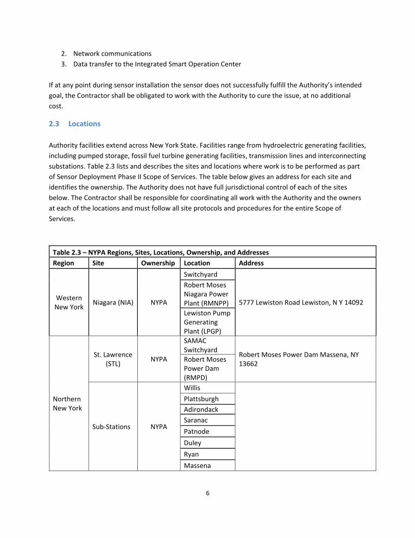
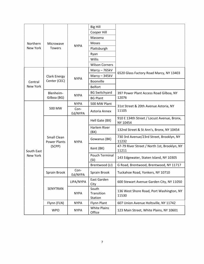
2.3 Locations
Authority facilities extend across New York State. Facilities range from hydroelectric generating facilities,
including pumped storage, fossil fuel turbine generating facilities, transmission lines and interconnecting
substations. Table 2.3 lists and describes the sites and locations where work is to be performed as part
of Sensor Deployment Phase II Scope of Services. The table below gives an address for each site and
identifies the ownership. The Authority does not have full jurisdictional control of each of the sites
below. The Contractor shall be responsible for coordinating all work with the Authority and the owners
at each of the locations and must follow all site protocols and procedures for the entire Scope of
Services.
Table 2.3 – NYPA Regions, Sites, Locations, Ownership, and Addresses
Region Site Ownership Location Address
Western New York
Niagara (NIA) NYPA
Switchyard
5777 Lewiston Road Lewiston, N Y 14092
Robert Moses Niagara Power Plant (RMNPP)
Lewiston Pump Generating Plant (LPGP)
Northern New York
St. Lawrence (STL)
NYPA
SAMAC Switchyard
Robert Moses Power Dam Massena, NY 13662
Robert Moses Power Dam (RMPD)
Sub‐Stations NYPA
Willis
Plattsburgh
Adirondack
Saranac
Patnode
Duley
Ryan
Massena
7
Northern New York
Microwave Towers
NYPA
Big Hill
Cooper Hill
Massena
Moses
Plattsburgh
Ryan
Willis
Wilson Corners
Central New York
Clark Energy Center (CEC)
NYPA
Marcy – 765kV 6520 Glass Factory Road Marcy, NY 13403
Marcy – 345kV
Boonville
Belfort
Blenheim‐Gilboa (BG)
NYPA BG Switchyard 397 Power Plant Access Road Gilboa, NY
12076 BG Plant
South East New York
500 MW
NYPA 500 MW Plant 31st Street & 20th Avenue Astoria, NY 11105 Con‐
Ed/NYPA Astoria Annex
Small Clean Power Plants
(SCPP) NYPA
Hell Gate (BX) 910 E 134th Street / Locust Avenue, Bronx, NY 10454
Harlem River (BX)
132nd Street & St Ann's, Bronx, NY 10454
Gowanus (BK) 730 3rd Avenue/23rd Street, Brooklyn, NY 11232
Kent (BK) 47‐79 River Street / North 1st, Brooklyn, NY 11211
Pouch Terminal (SI)
143 Edgewater, Staten Island, NY 10305
Brentwood (LI) G Road, Brentwood, Brentwood, NY 11717
Sprain Brook Con‐
Ed/NYPA Sprain Brook Tuckahoe Road, Yonkers, NY 10710
SENYTRAN
LIPA/NYPA East Garden City
600 Stewart Avenue Garden City, NY 11050
NYPA South Transition Station
136 West Shore Road, Port Washington, NY 11530
Flynn (FLN) NYPA Flynn Plant 607 Union Avenue Holtsville, NY 11742
WPO NYPA White Plains Office
123 Main Street, White Plains, NY 10601
8
2.4 Contractor Scope of Services
The Sensor Deployment Phase II project implements a system installed on the Authority’s business LAN
(Local Area Network) that will monitor and log the information from Sensor Systems to be installed on
critical assets. The information will be used to determine maintenance intervals and improve reliability
of the critical equipment. The newly installed Sensor Systems will be networked through the Authority’s
business LAN. The data will be collected by the OSI PI System and analyzed by the Authority’s Condition
Monitoring and Predictive Maintenance systems.
The following section presents the initial overall functionality for Sensor Deployment Phase II, as well as
a table of major deliverables envisioned by the Authority.
2.4.1 FunctionalRequirementsofSensorDeploymentPhaseII
The critical assets included in the Sensor Deployment Phase II project and the associated sensor systems
are outlined below. Each sensor system is detailed in Attachment C, quantities of each asset and sensor
system, by location and region, are provided in Attachment J.
Transformers & Reactors:
o Bushing Monitoring
o Main Tank Dissolved Gas Analyzer (DGA)
o Infrared Camera (Temperature of tank, bushings, cooling system, and Load Tap Changer)
o Temperature (Oil and Winding)
Circuit Breakers:
o Circuit Breaker Monitor (Pressure, Moisture, Density, Timing and Travel, Interrupter
Wear, Cabinet Temp, Coil Current, Coil Continuity, Motor Current, Control Voltage,
Busing Leakage Current)
Battery Banks:
o Battery Monitor (System Voltage, Cell Voltage, Load Current, Intercell Resistance,
Internal Resistance, Cell Temperature, Ambient Temperature, Electrolyte Level, Ground
Fault Monitor)
Fluid Filled Cable System:
o Leak Detection
Combustion Turbines and Generators:
o Lube, Seal & Hydraulic Oil Discharge Pressure
o Turning Gear Motor Current
o Inlet Air Filter Differential Air Pressure
o Combustion Turbine Blade Health
9
o Generator Monitoring
o Reliability Max
o Pre‐Catalyst Emissions
Steam Turbines and Generators:
o Lube & Hydraulic Oil Discharge Pressure
o Turning Gear Motor Current
Hydro Turbines and Generators:
o Air Gap Monitoring
o Bearing Oil Temperature
o Head Cover Priming Pressure
o Runner Band Drain Valve Oil Pressure
o Runner Band Drain Valve Water Pressure
o Spherical Valve Servomotor Oil Pressures
o Spherical Valve Differential Water Pressure
o Vibration Monitoring for Rotor Journals & Bearings
o Vibration Monitoring for Shaft Bearings
o Wicket Gasket Servomotor Oil Pressures
o Wicket Gasket Steam Leakage Flow Rate
The Contractor shall be responsible for ensuring that the Sensor Systema designed and installed for each
asset transmits the data to the iSOC as specified in Attachment C.
2.4.2 SiteAssessment&PlanningVisit
The Contractor is required to perform site/field visits to each location identified in Table 2.3 at the kick‐
off level to introduce conceptual/preliminary designs to site engineering, verify existing conditions and
obtain feedback on proposed work. This includes preparation of preliminary engineering packages that
would serve as design basis for discussion and concurrence with project stake‐holders. Preliminary
engineering packages include, but are not limited to, markups of existing drawings and sketches of new
ones.
The Contractor shall comply with the following requirements:
1. Attend on‐site kick‐off meetings at each location to confirm requirements, schedule, and conduct a site survey to validate conceptual designs and existing conditions.
2. Provide kick‐off meeting minutes and site survey reports.
3. Conduct on‐site investigations as necessary to become familiar with all information pertaining to installation, wiring and network of the currently available sensor system. The Contractor shall also become familiar with any existing impediments and restrictions which could affect the development of design and deployment process.
4. Verify and coordinate schedules for all work requiring equipment outages.

10
5. Attend additional follow‐up meetings and site visits to obtain and confirm requirements, conditions, and site feedback.
6. Prepare a Basis of Design Document (BOD) or Memorandum of Understanding (MOU) which shall address all pertinent design considerations for each location and asset. The BOD shall include detailed design criteria based on Attachment E & F. Submit within 3 weeks after project kick‐off. The Authority will review and provide comments to be incorporated in the 30% design progress submittal.
2.4.3 Design The Contractor shall engineer, optimize and produce detailed engineering design packages for Phase II of this program to install and network the Sensor Systems to data concentrators and network architecture for all the assets provided in Attachment C. Detailed design shall mean an “Issue for Construction” level of completeness for the installation and/or connectivity of the Sensor Systems on each asset. The design shall include comprehensive elementary, schematic, wiring, cable schedule, plan and elevations, bill of materials, conduit and raceway, communication and network drawings, and other relevant design drawings, spec and documents for fully operational sensor systems. The Contractor shall perform field investigation, analysis, evaluation, preliminary and detailed engineering design execution using multiple crews of field investigators visiting the sites in parallel to achieve the Authority’s project goals and objectives as indicated in this document. The Contractor will be required to confirm prior preliminary engineering assumptions, functional and project requirements, and concepts. The design for this project will require work at the asset level at various locations throughout the multiple Authority facilities including, but not limited to, power plants, sub‐stations, as well as locations in terminal rooms, control rooms and communication rooms throughout all the sites listed on Table 2.3. The Contractor is required to determine, in collaboration with NYPA’s engineering and site team, practicable and allowable locations for the sensors to be installed on each individual type of asset and provide optimal engineering designs that meet the Authority’s requirements. The Contractor shall also coordinate sensor installment design with the OEM of the asset. The Contractor shall identify and evaluate existing conduit systems and consider the need for upgrades, or for new duct banks, cable trays, conduits and junction boxes to be utilized for the physical routing of communication and power supply cables between the location of the sensor and the data concentrator and the power source. Also, part of the scope is identifying suitable locations for sensor data concentrators collecting measurements from all sensors at each site, and identifying fiber optic cable routing, patch panel and switch locations where fibers from multiple sensors are merged to be further routed to the concentrator. Finally, providing secure network connectivity for the data concentrator via fiber to the Authority’s network in compliance with the North American Electric Reliability Corporation – Critical Infrastructure Protection (NERC‐CIP) requirements and any other governing codes/standards. The Contractor shall provide a fiber optic connection for each individual sensor for communication purposes between the sensor control cabinet and the data concentrator. In cases where the sensor does not include a fiber communication option, the Contractor should consider the installation of media converters as the communication backbone for this project will be entirely based on fiber optic cable.

11
The Contractor shall produce details and pin‐outs of the new fiber optic patch panels and connections to other existing fiber optics. Necessary upgrades to existing fiber optics should be considered. The project requires the Contractor to identify and implement the use of a reference communication architecture (IEC61850, MODBUS, or similar) for all new sensors being installed, and all existing sensors requiring connection to the communication interface. These characteristics will determine the type of data concentrator to be used at all sites, as one single device will be required to aggregate all data sources. The selected data concentrator shall be able to collect data from different sensors, as such, a standard protocol shall be optimal for addressing consistency and compatibility. Data collected from all asset sensors shall be manipulated using OSIsoft’s PI System. The Contractor shall utilize the Phase I design as an outline for the design and equipment selection of all new networking systems. Any substitutions or additions of networking equipment must be approved by the Authority’s IT Infrastructure, Operation Technology(OT) and Engineering teams. This network design must comply with NERC‐CIP cyber security and physical security standards. Based on the functional requirements for the sensor system, The Authority and the Contractor will work to define the network requirements to be documented by the Contractor and submitted as a design deliverable as part of the Basis of Design (BOD) document. The Contractor shall be responsible for detailed design and layout of the network system including, but not limited to, network cabinets, connections to existing NYPA’s network and updates to existing network schemes. The Contractor shall identify power requirements for each Sensor System and determine whether a power source local to the asset can support the additional load, or if new circuits are to be wired from distribution panels. The Contractor shall program all sensors, concentrators and network equipment utilizing the standard developed by the Authority during construction of Phase I and further detailed in Section 2.4.4. Design packages provided by the Contractor shall go through a minimum of three review cycles as follows. The Contractor shall provide an in‐person review presentation at each Design Review Cycle to the NYPA team. To compress review cycle time, the Authority will provide written comments to the Contractor for each of the 30%, 60% and 90% submittals within 10 days of submittal. The Contractor may continue with design incorporating the comments and will not require Authority approval to move to the next level of detail design. All the review comments must be responded to and addressed by the IFC submittal. The Contractor may only proceed to the construction phase of this project after the Authority has approved the IFC submittal and issued a written Notice to Proceed.
2.4.3.1 30%EngineeringDesignPackageandDrawingsRequest Prepare a conceptual design package for each location for NYPA review. This design shall include proposed locations and methods for installing the sensors, elementary drawings of proposed power sources, communication connections, and cable routing. Complete drawing requests shall be submitted upon NYPA’s concurrence on the conceptual design. The Contractor is required to attend an on‐site 30% review meeting and respond to NYPA review comments. The 30% design package shall include the following:
1. Submittal Cover Sheet, Submittal Memo, General Notes, Symbols, and Abbreviations.
12
2. Plans, Elevations, Sections, and Details to clearly identify the design intent, space layout, location of equipment and routing for distribution.
3. Preliminary phasing plan(s) including any required “temporary” construction.
4. New and existing elementary diagrams showing proposed connections to power and communications.
5. Deliverables at this level of completion include, but are not limited to:
a. Elementary drawings for the sensor and asset
b. Wiring drawings for the sensor and asset
c. Plan, elevations and layout drawings of the sensor and asset
d. Elementary drawings for the concentrator
e. Wiring drawings for the concentrator
f. Layout drawings for the concentrator
2.4.3.2 60%EngineeringDesignPackage The Contractor is required to issue review packages to the NYPA designated lead, WPO engineering, site engineering, and to the Authority’s Design & Drafting (D&D) group for verification of CAD requirements. The packages shall include complete sets of drawings required for the installation of the Sensor Systems at each location. These packages shall be prepared using NYPA issued drawing clones, following the Authority’s drafting requirements and standards outlined in Appendix M, and include installation and demolition drawings as required for each sensor and asset. The Contractor must respond to review comments and feedback provided on these packages, prior to submitting the IFC design package with NYPA acceptance of the response. The 60% design package shall include the following:
1. Submittal Cover Sheet, Submittal Memo, General Notes, Symbols, Spec and Abbreviations.
2. Complete set of installation and demolition drawings including physical, electrical and communication drawings
3. Deliverables at this level of completion include, but are not limited to: a. Elementary drawings for the sensor and asset
b. Wiring drawings for the sensor and asset
c. Plan, elevations and layout drawings of the sensor and asset including Bills of Materials
d. Elementary drawings for the concentrator
e. Wiring drawings for the concentrator
f. Layout drawings for the concentrator including Bills of Materials
g. Conduit and cable routing
h. Network drawings
i. Other drawings deemed necessary during previous review cycles 4. Drawing list
13
2.4.3.3 90%EngineeringDesignPackage The Contractor is required to issue final review packages to the NYPA designated lead, WPO engineering, site engineering, and to the Authority’s Design & Drafting (D&D) group for verification of CAD requirements. The packages shall include complete sets of drawings required for the installation of the Sensor Systems at each location. These packages shall be prepared using NYPA issued drawing clones, following the Authority’s drafting requirements and standards outlined in Attachment M, and include installation and demolition drawings as required for each sensor and asset. Additional revisions (>Rev B) might be required by the Authority. The Contractor must respond to review comments and feedback provided on these comments, prior to submitting the IFC design package with NYPA acceptance of the response. The 90% design package shall include the following:
1. Submittal Cover Sheet, Submittal Memo, General Notes, Symbols, Specifications and Abbreviations
2. Complete set of installation and demolition drawings including physical, electrical and communication drawings
3. Deliverables at this level of completion include, but are not limited to: a. Elementary drawings for the sensor and asset
b. Wiring drawings for the sensor and asset
c. Plan, elevations and layout drawings of the sensor and asset including Bills of Materials
d. Structural support, wall penetration, and fireproofing details
e. Structural calculations, where applicable
f. Elementary drawings for the concentrator
g. Wiring drawings for the concentrator
h. Layout drawings for the concentrator including Bills of Materials
i. Conduit and cable routing
j. Network drawings
k. Other drawings deemed necessary during previous review cycles 4. Drawing list
2.4.3.4 IFCEngineeringDesignPackage The Contractor is required to submit Issued for Construction (IFC) engineering design packages upon the Authority’s review of the 90% engineering design package. IFC packages shall be sealed by a State of New York Licensed Professional Engineer and shall include complete sets of drawings required for the installation of the Sensor Systems at each location for each asset. These packages shall be prepared using NYPA issued drawing clones, following the Authority’s drafting requirements and standards outlined in Attachment M, and include installation and demolition drawings as required for each sensor and asset and facility. All comments provided by NYPA during previous design reviews must be identified and reflected on these packages, guaranteeing a 100% level of completion. Upon approval of the IFC Engineering Design Package, the Authority will issue written notice to proceed and the Contractor may
14
begin construction. The IFC design package shall include the following:
1. Submittal Cover Sheet, Submittal Memo, General Notes, Symbols, Full Specs and Abbreviations.
2. Electronic copies of complete sets of installation and demolition drawings including physical, electrical and communication drawings in the following formats:
a. DWG (compatible with AutoCAD 2012, or as required by the D&D group
b. PDF
c. DWF (one single file) 3. Hard copies of complete sets of installation and demolition drawings including physical,
electrical and communication drawings
4. Deliverables at this level of completion include, but are not limited to: a. Elementary drawings for the sensor and asset
b. Wiring drawings for the sensor and asset
c. Plan, elevations and layout drawings of the sensor and asset including Bills of Materials
d. Structural support, wall penetration, and fireproofing details
e. Structural calculations, where applicable
f. Elementary drawings for the concentrator
g. Wiring drawings for the concentrator
h. Layout drawings for the concentrator including Bills of Materials
i. Conduit and cable routing
j. Network drawings
k. Other drawings deemed necessary during previous review cycles 5. Drawing list
2.4.3.5 ContractorDocumentationandSubmittals In addition to the Division 01 Specification for the standard document submittal requirements, the Contractor shall satisfy the following requirements:
1. Progress submittals require Authority review. Allow 10 days for NYPA review.
2. Submittals deemed incomplete and/or of poor quality shall be corrected and resubmitted. Examples of poor quality: required content missing, technical errors, not following NYPA drafting standards, poor coordination, and numerous grammatical errors.
3. Final design submittal shall be PE sealed and issued for construction upon approval of the IFC submittal.
4. Any design to be performed by the contractor shall have a reviewer different than designer to check the design, drawings and calculations. Designer, reviewer and approver shall put their signatures in calculations, specifications and drawings.
5. All design submittals shall be accompanied by a cover letter containing an updated summary of the proposed scope of services, list of design documents (number and title), resolution of
15
comments from previous submittal and discussion of any outstanding questions and items for NYPA’s attention.
6. Design progress submittals shall include a minimum of two hard copies and PDF files. Microsoft Word files of draft specifications or reports shall be provided upon request to facilitate NYPA review.
7. Calculation submittals shall include full details of any proprietary software used along with back‐up for all input. Contractor shall submit direct computer output prints to the Authority only after a detailed manual review and validation of the output with a summary of the results.
8. Contractor’s engineer shall respond to NYPA comments in writing and shall address the comments prior to the IFC design submittal.
9. Final design submittals and As‐built Drawings shall include a minimum of two hard copies, PDF files and AutoCAD files for drawings prepared.
2.4.4 Networking As part of the Sensor Deployment Phase I (by others), networking equipment and communications backbone infrastructure is being designed at many of the NYPA sites for sensor interconnection including provisions for Sensor Deployment Phase II sensor connections. Phase II design at these sites shall integrate with the Phase I installations. Final design packages for the Phase I equipment will be provided to the Contractor upon execution of a non‐disclosure agreement. Bidders shall reference the Phase I 90% Design provided in Attachments G and H to understand the scope of networking equipment to be installed during Phase I. Phase II network design, construction and commissioning shall utilize the design and specifications in the Phase I final design package as an outline to design, construct and commission any networking required during Phase II. All new networking equipment shall be of similar make and manufacture as included in the Phase I design. The Phase II design shall provide a minimum of 20% spare port/connection capacity for future expansion.
2.4.4.1 Axion/RTACConfiguration
The Contractor shall configure or re‐configure all field Axions (RTACs) as well as the Plant Master RTACs. Configuration shall include: 1. Configuration includes designing /creating the Axion (SEL 2240) RTAC mapping config. files to
read in the sensor data, alarms and diagnostic info from the field sensors. Map the data registers within the Axions to allow the Plant Master RTAC (SEL 3555) to poll for the sensor data, alarms and diagnostic information. Design and create the Plant Master RTAC configuration file to read in sensor data, alarms and diagnostic information from the field Axions. i. Data, alarms and diagnostic information from field sensors to the Axion will be assumed to
be via either: 1. Modbus TCP (Preferred) 2. Modbus RTU 3. DNP 3.0 (Serial or TCP/IP) 4. 4‐20mA hardwired
ii. Axions will act as a Master/Client to the smart sensors
16
iii. Axions will act as a Slave/Server to the Plant Master RTAC 2. Documentation for the data register maps (either Modbus or DNP map) for each of the smart
sensors shall be provided by the contractor. 3. Create a complete data address/register map, of the path, from end to end (Smart Sensor to
OSI PI) of each of the tags, for each of the sensors (One complete map for each site). 4. Configuration scheme and firmware revision levels of the Axions and Master RTACs should be
consistent, as much as possible, across the NYPA fleet.
A copy of all As‐Commissioned Axion and RTAC configuration files shall be provided to NYPA, one
submittal package per site.
2.4.4.2 OSIPIHistorianConfigurationandNaming All the Authority locations are equipped with existing PI servers and Historians except for Clark Energy
Center. The Authority is currently installing a PI server at this location and the expected completion date
is in April of 2018.
1. Contractor shall collaborate with the Authority IT contact for configuration of Historian environment(s) at each location, including tag creation and adherence to naming conventions, at the iSOC, to ensure all individual sensor data is collected for analysis.
2. Contractor shall provide detailed network and firewall requirements in advance of installation, including location‐specific specifications and estimates as follows:
3. Anticipated number of points, polling frequency, and resulting bandwidth and storage requirements
4. Details regarding any required ports, communication protocols, directionality, and firewall configuration
5. Connect all new sensor data to local site PI Historian, in accordance with Authority security and network standards.
6. The Authority will provide current‐state environment configuration as needed 7. End‐to‐end verification (accuracy and completion) of data flow
2.4.5 VibrationMonitoringSystem Within the first two weeks of award, the Contractor shall schedule, with General Electric Company (GE), an audit of the existing Bentley Nevada vibration monitoring systems at all turbine generation sites. The audit results shall be shared with the Authority. Using the GE recommendations, the Contractor shall coordinate with Authority site operations personnel to revise/update and submit a procurement, installation, and commissioning plan to upgrade all turbine generation sites to utilize System 1. A detailed scope for the System 1 upgrade is provided in Attachment O.
17
2.4.6 OutagePlanning During the first 2 months after contract award, Contractor shall prepare a detailed outage schedule for the project. All work requiring an outage shall be coordinated with the Authority and utilize existing outages to the best extent possible. A draft outage schedule shall be submitted to the Authority for review and comment prior to final issue.
It is understood that completion of the scope of services requiring equipment outages cannot be completed within the provided 2018 equipment outages. The Contractor is responsible for providing a fully coordinated outage schedule, for both 2018 and 2019, with the Authority. The Authority will provide personnel to help coordinate the scheduling of this work with the Contractor, NYISO and all other authority having jurisdictions. Contractor should note that NYISO typically only approves major outages during the Spring and Fall periods of January 1 to May 30, and September 1 to December 15. If the Contractor/Authority cannot schedule an outage within the provided contract schedule, the Authority reserves the right to remove the scope from the contract or extend the schedule at its discretion. The Contractor shall design, furnish, install and commission all scope not dependent on outages prior to the scheduled outage, only the final sensor system installation on the asset, testing and commissioning shall be outage dependent.
2.4.7 PilotProgram The authority will coordinate a Pilot Program with the successful Bidder/s, as part of the Sensor Deployment Phase II project. This pilot program will include the site/field visit, design, procurement, installation, commissioning, System 1 upgrades, communications networking and PI system configuration and naming for one of each sensor system on one of each asset type. The Authority will coordinate the location and schedule of each asset to be included in the pilot program after the award of the contract. The Pilot Program shall be completely in service prior to installation of the remaining sensors for each asset type in the Sensor Deployment Phase II Scope of Services. The cost of the Pilot Program shall be included in the base bid and the Sensor Systems and assets will be selected by the Authority from the Schedule of Values (Attachment J). The Authority may include assets at one or multiple locations in this program.
2.4.8 Commissioning
The Contractor shall coordinate an installation and commissioning schedule with the Authority site personnel. The Contractor must provide, at a minimum, two experienced engineers for the duration of commissioning activities at each location. The Authority may elect to perform have commissioning work on a 6/10 schedule without any cost increase. (10 hours per day, Monday to Saturday). Contractor must prepare and submit a step by step commissioning procedure to the Authority for approval 90 days before commissioning. Contractor shall maintain a complete record of the results of commissioning. These records shall be inclusive of the steps enumerated in the test procedures and shall be delivered to NYPA at the completion of the Site Acceptance Test. The test records shall be available to NYPA at all time and shall include the following:
1. Reference to the appropriate section of the test procedure.
18
2. Description of any special test conditions or special action taken (e.g., test data) 3. Test results, including a full description of any failures noted. 4. A copy of any variance report generated, and the resolution. 5. Identification of the vendor Test Engineer and Owner’s representative witnessing the test. 6. Date of the test, and any associated re‐test. 7. Provision for signatures and comments by Owner’s representatives. 8. Copies of outputs generated on hardcopy devices (e.g., diagnostic printouts).
The Contractor shall provide test procedures, test hardware and software, and all necessary space and facilities for the testing. Contractor shall provide all manpower necessary to perform tests with Authority’s and manufacturer’s representatives only witnessing the testing. The Authority may elect for Authority representatives to perform any or all portions of the test, with a Contractor representative assisting. If, as a result of the test, it is determined that the system has not been adequately designed, manufactured or debugged, the test shall be halted and re‐run at a time agreed upon between the Contractor and the Authority at no additional cost and with no relief in schedule. Successful completion of the test shall in no way constitute final acceptance of the system or of any part of it. The Contractor shall still be obligated to provide a system in accordance with the scope of services. The Contractor is responsible for the calibration and certification of all test equipment. The Contractor shall provide a completed Excel spreadsheet with the information for each field included in Attachment P for entry into the Authority’s asset management system. All defects discovered during the installation and commissioning of the new equipment shall be recorded in the Corrective Action Database which shall be maintain by the Contractor. All defects shall be corrected prior to the completion of the commissioning of the unit.
2.4.9 SitePersonnel The Contractor shall provide a minimum of one project manager per region, one quality control manager per region and one project superintendent per location. Project Superintendents may be responsible for multiple locations; however, each location must have a Project Superintendent present during any construction/configuration activity. All onsite project personnel are required to be present at each region/location for the duration of construction/configuration activities, including any warranty or service work. All onsite project personnel shall be assigned full time to this project. No one person may hold more than one title without the Authority’s approval.
1. Project Manager (PM) ‐ Unless otherwise specified, contractor must supply a full time, onsite Project Manager while work is in progress. The PM is responsible for overall project management, project quality, quality of purchased materials and quality of sub‐contracted work and personnel qualifications. The PM performs overall control of the project. His duties include implementing and tracking the submittal program; ensuring adequate staffing for the project, monitoring and controlling the schedule and budget, providing liaison with the customer and providing guidance to the field forces. The PM is responsible for all aspects of the project, including quality, schedule and work plan. He also insures that products and services

19
satisfy customer requirements including quality, safety, cost, schedule, performance, reliability, durability, accuracy, and maintainability. The PM has authority to direct work to begin and to halt work for reasons of safety or quality.
2. Project Superintendent (PS) ‐ Unless otherwise specified, contractor must supply a full time PS at all time while work is in progress. The PS shall be located onsite and shall be responsible for the overall site project quality, quality of purchased materials, quality of sub‐contracted work, and personnel qualifications. The responsibilities of the Site Safety Representative (SSR) shall be delegated to the PS. The PS performs overall control of the project at site. PS duties include; ensuring adequate staffing for the project, monitoring and controlling the site schedule and budget, providing liaison with the customer and providing guidance to the field forces. The PS is responsible for all on‐site aspects of the project including quality, site schedule and work plan. He also ensures that products and services satisfy customer requirements including quality, safety, cost, site schedule, performance, reliability, durability, accuracy, and maintainability. The PS is responsible for leading weekly progress meetings and for the implementation and execution of the installation quality control system for all aspects of the work specified. The PS has authority to direct work to begin and to halt work for reasons of safety or quality.
3. Quality Control Manager (QCM) – The QCM is responsible for the overall management of the site QC System. The QCM shall administer the quality control plans, plan and direct all inspection and reporting activities. The QCM will review, resolve and approve all inspection reports, non‐conformance reports, field changes and other quality assurance documentation. The QCM shall interface with the Authority, inspectors, engineers and personnel regarding, quality issues, non‐conformances, inspections and tests. The QCM shall conduct periodic inspections to ensure that equipment, materials and operations are in compliance with the quality control plan, contract specifications, and regulatory requirements, assure that all site personnel (employees, subcontractors, etc.) have received proper training, consult with the Contractor’s headquarters, subcontractors, suppliers and other project supervisory personnel to assure compliance with the quality control requirement of the contract. The QCM also ensures all inspections, tests, non‐conformance, field changes and other quality issues are properly documented and rectified in accordance with the contract. The QCM is responsible for on‐site quality of the installed product or service, for the control at site of incoming and outgoing documents, for the control of quality records, and for the implementation and execution of the Installation Quality Control System for all aspects of the work specified. The QCM is also responsible for tracking of on‐site nonconforming items, for planning and daily progress of inspection and testing.
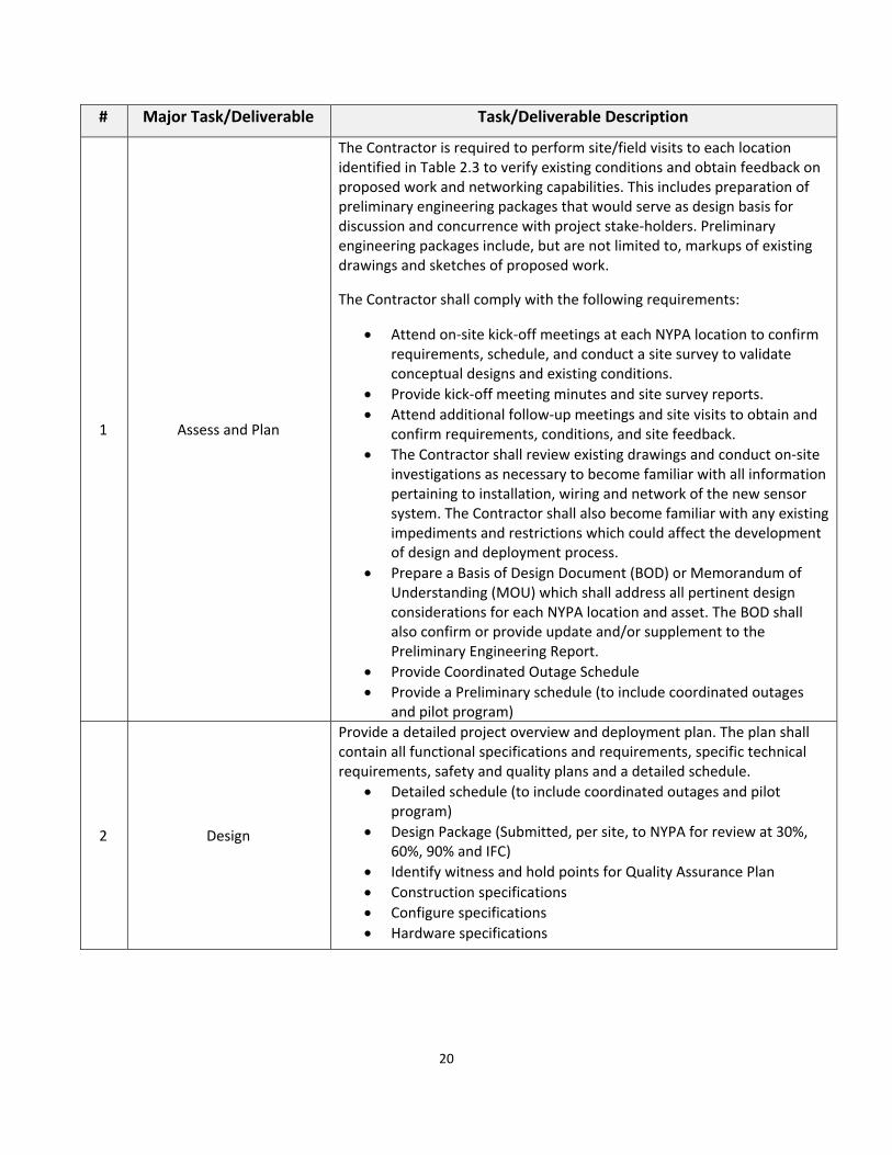
2.4.10 Major Task/DeliverablesWorkPlan The following table describes rough order of work for the five (5) major tasks/deliverable groups of the Sensor Deployment Phase II project. Regardless of which Phase II Sensor Systems, asset, or location, it will be expected to adhere to the below major task/deliverable sequence.
20
# Major Task/Deliverable Task/Deliverable Description
1 Assess and Plan
The Contractor is required to perform site/field visits to each location identified in Table 2.3 to verify existing conditions and obtain feedback on proposed work and networking capabilities. This includes preparation of preliminary engineering packages that would serve as design basis for discussion and concurrence with project stake‐holders. Preliminary engineering packages include, but are not limited to, markups of existing drawings and sketches of proposed work.
The Contractor shall comply with the following requirements:
Attend on‐site kick‐off meetings at each NYPA location to confirm requirements, schedule, and conduct a site survey to validate conceptual designs and existing conditions.
Provide kick‐off meeting minutes and site survey reports.
Attend additional follow‐up meetings and site visits to obtain and confirm requirements, conditions, and site feedback.
The Contractor shall review existing drawings and conduct on‐site investigations as necessary to become familiar with all information pertaining to installation, wiring and network of the new sensor system. The Contractor shall also become familiar with any existing impediments and restrictions which could affect the development of design and deployment process.
Prepare a Basis of Design Document (BOD) or Memorandum of Understanding (MOU) which shall address all pertinent design considerations for each NYPA location and asset. The BOD shall also confirm or provide update and/or supplement to the Preliminary Engineering Report.
Provide Coordinated Outage Schedule
Provide a Preliminary schedule (to include coordinated outages and pilot program)
2 Design
Provide a detailed project overview and deployment plan. The plan shall contain all functional specifications and requirements, specific technical requirements, safety and quality plans and a detailed schedule.
Detailed schedule (to include coordinated outages and pilot program)
Design Package (Submitted, per site, to NYPA for review at 30%, 60%, 90% and IFC)
Identify witness and hold points for Quality Assurance Plan
Construction specifications
Configure specifications
Hardware specifications
21
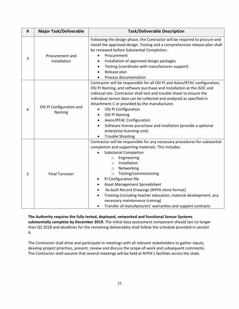
# Major Task/Deliverable Task/Deliverable Description
3 Procurement and
Installation
Following the design phase, the Contractor will be required to procure and install the approved design. Testing and a comprehensive release plan shall be reviewed before Substantial Completion.
Procurement
Installation of approved design packages
Testing (coordinate with manufacturer support)
Release plan
Process documentation
4 OSI PI Configuration and
Naming
Contractor will be responsible for all OSI PI and Axion/RTAC configuration, OSI PI Naming, and software purchase and installation at the iSOC and indiviual site. Contractor shall test and trouble shoot to ensure the individual sensor data can be collected and analyzed as specified in Attachment C or provided by the manufacturer.
OSI PI Configuration
OSI PI Naming
Axion/RTAC Configuration
Software license puruchase and intallation (provide a optional enterprise licensing cost)
Trouble Shooting
5 Final Turnover
Contractor will be responsible for any necessary procedures for substantial completion and supporting materials. This includes:
Substanial Completion o Engineering o Installation o Networking o Testing/commissioning
PI Configuration file
Asset Management Spreadsheet
As‐built Record Drawings (NYPA clone format)
Training (including teacher education, material development, any necessary maintenance training)
Transfer of manufacturers’ warranties and support contracts
The Authority requires the fully tested, deployed, networked and functional Sensor Systems substantially complete by December 2019. The initial data assessment component should last no longer than Q2 2018 and deadlines for the remaining deliverables shall follow the schedule provided in section 4. The Contractor shall drive and participate in meetings with all relevant stakeholders to gather inputs, develop project priorities, present, review and discuss the scope‐of‐work and subsequent comments. The Contractor shall assume that several meetings will be held at NYPA’s facilities across the state.
22
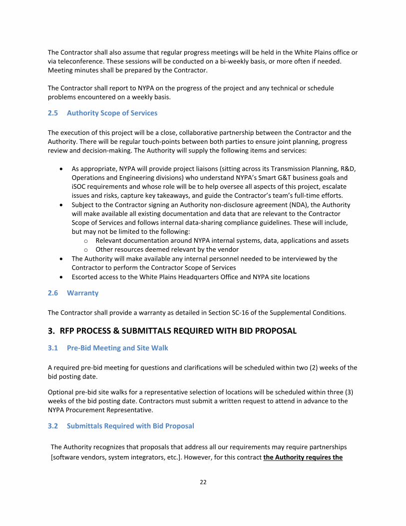
The Contractor shall also assume that regular progress meetings will be held in the White Plains office or via teleconference. These sessions will be conducted on a bi‐weekly basis, or more often if needed. Meeting minutes shall be prepared by the Contractor. The Contractor shall report to NYPA on the progress of the project and any technical or schedule problems encountered on a weekly basis.
2.5 Authority Scope of Services
The execution of this project will be a close, collaborative partnership between the Contractor and the Authority. There will be regular touch‐points between both parties to ensure joint planning, progress review and decision‐making. The Authority will supply the following items and services:
As appropriate, NYPA will provide project liaisons (sitting across its Transmission Planning, R&D, Operations and Engineering divisions) who understand NYPA’s Smart G&T business goals and iSOC requirements and whose role will be to help oversee all aspects of this project, escalate issues and risks, capture key takeaways, and guide the Contractor’s team’s full‐time efforts.
Subject to the Contractor signing an Authority non‐disclosure agreement (NDA), the Authority will make available all existing documentation and data that are relevant to the Contractor Scope of Services and follows internal data‐sharing compliance guidelines. These will include, but may not be limited to the following:
o Relevant documentation around NYPA internal systems, data, applications and assets o Other resources deemed relevant by the vendor
The Authority will make available any internal personnel needed to be interviewed by the Contractor to perform the Contractor Scope of Services
Escorted access to the White Plains Headquarters Office and NYPA site locations
2.6 Warranty
The Contractor shall provide a warranty as detailed in Section SC‐16 of the Supplemental Conditions.
RFP PROCESS & SUBMITTALS REQUIRED WITH BID PROPOSAL
3.1 Pre‐Bid Meeting and Site Walk
A required pre‐bid meeting for questions and clarifications will be scheduled within two (2) weeks of the bid posting date.
Optional pre‐bid site walks for a representative selection of locations will be scheduled within three (3) weeks of the bid posting date. Contractors must submit a written request to attend in advance to the NYPA Procurement Representative.
3.2 Submittals Required with Bid Proposal
The Authority recognizes that proposals that address all our requirements may require partnerships
[software vendors, system integrators, etc.]. However, for this contract the Authority requires the
23
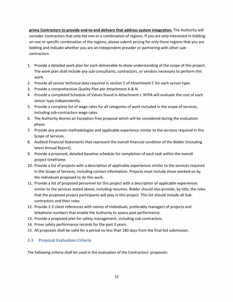
prime Contractors to provide end‐to‐end delivery that address system integration. The Authority will
consider Contractors that only bid one or a combination of regions. If you are only interested in bidding
on one or specific combination of the regions, please submit pricing for only those regions that you are
bidding and indicate whether you are an independent provider or partnering with other sub‐
contractors.
1. Provide a detailed work plan for each deliverable to show understanding of the scope of this project.
The work plan shall include any sub‐consultants, contractors, or vendors necessary to perform this
work.
2. Provide all sensor technical data required in section 5 of Attachment C for each sensor type.
3. Provide a comprehensive Quality Plan per Attachment A & N.
4. Provide a completed Schedule of Values found in Attachment J. NYPA will evaluate the cost of each
sensor type independently.
5. Provide a complete list of wage rates for all categories of work included in the scope of services,
including sub‐contractors wage rates.
6. The Authority desires an Exception‐free proposal which will be considered during the evaluation
phase.
7. Provide any proven methodologies and applicable experience similar to the services required in this
Scope of Services.
8. Audited Financial Statements that represent the overall financial condition of the Bidder (including
latest Annual Report).
9. Provide a proposed, detailed baseline schedule for completion of each task within the overall
project timeframe.
10. Provide a list of projects with a description of applicable experiences similar to the services required
in this Scope of Services, including contact information. Projects must include those worked on by
the individuals proposed to do this work.
11. Provide a list of proposed personnel for this project with a description of applicable experiences
similar to the services stated above, including resumes. Bidder should also provide, by title, the roles
that the proposed project participants will play in this project. This list should include all Sub‐
contractors and their roles
12. Provide 2‐3 client references with names of individuals, preferably managers of projects and
telephone numbers that enable the Authority to assess past performance.
13. Provide a proposed plan for safety management, including sub‐contractors.
14. Prove safety performance records for the past 3 years.
15. All proposals shall be valid for a period no less than 180 days from the final bid submission.
3.3 Proposal Evaluation Criteria
The following criteria shall be used in the evaluation of the Contractors’ proposals:

24
1. Experience ‐ The Authority will evaluate submitted materials for demonstrated experience and
knowledge shown by the previous performance of similar work.
2. Schedule compatibility ‐ The Bidder's proposed schedule will be evaluated for compliance to the
Authority’s requirements. Ability to develop schedule, complete tasks and meet deadlines, on time
and within budget.
3. Price ‐ The contract award will be based on the proposal that most meets the overall needs of the
contract. Project cost will not be the sole determining factor. The Bid amount shall be submitted to
perform all the work as indicated in the Bid/Contract Documents.
4. References ‐ The Bidder must provide a list of contacts that it, and its sub‐contractors, has
performed similar work. Bidder failure to meet the requirements of this section may result in no
further consideration of its Bid Proposal.
5. Safety – The Bidder will be evaluated on its safety history and its overall safety plan.
6. The Authority reserves the right, at its discretion, to require pre‐award presentations and inspection
of the facilities of selected Bidders.
SCHEDULE OF DELIVERABLES It is expected that the five tasks/deliverables outlined in the Scope of Services section would last no longer than 19 months. It is expected that all five tasks will be completed at different times for individual assets and sites. The schedule of deliverables below is a representation of the absolute deadline for each deliverable. Contractor’s schedule shall be developed to ensure that every deliverable for all sites meet the deadlines presented below.
# Major Deliverable Due Date
1 Assess and Plan Issue Coordinated Outage Schedule: July 27, 2018 Complete Site Visits: July 13, 2018
2 Design, Build and Configure December 31, 2019
3 Procurement and Installation October 31, 2019
4 OSI PI Configuration and Naming October 31, 2019
5 Transition As‐built Drawings: December 31, 2020 All other items: December 31, 2019
The Authority is aiming to have the pilot program complete by October of 2018. For all other facilities, a detailed schedule, including durations and task/deliverable details is required. The Authority understands the above schedule may need to be modified. However, the Asset Management Strategic Initiative is under an aggressive delivery schedule and, given adequate access to information and personnel, NYPA will expect Contractors to adhere to the schedule provided.

25
ATTACHMENT A – DIVISION 01 SPECIFICATIONS
Division 1 Sensor Deployment Phase II
1
Sensor Deployment Phase II
DIVISION 1 - PROJECT SPECIFICATION
TABLE OF CONTENTS
SECTION PAGE
SECTION 01010 - SUMMARY OF WORK .....................................................................................2
SECTION 01090 - REFERENCES ....................................................................................................7
SECTION 01100 - JOBSITE REQUIREMENTS ............................................................................9
SECTION 01220 - PROJECT MEETINGS .......................................................................................19
SECTION 01240 - PROJECT CONTROL REQUIREMENTS ........................................................21
SECTION 01310 - CONSTRUCTION SCHEDULES .......................................................................25
SECTION 01335 - DATA TO BE FURNISHED BY THE CONTRACTOR ......................................28
SECTION 01340 - SHOP DRAWINGS, PRODUCT DATA, DOCUMENTS, AND SAMPLES ......30
SECTION 01410 - TESTING LABORATORY SERVICES .........................................................38
SECTION 01440 - CONTRACTOR'S QUALITY CONTROL ....................................................40
SECTION 01505 - MOBILIZATION AND DEMOBILIZATION ...................................................45
SECTION 01524 – ENVIRONMENTAL, HEALTH, SAFETY AND CONSTRUCTION WASTE
MANAGEMENT ................................................................................................................................47
SECTION 01576 - FACILITY POLLUTION, WATER, AND EROSION CONTROL ...............58
SECTION 01577 - FACILITY PROTECTION AND SITE RESTORATION ...........................63
SECTION 01701 - CONTRACT CLOSEOUT ...............................................................................69
ATTACHMENT 1 – FIELD CHANGE NOTICE ..........................................................................73
ATTACHMENT 2 – FIELD CHANGE REQUEST ......................................................................75
ATTACHMENT 3 – DESIGN CHANGE NOTICE .......................................................................77
ATTACHMENT 4 – SUBMITTAL COVER SHEET ....................................................................79
ATTACHMENT 5 – CONTRACTOR’S SUBMITTAL LOG ......................................................81
ATTACHMENT 6 - REQUEST FOR INFORMATION (RFI) SHEET ......................................83
ATTACHMENT 7 - CONSTRUCTION INSPECTION/MONITORING PROGRAM .............85
Division 1 Sensor Deployment Phase II
2
SECTION 01010 - SUMMARY OF WORK
PART 1 GENERAL
1.1 SUMMARY Title of Project: Sensor Deployment Phase II
A. Location of Project:
Various locations refer to Attachment B for physical addresses
1.2 WORKS UNDER THIS CONTRACT
A. The work covered under these specifications consists of furnishing all plant supervision, labor, materials and equipment (except for services, materials, and/or equipment to be furnished by others as specifically referred to in the Contract Documents), and performing all operations required for the Sensor Deployment Phase II including, but not limited to the following:
The objective of the Sensor Deployment project is to provide increased real-time
insight into asset health status and productivity in order to optimize regular maintenance spend, deter emergent capital spending, and reduce environmental, regulatory and safety penalties. NYPA is looking to partner with a vendor or selection of vendors to phase in the implementation of a state-of-the-art Monitoring & Diagnostics Center (M&D Center) that will ultimately analyze data for all critical NYPA assets to inform smart asset management decisions on both a routine and emergent basis.
1. Perform site/field visits to each location to verify existing conditions and
obtain feedback on networking capabilities. 2. Design, procure, install, and commission the identified sensors at each
asset (Reference Attachment A- O) 3. Design, procure, install and commission a communications network,
including System 1 upgrades, that will transmit the diagnostic data from each of the sensors to the iSOC
4. Configure OSI PI system including PI naming (Reference Attachment D) 5. Provide a detailed schedule of the installation of the sensors (Reference
Attachment I) 6. Provide and coordinate a schedule of outages (Reference Attachment K) 7. Address any data quality needs or cleanup necessary to effectively
transmit the senor data to the iSOC 8. Provide As-built drawings per the Authority’s clone process (Reference
Attachment M)
Division 1 Sensor Deployment Phase II
3
1.3 SERVICES, MATERIAL, AND EQUIPMENT PROVIDED BY THE
AUTHORITY:
The execution of this project will be a joint product development between the successful bidder and the Authority. There will be regular touch-points between both parties to ensure joint planning, progress review, and decision-making. The Authority will supply the following items and services: a. As appropriate according to the agreed commercial terms with the successful
bidder, NYPA will provide technical expertise and project resources (sitting across its Operations Technology, Information Technology, Operations Planning, R&D, Strategic Operations and Engineering divisions) who understand NYPA’s Smart G&T business goals and the grid’s Next-Gen EMS requirements, and whose role will be to help oversee all aspects of this effort, contribute expertise, escalate issues and risks, capture key takeaways, and guide the Vendor team’s full-time efforts.
b. Subject to the vendor signing the contract and a NYPA non-disclosure agreement (“NDA”), the Authority will make available existing NYPA-owned intellectual property, documentation and data that are relevant to the vendor scope of services and follows internal data-sharing compliance guidelines. These will include, but may not be limited to the following: i. Relevant, non-proprietary documentation about NYPA systems, data,
applications and assets. ii. Other resources deemed relevant by the successful bidder.
c. The Authority will make available any internal personnel needed to be
interviewed by the successful bidder to perform the vendor scope of services.
d. Escorted access to the White Plains office and other NYPA facilities.
1.4 COOPERATION
A. The New York Power Authority (hereinafter referred to as the “Authority”) shall
cooperate with the Contractor to facilitate the continuity and progress of the work. The Contractor shall cooperate with the Authority by minimizing the disturbance of the Authority's activities in the areas within or adjacent to the contract work.
B. With direction from the Authority’s Site Representative, the Contractor shall
coordinate all work activities with those of the Authority. The Contractor shall avoid
Division 1 Sensor Deployment Phase II
4
causing disruptions to the daily activities of the operation and maintenance personnel and their equipment at the Authority’s facilities. When work must be coordinated with plant personnel, the Contractor may be required to stop or rearrange the project schedule.
C. With direction from the Authority’s Site Representative, the Contractor shall
coordinate all work activities with other contractors performing work in these and adjacent areas. The Contractor shall avoid interference and ensure the continued progression of work.
D. All operations of the Contractor shall be confined to the areas authorized and
approved by the Authority. No unauthorized and unwarranted entry or passage, storage or disposal of materials shall be made upon the property of the Authority.
E. The Contractor shall maintain access to existing roads to the jobsite at all times.
When work will interfere with access to the facilities, the Contractor shall advise the Authority of the proposed work schedule at least forty-eight (48) hours in advance. The Authority will strive to accommodate the proposed work schedule.
F. The Contractor shall be responsible for the conduct of all employees in relation with
one another, all Authority employees, and other contractors working at the Authority’s facilities. Any misconduct shall be dealt with in a responsible and timely matter by the Contractor.
1.5 INTERPRETATION OF DRAWINGS AND SPECIFICATIONS
A. The lists of equipment, tabulations of data, and schedules appearing in the specifications and/or drawings are included only for the assistance and guidance of the Contractor in arriving at a more complete understanding of the intended scope of work. They are not intended, or to be construed, as relieving the responsibility of the Contractor in conducting their own takeoffs and preparing a work plan.
B. The Contractor shall perform all measurements necessary to determine actual
dimensions for the matching and proper fit of new material to the existing components.
C. The Contractor is responsible for taking measurements of existing conditions and
elevations. These shall take precedence over dimensions provided in the Contract Documents. If an error should exist, deviations from the Contract Documents shall be made only after an agreement in writing is obtained from the Authority.
1.6 OBSTACLES AND MINOR ADJUSTMENTS
A. The drawings are not intended to show all details and requirements relating to the
scope of work. The Contractor shall advise the Authority's Site Representative
Division 1 Sensor Deployment Phase II
5
immediately, in writing, when the Contractor encounters obstacles or discrepancies, which require minor changes or adjustments to the approved design and work procedures.
1.7 ABBREVIATIONS AND SYMBOLS
A. The Contractor is expected to be familiar with the standard abbreviation symbols
used in the Contract Documents. The Contractor shall inform the Authority, in writing, of any unclear or unknown abbreviation or symbol. Unless notified, the Authority will assume that the Contractor is fully familiar with all such items and can execute the work accordingly.
1.8 LANGUAGE AND SYSTEM OF UNITS
A. All dimensions, descriptions, calculations, drawings, test reports, progress estimates,
packing lists, and correspondences submitted to the Authority shall be in English and shall have English system of units throughout, in addition to any other language and any other system of units. Where the English language or system of units is in conflict with the language or system of units used by the Contractor, the English language and system of units shall be binding.
1.9 PROTECTION OF AUTHORITY PROPERTY AND PERSONNEL
A. The Contractor shall provide protection to prevent damage to the Authority property,
including all facilities, interior and exterior, during construction operations. B. The Contractor shall protect the occupants and surrounding areas against hazards
during constructions operation and shall provide safe access to Authority occupied areas. If elimination of access to any area becomes necessary, it shall occur only after advance notice and written approval by the Authority.
C. The Contractor shall provide necessary barricades, temporary partitions, other
separations including those for dust control, and closures to protect the Authority’s personnel, equipment, facilities, and the public from harm or injury due to the construction operations.
D. The Contractor shall repair any damage to Authority property to the satisfaction of
and at no cost to the Authority.
1.10 PROTECTION OF EQUIPMENT AND MATERIALS
A. The Contractor shall assume full and complete responsibility for protection and security of their materials and equipment stored at the project location.
PART 2 PRODUCTS NOT APPLICABLE
Division 1 Sensor Deployment Phase II
6
PART 3 EXECUTION 3.1 CONTRACT DRAWINGS Drawing Number Drawing Title Revision Number TBD 3.2 CONTRACT SPECIFICATION SECTIONS Section Title Revision Number END OF SECTION 01010
Division 1 Sensor Deployment Phase II
7
SECTION 01090 - REFERENCES PART 1 GENERAL 1.1 CODES AND STANDARDS
A. All material and workmanship shall comply with, but not be limited to the
following U.S. standards where applicable, and other standards explicitly referred to in the specifications, including such revisions which are in effect on the date that Proposals are received.
1. American Concrete Institute (ACI) 2. American National Standards Institute (ANSI) 3. American Society for Testing and Materials (ASTM) 4. American Society of Civil Engineers (ASCE) 5. American Society of Mechanical Engineers (ASME) 6. Concrete Reinforcing Steel Institute (CRSI) 7. Federal Communications Commission (FCC) 8. International Building Code (IBC) 9. International Code Council (ICC) 10. International Electromechanical Commission (IEC) 11. Instrumentation, Systems and Automation Society (ISA) 12. International Telecommunication Union (ITU) 13. North-American Electric Reliability Corporation (NERC) 14. National Electrical Manufacturers Association (NEMA) 15. National Fire Protection Association (NFPA) 16. Occupational Safety and Health Administration Standards (OSHA) 17. Underwriters Laboratories (UL)
B. The Contractor may propose the use of standards that are equal to or better than the
above. In the event such standards are proposed, the Contractor shall submit the latest issue of the proposed standards and codes with any revisions in effect. The Contractor shall state all differences between the proposed standards and the above. All design and equipment shall adhere to the above standards except where the Contractor specifically states the differences, which are then accepted by the Authority. All proposed changes shall be documented in writing.
C. All parts, hardware, fittings, and materials shall conform to the standards listed
above and all others indicated in the Contract Documents. D. Materials furnished by the Contractor needed to complete all installations shall be
compatible with both existing and new Authority furnished materials and shall be in accordance with the standards applicable to the work.

Division 1 Sensor Deployment Phase II
8
PART 2 PRODUCTS NOT APPLICABLE PART 3 EXECUTION NOT APPLICABLE END OF SECTION 01090
Division 1 Sensor Deployment Phase II
9
SECTION 01100 - JOBSITE REQUIREMENTS PART 1 GENERAL
1.1 EMPLOYEE ORIENTATION A. All Contractors’ employees are required to attend an employee orientation
given by the Authority. The duration of the orientation is approximately two (2) hours.
B. The employee orientation will be held on the Authority's property and will be at
the Authority's expense. C. The employee orientation will cover the Authority's Safety, Fire Protection,
Environmental and Security requirements. D. No compensation will be offered for the loss of time to the Contractor for
attending the employee orientation. E. No unescorted Contractor employee will be permitted on the Authority's property
unless the employee orientation has been completed. F. Contractor's employees who occasionally visit the site will be permitted access if
escorted at all times by an employee who has completed the orientation. Truck drivers making deliveries to the site will require an escort by the Contractor.
1.2 SECURITY AND BACKGROUND SCREENING PROGRAM
A. The Contractor's personnel are expected to adhere to the Authority's security
requirements as included in the Authority Safety/Security Manual. Reasonable delays due to the Authority performing its security-related duties (i.e., verifying an employee’s identification badge, etc.) are to be expected by the Contractor.
B. All Contractors must comply with the background screening requirements outlined
in Appendix “D” – “SDP 45-01 Background Security Screening for NYPA Contractors”, found in the Bid Documents.
1.3 PHOTO IDENTIFICATION BADGES
A. Following the completion of employee orientation, all Contractor employees will
be issued photo identification (ID) badges. All badges are the property of the Authority and must be returned upon termination of employment on site. A fee will be charged to the Contractor for each badge not returned.
Division 1 Sensor Deployment Phase II
10
B. All Contractor's employees must show the badge to the Authority's security personnel to gain entrance to the site and must wear the badge on outer garments so that it is visible at all times while working on Authority property.
C. Any Contractor's employee without the appropriate badge will not be allowed
access to the Authority's property.
1.4 PROHIBITED ITEMS A. Firearms, liquor and drugs (except prescription drugs, which must be in the original
labeled container) and other controlled substances are prohibited on the Authority's property. Any Contractor's employee in violation of this requirement will be subject to immediate removal from the site by the Authority and will not be permitted to return.
1.5 HOURS OF WORK
A. The Contractor shall confine normal hours of work from 7:00am to 3:30pm,
Monday through Friday, unless otherwise noted. Upon written request and approval, the Authority may grant the Contractor extended hours at no additional cost to the Authority. 1. If the schedule requires that overtime be worked (i.e. in addition to the normal
eight hour work day), the Contractor shall apply for and receive an Overtime Dispensation from the New York State Department of Labor.
B. Site Union/Craft labor is granted a lunch and breakfast break at specific times at
each site. The Contractor will not be granted any standby time during these breaks. The lunch and breakfast break times are subject to change by the Authority at any time.
C. The Authority may schedule all commissioning activities on a 6/10 schedule (Ten hours per day, Monday-Saturday) with no additional cost to the Authority.
D. All work activities and material deliveries shall be scheduled in advance and submitted to the Authority’s Site Representative. No work shall commence prior to the full knowledge of the Authority’s Site Representative
1.6 SITE ACCESS REQUIREMENTS
A. All private vehicles and commercial vehicles entering and exiting the Authority's
property are subject to search by the Authority. B. No material, parts and components can leave or arrive to the site without a prior
written approval from the site Construction Manager. Contractor must obtain
Division 1 Sensor Deployment Phase II
11
written authorities 5 working days in advance on the appropriate form.
C. Parking for employee's private vehicles shall be limited to those areas designated by the Authority's Site Representative. Vehicles parked on private property, blocking roadways, or otherwise illegally parked, will be towed at the owner's expense.
D. At the discretion of the Authority’s Site Representative, the Contractor's supervisory
staff (i.e. Site Superintendent, QA Inspector, Safety Officer) may be issued keys to doors accessing the work areas, where applicable. Keys are property of the Authority and must be returned upon completion of work or leaving the project.
1.7 USE OF AUTHORITY FACILITIES
A. Contractor shall provide temporary restroom facilities for its personnel. The
Contractor shall be responsible for good housekeeping practices. B. The Contractor may be permitted to use the tools and equipment provided by the
Authority as per Section 01010 Paragraph 1.3.
1.8 FACILITIES TO BE PROVIDED BY THE CONTRACTOR A. The Contractor shall provide storage areas, employee facilities, waste disposal,
tools, fire prevention and safety equipment, fuel, gases, communication services, potable water and sanitary facilities. The Contractor will not be permitted to use any of the Authority’s facilities or service equipment, unless otherwise noted.
B. The Contractor shall supply, install, maintain in a safe working condition, and
remove the following as required in the performance of the work:
1. Scaffolding. 2. Ladders and railings. 3. Temporary lighting. 4. Jobsite Trailers. 5. Service equipment required to support project work. 6. Any other items necessary to perform project work.
1.9 SITE OPERATIONS AND STORAGE SPACE ALLOCATION
A. The Authority retains sole authority to assign space for material and tool storage as
needed by the Contractor. Allocation of space will be based on the most beneficial use of the area in regards to the interests of the Authority. The Contractor is advised that the need for space for installation work will likely exceed the space which will be assigned. Accordingly, the Contractor shall be prepared to develop, at their expense, temporary assembly facilities and office space in yard areas
Division 1 Sensor Deployment Phase II
12
elsewhere on the site and to perform Contract Work within such areas. The Contractor shall not be entitled to an extension of time or to additional compensation by reason of any decision of the Authority in the assignment or reassignment of space in or adjacent to the area or by reason of the need for the Contractor to develop temporary erection areas and perform the Contract Work therein.
B. The Authority will provide space to the Contractor for temporary facilities
required for their operations, storage and personnel etc. This space represents the total outside space on Authority property to be allocated for the Contractor's use. The Contractor is to develop the layout of their facilities within this space and submit it to the Authority for approval. The Contractor shall remove such temporary structures at the completion of Contract Work.
Jobsite Trailers: Jobsite trailers shall comply with NYSBC and bear the Insignia of Approval (Insignia) by the State of New York. The Insignia shall be physically located on the trailer indicating the Insignia serial number, name of manufacturer, plan approval number, model or component designation, manufacturer’s serial number, and date of manufacture. The Insignia is applied at the manufacturer’s plant and the State will not provide one once it leaves the plant. If the jobsite trailers contain the Insignia the Authority shall verify that the appropriate design parameters were used for the location the trailer will be installed – specifically, snow, wind and seismic design criteria. Signed and sealed construction calculations may be requested by the Authority. If the jobsite trailers do not contain an Insignia, signed and sealed drawings and calculations specific for the project and location will be required for Authority review and acceptance. Inspection of the trailers including exposing all concealed work may be required. For all trailers the Authority will need NYS PE signed and sealed site-specific installation drawings for the trailers, foundation and all utilities. NYS PE signed and sealed drawings will also be required, required for site renovations, as built documentation and restoration design. The engineer of record and contractor shall apply and obtain all necessary permits. The color of the trailer(s) must be approved by NYPA prior to the installation and shall blend into the surroundings and nearby buildings. The contractor shall be responsible for all maintenance and up keep including; power, internet and communication connections, lavatory facilities, cleaning, snow and ice removal, surcharges, fees and usage for the duration of the “project”. NYPA reserves the right to perform periodic inspections of trailer(s) and the contractor must address
Division 1 Sensor Deployment Phase II
13
all deficiencies identified (within 10 calendar days minimum) otherwise trailer(s) will be directed to be removed off site at the contractor’s expense. All trailers and associated equipment (utility poles, junction boxes, roads, sidewalks, gravel, backfill, trenching, etc…) along with all temporary connections (power, communication, water, sewer, etc…) shall be removed from the site upon completion of the construction activities. The site and utilities shall be restored to the condition prior to the trailer installation and will be included in the demobilization activities prior to final payment.
C. If the Contractor anticipates that additional outside space is required for their
operations, a specific request in writing shall be submitted to the Authority for review and approval.
D. Equipment susceptible to damage due to extreme temperature and/or humidity conditions shall be stored in an enclosed space that is climate-controlled to reduce the chance of damage. Contractor must supply storage procedure for all equipment. Periodic inspections of climate-controlled stored equipment must be performed monthly by the Contractor and the cost shall be included in the Contractor’s base bid price.
E. All areas to be utilized by the Contractor are to be jointly inspected and
photographed by the Authority and the Contractor before the Contractor’s facilities are established. Both the Authority and the Contractor shall retain one (1) complete set of the photographs.
F. Upon the removal of the Contractor's facilities, the Contractor shall fully restore
these areas to their original condition. This includes, but is not limited to, grass areas, roadway, sidewalks, curbs, catch basins, plants, shrubs, trees, retaining walls, etc. This restoration shall be done completely at the Contractor's cost.
G. All operations of the Contractor upon Authority's premises shall be confined to
areas authorized or approved by the Authority. No unauthorized or unwarranted entry upon, or passage through, shall be made upon Authority premises.
1.10 JOB CONDITIONS
A. Occupancy: The Authority will be continuously utilizing areas of the building(s)
and site immediately adjacent to the work areas. The Contractor shall prevent disruption of the Authority's normal operations and shall provide a minimum of three (3) days advance notice to the Authority of activities which will impact the Authority's normal operations.
B. Condition of Structures: The Authority assumes no responsibility for the actual
condition of items, structures or existing roadways.
Division 1 Sensor Deployment Phase II
14
C. Traffic: The Contractor shall conduct operations in a manner to ensure minimum interference with roads, streets, walks, and other adjacent occupied or used facilities. Do not close, block, or otherwise obstruct Authority streets, roadways, grass areas, walkways, or other occupied or used facilities without written permission from the Authority. Provide alternate routes around closed or obstructed traffic ways.
D. Cutting, Burning, and Welding: All cutting, burning, and welding operations
require issuance of written permits from both the Contractor and the Authority. The Contractor shall provide a fire watch during all cutting, burning, and welding operations. A fire extinguisher shall be located within 20 feet of any operation.
1.11 DISPOSAL OF MATERIALS AND DEBRIS
A. The Contractor shall be responsible for the removal and disposal of excess unused
material and debris resulting from operations, unless otherwise noted. Any material and equipment required for proper execution of the work shall be furnished by the Contractor and removed off-site when no longer needed.
B. The Contractor shall submit a proposed disposal site along with all applicable permits and documentation for review and approval by the Authority.
1. If hazardous materials are encountered during operations, the Authority’s Site Representative must immediately be notified. At the direction of the Authority’s Site Representative and/or Environmental Supervisor, the Contractor shall comply with all applicable Federal, State, and local regulations, laws, and ordinances concerning removal, handling, and protection against exposure or environmental pollution.
2. Burning, burial, or storage of excess materials, excavated materials, trash, debris, etc. is not permitted on site, unless otherwise noted.
3. Trash and debris shall be removed from the worksite(s) on a daily basis.
C. Prior to loading any vehicle/equipment/tools that leave a highway, access road, or break the surface of soil, remove as much debris, vegetation, dirt and mud clinging to the equipment as possible. 1. If required, after loading, Contractor shall be responsible for transporting
vehicle/equipment/tools to shop or car wash for thorough cleaning prior to entering another right-of-way.
D. All spoils shall become the property of the Contractor and must be disposed of in accordance with all local, state, and federal requirements. The Contractor shall obtain prior approval from the Authority and the New York State Department of
Division 1 Sensor Deployment Phase II
15
Environmental Protection for all spoil areas to be used for material generated from demolition and repair activities.
E. If drum containers are used to dispose of materials, only new DOT approved
drums shall be used.
F. Unless otherwise specified, contractor must dispose of all old material, components, oil, debris, paint etc.
1.12 SAFETY AND ACCIDENT PREVENTION
A. The Contractor shall observe the Authority’s, DOSH, and OSHA safety rules and
practices. Where conflict arises, the most stringent requirements, as determined by the Authority, shall apply. 1. According to the New York State Labor Laws, public work contracts of at least
$250,000 require all laborers, workers, and mechanics employed in the performance of the contract on this worksite, either by the contractor, subcontractor or other person doing or contracting to do the whole or a part of the work contemplated by the contract, shall be certified prior to performing any work on the project as having successfully completed the OSHA 10-hour Construction Safety and Health Course.
B. The Contractor shall ensure that the work environment is free from recognized hazards and is in compliance with applicable statutory, regulatory and other standards.
C. The Contractor shall prepare and submit a comprehensive and signed “Site Specific Health, Safety, and Accident Prevention Program” administered by a Corporate-level Safety Officer which covers all specific project issues. The Contractor shall provide a written site specific rescue plan coordinated with local emergency response agencies.
D. The Contractor shall review the Authority’s Safety Rules and Emergency Procedure
and ensure compliance by all employees. This review shall be documented by the Contractor and submitted to the Authority. Should a required Authority safety practice be more restrictive than the Contractor’s Manual or practice, the Authority’s practice will be required.
E. The Contractor shall take all necessary precautions for the safety of employees,
protection of the work, and protection of adjoining property. The Contractor shall conform to all Federal, State, and local laws, Building Codes, and New York Power Authority rules and regulations in effect during performance of this Contract Work.
F. The Contractor shall erect and properly maintain at all times, as required by

Division 1 Sensor Deployment Phase II
16
conditions and as directed by the Authority during the progress of the work, all necessary safeguards for the protection of workers, the Authority, and the public. Danger signs warning against the hazards created by such features of construction shall be posted as applicable.
G. The Contractor is solely responsible for initiating, maintaining, and supervising all
safety precautions and programs in connection with the work.
H. The Contractor is advised that work may be done in the vicinity of energized lines and equipment, and shall take necessary precaution to protect employees and adjacent facilities from damage and maintain proper working clearances in accordance with OSHA and NESC guidelines and any additional requirements imposed by the Authority.
I. The Contractor shall properly ground all mobile equipment working in the vicinity
of energized lines and equipment (and within the switchyard if applicable). Adjacent structures and their ground systems shall not be used to ground Contractor's equipment.
J. Reflective orange safety vests or fluorescent orange jackets shall be worn at all times
while working on or adjacent to roadways.
K. The use of hard hats, safety shoes, and eye protection (with side shields) is mandatory. Additional Personal Protection Equipment, required by the construction activities, such as gloves, hearing and respiratory protection shall be provided by the Contractor to all employees as required by regulations.
L. One hundred percent (100%) fall protection shall be provided when involved in
above-the-ground (four feet or higher) work. This includes but is not limited to the use of safety full body harnesses during the following operations: work from suspended scaffold; work in aerial device (lift vehicles); and working from ladders, scaffold, or platforms (not protected). The Contractor shall submit a detailed Project Specific Fall Protection Plan, subject to review and approval by the Authority.
M. For each calendar week the Contractor has employees working on-site, at least
one organized and documented Safety Talk shall be conducted by the Contractor’s Site Supervisor. Documentation of such should be submitted to the Authority’s Site Representative.
1.13 CLEARANCE AND PROTECTION PROCEDURES
A. All Contractor personnel shall adhere to, train, and qualify for the Authority’s
lockout / tagout procedure, Clearance and Protection Procedures (CPP-1).
Division 1 Sensor Deployment Phase II
17
B. All personnel working under a clearance, including Authority employees and Contractors, must sign on to any clearances issued for the particular project, deeming them “authorized” to work on the equipment.
C. These “authorized” workers shall receive initial training on CPP-1 as well as
refresher training on an annual basis. D. Contractors shall receive this training as part of the initial orientation. The duration
of the training is approximately two (2) hours.
1.14 NORTH AMERICAN ELECTRIC RELIABILITY CORPORATION (NERC) REQUIREMENTS a. All Contractor personnel shall adhere to, train, and qualify for the NERC Critical
Infrastructure Protection (CIP) standards. b. All personnel working on or near Critical Cyber Assets shall be trained within
ninety calendar days of authorization to work in such areas, deeming them “authorized” workers.
c. Training shall cover the policies, access controls, and procedures as developed for
the Critical Cyber Assets and shall include, at a minimum, the following required items appropriate to personnel roles and responsibilities:
1. Proper use of Critical Cyber Assets. 2. Physical and electronic access controls to Critical Cyber Assets. 3. Proper handling of Critical Cyber Asset information. 4. Action plans and procedures to recover or re-establish Critical Cyber
Assets and access thereto following a Cyber Security Incident. d. All personnel shall sign a form to indicate that training has been completed. e. These “authorized” workers shall receive initial training as well as refresher
training on an annual basis. f. Contractors shall receive this training as part of the initial orientation. The
duration of the training is approximately one (1) hour.
1.15 DIESEL EMISSIONS REDUCTION ACT AND BEST AVAILABLE RETROFIT TECHNOLOGY (BART) A. All Contractors and subcontractor(s) shall comply with 6 NYCRR Part 248 –
Diesel Emissions Reduction Act and Best Available Retrofit Technology (BART).
Division 1 Sensor Deployment Phase II
18
1. All diesel-powered Heavy Duty Vehicles (HDVs), greater than 8500 GVW, owned by, operated by, or leased by Contractor personnel and/or subcontractor(s) personnel and used in the performance of the Contract/Purchase Order, shall be powered by Ultra Low Sulfur Diesel Fuel (ULSD) and shall utilize BART.
2. As outlined in Appendix “M” of the Bid Documents, Contractor(s) and subcontractor(s) shall submit proof of compliance with 6 NYCRR Part 248, including a complete HDV inventory/equipment list of all vehicles, equipment, etc. subject to review and approval by the Authority. Such information collected will be submitted to the NYSDEC.
3. Violations shall result in fines from the NYSDEC.
1.16 VIOLATION OF THE AUTHORITY'S REQUIREMENTS
A. Any Contractor's employee found in violation of any of the Authority's
requirements (safety, fire protection, environmental, security, etc.) will be required to leave the property and will be prohibited from future work.
PART 2 PRODUCTS NOT USED PART 3 EXECUTION NOT USED END OF SECTION 01100
Division 1 Sensor Deployment Phase II
19
SECTION 01220 - PROJECT MEETINGS
PART 1 GENERAL 1.1 DESCRIPTION
A. The Contractor's Project Representative will schedule and administer all project
meetings. 1.2 PRE-CONSTRUCTION MEETING
A. The Contractor's Project Representative will schedule one (1) or more meetings after Award of Contract and prior to the start of construction.
B. The Contractor shall have in attendance at the Meeting(s), as a minimum,
Representatives including Project Superintendent, Safety and Quality Control Inspector(s), and Project Manager. Other key personnel responsible for the performance of the Project, including representatives from the Authority, engineering and major subcontractor(s), will be requested to attend on an as-needed basis.
C. Items to be discussed, but not limited to:
1. Introductions. 2. Responsibilities of Contractor's and Authority's Key Project Personnel. 3. Project Administration. 4. Commercial Submittals. 5. Technical Submittals. 6. Design Documents Configuration Management Procedures (FCNs, FCRs,
etc.). 7. Project Schedule. 8. Partial Estimate Payments. 9. Additional Work Request and Change Order Procedures. 10. Quality Control Program. 11. Environmental/Hazardous Waste Concerns. 12. Contractor’s Site Specific Health and Safety Program. 13. New York Power Authority Safety Orientation. 14. Project Close-out.
1.3 PROGRESS MEETINGS
A. The schedule for regular meetings, which are to be held weekly, will be set up at
the pre-construction meeting. The Authority's Site Representative, Contractor's Project Superintendent, Project Manager, and subcontractor(s) pertinent to the agenda, shall attend these meetings.
Division 1 Sensor Deployment Phase II
20
B. The Agenda at the regular progress meeting shall include:
1. Review minutes of previous meeting. 2. Review administrative items. 3. Review schedule and status of submittals and shop drawings. 4. Review status of construction schedule. 5. Plan work progress during next work period and its effect on related work of
others (two week look-ahead schedule). 6. Review and note field observations, problems, and decisions. 7. Identify and resolve all present and outstanding problems.
C. The Contractor will make physical arrangements for the meetings, prepare an
agenda with copies for participants, preside over the meetings, record the minutes of the meetings, and distribute copies, within two (2) work days, to the participants and those affected by the decisions made at the meeting
1.4 SPECIAL MEETINGS
A. Meetings other than the regularly scheduled progress meetings may be called by
the Authority or requested by the Contractor to review special issues. These meetings shall be attended by the entities directly affected by the purpose of the meeting.
1.5 MEETING COSTS
A. The cost to attend all meeting including but not limited to face to face meetings, teleconferences and meeting at the third party locations shall be included in the contractor’s base bid price. All meeting costs related to the work under a change order shall be included in the contractor’s base additional work authorization request.
PART 2 PRODUCTS NOT USED PART 3 EXECUTION NOT USED END OF SECTION 01220

Division 1 Sensor Deployment Phase II
21
SECTION 01240 - PROJECT CONTROL REQUIREMENTS
PART 1 GENERAL 1.1 DAILY WORK REPORTS
A. The Contractor shall submit daily work reports indicating, at a minimum, the following:
1. Work performed. 2. Manual (craft) and non-manual manpower expended. 3. Equipment both utilized and idle.
B. The daily work reports are due to the Authority by the end of the next days’ work.
1.2 ACCIDENT / INCIDENT REPORTS
A. Accidents that occur to the vehicles or property of the Contractor or Authority employees, as a result of the Contractor's actions are to be reported, in writing, to the Authority, within one (1) day of the accident. The Authority will provide the Contractor with both the Authority and applicable legal damage and accident report forms.
B. Incidents (i.e. theft, vandalism, etc.) that occur to the vehicles or property of the
Contractor or Authority’s employees, as a result of the Contractor's actions are to be reported, in writing, to the Authority, within one (1) day of the incident.
C. All Contractor injuries or near miss incidents must be reported to the Authority’s
Site Representative immediately. If any injuries occur, the Contractor’s Safety Manager shall be required to report to the site and conduct a full investigation into the causes of the injury and a written report must be submitted to the Authority within 48 hours after the injury occurrence.
D. The Contractor shall submit a completed and signed OSHA’s Form 300 “Log of
Work-Related Injuries and Illnesses” at the completion of every project. 1.3 DAILY SAFETY INSPECTION REPORTS
A. Checklists listing safety related items are to be prepared and submitted to the
Authority daily indicating that the work areas present a safe environment. 1.4 BASELINE CASH FLOW SUBMITTAL
A. Within fifteen (15) calendar days after receiving the contract Notice of Award, the
Contractor shall submit to the Authority the baseline cash flow for the Contract.

Division 1 Sensor Deployment Phase II
22
This cash flow shall be based on, and submitted with, the baseline schedule as defined in Section 01310 Paragraph 1.2.
B. The cash flow shall be based on the following:
1. Current delivery dates for Contractor furnished materials. 2. Current delivery dates for Authority furnished materials. 3. The baseline manpower forecast. 4. The work performed by subcontractor(s). 5. Payments made against the contract will be paid thirty days after receipt of the
invoice by Accounts Payable upon prior approval from the Authority’s Site Construction Representative.
C. The cash flow shall be time-scaled and equal to the total contract value. The exact
format will be as agreed to between the Authority and the Contractor.
1.5 UPDATE CASH FLOW SUBMITTALS
A. The Contract cash flow shall be updated and submitted to the Authority on monthly basis.
B. The updated cash flow shall be based on the following:
1. The updated construction schedule as per Section 01310 Paragraph 1.3. 2. The current delivery dates for Contractor and Authority furnished materials. 3. The current manpower forecast for the month. 4. The work performed by subcontractor(s). 5. Approved change orders. 6. Payments made against the contract will be paid thirty days after receipt of
invoice by the Authority. 7. Actual payments made to the Contractor to-date.
1.6 BASELINE MANPOWER FORECAST
1. Within fifteen (15) calendar days after receiving the contract Notice of Award, the Contractor shall submit to the Authority the baseline manpower forecast for the Contract. This forecast shall be based on, and submitted with, the baseline schedule as defined in Section 01310 1.2.
2. The manpower forecast shall be based on the following:
a. Scheduled installation of Contractor furnished and Authority furnished material.
b. The work performed by subcontractor(s). c. The manpower usage by craft to be utilized on the Contract.

Division 1 Sensor Deployment Phase II
23
The number of craftsmen per month and overtime and shift work, if utilized, shall be indicated.
d. Both direct labor and indirect labor (i.e. field office and other overhead support labor) shall be indicated.
1.7 UPDATE MANPOWER FORECASTS
A. The manpower forecast shall be updated and submitted to the Authority monthly. B. The updated manpower forecast shall be based on the following:
1. Scheduled installation of Contractor furnished and Authority furnished material.
2. The work performed by subcontractor(s). 3. The manpower usage by craft on the Contract. The number of craftsmen per
month and overtime and shift work, if any, shall also be indicated. 4. Actual manpower expended by the Contractor to-date shall be indicated. 5. Both direct labor and indirect labor (i.e. field office and other overhaul support
labor) shall be indicated. 1.8 MANHOUR REPORTS
A. The Contractor shall submit to the Authority weekly and monthly manpower expenditure reports.
B. The reports shall be based on the following:
1. The reports shall indicate the actual number of man-hours expended by the
Contractor and any subcontractor(s) by craft and work activities. The reports shall be time scaled up to the week or month of the respective report.
2. A list of the work activities shall be agreed to between Contractor and the Authority before work commences.
3. Both direct man hours and indirect man-hours (i.e. field office and other overhead support man-hours) shall be indicated.
4. The reports shall segregate the Contractor's man-hours, subcontractor(s)’ man-hours by work activity and direct and indirect man-hours.
1.9 DESIGN DOCUMENTS
A. The Authority’s Configuration Management Policy shall be utilized in order to control, evaluate, and implement changes to design documents.
B. To document minor construction changes to attributes specified in released
engineering documents, the Contractor, in conjunction with the Authority’s Site Representative, may submit a Field Change Notice (FCN), which is included as
Division 1 Sensor Deployment Phase II
24
Attachment 1. This FCN shall be reviewed by the Engineer of Record on the project.
C. To document a request for a change that may affect the original design intent, the
Contractor, in conjunction with the Authority’s Site Representative, may submit a Field Change Request (FCR), which is included as Attachment 2. This FCR must be reviewed and approved by the Engineer of Record, prior to commencement of this work.
D. During construction, the Engineer of Record may issue a Design Change Notice
(DCN), which is included as Attachment 3, which documents required changes to the design due to newly discovered information that was not available during the initial design phase.
PART 2 PRODUCTS NOT USED PART 3 EXECUTION NOT USED END OF SECTION 01240
Division 1 Sensor Deployment Phase II
25
SECTION 01310 - CONSTRUCTION SCHEDULES
PART 1 GENERAL 1.1 SCHEDULE SUBMITTAL WITH PROPOSAL
A. The schedule to be provided with the Bid Proposal shall be a detailed, time-scaled, schedule showing all fabrication and construction activities and sequence of operations needed for the orderly performance and completion in accordance with milestone dates indicated in the Supplementary Conditions of the Contract.
1.2 BASELINE SCHEDULE SUBMITTAL
A. The Contractor shall submit to the Authority the baseline schedule for the contract with the bid proposal. The schedule shall be a detailed Critical Path Method (CPM) schedule including the milestone dates specified in the Supplementary Conditions of the Contract. A tabular listing including, but not limited to, the work activities, early and late start dates, early and late finish dates, total float and free float shall also be provided.
B. The Authority will review and return the schedule with comments within ten (10)
days after receipt. C. The Contractor shall make any necessary changes and resubmit the schedule
within fifteen (15) days after return from the Authority. The revised schedule shall, as determined by the Authority, be sufficient to meet the requirements for the project as set forth in the Contract. The approved schedule shall be maintained and updated to account for actual progress of the work.
D. The Contractor shall assist the Authority in reviewing and evaluating each
schedule furnished. Approved schedules shall in no way relieve the Contractor of any obligations set forth in the Contract Documents.
1.3 SCHEDULE UPDATES
A. The construction CPM schedule shall be updated monthly with the partial payment request, or more often as project conditions require, to record progress. Schedule updates shall include all changes required to recover any schedule slippage incurred since the previous submission.
Schedule updates are to include, at a minimum, the following:
1. Actual work progress from the start of work up to the current schedule update. 2. Future schedule changes proposed by the Contractor.
Division 1 Sensor Deployment Phase II
26
3. Schedule changes approved by the Authority via Additional Work Authorizations and change orders.
1.4 CONSTRUCTION SCHEDULES - GENERAL
A. The Authority will not process the first partial estimate until the baseline CPM schedule described in this section has been submitted by the Contractor. The Authority will delay the first partial estimate for as many days as the schedule submittal is delayed.
B. Both the baseline schedule and schedule updates shall include delivery lead time for
materials furnished by either the Authority or the Contractor, and activities for the review and approval of Contractor submittals of the Contract.
C. The construction schedule shall be complete in all respects and shall include all major
milestones, manpower forecasts by craft, and detailed work activities. D. The schedule shall include fifteen (15) working days for the Authority’s review of all
submittals. E. The Contractor shall be available to review both the baseline schedule and
schedule update submittals with the Authority during their review period. F. The Contractors manpower forecast and cash flow forecast shall be integrated with,
and based on, the Contract schedule. G. If the schedule is based on overtime and/or multiple shifts, this is to be clearly
stated. 1.5 TWO WEEK LOOK-AHEAD SCHEDULE
A. During Construction, the Contractor shall submit to the Authority weekly, a two week look-ahead schedule. The schedule shall indicate the actual work performed by the Contractor and any subcontractor(s), for the previous week and the scheduled work to be performed during the next two (2) weeks.
B. Contractor must supply an updated construction schedule every Friday by 12 noon. Contractor must supply an updated fabrication schedule, including 3 weeks look ahead, every Friday by 12 noon.
1.6 RELATED SECTIONS
A. SECTION 01010 - Summary of Work B. SECTION 01100 - Jobsite Requirements
Division 1 Sensor Deployment Phase II
27
C. SECTION 01340 - Shop Drawings, Product Data, Documents, and Samples
D. SECTION 01410 - Testing Laboratory Services
E. SECTION 01440 - Contractor's Quality Control
F. SECTION 01505 - Mobilization and Demobilization
G. SECTION 01576 - Facility Pollution, Water, and Erosion Control
H. SECTION 01577 - Facility Protection and Site Restoration
PART 2 PRODUCTS NOT USED PART 3 EXECUTION NOT USED END OF SECTION 01310
Division 1 Sensor Deployment Phase II
28
SECTION 01335 - DATA TO BE FURNISHED BY THE CONTRACTOR
PART 1 GENERAL 1.1 MATERIAL AND EQUIPMENT TEST REPORTS
A. Where required, material and equipment tests herein specified or where such tests are required by standards governing the manufacture of such materials, eight (8) copies of certified tests reports shall be submitted by the Contractor to the Authority within fifteen (15) calendar days following completion of such tests, unless otherwise specified in the Contract Documents.
1.2 PHOTOGRAPHS
A. The Contractor shall furnish to the Authority four (4) copies (approximately 8 inches x 10 inches) of color photographs (digital photographs are acceptable) of fabrication work in progress, part and assemblies in the manufacturing plants, and any deficient components as specified in the technical specifications. The scope of the photographs shall be reviewed and agreed to by the Contractor and the Authority.
1.3 LIST OF MANUFACTURERS AND SUBCONTRACTOR(S)
A. The Contractor shall provide a list of all vendors and subcontractors that will be utilized on the Project, including the actual locations of the activities (FAT, fabrication, etc.) for all systems and equipment provided under this contract including the change order work, with its bid proposal. Any proposed changes to this list and location shall be approved by NYPA prior to implementation of these changes. Any cost associated with these changes shall be borne by the contractor.
1.4 LICENSES, CERTIFICATIONS, ETC.
A. The Contractor shall be responsible for ensuring all personnel that have a
requirement for licensure/certification, qualification, or competency as required by federal, state, and local laws, meet those requirements.
B. The Contractor shall be responsible for submitting verification and copies of all up-to-date licenses and certifications as required for the contract work.
1.5 DRAWINGS AND DOCUMENTS
A. The Contractor shall submit drawings and documents as required by Section 01340 and the Appendix “F” – “Computer Aided Drawing Requirements for New York Power Authority”, found in the Bid Documents.
Division 1 Sensor Deployment Phase II
29
1.6 TIME SCHEDULE AND PROGRESS CHART
A. The Contractor shall submit the time schedule and progress chart as required by Section 01310.
1.7 QUALITY CONTROL INSPECTION PROGRAM
A. The Contractor shall submit the quality control/inspection program and documentation as required by Section 01440.
1.8 ADDITIONAL DATA
A. The Contractor shall submit any additional data requested by the Authority to review the Work of the Contract.
1.9 RELATED SECTIONS
A. SECTION 01010 - Summary of Work B. SECTION 01100 - Jobsite Requirements C. SECTION 1310 - Construction Schedules D. SECTION 01340 - Shop Drawings, Product Data, Documents, and Samples E. SECTION 01410 - Testing Laboratory Services F. SECTION 01440 - Contractor's Quality Control G. SECTION 01505 - Mobilization and Demobilization
H. SECTION 01576 - Facility Pollution, Water, and Erosion Control
I. SECTION 01577 - Facility Protection and Site Restoration
PART 2 PRODUCTS NOT USED PART 3 EXECUTION NOT USED END OF SECTION 01335
Division 1 Sensor Deployment Phase II
30
SECTION 01340 - SHOP DRAWINGS, PRODUCT DATA, DOCUMENTS, AND SAMPLES
PART 1 GENERAL 1.1 DESCRIPTION
A. The Contractor shall furnish to the Authority such drawings, data, and calculations on materials and equipment and documents as required for the control and completion of the work, including but not limited to information specifically required in the Contract Documents. Documents shall include product and equipment data, design data and fabrication and installation procedures.
B. Drawings, data and calculations, including dimensions shall be in the English
language and in U.S. units. Any conversion to/from metric and U.S. units must be approved by the Authority.
C. All drawings and data will be subject to review by the Authority for conformity
with the Contract Documents. The sequence of submission of all drawings, data and related material shall be such that all necessary information is available for reviewing the drawing or data when received and to maintain the Contractor's supply, fabrication and construction schedule.
D. All drawings and data submitted for review shall be correct and complete for preparation
of associated engineering work unless otherwise noted in writing by the Contractor. E. Electronic files shall be submitted to the Authority in accordance with Appendix
“F” – “Computer Aided Drawing Requirements for New York Power Authority”, found in the Bid Documents.
1.2 CONTRACTOR RESPONSIBILITIES
A. Within fifteen (15) days after receipt of Notice of Award, the Contractor shall furnish to the Authority a complete schedule plan of submission of all drawings, calculations and data on materials and equipment for manufacture and installation. Each drawing to be submitted for the Work of the Contract shall be listed and properly identified on the schedule. The schedule will be reviewed by the Authority and the Contractor shall correct any defects noted therein. The schedule shall at all times present a complete plan for orderly submission of such drawings and data and shall be reviewed as necessary to meet this requirement. The Contractor shall promptly notify the Authority of any occurrence requiring substantial revision of the schedule giving a detailed explanation of the cause of the revision, and shall furnish a revised schedule within fifteen (15) days of such occurrence. Reviewed schedules will be reviewed by the Authority and corrected by the Contractor in the same manner as the original schedule.
Division 1 Sensor Deployment Phase II
31
B. The Contactor shall not commence, fabricate or install work requiring submittals
until submittals meeting Contract Requirements have been returned to the Contractor.
C. The Contractor shall review, approve, stamp and sign shop drawings, product data
and samples prior to submission to the Authority. D. Verify:
1. Field measurements and interferences. 2. Field construction criteria. 3. Catalog numbers and other data.
E. The Contractor shall coordinate each submittal with requirements of work and Contract Documents.
F. The Contractor's responsibility for errors and omissions in submittals is not
relieved by the Authority's Representative review and approval of submittals. G. The Contractor's responsibility for deviations in submittals is not relieved by the
Authority's review or approval of submittals unless given written acceptance of the specific deviations by the Authority. The Contractor shall notify the Authority at time of submission, deviations in submittals from requirements of Contract Documents.
H. The Contractor shall submit a list of submittals using the Submittal Log, which is
included as Attachment 5. The log shall be updated weekly or on an as-needed basis to accurately reflect progress of work.
I. The Contractor shall submit questions if further verification or clarification is
needed regarding the Contract Documents on the Request for Information (RFI) Sheet, included as Attachment 6.
1.3 SPECIFIC DRAWING REQUIREMENTS
A. Drawings to be submitted shall include but not be limited to construction drawings of the work to be performed at the site, shop drawings of fabricated parts and materials, manufacturers' drawings of purchased equipment including assembly drawings, details of parts and components, catalog pages where applicable and bills of material.
B. Documents to be submitted shall include, but not be limited to, product and equipment
data, design calculations, installation procedures, and other applicable documents. C. Additional drawings and documents shall be submitted which, as determined by the

Division 1 Sensor Deployment Phase II
32
Authority and Engineer, will be required to detail the work to be performed and the material, parts, and equipment to be supplied by the Contractor.
D. Drawings and documents shall be submitted as early as possible to permit
the Authority and Engineer to review the drawings and documents to permit the Contractor to maintain the project schedule.
E. Bills of material shall be submitted for all equipment and work and shall describe
and give the characteristics and identification of all equipment and parts. Items shall be numbered sequentially and each item shall have a different number.
F. The Contractor may use their own title block on the drawings. The title block must
contain "New York Power Authority, Sensor Deployment Phase II" and a space located in the lower right-hand corner, inside of the margin, not smaller than 3 inches long and 1/2 inch high for the Authority's drawing file number to be added by the Authority.
G. Additional requirements for detail drawings and documents are specified in the various
sections of the Contract Documents.
H. All structural drawings shall be stamped by a NYS Professional Engineer. All equipment provided shall be seismic qualified.
1.4 SHOP DRAWINGS
A. Original drawings, prepared by the Contractor, subcontractor(s), supplier(s) or distributer(s), which illustrate some portion of the work showing fabrication, layout, setting, or erection details shall comply with all Standard Construction Practices and the following:
1. Identify details by reference to sheet and detail numbers shown on shop drawings. 2. Photographic reproductions of contract drawings will not be accepted as shop
drawings and will be rejected. 3. Bar type dimension scale shall be included on ALL drawings.
1.5 PRODUCT DATA
A. Manufacturer's catalog sheets, brochures, diagrams, schedules, performance charts and other standard descriptive data: 1. Modify product data to delete information which is not applicable to the
project and supplement any additional information required. 2. Clearly mark each copy to identify applicable materials, products or models. 3. Show dimensions and clearances required.
Division 1 Sensor Deployment Phase II
33
1.6 SAMPLES
A. Physical examples to illustrate materials, equipment or workmanship, and to establish standards by which completed work is judged.
B. Office samples shall be of sufficient size and quantity to clearly illustrate
functional characteristics of product or material, with related parts and method of attachment.
C. The Contractor shall submit field samples and erect mock-ups at an acceptable
location designated by the Authority's Construction Representative.
1.7 SUBMITTAL REQUIREMENTS
A. Each submittal shall include a “Submittal Cover Sheet” found in Attachment 4, and shall be completed and submitted to the proper personnel as indicated in the Supplementary Conditions.
B. The Contractor shall be responsible for reviewing all Contract Documents to
determine required submittals. C. Submittals shall include:
1. Completed “Submittal Cover Sheet”. 2. Identification of product. 3. Relation to adjacent structure or materials. 4. Field dimensions, clearly identified. 5. Applicable standards. 6. A blank space, 4 by 4 inches, for the approval stamp.
D. Accompany each submittal with a transmittal letter, containing:
1. Date. 2. Authority's project title and Contract number 3. Contractor's name and address. 4. Notification of deviations from Contract Documents. 5. Additional pertinent data.
1.8 SUBMITTAL REVIEW PROCEDURE
A. Drawings shall be clearly identified and coordinated with the approved schedule furnished pursuant to Section 01340 Paragraph 1.2 by means of suitable drawing numbers and drawing titles. Space shall be provided in the title block to enable the Authority to add the Project file number. Such number once assigned shall be added by the Contractor to the original drawing and to the drawing schedules.
Division 1 Sensor Deployment Phase II
34
B. The Contractor shall properly check and correct all drawings and data before
submission, whether they are prepared within their own organization or by subcontractor(s). The Contractor shall be responsible for assuring that all equipment, parts, materials, and features are fully coordinated and compatible. If specifically requested, the Authority shall be furnished copies of correspondence between the Contractor, subcontractor(s), supplier(s) and distributer(s).
C. The Authority will review and return drawings and data as provided below within
fifteen (15) working days after date of receipt of all related information necessary for such review. If the Authority requires additional time for review, the Authority will so notify the Contractor and a reasonable extension of time shall be agreed to. The Authority shall not be responsible for any damage for delay or disruption resulting from such extension related to drawing or other submittal review.
D. Submittals sent to the Authority with the attached completed Submittal Cover
Sheet, will be returned to the Contractor marked with one (1) of the following codes:
1. NO EXCEPTION TAKEN – The Contractor may proceed with the work.
2. MAKE CORRECTIONS NOTED – The submittal contains a minor amount
of corrections. The Contractor may fabricate all items at its own risk without further correction.
3. REVISE AND RESUBMIT – The submittal contains a minor amount of
corrections, but the noted items must not be fabricated without further correction. Details of items noted by checker are to be further clarified. All items not noted to be corrected can be fabricated at Contractor's risk under this designation.
4. REJECTED – The submittal is rejected as it is not in accordance with the
Contract, contains too many corrections, or other justifiable reason. The submittal must be corrected and resubmitted. No items are to be fabricated under this stamp
5. SUBMIT SPECIFIED ITEM – The submitted item is not as specified. The
Contractor must submit named manufacturer.
6. NOT REVIEWED – Item accepted for information only.
E. One (1) print of each drawing and applicable data sheets will be returned to the Contractor marked with one (1) of the following codes:
Division 1 Sensor Deployment Phase II
35
1. ACCEPTED – The Contractor may proceed with the work.
2. ACCEPTED AS NOTED RESUBMITTAL NOT REQUIRED – The Contractor may proceed with the work taking into account the corrections and comments noted on the drawing by the Authority or the Engineer. The drawings shall be resubmitted for record and reference after the necessary revisions are made.
3. ACCEPTED AS NOTED RESUBMITTAL REQUIRED – The Contractor shall not proceed with work but, within fifteen (15) calendar days, shall make the corrections and revisions or prepare a new drawing or calculation and resubmit the revised information for review at no change in schedule or cost to the Authority.
4. NOT ACCEPTED – The Contractor shall not proceed with the work but, within fifteen (15) calendar days shall resubmit the required information to the Authority for review at no change in schedule or cost to the Authority.
F. If the Contractor does not agree with exceptions taken by the Authority, the
Contractor shall state in a letter of re-submittal the reasons for not complying with the Authority's exceptions. The Authority shall review the letter and respond within ten (10) working days of receipt. Time required for such revisions and re submittal of drawings or calculations will not entitle the Contractor to any extension in Contract time.
G. Review of the drawings and documents by the Authority shall not relieve the Contractor
from responsibility for making any variations from the requirements of the Contract Documents unless the Contractor has, in writing, called the Authority's attention to each such variation at the time of submission of the drawing or document. The Authority must give written approval of each such variation by a specific notation incorporated in or accompanying the drawing or document.
H. Review of the drawing by the Authority shall not relieve the Contractor in any
way from responsibility for proper detailing of the design furnished by the Authority, satisfactory construction, compliance with the Specifications and applicable codes, or for errors or omission of any kind in the final installed work. The Authority's review does not constitute approval of the Contractor's detail design, safety precautions or construction means, methods, techniques, sequences or procedures. Review by the Authority does not substantiate instructions for installation or performance of the equipment or systems designed, supplied or reviewed by the Contractor, all of which remain the responsibility of the Contractor. Review of a specific item does not indicate approval of an assembly of which the item is a component. The Authority shall be entitled to rely upon the Contractor's certification of performance, characteristics of
Division 1 Sensor Deployment Phase II
36
materials, systems and equipment to establish that such materials, systems and equipment meet the performance criteria required by the Contract.
I. Drawings changed by the Contractor during the development of a design, shall be
resubmitted to the Authority for review. J. The Authority shall have the right to require the Contractor to make any changes
in the design, which may be necessary in the opinion of the Authority, to make the equipment conform to the requirements and intent of these Specifications, with no additional cost to the Authority or change in schedule.
K. The Contractor shall prepare and resubmit to the Authority within fourteen (14)
calendar days after completion of work, a complete set of Authority drawings marked with all "As-Built" changes made during construction.
L. The Contractor shall furnish to the Authority one (1) reproducible set of all final
correct Contractor's drawings which, in the opinion of the Authority, will be required for erection, operation and maintenance; for identification of parts, and for ordering replacement parts and materials. The final drawings shall be furnished at the time of completion of the work and shall include all changes made during installation. All submitted final documents must be in accordance with Appendix “F” – “Computer Aided Drawing Requirements for New York Power Authority”, found in the Bid Documents.
M. All drawings submitted to the Authority shall become the property of the Authority
for use as it sees fit. 1.9 RESUBMITTAL REQUIREMENTS
A. Shop Drawings: Revise initial drawings as required and resubmit as specified for initial submittal. Indicate on drawings changes which have been made other than those requested by the Authority's Construction Representative.
B. Product Data and Samples: Submit new data and samples as required for initial
submittal. C. Resubmitted drawings and documents shall be submitted and reviewed by
the same procedure as the initial submittal. Drawings and documents resubmitted shall be marked with the revision number and date, and the changes shall be marked by circling, numbering or other method.
1.10 RELATED SECTIONS
A. SECTION 01010 - Summary of Work
Division 1 Sensor Deployment Phase II
37
B. SECTION 01310 - Construction Schedules PART 2 PRODUCTS NOT USED PART 3 EXECUTION NOT USED END OF SECTION 01340
Division 1 Sensor Deployment Phase II
38
SECTION 01410 - TESTING LABORATORY SERVICES PART 1 GENERAL 1.1 DESCRIPTION
A. The Authority may obtain testing laboratory services by separate contract, the provisions of which may be examined by the Contractor for its information only.
B. Laboratory services, where utilized by the Authority, are solely an assurance that
contract provisions are met and in accordance with applicable regulatory requirements. These services do not relieve the Contractor of its responsibility under the provisions of Section 01440.
C. Where results of Authority procured tests are made available to the Contractor,
the Authority does so as a convenience only, and in no way shall this act be construed as relieving the Contractor of its obligations to provide materials and workmanship in accordance with the Contract Documents.
1.2 RESPONSIBILITIES AND DUTIES OF CONTRACTOR
A. Laboratory services required by the Contractor shall be as indicated in the Contract Documents.
B. The Contractor shall furnish such labor, equipment, and facilities as is necessary
to obtain and handle samples at the project. C. The Contractor shall provide safe access to items to be tested / inspected. This
includes sheeting, scaffolding, stairs and ladders. D. The Contractor shall submit proper testing procedures and certifications and
indicated in the Contract Documents for Authority review and approval. E. The Contractor shall advise the Authority's Representative sufficiently in advance
of operations to allow for completion of tests and for the assignment of personnel. A minimum of twenty-four (24) hours notice is required.
F. For onsite testing the Authority reserves the rights to ask Contractor or Vendor to
perform testing after normal business hours or on weekends without any additional cost
PART 2 PRODUCTS NOT USED PART 3 EXECUTION NOT USED

Division 1 Sensor Deployment Phase II
39
END OF SECTION 01410
Division 1 Sensor Deployment Phase II
40
SECTION 01440 - CONTRACTOR'S QUALITY CONTROL PART 1 GENERAL 1.1 QUALITY PROGRAM
A. Quality Control/Inspection Program
1. The Contractor is responsible for performing and documenting complete inspection of its work and any subcontractor(s)’ work.
2. The Contractor shall implement the Authority's Construction Inspection/Monitoring Program including the Construction Checklists, which is included as Attachment 7. The Contractor may use the Authority’s program to implement its own inspection monitoring program meeting the minimum requirements of the Authority's program. The Contractor's program shall be submitted to the Authority for review and approval.
3. Checklists to be utilized by the Contractor are to be included as part of the
monitoring program. Additional checklists may be required and shall be added by the Authority or the Contractor as needed with no additional cost to the Authority. Checklists shall be filled in at the time the work is performed. Checklists shall be submitted to the Authority on a weekly basis for all work performed during the week. Partial payments will not be processed if the completed checklists are not submitted in a timely manner. The Construction Inspection/Monitoring Program (CI/MP) and construction checklists reflect significant inspection points but shall not relieve the Contractor of responsibility to comply with the detailed requirements of the specifications and drawings. Implementation of the CI/MP and construction checklists by the Contractor shall not constitute acceptance of the work by the Authority. The Contractor's CI/MP shall, as a minimum, meet the requirements of all applicable standard practices and all regulatory agencies. The Quality Control Inspection requirements required of the Contractor shall in turn be required of its subcontractor(s) and supplier(s) to the extent applicable consistent with their scope of work. Changes to the Inspection Program require prior written approval by the Authority.
4. The Contractor shall provide at least one (1) Quality Assurance/Quality Control Inspector to meet the inspection requirements of this Contract. Such a person shall not report directly to the immediate supervisor who is responsible for the work being inspected. The checklists developed by the contractor shall also include data sheets which
Division 1 Sensor Deployment Phase II
41
will be used as dimensional verification for the various stages of work. These checklists shall include witness and/or hold points, as required to adequately verify the work. Data to be recorded shall include, but not be limited to dimensional checks, the recording of clearances, concentricities, etc.
5. The original checklists shall be maintained in the Contractor's Site office while the work is in progress and shall be available for Authority review at any time.
6. Measuring and testing equipment used by the Contractor in the implementation of the CI/MP shall be calibrated, within a maximum of one year of use, with traceability to the National Institute of Standards and Technology (NIST). Copies of the all calibration reports shall be provided to the Authority.
B. Site Inspection and Test Plan (ITP)
1. Contractor must supply within 60 days from the award of a contract a detail,
step by step site inspection and test plan (ITP) of all equipment supplied, maintained and upgraded under this contract. Each step must have separate sign off lines for contractor’s commissioning/test engineer, who is performing the test and NYPA engineer, who is witnessing the test. Once a test/ commissioning is completed, contractor must supply the completely filled out and signed off ITP to NYPA.
1.2 DEFINITIONS A. Witness Points
1. Those inspection and test points that do not require the Contractor to delay the performance of inspection or work if the Authority's Quality Assurance Representative (AQAR) is not available to witness performance.
B. Hold Points
1. Inspection hold points beyond which work shall not proceed without the specific approval of the Authority's Quality Assurance Representative. Consent to waive specified hold points shall be recorded prior to continuation of work beyond the designated hold points.
2. If an inspection or test operation designated as a hold point does not have the requisite witnessing by the AQAR, unless a waiver has been granted, the Contractor faces rejection of the work by the Authority and must repeat, at its cost, the inspection or test for the AQAR before the work can be considered acceptable. The hold points will cover NDE, welding examinations, function
Division 1 Sensor Deployment Phase II
42
tests and significant or complex fabrication operations. 1.3 NONCONFORMANCE
A. Non-conformances to required codes, specifications, drawings, etc. relating to the contracted items which involve final form, fit or performance shall be documented by the Contractor. Whenever the Contractor's recommended disposition of a non-conformance in these specified areas is "Use As Is" or "Repair", the Contractor must notify the Authority accordingly. Prior to incorporating the conforming or repaired part into the work the Authority's approval is required.
1.4 SHOP INSPECTION
A. As used herein the term "Authority Quality Assurance Representative" (AQAR) shall mean the Authority's employee(s) or the Authority's Engineering Representative assigned to do inspection and/or test verification work in the Contractor's shop or those of its subcontractor(s) or supplier(s). Such personnel shall have the right to any information as is necessary to determine the progress of engineering, procurement and production. They shall also have the right to witness inspection and/or test of the material or equipment, to review Contractor's inspection procedures, and to confirm compliance with the requirements of detailed drawings and these Technical Specifications. Failure to comply with the requirements of this paragraph may be cause for rejection of the work by the AQAR.
1.5 AUTHORITY PARTICIPATION IN INSPECTION/ TEST VERIFICATION/
AUDIT A. The Authority reserves the right to participate in inspection, tests or audits at the
Contractor's facility relating to the services provided under this contract.
1.6 SHIPPING RELEASE A. For each shipment made to the Site, the Contractor will present to the Authority a
signed Certificate of Compliance fully identifying the product to be shipped and certifying that all Contract Documents have been adhered to except as noted by referenced non-conformances, which have been resolved. The Certificate of Compliance must be signed by the Contractor's Quality Assurance Representative. One (1) copy of this letter of compliance must accompany each shipment. No shipment shall be made until released by the Authority's Quality Assurance Representative.
1.7 PROCEDURE AND DOCUMENTATION REQUIREMENTS
A. All project submittals shall include one of the following coded notations, as
Division 1 Sensor Deployment Phase II
43
indicated by the Contract Specifications.
C - To be submitted to the Authority for review and concurrence at least fourteen (14) days prior to start of fabrications. The Authority will provide written concurrence to the Contractor, and the AQAR will verify each concurrence at the Contractor's plant.
R - To be submitted to the Authority for review and retention either as they are
generated or as a final documentation package dependent upon the agreement with the Authority. Documentation shall be clear, legible, and of suitable quality.
F - To be available in the Contractor's files for review by the Authority. No
submittal of documents is required.
1.8 MATERIALS A. Materials shall be new and of first class quality, suitable for the scope of work,
free from defects and imperfections. All material shall also be of the classes and types listed in this Specification and all Technical Specifications or the equivalent ASTM materials. The equipment design and manufacture will be in accordance with the latest applicable standards.
B. All materials or parts used shall be tested in conformance with the applicable
specifications and purchased with certified, electrical, mechanical, and chemical properties. Stocked materials may be used provided the required certifications for the material are available.
C. The materials selected shall be suitable for the purpose intended and adequate
factors of safety shall be used throughout the design of the equipment specified herein.
D. The Contractor shall receive, inspect, and store all material delivered for this
Contract. Material inspection shall be documented on material receiving reports. Any damage or defect shall be reported to the Authority immediately.
E. Petroleum products used on Site shall be stored in tightly sealed containers, which
are clearly labeled and either stored in a storage container, or if stored outdoors, placed in a dike with a lined secondary containment structure.
F. No hazardous products shall be brought to the Site without prior written approval by
the Authority and without a written plan for storage, containment, and disposal, if required.
G. The Contractor shall be responsible to identify any substances brought on Site
Division 1 Sensor Deployment Phase II
44
requiring special handling or that may be harmful if employees may come in contact with the material. It is the responsibility of the Contractor to identify these items and have Material Data Safety Sheets (MSDS) available to all employees and to notify the Authority of the same. A copy of all MSDS shall accompany materials delivered to the Site and shall be submitted to the Authority.
1.9 CONTRACTOR NONCOMPLIANCE
A. If the Contractor fails to comply with the submittal requirements, as stated herein
to the satisfaction of the Authority, then the Authority may take action as follows until such noncompliance is satisfactorily resolved.
B. The Contractor's payments will be withheld pending compliance by the Contractor with the QC Program, and submittal of completed check lists, organization charts, report forms, resumes and other requirements.
1.10 MEASURING AND TESTING
A. Measuring and testing equipment supplied by the Contractor shall be calibrated with traceability to the National Bureau of Standards and all other applicable standards and codes.
1.11 RELATED SECTIONS
A. SECTION 01010 - Summary of Work
B. S ECTION 01410 - Testing Laboratory Services
PART 2 PRODUCTS NOT USED PART 3 EXECUTION NOT USED END OF SECTION 01440
Division 1 Sensor Deployment Phase II
45
SECTION 01505 - MOBILIZATION AND DEMOBILIZATION
PART 1 GENERAL 1.1 MOBILIZATION
A. Mobilization shall include, but not limited to, the following:
1. Furnish, deliver, install, and maintain an on-site construction headquarters for the Contractor’s use provided with offices, communications, sanitary facilities, etc., at the project Site.
2. The furnishing of all temporary services to be provided by the Contractor to support the on-site construction headquarters including heating, lighting, water, electric power, etc., unless otherwise noted.
3. The establishment of Contractor laydown and storage areas as agreed-to with
the Authority. Approved areas shall be appropriately fenced, which shall be locked and secured when not attended. When attended, access shall be restricted to authorized personnel only.
4. Submission of all required initial scheduling, manpower forecast and cash flow
forecast requirements for review by the Authority.
5. Submission of all required insurance certificates for the Contractor and any
subcontractor(s) for review by the Authority.
6. The Contractor shall submit, within fifteen (15) days after the Notice of Award
of the Contract, a detailed Project Specific Construction Security and Safety Program for the Authority’s review and approval. The program shall address all job rules, security and safety provisions affecting personnel, visitors, vehicles, traffic, fence barricades, signs, tools, materials, and equipment at the construction site. The Contractor shall be responsible for enforcing the Security and Safety Program and will assure that all personnel and subcontractor(s)’ personnel comply with all security and safety requirements.
7. The Contactor shall submit all applicable permits. New York City Department
of Building permits will be required for all work at the 500MW and Astoria Annex locations.
1.2 DEMOBILIZATION
Division 1 Sensor Deployment Phase II
46
A. Demobilization shall include, but not limited to, the following:
1. Removal of all temporary construction facilities, construction fencing, signs, and traffic control measures. 2. Removal of all construction equipment and materials. 3. Removal of all debris. 4. Completion and submission of all Quality Control Checklists including
resolution of all open Deficiency Reports. 5. Turn over to the Authority all Contractor Photo Identification Badges, Keys,
and Card Keys. 6. Furnish to the Authority Project Record Documents including all As-Built
Drawings. 7. Repair all pavement damaged by Contractor operations. 8. Broom sweep all pavement areas disturbed by the Contractor’s activities. 9. The Contractor shall obtain written approval from the Authority that all work is
done in accordance with the Contract Documents, including all specifications and drawings, before final demobilization.
1.3 RELATED SECTIONS
A. SECTION 01010 - Summary of Work B. SECTION 01100 - Jobsite Requirements C. SECTION 01310 - Construction Schedules D. SECTION 01440 - Contractor's Quality Control
E. SECTION 01576 - Facility Pollution, Water, and Erosion Control
PART 2 PRODUCTS NOT USED PART 3 EXECUTION NOT USED END OF SECTION 01505
Division 1 Sensor Deployment Phase II
47
SECTION 01524 – ENVIRONMENTAL, HEALTH, SAFETY AND CONSTRUCTION WASTE MANAGEMENT
PART 1 - GENERAL
1.1 RELATED DOCUMENTS
Drawings and general provisions of the Contract, including General and Supplementary Conditions and other Division 01 Specification Sections, apply to this Section.
1.2 PERFORMANCE REQUIREMENTS
Perform all work in compliance with all Federal, State, local and Authority requirements related to environmental, health and safety.
Practice efficient waste management in the use of materials in the course of the work. 1. Salvage/Recycle Goals:
a. Use all reasonable means to divert construction and demolition waste from landfills and incinerators. Facilitate recycling and salvage of materials.
b. The Authority’s goal is to salvage and recycle as much non-hazardous demolition and construction materials as possible.
1.3 SUMMARY OF WORK INCLUDED
This Specification section shall apply to all demolition and construction materials and wastes, associated with the Contract Documents or these Specifications. It shall also apply to any materials or equipment generated or discovered during the construction or demolition work.
The work covered under these specifications consists of furnishing all plant supervision, labor, materials and equipment (except for services, materials, and/or equipment to be furnished by others as specifically referred to in the Contract Documents), and performing all operations required for the drainage improvements as detailed in the technical specifications and drawings.
The Contractor shall notify the Authority designated representative of any spills or other emergency situations. The Contractor is responsible for containing and cleaning spills or leaks including all costs associated with such work.
Division 1 Sensor Deployment Phase II
48
1.4 SUBMITTALS AND WORK PLANS
Submit the following plans at least 3 weeks prior to date established for commencement of the Work. The Contractor shall not begin the work until these documents are reviewed and approved by the Authority.
1. Materials and Waste Management Plan
a. The Contractor shall establish and submit a waste management plan according to ASTM E 1609 and requirements in this Section. Plan shall consist of waste identification, waste reduction work plan, and cost/revenue analysis. Distinguish between demolition and construction waste. Indicate quantities by weight or volume, but use same units of measure throughout waste management plan. Plan must include at a minimum, the following:
1) Anticipated waste streams including recyclable materials and their
quantities and volumes; 2) Types and specifications of containers to be used; 3) How wastes will be segregated, staged, and labeled; 4) Storage, inspection and security procedures; 5) Name, address and permits for proposed recycling facilities; 6) Name, address and permits for proposed waste disposal facilities; 7) Name, address and permits for all proposed waste transporters; 8) Name, address, accreditation and certifications for a proposed
laboratory for waste analyses; 9) Evidence of current training documentation (i.e. RCRA, DOT) for
personnel proposed for waste handling functions; 10) Handling and transportation procedures shall also be discussed;
2. Site/Job Specific Health and Safety Plan (HASP)
a. The Contractor shall establish and submit a comprehensive Site-Specific Health and Safety Plan (HASP). The HASP shall include both general procedures and specific requirements to be followed by the Contractor and their Sub-contractors to ensure the health and safety of employees, the public and the environment. The HASP shall be reviewed and approved by the Contractor’s Certified Industrial Hygienist (CIH) or Certified Safety Professional (CSP) prior to submittal to Authority. The HASP shall include, but shall not be limited to:
1) Emergency Action Plans and Accident Prevention Plan 2) Employee Training and Certifications 3) Personal Protective Equipment (PPE) Requirements
Division 1 Sensor Deployment Phase II
49
4) Medical Surveillance Program 5) Exposure Monitoring, Action Levels and Engineering Controls 6) Health Risk Identification and Hazard Analysis 7) Hazard Communication 8) Equipment Safety and Inspection 9) Identification and Regulation of Work Zones 10) Decontamination Procedures and Worker Hygiene Practices 11) Spill Response Procedures and Notification Protocol 12) Competent Person Inspections and Reporting Requirements 13) Clearance Testing and Inspections 14) Hazardous Materials Handling
3. Respiratory Protection Plan
a. The Contractor shall submit a comprehensive Respiratory Protection Plan. The written respirator protection plan at a minimum, shall address respirator protection that is in full compliance with all aspects of 29 CFR 1910.134, 1) exposure assessment, 2) signs to be posted in work areas, 3) protective clothing, 4) engineering and administrative controls, 5) hygiene facilities and practices, 6) decontamination, 7) housekeeping, 8) medical surveillance, 9) training and other items to satisfy OSHA standards as required
4. Lead Abatement Work Plan
a. All paints/coatings shall be considered lead containing and are subject to OSHA standards. The contractor shall comply with all Federal, State, local and Authority requirements for worker protection when assessing exposure to, and working with, lead containing materials. Requirements of note are specified in OSHA’s Lead in Construction (29 CFR 1926.62), Respiratory Protection (29 CFR 1910.134) and Hazard Communication (29 CFR 1910.1200) standards.
b. The Contractor shall establish and submit a Lead Abatement Work Plan in
addition to the Site-Specific Health and Safety Plan (HASP) for review in accordance with all applicable Federal, State and local codes and regulations.
c. The Work Plan shall include, at a minimum,
1) locations and square footage for abatement (sketch preferred), 2) detail how wastes will be handled and containerized,
Division 1 Sensor Deployment Phase II
50
3) describe the PPE to be worn by the workers, including need rationale with documentation of exposure assessment(s),
4) provide training documentation, 5) list of materials and equipment, describing their use relevant to the
subject project.
d. Abrasive work methods and burning of paint is not permitted. e. Chemical stripping and/or HEPA shrouded tool methods may be used for paint
removal where the painted components are to be cut and/or welded. f. If water is used for water blasting/pressure washing or any purpose, a
portion of the work plan shall be dedicated to water management. The water shall not be allowed to flow into drains or allowed to flow to the river. Water shall be collected and tested by Contractor to determine proper disposal in consultation with Authority designated representative and properly disposed of by the Contractor.
g. Improper handling and storage of waste may result in immediate
shutdown of the project until corrective action is completed. h. Contractors and subcontractors shall comply with all worker protection
requirements including respiratory protection, personal protective equipment, medical monitoring, blood lead testing, proper removal/handling procedures, and worker training.
5. Confined Space Work Plan
a. Contractors shall comply with applicable requirements with respect to Confined Spaces as defined in Title 29, Part 1910, Section 146 of the Code of Federal Regulations (29CFR 1910.146), Safety Requirements for Confined Spaces (ANSI/ASSE Z117.1-2009) and The Authority’s Confined Space Safety Program. Where a conflict arises, the more stringent requirements shall apply.
b. Contractors involved in Confined Space work must:
1) Issue and post their own confined space entry permits by qualified issuers;
2) Provide appropriate calibrated confined space instrumentation to measure oxygen levels, explosive atmospheres, or the presence of toxic gases;
3) Provide documentation of Employee training; 4) Provide appropriate rescue equipment including, but not limited to:
i. Tripods and retrieval systems; ii. Full body harnesses and lanyards;

Division 1 Sensor Deployment Phase II
51
iii. Life lines and; iv. Communication devices
c. Potential Hazardous Atmosphere Entry - Prior to and for the duration of
any blasting, concrete disturbances, and/or painting activities within the Head Gate Slot space, the Alternate Method Entry Procedures form shall be completed by the Entry Supervisor for potential Hazardous Atmospheres. The form must be posted on the job site, is valid only on the date indicated, and must be turned over to the construction engineer at the end of the day.
d. During these activities, prior to entry, each potential hazard shall be
identified and evaluated by the entry supervisor. The space be entered using Hazardous Atmospheres-only if the actual or potential atmospheric hazards can be controlled with ventilation (and documented). Entry for reclassification and hazardous atmosphere-only will follow the Alternate Method Entry Procedure.
1.5 REFERENCES
Safety and environmental regulations to be adhered to throughout all stages of the project include, but are not limited to: 1. Waste Analysis and Hazardous Waste Determination – SW-846 Methods for
Analysis of Solid and Hazardous Wastes 2. Waste Analysis Laboratory Accreditation - NYSDOH ELAP Certified
laboratory 3. Hazardous Waste Identification, Handling and Storage - 40 CFR 261, 40 CFR
262 and 6 NYCRR 370-376 4. Hazardous Waste and Material Transportation - 40 CFR 263, 49 CFR 171- 179,
and 6 NYCRR 364, 372 5. Hazardous Waste Disposal - 40 CFR 264, 268 and 6 NYCRR 376 6. Hazardous Waste Handling Reporting - 40 CFR 262, 268 and 6 NYCRR 372 7. Solid Waste Disposal – 6 NYCRR Part 360 8. Federal Water Pollution Control Act (33 U.S.C.1251, et seq) 9. Environmental Conservation Law (ECL) Art 3, Title 3; Article 15; Article 17,
Titles 3,5,7,8; Article 21; Article 70, Title 1, Article 71, Title 19. 10. New York State Penal Code, Article 175 and 210. 11. Public Health Law, Section 502 12. OSHA General Industry Standard – 29 CFR 1910 13. OSHA Construction Standard – 29 CFR 1926 14. OSHA Respiratory Protection - 29 CFR 1910.134 15. OSHA Hazard Communication – 29 CFR 1910.1200 16. OSHA Permit-Required Confined Space – 29 CFR 1910.146
Division 1 Sensor Deployment Phase II
52
PART 2 - PRODUCTS
2.1 PACKAGING AND TRANSPORTATION
Contractor is responsible and assumes all costs for providing containers, and all packaging, labeling and placarding of all waste in accordance with United States Department (USDOT) regulations 49 CFR 171-180, as applicable.
Waste drums shall be new drums provided by the contractor (55-gallon, open head, DOT approved drums) or other DOT approved bulk or non-bulk containers.
Contractor is responsible and assumes all costs for transportation of materials and wastes to the recycling or non-hazardous waste disposal facilities.
Contractor shall arrange transportation of waste using only a 6 NYCRR Part 364 or equivalent transporter to transport waste off-site for disposal, unless the material is being recycled. Authority wastes may not be transshipped with wastes from other generators (only Authority wastes are allowed on the transport vehicle). Contractor shall complete Authority’s Pre-Transportation Checklist for each shipment of waste off-site, which can be obtained from the Authority’s construction manager.
PART 3 - EXECUTION
General: Implement all approved plans. Provide handling, containers, storage, signage, transportation, and other items as required to implement management plans during the entire duration of the Contract.
Training: Utilize only workers and subcontractors that have been trained on proper waste management procedures, as well as safety hazards present.
All wastes shall be transported to the appropriate recycling or disposal facility within 60 days after the waste is generated. With Authority representative prior written approval, waste can be stored for an additional 30 days, but in no event shall waste be stored at the work site for more than 90 days from the date of generation. Authority Corporate Policy does not permit the transshipping of waste.
Contractor and all sub-contractors shall comply with Hazard Communication Standards, and shall be able to provide an MSDS for each product brought on-site. The Contractor shall keep a copy of the MSDS on site and readably available. Contractor shall keep wastes segregated and shall not co-mingle wastes (for example listed waste such as solvent, alcohol shall not be mixed with non-hazardous debris).
Waste transporters shall have all applicable permits and motor vehicle licenses and registrations required to legally transport waste over the road.
Division 1 Sensor Deployment Phase II
53
Improper handling and storage of waste may result in immediate shutdown of the project until corrective action is completed.
If repackaging or re-sizing of material is required for acceptance at TSDF, Contractor is responsible for all costs to transfer and/or manipulate materials into a transportable form.
3.1 WASTE CHARACTERIZATION
All materials removed shall be segregated and characterized for recycling and disposal in accordance with all applicable regulations. Contractor is responsible for performing testing required for acceptance at recycling or disposal facilities.
Contractor must identify laboratory to be used for waste testing. It must be a New York State Department of Health (NYSDOH) Environmental Laboratory Accreditation Program (ELAP) certified lab for United States Environmental Protection Agency (USEPA) SW-846 Methods for Analysis of Solid and Hazardous Wastes.
Contractor shall cooperate and provide logistical support to assist the Authority’s representative in the quantification, identification, sampling and testing of wastes from containers. Wastes shall not be allowed to accumulate more than 5 days from filling without testing or performing this determination
The Authority reserves the right to audit, inspect and perform its own testing to validate that the materials and wastes are suitable for recycling, ultimate end-use, or disposition. The right of inspection, and the exercise thereof, shall not relieve the Contractor of its obligation to indemnify the Authority. The Contractor shall cooperate fully with the Authority in all audits and inspections.
Contractor shall prepare draft waste profiles and other documents as may be required for acceptance of the waste streams by the disposal facility. Contractor shall submit draft profiles and supporting data (i.e. analytical data, MSDSs) for each waste stream for the Authority’s review and approval. Following Authority’s review and acceptance, contractor shall submit profiles to disposal vendors for approval.
Contractor shall coordinate submittals and approvals of waste disposal facilities with the Authority’s site environmental representative. In no event can accumulation times be exceeded for materials pending shipment.
3.2 HAZARDOUS WASTE
All hazardous wastes generated shall be collected and placed into appropriate containers. All drums/containers shall be labeled and logged as they are filled. All containers shall be sealed, when filled or work is complete, and moved to an Authority approved
Division 1 Sensor Deployment Phase II
54
storage location until transported off-site for disposal at an Authority approved TSDF (Treatment Storage and Disposal Facility). Contractor shall maintain containers in good condition. In the event a container becomes dented, punctured or damaged in handling or transfer, the contents shall either be transferred to a new container, or the damaged container shall be salvage packed.
The Contractor shall be responsible for the collection, segregated by waste type, testing, and storage of all hazardous waste material generated by the Contractor’s work. 1. Labels shall bear the following marking:
HAZARDOUS WASTE. Federal law prohibits improper disposal. If found, contact the
nearest police, or public safety authority, or the US Environmental Protection Agency.
Generator’s name: New York Power Authority
Generator’s EPA ID:______________________________
Manifest document No.:___________________________
Date:__________________________________________
Niagara Power Project, 5777 Lewiston Road, Lewiston, NY
While wastes are in storage pending disposal by the Authority, the Contractor shall comply with Authority waste handling procedures. Wastes shall be stored in a secure preferably indoor, paved facility, or shall to be transferred by Contractor to a designated area at a frequency directed by Authority representative. In the event that an indoor paved storage area is not available, the Contractor shall place waste in the containers on a pallet and cover the containers to prevent weather damage. All wastes shall be segregated and properly labeled. Contractor shall perform weekly inspection of the temporary waste storage area and containers while in storage.
Contractor shall correct improperly prepared, packaged, labeled or stored containers at the Authority’s request.
Contractor shall assign a unique identifier (ID number) to each container, complete log for each container and affix log to each container. Contractor shall enter the volume and type of waste added to the container and date drum was filled.
Contractor shall maintain a tracking log of containers and provide an updated copy to the Authority on a daily basis.
The Authority shall bear the responsibility and costs for transportation and disposal of hazardous waste materials.
Division 1 Sensor Deployment Phase II
55
3.3 NON-HAZARDOUS WASTE
All waste materials shall be collected and stored in a dumpster, or bulk or non-bulk containers. The dumpster/container will be emptied as necessary by the contractor and shall conform to limits as specified in 6 NYCRR 360, at a permitted facility.
For non-hazardous waste disposal, the Contractor shall submit a proposed disposal site along with all applicable permits and documentation for review and approval by the Authority. Contractor shall submit for Authority approval the name, address, contact person and copies of permits for any solid waste, construction and demolition, metal recycling, or landfill proposed to be used for non-hazardous wastes generated by contractor.
Contractor shall prepare all shipping papers (Non-Hazardous Waste Manifests or Bills of Lading, as appropriate, and as required by law) for review and approval by Authority representative. 1. Contractor is responsible to provide Authority representative with copies of
laboratory analyses, MSDSs, waste profiles, and all supporting documentation used to prepare for shipments.
2. Contractor shall provide waste analysis, draft profiles and shipping papers to the Site Environmental Representative in advance of submittal and shipment dates.
3. Shipments shall be coordinated in advance so that the Authority’s Site Representative or designee is present for shipment. No wastes shall leave Site without approval of Site Environmental Representative.
Contractor shall execute shipping papers and bear transportation and disposal costs for non-hazardous wastes.
Contractor shall provide the Authority with all weight tickets, return copies of all manifests, receipts and certificates of disposal or recycling for all shipments.
Burning, burial, or storage of removed materials is not permitted on site.
3.4 RECYCLING CONSTRUCTION AND DEMOLITION MATERIALS
Preparation of Recyclables: Prepare and maintain recyclable materials according to recycling or reuse facility requirements
The Contractor shall obtain the approval of the Authority’s Site Representative for off-site shipments of equipment and waste before allowing materials to be shipped off-site.
Dumpsters and bins used to store and ship trash and solid waste shall be subject to inspection by Authority before shipment. Trash and construction waste shall be removed regularly from the site.
Division 1 Sensor Deployment Phase II
56
3.5 DUST AND FUME CONTROL
The control of potentially harmful dusts, fumes, mists, gases, smoke, sprays, or vapor, shall be accomplished by accepted engineering control measures. Examples of accepted controls include enclosure or confinement of the operation, ventilation, or substitution of less toxic materials.
The contractor shall provide all necessary controls to ensure worker exposures to dust from disturbances to materials with crystalline silica, remain below the Permissible Exposure Limit (PEL) established by OSHA. This is necessary during any cutting, grinding and/or chipping of concrete, mortar, rock or brick. Mandatory dust control measures include utilizing continuous wet methods, where possible, and/or other engineering controls such as Local Exhaust Ventilation (LEV) and High-Efficiently Particulate Air (HEPA) ventilated enclosures to minimize dust exposures.
The Authority’s preferred means of reducing worker exposure to respirable silica is to continuously apply water to the point of dust generation to suppress respirable silica dust. Under conditions where it is not practical or safe to use water to suppress dust, alternative engineering controls such as LEV and/or HEPA Filtration shall be to control dust exposures.
Where working conditions permit, a water hose shall be directly affixed to the tool(s). When the use of a hose directly affixed to the tool is not feasible, an assistant shall continuously apply water with a hand-held sprayer at each point of dust generation.
Tools not originally designed for dust control may be retrofitted with hoods and tubing so that an industrial-grade HEPA vacuum, or HEPA-filtered local exhaust can be used to reduce respirable silica dust. For portable tools where ducting is not feasible, or simply as an alternative to a capture hood, an assistant with can vacuum hose can be implemented.
Use of water as a dust suppression or local exhaust ventilation will typically reduce Silica exposures substantially; these controls, however, may not eliminate the hazards of silica exposure completely. As such, the minimum respiratory protection for personnel cutting, grinding and/or chipping of concrete, rock, mortar or brick is a P100 NIOSH-approved respirator. Additionally, personnel working near the respiratory hazard, such as the water sprayer, shall wear respiratory protection while the hazard exists.
The Authority requires that respiratory protection be implemented by the contractor in accordance with 29 CFR 1910.134, 29 CFR 1926.103 and The Authority’s Respiratory Protection Standard (SFH 4-2). Written proof of Contractors’ respiratory protection program, including employee medical surveillance, training, fit tests, etc. must be included in the respiratory protection plans and made available to the Authority’s representative upon request.
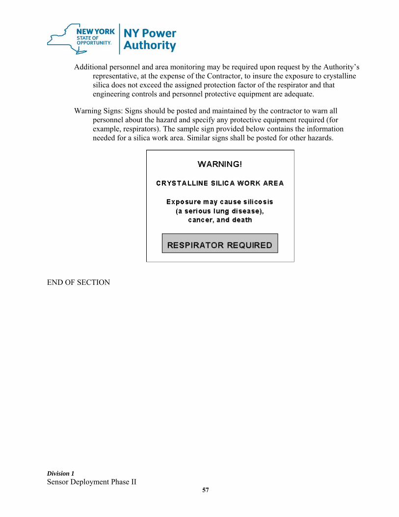
Division 1 Sensor Deployment Phase II
57
Additional personnel and area monitoring may be required upon request by the Authority’s representative, at the expense of the Contractor, to insure the exposure to crystalline silica does not exceed the assigned protection factor of the respirator and that engineering controls and personnel protective equipment are adequate.
Warning Signs: Signs should be posted and maintained by the contractor to warn all personnel about the hazard and specify any protective equipment required (for example, respirators). The sample sign provided below contains the information needed for a silica work area. Similar signs shall be posted for other hazards.
END OF SECTION
Division 1 Sensor Deployment Phase II
58
SECTION 01576 - FACILITY POLLUTION, WATER, AND EROSION CONTROL
PART 1 GENERAL 1.1 DESCRIPTION
A. This work shall consist of control measures required by the specifications or as ordered by the Authority's Site Construction Representative during the life of the Contract to control erosion, water pollution, and water runoff through the use of berms, filter netting, gravel, mulches, silt fences, hay bales, sedimentation basins, and other control devices or methods. All drain trenches, and catch basins shall be protected and maintained free flowing and free of debris. All roadways shall be maintained free of debris.
B. In the event of conflict between these specification requirements and pollution control laws, rules or regulations of other Federal, State or local agencies, the more restrictive laws, rules or regulations shall apply.
1.2 PROTECTION OF WATER RESOURCES
A. All water resources (i.e. ground and surface waters), including all drains, shall be protected from leaching and /or run-off of chemical pollutants, solid wastes and construction site debris.
B. Prior to construction, the Contractor shall submit for review and approval by the
Authority, schedules and methods for accomplishment of site-specific pollution and erosion control plan for the duration of the project.
1. The water and pollution control plan shall be submitted to the Authority at
least ten (10) days prior to commencement of the work. 2. No work shall begin until the erosion and pollution control schedules and plans
have been approved by the Authority. 3. If conditions change during construction, the Contractor shall revise the plan
and resubmit to the Authority for review and approval.
C. A chemical and oil spill prevention and cleanup plan shall be provided and implemented during the course of the work. The Contractor shall maintain on site, sufficient quantities of absorbent materials for use in case of chemical or oil spills. In the event of any actual or suspected spill of any chemical, petroleum product, or waste water, the Contractor shall immediately notify the Authority's Construction Representative and immediately take all measures necessary to control the spread of the spilled material, and to clean it up.
D. Storage and/or use of chemicals, fuels, oils, greases, bituminous materials, solids,

Division 1 Sensor Deployment Phase II
59
waste washings, and cement shall be handled appropriately as to prevent leaching or surface run-off into public waters or drains. All Authority approved storage areas for these materials must be diked.
E. Disposal of any waste materials on the construction site is prohibited.
F. Water resulting from or contaminated by construction operations shall not be directly
discharged into any bodies of water or drainage systems.
G. There shall be no discharge of suspended and/or settle-able solids in amounts that cause visible contrast to natural conditions.
1.3 DEWATERING
A. Construction activities shall be performed in such a manner that the site shall be effectively drained. Drainage shall be by gravity wherever possible. Additional means shall be utilized when necessary and shall include pumping and bailing.
B. Water resulting from or contaminated by construction operations shall not be directly discharged to any water bodies or drain systems. Water discharged from pumps and associated equipment shall be handled to prevent ponding, sediment runoff, and creating hazardous conditions on paved surfaces.
1.4 FLOOR DRAIN AND CATCH BASIN PROTECTION
A. Drains shall be kept open during the duration of the work and rendered fully operational by the Contractor at the completion of the project.
B. Discharge of any liquids or solids into the Authority's sanitary or storm piping
system is prohibited unless specifically authorized in writing by the Authority. C. All exterior drains and catch basins within or adjacent to work areas or ground
disturbed by the Contractor’s activities shall be protected from sediment runoff. 1.5 EROSION AND SEDIMENT CONTROL
A. The Contractor shall provide all labor, equipment and materials necessary to
construct temporary and/or permanent control measures to control erosion and limit sediment discharges to storm drains, streams, rivers, lakes or canals from construction operation. Such measures shall include the construction of temporary berms, diversion ditches, dike checks, sediment structures (traps, basin(s), embankments), silt fence, and the use of mulches, mats, seeding or other control measures as necessary.
B. The Contractor shall comply with all applicable Federal, State and Local
Division 1 Sensor Deployment Phase II
60
regulations and laws. In the event of a discharge to streams, rivers, lakes or canals that causes a visible plume in the receiving water body, the Contractor shall immediately notify the Construction Representative and the Site Environmental Supervisor.
C. Erosion control features shall be installed by the Contractor as required to comply with the New York State Department of Transportation Standard Specifications.
D. The Contractor shall make every effort to minimize erosion from clearing and
grubbing, excavation and backfilling operations, including, but not limited to, the following:
1. Construction of temporary berms, dikes, and diversion ditches to divert runoff
of rainwater in an approved manner, at the conclusion of each day's activities. Runoff, as defined in this specification, is that portion of the precipitation on a drainage area resulting from the 10-year, 24-hour rainfall event, which is discharged from that area via surface drainage.
2. Use of extreme caution to limit disturbances of natural areas to the absolute minimum required.
3. Sequencing of clearing and grubbing, excavation and backfilling operations to
maintain natural traps for eroded material and any other measures effective in minimizing erosion and limiting sediment discharge.
4. Excavation from any source shall not be deposited in or near rivers, streams,
or impoundments nor otherwise located to be susceptible to erosion due to high water, flooding, or rainwater runoff.
5. Shaping of the top of earthwork in a manner to permit and facilitate the runoff
of rainwater. Drainage ditches and/or intercept dikes shall be provided along the top of all excavated slopes and along the inside edge of all berms. The protective measures at the top of slopes shall be constructed before excavation.
6. Providing of temporary slope drains to accommodate the runoff of rainwater.
These drains shall be located as needed at no greater than 500-foot intervals.
E. The Contractor shall submit for approval with its proposal an Erosion and Sediment Control Plan, which shall include the following: 1. Detailed information on the generic erosion and sediment control measures,
procedures and equipment to be used during trench excavation and backfilling, including dewatering and sediment settling methodologies.
Division 1 Sensor Deployment Phase II
61
2. Drawings describing the proposed methods and detailing the location and type of erosion control measures.
3. An inventory list of supplies needed to respond to unanticipated sediment
discharges including, but not limited to, hay bales, diking materials, and stakes. The inventory list shall also include items that will be maintained on hand in order to respond to accidental discharges of other deleterious substances, including, but not limited to, oil absorbent booms, spill pads, absorbent materials, and brooms.
F. All erosion and sediment control measures must be constructed prior to beginning
any land disturbances. These measures and devices cannot be removed until the disturbed areas are stabilized. All devices must be properly maintained and kept in optimum operating condition for the duration of construction.
G. Runoff from any land disturbing activity shall not be directly discharged or have the potential to be discharged off site, onto roadways, or into storm drains or into a watercourse. Accumulated sediment in a properly designed silt fence or trap shall be removed when 60% of the storage capacity of the structure/fence is filled with sediment.
H. All sites shall be stabilized and seeded with erosion control measures, such as
straw mulch, jute mesh, or excelsior within five (5) days of final grading. If construction is suspended, or sections completed, areas shall be seeded immediately and stabilized with appropriate erosion control measures. Maintenance shall be performed as necessary to ensure continued stabilization.
I. Temporary sediment trapping devices, such as silt fences, shall be removed within
thirty (30) calendar days following establishment of permanent stabilization.
J. All points of construction ingress and egress shall be protected to prevent the deposition of materials onto roadways and paved areas either by installing and maintaining a stabilized construction entrance, or by washing all vehicle wheels in a safe disposal area. All materials deposited onto roadways and paved areas shall be removed immediately.
K. Areas that are completed either before or after the seeding season specified, and
all areas that will be left exposed for more than five (5) days, including all excavated and stockpiled materials, shall be temporarily mulched with hay (straw) and anchored with Terratac or other approved binder. The application rate for temporary mulching shall be two (2) tons of mulch per acre and application of mulch anchorage/binder at rates recommended by the manufacturer, unless otherwise noted.
L. Seeding shall be in accordance with NYSDOT Standard Specifications Sections,
Division 1 Sensor Deployment Phase II
62
unless noted otherwise. 1.6 DUST AND FUME CONTROL
A. The control of potentially harmful dusts, fumes, mists, gases, smoke, sprays, or vapor, shall be accomplished by accepted engineering control measures, for example, enclosure or confinement of the operation, ventilation, and substitution of less toxic materials.
PART 2 PRODUCTS 2.1 MATERIALS
A. All materials shall comply with the applicable sections of the NYSDOT Standard Specifications, unless otherwise noted.
PART 3 EXECUTION 3.1 EXECUTION
A. All materials shall be installed in accordance with the applicable sections of the NYSDOT Standard Specifications, unless otherwise noted..
END OF SECTION 01576
Division 1 Sensor Deployment Phase II
63
SECTION 01577 - FACILITY PROTECTION AND SITE RESTORATION PART 1 GENERAL 1.1 DESCRIPTION OF WORK
A. For the duration of the work, the Contractor is responsible for adequately protecting all Authority equipment and facilities from damage/contamination. This shall include, but not limited to, the prevention of dust, fumes, and debris caused or created by construction activities from entering Authority occupied or public access spaces.
1.2 FACILITY PROTECTION
A. The Authority shall be continuously utilizing areas of the facility and property adjacent to the work areas. The Contractor shall conduct work in a manner that will minimize disruption of the Authority's normal operations. The Contractor shall provide a minimum of seventy-two (72) hours advance notice to the Authority of activities, which will impact the Authority's normal operations.
B. The Contractor shall provide temporary barricades and other forms of protection
as required to protect the Authority's personnel, equipment, and facilities from injury or damage due to the Contractor's work.
1. The Contractor shall provide protective measures, as required, for free and
safe passage of Authority's personnel to and from occupied portions of the work zones.
2. Where required, interior and exterior shoring, bracing, or supports shall be installed to prevent movement, settlement, or collapse of structures or elements which are to be modified or otherwise affected by the Contractor's activities.
3. The Contractor shall protect existing finish work that is to remain in place and becomes exposed during work operations.
C. Traffic Control Measures
1. The Contractor shall conduct operations in a manner to ensure minimum interference with roads, streets, walks, and other adjacent occupied or used facilities.
2. The Authority’s streets, roadways, walks, or other occupied or used facilities shall not be closed, blocked, or otherwise obstructed without written permission from the Authority. Alternate routes around closed or obstructed
Division 1 Sensor Deployment Phase II
64
traffic ways must be provided.
3. All lane and/or road closing shall conform to the requirements of the NYS Manual of Uniform Traffic Control Devices (NYS MUTCD).
D. Explosives: Use of explosives is not permitted. E. Utility Services
1. The Contractor shall maintain existing utilities not indicated to be removed, keep in service, and protect against damage during Contractor's operations.
2. The Contractor shall not interrupt existing utilities serving occupied or used facilities, except when authorized in writing by the Authority. Provide temporary services during interruptions to existing utilities, as acceptable to the Authority.
F. Environmental Controls
1. Water sprinkling, temporary enclosures, and other suitable methods shall be used to limit dust and dirt rising and scattering in air. The Contractor shall comply with governing regulations pertaining to environmental protection.
2. Water shall not be used when it may create hazardous or objectionable conditions such as ice, flooding, or pollution and in areas of live electrical cables.
G. Cutting, Burning, and Welding
1. All cutting, burning, and welding operations require issuance of written permits from both the Contractor and the Authority.
2. The Contractor shall provide a fire watch during all cutting, burning, and welding operations. Fire extinguisher shall be located within 20 feet of any operation.
H. The Authority assumes no responsibility for actual condition of items, structures
or existing roadways. I. The Contractor shall promptly repair damages caused to facilities and surfaces at
no cost to the Authority.
1.3 SUBMITTALS
A. Schedule: Submit a schedule indicating proposed methods and sequence of
Division 1 Sensor Deployment Phase II
65
operations for demolition work to the Authority for review prior to commencement of work. Include coordination for shutoff, capping, and continuation of utility services as required, together with details for dust, exhaust fumes, and noise control protection.
1. Provide detailed sequence of work to ensure continued access through the
work zones as required for Authority's on-site operations. 2. Coordinate with Authority's continuing occupation of the site. 3. Coordinate with Authority for storage of materials that are scheduled to be
salvaged and/or reused. 4. Methods of how various items will be protected. 5. Provide temporary support to utilities, equipment, structures as required.
B. Drawings: Submit drawings and/or design calculations on how the existing
facilities and utilities will be protected and/or temporarily supported. 1.4 INSPECTION
A. Prior to commencement of work, inspect areas in which work will be performed. Photograph existing conditions of structures, surfaces, equipment, and surrounding utilities which could be misconstrued as damage resulting from the work; file with the Authority prior to starting work.
B. Verify that all underground utilities have been identified prior to all work.
1.5 PREPARATION
A. Provide interior and exterior shoring, bracing, or temporary support to prevent movement, settlement, or collapse of structures and utilities as required.
1. Cease operations and notify the Authority immediately if safety of structure
appears to be endangered. Take precautions to support structure until determination is made for continuing operations.
B. Cover and protect equipment and fixtures to remain from damage when
demolition work is performed in areas from which such items have not been removed.
1.6 SEQUENCE OF OPERATIONS
A. Perform work in a systematic manner. Use such methods as required to complete work in accordance with the approved schedule and governing regulations. 1. Promptly remove debris. 2. Provide services for effective air and water pollution controls as required by
Division 1 Sensor Deployment Phase II
66
applicable regulatory agencies.
1.7 DISPOSAL OF MATERIALS AND DEBRIS
A. Debris shall be removed from the site of work promptly. Items indicated to be removed and disposed of, but of salvageable value to Contractor may be removed as work progresses. Transport salvaged items from the site as they are removed. Storage of or sale of removed items designated to be disposed of on-site is not permitted.
B. Remove debris, rubbish, and other materials resulting from operations from
jobsite. Transport and legally dispose of materials off-site. Indicate to the Authority in writing the disposal site to be used and provide copies of all applicable permits.
1. If hazardous materials are encountered during operations, comply with
applicable Federal, State, and local regulations, laws, and ordinances concerning removal, handling, and protection against exposure or environmental pollution. a. All insulation when encountered shall be presumed asbestos containing
material (PACM) and must be verified as such before proceeding with work.
b. The Authority shall be immediately notified should the Contractor encounter such material. Work shall not proceed without the prior approval of the Authority.
c. All permits required for the removal of asbestos containing materials shall be reviewed by the Authority prior to submission to the appropriate regulatory agencies.
2. Burning, burial, or storage of removed materials is not permitted on the project site.
3. Trash and debris shall be removed from the worksite(s) on a daily basis. C. The Contractor is not permitted to store or dispose of excess materials, excavated
materials, garbage, etc. at the Authority Facility, except as noted. The Contractor shall obtain the necessary permits, and at its own cost, to dispose of unwanted material or garbage at a proper licensed dump facility. All debris from operations shall be removed on a daily basis and shall not be permitted to accumulate or hinder access throughout the work areas.
1.8 CLEAN-UP AND REPAIR
A. Upon completion of work, remove tools, equipment, materials, and debris from
Division 1 Sensor Deployment Phase II
67
site. All roadway and storage areas shall be cleaned and swept.
B. The Contractor shall repair areas damaged during construction and shall return all areas affected by construction to their pre-existing conditions, at no cost to the Authority.
1.9 STORAGE OF FLAMMABLE MATERIALS
A. All flammable materials shall be stored in their original, labeled containers and
placed within an approved storage cabinet when not in use.
B. All combustible waste materials shall be placed in covered metal containers and promptly disposed of in an approved manner at an approved waste disposal facility.
C. Appropriate type fire extinguishers shall be provided and placed near all storage locations.
1.10 RELATED SECTIONS
A. SECTION 01010 - Summary of Work B. SECTION 01100 - Jobsite Requirements C. SECTION 01576 - Facility Pollution, Water, and Erosion Control
1.11 REFERENCES
A. New York State Department of Transportation Manual of Uniform Traffic Control Devices (NYS MUTCD).
B. New York State Department of Transportation Standard Specifications
Construction and Materials. PART 2 PRODUCTS 2.1 MATERIALS
A. All materials shall comply with the applicable sections of the NYSDOT standard Specifications, unless otherwise noted.
B. Grass seed mixture for lawn areas shall consist of the following varieties by
weight: 33% Creeping Red Fescue, 33% Kentucky Bluegrass Improved, and 33% Perennial Rye Grass Improved, unless otherwise noted.
Division 1 Sensor Deployment Phase II
68
C. Asphalt Materials (unless otherwise noted):
Top Course: 1½” NYSDOT Type 6
Binder Course: 2½” NYSDOT Type 3 Base Course: 12” NYSDOT Type 1
PART 3 EXECUTION 3.1 SITE RESTORATION
A. Unless otherwise noted on the drawings or in the specifications, all materials shall be installed in accordance with the applicable sections of the NYSDOT Standard Specifications.
B. Turf areas disturbed or damaged by the Contractor's operations shall be reestablished in accordance with NYSDOT Standard Specifications except as modified by the Contract Documents.
3.2 RESTORATION OF PAVED AND UNPAVED AREAS
A. After work is completed, the grade shall be restored to its original elevation and condition, unless otherwise noted.
B. Asphaltic patch and concrete for sidewalk areas shall be used in areas that were originally paved. Original paving material shall be matched in grade and finish.
END OF SECTION 01577
Division 1 Sensor Deployment Phase II
69
SECTION 01701 - CONTRACT CLOSEOUT PART 1 GENERAL 1.1 SUMMARY
A. This Section includes administrative and procedural requirements for contract closeout including, but not limited to, the following:
1. Inspection procedures. 2. Project record document submittal. 3. Submittal of warranties. 4. Submittal of “New Equipment Data Sheet”. 5. Final cleaning.
B. Closeout requirements for specific construction activities are included in the
appropriate Sections in the Technical Specifications and the Supplementary and General Conditions.
1.2 CLOSEOUT DOCUMENTS
C. Contractor shall provide all as built drawings, manuals, cut sheets, all approved
submittals, completely filled out test procedures, FAT documents, O&M manual, installation instruction, preventive maintenance manual, torque values, storage instructions, fabrication and installation photographs, nameplate photographs, test results, graphs, traces and recommended spare parts list as one official submittal within 30 days of arrival of the equipment to the site or within 30 days of the completion of installation work. The authority may withhold the final 10% payment until all as built documents are approved by the authority. The said 10% withhold is addition to any payment retention set forth in the contract.
1.3 SUBSTANTIAL COMPLETION
A. Prior to requesting an inspection for certification of Substantial Completion, the
following shall be completed: 1. In the Application for Payment that coincides with, or first follows, the date
Substantial Completion is claimed, show 100 percent (100%) completion for the portion of the work claimed as substantially complete.
a. Include supporting documentation for completion as indicated in these
Contract Documents and a statement showing an accounting of changes to the Contract Sum.
Division 1 Sensor Deployment Phase II
70
b. If 100 percent (100%) completion cannot be shown, include a list of incomplete items, the value of incomplete construction, and reasons the work is not complete.
2. Advise the Authority of pending insurance changeover requirements. 3. Submit specific warranties, workmanship bonds, maintenance agreements, final
certifications, and similar documents. 4. Obtain and submit releases enabling the Authority unrestricted use of the work
and access to services and utilities. Include occupancy permits, operating certificates, and similar releases.
5. Submit record drawings, maintenance manuals, final project photographs, damage or settlement surveys, property surveys, and similar final record information.
6. Make final changeover of permanent locks and transmit keys to the Authority. Advise the Authority's personnel of changeover in security provisions.
7. Discontinue and remove temporary facilities from the site, along with mockups, construction tools, and similar elements.
8. Submit all “New Equipment Data Sheets” for all equipment installed under this contract.
9. Complete final cleanup requirements. 10. Sweep and clean all sidewalks and roadways. 11. Complete all site restoration.
B. In receipt of a request for inspection, the Authority will either proceed with inspection or advise the Contractor of unfulfilled requirements. The Authority will prepare the "Certificate of Substantial Completion" form following inspection or advise the Contractor of construction that must be completed or corrected before the certificate will be issued.
1. The Authority will repeat inspection when requested and assured that the work is
substantially complete. 2. Results of the completed inspection will form the basis of requirements for final
acceptance. 1.4 COMPLETION REPORT
A. Contract must supply a unit completion report for each unit within 45 days of unit return to commercial operation date. The completion report shall include detail photographs, diagram, drawings, lesson learn, nameplates, periodic maintenance and update recommendation, warranty information, cut sheets, contact information of all subcontractor.
1.5 FINAL ACCEPTANCE
Division 1 Sensor Deployment Phase II
71
A. Prior to requesting an inspection for certification of final acceptance and final payment, the following shall be submitted:
1. The final payment request in accordance with the Contract Documents with
releases and supporting documentation not previously submitted and accepted. Include insurance certificates for products and completed operations where required.
2. An updated final statement, accounting for final additional changes to the Contract Sum.
3. A copy of the final inspection list of items to be completed or corrected. The certified copy of the list shall state that each item has been completed or otherwise resolved for acceptance and shall be endorsed and dated by the Authority.
4. The consent of surety to final payment. 5. A final liquidated damages settlement statement, if applicable. 6. Evidence of final, continuing insurance coverage complying with insurance
requirements. 7. All final documentation, including As-Built Drawings.
B. The Authority will re-inspect the work upon receipt of notice that all outstanding
items have been completed, except for items whose completion is delayed under circumstances acceptable to the Authority.
1. Upon completion of re-inspection, the Authority will prepare a certificate of
final acceptance. If the work is incomplete, the Authority will advise the Contractor of work that is incomplete or of obligations that have not been fulfilled but are required for final acceptance.
2. If necessary, re-inspection will be repeated. PART 2 PRODUCTS 2.1 NEW EQUIPMENT DATA SHEET
A. The Contractor shall complete a New Equipment Data Sheet, to be provided by the
Authority, for each piece of equipment installed under this contract. PART 3 EXECUTION 3.1 FINAL CLEANING
A. The facility and project areas shall be returned to the Authority in proper condition. B. All areas shall be properly cleaned and all debris properly removed and disposed.

Division 1 Sensor Deployment Phase II
72
C. All temporary protection and facilities installed for protection of the work during construction shall be removed.
END OF SECTION 01701
Division 1 Sensor Deployment Phase II
73
ATTACHMENT 1 – FIELD CHANGE NOTICE
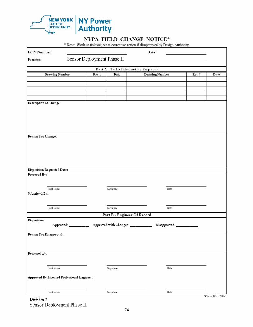
Division 1 Sensor Deployment Phase II
74
Sensor Deployment Phase II

Division 1 Sensor Deployment Phase II
75
ATTACHMENT 2 – FIELD CHANGE REQUEST

Division 1 Sensor Deployment Phase II
76
Sensor Deployment Phase II
Division 1 Sensor Deployment Phase II
77
ATTACHMENT 3 – DESIGN CHANGE NOTICE
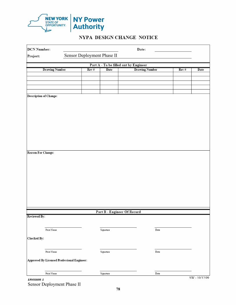
Division 1 Sensor Deployment Phase II
78
Sensor Deployment Phase II
Division 1 Sensor Deployment Phase II
79
ATTACHMENT 4 – SUBMITTAL COVER SHEET
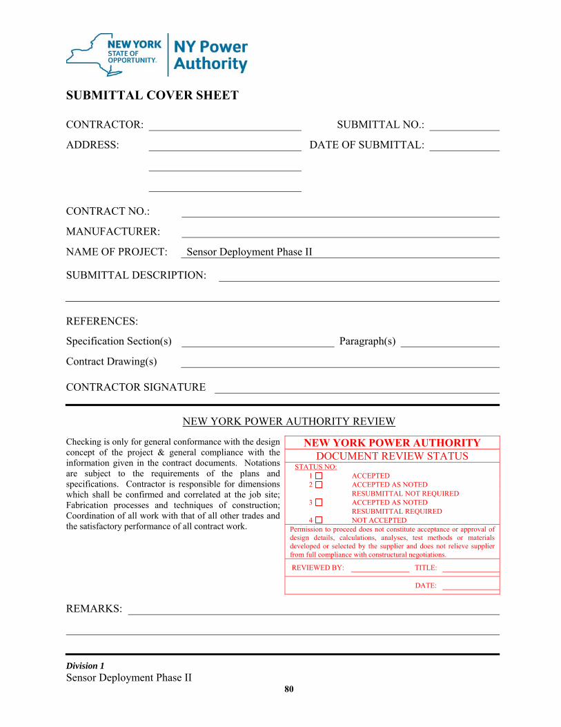
Division 1 Sensor Deployment Phase II
80
SUBMITTAL COVER SHEET
CONTRACTOR: SUBMITTAL NO.:
ADDRESS: DATE OF SUBMITTAL:
CONTRACT NO.:
MANUFACTURER:
NAME OF PROJECT: Sensor Deployment Phase II
SUBMITTAL DESCRIPTION:
REFERENCES:
Specification Section(s) Paragraph(s)
Contract Drawing(s) CONTRACTOR SIGNATURE
NEW YORK POWER AUTHORITY REVIEW
Checking is only for general conformance with the design concept of the project & general compliance with the information given in the contract documents. Notations are subject to the requirements of the plans and specifications. Contractor is responsible for dimensions which shall be confirmed and correlated at the job site; Fabrication processes and techniques of construction; Coordination of all work with that of all other trades and the satisfactory performance of all contract work.
NEW YORK POWER AUTHORITY DOCUMENT REVIEW STATUS
STATUS NO: 1 ACCEPTED 2 ACCEPTED AS NOTED
RESUBMITTAL NOT REQUIRED 3 ACCEPTED AS NOTED
RESUBMITTAL REQUIRED 4 NOT ACCEPTED
Permission to proceed does not constitute acceptance or approval of design details, calculations, analyses, test methods or materials developed or selected by the supplier and does not relieve supplier from full compliance with constructural negotiations.
REVIEWED BY: TITLE:
DATE:
REMARKS:
Division 1 Sensor Deployment Phase II
81
ATTACHMENT 5 – CONTRACTOR’S SUBMITTAL LOG
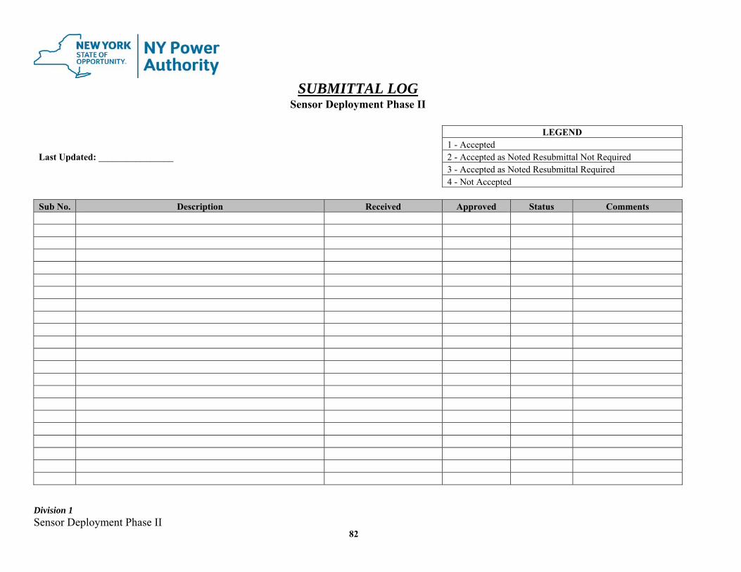
Division 1 Sensor Deployment Phase II
82
SUBMITTAL LOG Sensor Deployment Phase II
LEGEND 1 - Accepted Last Updated: ________________ 2 - Accepted as Noted Resubmittal Not Required
3 - Accepted as Noted Resubmittal Required 4 - Not Accepted
Sub No. Description Received Approved Status Comments

Division 1 Sensor Deployment Phase II
83
ATTACHMENT 6 - REQUEST FOR INFORMATION (RFI) SHEET

Division 1 Sensor Deployment Phase II
84
REQUEST FOR INFORMATION (RFI)
CONTRACTOR:
ADDRESS:
PROJECT: Sensor Deployment Phase II
CONTRACT #:
RFI #:
DATE:
DESCRIPTION: REFERENCES:
Specification Section(s): Paragraph(s):
Contract Drawing(s):
Submitted By: NYPA RESPONSE:
NYPA ENGINEER:
Division 1 Sensor Deployment Phase II
85
ATTACHMENT 7 - CONSTRUCTION INSPECTION/MONITORING PROGRAM

Division 1 Sensor Deployment Phase II
86
CONSTRUCTION INSPECTION/MONITORING PROGRAM (CI/MP)
1.0 INTRODUCTION
1.1 The purpose of this document is to provide guidelines for converting the project design into a completed high-quality facility through the establishment and implementation of a construction inspection/monitoring program for the Contractor and associated subcontractor(s). All guidelines set forth in this document shall pertain to the Contractor and all associated subcontractor(s) on this project.
1.2 Implementation of the Construction Inspection/Monitoring Program must recognize
the need not only for quality construction consistent with the intent of the project design and contract.
1.3 This program is based on a combination of direct inspection of material, equipment
and processes as well as a systematic monitoring of construction activities. This inspection and monitoring process as well as responsibilities are described in the following sections.
1.4 The Contractor and their subcontractor(s) shall employ a full time independent
Quality Control Inspector which is knowledgeable in the specific discipline to inspect and monitor the work. The inspector(s) shall be independent from organizational personnel with responsibilities of scheduling, manufacturing, project management, field construction activities, fabrication and engineering. Resumes of all inspector(s) shall be provided to the Authority for review and acceptance.
2.0 CONTRACTOR RESPONSIBILITIES
2.1 The Contractor has the responsibility to assure that all aspects of work comprising any activity during construction are performed in accordance with the Project’s design requirements, specifications, drawings and applicable codes and standards.
2.2 The Contractor has the responsibility for performing and documenting inspection of
all project work verifying conformance to the requirements specified in the Contract Documents.
2.3 The Contractor shall hire a third-party safety company to walk each site, at a
minimum, every 30 days. The third-party safety company shall provide a written report to the Authority documenting OSHA safety violations with recommendations for a return to compliance.
2.4 The Contractor shall develop, implement, and completed inspection checklists, with
the Authority’s approval, and forms to verify that an inspection of work has been completed and that the materials used and the workmanship performed by the
Division 1 Sensor Deployment Phase II
87
Contractor comply with the project’s Contract Documents. Prior to the start of work, the Contractor, Authority’s Construction Site Representative (CSR), and a representative from the Authority’s Quality Assurance (QA) Department, shall meet to review and approve the checklists to be used for the project and the applicable hold and witness points.
2.5 Witness Points
Those inspection and test points for which five (5) working days notice must be given by the Contractor to the Authority’s CSR but do not require the Contractor to hold up the performance of inspection or test if the Authority’s CSR is not available to witness performance.
Hold Points
Those inspection and test points for which five (5) working days notice must be given by the Contractor to the Authority’s CSR, and require witness of the inspection or test by the CSR unless a documented waiver is given to the Contractor.
Unless a waiver has been granted, if an inspection or test point designated as a hold point does not have the requisite witnessing by the CSR, the Contractor faces rejection of the work by the Authority and must repeat the inspection or test for the CSR before the work can be considered acceptable.
3.0 INTERFACE WITH THE AUTHORITY’S CONSTRUCTION SITE
REPRESENTIVE The Contractor shall cooperate fully and provide the necessary support for the
Authority’s Construction Site Representative (CSR) and QA Representative during inspection of construction activities. They will monitor the Contractor’s compliance with the Contract Documents by, but not limited to, the following methods:
Review of completed checklists Inspection of ongoing work activities Verification of selected contractor inspections by witness, document review
and/or test Citing items requiring corrective action by the contractor
The Contractor shall provide the Authority’s Site Representative full access to all work areas and equipment that are associated with performance of the Contract work.
Division 1 Sensor Deployment Phase II
88
4.0 AREAS OF INSPECTION As a minimum, the following areas shall be inspected:
A. Field Inspection
1. During construction, the Contractor shall perform inspections and tests detailed in the Contract Documents, in the checklists, and others that may be necessary to assure the Contractor has fulfilled the requirements of the Contract Documents.
2. Inspections may be delegated to subcontractors. However, the prime Contractor
shall retain responsibility for compliance with contractual requirements and shall perform inspections and reviews of subcontractor(s) to provide assurance of compliance with contractual requirements.
B. Vendor Inspection
The Contractor shall perform inspections at vendor(s)’ facilities on items which may affect fit, function, and schedule if the item is defective. The Contractor shall, as a minimum, delegate to its vendor(s) the conditions of the contract which are applicable. In addition, provision for access of the authorized Authority personnel shall be included.
5.0 MATERIAL VERIFICATION AND CONTROL
5.1 The Contractor is responsible for receipt inspection, storage, maintenance and safekeeping of all material, components and equipment, whether Contractor or Authority-furnished from the time received until finally installed and accepted by the Authority.
5.2 The Authority’s Construction Site Representative will monitor the Contractor’s
compliance to the material control program to verify that material, components and equipment conform to the requirements of the contract documents.
5.3 The Contractor shall prepare in proper form all documents required for claims based
on shipping damage or shortage. Where such claims involve material furnished by the Authority, they shall be processed in accordance with the procedures established by the Authority for the project. Claims involving material purchased by the Contractor shall be processed by the Contractor, and the Authority shall be informed of the status of such claims and the provisions made for timely replacement of damaged or missing items.
Division 1 Sensor Deployment Phase II
89
5.4 Certain material may be subject to an additional receiving inspection by the Authority. Such inspections will be made concurrently with the Contractor’s inspections for immediately thereafter, before the items are moved to storage or to their installation location. Inspections will include checking for condition, shipping damage, or shortage, as well as for conformance with specifications and purchase orders. The Contractor shall provide at no expense to the Authority all labor and equipment necessary for the Authority’s Receiving Inspection.
5.5 MATERIAL RECEIVING
a) The Authority shall notify the Contractor of the arrival of material, components and equipment furnished by the Authority requiring receipt inspection.
b) The Authority’s CSR shall monitor Contractor’s use of accepted industry
practices to handle all components and equipment so as not to jeopardize the physical condition of each component. This shall include material purchased by the Contractor or the Authority.
c) Equipment requiring special handling instructions shall be observed by the
Authority.
d) The receipt inspection shall be documented by the Contractor on the Material Receiving Report. This report reflects the status of the materials, components or equipment received at the site whether Authority or Contractor furnished.
e) Any material damage or discrepancies found on Authority furnished material shall
be noted on the Material Deficiency Report. and shall be forwarded to the Authority’s Construction Site Representative for disposition.
f) The Material Receiving Instruction shall be initiated by the Authority’s CSR
whenever specific instructions are necessary to define mandatory receiving inspections, storage or maintenance requirements on Authority furnished material or equipment.
5.6 RECEIPT INSPECTION
The material receipt inspection to be performed by the contractor shall consist of the following items as minimum: Review of the packing list for correctness and traceability of the items received.
Visual examination to verify the items have no physical damage caused by, but not
limited to, the following:
a. Rough handling and shipping.
Division 1 Sensor Deployment Phase II
90
b. Failure of packaging, dunnage, protective covers, and seals.
c. Loss of inert gas blanketing or missing desiccant.
Spot checks and random measurements of critical dimensions to verify that overall dimensions, mounting holes, weld ends preps, flanged connections, configuration, and orientation conform to the requirements of the design documents.
General visual examination to determine that general workmanship, materials, welding,
machining, and painting conform to the requirements of the design documents.
Marking and identification conform to specified requirements as follows:
a. Material marking: heat numbers, piece marking, etc.
b. Nameplates: code stamping, manufacture’s name, serial number, model number, etc.
c. Tags: purchase order, item numbers, etc.
Documentation is acceptable for:
a. Traceability to item.
b. Legibility.
c. Completeness to the requirements of the specifications.
d. Certified Material Test Reports of Certificates of Conformity as required by this specification
6.0 STORAGE OF EQUIPMENT/MATERIAL BY THE CONTRACTOR
6.1 Storage of equipment/material by the Contractor shall be performed in a manner not to degrade the cleanliness or packaging, and to minimize corrosion or deterioration of materials. Certain metals shall not be stored in contact with each other and special instructions from the manufacturer of the item or within the procurement specifications shall apply.
6.2 The Contractor shall be responsible for the receipt, storage maintenance, and
safekeeping of all items from the time received until they are installed and accepted by the Authority. The Contractor shall also receive, handle, and store any materials returned by the construction force after original issue due to damage, defects, wrong description, changes in requirements, surplus, or any other cases.
Division 1 Sensor Deployment Phase II
91
6.3 The Authority’s CSR will monitor the Contractor’s performance of periodic
maintenance, such as lubrication and rotation of pumps and motors, and conducting tests to assure that the item has not or will not deteriorate while stored in accordance with the manufacturer’s instructions.
6.4 All material shall be so arranged in storage as to permit ready access to any item for
inspection, or retrieval without excessive handling or movement of the item involved, or of items stored adjacent to it.
6.5 External identification markings shall be used on all items. They shall be of such size
and so located as to be clearly visible. Hazardous material such as paints, chemicals or flammable oils and solvents shall be separated and shall have a “Warning Notice” on the outside of the container.
6.6 Items stacked for storage shall be so arranged and supported that excessive strains are
not imposed on material in the lower tiers. Weatherproof coverings used for outdoor storage protection shall be of flame resistant sheeting or tarpaulin, so placed as to permit drainage and air circulation, and tied securely to prevent wind damage.
6.7 Storage areas shall be kept clean. Access shall be limited to as required to prevent
theft and/or vandalism. Fire protection shall be provided commensurate with the type of storage area and the type, value and vulnerability of the items stored. Where necessary, special measures shall be used to exclude rodents and other animals. Fences, barriers, and personal surveillance shall be provided as required to prevent vandalism and theft.
6.8 Surveillance activities shall be conducted on any special maintenance activities
required by the manufacturers specification and shall be documented on the Inspection Report.
6.9 Contractor shall furnish to NYPA written procedures 90 days prior to delivery of
equipment on recommended handling for long term storage, including descriptions of periodic inspections, and/or storage maintenance required to prevent degradation of the supplied equipment and to maintain the warranty. Contractor must supply all required test equipment to perform any periodic test at the warehouse. All costs to obtain the test equipment, support and crane must be paid by the contractor. It is contractor’s responsibility to make arrangement with the Authority to inspect the warehouse. All spare parts will be stored at warehouse.
6.10 The contractor and its subcontractor(s) are responsible to transport their equipment,
parts and material to/from the above location with no charge to the Authority. 7.0 CONTROL OF NONCONFORMANCE
Division 1 Sensor Deployment Phase II
92
7.1 The Deficiency Report is a written report to document and control nonconformance
or deficiency in characteristic, documentation, or procedure which could affect the reliability or render the quality of an item or activity unacceptable or indeterminate.
7.2 A Deficiency Report (DR) can be issued by the Contractor or the Authority to report
a nonconformance condition. This report is not intended for minor issues that are corrected by the Contractor after oral direction from the Authority’s CSR.
7.3 When the Contractor fails to take corrective measures after being advised of the
nonconformance condition, the Authority’s CSR prepares the Deficiency Report and forwards it to the Contractor for disposition.
7.4 The Contractor shall assign the DR number, log it in the DR log book and provide the
disposition as one of the following: REWORK
The process by which a nonconforming item is made to conform to the specified requirements of the design documents. When rework is the disposition, the responsible Contractor or vendor(s) shall provide the method to be used to perform the rework. The method of rework must be reviewed by the Authority prior to start of rework.
REJECT
A disposition in which a nonconforming item or service will not be permitted to be used on the project. ACCEPT-AS-IS A disposition that is permitted for a nonconforming item on service when it can be established that the item is satisfactory for its intended use. Whenever the Contractor’s recommended disposition is “ACCEPT-AS-IS”, the Authority’s approval is required.
7.5 Copies of Deficiency Reports shall be distributed to:
Contractor Site Office Authority’s Site Representative Authority’s Project Manager
Division 1 Sensor Deployment Phase II
93
7.6 If the nonconformance is to be corrected by rework, the CSR or Authority’s QA Representative shall verify where corrective action has been implemented, and that the specified corrective action has been satisfactorily completed.
8.0 CONTROL OF NONCONFORMANCE FOR NON-MATERIAL RECEIPT ISSUES
8.1 The Contractor and their subcontractor(s) shall document in a written procedure the
methods for disposition of items and performance that do not meet contract documents requirements, or Authority approved drawings, procedures, or vendor drawings. These methods shall contain provisions for:
1. Evaluation of conforming items 2. Submittal of all conformance notices to the Authority. These submittals shall
include supplier – recommended disposition (e.g. use – as – is or repair) and technical justification, and shall be approved by the Authority
The Non-Conformance Procedure shall be submitted for the Authority’s review and approval.
9.0 TESTING SERVICES
9.1 An independent testing laboratory employed by the Authority by a separate contract, will perform verification testing or inspecting as directed by the Authority’s CSR during the construction activities.
9.2 The following testing will generally be performed by the testing laboratory engaged
by the Authority unless otherwise noted in the contract:
a) Soil testing
b) Bituminous paving testing
c) Concrete testing
d) Nondestructive Weld Examination
e) Electrical Testing
9.3 The Authority CSR shall utilize the services for the testing laboratory to randomly check critical installation work performed by the Contractor.
9.4 Laboratory services obtained by the Authority are solely an assurance that the
Contract provisions are met. 9.5 Where results of Authority-procured tests are made available to the Contractor, the

Division 1 Sensor Deployment Phase II
94
Authority does so as a convenience only, and in no way shall this act be construed as relieving the Contractor of his obligations to provide materials and workmanship in accordance with the Contract Document.
9.6 The Contractor shall, at his expense, furnish labor, equipment, and materials to assist
in field inspections that may occur as mentioned in Section 9.3. 10.0 QUALIFICATION FOR CONTRACTOR’S INSPECTION AND TESTING
PERSONNEL
10.1 RESPONSIBILITY
It is the responsibility of the Contractor to assure that only those personnel within its organization who meet the requirements established herein are permitted to perform inspection, examination, and testing activities. It shall also be the Contractor’s responsibility to comply with the procedure and instructions issued for the work and to the requirements established therein.
10.2 GENERAL REQUIREMENTS
a. Certifications Each person who verifies conformance of work activities to quality requirements shall be certified by their employer as being qualified to perform their assigned work. This certification shall be supported by appropriate measures such as education or training, testing, evaluation, and periodic review to assure the initial and continued proficiency of each person. The effective period of certification shall be established and at the end of the effective period of certification, each individual shall be re-certified in accordance with the requirements of this criteria. b. Certificate of Qualification The qualification of personnel shall be documented in an appropriate form. The certificate shall include the following information: Employer’s name. Person being certified. Activity qualified to perform. Effective period of certification. Signature of employer’s designated representative. Basis used for certification.
c. Inspection Personnel
Division 1 Sensor Deployment Phase II
95
Inspection activities to verify the quality of the work shall be performed by persons other than those who performed the activity being inspected. Such person shall not report directly to the immediate supervisors who are responsible for the work being inspected.
10.3 QUALIFICATIONS
a. To be considered for certification, a candidate must satisfy the following requirements:
Graduate of a 4-year accredited engineering or science college or university, plus 2 years of experience in quality assurance, including testing or inspection (or both) of power plant, heavy industrial, or other similar equipment or facilities.
High school graduate, plus 4 years of experience in testing or inspection (or both)
of power plant, heavy industrial, or other similar equipment or facilities.
b. Inspection and Testing Functions
A person shall have experience and training in the performance of required inspections and tests and in the organization and evaluation of the results of the inspections and tests. The person shall be capable of determining the validity of test results. c. Nondestructive Examination Functions
Personnel involved in the performance, evaluation, or supervision of nondestructive examinations, including radiography, ultrasonic, penetrant, magnetic particle, or eddy current methods shall meet the qualification requirements specified in SNT-TC-IA and supplements. These personnel involved in the performance, evaluation, and supervision of gas leak test methods shall meet the qualification requirements specified in sections a and b above. d. Visual Examination of Welds
An AWS Certified Welding Inspector with a minimum of 7 years of
documented experience will be required to perform all visual welding examinations. Weld visual examinations are to include fit up checks, root pass inspection and final weld pass inspection. All inspection checks are to be documented. No self-inspection of welds is allowed.
e. Weld Maps Documentation
a. The Contractor and subcontractor(s) shall provide weld map records
Division 1 Sensor Deployment Phase II
96
that specifically identify the new or repaired welds with a unique traceable weld joint designation number, date the weld was completed, location of the weld, welder who performed the weld, and NDE types performed. Examiner(s) initials and date inspection was completed, shall also be documented.
b. All weld map records as a minimum will be documented on Authority approved drawings for piping and supports or on structural drawings for structural welds, that will depict the location of the welded joint.
c. The Contractor shall submit a typical weld map record for the Authority’s review and approval. Any changes requested by the Authority shall be made with cost to the Authority.
10.4 RECORDS
A file of records of personnel qualification shall be established and maintained by the Contractor throughout the employee’s period of work activities at the work site. This file shall contain records of past performance history, training, initial and periodic evaluations, and certification of the qualifications of each person.
11.0 RECORD CONTROL
11.1 Material receiving documentation, maintenance documentation, nonconformance documentation, and construction records in the form of test reports and inspection checklists shall be provided by the Contractor to the Authority for review.
11.2 The Contractor shall maintain on-going logs for all documents to assure that all
required documents are available and filed and that all unsatisfactory conditions have been resolved.
11.3 The Contractor shall complete and submit checklists at the frequency required in the
Contract Documents. 12.0 LIST OF ATTACHED REPORTS
Material Receiving Report (MRR)
Material Receiving Instruction (MRI)
Material Deficiency Report (MDR)
Storage Yard Inspection Report
Deficiency Report (DR)

Division 1 Sensor Deployment Phase II
97
Deficiency Report Log
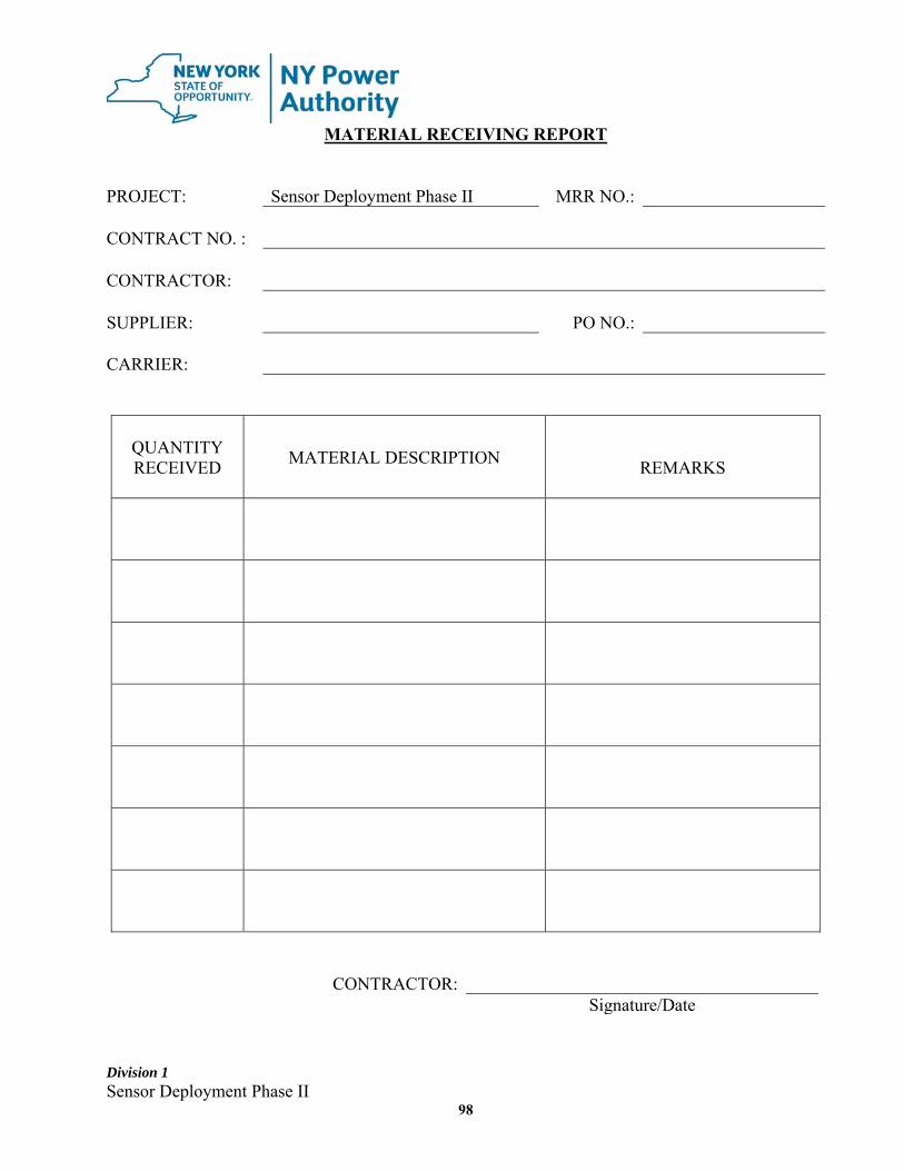
Division 1 Sensor Deployment Phase II
98
MATERIAL RECEIVING REPORT PROJECT: Sensor Deployment Phase II MRR NO.: CONTRACT NO. : CONTRACTOR: SUPPLIER: PO NO.: CARRIER:
QUANTITY RECEIVED
MATERIAL DESCRIPTION
REMARKS
CONTRACTOR: Signature/Date

Division 1 Sensor Deployment Phase II
99
MATERIAL RECEIVING INSTRUCTION PROJECT: Sensor Deployment Phase II MRI NO. CONTRACT NO.: CONTRACTOR: SUPPLIER: ITEMS: RECEIVING, STORAGE AND MAINTENANCE REQUIREMENTS:
DOCUMENTATION REQUIRED: (√)
Mill Test Report Welding Procedure
Material Certification Non-destructive Test Report Specify: Specify:
Installation Manual Test Reports Remarks: Prepared by:
Division 1 Sensor Deployment Phase II
100
MATERIAL DEFICIENCY REPORT PROJECT: Sensor Deployment Phase II MDR NO. CONTRACT NO.: CONTRACTOR: SUPPLIER: REFERENCE MDR NO.: (Attached) MATERIAL DESCRIPTION: Description of Loss, Damage or Unsatisfactory Condition: Contractor: Signature/Date Disposition: NYPA: Signature/Date
Division 1 Sensor Deployment Phase II
101
STORAGE YARD INSPECTION REPORT PROJECT: Sensor Deployment Phase II CONTRACT NO.: CONTRACTOR: STORAGE YARD LOCATION: ITEMS YES NO N/A
1. 24 hours guard service is provided
2. Materials are properly cribbed and stacked to prevent sagging.
3. Materials are properly banded and covered where required.
4. Damage materials are properly tagged for repair or replacement and have been properly segregated.
5. Erosion control is properly maintained by the contractor. Sedimentation basins are cleaned out and functional Weed control adequate Ditching is adequate and in working condition Roads are free of ruts and any erosion
6. Site is clean and free of all garbage and debris.
7. Combustible materials are isolated as required and safety regulations are in force.
8. Other verification performed.
Inspected by: Name/Organization/Date
Division 1 Sensor Deployment Phase II
102
DEFICIENCY REPORT (DR) PROJECT: Sensor Deployment Phase II DR NO. CONTRACT NO.: CONTRACTOR LOCATION: Description of problem or deficiency and recommended corrective action (if any): Initiated by: Signature/Date Disposition: (Check One) Rework Reject Accept-As-Is (Explain): Authority Construction Site Representative Corrective action and work completed: Date of completion: Verified by: Authority Construction Site Representative
Division 1 Sensor Deployment Phase II
103
DEFICIENCY REPORT LOG
DR NO. INITIATED BY
NAME/ORGANIZATION DATE
WRITTEN
DATE OF WORK
COMPLETED REMARKS
Division 1 Sensor Deployment Phase II
104
CONSTRUCTION CHECKLISTS
TABLE OF CONTENTS
ARCHITECTURAL CHECKLISTS A-1 MASONRY A-2 INSTALLATION OF METAL JOISTS A-3 METAL DECKING INSTALLATION A-4 INSULATION A-5 ROOF INSTALLATION A-6 METAL DOORS AND FRAMES A-7 METAL WINDOWS INSTALLATION A-8 GYPSUM DRYWALL INSTALLATION A-9 TILE INSTALLATION A-10 GLAZING A-11 PREFORMED WALL SYSTEM A-12 APPLICATION OF PROTECTIVE COATINGS (3 COATS) A-13 APPLICATION OF PROTECTIVE COATINGS (2 COATS) A-14 APPLICATION OF PROTECTIVE COATING – PIPELINE A-15 SPRAY-ON FIREPROOFING A-16 GYPSUM DRYWALL & PLASTERING INSTALLATION A-17 GYPSUM DRWALL FRAMING INSTALLATION
Division 1 Sensor Deployment Phase II
105
CIVIL CHECKLISTS C-1 CLEARING AND GRUBBING C-2 EXCAVATION C-3 EROSION CONTROL C-4 BACKFILL C-5 SITE GRADING C-6 FORMING C-7 PLACING REINFORCEMENT STEEL AND EMBEDMENT C-8 CONCRETE PLACEMENT C-9 GROUTING C-10 BITUMINOUS CONCRETE PAVING C-11 WELDING STRUCTURAL AND MISCELLANEOUS STEEL C-12 INSTALLATION OF STRUCTURAL AND MISCELLANEOUS STEEL C-13 INSTALLATION OF UNDERGROUND PIPE C-14 PRECAST CONCRETE GRILL INSTALLATION C-15 GUIDE RAIL INSTALLATION C-16 TRANSVERSE EXPANSION JOINT INSTALLATION C-17 PENETRATING SEALER APPLICATION C-18 TRANSVERSE SAWCUT GROOVING OF CONCRETE C-19 PERMANENT PAVING MARKINGS C-20 SEALING EXPANSION JOINTS C-21 CLEANING DRAINAGE SYSTEM C-22 CONCRETE REPAIR – REMOVALS & SURFACE PREPARATION
Division 1 Sensor Deployment Phase II
106
C-23 MANHOLE PIPE REPAIR C-24 INSTALLATION OF NEW PIPE SUPPORTS C-25 REPAIR TO EXISTING PIPE SUPPORTS C-26 FOUNDATION DESIGN SUMMARY C-27 TYPE WB / WG / WR FOUNDATION INSTALLATION C-28 AS-BUILT STRUCTURE GROUNDING C-29 WOOD POLE ASSEMBLY & ERECTION C-30 STRINGING REPORT – OVERHEAD GROUND WIRE C-31 SAGGING REPORT C-32 INSULATOR AND HARDWARE – INSTALLATION REPORT C-33 SPACER / DAMPER REPORT C-34 LAMINATED WOOD PRODUCTS C-35 PEDESTRIAN BRIDGE ERECTION C-36 SOLDIER PILE AND LAGGING (ROCK INSTALLATION) C-37 SHEET PILE INSTALLATION C-38 PRE-INSTALLATION OF POST-TENSIONED ANCHORS C-39 POST-TENSIONED ANCHOR INSTALLATION C-40 TAINTER GATE REHABILITATION & INSTALLATION C-41 CONCRETE STAIR NOSING REPLACEMENT C-42 WALL MOUNTED HAND RAILING INSTALLATION C-43 CONCRETE STAIR CRACK REPAIR C-44 CONCRETE STAIR TREAD AND RISER REPAIR C-45 DEMOLITION
Division 1 Sensor Deployment Phase II
107
C-46 EMBANKMENT REPAIR C-47 INSTALLATION OF PRECAST CONCRETE UNITS C-48 INSTALLATION OF FIBERGLASS PANELS C-49 REINFORCEMENT C-50 CONCRETE PLACING DAILY INSPECTION REPORT
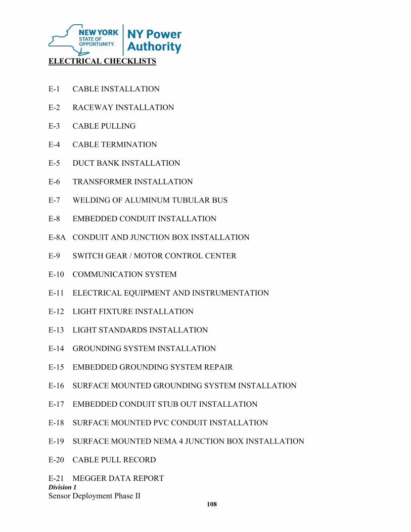
Division 1 Sensor Deployment Phase II
108
ELECTRICAL CHECKLISTS E-1 CABLE INSTALLATION E-2 RACEWAY INSTALLATION E-3 CABLE PULLING E-4 CABLE TERMINATION E-5 DUCT BANK INSTALLATION E-6 TRANSFORMER INSTALLATION E-7 WELDING OF ALUMINUM TUBULAR BUS E-8 EMBEDDED CONDUIT INSTALLATION E-8A CONDUIT AND JUNCTION BOX INSTALLATION E-9 SWITCH GEAR / MOTOR CONTROL CENTER E-10 COMMUNICATION SYSTEM E-11 ELECTRICAL EQUIPMENT AND INSTRUMENTATION E-12 LIGHT FIXTURE INSTALLATION E-13 LIGHT STANDARDS INSTALLATION E-14 GROUNDING SYSTEM INSTALLATION E-15 EMBEDDED GROUNDING SYSTEM REPAIR E-16 SURFACE MOUNTED GROUNDING SYSTEM INSTALLATION E-17 EMBEDDED CONDUIT STUB OUT INSTALLATION E-18 SURFACE MOUNTED PVC CONDUIT INSTALLATION E-19 SURFACE MOUNTED NEMA 4 JUNCTION BOX INSTALLATION E-20 CABLE PULL RECORD E-21 MEGGER DATA REPORT
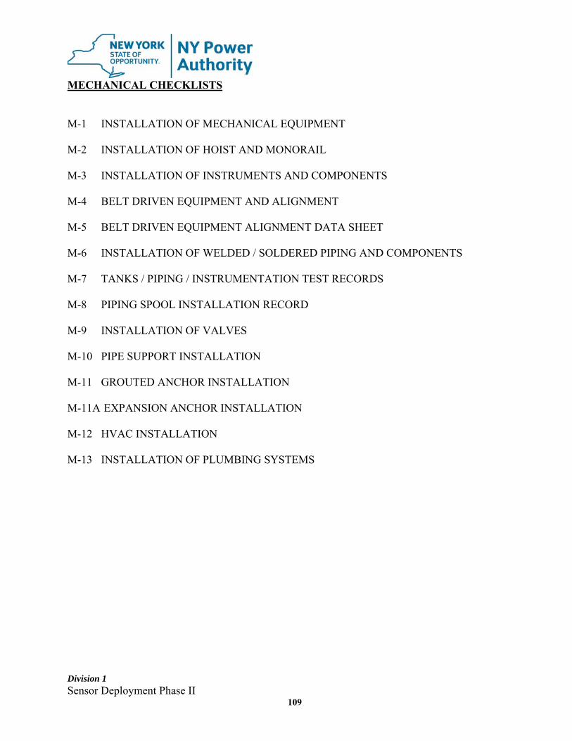
Division 1 Sensor Deployment Phase II
109
MECHANICAL CHECKLISTS M-1 INSTALLATION OF MECHANICAL EQUIPMENT M-2 INSTALLATION OF HOIST AND MONORAIL M-3 INSTALLATION OF INSTRUMENTS AND COMPONENTS M-4 BELT DRIVEN EQUIPMENT AND ALIGNMENT M-5 BELT DRIVEN EQUIPMENT ALIGNMENT DATA SHEET M-6 INSTALLATION OF WELDED / SOLDERED PIPING AND COMPONENTS M-7 TANKS / PIPING / INSTRUMENTATION TEST RECORDS M-8 PIPING SPOOL INSTALLATION RECORD M-9 INSTALLATION OF VALVES M-10 PIPE SUPPORT INSTALLATION M-11 GROUTED ANCHOR INSTALLATION M-11A EXPANSION ANCHOR INSTALLATION M-12 HVAC INSTALLATION M-13 INSTALLATION OF PLUMBING SYSTEMS

26
ATTACHMENT B – SITE LIST
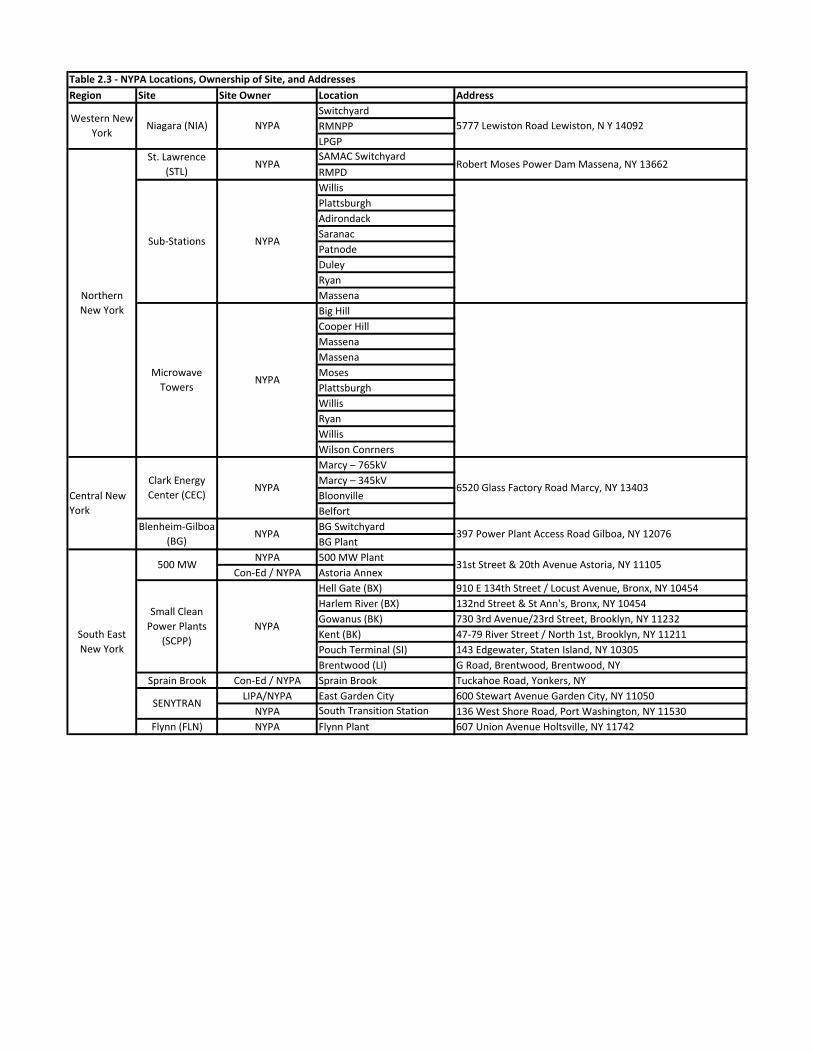
Region Site Site Owner Location Address
Switchyard
RMNPP
LPGP
SAMAC Switchyard
RMPD
Willis
Plattsburgh
Adirondack
Saranac
Patnode
Duley
Ryan
Massena
Big Hill
Cooper Hill
Massena
Massena
Moses
Plattsburgh
Willis
Ryan
Willis
Wilson Conrners
Marcy – 765kV
Marcy – 345kV
Bloonville
Belfort
BG Switchyard
BG Plant
NYPA 500 MW Plant
Con‐Ed / NYPA Astoria Annex
Hell Gate (BX) 910 E 134th Street / Locust Avenue, Bronx, NY 10454
Harlem River (BX) 132nd Street & St Ann's, Bronx, NY 10454
Gowanus (BK) 730 3rd Avenue/23rd Street, Brooklyn, NY 11232
Kent (BK) 47‐79 River Street / North 1st, Brooklyn, NY 11211
Pouch Terminal (SI) 143 Edgewater, Staten Island, NY 10305
Brentwood (LI) G Road, Brentwood, Brentwood, NY
Sprain Brook Con‐Ed / NYPA Sprain Brook Tuckahoe Road, Yonkers, NY
LIPA/NYPA East Garden City 600 Stewart Avenue Garden City, NY 11050
NYPA South Transition Station 136 West Shore Road, Port Washington, NY 11530
Flynn (FLN) NYPA Flynn Plant 607 Union Avenue Holtsville, NY 11742
500 MW
SENYTRAN
Robert Moses Power Dam Massena, NY 13662NYPA
NYPASub‐Stations
NYPAMicrowave
Towers
Table 2.3 ‐ NYPA Locations, Ownership of Site, and Addresses
Western New
YorkNiagara (NIA) NYPA
St. Lawrence
(STL)
NYPA
Small Clean
Power Plants
(SCPP)South East
New York
5777 Lewiston Road Lewiston, N Y 14092
Northern
New York
397 Power Plant Access Road Gilboa, NY 12076
31st Street & 20th Avenue Astoria, NY 11105
Clark Energy
Center (CEC)Central New
York
6520 Glass Factory Road Marcy, NY 13403NYPA
NYPABlenheim‐Gilboa
(BG)

27
ATTACHMENT C – TECHNICAL SPECIFICATION FOR EQUIPMENT SENSORS
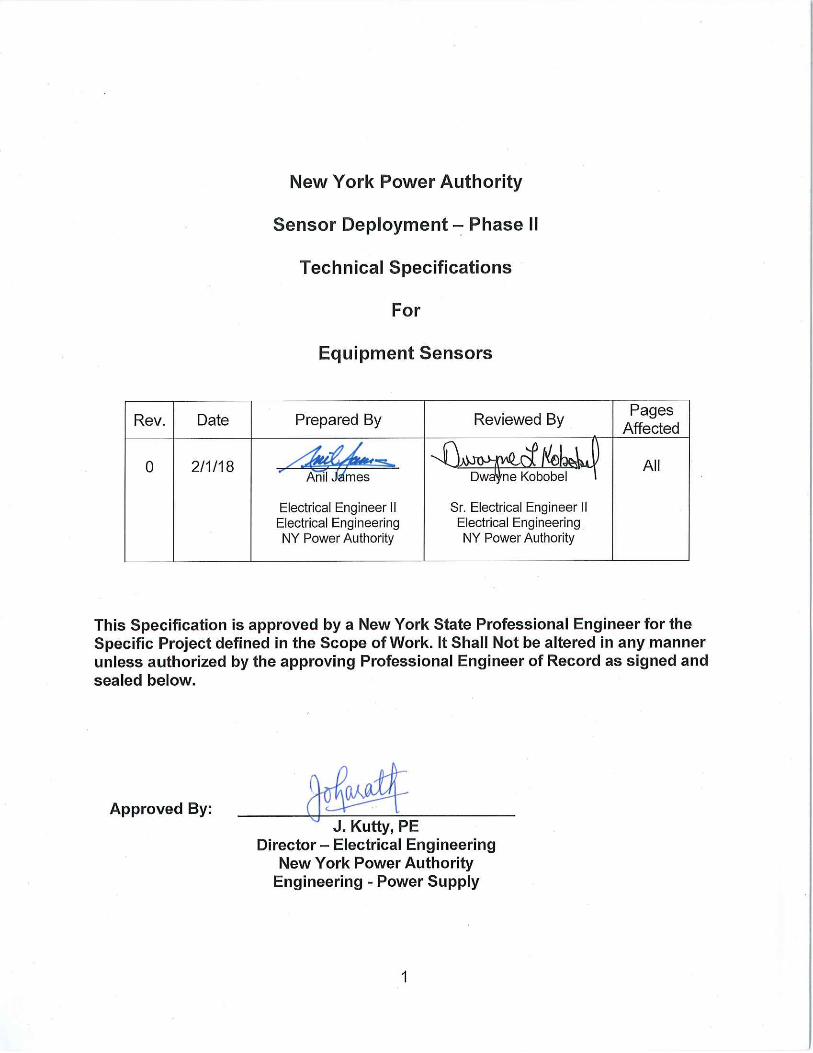
2
TABLE OF CONTENTS
1.0 SCOPE .................................................................................................................. 3
2.0 DEFINITIONS ........................................................................................................ 3
3.0 STANDARDS AND CODES .................................................................................. 3
4.0 GENERAL REQUIREMENTS ............................................................................... 4
5.0 BIDDER TECHNICAL DATA ................................................................................. 5
6.0 SENSORS ............................................................................................................. 6
7.0 ACCESSORIES AND SPECIAL TOOLS ............................................................. 20
8.0 PAINTING AND COATING .................................................................................. 20
9.0 SPARE PARTS ................................................................................................... 20
10.0 QUALITY ASSURANCE ...................................................................................... 21
11.0 SHIPPING ........................................................................................................... 21
12.0 TECHNICAL SUPPORT ...................................................................................... 21
13.0 STORAGE ........................................................................................................... 22
14.0 TRAINING ........................................................................................................... 22
15.0 WARRANTY ........................................................................................................ 22
16.0 ENVIRONMENTAL.............................................................................................. 22
ATTACHMENT 1: EQUIPMENT LIST .......................................................................... 23
3
TECHNICAL SPECIFICATIONS 1.0 SCOPE
1.1 This procurement specification establishes the technical requirements for the design, fabrication, shipment, delivery, installation, testing, commissioning and training of Sensors/Monitoring Systems. The location of the various facilities are provided in Attachment B and the quantity of sensors is provided in Attachment 1. Note Sensors indicated as “future” in Attachment 1 are not in the scope of this work.
1.2 It is not the Authority's intent to specify all technical requirements or to set forth those requirements adequately covered by applicable codes, regulations and standards.
1.3 Any exceptions to this Specification, or its referenced codes, regulations and
standards shall be listed on a separate sheet to be submitted with the bid response documentation and are subject to agreement between the Authority and the Contractor in writing prior to Contract Award.
2.0 DEFINITIONS
2.1 Whenever reference is made to “Authority” or “Purchaser”, it shall mean “New
York Power Authority”.
2.2 Whenever reference is made to “Bidder”, “Contractor, or “Vendor”, it shall mean the successful bidder providing the equipment and services described throughout the specification.
2.3 Whenever reference is made to “Supplier” or “Manufacturer”, it shall mean the
sensor manufacturer selected by the Contractor to provide equipment and services.
3.0 STANDARDS AND CODES
3.1 All equipment to be furnished shall be manufactured and tested in
accordance with the applicable requirements of all federal, state and local laws, codes, regulations, statutes and ordinances, and latest revisions of publications as listed below; in effect on the date of the contract award. All equipment shall be UL/CSA Listed as a minimum and shall have a NEMA 4 or 4X enclosure unless otherwise noted. IEC rated equipment is not acceptable unless otherwise noted or pre-approved by NYPA.
American Iron and Steel Institute (AISI) American National Standards Institute (ANSI) American Society for Testing and Materials (ASTM)
4
American Society of Mechanical Engineers (ASME) American Welding Society (AWS) Electronic Industries Alliance (EIA) Federal Communications Commission (FCC) International Engineering Consortium (IEC) Institute of Electrical and Electronic Engineers (IEEE) International Society for Measurement and Control (ISA) National Electrical Manufacturers Association (NEMA) National Electrical Safety Code (NESC) National Electrical Testing Association (NETA) National Fire Protection Association (NFPA) Northeast Power Coordinating Council (NPCC) Occupational Safety and Health Act (OSHA) Steel Structures Painting Council (SSPC) Underwriter's Laboratory (UL)
4.0 GENERAL REQUIREMENTS
4.1 This specification covers the design, fabrication, shipment, delivery, installation, testing, commissioning and training of sensors and associated equipment as herein specified across the various New York Power Authority’s locations.
4.2 It is the intent for the sensors as specified herein to be fully automated to facilitate monitoring of equipment by the Integrated Smart Operation Center (iSOC), located in the NYPA White Plains office. All communications protocols utilized for the monitoring of the electrical equipment specified herein shall be compatible with the OSI PI System. All equipment will be considered being successfully commissioned when sensor data is available at the iSOC.
4.3 The Contractor shall field verify all equipment to confirm the accuracy of
available NYPA and OEM drawings, prior to commencing his/her work.
4.4 The following list includes, but is not limited to, the minimum required drawings and documents that shall be submitted:
4.4.1 Manufacturer’s Technical Data Sheets 4.4.2 Delivery Schedule 4.4.3 Instrument & Sensor Installation Details. 4.4.4 Wiring Diagram with Cable Schedule 4.4.5 Schematics and P&ID’s 4.4.6 Plan & Profile Drawing of all affected equipment 4.4.7 Bill of material 4.4.8 Spare Parts List
5
4.4.9 Special Tools list 4.4.10 Software Documentation 4.4.11 Site Acceptance Test 4.4.12 Installation & Startup Instructions 4.4.13 Operations & Maintenance Manual
4.4.13.1 Sensor Calibration Criteria and Frequency 4.4.14 Warranty Information 4.4.15 Training Material
4.5 All equipment and documents furnished under this contract shall be
coordinated and field-tested (functional) with the Authority during commissioning of each sensor at the site and after mapping sensor data to the iSOC.
4.6 The Contractor shall retain a manufacturer’s qualified personnel to provide
technical assistance in the field during equipment start up including trouble shooting and programming changes.
4.7 The Contractor shall also be responsible for retaining manufacturer’s qualified
personnel to provide onsite technical assistance for a period of five years after commissioning. This includes assistance analyzing sensor problems, troubleshooting, coordinating repairs and providing recommendation on alarms and warnings. For these purposes, date of commissioning is defined as the date when the manufacturer’s authorized service engineer certifies that the sensors are in proper working order, completes Site Acceptance Test (SAT) checklist and data is available at the iSOC.
4.8 Refer to Section 2.4.8 of Scope of Services for additional commissioning and
testing requirements. 5.0 BIDDER TECHNICAL DATA
5.1 The Bidder shall supply all the technical information for the individual sensors
or sensor packages.
5.2 Incomplete Bidder Technical Data Sheets may be cause for rejection of Bidder's proposal.
5.3 The Bidder’s proposal shall include the front and plan views of each sensor assembly giving overall dimensions and dimensions of each unit.
5.4 The Bidder shall provide information regarding the software packages
associated with each sensor/sensor package.
5.5 The Bidder shall indicate list of Manufacture’s recommended spare parts and special tools and indicate which ones are included in the Bid.
6
5.6 Indicate outage period required for installation of each sensor.
5.7 Provide three (3) references from customers that have recently deployed
sensors of the same type. Include project location, completion date, units installed, contact names, email addresses and telephone numbers.
5.8 The Bidder's proposal shall include confirmation that the preferred equipment
arrangements for the sensor/sensor packages can be as indicated by the Authority herein or submit with proposal the alternate recommended arrangement(s) that meet the intent and comply with applicable codes.
6.0 SENSORS
6.1 General
6.1.1 Provide sensors and accessories for each asset type as described in this
section. The Contractor shall be responsible for the engineering and design of sensors/sensor systems to ensure a complete functioning system, including transmission of data back to the iSOC.
6.1.2 Sensors shall be compatible with all makes/models/manufacturers of the various asset types. Contractor shall work with OEMs to furnish appropriate sensors for each equipment type.
6.1.3 Sensors shall operate at voltages currently available at each asset.
Common nominal voltages which may be available are 120VAC (60Hz), 208VAC (60Hz), 277VAC (60Hz), 480VAC (60Hz) or 125VDC.
6.1.4 Non-field devices (microprocessors, electronics, and alarm indicators/HMI)
shall be provided in or mounted in an NEMA 4/4X enclosure. Enclosures shall be equipped with anti-condensation heater and thermostats.
6.1.5 The sensors and data concentrators shall be capable, with configuration,
of communicating with existing data historian and SCADA systems via standard communication protocols. All devices shall meet NYPA NERC CIP V5/V6 requirements.
6.1.6 Provide software for each sensor type. Software shall be capable of data
storage, trending, alarming, analysis and diagnostic capabilities, with an optional fleet wide health monitoring version. Include optional price for enterprise license for each sensor type in base bid.
6.1.7 Allow authorized user(s) to be able to configure alarms locally and
remotely via web browser and/or sensor specific software.
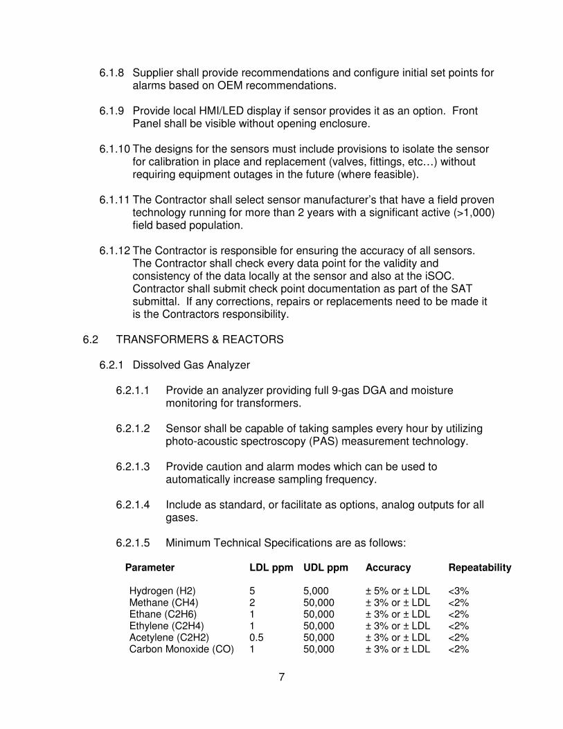
7
6.1.8 Supplier shall provide recommendations and configure initial set points for alarms based on OEM recommendations.
6.1.9 Provide local HMI/LED display if sensor provides it as an option. Front
Panel shall be visible without opening enclosure. 6.1.10 The designs for the sensors must include provisions to isolate the sensor
for calibration in place and replacement (valves, fittings, etc…) without requiring equipment outages in the future (where feasible).
6.1.11 The Contractor shall select sensor manufacturer’s that have a field proven
technology running for more than 2 years with a significant active (>1,000) field based population.
6.1.12 The Contractor is responsible for ensuring the accuracy of all sensors.
The Contractor shall check every data point for the validity and consistency of the data locally at the sensor and also at the iSOC. Contractor shall submit check point documentation as part of the SAT submittal. If any corrections, repairs or replacements need to be made it is the Contractors responsibility.
6.2 TRANSFORMERS & REACTORS
6.2.1 Dissolved Gas Analyzer
6.2.1.1 Provide an analyzer providing full 9-gas DGA and moisture
monitoring for transformers. 6.2.1.2 Sensor shall be capable of taking samples every hour by utilizing
photo-acoustic spectroscopy (PAS) measurement technology.
6.2.1.3 Provide caution and alarm modes which can be used to automatically increase sampling frequency.
6.2.1.4 Include as standard, or facilitate as options, analog outputs for all
gases. 6.2.1.5 Minimum Technical Specifications are as follows:
Parameter LDL ppm UDL ppm Accuracy Repeatability
Hydrogen (H2) 5 5,000 ± 5% or ± LDL <3% Methane (CH4) 2 50,000 ± 3% or ± LDL <2% Ethane (C2H6) 1 50,000 ± 3% or ± LDL <2% Ethylene (C2H4) 1 50,000 ± 3% or ± LDL <2% Acetylene (C2H2) 0.5 50,000 ± 3% or ± LDL <2% Carbon Monoxide (CO) 1 50,000 ± 3% or ± LDL <2%
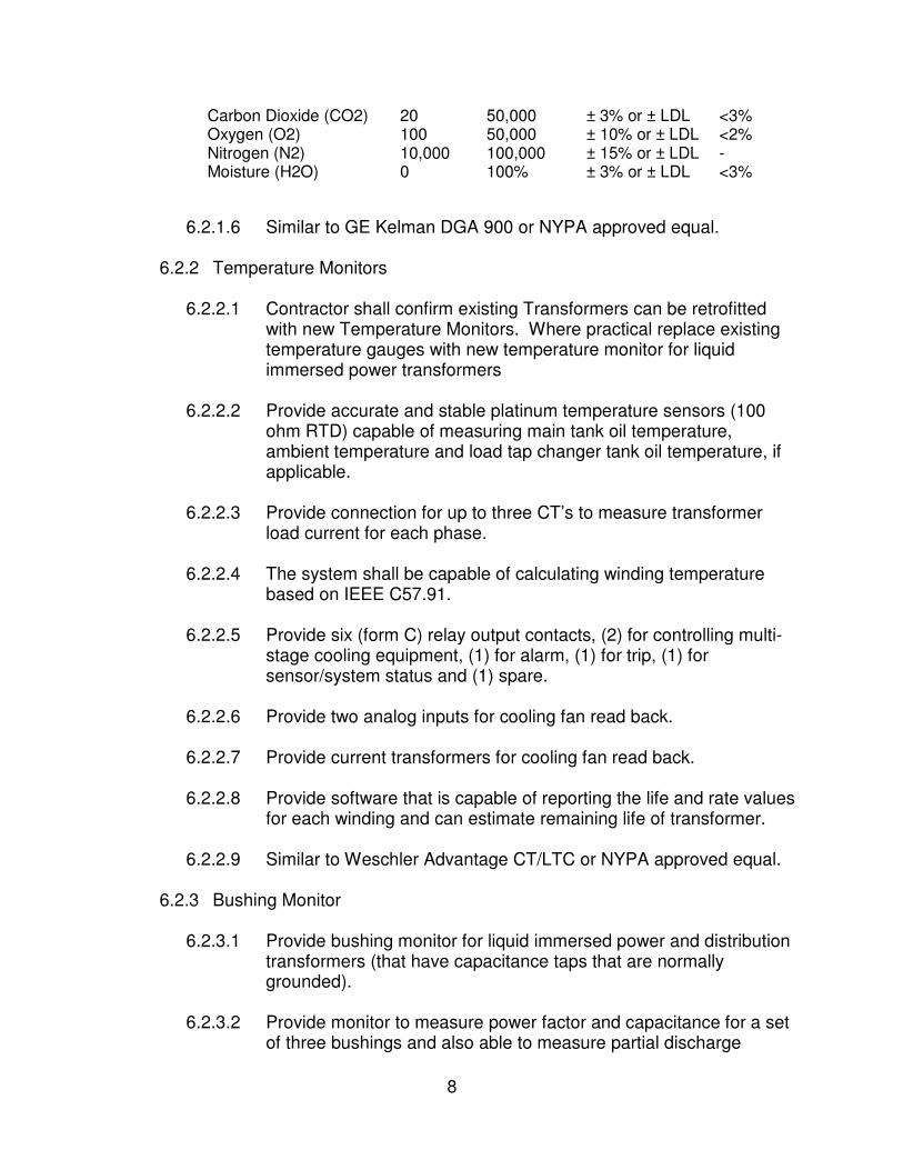
8
Carbon Dioxide (CO2) 20 50,000 ± 3% or ± LDL <3% Oxygen (O2) 100 50,000 ± 10% or ± LDL <2% Nitrogen (N2) 10,000 100,000 ± 15% or ± LDL - Moisture (H2O) 0 100% ± 3% or ± LDL <3%
6.2.1.6 Similar to GE Kelman DGA 900 or NYPA approved equal.
6.2.2 Temperature Monitors
6.2.2.1 Contractor shall confirm existing Transformers can be retrofitted with new Temperature Monitors. Where practical replace existing temperature gauges with new temperature monitor for liquid immersed power transformers
6.2.2.2 Provide accurate and stable platinum temperature sensors (100
ohm RTD) capable of measuring main tank oil temperature, ambient temperature and load tap changer tank oil temperature, if applicable.
6.2.2.3 Provide connection for up to three CT’s to measure transformer
load current for each phase.
6.2.2.4 The system shall be capable of calculating winding temperature based on IEEE C57.91.
6.2.2.5 Provide six (form C) relay output contacts, (2) for controlling multi-
stage cooling equipment, (1) for alarm, (1) for trip, (1) for sensor/system status and (1) spare.
6.2.2.6 Provide two analog inputs for cooling fan read back.
6.2.2.7 Provide current transformers for cooling fan read back.
6.2.2.8 Provide software that is capable of reporting the life and rate values
for each winding and can estimate remaining life of transformer.
6.2.2.9 Similar to Weschler Advantage CT/LTC or NYPA approved equal.
6.2.3 Bushing Monitor
6.2.3.1 Provide bushing monitor for liquid immersed power and distribution transformers (that have capacitance taps that are normally grounded).
6.2.3.2 Provide monitor to measure power factor and capacitance for a set
of three bushings and also able to measure partial discharge
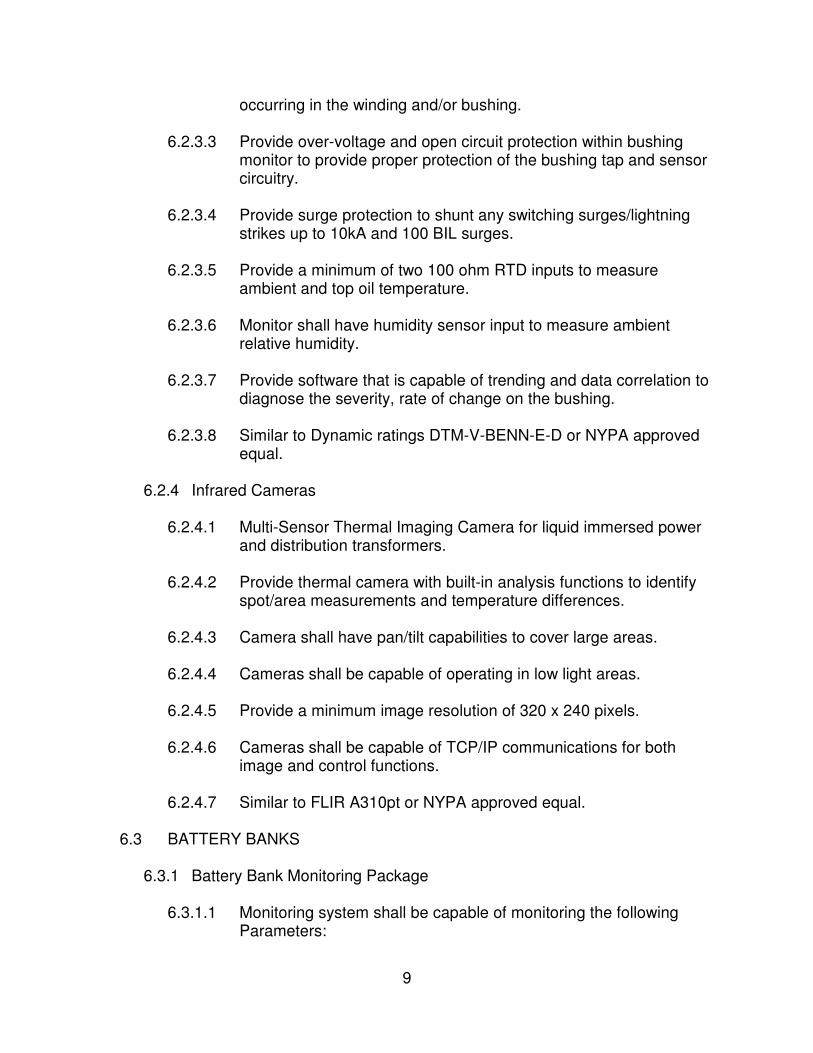
9
occurring in the winding and/or bushing.
6.2.3.3 Provide over-voltage and open circuit protection within bushing monitor to provide proper protection of the bushing tap and sensor circuitry.
6.2.3.4 Provide surge protection to shunt any switching surges/lightning
strikes up to 10kA and 100 BIL surges.
6.2.3.5 Provide a minimum of two 100 ohm RTD inputs to measure ambient and top oil temperature.
6.2.3.6 Monitor shall have humidity sensor input to measure ambient
relative humidity.
6.2.3.7 Provide software that is capable of trending and data correlation to diagnose the severity, rate of change on the bushing.
6.2.3.8 Similar to Dynamic ratings DTM-V-BENN-E-D or NYPA approved
equal.
6.2.4 Infrared Cameras
6.2.4.1 Multi-Sensor Thermal Imaging Camera for liquid immersed power and distribution transformers.
6.2.4.2 Provide thermal camera with built-in analysis functions to identify spot/area measurements and temperature differences.
6.2.4.3 Camera shall have pan/tilt capabilities to cover large areas.
6.2.4.4 Cameras shall be capable of operating in low light areas.
6.2.4.5 Provide a minimum image resolution of 320 x 240 pixels.
6.2.4.6 Cameras shall be capable of TCP/IP communications for both
image and control functions.
6.2.4.7 Similar to FLIR A310pt or NYPA approved equal.
6.3 BATTERY BANKS
6.3.1 Battery Bank Monitoring Package
6.3.1.1 Monitoring system shall be capable of monitoring the following Parameters:
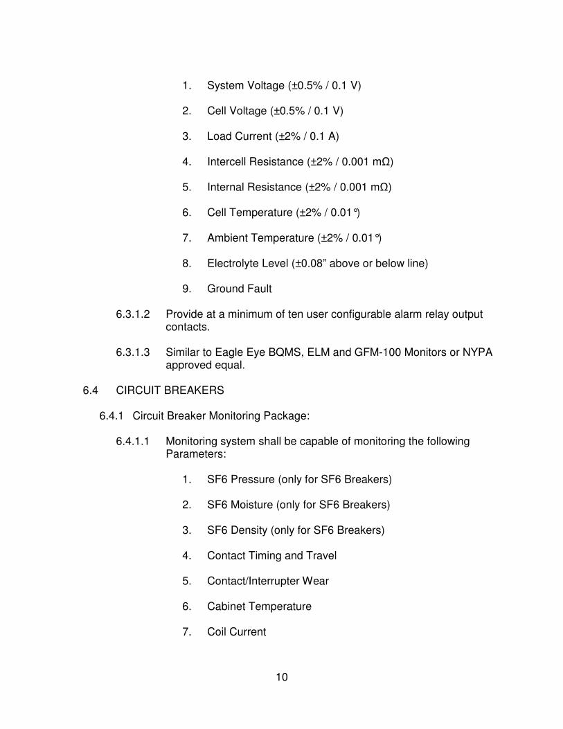
10
1. System Voltage (±0.5% / 0.1 V)
2. Cell Voltage (±0.5% / 0.1 V)
3. Load Current (±2% / 0.1 A)
4. Intercell Resistance (±2% / 0.001 mΩ)
5. Internal Resistance (±2% / 0.001 mΩ)
6. Cell Temperature (±2% / 0.01°) 7. Ambient Temperature (±2% / 0.01°)
8. Electrolyte Level (±0.08” above or below line)
9. Ground Fault
6.3.1.2 Provide at a minimum of ten user configurable alarm relay output
contacts.
6.3.1.3 Similar to Eagle Eye BQMS, ELM and GFM-100 Monitors or NYPA approved equal.
6.4 CIRCUIT BREAKERS
6.4.1 Circuit Breaker Monitoring Package:
6.4.1.1 Monitoring system shall be capable of monitoring the following
Parameters:
1. SF6 Pressure (only for SF6 Breakers)
2. SF6 Moisture (only for SF6 Breakers)
3. SF6 Density (only for SF6 Breakers)
4. Contact Timing and Travel
5. Contact/Interrupter Wear
6. Cabinet Temperature
7. Coil Current
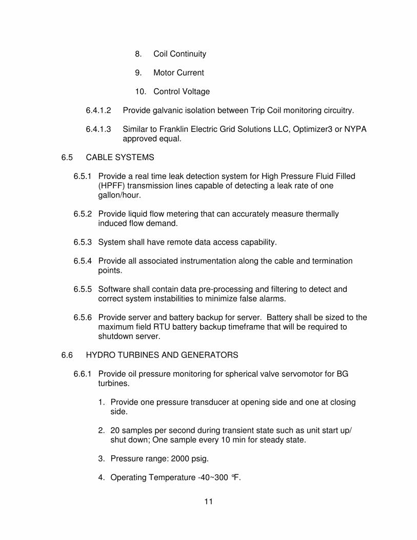
11
8. Coil Continuity
9. Motor Current
10. Control Voltage
6.4.1.2 Provide galvanic isolation between Trip Coil monitoring circuitry.
6.4.1.3 Similar to Franklin Electric Grid Solutions LLC, Optimizer3 or NYPA approved equal.
6.5 CABLE SYSTEMS
6.5.1 Provide a real time leak detection system for High Pressure Fluid Filled
(HPFF) transmission lines capable of detecting a leak rate of one gallon/hour.
6.5.2 Provide liquid flow metering that can accurately measure thermally
induced flow demand. 6.5.3 System shall have remote data access capability. 6.5.4 Provide all associated instrumentation along the cable and termination
points. 6.5.5 Software shall contain data pre-processing and filtering to detect and
correct system instabilities to minimize false alarms. 6.5.6 Provide server and battery backup for server. Battery shall be sized to the
maximum field RTU battery backup timeframe that will be required to shutdown server.
6.6 HYDRO TURBINES AND GENERATORS
6.6.1 Provide oil pressure monitoring for spherical valve servomotor for BG
turbines. 1. Provide one pressure transducer at opening side and one at closing
side.
2. 20 samples per second during transient state such as unit start up/ shut down; One sample every 10 min for steady state.
3. Pressure range: 2000 psig.
4. Operating Temperature -40~300 °F.
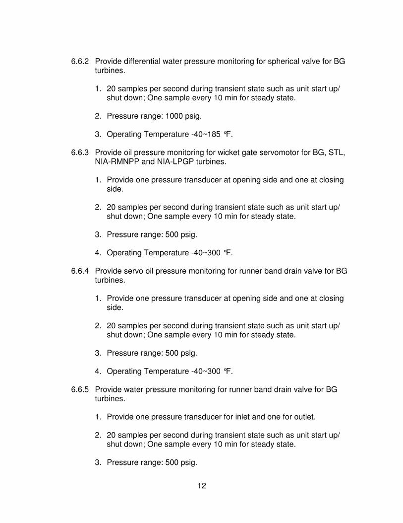
12
6.6.2 Provide differential water pressure monitoring for spherical valve for BG
turbines. 1. 20 samples per second during transient state such as unit start up/
shut down; One sample every 10 min for steady state. 2. Pressure range: 1000 psig.
3. Operating Temperature -40~185 °F.
6.6.3 Provide oil pressure monitoring for wicket gate servomotor for BG, STL, NIA-RMNPP and NIA-LPGP turbines. 1. Provide one pressure transducer at opening side and one at closing
side.
2. 20 samples per second during transient state such as unit start up/ shut down; One sample every 10 min for steady state.
3. Pressure range: 500 psig.
4. Operating Temperature -40~300 °F.
6.6.4 Provide servo oil pressure monitoring for runner band drain valve for BG turbines. 1. Provide one pressure transducer at opening side and one at closing
side.
2. 20 samples per second during transient state such as unit start up/ shut down; One sample every 10 min for steady state.
3. Pressure range: 500 psig.
4. Operating Temperature -40~300 °F.
6.6.5 Provide water pressure monitoring for runner band drain valve for BG turbines. 1. Provide one pressure transducer for inlet and one for outlet.
2. 20 samples per second during transient state such as unit start up/
shut down; One sample every 10 min for steady state.
3. Pressure range: 500 psig.
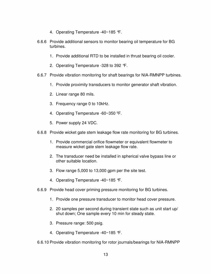
13
4. Operating Temperature -40~185 °F.
6.6.6 Provide additional sensors to monitor bearing oil temperature for BG turbines. 1. Provide additional RTD to be installed in thrust bearing oil cooler.
2. Operating Temperature -328 to 392 °F.
6.6.7 Provide vibration monitoring for shaft bearings for NIA-RMNPP turbines.
1. Provide proximity transducers to monitor generator shaft vibration.
2. Linear range 80 mils.
3. Frequency range 0 to 10kHz.
4. Operating Temperature -60~350 ºF.
5. Power supply 24 VDC.
6.6.8 Provide wicket gate stem leakage flow rate monitoring for BG turbines.
1. Provide commercial orifice flowmeter or equivalent flowmeter to
measure wicket gate stem leakage flow rate.
2. The transducer need be installed in spherical valve bypass line or other suitable location.
3. Flow range 5,000 to 13,000 gpm per the site test.
4. Operating Temperature -40~185 °F.
6.6.9 Provide head cover priming pressure monitoring for BG turbines. 1. Provide one pressure transducer to monitor head cover pressure.
2. 20 samples per second during transient state such as unit start up/
shut down; One sample every 10 min for steady state.
3. Pressure range: 500 psig.
4. Operating Temperature -40~185 °F.
6.6.10 Provide vibration monitoring for rotor journals/bearings for NIA-RMNPP

14
generators. 1. Provide proximity transducers to monitor generator shaft vibration.
2. Linear range 80 mils.
3. Frequency range 0 to 10kHz.
4. Operating Temperature -60~350 ºF.
5. Power supply 24 VDC.
6.6.11 Provide air gap monitoring for NIA-RMNPP generators.
1. Provide air gap transducers to monitor distance between generator
rotor and stator.
2. 8 transducers for each generator.
3. Linear range 720 mils.
4. Frequency range 0 to 10kHz.
5. Operating Temperature 32~257 ºF.
6. Power supply 24 VDC. 6.6.12 Provide suitable sensor module(s) for the existing Bentley Nevada 3500
rack at each turbine to acquire signal from the new sensor(s). Alternative data acquisition solution, including data acquisition, data processing and data storage, shall be reviewed and approved by NYPA.
6.7 STEAM TURBINES AND GENERATORS
6.7.1 Provide oil pressure monitoring for Lube and Hydraulic Oil Discharges per pump, AC & DC, upstream of any check valves as applicable for 500MW units. (5 Pressures Total – 2 AC Lube, 1 DC Lube, 2 AC Hydraulic)
1. Reference GE Drawing 124E3372 for system Lube / Hydraulic P&ID.
Hebeler (skid manufacturer) project - # V1792A.
2. Lubrication Oil Discharge Pressure to Bearing
a. Normal / Max Temp: 120 F / 180 F

15
b. Normal / Max Pressure: 50 psig / 55 psig
c. Fluid: Conoco Philips Diamond Class Turbine Oil 32
3. Hydraulic Oil Discharge to System a. Normal / Max Temp: 105 F / 150 F
b. Normal / Max Pressure: 2400 psig / 3000 psig
c. Fluid: Fryquel Plus (ester based fluid)
4. Rosemount 3051 Series or equivalent Yokagawa transmitters
a. Shall utilize the HART ("Highway Addressable Remote
Transducer") communication protocol.
5. Data samples shall be continuously recorded by the plant Historian. Configuration of any other sample frequency shall be handled by plant personnel.
6. Signals be tied into the plants’ Steam Turbine or Balance of Plant
(BOP) Mark VI (MKVI) Control System. a. The TBD Control Cabinet shall be audited to determine if spare I/O
termination points are available.
b. New GE OEM I/O cards to be utilized if required.
c. Only General Electric MKVI Controls Engineers shall alter the control .m6b files.
6.7.2 Provide Current (CT) measurement of each phase of the turning gear
motor for 500MW units. (GE MCC Drawing 337B7030) (3 Currents Total – 3 Phases) 1. Motor HP = 20 HP
2. Motor Voltage = 480 VAC
3. Motor Speed = 1800 RPM
4. Motor FLM = 23.1 A
5. Motor SF = 1.15

16
6. Fuse Trip = 40 A
6.8 COMBUSTION TURBINES AND GENERATORS
6.8.1 Provide oil pressure monitoring for Lube, Seal and Hydraulic Oil Discharges per pump, AC & DC, upstream of any check valves for 500MW units as applicable. 1. Reference GE Drawing 123E3114 (Hydraulic) and 123E3104 (Lube /
Seal Oil) for system Lube / Seal / Hydraulic P&IDs. Mitten Manufacturing (skid manufacturer) project - # J2911A (6 Pressures per Each Turbine (12 Total) – 2 AC Lube, 1 DC Lube, 2 AC Hydraulic, 1 AC/DC Seal Oil )
2. Hydraulic Oil Discharge to System
a. Normal / Max Temp: 130 F / 160 F
b. Normal / Max Pressure: 3100 psig / 3850 psig
i. Lift oil values utilized. Max Design on Mitten Drawings is listed as 4500 psig. This maximum limit shall be utilized during device selection.
c. Fluid: Conoco Philips Diamond Class Turbine Oil 32
3. Lubrication Oil Discharge Pressure to Bearing
a. Normal / Max Temp: 130 F / 160 F
b. Normal / Max Pressure: 35 psig / 150 psig
c. Fluid: Conoco Philips Diamond Class Turbine Oil 32
4. Seal Oil Discharge Pressure to Generator
a. Normal / Max Temp: 130 F / 160 F
b. Normal / Max Pressure: 100 psig / 150 psig
c. Fluid: Conoco Philips Diamond Class Turbine Oil 32
5. Rosemount 3051 Series or equivalent Yokagawa transmitters
a. Shall utilize the HART ("Highway Addressable Remote
Transducer") communication protocol.
17
6. Data samples shall be continuously recorded by the plant Historian.
Configuration of any other sample frequency shall be handled by plant personnel.
7. Signals be tied into the plants’ Combustion Turbine Mark VI (MKVI) Control System.
a. The Control Cabinet shall be audited to determine if spare I/O
termination points are available.
b. New GE OEM I/O cards to be utilized if required.
c. Only General Electric MKVI Controls Engineers shall alter the control .m6b files.
6.8.2 Provide inlet air filter house differential air pressure monitoring between
the outside / pre-filtration (dirty) air and internal / post filtration (clean) air for 500MW units. (1 Diff Pressure per Turbine (2 Total) – Air Diff) 1. Reference GE Drawing 356B6660 / Donaldson 2SG-AD24947-01 for
air filter system specification and general arrangement. GE Drawing 362B8609 / Donaldson 2SG-AD24947-01 for air filter system control cabinet (existing pressure switches).
2. Outside Air through filter
a. Min / Max Temp: -20 F / 120 F
b. Differential Pressure:
i. Clean Filters: 0.60 inWG (~0.021 psig)
ii. Alarm Warning: 6.00 inWG (~0.216 psig)
iii. Alarm Shutdown: 8.00 inWG (~0.288 psig)
3. Data samples shall be continuously recorded by the plant Historian. Configuration of any other sample frequency shall be handled by plant personnel.
4. Signals be tied into the plants’ Combustion Turbine Mark VI (MKVI) Control System or Possibly the Balance of Plant Control System (BOP).
a. The Control Cabinet shall be audited to determine if spare I/O
18
termination points are available.
b. New GE OEM I/O cards to be utilized if required.
c. Only General Electric MKVI Controls Engineers shall alter the control .m6b files.
6.8.3 Provide Combustion Turbine Blade Health Monitoring System for 500MW
units. (Potential 6 sensors per Turbine (12 Total)– 3 stages monitored, two probes each, Special Software Package Required to Analysis Data)
1. During the Combustion Turbine 2018 outage season, the OEM,
General Electric is machining ports within the upper half of the Compressor Casing directly in line with a few of the early compressor rotating blade stages for the future installation of their Blade Health Monitoring System. a. Contractor shall work with General Electric to design and install the
OEM product.
6.8.4 Provide Generator Monitoring for 500MW units.
1. Partial Discharge (IRIS - BusTrac) and Rotor Flux (GENERATORTECH) are currently being monitored. While the IRIS system collects it data to a local IRIS server and ports some of its data to the plants’ control system a diagnostic software suite is desired to enhance potential anomalies. The Generatortech system also collects data to a local system specific sever however this data is only available on that system. The data and software suite shall be made available to the iSOC.
6.8.5 Provide Current (CT) measurement of each phase of the turning gear
motor for 500MW units. (GE MCC Drawing 338B1360) (3 Currents per Turbine (6 Total) – 3 Phases) 1. Motor HP = 5 HP
2. Motor Voltage = 480 VAC
3. Motor Speed = 1800 RPM
4. Motor FLM = 6.3 A
5. Motor SF = 1.15
6. Fuse Trip = 15 A
19
6.8.6 Provide Reliability Max for SCPP units.
1. General Electric has a packaged LM6000 product suite to monitor
various turbine elements such as blade health (tip timing), combustion dynamics, roller bearing vibration and gas path debris. Contractor shall work with General Electric to identify the components of the package which are offered which directly impact our particular LM6000PC units. Once an evaluation is completed a summary report shall be generated and presented to the Authority for review and approval of individual packaged components or the entire suite, prior to the integration of this suite within this phase of the project.
2. The first units installation shall be designated a “pilot” to determine if long term value is seen with the suite. Site to be determined.
6.8.7 Provide Engine Pre-Catalyst Emissions Monitoring for SCPP units.
1. To determine the efficiency of the catalyst system and tracking of lifespan, accurate, CEMS quality, measurement of pre and post catalyst NOx, CO and O2 is required. The post measurement system is in place as part of normal regulatory requirements however a pre measurement system is required for the tracking mentioned above. The Contractor to evaluate CEMTEK or Authority approved equal manufactures to measure the following air constituents utilizing the listed measurement technology. Alternatives manufactures and measurement technologies could be proposed however they shall closely match currently utilized Authority emissions monitoring equipment to reduce the inventory of spare equipment required to keep on hand. Once the system components has been chosen by the Contractor a summary report shall be generated and presented to the Authority for review and approval, prior to the project integration. a. NOx – Chemiluminescent
b. CO – NDIR
c. O2 – Paramagnetic
2. The design of the sample probes as well as any other mechanical, electrical (power / signal / communication / networking) and civil interconnections between the turbine exhaust ducting, the new monitoring system and the site shall be the responsibility of the Contractor.
6.9 COMMUNICATION
20
6.9.1 All sensors shall have hardware communication options available for RS-
485, 10/100/1000 Ethernet and/or Fiber Optic.
6.9.2 All sensors shall support the following communications protocols either natively or via additional hardware options: MODBUS TCP/IP (preferred), MODBUS RTU and/or DNP3.0.
6.9.3 Support “HTTP” or “HTTPS” protocol for local or remote browser based
HMI or software of sensor.
6.9.4 All sensors shall be compliant with NYPA NERC/CIP V5/V6 policies and procedures, Physical Access Controls (lockable enclosures), Electronic Access controls (Passwords, HTTPS, and security policy’s).
7.0 ACCESSORIES AND SPECIAL TOOLS
7.1 All necessary accessories and special tools required for initial erection, inspection, testing and future maintenance for all of the above-specified equipment shall be furnished by the Contractor.
8.0 PAINTING AND COATING
8.1 Equipment shall be cleaned, primed and finish-painted in accordance with
manufacturer’s standard specification. Touch up paint shall be furnished with each equipment delivery over the span of the contract.
8.2 All metal sheets and framework shall be thoroughly cleaned after fabrication,
treated with a phosphate coating, and unless otherwise noted, given a prime coat of rust-inhibiting paint. A finish coat of gray lacquer or enamel, or NYPA approved equal, shall be applied overall.
8.3 Equipment openings, terminals and connections shall be protected against
entrance of dirt, dust, moisture or other deleterious elements. All surfaces shall be protected from corrosion and oxidation in accordance with manufacturer’s standard methods.
8.4 NYPA reserves the rights to approve each and every component’s color. The
contractor must submit an RFI to obtain NYPA’s approval at the start of the fabrication.
9.0 SPARE PARTS
9.1 The Contractor shall provide a detailed list of recommended spare parts with prices.
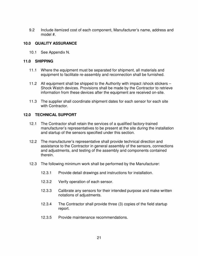
21
9.2 Include itemized cost of each component, Manufacturer’s name, address and
model #.
10.0 QUALITY ASSURANCE
10.1 See Appendix N. 11.0 SHIPPING
11.1 Where the equipment must be separated for shipment, all materials and
equipment to facilitate re-assembly and reconnection shall be furnished.
11.2 All equipment shall be shipped to the Authority with impact /shock stickers – Shock Watch devices. Provisions shall be made by the Contractor to retrieve information from these devices after the equipment are received on-site.
11.3 The supplier shall coordinate shipment dates for each sensor for each site
with Contractor. 12.0 TECHNICAL SUPPORT
12.1 The Contractor shall retain the services of a qualified factory-trained
manufacturer’s representatives to be present at the site during the installation and startup of the sensors specified under this section.
12.2 The manufacturer’s representative shall provide technical direction and assistance to the Contractor in general assembly of the sensors, connections and adjustments, and testing of the assembly and components contained therein.
12.3 The following minimum work shall be performed by the Manufacturer: 12.3.1 Provide detail drawings and instructions for installation.
12.3.2 Verify operation of each sensor.
12.3.3 Calibrate any sensors for their intended purpose and make written
notations of adjustments.
12.3.4 The Contractor shall provide three (3) copies of the field startup report.
12.3.5 Provide maintenance recommendations.

22
13.0 STORAGE
13.1 The Contractor shall provide long term storage requirements of the Sensors necessary to maintain the warranty.
14.0 TRAINING
14.1 Contractor shall provide training to Authority personnel on operation, adjustment and maintenance of sensors and associated devices.
14.2 All training must be instructor led and must be in person. Instructor shall be Manufacturer’s authorized personnel.
14.3 Provide a minimum of two hours of training per sensor type at each project
site.
14.4 Contractor shall provide all training material, books, manual etc. for all attendees. Assume 12 attendees per session.
14.5 All cost for training including but not limited to equipment, lodging, traveling,
training material shall be included in the base price including change order work.
14.6 Provide optional price for additional training sessions.
15.0 WARRANTY
15.1 Refer to Section 2.6 of Scope of Services for warranty requirements.
16.0 ENVIRONMENTAL
16.1 All devices shall be rated for the following atmospheric conditions: -40⁰C to
85⁰C and RH 95-100%

23
ATTACHMENT 1: EQUIPMENT LIST
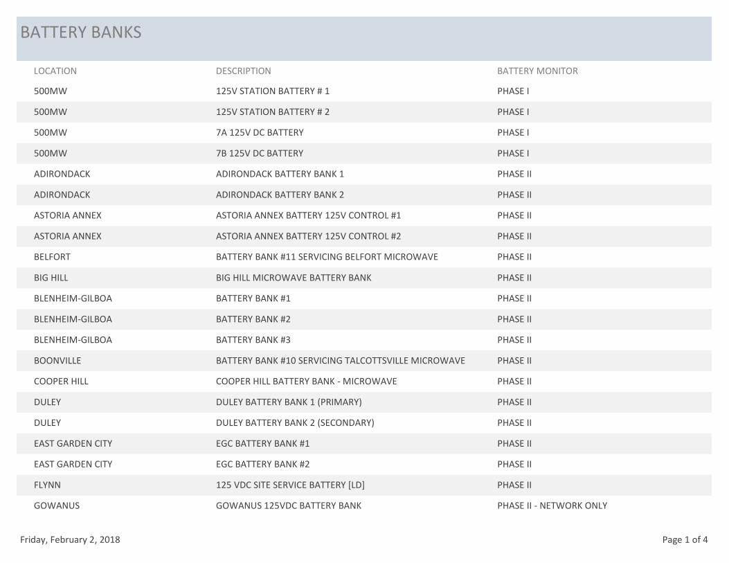
BATTERY BANKS
LOCATION DESCRIPTION BATTERY MONITOR
500MW 125V STATION BATTERY # 1 PHASE I
500MW 125V STATION BATTERY # 2 PHASE I
500MW 7A 125V DC BATTERY PHASE I
500MW 7B 125V DC BATTERY PHASE I
ADIRONDACK ADIRONDACK BATTERY BANK 1 PHASE II
ADIRONDACK ADIRONDACK BATTERY BANK 2 PHASE II
ASTORIA ANNEX ASTORIA ANNEX BATTERY 125V CONTROL #1 PHASE II
ASTORIA ANNEX ASTORIA ANNEX BATTERY 125V CONTROL #2 PHASE II
BELFORT BATTERY BANK #11 SERVICING BELFORT MICROWAVE PHASE II
BIG HILL BIG HILL MICROWAVE BATTERY BANK PHASE II
BLENHEIM-GILBOA BATTERY BANK #1 PHASE II
BLENHEIM-GILBOA BATTERY BANK #2 PHASE II
BLENHEIM-GILBOA BATTERY BANK #3 PHASE II
BOONVILLE BATTERY BANK #10 SERVICING TALCOTTSVILLE MICROWAVE PHASE II
COOPER HILL COOPER HILL BATTERY BANK - MICROWAVE PHASE II
DULEY DULEY BATTERY BANK 1 (PRIMARY) PHASE II
DULEY DULEY BATTERY BANK 2 (SECONDARY) PHASE II
EAST GARDEN CITY EGC BATTERY BANK #1 PHASE II
EAST GARDEN CITY EGC BATTERY BANK #2 PHASE II
FLYNN 125 VDC SITE SERVICE BATTERY [LD] PHASE II
GOWANUS GOWANUS 125VDC BATTERY BANK PHASE II - NETWORK ONLY
Friday, February 2, 2018 Page 1 of 4
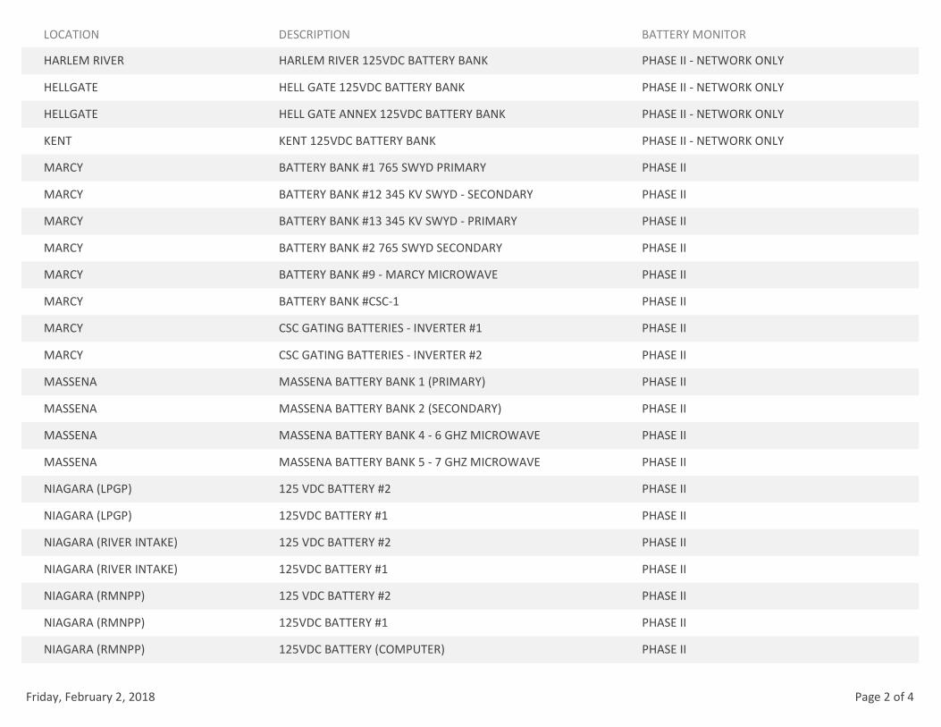
LOCATION DESCRIPTION BATTERY MONITOR
HARLEM RIVER HARLEM RIVER 125VDC BATTERY BANK PHASE II - NETWORK ONLY
HELLGATE HELL GATE 125VDC BATTERY BANK PHASE II - NETWORK ONLY
HELLGATE HELL GATE ANNEX 125VDC BATTERY BANK PHASE II - NETWORK ONLY
KENT KENT 125VDC BATTERY BANK PHASE II - NETWORK ONLY
MARCY BATTERY BANK #1 765 SWYD PRIMARY PHASE II
MARCY BATTERY BANK #12 345 KV SWYD - SECONDARY PHASE II
MARCY BATTERY BANK #13 345 KV SWYD - PRIMARY PHASE II
MARCY BATTERY BANK #2 765 SWYD SECONDARY PHASE II
MARCY BATTERY BANK #9 - MARCY MICROWAVE PHASE II
MARCY BATTERY BANK #CSC-1 PHASE II
MARCY CSC GATING BATTERIES - INVERTER #1 PHASE II
MARCY CSC GATING BATTERIES - INVERTER #2 PHASE II
MASSENA MASSENA BATTERY BANK 1 (PRIMARY) PHASE II
MASSENA MASSENA BATTERY BANK 2 (SECONDARY) PHASE II
MASSENA MASSENA BATTERY BANK 4 - 6 GHZ MICROWAVE PHASE II
MASSENA MASSENA BATTERY BANK 5 - 7 GHZ MICROWAVE PHASE II
NIAGARA (LPGP) 125 VDC BATTERY #2 PHASE II
NIAGARA (LPGP) 125VDC BATTERY #1 PHASE II
NIAGARA (RIVER INTAKE) 125 VDC BATTERY #2 PHASE II
NIAGARA (RIVER INTAKE) 125VDC BATTERY #1 PHASE II
NIAGARA (RMNPP) 125 VDC BATTERY #2 PHASE II
NIAGARA (RMNPP) 125VDC BATTERY #1 PHASE II
NIAGARA (RMNPP) 125VDC BATTERY (COMPUTER) PHASE II
Friday, February 2, 2018 Page 2 of 4
LOCATION DESCRIPTION BATTERY MONITOR
NIAGARA (SWYD) 125VDC BATTERY #1 (FAN BLDG) PHASE II
NIAGARA (SWYD) 125VDC BATTERY #1A (S&R) PHASE II
NIAGARA (SWYD) 125VDC BATTERY #1B (S&R) PHASE II
NIAGARA (SWYD) 125VDC BATTERY #2 (FAN BLDG) PHASE II
NIAGARA (SWYD) 125VDC BATTERY #2A (S&R) PHASE II
NIAGARA (SWYD) 125VDC BATTERY #2B (S&R) PHASE II
NIAGARA (SWYD) 125VDC BATTERY #3A (S&R) PHASE II
NIAGARA (SWYD) 125VDC BATTERY #3B (S&R) PHASE II
PATNODE PATNODE BATTERY BANK 1 (PRIMARY) PHASE II
PATNODE PATNODE BATTERY BANK 2 (SECONDARY) PHASE II
PLATTSBURGH PLATTSBURGH BATTERY BANK 1 (PRIMARY) PHASE II
PLATTSBURGH PLATTSBURGH BATTERY BANK 2 (SECONDARY) PHASE II
PLATTSBURGH PLATTSBURGH BATTERY BANK 21 (PRIMARY) (230 BLDG) PHASE II
PLATTSBURGH PLATTSBURGH BATTERY BANK 22 (SECONDARY) (230 BLDG) PHASE II
PLATTSBURGH PLATTSBURGH BATTERY BANK 24 - MICROWAVE PHASE II
POUCH TERMINAL GT POUCH 125VDC BATTERY BANK PHASE II - NETWORK ONLY
RYAN RYAN BATTERY BANK - MICROWAVE PHASE II
RYAN RYAN BATTERY BANK 1 (PRIMARY) PHASE II
RYAN RYAN BATTERY BANK 2 (SECONDARY) PHASE II
SOUTH TRANSITION STS BATTERY BANK #1 PHASE II
SOUTH TRANSITION STS BATTERY BANK #2 PHASE II
ST. LAWRENCE (RMPD) RMPD BATTERY BANK 1 - ELEV 194.5 (PRIMARY) PHASE II
ST. LAWRENCE (RMPD) RMPD BATTERY BANK 2 - ELEV 194.5 (PRIMARY) PHASE II
Friday, February 2, 2018 Page 3 of 4
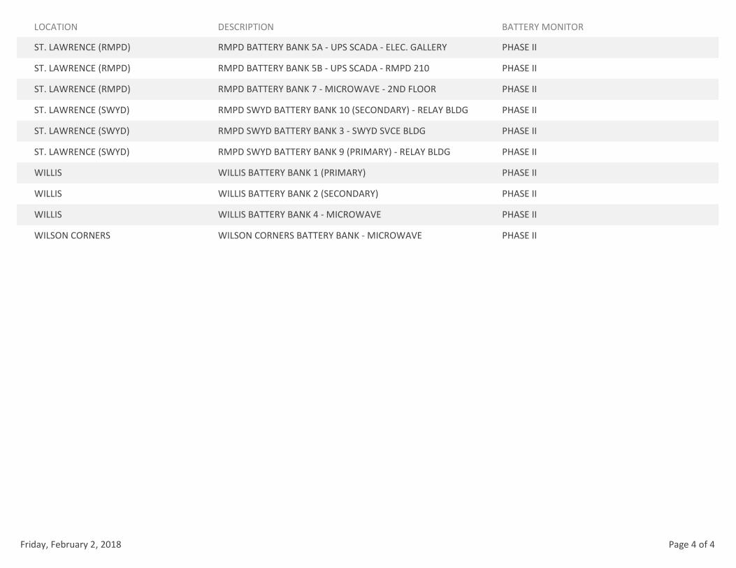
LOCATION DESCRIPTION BATTERY MONITOR
ST. LAWRENCE (RMPD) RMPD BATTERY BANK 5A - UPS SCADA - ELEC. GALLERY PHASE II
ST. LAWRENCE (RMPD) RMPD BATTERY BANK 5B - UPS SCADA - RMPD 210 PHASE II
ST. LAWRENCE (RMPD) RMPD BATTERY BANK 7 - MICROWAVE - 2ND FLOOR PHASE II
ST. LAWRENCE (SWYD) RMPD SWYD BATTERY BANK 10 (SECONDARY) - RELAY BLDG PHASE II
ST. LAWRENCE (SWYD) RMPD SWYD BATTERY BANK 3 - SWYD SVCE BLDG PHASE II
ST. LAWRENCE (SWYD) RMPD SWYD BATTERY BANK 9 (PRIMARY) - RELAY BLDG PHASE II
WILLIS WILLIS BATTERY BANK 1 (PRIMARY) PHASE II
WILLIS WILLIS BATTERY BANK 2 (SECONDARY) PHASE II
WILLIS WILLIS BATTERY BANK 4 - MICROWAVE PHASE II
WILSON CORNERS WILSON CORNERS BATTERY BANK - MICROWAVE PHASE II
Friday, February 2, 2018 Page 4 of 4
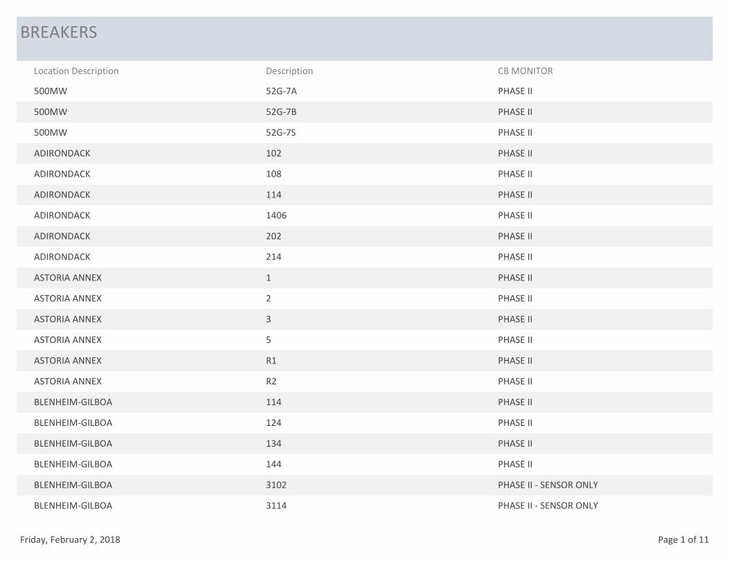
BREAKERS
Location Description Description CB MONITOR
500MW 52G-7A PHASE II
500MW 52G-7B PHASE II
500MW 52G-7S PHASE II
ADIRONDACK 102 PHASE II
ADIRONDACK 108 PHASE II
ADIRONDACK 114 PHASE II
ADIRONDACK 1406 PHASE II
ADIRONDACK 202 PHASE II
ADIRONDACK 214 PHASE II
ASTORIA ANNEX 1 PHASE II
ASTORIA ANNEX 2 PHASE II
ASTORIA ANNEX 3 PHASE II
ASTORIA ANNEX 5 PHASE II
ASTORIA ANNEX R1 PHASE II
ASTORIA ANNEX R2 PHASE II
BLENHEIM-GILBOA 114 PHASE II
BLENHEIM-GILBOA 124 PHASE II
BLENHEIM-GILBOA 134 PHASE II
BLENHEIM-GILBOA 144 PHASE II
BLENHEIM-GILBOA 3102 PHASE II - SENSOR ONLY
BLENHEIM-GILBOA 3114 PHASE II - SENSOR ONLY
Friday, February 2, 2018 Page 1 of 11
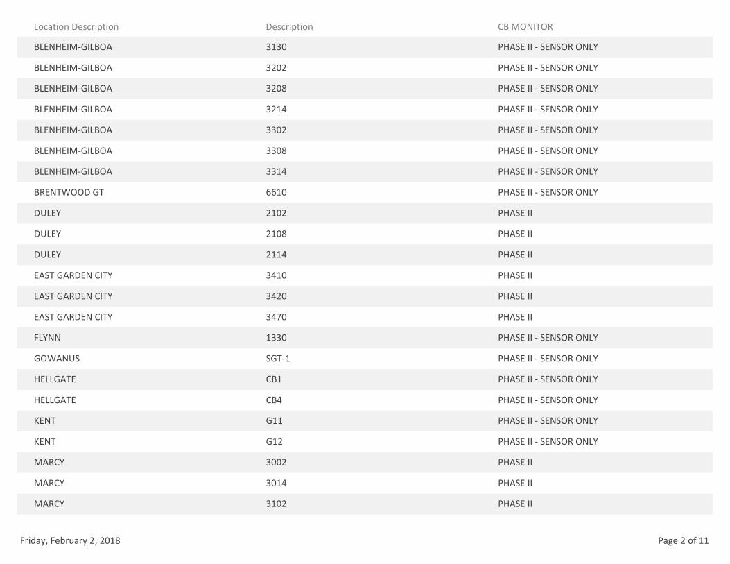
Location Description Description CB MONITOR
BLENHEIM-GILBOA 3130 PHASE II - SENSOR ONLY
BLENHEIM-GILBOA 3202 PHASE II - SENSOR ONLY
BLENHEIM-GILBOA 3208 PHASE II - SENSOR ONLY
BLENHEIM-GILBOA 3214 PHASE II - SENSOR ONLY
BLENHEIM-GILBOA 3302 PHASE II - SENSOR ONLY
BLENHEIM-GILBOA 3308 PHASE II - SENSOR ONLY
BLENHEIM-GILBOA 3314 PHASE II - SENSOR ONLY
BRENTWOOD GT 6610 PHASE II - SENSOR ONLY
DULEY 2102 PHASE II
DULEY 2108 PHASE II
DULEY 2114 PHASE II
EAST GARDEN CITY 3410 PHASE II
EAST GARDEN CITY 3420 PHASE II
EAST GARDEN CITY 3470 PHASE II
FLYNN 1330 PHASE II - SENSOR ONLY
GOWANUS SGT-1 PHASE II - SENSOR ONLY
HELLGATE CB1 PHASE II - SENSOR ONLY
HELLGATE CB4 PHASE II - SENSOR ONLY
KENT G11 PHASE II - SENSOR ONLY
KENT G12 PHASE II - SENSOR ONLY
MARCY 3002 PHASE II
MARCY 3014 PHASE II
MARCY 3102 PHASE II
Friday, February 2, 2018 Page 2 of 11

Location Description Description CB MONITOR
MARCY 3108 PHASE II
MARCY 3114 PHASE II
MARCY 3202 PHASE II
MARCY 3208 PHASE II
MARCY 3214 PHASE II
MARCY 3222 PHASE II
MARCY 3302 PHASE II
MARCY 3308 PHASE II
MARCY 3314 PHASE II
MARCY 3322 PHASE II
MARCY 3402 PHASE II
MARCY 3414 PHASE II
MARCY 765KV 7202 FUTURE
MARCY 765KV 7214 PHASE II
MARCY 765KV 7223 FUTURE
MARCY 765KV 7223X FUTURE
MARCY 765KV 7302 PHASE II
MARCY 765KV 7402 PHASE II
MARCY 765KV 7414 PHASE II
MASSENA 7102 FUTURE
MASSENA 7108 FUTURE
MASSENA 7114 FUTURE
MASSENA 7122 PHASE II
Friday, February 2, 2018 Page 3 of 11
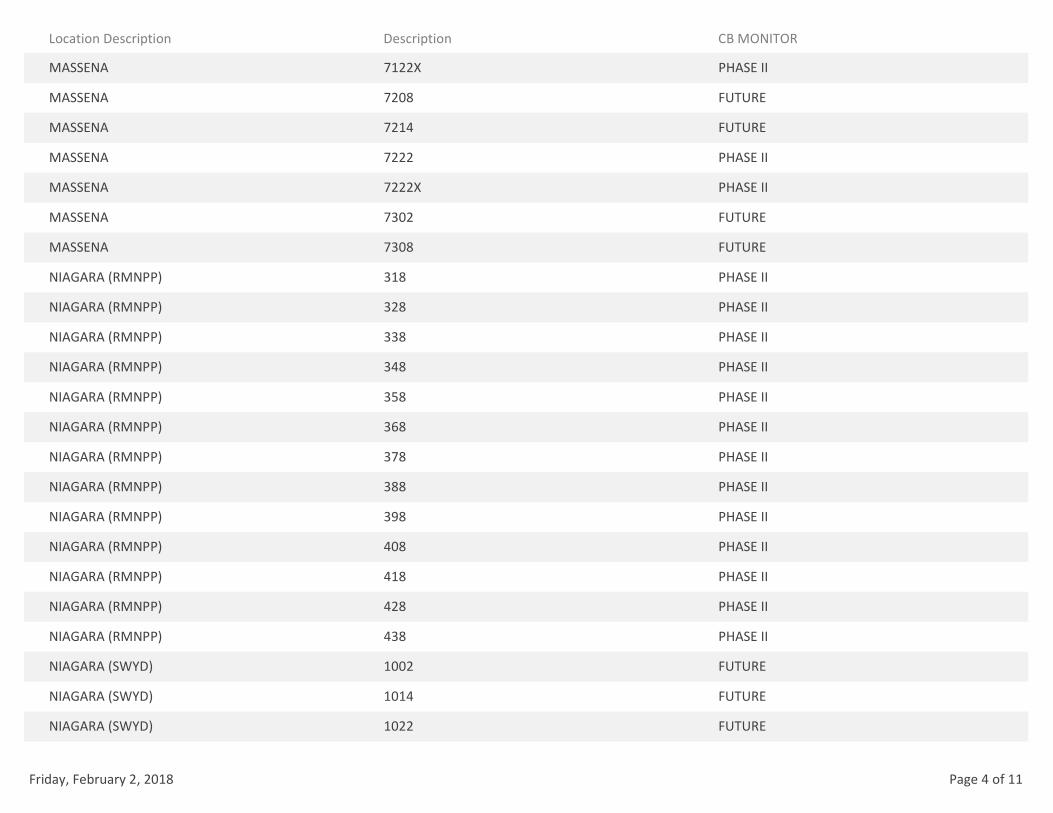
Location Description Description CB MONITOR
MASSENA 7122X PHASE II
MASSENA 7208 FUTURE
MASSENA 7214 FUTURE
MASSENA 7222 PHASE II
MASSENA 7222X PHASE II
MASSENA 7302 FUTURE
MASSENA 7308 FUTURE
NIAGARA (RMNPP) 318 PHASE II
NIAGARA (RMNPP) 328 PHASE II
NIAGARA (RMNPP) 338 PHASE II
NIAGARA (RMNPP) 348 PHASE II
NIAGARA (RMNPP) 358 PHASE II
NIAGARA (RMNPP) 368 PHASE II
NIAGARA (RMNPP) 378 PHASE II
NIAGARA (RMNPP) 388 PHASE II
NIAGARA (RMNPP) 398 PHASE II
NIAGARA (RMNPP) 408 PHASE II
NIAGARA (RMNPP) 418 PHASE II
NIAGARA (RMNPP) 428 PHASE II
NIAGARA (RMNPP) 438 PHASE II
NIAGARA (SWYD) 1002 FUTURE
NIAGARA (SWYD) 1014 FUTURE
NIAGARA (SWYD) 1022 FUTURE
Friday, February 2, 2018 Page 4 of 11

Location Description Description CB MONITOR
NIAGARA (SWYD) 1102 PHASE II
NIAGARA (SWYD) 1114 PHASE II
NIAGARA (SWYD) 1122 PHASE II
NIAGARA (SWYD) 1202 PHASE II
NIAGARA (SWYD) 1214 PHASE II
NIAGARA (SWYD) 1222 PHASE II
NIAGARA (SWYD) 1302 PHASE II
NIAGARA (SWYD) 1322 PHASE II
NIAGARA (SWYD) 1402 FUTURE
NIAGARA (SWYD) 1414 FUTURE
NIAGARA (SWYD) 1422 FUTURE
NIAGARA (SWYD) 1432 PHASE II
NIAGARA (SWYD) 1442 PHASE II
NIAGARA (SWYD) 1502 PHASE II
NIAGARA (SWYD) 1508 PHASE II
NIAGARA (SWYD) 1522 PHASE II
NIAGARA (SWYD) 1602 PHASE II
NIAGARA (SWYD) 1608 PHASE II
NIAGARA (SWYD) 1614 PHASE II
NIAGARA (SWYD) 1622 PHASE II
NIAGARA (SWYD) 1702 PHASE II
NIAGARA (SWYD) 1708 PHASE II
NIAGARA (SWYD) 1714 PHASE II
Friday, February 2, 2018 Page 5 of 11

Location Description Description CB MONITOR
NIAGARA (SWYD) 1722 PHASE II
NIAGARA (SWYD) 1802 PHASE II
NIAGARA (SWYD) 1814 PHASE II
NIAGARA (SWYD) 1822 PHASE II
NIAGARA (SWYD) 1902 PHASE II
NIAGARA (SWYD) 1914 PHASE II
NIAGARA (SWYD) 1922 PHASE II
NIAGARA (SWYD) 1932 FUTURE
NIAGARA (SWYD) 1942 FUTURE
NIAGARA (SWYD) 2002 FUTURE
NIAGARA (SWYD) 2014 PHASE II
NIAGARA (SWYD) 2022 PHASE II
NIAGARA (SWYD) 2102 FUTURE
NIAGARA (SWYD) 2108 FUTURE
NIAGARA (SWYD) 2114 FUTURE
NIAGARA (SWYD) 2122 FUTURE
NIAGARA (SWYD) 2202 FUTURE
NIAGARA (SWYD) 2208 FUTURE
NIAGARA (SWYD) 2214 FUTURE
NIAGARA (SWYD) 2222 FUTURE
NIAGARA (SWYD) 2302 PHASE II
NIAGARA (SWYD) 2308 PHASE II
NIAGARA (SWYD) 2314 PHASE II
Friday, February 2, 2018 Page 6 of 11
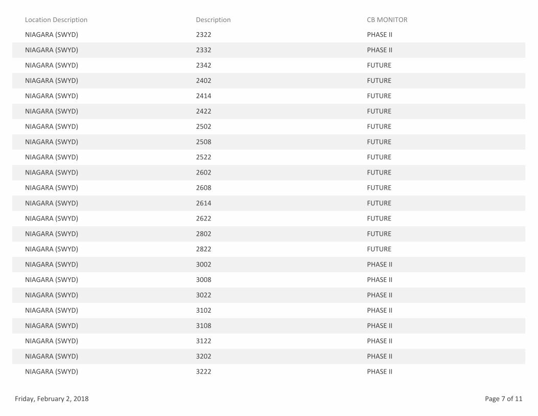
Location Description Description CB MONITOR
NIAGARA (SWYD) 2322 PHASE II
NIAGARA (SWYD) 2332 PHASE II
NIAGARA (SWYD) 2342 FUTURE
NIAGARA (SWYD) 2402 FUTURE
NIAGARA (SWYD) 2414 FUTURE
NIAGARA (SWYD) 2422 FUTURE
NIAGARA (SWYD) 2502 FUTURE
NIAGARA (SWYD) 2508 FUTURE
NIAGARA (SWYD) 2522 FUTURE
NIAGARA (SWYD) 2602 FUTURE
NIAGARA (SWYD) 2608 FUTURE
NIAGARA (SWYD) 2614 FUTURE
NIAGARA (SWYD) 2622 FUTURE
NIAGARA (SWYD) 2802 FUTURE
NIAGARA (SWYD) 2822 FUTURE
NIAGARA (SWYD) 3002 PHASE II
NIAGARA (SWYD) 3008 PHASE II
NIAGARA (SWYD) 3022 PHASE II
NIAGARA (SWYD) 3102 PHASE II
NIAGARA (SWYD) 3108 PHASE II
NIAGARA (SWYD) 3122 PHASE II
NIAGARA (SWYD) 3202 PHASE II
NIAGARA (SWYD) 3222 PHASE II
Friday, February 2, 2018 Page 7 of 11
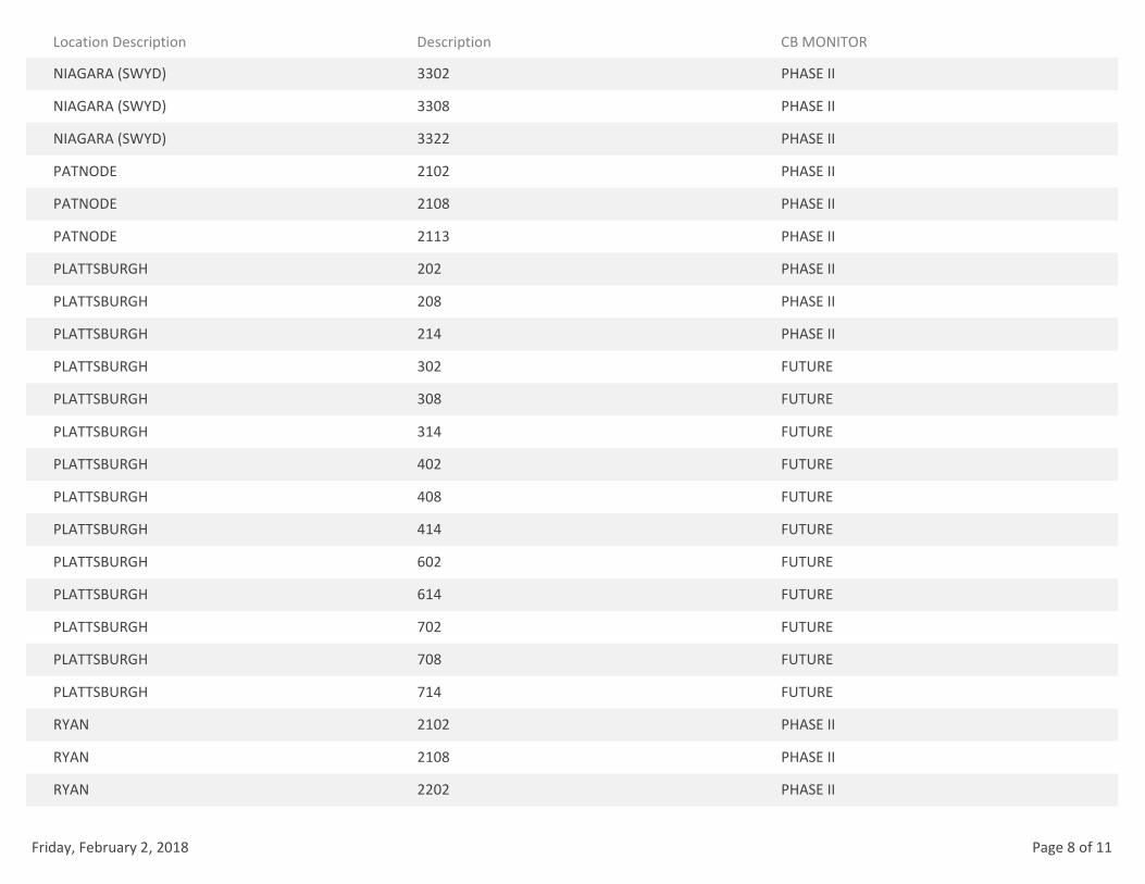
Location Description Description CB MONITOR
NIAGARA (SWYD) 3302 PHASE II
NIAGARA (SWYD) 3308 PHASE II
NIAGARA (SWYD) 3322 PHASE II
PATNODE 2102 PHASE II
PATNODE 2108 PHASE II
PATNODE 2113 PHASE II
PLATTSBURGH 202 PHASE II
PLATTSBURGH 208 PHASE II
PLATTSBURGH 214 PHASE II
PLATTSBURGH 302 FUTURE
PLATTSBURGH 308 FUTURE
PLATTSBURGH 314 FUTURE
PLATTSBURGH 402 FUTURE
PLATTSBURGH 408 FUTURE
PLATTSBURGH 414 FUTURE
PLATTSBURGH 602 FUTURE
PLATTSBURGH 614 FUTURE
PLATTSBURGH 702 FUTURE
PLATTSBURGH 708 FUTURE
PLATTSBURGH 714 FUTURE
RYAN 2102 PHASE II
RYAN 2108 PHASE II
RYAN 2202 PHASE II
Friday, February 2, 2018 Page 8 of 11
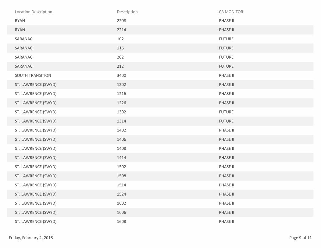
Location Description Description CB MONITOR
RYAN 2208 PHASE II
RYAN 2214 PHASE II
SARANAC 102 FUTURE
SARANAC 116 FUTURE
SARANAC 202 FUTURE
SARANAC 212 FUTURE
SOUTH TRANSITION 3400 PHASE II
ST. LAWRENCE (SWYD) 1202 PHASE II
ST. LAWRENCE (SWYD) 1216 PHASE II
ST. LAWRENCE (SWYD) 1226 PHASE II
ST. LAWRENCE (SWYD) 1302 FUTURE
ST. LAWRENCE (SWYD) 1314 FUTURE
ST. LAWRENCE (SWYD) 1402 PHASE II
ST. LAWRENCE (SWYD) 1406 PHASE II
ST. LAWRENCE (SWYD) 1408 PHASE II
ST. LAWRENCE (SWYD) 1414 PHASE II
ST. LAWRENCE (SWYD) 1502 PHASE II
ST. LAWRENCE (SWYD) 1508 PHASE II
ST. LAWRENCE (SWYD) 1514 PHASE II
ST. LAWRENCE (SWYD) 1524 PHASE II
ST. LAWRENCE (SWYD) 1602 PHASE II
ST. LAWRENCE (SWYD) 1606 PHASE II
ST. LAWRENCE (SWYD) 1608 PHASE II
Friday, February 2, 2018 Page 9 of 11
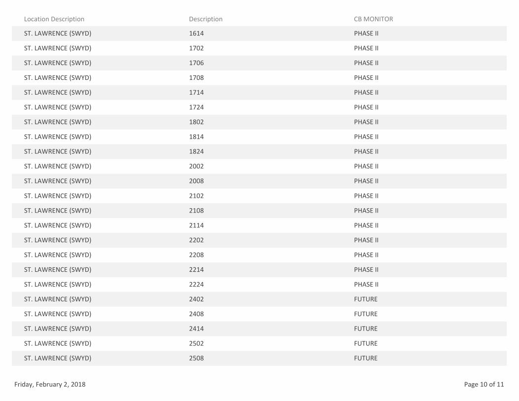
Location Description Description CB MONITOR
ST. LAWRENCE (SWYD) 1614 PHASE II
ST. LAWRENCE (SWYD) 1702 PHASE II
ST. LAWRENCE (SWYD) 1706 PHASE II
ST. LAWRENCE (SWYD) 1708 PHASE II
ST. LAWRENCE (SWYD) 1714 PHASE II
ST. LAWRENCE (SWYD) 1724 PHASE II
ST. LAWRENCE (SWYD) 1802 PHASE II
ST. LAWRENCE (SWYD) 1814 PHASE II
ST. LAWRENCE (SWYD) 1824 PHASE II
ST. LAWRENCE (SWYD) 2002 PHASE II
ST. LAWRENCE (SWYD) 2008 PHASE II
ST. LAWRENCE (SWYD) 2102 PHASE II
ST. LAWRENCE (SWYD) 2108 PHASE II
ST. LAWRENCE (SWYD) 2114 PHASE II
ST. LAWRENCE (SWYD) 2202 PHASE II
ST. LAWRENCE (SWYD) 2208 PHASE II
ST. LAWRENCE (SWYD) 2214 PHASE II
ST. LAWRENCE (SWYD) 2224 PHASE II
ST. LAWRENCE (SWYD) 2402 FUTURE
ST. LAWRENCE (SWYD) 2408 FUTURE
ST. LAWRENCE (SWYD) 2414 FUTURE
ST. LAWRENCE (SWYD) 2502 FUTURE
ST. LAWRENCE (SWYD) 2508 FUTURE
Friday, February 2, 2018 Page 10 of 11
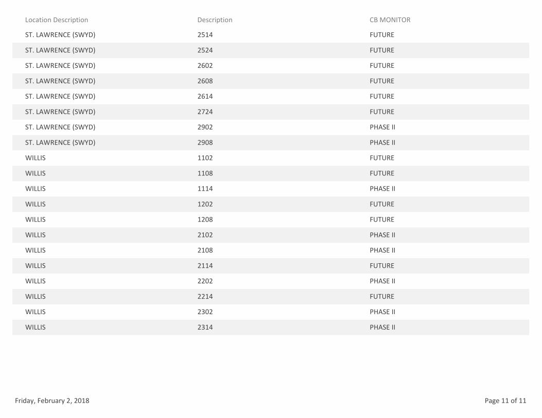
Location Description Description CB MONITOR
ST. LAWRENCE (SWYD) 2514 FUTURE
ST. LAWRENCE (SWYD) 2524 FUTURE
ST. LAWRENCE (SWYD) 2602 FUTURE
ST. LAWRENCE (SWYD) 2608 FUTURE
ST. LAWRENCE (SWYD) 2614 FUTURE
ST. LAWRENCE (SWYD) 2724 FUTURE
ST. LAWRENCE (SWYD) 2902 PHASE II
ST. LAWRENCE (SWYD) 2908 PHASE II
WILLIS 1102 FUTURE
WILLIS 1108 FUTURE
WILLIS 1114 PHASE II
WILLIS 1202 FUTURE
WILLIS 1208 FUTURE
WILLIS 2102 PHASE II
WILLIS 2108 PHASE II
WILLIS 2114 FUTURE
WILLIS 2202 PHASE II
WILLIS 2214 FUTURE
WILLIS 2302 PHASE II
WILLIS 2314 PHASE II
Friday, February 2, 2018 Page 11 of 11
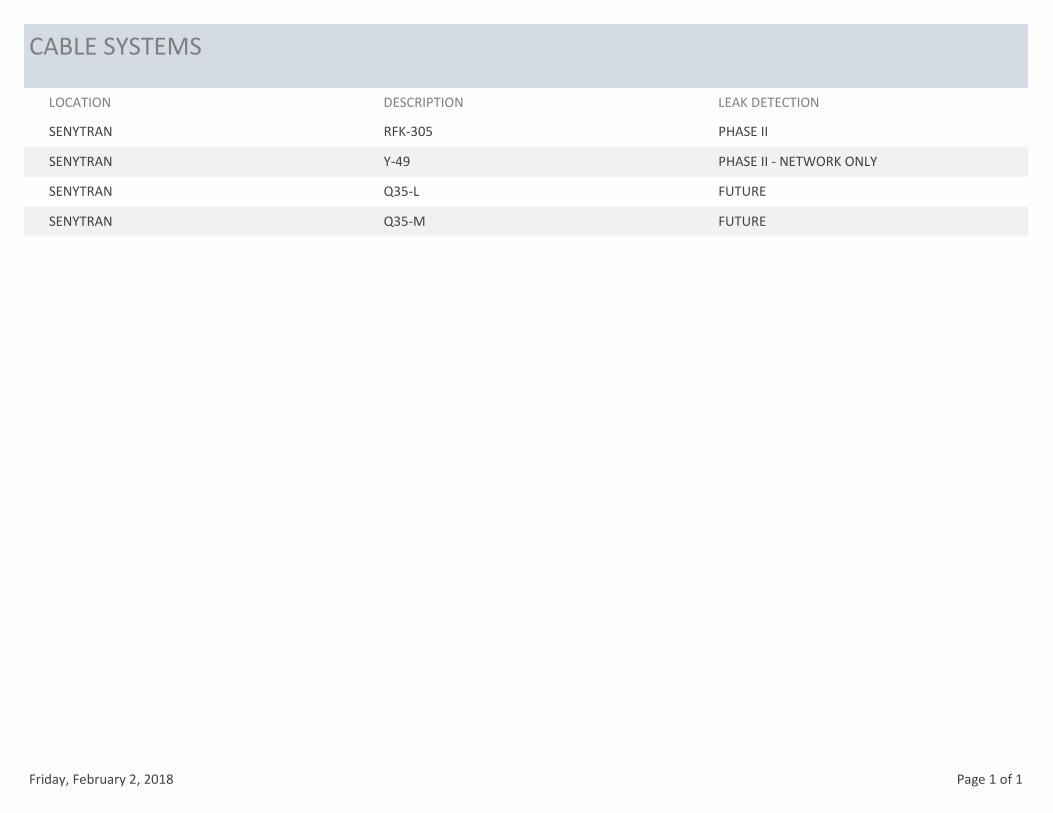
CABLE SYSTEMS
LOCATION DESCRIPTION LEAK DETECTION
SENYTRAN RFK-305 PHASE II
SENYTRAN Y-49 PHASE II - NETWORK ONLY
SENYTRAN Q35-L FUTURE
SENYTRAN Q35-M FUTURE
Friday, February 2, 2018 Page 1 of 1
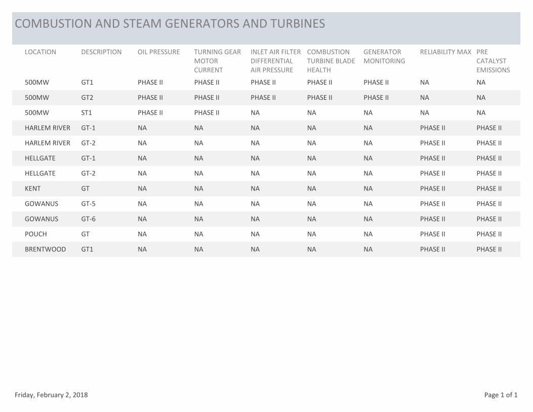
COMBUSTION AND STEAM GENERATORS AND TURBINES
LOCATION DESCRIPTION OIL PRESSURE TURNING GEAR
MOTOR
CURRENT
INLET AIR FILTER
DIFFERENTIAL
AIR PRESSURE
COMBUSTION
TURBINE BLADE
HEALTH
GENERATOR
MONITORING
RELIABILITY MAX PRE
CATALYST
EMISSIONS
500MW GT1 PHASE II PHASE II PHASE II PHASE II PHASE II NA NA
500MW GT2 PHASE II PHASE II PHASE II PHASE II PHASE II NA NA
500MW ST1 PHASE II PHASE II NA NA NA NA NA
HARLEM RIVER GT-1 NA NA NA NA NA PHASE II PHASE II
HARLEM RIVER GT-2 NA NA NA NA NA PHASE II PHASE II
HELLGATE GT-1 NA NA NA NA NA PHASE II PHASE II
HELLGATE GT-2 NA NA NA NA NA PHASE II PHASE II
KENT GT NA NA NA NA NA PHASE II PHASE II
GOWANUS GT-5 NA NA NA NA NA PHASE II PHASE II
GOWANUS GT-6 NA NA NA NA NA PHASE II PHASE II
POUCH GT NA NA NA NA NA PHASE II PHASE II
BRENTWOOD GT1 NA NA NA NA NA PHASE II PHASE II
Friday, February 2, 2018 Page 1 of 1
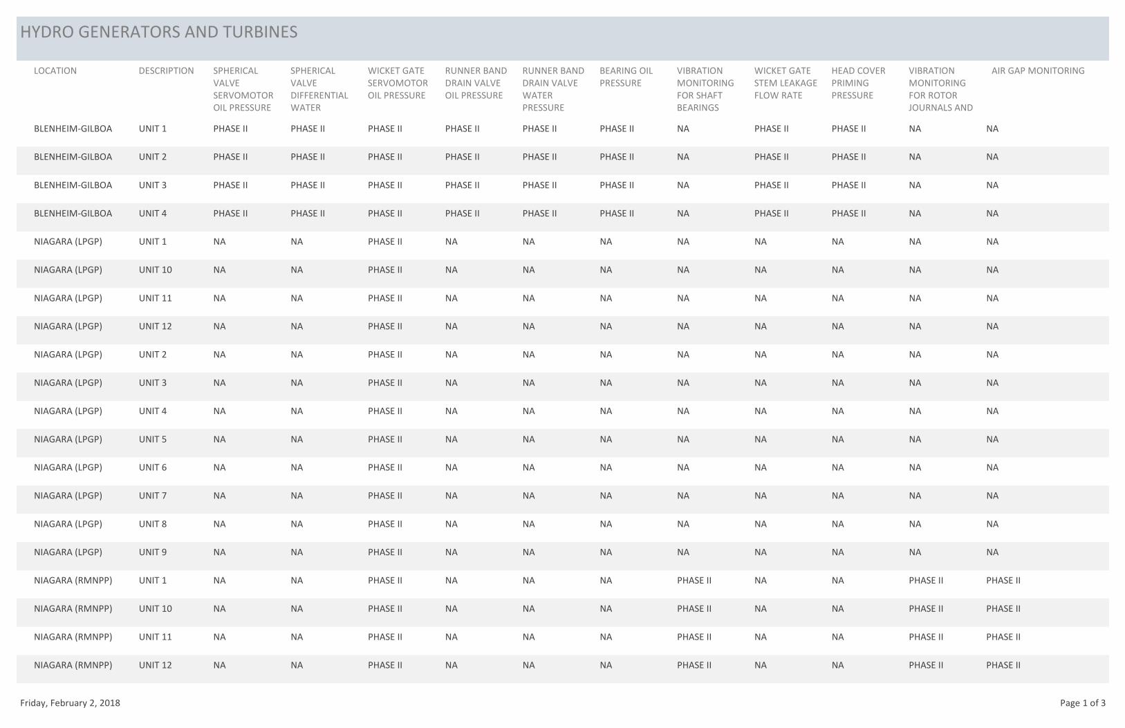
HYDRO GENERATORS AND TURBINES
LOCATION DESCRIPTION SPHERICAL
VALVE
SERVOMOTOR
OIL PRESSURE
SPHERICAL
VALVE
DIFFERENTIAL
WATER
WICKET GATE
SERVOMOTOR
OIL PRESSURE
RUNNER BAND
DRAIN VALVE
OIL PRESSURE
RUNNER BAND
DRAIN VALVE
WATER
PRESSURE
BEARING OIL
PRESSURE
VIBRATION
MONITORING
FOR SHAFT
BEARINGS
WICKET GATE
STEM LEAKAGE
FLOW RATE
HEAD COVER
PRIMING
PRESSURE
VIBRATION
MONITORING
FOR ROTOR
JOURNALS AND
AIR GAP MONITORING
BLENHEIM-GILBOA UNIT 1 PHASE II PHASE II PHASE II PHASE II PHASE II PHASE II NA PHASE II PHASE II NA NA
BLENHEIM-GILBOA UNIT 2 PHASE II PHASE II PHASE II PHASE II PHASE II PHASE II NA PHASE II PHASE II NA NA
BLENHEIM-GILBOA UNIT 3 PHASE II PHASE II PHASE II PHASE II PHASE II PHASE II NA PHASE II PHASE II NA NA
BLENHEIM-GILBOA UNIT 4 PHASE II PHASE II PHASE II PHASE II PHASE II PHASE II NA PHASE II PHASE II NA NA
NIAGARA (LPGP) UNIT 1 NA NA PHASE II NA NA NA NA NA NA NA NA
NIAGARA (LPGP) UNIT 10 NA NA PHASE II NA NA NA NA NA NA NA NA
NIAGARA (LPGP) UNIT 11 NA NA PHASE II NA NA NA NA NA NA NA NA
NIAGARA (LPGP) UNIT 12 NA NA PHASE II NA NA NA NA NA NA NA NA
NIAGARA (LPGP) UNIT 2 NA NA PHASE II NA NA NA NA NA NA NA NA
NIAGARA (LPGP) UNIT 3 NA NA PHASE II NA NA NA NA NA NA NA NA
NIAGARA (LPGP) UNIT 4 NA NA PHASE II NA NA NA NA NA NA NA NA
NIAGARA (LPGP) UNIT 5 NA NA PHASE II NA NA NA NA NA NA NA NA
NIAGARA (LPGP) UNIT 6 NA NA PHASE II NA NA NA NA NA NA NA NA
NIAGARA (LPGP) UNIT 7 NA NA PHASE II NA NA NA NA NA NA NA NA
NIAGARA (LPGP) UNIT 8 NA NA PHASE II NA NA NA NA NA NA NA NA
NIAGARA (LPGP) UNIT 9 NA NA PHASE II NA NA NA NA NA NA NA NA
NIAGARA (RMNPP) UNIT 1 NA NA PHASE II NA NA NA PHASE II NA NA PHASE II PHASE II
NIAGARA (RMNPP) UNIT 10 NA NA PHASE II NA NA NA PHASE II NA NA PHASE II PHASE II
NIAGARA (RMNPP) UNIT 11 NA NA PHASE II NA NA NA PHASE II NA NA PHASE II PHASE II
NIAGARA (RMNPP) UNIT 12 NA NA PHASE II NA NA NA PHASE II NA NA PHASE II PHASE II
Friday, February 2, 2018 Page 1 of 3
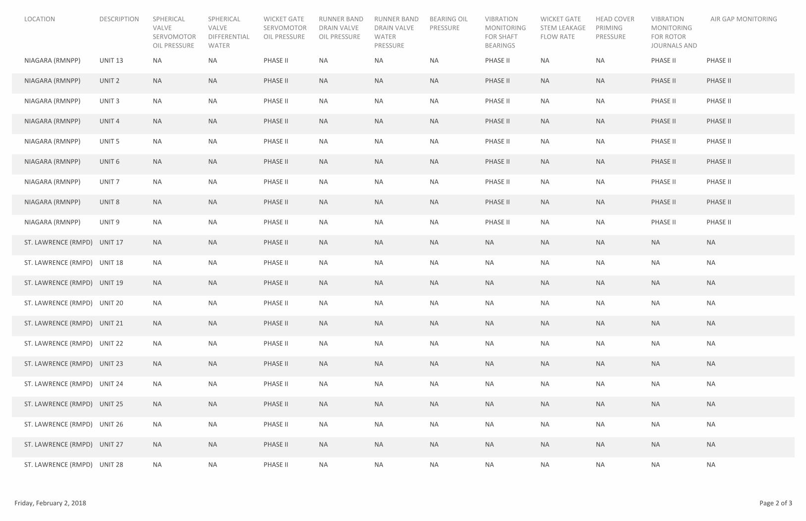
LOCATION DESCRIPTION SPHERICAL
VALVE
SERVOMOTOR
OIL PRESSURE
SPHERICAL
VALVE
DIFFERENTIAL
WATER
WICKET GATE
SERVOMOTOR
OIL PRESSURE
RUNNER BAND
DRAIN VALVE
OIL PRESSURE
RUNNER BAND
DRAIN VALVE
WATER
PRESSURE
BEARING OIL
PRESSURE
VIBRATION
MONITORING
FOR SHAFT
BEARINGS
WICKET GATE
STEM LEAKAGE
FLOW RATE
HEAD COVER
PRIMING
PRESSURE
VIBRATION
MONITORING
FOR ROTOR
JOURNALS AND
AIR GAP MONITORING
NIAGARA (RMNPP) UNIT 13 NA NA PHASE II NA NA NA PHASE II NA NA PHASE II PHASE II
NIAGARA (RMNPP) UNIT 2 NA NA PHASE II NA NA NA PHASE II NA NA PHASE II PHASE II
NIAGARA (RMNPP) UNIT 3 NA NA PHASE II NA NA NA PHASE II NA NA PHASE II PHASE II
NIAGARA (RMNPP) UNIT 4 NA NA PHASE II NA NA NA PHASE II NA NA PHASE II PHASE II
NIAGARA (RMNPP) UNIT 5 NA NA PHASE II NA NA NA PHASE II NA NA PHASE II PHASE II
NIAGARA (RMNPP) UNIT 6 NA NA PHASE II NA NA NA PHASE II NA NA PHASE II PHASE II
NIAGARA (RMNPP) UNIT 7 NA NA PHASE II NA NA NA PHASE II NA NA PHASE II PHASE II
NIAGARA (RMNPP) UNIT 8 NA NA PHASE II NA NA NA PHASE II NA NA PHASE II PHASE II
NIAGARA (RMNPP) UNIT 9 NA NA PHASE II NA NA NA PHASE II NA NA PHASE II PHASE II
ST. LAWRENCE (RMPD) UNIT 17 NA NA PHASE II NA NA NA NA NA NA NA NA
ST. LAWRENCE (RMPD) UNIT 18 NA NA PHASE II NA NA NA NA NA NA NA NA
ST. LAWRENCE (RMPD) UNIT 19 NA NA PHASE II NA NA NA NA NA NA NA NA
ST. LAWRENCE (RMPD) UNIT 20 NA NA PHASE II NA NA NA NA NA NA NA NA
ST. LAWRENCE (RMPD) UNIT 21 NA NA PHASE II NA NA NA NA NA NA NA NA
ST. LAWRENCE (RMPD) UNIT 22 NA NA PHASE II NA NA NA NA NA NA NA NA
ST. LAWRENCE (RMPD) UNIT 23 NA NA PHASE II NA NA NA NA NA NA NA NA
ST. LAWRENCE (RMPD) UNIT 24 NA NA PHASE II NA NA NA NA NA NA NA NA
ST. LAWRENCE (RMPD) UNIT 25 NA NA PHASE II NA NA NA NA NA NA NA NA
ST. LAWRENCE (RMPD) UNIT 26 NA NA PHASE II NA NA NA NA NA NA NA NA
ST. LAWRENCE (RMPD) UNIT 27 NA NA PHASE II NA NA NA NA NA NA NA NA
ST. LAWRENCE (RMPD) UNIT 28 NA NA PHASE II NA NA NA NA NA NA NA NA
Friday, February 2, 2018 Page 2 of 3
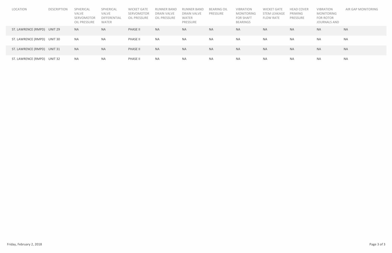
LOCATION DESCRIPTION SPHERICAL
VALVE
SERVOMOTOR
OIL PRESSURE
SPHERICAL
VALVE
DIFFERENTIAL
WATER
WICKET GATE
SERVOMOTOR
OIL PRESSURE
RUNNER BAND
DRAIN VALVE
OIL PRESSURE
RUNNER BAND
DRAIN VALVE
WATER
PRESSURE
BEARING OIL
PRESSURE
VIBRATION
MONITORING
FOR SHAFT
BEARINGS
WICKET GATE
STEM LEAKAGE
FLOW RATE
HEAD COVER
PRIMING
PRESSURE
VIBRATION
MONITORING
FOR ROTOR
JOURNALS AND
AIR GAP MONITORING
ST. LAWRENCE (RMPD) UNIT 29 NA NA PHASE II NA NA NA NA NA NA NA NA
ST. LAWRENCE (RMPD) UNIT 30 NA NA PHASE II NA NA NA NA NA NA NA NA
ST. LAWRENCE (RMPD) UNIT 31 NA NA PHASE II NA NA NA NA NA NA NA NA
ST. LAWRENCE (RMPD) UNIT 32 NA NA PHASE II NA NA NA NA NA NA NA NA
Friday, February 2, 2018 Page 3 of 3

TRANSFORMERS AND REACTORS
LOCATION DESCRIPTION DGA TEMP WINDING BUSHING MONITOR IR CAMERA
500MW GSU 7A PHASE I PHASE I PHASE II PHASE II
500MW GSU 7B PHASE I PHASE I PHASE II PHASE II
500MW GSU 7S PHASE I PHASE I PHASE II PHASE II
500MW UAT 7A PHASE I PHASE I PHASE II PHASE II
500MW UAT 7B PHASE I PHASE I PHASE II PHASE II
ADIRONDACK AUTO TRANSF. 1 PHASE II PHASE II PHASE II PHASE II
ASTORIA ANNEX R1 PHASE II PHASE II PHASE II PHASE II
ASTORIA ANNEX R2 PHASE II PHASE II PHASE II PHASE II
BLENHEIM-GILBOA GSU #1 PHASE I PHASE I PHASE II PHASE II
BLENHEIM-GILBOA GSU #2 PHASE I PHASE I PHASE II PHASE II
BLENHEIM-GILBOA GSU #3 PHASE I PHASE I PHASE II PHASE II
BLENHEIM-GILBOA GSU #4 PHASE I PHASE I PHASE II PHASE II
BLENHEIM-GILBOA SST #1 PHASE I PHASE I PHASE II PHASE II
BLENHEIM-GILBOA SST #2 PHASE I PHASE I PHASE II PHASE II
BRENTWOOD GT BANK 1 PHASE I PHASE I PHASE II PHASE II
EAST GARDEN CITY AUTO TRANSF. NO. 1 PHASE I PHASE I PHASE II PHASE II
EAST GARDEN CITY AUTO TRANSF. NO. 2 PHASE I PHASE I PHASE II PHASE II
EAST GARDEN CITY PAR NO. 1 PHASE I PHASE I PHASE II PHASE II
EAST GARDEN CITY PAR NO. 2 PHASE I PHASE I PHASE II PHASE II
EAST GARDEN CITY SR-1 PHASE II PHASE II PHASE II PHASE II
FLYNN TRANSFORMER 1 PHASE I PHASE I PHASE II PHASE II
Friday, February 2, 2018 Page 1 of 5
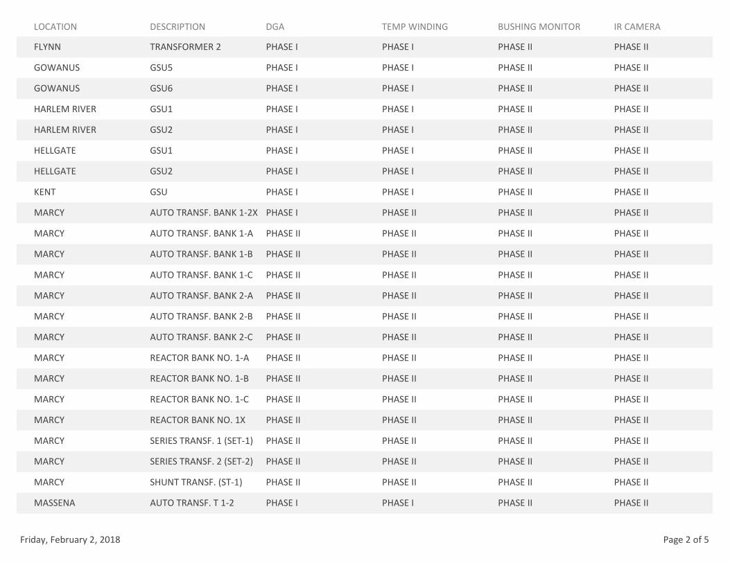
LOCATION DESCRIPTION DGA TEMP WINDING BUSHING MONITOR IR CAMERA
FLYNN TRANSFORMER 2 PHASE I PHASE I PHASE II PHASE II
GOWANUS GSU5 PHASE I PHASE I PHASE II PHASE II
GOWANUS GSU6 PHASE I PHASE I PHASE II PHASE II
HARLEM RIVER GSU1 PHASE I PHASE I PHASE II PHASE II
HARLEM RIVER GSU2 PHASE I PHASE I PHASE II PHASE II
HELLGATE GSU1 PHASE I PHASE I PHASE II PHASE II
HELLGATE GSU2 PHASE I PHASE I PHASE II PHASE II
KENT GSU PHASE I PHASE I PHASE II PHASE II
MARCY AUTO TRANSF. BANK 1-2X PHASE I PHASE II PHASE II PHASE II
MARCY AUTO TRANSF. BANK 1-A PHASE II PHASE II PHASE II PHASE II
MARCY AUTO TRANSF. BANK 1-B PHASE II PHASE II PHASE II PHASE II
MARCY AUTO TRANSF. BANK 1-C PHASE II PHASE II PHASE II PHASE II
MARCY AUTO TRANSF. BANK 2-A PHASE II PHASE II PHASE II PHASE II
MARCY AUTO TRANSF. BANK 2-B PHASE II PHASE II PHASE II PHASE II
MARCY AUTO TRANSF. BANK 2-C PHASE II PHASE II PHASE II PHASE II
MARCY REACTOR BANK NO. 1-A PHASE II PHASE II PHASE II PHASE II
MARCY REACTOR BANK NO. 1-B PHASE II PHASE II PHASE II PHASE II
MARCY REACTOR BANK NO. 1-C PHASE II PHASE II PHASE II PHASE II
MARCY REACTOR BANK NO. 1X PHASE II PHASE II PHASE II PHASE II
MARCY SERIES TRANSF. 1 (SET-1) PHASE II PHASE II PHASE II PHASE II
MARCY SERIES TRANSF. 2 (SET-2) PHASE II PHASE II PHASE II PHASE II
MARCY SHUNT TRANSF. (ST-1) PHASE II PHASE II PHASE II PHASE II
MASSENA AUTO TRANSF. T 1-2 PHASE I PHASE I PHASE II PHASE II
Friday, February 2, 2018 Page 2 of 5
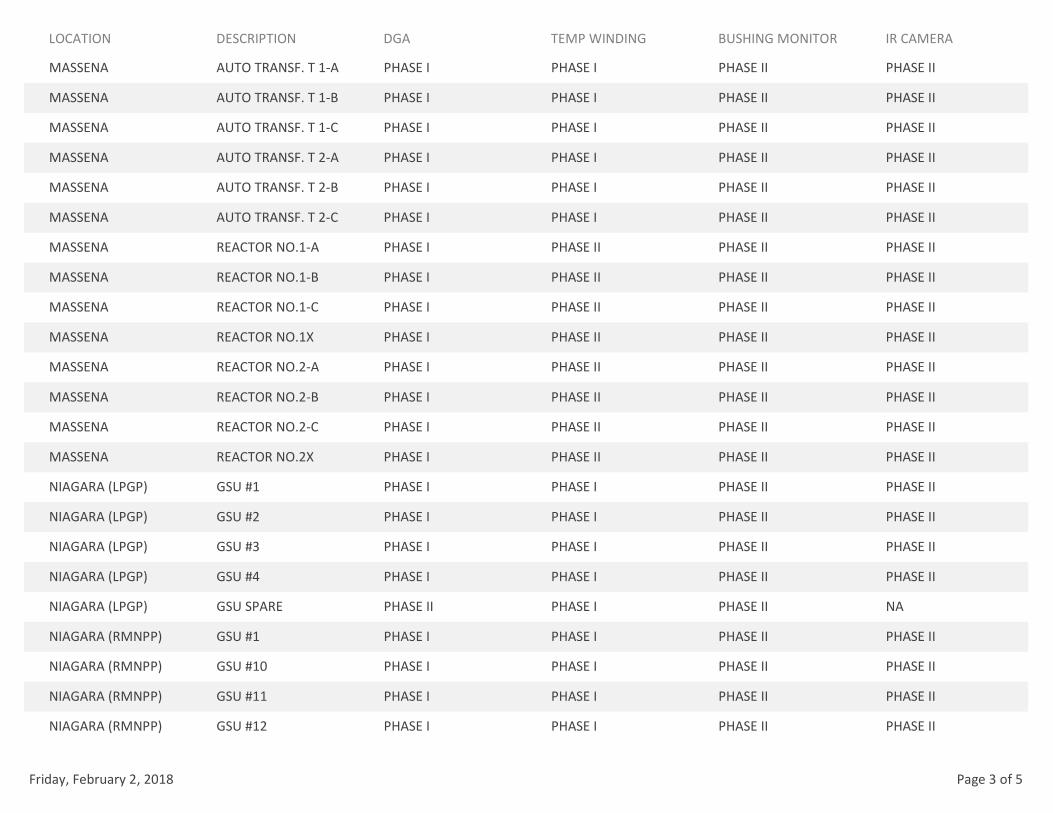
LOCATION DESCRIPTION DGA TEMP WINDING BUSHING MONITOR IR CAMERA
MASSENA AUTO TRANSF. T 1-A PHASE I PHASE I PHASE II PHASE II
MASSENA AUTO TRANSF. T 1-B PHASE I PHASE I PHASE II PHASE II
MASSENA AUTO TRANSF. T 1-C PHASE I PHASE I PHASE II PHASE II
MASSENA AUTO TRANSF. T 2-A PHASE I PHASE I PHASE II PHASE II
MASSENA AUTO TRANSF. T 2-B PHASE I PHASE I PHASE II PHASE II
MASSENA AUTO TRANSF. T 2-C PHASE I PHASE I PHASE II PHASE II
MASSENA REACTOR NO.1-A PHASE I PHASE II PHASE II PHASE II
MASSENA REACTOR NO.1-B PHASE I PHASE II PHASE II PHASE II
MASSENA REACTOR NO.1-C PHASE I PHASE II PHASE II PHASE II
MASSENA REACTOR NO.1X PHASE I PHASE II PHASE II PHASE II
MASSENA REACTOR NO.2-A PHASE I PHASE II PHASE II PHASE II
MASSENA REACTOR NO.2-B PHASE I PHASE II PHASE II PHASE II
MASSENA REACTOR NO.2-C PHASE I PHASE II PHASE II PHASE II
MASSENA REACTOR NO.2X PHASE I PHASE II PHASE II PHASE II
NIAGARA (LPGP) GSU #1 PHASE I PHASE I PHASE II PHASE II
NIAGARA (LPGP) GSU #2 PHASE I PHASE I PHASE II PHASE II
NIAGARA (LPGP) GSU #3 PHASE I PHASE I PHASE II PHASE II
NIAGARA (LPGP) GSU #4 PHASE I PHASE I PHASE II PHASE II
NIAGARA (LPGP) GSU SPARE PHASE II PHASE I PHASE II NA
NIAGARA (RMNPP) GSU #1 PHASE I PHASE I PHASE II PHASE II
NIAGARA (RMNPP) GSU #10 PHASE I PHASE I PHASE II PHASE II
NIAGARA (RMNPP) GSU #11 PHASE I PHASE I PHASE II PHASE II
NIAGARA (RMNPP) GSU #12 PHASE I PHASE I PHASE II PHASE II
Friday, February 2, 2018 Page 3 of 5

LOCATION DESCRIPTION DGA TEMP WINDING BUSHING MONITOR IR CAMERA
NIAGARA (RMNPP) GSU #13 PHASE I PHASE I PHASE II PHASE II
NIAGARA (RMNPP) GSU #2 PHASE I PHASE I PHASE II PHASE II
NIAGARA (RMNPP) GSU #3 PHASE I PHASE I PHASE II PHASE II
NIAGARA (RMNPP) GSU #4 PHASE I PHASE I PHASE II PHASE II
NIAGARA (RMNPP) GSU #5 PHASE I PHASE I PHASE II PHASE II
NIAGARA (RMNPP) GSU #6 PHASE I PHASE I PHASE II PHASE II
NIAGARA (RMNPP) GSU #7 PHASE I PHASE I PHASE II PHASE II
NIAGARA (RMNPP) GSU #8 PHASE I PHASE I PHASE II PHASE II
NIAGARA (RMNPP) GSU #9 PHASE I PHASE I PHASE II PHASE II
NIAGARA (RMNPP) GSU SPARE #1 PHASE I PHASE I PHASE II NA
NIAGARA (RMNPP) GSU SPARE #2 PHASE I PHASE I PHASE II NA
NIAGARA (SWYD) AUTO TRANSF. 1 FUTURE FUTURE FUTURE FUTURE
NIAGARA (SWYD) AUTO TRANSF. 2 PHASE II PHASE I PHASE II PHASE II
NIAGARA (SWYD) AUTO TRANSF. 3 FUTURE FUTURE FUTURE FUTURE
NIAGARA (SWYD) AUTO TRANSF. 4 PHASE I PHASE I PHASE II PHASE II
NIAGARA (SWYD) AUTO TRANSF. 5 FUTURE FUTURE FUTURE FUTURE
PLATTSBURGH AUTO TRANSF. NO. 1 PHASE II PHASE II PHASE II PHASE II
PLATTSBURGH AUTO TRANSF. NO. 2 PHASE II PHASE II PHASE II PHASE II
PLATTSBURGH AUTO TRANSF. NO. 4 PHASE II PHASE II PHASE II PHASE II
POUCH GSU PHASE I PHASE I PHASE II PHASE II
SARANAC TRANSFORMER 2 PHASE II PHASE II PHASE II PHASE II
SOUTH TRANSITION SR-2 PHASE II PHASE II PHASE II PHASE II
SPRAIN BROOK REACTOR 2N1 PHASE II PHASE II PHASE II PHASE II
Friday, February 2, 2018 Page 4 of 5
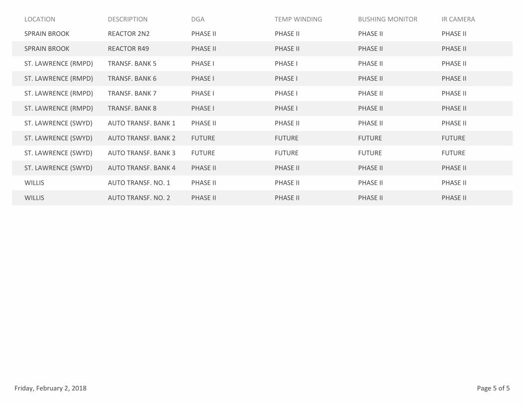
LOCATION DESCRIPTION DGA TEMP WINDING BUSHING MONITOR IR CAMERA
SPRAIN BROOK REACTOR 2N2 PHASE II PHASE II PHASE II PHASE II
SPRAIN BROOK REACTOR R49 PHASE II PHASE II PHASE II PHASE II
ST. LAWRENCE (RMPD) TRANSF. BANK 5 PHASE I PHASE I PHASE II PHASE II
ST. LAWRENCE (RMPD) TRANSF. BANK 6 PHASE I PHASE I PHASE II PHASE II
ST. LAWRENCE (RMPD) TRANSF. BANK 7 PHASE I PHASE I PHASE II PHASE II
ST. LAWRENCE (RMPD) TRANSF. BANK 8 PHASE I PHASE I PHASE II PHASE II
ST. LAWRENCE (SWYD) AUTO TRANSF. BANK 1 PHASE II PHASE II PHASE II PHASE II
ST. LAWRENCE (SWYD) AUTO TRANSF. BANK 2 FUTURE FUTURE FUTURE FUTURE
ST. LAWRENCE (SWYD) AUTO TRANSF. BANK 3 FUTURE FUTURE FUTURE FUTURE
ST. LAWRENCE (SWYD) AUTO TRANSF. BANK 4 PHASE II PHASE II PHASE II PHASE II
WILLIS AUTO TRANSF. NO. 1 PHASE II PHASE II PHASE II PHASE II
WILLIS AUTO TRANSF. NO. 2 PHASE II PHASE II PHASE II PHASE II
Friday, February 2, 2018 Page 5 of 5

28
ATTACHMENT D – OSI PI NAMING CONVENTION
1
Original Issue Date: April 26, 2017
Revision Date:
Revision No.: Draft
New York Power Authority
Enterprise PI Tag Naming Convention Proposal
Prepared by
Tom Sayers
Computer Systems Engineering
2
1. Summary This document proposes a PI tag naming convention to be used by NYPA in naming data points being brought in to PI servers at the various NYPA sites. The proposed tag naming convention is as follows: PI_tag_name => site.system:native_tagname
where... site => Well defined site designation string discussed below system => Well defined source system name native_tagname => tag name from source system (naming convention based on source system tag Naming convention)
site
Site may be NIA, STL, BG, FLN. Other sites are TBD.
The site refers to the facility at which the data source is located. For instance, Ashokan data resides in an Oracle database at BG. The site would be BG, because the data source resides at BG. Note that an Ashokan location reference is part of the native tag present in the existing tags within the Oracle database.
system
Is the system name of the source system for the data point
Suggested system names are: o SORA for SCADA Oracle o GEHISxxx for GE Historian numbered 1 through xxx o BNSxxx for Bently Nevada System 1 number 1 through xxx
native_tagname
Is the tag name that exists in the source as named by site staff using naming conventions associated with the source system.
Consideration must be given to SENY assets already named in PI servers to determine if the SENY points are grandfathered for use of the native_tagname portion of their current tags or if the site.system: prefix is to be added.
The rest of this document presents background discussion on the proposed naming convention.
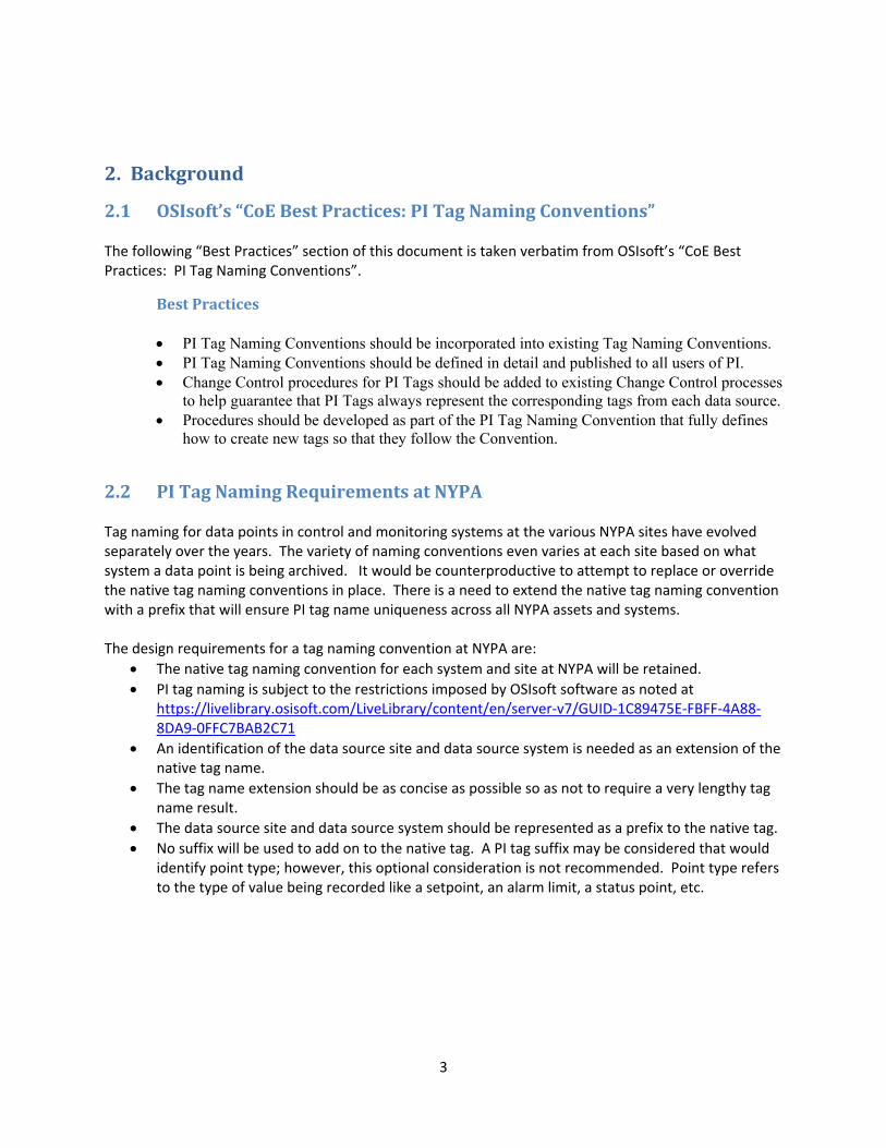
3
2. Background
2.1 OSIsoft’s“CoEBestPractices:PITagNamingConventions” The following “Best Practices” section of this document is taken verbatim from OSIsoft’s “CoE Best Practices: PI Tag Naming Conventions”.
BestPractices
PI Tag Naming Conventions should be incorporated into existing Tag Naming Conventions. PI Tag Naming Conventions should be defined in detail and published to all users of PI. Change Control procedures for PI Tags should be added to existing Change Control processes
to help guarantee that PI Tags always represent the corresponding tags from each data source. Procedures should be developed as part of the PI Tag Naming Convention that fully defines
how to create new tags so that they follow the Convention.
2.2 PITagNamingRequirementsatNYPA Tag naming for data points in control and monitoring systems at the various NYPA sites have evolved separately over the years. The variety of naming conventions even varies at each site based on what system a data point is being archived. It would be counterproductive to attempt to replace or override the native tag naming conventions in place. There is a need to extend the native tag naming convention with a prefix that will ensure PI tag name uniqueness across all NYPA assets and systems. The design requirements for a tag naming convention at NYPA are:
The native tag naming convention for each system and site at NYPA will be retained.
PI tag naming is subject to the restrictions imposed by OSIsoft software as noted at https://livelibrary.osisoft.com/LiveLibrary/content/en/server‐v7/GUID‐1C89475E‐FBFF‐4A88‐8DA9‐0FFC7BAB2C71
An identification of the data source site and data source system is needed as an extension of the native tag name.
The tag name extension should be as concise as possible so as not to require a very lengthy tag name result.
The data source site and data source system should be represented as a prefix to the native tag.
No suffix will be used to add on to the native tag. A PI tag suffix may be considered that would identify point type; however, this optional consideration is not recommended. Point type refers to the type of value being recorded like a setpoint, an alarm limit, a status point, etc.
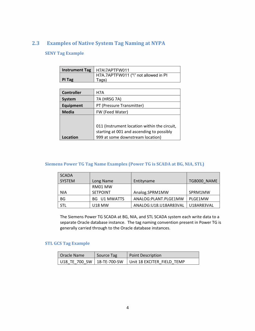
4
2.3 ExamplesofNativeSystemTagNamingatNYPA
SENYTagExample
Instrument Tag H7A\7APTFW011
PI Tag H7A.7APTFW011 (“\” not allowed in PI Tags)
Controller H7A
System 7A (HRSG 7A)
Equipment PT (Pressure Transmitter)
Media FW (Feed Water)
Location
011 (Instrument location within the circuit, starting at 001 and ascending to possibly 999 at some downstream location)
SiemensPowerTGTagNameExamples(PowerTGisSCADAatBG,NIA,STL)
SCADA SYSTEM Long Name Entityname TG8000_NAME
NIA RM01 MW SETPOINT Analog.SPRM1MW SPRM1MW
BG BG U1 MWATTS ANALOG:PLANT.PLGE1MW PLGE1MW
STL U18 MW ANALOG:U18.U18AR83VAL U18AR83VAL
The Siemens Power TG SCADA at BG, NIA, and STL SCADA system each write data to a separate Oracle database instance. The tag naming convention present in Power TG is generally carried through to the Oracle database instances.
STLGCSTagExample
Oracle Name Source Tag Point Description
U18_TE_700_SW 18‐TE‐700‐SW Unit 18 EXCITER_FIELD_TEMP

5
NIAGEProficyHistorianTagnameExample
GE Historian Tagname Description Collector Name Source Address
RM01.R01EVOLT.F_CV RM 01 Exciter Voltage (F_CV) NYPADAS_File RM01.R01EVOLT.F_CV
2.4 ExamplesofProposedPITagNaming
Site Source System Native Tag Name Proposed PI Tag Name
NIA SORA1 SPRM1MW NIA.SORA1:SPRM1MW
BG SORA1 PLGE1MW BG.SORA1:PLGE1MW
STL SORA1 U18AR83VAL STL.SORA1:U18AR83VAL
STL SORA1 U18_TE_700_SW STL.SORA1:U18_TE_700_SW
NIA GEH001 RMO1.RO1EVOLT.F_CV NIA.GEH001:R01EVOLT.F_CV
No SENY PI tag naming is shown in the examples because a determination needs to be made whether the PI tag naming convention described in this document is to be applied retroactively to PI tags already defined for SENY points.

29
ATTACHMENT E – ELECTRICAL DESIGN CRITERIA
SENSOR DEPLOYMENT PHASE II ENGINEERING AND CONSTRUCTION
PROJECT NUMBER: CPR 1553
FOR
General Installation of Electrical and Communication Equipment and Materials
New York Power Authority
Revision: 0 Status: Issued for Release
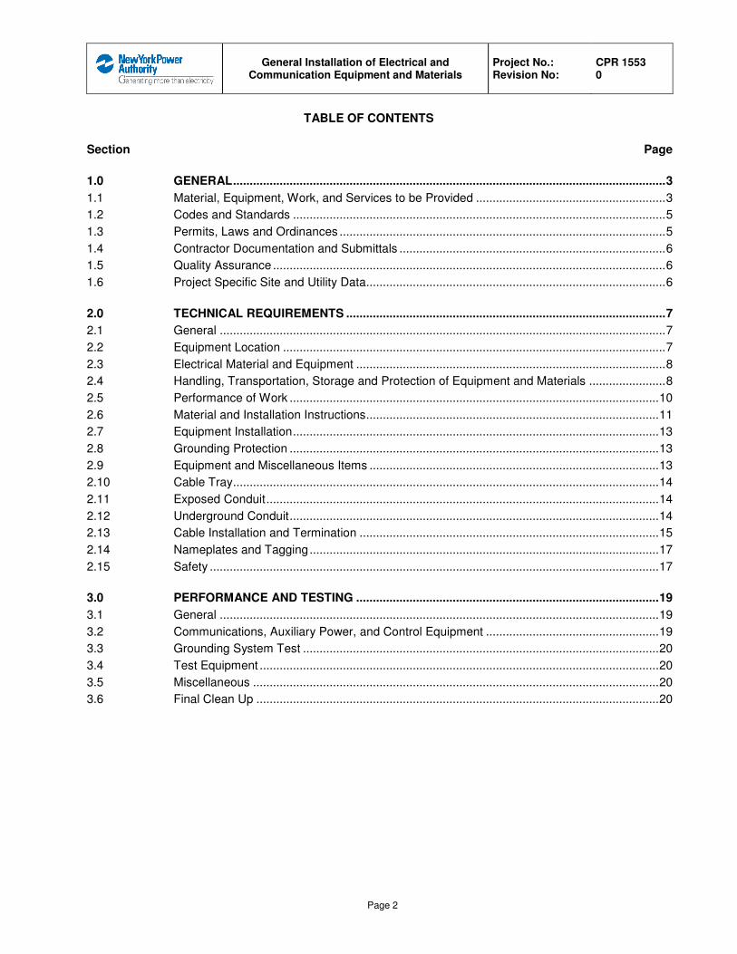
General Installation of Electrical and
Communication Equipment and Materials
Project No.: Revision No:
CPR 1553 0
Page 2
TABLE OF CONTENTS
Section Page
1.0 GENERAL .................................................................................................................................. 3
1.1 Material, Equipment, Work, and Services to be Provided ......................................................... 3
1.2 Codes and Standards ................................................................................................................ 5
1.3 Permits, Laws and Ordinances .................................................................................................. 5
1.4 Contractor Documentation and Submittals ................................................................................ 6
1.5 Quality Assurance ...................................................................................................................... 6
1.6 Project Specific Site and Utility Data.......................................................................................... 6
2.0 TECHNICAL REQUIREMENTS ................................................................................................ 7
2.1 General ...................................................................................................................................... 7
2.2 Equipment Location ................................................................................................................... 7
2.3 Electrical Material and Equipment ............................................................................................. 8
2.4 Handling, Transportation, Storage and Protection of Equipment and Materials ....................... 8
2.5 Performance of Work ............................................................................................................... 10
2.6 Material and Installation Instructions ........................................................................................ 11
2.7 Equipment Installation .............................................................................................................. 13
2.8 Grounding Protection ............................................................................................................... 13
2.9 Equipment and Miscellaneous Items ....................................................................................... 13
2.10 Cable Tray ................................................................................................................................ 14
2.11 Exposed Conduit ...................................................................................................................... 14
2.12 Underground Conduit ............................................................................................................... 14
2.13 Cable Installation and Termination .......................................................................................... 15
2.14 Nameplates and Tagging ......................................................................................................... 17
2.15 Safety ....................................................................................................................................... 17
3.0 PERFORMANCE AND TESTING ........................................................................................... 19
3.1 General .................................................................................................................................... 19
3.2 Communications, Auxiliary Power, and Control Equipment .................................................... 19
3.3 Grounding System Test ........................................................................................................... 20
3.4 Test Equipment ........................................................................................................................ 20
3.5 Miscellaneous .......................................................................................................................... 20
3.6 Final Clean Up ......................................................................................................................... 20
General Installation of Electrical and
Communication Equipment and Materials
Project No.: Revision No:
CPR 1553 0
Page 3
1.0 GENERAL
1.1 Material, Equipment, Work, and Services to be Provided
1.1.1 Field design, furnish, install and test items and materials required for distribution and communication
systems installation at project locations in accordance with this specification, and as described in the
main installation specification, the site specific work scope statements, and this specification.
A. Items to be Provided by Contractor
� Installation of the sensor deployment distribution and communications equipment and
material including, but not limited to sensors, network switches, network firewalls, network
cabinets, enclosures, copper and fiber optic cables, UPS’s, circuit breakers, electrical
distribution equipment, and accessories.
� Supply and installation of the grounding system connections.
� Supply and installation of exposed and buried raceway and conduit, supports, and fittings.
� Supply and installation of power, control, instrument, and communication cables.
� Supply and installation of power distribution equipment, switches, circuit breakers, fuses,
miscellaneous materials, and accessories.
� Supply and installation of all required nameplates and tags.
� Touch up painting of all equipment and systems installed by Contractor.
� Construction completion, checkout, commissioning, and migration including communication
checks, testing, and documentation.
� Preparation of system/area/component turnover packages for hand over to the Authority.
� Preparation of as-built drawings including field changes for turnover to the Authority.
� Protection, care, and maintenance of equipment, and materials that have been released for
installation until turnover to the Authority.
� Outdoor and indoor storage areas including clean, heated, and air-conditioned environments
for electrical equipment.
� Quality Assurance Program, Safety Program, Electrical Tagout, and Acceptance and
Performance Testing.
B. Services Provided by the Authority:
General Installation of Electrical and
Communication Equipment and Materials
Project No.: Revision No:
CPR 1553 0
Page 4
� Construction Management including but not limited to; oversight inspection, contract
administration, scheduling coordination, safety oversight, and security, etc.
� Designated lay-down and work areas.
1.1.2 Other Contractors:
A. Contractor is advised that the Owner may be working around the project locations including
substation, and switchyard sites. Contractor shall also coordinate its operations with the Authority
crews.
B. The Contractor shall coordinate its operations with the operations of the Authority’s Forces or any
other Contractors, by mutual agreement.
C. Should any conflict in operations arise, the Authority will resolve the conflict. Any change
required in a Contractor’s operations shall be at no additional expense to the Authority.
1.1.3 Hauling
A. Loads shall be moved on vehicles complying with local regulations, particularly those regarding
wheel loading. Contractor shall obtain all required permits.
1.1.4 Descriptive Drawings
A. The Contractor shall maintain as-built drawings showing locations, routing, and critical
coordinates of all equipment, raceway, wiring changes, etc. All work shall be done in compliance
with NYPA drafting standards.
1.1.5 Schedule
A. The work is expected to start immediately after the contract award and be ready for startup
testing in accordance with the project schedule.
B. The work is expected to be performed simultaneously with other work at various locations.
C. Contractor shall coordinate its efforts with the Authority and ensure that the installation, testing,
and interfaces are made safely and on schedule.
D. Contractor shall supply a detailed construction schedule by site and equipment. It shall
specifically identify interface points with the Authority and others including when equipment,
areas, lines, etc., are required. This schedule shall be updated showing weekly progress and
submitted to the Authority.
General Installation of Electrical and
Communication Equipment and Materials
Project No.: Revision No:
CPR 1553 0
Page 5
1.2 Codes and Standards
1.2.1 Work to be provided under this specification shall be in strict accordance with the applicable
codes, standards, specifications, regulations, tests and procedures of the following organizations
in force on the date of contract award:
� ACI – American Concrete Institute
� ANSI – American National Standards Institute
� ASTM – American Society for Testing and Materials
� AWS – American Welding Society
� EIA - Electronic Industries Alliance
� FCC - Federal Communications Commission
� ICC – International Code Council
� ICEA – Insulated Cable Engineers Association, Inc.
� IEEE – Institute of Electrical and Electronic Engineers
� IEC – International Engineering Consortium
� ISA - Instrumentation, Systems and Automation Society
� ITU - International Telecommunication Union
� NEC – National Electrical Code
� NEMA – National Electric Manufacturers Association
� NESC – National Electrical Safety Code
� NFPA – National Fire Protection Association
� NPCC – Northeast Power Coordinating Council
� OSHA – Occupational Safety and Health Administration
� Telcordia - formerly Bellcore
� UL – Underwriter’s Laboratories, Inc.
1.2.2 In case of conflict the most stringent code requirement shall govern. The Authority shall be
apprised of all apparent conflicts for resolution.
1.2.3 The Contractor shall be responsible to procure any copies of the reference standards it may
require to perform the work.
1.3 Permits, Laws and Ordinances
1.3.1 The Contractor shall be responsible, at their own expense, for complying with all State of New
York and local codes and requirements that may be applicable.
General Installation of Electrical and
Communication Equipment and Materials
Project No.: Revision No:
CPR 1553 0
Page 6
1.4 Contractor Documentation and Submittals
1.4.1 Contractor shall refer to Division 01 Specification for the document submittal requirements.
1.5 Quality Assurance
1.5.1 Contractor shall refer to the Division 01 Specification for the Quality Assurance requirements.
1.6 Project Specific Site and Utility Data
1.6.1 Contractor shall refer to the Division 01 Specification for site and utility data. Contractor’s design
shall be suitable for operation at the conditions of service identified by this specification.
General Installation of Electrical and
Communication Equipment and Materials
Project No.: Revision No:
CPR 1553 0
Page 7
2.0 TECHNICAL REQUIREMENTS
2.1 General
2.1.1 All work and material including installation of and modifications to equipment, raceway, and
grounding shall comply with and satisfy the fundamental technical and operational requirements of
the communication and sensor systems to be accommodated.
2.1.2 All labor, transits, tape, etc., necessary to do so shall be furnished by the Contractor. Necessary
clearance and maintenance access shall be verified before installation. The Contractor shall be
responsible to make all field measurements, which may affect the ordering, detailing or fabrication
of materials and execution of the work for this contract. This shall apply to all anchor bolts,
support steel, or other miscellaneous work, which is to be tied into work already installed.
Discrepancies shall be immediately brought to the attention of the Authority for resolution. The
Contractor shall be responsible for repairs and/or rework resulting from its failure to verify
dimensions.
2.1.3 There are operating power, communications, and sensor systems, which will be in the work areas
and will be energized during construction. Minimum required distances between is equipment and
personnel or equipment shall be in accordance with NEC and NESC.
2.2 Equipment Location
2.2.1 Prior to the start of construction, the primary working points, columns, or control line from which to
lay out all subsequent work shall be identified.
2.2.2 Work shall be laid out and located from established control lines and columns. Contractor shall
assume all responsibility for the accuracy of all locations and elevations as referenced to the
control lines and columns.
2.2.3 The equipment including racks, raceway, cable, conduit, grounding, boxes, etc., shall be installed
to avoid interference with any structure or work by others, maintaining adequate headroom and
clearance at doors and passageways, to the satisfaction of the Authority and in accordance with
NEC, NFPA and OSHA requirements. Installation shall permit clearance for access to equipment
for repair, servicing, and replacement.
2.2.4 Such equipment shall not be installed until it has been verified that proposed location of such
equipment will not interfere with other site equipment and that final installation complies with other
provisions of this section.
2.2.5 The equipment installation drawings, and field conditions shall be coordinated in order to
determine the final exact routing and terminations for all conduits and cables.
2.2.6 All equipment shall be located and installed so that it will be readily accessible for operation and
maintenance.
General Installation of Electrical and
Communication Equipment and Materials
Project No.: Revision No:
CPR 1553 0
Page 8
2.2.7 Site conditions and dimensions of equipment shall be verified to ensure access for proper
installation of equipment without disassembly that may void warranty. The Authority shall be
reported to in writing, prior to installation of equipment involved, on conditions that may prevent
proper installation.
2.2.8 Equipment, boxes, controls, and devices shall be positioned to be accessible for operation or
maintenance without the need for platforms, ladders, scaffolding, or temporary lighting. Conduit
entrance shall be from the side or bottom.
2.2.9 Equipment mismatch, interference, or lack of access for any equipment, if encountered in
construction, due to the failure to follow these procedures shall be resolved to the Authority
satisfaction at Contractor’s expense. If there is a conflict between installation of equipment and
equipment interference, such matters shall be referred to the Authority for resolution before
installation of any equipment. In these instances, the Authority decision shall be final and binding.
2.2.10 Equipment that is placed incorrectly shall be relocated at the Contractor’s expense. This shall
include restoration of previous location to its original condition if required by the Authority.
2.2.11 Where field conditions make it advisable or necessary to change the specified location of new
wiring, raceways, boxes, or electrical equipment, such changes shall be made with the consent of
the Authority.
2.2.12 Cables shall be kept a minimum of six inches from lines and ducts carrying heated material.
2.3 Electrical Material and Equipment
2.3.1 Where materials of specific manufacture are called for, either on the drawings or in specifications,
no substitution shall be made without prior written approval of the Authority.
2.3.2 The materials furnished shall be free from defects and imperfections, of recent manufacture and
unused. Their design shall be in accordance with best modern practices. All equipment and
materials shall be the products of reputable and recognized contractors and shall comply and be in
accordance with the applicable codes, standards and regulations.
2.3.3 Communications and electrical materials shall be provided in accordance with this specification,
the system Contractor’s requirements, drawings, and the related specifications.
2.4 Handling, Transportation, Storage and Protection of Equipment and Materials
2.4.1 Work shall include the unloading, uncrating, inspecting, accepting, moving to and from local
storage, proper protection and storage in the areas designated, and the placing and assembling of
all electrical equipment and materials.
2.4.2 All equipment received at the jobsite shall be inspected for damage that might have occurred
during transit.
General Installation of Electrical and
Communication Equipment and Materials
Project No.: Revision No:
CPR 1553 0
Page 9
2.4.3 Contractor shall take responsibility for the protection of all equipment. Extreme care shall be taken
to prevent damage or distortion to equipment during handling, storage and installation. Suitable
protection against dust, moisture, contamination and/or damage shall be provided and maintained
during storage on site; during subsequent handling, erecting, and installing; and after installation,
until accepted as complete by the Authority. Equipment shall be properly protected to prevent
damage due to other work in the vicinity, from the weather or from other possible sources. Space
heaters shall be energized to control moisture. Contractor shall supply power and wiring for the
space heaters.
2.4.4 Positive precautionary measures, such as plugs, covers, and seals, shall be applied to equipment
as necessary to keep all dirt, grit or other contaminating matter out of cabinets, panels, controllers,
instrumentation, motors, etc. Panels and cabinets shall be covered during storage and all stages
of construction with a heavy polyethylene plastic sheet or laminated Kraft paper having a moisture
barrier. Protective measures shall also include suitable box-type structures or other arrangements
as necessary on or around installed equipment to prevent breakage or damage to vulnerable parts
and to prevent harmful contamination, such as weld spatter, concrete drippings, or other
construction debris, from entering the equipment. These protection measures shall be applied at
the discretion and direction of the Authority.
2.4.5 Storage and handling of all electrical equipment and material shall be in accordance with the
equipment manufacturer’s instructions and/or requirements.
2.4.6 Any materials or equipment which becomes damaged, disfigured, dirty, rusted or contaminated in
the course of storage, handling, installation or testing, shall be cleaned, repaired, or replaced in a
manner meeting with the approval of the Authority. Any material that appears damaged shall not
be repaired and installed until properly inspected and authorized by the Authority.
2.4.7 Finished paint that is scratched or damaged during storage or installation shall be properly
repaired or refinished. All materials required for the repairs shall be furnished. Painting shall be
done in accordance with the main erection specification.
2.4.8 Only touch-up paint furnished by the equipment manufacturer shall be used. Paint shall be
blended into the surface such that the refinished surface is not noticeable and is free from ridges,
bumps, or defects.
2.4.9 The Authority shall be informed of any damage that may affect the construction schedule.
2.4.10 Appropriate measures shall be taken to prevent condensation in electrical equipment if it is evident
that the equipment will remain de-energized for extended periods. All anti-condensation heaters
shall be connected to the proper supply voltage and energized during the period when the
equipment is idle. When equipment subject to moisture absorption is not provided with heaters by
the manufacturer, thermostatically-controlled heaters of sufficient size to keep the temperature of
the equipment above the dew point shall be furnished, installed, connected and energized by the
Contractor. Such heaters shall be maintained while the equipment is in storage and during all
phases of construction.
General Installation of Electrical and
Communication Equipment and Materials
Project No.: Revision No:
CPR 1553 0
Page 10
2.4.11 Ends of conduit lengths and cable shall be protected during storage and handling to exclude dirt,
excessive moisture, and other foreign substances, and to preserve undamaged threads.
2.4.12 The communication system equipment and other indoor equipment shall be stored in an air-
conditioned warehouse or building not subject to dust and moisture.
2.5 Performance of Work
2.5.1 The technical requirements of this section shall apply to work covered by this specification. The
work indicated in the drawings is diagrammatic and shall be closely coordinated with the
requirements of the specification. Any conflicts between the requirements of this section and other
sections or contract documents shall be submitted to the Authority for resolution.
2.5.2 All work shall be coordinated to suit and comply with the site operational requirements and
schedules. All necessary steps shall be taken to ensure that the work will not interrupt or disrupt
the site’s operations. Recognized construction techniques, methods and procedures shall be used
and the work performed in a neat, thorough, and workmanlike manner in accordance with
applicable codes and standards. The work and schedule shall be coordinated with and approved
by the Authority.
2.5.3 All work shall be performed in a thorough and workmanlike manner by personnel fully qualified for
the job. All personnel employed shall be knowledgeable in the installation of the equipment that is
being installed or modified.
2.5.4 The work shall be coordinated to avoid interference, so that wiring, cable, conduit, trays, and
equipment will be properly installed and connected to existing equipment in the proper sequence.
2.5.5 Proper work schedule shall be made with due allowance of sufficient time to install power and
control wiring and make permanent electrical connections to loads and power distribution
equipment such that check out, start-up and performance testing schedule is not delayed on
account of non-availability of power. This schedule shall be reviewed and approved by the
Authority.
2.5.6 The work shall be coordinated and sufficient time allowed within the work schedule so as not to
interfere with or delay other phases of the work.
2.5.7 Due care shall be exercised to safeguard all existing facilities and installations including buildings,
operating equipment, roads, and structural steel within the areas covered by this contract. Any
damages incurred shall be repaired and any damaged facility restored to its original condition.
2.5.8 Penetrations for raceway, conduit or cable bus through building walls shall be as shown on the
contract drawings. Penetrations through corrugated siding shall be saw cut and framed using
angle irons or tube steel welded to existing building girts or trailer frame members. Exterior
penetrations shall be made weather tight. Penetrations through fire-rated walls shall use fire
stops. Penetrations into air-conditioned or ventilated rooms shall be sealed.
General Installation of Electrical and
Communication Equipment and Materials
Project No.: Revision No:
CPR 1553 0
Page 11
2.6 Material and Installation Instructions
2.6.1 General
A. This section of the Technical Specifications details the general material supply and construction
requirements, which shall be observed for this project. All work shall be done in a neat, efficient,
safe, and thorough manner and by personnel who are skilled and trained for each phase of the
job. All work shall conform with the specification and accompanying drawings of this document.
B. The Contractor shall be responsible for placing sufficient manpower at the job site to insure
completion of the work on schedule. This shall apply to both the Contractor’s and all of its
Contractor’s personnel.
C. Detailed installation instructions shall be obtained from the system contractor’s and
manufacturers, and followed for all equipment.
D. For equipment not supplied with instruction manuals, standard practices acceptable to the
Authority shall be followed.
E. Support structures shall be fabricated from galvanized uni-strut type material and installed by the
Contractor as required to support isolated groups of equipment, contactors, safety switches,
fuses, circuit breakers, other controls, pull boxes, power receptacles, junction boxes, etc. Where
indicated, grille or fencing enclosures shall also be provided for isolation of individual items of
equipment to prevent accidental contact by personnel.
F. Wall-mounted equipment shall not be bolted directly to walls or structures. The equipment shall
be separated from the wall with structural members or struts. All equipment shall be bolted to
these structural members or struts, which shall in turn be fastened to walls or structures.
G. Freestanding equipment shall be securely anchored to floors or foundations.
H. Electrical equipment and raceways shall be supported from walls, building structural members, or
concrete piers. Equipment shall not be supported from piping or other equipment.
I. Equipment shall be installed to properly distribute equipment loads on building structural
members. Roof-mounted equipment shall be installed and supported on roof structural steel.
Removal and replacement of roofing materials shall be done as required. Materials and finished
repairs shall be equivalent to that existing.
J. Shape, size, and position of openings required for material or equipment shall be determined.
Full information shall be provided to the Authority so those openings required for electrical work
may be coordinated with other work and other openings and may be provided for in advance. In
case of failure to provide necessary and sufficient information in proper time, the required cutting,
and patching shall be done at Contractor’s expense to full satisfaction of the Authority.
General Installation of Electrical and
Communication Equipment and Materials
Project No.: Revision No:
CPR 1553 0
Page 12
K. The internal surfaces of all equipment, boxes, cabinets, etc., shall be thoroughly clean and free of
scale, dirt, and other foreign matter when installed. All components shall be inspected prior to
installation and cleaned as necessary by vacuuming, wiping, swabbing, or other suitable means.
L. Torque wrenches shall be used for making up connection bolts for bus joints, gasketed joints,
etc., and where called for on the drawings or equipment instructions.
M. Connectors, Bolts and Lock Washers shall be high strength, high corrosion resistance, non-
magnetic, nonferrous bolts, hex nut, flat washer, and lock washer.
N. Material furnished with the electrical equipment in conformance with the specification for electrical
equipment is acceptable. The bolts shall be torqued in accordance with the equipment
manufacturer’s instruction
2.6.2 Welding
A. Field welding shall be kept to a minimum. Welds to the existing structural steel shall be made only
with prior approval of the Authority. When permitted, attached welds, whether permanent or
temporary, shall not be detrimental to the structure’s components. All welding shall be done by an
experienced welder, qualified to the satisfaction of the Construction Manager.
B. Non-asbestos fireproofing blankets shall be used to cover nearby trays and equipment and
flammable material whenever welding and flame cutting is performed.
2.6.3 Miscellaneous Structural Support Steel
A. Structural support steel shall be and installed by the Contractor as required for support of
electrical equipment and raceways. Steel shall be galvanized A36 fabricated steel members or
galvanized uni-strut type material with compatible fittings, bolts, and accessories.
B. Attachments to the building steel shall be at beam centerlines. Cantilevers from existing beams
shall be avoided if possible.
C. Steel shall be of hot-dipped galvanized members. Galvanized steel cut, drilled, or punched in the
field shall have cut surfaces painted before assembly with zinc-rich corrosion resistant paint.
Galvanox or the Authority approved equal.
D. All cable entrance provisions in terminal boxes, switchgear and other equipment where conduit is
not used shall be sealed. Openings shall be field drilled as required.
2.6.4 Site Work and Demolition
A. The Contractor shall do some minor excavation and backfill associated with conduit work and
with the laying of the underground grounding grid.
General Installation of Electrical and
Communication Equipment and Materials
Project No.: Revision No:
CPR 1553 0
Page 13
B. All construction debris shall be removed as soon as practical and the worksite shall be kept clean
at all times. All waste materials shall be properly removed from the worksite and handled
appropriately.
C. All access roads, driveways, parking areas, and sidewalks damaged by the Contractor’s
operations shall be repaired or replaced, as necessary, to the pre-existing standard.
2.7 Equipment Installation
A. All equipment shall be handled, assembled, and installed in accordance with the manufacturer’s
instructions and drawings. The manufacturer shall be contacted for any technical direction
required during the installation.
B. Major equipment shall be inspected by the manufacturer’s technical representative after
installation.
C. Electrical and ground connections shall be made to all equipment..
2.8 Grounding Protection
2.8.1 A grounding system consisting of buried ground conductors and rods, equipment, raceway, and
cable ground wires shall be supplied and installed as required to supply an effectively grounded
and shielded facility per the NEC and NESC, and EIA-222 for the equipment.
2.8.2 The system shall be include bare copper wired sized per the NEC. Underground connections shall
be cad-weld and aboveground connections shall be compression or bolted lugs designed
specifically for grounding.
2.8.3 The grounding system shall be protected against damage during construction. Damaged portions
should be repaired.
2.9 Equipment and Miscellaneous Items
2.9.1 All equipment shall be supplied, handled, assembled, and installed in accordance with the
manufacturer’s instructions and drawings. The manufacturer shall be contacted for any technical
direction required during the installation.
2.9.2 Major equipment shall be inspected by the manufacturer’s technical representative after
installation.
2.9.3 Electrical and ground connections shall be made to all equipment.
2.9.4 Equipment on structures such as disconnect switches, circuit breakers, bus supports, surge
arresters, instrument transformers, etc., shall be installed using shims as required to provide an
overall plumb installation.
General Installation of Electrical and
Communication Equipment and Materials
Project No.: Revision No:
CPR 1553 0
Page 14
2.10 Cable Tray
2.10.1 All trays and fittings shall be hot-dip galvanized steel, ladder type with flanges facing in.
2.10.2 Connector bolts, nuts and other hardware shall be compatible with the tray system, cadmium
plated and installed with an oxidation inhibitor. Hold down clamps shall be used for both trays and
covers.
2.10.3 The cable tray system shall be supported with hot-dipped galvanized Unistrut channels and
threaded rods, and electro-galvanized hardware. Unless otherwise noted supports shall be a
minimum of 8-ft apart or as required to support fittings with no more than one splice point between
supports. The maximum support location from the end of a fitting shall be 2'-0". The end of the tray
shall not be more than 2'-0" from a support. The supports and tray shall be chosen and designed
to handle 60 lbs/ft of cable plus a 200 lb point load in between the supports.
2.10.4 Where trays penetrate building walls, a 1-hour fire rated stop shall be installed that will not affect
the ampacity of the cable in the tray.
2.10.5 Unless otherwise specified, trays are 6” deep with a 24” radius.
2.11 Exposed Conduit
2.11.1 All indoor exposed conduit shall be electric metallic tubing with crimp fittings indoors. All outdoor
exposed conduit shall be hot dipped rigid galvanized steel. Conduit sized, routed, installed,
supported, and effectively grounded in accordance with the NEC and NESC.
2.11.2 All metal conduit shall be cut with a power hacksaw or band saw to accomplish a square cut end,
or a rotary pipe cutter may be used to make a complete cut as long as a reamer is used to smooth
out the interior of the conduit after making the cut.
2.11.3 All burrs and sharp edges shall be removed from the interior of the conduit with a reaming tool.
A. Conduits shall enter outdoor equipment from the bottom and the conduit shall be installed to
prevent drainage of water into the equipment.
B. Pulling sleeves and pull boxes shall be installed as required to avoid violating the pulling tension
and sidewall pressure limits of the cables to be installed in the conduits.
2.12 Underground Conduit
2.12.1 All underground conduit shall be PVC Schedule 40 in normal areas, and rigid galvanized steel
under road and areas marked roadways. The conduit shall be sized, routed, installed, supported,
and effectively grounded in accordance with the NEC and NESC
2.12.2 Underground conduit within the site shall be direct buried at least 36-inch deep, frost depth to be
verified by the contractor to ensure correct burial depth.
General Installation of Electrical and
Communication Equipment and Materials
Project No.: Revision No:
CPR 1553 0
Page 15
2.12.3 Conduit stub-ups shall be plumb within 1/8-inch tolerance per foot of conduit (3-mm tolerance per
305 mm of conduit). Conduit stub-ups shall be located to properly connect or enter the equipment
or raceway to be fed.
2.12.4 Reverse curves in any conduit are not permitted. Curved alignment shall be accomplished by
forming the desired curve from straight conduit sections or using long-radius factory-made bends.
2.12.5 A 2” minimum separation both vertically and horizontally between conduits is required to provide
room for good backfill compaction and heat dissipation. A 3” minimum clearance shall be
maintained between trench bottom, trench walls and ducts. The trench should be grade true and
free of stones and soft spots.
2.12.6 For buried conduits, a sand backfill shall be placed dry to a depth of at least 8” over the top of the
conduit.
2.12.7 After backfilling each conduit shall be rodded with a ten inch (10”) long mandrel which is one half
inch (1/2”) smaller in diameter than the duct’s inside diameter. The mandrel shall be drawn
completely through the duct and followed by a duct brush and swab to remove any obstructions.
After rodding, a single No. 8 AWG Type “TW” aluminum wire or a 3/16-inch nylon (or
polyproplylene) rope shall be pulled through and left in each duct. The ends of the No. 8 AWG
wire are to be taped to seal out moisture.
2.12.8 A 6-inch wide polyethylene warning tape, marked BURIED ELECTRICAL CONDUIT shall be
buried one foot above the entire length of all conduit runs.
2.12.9 Contractor shall keep an accurate record of the location of all underground duct banks, which shall
be turned over to the Authority at the completion of the work. All recorded locations of duct banks
shall include surface directions and depths below finished grade.
2.13 Cable Installation and Termination
2.13.1 All cables shall be XHHW, jacketed, multi-conductor cables sized per the NEC.
2.13.2 Insulation of all cables shall be low smoke, zero halogen.
2.13.3 Cables shall be installed in conduit, cable tray, or cable trench in accordance with the NEC and
manufacturer’s instructions. Provide proper separation of cables within cable trays and tunnel
areas. Routes shall be determined by the Contractor. All fiber-optic cables shall be run in orange
innerduct except when it is in its own conduit.
2.13.4 No splices are permitted in wires or cables.
2.13.5 All cable handling, transporting, installing, terminating, splicing, and testing shall be done in
compliance with all applicable standards, codes, specifications, and manufacturer’s
recommendations by qualified personnel.

General Installation of Electrical and
Communication Equipment and Materials
Project No.: Revision No:
CPR 1553 0
Page 16
2.13.6 All cable pulls shall be continuous, where practical. Where it is necessary to bend cable during
installation, the Authority shall use such procedures and equipment to prevent over stressing the
sheath and insulation. The cable manufacturer’s recommended minimum bending radius shall be
used for these operations.
2.13.7 Whenever possible, all wire and cable shall be fed directly from spools or reels into conduits or
manholes to prevent cable damage due to dragging over ground during cable pulling. If pulling the
cable over ground is necessary, ground surfaces shall be smooth, clear of sharp gravel and, if
required, covered with protective material. Driving or walking over these wires or cables shall be
prohibited.
2.13.8 Cables shall be installed using an approved cable lubricant. Only those cable lubricant compounds
which are recommended or approved by the cable manufacturer shall be used. In all cases, no
cable pulling lubricant shall be used which will destroy, degrade, or in any manner adversely affect
the insulation, jacketing, or shielding of any cable. Cable lubricants shall be applied as
recommended or approved by the lubricant and/or cable manufacturer(s).
2.13.9 The Contractor shall obtain recommended maximum pulling tensions from cable manufacturers
and shall use proper procedures so as to not exceed recommended tensions when pulling cables.
2.13.10 Cables shall be trained around manhole walls and supported by galvanized steel cable racks and
extension hooks. Porcelain insulator saddles for medium voltage cable and tywraps for other
cables shall be used for all cables where the cable contacts the supports.
2.13.11 The Contractor shall use pulling-eyes for pulling medium voltage power cable into ducts. Sufficient
length shall be left to cut back the ends which may be damaged by handling or pulling. The pulling
lines shall contain swivels.
2.13.12 Cables that have been installed in raceway shall not be removed and reinstalled without the
written permission of the Owner.
2.13.13 Cable clamps or tywraps shall be provided to limit the movement of conductors within the tray.
Strapping shall be installed at minimum intervals of 6-ft for horizontal runs and 3-ft for vertical runs.
2.13.14 All cables and wiring installed within panels or equipment enclosures shall be neatly bundled and
adequately secured unless wiring ducts are provided and may be used. Bundles shall be secured
by attachment of cable ties to the interval structure of the enclosure or to screw-applied cable tie
mounts. Self-adhesive cable tie mounts may not be used.
2.13.15 All spare wires in equipment shall be pulled into the equipment and shall be long enough to extend
to any device in the equipment.
2.13.16 Medium-voltage terminations shall be covered with insulating boots or insulating tape equivalent to
the insulation rating of the cable. Filler material should be used as required.
General Installation of Electrical and
Communication Equipment and Materials
Project No.: Revision No:
CPR 1553 0
Page 17
2.13.17 Power, control, and instrument wires shall be terminated to terminal blocks with no more than two
wires to a terminal.
2.13.18 Any shield wires or shields shall be bonded to ground at the source end for power cables and
control panel for control cables.
2.13.19 The contractor shall evaluate cable tray loading prior to using existing trays.
2.13.20 Contractor shall keep an accurate set of prints of the cable system which shall show, at all times,
the “as built” installations of all cables. Upon completion of the work, these maps shall be turned
over to the Authority in good condition, with all cables and equipment shown as installed.
2.14 Nameplates and Tagging
2.14.1 Major pieces of equipment shall be labeled with phenolic nameplates visible and readable from 10
ft away.
2.14.2 Conduits shall be tagged at each end with a unique conduit number.
2.14.3 Cables shall be tagged at each end and in manholes with a unique cable number.
2.14.4 Individual wires shall be tagged at each end with a phase or unique wire number for low-voltage
power, control, and fiber-optic cables.
2.14.5 Wording of nameplates and tags shall be approved by the Authority before installation.
2.14.6 Contractor shall provide nameplates within 15 days of completion of work.
2.15 Safety
2.15.1 The Contractor shall have and work in accordance with an established safety program that
assures compliance with all OSHA and Local safety requirements. This shall cover all furnished
equipment and materials, construction equipment, installation practices, personnel protective
equipment and clothing, training, certifications, etc.
2.15.2 Prior to start of work on site, the Contractor shall provide to the Authority the name and phone
number of the individual responsible for handling all safety issues during the duration of this
contract.
2.15.3 The Contractor shall be aware that some of the work being performed is near operation
equipment. The Contractor awareness shall extend beyond their immediate work area to ensure
that their activities will not have an adverse effect on any operating systems.
2.15.4 The Contractor shall take whatever practicable measures are necessary and assure that due
diligence is practiced to the fullest extent possible to perform the work in a safe manner.
General Installation of Electrical and
Communication Equipment and Materials
Project No.: Revision No:
CPR 1553 0
Page 18
2.15.5 The Contractor shall not perform excavation work of any kind without the owner being present.
Contractor shall not perform any backfill operations without prior approval from the Authority.
2.15.6 The Contractor shall pothole for all known underground utilities in advance of excavation using
hand excavation. The Contractor shall take extreme caution not to damage any existing lines or
utilities. Should the Contractor have any questions or problems concerning safety, he shall
immediately contact the Authority. Hand excavation is required near all utilities and underground
lines. If any underground utilities are not found by potholing at the location shown on drawings, all
work shall stop at this location and the Authority shall be notified.
2.15.7 Contractor shall repair, at its own expense, any and all damages to existing lines, equipment, or
utilities caused by Contractor. Any claims for consequential damages resulting from damage to
any existing lines or utilities caused by the Contractor shall be charged to the Contractor’s
account.
2.15.8 The use of asbestos or asbestos containing materials is strictly prohibited.
2.15.9 Blasting shall not be permitted.
2.15.10 The Authority reserves the right to stop a work activity for reasonable cause without penalty for
time or wages lost as a result of noncompliance to safety rules or regulations.
General Installation of Electrical and
Communication Equipment and Materials
Project No.: Revision No:
CPR 1553 0
Page 19
3.0 PERFORMANCE AND TESTING
3.1 General
3.1.1 Tests as specified by the system Contractor and manufacturer shall be conducted during the
construction and commissioning period, and the completion of records covering such work shall be
maintained.
3.1.2 All such tests and checks shall be made in strict accordance with this specification and applicable
manufacturer’s instructions.
3.1.3 Testing shall be done under the immediate supervision and direction of the project start-up group,
and where available, with the advice and assistance of representatives of the manufacturers.
3.1.4 Inspection, testing, and initial energization shall be performed as follows:
A. Installation and testing of all equipment shall be performed that complies with the instructions and
requirements of the equipment manufacturers and the Authority.
B. On completion, the installation and wiring shall be thoroughly tested to ensure proper polarity and
phasing, freedom from grounds and short circuits, proper fusing, and proper connection.
3.1.5 Prior to releasing the systems and equipment for testing, the following inspections shall be
performed:
A. Check all connections and fittings for tightness using calibrated torque wrench method.
B. Verify that all equipment and structure ground connections have been made and properly
tightened.
C. Compare equipment nameplates with drawing and verify proper installation location.
D. Inspect al equipment for cleanliness and other physical damage. Clean all items that have any
evidence of contamination in accordance with the manufacturer’s instructions.
E. Inspect wiring for correctness and compliance with drawings.
F. Notify Construction Manager of all discrepancies found as a result of the inspection and rectify as
required.
3.2 Communications, Auxiliary Power, and Control Equipment
3.2.1 For all equipment, the Contractor shall functionally test for correct operation, set all alarms, set all
trips, etc. in accordance with the manufacturers' and the Authority instructions.
General Installation of Electrical and
Communication Equipment and Materials
Project No.: Revision No:
CPR 1553 0
Page 20
3.3 Grounding System Test
3.3.1 The Contractor shall measure the continuity and ground resistance of the equipment ground
connections.
3.4 Test Equipment
3.4.1 Testing equipment used during construction testing shall include, but shall not be limited to:
meggers, ground test sets. All equipment shall be in good operating condition and shall be
properly maintained and calibrated. The calibrations shall be checked at intervals and
recalibration shall be done at least every three months.
3.4.2 Upon completion of testing, checking, and preliminary operation of each item of equipment, circuit,
or system, any necessary maintenance and protection shall be provided until the item is turned
over to and accepted by the project start-up group.
3.5 Miscellaneous
3.5.1 All testing shall be scheduled by the Contractor and cleared through the Authority. No testing of
any kind shall be done or scheduled without this clearance.
3.5.2 Arrangements shall be made with the Authority before any work is done on an energized circuit.
There shall be no interruption of energized circuits, either at primary or control voltages without
previous arrangements with the Authority.
3.5.3 Complete test and inspection records shall be made and incorporated into a report which shall be
given to Authority. All readings taken shall be recorded. Test records shall be given to the
Authority daily as work progresses.
3.5.4 Necessary adjustments to equipment shall be made in cooperation with the Authority and the
equipment manufacturer’s representative.
3.5.5 Any failure or defects in workmanship revealed by the above tests shall be corrected to the
satisfaction of the Authority. Contractor shall furnish labor to perform equipment adjustments or
additional operational checks as required.
3.5.6 All material and workmanship shall be subjected to inspection and examination by the Authority
and any defective material shall be corrected to its satisfaction.
3.6 Final Clean Up
3.6.1 Upon completion of the project, the work site shall be cleaned of all construction debris and the
entire site left clean and orderly.
3.6.2 Painted surfaces of steel and equipment damaged during the installation shall be treated with
matching touch-up paint.

General Installation of Electrical and
Communication Equipment and Materials
Project No.: Revision No:
CPR 1553 0
Page 21
3.6.3 All penetrations of conduit or cable tray through building walls shall be sealed with polyurethane
foam as required to provide a weatherproof seal.
3.6.4 The Contractor shall neatly patch, repair, and repaint existing work, which may have been
damaged, removed, or altered by performance of this work. Work shall be similar and equal in
quality to the work removed and/or damaged, unless otherwise shown or specified. Such work
shall include, but is not limited to, patching and/or replacement of existing masonry, siding, roofing,
partitions, painting, etc., to the condition it was in prior to installation of electrical equipment.

30
ATTACHMENT F – CIVIL DESIGN CRITERIA
SENSOR DEPLOYMENT PHASE II ENGINEERING AND CONSTRUCTION
PROJECT NUMBER: CPR 1553
FOR
General Installation of Civil Equipment, Structures and Materials
New York Power Authority
Revision: 0 Status: Issued for Release
�
General Installation of Civil Equipment,
Structures and Materials
Project No.: Revision No:
CPR 1553 0
Page 2
TABLE OF CONTENTS
Section Page
GENERAL …………………………………………………………………………………………………………...3
1.1 Scope of work ............................................................................................................................ 3
1.2 Codes and Standards ................................................................................................................ 3
1.3 Contractor Qualifications ............................................................................................................ 4
1.4 Contractor Submittal with the Proposal...................................................................................... 5
1.5 Quality Assurance ...................................................................................................................... 5
1.6 Project Specific Site and Utility Data.......................................................................................... 5
PRODUCT …………………………………………………………………………………………………………...6
1.7 Design and Material Requirements ............................................................................................ 6
1.8 Construction Requirements ....................................................................................................... 7
General Installation of Civil Equipment,
Structures and Materials
Project No.: Revision No:
CPR 1553 0
Page 3
GENERAL
1.1 Scope of work
1.1.1 This specification covers general requirements for the field survey, assessment, design, supply,
fabrication, delivery, installation, monitoring and testing associated with the civil modifications of site
structures, equipment and raceway supports, and service equipment to be installed or modified at
NYPA facilities.
1.1.2 It is not the Authority intent to specify all technical requirements and set forth those requirements
covered by applicable codes and standards. Contractor shall clearly specify the requirements in their
design documents. The product procurement and installation shall meet the requirements of this
specification and shall meet or exceed the applicable industry standards.
1.1.3 Upon acceptance of an order based on this specification, the Contractor accepts full responsibility for
survey, assessment, engineering, design, material and workmanship of the affected structure and
product and warrants that the product will satisfy the performance requirements of this specification.
1.1.4 The work shall include all items necessary or usually supplied for safe, efficient, continuous and
convenient operation of the equipment within the scope of this specification.
1.1.5 Work by Contractor
Field survey, assessment, design, furnish, install, supervise, inspect, monitor, test and close-out
items and materials required for the civil installation and modifications of NYPA facilities in
accordance with this specification, and as described in the main installation specification and the site-
specific work scope statements.
1.1.6 Work by Authority
Provide access to the facility.
1.2 Codes and Standards
1.2.1 These codes and standards set forth minimum requirements necessary to assure satisfactory
performance of the Contractor equipment. Other internationally recognized codes and standards may
be acceptable provided that they meet or exceed the requirements of the listed codes and standards.
If different from the project list, the Contractor shall submit for Authority approval, details of the codes
and standards, which Contractor proposes to use. Contractor shall demonstrate to the satisfaction of
the Authority and the jurisdiction that oversight compliance that the requirements of these codes and
standards meet or exceed the requirements of the codes and standards listed.
1.2.2 In the event of any conflict between codes, standards, and this specification; the Contractor shall refer
the conflict to the Authority for written resolution before start of design.
General Installation of Civil Equipment,
Structures and Materials
Project No.: Revision No:
CPR 1553 0
Page 4
1.2.3 Contractor shall provide a list of codes and standards used for the manufacture of Contractor's
product in effect at the time of purchase order.
1.2.4 As a minimum, the works shall be designed and executed in accordance with the latest versions of
the following standards or other recognized civil engineering standards and codes of practice
approved by the Authority. The Contractor shall investigate the existence of any federal, state or local
regulations and laws governing the proposed works and he shall fully comply with relevant
requirements therein.
� NYSBC – New York State Building Code
� ASCE – American Society of Civil Engineers
� AISC – American Institute of Steel Construction Specifications and Standards
� CRSI – Concrete Reinforcing Steel Institute
� AASHTO – American Association of State Highway and Transportation Office
� AA – Aluminum Association
� ACI – American Concrete Institute
� ANSI – American National Standards Institute
� ASTM – American Society for Testing Materials
� AWS – American Welding Society
� ICC – International Code Council
� IEEE – Institute of Electrical and Electronics Engineers
� NPCA – National Precast Concrete Institute
� NEMA – National Electric Manufacturers Association
� NESC – National Electrical Safety Code
� TIA/EIA – Telecommunications Industry Association
� OSHA – Occupational Safety and Health Act
� NYSDOT- New York State Department of Transportation Standards
1.3 Contractor Qualifications
1.3.1 It is intended that the Engineering Consultant under this contract be a specialized firm experienced in
the required engineering and construction disciplines with an in-house or subcontracted Engineering
consultant.
1.3.2 The Engineering Consultant under this contract shall have a minimum of 5 years of applicable
experience for the Civil/Structural portion of the services stated above. The Engineer of Record shall
be licensed in the State of New York.
General Installation of Civil Equipment,
Structures and Materials
Project No.: Revision No:
CPR 1553 0
Page 5
1.4 Contractor Submittal with the Proposal
1.4.1 Proposed Civil/Structural work plan and technical approach. The work plan shall include names of
any sub-contractors, consultants, or vendors necessary to perform this work.
1.4.2 Resume of proposed personnel with descriptions of applicable experience.
1.4.3 List of projects with a description of applicable experience similar to the services required on this
project, including contact information.
1.4.4 Quality Control/Quality Assurance structure and summary of approach
1.5 Quality Assurance
1.5.1 Contractor shall refer to the Division 01 Specification for the standard Quality Assurance
requirements. Contractor shall include specific Quality Control Plan in the specification for each
civil/structural product or methodology to be used in the design and construction.
1.6 Project Specific Site and Utility Data
1.6.1 Contractor shall refer to the NYPA site personnel for site and utility data. Contractor’s design shall be
suitable for operation at the conditions of service identified by this specification.
General Installation of Civil Equipment,
Structures and Materials
Project No.: Revision No:
CPR 1553 0
Page 6
PRODUCT
1.7 Design and Material Requirements
1.7.1 All building modifications, concrete and foundation repair, landscaping, equipment refurbishment, and
structure erection including underground raceway, and grounding material shall comply with and
satisfy the fundamental technical and operational requirements of the electrical items to be installed.
1.7.2 The Contractor shall arrange for, construct, and maintain any temporary access required to execute
the work. After completion of the work, the Contractor shall return the site to its original condition. The
cost of these activities shall be included in the Contractor's bid.
1.7.3 Rainwater from buildings, roof, trenches, transformer foundations and roads shall be drained and
finally discharged to an off-site natural watercourse. The Contractor shall agree with the appropriate
local authority as to the location and details of the final discharge points. Due care shall be taken in
the surface water drainage system to ensure that ground erosion and flooding cannot occur,
particularly around building or equipment foundations. Drainage shall be provided where necessary to
prevent ponding and to carry surface water away from buildings, structures and other works, including
roads.
1.7.4 All foundations shall be reinforced concrete unless otherwise directed by the Authority. The minimum
concrete cover to reinforcement shall be per ACI standards and the cement shall be of a type
appropriate to the ground conditions. Where the ground is excavated for any reason below the design
level the void shall be filled with mass concrete at the Contractor’s expense. The depth of
excavations and dimensions of foundations may be modified in accordance with actual soil conditions
on site tested and approved by the Engineer of Record. All the foundation surface concrete in contact
with soil shall be painted with two layers of bitumen or tars to decrease the affect of chemical material
on the reinforced concrete.
1.7.5 Unless otherwise approved by the Authority, all reinforcing steel shall be ASTM A615; 60 ksi yield
grade billet steel deformed bars; uncoated finish. The steel shall be free of oil, grease, dirt and paint.
Any loose rust shall be removed before use. No heating, except for fishtailing and no welds excepting
in reinforcing fabric shall be made in any bar without permission in writing from the Authority.
1.7.6 No concrete shall be deposited during weather conditions that are considered by the Authority to be
unsuitable. During the first seven (7) days of hardening all concrete shall be protected from effects of
the direct rays of the sun. No concrete shall be allowed to dry out too rapidly during the first 7 days of
hardening. Shuttering and exposed faces of concrete shall be kept constantly wet. All precautions in
curing concrete shall be carried out to satisfaction of the Authority without extra charge.
1.7.7 Miscellaneous equipment support structures shall be fabricated from hot dip galvanized steel
materials. Steel plate and shapes for base plates shall be ASTM A36, A572, or A633. Structural
tubing shall be ASTM A500, Grade B. Cold formed, round, and tapered tube shall be ASTM A595.
1.7.8 Connection bolts, nuts and washers shall be in accordance with ASTM A325 or A307 and shall be
galvanized in accordance with ASTM A153.
General Installation of Civil Equipment,
Structures and Materials
Project No.: Revision No:
CPR 1553 0
Page 7
1.8 Construction Requirements
1.8.1 Excavation, Compaction and Backfilling Work
Excavation shall be according to the drawings and the levels prescribed or as required due to the
topography of the site and boring test data for the soil properties. Foundation excavation should be
quite enough to use formwork for concrete foundation and at least a minimum of the frost depth at the
project site. The Contractor is to include in his price all shuttering and shoring necessary to support
the excavated area for the safe execution of the works. The bottom of all excavation areas shall be
trimmed, leveled and well rammed. The sides of the footings shall be back- filled and well-compacted
with clean soil. Fill earth shall consist of natural soil, free from vegetation and injurious matter, harmful
to copper and other metals. All earth fill, internal or external to the building, filling trenches, other
excavations and leveling of the site, and when required and prescribed by the Authority, shall be
deposited in layers not exceeding 6” in thickness, each layer sprayed with optimum moisture content
of minus 3%/plus 2% and well compacted to 95% of the maximum dry density. Soft, organic and
other unacceptable material shall be removed from the foundation. The Contractor shall provide
detailed specifications for the excavation, compaction and backfilling requirements per applicable
standards.
1.8.2 Excavation and Backfilling for the Grounding System
A. Excavation of trenches for ground grid to a depth of 18”.
B. Installation of grounding system, including electrodes and cad weld joints and back filling of
trenches. The back filling of first 3” shall be done with clean soil, free from materials and
chemicals detrimental to the copper-earthing conductor.
C. Provision of ground bonding to all building concrete reinforcement in floors, walls, roof and
columns, and bonded to the earthing grid.
1.8.3 Concrete Works
The strength requirement of concrete shall be proven by means of preliminary trial tests of design mix
job before the actual concrete work commences. The water cement ratio shall be 0.45. ASTM
specifications can be applied for testing for reinforcement. Only fresh clean water from an approved
source shall be used during the casting and concrete curing and shall not contain SO4 more than 200
ppm, PH between 7-8.5 and total soluble salts not more than 500ppm and chloride 200 ppm. 28 days
compressive strength of the new concrete shall be a minimum of 4000 psi but may be higher
depending on the project need to be determined by the Contractor subject to the Authority approval or
as directed by the Authority. Concrete specification shall clearly specify testing requirements,
inspection procedures, and quality control to be performed by the Contractor. Authority will perform
independent inspection of the concrete work and the Contractor shall comply with Authority testing
and QA requirements. The Contractor shall provide detailed specifications for the concrete
requirements per applicable standards.

General Installation of Civil Equipment,
Structures and Materials
Project No.: Revision No:
CPR 1553 0
Page 8
1.8.4 Cement
The cement used in concrete works should be ordinary Portland cement or sulphate resisting
Portland cement according to ASTM specifications. The cement shall be used immediately after
delivery and cement which the Authority considers has become stale or unsuitable through absorption
of moisture shall be rejected and removed from the site. Samples for testing should be taken from
each delivery on site of cement or any new delivery from different sources.
1.8.5 Sand
The sand to be used for concrete shall be according to ASTM C33, C94, and FS TT-C-800 and shall
be clean, sharp, freshwater river or pit sand and shall not contain more than a total of 0.25 percent
clay and dust. It shall be a well-graded mixture of washed and screened grains giving grading curve.
Sulphate content shall not exceed 0.5 per cent. Sand for concrete and backfill shall comply with the
minimum requirements of NYSDOT. Aggregates shall be supplied from approved NYSDOT sources.
1.8.6 Coarse Aggregate
Coarse aggregate for concrete work shall be screened gravel or other material approved by the
Authority according to ASTM C33 and shall be free from clay, chalk, dust, earth soluble sulphates,
organic and other deleterious matter and of flat, flaky or elongated particles. The sulphate content as
SO3 shall be nil. Coarse aggregate for concrete and aggregates for backfill shall satisfy the minimum
requirements of NYSDOT.
1.8.7 Deposition of Concrete
Deposition of concrete shall not be commenced until the Authority inspects and approves the
shuttering and any reinforcement etc. against which the concrete is to be placed. The concrete
immediately after being mixed, before the initial set has taken place, shall be carefully transported
and deposited into position in regular layers. It shall be thoroughly consolidated and compacted
against any shuttered faces and throughout its mass and around any objects to be embedded in the
concrete by means of suitable rammers and spares, or if allowed or required by the Authority, by
means of approved mechanical vibrators until the concrete assumes a jelly- like consistency, care
being taken during the forgoing operations not to disturb any shuttering or displace any objects to be
embedded. During transit and separation of the coarse material from the finer material of the
concrete and if, in the opinion of the Authority, any separation of the various materials has taken
place; the concrete shall be again turned over and mixed just before it is finally rammed in position.
The receptacles and chutes used for transport and deposition of concrete shall be kept clean washed
out after stopping work and the end of each shift. The operation of depositing concrete is to be
continuous so far as is practicable, until the section authorizes by the Authority has been completed
to the height required. All work shall be completed on the concrete once the initial set commences
and care shall be taken not to disturb the concrete until it has set hard. Concrete generally shall not
be deposited from a height greater than 3 feet, but should contain sections of the work require the
concrete to be deposited from a greater height (it shall be deposited in such a way as to avoid
segregation of the materials and ensures and unbroken stream of concrete, such means being
subject to the approval of the Authority). The specifications for the concrete including its placement
General Installation of Civil Equipment,
Structures and Materials
Project No.: Revision No:
CPR 1553 0
Page 9
shall be part of the specifications to be prepared by the Contractor shall satisfy the requirements of
ACI, ASTM, NYSBC, NYSDOT and other applicable codes and standards.
1.8.8 Concrete Mixing, Compaction and Curing
Mechanical mixers shall be used for concrete mixing. The concrete shall be discharged from the
mixer and transported by means that shall be approved by the Authority and which shall prevent
adulteration, segregation or loss of ingredients and ensure that the concrete is of the required
workability at the point and time of placing. The concrete surfaces shall be uniform, and free from
surface craze or excessive dusting. Experienced operators shall use approved power-driven
vibrators of the immersion type for concrete compaction. The finished concrete shall be cured by
covering by a layer of sacking, canvas, straw mats or washed sand, maintained continuously wet.
Controlled curing shall be maintained for at least ten days, after which time the concrete shall remain
covered for a further four days. The Authority shall retain the right to undertake any concrete tests at
any time prior to the placement of concrete and reject any batch of concrete that fails such tests and
at the cost of the Contractor. Concrete specifications shall clearly state all requirements and approved
by the Authority.
1.8.9 Form Work and Concrete Finishes
Formwork shall always be used while pouring concrete, including in foundations, trenches and any
part adjacent to earth. Forms shall be free from defects and so constructed that the concrete can be
properly placed and compacted with vibrators maintaining the stability of the formwork and the
tightness of the joints. When fair face concrete is required, the forms shall consist of plywood of very
smooth face as directed by the Authority. The exposed surface shall have the best appearance and
alignment free of board marks. The form shall be fixed to the structure by approved means and joints
shall include an approved water stop to prevent leakage. Prior to placement of second stage
concrete, or concrete at a joint face, the first stage concrete or joint face shall be scabbed, dusted
clean and coated with a suitable bonding agent. The use of internal metal ties shall not be allowed for
the walls. Any defective concrete will be rejected. Plastering of defective concrete, as a means of
making good will not be permitted, all exposed edges and exposed internal angles and corners of
concrete members shall have chamfers of minimum dimension 1x1 inch.
1.8.10 Metal Work
The Contractor shall develop detailed specifications of new metals or modification on the existing
metals and submit to the Authority for review and approval. All metals and metal work components
whether fabricated on or off site shall have a highest grade material and finish and be free from scale,
rust, damage or other defects. Components shall be properly assembled and jointed in a neat and
functional manner. Welded connections shall be ground off as necessary to present a clean smooth
finish.. The contractor shall develop specifications for lead based paint removal and disposal to the
final satisfaction and approval of Authority’s Environment and Safety. Where new paint or repainting
of any metal is required, the specification shall be prepared up to the satisfaction and approval of the
Authority and the work shall be completed to satisfy all requirements of the specifications. Hangers

General Installation of Civil Equipment,
Structures and Materials
Project No.: Revision No:
CPR 1553 0
Page 10
and supports, whether temporary or permanent, shall be engineered, supplied and installed per the
applicable codes and standards.
1.8.11 Working with the Authority’s existing structures.
Existing structures supporting new equipment or modification of any nature shall be evaluated with
non-destructive methods as much as possible prior to imposing new loads. Contractor shall develop
clear plans and design documents (drawings, specifications, calculations, bill of materials) on what
work is to be proposed on the existing structure. Structural integrity of the existing structure due to the
addition of new loads shall be properly evaluated based on the latest applicable codes and design
loads, including seismic and documented with the reinforcement or replacement as needed and
approved with seals by New York State Professional Engineer (PE). Prior to drilling of existing
concrete foundations, the contractor shall x-ray the foundations to avoid interferences of existing
rebar and embedded conduits. The plans and design documents will be reviewed and commented by
the Authority. These documents shall be revised until they are approved by the Authority.
1.8.12 Working with the new structure.
Where completely new structure is required for this project, Contractor shall develop clear plans and
design documents (drawings, specifications, calculations, bill of materials) based on the latest
applicable codes and design loads, including seismic and approved with seals by New York State
Professional Engineer (PE). The plans and design documents will be reviewed and commented by
the Authority. These documents shall be revised until they are approved by the Authority.
1.8.13 Design Criteria for the Loadings on Civil Structural Components.
The Contractor under this contract shall develop a design criteria based on the applicable codes and
standards for the loading and get the Authority approval before the design begins. In addition to the
applicable code requirements, contractor shall use 1.5” ice load while designing structures in NYPA’s
Northern Region. Any modification in the design criteria shall be approved by the Authority.

31
ATTACHMENT G – SENSOR DEPLOYMENT PHASE I – 90% DESIGN SENY & CENTRAL

32
ATTACHMENT H – SENSOR DEPLOYMENT PHASE I – 90% DESIGN WESTERN & NORTHERN

33
ATTACHMENT I ‐ SCHEDULE

34
ATTACHMENT J – SCHEDULE OF VALUES

35
ATTACHMENT K – 2018 OUTAGE SCHEDULE

36
ATTACHMENT L ‐ CIP ATTRIBUTES
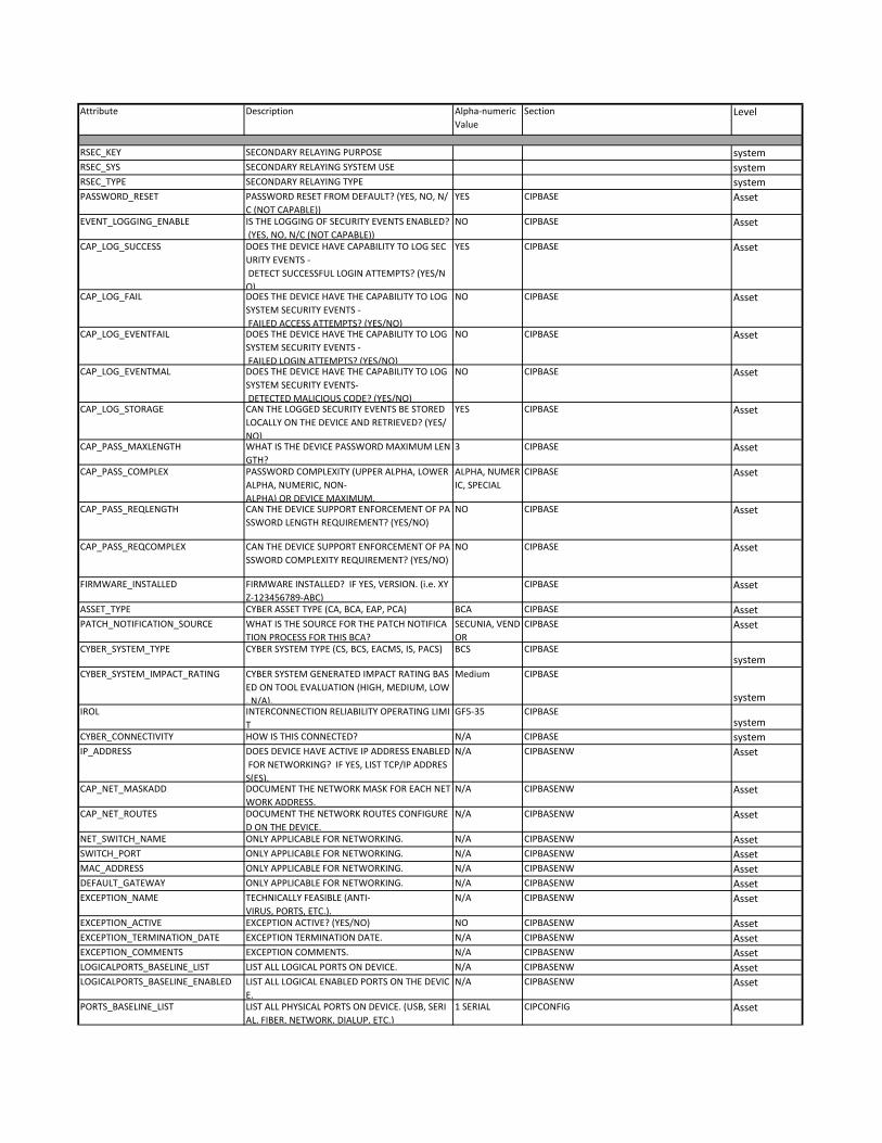
Attribute Description Alpha‐numeric
Value
Section Level
RSEC_KEY SECONDARY RELAYING PURPOSE systemRSEC_SYS SECONDARY RELAYING SYSTEM USE systemRSEC_TYPE SECONDARY RELAYING TYPE systemPASSWORD_RESET PASSWORD RESET FROM DEFAULT? (YES, NO, N/
C (NOT CAPABLE))
YES CIPBASE Asset
EVENT_LOGGING_ENABLE IS THE LOGGING OF SECURITY EVENTS ENABLED?
(YES, NO, N/C (NOT CAPABLE))
NO CIPBASE Asset
CAP_LOG_SUCCESS DOES THE DEVICE HAVE CAPABILITY TO LOG SEC
URITY EVENTS ‐
DETECT SUCCESSFUL LOGIN ATTEMPTS? (YES/N
O)
YES CIPBASE Asset
CAP_LOG_FAIL DOES THE DEVICE HAVE THE CAPABILITY TO LOG
SYSTEM SECURITY EVENTS ‐
FAILED ACCESS ATTEMPTS? (YES/NO)
NO CIPBASE Asset
CAP_LOG_EVENTFAIL DOES THE DEVICE HAVE THE CAPABILITY TO LOG
SYSTEM SECURITY EVENTS ‐
FAILED LOGIN ATTEMPTS? (YES/NO)
NO CIPBASE Asset
CAP_LOG_EVENTMAL DOES THE DEVICE HAVE THE CAPABILITY TO LOG
SYSTEM SECURITY EVENTS‐
DETECTED MALICIOUS CODE? (YES/NO)
NO CIPBASE Asset
CAP_LOG_STORAGE CAN THE LOGGED SECURITY EVENTS BE STORED
LOCALLY ON THE DEVICE AND RETRIEVED? (YES/
NO)
YES CIPBASE Asset
CAP_PASS_MAXLENGTH WHAT IS THE DEVICE PASSWORD MAXIMUM LEN
GTH?
3 CIPBASE Asset
CAP_PASS_COMPLEX PASSWORD COMPLEXITY (UPPER ALPHA, LOWER
ALPHA, NUMERIC, NON‐
ALPHA) OR DEVICE MAXIMUM.
ALPHA, NUMER
IC, SPECIAL
CIPBASE Asset
CAP_PASS_REQLENGTH CAN THE DEVICE SUPPORT ENFORCEMENT OF PA
SSWORD LENGTH REQUIREMENT? (YES/NO)
NO CIPBASE Asset
CAP_PASS_REQCOMPLEX CAN THE DEVICE SUPPORT ENFORCEMENT OF PA
SSWORD COMPLEXITY REQUIREMENT? (YES/NO)
NO CIPBASE Asset
FIRMWARE_INSTALLED FIRMWARE INSTALLED? IF YES, VERSION. (i.e. XY
Z‐123456789‐ABC)
CIPBASE Asset
ASSET_TYPE CYBER ASSET TYPE (CA, BCA, EAP, PCA) BCA CIPBASE AssetPATCH_NOTIFICATION_SOURCE WHAT IS THE SOURCE FOR THE PATCH NOTIFICA
TION PROCESS FOR THIS BCA?
SECUNIA, VEND
OR
CIPBASE Asset
CYBER_SYSTEM_TYPE CYBER SYSTEM TYPE (CS, BCS, EACMS, IS, PACS) BCS CIPBASEsystem
CYBER_SYSTEM_IMPACT_RATING CYBER SYSTEM GENERATED IMPACT RATING BAS
ED ON TOOL EVALUATION (HIGH, MEDIUM, LOW
, N/A).
Medium CIPBASE
systemIROL INTERCONNECTION RELIABILITY OPERATING LIMI
T
GF5‐35 CIPBASEsystem
CYBER_CONNECTIVITY HOW IS THIS CONNECTED? N/A CIPBASE systemIP_ADDRESS DOES DEVICE HAVE ACTIVE IP ADDRESS ENABLED
FOR NETWORKING? IF YES, LIST TCP/IP ADDRES
S(ES).
N/A CIPBASENW Asset
CAP_NET_MASKADD DOCUMENT THE NETWORK MASK FOR EACH NET
WORK ADDRESS.
N/A CIPBASENW Asset
CAP_NET_ROUTES DOCUMENT THE NETWORK ROUTES CONFIGURE
D ON THE DEVICE.
N/A CIPBASENW Asset
NET_SWITCH_NAME ONLY APPLICABLE FOR NETWORKING. N/A CIPBASENW AssetSWITCH_PORT ONLY APPLICABLE FOR NETWORKING. N/A CIPBASENW AssetMAC_ADDRESS ONLY APPLICABLE FOR NETWORKING. N/A CIPBASENW AssetDEFAULT_GATEWAY ONLY APPLICABLE FOR NETWORKING. N/A CIPBASENW AssetEXCEPTION_NAME TECHNICALLY FEASIBLE (ANTI‐
VIRUS, PORTS, ETC.).
N/A CIPBASENW Asset
EXCEPTION_ACTIVE EXCEPTION ACTIVE? (YES/NO) NO CIPBASENW AssetEXCEPTION_TERMINATION_DATE EXCEPTION TERMINATION DATE. N/A CIPBASENW AssetEXCEPTION_COMMENTS EXCEPTION COMMENTS. N/A CIPBASENW AssetLOGICALPORTS_BASELINE_LIST LIST ALL LOGICAL PORTS ON DEVICE. N/A CIPBASENW AssetLOGICALPORTS_BASELINE_ENABLED LIST ALL LOGICAL ENABLED PORTS ON THE DEVIC
E.
N/A CIPBASENW Asset
PORTS_BASELINE_LIST LIST ALL PHYSICAL PORTS ON DEVICE. (USB, SERI
AL, FIBER, NETWORK, DIALUP, ETC.)
1 SERIAL CIPCONFIG Asset

Attribute Description Alpha‐numeric
Value
Section Level
PORTS_BASELINE_ENABLED LIST ALL PHYSICAL ENABLED PORTS ON THE DEVI
CE.
CIPCONFIG Asset
PORTS_BASELINE_DISABLED ARE ALL UNNECCESSARY PHYSICAL PORTS DISABL
ED? (LIST PROTECTION TYPE IF REQUIRED)
4 CIPCONFIG Asset
PSP_NAME PSP/PSA IN WHICH THE ASSET IS LOCATED, IF AP
PLICABLE.
RELAY BUILDIN
G TONE AND C
ARRIER ROOM
CIPCONFIG Asset
ESP_NAME ESP IN WHICH THE ASSET IS LOCATED, IF APPLICA
BLE.
CIPCONFIG Asset
CAP_LOG_EVENTSYS CAN THE DEVICE SEND SECURITY EVENTS TO A R
EMOTE LOGGING SYSTEM? (YES/NO)
NO CIPCONFIG Asset
CAP_ACC_INDIVID DOES THE DEVICE SUPPORT INDIVIDUAL USER AC
COUNTS? (YES/NO)
NO CIPCONFIG Asset
CAP_LOG_EVENTLOCK DOES THE DEVICE LOCK‐
OUT ON MULTIPLE FAILED LOGIN ATTEMPTS? (Y
ES/NO)
NO CIPCONFIG Asset
GEN_COMMENTS GENERAL COMMENTS. CIPCONFIG AssetASPEN_ID ASPEN ID IF AVAILABLE FOR THE CYBER ASSET. CIPCONFIG AssetDECOMMISSION_CLEAN DATE WHEN THE ASSET WAS SANITIZED POST DE
COMMISSIONING
CIPCONFIG Asset
NYPA_OWNED_ASSET ASSET OWNERSHIP (WHO OWNS, WHO MAINTAI
NS)
NYPA CIPCONFIG Asset
THIRD_PARTY_ASSET_ID THIRD PARTY ASSET ID. N/A CIPCONFIG AssetLOGICALPORTS_BASELINE_DISABLED ARE ALL UNNECESSARY LOGICAL PORTS DISABLE
D?
N/A CIPCONFIG Asset
BUILDING_DRAWING_NUMBER DRAWING # OF THE BUILDING, IDENTIFIES PSP'S
AND ESP'S (ESP=PSP FOR NON‐
NETWORKED RELAYS).
CIPCONFIG
system

37
ATTACHMENT M – CAD REQUIREMENTS
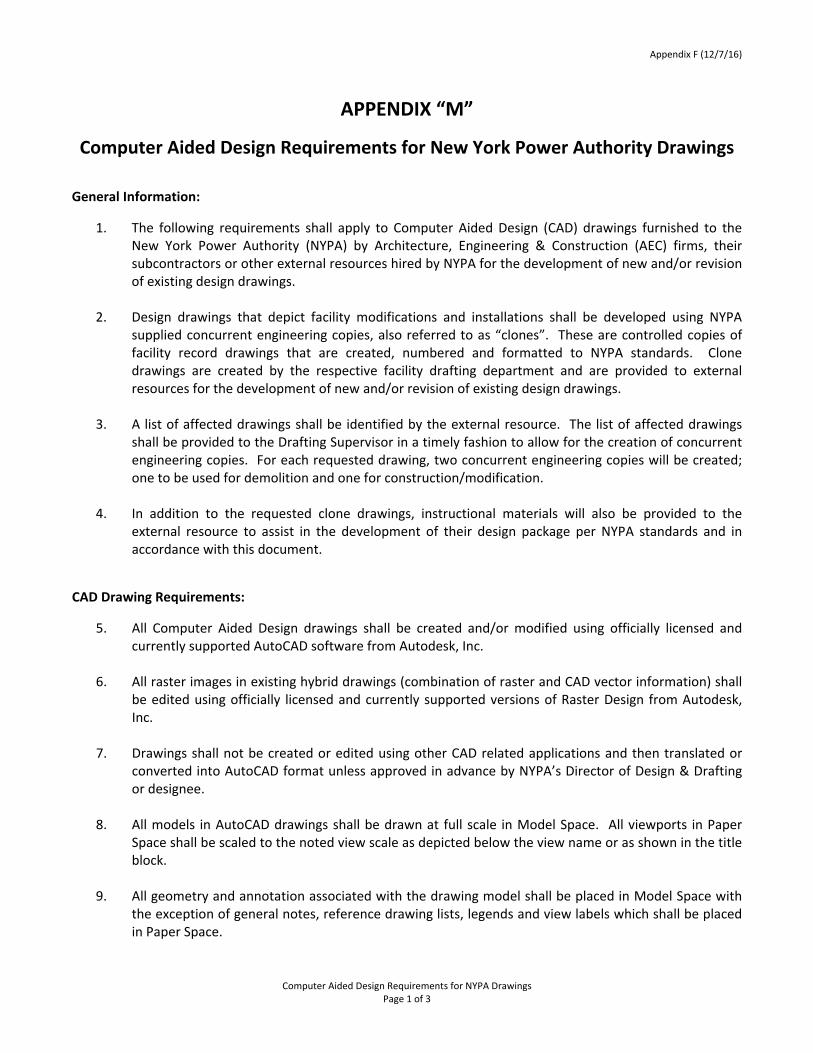
Appendix F (12/7/16)
Computer Aided Design Requirements for NYPA Drawings Page 1 of 3
APPENDIX “M”
Computer Aided Design Requirements for New York Power Authority Drawings
General Information:
1. The following requirements shall apply to Computer Aided Design (CAD) drawings furnished to theNew York Power Authority (NYPA) by Architecture, Engineering & Construction (AEC) firms, theirsubcontractors or other external resources hired by NYPA for the development of new and/or revisionof existing design drawings.
2. Design drawings that depict facility modifications and installations shall be developed using NYPAsupplied concurrent engineering copies, also referred to as “clones”. These are controlled copies offacility record drawings that are created, numbered and formatted to NYPA standards. Clonedrawings are created by the respective facility drafting department and are provided to externalresources for the development of new and/or revision of existing design drawings.
3. A list of affected drawings shall be identified by the external resource. The list of affected drawingsshall be provided to the Drafting Supervisor in a timely fashion to allow for the creation of concurrentengineering copies. For each requested drawing, two concurrent engineering copies will be created;one to be used for demolition and one for construction/modification.
4. In addition to the requested clone drawings, instructional materials will also be provided to theexternal resource to assist in the development of their design package per NYPA standards and inaccordance with this document.
CAD Drawing Requirements:
5. All Computer Aided Design drawings shall be created and/or modified using officially licensed andcurrently supported AutoCAD software from Autodesk, Inc.
6. All raster images in existing hybrid drawings (combination of raster and CAD vector information) shallbe edited using officially licensed and currently supported versions of Raster Design from Autodesk,Inc.
7. Drawings shall not be created or edited using other CAD related applications and then translated orconverted into AutoCAD format unless approved in advance by NYPA’s Director of Design & Draftingor designee.
8. All models in AutoCAD drawings shall be drawn at full scale in Model Space. All viewports in PaperSpace shall be scaled to the noted view scale as depicted below the view name or as shown in the titleblock.
9. All geometry and annotation associated with the drawing model shall be placed in Model Space withthe exception of general notes, reference drawing lists, legends and view labels which shall be placedin Paper Space.
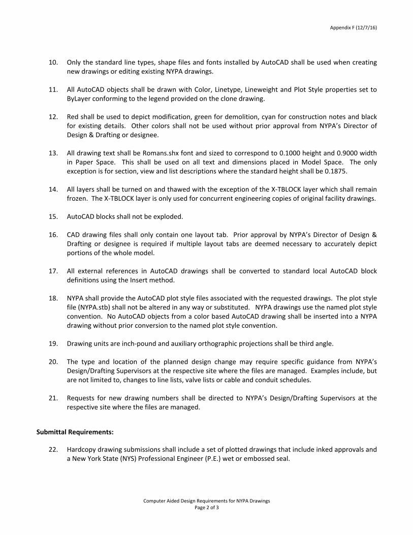
Appendix F (12/7/16)
Computer Aided Design Requirements for NYPA Drawings Page 2 of 3
10. Only the standard line types, shape files and fonts installed by AutoCAD shall be used when creating
new drawings or editing existing NYPA drawings.
11. All AutoCAD objects shall be drawn with Color, Linetype, Lineweight and Plot Style properties set to ByLayer conforming to the legend provided on the clone drawing.
12. Red shall be used to depict modification, green for demolition, cyan for construction notes and black
for existing details. Other colors shall not be used without prior approval from NYPA’s Director of Design & Drafting or designee.
13. All drawing text shall be Romans.shx font and sized to correspond to 0.1000 height and 0.9000 width in Paper Space. This shall be used on all text and dimensions placed in Model Space. The only exception is for section, view and list descriptions where the standard height shall be 0.1875.
14. All layers shall be turned on and thawed with the exception of the X‐TBLOCK layer which shall remain frozen. The X‐TBLOCK layer is only used for concurrent engineering copies of original facility drawings.
15. AutoCAD blocks shall not be exploded.
16. CAD drawing files shall only contain one layout tab. Prior approval by NYPA’s Director of Design & Drafting or designee is required if multiple layout tabs are deemed necessary to accurately depict portions of the whole model.
17. All external references in AutoCAD drawings shall be converted to standard local AutoCAD block definitions using the Insert method.
18. NYPA shall provide the AutoCAD plot style files associated with the requested drawings. The plot style file (NYPA.stb) shall not be altered in any way or substituted. NYPA drawings use the named plot style convention. No AutoCAD objects from a color based AutoCAD drawing shall be inserted into a NYPA drawing without prior conversion to the named plot style convention.
19. Drawing units are inch‐pound and auxiliary orthographic projections shall be third angle.
20. The type and location of the planned design change may require specific guidance from NYPA’s
Design/Drafting Supervisors at the respective site where the files are managed. Examples include, but are not limited to, changes to line lists, valve lists or cable and conduit schedules.
21. Requests for new drawing numbers shall be directed to NYPA’s Design/Drafting Supervisors at the respective site where the files are managed.
Submittal Requirements:
22. Hardcopy drawing submissions shall include a set of plotted drawings that include inked approvals and a New York State (NYS) Professional Engineer (P.E.) wet or embossed seal.
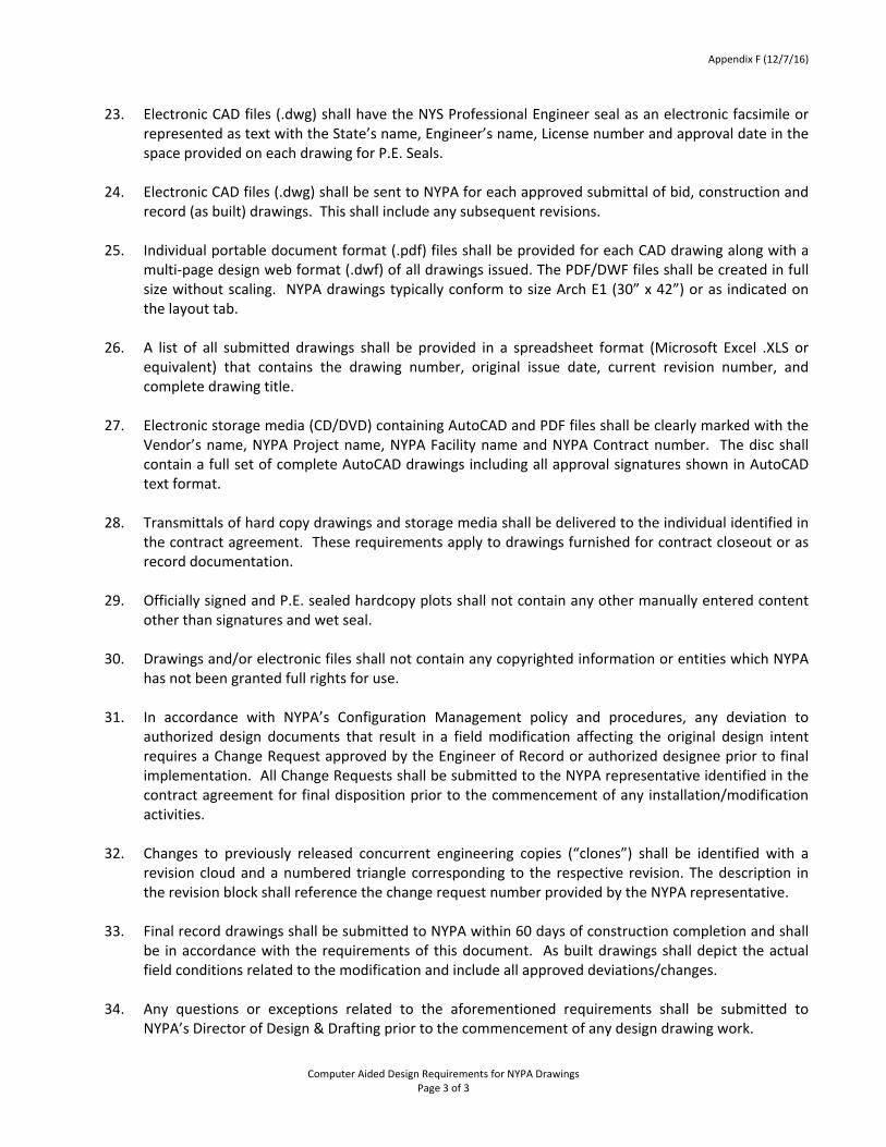
Appendix F (12/7/16)
Computer Aided Design Requirements for NYPA Drawings Page 3 of 3
23. Electronic CAD files (.dwg) shall have the NYS Professional Engineer seal as an electronic facsimile or represented as text with the State’s name, Engineer’s name, License number and approval date in the space provided on each drawing for P.E. Seals.
24. Electronic CAD files (.dwg) shall be sent to NYPA for each approved submittal of bid, construction and
record (as built) drawings. This shall include any subsequent revisions.
25. Individual portable document format (.pdf) files shall be provided for each CAD drawing along with a multi‐page design web format (.dwf) of all drawings issued. The PDF/DWF files shall be created in full size without scaling. NYPA drawings typically conform to size Arch E1 (30” x 42”) or as indicated on the layout tab.
26. A list of all submitted drawings shall be provided in a spreadsheet format (Microsoft Excel .XLS or equivalent) that contains the drawing number, original issue date, current revision number, and complete drawing title.
27. Electronic storage media (CD/DVD) containing AutoCAD and PDF files shall be clearly marked with the Vendor’s name, NYPA Project name, NYPA Facility name and NYPA Contract number. The disc shall contain a full set of complete AutoCAD drawings including all approval signatures shown in AutoCAD text format.
28. Transmittals of hard copy drawings and storage media shall be delivered to the individual identified in the contract agreement. These requirements apply to drawings furnished for contract closeout or as record documentation.
29. Officially signed and P.E. sealed hardcopy plots shall not contain any other manually entered content other than signatures and wet seal.
30. Drawings and/or electronic files shall not contain any copyrighted information or entities which NYPA has not been granted full rights for use.
31. In accordance with NYPA’s Configuration Management policy and procedures, any deviation to authorized design documents that result in a field modification affecting the original design intent requires a Change Request approved by the Engineer of Record or authorized designee prior to final implementation. All Change Requests shall be submitted to the NYPA representative identified in the contract agreement for final disposition prior to the commencement of any installation/modification activities.
32. Changes to previously released concurrent engineering copies (“clones”) shall be identified with a revision cloud and a numbered triangle corresponding to the respective revision. The description in the revision block shall reference the change request number provided by the NYPA representative.
33. Final record drawings shall be submitted to NYPA within 60 days of construction completion and shall be in accordance with the requirements of this document. As built drawings shall depict the actual field conditions related to the modification and include all approved deviations/changes.
34. Any questions or exceptions related to the aforementioned requirements shall be submitted to NYPA’s Director of Design & Drafting prior to the commencement of any design drawing work.

38
ATTACHMENT N – QUALITY ASSURANCE PROGRAM
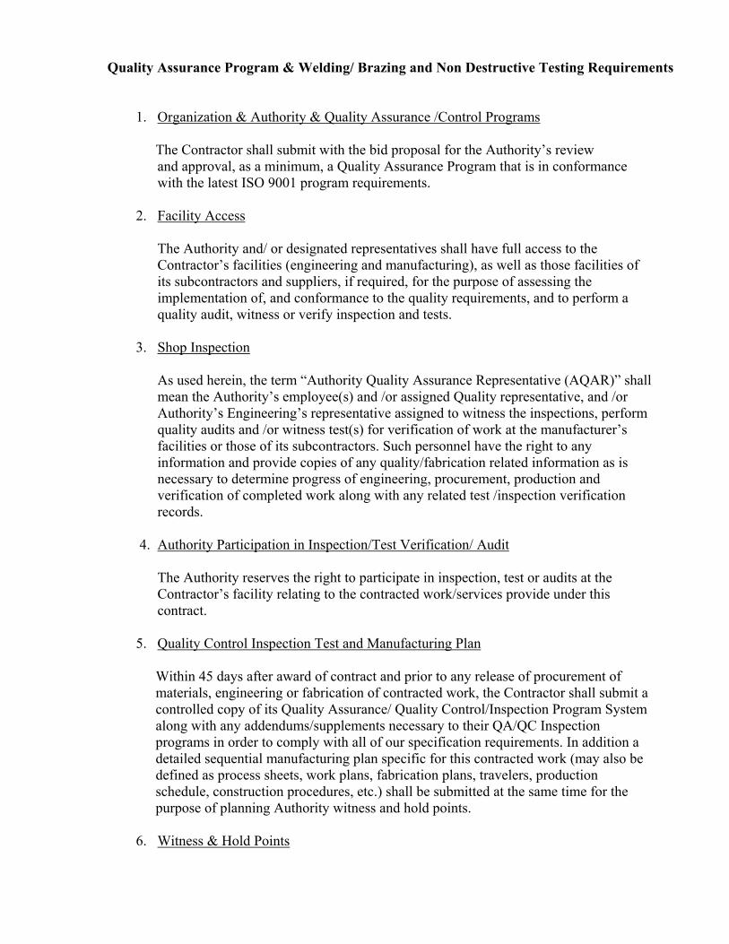
Quality Assurance Program & Welding/ Brazing and Non Destructive Testing Requirements
1. Organization & Authority & Quality Assurance /Control Programs The Contractor shall submit with the bid proposal for the Authority’s review and approval, as a minimum, a Quality Assurance Program that is in conformance with the latest ISO 9001 program requirements.
2. Facility Access
The Authority and/ or designated representatives shall have full access to the Contractor’s facilities (engineering and manufacturing), as well as those facilities of its subcontractors and suppliers, if required, for the purpose of assessing the implementation of, and conformance to the quality requirements, and to perform a quality audit, witness or verify inspection and tests.
3. Shop Inspection
As used herein, the term “Authority Quality Assurance Representative (AQAR)” shall mean the Authority’s employee(s) and /or assigned Quality representative, and /or Authority’s Engineering’s representative assigned to witness the inspections, perform quality audits and /or witness test(s) for verification of work at the manufacturer’s facilities or those of its subcontractors. Such personnel have the right to any information and provide copies of any quality/fabrication related information as is necessary to determine progress of engineering, procurement, production and verification of completed work along with any related test /inspection verification records.
4. Authority Participation in Inspection/Test Verification/ Audit The Authority reserves the right to participate in inspection, test or audits at the Contractor’s facility relating to the contracted work/services provide under this contract.
5. Quality Control Inspection Test and Manufacturing Plan
Within 45 days after award of contract and prior to any release of procurement of materials, engineering or fabrication of contracted work, the Contractor shall submit a controlled copy of its Quality Assurance/ Quality Control/Inspection Program System along with any addendums/supplements necessary to their QA/QC Inspection programs in order to comply with all of our specification requirements. In addition a detailed sequential manufacturing plan specific for this contracted work (may also be defined as process sheets, work plans, fabrication plans, travelers, production schedule, construction procedures, etc.) shall be submitted at the same time for the purpose of planning Authority witness and hold points.
6. Witness & Hold Points
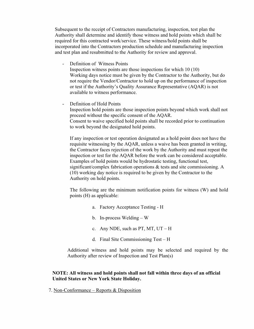
Subsequent to the receipt of Contractors manufacturing, inspection, test plan the Authority shall determine and identify those witness and hold points which shall be required for this contracted work/service. These witness/hold points shall be incorporated into the Contractors production schedule and manufacturing inspection and test plan and resubmitted to the Authority for review and approval.
- Definition of Witness Points Inspection witness points are those inspections for which 10 (10) Working days notice must be given by the Contractor to the Authority, but do not require the Vendor/Contractor to hold up on the performance of inspection or test if the Authority’s Quality Assurance Representative (AQAR) is not available to witness performance.
- Definition of Hold Points Inspection hold points are those inspection points beyond which work shall not proceed without the specific consent of the AQAR. Consent to waive specified hold points shall be recorded prior to continuation to work beyond the designated hold points. If any inspection or test operation designated as a hold point does not have the requisite witnessing by the AQAR, unless a waive has been granted in writing, the Contractor faces rejection of the work by the Authority and must repeat the inspection or test for the AQAR before the work can be considered acceptable. Examples of hold points would be hydrostatic testing, functional test, significant/complex fabrication operations & tests and site commissioning. A (10) working day notice is required to be given by the Contractor to the Authority on hold points. The following are the minimum notification points for witness (W) and hold points (H) as applicable:
a. Factory Acceptance Testing - H
b. In-process Welding – W
c. Any NDE, such as PT, MT, UT – H
d. Final Site Commissioning Test – H
Additional witness and hold points may be selected and required by the Authority after review of Inspection and Test Plan(s)
NOTE: All witness and hold points shall not fall within three days of an official United States or New York State Holiday.
7. Non-Conformance – Reports & Disposition
The Contractor shall document methods for disposition of items and performance that do not meet contract documents requirements, or Authority approval drawings, procedures, or drawings the Vendor uses to fabricate the equipment. These methods shall contain provision for:
1. Evaluation of non-conforming items 2. Submittal of all non-conformance notices to the Authority. These submittals
shall include supplier – recommended disposition (e.g. use- as – is or repair) and technical justification, and shall be approved by the Authority
8. Shipping Release
For each shipment made to the site, the contractor will present to the Authority a signed letter of Compliance fully identifying the product to be shipped and certifying that all contract specifications have been fully adhered to, except as noted by referenced nonconformance shall be included. One (1) copy of the Letter of Compliance must accompany each shipment. No shipment shall be made until released by an Authority Representative.
Workmanship Welding/Brazing and Non Destructive Testing
Workmanship
1. The work shall be performed by personnel skilled in their various trades. Welding and brazing shall be performed only by trained and qualified personnel in accordance with the latest revisions to qualified welding/brazing procedures and this specification.
Welding/ Brazing
1. All welded construction shall be suitable for outdoor equipment. 2. The qualification of welding procedures, welders, and welding operators for all
welding shall conform to AWSD1.1, “Structural Welding Code – Steel” or ASME Section IX, as applicable. All welding procedure specifications (WPS), procedure qualifications records, and welder qualifications shall be submitted for NYPA Q.A. review and approval.
3. The Authority (at the Contractors expense) has the right to verify any contractors’ welders’ qualifications by having their welder(s) weld up AWS D1.1. weld test coupons. The Authority will only select the Contractors’ welders that are assigned to weld on this project. Test coupon samples shall be welded in the presence of the Authority and prepared by the Contractor for testing. The Authority shall use these coupons to verify welder qualifications. No welder shall be allowed to work unless he has passed an Authority bend tests and visual examination.
4. Supplemental Requirements for Welding 4.1 Welding Processes – Welding shall be performed by one or more of the
following processes: - Shielded Metal Arc Welding (SMAW)- except that SMAW of
aluminum shall not be permitted - Submerged Arc Welding (SAW) - Gas Tungsten-Arc Welding (GTAW) with filler metal added - Gas Metal – Arc welding (GMAW) only for aluminum welding and no short circuiting or globular mode of transfer shall be permitted - Flux Cored Arc Welding (FCAW) with externally supplied shielding
gas only 4.2 Weld End Preps shall be clean bare metal. Any rust inhibitor or preventative coating on these areas to be welded is to be fully removed prior to welding.
4.3 Any welding of galvanized steel requires removal of galvanized coating prior to welding and reapplication of a NYPA approved galvanized coatings after welding is completed. This requires a procedure and product applicator approval by NYPA.
4.4 All weld spatter is required to be removed from base metal and completed welds.
4.5 Welding Materials Control - Contractor shall install controls for all weld filler materials. The controls
shall be documented in a welding material control procedure that is submitted to the Authority for review and approval.
- The use (temporary or permanent welding) and storage of 6010 Weld Rod on any NYPA welding work is not allowed to be used or stored on site.
- The procedure shall provide for the following: Positive identification of all filler materials, weld ovens and
portable weld ovens Segregation of filler materials by classification, alloy, size and
type Weld Wire/Rods Storage, Documented Distribution Controls
and Handling in the field and shop areas Controls for Welding Ovens and for Portable Welding Ovens
e.g. Distribution controls, Calibration controls for temperature monitoring instrumentation
Any weld rod not stored in a hermetically sealed can shall be stored in welding oven
o Weld/Brazing Map Records
4.6 Contractor shall provide weld/braze map records that specifically identifies the new or repaired weld joint identification, date the weld joint was completed, location of the weld joints, NDE and date that it was completed. - All weld maps’ records as a minimum will be documented on approved NYPA P & I Drawings on structural/mechanical
drawings for structural welds that will depict the location of the welded joint.
- Contractor shall submit a typical weld map record for NYPA Q.A. approval. Any changes requested by NYPA Q.A. to the Contractor proposed typical weld/braze map arrangement requested shall be made
with no increase in costs.
5.0 All welds for lifting lugs or other lifting means shall be 100% inspected by Liquid Penetrant Inspection.
6.0 Brazing procedure and personnel qualification shall be in accordance with the latest
edition of AWS B2.2, Specification for Brazing Procedure and Performance Qualification. All applicable brazing procedure specifications (BPS), procedure qualifications records (BPQR), and brazing performance qualifications records shall be submitted for NYPA Q.A. review and approval.
7.0 Any Welder(s) performing any structural welding within the jurisdiction of New York City Building Code shall be required to have an additional valid New York
City Welder’s license.
NDE Qualifications and Qualifications of Examination and Testing Personnel Responsibility 1. It is the responsibility of the Contractor to assure that only those personnel
within its organization who meet the requirements established herein are
permitted to perform inspection, examination, and testing activities that result in or assure the attainment of quality. It shall also be the Contractor’s responsibility
to comply with the procedure and instructions issued for the work and to the requirements established therein
Certification
1. Each person who verifies conformance of work activities to quality requirements shall be certified by their employer as being qualified to perform their assigned work. This certification shall be supported by appropriate measure such as education or training, evaluation and periodic review to assure the initial and continued proficiency of each person. The effective period of certification shall be established and at the end of the effective period of certification, each individual shall be re-certified in accordance with the requirements of these criteria. Personnel involved in the performance, evaluation, or supervision of non- destructive examinations, shall be certified in accordance with the requirements specified in American society for Non –Destructive Testing- Recommended Practice SNT-TC-1a and supplements for the type of NDE being performed.
Records 1. A file of records of personnel qualification shall be established and maintained by
the Contractor throughout the employee’s period of work activities at the Work Site. The file shall contain records of past performance history, training, initial and periodic evaluations and certifications of the qualifications of each person.
NDE 1. Personnel involved in the performance, evaluation, or supervision of non- destructive
examinations, including radiography, ultrasonic, penetrant, magnetic particle, or eddy current must meet the requirements specified in SNT-TC-1a and supplements.
2. All weld visual examinations shall be performed by an AWS Certified Welding Inspector (CWI) with at least a minimum of 7 years of documented experience.
3. All visual examinations, magnetic particle examinations, liquid penetrant examinations, eddy current, ultrasonic examinations that are to be performed shall be performed on uncoated (No Paint), rust free, clean bare metal surfaces. All metal surfaces to be examined will have all rust inhibitor removed also.
4. For any temporary tacks and arc strikes will be required to be removed and after removal shall be NDE tested by visually examination and liquid penetrant examination to verify no cracks or linear indications are present.

39
ATTACHMENT O – VIBRATION MONITORING SYSTEM SCOPE
Authority Vibration / Data, Acquisition, Monitoring and Analysis System 02/01/2018 Rev: 0
New York Power Authority
Operations – Support Services – Mechanical Engineering Page 2 of 30
Contents
PART 1 GENERAL ................................................................................................................................ 3
1.1 GENERAL DESCRIPTION ........................................................................................................ 3
1.2 SITE LOCATIONS BY REGIONS .............................................................................................. 3
1.3 PROJECT BACKGROUND AND DESCRIPTION ....................................................................... 4
1.4 PROJECT SCOPE OF SERVICES .............................................................................................. 6
1.5 SYSTEM 1 CONDITION MONITORING AND AUTOMATED DIAGNOSTIC SOFTWARE ........ 8
1.6 EXPERIENCE AND QUALIFICATIONS .................................................................................. 10
1.7 WORK / ITEMS PROVIDED BY THE CONTRACTOR ............................................................. 11
1.8 WORK / ITEMS PROVIDED BY SUBCONTRACTORS (IF APPLICABLE)............................... 13
1.9 WORK / ITEMS PROVIDED BY THE AUTHORITY ................................................................ 13
1.10 CODES AND STANDARDS .................................................................................................... 14
1.11 QUALITY ASSURANCE ......................................................................................................... 15
1.12 ADDITIONAL PROJECT DATA .............................................................................................. 17
1.13 APPENDICES ......................................................................................................................... 17
Authority Vibration / Data, Acquisition, Monitoring and Analysis System 02/01/2018 Rev: 0
New York Power Authority
Operations – Support Services – Mechanical Engineering Page 3 of 30
PART 1 GENERAL
1.1 GENERAL DESCRIPTION
A. This Scope of Services Specification establishes the minimum technical requirements for the
Engineering, Procurement and Construction (EPC) of a comprehensive Vibration & Data
Acquisition, Monitoring, & Analysis / Diagnostic System herein “vibration system”. The scope
of these services shall be performed for the New York Power Authority, herein “Authority”. All
work as part of this scope shall be within the following Authority regions:
1. South East New York region, herein “SENY”. This region encompasses the Authority’s
fossil power plants, located throughout New York City and Long Island. A full list of
this region’s nine affected facilities and their associated addresses are listed below in
Section 1.2.
2. Central Region, herein specifically our Blenheim Gilboa Project “BG”.
3. Northern Region, herein specifically our St. Lawrence Project, “STL”.
4. Western Region, herein two facilities, Robert Moses Niagara Power Project “RMNPP”
and Lewiston Pump Generating Project “LPGP”.
B. It is not the Authority's intent to specify all technical requirements or to set forth those
requirements adequately covered by applicable codes, regulations and industrial standards.
Contractor shall assess the systems, meeting all of the requirements of this Specification and
applicable industry standards and applicable Codes and Regulations.
C. Any exceptions to this Specification, or its referenced codes, regulations and standards shall be
listed on a separate sheet to be submitted with the bid response documentation and are subject to
agreement between the Authority and the Contractor in writing prior to Contract Award.
1.2 SITE LOCATIONS BY REGIONS
A. SOUTH EAST NEW YORK (SENY)
1. Poletti Power Project
500 MW 31st Street & 20th Avenue, Astoria, NY 11105
2. Small Clean Power Plants (SCPP)
Hell Gate (HG) 910E 134th Street / Locus Ave, Bronx, NY 10454
Harlem River (HR) 132nd Street / Saint Ann’s, Bronx, NY 10454
Vernon (VN) 42-30 Vernon Blvd, Long Island City, NY 11101
Kent (KT) 47-79 River Street / North 1st, Brooklyn, NY 11211
Gowanus (GW) 730 3rd Ave / 23rd, Brooklyn, NY 11232
Pouch (PT) 143 Edgewater, Staten Island, NY 10305

Authority Vibration / Data, Acquisition, Monitoring and Analysis System 02/01/2018 Rev: 0
New York Power Authority
Operations – Support Services – Mechanical Engineering Page 4 of 30
3. Richard M. Flynn Power Project
Flynn 607 Union Ave., Holtsville, NY 11742
Brentwood (BW) 995 G Road, Brentwood, NY 11717
B. CENTRAL REGION
1. Blenheim Gilboa Project (BG)
397 Power Plant Access Rd, Gilboa, NY 12076
C. NORTHERN REGION
1. St. Lawrence Power Project (STL)
Robert Moses Power Dam, Massena, NY 13662
D. WESTERN REGION
1. Robert Moses Niagara Power Project (RMNPP)
5777 Lewiston Road, Lewiston NY 14092
2. Lewiston Pump Generating Project (LPGP)
5777 Lewiston Road, Lewiston NY 14092
1.3 PROJECT BACKGROUND AND DESCRIPTION
A. The Authority has many vital power producing pieces of rotating equipment within its hydro and
fossil fleet. These critical pieces of equipment and some of the equipment within their auxiliary
systems, have various Vibration / Data Acquisition and monitoring devices & tools. Since
vibration data plays a crucial role in both the proactive and reactive analysis of rotating
equipment anomalies it is imperative that a proactive approach be taken to properly maintain,
upgrade and enhance the system.
B. All of the Authority’s listed regions, predominantly utilize Bently Nevada vibration hardware to
acquire vibration data. At some locations the Bently Nevada hardware is exclusively used and at
other locations Bently Nevada hardware is used in conjunction with other third party systems (to
be discussed further herein). This project shall not stray from the use of Bently Nevada
hardware, as we shall be maintaining companywide consistency.
Authority Vibration / Data, Acquisition, Monitoring and Analysis System 02/01/2018 Rev: 0
New York Power Authority
Operations – Support Services – Mechanical Engineering Page 5 of 30
C. The primary objective of this project is to provide the Authority’s facilities with the latest
monitoring, acquisition and analysis / diagnostic vibration suite. The data acquired shall be
ported to the latest Bently Nevada System 1 Condition Monitoring and Automated Diagnostic
System, herein “System 1” and utilized by both the individual facilities and the Authority’s
Integrated Smart Operation Center (iSOC), located in the White Plains Office (WPO), to move
towards a greater proactive vs. reactive asset management approach. GE’s Enterprise Impact
“EI” which is currently slated for integration into our current diagnostic system infrastructure,
throughout the Authority, by our GE Digital partnership, shall be the conduit to transfer the
System 1 data to the APM Cloud for enhanced diagnostics in the future.
D. The SENY region’s combustion and steam turbine and generators have varying degrees of the
Bently Nevada 3300 and 3500 Series Condition Acquisition / Monitoring Equipment. Appendix
I is an attempt at detailing the extent of existing equipment as well as our already in-progress
path, which in some cases requires additional evaluation and in some cases only the installation
and commissioning of already purchased equipment. Our desired path forward in some cases is
also detailed. Third party vibration systems (i.e. other than Bently Nevada) shall not be replaced.
The data within these systems shall be required to be imported, to be accessed for analysis and
diagnosis (to the extent possible) by the System 1 system.
E. The BG facilities’ 4 vertical hydro pump / generation turbines and generators have Bently
Nevada 3500 Series Condition Acquisition / Monitoring Equipment as well as a System 1
Condition Monitoring and Automated Diagnostic System. Appendix II is an attempt at detailing
the extent of the existing equipment as well as our desired path forward.
F. The STL facilities’ 16 vertical hydro turbines and generators have Bently Nevada 3500 Series
Condition Acquisition / Monitoring Equipment as well as a System 1 Condition Monitoring and
Automated Diagnostic System. STL also has an additional enhancements to the diagnostic
system as they have a jointly developed, NYPA / BN / IRIS, Hydro X rule pack suite. This suite
was developed to not only utilize vibration data for diagnostics but other critical electrical
machinery parameters, e.g. air gap, stator temperature, flux monitoring, etc. Appendix III is an
attempt at detailing the extent of the existing equipment as well as our desired path forward.
G. The Niagara (NIA) Projects’ two facilities RMNPP (13 vertical hydro turbines and generators)
and LPGP (12 vertical hydro pump / generation turbines and generators), have incorporated
vibration monitoring differently. All of the RMNPP turbine / generators have varying degrees of
the Bently Nevada 3300 and 3500 Series Condition Acquisition / Monitoring Equipment.
LPGP’s units either have Bently Nevada 3500 Series Condition Acquisition / Monitoring
Equipment or nothing at all. Appendix IV is an attempt at detailing the extent of the existing
equipment as well as our desired path forward.
Authority Vibration / Data, Acquisition, Monitoring and Analysis System 02/01/2018 Rev: 0
New York Power Authority
Operations – Support Services – Mechanical Engineering Page 6 of 30
1.4 PROJECT SCOPE OF SERVICES
A. The existing vibration system hardware for the pieces of equipment specifically listed in
Appendix I, II, III, and IV shall be assessed for all required System 1 upgrades.
1. This assessment shall include a complete vetting of all:
a. System components: This shall include and extend from the monitoring probes on
the rotating equipment, to the hardware on the acquisition, storage and monitoring
hardware (i.e. from shaft / casing to rack) Where applicable this shall also extend
to the System 1 servers already installed (BG / STL).
1) Equipment / component applicability, location / position and details of
installation methods (brackets / hangers / adhesive), wiring connection
labels / identification, firmware and software revision etc. shall be
reviewed.
2) Due to some of the hardware within casings and others interconnecting to
the facilities control systems, access for physical inspection and
subsequent work (installation / commissioning) activities will be limited to
available site outages. Visual inspection of accessible hardware while
online, shall be permitted on a case by case basis. This note shall apply to
all phases of the work scope herein.
b. Applicable system drawings: This shall include and extend, as above, from shaft /
casing to rack.
1) The Contractor shall utilize their expertise and the available
documentation to determine applicability of the hardware, if an opportune
time period cannot be scheduled for physical examination.
2. Technical synopsis report per each of the 4 Regions shall be presented to the Authority
for review. These four independent reports shall contain but are not limited to:
a. Summary of a complete System 1 package implementation. This shall include,
but is not limited to, an overview of the following topics: design, engineering,
procurement, factory acceptance testing, installation, commissioning,
documentation package, quality assurance & quality control.
b. A preliminary schedule of implementation shall be provided per region.
1) Schedule shall identify the specific activities to be performed with
durations.
Authority Vibration / Data, Acquisition, Monitoring and Analysis System 02/01/2018 Rev: 0
New York Power Authority
Operations – Support Services – Mechanical Engineering Page 7 of 30
2) Final interconnections shall require major facility equipment, i.e. turbine -
generators, to be in their non-power producing or dormant states.
Preliminary coordination with the sites shall take place during this stage of
the project to determine when demolition or new construction can occur as
to not disrupt normal operations.
c. Major project anomalies or hurdles foreseen shall be identified at this time as well
as the expected delays and potential resolutions.
3. On-site presentations shall be held with each of the above four regions to review the,
region specific reports, mentioned above.
4. Only after Authority review and approval of the technical reports, shall the project
proceed accordingly.
B. An upgrade path following Appendix I, II, III and IV shall be designed / engineered by the
Contractor. As the work progresses calculations, drawings (network, instrumentation
interconnections, instrumentation mounting details, etc.), etc., shall be submitted at 30%, 60%
and 90% intervals for Authority review and approval. The vibration system shall allow for both
local and remote data storage, analysis, diagnostics and monitoring utilizing System 1 and
eventually APM Cloud Diagnostics.
C. Appendix I - IV are overviews of the existing equipment as well as an overview of the proposed
path forward. Below is a top level summary of those Appendices.
1. The existing 3300 Series equipment shall be replaced with the latest generation 3500
Series equipment directly compatible with System 1.
2. The existing 3500 Series equipment not compatible with System 1 shall be replaced with
the latest generation 3500 Series equipment directly compatible with System 1.
3. Existing third party vibration systems (Vibrometer, VibroSysM, SKF, etc.) shall be
integrated, to the extent possible, into System 1. Contractor to recommend if there is a
more streamlined solution to incorporate these systems into our iSOC / Asset
Management Program.
4. Acquisition probes (accelerometers, velocity sensors, displacement sensors, etc.) which
are required to be replaced or are recommended to be replaced, relocated or removed due
to the Contractors evaluation, shall be presented for the Authority’s review and
acceptance prior to proceeding with any inclusion in the design.
5. Contractor can assess our existing configurations and future upgrade plans and provide
input on additional probes which are not currently installed or slated to be installed.
Background reasoning’s, documentation, examples, etc. shall be provided to aid in the
evaluation process.
Authority Vibration / Data, Acquisition, Monitoring and Analysis System 02/01/2018 Rev: 0
New York Power Authority
Operations – Support Services – Mechanical Engineering Page 8 of 30
6. The Authority is currently evaluating various non-vibration specific sensors / probes to be
incorporated into our various Turbine / Generator packages as part of our overall Sensor
Deployment Phase II Project. These pressure, temperature, etc. probes may be chosen to
be integrated into the Bently 3500 Rack due to their vicinity and capability to handle
general 4-20mA I/O signals. See Appendices II / III / IV for a sampling of these signals.
a. The Contractor shall be responsible to select these probes utilizing the parameters
provided in the overall Sensor Deployment Phase II Specification. Contractor can
recommend alternatives design parameters and implementation methods.
Contractor shall submit to the Authority, for review and approval, the cost and
schedule impact.
D. The necessary equipment which is determined to be required for this project per the engineered
solution shall be procured by the Contractor. This shall only occur after the necessary Stamped
and Sealed, 100% Final, documentation by a licensed Professional Engineer currently registered
in the State of New York has been reviewed, approved and released by the Authority.
1. All procured vibration system equipment (complete racks, individual rack card,
computer, network equipment, etc.) shall be fully factory tested prior to release. The
Authority shall be allowed the option of witnessing the testing of any or all components.
All calibrated devices shall be traceable to NIST standards and a copy of the calibration
records included with the equipment. Refer to Section 1.11 below for additional QA/QC
requirements.
E. The equipment procured shall be installed in accordance with the equipment manufacturer(s) (i.e.
Bently Nevada, Cisco, etc.), as well as the references listed in the Codes and Standards Section,
1.10 below.
F. The installed hardware and software for System 1 shall be commissioned per equipment
manufacture requirements. NYPA shall be the sole, full term license and warrantee holder upon
completion of the project.
G. All equipment and hardware procured as part of this project shall be new. Old, used, refurbished
or reconditioned equipment and hardware is not acceptable.
H. Upon completion of the project all applicable As-Built documentation and drawings shall be
signed and sealed by a licensed Professional Engineer currently registered in the State of New
York and turned over to the Authority for our records. The Contractor shall follow the
Authority’s Design and Drafting protocols, as referenced in Appendix “F” – “Computer Aided
Drawing Requirements for New York Power Authority”. OEM assembled O&M manuals
containing instruction manuals, testing reports / data as well as other ancillary documentation
shall also be turned over the Authority.
1.5 SYSTEM 1 CONDITION MONITORING AND AUTOMATED DIAGNOSTIC SOFTWARE
A. The software provided shall be provided in the US English language. Other language packages
shall not be required.
B. The software shall support five concurrent users at each of the four regions.
Authority Vibration / Data, Acquisition, Monitoring and Analysis System 02/01/2018 Rev: 0
New York Power Authority
Operations – Support Services – Mechanical Engineering Page 9 of 30
C. The software shall be capable of profiling different users and facility assets to allow access only
to the desired data, menus, graphical plots and displays, and alarms and events.
D. The software shall include integrated electronic documentation management, electronic operator
journal, and automated electronic report capabilities.
E. Software shall be the latest revision or edition, with the latest, at time of installation and
turnover, stable package of patches.
F. Supplied with the system shall be six copies (one per region plus two for headquarters) of the
Bently Nevada Machine Library & Data Acquisition Computer Based Training CD.
1. The Training CD is in addition to, not a replacement for, Physical Instructor Lead On-
Site training at the conclusion of the project as stated in Section 1.7 below.
G. The system shall store and display real time static and dynamic data from transient events (for
machines employing an online Continuous Monitoring & Protection System), steady state static
and dynamic data (for machines employing online continuous and scanning systems), and
periodic static and dynamic data.
H. Software shall provide continuous on-line machinery vibration data acquisition at configurable
time intervals of one second or longer, with selectable change-filtering feature for database size
optimization. The signal processing method must support a minimum 800 spectral lines and
high resolution data at 3200 spectral lines, with Fmax configurable from DC to 30kHz. The
system must be capable of automatically sampling more frequently for a set time period
surrounding (both before and after) alarm events, and automatically sampling at configurable
speed intervals during transient events (start-up and shut-down).
I. Diagnostic capabilities for Online Periodic Scanning or Portable Data Collection shall include
Synchronous waveform / Orbit analysis, Acceleration enveloping, and spectral resolution to
3200 lines, DC to 20kHz.
J. Vibration data captured shall be able to be visually analyzed within the software package via
multiple graph and chart styles, such as but not limited to Orbit, XY, Polar, Bode, Shaft Center
Line, Waterfall, and Cascade.
K. Data / Files shall be able to be exported for in-house and third party examination / use.
L. The software shall be able to incorporate a knowledge-based decision support root-cause fault
diagnostic rule library for automated detection and communication of commonly experienced
machinery fault conditions, including a customizable machine and process diagnostic rule
generator.
M. The Condition Monitoring Software Platform shall be capable of integration with other
machinery and process data systems (Vibrometer, VibroSysM, SKF, etc.) using standard
protocols, i.e. OPC.
Authority Vibration / Data, Acquisition, Monitoring and Analysis System 02/01/2018 Rev: 0
New York Power Authority
Operations – Support Services – Mechanical Engineering Page 10 of 30
1.6 EXPERIENCE AND QUALIFICATIONS
A. The Contractor shall:
1. Have a proven record of experience (minimum 10 years) in the engineering, design and
installation of various rotating and reciprocating machinery (pumps, compressors,
motors, gear boxes, turbines, etc.) vibration systems.
2. Have experience greater than or equal to the above in:
a. The analysis and reporting of various inherent rotating and reciprocating
equipment (combustion and steam turbines, gas compressors, gear boxes, etc.)
instabilities.
b. The full array of GE / Bently Nevada equipment and software, specifically the
3300 and 3500 Series Acquisition Equipment, the System 1 Condition Monitoring
and Diagnostic System and Enterprise Impact.
c. The application of the Bently Nevada Systems to a variety of Original Equipment
Manufacturers (OEM) equipment, such as but not limited to, General Electric
(GE) 7FA Combustion Turbines, GE D11 Steam Turbines, GE 7FH2 Generators
and other large Hydro Generators, Nuovo Pignone Compressors, GE LM6000
Aero Derivative Combustion Turbines, Siemens V84.2 Combustion Turbines,
Ingersoll Rand Compressor, Various (Alstom / Voith / Hitachi) Upgraded
Generation and Pump / Generation Hydro Turbines, etc.
d. Consolidation of various third party (Vibrometer, VibroSysM, SKF, etc.)
vibration monitoring and acquisition systems into the System 1 Condition
Monitoring and Diagnostic System.
e. Networking architecture in regards to a multi-site (large geographic area)
network. This includes knowledge of general power plant cyber security
protocols as well as NERC CIP (North American Electric Reliability Corporation
Critical Infrastructure Protection) protocols.
1) Note: The NERC CIP classification / ratings of these sites may in the
future interconnect with sites with the highest classification / rating.
3. Provide a reference list of the projects utilized as the basis of their experience with
contact numbers for the Authority’s due diligence inquiries.
a. Projects within New York State would be beneficial as the assessment team
would prefer to physically view examples.
4. Be responsible for providing qualified engineering and design services performed under
the supervision of a licensed Professional Engineer currently registered in the State of
New York.
Authority Vibration / Data, Acquisition, Monitoring and Analysis System 02/01/2018 Rev: 0
New York Power Authority
Operations – Support Services – Mechanical Engineering Page 11 of 30
1.7 WORK / ITEMS PROVIDED BY THE CONTRACTOR
A. The Contractor shall Engineer, Procure, Install, Test and Commission all of the, but not limited
to, tasks identified above, within Section 1.4, Project Scope of Services. Below are additional
particulars which shall be the responsibility of the Contractor.
1. Requesting and Manipulating Clone Drawings
a. The Contractor will be required to manipulate Authority facility drawings per this
project. In order to do so, upon specific drawing request by the Contractor, the
Authority shall create Clone drawings. These Clones are copies of the latest
revisions of the facility drawings within the Authority’s system, to be utilized by
the Contractor to develop such drawings as Demolition and Installation drawings.
The Contractor shall follow the Authority’s Design and Drafting protocols, as
referenced in Appendix “F” – “Computer Aided Drawing Requirements for New
York Power Authority”. This document is located within Division 1 of the RFQ
Package.
b. New Contractor drawings furnished to the Authority shall require a request for a
Blank Template from the Authority and follow the requirements of Appendix “F”
mentioned above.
2. Interaction with the Authority
a. During the course of the project, especially during the engineering and design
phase, the Contractor shall work with, but not limited to, the following Authority
groups to verify that Authority technically specific requirements are met (i.e.
typical wire types, ring terminal connectors, server / router options, etc.).
1) Discipline Engineers (Mechanical, Electrical, Computer Systems, Civil /
Structural, etc.)
2) Site Staff – Operation and Maintenance Departments
3) Code Compliance - QA/QC
a) Permitting for SCPP, Flynn, BG, STL, RMNPP and LPGP Projects
are handled through our in-house Code Compliance Group.
Permitting for the 500MW is handled thru the City of New York.
3. Installation and Commissioning Support
a. The Contractor shall arrange for equipment Manufacturer’s representative to
provide continual support during equipment’s installation and commissioning at
each site. Remote support is acceptable during equipment installation however
during commissioning; on-site support to aid in potential troubleshooting
activities shall be required.
Authority Vibration / Data, Acquisition, Monitoring and Analysis System 02/01/2018 Rev: 0
New York Power Authority
Operations – Support Services – Mechanical Engineering Page 12 of 30
4. Training
a. At the conclusion of the project a Bently Nevada Training representative shall
perform:
1) One (1), full day System 1 Basic Introduction / System Familiarization
training session at each of the four regions including the WPO (Five (5)
days total).
2) One (1) full day System 1 Advanced training session shall be offered at
each of the four regions including the WPO (Five (5) days total).
3) Training topics for the Basic and Advanced sessions shall be determined
as the project progresses.
a) Regions can choose to incorporate the two sessions back to back.
b) If topics chosen require additional days of training, cost adder shall
be presented to the Authority for review and approval prior to
scheduling.
4) The Authority reserves the right to video tape the training sessions
performed at site.
5. Warrantees / Licenses
a. Contractor to provide warranty per Section 2.6 of the Sensor Deployment Scope
of Services
b. Contractor shall have the ability to transfer all software and hardware warrantees
and licenses to the Authority for their full term(s), without any encumbrances.
c. The System 1 software license shall allow for full rotating and possible future
reciprocating machinery (currently SCPP / Flynn only) monitoring and
diagnostics.
1) A La-Cart style licensing, in which full software functionality is impeded
until subsequent or additional licenses are required, is not acceptable.
6. As-Built drawing updates
a. Prior to the completion of the project but after the completion of installation, all
applicable new and existing Vendor and Authority Modified Drawings shall be
required to be As-built. As-built refers to, updating the drawings to match actual
physical installation.
Authority Vibration / Data, Acquisition, Monitoring and Analysis System 02/01/2018 Rev: 0
New York Power Authority
Operations – Support Services – Mechanical Engineering Page 13 of 30
b. The Contractor shall follow the Authority’s Design and Drafting protocols, as
referenced in Appendix “F” – “Computer Aided Drawing Requirements for New
York Power Authority”.
7. Project closeout
a. At the completion of the project each region shall receive 2 electronic copies of
all region specific project documentation, including but not limited to the
following shall be transferred to the Authority.
1) O&M Manuals
2) Vendor and Authority Updated As-Built Drawings (Signed and Sealed by
Licensed Professional Engineer currently registered in the State of New
York)
3) Hardware and Software License / Warrantee documentation
4) Software Electronic Backup Media (Compact Disks - CD’s / Digital
Versatile Discs – DVD’s)
5) Recommended Authority Wide Spare Parts List
6) Manufacturer’s Representative Contact Information.
b. The WPO shall receive 2 electronic copies of the above documentation package
for each of the 4 regions. The WPO shall also receive 3 sets of hardcopy Signed /
Sealed As-Built Prints for each of the 4 regions.
1.8 WORK / ITEMS PROVIDED BY SUBCONTRACTORS (IF APPLICABLE)
A. Subcontractors are bound by the same requirements as the Contractor. It is the duty of the
Contractor to make sure all of the Authority’s requirements are met and maintained throughout
the project
1.9 WORK / ITEMS PROVIDED BY THE AUTHORITY
A. Provide available applicable Authority documentation for assessment.
B. Provide technical review and comments of all documentation (drawings, cut sheets, factory
acceptance testing and commissioning procedures, etc.) for equipment to be procured and
installed.
1. For new pieces of equipment, cables and wires, the Authority shall assign unique
identification numbers which follow, facility specific nomenclature requirements.
Contractor to install physical labels / tags on equipment, cables and wires.
C. Attend, as applicable, factory acceptance testing.
D. Provide technical and commercial input regarding project interaction with outside third party
entities.
1. Ex. Authority shall work with external communication companies (Verizon, etc.) if
required due to project remote bandwidth requirements.
Authority Vibration / Data, Acquisition, Monitoring and Analysis System 02/01/2018 Rev: 0
New York Power Authority
Operations – Support Services – Mechanical Engineering Page 14 of 30
E. Provide outage schedules for inspection access.
F. Provide escorted access to the equipment, during scheduled visits. This shall include all
necessary LOTO and Safety protection to properly assess and eventually install the equipment.
G. Receive, unload and store project equipment within a dry warehouse.
1.10 CODES AND STANDARDS
A. All work, tests and measurements shall comply with the general conditions and the following
U.S. standards where applicable, and other standards and requirements referred to in these
Specifications, including such revisions as are in effect on the date of award:
1. American Gear Manufacturers Association (AGMA)
2. American Institute of Steel Construction (AISC)
3. American National Standards Institute (ANSI)
4. American Petroleum Institute (API)
5. American Society of Civil Engineers (ASCE)
6. American Society of Mechanical Engineers (ASME)
7. American Society for Testing and Materials (ASTM)
8. American Welding Society (AWS)
9. Code of Federal Regulations (CFR Title 29)
10. Factory Mutual (FM)
11. Institute of Electrical and Electronics Engineers (IEEE)
12. International organization for Standardization (ISO)
13. National Electrical Code (NEC)
14. National Electrical Manufacturers Association (NEMA)
15. National Fire Protection Association (NFPA)
16. New York State Building Codes and Referenced Standards
17. New York City Building Codes
18. New York State Department of Environmental Conservation (DEC)
19. Occupational Safety & Health Administration (OSHA)
20. Society of Automotive Engineers (SAE) Standards
21. Underwriters Laboratories (UL)
22. North American Electric Reliability Corporation (NERC)
23. NERC CIP (Critical Infrastructure Protection) Standard Version 5 or Latest
B. Be knowledgeable of the current provisions and intent of all applicable federal, state and local
Codes and Regulations as well as Industry Standards.
C. In the event of a conflict between the text of this Specification and the reference standards cited
above, the more stringent requirement shall be applied.
Authority Vibration / Data, Acquisition, Monitoring and Analysis System 02/01/2018 Rev: 0
New York Power Authority
Operations – Support Services – Mechanical Engineering Page 15 of 30
1.11 QUALITY ASSURANCE
A. Quality Assurance Program
1. The Contractor shall submit an ISO 9000 Quality Assurance (QA) Program, or Authority
approved equal with the bid proposal. The QA Program shall include an Organization
Chart indicating the applicable management structure, engineering, procurement, project
management, fabrication, supervision and inspection departments. The organization
chart shall indicate how these personnel interface and provide a description of their
responsibilities along with their experience records. All inspection personnel shall be
independent of the field and shop fabrication personnel and production supervision.
2. The Authority will review and approve the Contractor’s QA Program and may request
changes during contract negotiations and during the contracted work.
3. The Contractor shall adhere to the approved QA Program and to the Construction
Inspection / Monitoring Program (CI/MP), attached to the Division 1 Specification, The
Contractor shall use sample the sample provided to develop a Job Specific CI/MP.
B. Quality Inspections
1. The Authority shall have full access to the Contractor’s facilities, as well as the facilities
of its Subcontractors and suppliers for the purpose of assessing conformance to the
quality requirements.
2. An Authority QA representative will assign a QA Representative (AQAR) to witness the
inspections, perform quality audits and /or witness test(s) for verification of work at the
manufacturer’s facilities or those of its Subcontractor(s).
3. Such personnel shall have access to any information necessary to determine progress of
engineering, procurement, production and verification of completed work along with any
related test or inspection verification records.
4. The Authority reserves the right to participate in inspections, tests or audits at the
Contractor’s facilities relating to the work and services provided under this Contract.
5. Witness and hold points will be established in accordance with the ISO 9000 Inspection
and Test Plans. The Contractor is required to submit their Inspection and Test Plans as
well as their subcontractors for the Authority’s review. From this plan the Authority’s
QA or QA approved designee shall select witness and hold points. The CI/MP will have
their witness and hold points established in the programs checklists. These witness / hold
points shall be incorporated into the Contractors and their Subcontractors’ production
schedules.
Authority Vibration / Data, Acquisition, Monitoring and Analysis System 02/01/2018 Rev: 0
New York Power Authority
Operations – Support Services – Mechanical Engineering Page 16 of 30
a. Witness Points
1) Inspection witness points are those inspection points for which five (5)
working days’ notice must be given by the Contractor to the Authority, but
do not require the Contractor or its subcontractors to hold up on the
performance of inspections or tests if the AQAR is not available.
b. Hold Points
1) Inspection hold Inspection hold points are those inspection points for
which ten (10) working days’ notice must be given by the Contractor to
the Authority. Work shall not proceed without specific consent of the
AQAR. Written consent by the AQAR to waive specified hold points
shall be recorded prior to continuation of work beyond the designated hold
point.
2) If any inspections or test operations designated as hold points are not
witnessed by the AQAR, unless a waive has been granted in writing, the
Contractor faces rejection of the work by the Authority and must repeat
the inspections or tests for the AQAR before the work can be considered
C. Calibration Program
1. The Contractor and their Subcontractors and Suppliers shall have a calibration program
for all applicable measuring and test equipment (M&TE) and intermediate standards,
providing traceability to NIST. The program shall be documented and includes
procedure for performing in-house calibrations. The program shall include the following:
a. Each M&TE shall have a permanent unique identification number.
b. Calibration procedures shall include established intervals for the periodic
calibration, the standard to be used, the required accuracy and environmental
condition. Other acceptance criteria shall also be included.
c. Standards used for calibration shall have adequate accuracy, range, stability and
resolution for the intended use.
d. Records shall be maintained for all calibrations performed and include date of
calibration, date due and latest as-found and as-left data.
e. An identification system shall be used to provide calibration status of M&TE shall
as labels or color coding.
f. A system to recall or change the status indicator
Authority Vibration / Data, Acquisition, Monitoring and Analysis System 02/01/2018 Rev: 0
New York Power Authority
Operations – Support Services – Mechanical Engineering Page 17 of 30
D. Shipping Release
1. Before each shipment is made to the site, the Contractor shall submit a signed Letter of
Compliance, along with one set of testing and inspection records fully identifying the
product to be shipped and certifying that all contract Specifications have been fully
adhered to. All product non-conformances shall be submitted with their respective Letter
of Compliance. No shipments shall be made until released by the Authority’s QA
department or their approved designee.
E. Non-Conformances – Reports & Dispositions
1. The Contractor shall document procedures for methods for disposition of items and
performance that do not meet the Contract Documents requirements, or Authority
approval drawings, procedures, or drawings. This procedure and methods shall contain
provisions for:
a. Full description of the nonconforming item(s)
b. Evaluation of conforming items(s)
c. Submittal of all non-conformances’ notices to the Authority for review and
approval. These submittals shall include supplier – recommended disposition
(e.g. use-as-is or repair) and including technical justification.
1.12 ADDITIONAL PROJECT DATA
A. The information provided with this document, is to allow the Contractor to gain an
understanding of the project during the bidding phase. The Contractor shall be responsible for
verifying these, or any other provided, “for reference” information as required throughout the
project.
B. During the project the Authority shall make an effort to locate and provide Contractor requested
information. The requested information shall be specific in nature. Queries which are based in
generalities will not be entertained.
1.13 APPENDICES
A. Non-Disclosure Agreement
1. Prior to the release of any reference documentation, all interested bidders shall be
required to sign a Non-Disclosure Agreement. This document shall be provided by the
Authority’s procurement department
2. For those interested parties wishing to view the documents prior to signing the
agreement, a set shall be available for viewing only during the pre-bid site walk down.
NOTE: No drawings shall be released during the pre-bid walk down.

Authority Vibration / Data, Acquisition, Monitoring and Analysis System 02/01/2018 Rev: 0
New York Power Authority
Operations – Support Services – Mechanical Engineering Page 18 of 30
APPENDIX I
Existing and Proposed Equipment SENY
500MW
Data Acquisition
Existing Equipment Proposed/Additional Equipment
N/A • System 1 Server to collect all applicable 500MW data.
° Exact location within the Electronics Room
. TBD. If rack mounted, potential location in the
. new Bently 1 Cabinet.
• System 1 Evolution (EVO) static and dynamic data shall
interact with Enterprise Impact unencumbered.
Combustion Turbine / Generator (CTG) (GE 7FA DLN2.6+e)
Existing Equipment Proposed/Additional Equipment
• 3500 Series Rack Equipment
° Proximity Probes - CT bearings 1, 2 (x,y), thrust
. (two, redundant) & Keyphasor
° Proximity Probes for GEN bearings 3 and 4
. (x,y) (Exciter / Collector end)
° Velocity Sensors for CT 1 and 2 bearings (dual)
° Velocity Sensors for GEN TE (dual) and CE
. (single) bearings.
• VibroSysM
° Accelerometers for Stator Bar Vibration
• Existing equipment shall remain the same with the
addition of:
° Necessary upgrades to 3500 series cards for
. System 1 compatibility
° Bringing the Velocity Sensor data back to the
. 3500 rack (local from the MKVI VVIB cards.
. Also additional 3500 card(s) as required)
° Bringing the VibroSysM data back to the 3500
. rack (local from the VibrosysteM rack. Also
. additional 3500 cards(s) required)
• 3 x 42M Front / Cylinder Pressure I/O
. Back (12 total channels), Bently MOD
. 176590 performed on existing
. Steam Turbine Rack to make this
. combination work.
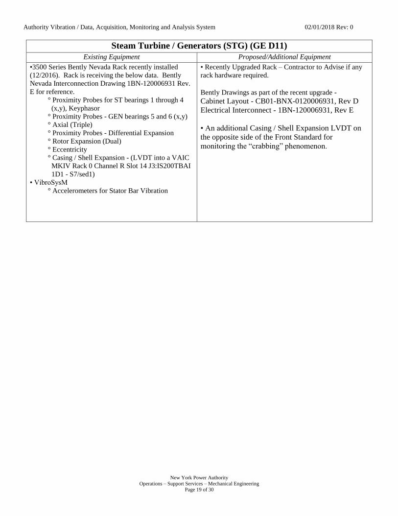
Authority Vibration / Data, Acquisition, Monitoring and Analysis System 02/01/2018 Rev: 0
New York Power Authority
Operations – Support Services – Mechanical Engineering Page 19 of 30
Steam Turbine / Generators (STG) (GE D11)
Existing Equipment Proposed/Additional Equipment
•3500 Series Bently Nevada Rack recently installed
(12/2016). Rack is receiving the below data. Bently
Nevada Interconnection Drawing 1BN-120006931 Rev.
E for reference.
° Proximity Probes for ST bearings 1 through 4
. (x,y), Keyphasor
° Proximity Probes - GEN bearings 5 and 6 (x,y)
° Axial (Triple)
° Proximity Probes - Differential Expansion
° Rotor Expansion (Dual)
° Eccentricity
° Casing / Shell Expansion - (LVDT into a VAIC
. MKIV Rack 0 Channel R Slot 14 J3:IS200TBAI
. 1D1 - S7/sed1)
• VibroSysM
° Accelerometers for Stator Bar Vibration
• Recently Upgraded Rack – Contractor to Advise if any
rack hardware required.
Bently Drawings as part of the recent upgrade -
Cabinet Layout - CB01-BNX-0120006931, Rev D
Electrical Interconnect - 1BN-120006931, Rev E
• An additional Casing / Shell Expansion LVDT on
the opposite side of the Front Standard for
monitoring the “crabbing” phenomenon.

Authority Vibration / Data, Acquisition, Monitoring and Analysis System 02/01/2018 Rev: 0
New York Power Authority
Operations – Support Services – Mechanical Engineering Page 20 of 30
Small Clean Power Plants (SCPP) and Brentwood
All SCPP Sites
Data Acquisition
Existing Equipment Proposed/Additional Equipment
N/A • System 1 Server to collect all applicable SCPP data.
• Location of Server TBD, most probable location the
500MW Electronics Room or NAES Control Room
• Brentwood to be linked to Flynn and possibly the
SCPP’s for LM6000 Fleet consistency.
• System 1 Evolution (EVO) static and dynamic data
shall interact with Enterprise Impact unencumbered.
Hell Gate (HG) & Harlem River (HR)
Combustion Turbine / Generator (CTG) (GE LM6000PC)
Existing Equipment Proposed/Additional Equipment
• 3500 Series Rack (System 1 compatible – recent 2014
upgraded from 3300 Series rack equipment)
° LP & HP CT Rotor Magnetic Speed Pickups –
. (for Keyphasor)
° Turbine & Compressor Rear Frame
. Accelerometers
° Proximity probes GEN bearings DE and NDE
. (x,y) and Keyphasor (BRUSH GENERATOR).
* Generator Keyphasor installed in 2014
. during upgrade, original Brush units were
. not provided with them.
• Configuration of Data Stream to System 1 Server.
Small Clean Power Plants (SCPP)
Kent (KT), Gowanus (GW), Pouch (PT), *Brentwood (BW) - Flynn*, ((Vernon (VN)))
Combustion Turbine / Generator (CTG) (GE LM6000PC)
Existing Equipment Proposed/Additional Equipment
• 3500 Series Rack Equipment
° LP & HP CT Rotor Magnetic Speed Pickups –
. (for Keyphasor)
° Turbine & Compressor Rear Frame
. Accelerometers
° Proximity probes GEN bearings DE and NDE
. (x,y), NO KEYPHASOR
° PT and KT have General Electric Generators
° VN, GW & BW have Brush Generators
• Existing devices shall remain with the addition of :
° Necessary upgraded 3500 Series cards to be
. utilized with System 1.
* The already purchased, however not
. installed, TDI Communication cards
. should bring the 3500 racks at GW, BW,
. KT & PT to System 1 ready status.
° Keyphasors
* GW, BW, KT & PT have the hardware
. required to install Keyphasors.
• VN, no equipment purchased, Authority to decide if
desired.
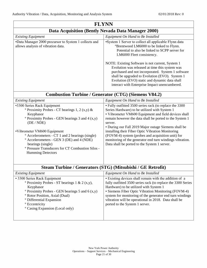
Authority Vibration / Data, Acquisition, Monitoring and Analysis System 02/01/2018 Rev: 0
New York Power Authority
Operations – Support Services – Mechanical Engineering Page 21 of 30
FLYNN
Data Acquisition (Bently Nevada Data Manager 2000)
Existing Equipment Equipment On Hand to Be Installed
•Data Manager 2000 precursor to System 1 collects and
allows analysis of vibration data.
•System 1 Server to collect all applicable Flynn data
°Brentwood LM6000 to be linked to Flynn.
. Potential to also be linked to SCPP server for
. LM6000 Fleet consistency.
NOTE: Existing Software is not current, System 1
Evolution was released at time this system was
purchased and not incorporated. System 1 software
shall be upgraded to Evolution (EVO). System 1
Evolution (EVO) static and dynamic data shall
interact with Enterprise Impact unencumbered.
Combustion Turbine / Generator (CTG) (Siemens V84.2)
Existing Equipment Equipment On Hand to Be Installed
•3300 Series Rack Equipment
° Proximity Probes - CT bearings 1, 2 (x,y) &
. Keyphasor
° Proximity Probes - GEN bearings 3 and 4 (x,y)
. (DE / NDE)
•Vibrometer VM600 Equipment
° Accelerometers - CT 1 and 2 bearings (single)
° Accelerometers - GEN 3 (DE) and 4 (NDE)
. bearings (single)
° Pressure Transducers for CT Combustion Silos -
. Humming Detectors
• Fully outfitted 3500 series rack (to replace the 3300
Series Hardware) to be utilized with System 1
• Vibrometer VM600 Equipment and field devices shall
remain however the data shall be ported to the System 1
server.
• During our Fall 2019 Major outage Siemens shall be
installing their Fiber Optic Vibration Monitoring
(FOVM-4) system (probes and acquisition unit) for
monitoring of the generator end turn windings vibration.
Data shall be ported to the System 1 server.
Steam Turbine / Generators (STG) (Mitsubishi / GE Retrofit)
Existing Equipment Equipment On Hand to Be Installed
• 3300 Series Rack Equipment
° Proximity Probes - ST bearings 1 & 2 (x,y),
. Keyphasor
° Proximity Probes - GEN bearings 5 and 6 (x,y)
° Rotor Position, Axial (Dual)
° Differential Expansion
° Eccentricity
° Casing Expansion (Local only)
• Existing devices shall remain with the addition of a
fully outfitted 3500 series rack (to replace the 3300 Series
Hardware) to be utilized with System 1
• Siemens Fiber Optic Vibration Monitoring (FOVM-4)
system for monitoring of the generator end turn windings
vibration will be operational in 2018. Data shall be
ported to the System 1 server.

Authority Vibration / Data, Acquisition, Monitoring and Analysis System 02/01/2018 Rev: 0
New York Power Authority
Operations – Support Services – Mechanical Engineering Page 22 of 30
APPENDIX II
Existing and Proposed Equipment BG
Blenheim Gilboa (BG)
Data Acquisition
Existing Equipment Proposed/Additional Equipment
System 1 Server collecting various turbine / generator
data.
• Existing server hardware and some of the software is at
its stage of obsolescence. A new server with the latest
System 1 evolution software suite to be instituted. The
software shall be able to transfer static data to the
existing PI system through an OPC server / client
relationship. System 1 Evolution (EVO) static and
dynamic data shall interact with Enterprise Impact
unencumbered.
Turbine / Generator (Pumping & Generating) (Hitachi / GE)
Existing Equipment Proposed/Additional Equipment
• 3500 Series Rack – Units 1 - 4
° Proximity Probes (Hydro 46M Card)
•Turbine Guide Shaft Vibration (x,y)
•Generator Upper Guide Shaft Vibration (x,y)
•Generator Lower Guide Shaft Vibration (x,y)
° Proximity Probes (Keyphasor 25 Card)
• Turbine Shaft Speed
° Accelerometer (Hydro 46M Card)
• Turbine Guide Shaft Seismic (x,y)
•Generator Upper Guide Shaft Seismic (x,y)
•Generator Lower Guide Shaft Seismic (x,y)
•Servo Ring Seismic (x,y (N/S/E))
•Draft Tube Seismic (x)
•Stator Frame Tangential Seismic (x)
•Stator Frame Radial Seismic (y)
° Air Gas Probes (Hydro 46M Card)
• N/S/E/W Air Gap Upper
• N/S/E/W Air Gap Lower
• All Existing devices shall remain. • Configuration of Data Stream to System 1 Server.
• Potential Non-Vibration Sensor Added to 3500 Rack.
Applicable card selection through consult with BN.
° Spherical Valve Servo Motor Oil Pressure
° Spherical Valve Differential Water Pressure
° Wicket Gate Servo Motor Oil Pressure
° Runner Band Drain Valve Oil Pressure
° Runner Band Drain Valve Water Pressure
° Bearing Oil Temperature
° Wicket Gate Stem Leakage Flow
° Head Cover Pressure
• If the amount of Non-Vibration Sensors will over fill
the 3500 Rack all the new sensors shall be landed
into another, yet to be determined, data acquisition
unit, NOT ANOTHER 3500 RACK. National
Instruments has some options which may work with
our application.

Authority Vibration / Data, Acquisition, Monitoring and Analysis System 02/01/2018 Rev: 0
New York Power Authority
Operations – Support Services – Mechanical Engineering Page 23 of 30
APPENDIX III
Existing and Proposed Equipment STL
St. Lawrence (STL)
Data Acquisition
Existing Equipment Proposed/Additional Equipment
Two System 1 Servers collecting various turbine /
generator data. *Two servers were required due to older
version of the system only allowing a maximum of 12
units of data to be handled.*
• Existing server hardware and some of the software is at
its stage of obsolescence. One new server with the latest
System 1 evolution software suite to be instituted. The
software shall be able to transfer static data to the
existing PI system through an OPC server / client
relationship. System 1 Evolution (EVO) static and
dynamic data shall interact with Enterprise Impact
unencumbered.
*Newer Versions of System 1 will allow all 16 units to be
handled by one server. *
Turbine / Generator
Existing Equipment Proposed/Additional Equipment
• 3500 Series Rack – Units 17–32 (1–16 Canadian Side)
° Proximity Probes (Hydro 46M Card)
•Generator Thrust (z)
° Proximity Probes (Hydro 46M Card)
•Turbine Guide Shaft Vibration (x,y)
•Generator Guide Shaft Vibration (x,y)
° Proximity Probes (Keyphasor 25 Card)
• Turbine Shaft Speed
° Proximity Probes (Tachometer 50 Card)
• Turbine Shaft Speed
° Accelerometer (Hydro 46M Card)
•Head Cover Seismic (x)
•Stator Frame Tangential Seismic (x)
•Stator Frame Radial Seismic (y)
° Air Gap Probes (Hydro 46M Card)
• N/S/E/W Air Gap
° Temperature RTD (Temp 61 Cards)
• Top / Mid / Bottom Core Position 1
• Top / Mid / Bottom Core Position 2
• Top / Mid / Bottom Core Position 3
• Top / Mid / Bottom Core Position 4
• Top / Mid / Bottom Core Position 5
• Top / Mid / Bottom Core Position 6
• Top / Mid / Bottom Core Position 7
• Top / Mid / Bottom Core Position 8
• 3500 Series Rack Cabinet Drawing 179329 Rev A,
12/27/2007, 12 sheets. This rev does not have any of the
signals laid out per channel.
• All Existing devices shall remain. • Configuration of Data Stream to System 1 Server.
• Potential Non-Vibration Sensor Added to 3500 Rack.
Applicable card selection through consult with BN.
° Wicket Gate Servo Motor Oil Pressure
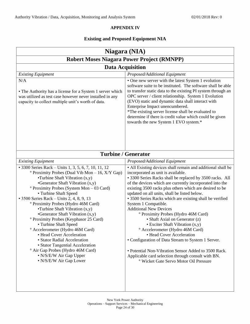
Authority Vibration / Data, Acquisition, Monitoring and Analysis System 02/01/2018 Rev: 0
New York Power Authority
Operations – Support Services – Mechanical Engineering Page 24 of 30
APPENDIX IV
Existing and Proposed Equipment NIA
Niagara (NIA)
Robert Moses Niagara Power Project (RMNPP)
Data Acquisition
Existing Equipment Proposed/Additional Equipment
N/A
• The Authority has a license for a System 1 server which
was utilized as test case however never installed in any
capacity to collect multiple unit’s worth of data.
• One new server with the latest System 1 evolution
software suite to be instituted. The software shall be able
to transfer static data to the existing PI system through an
OPC server / client relationship. System 1 Evolution
(EVO) static and dynamic data shall interact with
Enterprise Impact unencumbered.
*The existing server license shall be evaluated to
determine if there is credit value which could be given
towards the new System 1 EVO system.*
Turbine / Generator
Existing Equipment Proposed/Additional Equipment
• 3300 Series Rack – Units 1, 3, 5, 6, 7, 10, 11, 12
° Proximity Probes (Dual Vib Mon – 16, X/Y Gap)
•Turbine Shaft Vibration (x,y)
•Generator Shaft Vibration (x,y)
° Proximity Probes (System Mon – 03 Card)
• Turbine Shaft Speed • 3500 Series Rack – Units 2, 4, 8, 9, 13
° Proximity Probes (Hydro 46M Card)
•Turbine Shaft Vibration (x,y)
•Generator Shaft Vibration (x,y)
° Proximity Probes (Keyphasor 25 Card)
• Turbine Shaft Speed
° Accelerometer (Hydro 46M Card)
• Head Cover Acceleration
• Stator Radial Acceleration
• Stator Tangential Acceleration
° Air Gap Probes (Hydro 46M Card)
• N/S/E/W Air Gap Upper
• N/S/E/W Air Gap Lower
• All Existing devices shall remain and additional shall be
incorporated as unit is available.
• 3300 Series Racks shall be replaced by 3500 racks. All
of the devices which are currently incorporated into the
existing 3500 racks plus others which are desired to be
updated on all units, shall be listed below.
• 3500 Series Racks which are existing shall be verified
System 1 Compatible.
Additional New Devices
° Proximity Probes (Hydro 46M Card)
• Shaft Axial on Generator (z)
• Exciter Shaft Vibration (x,y)
° Accelerometer (Hydro 46M Card)
• Head Cover Acceleration
• Configuration of Data Stream to System 1 Server.
• Potential Non-Vibration Sensor Added to 3500 Rack.
Applicable card selection through consult with BN.
° Wicket Gate Servo Motor Oil Pressure

Authority Vibration / Data, Acquisition, Monitoring and Analysis System 02/01/2018 Rev: 0
New York Power Authority
Operations – Support Services – Mechanical Engineering Page 25 of 30
Lewiston Pump Generating Plant (LPGP)
Data Acquisition
Existing Equipment Proposed/Additional Equipment
N/A • One new server with the latest System 1 evolution
software suite to be instituted. The software shall be able
to transfer static data to the existing PI system through an
OPC server / client relationship. System 1 Evolution
(EVO) static and dynamic data shall interact with
Enterprise Impact unencumbered.
Turbine / Generator (Pumping & Generating)
Existing Equipment Proposed/Additional Equipment
• No Vibration Rack / Equipment – Units 1, 3, 4, 8, 9, 10
• 3500 Series Rack – Units 2, 4, 8, 9, 13
° Proximity Probes (Hydro 46M Card)
•Turbine Shaft Vibration (x,y)
•Generator Shaft Vibration (x,y)
° Proximity Probes (Keyphasor 25 Card)
• Turbine Shaft Speed
° Air Gap Probes (Hydro 46M Card)
• N/S/E/W Air Gap Upper
• N/S/E/W Air Gap Lower
• Units with No Vibration Equipment are being upgraded
with 3500 Series Racks (System 1 compliance needs
verification) as well as a vibration sensor suite. These
upgrades are occurring as part of a long term Life
Extension Modernization Program (LEM).
• 3500 Series Racks which are existing shall be verified
System 1 Compatible.
Additional New Devices
° Proximity Probes (Hydro 46M Card)
• Shaft Axial on Generator (z)
• Exciter Shaft Vibration (x,y)
° Accelerometer (Hydro 46M Card)
• Head Cover Acceleration
• Configuration of Data Stream to System 1 Server.
• Potential Non-Vibration Sensor Added to 3500 Rack.
Applicable card selection through consult with BN.
° Wicket Gate Servo Motor Oil Pressure
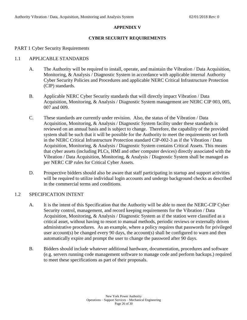
Authority Vibration / Data, Acquisition, Monitoring and Analysis System 02/01/2018 Rev: 0
New York Power Authority
Operations – Support Services – Mechanical Engineering Page 26 of 30
APPENDIX V
CYBER SECURITY REQUIREMENTS
PART 1 Cyber Security Requirements
1.1 APPLICABLE STANDARDS
A. The Authority will be required to install, operate, and maintain the Vibration / Data Acquisition,
Monitoring, & Analysis / Diagnostic System in accordance with applicable internal Authority
Cyber Security Policies and Procedures and applicable NERC Critical Infrastructure Protection
(CIP) standards.
B. Applicable NERC Cyber Security standards that will directly impact Vibration / Data
Acquisition, Monitoring, & Analysis / Diagnostic System management are NERC CIP 003, 005,
007 and 009.
C. These standards are currently under revision. Also, the status of the Vibration / Data
Acquisition, Monitoring, & Analysis / Diagnostic System facility under these standards is
reviewed on an annual basis and is subject to change. Therefore, the capability of the provided
system shall be such that it will be possible for the Authority to meet the requirements set forth
in the NERC Critical Infrastructure Protection standard CIP-002-3 as if the Vibration / Data
Acquisition, Monitoring, & Analysis / Diagnostic System contains Critical Assets. This means
that cyber assets (including PLCs, HMI and other computer devices) directly associated with the
Vibration / Data Acquisition, Monitoring, & Analysis / Diagnostic System shall be managed as
per NERC CIP rules for Critical Cyber Assets.
D. Prospective bidders should also be aware that staff participating in startup and support activities
will be required to utilize individual login accounts and undergo background checks as described
in the commercial terms and conditions.
1.2 SPECIFICATION INTENT
A. It is the intent of this Specification that the Authority will be able to meet the NERC-CIP Cyber
Security control, management, and record keeping requirements for the Vibration / Data
Acquisition, Monitoring, & Analysis / Diagnostic System as if the station were classified as a
critical asset, without having to resort to manual methods, periodic reviews or externally driven
administrative procedures. As an example, where a policy requires that passwords for privileged
user account(s) be changed every 90 days, the account(s) shall be configured to warn and then
automatically expire and prompt the user to change the password after 90 days.
B. Bidders should include whatever additional hardware, documentation, procedures and software
(e.g. servers running code management software to manage code and perform backups.) required
to meet these specifications as part of their proposals.

Authority Vibration / Data, Acquisition, Monitoring and Analysis System 02/01/2018 Rev: 0
New York Power Authority
Operations – Support Services – Mechanical Engineering Page 27 of 30
1.3 SYSTEM SECURITY ARCHITECTURE
A. CYBER ASSET HARDENING
1. ACCOUNTS AND PRIVILEGES
a. The VIBRATION / DATA ACQUISITION, MONITORING, & ANALYSIS /
DIAGNOSTIC SYSTEM computers must have the capability to manage user
accounts, manage user rights, and log access to the account and user rights
database. User accounts must be configured for minimum rights for the
respective user to accomplish their tasks. The root/Administrator accounts shall
not be enabled for remote login. None of the delivered platforms may be
delivered with standard default passwords, and all interactive accounts must
utilize passwords.
b. As a minimum it is expected that the following levels of user rights will be
provided for:
1) Unprivileged User: This account does not provide any write capabilities
except to the users home directory. It is expected that the main use for this
account would be for automatic startup/login of operator consoles. (Note
that in this case access to VIBRATION / DATA ACQUISITION,
MONITORING, & ANALYSIS / DIAGNOSTIC SYSTEM functionality
is controlled via the HMI application.) It shall not be possible to elevate
the rights for this user.
2) Privileged Support User: This will allow write access to the main
VIBRATION / DATA ACQUISITION, MONITORING, & ANALYSIS /
DIAGNOSTIC SYSTEM computer system directories for the purpose of
changing data files, replacing executable files, etc. Access to critical O/S
files such as password files, network files and configuration files (e.g.
SSH configuration files) will not be allowed. It shall be possible to
elevate the privileges of this user.
3) Privileged Admin User: This shall allow full access to the system files.
4) Application/System: Account(s) that the VIBRATION / DATA
ACQUISITION, MONITORING, & ANALYSIS / DIAGNOSTIC
SYSTEM HMI software, as well as PLC support software, run under shall
be provided with the minimum privileges required for operation, and shall
not be enabled for interactive access.
Authority Vibration / Data, Acquisition, Monitoring and Analysis System 02/01/2018 Rev: 0
New York Power Authority
Operations – Support Services – Mechanical Engineering Page 28 of 30
2. Minimum O/S Installations
a. It is expected that the Contractor will perform a detailed analysis of his software
to determine exactly what programs, libraries, and services are utilized by his
programs and any third party programs provided as part of this project. This list
will be specific to each node (e.g. Software Support Node) or type of node (e.g.
VIBRATION / DATA ACQUISITION, MONITORING, & ANALYSIS /
DIAGNOSTIC SYSTEM HMI).
b. That information will be compared against the O/S install on each node and a list
of programs, libraries and services to be removed/disabled for each node or type
of node will be generated. The software to be removed and/or disabled shall
include, but is not limited to:
1) Games
2) Device drivers for network devices not delivered
3) Messaging services (e.g., MSN, AOL IM, etc.)
4) Servers or clients for unused Internet services
5) Software compilers in all user workstations and servers except for
development workstations and servers.
6) Software compilers for languages that are not used in the control system
7) Unused networking and communications protocols
8) Unused administrative utilities, diagnostics, network management, and
system management functions
9) Unused document processing utilities (Microsoft Word, Excel,
PowerPoint, Adobe Acrobat, OpenOffice, etc.).
c. System Integration is not considered complete until this hardening is done. The
Authority shall perform an inspection and perform scans to verify that the scans
match the hardening documentation.
Authority Vibration / Data, Acquisition, Monitoring and Analysis System 02/01/2018 Rev: 0
New York Power Authority
Operations – Support Services – Mechanical Engineering Page 29 of 30
3. Ports and Services
a. The vendor must deliver each computer capable of supporting a network
communication protocol with minimal activation of network services or ports in
order to properly operate in VIBRATION / DATA ACQUISITION,
MONITORING, & ANALYSIS / DIAGNOSTIC SYSTEM mode. The vendor
will list the required network ports and the associated VIBRATION / DATA
ACQUISITION, MONITORING, & ANALYSIS / DIAGNOSTIC SYSTEM
applications that require them. The vendor will be required to update this list
throughout the warranty period when any modifications or upgrades to the
VIBRATION / DATA ACQUISITION, MONITORING, & ANALYSIS /
DIAGNOSTIC SYSTEM are implemented.
4. Malware Detection
a. Each node will be provided with appropriate software to guard against the
inadvertent or malicious installation or running of unauthorized software.
Examples of appropriate software would include A/V software for workstations
and servers, and white-list applications in some server environments.
B. SYSTEM SEGREGATION
1. The core VIBRATION / DATA ACQUISITION, MONITORING, & ANALYSIS /
DIAGNOSTIC SYSTEM assets that provide the main functionality shall be isolated via
firewall(s) from all external connections during development and system integration.
This is meant to limit exposure to potential cyber threats. The vendor shall also provide
the DMZ networks required to support configuration and testing. The Authority provided
firewalls shall be provided to link the vendor supplied system to the Authority’s
resources. Those firewalls shall be configured to provide the vendor provided DMZ
networks as per vendor documentation. The Authority’s current firewalls are Cisco
ASA5500 Series.
2. Support hardware such as development server, database management node, external
support gateway and other equipment shall be segregated onto a DMZ network. The
Authority shall provide network hardware (router or firewall) which shall be configured
to allow the minimum ports and services between individual asset nodes as per
Contractor provided security documentation.
3. Additional isolated network DMZ segments that shall be provided include an external
access DMZ that will include historian and reporting nodes. Again, the Authority will
configure the network hardware for minimum traffic as per vendor documentation.
Authority Vibration / Data, Acquisition, Monitoring and Analysis System 02/01/2018 Rev: 0
New York Power Authority
Operations – Support Services – Mechanical Engineering Page 30 of 30
C. SECURITY SUPPORT INFRASTRUCTURE
1. While the Authority shall be providing and configuring all network/access control
hardware associated with the VIBRATION / DATA ACQUISITION, MONITORING, &
ANALYSIS / DIAGNOSTIC SYSTEM Electronic Security Perimeter (ESP), the
Contractor is required to provide all other hardware and systems to support all other
security activities including logging, backup, recovery, password management,
patch/update management and periodic security assessments. It is expected that this
equipment shall be installed on a DMZ network segment, not on the VIBRATION /
DATA ACQUISITION, MONITORING, & ANALYSIS / DIAGNOSTIC SYSTEM
LAN.
2. This includes the following equipment:
a. Backup Server: A server with a large (suitable for storing multiple copies of all
VIBRATION / DATA ACQUISITION, MONITORING, & ANALYSIS /
DIAGNOSTIC SYSTEM node backups) RAID disk array shall be provided with
backup software that will allow the periodic complete backups over the
VIBRATION / DATA ACQUISITION, MONITORING, & ANALYSIS /
DIAGNOSTIC SYSTEM LAN and incremental snapshot backups of the online
system nodes (e.g. every midnight). This system shall also provide for automatic
restoration and rollback.
b. Password Management: A facility is to be provided to make password changes on
all the production nodes at once.
c. Centralized A/V (Anti-Virus) Update/Management: Similar to the O/S update
server, a centralized node for collecting A/V results and updating signatures shall
be provided. Virus scan positive results should be logged as security events.
d. Security Logging: The vendor shall configure each critical system node and the
network switches for the main VIBRATION / DATA ACQUISITION,
MONITORING, & ANALYSIS / DIAGNOSTIC SYSTEM LAN to generate, as
system events, login/logout, password change and other security related
information each nodes OS logging facility (e.g. syslog) and forward that
information to a central Authority provided logging/monitoring facility.
Depending on each switch or system node this may require the purchase of
additional software (e.g. agents to install on remote nodes). It is also required that
the Contractor provide a single node, to be installed on the DMZ that collects all
the event information, stores it for a minimum of 100 days in addition to
forwarding it on to the Authority’s Security Operations Center (SOC).

40
ATTACHMENT P – ASSET MANAGEMENT REQUIRED FIELDS
Related Documents