Jurnal Mekanikal Dec 2017, Vol 40, 37-46 37 Sensivity Analysis of Tensioned–Leg Mooring Line Under Variations of Water Depth Tengku Luqman Hakim Tengku Halim 1 , Siow Chee-Loon 1,2 , Arifah Ali 1 , Lee Kee- Quen 3 and Kang Hooi-Siang 1,2,* 1 Faculty of Mechanical Engineering 2 Marine Technology Centre Universiti Teknologi Malaysia 81310 UTM Johor Bahru Johor, Malaysia 3 Malaysia-Japan International Institute of Technology Universiti Teknologi Malaysia Jalan Sultan Yahya Petra 54100 Kuala Lumpur Malaysia ABSTRACT Floating structures can provide an alternative solution to the developments in the highly populous urban area. The agile mobility and flexible of deployment for a floating solution are considered more effective in the nearshore areas where the conventional piling for construction of a fixed offshore structure is prohibited due to the protection of the diversity of marine lives. However, the sensitivity of its mooring system subjects to variations of water depth is of research interest. This paper discusses a numerical study of a cylindrical floating structure with its single mooring line connected to the seabed in a tensioned condition. The response of floater heave motion and in-line tension of mooring line for water depths of 300 m, 200 m, 100 m and 50 m were investigated. The mooring line is a steel wire rope subjects to the wave-induced motions of the floater. A numerical model of the floater was analyzed in hydrodynamic software, Ansys-Aqwa, under predefined environmental loading conditions to determine the in-line tension of the mooring system and the behaviors of the floater in a time domain. The results indicated that the floater oscillated at a vertical stiffness which magnitude is inversely proportional to the length of mooring lines. The ratio of the maximum in-line tension for mooring line in the 50 m water depth can be up to 1.52 to the original one in the 300 m water depth if the mooring line with an identical diameter is truncated. This study is significant to provide a reference for the mobility and redeployment of floating structures in locations with different water depth. Keywords: Mooring line, tensioned-leg, water depth, floating structure 1.0 INTRODUCTION A large floating structure has huge potential in the coastal areas of the island regions as an alternative hub to support the human’s activities. * Corresponding author : [email protected]

Welcome message from author
This document is posted to help you gain knowledge. Please leave a comment to let me know what you think about it! Share it to your friends and learn new things together.
Transcript

Jurnal Mekanikal
Dec 2017, Vol 40, 37-46
37
Sensivity Analysis of Tensioned–Leg Mooring Line Under
Variations of Water Depth
Tengku Luqman Hakim Tengku Halim
1, Siow Chee-Loon
1,2, Arifah Ali
1, Lee Kee-
Quen3 and Kang Hooi-Siang
1,2,*
1Faculty of Mechanical Engineering
2Marine Technology Centre
Universiti Teknologi Malaysia
81310 UTM Johor Bahru
Johor, Malaysia
3Malaysia-Japan International Institute of Technology
Universiti Teknologi Malaysia
Jalan Sultan Yahya Petra
54100 Kuala Lumpur
Malaysia
ABSTRACT
Floating structures can provide an alternative solution to the developments in the
highly populous urban area. The agile mobility and flexible of deployment for a
floating solution are considered more effective in the nearshore areas where the
conventional piling for construction of a fixed offshore structure is prohibited due to
the protection of the diversity of marine lives. However, the sensitivity of its mooring
system subjects to variations of water depth is of research interest. This paper
discusses a numerical study of a cylindrical floating structure with its single mooring
line connected to the seabed in a tensioned condition. The response of floater heave
motion and in-line tension of mooring line for water depths of 300 m, 200 m, 100 m
and 50 m were investigated. The mooring line is a steel wire rope subjects to the
wave-induced motions of the floater. A numerical model of the floater was analyzed
in hydrodynamic software, Ansys-Aqwa, under predefined environmental loading
conditions to determine the in-line tension of the mooring system and the behaviors of
the floater in a time domain. The results indicated that the floater oscillated at a
vertical stiffness which magnitude is inversely proportional to the length of mooring
lines. The ratio of the maximum in-line tension for mooring line in the 50 m water
depth can be up to 1.52 to the original one in the 300 m water depth if the mooring
line with an identical diameter is truncated. This study is significant to provide a
reference for the mobility and redeployment of floating structures in locations with
different water depth.
Keywords: Mooring line, tensioned-leg, water depth, floating structure
1.0 INTRODUCTION
A large floating structure has huge potential in the coastal areas of the island regions
as an alternative hub to support the human’s activities.
* Corresponding author : [email protected]
Jurnal Mekanikal Dec 2017
38
One of the major attractions to use floating solution is this is free from the
competition of land acquisition, which could be a very cost-effective solution
especially for the well-developed area where the rental price of land is relatively high.
In the coastal regions, the water depth is relatively shallow. In the island regions of
South East Asia, a majority of the coastal areas was surrounded by the water depth
less than 100 m. A conventional type of fixed structure, such as jacket platform, is
dominated in the coastline of this region. However, offshore piling for the
construction of a fixed marine structure has been facing stricter regulations in the
areas with a diversity of marine lives. The balance in between the environmental
protection and the economic development calls for an advanced solution which has
been identified as a floating solution.
The agile mobility of floating structure has enabled it to operate in multiple
locations. For instance, a floating energy terminal is deployable in different locations
according to seasonal energy consumptions. A floating fish farm, on the other hand,
can be redeployed in another location if the water pollution at its original location is
detected. The agile mobility of floating structure is highly depending on its station-
keeping system where its mooring lines play a dominant role. Mooring line is a long
cylindrical structure (LCS), which is regarded as a space curve [1, 2] in the deep-
water oil and gas industry. The mooring line is excited by a highly complex motion
which consisted of the forces and moments from wave [3, 4], current [5–7], platform
motion [8] and self-excitation [9–11]. The interactions in between the floater and its
mooring lines (and other LCS which connected the floater to the seabed) is one of the
major research interests for the floating solution. The variations of water depth can
cause the change of dynamic behaviors of the overall floater system. Yang and Xiao
[12] investigated the dynamic instability of LCS subjects to the combined effects of
parametric resonance and vortex excitation. They reported that parametric excitation
is predominant to the instability in the severer sea states, whereas the vortex shedding
contributes more to the instability when the sea state is milder. Coupled dynamics of
the mooring lines and the floating platform motion can be simulated in a coupled
time-domain dynamic-analysis program for floating bodies, mooring lines/tendons,
and risers [2, 13–15]. Wang et al. (2015) studied the coupled dynamic of LCS under
combined forcing and parametric excitation in deep water. Wang and Yang [8]
investigated the behaviors of an LCS between two floating vessels under combined
vortex excitations and they found that this combined effects can lead to huge
displacement and damage of the LCS in deep water. Coupled equations which contain
vortex-load and parametric excitation due to the floating platforms were developed in
Mathieu equation. They concluded the combined excitations are larger than that
subjected to only either vortex excitation or parametric instability [8].
This paper discusses the effects of water depth on the mooring line. The
tensioned-leg mooring line is the focal subject of study. The main objectives of this
paper are to (1) investigate numerically the heave motion of floater and (2) determine
the in-line tension of tensioned-leg mooring line with respect to different water
depths.
2.0 METHODOLOGY
2.1 Theoretical Modeling
A cylindrical floater is shown in Figure 1 where it is subjected to external excitation
loads from waves. The floater is connected at its bottom to the seabed through a
tensioned-leg mooring line. The in-line tension ΔTline can be defined as:

Jurnal Mekanikal Dec 2017
39
line e st
e d B us
T k L B W
k h d z L B W
(1)
where ke is the equivalent stiffness of the mooring line, ΔLst refers to the stretched
length of the mooring line, ΔB is the changes of buoyancy force, and W is the weight
of the floater. The geometry of mooring line stretched length ΔLst is an output of
water depth h, dynamic draught dd, vertical coordinate of floater center of gravity zB,
and an unstretched length Lus of a mooring line. The equivalent stiffness of the
mooring line is represented as:
2
4e
st
E Dk
L
(2)
where E refers to the Young modulus of the material, and D is a diameter of the
mooring line.
Figure 1: Floater at the initial condition
The net buoyancy to support the weight of floater and induced tension to the
mooring line is defined as:
2
sw BB W g r d z (3)
where ρsw refers to the density of seawater, g is the gravitational acceleration, r is
the radius of the cylindrical floater and d is the draught of a floater.
2.2 Numerical Simulation
A model of cylindrical floater was modeled in AutoCAD software package and
exported in the format of initial graphic exchange specification (IGES) to the Ansys-
c.g.
Seabed
d
h
L
H
D
MWL
zB

Jurnal Mekanikal Dec 2017
40
Aqwa package for hydrodynamic analysis. The principal dimensions of the floater are
shown in Table 1.
Table 1: Principal dimensions of floater
Height, H (m) 60
Outer diameter, D (m) 30
Draught at initial condition, d0 (m) 30
Draught at free floating condition, df (m) 15
Initial vertical coordinate of c.g., zB (m) -15
Mass, mf (kg) 1.082×10⁷
Moment of inertia (Ixx, Iyy, Izz) (kg.m2) (3.85×10⁹ , 3.85×10⁹, 1.22×10⁹)
Moment of inertia (Ixy, Ixz, Iyz) (kg.m2) (0.0, 0.0, 0.0)
Density of sea water, ρsw (kg/m3) 1025
Gravitational acceleration, g (m/s2) 9.81
Note: c.g.: center of gravity of floater
The sensitivities of floater heave motion and in-line tension of tensioned-leg
mooring line are investigated for a four different water depths h, which are 50 m, 100
m, 200 m and 300 m, respectively, as illustrated in Figure 2. The simulations are
conducted under two parametrical cases as tabulated in Table 2. In Case A, the
equivalent stiffness ke is kept as a constant. Hence, the diameter of tensioned-leg
mooring line will be reduced accordingly to the reduction of water depth. On the
other hand, in Case B, the diameter of the mooring line is constant regardless of the
water depth. The mooring line in Case B is an analogy of a truncated mooring line
when the floater is relocated to shallower water regions.
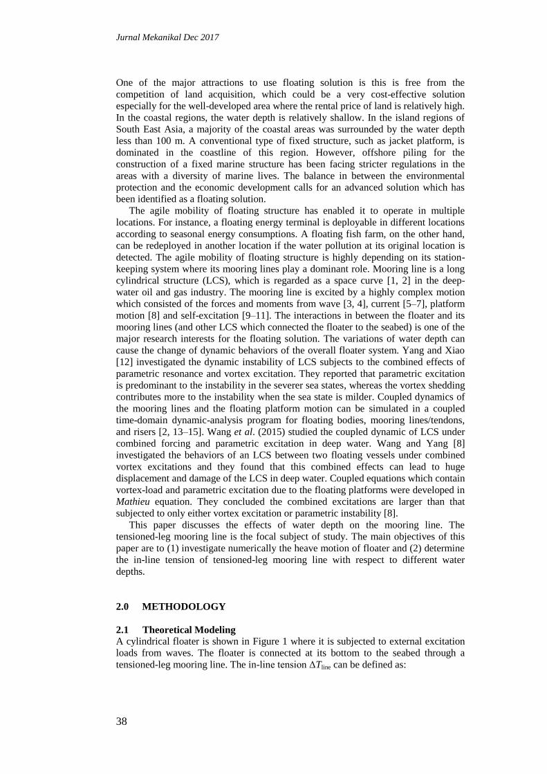
In both cases, the floater subjects to wave excitation under regular wave train form.
The wave direction comes from 0°. The wave height is 2 m and wave period is 10 s.
The time series of wave input is shown in Figure 3.
Figure 2: Setting of floater for water depth of (left to right): 50 m, 100 m, 200 m and 300 m
Table 2: Simulation cases for the sensitivity analyses
Water depth (m) 50 100 200 300
Case A: ke = constant, Dline = variable
Young modulus of line, E (GPa) 200 200 200 200
Diameter of line, Dline (m) 0.01 0.02 0.03 0.04
Equivalent stiffness, ke (kN/m) 11070 11070 11070 11070
Unstretched length of line, Lus (m) 18.26 63.91 155.22 246.52
Case B: ke = variable, Dline = constant
Young modulus of line, E (GPa) 200 200 200 200
Diameter of line, Dline (m) 0.04 0.04 0.04 0.04
Equivalent stiffness, ke (kN/m) 149445 42699 17582 11070
Unstretched length of line, Lus (m) 18.26 63.91 155.22 246.52
Jurnal Mekanikal Dec 2017
41
Figure 3: Wave input in regular form (wave amplitude = -1.0 m to 1.0 m, period = 10 s)
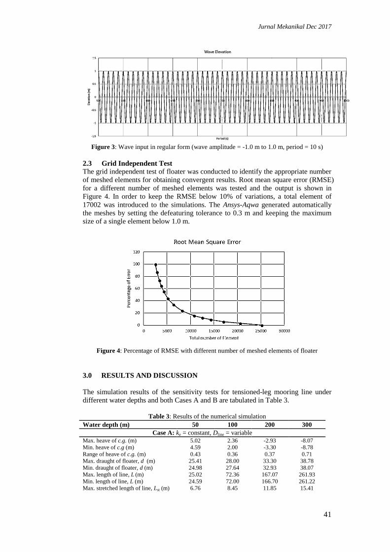
2.3 Grid Independent Test
The grid independent test of floater was conducted to identify the appropriate number
of meshed elements for obtaining convergent results. Root mean square error (RMSE)
for a different number of meshed elements was tested and the output is shown in
Figure 4. In order to keep the RMSE below 10% of variations, a total element of
17002 was introduced to the simulations. The Ansys-Aqwa generated automatically
the meshes by setting the defeaturing tolerance to 0.3 m and keeping the maximum
size of a single element below 1.0 m.
Figure 4: Percentage of RMSE with different number of meshed elements of floater
3.0 RESULTS AND DISCUSSION
The simulation results of the sensitivity tests for tensioned-leg mooring line under
different water depths and both Cases A and B are tabulated in Table 3.
Table 3: Results of the numerical simulation
Water depth (m) 50 100 200 300
Case A: ke = constant, Dline = variable
Max. heave of c.g. (m) 5.02 2.36 -2.93 -8.07
Min. heave of c.g (m) 4.59 2.00 -3.30 -8.78
Range of heave of c.g. (m) 0.43 0.36 0.37 0.71
Max. draught of floater, d (m) 25.41 28.00 33.30 38.78
Min. draught of floater, d (m) 24.98 27.64 32.93 38.07
Max. length of line, L (m) 25.02 72.36 167.07 261.93
Min. length of line, L (m) 24.59 72.00 166.70 261.22
Max. stretched length of line, Lst (m) 6.76 8.45 11.85 15.41
Jurnal Mekanikal Dec 2017
42
Min. stretched length of line, Lst (m) 6.33 8.09 11.48 14.70
Max. in-line tension, Tline (kN) 76369 93582 131222 170698
Min. in-line tension, Tline (kN) 70034 86542 127006 162758
Range of tension (kN) 6335 7040 4216 7940
Case B: ke = variable, Dline = constant
Max heave of c.g. (m) -0.97 -2.79 -5.96 -8.07
Min. heave of c.g (m) -0.99 -3.39 -6.47 -8.78
Range of heave of c.g. (m) 0.02 0.60 0.51 0.71
Max. draught of floater, d (m) 30.99 33.39 36.47 38.78
Min. draught of floater, d (m) 30.97 32.79 35.96 38.07
Max. length of line, L (m) 19.03 67.21 164.04 261.93
Min. length of line, L (m) 19.01 66.61 163.63 261.22
Max. stretched length of line, Lst (m) 0.77 3.30 8.82 15.41
Min. stretched length of line, Lst (m) 0.75 2.70 8.31 14.70
Max. in-line tension, Tline (kN) 115750 140832 155130 170698
Min. in-line tension, Tline (kN) 112365 115853 146212 162758
Range of tension (kN) 3385 24978 8918 7940
3.1 Case A: Constant Equivalent Stiffness of Mooring Line
In Case A, the equivalent stiffness of mooring line was in constant. The heave motion
of the c.g. for the floater under variations of water depth is shown in Figure 5. The
heave motion of floater was captured from the simulation time series from the 500th
second to the 1000th second where the system was assumed to be in a steady-state.
Since the excitation wave load is in regular form, the heave motion of the floater is in
generally regular for all the water depths. It is noteworthy that the position on the
vertical axis refers to the coordinates at the vertical direction in the global axes
system. The ratio for the range of heave motion of the c.g. to the corresponding water
depth are 0.86%, 0.36%, 0.19%, and 0.24% for water depths 50 m, 100 m, 200 m,
and 300 m, respectively.
Figure 5: Heave of the c.g. for floater under different water depths in Case A, where the
position refers to the coordinates at the vertical direction in global axes system
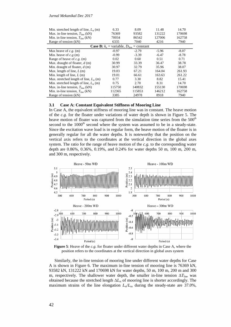
Similarly, the in-line tension of mooring line under different water depths for Case
A is shown in Figure 6. The maximum in-line tension of mooring line is 76369 kN,
93582 kN, 131222 kN and 170698 kN for water depths, 50 m, 100 m, 200 m and 300
m, respectively. The shallower water depth, the smaller in-line tension ΔTline was
obtained because the stretched length ΔLst of mooring line is shorter accordingly. The
maximum strains of the line elongation Lst/Lus during the steady-state are 37.0%,
Jurnal Mekanikal Dec 2017
43
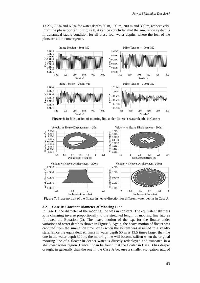
13.2%, 7.6% and 6.3% for water depths 50 m, 100 m, 200 m and 300 m, respectively.
From the phase portrait in Figure 8, it can be concluded that the simulation system is
in dynamical stable condition for all these four water depths, where the loci of the
plots are all in convergence.
Figure 6: In-line tension of mooring line under different water depths in Case A
Figure 7: Phase portrait of the floater in heave direction for different water depths in Case A
3.2 Case B: Constant Diameter of Mooring Line
In Case B, the diameter of the mooring line was in constant. The equivalent stiffness
ke is changing inverse proportionally to the stretched length of mooring line ΔLst as
followed the Equation (2). The heave motion of the c.g. for the floater under
variations of water depth is shown in Figure 8. Again, the heave motion of floater was
captured from the simulation time series when the system was assumed in a steady-
state. Since the equivalent stiffness in water depth 50 m is 13.5 times larger than the
one in the water depth 300 m, the mooring line will become stiffen when the original
mooring line of a floater in deeper water is directly redeployed and truncated in a
shallower water region. Hence, it can be found that the floater in Case B has deeper
draught in generally than the one in the Case A because a smaller elongation ΔLst of

Jurnal Mekanikal Dec 2017
44
thicker mooring line (larger πD2/4) can provide comparably sufficient restoring force
to keep the position of the floater, as suggested in Equation (1). It can be verified by
the maximum strains of the line elongation Lst/Lus during the steady-state in Case B
are only 4.2%, 5.2%, 5.7% and 6.3% for water depths 50 m, 100 m, 200 m and 300 m,
respectively.
The in-line tension of mooring line under different water depths for Case B is
shown in Figure 9. The ratio of maximum inline tension for mooring line in Case B
compared to Case A are 1.52, 1.50, 1.18 and 1.00 for water depths 50 m, 100 m, 200
m and 300 m, respectively. Therefore, a larger in-line tension is expected if the
diameter of the mooring line is maintained and the length is truncated from a deeper
to a shallower water. From the phase portrait in Figure 10, it can be concluded that
the simulation system is in dynamical stable condition for all these four water depths
in Case B, where the loci of the plots are all in convergence.
Figure 8: Heave of the c.g. for floater under different water depths in Case B, where the
position refers to the coordinates at the vertical direction in global axes system
Figure 9: In-line tension of mooring line for different water depths in Case B
Jurnal Mekanikal Dec 2017
45
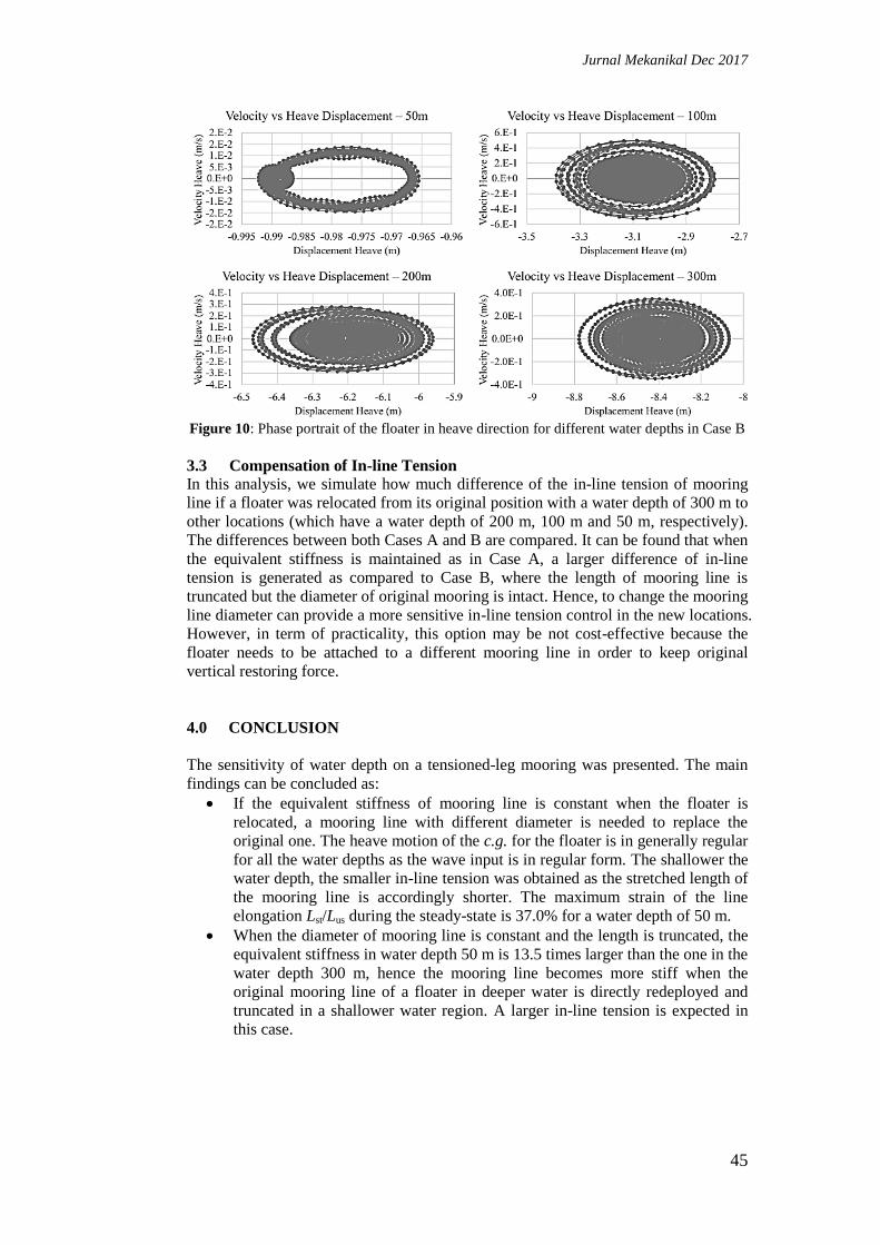
Figure 10: Phase portrait of the floater in heave direction for different water depths in Case B
3.3 Compensation of In-line Tension
In this analysis, we simulate how much difference of the in-line tension of mooring
line if a floater was relocated from its original position with a water depth of 300 m to
other locations (which have a water depth of 200 m, 100 m and 50 m, respectively).
The differences between both Cases A and B are compared. It can be found that when
the equivalent stiffness is maintained as in Case A, a larger difference of in-line
tension is generated as compared to Case B, where the length of mooring line is
truncated but the diameter of original mooring is intact. Hence, to change the mooring
line diameter can provide a more sensitive in-line tension control in the new locations.
However, in term of practicality, this option may be not cost-effective because the
floater needs to be attached to a different mooring line in order to keep original
vertical restoring force.
4.0 CONCLUSION
The sensitivity of water depth on a tensioned-leg mooring was presented. The main
findings can be concluded as:
If the equivalent stiffness of mooring line is constant when the floater is
relocated, a mooring line with different diameter is needed to replace the
original one. The heave motion of the c.g. for the floater is in generally regular
for all the water depths as the wave input is in regular form. The shallower the
water depth, the smaller in-line tension was obtained as the stretched length of
the mooring line is accordingly shorter. The maximum strain of the line
elongation Lst/Lus during the steady-state is 37.0% for a water depth of 50 m.
When the diameter of mooring line is constant and the length is truncated, the
equivalent stiffness in water depth 50 m is 13.5 times larger than the one in the
water depth 300 m, hence the mooring line becomes more stiff when the
original mooring line of a floater in deeper water is directly redeployed and
truncated in a shallower water region. A larger in-line tension is expected in
this case.

Jurnal Mekanikal Dec 2017
46
ACKNOWLEDGMENTS
The authors would like to thank the Universiti Teknologi Malaysia for supporting the
research and providing the GUP grant (Vote No.: 03G92).
REFERENCES
1. Garrett D.L., 1982. Dynamic Analysis of Slender Rods, J. Energy Resour. Technol.,
104(4): 302–306.
2. Ran Z., 2000. Coupled Dynamic Analysis of Floating Structures in Waves and
Currents, Doctoral Dissertation, Texas A&M University.
3. Xiao F. and Yang H.Z., 2014. Probabilistic Assessment of Parametric Instability of A
Top Tensioned Riser in Irregular Waves, J. Mar. Sci. Technol., 19(3): 245–256.
4. Radhakrishnan S., Datla R. and Hires, R.I., 2007. Theoretical and Experimental
Analysis of Tethered Buoy Instability in Gravity Waves, Ocean Eng., 34(2): 261–274.
5. Kang H.-S., Tang C.H.-H., Quen L.K., Steven A. and Yu X., 2016. Prediction on
Parametric Resonance of Offshore Crane Cable for Lowering Subsea Structures,
2016 IEEE International Conference on Underwater System Technology: Theory and
Applications (USYS), IEEE, Penang, Malaysia, 165–170.
6. Lucor D. and Triantafyllou M.S., 2008. Parametric Study of A Two Degree-of-
Freedom Cylinder Subject to Vortex-Induced Vibrations, J. Fluids Struct., 24(8):
1284–1293.
7. Lee K.Q., Abu A., Muhamad P., Tan L.K., Kang H.S., Tang H.H. and Toh H.T.,
2017. Prediction on the Performance of Helical Strakes Through Fluid-Structure
Interaction Simulation, Communications in Computer and Information Science,
Springer Verlag, Singapore, 538–547.
8. Wang Z. and Yang H., 2016. Parametric Instability of A Submerged Floating
Pipeline between Two Floating Structures Under Combined Vortex Excitations, Appl.
Ocean Res., 59: 265–273.
9. Yang H., Xiao F. and Xu P., 2013. Parametric Instability Prediction in A Top-
Tensioned Riser in Irregular Waves, Ocean Eng., 70: 39–50.
10. Kang H.-S., Wu Y.-T., Quen L.K., Tang C.H.-H. and Siow C.-L., 2017. Underwater
Target Tracking of Offshore Crane System in Subsea Operations, Communications in
Computer and Information Science, Springer Verlag, Singapore, 126–137.
11. Akcabay D.T. and Young Y.L., 2015. Parametric Excitations and Lock-in of Flexible
Hydrofoils in Two-Phase Flows, J. Fluids Struct., 57: 344–356.
12. Yang H. and Xiao F., 2014. Instability Analyses of a Top-Tensioned Riser Under
Combined Vortex and Multi-Frequency Parametric Excitations, Ocean Eng., 81: 12–
28.
13. Kim M.H. and Koo W.C., 2005. 2D Fully Nonlinear Numerical Wave Tanks,
Numerical Models in Fluid-Structure Interaction, WIT Press, 43–81.
14. Bae Y.H. and Kim M.-H., 2013. Influence of Failed Blade-Pitch-Control System to
FOWT by Aero-Elastic-Control-Floater-Mooring Coupled Dynamic Analysis, Ocean
Syst. Eng., 3(4): 295–307.
15. Kang H.-S., Kim M.-H., Bhat Aramanadka S.S.and Kang H.-Y., 2014. Dynamic
Response Control of Top-Tension Risers by A Variable Damping and Stiffness
System with Magneto-Rheological Damper, ASME 2014 33rd
International
Conference on Ocean, Offshore and Arctic Engineering (OMAE), Volume 6A:
Pipeline and Riser Technology, San Francisco, California, USA.
Related Documents