Sensing the environment through SpiderSense Victor Mateevitsi 1 , Brad Haggadone 2 , Jason Leigh 1 , Brian Kunzer 3 , Robert V. Kenyon 1 1 Electronic Visualization Laboratory, Department of Computer Science 2 Department of Communication 3 Neural Engineering Vision Laboratory, Department of Bioengineering University of Illinois at Chicago {vmatee2, bhagga2, spiff, bkunze1, kenyon}@uic.edu ABSTRACT Recent scientific advances allow the use of technology to expand the number of forms of energy that can be perceived by humans. Smart sensors can detect hazards that human sensors are unable to perceive, for example radiation. This fusing of technology to human’s forms of perception enables exciting new ways of perceiving the world around us. In this paper we describe the design of SpiderSense, a wearable device that projects the wearer’s near environment on the skin and allows for directional awareness of objects around him. The millions of sensory receptors that cover the skin presents opportunities for conveying alerts and messages. We discuss the challenges and considerations of designing similar wearable devices. Categories and Subject Descriptors H.5.1 [Multimedia Information Systems]: Multimedia Information Systems—Artificial, augmented, and virtual re- alities ; H.5.2 [User Interfaces]: Haptic I/O General Terms Algorithms, Design, Experimentation Keywords Environment Perception, Human Augmentics, SpiderSense, Tactile Displays, Wearable Computing 1. INTRODUCTION Humans have always had the ambition to radically change the world around them and recently our opportunity to do so has increased due to rapidly evolving technology. Feeling, tasting, smelling, seeing, hearing and communicating with the world is limited by our body’s sensors and our interpre- tation of their signals. Radiation for example, is invisible, does not have any taste or odor, emits no sound and cannot be detected by our sensors, yet should be avoided since it is extremely deadly. Permission to make digital or hard copies of all or part of this work for personal or classroom use is granted without fee provided that copies are not made or distributed for profit or commercial advantage and that copies bear this notice and the full citation on the first page. To copy otherwise, to republish, to post on servers or to redistribute to lists, requires prior specific permission and/or a fee. AH’13, March 07 - 08 2013, Stuttgart, Germany Copyright 2013 ACM 978-1-4503-1904-1/13/03 ...$15.00. In the Comic Book world, the heroes and their villains have senses and powers that enable them to feel some of those invisible threats. Daredevil for example, while blind, possesses an echolocation system that allows him to “feel” the environment instead of seeing it. Spiderman on the other hand can feel imminent dangers with a tingling sensation at the base of his skull, a power known as SpiderSense. Even though he was never trained in martial arts, SpiderSense allows him to “feel” incoming attacks, lasers, and blasts, en- abling him to react before they cause him harm. While the latest advancements in bioengineering and ge- netics are promising, we are far from engineering such bio- logic sensory systems. Electronic sensors on the other hand are capable of detecting environmental factors that humans cannot. Geiger counters for example can sense and measure radiation; infrared sensors can do the same for infrared light; ultrasonic microphones can detect frequencies that are out- side the audible range of human hearing. To communicate such information to the user, these devices primarily use a display screen (this screen can either be an embedded screen, or a remote screen, like a smart-phone’s display) and visu- alize the information using graphics, charts or quantitative methods. Our body is covered with skin that contains millions of sensory receptors. The density of the receptors varies on different parts of our body, with the fingertips having the most receptors per square centimeter [2, 6, 18]. Visually handicapped individuals have relied on these receptors as one of the primary channels for information capture, such as when reading Braille texts or navigating a space with a cane. In this paper we examine the scenario in which the mul- tiple sites all over the body, rather than just the hands, is fitted with transducers to transform information about the environment into a tactile sensations. 2. RELATED WORK Advances in bioengineering, technology miniaturization and computing are paving the ground to technologies re- ferred as Human Augmentics (HA) for expanding the capa- bilities, and characteristics of humans [7]. These technolo- gies aim to improve the quality of life by monitoring the user or environment using smart sensors, then intervening at an appropriate time to inform or persuade him to change behavior. One example of a HA technology is a tactile display. Gem- perle et al [3], defines a tactile display as a device that presents information to the wearer by stimulating the sen-

Welcome message from author
This document is posted to help you gain knowledge. Please leave a comment to let me know what you think about it! Share it to your friends and learn new things together.
Transcript

Sensing the environment through SpiderSense
Victor Mateevitsi1, Brad Haggadone2, Jason Leigh1, Brian Kunzer3, Robert V. Kenyon1
1Electronic Visualization Laboratory, Department of Computer Science2Department of Communication
3Neural Engineering Vision Laboratory, Department of BioengineeringUniversity of Illinois at Chicago
{vmatee2, bhagga2, spiff, bkunze1, kenyon}@uic.edu
ABSTRACTRecent scientific advances allow the use of technology toexpand the number of forms of energy that can be perceivedby humans. Smart sensors can detect hazards that humansensors are unable to perceive, for example radiation. Thisfusing of technology to human’s forms of perception enablesexciting new ways of perceiving the world around us. Inthis paper we describe the design of SpiderSense, a wearabledevice that projects the wearer’s near environment on theskin and allows for directional awareness of objects aroundhim. The millions of sensory receptors that cover the skinpresents opportunities for conveying alerts and messages.We discuss the challenges and considerations of designingsimilar wearable devices.
Categories and Subject DescriptorsH.5.1 [Multimedia Information Systems]: MultimediaInformation Systems—Artificial, augmented, and virtual re-alities; H.5.2 [User Interfaces]: Haptic I/O
General TermsAlgorithms, Design, Experimentation
KeywordsEnvironment Perception, Human Augmentics, SpiderSense,Tactile Displays, Wearable Computing
1. INTRODUCTIONHumans have always had the ambition to radically change
the world around them and recently our opportunity to doso has increased due to rapidly evolving technology. Feeling,tasting, smelling, seeing, hearing and communicating withthe world is limited by our body’s sensors and our interpre-tation of their signals. Radiation for example, is invisible,does not have any taste or odor, emits no sound and cannotbe detected by our sensors, yet should be avoided since it isextremely deadly.
Permission to make digital or hard copies of all or part of this work forpersonal or classroom use is granted without fee provided that copies arenot made or distributed for profit or commercial advantage and that copiesbear this notice and the full citation on the first page. To copy otherwise, torepublish, to post on servers or to redistribute to lists, requires prior specificpermission and/or a fee.AH’13, March 07 - 08 2013, Stuttgart, GermanyCopyright 2013 ACM 978-1-4503-1904-1/13/03 ...$15.00.
In the Comic Book world, the heroes and their villainshave senses and powers that enable them to feel some ofthose invisible threats. Daredevil for example, while blind,possesses an echolocation system that allows him to “feel”the environment instead of seeing it. Spiderman on the otherhand can feel imminent dangers with a tingling sensation atthe base of his skull, a power known as SpiderSense. Eventhough he was never trained in martial arts, SpiderSenseallows him to “feel” incoming attacks, lasers, and blasts, en-abling him to react before they cause him harm.
While the latest advancements in bioengineering and ge-netics are promising, we are far from engineering such bio-logic sensory systems. Electronic sensors on the other handare capable of detecting environmental factors that humanscannot. Geiger counters for example can sense and measureradiation; infrared sensors can do the same for infrared light;ultrasonic microphones can detect frequencies that are out-side the audible range of human hearing. To communicatesuch information to the user, these devices primarily use adisplay screen (this screen can either be an embedded screen,or a remote screen, like a smart-phone’s display) and visu-alize the information using graphics, charts or quantitativemethods.
Our body is covered with skin that contains millions ofsensory receptors. The density of the receptors varies ondifferent parts of our body, with the fingertips having themost receptors per square centimeter [2, 6, 18]. Visuallyhandicapped individuals have relied on these receptors asone of the primary channels for information capture, suchas when reading Braille texts or navigating a space with acane.
In this paper we examine the scenario in which the mul-tiple sites all over the body, rather than just the hands, isfitted with transducers to transform information about theenvironment into a tactile sensations.
2. RELATED WORKAdvances in bioengineering, technology miniaturization
and computing are paving the ground to technologies re-ferred as Human Augmentics (HA) for expanding the capa-bilities, and characteristics of humans [7]. These technolo-gies aim to improve the quality of life by monitoring theuser or environment using smart sensors, then interveningat an appropriate time to inform or persuade him to changebehavior.
One example of a HA technology is a tactile display. Gem-perle et al [3], defines a tactile display as a device thatpresents information to the wearer by stimulating the sen-

sors on the skin. One type of a tactile display is a tactilevest. These vests have tactors (vibrators) sewn inside thefabric at various locations and communicate information tothe wearer through vibro-tactile stimulation.
“ActiveBelt” is a wearable device that conveys directionalinformation through eight vibrators that are positioned atequal distances along the length of a belt [15]. The wearerselects a destination and the belt, like a compass, vibrates inthe direction that the user needs to travel. Distance to thetarget destination is conveyed through changes in vibrationfrequency. In the user study, even though subjects failedto recognize changes in pulse intervals when walking, theysucceeded in navigating to the target location. Van Veenand Van Erp [17] also showed that a vibro-tactile stimuluson the torso generates a percept of external direction, aneffect which is called the “tap on the shoulder” principle[16]. Multimodal motion guidance systems using differentfeedback modalities are discussed in Schonauer et al [13] andMiaw et al [9]. Cassinelli et al [1] demonstrated that a vibro-tactile headband on untrained users causes head movementin response to an unseen object approaching from behind.
3. SPIDERSENSEThe brain learns from a young age how to combine multi-
ple sensory stimuli to create an awareness of the surround-ing environment in order to accomplish various goals such asprotecting the body from harm [10]. The perception of painfor example is helpful in identifying the location of a bodilyinjury so that the individual can take appropriate action.Yet each sense has its limitations or blindspots; thereforeit is impossible to be fully aware of all aspects of ones sur-rounding environment all the time.
Drawing inspiration from Spiderman’s SpiderSense, ourHA wearable tactile display utilizes the skin’s pressure re-ceptors to communicate an awareness of the surroundingenvironment by conveying information about the wearer’sdistance from surrounding objects. While previous tactilevests communicate directional information, SpiderSense cre-ates an actual feeling of the environment by conveying dis-tance information from objects by applying pressure on theskin. SpiderSense consists of a series of Sensor Modules thatare positioned on the body of the user (Figure 1). The Sen-sor Modules scan the environment using ultrasound to alertthe user of objects that are closer than 60 feet. Worn atstrategic points over the body (see 7.1), the user can poten-tially gain a sense of all the obstacles that surround him.
4. APPLICATIONSOne can envision two categories of broad applications of
SpiderSense: compensating for a dysfunctional or missingsense (i.e. visually or hearing impaired); or supplementingthe existing senses (spatial awarness in a spacesuit or seeingbehind one’s head).
4.1 Compensating for a dysfunctional or miss-ing sense
Individuals with dysfunctional or missing senses may notperceive important cues from their surroundings. For exam-ple a person with a hearing disability or poor vision may notbe able to perceive an oncoming car while crossing a street.Research suggests that tactile displays are beneficial to vi-
Figure 1: SpiderSense on a blindfolded user
sually impaired people, by being able to detect and avoidobstacles as they walk [14].
SpiderSense steps in as an aid to supplement those senses.The pressure stimuli from the sensors could possibly allowthem to navigate faster and safer, while avoiding obstacles.
4.2 Supplementing existing sensesSpiderSense could provide another gateway for informa-
tion; if the user can learn how to use it to supplementtheir natural perception of the environment. There are threesenarios that can benefit from the use of SpiderSense.
1. One of the wearer’s senses has already identified anobject and SpiderSense helps localize the direction ofthe object. Pedestrians for example when walking usetheir vision to locate obstacles and avoid them. Byusing SpiderSense they could benefit by “feeling” ontheir body how far away, qualitatively, an obstacle is.This is especially useful if, at some point, the object ishidden from the wearer as they approach.
2. Sometimes senses are overwhelmed with informationand SpiderSense may be used to ease the load on onesense by displaying this information through anothersense. Firemen for example, when working in a haz-ardous environment have limited visibility because ofsmoke and need to be constantly aware of their sur-roundings to avoid falling debris for example. By usingSpiderSense they get spatial information of the roomfrom these Sensor Modules, therefore potentially al-lowing them to concentrate their vision on the fire haz-ards.
3. There is an incoming obstacle or threat that is notbeing detected by any of the other senses (e.g. anintruder approaching from behind).

Scaled-down versions of SpiderSense could augment thewearer as well. Imagine positioning two Sensor Moduleson a pair of slippers of an elderly person with vision dis-abilities. His vision would be supplemented with feedbackfrom the slippers, keeping him safe from obstacles that couldpotentially harm him. Bicyclists could have one sensor oneach forearm facing outwards and two sensors on their backtherefore being aware of passing or incoming traffic.
Furthermore, the sensor itself could be completely sepa-rated from the feedback mechanism but communicate viaa wireless connection. For example, for racing car drivers,a set of sensors can be mounted to the exterior of the carenabling the driver to sense other surrounding drivers whencompeting for tight turns allowing full attention of their vi-sion to the task of driving.
5. SPIDERSENSE DESIGNThe prototype wearable system (Figure 2) consists of Sen-
sor Modules that scan the environment providing pressureto the skin and are connected to and controlled througha Controller Box. The Controller Box contains the powersource, the electronics and the logic of the system. The Sen-sor Modules are connected to the Controller Box through10-pin ribbon cables but one can imagine this being replacedin the future by a wireless Bluetooth connection.
Figure 2: Positioning of Sensor Modules and Con-troller Box
5.1 Sensor ModuleThe Sensor Module (Figure 3) is the device that scans
the room for objects and provides pressure feedback to thewearer. Thirteen Sensor Modules were constructed to en-able us to experiment with a variety of placements on anindividual’s body. Each Sensor Module houses an ultrasonicdistance sensor, a rotary servomotor and a 10-pin connectorport. The distance sensor detects the closest object to thewearer inside its field of “view”; and the arm of the servo-motor rotates to provide pressure information to the wearerin accordance to distance - the shorter the distance, the
stronger the pressure. To measure distance we use the HC-SR04 Ultrasound Sensor that has a 15o “view” angle and 200inch range. To create pressure we use the T-Pro Mini ServoSG-90 9G that has a stall torque of 16.7oz/in and rotationspeed of 0.12sec/60degrees as the servo motor.
Figure 3: The Sensor Module
5.2 Controller BoxThe Controller Box (Figure 4) houses the logic of the hard-
ware which primarily consists of an Arduino Mega microcon-troller. The Controller Box controls and synchronizes theSensor Modules to avoid sonar interference and calculatesthe rotation angle for the Sensor Module arm.
Figure 4: The Controller Box
6. CONTROLLER ALGORITHMThe software architecture of the system is shown in Fig-
ure 5. The Sensor Module initially emits a pulse and listensfor a reflection. After the reflected wave has been received(i.e. there is an obstacle in the range of the SensorModule)or the Module timed out without any response (i.e. no ob-stacle in range) the Sensor Module sends the reading to the

Figure 5: Architecture of SpiderSense
Controller Box. The Controller Box converts that readinginto a rotation angle and commands the Sensor Module torotate accordingly. After the rotation has finished the nextServo Module of the vest will initiate the same process.
6.1 Environment ScanningOperating akin to radar, the ultrasonic sensors are trans-
ceivers that generate and emit a pulse of high frequencywaves and then listen for the signal’s rebound from an ob-ject. The HC-SR04 sensor emits a 12µs pulse of 40 kHzsound wave. An internal clock records the elapsed time fromthe end of the transmission to receiving the reflected wave(reflection). Ultrasonic waves travel at the speed of sound(1126ft/s) allowing us to convert the time between transmis-sion and reception to distance information:
d = t ∗ c (1)
where d is the distance in inches, t is the time in microsec-onds and c is the speed of sound (0.01351in/µs in dry air at68o F). If the wave does not encounter any object no reflec-tion is received. Therefore when listening for a response, theamount of time that the sensor awaits an answer needs to bespecified, else it may forever wait for a reflection. The HC-SR04 has a maximum range of 200 inches, thus substitutingd with 200 inches in the above equation yields the maximumtimeout threshold t of a Sensor Module to be: 14803µs.
6.2 Distance to pressure transformationThe measured distance d needs to be converted to an an-
gle for the servomotor to rotate the arm. The initial positionof the servo arm is parallel to the body surface. When anobject is very close the servo arm will apply the maximumpressure, hence a maximum allowable rotation must be de-fined. For our implementation we found that a rotation of50 degrees or more is somewhat painful to the user. How-ever, conversion of the reflection distance d to the servo arm
rotation a can be mapped in a variety of ways. This systemallows both linear and logarithmic mapping of the distanceinformation to the pressure applied to the skin. For Spider-Sense, we used linear mapping:
alinear = amin +d− dmin
dmax − dmin∗ (amax − amin) (2)
where amin is the minimum and amax is the maximumallowed angle for the arm, dmin is the minimum and dmax isthe maximum ranging distance that can be computed andd is the measured distance from the previous step. For Spi-derSense, amin = 0, amax = 50, dmin = 6, dmax= 60.
6.3 Concurrent use of ultrasonic sensorsConcurrent use of ultrasonic sensors can result in interfer-
ence between the audio signals. For example if two SensorModules operate concurrently, one Sensor Module could pickup the other one’s reflected pulse, falsely interpreting it asits own. To minimize this problem, the sensors are com-manded to initiate sensing in round-robin fashion. In theworst case scenario when there is no object in the range ofthe sensor, the controller will timeout after:
ttimeout =dmax − dmin
c(3)
If there are n Sensor Modules, and there is no object inthe ranging distance dmax of all the Sensor Modules, thenall of them will timeout. In this case, the worst case scenariofor one full cycle of the system is:
ttimeout = n ∗ dmax − dmin
c(4)
For the system we developed, n = 13 and dmax - dmin = 54,therefore one full cycle can take up to 51.96ms.
Another consideration is that since the ultrasonic sen-sors are actually microphones that operate in the ultrasonicrange, they are extremely sensitive and can pick up noisefrom other sources. More specifically, the servos when mov-ing can also create noise that the ultrasonic sensors pick upas false positives. To solve this problem, the operation ofthe Sensor Modules is halted until the servomotor rotates toits final position. The delay induced here for one servomotoris:
tdelay = (adest − acurr) ∗ tspeed (5)
Where adest is the angle that the servomotor needs torotate to, acurr is the position where the servomotor is cur-rently and tspeed is the time in milliseconds for the servo toturn by one degree.
To sum up, the total time for a system with n sensors tocycle once through all the sensors, is:
ttotal = n ∗ temit +
n∑i=1
tmi +
n∑i=1
tdi (6)
Where temit is the duration of one sensor to emit the initialsignal (12µs for the HC-SR04 sensor), tmi is the timeout forsensor i and tdi is the delay for sensor i. Therefore if all theSensor Modules do not detect any object and do not needto rotate, the total time is 52.11ms; if the user is suddenlysurrounded by objects that are touching him, the total timeis 1300.15ms.
7. TACTILE PERCEPTION
7.1 PositioningWeber’s [19, 21, 20] and Weinstein’s [22] research on pres-
sure sensitivity thresholds for different regions of the bodyhave yielded a complete acuity map of the human skin. Us-ing their findings we can compute the minimum distanceneeded between two sensors in order to be perceived as twodiscrete points. For example, the calf has a two-point dis-crimination threshold of 47mm; this means that any twopoints that touch the calf in a radius of 47mm or less willbe perceived as the same point by the subject. The sensorplacement in SpiderSense is such that the sensors are suffi-ciently apart to be perceived as separate locations, but theacuity map needs to be consulted for higher resolution con-figurations. Figure 6 shows the chosen positions for sensorplacement.
Figure 6: Two point discrimination threshold.
7.2 Reaction TimesReaction time (RT) is defined as the time between the
onset of a stimulus and the motor response for that stimulus.[4]. Studies have shown that reaction time for touch is 155ms[11]. Age does affect reaction time with decreasing RT frominfancy to the late 20s, slightly increasing until the 50s and60s and faster increasing in the 70s [23, 5, 8, 12].
Consequently the total delay from the moment an objectappears in the sensing distance of a sensor, to the motorreaction time is:
tRT = temit + ttimeout + tdelay +RT (7)
8. PRELIMINARY EXPERIMENTSFour preliminary experiments were performed on two sub-
jects to quickly assess the prototype: a hallway navigationtrial; outside walkway pedestrian recognition; navigation in-side a library (a confined space); and static surroundingthreat detection. In all the experiments the subjects wereblindfolded.
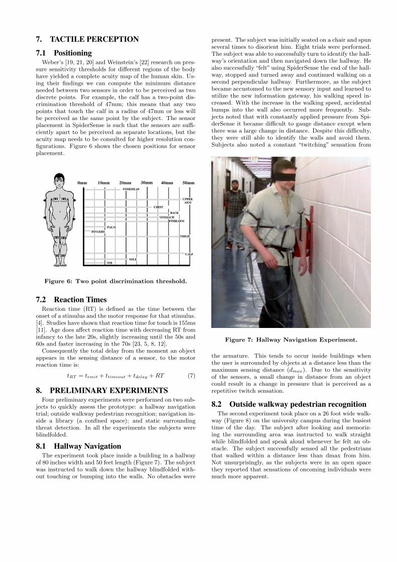
8.1 Hallway NavigationThe experiment took place inside a building in a hallway
of 80 inches width and 50 feet length (Figure 7). The subjectwas instructed to walk down the hallway blindfolded with-out touching or bumping into the walls. No obstacles were
present. The subject was initially seated on a chair and spunseveral times to disorient him. Eight trials were performed.The subject was able to successfully turn to identify the hall-way’s orientation and then navigated down the hallway. Healso successfully “felt” using SpiderSense the end of the hall-way, stopped and turned away and continued walking on asecond perpendicular hallway. Furthermore, as the subjectbecame accustomed to the new sensory input and learned toutilize the new information gateway, his walking speed in-creased. With the increase in the walking speed, accidentalbumps into the wall also occurred more frequently. Sub-jects noted that with constantly applied pressure from Spi-derSense it became difficult to gauge distance except whenthere was a large change in distance. Despite this difficulty,they were still able to identify the walls and avoid them.Subjects also noted a constant “twitching” sensation from
Figure 7: Hallway Navigation Experiment.
the armature. This tends to occur inside buildings whenthe user is surrounded by objects at a distance less than themaximum sensing distance (dmax). Due to the sensitivityof the sensors, a small change in distance from an objectcould result in a change in pressure that is perceived as arepetitive twitch sensation.
8.2 Outside walkway pedestrian recognitionThe second experiment took place on a 26 foot wide walk-
way (Figure 8) on the university campus during the busiesttime of the day. The subject after looking and memoriz-ing the surrounding area was instructed to walk straightwhile blindfolded and speak aloud whenever he felt an ob-stacle. The subject successfully sensed all the pedestriansthat walked within a distance less than dmax from him.Not unsurprisingly, as the subjects were in an open spacethey reported that sensations of oncoming individuals weremuch more apparent.

Figure 8: Outside walkway pedestrian recognition.
8.3 Navigation inside a library
Figure 9: Library Experiment.
The third experiment took place inside the university li-brary (Figure 9) and was intended to determine how wellsubjects could navigate cramped environments. Figure 10shows the library top-down organization, starting position-ing and path of the subject for one of the experiments. Thesubject was given verbal instructions describing the routehe had to follow (e.g.: On the third opening go left, thenstraight down the corridor and on the first opening go rightand then straight again). We performed ten trials and allof them were unsuccessful. The subject was unable to findthe openings and constantly bumped into the bookshelves.The subject said that he was constantly feeling pressure onhis forearms without a significant change that would have
Figure 10: Starting position of the user and one ofthe paths he followed. The blue boxes show theshelves positioning.
allowed him to gauge his distance from the bookshelves. An-other problem was that when there was an empty space ina bookshelf, the sensors would stop applying pressure hencethe subject would falsely perceive that as an opening.
8.4 Static surrounding threat detection
Figure 11: The wearer sensing one of the experi-menters approaching from behind and throwing acardboard shuriken.
In this last experiment the subjects were asked to standstill in an open space, while the experimenters approachedhim from random directions (Figure 11). The subject wasasked to throw a cardboard shuriken to the direction of theapproaching experimenter. In all the trials the subject suc-cessfully recognized when somebody was approaching and

from which direction, and was able to hit the experimenterwith the shuriken. Furthermore, when somebody was insidethe sensing distance and was walking around the subject,the subject could localize and describe the direction of themovement.
9. DISCUSSION AND FUTURE WORKThe preliminary experiments showed that the tactile dis-
play works well in outdoor environments where the numberof obstacles is low. However this is more challenging indoorswhen the sensor modules overwhelm the user with tactilefeedback.
We described how to calculate the maximum delay thatoccurs when using ultrasonic distance sensors to build atactile display. While we identified a positioning for theSensor Modules that we believe is representative for 360ocoverage, other configurations need to be evaluated as well.Psychophysical studies show that tactile distance is overes-timated on areas with high mechanoreceptor density (as op-posed to low) [20] hence a more elaborate algorithm needs totake this into consideration when providing tactile feedback.Furthermore, we experimented only with a linear mappingbetween sensor distance and tactile pressure, therefore othermappings need to be investigated. It is conceivable that dif-ferent environments will require different distance to pres-sure mappings.
Also to be determined is whether an individual, throughlong-term use of the sensors, can learn to adapt to them andbegin to recognize signature patterns such as the feeling onboth their arms whenever they walk through a door; andwhether sequences of signature patterns can be rememberedand therefore used to form a tactile map of the environment.
Lastly it would be interesting to solicit the feedback ofindividuals who are visually handicapped to compare howwell their current technologies (physical or ultrasound cane)compares to SpiderSense.
10. REFERENCES[1] A. Cassinelli, C. Reynolds, and M. Ishikawa.
Augmenting spatial awareness with haptic radar. InWearable Computers, 2006 10th IEEE InternationalSymposium on, pages 61–64. IEEE, 2006.
[2] J. C. Craig and K. B. Lyle. A comparison of tactilespatial sensitivity on the palm and fingerpad.Attention, Perception, & Psychophysics,63(2):337–347, 2001.
[3] F. Gemperle, N. Ota, and D. Siewiorek. Design of awearable tactile display. In Wearable Computers,2001. Proceedings. Fifth International Symposium on,pages 5–12. IEEE, 2001.
[4] P. Jaskowski. Simple reaction time and perception oftemporal order: Dissociations and hypotheses.Perceptual and motor skills, 82(3):707–730, 1996.
[5] S. Jevas and J. H. Yan. The effect of aging on cognitivefunction: a preliminary quantitative review. ResearchQuarterly for Exercise and Sport, 72:49, 2001.
[6] K. O. Johnson and J. R. Phillips. Tactile spatialresolution. i. two-point discrimination, gap detection,grating resolution, and letter recognition. Journal ofNeurophysiology, 46(6):1177–1192, 1981.
[7] R. V. Kenyon and J. Leigh. Human augmentics:Augmenting human evolution. In Engineering in
Medicine and Biology Society, EMBC, 2011 AnnualInternational Conference of the IEEE, pages6758–6761. IEEE, 2011.
[8] C. W. Luchies, J. Schiffman, L. G. Richards, M. R.Thompson, D. Bazuin, and A. J. DeYoung. Effects ofage, step direction, and reaction condition on theability to step quickly. The Journals of GerontologySeries A: Biological Sciences and Medical Sciences,57(4):M246–M249, 2002.
[9] D. R. Miaw and R. Raskar. Second skin: Motioncapture with actuated feedback for motor learning. InProceedings of the 27th international conferenceextended abstracts on Human factors in computingsystems, pages 4537–4542. ACM, 2009.
[10] G. Mowbray and J. Gebhard. Man’s senses asinformational channels. Technical report, DTICDocument, 1958.
[11] E. S. Robinson. Work of the integrated organism.1934.
[12] S. A. Rose, J. F. Feldman, J. J. Jankowski, and D. M.Caro. A longitudinal study of visual expectation andreaction time in the first year of life. ChildDevelopment, 73(1):47–61, 2002.
[13] C. Schonauer, K. Fukushi, A. Olwal, H. Kaufmann,and R. Raskar. Multimodal motion guidance:techniques for adaptive and dynamic feedback. InProceedings of the 14th ACM international conferenceon Multimodal interaction, pages 133–140. ACM, 2012.
[14] B.-S. Shin and C.-S. Lim. Obstacle detection andavoidance system for visually impaired people. Hapticand Audio Interaction Design, pages 78–85, 2007.
[15] K. Tsukada and M. Yasumura. Activebelt: Belt-typewearable tactile display for directional navigation.UbiComp 2004: Ubiquitous Computing, pages384–399, 2004.
[16] J. B. van Erp and H. Van Veen. A multipurposetactile vest for astronauts in the international spacestation. In Proceedings of eurohaptics, pages 405–408.Dublin, Ireland: ACM, Press, 2003.
[17] H. Van Veen and J. B. Van Erp. Providing directionalinformation with tactile torso displays. In Proceedingsof EuroHaptics, pages 471–474, 2003.
[18] R. T. Verrillo. A duplex mechanism ofmechanoreception. The skin senses, pages 139–156,1968.
[19] E. Weber. De tactu. Koehler, Leipzig, 1834.
[20] E. Weber. The sense of touch (he ross, trans.).Academic, London (Original work published 1834),1978.
[21] E. H. Weber. Der tastsinn und das gemeingefuhl[1846], hg. v. Ewald Hering, Leipzig, 1905.
[22] S. Weinstein. Intensive and extensive aspects of tactilesensitivity as a function of body part, sex andlaterality. In the First Int’l symp. on the Skin Senses,1968, 1968.
[23] A. Welford. Motor performance. Handbook of thepsychology of aging, 2:450–95, 1977.
Related Documents