SENIOR DESIGN I REPORT A2G Recon System GROUP 20 Hamza Nawaz - EE Jerrod Rout - EE Nate Jackson - EE William Isidort - EE

Welcome message from author
This document is posted to help you gain knowledge. Please leave a comment to let me know what you think about it! Share it to your friends and learn new things together.
Transcript

SENIOR DESIGN I REPORT
A2G Recon System
GROUP 20
Hamza Nawaz - EE
Jerrod Rout - EE
Nate Jackson - EE
William Isidort - EE

i
Table of Contents
1 Executive Summary ....................................................................................... 1
2 Project Description ......................................................................................... 2
2.1 Motivation ................................................................................................ 2
2.2 Goals and Objectives .............................................................................. 2
3 Project Requirements and Specifications....................................................... 4
3.1 Vehicle Requirements and Specifications ............................................... 4
3.1.1 Physical Properties ........................................................................... 4
3.1.2 Wireless Communication .................................................................. 4
3.2 Quadcopter Requirements and Specifications ........................................ 5
3.2.1 Wireless Transmission ...................................................................... 5
3.2.2 Software Requirements .................................................................... 6
3.3 Maze Requirements and Specifications .................................................. 6
4 Realistic Design Constraints .......................................................................... 8
5 Research ...................................................................................................... 12
5.1 Existing and Similar Projects ................................................................. 12
5.2 Ground Vehicle ...................................................................................... 17
5.2.1 Printed Circuit Board ....................................................................... 17
5.2.1.1 PCB Manufactures ................................................................... 18
5.2.2 Processors ...................................................................................... 18
5.2.2.1 AM3359 Sitara .......................................................................... 19
5.2.2.2 ATmega328 .............................................................................. 20
5.2.2.3 MSP430G2553 ......................................................................... 21
5.2.2.4 PIC16F690 ............................................................................... 21
5.2.3 Chassis ........................................................................................... 22
5.2.3.1 Drive Type ................................................................................ 23
5.2.3.2 Propulsion ................................................................................ 24
5.2.3.3 Commercial Chassis Considerations ........................................ 25

ii
5.2.4 Custom Chassis Designs ................................................................ 25
5.2.4.1 3D Printed Chassis ................................................................... 26
5.2.4.2 PCB Based Chassis ................................................................. 26
5.2.4.3 Chassis Design Conclusion ...................................................... 28
5.2.5 Power Supply .................................................................................. 28
5.2.5.1 Measures of Discharge Rate .................................................... 28
5.2.5.2 Battery Technologies Overview ................................................ 28
5.2.5.2.1 Lithium-Ion ........................................................................... 29
5.2.5.2.2 Nickel Cadmium ................................................................... 30
5.2.5.2.3 Nickel Metal Hydride (NiMH) ................................................ 31
5.2.5.2.4 Overview .............................................................................. 32
5.2.5.2.5 Brand and Capacity Considerations ..................................... 33
5.2.6 Circuit Protection and Voltage Regulation ...................................... 33
5.2.6.1 Low Voltage Indicator ............................................................... 34
5.2.6.2 Linear Regulator ....................................................................... 35
5.2.6.3 Switching Regulator ................................................................. 36
5.2.6.4 Zener Diode .............................................................................. 37
5.2.7 Proximity Sensors ........................................................................... 38
5.2.7.1 Ultrasonic ................................................................................. 38
5.2.7.2 Infrared ..................................................................................... 39
5.2.7.3 LIDAR ....................................................................................... 40
5.2.7.4 Distance Sensor Comparison ................................................... 40
5.2.8 Acceleration and Orientation ........................................................... 41
5.2.8.1 IMU ........................................................................................... 41
5.2.8.2 IMU Comparison ...................................................................... 42
5.2.9 Rotary Encoders ............................................................................. 43
5.2.9.1 Absolute Rotary Encoders ........................................................ 44
5.2.9.2 Incremental Rotary Encoders ................................................... 45
5.2.9.3 Rotary Encoder Comparison .................................................... 46
5.3 UAV ....................................................................................................... 47
5.3.1 Camera ........................................................................................... 47
5.3.1.1 Camera Technologies .............................................................. 47
iii
5.3.1.2 Raspberry Pi Camera Module .................................................. 49
5.3.1.3 Pixy CMUcam5 ......................................................................... 50
5.3.2 UAV Power Supply ......................................................................... 52
5.3.3 UAV Transmitter ............................................................................. 54
5.3.4 RC Transmitter Cost Comparison ................................................... 56
5.3.5 Types of UAVs ................................................................................ 58
5.3.5.1 Fixed-Wing Aircraft ................................................................... 58
5.3.5.2 Rotorcraft.................................................................................. 58
5.3.5.3 Multirotor .................................................................................. 59
5.3.5.4 UAV Conclusion ....................................................................... 61
5.4 Computer Software ............................................................................... 62
5.4.1 OpenCV .......................................................................................... 63
5.4.1.1 Perspective and Scaling ........................................................... 64
5.4.2 Binary Image Conversion ................................................................ 69
5.4.3 Maze Solving Algorithms ................................................................ 70
5.4.4 Mission Planner .............................................................................. 75
5.4.4.1 GeoFencing .............................................................................. 77
5.5 Wireless Technologies .......................................................................... 78
5.5.1 Bluetooth ......................................................................................... 78
5.5.2 Wi-Fi ............................................................................................... 79
5.5.3 ZigBee ............................................................................................ 80
5.6 Camera to Base Wireless Transmission ................................................ 81
5.6.1 Frequency Selection ....................................................................... 82
5.6.1.1 900 Hz Frequency .................................................................... 82
5.6.1.2 1.3 GHz Frequency .................................................................. 82
5.6.1.3 2.4 GHz Frequency .................................................................. 82
5.6.1.4 5.8 GHz Frequency .................................................................. 83
5.6.2 FCC Licensing ................................................................................ 83
5.6.3 Video Transmitters .......................................................................... 83
5.6.3.1 Boscam TS351 Transmitter ...................................................... 83
5.6.3.2 Boscam TS352 Transmitter ...................................................... 84
5.6.3.3 Boscam TS350 Transmitter ...................................................... 85
iv
5.6.3.4 Overview .................................................................................. 86
5.6.4 Video Receivers .............................................................................. 87
5.6.4.1 Boscam RC305 Receiver ......................................................... 87
5.6.4.2 Aomway DVR 5.8GHz AV Receiver ......................................... 88
5.6.4.3 Overview .................................................................................. 89
5.7 Base to Ground Vehicle Wireless Transmission .................................... 89
5.7.1 Wireless RF Transceivers ............................................................... 90
5.7.1.1 XBee Explorer Dongle .............................................................. 90
5.7.1.2 XCTU Software ........................................................................ 91
5.7.1.2.1 AT vs. API ............................................................................ 91
5.7.1.3 Choosing an Antenna ............................................................... 92
5.7.1.4 XBee 1mW Series 1 ................................................................. 92
5.7.1.5 XBee 2mW Series 2 ................................................................. 94
5.7.1.6 XRF Wireless Data Module ...................................................... 94
5.7.1.7 Overview of RF Transceivers ................................................... 95
5.8 Maze...................................................................................................... 95
5.8.1 Type of mazes ................................................................................ 96
5.8.2 Maze Layout ................................................................................... 99
5.8.3 Materials ....................................................................................... 103
6 Project Design ............................................................................................ 105
6.1 Initial Ground Vehicle Design .............................................................. 105
6.1.1 PCB Design .................................................................................. 106
6.2 Initial Camera to Base Wireless Communication Design..................... 107
6.3 Initial Base to Ground Vehicle Wireless Communications Design ....... 108
7 Prototype Test Plan ................................................................................... 109
7.1 Hardware Testing ................................................................................ 109
7.1.1 Quadcopter Wireless Transmission .............................................. 110
7.1.2 Base to Ground Vehicle Wireless Transmission and .................... 112
7.1.3 Quadcopter Flight and GeoFencing .............................................. 115
7.1.4 Ground Vehicle ............................................................................. 116
7.1.4.1 Circuitry .................................................................................. 116
7.1.4.2 Power Supply ......................................................................... 117

v
7.1.4.3 Ultrasonic Sensor ................................................................... 117
7.2 Software Testing ................................................................................. 117
7.2.1 Maze detection.............................................................................. 117
7.2.2 Binary Image Conversion .............................................................. 118
7.2.3 Maze Solving Algorithm ................................................................ 119
8 Administrative Content ............................................................................... 120
8.1 Budget and Financing.......................................................................... 120
8.2 Development of Milestone ................................................................... 122
8.3 Senior Design Charts .......................................................................... 122
8.4 Milestones Details ............................................................................... 124
8.5 Division of Labor .................................................................................. 125
Appendices ....................................................................................................... 128
A. Copyright Permissions ......................................................................... 129
B. References ............................................................................................... 134
Table of Tables
Table 1 Ground Vehicle Physical Properties ........................................................ 4
Table 2 Processors Overview ............................... Error! Bookmark not defined.
Table 3 Li-Ion Batteries ...................................................................................... 30
Table 4 NiCD Batteries ....................................................................................... 31
Table 5 NiMH Batteries ...................................................................................... 31
Table 6 Battery Considerations Overview .......................................................... 33
Table 7 Sensor Comparisons ............................................................................. 41
Table 8 IMU Comparison .................................................................................... 43
Table 9 Rotary Encoder Comparison ................................................................. 46
Table 10 Sensor Comparison ............................................................................. 48
Table 11 Raspberry Pi Specifications ................................................................. 50
Table 12 Pixy CMUcam5 Specifications ............................................................. 51
Table 13 Camera Comparisons .......................................................................... 52
Table 14 RC Transmitters .................................................................................. 56
Table 15 Receiver Comparison .......................................................................... 57
Table 16 UAV Decision Matrix ............................................................................ 62
Table 17 Poster-board Advantage & Disadvantages ........................................ 103
Table 18 Budget ............................................................................................... 122
Table 19 Timeline ............................................................................................. 125
Table of Figures

vi
Figure 1 Battery Safety (permission granted) ..................................................... 10
Figure 2 Autonomous Robot (permission granted) ............................................. 13
Figure 3 Autonomous Tank (permission granted)............................................... 14
Figure 4 Autonomous A.B.C (Permission Pending) ............................................ 15
Figure 5 Drone-Net (Permission granted) ........................................................... 16
Figure 6: PCB Design of the MicroMouse (permission pending) ........................ 27
Figure 7: Example Low-Voltage Indicator Circuit ................................................ 35
Figure 8: Linear Regulator Circuit (permission pending) .................................... 36
Figure 9: Switching Regulator Circuit (permission pending) ............................... 37
Figure 10: Zener Diode OVP Circuit (permission pending) ................................. 38
Figure 11 Sensor Orientation (permission pending) ........................................... 39
Figure 12 Binary Coding Patterns ....................................................................... 44
Figure 13 Incremental Encoding Patterns .......................................................... 45
Figure 14 Batteries ............................................................................................. 54
Figure 15: Balanced Rotation of Rotors (permission pending) ........................... 60
Figure 16 Perspective and Scaling Correction ................................................... 64
Figure 17 Image Pyramid ................................................................................... 65
Figure 18 Distortion Correction ........................................................................... 65
Figure 19 Maze Detection (permission pending) ................................................ 66
Figure 20 Gradient Filters (permission pending)................................................. 66
Figure 21 Edge Detection ................................................................................... 67
Figure 22 Thresholding (permission pending) .................................................... 68
Figure 23 Hough Circle (permission pending) .................................................... 68
Figure 24 Image conversion ............................................................................... 69
Figure 25 Tree Representation of Maze ............................................................. 70
Figure 26 Random Mouse .................................................................................. 71
Figure 27 Wall Follower ...................................................................................... 71
Figure 28 Dead-end filling .................................................................................. 72
Figure 29 Depth-First Search ............................................................................. 73
Figure 30 Breadth-First Search .......................................................................... 74
Figure 31 A* Algorithm ....................................................................................... 74
Figure 32 Watershed transform (permission pending) ........................................ 75
Figure 33 Waypoint implementation (permission granted) ................................. 76
Figure 34 ZigBee mesh network (pending approval) .......................................... 80
Figure 35 Boscam TS350 Transmitter (permission pending) ............................. 86
Figure 36 Boscam RC305 Receiver (permission pending) ................................. 88
Figure 37 Sparkfun XBee Explorer Dongle (permission granted) ....................... 91
Figure 38 XBee Module (permission granted) .................................................... 93
Figure 39 Orthogonal Maze (permission granted) .............................................. 97
Figure 40 Circular Maze (permission granted) ................................................... 98
Figure 41 Braid Maze (permission granted) ....................................................... 98
Figure 42 Delta Maze (permission granted) ....................................................... 99
Figure 43 Layout one with one possible solution .............................................. 100

vii
Figure 44 Layout two, has 2 possible solutions ................................................ 100
Figure 45 Layout three with three possible solutions ........................................ 101
Figure 46 Layout four, with four posible solutions ............................................. 101
Figure 47 Layout five Braid maze No Dead End............................................... 102
Figure 48 Outerwall Wall Maze Prediction ........................................................ 102
Figure 49 Ground Vehicle Design Flow ............................................................ 105
Figure 50 Pirate 4WD Mobile Robot Platform (permission pending) ................ 106
Figure 51 Arduino Romeo ................................................................................ 107
Figure 52 Wireless Communication Flow ......................................................... 108
Figure 53 Boscam TS350 Transmitter Connections (permission pending) ....... 110
Figure 54 Frequency Selection Set up (permission pending) ........................... 111
Figure 55 Frequency Selection (permission pending) ...................................... 111
Figure 56 Receiver set up (permission pending) .............................................. 112
Figure 57 GeoFence Parameters ..................................................................... 115
Figure 58 Project Milestones ............................................................................ 123
Figure 59 Milestone Split up ............................................................................. 123
Figure 60 Hardware Division of Labor .............................................................. 126
Figure 61 Software Division of Labor ................................................................ 127

1
1 Executive Summary
The purpose of senior design is to simulate the project development process
encountered within an engineering career. This course provides students the
chance to experience firsthand the project development lifecycle which involves
research, design, prototyping, testing, and presenting a final product. The class is
divided into groups of three or four; as in industry a single project may be worked
on by many employees. This team-based approach familiarizes the student with
the challenges associated with working in a group and provides a chance to
develop skills in time management and project relegation.
For our project, we decided to incorporate aspects of robotics, communications,
computer vision, and UAV technology by designing a ground vehicle that is
capable of navigating a maze based on images taken from a quadcopter
positioned above. This will be done by using computer vision techniques to
generate a binary image that can be solved through algorithms such as Breadth-
First Search and A*. Once a solution is obtained, it will be translated into
navigational cues that can be sent to the ground vehicle. The ground vehicle will
interpret these commands by using a pre-programmed MCU and onboard sensors
such as ultrasonics and rotary encoders. It will continue to traverse the maze until
it locates an object placed within (such as a tennis ball) and then exit. The maze
itself will be constructed to have a braid-type layout; this will add another dimension
to the project by requiring not only a solution to the maze to be obtained but also
for the computed path to be the shortest.
The following report is a culmination of our research into the various components
and concepts needed to realize this design. Hardware will be constructed based
on several aspects such as, component cost, power consumption, transmission
rate, effective range, resolution, and efficiency. Likewise, algorithms and
techniques will be chosen based on ease of implementation, effectiveness, and
computation time. A PCB will be designed for the ground vehicle that allows the
selected hardware to communicate with the programmed MCU. Once the PCB has
been assembled and programs have been written for image processing, maze
solving, and navigation, a prototype of the system will be built. This initial prototype
will be extensively tested according to the procedures outlined in the section within.
If errors are detected, the design will be reevaluated and adjusted accordingly.
Once the prototype is working without error, the final project will be presented
before a committee.
2
2 Project Description
The following sections are a description of our project, outlining our initial
motivation, goals, and objectives.
2.1 Motivation
With the advent and subsequent popularity growth of UAVs (unmanned air vehicles) and autonomous vehicles, we have begun to see their use and functionality expand and diversify in both civilian and military applications. Piggybacking on this technology boom, we have decided to explore ways in which UAVs and wheeled robots might be implemented to work in concert in a semi-autonomous, Internet of Things type of application in an effort to aid ground personnel in high-risk scenarios. Military departments and public safety organizations with Search & Rescue or Search & Destroy type needs could benefit from the added efficiency and reduced manpower facilitated by such technology.
As a team, we also feel that this would be an excellent project to exercise and develop our engineering knowledge and skillset. Half of our team consists of Electrical Engineers whose interests fall squarely on the line between hardware and software fields, whereas the other half has interests more traditionally in-line with those of an Electrical Engineer. We feel the area of robotics fully encompasses all of these interests, and typical projects can still remain feasible in terms of cost and difficulty. The computer vision and embedded programming aspects will help us hone our software skills, and the hardware design and implementation aspects, including sensor integration, power systems implementation, and PCB design, will allow us to apply and develop the skills and versatility that every Electrical Engineer should have.
Robotics is a broad field and so we have designed a project that will implement many of its components to better suit our interests. Our project, which consists of a UAV, a maze traversing wheeled robot, and a ground base/communications hub, will allow us to draw from these disparate aspects and necessitate means of successfully getting them to work in concert. We feel this will also set our group apart from past and current projects in terms of the unique challenges and future potential our project presents.
2.2 Goals and Objectives
Goal: In an attempt to simulate the techniques employed by the military and public
safety organizations during search and rescue type missions, we seek to design
and prototype a robotic system in which a ground vehicle and UAV communicate
through a master-slave dynamic in order to navigate through a maze and locate a
predetermined object.
3
Objectives: In order to ensure that our system performs as expected and operates
according to standard procedure, there are certain objectives that must be met.
These include the following:
Lightweight – The UAV and ground vehicle must be designed to be lightweight
so that they can be easily transported long distances on foot, as many search and
rescue missions take place off-road or on rough terrain that would prevent
transport by car. Furthermore, additional weight would require more power to be
consumed in order to drive the ground vehicle or lift the quadcopter. In extreme
situations excess weight could prevent either vehicle from moving. Preferably, both
vehicles should weigh no more than 10 – 15 pounds each.
Low Power – Both the UAV and ground vehicle must have low power consumption
as they will be running on battery power alone for extended periods of time. If
components are chosen that consume too much power the duration that the
system can be used will decrease. In addition, a system that is designed to operate
at low power will be more autonomous as an additional power supply and cabling
will not be needed.
Operating Duration – The duration that the system can be operated is limited by
both the battery life and weight of each vehicle. The quadcopter’s time of flight is
limited by the capacity of battery selected to power it, power consumption of its
components, and its overall weight.
Wall Detection – The walls of the maze will be detected by both the ground vehicle
and computer vision techniques such as edge detection. Computer vision will be
used to locate the walls of the maze and produce a binary image that can be solved
through algorithms. The ground vehicle will be equipped with several sensors that
will allow it to traverse the maze without colliding with its walls.
Object Detection – The image received by the quadcopter’s camera will be
analyzed in order to locate a tennis ball within the maze. This will be done by using
thresholding in combination with Hough circle transforms.
Maze Solving – In our approach, the robot itself does not have the capabilities to
actually solve a maze. The maze will instead be solved by using algorithms on a
binary image generated from a top-down view of the maze. When the maze solving
algorithm is run, it will compute a path from the robot’s starting location to the maze
exit while making sure to pass through the area where the detected object is
located. Navigational cues will be used to the guide the robot through the maze
according to the path generated by the solving algorithm.

4
3 Project Requirements and Specifications
There are several different sections in our project, each having to meet certain
specifications to ensure a successful prototype. These include the vehicle,
vehicle software, maze, quadcopter (flight, software, wireless transmission)
requirements and specifications.
3.1 Vehicle Requirements and Specifications
The ground vehicle must meet requirements and specifications relating to its
physical properties, its microcontroller embedded programming, and its wireless
communication to receive commands
3.1.1 Physical Properties
The ground vehicle needs to meet the following requirements:
DIMENSIONS 200 X 170 X 105 MM
POWER SUPPLY VOLTAGE 7.5 V
BATTERY LIFE 1.5 HOURS
RECHARGE TIME 10 HOURS
WEIGHT 45 G
MINIMUM SPEED 0.5 M/S
MAXIMUM SPEED 1 M/S
Table 1 Ground Vehicle Physical Properties
3.1.2 Wireless Communication
The ground vehicle will be communicated with our laptop or “base” to receive
commands that will let the ground vehicle know how to solve the maze. The actual
wireless communication will be using ZigBee, and must meet the requirements and
specifications below:
Be able to transmit a maximum of 250kbps at a 9600 baud rate to ensure a
fast and reliable data transfer
Be able to use serial communication through Python to transmit data and
then receive that data on the ground vehicle.

5
Be able to send and receive data without any significant delay (<1 second)
3.2 Quadcopter Requirements and Specifications
The quadcopter serves as a way to gain an aerial snapshot of the maze and be
able to send that snapshot to a computer so it may solve the maze which relays
that information in the form of commands to a ground vehicle. In order to do this,
the quadcopter must meet certain requirements and specifications that are listed
below:
Must be able to hover above the maze for the entire duration that the ground
vehicle takes to solve the maze
Must be able to hover above the maze at a height of at least 20 feet.
Must be able to autonomously lift off using mission planner software and
hover above the maze by itself including the liftoff event.
Must be able to handle the load of having a camera, and wireless transmitter
to transmit a video feed.
Must have fail-safes if quadcopter experiences a malfunction and ventures
out of GeoFence.
3.2.1 Wireless Transmission
The quadcopter will be fitted with a camera and a transmitter which will send a
video stream to a screen that has a receiver. The requirements and specifications
of the wireless transmissions are listed below:
Must be able to transmit at a minimum of 480p to the video screen.
Must not experience a video delay of more than one second.
Must have the option to transmit on various 5.8 GHz frequencies due to
interference from other devices.
Transmitter must be lightweight as to not affect the quadcopters flight.
Receiver must be able to receive on the same frequencies as transmitter.
If the quadcopter meets all the above requirements and specifications, it will
ensure a successful flight, prototype, and test.

6
3.2.2 Software Requirements
GeoTagging – Mission Planner will be used to GeoTag images received by the
quadcopter’s attached camera. This will be done to preserve a record of the
quadcopter’s altitude, latitude and longitude coordinates, and bearing when the
image is taken. The GeoTagged images can then be stitched together to create
orthomosaics which can be analyzed in remote sensing software.
External Image Storage – All images collected will be transmitted wirelessly to a
ground station as opposed to being stored on the quadcopter platform itself. This
will allow images taken during the mission to remain visible in the event that the
UAV is lost or destroyed.
GeoFencing – A GeoFence is a virtual barrier that is drawn around the area where
the system will be tested and will cause the quadcopter to stop operating if it
ventures outside of the set boundaries. This is done to ensure that onlookers are
not harmed and that the quadcopter is not lost if a malfunction occurs which causes
control of the quadcopter to be lost.
3.3 Maze Requirements and Specifications
In a project, a design specification is very important aspect. It provides more
information and detail characteristics about the project that is to be design. For
instance, a design specification may give details about dimensions, and necessary
drawings. As any other part in this project, the specifications for the maze
construction is one important factor that should be taken into consideration due to
space restriction. Presented below are some predetermined detail on the maze
specifications.
The maze is estimated to be at 7 x 7 square feet.
The walls constituting the maze shall be 12 inches high and at least .5 inch
thick.
The Corridors between the walls shall be 24 inches wide.
The outside wall shall enclose the entire maze with one entrance and one
exit that can be at the corners or the side.
The floor of the maze shall be made of anything that can minimize slipping
from the ground vehicle’s tires. Also, it shall be uniform.

7
Dark or color tape should be used for the top walls of the maze and the
sides of the maze walls shall be with a color that can be detected by sensors
in order to avoid the robot from getting hit.
The turning point within the maze shall be at least 90 degrees.

8
4 Realistic Design Constraints
After completing all the required engineering courses, students are required to build a senior design that meets both hardware and software requirements by the time of graduation. This project must also meet the needs within realistic constraint Realistic design constraint is an important part that needs to be taking into account. By its definition, it is a design decision enforced by the environment or stakeholder that impacts or limits the design that is to be built. This decision can be based on many different factors such as economic or costing, environmental, social, political, health and safety, timing, sustainability and even more. If we were to write about all these factors cited above, that would be enough to meet the minimum a hundred twenty pages requirement. For ABET purposes, we choose to include the following: economic, health and safety, timing, and environmental.
Economic – One of the main constraint in this project is the budget. This is a major concern because the project’s cost must be reasonable in order for us, members, to afford in case no funding is provided. The current estimate for the project entirely is to be around $1000, which is realistically fair to be funded by UCF fellow sponsors if possible. Economically speaking, the budget sets a boundary on the versatility and complexity of the completed project.
Since our entire project is not based only on the electrical parts or subsystems, parts such as mechanical and other components will be purchased. Therefore, the project can be a little costly but not our primarily estimation which is about $980.0. For instance, a good UAV (quad-copter) price can vary from $200 up to $750. After that, all other expenses are basically based on the hardware, software and tools needed to assemble the project.
Health and Safety – Another major constraint for this project is the health and safety. We consider health and safety as a main concern because in anything and everything these two characteristics must have priorities. Our project is not only to be completed for our educational purposes, but we want to ensure that no one is exposed to potential injury or health hazard. For instance, we will have to deal electrical supply such as battery, UAV (quadcopter) and soldering tools, which require us to know the proper way and basic knowledge of how to interact with them.
For our project, the main power that is to be used for the ground vehicle is a rechargeable battery known as NiMH (Nickel Metal Hydride). Presented below are some important health and safety concerns or instructions for this particular type of battery.

9
SAFETY INSTRUCTIONS
IMPORTANT SAFETY INSTRUCTIONS AND WARNINGS For NIMH BATTERIES
Never make wrong polarity connection when charging and discharging
battery packs. Always double check polarity of battery's connector to make
sure red wire to red wire and black wire to black wire.
Please always use a smart charger (with automatic power cut-off function)
to charging NiMH battery, charging NiMH battery without an attention may
cause battery explode.
When charging NiMH battery, please always put the battery in a wire-proof
place to avoid any accident happen.
Please always following specification listed on our web page to charging
and discharging NiMH battery.
For larger battery pack (10Ah or larger), please always use a smart charger
with temperature sensor to avoid over heating which may cause the
accident. NiMH batteries have higher energy than NiCD battery, but they
have higher self-discharging rate and shorter shelf life. Therefore, please
always keep NiMH cells / battery pack in charged condition after using or
before storing them.
Suggest you charging NiMH batteries and packs at least every six months,
otherwise NiMH battery will reduce capacity or dead. For safety reason, we
usually ship NiMH battery without fully charged. You must charging NiMH
battery before use, and allow 3-5 cycles of charging and discharging for
battery capacity to recover.
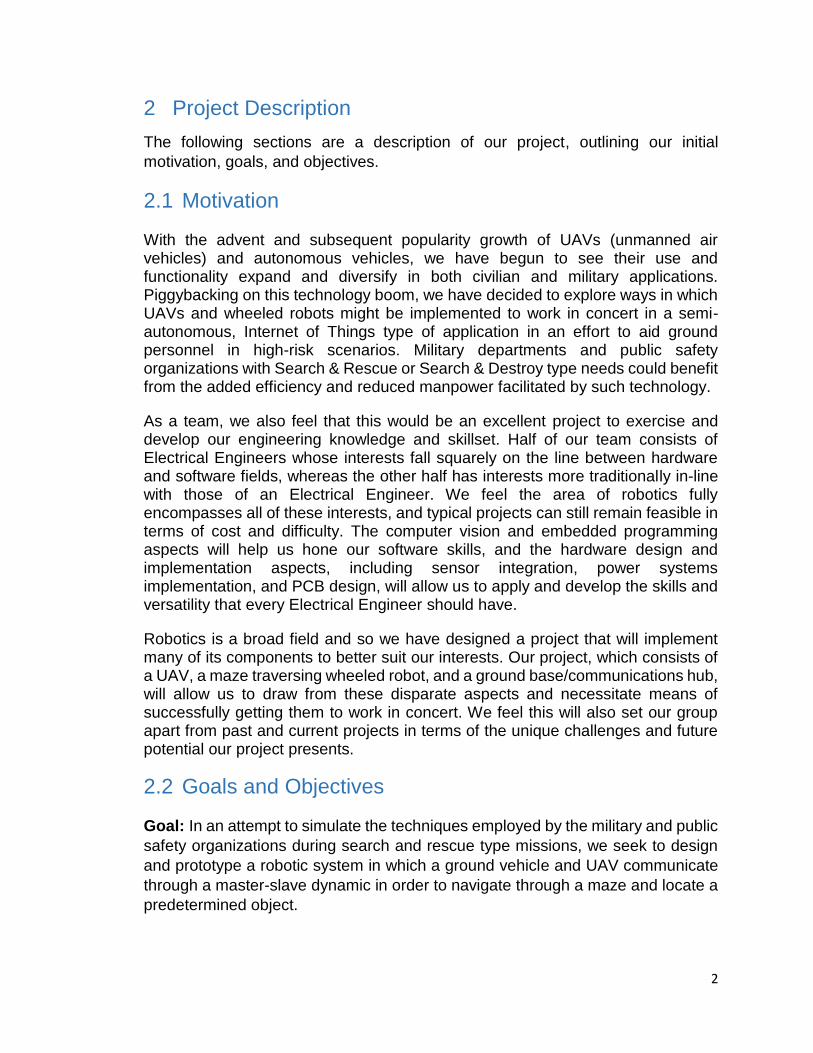
Battery Safety for Li-Po: Always transport, charge, and store the battery in
the guard bag. Charge the battery using a designated Li-Po balance charger
only. Always monitor the battery while charging.
10
Figure 1 Battery Safety (permission granted)
The quadcopter can also be hazardous if operated incorrectly. A good suggestion is to learning on a mini-drone first. Make safety your first priority, and always follow the best practices.
Handling – Never touch the propellers while running. When flying, always
ensure to keep a safe distance between yourself and the drone. Don’t take
off with the drone facing towards you or fly directly over your head. Also,
watch out for people around you.
Visual sight – Ensure to keep your eyes on your UAV while it is flying.
Altitude and distance – When flying the UAV, always one should not reach
higher than 400 feet, so you do not interfere with any commercial flights or
other aircrafts. Always maintain at least 100 feet (30 meters) between your
drone and people, vehicles, and buildings.
Flight Zone – You should avoid flying near airports.
Timing – Just as money management is a key constraint when it comes to a project, timing is also one main constraint that must take into account. It is considered as major concern because we have to deal with in almost everything. For our project, a period of two semesters with a specific deadline is given in order to achieve our final product. At the end of the time limit or earlier if possible, we must be able to deliver our project. Therefore, each member of our group is required to carefully work in a timely manner toward accomplishing his/her related tasks.
Environmental – Environmental constraint is not an effect for our project. There
is basically nothing that will cause potential damage to the environment. For
instance, waste of energy and air pollution are not going to involve for this
project.
11
Manufacturability – Manufacturability is one constraint that is not going to have
any impact on our project. This constraint will not affect our design because
almost all components that is to be used can easily be made.
Ethical – This particular design constraint is not going to be a problem in design.
If we use pictures and diagrams, there should be a request of permission from
the owner of the content being used.
Political – This type of design constraint will not come into play when it come to
our project. This project is just for our educational purposes. No patent protected
designs is required.
Sustainability – This can be one of the constraint in this project. Rechargeable
batteries will be used in order to avoid wasting too much energy. Also, the
wireless component such ZigBee is to be considered in our design due to the fact
that they consume very low power.
Social – Socially speaking, this constraint is not going to relate to our project.
12
5 Research
The entire project requires a considerable amount of research. If there is a
possibility that a part or software might be a part of our overall design, it has to
be researched to gain a clear understanding of what parts we will use in our final
design, and why we are using these parts such as knowing the advantages and
disadvantages of each part that will be included in the prototype.
5.1 Existing and Similar Projects
As the modern technology advances, Autonomous robots are getting more and
more useful. These intelligent robots are capable of accomplishing tasks with some
degree of self-sufficiency. Some of these specific robot can be used to go
accomplish missions where human’s life can be jeopardized. For instance, a self-
commanded robots can be used in a battlefield to detect a danger zone without
putting human soldier’s life in danger. Most of these autonomous robots’ feature
are unique. They are able of functioning without continuous human guidance. For
example, they are capable of interacting with the environment, sometimes even
gaining knowledge and familiarizing to their atmospheres. These features that are
just mentioned are not only the impressive things about these robots, yet another
great feature that can be found in these autonomous robots is their self-maintained
abilities.
To continue, our main purpose in this section is to make some researches on
similar projects that have already done. After we have completed this task, we
have found a few project that are related to our project. They are all amazing
project in many different aspects. Listed are some great projects that have been
completed by some different individuals.
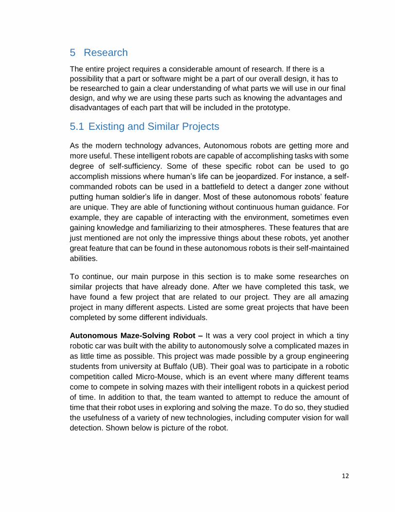
Autonomous Maze-Solving Robot – It was a very cool project in which a tiny
robotic car was built with the ability to autonomously solve a complicated mazes in
as little time as possible. This project was made possible by a group engineering
students from university at Buffalo (UB). Their goal was to participate in a robotic
competition called Micro-Mouse, which is an event where many different teams
come to compete in solving mazes with their intelligent robots in a quickest period
of time. In addition to that, the team wanted to attempt to reduce the amount of
time that their robot uses in exploring and solving the maze. To do so, they studied
the usefulness of a variety of new technologies, including computer vision for wall
detection. Shown below is picture of the robot.
13
Figure 2 Autonomous Robot (permission granted)
This vehicle is well designed and equipped with hardware technologies. Instead of
using a separate chassis, the printed circuit board were used to conserve the
weight in order to make the autonomous smaller. On board of this vehicle, infrared
emitters and receivers were used to sense the walls that are surrounded the robot.
This technologies were used as some helps to move smoothly and quickly without
getting crashed in the walls. In addition, some tiny microcontrollers were used to
reach a clock rate of 96MHz, which permits the vehicle detect the surrounding
walls as fast as possible. According the team, this robot is able to decide it next
move in a time of less than 1ms. In order to reach a fast speed, they chose DC
motor encoders.
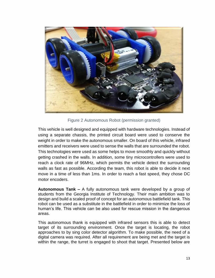
Autonomous Tank – A fully autonomous tank were developed by a group of students from the Georgia Institute of Technology. Their main ambition was to design and build a scaled proof of concept for an autonomous battlefield tank. This robot can be used as a substitute in the battlefield in order to minimize the loss of human’s life. This vehicle can be also used for rescue mission in the dangerous areas.
This autonomous thank is equipped with infrared sensors this is able to detect target of its surrounding environment. Once the target is locating, the robot approaches to by sing color detector algorithm. To make possible, the need of a digital camera was required. After all requirement are being met and the target is within the range, the turret is engaged to shoot that target. Presented below are

14
some of the hardware that were used in this project and a picture the autonomous tank.
ICOP Technology eBox-2300
Logitech Quick Cam Pro 5000
Phidgets 8/8/8 Kit With Text LCD
1/16 Scale German Tiger RC Tank
Panasonic AMN23111 IR Motion Sensors (4)
Phidgets IR Spot Sensor
CV-HB 401 Dual H-Bridge
NiCad Battery Pack With Custom Power Regulator
Custom Relays (3)
Figure 3 Autonomous Tank (permission granted)
As you can see, this project was a very impressive one. Most of the hardware components that have been used to make this project possible were conventional parts. They can be purchased online or at a convenient electronic shop. We are not implying that it was an easy project, as a matter of fact, even though the components can be find at one’s preferable electronic shopping place, of course

15
additional engineering skills are still required. If it was a plug and play project, there would have been no need for them to spend of this time studying to become an engineer. For instance, the CV-HB 401 Dual H-Bridge for the motor control system requires some knowledge other than plug and play. Its acceptable voltage range is from 5V up to 28V for normal operation.
Autonomous Ball Collector – An autonomous ball collector known as A.B.C was a senior design project that made possible by a group of undergraduate talents here at the University of Central Florida. Those students wanted to base their project on the theory of tennis game. Their robot was uniquely built to achieve a certain mission. During a game of tennis, the robot will be programmed to collect ball around the field. To make this task realizable, the use of computer vision/camera has to come into play. The camera has to have the ability to detect objects. For instance, it must be able to recognize tennis balls based on either their shape or their color. Once the camera has found a target, the robot will evaluate its position and move toward the object then grab it. Shown in the following picture is the autonomous ball collector or A.B.C after being fully designed and developed.
Figure 4 Autonomous A.B.C (Permission Pending)
The main software that is used in this autonomous Bot is an AVR programmer. It is a product made by Atmel that is so inexpensive and comes with the easy to use functionality. This product has a chip that has a flash memory and is able to execute any program that is written in the inside. In addition, it has the ability to run at a rate in about 10 MHz with a 1KB random access memory (RAM) and a 10KB of internal storage built-in. these features make this software very efficient when it comes to energy saving for a whole tennis game session.

16
This robot as describe in its documentation, is very simple when it comes to it usability. If someone wants to use it, all that is required is to turn on the power button then A.B.C will start collecting the tennis balls. As you can see in the image above, there is a plastic storage attaches to robot. It is where A.B.C will put and hold the tennis balls after being collecting. This container can be easily accessed by just opening the container and reaching for the balls. I think that was cool robot for those who are in tennis ball business tournament. Instead of running around tennis court to collect the balls, they can just let the robot accomplish this task.
Drone-Net: The Quad Chronicles – This is another great senior design that was done by our local talents here at UCF. It is a project in which the same idea of robotic mechanism is used in order to achieve a final goal. These students were inspired and believed in their skills and knowledge that they could build a project that consisted of two quad-copters that could wirelessly communicate with a mobile landing platform with sustainable charging structures.
According to the project documentation, the quadcopters purposes were to gather and transmit visual data to an all-terrain landing and charging ground vehicle. The flying vehicles and ground robot were capable of navigate, negotiate landings, evaluate remaining flight time, and recharge by making use of a sustainable energy system. A picture of the complete designed is shown below.
Figure 5 Drone-Net (Permission granted)
On board of this mobile platform, there are various novel technologies that help the team upon achieving their goal. It contains a charging system that uses renewable energy from which the quad-copters are able to recharge. To achieve such a goal, there were two solar panels aboard the mobile vehicle. These solar panels were not only there to provide energy to recharge the quad-copters batteries, yet they serve as supplement or extra source of energy that can be used to recharge all other batteries on board of the ground vehicle. That was a smart thing to do because it helped them on extending the operation of the entire system

17
when it comes to sufficient energy. In addition, there are many microcontrollers for different subsystems. They help in accomplishing specific tasks such as different pins configuration.
As previously mentioned, our goal was to perform researches on existing and similar projects that have been done in the pass. As we have completed this task, we have found that are few interesting one. They were all based on the same ideology of robotic vehicle that is being programmed to perform a specific task or accomplishing a specific goal without the need of humans on board. Wireless communication and sensing ability played a major role in all these projects. Compare to our project, the use of a ground vehicle is needed but not for the same purposes except for the autonomous maze-solving robot which was used for solving a maze just we are planning to. In our project, in order to solve the maze, we will use a UAV to which a camera will be attached as mentioned in our objective and goal. This device or camera will stream a live video or capture an image of the entire maze and then wirelessly transmit that video or picture to a base where the solution will be found using computer vision.
5.2 Ground Vehicle
The ground vehicle requires extensive research, as it is the most involved aspect
of the project because its major components are the PCB design, sensors, entire
chassis design, and embedded programming.
5.2.1 Printed Circuit Board
A requirement of Senior Design is having a functioning double-sided printed circuit board (PCB) implemented in the final prototype of our design. The PCB will provide an interface between the microcontroller and the input/output peripherals to control the ground vehicle’s motors, sensors, and power system. It may also house other onboard components. Because none of us has any direct experience with designing or building PCBs nor preference with respect to brand, we did a survey of available PCB design software, online PCB manufacturers, and hardware components our PCB design will utilize. We also considered the option of bypassing the PCB manufacturer by masking and etching our own PCB using copper-clad using toner. Aside from providing good experience, this would save on materials expenses and delivery time. We ultimately decided against this because our inexperience may needlessly delay our project build.
Also, we feel our inexperience warrants approaching the design of our PCB by starting with a model based off an existing commercial platform. This required looking at several microcontrollers and development boards from various companies which we evaluated, compared and contrasted, and will ultimately customize our PCB using one of these as a basis. Our main objective when evaluating these models was ensuring our design requirements and specifications could be met with respect to processing speed, memory, and other functionality
18
aspects. The PCB customization includes eliminating unused input/output pins and/or peripherals.
5.2.1.1 PCB Manufactures
OSH Park – OSH Park has long been used by Senior Design groups at UCF and has a good reputations. They offer 2 layer boards at $5 per square inch (with 3 copies of your board included in that price) shipped in under 12 calendar days from ordering, or 4 layer boards at $10 per square inch (also including 3 copies of your board), which go to the fab once a week, and have a 2 week turn time from the fab. Prices do not include shipping.
Express PCB – Express PCB is another high quality PCB manufacturer with good reviews. They charge a flat fee for a 2-layer and 4-layer PCB. The orders include 3 PCBs and with pricing for 2-layer PCBs at a flat rate of $51 and 4-layer PCBs at a flat rate of $98. This does not include shipping. Orders submitted Monday through Friday by 2:00pm ET are shipped the next business day. In addition, they offer their own, free PCB layout and schematic design software.
Advanced Circuits – Advanced Circuits is North America's third largest PCB manufacturer and they have a good online presence. They advertise quick turn full-spec, small quantity 2-Layer PCBs for $33 each and 4-Layer PCBs for $66 each, either which ship in 5 days. For students, no minimum purchase is necessary. This does not include shipping. They also offer their own PCB design software.
5.2.2 Processors
During the course of our academic careers and personal hobby electronics pursuits, we’ve come across several manufacturers of quality microcontrollers. To narrow our choice of microprocessor down a bit, we looked at three high-quality manufacturers of microcontrollers with which we were at least partially familiar.
We did initial microcontroller research under the assumption that we would be doing onboard image processing (see AM3359 Sitara section). After a reevaluation of project scope, we decided to utilize an offboard processing hub for image processing which would wirelessly transmit navigational cues to the ground vehicle. This means minimal processing power would be needed for the ground vehicle, though we did decide to some ground vehicle peripherals would be useful in order to retain some aspects of environmental “awareness”, such as the ability to do wall sensing and process wheel encoder information. Below is a comparison table giving a brief overview of the processors we are considering and a comparative list of their specifications.

19
AM3359 Sitara ATmega328 MSP430G2553 PIC16F690
Architecture 32-Bit RISC 8-Bit RISC 16-Bit RISC 8-Bit RISC
Frequency 800 MHz 20 MHz 16 MHz 20 MHz
I/O Supply Voltage
1.8 V-3.3 V 1.8 V-5.5 V 1.8 V-3.6 V 2 V-5.5 V
Code Storage 64 KB OCMC RAM
16 KB FLASH 16 KB Non-volatile
7 KB Flash
I/O Pins 4 Banks x 32 GPIO Pins
28 Pin PDIP 80 GPIO Pins 18 I/O Pins
Development Board
BeagleBone Black
Arduino Uno, DueMilanove,
etc.
MSP430 Launchpad
Explorer 8 Development
Kit, etc.
Table 2 Processors Overview
5.2.2.1 AM3359 Sitara
The AM3359 is one of the higher end microprocessors Texas Instruments has to offer and is more than enough to meet our requirements. This processor is based on the ARM Cortex-A8 processor and is enhanced with image, graphics processing, peripherals, and industrial interface options such as EtherCAT and PROFIBUS. It supports high-level operating systems (HLOS), Linux and Android, which TI makes available free of charge. This would be very advantageous if we decided to implement onboard processing of OpenCV algorithms. At $55, the price of the BeagleBone development is reasonable considering its capability, which would make it a good candidate as far as development and protyping is concerned. But at just over $30, the price of the AM3359 could add considerable cost to PCB manufacturing, since we will probably be ordering multiple boards with our order.
Additional Features of the AM3359
800 ARM MHz (max.)
1600 DMIPS
Available with LPDDR, DDR2, DDR3, or DDR3L DRAM depending on memory controller
Display Output
3D Graphics Acceleration
2 PRU-ICSS Co-Processors

20
Available CAN, I2C, SPI, UART, or USB Serial I/O
128 KB On-Chip Memory
256 KB (ARM Cortex-A8) On-Chip L2 Cache
Texas Instruments makes the AM3359 available on the BeagleBone Development Board which is ideal for portable applications that have heavy computational needs. We have never used the BeagleBone, but it has a steady track record of being used successfully in several Senior Design projects. Since it has its own HLOS, programming would be more straightforward than traditional embedded programming. There is a large amount of materials and resources online dedicated to its use. Although the AM3359 was our initial microprocessor choice, we have decided to explore other options given its complexity. Because we’ve decided to integrate a computation hub external to the ground vehicle PCB, this processor would probably be overkill and paring down its I/O and unused components may end up being adding an unnecessary level of complexity to our design.
5.2.2.2 ATmega328
The ATmega328 microprocessor is ubiquitous in the robotics world due to its implementation in the popular Arduino line of development boards. The Atmel 8-bit AVR RISC-based microcontroller combines 32 KB ISP flash memory with read-while-write capabilities, 1 KB EEPROM, 2 KB SRAM, 23 general purpose I/O lines, and utilizes a relatively large instruction set powerful enough that its RISC-based architecture allows the device to achieve throughputs approaching 1 MIPS per MHz, balancing power consumption and processing speed. Two members of our group have experience programming an autonomous robot enabled with the Arduino Uno microcontroller, which utilizes the ATmega328. These development boards are open-source and documentation is freely available online. They can be programmed in the Processing programming language and IDE, which is very similar to C. The development kit is around $30, but the processor itself is less than $3. These kits are not available for sample.
Additional Features of the ATmega328
32 KB of In-System Self-Programmable Flash Program Memory
1 kB EEPROM
2 KB Internal SRAM
Programmable Serial USART
Master/Slave SPI Serial Interface
I2C Compatible

21
Compared to the other microprocessors, the board is midrange in terms of clock frequency, number of I/O pins, and code storage space. This is not necessarily a con in terms of limitedness since our vision is to have an extremely simple ground vehicle with most of the computation executed externally. The Arduino has a boot loader, which allows code to easily be loaded onto the microcontroller, whereas, the MSP430 for example requires a programmer device to load code. One downside may be its reliability – the autonomous robot our group members worked on previously had several problems with bad components. While we may be able to mitigate this by selecting as many onboard components as possible from reputable vendors, we do not know how much if any component failure was due to component layout or the ATmega328 itself.
5.2.2.3 MSP430G2553
The MSP430G2553 is a 16-bit microprocessor manufactured by Texas Instruments. All group members have experience programming this microcontroller from the EGN 3211 class, in which we used the MSP430 Launchpad as the development board. We also did more extensive programming with a similar TI microprocessor in EEL 4742. This microcontroller in an inexpensive, ultra low-power option that is easy to program in C using the free Code Composer Studio software. The architecture, combined with five low-power modes, is optimized to achieve extended battery life. It features a digitally controlled oscillator (DCO) that allows wake-up from low-power modes to active mode in less than 1 µs. This makes it ideal for low-power applications, such as portable measurement. The processor costs less than $1, while the development kit itself is available for under $10 and includes two microcontrollers. The development board appears to be available as a free sample, as well.
Additional Features of the MSP430G2553
16 KB of Non-Volatile Memory
0.5 KB of RAM
I2C, SPI, UART
Though it meets our requirements, the MSP430 is not perfect. Because it is an ultra low-power microcontroller, it has the lowest processing speed of the four microprocessors we evaluated. It also has an almost excessive number of pins, and the development board’s intended purpose may be too far removed from our application. Its main use in industry is for portable measurement.
5.2.2.4 PIC16F690
Another group of microcontrollers we looked at was the PIC family of microcontrollers manufactured by Microchip Technology. Although none of has any experience with these microcontrollers, we decided to include them in our
22
evaluation do to their use in many autonomous robotic applications. The PIC16F690 microcontroller is programmed in C, and although the code compilers are usually a priced commodity, there are free versions available to students for which we would qualify. The price of the processor is relatively cheap, ranging from between $1 and $3. The price of the DM160228 - Explorer 8 Development Kit and the DM163046 - PICDEM Lab II Development Platform are around $75 and $100 respectively, however, which would make development and prototyping expensive.
Additional Features of the PIC16F690
7 KB of Flash Memory
256 B of EEPROM data memory
256 B RAM
UART, EUSART, SPI, I2C
The PIC is the simplest of the 4 in terms of code storage space and I/O Pins. We still believe it meets the main requirements of our project. It only uses an 8-Bit architecture, but separate program bus and data bus allow for different bus and data width. Although it only allows for 7 KB of code storage, PIC’s code is known to be extremely efficient, allowing the PIC to run with typically less program memory than its larger competitors.
We took several parameters into account for our processor decision. Since all the
processors we looked at were comparable in most aspects of major concern, we
only had two major deciding factors. Namely, ease of implementation and readily
available recourse for programming and implementation. All other factors equal,
we decided to use the ATmega328 processor in our design. We believe the
ATmega328 would be sufficient in supplying us with the required amount of control
while also having a huge online support community do to its use in open source
applications, such as the Arduino
5.2.3 Chassis
Our largest considerations in chassis design are cost, durability, and size. A relatively large portion of our budget will be contributed to the chassis, but we still aim to keep our costs conservative in order to budget for the event of component failure and replacement. Our design will not carry more than its own weight, i.e. sensors, frame, power supply, PCB, etc. therefore, many types of advanced chassis designs will not be considered. Also, in its current scope, our project ground vehicle will traverse across strategically selected flooring, therefore a design’s ability to negotiate rugged terrain types will not be considered. We want the design to be durable but do not expect it to be robust to harsh outdoor environments. The ground vehicle’s size is important as it directly relates to maze size. We want the ground vehicle to be sufficiently small such that it allows us to

23
make a relatively small and complex maze but with plenty of room on either side of the ground vehicle throughout the corridors. We also want its size relatively small such that it can easily negotiate 90 degree turns.
5.2.3.1 Drive Type
Our ground vehicle will have two planes of propulsion: A left forward active plane of motion and a right forward active plane of motion. This can be achieved in a number of ways as outlined below. 3 Wheel Drive approaches (i.e. three forward active planes of motion) have many advantages, especially in regards to vehicle size and turn accuracy. These vehicle designs were not considered for our project due to a more involved implementation process and our group’s lack of familiarity with this vehicle type. Also, vehicles with more than four wheels, legged robots, and other types of propulsion methods were not considered, as their main advantages lie outside of our project’s objectives.
2 Wheel Drive – These RC vehicles are extremely efficient; they involve the bare
minimum hardware needed to accomplish a wide range of tasks. As such, the
electronics and programming needed to govern their actions can be pared down
considerably.
Advantages
Able to negotiate tighter turns
Lighter in weight
Fewer motors use less battery power
Reduced electronics and simpler controls hardware
Small in size
Disadvantages
Rough terrains are more difficult to navigate
No in-place turning
More likely to drift during straight-line propulsion
Requires the use of a caster wheel or skid for support
4 Wheel Drive – These types of RC vehicles are probably more common, given
the resultant familiarity of their design proximity to motor vehicles. They are more
robust in most ways but also involve more complex hardware and electronics.
24
Advantages
Capable of navigating more varied terrains
Capable of in-place turning
Less drift during straight-line propulsion
Self-supporting/no need for caster wheel or skid
Disadvantages
Slippage occurs during turning
Heavier in weight
More motors use more battery power
More moving parts/hardware
5.2.3.2 Propulsion
Two types of propulsion we considered were DC motors and stepper motors. Servo motors were not considered because, after summarily researching their use in such an application, it was clear that they would be severely limited in their size-to-torque ratio, such that they would have to be unfeasibly large. DC motors appear to be fairly standard equipment with regard to the propulsion systems in mobile robot applications, but we took special consideration of their turning accuracy limitations. Stepper motors can be much more accurately controlled among other advantages.
DC Motors Advantages
Wide selection available
Easy to implement
DC MotorsDisadvantages
Requires gear reduction for large torque applications
Imprecise motor control
25
Stepper Motor Advantages
Does not require gear reduction
Low cost
Most precise motor control
Stepper Motor Disadvantages
Poor performance under varying loads
Consumes high amount of current
Needs special driving circuit for stepping rotation
No feedback mechanism to sense motor’s position
5.2.3.3 Commercial Chassis Considerations
We originally planned to build our own chassis, but given the number of inexpensive and application specific robots available, we decided to explore this option. In particular, given the opportunity to use one of these robots free of charge, we considered the Pirate 4WD Platform.
Pirate 4WD Mobile Platform
Our group had access to two Pirate 4WD chassis, one loaned from the UCF ECE Department and a potential parts vehicle from a past project of two of the group members. The platform is designed to mate particularly with Arduino microcontrollers but can be mated with any comparable microcontroller. Its own DC motors and battery pack as well as any additional sensors are protected by the aluminum case.
4 DC motors, allowing for in-place turning
Speed: 90cm/s
Dimensions: 200 x 170 x 105mm
Though this platform should be small enough so that we can still make a
reasonably complex maze without too much need to scale the maze size, the size
is not ideal compared to other more expensive models.
5.2.4 Custom Chassis Designs
Full custom chassis designs obviously allow for the most specificity for any given application. General maze solving robot chassis used for solving right-angled

26
mazes are fairly common and straightforward in design. But more advanced or customized maze systems may require certain dimensional or functional aspects be met by the robot. With regard to our project, this would likely be related to the scale of the maze.
5.2.4.1 3D Printed Chassis
3D printing of the chassis would allow us to incorporate the maximum amount customizability possible in our ground vehicle design. Accordingly, there are a great many advantages to this approach. Firstly, we could easily incorporate non-traditional technologies, such as mechanum wheels, allowing us to optimize performance or solve non-traditional maze layouts. Secondly, we could maximize the real estate use on the ground vehicle for electronic components layout – this would allow us to create a more dense design, resulting in a smaller robot, and ultimately, allowing to create a smaller, more complex maze. Practically speaking, this would also save on costs, since 3D printing a chassis would cost a fraction of the commercial alternatives. The only disadvantages in this approach would be would be the time spent in creating the design, the lack of replacement parts, and the implementation of unvetted hardware with no recourse to a warranty in the event of failure.
5.2.4.2 PCB Based Chassis
One common design approach is to implement the PCB as the main functional part of the chassis. To save on weight, size, and also limit the amount of mechanical hardware subject to failure, often the PCB will take the place of a traditional frame when these issues are of concern. This type of design implementation could be particularly efficacious to us, since minimizing the size of the robot will allow us to make a smaller, more complex maze.
Utilizing a PCB as such means peripherals, wheels, batteries, etc. will be mounted directly to the PCB, which can be crafted in a desired size and shape in accordance with the robot’s objectives. The resulting size and weight savings stem from a two areas: The bulk of the chassis itself will be omitted and the fact that a robot with a traditional frame has the added size and weight of additional mounting hardware in order to accommodate the separate PCB.
PCB based chassis have other advantages as well as some disadvantages – in point of fact, the remaining advantages of this design can also act as disadvantages if taken too far. Namely, bringing the more components onboard and within close proximity of each other effectively means the distances between electronic components and the power supply, and thus the lengths of the wires and traces, is shorter, which makes them less susceptible to line impedance and line inductance. This means there’s less thermal energy loss and we can reliably run higher clock speeds. By the same token, and perhaps to a larger extent, this can create crosstalk, mutual capacitance, and mutual inductance, and other

27
parasitic effects in the circuity. As regards our purposes, however, we will likely be running relatively low clock speeds.
MicroMouse – MicroMouse is an event in which teams of participants construct robots that autonomously solve mazes in as little time as possible. These projects invariably utilize PCB based chassis. One such example is the University of Buffalo MicroMouse entrant. The PCB was designed using an atypical shape, with the forward section expanded in a circular fashion to accommodate additional surface-mount electronic packages (which were also used to reduce vehicle size). The wheels supported the center of the PCB based chassis and the middle section of the PCB was designed incorporated cutouts surrounded by a minimal number of traces such that the axle could be accommodated here. The aft section contained additional components.
Figure 6: PCB Design of the MicroMouse (permission granted)
This approach allows teams a number of advantages which would directly translate to our project given the conceptual similarity between the two projects. Importantly, however, it also requires a large amount of customization on their end, which is a big tradeoff and, given the number of distinct subsystems in our project, this level of devotion to the ground vehicle’s efficiency may limit us in other aspects of the project’s design.
28
5.2.4.3 Chassis Design Conclusion
Although 3D printing or utilizing a PCB based chassis design would allow us the greatest amount of cost savings, designs can be time consuming, and inexpensive commercial chassis are readily available. Also, with commercial chassis we have recourse to customer reviews in regards to durability, which is not an option for 3D printing, where chassis failure could prove catastrophic to our deadlines. Furthermore, because the UCF ECE department allowed us to use a commercial platform they were in possession of, we decided to go this route, namely using the Pirate 4WD Mobile Platform.
5.2.5 Power Supply
The most straightforward and practical way of powering our ground vehicle is through a battery pack. A battery’s purpose is to store and release energy at the appropriate time and in a controlled manner. There are many options, several of which we considered in order to meet our design specifications and requirements. Our power supply will need to be able to deliver short, powerful bursts of energy, have sufficient capacity to operate the ground vehicle for relatively long periods of time, and have an appropriate recharge time.
The robot platform we decided to use comes equipped with a five AA battery cradle. Although it is not the optimum choice as concerns performance, particularly in the case of weight savings, we’ve decided to use this in place of other options, such as popular RC lithium polymer battery packs. This is mainly due to cost and convenience considerations.
5.2.5.1 Measures of Discharge Rate
The rate at which a battery discharges is an important metric for determining battery selection. This discharge rate can be measured in C-rate or E-rate – this is done in order to normalize against battery capacity, which can differ among batteries. Most portable batteries (except lead acid batteries) are rated at 1C. A 1C rate means that the discharge current will discharge the entire battery in 1 hour – this can be measured with a battery analyzer. Since a new battery sometimes provides more than 100% capacity, our runtime specification and requirements will likely be exceeded until our batteries are properly broken in.
5.2.5.2 Battery Technologies Overview
One of our goals and objectives is rechargeability of the ground vehicle power supply. Therefore, though they have much longer charge capacities than rechargeable batteries, we will not consider primary batteries such as alkaline of lithium primary (not to be confused with lithium ion) batteries. The reason we desire rechargeability is so we can test the reproducibility on the prototypal ground vehicle subsystems, which will require many successive runs under various conditions.
29
There exist many different types of rechargeable battery technologies, each with pros, cons, and application specific uses. Three technologies we will evaluate are Nickel Cadmium (NiCd), Nickel Metal Hydride (NiMH), and Lithium Ion (Li-Ion) batteries. NiCd, NiMH and Li-Ion are all fundamentally different from one another in terms of care and break-in protocol. This is a result of the different charging patterns required by each technology. As such, they each lend themselves to certain applications and conditions but not to others.
Two of the battery technologies, NiCd and, on a smaller scale, NiMH batteries, are subject to the memory effect. This is the tendency for batteries to “forget” their maximum capacity. Specific conditions that cause this are partially discharging the battery during regular use before recharging. If repeatedly discharged to a certain capacity, NiCd and NiMH batteries will only “remember” that smaller capacity as their maximum capacity. In point of fact, it is most analogous to “wearing a groove,” such that if only a certain part of the groove is used repeatedly, over time the rest of the groove will no longer be useable. Li-Ion batteries are not subject to this effect whatever, which is a huge advantage in our case since runtime of our system will be relatively short given the scale of the maze and other facets of our system.
Research Note – We originally intended to contrast and compare the three types
of batteries we were interested in for our project, by looking at batteries of the same
brand so as to form an objective opinion about each battery technology.
Unfortunately, we could not find a single manufacturer that produced all three types
of battery technologies. Therefore, in lieu of using this information, we garnered
data from three different, high quality brands but did not consider price as a major
factor in the comparison, which is the main difference among battery brand. We
may not buy these actual brands of batteries, and instead opt for a cheaper
manufacturer of the battery technology in which we are most interested.
5.2.5.2.1 Lithium-Ion
Li-Ion batteries is a relatively new type of rechargeable battery technology that has a slew of advantages as well as but a number of disadvantages. They are the lightest of the three battery choices and have a high energy density, which would lighten the ground vehicle weight, thus mitigating discharge rate (longer run times) and wear of the ground vehicle. Unlike the other two choices, Li-Ion has negligible memory effect. Their self-discharge rate is several fold below that of NiCD and typical NiMH batteries, and about equal to low self-discharge NiMH batteries, a special type of NiMH batteries which are much more expensive than typical NiMH batteries. Also, unlike NiMH and NiCD batteries, Li-Ion batteries do not require conditioning. Another advantage is that the nominal voltage of Li-Ion batteries (3.7V) is much higher than the 1.2V produced by both NiCD and NiMH batteries. Therefore, with Li-Ion batteries we could reliably power our systems without concern of expanding the battery pack to account for DC fan-out.
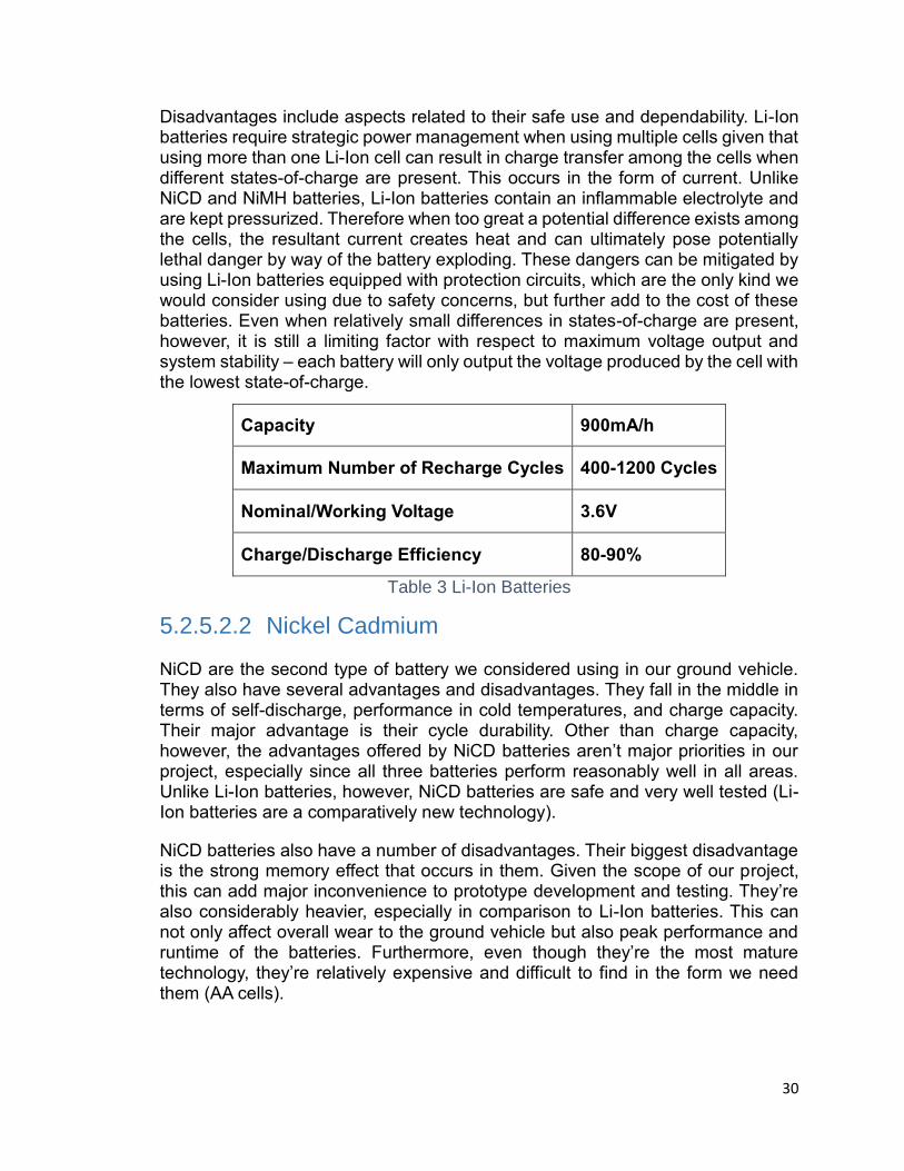
30
Disadvantages include aspects related to their safe use and dependability. Li-Ion batteries require strategic power management when using multiple cells given that using more than one Li-Ion cell can result in charge transfer among the cells when different states-of-charge are present. This occurs in the form of current. Unlike NiCD and NiMH batteries, Li-Ion batteries contain an inflammable electrolyte and are kept pressurized. Therefore when too great a potential difference exists among the cells, the resultant current creates heat and can ultimately pose potentially lethal danger by way of the battery exploding. These dangers can be mitigated by using Li-Ion batteries equipped with protection circuits, which are the only kind we would consider using due to safety concerns, but further add to the cost of these batteries. Even when relatively small differences in states-of-charge are present, however, it is still a limiting factor with respect to maximum voltage output and system stability – each battery will only output the voltage produced by the cell with the lowest state-of-charge.
Capacity 900mA/h
Maximum Number of Recharge Cycles 400-1200 Cycles
Nominal/Working Voltage 3.6V
Charge/Discharge Efficiency 80-90%
Table 3 Li-Ion Batteries
5.2.5.2.2 Nickel Cadmium
NiCD are the second type of battery we considered using in our ground vehicle. They also have several advantages and disadvantages. They fall in the middle in terms of self-discharge, performance in cold temperatures, and charge capacity. Their major advantage is their cycle durability. Other than charge capacity, however, the advantages offered by NiCD batteries aren’t major priorities in our project, especially since all three batteries perform reasonably well in all areas. Unlike Li-Ion batteries, however, NiCD batteries are safe and very well tested (Li-Ion batteries are a comparatively new technology).
NiCD batteries also have a number of disadvantages. Their biggest disadvantage is the strong memory effect that occurs in them. Given the scope of our project, this can add major inconvenience to prototype development and testing. They’re also considerably heavier, especially in comparison to Li-Ion batteries. This can not only affect overall wear to the ground vehicle but also peak performance and runtime of the batteries. Furthermore, even though they’re the most mature technology, they’re relatively expensive and difficult to find in the form we need them (AA cells).

31
Capacity 600mAh
Maximum Number of Recharge Cycles ~ 2000 Cycles
Nominal/Working Voltage 31.2V
Charge/Discharge Efficiency 70-90%
Table 4 NiCD Batteries
5.2.5.2.3 Nickel Metal Hydride (NiMH)
These are the last type of rechargeable battery we will consider. They have the largest market share of all small, rechargeable batteries. They offer a number of advantages over NiCD batteries and are better tested and more readily available than Li-Ion batteries. While they aren’t as light as Li-Ion batteries they are considerably lighter than NiCD batteries. NiCD batteries have traditionally had a much lower self-discharge rate than NiMH batteries, but with the innovation of Sanyo’s Eneloop brand low self-discharge NiMH batteries, which utilize an improved electrode separator and improved anode, NiMH batteries can now have shelf lives on par with Li-Ion batteries (though you must pay a premium for this specific type of NiMH battery). NiMH batteries are available with extremely high capacity and are available from all of the major brands. They have lower internal resistance which makes them advantageous for high current drain applications, such as will be required from the short bursts of energy needed to power our ground vehicle.
Like the other batteries, NiMH batteries still have disadvantages. Of the biggest concern to us is the significant voltage drop at near-discharged levels compared to other battery types, especially for high capacity NiMH batteries (at or near 3000mAh). Also, the still present memory effect compared Li-Ion batteries, as well as their charge/discharge efficiency.
Capacity 2000-3000mAh
Maximum Number of Recharge Cycles 500-2000 cycles
Nominal/Working Voltage 31.2V
Charge/Discharge Efficiency 66%
Table 5 NiMH Batteries

32
5.2.5.2.4 Overview
We originally planned on making a decision matrix to choose battery technology. However, since our top priorities by far were charge capacity (see figure below) and safety, after researching the subject, it was clear that NiMH would be the most apropos choice for our application.
Figure 7 Capacity
Furthermore, given the ubiquity of NiMH technology compared to the outplaced NiCD and the still emerging Li-Ion technologies, price, quality, and choice of brand were direct advantages of choosing NiMH batteries. Other, newer technologies, though promising, share such a small market share a result of their recency, that information to evaluate their efficacy was difficult to obtain.
The current draw of the ATmega328 VCC and GND pins is 200mA. The maximum no-load current of the DFRobot DC motors included on the Pirate 4WD mobile platform is 170mA for four DC motors. So, under ideal conditions with no peripherals drawing current, the current draw on the battery pack will be:
Optimal Discharge Rate: 200𝑚𝐴 + 4 ∙ 170𝑚𝐴 = 880𝑚𝐴
Rounding off to a 1A discharge current in order to account for peripherals, load on the DC motors, and other non-ideal conditions, and assuming a battery capacity of 2300mAh yields a C-rate of:
𝐶 − 𝑟𝑎𝑡𝑒: 2300𝑚𝐴ℎ
1𝐴= 2.3 𝐻𝑜𝑢𝑟𝑠
600
900
2300
NiCD Li-Ion NiMH
Cap
acit
y (m
Ah
)
Battery Technoloies
Capacity
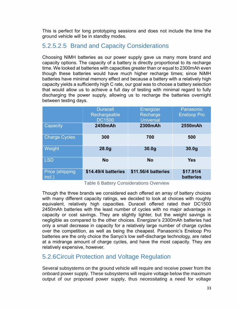
33
This is perfect for long prototyping sessions and does not include the time the ground vehicle will be in standby modes.
5.2.5.2.5 Brand and Capacity Considerations
Choosing NiMH batteries as our power supply gave us many more brand and capacity options. The capacity of a battery is directly proportional to its recharge time. We looked at batteries with capacities greater than or equal to 2300mAh even though these batteries would have much higher recharge times; since NiMH batteries have minimal memory effect and because a battery with a relatively high capacity yields a sufficiently high C rate, our goal was to choose a battery selection that would allow us to achieve a full day of testing with minimal regard to fully discharging the power supply, allowing us to recharge the batteries overnight between testing days.
Duracell Rechargeable
DC1500
Energizer Recharge Universal
Panasonic Eneloop Pro
Capacity 2450mAh 2300mAh 2550mAh
Charge Cycles 300 700 500
Weight 28.0g 30.0g 30.0g
LSD No No Yes
Price (shipping incl.)
$14.49/4 batteries $11.56/4 batteries $17.91/4 batteries
Table 6 Battery Considerations Overview
Though the three brands we considered each offered an array of battery choices with many different capacity ratings, we decided to look at choices with roughly equivalent, relatively high capacities. Duracell offered rated their DC1500 2450mAh batteries with the least number of cycles with no major advantage in capacity or cost savings. They are slightly lighter, but the weight savings is negligible as compared to the other choices. Energizer’s 2300mAh batteries had only a small decrease in capacity for a relatively large number of charge cycles over the competition, as well as being the cheapest. Panasonic’s Eneloop Pro batteries are the only choice the Sanyo’s low self-discharge technology, are rated at a midrange amount of charge cycles, and have the most capacity. They are relatively expensive, however.
5.2.6 Circuit Protection and Voltage Regulation
Several subsystems on the ground vehicle will require and receive power from the onboard power supply. These subsystems will require voltage below the maximum output of our proposed power supply, thus necessitating a need for voltage
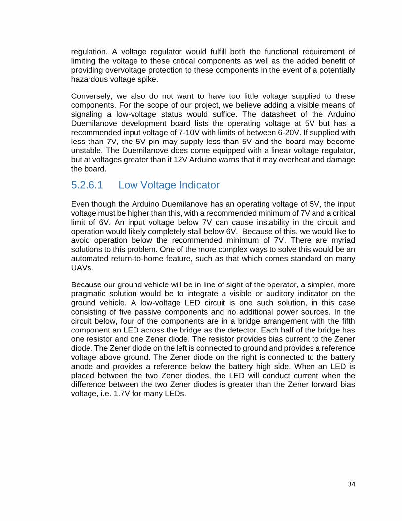
34
regulation. A voltage regulator would fulfill both the functional requirement of limiting the voltage to these critical components as well as the added benefit of providing overvoltage protection to these components in the event of a potentially hazardous voltage spike.
Conversely, we also do not want to have too little voltage supplied to these components. For the scope of our project, we believe adding a visible means of signaling a low-voltage status would suffice. The datasheet of the Arduino Duemilanove development board lists the operating voltage at 5V but has a recommended input voltage of 7-10V with limits of between 6-20V. If supplied with less than 7V, the 5V pin may supply less than 5V and the board may become unstable. The Duemilanove does come equipped with a linear voltage regulator, but at voltages greater than it 12V Arduino warns that it may overheat and damage the board.
5.2.6.1 Low Voltage Indicator
Even though the Arduino Duemilanove has an operating voltage of 5V, the input voltage must be higher than this, with a recommended minimum of 7V and a critical limit of 6V. An input voltage below 7V can cause instability in the circuit and operation would likely completely stall below 6V. Because of this, we would like to avoid operation below the recommended minimum of 7V. There are myriad solutions to this problem. One of the more complex ways to solve this would be an automated return-to-home feature, such as that which comes standard on many UAVs.
Because our ground vehicle will be in line of sight of the operator, a simpler, more pragmatic solution would be to integrate a visible or auditory indicator on the ground vehicle. A low-voltage LED circuit is one such solution, in this case consisting of five passive components and no additional power sources. In the circuit below, four of the components are in a bridge arrangement with the fifth component an LED across the bridge as the detector. Each half of the bridge has one resistor and one Zener diode. The resistor provides bias current to the Zener diode. The Zener diode on the left is connected to ground and provides a reference voltage above ground. The Zener diode on the right is connected to the battery anode and provides a reference below the battery high side. When an LED is placed between the two Zener diodes, the LED will conduct current when the difference between the two Zener diodes is greater than the Zener forward bias voltage, i.e. 1.7V for many LEDs.

35
Figure 8: Example Low-Voltage Indicator Circuit
The LED is in active operation when 𝑉𝑖𝑛 < 𝑉𝑍1 + 𝑉𝑍2 − 𝑉𝐿𝐸𝐷
At this point the LED will be forward biased and will illuminate. For a LED to indicate a low voltage at 7.2V a Zener diode pair of 3.9V and 5V will work with a LED with a 1.7 volt forward voltage drop. The value of the bias resistors and the properties of the LED will determine how bright the LED will be when conducting.
5.2.6.2 Linear Regulator
Linear regulators are one component commonly used for voltage regulation. It has several advantages over other voltage regulation approaches, namely ease of implementation and cost. Linear regulators are going to be considered for the proximity sensors and for wireless receiver. Due to the way they are function, they commonly used in low voltage and low power applications. They limit output voltage by converting excess power to heat, which makes it less efficacious in high voltage applications. The LM7805 from Texas Instruments was used in our Electronics II Lab and is available for $0.67. The figure below illustrates a basic linear regulator circuit, as implemented in our Electronics II Lab.

36
Figure 9: Linear Regulator Circuit (permission pending)
The LM7805 has a dropout voltage of 2V and actively regulates at 5V, meaning a minimum voltage of 7V must be present for it to reliably produce a 5V output. This agrees with the minimum recommended input voltage of the Arduino Duemilanove. Other linear voltage regulator models with various dropout and output voltages are also available from Texas Instruments. Texas Instruments also offer adjustable linear regulators at a slightly higher cost.
5.2.6.3 Switching Regulator
Switching regulators are probably the most common type of voltage regulator. They offer several advantages over linear regulators. As the name implies, a switching mechanism limits the amount of voltage available at the output, so very little power is lost as heat. As a result they’re more efficient and better for applications such as ours where heat dissipation may be an issue. They are slightly more expensive, however, and circuit integration is more complex. The LM2576HVS-ADJ from Texas Instruments was used in our Electronics II Lab and is available for $3.79, with similar models available as free samples. The figure below illustrates a basic switching regulator circuit, as implemented in our Electronics II Lab.
37
Figure 10: Switching Regulator Circuit (permission pending)
In contrast to the linear regulator, the switching regulator essentially pumps energy through from the input voltage source a “piece” at a time. This is accomplished with the help of the switching mechanism of the MOSFET and the varying duty cycle of the pulse width modulator which acts as a controller to regulate the rate at which energy is transferred to the output. This means that when the MOSFET in the circuit is on and conducting current, the voltage drop across its power path is minimal. When the MOSFET is off and blocking high voltage, there is almost no current through its power path. So the MOSFET acts as a switch governed by the pulse width modulator (hence the term “switching regulator”), thus, the power loss across it is minimized.
5.2.6.4 Zener Diode
A simple Zener diode can be used to create a voltage regulation circuit. In the figure below, we see that this is an example of a Zener Diode circuit. The voltage drop across a resistor, which is in series with the Zener, establishes the current. The current splits between what the load draws and the current through the Zener. When the voltage becomes too large, the Zener becomes active and current is shunted through, thus limiting keeping the load current stable. In principle, this circuit protects against excess current, but achieves the same end as far as voltage effects on the load are concerned.
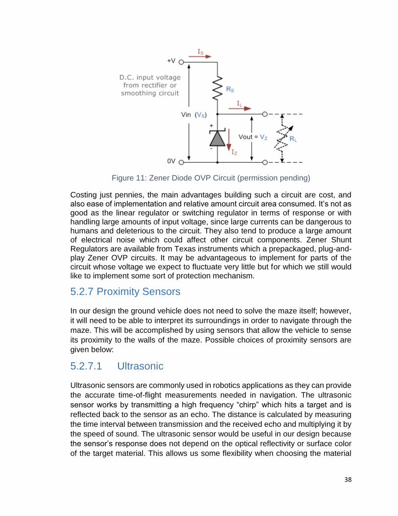
38
Figure 11: Zener Diode OVP Circuit (permission pending)
Costing just pennies, the main advantages building such a circuit are cost, and also ease of implementation and relative amount circuit area consumed. It’s not as good as the linear regulator or switching regulator in terms of response or with handling large amounts of input voltage, since large currents can be dangerous to humans and deleterious to the circuit. They also tend to produce a large amount of electrical noise which could affect other circuit components. Zener Shunt Regulators are available from Texas instruments which a prepackaged, plug-and-play Zener OVP circuits. It may be advantageous to implement for parts of the circuit whose voltage we expect to fluctuate very little but for which we still would like to implement some sort of protection mechanism.
5.2.7 Proximity Sensors
In our design the ground vehicle does not need to solve the maze itself; however,
it will need to be able to interpret its surroundings in order to navigate through the
maze. This will be accomplished by using sensors that allow the vehicle to sense
its proximity to the walls of the maze. Possible choices of proximity sensors are
given below:
5.2.7.1 Ultrasonic
Ultrasonic sensors are commonly used in robotics applications as they can provide
the accurate time-of-flight measurements needed in navigation. The ultrasonic
sensor works by transmitting a high frequency “chirp” which hits a target and is
reflected back to the sensor as an echo. The distance is calculated by measuring
the time interval between transmission and the received echo and multiplying it by
the speed of sound. The ultrasonic sensor would be useful in our design because
the sensor’s response does not depend on the optical reflectivity or surface color
of the target material. This allows us some flexibility when choosing the material

39
used to construct the walls of the maze. These sensors are also normally low
power and relatively inexpensive.
For the most part ultrasonic sensors are reliable and provide accurate
measurements; however, there are situations where they are not. When the
ground vehicle is navigating the maze it will be making several 90˚ turns which will
cause mounted sensors to face towards an angular surface for several seconds.
This could cause distance readings to be affected as ultrasonic sensors work best
when facing perpendicular to a flat surface.
Figure 12 Sensor Orientation (permission pending)
Measurements can also be affected if the target is too close to the sensor and an
echo is received before the transmitter has finished transmitting. This could cause
erroneous results if the sensor passes too close to the wall and could affect vehicle
movement. Overall, the ultrasonic sensor would be a good choice because our
application requires accurate measurements in sunlit areas, low power
consumption, and resilience to various material types.
5.2.7.2 Infrared
IR sensors can also be used to obtain distance measurements; however, they are
not as accurate as ultrasonic sensors and more sensitive to the environment.
Unlike ultrasonic sensors, IR sensors emit infrared light which is reflected by the
target back to the sensor. The angle of reflection is used to calculate distance
through triangulation and varies depending on the target’s surface type and color.
This causes measurements to vary even if the sensor collects data from the same
distance away. In our design we would need to ensure that the optical reflectivity
of the material chosen for the walls does not affect sensor response.
In addition, this type of sensor only works under specific lighting conditions as it is
sensitive to the infrared light produced by the sun. If we were to use this sensor
outdoors or in indirect sunlight it would need to be shielded to avoid inaccurate
measurement. IR sensors are often less expensive than ultrasonic sensors but
they are not as accurate and more sensitive to environmental conditions.

40
5.2.7.3 LIDAR
LIDAR sensors are similar to IR sensors in that they both use light to measure
distance, but LIDAR provides much greater range and is often much more
expensive. Unlike IR sensors, which are fixed, the LIDAR sensor has an emitter
that sits on a rotating base which scans the area and provides distance
measurements. This allows 3D point clouds of the environment to be generated
relatively quickly. Incorporating this sensor would allow the ground vehicle to
localize itself within the maze and provide accurate distance measurements that
could be used to prevent collision with the walls.
For our design most of the advantages that LIDAR offers would not be used. If the
maze was designed on a grand scale and the ground vehicle was able to navigate
without the aid of the quadcopter, investing in LIDAR might be a worthwhile
endeavor. However, for our purposes it would be more cost effective to choose a
less powerful distance sensor with a smaller range.
5.2.7.4 Distance Sensor Comparison
The six sensors below were compared to determine which would work best according to the specifications of our project.
HC-SR04 Ultrasonic Range Finder
Parallax PING Ultrasonic Sensor
Sharp GP2Y0A21YK0F IR Range Sensor - 10cm to 80cm
Sharp GP2Y0A41SK0F IR Range Sensor - 4 to 30cm
PulsedLight LIDAR-Lite 2 Laser Rangefinder
RPLIDAR 360° Laser Scanner
Ultrasonic Infrared LIDAR HC-
SRO4 PING 21YK0F 41SK0F PulsedLight RPLIDAR
Cost $2.50 $29.99 $9.95 $9.95 $114.89 $398.90
Operating Voltage
5V 5V 4.5-5.5V 4.5-5.5V 4.75-5.5V 3.6-6V
Supply Current
15mA 30mA 30mA 12mA <100mA Max 200mA
Power Consumption
75mW 150mW 165mW 66mW Max 550mW
Max 1.2W
Weight 15g 9g 15-20g 10-15g 26.5g 170g

41
Ultrasonic Infrared LIDAR HC-
SRO4 PING 21YK0F 41SK0F PulsedLight RPLIDAR
Range 2-500cm
2-300cm
10-80cm
4-30cm 40m 0.2-6m
Wavelength N/A N/A >750nm >750nm 905nm 785nm
Resolution 0.3cm N/A N/A N/A 2.5cm <0.5mm
Table 7 Sensor Comparisons
The most important sensor parameters for our design are cost, power
consumption, range, and accuracy. The least expensive sensor choice is the HC-
SRO4 which has comparable performance to the other ultrasonic sensor choice
(Parallax PING) and is 12X cheaper. The only drawback with choosing this model
is that, while often accurate, factory defects tend to be common. We would ensure
that our sensor is working properly by ordering multiple HC-SRO4s and comparing
their measurements. In terms of power consumption, the HC-SRO4 and Sharp 4-
30cm IR sensor use the least amount of power. It would be ideal to choose either
of these because their low power consumption would provide the ground vehicle
with a greater operating duration. The LIDAR sensors have the greatest operating
range and excellent accuracy; however, they also consume the most power and
are expensive. This large measurement range does not constitute the high cost of
these sensors as the distance between walls in the maze would be no larger than
2 feet and a cheaper sensor with a smaller range would suffice. One major
drawback of using the LIDAR or IR sensors in the chart above is that they all use
infrared light and, as a result, are affected by the presence of sunlight. In all
likelihood, the HC-SRO4 ultrasonic sensor will be used in the final design as it is
cheap, has a decent range, and will not be affected by environmental conditions.
5.2.8 Acceleration and Orientation
In order for the ground vehicle to navigate through the maze it must be equipped
with sensors that monitor its speed and orientation. These will allow the vehicle to
make precise 90˚ turns and should decrease the time needed for the vehicle to
solve the maze.
5.2.8.1 IMU
The IMU (Inertial Measurement Unit) is an electronic device that combines an
accelerometer, gyroscope, and occasionally a magnetometer. The typical IMU
records on 6 degrees of freedom; 3 axes of accelerometer data and 3 axes of
gyroscope data. The data collected from each of these axes can be used to
compute the current location and orientation of a vehicle equipped with an IMU.
An IMU would be used in our project to localize the ground vehicle within the maze
and would allow the solved path to be broken into a series of commands for the

42
robot to follow. The coordinates returned by the location of the vehicle as it moves
through the maze will be compared to the coordinates of the maze solution.
In most circumstances, the data received from the IMU is inaccurate and does not
reflect the true position or orientation of the actual object. This is because the
accelerometer is sensitive to small forces and this error is accumulated as position
is calculated. The gyroscope measurements also degrade over time and have a
tendency to drift. The rate acceleration measurements are taken can also
contribute to error as these values are all averages and do not reflect the
instantaneous acceleration at each instance.
These errors can be addressed by implementing filters that “fuse” sensory data
from the accelerometer and gyroscope to reduce the amount of noise in the
measurements and reduce error. The most common filter choices are the Kalman
filter, Complimentary filter, and Madgwick filter. The Kalman filter is the most
commonly used, but it is also the most complex to implement and requires the
most calculations. On the contrary, the Complementary filter is much easier to
implement and the same update equation as the Kalman filter is obtained. This is
done by passing accelerometer data through a 1st order low-pass filter and
gyroscope data through a 1st order high-pass filter. The output of each of these
filters is then added together and the result is nearly identical to the output of the
Kalman filter. Another alternative is the Madgwick filter which requires less
computations than the Kalman filter and is effective at low sampling rates.
For our project, we will most likely fuse sensor data by using the Complementary
filter as it requires less computations and is easier to implement than the Kalman
filter. There are also IMUs available which include built-in sensor fusion. The
VectorNav VN-100 and xOEMcore both contain on-board processors along with
an IMU to provide sensor fusion without the need to construct a Kalman filter on
the microcontroller.
5.2.8.2 IMU Comparison
VectorNav VN-100 SMD IMU (on board Kalman filter)
Invensense MPU-6050
OxTS (Oxford Technical Solutions) xOEMcore (on board Kalman filter)
Adafruit IMU Breakout (L3GD20H + LSM303 + BMP180)
Bosch Sensortec BMI055
Sparkfun Razor IMU Breakout (ITG-3200 + ADXL345 + HMC5883L)
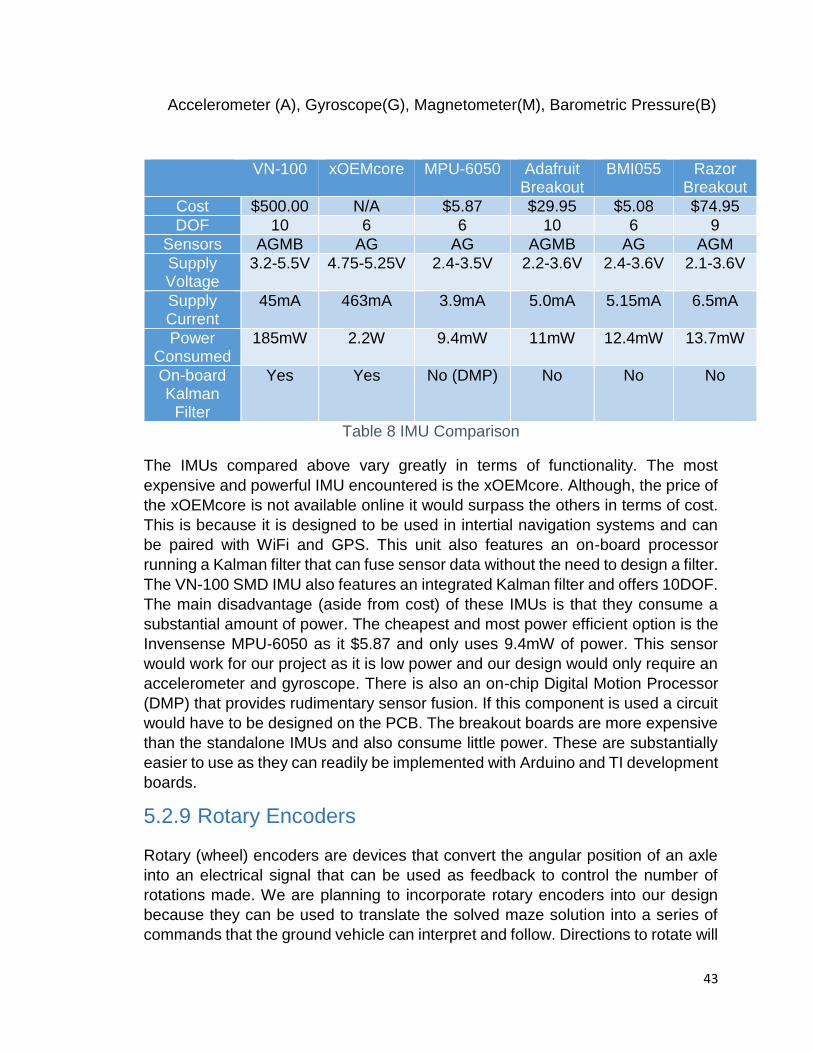
43
Accelerometer (A), Gyroscope(G), Magnetometer(M), Barometric Pressure(B)
VN-100 xOEMcore MPU-6050 Adafruit Breakout
BMI055 Razor Breakout
Cost $500.00 N/A $5.87 $29.95 $5.08 $74.95
DOF 10 6 6 10 6 9
Sensors AGMB AG AG AGMB AG AGM
Supply Voltage
3.2-5.5V 4.75-5.25V 2.4-3.5V 2.2-3.6V 2.4-3.6V 2.1-3.6V
Supply Current
45mA 463mA 3.9mA 5.0mA 5.15mA 6.5mA
Power Consumed
185mW 2.2W 9.4mW 11mW 12.4mW 13.7mW
On-board Kalman
Filter
Yes Yes No (DMP) No No No
Table 8 IMU Comparison
The IMUs compared above vary greatly in terms of functionality. The most
expensive and powerful IMU encountered is the xOEMcore. Although, the price of
the xOEMcore is not available online it would surpass the others in terms of cost.
This is because it is designed to be used in intertial navigation systems and can
be paired with WiFi and GPS. This unit also features an on-board processor
running a Kalman filter that can fuse sensor data without the need to design a filter.
The VN-100 SMD IMU also features an integrated Kalman filter and offers 10DOF.
The main disadvantage (aside from cost) of these IMUs is that they consume a
substantial amount of power. The cheapest and most power efficient option is the
Invensense MPU-6050 as it $5.87 and only uses 9.4mW of power. This sensor
would work for our project as it is low power and our design would only require an
accelerometer and gyroscope. There is also an on-chip Digital Motion Processor
(DMP) that provides rudimentary sensor fusion. If this component is used a circuit
would have to be designed on the PCB. The breakout boards are more expensive
than the standalone IMUs and also consume little power. These are substantially
easier to use as they can readily be implemented with Arduino and TI development
boards.
5.2.9 Rotary Encoders
Rotary (wheel) encoders are devices that convert the angular position of an axle
into an electrical signal that can be used as feedback to control the number of
rotations made. We are planning to incorporate rotary encoders into our design
because they can be used to translate the solved maze solution into a series of
commands that the ground vehicle can interpret and follow. Directions to rotate will
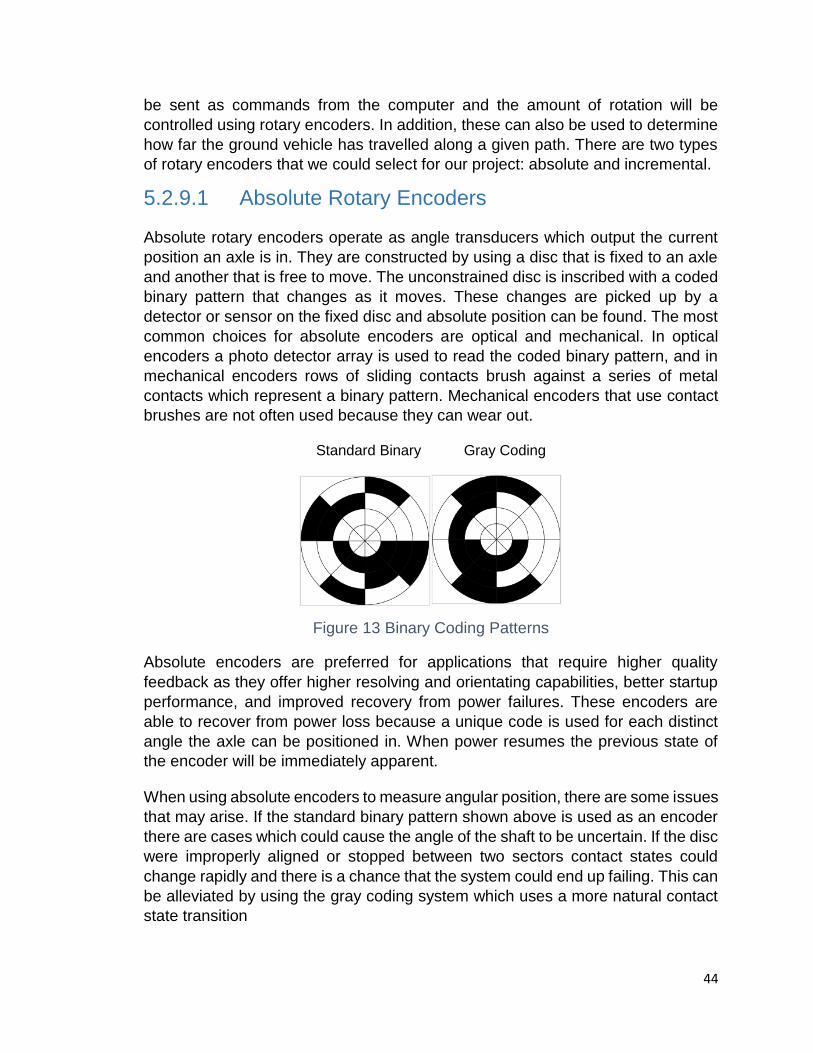
44
be sent as commands from the computer and the amount of rotation will be
controlled using rotary encoders. In addition, these can also be used to determine
how far the ground vehicle has travelled along a given path. There are two types
of rotary encoders that we could select for our project: absolute and incremental.
5.2.9.1 Absolute Rotary Encoders
Absolute rotary encoders operate as angle transducers which output the current
position an axle is in. They are constructed by using a disc that is fixed to an axle
and another that is free to move. The unconstrained disc is inscribed with a coded
binary pattern that changes as it moves. These changes are picked up by a
detector or sensor on the fixed disc and absolute position can be found. The most
common choices for absolute encoders are optical and mechanical. In optical
encoders a photo detector array is used to read the coded binary pattern, and in
mechanical encoders rows of sliding contacts brush against a series of metal
contacts which represent a binary pattern. Mechanical encoders that use contact
brushes are not often used because they can wear out.
Standard Binary Gray Coding
Figure 13 Binary Coding Patterns
Absolute encoders are preferred for applications that require higher quality
feedback as they offer higher resolving and orientating capabilities, better startup
performance, and improved recovery from power failures. These encoders are
able to recover from power loss because a unique code is used for each distinct
angle the axle can be positioned in. When power resumes the previous state of
the encoder will be immediately apparent.
When using absolute encoders to measure angular position, there are some issues
that may arise. If the standard binary pattern shown above is used as an encoder
there are cases which could cause the angle of the shaft to be uncertain. If the disc
were improperly aligned or stopped between two sectors contact states could
change rapidly and there is a chance that the system could end up failing. This can
be alleviated by using the gray coding system which uses a more natural contact
state transition

45
5.2.9.2 Incremental Rotary Encoders
Incremental rotary encoders output information relating to the motion of the axle
only. Unique codes are not used to track every angle position and, and as a result,
if there is a power failure the previous position would not be known. In order to
initialize the starting position these devices incorporate “homing” to return to a fixed
reference point. These encoders are commonly of the optical or magnetic type.
Figure 14 Incremental Encoding Patterns
Optical rotary encoders are used to track the number of revolutions a wheel makes
by using a black and white striped pinwheel and optical sensors. The pinwheel is
attached to the inside of the vehicle wheel and, as it rotates, an optical sensor
records when readings alternate between black and white. This allows the wheels
to be rotated by a certain number of degrees and the speed and distance the
vehicle travels can be precisely controlled. In our design, wheel encoders will be
used to ensure that the ground vehicle makes turns that are exactly 90˚ as it
navigates through the maze. These can be used in combination with an IMU to
move the vehicle to particular locations and execute exact turns. If wheel encoders
were not used vehicle movement would need to constantly be corrected as
distance sensors would prevent the vehicle from crashing into the boundaries of
the maze and the vehicle would need to reorient itself each time this occurs.
The magnetic encoder works in a similar way to the optical encoder, but it
determines position through magnetic fields rather than light. These encoders are
also more resilient than optical sensors in dusty or harsh environments. In addition,
they are also resistant to shock and vibration due to a large gap between the
sensor and target magnet.
An alternative to wheel encoders would be to use stepper motors as mentioned in
the Chassis section above. Since stepper motors make use of pulse width
modulation, each “pulse” would turn the wheels by a certain number of degrees. A
specified number of pulses could be used to make the wheels move the vehicle
some distance. By themselves, stepper motors are not able to be used to
determine position; however, they can be combined with motor encoders to make
this possible.

46
5.2.9.3 Rotary Encoder Comparison
Several rotary encoders of both the absolute and incremental type were
considered for use in our design. They are as follows:
Bourns AMS22S Non-Contacting Analog Position Sensor (Magnetic)
Bourns EMS22A Non-Contacting Absolute Encoder (Magnetic)
Bourns EM14 Rotary Optical Encoder
Grayhill Inc. 62AG22 (Optical)
Honeywell 600128CN1 (Optical)
AMS22S EMS22A EM14 62AG22 600128CN1
Cost $47.30 $41.85 $28.30 $25.20 $37.41
Type Magnetic Magnetic Optical Optical Optical
Pulse Per Revolution
N/A 1024 64 16 128
Operating RPM
200 10,000 120 100 300
Supply Voltage
5V 5V 5V 5V 5V
Supply Current
20mA 20mA 26mA 30mA 30mA
Power Consumpti
on
100mW 100mW 130mW 150mW 150mW
Output Type
Analog Binary (Absolute)
Binary 2-bit quadrature
2-square wave
Rotational Life
50M 100M 1M 1M 10M
Table 9 Rotary Encoder Comparison
Each of the encoders compared above require a supply voltage of 5V and draw
between 20-30mA of current. This gives an overall power consumption that varies
between 100-150mW. Based on these values, we could use any of the encoders
compared in our design as they use relatively low power. If we were trying to
improve the lifetime of the system we would choose a magnetic encoder over
optical as they are more resilient to environmental contamination and have a
longer rotational life. Out of the encoders compared, the Bourns EMS22A offers
the highest resolution, operating life, and can provide the highest operating rpm.
In addition, it outputs in binary which can be interpreted by the MCU onboard the

47
ground vehicle. This will allow the position and orientation of the ground vehicle to
be known as it travels through the maze.
5.3 UAV
The UAV requires many different design considerations including weight, type of
camera, its power supply, video transmission, RC transmitters, types of UAVs,
and flight controllers.
5.3.1 Camera
Objective. - The main goal of this section is to quickly research about camera since we are planning to use or implement this device in our project. By doing so, we would like to go briefly by focusing on the following:
Some different type of cameras.
Compare and contrast two or more types of cameras
Their technologies and features
Make a decision of which one is best suitable for our project.
Since one of the main parts of our project is to detect a small object within a maze, the use of a camera will be an important aspect to be put into consideration. To take care of this problem, the following questions need be answered. What type of camera will we use? Will this camera have enough feature to meet our requirement? Such as speed, power efficiency, frequency range and auto focusing and more.
In this project, choosing the right type of camera is not an easy task. Due to the fact that there are a multiplicity of them out there, where each one of them has different functionalities depending on the task for which a person need these types of device to perform. Each one of them may have their advantages and disadvantages when it comes to their performances and costs.
5.3.1.1 Camera Technologies
As the technologies of digital camera advance, we can observe that there is a falling when it comes to prices. The real reason behind these drops in cost is none other than the type of image sensor being used. We all know that there are two images sensor known as CCD (Charge-Coupled Device) and CMOS (Complementary Metal-Oxide-Semiconductor). CMOS imager and CCD technology were both developed in the 1960s. Due the fact that the CMOS image sensor cost less to manufacture than the CCD image sensor, most digital camera

48
manufactures make a switch from CCD to CMOS technology, therefore; the price for these devices continue to fall significantly.
While we were searching the internet, we came across some great articles that provide some useful information about CCDs and CMOS sensors in camera. One the most interesting is an article being written by Barry Green. In his article, he explains some major differences between CMOS and CCD imager.
To continue, both of CCD and CMOS are there to perform the same job, which convert light into electrons or images. However; when it comes to energy, noise, cost, and picture quality, there exist some noticeable differences between these two image sensors. For instance, CMOS image sensors are very low power to be operated because there are a lot of transistors placing next to each other per pixels. Below is a side by side comparison table that gives more information about CCD and CMOS sensors.
CCD sensors CMOS sensors
High-quality and low-noise images Traditional, and more subject to noise
Higher light sensitivity
Lower light sensitivity due to a lot of
transistors placing next to each other
per pixels
High power consumption (100 times
more power)
Require very little power
CCD chip is expensively high to
manufacture
CMOS chip is very cheap fabricate
because of the use of any standard of
silicon
More mature, for they have been
around for a long period of time and
tend to offer a higher quality and
more pixels.
Table 10 Sensor Comparison
Description – For our project, the main purpose of the camera we are planning to
use is to capture images or recording videos of the entire maze layout from a
distance above the maze then use wireless communications to send the image or
video to a base for processing in order to find the best and fastest way to solve the
maze. The camera needs to have a reasonable frame rate to increase the chance
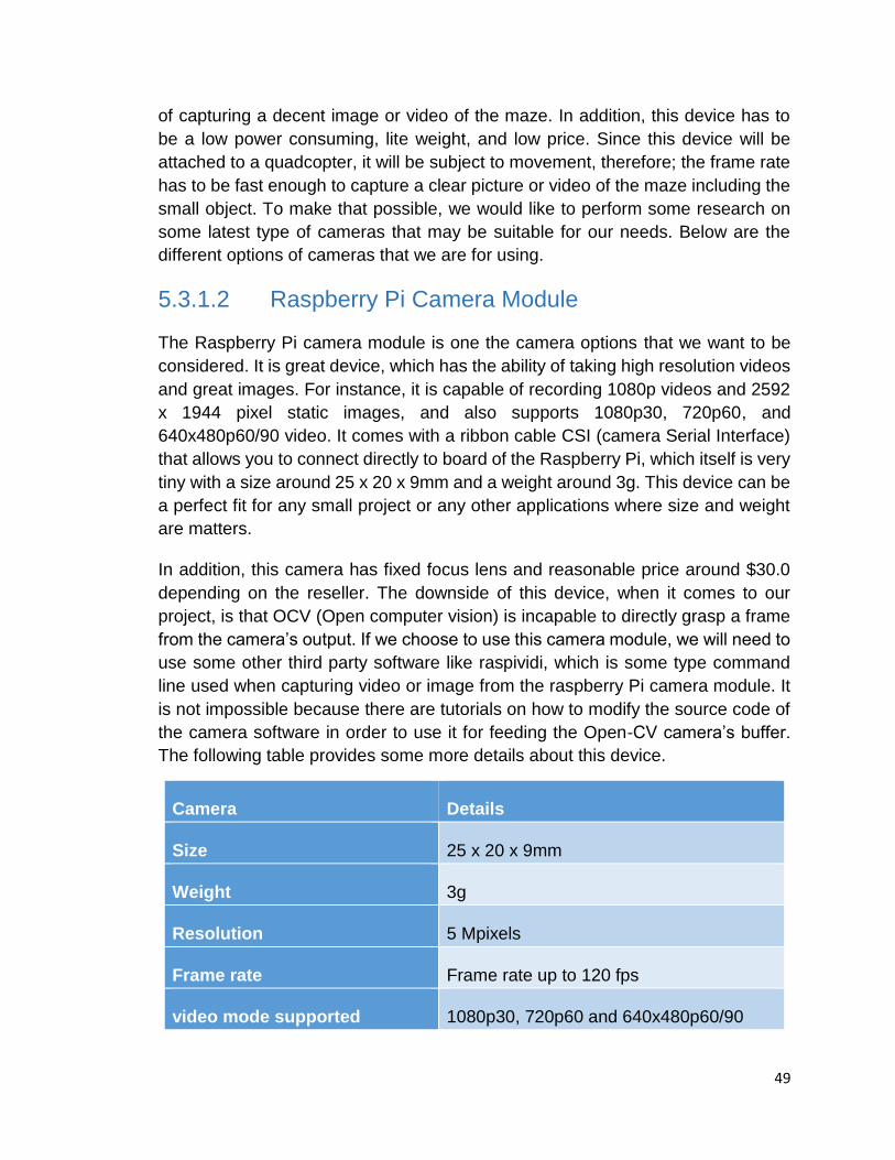
49
of capturing a decent image or video of the maze. In addition, this device has to
be a low power consuming, lite weight, and low price. Since this device will be
attached to a quadcopter, it will be subject to movement, therefore; the frame rate
has to be fast enough to capture a clear picture or video of the maze including the
small object. To make that possible, we would like to perform some research on
some latest type of cameras that may be suitable for our needs. Below are the
different options of cameras that we are for using.
5.3.1.2 Raspberry Pi Camera Module
The Raspberry Pi camera module is one the camera options that we want to be
considered. It is great device, which has the ability of taking high resolution videos
and great images. For instance, it is capable of recording 1080p videos and 2592
x 1944 pixel static images, and also supports 1080p30, 720p60, and
640x480p60/90 video. It comes with a ribbon cable CSI (camera Serial Interface)
that allows you to connect directly to board of the Raspberry Pi, which itself is very
tiny with a size around 25 x 20 x 9mm and a weight around 3g. This device can be
a perfect fit for any small project or any other applications where size and weight
are matters.
In addition, this camera has fixed focus lens and reasonable price around $30.0
depending on the reseller. The downside of this device, when it comes to our
project, is that OCV (Open computer vision) is incapable to directly grasp a frame
from the camera’s output. If we choose to use this camera module, we will need to
use some other third party software like raspividi, which is some type command
line used when capturing video or image from the raspberry Pi camera module. It
is not impossible because there are tutorials on how to modify the source code of
the camera software in order to use it for feeding the Open-CV camera’s buffer.
The following table provides some more details about this device.
Camera Details
Size 25 x 20 x 9mm
Weight 3g
Resolution 5 Mpixels
Frame rate Frame rate up to 120 fps
video mode supported 1080p30, 720p60 and 640x480p60/90

50
Linux integration V4L2 driver available
Sensor Omni Vision OV5647
Sensor resolution 2592 x 1944 pixels
Sensor image area 3.76 x 2.74 mm
Fixed Focus 1 m to infinite
shutter Rolling shutter
Cost around $30
Table 11 Raspberry Pi Specifications
5.3.1.3 Pixy CMUcam5
Another great device is to be considered in our project is the Pixy cam camera. It
is a fast, very smart and easy to use vision sensor camera that can easily program
to detect up to seven different objects with different colors. It is compatible with
most microcontrollers such as Arduino and Raspberry Pi. It comes with 6 to 10-pin
IDC cable that you to connect directly to an Arduino or some other controllers. A
drawback of this device is that it does not have a Wi-Fi build in for sending pictures
or streaming live videos from the UAV to the control base. Since we already recycle
one them we will need to use a microcontroller to perform the wireless transmission
job. By using this device connecting to a Wi-Fi microcontroller capable, we will be
able to wirelessly stream a live video from the Quadcopter to our PC. Below are a
table and some specifications about this device.
Camera details
Size or dimension 50mm x 54mm x 2mm / 2" x 2.1" x 0.08"
Weight 27g
Processor: NXP LPC4330, 204 MHz, dual core
Sensor Omni Vision OV9715
Frame rate 50 frame /sec
Image sensor 1280x800
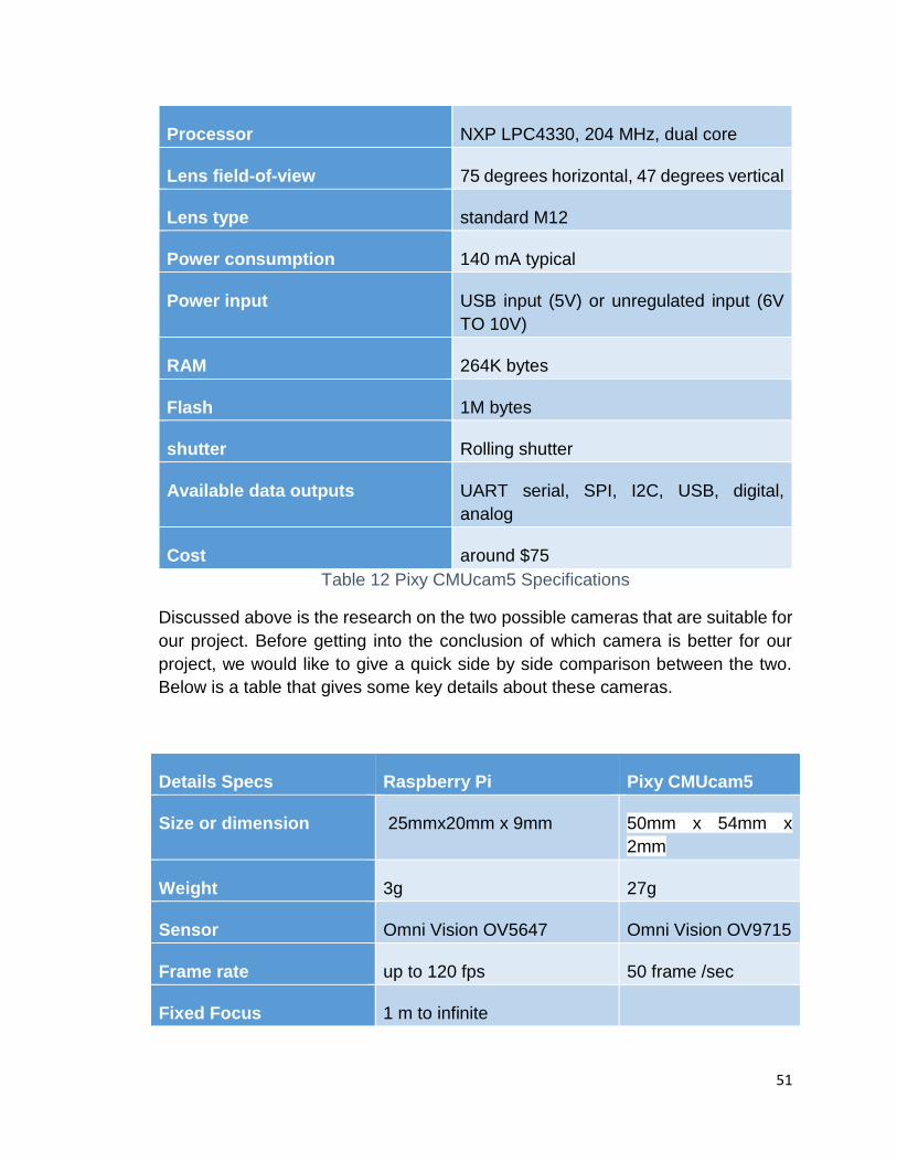
51
Processor NXP LPC4330, 204 MHz, dual core
Lens field-of-view 75 degrees horizontal, 47 degrees vertical
Lens type standard M12
Power consumption 140 mA typical
Power input USB input (5V) or unregulated input (6V
TO 10V)
RAM 264K bytes
Flash 1M bytes
shutter Rolling shutter
Available data outputs UART serial, SPI, I2C, USB, digital,
analog
Cost around $75
Table 12 Pixy CMUcam5 Specifications
Discussed above is the research on the two possible cameras that are suitable for
our project. Before getting into the conclusion of which camera is better for our
project, we would like to give a quick side by side comparison between the two.
Below is a table that gives some key details about these cameras.
Details Specs Raspberry Pi Pixy CMUcam5
Size or dimension 25mmx20mm x 9mm 50mm x 54mm x
2mm
Weight 3g 27g
Sensor Omni Vision OV5647 Omni Vision OV9715
Frame rate up to 120 fps 50 frame /sec
Fixed Focus 1 m to infinite
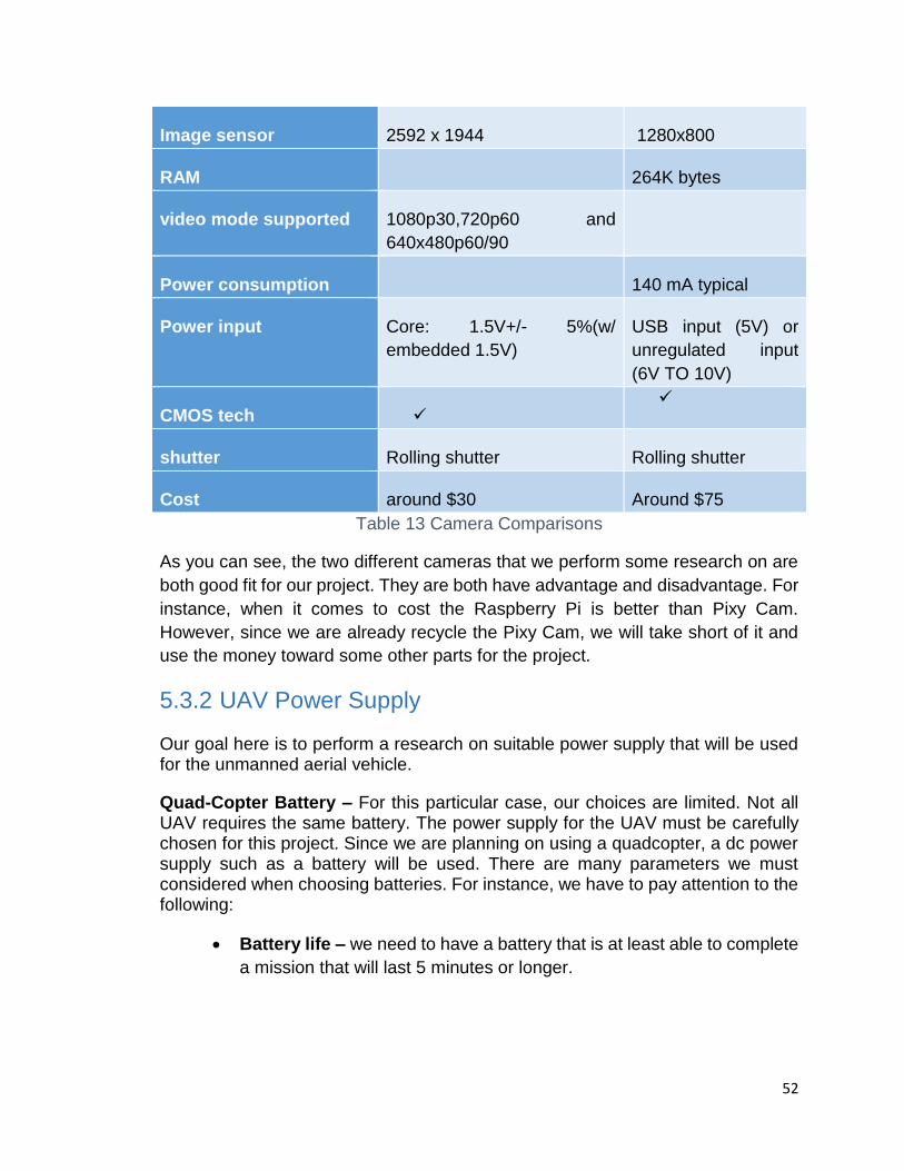
52
Image sensor 2592 x 1944 1280x800
RAM 264K bytes
video mode supported 1080p30,720p60 and
640x480p60/90
Power consumption 140 mA typical
Power input Core: 1.5V+/- 5%(w/
embedded 1.5V)
USB input (5V) or
unregulated input
(6V TO 10V)
CMOS tech
shutter Rolling shutter Rolling shutter
Cost around $30 Around $75
Table 13 Camera Comparisons
As you can see, the two different cameras that we perform some research on are
both good fit for our project. They are both have advantage and disadvantage. For
instance, when it comes to cost the Raspberry Pi is better than Pixy Cam.
However, since we are already recycle the Pixy Cam, we will take short of it and
use the money toward some other parts for the project.
5.3.2 UAV Power Supply
Our goal here is to perform a research on suitable power supply that will be used for the unmanned aerial vehicle.
Quad-Copter Battery – For this particular case, our choices are limited. Not all UAV requires the same battery. The power supply for the UAV must be carefully chosen for this project. Since we are planning on using a quadcopter, a dc power supply such as a battery will be used. There are many parameters we must considered when choosing batteries. For instance, we have to pay attention to the following:
Battery life – we need to have a battery that is at least able to complete
a mission that will last 5 minutes or longer.

53
Recharge time – when it comes to recharging time interval, the battery
must not take too long to recharge. To accomplish such tasks, we must
consider having a quick rechargeable charger.
Weight – Based on the load capacity of the quadcopter, the weight of
the battery is to be taken into account. For instance, the chosen battery
should be under 1kg of weight.
Cost – when it comes to battery, the price can be varied depending on
how well this battery can perform. In this case, we want to stick within our
budget; therefore, we want to buy a battery that is not over $200.
The UAV that we have is a 3DR Pixhawk quadcopter. For this type of quadcopter, here are the two reliable batteries that is to be considered.
Lithium polymer (LiPo) power pack: this battery is compatible with most 3DR X8, X6 and quadcopter. One issue of this battery is that it adds some extra weight to quadcopter which may cause balancing problem. The specs of it are as follow:
4S 14.8 V 10000 mAh 10C
Dimensions: 6.6 in x 2.6 in x 1.4 in or (16.7 cm x 6.5 cm x 3.5 cm)
Weight: 803 g
Cost: about $75.0 depending on the reseller and shipping rates. The
regular price is about $150.
Flight time: from fully charge, it may last about 20 minutes
Y6/X8/Aero Battery Pack: is another battery pack that is compatible with the quad that we will use. It is also a LiPo battery but lighter than LiPo power pack. Shown below is specs for this product.
Specifications:
4S 14.8 V 6000 mAh 35c
Dimensions: 16 cm x 5 cm x 4 cm
Weight: 680 g
Cost: regular price $75. On sale for $9.
Flight time is from 6 to 10 minutes depend on the environment.

54
Figure 15 Batteries
To conclude, both batteries are great for our project. However, there exist some advantages and disadvantages. LiPo power pack is last longer but may be too heavy while the Y6/X8/Aero Battery Pack is cheaper and lighter for our quad. We are planning on using Y6/X8/Aero Battery Pack due to its light weight. Also, we will need to attach other device on board of the UAV.
5.3.3 UAV Transmitter
One of the most important things to consider when building a quadcopter is the
choice of RC transmitter. We decided to purchase a RC transmitter, as opposed
to design one, because the quadcopter is not the focus of our project. When
selecting an RC transmitter it is important to consider the following:
Number of Channels
Flight Modes
Frequency of Transmission
Cost
Controls – The control schemes used by RC transmitters are fairly consistent. The
two control configurations that are often used are:
Mode One – Pitch and yaw are controlled by the left joystick and throttle
and roll is controlled by the right joystick.
Mode Two – Throttle and yaw are controlled by the left joystick and pitch
and roll is controlled by the right joystick.
Mode 2 is used more often than Mode 1 because the movement of the joystick
mirrors the movement of the quadcopter itself. In addition to the movement
joysticks, transmitters have trim buttons that decrease the quadcopter’s tendency

55
to drift. Transmitters with multiple channels will also have buttons to change flight
mode, hold altitude, deploy landing gear, illuminate LEDs, etc.
Number of Channels – The number of channels available determines how many
actions can be controlled from the RC transmitter. The minimum amount of
channels needed to control a quadcopter is four as pitch, roll, throttle, and yaw all
need to be adjusted in order to fly. RC transmitters are available which have six,
eight, and nine channels. These extra channels can be used for other purposes
such as altitude hold, LED illumination, and switching between modes. Our
transmitter will have a minimum of six channels as four will be used for movement,
one for switching modes (altitude hold), and another to trigger the video camera to
take a snapshot.
Flight Modes – There are several different modes of flight which can be alternated
between during flight. The most common are:
Manual Mode – Only uses the gyroscope sensor. The quadcopter will
not level itself if tilted. If the stick is released the quadcopter will remain
tilted.
Self-Level Mode – Uses both accelerometer and gyroscope sensors.
The quadcopter levels itself out if tilted. If the stick is released the
quadcopter will remain hovering.
Attitude Mode – Uses both accelerometer and gyroscope sensors. The
quadcopter attempts to level itself out if tilted. If the stick is released the
quadcopter will slowly drift and wobble as it tries to stabilize.
GPS Hold – Attempts to maintain current GPS position, heading, and
altitude
GPS Home – Returns to pre-programmed starting location
Frequency of Transmission – The two main frequencies that are commonly used
for RC transmission are 72MHz and 2.4GHz. 72MHz has been used for RC
transmission for a much longer period than 2.4GHz; however, today it is more
common to use a 2.4GHz transmitter. While there are some advantages to using
72MHz (longer range than 2.4GHz and receivers are often cheaper) there are
some disadvantages. When flying with others who also use 72MHz RC
transmission interference can occur and crashing of the quadcopter can result.
2.4GHz transmitters have largely replaced 72MHz transmitters because they
provide more available channels and no interference from others flying at the same
frequency. These transmitters are often more expensive and there is a greater risk
of brownout.
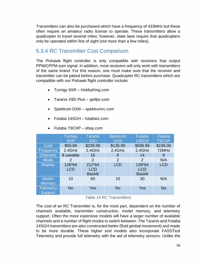
56
Transmitters can also be purchased which have a frequency of 433MHz but these
often require an amateur radio license to operate. These transmitters allow a
quadcopter to travel several miles; however, state laws require that quadcopters
only be operated within line of sight (not more than a few miles).
5.3.4 RC Transmitter Cost Comparison
The Pixhawk flight controller is only compatible with receivers that output
PPM/CPPM sum signal. In addition, most receivers will only work with transmitters
of the same brand. For this reason, one must make sure that the receiver and
transmitter can be paired before purchase. Quadcopter RC transmitters which are
compatible with our Pixhawk flight controller include:
Turnigy 9XR – HobbyKing.com
Taranis X9D Plus – getfpv.com
Spektrum DX6i – spektrumrc.com
Futaba 14SGH – futabarc.com
Futaba T9CHP – ebay.com
Turnigy 9XR
Taranis X9D
Spektrum DX6i
Futaba 14SGH
Futaba T9CHP
Cost $59.99 $239.99 $139.99 $599.99 $199.00
Frequency 2.4GHz 2.4GHz 2.4GHz 2.4GHz 72MHz
Channels 8 useable 16 6 14 9
Mode 2 2 2 2 N/A
Display 128*64 LCD
212*64 LCD
Backlit
LCD 128*64 LCD
Backlit
LCD
Model Memory
10 60 10 30 N/A
Telemetry Support
No Yes No Yes No
Table 14 RC Transmitters
The cost of an RC Transmitter is, for the most part, dependent on the number of
channels available, transmitter construction, model memory, and telemetry
support. Often the more expensive models will have a larger number of available
channels and a number of flight modes to switch between. The Taranis and Futaba
14SGH transmitters are also constructed better (fluid gimbal movement) and made
to be more durable. These higher end models also incorporate FASSTest
Telemetry and provide full telemetry with the aid of telemetry sensors. Unlike the
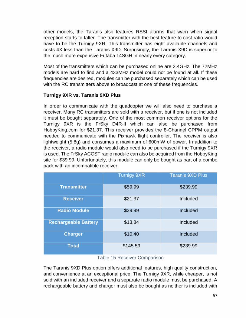
57
other models, the Taranis also features RSSI alarms that warn when signal
reception starts to falter. The transmitter with the best feature to cost ratio would
have to be the Turnigy 9XR. This transmitter has eight available channels and
costs 4X less than the Taranis X9D. Surprisingly, the Taranis X9D is superior to
the much more expensive Futaba 14SGH in nearly every category.
Most of the transmitters which can be purchased online are 2.4GHz. The 72MHz
models are hard to find and a 433MHz model could not be found at all. If these
frequencies are desired, modules can be purchased separately which can be used
with the RC transmitters above to broadcast at one of these frequencies.
Turnigy 9XR vs. Taranis 9XD Plus
In order to communicate with the quadcopter we will also need to purchase a
receiver. Many RC transmitters are sold with a receiver, but if one is not included
it must be bought separately. One of the most common receiver options for the
Turnigy 9XR is the FrSky D4R-II which can also be purchased from
HobbyKing.com for $21.37. This receiver provides the 8-Channel CPPM output
needed to communicate with the Pixhawk flight controller. The receiver is also
lightweight (5.8g) and consumes a maximum of 600mW of power. In addition to
the receiver, a radio module would also need to be purchased if the Turnigy 9XR
is used. The FrSky ACCST radio module can also be acquired from the HobbyKing
site for $39.99. Unfortunately, this module can only be bought as part of a combo
pack with an incompatible receiver.
Turnigy 9XR Taranis 9XD Plus
Transmitter $59.99 $239.99
Receiver $21.37 Included
Radio Module $39.99 Included
Rechargeable Battery $13.84 Included
Charger $10.40 Included
Total $145.59 $239.99
Table 15 Receiver Comparison
The Taranis 9XD Plus option offers additional features, high quality construction,
and convenience at an exceptional price. The Turnigy 9XR, while cheaper, is not
sold with an included receiver and a separate radio module must be purchased. A
rechargeable battery and charger must also be bought as neither is included with

58
the transmitter purchase. Depending on the charge for shipping, the total price of
setting up Turnigy 9XR communication could be comparable to the cost of buying
the Taranis 9XD Plus with everything already included. However, it is unlikely that
shipping will be close to the $100 difference between the two options; the Turnigy
9XD will still be the more economical purchase.
5.3.5 Types of UAVs
Our project will utilize a UAV in the role of a reconnaissance scout with which we will obtain aerial images of the maze. In particular, the UAV will have two main functions: to provide a single aerial photograph of the maze which it will transmit to the hub for a solution, and to provide a live video feed of the maze which will be transmitted to the hub for display on a GUI. Because of live the video element of our project, a UAV capable of stable, stationary flight is necessary.
5.3.5.1 Fixed-Wing Aircraft
Fixed-wing aircraft, such as airplanes, utilize bilateral wings which create lift when the aircraft achieves sufficient forward airspeed. Although some it is possible with these types of aircraft, autonomy is considerably harder to achieve due to the constant forward motion required to generate lift. Though this type of aircraft has a number of advantages over rotorcraft, namely in the areas of speed and range, their integration into the current scope of our project would not be practical due their hovering limitations. Future incarnations of air-to-ground autonomous control systems for commercial and defense purposes, however, may find the implementation of a fixed-wing aircraft more useful over long distances.
5.3.5.2 Rotorcraft
Helicopter – The helicopter is oldest and most well-studied type of rotorcraft. It has a number of advantages related to its relative lack of moving parts.
Pros
Cheapest
Learning to fly has a milder learning curve
Long battery life and flight time
Light weight body yields better crash recovery
Simplistic design makes it easy to modify and repair
Cons
Least stable

59
Least efficient
Least safe in the event of motor failure
5.3.5.3 Multirotor
Multirotor aircraft are a type of rotorcraft that use more than one rotor to achieve lift. These are ideal for our project since they can achieve relatively stable stationary flight and have the ability to carry the weight of additional hardware.
Tricopter – Tricopters are probably the least common type of multirotor UAV, though they have a number of stability advantages over helicopters and cost and weight advantages over larger multirotor aircraft.
Pros
Cheapest type of multirotor
Easy to repair and modify
Excellent flight time
Lightest multirotor
Cons
Least thrust of any multirotor
Can only reach limited heights
Quadcopter – Quadcopters are probably the most common type of UAV on the market. This because they are midrange in almost all relative advantages and disadvantages among multirotor aircraft. As opposed to the tricopter, the quadcopter and all higher order multirotor aircraft have an even number of rotors which allows for balanced rotation of the rotors (see figure below).
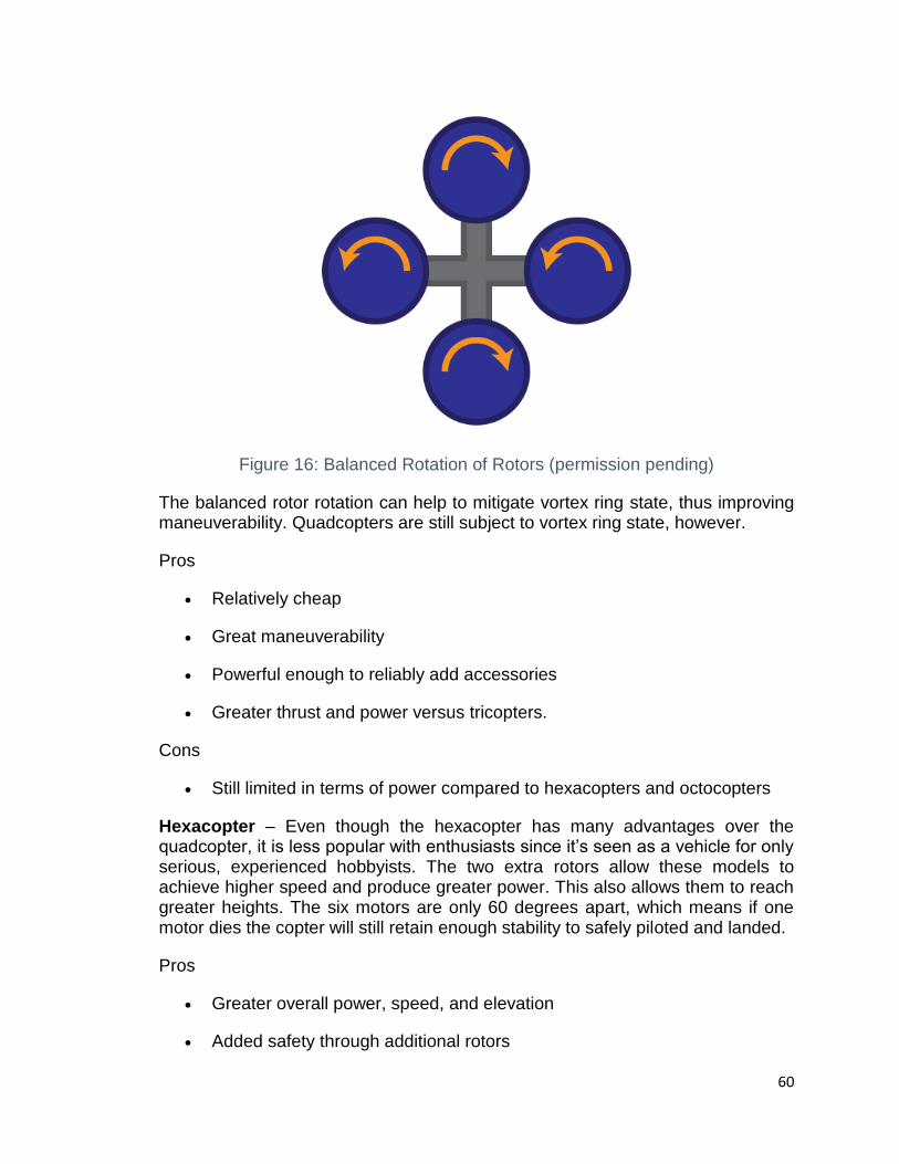
60
Figure 16: Balanced Rotation of Rotors (permission pending)
The balanced rotor rotation can help to mitigate vortex ring state, thus improving maneuverability. Quadcopters are still subject to vortex ring state, however.
Pros
Relatively cheap
Great maneuverability
Powerful enough to reliably add accessories
Greater thrust and power versus tricopters.
Cons
Still limited in terms of power compared to hexacopters and octocopters
Hexacopter – Even though the hexacopter has many advantages over the quadcopter, it is less popular with enthusiasts since it’s seen as a vehicle for only serious, experienced hobbyists. The two extra rotors allow these models to achieve higher speed and produce greater power. This also allows them to reach greater heights. The six motors are only 60 degrees apart, which means if one motor dies the copter will still retain enough stability to safely piloted and landed.
Pros
Greater overall power, speed, and elevation
Added safety through additional rotors

61
Higher payload possible
Excellent stability
Cons
Higher priced
Considerably larger
Parts are more costly
Octocopter – Every advantage seen in the hexacopter is essentially multiplied in the octocopter. They are the fastest and most stable multirotor aircraft available. They are not hindered as much by inclement conditions. Losing a motor would only diminish vehicle stability to the level of a hexacopter, allowing for several motors to fail.
Pros
Extremely fast
Can reach exceptionally high altitudes
Highest possible power
Highest possible payload
Greatest amount of safety and stability
Cons
Large and cumbersome
Most expensive
Limited battery life
5.3.5.4 UAV Conclusion
Because of the many choices we have in regards to UAV selection, we decided to rank each aspect of the various UAVs based with respect to the set and create a decision matrix to generate a score for best choice of UAV. A rank of 1 for any given parameter corresponds to the greatest rank among the set for that parameter. The lowest total score generated by the decision matrix will be our choice for UAV.
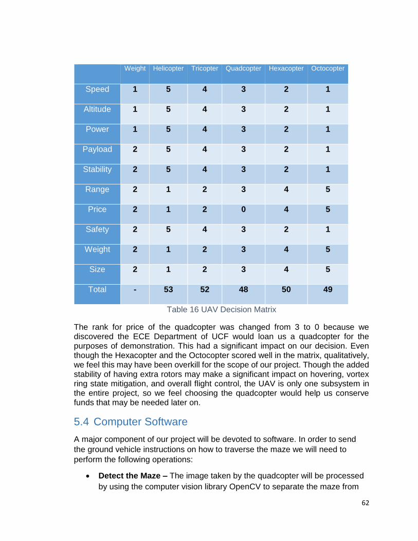
62
Weight Helicopter Tricopter Quadcopter Hexacopter Octocopter
Speed 1 5 4 3 2 1
Altitude 1 5 4 3 2 1
Power 1 5 4 3 2 1
Payload 2 5 4 3 2 1
Stability 2 5 4 3 2 1
Range 2 1 2 3 4 5
Price 2 1 2 0 4 5
Safety 2 5 4 3 2 1
Weight 2 1 2 3 4 5
Size 2 1 2 3 4 5
Total - 53 52 48 50 49
Table 16 UAV Decision Matrix
The rank for price of the quadcopter was changed from 3 to 0 because we discovered the ECE Department of UCF would loan us a quadcopter for the purposes of demonstration. This had a significant impact on our decision. Even though the Hexacopter and the Octocopter scored well in the matrix, qualitatively, we feel this may have been overkill for the scope of our project. Though the added stability of having extra rotors may make a significant impact on hovering, vortex ring state mitigation, and overall flight control, the UAV is only one subsystem in the entire project, so we feel choosing the quadcopter would help us conserve funds that may be needed later on.
5.4 Computer Software
A major component of our project will be devoted to software. In order to send
the ground vehicle instructions on how to traverse the maze we will need to
perform the following operations:
Detect the Maze – The image taken by the quadcopter will be processed
by using the computer vision library OpenCV to separate the maze from
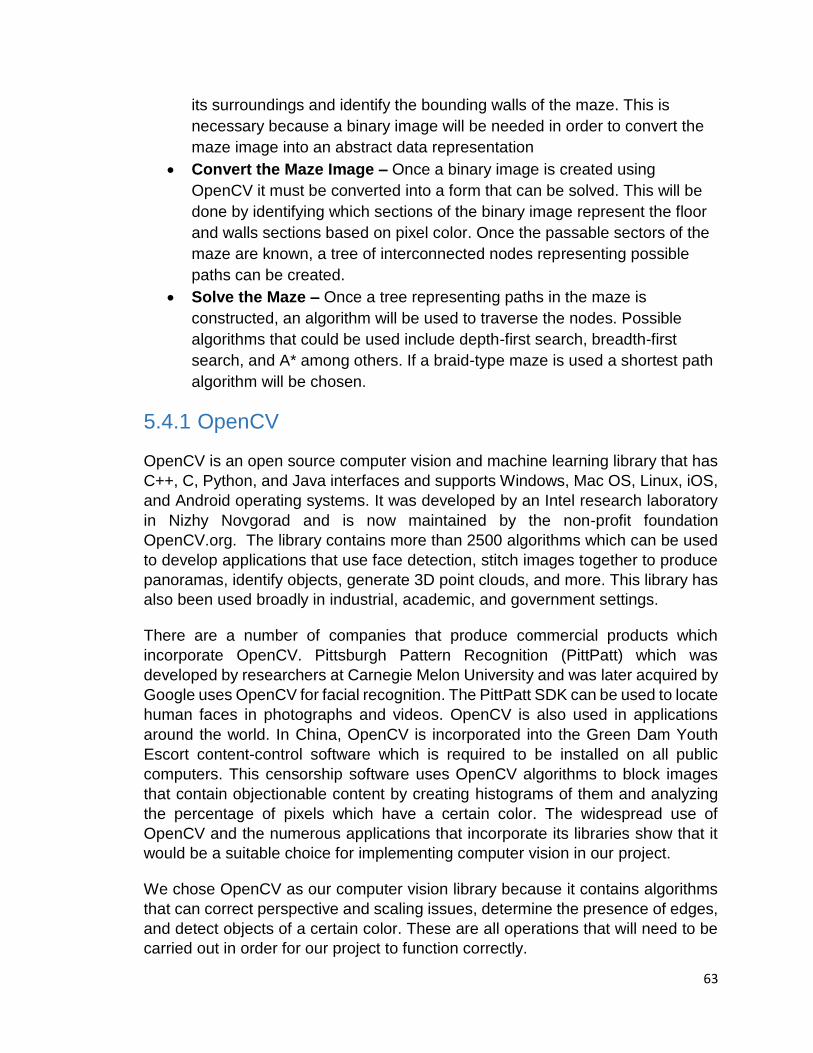
63
its surroundings and identify the bounding walls of the maze. This is
necessary because a binary image will be needed in order to convert the
maze image into an abstract data representation
Convert the Maze Image – Once a binary image is created using
OpenCV it must be converted into a form that can be solved. This will be
done by identifying which sections of the binary image represent the floor
and walls sections based on pixel color. Once the passable sectors of the
maze are known, a tree of interconnected nodes representing possible
paths can be created.
Solve the Maze – Once a tree representing paths in the maze is
constructed, an algorithm will be used to traverse the nodes. Possible
algorithms that could be used include depth-first search, breadth-first
search, and A* among others. If a braid-type maze is used a shortest path
algorithm will be chosen.
5.4.1 OpenCV
OpenCV is an open source computer vision and machine learning library that has
C++, C, Python, and Java interfaces and supports Windows, Mac OS, Linux, iOS,
and Android operating systems. It was developed by an Intel research laboratory
in Nizhy Novgorad and is now maintained by the non-profit foundation
OpenCV.org. The library contains more than 2500 algorithms which can be used
to develop applications that use face detection, stitch images together to produce
panoramas, identify objects, generate 3D point clouds, and more. This library has
also been used broadly in industrial, academic, and government settings.
There are a number of companies that produce commercial products which
incorporate OpenCV. Pittsburgh Pattern Recognition (PittPatt) which was
developed by researchers at Carnegie Melon University and was later acquired by
Google uses OpenCV for facial recognition. The PittPatt SDK can be used to locate
human faces in photographs and videos. OpenCV is also used in applications
around the world. In China, OpenCV is incorporated into the Green Dam Youth
Escort content-control software which is required to be installed on all public
computers. This censorship software uses OpenCV algorithms to block images
that contain objectionable content by creating histograms of them and analyzing
the percentage of pixels which have a certain color. The widespread use of
OpenCV and the numerous applications that incorporate its libraries show that it
would be a suitable choice for implementing computer vision in our project.
We chose OpenCV as our computer vision library because it contains algorithms
that can correct perspective and scaling issues, determine the presence of edges,
and detect objects of a certain color. These are all operations that will need to be
carried out in order for our project to function correctly.
64
5.4.1.1 Perspective and Scaling
The snapshot below taken by the quadcopter must be free of distortion and rotation
in order to accurately convert the maze image into a solvable graph. If this is not
done, there is a risk of generating a graph that does not represent the actual layout
of the maze. A graph of the maze will be created by dividing the maze image into
a grid of cells with equal dimensions. If the image is rotated, the type of cell could
be incorrectly determined to be a floor section when there is actually a wall section
present as shown in the figure above. When a segment of the maze is divided into
four cells as shown in figure 1, it is clear that the cell should be either wall (black)
or floor (white). However, in the second figure distortion can cause a cell to have
a significant portion of both black and white pixels. In this case it is unclear of
whether the cell is a floor or wall tile. To prevent this situation from occurring, a
number of methods will be used to straighten the image.
Figure 17 Perspective and Scaling Correction
Geometric Transformations – Geometric transformations can be used to scale,
translate, and rotate an image. These transformations may be required if the
snapshot taken is rotated or distorted due to instability in the quadcopter or poor
camera quality, respectfully. When the quadcopter is hovering in the air it may
experience imbalance due to wind, variation in motor function, or poor calibration.
As a precaution, image processing will correct these discrepancies through affine
transformation. OpenCV also has algorithms that correct errors in perspective.
These could be used to allow the quadcopter to take an aerial view from a position
other than the center of the maze or from a lower altitude.
Image Pyramids – Another approach to correcting scaling issues is to use image
pyramids. Image pyramids are sets of images with different resolution that can be
used to aid object detection. There are two types of image pyramids:
Gaussian Pyramid – An image with high resolution is used as a kernel to produce higher levels of images with lower resolution. This is done by scaling the kernel image down by a factor of 2 and then blurring it by applying a smoothing filter.
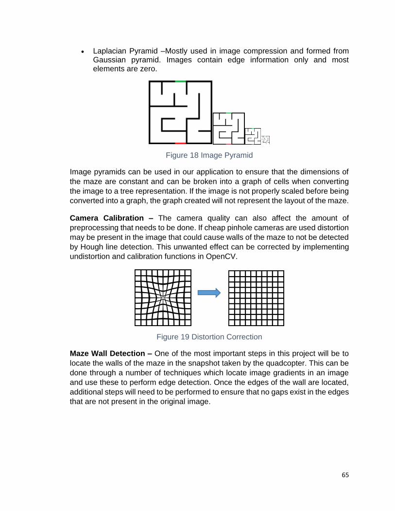
65
Laplacian Pyramid –Mostly used in image compression and formed from Gaussian pyramid. Images contain edge information only and most elements are zero.
Figure 18 Image Pyramid
Image pyramids can be used in our application to ensure that the dimensions of
the maze are constant and can be broken into a graph of cells when converting
the image to a tree representation. If the image is not properly scaled before being
converted into a graph, the graph created will not represent the layout of the maze.
Camera Calibration – The camera quality can also affect the amount of
preprocessing that needs to be done. If cheap pinhole cameras are used distortion
may be present in the image that could cause walls of the maze to not be detected
by Hough line detection. This unwanted effect can be corrected by implementing
undistortion and calibration functions in OpenCV.
Figure 19 Distortion Correction
Maze Wall Detection – One of the most important steps in this project will be to
locate the walls of the maze in the snapshot taken by the quadcopter. This can be
done through a number of techniques which locate image gradients in an image
and use these to perform edge detection. Once the edges of the wall are located,
additional steps will need to be performed to ensure that no gaps exist in the edges
that are not present in the original image.
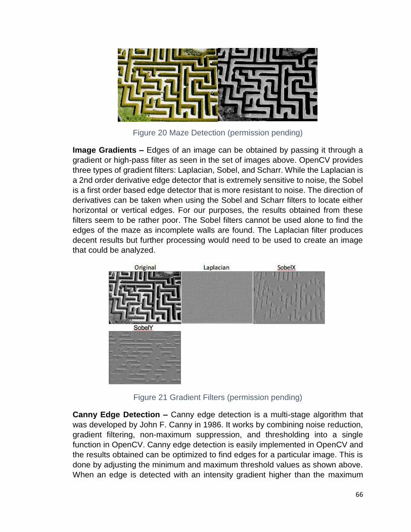
66
Figure 20 Maze Detection (permission pending)
Image Gradients – Edges of an image can be obtained by passing it through a
gradient or high-pass filter as seen in the set of images above. OpenCV provides
three types of gradient filters: Laplacian, Sobel, and Scharr. While the Laplacian is
a 2nd order derivative edge detector that is extremely sensitive to noise, the Sobel
is a first order based edge detector that is more resistant to noise. The direction of
derivatives can be taken when using the Sobel and Scharr filters to locate either
horizontal or vertical edges. For our purposes, the results obtained from these
filters seem to be rather poor. The Sobel filters cannot be used alone to find the
edges of the maze as incomplete walls are found. The Laplacian filter produces
decent results but further processing would need to be used to create an image
that could be analyzed.
Figure 21 Gradient Filters (permission pending)
Canny Edge Detection – Canny edge detection is a multi-stage algorithm that
was developed by John F. Canny in 1986. It works by combining noise reduction,
gradient filtering, non-maximum suppression, and thresholding into a single
function in OpenCV. Canny edge detection is easily implemented in OpenCV and
the results obtained can be optimized to find edges for a particular image. This is
done by adjusting the minimum and maximum threshold values as shown above.
When an edge is detected with an intensity gradient higher than the maximum

67
threshold value it is assumed to be an edge and will be marked in the final image.
The effect of raising this value is seen in the set of images above when ‘Max’
changes from 250 to 900. This causes a decrease in the number of edges present.
On the contrary, values below the minimum threshold are assumed to not be
edges. When this value is lowered from 180 to 10, additional edges are found that
are not actual edges in the original picture. The ideal threshold for this image of a
maze was found to be 180 and 250 for minimum and maximum threshold values,
respectfully. This range ensures that non-edges are not included and that actual
edges are not diminished.
Min: 180 Max: 250 Min: 10 Max: 250
Min: 180 Max: 900
Figure 22 Edge Detection
Object Detection – In addition to detecting the walls of the maze, we will also
need to locate an object within it. We have decided to require the ground vehicle
to find a tennis ball placed within the maze due to its fluorescent yellow color and
spherical shape. The tennis ball can be detected by using computer vision
algorithms which threshold the image based on color and others that detect circles.
It is important to locate this object because it will serve as the exit of the maze.
Once the tennis ball is found, a new path out of the maze will be calculated.

68
Image Thresholding – Image thresholding can be used to locate the position of a
tennis ball within the boundaries of the maze so that the ground vehicle can be
directed towards it. This will be done by opening the image taken by the quadcopter
in OpenCV and converting it from a BGR to HSV colorspace. This is done to make
the object detection algorithm more robust against lighting variation; HSV
separates intensity from color information unlike BGR which blends the two. Next,
the HSV image will be thresholded for a range of yellow color. This is accomplished
by choosing a lower color threshold and upper color threshold with encompass
different hues of yellow. For the above images, lower and upper thresholds were
[20, 100, 100] and [30, 255, 255], respectfully.
Original Photo with Ball Mask for HSV color range Extract Yellow Object
Figure 23 Thresholding (permission pending)
Hough Circle Transform – Another option to identify the tennis ball in the
snapshot taken by the quadcopter is to use the Hough circle transform to locate
any circles that appear in the image. This algorithm can easily be implemented in
OpenCV and its parameters can be adjusted to find circles with a certain radius.
The parameters min_radius and max_radius can be used to find different circle
sizes within a range. In addition, the Hough circle transform can also detect
overlapping circles and separate them if enough of the boundary is visible.
Figure 24 Hough Circle (permission pending)
Feature Detection – The final option we could use to locate the tennis ball is
feature detection. Feature detection can be used to detect objects that have
undergone an affine transformation. This option would work for our project, but it

69
is more suited to an application that involves video streaming. In this case, there
would be scaling and perspective changes that will need to be addressed in order
to perform object detection. Template matching is one of the simplest forms of
feature detection that uses a separate template image to scan through a larger
image; however, this method is not robust against perspective and rotation
alteration. Since the quadcopter is hovering above the maze at a predetermined
height the snapshot taken of the maze below will have differences in scale across
sessions and rotation may be present. This would lead to template matching being
a poor choice to detect the tennis ball. More robust options include the SIFT and
ORB algorithms present in OpenCV. SIFT is a scale-invariant feature detection
algorithm that uses descriptors to match keypoints (features) between two images.
This algorithm would be usable because it is not affected by scaling and
perspective issues. The ORB algorithm is often used as an alternative to SIFT
because it does not require a commercial license to use in applications.
5.4.2 Binary Image Conversion When the maze is converted from a binary image and broken up into a graph the
non-wall sections of the maze are broken up into nodes which are linked together
to form paths or branches. The resulting structure is akin to a tree which can be
traversed using common search algorithms such as Breadth-First Search, A*, and
Dead-End Filling.
Figure 25 Image conversion
This will be done by taking a binary image of the maze (similar to the one above)
and dissecting it into a grid of small cells. Each cell will either be white (maze floor
– open space) or black (maze wall – blocked space) and will have the same
dimensions. Each cell marked as open will be added to an array and the
neighboring open cells will be identified and connected to one another to form a
tree structure similar to the one below.

70
Figure 26 Tree Representation of Maze
5.4.3 Maze Solving Algorithms
There are two approaches that one can take when solving a maze. The first is
used when a traveler is traversing a maze without knowledge of its layout and the
second is used only when the entire layout of the maze is available. The choice of
which to use is dependent on whether or not the whole maze can be viewed at
once. Our design will use the second approach to maze solving as the quadcopter
positioned above the maze will take a snapshot of its entirety from overhead.
If the maze traveler does not have any knowledge of the maze’s layout, algorithms
can be used that will allow them to intelligently (or unintelligently) traverse the
maze. These include the random mouse, wall follower, Pledge, and Trémaux
algorithms. Conversely, if the layout out the maze is known, a solution can be found
by applying the Dead-End Elimination algorithm, image analysis, or a number of
other algorithms to compute the shortest path. An introduction to some of these
algorithms is provided below.
Random Mouse – The random mouse algorithm is one of the easiest algorithms
to implement when solving a maze, but it is also an unintelligent approach that is
by no means efficient. It works by instructing the robot to move along a passage in
the maze until an intersection is reached. Once this occurs, the robot will choose
path at random until it comes upon the next junction. This will continue until the
finds the goal or the battery of the robot is depleted. If the maze is sufficiently large
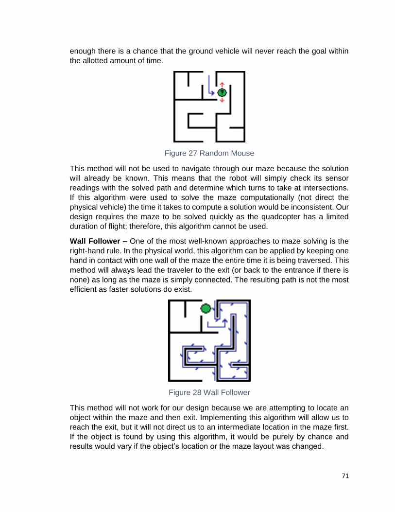
71
enough there is a chance that the ground vehicle will never reach the goal within
the allotted amount of time.
Figure 27 Random Mouse
This method will not be used to navigate through our maze because the solution
will already be known. This means that the robot will simply check its sensor
readings with the solved path and determine which turns to take at intersections.
If this algorithm were used to solve the maze computationally (not direct the
physical vehicle) the time it takes to compute a solution would be inconsistent. Our
design requires the maze to be solved quickly as the quadcopter has a limited
duration of flight; therefore, this algorithm cannot be used.
Wall Follower – One of the most well-known approaches to maze solving is the
right-hand rule. In the physical world, this algorithm can be applied by keeping one
hand in contact with one wall of the maze the entire time it is being traversed. This
method will always lead the traveler to the exit (or back to the entrance if there is
none) as long as the maze is simply connected. The resulting path is not the most
efficient as faster solutions do exist.
Figure 28 Wall Follower
This method will not work for our design because we are attempting to locate an
object within the maze and then exit. Implementing this algorithm will allow us to
reach the exit, but it will not direct us to an intermediate location in the maze first.
If the object is found by using this algorithm, it would be purely by chance and
results would vary if the object’s location or the maze layout was changed.

72
Pledge – If the walls of a maze are not simply connected the wall follower will fail
to locate the exit. When this type of maze is required to be solved the Pledge
algorithm can be used in its place. The Pledge algorithm requires a direction to
move toward to be randomly chosen and a turn counter to be used. When
implemented the vehicle will move towards the chosen direction until it reaches an
obstacle. The vehicle will then either turn left or right depending on if the right or
left side algorithm is chosen. When the turn is made the counter will increment or
decrement (depending on direction of the turn) and move in that direction if it is
able. If it is unable it will turn in the same direction until it is able to progress. Once
the vehicle is able to move in the original direction chosen, it will reorient and move
in that direction once more.
Dead-end Filling – This algorithm involves locating the location of all dead ends
in a maze and then filling them in until a junction is reached. This is only possible
if the entire maze is visible and, as such, it is not useful to a traveler within the
maze that has no knowledge of its layout. In our design the quadcopter is capturing
a snapshot of the entire maze’s layout and the dead-end filling algorithm can be
used. This algorithm will produce a path that is efficient and there is no risk of the
final path resulting in an unsolvable maze. The only case where the path generated
would not be the shortest is if a braid maze was used that features no dead ends.
This would result in multiple paths being computed that each lead to the exit.
Another algorithm would need to be used in order to reveal the shortest path.
Figure 29 Dead-end filling
Depth-First Search (Trémaux’s Algorithm) – Depth-First Search (DFS) is an
algorithm which traverses the tree representation of a maze by arbitrarily choosing
a node and then exploring as far as possible along each branch. The above figures
show how this process is used to solve the maze. Starting from the green tile a
direction is chosen and then the path is explored until terminated by a dead end.
When a dead end is reached the algorithm traverses back up the branch to the
nearest adjacent node and follows its branch to completion. This process
continues until a path to the exit is discovered as shown in the last picture.
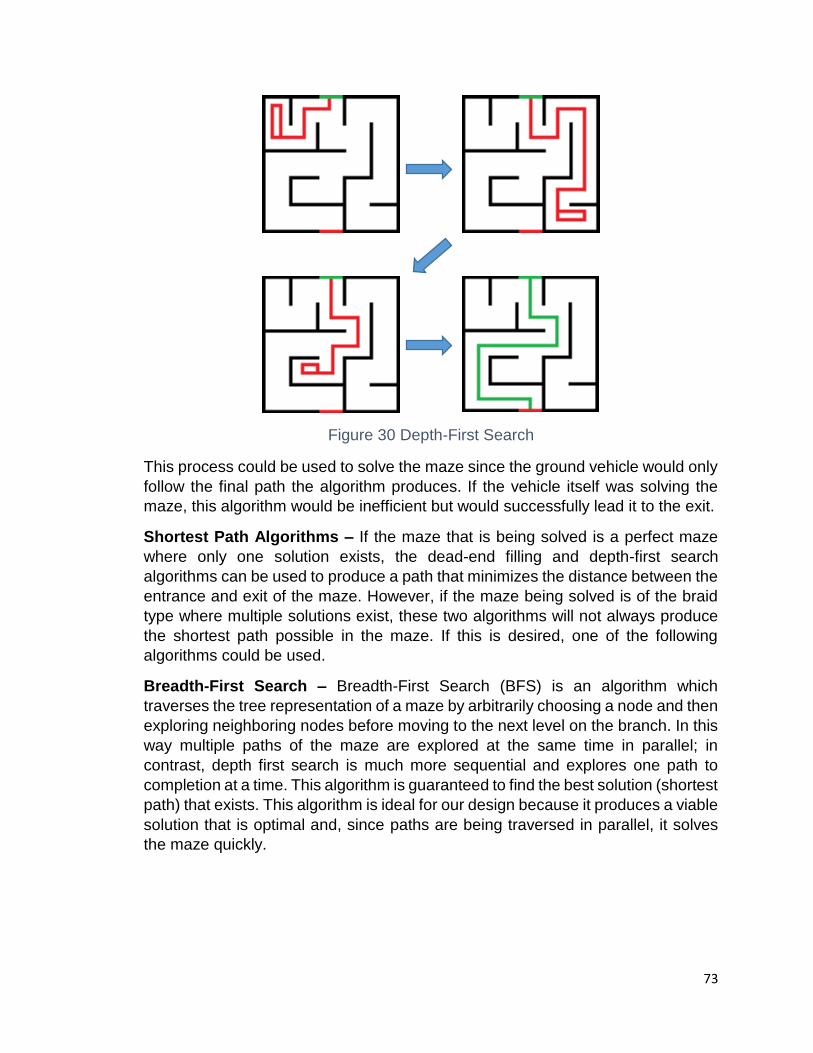
73
Figure 30 Depth-First Search
This process could be used to solve the maze since the ground vehicle would only
follow the final path the algorithm produces. If the vehicle itself was solving the
maze, this algorithm would be inefficient but would successfully lead it to the exit.
Shortest Path Algorithms – If the maze that is being solved is a perfect maze
where only one solution exists, the dead-end filling and depth-first search
algorithms can be used to produce a path that minimizes the distance between the
entrance and exit of the maze. However, if the maze being solved is of the braid
type where multiple solutions exist, these two algorithms will not always produce
the shortest path possible in the maze. If this is desired, one of the following
algorithms could be used.
Breadth-First Search – Breadth-First Search (BFS) is an algorithm which
traverses the tree representation of a maze by arbitrarily choosing a node and then
exploring neighboring nodes before moving to the next level on the branch. In this
way multiple paths of the maze are explored at the same time in parallel; in
contrast, depth first search is much more sequential and explores one path to
completion at a time. This algorithm is guaranteed to find the best solution (shortest
path) that exists. This algorithm is ideal for our design because it produces a viable
solution that is optimal and, since paths are being traversed in parallel, it solves
the maze quickly.
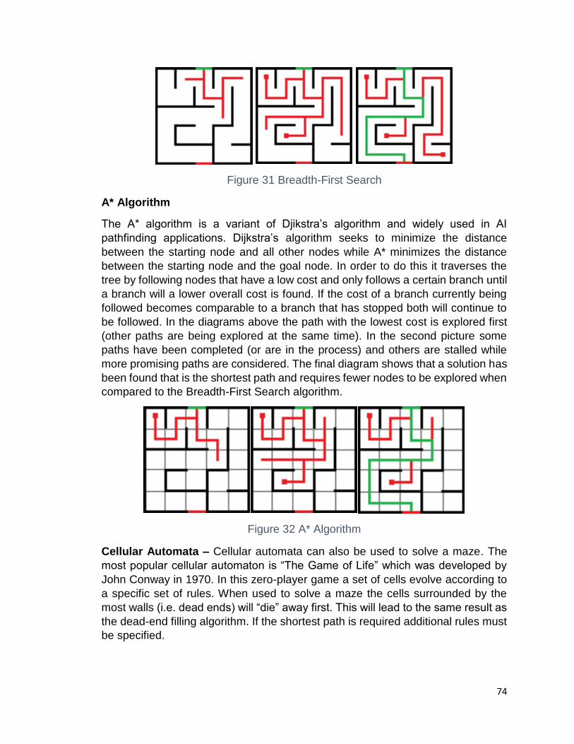
74
Figure 31 Breadth-First Search
A* Algorithm
The A* algorithm is a variant of Djikstra’s algorithm and widely used in AI
pathfinding applications. Dijkstra’s algorithm seeks to minimize the distance
between the starting node and all other nodes while A* minimizes the distance
between the starting node and the goal node. In order to do this it traverses the
tree by following nodes that have a low cost and only follows a certain branch until
a branch will a lower overall cost is found. If the cost of a branch currently being
followed becomes comparable to a branch that has stopped both will continue to
be followed. In the diagrams above the path with the lowest cost is explored first
(other paths are being explored at the same time). In the second picture some
paths have been completed (or are in the process) and others are stalled while
more promising paths are considered. The final diagram shows that a solution has
been found that is the shortest path and requires fewer nodes to be explored when
compared to the Breadth-First Search algorithm.
Figure 32 A* Algorithm
Cellular Automata – Cellular automata can also be used to solve a maze. The
most popular cellular automaton is “The Game of Life” which was developed by
John Conway in 1970. In this zero-player game a set of cells evolve according to
a specific set of rules. When used to solve a maze the cells surrounded by the
most walls (i.e. dead ends) will “die” away first. This will lead to the same result as
the dead-end filling algorithm. If the shortest path is required additional rules must
be specified.

75
Watershed Transform – The final maze solving approach we are considering is
using image analysis to solve a maze. The watershed transform will be used to
perform image segmentation on an image of a perfect (single solution) maze.
Since this maze is composed of two distinct walls, two catchment basins will be
produced by the transform. The watershed line that separates these two basins
is the solution path for the maze. Once this is done the interface solution can be
extracted.
Figure 33 Watershed transform (permission pending)
This approach is limited and cannot be used to navigate the ground vehicle
because the solution is graphically found and not computed from a collection of
nodes. This means that little information can be gleaned to pinpoint where turns
need to be made and determine distance to travel. In addition, our design will
involve the use of a braid type maze which will have multiple solutions and this
method will not be applicable.
5.4.4 Mission Planner
The goal for this project is to be able to autonomously move the quadcopter above
the maze without the need of using an RC radio and have it stay hovered above
the maze. In order to do this, mission planner software is required. Mission planner
software will allow us to pre-program the quadcopter with instructions and will set
it to autopilot with the given instructions. What we want the quadcopter to do is a
very simple set of instructions which:
1. Turn quadcopter on
2. Ascend to a height of 20ft
3. Move forward 3ft to be positions above the maze
4. Once maze has been solved, go back to original position on ground
5. Turn quadcopter off

76
Our quadcopter is a “Do it yourself” (DIY) kit from 3Drobotics. The website provides
mission planning software in order to do this. The basic procedure for our case is
fairly simple. First we would have to program in a “takeoff” event that will tell the
quadcopter to start takeoff at a specified height. The next step is to add waypoints
to the flight path, which will actually create the quadcopters flight path. After adding
the waypoint destination you have to add a landing event, where you add a third
waypoint where you want the drone to land. The figure below shows the waypoint
implementation in the software. Although, this may not be possible for our project
though. We need precision when piloting our quadcopter because it needs to hover
exactly over the maze at an exact height. This may not be possible because the
mission planner software gets somewhere within 2 meters of the set waypoint. If
implementing mission planner software is unsuccessful, we will manually pilot the
quadcopter with an RC radio controller.
Figure 34 Waypoint implementation (permission granted)
There are many things to consider when programming the quadcopter with mission
planning software. These include environmental awareness, radio signal
conditions, altitude, power management, and being able to regain manual control
of the quadcopter. When looking at environmental awareness, proper boundaries
must be drawn to insure a safe flying area, and to take into account ant risks that
might be at the location of flying. When taking radio signal conditions into account,
you have to be sure that when the quadcopter is flying behind any type of object,
the radio signal to control the quadcopter is unobstructed to insure a safe flight,
and also take into account interference from other sources around if flying in a
populated area. Altitude should be appropriate for the location the quadcopter is
77
flying in and should abide by local regulations. The mission planning does not take
into account battery life so it is up to the operator to ensure that the flight time does
not outstretch the life of the battery, or it can create dangers for people around the
quadcopter if it fails. In case something does go wrong with the mission planning
software on the quadcopter, always keep the RC radio controller on hand and
switch to standard mode to regain the manual control of the quadcopter. Keeping
all these safety tips in mind will ensure a safe and successful flight.
5.4.4.1 GeoFencing
GeoFencing is an important thing to consider whenever flying UAVs such as the
quadcopter being used in our project. A GeoFence is a virtual perimeter that is
programmed into the quadcopter, and the quadcopter will not be able fly outside
of these boundaries. This prevents the quadcopter for unintentionally flying too far
away, thus losing control and possibly losing the quadcopter itself. GeoFencing is
also used for safety, as there have been cases even during the UCF senior design
presentations where a quadcopter journeyed too far unintentionally was never
recovered, and it’s always possible that the quadcopter could either crash or
deplete its battery and cause others harm when it does crash, which is why
GeoFencing is needed. To set up the GeoFencing option for the quadcopter, we
will be using the mission planner software that the 3DRobotics website provides,
which was also discussed in the Mission Planner section.
There are five parameters when setting up the GeoFence:
1. Type – This is the type of geofence you want. It ranges from altitude, circle, and altitude and circle. Altitude will prevent the quadcopter from going above a certain altitude (FAA regulations state that it can go no higher than 400 ft). A circle is for the maximum distance it can travel, and obviously the third option is a combination of both altitude and circle.
2. Action: This determines what happens when the quadcopter passes the
geofence. There are two options to choose from, one being RTL and the
other being land. If choosing RTL, it will fly back to the its starting position
from where it took off, and if the Land option is chosen, it will as soon as it
passes the geofence. The option is determined by whatever failsafe the
quadcopter is configured with (Land or RTL). RTL is the more likely option
as if Land is chosen, it will land where the end of that geofence is,
regardless if its over a body of water or someone’s house, so the better
option is to use RTL.
3. Max Altitude – This setting is just the max height that the quadcopter will be able to reach before the action/failsafe takes into effect.

78
4. Max Radius – This setting is just the max radius that the quadcopter will be able to reach before the action/failsafe takes into effect.
5. RTL Altitude – This is the altitude that the quadcopter will reach once it gets past the GeoFence before returning, so for example if the altitude for the quadcopter is 60ft, and it passes the GeoFence and the RTL altitude is set for 100ft, the quadcopter will go up to 100ft to ensure that it will not have any obstacles when returning.
5.5 Wireless Technologies
Wireless communications is one of the most important elements in our project and several functions of the project depend data being transmitted successfully. The quad-copter will have a camera which will be streaming video of the maze and ground vehicle at a 480p resolution to our “base” which is a laptop in order to do the processing to solve the maze. Once the software on the base finds a path for the maze, it must send commands to our ground vehicle so it may start going navigating through the maze. There are many different types of wireless short range communications that were explored such at Bluetooth, Wi-fi, and ZigBee. The main factors that have to be considered when choosing a type of wireless communication are range, data transfer rate, and the wireless frequency that we will be operating on, and also the cost of implementing the wireless communication will be factored in.
5.5.1 Bluetooth
Bluetooth (IEEE 802.15.11 standard) is a possible wireless communication that was considered. We have to look at the factors involved when choosing an appropriate wireless technology, first being the range. Bluetooth is has a short range typically varying around 10m depending on the class of technology used, with the 10m range using the commonly used Bluetooth 2.0. But for our purposes, this range most likely would be not be sufficient because the quad-copter will be hovering approximately 20ft above the maze, and then we have to consider the distance to the base which will have to be a safe distance away of 20 feet so Bluetooth would most likely have trouble connecting to our base and not be able to send a steady signal. Bluetooth is primarily used for sending small amounts of data a time at approximately 1-3 mbps operating on a 2.4 GHz spectrum. This type of transfer rate would most likely be sufficient because we would only be sending commands to our ground vehicle which will interpret those commands, and the commands themselves do not take up that much data. Although, a clear advantage of using Bluetooth technology is that it is relatively cheaper than most other competing technologies. Another advantage of using Bluetooth is that it easy to use in many locations such an outside setting, which our project will most likely take place, and other forms of wireless communication rely on networks that are in buildings such as Wi-Fi. In the end, we were not able to use Bluetooth

79
technology mainly due to it most likely not having sufficient range, and the fact there are other wireless technologies that support all the characteristics we need.
Pros:
Good throughput (1-3 Mbps)
Low cost
Cons:
Low range
Higher cost compared to ZigBee
Not power efficient
5.5.2 Wi-Fi
Wi-Fi (IEEE 802.11 b/g/n standard) is another option to use for our short-range wireless communication. Looking at the main factors, Wi-Fi looks to be advantageous in almost every way. If we were to use Wi-Fi we would be using the 802.11b protocol which operates on a 2.4 GHz frequency. When we look at the range, we see it has a range of about 200 feet which is more than sufficient for our purposes of sending a stream to our base. Wi-Fi is also able to have a max data transfer rate of 11 Mbps which will be able to easily stream our video to our base. We also need to send commands to the ground vehicle so the bandwidth is large enough to support both streaming and then from the base send the necessary commands to our ground vehicle to solve the maze. The cost of using Wi-Fi is also not significant compared to other short-range communications and fits well within our budget. One main thing that must be considered is if Wi-Fi would readily be available where we do our prototype tests and main presentation. Because there is a drone hovering above the maze it can cause safety concerns if we were to test our project in doors, so doing it outside would require Wi-Fi to also be available with a good signal, which in a lot of cases is not. Because of this, Wi-Fi does not seem to be an optimal choice for our project.
Pros:
High throughput (11mbps)
High range (200ft)
Allow for multiple devices on the network
Cons:

80
Higher cost compared to other technologies
Not readily available in any location
Uses more power than other technologies
5.5.3 ZigBee
Another wireless communication option to look is ZigBee (IEEE 802.15.4 standard), which utilizes radio frequency communication. Looking at the main factors, ZigBee does seem to be a good, viable option for our purposes. When operating on a 2.4 GHz frequency, the maximum data transfer rate that ZigBee can achieve is a 250Kbits, which will be enough to send commands to our ground vehicle. It has other advantages such as a very high range so we will not have any problem keep a steady signal between our base and ground vehicle, and it also includes a low duty-cycle which gives it a longer battery life and has low latency so there will not be any significant delay from sending the command and the ground vehicle interpreting it to issue the next movement to solve the maze. Another advantage is that is has a very low cost compared to Wi-Fi which was is another good option but a key factor is that ZigBee using RF communication which is very reliable. Depending on where we do our tests, we know that the communication that ZigBee uses will always be consistent which is what we need, and Wi-Fi can always experience problems such as being unable to connect devices, or just not functioning in general. What also must be considered is that our project will most likely be operated outside rather than inside, so whereas Wi-Fi is readily available in buildings, it is not so much outside, which is why using a radio frequency based communication is the optimal choice when choosing a short-range wireless communication to send commands to our ground vehicle. The figure below shows a general diagram of a ZigBee network.
Figure 35 ZigBee mesh network (permission pending)
81
ZigBee mesh networks consists of coordinators, routers, and end devices. There is one coordinator in each network, which creates the network originally, it can store information relating to the network which can include security keys. Routers in the network will act is intermediate nodes which will relay information from other devices, and are commonly used to extend the network range. Lastly end devices are devices such as sensors and other battery powered devices which communicate with the parent devices such as the coordinator or router. After researching different possibilities of wireless communication from our base to ground vehicle, and considering all the advantages and disadvantages, we chose to go with ZigBee. In the figure below, it summarizes all the advantages and disadvantages found when researching the above wireless technologies. From the table you can see that ZigBee has the least amount of disadvantages and the most amount of advantages. It allows for point to point short range communications very well and was the ideal choice for our wireless technology to send commands to our ground vehicle.
Pros:
Cost effective
Long Range (300ft to a mile)
Created for point to point machine communication
Very power efficient
Good throughput for our purposes (250Kbps)
Low duty cycle
Cons:
Not always reliable
5.6 Camera to Base Wireless Transmission
For our project, the quad copter that will is hovering above the maze will have a camera attached to it that will be looking down on the maze and ground vehicle. The camera will send a video stream to our base, so we can monitor the ground vehicle as it is moving to make sure it is on the correct path. In order to do this a video transmitter connected to the camera and a video receiver connected to the base are needed. For our application, the video transmitter will be using more than 25mW so a HAM radio license will be needed to operate the transmitter.
82
5.6.1 Frequency Selection
It is very important to consider which frequency to select when considering any type of wireless communication such as video streaming. Selecting a frequency such as 2.4 GHz which a popular frequency has a chance of effecting other devices on that same frequency, so we have to choose one that will not interfere with our other systems. Because most R/C radios that are used to pilot quad copters use 2.4 GHz frequency, we have to take that into consideration so our control signals to the quad copter are not effected when using other devices on that same frequency. A good frequency to transmit video would be 5.8 GHz as it requires a small antenna, used mostly for only wireless networks and not used for many other communications, have mostly open channels, and also works well with 2.4 GHz control systems. There are disadvantages such as poor penetration through different things such as walls and trees but we will be conducting our tests in a fairly open area with direct line of sight of our quad copter so this should not be issue that effects the feed.
5.6.1.1 900 Hz Frequency
The main advantages of using a 900 Hz frequency to stream our video is that it has very good range and penetration through obstructions and excellent range. This option cannot be used though due to the requirement of having a FCC ham license, a very large antenna on our quad copter, and a low pass filter when using a control frequency at 2.4 GHz.
5.6.1.2 1.3 GHz Frequency
Like the 900 Hz frequency, the 1.3 GHz frequency has great penetration through obstructions and doesn’t have many other devices operating on this frequency. But again, an FCC ham license is required along with a sizeable antenna on the quad copter, and a low pass filter when using a control frequency of 2.4 GHz.
5.6.1.3 2.4 GHz Frequency
The 2.4 GHz frequency is a very popular one. It has good penetration through obstructions, and does not require any license to operate on, and requires a relatively small antenna size. One of the main disadvantages is that the R/C radio used to control our quad copter will most likely be operating at this same frequency, so there is a very real possibility of interference when controlling our quad copter. There are also many other devices that operate on this frequency such as other Bluetooth devices, wifi capable devices such as computers and smartphones, and other R/C control systems, so we cannot use the 2.4 GHz frequency either for our live video stream.

83
5.6.1.4 5.8 GHz Frequency
The 5.8 GHz frequency is a good choice for our purposes for many reasons. Many quadcopter video streaming applications use this frequency because of the very small antenna size it requires. It also is a relatively open channel with not many other devices on this frequency. There is also license required when using R/C equipment such as transmitters that use more than 25mW of power.
5.6.2 FCC Licensing
Due to our project needing a live video stream of our maze, we will have to use a transmitter using high power and frequencies that require FCC licensing to use equipment that isn’t approved by the FCC. In order to get lawfully licensed, one must complete a 35-question test to qualify for a technician license which is enough to be able to use FPV equipment such as video transmitters that operate on certain frequencies that require licensing.
5.6.3 Video Transmitters
A video transmitter will be needed that will connect to our camera to send a live video stream of the ground vehicle as it solves the maze to our base which in our case will be a laptop. There are many different frequencies in which the video transmitter can send data but the most common frequency and the one we will select is a 5.8 GHz transmitter because the other likely option would be a 2.4 GHz transmitter, but due to our R/C radio that controls are quad copter also transmitting on that frequency, there is a chance for interference so we will not use a 2.4 GHz transmitter.
The factors that will be considered when choosing a transmitter include the power requirement and power output, size of the transmitter and antenna, number of channels, range, and cost. Many wireless transmitters are often paired with wireless receivers so instead of purchasing both of these items separately, it would make good fiscal sense to also buy these together, and you would also be sure that the transmitter and receiver won’t have any compatibility issues.
5.6.3.1 Boscam TS351 Transmitter
The Boscam FPV AV Wireless transmitter is a good choice to send our video stream to our wireless receiver. Its transmitter frequency is 5645-5945MHz, and is an 8-channel transmitter. . It requires a 7-12V DC power supply which can be supplied from our chosen battery for the quadcopter or a separate external battery than we can add to the quad copter if needed, as we will have to conserve our quadcopter battery because it will be constantly hovering over the maze, and consuming a good amount of power the whole time. This transmitter also has a power output of 200mW, which is on the lower end of power consumption that other transmitters so it will last longer. It is also not complicated to install and

84
connect to the camera because it has a power output port to connect with the camera on our quadcopter, so it would not require any type of soldering, allowing us to have an easy install. The cost of the transmitter is relatively cheap when comparing it to other transmitters also. Its current price is only $18, when other transmitters go upwards of $60. This transmitter is also popular and used by many other consumers that use video streaming on their quad copters so it known to be reliable, which is an important necessity because the video stream will be shown to anyone who is watching the ground vehicle going through the maze. Lastly, another advantage of using this transmitter is the relatively small size of it. The actual transmitter itself is small and lightweight, and the antenna that attaches to the transmitter is short. It also has a built-in microphone audio pick up device and also built-in high-frequency phase lock loop stability which allows it to generate stable frequencies at the possible 8 channels it can transmit on. After researching, the video quality seems to be high enough for our purposes. Lastly, the range is about 300 meters, which more than enough for our requirements and standards.
Pros:
Crisp and clean video quality
Reliable
Far range (300 meters)
5.8 GHz, 8 channels
Lightweight, small size
Cons:
Requires HAM radio license to operate
High power consumption (200 mW)
5.6.3.2 Boscam TS352 Transmitter
The Boscam TS352 Transmitter is another good candidate to use as our video transmitter. Its an 8 channel transmitter which can transmit on the frequencies between 5705-5945 MHz. It can operate with a supply voltage between 7.4-14.8V which will most likely be powered with its own battery. The transmitter is widely used and known for its reliability and its crisp image quality. The power consumption is more than the lower models at 500mW, but this transmitter has many more advantages than other lower cost transmitters. It has high quality integrated circuit chips which allow for a more stable performance, and its range is much farther than other transmitters at 500-800 meters, which much farther than what we need. This model of transmitter also includes a built in aluminum heat sink and cooling fan to prevent over heating of the transmitter which allows for a reliable transmission. The transmitter is also easy to install, although depending on which

85
camera is chosen, soldering may be required. It is a little heavier at 55g than other transmitters but with the quality and advantages you get with the transmitter, it is worth having a few extra grams. The size of the transmitter itself and antenna is comparable to other transmitters and will easily fit on our quad copter. This transmitter also has a built in audio mic and phase lock loops stability. The cost of this transmitter is close to $40 which is a good price for what is included and all the features it comes with. This is an excellent option to use to stream our live video to our base.
Pros:
Crisp and clean video quality
Reliable
Very far range (500-800 meters)
5.8 GHz, 8 channels
Cons:
Crisp and clean video quality
Reliable
Very far range (500-800 meters)
5.8 GHz, 8 channels
5.6.3.3 Boscam TS350 Transmitter
The Boscam TS350 Transmitter as seen in the figure below will most likely be the best choice to use as our video transmitter for a number of reasons. One of the biggest reasons for this transmitter is that the extremely low power output of 10 mW. The reason why this power output is so important is that having this low of an output allows us to get pass the requirement of having a HAM radio license to operate a drone with a video transmitter that has a power output of more than 25mW. Anything over this requirement requires the operator of the drone to pass the license test to be able to operate the drone. This transmitter also operates on a 5.8 GHz frequency with 8 channels to select from ranging from 5705 MHz to 5945 MHz. The operating voltage that is can be used on is between 7-12V. One of the best things about this transmitter is the very small size of it and of the antenna. It is very lightweight at only 25 grams. The cost is cheaper than other transmitters that do more than what we need, which is close to $30. The range of the transmitter is 40-50 meters, which may seem small but for our purposes, we will not be far enough from the quad-copter for this range to be an issue. The video quality is known to be sufficient for most purposes, and we don’t need any

86
extremely high quality video, we just need to be able to see our maze and ground vehicle clear enough to see and have our software identify.
Pros:
Very low power output (10mW)
Does not require HAM radio license
5.8 GHz, 8 channels
Small and compact size
Low cost ($20)
Stable connection
Cons:
Video quality not as good as other transmitters
Low range (40m)
Figure 36 Boscam TS350 Transmitter (permission pending)
5.6.3.4 Overview
After reviewing several video transmitters, there seems to be only one that has been researched that meets all our requirements and clearly is more advantageous than the other transmitters that were researched which was the Boscam TS350 Video Transmitter as detailed in section 6.5.3.3.
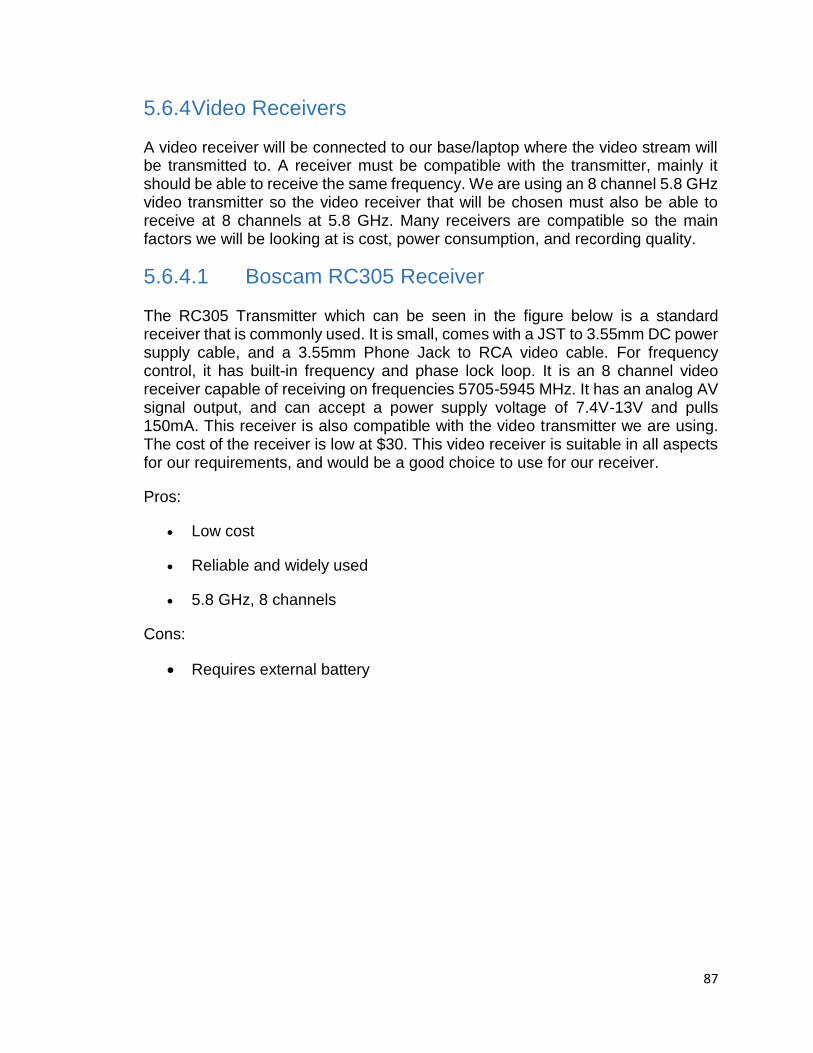
87
5.6.4 Video Receivers
A video receiver will be connected to our base/laptop where the video stream will be transmitted to. A receiver must be compatible with the transmitter, mainly it should be able to receive the same frequency. We are using an 8 channel 5.8 GHz video transmitter so the video receiver that will be chosen must also be able to receive at 8 channels at 5.8 GHz. Many receivers are compatible so the main factors we will be looking at is cost, power consumption, and recording quality.
5.6.4.1 Boscam RC305 Receiver
The RC305 Transmitter which can be seen in the figure below is a standard receiver that is commonly used. It is small, comes with a JST to 3.55mm DC power supply cable, and a 3.55mm Phone Jack to RCA video cable. For frequency control, it has built-in frequency and phase lock loop. It is an 8 channel video receiver capable of receiving on frequencies 5705-5945 MHz. It has an analog AV signal output, and can accept a power supply voltage of 7.4V-13V and pulls 150mA. This receiver is also compatible with the video transmitter we are using. The cost of the receiver is low at $30. This video receiver is suitable in all aspects for our requirements, and would be a good choice to use for our receiver.
Pros:
Low cost
Reliable and widely used
5.8 GHz, 8 channels
Cons:
Requires external battery

88
Figure 37 Boscam RC305 Receiver (permission pending)
5.6.4.2 Aomway DVR 5.8GHz AV Receiver
The Aomway video receiver is another type of receiver that can be used with our video transmitter. This is actually a receiver and video recorder built in one. This system allows you to directly record the video feed coming from the transmitter onto a video card which will can be very useful during the prototype testing phase, as it will allow us to look at each maze solving attempt and see where we can improve or fix any problems, or notice any problems that otherwise would have gone unnoticed. It is a very easy and intuitive device to use, as it is one-click recording and stopping feature. It has the ability to receive on 32 channels ranging from 5465-5945 MHz, and has a display that shows you the band and channel that is on. It can accept a 7-24V power supply and has a working current of 300mA max. It records with a video format NTSC and PAL. The receiver itself is fairly large and is heavier than most but that is due to the video recording device built in. For the recording quality, it has a HD/D1 quality for when viewing the video stream but when playing back the stream from the recording, it is 640x480. The price is at $60 which is more expensive most receivers. This one would be a very good choice for our receiver if we can make use of the video DVR, but there are also other ways such as using recording software on the computer to record the video feed if needed. This will most likely not be our choice of video receivers to use in our project.
Pros:
5.8 GHz, 8 channels
DVR and Video receiver built in one
Can accept micro SD cards

89
Cons:
High cost
High power consumption
Requires external battery
5.6.4.3 Overview
After reviewing several video receivers, there seems to be only one that has been researched that meets all our requirements and clearly is more advantageous than the other transmitters that were researched which was the Boscam RC305 Receiver.
A battery for the video receiver that will be connected to our base will be required. Because the Boscam RC305 is the most likely choice to use as our receiver, the suggested battery for it is a 11.1V 2200mAh/30c LiPo battery. There are several to choose from but there is no big variety in between different brands of battery.
The table below shows a brief summary of the features, advantages, and disadvantages of the researched receivers.
5.7 Base to Ground Vehicle Wireless Transmission
Wireless transmission from our base to our ground vehicle is one of most important elements and features of the overall project. The ground vehicle depends on the base to solve the maze and to send those commands so it knows what path to follow and what instructions to execute so it can solve the maze on its own. To do that, we will be using short range wireless radio communication. There are many ways to send commands to our ground vehicle but using radio frequency technology allows for low power costs and is reliable for our machine to machine communication. Also we will only be sending small amounts of data to the ground vehicle which is another reason why RF communication will be used. ZigBee is mainly used for short range, low data rate applications which is exactly what we will need for our communication so when researching wireless transmitters and receivers, ZigBee was the chosen standard due to its many advantages.
The figure below shows the communication set up for our project.

90
5.7.1 Wireless RF Transceivers
A wireless transceiver will be connected to our base which will be a laptop for our purposes. Our maze algorithm will solve the maze, and create the necessary commands for our ground vehicle, and send those commands via RF communication to our ground vehicle. There are many things that must be taken into account when choosing a transmitter, such as power consumption, range, frequency, type of antenna, and data rate. Because we will be communicated between a computer and a receiver that is on a PCB board, we need a unit that can be plugged directly into our base so it will be to directly communicate with our ground vehicle, so a USB input is required to interface with the XBee and our base to the XBee on our ground vehicle.
5.7.1.1 XBee Explorer Dongle
The XBee Explorer Dongle is a unit that can be plugged via USB directly into the laptop we will be using as our base. It has many advantages, one of them being that it is just simple to use and is compatible with all XBee modules. This board contains a FT231X USB-to-Serial converter which will be able to translate the data between our base and XBee module on our ground vehicle. It comes with a voltage regulator already built in which is good up to 500mA, so there is no need to worry about its power costs or consumption, and also it comes with four LEDs to debug the XBee module (Rx, Tx, RSSI (signal-strength indicator) and power indicator). The board can also break out each of the XBee’s I/O pins to pair with a breadboard-compatible header in case we wanted to use some of the extended functionality of the XBee. The XBee itself does not come with the USB dongle and must be purchased separately, but using this dongle makes operating the XBee much easier.
Base solves maze and creates
commands for ground vehicle
Base sends commands through
XBee module
Xbee module on ground vehicle
receives commands
Microcontroller interprets
commands
Ground Vehicle goes through maze

91
There are other similar boards that have the same exact functionality but they require a micro USB cable, and this dongle can plug directly into the laptop, so this one was chosen instead because it has the same costs.
An XBee Shield must also be chosen which will be needed so the XBee will be able to communicate to our microcontroller such as an Arduino, Rasberry Pi, or MSP430. The shield will interface with the microcontroller in order to send the commands that it receives from the coordinator XBee and send those commands to the microcontroller for it to process.
Figure 38 Sparkfun XBee Explorer Dongle (permission granted)
5.7.1.2 XCTU Software
The XCTU Software will be the software used which his provided by Digi to configure the XBee modules that are connected to the base and that is on the ground vehicle and then allows the users to interact with the two modules as they both must be configured correctly if there is to be successful wireless communication between the two. It has many useful features such as having API and AT consoles (which are discussed below), frames generator and interpreter, recovery, loading console sessions saved in any PC, range testing between two RF modules, and seamlessly restoring module settings during firmware updates. It is a very useful program
5.7.1.2.1 AT vs. API
There are two modes that XBee modules can be configured in, one is AT mode, which is more commonly referred to as transparent mode, and the other is API mode which stands for Application Programming Interface. You cannot choose either or when using XBees, you have to know what type of communication you will be having exactly between your modules and determine which mode is best suited to your needs.
92
When configured in AT mode, the data received by the XBee module will be sent immediately to the other XBee module. There is no packet formation, and is simply sending serial data to the transmitter of one XBee which will be received by the receiver of the other XBee, in which our case would be the XBee module on the ground vehicle. This is the fastest way to transmit when using XBees and is optimal for you are only using point to point communication, as in you are communicated between only two XBees where one is transmitting and one is receiving.
When configured in API mode, the data is formatted in frames with destination information. API mode is mainly used for larger mesh networks that involves multiple modules sending and receiving data to each other, and if you need to change parameters without having to enter the command mode. This mode also allows a “sleep” mode for end devices that are receiving data to only turn on when data is requested, which saves power if power needs to be conserved.
For our purposes, we will only be communicating between two XBee modules, one connected to our base which will be sending simple commands and one connected to our ground vehicle which will be receiving commands so we will most likely be using AT mode to communicate.
5.7.1.3 Choosing an Antenna
When choosing an RF module which will be placed onto the PCB on our ground vehicle, the type of antenna that will be used must be considered and depends on the applications it is being used for. There are many different types of antennas such as a chip antenna, wire, u.FL, RPSMA, and trace. A chip antenna is just a chip that acts as an antenna and is printed directly to the circuit board. It is small but it does not have the best gain. . A wire antenna is has a small wire connected to the XBee module, adding more range, but is larger than a chip antenna. You can connect your own antenna with a u.FL connector, and RPSMA is simply a bigger connector to connect your own antenna which you would use if your project was enclosed and you wanted your antenna outside of whatever it is enclosed in (such as a box). And finally a trace antenna, which is also called a PCB antenna is an antenna that is directly on the XBee module via conductive traces and have the same type of performance of wire antennas.
For our purposes we will most likely be using a trace, because they are known to be more reliable and compact than the other antennas.
5.7.1.4 XBee 1mW Series 1
The XBee 1mW Series 1 which uses the 802.15.4 wireless protocol which is the basis for ZigBee. It comes in three antenna variations which are as mentioned in the section above: chip, wire, and trace. This is most likely the most widely used XBee module due to its many features and simplicity. It is allows for simple communication between two XBee modules and has easy integration and support
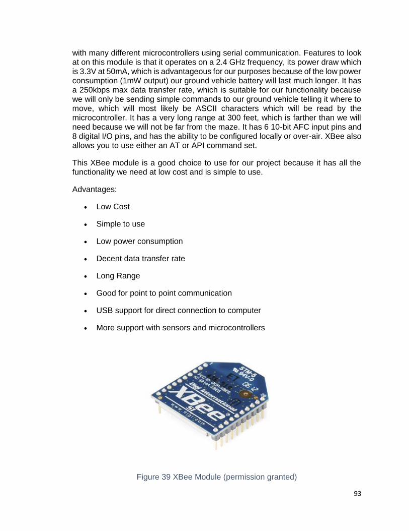
93
with many different microcontrollers using serial communication. Features to look at on this module is that it operates on a 2.4 GHz frequency, its power draw which is 3.3V at 50mA, which is advantageous for our purposes because of the low power consumption (1mW output) our ground vehicle battery will last much longer. It has a 250kbps max data transfer rate, which is suitable for our functionality because we will only be sending simple commands to our ground vehicle telling it where to move, which will most likely be ASCII characters which will be read by the microcontroller. It has a very long range at 300 feet, which is farther than we will need because we will not be far from the maze. It has 6 10-bit AFC input pins and 8 digital I/O pins, and has the ability to be configured locally or over-air. XBee also allows you to use either an AT or API command set.
This XBee module is a good choice to use for our project because it has all the functionality we need at low cost and is simple to use.
Advantages:
Low Cost
Simple to use
Low power consumption
Decent data transfer rate
Long Range
Good for point to point communication
USB support for direct connection to computer
More support with sensors and microcontrollers
Figure 39 XBee Module (permission granted)

94
5.7.1.5 XBee 2mW Series 2
The XBee 2mW series (ZigBee Mesh) is similar to the Series 1 but it has useful extra features. Like the series 1, it has three different antennas: chip, wire, and trace. The series 2 module allows the user to create mesh networks using ZigBee mesh firmware. This feature may be useful in projects such as home automation where many different machines need to communicate with each other, but our project is mainly point-to-point communication from our base to our ground vehicle, so this feature would not be used. It specifications are: 3.3V at 40mA, which is good and low, and has a 250kbps max data rate which is high enough for our purposes. It operates on a 2.4 GHz frequency and has a range of 400 feet which we will be well within the range of. It has six 10-bit ADC input pins and 8 digital I/O pins with 128-bit encryption and allows for local or over-air configuration and lastly it allows for either an AT or API command set. We will most likely not be using this XBee module, not because it can’t accomplish what we need for the project, but because it has more features than we need such as the ability to create complex mesh networks, when we will only be doing communication between two points.
Advantages:
Low Cost
Simple to use
Low power consumption
Decent data transfer rate
Long Range
Allow for multiple nodes for communication
USB support for direct connection to computer
More support with sensors and microcontrollers
5.7.1.6 XRF Wireless Data Module
Another option instead of using an XBee module would be to use an XRF Wireless
Data Module. The XRF module would be chosen more for its simplicity but it ready
to use out of the box without having to program or do any end-user configuration
and allows for transmitting and receiving serial data in packets or short bursts. It
operating on the frequencies between 868-915 MHz, which gives it better
penetration than other devices running on other frequencies such 2.4 GHz. It also
has a lot of support when using with it with microcontrollers such as Arduinos and
Raspberry Pis. It is has a CC1110 on system chip which acts as a microcontroller.
Its many features include:

95
Over-air programming
Acts as a drop in replacement for XBees Series 1 (researched above)
Same footprint as other RF modules such as XBee
Serial bootloading
Supports PANID if communication into separate networks is required
900 MHz for better penetration
Easier configuration out of box than XBee
Cheaper than XBee
5.7.1.7 Overview of RF Transceivers
After careful consideration, the RF transceiver that was chosen to be used to send
commands to our ground vehicle was the XBee Series 1 with a trace antenna.
Using an XBee module has many advantages such as being optimal for point to
point short range communication to send small amounts of data which is exactly
what our project needs, is very simple to use, and is easy to program serial
communication within software reliably using the XBees serial connection. One of
the final considerations was the cost, and the XBee module is currently $25 which
is expensive but it still meets our budget requirements so in the end the XBee was
the most logical choice as it fits every requirement nicely and is an overall good
purchase.
From the list of advantages, we see that the two XBee modules have more
advantages than the XRF Wireless Data module. And then between the two XBee
modules, we chose to go with the Series 1, because it was more suited to our
requirements and specifications, mainly that we are only using two XBee modules,
so the advantage of being able to create a mesh network with the XBee Series 2
model was of no benefit to us.
5.8 Maze
Overview – In our project, we are planning on construct a maze in which a small
object will be placed. This maze will consist of an entrance and an exit. In the
entrance the ground vehicle will enter in order to start searching for the small
object. After the mission is completed, the ground vehicle will use the exit port to
start a new mission as we modify the maze structure.

96
Definition – A maze can be defined as pathway or collection of tracks with an
entrance that can lead to a specific target or goal. It can be used to refer both to
branching tour puzzles through which the solver must find a way, and to simpler
non-branching patterns that lead unambiguously through a complicated design to
a goal. If were to write about the history of mazes, it would have taken the entire
report to do so. In short, the history of mazes can be traced back to the time of the
late middle ages. In the beginning, Puzzle mazes such as Labyrinths were very
simple. They underwent some fast development from time to time. Mazes can be
presented in different dimensions as shown below:
2-D maze – This can be made possible by some drawing on any flat surfaces such as one painted onto a floor.
3D maze – This is one that have multiple levels or with raised walls.
Weave maze – This is basically a 2D (or more accurately a 2.5D) Maze; however, the corridors can overlap each other.
5.8.1 Type of mazes
Mazes does not only come in different dimensions, they can be presented in many
different types. Some of them are simple while others are very complex according
the number layers. Most of the traditional mazes are constructed with walls;
however, they are all have one thing in common. Their pathway can only be in two
dimensional. A few out of many types of maze are described below.
An orthogonal maze – This type of maze is maze structure that has only
solution. Below is a 20 x 20 simply connected maze. To avoid complexity,
we won’t be using this type of maze. If we plan to use this type, it will have
to be simpler and smaller.
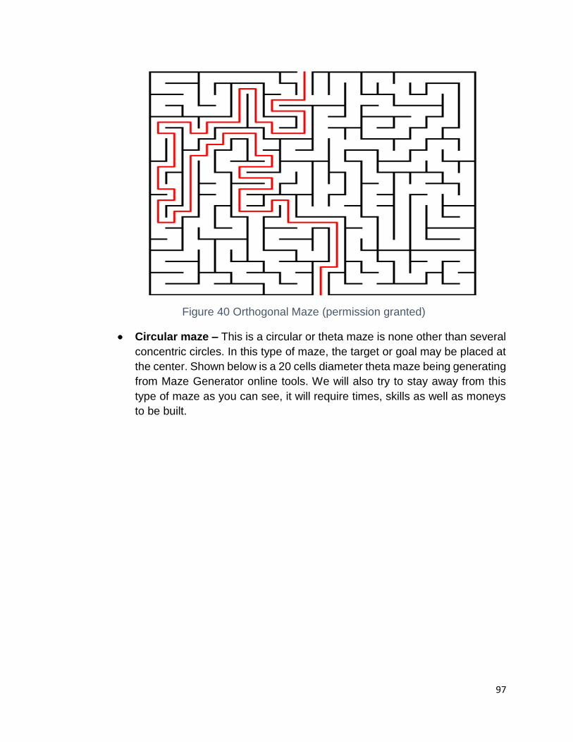
97
Figure 40 Orthogonal Maze (permission granted)
Circular maze – This is a circular or theta maze is none other than several
concentric circles. In this type of maze, the target or goal may be placed at
the center. Shown below is a 20 cells diameter theta maze being generating
from Maze Generator online tools. We will also try to stay away from this
type of maze as you can see, it will require times, skills as well as moneys
to be built.
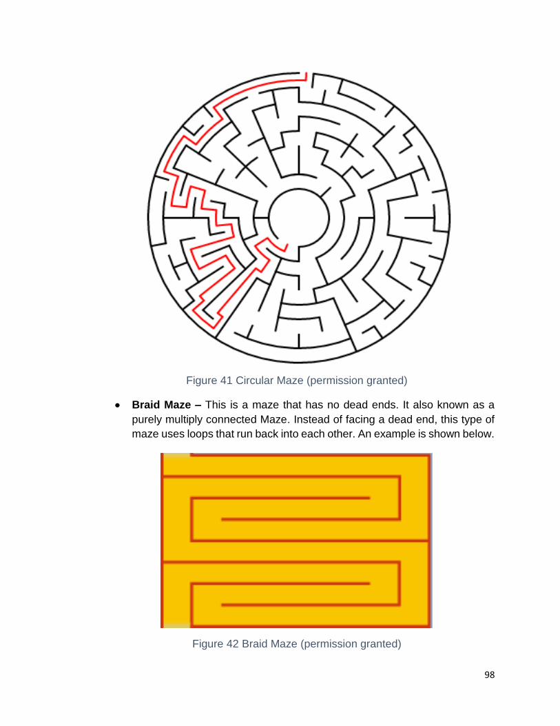
98
Figure 41 Circular Maze (permission granted)
Braid Maze – This is a maze that has no dead ends. It also known as a
purely multiply connected Maze. Instead of facing a dead end, this type of
maze uses loops that run back into each other. An example is shown below.
Figure 42 Braid Maze (permission granted)

99
Delta Maze – The last but not least type of maze we would like to present
is the delta maze. It consisting of interlocking triangles. This maze also has
an entrance and an exit. It is a really great type of maze but not ideal for our
project. Shown below is 20 x 20 delta maze structure that we generated
from the online maze generator tools.
Figure 43 Delta Maze (permission granted)
5.8.2 Maze Layout
A maze may require some simple math and art skills depending on its level of
complexity. As one may choose to add more layer to a maze, the more the
complexities of that maze will be. Some maze can have more layers than another.
By having more level, the maze can be much more difficult before reaching a
specific target. For example, when building the maze, we want to make sure that
all measurements are right. Also, the Maze builder has to be somehow creative.
Due to time constraint, our maze layout will be simple. Some angles will be allowed
and will not base on the type of that is to be used. Shown below are some
predetermined drawings of how the maze layout may be presented.

100
Figure 44 Layout one with one possible solution
Figure 45 Layout two, has 2 possible solutions

101
Figure 46 Layout three with three possible solutions
Figure 47 Layout four, with four posible solutions

102
Figure 48 Layout five Braid maze No Dead End
Figure 49 Outerwall Wall Maze Prediction
To sum up, these drawings that are presented above are just some predictions of
the maze might layout. They may be more or less complicated due to the

103
environment or space where our final presentation will take place. Also, it is not
really our purpose in completing this project because we are more concerning on
how we will apply our skills based on software and hardware requirements.
5.8.3 Materials
Constructing a maze sounds like a very easy task, but when it comes to the
materials, it may be a little challenging. It can be challenging because there are
various types of materials out there for the construction. In the construction of the
maze, the material has to provide a simple, organized sensory environment to
ensure that the ground vehicle (robot) can navigate as easy as possible. We also
want the ground vehicle to make turns as freely as possible, avoid getting stuck in
Dead Ends or hallways depending on the type of maze being used. By doing that,
we will probably have a better control of what the robot detects within the maze
using its rangefinder sensors. To make that possible, the walls of our maze shall
be reasonably high based on the sensors’ position on the ground vehicle.
Presented below are some ideal materials we might be considered for our maze
construction.
Poster Board – It is considered as one possible material for the maze assembly.
As we completed the research on this material, we came across some advantages
as well as disadvantages as presented in the following table.
Advantages Disadvantages
Lite weight more work to build
Size and shape controllability Fragile when assembly or disassembly
Very cheap Stability rely on the corners
Can fold up into a very compact space Small thickness
Table 17 Poster-board Advantage & Disadvantages
2 x 4 in. x 10 ft. (Wood) – This is good material for maze assembly. Its thickness
is great (2 in) and it can be very stable, but it may require a lot of work. We have
to have wood cutting skills as well as the appropriate tools. Also, it is expensive
($4.05 for each) and heavy.
Box – Using boxes is one of the fastest way to build maze-walls. By just lining
them up we can form maze walls. The cost can be varied based on the size and
shape. Also, we buy box at any local U-Haul store.

104
Plasticor Board (Corrugated Plastic Board) – The last but not least of many
materials for construction of maze is Corrugated Plastic Board. It is a lightweight
plastic board material that is ideal for indoor and outdoor uses. It is easy to cut and
come with different colors and dimensions. It can be purchased online or at art
supply stores.

105
6 Project Design
After extensively researching every aspect of the design, we know the final
components which will be used in our functioning prototype. The three main
design portions are the quadcopter, ground vehicle, and the maze.
6.1 Initial Ground Vehicle Design
A system-level abstraction of the onboard hardware shows that the processors receives and processes data and commands from three sources: The computational hub, the wheel encoders, and the wall-detection sensors.
Figure 50 Ground Vehicle Design Flow
Our vehicle design will utilize the Pirate 4WD chassis. We intend to have one onboard PCB to drive the motors and control navigation as well as process

106
information from peripheral sensors and remotely sent navigational cues from the RF receiver. We plan to utilize the included battery cradle, which holds five AA batteries. For our initial design, we will use the included DC motors, but we’ve had problems with these motors in the past, so we may switch these out if we have problems with the ground vehicle drifting when trying to negotiate straight lines, so we may upgrade these to a different design at a later date if wear becomes an issue.
Figure 51 Pirate 4WD Mobile Robot Platform (permission pending)
The platform includes pre-made mounting brackets for peripheral sensors. We will utilize a ultrasonic sensor setup for basic wall detection fastened to one of these mounts.
6.1.1 PCB Design
Our PCB will be a heavily modified, application specific form of an Arduino microcontroller. We decided to model our PCB after the Arduino Romeo since this model already had an onboard H-bridge to drive the DC motors. Below is the pinout.
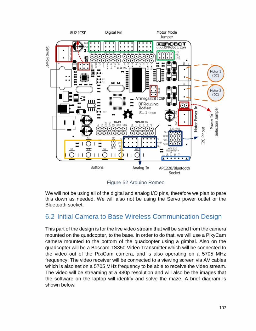
107
Figure 52 Arduino Romeo
We will not be using all of the digital and analog I/O pins, therefore we plan to pare this down as needed. We will also not be using the Servo power outlet or the Bluetooth socket.
6.2 Initial Camera to Base Wireless Communication Design
This part of the design is for the live video stream that will be send from the camera
mounted on the quadcopter, to the base. In order to do that, we will use a PixyCam
camera mounted to the bottom of the quadcopter using a gimbal. Also on the
quadcopter will be a Boscam TS350 Video Transmitter which will be connected to
the video out of the PixiCam camera, and is also operating on a 5705 MHz
frequency. The video receiver will be connected to a viewing screen via AV cables
which is also set on a 5705 MHz frequency to be able to receive the video stream.
The video will be streaming at a 480p resolution and will also be the images that
the software on the laptop will identify and solve the maze. A brief diagram is
shown below:

108
Figure 53 Wireless Communication Flow
6.3 Initial Base to Ground Vehicle Wireless Communications
Design
This is the system that will be sending the commands once they have been created
by the software and will then be sent to the ground vehicle for processing and
execution. For this design we will have a XBee 1mW series 1 module connected
to a XBee explorer USB dongle, which will plug into the laptop for direct
communication with another XBee 1mW series 1 module that will be connected
using a shield to the microcontroller on the ground vehicle. The microcontroller will
be connected to the XBee through its receiving and transmission pins to transfer
data to the microcontroller through the XBee. The software will initial serial
communication to the Xbee on the microcontroller and the microcontroller will have
software installed that will receive and interpret the data send from the base data
transmission. The software will create commands which will convert them to hex
values and transmit them to the microcontroller via XBee, and depending on the
hex values that were received, the microcontroller will tell the ground vehicle in
which direction and how far to move. The XBees will be transmitting/receiving at
baud rate of 9600 which is more than enough to send the small amount of data as
they are only hex values
Mounted CameraVideo
TransmitterVideo
Receiver
Maze Solving
Algorithm

109
6.4 Initial Maze Design
For this section in our design, we are planning to use a braid maze. It may contain
more than one way to reach to the target. The materials that will be used are as
follow:
For the walls, we are using plywood.
On the top of the wall we will use color tape in order to detect edges and nodes before a reasonable solution found.
For it overall dimension or perimeter, that should not exceed 100 square feet.
The height I to be under on foot tall.
All pathways’ dimension shall have same size based on the ground vehicle specific dimension. For instance, if the dimension for our ground vehicle is 8 in. x 5 in., the corridors should be reasonably greater because we do not want the vehicle stuck while navigating through the maze.
The angle for turning left or right is to be 90 degrees or higher.
7 Prototype Test Plan
The prototype requires extensive testing of each aspect that will be included,
including the wireless transmission, flight, and ground vehicle functionality.
7.1 Hardware Testing Environment
For our hardware testing, everything will be tested by the group. For the
quadcopter testing it will have to be in a location without any other people or
buildings for safety reasons, such as an open field. For the ground vehicle and
software, the testing will be done in the senior design lab at UCF, and our final
project prototype will be done outside, and again without anyone nearby for
safety concerns.
7.2 Hardware Specific Testing
Each piece of hardware in the project requires its own testing which can be found
in the sections below.
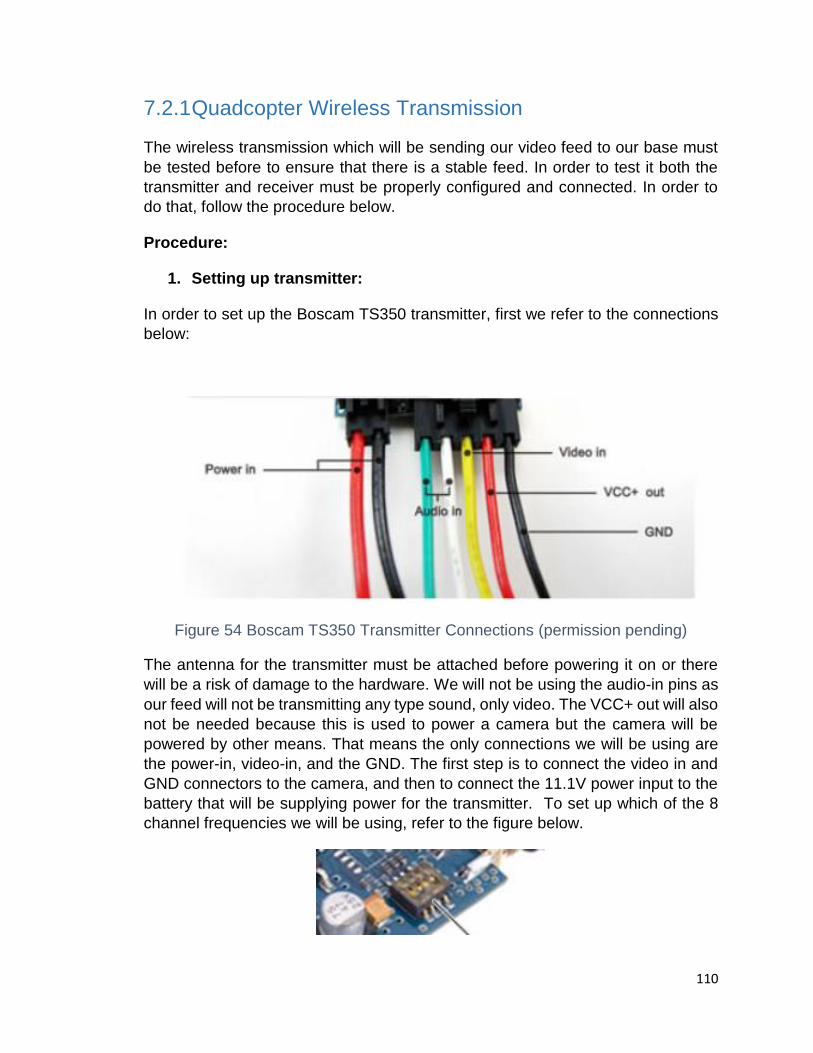
110
7.2.1 Quadcopter Wireless Transmission
The wireless transmission which will be sending our video feed to our base must
be tested before to ensure that there is a stable feed. In order to test it both the
transmitter and receiver must be properly configured and connected. In order to
do that, follow the procedure below.
Procedure:
1. Setting up transmitter:
In order to set up the Boscam TS350 transmitter, first we refer to the connections
below:
Figure 54 Boscam TS350 Transmitter Connections (permission pending)
The antenna for the transmitter must be attached before powering it on or there
will be a risk of damage to the hardware. We will not be using the audio-in pins as
our feed will not be transmitting any type sound, only video. The VCC+ out will also
not be needed because this is used to power a camera but the camera will be
powered by other means. That means the only connections we will be using are
the power-in, video-in, and the GND. The first step is to connect the video in and
GND connectors to the camera, and then to connect the 11.1V power input to the
battery that will be supplying power for the transmitter. To set up which of the 8
channel frequencies we will be using, refer to the figure below.
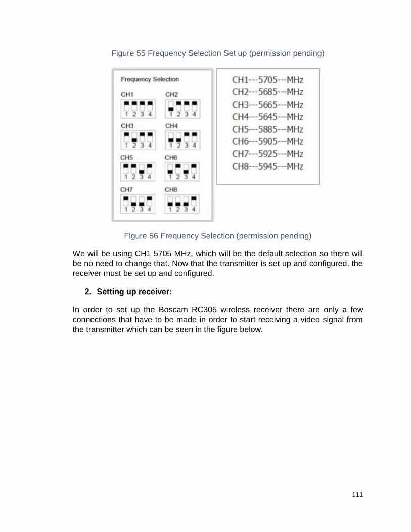
111
Figure 55 Frequency Selection Set up (permission pending)
Figure 56 Frequency Selection (permission pending)
We will be using CH1 5705 MHz, which will be the default selection so there will
be no need to change that. Now that the transmitter is set up and configured, the
receiver must be set up and configured.
2. Setting up receiver:
In order to set up the Boscam RC305 wireless receiver there are only a few
connections that have to be made in order to start receiving a video signal from
the transmitter which can be seen in the figure below.
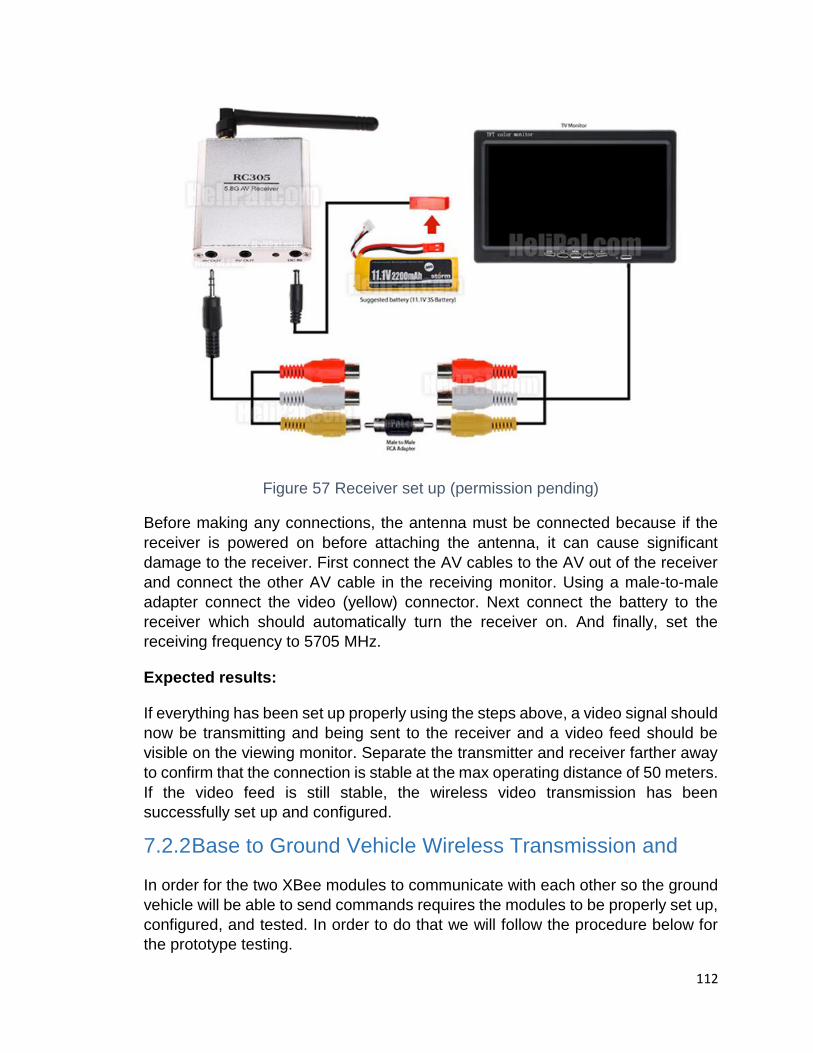
112
Figure 57 Receiver set up (permission pending)
Before making any connections, the antenna must be connected because if the
receiver is powered on before attaching the antenna, it can cause significant
damage to the receiver. First connect the AV cables to the AV out of the receiver
and connect the other AV cable in the receiving monitor. Using a male-to-male
adapter connect the video (yellow) connector. Next connect the battery to the
receiver which should automatically turn the receiver on. And finally, set the
receiving frequency to 5705 MHz.
Expected results:
If everything has been set up properly using the steps above, a video signal should
now be transmitting and being sent to the receiver and a video feed should be
visible on the viewing monitor. Separate the transmitter and receiver farther away
to confirm that the connection is stable at the max operating distance of 50 meters.
If the video feed is still stable, the wireless video transmission has been
successfully set up and configured.
7.2.2 Base to Ground Vehicle Wireless Transmission and
In order for the two XBee modules to communicate with each other so the ground
vehicle will be able to send commands requires the modules to be properly set up,
configured, and tested. In order to do that we will follow the procedure below for
the prototype testing.

113
Procedure:
1. Setting up XBee Module 1 (connected to laptop):
This will be the XBee module that will be sending the commands to the Xbee
module on the ground vehicle. First you will want to connect the XBee module to
the USB explorer dongle so it may interface with the computer. The next step will
be to open up the X-CTU software which will allow us to configure the XBees
properly so they will be able to communicate with each other.
Steps:
1. Open the X-CTU software
2. Using the “add device” button, select the USB serial port that the XBee module is plugged into.
3. Set proper configuration such as the baud rate, data bits, parity, stop bits, and flow control.
4. Set Baud rate to 9600, data bits to 8, no parity, stop bits to 1, and no flow control.
5. Set the function set as “ZigBee Router API”
6. Create a PAN ID that will be the same for both modules such as 1234.
7. Set the source address and destination address so determine where the XBee will send and receive data, which correspond to the source and destination addresses on the other XBee module.
8. Write the changes to save the configuration settings to the XBee module.
2. Setting up XBee module 2 (will connect to microcontroller)
This will be for setting up the second XBee module that will be receiving commands
from the XBee module connected to the laptop.
Steps:
1. Open the X-CTU software
2. Using the “add device” button, select the USB serial port that the XBee module is plugged into.

114
3. Set proper configuration such as the baud rate, data bits, parity, stop bits, and flow control.
4. Set Baud rate to 9600, data bits to 8, no parity, stop bits to 1, and no flow control.
5. Set the function set as “ZigBee Coordinator API”.
6. Set the PAN ID that was created for the first XBee module.
7. Set the source and destination address that correspond the destination and source address that was used for the Router.
8. Write the changes to save the configuration settings to the XBee module.
Next we will be testing if the XBee modules can communicate with each other
before attaching the XBee module to the microcontroller. Connect both XBee
modules to the laptop via the dongles and open an X-CTU instance for each of
them.
Steps:
1. Open the X-CTU software for each XBee module
2. Select the correct serial ports for each of the modules.
3. Switch to the console tab by clicking “switch to consoles”
4. Open a serial connection for each device which will open two windows, one for each XBee module
5. On the left console which is our Router which is sending commands, type a letter or number and see the corresponding hex values received by the other XBee module.
6. Switch to the other XBee module and confirm the same results that it can send and receive.
7. Close the X-CTU software
Expected results:
The XBee modules can send and receive data from each other confirming a stable
connection. To actually test if the XBee modules will send and receive data once
connected to the microcontroller on the ground vehicle, we must perform software
testing because the serial data will be sent through the software written to interpret
and send the commands to the ground vehicle.

115
7.2.3 Quadcopter Flight and GeoFencing
For the quadcopter, a GeoFence must be placed and added before initiating flight.
This will allow the quadcopter to return back to its starting position if it goes past
the GeoFence.
Procedure:
1. Connect the quadcopter to the computer and launch the mission planner software.
2. There will be five parameters to set:
a. Type – Set to altitude and circle.
b. Action – Set to RTL.
c. Max Altitude – Set to 50 ft.
d. Max Radius – Set to 50 ft.
e. RTL Altitude – Set to 100 ft.
Figure 58 GeoFence Parameters
3. Save settings to your quadcopter and disconnect
4. Go outside to test if GeoFence works by flying the quadcopter outside of its GeoFence.
5. Both the altitude and the radius must be checked, so one run must be made with the quadcopter going past the radius, and then another run must be made with the quadcopter exceeded the maximum altitude.
Expected Results:
Once the quadcopter if flown outside of the GeoFence, it should reach an altitude
of 100ft which is the RTL altitude, then fly back to the starting position from which
116
it was flown and then slowly come down for a landing. If all of these things happen
the test was a success. .
7.2.4 Ground Vehicle
The ground vehicle requires lots of testing which can be found in the below
sections.
7.2.4.1 Circuitry
Because we are basing our PCB design on a heavily modified and pared down version of an Arduino microcontroller, testing of our ground vehicle with the Arduino Romeo or an Arduino Uno paired with an external H-bridge will be more than sufficient. This will allow us to test the DC motors and power supply.
OVP Circuit – This circuit can be breadboarded and tested externally from the chassis. Once we are satisfied with its performance we can implement it onto the chassis.
Low-Voltage Protection Circuit – This circuit can also be breadboarded and tested separately from the other components. Because the OVP circuit is more critical to our design, we will implement the Low-Voltage Protection Circuit only after the OVP circuit is functioning properly.

117
7.2.4.2 Power Supply
The ground vehicle will utilize the included battery cradle. We will be using five Energizer Recharge Universal AA 2300mAh batteries. Each battery is rated at a nominal voltage of 1.2V each. In series, this will yield a total nominal voltage of 6Vl. The batteries we chose come pre-charged. We will install them in the battery cradle and test the voltage from the two leads. This will give us the voltage of the cradle without load. We then will attach the leads to 1MΩ resistor and measure the voltage across the load. This will tell us the voltage of the power supply across a load. If there’s a difference between the two, then the batteries are not fully charged.
7.2.4.3 Ultrasonic Sensor This test must be conducted outside or in a room with a high ceiling
1. Program MCU to trigger ultrasonic sensor to emit pulse and convert sensor
output from time interval to distance.
2. Position sensor 3in. in front of flat surface.
3. Connect sensor pins to the correct pins on the MCU and supply voltage to
the MCU.
4. If sensor distance reading matches the actual distance from the surface the
sensor is working correctly. If sensor readings are incorrect calibrate by
adding a calibration constant to the calculation.
7.3 Software Testing
There are many software tests that must be done which can be found in the below
sections.
7.3.1 Maze detection
To test the maze detection algorithm, follow the steps written below:
1. Read the image shown below into OpenCV.
2. Correct scaling and perspective issues by using geometric transforms (will
be needed in actual design).
3. Perform Canny edge detection to locate edges of the maze walls and
produce a binary image.
a. Determine minimum threshold by testing various values and find
threshold needed to only outline maze walls.
b. Determine maximum threshold value which can be used which does
not cause edges of maze to disappear.

118
4. Threshold the original image for the color yellow and get the coordinates of
the center of the tennis ball.
5. Mark the location of the tennis ball on the binary image of the maze created
by using Canny edge detection.
Figure 59 Prototype Test Image (permission pending)
7.3.2 Binary Image Conversion
To test the binary imagine conversion, follow the steps below.
1. Locate and open the binary image created in OpenCV using Python, C#,
C++, etc.
2. Create nested for-loop which divides the image into a grid of cells with
equivalent dimensions based on maze wall to floor ratio.
3. Determine average weight of pixels in each cell.
a. If majority of the pixels inside a given cell are black, mark the cell as
an impassable wall tile.
b. If a majority of the pixels inside a given cell are white, mark the cell
as a passable floor tile.
4. Link each passable floor tile with its neighboring passable floor tiles in order
to create a nodal network representing the layout of the maze.

119
7.3.3 Maze Solving Algorithm
1. Once a tree representation of the maze has been developed, implement a
search algorithm (Breadth-First Search) to solve the maze.
a. Iterate through all nodes in tree and mark them as not visited
b. Identify starting or root node (location of ground vehicle)
c. Place the root node in a queue and explore its adjacent nodes
d. Once all adjacent nodes have been visited (queue is empty) set a
visited node that was adjacent to the root node as the current node
and explore its neighbors
e. Continue this process until all nodes in the maze layout tree have
been visited
Key: Current Node Unexplored Adjacent Node Visited Node Solution Unexplored Node

120
Figure 60 Breadth-First Search Algorithm
8 Administrative Content
The project required administrative considerations such as budget and financing,
milestones, and divisions of labor which are described below.
8.1 Budget and Financing
One of the most important factors for any project is budget management. Without
money, it would be naïve to even talk about accomplishing a project. Once our
group agrees on our ideal project, we start by asking the following questions: How
much money does this project require? Will we be able to find a sponsor for the
project?
In our project, to satisfy our financial needs, various things needed to be done.
First we had to make a final decision on what project we wanted to work on. After
being agreed, then we started by defining the different factors that will be involved
in the project. For instance, we defined all the requirements and specifications of
the key components on the main part of the project such as the UAV (unmanned
Air Vehicle) the Base control and the ground vehicle. Having done all of that, we
wrote the project proposal to different sponsorships in order to get some funding.
The initial estimated cost for the budget was $980.00. After sending the funding
request, we have an award of $881.47 from Boeing and Leidos. This award will be
reimburse to the team after the end of the project.

121
Since we don’t have the funding in hand, we are planning on splitting the cost of
the project evenly within each member of the group. Shown below is the initial table
of the estimated cost for our project. It may subject to some adjustments as prices
for the required components vary according to the up and down.
Quadcopter
Part Estimated Cost
RC Transmitter, 2.4GHz, 9-Ch. $220
3DR Video Transmission Kit $200
LiPo 14.8V 6000mAh Battery
Pack
$80
Battery Charger $20
Replacement Propellers $10
-------------------------------------- Subtotal: $530
Maze
Part Estimated Cost
Poster Board (Maze Walls) $50
Multi-Purpose Paper Roll (Floor) $25
Spray Paint $5
Glue Gun w/Glue Cartridges $15
------------------------------- Subtotal: $95
Ground Vehicle (Robot)
Part Estimated Cost
Stepper Motors $55
PCBs $100
Wall Sensors (Ultrasonic, etc.) $60
IMU/Magnetometer $20

122
Wheels $15
MCU $10
Battery/Power Supply $20
Charger $10
XBee Transmitter/Receiver $25
Soldering Iron $40
-------------------------------------- Subtotal: $355
GRAND TOTAL: $980.00
Table 18 Budget
8.2 Development of Milestone
Objective – To create a schedule for the completion of the project using major
milestones as a guideline for staying on track.
Unlike other classes that we have completed as undergraduate students, senior
design is more challenging for various reasons. It can be a time consuming course
and, because of this, it is important for each member involved to share his/ her
most important values and develop a suitable schedule that works out for the entire
team. Also, it is essential for each member in the group to share the work and
establish a project milestone to be able to stay within the scope of the design.
Milestones allow group members to more precisely determine whether or not the
project is on the right track.
In our project, developing the milestones is an important for the team because time
can be very difficult to manage. In the beginning of the semester when we started
discussing about our project, we were all agreed on having a milestone. The group
agreed on that decision to ensuring that everything was going smoothly and in a
timely matter due to the fact that some tasks require more effort to be completed
than another. Due to time constraint that exists within the group while completing
this project, the milestone may have some minor adjustment as time goes along.
8.3 Senior Design Charts
The charts blow contain milestones and due dates for the for the entire senior
design class. It is mainly of defining the task that we need to accomplish.
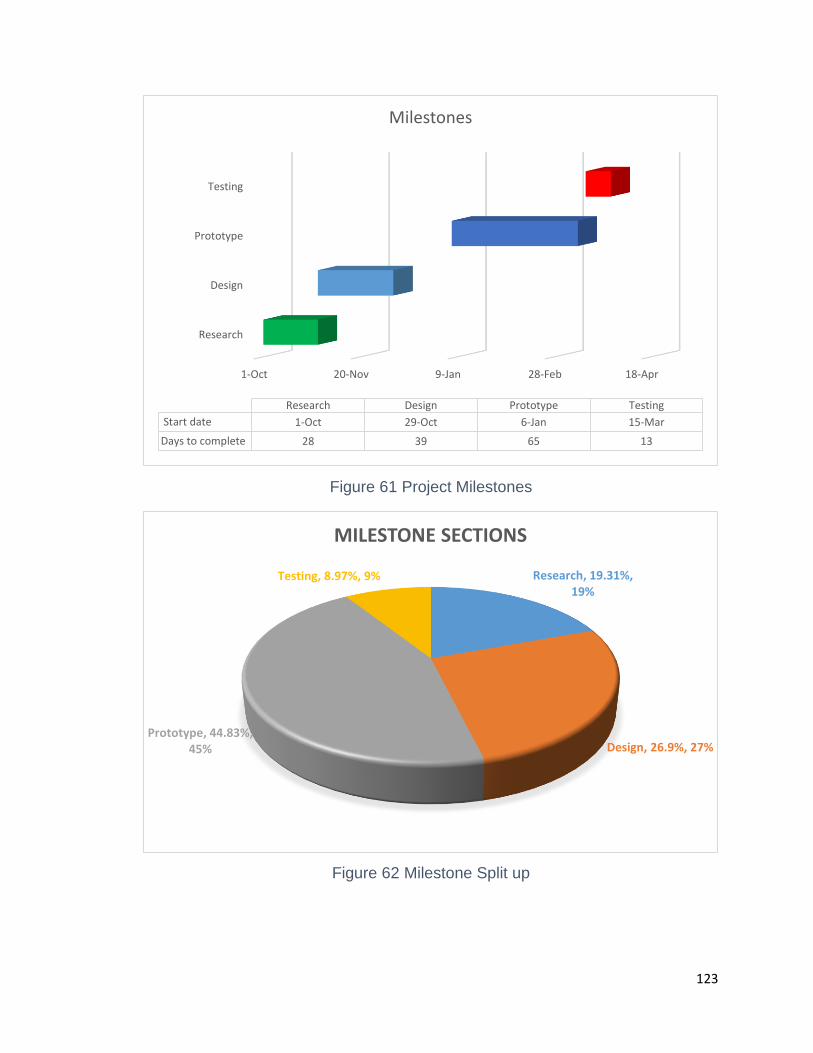
123
Figure 61 Project Milestones
Figure 62 Milestone Split up
1-Oct 20-Nov 9-Jan 28-Feb 18-Apr
Research
Design
Prototype
Testing
Research Design Prototype Testing
Start date 1-Oct 29-Oct 6-Jan 15-Mar
Days to complete 28 39 65 13
Milestones
Research, 19.31%, 19%
Design, 26.9%, 27%Prototype, 44.83%,
45%
Testing, 8.97%, 9%
MILESTONE SECTIONS
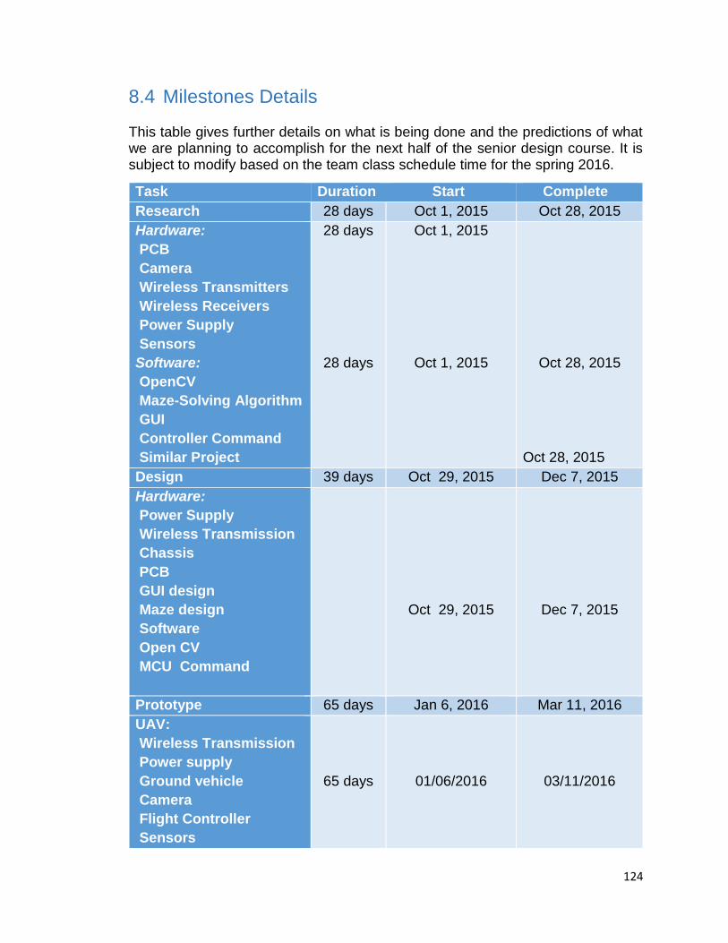
124
8.4 Milestones Details
This table gives further details on what is being done and the predictions of what we are planning to accomplish for the next half of the senior design course. It is subject to modify based on the team class schedule time for the spring 2016.
Task Duration Start Complete
Research 28 days Oct 1, 2015 Oct 28, 2015
Hardware:
PCB
Camera
Wireless Transmitters
Wireless Receivers
Power Supply
Sensors
Software:
OpenCV
Maze-Solving Algorithm
GUI
Controller Command
Similar Project
28 days
28 days
Oct 1, 2015
Oct 1, 2015
Oct 28, 2015
Oct 28, 2015
Design 39 days Oct 29, 2015 Dec 7, 2015
Hardware:
Power Supply
Wireless Transmission
Chassis
PCB
GUI design
Maze design
Software
Open CV
MCU Command
Oct 29, 2015
Dec 7, 2015
Prototype 65 days Jan 6, 2016 Mar 11, 2016
UAV:
Wireless Transmission
Power supply
Ground vehicle
Camera
Flight Controller
Sensors
65 days
01/06/2016
03/11/2016

125
Prototype Testing 13 days Mar 15, 2016 Mar 28, 2016
Table 19 Timeline
8.5 Division of Labor
Our project was chosen based on the ambition of the entire team. We do not just want build a project because it is required, but we also want do something that is both challenging, enjoyable and fun. After completing this project, we want to learn as much as possible on both design and developmental. When the semester began, we tried to brainstorm ideas then narrow down on this specific project that is able to meet all the basic criteria for an ideal senior design.
As four electrical engineering major students, we wanted to challenge ourselves with this project, which requires us to test our understanding on these fundamental areas, software, hardware and electrical engineering concepts. Before starting working on the project, we agreed on sharing the work equally and with the same level of difficulty among each member of the group. This was an important thing for us to do because we wanted to make sure everyone’s contribution was taking into consideration. In case anyone needs assistance in a specific area, as a team, we will do our best to provide assistance to that member. Based on each member’s best interest, the labor gets divided as describe in the figure below.
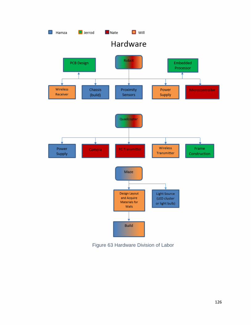
126
Figure 63 Hardware Division of Labor
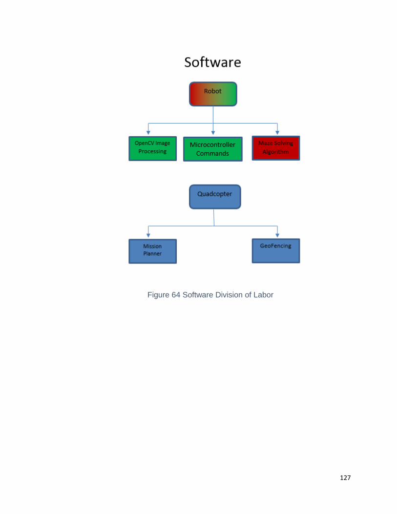
127
Figure 64 Software Division of Labor

128
9 Conclusion
The entirety of this project documentation was written to achieve a final goal to
build a functioning prototype of our Air to Ground Reconnaissance System. The
project spanned many different phases from project concept ideas, research,
requirements and specifications, designing the prototype, building the prototype,
and finally testing the prototype. This involved learning about many different topics
such as wireless communications, aspects of robotics, embedded programming
and also object recognition and image processing using software such as
OpenCV. The three main designs of our project consist of the UAV, the ground
vehicle, and the maze, which will seamlessly work together once the entire system
is constructed. When considering components in research, every factor was
considered ranging from cost, efficiency, need, hardware and software
requirements.
The main design of our project and goal is for a UAV to take an image of a maze,
and send that information to a computer for image processing and running it
through an algorithm to create a path through the maze. Commands will then be
created for our ground vehicle which is placed at the entrance of the maze, and
will autonomously navigate through the maze. After the design phase, the
prototype construction is begun and the prototype will be built. The prototype
requires extensive hardware and software testing to ensure a successful test, and
ensures that all safety requirements are accounted for such as the quadcopter
potentially failing and crashing. Although, all of the prototype building and testing
is the main goal for Senior Design II, and all of the research and design was our
main goal for Senior Design I.
Many administrative aspects and logistics also had to be considered while working
on the project through the semester such as coordinating with team members to
finish on time, creating budget charts so we stay under our max spending amount,
and creating weekly goals that each member should achieve to finish the final
documentation in a timely manner. Because we followed all these guidelines we
were able to complete all of our goals and finish the Senior Design I
documentation.

129
Appendices
A. Copyright Permissions
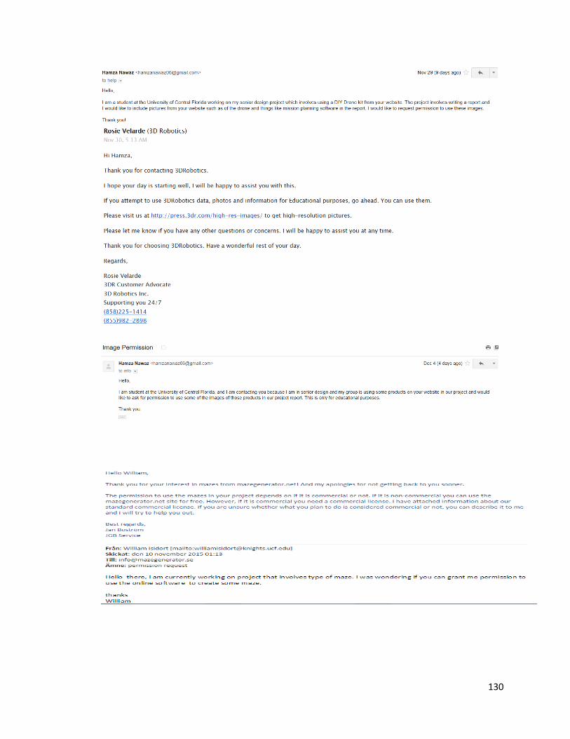
130

131

132

133
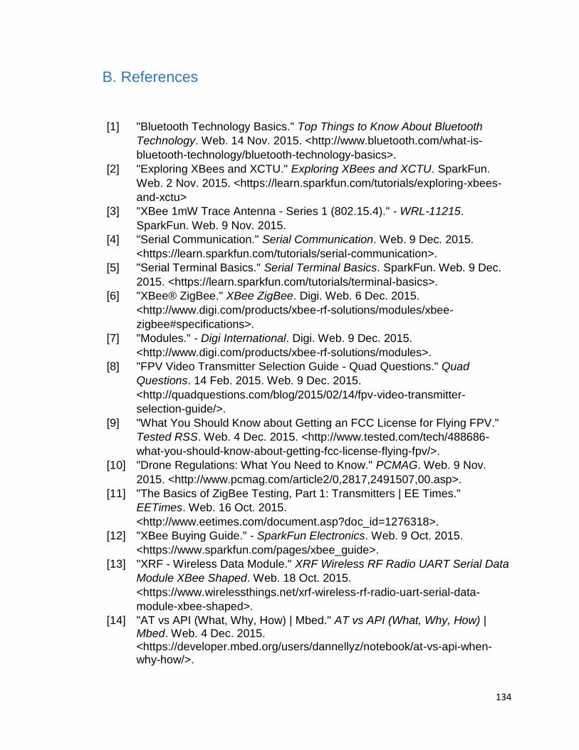
134
B. References
[1] "Bluetooth Technology Basics." Top Things to Know About Bluetooth
Technology. Web. 14 Nov. 2015. <http://www.bluetooth.com/what-is-
bluetooth-technology/bluetooth-technology-basics>.
[2] "Exploring XBees and XCTU." Exploring XBees and XCTU. SparkFun.
Web. 2 Nov. 2015. <https://learn.sparkfun.com/tutorials/exploring-xbees-
and-xctu>
[3] "XBee 1mW Trace Antenna - Series 1 (802.15.4)." - WRL-11215.
SparkFun. Web. 9 Nov. 2015.
[4] "Serial Communication." Serial Communication. Web. 9 Dec. 2015.
<https://learn.sparkfun.com/tutorials/serial-communication>.
[5] "Serial Terminal Basics." Serial Terminal Basics. SparkFun. Web. 9 Dec.
2015. <https://learn.sparkfun.com/tutorials/terminal-basics>.
[6] "XBee® ZigBee." XBee ZigBee. Digi. Web. 6 Dec. 2015.
<http://www.digi.com/products/xbee-rf-solutions/modules/xbee-
zigbee#specifications>.
[7] "Modules." - Digi International. Digi. Web. 9 Dec. 2015.
<http://www.digi.com/products/xbee-rf-solutions/modules>.
[8] "FPV Video Transmitter Selection Guide - Quad Questions." Quad
Questions. 14 Feb. 2015. Web. 9 Dec. 2015.
<http://quadquestions.com/blog/2015/02/14/fpv-video-transmitter-
selection-guide/>.
[9] "What You Should Know about Getting an FCC License for Flying FPV."
Tested RSS. Web. 4 Dec. 2015. <http://www.tested.com/tech/488686-
what-you-should-know-about-getting-fcc-license-flying-fpv/>.
[10] "Drone Regulations: What You Need to Know." PCMAG. Web. 9 Nov.
2015. <http://www.pcmag.com/article2/0,2817,2491507,00.asp>.
[11] "The Basics of ZigBee Testing, Part 1: Transmitters | EE Times."
EETimes. Web. 16 Oct. 2015.
<http://www.eetimes.com/document.asp?doc_id=1276318>.
[12] "XBee Buying Guide." - SparkFun Electronics. Web. 9 Oct. 2015.
<https://www.sparkfun.com/pages/xbee_guide>.
[13] "XRF - Wireless Data Module." XRF Wireless RF Radio UART Serial Data
Module XBee Shaped. Web. 18 Oct. 2015.
<https://www.wirelessthings.net/xrf-wireless-rf-radio-uart-serial-data-
module-xbee-shaped>.
[14] "AT vs API (What, Why, How) | Mbed." AT vs API (What, Why, How) | Mbed. Web. 4 Dec. 2015. <https://developer.mbed.org/users/dannellyz/notebook/at-vs-api-when-why-how/>.
135
[15] "Mission Planning for Mission Planner | 3DR | Drone & UAV Technology." 3DR Drone UAV Technology. 3DRobotics. Web. 9 Dec. 2015. <https://3drobotics.com/kb/mission-planning-mission-planner/>.
[16] "Maze Generator." Maze Generator. Web. 9 Oct. 2015. <http://www.mazegenerator.net/>.\
[17] "Drone Safety | 3DR | Drone & UAV Technology." 3DR Drone UAV Technology. Web. 9 Dec. 2015. <https://3drobotics.com/kb/drone-safety/>.
[18] "Camera." - Raspberry Pi Documentation. Web. 15 Nov. 2015. <http://www.raspberrypi.org/documentation/hardware/camera.md>.
[19] "Autonomous Tank - An ECE4007 Project." Autonomous Tank - An ECE4007 Project. Web. 9 Dec. 2015. <http://www.autotank.nateklein.net/about.html>.
[20] Wikipedia. Wikimedia Foundation. Web. 17 Oct. 2015. <https://en.wikipedia.org/wiki/History_of_the_camera>.
[21] Wikipedia. Wikimedia Foundation. Web. 3 Nov. 2015. <https://en.wikipedia.org/wiki/Maze>.
[22] "CMOS Is Winning the Camera Sensor Battle, and Here's Why." TechHive. Web. 16 Oct. 2015. http://www.techhive.com/article/246931/cmos_is_winning_the_camera_sensor_battle_and_heres_why.html>
[23] "CMUcam5 Pixy." Wiki. Web. 11 Nov. 2015. <http://cmucam.org/projects/cmucam5/wiki>.
[24] "CMOS Rolling Shutter." CMOS Rolling Shutter. Web. 1 Dec. 2015. <http://dvxuser.com/jason/CMOS-CCD/>.
[25] "A Guide to Understanding Battery Specifications." Web. 9 Dec. 2015. <http://web.mit.edu/evt/summary_battery_specifications.pdf>.
[26] "Arduino Romeo Pinout." Web. 29 Sept. 2015.
<http://www.dfrobot.com/index.php?route=product/product&product_id=656#.VmicuHarTIU>.
[27] "Duracell Rechargeable Battery Datasheet." Web. 13 Nov. 2015.
<http://ww2.duracell.com/media/en-US/pdf/gtcl/Product_Data_Sheet/NA_DATASHEETS/DC1500 NiMh- 2450mAH-AA.pdf>.
[28] "Energizer Recharge Univeral AA Datasheet." Web. 10 Oct. 2015.
<http://data.energizer.com/PDFs/HR6-2300_EU.pdf>.
[29] "Parallax BOEBot Robot for Arduino Kit." Adafruit Industries Blog RSS. Web. 14 Dec. 2015. <http://www.adafruit.com/products/749>.
[30] "Pirate 4WD Mobile Platform." Web. 17 Dec. 2015.
<http://www.dfrobot.com/index.php?route=product/product&product_id=97#.VmS_oHarTIU>.
136
[31] "Product Lineup | Eneloop Pro | Panasonic Batteries Site | Panasonic
Global." Product Lineup | Eneloop Pro | Panasonic Batteries Site | Panasonic Global. Web. 1 Dec. 2015. <http://panasonic.net/energy/battery/us/eneloop/eneloop_pro/lineup/index.html?title=AA 4-Pack&img=./img/products/AA4pk_HR-4UWXA4A_A .jpg&color=undefined&volt=undefined>.
[32] "Quadcopter vs Hexacopter vs Octocopter: PROS & CONS." Dronebly. 24
Nov. 2014. Web. 15 Nov. 2015. <http://dronebly.com/quadcopter-vs-hexacopter-vs-octocopter-the-pros-and-cons>.
[33] "Quadcopter vs Helicopter, Tricopter, Hexacopter and Octocopter." FXheli.
Web. 23 Nov. 2015. <http://www.fxheli.com/quadcopter-vs-heli-tri-hexa-octocopter/>.
[34] "Rechargeable Battery Care." Rechargeable Battery Care. Web. 3 Dec.
2015. <http://www.copquest.com/battery_care.htm>.
[35] "What's The Difference Between DC, Servo & Stepper Motors?" Cases for Your Raspberry Pi. Web. 9 Oct. 2015. <http://www.modmypi.com/blog/whats-the-difference-between-dc-servo-stepper-motors>.
[36] "Sitara™ AM335x Processors." AM335x. Web. 26 Oct. 2015.
<http://www.ti.com/lsds/ti/processors/sitara/arm_cortex-a8/am335x/overview.page>.
[37] "Atmega328p Datasheet." Web. 31 Oct. 2015.
<http://www.atmel.com/images/atmel-8271-8-bit-avr-microcontroller-atmega48a-48pa-88a-88pa-168a-168pa-328-328p_datasheet_complete.pdf>.
[38] "MSP430G2553 (ACTIVE)." MSP430G2553. Web. 27 Oct. 2015.
<http://www.ti.com/product/msp430g2553>.
[39] "PIC16F690." - 8-bit PIC Microcontrollers. Web. 2 Oct. 2015. <http://www.microchip.com/wwwproducts/Devices.aspx?product=PIC16F690#documentation>.
Related Documents