1 Senior Design Final Report UCSC Autonomous Rover Team Geoff Budd, Amir Pourshafiee, Sina Kahnemouyi, Samir Mohammed, Tuan Ho, Leonardo Bravo Professors: John Vesecky, Mircea Teodorescu UNIVERSITY OF CALIFORNIA SANTA CRUZ [email protected] [email protected] [email protected] [email protected] [email protected] [email protected] Abstract The NASA Centennial Challenge Sample Return Robot involves the design and construction of an autonomously navigating sample collecting rover. In accordance with the guidelines set by NASA [1] , the rover must navigate through an unknown terrain and retrieve a cached sample, while avoiding any obstacles in its path. It must then navigate back to its starting position with the collected sample. Terrestrial navigation aids such as GPS and magnetometers are not allowed, as the purpose of the competition is to simulate navigation and control in extra- terrestrial environments, such as other planets, moons, and asteroids. Keywords Robot, NASA, Autonomous, Navigation I. INTRODUCTION Our entry in the NASA Centennial Challenge Sample Return Robot was taken on as our engineering capstone project at the University of California Santa Cruz. Our team of six engineering students designed, tested, and built a rover that meet all the requirements set by NASA and competed in the challenge in June of 2013. In order to retrieve the sample autonomously the rover needs a way to identify the sample in its surroundings. To accomplish this we used OpenCV (Open Source Computer Vision) which is a library package mainly aimed at real-time computer vision. For our project we used OpenCV to filter images captured from the video stream of the rover’s camera, feature matching and polygon shape detection. The major challenge of navigating an autonomous rover is that it must be capable of reacting to its surroundings without any external human input. The rover is completely blind without input from sensors influencing its navigation sequence. To maximize the rover’s navigation capabilities we deduced that a path finding algorithm would need to be included in our state machine. A path finding algorithm allows the environmental input from the IR proximity sensors and FSR bump sensors to be converted into digital logic which can be communicated to the state machine controlling the robot. This allows the rover to react to unknown obstacles, and navigate to its desired goal in an efficient manner [2] . We designed the state machines to navigate the rover to a destination and allow for obstacle avoidance as necessary. We knew that a navigation algorithm had to be incorporated to allow for accurate and stable course traversal. Once we selected D* Lite [10] , we realized that our chosen micro controller, the Uno32, did not have enough memory to run the algorithm properly, so multiple processors would be required. We also realized that the rover would have to make frequent stops to allow information to be properly transmitted, received, and decoded, and thus incorporated many delays in our code to accommodate these issues. Figure 1: High Level State Diagram

Welcome message from author
This document is posted to help you gain knowledge. Please leave a comment to let me know what you think about it! Share it to your friends and learn new things together.
Transcript

1
Senior Design Final Report
UCSC Autonomous Rover Team Geoff Budd, Amir Pourshafiee, Sina Kahnemouyi,
Samir Mohammed, Tuan Ho, Leonardo Bravo
Professors: John Vesecky, Mircea Teodorescu
UNIVERSITY OF CALIFORNIA SANTA CRUZ
Abstract The NASA Centennial Challenge Sample Return
Robot involves the design and construction of an
autonomously navigating sample collecting rover. In
accordance with the guidelines set by NASA[1]
, the rover
must navigate through an unknown terrain and retrieve a
cached sample, while avoiding any obstacles in its path. It
must then navigate back to its starting position with the
collected sample. Terrestrial navigation aids such as GPS
and magnetometers are not allowed, as the purpose of the
competition is to simulate navigation and control in extra-
terrestrial environments, such as other planets, moons, and
asteroids.
Keywords Robot, NASA, Autonomous, Navigation
I. INTRODUCTION
Our entry in the NASA Centennial Challenge Sample
Return Robot was taken on as our engineering capstone project
at the University of California Santa Cruz. Our team of six
engineering students designed, tested, and built a rover that
meet all the requirements set by NASA and competed in the
challenge in June of 2013.
In order to retrieve the sample autonomously the rover
needs a way to identify the sample in its surroundings. To
accomplish this we used OpenCV (Open Source Computer
Vision) which is a library package mainly aimed at real-time
computer vision. For our project we used OpenCV to filter
images captured from the video stream of the rover’s camera,
feature matching and polygon shape detection.
The major challenge of navigating an autonomous rover is
that it must be capable of reacting to its surroundings without
any external human input. The rover is completely blind
without input from sensors influencing its navigation sequence.
To maximize the rover’s navigation capabilities we deduced
that a path finding algorithm would need to be included in our
state machine. A path finding algorithm allows the
environmental input from the IR proximity sensors and FSR
bump sensors to be converted into digital logic which can be
communicated to the state machine controlling the robot. This
allows the rover to react to unknown obstacles, and navigate to
its desired goal in an efficient manner [2]
.
We designed the state machines to navigate the rover to a
destination and allow for obstacle avoidance as necessary. We
knew that a navigation algorithm had to be incorporated to
allow for accurate and stable course traversal. Once we selected
D* Lite [10]
, we realized that our chosen micro controller, the
Uno32, did not have enough memory to run the algorithm
properly, so multiple processors would be required. We also
realized that the rover would have to make frequent stops to
allow information to be properly transmitted, received, and
decoded, and thus incorporated many delays in our code to
accommodate these issues.
Figure 1: High Level State Diagram
2
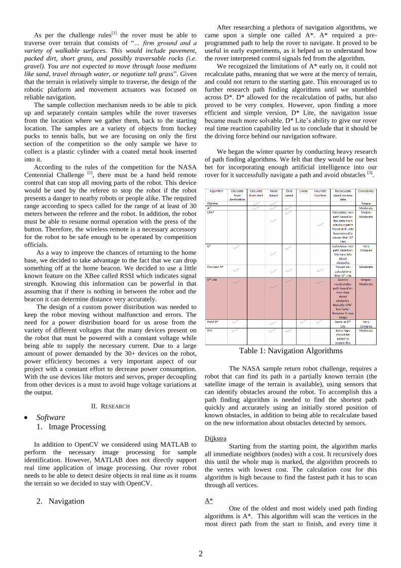
As per the challenge rules[1]
the rover must be able to
traverse over terrain that consists of “… firm ground and a
variety of walkable surfaces. This would include pavement,
packed dirt, short grass, and possibly traversable rocks (i.e.
gravel). You are not expected to move through loose mediums
like sand, travel through water, or negotiate tall grass”. Given
that the terrain is relatively simple to traverse, the design of the
robotic platform and movement actuators was focused on
reliable navigation.
The sample collection mechanism needs to be able to pick
up and separately contain samples while the rover traverses
from the location where we gather them, back to the starting
location. The samples are a variety of objects from hockey
pucks to tennis balls, but we are focusing on only the first
section of the competition so the only sample we have to
collect is a plastic cylinder with a coated metal hook inserted
into it.
According to the rules of the competition for the NASA
Centennial Challenge [1]
, there must be a hand held remote
control that can stop all moving parts of the robot. This device
would be used by the referee to stop the robot if the robot
presents a danger to nearby robots or people alike. The required
range according to specs called for the range of at least of 30
meters between the referee and the robot. In addition, the robot
must be able to resume normal operation with the press of the
button. Therefore, the wireless remote is a necessary accessory
for the robot to be safe enough to be operated by competition
officials.
As a way to improve the chances of returning to the home
base, we decided to take advantage to the fact that we can drop
something off at the home beacon. We decided to use a little
known feature on the XBee called RSSI which indicates signal
strength. Knowing this information can be powerful in that
assuming that if there is nothing in between the robot and the
beacon it can determine distance very accurately.
The design of a custom power distribution was needed to
keep the robot moving without malfunction and errors. The
need for a power distribution board for us arose from the
variety of different voltages that the many devices present on
the robot that must be powered with a constant voltage while
being able to supply the necessary current. Due to a large
amount of power demanded by the 30+ devices on the robot,
power efficiency becomes a very important aspect of our
project with a constant effort to decrease power consumption.
With the use devices like motors and servos, proper decoupling
from other devices is a must to avoid huge voltage variations at
the output.
II. RESEARCH
Software
1. Image Processing
In addition to OpenCV we considered using MATLAB to
perform the necessary image processing for sample
identification. However, MATLAB does not directly support
real time application of image processing. Our rover robot
needs to be able to detect desire objects in real time as it roams
the terrain so we decided to stay with OpenCV.
2. Navigation
After researching a plethora of navigation algorithms, we
came upon a simple one called A*. A* required a pre-
programmed path to help the rover to navigate. It proved to be
useful in early experiments, as it helped us to understand how
the rover interpreted control signals fed from the algorithm.
We recognized the limitations of A* early on, it could not
recalculate paths, meaning that we were at the mercy of terrain,
and could not return to the starting gate. This encouraged us to
further research path finding algorithms until we stumbled
across D*. D* allowed for the recalculation of paths, but also
proved to be very complex. However, upon finding a more
efficient and simple version, D* Lite, the navigation issue
became much more solvable. D* Lite’s ability to give our rover
real time reaction capability led us to conclude that it should be
the driving force behind our navigation software.
We began the winter quarter by conducting heavy research
of path finding algorithms. We felt that they would be our best
bet for incorporating enough artificial intelligence into our
rover for it successfully navigate a path and avoid obstacles [3]
.
Table 1: Navigation Algorithms
The NASA sample return robot challenge, requires a
robot that can find its path in a partially known terrain (the
satellite image of the terrain is available), using sensors that
can identify obstacles around the robot. To accomplish this a
path finding algorithm is needed to find the shortest path
quickly and accurately using an initially stored position of
known obstacles, in addition to being able to recalculate based
on the new information about obstacles detected by sensors.
Dijkstra
Starting from the starting point, the algorithm marks
all immediate neighbors (nodes) with a cost. It recursively does
this until the whole map is marked, the algorithm proceeds to
the vertex with lowest cost. The calculation cost for this
algorithm is high because to find the fastest path it has to scan
through all vertices.
A*
One of the oldest and most widely used path finding
algorithms is A*. This algorithm will scan the vertices in the
most direct path from the start to finish, and every time it
3
encounters an obstacle it starts scanning the next shortest path
from the starting point to the destination. The algorithm does
this recursively until it finds the shortest and less expensive
path possible. One drawback of this algorithm is that once the
robot starts moving, the algorithm can’t update the preloaded
map with newly founded obstacles.
LPA*/ Incremental A*
This is an improved version of the algorithm A*. It
repeatedly finds shortest paths from a given start vertex to a
given goal vertex while the edge costs of a graph change or
vertices are added or deleted. Its first search is the same as that
of a version of A* that breaks ties in favor of vertices with
smaller g-values but many of the subsequent searches are
potentially faster because it reuses those parts of the previous
search tree that are identical to the new one
However this algorithm lacks the ability to initially
store information about the cost of each vertex.
D*
Unlike A*, D* starts from the goal vertex and has the
ability to change the costs of parts of the path that include an
obstacle. This allows D* to re-plan around an obstacle while
maintaining most of the already calculated path. However, D*
is very complex to implement and lacks the ability to initially
store information about the cost of each vertex.
Focused D*
This algorithm is an improvement to make D* faster.
However, this algorithm still does not get as simple and
efficient as D* lite
D* Lite
This algorithm uses LPA* to be able to recalculate the
shortest path even when the cost of vertices change. D* Lite
combines LPA* with heuristic search algorithm in which the
costs of some vertices in the map are initially known. This
makes D* Lite a great choice for partially known trains that
change dynamically.
Also the implementation of this algorithm can be much simpler
than D* and Field D*.
Field D*
A variant of D*-Lite which does not constrain
movement to a grid; that is, the best path can have the unit
moving along any angle, not just 45 (or 90) degrees between
grid-points. However, this algorithm is more complex to
implement.
RTT
This algorithm selects a random point in the
environment and connects it to the initial vertex. Subsequent
random points are then connected to the closest vertex in the
emerging graph. The graph is then connected to the goal node,
whenever a point in the tree comes close enough given some
threshold.
The cost of finding the closest in this algorithm is
really low; however more work should be done to add the
capability to recalculate a new path when encountering newly
discovered obstacles while the robot is moving.
After comparing all of the algorithms [3]
, we
concluded that LPA* is easy and feasible to implement;
however, the high efficiency of D* Lite because of reusing its
previous searches for calculating new paths, made it the
appropriate choice for our purposes [4]
. D* lite has the best of
both worlds. Although Field D* is a linear path finding
algorithm, it almost has the same functionality and it is more
complex to implement. Also for our purposes, the grid system
should be good enough and the capability to find linear shortest
path will not add a lot more accuracy. The simplicity, speed,
and having all the functionalities that we need make D* lite a
very good choice.
After some more research, we found a very simple and
efficient implementation of D* Lite done by James Neufeld a
PhD student at University of Alberta in Canada [10]
. His open
source implementation of D* Lite was in C++. This made our
job a lot easier since most of our other programs were written
in the same language.
Hardware
1. Bogie
Because of the simple terrain
[1], our robot design was
based on a simple wheeled platform. It had to be able to
traverse the given terrain as well as carry the sensors, batteries,
computers, sample pickup mechanism, and the samples that it
collected. By using a six wheeled platform (as opposed to a 3
or 4 wheeled one) the weights of the robot and samples are
more easily distributed to each wheel, allowing the wheels and
motors to be smaller as each one is required to do less work [11]
.
In an effort to simplify our navigation algorithm, our rover
was restricted making turns in 90 degree increments while not
driving forward. This means the rover made tank turns in place
and due to the placement of the wheels the robot may have
slipped and fell short of the desired turn angle. To mitigate this
problem the wheels on both the front and back were designed
to pivot so that the wheels can be aligned with the
circumference of the turning circle of the rover.
2. Sample Collection
To keep the complexity of the collection mechanism low
we decided to go with a bucket style system that can scoop up
the sample using a lid and then contain the sample with the
same lid. This has the side benefit of keeping the control
software for the sample collection relatively simple as well.
The bucket style system is versatile and allowed us to collect
differing samples with the same collection mechanism.
The collection mechanism was divided into two sections,
thus allowing the robot to collect and keep separate two
samples at time. Each section of the collection mechanism had
its own lid that could be controlled individually.
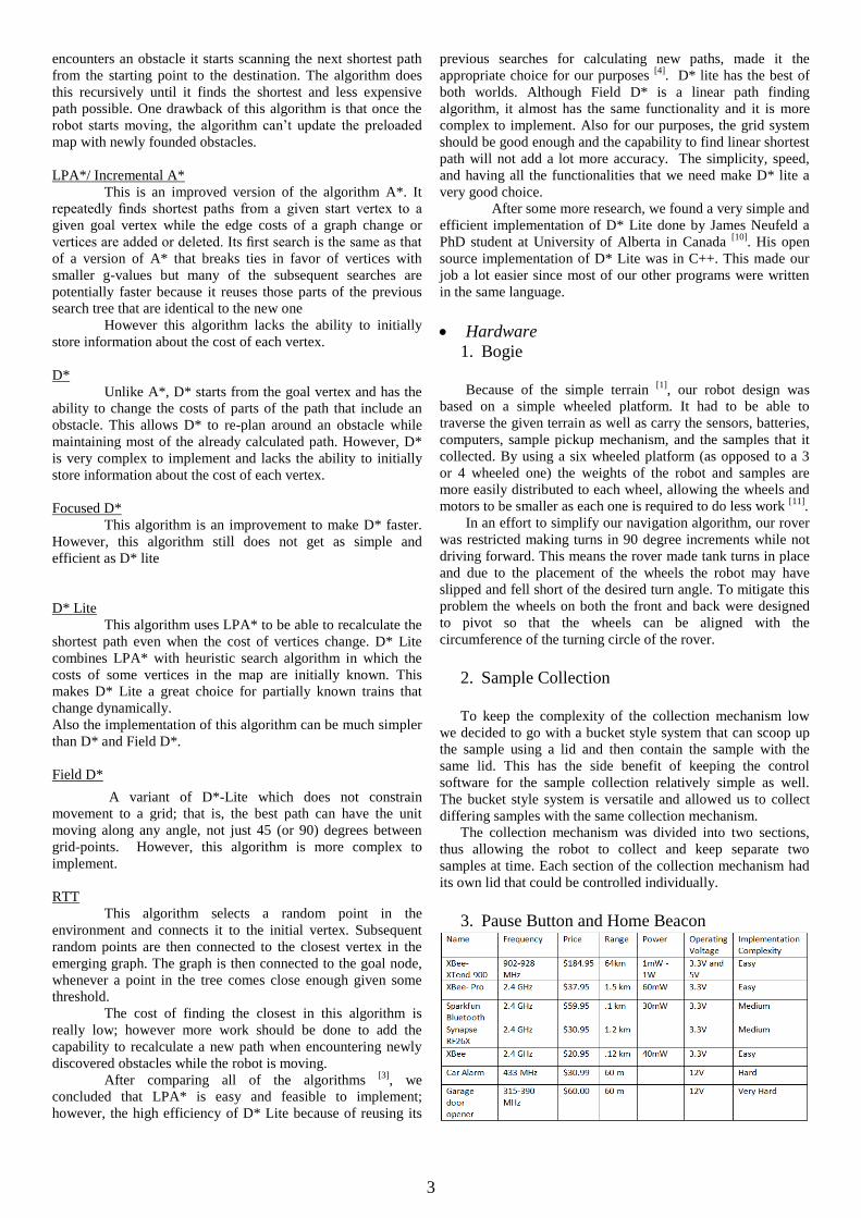
3. Pause Button and Home Beacon

4
Table 2: Wireless Tx/Rx
Looking at various wireless devices, we decided to go with
the XBee because of the ease of implementation and relatively
low price. In addition, the minimum requirement of 30 meters
is easily exceeded by the chip with a maximum of 120 meters
of range. While the synapse wireless chip was comparable in
price to the XBee with a much higher range, the competition [1]
only called for 30 meters of range so the use of the synapse
would be “overkill “ for our purposes. The chip also has a very
small power footprint which is a big deal for us because of the
tight power budget. Since this device required very little data to
be transmitted, transmission speed was not a parameter that
was considered for the selection of a wireless chip.
For the beacon, research began on whether we could
implement it. Looking at the forums of a sizeable community [12]
we found many examples of the use of this feature to not
only determine the strength of a signal but also do it accurately.
We found the a particular video that depending on where the
receiving beacon would be in respect to the transmitting
XBee’s at the corner of the room would update a map that
would keep track of where in the room the receiver was. While
we could not use this particular method because we could only
have one beacon, it was an encouraging sign that they could be
very accurate.
4. Power Distribution
There are 2 criteria that were accounted for when designing
the power distribution board; Efficiency, and reliability.
Table 3: Power Requirements
Efficiency was a big factor for the design of this power
distribution board because of the large number of sensors,
servos, motors that were used on the robot called for the
maximization of power available from the battery. The goal for
our robot was to be able to last at least 30 min in between
charges so in order to make it through the entire competition.
After doing a power budget, the estimated max current that will
be drawn will be 12 Amps. From inspection, a battery of 6 Ah
would give us the required time for the robot to work for 30
min. This however does not translate to an actual 6 Ah battery
because a real battery has finite output impedance which
increases as the current drawn increases. Therefore, the actual
Ah of the battery drops to well below 6 Ah. Knowing this a
12Ah battery which at the maximum 12amp we estimate will
be drawn the normalized capacity of the battery is dropped to
6.2Ah. With this capacity, we know that the battery can source
6.2 amps of current for an hour meaning that we can narrowly
make the 30 min mark. Fortunately, since the 12Amps is the
maximum value we gave ourselves a cushion at which we
could easily make the 30 minute mark.
Reliability of the power distribution must also be heavily
accounted for when designing it as it important for the robot to
have uninterrupted power supply at all times. This means that
even with suddenly changing load like that of a servo which
can cause severe voltage swings, the power distribution board
must be able to reduce the effects of this phenomenon with
proper use of bypass capacitors to smooth out the response.
Heat dissipation brings a lot of engineering issues if not
properly managed. In our case heat dissipation was an
important issue due to the fact that current in the range of
12Amps was supplied by the battery and thus the power board.
The problem with huge currents is completely a layout issue
where if the proper trace lengths and widths are not used, a
smaller geometry of a trace can cause voltage drops
everywhere on the power board and thus lead to a huge loss in
power. The issue of heat management brings up both efficiency
and reliability problems if attention is not paid to the layout. In
order to limit the heat fluctuations experienced by the board, a
power trace must be designed so that the current can have the
least amount of impedance as it travels through the board. This
is done by making the traces wider thus maintaining an
adequate density of electrons and thus keeping impedance low.
To maintain the board smaller with the benefit of low trace
impedance, a 2.5 Oz copper board was used to further lower
the characteristic impedance by increasing the cross-sectional
area. Keeping trace impedance low makes sure most of the
energy is used at the load rather than dissipated as heat as a
result of the impedance of the trace.
Once we decided on a battery, we began research on the
power distribution board by reading multiple references like
TNN1068 and the Handbook of Black Magic: High Speed
Digital Design. Eventually with the help of out TA, Paul Naud,
we chose the LM3150 and LM2596 as possible solutions to the
problem.
5. Sensors
In order to comply with the rules of the competition, we
were not allowed to use sonars, Global Positioning Systems
(GPS), magnetometers, or any sensors that rely on the earth’s
magnetic field [1]
.
Also the rules mention that the judges may place a strong
magnet as a payload on the rover which rules out the use of
most of the magnetic and Hall Effect sensors. We have
compared some of the sensors that could be used to solve the
problem of navigating to a field, avoiding obstacles, and
sensing the sample in Table 4. Since we did not have the
precise coordinates of the sample, a barometer could not be
used to find the whereabouts of the sample.

5
Table 4: Sensor comparison
Since we did not have the precise coordinates of the sample,
a barometer could not be used to find the whereabouts of the
sample.
III. IMPLEMENTATION
Software
1. Image Processing
We used OpenCV Haarcascade and trainingcascade
[13] to
generate Xml files specifically to detect the sample. We
trained the cascade and convert it into a usable Xml, which
consisted of accumulating thousands of pictures of the sample
from different angles and background. By applying our Xml
classifier, the first sample in the NASA Centennial Challenge is
able to be detected with the rover’s top camera.
To interact with the image processing routine there are
four main states that the rovers main microcontroller can
request information from. The states are Top_Camera,
Top_Width, Bottom_Camera, and Bottom_width. On power up,
the image processing software start at WaitForRequest, this is
the wait state. In the wait state, the program waits for a signal
from the microcontroller to move to one of the four main states.
Each of the four main states have an acknowledge state to send
back to the microcontroller a confirmation signal before
moving to any of the four main states. The four
acknowledgement states are AckRequest_TopCam,
AckRequest_Top_Width, AckRequest_BottomCam, and
AckRequest_Bottom_Width. At the end of each of the four
main states, the program returns to wait state and is ready for
new quests from the microcontroller.
The states are entered in the following manner:
WaitforRequest AckRequest_TopCam Top_Camera
WaitforRequest
WaitforRequest AckRequest_Top_Width Top_Width
WaitforRequest
WaitforRequest AckRequest_BottomCam
Bottom_Camera WaitforRequest
WaitforRequest AckRequest_Botom_Width
Bottom_Width WaitforRequest
In the states, Top_Camera and Bottom_Camera the
Haar Cascade object detection function, detect_and_draw(), is
called. Once the function detect_and_draw( ) executes, we
save the last width of the sample detected from each camera
send back to the microcontroller upon request to enter states
Top_Width or Bottom_Width.
The function detect_and_draw( ) determines the
sample detection. The parameters are camera slection (top or
bottom) and location of the cascade XML file. The function is
called inside the follows states: Top_Camera and
Bottom_Camera. Before exiting a state, a signal is sent to the
microcontroller; N, C, L, or R, representing Not Found, object
in center of frame, rotate rover to the Left, and rotate rover to
the Right.
The function detect_and_draw ( ), loads the specified
XML cascade classifier from disk. To make the perform
detection from our camera, we use OpenCV function
cvHaarDetectionObjects( ). This function compares each
frame capture from the mounted camera and calculates pixel
regions that are close to our trained XML and stores the data
into the vector. Next we loop through the vectors to draw an
enclosed squared around the region and display it on the
camera output. The coordinate of the center of the square
relative to the camera frame is stored in a global variable to be
used in the “Top_Camera” and “Bottom_Camera” to send the
appropriate signals to the microcontroller depending on
position of the square’s center. The width of the square is also
send to the microcontroller in order set a threshold value of
when to begin the rover’s collecting mechanism.
2. Navigation
We decided to run D* Lite on the main microcontroller
that we used for controlling all the motors. This worked well
since we could directly control the motors in the same program
that would produce the shortest path. However, half-way
through the implementation of D* Lite in C on the
microcontroller, we realized that the microcontroller did not
have enough memory to process the path finding algorithm.
The next step for us was to decide what type of hardware
would be suitable to run the path finding algorithm efficiently
and communicate with our other processors effectively. One of
our first choices to consider was to run D* Lite on the same
computer that was in charge of image processing; however,
while we were researching about that, one of our advisors
suggested that we use the raspberry pi board. After doing a
little research, we soon realized that raspberry pi is an ideal
choice for our purposes. The microcontroller that failed to run
D*Lite only had 16KBs of RAM, but the raspberry pi had
512MBs. Also raspberry pi had UART communication pins [14]
ready which were compatible with our micro-controller
(PIC32).
We designed the program on the raspberry pi side to act as
a client for the requests that the main state machine would send.
This would keep the raspberry pi in an idle state until the micro
sends it a request. Then the raspberry pi would process the
6
request and respond correspondingly. Some of the requests
received by the D*Lite client:
Request to update goal
Request to update starting position
Request to set an obstacle on a coordinate
point in the map
Request to recalculate the path
Request to send the next coordinate point on
the path
3. State Machines
Our control scheme consists of three main state machines:
one to communicate with D* Lite (on the Raspberry Pi), one to
communicate with the image processing software (on the
laptop), and a main state machine, which initiates all ports and
actuators on the Uno32, as well as telling the rover when to
navigate paths and when to search for and collect samples.
Because multiple processors are required to implement an
effective navigation scheme, numerous delays are incorporated
into all three state machines to ensure that commands are sent
and received properly. While this prevents the rover from
quickly traversing terrain, it allows D* Lite to accurately map
the rover’s path to the sample. Since the motors only run at
about half of their maximum capability, encoder counts are
more accurate (because edge detection is superior with slower
pulses). This helps the state machine send more exact
coordinates of the rover’s location to D* Lite, and increases the
precision of its navigation.
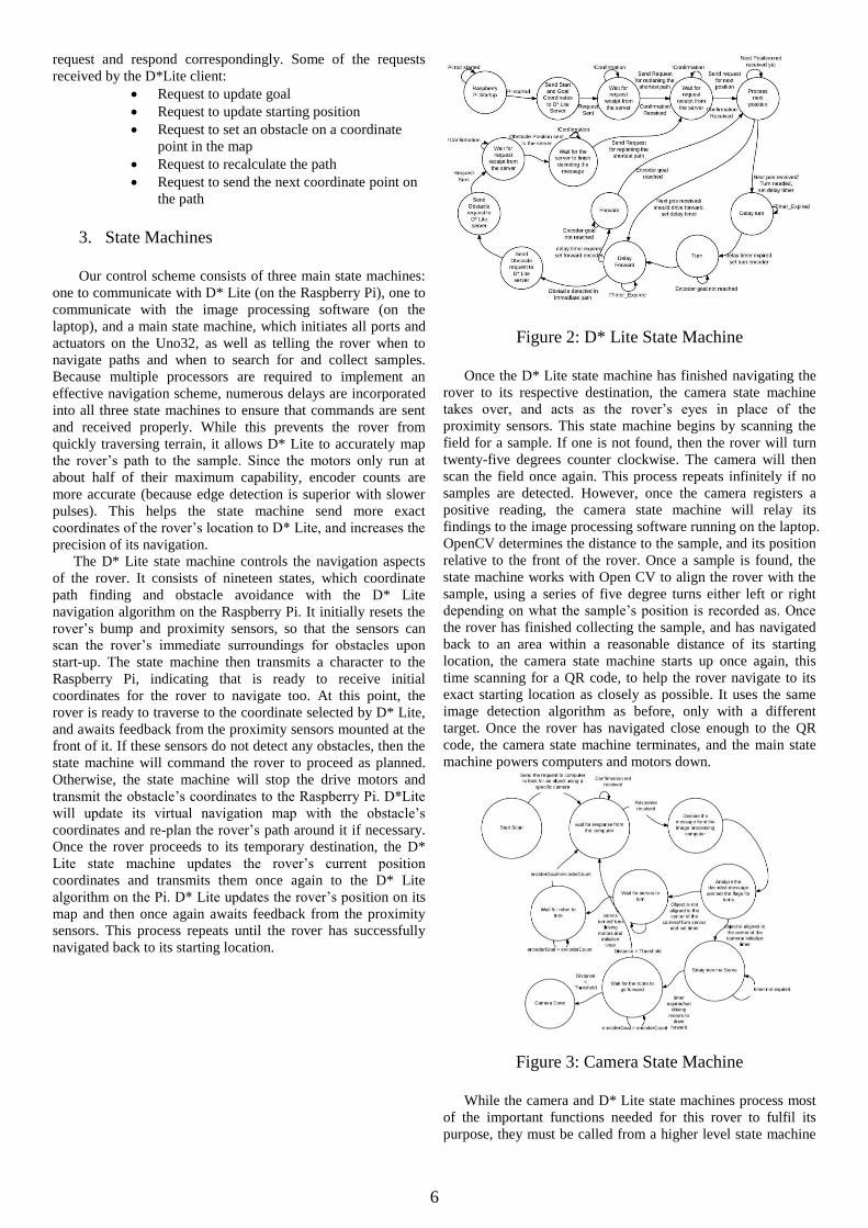
The D* Lite state machine controls the navigation aspects
of the rover. It consists of nineteen states, which coordinate
path finding and obstacle avoidance with the D* Lite
navigation algorithm on the Raspberry Pi. It initially resets the
rover’s bump and proximity sensors, so that the sensors can
scan the rover’s immediate surroundings for obstacles upon
start-up. The state machine then transmits a character to the
Raspberry Pi, indicating that is ready to receive initial
coordinates for the rover to navigate too. At this point, the
rover is ready to traverse to the coordinate selected by D* Lite,
and awaits feedback from the proximity sensors mounted at the
front of it. If these sensors do not detect any obstacles, then the
state machine will command the rover to proceed as planned.
Otherwise, the state machine will stop the drive motors and
transmit the obstacle’s coordinates to the Raspberry Pi. D*Lite
will update its virtual navigation map with the obstacle’s
coordinates and re-plan the rover’s path around it if necessary.
Once the rover proceeds to its temporary destination, the D*
Lite state machine updates the rover’s current position
coordinates and transmits them once again to the D* Lite
algorithm on the Pi. D* Lite updates the rover’s position on its
map and then once again awaits feedback from the proximity
sensors. This process repeats until the rover has successfully
navigated back to its starting location.
Figure 2: D* Lite State Machine
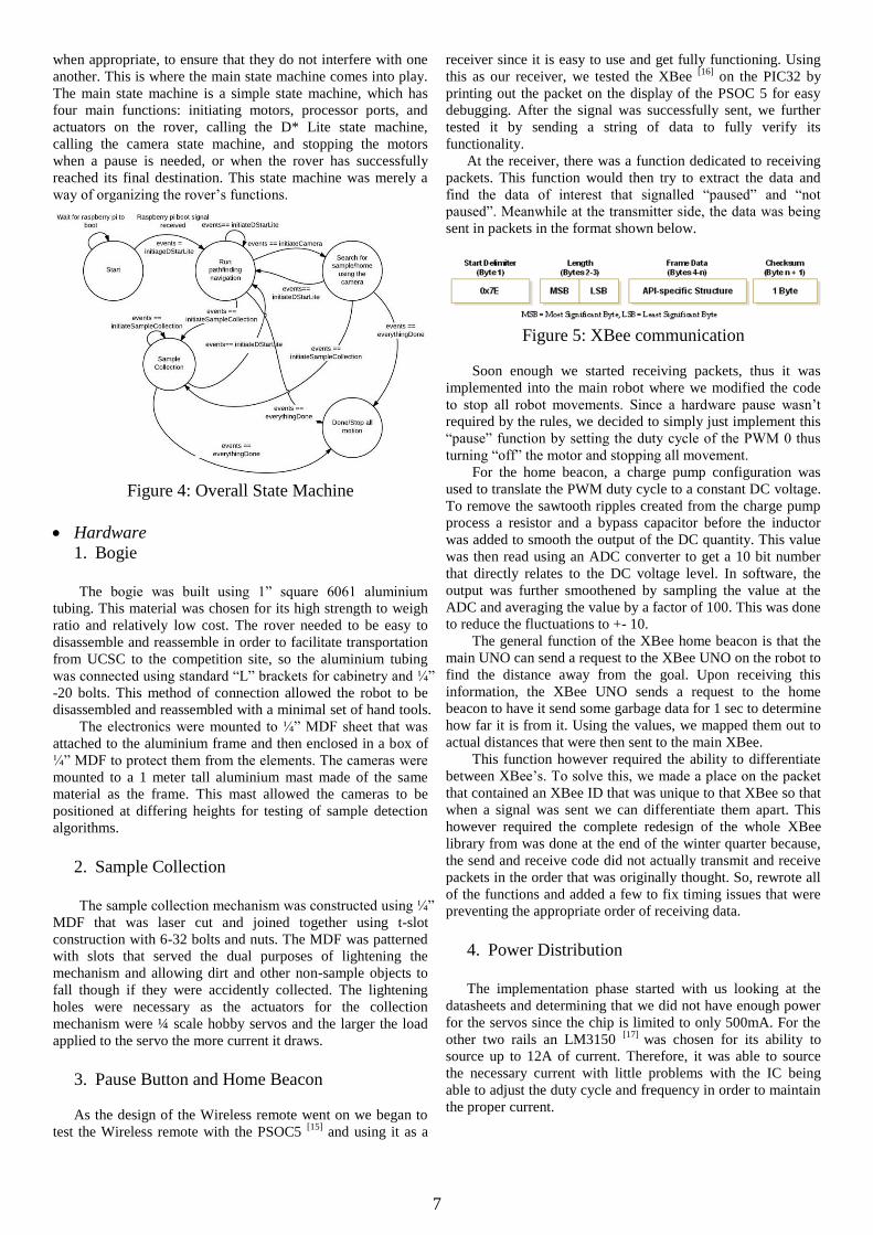
Once the D* Lite state machine has finished navigating the
rover to its respective destination, the camera state machine
takes over, and acts as the rover’s eyes in place of the
proximity sensors. This state machine begins by scanning the
field for a sample. If one is not found, then the rover will turn
twenty-five degrees counter clockwise. The camera will then
scan the field once again. This process repeats infinitely if no
samples are detected. However, once the camera registers a
positive reading, the camera state machine will relay its
findings to the image processing software running on the laptop.
OpenCV determines the distance to the sample, and its position
relative to the front of the rover. Once a sample is found, the
state machine works with Open CV to align the rover with the
sample, using a series of five degree turns either left or right
depending on what the sample’s position is recorded as. Once
the rover has finished collecting the sample, and has navigated
back to an area within a reasonable distance of its starting
location, the camera state machine starts up once again, this
time scanning for a QR code, to help the rover navigate to its
exact starting location as closely as possible. It uses the same
image detection algorithm as before, only with a different
target. Once the rover has navigated close enough to the QR
code, the camera state machine terminates, and the main state
machine powers computers and motors down.
Figure 3: Camera State Machine
While the camera and D* Lite state machines process most
of the important functions needed for this rover to fulfil its
purpose, they must be called from a higher level state machine
7
when appropriate, to ensure that they do not interfere with one
another. This is where the main state machine comes into play.
The main state machine is a simple state machine, which has
four main functions: initiating motors, processor ports, and
actuators on the rover, calling the D* Lite state machine,
calling the camera state machine, and stopping the motors
when a pause is needed, or when the rover has successfully
reached its final destination. This state machine was merely a
way of organizing the rover’s functions.
Figure 4: Overall State Machine
Hardware
1. Bogie
The bogie was built using 1” square 6061 aluminium
tubing. This material was chosen for its high strength to weigh
ratio and relatively low cost. The rover needed to be easy to
disassemble and reassemble in order to facilitate transportation
from UCSC to the competition site, so the aluminium tubing
was connected using standard “L” brackets for cabinetry and ¼”
-20 bolts. This method of connection allowed the robot to be
disassembled and reassembled with a minimal set of hand tools.
The electronics were mounted to ¼” MDF sheet that was
attached to the aluminium frame and then enclosed in a box of
¼” MDF to protect them from the elements. The cameras were
mounted to a 1 meter tall aluminium mast made of the same
material as the frame. This mast allowed the cameras to be
positioned at differing heights for testing of sample detection
algorithms.
2. Sample Collection
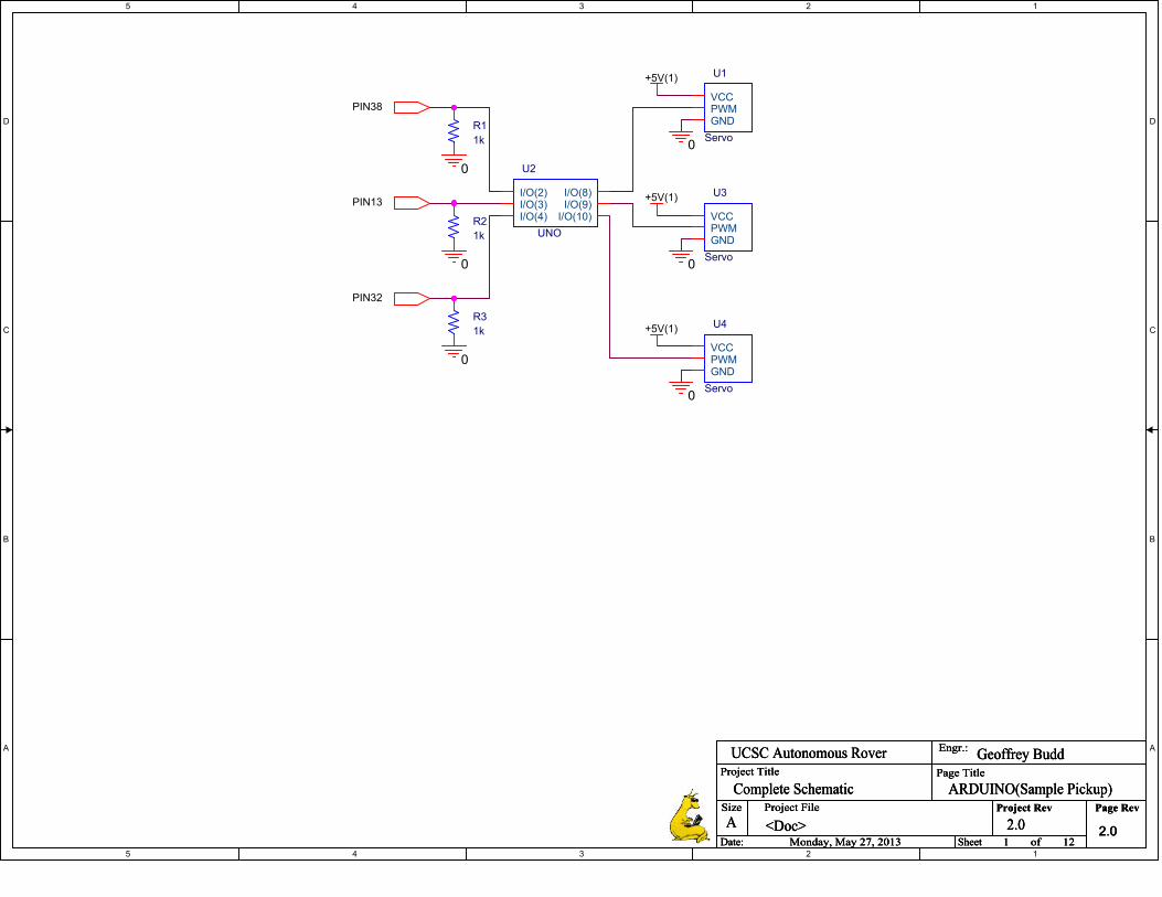
The sample collection mechanism was constructed using ¼”
MDF that was laser cut and joined together using t-slot
construction with 6-32 bolts and nuts. The MDF was patterned
with slots that served the dual purposes of lightening the
mechanism and allowing dirt and other non-sample objects to
fall though if they were accidently collected. The lightening
holes were necessary as the actuators for the collection
mechanism were ¼ scale hobby servos and the larger the load
applied to the servo the more current it draws.
3. Pause Button and Home Beacon
As the design of the Wireless remote went on we began to
test the Wireless remote with the PSOC5 [15]
and using it as a
receiver since it is easy to use and get fully functioning. Using
this as our receiver, we tested the XBee [16]
on the PIC32 by
printing out the packet on the display of the PSOC 5 for easy
debugging. After the signal was successfully sent, we further
tested it by sending a string of data to fully verify its
functionality.
At the receiver, there was a function dedicated to receiving
packets. This function would then try to extract the data and
find the data of interest that signalled “paused” and “not
paused”. Meanwhile at the transmitter side, the data was being
sent in packets in the format shown below.
Figure 5: XBee communication
Soon enough we started receiving packets, thus it was
implemented into the main robot where we modified the code
to stop all robot movements. Since a hardware pause wasn’t
required by the rules, we decided to simply just implement this
“pause” function by setting the duty cycle of the PWM 0 thus
turning “off” the motor and stopping all movement.
For the home beacon, a charge pump configuration was
used to translate the PWM duty cycle to a constant DC voltage.
To remove the sawtooth ripples created from the charge pump
process a resistor and a bypass capacitor before the inductor
was added to smooth the output of the DC quantity. This value
was then read using an ADC converter to get a 10 bit number
that directly relates to the DC voltage level. In software, the
output was further smoothened by sampling the value at the
ADC and averaging the value by a factor of 100. This was done
to reduce the fluctuations to +- 10.
The general function of the XBee home beacon is that the
main UNO can send a request to the XBee UNO on the robot to
find the distance away from the goal. Upon receiving this
information, the XBee UNO sends a request to the home
beacon to have it send some garbage data for 1 sec to determine
how far it is from it. Using the values, we mapped them out to
actual distances that were then sent to the main XBee.
This function however required the ability to differentiate
between XBee’s. To solve this, we made a place on the packet
that contained an XBee ID that was unique to that XBee so that
when a signal was sent we can differentiate them apart. This
however required the complete redesign of the whole XBee
library from was done at the end of the winter quarter because,
the send and receive code did not actually transmit and receive
packets in the order that was originally thought. So, rewrote all
of the functions and added a few to fix timing issues that were
preventing the appropriate order of receiving data.
4. Power Distribution
The implementation phase started with us looking at the
datasheets and determining that we did not have enough power
for the servos since the chip is limited to only 500mA. For the
other two rails an LM3150 [17]
was chosen for its ability to
source up to 12A of current. Therefore, it was able to source
the necessary current with little problems with the IC being
able to adjust the duty cycle and frequency in order to maintain
the proper current.

8
Figure 6: Power Distribution Requirements
As shown in figure 6 above, the power distribution board
consists of a 3 different rails to power the many different
devices on the robot. For the 3.3V rail we used the LM2596
because it was much easier to design with and can handle more
than 100mA required from the 3.3V rail. This was due to the
fact that the LM2596 has less features therefore the required
setup for this chip requires nothing more than a capacitor,
inductor and two feedback resistors.
For the 5V rail we decided to go with the LM3150. Using
the manufacturer’s recommended design procedure on the IC
datasheet, we were able to come up with a preliminary design.
Due to changing load demands however, we had to recalculate
the circuit with extra headroom required when driving things
like servos which introduce huge current spikes and thus
turning off devices like the raspberry pi while the robot was
moving. This was due to the fact that frequency wasn’t set to
keep up with current demands.
Figure 7: Power Distribution PCB
In figure 7, the top and bottom layers are shown. For both
the top and bottom layers, the traces were made thick were high
currents are likely. To calculate how thick they have to be we
use the equation:
))
where k= 0.048, b = .44, c = 0.725. Then after calculating
the area A, we can calculate the width W using the equation:
)
Using these two equations, we determined that the trace
width needed to be 100 mils or more with a 2.5 oz copper. We
made all the traces well above that number in order to avoid
any chance of high trace impedance.
5. Sensors
Due to the grid-based navigation algorithm of the D* lite,
knowing the precise distance to the obstacle would not benefit
us and merely knowing if there is any obstacles in the adjacent
grids is enough. To check for obstacles, we used the
GP2Y0A02YK0F long range sharp® [6]
infrared proximity
sensors. Since proximity sensors can only scan in one
dimension, we decided to pan them using servo motors. We
placed three proximity sensors in the front of the rover to
increase the reliability using redundancy. Also we compared 5
consecutive samples, read by the analog to digital converter, to
reduce the number of false positives caused by the noise. The
proximity sensors have built-in band-pass filters and operate in
the infrared spectrum of λ = 850 ± 70nm. The only signal
conditioning that was done for them was adding bypass
capacitors of 10µF from Vcc and signal to the ground to
suppress the power supply and analog to digital converter noise.
Since we chose each grid of the map to be 1m2, the proximity
sensors had to read anything that was at least 1 meter away
from them. The data sheet that sharp provides is for indoor use
and since the sun light has the full spectrum, the threshold of
the proximity sensors decreased [6]
. We found the ADC reading
of 1 meter and set it to be the threshold. Each servo rotates 45
with the servos to the side initially angled 22.5 toward the
middle of the rover.
)
Figure 8 illustrates the line of sight of the infrared
proximity sensors. The lines of sight have been colored in
different colors so they are easily distinguishable. As it can be
seen in the image, using the 3 proximity sensors reduces the
blind spots and increases reliability by redundancy. The grids
in figure 8 are 1 meter by 1 meter.
rover
Figure 8: scanning the next grid using the infrared
proximity sensors
For the case that the proximity sensors failed and did
not register an obstacle in the map, the rover is equipped with
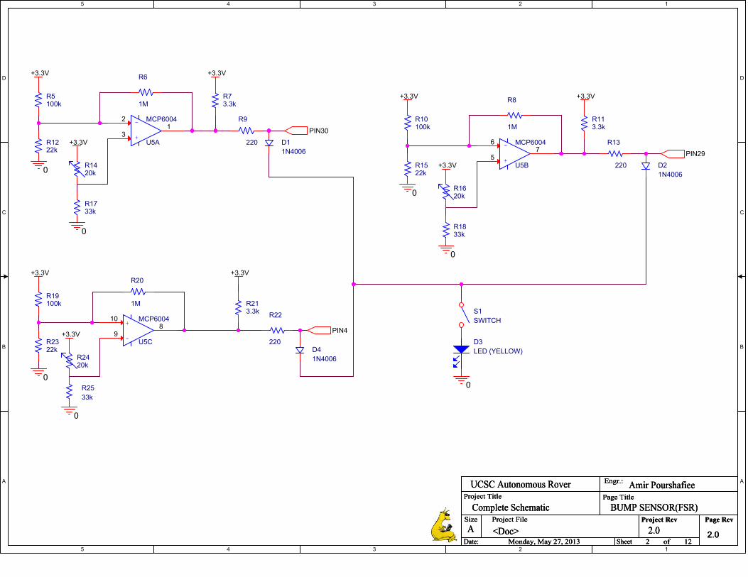
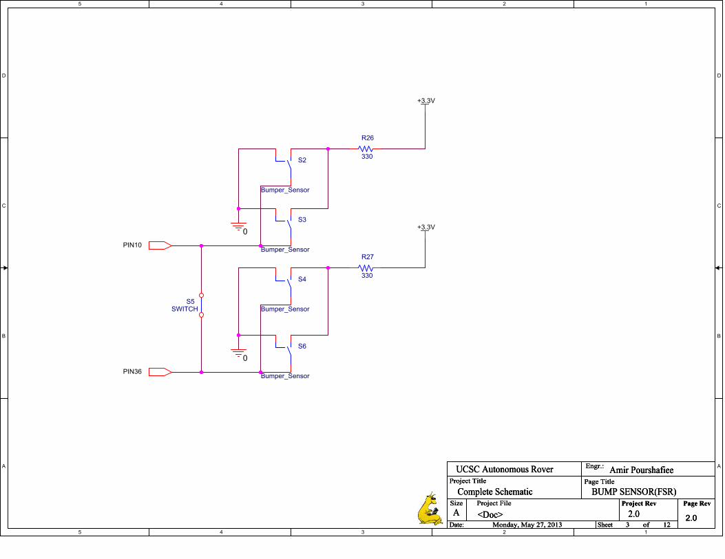
the force sensing resistors (FSR ®). The FSRs are made of
polymer tick film material which has an infinitely large
resistance when there is no force being applied to them [7]
.
When a force is applied to the FSR, the resistance decreases to
a finite value which by building a voltage divider, can be
measured. Since we only wanted to use them as bump sensors,
we disregarded the exact resistance value of stripe and used a
comparator to convert that analog value to a digital value (not
bumped as low and bumped as high). As it can be seen in
figure 9, the constant resistor is chosen to be a relatively large
value since the FSR has a large resistance even when it is under
an applied force (typically between 22K to 60K). We need a
comparator and a reference voltage to compare it with the
signal from the sensor and implement a hardware hysteresis.

9
Figure 9: FSR signal
Figure 9 illustrates the schematics of the circuit design
of the FSR bump sensors. Since the comparator has an open
collector output, it needs a pull-up resistor. We chose a 3.3kΩ
resistor to source to the open collector output. We are using the
MCP6004 comparator in non-inverting configuration and we
need a very high resistance negative feedback resistor which
we chose to be 1MΩ.
To choose the rest of the resistors, we followed
following instructions [8]
:
)
So we used a 100KΩ resistor for .
)
So we chose a 20kΩ for .
With the estimations and round offs, the real high and
low thresholds are:
)
) And,
)
)
Since the threshold values are close to what they were
planned to be, the choice of resistors are justified. Finally, in
order to connect the output of the comparator to the
microprocessor, we need to limit the current to at most 20mA.
Thus we use a 220 ohm resistor to do so.
)
The 220Ω resistor is greater than the minimum
resistance (165Ω) and limits the current to 15mA which is a
within the specs of the microcontroller.
We used Inertial Measurement Units including accelerometers
and gyroscopes:
Accelerometers output the acceleration reading that is
sensed by the chip. We are using a MMA7361, a three axis
analog accelerometer. The datasheet of the accelerometer
includes it’s sensitivity factor 800mv/g (for 1.5g) which is a
multiplier that converts the output voltage to the acceleration of
the three axes.[6] The accelerometer has two acceleration
settings (1.5g and 6g), which are the maximum acceleration
that the accelerometer can measure accurately before losing
precision. We chose to operate under 1.5g because the
resolution of the accelerometer is almost 4 times as high as
when it is operated in 6g mode (sensitivity of 800 for 1.5g
versus 206 for 6g).
The maximum acceleration happens when the rover
starts from rest and reaches the maximum velocity. In order to
calculate the minimum time needed for the rover to start from
rest to maximum velocity, we have:
)
The first integral of the acceleration in each axis, results in
the velocity on that axis and the second integral would result in
the position on that axis. The steps of converting an
accelerometer’s ADC reading to the acceleration, velocity,
speed, and position of the rover are listed below:
Read the ADC value as a 10 bit number and convert it
to a voltage between 0-3.3v
To initialize the accelerometer, we averaged 10000
sample and while the accelerometer is at rest. (This is
done to compensate for the noise of the accelerometer
offset value)
We subtract the current value from the offset value
and multiply the result by the accelerometer sensitivity
to obtain gross acceleration of each axis.
By adding the acceleration values over time, we are
taking its Riemann sum and as a result we are
calculating the velocity of that axis.
The overall speed of the rover is calculated by the
square root of squares of the velocity in each
axis. √ )

10
The Riemann sum of the velocity generates the
displacement, so we add the velocities over time and
calculate the displacement for each axis.
To ensure that the rover is moving (and the
microcontroller is not reading false odometer reading),
we check that when the rover starts, it accelerates and
is moving until there is a large deceleration which
indicates a stop. If the finite state machine commands
the rover to move and the encoders are registering a
movement but the accelerometer indicates the rover is
stalling, it means the wheels are slipping.
Since we did not need any information about the z axis, it
is excluded from the calculations. Since the accelerometer we
used had a very low quality and because of noise and drift
issues, the choice of this specific accelerometer was not a good
choice. However, accelerometers that are more precise are very
expensive. Since the mathematical operations on the
accelerometers to obtain velocity and distance involve
integration, the time intervals have to be very small and
consistent which requires a separate processor for which the
values have to run on a timer interrupt.
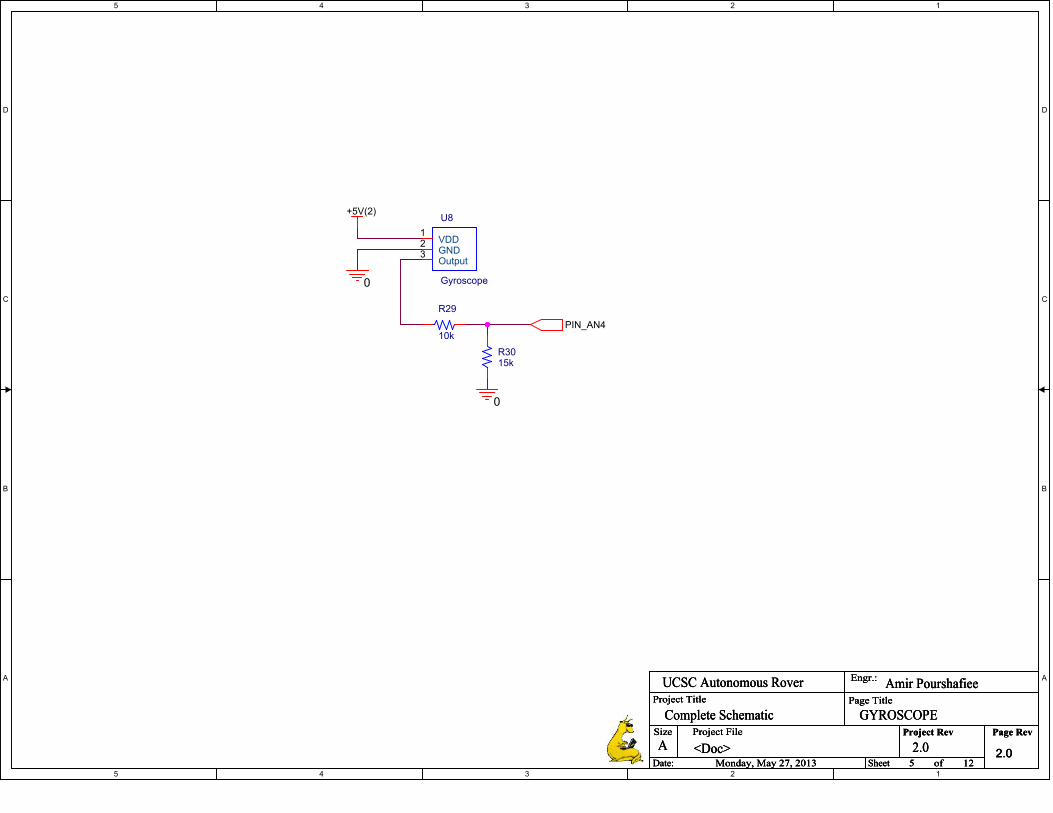
Gyroscopes measure the angular rate of an object, thus
the angular position at a given time is the sum of the rates [9]
(integral of the angular rates over time). We are using a
CRS03-02 gyroscope that outputs an analog signal that is read
by the analog to digital converter of the microprocessor. At rest
the gyroscope outputs a value close to the midpoint of the
potential of the power supply that it is connected. However
since the UNO32 board’s ADC port can only receive 3.3 v
inputs, we use a voltage divider to limit the output voltage of
the gyroscope to 3.3v (thus the midpoint is 1.65v).The
schematics of the gyroscope circuit diagram is attached in
appendix I. The gyroscope is rated for 100°/s and thus if it
turns faster than this rate, it loses its accuracy. The steepest
turns planned for the finite state machine and navigation
algorithm are 180° and thus for the angle and angular rate ,
we have:
√
)
Using Eq.1, for a 180° we have:
√
For a 90° turn, we have:
√
And for a 45° turn we have:
√
In order to comply with these values, we will adjust the
maximum pulse width modulation for the motors so it takes
longer than the time that is required for the gyroscope to
measure the rate of change of the angle while turning.
The steps of converting a gyroscope’s ADC reading to the
rotation that has taken place in time are listed below:
Run the gyroscope for 10 seconds when the rover is
still and average the ADC values read by the
gyroscope.
Read the ADC value as a 10 bit number and convert it
to a voltage between 0-3.3v
Subtract the current gyro rate from the gyro rate at rest
Multiply the gross gyro rate by the gyro sensitivity
(multiplier that converts gyro reading to degrees)
Set a threshold to reduce the effect of noise and only
take into account the values that are higher than the
threshold (Our threshold is 1°)
Add the values until the timer expires (integration)
To keep the rotational degrees between 0° and 360°, if
angle <0°, add 360° to it and if angle>359°, subtract
360° from it.
We calculated the gyroscope sensitivity (a multiplier that
converts the voltage reading to the rate of rotation using the
trial and error method and by taking its integral in the code, we
obtain the rotation angle of the rover. Since gyroscopes drift
over time, we will only use the gyroscope for short period of
times (the time it takes to make a rotation) and reset it each
time that the rotation is completed.
Although the CRS03-02 gyroscope was a not noisy,
when the servos were running they would produce noise in
ADC I/O pins which would add up (integral over time of noise)
to decouple the noise we used by-pass capacitors from the Vcc
and ADC pin to the ground. Since the algorithm to find the
angle of rotation involves integration and in order to take an
accurate integral, the time steps of the integral have to be
consistent and short. Since the microcontroller had to do many
calculations, the time intervals were varying, reducing the
reliability of the gyroscope when it was integrated with the rest
of the subsystems. In order to fix this problem, the gyroscope
has to be run on a different microprocessor which only deals
with the gyroscope and the sampling has to be done using timer
interrupts. This would require a relatively fast and powerful
microprocessor that can handle all of the mathematical
operations of the algorithm using timer interrupts.
In order to comply with the safety rules of the competition
[1], we removed the battery from the laptop and used a laptop
charger that nominally takes 12v DC and converts it to 19v DC
(boost converter that converts car battery to laptop battery) and
connected converter and the power distribution board to the
emergency stop button.
To control the safety light, using the microcontroller, we
send a signal to the base of BJT and alter the signal from high
to low every half a second. The BJT’s collector is connected to
the gate of a power MOSFET which turns the light on and off.
When the rover is paused, the light is solid and when it is un-
paused, it blinks at 1 Hz.
IV. TESTING
Software
1. Image Processing
To ensure the image processing algorithms would work
during the competition we tested between the times from 90:00
am to 4:00 pm. The majority of the image processing testing all
took place outside on the UCSC OPERS grass field as it was
the best analog to the competition field that was available to us.

11
The testing consisted of detection rate, false positive rate,
distance of detection.
We discovered that using the edge detection doesn’t work
when the outside during field testing and when the camera is
moving because the outline of the sample changes as the
orientation of the camera is rotated around it. Along with that
the method that involves background/foreground saturation
doesn’t work when the camera is moving. OpenCV Surf
worked however it was ineffective; the competition sample did
not display enough key features to make it distinguishable for
matching at any reasonable distance (greater than 1 meter).
We found that under ideal conditions, using the Haar
Cascade, the sample could be detected from over 10 meters, but
that in doing so false positives would also be detected. If the
range was decreased to 5 meters the false positive rate was
significantly lower and thus that is the range we set as our goal
for the competition.
2. Navigation
During the winter quarter we tested D* Lite on the test
rover, and after a few tweaks and some debugging, we
achieved satisfactory results. At first we used a timer based
system to test A* but when converted to an encoder based
system, we tested D* Lite with the updated encoder based
system. D* Lite performed as we expected it to, confirming
that it can help navigate our rover and avoid obstacles the way
we planned to. We used tall coffee containers and our legs to
simulate obstacles in the path of the range finder. The range
finder sent a signal noting obstruction to the Raspberry Pi,
which caused D* Lite to recalculate the path each time this
occurred.
After the mechanical implementation of our final prototype
was ready, we tested the same code on the bigger rover. The
results were similar; however while testing, we noticed a bug
that would sometimes crash D*Lite. After countless hours of
reading and analysing the code, we concluded that the problem
lied in the communication code between the raspberry pi and
the micro-controller. The issue was that sometimes raspberry pi
couldn’t receive the whole request message from the micro-
controller and wasn’t able to correctly decode the coordinate
points. This sometimes caused the path finding algorithm to
update the start and goal position to a wrong coordinate point.
We then realized that when the message was larger than 5
characters, raspberry pi would truncate the message. The
solution to this problem was to set a timeout timer. Whenever it
took more than 0.5 second for the raspberry pi to receive the
message completely, it would send another request to the micro
to send the rest of the message. After solving this problem, we
never had any problems with the code on the raspberry pi and
we modified the code very occasionally only to add extra
features.
After finalizing the code and testing it for a few times our
path finding algorithm never failed to find the shortest path.
During all of our tests before the competition, whenever the
sensors and motors worked properly as they were supposed to
work, D* Lite was able to navigate the robot to the goal. This
method of navigation to the goal is called dead reckoning.
Dead reckoning is basically the method in which the robot
measures and records its every movement in each direction,
and uses that data to find its position on the map relative to the
starting zone. Since we were not allowed to use GPS to confirm
the position using satellites, we expected some degree of error
in the position that the robot ended up at each time. We solely
depended on the encoders as a sensor to help us measure the
movement of the robot. Although the encoders we used had a
really good resolution, we encountered some error in the
distance travelled which was completely independent of the
path finding algorithm.
To confirm the functionality of our algorithm, we
programmed a user interface which would re-draw the map
including the obstacles and the shortest path every time the
map was re-calculated. In figure 10 below the obstacles are
marked as ‘X’s and each square in the path is marked as a dot.
Also below the map you can see the coordinate points that the
robot has to travel step by step to reach the goal.
Figure 10: D* Lite Map
3. State Machines
While we continuously tweaked the state machine up until
the final minutes before the NASA Centennial Challenge, the
main prototype was ready for testing by early April. Initial tests
indicated the state machine was able to run D* Lite flawlessly,
but that noise from the gyroscope was causing errors to
accumulate in turns and causing the servos to malfunction. We
dealt with this by taking out the gyro and making the state
machine calculate turns purely based on encoder counts.
Normally this results in inaccurate turns, but because we had
high quality encoders and spent long hours calculating the
thresholds exactly, the rover was able to perform almost perfect
turns every time. Another issue that rose was faulty wiring on
the proximity sensors. At first we thought that our thresholds
were inaccurate, but eventually we decoded that the real fault
lay within the phone cables that we used. Once the sensors
were rewired, the state machine was able to navigate the rover
much more accurately. The main pitfall of our state machine is
that it does not have much software protection against false
positives. It relies on the sensor input, and feedback from D*
Lite and OpenCV to be accurate. However, we were able to
eliminate most false positives, so this was not as much of a
problem as it could have been.

12
Hardware
1. Bogie
The bogie was tested on the UCSC OPERS field to
simulate the terrain that would be found on the competition
field. Testing showed that the rover was very sensitive to slight
misalignment of the pivoting front and rear wheels. If any
single wheel was misaligned the rover would tend to travel in
an arc rather than the straight line that the navigation algorithm
was expecting. To remedy this problem the pivots were
modified with the addition of set screws to clamp the pivots in
place rather than relying on the friction of the mounting bolts.
Testing also showed that the rocker bogie suspension
allowed the rover to traverse terrain that contained holes and
small mounds without having any wheels leave the ground.
This was important as it ensured the wheel encoders were not
likely to lose a step due to variations in the terrain.
2. Sample Collection
Sample collection was tested on a number of surfaces to
include hard flooring, carpet, pavement, dirt, and cut grass. The
competition field consists of mostly short cut grass and thus
most testing was focused on this surface. The sample hook
proved to be of great use as the intent of using the lid to push
the sample into the collection bucket proved to not work very
well, but the hook would often catch on the lid and allow the
sample to be picked up in that manner.
To make sure the sample was collected even when the
hook did not catch on the lid the sample collection process was
modified so that the lid would pinch the sample on the bucket,
then the bucket would rotate up to the travel position, and then
the lid would open allowing the sample to fall in the upright
collection bucket. This proved to be fairly successful as long as
the sample was aligned with the front of the bucket when the
process began.
3. Pause Button and Home Beacon
After the transmitter was done, the receiver was
designed using another PIC32 and XBee module by then using
the PIC32 as the receiver. To verify functionality, a signal was
sent to the computer when data was received through the
UART and also turned on an LED on the Microcontroller to
further verify a received signal.
To test whether the RSSI function worked, the output
of the charge pump was connected to an oscilloscope where the
waveform was observed as well as the value from the ADC
was also printed to the computer screen for debugging purposes.
Then we would move the XBee around the room and observe a
drop in the DC value depending on the distance away from the
receiver. We found that the sensitivity of the RSSI was about 1
foot.
The testing for the XBee beacon was done by wiring
up 3 XBee’s with 3 microcontrollers and to see whether the 3
were able to communicate. One test was to send a signal from
the home beacon to the robot XBee while the pause button was
being triggered. As expected the pause button still worked
under those conditions where its code was changed as well to
only transmit for 1 sec to more easily allow the robot XBee to
be able to handle multiple signals. We also tried to change the
XBee ID to another and sure enough the robot XBee would
reject that packet.
4. Power Distribution
Testing for this circuit was generally straight forward
where the circuit was first placed on a power supply and
measured the outputs to verify operation. Unfortunately though,
the circuit had a short somewhere until many hours were spent
to find a small spec of copper connecting two traces. Once
populated and individually tested each rail.
To fully test the circuit, the board was placed onto
robot with a full load. We experienced some problems with one
rail that was outputting the right voltage but once current was
being drawn, the voltage would drop to zero. This however was
due to lack of a ground connection to one of the power mosfets
on the board. There was also a situation where we reverse
connected the Vcc and gnd and completely blew out the power
mosfets on the board.
5. Sensors
Since the competition takes place outdoors in the
daylight, we tested the infrared proximity sensors in UCSC
OPERS Field which had many similar features as the
competition filed. The thresholds that were set in the lab
decreased because of the sunlight exposure and we have
recalibrated the proximity sensors in the OPERS Filed. When
the sun was low in the horizon (between 7 A.M. to 9:00 A.M.
or 5:00 P.M to 8:00P.M.), the infrared proximity sensors read
false positives due to the reflections off the surfaces around
them however the competition was held when the sun was high
above the horizon (between 9:30 A.M. to 3:00 P.M.).
The gyroscope was integrated early in the project;
however, the more complicated the state machine became and
the more subsystems that were integrated to the rover, the less
reliable its reading became. Although we were able to suppress
the noise using 10µF bypass capacitors from signal and power
to the ground, the time intervals were volatile and random (they
depended on how fast each iteration of the while loop is being
run, which we did not have control over them). As a result,
because the rocker bogie suspension system and the pivots on
the wheels would offer very accurate encoder counts, we used
the optical encoders that came with the motors and set encoder
goals for turning and moving one meter straight.
The force sensing resistors were tested in both lab and filed
settings and have been reliable as long as the tip of the stripe
was not bent.
V. RESULTS/DISCUSSION
The rover is able to perform quite well in grass fields. It can
successfully navigate to a sample, pick it up, and navigate back
to its starting location with a very high success rate. If the
scoop mechanism was improved, and our cameras securely
mounted, the rover would be even more robust. However, due
to time constraints these goals were not achievable within the
scope of this project.
During the competition in June of 2013, the robot was able
to navigate to the goal position indicated on its internal D* Lite
map and then locate the sample using the on-board cameras.
Once the sample was located the rover navigated to it in an
effort to retrieve it and unfortunately, due to camera

13
misalignment, knock it over. Having finished the sample
collection routine the rover attempted to navigate to the starting
location, but due to a wheel pivot servo failure was unable to
move correctly.
ACKNOWLEDGMENTS
Our special thanks to Professors John Vesecky,
Mircea Teodorescu, and Gabrielle Elkaim for their
assistance and guidance. We would also like to thank
UCSC graduate student Paul Naud for his help.
In addition, without the generous support of the
UC Santa Cruz Foundation, this project would not
have been possible.
REFERENCES
[1] http://wp.wpi.edu/challenge/files/2012/10/NASACC_SampleReturn_Rulev1_3_2013_withFAQ.pdf
[2] http://correll.cs.colorado.edu/?p=965 [3] http://cstheory.stackexchange.com/questions/11855/how-do-the-state-of-
the-art-pathfinding-algorithms-for-changing-graphs-d-d-l
[4] http://en.wikipedia.org/wiki/Rapidly-exploring_random_tree [5] http://idm-lab.org/bib/abstracts/papers/aaai02b.pdf
[6] http://www.sharpsma.com/webfm_send/1487
[7] http://media.digikey.com/pdf/Data%20Sheets/Interlink%20Electronics.PDF/FSR400_Series.pdf
[8] Introduction to Mechantronic Design, 1st Ed., Carryer, Ohline, and
Kenny, Prentice Hall, 2010 [9] http://www.valentiniweb.com/Piermo/robotica/doc/borenstein/paper63.p
df
[10] http://s.ualberta.ca/~neufeld/ [11] http://groups.engr.oregonstate.edu/osurc/urc/design.php
[12] http://www.digi.com/support/forum/
[13] http://opencv.org/ [14] https://sites.google.com/site/semilleroadt/raspberry-pi-tutorials/gpio
[15] http://www.cypress.com/?id=2233
[16] http://www.digi.com/xbee/ [17] http://www.ti.com/product/lm3150
5
5
4
4
3
3
2
2
1
1
D D
C C
B B
A A
UCSC Autonomous Rover Team
Contents:
ARDUINO(Sample Pickup)BUMP SENSOR(FSR)BUMP SENSOR(MS)CONTROLLERGYROSCOPEHOME BEACONMAIN UNO32MOTOR/SERVOSPAUSE BUTTONPOWERPROXIMITY SENSORSRASP COMPSAFETY COMP
ENGINEERS: Geoffrey Budd, Samir Mohammed, Amir Pourshafiee, Tuan Ho, Sina Kahnemouyi, Leonardo Bravo
5
5
4
4
3
3
2
2
1
1
D D
C C
B B
A A
PIN38
PIN13
PIN32
0
0
0
+5V(1)
+5V(1)
+5V(1)
0
0
0
Project Title
Size Project File Page Rev
Date: Sheet of
Engr.:
Project Rev
Page Title
<Doc>A
1 12Monday, May 27, 2013
Geoffrey BuddUCSC Autonomous Rover
ARDUINO(Sample Pickup)
2.0
Complete Schematic
2.0
Project Title
Size Project File Page Rev
Date: Sheet of
Engr.:
Project Rev
Page Title
<Doc>A
1 12Monday, May 27, 2013
Geoffrey BuddUCSC Autonomous Rover
ARDUINO(Sample Pickup)
2.0
Complete Schematic
2.0
Project Title
Size Project File Page Rev
Date: Sheet of
Engr.:
Project Rev
Page Title
<Doc>A
1 12Monday, May 27, 2013
Geoffrey BuddUCSC Autonomous Rover
ARDUINO(Sample Pickup)
2.0
Complete Schematic
2.0
R1
1k
U1
Servo
VCCPWMGND
U3
Servo
VCCPWMGND
U4
Servo
VCCPWMGND
U2
UNO
I/O(2)I/O(3)I/O(4)
I/O(8)I/O(9)
I/O(10)
R3
1k
R2
1k
5
5
4
4
3
3
2
2
1
1
D D
C C
B B
A A
PIN30
PIN4
PIN29
0
+3.3V
+3.3V
0
+3.3V
0
+3.3V
+3.3V
0
+3.3V
0
+3.3V
+3.3V
0
+3.3V
0
Project Title
Size Project File Page Rev
Date: Sheet of
Engr.:
Project Rev
Page Title
<Doc>A
2 12Monday, May 27, 2013
Amir PourshafieeUCSC Autonomous Rover
BUMP SENSOR(FSR)
2.0
Complete Schematic
2.0
Project Title
Size Project File Page Rev
Date: Sheet of
Engr.:
Project Rev
Page Title
<Doc>A
2 12Monday, May 27, 2013
Amir PourshafieeUCSC Autonomous Rover
BUMP SENSOR(FSR)
2.0
Complete Schematic
2.0
Project Title
Size Project File Page Rev
Date: Sheet of
Engr.:
Project Rev
Page Title
<Doc>A
2 12Monday, May 27, 2013
Amir PourshafieeUCSC Autonomous Rover
BUMP SENSOR(FSR)
2.0
Complete Schematic
2.0
D3
LED (YELLOW)
R22
220
R213.3k
R19100k
R20
1M
D2
1N4006
+
-
U5A
MCP6004
3
21
R25
33k
+
-U5C
MCP600410
98
R2322k
S1
SWITCH
D4
1N4006
+
-
U5B
MCP6004
5
67
R13
220
R9
220 D1
1N4006
R1620k
R2420k
R113.3k
R73.3k
R8
1M
R6
1M
R1833k
R1733k
R1522k
R1222k
R1420k
R10100k
R5100k
5
5
4
4
3
3
2
2
1
1
D D
C C
B B
A A
PIN10
PIN36
0
+3.3V
+3.3V
0
Project Title
Size Project File Page Rev
Date: Sheet of
Engr.:
Project Rev
Page Title
<Doc>A
3 12Monday, May 27, 2013
Amir PourshafieeUCSC Autonomous Rover
BUMP SENSOR(FSR)
2.0
Complete Schematic
2.0
Project Title
Size Project File Page Rev
Date: Sheet of
Engr.:
Project Rev
Page Title
<Doc>A
3 12Monday, May 27, 2013
Amir PourshafieeUCSC Autonomous Rover
BUMP SENSOR(FSR)
2.0
Complete Schematic
2.0
Project Title
Size Project File Page Rev
Date: Sheet of
Engr.:
Project Rev
Page Title
<Doc>A
3 12Monday, May 27, 2013
Amir PourshafieeUCSC Autonomous Rover
BUMP SENSOR(FSR)
2.0
Complete Schematic
2.0
S2
Bumper_Sensor
R27
330
R26
330
S5SWITCH
S6
Bumper_Sensor
S4
Bumper_Sensor
S3
Bumper_Sensor

5
5
4
4
3
3
2
2
1
1
D D
C C
B B
A A
rx
txrx
REG
REG
tx
PIC_VCC
0
0
BATTERY
0
0
BATTERY
Project Title
Size Project File Page Rev
Date: Sheet of
Engr.:
Project Rev
Page Title
<Doc>A
4 12Monday, May 27, 2013
Leonardo BravoUCSC Autonomous Rover
CONTROLLER
2.0
Complete Schematic
2.0
Project Title
Size Project File Page Rev
Date: Sheet of
Engr.:
Project Rev
Page Title
<Doc>A
4 12Monday, May 27, 2013
Leonardo BravoUCSC Autonomous Rover
CONTROLLER
2.0
Complete Schematic
2.0
Project Title
Size Project File Page Rev
Date: Sheet of
Engr.:
Project Rev
Page Title
<Doc>A
4 12Monday, May 27, 2013
Leonardo BravoUCSC Autonomous Rover
CONTROLLER
2.0
Complete Schematic
2.0
R28
1k
U7
XBEE
VCC1
DOUT2
GND3
DIN4
RS
S5
PIC32_MX320F128H
U6
I/O(0)I/O(1)I/O(2)I/O(3)I/O(4)I/O(5)I/O(6)I/O(7)
I/O(8)I/O(9)I/O(10)I/O(11)I/O(12)I/O(13)
A0A1A2A3A4A5
A6A7A8A9A10A11 I/O(26)
I/O(27)I/O(28)I/O(29)I/O(30)I/O(31)I/O(32)I/O(33)
I/O(34)I/O(35)I/O(36)I/O(37)I/O(38)I/O(39)I/O(40)I/O(41)
GNDVCC
3.3V5.0V
RESET
V1
9Vdc
S7SWITCH

5
5
4
4
3
3
2
2
1
1
D D
C C
B B
A A
rx
txrx
REG
REG
tx
0
BATTERY
0
BATTERY
0
Project Title
Size Project File Page Rev
Date: Sheet of
Engr.:
Project Rev
Page Title
<Doc>A
4 12Monday, May 27, 2013
Leonardo BravoUCSC Autonomous Rover
HOME BEACON
2.0
Complete Schematic
2.0
Project Title
Size Project File Page Rev
Date: Sheet of
Engr.:
Project Rev
Page Title
<Doc>A
4 12Monday, May 27, 2013
Leonardo BravoUCSC Autonomous Rover
HOME BEACON
2.0
Complete Schematic
2.0
Project Title
Size Project File Page Rev
Date: Sheet of
Engr.:
Project Rev
Page Title
<Doc>A
4 12Monday, May 27, 2013
Leonardo BravoUCSC Autonomous Rover
HOME BEACON
2.0
Complete Schematic
2.0
U38
XBEE
VCC1
DOUT2
GND3
DIN4
RS
S5
V3
9Vdc
PIC32_MX320F128H
U37
I/O(0)I/O(1)I/O(2)I/O(3)I/O(4)I/O(5)I/O(6)I/O(7)
I/O(8)I/O(9)I/O(10)I/O(11)I/O(12)I/O(13)
A0A1A2A3A4A5
A6A7A8A9A10A11 I/O(26)
I/O(27)I/O(28)I/O(29)I/O(30)I/O(31)I/O(32)I/O(33)
I/O(34)I/O(35)I/O(36)I/O(37)I/O(38)I/O(39)I/O(40)I/O(41)
GNDVCC
3.3V5.0V
RESET
5
5
4
4
3
3
2
2
1
1
D D
C C
B B
A A
PIN_AN4
+5V(2)
0
0
Project Title
Size Project File Page Rev
Date: Sheet of
Engr.:
Project Rev
Page Title
<Doc>A
5 12Monday, May 27, 2013
Amir PourshafieeUCSC Autonomous Rover
GYROSCOPE
2.0
Complete Schematic
2.0
Project Title
Size Project File Page Rev
Date: Sheet of
Engr.:
Project Rev
Page Title
<Doc>A
5 12Monday, May 27, 2013
Amir PourshafieeUCSC Autonomous Rover
GYROSCOPE
2.0
Complete Schematic
2.0
Project Title
Size Project File Page Rev
Date: Sheet of
Engr.:
Project Rev
Page Title
<Doc>A
5 12Monday, May 27, 2013
Amir PourshafieeUCSC Autonomous Rover
GYROSCOPE
2.0
Complete Schematic
2.0
R29
10k
U8
Gyroscope
VDD1
GND2
Output3
R3015k
5
5
4
4
3
3
2
2
1
1
D D
C C
B B
A A
+5V(2)
tx_to_comprx_to_comp
PIN7
PIN8
rx_to_raspitx_to_raspi
PIN33
PIN10
PIN36
PIN_AN4
PIN29PIN30
PIN4
PAUSE
PIN_AN3PIN_AN2
PIN_AN5
PIN_AN6
PIN27
PIN2
Micro_5V
PIN13PIN38
PIN32
0
Project Title
Size Project File Page Rev
Date: Sheet of
Engr.:
Project Rev
Page Title
<Doc>A
6 12Monday, May 27, 2013
Sina K. & Samir M.UCSC Autonomous Rover
MAIN_UNO32
2.0
Complete Schematic
2.0
Project Title
Size Project File Page Rev
Date: Sheet of
Engr.:
Project Rev
Page Title
<Doc>A
6 12Monday, May 27, 2013
Sina K. & Samir M.UCSC Autonomous Rover
MAIN_UNO32
2.0
Complete Schematic
2.0
Project Title
Size Project File Page Rev
Date: Sheet of
Engr.:
Project Rev
Page Title
<Doc>A
6 12Monday, May 27, 2013
Sina K. & Samir M.UCSC Autonomous Rover
MAIN_UNO32
2.0
Complete Schematic
2.0
PIC32_MX320F128H
U9
I/O(0)I/O(1)I/O(2)I/O(3)I/O(4)I/O(5)I/O(6)I/O(7)
I/O(8)I/O(9)I/O(10)I/O(11)I/O(12)I/O(13)
A0A1A2A3A4A5
A6A7A8A9A10A11 I/O(26)
I/O(27)I/O(28)I/O(29)I/O(30)I/O(31)I/O(32)I/O(33)
I/O(34)I/O(35)I/O(36)I/O(37)I/O(38)I/O(39)I/O(40)I/O(41)
GNDVCC
3.3V5.0V
RESET

5
5
4
4
3
3
2
2
1
1
D D
C C
B B
A A
M1
M2
M1
M2
M1
M2
M3
M4
M3
M4
M3
M4
PIN8
PIN33
PIN2
PIN27
+12V
+12V
0
0
0
0
0
0
0
0
+5V(1)
+5V(1)
+5V(2)
+5V(2)
Project Title
Size Project File Page Rev
Date: Sheet of
Engr.:
Project Rev
Page Title
<Doc>A
7 12Monday, May 27, 2013
Geoffrey BuddUCSC Autonomous Rover
MOTOR
2.0
Complete Schematic
2.0
Project Title
Size Project File Page Rev
Date: Sheet of
Engr.:
Project Rev
Page Title
<Doc>A
7 12Monday, May 27, 2013
Geoffrey BuddUCSC Autonomous Rover
MOTOR
2.0
Complete Schematic
2.0
Project Title
Size Project File Page Rev
Date: Sheet of
Engr.:
Project Rev
Page Title
<Doc>A
7 12Monday, May 27, 2013
Geoffrey BuddUCSC Autonomous Rover
MOTOR
2.0
Complete Schematic
2.0
U15
MOTORS
M+1
M-2
U19
Servo
VCCPWMGND
U18
MOTORS
M+1
M-2
U10
H_Bridge
G1 W2 S3
M+4
M-5
V+
6V
-7
U11
MOTORS
M+1
M-2
U12
Servo
VCCPWMGND
U16
H_Bridge
G1 W2 S3
M+4
M-5
V+
6V
-7
U14
Servo
VCCPWMGND
U13
MOTORS
M+1
M-2
U17
Servo
VCCPWMGND

5
5
4
4
3
3
2
2
1
1
D D
C C
B B
A A
+5V(1)
PIC_VCC
PIC_VCC
PAUSE
AN4
AN4
tx_to_xbeerx_to_xbee
rx_to_xbeetx_to_xbee
0
0
0 0 0
Project Title
Size Project File Page Rev
Date: Sheet of
Engr.:
Project Rev
Page Title
<Doc>A
8 12Monday, May 27, 2013
Leonardo BravoUCSC Autonomous Rover
RECEIVER
2.0
Complete Schematic
2.0
Project Title
Size Project File Page Rev
Date: Sheet of
Engr.:
Project Rev
Page Title
<Doc>A
8 12Monday, May 27, 2013
Leonardo BravoUCSC Autonomous Rover
RECEIVER
2.0
Complete Schematic
2.0
Project Title
Size Project File Page Rev
Date: Sheet of
Engr.:
Project Rev
Page Title
<Doc>A
8 12Monday, May 27, 2013
Leonardo BravoUCSC Autonomous Rover
RECEIVER
2.0
Complete Schematic
2.0
PIC32_MX320F128H
U20
I/O(0)I/O(1)I/O(2)I/O(3)I/O(4)I/O(5)I/O(6)I/O(7)
I/O(8)I/O(9)I/O(10)I/O(11)I/O(12)I/O(13)
A0A1A2A3A4A5
A6A7A8A9A10A11 I/O(26)
I/O(27)I/O(28)I/O(29)I/O(30)I/O(31)I/O(32)I/O(33)
I/O(34)I/O(35)I/O(36)I/O(37)I/O(38)I/O(39)I/O(40)I/O(41)
GNDVCC
3.3V5.0V
RESET
L1
10uHC2
100u
C1
1u
U21
XBEE
VCC1
DOUT2
GND3
DIN4
RS
S5
R3145k

5
5
4
4
3
3
2
2
1
1
D D
C C
B B
A A
+3.3V
+5V(1)
+5V(2)
0
0 0
0
0
0
0
0
0
0 0
0
0
0
0
00
0
0
0
0
0
0
0
00
0
0
0
0
0
0
+12V
0 0
0
+19V
Project Title
Size Project File Page Rev
Date: Sheet of
Engr.:
Project Rev
Page Title
<Doc>B
9 12Monday, May 27, 2013
Leonardo BravoUCSC Autonomous Rover
POWER
2.0
Complete Schematic
2.0
Project Title
Size Project File Page Rev
Date: Sheet of
Engr.:
Project Rev
Page Title
<Doc>B
9 12Monday, May 27, 2013
Leonardo BravoUCSC Autonomous Rover
POWER
2.0
Complete Schematic
2.0
Project Title
Size Project File Page Rev
Date: Sheet of
Engr.:
Project Rev
Page Title
<Doc>B
9 12Monday, May 27, 2013
Leonardo BravoUCSC Autonomous Rover
POWER
2.0
Complete Schematic
2.0
C9257n
C18
64n
C21
4.7n
R411.7k
G
S
DM3
BSC
R34
1k
C11
64n
S9
ON/OFF
J8
3.3V
12
C12
252p
S8
Emergency Stop
J4
5.0V
12
L4
100uH
J9
5.0V
12
J11
3.3V
12
U25
LM2594IN7
OUT8FB4
GN
D6
ON
/OF
F5
N1
1
N2
2
N3
3
R395k
U22
Boost_Converter
Vin+1
Vin-2
Vout+3
Vout-4
J7
5.0V
12
R3836.7k
R37
1k
C164.7uU24
LM3150
VCC1
Vin2
EN3
FB4
SGND15
SS6
Ron7
SGND29
ILIM8
BST12
PGND14
HG11
LG13
SW10
C2085u
L3
3.3uC19
252p
J3
5.0V
12
R3292k
J10
3.3V
12
R36
92k
C6100nF
C84.7u
C1385u
C14
457n
G
S
DM2
BSC
+ C3
1mF
V2
0Vdc
G
S
DM4
BSC
D5
MUR1520
C5
457nU23
LM3150
VCC1
Vin2
EN3
FB4
SGND15
SS6
Ron7
SGND29
ILIM8
BST12
PGND14
HG11
LG13
SW10
C2268p
C10
.47u
R355k
C15457n
C23
120u
D6
D1N4148
R3336.7k
J1
12.0V
12
C4
100nF
J6
5.0V
12
L2
3.3u
J5
5.0V
12
+ C710uF
U36
FUSE
R40
1k
J2
12.0V
12
C17
.47u
G
S
DM1
BSC
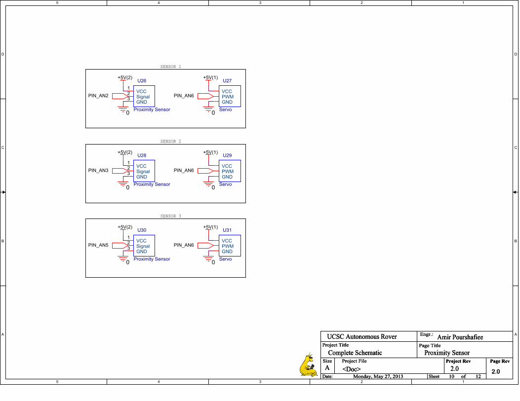
5
5
4
4
3
3
2
2
1
1
D D
C C
B B
A A
SENSOR 1
SENSOR 2
SENSOR 3
PIN_AN2
PIN_AN3
PIN_AN5
PIN_AN6
PIN_AN6
PIN_AN6
+5V(2)
+5V(2)
+5V(2) +5V(1)
+5V(1)
+5V(1)
0 0
00
0 0
Project Title
Size Project File Page Rev
Date: Sheet of
Engr.:
Project Rev
Page Title
<Doc>A
10 12Monday, May 27, 2013
Amir PourshafieeUCSC Autonomous Rover
Proximity Sensor
2.0
Complete Schematic
2.0
Project Title
Size Project File Page Rev
Date: Sheet of
Engr.:
Project Rev
Page Title
<Doc>A
10 12Monday, May 27, 2013
Amir PourshafieeUCSC Autonomous Rover
Proximity Sensor
2.0
Complete Schematic
2.0
Project Title
Size Project File Page Rev
Date: Sheet of
Engr.:
Project Rev
Page Title
<Doc>A
10 12Monday, May 27, 2013
Amir PourshafieeUCSC Autonomous Rover
Proximity Sensor
2.0
Complete Schematic
2.0
U27
Servo
VCCPWMGND
U30
Proximity Sensor
VCC1
Signal2
GND3
U29
Servo
VCCPWMGND
U31
Servo
VCCPWMGND
U26
Proximity Sensor
VCC1
Signal2
GND3
U28
Proximity Sensor
VCC1
Signal2
GND3

5
5
4
4
3
3
2
2
1
1
D D
C C
B B
A A
USB1
USB2
rx_to_comptx_to_comp
rx_to_raspitx_to_raspi
+19V
0
Project Title
Size Project File Page Rev
Date: Sheet of
Engr.:
Project Rev
Page Title
<Doc>A
11 12Monday, May 27, 2013
Sina Kahnemouyi & Tuan HoUCSC Autonomous Rover
RASP PI AND COMPUTER
2.0
Complete Schematic
2.0
Project Title
Size Project File Page Rev
Date: Sheet of
Engr.:
Project Rev
Page Title
<Doc>A
11 12Monday, May 27, 2013
Sina Kahnemouyi & Tuan HoUCSC Autonomous Rover
RASP PI AND COMPUTER
2.0
Complete Schematic
2.0
Project Title
Size Project File Page Rev
Date: Sheet of
Engr.:
Project Rev
Page Title
<Doc>A
11 12Monday, May 27, 2013
Sina Kahnemouyi & Tuan HoUCSC Autonomous Rover
RASP PI AND COMPUTER
2.0
Complete Schematic
2.0
U33
Camera
+5V1
OUT2
IN3
GND4
U32
Raspberry Pi
TX1
RX2
U35
Camera
+5V1
OUT2
IN3
GND4
U34
Computer
VCCGNDTXRX
+5V
GND
INOUT
+5VIN
OUTGND
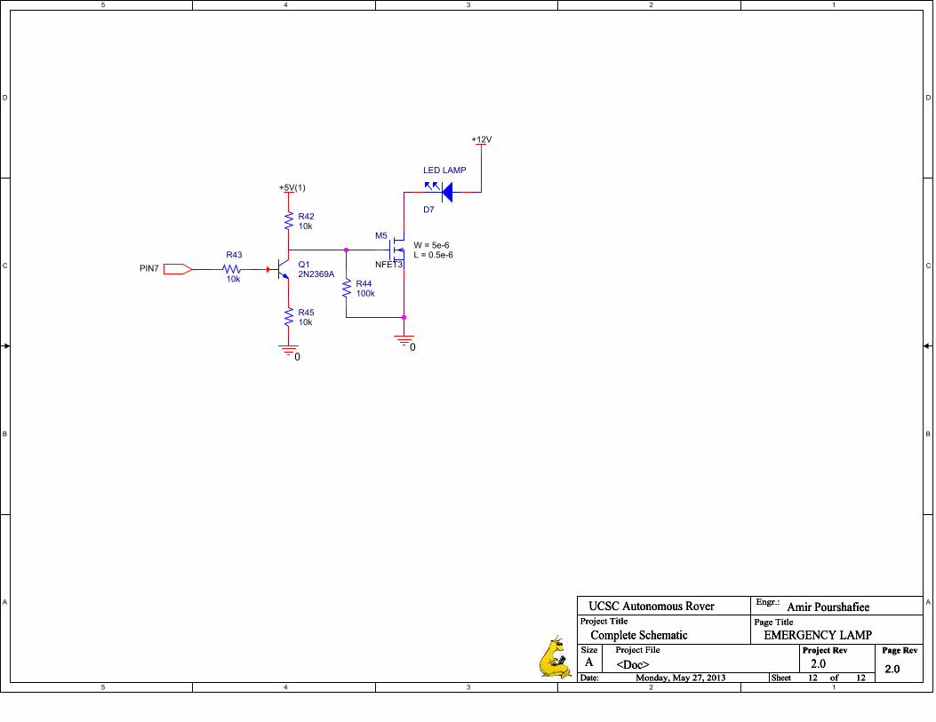
5
5
4
4
3
3
2
2
1
1
D D
C C
B B
A A
PIN7
+5V(1)
00
+12V
Project Title
Size Project File Page Rev
Date: Sheet of
Engr.:
Project Rev
Page Title
<Doc>A
12 12Monday, May 27, 2013
Amir PourshafieeUCSC Autonomous Rover
EMERGENCY LAMP
2.0
Complete Schematic
2.0
Project Title
Size Project File Page Rev
Date: Sheet of
Engr.:
Project Rev
Page Title
<Doc>A
12 12Monday, May 27, 2013
Amir PourshafieeUCSC Autonomous Rover
EMERGENCY LAMP
2.0
Complete Schematic
2.0
Project Title
Size Project File Page Rev
Date: Sheet of
Engr.:
Project Rev
Page Title
<Doc>A
12 12Monday, May 27, 2013
Amir PourshafieeUCSC Autonomous Rover
EMERGENCY LAMP
2.0
Complete Schematic
2.0
M5
NFET3
W = 5e-6L = 0.5e-6
Q12N2369A
R43
10k
R4510k
D7
LED LAMP
R4210k
R44100k
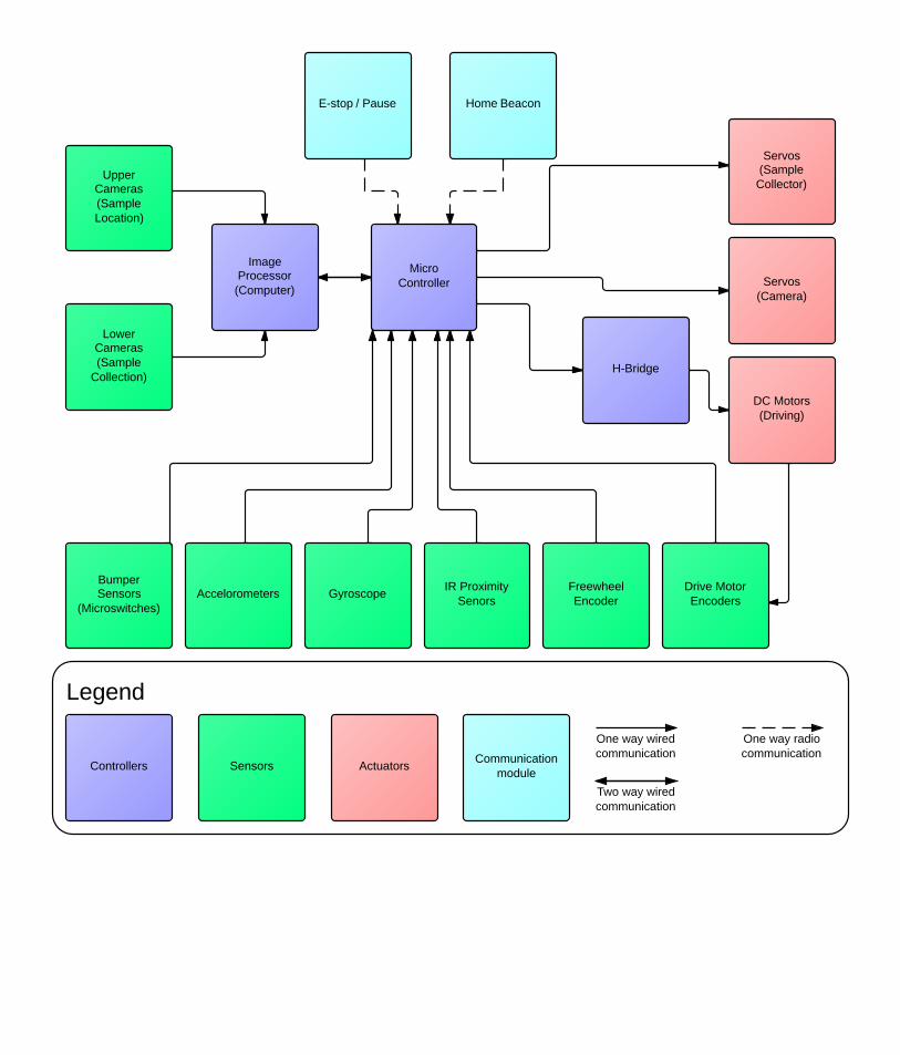

DO NOT SCALE DRAWING
Bogie V2SHEET 1 OF 1
UNLESS OTHERWISE SPECIFIED:
SCALE: 1:16 WEIGHT:
REVDWG. NO.
ASIZE
TITLE:
NAME DATE
COMMENTS:
Q.A.
MFG APPR.
ENG APPR.
CHECKED
DRAWN
FINISH
MATERIAL
INTERPRET GEOMETRICTOLERANCING PER:
DIMENSIONS ARE IN INCHESTOLERANCES:FRACTIONALANGULAR: MACH BEND TWO PLACE DECIMAL THREE PLACE DECIMAL
APPLICATION
USED ONNEXT ASSY
PROPRIETARY AND CONFIDENTIALTHE INFORMATION CONTAINED IN THISDRAWING IS THE SOLE PROPERTY OF<INSERT COMPANY NAME HERE>. ANY REPRODUCTION IN PART OR AS A WHOLEWITHOUT THE WRITTEN PERMISSION OF<INSERT COMPANY NAME HERE> IS PROHIBITED.
5 4 3 2 1
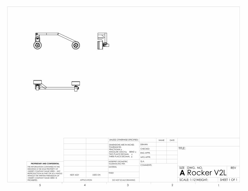
DO NOT SCALE DRAWING
Rocker V2LSHEET 1 OF 1
UNLESS OTHERWISE SPECIFIED:
SCALE: 1:12 WEIGHT:
REVDWG. NO.
ASIZE
TITLE:
NAME DATE
COMMENTS:
Q.A.
MFG APPR.
ENG APPR.
CHECKED
DRAWN
FINISH
MATERIAL
INTERPRET GEOMETRICTOLERANCING PER:
DIMENSIONS ARE IN INCHESTOLERANCES:FRACTIONALANGULAR: MACH BEND TWO PLACE DECIMAL THREE PLACE DECIMAL
APPLICATION
USED ONNEXT ASSY
PROPRIETARY AND CONFIDENTIALTHE INFORMATION CONTAINED IN THISDRAWING IS THE SOLE PROPERTY OF<INSERT COMPANY NAME HERE>. ANY REPRODUCTION IN PART OR AS A WHOLEWITHOUT THE WRITTEN PERMISSION OF<INSERT COMPANY NAME HERE> IS PROHIBITED.
5 4 3 2 1

DO NOT SCALE DRAWING
Rocker V2RSHEET 1 OF 1
UNLESS OTHERWISE SPECIFIED:
SCALE: 1:12 WEIGHT:
REVDWG. NO.
ASIZE
TITLE:
NAME DATE
COMMENTS:
Q.A.
MFG APPR.
ENG APPR.
CHECKED
DRAWN
FINISH
MATERIAL
INTERPRET GEOMETRICTOLERANCING PER:
DIMENSIONS ARE IN INCHESTOLERANCES:FRACTIONALANGULAR: MACH BEND TWO PLACE DECIMAL THREE PLACE DECIMAL
APPLICATION
USED ONNEXT ASSY
PROPRIETARY AND CONFIDENTIALTHE INFORMATION CONTAINED IN THISDRAWING IS THE SOLE PROPERTY OF<INSERT COMPANY NAME HERE>. ANY REPRODUCTION IN PART OR AS A WHOLEWITHOUT THE WRITTEN PERMISSION OF<INSERT COMPANY NAME HERE> IS PROHIBITED.
5 4 3 2 1

DO NOT SCALE DRAWING
scoopSHEET 1 OF 1
UNLESS OTHERWISE SPECIFIED:
SCALE: 1:4 WEIGHT:
REVDWG. NO.
ASIZE
TITLE:
NAME DATE
COMMENTS:
Q.A.
MFG APPR.
ENG APPR.
CHECKED
DRAWN
FINISH
MATERIAL
INTERPRET GEOMETRICTOLERANCING PER:
DIMENSIONS ARE IN INCHESTOLERANCES:FRACTIONALANGULAR: MACH BEND TWO PLACE DECIMAL THREE PLACE DECIMAL
APPLICATION
USED ONNEXT ASSY
PROPRIETARY AND CONFIDENTIALTHE INFORMATION CONTAINED IN THISDRAWING IS THE SOLE PROPERTY OF<INSERT COMPANY NAME HERE>. ANY REPRODUCTION IN PART OR AS A WHOLEWITHOUT THE WRITTEN PERMISSION OF<INSERT COMPANY NAME HERE> IS PROHIBITED.
5 4 3 2 1

DO NOT SCALE DRAWING
Proximity Servo Mount MountSHEET 1 OF 1
UNLESS OTHERWISE SPECIFIED:
SCALE: 1:1 WEIGHT:
REVDWG. NO.
ASIZE
TITLE:
NAME DATE
COMMENTS:
Q.A.
MFG APPR.
ENG APPR.
CHECKED
DRAWN
FINISH
MATERIAL
INTERPRET GEOMETRICTOLERANCING PER:
DIMENSIONS ARE IN INCHESTOLERANCES:FRACTIONALANGULAR: MACH BEND TWO PLACE DECIMAL THREE PLACE DECIMAL
APPLICATION
USED ONNEXT ASSY
PROPRIETARY AND CONFIDENTIALTHE INFORMATION CONTAINED IN THISDRAWING IS THE SOLE PROPERTY OF<INSERT COMPANY NAME HERE>. ANY REPRODUCTION IN PART OR AS A WHOLEWITHOUT THE WRITTEN PERMISSION OF<INSERT COMPANY NAME HERE> IS PROHIBITED.
5 4 3 2 1

DO NOT SCALE DRAWING
BumperSHEET 1 OF 1
UNLESS OTHERWISE SPECIFIED:
SCALE: 1:4 WEIGHT:
REVDWG. NO.
ASIZE
TITLE:
NAME DATE
COMMENTS:
Q.A.
MFG APPR.
ENG APPR.
CHECKED
DRAWN
FINISH
MATERIAL
INTERPRET GEOMETRICTOLERANCING PER:
DIMENSIONS ARE IN INCHESTOLERANCES:FRACTIONALANGULAR: MACH BEND TWO PLACE DECIMAL THREE PLACE DECIMAL
APPLICATION
USED ONNEXT ASSY
PROPRIETARY AND CONFIDENTIALTHE INFORMATION CONTAINED IN THISDRAWING IS THE SOLE PROPERTY OF<INSERT COMPANY NAME HERE>. ANY REPRODUCTION IN PART OR AS A WHOLEWITHOUT THE WRITTEN PERMISSION OF<INSERT COMPANY NAME HERE> IS PROHIBITED.
5 4 3 2 1
Related Documents