Send Receive SMS & Call with SIM900 GSM Shield & Arduino Whether you want to listen to what happens in your house that’s miles away from you or activate sprinkler system in your garden just with a silent call; Then SIM900 GSM/GPRS shield serves as a solid launching point for you to get you started with IoT! SIM900 GSM/GPRS shield is a GSM modem, which can be integrated into a great number of IoT projects. You can use this shield to accomplish almost anything a normal cell phone can; SMS text messages, Make or receive phone calls, connecting to internet through GPRS, TCP/IP, and more! To top it off, the shield supports quad-band GSM/GPRS network, meaning it works pretty much anywhere in the world. Hardware Overview of SIM900 GSM/GPRS Shield The SIM900 GSM/GPRS shield is designed to surround the SIM900 chip with everything necessary to interface with Arduino, plus a few extra goodies to take advantage of the chip’s unique features. Let’s familiarize ourselves with these features and abilities of the shield. Here’s a quick overview:

Welcome message from author
This document is posted to help you gain knowledge. Please leave a comment to let me know what you think about it! Share it to your friends and learn new things together.
Transcript

Send Receive SMS & Call with SIM900
GSM Shield & Arduino
Whether you want to listen to what happens in your house that’s miles away from you or
activate sprinkler system in your garden just with a silent call; Then SIM900 GSM/GPRS
shield serves as a solid launching point for you to get you started with IoT!
SIM900 GSM/GPRS shield is a GSM modem, which can be integrated into a great number of
IoT projects. You can use this shield to accomplish almost anything a normal cell phone can;
SMS text messages, Make or receive phone calls, connecting to internet through GPRS,
TCP/IP, and more! To top it off, the shield supports quad-band GSM/GPRS network,
meaning it works pretty much anywhere in the world.
Hardware Overview of SIM900 GSM/GPRS Shield
The SIM900 GSM/GPRS shield is designed to surround the SIM900 chip with everything
necessary to interface with Arduino, plus a few extra goodies to take advantage of the chip’s
unique features.
Let’s familiarize ourselves with these features and abilities of the shield. Here’s a quick
overview:

The SIM900 shield packs a surprising amount of features into its little frame. Some of them
are listed below:
Supports Quad-band: GSM850, EGSM900, DCS1800 and PCS1900 Connect onto any global GSM network with any 2G SIM Make and receive voice calls using an external earphone & electret microphone Send and receive SMS messages Send and receive GPRS data (TCP/IP, HTTP, etc.) Scan and receive FM radio broadcasts Transmit Power:
o Class 4 (2W) for GSM850 o Class 1 (1W) for DCS1800
Serial-based AT Command Set U.FL and SMA connectors for cell antenna Accepts Full-size SIM Card
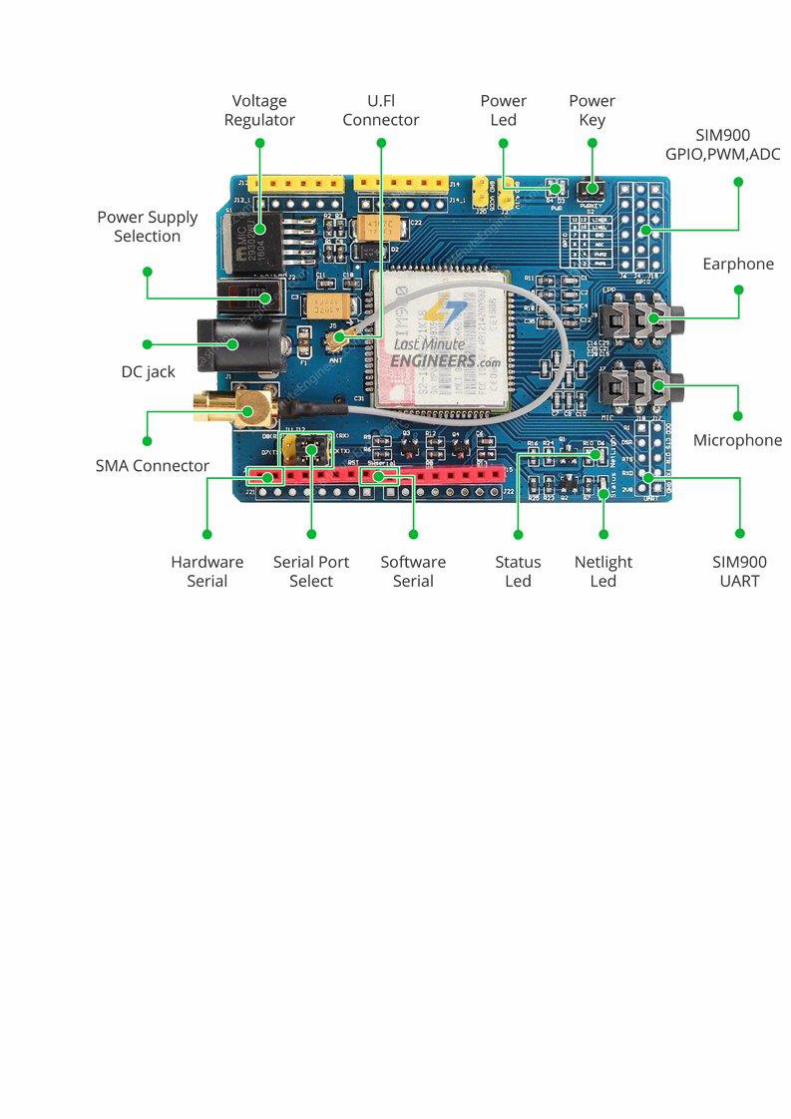
LED Status Indicators
There are three LEDs on the SIM900 GSM/GPRS shield which indicates connectivity or
power status. By observing these LEDs you can get a visual feedback on whats going on with
the shield.

PWR: This LED is connected to the shield’s power supply line. If this LED is on, the shield
is receiving power.
Status: This LED indicates SIM900’s working status. If this LED is on, the chip is in
working mode.
Netlight: This LED indicates the status of your cellular network. It’ll blink at various rates to
show what state it’s in.
off: The SIM900 chip is not running
64ms on, 800ms off: The SIM900 chip is running but not registered to the cellular
network yet.
64ms on, 3 seconds off: The SIM900 chip is registered to the cellular network & can
send/receive voice and SMS.
64ms on, 300ms off: The GPRS data connection you requested is active.
Supplying Power for SIM900 Shield
One of the most important parts of getting the SIM900 shield working is supplying it with
enough power.
Depending on which state it’s in, the SIM900 can be a relatively power-hungry device. The
maximum current draw of the chip is around 2A during transmission burst. It usually won’t
pull that much, but may require around 216mA during phone calls or 80mA during network
transmissions. This chart from the datasheet summarizes what you may expect:

Modes Frequency Current Consumption
Power down
60 uA
Sleep mode
1 mA
Stand by
18 mA
Call
GSM850 199 mA
EGSM900 216 mA
DCS1800 146 mA
PCS1900 131 mA
GPRS
453 mA
Transmission burst
2 A
The operating voltage of SIM900 chip is from 3.4V to 4.4V. To keep supply voltage safe at 4.1V, the
shield comes with a high current, high accuracy, low-dropout voltage regulator MIC29302WU from
Micrel – capable of handling load currents up to 3A.
You can add an external power supply to the shield with the 5.5mm DC jack, to which you can
connect any 5V-9V DC wall adapter you have. Next to the DC jack, is a Slide Switch to select the
power source labeled EXTERN. To use external power source, move the slider as shown above.

Warning:
The power supply should be able to source minimum 2A of surge current, otherwise the chip
will keep shutting down.
UART Communication
The SIM900 GSM/GPRS shield uses UART protocol to communicate with an Arduino. The
chip supports baud rate from 1200bps to 115200bps with Auto-Baud detection.
With the help of jumpers you can connect (RX,TX) of the shield to either Software
Serial(D8,D7) or Hardware Serial(D1,D0) of the Arduino.
Speaker & Microphone
The shield comes with two standard 3.5mm jacks. One for stereo earphone and other for
mono microphone. It allows you to use SIM900’s audio interface to make and receive voice
calls and listen FM radio.

Mic: You can connect an external electret microphone to this jack.
Earphone: You can connect earphones to this jack. Any ‘iPhone’ or ‘Android’ compatible
earphones should work.
Antenna
An antenna is required to use the SIM900 for any kind of voice or data communications as
well as some SIM commands.
The shield has two interfaces for connecting antenna viz. a U.FL connector and a SMA
connector. They are connected through a patch cord.
The shield usually comes with a 3dBi GSM antenna and allows you to put the shield inside a
metal case(as long the antenna is outside).

SIM Socket
There’s a SIM socket on the back. Any activated, 2G full-size SIM card would work
perfectly.
The workings of the SIM card socket can take some getting used to. To unlock the latch, push
the top part of the assembly, and then lift it up. Place the SIM card into the bottom part of the
socket. Then fold the arm back into the body of the socket, and gently push it forward
towards the LOCK position.
RTC(Real Time Clock)
The SIM900 shield can be configured to keep time. So there is no need for any separate RTC.
This will keep the time even when the power is OFF.
If you want to use internal RTC, you need to install CR1220 battery at the back side of the
shield.
Your network provider may not support setting the time automatically. In that case you can
do it manually using AT+CCLK AT command.
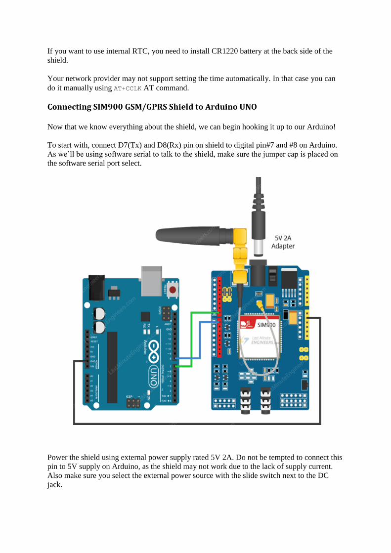
Connecting SIM900 GSM/GPRS Shield to Arduino UNO
Now that we know everything about the shield, we can begin hooking it up to our Arduino!
To start with, connect D7(Tx) and D8(Rx) pin on shield to digital pin#7 and #8 on Arduino.
As we’ll be using software serial to talk to the shield, make sure the jumper cap is placed on
the software serial port select.
Power the shield using external power supply rated 5V 2A. Do not be tempted to connect this
pin to 5V supply on Arduino, as the shield may not work due to the lack of supply current.
Also make sure you select the external power source with the slide switch next to the DC
jack.
Now connect all the ground in the circuit.
Finally, connect the antenna, insert fully activated SIM card in the socket.
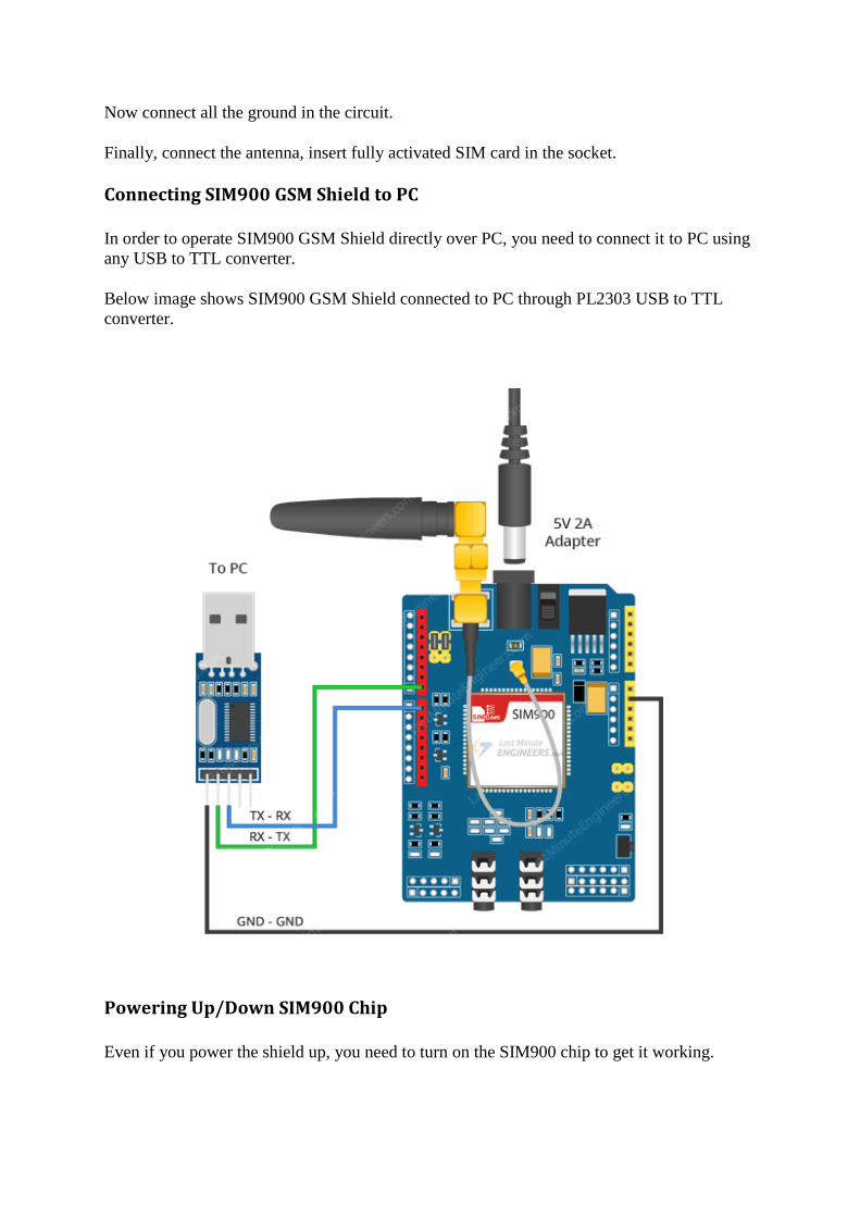
Connecting SIM900 GSM Shield to PC
In order to operate SIM900 GSM Shield directly over PC, you need to connect it to PC using
any USB to TTL converter.
Below image shows SIM900 GSM Shield connected to PC through PL2303 USB to TTL
converter.
Powering Up/Down SIM900 Chip
Even if you power the shield up, you need to turn on the SIM900 chip to get it working.
As per datasheet, pulling the PWRKEY pin on the chip LOW for at least 1 second will
power up/down the chip. There are two ways to do this with our shield.
Hardware Trigger
The shield comes with a right angle tactile switch situated near the PWR LED indicator. You
need to press that switch for about 2 seconds to power the shield up/down.
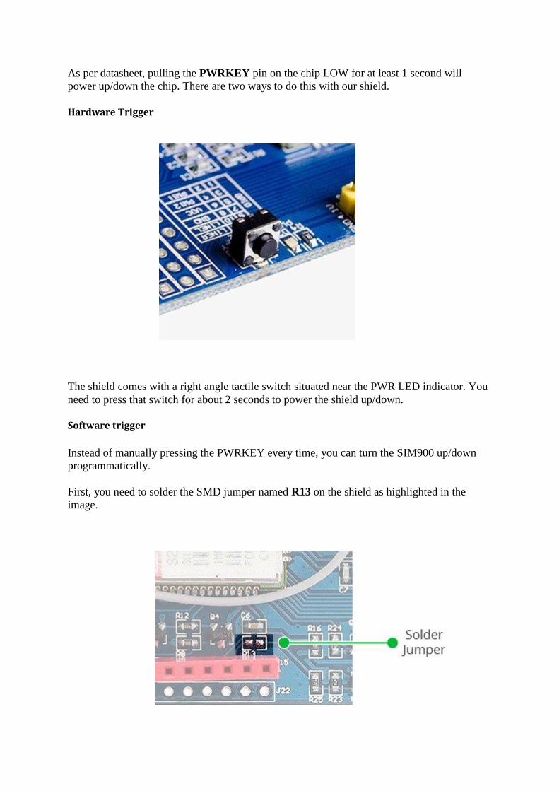
Software trigger
Instead of manually pressing the PWRKEY every time, you can turn the SIM900 up/down
programmatically.
First, you need to solder the SMD jumper named R13 on the shield as highlighted in the
image.
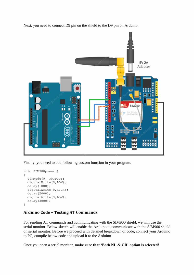
Next, you need to connect D9 pin on the shield to the D9 pin on Arduino.
Finally, you need to add following custom function in your program.
void SIM900power()
{
pinMode(9, OUTPUT);
digitalWrite(9,LOW);
delay(1000);
digitalWrite(9,HIGH);
delay(2000);
digitalWrite(9,LOW);
delay(3000);
}
Arduino Code – Testing AT Commands
For sending AT commands and communicating with the SIM900 shield, we will use the
serial monitor. Below sketch will enable the Arduino to communicate with the SIM900 shield
on serial monitor. Before we proceed with detailed breakdown of code, connect your Arduino
to PC, compile below code and upload it to the Arduino.
Once you open a serial monitor, make sure that ‘Both NL & CR’ option is selected!

#include <SoftwareSerial.h>
//Create software serial object to communicate with SIM900
SoftwareSerial mySerial(7, 8); //SIM900 Tx & Rx is connected to Arduino #7
& #8
void setup()
{
//Begin serial communication with Arduino and Arduino IDE (Serial
Monitor)
Serial.begin(9600);
//Begin serial communication with Arduino and SIM900
mySerial.begin(9600);
Serial.println("Initializing...");
delay(1000);
mySerial.println("AT"); //Handshaking with SIM900
updateSerial();
mySerial.println("AT+CSQ"); //Signal quality test, value range is 0-31 ,
31 is the best
updateSerial();
mySerial.println("AT+CCID"); //Read SIM information to confirm whether
the SIM is plugged
updateSerial();
mySerial.println("AT+CREG?"); //Check whether it has registered in the
network
updateSerial();
}
void loop()
{
updateSerial();
}
void updateSerial()
{
delay(500);
while (Serial.available())
{
mySerial.write(Serial.read());//Forward what Serial received to
Software Serial Port
}
while(mySerial.available())
{
Serial.write(mySerial.read());//Forward what Software Serial received
to Serial Port
}
}
Code Explanation:
The sketch starts by including a SoftwareSerial.h library and initializing it with the Arduino
pins to which Tx and Rx of SIM900 shield is connected.
#include <SoftwareSerial.h>
//Create software serial object to communicate with SIM900
SoftwareSerial mySerial(7, 8); //SIM900 Tx & Rx is connected to Arduino #7
& #8
In setup function: we initialize a serial communication link between Arduino, Arduino IDE
and SIM900 shield at a baud rate of 9600.
//Begin serial communication with Arduino and Arduino IDE (Serial Monitor)
Serial.begin(9600);
//Begin serial communication with Arduino and SIM900
mySerial.begin(9600);
Now that we have established a basic connection, we will try to communicate with the
SIM900 shield by sending AT commands.
AT – It is the most basic AT command. It also initializes Auto-baud’er. If it works you
should see the AT characters echo and then OK, telling you it’s OK and it’s understanding
you correctly! You can then send some commands to query the shield and get information
about it such as
AT+CSQ – Check the ‘signal strength’ – the first # is dB strength, it should be higher than
around 5. Higher is better. Of course it depends on your antenna and location!
AT+CCID – get the SIM card number – this tests that the SIM card is found OK and you can
verify the number is written on the card.
AT+CREG? Check that you’re registered on the network. The second # should be 1 or 5. 1
indicates you are registered to home network and 5 indicates roaming network. Other than
these two numbers indicate you are not registered to any network.
mySerial.println("AT"); //Handshaking with SIM900
updateSerial();
mySerial.println("AT+CSQ"); //Signal quality test, value range is 0-31 ,
31 is the best
updateSerial();
mySerial.println("AT+CCID"); //Read SIM information to confirm whether
the SIM is plugged
updateSerial();
mySerial.println("AT+CREG?"); //Check whether it has registered in the
network
updateSerial();
In the looping part of the code, we call custom function called updateSerial() which
continuously waits for any inputs from the serial monitor and send it to the SIM900 shield
through the D8 pin (Rx of shield). It also continuously reads the D7 pin (Tx of shield) if the
shield has any responses.
void updateSerial()
{
delay(500);
while (Serial.available())
{
mySerial.write(Serial.read());//Forward what Serial received to
Software Serial Port
}
while(mySerial.available())
{
Serial.write(mySerial.read());//Forward what Software Serial received
to Serial Port
}
}
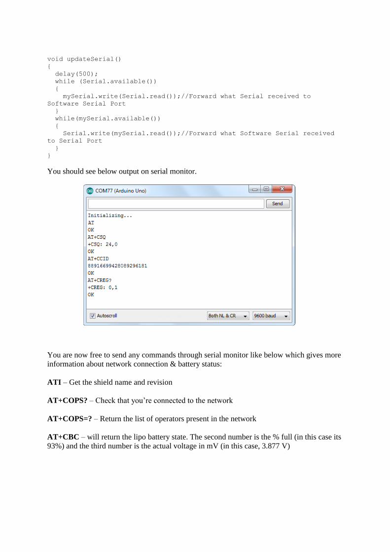
You should see below output on serial monitor.
You are now free to send any commands through serial monitor like below which gives more
information about network connection & battery status:
ATI – Get the shield name and revision
AT+COPS? – Check that you’re connected to the network
AT+COPS=? – Return the list of operators present in the network
AT+CBC – will return the lipo battery state. The second number is the % full (in this case its
93%) and the third number is the actual voltage in mV (in this case, 3.877 V)

Arduino Code – Sending SMS
Let’s move on to the interesting stuff. Let’s program our Arduino to send an SMS to any
phone number you wish. Before trying the sketch out, you need to enter the phone number.
Search for the string ZZxxxxxxxxxx and replace ZZ with county code and xxxxxxxxxx with
the 10 digit phone number.
#include <SoftwareSerial.h>
//Create software serial object to communicate with SIM900
SoftwareSerial mySerial(7, 8); //SIM900 Tx & Rx is connected to Arduino #7
& #8
void setup()
{
//Begin serial communication with Arduino and Arduino IDE (Serial
Monitor)
Serial.begin(9600);
//Begin serial communication with Arduino and SIM900
mySerial.begin(9600);
Serial.println("Initializing...");
delay(1000);
mySerial.println("AT"); //Handshaking with SIM900
updateSerial();
mySerial.println("AT+CMGF=1"); // Configuring TEXT mode
updateSerial();
mySerial.println("AT+CMGS=\"+ZZxxxxxxxxxx\"");//change ZZ with country
code and xxxxxxxxxxx with phone number to sms
updateSerial();
mySerial.print("Last Minute Engineers | lastminuteengineers.com"); //text
content
updateSerial();
mySerial.write(26);
}
void loop()
{
}
void updateSerial()
{
delay(500);
while (Serial.available())
{
mySerial.write(Serial.read());//Forward what Serial received to
Software Serial Port
}
while(mySerial.available())
{
Serial.write(mySerial.read());//Forward what Software Serial received
to Serial Port
}
}
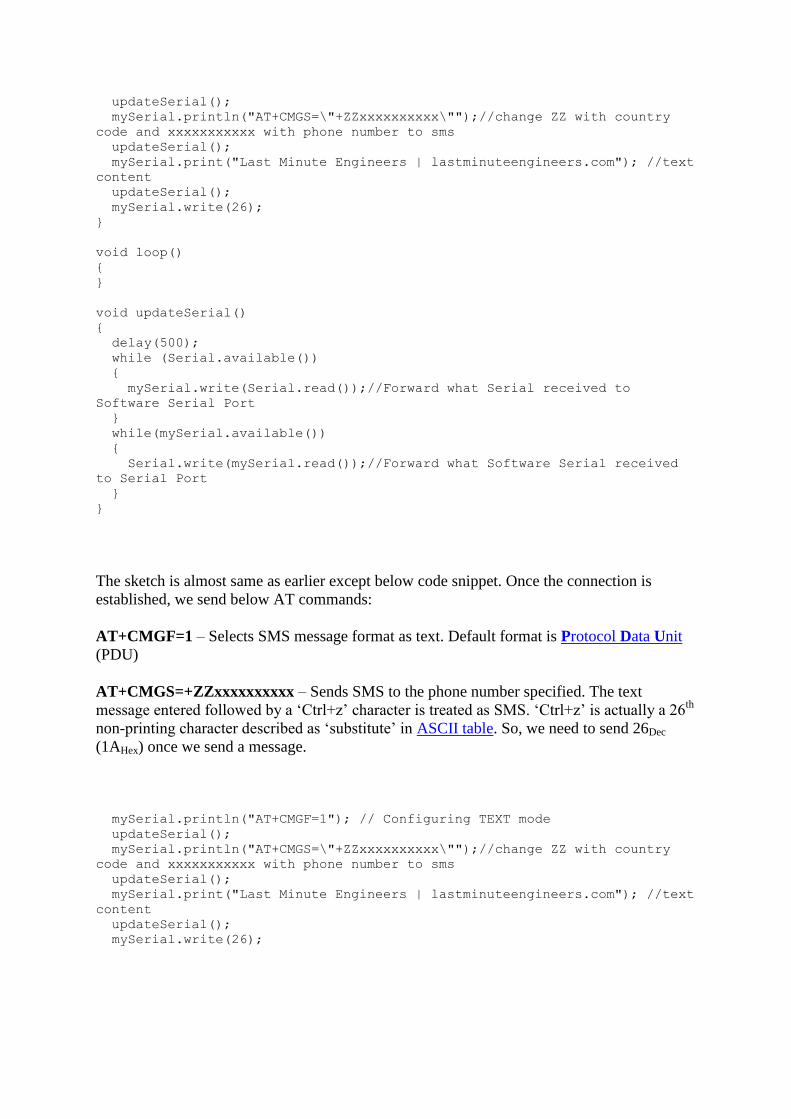
The sketch is almost same as earlier except below code snippet. Once the connection is
established, we send below AT commands:
AT+CMGF=1 – Selects SMS message format as text. Default format is Protocol Data Unit
(PDU)
AT+CMGS=+ZZxxxxxxxxxx – Sends SMS to the phone number specified. The text
message entered followed by a ‘Ctrl+z’ character is treated as SMS. ‘Ctrl+z’ is actually a 26th
non-printing character described as ‘substitute’ in ASCII table. So, we need to send 26Dec
(1AHex) once we send a message.
mySerial.println("AT+CMGF=1"); // Configuring TEXT mode
updateSerial();
mySerial.println("AT+CMGS=\"+ZZxxxxxxxxxx\"");//change ZZ with country
code and xxxxxxxxxxx with phone number to sms
updateSerial();
mySerial.print("Last Minute Engineers | lastminuteengineers.com"); //text
content
updateSerial();
mySerial.write(26);
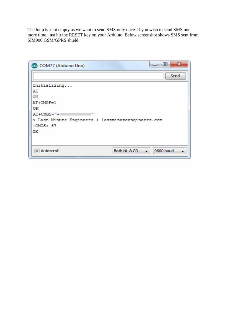
The loop is kept empty as we want to send SMS only once. If you wish to send SMS one
more time, just hit the RESET key on your Arduino. Below screenshot shows SMS sent from
SIM900 GSM/GPRS shield.

Arduino Code – Reading SMS
Now let’s program our Arduino to read incoming messages. This sketch is very useful when
you need to trigger an action when a specific SMS is received. For example, when the
Arduino receives an SMS, you can instruct it to turn on or off a relay. You got the idea!
#include <SoftwareSerial.h>
//Create software serial object to communicate with SIM900
SoftwareSerial mySerial(7, 8); //SIM900 Tx & Rx is connected to Arduino #7
& #8
void setup()
{
//Begin serial communication with Arduino and Arduino IDE (Serial
Monitor)
Serial.begin(9600);
//Begin serial communication with Arduino and SIM900
mySerial.begin(9600);
Serial.println("Initializing...");
delay(1000);

mySerial.println("AT"); //Handshaking with SIM900
updateSerial();
mySerial.println("AT+CMGF=1"); // Configuring TEXT mode
updateSerial();
mySerial.println("AT+CNMI=1,2,0,0,0"); // Decides how newly arrived SMS
messages should be handled
updateSerial();
}
void loop()
{
updateSerial();
}
void updateSerial()
{
delay(500);
while (Serial.available())
{
mySerial.write(Serial.read());//Forward what Serial received to
Software Serial Port
}
while(mySerial.available())
{
Serial.write(mySerial.read());//Forward what Software Serial received
to Serial Port
}
}
The sketch is similar as earlier except below code snippet. Once the connection is established,
we send below AT commands:
AT+CMGF=1 – Selects SMS message format as text. Default format is Protocol Data Unit
(PDU)
AT+CNMI=1,2,0,0,0 – specifies how newly arrived SMS messages should be handled. This
way you can tell the SIM900 shield either to forward newly arrived SMS messages directly to
the PC, or to save them in message storage and then notify the PC about their locations in
message storage.
Its response starts with +CMT: All the fields in the response are comma-separated with first
field being phone number. The second field is the name of person sending SMS. Third field is
a timestamp while forth field is the actual message.
mySerial.println("AT+CMGF=1"); // Configuring TEXT mode
updateSerial();
mySerial.println("AT+CNMI=1,2,0,0,0"); // Decides how newly arrived SMS
messages should be handled
updateSerial();
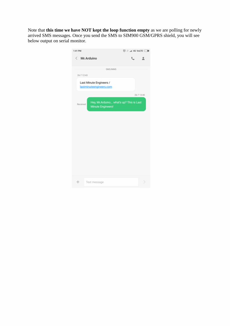
Note that this time we have NOT kept the loop function empty as we are polling for newly
arrived SMS messages. Once you send the SMS to SIM900 GSM/GPRS shield, you will see
below output on serial monitor.

Expanding Arduino SoftwareSerial Buffer Size
If your message is long enough just like ours, then you’ll probably receive it with some
missing characters. This is not because of a faulty code. Your SoftwareSerial receive buffer is
getting filled up and discarding characters. You are not reading fast enough from the buffer.
The simplest solution to this is to increase the size of the SoftwareSerial buffer from its
default size of 64 bytes to 256 bytes (or smaller, depending on what works for you).
On a Windows PC, go to C:\Program Files (x86) -> Arduino -> hardware -> Arduino ->
avr -> libraries -> SoftwareSerial (-> src for newer version of Arduino IDE) Open
SoftwareSerial.h and change the line:
// RX buffer size
#define _SS_MAX_RX_BUFF 64
To
// RX buffer size
#define _SS_MAX_RX_BUFF 256
Save the file and try your sketch again.

Expanding Arduino SoftwareSerial Buffer Size
Arduino Code – Making Call
Now let’s program our Arduino to make call. This sketch is very useful when you want your
Arduino to make an SOS/distress call in case of emergency like temperature being exceeded
or someone breaks into your house. You got the idea!
Before trying the sketch out, you need to enter the phone number. Search for the string
ZZxxxxxxxxxx and replace ZZ with county code and xxxxxxxxxx with the 10 digit phone
number.
#include <SoftwareSerial.h>
//Create software serial object to communicate with SIM900
SoftwareSerial mySerial(7, 8); //SIM900 Tx & Rx is connected to Arduino #7
& #8
void setup()
{
//Begin serial communication with Arduino and Arduino IDE (Serial
Monitor)
Serial.begin(9600);
//Begin serial communication with Arduino and SIM900
mySerial.begin(9600);

Serial.println("Initializing...");
delay(1000);
mySerial.println("AT"); //Handshaking with SIM900
updateSerial();
mySerial.println("ATD+ +ZZxxxxxxxxxx;"); // change ZZ with country code
and xxxxxxxxxxx with phone number to dial
updateSerial();
delay(20000); // wait for 20 seconds...
mySerial.println("ATH"); //hang up
updateSerial();
}
void loop()
{
}
void updateSerial()
{
delay(500);
while (Serial.available())
{
mySerial.write(Serial.read());//Forward what Serial received to
Software Serial Port
}
while(mySerial.available())
{
Serial.write(mySerial.read());//Forward what Software Serial received
to Serial Port
}
}
To place a call following AT commands are used:
ATD+ +ZZxxxxxxxxxx; – Dials a specified number. The semicolon ; modifier at the end
separates the dial string into multiple dial commands. All but the last command must end
with the semicolon ; modifier.
ATH – Hangs up the call
mySerial.println("ATD+ +ZZxxxxxxxxxx;"); // change ZZ with country code
and xxxxxxxxxxx with phone number to dial
updateSerial();
delay(20000); // wait for 20 seconds...
mySerial.println("ATH"); //hang up
updateSerial();
Below screenshot shows call made from SIM900 GSM/GPRS shield.


Arduino Code – Receiving Call
Receiving call doesn’t require any special code; you just have to keep listening to the
SIM900 shield. Yet, you may find this sketch very useful, when you need to trigger an action
when a call from specific phone number is received.
#include <SoftwareSerial.h>
//Create software serial object to communicate with SIM900
SoftwareSerial mySerial(7, 8); //SIM900 Tx & Rx is connected to Arduino #7
& #8
void setup()
{
//Begin serial communication with Arduino and Arduino IDE (Serial
Monitor)
Serial.begin(9600);
//Begin serial communication with Arduino and SIM900
mySerial.begin(9600);
Serial.println("Initializing...");
}
void loop()
{
updateSerial();
}
void updateSerial()
{
delay(500);
while (Serial.available())
{
mySerial.write(Serial.read());//Forward what Serial received to
Software Serial Port
}
while(mySerial.available())
{
Serial.write(mySerial.read());//Forward what Software Serial received
to Serial Port
}
}
Incoming call is usually indicated by ‘RING’ on serial monitor followed by phone number
and caller ID. To accept/hang a call following AT commands are used:
ATA – Accepts incoming call.
ATH – Hangs up the call. On hanging up the call it sends NO CARRIER on the serial
monitor indicating call couldn’t connect.
Below output on serial monitor shows call received by SIM900 GSM/GPRS shield.

Related Documents