SEMIOTICS OF STRUCTURAL FRAMES IN MODERN ARCHITECTURE by Danny Cheong-Yin Chan B.A.Sc, The University of British Columbia, 1999 A THESIS SUBMITTED IN PARTIAL FULFILMENT OF THE REQUIREMENTS FOR THE DEGREE OF MASTER OF APPLIED SCIENCE in THE FACULTY OF GRADUATE STUDIES (Department of Civil Engineering) We accept this thesis as conforming to the required standard THE UNIVERSITY OF BRITISH COLUMBIA August 2001 © Danny Cheong-Yin Chan, 2001

Welcome message from author
This document is posted to help you gain knowledge. Please leave a comment to let me know what you think about it! Share it to your friends and learn new things together.
Transcript

SEMIOTICS OF STRUCTURAL FRAMES IN MODERN ARCHITECTURE
by
Danny Cheong-Yin Chan
B.A.Sc, The University of British Columbia, 1999
A THESIS SUBMITTED IN PARTIAL FULFILMENT OF THE REQUIREMENTS FOR THE DEGREE OF
MASTER OF APPLIED SCIENCE
in
THE FACULTY OF GRADUATE STUDIES
(Department of Civil Engineering)
We accept this thesis as conforming to the required standard
THE UNIVERSITY OF BRITISH COLUMBIA
August 2001
© Danny Cheong-Yin Chan, 2001

In presenting this thesis in partial fulfilment of the requirements for an advanced
degree at the University of British Columbia, I agree that the Library shall make it
freely available for reference and study. I further agree that permission for extensive
copying of this thesis for scholarly purposes may be granted by the head of my
department or by his or her representatives. It is understood that copying or
publication of this thesis for financial gain shall not be allowed without my written
permission.
Department of l*v*l~ ^ ' i s H g / W t f
The University of British Columbia Vancouver, Canada
Date JM P±. / Z-ff* I
DE-6 (2/88)
Abstract
Structural semiotics often plays an important role in contributing to the overall architectural
expression of a building. Semiotics is defined as the meaning behind or expression of an object. A
structure having a semiotic message is one that communicates beyond its functional purposes. It has in
itself extraordinary inspirational and expressive values. These values are rooted in the historical, cultural
and social contexts, and reflect a sensibility to the built environment and human ways of living. With
careful observation of structural semiotics, these values can be elicited. Structural semiotics is also the
common language of architecture and structure. Its proper execution prevents a structure from becoming
merely subordinate to the architecture. Rather, the structural design can be integrated with the
architectural principles of form, space and order, so that structure and architecture truly become one and
constitute to a unified theme of design.
In this thesis, the structural semiotics of skeletal frame construction is dwelled upon. The
structural frame is the most common yet most representative of all types of construction in modern
architecture. It emancipates the facade and partitions from their structural responsibilities, thus promoting
greater freedom in shaping forms and organizing space. It also utilizes the structural potentials of steel
and reinforced concrete, and allows buildings to be constructed economically by means of repetition and
pattern. In the interior of the building, the frame often supplies in three dimensions a neutral grid of
space, one that not only accommodates but also reshapes human activities of contemporary life. These
unique qualities of structural frames and their corresponding semiotics will be examined in this thesis
from both architectural and engineering perspectives. They are illustrated through a series of case studies
of Modernist architecture. It can be shown that, by a sensible choice of structural system, materials and
construction method, by proper proportioning and detailing, and by careful observation to the contextual
and programmatic requirements, even the most commonplace structural frames can become architecture.
D.C. Chan email: [email protected] 11

Table of Contents
Abstract ii
Table of Contents : iii
List of Figures v
List of Tables ix
Acknowledgements x
1.0 Introduction 1
1.1 Method of Dissertation 10
2.0 Three-Hinged Truss Arches in Early Modernist Architecture 12
2.1 Precursors of Trusswork Arches 13
2.2 Three-Hinged Truss Arches and Structural Frames 17
2.3 Palais des Machines 18
2.4 A E G Turbine Hall 22
2.5 Conclusion 27
2 0 Steel Moment-Resisting Frames and Mies van der Rohe's 29 Structural & Spatial Concepts
3.1 The Development of Steel Moment-Resisting Frames 30
3.2 Establishing An Architectural Expression 34
3.2.1 Structure and Space 34
3.2.2 Part and Whole 35
3.2.3 Skin and Skeleton 35
3.3 Mies van der Rohe's Structural and Spatial Concepts 36
3.4 Barcelona Pavilion 39
3.5 Steel-Framed Campus Buildings at I.I.T. 43
3.5.1 Fireproofed Construction 44
3.5.2 Un-fireproofed Construction 47
3.6 Crown Hall 49
3.7 Conclusion 54
D.C. Chan email: [email protected] iii
^ Two-Way Reinforced Concrete Slab System and Le Coibusier's ^ Ideas of Modernism
4.1 The Development of Reinforced Concrete Frame Construction 60
4.2 25bis Rue Franklin Apartment Building 61
4.3 Le Corbusier7s Ideas of Modernism 65
4.3.1 Dom-ino Housing Project 66
4.3.2 Five Points of A New Architecture 68
4.4 Villa Savoye 69
4.5 Conclusion 74
5.0 Conclusion 77
6.0 Technical Notes 82
6.1 Degree of Indeterminacy and Stability 82
6.2 Funicular Profile 86
6.3 Portal Frame vs. Funicular Profile 91
6.4 Structural Analysis of Palais des Machines 94
6.5 Structural Analysis of A E G Turbine Hall 98
6.6 Simplified Analysis of Moment-Resisting Portal Frame (Part I) 101
6.6.1 Stiffness Matrix 102
6.6.2 Load Cases 105
6.6.3 Inflection Point and Relative Stiffness 106
6.6.4 Graphical Results I l l
6.6.5 Inflection Point and Buckling Load 115
6.6.6 Summary 118
6.7 Simplified Analysis of Moment-Resisting Portal Frame (Part II) 119
6.7.1 Fixed-Based Rigid Frame 119
6.7.2 Hinged-Based Rigid Frame 121
6.7.3 Multi-span Rigid Frame 122
6.8 Two-Way Reinforced Concrete Slab System 126
7.0 Bibliography 129
8.0 Citations of Figures 131
DC. Chan email: [email protected] iv

List of Figures
1.1 Eiffel Tower, Paris, Gustave Eiffel, 1889 2
1.2 Flying Buttresses of A Gothic Cathedral 2
j ^ Trans World Airlines Terminal, International Airport in Idelwild, 2 New York, Eero Saarinen, 1956-62
1.4 Fireproofed Iron Frame Construction for Fair Store in Chicago 4
1.5 Reinforced Concrete Frame Construction 4
1.6 The Crystal Palace, London, Joseph Paxton, 1850 5
1.7 Benyon, Marshall and Bage Mill, Shrewsbury, 1797 5
1.8 Wainwright Building, St. Louis, Louis Sullivan and Dankmar Adler, 1890-91 6
1.9 Dom-ino Housing Project, Reinforced Concrete Skeleton, Le Corbusier, 1914-15 8
j German Pavilion for the International Exhibition in Barcelona, ^ Ludwig Mies van der Rohe, 1928-29
2.1 Pont du Garabit, Southern France, Gustave Eiffel, 1880-85 15
2.2 Main Railway Station in Leipzig, William Lossow and Max Kuhne, 1908-16 16
7 _ Palais des Machines at the Universal Exposition in Paris, Charles Dutert and . „ Victor Contamin, 1887-89
2.4 Universal Exposition in Paris, 1889 19
2.5 Facade of Palais des Machines 21
2.6 Interior view of Palais des Machines 22
2.7 A E G Turbine Hall, Berlin, Peter Behrens, 1908-09 23
2.8 Box-sectioned Steel Pillars 26
3.1 Sheerness Boathouse, facade details, 1860 30
3.2 Sheerness Boathouse, front view 30
3.3 Monadnock Building, Chicago, John Wellborn Root and Daniel Burnham, 1884-91 ... 32
3.4 Home Insurance Building, Chicago, William LeBaron Jenney, 1885 32
3.5 Fair Store under construction, Chicago, William LeBaron Jenney, 1891 32
3.6 Ludwig Mies van der Rohe, 1886-1969 36
3.7 Crown Hall, facade details, I.I.T., Mies van der Rohe, 1952-56 37
3.8 Crown Hall night view 38
2 2 German Pavilion for the International Exhibition in Barcelona ^ (Barcelona Pavilion), Mies van der Rohe, 1928-29
3.10 Barcelona Pavilion, column details 40
D.C. Chan email: d.c.chanfSeudoramail.com
3.11 Barcelona Pavilion, wall and column arrangement 42
3.12 Barcelona Pavilion, section through roof, wall and foundation 42
3.13 Illinois Institute of Technology, Campus Model 43
3.14 Metallurgical and Chemical Engineering Building, I.I.T., Mies van der Rohe, 1945-46 44
3.15 Alumni Memorial Hall, I.I.T., facade details, Mies van der Rohe, 1945-46 45
3.16 Alumni Memorial Hall, I.I.T., facade details, plan 45
3.17 Alumni Memorial Hall, I.I.T., corner details 46
3.18 Library and Administration Building, I.I.T., exterior, Mies van der Rohe, 1944 47
3.19 Library and Administration Building, I.I.T., Interior 47
3.20 Commons Building, I.I.T., Interior, Mies van der Rohe, 1952-53 49
3.21 Crown Hall, I.I.T., Mies van der Rohe, 1952-56 50
3.22 Crown Hall, I.I.T., side view 51
3.23 Crown Hall, L I T . , under construction 52
3.24 Crown Hall, I.I.T., interior looking towards the back 52
3.25 Crown Hall, I.I.T., wall section details 53
4.1 Felix Potin Store, 1904 56
4.2 Villa Savoye, Poissy, Le Corbusier, 1928-31 56
4.3 Pantheon, Rome, 120-4 A.D. , Sections 57
4.4 Leland Stanford Junior Museum of Stanford University, California, 59 4.4
Ernest L. Ransome, 1889-91 59
4.5 Trabeated reinforced concrete frame system, Francois Hennebique, 1892 59
4.6a Two-way slab system with beams 60
4.6b Two-way flat plate system 60
4.6c Two-way flat slab system with drop panels and capitals 60
4.7 Two-way ribbed system or waffle slab 61
4.8 Apartment Building at 25bis rue Franklin, Paris, Auguste Perret, 1902 62
4.9 Apartment Building at 25bis rue Franklin, plan 63
4.10 Apartment Building at 25bis rue Franklin, frame skeleton, ceramic tile infill, overhangs 64
4.11 Apartment Building at 25bis rue Franklin, light court 64
4.12 Le Corbusier (Claries Edouard Jeanneret), 1887-1965 65
4.13 Dom-ino House Unit, Flanders, Le Corbusier, 1914-15 67
4.14 Villa Savoye, southwest, northwest, southeast 69
4.15 Villa Savoye, interiors, vestibule at lower level, roof terrace at upper level 70
4.16 Villa Savoye, plans 71
D.C. Chan email: [email protected] vi
4.17 Villa Savoye, northwest facade 73
4.18 Villa Savoye, plans 74
4.19 Unite d'Habitation, Marseilles, Le Corbusier, 1947-53, bare concrete facade, brise-soleil 75
4.20 General Assembly, Chandigarh, Le Corbusier, 1953-61, exterior/interior views 75
4.21 Gatti Wool Factory, Rome, ribbed roof pattern following isostatic lines 76
5.1 Maconnerie, Eugene Viollet-le-Duc, 1864 78
5.2 Crown Hall, I.I.T., Mies van der Rohe, 1952-56 78
5.3 Centre Pompidou, Paris, Renzo Piano and Richard Rogers, 1971-77 79
5.4 Renault Sales headquarters, Swindon, Norman Foster, 1981-83 80
6.2.1 Graphical Method (Step 1) 88
6.2.2 Graphical Method (Step 2) 88
6.2.3 Graphical Method (Step 3) 89
6.2.4 Graphical Method (Step 4) 89
6.3.1 Approximate Bending Moment Diagram for Hinged-Based Portal Frame 91
6.3.2 Funicular Profdes, Bending Moment and Shear Diagrams of Portal Frames 93
6.4.1 Palais des Machines subjected to a uniformly distributed load 94
6.4.2 Free-body diagrams of half-arches 94
6.4.3 Resultant lines of action and funicular profile for uniformly distributed load case 95
6.4.4 Resultant lines of action and funicular profile for asymmetric distributed load case ... 96
6.4.5a Funicular Profile 97
6.4.5b Axial Force Diagram 97
6.4.5c Cross-Sectional Area 97
6.4.5d Axial Stress Diagram 97
6.5.1 A E G Turbine Hall subjected to two uniformly distributed loads 98
6.5.2 Free-body diagram of the entire structure 99
6.5.3 Free-body diagram of half-arch 99
6.6.1 Degrees of freedom for fixed-based rigid frame 102
6.6.2 Degrees of freedom for hinged-based rigid frame 102
6.6.3 Consistent load vectors 105
6.6.4 Location of inflection points for hinged-based rigid frame 113
6.6.5 Location of inflection points for fixed-based rigid frame 114
6.6.6 Effective lengths and deformed shapes of columns 116
D.C. Chan email: [email protected] vii
6.7.1 Applied loads and reactions; deflected shape 119
6.7.2 Bending moment diagram; inflection point locations 119
6.7.3 Free body diagrams 120
6.7.4 Applied loads and reactions; deflected shape 122
6.7.5 Bending moment diagram; inflection point locations 122
6.7.6 Multi-span rigid frame under partial loading condition 123
6.7.7 Bending moment diagram; locations of inflection points 124
6.7.8 Critical positive and negative bending moments (in terms of wL 2) 125
6.7.9 Critical positive and negative bending moments (in terms of wL 2) 125
6.7.10 Critical design values using the inflection point method (in terms of wL 2) 125
6.7.11 Critical design values using the CSA Standard (in terms of wL 2) 125
6.8.1 Bending moment diagrams across y-axis 126
6.8.2 Bending moment distributions across x-axis 126
6.8.3 Column Strips and Middle Strip 127
6.8.4 Bending moment distributions of flat plate system 127
6.8.5 Bending moment distributions of two-way slab with stiff beams 127
6.8.6 Bending moment distributions of two-way slab with flexible beams 127
D.C. Chan email: [email protected] viii
List of Tables
6.1.1 Degree of Indeterminacy and Stability Calculations for different kinds of Portal Frames 84
6.6.1 Summary of Locations of Inflection Points and Bending Moment Diagram (h/L = 0.25) 118
D.C. Chan email: [email protected] ix

Acknowledgements
I wish to express my sincere gratitude to my thesis supervisor, Dr. Siegfried F. Stiemer, whose
support, insights and open-mindedness have guided me throughout this research project. I am also
grateful to Mr. Steve Taylor from the UBC School of Architecture for his advice and encouragement.
Without their support, this research project would not have been possible.
This research is funded by the National Engineering Research Council Scholarship (NSERC). 1
wish to express my thanks for the financial support provided.
D.C. Chan email: [email protected] x
Semiotics of Structural Frames in Modern Architecture
D. C. C H A N M.A.Sc. Student in U B C Department of Civ i l Engineering
1.0 Introduction
Since its development in the nineteenth century, the structural frame system has defined a new
position for building structure in relation to architecture. In certain ways, it has also facilitated the critical
synthesis of a later worldwide movement of Modernism. Architecture prior to the nineteenth century
were characterized by building facades and walls that also acted as load-bearing structures. Today, the
advents of structural frame design and new construction materials allow the exterior of a building to
literally be hung from a framework of steel or reinforced concrete, rendering the skin and skeleton
autonomous to each other. Given this unprecedented freedom in shaping the building facade that bears
little or no structural responsibility, an architect can assert a design expression without many constraints
from the engineering rules. In turn, the increasing audacity of architectural design demands more
complex solutions from the structural engineer. Amidst the force of rapid technological advances that
constantly reshape the interdependency relationship of these two building "cultures", there lies the
question whether the structural frame of a building has become merely a subordinate to the architecture;
its sole purpose of existence is to fulfill an architectural design concept by transforming it into a
constructed reality. Or, can the structural frame play a major role in deriving the form, space and order of
a building and hence is a matter of primary architectural design. In this paper, the integrative concept of
structural semiotics - a means by which a structure exerts itself to the overall architectural expression of
the building - is examined. It is from this holistic standpoint that architecture and engineering can work
together not only to affect and aestheticize the rapid pace of technological development but to
contextualize it as well.
A structure having a semiotic message is one that communicates beyond its functional purposes.
Mario Salvadori in his Why Buildings Stand Up: The Strength of Architecture gave an analogy of this
quality:
D.C. Chan email: [email protected] Page 1
"The window....through its shape and dimensions, may indicate something other than its
intrinsic purpose of transmitting light. The barred windows of a jail speak clearly, and
the ornamented windows of a Renaissance palace state unequivocally the status of the
personage occupying the palace. "'
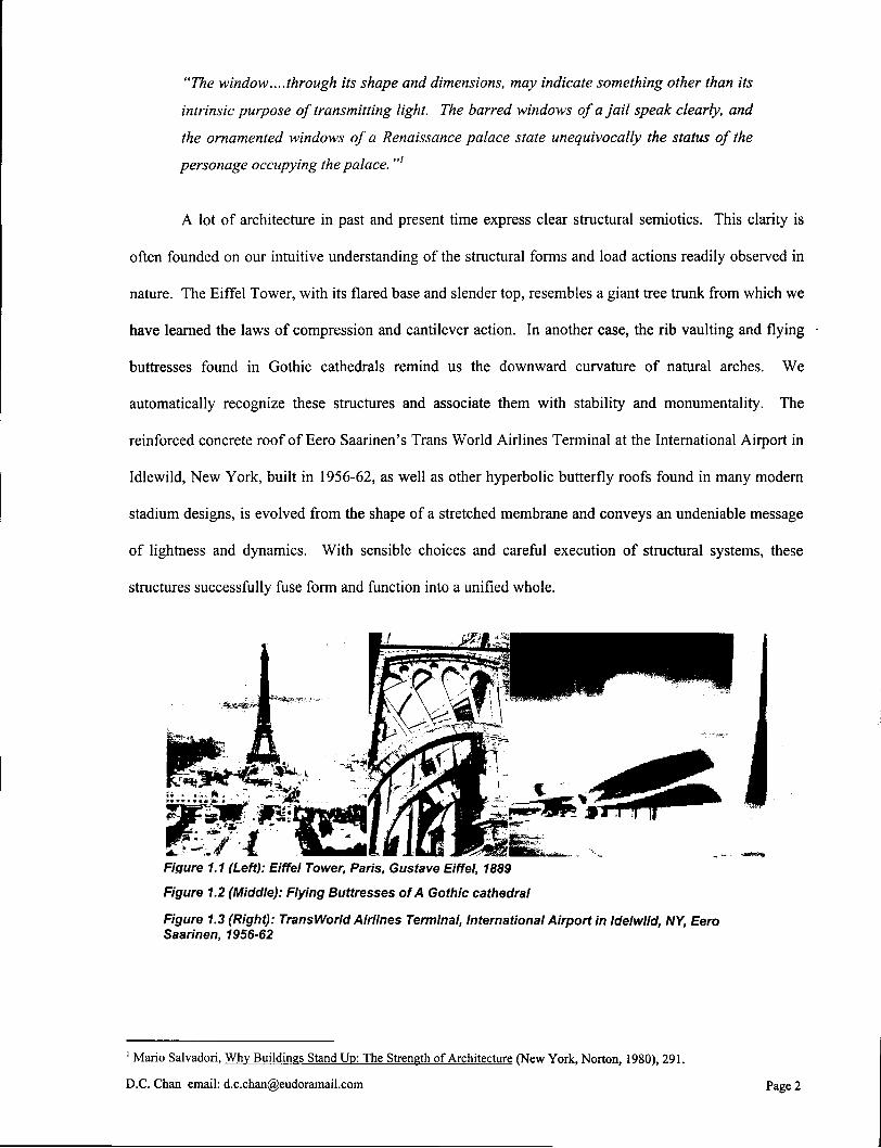
A lot of architecture in past and present time express clear structural semiotics. This clarity is
often founded on our intuitive understanding of the structural forms and load actions readily observed in
nature. The Eiffel Tower, with its flared base and slender top, resembles a giant tree trunk from which we
have learned the laws of compression and cantilever action. In another case, the rib vaulting and flying
buttresses found in Gothic cathedrals remind us the downward curvature of natural arches. We
automatically recognize these structures and associate them with stability and monumentality. The
reinforced concrete roof of Eero Saarinen's Trans World Airlines Terminal at the International Airport in
Idlewild, New York, built in 1956-62, as well as other hyperbolic butterfly roofs found in many modern
stadium designs, is evolved from the shape of a stretched membrane and conveys an undeniable message
of lightness and dynamics. With sensible choices and careful execution of structural systems, these
structures successfully fuse form and function into a unified whole.
Figure 1.1 (Left): Eiffel Tower, Paris, Gustave Eiffel, 1889
Figure 1.2 (Middle): Flying Buttresses of A Gothic cathedral
Figure 1.3 (Right): TransWorld Airlines Terminal, International Airport in Idelwild, NY, Eero Saarinen, 1956-62
' Mario Salvadori, Why Buildings Stand Up: The Strength of Architecture (New York, Norton, 1980), 291.
D.C. Chan email: [email protected] Page 2

On the other hand, frame structures lack a precedent with which they can be associated. Also,
their combined responses to gravity and lateral loads - the so-called frame action - are not immediately
comprehensible to an average person. The structural frame system was developed in the nineteenth
century; it was made possible by the development of ferrous metals and reinforced concrete as building
materials. As early as 1797, cast iron structural frames had already started to replace load-bearing
masonry construction in factory buildings throughout England. But the structural system did not become
well known to the western world until 1851, when horticultural engineer Joseph Paxton used
ferrovitreous structural frames to create his famous Crystal Palace for the Great Exhibition held in
London's Hyde Park. The 24 x 24 foot (7.3 x 7.3 metres) grid arrangement allowed rational
prefabrication and easy assembly of the standardized pieces of iron and glass. In 1885, American
engineer William LeBaron Jenney became one of the creators of the modern skyscraper by building the
10-storey Home Insurance Building in Chicago. Instead of using the traditional load-bearing masonry to
support gravity load, steel framework was used and the exterior masonry walls were hung from this
skeleton. Ernest L. Ransome in America and Francois Hennebique in France both invented reinforced
concrete frame construction during the 1870s. By the turn of the century, the appropriateness of the
structural frame for utilitarian buildings, including residential, commercial and industrial, was
acknowledged by architects with much enthusiasm. The system weighed less than load-bearing masonry
construction, spanned longer distance, occupied less interior space, and in the case of a ferrous metal
frame, its parts could be factory-produced. Despite its wide acceptance, the question of the semiotic
messages that a structural frame conveyed, and the means by which these messages contributed to the
overall expression of a building, still remained to be answered.
D.C. Chan email: [email protected] Page 3
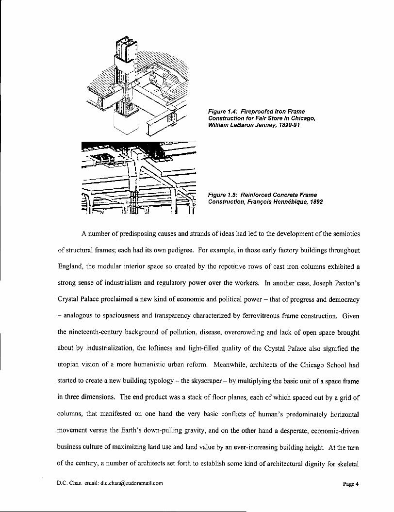
Figure 1.4: Fireproofed Iron Frame Construction for Fair Store in Chicago, William LeBaron Jenney, 1890-91
Figure 1.5: Reinforced Concrete Frame Construction, Francois Hennebique, 1892
A number of predisposing causes and strands of ideas had led to the development of the semiotics
of structural frames; each had its own pedigree. For example, in those early factory buildings throughout
England, the modular interior space so created by the repetitive rows of cast iron columns exhibited a
strong sense of industrialism and regulatory power over the workers. In another case, Joseph Paxton's
Crystal Palace proclaimed a new kind of economic and political power - that of progress and democracy
- analogous to spaciousness and transparency characterized by ferrovitreous frame construction. Given
the nineteenth-century background of pollution, disease, overcrowding and lack of open space brought
about by industrialization, the loftiness and light-filled quality of the Crystal Palace also signified the
Utopian vision of a more humanistic urban reform. Meanwhile, architects of the Chicago School had
started to create a new building typology - the skyscraper - by multiplying the basic unit of a space frame
in three dimensions. The end product was a stack of floor planes, each of which spaced out by a grid of
columns, that manifested on one hand the very basic conflicts of human's predominately horizontal
movement versus the Earth's down-pulling gravity, and on the other hand a desperate, economic-driven
business culture of maximizing land use and land value by an ever-increasing building height. At the rum
of the century, a number of architects set forth to establish some kind of architectural dignity for skeletal
D.C. Chan email: [email protected] Page 4

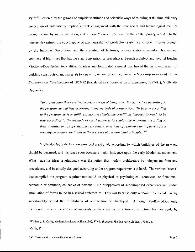
high-rise construction; these architects included William LeBaron Jenney, Henry H. Richardson and
Louis Sullivan. Their works added further insights to the semiotics of structural frames. The discussion
on structural semiotics hence is a diverse, complex and pluralistically cultural endeavor, with equal
emphasis on engineering principles and construction methods. Because of the diversity of issues to be
accounted for, it is more suitable to examine the topic on a case study basis. Through a collective
analysis of individual architectural work, a deeper understanding on how the semiotic messages
contributed to the overall expression of a building can be achieved.
D.C. Chan email: [email protected] Page 5
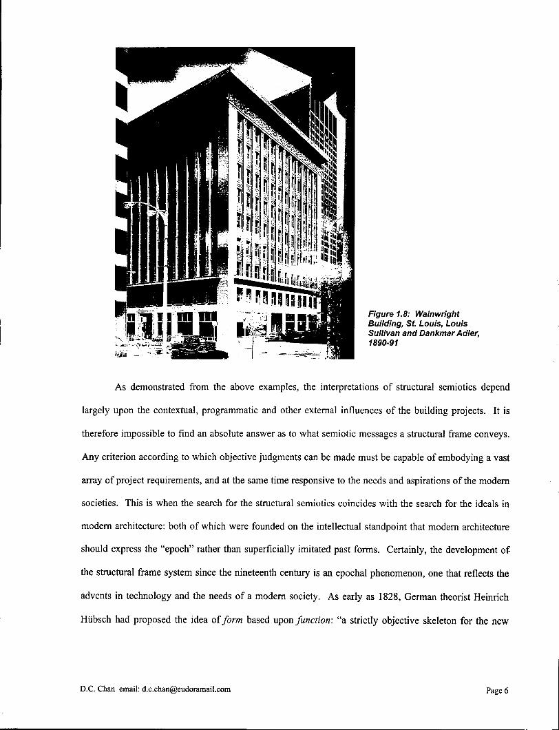
Figure 1.8: Wainwright Building, St. Louis, Louis Sullivan and Dankmar Adler, 1890-91
As demonstrated from the above examples, the interpretations of structural semiotics depend
largely upon the contextual, programmatic and other external influences of the building projects. It is
therefore impossible to find an absolute answer as to what semiotic messages a structural frame conveys.
Any criterion according to which objective judgments can be made must be capable of embodying a vast
array of project requirements, and at the same time responsive to the needs and aspirations of the modern
societies. This is when the search for the structural semiotics coincides with the search for the ideals in
modern architecture: both of which were founded on the intellectual standpoint that modern architecture
should express the "epoch" rather than superficially imitated past forms. Certainly, the development of
the structural frame system since the nineteenth century is an epochal phenomenon, one that reflects the
advents in technology and the needs of a modem society. As early as 1828, German theorist Heinrich
Hiibsch had proposed the idea of form based upon function: "a strictly objective skeleton for the new
D.C. Chan email: [email protected] Page 6
style".2 Fostered by the growth of empiricist attitude and scientific ways of thinking at the time, this very
conception of authenticity implied a frank engagement with the new social and technological realities
brought about by industrialization, and a more "honest" portrayal of the contemporary world. In the
nineteenth century, the epoch spoke of mechanization of production systems and social reforms brought
by the Industrial Revolution, and the sprouting of factories, railway stations, suburban houses and
commercial high-rises that had no clear convention or precedence. French architect and theorist Eugene
Viollet-le-Duc further took Hiibsch's ideas and formulated a model that linked the frank expression of
building construction and materials to a new movement of architecture - the Modernist movement. In his
Entretiens sur I 'architecture of 1863-72 (translated as Discourses on Architecture, 1877-81), Viollet-le-
Duc wrote:
"In architecture there are two necessary ways of being true. It must be true according to
the programme and true according to the methods of construction. To be true according
to the programme is to fulfil, exactly and simply, the conditions imposed by need; to be
true according to the methods of construction is to employ the materials according to
their qualities and properties ...purely artistic questions of symmetry and apparent form
are only secondary conditions in the presence of our dominant principles. "3
Viollet-le-Duc's declaration provided a rationale according to which buildings of the new era
should be designed, and his ideas soon became a major influence upon the early Modernist movement.
What made his ideas revolutionary was the notion that modern architecture be independent from any
precedence, and be strictly designed according to the program requirements at hand. The various "needs"
that compiled the program requirements could be physical or psychological, contextual or functional,
economic or aesthetic, collective or personal. He disapproved of superimposed ornaments and undue
articulation of forms found in classical architecture. This was because only without the concealment by
superficiality would the truthfulness of architecture be displayed. Although Viollet-le-Duc only
mentioned the sensible choice of materials be the criterion for a true construction, his idea could be
2 William J. R. Curtis, Modern Architecture Since 1900. 3 r d ed. (London: Phaidon Press Limited, 1996), 24.
3 Curtis, 27.
D.C. Chan email: [email protected] Page 7

expanded to that of a structural system, whose appropriateness could equally be judged by its suitability
to fulfil the program requirements. In other words, a true structure, besides being efficient, economical
and functional, spoke for the building purposes as lucidly as its architectural counterpart. Applying to our
earlier discussion on semiotics of structural frames, it follows that the semiotic messages a structural
frame conveys are no longer only formal or precedential but also programmatic, and only through this
faithful conformance to the program requirements will the structure and architecture work together to
contribute to the overall expression of the building.
Figure 1.9 (Left): Dom-ino Housing Project, Reinforced Concrete Skeleton, Le Corbusier, 1914-15
Figure 1.10 (Right): German Pavilion for the International Exhibition in Barcelona, Ludwig Mies van der Rohe, 1928-29
Entering the twentieth century, pioneers of the Modernist movement started to use the structural
frame system as form and idea generators for their works. Among these revolutionary architects were Le
Corbusier and Ludwig Mies van der Rohe. In 1914-15, Le Corbusier put together his Dom-ino concrete
housing project, a housing kit that allowed rapid reconstruction in war-devastated Flanders, Belgium.
The project not only advocated mass production as a means to construct economical urban dwellings, but
also transcended the structural frame system from a basic necessity into pure structural and spatial ideas.
Each housing unit comprised of a simple, six-point support reinforced concrete skeleton with three planes
of cantilevered slabs, smooth above and below; the lower level was raised from the ground on squat
concrete blocks. Rubble walls made from ruined buildings were used as infdl. What was intrinsic about
the Dom-ino project was the distillation of functions by a clear separation between structure and infill.
The former became a purified, functional making for supporting loads, the latter became a membrane to
be punctured as functional necessities or aesthetic composition required. The minimal supporting
columns and smoothness of floor planes also entailed a new kind of spatial flexibility by allowing
D.C. Chan email: [email protected] Page 8
partitions to be positioned at will. Although the Dom-ino project was never built, it was not long before
Le Corbusier's idea of the free plan was realized in physical form. In 1928-29, Ludwig Mies van der
Rohe designed the German Pavilion for the International Exhibition in Barcelona, a building that was
intended to project the image of openness, liberality, modernity and internationalism of the new Germany.
Eight cruciform steel columns were used to support a thin, cantilevered roof-slab, underneath which
partition walls were fluently arranged to describe a sequence of spatial experiences. Visual and physical
movements were completely defined by the wall planes and were unobstructed by the columns due to
their slenderness. The Dom-ino housing unit and the German Pavilion were the pilot projects that gave
shape to many Modernist works, and the structural frame system had indubitably played a major role in
the critical synthesis of this new architectural movement.
By the 1930s, Modernist architects like Henry-Russell Hitchcock and Philip Johnson had already
observed some visual trends of new building designs towards what they called the "International Style",
which was essentially a marriage between the structural frame system and modern architecture. This
further proved the growing maturity of the semiotic messages a structure frame conveyed. In their
catalogue, The International Style: Architecture since 1922, Hitchcock and Johnson outlined the main
visual principles of the new style:
"There is first of all a new conception of architecture as volume, rather than as mass.
Secondly, regularity rather than axial symmetry serves as the chief means of ordering
design. These two principles with a third proscribing arbitrary applied decoration mark
the productions of the International Style. "4
The crystallization of the Modernist movement in the twentieth century is rooted in the
transformation of technological ideas and processes into its own architectural vocabulary. A sensible
choice and careful execution of structural semiotics help this to be realized. To thoroughly understand the
semiotics of structural frames and its contributions to the overall architectural expression of a building, it
is necessary to probe beyond appearances to deeper levels of engineering principles, spatial organization,
and generating ideas that are influenced by the contextual and programmatic requirements. Over the
years, some of the most inspiring Modernist work has shown not only a real functionality, but also an
D.C. Chan email: [email protected] Page 9

integrated view of modern societies, all of which are supported by rigorous design philosophies. In recent
decades, however, there is a tendency that some of the visual principles of Modernism have been
hackneyed through mass industrialization such that an empty design formula or cliche is produced. The
result is a subordinate structural frame solely for the purpose of satisfying a superficial formalism. The
increasingly diverging roles and specialization of structural engineers and architects in the building
industry have also precipitated the problem, and vice versa. This problem can be alleviated in the future
if there is a better understanding and appreciation of the semiotics of structural frames.
1.1 Method of Dissertation
The above discourse provides an overview of the semiotics of the structural frame system and the
role it plays in modern architecture. The means by which structural semiotics contributes to the overall
expression of a building is dwelled on in this thesis, and is illustrated through a series of case studies of
Modernist architecture, and some of its precedents since the end of the nineteenth century. The method of
case studies works well in this kind of dissertation because examples of existing buildings can be cited
and their structural and architectural designs can be scrutinized with solid evidence. The task at hand is to
define the rules on which the selection of buildings can be based. This involves finding buildings that not
only make use of structural frame systems effectively, but those designs that are also backed by rigorous
architectural philosophies and a strong sense of commitment to the development of Modernist
architecture.
The buildings to be presented are grouped in chapters, each of which will be devoted to a topic
relating to either a specific frame system or building typology. For each building studied, information
ranging from its underlying architectural design concepts to engineering details will be provided
whenever available. It is hoped that, by devoting equally thorough coverage to the structural engineering
and architectural design of the case-study buildings, readers from both architecture and engineering
4 Curtis, 239.
D.C. Chan email: [email protected] Page 10
disciplines will benefit from the thesis. After all, the successful execution of structural semiotics in a
building project will not come alive without the utmost cooperation between both professions.
\
D.C. Chan email: [email protected] Page 11
2.0 Three-Hinged Truss Arches in Early Modernist Architecture
Three-hinged arches were developed by French and German engineers in the mid-nineteenth
century. This was a time when ferrous materials and their various structural manifestations, including
trusswork arches, proliferated in the construction of large-scale utilitarian structures such as railway
stations, market halls and exhibition buildings. The incorporation of the three hinges in an arch, one at
the crown and two at the bases, compensates for the thermal expansion and contraction of metal. Also,
because of the relief of three rotational degrees of freedom, one from each hinge, it overcomes the
calculation difficulties associated with fixed frames by making the structural system statically
determinate* (see Technical Note 6.1). Technically speaking, the two rigid segments between the hinges
can adopt any non-arched shapes without losing structural stability and static determinacy, given that the
materials of which the segments are made possess sufficient flexural strengths to support any bending
caused by the profile deviation. In other words, unless the two rigid segments form an arch, as in
traditional masonry construction, the term three-hinged "arch" can be somewhat a misnomer. In terms of
the actual structural behavior, a three-hinged arch, whether it is composed of trusses or girders, can be
thought of as a unique version of a fixed-based, fixed-jointed structural frame with zero bending moment
defined at three specific locations (which are called inflection points).
The architectural implications of the three-hinged truss arch in the nineteenth century are
significant. The trusswork arch not only revealed the full potential of ferrous materials, it also established
its own aesthetic convention - one of transparency, lightness and space - contrary to the solidity and
massiveness of traditional masonry construction. Furthermore, the incorporation of the three hinges in the
arch provided much technical reassurance due to the simplified calculation procedures of a statically
determinate structure. As a result, architects were encouraged to design an arch profile without being
strictly conformed to any precedence. They could freely express their own aesthetic and programmatic
1 Daniel L . Schodek, Structures, ed. (Englewood Cliffs: Prentice-Hall, Inc., 1992), 94. For statically determinate structures, the reactions at the supports can be found through simple application of the basic equations of statics (SF X = 0, I F y = 0 and 2 M x y = 0) without accounting for the physical and material properties of the cross sections of the structural members.
D.C. Chan email: [email protected] Page 12

concerns through the overall structural form. Indeed, some of the pioneers of early Modernist
architecture had boldly expressed the structural semiotics of three-hinged truss arches in their projects by
exhibiting the tectonics of the structures. In the Palais des Machines for the Universal Exposition of
Paris, 1889, architect Charles-Louis-Ferdinand Dutert and engineer Victor Contamin transformed the
utilitarian train shed of the industrial age into an astonishing engineering spectacle of twenty gigantic
three-hinged truss arches. In the A E G Turbine Hall in Berlin, 1909, architect Peter Behrens used a
similar structural system but inscribed it into a Neoclassical facade, blending architecture and structure
into a unified whole. Both of these projects have far-reaching ramifications to the development of
structural semiotics in early Modernist architecture.
2.1 Precursors of Trusswork Arches
To embark on our discussion of structural semiotics within an architectural context, it is
noteworthy that the historical process which led to the critical synthesis of art and engineering began as
the consequence of the Industrial Revolution, since then architecture had been evolving in parallel to the
accomplishments of technology.2 The Industrial Revolution of the eighteenth century had left two
legacies that profoundly influenced modern architecture. The first one was the mass production of iron,
and later steel, as a construction material, and the second one was the development of new structural
systems that exploited its tensile strength. Before the era of iron, construction materials were mostly
extracted from the earth and piled up into built forms. The structural systems that kept the individual
piled-up pieces together basically followed a vertical hierarchy, and resulted in various forms of cornices,
architraves, capitals, columns and bases, not to mention the most commonly known arches, vaults and
domes. Except for the tensile forces being carried in the lower strata of lintels by bending action, the
stresses experienced by the building elements were essentially compressive ones. This was naturally the
case because of the very limited tensile strengths inherent of stone and brick. In order to transfer gravity
loads by compression across a horizontal distance (e.g. to create an opening), masonry blocks were cut
into voussoirs and stacked to form an arch, or in its three-dimensional version, a vault. Theoretically,
2 Susanne Anna, Archi-Neering: Helmut Jahn and Werner Sobek (Ostfildern: Hatje Cantz Verlag, 1999), 12.
D.C. Chan email: [email protected] Page 13
unless the shape of a masonry arch strictly followed a funicular profile3 (see Technical Note 6.2), which
would be parabolic in nature for uniformly distributed loads on horizontal projection, there would be
some bending and associated shape changes which led to the development of tensile stresses, hence
cracks, between individual masonry voussoirs. Certainly, there were often cases where the masonry
arches did not exactly followed the funicular shapes, or the loading conditions experienced by these
arches did not remain uniformly distributed throughout their structural lives. What prevented the
masonry arches from collapsing were the large dimensions of the blocks and the surrounding masonry
wall enclosures that helped "containing" the funicular line of compression (the so-called thrust line).
The introduction of ferrous materials fostered the invention, or reinvention, of other structural
systems that defied all rules of traditional masonry construction. The truss system, originally made of
timber, was built with little theoretical knowledge on its load-carrying mechanisms until the early
nineteenth century, when bridge builders began systematically to explore and experiment with its
potential along with the possibility of using iron as its construction material. Based on the concept of the
rigidity of a triangular framework, a truss was composed of individual linear elements, or struts, being
arranged into a lattice of triangles and jointed at their intersections with pinned connections. Individual
struts would deform when subjected to an external load, but the triangular configuration would not distort
(as opposed to a pinned-connected rectangle of any polygons with more than three sides). Depending on
the exact configuration of the truss and the direction of the loading, some struts would experience
compression and others tension. A truss was thus able to carry transverse loading along its length by
transforming the bending moments into a set of discrete axial forces, which in turn was readily absorbed
by the inherited compressive and tensile strengths of iron. One of the most successful applications of the
iron truss in the nineteenth century was Gustave Eiffel's Pont du Garabit in southern France. Built in
1880-85, the viaduct combined spidery trusswork pylons, a crescent-shaped trusswork arch, and a
3 Schodek, 164. The term funicular is derived from the Latin word for "rope" and suggests the load-dependent deformed shape of a hanging cable. A cable subjected to external loads deforms to a specific profile according to the magnitude and location of the external forces; but only tension forces are developed in the cable. In the case of a uniformly distributed load on a horizontal projection, the cable adopts a parabolic shape. By analogy, inverting this deformed shape of a cable yields an arch profile except that pure compression rather than tension forces are developed. This is why non-rigidly connected masonry blocks, i f stacked into an arch, can form a stable structure.
D.C. Chan email: [email protected] Page 14
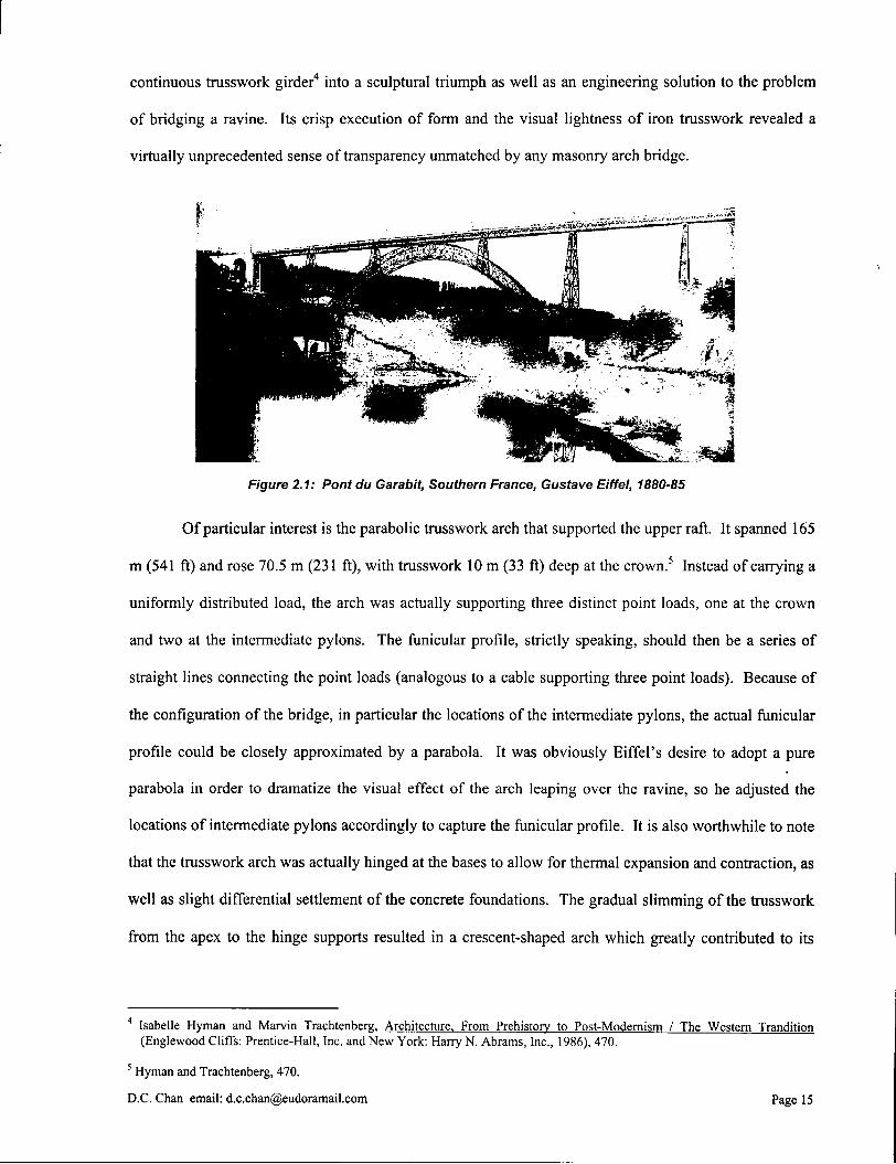
continuous trusswork girder4 into a sculptural triumph as well as an engineering solution to the problem
of bridging a ravine. Its crisp execution of form and the visual lightness of iron trusswork revealed a
virtually unprecedented sense of transparency unmatched by any masonry arch bridge.
Of particular interest is the parabolic trusswork arch that supported the upper raft. It spanned 165
m (541 ft) and rose 70.5 m (231 ft), with trusswork 10 m (33 ft) deep at the crown.5 Instead of carrying a
uniformly distributed load, the arch was actually supporting three distinct point loads, one at the crown
and two at the intermediate pylons. The funicular profile, strictly speaking, should then be a series of
straight lines connecting the point loads (analogous to a cable supporting three point loads). Because of
the configuration of the bridge, in particular the locations of the intermediate pylons, the actual funicular
profile could be closely approximated by a parabola. It was obviously Eiffel's desire to adopt a pure
parabola in order to dramatize the visual effect of the arch leaping over the ravine, so he adjusted the
locations of intermediate pylons accordingly to capture the funicular profile. It is also worthwhile to note
that the trusswork arch was actually hinged at the bases to allow for thermal expansion and contraction, as
well as slight differential settlement of the concrete foundations. The gradual slimming of the trusswork
from the apex to the hinge supports resulted in a crescent-shaped arch which greatly contributed to its
4 Isabelle Hyman and Marvin Trachtenberg, Architecture. From Prehistory to Post-Modernism / The Western Trandition (Englewood Cliffs: Prentice-Hall, Inc. and New York: Harry N . Abrams, Inc., 1986), 470.
5 Hyman and Trachtenberg, 470.
D.C.Chan email: [email protected] Page 15
Figure 2.1: Pontdu Garabit, Southern France, Gustave Eiffel, 1880-85

formal elegance. In Eiffel's Pont du Garabit, the aesthetic and structural potentials of trusswork arches
came to full realization.
Figure 2.2: Main Railway Station in Leipzig, William Lossow and Max Kuhne, 1908-16
Besides bridges, the other type of utilitarian structures that took full advantages of the trusswork
arches during the nineteenth century was the railway train shed. The design process of the train sheds
consisted of a set of pragmatic problems that were considered the technical endeavors of civil engineers.
Sufficient width of the structure was required to accommodate a number of parallel train tracks and
platforms, while sufficient ceiling height was required to diffuse the steam and smoke of the locomotives.
As a result, the train shed often took on a pure, undisguised functional appearance totally antithetical to
the massively decorated and superficial masonry facade of the passenger hall, which outwardly reflected
the typology of an urban building exclusively for human uses. From the bridge construction technology,
a number of schemes were employed. The trusswork arch was most commonly used scheme in larger
stations due to its dual capability of long span and large overhead clearance. Once an arch profile was
selected, the rest was a matter of repeating it one after another into a barrel vault, connecting the series
with longitudinal trusswork ribs, and covering the whole volume with iron-framed glass panels. Despite
this simple, spatial concept of the extended, repetitive forms, the semiotic message conveyed by these
ferrovitreous trusswork-arched train sheds was overwhelming. Rows after rows of the identical,
D.C. Chan email: [email protected] Page 16

prefabricated parts stretched across the infinite perspective, suggesting the limitless mass production of
the industrial age. The great, conserving forces of modern civilization were nakedly displayed. The
image of the large-scale, high-technology, down-to-earth functionalism of the railway train sheds was so
pronounced that it generated a whole new building typology which soon became a progenitor of some of
the early Modernist architecture, including the Palais des Machines and the A E G Turbine Hall.
2.2 Three-Hinged Truss Arches and Structural Frames
Early trusswork arches often retained the typical funicular profile of a parabola (or nearly a
parabola), as in the case of Eiffel's Pont du Garabit and numerous train sheds of the early industrial age.
This was partly due to nostalgia for ancient aesthetics of masonry arches so deeply rooted in the society,
and partly because of the still fledgling science of statics in analyzing complex, statically indeterminate
structure. The full structural qualities of iron had also to be exploited. Certainly, if it suits the
programmatic and contextual requirements of the project, a funicular-shaped trusswork arch still offers
the most effective solution to the problem of spanning long distance. On the other hand, any deviation
from the funicular profile means that the structure will no longer be in pure compression, and bending
moment will be created in proportion to the amount of eccentricity of the new profile with respect to the
thrust line (see Technical Note 6.3). The structure also becomes statically indeterminate to the third
degree. What this means is that there are altogether six reaction forces at the bases of a fixed-supported
frame to be solved, being R x , R y and M x y at each support, but only three equations of statics: EF X = 0, Z F y
= 0 and L M x y = 0 available for the whole structure, thus yielding a total of three outstanding unknowns.
The reactions cannot otherwise be solved without resorting to more in-depth analyses that took into
consideration the physical and material properties of the cross sections of the structural members. A
common example is a fixed-based, fixed-jointed rectilinear portal frame. To become statically
determinate, the structure requires the relief of three degrees of freedom, be they translational, rotational,
or a mixture of both. In the case of Pont du Garabit, the bases of the arch are pinned-supported in order to
avoid undesirable stresses caused by temperature-induced forces and differential foundation settlement.
The structure thus becomes statically indeterminate to the first degree due to the relief of two rotational
D.C. Chan email: [email protected] Page 17

degrees of freedom. Three-hinged truss arches are developed under the persistent desire to transform a
statically indeterminate structure into a statically determinate one by providing an additional rotational
degree of freedom at the crown. In terms of the actual structural behavior, a three-hinged arch, whether it
is composed of trusses or girders, can be thought of as a unique version of a fixed-based, fixed-jointed
structural frame with zero bending moment defined at three specific locations (which are called inflection
points).
2.3 Palais des Machines
Figure 2.3: Palais des Machines at the Universal Exposition In Paris, Charles
Dutert and Victor Contamln, 1887-89
Constructed for the 1889 Universal
Exposition on the Champ de Mars, Paris, the
Palais des Machines was a resounding
triumph in demonstrating the art and
engineering of three-hinged truss arches.
Steel was employed for the entire structure,
after the patenting of the Bessemer process
that allowed economic production of steel in
1856.6 Individual structural elements were
connected by riveting rather than the old
practice of plugging and wedging.7 The scale
6 William J. R. Curtis, Modern Architecture Since 1900. 3 r d ed. (London: Phaidon Press Limited, 1996), 38.
7 Stuart Durant, Palais des Machines: Ferdinand Dutert (London: Phaidon Press Limited, 1994), 57. Two companies, Fives-Lille and Cail et Cie, were awarded the contracts of erecting the nave of Palais des Machines, each company being responsible for half the length of the structure. Although the construction methods employed by both contractors were somewhat different, they both involved riveting portions of the steel trusses on the scaffold. "The rivets were heated in a furnace until the steel was red hot and quite soft. The furnace would be big and heavy and would probably be situated at ground level. Without having time to cool the rivets were thrown to the team on the scaffold consisting of a catcher, a placer and two hammer men, who would strike the two ends simultaneously. The resulting connections were strong because
D.C.Chan email: [email protected] Page 18
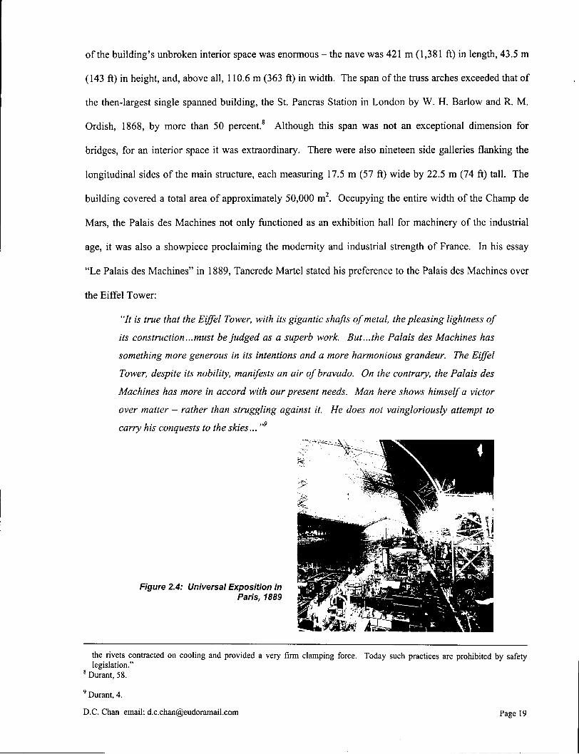
of the building's unbroken interior space was enormous - the nave was 421 m (1,381 ft) in length, 43.5 m
(143 ft) in height, and, above all, 110.6 m (363 ft) in width. The span of the truss arches exceeded that of
the then-largest single spanned building, the St. Pancras Station in London by W. H. Barlow and R. M .
Ordish, 1868, by more than 50 percent.8 Although this span was not an exceptional dimension for
bridges, for an interior space it was extraordinary. There were also nineteen side galleries flanking the
longitudinal sides of the main structure, each measuring 17.5 m (57 ft) wide by 22.5 m (74 ft) tall. The
building covered a total area of approximately 50,000 m 2. Occupying the entire width of the Champ de
Mars, the Palais des Machines not only functioned as an exhibition hall for machinery of the industrial
age, it was also a showpiece proclaiming the modernity and industrial strength of France. In his essay
"Le Palais des Machines" in 1889, Tancrede Martel stated his preference to the Palais des Machines over
the Eiffel Tower:
"It is true that the Eiffel Tower, with its gigantic shafts of metal, the pleasing lightness of
its construction...must be judged as a superb work. But...the Palais des Machines has
something more generous in its intentions and a more harmonious grandeur. The Eiffel
Tower, despite its nobility, manifests an air of bravado. On the contrary, the Palais des
Machines has more in accord with our present needs. Man here shows himself a victor
over matter - rather than struggling against it. He does not vaingloriously attempt to
carry his conquests to the skies... "9
Figure 2.4: Universal Exposition in Paris, 1889
the rivets contracted on cooling and provided a very firm clamping force. Today such practices are prohibited by safety legislation."
8 Durant, 58.
9 Durant, 4.
D.C.Chan email: [email protected] Page 19
Indeed, the Palais des Machines was less flamboyant than the Eiffel Tower and actually had a use
- to houses machinery exhibits of every sort. It was probably because of this specific utilitarian purpose
that the building typology of contemporary railway train sheds was adopted in order to draw an analogy
to the great power of the locomotive. The nave of the Palais des Machines was constructed just like a
train shed - twenty gigantic trusswork arches were replicated along the length of the site, dividing it into
nineteen structural bays. These arches were hinged at the crown, and their bases rested in a little hinged
slot in the pavement. Across the width of the roof, the arches were restrained at 10.7 m centers by
longitudinal truss ribs, while the whole nave was clad with a ferrovitreous grid envelope. A clear, light-
filled, enormous interior space was created without a single intermediate column. The trusswork and the
hinges were fully exposed to the spectators (see Technical Note 6.4).
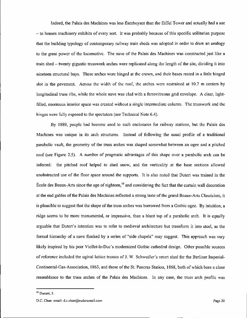
By 1889, people had become used to such enclosures for railway stations, but the Palais des
Machines was unique in its arch structures. Instead of following the usual profile of a traditional
parabolic vault, the geometry of the truss arches was shaped somewhat between an ogee and a pitched
roof (see Figure 2.5). A number of pragmatic advantages of this shape over a parabolic arch can be
inferred: the pitched roof helped to shed snow, and the verticality at the base sections allowed
unobstructed use of the floor space around the supports. It is also noted that Dutert was trained in the
Ecole des Beaux-Arts since the age of eighteen,10 and considering the fact that the curtain wall decoration
at the end gables of the Palais des Machines reflected a strong taste of the grand Beaux-Arts Classicism, it
is plausible to suggest that the shape of the truss arches was borrowed from a Gothic ogee. By intuition, a
ridge seems to be more monumental, or impressive, than a blunt top of a parabolic arch. It is equally
arguable that Dutert's intention was to refer to medieval architecture but transform it into steel, as the
formal hierarchy of a nave flanked by a series of "side chapels" may suggest. This approach was very
likely inspired by his peer Viollet-le-Duc's modernized Gothic cathedral design. Other possible sources
of reference included the ogival lattice trusses of J. W. Schwedler's retort shed for the Berliner Imperial-
Continental-Gas-Association, 1863, and those of the St. Pancras Station, 1868, both of which bore a close
resemblance to the truss arches of the Palais des Machines. In any case, the truss arch profile was
1 0 Durant, 5.
D.C. Chan email: [email protected] Page 20
suitably chosen to express Dutert's aesthetic aspiration, and the incorporation of the three hinges in the
arches helped this to be realized.
Figure 2.5: Fagade of Palais des Machines
What really made Dutert's design successful was that it went beyond a mere revivalism of past
forms. The Palais des Machines was by itself an architectural and technological invention that strived to
make its own statement. Its programmatic requirements suggested the architectural solution, and
conversely its form gave hints to the programs contained within. Upon entering the building, the
spectators were not only amazed by the enormous scale of the interior, their sensations were also
heightened by the illusion of "potential movement" of the structure. The reassuring profde of the
traditional parabolic arches were replaced by twin cantilever arms, which extended across the width of
building until they finally met and were jointed by a cylindrical pin bearing at the apex. For a moment,
the prolonged cantilever arms seemed to be on the verge of overturning inwards, only to be held in
equilibrium by three hinges. The illusion was amplified by the fact that the hinges were explicitly
articulated; maximum visual impact was produced by positioning the base hinges exactly at floor level.
The three-hinged truss arches conveyed lucidly the semiotic message of a giant machine, one that could
start moving in any second - a design concept that precisely represented the contents housed within the
building. The Palais des Machines thus achieved a new synthesis of form and function, with a vigorous
engagement in human psychology. The functionalist ideal of "form follows function"11 or Viollet-le-
Duc's "...true according to the programme and true according to the methods of construction"12 could be
detected from the overall formal design right down to the detailing of the structure.
" Louis H. Sullivan, "The Tall Office Building Artistically Considered" Inland Architect 27, 1896, 32-34.
1 2 Curtis, 27.
D.C. Chan email: [email protected] Page 21
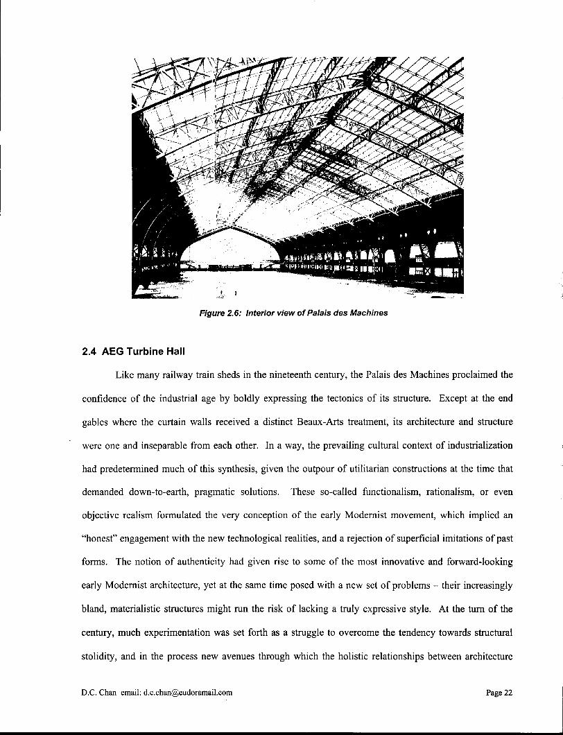
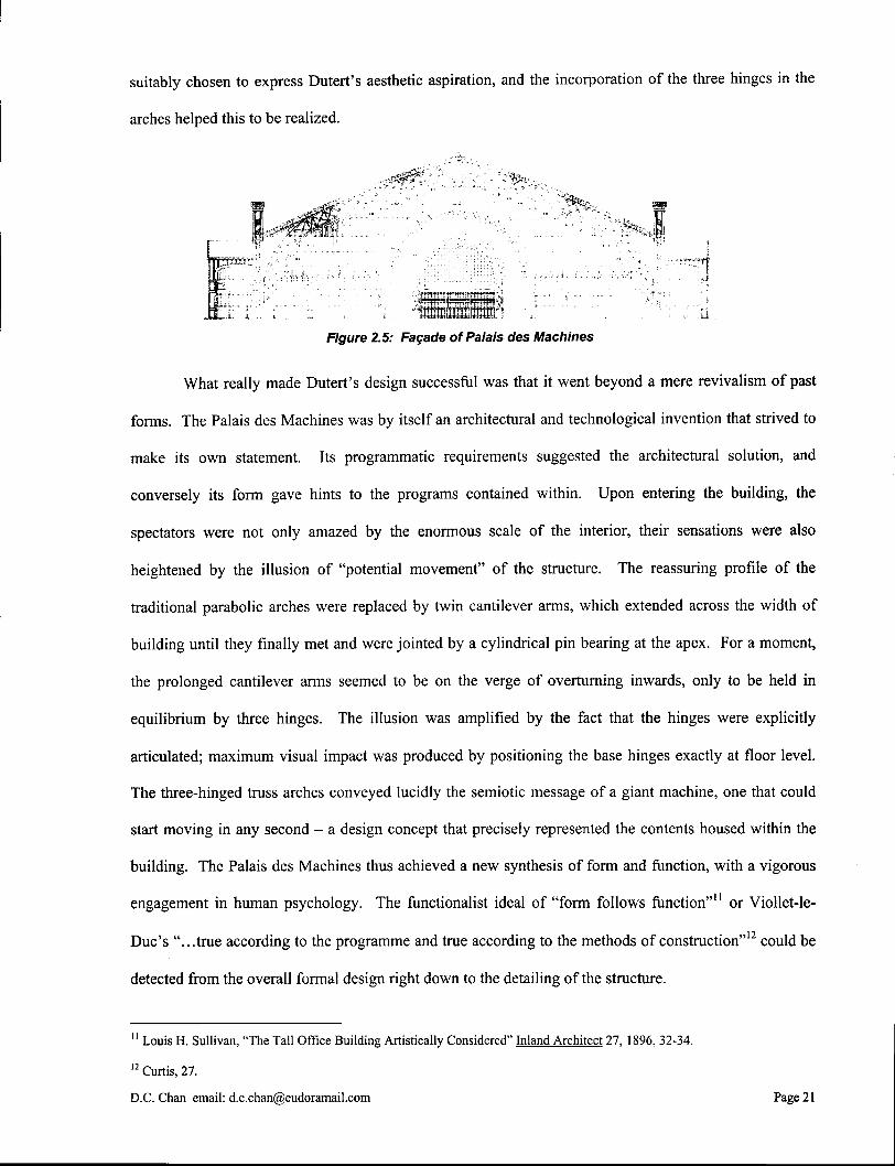
Figure 2.6: Interior view of Palais des Machines
2.4 AEG Turbine Hall
Like many railway train sheds in the nineteenth century, the Palais des Machines proclaimed the
confidence of the industrial age by boldly expressing the tectonics of its structure. Except at the end
gables where the curtain walls received a distinct Beaux-Arts treatment, its architecture and structure
were one and inseparable from each other. In a way, the prevailing cultural context of industrialization
had predetermined much of this synthesis, given the outpour of utilitarian constructions at the time that
demanded down-to-earth, pragmatic solutions. These so-called functionalism, rationalism, or even
objective realism formulated the very conception of the early Modernist movement, which implied an
"honest" engagement with the new technological realities, and a rejection of superficial imitations of past
forms. The notion of authenticity had given rise to some of the most innovative and forward-looking
early Modernist architecture, yet at the same time posed with a new set of problems - their increasingly
bland, materialistic structures might run the risk of lacking a truly expressive style. At the turn of the
century, much experimentation was set forth as a struggle to overcome the tendency towards structural
stolidity, and in the process new avenues through which the holistic relationships between architecture
D.C. Chan email: [email protected] Page 22

and structure could be explored were opened up. In the context of our discussion on three-hinged truss
arches, Peter Behrens' A E G Turbine Hall in Berlin, 1909, is a representative example during this
transitional phase.
Figure 2.7: AEG Turbine Hall, Berlin, Peter Behrens, 1908-09
The A E G Turbine Hall was constructed at the time when General Electric Company (Allgemeine
Elektricitats-Gesellschaft) was undergoing rapid expansion in Germany. Walther Rathenau, the owner of
A E G , described the company as "undoubtedly the largest European combination of industrial units under
a centralized control and with a centralized organization".13 The notion of a centralized work force
influenced much of the fundamental design concepts of the A E G Turbine Hall, and the building
eventually took on an architectural design that was destined to go beyond a merely functional making.
The factory building was designed to receive materials from the railway tracks that entered straight into
its rear entrance. Operational requirements called for two huge traveling gantries, each with a 50-ton
lifting capacity, to upload materials and move large turbine engines along the entire length of the hall. An
overhead clearance of 15 m (49 ft) under the gantries was specified. Several swiveling cranes were also
to be installed for moving smaller components and materials from the sidewalls. A perfectly clear
rectangular volume had to be created.
1 3 Alan Windsor, Peter Behrens: Architect and Designer 1868-1940 (London: The Architectural Press, 1981), 78.
D.C. Chan email: [email protected] Page 23

The resultant factory building was the largest steel hall in Berlin at the time: 123 m (404 ft) in
length and 25.6 m (84 ft) in width, with a ridge height of approximately 25 m (82 ft).14 There was also a
secondary two-storey hall, 12.5 m (41 ft) wide, flanking the courtyard side of the main turbine hall.
While the side hall employed a fixed-end, rigid frame structural system, the main turbine hall took full
advantage of the possible expressivity inherent in three-hinged truss arches. The arch shape had resulted
in a highly geometric pediment with a curvature made up of six chords inscribable in a circle - possibly a
symbolic reference to the hexagonal company emblem. These truss arches, fourteen in total and at
regular intervals of 9.22 m (30 ft), were hinged to the top of the rigid frames of the side hall on the
courtyard side, and rigidly connected to a longitudinal steel box girder on the Berlichingerstrasse street-
front side (see Technical Note 6.5). The box girder was supported by fourteen sturdy box-sectioned steel
pillars. The pillar shafts tapered downwards along their interior faces into tight-waisted hinge joints,
which in turn rested on concrete plinths approximately 1.50 m above ground level. To lend a sense of
drama, the actual load-bearing pins on which the pillars were supported were hidden from view. The
tight-waisted hinge joints appeared as two groups of curved web stiffeners that barely touched each other.
The impression of "hinging" induced by these joints was as powerful as the one of the Palais des
Machines. Between the pillars there were entirely glazed infill. The glazing leaned inwards along the
interior faces of the pillars, revealing the colossal steel supports as they rose. Saddle-shaped skylights
crowned the main and side halls; they were hardly visible from street level due to their setbacks from the
facade.
It was the front facade that set the A E G Turbine Hall apart from the prevailing architectural trend
of functionalism. Facing Huttenstrasse, the steel pediment of the truss arches was disguised by a huge
concrete gable on which the company emblem was engraved. The dramatic expression was intensified by
two massive reinforced concrete cornerstones, which, like the glazing infill, were obliquely supported on
the interior. To complete the formal composition, a vast area of glass in the main facade was laid flush
with the pediment plane, resembling a thin screen that hovered in front of the concrete quoins. Neither
the concrete gable nor the concrete quoins was needed for structural purpose. To the contrary, by tilting
1 4 Tilmann Buddensieg, "Peter Behrens and the A E G , 1907-1914" Industriekultur. 1984, 273.
D.C. Chan email: [email protected] Page 24
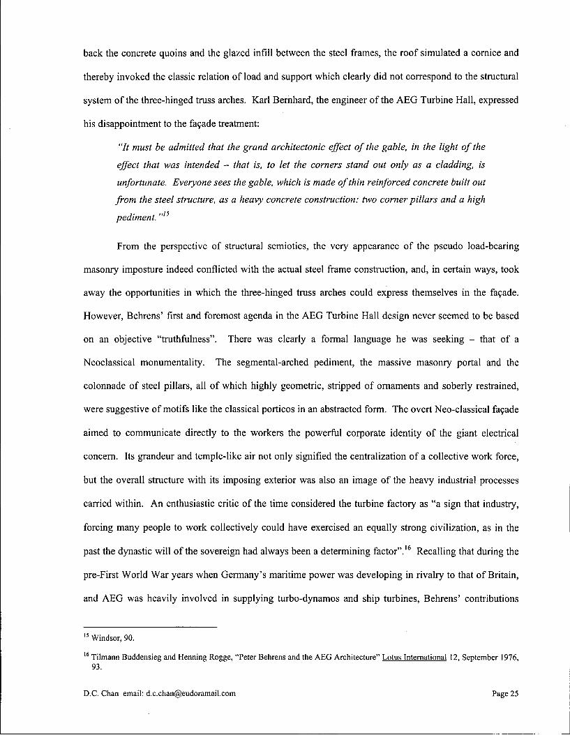
back the concrete quoins and the glazed infill between the steel frames, the roof simulated a cornice and
thereby invoked the classic relation of load and support which clearly did not correspond to the structural
system of the three-hinged truss arches. Karl Bernhard, the engineer of the A E G Turbine Hall, expressed
his disappointment to the facade treatment:
"It must be admitted that the grand architectonic effect of the gable, in the light of the
effect that was intended - that is, to let the corners stand out only as a cladding, is
unfortunate. Everyone sees the gable, which is made of thin reinforced concrete built out
from the steel structure, as a heavy concrete construction: two corner pillars and a high
pediment. "I5
From the perspective of structural semiotics, the very appearance of the pseudo load-bearing
masonry imposture indeed conflicted with the actual steel frame construction, and, in certain ways, took
away the opportunities in which the three-hinged truss arches could express themselves in the facade.
However, Behrens' first and foremost agenda in the A E G Turbine Hall design never seemed to be based
on an objective "truthfulness". There was clearly a formal language he was seeking - that of a
Neoclassical monumentality. The segmental-arched pediment, the massive masonry portal and the
colonnade of steel pillars, all of which highly geometric, stripped of ornaments and soberly restrained,
were suggestive of motifs like the classical porticos in an abstracted form. The overt Neo-classical facade
aimed to communicate directly to the workers the powerful corporate identity of the giant electrical
concern. Its grandeur and temple-like air not only signified the centralization of a collective work force,
but the overall structure with its imposing exterior was also an image of the heavy industrial processes
carried within. An enthusiastic critic of the time considered the turbine factory as "a sign that industry,
forcing many people to work collectively could have exercised an equally strong civilization, as in the
past the dynastic will of the sovereign had always been a determining factor".16 Recalling that during the
pre-First World War years when Germany's maritime power was developing in rivalry to that of Britain,
and A E G was heavily involved in supplying turbo-dynamos and ship turbines, Behrens' contributions
1 5 Windsor, 90.
1 6 Tilmann Buddensieg and Henning Rogge, "Peter Behrens and the A E G Architecture" Lotus International 12, September 1976, 93.
D.C. Chan email: [email protected] Page 25

could also be transcended to the level of nationalism. The sober German spirit manifested in his
architecture was comparable to the national identity of Germany established by Karl Friedrich Schinkel a
century ago through a series of Neo-classical monuments in Berlin. In an article entitled "Berlin at the
Beginning of the Twentieth Century", Goerd Peschken and Tilmann Heinisch interpreted Behrens' Neo
classical version of the traditional masonry pillars with a more national character:
"Colossal classical pillars are an imperial motif and reflect not only imperial claims in
Germany but in the world as well. Le Corbusier has already commented on this with
regard to the turbine factory, and one cannot blame a leading industrial nation for
wishing to exert political influence and standing wherever its exports or imports were
concerned. " n
Figure 2.8: Box-sectioned Steel Pillars - fourteen pillars flank
Berlichingerstrasse with glazed infill. Noted that the tight-waisted
hinged supports are set on concrete plinths approximately 1.5 m from ground level. To add a sense ot
drama, the actual load-bearing pins on which the pillars were supported
were hidden from view.
Behrens recognized that it was the solidity and strong play of light and shadow that gave the
colossal classical pillars a monumental presence. In the A E G Turbine Hall, he transformed the fully
aerated truss arches inside the building into solid box sections outside. The fourteen box-sectioned steel
pillars that flanked Berlichingerstrasse, together with the shadow lines created by the recessing glazed
infill, conveyed an undeniable sense of volumetric corporeality. A fusion of abstracted classical
1 7 Goerd Peschken and Tilmann Heinisch, "Berlin at the Beginning of the Twentieth Century." Berlin: An Architectural History. Doug Clelland. (London: A D Publications Ltd., 1983), 43.
D.C. Chan email: [email protected] Page 26
vocabulary and modern structural skeleton was achieved. Together with the non-load bearing glazed
infill that was stretched like webs in between the steel skeleton, the visual effects of lightness and
massiveness were cleverly orchestrated to emphasize the overall formal composition between different
materials. Some contemporary debates about skeletal frame constructions at the turn of the century
revolved around the concerns of "volumetric emptiness", as Siegfried Giedion described "the eye of the
contemporary onlookers felt insecure and disturbed as the light pouring in from above swallowed up the
thin lattice work",18 or Gottfried Semper argued that iron never in itself became monumental. Behrens
refuted these claims by making the following argument, which in effect also summarized his point of
view towards steel frame constructions:
"If it is said that the beauty of a pure iron construction lies in the line, I must repeat that
the line is of no substance: architecture lies in corporeality. The practical purpose of
large industrial buildings and our general need today for air and light call for large
openings, but nevertheless there is no reason for the entire architecture to convey the
impression of a thin, wiry scaffolding of bars or threadbare framework. ...Architecture is
the design of volumes, and its task in not to disclose, but its cardinal essence is to enclose
space."19
2. 5 Conclusion
Since its invention in the mid-nineteenth century, the three-hinged truss arch has been one of the
favorite choices of structural system in large-scale industrial and utilitarian architecture. This is mainly
due to the potential expressivity of the arch form and the visual elasticity of the hinges, not to mention the
simplified calculation procedures fostered by the inherent static determinacy of the system. In this paper,
the structural semiotics of the three-hinged truss arches is discussed through two examples of the early
Modernist architecture, namely the Palais des Machines and the A E G Turbine Hall. Each structure has its
own programmatic and contextual requirements, as well as reflections upon the architect's own
convictions on how iron skeletal constructions participate in the development of the Modernist
movement. It is important to note that although structural semiotics has often been associated with the
1 8 Mechtild Henser, "La finestra sul cortile. Behrens e Mies van der Rohe: AEG-Turbinenhalle; Berlino 1908-1909," Casabella 651/652, Dec 1997 - Jan 1998, 20.
1 9 Henser, 20.
D.C. Chan email: [email protected] Page 27

functionalist or rationalist ideology of being "true" to materials and to the methods of construction,
structure can certainly take on more than the role of a functional affiliation. This is especially true when
the task of building construction is viewed as a diverse, complex, and pluralistic cultural endeavor. Like
architecture, there are certain languages through which a structure can communicate with the viewer.
These languages are waiting to be explored by both the architects and the engineers.
D.C. Chan email: [email protected] Page 28

3.0 Steel Moment-Resisting Frames and Mies van der Rohe's Structural and Spatial Concepts
Moment-resisting structural frames have many advantages over other frame systems. When
subjected to a distributed gravity load, the beam of a moment-resisting frame experiences much less
bending than that of a post-and-beam or three-hinged frame. When a lateral load is applied, the joint
rigidity of a moment-resisting frame keeps deflection within acceptable limits, where in other frame
systems additional bracing elements or shear walls are often required for lateral stability and deflection
control (see Technical Notes 6.6 and 6.7). In building design, these outstanding structural performances
of moment-resisting frames have promoted the divorce of enclosure and partition walls from their
traditional load-bearing responsibility, resulting in more flexible planning of interior space that responds
to various architectural requirements. In the case where the frame skeleton is exposed and isolated from
other space-defining elements, it demands an architectural expression of its own right. The structural
semiotics of moment-resisting frames has become an indispensable design task in modern architecture
that is to be reckoned with.
It is generally agreed that Ludwig Mies van der Rohe (1886-1969) was the one who successfully
gave the steel moment-resisting frame an aesthetic definition. Born in Germany and immigrated to
America in 1938, Mies van der Rohe lived in an era when technology was a strong civilizing force that its
influences on many aspects of modern life became increasingly apparent. He believed that architecture at
its most valuable should reflect the driving and sustaining forces of an epoch. In the time of
industrialization, functionalism and economy, his architecture was a manifestation of the technological
society and modern ways of living. To achieve so he used clear and reasonable choices of building
materials, structural systems and construction details to the point of refinement that the structure became
the architecture and the elements of construction reached a level of poetic expression. Mies van der
Rohe's preoccupation with steel structures was accounted to his obsession with precision craftsmanship,
but it was the use of moment-resisting structural frames that allowed his spatial concepts to be fully
realized. The German Pavilion for the International Exhibition in Barcelona, 1928-29, was regarded in
D.C. Chan email: [email protected] Page 29
retrospect as Mies van der Rohe's first project in which his idea of a continuous, free-flowing space was
formalized through a regular framework of open steel structural frame. During his years of residence in
America, Mies van der Rohe's architectural language of steel moment-resisting frame construction
gradually matured. Some of his notable projects include the Crown Hall, 1950-56, and other steel-framed
campus buildings in the Illinois Institute of Technology built throughout 1938 to 1958.
3.1 The Development of Steel Moment-Resisting Frames
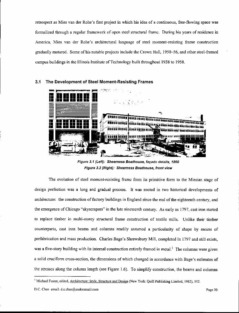
Figure 3.1 (Left): Sheerness Boathouse, fagade details, 1860
Figure 3.2 (Right): Sheerness Boathouse, front view
The evolution of steel moment-resisting frame from its primitive form to the Miesian stage of
design perfection was a long and gradual process. It was rooted in two historical developments of
architecture: the construction of factory buildings in England since the end of the eighteenth century, and
the emergence of Chicago "skyscrapers" in the late nineteenth century. As early as 1797, cast iron started
to replace timber in multi-storey structural frame construction of textile mills. Unlike their timber
counterparts, cast iron beams and columns readily assumed a particularity of shape by means of
prefabrication and mass production. Charles Bage's Shrewsbury Mill, completed in 1797 and still exists,
was a five-story building with its internal construction entirely framed in metal.1 The columns were given
a solid cruciform cross-section, the dimensions of which changed in accordance with Bage's estimates of
the stresses along the column length (see Figure 1.6). To simplify construction, the beams and columns
Michael Foster, edited, Architecture: Style. Structure and Design (New York: Quill Publishing Limited, 1982), 112.
D.C. Chan email: [email protected] Page 30
were shaped so that they slid into each other to form a joint. These connections, however, had no
moment-resisting capacity. Lateral stability of the whole building was imparted by maintaining the
external masonry wall, which also acted as the vertical load-bearing element at the periphery.
The technological breakthrough of moment-resisting frame construction came in 1860 with the
completion of Sheerness Boathouse. In this four-storey building, the continuous struggle of maximizing
interior open space finally forced the ferrous skeleton frame to the plane of the external wall. The beam-
column joints were subsequently made rigid, rendering the massive load-bearing masonry walls
structurally obsolete.2 As a result, a more structurally efficient, light-weighed cladding of corrugated iron
was used as an infill, and large panes of glass windows were inserted in the facade for optimal indoor
light quality. The Sheerness Boathouse was also the first building in which hot-rolled, wrought iron H -
sections and I-beams were used for structural elements. This marked the beginning of the moment-
resisting frame construction.
The Chicago multi-storey office buildings of the late nineteenth century underwent a parallel
evolution to that of the factory buildings. These early "skyscrapers" were made possible by the use of
metal moment-resisting frame construction. Prior to William LeBaron Jenney's Home Insurance
Building in 1885, there were already internal frame constructions done in Chicago that used a mixture of
timber and cast iron structural members, with masonry cladding covering the outermost columns and
beams. The external masonry wall maintained both its structural and formal compositional roles. As
multi-storey buildings increased in height, however, the massive masonry wall became a burden to the
structural frame and foundation. The thickened ground-floor walls also obstructed generous shop
windows and thus lucrative rental space. For example, in the sixteen-storey Monadnock Building by John
Wellborn Root and Daniel Burnham, 1884-91, the unreinforced brick walls were 18 inches thick at the
top, and 6 feet thick at the bottom of the building.3 The building was probably the end of the line for
monolithic masonry construction on this scale.
2 Alan Ogg, Architecture in Steel: The Australian Context (The Royal Australian Institute of Architecture, 1987), 19.
3 Edward Allen, Fundamentals of Building Construction: Materials and Methods. 3 r d ed. (New York: John Wiley & Sons, Inc., 1999), 271.
D.C. Chan email: [email protected] Page 31
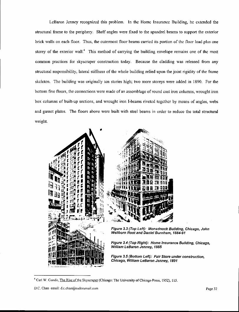
LeBaron Jenney recognized this problem. In the Home Insurance Building, he extended the
structural frame to the periphery. Shelf angles were fixed to the spandrel beams to support the exterior
brick walls on each floor. Thus, the outermost floor beams carried its portion of the floor load plus one
storey of the exterior wall.4 This method of carrying the building envelope remains one of the most
common practices for skyscraper construction today. Because the cladding was released from any
structural responsibility, lateral stiffness of the whole building relied upon the joint rigidity of the frame
skeleton. The building was originally ten stories high; two more storeys were added in 1890. For the
bottom five floors, the connections were made of an assemblage of round cast iron columns, wrought iron
box columns of built-up sections, and wrought iron I-beams riveted together by means of angles, webs
and gusset plates. The floors above were built with steel beams in order to reduce the total structural
weight.
Figure 3.5 (Bottom Left): Fair Store under construction, Chicago, William LeBaron Jenney, 1891
Figure 3.4 (Top Right): Home Insurance Building, Chicago, William LeBaron Jenney, 1885
Figure 3.3 (Top Left): Monadnock Building, Chicago, John Wellborn Root and Daniel Burnham, 1884-91
4 Carl W. Condit, The Rise of the Skyscraper (Chicago: The University of Chicago Press, 1952), 115.
D.C. Chan email: [email protected] Page 32
In the Home Insurance Building, the utilitarian advantages of metal moment-resisting frame
construction became immediately obvious to architects and engineers. New buildings continued to
increase in height and diminish in weight. Wider structural bays allowed flexibility of interior space use.
Extensive coverage of glass on the facade and the introduction of bay windows also led to the maximum
admission of natural light even on a narrow, densely built street. In subsequent years, many technological
improvements were made to the steel moment-resisting frame. One of them was the development of
fireproof steel frame construction. The Great Fire of 1871 in the center of Chicago caused an alarming
awareness to the danger of exposed cast iron construction. In the heat of 3,000 degrees, exposed cast iron
structural members melted into a completely fluid state and further contributed to the spread of fire. In
about forty-eight hours the flames destroyed $192 million worth of property, out of a total property
evaluation of $575 million. Approximately 100,000 people were made homeless.5 In the following
years, fireproof metal frame construction using concrete, plaster and hollow terracotta blocks emerged. In
LeBaron Jenney's Fair Store, 1891, the steel frame was completely fireproofed. The hardwood flooring
was laid on a subfloor of concrete, which in turn was carried on hollow tile arches. The ceiling was
plastered. The columns were fireproofed with a plastered terracotta surround. Other innovations in steel
moment-resisting frame construction included the replacement of riveting by high-strength bolting and
welding, and the widening of selection for hot-rolled steel beam and column sections. The standardized
steel beam, column and channel sections predominantly used today were first produced in around 1905
and manufactured in most industrialized countries by the 1950's. Tubular sections became viable for
building structures in the early 1960's.6 During the First World War, the techniques of welding were
developed in the munitions industry, and its uses quickly spread to building construction. Welding offers
compositional clarity of the rigid joints as well as connections between structural and cladding
components, and can be observed in Mies van der Rohe's steel-framed construction. All in all, these
technological innovations not only foster more efficient structural uses of steel moment-resisting frames,
but also lead to significant changes in the overall form and architectural expression of buildings.
5 Condit , 13.
6 O g g , 15.
D.C. Chan email: [email protected] Page 33
3.2 Establishing An Architectural Expression
3.2.1 Structure and Space
The development of factory buildings in England and Chicago "skyscrapers" into today's modern
buildings illustrates the continuous struggle to find appropriate architectural expressions for the steel
moment-resisting structural frame. Indeed, the unique means of construction lacks a historical precedent
with which they can be associated, and it poses new conceptual dilemmas. First of all, the concept of
repetition remains central to all steel structural frame construction. It is intimately related to the means by
which individual structural parts are produced and assembled, namely, by prefabrication and mass
production. Repetition effects the delineation in three dimensions of neutral grid, in which space is
disciplined and order is established. On the other hand, it results in a structure that is restricted in a
regular and rigid pattern, which in some cases becomes irresponsive to the actual spatial definition at the
interior of the building. The geometries of space are thus more readily defined by non-load-bearing
partition walls than by the structure, the former of which are more flexible in their form, freely arranged
and often demountable to suit a wide range of spatial requirements. Space is now defined without
necessarily being conformed to the geometry of the structural frame. This phenomenon of spatial
anonymity of the structure is precipitated by the fact that the structural frame diminishes in both physical
and visual scales in relation to the space enclosed. Massive internal and external load-bearing masonry
walls are reduced to small cross-sections of steel, simply by virtue of the structural efficiency inherent in
the new material and the new system. The entire building fabric lightens as a consequence. With its
diminishing space-defining role, the structural frame runs into the danger of being viewed merely as a
subordinate, rather than a participant, in the overall architectural expression of the building. Unless
subduing the spatial significance is one of the design criteria for the structure, it should be recognized that
the purpose of shaping structure is not only to resolve functional problems but also to give spatial form.
Structure and space must constitute a whole.
D.C. Chan email: [email protected] Page 34
3.2.2 Part and Whole
Another point to make concerns about compositional consistency. The innovative change in the
structural nature of the joint has transformed the overall build form. As in the case of many modern
multi-storey buildings, the cage-like building facade is in fact an impartial revelation of the interior
moment-resisting frame. Compositional consistency is achieved in which the expression of the "part" is
carried into the "whole". In the course of modern architecture, this means of architectonic revelation is
often regarded as the "honest" portrayal of the steel moment-resisting frame, one that is along the line of
Viollet-le-Duc's ideology of a true construction. On the other hand, because the engineering of a
structure is largely based on efficiency and economy, the architectural expression of the building may end
up overloaded with these two factors, thereby disparaging other fundamental design considerations. In
addition, this way of conceptualizing a building - by relying on the structural parts as the overall form
generator - works against the natural sequence in which a spectator experiences the building. A spectator
who first encounters the building has his first visual impression on the overall form. Physical engagement
then adds to his understanding of the space. Finally, his attention resides on more intricate architectural
and structural details. From this point of view, it appears equally logical to carry the larger architectural
and spatial ideas that constitute the formal expression of the "whole" into the "part". In both cases, in
order to ensure compositional consistency, the structural members and connections must be properly
detailed to convey the larger architectural design concept. Attention to details is particularly important in
steel construction because of the homogeneous and isotropic properties of the material. Unlike masonry
and reinforced concrete constructions, the standardized hot-rolled sections are fabricated with great
precision. The highly disciplined procedures of assembling steel structural elements into functional parts
encompass a whole new aesthetic convention that sets steel construction apart from other kinds of
construction.
3.2.3 Skin and Skeleton
The last point to make regards the relationship between the skin and skeleton of a building fabric.
The conceptual distinction between skin and skeleton is fundamental in understanding the making of steel
D.C. Chan email: [email protected] Page 35
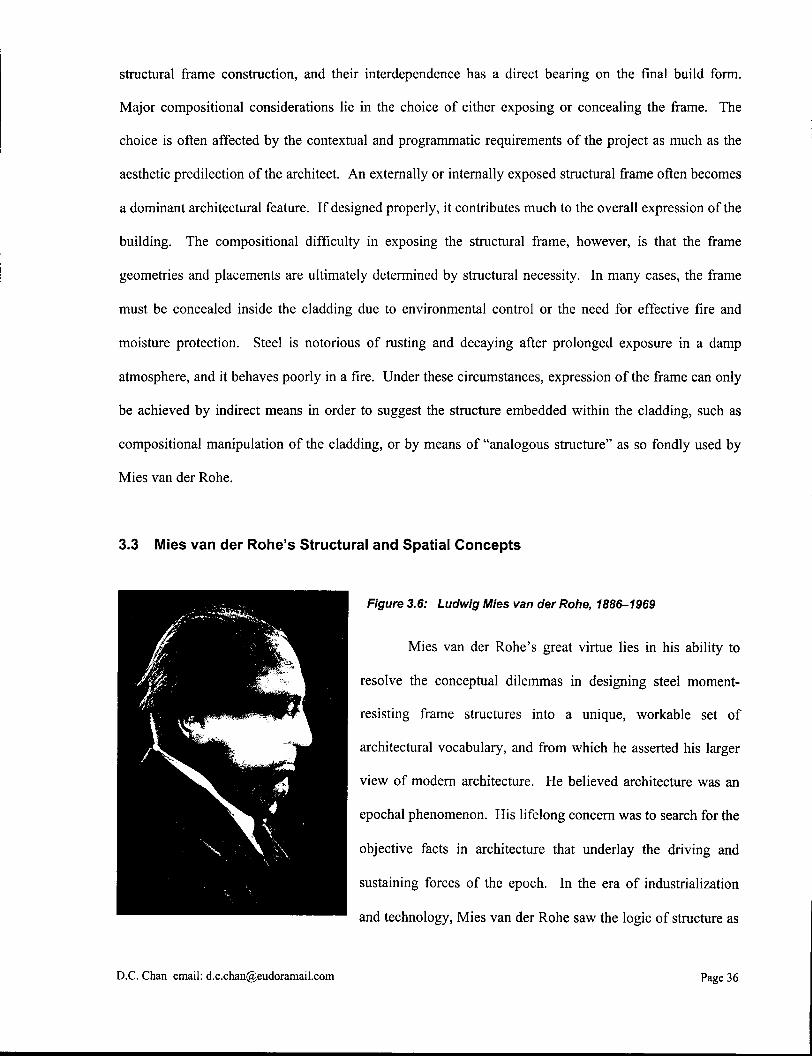
structural frame construction, and their interdependence has a direct bearing on the final build form.
Major compositional considerations lie in the choice of either exposing or concealing the frame. The
choice is often affected by the contextual and programmatic requirements of the project as much as the
aesthetic predilection of the architect. An externally or internally exposed structural frame often becomes
a dominant architectural feature. If designed properly, it contributes much to the overall expression of the
building. The compositional difficulty in exposing the structural frame, however, is that the frame
geometries and placements are ultimately determined by structural necessity. In many cases, the frame
must be concealed inside the cladding due to environmental control or the need for effective fire and
moisture protection. Steel is notorious of rusting and decaying after prolonged exposure in a damp
atmosphere, and it behaves poorly in a fire. Under these circumstances, expression of the frame can only
be achieved by indirect means in order to suggest the structure embedded within the cladding, such as
compositional manipulation of the cladding, or by means of "analogous structure" as so fondly used by
Mies van der Rohe.
3.3 Mies van der Rohe's Structural and Spatial Concepts
Figure 3.6: Ludwig Mies van der Rohe, 1886-1969
Mies van der Rohe's great virtue lies in his ability to
resolve the conceptual dilemmas in designing steel moment-
resisting frame structures into a unique, workable set of
architectural vocabulary, and from which he asserted his larger
view of modern architecture. He believed architecture was an
epochal phenomenon. His lifelong concern was to search for the
objective facts in architecture that underlay the driving and
sustaining forces of the epoch. In the era of industrialization
and technology, Mies van der Rohe saw the logic of structure as
D.C. Chan email: [email protected] Page 36

a "universally tenable concept capable of embracing the diverse functional requirements of our epoch."
Interesting enough, his design priority never seemed to be concerning the truthfulness of construction per
se. There were certainly cases in which the structure was fully exposed, as in the Crown Hall of 1952-56.
But there were also cases in which Mies van der Rohe decided, or was required, to conceal important
structural connections. For example, in many multi-storey academic buildings at Illinois Institute of
Technology, the steel skeletons were encased in concrete due to fireproofing regulations. Here he
employed a method called "analogous structure" - the concrete surround was in turn covered with an
extra veneer of steel. The visible steel became a symbolic representation of the true construction that lay
underneath.
Figure 3.7: Crown Hall, facade details, I.I.T., Mies van der Rohe, 1952-56
What is consistently displayed in Mies van der Rohe's steel
frame constructions is the use of standardized rolled steel sections as
facade elements - angles for copings, channels for fascias, I-beams for
window mullions, etc. - to form a rigorous interplay with the exposed or
analogous structure. The facade elements and any exposed structural
members are weld-jointed and grounded flush to form seamless and
invisible connections. Edward Ford in his The Details of Modern
Architecture points out that Mies van der Rohe in fact went to
extraordinary lengths to erase the marks of joining in his work.8 The usage of standardized rolled sections
is clearly a manifest of industrialization, but the idea also holds larger architectural ramifications. What
appears on the facade is a willful but systematic articulation of structural members, rationally ordered and
precisely crafted down to their cores. Because the welded joints are made invisible, the structural
7 Peter Carter, Mies van der Rohe at Work (New York: Praeger Publishers, Inc., 1974), 10.
8 Edward Ford, The Details of Modern Architecture (Cambridge: MIT Press, 1990), 267.
D.C. Chan email: [email protected] Page 37
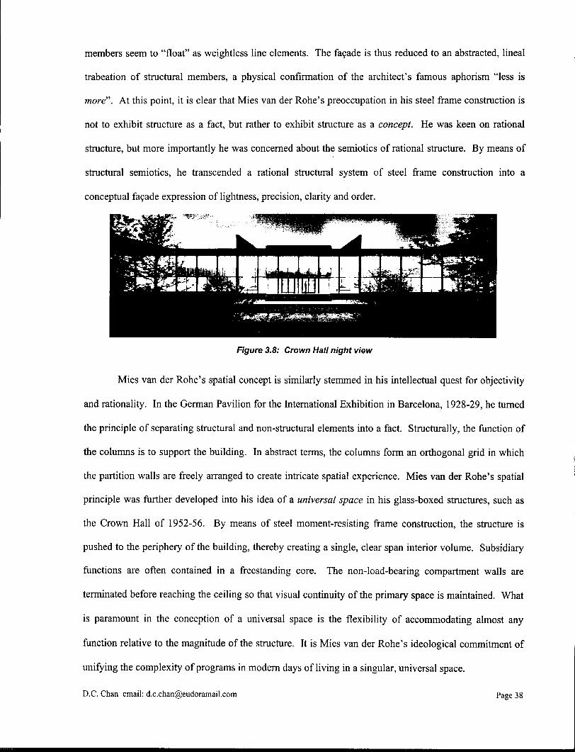
members seem to "float" as weightless line elements. The facade is thus reduced to an abstracted, lineal
trabeation of structural members, a physical confirmation of the architect's famous aphorism "less is
more". At this point, it is clear that Mies van der Rohe's preoccupation in his steel frame construction is
not to exhibit structure as a fact, but rather to exhibit structure as a concept. He was keen on rational
structure, but more importantly he was concerned about the semiotics of rational structure. By means of
structural semiotics, he transcended a rational structural system of steel frame construction into a
conceptual facade expression of lightness, precision, clarity and order.
Figure 3.8: Crown Hall night view
Mies van der Rohe's spatial concept is similarly stemmed in his intellectual quest for objectivity
and rationality. In the German Pavilion for the International Exhibition in Barcelona, 1928-29, he turned
the principle of separating structural and non-structural elements into a fact. Structurally, the function of
the columns is to support the building. In abstract terms, the columns form an orthogonal grid in which
the partition walls are freely arranged to create intricate spatial experience. Mies van der Rohe's spatial
principle was further developed into his idea of a universal space in his glass-boxed structures, such as
the Crown Hall of 1952-56. By means of steel moment-resisting frame construction, the structure is
pushed to the periphery of the building, thereby creating a single, clear span interior volume. Subsidiary
functions are often contained in a freestanding core. The non-load-bearing compartment walls are
terminated before reaching the ceiling so that visual continuity of the primary space is maintained. What
is paramount in the conception of a universal space is the flexibility of accommodating almost any
function relative to the magnitude of the structure. It is Mies van der Rohe's ideological commitment of
unifying the complexity of programs in modern days of living in a singular, universal space.
D.C. Chan email: [email protected] Page 38
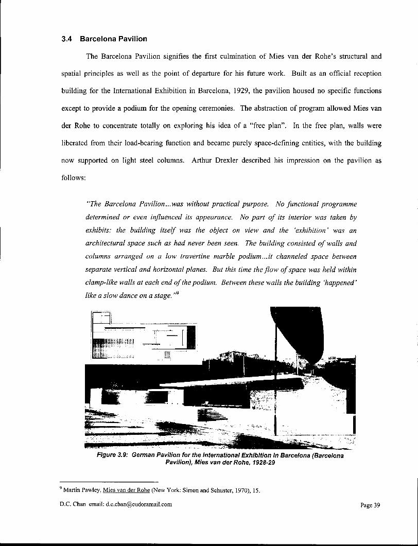
3.4 Barcelona Pavilion
The Barcelona Pavilion signifies the first culmination of Mies van der Rohe's structural and
spatial principles as well as the point of departure for his future work. Built as an official reception
building for the International Exhibition in Barcelona, 1929, the pavilion housed no specific functions
except to provide a podium for the opening ceremonies. The abstraction of program allowed Mies van
der Rohe to concentrate totally on exploring his idea of a "free plan". In the free plan, walls were
liberated from their load-bearing function and became purely space-defining entities, with the building
now supported on light steel columns. Arthur Drexler described his impression on the pavilion as
follows:
"The Barcelona Pavilion...was without practical purpose. No functional programme
determined or even influenced its appearance. No part of its interior was taken by
exhibits: the building itself was the object on view and the 'exhibition' was an
architectural space such as had never been seen. The building consisted of walls and
columns arranged on a low travertine marble podium...it channeled space between
separate vertical and horizontal planes. But this time the flow of space was held within
clamp-like walls at each end of the podium. Between these walls the building 'happened'
like a slow dance on a stage. "9
Figure 3.9: German Pavilion for the International Exhibition in Barcelona (Barcelona Pavilion), Mies van der Rohe, 1928-29
9 Martin Pawley, Mies van der Rohe (New York: Simon and Schuster, 1970), 15.
D.C. Chan email: [email protected] Page 39
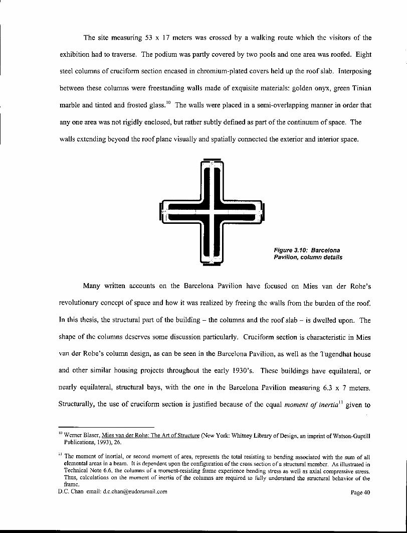
The site measuring 53 x 17 meters was crossed by a walking route which the visitors of the
exhibition had to traverse. The podium was partly covered by two pools and one area was roofed. Eight
steel columns of cruciform section encased in chromium-plated covers held up the roof slab. Interposing
between these columns were freestanding walls made of exquisite materials: golden onyx, green Tinian
marble and tinted and frosted glass.10 The walls were placed in a semi-overlapping manner in order that
any one area was not rigidly enclosed, but rather subtly defined as part of the continuum of space. The
walls extending beyond the roof plane visually and spatially connected the exterior and interior space.
Figure 3.10: Barcelona Pavilion, column details
Many written accounts on the Barcelona Pavilion have focused on Mies van der Rohe's
revolutionary concept of space and how it was realized by freeing the walls from the burden of the roof.
In this thesis, the structural part of the building - the columns and the roof slab - is dwelled upon. The
shape of the columns deserves some discussion particularly. Cruciform section is characteristic in Mies
van der Rohe's column design, as can be seen in the Barcelona Pavilion, as well as the Tugendhat house
and other similar housing projects throughout the early 1930's. These buildings have equilateral, or
nearly equilateral, structural bays, with the one in the Barcelona Pavilion measuring 6.3 x 7 meters.
Structurally, the use of cruciform section is justified because of the equal moment of inertia11 given to
1 0 Werner Blaser, Mies van der Rohe: The Art of Structure (New York: Whitney Library of Design, an imprint of Watson-Guptill Publications, 1993), 26.
1 1 The moment of inertial, or second moment of area, represents the total resisting to bending associated with the sum of all elemental areas in a beam. It is dependent upon the configuration of the cross section of a structural member. As illustrated in Technical Note 6.6, the columns of a moment-resisting frame experience bending stress as well as axial compressive stress. Thus, calculations on the moment of inertia of the columns are required to fully understand the structural behavior of the frame.
D.C. Chan email: [email protected] Page 40
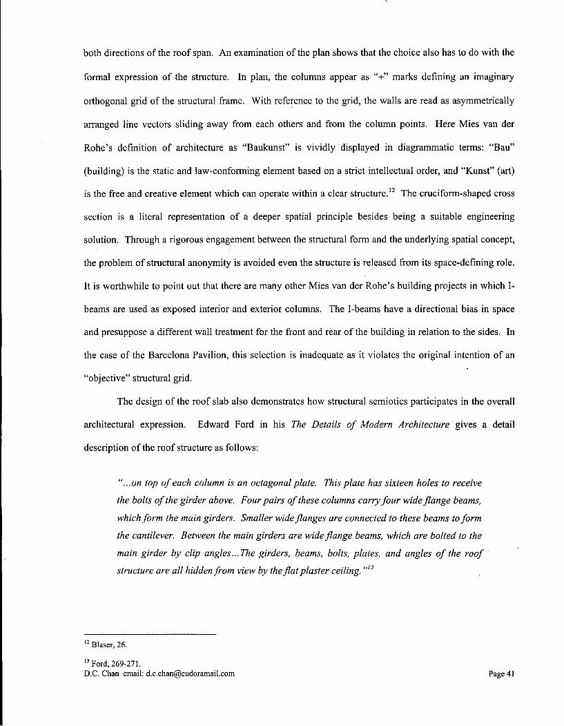
both directions of the roof span. An examination of the plan shows that the choice also has to do with the
formal expression of the structure. In plan, the columns appear as "+" marks defining an imaginary
orthogonal grid of the structural frame. With reference to the grid, the walls are read as asymmetrically
arranged line vectors sliding away from each others and from the column points. Here Mies van der
Rohe's definition of architecture as "Baukunst" is vividly displayed in diagrammatic terms: "Bau"
(building) is the static and law-conforming element based on a strict intellectual order, and "Kunst" (art)
is the free and creative element which can operate within a clear structure.12 The cruciform-shaped cross
section is a literal representation of a deeper spatial principle besides being a suitable engineering
solution. Through a rigorous engagement between the structural form and the underlying spatial concept,
the problem of structural anonymity is avoided even the structure is released from its space-defining role.
It is worthwhile to point out that there are many other Mies van der Rohe's building projects in which I-
beams are used as exposed interior and exterior columns. The I-beams have a directional bias in space
and presuppose a different wall treatment for the front and rear of the building in relation to the sides. In
the case of the Barcelona Pavilion, this selection is inadequate as it violates the original intention of an
"objective" structural grid.
The design of the roof slab also demonstrates how structural semiotics participates in the overall
architectural expression. Edward Ford in his The Details of Modern Architecture gives a detail
description of the roof structure as follows:
"...on top of each column is an octagonal plate. This plate has sixteen holes to receive
the bolts of the girder above. Four pairs of these columns carry four wide flange beams,
which form the main girders. Smaller wide flanges are connected to these beams to form
the cantilever. Between the main girders are wide flange beams, which are bolted to the
main girder by clip angles...The girders, beams, bolts, plates, and angles of the roof
structure are all hidden from view by the flat plaster ceiling. "'3
1 2 Blaser, 26.
1 3 Ford, 269-271. D.C. Chan email: [email protected] Page 41
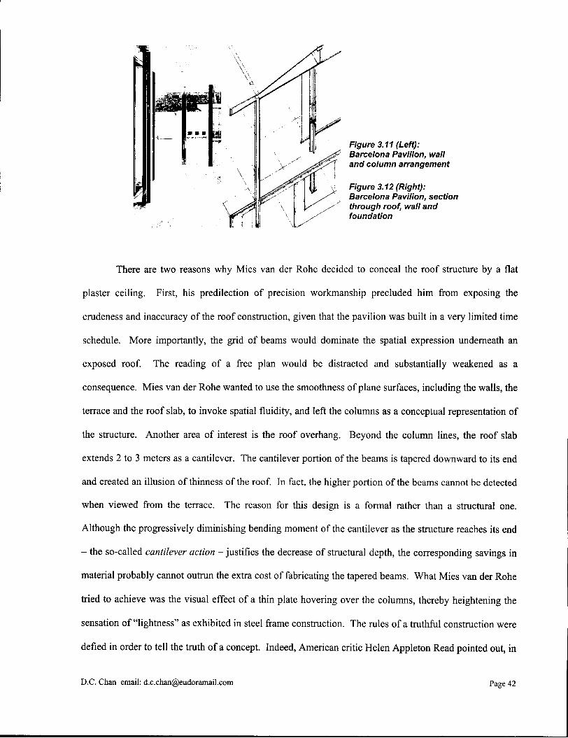
Figure 3.11 (Left): Barcelona Pavilion, wall
1 and column arrangement
Figure 3.12 (Right): Barcelona Pavilion, section through roof, wall and foundation
There are two reasons why Mies van der Rohe decided to conceal the roof structure by a flat
plaster ceiling. First, his predilection of precision workmanship precluded him from exposing the
crudeness and inaccuracy of the roof construction, given that the pavilion was built in a very limited time
schedule. More importantly, the grid of beams would dominate the spatial expression underneath an
exposed roof. The reading of a free plan would be distracted and substantially weakened as a
consequence. Mies van der Rohe wanted to use the smoothness of plane surfaces, including the walls, the
terrace and the roof slab, to invoke spatial fluidity, and left the columns as a conceptual representation of
the structure. Another area of interest is the roof overhang. Beyond the column lines, the roof slab
extends 2 to 3 meters as a cantilever. The cantilever portion of the beams is tapered downward to its end
and created an illusion of thinness of the roof. In fact, the higher portion of the beams cannot be detected
when viewed from the terrace. The reason for this design is a formal rather than a structural one.
Although the progressively diminishing bending moment of the cantilever as the structure reaches its end
- the so-called cantilever action - justifies the decrease of structural depth, the corresponding savings in
material probably cannot outrun the extra cost of fabricating the tapered beams. What Mies van der Rohe
tried to achieve was the visual effect of a thin plate hovering over the columns, thereby heightening the
sensation of "lightness" as exhibited in steel frame construction. The rules of a truthful construction were
defied in order to tell the truth of a concept. Indeed, American critic Helen Appleton Read pointed out, in
D.C. Chan email: [email protected] Page 42
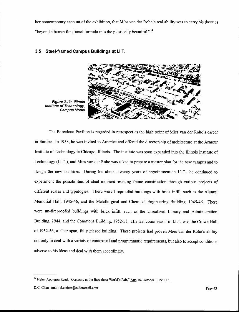
her contemporary account of the exhibition, that Mies van der Rohe's real ability was to carry his theories
"beyond a barren functional formula into the plastically beautiful."14
3.5 Steel-framed Campus Buildings at LIT.
The Barcelona Pavilion is regarded in retrospect as the high point of Mies van der Rohe's career
in Europe. In 1938, he was invited to America and offered the directorship of architecture at the Armour
Institute of Technology in Chicago, Illinois. The institute was soon expanded into the Illinois Institute of
Technology (LIT.), and Mies van der Rohe was asked to prepare a master plan for the new campus and to
design the new facilities. During his almost twenty years of appointment in LIT. , he continued to
experiment the possibilities of steel moment-resisting frame construction through various projects of
different scales and typologies. There were fireproofed buildings with brick infill, such as the Alumni
Memorial Hall, 1945-46, and the Metallurgical and Chemical Engineering Building, 1945-46. There
were un-fireproofed buildings with brick infill, such as the unrealized Library and Administration
Building, 1944, and the Commons Building, 1952-53. His last commission in L I T . was the Crown Hall
of 1952-56, a clear span, fully glazed building. These projects had proven Mies van der Rohe's ability
not only to deal with a variety of contextual and programmatic requirements, but also to accept conditions
adverse to his ideas and deal with them accordingly.
1 4 Helen Apple ton Read, "Germany at the Barcelona W o r l d ' s Fa i r , " Arts 16, October 1929: 113.
D . C . Chan email : [email protected] Page 43

The I.I.T. campus was constructed on a 24-foot gird to which all the elements of the project were
conformed. Low-rise, rectilinear building blocks made of matt-black welded structural sections, large
glazing and buff-colored brick infill formed a coherent architectural language throughout the campus as
well as a harmonious whole with the residential neighborhood. These campus buildings were built using
modular steel moment-resisting frame construction. The structural system allows flexibility in
accommodating different functional uses, such as classrooms, laboratories and offices. Repetitive module
is also economical and efficient in terms of construction, given, at the time, the material shortages and
limitations resulted from United States' entry into World War II. Greater spans are usually more
economically feasible in low-rise buildings than in high-rises because the accumulative weight from
higher storeys is not severe. Thus, each column can be responsible for a larger tributary area of gravity
loads. This is particularly advantageous in campus building construction due to the different types of
occupancy and uses within a single building, thus a need of flexible, open space.
3.5.1 Fireproofed Construction
Figure 3.14: Metallurgical and Chemical Engineering Building,
I.I.T., Mies van der Rohe, 1945-46
The Chicago fire codes require multi-storey steel frame construction to be fireproofed. This is the
case for the Alumni Memorial Hall and the Metallurgical and Chemical Engineering Building, 1945-46,
in which the load-bearing steel H-columns are encased in a layer of reinforced concrete. In order to
maintain a uniform architectural language of steel frame construction throughout, an I-beam is affixed to
D.C. Chan email: [email protected] Page 44

the outside of each concrete column. Brick infill panels are then inserted in between the I-beams to form
a continuous facade, thereby hiding the concrete columns behind. As a comparison, the brick infill could
have been positioned in between the concrete columns to form an equally functional enclosure, but the
architectural expression of a steel structure would be lost entirely. To reassert the non-structural nature of
the surface steel, the I-beams are terminated at the bottom on a brick plinth several courses high rather
than rooted into the foundation. Another surface articulation worth noting is the juncture between the
brick infill panels and the I-beams. The brick face is flush with the outer flanges of the I-beams except at
the juncture, where the brick is recessed to form a subtle shadow line. This articulation possesses an
almost metaphysical implication as if the brick infill panels are "clipped" in between the flanges of the I-
beams. Indeed, each side of the panels is secured to a hidden T-section, which in turn is stitch-welded
onto the webs of the I-beams. Structurally, the connection further stiffens the column as well as allows
some lateral loads to be transferred from the steel frame to the brick infill panels.
~ '
T 1 ! r* • I r> IS
] T T " f j r i P T
y. . • t < I | -* i; : t
1 1 1 1 ; . , ,; , i
„.f r„n ,
> , } • r 7 _
'
Figure 3.15 (Left): Alumni Memorial Hall, I.I.T., fagade details, Mies van der Rohe, 1945-46
Figure 3.16 (Right): Alumni Memorial Hall, I.I.T., fagade details, plan
At the corners of the buildings, the I-beams can be seen in full revelation. Here the in-coming
brick infill panels are terminated, and the recessed coiner of the concrete column is re-covered by a steel
D.C. Chan email: [email protected] Page 45

angle which set behind the inner flanges of the two corner I-beams. The top of the brick plinth, which
would otherwise be exposed due to the discontinuity of the infill, is overlaid with a steel plate. All
surface steel, including the I-beams, the angle and the plate, are weld-jointed, grounded smooth and then
painted matt-black. The result is an intricate corner detail that cuts into the wall planes and thus reveals
the essential components of the skin and skeleton construction - the I-beams define the cladding while the
steel angle hints the structural column. An otherwise complicate and awkward corner assembly is
resolved aesthetically into an abstraction of lines that runs the whole height of the building. Because the
two I-beams affixed to the corner column are perpendicular to each other, the horizontal projection of
their webs intersects somewhere inside the column. The point of intersection defines exactly the centroid
of the concealed H-column, which in turn marks the structural grid of the entire building, and further
reinstates the orthogonal organization of the whole campus - a "part" implies the "whole". Thus,
although the grid is not a physical entity that can be seen, it can be felt right from the precise alignment of
the comer detail. This shows the extremes to which Mies van der Rohe took his pursuit of precision, and
in doing so turned the inevitable technical intricacy of skin and skeleton construction into a level of poetic
expression.
D.C. Chan email: [email protected] Page 46
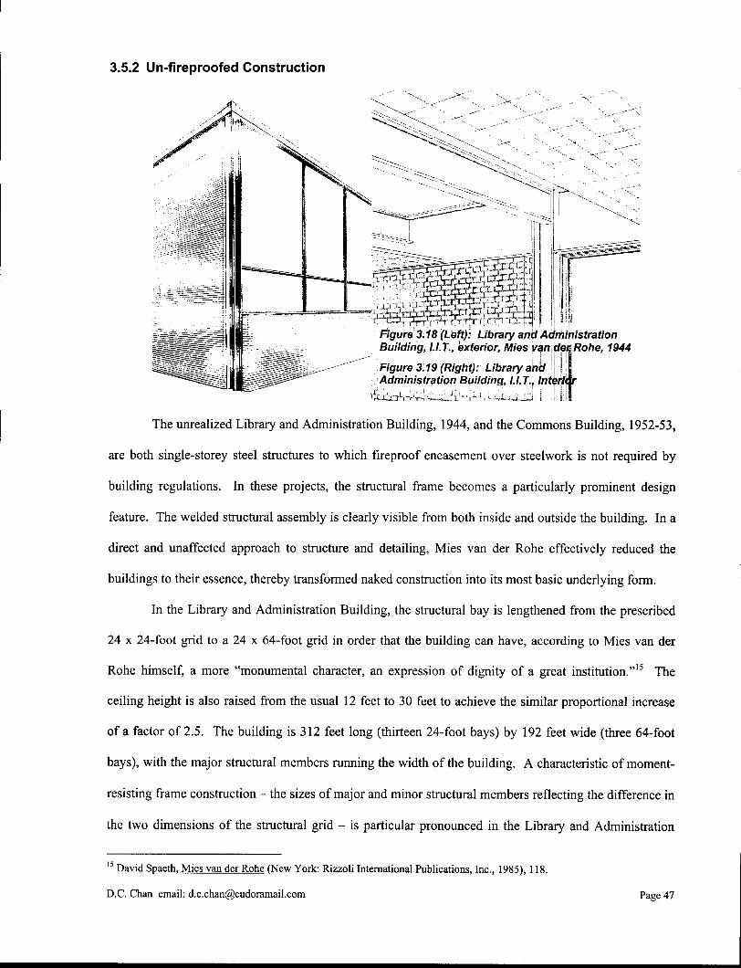
3.5.2 Un-fireproofed Construction
Figure 3.18 (Left): Library and Administration Building, I.I.T., exterior, Mies van der Rohe, 1944
Figure 3.19 (Right): Library and Administration Building, I.I.T., Interior
The unrealized Library and Administration Building, 1944, and the Commons Building, 1952-53,
are both single-storey steel structures to which fireproof encasement over steelwork is not required by
building regulations. In these projects, the structural frame becomes a particularly prominent design
feature. The welded structural assembly is clearly visible from both inside and outside the building. In a
direct and unaffected approach to structure and detailing, Mies van der Rohe effectively reduced the
buildings to their essence, thereby transformed naked construction into its most basic underlying form.
In the Library and Administration Building, the structural bay is lengthened from the prescribed
24 x 24-foot grid to a 24 x 64-foot grid in order that the building can have, according to Mies van der
Rohe himself, a more "monumental character, an expression of dignity of a great institution."15 The
ceiling height is also raised from the usual 12 feet to 30 feet to achieve the similar proportional increase
of a factor of 2.5. The building is 312 feet long (thirteen 24-foot bays) by 192 feet wide (three 64-foot
bays), with the major structural members running the width of the building. A characteristic of moment-
resisting frame construction - the sizes of major and minor structural members reflecting the difference in
the two dimensions of the structural grid - is particular pronounced in the Library and Administration
1 5 David Spaeth, Mies van der Rohe (New York: Rizzoli International Publications, Inc., 1985), 118.
D.C. Chan email: [email protected] Page 47
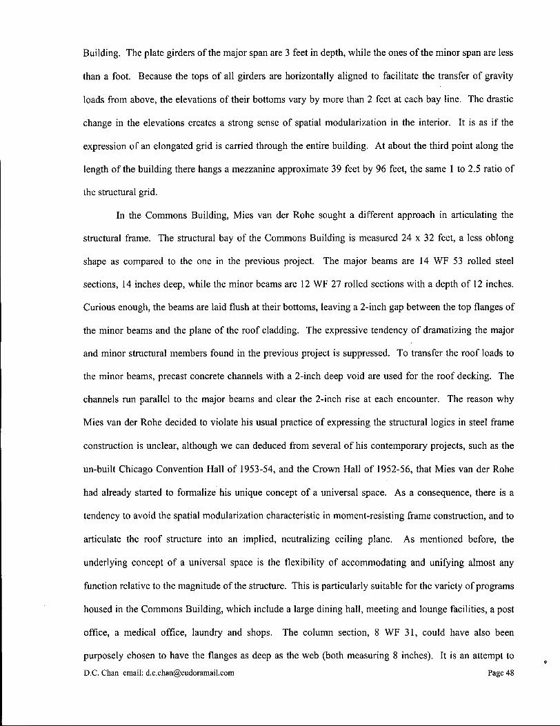
Building. The plate girders of the major span are 3 feet in depth, while the ones of the minor span are less
than a foot. Because the tops of all girders are horizontally aligned to facilitate the transfer of gravity
loads from above, the elevations of their bottoms vary by more than 2 feet at each bay line. The drastic
change in the elevations creates a strong sense of spatial modularization in the interior. It is as if the
expression of an elongated grid is carried through the entire building. At about the third point along the
length of the building there hangs a mezzanine approximate 39 feet by 96 feet, the same 1 to 2.5 ratio of
the structural grid.
In the Commons Building, Mies van der Rohe sought a different approach in articulating the
structural frame. The structural bay of the Commons Building is measured 24 x 32 feet, a less oblong
shape as compared to the one in the previous project. The major beams are 14 WF 53 rolled steel
sections, 14 inches deep, while the minor beams are 12 WF 27 rolled sections with a depth of 12 inches.
Curious enough, the beams are laid flush at their bottoms, leaving a 2-inch gap between the top flanges of
the minor beams and the plane of the roof cladding. The expressive tendency of dramatizing the major
and minor structural members found in the previous project is suppressed. To transfer the roof loads to
the minor beams, precast concrete channels with a 2-inch deep void are used for the roof decking. The
channels run parallel to the major beams and clear the 2-inch rise at each encounter. The reason why
Mies van der Rohe decided to violate his usual practice of expressing the structural logics in steel frame
construction is unclear, although we can deduced from several of his contemporary projects, such as the
un-built Chicago Convention Hall of 1953-54, and the Crown Hall of 1952-56, that Mies van der Rohe
had already started to formalize his unique concept of a universal space. As a consequence, there is a
tendency to avoid the spatial modularization characteristic in moment-resisting frame construction, and to
articulate the roof structure into an implied, neutralizing ceiling plane. As mentioned before, the
underlying concept of a universal space is the flexibility of accommodating and unifying almost any
function relative to the magnitude of the structure. This is particularly suitable for the variety of programs
housed in the Commons Building, which include a large dining hall, meeting and lounge facilities, a post
office, a medical office, laundry and shops. The column section, 8 WF 31, could have also been
purposely chosen to have the flanges as deep as the web (both measuring 8 inches). It is an attempt to
D.C. Chan email: [email protected] Page 48

suppress the dominant visual orientation of an I-section in the direction of its web, without sacrificing the
more superior bending stiffness required in that direction for structural reasons.
Figure 3.20: Commons Building, I.I.T., Interior, Mies van der Rohe, 1952-53
3.6 Crown Hall
Perhaps the finest achievement of all steel-framed campus buildings at I.I.T. is the Crown Hall.
Being the building for the Department of Architecture, City and Regional Planning and also houses the
Institute of Design, the Crown Hall represents the crystallization of Mies van der Rohe's ideology of a
vast, uninterrupted universal space. The building consists of a 220 feet long, 120 feet wide and 18 feet
high column-free "glass box", in which the space is partially subdivided by free-standing partition walls
of only 8 feet high into student working areas on the sides and a small administrative office in the center.
With the two slender service shafts that extend from floor to ceiling, the space is virtually continuous.
The very openness of the interior space reflects Mies van der Rohe's own thinking on the principles of
architectural education: a subject of lively exchange among the faculty and students. It is a place where
open-mindedness and objectivity are encouraged, and where individual student works are cross-fertilized
in a way that is beneficial to students at all levels.
D.C. Chan email: [email protected] Page 4 9
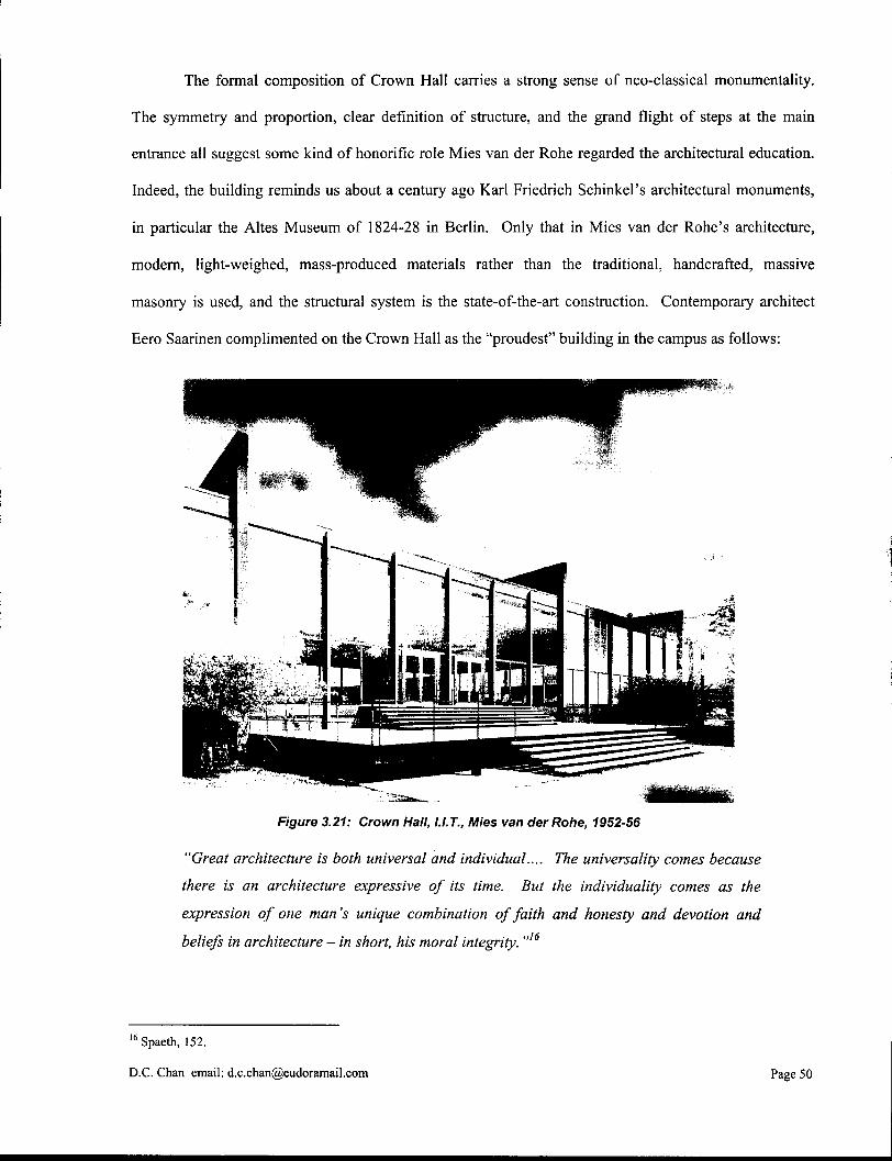
The formal composition of Crown Hall carries a strong sense of neo-classical monumentality.
The symmetry and proportion, clear definition of structure, and the grand flight of steps at the main
entrance all suggest some kind of honorific role Mies van der Rohe regarded the architectural education.
Indeed, the building reminds us about a century ago Karl Friedrich Schinkel's architectural monuments,
in particular the Altes Museum of 1824-28 in Berlin. Only that in Mies van der Rohe's architecture,
modern, light-weighed, mass-produced materials rather than the traditional, handcrafted, massive
masonry is used, and the structural system is the state-of-the-art construction. Contemporary architect
Eero Saarinen complimented on the Crown Hall as the "proudest" building in the campus as follows:
Figure 3.21: Crown Hall, I.I.T., Mies van der Rohe, 1952-56
"Great architecture is both universal and individual.... The universality comes because
there is an architecture expressive of its time. But the individuality comes as the
expression of one man's unique combination of faith and honesty and devotion and
beliefs in architecture - in short, his moral integrity. "'6
1 6 Spaeth, 152.
D.C. Chan email: [email protected] Page 50
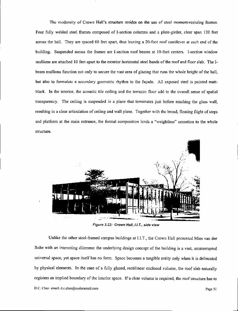
The modernity of Crown Hall's structure resides on the use of steel moment-resisting frames.
Four fully welded steel frames composed of I-section columns and a plate-girder, clear span 120 feet
across the hall. They are spaced 60 feet apart, thus leaving a 20-foot roof cantilever at each end of the
building. Suspended across the frames are I-section roof beams at 10-foot centers. I-section window
mullions are attached 10 feet apart to the exterior horizontal steel bands of the roof and floor slab. The I-
beam mullions function not only to secure the vast area of glazing that runs the whole height of the hall,
but also to formulate a secondary geometric rhythm to the facade. All exposed steel is painted matt-
black. In the interior, the acoustic tile ceiling and the terrazzo floor add to the overall sense of spatial
transparency. The ceiling is suspended in a plane that terminates just before reaching the glass wall,
resulting in a clear articulation of ceiling and wall plane. Together with the broad, floating flight of steps
and platform at the main entrance, the formal composition lends a "weightless" sensation to the whole
structure.
Figure 3.22: Crown Hall, I.I.T., side view
Unlike the other steel-framed campus buildings at I.I.T., the Crown Hall presented Mies van der
Rohe with an interesting dilemma: the underlying design concept of the building is a vast, uninterrupted
universal space, yet space itself has no form. Space becomes a tangible entity only when it is delineated
by physical elements. In the case of a fully glazed, rectilinear enclosed volume, the roof slab naturally
registers an implied boundary of the interior space. If a clear volume is required, the roof structure has to
D.C.Chan email: [email protected] Page 51

be thickened in order to resist the increased bending moment of a larger span, and at some point the roof
becomes a significant formal element both physically and visually. It is obviously Mies van der Rohe's
desire to avoid a heavy roof that compromises the lightness and transparency of the steel structure. The
employment of welded steel moment-resisting frames not only provides a workable engineering solution
to the problem of spanning large distance, but also allows his structural and spatial concepts to unfold.
Each moment-resisting frame is made of a 6-foot 3-inch deep plate girder, whose flanges gradually
increase in width from their ends to midspan to account for the changes in bending moment. To prevent
lateral buckling of the plate girder when it is subjected to a concentrated load, stiffeners are welded to the
web of the plate girder at the connection points to the roof beams. The frames are left exposed on the top
of the roof rather than being absorbed into its thickness, and they become a pronounced design feature of
the building. Their prominence is comparable to those of classical motifs like the Doric columns of a
Greek temple. In fact, by dissolving the roof thickness, the building becomes essentially a floating
volume of space that is held in place solely by four slender steel frames. These frames are in turn
compressed to the periphery by the glass box and blended with the skin of the building. In the Crown
Hall, the structure integrates with the space and skin into a unified entity.
Figure 3.23 (Left): Crown Hall, I.I.T., under construction
Figure 3.24 (Right): Crown Hall, I.I.T., interior looking towards the back
D.C. Chan email: [email protected] Page 52
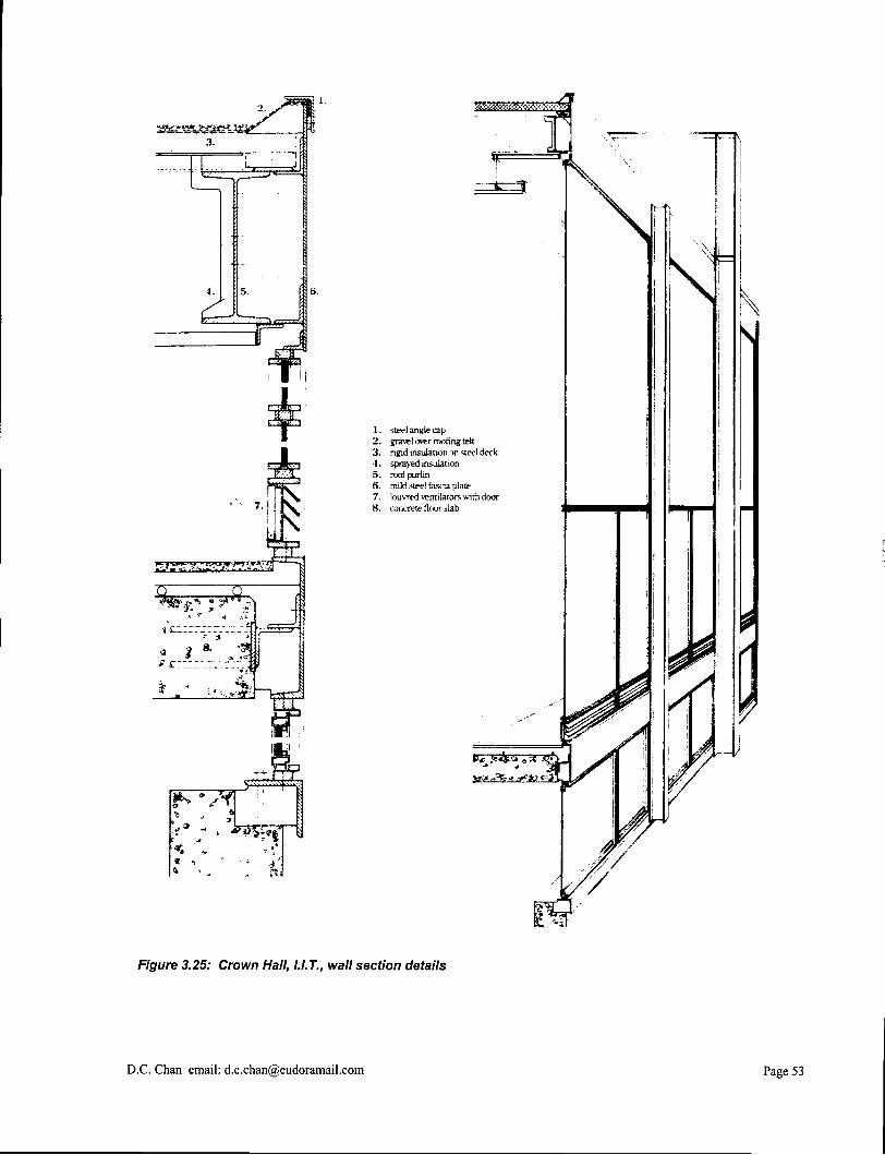
1. steel angle cap 2. £ra\̂ l over rooting lelt 3. rigid insulation on steel deck 4. sprayed insulat ion 5. roof purlin 6. mild stee! fascia plate 7. buvred ventilators with door 8. concrete floor slab
Figure 3.25: Crown Hail, U.T., wall section details
D . C . Chan email: [email protected]
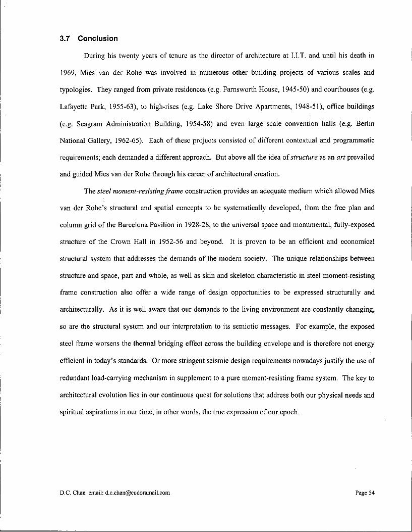
3.7 Conclusion
During his twenty years of tenure as the director of architecture at I.I.T. and until his death in
1969, Mies van der Rohe was involved in numerous other building projects of various scales and
typologies. They ranged from private residences (e.g. Farnsworth House, 1945-50) and courthouses (e.g.
Lafayette Park, 1955-63), to high-rises (e.g. Lake Shore Drive Apartments, 1948-51), office buildings
(e.g. Seagram Administration Building, 1954-58) and even large scale convention halls (e.g. Berlin
National Gallery, 1962-65). Each of these projects consisted of different contextual and programmatic
requirements; each demanded a different approach. But above all the idea of structure as an art prevailed
and guided Mies van der Rohe through his career of architectural creation.
The steel moment-resisting frame construction provides an adequate medium which allowed Mies
van der Rohe's structural and spatial concepts to be systematically developed, from the free plan and
column grid of the Barcelona Pavilion in 1928-28, to the universal space and monumental, fully-exposed
structure of the Crown Hall in 1952-56 and beyond. It is proven to be an efficient and economical
structural system that addresses the demands of the modem society. The unique relationships between
structure and space, part and whole, as well as skin and skeleton characteristic in steel moment-resisting
frame construction also offer a wide range of design opportunities to be expressed structurally and
architecturally. As it is well aware that our demands to the living environment are constantly changing,
so are the structural system and our interpretation to its semiotic messages. For example, the exposed
steel frame worsens the thermal bridging effect across the building envelope and is therefore not energy
efficient in today's standards. Or more stringent seismic design requirements nowadays justify the use of
redundant load-carrying mechanism in supplement to a pure moment-resisting frame system. The key to
architectural evolution lies in our continuous quest for solutions that address both our physical needs and
spiritual aspirations in our time, in other words, the true expression of our epoch.
D.C. Chan email: [email protected] Page 54
4.0 Two-Way Reinforced Concrete Slab System and Le Corbusier's Ideas of Modernism
Two-way slab system is characterized by a multidirectional dispersal of gravity loads across the
slab into the peripheral supports. It is different from the one-way system, such as those made of three-
hinged truss arches or moment-resisting steel frames, in which loads are transferred along a hierarchy of
linear structural members orthogonally arranged to span a floor area. The advent of modern reinforced
concrete construction in the late nineteenth century has made the two-way slab system among the most
common of all building systems, especially for those with structural bays of low to medium span ranges.
Concrete is a fireproof material and offers excellent sound insulation against airborne noise. It can easily
be moulded to virtually any shape during its initial plastic state. Structurally, concrete has a strong
compressive strength but behaves poorly in tension and shear. With the embedment of steel
reinforcement, however, the deficiencies in tension and shear is overcome, and the composite material
becomes capable of spanning horizontal distances as well as negotiating vertical heights. The appropriate
placement and bending of reinforcing steel, together with the moldable nature of concrete, allow slabs,
beams and columns to be continuously cast into one monolithic structural unit. The otherwise discrete
structural members characteristic in other types of frame construction can therefore work together as an
entity in reinforced concrete frame construction that distributes the loads and stresses of one part to all the
others and in all directions.
Given the many unique advantages of reinforced concrete, pioneers of the Modernist movement
at the turn of the twentieth century were urged to develop a suitable architectural vocabulary for the new
material. Some designers regarded its malleable character made it the ideal medium for Art Nouveau
expression, such as the roof structure of Auscher's Felix Potin Store in the rue de Rennes, 1904.1 Perhaps
the more influential undertakings involved the exploration of the structural potentials of reinforced
concrete frame construction together with its aesthetic implications. This was particularly so in the area
of monolithic two-way slab construction. Some of the early attempts included Francois Hennebique's
' Peter Collins, Concrete: The Vision of A New Architecture (London: Faber and Faber Limited, 1959), 180.
D.C. Chan email: [email protected] Page 55
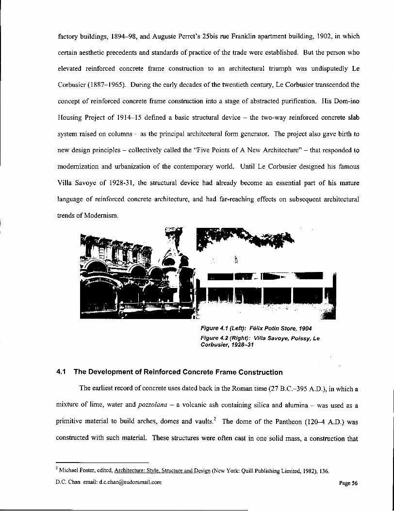
factory buildings, 1894-98, and Auguste Perret's 25bis rue Franklin apartment building, 1902, in which
certain aesthetic precedents and standards of practice of the trade were established. But the person who
elevated reinforced concrete frame construction to an architectural triumph was undisputedly Le
Corbusier (1887-1965). During the early decades of the twentieth century, Le Corbusier transcended the
concept of reinforced concrete frame construction into a stage of abstracted purification. His Dom-ino
Housing Project of 1914-15 defined a basic structural device - the two-way reinforced concrete slab
system raised on columns - as the principal architectural form generator. The project also gave birth to
new design principles - collectively called the "Five Points of A New Architecture" - that responded to
modernization and urbanization of the contemporary world. Until Le Corbusier designed his famous
Villa Savoye of 1928-31, the structural device had already become an essential part of his mature
language of reinforced concrete architecture, and had far-reaching effects on subsequent architectural
trends of Modernism.
Figure 4.1 (Left): Felix Potin Store, 1904
Figure 4.2 (Right): Villa Savoye, Poissy, Le Corbusier, 1928-31
4.1 The Development of Reinforced Concrete Frame Construction
The earliest record of concrete uses dated back in the Roman time (27 B.C.-395 A.D.), in which a
mixture of lime, water and pozzolana - a volcanic ash containing silica and alumina - was used as a
primitive material to build arches, domes and vaults.2 The dome of the Pantheon (120-4 A.D.) was
constructed with such material. These structures were often cast in one solid mass, a construction that
2 Michael Foster, edited, Architecture: Style. Structure and Design (New York: Quill Publishing Limited, 1982), 136.
D.C. Chan email: [email protected] Page 56

was fundamentally different from the un-mortared, post-and-beam methods of the Greeks. With the
decline of the Roman Empire, concrete quickly dropped out of use, only to reappear again after the
Industrial Revolution in the late eighteenth century when the search for economical building methods
became particularly intensive. In 1824, English brick-layer Joseph Aspdin patented an artificial cement
that he named "portland cement", because its color was similar to the Portland limestone quarried off the
English coast. Portland cement as a commercial product was grinded into a fine powder, but once reacted
with water and bound with aggregates, it was transformed into a building stone whose hardness and
durability was extraordinary. The product soon became extensively available in the building industry and
its popularity remains to the present day.
During the early years after its development, portland cement was restrictively used in stuccos,
infill materials, fireproof casting, and at most load-bearing walls due to its lack of tensile strength.
Although iron rods or strips had long been used in masonry practice to increase the bonding strength of
the material, limited understanding on the rational theories of structural design precluded any further
enlargement upon the scope of reinforced concrete construction. The embedment of iron rods was often
distrusted because any rusting could not be detected once the rods were covered up, or else some hidden
structural weaknesses would develop. Cast-in-place concrete construction was also particularly
vulnerable to faulty workmanship and inadequate mix ingredients. From an aesthetic point of view, the
rough, mottled, honeycombed appearance of the untreated concrete surface at the time (unlike the highly
D.C. Chan email: [email protected] Page 57
Figure 4.3: Pantheon, Rome, 120-4 A.D., Sections
compact, smooth surface that we have seen nowadays) hardly looked appealing to contemporary
architects and clients. Prejudices against concrete as a cheap and primitive material also caused
reluctance of exposing it in its natural state. Nevertheless, the cheapness and fireproofing quality of the
material were undisputedly proven advantageous in many types of building projects, including housing
and theatres, that these qualities alone had encouraged a continuous exploration of the structural and
architectural possibilities of reinforced concrete construction.
The technological breakthrough for reinforced concrete construction occurred during the 1870s
and 80s, and was attributed to a number of American and European inventors. William E. Ward in 1871—
72 conducted experiments on the structural properties of reinforced concrete beams, including their
deflection, shear strength and fire resistance. He concluded, with scientific precision, that the iron should
be placed near the bottom of the beam "to utilize its tensile quality for resisting the strain below the
neutral axis".3 In 1877, Thaddeus Hyatt conducted testing on fifty beams of various weights and
reinforcement combinations. His experimental results added significantly to the understanding of
reinforced concrete design. Ernest L. Ransome in San Francisco started constructing reinforced concrete
structures in the early 1870s. He also originated the deformed bars, for which he received a patent in
1884. Squared cross-section steel bars were cold-twisted at regular intervals to prevent from losing their
grip to the concrete.4 Ransome's another important contribution to the reinforced concrete construction
was his Leland Stanford Junior Museum of Stanford University in California, 1889-91, in which the
entire wall and floor construction was made of reinforced concrete, and concrete tiles on iron trusses were
used on the roof. The concrete was exposed in the exterior and was tool-dressed to show the texture of
the aggregate. Peter Collins stated the significance of this as follows:
"he [Ransome] set a precedent for treating concrete as possessing a natural nobility of
its own, instead of regarding it as a cheap infilling or backing to which a fair surface
must be subsequently applied. For the first time in the history of architecture, concrete
was considered to be the concern of skilled craftsmen, and capable of displaying an
inherent beauty. "5
3 Collins, 57.
4 Jack C. McCormac, Design of Reinforced Concrete. 3 r d ed. (New York: HarperCollins College Publishers, 1993), 5.
D.C. Chan email: [email protected] Page 58
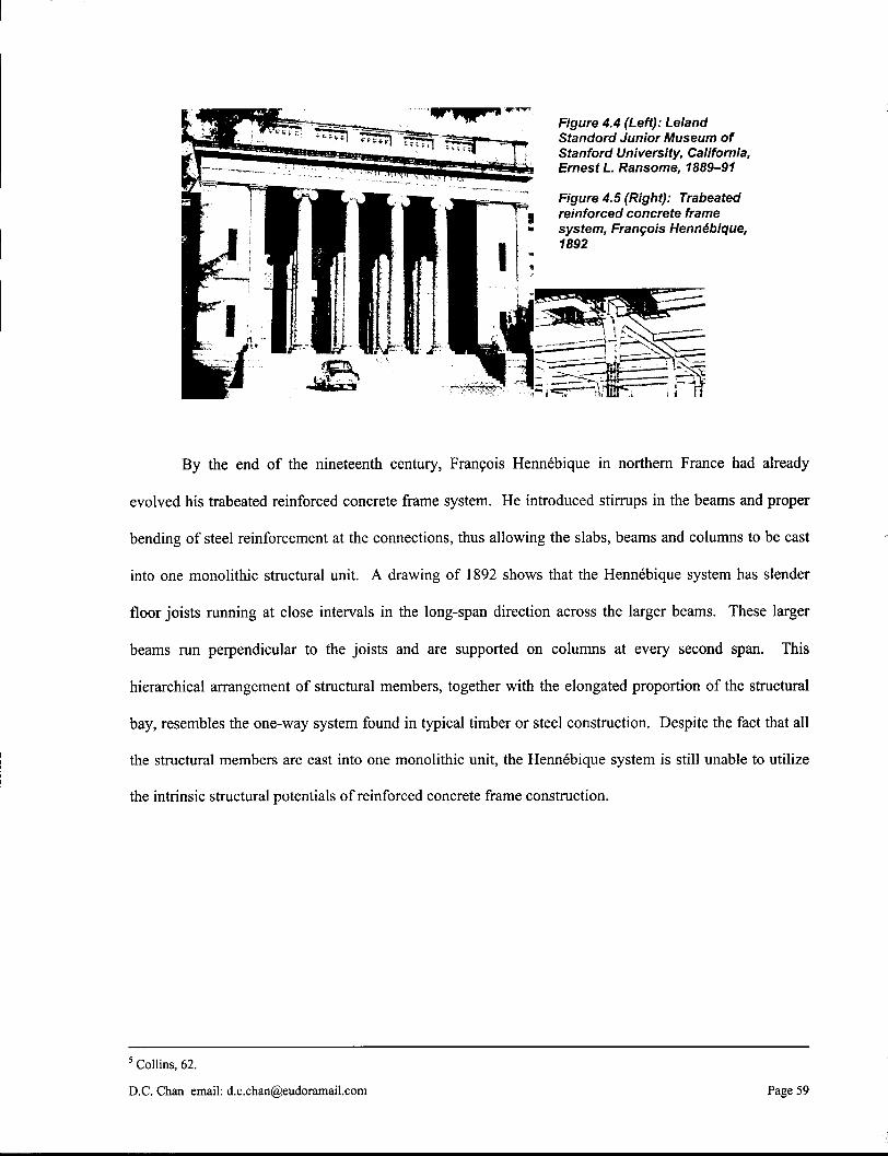
By the end of the nineteenth century, Francois Hennebique in northern France had already
evolved his trabeated reinforced concrete frame system. He introduced stirrups in the beams and proper
bending of steel reinforcement at the connections, thus allowing the slabs, beams and columns to be cast
into one monolithic structural unit. A drawing of 1892 shows that the Hennebique system has slender
floor joists running at close intervals in the long-span direction across the larger beams. These larger
beams run perpendicular to the joists and are supported on columns at every second span. This
hierarchical arrangement of structural members, together with the elongated proportion of the structural
bay, resembles the one-way system found in typical timber or steel construction. Despite the fact that all
the structural members are cast into one monolithic unit, the Hennebique system is still unable to utilize
the intrinsic structural potentials of reinforced concrete frame construction.
5 Collins, 62.
D.C. Chan email: [email protected] Page 59
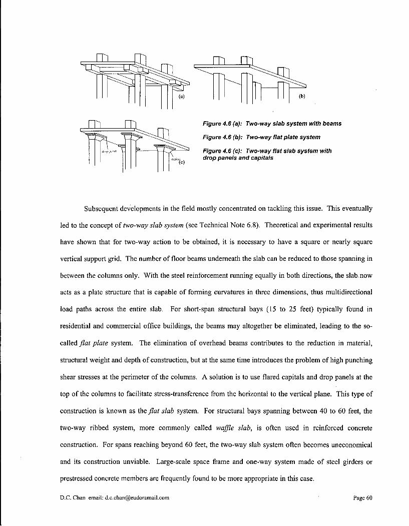
Subsequent developments in the field mostly concentrated on tackling this issue. This eventually
led to the concept of two-way slab system (see Technical Note 6.8). Theoretical and experimental results
have shown that for two-way action to be obtained, it is necessary to have a square or nearly square
vertical support grid. The number of floor beams underneath the slab can be reduced to those spanning in
between the columns only. With the steel reinforcement running equally in both directions, the slab now
acts as a plate structure that is capable of forming curvatures in three dimensions, thus multidirectional
load paths across the entire slab. For short-span structural bays (15 to 25 feet) typically found in
residential and commercial office buildings, the beams may altogether be eliminated, leading to the so-
called flat plate system. The elimination of overhead beams contributes to the reduction in material,
structural weight and depth of construction, but at the same time introduces the problem of high punching
shear stresses at the perimeter of the columns. A solution is to use flared capitals and drop panels at the
top of the columns to facilitate stress-transference from the horizontal to the vertical plane. This type of
construction is known as the flat slab system. For structural bays spanning between 40 to 60 feet, the
two-way ribbed system, more commonly called waffle slab, is often used in reinforced concrete
construction. For spans reaching beyond 60 feet, the two-way slab system often becomes uneconomical
and its construction unviable. Large-scale space frame and one-way system made of steel girders or
prestressed concrete members are frequently found to be more appropriate in this case.
D.C. Chan email: [email protected] Page 60

Figure 4.7: Two-way ribbed system or waffle slab
4.2 25bis Rue Franklin Apartment Building
While researches on the engineering of reinforced concrete frame construction were undergoing
rapid improvement, contemporary architects were busy establishing an aesthetic expression for the new
type of structure. In a number of mill constructions, Hennebique demonstrated how his trabeated,
rectangular frame system could be expressed visibly on the face of a building. A new kind of proportion
was created between the slender supports and the large openings, which in many cases were fdled entirely
with sheets of glass to maximize sunlight penetration. Hennebique's straightforward solution, however
revolutionary at the time, was largely a response to the most compelling utilitarian requirements. There
was still much to be achieved in terms of turning a mere construction into architecture. Strictly speaking
then, Hennebique's contribution to the trade was confined to its engineering, even though his factories
indeed established certain aesthetic precedents and standards of practice.
The person who broke new ground in making an architectural statement for reinforced concrete
frame construction was Auguste Perret (1874-1954). Trained in the classical school of Ecole des Beaux
Arts, Perret was no less influenced by Viollet-le-Duc's revolutionary ideas of structural integrity as well
as his own practical work experience in his father's construction firm since early age. Thus his work
repeatedly exhibited a sensibility to fundamental classical principles, with equal emphasis on rationality
and pragmatism. One of his finest creations was the apartment building at 25bis rue Franklin in Paris,
1902. Still exists, the building stands in a narrow lot in a surrounding gray stone neighborhood, with fine
D.C. Chan email: [email protected] Page 61

views down towards River Seine and the Eiffel Tower in the distance.6 To maximize views and sunlight
penetration in the narrow lot, large window openings are extended full-height at each storey, a move that
necessitates the employment of reinforced concrete frame construction. The abolishment of traditional
load-bearing masonry walls opens up the interior space, which is now defined by slender columns with
thin, and in some cases movable, partitions in between. An entirely new order of spatial effects -
loftiness, flexibility and transparency - is created. On the ground floor where Perret once situated his
studio, the columns stand freely in open space,7 adding to the visual lightness of the skeletal frame
construction.
6 William J. R. Curtis, Modern Architecture Since 1900. 3 r d ed., (London: Phaidon Press Limited, 1996), 77.
7 Sigfried Giedion, Building in France. Building in Iron. Building in Ferroconcrete (Santa Monica: Getty Center for the History of Art and the Humanities, 1995), 154.
D.C. Chan email: [email protected] Page 62

The statutory light court is located in the front of the building rather than at the back as in most
contemporary bourgeois apartment design. This strategic placement does not only serve the practical
purpose of bringing in light and air more effectively, but also adds to the formal richness of the building
and a visual variation to the flat-faced facades of the surrounding neighborhood. The light court is in the
shape of a trapezoid deeply recessed into the front facade. Where the light court cuts into the facade,
there requires a modification to the alignment of the structural columns. In other words, the columns
have to be repositioned away from the underlying rectangular structural grid in order to trace out the
shape of the recession. If a one-way structural system constructed with discrete structural members were
used, the modification would have been difficult to achieve without awkward connection detailing. The
beams would have to be obliquely trimmed to suit the continuous angular changes in the light court. With
the monolithic, two-way reinforced concrete slab system now in place, the structural design and
construction become much easier. By virtue of the multidirectional load paths characteristic of the two-
way slab system, columns can be freely arranged to conform to any formal and spatial requirements,
given that sufficient number of vertical supports are provided to hold up the slab and any superimposed
live and dead loads above.
Figure 4.9: Apartment Building at 25bis rue Franklin, plan (grey lines show underlying 3 x 1 rectangular structural grid; shaded area shows light court at front fagade)
On the exterior of the building, the underlying reinforced concrete frame is given a clear semiotic
expression. The facade openly shows the skeletal frame as a constituent element. In order to accentuate
the presence of the frame in relation to the infill, two distinct ceramic surfaces are used to express the
specific tectonic functions of each. Plain, flat tiles are applied as continuous strips lining the structural
D.C. Chan email: [email protected] Page 63
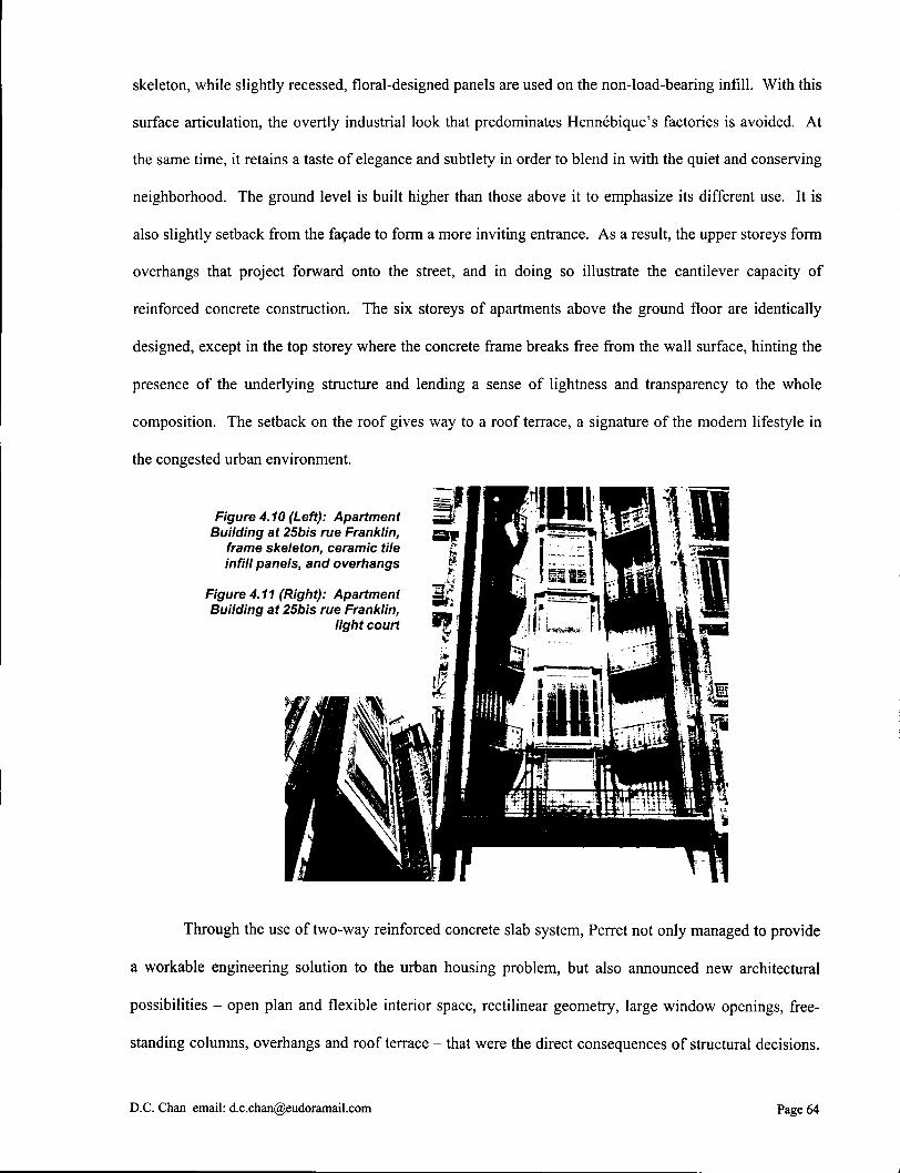
skeleton, while slightly recessed, floral-designed panels are used on the non-load-bearing infill. With this
surface articulation, the overtly industrial look that predominates Hennebique's factories is avoided. At
the same time, it retains a taste of elegance and subtlety in order to blend in with the quiet and conserving
neighborhood. The ground level is built higher than those above it to emphasize its different use. It is
also slightly setback from the facade to form a more inviting entrance. As a result, the upper storeys form
overhangs that project forward onto the street, and in doing so illustrate the cantilever capacity of
reinforced concrete construction. The six storeys of apartments above the ground floor are identically
designed, except in the top storey where the concrete frame breaks free from the wall surface, hinting the
presence of the underlying structure and lending a sense of lightness and transparency to the whole
composition. The setback on the roof gives way to a roof terrace, a signature of the modern lifestyle in
the congested urban environment.
Through the use of two-way reinforced concrete slab system, Perret not only managed to provide
a workable engineering solution to the urban housing problem, but also announced new architectural
possibilities - open plan and flexible interior space, rectilinear geometry, large window openings, free
standing columns, overhangs and roof terrace - that were the direct consequences of structural decisions.
D . C . Chan email: [email protected] Page 64

All of these had profound influences upon the works of Modernist architects of the next generation,
including the legendary Le Corbusier. In fact, a lot of Le Corbusier's formal vocabulary of his reinforced
concrete frame structures was originated and expanded from this set of precedents. At the age of twenty,
Le Corbusier worked in Perret's office, where he learned the business of reinforced concrete frame
construction.8 He was soon convinced that it would become a central instrument of his architecture for
the rest of his career.
4.3 Le Corbusier's Ideas of Modernism
Figure 4.12: Le Corbusier (Claries Edouard Jeanneret), 1887-1965
When Le Corbusier put together his Dom-ino Housing Project
in 1914-15, it was already apparent that his future preoccupation with
defining the elements of a new architecture would be attributed to
reinforced concrete frame construction. One of the reasons was the
material's ability to produce smooth, precisely-edged geometric shapes
(the so-called object types), whose abstract quality was in tune with the
architect's personal predilection to Cubism and Purism. The choice also reflected Le Corbusier's
admiration for the unadorned dwellings of the Mediterranean, with their flat roofs and cubic shapes
modeled by light.9 Another reason had to do with the structural advantages of two-way slab construction.
They allowed new types of interior and exterior spaces to be developed that were compatible with the
architect's perception of modern lifestyle. The many unique characteristics of reinforced concrete frame
construction convinced the architect that this type of structure offered a universal visual language of the
epoch, one that embodied the ideas of modernization and urbanization of the industrial age. In fact, from
the Dom-ino Housing Project to his Villa Savoye of 1928-31, there were a certain vocabulary of forms
8 Curtis, 164.
9 Curtis, 85.
D.C. Chan email: [email protected] Page 65

and syntax of compositions of the structure that he gradually synthesized in his domestic houses, all of
which pointed towards a larger ideology of Modernism.
4.3.1 Dom-ino Housing Project
The Dom-ino Housing Project was intended to be a housing kit that allowed rapid reconstruction
in the war-devastated Flanders, Belgium. The project was never built, but the concept that a reinforced
concrete frame transcended from a basic structural necessity into pure architectural ideas lived on and
continued to inspire the architect through enduring years. What made the Dom-ino houses revolutionary
was the generation of architectural form, space and order by a simple structural device. Each housing unit
comprised of a simple, six-point supported, reinforced concrete frame skeleton with three planes of
cantilevered slabs, all of which were smooth above and below. The lower level was raised from the
ground on squat concrete blocks. Staircases were pulled to one side. The enclosure was originally
assumed to be rubble wall infdl made from ruined buildings, but given its non-load-bearing nature, it
could equally be made from other materials and into other shapes. Windows and furnishings were all
mass-produced and readily inserted into the building.
Like Hennebique's factories and Perret's Rue Franklin apartment building, the Dom-ino houses
implied that the most appropriate form for reinforced concrete frame construction was rectangular,
although the plasticity of the material certainly allowed much broader applications. Indeed, rectangularity
facilitated simpler formwork construction and prefabrication of mass-produced parts. If one were to
recall William Morris' Arts and Crafts movement in the mid-nineteen century, this is the idea that the
process of making often foreshadows the final form of a building. The elimination of overhead beams in
the skeleton could have been attributed to the same constructional advantage. More likely, it was the
multidirectional load dispersal capability of two-way reinforced concrete slab system that made the beams
structurally obsolete. To reduce the positive bending moments at mid-span, each slab extended well
beyond the line of supports in order that the loads on the cantilevers counterbalanced those at mid-span.
This is analogous to a continuous beam with cantilevered free ends. The exterior walls attaching to the
edges of the slabs helped this to be realized. The columns or pilotis, slender as they might seem, ensured
D.C. Chan email: [email protected] Page 66

frame action to take place by which compressions and bending moments were transferred from each
successive storey down to the base, where the weight of the squat concrete blocks absorbed the stresses.
From a structural point of view, in the Dom-ino houses there was a simple but complete load-carrying
system, with each element participated in the stability of the whole. From a metaphysical point of view,
the formal composition of the Dom-ino houses - three smooth cantilevering slabs on six slender point
supports - evoked an entirely pure structural idea. It appeared as if three horizontal planes were hovering
in space, holding their own weights off the ground.
Figure 4.13: Dom-ino House Unit, Flanders, Le Corbusier, 1914-15
As the underlying structural idea of the Dom-ino houses crystallized, the architectural and spatial
ideas also began to unfold. The smoothness of the cantilevering slabs and the minimal of supporting
columns entailed a new kind of spatial flexibility. Partitions could be positioned at will in the free plan
without conflicting with the otherwise prescribed locations of the overhead beams or massive vertical
supports. The sense of "levitation" resulted from the lightness of the structural frame was further
reinstated by raising the building off the ground using squat concrete blocks. In later projects Le
Corbusier liberated the entire ground level altogether using pilotis in order to accommodate vehicular
access. The flat roof was turned into a terrace. In the exterior of the Dom-ino houses, the non-load-
bearing enclosure could be designed according to local precedents or the architect's predilection. A clear
distillation of functions between structure and infdl allowed the latter to become effectively a membrane
to be punctured as functional necessities or aesthetic composition dictated. This idea of a free fagade,
together with the fenetre en longeur, or strip windows as so fondly used by Le Corbusier in his later
D.C. Chan email: [email protected] Page 67

projects, confirmed with the viewer the non-load-bearing nature of the enclosure in contrast with the
structural efficiency of the reinforced concrete frame skeleton.
4.3.2 Five Points of A New Architecture
The free plan, free facade, free-standing pilotis and roof terrace of the Dom-ino houses, together
with the strip windows developed in later projects, are all constituents of the "Five Points of A New
Architecture". Endorsed by Le Corbusier himself in 1926, the "Five Points" not only have brought
together the very structural manifestations of reinforced concrete frame construction. They also
summarize his almost twenty years of research on the architectural principles and urbanistic notions for
modern habitation. Central to the "Five Points" is the idea that the dwelling functions as a machine for
living in: its purpose is to facilitate the daily activities of a healthy, efficient and modern lifestyle.
The pilotis remains the most crucial element of all. They lift the building partially or entirely off
the ground to allow vehicular circulation underneath - an increasing prominent feature of the modern
lifestyle, and certainly one of the emerging issues in urban planning. This also represents a more hygienic
way of living, one that is ensured by elevating living space off the dirt and moisture of the ground to
better sunlight quality above. Tim Benton relates Le Corbusier's intention to his pathological anxiety as
well as the "desirability of raising human habitation to a level from which nature could be contemplated
'as in a Virgilian dream'."10 While on one hand the pilotis separate the living area from the earth, the roof
terrace on the other hand reintroduces nature into the dwelling. In terms of city planning, this is also a
means to bring greenery into the urban environment. In the interior of the dwelling, the pilotis support the
weight of the building while partitions divide space. Because the living space is free from the cluster of
load-bearing walls, it becomes more flexible and better conformed to the actual spatial needs of the
dwellers - the idea of a free plan. Similarly, the free facade is liberated from its traditional load-bearing
role and can now be designed exclusively according to its programmatic and functional requirements.
Finally, the strip windows form horizontal bands across the facade to allow maximum sunlight
penetration and views.
1 0 Tim Benton, The Villas of Le Corbusier. 1920-1930 (New Haven and London: Yale University Press, 1987), 195.
D.C. Chan email: [email protected] Page 68

Until the announcement of the "Five Points" in 1926, Le Corbusier had already designed a
number of domestic houses, each of which brought him closer to his own architectural and structural
ideals. These projects, mostly concentrated in the 1920s, were often called Purist villas because they
shared the same formal vocabulary and aesthetic values of the contemporary art movement of Purism.
The last of these Purist villas was Villa Savoye at Poissy, 1928-31. It was Le Corbusier's last, and
perhaps most successful, attempt to bring the "Five Points" into full realization. Villa Savoye drew
together many of the archtiect's earlier themes and formal experiments; they were combined together into
an unprecedented synthesis of high order. Thus it contained an enormous quantity of ideas that precluded
complete coverage in any single account. Here a number of structural features pertaining to two-way
reinforced concrete slab construction are discussed, along with their contributions to the overall
architectural expression of the building.
4.4 Villa Savoye
Fiaure 4.14: Villa Savove. (from Left to Riaht) southwest, northwest, southeast
Villa Savoye is clearly an exhibit of Le Corbusier's "Five Points" being transcended to a state of
purity. A horizontal white box is raised on cylindrical pilotis, with a continuous band of strip windows
running the entire facade. The box appears to hover in space, only to be reassured by the curving forms
of the solarium above. From a distance, the image of a perfect, white cube poised above the green
meadow registers firmly in the viewer's mind. Arriving vehicles turn off the road into a gravel driveway,
which leads into the rows of pilotis underneath the rectangular superstructure, turn around and enter the
garage on the lower level. The lower level, painted deep green to suppress its appearance, also houses the
mundane functions of servants' and chauffeur's quarters. It is curved about the turning path of the
D.C. Chan email: [email protected] Page 69

driveway as a means of integrating automobile circulation into the architectural form. One enters the
house at the apex of the curve into the vestibule, where a ramp gradually ascends along the central axis of
the building to the upper levels. The second floor contains the complete living accommodation wrapped
in an L on the southwest side of the open terrace. Here functional spaces are dynamically arranged within
the stable perimeter of a square volume: the idea of free plan is in full display. The ramp continues to rise
to the solarium above, where a small rectangular opening is aligned with the ramp and re-opens one's
view to the distant landscape, a conclusion to the architectural journey within the house. Le Corbusier
explained in his Oeuvre complete (1929-34) the idea of a "promenade" in terms of Arabian architecture:
"Arab architecture provides us with a precious lesson. It is appreciated on the move, on
foot; it is in walking, in moving about, that one sees the ordering devices of architecture
develop. It is a principle contrary to Baroque architecture which is conceived on paper,
around a fixed, theoretical point... " n
"In this house there is a true architectural promenade, offering ever-changing views,
some of them unexpected, some of them astonishing. It is interesting to obtain so much
diversity when one has, for instance, admitted a constructive system based on an
absolutely rigorous schema of beams and columns. " n
Figure 4.15: Villa Savoye, interiors, (Left) vestibule at lower level, (Right) roof terrace at upper level
The central theme of Villa Savoye is the ramp. It is the device by which the sequentially staged
architectural promenade of the "Five Points" is organized, and itself a dynamic passage juxtaposing
" Curtis, 281.
1 2 Curtis, 281.
D.C. Chan email: [email protected] Page 70
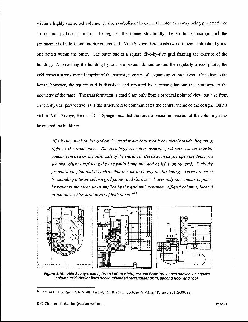
within a highly controlled volume. It also symbolizes the external motor driveway being projected into
an internal pedestrian ramp. To register the theme structurally, Le Corbusier manipulated the
arrangement of pilotis and interior columns. In Villa Savoye there exists two orthogonal structural grids,
one netted within the other. The outer one is a square, five-by-five grid framing the exterior of the
building. Approaching the building by car, one passes into and around the regularly placed pilotis, the
grid forms a strong mental imprint of the perfect geometry of a square upon the viewer. Once inside the
house, however, the square grid is dissolved and replaced by a rectangular one that conforms to the
geometry of the ramp. The transformation is crucial not only from a practical point of view, but also from
a metaphysical perspective, as if the structure also communicates the central theme of the design. On his
visit to Villa Savoye, Herman D. J. Spiegel recorded the forceful visual impression of the column grid as
he entered the building:
"Corbusier stuck to this grid on the exterior but destroyed it completely inside, beginning
right at the front door. The seemingly relentless exterior grid suggests an interior
column centered on the other side of the entrance. But as soon as you open the door, you
see two columns replacing the one you'd bump into had he left it on the grid. Study the
ground floor plan and it is clear that this move is only the beginning. There are eight
freestanding interior column grid points, and Corbusier leaves only one column in place;
he replaces the other seven implied by the grid with seventeen off-grid columns, located
to suit the architectural needs of both floors. " n
Figure 4.16: Villa Savoye, plans, (from Left to Right) ground floor (grey lines show 5x5 square column grid, darker lines show imbedded rectangular grid), second floor and roof
1 3 Herman D. J. Spiegel, "Site Visits: An Engineer Reads Le Corbusier's Villas," Perspecta 31. 2000, 92.
D.C. Chan email: [email protected] Page 71
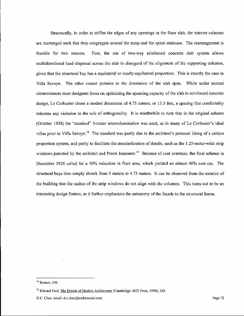
Structurally, in order to stiffen the edges of any openings in the floor slab, the interior columns
are rearranged such that they congregate around the ramp and the spiral staircase. The rearrangement is
feasible for two reasons. First, the use of two-way reinforced concrete slab system allows
multidirectional load dispersal across the slab in disregard of the alignment of the supporting columns,
given that the structural bay has a equilateral or nearly-equilateral proportion. This is exactly the case in
Villa Savoye. The other reason pertains to the dimension of the slab span. While under normal
circumstances most designers focus on optimizing the spanning capacity of the slab in reinforced concrete
design, Le Corbusier chose a modest dimension of 4.75 meters, or 15.5 feet, a spacing that comfortably
tolerates any violation to the rule of orthogonality. It is worthwhile to note that in the original scheme
(October 1928) the "standard" 5-meter intercolumniation was used, as in many of Le Corbusier's ideal
villas prior to Villa Savoye.14 The standard was partly due to the architect's personal liking of a certain
proportion system, and partly to facilitate the standardization of details, such as the 1.25-meter-wide strip
windows patented by the architect and Pierre Jeanneret.15 Because of cost overruns, the final scheme in
December 1928 called for a 10% reduction in floor area, which yielded an almost 40% cost cut. The
structural bays then simply shrank from 5 meters to 4.75 meters. It can be observed from the exterior of
the building that the sashes of the strip windows do not align with the columns. This turns out to be an
interesting design feature, as it further emphasizes the autonomy of the facade to the structural frame.
1 4 Benton, 196.
1 5 Edward Ford, The Details of Modern Architecture (Cambridge: MIT Press, 1990), 249.
D.C. Chan email: [email protected] Page 72

Figure 4.17: Villa Savoye, northwest fagade
The two-way slab system in Villa Savoye is largely flat plate construction, which, as explained
earlier, requires no transfer beams running in between columns. At around the entrance area, however,
three beams running parallel to the longitudinal axis of the building can be seen. The central beam even
notches through the front door transom glass and extends to the interior of the building. These beams
stabilize the slab against negative bending moments, which can potentially be caused by the heavy
exterior wall resting on the cantilevered portion of the slab. Observing from Le Corbusier's previous
projects, one would have figured out that these beams also formally define the entrance area and imply
the building's principal orientation, a purpose similar to that of the cantilever. At the vestibule where the
central beam meets with the first pair of columns, a transverse beam spans across the two columns to
form some kind of ceremonial "arch" through which the visitor proceeds onto the ascending ramp. This
D.C. Chan email: [email protected] Page 73
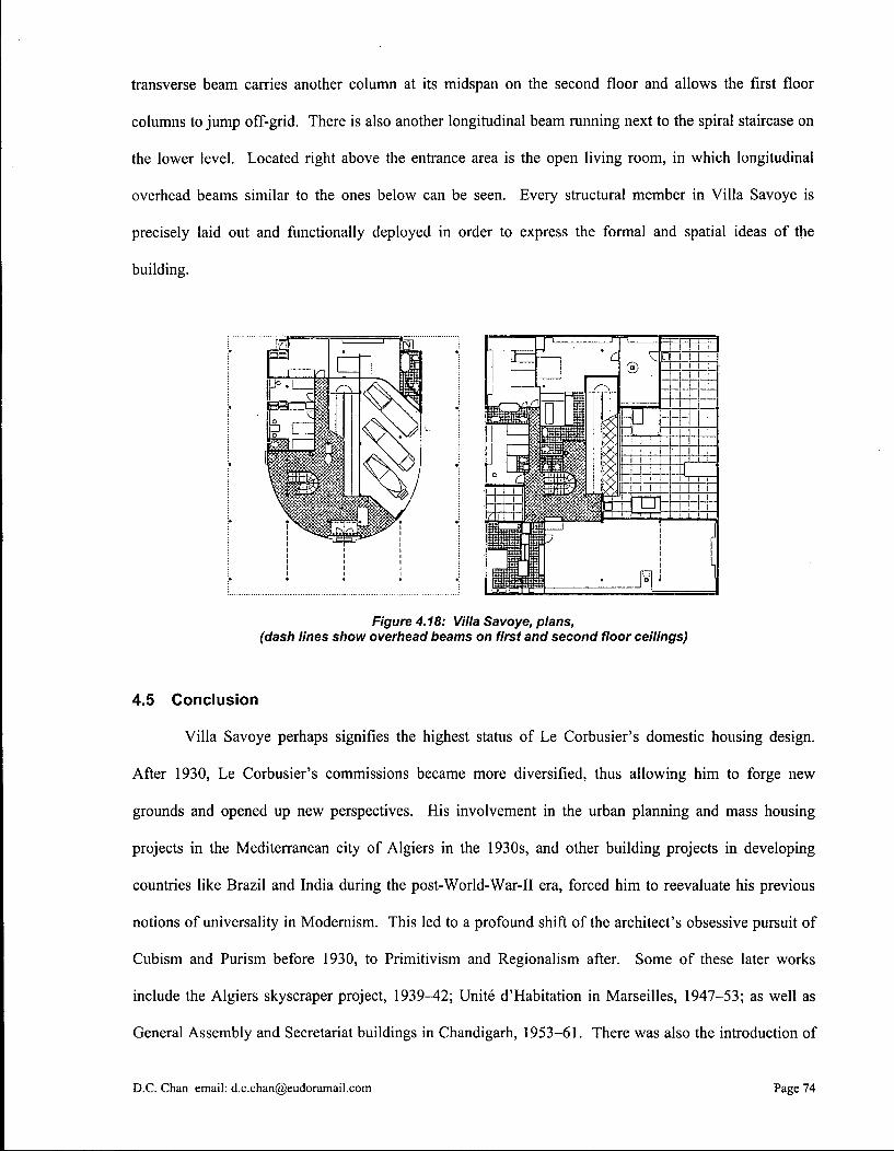
transverse beam carries another column at its midspan on the second floor and allows the first floor
columns to jump off-grid. There is also another longitudinal beam running next to the spiral staircase on
the lower level. Located right above the entrance area is the open living room, in which longitudinal
overhead beams similar to the ones below can be seen. Every structural member in Villa Savoye is
precisely laid out and functionally deployed in order to express the formal and spatial ideas of the
building.
Figure 4.18: Villa Savoye, plans, (dash lines show overhead beams on first and second floor ceilings)
4.5 Conclusion
Villa Savoye perhaps signifies the highest status of Le Corbusier's domestic housing design.
After 1930, Le Corbusier's commissions became more diversified, thus allowing him to forge new
grounds and opened up new perspectives. His involvement in the urban planning and mass housing
projects in the Mediterranean city of Algiers in the 1930s, and other building projects in developing
countries like Brazil and India during the post-World-War-II era, forced him to reevaluate his previous
notions of universality in Modernism. This led to a profound shift of the architect's obsessive pursuit of
Cubism and Purism before 1930, to Primitivism and Regionalism after. Some of these later works
include the Algiers skyscraper project, 1939-42; Unite d'Habitation in Marseilles, 1947-53; as well as
General Assembly and Secretariat buildings in Chandigarh, 1953-61. There was also the introduction of
D.C. Chan email: [email protected] Page 74

new architectural devices such as the beton brut (bare concrete), sculpture-like "acoustic" forms and
brise-soleil (sun breaker), all of which being part of his regional vocabulary. In all of these cases, the
reinforced concrete frame, particularly the two-way slab system, continued to serve as the spine of his
architectural creation and an avenue for endless design possibilities.
Figure 4.19 (Top): Unite d 'Habitation, Marseilles, Le Corbusier, 1947-53, bare concrete fagade with brise-soleil
Figure 4.20 (Bottom): General Assembly, Chandigarh, Le Corbusier, 1953-61, exterior and interior views
D.C. Chan email: [email protected] Page 75

By the end of the nineteenth century, reinforced concrete frame construction had already been
transformed from an idea of skepticism to a constructed reality. Much of the technological development
in the twentieth century has been concentrated on economizing the construction process and material use.
One of the more pronounced projects that achieved both of these criteria as well as exhibiting an artistic
sensibility was the Gatti Wool Factory in Rome. The floor slab was stiffened by using ribs that followed
the pattern of the isostatic lines, or lines of principal stresses.16 This resulted in an interesting ceiling
pattern rich in aesthetic expression. To shape the mold for the curvilinear ribs, the traditional wooden
formwork was replaced by a ferrocemento one, which was made of wire mesh and cement mortar into
formwork % to IVi inches thick only.1 7 Observing the ceiling pattern, one may marvels at how the plastic
richness of reinforced concrete construction has allowed an engineering manipulation for structural
purposes to be revealed in the architectural form almost biomorphically, like a species constantly
evolving to adapt to its environment. This "organic" nature of the material probably accounts for the one
of the main reasons that why so many architects prefer reinforced concrete to other types of construction.
Figure 4.21: Gatti Wool Factory, Rome, ribbed roof pattern following isostatic lines
1 6 Daniel L . Schodek, Structures. 2 n d ed. (Englewood Cliffs: Prentice-Hall, Inc., 1992), 382.
1 7 Pier Luigi Nervi, Aesthetics and Technology in Building (Cambridge: Harvard University Press, 1966), 31.
D.C. Chan email: [email protected] Page 76
5.0 Conclusion
For more than a century, the structural frame in its diverse manifestations has continued to hold out
the promises of technological and social changes. In its simplest, the frame is the skeleton of a building
on which the enclosing skin is supported. It emancipates the facade and partitions from their structural
responsibilities, thus promotes greater freedom in shaping forms and organizing space. Whether the
frame is an assemblage of standardized elements manufactured in a mill, or monolithically cast into a
single whole, skeletal frame construction effectuates the structural potentials of steel and reinforced
concrete, and allows buildings to be constructed economically by means of repetition and pattern. It is by
now an indisputable argument that this unique type of construction possesses a value for modern
architecture. In many parts of the world, it has single-handedly determined the dominant building
typology of the urban landscape. The prismatic office towers, box-like industrial complexes and stacking
housing slabs that congregate in every city grid are testimonies to its triumph.
The interior of a structural frame building equally conveys the notion of modernity. The frame
supplies in three dimensions a neutral grid of space, one that not only accommodates but also reshapes
human activities of the contemporary life. For this reason the frame has evoked to its occupants some
particular symbolic values; it captures the physical and psychological resonance of the en-framed to the
en-framing. Nowadays, we see a regular grid of beams and columns and associate it with the ideas of
discipline, order, and efficiency. We appreciate certain structural "truths" when the construction methods
and materials are made tangible. Depending on the legibility of the design, we can even anticipate certain
building form, spatial hierarchy, circulation arrangement, or abstract qualities of proportion and scale by
observing the structural layout of the frame. All in all, we have learned to understand architecture by
reading structure. This is particularly so in skeletal frame construction which we closely experience in
every day life.
It is for this reason that structural semiotics plays an imperative role in contributing to the overall
architectural expression of skeletal frame construction. Over the years, the frame has become
increasingly capable of establishing its own architectural vocabularies. It defined the formal and spatial
D.C. Chan email: [email protected] Page 77
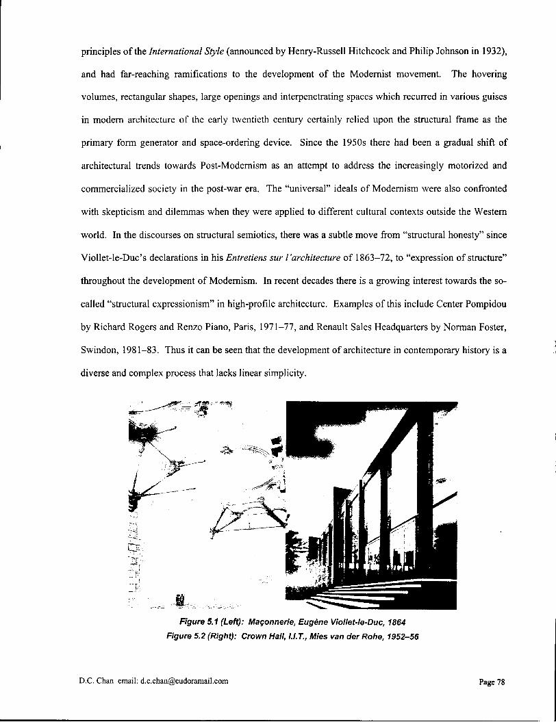
principles of the International Style (announced by Henry-Russell Hitchcock and Philip Johnson in 1932),
and had far-reaching ramifications to the development of the Modernist movement. The hovering
volumes, rectangular shapes, large openings and interpenetrating spaces which recurred in various guises
in modern architecture of the early twentieth century certainly relied upon the structural frame as the
primary form generator and space-ordering device. Since the 1950s there had been a gradual shift of
architectural trends towards Post-Modernism as an attempt to address the increasingly motorized and
commercialized society in the post-war era. The "universal" ideals of Modernism were also confronted
with skepticism and dilemmas when they were applied to different cultural contexts outside the Western
world. In the discourses on structural semiotics, there was a subtle move from "structural honesty" since
Viollet-le-Duc's declarations in his Entretiens sur I'architecture of 1863-72, to "expression of structure"
throughout the development of Modernism. In recent decades there is a growing interest towards the so-
called "structural expressionism" in high-profile architecture. Examples of this include Center Pompidou
by Richard Rogers and Renzo Piano, Paris, 1971-77, and Renault Sales Headquarters by Norman Foster,
Swindon, 1981-83. Thus it can be seen that the development of architecture in contemporary history is a
diverse and complex process that lacks linear simplicity.
Figure 5.1 (Left): Magonnerie, Eugene Viollet-le-Duc, 1864
Figure 5.2 (Right): Crown Hall, I.I.T., Mies van der Rohe, 1952-56
D.C. Chan email: [email protected] Page 78
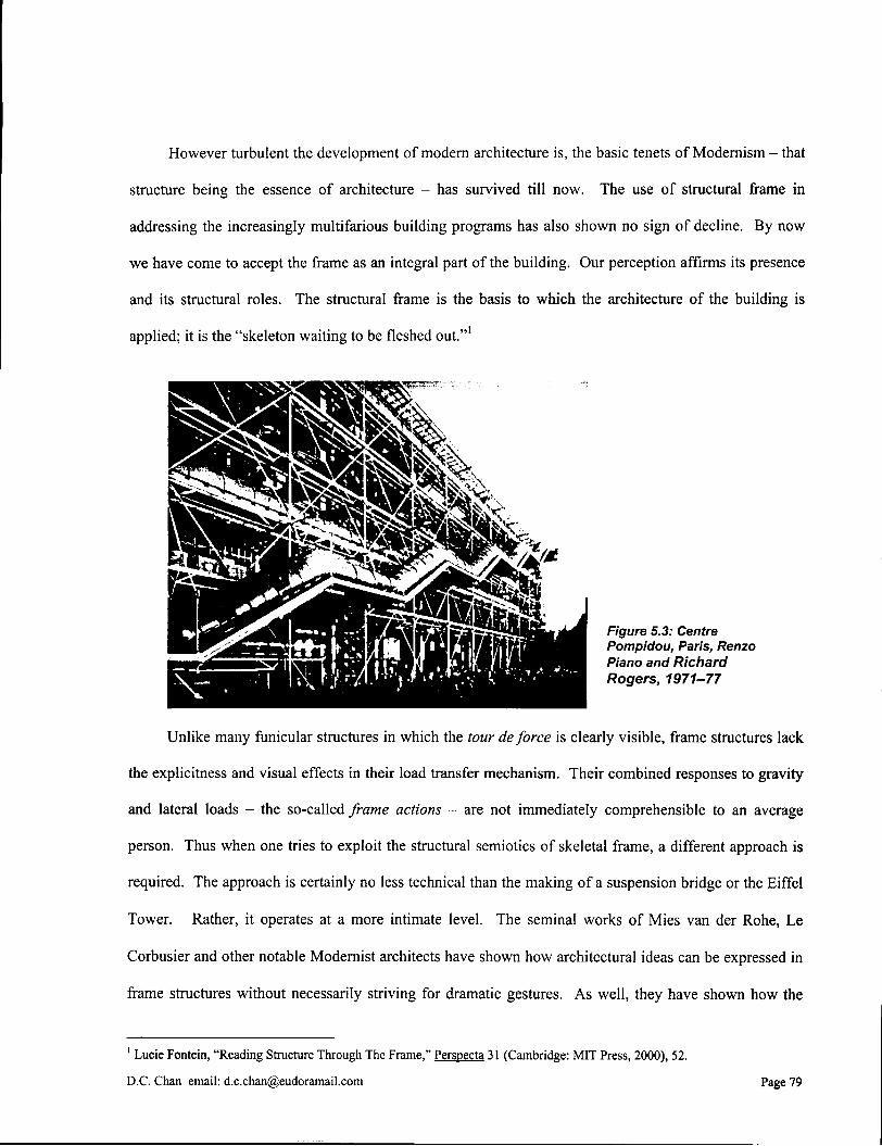
However turbulent the development of modern architecture is, the basic tenets of Modernism - that
structure being the essence of architecture - has survived till now. The use of structural frame in
addressing the increasingly multifarious building programs has also shown no sign of decline. By now
we have come to accept the frame as an integral part of the building. Our perception affirms its presence
and its structural roles. The structural frame is the basis to which the architecture of the building is
applied; it is the "skeleton waiting to be fleshed out."1
Unlike many funicular structures in which the tour de force is clearly visible, frame structures lack
the explicitness and visual effects in their load transfer mechanism. Their combined responses to gravity
and lateral loads - the so-called frame actions - are not immediately comprehensible to an average
person. Thus when one tries to exploit the structural semiotics of skeletal frame, a different approach is
required. The approach is certainly no less technical than the making of a suspension bridge or the Eiffel
Tower. Rather, it operates at a more intimate level. The seminal works of Mies van der Rohe, Le
Corbusier and other notable Modernist architects have shown how architectural ideas can be expressed in
frame structures without necessarily striving for dramatic gestures. As well, they have shown how the
1 Lucie Fontein, "Reading Structure Through The Frame," Perspecta 31 (Cambridge: MIT Press, 2000), 52.
D.C. Chan email: [email protected] Page 79
Figure 5.3: Centre Pompidou, Paris, Renzo Piano and Richard Rogers, 1971-77

structural logics of frame construction can be expressed in the architecture without defying engineering
rules. By sensible choice of structural system, materials and construction method, by proper
proportioning and detailing, and by careful observation to the contextual and programmatic requirements,
even the most commonplace structural frame can become architecture.
Figure 5. headquarters, Si
Unfortunately, in the building industry today, there is a tendency that some of the visual
principles of Modernism, especially in the use of structural frames as form generators, have been
hackneyed through mass industrialization such that a banal design formula is produced. The situation is
particularly severe in the fields of general construction, where design decisions are often inappropriately
and unnecessarily undermined by the financial purposes of real estate. The increasingly diverging roles
and specialization of structural engineers and architects have also precipitated the problem. The division
exists for reasons of simplifying the design and construction processes, and to avoid the risks of legal
responsibility. It is however at the cost of weakening the interconnection between the two professions.
Conflicts often arise due to misunderstanding between the architect and the engineer, with each
profession lacking the sensibility and knowledge to the other's work. The architect takes the structural
frame for granted as a mere necessity. Rather than being properly accounted for as part of the
architectural design, the frame is treated subordinate to the architecture. On the other hand, the engineer
regards architectural features as flamboyant display without any functional significance. All of these
D.C. Chan email: [email protected] Page 80
prejudices and misconceptions manifest themselves in structural frame designs that lack any architectural
insight. Other than its load-carrying role, the frame exists solely for the purpose of satisfying a superficial
formalism. The author feels strongly that this problem can be alleviated in the future if there is a better
understanding and appreciation towards the semiotics of structural frames. Structural semiotics is the
common language between both professions; to turn away from it is to miss architectural opportunities.
D.C. Chan email: [email protected] Page 81
6.0 Technical Notes
6.1 Degree of Indeterminacy and Stability
Stable structures can either be statically determinate or statically indeterminate. For statically
determinate structures, the number of unknown forces can be found strictly from the equilibrium
equations available to solve for these forces. These equations provide both the necessary and sufficient
conditions for equilibrium. Structures having more unknown forces than available equilibrium equations
are called statically indeterminate, and more in-depth calculations accounting for the physical and
material properties of the cross sections of the structural members are required to solve for all the
unknown forces. If the number of unknown forces is less than the number of available equilibrium
equations, the structure is unstable. As a general rule, a structure can be identified as being either
statically determinate or statically indeterminate by sectioning the structure at its joints. The number of
unknown forces at the joints is then compared with the number of available equilibrium equations for all
structural members, considering that each structural member can be analyzed as an individual free-body
diagram. The difference between the two numbers gives the degree of indeterminacy, or redundancy, of
the structure.
In planar frame structures, there are three available equilibrium equations for each member: HFX =
0, Z F y = 0, and ~LMxy = 0. The number of unknown forces depends on the type of joint. For examples, at
a fixed (moment-resisting) joint, because all the axial, transverse and rotational deformations are
restrained, there are a total of three unknown forces: Fx, Fy, and Mxy. At a pinned joint, there are two
unknown forces: Fx and Fy. A sleeve joint also yields two unknown forces: Fy and M^. At a roller joint,
only one unknown force needs to be calculated, namely Fx. In mathematical terms, the degree of
indeterminacy of a structure can be formulated as follows:
Available equilibrium equations = 3m
Unknown forces at joints = 3jf + 2(jp+js) + j r
where m = the number of structural members j f = the number of fixed (moment-resisting) joints j p = the number of pinned joints j s = the number of sleeve joints j r = the number of roller joints
D.C. Chan, email: [email protected] Page 82

If 3m < 3jf + 2( jp+j s ) + j r , the structure is statically indeterminate and stable. The degree of indeterminacy
equals to [3jf + 2 ( j p + j s ) + j r ] - 3m.
If 3m = 3jf + 2( jp+j s ) + j r , the structure is statically determinate, but it can either be stable or unstable
depending on the exact configuration and location of the connections. A closer examination of the structure is
required in order to detect any possible inherent mechanism.
If 3m > 3jf + 2( jp+j s ) + j r , the structure is unstable.
Using the above equations, identifying the degree of indeterminacy for planar frame structures
becomes a simple task of counting the numbers of structural members and connection restraints. A
structural member is defined as one that lies between two connections of any kind. As an alternative, two
members connected by a fixed joint can be considered as one member; the fixed joint must then be
ignored when counting the total number of connections. In addition, when a joint connects more than two
structural components together (including structural members and supports), it must be counted more than
once. The total number of counts for each joint is equal to the number of sectional cuts required to isolate
the free-body diagrams of individual members. Therefore, in a braced frame or a truss, a pinned joint that
connects three structural members together is counted twice, and the one that connects four structural
members together is counted three times, so on and so forth.
It is worthwhile to note that a number of other methods are available to calculate the degree of
indeterminacy for planar frame structures. For example, in Russell C. Efibbeler's Structural Analysis, 3 r d
ed.,1 the method of sections is used in which closed loops formed by two beams and two columns are
"cut" apart. Since the number and direction of cuts depend on the exact configuration of the frame, each
case must be examined on an individual basis. In Wolfgang Schueller's Horizontal-Span Building
Structures? the frame is treated as having entirely fixed joints. Pinned joints and other releases in
restraints are counted as "special conditions". It is felt that these methods become increasingly
cumbersome when the frame configuration becomes more complex. The method suggested in this thesis
provides a direct and universal procedure of simply counting the number of structural members and
1 Russell C. Hibbeler, Structural Analysis. 3 r d ed. (Englewood Cliffs: Prentice Hall, 1990), 48-49.
2 Wolfgang Schueller, Horizontal-Span Building Structures (New York: John Wiley & Sons, Inc., 1983), 189-190.
D.C. Chan email: [email protected] Page 83
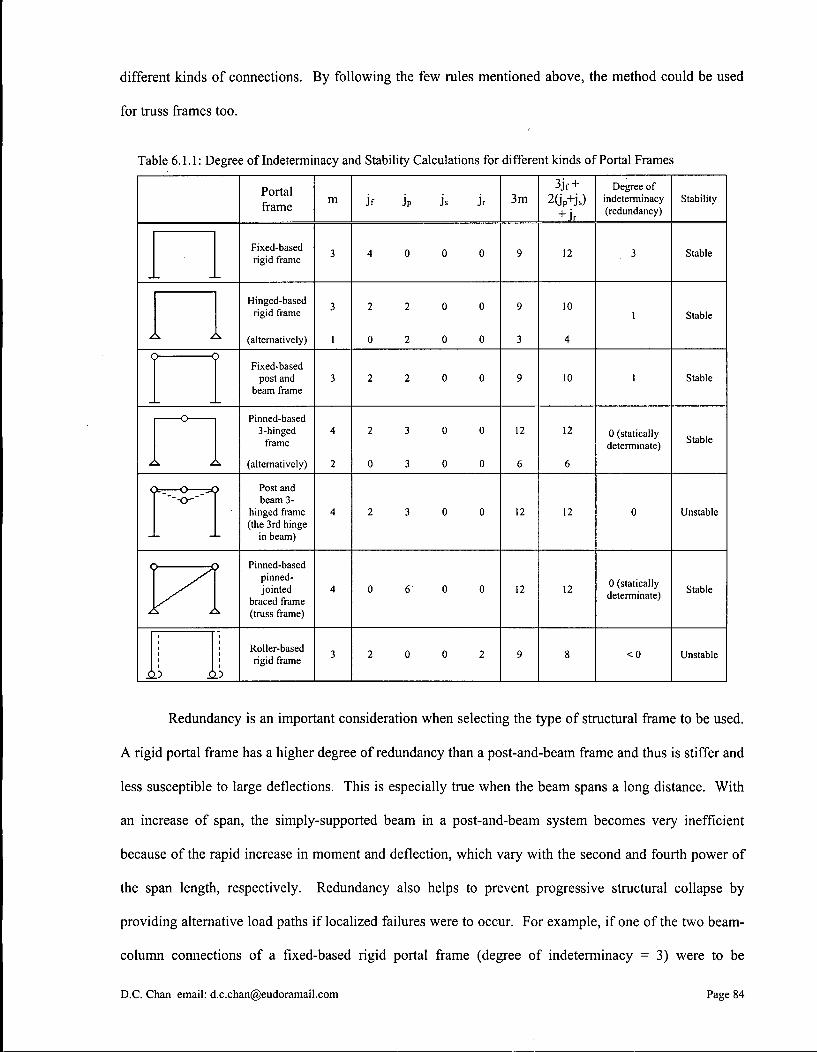
different kinds of connections. By following the few rules mentioned above, the method could be used
for truss frames too.
Table 6.1.1: Degree of Indeterminacy and Stability Calculations for different kinds of Portal Frames
Portal frame
m j f jp js jr 3m 3jr +
2GP+Js)
+ jr
Degree of indeterminacy (redundancy)
Stability
Fixed-based rigid frame 3 4 0 0 0 9 12 3 Stable
Hinged-based rigid frame
(alternatively)
3
1
2 2 0 0
0 2 0 0
9
3
10
4
1 Stable
< p < j> Fixed-based
post and beam frame
3 2 2 0 0 9 10 1 Stable
o
\
Pinned-based 3-hinged
frame
(alternatively)
4
2
2 3 0 0
0 3 0 0
12
6
12
6
0 (statically determinate) Stable
<j >-. O 5< "--o~~
j> Post and beam 3-
hinged frame (the 3rd hinge
in beam)
4 2 3 0 0 12 12 0 Unstable
<:
/.
j> —L Pinned-based pinned-jointed
braced frame (truss frame)
4 0 6 0 0 12 12 0 (statically determinate) Stable
h. .5 i 3
Roller-based rigid frame 3 2 0 0 2 9 8 <0 Unstable
Redundancy is an important consideration when selecting the type of structural frame to be used.
A rigid portal frame has a higher degree of redundancy than a post-and-beam frame and thus is stiffer and
less susceptible to large deflections. This is especially true when the beam spans a long distance. With
an increase of span, the simply-supported beam in a post-and-beam system becomes very inefficient
because of the rapid increase in moment and deflection, which vary with the second and fourth power of
the span length, respectively. Redundancy also helps to prevent progressive structural collapse by
providing alternative load paths if localized failures were to occur. For example, if one of the two beam-
column connections of a fixed-based rigid portal frame (degree of indeterminacy = 3) were to be
D.C. Chan email: [email protected] Page 84
disengaged, thus losing all its axial, shear and bending moment resistances, the beam may still be held in
place through cantilever action from the other column. In the case of a fixed-based post-and-beam frame
(degree of indeterminacy = 1), however, the detached end of the beam simply falls. The situation is
worse for a three-hinged frame (statically determinate), because once a beam-column connection fails, the
whole structure collapses. On the other hand, statically determinate structures are relatively easy to
analyze; unknown forces and reactions can usually be found by a set of static equilibrium equations of
free-body diagrams. More importantly, they can absorb material changes and movements, such as
temperature, shrinkage, creep, moisture content, foundation settlement, etc., without causing additional
internal stresses. Many early planar frame structures, such as the Palais des Machines for the Universal
Exposition of Paris, 1889, and the A E G Turbine Hall in Berlin, 1909, incorporated a three-hinged system
design mainly for these two reasons.
D.C. Chan email: [email protected] Page 85
6.2 Funicular Profile
The term funicular is derived from the Latin word for "rope" and suggests the load-dependent
deformed shape of a hanging cable. A cable subjected to external loads deforms to a specific profile
according to the magnitude and location of the external forces. For instance, a cable of constant cross
section carrying only its own dead weight naturally deforms into a catenary profile. If the cable supports
several point loads, the funicular profde is a series of straight segments that change direction at each load-
application point. If the cable supports a uniformly distributed load on a horizontal projection, it adopts a
parabolic shape. In all cases, only tension forces are developed in the cable. By analogy, inverting this
deformed shape of a cable yields an arch profde except that pure compression forces rather than tension
forces are developed. This is why non-rigidly connected masonry blocks are stacked into a parabolic arch
in order to form a stable structure. A funicular profile, therefore, is the structural shape that transforms a
set of prescribed external loads into internal member forces of either pure tension or compression and
transfers them to the foundations.
For a typical loading condition and specified anchorage locations, there exists a family of
funicular profiles. These profiles retain the same relative proportion and they only vary in depth.
Generally, the greater the rise of an arch or the sag of a cable is, the smaller the internal forces developed
in the structure are, and vice versa. The profile also governs the magnitude and direction of the reaction
forces at the foundations. These reaction forces consist of vertical and horizontal thrusts which must be
taken into consideration when designing the foundation supports and other types of end constraints, such
as compression struts or tie rods. During the design process, it is a matter of resolving these often-
conflicting requirements into a formally suitable, aesthetically pleasing, structurally workable and
economically feasible solution. When designing an arch frame, the loading conditions and foundation
locations are often provided. Other project requirements, such as minimum overhead clearance and
internal member force tolerance, help to single out a unique arch profile from a family of funicular
shapes. What needed to be calculated are the internal member forces and the vertical and horizontal
components of the support reactions. The task at hand then is to formulate a calculation procedure that
allows the designer to start with the set of initial information mentioned above, and then systematically
D.C. Chan email: [email protected] Page 86
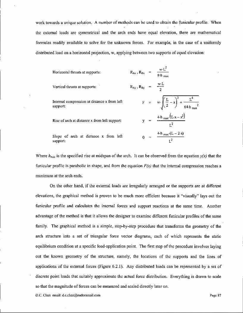
work towards a unique solution. A number of methods can be used to obtain the funicular profile. When
the external loads are symmetrical and the arch ends have equal elevation, there are mathematical
formulas readily available to solve for the unknown forces. For example, in the case of a uniformly
distributed load on a horizontal projection, w, applying between two supports of equal elevation:
Horizontal thrusts at supports: R A X , RBX w - L
8'h max
w - L Vert ical thrusts at supports: R A y , R^y = — ~
L \ 2 L 4
Internal compression at distance x from left p = w II x + support: IV ^ J 64-h, 2
max
Rise o f arch at distance x from left support: 4 h m a x - ( L - x - x 2 )
L 2
^ h ^ - C L - ^ x ) Slope o f arch at distance x from left Q -support: L 2
Where hmax is the specified rise at midspan of the arch. It can be observed from the equation y(x) that the
funicular profde is parabolic in shape, and from the equation F(x) that the internal compression reaches a
maximum at the arch ends.
On the other hand, if the external loads are irregularly arranged or the supports are at different
elevations, the graphical method is proven to be much more efficient because it "visually" lays out the
funicular profile and calculates the internal forces and support reactions at the same time. Another
advantage of the method is that it allows the designer to examine different funicular profiles of the same
family. The graphical method is a simple, step-by-step procedure that transforms the geometry of the
arch structure into a set of triangular force vector diagrams, each of which represents the static
equilibrium condition at a specific load-application point. The first step of the procedure involves laying
out the known geometry of the structure, namely, the locations of the supports and the lines of
applications of the external forces (Figure 6.2.1). Any distributed loads can be represented by a set of
discrete point loads that suitably approximate the actual force distribution. Everything is drawn to scale
so that the magnitude of forces can be measured and scaled directly later on.
D.C. Chan email: [email protected] Page 87
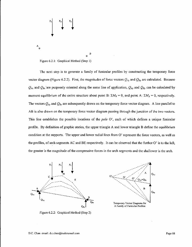
B o
Figure 6.2.1: Graphical Method (Step 1)
The next step is to generate a family of funicular profiles by constructing the temporary force
vector diagram (Figure 6.2.2). First, the magnitudes of force vectors QAy and QBy are calculated. Because
QAx and ^ are purposely oriented along the same line of application, QAy and QBy can be calculated by
moment equilibrium of the entire structure about point B: T,MB = 0, and point A: I.MA = 0, respectively.
The vectors QAy and QBy are subsequently drawn on the temporary force vector diagram. A line parallel to
A B is also drawn on the temporary force vector diagram passing through the junction of the two vectors.
This line establishes the possible locations of the pole O', each of which defines a unique funicular
profile. By definition of graphic statics, the upper triangle A and lower triangle B define the equilibrium
condition at the supports. The upper and lower radial lines from O' represent the force vectors, as well as
the profiles, of arch segments A C and BE respectively. It can be observed that the further O' is to the left,
the greater is the magnitude of the compressive forces in the arch segments and the shallower is the arch.
Figure 6.2.2: Graphical Method (Step 2)
D.C. Chan email: [email protected] Page 88
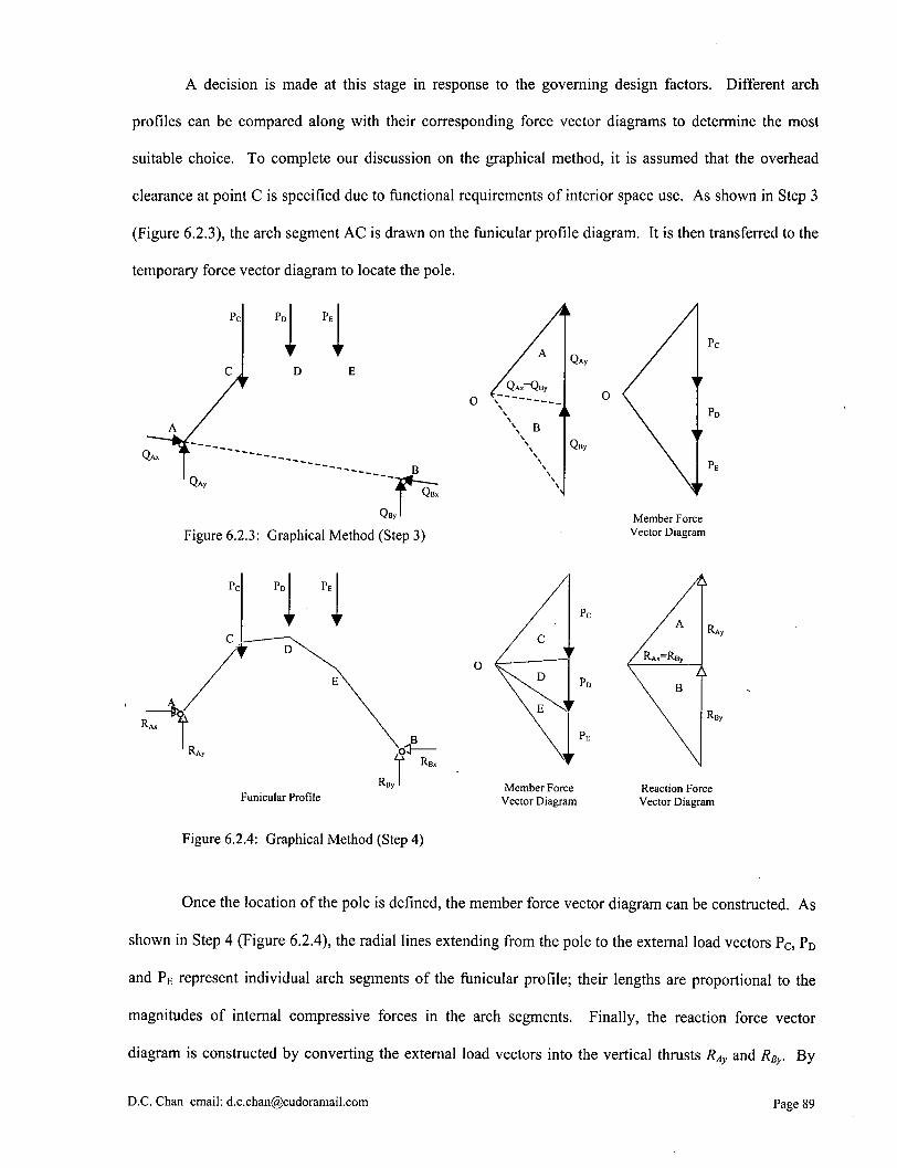
A decision is made at this stage in response to the governing design factors. Different arch
profdes can be compared along with their corresponding force vector diagrams to determine the most
suitable choice. To complete our discussion on the graphical method, it is assumed that the overhead
clearance at point C is specified due to functional requirements of interior space use. As shown in Step 3
(Figure 6.2.3), the arch segment A C is drawn on the funicular profile diagram. It is then transferred to the
temporary force vector diagram to locate the pole.
o \
B
Figure 6.2.3: Graphical Method (Step 3) Member Force
Vector Diagram
Funicular Profile Member Force
Vector Diagram Reaction Force Vector Diagram
Figure 6.2.4: Graphical Method (Step 4)
Once the location of the pole is defined, the member force vector diagram can be constructed. As
shown in Step 4 (Figure 6.2.4), the radial lines extending from the pole to the external load vectors P C , PD
and PE represent individual arch segments of the funicular profile; their lengths are proportional to the
magnitudes of internal compressive forces in the arch segments. Finally, the reaction force vector
diagram is constructed by converting the external load vectors into the vertical thrusts RAy and RBy. By
D.C. Chan email: [email protected] Page 89

static equilibrium of the entire structure in the vertical direction, I,FY = 0, it can be shown that PC + PD +
PE - RAX + PBX- The magnitude of each vertical thrust is found by intersecting with a horizontal line
extending from the pole. This line naturally represents the horizontal thrusts RAX and RBX at the supports,
both of which are equal in magnitude but opposite in direction.
In actual design, an arch frame is often presented with a set of different load cases. Since it is not
possible to design a single shape that is funicular for all load cases, an envelope of funicular profiles is
constructed by superposing individual funicular profiles onto each other. If the effects of off-balanced
live loads are not substantial, the funicular curves will usually be close together. The structure can then
be designed so that the cross sections of the structural members contain all these curves. This is the
primary reason why masonry arches are prevented from collapsing even though they may not be parabolic
in shape. The large dimensions of the masonry blocks and the surrounding masonry wall enclosures help
to keep the funicular lines of compression within the cross sections of the structure. Strictly speaking, the
envelope of funicular profiles should be restricted within the kern area of the cross section in order to
safeguard the development of pure compressive stresses. The kern area is dependent upon the area and
moment of inertia of the cross section. For rectangular cross sections, the kern area is located within the
third points on both centroidal axes. This has given rise to the well-known "middle third rule" that is
frequently referred to in traditional masonry construction.
D.C. Chan email: [email protected] Page 90
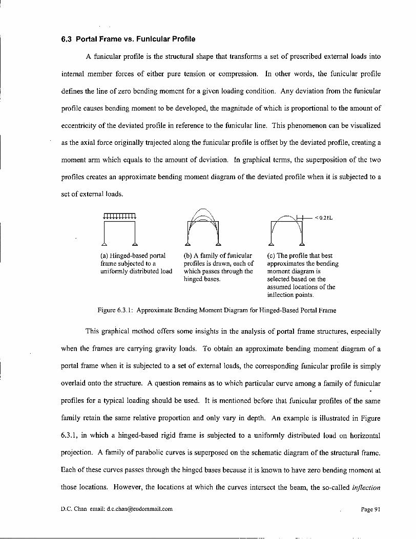
6.3 Portal Frame vs. Funicular Profile
A funicular profile is the structural shape that transforms a set of prescribed external loads into
internal member forces of either pure tension or compression. In other words, the funicular profile
defines the line of zero bending moment for a given loading condition. Any deviation from the funicular
profile causes bending moment to be developed, the magnitude of which is proportional to the amount of
eccentricity of the deviated profile in reference to the funicular line. This phenomenon can be visualized
as the axial force originally trajected along the funicular profile is offset by the deviated profile, creating a
moment arm which equals to the amount of deviation. In graphical terms, the superposition of the two
profiles creates an approximate bending moment diagram of the deviated profile when it is subjected to a
set of external loads.
<0.21L
(a) Hinged-based portal (b) A family of funicular frame subjected to a profiles is drawn, each of uniformly distributed load which passes through the
hinged bases.
(c) The profile that best approximates the bending moment diagram is selected based on the assumed locations of the inflection points.
Figure 6.3.1: Approximate Bending Moment Diagram for Hinged-Based Portal Frame
This graphical method offers some insights in the analysis of portal frame structures, especially
when the frames are carrying gravity loads. To obtain an approximate bending moment diagram of a
portal frame when it is subjected to a set of external loads, the corresponding funicular profile is simply
overlaid onto the structure. A question remains as to which particular curve among a family of funicular
profiles for a typical loading should be used. It is mentioned before that funicular profiles of the same
family retain the same relative proportion and only vary in depth. An example is illustrated in Figure
6.3.1, in which a hinged-based rigid frame is subjected to a uniformly distributed load on horizontal
projection. A family of parabolic curves is superposed on the schematic diagram of the structural frame.
Each of these curves passes through the hinged bases because it is known to have zero bending moment at
those locations. However, the locations at which the curves intersect the beam, the so-called inflection
D.C. Chan email: [email protected] Page 91
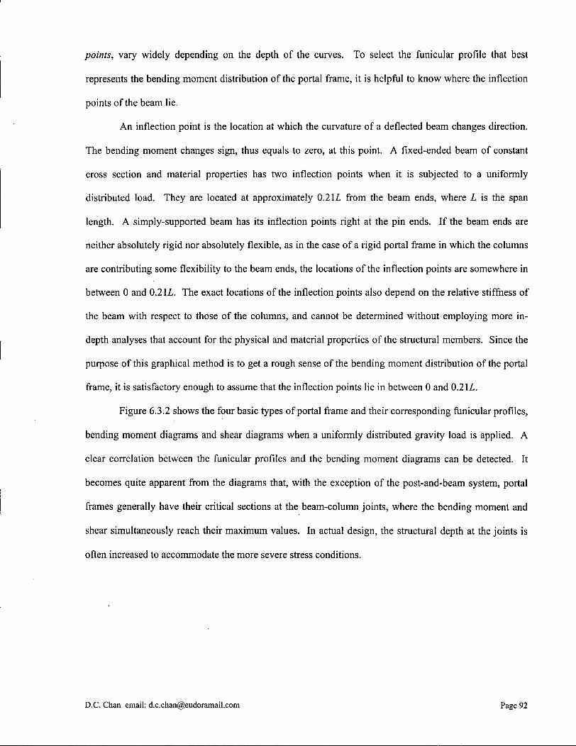
points, vary widely depending on the depth of the curves. To select the funicular profde that best
represents the bending moment distribution of the portal frame, it is helpful to know where the inflection
points of the beam lie.
An inflection point is the location at which the curvature of a deflected beam changes direction.
The bending moment changes sign, thus equals to zero, at this point. A fixed-ended beam of constant
cross section and material properties has two inflection points when it is subjected to a uniformly
distributed load. They are located at approximately 0.2 IL from the beam ends, where L is the span
length. A simply-supported beam has its inflection points right at the pin ends. If the beam ends are
neither absolutely rigid nor absolutely flexible, as in the case of a rigid portal frame in which the columns
are contributing some flexibility to the beam ends, the locations of the inflection points are somewhere in
between 0 and 0.2 IL. The exact locations of the inflection points also depend on the relative stiffness of
the beam with respect to those of the columns, and cannot be determined without employing more in-
depth analyses that account for the physical and material properties of the structural members. Since the
purpose of this graphical method is to get a rough sense of the bending moment distribution of the portal
frame, it is satisfactory enough to assume that the inflection points lie in between 0 and 0.2IL.
Figure 6.3.2 shows the four basic types of portal frame and their corresponding funicular profdes,
bending moment diagrams and shear diagrams when a uniformly distributed gravity load is applied. A
clear correlation between the funicular profdes and the bending moment diagrams can be detected. It
becomes quite apparent from the diagrams that, with the exception of the post-and-beam system, portal
frames generally have their critical sections at the beam-column joints, where the bending moment and
shear simultaneously reach their maximum values. In actual design, the structural depth at the joints is
often increased to accommodate the more severe stress conditions.
D.C. Chan email: [email protected] Page 92
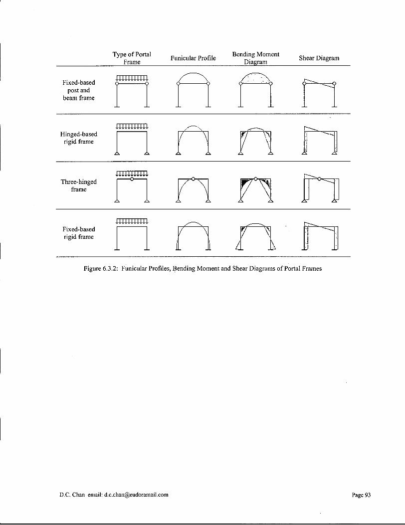
Type of Portal Frame
Funicular Profile Bending Moment Diagram
Shear Diagram
Fixed-based post and
beam frame
UUUU44I
Hinged-based rigid frame
Three-hinged frame
AT
Fixed-based rigid frame 7 ^
i i A
Figure 6.3.2: Funicular Profiles, Bending Moment and Shear Diagrams of Portal Frames
D.C. Chan email: [email protected] Page 93

6.4 Structural Analysis of Palais des Machines
The Palais des Machines for the Universal Exposition of Paris, 1889, is composed of a series of
three-hinged truss arches. By inspection, the arches are not funicular in shape. The profile deviation
creates bending moments at all points along the structure except at the hinges. Because three-hinged
arches are statically determinate structures, it is possible to solve for all the unknown forces by first
drawing the free-body diagram of each half-arch, and then applying the set of static equilibrium
equations: T,FX = 0, T,Fy = 0 and SM^, = 0. By means of graphic statics of three-force members, it can also
be deduced that the lines of action of the external forces for each half-arch, including the gravity load and
the reactions at the hinges, coincide at exactly one point due to rotational equilibrium requirement (Figure
6.4.3).
Figure 6.4.1: Palais des Machines subjected to a uniformly distributed load
Figure 6.4.2: Free-body diagrams o f half-arches
D.C. Chan email: [email protected] Page 94
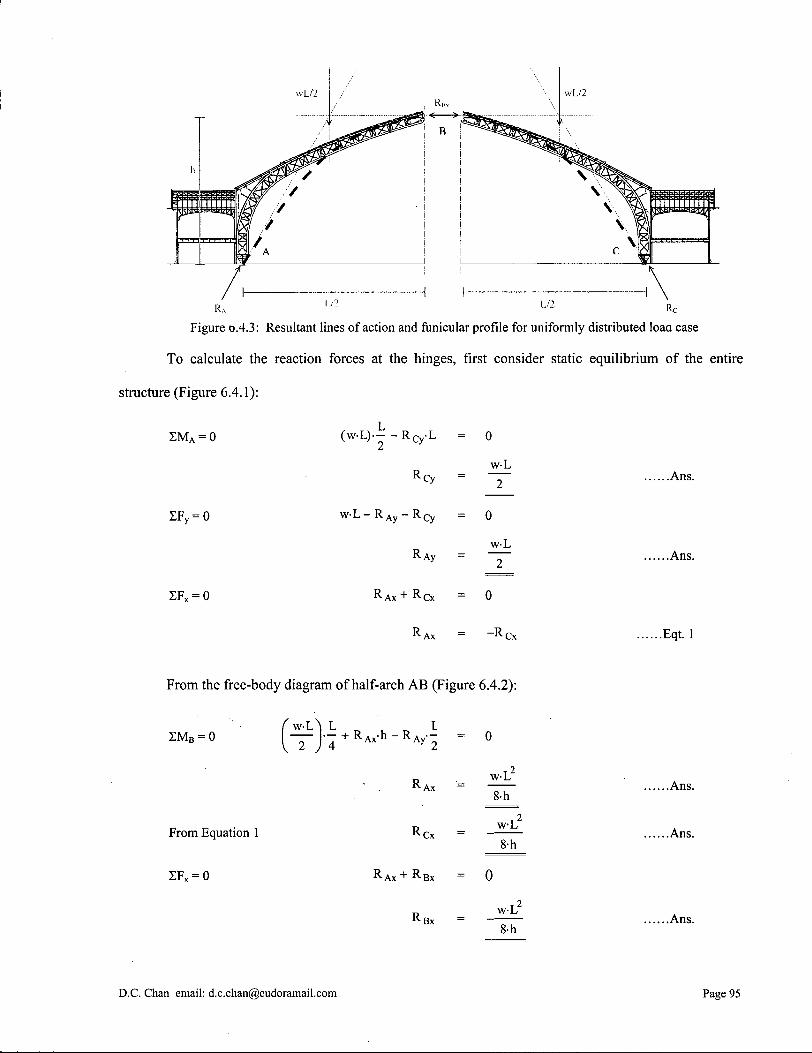
wL/2
K
Figure 0.4.3: Resultant lines of action and funicular profile for uniformly distributed load case
To calculate the reaction forces at the hinges, first consider static equilibrium of the entire
structure (Figure 6.4.1):
S M A = 0 (w-L)-- - R C y L
R Cy
0
w-L 2
EF y = 0
SF x = 0
w - L - R A y - R C y = 0
R ̂Ay w-L
2
R A x + R C x = 0
R Ax = ~R Cx
.Ans.
.Ans.
.Eqt. 1
From the free-body diagram of half-arch A B (Figure 6.4.2):
w-L\ L _ . _ L E M B = 0
From Equation 1
2FX = 0
2 ) 4 A x A y 2
R Ax
0
w-L
8-h
R w-L Cx
8-h
R A x + R B x = 0
R Bx w-L 8-h
.Ans.
.Ans.
.Ans.
D.C. Chan email: [email protected] Page 95
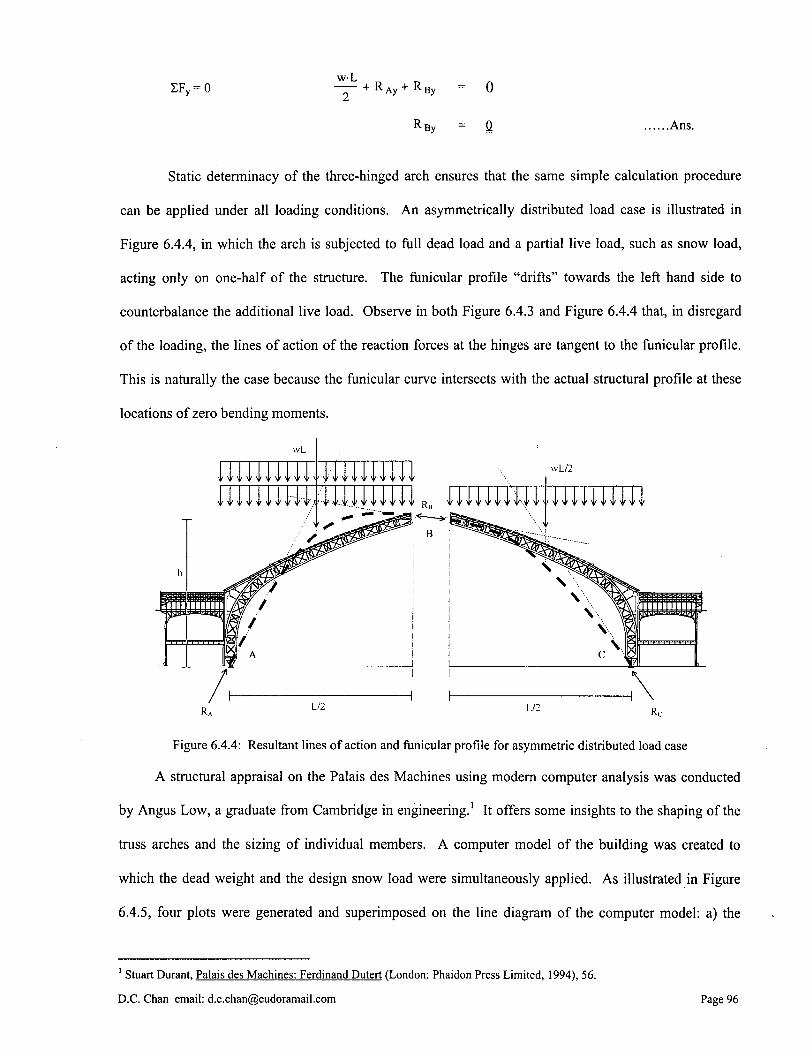
EFy = 0 w-L
+ R Ay + R By _ 0
R By = Q .Ans.
Static determinacy of the three-hinged arch ensures that the same simple calculation procedure
can be applied under all loading conditions. An asymmetrically distributed load case is illustrated in
Figure 6.4.4, in which the arch is subjected to full dead load and a partial live load, such as snow load,
acting only on one-half of the structure. The funicular profde "drifts" towards the left hand side to
counterbalance the additional live load. Observe in both Figure 6.4.3 and Figure 6.4.4 that, in disregard
of the loading, the lines of action of the reaction forces at the hinges are tangent to the funicular profde.
This is naturally the case because the funicular curve intersects with the actual structural profile at these
locations of zero bending moments.
wL
wL/2
\y-V-y..Y \y \y 4» \y \y \v n <l ^ y ^ V y-,^ ^
R A
L / - Rc
Figure 6.4.4: Resultant lines of action and funicular profile for asymmetric distributed load case
A structural appraisal on the Palais des Machines using modern computer analysis was conducted
by Angus Low, a graduate from Cambridge in engineering.1 It offers some insights to the shaping of the
truss arches and the sizing of individual members. A computer model of the building was created to
which the dead weight and the design snow load were simultaneously applied. As illustrated in Figure
6.4.5, four plots were generated and superimposed on the line diagram of the computer model: a) the
1 Stuart Durant, Palais des Machines: Ferdinand Dutert (London: Phaidon Press Limited, 1994), 56.
D.C. Chan email: [email protected] Page 96
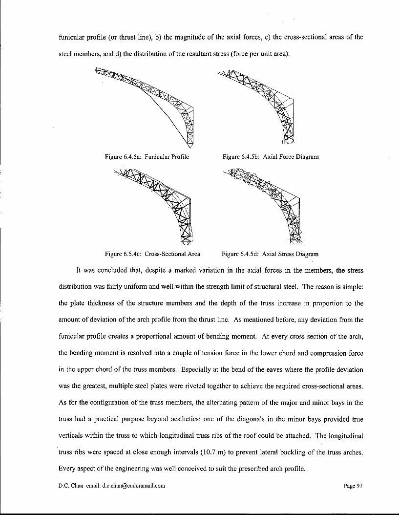
fAinicular profile (or thrust line), b) the magnitude of the axial forces, c) the cross-sectional areas of the
steel members, and d) the distribution of the resultant stress (force per unit area).
Figure 6.4.5a: Funicular Profile Figure 6.4.5b: A x i a l Force Diagram
Figure 6.5.4c: Cross-Sectional Area Figure 6.4.5d: A x i a l Stress Diagram
It was concluded that, despite a marked variation in the axial forces in the members, the stress
distribution was fairly uniform and well within the strength limit of structural steel. The reason is simple:
the plate thickness of the structure members and the depth of the truss increase in proportion to the
amount of deviation of the arch profile from the thrust line. As mentioned before, any deviation from the
funicular profile creates a proportional amount of bending moment. At every cross section of the arch,
the bending moment is resolved into a couple of tension force in the lower chord and compression force
in the upper chord of the truss members. Especially at the bend of the eaves where the profile deviation
was the greatest, multiple steel plates were riveted together to achieve the required cross-sectional areas.
As for the configuration of the truss members, the alternating pattern of the major and minor bays in the
truss had a practical purpose beyond aesthetics: one of the diagonals in the minor bays provided true
verticals within the truss to which longitudinal truss ribs of the roof could be attached. The longitudinal
truss ribs were spaced at close enough intervals (10.7 m) to prevent lateral buckling of the truss arches.
Every aspect of the engineering was well conceived to suit the prescribed arch profile.
D.C. Chan email: [email protected] Page 97

6.5 Structural Analysis of AEG Turbine Hall
The three-hinged structure of the A E G Turbine Hall can be analyzed in the same way as that of
the Palais des Machines. Note that the arch structure of the A E G Turbine Hall is asymmetric; the arch
bases have different elevations. The locations of the three hinges are points A, B and C in Figure 6.5.1.
At point D, the roof truss is rigidly connected to a longitudinal steel box girder, which in turn is supported
by fourteen box-sectioned steel pillars from point D to C. The longitudinal steel box girder runs the entire
length of the building, thus providing out-of-plane stability to the three-hinged arches. During the
structural analysis, the half-arch BDC can be treated as a rigid assembly.
For illustrative purpose, each half-arch is subjected to a different uniformly distributed load
(Figure 6.5.1). To calculate the reaction forces at the hinges, first consider static equilibrium of the entire
structure (Figure 6.5.2):
L/2 L/2
Figure 6.5.1: AEG Turbine Hall subjected to two uniformly distributed loads
D.C. Chan email: [email protected] Page 98
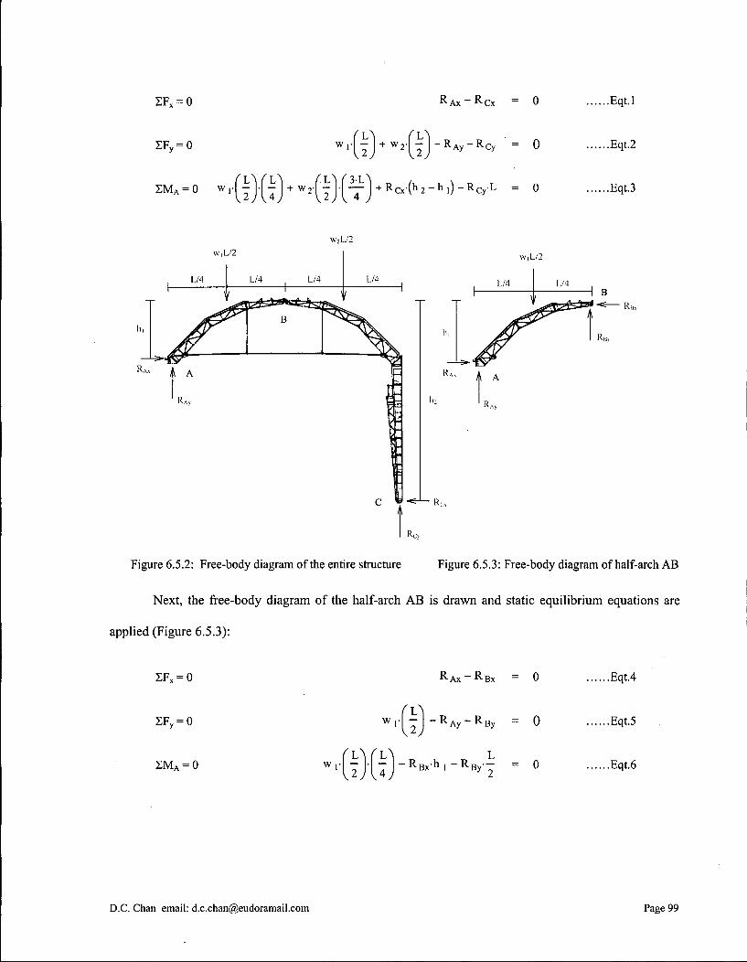
ZF x = 0
ZF y = 0
R A x _ R C x = 0
L \ f L w,-| - + w2- - I - R A u - R ( 2 1 V 2 ^Ay - ^ C y = 0
L / L l AL V 3 - L N , s Z M A = 0 w, - | - • - +w2- - • — + R C x ( h 2 - h , ) - R C Y L
L ) \ °> V . 2 / V 4
.Eqt.l
.Eqt.2
.Eqt.3
w2L/2 w,L .12
L/4 ( L/4 L/4
' \ i 1
w,L/2
L/4 L/4
Figure 6.5.2: Free-body diagram of the entire structure Figure 6.5.3: Free-body diagram of half-arch AB
Next, the free-body diagram of the half-arch A B is drawn and static equilibrium equations are
applied (Figure 6.5.3):
ZF x = 0
ZF y = 0
S M A = 0
R A x _ R B x = 0
W ,• —
•J R Ay ~ R By
, L L L w 1 ' I T ' T ~ R B x n 1 - R B y T I J V 4 J I
= 0
= 0
.Eqt.4
.Eqt.5
.Eqt.6
D.C. Chan email: [email protected] Page 99
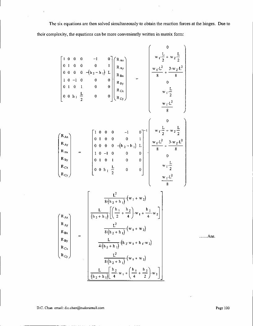
The six equations are then solved simultaneously to obtain the reaction forces at the hinges. Due to
their complexity, the equations can be more conveniently written in matrix form:
1 0 0 0
0 1 0 0
0 0 0 0
1 0 - 1 0
0 1 0 1
0 0 h , -
R
R
R
Ax
Ay
Bx
By
R C x
V R c y y
-1 0
0 1
"(h 2 - h j) L
0 0
' R A X ^
R Ay
RBX
R By
R C x
V R c y ;
0
L L W | 1- W 7
2 2
w i'L 3 - w r L
1 0 0 0 -1 0
0 1 0 0 0 1
0 0 0 0 - ( h 2 - h , ; L
1 0 -1 0 0 0
0 1 0 1 0 0
0 0 h , L
0 0
0
L w 1 —
2 T2
8
0
L L W i H W 2—
T2 -> T2 w | - L 3 w 2 - L
w ]-L
f R A x ^
R A y
R B x
R B y
R C x
V R c y y
8-(h 2 + h ,) W i + w -
( h 2 + h,)
( h _ 2 ^
V 2~ + T y W i H W T
4
8-(h 2 + h i) W I + w
2)
4-(h 2 + h,)
8-(h 2 + h,)
•(h 2-w , + h ,-w 2)
• ( w 1 + w 2 )
( h 2 + h,)
" h 2 h 2 ^ w + _|_ •w 2
_ 4 1 4 2 )
.Ans.
D.C. Chan email: [email protected] Page 100
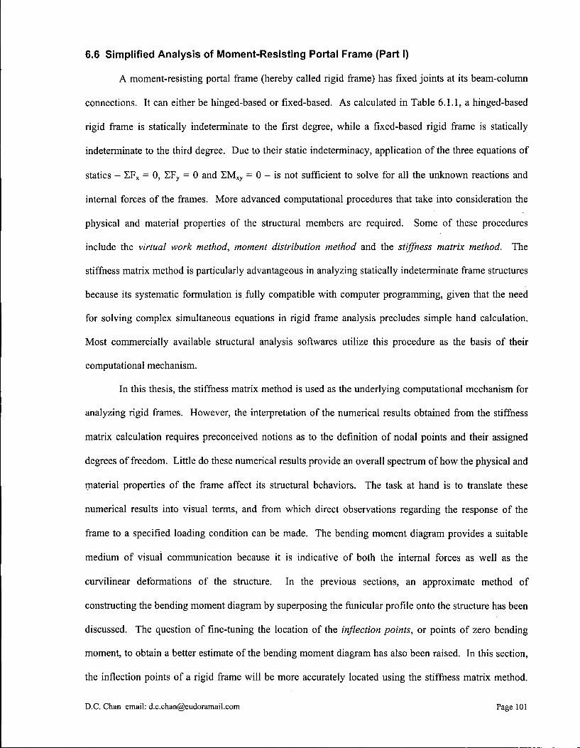
6.6 Simplified Analysis of Moment-Resisting Portal Frame (Part I)
A moment-resisting portal frame (hereby called rigid frame) has fixed joints at its beam-column
connections. It can either be hinged-based or fixed-based. As calculated in Table 6.1.1, a hinged-based
rigid frame is statically indeterminate to the first degree, while a fixed-based rigid frame is statically
indeterminate to the third degree. Due to their static indeterminacy, application of the three equations of
statics - EF X = 0, Z F y = 0 and X M x y = 0 - is not sufficient to solve for all the unknown reactions and
internal forces of the frames. More advanced computational procedures that take into consideration the
physical and material properties of the structural members are required. Some of these procedures
include the virtual work method, moment distribution method and the stiffness matrix method. The
stiffness matrix method is particularly advantageous in analyzing statically indeterminate frame structures
because its systematic formulation is fully compatible with computer programming, given that the need
for solving complex simultaneous equations in rigid frame analysis precludes simple hand calculation.
Most commercially available structural analysis softwares utilize this procedure as the basis of their
computational mechanism.
In this thesis, the stiffness matrix method is used as the underlying computational mechanism for
analyzing rigid frames. However, the interpretation of the numerical results obtained from the stiffness
matrix calculation requires preconceived notions as to the definition of nodal points and their assigned
degrees of freedom. Little do these numerical results provide an overall spectrum of how the physical and
material properties of the frame affect its structural behaviors. The task at hand is to translate these
numerical results into visual terms, and from which direct observations regarding the response of the
frame to a specified loading condition can be made. The bending moment diagram provides a suitable
medium of visual communication because it is indicative of both the internal forces as well as the
curvilinear deformations of the structure. In the previous sections, an approximate method of
constructing the bending moment diagram by superposing the funicular profile onto the structure has been
discussed. The question of fine-tuning the location of the inflection points, or points of zero bending
moment, to obtain a better estimate of the bending moment diagram has also been raised. In this section,
the inflection points of a rigid frame will be more accurately located using the stiffness matrix method.
D.C. Chan email: [email protected] Page 101

The generated plots showing the relationship between the locations of the inflection points and the
physical and material properties of the frame are particularly informative as they provide future reference
for the construction of bending moment diagrams and subsequently structural analysis of rigid frames.
6.6.1 Stiffness Matrix
The stiffness matrix method of analysis belongs to the so-called displacement method, in which
all unknown degrees of freedom of the structure D, are first identified and subsequently solved using
matrix formulation. The global stiffness matrix K of the whole structure is formed by combining local
stiffness matrices k of individual structural members; each member is defined by two nodes that mark its
ends. Because the construction of stiffness matrix requires equilibrium, constitutive (stress-strain
relationship) and compatibility (continuity of displacements) to be satisfied, by successive applications of
the method the displacements of the nodes as well as the internal forces of the structural members can
altogether be solved with much accuracy. Here the process of constructing the global stiffness matrices
for the fixed-based rigid frame and the hinged-based rigid frame is shown below:
_D4 d'=D:
d3=0
d5= D2
_d4=D,_
d3= D,
d2= D2
d6=D,
d,= D,
d5= D5
d6=D,
»2=0
d,= 0 d3=0
d5= D5
d4=D 4
%=0
d,= 0
Figure 6.6.1: Degrees of freedom for fixed-based rigid frame
Figure 6.6.2: Degrees of freedom for hinged-based rigid frame
D.C. Chan email: [email protected] Page 102

Stiffness matrix of column:
Stiffness matrix of beam:
kc =
121 c -61 c -12-1 c n -6-1 c
h3
yj h2 h3
U h2
0 A c h
0 0 - A c
h 0
-61 C 0
41 C 61 C 2-1 c
h2
0 h h2
u h
-121 c A 61 c 12 1 c 61 c
h3
U h2 h3
\j h2
0 - A c
h 0 0
Ac
h 0
-61 c
h2
0 21 C
h
61 c
h2
0 41 c h
AjB L
0 0 ~A B
L 0 0
0 121 B
L 3
61 B
L 2
0 --12-1 B
L 3
61 B
L 2
0 61 B
L 2
41 B
L 0
- 6 I B
L 2
21 B
L
" A B
L 0 0
A B
L 0 0
0 --12-1 B
L 3
-61 B
L 2
0 121 B
L 3
-61 B
L 2
0 61 B
L 2
21 B
L 0
-61 B
L 2
41 B
L
where E
A c
A B
Ic
IB
h
L
modulus of elasticity
cross sectional area of column
cross sectional area of beam
moment of inertia of column
moment of inertia of beam
length of column
span of beam
For fixed-based rigid portal frame:
Global Stiffness Matrix
K =
'k BII + k C44 k B12+ k C45 k BI3+ k C46 k BI4 kBI5 kB16
k B2I + k C54 k B22+ k C55 k B23+ k B56 k B24 kB25 kB26
k B3I + k C64 k B32+ k C65 k B33+ k C66 k B34 kB35 k B36
k B4I k B42 k B43 k B44 + k C44 k B45 + k C45 k B46+ k
k B5I kB52 kB53 k B54 + k C54 k B55 + k C55 k B56+ k
V kB6l kB62 k B63 k B64 + k C64 k B65 + k C65 k B66+ k
C46
C56
C66J
D.C. Chan email: [email protected] Page 103
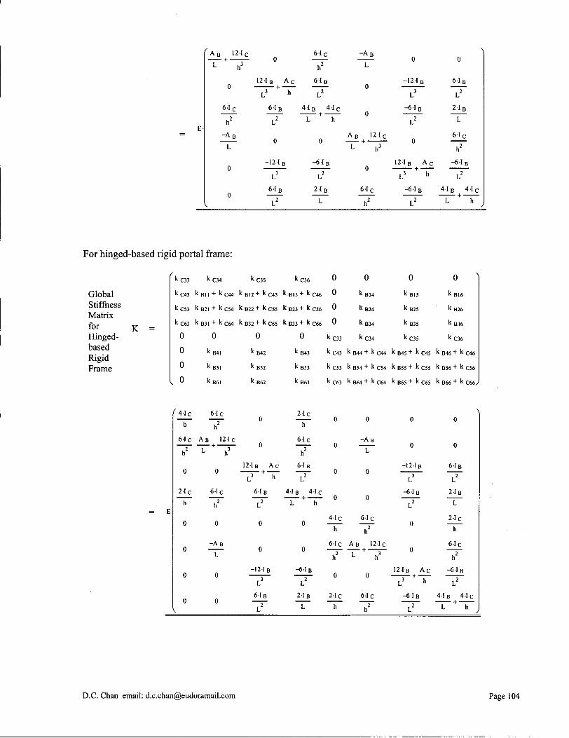
A B 12-1 c
L + u 3
61 c
h 2
~A B
L
0
121B A c
L 3 + h
61 B
L 2
0
-12-1 B
L 3
61 B
T 2
61 c
h 2
61 B T 2
4-1 B 41 c
L + h
0
-61 B
V
21 B L
A B 121C
L + u 3
61 C
u 2
0
-121 B
L 3
-61 B
L 2
0
121B A C
,3 + h
-6-1,
61 B
L 2
21 B L
61 C
h 2
-61 B
41 B 41 c
L + h
For hinged-based rigid portal frame:
kc33 kc34 kc35 kc36 0 0 0 0 N
Global kc43 k Bll + k C44 k B12+ k C45 k BI3+ k C46 0 k BI4 kB15 k B16 Stiffness kC53 k B21 + k C54 k B22+ k C55 k B23+ k C56 0 k B24 kB25 kB26 Matrix
0 for K = kC63 k B31 + k C64 k B32+ k C65 k B33+ k C66 0 k B34 kB35 k B36
Hinged- 0 0 0 0 kc33 kc34 kc35 kc36 based 0 k B41 k B42 k B43 kc43 k B44+ k C44 k B45+ k C45 k B46 + k C46 Rigid
0 Frame 0 k B5I k B52 kB53 kc53 k B54+ k C54 k B55+ k CS5 k B56 + k C56
, o k B6I k B62 k B63 kc63 k B64+ k C64 k B65+ k C65 k B66 + k C66/
4-1 c 61 c . 2
61 C A B 121 C
h L h
0 0
2-1 c h
61 c
IF 0
- A B
L
12-1 B A c
61 B
, 2 L
0
0
-121 B
61 B
21c h
61 c
6-1 B
41 B 4 1 C
L + h
0
0
-61 B
IF 2-1 B
L
4-1 c h
- A B
L
6-1 c , 2
61c A B 121 C
0 0
21 c h
61 c , 2
0
0
-121 B
-61 B
~\T 0
121B A c + —
-61 B
61 B
iT 21B
L
2-1 c h
61c
- 6 I B
41 B 4-1 C L + h
D.C. Chan email: [email protected] Page 104
6.6.2 Load Cases
Three load cases are applied to both types of rigid frames. These include a uniformly distributed
gravity load w, lateral point loads P that act on both beam-column joints (e.g. seismic inertial forces
lumped onto the nodes), and a lateral point load 2P that acts on one beam-column joint (e.g. wind loads).
These loading conditions are written in vector form Sj to facilitate subsequent matrix operations. It is
noted that the uniformly distributed load w must be represented by a set of equivalent nodal forces and
moments before it can be written in vector form. This so-called consistent load vector is defined as a set
of discrete nodal forces and moments by which the virtual work done is identical to that of the
continuously distributed load. The consistent load vector can also be viewed as the reverse of the
reactions at the nodes that restrains nodal displacements, in other words, the reverse of the reactions of a
fixed-supported beam.
Uniformly Distributed Gravity Load and Reactions
Figure 6.6.3: Consistent load vectors
-w-L 2
-w-L 2
12 0
-w-L 2
w-L2
v 12 ;
Fixed-based rigid frame:
w-L
12
w-L 2
Consistent Load Vectors
w-L
12
w-L 2
r2.?\ o o 0 0
V o ;
SP =
0 0 p
0
Hinged-base rigid frame:
0 -w-L 2
-w-L 2
12 0 0
-w-L 2
w-L2
^ 12 ;
f 0 > 2-P
0 0 0 0 0
V o ;
sP =
p
0 0 0 p
0 \0y
D.C. Chan email: [email protected] Page 105

After assembling the global stiffness matrix K and the load vectors Sj, the nodal displacements of
the frame structures Dj are found by the operation Dj•• = jCx Sj. The internal forces in each structural
member are then obtained by multiplying the local displacement vector with the local stiffness matrix of
the member. That is, sc = kc dj and SB = ks Qj. Bending moment diagrams are constructed according to
these calculated internal forces. Finally, the locations of the inflection points are plotted in relation to the
physical and material properties of the structural members for different load cases.
6.6.3 Inflection Point and Relative Stiffness
In Technical Note 6.3, it has been pointed out that there is a range in which the inflection point
lies that is dependent upon the end support conditions of the structural member. For example, when
subjected to a uniformly distributed load, a beam develops two inflection points symmetrically located at
each half-span. Their locations range from precisely at the ends when the beam is simply supported, to
approximately 0.21 L from the ends when the beam is fixed-supported, where L is the span of the beam.
The exact locations of the inflection points in the latter case can be calculated as follows:
w
From beam theory:
t " V L
By symmetry argument, the two inflection points are equidistant from the end supports.
Assuming each inflection point is located at a distance x from the end support, the free body diagram of
the beam section at the ends can be drawn. Taking rotational equilibrium at the inflection point:
D.C. Chan email: [email protected] Page 106

M L + w-x-| - j - V L - x
W 2 — x - V L - X + M L 2
= 0
Solving the quadratic equation:
2 ( W ^
v L - V L
2 - 4 - - - M L
\2J
2 - 1 ^ 2
w-L
2
w - L - 2-w-
w - L
X =
X =
II 1 V 2 ^ 4 6 y
0-2113 L
The result obtained by the beam theory can be applied to the analysis of rigid frame when it is
subjected to a uniformly distributed gravity load Sw- Because of the inherent flexibility of the supporting
columns, the end conditions of the beam lie somewhere in between a fixed end and a simply-supported
end. The exact structural behavior depends on the relative stiffness of the column with respect to that of
the beam. By intuition, if the stiffness of the beam approaches infinity, the columns become relative
flexible and offer no rotational restraint to the beam. The inflection points move towards the joints and
assume the conditions of a simply-supported beam. Conversely, if the stiffness of the columns
approaches infinity, the beam behaves as if it is fixed between two walls. The inflection points move
away from the joints and assume the conditions of a fixed-ended beam. In all cases, the location of the
inflection points is bounded within 0 and 0.2113 L. This phenomenon occurs in both the hinged-based
and the fixed-based rigid frames.
Inflection points can be, but not necessarily, developed in the columns when a rigid frame is
subjected to a uniformly distributed gravity load. Unlike the beam, the columns do not experience any
direct loading along their lengths. Thus, there is at most one inflection point developed per column. The
extreme locations of the inflection point in the columns can be found using a similar procedure. When a
uniformly distributed gravity load is applied to the beam, bending moment is transferred from the beam to
the columns due to joint rigidity. For a hinged-based rigid frame the inflection point is prescribed at the
D.C. Chan email: [email protected] Page 107
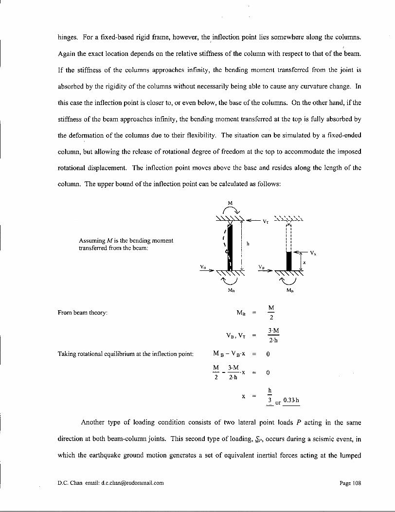
hinges. For a fixed-based rigid frame, however, the inflection point lies somewhere along the columns.
Again the exact location depends on the relative stiffness of the column with respect to that of the beam.
If the stiffness of the columns approaches infinity, the bending moment transferred from the joint is
absorbed by the rigidity of the columns without necessarily being able to cause any curvature change. In
this case the inflection point is closer to, or even below, the base of the columns. On the other hand, if the
stiffness of the beam approaches infinity, the bending moment transferred at the top is fully absorbed by
the deformation of the columns due to their flexibility. The situation can be simulated by a fixed-ended
column, but allowing the release of rotational degree of freedom at the top to accommodate the imposed
rotational displacement. The inflection point moves above the base and resides along the length of the
column. The upper bound of the inflection point can be calculated as follows:
Assuming M is the bending moment transferred from the beam:
From beam theory:
Taking rotational equilibrium at the inflection point:
M B = —
V B , V T
M B - V B - x
M 3-M 2-h
x =
M 2
3-M 2-h
= 0
3 o r 0.33-h
Another type of loading condition consists of two lateral point loads P acting in the same
direction at both beam-column joints. This second type of loading, Sp, occurs during a seismic event, in
which the earthquake ground motion generates a set of equivalent inertial forces acting at the lumped
D.C. Chan email: [email protected] Page 108
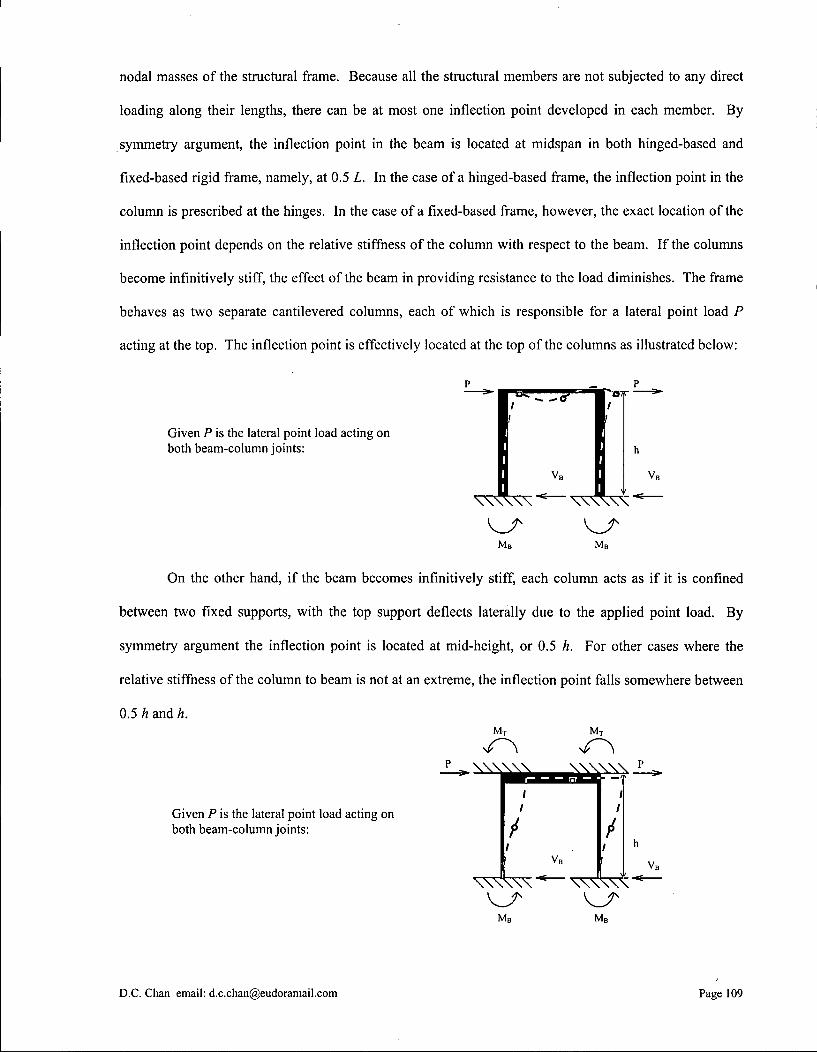
nodal masses of the structural frame. Because all the structural members are not subjected to any direct
loading along their lengths, there can be at most one inflection point developed in each member. By
symmetry argument, the inflection point in the beam is located at midspan in both hinged-based and
fixed-based rigid frame, namely, at 0.5 L. In the case of a hinged-based frame, the inflection point in the
column is prescribed at the hinges. In the case of a fixed-based frame, however, the exact location of the
inflection point depends on the relative stiffness of the column with respect to the beam. If the columns
become infmitively stiff, the effect of the beam in providing resistance to the load diminishes. The frame
behaves as two separate cantilevered columns, each of which is responsible for a lateral point load P
acting at the top. The inflection point is effectively located at the top of the columns as illustrated below:
Given P is the lateral point load acting on both beam-column joints:
07f
M B M B
On the other hand, if the beam becomes infmitively stiff, each column acts as if it is confined
between two fixed supports, with the top support deflects laterally due to the applied point load. By
symmetry argument the inflection point is located at mid-height, or 0.5 h. For other cases where the
relative stiffness of the column to beam is not at an extreme, the inflection point falls somewhere between
0.5 h and h.
Given P is the lateral point load acting on both beam-column joints:
M B M B
D.C. Chan email: [email protected] Page 109

The last load case Sjp involves a lateral point load 2P acting on one beam-column joint only.
Wind load belongs to this type of loading. This load case shares a lot of similarity with the previous load
case Sp, including the general shifting of the inflection points from one extreme value to the next.
However, there are also subtle differences due to the asymmetry of load application. Central to the
understanding of the structural behavior of an asymmetrically-loaded rigid frame is the question of how
well the system can transfer the load across the span and distribute it evenly into the columns. If so, the
frame responses much like in the symmetric load case Sj>. A rigid frame with a relatively stiff beam
behaves in this manner. When subjected to a lateral point load at one end, the beam deflects as a rigid
body and thereby induces the same amount of deflection to both columns at their tops. The internal
forces in both columns thus also become equal (recall that the relationship between the internal forces and
displacements of the columns is given by sc = kc dd- In other word, the rigidity of the beam helps
distributing the asymmetric load to both columns. This phenomenon is in disregard of the support
conditions at the column bases. For a hinged-based rigid frame, the inflection points are located at the column
bases and at midspan of the beam. For a fixed-based rigid frame, the inflection points are located at midspans of
both beam and columns.
Hinged-based rigid frame subjected to S2P
M B M B
Fixed-based rigid frame subjected to S2P
In the case of a stiff-column, flexible-beam rigid frame, the structural behavior is as follows. For
a hinged-based rigid frame, the free rotation at the bases ensures that the columns deflect by the same
amount. The inflection point in the beam resides at midspan simply by symmetry argument. In other
words, in disregard of the relative stiffness and the type of lateral load (Sp or SjP), a hinged-based rigid
frame always has its inflection points at the bases of the columns and at the midspan of the beam. In the
D.C. Chan email: [email protected] Page 110
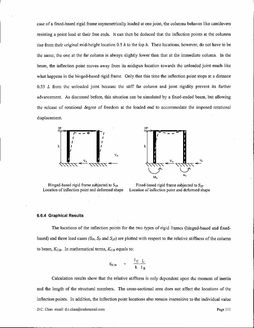
case of a fixed-based rigid frame asymmetrically loaded at one joint, the columns behaves like cantilevers
resisting a point load at their free ends. It can then be deduced that the inflection points at the columns
rise from their original mid-height location 0.5 h to the top h. Their locations, however, do not have to be
the same; the one at the far column is always slightly lower than that at the immediate column. In the
beam, the inflection point moves away from its midspan location towards the unloaded joint much like
what happens in the hinged-based rigid frame. Only that this time the inflection point stops at a distance
0.33 L from the unloaded joint because the stiff far column and joint rigidity prevent its further
advancement. As discussed before, this situation can be simulated by a fixed-ended beam, but allowing
the release of rotational degree of freedom at the loaded end to accommodate the imposed rotational
displacement.
2P
\ \ \ \ \ \ — \ \ \ \ \ \ '
Hinged-based rigid frame subjected to S2p
M B
Fixed-based rigid frame subjected to S 2p Location of inflection point and deformed shape Location of inflection point and deformed shape
6.6.4 Graphical Results
The locations of the inflection points for the two types of rigid frames (hinged-based and fixed-
based) and three load cases (Sw, SP and S2p) are plotted with respect to the relative stiffness of the column
to beam, KCm- In mathematical terms, KCm equals to:
Ic L KC/B - •
h I B
Calculation results show that the relative stiffness is only dependent upon the moment of inertia
and the length of the structural members. The cross-sectional area does not affect the locations of the
inflection points. In addition, the inflection point locations also remain insensitive to the individual value
D.C.Chan email: [email protected] Page 111
of each of these physical properties and the magnitude of the loads. The only exception is at the columns of a
fixed-based rigid frame under a uniformly distributed gravity load Sw, where the ratio between the column height
and beam length, h/L, has a significant bearing on the final result. This is particularly so when the KC/B value
increases. The assumptions here are an equal modulus of elasticity E for both beam and columns, and the two
columns being identical to each other. If the beam and columns are made from different materials, the expression of
KC/B can be modified as follows:
Ec - ! c L
h E B - I B
A Kern domain of 0.1 to 10 is considered the range for most practical applications. Values in this
domain serve to provide future reference for the construction of bending moment diagrams and
subsequent structural analysis of rigid frames. The plots listed here use a wider KaB domain of 0.001 to
1000 in order that the calculated extreme values shown in the graphs can be compared with our earlier
predictions. The ratio between the cross sectional areas of column and beam is set as 1.0. The ratio
between column height and beam length is set as 0.25 unless otherwise specified. Second order effect (P-
A effect) is not considered.
The graphical results below show a close match with our earlier predictions. There are indeed
well-defined extreme values of the inflection point locations when the relative stiffness of the column to
beam, KaB, becomes infinitely small or large. The plots also give a fairly accurate guide as to where the
inflection points should be located during the structural analysis of a rigid frame under different loading
conditions. With this piece of information, the frame can be dissected at its inflection points and free-
body diagrams of individual member sections can be drawn. Because bending moment is zero at the
inflection points, the total number of unknown internal forces of the entire structure is reduced to a
statically determinate condition. The internal forces and reactions can be calculated by writing the three
equations of statics - SF X = 0, Z F y = 0 and E M x y = 0 - for each member section. The bending moment
diagram of the rigid frame can then be constructed with incredible precision.
D.C. Chan email: [email protected] Page 112

LOCATION OF INFLECTION POINT Hinged-Based Rigid Frame under Syy
I f T= * • £ o "ft c
o o c o o
2 ro H -o — o
LOCATION OF INFLECTION POINT Hinged-Based Rigid Frame under Sp
-0.4-
-0:3-
-0:2-
-0r1-
- column
•beam
0.1 1 10
Relative Stiffness
100
P P
(b)
I f S ° a> _ j •E *• £ o
O o c * =
o u ro o
LOCATION OF INFLECTION POINT Hinged-Based Rigid Frame under S 2 P
-0.4-
-0:2-
-0r1-
- column
— beam
0.001 0.01 0.1 1 10
Relative Stiffness K̂ g 100
2P
(c)
Figure 6.6.4: Location of inflection points for hinged-based rigid frame
D.C. Chan email: [email protected] Page 113

LOCATION OF INFLECTION POINT
Fixed-Based Rigid Frame under S m
038
0.001 0.01 0.1 1 10
Relative Stiffness
100 1000
w
(a)
I f o o S -> t •*-£ o " f t c
O o
s 1 o — o
LOCATION OF INFLECTION POINT
Fixed-Based Rigid Frame under S p
0.001 0.01
0.8 |
0.4
•column
•beam
0.1 1 10
Relative Stiffness K,-B
100 1000
(b)
£ O
"S c
O o c *<
33 2 ™ o — o
LOCATION OF INFLECTION POINT
Fixed-Based Rigid Frame under S 2 P
- immediate column
-beam
far column
0.001 0.01 0.1 1 10 100
Relative Stiffness
2P
(c)
Figure 6.6.5: Location of inflection points for fixed-based rigid frame
D.C. Chan email: [email protected] Page 114

6.6.5 Inflection Point and Buckling Load
During structural design, it is necessary that a member satisfies certain strength requirements.
The method of constructing the bending moment diagram by locating the inflection points is shown in the
preceding sections. Because the relationship between the inflection point location and the relative
stiffness KaB value is established, the critical internal member forces and external reactions can be
conveniently obtained by assuming the physical and material properties of the member, and vise versa.
These properties include the moments of inertia IB and Ic, spans L and h; and moduli of elasticity EB and
Ec. In the end, the member is proportioned in order that the internal stresses are kept well within the
allowable magnitudes.
On the other hand, a member can fail even when it is stressed within the allowable limit. This is
the case when an unrestrained, slender column is subjected to an axial compressive force. The column
may deflect laterally or side-sway, thereby enters an unstable state called buckling. Quite often the
buckling of a column can lead to a sudden and drastic failure of a frame structure, and so it must be
accounted for during the design process. The stability of a column under an axial compression P depends
on its ability to restore itself, which is in turn based on its bending resistance. For a given set of Ic, h and
Ec values., there is a maximum axial force Pcr that the column can support before it buckles. This force is
called the critical buckling load or the Eular buckling load. In mathematical terms, Pcr can be expressed
as follows:
rc2-E-I (K-h)2
This is known as the Euler Buckling Equation. K is a dimensionless coefficient called the
effective length factor, while the product Kh is called the effective length of the column. The longer the
effective length is, the larger the effective slenderness of the column becomes, and the smaller the critical
buckling load will be. The effective length is in reference to a simply-supported column deflecting into a
single-curvature, half-sine-curve shape. K is set as unity in this case (Case 1: Figure 6.6.6a). For other
end support conditions, Kh equals to the equivalent length of the deflected column that exhibits a half-
sine curve. For example, in a fixed-ended column, two inflection points are developed at approximately
D.C.Chan email: [email protected] Page 115
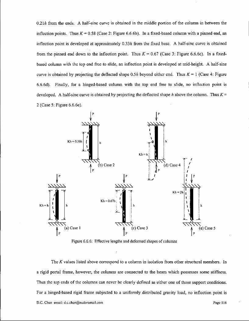
0.21/? from the ends. A half-sine curve is obtained in the middle portion of the column in between the
inflection points. Thus K - 0.58 (Case 2: Figure 6.6.6b). In a fixed-based column with a pinned end, an
inflection point is developed at approximately 0.33/? from the fixed base. A half-sine curve is obtained
from the pinned end down to the inflection point. Thus K = 0.67 (Case 3: Figure 6.6.6c). In a fixed-
based column with the top end free to slide, an inflection point is developed at mid-height. A half-sine
curve is obtained by projecting the deflected shape 0.5h beyond either end. Thus K = 1 (Case 4: Figure
6.6.6d). Finally, for a hinged-based column with the top end free to slide, no inflection point is
developed. A half-sine curve is obtained by projecting the deflected shape h above the column. Thus K =
2 (Case 5: Figure 6.6.6e).
K h = 0.58h
Kh = h
A. (b) Case 2 p
K h = h
A (d) Case 4
K h = 0.67h
K h = 2h
\ \ \ \ \ \ | (a) Case 1
p A (c) Case 3
\ \ \ \ \ \ A. (e) Case 5
p
Figure 6.6.6: Effective lengths and deformed shapes of columns
The K values listed above correspond to a column in isolation from other structural members. In
a rigid portal frame, however, the columns are connected to the beam which possesses some stiffness.
Thus the top ends of the columns can never be clearly defined as either one of those support conditions.
For a hinged-based rigid frame subjected to a uniformly distributed gravity load, no inflection point is
D.C.Chan email: [email protected] Page 116

developed along the columns. The deflection falls somewhere in between Case 1 and Case 5. Thus K can
range anywhere from 1 to 2. For a fixed-based rigid frame subjected to a uniformly distributed gravity
load, only one inflection point is developed along the columns. The deflection falls somewhere in
between Case 3 and Case 4. Thus K ranges from 0.67 to 1. At this point, it is clear that the inflection
point locations have a direct bearing on the effective length. Locating the inflection points help sketching
the deformed shape of the frame, thus a better estimate of the effective length.
D.C. Chan email: [email protected] Page 117
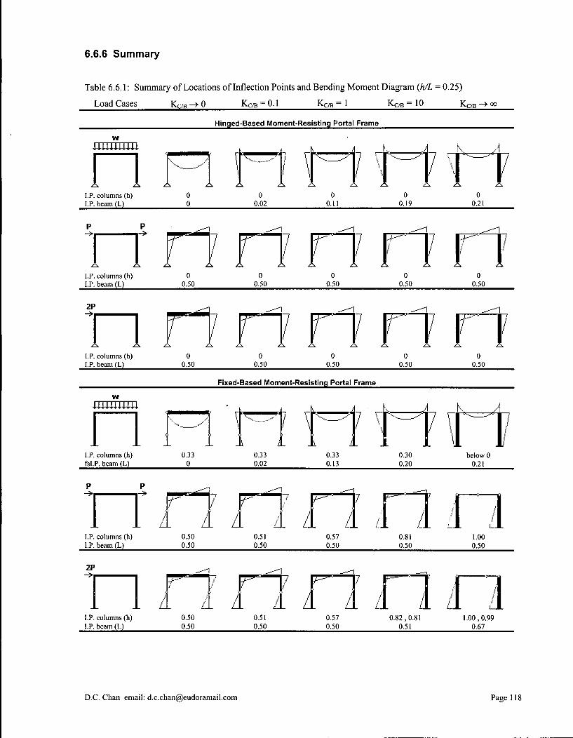
6.6.6 Summary
Table 6.6.1: Summary of Locations of Inflection Points and Bending Moment Diagram (h/L = 0.25)
Load Cases KQ/B -> 0 Kc / B = 0.1 Kc / B = 1 KC/B = 10 K C / B -> °o
Hinged-Based Moment-Resisting Portal Frame
w
I.P. columns (h) I.P. beam (L)
0 0
Z \ Z i
0 0.02
inn 0
0.11 0
0.19 0
0.21
n LP. columns (h) I.P. beam (L)
P --1
1 r 17
o 0.50
A . A 0
0.50
A A 0
0.50
I i n 0.50 0.50
2P n I.P. columns (h) I.P. beam (L)
n
0 0.50
/
0 0.50
n r 11 • i 0.50 0.50
0 0.50
Fixed-Based Moment-Resisting Portal Frame
J L
v . \
\ I \ v . . ^
i i \ i
7 V
n ' f i I.P. columns (h) fsI.P. beam (L)
0.33 0
0.33 0.02
0.33 0.13
0.30 0.20
below 0 0.21
I.P. columns (h) 0.50 0.51 0.57 0.81 1.00 I.P. beam (L) O50 O50 O50 O50 O50 no I.P. columns (h) 0.50 0.51 0.57 0.82,0.81 1.00,0.99 I.P. beam (L) O50 O50 O50 051 0.67
D.C. Chan email: [email protected] Page 118

6.7 Simplified Analysis of Moment-Resisting Portal Frame (Part 2)
As discussed in the previous section, the inflection points are the physical manifestation of the
complex mathematics behind rigid frame analysis. They are the stepping-stones upon which the solving
of internal forces and external reactions can proceed. Once the locations of the inflection points are
determined, the rigid frame can be dissected at those locations and free body diagrams of individual frame
segments can be drawn. At each cut, the bending moment is known to be zero (by definition of inflection
point). Thus, there leaves only an axial force and a shear force to be solved. The elimination of bending
moment at the cuts reduces the total number of unknown forces in the entire frame, thereby allowing a
statically indeterminate structure to be solved as if it were statically determinate. In this section, rigid
frames subjected to a uniformly distributed gravity load are analyzed by means of constructing free body
diagrams, given the locations of the inflection points in both columns and the beam..
6.7.1 Fixed-based rigid frame
Figure 6.7.1: Applied loads and Figure 6.7.2: Bending moment reactions; deflected shape diagram; inflection point locations
Figure 6.7.1 shows a fixed-based rigid frame subjected to a uniformly distributed gravity load, w;
the reaction forces at the bases, VB, FB and MB; and the deflected shape of the frame. By symmetry
argument, the left-half of the frame behaves identically to the right-half. At the joints, the beam is always
perpendicular to the columns in disregard of the deflected shape. Similarly, the columns are always
normal to the ground at their bases. Figure 6.7.2 shows the bending moment diagram and the locations of
the inflection points, or points of zero bending moment. It is worthwhile to note that, by beam theory:
D.C. Chan email: [email protected] Page 119

M j + M m
w-L 8
•(1)
•(2) M B + M j = V B -h
Free body diagrams for the five frame segments, dissected at four inflection point locations - p, q,
r and £ - are drawn in Figure 6.7.3 below. The first two segments to the left and the middle segment are
used for the analysis; the ones to the right are basically mirrored from the left ones. Starting from the
middle segment q-r and work counterclockwise to the left:
vr
1111
h-b
V V,
M, s i s FB' ' F,
Figure 6.7.3: Free body diagrams
V + V Q r w(L - 2 a )
w-(L- 2-a) .ans.
For frame segment p-q:
, a A w(L-2a) ^ „ 2M D = 0: w-a-| - +— - - a - F q - ( h - b )
2 1 2 = 0
SF x = 0: V - F
wa (L - a) 2 (h-b)
= 0
w-a (L - a) " ( h - b )
.ans.
.ans.
D.C. Chan email: [email protected] Page 120
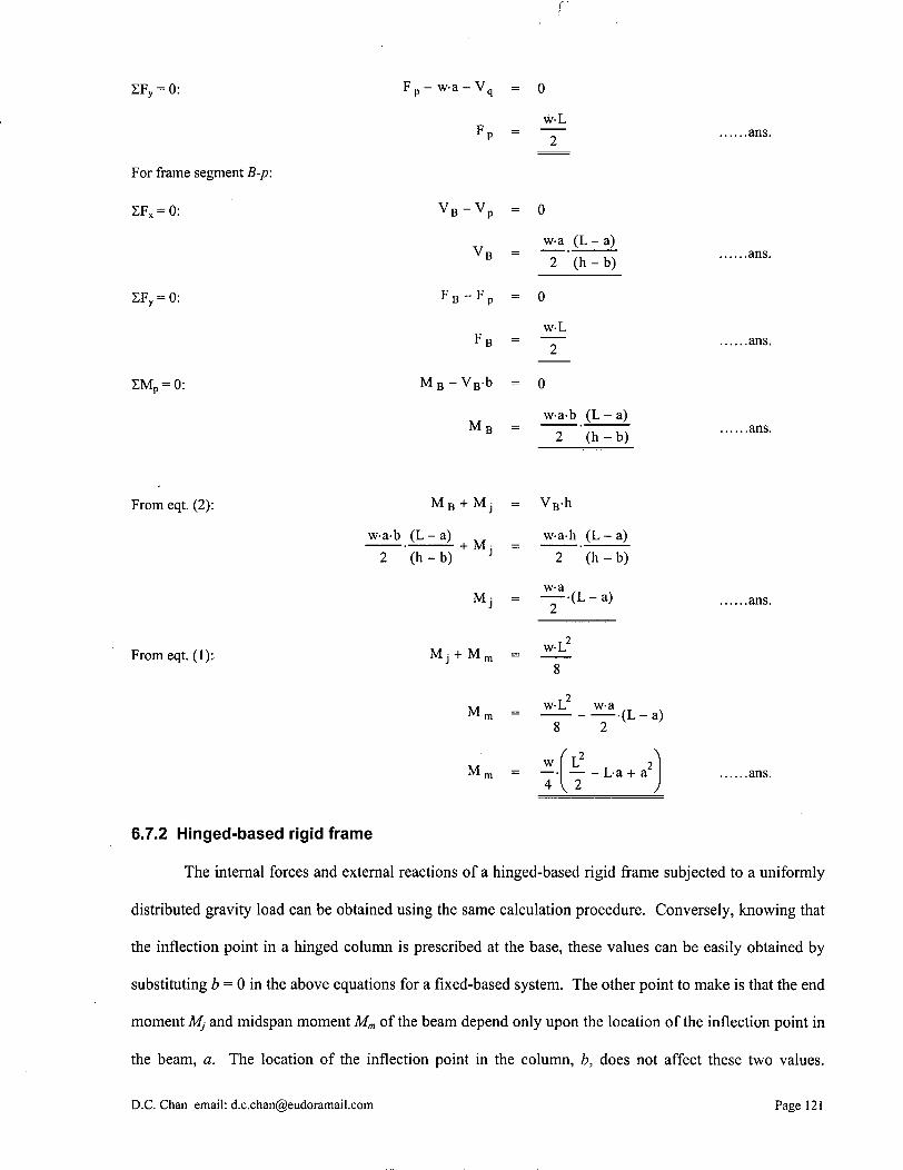
r
XFy = 0:
For frame segment B-p:
2FX = 0:
ZF y = 0:
Z M p = 0:
From eqt. (2):
From eqt. (1):
F p - w-a- V q
v B - v p
F B - F P
M B - V B b
M B
M B + M J
w-a-b (L-a) 2 (h-b)
+ M i
M i
M j + M m
M ,
M ,
= 0
w-L 2
= 0
w-a (L - a) 2 (h-b)
0
w-L 2
= 0
w-a-b (L-a) ~ 2 ~ ' ( h - b )
V B -h
w-a-h (L-a) 2 (h-b)
w-a — •(L-a)
2
T 2 w-L
8
w-L 8
w L 4 , 2
w-a — •(L-a)
2 \
.ans.
.ans.
.ans.
.ans.
.ans.
.ans.
6.7.2 Hinged-based rigid frame
The internal forces and external reactions of a hinged-based rigid frame subjected to a uniformly
distributed gravity load can be obtained using the same calculation procedure. Conversely, knowing that
the inflection point in a hinged column is prescribed at the base, these values can be easily obtained by
substituting b = 0 in the above equations for a fixed-based system. The other point to make is that the end
moment Mj and midspan moment Mm of the beam depend only upon the location of the inflection point in
the beam, a. The location of the inflection point in the column, b, does not affect these two values.
D.C. Chan email: [email protected] Page 121

Therefore, the bending moment diagram of the beam can be constructed independently from the columns.
This is particularly advantageous when analyzing a rigid frame with multiple spans (as in most skeletal
frame building construction), because the frame can be visualized as a continuous beam connected to a
series of point supports regardless of the support conditions at the column bases.
w * — ; : >
w y y y y y y y y y y y w
•XT-1
FB
Figure 6.7.4: Applied loads and reactions; deflected shape
Substituting b = 0 to the above equations:
Figure 6.7.5: Bending moment diagram; inflection point locations
B =
w-a ( L - a)
2-h w-L 2
.ans.
.ans.
M: = (L-a) j 2 .ans.
M, w 4
fL 2 T : L-a + a
V 2 j .ans.
6.7.3 Multi-span rigid frame
In the case of a multi-span rigid frame subjected to a uniformly distributed gravity load, the
analysis can become quite tedious, even if the frame has identical span lengths. First of all, the end spans
behave somewhat differently than the intermediate ones due to dissimilar joint continuity conditions.
More importantly, not all the spans have to be simultaneously loaded in a multi-span rigid frame. The so-
called partial loading condition is resulted from an unevenly distributed live load across the floor, and
must be accounted for in actual design practice. In any span where the continuity conditions are different
at both ends, or the loadings are different on the adjacent sides, the bending moment distribution of that
span becomes asymmetric. This often produces the most critical positive and negative bending moments.
D.C. Chan email: [email protected] Page 122
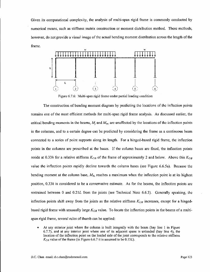
Given its computational complexity, the analysis of multi-span rigid frame is commonly conducted by
numerical means, such as stiffness matrix construction or moment distribution method. These methods,
however, do not provide a visual image of the actual bending moment distribution across the length of the
frame.
© © © © © © Figure 6.7.6: Multi-span rigid frame under partial loading condition
The construction of bending moment diagram by predicting the locations of the inflection points
remains one of the most efficient methods for multi-span rigid frame analysis. As discussed earlier, the
critical bending moments in the beams, Mj and Mm, are unaffected by the locations of the inflection points
in the columns, and to a certain degree can be predicted by considering the frame as a continuous beam
connected to a series of point supports along its length. For a hinged-based rigid frame, the inflection
points in the columns are prescribed at the bases. If the column bases are fixed, the inflection points
reside at 0.33/J for a relative stiffness KCIB of the frame of approximately 2 and below. Above this KC/B
value the inflection points rapidly decline towards the column bases (see Figure 6.6.5a). Because the
bending moment at the column base, MB, reaches a maximum when the inflection point is at its highest
position, 0.33A is considered to be a conservative estimate. As for the beams, the inflection points are
restrained between 0 and 0.2 IL from the joints (see Technical Note 6.6.3). Generally speaking, the
inflection points shift away from the joints as the relative stiffness KC/B increases, except for a hinged-
based rigid frame with unusually large KaB value. To locate the inflection points in the beams of a multi-
span rigid frame, several rules of thumb can be applied:
• At any exterior joint where the column is built integrally with the beam (bay line 1 in Figure 6.7.7), and at any interior joint where one of its adjacent spans is unloaded (bay line 4), the location of the inflection point on the loaded side of the joint corresponds to the relative stiffness KC/B value of the frame (in Figure 6.6.7 it is assumed to be 0.151).
D.C. Chan email: [email protected] Page 123

• At any interior joint where both of its adjacent spans are fully loaded (bay lines 2 and 3), the locations of the inflection points on both sides correspond a larger KC/B value than that of the frame, i.e. between 0.15L and 0.2IL.
• At any unrestrained exterior joint, the inflection point is located at the joint (bay line 6). The inflection point at the first interior support can be conservatively taken as 0.191 from the joint (bay line 5).
0.15L 0.15-0.21L 0.15-0.21L
Figure 6.7.7: Bending moment diagram; locations of inflection points
Once the locations of the inflection points ai and aR are determined, the magnitudes of the
positive and negative bending moments for each span can be calculated by the following equations.
These equations are derived from basic quadratic functions, and are summarized in the diagram below:
For each span:
where
M(x)
M(x) = p-x2 + q-x+r
P = w-L
2 - ( L + a L - a R ) - ( - L + a L - a R )
-w-L
M j R =
M m =
2 - ( - L + a L - a R )
( L - aR)-aL-w-L 2
2 - ( L + a L - a R ) - ( - L + a L - a R )
MG)
MM
L ' M
L+ a L - a R ^
.ans.
.ans.
.ans.
Figures 6.7.8 and 6.7.9 show the calculated values of MJL, MJR and MM for the two extreme cases
under consideration. In actual design practice, the highest positive and negative bending moments that
can possibly occur are used as design values. This leads to the concept of constructing bending moment
envelope, where bending moment diagrams for different load cases are superimposed onto each other so
that the most critical design values are singled out. Because it is entirely possible that an originally
D.C. Chan email: [email protected] Page 124

loaded span can become unloaded at any instance, and vise versa, the critical design values will
eventually only depend upon the position of the span and its joint continuity at both ends (Figure 6.7.10). For
comparison purpose, Figure 6.7.11 shows the design values listed in the CSA Standard A23.3-94 Design of
Concrete Structures, which show a close resemblance to our estimated values.
19
( ± 1 1— 17 ' "—• | 10 11
I 1 12
Figure 6.7.8: Critical positive and negative bending moments (in terms of wL2) ± ± ± - i -16 16 16
10 16 16
I 1 ) ( 3 , ( 4 )
Figure 6.7.9: Critical positive and negative bending moments (in terms of wL2)
_i_ 16 16 16
_1_ 16
J_ 12
-1 16 12 12
( 1 ) ( 2 ) 1. 4 t 6 i
Figure 6.7.10: Critical design values using the inflection point method (in terms of wL2)
\_
16 16 16 n
(«) Figure 6.7.11: Critical design values using the CSA Standard (in terms of wL2)
D.C. Chan email: [email protected] Page 125

6.8 Two-Way Reinforced Concrete Slab System
Two-way slab system is a form of construction unique to reinforced concrete. Its wide
acceptance in the building industry is due to its efficiency and economy. Structurally speaking, two-way
slabs are most suitable to column grids with a square or nearly-square proportion, in which case the
critical bending moments are often found to be smaller than those in one-way slabs. The more
rectangular a slab becomes, the more it behaves as a one-way rather than a two-way system. In actual
design practice, the ratio between bay dimensions is often taken as 1 : 1.5 below which two-way action
can be considered. The other case in which a two-way slab may experience predominately one-way load
transfer is when there are beams of very different stiffnesses spanning in between the columns. If the
beams running in one direction are significantly stiffer than those running in the other direction, larger
curvature is obtained in the direction perpendicular to the stiffer beams, implying that there is also a larger
moment transfer in that direction.
1 r "1
f -M K
L
\ ' c
• y
J * \. £ y
J
L
J
Figure 6.8.1: Bending moment diagrams across y-axis
Figure 6.8.2: Bending moment distributions across x-axis
The multi-directional load dispersal characteristic in two-way slabs causes a continuously
changing bending moment distribution along the width of the slab. For a typical interior slab subjected to
a uniformly distributed gravity load, w' (in kN/m2), bending moment per unit width is often found to be
larger in the strips spanning between the columns than between midspans (Figures 6.8.1 and 6.8.2). This
phenomenon takes place equally in both span directions. Simplified design procedures allow the slab to
be divided into the column strip and the middle strip, each of which has a width of haft of the span, or
D.C. Chan email: [email protected] Page 126
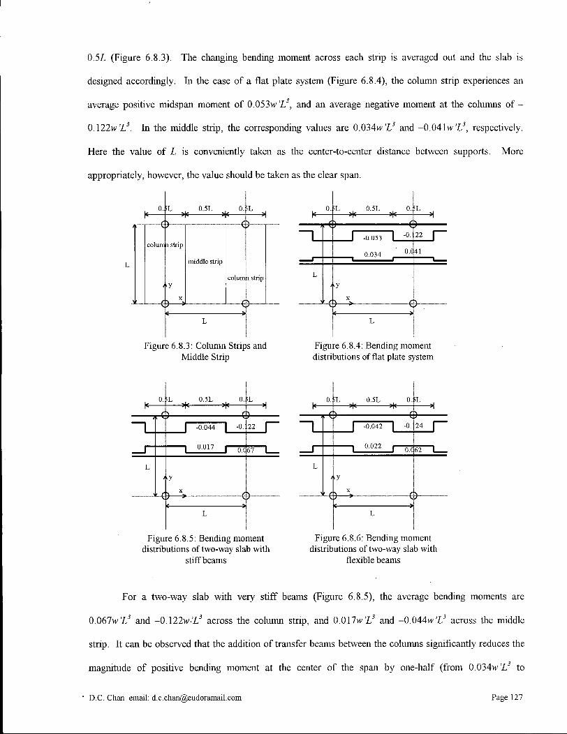
0.5L (Figure 6.8.3). The changing bending moment across each strip is averaged out and the slab is
designed accordingly, hi the case of a flat plate system (Figure 6.8.4), the column strip experiences an
average positive midspan moment of 0.053w 'L3, and an average negative moment at the columns of -
0A22w'L3. In the middle strip, the corresponding values are 0.034ve'Z,3 and -0.041wZ 5, respectively.
Here the value of L is conveniently taken as the center-to-center distance between supports. More
appropriately, however, the value should be taken as the clear span.
fL 0.5L 0. — * *
column strip
0 — ^
middle strip
colump strip
Figure 6.8.3: Column Strips and Middle Strip
fL 0.5L 0.
4
fL
-0.053
0.034
•0.122
0.041
Figure 6.8.4: Bending moment distributions of flat plate system
fL 0.5L 0. — * * •
4-
fL
-9" -0.044 | -0.
0.017 0TT67
4-
22
Figure 6.8.5: Bending moment distributions of two-way slab with
stiff beams
fL 0.5L 0. * * •
5L
-0.042 | -0.
0.022 0.062
24
Figure 6.8.6: Bending moment distributions of two-way slab with
flexible beams
For a two-way slab with very stiff beams (Figure 6.8.5), the average bending moments are
0.067w'Z3 and -0.\22w'L3 across the column strip, and O.Ollw'L3 and -0.044w'Z/ across the middle
strip. It can be observed that the addition of transfer beams between the columns significantly reduces the
magnitude of positive bending moment at the center of the span by one- half (from 0.034w'Z/ to
D.C. Chan email: [email protected] Page 127
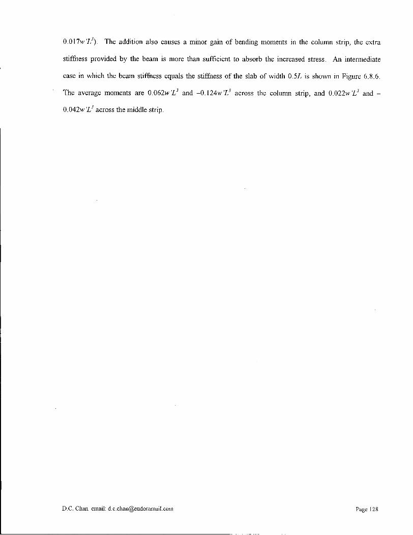
Q.Qllw'L3). The addition also causes a minor gain of bending moments in the column strip, the extra
stiffness provided by the beam is more than sufficient to absorb the increased stress. An intermediate
case in which the beam stiffness equals the stiffness of the slab of width 0.5L is shown in Figure 6.8.6.
The average moments are 0.062w'Z5 and -0.124wX 5 across the column strip, and 0.022w'L3 and -
0.042w 'L3 across the middle strip.
D.C. Chan email: [email protected] Page 128

7.0 Bibliography
Allen, Edward. Fundamentals of Building Construction: Materials and Methods. 3r d ed. New York: John Wiley & Sons, Inc., 1999.
Anna, Susanne. Archi-Neering: Helmut Jahn and Werner Sobek. Ostfildern: Hatje Cantz Verlag, 1999.
Benton, Tim. The Villas of Le Corbusier. 1920-1930. New Haven and London: Yale University Press, 1987.
Besset, Maurice. Le Corbuiser. Geneve: Editions d'Art Albert Skira S.A., 1987.
Blaser, Werner. Mies van der Rohe: The Art of Structure. New York: Whitney Library of Design, imprint of Watson-Guptill Publications, 1993.
Buddensieg, Tilmann and Henning Rogge. "Peter Behrens and the A E G Architecture." Lotus International 12, September 1976: 90-127.
Carter, Peter. Mies van der Rohe at Work. New York: Praeger Publishers, Inc., 1974.
Peschken, Goerd and Tilmann Heinisch. "Berlin at the Beginning of the Twentieth Century." Berlin: An Architectural History. Doug Clelland. London: A D Publications Ltd., 1983. 40-43.
Collins, Peter. Concrete: The Vision of A New Architecture. London: Faber and Faber Limited, 1959.
Condit, Carl W. The Rise of the Skyscraper. Chicago: The University of Chicago Press, 1952.
Curtis, William J. R. Modern Architecture Since 1900.3rd ed. London: Phaidon Press Limited, 1996.
Durant, Stuart. Palais des Machines: Ferdinand Dutert. London: Phaidon Press Limited, 1994.
Fontein, Lucie. "Reading Structure Through The Frame." Perspecta 31, 2000: 50-59.
Ford, Edward. The Details of Modern Architecture. Cambridge: MIT Press, 1990.
Foster, Michael, edited. Architecture: Style. Structure and Design. New York: Quill Publishing Limited. 1982.
Fraser, Derek. The Buildings of Europe. Manchester: Manchester University Press, 1996.
Giedion, Sigfried. Building in France. Building in Iron. Building in Ferroconcrete. Santa Monica: Getty Center for the History of Art and the Humanities, 1995.
Gossel, Peter and Gabriele Leuthauser. Architecture in the Twentieth Century. Koln: Benedikt Taschen Verlag GmbH, 1991.
Henser, Mechtild. "La finestra sul cortile. Behrens e Mies van der Rohe: AEG-Turbinenhalle; Berlino 1908-1909." Casabella 651/652. Dec 1997-Jan 1998:19-22.
Hibbeler, Russell C. Structural Analysis. 3rd ed. Englewood Cliffs: Prentice Hall, 1990.
D.C. Chan email: [email protected]
Hymen, Isabelle and Marvin Trachtenberg. Architecture. From Prehistory to Post-Modernism / The Western Trandition. Englewood Cliffs: Prentice-Hall, Inc. and New York: Harry N. Abrams, Inc., 1986.
Jencks, Charles. Le Corbusier and the Tragic View of Architecture. Cambridge: Harvard University Press, 1973.
McCormac, Jack C. Design of Reinforced Concrete. 3rd ed. New York: HarperCollins College Publishers, 1993.
Nervi, Pier Luigi. Aesthetics and Technology in Building. Cambridge: Harvard University Press, 1966.
Ogg, Alan. Architecture in Steel: The Australian Context. The Royal Australian Institute of Architecture. 1987.
Pawley, Martin. Mies van der Rohe. New York: Simon and Schuster, 1970.
Salvadori, Mario. Why Buildings Stand Up: The Strength of Architecture. New York, Norton, 1980.
Schodek, Daniel L. Structures, ed. Englewood Cliffs: Prentice-Hall, Inc., 1992.
Schueller, Wolfgang. Horizontal-Span Building Structures. New Work: John Wiley & Sons, Inc., 1983.
Spaeth, David. Mies van der Rohe. New York: Rizzoli International Publications, Inc., 1985.
Spiegel, Herman D. J. "Site Visits: An Engineer Reads Le Corbusier's Villas." Perspecta31. 2000: 86-95.
Windsor, Alan. Peter Behrens: Architect and Designer 1868-1940. London: The Architectural Press, 1981.
Zalewski, Waclaw and Edward Allen. Shaping Structures. Statics. New York: John Wiley & Sons, Inc., 1998.
D.C. Chan email: [email protected] 130

8.0 Citations of Figures
Chapter 1
Figure 1.1:
William J. R. Curtis, Modern Architecture Since 1900. 3rd ed. (London: Phaidon Press Limited, 1996),
Figure 1.2:
Michael Foster, edited, Architecture: Style. Structure and Design (New York: Quill Publishing Limited 1982), 12. Figure 1.3: Peter Gossel and Gabriele Leuthauser, Architecture in the Twentieth Century (Koln: Benedikt Taschen Verlag GmbH, 1991), 251.
Figure 1.4: Gossel and Leuthauser, 34.
Figure 1.5: Curtis, 76.
Figure 1.6: Gossel and Leuthauser, 21.
Figure 1.7: Foster, 110.
Figure 1.8: Curtis, 48.
Figure 1.9: Curtis, 85.
Figure 1.10: Curtis, 271.
Chapter 2
Figure 2.1: Curtis, 74.
Figure 2.2:
Gossel and Leuthauser, 28.
Figure 2.3: Stuart Durant, Palais des Machines: Ferdinand Dutert (London: Phaidon Press Limited, 1994), 41.
Figure 2.4: Durant, 38.
D.C. Chan email: [email protected] 1
Figure 2.5: Durant, 30.
Figure 2.6: Durant, 29.
Figure 2.7:
Gossel and Leuthauser, 92.
Figure 2.8: Mechtild Henser, "La finestra sul cortile. Behrens e Mies van der Rohe: AEG-Turbinenhalle; Berhno 1908-1909." Casabella 651/652, Dec 1997-Jan 1998: 23.
Chapter 3
Figure 3.1: Alan Ogg, Architecture in Steel: The Australian Context (The Royal Australian Institute of Architecture, 1987), 69.
Figure 3.2: Ogg, 69.
Figure 3.3: Curtis, 46.
Figure 3.4: Carl W. Condit, The Rise of the Skyscraper (Chicago: The University of Chicago Press, 1952), 64.
Figure 3.5: Curtis, 42.
Figure 3.6:
Martin Pawley, Mies van der Rohe (New York: Simon and Schuster, 1970), 1.
Figure 3.7: Werner Blaser, Mies van der Rohe: The Art of Structure (New York: Whitney Library of Design, an imprint of Watson-Guptill Publications, 1993), 83.
Figure 3.8: David Spaeth, Mies van der Rohe (New York: Rizzoli International Publications, Inc., 1985), 153.
Figure 3.9: Curtis, 271.
Figure 3.10: Blaser, 30.
Figure 3.11: Blaser, 27.
Figure 3.12: Edward Ford, The Details of Modern Architecture (Cambridge: MIT Press, 1990), 270.
D.C. Chan email: [email protected] 132

Figure 3.13: Curtis, 401.
Figure 3.14: Peter Carter, Mies van der Rohe at Work (New York: Praeger Publishers, Inc., 1974), 72.
Figure 3.15: Blaser, 67.
Figure 3.16: Carter, 73.
Figure 3.17: Blaser, 71.
Figure 3.18: Blaser, 77.
Figure 3.19: Blaser, 75.
Figure 3.20: Carter, 74.
Figure 3.21: Curtis, 402.
Figure 3.22: Pawley, 7.
Figure 3.23: Spaeth, 150.
Figure 3.24: Spaeth, 151.
Figure 3.25: Ogg, 94.
Chapter 4
Figure 4.1: Peter Collins, Concrete: The Vision of A New Architecture (London: Faber and Faber Limited, 1959), plate 36.
Figure 4.2: Curtis,'284.
Figure 4.3: Gert Sperling. The Quadrivium in the Pantheon of Rome. NEXUS'98: Second International, Interdisciplinary Conference on Relationships Between Architecture and Mathematics. 18 June 2001 <http ://www. leonet.it/culture/nexus/98/Sperling .html>.
D.C. Chan email: [email protected]

Figure 4.4: Collins, plate 12A.
Figure 4.5: Curtis, 76.
Figure 4.6 (a): Jack C. McCormac, Design of Reinforced Concrete, 3rd ed. (New York: HarperCollins College Publishers, 1993), 524.
Figure 4.6 (b): McCormac, 523.
Figure 4.6 (c): McCormac, 523.
Figure 4.7: Daniel L. Schodek, Structures, ed. (Englewood Cliffs: Prentice-Hall, Inc., 1992), 379.
Figure 4.8: Curtis, p.78.
Figure 4.9: Curtis, p.78.
Figure 4.10: Collins, plate 51.
Figure 4.11: Collins, plate 50.
Figure 4.12: Charles Jencks, Le Corbusier and the Tragic View of Architecture (Cambridge: Harvard University Press, 1973), 50.
Figure 4.13: Curtis, 85.
Figure 4.14:
Maurice Besset, Le Corbuiser (Geneve: Editions d'Art Albert Skira S.A., 1987), 102.
Figure 4.15: Curtis, 277 and Besset, 104. Figure 4.16: Curtis, 283.
Figure 4.17: Curtis, 276.
Figure 4.18: Curtis, 283.
D.C. Chan email: [email protected] 134
Figure 4.19: Besset, 157.
Figure 4.20: Curtis, 431.
Figure 4.21: Pier Luigi Nervi, Aesthetics and Technology in Building (Cambridge: Harvard University Press, 1966), 67.
Chapter 5
Figure 5.1: Gossel and Leuthauser, 10.
Figure 5.2: Spaeth, 149.
Figure 5.3:
Gossel and Leuthauser, 324
Figure 5.4: Gossel and Leuthauser, 329.
D.C. Chan email: [email protected]
Related Documents


![[Nowak] Structural Ism and Semiotics in Philosophical Aesthetics](https://static.cupdf.com/doc/110x72/577d238e1a28ab4e1e9a20b4/nowak-structural-ism-and-semiotics-in-philosophical-aesthetics.jpg)


