Seminar 8 Building Spacecraft & Launch Vehicles Space Vehicle Design FRS 112, Princeton University Robert Stengel Copyright 2015 by Robert Stengel. All rights reserved. For educational use only. http://www.princeton.edu/~stengel/FRS.html Building Spacecraft & Launch Vehicles Chariots for Apollo, NASA-SP-4205, Ch 3 to 7 Stages to Saturn, NASA-SP-4206, Parts & IV Space Vehicle Design Understanding Space, Ch 11, Sec 13.3, 13.4 1 • Defining a mode for the mission, who would execute it • What was the goal? • First LOR proposals; Tom Dolan, Vought Astronautics, 1958 • Energy budgets • MALLAR, MORAD, ARP, MALLIR • Safety and reliability of LOR • Number of launches, complexity of systems • Evolution: Mercury, Mercury II (Gemini) • Dynamics of lunar touchdown Contending Modes 2

Welcome message from author
This document is posted to help you gain knowledge. Please leave a comment to let me know what you think about it! Share it to your friends and learn new things together.
Transcript

Seminar 8!Building Spacecraft & Launch Vehicles!
Space Vehicle Design!FRS 112, Princeton University!
Robert Stengel"
Copyright 2015 by Robert Stengel. All rights reserved. For educational use only.!http://www.princeton.edu/~stengel/FRS.html!
Building Spacecraft & Launch Vehicles !Chariots for Apollo, NASA-SP-4205, Ch 3 to 7 !
Stages to Saturn, NASA-SP-4206, Parts & IV!!
Space Vehicle Design " "Understanding Space, Ch 11, Sec 13.3, 13.4!
1!
•# Defining a mode for the mission, who would execute it"
•# What was the goal?"•# First LOR proposals; Tom Dolan, Vought
Astronautics, 1958"•# Energy budgets"•# MALLAR, MORAD, ARP, MALLIR"•# Safety and reliability of LOR"•# Number of launches, complexity of systems"•# Evolution: Mercury, Mercury II (Gemini)"•# Dynamics of lunar touchdown"
Contending Modes"
2!

•# Reaching consensus"•# Centralizing decision processes at
NASA HQ"•# Lunar crasher"•# Chance Vought study"•# Weight-lifting capability of Saturn C-5"•# Von Braun’s acquiescence for LOR"
Joe Shea"
3!
•# Evolution of Saturn launch vehicles"•# Development of rocket motors with greater thrust than ICBMs’"•# F-1 and J-2"•# Evaporation of C-1 and Dyna-Soar (X-20)"•# Von Braun group used to developing integrated vehicle and
payload; now different design teams would be involved"•# Contending styles and approaches: MSFC, MSC. STG,
companies"•# Grumman: prime contractor for LEM"•# Expansion of MSFC facilities"
Missions, Modes, and Manufacturing"
4!

•# MSFC’s “factory look” inherited from former Army arsenal"•# Chrysler, Boeing, North American: Saturn contractors"•# Description of extensive facilities for production"•# Flight worthiness certificates"•# GE: facilities management"•# Rocketdyne: F-1 engine contractor; thrust vectoring
requirement"•# Separate tanks, fuel slosh baffles"•# Study of 1st stage recovery"
5!
•# Improbable estimate of Saturn launch rates (100/year)"•# Block I and Block II concept"•# Loads and stiffness of structure"•# Spider beams"•# Thrust structure, cross beams, holddown points, stabilizing fins"•# Flight stability, low natural frequency, advanced control
procedures"•# Base heating, shock waves, turbulent mixing, hot spot, turbopump
exhaust, no dead air"•# Acoustic vibration and impact"•# Douglas: S-IV engine contractor"
6!

•# NASA-North American relationship, defending LOR, finding LEM contractor"
•# Harrison Storms, et al, at NAA"•# Design and testing facilities"•# Briefings, agendas, subcontractors, mockups,
boilerplates"•# Test launches, landing systems, cabin layout"•# Involvement of NASA centers, MIT
Instrumentation Lab"•# GM/AC Spark Plug Division"•# Interface control documents"
Matching Modules and Missions"
Harrison Storms"7!
•# Lunar landing vehicle, mysterious nature of the surface"•# PSAC pressures, reliability estimates, success-failure probabilities"•# JFK’s opinion of landing mode, preoccupation with the Cuban
missile crisis"•# Wiesner’s opposition, Webb’s commitment to LOR"•# Responsibility for CSM-LEM rested with MSC"•# NAA suggested that LEM builder be sub-contractor to NAA"•# Grumman vs. McDonnell, other programs in progress (primarily
aircraft), contract negotiations"•# Integrated Mission Control Center at MSC"•# Selection of Gemini for critical rendezvous and docking tests"
Jerome Wiesner"
8!
•# Selection of CSM-LEM docking configuration"•# Block I and Block II CM configurations (before AS-204 fire)"•# Mercury, Gemini, and Apollo programs all in motion at same time"•# GE role in ground support"•# Interjecting Bellcomm (NASA HQ support contractor) into the mix"•# Apollo Systems Specification manual "•# Countless systems review meetings [Critical Design Review (CDR),
Performance Development Review (PDR), Panel Review Board]"•# Competition, lack of cooperation among NASA centers, a
consequence of overlapping responsibilities; HQ as arbitrator"•# Telecommunications and Tracking Stations, GSFC"•# 9-, 26-, and 64-m diameter antenna dishes"
Command Module and Program Changes"
9!
•# Selection of landing sites, 5 types:"•# High latitudes"•# Maria"•# Inside craters"•# Near rilles or “wrinkles”"•# In mountainous areas"
•# General objectives for lunar science:"•# Lithosphere"•# Gravitational and magnetic fields"•# Solar protons and cosmic radiation"•# Astronomical observatories"•# Studies of proto-organic material" 10!

•# “The Apollo project is primarily a ‘glorious adventure’”"•# Technical/financial problems in Gemini program;
removal of Holmes, Mueller replacement"•# USAF experience in configuration and logistics
management, Gen’l. Sam Phillips"•# Request for long-range plans for program management"•# Associate administrators"•# Termination of Saturn I after 10 flights"•# JFK assassination, criticism of NASA’s priorities"
11!
•# Block I (Earth orbital) and Block II (lunar) versions of the CM"
•# Stabilizing the CM during launch abort"•# Land or water touchdown"•# Design Reference Mission; division of
responsibilities between NAA and Grumman"•# Probe-and-drogue docking adapter"•# Mockup Review Board"•# Parachute failure in Little Joe II test"•# From fixed to controlled fins on LJII"
12!
13!
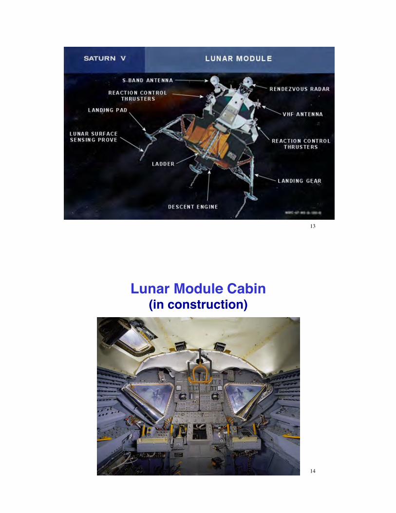
Lunar Module Cabin!(in construction)"
14!

Lunar Landing Flight Simulators"Lunar Landing Research Facility" Lunar Landing Research Vehicle"
Lunar Landing Training Vehicle Cockpit"
15!
Ground-Based Lunar Landing Simulators, NASA JSC/KFC"
16!
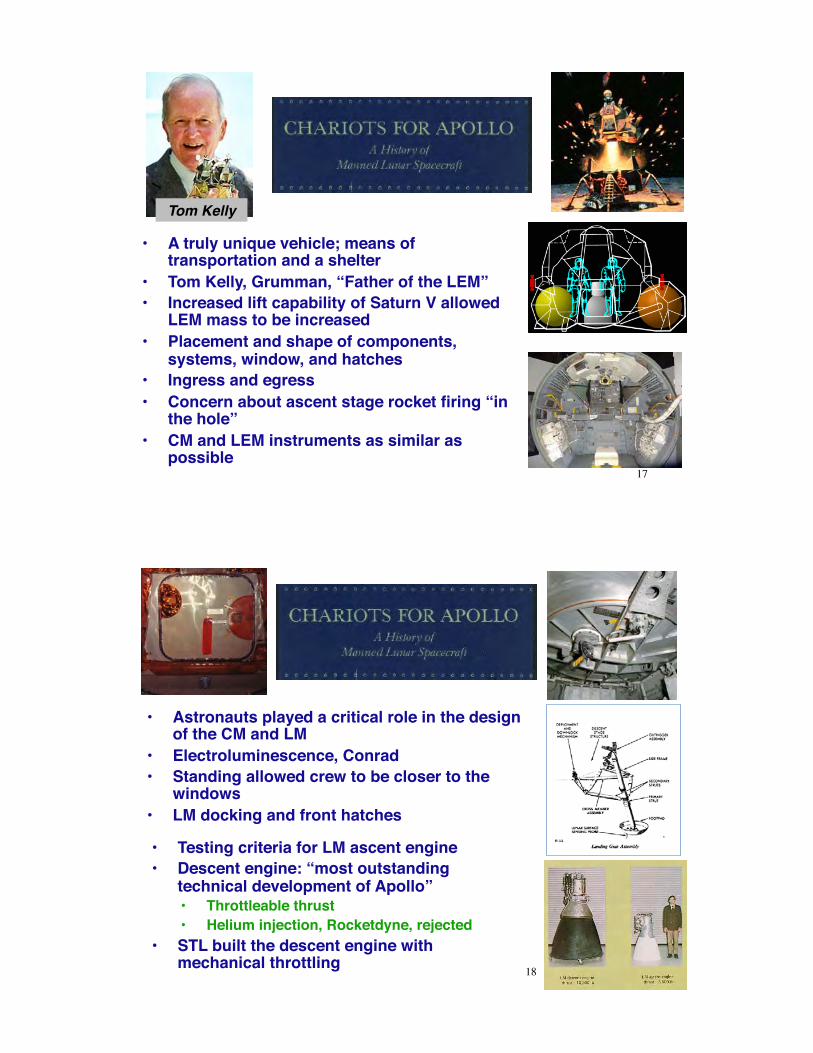
•# A truly unique vehicle; means of transportation and a shelter"
•# Tom Kelly, Grumman, “Father of the LEM”"•# Increased lift capability of Saturn V allowed
LEM mass to be increased"•# Placement and shape of components,
systems, window, and hatches"•# Ingress and egress"•# Concern about ascent stage rocket firing “in
the hole”"•# CM and LEM instruments as similar as
possible"
Tom Kelly"
17!
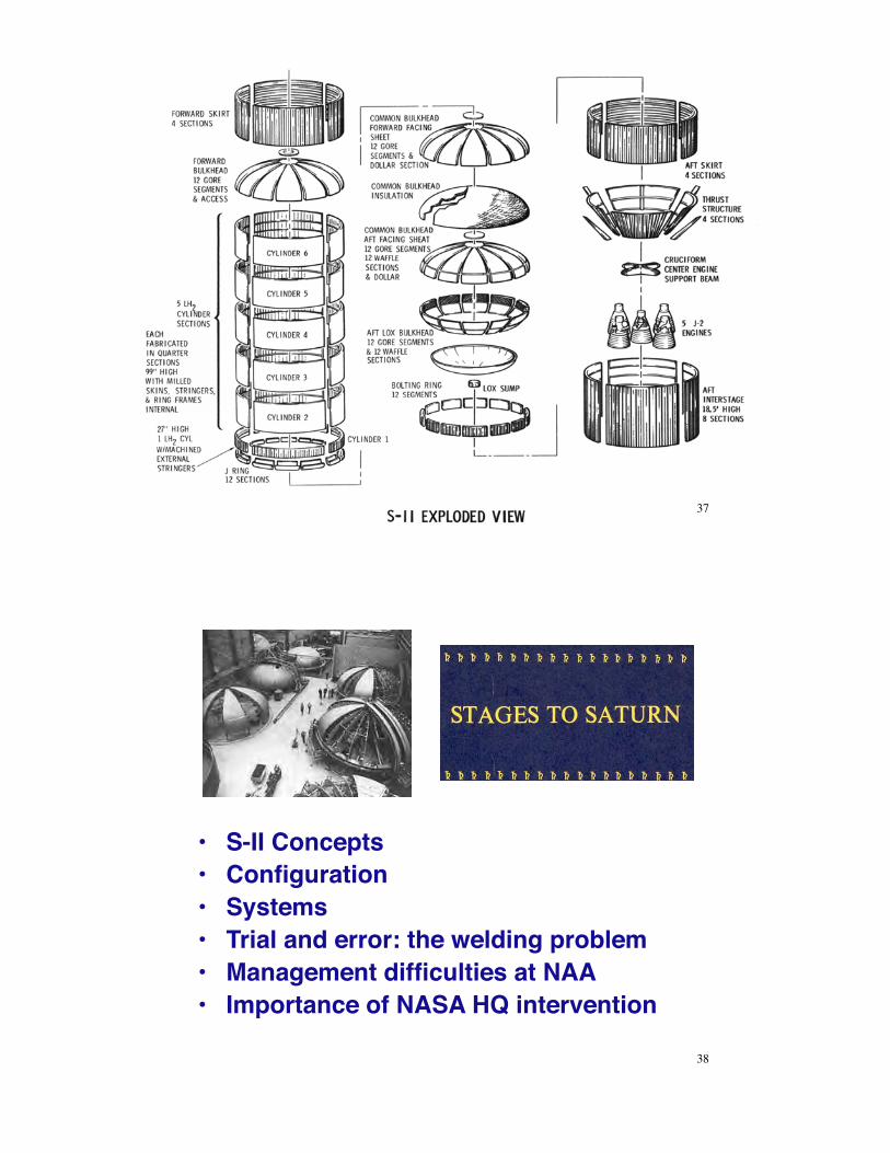
•# Astronauts played a critical role in the design of the CM and LM"
•# Electroluminescence, Conrad"•# Standing allowed crew to be closer to the
windows"•# LM docking and front hatches"
•# Testing criteria for LM ascent engine"•# Descent engine: “most outstanding
technical development of Apollo”"•# Throttleable thrust"•# Helium injection, Rocketdyne, rejected"
•# STL built the descent engine with mechanical throttling" 18!

•# Note continuing competition between corporations to build Apollo components"
•# Bi-propellant RCS thrusters, Marquardt. Thrust spiking problem remediated"
•# RCA: "•# engineering support"•# landing and rendezvous radars"•# sub-sub contract to Ryan"•# antennas, accuracy, weight"•# inflight test system"•# radar control system"
•# In-flight maintenance considered; redundancy chosen instead"
19!
•# Adoption of CM GNC for LM not immediately accepted"
•# Everything had to be renegotiated"•# Reliability, 3-gimbal platform, conflict between
Grumman and MIT (“scratchy”)"•# Mockup reviews"•# Grumman: Test to failure"•# Mueller: All-up testing concept"
20!

•# Flight Article Configuration Inspection (FACI)"•# Certification of Flight Worthiness (COFW)"•# Design Certification Review (DCR)"•# Flight Readiness Review (FRR)"•# Weight control, configuration control"•# Unnecessary changes in Block II"•# LEM testing program: a pacing item, Grumman
moving slowly"•# Space suit development"•# Expansion of the astronaut corps"•# Concern about solar radiation"
Searching for Order - 1965"
21!
•# Cryogenic technology"•# Apparently overlooked Goddard’s work, referred to German
experience"•# Saturn engine antecedents"
•# Development relied on IRBM/ICBM experience"•# LOX/RP-1 (Kerosene) propellants"•# H-1 powered the Saturn I and IB"
•# Upgrade of an existing engine for Thor-Jupiter missiles"•# F-1 powered the Saturn V"
•# Largest rocket motor ever built"
Conventional Cryogenics: H-1 and F-1"
22!

•# Thrust chambers"•# Double-wall construction, propellant passed between"
•# Exhaust nozzles"•# Bell shape improved flow"
•# Turbopumps"•# Problems with turbine blades, bearings, and cavitation"
•# Packaging and system design"•# Gimballing for thrust vector control"
•# Engine problem phases "
23!
•# H-1 milestones and facilities"•# General description"•# Development problems"•# Testing and controlling combustion instability"
24!

•# Origins of the F-1"•# Air Force legacy (1955)"•# Design undertaken before vehicle or mission
were identified"•# Santa Susana rocket test facility, Edwards AFB"
•# Big engine, big problems"•# 16:1 nozzle expansion"•# 6.67 MN thrust"
•# F-1 injector"25!
•# Origins of the F-1"•# Air Force legacy (1955)"•# Design undertaken before vehicle
or mission were identified"•# Santa Susana F-1 Test Stand,
Edwards AFB"•# Big engine, big problems"
•# 16:1 nozzle expansion"•# 6.67 MN thrust"
•# F-1 injector"•# Combustion instability"
•# Significant theoretical work by Luigi Crocco and David Harrje, Princeton" 26!

•# F-1 turbopumps"•# Oxygen: 24,811 gal/min"•# RP-1: 15,741 gal/min"
•# Thrust chamber and furnace brazing"
•# Other components and subsystems"
•# Static test to flight test"
27!
•# Tsiolkovsky proposed LOX/LH2 propellants"
•# Early testing at Aerojet General, NASA Lewis Research Center"
•# Centaur upper stage"•# 6-RL-10 engines
used on Saturn 1 S-IV stage"
•# Succeeded by one J-2 engine on SIVB"
Unconventional Cryogenics: RL-10 and J-2"
28!

29!
S-IVB with single J-2 engine""
30!

•# 1st stage of the Saturn V to be designed"•# Started before von Braun group transferred from ABMA to NASA"•# Rationale for choosing Douglas to build the S-IV and S-IVB"
From the S-IV to the S-IVB"
31!
•# Coasting orbit, restart capability"
•# Expansion of launch window"
•# Volumetric considerations for hydrogen and oxygen tank positions"
•# Fabrication and manufacturing"•# “Waffle-shaped” integral stiffening of the skin"•# Reliance on aviation production technology"•# Ullage rockets? Retro-rockets?"•# Domes and hemispheric common bulkhead"•# Thin aluminum shells"•# Self-supporting structures rather than reliance on internal
pressure (Atlas, Centaur)" 32!

•# Proportions of the stages"•# Both used brand new technology
extensively"•# Welding, forging, materials"
•# S-IC off to a better start"•# S-II left to make up for end-game
problems, as S-IC and S-IVB were further along in development "
Lower Stages:S-IC and S-II"
33!
34!

•# S-IC and the Huntsville connection"•# Tools and tankage"•# Few but cumbersome components"•# Fabrication and manufacture"
35!
36!
37!
•# S-II Concepts"•# Configuration"•# Systems"•# Trial and error: the welding problem"•# Management difficulties at NAA"•# Importance of NASA HQ intervention"
38!

Space Vehicle Design!
39!
Launch Vehicle Configuration Design Goals "•# Minimum weight -> sphere"•# Minimum drag -> slender body"•# Minimum axial load -> low thrust"•# Minimum gravity loss -> high thrust"•# Maximum payload -> lightweight structure, high
mass ratio, multiple stages, high specific impulse"•# Perceived simplicity, improved range safety ->
single stage"•# Minimum cost -> low-cost materials, economies of
scale"•# Minimum environmental impact -> non-toxic
propellant"
Delta Clipper"
40!

Typical Payload Ratios, #overall, for Launch to Low Earth Orbit
(LEO) without SRBs"•# Ariane 5: " "0.021"•# Atlas V: " "0.027"•# Delta IV: " "0.034"•# Epsilon: " "0.014"•# Falcon 9: " "0.026"•# GSLV: " "0.012"•# H-IIA: " "0.035"•# Long March 3: "0.025"•# Minotaur IV: "0.02"•# Proton: " "0.029"
•# PSLV: " "0.011"•# Saturn IB:" "0.035"•# Scout: " "0.008"•# Shahab: " "0.002"•# Shavit: " "0.011"•# Sputnik R-7: "0.002"•# Taurus: " "0.018"•# Vega: " "0.011"•# Voshkod: " "0.020"•# Zenit: " "0.031"
41!
Launch Vehicle Structural Loads"
•# Static/quasi-static loads"–# Gravity and thrust"–# Propellant tank internal pressure"–# Thermal effects"
•# Rocket"•# Cryogenic propellant"•# Aerodynamic heating"
•# Dynamic loads"–# Bending and torsion"–# Pogo oscillations"–# Fuel sloshing"–# Aerodynamics and thrust
vectoring"•# Acoustic and mechanical vibration
loads"–# Rocket engine"–# Aerodynamic noise"
42!
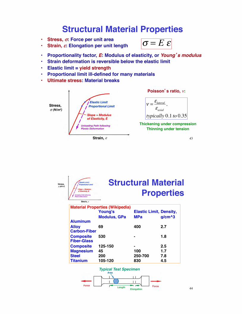
Structural Material Properties"•# Stress, !!: Force per unit area"•# Strain, "": Elongation per unit length"
! = E "•# Proportionality factor, E: Modulus of elasticity, or Young s modulus"•# Strain deformation is reversible below the elastic limit"•# Elastic limit = yield strength"•# Proportional limit ill-defined for many materials"•# Ultimate stress: Material breaks"
Poisson s ratio, #:"
! = "lateral"axial
,
typically 0.1 to 0.35Thickening under compression"
Thinning under tension"
43!
Structural Material Properties"
Material Properties (Wikipedia)Young's Modulus, GPa
Elastic Limit, MPa
Density, g/cm^3
Aluminum Alloy 69 400 2.7Carbon-Fiber Composite 530 - 1.8Fiber-Glass Composite 125-150 - 2.5Magnesium 45 100 1.7Steel 200 250-700 7.8Titanium 105-120 830 4.5
44!
Typical Test Specimen"

Structural Stiffness"•# Geometric stiffness of a structure that bends about
its x axis is portrayed by its area moment of inertia"
Ix = x z( )z2 dzzmin
zmax
!•# Area moment of inertia for simple cross-sectional
shapes"•# Solid rectangle of height, h,
and width, w:"•# Solid circle of radius, r:"•# Circular cylindrical tube with
inner radius, ri, and outer radius, ro:"
Ix = wh3 /12
Ix = !r4 / 4
Ix = ! ro4 " ri
4( ) / 4
45!
Structural Stiffeners"•# Axial stiffeners provide high
Ix per unit of cross-sectional area"
•# Circular stiffeners increase resistance to buckling"
•# Honeycomb and waffled surfaces remove weight while retaining Ix"
46!

Propellant Tank Configurations!for Launch Vehicles"
Serial tanks with common bulkhead"
Separate serial tanks" Parallel tanks"
47!
Mercury-Redstone Structure"
Semi-monocoque structure (load-bearing skin stiffened by internal components)"
External skin, internal tanks separated by longerons and circular stiffeners"
Aerodynamic and exhaust vanes for thrust vectoring "
48!

Hoop, Axial, and Radial Stresses in Pressurized, Thin-Walled Cylindrical Tanks"
For the cylinder"R : radiusT : wall thicknessp : pressure! : stress
! hoop = pR /T! axial = pR / 2T
! radial " negligible
For the spherical end cap"! hoop =! axial = pR / 2T! radial " negligible
Cylinder hoop stress is limiting factor, $hoop > $axial" 49!
Weight Comparison of Thin-Walled Spherical and Cylindrical Tanks
(Sechler, in Space Technology, 1959)"
•# Pressure vessels have same volume and same maximum shell stresses due to internal pressure; hydraulic head* neglected"•# Rc = cylindrical radius"•# Rs = spherical radius"
•# Weight increases as L/D increases"* Hydraulic head = Liquid pressure per unit of weight x load factor" 50!

Staged Spherical vs. Cylindrical Tanks !(Sechler, in Space Technology, 1959)"
51!
Comparison: pressure vessels have same volume and same maximum shell stresses due to internal pressure with and
without hydraulic head (with full tanks)"
Numerical example for load factor of 2.5"Cylindrical tanks lighter than comparable spherical tanks"
Common bulkead even lighter"
Critical Axial Stress in Thin-Walled Cylinders!(Sechler, in Space Technology, 1959)"
•# Compressive axial stress can lead to buckling failure"
•# Critical stress, !!c, can be increased by"
–# Increasing E"–# Increasing wall thickness, t"
•# solid material"•# honeycomb"
–# Adding rings to decrease effective length"
–# Adding longitudinal stringers"
–# Fixing axial boundary conditions"
–# Pressurizing the cylinder"
52!

SM-65/Mercury Atlas"•# Launch vehicle originally designed with
“balloon” propellant tanks to save weight"–# Monocoque design (no internal bracing or
stiffening)"–# Stainless steel skin 0.1- to 0.4-in thick"–# Vehicle would collapse without internal
pressurization"–# Filled with nitrogen at 5 psi when not fuelled"
•# Pressure stiffening effect"–# No internal pressure"
! c
E= 9 t
R"#$
%&'1.6
+ 0.16 tL
"#$
%&'1.3
–# With internal pressure"
! c
E= Ko + Kp( ) tR
where
Ko = 9tR
"#$
%&'0.6
+ 0.16 RL
"#$
%&'1.3 t
R"#$
%&'0.3
Kp = 0.191pE
"#$
%&'
Rt
"#$
%&'2
53!
Force and Moments on a Slender Cantilever (Fixed-Free) Beam"
•# Idealization of "–# Launch vehicle tied-down to a
launch pad"–# Structural member of a payload"
•# For a point force"–# Force and moment must be
opposed at the base"–# Shear distribution is constant"–# Bending moment increases as
moment arm increases"–# Torsional moment and moment
arm are fixed"
54!

Bending Stiffness"•# Neutral axis neither shrinks nor stretches in bending"•# For small deflections, the bending radius of curvature of
the neutral axis is"
r = EIM
Deflection at a point characterized by displacement and angle:"
55!
Bending Deflection"
Second derivative of z and first derivative of ! are inversely proportional to the bending radius:"
d2zdx 2
= d!dx
=My
EIy
56!

Buckling"
•# Predominant steady stress during launch is compression"
•# Thin columns, plates, and shells are subject to elastic instability in compression"
•# Buckling can occur below the material s elastic limit"
! cr =C" 2EL / #( )2
= PA
Critical buckling stress of a column (Euler equation)"
C = function of end " fixity"E = modulus of elasticityL = column length
! = I A = radius of gyrationPcr = critical buckling loadA = cross sectional area 57!
Effect of Fixity on Critical Loads for Beam Buckling"
Crippling vs. Buckling"
58!
•# Euler equation"–# Slender columns"–# Critical stress below the
elastic limit"–# Relatively thick column
walls"•# Local collapse due to thin
walls is called crippling"

Quasi-Static Loads!(Spacecraft Systems Engineering, 2003)"
59!
Springs and Dampers"
fx = !ks"x = !ks x ! xo( ) ; k = springconstant
fx = !kd"!x = !kd"v = !kd v ! vo( ) ; k = dampingconstant
Force due to linear spring"
Force due to linear damper"
60!

Mass, Spring, and Damper"
!!!x = fx m = "kd!!x " ks!x + forcing function( ) m
!!!x + kd
m!!x + ks
m!x = forcing function
m
!!!x + 2"# n!!x +# n2!x =# n
2!u
!n = natural frequency, rad /s" = damping ratio#x = displacement#u = disturbance or control
Newton s second law leads to a second-order dynamic system"
61!
Response to Initial Condition"
•# Lightly damped system has a decaying, oscillatory transient response"
•# Forcing by step or impulse produces a similar transient response"
! n = 6.28 rad / sec" = 0.05
62!

Oscillations"
!x = Asin "t( )
!!x = A" cos "t( )= A" sin "t +# 2( )
!!!x = "A# 2 sin #t( )= A# 2 sin #t +$( )
•# Phase angle of velocity (wrt displacement) is $$/2 rad (or 90°)"•# Phase angle of acceleration is % rad (or 180°)"•# As oscillation frequency, & varies"
–# Velocity amplitude is proportional to &%%–# Acceleration amplitude is proportional to &2"
63!
Frequency Response of the 2nd-Order System"
•# Bode plot"–# 20 log(Amplitude Ratio) [dB] vs. log &%%–# Phase angle (deg) vs. log &%%
•# Natural frequency characterized by"–# Peak (resonance) in amplitude
response"–# Sharp drop in phase angle"
•# Acceleration frequency response peak occurs at natural frequency!!
•# Convenient to plot response on logarithmic scale"
ln A(!)e j" (! )[ ] = lnA(!) + j"(!)
64!
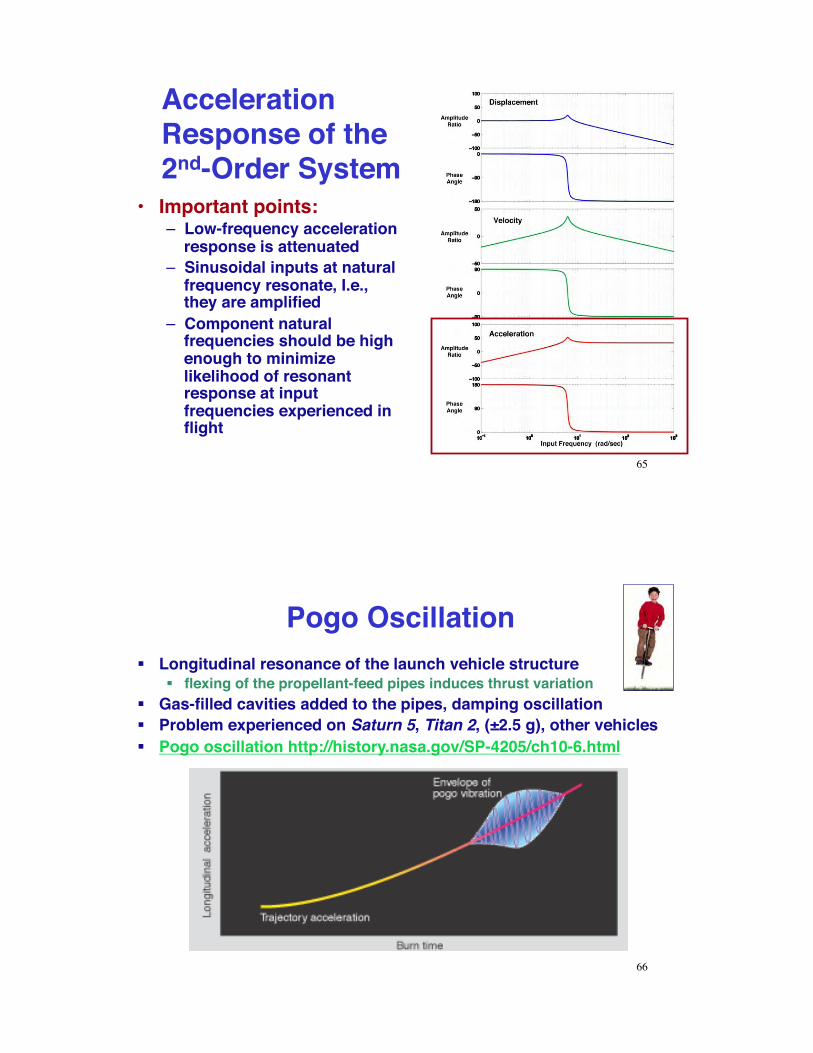
Acceleration Response of the 2nd-Order System"
•# Important points:"–# Low-frequency acceleration
response is attenuated"–# Sinusoidal inputs at natural
frequency resonate, I.e., they are amplified"
–# Component natural frequencies should be high enough to minimize likelihood of resonant response at input frequencies experienced in flight"
65!
Pogo Oscillation "!# Longitudinal resonance of the launch vehicle structure "
!# flexing of the propellant-feed pipes induces thrust variation"!# Gas-filled cavities added to the pipes, damping oscillation"!# Problem experienced on Saturn 5, Titan 2, (±2.5 g), other vehicles"!# Pogo oscillation http://history.nasa.gov/SP-4205/ch10-6.html"
66!

Pogo Oscillation Mitigation for Ares I Launch Vehicle "
67!“This concept is expected to reduce the G-forces on the
astronauts from about 5 G’s to 0.25 G’s”"
http://www.universetoday.com/17040/nasa-to-install-shock-absorbers-to-mitigate-thrust-oscillation/!
Fuel Slosh"•# Fuel slosh"
–# Lateral motion of liquid propellant in partially empty tank induces inertial forces"
–# Resonance with flight motions can occur"–# Problem reduced by baffles"
Saturn I Fuel Slosh"http://www.youtube.com/watch?v=fL-Oi9m2beA"
68!

Typical Acoustic and Shock Environment (Delta II)"
Sound Pressure (dB)" Peak Acceleration (g)"
Decibel (dB)
10log10Measured PowerReference Power
!
" #
$
% & or 20log10
Measured AmplitudeReference Amplitude
!
" #
$
% &
69!
Transient Loads at Thrusting Cutoff!
(Spacecraft Systems Engineering, 2003)"
70!
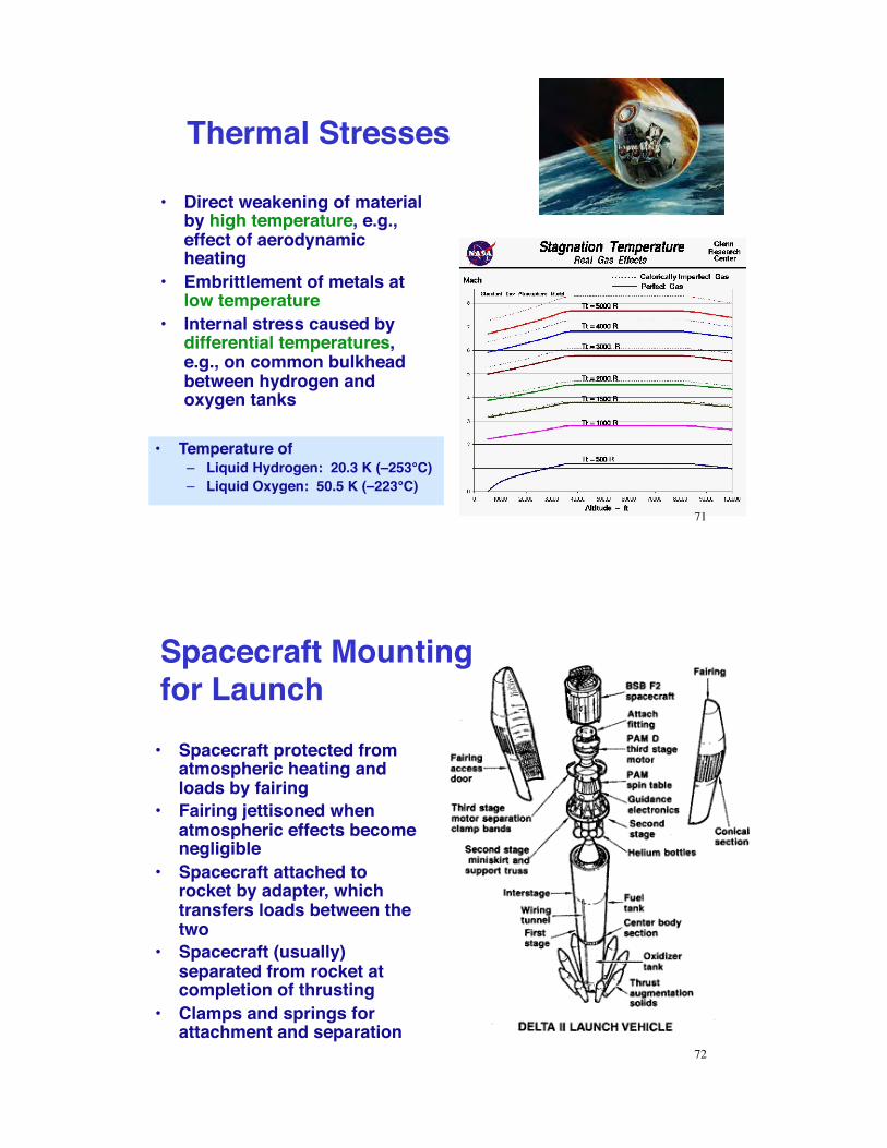
Thermal Stresses"
•# Direct weakening of material by high temperature, e.g., effect of aerodynamic heating"
•# Embrittlement of metals at low temperature"
•# Internal stress caused by differential temperatures, e.g., on common bulkhead between hydrogen and oxygen tanks"
•# Temperature of"–# Liquid Hydrogen: 20.3 K (–253°C)"–# Liquid Oxygen: 50.5 K (–223°C)"
71!
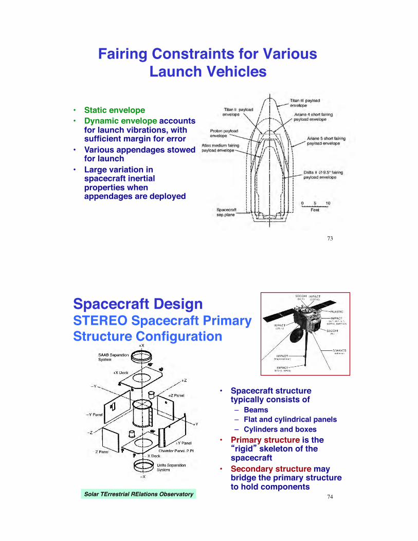
•# Spacecraft protected from atmospheric heating and loads by fairing"
•# Fairing jettisoned when atmospheric effects become negligible"
•# Spacecraft attached to rocket by adapter, which transfers loads between the two"
•# Spacecraft (usually) separated from rocket at completion of thrusting"
•# Clamps and springs for attachment and separation"
Spacecraft Mounting for Launch"
72!
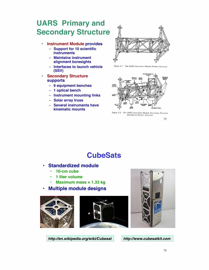
Fairing Constraints for Various Launch Vehicles"
•# Static envelope"•# Dynamic envelope accounts
for launch vibrations, with sufficient margin for error"
•# Various appendages stowed for launch"
•# Large variation in spacecraft inertial properties when appendages are deployed"
73!
•# Spacecraft structure typically consists of"–# Beams"–# Flat and cylindrical panels"–# Cylinders and boxes"
•# Primary structure is the rigid skeleton of the
spacecraft"•# Secondary structure may
bridge the primary structure to hold components"
Solar TErrestrial RElations Observatory" 74!
Spacecraft Design!STEREO Spacecraft Primary Structure Configuration"
UARS Primary and Secondary Structure"
•# Instrument Module provides"–# Support for 10 scientific
instruments"–# Maintains instrument
alignment boresights"–# Interfaces to launch vehicle
(SSV)"•# Secondary Structure
supports"–# 6 equipment benches"–# 1 optical bench"–# Instrument mounting links"–# Solar array truss"–# Several instruments have
kinematic mounts"
75!
CubeSats"•# Standardized module"
•# 10-cm cube"•# 1 liter volume"•# Maximum mass = 1.33 kg"
•# Multiple module designs"
http://en.wikipedia.org/wiki/Cubesat" http://www.cubesatkit.com"
76!
CubeSats"
77!
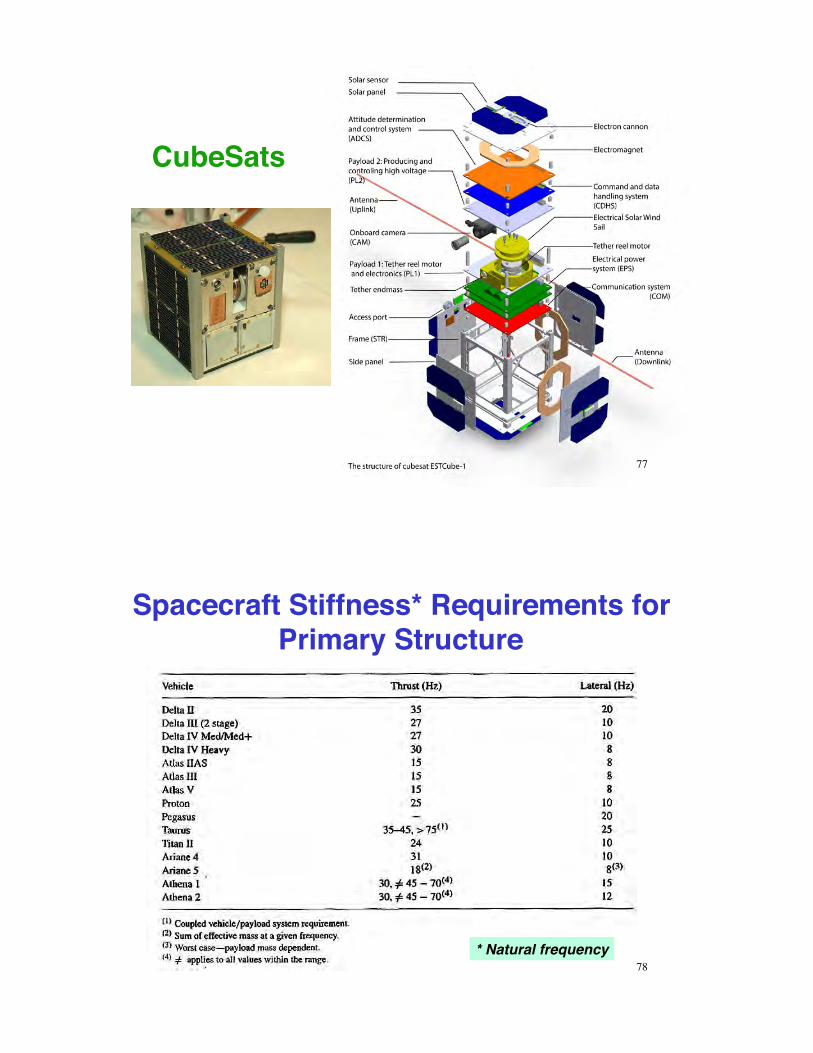
Spacecraft Stiffness* Requirements for Primary Structure "
* Natural frequency"78!
Factors and Margins of Safety"•# Factor of Safety"
–# Typical values: 1.25 to 1.4"
Allowable load (yield stress)Expected limit load (stress)! Design factor of safety
"1
•# Margin of Safety"–# the amount of margin that exists above the
material allowables for the applied loading condition (with the factor of safety included) , Skullney, Ch. 8, Pisacane, 2005"
Load (stress) that causes yield or failureExpected service load
79!
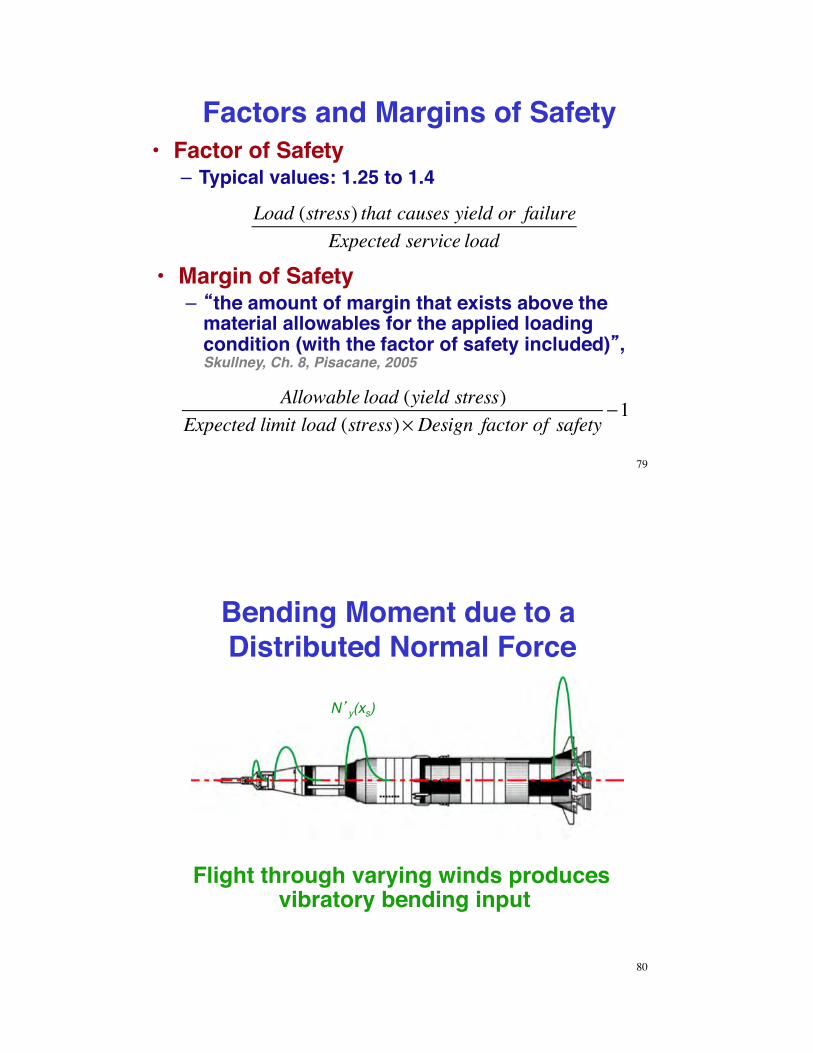
Bending Moment due to a Distributed Normal Force"
Flight through varying winds produces vibratory bending input"
N y(xs)!
80!

Bending Vibrations of a Free-Free Uniform Beam"
Mode shapes of bending vibrations"
81!
82!
Vibrational Mode
Shapes for Saturn 5"

Fundamental Vibrational Frequencies of Circular Plates"
f = natural frequency of first mode, Hz"
83!
Finite-Element Structural Model"TIMED Spacecraft" •# Grid of elements, each with "
–# mass, damping, and elastic properties"
–# 6 degrees of freedom"
84!

Next Time:!
85!
Early Robotic Lunar Spacecraft: Ranger, Surveyor, and Lunar Orbiter"
Lunar Impact: A History of Project Ranger, NASA-SP-4210!
Unmanned Space Craft Management: Surveyor and Lunar Orbiter, NASA-SP-4901"
"Spacecraft Attitude Dynamics and Control:"!
Understanding Space, Sec 12.1, 12.2!
Supplemental Material!
86!
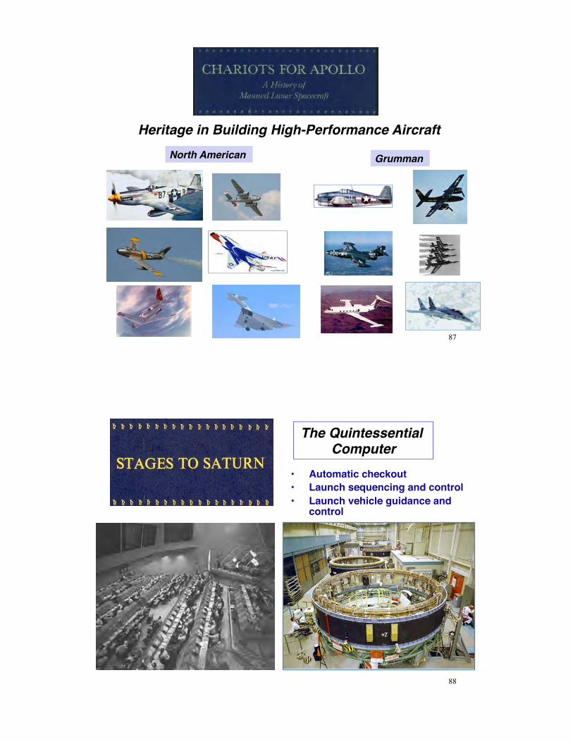
Heritage in Building High-Performance Aircraft"North American" Grumman"
87!
•# Automatic checkout"•# Launch sequencing and control"•# Launch vehicle guidance and
control"
The Quintessential Computer"
88!

Apollo Launch Vehicles"Saturn IB" Saturn V"
89!
Command Module"Service Module"
Lunar Module"
90!

Apollo"Command Module"
Service Module"
Lunar Module"
91!
Apollo Command and Service Modules (CSM)"!# 3-person crew"!# Autonomous
guidance and control capability"
92!

Apollo !Lunar Module (LM)"
93!
Saturn Checkout – Control Center "
94!

Saturn Checkout - Vehicle "
95!
96!

F-1 Engine Start from Command Module"
97!
Saturn ST-124 Inertial Measurement Unit "
98!

Specific Impulse of Launch Vehicle Powerplants"
99!
Vertical Takeoff, Horizontal Landing Vehicles"
•# Martin Astro-Rocket" •# General Dynamics Triamese"
•# Heat shield-to-heat shield" •# Three identical parallel stages"
100!

Horizontal vs. Vertical Launch"•# Feasibility of airline-like operations?"•# Use of high Isp air-breathing engines"•# Rocket stages lifted above the sensible atmosphere"•# Flexible launch location, direction, and time"
101!
Specific Energy Contributed in Boost Phase"
•# Total Energy = Kinetic plus Potential Energy (relative to flat earth)"
•# Specific Total Energy = Energy per unit weight = Energy Height (km)"
E = mV2
2+mgh
E ' = V2
2g+ h
102!

Specific Energy Contributed in Boost Phase"
•# Specific Energy contributed by 1st stage of launch vehicle"–# Less remaining drag loss (typical)"–# Plus Earth s rotation speed (typical)"
Altitude, kmMach Number
Earth-RelativeVelocity, km/s
Remaining Drag Loss, km/s
Earth Rotation Speed, km/s
Specific Kinetic Energy, km
Total Specific Energy, km
Percent of Goal
Scout 1st-Stage Burnout 22 4 1.2 0.05 0.4 123.42 145.42 3.93%Subsonic Horizontal Launch 12 0.8 0.235 0.15 0.4 12.05 24.05 0.65%Supersonic Horizontal Launch 25 3 0.93 0.04 0.4 85.57 110.57 2.99%Scramjet Horizontal Launch 50 12 3.6 0 0.4 829.19 879.19 23.74%Target Orbit 300 25 7.4 0.4 3403.34 3703.34
103!
Aerospace Planes (Trans-Atmospheric Vehicles)"
•# Power for takeoff"–# Turbojet/fans"–# Multi-cycle air-breathing
engines"–# Rockets"
•# Single-stage-to-orbit"–# Carrying dead weight into
orbit"–# High structural ratio for
wings, powerplants, and reusability"
–# SSTO has very low payload ratio"
104!

Venture Star/X-33"•# Venture Star: Reusable, single-stage-to-orbit,
proposed Space Shuttle replacement"•# X-33: Sub-orbital test vehicle"•# Improved thermal protection system
(compared to SSV)"•# Linear spike nozzle rocket (altitude
compensation)"•# Cancelled following tank failure in testing"
105!
Trans-Atmospheric Vehicle Concepts"
•# Boeing TAV" •# Rockwell TAV" •# Rockwell StarRaker"
•# Lockheed Clipper" •# Lockheed TAV"
•#Various approaches to staging"
106!

Pegasus Air-Launched Rocket"
•# Three solid-rocket stages launched from an aircraft"
•# Aerodynamic lift used to rotate vehicle for climb"
•# Initial mass: 23,000 kg"•# Payload mass to LEO: 440 kg"•# Payload ratio = 0.019 (rocket)
= 0.001 (airplane)"
107!
Stratolaunch"•# Based on two Boeing 747-400
airplanes"•# Six turbofan engines"•# Wingspan: 117 m"•# Takeoff mass: 540,000 kg"
•# Pegasus II rocket: 210,000 kg"•# Payload to LEO: 6,100 kg"•# Payload ratio = 0.029 (rocket) =
0.011 (airplane)"
108!

Uniform Stress Conditions"
•# Average axial stress, !!"
! = P A = Load Cross Sectional Area
•# Average axial strain, """! = "L L
•# Effective spring constant, ks"
! = P A = E" = E #LL
P = AEL
#L = ks#L
109!
Example 8.1!(Fundamentals of Space Systems, 2005)"
•# Atlas IIAS launch vehicle"•# Spacecraft structure meets
primary stiffness requirements"
•# What are axial stiffness requirements for Units A and B?"–# Support deck natural
frequency = 50 Hz"
Octave Rule: Component natural frequency ' 2 x natural frequency of supporting structure"
•# Unit A: 2 x 15 Hz = 30 Hz, supported by primary structure"•# Unit B: 2 x 50 Hz = 100 Hz, supported by secondary structure"
110!

Worst-Case Axial Stress on a Simple Beam"
•# Axial stress due to bending"! = My I
! =M h / 2( )
I
•# Maximum stress"
•# Worst-case axial stress due to bending and axial force "
! wc = ± PA
"#$
%&' max
±M h / 2( )
I
111!
Example 8.3!(Fundamentals of Space Systems, 2005)"
•# Spacecraft weight = 500 lb"•# Atlas IIAS launch vehicle"•# Factor of safety = 1.25"•# Maximum stress on
spacecraft adapter?"
Atlas IIAS Limit Loads (g)"
112!

Example 8.3, con t."
•# Worst-case axial load at BECO (5±0.5 g)"
! wc = ± PA
"#$
%&' max
± McI
A = 2!rt = 7.1 in2
I = !r3t = 286 in4
•# Worst-case stress "
! wc =500 " 5.57.1
+ 500 " 0.5 " 42 " 9286
#$%
&'("1.25 = 897.1 psi
•# Worst-case lateral load at BECO (2.5 ± 1 g) or Maximum Flight Winds (2.7 ± 0.8 g)"
! wc =500 " 3.57.1
+ 500 " 2 " 42 " 9286
#$%
&'("1.25 = 1960 psi
113!
Response to Oscillatory Input"
A! 2 sin !t +"( )#$ %& + 2'! n A! sin !t +" 2( )#$ %& +! n2 Asin !t( )#$ %& =! n
2 Bsin !t( )#$ %&
•# ... however, A must be a complex number for this to work"•# A better way: Compute Laplace transform to find transfer
functions"
L !x(t)[ ] = !x(s) = !x(t)e"stdt0
#
$ , s = % + j&, ( j = i = "1)
L !˙ x (t)[ ] = s!x(s)
L !˙ ̇ x (t)[ ] = s2!x(s)
•# Neglecting initial conditions"
114!

Transfer Function"
or" L !!!x + 2"# n!!x +# n
2!x( ) = L # n2!u( )
s2 + 2!" ns +" n2( )#x(s) =" n
2#u(s)
Transfer function from input to displacement"
!x(s)!u(s)
= " n2
s2 + 2#" ns +" n2( )
115!
Transfer Functions of Displacement, Velocity, and
Acceleration"
!x(s)!u(s)
= " n2
s2 + 2#" ns +" n2( )
!!x(s)!u(s)
= " n2s
s2 + 2#" ns +" n2( )
!!!x(s)!u(s)
= " n2s2
s2 + 2#" ns +" n2( )
•# Input to velocity: multiply by s"
•# Input to acceleration: multiply by s2"
•# Transfer function from input to displacement"
116!
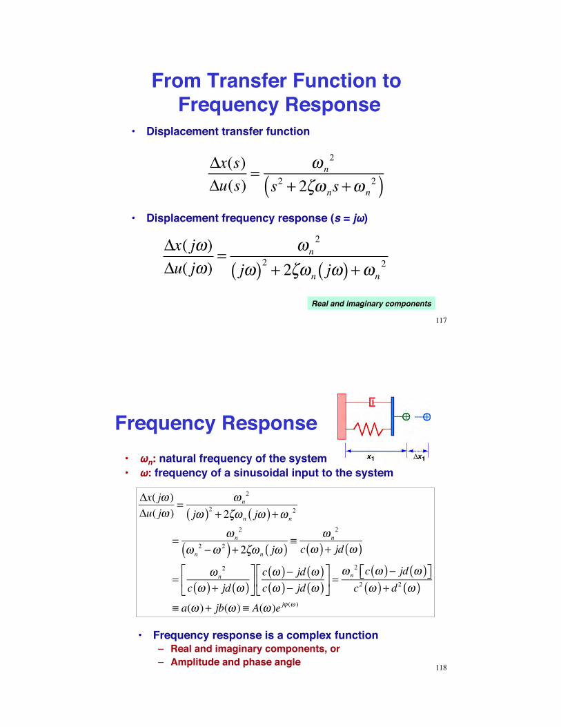
From Transfer Function to Frequency Response"
•# Displacement frequency response (s = j&)"
!x( j")!u( j")
= "n2
j"( )2 + 2#"n j"( ) + "n2
!x(s)!u(s)
= " n2
s2 + 2#" ns +" n2( )
•# Displacement transfer function"
Real and imaginary components"
117!
Frequency Response"•# &n: natural frequency of the system"•# &: frequency of a sinusoidal input to the system"
!x( j" )!u( j" )
= " n2
j"( )2 + 2#" n j"( ) +" n2
= " n2
" n2 $" 2( ) + 2#" n j"( ) %
" n2
c "( ) + jd "( )
= " n2
c "( ) + jd "( )&
'(
)
*+c "( )$ jd "( )c "( )$ jd "( )
&
'(
)
*+ =
" n2 c "( )$ jd "( )&' )*c2 "( ) + d 2 "( )
% a(" )+ jb(" ) % A(" )e j, (" )
•# Frequency response is a complex function"–# Real and imaginary components, or"–# Amplitude and phase angle" 118!

Maximum Deflection and Bending Moment of Beams!
(see Fundamentals of Space Systems for additional cases)"
Fixed-Free Beam" Fixed-Fixed Beam" Pinned-Pinned Beam"
Ymax = maximum deflection" Mmax = maximum bending moment" 119!
Maximum Deflection and Bending Moment of Plates!
(see Fundamentals of Space Systems for additional cases)"
Circular Plate"
m =1/!
120!
Rectangular Plate"

Typical Cross-Sectional Shear Stress Distribution for a Uniform Beam"
•# Shear stress due to bending moment is highest at the neutral axis"
•# Maximum values for various cross sectons (see Fundamentals of Space Systems)"
121!
Critical Stress for Plate and Cylinder Buckling"
122!

Bending Vibrations of a Free-Free Uniform Beam"
EIyd 4zdx4 x=xs
= k = !m ' d2zdt 2 x=xs
EIy = constantm©=mass variation with length (constant)k = effective spring constant
•# Solution by separation of variables requires that left and right sides equal a constant, k"
•# An infinite number of separation constants, ki, exist"•# Therefore, there are an infinite number of vibrational
response modes"
123!
Vibrational Mode Shapes for the X-30 Vehicle !(Raney et al, J. Aircraft, 1995)"
Computational Grid Model"
•# Body elastic deflection distorts the shape of scramjet inlet and exhaust ramps"
•# Aeroelastic-propulsive interactions"•# Impact on flight dynamics"
Shapes of the First Seven Modes"
124!
Related Documents