1 CREATED BY: ER. GAURAV DWIVEDI MECHANICAL ENGINEERING CHAPTER-1 INTRODUCTION In this model we show that how we can generate a voltage from the busy traffic. Conversion of the mechanical energy into electrical energy is widely used concept. It’s a mechanism to generate power by converting the potential energy generated by a vehicle going up on a speed breaker into rotational energy. We have used that simple concept to the project. We connect one mechanical rod with the dynamo and fit this rod on the surface of the road. When any vehicle moves from this roller then due to friction, vehicle Rotate the rod or roller and roller then move the dynamo. When dynamo move then it generates a voltage and this voltage now connects to the bulbs. In actual practice with the help of this voltage we will charge the battery and then we use this voltage to light the small bulb. If we install this unit to the any small flyover then with the help of this voltage we generate a small voltage, and with the help of this voltage we light the bulb. The second part of that project is an efficient use of energy by using simple electronics. We always see that road light continuously glow whether vehicle on path or not. We have introduced a concept to avoid a waste of light. We have used two sensors between some distances. When vehicle pass through first sensor it sends the signal to the microcontroller that the vehicle is passing along that particular distance then light will glow for that particular time and when vehicle goes out from the second sensor

SEMI-PROJECT Power Generation Using Speed Breakers and Efficient Use of Energy Created by It.
Oct 23, 2015
mechanical project
Welcome message from author
This document is posted to help you gain knowledge. Please leave a comment to let me know what you think about it! Share it to your friends and learn new things together.
Transcript
1
CREATED BY:
ER. GAURAV DWIVEDI
MECHANICAL ENGINEERING
CHAPTER-1
INTRODUCTION
In this model we show that how we can generate a voltage
from the busy traffic. Conversion of the mechanical energy into electrical
energy is widely used concept. It’s a mechanism to generate power by
converting the potential energy generated by a vehicle going up on a speed
breaker into rotational energy. We have used that simple concept to the
project. We connect one mechanical rod with the dynamo and fit this rod on
the surface of the road. When any vehicle moves from this roller then due to
friction, vehicle Rotate the rod or roller and roller then move the dynamo.
When dynamo move then it generates a voltage and this voltage now
connects to the bulbs. In actual practice with the help of this voltage we will
charge the battery and then we use this voltage to light the small bulb.
If we install this unit to the any small flyover then with the
help of this voltage we generate a small voltage, and with the help of this
voltage we light the bulb.
The second part of that project is an efficient use of energy
by using simple electronics. We always see that road light continuously
glow whether vehicle on path or not. We have introduced a concept to avoid
a waste of light. We have used two sensors between some distances. When
vehicle pass through first sensor it sends the signal to the microcontroller
that the vehicle is passing along that particular distance then light will glow
for that particular time and when vehicle goes out from the second sensor
2
CREATED BY:
ER. GAURAV DWIVEDI
MECHANICAL ENGINEERING
then the second sensor sends a signal to a microcontroller that vehicle has
been passed through that particular path then light gets off automatically.
Different types of basic electronics components has been used to get the
desired output like capacitor, resister etc.
We have also used a light diode resistance(LDR) when
LDR senses a light around it all the road lights gets off and when LDR
senses there is a dark around it then LDR sends a signal to microcontroller
then all the road lights gets on. By using a LDR we can avoid a waste of
light that glow in a day time. The two sensors are made from the concept of
electronics. These sensors are called an infrared sensor which is made from
photo diode and light emitting diode each. When any vehicle pass from first
sensor then first sensor becomes on, for that time the road lights gets on and
when it pass from second sensor the second sensor become on and the first
sensor gets off then the road light gets off.
1.1 ALTERNATIVE METHOD:
In power generation using speed breaker we can use different mechanism to
convert the mechanical energy into the electrical energy from the speed
breaker. The generation of electricity using the vehicle weight can considers
as an input. The possible three different mechanisms are given below:
Crank-shaft mechanism
Roller mechanism
Rack and pinion mechanism
In that project we have introduced a roller mechanism to
convert the mechanical energy into the electrical energy. We have
3
CREATED BY:
ER. GAURAV DWIVEDI
MECHANICAL ENGINEERING
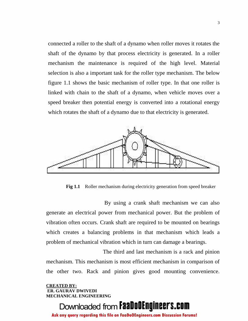
connected a roller to the shaft of a dynamo when roller moves it rotates the
shaft of the dynamo by that process electricity is generated. In a roller
mechanism the maintenance is required of the high level. Material
selection is also a important task for the roller type mechanism. The below
figure 1.1 shows the basic mechanism of roller type. In that one roller is
linked with chain to the shaft of a dynamo, when vehicle moves over a
speed breaker then potential energy is converted into a rotational energy
which rotates the shaft of a dynamo due to that electricity is generated.
Fig 1.1 Roller mechanism during electricity generation from speed breaker
By using a crank shaft mechanism we can also
generate an electrical power from mechanical power. But the problem of
vibration often occurs. Crank shaft are required to be mounted on bearings
which creates a balancing problems in that mechanism which leads a
problem of mechanical vibration which in turn can damage a bearings.
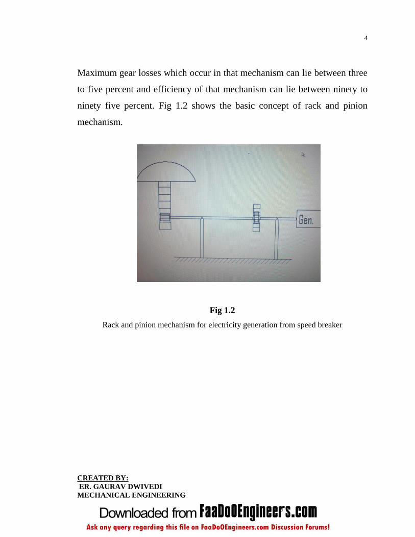
The third and last mechanism is a rack and pinion
mechanism. This mechanism is most efficient mechanism in comparison of
the other two. Rack and pinion gives good mounting convenience.
4
CREATED BY:
ER. GAURAV DWIVEDI
MECHANICAL ENGINEERING
Maximum gear losses which occur in that mechanism can lie between three
to five percent and efficiency of that mechanism can lie between ninety to
ninety five percent. Fig 1.2 shows the basic concept of rack and pinion
mechanism.
Fig 1.2
Rack and pinion mechanism for electricity generation from speed breaker

5
CREATED BY:
ER. GAURAV DWIVEDI
MECHANICAL ENGINEERING
CHAPTER-2
OVERVIEW
2.1 WORKING PRINCIPLE:
2.1.1 MECHANICAL TO ELECTRICAL ENERGY:
One rod with the dynamo is placed like a speed breaker. Dynamo means a
generator that produces direct current with the use of a commutator. The
dynamo uses rotating coils of wire and magnetic fields to convert
mechanical rotation into a pulsing direct electric current through Faraday's
law. A dynamo machine consists of a stationary structure, called the stator,
which provides a constant magnetic field, and a set of rotating windings
called the armature which turn within that field. Movement of vehicle just
rotates the dynamo shaft and electricity is generated. This voltage is to be
stored in the chargeable battery.
In the night lights are automatic on with the help of
photovoltaic switch logic. But all lights are not on, only half light are on.
Other half lights switch on automatically when any vehicle move on the
bridge, when there is no vehicle on the bridge then lights are off
automatically. We use two infrared sensors’ to check the movement of
vehicle. When first infra red sensor is on then lights are on and when
second sensor is interrupting then lights are off. A Street
light, lamppost, street lamp, light standard, or lamp standard is a raised
source of light on the edge of a road, which is turned on or lit at a certain
time every night. Modern lamps may also have light-sensitive photocells to
6
CREATED BY:
ER. GAURAV DWIVEDI
MECHANICAL ENGINEERING
turn them on at dusk, off at dawn, or activate automatically in dark weather.
In older lighting this function would have been performed with the aid of
a solar dial. Here we used some electronics for that purpose. It is not
uncommon for street lights to be on posts which have wires strung between
them, such as on telephone poles or utility poles.
Major advantages of street lighting includes: prevention
of accidents and increase in safety. Studies have shown that darkness results
in a large number of crashes and fatalities, especially those involving
pedestrians; pedestrian fatalities are 3 to 6.75 times more vulnerable in the
dark than in daylight. Street lighting has been found to reduce pedestrian
crashes by approximately half percent.
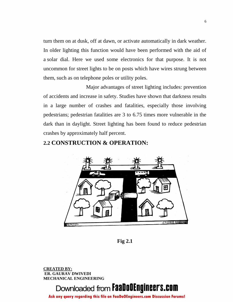
2.2 CONSTRUCTION & OPERATION:
Fig 2.1
7
CREATED BY:
ER. GAURAV DWIVEDI
MECHANICAL ENGINEERING
In this model we show that how we generate a voltage from the busy road
traffic. In all the city’s traffic is very much high and on some road, traffic
move like a tortoise. If we employ a speed breaker type generator on the
road then we utilize the friction of vehicle into mechanical energy and then
this mechanical energy is further converted into electrical energy with the
help of the powerful dynamo. So we install a one powerful dynamo on the
road.
Output of the dynamo is connected to the L.E.D. in this project.
When we move the shaft of the dynamo then dynamo generate a voltage
and this voltage is sufficient to drive the L.E.D.
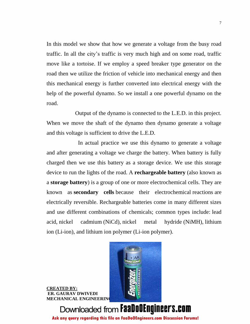
In actual practice we use this dynamo to generate a voltage
and after generating a voltage we charge the battery. When battery is fully
charged then we use this battery as a storage device. We use this storage
device to run the lights of the road. A rechargeable battery (also known as
a storage battery) is a group of one or more electrochemical cells. They are
known as secondary cells because their electrochemical reactions are
electrically reversible. Rechargeable batteries come in many different sizes
and use different combinations of chemicals; common types include: lead
acid, nickel cadmium (NiCd), nickel metal hydride (NiMH), lithium
ion (Li-ion), and lithium ion polymer (Li-ion polymer).

8
CREATED BY:
ER. GAURAV DWIVEDI
MECHANICAL ENGINEERING
Fig 2.2 Rechargeable battery
9
CREATED BY:
ER. GAURAV DWIVEDI
MECHANICAL ENGINEERING
10
CREATED BY:
ER. GAURAV DWIVEDI
MECHANICAL ENGINEERING
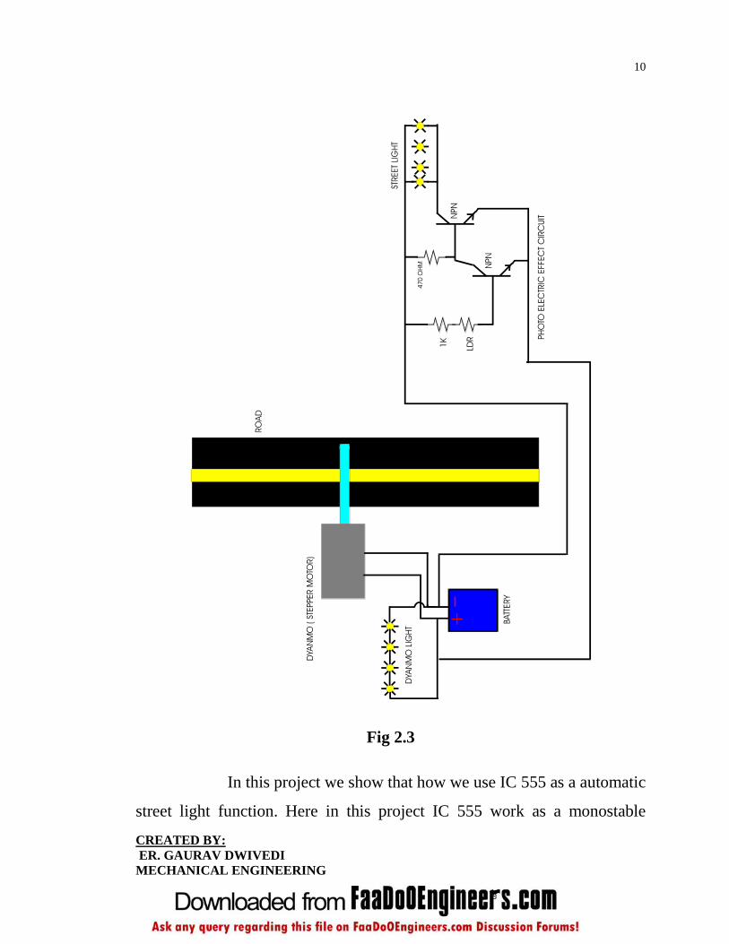
Fig 2.3
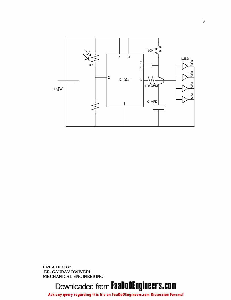
In this project we show that how we use IC 555 as a automatic
street light function. Here in this project IC 555 work as a monostable

11
CREATED BY:
ER. GAURAV DWIVEDI
MECHANICAL ENGINEERING
timer. Pin no 4 and 8 of the IC is connected to the positive supply. Pin no 1
of the IC is connected to the ground pin. Pin no 3 is the output pin. On this
pin we connect a output L.E.D. LDR is connected to the pin no 2 of the IC
via 100 k ohm resistor. When light fall on the LDR then LDR offers a low
resistance. When LDR is in dark then LDR offers a high resistance. When
we convert the LDR by hand then LDR resistance become high and so pin
no 2 become more negative. When pin no 2 become negative then IC 555
triggers itself and output is on. This is the function of the monostable timer.
2.3 MATERIAL REQUIRED:
After the general layout of the speed breaker system has been made of
successful working it is necessary to select proper material for the system of
refrigeration. This involves the consideration of many facts about available
material such as dynamo weight, size shape of the component material cost,
fabrication cost, overhead charges and many other properties peculiar to the
use of which to member is to be fitted.
The following four types of principle properties of
material effect their selection.
1. Mechanical
2. Physical
3. Chemical
4. Form manufacturing point of view.
It is important that the material to be used in such a
way as to take full advantage of their natural characteristics following
material is selected for the fabrication of speed breaker by road. The roller

12
CREATED BY:
ER. GAURAV DWIVEDI
MECHANICAL ENGINEERING
which is extensively used in speed breaker to generate a electricity are made
from a materials like synthetic rubber, rumble strips etc for a low weight
vehicles and medium weight vehicles like bikes, scooters, bicycles, auto
rickshaw, cabs etc.

13
CREATED BY:
ER. GAURAV DWIVEDI
MECHANICAL ENGINEERING
CHAPTER-3
CONSTRCTION DETAILS Power generation using speed breaker and efficient use of
energy has been constructed from different components, some of the
important components details are given below:
3.1 DYANAMO:
The dynamo uses rotating coils of wire and magnetic fields to convert
mechanical rotation into a pulsing direct electric current through Faraday's
law. A dynamo machine consists of a stationary structure, called the stator,
which provides a constant magnetic field, and a set of rotating windings
called the armature which turn within that field. On small machines the
constant magnetic field may be provided by one or more permanent
magnets; larger machines have the constant magnetic field provided by one
or more electromagnets, which are usually called field current.
The commutator was needed to produce direct current.
When a loop of wire rotates in a magnetic field, the potential induced in it
reverses with each half turn, generating an alternating current. However, in
the early days of electric experimentation, alternating current generally had
no known use. The few uses for electricity, such as electroplating, used
direct current provided by messy liquid batteries. Dynamos were invented
as a replacement for batteries. The commutator is a set of contacts mounted
on the machine's shaft, which reverses the connection of the windings to the

14
CREATED BY:
ER. GAURAV DWIVEDI
MECHANICAL ENGINEERING
external circuit when the potential reverses, so instead of alternating
current, a pulsing direct current is produced.
3.2 FARADAY PRINCIPLE:
Fig 3.1 Portable generator side view showing gasoline engine.
In 1831-1832 Michael Faraday discovered that a potential difference is
generated between the ends of an electrical conductor that moves
perpendicular to a magnetic field. He also built the first electromagnetic
generator called the 'Faraday disc', a type of homopolar generator, using a
copper disc rotating between the poles of a horseshoe magnet. It produced a
small DC voltage, and large amounts of current. The first dynamo based on
Faraday's principles was built in 1832 by Hippolyte Pixii, a French
instrument maker. It used a permanent magnet which was rotated by a
crank. The spinning magnet was positioned so that its north and south poles
passed by a piece of iron wrapped with wire. Pixii found that the spinning
magnet produced a pulse of current in the wire each time a pole passed the
coil. Furthermore, the north and south poles of the magnet induced currents
15
CREATED BY:
ER. GAURAV DWIVEDI
MECHANICAL ENGINEERING
in opposite directions. By adding a commutator, Pixii was able to convert
the alternating current to direct current.
Unlike the Faraday disc, many turns of wire connected in
series can be used in the moving windings of a dynamo. This allows the
terminal voltage of the machine to be higher than a disc can produce, so that
electrical energy can be delivered at a convenient voltage. The relationship
between mechanical rotation and electric current in a dynamo is reversible;
the principles of the electric motor were discovered when it was found that
one dynamo could cause a second interconnected dynamo to rotate if
current was fed through it.
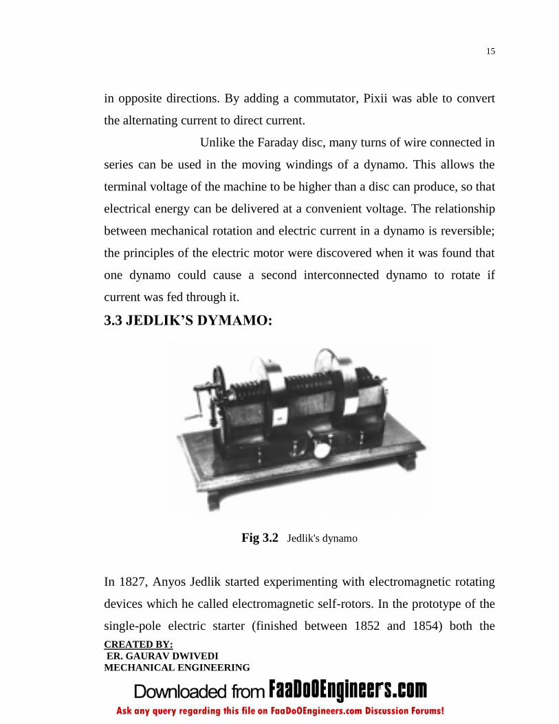
3.3 JEDLIK’S DYMAMO:
Fig 3.2 Jedlik's dynamo
In 1827, Anyos Jedlik started experimenting with electromagnetic rotating
devices which he called electromagnetic self-rotors. In the prototype of the
single-pole electric starter (finished between 1852 and 1854) both the
16
CREATED BY:
ER. GAURAV DWIVEDI
MECHANICAL ENGINEERING
stationary and the revolving parts were electromagnetic. He formulated the
concept of the dynamo at least 6 years before Siemens and Wheatstone. In
essence the concept is that instead of permanent magnets, two
electromagnets opposite to each other induce the magnetic field around the
rotor.
3.4 GRAMME DYNAMO:
Both of these designs suffered from a similar problem: they induced
"spikes" of current followed by none at all. Antonio Pacinotti, an Italian
scientist, fixed this by replacing the spinning coil with a toroidal one, which
he created by wrapping an iron ring. This meant that some part of the coil
was continually passing by the magnets, smoothing out the current. Zénobe
Gramme reinvented this design a few years later when designing the first
commercial power plants, which operated in Paris in the 1870s. His design
is now known as the Gramme dynamo. Various versions and improvements
have been made since then, but the basic concept of a spinning endless loop
of wire remains at the heart of all modern dynamos.
The generator moves an electric current, but does not
create electric charge, which is already present in the conductive wire of its
windings. It is somewhat analogous to a water pump, which creates a flow
of water but does not create the water itself.
Other types of electrical generator exist, based on other
electrical phenomena such as piezoelectricity, and magneto hydro-
dynamics. The construction of a dynamo is similar to that of an electric
motor, and all common types of dynamos could work as motors.
17
CREATED BY:
ER. GAURAV DWIVEDI
MECHANICAL ENGINEERING
3.5 TERMINOLOGY:
The parts of a dynamo or related equipment can be expressed in either
mechanical terms or electrical terms. Although distinctly separate, these
two sets of terminology are frequently used interchangeably or in
combinations that include one mechanical term and one electrical term.
This causes great confusion when working with compound machines such
as a brushless alternator or when conversing with people who are used to
working on a machine that is configured differently than the machines that
the speaker is used to.
Mechanical
Rotor: The rotating part of an alternator, generator, dynamo or motor.
Stator: The stationary part of an alternator, generator, dynamo or
motor.
Electrical
Armature: The power-producing component of an alternator,
generator, dynamo or motor. The armature can be on either the rotor
or the stator.
Field: The magnetic field component of an alternator, generator,
dynamo or motor. The field can be on either the rotor or the stator
and can be either an electromagnet or a permanent magnet.
3.6 EQUIVALENT CIRCUIT:

18
CREATED BY:
ER. GAURAV DWIVEDI
MECHANICAL ENGINEERING
Fig 3.3 Equivalent circuit of generator and load
G = generator
VG=generator open-circuit voltage
RG=generator internal resistance
VL=generator on-load voltage
RL=load resistance
Before starting the generator, measure the resistance across its
terminals using an ohmmeter. This is its DC internal resistance RGDC.
Start the generator. Before connecting the load RL, measure the
voltage across the generator's terminals. This is the open-circuit
voltage VG.
Connect the load as shown in the diagram, and measure the voltage
across it with the generator running. This is the on-load voltage VL.
Measure the load resistance RL, if you don't already know it.
3.7 MAXMIMUM POWER:
The maximum power theorem applies to generators as it does to any source
of electrical energy. This theorem states that the maximum power can be
obtained from the generator by making the resistance of the load equal to
19
CREATED BY:
ER. GAURAV DWIVEDI
MECHANICAL ENGINEERING
that of the generator. However, under this condition the power transfer
efficiency is only 50%, which means that half the power generated is
wasted as heat and Lorentz force or back emf inside the generator. For this
reason, practical generators are not usually designed to operate at maximum
power output, but at a lower power output where efficiency is greater.
3.8 ROLLER:
Suited for where heavy loads must be moved in confined spaces without
loss of precision or rigidity, Tschudin and Heid linear roller cages and
guides allows displacement of moving parts in axial direction via use of
parallel shafts and sleeves; no radial movement is possible. Rollers offer
line contact with guide, enabling low pre-load at assembly to be maintained.
Rollers are arranged within plastic or metallic cage in spiral fashion, spread
over entire surface area of shaft and sleeve.
Tschudin & Heid linear roller cages and guides are
components for machine, instrument, tool and fixture applications. The
novel design of the rollers and cages allows the displacement of moving
parts in an axial direction through the use of parallel shafts and sleeves. No
radial movement is possible. This novel construction is particularly
appropriate in cases where heavy loads must be moved in confined spaces
without loss of precision or rigidity.The use of special "rollers" instead of
balls results in line contact with the guide rather than point contact as with
ball-type guides. Because of this line contact, pre-load at assembly can be
kept low, which produces a low surface pressure between the rollers and
guides. In spite of this, the bearing is rigid, accurate and can be heavily
20
CREATED BY:
ER. GAURAV DWIVEDI
MECHANICAL ENGINEERING
loaded. The rollers are arranged within a plastic or metallic cage in spiral
fashion, spread over the entire surface area of the shaft and sleeve, leading
to a longer service life of the guide unit.
This is also a low maintenance unit, requiring only a thin
lubricating film for normal operation. Complete cylinder linear guides,
comprising shaft and sleeve with matched roller cage can be supplied ready
for fitting to customer's specifications.
Advanced Machine & Engineering Co., is a manufacturer
located in Rockford, Ill., serving the Machine Tool Industry with precision
components and accessories, including spindle interface components, work
holding devices, and, through our sister company, Hennig, machine
enclosures, chip removal and filtration systems. The Fluid Power - Safety
markets are served with cylinder rod locks and safety catcher devices; and
the Production Saw market with our Am Saw carbide saw machines and
Speed cut blade products. AME has manufacturing partners and customers
around the world.

21
CREATED BY:
ER. GAURAV DWIVEDI
MECHANICAL ENGINEERING
Fig 3.4 Roller
Henning, Inc. designs and produces custom machine
protection and chip/coolant management products for state-of-the-art
machine tools. Henning products are designed to protect against corrosion,
debris and common workplace contaminants. Manufacturing facilities are
located in the U.S., Germany, Brazil, India, Japan, China and South Korea.
Repair centers are located in Machesney Park, IL; Chandler, OK; Livonia,
MI; Blue Ash, OH; Mexico City, Mexico; and Saltillo, Mexico.
3.9 MICROCONTROLLER:
A microcontroller is a small computer on a single integrated
circuit containing a processor core, memory, and
programmable input/output peripherals. Program memory in the form

22
CREATED BY:
ER. GAURAV DWIVEDI
MECHANICAL ENGINEERING
of NOR flash or OTP ROM is also often included on chip, as well as a
typically small amount of RAM. Microcontrollers are designed for
embedded applications, in contrast to the microprocessors used in personal
computers or other general purpose applications.
Microcontrollers are used in automatically
controlled products and devices, such as automobile engine control systems,
implantable medical devices, remote controls, office machines, appliances,
power tools, and toys. By reducing the size and cost compared to a design
that uses a separate microprocessor, memory, and input/output devices,
microcontrollers make it economical to digitally control even more devices
and processes. Mixed signal microcontrollers are common, integrating
analog components needed to control non-digital electronic systems.
Some microcontrollers may use four-bit words and operate at clock
rate frequencies as low as 4 kHz, for low power consumption (mill watts or
microwatts). They will generally have the ability to retain functionality
while waiting for an event such as a button press or other interrupt; power
consumption while sleeping (CPU clock and most peripherals off) may be
just nanowatts, making many of them well suited for long lasting battery
applications. Other microcontrollers may serve performance-critical roles,
where they may need to act more like a digital signal processor (DSP).
Microcontrollers were originally programmed only in assembly language,
but various high-level programming languages are now also in common use
to target microcontrollers.

23
CREATED BY:
ER. GAURAV DWIVEDI
MECHANICAL ENGINEERING
These languages are either designed especially for the
purpose, or versions of general purpose languages such as the C
programming language. Compilers for general purpose languages will
typically have some restrictions as well as enhancements to better support
the unique characteristics of microcontrollers. Some microcontrollers have
environments to aid developing certain types of applications.
Microcontroller vendors often make tools freely available to make it easier
to adopt their hardwareher clock speeds and power consumption.
Fig 3.5 Microcontroller

24
CREATED BY:
ER. GAURAV DWIVEDI
MECHANICAL ENGINEERING
Many microcontrollers are so quirky that they
effectively require their own non-standard dialects of C, such as SDCC for
the 8051, which prevent using standard tools (such as code libraries or static
analysis tools) even for code unrelated to hardware features. Interpreters are
often used to hide such low level quirks.
Interpreter firmware is also available for some microcontrollers. For
example, BASIC on the early microcontrollers Intel 8052; BASIC
and FORTH on the Zilog Z8 as well as some modern devices. Typically
these interpreters support interactive programming.
Simulators are available for some microcontrollers, such as
in Microchip's MPLAB environment. These allow a developer to analyze
what the behavior of the microcontroller and their program should be if they
were using the actual part. A simulator will show the internal processor
state and also that of the outputs, as well as allowing input signals to be
generated. While on the one hand most simulators will be limited from
being unable to simulate much other hardware in a system, they can
exercise conditions that may otherwise be hard to reproduce at will in the
physical implementation, and can be the quickest way to debug and analyze
problems.
Recent microcontrollers are often integrated with on-
chip debug circuitry that when accessed by an in-circuit emulator via JTAG,
allow debugging of the firmware with a debugger.

25
CREATED BY:
ER. GAURAV DWIVEDI
MECHANICAL ENGINEERING
3.10 PHOTODIODE:
A photodiode is a type of photo detector capable of converting light into
either current or voltage, depending upon the mode of operation.
Photodiodes are similar to regular semiconductor diodes except that they
may be either exposed (to detect vacuum UV or X-rays) or packaged with a
window or optical fiber connection to allow light to reach the sensitive part
of the device. Many diodes designed for use specifically as a photodiode
will also use a PIN junction rather than the typical PN junction.
A photodiode is a PN junction or PIN structure. When
a photon of sufficient energy strikes the diode, it excites an electron,
thereby creating a mobile electron and a positively charged electron hole. If
the absorption occurs in the junction's depletion region, or one diffusion
length away from it, these carriers are swept from the junction by the built-
in field of the depletion region. Thus holes move toward the anode, and
electrons toward the cathode, and a photocurrent is produced.
When used in zero bias or photovoltaic mode, the flow of
photocurrent out of the device is restricted and a voltage builds up. The
diode becomes forward biased and "dark current" begins to flow across the
junction in the direction opposite to the photocurrent. This mode is
responsible for the photovoltaic effect, which is the basis for solar cells—in
fact, a solar cell is just a large area photodiode.

26
CREATED BY:
ER. GAURAV DWIVEDI
MECHANICAL ENGINEERING
Fig 3.6 Photodiode
In this mode the diode is often reverse biased, dramatically
reducing the response time at the expense of increased noise. This increases
the width of the depletion layer, which decreases the
junction's capacitance resulting in faster response times. The reverse bias
induces only a small amount of current (known as saturation or back
current) along its direction while the photocurrent remains virtually the
same. The photocurrent is linearly proportional to the luminance.
Although this mode is faster, the photoconductive
mode tends to exhibit more electronic noise. The leakage current of a good
PIN diode is so low (< 1nA) that the Johnson–Nyquist noise of the load
resistance in a typical circuit often dominates.
3.11 LED:

27
CREATED BY:
ER. GAURAV DWIVEDI
MECHANICAL ENGINEERING
A light-emitting diode (LED) is a semiconductor device that emits
incoherent narrow-spectrum light when electrically biased in the forward
direction of the P-n junction. This effect is a form of electroluminescence.
LEDs are small extended sources with extra optics added to the chip, which
emit a complex intensity spatial distribution. The color of the emitted light
depends on the composition and condition of the semi conducting material
used, and can be infrared, visible or near-ultraviolet.
Fig 3.7 Light emitting diode
The kinetic energy of the wheel gets converted in to electrical
energy by the help of generator. This electrical energy is shown by LED.
3.12 IC 555 TIMER:
IC555 timer available in 8 pin DIP or To-99 Package is one of the most
popular and versatile sequential logic devices which can be used in
monostable and a stable mode its inputs and outputs are directly compatible
both TT1 and CMOS logic circuit. The functional diagram of 555 timer is
shown in fig. On a negative going excursion of the trigger input when the

28
CREATED BY:
ER. GAURAV DWIVEDI
MECHANICAL ENGINEERING
trigger input passes through the reference voltage VCC/3, the output of the
comparator 2 goes high and sets the flip-flip (-1). On a resistive going
excursion of the threshold input, the output of a comparator 1 goes high
when the threshold voltage passes through the reference voltage 2VCC/3.
This reset the flip-flop ( = 1). The flip flop is cleared when the reset input
is less than about 0.4V. When this input is not required to be used it is
normally return to Vcc.
An extend timing capacitor C is to be connected between the
discharge terminal and ground. When the flip flop is in the reset state, its
= 1. This drives T1 to situation thereby discharging the timing capacitor.
The timing cycles starts when the flip flop goes to set state and therefore T1
is off. The timing capacitor charges with the time constant T=RA. Where C
is the timing capacitor and RA is an external resistor to be connected
between the discharge terminal and Vcc.
29
CREATED BY:
ER. GAURAV DWIVEDI
MECHANICAL ENGINEERING
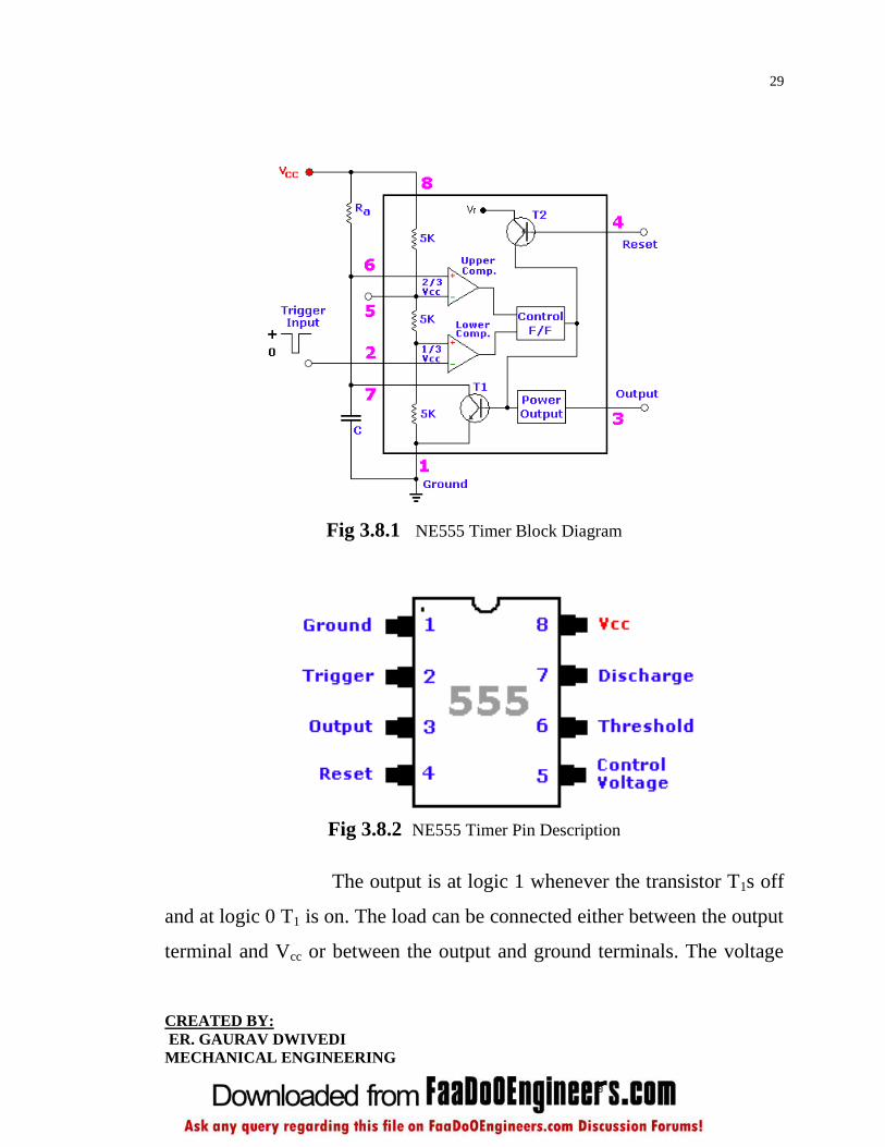
Fig 3.8.1 NE555 Timer Block Diagram
Fig 3.8.2 NE555 Timer Pin Description
The output is at logic 1 whenever the transistor T1s off
and at logic 0 T1 is on. The load can be connected either between the output
terminal and Vcc or between the output and ground terminals. The voltage

30
CREATED BY:
ER. GAURAV DWIVEDI
MECHANICAL ENGINEERING
corresponding to high output is approximately 0-5V below Vcc and for low
is approximately 0.1V.
3.13 MONOSTABLE MULTIVIBRATER USING 555
TIMER:
A monostable multivibrator circuit using a 555 timer is shown in fig. If the
trigger input is held high, then order steady – state condition the transistor
T1 is on the discharge and output terminal are at low level it can be verified
that T1 can not be off under steady state condition. When negative pulse
applied at trigger input across the voltage Vcc/3 the output of comparator 2
goes high which sets the flip flop and consequently. T1 turn off and output
goes high. The capacitor C starts getting charged to Vcc with timer constant
(T = RA.C).
3.14 DEFINITION OF PIN FUNCTION:
Pin 1 (Ground): The ground (or common) pin is the most-negative supply
potential of the device, which is normally connected to circuit common
(ground) when operated from positive supply voltages.
Pin 2 (Trigger): This pin is the input to the lower comparator and is used
to set the latch, which in turn causes the output to go high. This is the
beginning of the timing sequence in monostable operation. Triggering is
accomplished by taking the pin from above to below a voltage level of 1/3
V+ (or, in general, one-half the voltage appearing at pin 5). The action of
the trigger input is level-sensitive, allowing slow rate-of-change waveforms,
31
CREATED BY:
ER. GAURAV DWIVEDI
MECHANICAL ENGINEERING
as well as pulses, to be used as trigger sources. The trigger pulse must be of
shorter duration than the time interval determined by the external R and C.
If this pin is held low longer than that, the output will remain high until the
trigger input is driven high again. One precaution that should be observed
with the trigger input signal is that it must not remain lower than 1/3 V+ for
a period of time longer than the timing cycle. If this is allowed to happen,
the timer will re-trigger itself upon termination of the first output pulse.
Thus, when the timer is driven in the monostable mode with input pulses
longer than the desired output pulse width, the input trigger should
effectively be shortened by differentiation. The minimum-allowable pulse
width for triggering is somewhat dependent upon pulse level, but in general
if it is greater than the 1uS (micro-Second), triggering will be reliable. A
second precaution with respect to the trigger input concerns storage time in
the lower comparator. This portion of the circuit can exhibit normal turn-off
delays of several microseconds after triggering; that is, the latch can still
have a trigger input for this period of time after the trigger pulse. In
practice, this means the minimum monostable output pulse width should be
in the order of 10uS to prevent possible double triggering due to this effect.
The voltage range that can safely be applied to the trigger pin is between
V+ and ground. A dc current, termed the trigger current, must also flow
from this terminal into the external circuit. This current is typically 500nA
(nano-amp) and will define the upper limit of resistance allowable from pin
2 to ground. For an actable configuration operating at V+ = 5 volts, this
resistance is 3 Mega-ohm; it can be greater for higher V+ levels.
32
CREATED BY:
ER. GAURAV DWIVEDI
MECHANICAL ENGINEERING
Pin 3 (Output): The output of the 555 comes from a high-current totem-
pole stage made up of transistors Q20 - Q24. Transistors Q21 and Q22
provide drive for source-type loads, and their Darlington connection
provides a high-state output voltage about 1.7 volts less than the V+ supply
level used. Transistor Q24 provides current-sinking capability for low-state
loads referred to V+ (such as typical TTL inputs). Transistor Q24 has a low
saturation voltage, which allows it to interface directly, with good noise
margin, when driving current-sinking logic. Exact output saturation levels
vary markedly with supply voltage, however, for both high and low states.
At a V+ of 5 volts, for instance, the low state Vce(sat) is typically 0.25 volts
at 5 mA. Operating at 15 volts, however, it can sink 200mA if an output-
low voltage level of 2 volts is allowable (power dissipation should be
considered in such a case, of course). High-state level is typically 3.3 volts
at V+ = 5 volts; 13.3 volts at V+ = 15 volts. Both the rise and fall times of
the output waveform are quite fast, typical switching times being 100nS.
The state of the output pin will always reflect the inverse of the logic state
of the latch, and this fact may be seen by examining Fig 3.8. Since the latch
itself is not directly accessible, this relationship may be best explained in
terms of latch-input trigger conditions. To trigger the output to a high
condition, the trigger input is momentarily taken from a higher to a lower
level. [See "Pin 2 - Trigger"]. This causes the latch to be set and the output
to go high. Actuation of the lower comparator is the only manner in which
the output can be placed in the high state. The output can be returned to a
low state by causing the threshold to go from a lower to a higher level [see
33
CREATED BY:
ER. GAURAV DWIVEDI
MECHANICAL ENGINEERING
"Pin 6 - Threshold"], which resets the latch. The output can also be made to
go low by taking the reset to a low state near ground [see "Pin 4 - Reset"].
The output voltage available at this pin is approximately equal to the Vcc
applied to pin 8 minus 1.7V.
Pin 4 (Reset): This pin is also used to reset the latch and return the output
to a low state. The reset voltage threshold level is 0.7 volt, and a sink
current of 0.1mA from this pin is required to reset the device. These levels
are relatively independent of operating V+ level; thus the reset input is TTL
compatible for any supply voltage. The reset input is an overriding function;
that is, it will force the output to a low state regardless of the state of either
of the other inputs. It may thus be used to terminate an output pulse
prematurely, to gate oscillations from "on" to "off", etc. Delay time from
reset to output is typically on the order of 0.5 µS, and the minimum reset
pulse width is 0.5 µS. Neither of these figures is guaranteed, however, and
may vary from one manufacturer to another. In short, the reset pin is used to
reset the flip-flop that controls the state of output pin 3. The pin is activated
when a voltage level anywhere between 0 and 0.4 volt is applied to the pin.
The reset pin will force the output to go low no matter what state the other
inputs to the flip-flop are in. When not used, it is recommended that the
reset input be tied to V+ to avoid any possibility of false resetting.
Pin 5 (Control Voltage): This pin allows direct access to the 2/3 V+
voltage-divider point, the reference level for the upper comparator. It also
allows indirect access to the lower comparator, as there is a 2:1 divider (R8
34
CREATED BY:
ER. GAURAV DWIVEDI
MECHANICAL ENGINEERING
- R9) from this point to the lower-comparator reference input, Q13. Use of
this terminal is the option of the user, but it does allow extreme flexibility
by permitting modification of the timing period, resetting of the comparator,
etc. When the 555 timer is used in a voltage-controlled mode, its voltage-
controlled operation ranges from about 1 volt less than V+ down to within 2
volts of ground (although this is not guaranteed). Voltages can be safely
applied outside these limits, but they should be confined within the limits of
V+ and ground for reliability. By applying a voltage to this pin, it is
possible to vary the timing of the device independently of the RC network.
The control voltage may be varied from 45 to 90% of the Vcc in the
monostable mode, making it possible to control the width of the output
pulse independently of RC. When it is used in the astable mode, the control
voltage can be varied from 1.7V to the full Vcc. Varying the voltage in the
astable mode will produce a frequency modulated (FM) output. In the event
the control-voltage pin is not used, it is recommended that it be bypassed, to
ground, with a capacitor of about 0.01uF (10nF) for immunity to noise,
since it is a comparator input. This fact is not obvious in many 555 circuits
since I have seen many circuits with 'no-pin-5' connected to anything, but
this is the proper procedure. The small ceramic cap may eliminate false
triggering.
Pin 6 (Threshold): Pin 6 is one input to the upper comparator (the other
being pin 5) and is used to reset the latch, which causes the output to go
low. Resetting via this terminal is accomplished by taking the terminal from
below to above a voltage level of 2/3 V+ (the normal voltage on pin 5). The
35
CREATED BY:
ER. GAURAV DWIVEDI
MECHANICAL ENGINEERING
action of the threshold pin is level sensitive, allowing slow rate-of-change
waveforms. The voltage range that can safely be applied to the threshold
pin is between V+ and ground. A dc current, termed the threshold current,
must also flow into this terminal from the external circuit. This current is
typically 0.1µA, and will define the upper limit of total resistance allowable
from pin 6 to V+. For either timing configuration operating at V+ = 5 volts,
this resistance is 16 Mega-ohm. For 15 volt operation, the maximum value
of resistance is 20 MegaOhms.
Pin 7 (Discharge): This pin is connected to the open collector of a npn
transistor (Q14), the emitter of which goes to ground, so that when the
transistor is turned "on", pin 7 is effectively shorted to ground. Usually the
timing capacitor is connected between pin 7 and ground and is discharged
when the transistor turns "on". The conduction state of this transistor is
identical in timing to that of the output stage. It is "on" (low resistance to
ground) when the output is low and "off" (high resistance to ground) when
the output is high. In both the monostable and astable time modes, this
transistor switch is used to clamp the appropriate nodes of the timing
network to ground. Saturation voltage is typically below 100mV (milli-
Volt) for currents of 5 mA or less, and off-state leakage is about 20nA
(these parameters are not specified by all manufacturers, however).
Maximum collector current is internally limited by design, thereby
removing restrictions on capacitor size due to peak pulse-current discharge.
In certain applications, this open collector output can be used as an
36
CREATED BY:
ER. GAURAV DWIVEDI
MECHANICAL ENGINEERING
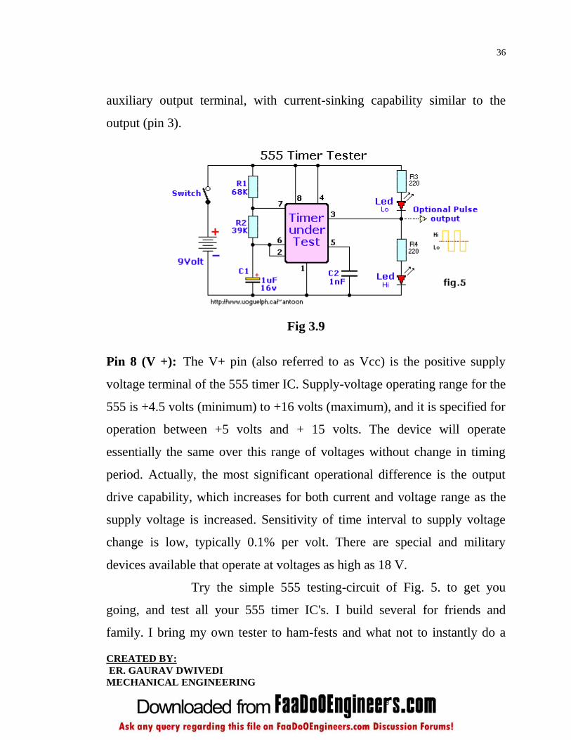
auxiliary output terminal, with current-sinking capability similar to the
output (pin 3).
Fig 3.9
Pin 8 (V +): The V+ pin (also referred to as Vcc) is the positive supply
voltage terminal of the 555 timer IC. Supply-voltage operating range for the
555 is +4.5 volts (minimum) to +16 volts (maximum), and it is specified for
operation between +5 volts and + 15 volts. The device will operate
essentially the same over this range of voltages without change in timing
period. Actually, the most significant operational difference is the output
drive capability, which increases for both current and voltage range as the
supply voltage is increased. Sensitivity of time interval to supply voltage
change is low, typically 0.1% per volt. There are special and military
devices available that operate at voltages as high as 18 V.
Try the simple 555 testing-circuit of Fig. 5. to get you
going, and test all your 555 timer IC's. I build several for friends and
family. I bring my own tester to ham-fests and what not to instantly do a
37
CREATED BY:
ER. GAURAV DWIVEDI
MECHANICAL ENGINEERING
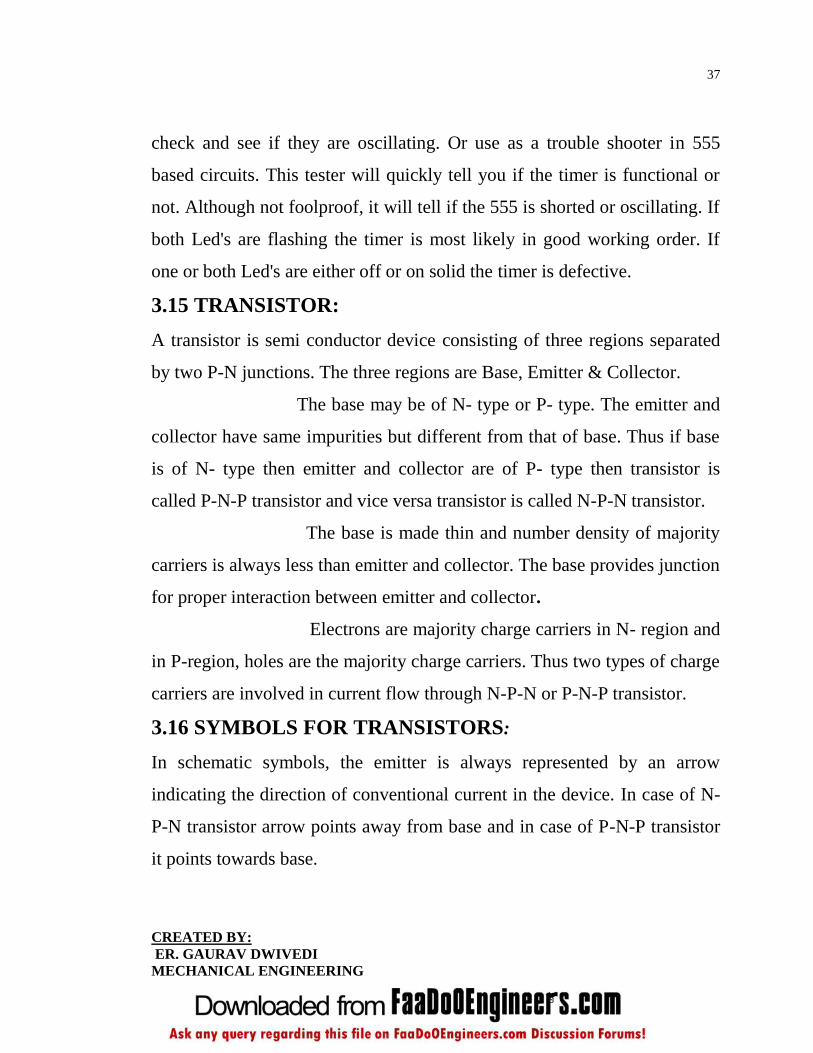
check and see if they are oscillating. Or use as a trouble shooter in 555
based circuits. This tester will quickly tell you if the timer is functional or
not. Although not foolproof, it will tell if the 555 is shorted or oscillating. If
both Led's are flashing the timer is most likely in good working order. If
one or both Led's are either off or on solid the timer is defective.
3.15 TRANSISTOR:
A transistor is semi conductor device consisting of three regions separated
by two P-N junctions. The three regions are Base, Emitter & Collector.
The base may be of N- type or P- type. The emitter and
collector have same impurities but different from that of base. Thus if base
is of N- type then emitter and collector are of P- type then transistor is
called P-N-P transistor and vice versa transistor is called N-P-N transistor.
The base is made thin and number density of majority
carriers is always less than emitter and collector. The base provides junction
for proper interaction between emitter and collector.
Electrons are majority charge carriers in N- region and
in P-region, holes are the majority charge carriers. Thus two types of charge
carriers are involved in current flow through N-P-N or P-N-P transistor.
3.16 SYMBOLS FOR TRANSISTORS:
In schematic symbols, the emitter is always represented by an arrow
indicating the direction of conventional current in the device. In case of N-
P-N transistor arrow points away from base and in case of P-N-P transistor
it points towards base.
38
CREATED BY:
ER. GAURAV DWIVEDI
MECHANICAL ENGINEERING
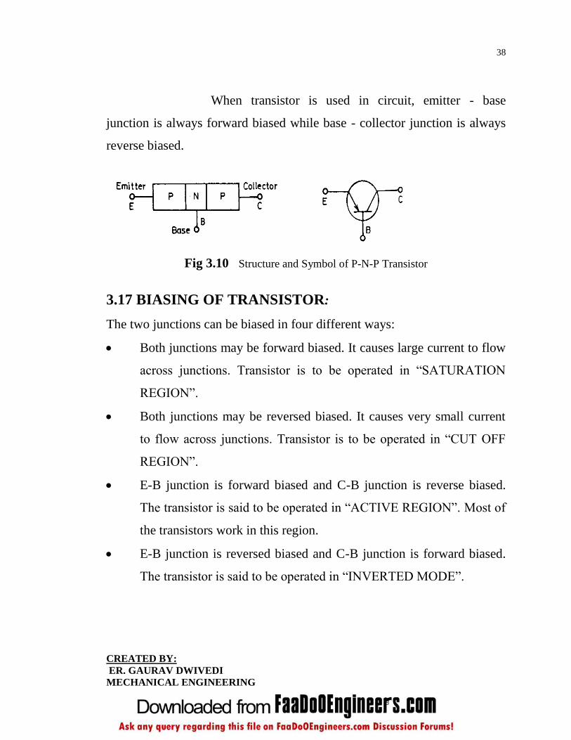
When transistor is used in circuit, emitter - base
junction is always forward biased while base - collector junction is always
reverse biased.
Fig 3.10 Structure and Symbol of P-N-P Transistor
3.17 BIASING OF TRANSISTOR:
The two junctions can be biased in four different ways:
Both junctions may be forward biased. It causes large current to flow
across junctions. Transistor is to be operated in ―SATURATION
REGION‖.
Both junctions may be reversed biased. It causes very small current
to flow across junctions. Transistor is to be operated in ―CUT OFF
REGION‖.
E-B junction is forward biased and C-B junction is reverse biased.
The transistor is said to be operated in ―ACTIVE REGION‖. Most of
the transistors work in this region.
E-B junction is reversed biased and C-B junction is forward biased.
The transistor is said to be operated in ―INVERTED MODE‖.
39
CREATED BY:
ER. GAURAV DWIVEDI
MECHANICAL ENGINEERING
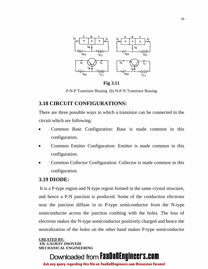
Fig 3.11
P-N-P Transistor Biasing (b) N-P-N Transistor Biasing
3.18 CIRCUIT CONFIGURATIONS:
There are three possible ways in which a transistor can be connected in the
circuit which are following:
Common Base Configuration: Base is made common in this
configuration.
Common Emitter Configuration: Emitter is made common in this
configuration.
Common Collector Configuration: Collector is made common in this
configuration.
3.19 DIODE:
It is a P-type region and N-type region formed in the same crystal structure,
and hence a P-N junction is produced. Some of the conduction electrons
near the junction diffuse in to P-type semiconductor from the N-type
semiconductor across the junction combing with the holes. The loss of
electrons makes the N-type semiconductor positively charged and hence the
neutralization of the holes on the other hand makes P-type semiconductor
40
CREATED BY:
ER. GAURAV DWIVEDI
MECHANICAL ENGINEERING
negatively charged. This region where positive and negative charges
develop is called depletion region.
If a P-region is made positive with respect to the N-
region by an external circuit then junction is forward biased and junction
has a very low resistance to the flow of current. Holes in the positive P-type
material are attracted across the junction to the negative side and the free
electrons in the N-type material are like wise attracted to the opposite side.
If a positive voltage is applied to N-zone with respect to the P-zone
terminal, the P-N junction is reverse biased.
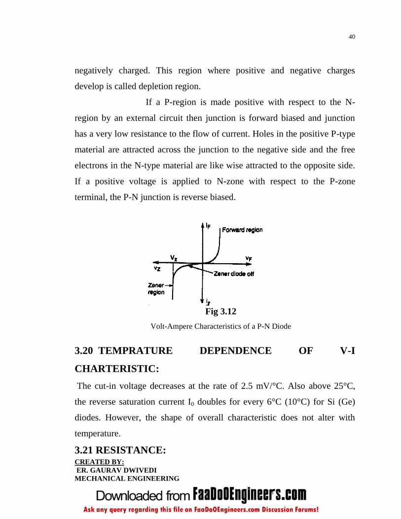
Fig 3.12
Volt-Ampere Characteristics of a P-N Diode
3.20 TEMPRATURE DEPENDENCE OF V-I
CHARTERISTIC:
The cut-in voltage decreases at the rate of 2.5 mV/°C. Also above 25°C,
the reverse saturation current I0 doubles for every 6°C (10°C) for Si (Ge)
diodes. However, the shape of overall characteristic does not alter with
temperature.
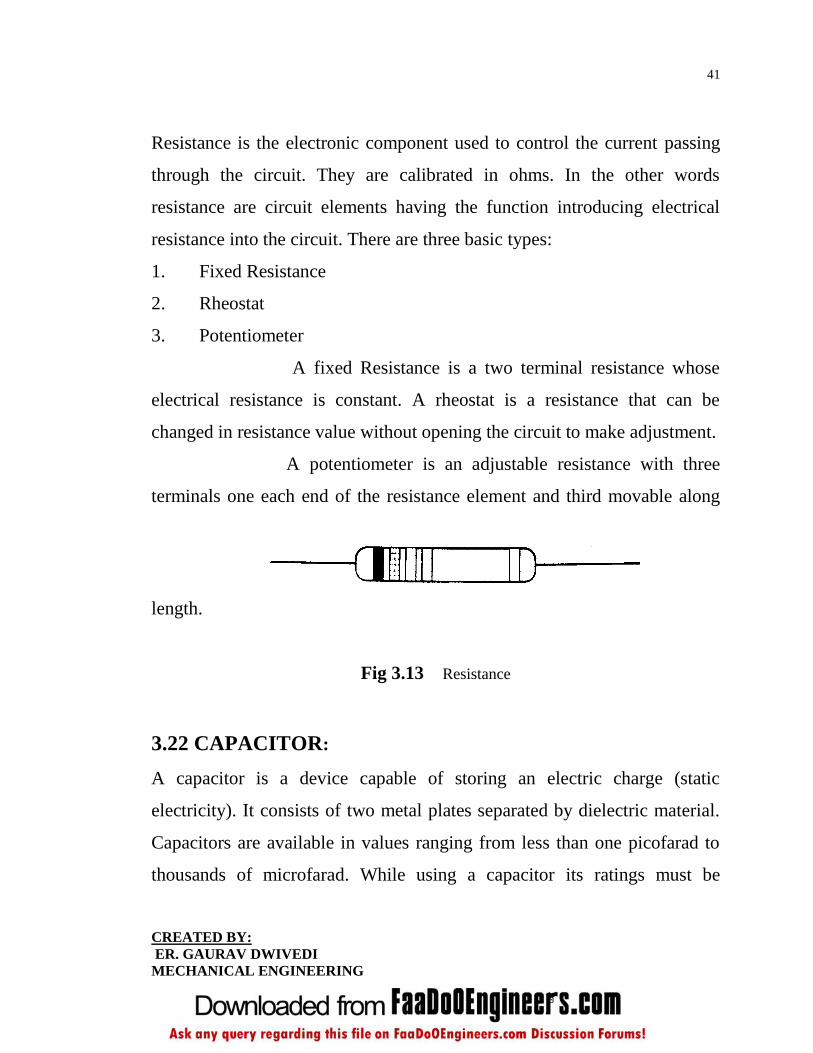
3.21 RESISTANCE:
41
CREATED BY:
ER. GAURAV DWIVEDI
MECHANICAL ENGINEERING
Resistance is the electronic component used to control the current passing
through the circuit. They are calibrated in ohms. In the other words
resistance are circuit elements having the function introducing electrical
resistance into the circuit. There are three basic types:
1. Fixed Resistance
2. Rheostat
3. Potentiometer
A fixed Resistance is a two terminal resistance whose
electrical resistance is constant. A rheostat is a resistance that can be
changed in resistance value without opening the circuit to make adjustment.
A potentiometer is an adjustable resistance with three
terminals one each end of the resistance element and third movable along
length.
Fig 3.13 Resistance
3.22 CAPACITOR:
A capacitor is a device capable of storing an electric charge (static
electricity). It consists of two metal plates separated by dielectric material.
Capacitors are available in values ranging from less than one picofarad to
thousands of microfarad. While using a capacitor its ratings must be
42
CREATED BY:
ER. GAURAV DWIVEDI
MECHANICAL ENGINEERING
carefully observed to make certain that the potential to be applied across the
capacitor is not greater than the rated value.
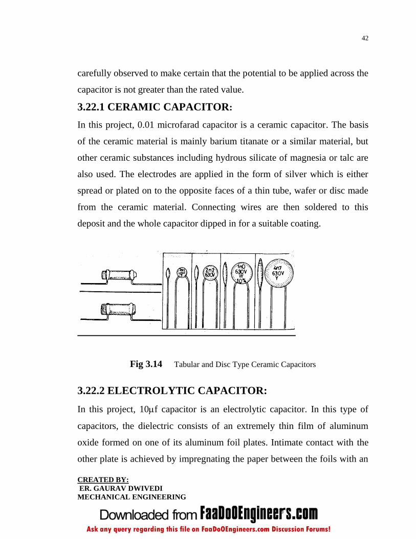
3.22.1 CERAMIC CAPACITOR:
In this project, 0.01 microfarad capacitor is a ceramic capacitor. The basis
of the ceramic material is mainly barium titanate or a similar material, but
other ceramic substances including hydrous silicate of magnesia or talc are
also used. The electrodes are applied in the form of silver which is either
spread or plated on to the opposite faces of a thin tube, wafer or disc made
from the ceramic material. Connecting wires are then soldered to this
deposit and the whole capacitor dipped in for a suitable coating.
Fig 3.14 Tabular and Disc Type Ceramic Capacitors
3.22.2 ELECTROLYTIC CAPACITOR:
In this project, 10f capacitor is an electrolytic capacitor. In this type of
capacitors, the dielectric consists of an extremely thin film of aluminum
oxide formed on one of its aluminum foil plates. Intimate contact with the
other plate is achieved by impregnating the paper between the foils with an

43
CREATED BY:
ER. GAURAV DWIVEDI
MECHANICAL ENGINEERING
electrolyte in the form of viscous substance, such as ammonium borate. The
sandwich is then rolled into a cylindrical element and housed in either
metallic cardboard, plastic or ceramic protective tube.
Fig 3.15 Electrolytic and Tantalum Capacitor
3.23 INTEGRATED CIRCUIT:
Fig 3.16 Integrated circuit
Integrated circuits were made possible by experimental
discoveries which showed that semiconductor devices could perform the

44
CREATED BY:
ER. GAURAV DWIVEDI
MECHANICAL ENGINEERING
functions of vacuum tubes, and by mid-20th-century technology
advancements in semiconductor device fabrication. The integration of large
numbers of tiny transistors into a small chip was an enormous improvement
over the manual assembly of circuits using electronic components. The
integrated circuits mass production capability, reliability, and building-
block approach to circuit design ensured the rapid adoption of standardized
ICs in place of designs using discrete transistors.
There are two main advantages of ICs over discrete
circuits: cost and performance. Cost is low because the chips, with all their
components, are printed as a unit by photolithography and not constructed
as one transistor at a time. Furthermore, much less material is used to
construct a circuit as a packaged IC die than as a discrete circuit.
Performance is high since the components switch quickly and consume
little power (compared to their discrete counterparts) because the
components are small and close together. As of 2006, chip areas range from
a few square millimeters to around 350 mm2, with up to 1
million transistors per mm2.
45
CREATED BY:
ER. GAURAV DWIVEDI
MECHANICAL ENGINEERING
CHAPTER-4
FUTURE SCOPE
In a present scenario such kind of speed breaker are being
used for a light vehicles in various countries. Now in a future that
technology can be used for heavy vehicles, thus increasing input torque to
various mechanism and ultimately output of the generator or dynamo. To
enhance the efficiency of that system, engineers have to find out more
compact, reliable and suitable mechanism to produce electricity.
Future goal of that system to enhance the efficiency, so
there should be rapid rotation of the dynamo shaft, to do the same we can
employ a flywheel to the system in such a way that it would be increase the
rotation per minute of dynamo or a generator. Generally a flywheel used in
machines serves as a reservoir which stores energy during the period when
supply energy more than the requirement and releases it during the period
when the requirement of energy more than the supply. Flywheel energy
storage (FES) works by accelerating a rotor (flywheel) to a very high speed
and maintaining the energy in the system as rotational energy. When energy
is extracted from the system, the flywheel's rotational speed is reduced as a
consequence of the principle of conservation of energy; adding energy to
the system correspondingly results in an increase in the speed of the
flywheel i.e. increasing the rotational energy of the shaft. Advanced FES
46
CREATED BY:
ER. GAURAV DWIVEDI
MECHANICAL ENGINEERING
systems have rotors made of high strength carbon filaments, suspended
by magnetic bearings, and spinning at speeds from 20,000 to over 50,000
rpm in a vacuum enclosure.
Stepper motor can be replaced by the dynamo in single way
traffic system to produce electricity from speed breakers.Stepper motors
operate differently from normal DC motors, which rotate when voltage is
applied to their terminals. Stepper motors, on the other hand, effectively
have multiple "toothed" electromagnets arranged around a central gear-
shaped piece of iron. The electromagnets are energized by an external
control circuit. To make the motor shaft turn, first one electromagnet is
given power, which makes the gear's teeth magnetically attracted to the
electromagnet's teeth. When the gear's teeth are thus aligned to the first
electromagnet, they are slightly offset from the next electromagnet. So
when the next electromagnet is turned on and the first is turned off, the gear
rotates slightly to align with the next one, and from there the process is
repeated. Each of those slight rotations is called a "step." In that way, the
motor can be turned by a precise angle.
4.1 STEPPER MOTOR:
Stepper motors are constant-power devices (power = angular
velocity x torque). As motor speed increases, torque decreases. The torque
curve may be extended by using current limiting drivers and increasing the
driving voltage.
Steppers exhibit more vibration than other motor types, as the
discrete step tends to snap the rotor from one position to another. This
47
CREATED BY:
ER. GAURAV DWIVEDI
MECHANICAL ENGINEERING
vibration can become very bad at some speeds and can cause the motor to
lose torque. The effect can be mitigated by accelerating quickly through the
problem speed range, physically damping the system, or using a micro-
stepping driver. Motors with a greater number of phases also exhibit
smoother operation than those with fewer phases.
4.2 OPEN LOOP VERSUS CLOSED LOOP
COMMUTATION:
Steppers are generally commutated open loop, i.e. the driver has no
feedback on where the rotor actually is. Stepper motor systems must thus
generally be over engineered, especially if the load inertia is high, or there
is widely varying load, so that there is no possibility that the motor will lose
steps. This has often caused the system designer to consider the trade-offs
between a closely sized but expensive servomechanism system and an
oversized but relatively cheap stepper.
A new development in stepper control is to incorporate a rotor
position feedback, so that the commutation can be made optimal for torque
generation according to actual rotor position. This turns the stepper motor
into a high pole count brushless servo motor, with exceptional low speed
torque and position resolution. An advance on this technique is to normally
run the motor in open loop mode, and only enter closed loop mode if the
rotor position error becomes too large -- this will allow the system to avoid
hunting or oscillating, a common servo problem.
4.3 TYPES:
There are three main types of stepper motors.

48
CREATED BY:
ER. GAURAV DWIVEDI
MECHANICAL ENGINEERING
Permanent Magnet Stepper
Hybrid Synchronous Stepper
Variable Reluctance Stepper
4.4 TWO PHASE STEPPER MOTOR:
There are two basic winding arrangements for the electromagnetic
coils in a two phase stepper motor: bipolar and unipolar.
4.4.1 UNIPOLAR MOTORS:
A unipolar stepper motor has logically two windings per phase, one
for each direction of current. Since in this arrangement a magnetic pole can
be reversed without switching the direction of current, the commutation
circuit can be made very simple (e.g. a single transistor) for each winding.
Typically, given a phase, one end of each winding is made common: giving
three leads per phase and six leads for a typical two phase motor. Often,
these two phase commons are internally joined, so the motor has only five
leads.

49
CREATED BY:
ER. GAURAV DWIVEDI
MECHANICAL ENGINEERING
CHAPTER-5
CONCLUSION
It is an non conventional type of producing the energy. The existing source
of energy such as coal, oil etc may not be adequate to meet the ever
increasing energy demands. These conventional sources of energy are also
depleting and may be exhausted at the end of the century or beginning of
the next century. Consequently sincere and untiring efforts shall have to be
made by engineers in exploring the possibilities of harnessing energy from
several non-conventional energy sources. This project is a one step to path
of that way. The overall goal was to design the speed breaker System while
keeping the engineering, producer and customer models in check. The
reason why this feature was used more than all of the other features are
because the other features would not have as much effect on the complete
system. By changing the size and desirable price, weight and capacity can
be realized.
We used a survey to find out how the price, weight and
capacity were scaled. Much was learned on how to and not to conduct a
survey. A preliminary survey should have been conducted to determine a
realistic value of variables. Also many of choices were not close enough
50
CREATED BY:
ER. GAURAV DWIVEDI
MECHANICAL ENGINEERING
together to get a reasonable cut off value. Therefore the data that was
produced using conjoint analysis was most likely not as accurate as it could
have been.
Future work would consist of a redesign of this model to see
exactly how much data we may be missing with the assumption that we
made with low price, weight and capacity. Despite all the assumptions, we
still have realized that this product can be very marketable and that the
demand is extremely large which means this is a viable design that will
yield a high return on an investment.

51
REFERENCES
1. Automobile Engineering : Kirpal Singh
2. Automobile Engineering : G.B.S. Narang
3. Automobile Engineering : S.M. Pandey & K.K. Shah
4. Basic Automobile Engineering : C.P. Nakra
5. A Text Book of Machine Design : R.S Khurmi & J.K. Gupta
6. Digital Systems Principles & : Ronald Ltocci.
Applications
7. Digital Design : Morris Manu.

52
CREATED BY:
ER. GAURAV DWIVEDI
MECHANICAL ENGINEERING
Related Documents