Brad A. Miller Department of Mechanical and Aerospace Engineering and Engineering Mechanics, University of Missouri-Rolla, 1870 Miner Circle, Rolla, MO 65409-0050 Itzhak Green George W. Woodruff School of Mechanical Engineering, Georgia Institute of Technology, Atlanta, GA 30332-0405 Semi-Analytical Dynamic Analysis of Spiral-Grooved Mechanical Gas Face Seals A novel semi-analytical formulation is presented for the linearized dynamic analysis of spiral-grooved mechanical gas face seals. The linearized rotordynamic properties of the gas film are numerically computed and then represented analytically by a constitutive model consisting of a cosine modified Prony series. The cosine modification enables the Prony series to characterize the gas film properties of face seals in applications with large compressibility numbers. The gas film correspondence principle is then employed to couple the constitutive model to the dynamics of the mechanical face seal. Closed-form solutions are presented for the transient natural response to initial velocity conditions, the steady-state response to rotor runout and initial stator misalignment, the transmissi- bility ratios, and the stability threshold. Results from the closed-form solutions are all within a few percent of the results from a full nonlinear numerical simulation. @DOI: 10.1115/1.1510876# Introduction Noncontacting mechanical gas face seals ~Fig. 1! are used in high speed rotating machinery to obstruct or prevent sealed gas from escaping around a rotating shaft from one compartment to another. Sealing is effected by forcing the leaking gas to escape through a small gap between the stator and rotor mating faces. The gap geometry has a significant effect on the sealing perfor- mance; in theory, a smaller gap increases the resistance to escap- ing flow. The ideal seal design then maximizes this resistance by maintaining the face separation as narrow and as parallel as pos- sible, even when inherent flaws, such as rotor runout and initial stator misalignment, are present. Such misalignments occur in all practical seals because of manufacturing tolerances, assembly im- perfections, mechanical warping, face wear, bent shafts, etc. In general, face seals are designed so that one or both of the seal rings are flexibly mounted to allow active tracking of mis- alignments. This flexibility adds to the complexity of dynamic interaction between the seal ring motion and the gas film. The relative motion between the mating rings generates hydrodynamic pressure in the sealing region, which can be advantageous or det- rimental. In a well designed seal, the gas film contributes both stiffness, which actively promotes face separation, and damping, which helps to dissipate energy from shock disturbances. How- ever, these gas film properties, under some circumstances, can also contribute to seal failure by instigating instabilities, and ne- glecting the gas film contribution can lead to seal designs with poor dynamic performance and sometimes catastrophic results. Therefore, a critically important challenge is to develop dynamic analysis tools for the design of mechanical face seals that incor- porate the complex properties of the gas film. To date, the dynamic analysis of gas face seals has relied mostly on the direct numerical simulation of motion @1–6#. Direct numerical simulations are useful because they are faster and less expensive than prototype development or experimental investiga- tions and because they can include the nonlinear effects. Though they yield a significant amount of detailed information about the overall seal motion, numerical simulations are computationally intensive and not insightful into the influence of any one compo- nent on the seal motion. Therefore, direct numerical simulations are not conducive to parametric studies of modifications to the geometry or operating conditions, which are often involved in seal design. On the other hand, small perturbation techniques and lin- ear analytical analysis methods are more practical and cost effi- cient alternatives. Analytical dynamic analysis methods are avail- able for liquid lubricated mechanical face seals @7#, but the same techniques are not applicable to gas face seals because of gas compressibility effects. So far, two specific obstacles have hin- dered the development of analytical techniques for gas face seals: ~i! closed-form representations of the gas film stiffness and damp- Contributed by the Tribology Division of THE AMERICAN SOCIETY OF ME- CHANICAL ENGINEERS for presentation at the ASME/STLE Tribology Conference, Cancun, Mexico October 27–30, 2002. Manuscript received by the Tribology Divi- sion April 16, 2002; revised manuscript received July 25, 2002. Associated Editor: J. A. Tichy. Fig. 1 Schematic of a mechanical face seal in a flexibly mounted stator configuration Copyright © 2003 by ASME Journal of Tribology APRIL 2003, Vol. 125 Õ 403

Welcome message from author
This document is posted to help you gain knowledge. Please leave a comment to let me know what you think about it! Share it to your friends and learn new things together.
Transcript
is off theutivees thewithloyed-form
ons,issi-are
Brad A. MillerDepartment of Mechanical and AerospaceEngineering and Engineering Mechanics,
University of Missouri-Rolla,1870 Miner Circle,
Rolla, MO 65409-0050
Itzhak GreenGeorge W. Woodruff School of Mechanical
Engineering,Georgia Institute of Technology,
Atlanta, GA 30332-0405
Semi-Analytical DynamicAnalysis of Spiral-GroovedMechanical Gas Face SealsA novel semi-analytical formulation is presented for the linearized dynamic analysspiral-grooved mechanical gas face seals. The linearized rotordynamic properties ogas film are numerically computed and then represented analytically by a constitmodel consisting of a cosine modified Prony series. The cosine modification enablProny series to characterize the gas film properties of face seals in applicationslarge compressibility numbers. The gas film correspondence principle is then empto couple the constitutive model to the dynamics of the mechanical face seal. Closedsolutions are presented for the transient natural response to initial velocity conditithe steady-state response to rotor runout and initial stator misalignment, the transmbility ratios, and the stability threshold. Results from the closed-form solutionsall within a few percent of the results from a full nonlinear numerical simulation.@DOI: 10.1115/1.1510876#
crs
iny
fi
o,n
c
t
t
p
nstheeallin-
effi-ail-
f gasin-als:
mp-
e
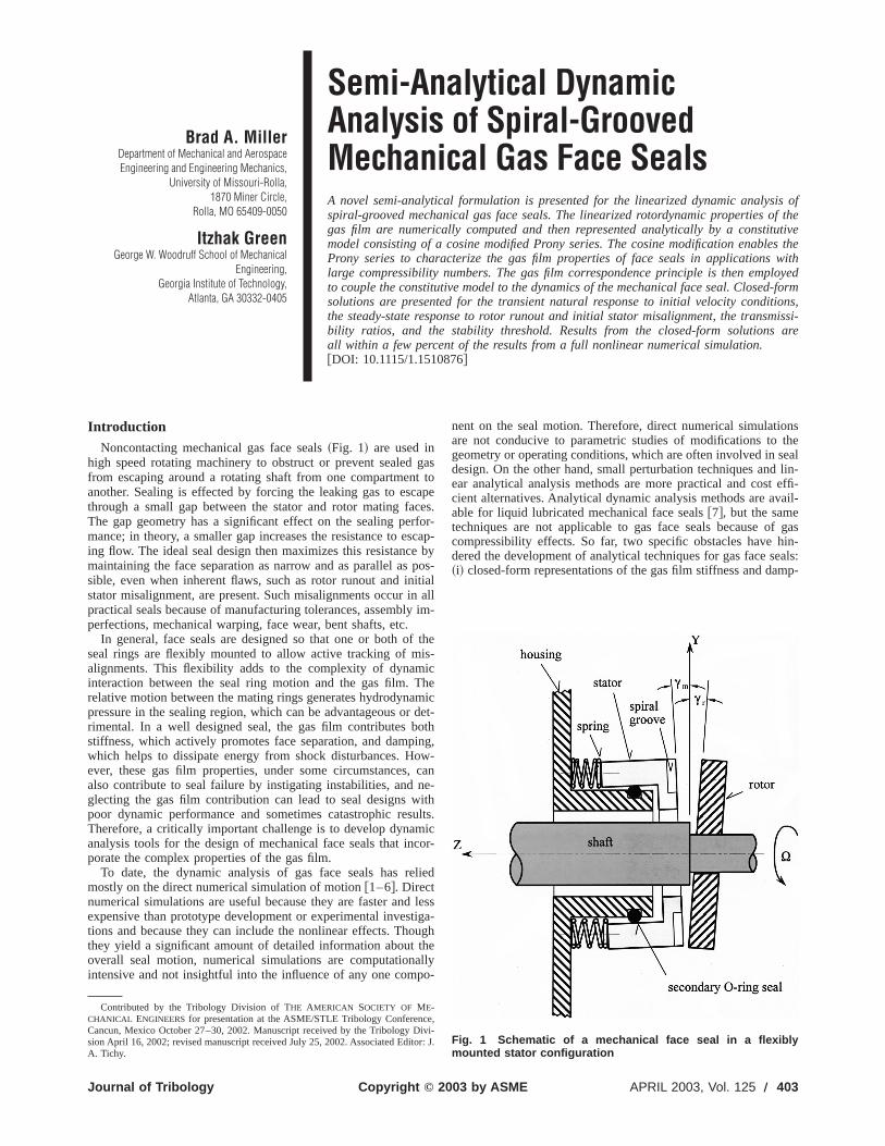
IntroductionNoncontacting mechanical gas face seals~Fig. 1! are used in
high speed rotating machinery to obstruct or prevent sealedfrom escaping around a rotating shaft from one compartmenanother. Sealing is effected by forcing the leaking gas to escthrough a small gap between the stator and rotor mating faThe gap geometry has a significant effect on the sealing pemance; in theory, a smaller gap increases the resistance to eing flow. The ideal seal design then maximizes this resistancemaintaining the face separation as narrow and as parallel assible, even when inherent flaws, such as rotor runout and instator misalignment, are present. Such misalignments occur ipractical seals because of manufacturing tolerances, assemblperfections, mechanical warping, face wear, bent shafts, etc.
In general, face seals are designed so that one or both oseal rings are flexibly mounted to allow active tracking of malignments. This flexibility adds to the complexity of dynaminteraction between the seal ring motion and the gas film. Trelative motion between the mating rings generates hydrodynapressure in the sealing region, which can be advantageous orrimental. In a well designed seal, the gas film contributes bstiffness, which actively promotes face separation, and dampwhich helps to dissipate energy from shock disturbances. Hever, these gas film properties, under some circumstancesalso contribute to seal failure by instigating instabilities, andglecting the gas film contribution can lead to seal designs wpoor dynamic performance and sometimes catastrophic resTherefore, a critically important challenge is to develop dynamanalysis tools for the design of mechanical face seals that inporate the complex properties of the gas film.
To date, the dynamic analysis of gas face seals has remostly on the direct numerical simulation of motion@1–6#. Directnumerical simulations are useful because they are faster andexpensive than prototype development or experimental investions and because they can include the nonlinear effects. Thothey yield a significant amount of detailed information aboutoverall seal motion, numerical simulations are computationaintensive and not insightful into the influence of any one com
Contributed by the Tribology Division of THE AMERICAN SOCIETY OF ME-CHANICAL ENGINEERSfor presentation at the ASME/STLE Tribology ConferencCancun, Mexico October 27–30, 2002. Manuscript received by the Tribology Dsion April 16, 2002; revised manuscript received July 25, 2002. Associated EditoA. Tichy.
Copyright © 2Journal of Tribology
gast toapees.
for-cap-by
pos-tialallim-
thes-ichemicdet-
othing,w-cane-ithults.icor-
lied
lessiga-ughhellyo-
nent on the seal motion. Therefore, direct numerical simulatioare not conducive to parametric studies of modifications togeometry or operating conditions, which are often involved in sdesign. On the other hand, small perturbation techniques andear analytical analysis methods are more practical and costcient alternatives. Analytical dynamic analysis methods are avable for liquid lubricated mechanical face seals@7#, but the sametechniques are not applicable to gas face seals because ocompressibility effects. So far, two specific obstacles have hdered the development of analytical techniques for gas face se~i! closed-form representations of the gas film stiffness and da
,ivi-r: J.Fig. 1 Schematic of a mechanical face seal in a flexiblymounted stator configuration
003 by ASME APRIL 2003, Vol. 125 Õ 403
404 Õ Vol. 125
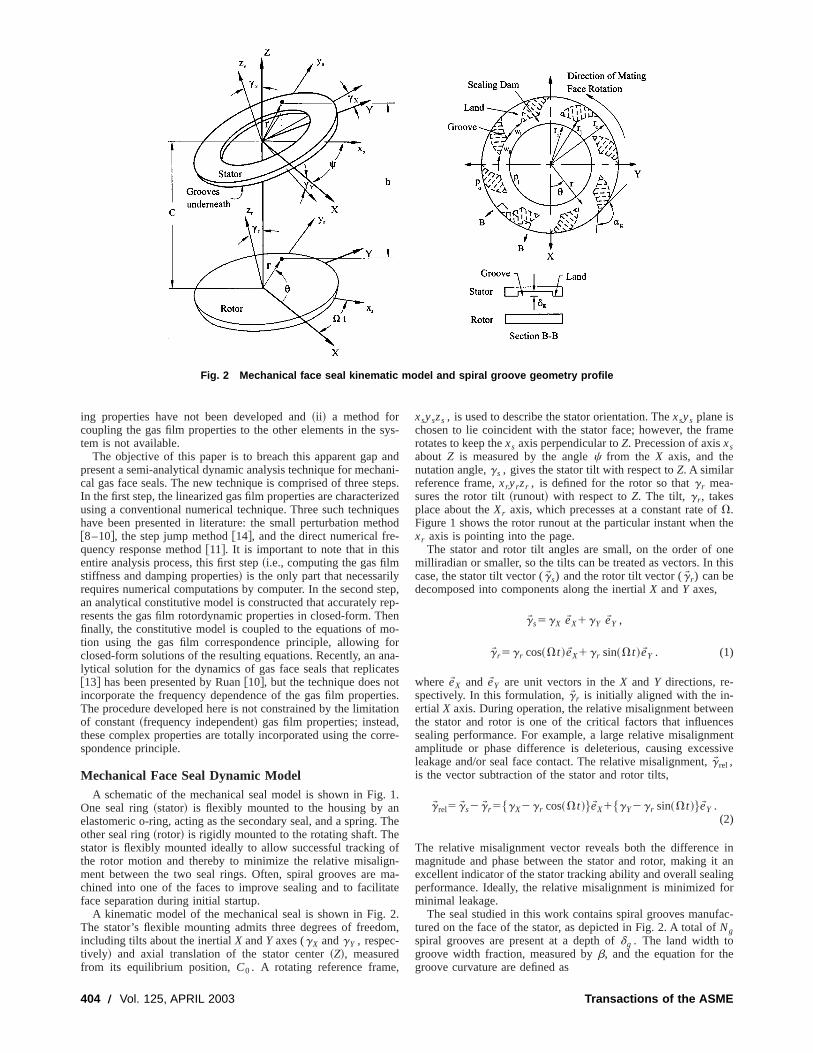
Fig. 2 Mechanical face seal kinematic model and spiral groove geometry profile
s
t-
y
rh
f
.n.e
a
o
,
me
the
nethis
encesentsive
init aningfor
fac-
ing properties have not been developed and~ii ! a method forcoupling the gas film properties to the other elements in thetem is not available.
The objective of this paper is to breach this apparent gappresent a semi-analytical dynamic analysis technique for mechcal gas face seals. The new technique is comprised of three sIn the first step, the linearized gas film properties are characterusing a conventional numerical technique. Three such techniqhave been presented in literature: the small perturbation me@8–10#, the step jump method@14#, and the direct numerical frequency response method@11#. It is important to note that in thisentire analysis process, this first step~i.e., computing the gas filmstiffness and damping properties! is the only part that necessarilrequires numerical computations by computer. In the second san analytical constitutive model is constructed that accuratelyresents the gas film rotordynamic properties in closed-form. Tfinally, the constitutive model is coupled to the equations of mtion using the gas film correspondence principle, allowingclosed-form solutions of the resulting equations. Recently, an alytical solution for the dynamics of gas face seals that replica@13# has been presented by Ruan@10#, but the technique does noincorporate the frequency dependence of the gas film properThe procedure developed here is not constrained by the limitaof constant~frequency independent! gas film properties; insteadthese complex properties are totally incorporated using the cospondence principle.
Mechanical Face Seal Dynamic ModelA schematic of the mechanical seal model is shown in Fig
One seal ring~stator! is flexibly mounted to the housing by aelastomeric o-ring, acting as the secondary seal, and a springother seal ring~rotor! is rigidly mounted to the rotating shaft. Thstator is flexibly mounted ideally to allow successful trackingthe rotor motion and thereby to minimize the relative misaligment between the two seal rings. Often, spiral grooves arechined into one of the faces to improve sealing and to facilitface separation during initial startup.
A kinematic model of the mechanical seal is shown in Fig.The stator’s flexible mounting admits three degrees of freedincluding tilts about the inertialX andY axes (gX andgY , respec-tively! and axial translation of the stator center~Z!, measuredfrom its equilibrium position,C0 . A rotating reference frame
, APRIL 2003
ys-
andani-teps.izedueshod
tep,ep-eno-orna-testties.tion,rre-
1.
The
ofn-ma-te
2.m,
xsyszs , is used to describe the stator orientation. Thexsys plane ischosen to lie coincident with the stator face; however, the frarotates to keep thexs axis perpendicular toZ. Precession of axisxsabout Z is measured by the anglec from the X axis, and thenutation angle,gs , gives the stator tilt with respect toZ. A similarreference frame,xryrzr , is defined for the rotor so thatg r mea-sures the rotor tilt~runout! with respect toZ. The tilt, g r , takesplace about theXr axis, which precesses at a constant rate ofV.Figure 1 shows the rotor runout at the particular instant whenxr axis is pointing into the page.
The stator and rotor tilt angles are small, on the order of omilliradian or smaller, so the tilts can be treated as vectors. Incase, the stator tilt vector (gW s) and the rotor tilt vector (gW r) can bedecomposed into components along the inertialX andY axes,
gW s5gX eWX1gY eWY ,
gW r5g r cos~Vt !eWX1g r sin~Vt !eWY . (1)
whereeWX and eWY are unit vectors in theX and Y directions, re-spectively. In this formulation,gW r is initially aligned with the in-ertial X axis. During operation, the relative misalignment betwethe stator and rotor is one of the critical factors that influensealing performance. For example, a large relative misalignmamplitude or phase difference is deleterious, causing excesleakage and/or seal face contact. The relative misalignment,gW rel ,is the vector subtraction of the stator and rotor tilts,
gW rel5gW s2gW r5$gX2g r cos~Vt !%eWX1$gY2g r sin~Vt !%eWY .(2)
The relative misalignment vector reveals both the differencemagnitude and phase between the stator and rotor, makingexcellent indicator of the stator tracking ability and overall sealperformance. Ideally, the relative misalignment is minimizedminimal leakage.
The seal studied in this work contains spiral grooves manutured on the face of the stator, as depicted in Fig. 2. A total ofNgspiral grooves are present at a depth ofdg . The land width togroove width fraction, measured byb, and the equation for thegroove curvature are defined as
Transactions of the ASME
a
e
n
g
e
o
p
i
r
ta-enticalforsed-ed,at.
allcor-
thenine
-
lued
rage
imemea-malltepUn-alideping
thendareterms
b5wg
wg1wl; r 5r ie
u tan~ag!, 0,ag,180 deg, (3)
whereag is the spiral angle andag590 deg corresponds to radiagrooves. The radius,r j , marks the junction between the spirgroove region and the sealing dam region.
The applied forces and moments on the stator come fromflexible support and the gas film pressure. For this analysis,flexible support is assumed to have a constant axial stiffnessdamping ofksZ and dsZ , respectively. According to Green anEtsion @7#, the flexible support also contributes angular stiffneand damping of
ksg51
2ksZ•r o
2, dsg51
2dsZ•r o
2, (4)
assuming that the support forces act at the outer radius,r o .During operation, the relative motion between the seal rin
and the pressure difference across the inner and outer sealgenerate hydrodynamic and hydrostatic pressure between thefaces. Assuming the gas flow is ideal, isothermal and inertialthe pressure distribution in the gas film is obtained from the copressible form of the Reynolds equation@12#,
¹W •@ph3¹W p26mVrpheW u#512m]~ph!
]t. (5)
The polar coordinate gradient operator is presumed here, andfollowing boundary conditions apply:
p~r i ,u,t !5pi ,
p~r o ,u,t !5po ,
p~r ,0,t !5p~r ,2p,t !. (6)
Solution of the Reynolds equation subject to the boundary cotions yields the pressure, from which the gas film force and mments,FZ , MX , andMY , are found by appropriately integratinthe pressure over the sealing area. The gas film force andments and the seal ring motion are coupled by the film thicknh, and the squeeze term,]h/]t, through the stator degrees ofreedom,
h~r ,u!5C01Z1rgX sin~u!2rgY cos~u!1^dg&
2g r r sin~u2Vt !,
]h~r ,u!
]t5Z1r gX sin~u!2r gY cos~u!1Vg r r cos~u2Vt !.
(7)
The ^dg& term is only added inside a groove and creates disctinuity in h but not in]h/]t.
The dynamic motion of the stator is governed by the equatiof motion @7#,
mZ52FZ,eq1FZ2ksZZ2dsZZ,
I gX5MX2ksggX2dsggX1MXi , (8)
I gY5MY2ksggY2dsggY .
The force,FZ,eq , which results from static deflection in the suport and external back pressure, offsets the gas film force at elibrium to establish the reference axial position of the stator,C0 .For the situations studied here, the target, or ideal, equilibrstate is when the stator is initially aligned with the rotor. Undthese conditions, the gas pressure at equilibrium provides noment. In Eq.~8!, the momentMXi accounts for the initial statomisalignment,gm , caused by manufacturing tolerances and inetable imperfections in the seal assembly process. Without losgenerality, the misalignment is arbitrarily assumed to occur ab
Journal of Tribology
ll
thetheanddss
gsradiisealss,m-
the
di-o-
mo-ss,f
on-
ns
-qui-
umermo-
vi-s ofout
the X axis. Using the model introduced by@7#, the magnitude ofthe moment produced by the initial stator tilt is given by
MXi5ksggm , (9)
whereksg is the angular stiffness of the flexible support.A full dynamic analysis of the seal system requires simul
neous solution of the kinetic and lubrication equations. Currdynamic analysis techniques focus mainly on direct numersimulations of motion, but analytical techniques are superiordesign purposes because the solutions are available in cloform. Before an analytical solution technique can be employthe gas film properties must first be available in analytical form
Analytical Characterization of Gas Film RotordynamicProperties
The gas film stiffness,Si j (v), and damping,Di j (v), character-ize the linear reaction of the gas film force and moments to smsinusoidal stator displacements about equilibrium and to theresponding velocity, respectively. Thev argument indicates theexcitation-frequency dependence of these properties. Sinceseal model has three degrees of freedom, there are a total ofterms for both of these quantities with thei subscript corresponding to the generalized force (FZ , MX , or MY), and thej subscriptcorresponding to the generalized displacement~Z, gX , or gY).The stiffness and damping together make up the complex-vagas film frequency response,Gi j (v), where
Gi , j~v!5Si , j~v!1 j vDi , j~v!. (10)
The real part of the frequency response is also called the stomodulus, and the imaginary part is called the loss modulus.
The gas film properties can also be characterized in the tdomain by a series of step responses. The step response is asure of the transient gas film generalized force response to a sstep jump in one degree of freedom. In this context, the sresponse physically represents the transient gas film stiffness.der the assumption that the force response is linear, which is vif the relative motion remains small about equilibrium, the stresponse is related to the frequency response by the followintegral transformation@13#,
Gi , j~v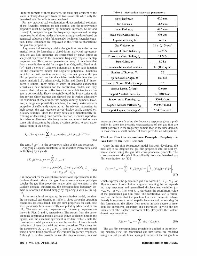
t
as
ned
a
taw
vx
d
c
srn
s
pref-areain.e fit.
thedy-heas
nd-(
eu-ave. Ine-net
w-ledfilm
From the formats of these matrices, the axial displacement ofstator is clearly decoupled from the two stator tilts when onlylinearized gas film effects are considered.
For any practical seal configuration, direct analytical solutioof the Reynolds equation are not possible, and the rotordynaproperties must be computed by numerical methods. MillerGreen@11# compute the gas film frequency responses and theresponses for all three modes of motion using procedures basenumerical solutions of the full unsteady, nonlinear Reynolds eqtion. These techniques are employed in this work to charactethe gas film properties.
Any numerical technique yields the gas film properties in nmerical form. To formulate a closed-form, analytical represention, the gas film properties are represented by curve fittinganalytical expression to the numerical frequency response orresponse data. This process generates an array of functionsform a constitutive model for the gas film. Originally, Elrod et a@14# used a series of Laguerre polynomials as the base funcfor the constitutive model, but Laguerre polynomial functiomust be used with caution because they can misrepresent thfilm properties and can introduce false instabilities into thenamic analysis@15#. Alternatively, Miller and Green@13# intro-duced a simple Prony series~a series of decaying exponentiterms! as a base function for the constitutive model, and thshowed that it does not suffer from the same deficiencies asguerre polynomials. They successfully used the Prony seriesdata for gas slider bearings and showed that it worked adequfor conditions of low or moderate compressibility numbers. Hoever, at large compressibility numbers, the Prony series alonincapable of sufficiently capturing all the relevant properties.high speeds, the step response curves display small, dampecillatory features. Since the Prony series is a monotonicallycreasing or decreasing time domain function, it cannot reprodthis behavior. However, the Prony series can be modified to ocome this shortcoming by adding a cosine product to each enential term in the series,
ki , j~ t !5ki , j~`!1(n51
N
Ai , j ,n•cos~v i , j ,nt1f i , j ,n!•e2a i , j ,nt.
(15)
The term,ki j (`), is the asymptotic value of the step responseApplying a Laplace transform to the modified Prony series a
multiplying by s yields
sKi , j~s!5ki , j~`!1(n51
N
Ai , j ,n•s
•
~s1a i , j ,n!cos~f i , j ,n!2v i , j ,n sin~f i , j ,n!
~s1a i , j ,n!21v i , j ,n2 . (16)
It is important for the constitutive model to be representable inLaplace domain since the gas film correspondence princcouples the gas film properties to the other seal elements inLaplace domain. Furthermore, the corresponding frequencymain relationship is found simply by replacings with j v in Eq.~16!.
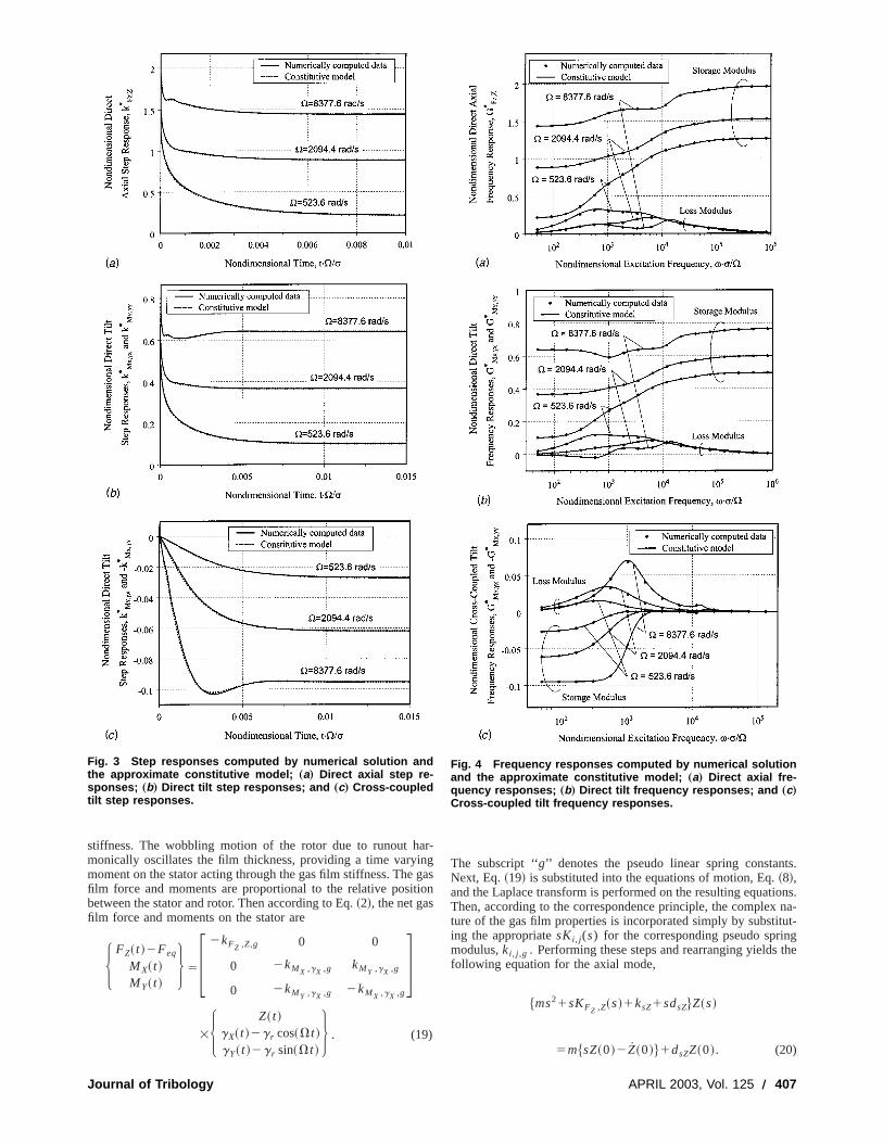
As an example of computing the constitutive model, consithe mechanical seal detailed in Table 1. Three particular operaconditions are considered. The gas film properties for eachhave previously been numerically computed by Miller and Gre@11#. The non-zero step responses and frequency responseshown in Figs. 3 and 4, respectively. The curves from the cosponding constitutive models are also shown as dashed lines ifigures, and the excellent agreement is evident. Table 2 listsconstitutive model parameters where the number of terms in eseries was chosen by a trial and error procedure. The valuethe parameters,Ai , j ,n , a i , j ,n , v i , j ,n , andf i , j ,n , were determinedusing a curve fitting process on the complex frequency responAlthough it is also possible to use the step responses, in m
406 Õ Vol. 125, APRIL 2003
thehe
nsmicndtepd onua-rize
u-ta-an
stepthat
l.tionsgas
y-
leyLa-o fittely-
e isAtd os-in-uceer-po-
.nd
theiplethedo-
ertingaseen
arere-thetheachfor
ses.ost
instances the curve fit using the frequency responses gives aerable fit since the dynamic characteristics of the gas filmbetter portrayed in the frequency domain than in the time domIn most cases, a small number of terms provides an adequat
The Gas Film Correspondence Principle: Coupling theGas Film to the Seal Elements
Once the gas film constitutive model has been developed,next step is to integrate the gas film properties into the sealnamic model using the gas film correspondence principle. Tcorrespondence principle follows directly from the linearized gfilm constitutive law@13#,
f i~ t !2 f i ,eq52(j 51
3 Fki , j~0!xj~ t !1E0
t
ki , j~t!xj~ t2t!dtG ,
(17)
which expresses the generalized gas film forces (f i5FZ , MX , orMY) as a sum of convolution integrals containing the correspoing step responses and generalized displacement variablesxj5Z, gX , or gY). The termf i ,eq represents the equilibrium valuof the generalized gas film force. The constitutive law is formlated on the basis that the gas film force and moments behlinearly in response to small step displacements of the seal ringthis formulation, the effects from motion in each degree of fredom are considered separately and superposed to yield theforce effect. The Laplace transform of Eq.~17! yields the Laplacedomain representation,
Fi~s!2 f i ,eq52(j 51
3
sKi , j~s!Xj~s!. (18)
The gas film correspondence principle is applied in the folloing manner. First, the generalized gas film forces are modeusing a set of pseudo linear springs to represent the net gas
Table 1 Mechanical face seal parameters
Transactions of the ASME
an
i
ts.
ons.na-
tut-gthe
stiffness. The wobbling motion of the rotor due to runout hmonically oscillates the film thickness, providing a time varyimoment on the stator acting through the gas film stiffness. Thefilm force and moments are proportional to the relative positbetween the stator and rotor. Then according to Eq.~2!, the net gasfilm force and moments on the stator are
H FZ~ t !2Feq
MX~ t !MY~ t !
J 5F 2kFZ ,Z,g 0 0
0 2kMX ,gX ,g kMY ,gX ,g
0 2kMY ,gX ,g 2kMX ,gX ,g
G3H Z~ t !
gX~ t !2g r cos~Vt !gY~ t !2g r sin~Vt !
J . (19)
Fig. 3 Step responses computed by numerical solution andthe approximate constitutive model; „a… Direct axial step re-sponses; „b… Direct tilt step responses; and „c… Cross-coupledtilt step responses.
Journal of Tribology
r-ggason
The subscript ‘‘g’’ denotes the pseudo linear spring constanNext, Eq.~19! is substituted into the equations of motion, Eq.~8!,and the Laplace transform is performed on the resulting equatiThen, according to the correspondence principle, the complexture of the gas film properties is incorporated simply by substiing the appropriatesKi , j (s) for the corresponding pseudo sprinmodulus,ki , j ,g . Performing these steps and rearranging yieldsfollowing equation for the axial mode,
$ms21sKFZ ,Z~s!1ksZ1sdsZ%Z~s!
5m$sZ~0!2Z~0!%1dsZZ~0!. (20)
Fig. 4 Frequency responses computed by numerical solutionand the approximate constitutive model; „a… Direct axial fre-quency responses; „b… Direct tilt frequency responses; and „c…Cross-coupled tilt frequency responses.
APRIL 2003, Vol. 125 Õ 407
mi-
gas
ing
ud-itialtatorarendatelyrpo-areeens ofble
tin
di-l todi-f thearts
erse
ws
Clearly, the axial mode is decoupled from the two angular modtherefore, the solutions can be treated separately. The solutioEq. ~20! is found by algebraic manipulation to be
Z~s!5m$sZ~0!2Z~0!%1dsZZ~0!
ms21sKFZ ,Z~s!1ksZ1sdsZ. (21)
The characteristic equation for the axial mode is
ms21sKFZ ,Z~s!1ksZ1sdsZ50. (22)
Now for the angular modes, the following equations are found
Fa11 a12
a21 a22G HGX~s!
GY~s!J 5 Hb1
b2J , (23)
where the matrix coefficients are defined as
a115Is21sKMX ,gX~s!1ksg1sdsg ,
a125sKMX ,gY~s!,
a215sKMY ,gX~s!,
a225Is21sKMY ,gY~s!1ksg1sdsg , (24)
and where
b15I $sgX~0!1gX~0!%1dsggX~0!1g rsKMX ,gX~s!
s
s21V2
1g rsKMX ,gY~s!
V
s21V2 11
sMXi ,
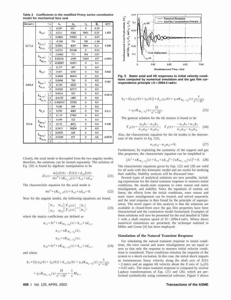
Table 2 Coefficients in the modified Prony series constitutivemodel for mechanical face seal
408 Õ Vol. 125, APRIL 2003
es;n of
,
b25I $sgY~0!1gY~0!%1dsggY~0!1g rsKMY ,gX~s!
s
s21V2
1g rsKMY ,gY~s!
V
s21V2 . (25)
The general solution for the tilt motion is found to be
GX~s!5a22b12a12b2
a11a222a12a21; GY~s!5
2a21b11a11b2
a11a222a12a21. (26)
Also, the characteristic equation for the tilt modes is the deternant of the matrix in Eq.~23!,
a11a222a12a2150. (27)
Furthermore, by exploiting the symmetry of the support andfilm properties, the characteristic equation can be simplified to
bIs21sKMX ,gX~s!1ksg1sdsgc21@sKMY ,gX
~s!#250. (28)
The characteristic equations given by Eqs.~22! and~28! are validfor all seals with this kinematic model and are useful for studytheir stability. Stability analysis will be discussed later.
Several types of analytical solutions are now possible, incling expressions for the initial transient response to nonzero inconditions, the steady-state response to rotor runout and smisalignment, and stability. Since the equations of motionlinear, the effects from the initial conditions, rotor runout astatic stator misalignment can be treated, and solved separand the total response is then found by the principle of supesition. The novel aspect of this analysis is that the solutionsavailable in closed-form once the gas film properties have bcharacterized and the constitutive model formulated. Examplethese solutions will now be presented for the seal detailed in Ta1 with a shaft rotation speed ofV52094.4 rad/s. Where direcnumerical simulations are presented, the technique outlinedMiller and Green@4# has been employed.
Simulation of the Natural Transient ResponseFor simulating the natural transient response to initial con
tions, the rotor runout and stator misalignment are set equazero so that only the response to nonzero initial velocity contions is considered. These conditions simulate the response osystem to a shock excitation. In this case, the initial shock impan instantaneous linear velocity along the shaft axis ofZ(0)52 mm/s and an angular tilt velocity about theX axis of gX(0)50.05 rad/s. The stator transient response is computed by invLaplace transformations of Eqs.~21! and ~26!, which are per-formed symbolically using commercial software. Figure 5 sho
Fig. 5 Stator axial and tilt responses to initial velocity condi-tions computed by numerical simulation and the gas film cor-respondence principle „VÄ2094.4 rad Õs…
Transactions of the ASME
uet
e
fit
sir
e
r
e
st
erge-syn-t at
ady-a
onOnmethe-gasna-onsig-
tialis-
porttate.
by
comparisons of the analytical solutions with responses compby a nonlinear direct numerical simulation. The natural frequcies of oscillation and the decay rates predicted by the analyand numerical solutions are in very good agreement. Also,correspondence principle accurately captures the couplingtween the two tilt modes. The quality of these results verifies tthe axial mode is effectively decoupled from the tilt modes athat the constitutive model accurately represents the stiffnessdamping properties of the gas film for this configuration.
Steady-State Response to Rotor RunoutThe amplitude and direction of the rotor misalignment are m
sured by the vector,gW r , which has been defined in Eq.~1!. If therunout is large, the stator is generally less capable of trackingrotor misalignment, leading to large seal ring separation andcessive leakage. Though the transient response may be signiwhen the seal experiences a shock disturbance, the transienusually short as long as the seal is stable. Most of the seal lifspent in steady-state tracking motion; therefore, the steady-response is used as the preferred indicator of tracking abSince the system is linear, the responses caused by therunout and initial stator misalignment can be computed separaand then added later using the principle of superposition. Thfore, neglecting the initial conditions andMxi , the only forcingfunctions remaining on the right hand side of Eq.~23! ~defined asb1 andb2 in Eq. ~25!! are those terms from the rotor runout. Throtor runout produces a harmonic forcing function at the fquency of shaft rotation,V, and the steady-state stator responsethis forcing has the same form. Taking advantage of the symmof the inertia, support and gas film properties, the stator respocan be simplified to
gX,r~ t !5g rA cos~Vt2f!,(29)
gY,r~ t !5g rA sin~Vt2f!.
Closed-form expressions forA andf are given by
A51
DA~Re@RX,c#2Im@RY,c# !21~Re@RX,s#2Im@RY,s# !2,
tan~f!5Re@RX,s#2Im@RY,s#
Re@RX,c#2Im@RY,c#, (30)
D5a11a222a12a21.
The termsa11, a22, a12, and a21, are defined in Eq.~24!, andRe@R# and Im@R# correspond to the real and imaginary parts ofR,respectively, where
RX,c~ j V!51
D•$a22j VKMX ,gX
~ j V!2a12j VKMg ,gX~ j V!%,
RX,s~ j V!51
D•$a22j VKMX ,gY
~ j V!2a12j VKMY ,gY~ j V!%,
(31)
RY,c~ j V!51
D•$2a21j VKMX ,gX
j ~V!1a11j VKMY ,gX~ j V!%,
RY,s~ j V!51
D•$2a21j VKMX ,gY
~ j V!2a11j VKMY ,gY~ j V!%.
The subscript ‘‘r’’ is added to the tilt vectors in Eq.~29! to indi-cate that it corresponds to the steady-state response to rotor rualone. The total stator response is found by vector addition to
gW s,r5$g rA cos~Vt2f!%eWX1$g rA sin~Vt2f!%eWY , (32)
or in complex notation,
gW s,r5g rAej ~Vt2f!. (33)
By this analysis, it is clear that the steady-state stator responrotor runout is proportional to the runout amplitude by the fac
Journal of Tribology
tedn-
icalthebe-
hatndand
a-
theex-cants aree istatelity.otortelyre-
ee-totrynse
noutbe
e toor
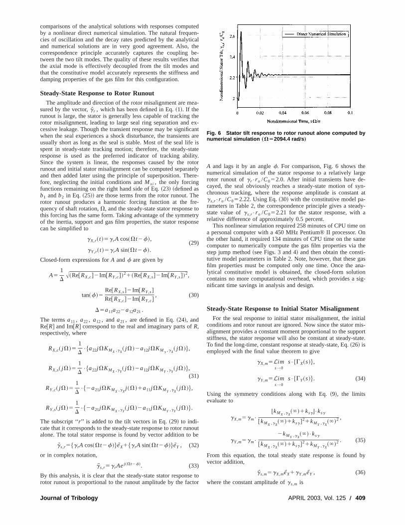
A and lags it by an anglef. For comparison, Fig. 6 shows thnumerical simulation of the stator response to a relatively larotor runout ofg r•r o /C052.0. After initial transients have decayed, the seal obviously reaches a steady-state motion ofchronous tracking, where the response amplitude is constangs,r•r o /C052.22. Using Eq.~30! with the constitutive model pa-rameters in Table 2, the correspondence principle gives a stestate value ofgs,r•r o /C052.21 for the stator response, withrelative difference of approximately 0.5 percent.
This nonlinear simulation required 258 minutes of CPU timea personal computer with a 450 MHz Pentium® II processor.the other hand, it required 134 minutes of CPU time on the sacomputer to numerically compute the gas film properties viastep jump method~see Figs. 3 and 4! and then obtain the constitutive model parameters in Table 2. Note, however, that thesefilm properties must be computed only one time. Once the alytical constitutive model is obtained, the closed-form soluticontains no more computational overhead, which provides anificant time savings in analysis and design.
Steady-State Response to Initial Stator MisalignmentFor the seal response to initial stator misalignment, the ini
conditions and rotor runout are ignored. Now since the stator malignment provides a constant moment proportional to the supstiffness, the stator response will also be constant at steady-sTo find the long-time, constant response at steady-state, Eq.~26! isemployed with the final value theorem to give
gX,m5Lims→0
s•$GX~s!%,
gY,m5Lims→0
s•$GY~s!%. (34)
Using the symmetry conditions along with Eq.~9!, the limitsevaluate to
gX,m5gm•
bkMX ,gX~`!1ksgc•ksg
@kMX ,gX~`!1ksg#21kMY ,gX
~`!2 ,
gY,m5gm•
2kMY ,gX~`!•ksg
@kMX ,gX~`!1ksg#21kMY ,gX
~`!2 . (35)
From this equation, the total steady state response is foundvector addition,
gW s,m5gX,meWX1gY,meWY , (36)
where the constant amplitude ofgs,m is
Fig. 6 Stator tilt response to rotor runout alone computed bynumerical simulation „VÄ2094.4 rad Õs…
APRIL 2003, Vol. 125 Õ 409
e
i
n
e
me
s
noutthenrre-
ffset
ive
tionlarge
rre-s byviorpled
tantthe
gs,m5gm•ksg
A@kMX ,gX~`!1ksg#21kMY ,gX
~`!2. (37)
This is a static response and, therefore, does not contain interms.
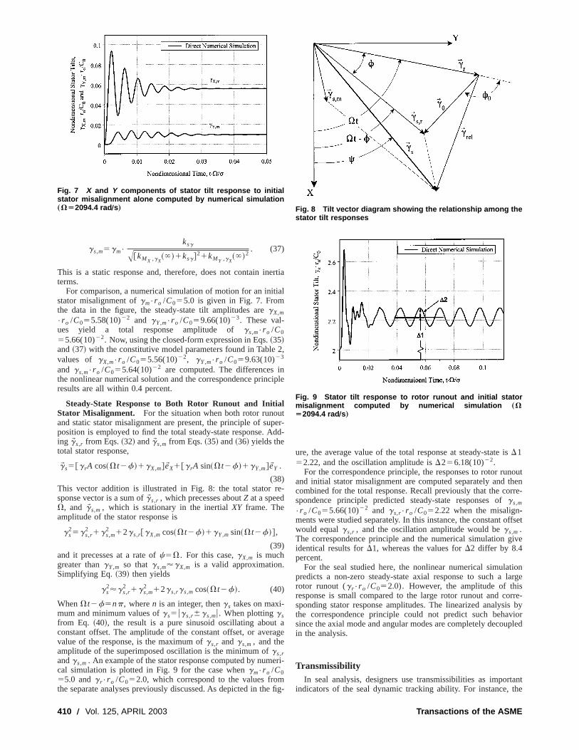
For comparison, a numerical simulation of motion for an initstator misalignment ofgm•r o /C055.0 is given in Fig. 7. Fromthe data in the figure, the steady-state tilt amplitudes aregX,m
•r o /C055.58(10)22 and gY,m•r o /C059.66(10)23. These val-ues yield a total response amplitude ofgs,m•r o /C0
55.66(10)22. Now, using the closed-form expression in Eqs.~35!and~37! with the constitutive model parameters found in Tablevalues of gX,m•r o /C055.56(10)22, gY,m•r o /C059.63(10)23
and gs,m•r o /C055.64(10)22 are computed. The differences ithe nonlinear numerical solution and the correspondence princresults are all within 0.4 percent.
Steady-State Response to Both Rotor Runout and InitialStator Misalignment. For the situation when both rotor runouand static stator misalignment are present, the principle of suposition is employed to find the total steady-state response. Aing gW s,r from Eqs.~32! andgW s,m from Eqs.~35! and~36! yields thetotal stator response,
gW s5@g rA cos~Vt2f!1gX,m#eWX1@g rA sin~Vt2f!1gY,m#eWY .
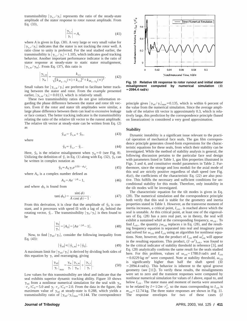
(38)This vector addition is illustrated in Fig. 8: the total stator rsponse vector is a sum ofgW s,r , which precesses aboutZ at a speedV, and gW s,m , which is stationary in the inertialXY frame. Theamplitude of the stator response is
gs25gs,r
2 1gs,m2 12gs,r@gX,m cos~Vt2f!1gY,m sin~Vt2f!#,
(39)and it precesses at a rate ofc5V. For this case,gX,m is muchgreater thangY,m so thatgs,m'gX,m is a valid approximation.Simplifying Eq. ~39! then yields
gs2'gs,r
2 1gs,m2 12gs,rgs,m cos~Vt2f!. (40)
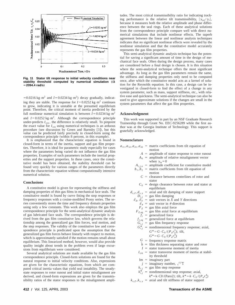
WhenVt2f5np, wheren is an integer, thengs takes on maxi-mum and minimum values ofgs5ugs,r6gs,mu. When plottinggsfrom Eq. ~40!, the result is a pure sinusoid oscillating aboutconstant offset. The amplitude of the constant offset, or avervalue of the response, is the maximum ofgs,r andgs,m , and theamplitude of the superimposed oscillation is the minimum ofgs,randgs,m . An example of the stator response computed by numcal simulation is plotted in Fig. 9 for the case whengm•r o /C055.0 andg r•r o /C052.0, which correspond to the values frothe separate analyses previously discussed. As depicted in th
Fig. 7 X and Y components of stator tilt response to initialstator misalignment alone computed by numerical simulation„VÄ2094.4 rad Õs…
410 Õ Vol. 125, APRIL 2003
rtia
al
2,
iple
tper-dd-
e-
aage
ri-
fig-
ure, the average value of the total response at steady-state iD152.22, and the oscillation amplitude isD256.18(10)22.
For the correspondence principle, the responses to rotor ruand initial stator misalignment are computed separately andcombined for the total response. Recall previously that the cospondence principle predicted steady-state responses ofgs,m
•r o /C055.66(10)22 and gs,r•r o /C052.22 when the misalign-ments were studied separately. In this instance, the constant owould equalgs,r , and the oscillation amplitude would begs,m .The correspondence principle and the numerical simulation gidentical results forD1, whereas the values forD2 differ by 8.4percent.
For the seal studied here, the nonlinear numerical simulapredicts a non-zero steady-state axial response to such arotor runout (g r•r o /C052.0). However, the amplitude of thisresponse is small compared to the large rotor runout and cosponding stator response amplitudes. The linearized analysithe correspondence principle could not predict such behasince the axial mode and angular modes are completely decouin the analysis.
TransmissibilityIn seal analysis, designers use transmissibilities as impor
indicators of the seal dynamic tracking ability. For instance,
Fig. 8 Tilt vector diagram showing the relationship among thestator tilt responses
Fig. 9 Stator tilt response to rotor runout and initial statormisalignment computed by numerical simulation „VÄ2094.4 rad Õs…
Transactions of the ASME
r
g
n
v,
i
f
t
e
fpli-
la-
ti-on-rac-be
theignin
Fur-e of
n-in
q.iplertiant ofeal-ill
arts-
ied
vetsd by
ed
11.(
transmissibility ugs,r /g r u represents the ratio of the steady-staamplitude of the stator response to rotor runout amplitude. FEq. ~33!,
Ugs,r
g rU5A, (41)
whereA is given in Eqs.~30!. A very large or very small value forugs,r /g r u indicates that the stator is not tracking the rotor well.ratio close to unity is preferred. For the seal studied earlier,transmissibility isugs,r /g r u51.105, which indicates good trackinbehavior. Another important performance indicator is the ratiostator response at steady-state to static stator misalignmugs,m /gmu. From Eq.~37!, this ratio is
Ugs,m
gmU5 ksg
A@kMX ,gX~`!1ksg#21kMY ,gX
~`!2. (42)
Small values forugs,m /g r u are preferred to facilitate better tracking between the stator and rotor. From the example preseearlier,ugs,m /g r u50.0113, which is relatively small.
These two transmissibility ratios do not give information rgarding the phase difference between the stator and rotor tilttors. Even if the rotor and stator tilt amplitudes were similarlarge phase difference between them can lead to excessive leaor face contact. The better tracking indicator is the transmissibrelating the ratio of the relative tilt vector to the runout amplitudThe relative tilt vector at steady-state can be written from Eq.~2!as
gW rel5gW s,m1gW 0 , (43)
where
gW 05gW s,r2gW r . (44)
Here, gW 0 is the relative misalignment whengm50 ~see Fig. 8!.Utilizing the definition ofgW r in Eq. ~1! along with Eq.~32!, gW 0 canbe written in complex notation as
gW 05A0g rej ~Vt2f0!, (45)
whereA0 is a complex number defined as
A05Ae2 j f21, (46)
and wheref0 is found from
tan~f0!5sin~f!
A cos~f!21. (47)
From this derivation, it is clear that the amplitude ofgW 0 is con-stant, and it precesses with speedV with a lag off0 behind therotating vector,gW r . The transmissibilityug0 /g r u is then found tobe
Ug0
g rU5uA0u5uAe2 j f21u. (48)
Now, to find ug rel /g r u, consider the following inequality fromEq. ~43!:
ugW relu<ugW s,mu1ugW 0u. (49)
A maximum limit for ug rel /g r u is derived by dividing both sides othis equation byg r and rearranging, giving
Ug rel
g rU
max
5gm
g rUgs,m
gmU1Ugs,r
g rU. (50)
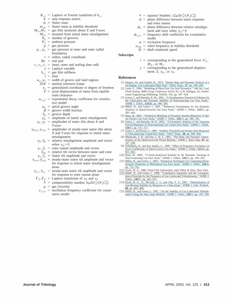
Low values for this transmissibility are ideal and indicate thatseal exhibits superior dynamic tracking ability. Figure 10 shog rel from a nonlinear numerical simulation for the seal withgm•r o /C055.0 andg r•r o /C052.0. From the data in the figure, thmaximum value ofg rel at steady-state is 0.288, which yieldstransmissibility ratio ofug rel /g r umax50.144. The correspondenc
Journal of Tribology
teom
Athe
ofent,
-ted
e-ec-a
kagelitye.
hews
ae
principle givesug rel /g r umax50.135, which is within 6 percent othe value from the numerical simulation. Since the average amtude of the relative tilt vector is approximately 0.3, which is retively large, this prediction by the correspondence principle~basedon linearization! is considered a very good approximation.
StabilityDynamic instability is a significant issue relevant to the prac
cal operation of mechanical face seals. The gas film correspdence principle generates closed-form expressions for the chateristic equations for these seals, from which their stability caninvestigated. While the method of stability analysis is general,following discussion pertains to the particular face seal deswith parameters listed in Table 1, gas film properties illustratedFigs. 3 and 4, and constitutive model parameters in Table 2.thermore, since the storage and loss moduli for the axial modthis seal are strictly positive regardless of shaft speed~see Fig.4~a!!, the coefficients of the characteristic Eq.~22! are also posi-tive. This fulfills the necessary and sufficient conditions for uconditional stability for this mode. Therefore, only instabilitythe tilt modes will be investigated.
The characteristic equation for the tilt modes is given in E~28!. The numerical simulation and the correspondence princboth verify that this seal is stable for the geometry and ineproperties stated in Table 1. However, as the transverse momeinertia increases, a critical point,I crit , is reached above which thseal is unstable. At this critical point, at least one of the eigenvues of Eq.~28! has a zero real part, so in theory, the seal wexhibit a sustained whirl at the corresponding frequency,vcrit . Tofind I crit , the quantityj vcrit replacess in Eq. ~28!, and the result-ing frequency equation is separated into real and imaginary pand solved forvcrit andI crit using an algorithm for nonlinear equations. Note, however, that the product ofI crit andvcrit
2 will appearin the resulting equations. This product, (I •v2)crit , was found tobe the critical indicator of stability threshold in reference@3#, andEq. ~28! analytically confirms the same result for the seals studhere. For this problem, values ofvcrit51788.0 rad/s andI crit
50.0229 kg•m2 were computed. Note at stability threshold,vcritis significantly higher than half the shaft speed (V52094.4 rad/s). This behavior is inherent to the spiral groogeometry~see @11#!. To verify these results, the misalignmenwere set to zero and the transient responses were computenonlinear numerical simulation for values ofI above, equal to, andbelow I crit . The stator mass and moment of inertia were assumto be related byI 51/2m•r o
2, so the mass corresponding toI crit ismcrit512.74 kg. The three stator responses are shown in Fig.The response envelopes for two of these casesI
Fig. 10 Relative tilt response to rotor runout and initial statormisalignment computed by numerical simulation „VÄ2094.4 rad Õs…
APRIL 2003, Vol. 125 Õ 411
l
u
t
ro
Tserfiy
l
tioiu
d
m
k-
iffer-ionsu-
erbquesthe
tely
ten-e-asestionantame,utedolu-
in-nyrela-o bethe
archau-t is
t
l
at
,
il-
50.0216 kg•m2 and I 50.0234 kg•m2) decay gradually, indicat-ing they are stable. The response forI 50.0252 kg•m2 continuesto grow, indicating it is unstable at the presumed equilibriupoint. Therefore, the critical moment of inertia predicted by tfull nonlinear numerical simulation is betweenI 50.0234 kg•m2
and I 50.0252 kg•m2. Although the correspondence principunder-predictsI crit , the difference is relatively small. To pinpointhe exact value forI crit using numerical techniques is an arduoprocedure~see discussion by Green and Barnsby@3#!, but thisvalue can be predicted fairly precisely in closed-form usingcorrespondence principle~within 8 percent, in this example!.
It is emphasized that the characteristic equation is foundclosed-form in terms of the inertia, support and gas film propties. Therefore, it is ideal for parametric study especially for cawhere the parameters being varied do not influence the gasproperties. Examples of such parameters include the inertial perties and the support properties. In these cases, once the ctutive model has been obtained, the stability threshold canfound very quickly for various ranges of the parameters direcfrom the characteristic equation without computationally intensnumerical solution.
ConclusionsA constitutive model is given for representing the stiffness a
damping properties of thin gas films in mechanical face seals.constitutive model is found by curve fitting the step responsefrequency responses with a cosine-modified Prony series. Thries conveniently stores the time and frequency domain propeusing only a few constants. This work also employs the gascorrespondence principle for the semi-analytical dynamic analof gas lubricated face seals. The correspondence principle isrived from the gas film constitutive law, which governs the retionship among the generalized gas film forces, seal motion,the step responses. The validity of the constitutive law and cospondence principle is predicated upon the assumption thageneralized gas film forces behave linearly with respect to motwhich is approximately satisfied if the motion remains small abequilibrium. This linearized method, however, would also provquality insight about trends in the problem even if large excsions from equilibrium were considered.
Several analytical solutions are made available by the gascorrespondence principle. Closed-form solutions are found fornatural response to initial velocity conditions. Also, expressioare given for the characteristic equations, from which are coputed critical inertia values that yield seal instability. The steastate responses to rotor runout and initial stator misalignmentderived, and closed-form expressions are given for the transsibility ratios of the stator responses to the misalignment am
Fig. 11 Stator tilt response to initial velocity conditions nearstability threshold computed by numerical simulation „VÄ2094.4 rad Õs…
412 Õ Vol. 125, APRIL 2003
mhe
ets
he
iner-sesfilmop-nsti-be
tlyive
ndheorse-
tieslmsisde-
a-andrre-the
on,ut
der-
filmthensm-y-areis-
pli-
tudes. The most critical transmissibility ratio for indicating tracing performance is the relative tilt transmissibility,ug rel /g r u,because it measures both the relative amplitude and phase dence between the seal rings. Each of these analytical solutfrom the correspondence principle compare well with direct nmerical simulations that include nonlinear effects. The supagreement between the linear and nonlinear analysis techniindicates that no significant nonlinear effects were revealed bynonlinear simulation and that the constitutive model accurarepresents the gas film properties.
This semi-analytical dynamic analysis technique has the potial for saving a significant amount of time in the design of mchanical face seals. Often during the design process, many care considered before a final design is chosen. It is this situawhere the semi-analytical technique offers the most significadvantage. As long as the gas film parameters remain the sthe stiffness and damping properties only need to be componce, after which the constitutive model acts as a kernel of stion for the Reynolds equation. In this case, a design can bevestigated in closed-form to find the effect of a change in asystem parameter, such as mass, support stiffness, etc., withtive ease and quickness. The semi-analytical technique can alsused to give approximate solutions if the changes are small insystem parameters that affect the gas film properties.
AcknowledgmentThis work was supported in part by an NSF Graduate Rese
Traineeship through Grant No. EEC-9256289 while the firstthor was at the Georgia Institute of Technology. This supporgratefully acknowledged.
Nomenclature
a11,a12,a21,a22 5 matrix coefficients from tilt equation ofmotion
A 5 amplitude of stator response to rotor runouA0 5 amplitude of relative misalignment vector
whengm50Ai , j ,n 5 amplitude coefficient for constitutive mode
b1 ,b2 5 matrix coefficients from tilt equation ofmotion
C 5 clearance between centerlines of rotor andstator
C0 5 design clearance between rotor and statorequilibrium
ds,Z ,ds,g 5 axial and tilt damping of stator supportDi , j 5 gas film damping
eWX, eWY 5 unit vectors inX andY directionseW u 5 unit vector inu directionFZ 5 gas film axial force
FZ,eq 5 gas film axial force at equilibriumf i 5 generalized force
f i ,eq 5 generalized force at equilibriumGi , j 5 gas film frequency responseGi , j* 5 nondimensional frequency response; axial
G* 5G•C0 /(Par o2); tilt,
G* 5G•C0 /(Par o4)
GI 5 frequency response matrixh 5 film thickness separating stator and rotorI 5 stator transverse moment of inertia
I crit 5 stator transverse moment of inertia at stabity threshold
Im 5 imaginary partj 5 imaginary number,A21
ki , j 5 gas film step responseki , j* 5 nondimensional step response; axial,
k*5k•C0 /~Paro2!; tilt, k* 5k•C0 /(Par o4)
ks,Z ,ks,g 5 axial and tilt stiffness of stator support
Transactions of the ASME
r
-
of a
forls,’’
ic
pi-
entibol.,
onse
ac-
f
r-
on-J.
ofol.,
e-
Ki , j 5 Laplace or Fourier transform ofki , jkI 5 step response matrixm 5 Stator mass
mcrit 5 Stator mass at stability thresholdMX ,MY 5 gas film moments aboutX andY-axes
MXi 5 moment from initial stator misalignmentNg 5 number of groovesPa 5 ambient pressure
p 5 gas pressurepi , po 5 gas pressure at inner and outer radial
boundariesr 5 radius, radial coordinate
Re 5 real partr i ,r o ,r j 5 inner, outer and sealing dam radii
s 5 Laplace variableSi , j 5 gas film stiffness
t 5 timewg ,wl 5 width of groove and land regions
XYZ 5 inertial reference framexj 5 generalized coordinate or degree of freedoZ 5 axial displacement of stator from equilib-
rium clearancea i , j ,n 5 exponential decay coefficient for constitu-
tive modelag 5 spiral groove angleb 5 groove width fraction
dg 5 groove depthgm 5 amplitude of initial stator misalignment
gX ,gY 5 amplitudes of stator tilts aboutX andY-axes
gX,m ,gY,m 5 amplitudes of steady-state stator tilts abouX andY-axes for response to initial statormisalignment
g0 ,gW 0 5 relative misalignment amplitude and vectowhengm50
g r ,gW r 5 rotor runout amplitude and vectorgW rel 5 relative tilt vector between stator and rotor
gs ,gW s 5 Stator tilt amplitude and vectorgs,m ,gW s,m 5 steady-states stator tilt amplitude and vect
for response to initial stator misalignmentalone
gs,r ,gW s,r 5 steady-state stator tilt amplitude and vectofor response to rotor runout alone
GX ,GY 5 Laplace transforms ofgX andgYL 5 compressibility number, 6mVr o
2/(PaC02)
m 5 gas viscosityv i , j ,n 5 oscillation frequency coefficient for consti-
tutive model
Journal of Tribology
m
t
or
r
s 5 squeeze Number, 12mVr o2/(PaC0
2)f 5 phase difference between stator response
and rotor runoutf0 5 phase difference between relative misalign
ment and rotor whengm50f i , j ,n 5 frequency shift coefficient for constitutive
modelv 5 excitation frequency
vcrit 5 whirl frequency at stability thresholdV 5 shaft rotational speed
Subscripts
i 5 corresponding to the generalized force:FZ ,MX , or MY
j 5 corresponding to the generalized displace-ment:Z, gX , or gY
References@1# Shapiro, W., and Colsher, R., 1974, ‘‘Steady State and Dynamic Analysis
Jet-Engine, Gas Lubricated Shaft Seal,’’ ASLE Trans.,17, pp. 190–200.@2# Leefe, S., 1994, ‘‘Modeling of Plain Face Gas Seal Dynamics,’’14th Int. Conf.
Fluid Sealing, BHR Group Conference Series No. 9, B. Halligan, ed., Profes-sional Engineering Publishing, Suffolk, UK, pp. 397–424.
@3# Green, I., and Barnsby, R. M., 2001, ‘‘A Simultaneous Numerical Solutionthe Lubrication and Dynamic Stability of Noncontacting Gas Face SeaASME J. Tribol.,123„2…, pp. 388–394.
@4# Miller, B., and Green, I., 2001, ‘‘Numerical Formulation for the DynamAnalysis of Spiral-Grooved Gas Face Seals,’’ ASME J. Tribol.,123~2!, pp.395–403.
@5# Ruan, B., 2002, ‘‘Numerical Modeling of Dynamic Sealing Behaviors of Sral Groove Gas Face Seals,’’ ASME J. Tribol.,124~1!, pp. 186–195.
@6# Green, I., and Barnsby, M. R., 2002, ‘‘A Parametric Analysis of the TransiForced Response of Noncontacting Gas Coned Face Seals,’’ ASME J. Tr124~1!, pp. 151–157.
@7# Green, I., and Etsion, I., 1985, ‘‘Stability Threshold and Steady-State Respof Noncontacting Coned-Face Seals,’’ ASLE Trans.,28, pp. 449–460.
@8# Malanoski, S. B., and Pan, C. H. T., 1965, ‘‘The Static and Dynamic Charteristics of the Spiral-Grooved Thrust Bearing,’’ ASME J. Basic Eng.,87, pp.547–558.
@9# Zirkelback, N., and San Andre`s, L., 1999, ‘‘Effect of Frequency Excitation onForce Coefficients of Spiral Groove Gas Seals,’’ ASME J. Tribol.,121~4!, pp.853–863.
@10# Ruan, B., 2002, ‘‘A Semi-Analytical Solution to the Dynamic Tracking oNon-Contacting Gas Face Seals,’’ ASME J. Tribol.,124~1!, pp. 196–202.
@11# Miller, B., and Green, I., 2002, ‘‘Numerical Techniques for Computing Rotodynamic Properties of Mechanical Gas Face Seals,’’ ASME J. Tribol.,124~4!,pp. 755–761.
@12# Gross, W. A., 1980,Fluid Film Lubrication, John Wiley & Sons, New York.@13# Miller, B., and Green, I., 1998, ‘‘Constitutive Equations and the Corresp
dence Principle for the Dynamics of Gas Lubricated Triboelements,’’ ASMETribol., 120~2!, pp. 345–352.
@14# Elrod, H. G., Jr., McCabe, J. T., and Chu, T. Y., 1967, ‘‘DeterminationGas-Bearing Stability by Response to a Step-Jump,’’ ASME J. Lubr. Techn89, pp. 493–498.
@15# Miller, B., and Green, I., 1997, ‘‘On the Stability of Gas Lubricated Triboelments Using the Step Jump Method,’’ ASME J. Tribol.,119~1!, pp. 193–199.
APRIL 2003, Vol. 125 Õ 413
Related Documents