Semantic Data Integration in (Software+) Engineering Projects DIPLOMARBEIT zur Erlangung des akademischen Grades Diplom-Ingenieur im Rahmen des Studiums Software Engineering/Internet Computing eingereicht von Michael Handler Matrikelnummer 0515280 an der Fakultät für Informatik der Technischen Universität Wien Betreuung Betreuer: Ao. Univ.-Prof. Dipl.Ing. Dr. Stefan Biffl Mitwirkung: Univ.-Ass. Dr. Thomas Moser Wien, 17.11.2010 (Unterschrift Verfasser) (Unterschrift Betreuer) Technische Universität Wien A-1040 Wien Karlsplatz 13 Tel. +43-1-58801-0 www.tuwien.ac.at

Welcome message from author
This document is posted to help you gain knowledge. Please leave a comment to let me know what you think about it! Share it to your friends and learn new things together.
Transcript
Semantic Data Integration in(Software+) Engineering Projects
DIPLOMARBEIT
zur Erlangung des akademischen Grades
Diplom-Ingenieur
im Rahmen des Studiums
Software Engineering/Internet Computing
eingereicht von
Michael HandlerMatrikelnummer 0515280
an derFakultät für Informatik der Technischen Universität Wien
BetreuungBetreuer: Ao. Univ.-Prof. Dipl.Ing. Dr. Stefan BifflMitwirkung: Univ.-Ass. Dr. Thomas Moser
Wien, 17.11.2010(Unterschrift Verfasser) (Unterschrift Betreuer)
Technische Universität WienA-1040 Wien � Karlsplatz 13 � Tel. +43-1-58801-0 � www.tuwien.ac.at


Erklärung zur Verfassung der Arbeit
Handler MichaelWiener Straße 12/272700 Wiener Neustadt
"Hiermit erkläre ich, dass ich diese Arbeit selbständig verfasst habe, dass ich die verwende-ten Quellen und Hilfsmittel vollständig angegeben habe und dass ich die Stellen der Arbeit —einschließlich Tabellen, Karten und Abbildungen —, die anderen Werken oder dem Internetim Wortlaut oder dem Sinn nach entnommen sind, auf jeden Fall unter Angabe der Quelle alsEntlehnung kenntlich gemacht habe."
Ort Datum Unterschrift
Abstract
Experts act in different roles in a project and use different tools to fulfill their tasks and contributeto the overall project progress. The major problem that arises, when complex systems have to beengineered, is weak interoperability of tools in one engineering domain and especially betweentools of different engineering domains. Incompatible syntactical representations of the samesemantic concepts make efficient integration of engineering tools especially difficult. In additionhigh quality standards and rapidly changing requirements for large engineering projects createthe need for advanced project management and quality assurance applications, like end-to-endtests across tool and domain boundaries.
The artificial intelligence and semantic web research community has been busy to develop lan-guages and mechanisms to describe ontological knowledge about real life objects. Based uponthese concepts ideas to improve the usability of all kinds of software are developed. Currently re-searchers try to facilitate semantic knowledge in other research areas, like enterprise applicationintegration to ease the process of engineering. Unfortunately there is currently no integrationplatform for large software intensive engineering projects addressing both technical and seman-tic integration issues. To solve the integration problem often costly and hard to maintain pointto point integration between the tools is done. But these systems are not capable of fulfilling therequirements of a modern engineering environment, like robustness, flexibility and usability.
The Engineering Knowledge Base (EKB) is a framework for engineering environment integra-tion. In this thesis a semantic integration system based upon the EKB is developed as part ofa technical integration system. The EKB concept is adapted for the integration into a technicalintegration system, which provides a common infrastructure for the EKB and other components.To make it possible for advanced applications to use data stored in different engineering tools, theEKB has to provide a virtual common data model, which contains schematic and semantic infor-mation about common engineering concepts and provides the infrastructure for semi-automaticconcept to concept transformations.
Based upon the results of this research a prototype of the EKB is developed and integrated intothe Open Engineering Service Bus (OpenEngSB). The prototype is evaluated against the currenttechnical-only integration provided by the OpenEngSB with the help of two use cases: (1) Def-inition Of Quality Criteria Across Tool Data Models in Electrical Engineering and (2) ChangeImpact Analysis for Requirement Changes. The empirical evaluation shows that the EKB is aneffective and efficient way to provide the necessary infrastructure for advanced applications likeend-to-end tests across tool boundaries. Nevertheless additional configuration and maintenanceeffort is needed to manage the semantic knowledge. Yet if applications like those described inthe real world use cases have to be performed, the additional features of the proposed semanticintegration framework outbalance these disadvantages.
Keywords: Technical Integration, Semantic Integration, Software-Intensive Systems, Dis-tributed Systems, OpenEngSB, EKB
Kurzfassung
Bei der Entwicklung von komplexen, softwareintensiven Systemen arbeiten Experten aus ver-schiedenen Gebieten in unterschiedlichen Rollen zusammen. Sie verwenden dabei Entwick-lungswerkzeuge, die zwar optimal für das jeweilige Einsatzgebiet geeignet sind, aber nicht pro-blemlos miteinander verbunden werden können. Besonders die verschieden Repräsentationenvon denselben Konzepten in verschiedenen Entwicklungswerkzeugen führen zu Problemen beider Toolintegration. Trotz dieser Probleme werden aber hohe Anforderungen an moderne Sys-teme gestellt, vor allem hinsichtlich Qualität und Sicherheit. Diese Anforderungen können nurdurch toolübergreifende Qualitätstests erreicht werden.
Forscher auf dem Gebiet der künstlichen Intelligenz und des Semantic Web haben in den letzenJahren viele verschiedene Ansätze und Sprachen zur Modellierung von semantischem Wissenüber reale Objekte entwickelt. Basierend auf diesen wird versucht Softwareprodukte in ande-ren Gebieten, wie beispielsweise der Unternehmensanwendungsintegration, zu verbessern. Trotzdieser Bemühungen gibt es derzeit keine offene Plattform für die semantische Integration vonEntwicklungsumgebungen für softwareintensive Systeme. Als Ersatz werden oft schwer zu er-haltende Integrationslösungen zwischen spezifischen Entwicklungstools manuell erstellt. SolchePunkt zu Punkt Integrationen sind aber nicht dazu geeignet, den Anforderungen eines modernenEntwicklungsumfeldes gerecht zu werden.
Das Konzept der Engineering Knowledge Base (EKB) versucht eine Lösung für die Integrationvon Entwicklungsumgebung zu liefern. In dieser Arbeit wird eine semantische Integrationslö-sung entwickelt und implementiert, die auf einem technischen Integrationssystem basiert undversucht das EKB Konzept zu verwirklichen. Die EKB muss dabei einerseits ein virtuelles ge-meinsames Datenmodell zur Verfügung stellen, das schematische und semantische Informationenthält und als Basis für die Entwicklung von komplexen Applikationen dient. Andererseitsmuss die EKB die Infrastruktur für die Transformation zwischen unterschiedlichen Konzeptenund für die Integration der Daten aus verschiedenen Werkzeugen bereitstellen.
Basierend auf dem OpenEngSB Projekt wird ein Prototyp einer EKB basierenden semanti-schen Integrationslösung entwickelt und implementiert und anschließend mit dem aktuellenOpenEngSB System, das nur technische Integration ermöglicht, verglichen. Dazu werden zweireale Anwendungsfälle untersucht: 1.) Definition von Qualitätskriterien über verschiedene Toolshinweg im Elektroingenieurwesen und 2.) Change-Impact Analyse nach einer Anforderungs-änderung. Die empirische Untersuchung dieser Anwendungsfälle zeigt, dass die entwickelteLösung für komplexe Anwendungen über Toolgrenzen hinweg verwendet werden kann. DerHauptnachteil dabei ist, dass zusätzlicher Konfigurations- und Entwicklungsaufwand bei der In-tegration von Tools in das System anfällt. Sind aber komplexe Anwendungen für den Erfolg desProjektes notwendig, dann lohnt sich der investierte Aufwand, da diese einfacher umgesetzt undgewartet werden können.
Schlagwörter: Technische Integration, Semantische Integration, Software-Intensive Systeme,Verteilte Systeme, OpenEngSB, EKB
Contents
1 Introduction 1
2 Technical Tool Integration for (Software+) Engineering 72.1 Introduction . . . . . . . . . . . . . . . . . . . . . . . . . . . . . . . . . . . . 72.2 Types of Technical Integration . . . . . . . . . . . . . . . . . . . . . . . . . . 82.3 Technical Integration Styles . . . . . . . . . . . . . . . . . . . . . . . . . . . . 11
2.3.1 File Transfer . . . . . . . . . . . . . . . . . . . . . . . . . . . . . . . 112.3.2 Shared Database . . . . . . . . . . . . . . . . . . . . . . . . . . . . . 122.3.3 Remote Procedure Invocation . . . . . . . . . . . . . . . . . . . . . . 122.3.4 Messaging . . . . . . . . . . . . . . . . . . . . . . . . . . . . . . . . 13
2.4 Architectures for Integration . . . . . . . . . . . . . . . . . . . . . . . . . . . 142.4.1 Service-Oriented Architecture . . . . . . . . . . . . . . . . . . . . . . 142.4.2 Enterprise Service Bus . . . . . . . . . . . . . . . . . . . . . . . . . . 15
2.5 Integration in the (software+) Engineering Domain . . . . . . . . . . . . . . . 16
3 Semantic System Integration 213.1 Introduction and Definition . . . . . . . . . . . . . . . . . . . . . . . . . . . . 213.2 Approaches for Semantic Integration . . . . . . . . . . . . . . . . . . . . . . . 22
3.2.1 Ontology-Based Semantic Integration . . . . . . . . . . . . . . . . . . 223.2.2 Model-Driven Semantic Integration . . . . . . . . . . . . . . . . . . . 24
3.3 Engineering Knowledge Base . . . . . . . . . . . . . . . . . . . . . . . . . . . 25
4 Data Integration for (Software+) Engineering 294.1 Definition and Introduction . . . . . . . . . . . . . . . . . . . . . . . . . . . . 294.2 Schema Mapping . . . . . . . . . . . . . . . . . . . . . . . . . . . . . . . . . 30
4.2.1 Local-As-View . . . . . . . . . . . . . . . . . . . . . . . . . . . . . . 314.2.2 Global-As-View . . . . . . . . . . . . . . . . . . . . . . . . . . . . . 324.2.3 GLAV and BAV . . . . . . . . . . . . . . . . . . . . . . . . . . . . . 324.2.4 Generating Schema Mappings . . . . . . . . . . . . . . . . . . . . . . 33
4.3 Query Processing . . . . . . . . . . . . . . . . . . . . . . . . . . . . . . . . . 364.3.1 Query Processing in LAV . . . . . . . . . . . . . . . . . . . . . . . . 36
4.3.2 Query Processing in GAV . . . . . . . . . . . . . . . . . . . . . . . . 374.4 Data Virtualization . . . . . . . . . . . . . . . . . . . . . . . . . . . . . . . . 37
5 Research Issues and Approach 415.1 Research Issues . . . . . . . . . . . . . . . . . . . . . . . . . . . . . . . . . . 435.2 Research Method . . . . . . . . . . . . . . . . . . . . . . . . . . . . . . . . . 44
5.2.1 Literature Research . . . . . . . . . . . . . . . . . . . . . . . . . . . . 445.2.2 Use Case based Feasibility Evaluation . . . . . . . . . . . . . . . . . . 465.2.3 Comparison to Technical Integration . . . . . . . . . . . . . . . . . . . 49
6 Use Cases and Requirements of a Semantic Integration Solution for (Software+)Engineering 516.1 Definition of Quality Criteria Across Tool Data Models in Electrical Engineering 51
6.1.1 Requirements . . . . . . . . . . . . . . . . . . . . . . . . . . . . . . . 546.2 Change Impact Analysis for Requirement Changes . . . . . . . . . . . . . . . 56
6.2.1 Requirements . . . . . . . . . . . . . . . . . . . . . . . . . . . . . . . 596.3 Additional Requirements . . . . . . . . . . . . . . . . . . . . . . . . . . . . . 60
7 An EKB based Semantic Integration Framework - Concept and Architecture 617.1 Concept and Architecture . . . . . . . . . . . . . . . . . . . . . . . . . . . . . 617.2 Core Components . . . . . . . . . . . . . . . . . . . . . . . . . . . . . . . . . 65
7.2.1 Model Analyzer . . . . . . . . . . . . . . . . . . . . . . . . . . . . . 667.2.2 Virtual Common Data Model Management . . . . . . . . . . . . . . . 677.2.3 Data Source Management . . . . . . . . . . . . . . . . . . . . . . . . 717.2.4 Life-cycle Manager . . . . . . . . . . . . . . . . . . . . . . . . . . . . 737.2.5 Data Retrieval Infrastructure . . . . . . . . . . . . . . . . . . . . . . . 757.2.6 Transformation Infrastructure . . . . . . . . . . . . . . . . . . . . . . 787.2.7 Core Component Overview . . . . . . . . . . . . . . . . . . . . . . . 80
7.3 Integration into the Open Engineering Service Bus . . . . . . . . . . . . . . . 80
8 Evaluation 858.1 Definition of Quality Criteria Across Tool Data Models in Electrical Engineering 85
8.1.1 Feasibility Evaluation . . . . . . . . . . . . . . . . . . . . . . . . . . 888.1.2 Comparison to Technical Integration . . . . . . . . . . . . . . . . . . . 90
8.2 Change Impact Analysis for Requirement Changes . . . . . . . . . . . . . . . 928.2.1 Feasibility Evaluation . . . . . . . . . . . . . . . . . . . . . . . . . . 938.2.2 Comparison to Technical Integration . . . . . . . . . . . . . . . . . . . 96
9 Discussion 999.1 Feasibility of an EKB based semantic integration framework for (software+)
engineering . . . . . . . . . . . . . . . . . . . . . . . . . . . . . . . . . . . . 99

9.2 Design of a robust semantic integration system based on a synchronized life-cycle model . . . . . . . . . . . . . . . . . . . . . . . . . . . . . . . . . . . . 100
9.3 Semi-automatic transformation instruction derivation based on semantic knowl-edge . . . . . . . . . . . . . . . . . . . . . . . . . . . . . . . . . . . . . . . . 102
9.4 Development of a usable query infrastructure . . . . . . . . . . . . . . . . . . 103
10 Conclusion and Perspectives 10510.1 Conclusion . . . . . . . . . . . . . . . . . . . . . . . . . . . . . . . . . . . . 10510.2 Future Work . . . . . . . . . . . . . . . . . . . . . . . . . . . . . . . . . . . . 106

1 Introduction
Modern automation systems are developed to supply our society with goods and services likesteel or electrical energy. These systems have to fulfill high safety standards, because a mal-function could cause severe financial loss and could even endanger the operators of the systemor other humans. These high standards have to be enforced in all phases of the system life-cycleincluding development. Yet during development experts from different domains, like softwareengineering, mechanical engineering, electrical engineering or process engineering have to co-operate and to integrate their work (Biffl et al., 2009). Because software engineering plays animportant part in the development of these systems, but other engineering disciplines are also in-volved in the engineering process and place requirements upon the resulting software, it is called(software+) engineering (Pieber, 2010). The domain experts typically use domain specific toolsand data formats, which are not designed for interoperability. These tools have been designedas large closed systems in the past, which had either no need for interaction with other tools, ordidn’t have the possibility for interaction with other systems, because no suitable infrastructurewas available when they were created. Additionally the development of these systems oftentakes place in physically separated groups, distributed all over the world. This results in weakintegration of the different engineering tools. Many integration tasks have to be done manuallycausing defects and a higher risk of cost and time overrun. System integration is becomingincreasingly complex as the overall system as well as its parts become more complex and pow-erful. If this process is done manually the quality of the resulting systems depends heavily onthe abilities and the performance of the system integrators.
To solve the integration problem often costly and hard to maintain point to point integrationbetween the tools is done. This makes tool exchange very difficult, because in addition to thetypical migration costs, like data migration and user education also the integration with all othertools has to be updated for the new tool. Therefore more advanced forms of technical integrationare necessary. Different integration architectures for technical integration have been proposed toreduce the complexity for tool integration and exchange. These advanced integration methodolo-gies have in common that they enforce a standardized way of tool integration and communicationbetween tools (Kaushal & Saravanan, 2004). Technical integration provides a logical connec-tion between the different tools, a messaging infrastructure and a common message format. Itthereby makes communication between the different tools possible.
1
1. Introduction
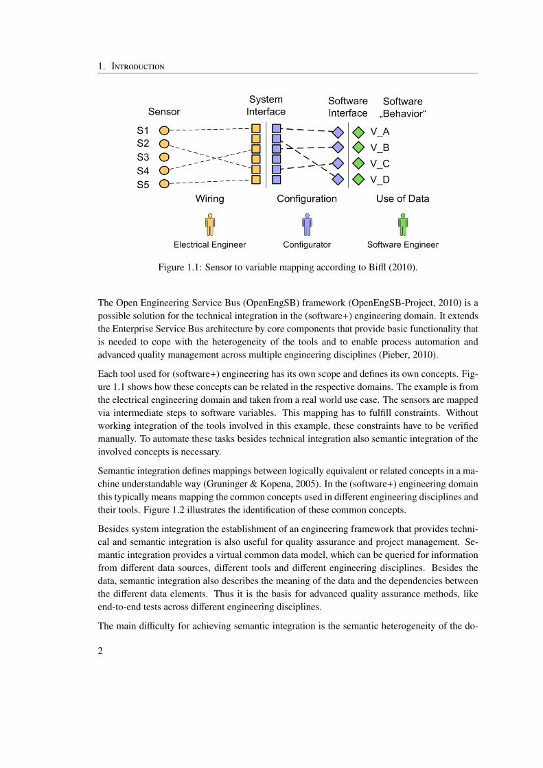
Figure 1.1: Sensor to variable mapping according to Biffl (2010).
The Open Engineering Service Bus (OpenEngSB) framework (OpenEngSB-Project, 2010) is apossible solution for the technical integration in the (software+) engineering domain. It extendsthe Enterprise Service Bus architecture by core components that provide basic functionality thatis needed to cope with the heterogeneity of the tools and to enable process automation andadvanced quality management across multiple engineering disciplines (Pieber, 2010).
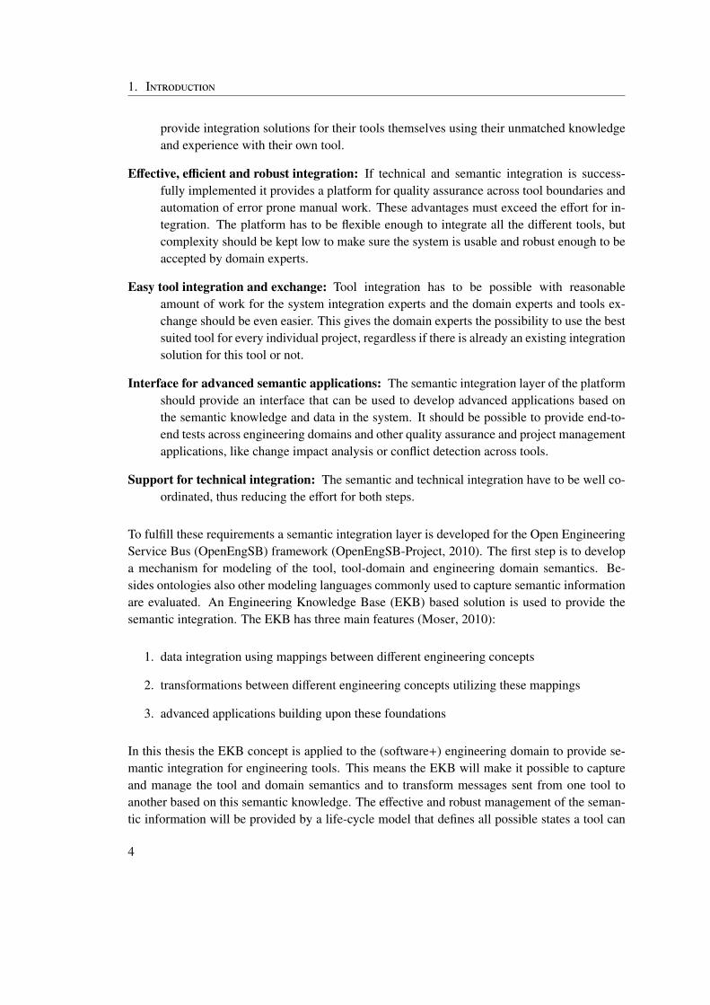
Each tool used for (software+) engineering has its own scope and defines its own concepts. Fig-ure 1.1 shows how these concepts can be related in the respective domains. The example is fromthe electrical engineering domain and taken from a real world use case. The sensors are mappedvia intermediate steps to software variables. This mapping has to fulfill constraints. Withoutworking integration of the tools involved in this example, these constraints have to be verifiedmanually. To automate these tasks besides technical integration also semantic integration of theinvolved concepts is necessary.
Semantic integration defines mappings between logically equivalent or related concepts in a ma-chine understandable way (Gruninger & Kopena, 2005). In the (software+) engineering domainthis typically means mapping the common concepts used in different engineering disciplines andtheir tools. Figure 1.2 illustrates the identification of these common concepts.
Besides system integration the establishment of an engineering framework that provides techni-cal and semantic integration is also useful for quality assurance and project management. Se-mantic integration provides a virtual common data model, which can be queried for informationfrom different data sources, different tools and different engineering disciplines. Besides thedata, semantic integration also describes the meaning of the data and the dependencies betweenthe different data elements. Thus it is the basis for advanced quality assurance methods, likeend-to-end tests across different engineering disciplines.
The main difficulty for achieving semantic integration is the semantic heterogeneity of the do-
2
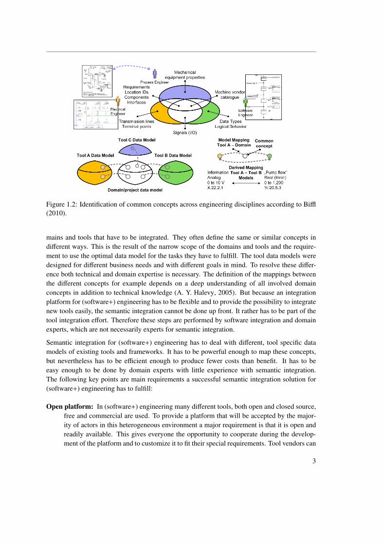
Figure 1.2: Identification of common concepts across engineering disciplines according to Biffl(2010).
mains and tools that have to be integrated. They often define the same or similar concepts indifferent ways. This is the result of the narrow scope of the domains and tools and the require-ment to use the optimal data model for the tasks they have to fulfill. The tool data models weredesigned for different business needs and with different goals in mind. To resolve these differ-ence both technical and domain expertise is necessary. The definition of the mappings betweenthe different concepts for example depends on a deep understanding of all involved domainconcepts in addition to technical knowledge (A. Y. Halevy, 2005). But because an integrationplatform for (software+) engineering has to be flexible and to provide the possibility to integratenew tools easily, the semantic integration cannot be done up front. It rather has to be part of thetool integration effort. Therefore these steps are performed by software integration and domainexperts, which are not necessarily experts for semantic integration.
Semantic integration for (software+) engineering has to deal with different, tool specific datamodels of existing tools and frameworks. It has to be powerful enough to map these concepts,but nevertheless has to be efficient enough to produce fewer costs than benefit. It has to beeasy enough to be done by domain experts with little experience with semantic integration.The following key points are main requirements a successful semantic integration solution for(software+) engineering has to fulfill:
Open platform: In (software+) engineering many different tools, both open and closed source,free and commercial are used. To provide a platform that will be accepted by the major-ity of actors in this heterogeneous environment a major requirement is that it is open andreadily available. This gives everyone the opportunity to cooperate during the develop-ment of the platform and to customize it to fit their special requirements. Tool vendors can
3
1. Introduction
provide integration solutions for their tools themselves using their unmatched knowledgeand experience with their own tool.
Effective, efficient and robust integration: If technical and semantic integration is success-fully implemented it provides a platform for quality assurance across tool boundaries andautomation of error prone manual work. These advantages must exceed the effort for in-tegration. The platform has to be flexible enough to integrate all the different tools, butcomplexity should be kept low to make sure the system is usable and robust enough to beaccepted by domain experts.
Easy tool integration and exchange: Tool integration has to be possible with reasonableamount of work for the system integration experts and the domain experts and tools ex-change should be even easier. This gives the domain experts the possibility to use the bestsuited tool for every individual project, regardless if there is already an existing integrationsolution for this tool or not.
Interface for advanced semantic applications: The semantic integration layer of the platformshould provide an interface that can be used to develop advanced applications based onthe semantic knowledge and data in the system. It should be possible to provide end-to-end tests across engineering domains and other quality assurance and project managementapplications, like change impact analysis or conflict detection across tools.
Support for technical integration: The semantic and technical integration have to be well co-ordinated, thus reducing the effort for both steps.
To fulfill these requirements a semantic integration layer is developed for the Open EngineeringService Bus (OpenEngSB) framework (OpenEngSB-Project, 2010). The first step is to developa mechanism for modeling of the tool, tool-domain and engineering domain semantics. Be-sides ontologies also other modeling languages commonly used to capture semantic informationare evaluated. An Engineering Knowledge Base (EKB) based solution is used to provide thesemantic integration. The EKB has three main features (Moser, 2010):
1. data integration using mappings between different engineering concepts
2. transformations between different engineering concepts utilizing these mappings
3. advanced applications building upon these foundations
In this thesis the EKB concept is applied to the (software+) engineering domain to provide se-mantic integration for engineering tools. This means the EKB will make it possible to captureand manage the tool and domain semantics and to transform messages sent from one tool toanother based on this semantic knowledge. The effective and robust management of the seman-tic information will be provided by a life-cycle model that defines all possible states a tool can
4
reach. To reduce the effort necessary for integration semi-automatic derivation of transformationinstructions for the messages sent and received by the different tools is developed, providing theplatform with the necessary scalability and usability. The EKB will also be the interface forqueries against the virtual common data model. These queries are essential for project manage-ment and quality assurance tasks as they provide the possibility to retrieve and combine the datafrom all tools integrated in the OpenEngSB.
To make this platform acceptable for the engineering experts it is necessary to ensure the feasi-bility and quality of this solution. Furthermore the additional effort for tool integration added bya semantic integration layer has to be evaluated. Therefore an empirical study will be performedbased upon two important use cases for (software+) engineering:
Definition of Quality Criteria Across Tool Data Models in Electrical Engineering: Thisuse case is an example of the integration of tools from different engineering domainsincluding software development and electrical engineering. It shows the importanceof semantic integration to provide a common data model across tool and engineeringdomain boundaries. The seamless integration of the different tools involved in this usecase is the basis to provide advanced functionality like end-to-end tests. The power of thepossibility to query the virtual common data model with the help of the EKB is shownby formulating a sample query against this data model that validates quality criteria forsensors across tool boundaries.
Change Impact Analysis for Requirement Changes: Requirement traceability is a wellknown goal of software development processes, which makes the implicit interdepen-dencies between requirements and other artifacts explicit. These interdependencies aresemantic information, so the EKB based semantic integration layer can be used to imple-ment requirement tracing. In this use case a change impact analysis is done for a changingrequirement to find out which issues and developers are affected by the change request.This information can be used to mark all dependent artifacts for review and to contact allinvolved developers automatically. Furthermore it allows better estimates for the costs ofthe changes.
Section 2 describes technical integration, which is the basis for semantic integration. Anoverview about the different types of technical integration and various integration architecturesis given. This section is interesting for system integration experts and software engineers, whowant to study the technical basis for semantic integration.
Section 3 gives a definition for semantic integration and summarizes the problems solved and theissues raised by semantic integration. The different types of semantic integration are describedand currently available semantic integration platforms are discussed. Finally the EKB conceptis explained in detail. This section is interesting for integration experts and software engineersthat want to understand the basic concepts of semantic integration and an EKB based integrationsolution.
5
1. Introduction
In section 4 the theoretical background of data integration is discussed. Different integrationmechanisms as well as the typical problems are covered. Finally the connection to the area ofdata virtualization is explained. The target group for this part is everyone interested in the basicprinciples and technologies used in data integration, like integration experts or domain experts.It is especially interesting for everyone who wants to capture the semantics of the data of a toolthat has to be integrated.
In the following section the research issues are derived from the requirements for semantic inte-gration in the (software+) engineering context (see section 5). The methodology that is used toresolve these issues is described and the use cases are explained in detail. Experts for semanticintegration will be interested in the key research issues in this domain.
In section 6 the requirements of an EKB based semantic integration solution for the (software+)engineering domain are derived from two real world use cases. Domain experts as well as systemdesigners and software engineers, who plan semantic integration systems will be interested inthis section.
In section 7 the architecture of the EKB based semantic integration layer for the OpenEngSBis discussed. This part is interesting for system designers and software engineers who plan toimplement a semantic integration system.
The solution is evaluated in section 8 with respect to feasibility robustness and efficiency. Thispart is especially interesting for system analysts and project managers, because the results forthe two engineering use cases are presented.
Section 9 gives a detailed discussion about the results. It shows the advantages and problems ofsemantic integration in this domain. In addition the architecture of the semantic integration layerand the integration into the OpenEngSB will be discussed. This section is focused on analyststhat plan to use the OpenEngSB platform with semantic integration.
Finally this work is concluded with section 10, which contains a summary of the thesis anddiscusses future work.
6
2 Technical Tool Integration for(Software+) Engineering
In this thesis a complete integration solution for (software+) engineering, supporting both tech-nical and semantic integration will be developed based upon an existing technical integrationsolution . Therefore this section provides a definition of technical integration, describes differ-ent types of technical integration and architectures used to achieve integration. Finally, technicalintegration in the (software+) engineering domain is discussed.
2.1 Introduction
In modern enterprises a large number of different tools, each with a different scope and differentproperties are used. The reason for this is on the one hand that building a single applicationthat serves all business needs is next to impossible and on the other hand that functional sectorsof a company want to use specialized software, which supports their work in a locally optimalway (Yan Du, 2008). Furthermore after company mergers heterogeneous IT systems are createdthrough the combination of the different IT infrastructures. In modern businesses the integrationof these systems is important due to many different factors including fast changing economicconditions, high quality standards, increasing complexity or high cost pressure in today’s glob-alized economy (Chappel, 2004). For technical integration the term Enterprise Application Inte-gration has been coined by Linthicum (2000), who defines it as the sharing of business processesand information between all connected systems of an enterprise. Yan Du (2008) takes a slightlydifferent viewpoint and defines EAI in the following way:
“The integration of applications that enables information sharing and business pro-cesses, both of which result in efficient operations and flexible delivery of businessservices to the customer.”
Both definitions have in common that they show two elements of EAI, namely data and func-tionality sharing. The second definition puts the focus on the expected result of EAI, which isan improvement of business processes.
7
2. Technical Tool Integration for (Software+) Engineering
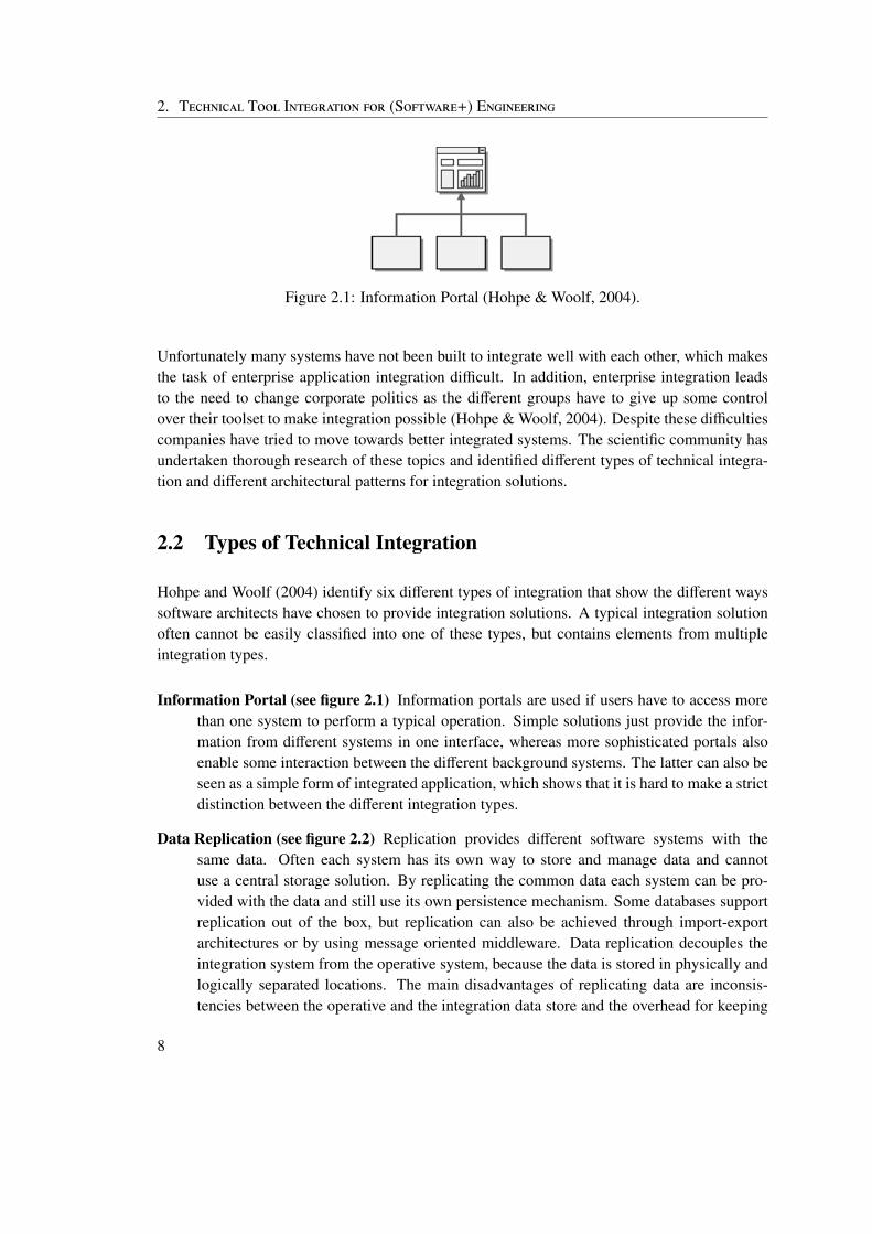
Figure 2.1: Information Portal (Hohpe & Woolf, 2004).
Unfortunately many systems have not been built to integrate well with each other, which makesthe task of enterprise application integration difficult. In addition, enterprise integration leadsto the need to change corporate politics as the different groups have to give up some controlover their toolset to make integration possible (Hohpe & Woolf, 2004). Despite these difficultiescompanies have tried to move towards better integrated systems. The scientific community hasundertaken thorough research of these topics and identified different types of technical integra-tion and different architectural patterns for integration solutions.
2.2 Types of Technical Integration
Hohpe and Woolf (2004) identify six different types of integration that show the different wayssoftware architects have chosen to provide integration solutions. A typical integration solutionoften cannot be easily classified into one of these types, but contains elements from multipleintegration types.
Information Portal (see figure 2.1) Information portals are used if users have to access morethan one system to perform a typical operation. Simple solutions just provide the infor-mation from different systems in one interface, whereas more sophisticated portals alsoenable some interaction between the different background systems. The latter can also beseen as a simple form of integrated application, which shows that it is hard to make a strictdistinction between the different integration types.
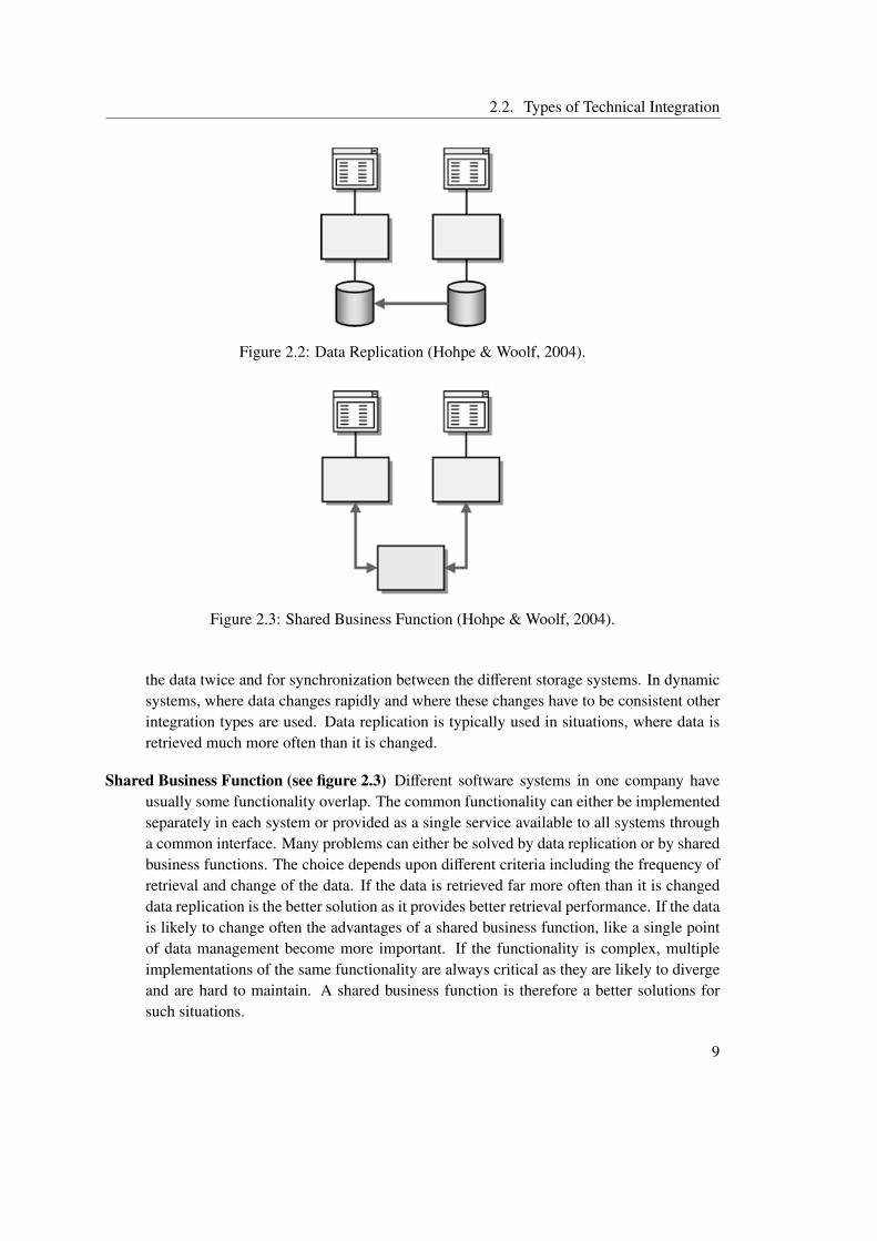
Data Replication (see figure 2.2) Replication provides different software systems with thesame data. Often each system has its own way to store and manage data and cannotuse a central storage solution. By replicating the common data each system can be pro-vided with the data and still use its own persistence mechanism. Some databases supportreplication out of the box, but replication can also be achieved through import-exportarchitectures or by using message oriented middleware. Data replication decouples theintegration system from the operative system, because the data is stored in physically andlogically separated locations. The main disadvantages of replicating data are inconsis-tencies between the operative and the integration data store and the overhead for keeping
8
2.2. Types of Technical Integration
Figure 2.2: Data Replication (Hohpe & Woolf, 2004).
Figure 2.3: Shared Business Function (Hohpe & Woolf, 2004).
the data twice and for synchronization between the different storage systems. In dynamicsystems, where data changes rapidly and where these changes have to be consistent otherintegration types are used. Data replication is typically used in situations, where data isretrieved much more often than it is changed.
Shared Business Function (see figure 2.3) Different software systems in one company haveusually some functionality overlap. The common functionality can either be implementedseparately in each system or provided as a single service available to all systems througha common interface. Many problems can either be solved by data replication or by sharedbusiness functions. The choice depends upon different criteria including the frequency ofretrieval and change of the data. If the data is retrieved far more often than it is changeddata replication is the better solution as it provides better retrieval performance. If the datais likely to change often the advantages of a shared business function, like a single pointof data management become more important. If the functionality is complex, multipleimplementations of the same functionality are always critical as they are likely to divergeand are hard to maintain. A shared business function is therefore a better solutions forsuch situations.
9
2. Technical Tool Integration for (Software+) Engineering
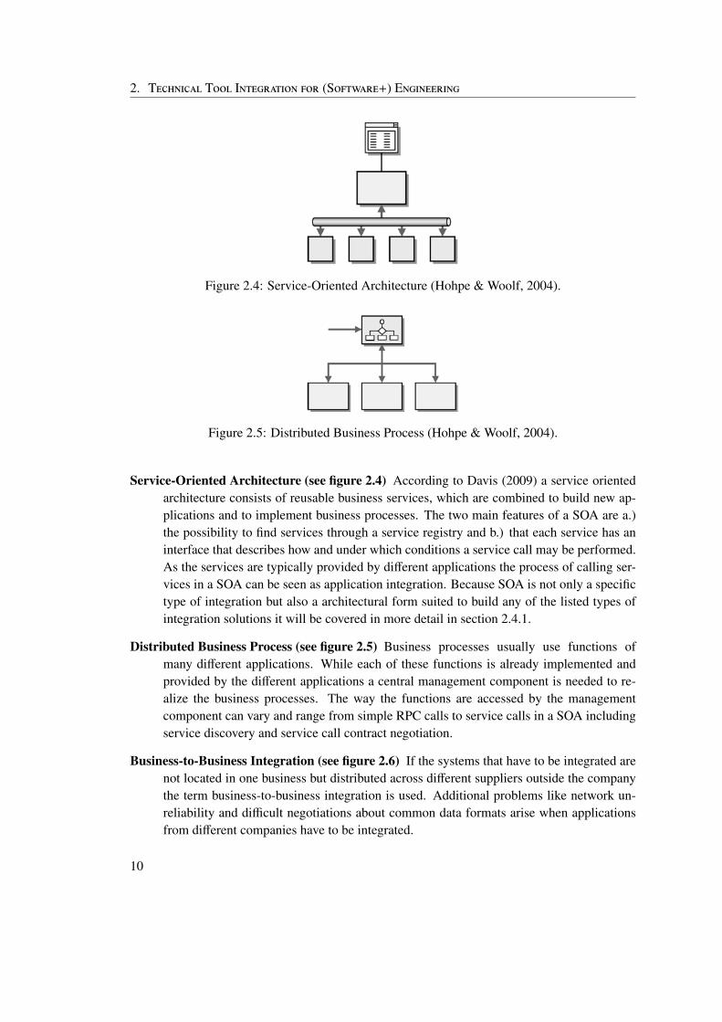
Figure 2.4: Service-Oriented Architecture (Hohpe & Woolf, 2004).
Figure 2.5: Distributed Business Process (Hohpe & Woolf, 2004).
Service-Oriented Architecture (see figure 2.4) According to Davis (2009) a service orientedarchitecture consists of reusable business services, which are combined to build new ap-plications and to implement business processes. The two main features of a SOA are a.)the possibility to find services through a service registry and b.) that each service has aninterface that describes how and under which conditions a service call may be performed.As the services are typically provided by different applications the process of calling ser-vices in a SOA can be seen as application integration. Because SOA is not only a specifictype of integration but also a architectural form suited to build any of the listed types ofintegration solutions it will be covered in more detail in section 2.4.1.
Distributed Business Process (see figure 2.5) Business processes usually use functions ofmany different applications. While each of these functions is already implemented andprovided by the different applications a central management component is needed to re-alize the business processes. The way the functions are accessed by the managementcomponent can vary and range from simple RPC calls to service calls in a SOA includingservice discovery and service call contract negotiation.
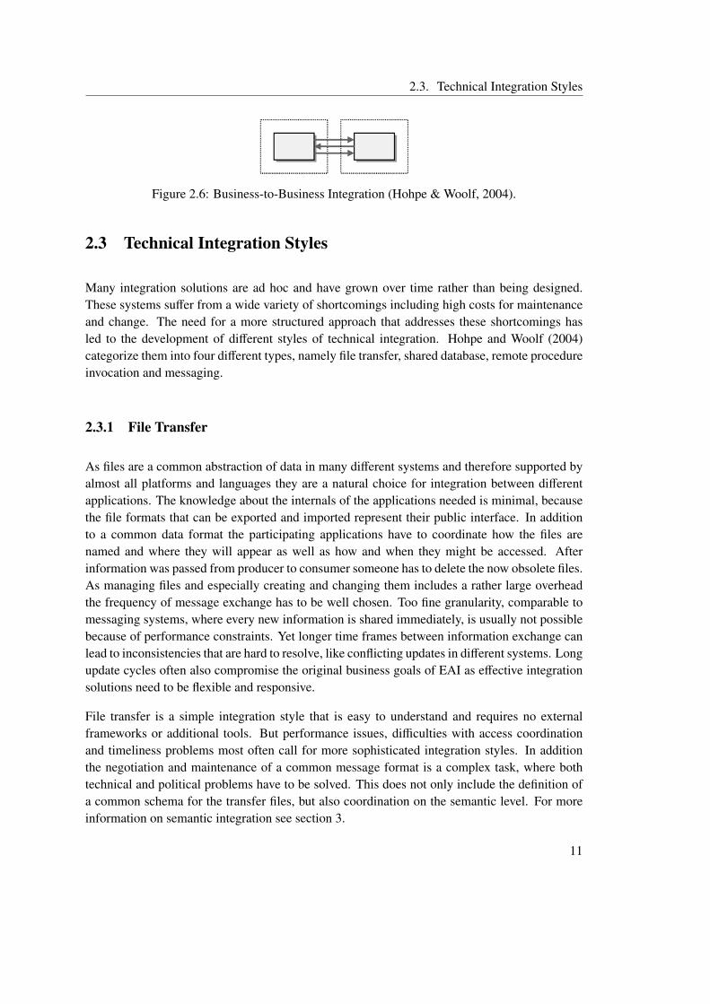
Business-to-Business Integration (see figure 2.6) If the systems that have to be integrated arenot located in one business but distributed across different suppliers outside the companythe term business-to-business integration is used. Additional problems like network un-reliability and difficult negotiations about common data formats arise when applicationsfrom different companies have to be integrated.
10
2.3. Technical Integration Styles
Figure 2.6: Business-to-Business Integration (Hohpe & Woolf, 2004).
2.3 Technical Integration Styles
Many integration solutions are ad hoc and have grown over time rather than being designed.These systems suffer from a wide variety of shortcomings including high costs for maintenanceand change. The need for a more structured approach that addresses these shortcomings hasled to the development of different styles of technical integration. Hohpe and Woolf (2004)categorize them into four different types, namely file transfer, shared database, remote procedureinvocation and messaging.
2.3.1 File Transfer
As files are a common abstraction of data in many different systems and therefore supported byalmost all platforms and languages they are a natural choice for integration between differentapplications. The knowledge about the internals of the applications needed is minimal, becausethe file formats that can be exported and imported represent their public interface. In additionto a common data format the participating applications have to coordinate how the files arenamed and where they will appear as well as how and when they might be accessed. Afterinformation was passed from producer to consumer someone has to delete the now obsolete files.As managing files and especially creating and changing them includes a rather large overheadthe frequency of message exchange has to be well chosen. Too fine granularity, comparable tomessaging systems, where every new information is shared immediately, is usually not possiblebecause of performance constraints. Yet longer time frames between information exchange canlead to inconsistencies that are hard to resolve, like conflicting updates in different systems. Longupdate cycles often also compromise the original business goals of EAI as effective integrationsolutions need to be flexible and responsive.
File transfer is a simple integration style that is easy to understand and requires no externalframeworks or additional tools. But performance issues, difficulties with access coordinationand timeliness problems most often call for more sophisticated integration styles. In additionthe negotiation and maintenance of a common message format is a complex task, where bothtechnical and political problems have to be solved. This does not only include the definition ofa common schema for the transfer files, but also coordination on the semantic level. For moreinformation on semantic integration see section 3.
11
2. Technical Tool Integration for (Software+) Engineering
2.3.2 Shared Database
A shared database is a suitable integration solution if multiple applications have to access thesame data. Modern databases provide good transaction support and access control. Data in-consistencies can be reduced to a absolute minimum and can be resolved easily. The maindisadvantage of shared databases is the need to define one common data schema that is used byall applications. Such a common data schema can become complex if it is used by the differentapplications to store all their data. Often the usability of such a schema is bad, which makesapplication development more complex. There are also political reasons that make the intro-duction of a common data model difficult. Some application development teams might not bewilling to take the additional effort involved in designing and using the common schema and theshared database. But not only the initial design of the schema is problematic, also changes tothe schema or database are hard, because in the worst case all applications have to be updated.Another disadvantage of this integration style is that the shared database can become a perfor-mance bottleneck or that applications might deadlock as they lock parts of the database. If thedatabase is replicated or distributed the performance of the network and distributed locking andsynchronizing mechanisms might become a problem. Finally the usage of a common schemaand a specific database is a hard to accomplish requirement if third party software is used. Onthe one hand most software products use their own way to store data and on the other handmost vendors reserve the right to change the way data is stored with every new version of theirsoftware.
Shared databases are a good solution if a common schema can be designed, which is usable forall involved applications and if there is enough control over the persistence mechanism of allapplications. If one of this factors is not given, scalability is very important or functionality hasto be shared rather than just data then a shared database is no suitable integration style.
2.3.3 Remote Procedure Invocation
Applications that need to share functionality in addition to data have to be integrated using theremote procedure invocation style also known as remote procedure call (RPC). By using RPCthe data can be encapsulated within the application that owns it. Data retrieval and modificationhappen by direct calls from one application to the other. There are different technologies forRPC including CORBA, COM, .NET, Java RMI and Web Services. The complexity of remotecalls is usually hidden by a middleware layer, which makes RPC calls appear like local callsto the programmer. Besides the advantage of better usability this can also be problematic, asprogrammers use RPC calls without having the performance and reliability issues in mind.
As the data is encapsulated within the different applications instead of a common data schemaonly the interfaces of the applications have to be negotiated. Although the RPC integrationstyle reduces coupling compared to a shared database solution it still makes changes of a singlepart of the system hard. Even when the interface of an application stays untouched changes in
12
2.3. Technical Integration Styles
the internal implementation can lead to unexpected consequences, especially when it comes tosequencing (doing actions in a particular order). Another drawback of RPC style integrationsolutions is that many technologies for RPC calls do not work across different platforms.
The RPC integration style offers the possibility to integrate applications in a way that is naturalto most programmers and therefore easy to understand. It enhances data encapsulation andenforces well defined interfaces between applications. The drawbacks of this methodology isthat there is still a rather tight coupling between the applications and that software engineerstend to build integration solutions using the RPC style like single applications, which oftenleads to performance and reliability issues.
2.3.4 Messaging
In most integration scenarios the applications that have to work together use different platformsand different languages. Therefore an integration style that enables loosely coupled cooperationis needed. File transfer offers this feature but at the cost of timeliness, reliability and abstractionof the transport layer. Messaging tries to overcome these problems by sending small packetsof data immediately in a reliable way. Messages are transmitted from sender to receiver asyn-chronously. They can be routed and transformed automatically while they are in the messagechannel or stored and retransmitted if the receiver is not available temporarily. Asynchronouscommunication is a main feature of messaging systems decoupling applications in terms ofavailability. One application can send information without having to wait for the receiver toconsume it. Therefore the sender can immediately continue with its own tasks. But becausemost developers are not used to asynchronous messaging the development is harder, especiallyas asynchronous communication is hard to debug. Another feature of messaging frameworksis the possibility to transform messages while they are transmitted. This makes communica-tion between two applications possible that do not even share the same message format furtherreducing coupling.
Application development and application integration are seen as two different tasks with theirown set of properties and problems. Using the messaging integration style supports this clearseparation much better than shared database or RPC. It allows the applications to use differentconceptual models while providing a possibility to share data and functionality. This helpsto create loosely coupled integration solutions, where each system has high cohesion but lowadhesion to the other systems. Messaging also supports an event driven view of the integrationsystem, which makes it easier to use for business analysts and project managers, who often haveto map event driven business processes to the integrated IT system.
13
2. Technical Tool Integration for (Software+) Engineering
2.4 Architectures for Integration
Enterprise Application Integration can only work in an effective and efficient way if a suitable ar-chitecture for the integrated system is chosen. Often this does not impose a specific architectureon the involved applications, but simply defines the interface between the integration frameworkand the attached systems. According to Yan Du (2008) Service-Oriented architectures and theEnterprise Service Bus are the two architectures most commonly used to design enterprise inte-gration solutions. Both architectures are based upon the messaging integration style. Thereforethey support loose coupling between the integration system and the involved systems as wellas asynchronous communication patterns. Nevertheless service-oriented architectures are oftenalso influenced by the RPC integration style and provide RPC like interfaces for informationexchange between integrated systems.
2.4.1 Service-Oriented Architecture
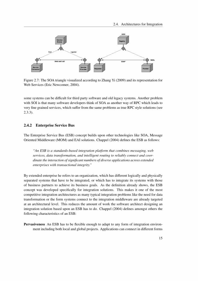
Service-Oriented architectures (SOA) are a language-independent conceptual model, that makesno assumptions about the underlying programming-model (Alonso, 2008). A service is a unitof functionality at a coarse enough abstraction level to provide business value. Services have awell defined interface and can be used without knowledge about implementation details (Dan& Narasimhan, 2009). In a SOA there are three different roles. Figure 2.7 shows the so calledSOA triangle, which is comprised of service broker, service provider and service consumer. Theservice broker is responsible for storage and management of service descriptors and provides aninterface to query and find services. A service provider contacts the broker to add its service andwaits for service consumers. After a service was found in the broker by the service consumerit contacts the service provider directly to negotiate the service contract and call the service(Zhang Yi, 2009).
Web Services are one possibility to implement a SOA. Due to the heavy usage of standardsand broad industry support Web Services have become the dominant form of SOA. The mostimportant standards used by Web Services are UDDI for the service broker, WSDL for serviceinterface description and SOAP for data transmission.
The term Service Oriented Integration (SOI) is used to refer to EAI using a service-orientedarchitecture (Zhang Yi, 2009). The basic principle is to add a service interface to an existingapplication and to build the integration based upon these high level interfaces. All applicationsthat have to be integrated can be reached through these interfaces in a standardized way. Thedifferent services can be combined to implement business processes. The advantages of thissolution are the standardization of the way services are described, found and accessed as well asthe fact that existing applications only have to be extended to provide the data and functionalitythey want to share with other systems through a SOA interface. Yet the definition of the serviceinterfaces can be difficult especially when the form and intensity of cooperation with other appli-cations are not clear at design time. In addition the implementation of the SOI wrapper around
14
2.4. Architectures for Integration
Figure 2.7: The SOA triangle visualized according to Zhang Yi (2009) and its representation forWeb Services (Eric Newcomer, 2004).
some systems can be difficult for third party software and old legacy systems. Another problemwith SOI is that many software developers think of SOA as another way of RPC which leads tovery fine grained services, which suffer from the same problems as true RPC style solutions (see2.3.3).
2.4.2 Enterprise Service Bus
The Enterprise Service Bus (ESB) concept builds upon other technologies like SOA, MessageOriented Middleware (MOM) and EAI solutions. Chappel (2004) defines the ESB as follows:
“An ESB is a standards-based integration platform that combines messaging, webservices, data transformation, and intelligent routing to reliably connect and coor-dinate the interaction of significant numbers of diverse applications across extendedenterprises with transactional integrity.”
By extended enterprise he refers to an organization, which has different logically and physicallyseparated systems that have to be integrated, or which has to integrate its systems with thoseof business partners to achieve its business goals. As the definition already shows, the ESBconcept was developed specifically for integration solutions. This makes it one of the mostcompetitive integration architectures as many typical integration problems like the need for datatransformation or the form systems connect to the integration middleware are already targetedat an architectural level. This reduces the amount of work the software architect designing anintegration solution based upon an ESB has to do. Chappel (2004) defines amongst others thefollowing characteristics of an ESB:
Pervasiveness An ESB has to be flexible enough to adapt to any form of integration environ-ment including both local and global projects. Applications can connect in different forms
15
2. Technical Tool Integration for (Software+) Engineering
to an ESB using different protocols, while all systems plugged into the bus must be reach-able in a standardized way.
Standards-Based Integration An ESB should make heavy usage of standards including WebService as well as MOM and other standards. Data management and transformation hasto be based upon XML standards. By using these industry standards the effort for anysystem to plug into the ESB should be kept low.
Distributed Integration The core services provided by an ESB like business process orchestra-tion, routing and transformation have to be implemented in a way that allows distributionto increase the scalability of the ESB.
Data Transformation An ESB has to provide a transformation infrastructure, where any mes-sage can be transformed between sender and receiver, regardless of the location or otherproperties of the participation components.
Layered Services The ESB has to support the addition of customized layers for specializedbusiness needs, like Business Process Management or collaboration servers. These shouldintegrate seamlessly into the bus providing their functionality to the other components.
Event-Driven SOA An ESB should abstract away the details of communication and informa-tion delivery. That means that from a architectural standpoint each application pluggedinto the bus is seen as a service endpoint reacting to asynchronous events.
Operational Awareness Business Activity Monitoring is used to examine the state of businessoperations while they are in progress. By using XML standards for data management anESB can provide real-time insight into the data processed by the ESB.
Incremental Adoption An ESB has to allow incremental adoption as big bang introduction ofintegration solutions usually do not work even for small companies and are completelyimpossible for extended organizations.
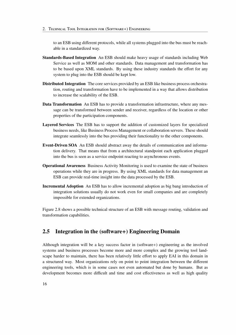
Figure 2.8 shows a possible technical structure of an ESB with message routing, validation andtransformation capabilities.
2.5 Integration in the (software+) Engineering Domain
Although integration will be a key success factor in (software+) engineering as the involvedsystems and business processes become more and more complex and the growing tool land-scape harder to maintain, there has been relatively little effort to apply EAI in this domain ina structured way. Most organizations rely on point to point integration between the differentengineering tools, which is in some cases not even automated but done by humans. But asdevelopment becomes more difficult and time and cost effectiveness as well as high quality
16
2.5. Integration in the (software+) Engineering Domain
Figure 2.8: A possible technical structure of an ESB (Jieming Wu, 2010).
standards become more important due to increased competition in a globalized economy andmany business leaders in this domain identified EAI as a key objective, companies are likely toincrease their integration efforts in the near future.
Taking a closer look at EAI in the (software+) engineering domain makes clear that the systemsthat have to be integrated are mainly the development tools. In a typical (software+) engineeringprocess some of these tools have always had to cooperate, but this integration is mainly achievedby hard to maintain, very specialized point to point integration solutions. In most cases someform of script-based approach is used to create these point to point links. The major problemof this point to point integration style is that it does not scale well. In software developmentintegrated development environments (IDE) have developed in the last years, which offer someamount of tool integration. Yet while there are very mature and successful IDEs for softwaredevelopment, there is no IDE for (software+) engineering. Different projects have been started totarget integration problems in the (software+) engineering domain. The following list describessome of them:
Cesar1 The aim of this project, which is funded by the European Union, is to define a multi-view, quality assuring process for (software+) engineering projects. Although some in-teresting solutions have been proposed no implementation using the results of this projectexists.
Modale2 In this project supported by the German government a semantic integration frame-work for (software+) engineering tools has been developed, but no complete integrationsolution. Modale uses ontologies to design the semantics of the tools, which have to beintegrated.
1http://www.cesarproject.eu/2http://www.modale.de/
17
2. Technical Tool Integration for (Software+) Engineering
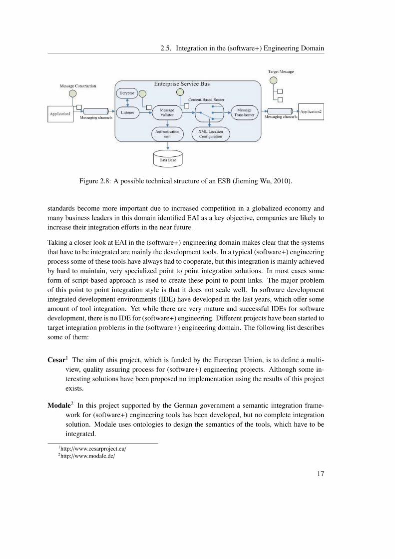
Figure 2.9: The architecture of the OpenEngSB (Pieber, 2010).
Medeia3 The goal of this project is to develop an automation component model. Medeia issupported by the European Union. Like Modale it is a semantic integration frameworkwith little technical integration support. To model the semantics of the integrated systemUML based meta models are used.
Comos4 An integration framework that uses XML files for data exchange between tools andprovides integration for some important tools. The system is meant for large scale automa-tion engineering environments and provides a unified view on the whole system. Comosis an all-in-one solution, which tries to incorporate all necessary components. Thereforecustomization is limited and can only be done using a predefined scripting approach.
OpenEngSB5 Although this project is still in a rather premature phase it shall be discussedhere as it is the target platform of this thesis. The Open Engineering Service Bus isan extended Enterprise Service Bus that was developed for the (software+) engineeringdomain. In this environment some of the characteristics of an ESB are especially impor-tant, although all of them contribute to a successful integration solution. Pervasiveness isnecessary, because (software+) engineering projects are usually large scale projects, butcompanies usually try new technology in small projects before they use it in projects withsignificant business value. Data transformation is needed, because the data format of in-tegrated tools often cannot be changed, as third party tools or other external componentsare used. Improved quality control and project management are key goals of system inte-
3http://www.medeia.eu4http://www.comos.com/5http://www.openengsb.org/
18
2.5. Integration in the (software+) Engineering Domain
gration in a (software+) engineering environment, which makes operational awareness acritical feature of an integration solution.
The OpenEngSB uses different integration types to achieve technical integration. It usesaspects from shared business function, as the different tools provide their functionality toworkflows and other tools via the bus. Furthermore as the OpenEngSB is based upon anESB it uses aspects from service-oriented architectures, like service discovery and stan-dardized service interfaces. Finally the OpenEngSB is designed to support distributedbusiness processes using the central components, which extend the typical ESB function-ality and like all ESBs the OpenEngSB also support business-to-business integration, asone typical characteristic of an ESB is distributed integration.
The major advantage of the OpenEngSB is that it is an open platform, which can be ex-tended and adapted to suit the needs of different organizations. The OpenEngSB supportstypical (software+) engineering tasks by providing basic components, like the workflowcomponent for process support. The advantage of this direct integration into the infras-tructure is the improved interaction possibility between the core system and these centralservices. To make tool exchange easy the OpenEngSB uses a two layer architecture toconnect tools. A domain, which abstracts the typical functionality of tools of a givendomain is used as an intermediate layer between system and tool. Domains define an in-terface, which has to be implemented by each tool connected to the domain. Thereforewhen business processes are defined they can interact with the domain interface. If a toolhas to be exchanged no changes in the business process definition is necessary. Figure2.9 shows the basic architecture of the OpenEngSB, with the core registry and workflowcomponents and the domain based two layer tool connection structure.
19

3 Semantic System Integration
In this thesis a semantic integration solution for (software+) engineering is developed. Thereforethis chapter discusses the theoretical background of semantic integration. Different types ofsemantic integration are identified and described. Finally the Engineering Knowledge Base(EKB) concept is explained in detail as it is the basis for the proposed integration solution for(software+) engineering.
3.1 Introduction and Definition
A major problem that occurs when different systems have to be integrated is data heterogene-ity. According to Cruz et al. (2004) the mismatch in data representation can be classified intothree categories: syntactic, schematic and semantic. Wile technical integration focuses moreon syntactical and to some extent schematic issues and on providing a common message for-mat to make communication between different systems possible, semantic integration focuseson the meaning of the data exchanged between those systems. This includes both schematic andsemantic factors. Effective and efficient cooperation between different tools or systems is onlypossible if the semantics of source and target system are compatible (Rosenthal et al., 2004).Yet this compatibility is not given in most organizations, because applications are not devel-oped with interoperability in mind and because new systems are added as a result of mergersor acquisitions (A. Halevy, 2005). Semantic integration tries to solve the problem of semanticheterogeneity by providing some form of intermediate layer that automatically transforms databetween the different involved systems.
A. Halevy (2005) states that the main reason why semantic integration is hard to achieve are thedifferences between data sources. These differences result from different design goals. Thereforethe same concept is often represented in different forms with varying levels of detail. A particularhard to resolve problem are overlapping or conflicting data representations. Furthermore in orderto resolve semantic heterogeneities both technical and domain expertise is needed. Automaticsolutions for semantic integration are usually not possible, because for machines the task tounderstand and align different data schemata is even harder than for humans as they do not havethe necessary meta information about the intent of the schema designer.
21
3. Semantic System Integration
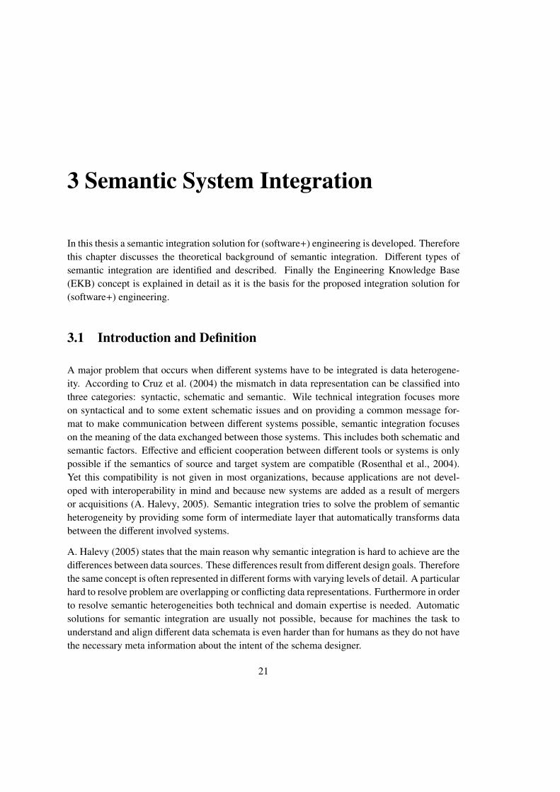
subject predicate objectglass be emptyAlice meet Bob
Table 3.1: Statements represented as RDF triples.
3.2 Approaches for Semantic Integration
Much research in the field of semantic integration has been undertaken to solve the problem ofconflicting data schemata and data semantics. The following two different solution categoriesare the most common solution types in literature. They are described in detail, because theyhave the most relevance for the proposed semantic integration infrastructure for (software+)engineering.
3.2.1 Ontology-Based Semantic Integration
In computer science an ontology is defined as representation of knowledge of a domain andrelationships between these concepts in a machine understandable notation (Rebstock et al.,2008). Ontologies have originated in artificial intelligence, but have been used for integrationsolutions, because they provide a high level platform independent format for describing datamodels. Hakimpour and Geppert (2001) state that the correct understanding of the semantics ofdata is important for integration. They further state that formal ontologies are a promising wayto describe the semantics of integrated systems in a application-independent way. Ontologiesrepresent semantic information in a form that enables reasoning about the data and the automaticderivation of new knowledge.
One of the most important application areas of ontologies is the semantic web. Therefore manystandards for ontology description and ontology languages have been developed in this researchfield. The most prominent among these ontology languages is the OWL Web Ontology Lan-guage, which is recommended by the World Wide Web Consortium (W3C). OWL is based uponthe Resource Description Framework (RDF). In RDF statements are captured in subject, pred-icate object triples. The statements “The glass is empty.” and “Alice meets Bob.” for exampleare represented in RDF as the triples shown in table 3.1. Because of this triple structure the datamodel is represented as a labeled directed graph in RDF and allows the mixture of structuredand semi-structured data. RDF can be serialized in different forms and is used as a model fordata interchange on the Web (W3C, 2010b).
The current version of OWL (OWL 2) is available in different so called profiles, which aresubsets of the full OWL language well suited for special use cases. These subsets are necessarybecause OWL is a very expressive language, which can be hard to implement if its full power isused. The profiles are:
22
3.2. Approaches for Semantic Integration
OWL2-EL When OWL2-EL is used, reasoning can be done in polynomial time which is usefulif ontologies are huge and performance is critical.
OWL2-QL OWL2-QL enables efficient querying of large numbers of individuals. It supportsthe usage of relational databases and SQL queries.
OWL2-RL This subset of OWL2 is used if lightweight ontologies are needed to organize largenumbers of individuals and when rule-extended database technology is used.
The full OWL2 language is also called OWL2-DL for OWL2 description logic (W3C, 2010a).
Noy (2004) gives an overview about different semantic integration approaches using ontologies.She defines three dimensions of semantic integration:
Mapping discovery The process of determining similar concepts in different ontologies alsocalled ontology alignment. A possible way to implement ontology alignment is the usageof a shared upper ontology. In this upper ontology basic concepts are defined, which areused to define the concepts of all dependent ontologies. The common upper layer can thenbe used to find possible mappings between upper level concepts and dependent conceptsand also between different dependent concepts. Other approaches rely on heuristics ormachine learning algorithms, which enable the utilization of information stored in theinstances rather then explicitly modeled in the ontologies.
Declarative formal representations of mappings The way a mapping is defined in a machineunderstandable way that allows automatic reasoning with mappings. A possible way torepresent mappings is to use an ontology of mappings. This has the advantage that noadditional external language is needed. Another possibility is to use a view based mech-anism for describing ontology mappings including both global-as-view and local-as-viewbased solutions.
Reasoning with mappings The process of deriving new knowledge about available data andrelations between data elements using the mappings determined and defined in the pre-vious steps. This includes automatic data and query transformation as well as ontologyinstance transformation. The reasoning mechanism used depends on the representationformat used for ontology mappings.
These three dimensions show the basic mechanism of semantic integration solutions. First thesemantics of the different systems are captured in ontologies, then mappings between these on-tologies are defined and finally the information gained by the mapping process is used to derivefurther knowledge by reasoning and to perform typical integration tasks like data transformation.
The main drawback of ontology-based integration solutions it the complexity of ontology devel-opment and management. There are often not enough experts available, which have both tech-nical knowledge about ontology creation and domain knowledge about the systems that have to
23
3. Semantic System Integration
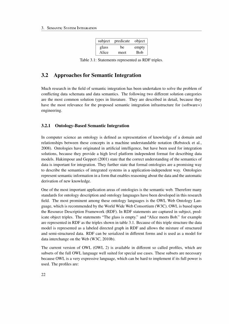
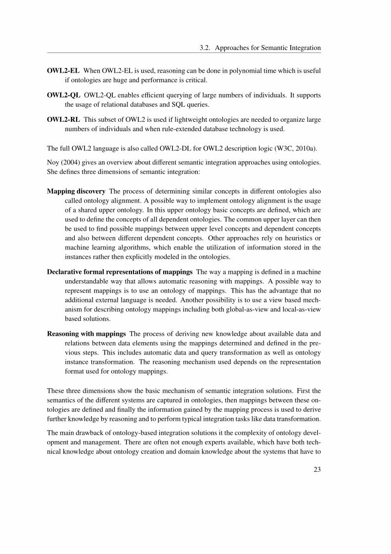
Figure 3.1: MOF as basis for other modeling languages like UML or CWM (OMG, 2010b).
be integrated. Further more ontologies are often hard to link to the actual data models used bythe different systems, because they describe the data at a very high level of abstraction. Toolsupport for ontology creation and management has improved recently, but is not comparable tothe sophisticated tools available for example in model-driven development.
3.2.2 Model-Driven Semantic Integration
The model-driven integration approach is closely related to the ontology-based integration ap-proach. The main difference is the heavy usage of standards, tools and processes that have beendeveloped in the context of model driven development and model driven architecture. Like in theontology based approach semantic integration is realized in three steps. First a model for everysystem is developed, then the relationships or mappings between the model elements from thesedifferent models have to be discovered and represented in a machine understandable way and fi-nally typical integration tasks like data transformation is performed based upon these mappings(Kramler et al., 2006).
Model-driven integration approaches rely heavily on standards, like Unified Modeling Language(UML), a specification of the Object Management Group (OMG). The Meta Object Facility(MOF) is the common basis for UML and other modeling languages like Common WarehouseMetamodel (CWM) and represents the foundation of Model-Driven Architecture as it is definedby the OMG. Figure 3.1 shows the connection between UML, CWM and MOF. The goal of thisstandards is to ease the process of software development by unifying the whole process frombusiness modeling to deployment, evolution and integration (OMG, 2010a).
One advantage of model driven semantic integration is the good tool support for model drivendevelopment as well as the fact that there are many developers familiar with model driven data
24
3.3. Engineering Knowledge Base
modeling. The models can automatically be transformed into executable code, which reducesmaintenance effort and increases flexibility with respect to model changes. In addition manydata models are already available as UML models, which reduces the initial effort for modelbased integration (Amar Bensaber & Malki, 2008).
The most important problem of model driven semantic integration is the fact that most modelingstandards that are in broad usage have not been developed to capture the semantics of data well.They are more focused on syntactic and schematic issues (Jamadhvaja & Senivongse, 2005).One possibility to add the semantic information is to define a specialized modeling languagebased upon MOF. Another possibility is to use ontologies to capture the semantic informationand to define formal mappings between concepts in the ontologies and model elements in theMOF based models. There is some overlap between MOF and ontology languages like OWL,e.g. the possibility to define classes, subclass-of relationships or relationships between classes.Yet the focus of OMF and ontology languages is different. Wile OWL was developed by thesemantic web research community to precisely define the meaning of concepts and to allowreasoning about statements containing information about those concepts, OMF has been devel-oped for software engineering purposes (Frankel et al., 2004). As semantic integration of (soft-ware+) systems touches both areas, software engineering and the need to capture and reasonabout semantic information, it is a good application area for model driven semantic integration.For other application scenarios with a weaker connection to software engineering specializedontology-based semantic integration solutions may be a better choice.
3.3 Engineering Knowledge Base
The Engineering Knowledge Base (EKB) is a semantic integration approach for tool and dataintegration in the engineering domain proposed by Moser (2010). The three main features of anEKB are:
1. data integration using mappings between different engineering concepts
2. transformations between different engineering concepts utilizing these mappings
3. advanced applications building upon these foundations
The EKB framework was developed for engineering tool integration. By providing an effectiveand efficient semantic integration layer it simplifies the process of engineering. Especially tasksthat span different domains, where experts with different technical background have to cooperatecan be performed with less effort if all involved tools are integrated semantically. Moser (2010)describes the main target of the EKB as follows:
“The EKB is used to facilitate the efficient data exchange between these engineeringtools and data sources by providing a so-called “virtual common data model”.”
25
3. Semantic System Integration
The common data model is called virtual, because the data is not stored and managed usingthis global knowledge model. The data of the involved tools is transformed to match the virtualcommon data model at runtime using mappings between the respective tool models and thecommon data model. Therefore the different tools are not directly bound to the common datamodel and do not have to use it to store their own data. Because of this abstraction of the virtualdata model the problems of common schema negotiation become less critical. As the differenttools can still build upon their own data schemata no difficult schema negotiations have to beundertaken between the different system designer. Changes to the common data schema have noinfluence to the data or functionality of the respective tools. Furthermore the complexity of thecommon data model does neither harm the performance nor complicate the development processof the integrated systems.
Although the EKB was developed as ontology-based integration solution, it is possible to useany format for knowledge representation including MOF based data models. The EKB frame-work manages engineering knowledge in a machine understandable format and performs datatransformation based upon semantic mappings at runtime.
The major drawback of an EKB based integration solution is the necessary effort needed tomodel the virtual common data model and the mappings to the tool models. This process needstechnical and domain knowledge and may include the usage of new technologies. Therefore theintroduction of an EKB into a company may meet with political opposition, because developersneed training or specialists have to be employed and new tools have to be introduced into thedevelopment process. Furthermore if ontologies are used to represent the semantic knowledgethe lack of industry standard tool support in this domain further complicates the usage of anEKB. Finally there is currently no complete implementation based upon the EKB approach,although the OpenEngSB1 project is currently evolving in this direction.
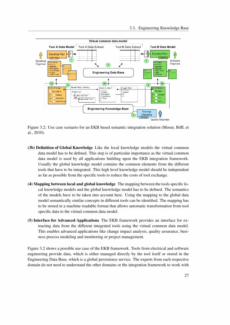
Figure 3.2 shows the internal structure of an EKB. The different parts are labeled with numberedtags in the the graphical representation.
(1) Tool Data Extraction Each tool provides its data by a connector to the EKB framework.The connector is responsible for extracting the data from the tool and making sure thedata adheres to the tool specific knowledge model.
(2) Data Storage A central persistence service called Engineering Data Base is provided bythe EKB framework for tools that cannot manage their data locally, because they are notalways available, or do not support sophisticated data management tasks.
(3a) Definition of Tool Specific Local Knowledge The knowledge model of the tool has to bedescribed. This must include the data structures the tool provides and consumes and canoptionally also include the meaning of the model elements.
1http://www.openengsb.org/
26
3.3. Engineering Knowledge Base
Figure 3.2: Use case scenario for an EKB based semantic integration solution (Moser, Biffl, etal., 2010).
(3b) Definition of Global Knowledge Like the local knowledge models the virtual commondata model has to be defined. This step is of particular importance as the virtual commondata model is used by all applications building upon the EKB integration framework.Usually the global knowledge model contains the common elements from the differenttools that have to be integrated. This high level knowledge model should be independentas far as possible from the specific tools to reduce the costs of tool exchange.
(4) Mapping between local and global knowledge The mapping between the tools specific lo-cal knowledge models and the global knowledge model has to be defined. The semanticsof the models have to be taken into account here. Using the mapping to the global datamodel semantically similar concepts in different tools can be identified. The mapping hasto be stored in a machine readable format that allows automatic transformation from toolspecific data to the virtual common data model.
(5) Interface for Advanced Applications The EKB framework provides an interface for ex-tracting data from the different integrated tools using the virtual common data model.This enables advanced applications like change impact analysis, quality assurance, busi-ness process modeling and monitoring or project management.
Figure 3.2 shows a possible use case of the EKB framework. Tools from electrical and softwareengineering provide data, which is either managed directly by the tool itself or stored in theEngineering Data Base, which is a global persistence service. The experts from each respectivedomain do not need to understand the other domains or the integration framework to work with
27

3. Semantic System Integration
the system, but can continue to use their well known tools to perform their tasks. One of theadvanced applications based upon the EKB framework in this use case would be an end-to-end test using data from tools for creating electrical plans, configuration tools and softwareengineering tools to find out if the data type in the software is consistent with the physicalcomponent it represents. Currently such end-to-end tests can only be performed manually, or byusing fragile and complex point-to-point integration between the different involved engineeringtools. In section 6.1 such an end-to-end test is described in detail as a use case scenario forthe semantic integration framework proposed in this thesis and in section 8.1 a prototypic EKBbased implementation is evaluated.
28
4 Data Integration for (Software+)Engineering
In this thesis a semantic integration solution for (software+) engineering is developed. As amain part of the integration solution is the provision of the data of the integrated tools througha virtual common data model, this section shall give an overview about data integration and itstheoretical background. Common problems and solution strategies as well as different integra-tion techniques are discussed. Finally the topic of data virtualization and its relationship to dataintegration is covered.
4.1 Definition and Introduction
Lenzerini (2002) defines data integration in the following way:
“Data integration is the problem of combining data residing at different sources,and providing the user with a unified view of these data.”
This definition already shows the general setup of data integration problems. There are differentexisting data sources with incompatible data models or even incompatible technologies and theirdata has to be offered to users through an uniform interface. The user should not realize that heis dealing with heterogeneous data sources, but the system has to react as if it uses a single datasource. Data integration therefore also includes the topics schema mapping and query process-ing, which will be discussed in detail in sections 4.2 and 4.3. The focus in this section is on dataintegration based on mapping data from different sources to a global schema or model rather thanon physically duplicating the data to store it according to the global schema. In a (software+)engineering environment the data stored by the different tools most often contains design orimplementation information, which can change rapidly. These changes have to be consistentthroughout the system. Duplicating this data would increase the probability of inconsistenciesand would contradict the principle of a single point of change. Therefore the data-warehouseapproach, where data from different sources is stored in one central place with respect to one
29
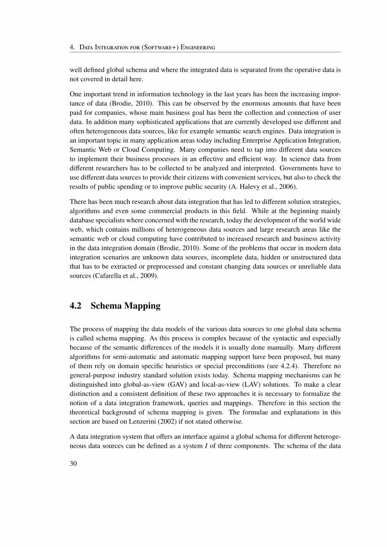
4. Data Integration for (Software+) Engineering
well defined global schema and where the integrated data is separated from the operative data isnot covered in detail here.
One important trend in information technology in the last years has been the increasing impor-tance of data (Brodie, 2010). This can be observed by the enormous amounts that have beenpaid for companies, whose main business goal has been the collection and connection of userdata. In addition many sophisticated applications that are currently developed use different andoften heterogeneous data sources, like for example semantic search engines. Data integration isan important topic in many application areas today including Enterprise Application Integration,Semantic Web or Cloud Computing. Many companies need to tap into different data sourcesto implement their business processes in an effective and efficient way. In science data fromdifferent researchers has to be collected to be analyzed and interpreted. Governments have touse different data sources to provide their citizens with convenient services, but also to check theresults of public spending or to improve public security (A. Halevy et al., 2006).
There has been much research about data integration that has led to different solution strategies,algorithms and even some commercial products in this field. While at the beginning mainlydatabase specialists where concerned with the research, today the development of the world wideweb, which contains millions of heterogeneous data sources and large research areas like thesemantic web or cloud computing have contributed to increased research and business activityin the data integration domain (Brodie, 2010). Some of the problems that occur in modern dataintegration scenarios are unknown data sources, incomplete data, hidden or unstructured datathat has to be extracted or preprocessed and constant changing data sources or unreliable datasources (Cafarella et al., 2009).
4.2 Schema Mapping
The process of mapping the data models of the various data sources to one global data schemais called schema mapping. As this process is complex because of the syntactic and especiallybecause of the semantic differences of the models it is usually done manually. Many differentalgorithms for semi-automatic and automatic mapping support have been proposed, but manyof them rely on domain specific heuristics or special preconditions (see 4.2.4). Therefore nogeneral-purpose industry standard solution exists today. Schema mapping mechanisms can bedistinguished into global-as-view (GAV) and local-as-view (LAV) solutions. To make a cleardistinction and a consistent definition of these two approaches it is necessary to formalize thenotion of a data integration framework, queries and mappings. Therefore in this section thetheoretical background of schema mapping is given. The formulae and explanations in thissection are based on Lenzerini (2002) if not stated otherwise.
A data integration system that offers an interface against a global schema for different heteroge-neous data sources can be defined as a system I of three components. The schema of the data
30
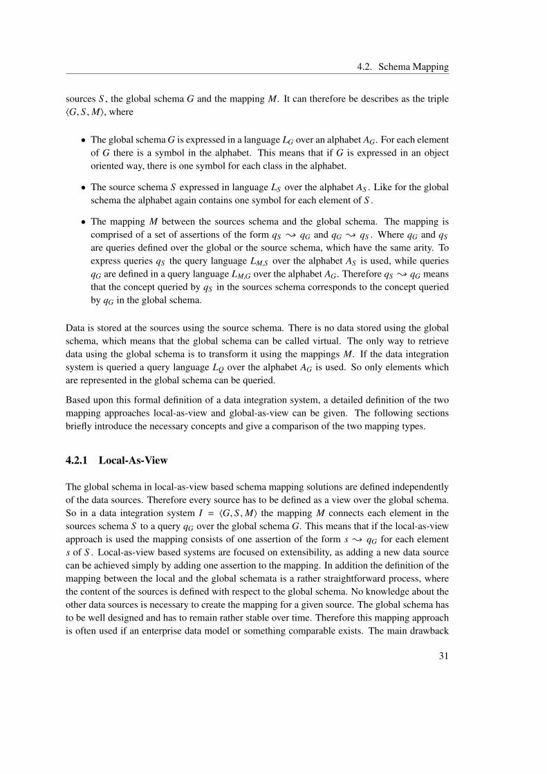
4.2. Schema Mapping
sources S , the global schema G and the mapping M. It can therefore be describes as the triple〈G, S ,M〉, where
• The global schema G is expressed in a language LG over an alphabet AG. For each elementof G there is a symbol in the alphabet. This means that if G is expressed in an objectoriented way, there is one symbol for each class in the alphabet.
• The source schema S expressed in language LS over the alphabet AS . Like for the globalschema the alphabet again contains one symbol for each element of S .
• The mapping M between the sources schema and the global schema. The mapping iscomprised of a set of assertions of the form qS { qG and qG { qS . Where qG and qS
are queries defined over the global or the source schema, which have the same arity. Toexpress queries qS the query language LM,S over the alphabet AS is used, while queriesqG are defined in a query language LM,G over the alphabet AG. Therefore qS { qG meansthat the concept queried by qS in the sources schema corresponds to the concept queriedby qG in the global schema.
Data is stored at the sources using the source schema. There is no data stored using the globalschema, which means that the global schema can be called virtual. The only way to retrievedata using the global schema is to transform it using the mappings M. If the data integrationsystem is queried a query language LQ over the alphabet AG is used. So only elements whichare represented in the global schema can be queried.
Based upon this formal definition of a data integration system, a detailed definition of the twomapping approaches local-as-view and global-as-view can be given. The following sectionsbriefly introduce the necessary concepts and give a comparison of the two mapping types.
4.2.1 Local-As-View
The global schema in local-as-view based schema mapping solutions are defined independentlyof the data sources. Therefore every source has to be defined as a view over the global schema.So in a data integration system I = 〈G, S ,M〉 the mapping M connects each element in thesources schema S to a query qG over the global schema G. This means that if the local-as-viewapproach is used the mapping consists of one assertion of the form s { qG for each elements of S . Local-as-view based systems are focused on extensibility, as adding a new data sourcecan be achieved simply by adding one assertion to the mapping. In addition the definition of themapping between the local and the global schemata is a rather straightforward process, wherethe content of the sources is defined with respect to the global schema. No knowledge about theother data sources is necessary to create the mapping for a given source. The global schema hasto be well designed and has to remain rather stable over time. Therefore this mapping approachis often used if an enterprise data model or something comparable exists. The main drawback
31
4. Data Integration for (Software+) Engineering
Figure 4.1: Structure of a local-as-view system based upon (Boulcane, 2006).
of local-as-view based approaches is the difficulty of query processing. The mapping gives littleinformation about how a query against the global schema can be translated into queries for thesource schemata. Figure 4.1 shows the basic structure of local-as-view based systems.
4.2.2 Global-As-View
A schema mapping solutions is considered to be global-as-view if the common data schema isdefined in terms of the integrated data sources. From the theoretical point of view this means thatfor every element g in G a query qS over S is included in the mapping M. In a global-as-viewbased approach the mapping M is a set of assertions of the form g{ qS , one for every elementg of G. This means that every element of G is linked to a view qS over the source schemata.The global-as-view based approach is therefore better suited if the sources are rather stable andmany queries have to be executed against the global schema, because the mapping M defineshow the data can be extracted from the sources. The drawback of global-as-view solutions is theinfluence each new data source may have on the global schema and all associated views, whichcan lead to a redefinition of these views. Furthermore the definition of the mapping between thesources and the global schema is harder than in local-as-view based systems, because the dataextraction procedure has to be defined. Therefore global-as-view systems are said to correspondto a more procedural way of modeling data integration systems. In figure 4.2 the structure of aglobal-as-view system is depicted.
4.2.3 GLAV and BAV
To combine the advantages of global-as-view and local-as-view based solutions hybrid solutionshave been developed, which are called GLAV for global-local-as-view. In GLAV both assertiontypes can be used to define the mapping between the source schema and the global schema.These hybrid systems are often also called mediated systems, because they usually use an addi-tional mediation layer between the global schema and the sources. Boulcane (2006) describes
32
4.2. Schema Mapping
Figure 4.2: Structure of a global-as-view system based upon (Boulcane, 2006).
a hybrid schema mapping systems, which operates on several layers, which is called a multi-mediator schema mapping architecture. In this solution the global schema is connected to anintermediate layer using the global-as-view approach, while the intermediate layer is connectedto the data sources using the local-as-view approach. Figure 4.3 shows the structure this media-tor based system. McBrien and Poulovassilis (2003) propose another schema mapping approachcalled both-as-view (BAV). BAV is based on reversible schema transformations and providesthe possibility to derive both a global-as-view and a local-as-view representation of the system.Therefore if BAV is used to model the mapping the advantages of local-as-view and global-as-view based solution can both be utilized. Further more the both-as-view solution supports theevolution of both the global schema and also the data sources.
In an EKB based integration solution the data integration layer can operate in any of the de-scribed schema mapping types. Therefore the EKB can be classified as a BAV solution, becauseit is possible to define the mappings between the local and the global schemata in a form whichallows the deduction of both a local-as-view and a global-as-view model of the system. Nev-ertheless it is also possible to use an EKB in a strict global-as-view or local-as-view manner,but with the restriction that if a local-as-view approach is used the system has to be providedwith enough information to process queries against the global data schema in an effective andefficient way.
4.2.4 Generating Schema Mappings
The generation of the mapping between the local and the global schema is a complex processthat requires both theoretical knowledge about database systems and mapping generation anddomain knowledge to be able to map the different schema elements correctly. Because of thetedious and repetitive character of this work many researchers have developed semi-automaticmapping support. These systems help to reduce the manual work and use different strategies toperform simple mappings automatically. As mapping generation is a NP complete problem and
33
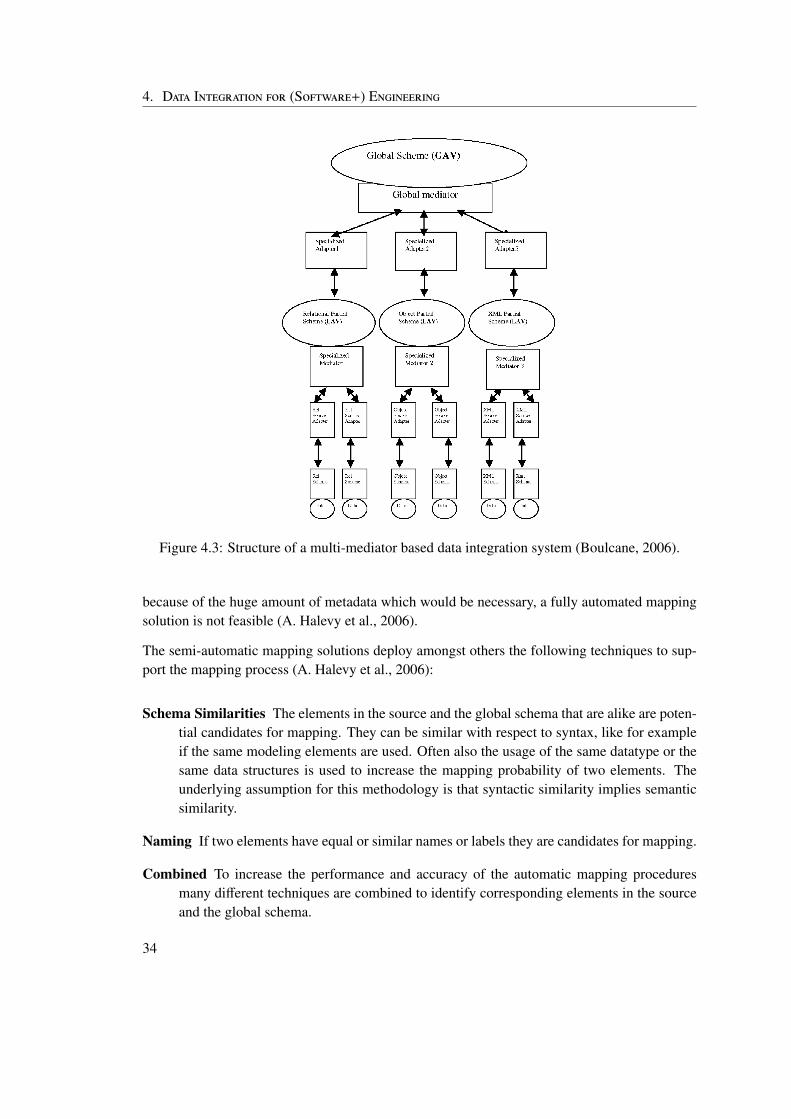
4. Data Integration for (Software+) Engineering
Figure 4.3: Structure of a multi-mediator based data integration system (Boulcane, 2006).
because of the huge amount of metadata which would be necessary, a fully automated mappingsolution is not feasible (A. Halevy et al., 2006).
The semi-automatic mapping solutions deploy amongst others the following techniques to sup-port the mapping process (A. Halevy et al., 2006):
Schema Similarities The elements in the source and the global schema that are alike are poten-tial candidates for mapping. They can be similar with respect to syntax, like for exampleif the same modeling elements are used. Often also the usage of the same datatype or thesame data structures is used to increase the mapping probability of two elements. Theunderlying assumption for this methodology is that syntactic similarity implies semanticsimilarity.
Naming If two elements have equal or similar names or labels they are candidates for mapping.
Combined To increase the performance and accuracy of the automatic mapping proceduresmany different techniques are combined to identify corresponding elements in the sourceand the global schema.
34
4.2. Schema Mapping
Machine Learning The repetitive nature of many tasks that have to be performed duringschema mapping and the fact that models from the same domain often are relatively simi-lar make the mapping process a suitable candidate for machine learning approaches. Hereat first some mappings are performed manually and used as learning sequence for the sys-tem. The quality of the solution depends on the similarity between the input model andthe training data.
There are many different approaches for automatic schema mapping support based upon on-tologies, model-driven or directly operating on relational data schemata. Chen et al. (2009) forexample propose an ontology based mapping mechanism, which extracts attributes from datasources on the web and evaluates the mapping probability using a semantic attribute matrix.This semantic similarity between attributes is calculated by WordNet and the matrix is later an-alyzed using a reverse backtracking algorithm to find semantically related attribute groups. Thisdata integration approach is local-as-view based, but uses some concepts from mediated schemaintegration. Xiong et al. (2009) present a mapping procedure for XML data integration. Theymatch similar elements after parsing and transforming the original XML schemata into an inter-mediate format. Therefore elements are mapped into the same concept in the global schema ifthey correspond in the intermediate format. The structure of the system proposed by Xiong etal. (2009) is mediator based, where the local XML schema is the mediator between the actualdata source schema and the global schema. Hu (2006) propose a local-as-view based approach,which generates the global schema from the local views. The algorithm he proposes tries toresolve structural and semantic conflicts and also generates the mapping information needed forquery processing parallel to the generation of the global schema. While the automatic generationof the global schema ensures a clear definition and perfect coordination with the mappings, itcan lead to a schema that is hard to understand and difficult to use. As the user has to use theglobal schema to formulate queries its usability is of special importance.
Besides mapping the schema of data that has to be integrated often also the instance data has tobe transformed before it can be presented to the user of the global interface. The reason is thatalthough the same schema is used there can be semantic differences in the way the data is rep-resented. For example could the same address be stored in different ways, or the same companyname could be stored in different forms and the data integration system has to reconcile this datato collapse the duplicated data elements. Because the amount of data that has to be processedis usually very large automatic systems have to be used to perform these operations (A. Halevyet al., 2006). As these automatic methods for data integration have been rather successful someresearchers are trying to use the research results from data mapping for fully automatic schemamapping. Gal (2008) discusses the problems and possibilities of fully automatic schema map-ping for data integration. Furthermore he focuses on the uncertainty of the mapping process andthe influence on the correctness of generated mappings.
Automatic mapping generation is an important part of an EKB based integration approach, asit reduces the initial effort for system integration. A combined automatic mapping procedure,
35
4. Data Integration for (Software+) Engineering
which uses syntactic, naming and other available information to create a mapping proposal isa feasible solution for an EKB based system. This proposal is then edited and corrected man-ually by domain experts. Machine learning approaches in the (software+) engineering domainsuffer from the lack of sufficient training data and the heterogeneity of different tools and engi-neering domains. Also the automatic generation of the global view as proposed by (Hu, 2006)is not feasible, because the usability of the global schema is important as it is used for projectmanagement and quality assurance tasks.
4.3 Query Processing
Query processing for data integration systems generally deals with transforming a query againstthe global schema into queries against the schemata of the data sources and with transformingthe answer of these sub-queries to provide a unified result for the original query. Because thebehavior of the data sources and their features are not as clearly specified as for a homogeneousdata storage system, query processing cannot be separated into a query optimization and a queryexecution step. The optimizer would not yield good results for two reasons:
1. The optimizer may not have enough information to create a good execution strategy for thequery, because most data source specific properties are abstracted by the data integrationsystem and therefore unavailable.
2. The strategy that seems optimal at optimization time may be arbitrarily bad at executiontime. In addition to the incompleteness of the information about the sources the optimizeralso has to deal with uncertainty with respect to the behavior of the sources. This meansthat if the sources behave differently than expected a query might take much longer thanexpected.
A solution for this problem is the usage of adaptive query processing, which combines optimiza-tion and execution (A. Halevy et al., 2006).
The query processing process is different for local-as-view and global-as-view systems, becausethe mapping contains a different amount of knowledge that can be utilized for the transformationof the queries in the two approaches. Therefore the following two sections describe the differ-ences and special features of query processing using a local-as-view or global-as-view approachrespectively.
4.3.1 Query Processing in LAV
In a local-as-view based system the sources are represented by views over the global schema.Therefore in a LAV environment the term view based query processing is used. This means
36
4.4. Data Virtualization
that the result for a query written against the global schema has to be computed using the viewsrather than directly the data in the sources. Two different solution strategies for view based queryprocessing can be distinguished (Lenzerini, 2002):
View Based Query Rewriting Using this approach the goal is to rewrite the query against theglobal schema so that it only refers to the views for the sources. This process is indepen-dent of the target source. The result query language of the rewriting process has to be fixedand is usually the same as the query language used for the original query. This means thatonly the target of the query changes from the global data schema to the views over thedata sources. If there is no exact representation of the original query over the views thanthe general strategy is to use a result that is as close as possible to the original query. Thisis called maximally contained rewriting. View based query rewriting is essentially a twostep process of a.) query rewriting and b.) evaluation of the result of a.) against the viewsof the data sources.
View Based Query Answering In this solution strategy the result for a query is calculated byevaluating its certain answers. Certain answers are those that can be logically derivedfrom the information at the sources to be a result for a given query. This means that queryanswering methods will try to use all available information to compute a result for a querydirectly.
4.3.2 Query Processing in GAV
In systems that use the global-as-view approach query processing is usually done by query un-folding. Because the mapping already contains information how to query an element of theglobal schema at the sources, each element that is part of the query can simply be queried at thesources using the mapping information. This means that every element in the original query isreplaced by the result of the corresponding query against the data sources. Then the unfoldedquery can be evaluated without any further need to contact the sources. Yet this is only true ifa plain global data schema is used without integrity constraints such as foreign key constraints.In such cases query answering becomes more complex, as an simple unfolding strategy wouldmiss all answers derived using the foreign key information.
4.4 Data Virtualization
Data virtualization is closely related to data integration as the following definition fromJagatheesan et al. (2005) shows:
“Data Virtualization is the concept of bringing together different heterogeneousdata and storage resources into one or more logical views so that the distributed
37
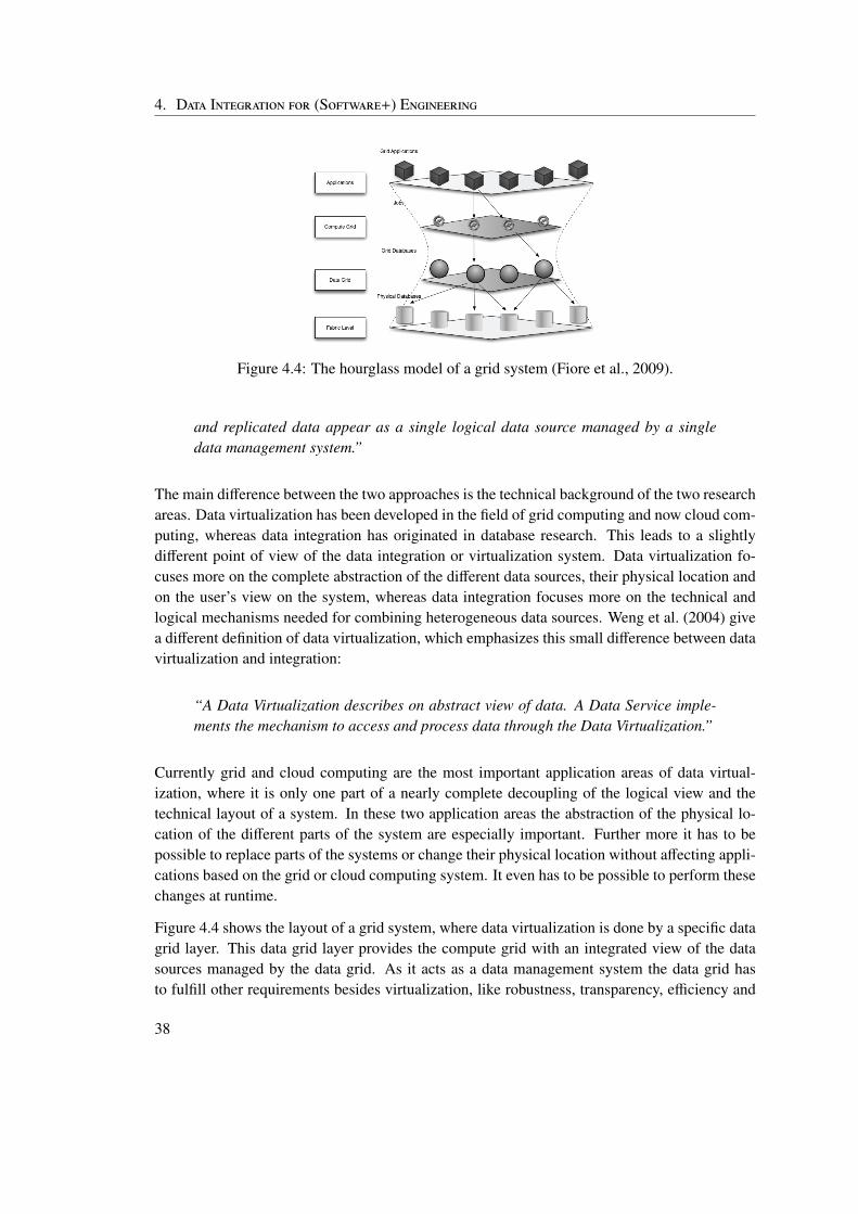
4. Data Integration for (Software+) Engineering
Figure 4.4: The hourglass model of a grid system (Fiore et al., 2009).
and replicated data appear as a single logical data source managed by a singledata management system.”
The main difference between the two approaches is the technical background of the two researchareas. Data virtualization has been developed in the field of grid computing and now cloud com-puting, whereas data integration has originated in database research. This leads to a slightlydifferent point of view of the data integration or virtualization system. Data virtualization fo-cuses more on the complete abstraction of the different data sources, their physical location andon the user’s view on the system, whereas data integration focuses more on the technical andlogical mechanisms needed for combining heterogeneous data sources. Weng et al. (2004) givea different definition of data virtualization, which emphasizes this small difference between datavirtualization and integration:
“A Data Virtualization describes on abstract view of data. A Data Service imple-ments the mechanism to access and process data through the Data Virtualization.”
Currently grid and cloud computing are the most important application areas of data virtual-ization, where it is only one part of a nearly complete decoupling of the logical view and thetechnical layout of a system. In these two application areas the abstraction of the physical lo-cation of the different parts of the system are especially important. Further more it has to bepossible to replace parts of the systems or change their physical location without affecting appli-cations based on the grid or cloud computing system. It even has to be possible to perform thesechanges at runtime.
Figure 4.4 shows the layout of a grid system, where data virtualization is done by a specific datagrid layer. This data grid layer provides the compute grid with an integrated view of the datasources managed by the data grid. As it acts as a data management system the data grid hasto fulfill other requirements besides virtualization, like robustness, transparency, efficiency and
38
4.4. Data Virtualization
security (Fiore et al., 2009). This makes the implementation of a data virtualization system in agrid or cloud computing environment a difficult task.
In many modern application areas data virtualization and data integration are both used toachieve a high level of data source abstraction. As applications are increasingly connected andtherefore have to interact and to share data this trend is likely to continue in the future.
39

5 Research Issues and Approach
In this section the requirements of a semantic integration layer for a (software+) engineeringframework are defined and based upon these requirements the research issues are formulated insection 5.1. In section 5.2 the research methods used to resolve the research issues are discussedand the two use cases used in this thesis are explained in detail.
(Software+) engineering is done by people with different technical backgrounds and differentviews on the overall system. The heterogeneity of the tasks they have to fulfill is reflected by theheterogeneity of the tools they use. These tools have not been built to integrate well with eachother, but rather to solve a specific task, like creating a circuit diagram, planning the connectivityof a device or implementing its software in an effective and efficient way. The need for qualityassurance and project management across tool borders as well as the introduction of iterative de-velopment paradigms resulted in the need for closer integration. As data is exchanged betweentools in both directions of the production chain more often, manual coordination of the datatransfer becomes more error prone and increasingly complex. This leads to a situation wherea reliable change impact analysis is virtually impossible. Therefore, manual coordination is nolonger a feasible option in a modern (software+) engineering environment. Existing technicalintegration solutions provide the infrastructure for data exchange and communication betweentools, but without semantic integration the identification of common concepts and the transfor-mation to a common data format from the tool specific data formats has to be done repetitivelyand in an uncoordinated way. A semantic integration solution for (software+) engineering has tosolve this problem by providing a central unit that is responsible for managing the common datamodel. This common data model has no physical representation, because the data is provided bythe tools in their specific format and has to be transformed to match the definition in the commondata format. Therefore the term virtual common data model will be used throughout this thesis.The semantic integration solution has to provide infrastructure for storing and editing the virtualcommon data model. Transformations from tool specific data models to the virtual commondata model have to be derived semi-automatically from the information provided in the datamodel. The semantic integration unit shall be the single point where changes to the commondata model are done. In addition the life-cycle of the integrated tools has to be coordinated withthe life-cycle of the semantic knowledge about these tools managed in the semantic integrationlayer. Therefore the semantic integration unit has to provide the possibility to add new tools,change the status of already connected tools or remove tools at runtime. A query interface is
41
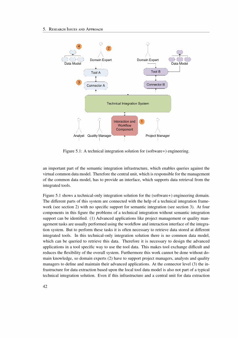
5. Research Issues and Approach
Figure 5.1: A technical integration solution for (software+) engineering.
an important part of the semantic integration infrastructure, which enables queries against thevirtual common data model. Therefore the central unit, which is responsible for the managementof the common data model, has to provide an interface, which supports data retrieval from theintegrated tools.
Figure 5.1 shows a technical-only integration solution for the (software+) engineering domain.The different parts of this system are connected with the help of a technical integration frame-work (see section 2) with no specific support for semantic integration (see section 3). At fourcomponents in this figure the problems of a technical integration without semantic integrationsupport can be identified. (1) Advanced applications like project management or quality man-agement tasks are usually performed using the workflow and interaction interface of the integra-tion system. But to perform these tasks it is often necessary to retrieve data stored at differentintegrated tools. In this technical-only integration solution there is no common data model,which can be queried to retrieve this data. Therefore it is necessary to design the advancedapplications in a tool specific way to use the tool data. This makes tool exchange difficult andreduces the flexibility of the overall system. Furthermore this work cannot be done without do-main knowledge, so domain experts (2) have to support project managers, analysts and qualitymanagers to define and maintain their advanced applications. At the connector level (3) the in-frastructure for data extraction based upon the local tool data model is also not part of a typicaltechnical integration solution. Even if this infrastructure and a central unit for data extraction
42
5.1. Research Issues
would be implemented, without semantic integration the data models of the tools (4) and a com-mon data model cannot be aligned. Therefore a semantic integration solution is necessary toprovide effective and efficient support for advanced tasks like end-to-end tests or change impactanalysis.
5.1 Research Issues
The main research issue of this thesis is to develop a semantic integration layer for a (software+)engineering framework. The integration solution has to be effective, efficient and robust. Inaddition it has to be operable by engineers with little experience in the field of semantic integra-tion. Derived from the requirements above the research issues of this thesis can be stated moreprecisely:
RI-1 Feasibility of an EKB based solution for semantic integration: It has to be investi-gated whether an EKB based integration layer is a feasible way to provide semantic inte-gration for a (software+) engineering environment. The typical requirements that can bederived from common use cases like data restriction enforcement or change impact anal-ysis have to be identified and it has to be evaluated if the proposed approach is capable offulfilling these requirements.
RI-2 Knowledge for semantic integration: Robustness in terms of error tolerance and stabil-ity is a critical requirement of an integration framework. Domain experts have to be con-fident about the results of automatic data processing or they will refuse to commit theirwork into the integration framework. A life-cycle for the management of semantic knowl-edge that is compatible with the life-cycle for the management of integrated tools has tobe developed to provide the system with the necessary robustness. The life-cycle has toclearly define the behavior of the integrated tool with respect to the virtual common datamodel in every possible state.
RI-3 Derivation of transformation instructions: A knowledge model provides informationabout the tool specific data models, the common elements of these models and the depen-dencies between data elements from tool specific data models and common data elements.This knowledge has to be facilitated to semi-automatically produce transformations be-tween the virtual common data model and the respective tool data models. Because man-ual transformation of the data is an error prone and time intensive task a feasible level ofautomation has to be reached to make the framework usable. In addition automatic gen-eration of transformations makes the framework more flexible in terms of tool exchangeand changes to the virtual common data model.
RI-4 Design of a query infrastructure for a virtual common data model: One of the mainbenefits of a working semantic integration solution is the possibility to query the virtual
43
5. Research Issues and Approach
common data model. The virtual common data model replaces a multitude of tool spe-cific data models and the query interface provides a common interface for data retrievalfrom heterogeneous data sources. By providing the tool specific data in a standardizedformat and via a simple interface advanced quality assurance and project managementtasks can be done with less effort. To facilitate these benefits an interface has to be de-fined which can be used to retrieve information from the different tools using the virtualcommon data model. The interface has to provide the information needed by a query en-gine that retrieves data using the virtual common data model and uses the transformationinfrastructure provided by the semantic integration layer.
Furthermore, to be able to retrieve the information from the different integrated tools, aninfrastructure has to be developed, which clearly defines the interface a connector has toimplement to expose its data and which reduces the implementation effort for a connectoras far as possible. As domain experts have to be able to create the connector imple-mentation, the data retrieval interface has to be easy to understand and well documented.Nevertheless it needs to be flexible enough to support query optimization and other moreadvanced features in the future. Therefore, besides providing all data of a tool connectorto the integration layer the infrastructure also has to provide the possibility to formulaterestrictions reducing the result set before it is sent to the integration infrastructure.
5.2 Research Method
In this thesis three different approaches are used to address the research issues RI-1 to RI-4.To gain insight into the theoretical background of system integration from the technical, se-mantic and data driven point of view a literature research is done (see section 5.2.1). To showthe feasibility of an EKB based semantic integration framework two real world use cases areimplemented as prototypes (see section 5.2.2). These use cases are also used to gather empir-ical information about the efficiency and robustness and the usability of the proposed solution.Further more a comparison between the original OpenEngSB solution, which only providestechnical integration to the proposed semantic integration framework with respect to the effortnecessary for tool integration and exchange and available functionality will be performed (seesection 5.2.3).
5.2.1 Literature Research
In this thesis an adapted version of a systematic literature review is used to gather informationabout the theoretical background of technical integration (see section 2) and semantic integra-tion (see section 3). Then this information is summarized from a specifically data centred pointof view in section 4. An effective and efficient semantic integration framework for (software+)
44
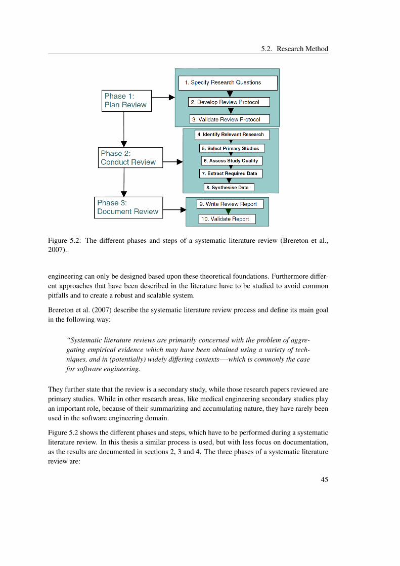
5.2. Research Method
Figure 5.2: The different phases and steps of a systematic literature review (Brereton et al.,2007).
engineering can only be designed based upon these theoretical foundations. Furthermore differ-ent approaches that have been described in the literature have to be studied to avoid commonpitfalls and to create a robust and scalable system.
Brereton et al. (2007) describe the systematic literature review process and define its main goalin the following way:
“Systematic literature reviews are primarily concerned with the problem of aggre-gating empirical evidence which may have been obtained using a variety of tech-niques, and in (potentially) widely differing contexts—-which is commonly the casefor software engineering.
They further state that the review is a secondary study, while those research papers reviewed areprimary studies. While in other research areas, like medical engineering secondary studies playan important role, because of their summarizing and accumulating nature, they have rarely beenused in the software engineering domain.
Figure 5.2 shows the different phases and steps, which have to be performed during a systematicliterature review. In this thesis a similar process is used, but with less focus on documentation,as the results are documented in sections 2, 3 and 4. The three phases of a systematic literaturereview are:
45
5. Research Issues and Approach
Plan Review In this phase research questions and a review protocol are defined and reviewed.This provides the basis and the systematic framework for the review. Furthermore it isnecessary to reduce the possibility of bias in the study. Included in the protocol are guide-lines with respect to the process that will be used, the conditions that have to be appliedwhen selecting the primary studies and quality issues. In this thesis only a very basic pro-tocol is established, because of the limited size of the review and the fact that the review isconducted by a single person. Therefore the focus is less on the explanation of the processand mainly on the selection of primary studies.
Conduct Review The second phase of the review is concerned with the actual realisation ofthe review. In this step the relevant research is identified, primary papers are selected andinteresting information gathered. This phase is conducted unaltered in this thesis. Primarypapers are searched for using the ACM Digital Library1 and IEEE Xplore2. Relevantsearch terms like “semantic integration” or “ontology + integration” are used. Then theresults are filtered with respect to relevance for integration using as a first criteria the titleand as a second criteria the abstract of the papers. Finally the content of the papers isreviewed and irrelevant papers are rejected. As the target of the systematic research isto identify the relevant sources for the theoretical background of technical and semanticintegration, only papers which focus on these theoretical foundations are accepted.
Document Review In the final phase of a systematic literate review the gather information issummarized in a report, which is later validated using for example a peer-review mecha-nism. In this thesis the information is summarized in sections 2, 3 and 4. Therefore noadditional report is generated.
The advantage of the usage of a structured approach based upon the process of a systematicliterature review instead of doing an ad-hoc literature research is the reduction of bias and thepossibility to gain a broader insight into the related work and the theoretical background of theresearch field. This is necessary to create an effective and efficient integration solution.
5.2.2 Use Case based Feasibility Evaluation
To investigate the feasibility of the proposed EKB based integration solution prototypes for tworeal world use cases based upon the requirements of industrial partners and common shortcom-ings in the (software+) engineering tool chain are developed and analyzed.
Definition of Quality Criteria Across Tool Data Models in Electrical Engineering This usecase is an example of the integration of tools from different engineering domains includ-ing software development and electrical engineering. It shows the importance of semantic
1http://portal.acm.org/2http://ieeexplore.ieee.org/
46
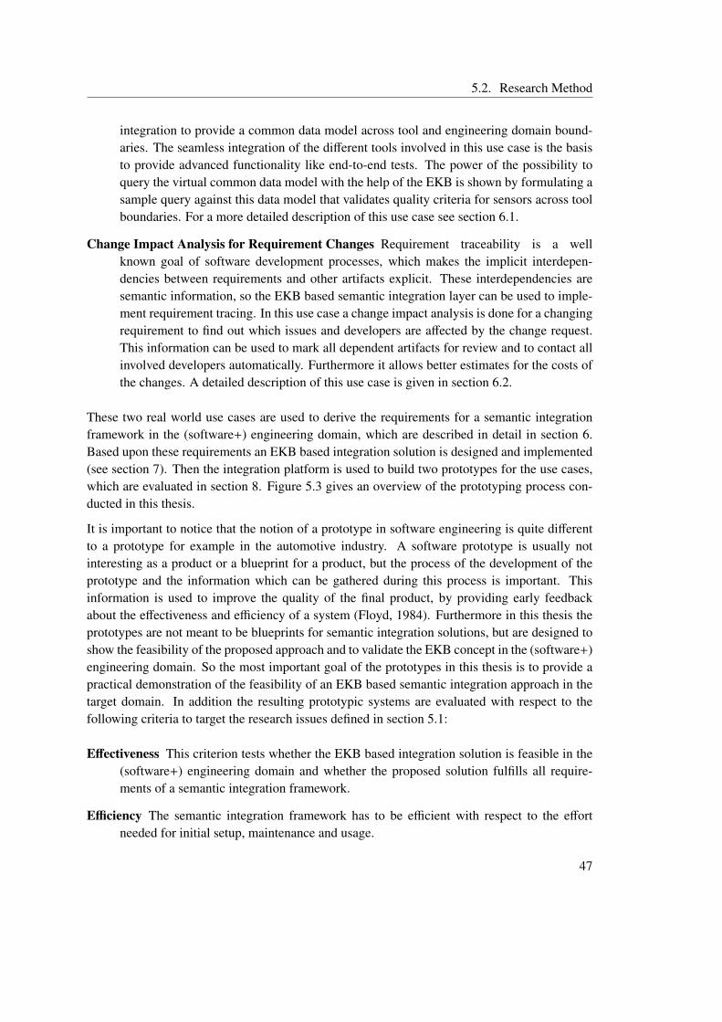
5.2. Research Method
integration to provide a common data model across tool and engineering domain bound-aries. The seamless integration of the different tools involved in this use case is the basisto provide advanced functionality like end-to-end tests. The power of the possibility toquery the virtual common data model with the help of the EKB is shown by formulating asample query against this data model that validates quality criteria for sensors across toolboundaries. For a more detailed description of this use case see section 6.1.
Change Impact Analysis for Requirement Changes Requirement traceability is a wellknown goal of software development processes, which makes the implicit interdepen-dencies between requirements and other artifacts explicit. These interdependencies aresemantic information, so the EKB based semantic integration layer can be used to imple-ment requirement tracing. In this use case a change impact analysis is done for a changingrequirement to find out which issues and developers are affected by the change request.This information can be used to mark all dependent artifacts for review and to contact allinvolved developers automatically. Furthermore it allows better estimates for the costs ofthe changes. A detailed description of this use case is given in section 6.2.
These two real world use cases are used to derive the requirements for a semantic integrationframework in the (software+) engineering domain, which are described in detail in section 6.Based upon these requirements an EKB based integration solution is designed and implemented(see section 7). Then the integration platform is used to build two prototypes for the use cases,which are evaluated in section 8. Figure 5.3 gives an overview of the prototyping process con-ducted in this thesis.
It is important to notice that the notion of a prototype in software engineering is quite differentto a prototype for example in the automotive industry. A software prototype is usually notinteresting as a product or a blueprint for a product, but the process of the development of theprototype and the information which can be gathered during this process is important. Thisinformation is used to improve the quality of the final product, by providing early feedbackabout the effectiveness and efficiency of a system (Floyd, 1984). Furthermore in this thesis theprototypes are not meant to be blueprints for semantic integration solutions, but are designed toshow the feasibility of the proposed approach and to validate the EKB concept in the (software+)engineering domain. So the most important goal of the prototypes in this thesis is to provide apractical demonstration of the feasibility of an EKB based semantic integration approach in thetarget domain. In addition the resulting prototypic systems are evaluated with respect to thefollowing criteria to target the research issues defined in section 5.1:
Effectiveness This criterion tests whether the EKB based integration solution is feasible in the(software+) engineering domain and whether the proposed solution fulfills all require-ments of a semantic integration framework.
Efficiency The semantic integration framework has to be efficient with respect to the effortneeded for initial setup, maintenance and usage.
47
5. Research Issues and Approach
Figure 5.3: Overview of the prototyping process used in this thesis.
Usability The system has to be usable by domain experts with little or no knowledge about se-mantic integration without the need for time and cost intensive training. Advanced tasksbased upon the semantic integration framework like end-to-end tests or project manage-ment tasks have to be easy to setup and perform. Therefore both the query interface of thesemantic integration framework and the interface for the definition of the virtual commondata model and the mappings to the tool data models have to be usable by domain experts.Furthermore the complexity of a typical tool connector is also part of the usability of thesystem, as these components have to be designed and implemented by domain experts.
Robustness The system has to be able to deal with unexpected input and defects in a welldefined way. The of semantic knowledge about tool connectors and the tool connectorsthemselves have to guarantee that the system will not reach an undefined state.
48
5.2. Research Method
The empirical evidence will be evaluated with respect to the guidelines for empirical research inthe software engineering domain proposed by Kitchenham et al. (2002). Their guidelines coverthe following six areas:
Experimental context There are three elements, which define the experimental context. Thefirst is background information about the context in which an empirical study is per-formed. The second is the research hypotheses and how it was defined and the third isinformation about related work in this research domain. The goal of guidelines for theexperimental context is to achieve a proper definition of the research objectives and anunderstandable description of the research as a whole.
Experimental design Guidelines in this area should improve the quality of empirical studieswith respect to the products, resources and processes involved. Furthermore they shouldhelp to design the study in a way which ensures that the research objectives defined be-forehand are achieved.
Conduct of the experiment and data collection It is necessary to clearly define how the out-come of the experiment is measured and how the experiment can be reproduced by otherresearchers. Furthermore every derivation from experimental plan has to be recorded.
Analysis Independent of the statistical approach used these guidelines try to ensure that the re-sults gathered in the previous step are analyzed correctly. The analysis has to be conductedwith respect to the study design and has to be powerful enough to cope with the require-ments stated in the design. The analysis guidelines aim at the correct usage of statisticalmethods.
Presentation Besides understandability also the ability to reproduce the study is an importantissue and has to be taken into account when the form of presentation of the study includ-ing its results is decided. To ensure that the study can be reproduced the presentationhas to include amongst others design procedures, data collection procedures and analysisprocedures.
Interpretation of the results The results of the empirical study have to be interpreted in a con-sistent and understandable way. No new information may be introduced at this stage of thestudy. In addition the guidelines try to support the researcher in the correct qualificationof his results.
5.2.3 Comparison to Technical Integration
The proposed semantic integration framework for the (software+) engineering domain providesimportant features for the integrated system including the possibility to query a virtual commondata model and data transformation based on semantic knowledge. But to use these featuresin an engineering environment additional setup is necessary. Further more the tool connectors
49
5. Research Issues and Approach
need to support the possibility of data extraction to act as data sources for the virtual commondata model. To provide empirical information about the complexity and costs of these additionalsetup, maintenance and usage steps a comparison between the prototype developed in this thesisand the original system will be performed with respect to the following criteria:
Tool Integration The different steps necessary to integrate a new tool are identified and evalu-ated with respect to time consumption. This evaluation will be performed with the help ofdomain experts. In addition the technologies, which have to be understood to perform thetool integration will be compared.
Tool Exchange The process of tool exchange is compared with respect to time consumption,involved technologies and necessary steps to exchange one tool by another tool of thesame tool domain.
Advanced Applications The effort needed to perform advanced applications like end-to-endtests or project management tasks, which use the features of the semantic integrationframework to extract data from different engineering tools is evaluated and compared.
The goal of this comparison is to provide practitioners with information about the trade-offs ofadding a semantic integration layer to a technical integration system. Furthermore it helps toshow the feasibility of the proposed approach and gives information about the robustness andefficiency of an EKB based semantic integration solution.
50
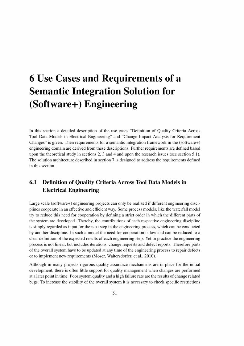
6 Use Cases and Requirements of aSemantic Integration Solution for(Software+) Engineering
In this section a detailed description of the use cases “Definition of Quality Criteria AcrossTool Data Models in Electrical Engineering” and “Change Impact Analysis for RequirementChanges” is given. Then requirements for a semantic integration framework in the (software+)engineering domain are derived from these descriptions. Further requirements are defined basedupon the theoretical study in sections 2, 3 and 4 and upon the research issues (see section 5.1).The solution architecture described in section 7 is designed to address the requirements definedin this section.
6.1 Definition of Quality Criteria Across Tool Data Models inElectrical Engineering
Large scale (software+) engineering projects can only be realized if different engineering disci-plines cooperate in an effective and efficient way. Some process models, like the waterfall modeltry to reduce this need for cooperation by defining a strict order in which the different parts ofthe system are developed. Thereby, the contributions of each respective engineering disciplineis simply regarded as input for the next step in the engineering process, which can be conductedby another discipline. In such a model the need for cooperation is low and can be reduced to aclear definition of the expected results of each engineering step. Yet in practice the engineeringprocess is not linear, but includes iterations, change requests and defect reports. Therefore partsof the overall system have to be updated at any time of the engineering process to repair defectsor to implement new requirements (Moser, Waltersdorfer, et al., 2010).
Although in many projects rigorous quality assurance mechanisms are in place for the initialdevelopment, there is often little support for quality management when changes are performedat a later point in time. Poor system quality and a high failure rate are the results of change relatedbugs. To increase the stability of the overall system it is necessary to check specific restrictions
51
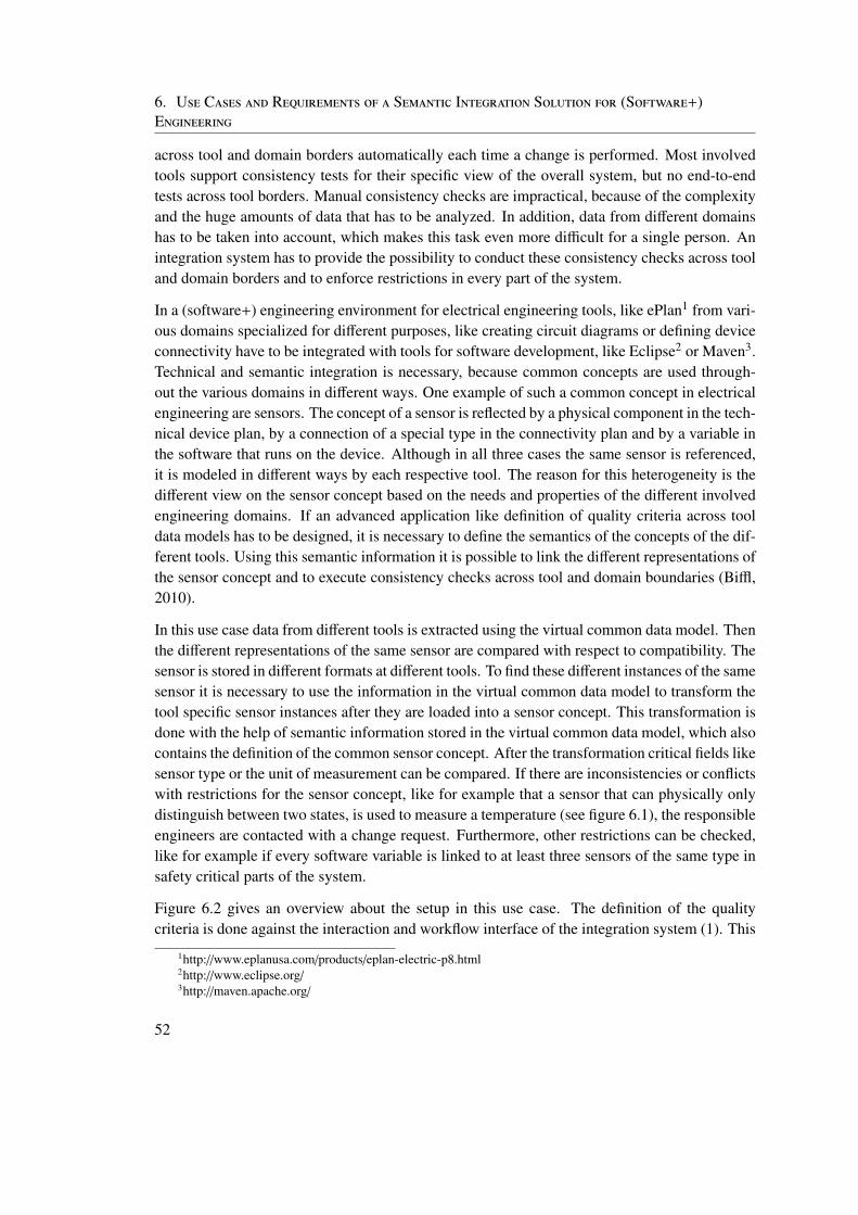
6. Use Cases and Requirements of a Semantic Integration Solution for (Software+)Engineering
across tool and domain borders automatically each time a change is performed. Most involvedtools support consistency tests for their specific view of the overall system, but no end-to-endtests across tool borders. Manual consistency checks are impractical, because of the complexityand the huge amounts of data that has to be analyzed. In addition, data from different domainshas to be taken into account, which makes this task even more difficult for a single person. Anintegration system has to provide the possibility to conduct these consistency checks across tooland domain borders and to enforce restrictions in every part of the system.
In a (software+) engineering environment for electrical engineering tools, like ePlan1 from vari-ous domains specialized for different purposes, like creating circuit diagrams or defining deviceconnectivity have to be integrated with tools for software development, like Eclipse2 or Maven3.Technical and semantic integration is necessary, because common concepts are used through-out the various domains in different ways. One example of such a common concept in electricalengineering are sensors. The concept of a sensor is reflected by a physical component in the tech-nical device plan, by a connection of a special type in the connectivity plan and by a variable inthe software that runs on the device. Although in all three cases the same sensor is referenced,it is modeled in different ways by each respective tool. The reason for this heterogeneity is thedifferent view on the sensor concept based on the needs and properties of the different involvedengineering domains. If an advanced application like definition of quality criteria across tooldata models has to be designed, it is necessary to define the semantics of the concepts of the dif-ferent tools. Using this semantic information it is possible to link the different representations ofthe sensor concept and to execute consistency checks across tool and domain boundaries (Biffl,2010).
In this use case data from different tools is extracted using the virtual common data model. Thenthe different representations of the same sensor are compared with respect to compatibility. Thesensor is stored in different formats at different tools. To find these different instances of the samesensor it is necessary to use the information in the virtual common data model to transform thetool specific sensor instances after they are loaded into a sensor concept. This transformation isdone with the help of semantic information stored in the virtual common data model, which alsocontains the definition of the common sensor concept. After the transformation critical fields likesensor type or the unit of measurement can be compared. If there are inconsistencies or conflictswith restrictions for the sensor concept, like for example that a sensor that can physically onlydistinguish between two states, is used to measure a temperature (see figure 6.1), the responsibleengineers are contacted with a change request. Furthermore, other restrictions can be checked,like for example if every software variable is linked to at least three sensors of the same type insafety critical parts of the system.
Figure 6.2 gives an overview about the setup in this use case. The definition of the qualitycriteria is done against the interaction and workflow interface of the integration system (1). This
1http://www.eplanusa.com/products/eplan-electric-p8.html2http://www.eclipse.org/3http://maven.apache.org/
52
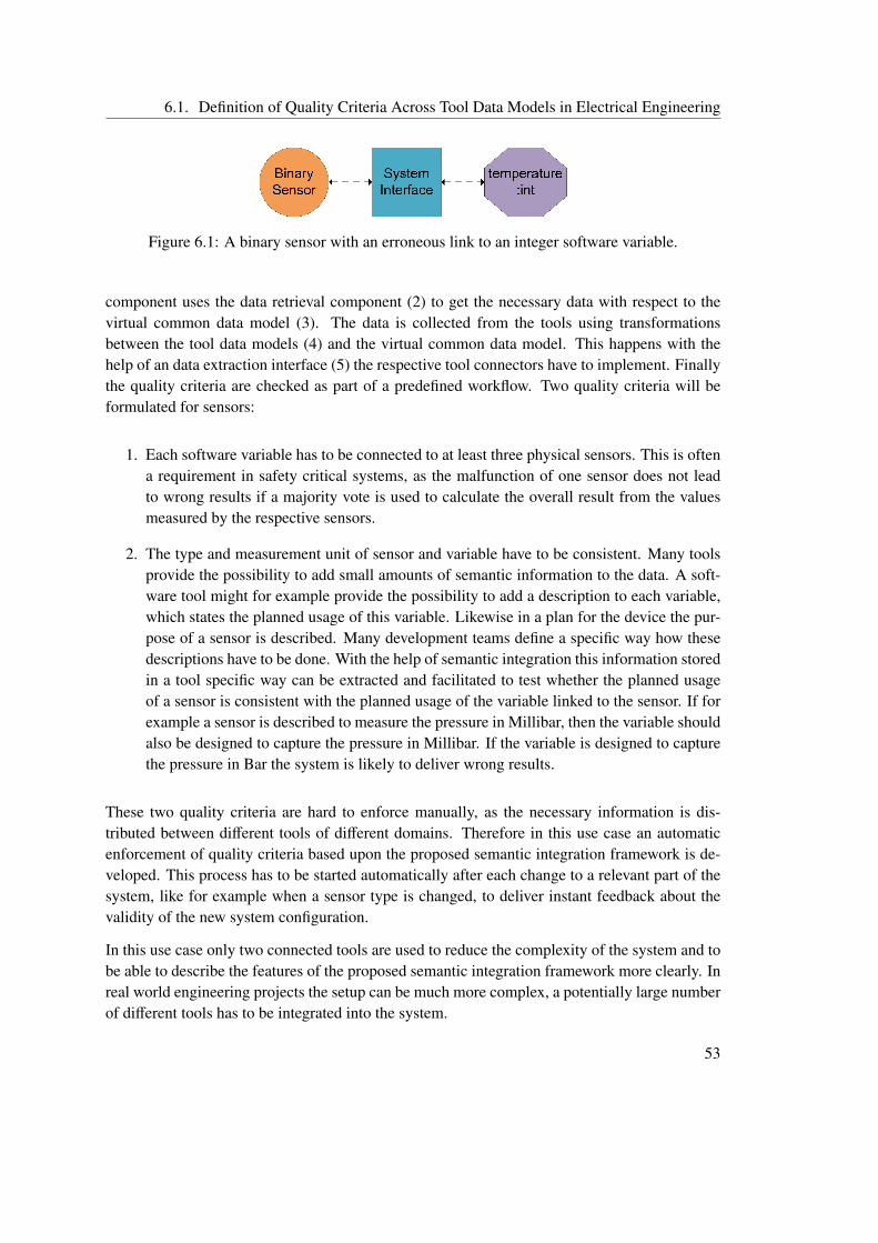
6.1. Definition of Quality Criteria Across Tool Data Models in Electrical Engineering
Figure 6.1: A binary sensor with an erroneous link to an integer software variable.
component uses the data retrieval component (2) to get the necessary data with respect to thevirtual common data model (3). The data is collected from the tools using transformationsbetween the tool data models (4) and the virtual common data model. This happens with thehelp of an data extraction interface (5) the respective tool connectors have to implement. Finallythe quality criteria are checked as part of a predefined workflow. Two quality criteria will beformulated for sensors:
1. Each software variable has to be connected to at least three physical sensors. This is oftena requirement in safety critical systems, as the malfunction of one sensor does not leadto wrong results if a majority vote is used to calculate the overall result from the valuesmeasured by the respective sensors.
2. The type and measurement unit of sensor and variable have to be consistent. Many toolsprovide the possibility to add small amounts of semantic information to the data. A soft-ware tool might for example provide the possibility to add a description to each variable,which states the planned usage of this variable. Likewise in a plan for the device the pur-pose of a sensor is described. Many development teams define a specific way how thesedescriptions have to be done. With the help of semantic integration this information storedin a tool specific way can be extracted and facilitated to test whether the planned usageof a sensor is consistent with the planned usage of the variable linked to the sensor. If forexample a sensor is described to measure the pressure in Millibar, then the variable shouldalso be designed to capture the pressure in Millibar. If the variable is designed to capturethe pressure in Bar the system is likely to deliver wrong results.
These two quality criteria are hard to enforce manually, as the necessary information is dis-tributed between different tools of different domains. Therefore in this use case an automaticenforcement of quality criteria based upon the proposed semantic integration framework is de-veloped. This process has to be started automatically after each change to a relevant part of thesystem, like for example when a sensor type is changed, to deliver instant feedback about thevalidity of the new system configuration.
In this use case only two connected tools are used to reduce the complexity of the system and tobe able to describe the features of the proposed semantic integration framework more clearly. Inreal world engineering projects the setup can be much more complex, a potentially large numberof different tools has to be integrated into the system.
53
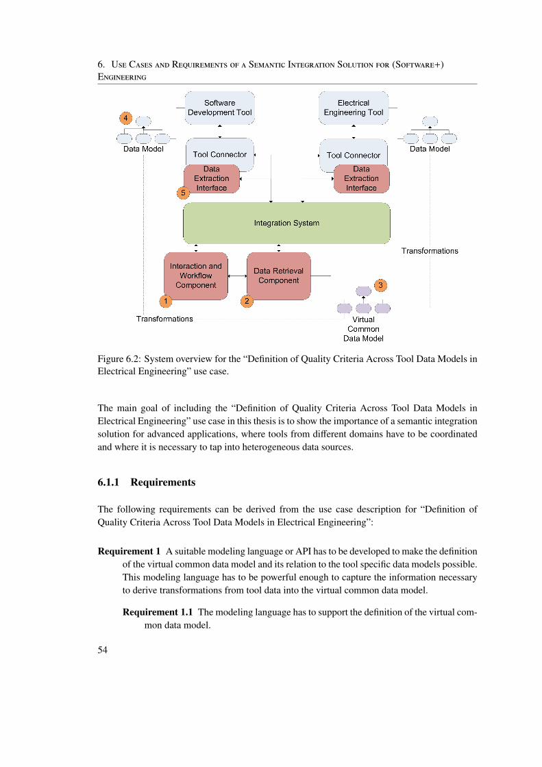
6. Use Cases and Requirements of a Semantic Integration Solution for (Software+)Engineering
Figure 6.2: System overview for the “Definition of Quality Criteria Across Tool Data Models inElectrical Engineering” use case.
The main goal of including the “Definition of Quality Criteria Across Tool Data Models inElectrical Engineering” use case in this thesis is to show the importance of a semantic integrationsolution for advanced applications, where tools from different domains have to be coordinatedand where it is necessary to tap into heterogeneous data sources.
6.1.1 Requirements
The following requirements can be derived from the use case description for “Definition ofQuality Criteria Across Tool Data Models in Electrical Engineering”:
Requirement 1 A suitable modeling language or API has to be developed to make the definitionof the virtual common data model and its relation to the tool specific data models possible.This modeling language has to be powerful enough to capture the information necessaryto derive transformations from tool data into the virtual common data model.
Requirement 1.1 The modeling language has to support the definition of the virtual com-mon data model.
54
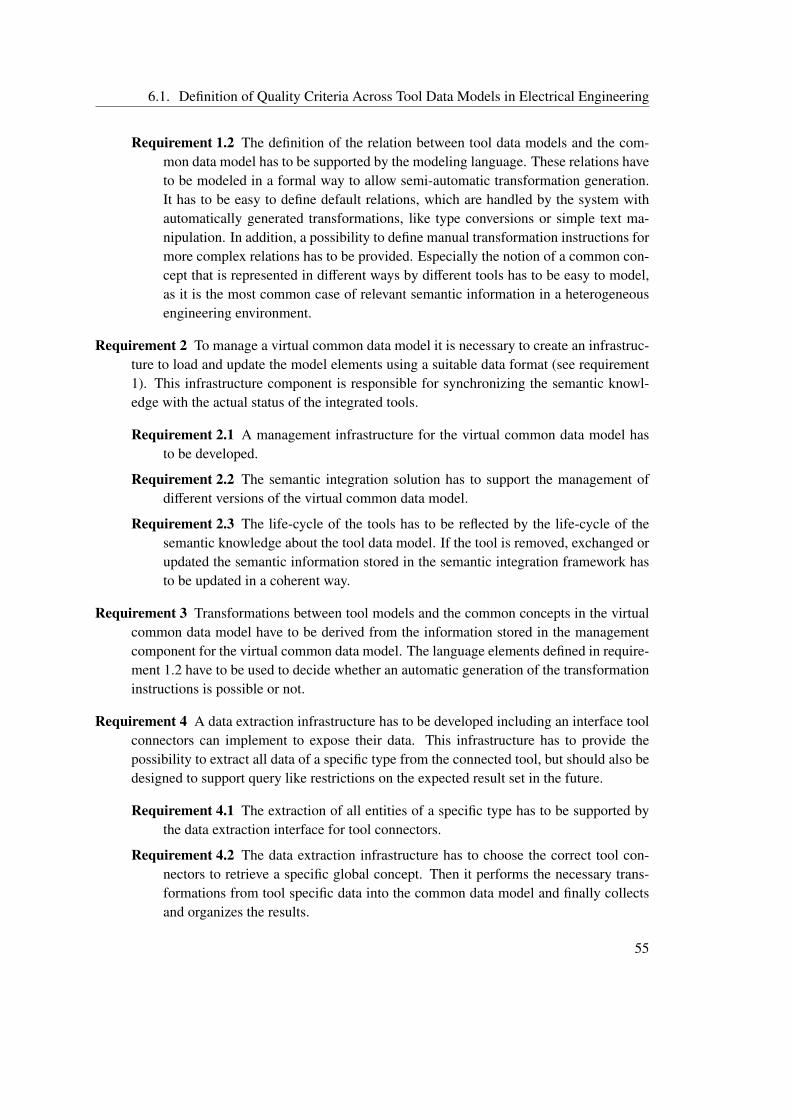
6.1. Definition of Quality Criteria Across Tool Data Models in Electrical Engineering
Requirement 1.2 The definition of the relation between tool data models and the com-mon data model has to be supported by the modeling language. These relations haveto be modeled in a formal way to allow semi-automatic transformation generation.It has to be easy to define default relations, which are handled by the system withautomatically generated transformations, like type conversions or simple text ma-nipulation. In addition, a possibility to define manual transformation instructions formore complex relations has to be provided. Especially the notion of a common con-cept that is represented in different ways by different tools has to be easy to model,as it is the most common case of relevant semantic information in a heterogeneousengineering environment.
Requirement 2 To manage a virtual common data model it is necessary to create an infrastruc-ture to load and update the model elements using a suitable data format (see requirement1). This infrastructure component is responsible for synchronizing the semantic knowl-edge with the actual status of the integrated tools.
Requirement 2.1 A management infrastructure for the virtual common data model hasto be developed.
Requirement 2.2 The semantic integration solution has to support the management ofdifferent versions of the virtual common data model.
Requirement 2.3 The life-cycle of the tools has to be reflected by the life-cycle of thesemantic knowledge about the tool data model. If the tool is removed, exchanged orupdated the semantic information stored in the semantic integration framework hasto be updated in a coherent way.
Requirement 3 Transformations between tool models and the common concepts in the virtualcommon data model have to be derived from the information stored in the managementcomponent for the virtual common data model. The language elements defined in require-ment 1.2 have to be used to decide whether an automatic generation of the transformationinstructions is possible or not.
Requirement 4 A data extraction infrastructure has to be developed including an interface toolconnectors can implement to expose their data. This infrastructure has to provide thepossibility to extract all data of a specific type from the connected tool, but should also bedesigned to support query like restrictions on the expected result set in the future.
Requirement 4.1 The extraction of all entities of a specific type has to be supported bythe data extraction interface for tool connectors.
Requirement 4.2 The data extraction infrastructure has to choose the correct tool con-nectors to retrieve a specific global concept. Then it performs the necessary trans-formations from tool specific data into the common data model and finally collectsand organizes the results.
55
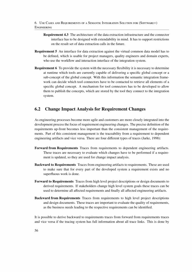
6. Use Cases and Requirements of a Semantic Integration Solution for (Software+)Engineering
Requirement 4.3 The architecture of the data extraction infrastructure and the connectorinterface has to be designed with extendability in mind. It has to support restrictionson the result set of data extraction calls in the future.
Requirement 5 An interface for data extraction against the virtual common data model has tobe defined, which is usable for project managers, quality engineers and domain experts,who use the workflow and interaction interface of the integration system.
Requirement 6 To provide the system with the necessary flexibility it is necessary to determineat runtime which tools are currently capable of delivering a specific global concept or asub-concept of the global concept. With this information the semantic integration frame-work can decide which tool connectors have to be contacted to retrieve all elements of aspecific global concept. A mechanism for tool connectors has to be developed to allowthem to publish the concepts, which are stored by the tool they connect to the integrationsystem.
6.2 Change Impact Analysis for Requirement Changes
As engineering processes become more agile and customers are more closely integrated into thedevelopment process the focus of requirement engineering changes. The precise definition of therequirements up-front becomes less important than the consistent management of the require-ments. Part of this consistent management is the traceability from a requirement to dependentengineering artifacts and vice versa. There are four different types of traces (Jarke, 1998):
Forward from Requirements Traces from requirements to dependent engineering artifacts.These traces are necessary to evaluate which changes have to be performed if a require-ment is updated, so they are used for change impact analysis.
Backward to Requirements Traces from engineering artifacts to requirements. These are usedto make sure that for every part of the developed system a requirement exists and nosuperfluous work is done.
Forward to Requirements Traces from high level project descriptions or design documents toderived requirements. If stakeholders change high level system goals these traces can beused to determine all affected requirements and finally all affected engineering artifacts.
Backward from Requirements Traces from requirements to high level project descriptionsand design documents. These traces are important to evaluate the quality of requirements,as the business needs leading to the respective requirements can be identified.
It is possible to derive backward to requirements traces from forward from requirements tracesand vice versa if the tracing system has full information about all trace links. This is done by
56
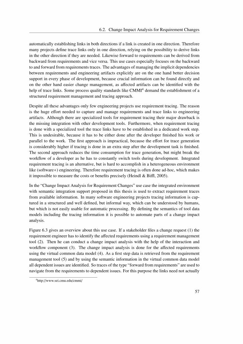
6.2. Change Impact Analysis for Requirement Changes
automatically establishing links in both directions if a link is created in one direction. Thereforemany projects define trace links only in one direction, relying on the possibility to derive linksin the other direction if they are needed. Likewise forward to requirements can be derived frombackward from requirements and vice versa. This use cases especially focuses on the backwardto and forward from requirements traces. The advantages of managing the implicit dependenciesbetween requirements and engineering artifacts explicitly are on the one hand better decisionsupport in every phase of development, because crucial information can be found directly andon the other hand easier change management, as affected artifacts can be identified with thehelp of trace links. Some process quality standards like CMMI4 demand the establishment of astructured requirement management and tracing approach.
Despite all these advantages only few engineering projects use requirement tracing. The reasonis the huge effort needed to capture and manage requirements and trace links to engineeringartifacts. Although there are specialized tools for requirement tracing their major drawback isthe missing integration with other development tools. Furthermore, when requirement tracingis done with a specialized tool the trace links have to be established in a dedicated work step.This is undesirable, because it has to be either done after the developer finished his work orparallel to the work. The first approach is impractical, because the effort for trace generationis considerably higher if tracing is done in an extra step after the development task is finished.The second approach reduces the time consumption for trace generation, but might break theworkflow of a developer as he has to constantly switch tools during development. Integratedrequirement tracing is an alternative, but is hard to accomplish in a heterogeneous environmentlike (software+) engineering. Therefore requirement tracing is often done ad-hoc, which makesit impossible to measure the costs or benefits precisely (Heindl & Biffl, 2005).
In the “Change Impact Analysis for Requirement Changes” use case the integrated environmentwith semantic integration support proposed in this thesis is used to extract requirement tracesfrom available information. In many software engineering projects tracing information is cap-tured in a structured and well defined, but informal way, which can be understood by humans,but which is not easily usable for automatic processing. By defining the semantics of tool datamodels including the tracing information it is possible to automate parts of a change impactanalysis.
Figure 6.3 gives an overview about this use case. If a stakeholder files a change request (1) therequirement engineer has to identify the affected requirements using a requirement managementtool (2). Then he can conduct a change impact analysis with the help of the interaction andworkflow component (3). The change impact analysis is done for the affected requirementsusing the virtual common data model (4). As a first step data is retrieved from the requirementmanagement tool (5) and by using the semantic information in the virtual common data modelall dependent issues are identified. So traces of the type “forward from requirements” are used tonavigate from the requirements to dependent issues. For this purpose the links need not actually
4http://www.sei.cmu.edu/cmmi/
57
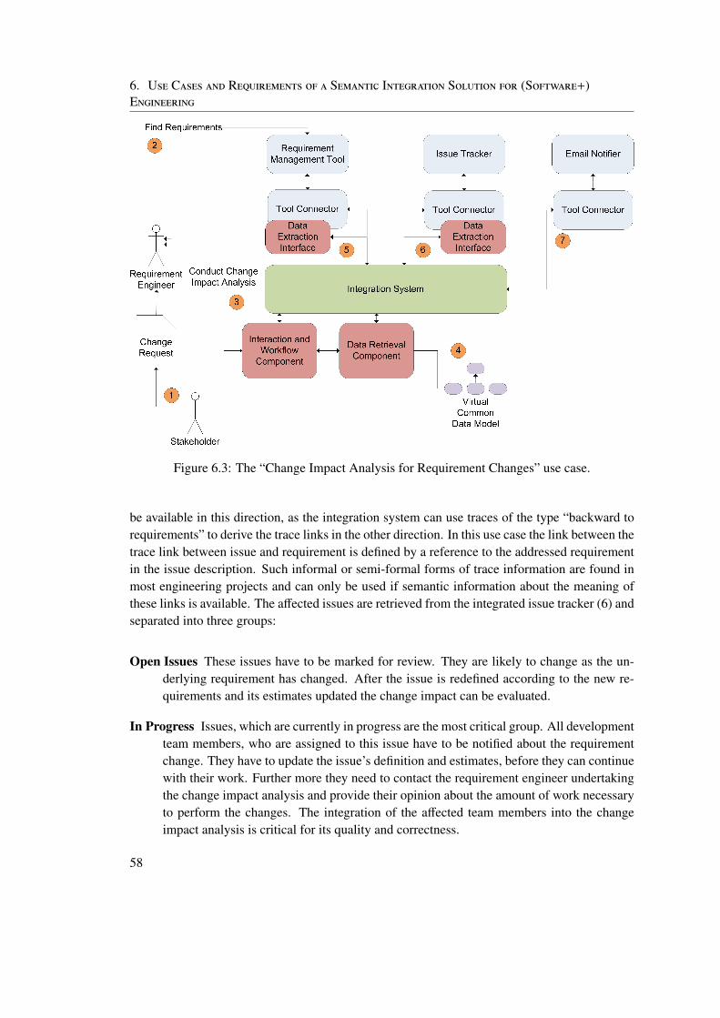
6. Use Cases and Requirements of a Semantic Integration Solution for (Software+)Engineering
Figure 6.3: The “Change Impact Analysis for Requirement Changes” use case.
be available in this direction, as the integration system can use traces of the type “backward torequirements” to derive the trace links in the other direction. In this use case the link between thetrace link between issue and requirement is defined by a reference to the addressed requirementin the issue description. Such informal or semi-formal forms of trace information are found inmost engineering projects and can only be used if semantic information about the meaning ofthese links is available. The affected issues are retrieved from the integrated issue tracker (6) andseparated into three groups:
Open Issues These issues have to be marked for review. They are likely to change as the un-derlying requirement has changed. After the issue is redefined according to the new re-quirements and its estimates updated the change impact can be evaluated.
In Progress Issues, which are currently in progress are the most critical group. All developmentteam members, who are assigned to this issue have to be notified about the requirementchange. They have to update the issue’s definition and estimates, before they can continuewith their work. Further more they need to contact the requirement engineer undertakingthe change impact analysis and provide their opinion about the amount of work necessaryto perform the changes. The integration of the affected team members into the changeimpact analysis is critical for its quality and correctness.
58
6.2. Change Impact Analysis for Requirement Changes
Resolved and Closed All issues, which are already finished have to be reopened and marked forreview, as the underlying requirement has changed. The developers, which are assignedto these issues are notified that an already finished piece of work has to be reevaluated.Furthermore, they have to provide their estimates for the amount of work necessary toperform the requested changes.
To notify the affected team members again semantic information has to be used. The issues con-tain information about the assignee, which has to be extracted and mapped to a member of thedevelopment team. Then another mapping between the developer and its contact informationhas to be used to determine the recipient of the notification. An integrated notification com-ponent, like an email connector (7) sends the notifications. Finally the requirement engineer,which started the change impact analysis process is presented with a report containing all the in-formation, which could be gathered automatically and a list of all persons, who have to providemanual feedback.
This semi-automatic form of change impact analysis for requirement changes provides a highquality result without the need to manually search and evaluate the trace links between require-ments, issues and developers. Furthermore, it provides the possibility to inform all affected teammembers during the process and to automatically perform necessary project management stepsin the issue tracker, like reopening already finished issues.
The goal of introducing the “Change Impact Analysis for Requirement Changes” use case intothis thesis is to show that the proposed EKB based semantic integration solution for (software+)engineering can be facilitated to perform a difficult and complex software engineering task,like requirement tracing. Furthermore, it should show how the semantic integration frameworksupports the development and project management process by automating tedious manual tasks.Advanced applications like change impact analysis can be built based upon the semantic integra-tion framework, which help to generate better estimates. This use case is designed to underlinethe importance of efficient cooperation between different team members to perform complextasks, like the reevaluation of parts of the system after a requirement change and the crucial roleof effective tool support during this process.
6.2.1 Requirements
The following additional requirements for a semantic integration framework in the (software+)engineering domain can be derived from this use case.
Requirement 7 The definition of informal semantic meta information has to be supported bythe modeling language used for the virtual common data model (see requirement 1). Suchmeta information includes for example the trace links from requirements to issues in thisuse case. The semantic integration framework has to provide the infrastructure to manageand to de-reference these links.
59
6. Use Cases and Requirements of a Semantic Integration Solution for (Software+)Engineering
Requirement 7.1 The modeling language has to support the definition of traces by se-mantic meta information in a simple format, which is both understandable by hu-mans and automatically processable.
Requirement 7.2 The semantic integration framework has to support the managementand usage of semantic meta information for traces between different engineeringartifacts. More specifically this means that it has to support the de-referencing ofthe trace links and the localization and retrieval of dependent artifacts. This has tobe done using a key or an identifier included in the trace link. The data extractioninterface for tool connectors (see requirement 4) has to support the retrieval of asingle element of a specific type by key or identifier for this purpose.
Requirement 7.3 The data extraction interface (see requirement 5) has to be extendedto allow project managers, quality engineers and domain experts to use the tracinginformation for advanced applications, like change impact analysis.
6.3 Additional Requirements
Based on the theoretical foundations in sections 2, 3 and 4 and on the research issues in section5.1 the following additional requirements for a semantic integration solution for the (software+)engineering domain can be defined. In this section the focus is more on the non-functionalrequirements for a semantic integration solution. Functional requirements have already beenderived from the two use cases described in this thesis in sections 6.1 and 6.2.
Requirement 8 The semantic integration framework has to be efficient with respect to theamount of work necessary to model semantic information. The benefits of semantic inte-gration like better support for advanced quality or project management applications has tosignificantly exceed its costs.
Requirement 9 Robustness is critical for the acceptance of the integration solution by practi-tioners. The semantic integration solution has to be robust with respect to failure manage-ment and stability. More specifically errors in the semantic integration framework shouldnot bring the whole integration system down. In addition the system has to remain in awell defined state at any point in time. This is addressed by the synchronization of the toollife-cycle with the tool knowledge life-cycle (see requirement 2).
Requirement 10 The main concern of this requirement is the usability of the integration so-lution. The integration infrastructure has to provide usable interfaces for data retrievaland management of the virtual common data model. Furthermore the interfaces, whichhave to be implemented by tool connectors to facilitate the semantic integration solutionhave to be easy to understand and well documented. The framework should reduce theeffort needed to write tool connectors as far as possible, as this is a repetitive task done bydomain experts with little or no knowledge about semantic integration.
60
7 An EKB based Semantic IntegrationFramework - Concept andArchitecture
In this section the architecture of the proposed semantic integration framework for (software+)engineering is described. At first section 7.1 gives an overview about the design and explainshow the EKB concept is used to implement a semantic integration framework. In section 7.2the architecture and design of the core components of the proposed solution are explained andevaluated with respect to the requirements stated in section 6 and research issues defined insection 5.1. Finally the integration into a technical integration framework is discussed using theexample of the prototype implementation for the Open Engineering Service Bus (see section7.3).
7.1 Concept and Architecture
Based on the theoretical foundations of semantic integration (see section 3) and especially theEngineering Knowledge Base approach, which is explained in detail in section 3.3, a semanticintegration framework for (software+) engineering is designed and implemented. This frame-work has to realize the three main features of an EKB (Moser, 2010):
1. data integration using mappings between different engineering concepts
2. transformations between different engineering concepts utilizing these mappings
3. advanced applications building upon these foundations
Figure 7.1 shows the externally visible parts of the EKB based semantic integration framework.The EKB component is part of the OpenEngSB and provides three different public interfaces fortree different usage scenarios:
61
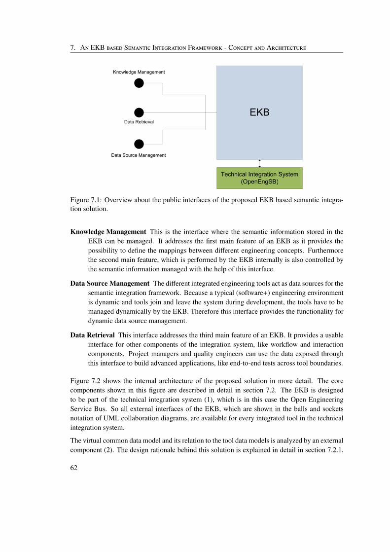
7. An EKB based Semantic Integration Framework - Concept and Architecture
Figure 7.1: Overview about the public interfaces of the proposed EKB based semantic integra-tion solution.
Knowledge Management This is the interface where the semantic information stored in theEKB can be managed. It addresses the first main feature of an EKB as it provides thepossibility to define the mappings between different engineering concepts. Furthermorethe second main feature, which is performed by the EKB internally is also controlled bythe semantic information managed with the help of this interface.
Data Source Management The different integrated engineering tools act as data sources for thesemantic integration framework. Because a typical (software+) engineering environmentis dynamic and tools join and leave the system during development, the tools have to bemanaged dynamically by the EKB. Therefore this interface provides the functionality fordynamic data source management.
Data Retrieval This interface addresses the third main feature of an EKB. It provides a usableinterface for other components of the integration system, like workflow and interactioncomponents. Project managers and quality engineers can use the data exposed throughthis interface to build advanced applications, like end-to-end tests across tool boundaries.
Figure 7.2 shows the internal architecture of the proposed solution in more detail. The corecomponents shown in this figure are described in detail in section 7.2. The EKB is designedto be part of the technical integration system (1), which is in this case the Open EngineeringService Bus. So all external interfaces of the EKB, which are shown in the balls and socketsnotation of UML collaboration diagrams, are available for every integrated tool in the technicalintegration system.
The virtual common data model and its relation to the tool data models is analyzed by an externalcomponent (2). The design rationale behind this solution is explained in detail in section 7.2.1.
62
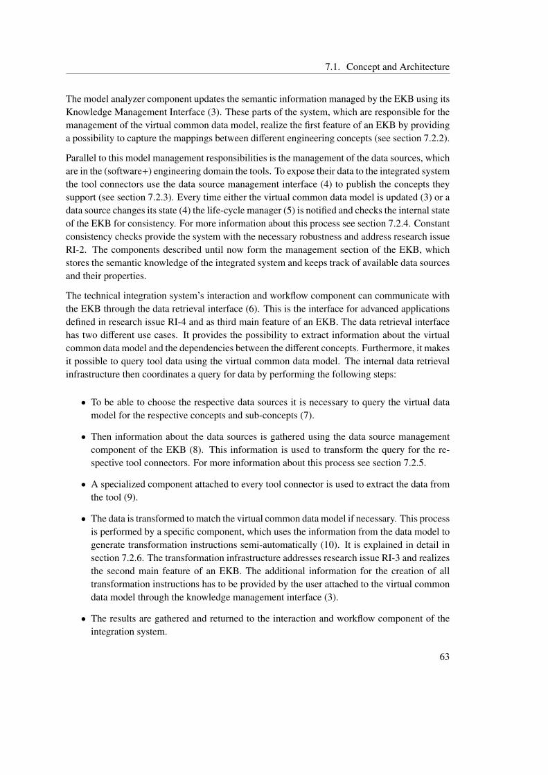
7.1. Concept and Architecture
The model analyzer component updates the semantic information managed by the EKB using itsKnowledge Management Interface (3). These parts of the system, which are responsible for themanagement of the virtual common data model, realize the first feature of an EKB by providinga possibility to capture the mappings between different engineering concepts (see section 7.2.2).
Parallel to this model management responsibilities is the management of the data sources, whichare in the (software+) engineering domain the tools. To expose their data to the integrated systemthe tool connectors use the data source management interface (4) to publish the concepts theysupport (see section 7.2.3). Every time either the virtual common data model is updated (3) or adata source changes its state (4) the life-cycle manager (5) is notified and checks the internal stateof the EKB for consistency. For more information about this process see section 7.2.4. Constantconsistency checks provide the system with the necessary robustness and address research issueRI-2. The components described until now form the management section of the EKB, whichstores the semantic knowledge of the integrated system and keeps track of available data sourcesand their properties.
The technical integration system’s interaction and workflow component can communicate withthe EKB through the data retrieval interface (6). This is the interface for advanced applicationsdefined in research issue RI-4 and as third main feature of an EKB. The data retrieval interfacehas two different use cases. It provides the possibility to extract information about the virtualcommon data model and the dependencies between the different concepts. Furthermore, it makesit possible to query tool data using the virtual common data model. The internal data retrievalinfrastructure then coordinates a query for data by performing the following steps:
• To be able to choose the respective data sources it is necessary to query the virtual datamodel for the respective concepts and sub-concepts (7).
• Then information about the data sources is gathered using the data source managementcomponent of the EKB (8). This information is used to transform the query for the re-spective tool connectors. For more information about this process see section 7.2.5.
• A specialized component attached to every tool connector is used to extract the data fromthe tool (9).
• The data is transformed to match the virtual common data model if necessary. This processis performed by a specific component, which uses the information from the data model togenerate transformation instructions semi-automatically (10). It is explained in detail insection 7.2.6. The transformation infrastructure addresses research issue RI-3 and realizesthe second main feature of an EKB. The additional information for the creation of alltransformation instructions has to be provided by the user attached to the virtual commondata model through the knowledge management interface (3).
• The results are gathered and returned to the interaction and workflow component of theintegration system.
63
7. An EKB based Semantic Integration Framework - Concept and Architecture
Figure 7.2: Architecture of the proposed EKB based semantic integration solution.
64
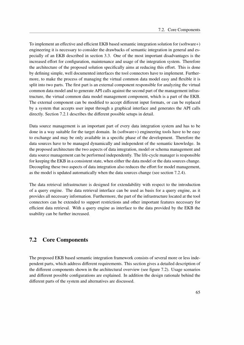
7.2. Core Components
To implement an effective and efficient EKB based semantic integration solution for (software+)engineering it is necessary to consider the drawbacks of semantic integration in general and es-pecially of an EKB described in section 3.3. One of the most important disadvantages is theincreased effort for configuration, maintenance and usage of the integration system. Thereforethe architecture of the proposed solution specifically aims at reducing this effort. This is doneby defining simple, well documented interfaces the tool connectors have to implement. Further-more, to make the process of managing the virtual common data model easy and flexible it issplit into two parts. The first part is an external component responsible for analyzing the virtualcommon data model and to generate API calls against the second part of the management infras-tructure, the virtual common data model management component, which is a part of the EKB.The external component can be modified to accept different input formats, or can be replacedby a system that accepts user input through a graphical interface and generates the API callsdirectly. Section 7.2.1 describes the different possible setups in detail.
Data source management is an important part of every data integration system and has to bedone in a way suitable for the target domain. In (software+) engineering tools have to be easyto exchange and may be only available in a specific phase of the development. Therefore thedata sources have to be managed dynamically and independent of the semantic knowledge. Inthe proposed architecture the two aspects of data integration, model or schema management anddata source management can be performed independently. The life-cycle manager is responsiblefor keeping the EKB in a consistent state, when either the data model or the data sources change.Decoupling these two aspects of data integration also reduces the effort for model management,as the model is updated automatically when the data sources change (see section 7.2.4).
The data retrieval infrastructure is designed for extendability with respect to the introductionof a query engine. The data retrieval interface can be used as basis for a query engine, as itprovides all necessary information. Furthermore, the part of the infrastructure located at the toolconnectors can be extended to support restrictions and other important features necessary forefficient data retrieval. With a query engine as interface to the data provided by the EKB theusability can be further increased.
7.2 Core Components
The proposed EKB based semantic integration framework consists of several more or less inde-pendent parts, which address different requirements. This section gives a detailed description ofthe different components shown in the architectural overview (see figure 7.2). Usage scenariosand different possible configurations are explained. In addition the design rationale behind thedifferent parts of the system and alternatives are discussed.
65
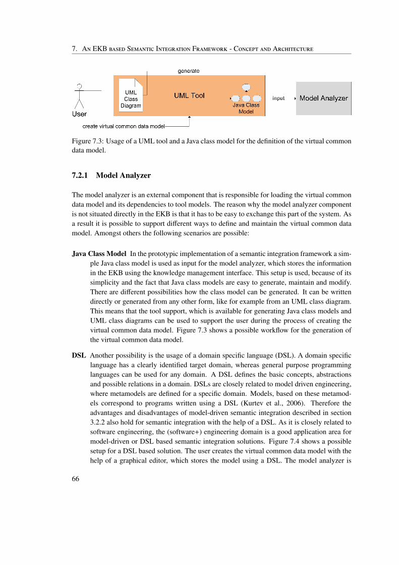
7. An EKB based Semantic Integration Framework - Concept and Architecture
Figure 7.3: Usage of a UML tool and a Java class model for the definition of the virtual commondata model.
7.2.1 Model Analyzer
The model analyzer is an external component that is responsible for loading the virtual commondata model and its dependencies to tool models. The reason why the model analyzer componentis not situated directly in the EKB is that it has to be easy to exchange this part of the system. Asa result it is possible to support different ways to define and maintain the virtual common datamodel. Amongst others the following scenarios are possible:
Java Class Model In the prototypic implementation of a semantic integration framework a sim-ple Java class model is used as input for the model analyzer, which stores the informationin the EKB using the knowledge management interface. This setup is used, because of itssimplicity and the fact that Java class models are easy to generate, maintain and modify.There are different possibilities how the class model can be generated. It can be writtendirectly or generated from any other form, like for example from an UML class diagram.This means that the tool support, which is available for generating Java class models andUML class diagrams can be used to support the user during the process of creating thevirtual common data model. Figure 7.3 shows a possible workflow for the generation ofthe virtual common data model.
DSL Another possibility is the usage of a domain specific language (DSL). A domain specificlanguage has a clearly identified target domain, whereas general purpose programminglanguages can be used for any domain. A DSL defines the basic concepts, abstractionsand possible relations in a domain. DSLs are closely related to model driven engineering,where metamodels are defined for a specific domain. Models, based on these metamod-els correspond to programs written using a DSL (Kurtev et al., 2006). Therefore theadvantages and disadvantages of model-driven semantic integration described in section3.2.2 also hold for semantic integration with the help of a DSL. As it is closely related tosoftware engineering, the (software+) engineering domain is a good application area formodel-driven or DSL based semantic integration solutions. Figure 7.4 shows a possiblesetup for a DSL based solution. The user creates the virtual common data model with thehelp of a graphical editor, which stores the model using a DSL. The model analyzer is
66
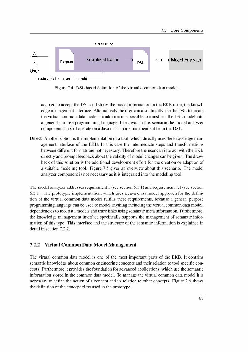
7.2. Core Components
Figure 7.4: DSL based definition of the virtual common data model.
adapted to accept the DSL and stores the model information in the EKB using the knowl-edge management interface. Alternatively the user can also directly use the DSL to createthe virtual common data model. In addition it is possible to transform the DSL model intoa general purpose programming language, like Java. In this scenario the model analyzercomponent can still operate on a Java class model independent from the DSL.
Direct Another option is the implementation of a tool, which directly uses the knowledge man-agement interface of the EKB. In this case the intermediate steps and transformationsbetween different formats are not necessary. Therefore the user can interact with the EKBdirectly and prompt feedback about the validity of model changes can be given. The draw-back of this solution is the additional development effort for the creation or adaption ofa suitable modeling tool. Figure 7.5 gives an overview about this scenario. The modelanalyzer component is not necessary as it is integrated into the modeling tool.
The model analyzer addresses requirement 1 (see section 6.1.1) and requirement 7.1 (see section6.2.1). The prototypic implementation, which uses a Java class model approach for the defini-tion of the virtual common data model fulfills these requirements, because a general purposeprogramming language can be used to model anything including the virtual common data model,dependencies to tool data models and trace links using semantic meta information. Furthermore,the knowledge management interface specifically supports the management of semantic infor-mation of this type. This interface and the structure of the semantic information is explained indetail in section 7.2.2.
7.2.2 Virtual Common Data Model Management
The virtual common data model is one of the most important parts of the EKB. It containssemantic knowledge about common engineering concepts and their relation to tool specific con-cepts. Furthermore it provides the foundation for advanced applications, which use the semanticinformation stored in the common data model. To manage the virtual common data model it isnecessary to define the notion of a concept and its relation to other concepts. Figure 7.6 showsthe definition of the concept class used in the prototype.
67
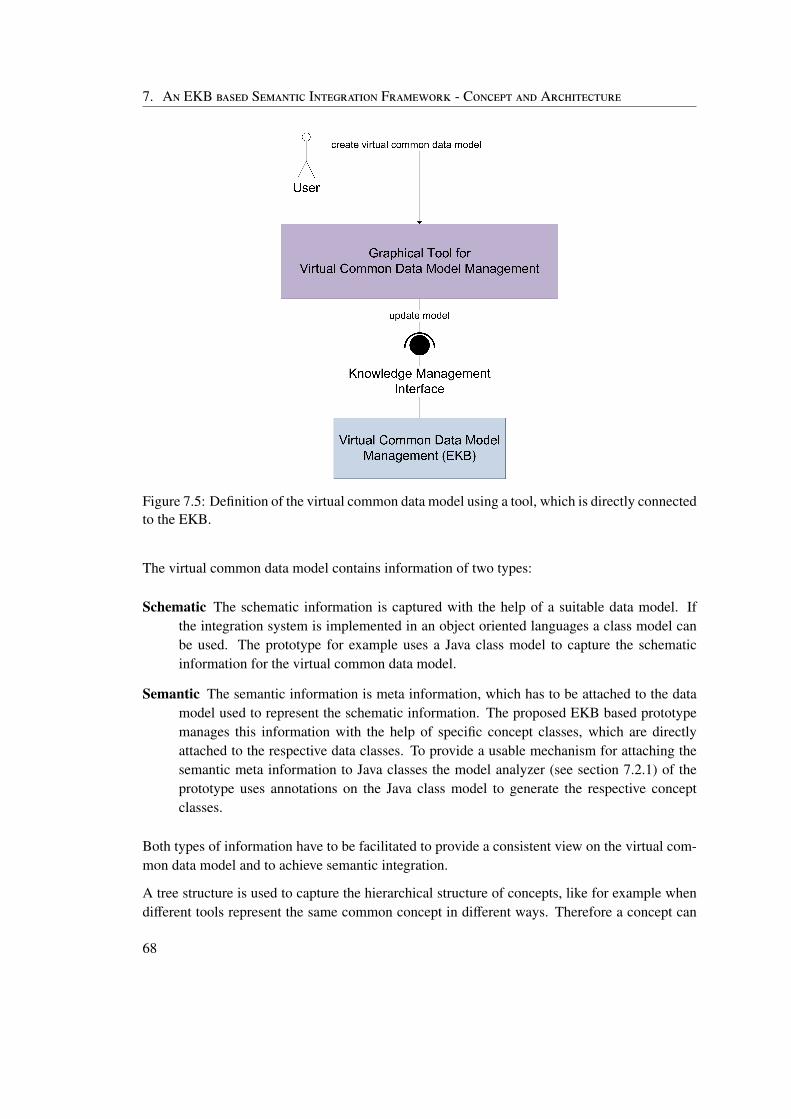
7. An EKB based Semantic Integration Framework - Concept and Architecture
Figure 7.5: Definition of the virtual common data model using a tool, which is directly connectedto the EKB.
The virtual common data model contains information of two types:
Schematic The schematic information is captured with the help of a suitable data model. Ifthe integration system is implemented in an object oriented languages a class model canbe used. The prototype for example uses a Java class model to capture the schematicinformation for the virtual common data model.
Semantic The semantic information is meta information, which has to be attached to the datamodel used to represent the schematic information. The proposed EKB based prototypemanages this information with the help of specific concept classes, which are directlyattached to the respective data classes. To provide a usable mechanism for attaching thesemantic meta information to Java classes the model analyzer (see section 7.2.1) of theprototype uses annotations on the Java class model to generate the respective conceptclasses.
Both types of information have to be facilitated to provide a consistent view on the virtual com-mon data model and to achieve semantic integration.
A tree structure is used to capture the hierarchical structure of concepts, like for example whendifferent tools represent the same common concept in different ways. Therefore a concept can
68
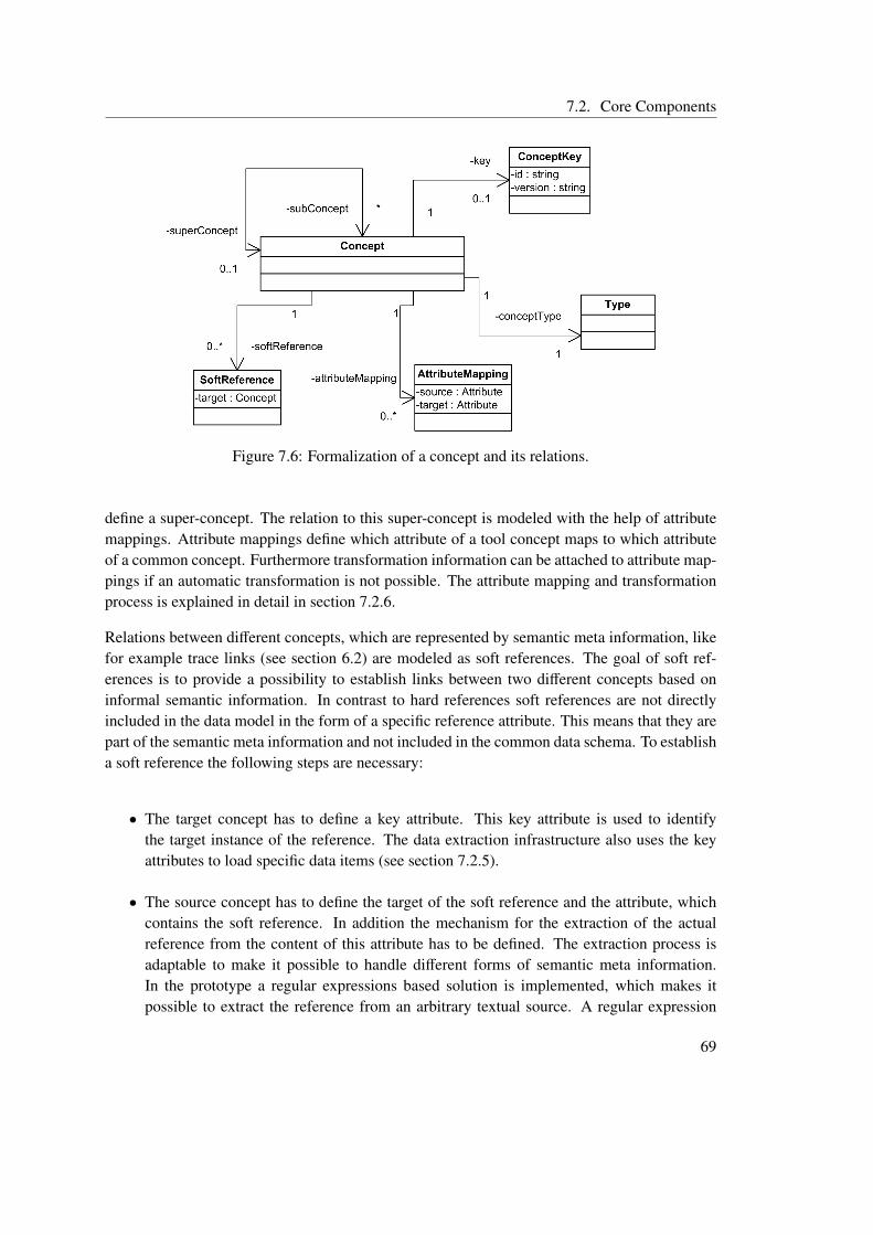
7.2. Core Components
Figure 7.6: Formalization of a concept and its relations.
define a super-concept. The relation to this super-concept is modeled with the help of attributemappings. Attribute mappings define which attribute of a tool concept maps to which attributeof a common concept. Furthermore transformation information can be attached to attribute map-pings if an automatic transformation is not possible. The attribute mapping and transformationprocess is explained in detail in section 7.2.6.
Relations between different concepts, which are represented by semantic meta information, likefor example trace links (see section 6.2) are modeled as soft references. The goal of soft ref-erences is to provide a possibility to establish links between two different concepts based oninformal semantic information. In contrast to hard references soft references are not directlyincluded in the data model in the form of a specific reference attribute. This means that they arepart of the semantic meta information and not included in the common data schema. To establisha soft reference the following steps are necessary:
• The target concept has to define a key attribute. This key attribute is used to identifythe target instance of the reference. The data extraction infrastructure also uses the keyattributes to load specific data items (see section 7.2.5).
• The source concept has to define the target of the soft reference and the attribute, whichcontains the soft reference. In addition the mechanism for the extraction of the actualreference from the content of this attribute has to be defined. The extraction process isadaptable to make it possible to handle different forms of semantic meta information.In the prototype a regular expressions based solution is implemented, which makes itpossible to extract the reference from an arbitrary textual source. A regular expression
69
7. An EKB based Semantic Integration Framework - Concept and Architecture
based soft reference definition contains the target concept and the regular expression forthe key extraction.
• To establish a concrete reference the content of the respective attribute of the source con-cept has to include the reference, which has to be extractable using the mechanism ex-plained in the previous step.
Figure 7.7 gives an overview about the different steps necessary for the definition of a softreference between an issue and a requirement. First the requirement concept has to define anidentifier (1) and the requirement type, which is the attached data type of the requirement concepthas to define a key attribute (2). In this example the requirement number attribute is used as key.Then the soft reference between the issue concept and the requirement concept can be defined.In the example shown in figure 7.7 this is done with the help of a regular expression based softreference. Besides the identifier for the target concept (3), also the regular expression for theextraction of the reference key has to be defined (4). Note that when only the identifier of thetarget concept is defined and the version is omitted then the version of the source concept is alsoused for the target concept. If an issue has a description which contains a reference (5) then thesemantic integration infrastructure can de-reference this link and load the respective requirement(6).
In this example the linking process is relatively simple, but it can become very complex anddifficult to define and manage trace links. Different default soft reference solutions for commontypes of links defined by semantic meta data have to be defined in the future and integrated intothe proposed solution to make it possible for the user to define the relationship between differentengineering concepts.
The virtual common data model management component has to be able to deal with differentversions of semantic tool information. Therefore, to be able to distinguish different versions ofthe same concept a binary concept key is used for the identification of concepts. The first part ofthe key is a textual identifier, while the second part contains version information.
This core component of the proposed EKB based semantic integration solution realizes require-ment 2.1 by providing a management infrastructure for the virtual common data model. Theformalization of a concept and its definition is derived from requirements 1.1 and 1.2. Theversion information in the concept key is introduced to resolve requirement 2.2 (see section6.1.1). Soft references address requirement 7.2 (see section 6.2.1) by providing a possibility touse semantic meta information to create references between two different concepts. In additionrequirement 2.3 is linked to virtual common data model management, as changes of the modeltrigger consistency checks by the life-cycle manager, which is described in detail in section7.2.4.
70
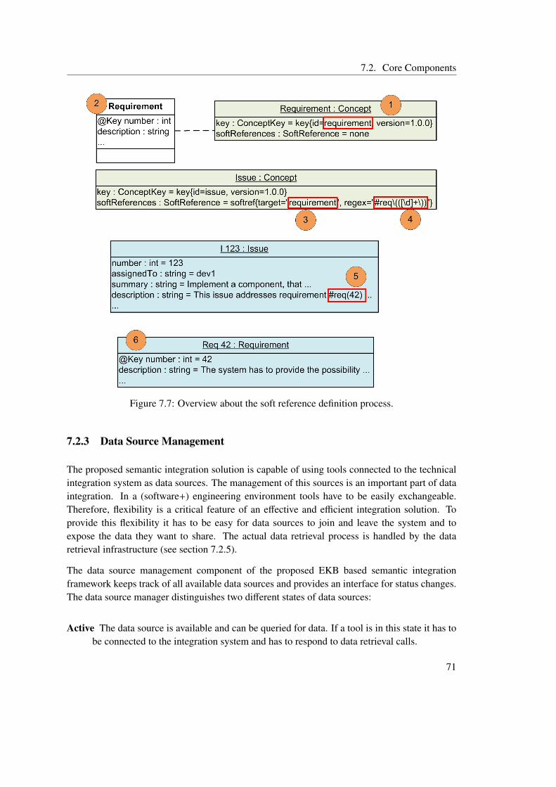
7.2. Core Components
Figure 7.7: Overview about the soft reference definition process.
7.2.3 Data Source Management
The proposed semantic integration solution is capable of using tools connected to the technicalintegration system as data sources. The management of this sources is an important part of dataintegration. In a (software+) engineering environment tools have to be easily exchangeable.Therefore, flexibility is a critical feature of an effective and efficient integration solution. Toprovide this flexibility it has to be easy for data sources to join and leave the system and toexpose the data they want to share. The actual data retrieval process is handled by the dataretrieval infrastructure (see section 7.2.5).
The data source management component of the proposed EKB based semantic integrationframework keeps track of all available data sources and provides an interface for status changes.The data source manager distinguishes two different states of data sources:
Active The data source is available and can be queried for data. If a tool is in this state it has tobe connected to the integration system and has to respond to data retrieval calls.
71
7. An EKB based Semantic Integration Framework - Concept and Architecture
Inactive The data source is either temporarily or permanently not available. To reduce thecomplexity of the system no distinction between these two possibilities is made. Thesystem can be extended to distinguish between permanently and temporarily unavailablesources and can allow temporarily unavailable sources to be queried, waiting for the toolto become active again and respond to the data retrieval call. The advantage of such adistinction is that tools, which are not available all of the time, like external tools or sharedresources can be supported more easily. One major drawback of temporary unavailabledata source support is that the response time can vary and is hard to predict. This can leadto unexpected behavior of workflows and other advanced applications using these datasources.
Tools, which are offline but provide their data by opening their private data storage are treatedas active by the system, as their data can be retrieved. The actual retrieval process is handled bythe data retrieval stub of the tool connector. As it is concerned with data integration the semanticintegration framework does not need to distinguish between tools that only provide their data oralso their functionality through an active connection to the integration system.
When data sources become active they have to publish the concepts they can provide. Versioninformation is included during this publishing process to make it possible for sources to de-termine which versions of a concept they support. There are two different possibilities how asource can provide a specific concept:
Direct The concept is directly supported by the data source. This means the the model typeattached to this specific concept is used by the tool and can be retrieved using the dataretrieval interface of the tool connector. No conversion of the result is necessary.
Sub-concept A sub-concept of the concept is supported. In this case the concept is supportedby transforming the data of the type attached to the sub-concept to the type attached tothe concept. This can include more then one transformation, as transitive transformationis possible, when for example a sub-sub-concept is supported by the tool. The mappinginformation stored in the virtual common data model is used to generate the transformationinstructions, which are carried out by the transformation infrastructure (see section 7.2.6).
For advanced applications there is no difference between these two different types, as the dataretrieval and transformation process is completely hidden by the semantic integration infrastruc-ture.
Tools, which act as data sources in the (software+) engineering domain are integrated into atechnical integration system. Therefore it is possible to define and enforce a common interfacefor all sources. This interface has to be implemented by the tool connectors and hides the het-erogeneity of the data sources. Hence data management and retrieval can focus on the semanticdifferences between the data of the respective sources without having to deal with technicalintegration issues.
72
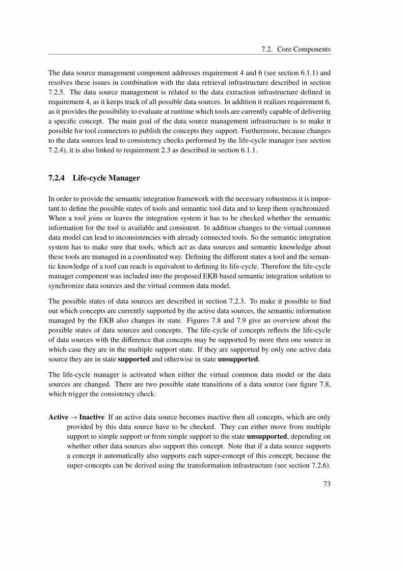
7.2. Core Components
The data source management component addresses requirement 4 and 6 (see section 6.1.1) andresolves these issues in combination with the data retrieval infrastructure described in section7.2.5. The data source management is related to the data extraction infrastructure defined inrequirement 4, as it keeps track of all possible data sources. In addition it realizes requirement 6,as it provides the possibility to evaluate at runtime which tools are currently capable of deliveringa specific concept. The main goal of the data source management infrastructure is to make itpossible for tool connectors to publish the concepts they support. Furthermore, because changesto the data sources lead to consistency checks performed by the life-cycle manager (see section7.2.4), it is also linked to requirement 2.3 as described in section 6.1.1.
7.2.4 Life-cycle Manager
In order to provide the semantic integration framework with the necessary robustness it is impor-tant to define the possible states of tools and semantic tool data and to keep them synchronized.When a tool joins or leaves the integration system it has to be checked whether the semanticinformation for the tool is available and consistent. In addition changes to the virtual commondata model can lead to inconsistencies with already connected tools. So the semantic integrationsystem has to make sure that tools, which act as data sources and semantic knowledge aboutthese tools are managed in a coordinated way. Defining the different states a tool and the seman-tic knowledge of a tool can reach is equivalent to defining its life-cycle. Therefore the life-cyclemanager component was included into the proposed EKB based semantic integration solution tosynchronize data sources and the virtual common data model.
The possible states of data sources are described in section 7.2.3. To make it possible to findout which concepts are currently supported by the active data sources, the semantic informationmanaged by the EKB also changes its state. Figures 7.8 and 7.9 give an overview about thepossible states of data sources and concepts. The life-cycle of concepts reflects the life-cycleof data sources with the difference that concepts may be supported by more then one source inwhich case they are in the multiple support state. If they are supported by only one active datasource they are in state supported and otherwise in state unsupported.
The life-cycle manager is activated when either the virtual common data model or the datasources are changed. There are two possible state transitions of a data source (see figure 7.8,which trigger the consistency check:
Active→ Inactive If an active data source becomes inactive then all concepts, which are onlyprovided by this data source have to be checked. They can either move from multiplesupport to simple support or from simple support to the state unsupported, depending onwhether other data sources also support this concept. Note that if a data source supportsa concept it automatically also supports each super-concept of this concept, because thesuper-concepts can be derived using the transformation infrastructure (see section 7.2.6).
73
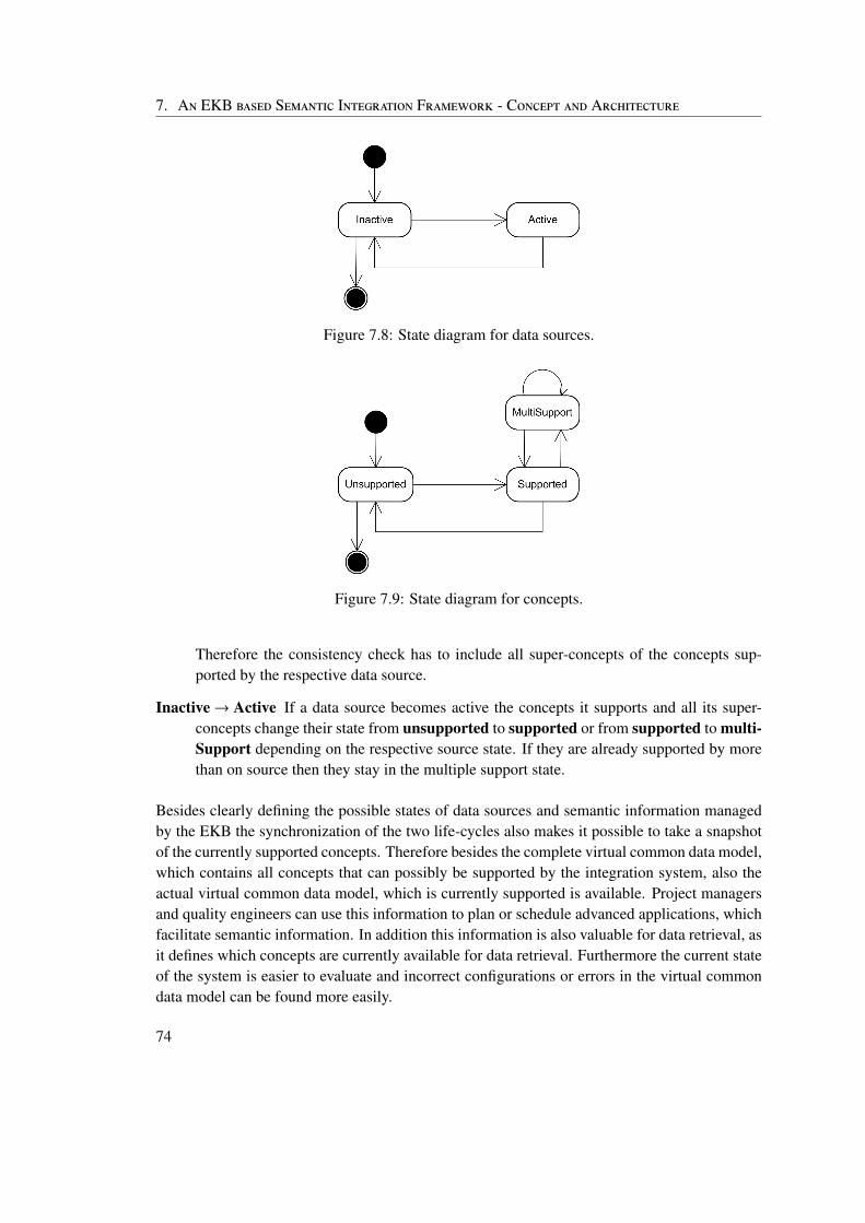
7. An EKB based Semantic Integration Framework - Concept and Architecture
Figure 7.8: State diagram for data sources.
Figure 7.9: State diagram for concepts.
Therefore the consistency check has to include all super-concepts of the concepts sup-ported by the respective data source.
Inactive→ Active If a data source becomes active the concepts it supports and all its super-concepts change their state from unsupported to supported or from supported to multi-Support depending on the respective source state. If they are already supported by morethan on source then they stay in the multiple support state.
Besides clearly defining the possible states of data sources and semantic information managedby the EKB the synchronization of the two life-cycles also makes it possible to take a snapshotof the currently supported concepts. Therefore besides the complete virtual common data model,which contains all concepts that can possibly be supported by the integration system, also theactual virtual common data model, which is currently supported is available. Project managersand quality engineers can use this information to plan or schedule advanced applications, whichfacilitate semantic information. In addition this information is also valuable for data retrieval, asit defines which concepts are currently available for data retrieval. Furthermore the current stateof the system is easier to evaluate and incorrect configurations or errors in the virtual commondata model can be found more easily.
74
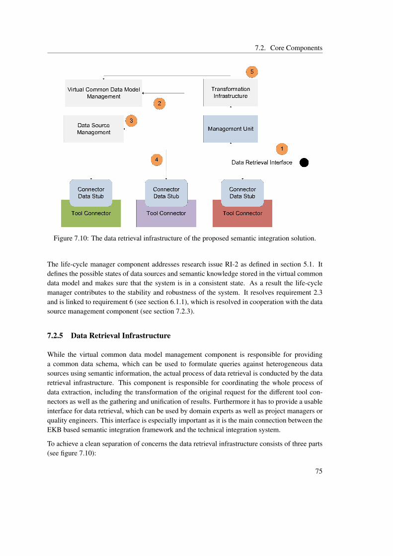
7.2. Core Components
Figure 7.10: The data retrieval infrastructure of the proposed semantic integration solution.
The life-cycle manager component addresses research issue RI-2 as defined in section 5.1. Itdefines the possible states of data sources and semantic knowledge stored in the virtual commondata model and makes sure that the system is in a consistent state. As a result the life-cyclemanager contributes to the stability and robustness of the system. It resolves requirement 2.3and is linked to requirement 6 (see section 6.1.1), which is resolved in cooperation with the datasource management component (see section 7.2.3).
7.2.5 Data Retrieval Infrastructure
While the virtual common data model management component is responsible for providinga common data schema, which can be used to formulate queries against heterogeneous datasources using semantic information, the actual process of data retrieval is conducted by the dataretrieval infrastructure. This component is responsible for coordinating the whole process ofdata extraction, including the transformation of the original request for the different tool con-nectors as well as the gathering and unification of results. Furthermore it has to provide a usableinterface for data retrieval, which can be used by domain experts as well as project managers orquality engineers. This interface is especially important as it is the main connection between theEKB based semantic integration framework and the technical integration system.
To achieve a clean separation of concerns the data retrieval infrastructure consists of three parts(see figure 7.10):
75
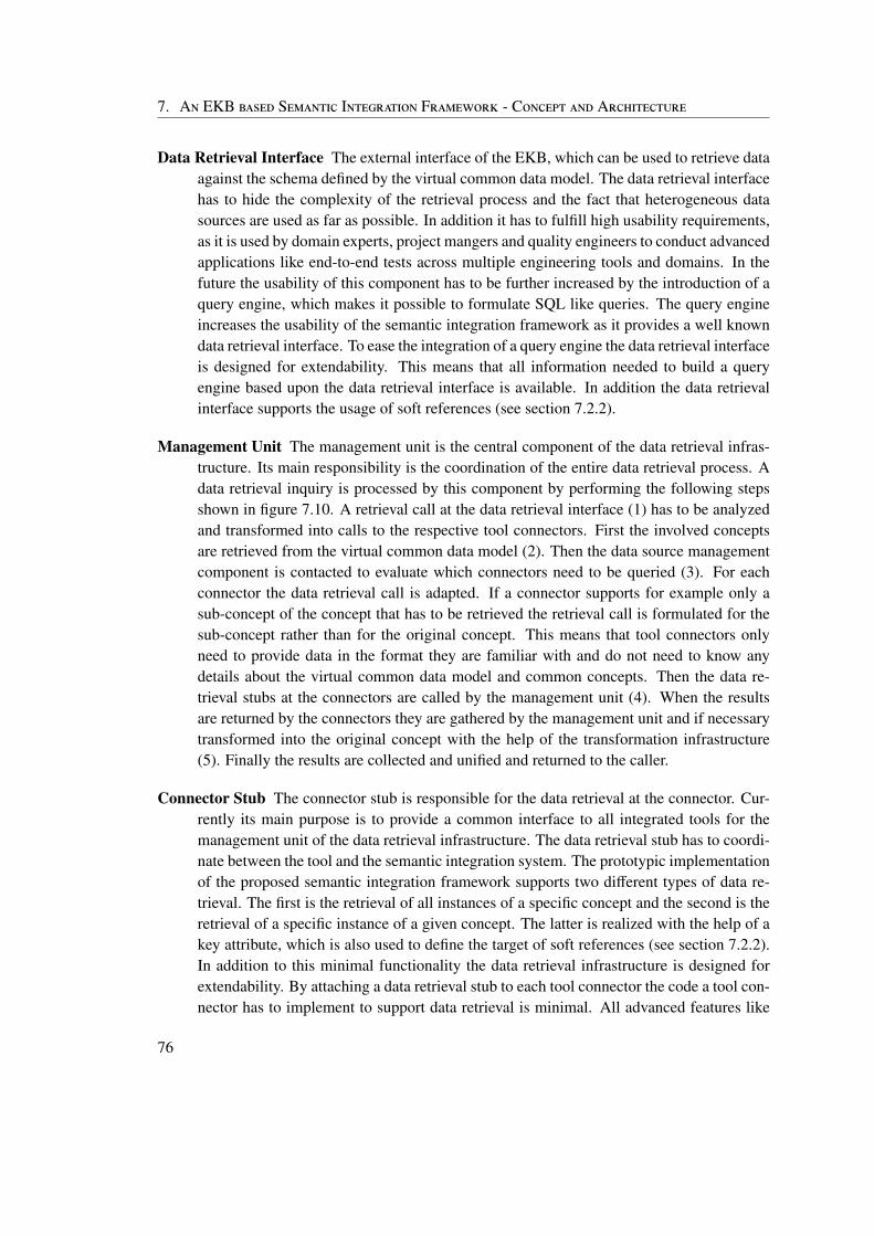
7. An EKB based Semantic Integration Framework - Concept and Architecture
Data Retrieval Interface The external interface of the EKB, which can be used to retrieve dataagainst the schema defined by the virtual common data model. The data retrieval interfacehas to hide the complexity of the retrieval process and the fact that heterogeneous datasources are used as far as possible. In addition it has to fulfill high usability requirements,as it is used by domain experts, project mangers and quality engineers to conduct advancedapplications like end-to-end tests across multiple engineering tools and domains. In thefuture the usability of this component has to be further increased by the introduction of aquery engine, which makes it possible to formulate SQL like queries. The query engineincreases the usability of the semantic integration framework as it provides a well knowndata retrieval interface. To ease the integration of a query engine the data retrieval interfaceis designed for extendability. This means that all information needed to build a queryengine based upon the data retrieval interface is available. In addition the data retrievalinterface supports the usage of soft references (see section 7.2.2).
Management Unit The management unit is the central component of the data retrieval infras-tructure. Its main responsibility is the coordination of the entire data retrieval process. Adata retrieval inquiry is processed by this component by performing the following stepsshown in figure 7.10. A retrieval call at the data retrieval interface (1) has to be analyzedand transformed into calls to the respective tool connectors. First the involved conceptsare retrieved from the virtual common data model (2). Then the data source managementcomponent is contacted to evaluate which connectors need to be queried (3). For eachconnector the data retrieval call is adapted. If a connector supports for example only asub-concept of the concept that has to be retrieved the retrieval call is formulated for thesub-concept rather than for the original concept. This means that tool connectors onlyneed to provide data in the format they are familiar with and do not need to know anydetails about the virtual common data model and common concepts. Then the data re-trieval stubs at the connectors are called by the management unit (4). When the resultsare returned by the connectors they are gathered by the management unit and if necessarytransformed into the original concept with the help of the transformation infrastructure(5). Finally the results are collected and unified and returned to the caller.
Connector Stub The connector stub is responsible for the data retrieval at the connector. Cur-rently its main purpose is to provide a common interface to all integrated tools for themanagement unit of the data retrieval infrastructure. The data retrieval stub has to coordi-nate between the tool and the semantic integration system. The prototypic implementationof the proposed semantic integration framework supports two different types of data re-trieval. The first is the retrieval of all instances of a specific concept and the second is theretrieval of a specific instance of a given concept. The latter is realized with the help of akey attribute, which is also used to define the target of soft references (see section 7.2.2).In addition to this minimal functionality the data retrieval infrastructure is designed forextendability. By attaching a data retrieval stub to each tool connector the code a tool con-nector has to implement to support data retrieval is minimal. All advanced features like
76
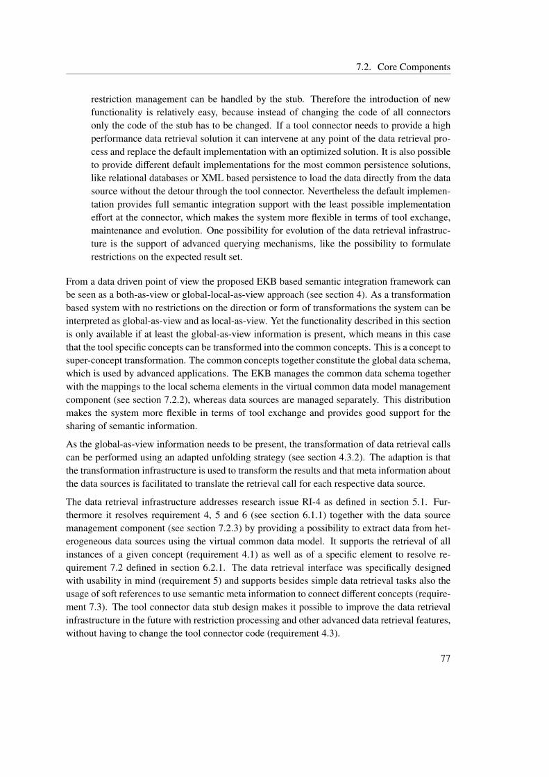
7.2. Core Components
restriction management can be handled by the stub. Therefore the introduction of newfunctionality is relatively easy, because instead of changing the code of all connectorsonly the code of the stub has to be changed. If a tool connector needs to provide a highperformance data retrieval solution it can intervene at any point of the data retrieval pro-cess and replace the default implementation with an optimized solution. It is also possibleto provide different default implementations for the most common persistence solutions,like relational databases or XML based persistence to load the data directly from the datasource without the detour through the tool connector. Nevertheless the default implemen-tation provides full semantic integration support with the least possible implementationeffort at the connector, which makes the system more flexible in terms of tool exchange,maintenance and evolution. One possibility for evolution of the data retrieval infrastruc-ture is the support of advanced querying mechanisms, like the possibility to formulaterestrictions on the expected result set.
From a data driven point of view the proposed EKB based semantic integration framework canbe seen as a both-as-view or global-local-as-view approach (see section 4). As a transformationbased system with no restrictions on the direction or form of transformations the system can beinterpreted as global-as-view and as local-as-view. Yet the functionality described in this sectionis only available if at least the global-as-view information is present, which means in this casethat the tool specific concepts can be transformed into the common concepts. This is a concept tosuper-concept transformation. The common concepts together constitute the global data schema,which is used by advanced applications. The EKB manages the common data schema togetherwith the mappings to the local schema elements in the virtual common data model managementcomponent (see section 7.2.2), whereas data sources are managed separately. This distributionmakes the system more flexible in terms of tool exchange and provides good support for thesharing of semantic information.
As the global-as-view information needs to be present, the transformation of data retrieval callscan be performed using an adapted unfolding strategy (see section 4.3.2). The adaption is thatthe transformation infrastructure is used to transform the results and that meta information aboutthe data sources is facilitated to translate the retrieval call for each respective data source.
The data retrieval infrastructure addresses research issue RI-4 as defined in section 5.1. Fur-thermore it resolves requirement 4, 5 and 6 (see section 6.1.1) together with the data sourcemanagement component (see section 7.2.3) by providing a possibility to extract data from het-erogeneous data sources using the virtual common data model. It supports the retrieval of allinstances of a given concept (requirement 4.1) as well as of a specific element to resolve re-quirement 7.2 defined in section 6.2.1. The data retrieval interface was specifically designedwith usability in mind (requirement 5) and supports besides simple data retrieval tasks also theusage of soft references to use semantic meta information to connect different concepts (require-ment 7.3). The tool connector data stub design makes it possible to improve the data retrievalinfrastructure in the future with restriction processing and other advanced data retrieval features,without having to change the tool connector code (requirement 4.3).
77
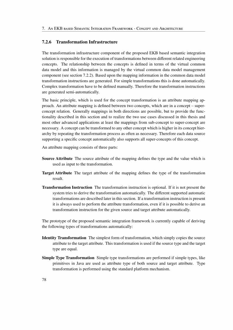
7. An EKB based Semantic Integration Framework - Concept and Architecture
7.2.6 Transformation Infrastructure
The transformation infrastructure component of the proposed EKB based semantic integrationsolution is responsible for the execution of transformations between different related engineeringconcepts. The relationship between the concepts is defined in terms of the virtual commondata model and this information is managed by the virtual common data model managementcomponent (see section 7.2.2). Based upon the mapping information in the common data modeltransformation instructions are generated. For simple transformations this is done automatically.Complex transformation have to be defined manually. Therefore the transformation instructionsare generated semi-automatically.
The basic principle, which is used for the concept transformation is an attribute mapping ap-proach. An attribute mapping is defined between two concepts, which are in a concept – super-concept relation. Generally mappings in both directions are possible, but to provide the func-tionality described in this section and to realize the two use cases discussed in this thesis andmost other advanced applications at least the mappings from sub-concept to super-concept arenecessary. A concept can be transformed to any other concept which is higher in its concept hier-archy by repeating the transformation process as often as necessary. Therefore each data sourcesupporting a specific concept automatically also supports all super-concepts of this concept.
An attribute mapping consists of three parts:
Source Attribute The source attribute of the mapping defines the type and the value which isused as input to the transformation.
Target Attribute The target attribute of the mapping defines the type of the transformationresult.
Transformation Instruction The transformation instruction is optional. If it is not present thesystem tries to derive the transformation automatically. The different supported automatictransformations are described later in this section. If a transformation instruction is presentit is always used to perform the attribute transformation, even if it is possible to derive antransformation instruction for the given source and target attribute automatically.
The prototype of the proposed semantic integration framework is currently capable of derivingthe following types of transformations automatically:
Identity Transformation The simplest form of transformation, which simply copies the sourceattribute to the target attribute. This transformation is used if the source type and the targettype are equal.
Simple Type Transformation Simple type transformations are performed if simple types, likeprimitives in Java are used as attribute type of both source and target attribute. Typetransformation is performed using the standard platform mechanism.
78
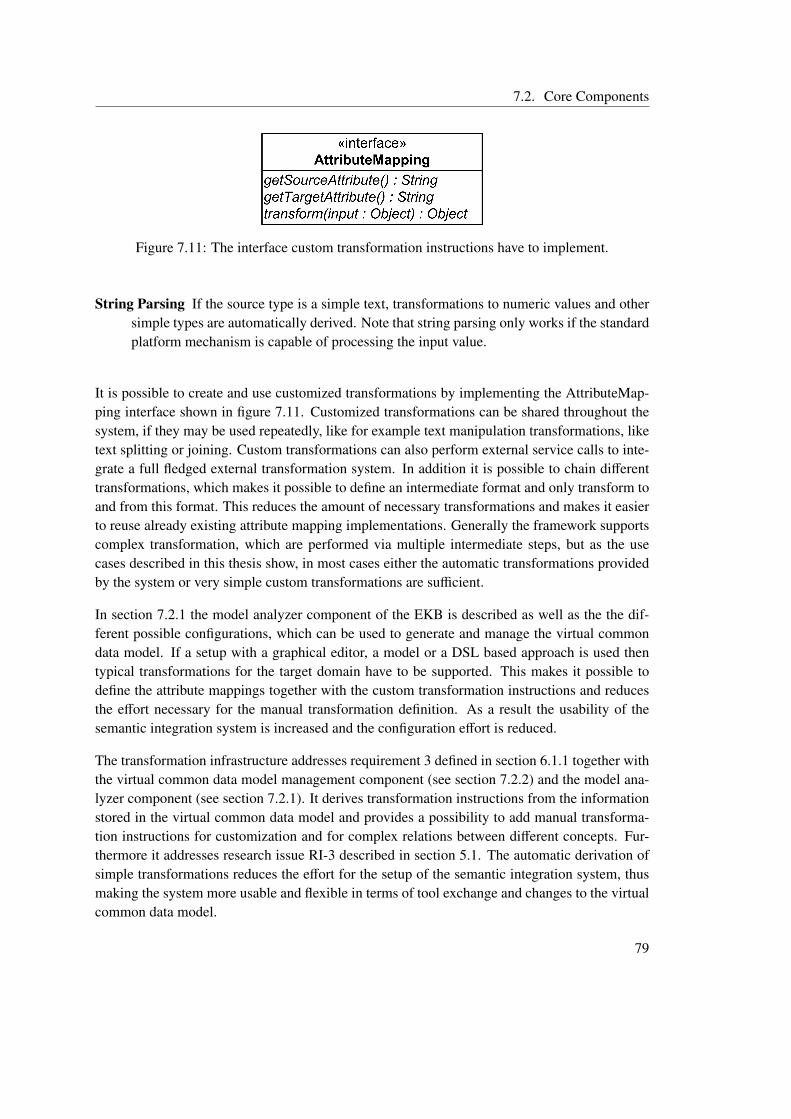
7.2. Core Components
Figure 7.11: The interface custom transformation instructions have to implement.
String Parsing If the source type is a simple text, transformations to numeric values and othersimple types are automatically derived. Note that string parsing only works if the standardplatform mechanism is capable of processing the input value.
It is possible to create and use customized transformations by implementing the AttributeMap-ping interface shown in figure 7.11. Customized transformations can be shared throughout thesystem, if they may be used repeatedly, like for example text manipulation transformations, liketext splitting or joining. Custom transformations can also perform external service calls to inte-grate a full fledged external transformation system. In addition it is possible to chain differenttransformations, which makes it possible to define an intermediate format and only transform toand from this format. This reduces the amount of necessary transformations and makes it easierto reuse already existing attribute mapping implementations. Generally the framework supportscomplex transformation, which are performed via multiple intermediate steps, but as the usecases described in this thesis show, in most cases either the automatic transformations providedby the system or very simple custom transformations are sufficient.
In section 7.2.1 the model analyzer component of the EKB is described as well as the the dif-ferent possible configurations, which can be used to generate and manage the virtual commondata model. If a setup with a graphical editor, a model or a DSL based approach is used thentypical transformations for the target domain have to be supported. This makes it possible todefine the attribute mappings together with the custom transformation instructions and reducesthe effort necessary for the manual transformation definition. As a result the usability of thesemantic integration system is increased and the configuration effort is reduced.
The transformation infrastructure addresses requirement 3 defined in section 6.1.1 together withthe virtual common data model management component (see section 7.2.2) and the model ana-lyzer component (see section 7.2.1). It derives transformation instructions from the informationstored in the virtual common data model and provides a possibility to add manual transforma-tion instructions for customization and for complex relations between different concepts. Fur-thermore it addresses research issue RI-3 described in section 5.1. The automatic derivation ofsimple transformations reduces the effort for the setup of the semantic integration system, thusmaking the system more usable and flexible in terms of tool exchange and changes to the virtualcommon data model.
79
7. An EKB based Semantic Integration Framework - Concept and Architecture
7.2.7 Core Component Overview
In this section an overview about the different core components and the requirements theyaddress is given. Table 7.1 shows which requirements (see section 6) are implemented bywhich components. The additional requirements defined in section 6.3 are not listed in thetable or specifically mentioned in the description of the core components, because they are non-functional and concern the whole integration system. They have been taken into account duringthe whole design and implementation process of the proposed semantic integration solution andits prototype.
7.3 Integration into the Open Engineering Service Bus
The proposed semantic integration solution is based upon a technical integration system, whichprovides a common message format as well as the technical infrastructure necessary to integratedifferent tools (see section 2). Basically it can cooperate with any technical integration solution,but it is specifically designed to work together with an Enterprise Service Bus based solution.To work in other environments, like a pure service oriented technical integration system someadaptions to the concept and architecture described in this section may be necessary. The eventdriven and service oriented character as well as the focus on integration of an ESB reduces thedesign and implementation effort for the semantic integration framework. The Open EngineeringService Bus (see section 2.5) is an ESB based technical integration system for the (software+)engineering domain. The prototype of the semantic integration framework proposed in thisthesis is developed for this system, as it is specifically designed for the target domain.
The following list describes the most important concepts and components of the OpenEngSB ac-cording to Pieber (2010) and how they are affected by the introduction of a semantic integrationframework.
Core Components Core components provide functionality for all members of the integrationsystem. They are specifically developed for the OpenEngSB, because no ready to use ex-ternal solutions exist, which fulfill all requirements. The EKB based semantic integrationframework is represented as a core component inside the OpenEngSB, as it provides dataretrieval functionality for heterogeneous data sources to other components of the Ope-nEngSB. Furthermore it needs to be easy to use within the OpenEngSB, because othercore components like the workflow engine need to interact with the EKB in advancedapplication scenarios like end-to-end tests across tool borders.
Tool Domains Tool domains in the OpenEngSB formalize the common functionality and con-cepts of a specific group of tools. The issue domain for example defines a common in-terface for various different issue tracker tools. Domains can provide functionality for alltools of a domain, like event triggering mechanisms, process support or a common data
80
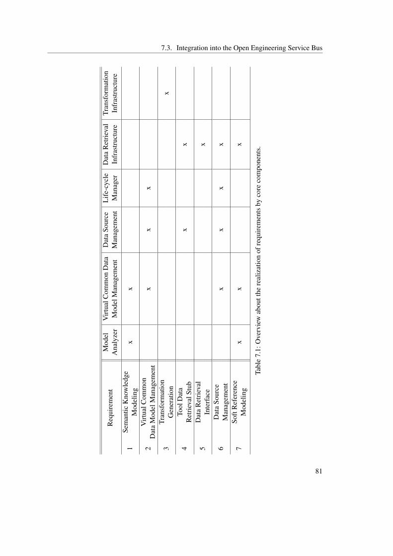
7.3. Integration into the Open Engineering Service Bus
Req
uire
men
tM
odel
Vir
tual
Com
mon
Dat
aD
ata
Sour
ceL
ife-
cycl
eD
ata
Ret
riev
alTr
ansf
orm
atio
nA
naly
zer
Mod
elM
anag
emen
tM
anag
emen
tM
anag
erIn
fras
truc
ture
Infr
astr
uctu
re
1Se
man
ticK
now
ledg
ex
xM
odel
ing
2V
irtu
alC
omm
onx
xx
Dat
aM
odel
Man
agem
ent
3Tr
ansf
orm
atio
nx
Gen
erat
ion
4To
olD
ata
xx
Ret
riev
alSt
ub
5D
ata
Ret
riev
alx
Inte
rfac
e
6D
ata
Sour
cex
xx
xM
anag
emen
t
7So
ftR
efer
ence
xx
xM
odel
ing
Tabl
e7.
1:O
verv
iew
abou
tthe
real
izat
ion
ofre
quir
emen
tsby
core
com
pone
nts.
81
7. An EKB based Semantic Integration Framework - Concept and Architecture
pool. The semantic integration framework builds upon the semantic information alreadycontained in the domains. Typically the virtual common data model will contain the con-cepts defined by the domain rather than the actual tool concepts, as the tools already haveto support the domain concepts to be integrated into the OpenEngSB. This reduces theeffort for the creation and maintenance of the virtual common data model and makes toolexchange easier.
Domain- and Client Tool Connectors Tool connectors act as interface between the Ope-nEngSB and any tool integrated into the system. Every tool connector is part of a tooldomain and therefore has to implement the domain interface and support the domain con-cepts. The EKB based semantic integration solution extends the connectors with a dataretrieval infrastructure, which makes it possible for tool connectors to publish which con-cepts of the virtual common data model they support. Furthermore the data retrieval stubat the connectors contains most of the functionality needed for a tool connector to act as adata source and as a result reduces the implementation effort necessary to create the actualconnector.
Figure 7.12 shows the architecture of the Open Engineering Service Bus and how the EKB basedsemantic integration solution is incorporated into this system. Furthermore it depicts the data in-tegration stub at the connectors and their connection to the EKB, which is used for data retrieval.It shows that the integration of the EKB does not lead to major changes of the underlying tech-nical integration system. The EKB is added as a core component. The only part of the system,which needs to be adapted are the tool connectors, which need to be extended with data retrievalstubs. These stubs are directly connected to the EKB using the messaging mechanisms providedby the service bus of the technical integration system. This direct connection is used for dataretrieval and data source management. Other features of the technical integration system, likeservice calls to integrated tools are not affected by the semantic integration component.
82
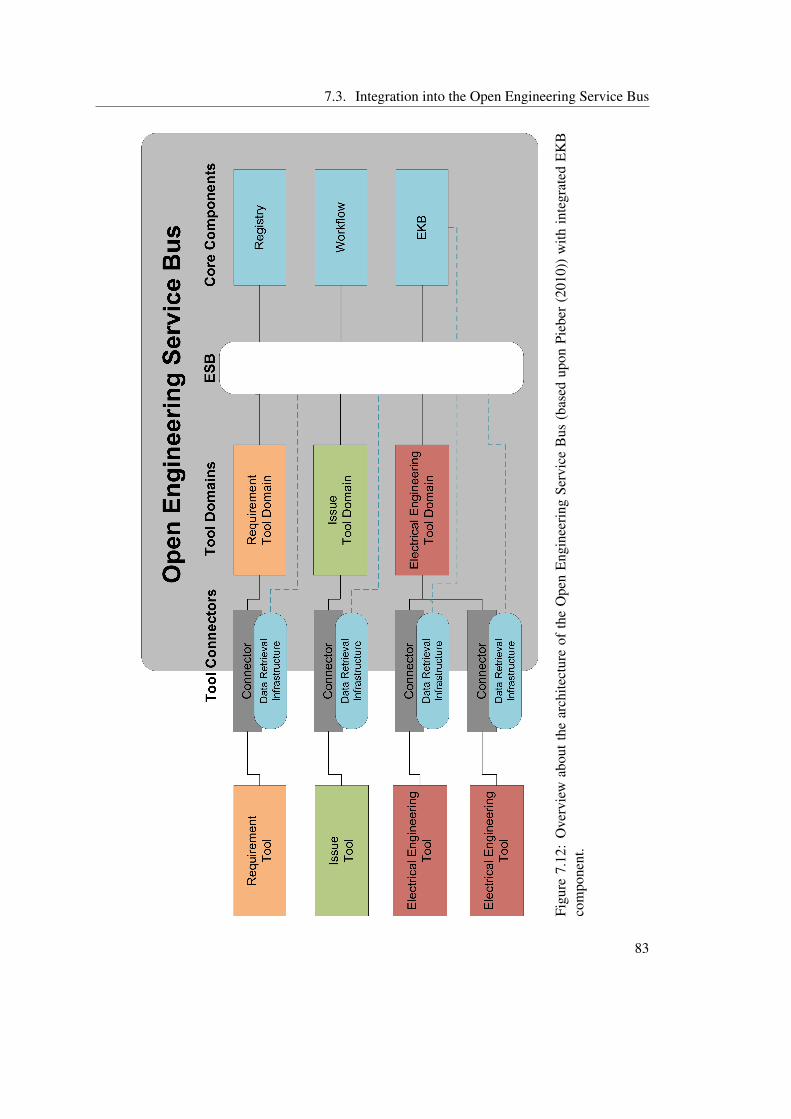
7.3. Integration into the Open Engineering Service Bus
Figu
re7.
12:
Ove
rvie
wab
outt
hear
chite
ctur
eof
the
Ope
nE
ngin
eeri
ngSe
rvic
eB
us(b
ased
upon
Pieb
er(2
010)
)w
ithin
tegr
ated
EK
Bco
mpo
nent
.
83

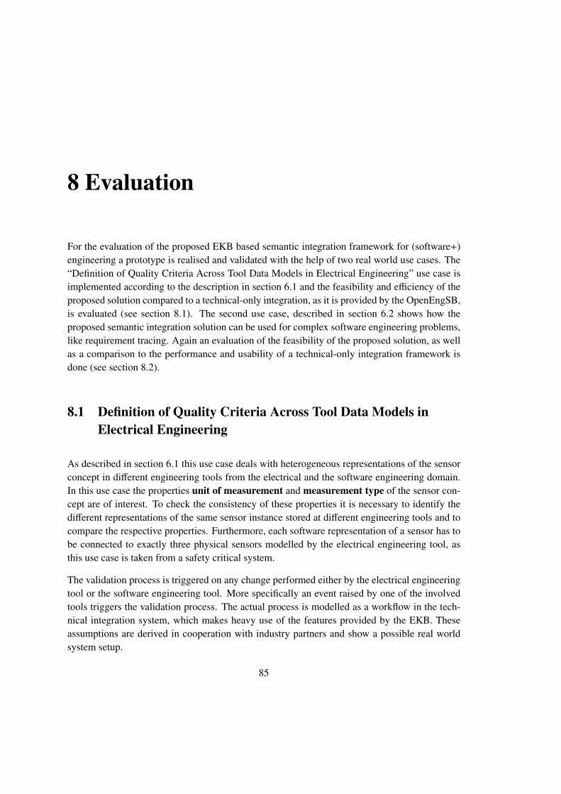
8 Evaluation
For the evaluation of the proposed EKB based semantic integration framework for (software+)engineering a prototype is realised and validated with the help of two real world use cases. The“Definition of Quality Criteria Across Tool Data Models in Electrical Engineering” use case isimplemented according to the description in section 6.1 and the feasibility and efficiency of theproposed solution compared to a technical-only integration, as it is provided by the OpenEngSB,is evaluated (see section 8.1). The second use case, described in section 6.2 shows how theproposed semantic integration solution can be used for complex software engineering problems,like requirement tracing. Again an evaluation of the feasibility of the proposed solution, as wellas a comparison to the performance and usability of a technical-only integration framework isdone (see section 8.2).
8.1 Definition of Quality Criteria Across Tool Data Models inElectrical Engineering
As described in section 6.1 this use case deals with heterogeneous representations of the sensorconcept in different engineering tools from the electrical and the software engineering domain.In this use case the properties unit of measurement and measurement type of the sensor con-cept are of interest. To check the consistency of these properties it is necessary to identify thedifferent representations of the same sensor instance stored at different engineering tools and tocompare the respective properties. Furthermore, each software representation of a sensor has tobe connected to exactly three physical sensors modelled by the electrical engineering tool, asthis use case is taken from a safety critical system.
The validation process is triggered on any change performed either by the electrical engineeringtool or the software engineering tool. More specifically an event raised by one of the involvedtools triggers the validation process. The actual process is modelled as a workflow in the tech-nical integration system, which makes heavy use of the features provided by the EKB. Theseassumptions are derived in cooperation with industry partners and show a possible real worldsystem setup.
85
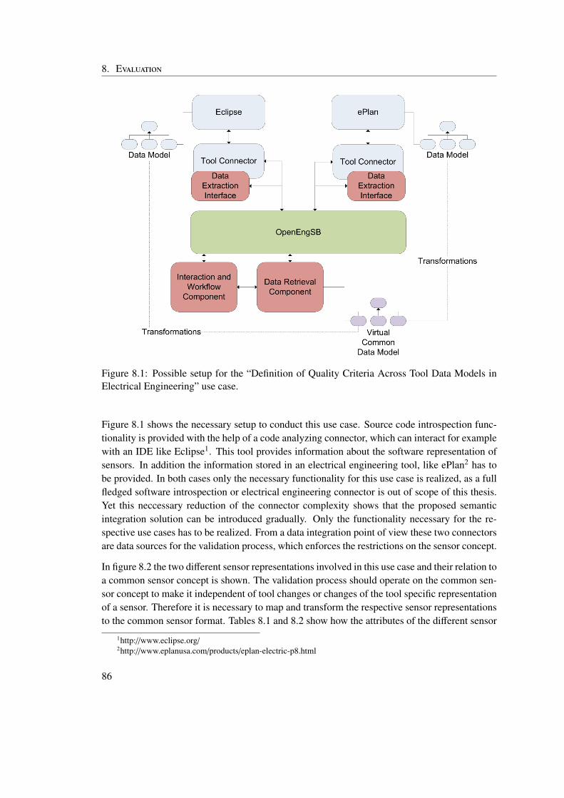
8. Evaluation
Figure 8.1: Possible setup for the “Definition of Quality Criteria Across Tool Data Models inElectrical Engineering” use case.
Figure 8.1 shows the necessary setup to conduct this use case. Source code introspection func-tionality is provided with the help of a code analyzing connector, which can interact for examplewith an IDE like Eclipse1. This tool provides information about the software representation ofsensors. In addition the information stored in an electrical engineering tool, like ePlan2 has tobe provided. In both cases only the necessary functionality for this use case is realized, as a fullfledged software introspection or electrical engineering connector is out of scope of this thesis.Yet this neccessary reduction of the connector complexity shows that the proposed semanticintegration solution can be introduced gradually. Only the functionality necessary for the re-spective use cases has to be realized. From a data integration point of view these two connectorsare data sources for the validation process, which enforces the restrictions on the sensor concept.
In figure 8.2 the two different sensor representations involved in this use case and their relation toa common sensor concept is shown. The validation process should operate on the common sen-sor concept to make it independent of tool changes or changes of the tool specific representationof a sensor. Therefore it is necessary to map and transform the respective sensor representationsto the common sensor format. Tables 8.1 and 8.2 show how the attributes of the different sensor
1http://www.eclipse.org/2http://www.eplanusa.com/products/eplan-electric-p8.html
86
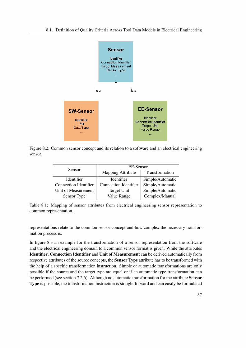
8.1. Definition of Quality Criteria Across Tool Data Models in Electrical Engineering
Figure 8.2: Common sensor concept and its relation to a software and an electrical engineeringsensor.
SensorEE-Sensor
Mapping Attribute TransformationIdentifier Identifier Simple/Automatic
Connection Identifier Connection Identifier Simple/AutomaticUnit of Measurement Target Unit Simple/Automatic
Sensor Type Value Range Complex/Manual
Table 8.1: Mapping of sensor attributes from electrical engineering sensor representation tocommon representation.
representations relate to the common sensor concept and how complex the necessary transfor-mation process is.
In figure 8.3 an example for the transformation of a sensor representation from the softwareand the electrical engineering domain to a common sensor format is given. While the attributesIdentifier, Connection Identifier and Unit of Measurement can be derived automatically fromrespective attributes of the source concepts, the Sensor Type attribute has to be transformed withthe help of a specific transformation instruction. Simple or automatic transformations are onlypossible if the source and the target type are equal or if an automatic type transformation canbe performed (see section 7.2.6). Although no automatic transformation for the attribute SensorType is possible, the transformation instruction is straight forward and can easily be formulated
87
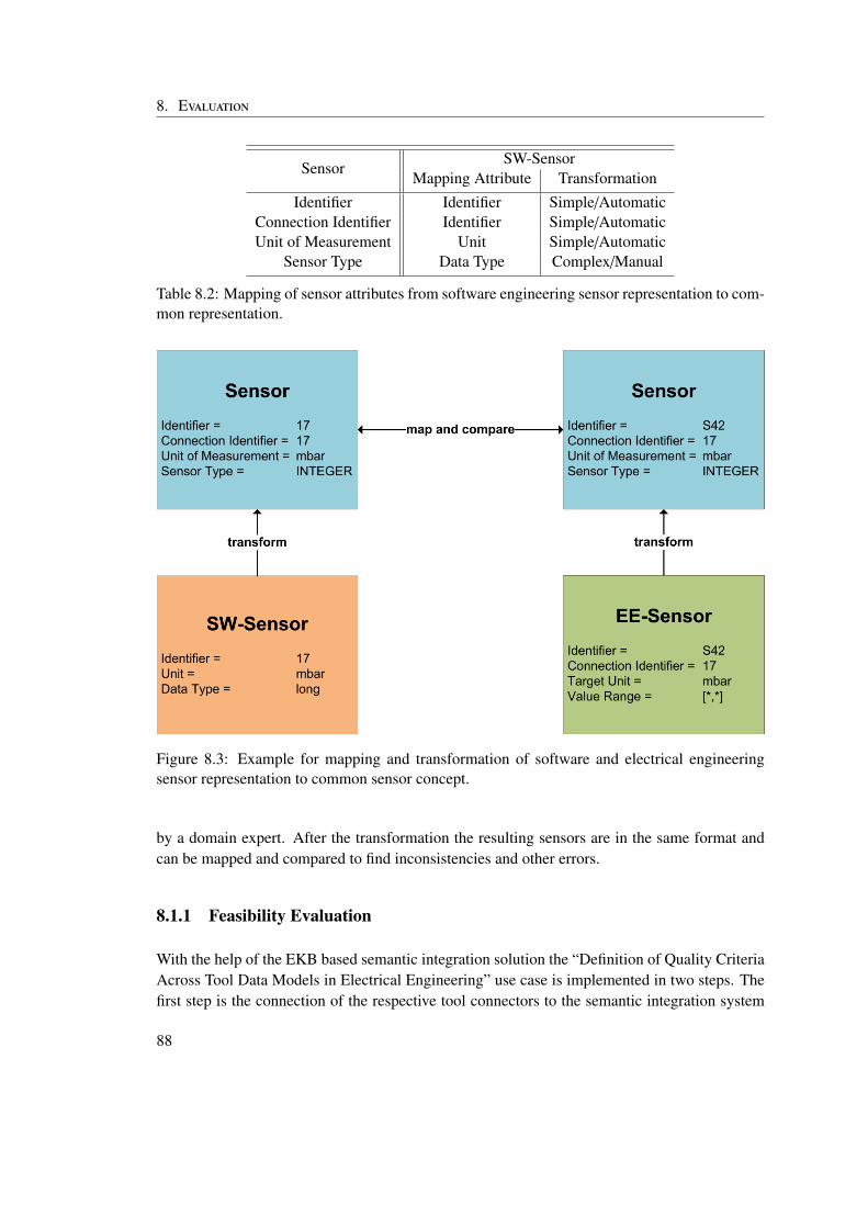
8. Evaluation
SensorSW-Sensor
Mapping Attribute TransformationIdentifier Identifier Simple/Automatic
Connection Identifier Identifier Simple/AutomaticUnit of Measurement Unit Simple/Automatic
Sensor Type Data Type Complex/Manual
Table 8.2: Mapping of sensor attributes from software engineering sensor representation to com-mon representation.
Figure 8.3: Example for mapping and transformation of software and electrical engineeringsensor representation to common sensor concept.
by a domain expert. After the transformation the resulting sensors are in the same format andcan be mapped and compared to find inconsistencies and other errors.
8.1.1 Feasibility Evaluation
With the help of the EKB based semantic integration solution the “Definition of Quality CriteriaAcross Tool Data Models in Electrical Engineering” use case is implemented in two steps. Thefirst step is the connection of the respective tool connectors to the semantic integration system
88
8.1. Definition of Quality Criteria Across Tool Data Models in Electrical Engineering
and the second step is the definition of the validation process in a workflow. This validationprocess is then performed by the technical integration system using the features provided by theEKB.
The main configuration and setup effort has to be performed in the first step, because the con-nector has to be implemented to provide the tool specific data to the integration system. Fur-thermore, the semantic information has to be modeled and stored in the virtual common datamodel or more specifically the tool concepts and their relation to common engineering conceptshave to be defined. As these steps happen at development time of the respective tool connec-tor, they can be performed by domain experts, who know how to map the tool specific sensorconcept to the common concept. This knowledge is available, because domain experts alreadyneed to perform the mapping manually to document their work and to provide information forother development activities building on their results. In addition the architecture of the dataextraction infrastructure of the EKB reduces the effort for the implementation and integration ofa tool connector into the OpenEngSB. This means that the additional effort for the connection ofa tool to the semantic integration system is reduced to the implementation of one data extractioninterface and a simple configuration of the meta data used by the data extraction system to findout which data sources can provide which concepts.
The fact that domain experts can perform the necessary mapping definition and tool integrationduring development time, as well as the minimal effort for tool integration show that the pro-posed semantic integration solution is efficient in terms of initial setup. As the tool connectorsare usually also maintained by domain experts updates of the tool connector and the semanticinformation stored in the virtual common data model can be performed efficiently. The usabilityof the system for developers, who are no semantic integration experts is guaranteed by the factthat no knowledge about semantic integration is necessary to implement a tool connector. Thedefinition of the mappings between the tool concepts and common concepts used throughout theintegration system can either be supported by a specific tool, or with the help of an integrationexpert if the development of such a tool is out of scope of the project. Although this is a rathercomplex task, which makes initial tool integration, tool exchange and tool evolution more diffi-cult, it is worth the effort as the realisation of advanced applications like the validation processin this use case becomes much easier.
The second step of the realisation of this use case is the definition of the validation process asworkflow. This task is usually performed by a quality engineers or someone else, who is not anexpert for each involved domain. Using the EKB based solution the validation process is definedwithout references to tool specific representations of the sensor concept. This means that thisworkflow is independent of the involved tools. Therefore the integration system can be usedby quality engineers and project managers without the need for extensive support of domainand tool experts. The data extraction and transformation process is completely hidden fromthe designer of the advanced application. This leads to portable and robust process definitions,which can be reused in other projects.
89
8. Evaluation
In terms of robustness the system is designed to cope with tools that dynamically join and leavethe system as well as with incomplete information in the virtual common data model. If sucha problem occurs, the process stops and information about the problem is provided in the sys-tem log. It is critical that the semantic information stored in the virtual common data model ismanaged and updated when tool data models change. Inconsistencies do not bring the systemdown, but can reduce the functionality of the semantic integration system so much, that it can-not be used for advanced applications. The discovery and correct handling of inconsistencies,which is needed to provide the system with the necessary robustness is possible by defining andsynchronizing the life-cycle of data sources and semantic tool information.
8.1.2 Comparison to Technical Integration
In this section a comparison between the necessary effort to integrate a tool, to exchange a tooland to perform advanced applications between the original OpenEngSB and the proposed EKBbased integration solution is performed. The different steps necessary to execute these threedifferent tasks as well as the technical expertise necessary to perform them is compared.
Tool Integration For tool integration in the original OpenEngSB it is first necessary to identifythe correct tool domain for the tool connector. If such a domain is not available it has to beimplemented and integrated into the technical integration system. The domain defines theservice interface the connector implements to provide functionality to other componentsin the integration system. In the proposed semantic integration solution this step does notchange if the domain does not define a data model for its connectors. If a data modelis defined, then the semantic information about the concepts in the domain data modelhave to be stored in the EKB. This process is rather complex and needs some knowledgeabout semantic integration as well as knowledge about the tool domain and usually takesbetween ten to thirty minutes per domain specific concept for an integration expert and adomain expert. In the optimal case they work together to perform the necessary changesto the virtual common data model. As only mappings relevant for advanced applicationsand other use cases have to be modelled the costs for the definition of the mappings isnot too high, although the necessary time for the definition of mappings does not scalelinearly.
Then the connector is implemented and integrated into the technical integration systembased on the domain interface. In the semantic integration system in addition to the im-plementation of the service interface also a data extraction interface has to be implementedby the tool connector and it has to publish which concepts it supports. The additional effortfor this tasks depends on the tool, which has to be integrated. If the tool data is accessi-ble the data extraction interface can be implemented in less than one developer work day.Note that in most cases the data extraction from the tool to the connector is the morecomplex part of the data integration process. But this step needs to be performed in any
90
8.1. Definition of Quality Criteria Across Tool Data Models in Electrical Engineering
case to provide the tool data to the integration system, regardless if a semantic integrationsolution is used or not.
One additional step is necessary for semantic integration. The semantic information aboutthe concepts provided by the tool, which was connected to the OpenEngSB has to bemodeled and stored in the EKB. This process is not necessary if the tool connector usesthe data model provided by the tool domain. If the virtual common data model has tobe adapted the same steps are necessary as described above, when a domain has to beimplemented, which provides a data model for its connectors. So in this case the additionaleffort is again between ten to thirty minutes per tool specific concept for an integrationexpert and a domain expert.
Tool Exchange If a tool needs to be exchanged for another tool of the same tool domain inthe original OpenEngSB it is necessary to implement the new tool connector as describedin the tool integration section above. If the proposed semantic integration solution isused, in addition to the data integration tasks, also the virtual common data model needsto be updated. Yet this step is only necessary if the connector does not use the datamodel provided by its domain and in most cases only minor updates, like changes tooutdated transformation instructions have to be performed. This means that compared toa technical-only integration in the worst case tool exchange takes one additional workdayfor a domain expert and one between ten to thirty minutes per tool specific concept for adomain expert and a semantic integration expert, while in the best case only one additionalworkday for a domain expert has to be invested.
Advanced Applications If advanced applications in the original OpenEngSB require datastored in specific tools, they need to either use the tool specific data model or manu-ally transform the tool data to some common format. The semantic knowledge about thisprocess is stored in the workflow definitions of the respective advanced application, whichintroduces a dependency from the process definition to the involved tools. Because of thisdependency every time a new tool is integrated or a tool is exchanged the workflows foradvanced applications have to be reviewed and possible adapted to the new data models ofthe involved tools. This process is complex and requires the involvement of experts fromdifferent domains as well as a data integration expert. The workflow definitions cannotbe used easily in other projects or other contexts, because of their dependency to the in-volved tools. This often makes automatic end-to-end tests across tool boundaries or otheradvanced applications infeasible.
When the proposed semantic integration solution is used, advanced applications can relyon the data and semantic integration features of the EKB. This means that they can beimplemented against common concepts independent of the involved tools and tool datamodels. Therefore neither integration nor domain experts are strictly necessary to defineand maintain the process definitions of advanced applications like end-to-end tests acrosstool and domain boundaries, although the definition of the workflows is usually done in
91
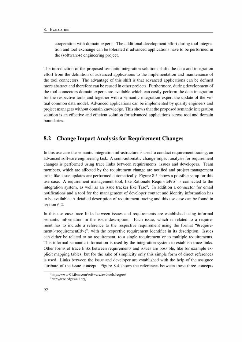
8. Evaluation
cooperation with domain experts. The additional development effort during tool integra-tion and tool exchange can be tolerated if advanced applications have to be performed inthe (software+) engineering project.
The introduction of the proposed semantic integration solutions shifts the data and integrationeffort from the definition of advanced applications to the implementation and maintenance ofthe tool connectors. The advantage of this shift is that advanced applications can be definedmore abstract and therefore can be reused in other projects. Furthermore, during development ofthe tool connectors domain experts are available which can easily perform the data integrationfor the respective tools and together with a semantic integration expert the update of the vir-tual common data model. Advanced applications can be implemented by quality engineers andproject managers without domain knowledge. This shows that the proposed semantic integrationsolution is an effective and efficient solution for advanced applications across tool and domainboundaries.
8.2 Change Impact Analysis for Requirement Changes
In this use case the semantic integration infrastructure is used to conduct requirement tracing, anadvanced software engineering task. A semi-automatic change impact analysis for requirementchanges is performed using trace links between requirements, issues and developers. Teammembers, which are affected by the requirement change are notified and project managementtasks like issue updates are performed automatically. Figure 8.5 shows a possible setup for thisuse case. A requirement management tool, like Rationale RequisitePro3 is connected to theintegration system, as well as an issue tracker like Trac4. In addition a connector for emailnotifications and a tool for the management of developer contact and identity information hasto be available. A detailed description of requirement tracing and this use case can be found insection 6.2.
In this use case trace links between issues and requirements are established using informalsemantic information in the issue description. Each issue, which is related to a require-ment has to include a reference to the respective requirement using the format “#require-ment(<requirementId>)”, with the respective requirement identifier in its description. Issuescan either be related to no requirement, to a single requirement or to multiple requirements.This informal semantic information is used by the integration system to establish trace links.Other forms of trace links between requirements and issues are possible, like for example ex-plicit mapping tables, but for the sake of simplicity only this simple form of direct referencesis used. Links between the issue and developer are established with the help of the assigneeattribute of the issue concept. Figure 8.4 shows the references between these three concepts
3http://www-01.ibm.com/software/awdtools/reqpro/4http://trac.edgewall.org/
92
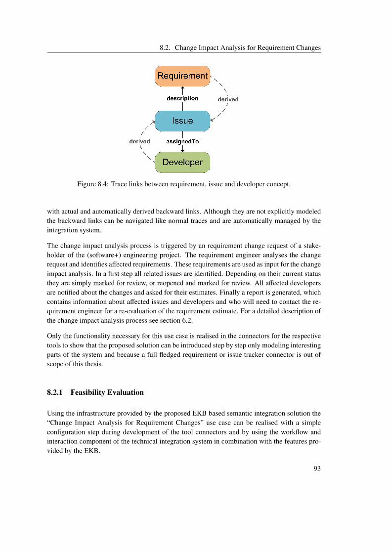
8.2. Change Impact Analysis for Requirement Changes
Figure 8.4: Trace links between requirement, issue and developer concept.
with actual and automatically derived backward links. Although they are not explicitly modeledthe backward links can be navigated like normal traces and are automatically managed by theintegration system.
The change impact analysis process is triggered by an requirement change request of a stake-holder of the (software+) engineering project. The requirement engineer analyses the changerequest and identifies affected requirements. These requirements are used as input for the changeimpact analysis. In a first step all related issues are identified. Depending on their current statusthey are simply marked for review, or reopened and marked for review. All affected developersare notified about the changes and asked for their estimates. Finally a report is generated, whichcontains information about affected issues and developers and who will need to contact the re-quirement engineer for a re-evaluation of the requirement estimate. For a detailed description ofthe change impact analysis process see section 6.2.
Only the functionality necessary for this use case is realised in the connectors for the respectivetools to show that the proposed solution can be introduced step by step only modeling interestingparts of the system and because a full fledged requirement or issue tracker connector is out ofscope of this thesis.
8.2.1 Feasibility Evaluation
Using the infrastructure provided by the proposed EKB based semantic integration solution the“Change Impact Analysis for Requirement Changes” use case can be realised with a simpleconfiguration step during development of the tool connectors and by using the workflow andinteraction component of the technical integration system in combination with the features pro-vided by the EKB.
93
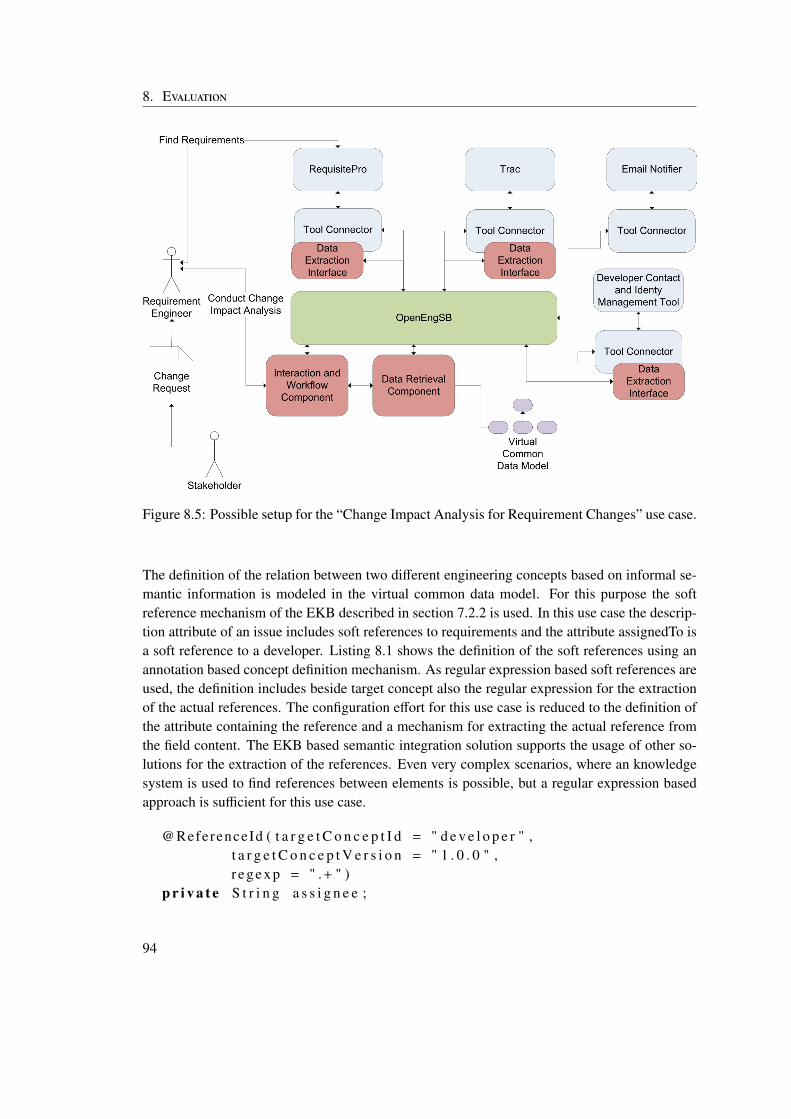
8. Evaluation
Figure 8.5: Possible setup for the “Change Impact Analysis for Requirement Changes” use case.
The definition of the relation between two different engineering concepts based on informal se-mantic information is modeled in the virtual common data model. For this purpose the softreference mechanism of the EKB described in section 7.2.2 is used. In this use case the descrip-tion attribute of an issue includes soft references to requirements and the attribute assignedTo isa soft reference to a developer. Listing 8.1 shows the definition of the soft references using anannotation based concept definition mechanism. As regular expression based soft references areused, the definition includes beside target concept also the regular expression for the extractionof the actual references. The configuration effort for this use case is reduced to the definition ofthe attribute containing the reference and a mechanism for extracting the actual reference fromthe field content. The EKB based semantic integration solution supports the usage of other so-lutions for the extraction of the references. Even very complex scenarios, where an knowledgesystem is used to find references between elements is possible, but a regular expression basedapproach is sufficient for this use case.
@ReferenceId ( t a r g e t C o n c e p t I d = " d e v e l o p e r " ,t a r g e t C o n c e p t V e r s i o n = " 1 . 0 . 0 " ,r eg ex p = " .+ " )
p r i v a t e S t r i n g a s s i g n e e ;
94
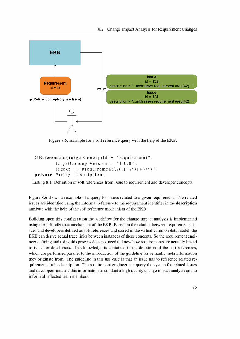
8.2. Change Impact Analysis for Requirement Changes
Figure 8.6: Example for a soft reference query with the help of the EKB.
@ReferenceId ( t a r g e t C o n c e p t I d = " r e q u i r e m e n t " ,t a r g e t C o n c e p t V e r s i o n = " 1 . 0 . 0 " ,r eg ex p = " # r e q u i r e m e n t \ \ ( ( [ ^ \ \ ) ] + ) \ \ ) " )
p r i v a t e S t r i n g d e s c r i p t i o n ;
Listing 8.1: Definition of soft references from issue to requirement and developer concepts.
Figure 8.6 shows an example of a query for issues related to a given requirement. The relatedissues are identified using the informal reference to the requirement identifier in the descriptionattribute with the help of the soft reference mechanism of the EKB.
Building upon this configuration the workflow for the change impact analysis is implementedusing the soft reference mechanism of the EKB. Based on the relation between requirements, is-sues and developers defined as soft references and stored in the virtual common data model, theEKB can derive actual trace links between instances of these concepts. So the requirement engi-neer defining and using this process does not need to know how requirements are actually linkedto issues or developers. This knowledge is contained in the definition of the soft references,which are performed parallel to the introduction of the guideline for semantic meta informationthey originate from. The guideline in this use case is that an issue has to reference related re-quirements in its description. The requirement engineer can query the system for related issuesand developers and use this information to conduct a high quality change impact analysis and toinform all affected team members.
95
8. Evaluation
As the setup to use informal semantic references between different engineering concepts is mini-mal, the proposed semantic integration solution is an effective and efficient solution for advancedapplications like requirement tracing. Using the EKB, the usage of relations between conceptsis decoupled from the actual form of the relation. This means that if the way requirements arelinked to issues is changed, the change impact analysis process does not need to be adapted. Therequirement engineer can perform the change impact analysis without knowledge about the is-sue domain and without tedious manual research which issues and developers are affected. Thismeans that the system is also usable for stakeholders, which are not part of the developmentteam, or not experts for all tools and tool domains involved in the development process. Noadditional effort is necessary for trace link generation, as the semantic meta information, whichis already available due to specific project guidelines is used to trace from requirements to issuesand from issues to developers.
Stakeholders, who are not part of the actual development team, usually do not know about team-internal guidelines, like the way requirements are referenced in issue descriptions. Yet they needto perform high level quality assurance and project management tasks, like the change impactanalysis described in this use case. Using the proposed EKB based semantic integration solution,they can perform advanced applications using informal relations between different engineeringconcepts, without the need to know how the different concepts are actually connected. Therobustness of the whole system is influenced positively by the fact that the semantic relationsbetween concepts are defined directly in the respective domains and can be updated every timethe underlying guidelines, a tool or a tool domain changes.
8.2.2 Comparison to Technical Integration
The differences in setup and implementation of the tool connectors are similar to the “Defini-tion of Quality Criteria Across Tool Data Models in Electrical Engineering” use case and aredescribed in detail in section 8.1.2. Therefore this section should only briefly cover the effortnecessary to model the semantic relation information between different engineering conceptsduring tool integration or exchange. It focuses on the implementation of a change impact analy-sis with the help of the features provided by the EKB compared to a solution for a technical-onlyintegration system.
The proposed EKB based semantic integration framework needs some additional setup, beforesoft references between different engineering concepts can be used. Basically two simple stepshave to be performed to make references between concepts possible:
Definition of the soft reference The source concept has to define which attribute contains a softreference and a mechanism for extracting the actual reference from the attribute value. Theprototypic implementation of the EKB supports a regular expression based mechanismfor soft reference definition. Listing 8.1 shows how this definition can be performed withthe help of an annotation based concept specification mechanism. Other types of soft
96
8.2. Change Impact Analysis for Requirement Changes
references can be implemented and integrated into the EKB easily using a plugin stylearchitecture.
Definition of a key attribute at the target concept The target concept of the soft referenceneeds to specify a key attribute. This has two specific implications. On the one handthe value of this key attribute is the actual reference value and used like a foreign key ina relational database. On the other hand the tool connector of the target concept needs tosupport queries for a specific element based on this key attribute.
These two steps are usually performed during integration of an engineering tool into the inte-gration system. Domain experts and integration experts work together to identify key attributesand relations between engineering concepts. Furthermore, project guidelines, which are alreadyin place and define how for example issues have to be described when they are created, givehints where semantic meta information is available and can be used to link between engineeringconcepts. Once the domain expert and the integration expert have an overview about potentialreferences between different concepts the actual definition of the references can be done in avery short time. The whole process including review of project guidelines and other availablemeta information usually can be performed in one to two developer workdays for both domainexpert and integration expert. If the project is smaller and each member has a good overviewabout the semantic meta information less effort is necessary for this task.
Using the proposed semantic integration framework the definition of the change impact analysisdoes not include any details about the relation between requirement and issue, besides the factthat such a relation exists. This means that a requirement engineer designing or using the changeimpact analysis workflow does not need to know any details about the relation between require-ment and issue concept and its actual representation. The requirement expert can concentrateon the task of change impact analysis, which is decoupled from the actual linking mechanismbetween different engineering concepts. The semantic linking information between engineeringconcepts is defined directly in the virtual common data model and can be used by any advancedapplication. This means that this knowledge is not duplicated throughout the system and canbe changed or updated easily. As a result the team is flexible and can decide to change spe-cific guidelines or standards for semantic meta information, if they feel the necessity to do so.Evolution of the system is possible without the fear of breaking high level process definitions.Therefore tasks like tool exchange or the introduction of new engineering tools are much easierto accomplish.
The explicit nature of the reference definition in the virtual common data model is also a veryuseful documentation of semantic dependencies between different engineering concepts and canbe analyzed by integration experts or domain experts to better understand the current setup ofthe system and to find potential inconsistencies or other problems.
To perform this use case in a technical only integration framework, like the original OpenEngSBwithout semantic integration it is necessary to use the semantic information in the change impact
97
8. Evaluation
analysis process definition. This means that in the process implementation the semantic relationbetween issues and requirements and issues and developers is explicitly used. The drawback ofsuch a solution is that the actual process of using the semantic information has to be duplicatedin every advanced applications which needs to facilitate the trace link between requirements andissues. In addition it is very hard to perform changes of the layout of the semantic meta infor-mation, as there is no single point of change, but all workflow definitions have to be reviewedand possibly updated.
Compared to a solution based on a technical-only integration system the definition of workflowsin the proposed EKB based semantic integration system is much more portable and reusableacross different projects. Due to the fact that only the existence of a link between two conceptsregardless of the actual form of the link is needed to build advanced applications, workflowscan be reused in other projects, where relations based on informal semantic information arerepresented differently. Therefore it is possible to use a common set of workflow definitions fortypical project and quality management tasks recurring in all kinds of different projects operatingwith the same engineering concepts.
These differences show that the proposed semantic integration solution is much better suited foradvanced software engineering applications like requirement tracing than a technical-only inte-gration solution. The possibility to define and use semantic meta information to model relationsbetween engineering concepts is a very flexible mechanism, which can also be used for other ad-vanced applications, like for example automatically linking commits to related issues. The mainadvantage of this solution is the simplicity of the setup and the single point of change makingthe overall system easier to change and to maintain. Similar to the “Definition of Quality Cri-teria Across Tool Data Models in Electrical Engineering” use case described in section 8.1 themain drawback of the EKB based semantic integration solution is the additional configurationand setup effort during development and implementation of the tool connectors. But if advancedapplications, like requirement tracing for change impact analysis have to be performed regularly,the additional effort during system setup pays off.
98
9 Discussion
In this section the results of this thesis with respect to the research issues defined in section5.1 are discussed. The basis of the discussion is on the one hand the review of the theoreticalfoundations of integration from the technical, semantic and data driven point of view in sections2, 3 and 4 and on the other hand the evaluation of the proposed semantic integration solutionin section 8. Two real world use cases are studied in this thesis to define the requirements andperform an evaluation (see section 6). In section 7 the main features and architecture of the EKBbased integration framework and its core components are explained in detail.
The research issues of this thesis can be summarized in the following way:
RI-1 – Feasibility The feasibility of an EKB based semantic integration framework in the (soft-ware+) engineering domain especially for advanced applications like end-to-end testsacross tool and domain boundaries has to be evaluated.
RI-2 – Life-cycle Life-cycles for semantic tool knowledge and the tool connectors have to bedeveloped and synchronized to provide the system with the necessary robustness to beaccepted by practitioners.
RI-3 – Transformation Transformation instructions are used to transform data from the toolspecific representation to a virtual common data model during runtime. These instructionshave to be generated semi-automatically to make the system easy to setup and use.
RI-4 – Query Infrastructure A query infrastructure with both a usable frontend for developerswith little knowledge about semantic integration and and a backend for data extractionfrom integrated tools has to be developed.
9.1 Feasibility of an EKB based semantic integration frameworkfor (software+) engineering
In this section research issue RI-1 as defined in section 5.1 is discussed. The proposed EKBbased semantic integration solution for (software+) engineering has to support project managers
99
9. Discussion
and quality engineers in their task of designing and implementing advanced applications, likeend-to-end tests across tool boundaries or requirement tracing. Two real world use cases are an-alyzed to find and define the specific requirements of such a system and to evaluate a prototype.The results show that the introduction of the proposed solution leads to higher setup and imple-mentation costs for tool connectors. In addition the setup of a connector involves the integrationof semantic tool knowledge into the virtual common data model, which is a complex task, wherethe support of a semantic integration expert may be necessary. Yet compared to other semanticintegration solutions, which are for example ontology based, the additional technical expertise isminimal, as simple annotation based, DSL based or even graphical approaches for the modelingof the semantic knowledge are possible. The prototype uses a simple annotated Java class modelto define the virtual common data model, which is sufficient for the use cases described in thisthesis. In the future an easy to use DSL based or graphical approach for the management ofthe virtual common data model is highly desirable as it would decrease the initial setup costsand reduce the severity of the main drawback of the proposed solution. The evaluation of thetwo use cases shows that the increased effort for the creation of the tool connectors pays off
when advanced applications are defined. The EKB based approach makes it possible to defineadvanced applications in an abstract way, without dependencies to semantic information or spe-cific tools. Therefore process definitions for advanced applications can be shared by multipleprojects reducing the overall development and maintenance costs. Furthermore, no knowledgeabout the target tools is necessary to implement the advanced applications, which makes the sys-tem usable for project managers and quality engineers, who are often not experts for all involvedengineering domains.
The flexibility of the proposed solution in terms of semantic knowledge modeling is an impor-tant advantage compared to other semantic integration solutions, which only support a specificmodeling language. This makes it possible to use integration expertise already available in en-gineering teams and to build a customized modeling solution, which suits the respective team’sneeds.
The evaluation of the two use cases from the software engineering and the electrical engineeringdomain clearly shows, that if advanced applications have to be performed across tool boundaries,or need to facilitate semantic meta information, the proposed EKB based framework is a feasiblesolution. The main advantage of the EKB based solution is the reduced effort for the design,implementation and maintenance of advanced applications, especially compared to technical-only integration systems.
9.2 Design of a robust semantic integration system based on asynchronized life-cycle model
This research issue aims at the development and implementation of a life-cycle system for bothsemantic tool knowledge and the actual tool connectors, which act as data sources for the seman-
100
9.2. Design of a robust semantic integration system based on a synchronized life-cycle model
tic integration system. The life-cycles are defined in section 7.2.4 and their relation to each otheris explained. The synchronisation of the semantic knowledge of a tool with the tool connectorstate leads to a more flexible system in terms of integration of new tools during runtime, toolexchange and the deactivation of tools. Compared to other semantic integration solutions, wherethe semantic tool knowledge is directly stored at the tool, the decoupling of semantic informa-tion from the actual tool instance allows for a flexible update of either the semantic informationor the tool instance. In addition it makes it possible to facilitate the tool domain concept of theOpenEngSB, which creates the possibility to define the data model used by tools of a certaintool domain directly in the respective domain implementation. As a result, no update of thevirtual common data model has to be performed if a tool is exchanged or a new tool instanceis integrated. Unfortunately the separation of a tool from its semantic information also leads tohigher maintenance efforts, as changes at the tool connector can lead to changes in the virtualcommon data model and vice versa.
Analysis of the evaluation of the two use cases shows that the life-cycle model leads to a morerobust integration system, as it provides a clear definition of tool and semantic knowledge state.The reaction of the system to configuration changes is more predictable. An additional benefit ofthe proposed solution is the possibility to gain knowledge about the actual system state throughcomparison of the active part of the virtual common data model, or in other words the conceptsof the virtual common data model currently provided by active tool instances, compared to thecomplete virtual common data model, which may also contain concepts that are completelyunavailable. This comparison makes it possible to perform a validation of the system setupand the current system state. Furthermore it improves the probability of configuration problemdetection. Practitioners, who use the semantic integration system, need to know the life-cycle oftools and semantic tool knowledge to understand the system’s reaction to configuration updates.Therefore this feature of the system needs to be well documented. In addition it would bedesirable to have a clear documentation of the system state changes. Currently they are loggedin the system log file. The development of a readily available and understandable system stateoverview would further increase the usability of the system.
In terms of robustness it is critical to manage the virtual common data model effectively andto update it if the underlying systems and concepts change. Inconsistencies between the actualsystem and the model stored in the EKB do not bring the system down, but if they are toofrequent they can reduce the functionality of the semantic integration system until it is virtuallyuseless. Therefore it is important to use the possibility to check the active part of the virtualcommon data model as explained above to gain insight into the current state of the system. Inaddition to the automatic consistency check already performed by the integration system, aftera tool or the virtual common data model is changed, a more sophisticated system state analysiswould lead to even higher robustness of the integration system and should be integrated into theEKB based system in the future.
101
9. Discussion
9.3 Semi-automatic transformation instruction derivation basedon semantic knowledge
The third research issue of this thesis addresses the semi-automatic transformation instructiongeneration based on semantic knowledge. In order to provide the system with the necessaryusability in terms of setup time and maintenance it is critical that simple transformations fromtool specific concepts to common concepts are performed automatically, while more complextransformations can be defined manually. The proposed semantic integration solution derivestransformation instructions of three different types automatically (see section 7.2.6): a.) identitytransformation, b.) simple type transformation and c.) string parsing. In addition it is possibleto split an attribute to different attributes of the target concept or to merge one or more attributevalues together to get the target attribute value. The two use cases evaluated in section 8 showthat these three simple cases are sufficient for most mappings between source and target con-cepts. Furthermore, the proposed semantic integration framework provides good support for thedefinition of manual transformation instructions. They can be defined in plain Java code and canbe attached directly to the concept definitions for the virtual common data model. This approachis especially well suited if an annotated Java class model is used for the modeling of the virtualcommon data model. If a graphical or DSL based approach, or even an ontology based approachis used, the efficient integration of the possibility to define manual transformation instructions iscritical.
Compared to other semantic integration systems the automatic transformation derivation capa-bilities of the proposed solution are rather simplistic. To further increase the usability of thesystem it is important to develop more advanced automatic mapping mechanisms, like nameand type based automatic attribute mapping procedures. It is also desirable to have a well inte-grated automatic mapping support in the tool used for the definition of the virtual common datamodel. Especially the possibility to automatically generate mapping candidates, which are ap-proved or updated manually is an important feature, which would further increase the usabilityof the system and which is also part of other semantic integration frameworks.
The automatic transformation instruction generation capabilities of the proposed EKB basedsemantic integration solution are simple, but sufficient for the use cases described in this thesisand many other real world use cases. Therefore the system is usable and it is adequately easy tomodel the mappings between tool concepts and common concepts. The evaluation shows thatthe integration of new tools and tool exchange can be performed in acceptable time, althoughthe update of the virtual common data model including the transformation definition has to beperformed without explicit tool support.
102
9.4. Development of a usable query infrastructure
9.4 Development of a usable query infrastructure
In this section research issue RI-4 is discussed. An effective and efficient semantic integrationsolution for (software+) engineering needs to provide a usable interface for data extraction fromheterogeneous sources, which can be used by project managers and quality engineers, who areneither domain nor integration experts. Furthermore, a data extraction infrastructure has to beprovided which makes it easy to connect tools as data sources to the integration system andwhich makes it possible for tools to publish which engineering concepts they can provide.
The proposed EKB based integration solution provides an interface for data extraction based onthe common engineering concepts modeled in the virtual common data model. This allows thedefinition of advanced applications based on these common concepts without dependencies totool specific data models. Therefore it is not necessary for project managers or quality engi-neers to have domain knowledge in order to design and implement advanced applications, likeend-to-end tests across tool boundaries using the data extraction capabilities of the EKB basedsystem. The interface is flexible and especially built to serve as basis for a query engine fordata extraction. With the integration of such a query engine the usability of the system can befurther increased and the necessary technological know-how to use the system is reduced. Theevaluation shows that the definition of advanced applications like “Definition of Quality CriteriaAcross Tool Data Models in Electrical Engineering” or “Change Impact Analysis for Require-ment Changes” can be performed with less effort than in a technical-only integration system.Especially the portability and re-usability of the process definitions for advanced applications isan important advantage of the abstraction provided by the data integration infrastructure of theproposed integration solution.
At the connector level the infrastructure for data extraction needs to provide simple connectionpoints for tools, which want to provide their data to the integration system. The proposed seman-tic integration framework solves this problem by providing a connector extension that handlesmost data extraction related issues and provides a very simple interface, which has to be imple-mented by the tool connector. This approach has the advantage that it is very flexible and that itis easy to add more advanced data retrieval capabilities as long as they can be implemented inthe data retrieval stub provided by the integration system. To perform such changes no update ofthe tool connectors is necessary. The major disadvantage of this solution is that it is not possibleto use the capabilities of the tools for efficient data extraction. Therefore the integration systemis designed to support the possibility to define a custom data extraction stub, which uses for ex-ample the features provided by a relational database storing the tool specific data. An importantfeature of the proposed solution is the possibility for tools to dynamically join and leave theintegration system during runtime. The EKB automatically performs consistency checks in sucha case and updates the state of the semantic knowledge of the tool.
As tool connector and the semantic information about the tool are separated, the implementationof the tool connector and the connection to the data extraction stub of the semantic integrationframework can be performed without knowledge about semantic integration. This reduces the
103
9. Discussion
development time and costs for tool connectors. The modeling of the semantic informationis then performed in a separate development step, which is usually performed by domain andsemantic integration experts together. Although this clear separation has some advantages it alsoreduces the locality of the tool related information. In other words, if a tool connector has tobe updated or changed, it is also necessary to review and possibly update the virtual commondata model, as tool related semantic information might have changed. Yet, if a technical-onlyintegration system is used the semantic information has to be included in the process definitionsof advanced applications. Therefore these process definitions are dependent on specific toolconnectors. If such a connector changes, all dependent process definitions have to be updated.Therefore, instead of having to update the system at two well defined places, multiple artifactshave to be reviewed and updated. This shows that the proposed semantic integration solutionreduces the maintenance effort compared to a technical-only integration framework.
From the data integration point of view the proposed solution can be seen as a both-as-viewor global-local-as-view solution (see section 4). This means that both a global-as-view and alocal-as-view representation of the system can be derived using the transformation instructionsstored in the virtual common data model. To implement the use cases described in this thesisand other advanced applications especially the global-as-view representation of the system isimportant, as it allows easy transformation of tool specific data into the virtual common datamodel. Therefore it is necessary that transformations from tool specific concepts to commonconcepts are available in the virtual common data model, while the reverse direction is seldomneeded in typical engineering projects and therefore does not need to be modeled.
104
10 Conclusion and Perspectives
In this section a short summary of this thesis is given as well as concluding remarks regardingthe proposed semantic integration solution in section 10.1. In addition possibilities to improvethe proposed EKB based solution are described in section 10.2.
10.1 Conclusion
Development of complex software intensive systems requires the cooperation of experts fromdifferent domains. These experts use different tools, which are well suited for their specificpurpose, but usually do not provide sufficient mechanisms for cooperation with other engineer-ing tools. Especially the integration of tools from different engineering domains, like electricalengineering or software engineering is problematic.
Literature research shows that technical integration systems try to provide a platform for toolintegration, which defines a common message format as well as the necessary infrastructure touse services from other integrated tools and to share data with other tools. Based on technicalintegration systems advanced quality assurance and project management applications like end-to-end tests across tool boundaries are possible. Yet because technical integration systems donot take the semantics of tool data models into account the definition of advanced applications isdifficult and often requires both domain and data integration expertise. Therefore these systemsare often hard to use for quality engineers and project managers.
To overcome this problem semantic integration solutions can be used to model the semanticinformation about tool models and to use this information for advanced applications. The En-gineering Knowledge Base (EKB) concept is one approach to provide semantic information forengineering projects. An EKB has three main features: a.) data integration using mappingsbetween different engineering concepts, b.) transformations between different engineering con-cepts utilizing these mappings and c.) advanced applications building upon these foundations.
In this thesis a semantic integration framework for (software+) engineering is developed basedon the EKB concept and the OpenEngSB project, a technical integration solution for engineer-ing projects. The proposed solution supports the modeling of semantic tool knowledge and its
105
10. Conclusion and Perspectives
usage for advanced applications like end-to-end tests across tool boundaries. In addition dataintegration tasks like schema mapping through transformation instructions and the possibility tointegrate different heterogeneous data sources are provided by the EKB based semantic integra-tion solution. The real world use cases Definition of Quality Criteria Across Tool Data Modelsin Electrical Engineering and Change Impact Analysis for Requirement Changes are used to de-fine the requirements of a semantic integration solution for (software+) engineering. Additionalrequirements with respect to effectiveness, efficiency, usability and robustness are formulatedas research issues for this thesis. Based on these requirements and the theoretical foundationsof integration from the technical, semantic and data integration point of view an architecturefor an EKB based semantic integration solution is developed. Again addressing these two usecases prototypes of the EKB based solution are developed and evaluated against a technical-onlyintegration solution, like it is provided by the original OpenEngSB.
Compared to a technical-only integration solution the EKB based semantic integration systemleads to less complex process definitions of advanced applications, as neither domain nor se-mantic integration knowledge and functionality has to be included. As a result the processdefinitions can be shared between different projects, because they do not contain any dependen-cies to project specific tools. Another advantage of the higher abstraction level of these processdefinitions is the fact that they can be designed and implemented by project managers or qual-ity engineers, who have little knowledge about the involved domains, tools, or data integration.The semantic integration solution provides an efficient possibility to define semantic meta infor-mation and to use it to transform tool specific concepts to common engineering concepts andto define informal relations between different engineering concepts. The major drawback of theproposed solution is the additional effort for tool connector implementation, as the connection tothe semantic integration system for data sharing has to be implemented and the semantic tool in-formation has to be modelled. Nevertheless, taking the reduced effort for design, implementationand maintenance of advanced applications into account, the proposed EKB based framework isan effective and efficient solution for semantic tool integration for (software+) engineering.
10.2 Future Work
Semantic integration for (software+) engineering is a complex task, which defines hard toachieve requirements with respect to usability, robustness and flexibility of the resulting sys-tem. As the development of a complete solution is out of scope of this thesis, some possibilitiesto improve the proposed semantic integration framework or the overall integration system aredescribed in this section.
Advanced Modeling Support In section 7.2.1 the model analyzer component of the proposedEKB based semantic integration solution is described. While this component operates onan annotated Java class model in the prototype developed in this thesis, the usage of an
106
10.2. Future Work
advanced modeling mechanism with the help of a DSL or a dedicated graphical editorwould increase the usability of the system. Basically one of the scenarios described insection 7.2.1 should be implemented to reduce the effort for the management of the virtualcommon data model and thus reduce the severity of the main disadvantage of the proposedsolution, which is the additional setup and configuration effort during tool integration andexchange.
Query Engine The interface of the EKB, which allows the retrieval of data from different toolsusing the virtual common data model is a good basis for advanced applications, like end-to-end tests across tool boundaries. Yet the usability of the system could be further in-creased if a query engine is developed based on the data extraction interface of the EKB.This query engine would make it possible for users to extract data without even realizingthat a semantic integration solution is used to provide the data. As a result the definitionsof advanced applications would become even more abstract leading to higher portabilityand reduced maintenance effort.
Advanced Data Extraction Infrastructure Parallel to the introduction of a query engine asfrontend for the semantic integration solution the improvement of the data extraction stubsat the connectors should be performed. This is on the one hand necessary to support ad-vanced querying mechanisms needed for the query engine and on the other hand couldincrease the performance of the overall system. Common persistence solutions like rela-tional databases should be supported using their power to perform queries in an efficientway.
Further Automation of Transformation Instruction Derivation The proposed semantic in-tegration solution only provides simple automatic transformation instruction derivationcapabilities. One possibility to improve the system, would be to implement more advancedautomatic mapping algorithms, which use attribute names and attribute types. Especiallythe development of a dedicated tool for the modeling of the virtual common data modelas described at the beginning of this section would make it possible to improve the map-ping mechanism. The tool could propose probable mappings between attributes of relatedconcepts, which can be accepted by the user or updated manually.
Advanced System State Monitoring Tool The life-cycle model used for semantic tool knowl-edge stored in the virtual common data model and actual tool instances makes it possibleto take a snapshot of the active part of the virtual common data model and to compare thissnapshot to the complete virtual common data model (see section 7.2.4). To make it easierfor users to take this snapshot and to perform the comparison, a simple to use managementinterface for the EKB could be developed. With the help of such a management interfacethe detection of configuration faults or other problems would become much easier.
107
10. Conclusion and Perspectives
References
Alonso, G. (2008). Challenges and opportunities for formal specifications in service orientedarchitectures. In Petri nets ’08: Proceedings of the 29th international conference onapplications and theory of petri nets (pp. 1–6). Berlin, Heidelberg: Springer-Verlag.
Amar Bensaber, D., & Malki, M. (2008). Development of semantic web services: modeldriven approach. In Notere ’08: Proceedings of the 8th international conference on newtechnologies in distributed systems (pp. 1–11). New York, NY, USA: ACM.
Biffl, S. (2010). Software engineering integration for flexible automation systems. Presentationfor Opening of Christian Doppler Laboratory SE-Flex-AS.
Biffl, S., Schatten, A., & Zoitl, A. (2009). Integration of heterogeneous engineering environ-ments for the automation systems lifecycle. In Indin 2009 7th international conferenceon industrial informatics (pp. 576–581). IEEE Computer Society. (Vortrag: IEEE Inter-national Conference on Industrial Informatics (INDIN), Cardiff, UK; 2009-06-24 – 2009-06-26)
Boulcane, F. (2006, April). An approach of mediation. In Information and communicationtechnologies, 2006. ictta ’06 (Vol. 2, pp. 3546–3551).
Brereton, P., Kitchenham, B. A., Budgen, D., Turner, M., & Khalil, M. (2007). Lessons fromapplying the systematic literature review process within the software engineering domain.J. Syst. Softw., 80(4), 571–583.
Brodie, M. (2010, April). Data integration at scale: From relational data integration to informa-tion ecosystems. In Advanced information networking and applications (aina), 2010 24thieee international conference on (pp. 2–3).
Cafarella, M. J., Halevy, A., & Khoussainova, N. (2009). Data integration for the relational web.Proc. VLDB Endow., 2(1), 1090–1101.
Chappel, D. A. (2004). Enterprise service bus (1st ed.). Sebastopol, CA, USA: O’Reilly Media,Inc.
Chen, J., Liang, H., & Mao, Y. (2009). Mapping mechanism based on ontology extended se-mantic related groups. In Wism ’09: Proceedings of the 2009 international conference onweb information systems and mining (pp. 45–48). Washington, DC, USA: IEEE ComputerSociety.
Cruz, I. F., Xiao, H., & Hsu, F. (2004). An ontology-based framework for xml semantic integra-tion. In Ideas ’04: Proceedings of the international database engineering and applicationssymposium (pp. 217–226). Washington, DC, USA: IEEE Computer Society.
Dan, A., & Narasimhan, P. (2009). Dependable service- oriented computing. IEEE InternetComputing, 13(2), 11–15.
Davis, J. (2009). Open source soa. Manning Publications Co.Eric Newcomer, G. L. (2004). Understanding soa with web services. Addison-Wesley Profes-
sional.Fiore, S., Negro, A., & Aloisio, G. (2009, November). Data virtualization in grid environments
108
References
through the grelc data access and integration service. In Internet technology and securedtransactions, 2009. icitst 2009. international conference for (pp. 1–6). London.
Floyd, C. (1984). A systematic look at prototyping. Approaches to Prototyping, 1–18.Frankel, D. S., Hayes, P., Kendall, E. F., & McGuinness, D. L. (2004, July). A model-driven
semantic web: Reinforcing complementary strengths. MDA Journal, Business ProcessTrends.
Gal, A. (2008, April). Interpreting similarity measures: Bridging the gap between schemamatching and data integration. In Data engineering workshop, 2008. icdew 2008. ieee24th international conference on (pp. 278–285).
Gruninger, M., & Kopena, J. B. (2005). Semantic integration through invariants. AI Mag., 26(1),11–20.
Hakimpour, F., & Geppert, A. (2001). Resolving semantic heterogeneity in schema integration.In Fois ’01: Proceedings of the international conference on formal ontology in informa-tion systems (pp. 297–308). New York, NY, USA: ACM.
Halevy, A. (2005). Why your data won’t mix. Queue, 3(8), 50–58.Halevy, A., Rajaraman, A., & Ordille, J. (2006). Data integration: the teenage years. In Vldb
’06: Proceedings of the 32nd international conference on very large data bases (pp. 9–16). VLDB Endowment.
Halevy, A. Y. (2005, October). Why your data won’t mix: Semantic heterogeneity. Queue, 3(8),50–58.
Heindl, M., & Biffl, S. (2005). A case study on value-based requirements tracing. In Esec/fse-13:Proceedings of the 10th european software engineering conference held jointly with 13thacm sigsoft international symposium on foundations of software engineering (pp. 60–69).New York, NY, USA: ACM.
Hohpe, G., & Woolf, B. (2004). Enterprise integration patterns : designing, building, anddeploying messaging solutions (I. Pearson Education, Ed.). Addison-Wesly.
Hu, G. (2006). Global schema as an inversed view of local schemas for integration. In Sera’06: Proceedings of the fourth international conference on software engineering research,management and applications (pp. 206–212). Washington, DC, USA: IEEE ComputerSociety.
Jagatheesan, A., Weinberg, J., Mathew, R., Ding, A., Vandekieft, E., Moore, D., et al. (2005).Datagridflows: Managing long-run processes on datagrids. In J.-M. Pierson (Ed.), Datamanagement in grids: first vldb workshop (pp. 113–128). Springer-Verlag.
Jamadhvaja, M., & Senivongse, T. (2005). An integration of data sources with uml class modelsbased on ontological analysis. In Ihis ’05: Proceedings of the first international workshopon interoperability of heterogeneous information systems (pp. 1–8). New York, NY, USA:ACM.
Jarke, M. (1998). Requirements tracing. Commun. ACM, 41(12), 32–36.Jieming Wu, X. T. (2010, March). Research of enterprise application integration based-on esb.
In Advanced computer control (icacc), 2010 2nd international conference on advancedcomputer control (pp. 90–93).
109
10. Conclusion and Perspectives
Kaushal, C., & Saravanan, S. (2004, July). Demystifying integration. Communications of theACM, 47(7).
Kitchenham, B. A., Pfleeger, S. L., Pickard, L. M., Jones, P. W., Hoaglin, D. C., Emam, K. E., etal. (2002). Preliminary guidelines for empirical research in software engineering. IEEETrans. Softw. Eng., 28(8), 721–734.
Kramler, G., Kappel, G., Reiter, T., Kapsammer, E., Retschitzegger, W., & Schwinger, W.(2006). Towards a semantic infrastructure supporting model-based tool integration. InGamma ’06: Proceedings of the 2006 international workshop on global integrated modelmanagement (pp. 43–46). New York, NY, USA: ACM.
Kurtev, I., Bézivin, J., Jouault, F., & Valduriez, P. (2006). Model-based dsl frameworks. In Oop-sla ’06: Companion to the 21st acm sigplan symposium on object-oriented programmingsystems, languages, and applications (pp. 602–616). New York, NY, USA: ACM.
Lenzerini, M. (2002). Data integration: a theoretical perspective. In Pods ’02: Proceedingsof the twenty-first acm sigmod-sigact-sigart symposium on principles of database systems(pp. 233–246). New York, NY, USA: ACM.
Linthicum, D. S. (2000). Enterprise application integration. Boston, Mass: Addison-Wesley.McBrien, P., & Poulovassilis, A. (2003, March). Data integration by bi-directional schema trans-
formation rules. In Data engineering, 2003. proceedings. 19th international conferenceon (pp. 227–238).
Moser, T. (2010). Semantic integration of engineering environments using an engineeringknowledge base. Unpublished doctoral dissertation, Vienna University of Technology.
Moser, T., Biffl, S., Sunindyo, W. D., & Winkler, D. (2010, February). Integrating productionautomation expert knowledge across engineering stakeholder domains. In Proceedingsof the 4th international conference on complex, intelligent and software intensive systems(cisis 2010) (pp. 352–359). IEEE Computer Society.
Moser, T., Waltersdorfer, F., Zoitl, A., & Biffl, S. (2010). Version management and conflictdetection across heterogeneous engineering data models. In Industrial informatics (indin),2010 8th ieee international conference on (pp. 928–935).
Noy, N. F. (2004). Semantic integration: a survey of ontology-based approaches. SIGMODRec., 33(4), 65–70.
OMG. (2010a). Uml by omg. Last visited July 13, 2010, online: http://www.uml.org/.OMG. (2010b, May). Unified modeling language (uml) infrastructure specification version 2.3
[Computer software manual]. Available from http://www.omg.org/spec/UML/2.3/Infrastructure/PDF/
OpenEngSB-Project. (2010). Official open engineering service bus website. Last visited April20, 2010, online: http://openengsb.org.
Pieber, A. (2010). Flexible engineering environment integration for (software+) developmentteams. Diplomarbeit, Institute of Software Technology and Interactive Systems ViennaUniversity of Technology.
Rebstock, M., Fengel, J., & Heiko, P. (2008). Ontologies-based business integration. Springer.Rosenthal, A., Seligman, L., & Renner, S. (2004). From semantic integration to semantics
110
References
management: case studies and a way forward. SIGMOD Rec., 33(4), 44–50.Ullman, J. D. (1997). Information integration using logical views. In Icdt ’97: Proceedings of
the 6th international conference on database theory (pp. 19–40). London, UK: Springer-Verlag.
W3C. (2010a). Owl2. Last visited July 13, 2010, online: http://www.w3.org/TR/owl2-overview/.
W3C. (2010b). Rdf. Last visited August 17, 2010, online: http://www.w3.org/RDF/.Weng, L., Agrawal, G., Catalyurek, U., Kurc, T., Narayanan, S., & Saltz, J. (2004). An approach
for automatic data virtualization. In Hpdc ’04: Proceedings of the 13th ieee internationalsymposium on high performance distributed computing (pp. 24–33). Washington, DC,USA: IEEE Computer Society.
Xiong, F., Han, X., & Liqun, K. (2009, August). Research and implementation of heterogeneousdata integration based on xml. In Electronic measurement and instruments, 2009. icemi’09. 9th international conference on (pp. 711–715).
Yan Du, L. Z., Wuliang Peng. (2008, December). Enterprise application integration: anoverview. In Intelligent information technology application workshops, 2008. iitaw ’08.international symposium on intelligent information technology application workshops(pp. 953–957).
Zhang Yi, Z. J. (2009, December). Research and implementation of eai based on soa. In Compu-tational intelligence and software engineering, 2009. cise 2009. international conferenceon computational intelligence and software engineering (pp. 1–4).
111
List of Figures
1.1 Sensor to variable mapping according to Biffl (2010). . . . . . . . . . . . . . . . . 21.2 Identification of common concepts across engineering disciplines according to Biffl
(2010). . . . . . . . . . . . . . . . . . . . . . . . . . . . . . . . . . . . . . . . . . 3
2.1 Information Portal (Hohpe & Woolf, 2004). . . . . . . . . . . . . . . . . . . . . . 82.2 Data Replication (Hohpe & Woolf, 2004). . . . . . . . . . . . . . . . . . . . . . . 92.3 Shared Business Function (Hohpe & Woolf, 2004). . . . . . . . . . . . . . . . . . 92.4 Service-Oriented Architecture (Hohpe & Woolf, 2004). . . . . . . . . . . . . . . . 102.5 Distributed Business Process (Hohpe & Woolf, 2004). . . . . . . . . . . . . . . . . 102.6 Business-to-Business Integration (Hohpe & Woolf, 2004). . . . . . . . . . . . . . 112.7 The SOA triangle visualized according to Zhang Yi (2009) and its representation for
Web Services (Eric Newcomer, 2004). . . . . . . . . . . . . . . . . . . . . . . . . 152.8 A possible technical structure of an ESB (Jieming Wu, 2010). . . . . . . . . . . . . 172.9 The architecture of the OpenEngSB (Pieber, 2010). . . . . . . . . . . . . . . . . . 18
3.1 MOF as basis for other modeling languages like UML or CWM (OMG, 2010b). . . 243.2 Use case scenario for an EKB based semantic integration solution (Moser, Biffl, et
al., 2010). . . . . . . . . . . . . . . . . . . . . . . . . . . . . . . . . . . . . . . . 27
4.1 Structure of a local-as-view system based upon (Boulcane, 2006). . . . . . . . . . 324.2 Structure of a global-as-view system based upon (Boulcane, 2006). . . . . . . . . . 334.3 Structure of a multi-mediator based data integration system (Boulcane, 2006). . . . 344.4 The hourglass model of a grid system (Fiore et al., 2009). . . . . . . . . . . . . . . 38
5.1 A technical integration solution for (software+) engineering. . . . . . . . . . . . . 425.2 The different phases and steps of a systematic literature review (Brereton et al., 2007). 455.3 Overview of the prototyping process used in this thesis. . . . . . . . . . . . . . . . 48
6.1 A binary sensor with an erroneous link to an integer software variable. . . . . . . . 536.2 System overview for the “Definition of Quality Criteria Across Tool Data Models in
Electrical Engineering” use case. . . . . . . . . . . . . . . . . . . . . . . . . . . . 546.3 The “Change Impact Analysis for Requirement Changes” use case. . . . . . . . . . 58
112
List of Figures
7.1 Overview about the public interfaces of the proposed EKB based semantic integra-tion solution. . . . . . . . . . . . . . . . . . . . . . . . . . . . . . . . . . . . . . 62
7.2 Architecture of the proposed EKB based semantic integration solution. . . . . . . . 647.3 Usage of a UML tool and a Java class model for the definition of the virtual common
data model. . . . . . . . . . . . . . . . . . . . . . . . . . . . . . . . . . . . . . . 667.4 DSL based definition of the virtual common data model. . . . . . . . . . . . . . . 677.5 Definition of the virtual common data model using a tool, which is directly con-
nected to the EKB. . . . . . . . . . . . . . . . . . . . . . . . . . . . . . . . . . . 687.6 Formalization of a concept and its relations. . . . . . . . . . . . . . . . . . . . . . 697.7 Overview about the soft reference definition process. . . . . . . . . . . . . . . . . 717.8 State diagram for data sources. . . . . . . . . . . . . . . . . . . . . . . . . . . . . 747.9 State diagram for concepts. . . . . . . . . . . . . . . . . . . . . . . . . . . . . . . 747.10 The data retrieval infrastructure of the proposed semantic integration solution. . . . 757.11 The interface custom transformation instructions have to implement. . . . . . . . . 797.12 Overview about the architecture of the Open Engineering Service Bus (based upon
Pieber (2010)) with integrated EKB component. . . . . . . . . . . . . . . . . . . . 83
8.1 Possible setup for the “Definition of Quality Criteria Across Tool Data Models inElectrical Engineering” use case. . . . . . . . . . . . . . . . . . . . . . . . . . . . 86
8.2 Common sensor concept and its relation to a software and an electrical engineeringsensor. . . . . . . . . . . . . . . . . . . . . . . . . . . . . . . . . . . . . . . . . . 87
8.3 Example for mapping and transformation of software and electrical engineering sen-sor representation to common sensor concept. . . . . . . . . . . . . . . . . . . . . 88
8.4 Trace links between requirement, issue and developer concept. . . . . . . . . . . . 938.5 Possible setup for the “Change Impact Analysis for Requirement Changes” use case. 948.6 Example for a soft reference query with the help of the EKB. . . . . . . . . . . . . 95
113
List of Tables
3.1 Statements represented as RDF triples. . . . . . . . . . . . . . . . . . . . . . . . . 22
7.1 Overview about the realization of requirements by core components. . . . . . . . . 81
8.1 Mapping of sensor attributes from electrical engineering sensor representation tocommon representation. . . . . . . . . . . . . . . . . . . . . . . . . . . . . . . . . 87
8.2 Mapping of sensor attributes from software engineering sensor representation tocommon representation. . . . . . . . . . . . . . . . . . . . . . . . . . . . . . . . . 88
114

A License
This work is published using the Creative Commons Attribution-NonCommercial-NoDerivs 3.0Unported License. The Human Readable Version could be found here, while the legal code isaccessible here.
115
Related Documents