International Journal of Power Electronics and Drive System (IJPEDS) Vol.2, No.4, December 2012, pp. 353~363 ISSN: 2088-8694 353 Journal homepage: http://iaesjournal.com/online/index.php/IJPEDS Self-Tuning Fuzzy PI-Type Controller in Z-Source Inverter for Hybrid Electric Vehicles Cong-Thanh Pham 1,3 , An Wen Shen 1 , Phan Quoc Dzung 2 , Nguyen Bao Anh 2 , Le Hoang Viet 2 1 Dept of Control Science and Engineering, Huazhong University of Science and Technology, Wuhan, China 2 HCMC University of Technology Ho Chi Minh City, Vietnam 3 Dept Electrical and Electronics Engineering Faculty, Ho Chi Minh City University of Transport, Ho Chi Minh City, Vietnam Article Info ABSTRACT Article history: Received Jun 17, 2012 Revised Oct 10, 2012 Accepted Oct 19, 2012 This paper presents new algorithms to control speed Induction motor (SIM) and the peak dc-link voltage (PDV) Across the inverter bridge in z-source inverters (ZSI) by applying self-tuning fuzzy PI controller (SFP) with robust structure and non-linear characteristic. In particular, this so-called SFP based control algorithm (SFPA) is applied to a closed loop speed control system of induction motor, which relies on direct torque control scheme combined with modified space vector modulation (DTC-MSVM) control strategy with so many exceptional features (e.g. fast torque response, low steady state torque ripple, and high accurate).Additionally, SFPA is used to control SIM and PDV are more adaptive to the sudden change of parameters such as load torque, stator resistance and dc input voltage (DIV), respectively. The transient response of SIM and PDV are thus improved with less overshoot, short rise time, small steady-state error and fast settling time, with low disturbance for output voltage stabilization in the inverter bridge. As a result, we achieve higher accuracy and robustness of SIM control system. Our new SFPA is verified in both simulation and experimental implementation using MATLAB and dSPACE DS1103, respectively. Keyword: Buck-boost converter; PWM; DTC-SVM; voltage source inverters (VSIs), Induction motor speed control; Z-source inverter; Hybrid electric vehicles Copyright © 2012 Institute of Advanced Engineering and Science. All rights reserved. Corresponding Author: Cong-Thanh Pham Dept of Control Science and Engineering, Huazhong University of Science and Technology, Wuhan, China Email: [email protected] 1. INTRODUCTION The ZSI is a power electronic converter with many advantages such as buck-boost characteristics, lower cost, and especially higher efficiency compared to traditional dc-dc converter [1], [2]. In addition, ZSI can be overcome drawbacks in conventional voltage source inverter (VSI) such as the maximum output voltage can exceed the dc bus voltage, the two switches of any phase leg can be gated at the same time which it does not affect to short circuit situation and destroy the inverter [3]. As a more sophisticated design of ZSI, high-performance ZSI (HP-ZSI) copes with dc-link voltage drops for wide range of load with even using small inductor while guaranteeing a simple design. Thus, HP-ZSI is more suitable for HEV applications [4],[5]. In control systems of the HEV, the control requirements are very high and stringent, they are fast torque response, low steady state torque ripple, high accuracy, wide speed range, and high torque at lows peed. It is really challenging to meet all of these requirements by using traditional control methods of induction motor (IM) such as: voltage/hezt, field oriented control and traditional direct torque control, but DTC-SVM control method can succeed [6], [7].

Welcome message from author
This document is posted to help you gain knowledge. Please leave a comment to let me know what you think about it! Share it to your friends and learn new things together.
Transcript

International Journal of Power Electronics and Drive System (IJPEDS) Vol.2, No.4, December 2012, pp. 353~363 ISSN: 2088-8694 353
Journal homepage: http://iaesjournal.com/online/index.php/IJPEDS
Self-Tuning Fuzzy PI-Type Controller in Z-Source Inverter for Hybrid Electric Vehicles
Cong-Thanh Pham1,3, An Wen Shen1, Phan Quoc Dzung2, Nguyen Bao Anh2, Le Hoang Viet2 1Dept of Control Science and Engineering, Huazhong University of Science and Technology, Wuhan, China
2HCMC University of Technology Ho Chi Minh City, Vietnam 3Dept Electrical and Electronics Engineering Faculty, Ho Chi Minh City University of Transport,
Ho Chi Minh City, Vietnam
Article Info ABSTRACT
Article history:
Received Jun 17, 2012 Revised Oct 10, 2012 Accepted Oct 19, 2012
This paper presents new algorithms to control speed Induction motor (SIM) and the peak dc-link voltage (PDV) Across the inverter bridge in z-source inverters (ZSI) by applying self-tuning fuzzy PI controller (SFP) with robust structure and non-linear characteristic. In particular, this so-called SFP based control algorithm (SFPA) is applied to a closed loop speed control system of induction motor, which relies on direct torque control scheme combined with modified space vector modulation (DTC-MSVM) control strategy with so many exceptional features (e.g. fast torque response, low steady state torque ripple, and high accurate).Additionally, SFPA is used to control SIM and PDV are more adaptive to the sudden change of parameters such as load torque, stator resistance and dc input voltage (DIV), respectively. The transient response of SIM and PDV are thus improved with less overshoot, short rise time, small steady-state error and fast settling time, with low disturbance for output voltage stabilization in the inverter bridge. As a result, we achieve higher accuracy and robustness of SIM control system. Our new SFPA is verified in both simulation and experimental implementation using MATLAB and dSPACE DS1103, respectively.
Keyword:
Buck-boost converter; PWM; DTC-SVM; voltage source inverters (VSIs), Induction motor speed control; Z-source inverter; Hybrid electric vehicles
Copyright © 2012 Institute of Advanced Engineering and Science. All rights reserved.
Corresponding Author:
Cong-Thanh Pham Dept of Control Science and Engineering, Huazhong University of Science and Technology, Wuhan, China Email: [email protected]
1. INTRODUCTION
The ZSI is a power electronic converter with many advantages such as buck-boost characteristics, lower cost, and especially higher efficiency compared to traditional dc-dc converter [1], [2]. In addition, ZSI can be overcome drawbacks in conventional voltage source inverter (VSI) such as the maximum output voltage can exceed the dc bus voltage, the two switches of any phase leg can be gated at the same time which it does not affect to short circuit situation and destroy the inverter [3]. As a more sophisticated design of ZSI, high-performance ZSI (HP-ZSI) copes with dc-link voltage drops for wide range of load with even using small inductor while guaranteeing a simple design. Thus, HP-ZSI is more suitable for HEV applications [4],[5].
In control systems of the HEV, the control requirements are very high and stringent, they are fast torque response, low steady state torque ripple, high accuracy, wide speed range, and high torque at lows peed. It is really challenging to meet all of these requirements by using traditional control methods of induction motor (IM) such as: voltage/hezt, field oriented control and traditional direct torque control, but DTC-SVM control method can succeed [6], [7].
ISSN: 2088-8694
IJPEDS Vol. 2, No. 4, December 2012 : 353 – 363
354
The dc link voltage of HP-ZSI is in square wave form, the relationship between the PDV (Vi) and the capacitor voltage are the non-linear [3], [8]. Therefore, the dc link voltage cannot be controlled directly which it is controlled by controlling PDV.
The design of the good controller greatly affects the performance of an electric drive system [9]. For some small inertia of systems, the PI controller is the most popular controller and widely used in industry with characteristics such as easy to operate, functional simplicity and robust performance. How-ever, in nonlinear control systems, the parameter variations or uncertain parameters, if using PI traditional controller the system response maybe very hard to get a good control performance because, while operating systems Kp , Ki gain of traditional PI controller don’t tune itself due to parameter variations of the nonlinear plants [10]. These drawbacks of the traditional PI controller have inspired to the substitution of the traditional PI controller with adaptive control techniques, such as (e.g. sliding mode control, fuzzy logic controller, model reference adaptive control, SFP).
This paper proposed control methods due to SFPA to control SIM and PDV which it is more adaptive to the sudden change of parameters such as load torque, stator resistance and dc input voltage (DIV), respectively. These adaptation means that the two parameters Kp, Ki of conventional PI controller are tuned by using fuzzy inference tuner while these change of parameters. Thus, the response of SIM and PDV are improved such as decrease error steady state, less overshoot, decrease rise time and faster settling time. In addition, the way SFPA has the advantages of adaptive, high performance, and increase robustness in PDV and SIM control strategies. 2. ANALYSIS CONTROL METHODS 2.1. Dynamic model of IM
The corresponding stationary frame equations [11] can be derived easily as follows: Stator Voltage:
dt
diRv dqs
dqssdqs
(1)
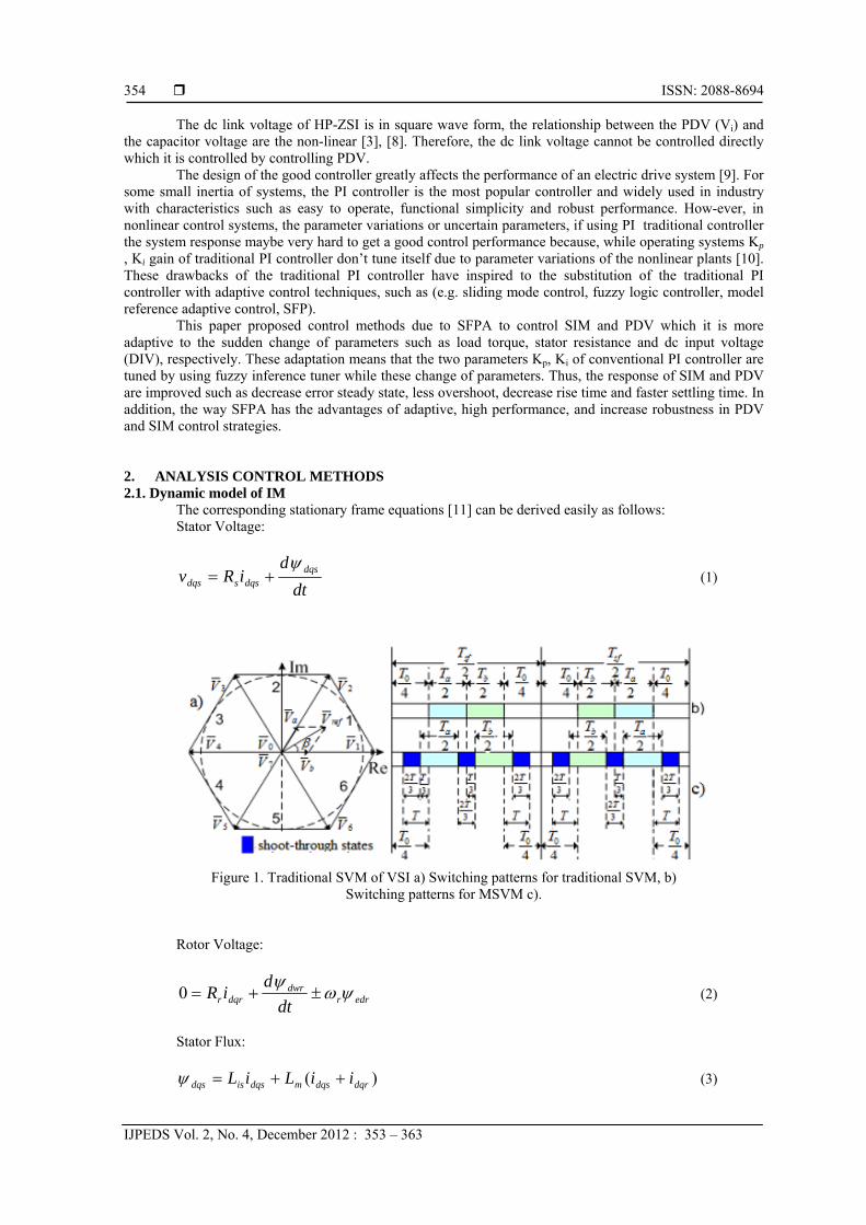
Figure 1. Traditional SVM of VSI a) Switching patterns for traditional SVM, b)
Switching patterns for MSVM c).
Rotor Voltage:
edrrdwr
dqrr dt
diR
0 (2)
Stator Flux:
)( dqrdqsmdqsisdqs iiLiL (3)
IJPEDS ISSN: 2088-8694
Self-Tuning Fuzzy PI-Type Controller in Z-Source Inverter for Hybrid Electric Vehicles (Cong-Thanh Pham)
355
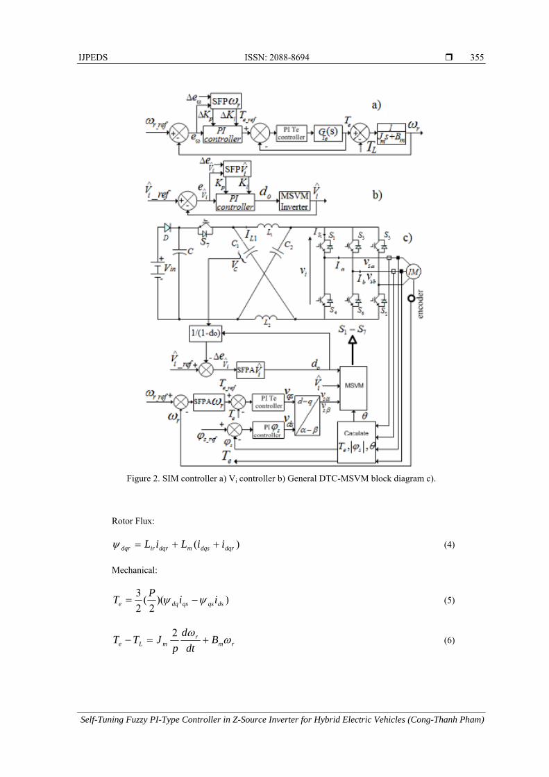
Figure 2. SIM controller a) Vi controller b) General DTC-MSVM block diagram c).
Rotor Flux:
)( dqrdqsmdqrirdqr iiLiL (4)
Mechanical:
))(2
(2
3dsqsqsdqe ii
PT (5)
rmr
mLe Bdt
d
pJTT
2 (6)
ISSN: 2088-8694
IJPEDS Vol. 2, No. 4, December 2012 : 353 – 363
356
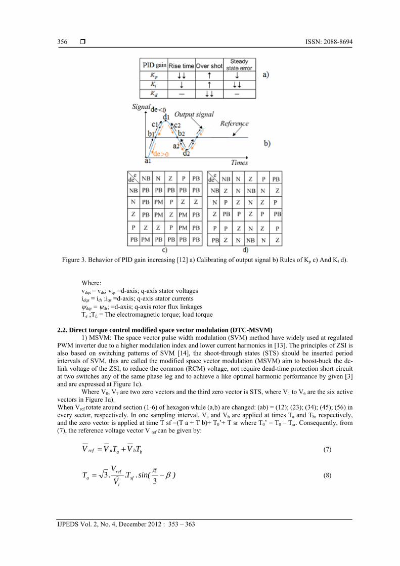
Figure 3. Behavior of PID gain increasing [12] a) Calibrating of output signal b) Rules of Kp c) And Ki d).
Where: vdqs = vds; vqs =d-axis; q-axis stator voltages idqs = ids ;iqs =d-axis; q-axis stator currents dqr = dr; =d-axis; q-axis rotor flux linkages Te ;TL = The electromagnetic torque; load torque
2.2. Direct torque control modified space vector modulation (DTC-MSVM) 1) MSVM: The space vector pulse width modulation (SVM) method have widely used at regulated
PWM inverter due to a higher modulation index and lower current harmonics in [13]. The principles of ZSI is also based on switching patterns of SVM [14], the shoot-through states (STS) should be inserted period intervals of SVM, this are called the modified space vector modulation (MSVM) aim to boost-buck the dc-link voltage of the ZSI, to reduce the common (RCM) voltage, not require dead-time protection short circuit at two switches any of the same phase leg and to achieve a like optimal harmonic performance by given [3] and are expressed at Figure 1c).
Where V0, V7 are two zero vectors and the third zero vector is STS, where V1 to V6 are the six active vectors in Figure 1a). When Vref rotate around section (1-6) of hexagon while (a,b) are changed: (ab) = (12); (23); (34); (45); (56) in every sector, respectively. In one sampling interval, Va and Vb are applied at times Ta and Tb, respectively, and the zero vector is applied at time T sf =(T a + T b)+ T0’+ T sr where T0’ = T0 – Tsr. Consequently, from (7), the reference voltage vector V ref can be given by:
bbaaref TVTVV (7)
)sin(.T.V
V.T sf
i
refa
3
3 (8)
IJPEDS ISSN: 2088-8694
Self-Tuning Fuzzy PI-Type Controller in Z-Source Inverter for Hybrid Electric Vehicles (Cong-Thanh Pham)
357
sin.T.V
V.T sf
i
refb 3 (9)
where is the angle between the reference voltage vector Vref and voltage vector V1 In the MSVM Figure 1c) where Tsr is shoot-through time, the STS are evenly assigned to each phase
with 3
2T within zero voltage period
40T
and 3
1T within active voltage period
2aT
and 3
1T within active
voltage period 2bT
, where Ta and Tb are unchanged. So the STS does not affect the SVM control method of
the inverter, and it is limited to the zero state time T0 .Where T are determined by (10).
44
326 sr
sr
TTT.
T.T (10)
And from [15] we have
20
2
10 sf
srsf
sro
TT
T
Td (11)
Where d0 is shoot through duty. From (10) and (11) we have
80 sfT
T (12)
There for, controlling the PDV across the inverter bridge have to found on limited of time T. 2) DTC-MSVM: The DTC-MSVM are combined from DTC and MSVM, the DTC-MSVM there
are features the same With DTC-SVM suchas: fast torque response, low steady state torque ripple, low current distortion, high-performance dynamic characteristics and accuracy, especially in DTC-MSVM, the value of dc-link voltage vi can be controlled by regulating STS when DIV sudden change, that it does not affect to SIM control and torque motor. There fore, the DTC-MSVM is the best candidate for HEV applications Figure 2c). 2.3. A new algorithm control the PDV across the inverter bridge and SIM due to SFPA, stator flux controller, electromagnetic torque controller, speed controller
All of the transfer functions and controllers parameters PI of electro magnetic torque and stator flux are given in [5] Figure 2c).
When we operate the general DTC-MSVM Figure 2c), All of parameters are always changing such as load torque, IM parameters and DIV. If we use conventional PI controller, two parameters Kp, Ki of PI controller don’t change to the continuous variations of those parameters. There fore, on-line tuning algorithms become desirable when high performance, accuracy and robustness are required from the control systems.
The first, PI Controllers parameters Kp , Ki are calculated base on sisotool of Matlab [5], then using SFPA to update Kp , Ki to cope with the continuous parameter variations in non-linear systems.
The PDV and SIM are controlled by SFPA that the two parameters Kp , Ki of conventional PI controller are tuned by using fuzzy inference tuner due to the sudden change of DIV, load torque and stator resistance, respectively. The transient response of PDV and SIM are thus improved with low disturbance for output voltage stabilization in the inverter bridge, high performance, accuracy and robustness Figure 2a) and b).
ISSN: 2088-8694
IJPEDS Vol. 2, No. 4, December 2012 : 353 – 363
358
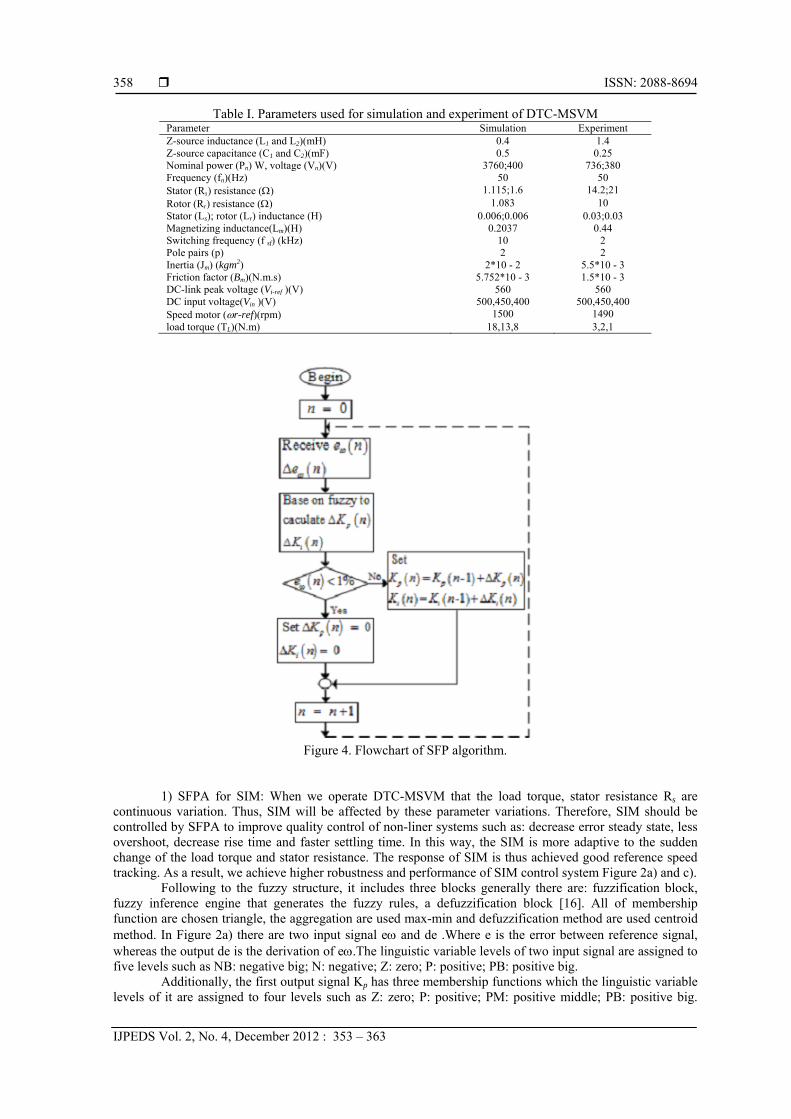
Table I. Parameters used for simulation and experiment of DTC-MSVM Parameter Simulation Experiment Z-source inductance (L1 and L2)(mH) 0.4 1.4 Z-source capacitance (C1 and C2)(mF) 0.5 0.25 Nominal power (Pn) W, voltage (Vn)(V) 3760;400 736;380 Frequency (fn)(Hz) 50 50 Stator (Rs) resistance () 1.115;1.6 14.2;21 Rotor (Rr) resistance () 1.083 10 Stator (Ls); rotor (Lr) inductance (H) 0.006;0.006 0.03;0.03 Magnetizing inductance(Lm)(H) 0.2037 0.44 Switching frequency (f sf) (kHz) 10 2 Pole pairs (p) 2 2 Inertia (Jm) (kgm2) 2*10 - 2 5.5*10 - 3 Friction factor (Bm)(N.m.s) 5.752*10 - 3 1.5*10 - 3 DC-link peak voltage (Vi-ref )(V) 560 560 DC input voltage(Vin )(V) 500,450,400 500,450,400 Speed motor (r-ref)(rpm) 1500 1490 load torque (TL)(N.m) 18,13,8 3,2,1
Figure 4. Flowchart of SFP algorithm.
1) SFPA for SIM: When we operate DTC-MSVM that the load torque, stator resistance Rs are continuous variation. Thus, SIM will be affected by these parameter variations. Therefore, SIM should be controlled by SFPA to improve quality control of non-liner systems such as: decrease error steady state, less overshoot, decrease rise time and faster settling time. In this way, the SIM is more adaptive to the sudden change of the load torque and stator resistance. The response of SIM is thus achieved good reference speed tracking. As a result, we achieve higher robustness and performance of SIM control system Figure 2a) and c).
Following to the fuzzy structure, it includes three blocks generally there are: fuzzification block, fuzzy inference engine that generates the fuzzy rules, a defuzzification block [16]. All of membership function are chosen triangle, the aggregation are used max-min and defuzzification method are used centroid method. In Figure 2a) there are two input signal e and de .Where e is the error between reference signal, whereas the output de is the derivation of e.The linguistic variable levels of two input signal are assigned to five levels such as NB: negative big; N: negative; Z: zero; P: positive; PB: positive big.
Additionally, the first output signal Kp has three membership functions which the linguistic variable levels of it are assigned to four levels such as Z: zero; P: positive; PM: positive middle; PB: positive big.
IJPEDS ISSN: 2088-8694
Self-Tuning Fuzzy PI-Type Controller in Z-Source Inverter for Hybrid Electric Vehicles (Cong-Thanh Pham)
359
Whereas the second output signal Ki has five membership functions which the linguistic variable levels of it are assigned to five levels such as NB: negative big; N: negative; Z: zero; P: positive; PB: positive big. In Figure 3a) when PID gain increase, Kp play critical role on rise time, Ki plays this critical role on error steady state and Kd only effects on overshot [12], [17]. Additionally, for some small inertia of systems, they are often used to the PI controller, especially for DTC-MSVM system. Therefore, we want to change Kp, Ki by only change ΔKp, ΔKi (13).
)n(K)n(K)n(K
)n(K)n(K)n(K
iii
ppp
1
1 (13)
Where n is sample time n – th, when n = 0 gain PI controller is designed based on [5], there are:
mnmp BJK 2)0( (14)
)12()0( 22 nmp JK (15)
From Figure 3b) at around a1, the signal control should be tuned to increase dramatically in order to
achieve fast rise time. So, Kp and Ki gain have to be tuned a big. Thus, the rule around a1, are given: If e is PB and de is Z, then ΔKp is PB, ΔKi is PB Figure 3c) and d). At around b1, the signal control should be tuned small so small error steady state and less overshoot.
Consequently, Kp gain have to be tuned a large, where as Ki have to be tuned a small. There fore, the following fuzzy rule is given:
If e is Z and de is NB, then ΔKp is PB, ΔKi is NB Figure 3c) and d). Similar for around a2, b2, c2, d2. As a result, fuzzy rule are given in Figure 3c) and d). In Figure 4 show that flowchart of SFP algorithm Kp, Ki Are updated on-line due to limit of
e.Therefore, response of SIM is thus improved, increase robustness and performance of SIM control system.
2) SFPA for PDV: The capacitor voltage (Vc) is somewhat equivalent to the PDV of inverter, which the relationship between the PDV (Vi) and the capacitor voltage are the non- linear [3]. Additionally, in [8] also show that non-minimum-phase when parameters of ZSI are variations. Consequently, the value of dc link voltage are controlled by controlling the PDV due to SFPA is most suitable for ZSI system.
Base on SFPA have just been analyzed, the PDV is also controlled by SFPA that the two parameters Kp, Ki of conventional PI controller are tuned by using fuzzy inference tuner due to the sudden change of DIV. Fuzzy rule tuning Kp, Ki is the same Figure 3c) and d). The transient response of PDV is thus improved with low disturbance for output voltage stabilization in the inverter bridge Figure 2b). 3. SIMULATION AND EXPERIMENTAL RESULTS
There are four main types of motor commonly used in Industry such as: DC motor, synchronous motor, switched reluctance motor and IM but IM is the most advantages such as reliability, controllability, maturity, technological and specially cost. So, IM is the most suitable term for the main requirements of automotive applications, especially the HEV electric propulsion [5], [18]. In this paper, we chose IM for simulation and experimental.
3.1. Simulation results
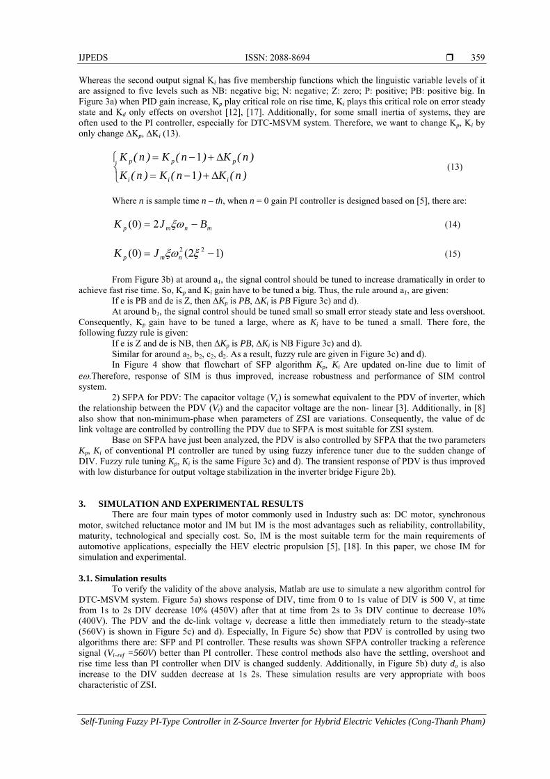
To verify the validity of the above analysis, Matlab are use to simulate a new algorithm control for DTC-MSVM system. Figure 5a) shows response of DIV, time from 0 to 1s value of DIV is 500 V, at time from 1s to 2s DIV decrease 10% (450V) after that at time from 2s to 3s DIV continue to decrease 10% (400V). The PDV and the dc-link voltage vi decrease a little then immediately return to the steady-state (560V) is shown in Figure 5c) and d). Especially, In Figure 5c) show that PDV is controlled by using two algorithms there are: SFP and PI controller. These results was shown SFPA controller tracking a reference signal (Vi–ref =560V) better than PI controller. These control methods also have the settling, overshoot and rise time less than PI controller when DIV is changed suddenly. Additionally, in Figure 5b) duty do is also increase to the DIV sudden decrease at 1s 2s. These simulation results are very appropriate with boos characteristic of ZSI.
ISSN: 2088-8694
IJPEDS Vol. 2, No. 4, December 2012 : 353 – 363
360
In addition, in Figure 5e) when the DIV sudden decrease then the current wave form is unvaried. In Figure 5f) THD% is shown current’s low total harmonic distortion THD% =379%. Therefore, the PDV is controlled by SFPA controller adapt to the DIV change, improves the transient response of PDV, small THD%, increase robust, applying good for speed control induction motor base on the DTC-MSVM control strategy.
In Figure 6c) shown low steady state electromagnetic torque ripple ΔTe. When load torque is sudden change at 1s, 2s Figure 6c), at that time, Te is always good tracking to load torque TL and SIM is also change due to load torque (6) Figure 6b). When load torque is sudden change at t =1s2s and stator resistance is increase 50% at t =05s speed control of induction motor r due to the way SFPA (blue-line) have the settling, overshoot and rise time less than PI controller (red-line) Figure 6b), Figure 6a), respectively. Therefore speed control of induction motor r due to SFPA is always tracking (r–ref =1500rpm) better than PI controller.
Figure 5. DIV Vin a) Duty do b) PDV Vi c) And the dc-link voltage vi d) The current e) THD% f). 3.2. Experimental results
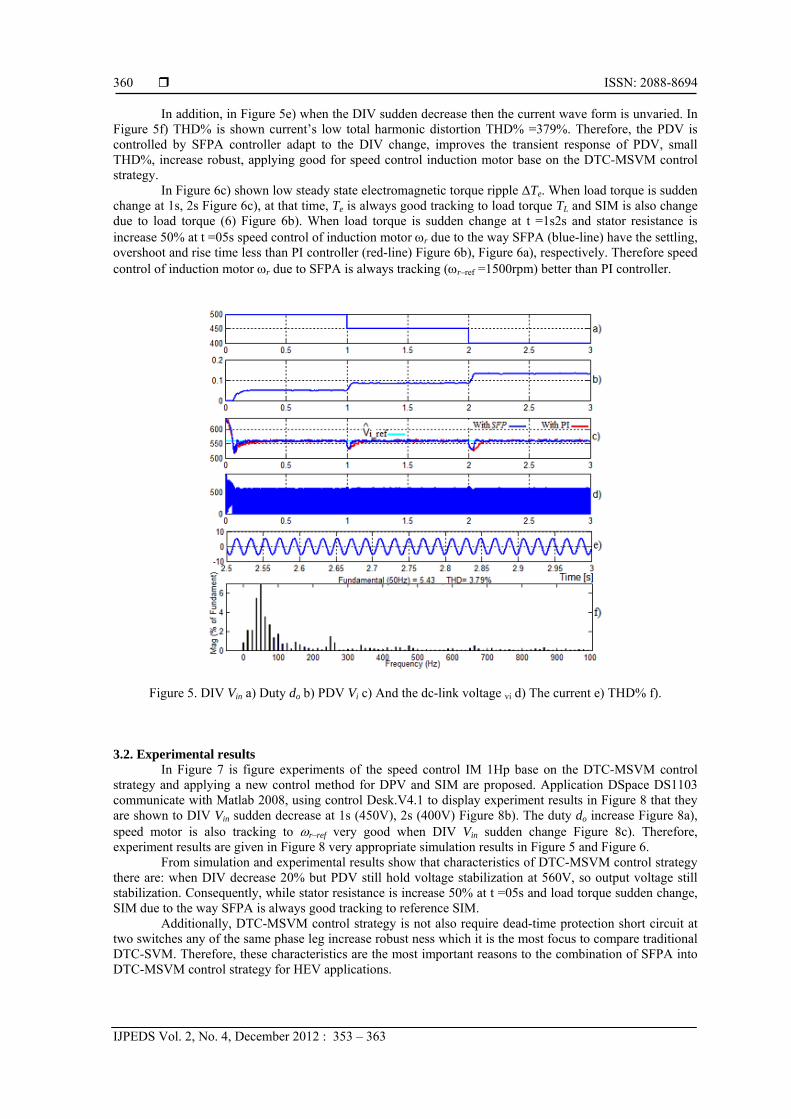
In Figure 7 is figure experiments of the speed control IM 1Hp base on the DTC-MSVM control strategy and applying a new control method for DPV and SIM are proposed. Application DSpace DS1103 communicate with Matlab 2008, using control Desk.V4.1 to display experiment results in Figure 8 that they are shown to DIV Vin sudden decrease at 1s (450V), 2s (400V) Figure 8b). The duty do increase Figure 8a), speed motor is also tracking to r–ref very good when DIV Vin sudden change Figure 8c). Therefore, experiment results are given in Figure 8 very appropriate simulation results in Figure 5 and Figure 6.
From simulation and experimental results show that characteristics of DTC-MSVM control strategy there are: when DIV decrease 20% but PDV still hold voltage stabilization at 560V, so output voltage still stabilization. Consequently, while stator resistance is increase 50% at t =05s and load torque sudden change, SIM due to the way SFPA is always good tracking to reference SIM.
Additionally, DTC-MSVM control strategy is not also require dead-time protection short circuit at two switches any of the same phase leg increase robust ness which it is the most focus to compare traditional DTC-SVM. Therefore, these characteristics are the most important reasons to the combination of SFPA into DTC-MSVM control strategy for HEV applications.

IJPEDS ISSN: 2088-8694
Self-Tuning Fuzzy PI-Type Controller in Z-Source Inverter for Hybrid Electric Vehicles (Cong-Thanh Pham)
361
Figure 6. Speed induction motor while r. Stator resistance increase 50% at t = 05s a) Load torque decrease
at t =1s and t =2s b) And torque c).
Figure 7. The figure experiments.
ISSN: 2088-8694
IJPEDS Vol. 2, No. 4, December 2012 : 353 – 363
362
Figure 8. Duty do a) The dc-link peak voltage Vi, DIV Vin b) And speed motor c). 4. CONCLUSION
Simulation and experimental results are given to verify the proposed a new algorithm to control SIM and PDV by applying SFPA with robust structure and non-linear characteristic. Additionally, SFPA is used to control SIM and PDV are more adaptive to the sudden change of parameters such as load torque, stator resistance and dc input voltage (DIV), respectively. The transient response of SIM and PDV are thus improved with less over shoot, short rise time, small steady-state error and fast settling time, with low disturbance for output voltage stabilization in the inverter bridge. As a result, we achieve higher accuracy and robustness of SIM control system. Therefore, the combination of SFPA into DTC-MSVM control strategy is the best candidate for HEV applications. REFERENCES [1] M. Olzwesky, “Z-source inverter for fuel cell vehicles,” U.S. Department of Energy, Freedom CAR and Vehicles
Technologies, EE-2G,1000 Independence Avenue, SW, Washington, D.C. 20585-0121, 2005. [2] K. Holland, M. Shen, and F.Z. Peng, “Z-source inverter control for traction drive of fuel cell-battery hybrid
vehicles,” Industry Applications Conference, Fourtieth IAS Annual Meeting, vol.3, no.4, pp.1651–1656, 2005. [3] I. Poh Chiang Loh, Member, D.M. Vilathgamuwa, I. Senior Member, Y.S. Lai, G.T. Chua, and I. Yunwei Li,
Student Member, “Pulse-width modulation of z-source inverters,” IEEE Transactions on Power Electronics, vol.20, no.6, pp.1346–1355, 2005.
[4] X. Ding, Z. Qian, Shuitao, Y.B. Cui, and F.Peng, “A high-performance z-source inverter operating with small inductor at wide-range load,” in Applied Power Electronics Conference, APEC 2007-Twenty Second Annual IEEE, March 2007, pp.615–620.
[5] O. Ellabban, J.V. Mierlo, and P. Lataire, “Direct torque controlled space vector modulated induction motor fed by a z-source inverter for electric vehicles,” in Proceeding of the 2011 International Conference on Power Engineering, Energy and Electrical Drivers, Malaga, Spain, May 2011.
[6] A. Haddoun, M. Benbouzid, D. Diallo, R. Abdessemed, J. Ghouili, and K. Srairi, “Comparative analysis of control techniques for efficiency improvement in electric vehicles,” in Vehicle Power and Propulsion Conference, VPPC, Sept2 007, pp.629–634.
[7] M. Vasudevan* and Dr. R. Arumugam, “New direct torque control scheme of induction motor for electric vehicles,” in 5th Asian Control Conference, 2004, pp.1377–1384.

IJPEDS ISSN: 2088-8694
Self-Tuning Fuzzy PI-Type Controller in Z-Source Inverter for Hybrid Electric Vehicles (Cong-Thanh Pham)
363
[8] X. Ding, S. Yang, Z. Qian, B. Cui, and F. Peng, “A direct peak dc-link boost voltage control strategy in z-source inverter,” in Applied Power Electronics Conference, APEC 2007-Twenty Second Annual IEEE, June 2007, pp.648–653.
[9] S. Gadoue, D. Giaouris, and J. Finch, “Articial intelligence-based speed control of dtc induction motor drives a comparative study,” Electric Power Systems Research, vol.79, no.01, pp.210–219, 2009.
[10] Zulfatman and M.F. Rahmat, “Application of self-tuning fuzzy pid controller on industrial hydraulic actuator using system identification approach,” INTERNATIONAL JOURNAL ON SMART SENSING AND INTELLIGENT SYSTEMS, vol.02, no.02, pp.246–261, 2009.
[11] B.K. Bose, Modern power Electronics and AC Drivers. USA: Pearson Education, 2002. [12] N. Nahapetian, M. Motlagh, and M. Analoui, “Adaptive pid gain tuning using fuzzy logic and additional external
performance index reference for controlling robot manipulator,” in International Conference on Advanced Computer Control, Jan. 2009, pp.448–452.
[13] T. Chun, Q. Tran, J. Ahn, and J. Lai, “Ac output voltage control with minimization of voltages tress across devices in the z-source inverter using modified svpwm,” in PESC 37th IEEE, 2006, pp.1–5.
[14] Q. Tran, I. Tae. Won Chun, Member, J. Ahn, and I. Hong. Hee Lee, Member, “Algorithms for controlling both the dc boost and ac output voltage of z-source inverter,” IEEE Trans. Industrial Electronics, vol.54, no.5, pp.2745–2750, Mar.2007.
[15] I. Fang Zheng Peng, Senior Member, “Z-source inverter,” IEEE Trans. Industry Applications, vol.39, no.2, pp.990–997, Mar.2003.
[16] X. Ding, Z. Qian, S. Yang, B. Cui, and F. Peng, “A direct dc-link boost voltage pid-like fuzzy control strategy in z-source inverter,” in Power Electronics Specialists Conference, PESC 2008. IEEE, June2008, pp. 405–411.
[17] I. Zhen-Yu Zhao, Member, I. Masayoshi Tomizuka, Member, and I. Satoru Isaka, Member, “Fuzzy gain scheduling of pid controllers,” IEEE TRANSACTIONS ON SYSTEMS, MAN, AND CYBERNETICS, vol.23, no.5, pp.1392–1398, 1993.
[18] M. Zeraoulia, M.E.H. Benbouzid, and D. Diallo, “Electric motor drive selection issues for hev propulsion systems: Acomparative study,” in Vehicle Power and Propulsion, 2005 IEEE Conference, Sept2005, pp. 1756–1764.
Related Documents