Self Oscillating Dimmable Electronic Ballast Azlan Kamil B Moharnrnad Fauzy This Report Is Submitted In Partial Fulfillment Of Requirements For The Bachelor Degree of Electronic Engineering (Industrial Electronic) Fakulti Kejuruteraan Elektronik dan Kejuruteraan Komputer Kolej Universiti Teknikal Kebangsaan Malaysia March 2006

Welcome message from author
This document is posted to help you gain knowledge. Please leave a comment to let me know what you think about it! Share it to your friends and learn new things together.
Transcript

Self Oscillating Dimmable Electronic Ballast
Azlan Kamil B Moharnrnad Fauzy
This Report Is Submitted In Partial Fulfillment Of Requirements For The Bachelor
Degree of Electronic Engineering (Industrial Electronic)
Fakulti Kejuruteraan Elektronik dan Kejuruteraan Komputer
Kolej Universiti Teknikal Kebangsaan Malaysia
March 2006

ABSTRACT
The lighting system provides many opportunities for cost-effective energy saving
without any sacrifice. The system is now part of the Energy Conservation program over
the world and reduction of energy consumption by implementing energy conservation
schemes is needed. Incandescent lamps convert just five per cent of energy into light and
the remainder into heat where as fluorescent lamps turn 25 per cent of energy into light.
As the rapid development of power electronics technology, inverters are now used
for energizjng the lamp. These inverter systems are now referred as the electronic ballast
and can eliminate the conventional magnetic ballast's disadvantages. A simple
explanation for the system is the main input is rectified to a DC voltage which is then
inverted into a high frequency AC voltage to drive the fluorescent lamp. Electronic
ballasts can also be provided with a dimming capability. Dimming controls have been
broadly employed in recent lighting systems to provide energy savings and improved
economic.
The self oscillating dimmable electronic ballast that will construct in this project
is hope will be useful not only in energy saving but also low cost and high reliability.
ABSTRAK
Sistem pencahayaan memberi banyak peluang bagi penjimatan tenaga secara kos
efektif tmpa sebarang pengorbanan. Sistem ini sekarang merupakan sebahagian daripada
program pemeliharaan tenaga (Energy Conservation) di seluruh dunia dan pengurangan
penggunaan tenaga dengan rnelaksanakan skim pengekalan yang diperlukan.
Dengan pembangunan yang pesat di dalam teknologi elektronik kuasa, pengubah
(inverter) dapat digunakan untuk penyalaan lampu. Sistem pengubah ini di kenali sebagai
ballast elektronik dan ia boleh menghilangkan kelemahan ballast magnetic yang masih di
guna pakai sekarang. Penerangan yang ringkas menegnai system ini ialah masukan utama
di tukar kepada voltan arus terus yang mana kemudiannya di ubah kepada voltan arus
ulang alik yang berfrekuensi tinggi untuk memacu larnpu fluorescent. Ballast elektronik
juga dapat disertakan dengan fungsi pemalap kawalan malapan telah banyak digunakan
di dalam system pencahayaan yang ada sekarang bertujuan untuk menjimatkan tenaga
dan meningkatkan ekonomi.
Litar yang akan dibina didalm projek ini di harap agar dapat digunakan bukan
sahaja bagi menjimatkan tenaga tetapi juga murah dan berkeupayaan tinggi.
CHAPTER I
INTRODUCTION
Ballasts are electrical devices that convert line current into the proper voltage,
amperage, and waveform to operate fluorescent lamps. Over the past 10 years, ballast
have been develops toward more efficient equipment. Electronic ballasts are the best
choice in most applications today, either as replacements for magnetic ballasts in
existing fixtures or in new installations.
To drive a fluorescent lamp, the electronic ballast, with respect to the magnetic
ballast, presents the following features: reduced ballast loss (higher efficiency) and
weight, facility on lamp power control, more eficient tube ignition, no flickering and
operating conditions improving lamp life.
This project involves voltage fed series half bridge converters. This topology is
operating in Zero Voltage Switching (ZVS) resonant mode which is reducing the
switching losses. The project are based on L6569 device that are able to directly
control a symmetric half bridge inverter of a fluorescent lamp ballast.

1.1 Project Objective
The objective of this final project is to gain knowledge in developing
electronic ballast. By study the prospect and ability of electronic ballast, a simple and
low cost electronic ballast circuit will be constructed. The circuit will be able to
operate in selected frequency range for an 18 watt lamp and possibility for dimming
are been study.
1.2 Project Scope
The scope for this project is to studies the electronic ballast function and then
planning for the required specification of the electronic ballast. By using software, a
development of the circuit by simulation is used to convince the theoretical of
electronic ballast. Beside in scope of work for this project followed by:-
1. Studies and development of the PCB design.
2. Studiesllearn the appropriate testing and troubleshooting technique.
CHAPTER I1
LITERATURE REVIEW
The first fluorescent lamp was patented over 100 years ago by American
inventor, Peter Cooper Hewitt. Cooper Hewitt's low pressure mercury arc lamp is the
direct parent for the generation of today modem fluorescent lamp. Fluorescent lamps
are far more efficient than incandescent lamps, fluorescent lamp use electricity to
excite molecules of Argon or krypton together with mercury vapor to create
luminescence. Unlike incandescent lamps, a fluorescent lamp cannot be connected
directly to electric lines. Fluorescent lamp required ballasts to stabilize the flow of
current or else they quickly become inoperable. Ballast provides the starting voltage
for a fluorescent lamp and limits the current passing through it. The ballast also
provides proper electrode or filament heating.

2.2 FLUORESCENT LAMP
A fluorescent tube is a low pressure mercury vapors discharge lamp containing
an inert gas that consisting of argon or krypton at low pressure (below 1 atmosphere)
plus a small measured dose of mercury. There is a filament at each end which when
hot, emits electrons to sustain the discharge when the lamp is operating. The mercury
vapors discharge produces ultraviolet light which is converted to visible light by the
phosphors coating the inside of the glass tube. The glass blocks the exit of the
ultraviolet radiation but allows the visible radiation through.
A non-operating fluorescent tube will appear as an open circuit, since there is
no electrical connection from one end to the other. To "strike the arc", a high voltage
must be applied across the lamp which will ionizes the gas and this will instantly "cold
start" the lamp and shorten its life by sputtering electronemitting material from its
cathodes. However, if the cathodes are first preheated to generate a space charge of
electrons at each end of the lamp, the strike voltage is considerably reduced and lamp
life will not be unduly compromised by the start-up. As soon as the discharge current
flows, the lamp's electrical impedance will drop. It now becomes as negative
impedance, where an increase in current is accompanied by a reduction in lamp
voltage. Therefore they will be a current-limiting device in series with the lamp which
compensates with a positive impedance characteristic to prevent current runaway and
rapid destruction of the lamp.
low pressure argon or crypton fjllmg
chatode
phospor coating 4
f small dose mercury
Figure 2.1: Fluorescent Lamp
2.3 BALLAST
Ballasts are electrical devices that convert line current into the proper voltage,
amperage, and waveform to operate fluorescent lamps. Electrical distribution systems
deliver fixed AC voltage (50 or 60 Hz) and expect connected electrical loads to limit
the current drawn from the source. Ballasts provide system stability by limiting the
curre. .L that can be drawn. Ballasts use inductive and capacitive components because
they impede alternating current with little power consumption. Resistive components
generate high loss and are usually avoided. The mix of ballasts has been shifting
steadily toward more efficient equipment over the past 15 years. Magnetic ballast and
electronic ballast are the common ballast that is being use now days.
23.1 MAGNETIC BALLAST
The requirements of fluorescent lamp ballast are to:
(a) Preheat the cathodes to induce electron emission,
(b) Provide the starting voltage to initiate the discharge,
(c) Limit the running current to the correct value.
There are several types of mains frequency "magnetic" ballast available. By far
the most common circuit for 230V mains supplies has traditionally been the switch
start ballast, where lamp ballasting is provided by the choke. Other circuits include, in
order of popularity, the semi-resonant circuit and the quick start circuit.
The switch start circuit has been widely adopted because of its simplicity, low
cost and improved efficiency when compared with the alternative options mentioned
above. Another reason is that the 230V mains voltage is sufficiently higher than the

tube running voltage to allow the use of the simple series impedance ballast in almost
all cases. . CHOKE
STARTER
Fignre 23: A fluorescent tube.
When the voltage is applied to the circuit, the lamp does not operate at first, so
the full mains voltage appears across the starter via the choke and lamp cathodes. The
starter consists of bi metallic contacts sealed within a small discharge bulb with an
inert gas filling such as argon or neon. The mains voltage causes a glow discharge
within the starter which heats up the bi metallic contacts, causing them to close. This
completes the circuit and allows preheat current to flow through the choke and both
cathodes. Since the glow discharge within the starter has now ceased, the bi metallic
contacts cool down and open. Because the inductance of the choke tries to maintain
current flow, the voltage across the lamp rises rapidly and strikes the lamp. If it does
n ~ t , the starter's contacts close again and the cycle repeats. Once the lamp has started,
the choke controls its current and voltage to the correct levels. The lamp running
current is enough to keep the cathodes (heaters) hot and emitting electrons without the
need for separate heater supplies, which would otherwise be wastehl of energy. Since
the lamp's running voltage is much lower than the &air& voltage, there is now not
enough voltage to cause a glow discharge in the starter, so it remains open circuit.

2.3.2 ELECTRONIC BALLAST
Electronic ballasts have been available since at least the beginning of the
1980's. Improvements in ballast performance and ever-increasing energy costs have
resulted in an upsurge in electronic ballast use since the beginning of the 1990's.
Replacing the most efficient low loss mains frequency switch start ballast with
electronic ballast leads to reduced energy consumption and improved perfo..nance.
The advantages of electronic ballast are:
1. Increased light output
2. Flicker eliminated
3. Audible noise eliminated
4. Lower ballast power
5. Extended lamp life
6. Versatile lamp control
7. Compact and light weight
23.2.1 INCREASED LIGHT OUTPUT
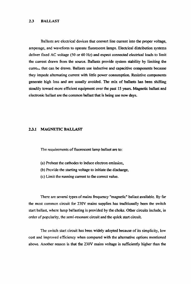
If the cperating frequency is increased from 50Hz to above the audible limit of
20 kHz, fluorescent lamps can produce around 10% more light for the same input
power. Alternatively, the input power can be reduced for the same light output.
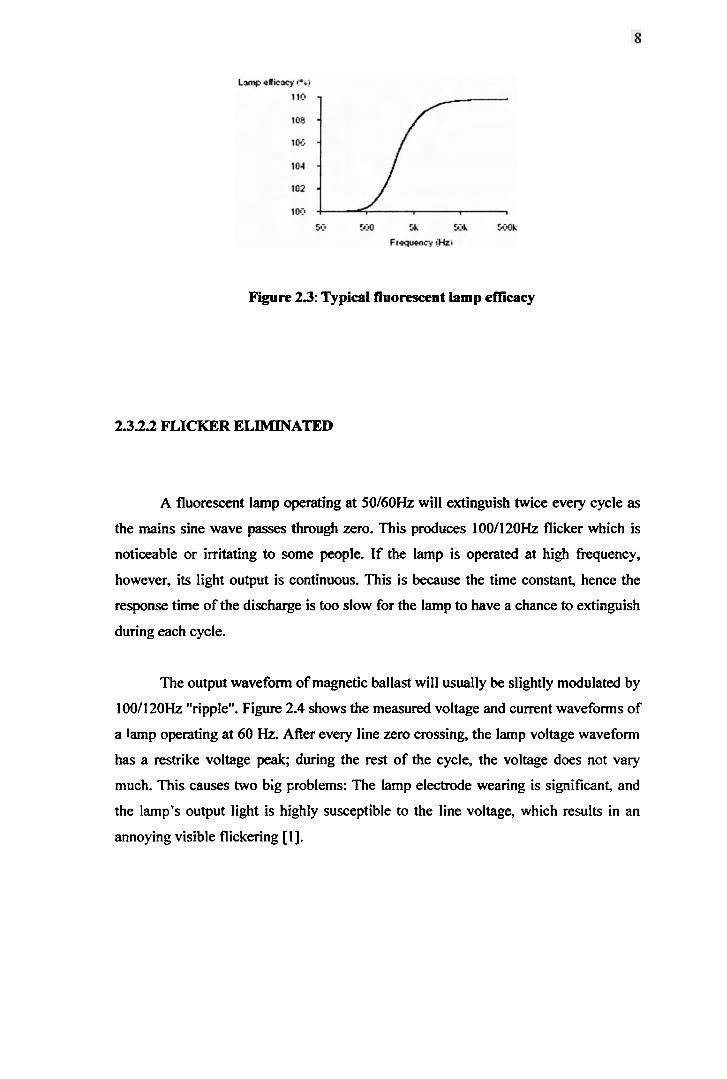
Figure 23: Typical fluorescent lamp eflicacy
2.3.2.2 FLICKER ELIMINATED
A fluorescent lamp operating at 50160Hz will extinguish twice every cycle as
the mains sine wave passes through zero. This produces 1001120Hz flicker which is
noticeable or irritating to some people. If the lamp is operated at high frequency,
however, its light output is continuous. This is because the time constant, hence the
response time of the discharge is too slow for the lamp to have a chance to extinguish
during each cycle.
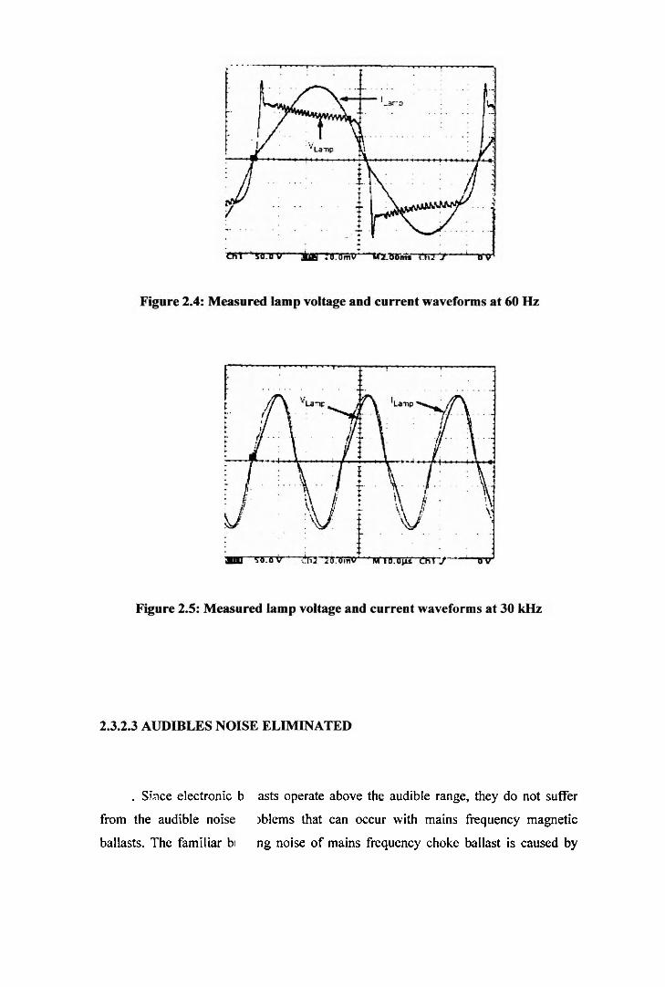
The output waveform of magnetic ballast will usually be slightly modulated by
1 001 120Hz "ripple". Figure 2.4 shows the measured voltage and current waveforms of
a lamp operating at 60 Hz. After every line zero crossing, the lamp voltage waveform
has a restrike voltage peak, during the rest of the cycle, the voltage does not vary
much. This causes two big ~roblems: The lamp electrode wearing is significant, and
the lamp's output light is highly susceptible to the line voltage, which results in an
annoying visible flickering [I].
o h
$g '3
s
2 $
3
z g
2 c
0
4 p
.??
w -
B g
g
s
2;
d
rc
P
M
c
23
2
*- 0
w2
-5
- e s g 3
3 5j
5 '3
s o
r!
>
c
-E: s
*-
a
U
2 3
-b
.
a 0
g 7
5
3 .-
Eg
o
c
E 2
3s
2 5
)
0
. - c -5
2 9
c.=
u
. - 8
2 E
z E
I2 8 3
E
r;. . - V)
'=
k
Sb
V)
E 2
0 7
& a

mechanical vibrations in its laminated steel core and, possibly, its coil as well. This
can excite vibrations in the steel body of the lighting fixture and the surface to which . it is fixed, which amplifies the original noise even further.
23.2.4 LOWER BALLAST iOWER
Electronic ballast will consume less power and therefore dissipate less heat
than mains frequency magnetic ballast. These power =ductions are because:
a) At high frequency, the' lamp can be run at a lower power for the same light output.
b) The power loss in electronic ballast is much lower than the power loss in mains
frequency magnetic ballasts.
2.3.2.5 EXTENDED LAMP LIFE
An electronic ballasts which "soft starts" the lamp will not sputter away the
electronemitting material from the cathodes during starting. This will give longer
lamp life when compared to the uncontrolled impulses to which the lamp is subjected
in a switch start circuit.
23.2.6 VERSETILE LAMP CONTROL
Electronic ballasts are available which permit lamp dimming. This gives
substantial energy savings in situations where the lights are linked to an automatic
control system which detects ambient light levels and adjusts lamp output to maintain
a constant level of illumination. Lights may also be programmed to dim during
intervals when ,eas are not in use, for example during lunch breaks.
Electronic ballasts can incorporate feedback to detect the operating conditions
of the lamp(s) so that failed lamps can be switched off to avoid annoying flicker and
possible ballast damage. They can also incorporate regulation, whereby a constant
light output is maintained over a range of input voltages.
23.2.7 COMPACT AND LIGHT WEIGHT
Owing to the high frequency of operation, the magnetic components in
electronic ballast are compact and lightweight with cores of ferrite material, whereas
at mains frequency the ballast choke must be larger and heavier with bulkier copper
windings and a core of laminated steel. The shape and geometry of a mains tiequency
choke is determined by magnetic efficiency requirements, whereas the circuitry within
electronic ballast can be arranged to produce a very slim final pacpcge. This permits
new levels of slimness and compactness for the final ballast and the lighting fixture.


few cycles, the voltage on capacitor Cres reaches enough value to strike the tube.
After that, the current will flow between the cathodes and the lamp can be considered
like a resistor (see figure 2.7) 151.
Figure 2.7: Simplified Schematic after lamp ignition
Using cool ignition, high current values (3, 4 times the nominal value) and
voltage values are present in the lamp for a short time, consequently the tube life is
reduced [5].
2.4.2 WARM IGNITION
To provide long life and to insure an efficient ignition of the lamps the
cathodes must be preheated. The preheating of the filaments allows an easy strike of
the lamp thanks to the ignition voltage reduction. During preheating time the tube
presents high impedance so the current flows through the filaments. Its resistance
value is strictly dependent on the lamp model. A simple rule to determine the right
preheating currentltime value is the following: the ratio between the cathode
resistance before and after the preheating has to be in the range of 3-5.Thei-e are two 5
methods to obtain the cathodes preheating:

Voltage mode heating;
Current mode heating.
2.4.2.1 VOLTAGE MODE HEAITVG
This function is achieved by heating the lamp cathodes by means of two
auxiliary windings. These ones are magnetically coupled with the main inductance as
shown in figure 2.8.
I , . I.\-5 1_ ti. 1 '"<'
Figure 2.8: Voltage Mode Heating lamp connection
During the preheating phase, the lamp can be considered an open circuit, the
current flows through L'res and Cres. The voltage across L'res is transferred to the
secondary windings L"res, generating a current heating the cathodes. The primary
current value is related to the half bridge working frequency, so the preheating
fkquency is chosen according to the tube specs (rms currentltime) [ 5 ] .
4
The capacitor Cres must be chosen considering that, during the preheating, the
voltage across it must be lower than the ignition voltage. At the end of the preheating

During the preheating phase the lamp is an open circuit and the current flows
through Lres and Cres heating the lamp cathodes. The current in this phase depends
on the half bridge working fkquency. At the end of the preheating time the ICs
perform the lamp ignition sequence reducing the frequency towards the resonant
frequency fixed by Cres and Lres. In this way the c m n t and the voltage on Cres
increase causing the strike of the lamp. Once the lamp is successfblly ignited, the ICs
determine the steady state frequency for a given power lamp [5] .
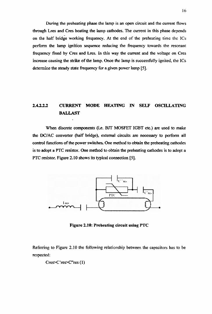
2.43.2.2 CURRENT MODE HEATING I N SELF OSCILLATING
BALLAST
When discrete components (i.e. BJT MOSFET IGBT etc.) are used to make
the DC/AC converter (half bridge), external circuits are necessary to perform all
control hnctions of the power switches. One method to obtain the preheating cathodes
is to adopt a PTC resistor. One method to obtain the preheating cathodes is to adopt a
PTC resistor. Figure 2.10 shows its typical connection [5].
Figure 2.10: Preheating circuit using PTC
Referring to Figure 2.10 the following relationship between the capacitors has to be
respected: . a
Cres>C'res>C"res (1)


In this case the current flows through the series formed by Cures and C'res.
According to (I) the equivalent capacitance (C9'res series C'res) across the lamp . becomes lower than the initial value (C'res) increasing the capacitive reactance and
allowing the tube ignition. After the ignition, C"res C'res and WC can be considered
a high impedance in parallel to the tube, thus its contribution can be neglected [S ] .
2.5 POWER FACTOR (PF)
Power Factor (PF) is the measurement of how effectively ballast converts the
voltage and current supplied by the power source into watts of usable power
delivered to the ballast and lamps. Perfect power utilization would result in a power
factor of one.
PF = Inwt Watts
Input Current x Input Voltage
Ballast's power factor may be classified under any one of the following
categories:
High Power Factor (HPF) - 0.90 or greater
Power Factor Corrected (PFC) - 0.80 to 0.89
Normal (Low) Power Factor (NPF) - 0.79 or less
Power factor measurements pertain only to the effective use of power
supplied to the ballast. They are not an indication of ';he +allasts ability to supply
light through the lamps. Because low power factor ballasts required about twice the
current needed by high power factor ballasts, they allowed fewer fixtures per circuit

and added wiring costs. High power factor ballast is generally specified for all
commercial lighting applications.
I I Main Power
Factor Correction
Figure 2.13: System Block Diagram
2.6 MAJOR ELECTRONIC BALLAST TOPOLOGIES @C/AC
INVERTER STAGE)
Electronic ballasts are expected to perform the following functions: supply
proper starting and operating voltage for the lamp; maintain a running current at the
designed value with a low CF; regulate the lamp current output against supply voltage
variations; and have a high overall efficiency. To obtain extra energy savings andlor
make intelligent lighting, the controllable light output or dimming feature is expected.
In addition, low cost and high reliability are very important considerations [I].
From a historical perspective, electronic ballasts originated from the solid-state
radio frequency (RF) power amplifiers (PAS). RF PAS are usually identified by their
classes of operat&n, that is, Classes A, B, C, D, E, F, G, H and S. Based on how the
transistor is biased and driven, all these classes of PAS are placed in the following
three categories:
I. linear-mode PAS
2. switching-mode PAS
3. mixed-mode PAS
2.6.1 LINEAR-MODE PAS
In the linear-mode PAS, the power transistors act as a high-resistance current
source to produce a magnified replica of the input signal voltage or current wave.
Because of the high voltage and current product (power dissipated) inherent in power
transistors, this category of Pas usually has low efficiency [I].
2.6.2 SWITCHING-MODE PAS
In switching-mode PAS, the power transistors operate as a switch, alternately
opencircuited and shortcircuited. Ideally, a switch has either zero voltage across it or
zero current through it at all times (i.e., zero resistance when on, infinite resistance
when off, no associated parasitic capacitance or inductance, and zero transition times).
Therefore, this category of PAS can theoretically achieve eficiencies of 100% [I.]. fi

2.63 MIXED-MODE PAS
In mixed-mode PAS, the power transistors basically act as a current source, but
partially also as a low-resistance "on" switch. Compared with linear-mode PAS, this
category of PAS can improve efficiency due to operating the power switch into
saturation. Obviously, the biggest achievements of switching-mode PAS are their high
efficiency, low power dissipation, high reliability, small ,ize and low cost [I].
Classes D, E and S usually comprise switching-mode PAS in RF engineering.
Essentially, Class S PAS are wideband PWM DCIDC converters with low-pass filters
to allow only a slowly varying DC or average voltage component to appear on the
load. The desired output signal is obtained by controlling the pulse width of the input
signal, and for this reason, it requires PWM control. In power electronics, Class S PAS
are appropriated for applications in variable-speed AC motor drives and
unintermptible power supplies (UPSs), which use batteries to provide standby AC
power. Classes D and E PAs, on the contrary, are essentially resonant power
converters with high-fkquency AC output voltage and current. This is most favored in
electronic ballast applications in which a sinusoidal current source is needed.
Actually, Class D and Class E electronic ballasts represent two major categories in
today's electronic ballast market [I] .
Class D PAS, employ a pair of active switches and a tuned network. The
switches are driven to act as a two-pole switch that defines either a rectangular voltage
or rectangular current waveforms. The output network is tuned to the switching
frequency and removes its harmonics, resulting in a sinusoidal output. This
characteristic of Class D PAS easily finds its application in electronic ballasts. With its
sinusoidal current drive, the lamp efficacy is highest and the EM1 is smallest.
Additionally, the tuned network also functions as an impedance match to the lamp.
The tuned network is probably the most cost-effective way to generate AC curreni as
well as allowing impedance matching.
4


Figure 2.17: voltage-fed balf-bridge series-resonant parallel-loaded ballast.
In the Class D voltage-fed push-pull (VFPP) electronic ballasts (Figure 2.14),
a square-wave voltage is fed into a series-resonant or series-resonantderived network,
thereby producing sinusoidal resonant current, as opposed to the CFPP electronic
ballasts in which a square-wave current is fed into a parallel-resonant or parallel-
resonantderived network, thereby producing sinusoidal resonant voltage such that the
voltage and current waveforms are interchanged.
Class D current-fed half-bridge (CFHB) and voltage-fed half-bridge (VFHB)
electronic ballasts are shown in Figures 2.15 and 2.16, respectively. Although the
circuit topologies are different, the circuit operations are essentially the same as those
of their push-pull counterparts. In contrast, Class D CFPP electronic ballasts have the
best performances. Due to the parallel resonant configuration with current feed, they
can operate indefinitely under virtually any load condition, including short, open, and
the most severe situation in which a lamp is socketed into a powered fixture. Another
important advantage is that they can achieve parallel lamp operation simply by adding
a single ballast capacitor per additional lamp, and part of the lamps' replacements
might occur while the rest of the lamps are in normal operation. But the downside is
that they have the largest component count. The required large inductor and step-up
transformer make the circuit bulky and lossy. High voltage stress on the two switches
also makes them less attractive, especially when operated after a PFC pre-regulator
[I]. . n

The Class D VFHB electronic ballasts, on the contrary, are simple circuits
requiring fcw components. When they operate at the undamped natural frequency,
they show curreni source characteristics such that no step up transformer is necessary.
If isolation is needed, a smaller transformer can be used because the secondary
winding voltage is equal to the lamp voltage, unlike the Class D CFPP electronic
ballasts in which separate ballast impedance is necessary to absorb the voltage
difference between the winding voltage (striking voltage) and the lamp's normal
operating . Atage. Another attractive feature is that the voltage stress of the two
switches is equal to the bus voltage, which allows low-voltage-rating MOSFETs to be
used [I].
2.7 PFC TECHNIQUES IN ELECTRONIC BALLAST
There are generally two methods for correcting the PF and suppressing
harmonic distortion: the passive PFC approach and the active PFC approach. Passive
PFC refers to using only 1 ine-frequency reactive components plus uncontrolled
rectifiers, while the active PFC uses active devices and high- requency reactive
components as well as passive switches such as diodes. The advantages of the passive
PFC approach are its simplicity, reliability, robustness, lack of EM1 generated, and
low cost. However, the physical size and weight of the line frequency components
renders the passive approach very unattractive. The active approach, on the other
hand, not only easily meets the specifications, but also significantly reduces the circuit
size and weight. The major issues are circuit complexity, reliability and cost [I].
Related Documents