385 Sumpter Road ● Belleville, MI 48111 http://www.contractwelding.com Self-Contained Compactor Service Manual Serial Number: _____________________________________ Power Unit Number: ________________________________ Date of Purchase: _____________________________________ Phone: (734) 699-5561 Fax: (734) 699-0360

Welcome message from author
This document is posted to help you gain knowledge. Please leave a comment to let me know what you think about it! Share it to your friends and learn new things together.
Transcript

385 Sumpter Road Belleville, MI 48111 http://www.contractwelding.com
Self-Contained Compactor
Service Manual Serial Number: _____________________________________ Power Unit Number: ________________________________ Date of Purchase: _____________________________________
Phone: (734) 699-5561 Fax: (734) 699-0360

WWAARRNNIINNGG!!
Before operating, performing maintenance, or servicing: Read and understand the contents of this entire manual Ensure that all appropriate OSHA regulations are observed Reference all applicable ANSI Z245 Standards and ensure that all parties
involved with the machine are familiar with the standard(s) Current versions of the ANSI Z245 standards for compactors can be obtained by contacting:
American National Standards Institute
Washington D.C. Headquarters 1819 L Street NW 6th Floor Washington, DC 20036 Tel: 202-293-8020 Fax: 202-293-9287
New York City Office Operations 25 West 43rd Street 4th Floor New York, NY 10036 Tel: 212-642-4900 Fax: 212-398-0023
WASTEC
Washington D.C. Headquarters 4301 Connecticut Avenue NW, Suite 300 Washington, DC 20008 Tel: 202-244-4700 Fax: 202-966-4824
It is the owner’s responsibility to ensure that this manual is updated with the most current version of these standards as they are subject to continuous revision by their respective boards.
DDAANNGGEERR!!
Proper maintenance and service are critical to safe operation of this compactor! Only authorized & certified technicians should service the compactor. Modifying, changing, or replacing any component with other components or in a manner not compliant with those specified by manufacturer will void warranty and may result in unsafe conditions that can lead to injury or death!

Table of Contents Compactor Operation Safety Rules ................................................................................................. 1
Power Lockout Procedure ................................................................................................................ 3
Hydraulic Lockout Procedure .......................................................................................................... 5
Operational Requirement ................................................................................................................. 7
Start Up Instructions ........................................................................................................................ 8
Self-Contained Compactor Operation ............................................................................................. 9
Multi-Stroke Adjustment Procedure .............................................................................................. 12
Cylinder Outstroke Adjustment Procedure .................................................................................... 13
Pressure Setting Procedure ............................................................................................................ 15
Preventative Maintenance Schedule .............................................................................................. 17
Preventative Maintenance Checklist .............................................................................................. 18
Troubleshooting ............................................................................................................................. 19
Self-Contained Compactor Schematic ........................................................................................... 21
Panel Layout & Fuse Table ........................................................................................................... 22
Compactor II Board Layout ........................................................................................................... 23
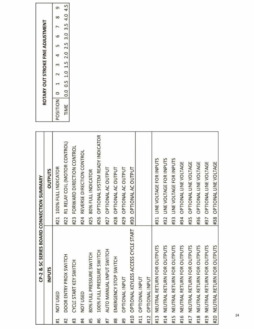
Connection Summary Table .......................................................................................................... 24
Dip Switch Setting ......................................................................................................................... 25
Electrical Quick Disconnect Wiring Table .................................................................................... 26
Hydraulic Oil Heater Element Data Sheet ..................................................................................... 27
Power Unit Schematic ................................................................................................................... 28
Motor Starter & Overload Data Sheet ........................................................................................... 29
Photo Eye Data Sheets ................................................................................................................... 30
Proximity Switch Data Sheet ......................................................................................................... 33
Timer Data Sheet ........................................................................................................................... 35

Compactor Operation Safety Rules
WWAARRNNIINNGG!!
IF INCORRECTLY USED THIS EQUIPMENT CAN CAUSE SEVERE INJURY AND EVEN DEATH! THE COMPACTOR IS TO BE OPERATED ONLY BY AUTHORIZED, FULLY TRAINED & QUALIFIED PERSONNEL 18 YEARS OF AGE OR OLDER WHO ARE AWARE OF THE DANGER AND FOLLOW THESE SAFETY RULES. All Safety Guards and covers must be in place prior to start up or operation of the compaction
equipment. Ensure the container is properly positioned and latched securely to the compactor before
starting the compactor. Maintain dock ramp(s), point of operation, and all surrounding areas of the stationary
compactor: Keep clear of refuse, grease, oil, and/or water. DO NOT PUT FLAMMABLE, EXPLOSIVE OR HAZARDOUS MATERIALS IN
MACHINE! Be familiar with all controls of the machine. Know the location, function, and operation of all
controls. Do not operate or touch the controls with wet hands or in a damp environment. In freezing
weather make sure controls are free of ice before operating. BEFORE OPERATING COMPACTOR BE CERTAIN THAT ALL INDIVIDUALS ARE
CLEAR OF THE CHARGING CHAMBER, HOPPER, AND PINCH-POINT AREAS! Wear safety glasses or goggles while operating compactor. NEVER REACH INTO OR ENTER THE CHARGING CHAMBER UNLESS THE
PRESCRIBED LOCKOUT MEASURES HAVE BEEN TAKEN TO PREVENT ACCIDENTAL START UP!
To prevent operation of the compactor by unauthorized persons, remove key from control panel key switch.
Fully retract packer ram before unlocking container. Stand clear of tailgate swing area when container is being removed. Report any damage or malfunctions of the stationary compaction equipment to the appropriate
parties. DO NOT CONTINUE OPERATION OF THE COMPACTOR IF THE DAMAGE OR MALFUNCTION INHIBITS SAFE OPERATION. BE SURE ALL SAFETY DEVICES ARE OPERATING CORRECTLY.
Before any maintenance or service work is started, follow the prescribed lockout procedures. NEVER ENTER AREA BEHIND PACKER RAM OR CHARGING CHAMBER WITH
POWER SWITCHED ON. The power unit operates on HIGH VOLTAGE. Refer all servicing to qualified personnel. The hydraulic system which powers the compactor is HIGHLY PRESSURIZED. NEVER
CHECK FOR LEAKS USING YOUR HANDS. If injured by hydraulic fluid under pressure SEEK MEDICAL ATTENTION IMMEDIATELY!
Before disconnecting hydraulic lines relieve the hydraulic pressure by backing off the cylinder or actuator until the external load is relieved. When connecting the hydraulic lines be certain that all connections are tight.
DO NOT EXCEED HYDRAULIC PRESSURE SETTINGS.
1

If equipped with side or end tipper: STAY CLEAR OF ANY MOVING PARTS OR POTENTIAL PINCH-POINTS WHILE UNIT IS IN OPERATION.
In the event of a fire in the container: o Call Fire Department o Run packer ram forward to close opening into box o Close any chute doors o Turn of power at master disconnect switch o Be prepared to aid the Fire Department in removing the container
2

Power Lockout Procedure
The following describes the MINIMUM requirements for establishing Power Lockout procedures.
DDAANNGGEERR!!
A WRITTEN POWER LOCKOUT PROCEDURE MUST BE PROVIDED BY THOSE RESPONSIBLE FOR ON SITE OPERATION. ALL NECESSARY EMPLOYEES MUST BE INSTRUCTED ON THIS PROCEDURE PRIOR TO ANY SERVICE, MAINTENANCE, OR REPAIRS! ALL EMPLOYEES ARE REQUIRED TO COMPLY WITH THE RESTRICTIONS IMPOSED UPON THEM DURING THE USE OF THE LOCKOUT. THE AUTHORIZED EMPLOYEES ARE REQUIRED TO PERFORM THE LOCKOUT ACCORDANCE WITH THIS PROCEDURE.
AATTTTEENNTTIIOONN!!
THE FOLLOWING PROCEDURE IS ONLY A SAMPLE OF WHAT A COMPANY MUST ESTABLISH AS A MINIMUM FOR POWER LOCKOUT PROCEDURES. ALL PROCEDURES MUST BE IN ACCORDANCE WITH ALL APPLICABLE LOCAL, STATE, AND FEDERAL ORDINANCES INCLUDING (BUT NOT LIMITED TO) THOSE SET FORTH BY OSHA AND OTHER SUCH GOVERNING BODIES. REFERENCE ALL LOCAL, STATE, AND FEDERAL GUIDELINES FOR POWER LOCKOUT PROCEDURES WITH RESPECT TO YOUR SPECIFIC APPLICATION(S).
1. Notify all affected employees that the machine is being shutdown, power is being disconnected and locked out for maintenance or service operations.
2. The authorized employee shall refer to the company procedure to identify the type and
magnitude of the energy the machine utilizes, shall understand the hazards of the energy, and shall know the methods to control the energy.
3. If machine is operating, shut it down by the normal stopping procedures.
4. All power sources must be disconnected and locked out by use of assigned individual
padlocks(s). No one other than the authorized person(s) placing the padlock(s) shall remove padlock(s) and restore power.
5. All stored or residual energy sources shall be relieved (such as that in capacitors, springs,
elevated machine members, rotating fly wheels, hydraulic systems, and air, gas, steam, or water pressure, etc.) by appropriate methods (grounding, restraining, bleeding, etc.).
Note: If a hydraulic problem exists, follow the Hydraulic Power Lockout Procedure first!
6. Before work is started, ensure equipment is disconnected from the energy source by first checking that no personnel are exposed, and then verify that power is disconnected by checking the voltage at the machine with a Volt Meter. An additional test may include operating the normal operating controls or testing to make certain the equipment will not
3

operate. Return the operating controls to the neutral or off position after verifying the isolation of the equipment.
7. Any equipment component that requires blocking to prevent its movement by gravity or other
means must be blocked. The machine or equipment is now locked out, and ready for hydraulic lockout procedures and/or blocking procedures as applicable.
4

Hydraulic Lockout Procedure The following describes the MINIMUM requirements for establishing Hydraulic Lockout procedures.
DDAANNGGEERR!!
A WRITTEN POWER LOCKOUT PROCEDURE MUST BE PROVIDED BY THOSE RESPONSIBLE FOR ON SITE OPERATION. ALL NECESSARY EMPLOYEES MUST BE INSTRUCTED ON THIS PROCEDURE PRIOR TO ANY SERVICE, MAINTENANCE, OR REPAIRS! ALL EMPLOYEES ARE REQUIRED TO COMPLY WITH THE RESTRICTIONS IMPOSED UPON THEM DURING THE USE OF THE LOCKOUT. THE AUTHORIZED EMPLOYEES ARE REQUIRED TO PERFORM THE LOCKOUT ACCORDANCE WITH THIS PROCEDURE.
AATTTTEENNTTIIOONN!!
THE FOLLOWING PROCEDURE IS ONLY A SAMPLE OF WHAT A COMPANY MUST ESTABLISH AS A MINIMUM FOR HYDRAULIC LOCKOUT PROCEDURES. ALL PROCEDURES MUST BE IN ACCORDANCE WITH ALL APPLICABLE LOCAL, STATE, AND FEDERAL ORDINANCES INCLUDING (BUT NOT LIMITED TO) THOSE SET FORTH BY OSHA AND OTHER SUCH GOVERNING BODIES. REFERENCE ALL LOCAL, STATE, AND FEDERAL GUIDELINES FOR HYDRAULIC LOCKOUT PROCEDURES WITH RESPECT TO YOUR SPECIFIC APPLICATION(S). Before You Begin Review all existing policies and procedures as set forth by your company for proper lockout procedures and safety protocols as applicable to servicing the compactor. Before starting the Hydraulic Lockout Procedure familiarize yourself with the location and operation of the pilot valve and solenoid override pins located on the power unit. Tools Required for Hydraulic Lockout: A 7/32” or smaller Allen wrench
Hydraulic Lockout Procedure
1. Cycle the compactor and stop the ram in the lowest position. 2. Disconnect and Lockout the main power at the disconnect according to protocol for your
facility.
3. After locking out the main power at the disconnect, any stored hydraulic energy can be released by manually depressing the solenoid override pin on the pilot valve. (The Pilot Valve is located above the main control valve).
o A 7/32” or smaller Allen wrench can be used to perform this operation. Expect approximately ¼” movement in the pin with some resistance.
4. This procedure must be performed for both ‘A’ and ‘B’ ports with corresponding solenoid
override pins.
5

Having successfully COMPLETED Power Lockout procedures, and with the above procedure followed properly, the hydraulic pressure should be released and the machine or equipment ready for service or maintenance.
6

Operational Requirements Employer Responsibilities for Stationary Compactors: Provide a properly maintained Compactor. Provide instructions and training prior to assigning employees for operation, cleaning, service
and/or maintenance. Maintain records of all employees’ names and training dates. Establish and follow a Stationary Compactor Inspection Program that includes documentation
of all malfunctions, inspections, and work performed. Repair any problem that may affect the safe operation of the compactor.
o This includes all safety interlock devices such as safety switches on gates, doors, etc. that may have been bypassed by an employee.
Ensure a Power Lockout procedure has been established. Ensure that authorized personnel follow the prescribed lockout procedure for all service and
maintenance performed, and that the work is performed only by those individuals authorized. Ensure all surrounding areas are free from obstructions, accumulation of waste matter, grease,
oil, and water. Ensure that only authorized and qualified employees of at least 18 years of age operate, inspect
and/or maintain the equipment.
7

Start Up Instructions
CCAAUUTTIIOONN!!
EMPLOYER SHOULD ALLOW ONLY AUTHORIZED PERSONNEL TO OPERATE COMPACTOR. Check the following parameters prior to operation.
1. Verify that the Electrical Disconnect is within direct line of site, and within 50-feet of the power unit of the machine.
2. Verify that the correct input line voltage is supplied to control panel.
a. Input line voltage should match the selected voltage of the transformer. b. The input voltage should remain within 10% between no load and full load conditions.
3. Verify that the oil level is at the proper level with all cylinders retracted.
a. The power unit is factory filled using a premium AW-32 Hydraulic Oil.
4. The Compactor has been factory tested for leaks and proper operation prior to shipping. Pressure is pre-set in factory and SHOULD NOT BE CHANGED OR FIRST YEAR WARRANTY WILL BE VOID.
5. Authorized operator(s) must ensure that all individuals are clear of all points of operation before activating the compactor.
6. The unit must be properly connected to a lockable fused disconnect switch. Upon completion
of connection to disconnect the motor must be checked for proper rotation direction. a. If the rotation is correct the Compactor should be ready for operation. b. If the rotation direction is not correct, reverse two of the three power line in
connections.
7. The Outstroke Time has been factory set. Confirm proper operation and adjust as needed. (See ‘Cylinder Outstroke Adjustment Procedure’ for details).
8

SC Series Self-Contained Compactor Operation
The following describes the operating procedures and indicators for the CP-2 Stationary Horizontal Compactor.
WWAARRNNIINNGG!!
IF INCORRECTLY USED THIS EQUIPMENT CAN CAUSE SEVERE INJURY AND EVEN DEATH! THE COMPACTOR IS TO BE OPERATED ONLY BY AUTHORIZED, FULLY TRAINED & QUALIFIED PERSONNEL 18 YEARS OLD OR OLDER WHO ARE AWARE OF THE DANGER AND FOLLOW ALL SAFETY RULES. Standard Operation (Manual)
1. Place material into compactor chamber opening.
SSaaffeettyy!!
AT NO TIME SHOULD HANDS OR ANY OTHER BODY PART ENTER THE COMPACTION CHAMBER!
2. Turn the keyed ‘START SWITCH’ to the ‘ON’ position (switch will spring return to ’OFF’
position).
3. The compactor will start and complete a full cycle.
4. For subsequent manual compactor cycles repeat procedure 1 above. Operation with Optional Photo-Eye Start
Operation for Compactors with the Photo-eye Start Option is Automatic!
As long as the Emergency Stop Button is pulled out and the door is latched, the compactor will automatically cycle when the rubbish level is sufficient to trigger the photo-eye sensor!
1. Place material into the compactor chamber opening.
SSaaffeettyy!! AT NO TIME SHOULD HANDS OR ANY OTHER BODY PART ENTER THE COMPACTION CHAMBER!
2. When the Photo-Eye is blocked (beam is broken) by trash, the cycle will begin.
9

3. The cycle is started by sounding an audible alarm (buzzer) and starting a visual indicator (panel mounted strobe light).
4. The audio and visual alarms will continue for 20 seconds prior to the actual compaction cycle
starting as mandated by ANSI Z245-2. Note: This compactor is programmed to automatically shut down after 30 minutes of continuous operation. In the event this situation occurs determine the cause of continuous cycling before restarting compactor. Refer to Troubleshooting. Loading with Enclosed Hopper with Interlocked Door
1. Open the Chamber Door by rotating the deadbolt handle 90-degrees and slide the handle past the stop to the open position.
Note: Any end-user locks (i.e. padlock) must also be removed prior to releasing the dead bolt.
2. Place rubbish into hopper through the chamber door.
SSaaffeettyy!! AT NO TIME SHOULD HANDS OR ANY OTHER BODY PART ENTER THE COMPACTION CHAMBER!
3. Close the chamber door completely and secure dead bolt handle into the locked position.
Note: Any end-user locks may also be replaced.
4. Turn the keyed ‘START SWITCH’ to the ‘ON’ position (switch will spring return to ’OFF’
position).
5. The compactor will start and complete a full cycle.
If equipped with Optional Photo-Eye Start:
Operation for Compactors with the Photo-eye Start Option is Automatic!
As long as the Emergency Stop Button is pulled out and the interlocked door is latched, the compactor will automatically cycle when the rubbish level is sufficient to trigger the photo-eye sensor! Safety Gates If the compactor is equipped with an Interlocked Safety Gate, the Safety Gate must be closed to allow normal operation. This applies to any compactor configuration (interlocked doors, photo-eye start, etc.).
10

Self-Contained Compactor Indicators 80% Full Light Indicator This Self-Contained compactor is equipped with 80% & 100% full light indicators. The ‘80% FULL’ light indicator will turn on when the trash container is approximately 80% full, or when the compactors overall system pressure reaches 80% of maximum pressure. The indicator acts as an advance warning to the operator and will remain on! 100% Full Light Indicator When the ‘100% FULL’ light turns on the compactor ram will stop in the fully extended position and the compactor will stop. The compactor will not restart until the 100% full condition/light is reset.
Note: After the ‘100% FULL’ light turns on and the compactor shuts down, the operator can continue to operate the compactor on a limited basis by following the reset procedure after each cycle.
100% Full Reset To reset the ‘100% FULL’ light/condition, perform the following: Push in and pull out on the “EMERGENCY STOP’ button. This will turn off both indicator lights and reset power to allow normal operation.
11

Multi-stroke Adjustment Procedure Tools Required for Multi-Stroke Adjustment: 1/8” or smaller Flat Blade Screw Driver
Before You Begin Before starting the Multi-stroke Adjustment Procedure familiarize yourself with the location and operation of the Dipswitches and Reset Button on the Horizontal Computer Board. Before starting the Multi-stroke Adjustment Procedure familiarize yourself with the location and operation of the dip switches and Reset Button on the Horizontal Compactor II Board. Multi-stroke Adjustment Procedure
1. Locate Dip Switch 1 in the upper left on the Horizontal Computer II Board. 2. Set switches 7 & 8 according to Table 1 below to correspond to the correct number of strokes
per cycle.
Note: The up position corresponds to “ON” and the down position corresponds to “OFF”.
3. Press the reset button located at the top (just right of center) on the Horizontal Compactor II Board.
Table 1 Multi-stroke Settings Chart
Multi-stroke Adjustment Table Dipswitch Number
of Strokes 7 8
OFF OFF 1 ON OFF 2 OFF ON 4 ON ON 10
12

Cylinder Outstroke Adjustment Procedure Tools Required for Outstroke Adjustment: 1/8” or smaller Flat Blade Screw Driver Stop Watch or Watch with Second Hand
Before You Begin Before starting the Outstroke Adjustment Procedure familiarize yourself with the location and operation of the dip switches, Rotary Switch, and Reset Button on the Horizontal Computer Board. Note: Anytime you change the dip switch or Rotary Switch settings you must press the reset button for the changes to take effect! Failure to reset the system after adjusting either of the switch settings will result in the outstroke setting being unrecognized by the system! Outstroke Adjustment Procedure
1. Ensure that the Ram and Container areas are free from all debris. (Any debris left in the compactor or container will affect the cycle time).
2. Locate the Dip Switch 1 located at the top left on the Horizontal Compactor II Board and set
switches 4, 5 & 6 to the up (on) position. Press the reset button located at the top (just right of center) on the Horizontal Compactor II Board.
3. With stop watch in hand, start the compactor. Allow the Ram to retract first! As soon as the
Ram starts forward, start the stop watch. Once the Ram extends forward completely and reaches the end of its stroke, stop the stop watch and record the resulting time for reference.
4. Reference the Course Outstroke Time Chart below in Table 1 and compare the time you
recorded to the times listed in the chart.
5. Set the Dip Switch 1 switches to the appropriate setting for the corresponding time recorded. Example: The recorded time was 27 seconds; therefore, the dip switch setting for the 25-30 second range obtained from the chart should be used.
Press the reset button located at the top (just right of center) on the Horizontal Compactor II Board.
6. To fine tune the Outstroke time, locate the Rotary Switch positioned at the top left corner of
the Compactor II Board. Turn the Rotary switch using the 1/8” flat blade screw driver to the zero position. Press the reset button located at the top (just right of center) of the Compactor II Board.
7. With stop watch in hand, start the compactor. Allow the Ram to retract first! As soon as the
Ram starts to extend forward, start the stop watch. When the Ram changes direction, stop the stop watch. Record the resulting time for reference.
13

8. Compare the time recorded from the stop watch with the fully extended time. The time should now be approximately 25 seconds.
Example: The recorded time was 27 seconds, and after first setting change should read approximately 25 seconds.
9. Reference the Rotary Outstroke Fine Adjustment Chart below in Table 2. Each digit on the
Rotary Switch represents 0.5 seconds. To avoid allowing the ram to hit the end of stroke position every time, turn the Rotary Switch to 0.5 seconds less than the Full Out Stroke Time.
Example: The Full Extend Time was recorded at 27 seconds, and the dip switch setting was set for the 25-30 second range. Therefore, the Rotary Switch Setting should be set to position 3.
Press the reset button located at the top (just right of center) of the Compactor II Board.
10. Start the Compactor and allow the Ram to cycle. Take note of the Ram’s full extension and power unit. If you hear the power unit building pressure, you should reduce the Rotary Switch time/setting. Press the reset button located at the top (just right of center) of the Compactor II Board. Cycle the compactor checking the Ram’s fully extended position and power unit.
Table 2 Course Outstroke Time Chart
Course Outstroke Timer Adjustment Table
Dip Switch Time (Sec)
4 5 6 OFF OFF OFF 10 - 15 ON OFF OFF 15 - 20 OFF ON OFF 20 - 25 ON ON OFF 25 - 30 OFF OFF ON 30 - 35 ON OFF ON 35 - 40 OFF ON ON 40 - 45 ON ON ON 45 - 50
Table 3 Rotary Fine Outstroke Time Chart
Rotary Outstroke Fine Adjustment Table
Rotary Switch Position
Time (Sec)
0 0.0 1 0.5 2 1.0 3 1.5 4 2.0 5 2.5 6 3.0 7 3.5 8 4.0 9 4.5
14

Pressure Setting Procedure
The pressure switch is adjusted to customer specifications at the factory.
CHANGING THE PRESSURE SETTING, UNLESS EXPLICITLY AUTHORIZED BY CONTRACT WELDING & FABRICATING, INC., WILL VOID THE WARRANTY!
Tools Required for Pressure Adjustment: 11/16” Wrench 3/16” Allen Wrench Flat Blade Screw Driver
Before you Begin Read all instructions prior to beginning the procedure and be familiar with the location of all components involved. Before starting the Pressure Adjustment Procedure locate the Dip Switches located at the top left on the Horizontal Compactor II Board. Take note of and record the positions of switches 4, 5 & 6 on Dip Switch 1. You will need to return these switches to their original position upon completion of the pressure setting procedure. To Adjust Pressure Setting
Note: The emergency stop button must be pulled out for the machine to operate.
1. After recording the initial Dip Switch 1 positions, move switches 4, 5, & 6 to the “ON” or “UP” position. (This will increase the outstroke time causing the ram to “bottom out” in the forward position). Press the reset button located in the center of the Horizontal Computer Board after setting the Dip Switches to the “ON” position.
2. Locate the Relief Valve Adjustment mounted below the Direction Valve on the hydraulic power unit (for most power units). Use the 11/16” Wrench to loosen the outer lock nut. (Note this nut need only be broken loose, not removed). Once the lock nut is loosened, use the 3/16” Allen Wrench and turn the adjustment screw counter-clockwise one full turn. This will lower the system pressure.
3. Locate the Barksdale Pressure switch. Use the Flat Blade Screw Driver to remove the Adjustment Screw Cover. Using the same Flat Blade Screw Driver, turn both the #1 & #2 Circuit Adjustment Screws counter-clockwise 3 to 4 complete turns. This will allow the power unit to build pressure without any forward movement of the ram.
Note: If ram shifts forward let the ram cycle completely, then turn Circuit #2 Adjustment Screw counter-clockwise an additional 3 to 4 turns.
15

WWAARRNNIINNGG!!
BEFORE STARTING MACHINE, BE SURE ALL START-UP PROCEDURE INSTRUCTIONS HAVE BEEN FOLLOWED.
4. Start the compactor. The ram should be in the retracted position, and system pressure at the lowered setting. (The lower pressure setting can be verified by reading the power unit pressure gauge).
5. While observing the pressure gauge, turn the Relief Valve clockwise until the desired 80% full
pressure is reached. (Factory default setting is 1200 PSI).
6. Locate the left-hand side Pressure Switch Adjustment Screws (Circuit #1 which corresponds to the 80% Full setting). Slowly turn the Adjustment Screw clockwise until the Input LED #5 (located on the Horizontal Computer Board) turns on and lights up steadily. The 80% Full Pressure setting is now set.
7. With the ram “bottomed out”, observe the pressure gauge while turning the Relief Valve Adjustment Screw (with the Allen Wrench) until the desire 100% full pressure is reached. (Factor default setting is 1500 PSI).
8. Locate the right-hand side Pressure Switch Adjustment Screws (Circuit #2 which corresponds to the 100% Full setting). Slowly turn the Adjustment Screw clockwise until the Input LED #6 (located on the Horizontal Computer Board) turns on and lights up steadily. Approximately 5 seconds after the LED turns on, the machine will shut off.
*The following procedure must be completed in this 5 second window between the ram “bottoming out” and the machine shutting down.*
9. The System Bypass Pressure must be set approximately 250 PSI above the 100% full pressure.
This is accomplished by turning the Relief Valve an additional ¼ turn clockwise immediately after the ram “bottoms out”.
If the pressure is not increased by 250 PSI (1/4 turn) during the 5 second window, repeat the procedure as necessary.
The 100% Full Pressure setting is now set.
10. When the setting is complete, the LEDs will be off, and the compactor will be ready to start once again.
To check operation of the lights, start machine. With Dip Switch 1 switches 4, 5, & 6 still in the ON position the ram will fully extend. At the end of the stroke the ram will reach full pressure and turn both the 80% and 100% Full lights on. The ram will return to mid position and shut off.
11. Return the Dip Switch 1 switches 4, 5 & 6 on the Horizontal Compactor II Board to their original positions, and press the Reset Button. Cycle the machine and check for normal operation.
12. Once normal operation has been established, replace the Pressure Switch Cover and tighten the Relief Valve lock nut.
16

Recommended Compactor Preventative Maintenance Schedule
DDAANNGGEERR!!
BEFORE ANY MAINTENANCE OR SERVICE IS PERFORMED ALL POWER MUST BE TURNED OFF AT DISCONNECT AND LOCKED OUT. FOLLOW YOUR COMPANY’S ESTABLISHED LOCKOUT PROCEDURES. The following is the recommended preventative maintenance schedule for the compactor under normal use. The frequency may need to be adjusted to accommodate usage of the compactor. Daily:
Keep all areas surrounding compactor free from all debris
All safety interlocks & barriers must be functioning & properly adjusted
Make sure all access covers are in place & securely fastened
Check compactor control keyed start & stop button before work shift begins
Be sure all applicable safety placards are in place
Weekly:
Lubricate all marked grease fittings on side of machine
o One pump from standard grease gun per fitting
Remove any debris that accumulates under midway of compactor
Check all exposed hoses for any signs of wear
Lubricate ratchet binder screws & latch mechanisms
Blow off dust or debris from power unit
Check all fittings for leaks
Monthly:
Check machine anchors Yearly:
Change oil filter (if applicable)
Change oil (frequency may vary based on operating conditions)
Check Ram Wear Pads/Guides (located at rear of ram) - if applicable
o Replace when worn beyond 1/8” from new
17

Compactor Preventative Maintenance Checklist Location: Date:
Compactor Size, Style & Serial No.
Approved Remarks/Comments
Compactor Area Free of All Debris
Proper Fuse Size
Proper Heater Overload Setting
Limit Switches
Start/Stop Buttons
Key Switches
Full Lights ____________________________________
Safety Switches
Electric Cords & Connections
Oil Fittings & Filters
Cylinder Packing
Hydraulic Hoses & Connections
Oil Level
Pressure Settings & Pressure Settings
Grease Motor, 1 Pump per Year
Motor – Pump Coupler
Compactor Mounting Secure
Hopper/Deck Area
Container
Container Guides
Comments:
______________________________________________________________________________
Technician:
18

Co
mp
acto
r T
rou
ble
sho
oti
ng
Gu
ide
Po
ssib
le C
ause
Ch
eck
So
luti
on
Ver
ific
atio
nE
mer
genc
y S
tart
But
ton
Pus
hed
InIn
put #
8 LE
DP
ull O
ut E
mer
genc
y S
top
But
ton
Inpu
t #8
LED
Sho
uld
be O
nH
oppe
r D
oor
Ope
nIn
put #
2 LE
DC
lose
Hop
per
Doo
rIn
put #
2 LE
D S
houl
d be
On
Mai
n P
ower
Off
LED
s B
linki
ng O
n C
ompu
ter
Boa
rdT
urn
On
Mai
n P
ower
to M
achi
neC
ompu
ter
Boa
rd L
ED
s sh
ould
be
On
Con
tain
er F
ull
Inpu
ts #
6 &
#17
LE
Ds
On
Em
pty
Con
tain
erIn
puts
#6
& #
17 L
ED
s sh
ould
be
Off
Ove
rload
Trip
ped
Res
et B
utto
nR
eset
Mot
or S
tart
er O
verlo
adR
est B
utto
n F
uses
Blo
wn
Che
ck C
ontin
uity
with
Met
erR
epla
ce F
uses
Fus
es s
houl
d ha
ve C
ontin
uity
Po
ssib
le C
ause
Ch
eck
So
luti
on
Ver
ific
atio
nO
il Le
vel L
owS
ight
Gau
geA
dd O
ilO
il G
auge
sho
uld
read
Ful
lP
ump
to M
otor
Cou
plin
g A
djus
ted
Inco
rrec
tlyC
heck
Cou
plin
gA
djus
t Cou
plin
gC
oupl
ing
Tig
ht w
ith P
ump
& M
otor
Pum
p M
alfu
nctio
ning
Che
ck fo
r E
xces
sive
Hea
tR
equi
res
Ser
vice
- C
onta
ct F
acto
ry
Po
ssib
le C
ause
Ch
eck
So
luti
on
Ver
ific
atio
nO
il Le
vel L
owS
ight
Gau
geA
dd O
ilO
il G
auge
sho
uld
read
Ful
lP
ump
Mal
func
tioni
ngC
heck
for
Exc
essi
ve N
oise
Req
uire
s S
ervi
ce -
Con
tact
Fac
tory
Po
ssib
le C
ause
Ch
eck
So
luti
on
Ver
ific
atio
n10
0% F
ull S
ettin
g In
corr
ect
Inpu
ts #
5 &
#6
Res
et P
ress
ure
Set
tings
via
Man
ual
Pre
ssur
e S
et In
corr
ectly
Pre
ssur
e G
auge
Res
et P
ress
ure
Set
tings
via
Man
ual
Mal
func
tioni
ng S
olen
oid
on V
alve
Out
put #
19 &
#20
on
Com
pute
r B
oard
Po
ssib
le C
ause
Ch
eck
So
luti
on
Ver
ific
atio
nLi
ght B
ulb
Bur
ned
Out
100%
Ful
l Bul
bR
epla
ce B
ulb
Ligh
t On
Boa
rd N
ot R
ecei
ving
100
% F
ull S
igna
l11
0 V
on
Inpu
t #6
Tes
t Pre
ssur
e S
witc
h &
Wiri
ngB
oard
Not
Sen
ding
100
% F
ull S
igna
l11
0 V
on
Out
put #
17T
est W
iring
& B
oard
Sys
tem
Pre
ssur
e S
et In
corr
ectly
Pre
ssur
e G
auge
Adj
ust S
yste
m P
ress
ure
Pre
ssur
e S
witc
h S
et In
corr
ectly
Inpu
t #6
& P
ress
ure
Gau
geA
djus
t Pre
ssur
e S
witc
h
Po
ssib
le C
ause
Ch
eck
So
luti
on
Ver
ific
atio
nD
oor
Ope
nIn
put #
2 LE
DC
lose
Hop
per
Doo
rIn
put #
2 LE
D S
houl
d be
On
Doo
r P
roxi
mity
Sw
itch
Not
Fun
ctio
ning
Inpu
t #2
LED
Clo
se H
oppe
r D
oor
Inpu
t #2
LED
Sho
uld
be O
nO
verlo
ad T
rippe
dR
eset
but
ton
on O
verlo
adR
eset
Ove
rload
Ful
l Lig
ht C
omin
g O
nO
utpu
t #17
Tra
nsfo
rmer
not
Wire
d fo
r C
orre
ct V
olta
geC
heck
Tra
nsfo
rmer
Wiri
ngR
ewire
for
Pro
per
Inco
min
g V
olta
ge
100%
Fu
ll L
igh
t D
oes
n't
Co
me
On
& M
ach
ine
Do
esn
't S
hu
t O
ff
Un
it S
hu
ts O
ff P
rem
atu
rely
Un
it W
ill N
ot
Sta
rt
Pu
mp
Mak
ing
Ab
no
rmal
No
ise
Pu
mp
Get
tin
g A
bn
orm
ally
Ho
t
Un
it S
tart
s B
ut
Do
es N
ot
Cyc
le
19

Co
mp
acto
r T
rou
ble
sho
oti
ng
Gu
ide
Po
ssib
le C
ause
Ch
eck
So
luti
on
Ver
ific
atio
nS
trok
e T
imer
Set
Inco
rrec
tlyD
ip S
witc
hes
4, 5
& 6
Fol
low
Pro
cedu
re fo
r S
trok
e T
imer
Adj
ustm
ent
Air
in S
yste
mC
ycle
Mac
hine
App
roxi
mat
ely
6 T
imes
Oil
Leve
l Low
Sig
ht G
auge
Add
Oil
Oil
Gau
ge s
houl
d re
ad F
ull
Cyl
inde
r Le
akO
il S
eepa
ge a
roun
d C
ylin
der
Req
uire
s S
ervi
ce -
Con
tact
Fac
tory
Pum
p M
alfu
nctio
ning
Che
ck fo
r E
xces
sive
Hea
tR
equi
res
Ser
vice
- C
onta
ct F
acto
ry
Ram
Do
esn
't G
o O
ut
Far
En
ou
gh
/ R
am M
ove
Ab
no
rmal
ly
20

21

Motor Size 5 HP 10 HP 20 HP 30 HP 60 HP
120 V 80 ‐ ‐ ‐ ‐
208 V 25 50 90 125 250
240 V 25 40 80 100 200
480 V 15 20 40 60 100
Fuse Table
System
Voltage
22

23
CP
-2 &
SC
SE
RIE
S B
OA
RD
CO
NN
EC
TIO
N S
UM
MA
RY
R
OT
AR
Y O
UT
STR
OK
E F
INE
AD
JUS
TM
EN
T
INP
UT
S
OU
TP
UT
S
#1
NO
T U
SE
D
#2
11
00
%F
UL
LIN
DIC
AT
OR
P
OS
ITIO
N
0 1
2 3
4 5
6 7
8 9
#2
DO
OR
EN
TRY
PR
OX
SW
ITC
H
#2
2
R1
RE
LAY
CO
IL (
MO
TO
R C
ON
TR
OL)
T
IME
0
.0
0.5
1
.0
1.5
2
.0
2.5
3
.0
3.5
4
.0
4.5
#3
CYC
LE S
TA
RT
KE
Y S
WIT
CH
#
23
F
OR
WA
RD
DIR
EC
TIO
N C
ON
TR
OL
#4
N
OT
US
ED
#
24
R
EV
ER
SE
DIR
EC
TIO
N C
ON
TR
OL
#S
80
% F
ULL
PR
ES
SU
RE
SW
ITC
H
#2S
8
0%
FU
LL I
ND
ICA
TOR
#6
10
0%
FU
LL P
RE
SS
UR
E S
WIT
CH
#
26
O
PT
ION
AL
SY
STE
M R
EA
DY
IN
DIC
AT
OR
#7
AU
TO
MA
NU
AL
INP
UT
SW
ITC
H
#2
7
OP
TIO
NA
LA
C O
UT
PU
T
#8
EM
ER
GE
NC
Y S
TOP
SW
ITC
H
#2
8
OP
TIO
NA
LA
C O
UT
PU
T
#9
OP
TIO
NA
L I
NP
UT
#
29
O
PT
ION
AL
AC
OU
TP
UT
#1
0
OP
TIO
NA
L K
EYLE
SS A
CC
ES
S C
YC
LE S
TA
RT
#
30
O
PT
ION
AL
AC
OU
TP
UT
#1
1
OP
TIO
NA
L I
NP
UT
#1
2
OP
TIO
NA
L I
NP
UT
#1
3
NE
UT
RA
L R
ETU
RN
FO
R O
UT
PU
TS
#
31
LI
NE
VO
LTA
GE
FO
R I
NP
UT
S
#1
4
NE
UT
RA
L R
ETU
RN
FO
R O
UT
PU
TS
#
32
LI
NE
VO
LTA
GE
FO
R I
NP
UT
S
#1
5 N
EU
TR
AL
RE
TUR
N F
OR
OU
TP
UT
S
#3
3
LIN
E V
OLT
AG
E F
OR
IN
PU
TS
#1
6
NE
UT
RA
L R
ETU
RN
FO
R O
UT
PU
TS
#
34
O
PT
ION
AL
LIN
E V
OLT
AG
E
#1
7
NE
UT
RA
L R
ETU
RN
FO
R O
UT
PU
TS
#3
S
OP
TIO
NA
L L
INE
VO
LTA
GE
#1
8
NE
UT
RA
L R
ETU
RN
FO
R O
UT
PU
TS
#
36
O
PT
ION
AL
LIN
E V
OLT
AG
E
#1
9
NE
UT
RA
L R
ETU
RN
FO
R O
UT
PU
TS
#
37
O
PT
ION
AL
LIN
E V
OLT
AG
E
#2
0
NE
UT
RA
L R
ETU
RN
FO
R O
UT
PU
TS
#
38
O
PT
ION
AL
LIN
E V
OLT
AG
E
24

1 2 OUTPUT 3 POSITION 4 5 6 TIME 7 8 STROKES 1 Timer 2 Type 3 State 4 State 5 6 7 8 Type
OFF OFF BLINKING LIGHTS OFF BACK OFF OFF OFF 15 ‐20 OFF OFF 1 ON Max Timer On
ON OFF CUSTOMER INPUTS ON FORWARD ON OFF OFF 20 ‐ 25 ON OFF 2 OFF 15 Sec OFF Pressure OFF Delay Start Off OFF OFF OFF OFF Horiz
OFF OFF CUSTOMER OUTPUTS OFF ON OFF 25 ‐ 30 OFF ON 4
ON ON CYCLE COUNTER ON ON OFF 30 ‐ 35 ON ON 10
OFF OFF ON 35 ‐ 40
ON OFF ON 40 ‐ 45
OFF ON ON 45 ‐ 50
1 2 OUTPUT 3 POSITION 4 5 6 TIME 7 8 STROKES 1 Timer 2 Type 3 State 4 State 5 6 7 8 Type
OFF OFF BLINKING LIGHTS OFF BACK OFF OFF OFF 5 ‐ 10 OFF OFF 1 ON 5 Sec ON Max Timer On ON Delay Start On
ON OFF CUSTOMER INPUTS ON FORWARD ON OFF OFF 10 ‐ 15 ON OFF 2 OFF Pressure OFF OFF OFF OFF Horiz
OFF OFF CUSTOMER OUTPUTS OFF ON OFF 15 ‐ 20 OFF ON 4
ON ON CYCLE COUNTER ON ON OFF 20 ‐ 25 ON ON 10
OFF OFF ON 25 ‐ 30
ON OFF ON 30 ‐ 35
OFF ON ON 35 ‐ 40
1 2 OUTPUT 3 POSITION 4 5 6 NA 7 8 STROKES 1 NA 2 Type 3 State 4 State 5 6 7 8 Type
OFF OFF BLINKING LIGHTS OFF BACK OFF OFF OFF OFF OFF 1 ON Limit ON Max Timer On
ON OFF CUSTOMER INPUTS ON FORWARD ON OFF 2 OFF OFF Delay Start Off OFF OFF OFF OFF Horiz
OFF OFF CUSTOMER OUTPUTS OFF ON 4
ON ON CYCLE COUNTER ON ON 10
1 2 OUTPUT 3 NA 4 5 6 TIME 7 8 NA 1 Timer 2 Type 3 State 4 State 5 6 7 8 Type
OFF OFF BLINKING LIGHTS OFF OFF OFF OFF 15 ‐20 ON Max Timer On ON ON
ON OFF CUSTOMER INPUTS ON OFF OFF 20 ‐ 25 OFF 15 Sec OFF Pressure OFF Delay Start Off OFF OFF Vertical
OFF OFF CUSTOMER OUTPUTS OFF ON OFF 25 ‐ 30
ON ON CYCLE COUNTER ON ON OFF 30 ‐ 35
OFF OFF ON 35 ‐ 40
ON OFF ON 40 ‐ 45
OFF ON ON 45 ‐ 50
1 2 OUTPUT 3 POSITION 4 5 6 NA 7 8 STROKES 1 NA 2 Type 3 State 4 State 5 6 7 8 Type
OFF OFF BLINKING LIGHTS OFF BACK Off Off Off OFF OFF 1 ON Max Timer On ON
ON OFF CUSTOMER INPUTS ON FORWARD ON OFF 2 OFF OFF Pressure OFF Delay Start Off OFF OFF OFF PreCrush
OFF OFF CUSTOMER OUTPUTS OFF ON 4
ON ON CYCLE COUNTER ON ON 10
Limit Shift Max TimerDelay Start for
Photo EyeUnused Type Selection
Delay Start for
Photo EyeUnused Type Selection
STATIONARY COMPACTOR WITH LIMIT SWITCH CONTROL BOARD DIP SWITCH 1 SETTINGS STATIONARY COMPACTOR WITH LIMIT SWITCH CONTROL BOARD DIP SWITCH 2 SETTINGS
Short Stroke Limit Shift Max TimerDelay Start for
Photo Eye
Unused
HORIZONTAL PRE‐CRUSHER COMPACTOR CONTROL BOARD DIP SWITCH 1 SETTINGS
STATUS LIGHTS RAM STOP POSITION UnusedNUMBER OF STROKES
ADJUSTMENT
HORIZONTAL PRE‐CRUSHER COMPACTOR CONTROL BOARD DIP SWITCH 2 SETTINGS
Short Stroke
Unused Type Selection
VERTICAL COMPACTOR CONTROL BOARD DIP SWITCH 1 SETTINGS
STATUS LIGHTS UnusedCOURSE OUT STROKE
TIMER ADJUSTMENT
VERTICAL COMPACTOR CONTROL BOARD DIP SWITCH 2 SETTINGS
Short Stroke Limit Shift Max Timer
STATUS LIGHTS RAM STOP POSITION UnusedNUMBER OF STROKES
ADJUSTMENT
Max TimerDelay Start for
Photo EyeUnused Type Selection
Unused Type Selection
AP‐030 COMPACTOR CONTROL BOARD DIP SWITCH 2 SETTINGS
Short Stroke Limit Shift
AP‐030 COMPACTOR CONTROL BOARD DIP SWITCH 1 SETTINGS
STATUS LIGHTS RAM STOP POSITION
CP‐2 & SC‐XX COMPACTOR CONTROL BOARD DIP SWITCH 1 SETTINGS
STATUS LIGHTS RAM STOP POSITIONCOURSE OUT STROKE
TIMER ADJUSTMENT
NUMBER OF STROKES
ADJUSTMENT
COURSE OUT STROKE
TIMER ADJUSTMENT
NUMBER OF STROKES
ADJUSTMENT
Compactor II Control Board Dip Switch & Rotory Settings
CP‐2 & SC‐XX COMPACTOR CONTROL BOARD DIP SWITCH 2 SETTINGS
Short Stroke Limit Shift Max TimerDelay Start for
Photo Eye
Dip Switch 1 Dip Switch 2
POSITION 0 1 2 3 4 5 6 7 8 9
TIME 0.0 0.5 1.0 1.5 2.0 2.5 3.0 3.5 4.0 4.5
ROTARY OUT STROKE FINE ADJUSTMENT
25

Electrical Quick Disconnect with Electric Door Lock Connection Table Wire Color Wire Number Plug Terminal Number
White 12 1 Black 2 2 None Not Used 3 Orange Not Used 4 Blue 55 5 Red 26 6 Green Ground Ground Note: If not equipped with an electric door lock then only wire numbers 2 & 26 are used with pins 2 & 6, respectively as shown in table. Part Number Description CN101900 Male Insert CN101910 Female Insert CN100210 Hood CN100040 Base Mount
26

27

28

Motor Starter & Over Load
HORSEPOWER VOLTAGE STARTER OVERLOAD REPLACES OLD STYLE
5 HP 240V 480V
LC1D18G7 LC1D09G7
LRD21 LRD12
LC1D1810G6/LR2D1321 LC1D0910G6/LR2D1312
10 HP 240V 480V
LC1D32G7 LC1D18G7
LRD32 LRD21
LC1D3210G6/LR2D2353 LC1D1810G6/LR2D1321
20 HP 240V 480V
LC1D65G7 LC1D32G7
LRD3359 LRD32
LC1D6511G6/LR2D3359 LC1D3210G6/LR2D2353
30 HP 240V 480V
LC1D80G7 LC1D50G7
LRD3363 LRD3355
LC1D8011G6/LR2D3363 LC1D5011G6/LR2D3355
29

30

++++----++--++++++--++tmOsiris XUC-•ARCT•••
XUC-2ARCTLi
Light on (1)
Electrical installation / Mise en oeuvre électrique / Elektrische Installation / Instalación eléctrica / Messa in opera elettrica / Instalação eléctrica
W91
5601
8101
11 A
06 1
/2
MIT détection Tome 2 / chap. 2 / page 20 08-2003
XUC-iARCTi XUC-iARCTU78U
7/8"mini change
M30 x 1,5M30 x 1,51/2" NPSM
max. 9 mmin.
0,2 mmin. 0,05 mmax. 1,3 m
Voltage limit / limites de tension / Betriebsspannung / Límites de tensión / Limiti di rensione / Limite de tensão 20 ... 264 V zSwitching capacity / Courant commuté / Schaltstrom / Intensidad conmutada / Corrente commutata / Corrente comutada 3 APower consumption / Puissance consommée / Leistung / Potencias consumida / Potenza consumata / Potencia consumida 2 WRelay contact : max. voltage rating / Tension maxi sur les contacts du relais / Maximale Spannung an den Hilfskontakten des relais / 250 V
Tensión máxima en los contactos del relé. / Tensione massima sui contatti del relé.Delays / Retards / Verzögerungszeiten / Retardos / Ritardo / AtrasosResponse / A l’action / Einschaltzeit / Al accionamiento / All’eccitazione / á acção < 25 msRecovery / Au relachement / Ausschaltzeit / Al desaccionamiento / Alla diseccitazione / Ao repouso < 25 msFirst up / A la disponibilité / Bereitschaftsverzögerung / Ala disponibilidad / All’ alimentazione / A disponibilidade < 60 msMax. switching frequency / Fréquence maxi. de commutation / Schaltfrequenz / Frecuencia máxima de conmutación / Frequenza a di intervento/ < 20 HzFrequência maxima de comutaçãoAmbient air temperature / Température de l’air ambiant / Umgebungstemperatur / Temperatura ambiente / Temperatura ambiente / °F = °C x 1,8 + 32Temperatura ambiente
Operation / Pour fonctionnement / Betrieb / Para funcionamiento / Utilizzabile / Para funcionamento - 25...+ 55°CStorage / Pour stockage / Lagerung / Para almacenamiento / Di conservazione / Para armazenamento - 40...+ 70°CDegree of protection / Degré de protection / Schutzart / Grado de proteccón / Grado di protezione / Índice de protecção NEMA 3,4,4X,6,6P,12,13Cover close / Couvercle fermé / Deckel geschlossen / Con tapa de protección cerrada / Coperchio chiuso/ Tampa fechada IP 67 ( IEC 60529 )Cover open / Couvercle ouvert / Deckel offen / Con tapa de protección abierta / Coperchio apperto / Tampa aberta IP 30 ( IEC 60529 )
XZCP1764L2 (2 m)XZCP1764L5 (5 m)XZCP1764L10 (10 m)
Tightening torque / Couple de serrage / Anzugsmoment maxi / Par de apriete máximo / Coppia di serraggio massima / Binário máximo de aperto
XUC-9ARCTLi XUC-8ARCTLi
XUC-2ARCTU78T XUC-iARCTU78
44,5
35
20
108
M30 x 1,5
M5
45
23
Ø5,5
34
5,5
43,5
18
3,7
95,1
80
150°
10011
8
mminch
25,41
=
d
c
a b
BN Brown Brun Brau Marrón Marrone CastanhoBU Blue Bleu Blau Azul Blu AzulBK Black Noir Schwarz Negro Nero PretoWH White Blanc Weiß Blanco Bianco BrancoGY Grey Gris Grau Gris Grigio Cinzento
Photo-electric sensor with 1 C/O output relay and timer / Détecteur photoélectrique à sortie relais temporisé 1 OF / Photoelektronischer Sensor miteinstellbarer Zeitverzögerung 1 O.F / Detector fotoélectrico con salida relé temporizada 1 «NANC» / Sensori potoelettrici, uscita a relé con Temporizazione1 contatto in deviazione / Detector fotoélectrico com saída por relé temporizado 1 NA/NF
max. 60 m
5
24
3
1 NONC
e
5
24
3
1
BN
BU
4
2
z
z
BN
BU
WHGY
BK
45312
z
z
45312
BN
BU
WHGY
BK
z
z
45312
BN
BU
WHGY
BK
z
z
Light on (1) Light on (1)
0,3 Nm (2,6 Lb.in) < a < 3 Nm (26,4 Lb.in)b < 25 Nm (220 Lb.in)c < 1,8 Nm (15,9 Lb.in)
0,1 Nm (0,9 Lb.in) < d < 0,3 Nm (2,6 Lb.in)e < 0,05 Nm (0,44 Lb.in)
31

T1 T20 to 2s
0 to 15s
Delayrange
1 2 3 4
LON
DON
ONESHT
TD/
T1 T2
2 3
20 ... 15s
0 ... 2s
3
0 ... 2s
0 ... 15s
T1T2
T1 T2
6
5T2
1 2 3 4
T1
7
++++----++--++++++--++tmOsiris XUC-•ARCT•••
W91
5601
8101
11 A
06 2
/2
08-2003
Programming / Programmation / Programmierung / Programación / Selezione / Programação
(1) Fonction claire / Hellschaltung / Función luz / Luce-on / Comutação clara(2) Fonction sombre / Dunkelschaltung / Función sombra / Buio-on / Comutação sombra(3) Etat du récepteur éclairé / Zustand des Ausgangs bei durchgesteuertem Sensor / Estado del receptor iluminado / Stato del ricevitore entrata luce / Estado do
receptor iluminado(4) Etat du récepteur non éclairé / Zustand des Ausgangs bei nicht durchgesteuertem Sensor / Estado del receptor no iluminado / Stato del ricevitore luce blocata /
Estado do receptor não iluminado
BK/1 «ON»BK/1 «OFF»
Time delay / Temporisation / Verzögerungszeiten / Temporización / Temporizzazione / Temporização
T1 T1T2 T2
T2 T1 T2 T1
T2 T2
T2T2 T2
T1 T1T2 T2
T1 T2 T1 T2
T1 = T2 = 0 T1 ≠ 0, T2 ≠ 0
Receiver state light (3)Receiver state dark (4)
T1 = 0, T2 ≠ 0 T1 ≠ 0, T2 ≠ 0
BK/1 «ON»BK/1 «OFF»
44
T1T2
T1 T2
1 - Light-on - Dark-on / Fonction claire - Fonction sombre / Hellschaltung - Dunkelschaltung / Función luz - Función sombra / Luce-on / Buio-on / Comutação clara - Comutação sombra2 - 3
4 - /5 - Sensitivity adjustment / réglage de la portée / Einstellung des Nutzschaltabstand / Reglaje del alcance de detección / Regolazione della distanza / Regulação do alcance6 - Yellow LED : output on / DEL jaune de sortie / Schaltzustandsanzeige LED gelb / LED amarillo de estado de la salida / LED giallo uscita / LED amarelo da saída7 - Red LED : unstable signal / DEL rouge d’instabilité / Stabilitätsanzeige LED rot / LED rojo de inestabilidad / LED rosso rilevamento stabile / LED vermelho de instabilidade
Lighton (1)1
Darkon (2)
1
XUC-8… XUC-8…
Installation précautions / Précautions de mise en oeuvre / Vorsicht bei der inbetriebnahme / Precauciones para la instalación / Consigli di messa in opera / Precauçaõ de instalaçaõ
WARNINGUNINTENDED EQUIPMENT OPERATION
These photoelectric presence sensors do NOT include self-checkingredudant circuitry. A sensor malfunction can result in either anenergized or a de-energized sensor output condition.
Do not use these products as sensing devices for personnel protection.
The use of these sensors as safety devices can result in death orserious injury.
32

MIT detection Tome 1 / chap. 6 / page 1 12/2001
W91
4119
1801
11 A
08 1
/2
+++++++++++++++++--tm XS7-C / XS8-C
Installation precautions Indication, SignalisationPrécautions de mise en œuvre Funktionsanzeige, SeñalizaciónVorsicht bei der Inbetriebnhame Segnalazione, SinalizaçãoPrecautión de instalatiónConsigli di messa in operaPrecaução de instalação
Sn e1 ≥ e2 ≥ e3 ≥ d1 ≥, h ≤XS7-C40 15 / 0.59 40 / 1.57 80 / 3.15 45 / 1.77 40 / 1.57, 40 / 1.57XS7-C40••••9 20 / 0.79 120 / 4.72 240/ 9.45 60/ 2.36 40 / 1.57, 40 / 1.57XS8-C40 20 / 0.79 80 / 3.15 160 / 6.30 60 / 2.36 200 / 7.87, 40 / 1.57XS8-C40••••9 40 / 1.57 160 / 6.30 320 / 12.60 120/ 4.72 200 / 7.87, 40 / 1.57
Mechanical installation XS7/8-C40•C44• XS7/8-C40•P2••Mise en œuvre mécaniqueMechanische InstallationInstalación mecánicaMessa in opera meccanicaInstalação mecânica
Inductive proximity sensors / Détecteurs de proximité inductifsInduktive Näherungsschalter / Detectores de proximidad inductivosInterruttori di prossimità induttivi / Detectores de proximidade indutivos
XS7/8-C40•C44• XS7/8-C40•P2••
≥ 100 / 3.94
mm / in
XS7/8-CNO NC
XS7/8-C•C44•
TENSION DANGEREUSECouper l'alimentation avantde travailler sur cet appareil.Une électrocution entrainera la mort ou des blessures graves.
TENSION PELIGROSADesenergice el equipo antes de realizarle servico.Una descarga eléctrica podrá causar la muerte o lesiones serias.
HAZARDOUS VOLTAGEDisconnect all power before servicing equipment.Electric shock will resultin death or serious injury.
DANGER / PELIGRO / DANGER
2x5,3 x 72x0.2x0.28
30/1.18
60/2
.36
2xØ5,32xØ0.2
40/1.57
25/0
.98
20/0
.79
==
LED
40/1.57
41/1.61
117/
4.61
24/0.94
16/0.63
13P
40/1
.57
L1
2x5,3 x 72x0.2x0.28
30/1.18
60/2
.36
2xØ5,32xØ0.2
40/1.57
25/0
.98
20/0
.79
==
LED
L2
40/1.57
41/1.61
117/
4.61
24/0.94
16/0.63
13P
40/1
.57
L1
d1
he2e1 e3
Head orientationOrientation de la têteAusrichtung des KopfteilsOrientación de la cabezaOrientamento della testaOrientação da cabeça
1
Te
2
Te
Te Te Te Te Te
HT
HT L1
L1L1
L1
YWGNL1L2
Power Output
YW/L1 Yellow Jaune Gerb Amarillo Giallo AmareloGN/L2 Green Vert Grün Verde Verde Verde
Listing and Certification :Applicable on proximity switchesbearing the UL and CSA marks only.Enclosure : Type 12, 4X indoor use only
33

12/2001 MIT detection Tome 1 / chap. 6 / page 1
W91
4119
1801
11 A
08 2
/2
+++++++++++++++++--tm XS7-C / XS8-C
Electrical installation XS7/8-C40PC440/449 XS7-C40KPM40 XS7/8-C40D•210 XS7/8-C40MP230 (*) XS7/8-C40FP260 (*)Mise en œuvre électriqueElektrische InstallationInstalación eléctricaMessa in opera elettricaInstalação elétrica
XS7/8-C40NC440/4492 x 1,5 mm2
Max.
Voltage limits (1) a 10...58 V a 10...38 V a 10...58 V z 20...264 V c 20...264 VLoad switching capacity (2) 0...200 mA 0...200 mA 1,5...100 mA a 5...200 mA, 5...500 mA
c 5...300 mAVoltage drop (3) ≤ 2 V ≤ 2,6 V ≤ 4 V ≤ 5,5 V ≤ 5,5VLeakage current (4) – – ≤ 0,5 mA ≤ 0,8 mA / 24 V, ≤ 1,5 mA
≤ 1,5 mA / 120 VCurrent consumption (5) ≤ 10 mA ≤ 15 mA – – –
Operating temperature - 25 ... + 70 °C / 0 ... + 50 °C / - 25 ... + 70 °C /Température de fonctionnement - 13 ... + 158 °F - 32 ... + 122 °F - 13 ... + 158 °FBetriebstemperaturTemperatura de funcionamientoTemperatura di funzionamentoTemperatura de funcionamento
(1) Limite de tension / Betriebsspannung / Límites de tensión / Limiti di tensione / Limites de tensão (*) Without short circuit protection(2) Courant commuté / Schaltstrom / Intensidad conmutada / Corrente commuta / Corrente comutada Non protégés court-circuit(3) Tension de déchet / Spannungsfall (Ausgang durchgesteuert) / Tensión residual / Caduta di tensione / Tensão de defeito Ohne Kurzschlußschutz(4) Courant résiduel / Reststrom (Ausgang gesperrt) / Intensidad residual / Corrente residual / Corrente residual No proteción cortocircuito(5) Courant consommé / Leerlaufstrom / Intensidad consumida / Corrente consumata / Corrente consumida Non protetto corto-circuito
Não protecção curto-circuito
Programmable NO / NCProgrammation NO / NCProgrammierbar NO / NCProgramable NO / NCProgrammabile NO / NCProgramáveis NO / NC
5
6
+/–
–/+
5
6
XUZ-E085
6
XUZ-E08
NO
NC
NO
NC
NO
NC
NO
NC
51
73
62
84
3(NO), 1(NC)
+2PNP
–
1(NO), 3(NC)
4
3(NO), 1(NC)
+2
NPN
–
1(NO), 3(NC)
4
NO
NC
NO
NC
1
3
+
–
2 (NC)PNP
4 (NO)
1
3
+
–2 (NC)
NPN4 (NO)
NO
NC
NO
NC
NO
NC
NO
NC
34

RTE Series Timers
G-8 www.idec.com USA: (800) 262-IDEC or (408) 747-0550, Canada: (888) 317-IDEC
G
Tim
ers
General SpecificationsOperation System Solid state CMOS Circuit
Operation Type Multi-Mode
Time Range 0.1sec to 600 hours
Pollution Degree 2 (IE60664-1)
Over voltage category III (IE60664-1)
Rated OperationalVoltage
AF20 100-240V AC(50/60Hz)AD24 24V AC(50/60Hz)/24V DCD12 12V DC
Voltage ToleranceAF20 85-264V AC(50/60Hz)AD24 20.4-26.4V AC(50/60Hz)/21.6-26.4V DCD12 10.8-13.2V DC
Input off Voltage Rated Voltage x10% minimum
Ambient Operating Temperature -20 to +65ºC (without freezing)
Ambient Storage andTransport Temperature -30 to +75ºC (without freezing)
Relative Humidity 35 to 85%RH (without condensation)
Atmospheric Pressure 80kPa to 110kPa (Operating), 70kPa to 110kPa (Transport)
Reset Time 100msec maximum
Repeat Error ±0.2%, ±20msec*
Voltage Error ±0.2%, ±20msec*
Temperature Error ±0.5%, ±20msec*
Setting Error ±10% maximum
Insulation Resistance 100MΩ minimum (500V DC)
Dielectric StrengthBetween power and output terminals: 2000V AC, 1 minuteBetween contacts of different poles: 2000V AC, 1 minuteBetween contacts of the same pole:1000V AC, 1 minute
Vibration Resistance 10 to 55Hz amplitude 0.5mm2 hours in each of 3 axes
Shock Resistance Operating extremes: 98m/sec2 (10G) Damage limits: 490m/sec2 (50G)3 times in each of 3 axes
Degree of Protection IP40 (enclosure) (IEC60529)
Pow
erCo
nsum
ptio
n(A
ppro
x.)
TYPE RTE-P1, -B1 RTE-P2, -B2
AF20120V AC/60Hz 6.5VA 6.6VA240V AC/60Hz 11.6VA 11.6VA
24V AC 60Hz/DC 3.4VA/1.7W 3.5VA/1.7WD12 1.6W 1.6W
Mounting Position Free
Dimensions RTE-P1, P2 40Hx 36W x 77.9D mmRTE-B1, B2 40Hx 36W x 74.9D mm
Weight (Approx.) RTE-P1 RTE-P2 RTE-B1, -B287g 89g 85g
RTE Series — Analog Timers
UL ListedFile No. E66043
Cert. No. E9950913332316 (EMC, RTE)cert. No. BL960813332355 (LVD, RTE)
Contact Ratings
Contact Configuration 2 Form C, DPDT (Delay output)
Allowable Voltage / Allowable Current 240V AC, 30V DC / 10A
Maximum Permissible Operating Frequency 1800 cycles per hour
Rated Load
Resistive 10A 240V AC, 30V DC
Inductive 7A 240V AC, 30V DC
Horse Power Rat-ing
1/6 HP 120V AC, 1/3 HP 240V AC
LifeElectrical
500,000 op. minimum (Resistive)
Mechanical 50,000,000 op. minimum
RTE Table of ContentsSpecifications —G-8Part Number Guide — G-9Part Number List — G-9RTE Timing Diagrams — G-10RTE Accessories — G-12Instructions: Setting Timer — G-11RTE Dimensions — G-13General Timing Diagrams — G-4*For the value of the error against a preset time, whichever the largest.
Key features of the RTE series include:• 20 time ranges and 10 timing functions• Time delays up to 600 hours• Space-saving package• High repeat accuracy of ± 0.2%• ON and timing OUT LED indicators• Standard 8- or 11-pin and 11-blade termination• 2 form C delayed output contacts• 10A Contact Rating
35

Timers RTE Series
www.idec.com USA: (800) 262-IDEC or (408) 747-0550, Canada: (888) 317-IDEC G-9
G
Tim
ers
RTE series part numbers are composed of 4 part number codes. When ordering a RTE series part, select one code from each category.Example: RTE-P1AF20
Part Numbers: RTE Series
Part Numbers
Time Range Determined by Time Range Selector & Dial Selector
Description Part Number Code Remarks
➀ Series RTE series RTE For internal circuits, see next page.
➁ Terminal StylePin P
Select one only.Blade B
➂ Function Group
ON-delay, interval, cycle OFF, cycle ON 1Each function group has different timing functions. See page G-4.ON-delay, cycle OFF, cycle ON, signal
ON/OFF delay, OFF-delay, one-shot 2
➃ Input Voltage
100 to 240V AC(50/60Hz) AF20
24V AC(50/60Hz)/24V DC AD24
12V DC D12
Power Triggered Start Input TriggeredVoltage 8-Pin Blade 11-Pin Blade12V DC RTE-P1D12 RTE-B1D12 RTE-P2D12 RTE-B2D1224V AC/DC RTE-P1AD24 RTE-B1AD24 RTE-P2AD24 RTE-B2AD24100-240V AC RTE-P1AF20 RTE-B1AF20 RTE-P2AF20 RTE-B2AF20
Dial 0 - 1 0 - 3 0 - 10 0 - 30 0 - 60
Rang
e
Second 0.1 sec - 1 sec 0.1 sec - 3 sec 0.2 sec - 10 sec 0.6 sec - 30 sec 1.2 sec - 60 secMinute 1.2 sec - 1 min 3.6 sec - 3 min 12 sec - 10 min 36 sec - 30 min 1.2 min - 60 minHour 1.2 min - 1 hr 3.6 min - 3 hr 12 min - 10 hr 36 min - 30 hr 1.2 hr - 60 hr10 Hours 12 min - 10 hr 36 min - 30 hr 2 hr - 100 hr 6 hr - 300 hr 12 hr - 600 hr
Part Numbering Guide
➀ Series ➁ Terminal
AF201RTE P
➂ Function Group
➃ Input VoltageStyle
Part Number List
Time Range Table
36

RTE Series Timers
G-10 www.idec.com USA: (800) 262-IDEC or (408) 747-0550, Canada: (888) 317-IDEC
G
Tim
ers
Timing Diagrams
RTE-P2
1110
9
12
3
4 8
(~/-)(~/+)
start
RTE-B2
2 3
A B
9
1
(~/-)(~/+)
4 5 6
7 8
2 3
A B
9
1
(~/-)(~/+)
5 6
7 8
RTE-B1
1
2
3
4 5
6
7
8
(~/-)(~/+)
RTE-P1
startexternalcontrol external
control
E: Signal OFF-Delay
C: Cycle 1 (power start, OFF first)
A: ON-Delay 1 (power start)
Set timer for desired delay, apply power to coil. First transfer of contacts occurs after preset delay has elapsed, after the next elapse of preset delay contacts return to original position. The timer now cycles between on and off as long as power is applied (duty ratio 1:1).
I tem Terminal No.
Power
DelayedContact
Indicator
Set Time
PWR
OUT
(1)1-4,5-8(2)1-7,3-9 (NC)
(1)1-3,6-8(2)4-7,6-9 (NO)
(1)2-7(2)A-B
Operation
TT
When a preset time has elapsed after the start input turned on while power is on, the NO output contact goes on.
RTE-P1, -B1
I tem Terminal No.
Power
DelayedContact
Indicator
Set Time
PWR
OUT
(A)1-4,8-11(B)1-7,3-9 (NC)
(A)1-3,9-11(B)4-7,6-9 (NO)
(A)2-10(B)A-B
Operation
Start(A)5-6(B)2-5
T
When the start input turns on while power is on, the NO contact goes on. The output oscillates at a preset cycle (duty ratio 1:1).
I tem Terminal No.
Power
DelayedContact
Indicator
Set Time
PWR
OUT
(A)1-4,8-11(B)1-7,3-9 (NC)
(A)1-3,9-11(B)4-7,6-9 (NO)
(A)2-10(B)A-B
Operation
Start(A)5-6(B)2-5
T TaT T T T T T T
When power is turned on while the start input is on, the NO output contact goes on. When a preset time has elapsed after the start input turned off, the NO output contact goes off.I tem Terminal No.
Power
DelayedContact
Indicator
Set Time
PWR
OUT
(A)1-4,8-11(B)1-7,3-9 (NC)
(A)1-3,9-11(B)4-7,6-9 (NO)
(A)2-10(B)A-B
Operation
Start(A)5-6(B)2-5
T TaTa T
When the start input turns on while power is on, the NO output contact goes on. When a preset time has elapsed, the NO output contact goes off.
I tem Terminal No.
Power
DelayedContact
Indicator
Set Time
PWR
OUT
(A)1-4,8-11(B)1-7,3-9 (NC)
(A)1-3,9-11(B)4-7,6-9 (NO)
(A)2-10(B)A-B
Operation
Start(A)5-6(B)2-5
T Ta
Set timer for desired delay, apply power to coil. Contacts transfer after preset time has elapsed, and remain in transferred position until timer is reset. Reset occurs with removal of power.I tem Terminal No.
Power
DelayedContact
Indicator
Set Time
PWR
OUT
(1)1-4,5-8(2)1-7,3-9 (NC)
(1)1-3,6-8(2)4-7,6-9 (NO)
(1)2-7(2)A-B
Operation
T
Set timer for desired delay, apply power to coil. Contacts transfer immediately, and return to original position after preset time has elapsed. Reset occurs with removal of power.I tem Terminal No.
Power
DelayedContact
Indicator
Set Time
PWR
OUT
(1)1-4,5-8(2)1-7,3-9 (NC)
(1)1-3,6-8(2)4-7,6-9 (NO)
(1)2-7(2)A-B
Operation
T
Note : T=Set Time, Ta=Shorter than set time, (1): RTE-P1, (2): RTE-B1, (A): RTE-P2, (B): RTE-B2
Functions in same manner as Mode C, with the exception that first transfer of contacts occurs as soon as power is applied. The ratio is 1:1. Time On = Time Off
I tem Terminal No.
Power
DelayedContact
Indicator
Set Time
PWR
OUT
(1)1-4,5-8(2)1-7,3-9 (NC)
(1)1-3,6-8(2)4-7,6-9 (NO)
(1)2-7(2)A-B
Operation
TT
RTE-P2, -B2
When the start input turns on while power is on, the output oscillates at a preset cycle (duty ratio 1:1), starting while the NO contact off.I tem Terminal No.
Power
DelayedContact
Indicator
Set Time
PWR
OUT
(A)1-4,8-11(B)1-7,3-9 (NC)
(A)1-3,9-11(B)4-7,6-9 (NO)
(A)2-10(B)A-B
Operation
Start(A)5-6(B)2-5
T TaT T T T T T T T
When the start input turns on while power is on, the NO output contact goes on. When a preset time has elapsed while the start input remains on, the output contact goes off. When the start input turns off, the NO contact goes on again. When a preset time has elapsed after the start input turned off, the NO contact goes off.
D: Signal ON/OFF-Delay
Item Terminal No.
Power
DelayedContact
Indicator
Set Time
PWR
OUT
(A)1-4,8-11(B)1-7,3-9 (NC)
(A)1-3,9-11(B)4-7,6-9 (NO)
(A)2-10(B)A-B
Operation
Start(A)5-6(B)2-5
T TaT Ta T T
A: ON-Delay 2 (signal start)
C: Cycle 4 (signal start, ON first)
F: One-Shot (signal start)
B: Cycle 2 (signal start, OFF first)
B: Interval (power start)
D: Cycle 3 (power start, ON first)
1. RTE-P2: Do not apply voltage to terminals #5, #6 & #7.2. RTE-B1, -B2: Do not apply voltage to terminals #2, #5 & #8.3. IDEC sockets are as follows: RTE-P1: SR2P-06* pin type socket,
RTE-P2: SR3P-05* pin type socket, RTE-B1, -B2: SR3B-05* blade type socket, (*-may be followed by suffix letter A,B,C or U).
37

Timers RTE Series
www.idec.com USA: (800) 262-IDEC or (408) 747-0550, Canada: (888) 317-IDEC G-11
G
Tim
ers
Types Switch Settings
Installation of Hold-Down Springs
Temperature Derating Curves
Mounting BMounting A10A
7A
Ambient Temperature
Allo
wab
leC
urre
nt
Mounting ADerating Curve
7A
5A
Ambient Temperature
Allo
wab
leC
urre
nt
Mounting BDerating Curve
50ºC 65ºC 50ºC 65ºC
Instructions
R T E - P 1 A F 2 0
Connection type P: Pin B: Blade
Operation Mode
Power Voltage AF20: 100 to 240V AC(50/60Hz) AD24: 24V AC(50/60Hz)/24V DC
D12: 12V DC
2: Control SignalA: ON-Delay 2B: Cycle 2C: Cycle 4D: Signal ON/OFF-DelayE: Signal OFF-DelayF: One-Shot
1: No Control SignalA: ON-Delay 1B: IntervalC: Cycle 1D: Cycle 3
Time RangeSelector
Scale Selector
Operation ModeSelector
2
3
1
2
3
1
1. Turn the selectors securely using a flat screwdriver 4mm wide (maximum). Note that incorrect setting may cause malfunction. Do not turn the selectors beyond their limits.
2. Since changing the setting during timer operation may cause malfunction, turn power off before changing.
DIN Rail Mount Socket
Socket SR2P-06 Hold-down Spring (sold separately)SFA-202 (use two springs)
Insert the springs into the outerslots with the projectionsfacing inside.
Socket SR3P-05
Insert the springsinto the slots.
Hold-down Spring (sold separately)SFA-203 (use two springs)
Safety Precautions
Special expertise is required to use Electronic Timers.• All Electronic Timers are manufactured under IDEC's rigorous qual-
ity control system, but users must add a backup or fail safe provision to the control system when using the Electronic Timer in applica-tions where heavy damage or personal injury may occur should the Electronic Timer fail.
• Install the Electronic Timer according to instructions described in this catalog.
• Make sure that the operating conditions are as described in the spec-ifications. If you are uncertain about the specifications, contact IDEC in advance.
• In these directions, safety precautions are categorized in order of importance under Warning and Caution.
WarningsWarning notices are used to emphasize that improper operation may cause severe personal injury or death.
• Turn power off to the Electronic timer before starting installation, removal, wiring, maintenance, and inspection on the Electronic Timer.
• Failure to turn power off may cause electrical shocks or fire hazard.• Do not use the Electronic Timer for an emergency stop circuit or
interlocking circuit . If the Electronic Timer should fail, a machine malfunction, breakdown, or accident may occur.
CautionCaution notices are used where inattention might cause personal injury or damage to equipment.
• The Electronic Timer is designed for installation in equipment. Do not install the Electronic Timer outside equipment.
• Install the Electronic Timer in environments described in the specifi-cations. If the Electronic Timer is used in places where it will be subjected to high-temperature, high-humidity, condensation, corro-sive gases, excessive vibrations, or excessive shocks, then electrical shocks, fire hazard, or malfunction could result.
• Use an IEC60127-approved fuse and circuit breaker on the power and output line outside the Electronic Timer.
• Do not disassemble, repair, or modify the Electronic Timer. • When disposing of the Electronic Timer, do so as industrial waste.
38
Related Documents