Welcome message from author
This document is posted to help you gain knowledge. Please leave a comment to let me know what you think about it! Share it to your friends and learn new things together.
Transcript

Selection Guide
Thermal Interface Materials
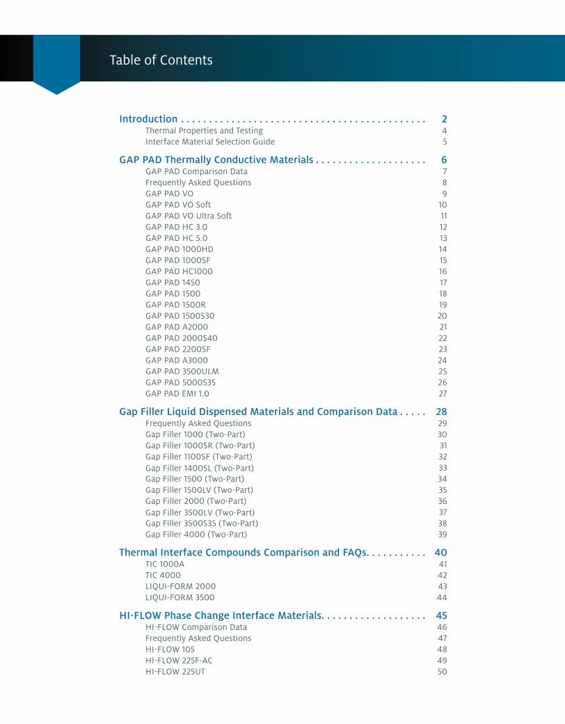
Table of Contents
Introduction . . . . . . . . . . . . . . . . . . . . . . . . . . . . . . . . . . . . . . . . . . . . 2Thermal Properties and Testing 4Interface Material Selection Guide 5
GAP PAD Thermally Conductive Materials . . . . . . . . . . . . . . . . . . . . 6GAP PAD Comparison Data 7Frequently Asked Questions 8GAP PAD VO 9GAP PAD VO Soft 10GAP PAD VO Ultra Soft 11GAP PAD HC 3.0 12GAP PAD HC 5.0 13GAP PAD 1000HD 14GAP PAD 1000SF 15GAP PAD HC1000 16GAP PAD 1450 17GAP PAD 1500 18GAP PAD 1500R 19GAP PAD 1500S30 20GAP PAD A2000 21GAP PAD 2000S40 22GAP PAD 2200SF 23GAP PAD A3000 24GAP PAD 3500ULM 25GAP PAD 5000S35 26 GAP PAD EMI 1.0 27
Gap Filler Liquid Dispensed Materials and Comparison Data . . . . . 2829303132 3334353637 38
Frequently Asked Questions Gap Filler 1000 (Two-Part)Gap Filler 1000SR (Two-Part) Gap Filler 1100SF (Two-Part) Gap Filler 1400SL (Two-Part)Gap Filler 1500 (Two-Part) Gap Filler 1500LV (Two-Part) Gap Filler 2000 (Two-Part) Gap Filler 3500LV (Two-Part) Gap Filler 3500S35 (Two-Part) Gap Filler 4000 (Two-Part) 39
Thermal Interface Compounds Comparison and FAQs . . . . . . . . . . . 40TIC 1000A 41TIC 4000 42LIQUI-FORM 2000 43 LIQUI-FORM 3500 44
HI-FLOW Phase Change Interface Materials . . . . . . . . . . . . . . . . . . . 45HI-FLOW Comparison Data 46Frequently Asked Questions 47 HI-FLOW 105 48 HI-FLOW 225F-AC 49HI-FLOW 225UT 50
Thermal Interface Selection Guide | 1
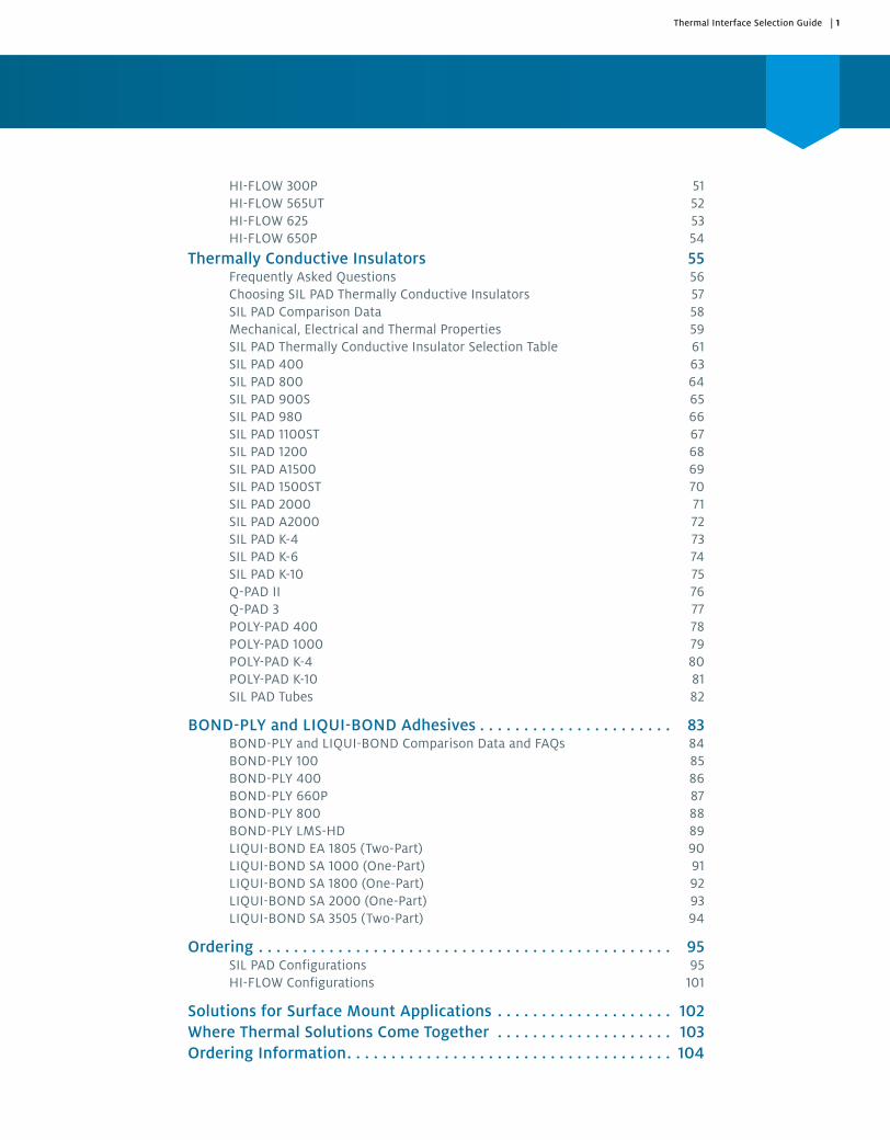
HI-FLOW 300P 51HI-FLOW 565UT 52HI-FLOW 625 53HI-FLOW 650P 54
Thermally Conductive Insulators 55Frequently Asked Questions 56Choosing SIL PAD Thermally Conductive Insulators 57SIL PAD Comparison Data 58Mechanical, Electrical and Thermal Properties 59SIL PAD Thermally Conductive Insulator Selection Table 61SIL PAD 400 63SIL PAD 800 64SIL PAD 900S 65SIL PAD 980 66SIL PAD 1100ST 67SIL PAD 1200 68SIL PAD A1500 69SIL PAD 1500ST 70SIL PAD 2000 71SIL PAD A2000 72SIL PAD K-4 73SIL PAD K-6 74SIL PAD K-10 75Q-PAD II 76Q-PAD 3 77POLY-PAD 400 78POLY-PAD 1000 79POLY-PAD K-4 80POLY-PAD K-10 81SIL PAD Tubes 82
BOND-PLY and LIQUI-BOND Adhesives . . . . . . . . . . . . . . . . . . . . . . 83BOND-PLY and LIQUI-BOND Comparison Data and FAQs 84BOND-PLY 100 85BOND-PLY 400 86BOND-PLY 660P 87BOND-PLY 800 88BOND-PLY LMS-HD 89LIQUI-BOND EA 1805 (Two-Part) 90LIQUI-BOND SA 1000 (One-Part) 91LIQUI-BOND SA 1800 (One-Part) 92LIQUI-BOND SA 2000 (One-Part) 93LIQUI-BOND SA 3505 (Two-Part) 94
Ordering . . . . . . . . . . . . . . . . . . . . . . . . . . . . . . . . . . . . . . . . . . . . . . . 95SIL PAD Configurations 95HI-FLOW Configurations 101
Solutions for Surface Mount Applications . . . . . . . . . . . . . . . . . . . . 102Where Thermal Solutions Come Together . . . . . . . . . . . . . . . . . . . . 103Ordering Information . . . . . . . . . . . . . . . . . . . . . . . . . . . . . . . . . . . . . 104

2 | Thermal Interface Selection Guide — INTRODUCTION
Henkel. Developing solutions for the electronics industry.
Proven thermal management solutions and problem-solving partnership.
We make it our business to know your business. We understand your problems. We also know that there will always be a better way to help you reach your goals and objectives. To that end, our company continually invests considerable time and money into research and development.
Henkel is in the business of solving problems. With our history and experience in the electronics industry, our experts can help find ways to improve your process, control and manage heat, and back it all with exceptional service.
Let us show you the value Henkel offers.

Thermal Interface Selection Guide — INTRODUCTION | 3
THERMAL MANAGEMENT LEADER
Our solutions to control and manage heat in electronic
assemblies and printed circuit boards are used by many of the world’s largest OEMs in a wide
range of industries
WHY Henkel?Henkel, the leading solution provider for adhesives, sealants and functional coatings worldwide, uses high-quality
BERGQUIST thermal management products—like BERGQUIST TCLAD,
BERGQUIST SIL PAD and BERGQUIST LIQUI-BOND—to offer technological
solutions for electronics. Beyond that, we work closely with our customers to understand your problems and deliver
technologically advanced solutions backed by exceptional service.
GLOBAL SUPPLY CHAINto maintain a reliable supply of
products to our customers
BROAD PRODUCT PORTFOLIO
that includes LOCTITE, TECHNOMELT and
BERGQUIST products
R&DOver 10 R&D Centers around the
world staffed by 3,000 design and application professionals
GLOBAL SUPPORT with locations in North America,
Asia and Europe, and sales staff in 30 countries
INNOVATIONHenkel’s BERGQUIST thermal
solutions were often developed for specific customer requests
4 | Thermal Interface Selection Guide — INTRODUCTION
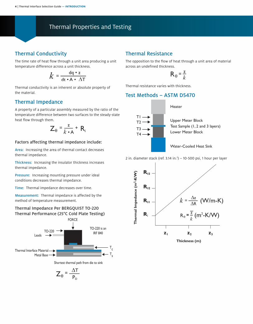
Thermal Properties and Testing
Thermal ConductivityThe time rate of heat flow through a unit area producing a unit temperature difference across a unit thickness.
Thermal conductivity is an inherent or absolute property of the material.
Thermal ImpedanceA property of a particular assembly measured by the ratio of the temperature difference between two surfaces to the steady-state heat flow through them.
Factors affecting thermal impedance include:
Area: Increasing the area of thermal contact decreases thermal impedance.
Thickness: Increasing the insulator thickness increases thermal impedance.
Pressure: Increasing mounting pressure under ideal conditions decreases thermal impedance.
Time: Thermal impedance decreases over time.
Measurement: Thermal impedance is affected by the method of temperature measurement.
Thermal Impedance Per BERGQUIST TO-220 Thermal Performance (25°C Cold Plate Testing)
Thermal ResistanceThe opposition to the flow of heat through a unit area of material across an undefined thickness.
Thermal resistance varies with thickness.
Test Methods – ASTM D5470
2 in. diameter stack (ref. 3.14 in.2) – 10-500 psi, 1 hour per layer
i
Thermal Interface Selection Guide — INTRODUCTION | 5
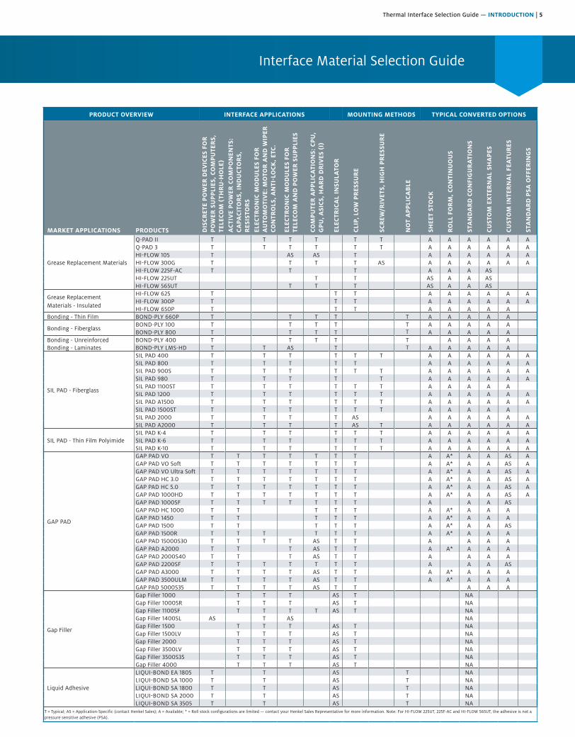
Interface Material Selection Guide
PRODUCT OVERVIEW INTERFACE APPLICATIONS MOUNTING METHODS TYPICAL CONVERTED OPTIONS
MARKET APPLICATIONS PRODUCTS DIS
CR
ETE
PO
WER
DEV
ICES
FO
R
PO
WER
SU
PP
LIES
, CO
MP
UTE
RS,
TE
LECO
M (
THR
U-H
OLE
)A
CTI
VE
PO
WER
CO
MP
ON
ENTS
: C
APA
CIT
OR
S, I
ND
UC
TOR
S,
RES
ISTO
RS
ELEC
TRO
NIC
MO
DU
LES
FOR
A
UTO
MO
TIV
E: M
OTO
R A
ND
WIP
ER
CON
TRO
LS, A
NTI
-LO
CK
, ETC
.
ELEC
TRO
NIC
MO
DU
LES
FOR
TE
LECO
M A
ND
PO
WER
SU
PP
LIES
COM
PU
TER
AP
PLI
CA
TIO
NS:
CP
U,
GP
U, A
SIC
S, H
AR
D D
RIV
ES (
I)
ELEC
TRIC
AL
INSU
LATO
R
CLI
P, L
OW
PR
ESSU
RE
SCR
EW/R
IVET
S, H
IGH
PR
ESSU
RE
NO
T A
PP
LIC
AB
LE
SHEE
T ST
OC
K
RO
LL F
OR
M, C
ON
TIN
UO
US
STA
ND
AR
D C
ON
FIG
UR
ATI
ON
S
CU
STO
M E
XTE
RN
AL
SHA
PES
CU
STO
M I
NTE
RN
AL
FEA
TUR
ES
STA
ND
AR
D P
SA O
FFER
ING
S
Grease Replacement Materials
Q-PAD II T T T T T T A A A A A AQ-PAD 3 T T T T T T A A A A A AHI-FLOW 105 T AS AS T A A A A A AHI-FLOW 300G T T T T AS A A A A A AHI-FLOW 225F-AC T T T A A A ASHI-FLOW 225UT T T AS A A ASHI-FLOW 565UT T T T AS A A AS
Grease Replacement Materials - Insulated
HI-FLOW 625 T T T A A A A A AHI-FLOW 300P T T T A A A A A AHI-FLOW 650P T T T A A A A A
Bonding - Thin Film BOND-PLY 660P T T T T T A A A A A
Bonding - FiberglassBOND-PLY 100 T T T T T A A A A ABOND-PLY 800 T T T T A A A A A
Bonding - Unreinforced BOND-PLY 400 T T T T T A A A ABonding - Laminates BOND-PLY LMS-HD T AS T A A A A A
SIL PAD - Fiberglass
SIL PAD 400 T T T T T T A A A A A ASIL PAD 800 T T T T T A A A A A ASIL PAD 900S T T T T T T A A A A A ASIL PAD 980 T T T T T A A A A A ASIL PAD 1100ST T T T T T T A A A A ASIL PAD 1200 T T T T T T A A A A A ASIL PAD A1500 T T T T T T A A A A A ASIL PAD 1500ST T T T T T T A A A A ASIL PAD 2000 T T T T AS A A A A A ASIL PAD A2000 T T T T AS T A A A A A A
SIL PAD - Thin Film PolyimideSIL PAD K-4 T T T T T T A A A A A ASIL PAD K-6 T T T T T T A A A A A ASIL PAD K-10 T T T T T T A A A A A A
GAP PAD
GAP PAD VO T T T T T T T A A* A A AS AGAP PAD VO Soft T T T T T T T A A* A A AS AGAP PAD VO Ultra Soft T T T T T T T A A* A A AS AGAP PAD HC 3.0 T T T T T T T A A* A A AS AGAP PAD HC 5.0 T T T T T T T A A* A A AS AGAP PAD 1000HD T T T T T T T A A* A A AS AGAP PAD 1000SF T T T T T T T A A A ASGAP PAD HC 1000 T T T T T A A* A A AGAP PAD 1450 T T T T T A A* A A AGAP PAD 1500 T T T T T A A* A A ASGAP PAD 1500R T T T T T T A A* A A AGAP PAD 15000S30 T T T T AS T T A A A AGAP PAD A2000 T T T AS T T A A* A A AGAP PAD 2000S40 T T T AS T T A A A AGAP PAD 2200SF T T T T T T T A A A ASGAP PAD A3000 T T T T AS T T A A* A A AGAP PAD 3500ULM T T T T AS T T A A* A A AGAP PAD 5000S35 T T T T AS T T A A A
Gap Filler
Gap Filler 1000 T T T AS T NAGap Filler 1000SR T T T AS T NAGap Filler 1100SF T T T T AS T NAGap Filler 1400SL AS T AS NAGap Filler 1500 T T T AS T NAGap Filler 1500LV T T T AS T NAGap Filler 2000 T T T AS T NAGap Filler 3500LV T T T AS T NAGap Filler 3500S35 T T T AS T NAGap Filler 4000 T T T AS T NA
Liquid Adhesive
LIQUI-BOND EA 1805 T T AS T NALIQUI-BOND SA 1000 T T AS T NALIQUI-BOND SA 1800 T T AS T NALIQUI-BOND SA 2000 T T AS T NALIQUI-BOND SA 3505 T T AS T NA
T = Typical; AS = Application-Specific (contact Henkel Sales); A = Available; * = Roll stock configurations are limited — contact your Henkel Sales Representative for more information. Note: For HI-FLOW 225UT, 225F-AC and HI-FLOW 565UT, the adhesive is not a pressure sensitive adhesive (PSA).
T T
T
6 | Thermal Interface Selection Guide — GAP PAD
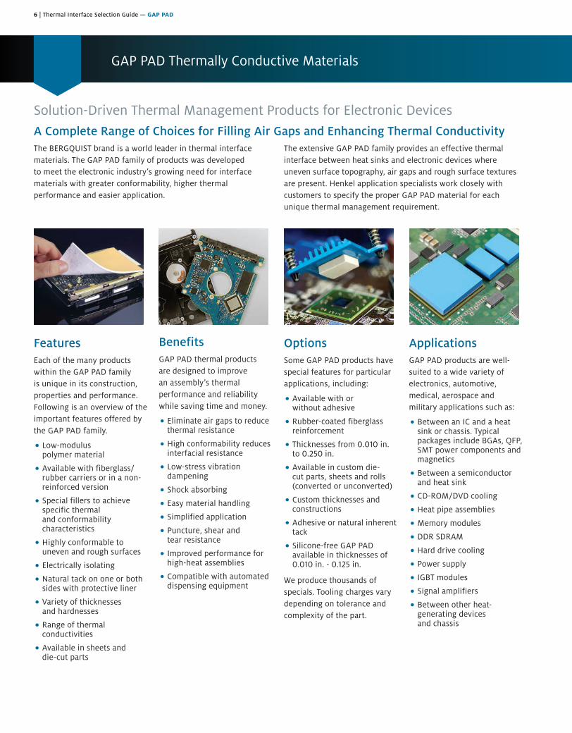
GAP PAD Thermally Conductive Materials
Solution-Driven Thermal Management Products for Electronic DevicesA Complete Range of Choices for Filling Air Gaps and Enhancing Thermal ConductivityThe BERGQUIST brand is a world leader in thermal interface materials. The GAP PAD family of products was developed to meet the electronic industry’s growing need for interface materials with greater conformability, higher thermal performance and easier application.
The extensive GAP PAD family provides an effective thermal interface between heat sinks and electronic devices where uneven surface topography, air gaps and rough surface textures are present. Henkel application specialists work closely with customers to specify the proper GAP PAD material for each unique thermal management requirement.
FeaturesEach of the many products within the GAP PAD family is unique in its construction, properties and performance. Following is an overview of the important features offered by the GAP PAD family.
• Low-modulus polymer material
• Available with fiberglass/ rubber carriers or in a non-reinforced version
• Special fillers to achieve specific thermal and conformability characteristics
• Highly conformable to uneven and rough surfaces
• Electrically isolating
• Natural tack on one or both sides with protective liner
• Variety of thicknesses and hardnesses
• Range of thermal conductivities
• Available in sheets and die-cut parts
BenefitsGAP PAD thermal products are designed to improve an assembly’s thermal performance and reliability while saving time and money.
• Eliminate air gaps to reduce thermal resistance
• High conformability reduces interfacial resistance
• Low-stress vibration dampening
• Shock absorbing
• Easy material handling
• Simplified application
• Puncture, shear and tear resistance
• Improved performance for high-heat assemblies
• Compatible with automated dispensing equipment
OptionsSome GAP PAD products have special features for particular applications, including:
• Available with or without adhesive
• Rubber-coated fiberglass reinforcement
• Thicknesses from 0.010 in. to 0.250 in.
• Available in custom die-cut parts, sheets and rolls (converted or unconverted)
• Custom thicknesses and constructions
• Adhesive or natural inherent tack
• Silicone-free GAP PAD available in thicknesses of 0.010 in. - 0.125 in.
We produce thousands of specials. Tooling charges vary depending on tolerance and complexity of the part.
ApplicationsGAP PAD products are well-suited to a wide variety of electronics, automotive, medical, aerospace and military applications such as:
• Between an IC and a heat sink or chassis. Typical packages include BGAs, QFP, SMT power components and magnetics
• Between a semiconductor and heat sink
• CD-ROM/DVD cooling
• Heat pipe assemblies
• Memory modules
• DDR SDRAM
• Hard drive cooling
• Power supply
• IGBT modules
• Signal amplifiers
• Between other heat-generating devices and chassis
Thermal Interface Selection Guide — GAP PAD | 7
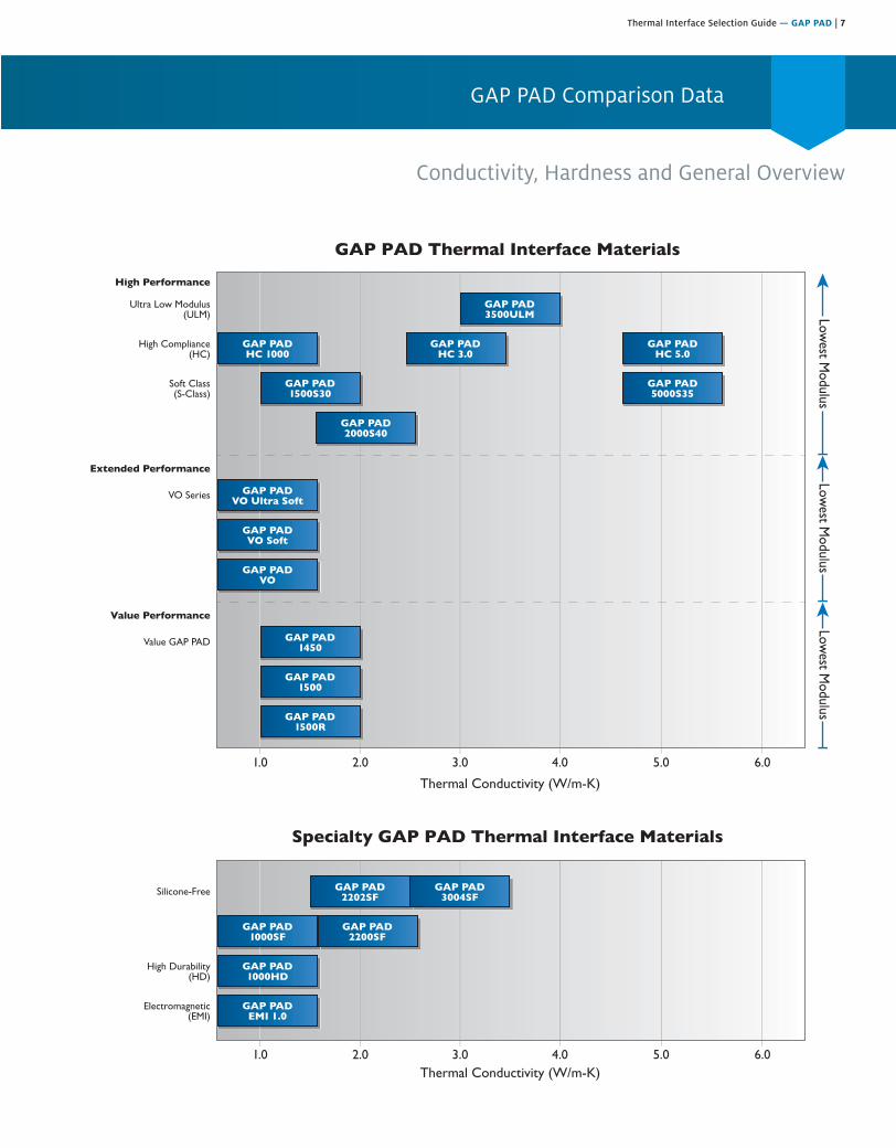
GAP PAD Comparison Data
Conductivity, Hardness and General Overview
2.0 3.0 4.0 5.0 6.01.0
2.0 3.0 4.0 5.0 6.01.0
GAP PAD Thermal Interface Materials
Specialty GAP PAD Thermal Interface Materials
Ultra Low Modulus(ULM)
High Performance
GAP PAD3500ULM
VO Series
Extended Performance
GAP PADVO Ultra Soft
Value GAP PAD
Value Performance
GAP PAD1450
Silicone-Free GAP PAD2202SF
GAP PAD3004SF
GAP PAD1000SF
GAP PAD2200SF
GAP PAD1500
GAP PAD1500R
GAP PADVO Soft
GAP PADVO
High Compliance(HC)
GAP PADHC 1000
High Durability(HD)
GAP PAD1000HD
Electromagnetic(EMI)
GAP PADEMI 1.0
GAP PADHC 3.0
GAP PADHC 5.0
Soft Class(S-Class)
GAP PAD1500S30
GAP PAD2000S40
GAP PAD5000S35
Lowest M
odulusLow
est Modulus
Lowest M
odulus

8 | Thermal Interface Selection Guide — GAP PAD
Frequently Asked Questions
Q: What thermal conductivity test method was used to achieve the values given on the data sheets?
A: A test fixture is utilized that meets the specifications outlined in ASTM D5470.
Q: Is GAP PAD offered with an adhesive?A: Currently, GAP PAD VO, GAP PAD VO Soft, and GAP PAD VO
Ultra Soft are offered with or without an adhesive on the SIL PAD 800/900 carrier-side of the material. The remaining surface has natural inherent tack. All other GAP PAD Materials have inherent tack.
Q: Is the adhesive repositionable?A: Depending on the surface being applied to, if care is taken,
the pad may be repositioned. Special care should be taken when removing the pad from aluminum or anodized surfaces to avoid tearing or delamination.
Q: What is meant by “natural tack”?A: The characteristic of the rubber itself has a natural inherent
tack, with the addition of an adhesive. As with adhesive-backed products, the surfaces with natural tack may help in the assembly process to temporarily hold the pad in place while the application is being assembled. Unlike adhesive-backed products, inherent tack does not have a thermal penalty since the rubber itself has the tack. Tack strength varies from one GAP PAD product to the next.
Q: Can GAP PAD with natural tack be repositioned?A: Depending on the material that the pad is applied to, in
most cases they are repositionable. Care should be taken when removing the pad from aluminum or anodized surfaces to avoid tearing or delaminating the pad. The side with the natural tack is always easier to reposition than an adhesive side.
Q: Is GAP PAD reworkable?A: Depending on the application and the pad being used,
GAP PAD has been reworked in the past. Some of our customers are currently using the same pad for reassembling their applications after burn-in processes and after fieldwork repairs. However, this is left up to the design engineer’s judgment as to whether or not the GAP PAD will withstand reuse.
Q: Will heat make the material softer?A: From -60°C to 200°C, there is no significant variance in
hardness for silicone GAP PAD Materials and Gap Fillers.
Q: What is the shelf life of GAP PAD?A: Shelf life for most GAP PAD Materials is one (1) year after the
date of manufacture. For GAP PAD with adhesive, the shelf life is six (6) months from the date of manufacture. After these dates, inherent tack and adhesive properties should be recharacterized. The GAP PAD material’s long-term stability is not the limiter on the shelf life; it is related to the adhesion or “age up” of the GAP PAD to the liner. Or in the case of a GAP PAD with adhesive, the shelf life is determined by how the adhesive ages up to the removable liner.
Q: How is extraction testing performed?A: The test method used is the Soxhlet Extraction Method;
please refer to GAP PAD S-Class White Paper.
Q: What is the thickness tolerance of your pads?A: The thickness tolerance is ±10% on materials >10 mil and ±1
mil on materials £10 mil.
Q: What are the upper processing temperature limits for GAP PAD and for how long can GAP PAD be exposed to them?
A: GAP PAD in general can be exposed to temporary processing temperatures of 250°C for five minutes and 300°C for one minute.
Q: Is GAP PAD electrically isolating?A: Yes, all GAP PAD materials are electrically isolating. However,
keep in mind that GAP PAD is designed to fill gaps and it is not recommended for applications where high mounting pressure is exerted on the GAP PAD.
Q: How much force will the pad place on my device?A: Refer to the Pressure vs. Deflection charts in BERGQUIST
Application Note #116 at our website’s Technical Library. In addition, there are other helpful resources online at www.henkel-adhesives.com/thermal.
Q: Why are “wet out,” “compliance” or “conformability” characteristics of GAP PAD important?
A: The better a GAP PAD lays smooth “wets out” or conforms to a rough or stepped surface, giving less interfacial resistance caused by air voids and air gaps. GAP PAD Materials are conformable or compliant as they adhere very well to the surface. The GAP PAD Materials can act similarly to a “suction cup” on the surface. This leads to a lower overall thermal resistance of the pad between the two interfaces.
Q: Is anything given off by the material (e.g., extractables, outgassing)?
A: 1) Silicone GAP PAD and Gap Fillers, like all soft silicone materials, can extract low molecular weight silicone (refer to White Paper on GAP PAD S-Class). Also note that GAP PAD and Gap Filler have some of the lowest extraction values for silicone-based gap filling products on the market and if your application requires minimal silicone, see our line of silicone-free material. The White Paper on GAP PAD S-Class and information about our silicone-free materials are available on our website.
2) Primarily for aerospace applications, outgassing data is tested per ASTM E595.
Q: Why does the Technical Data Sheet (on the website) describe the Shore hardness rating as a bulk rubber hardness?
A: A reinforcement carrier is generally used in BERGQUIST GAP PAD Materials for ease of handling. When testing hardness, the reinforcement carrier can alter the test results and incorrectly depict thinner materials as being harder. To eliminate this error, a 250 mil rubber puck is molded with no reinforcement carrier. The puck is then tested for hardness. The Shore hardness is recorded after a 30-second delay.

Thermal Interface Selection Guide — GAP PAD | 9
GAP PAD VO
Features and Benefits• Thermal conductivity: 0.8 W/m-K
• Enhanced puncture, shear and tear resistance
• Conformable gap filling material
• Electrically isolating
GAP PAD VO is a cost-effective, thermally conductive interface material. The material is a filled, thermally conductive polymer supplied on a rubber-coated fiberglass carrier allowing for easy material handling. The conformable nature of GAP PAD VO allows the pad to fill in air gaps between PC boards and heat sinks or a metal chassis.
Note: Resultant thickness is defined as the final gap thickness of the application.
1 3 5 7 9 11 13
250
200
150
100
50
0
Thickness vs. Thermal ResistanceGAP PAD VO
Thermal Resistance (C-in.2/W)
Res
ulta
nt T
hick
ness
(mils
)
Conformable, Thermally Conductive Material for Filling Air Gaps
Typical Applications Include:• Telecommunications
• Computer and peripherals
• Power conversion
• Between heat-generating semiconductors and a heat sink
• Area where heat needs to be transferred to a frame, chassis, or other type of heat spreader
• Between heat-generating magnetic components and a heat sink
Configurations Available:• Sheet form and die-cut parts
Building a Part Number Standard Options
Sect
ion
A
Sect
ion
B
Sect
ion
C
Sect
ion
D
Sect
ion
E NA = Selected standard option. If not selecting a standardoption, insert company name, drawing number, andrevision level.
GPVO = GAP PAD VO Material
GPVO 0.040 AC 0816 NA
Note: To build a part number, go to www.bergquistcompany.com/Part_Number_Builder.php.
Standard thicknesses available: 0.020", 0.040", 0.060",0.080", 0.100", 0.125", 0.160", 0.200", 0.250"
AC = Adhesive on SIL PAD side, natural tack on one side01 = No pressure sensitive adhesive, natural tack on one side
0816 = Standard sheet size 8" x 16" or00 = custom configuration
– – – – || example
TYPICAL PROPERTIES OF GAP PAD VO
PROPERTY IMPERIAL VALUE METRIC VALUE TEST METHOD
Color Gold/Pink Gold/Pink Visual
Reinforcement Carrier SIL PAD SIL PAD —
Thickness (in.) / (mm) 0.020 to 0.250 0.508 to 6.350 ASTM D374
Inherent Surface Tack (1-sided) 1 1 —
Density (Bulk Rubber) (g/cc) 1.6 1.6 ASTM D792
Heat Capacity ( J/g-K) 1.0 1.0 ASTM E1269
Hardness (Bulk Rubber) (Shore 00)(1) 40 40 ASTM D2240
Young’s Modulus (psi) / (kPa)(2) 100 689 ASTM D575
Continuous Use Temp. (°F) / (°C) -76 to 392 -60 to 200 —
ELECTRICAL
Dielectric Breakdown Voltage (Vac.) >6,000 >6,000 ASTM D149
Dielectric Constant (1,000 Hz) 5.5 5.5 ASTM D150
Volume Resistivity (Ohmmeter) 1011 1011 ASTM D257
Flame Rating V-O V-O UL 94
THERMAL
Thermal Conductivity (W/m-K) 0.8 0.8 ASTM D5470
THERMAL PERFORMANCE VS. STRAIN
Deflection (% strain) 10 20 30
Thermal Impedance (°C-in.2/W) 0.040 in.(3) 2.47 2.37 2.24
1) Thirty-second delay value Shore 00 hardness scale.2) Young’s Modulus, calculated using 0.01 in./min. step rate of strain with a sample size of 0.79 in.2. 3) The ASTM D5470 test fixture was used. The recorded value includes interfacial thermal resistance. These values are provided for reference only. Actual
application performance is directly related to the surface roughness, flatness and pressure applied.
10 | Thermal Interface Selection Guide — GAP PAD
GAP PAD VO Soft
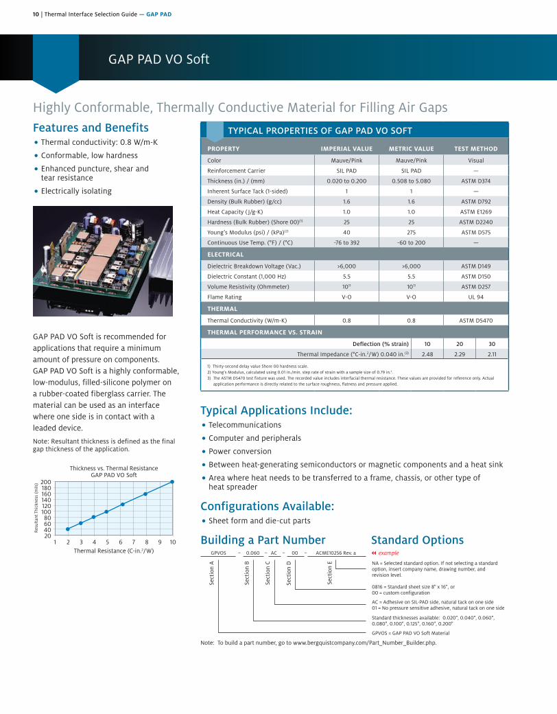
Highly Conformable, Thermally Conductive Material for Filling Air GapsFeatures and Benefits• Thermal conductivity: 0.8 W/m-K
• Conformable, low hardness
• Enhanced puncture, shear and tear resistance
• Electrically isolating
GAP PAD VO Soft is recommended for applications that require a minimum amount of pressure on components. GAP PAD VO Soft is a highly conformable, low-modulus, filled-silicone polymer on a rubber-coated fiberglass carrier. The material can be used as an interface where one side is in contact with a leaded device.
Note: Resultant thickness is defined as the final gap thickness of the application.
1 2 3 4 8765 9 10
20018016014012010080604020
Thickness vs. Thermal ResistanceGAP PAD VO Soft
Thermal Resistance (C-in.2/W)
Res
ulta
nt T
hick
ness
(mils
)
Typical Applications Include:• Telecommunications
• Computer and peripherals
• Power conversion
• Between heat-generating semiconductors or magnetic components and a heat sink
• Area where heat needs to be transferred to a frame, chassis, or other type of heat spreader
Configurations Available:• Sheet form and die-cut parts
Building a Part Number Standard Options
Sect
ion
A
Sect
ion
B
Sect
ion
C
Sect
ion
D
Sect
ion
E NA = Selected standard option. If not selecting a standardoption, insert company name, drawing number, andrevision level.
GPVOS = GAP PAD VO Soft Material
GPVOS 0.060 AC 00 ACME10256 Rev. a
Note: To build a part number, go to www.bergquistcompany.com/Part_Number_Builder.php.
Standard thicknesses available: 0.020", 0.040", 0.060",0.080", 0.100", 0.125", 0.160", 0.200"
AC = Adhesive on SIL-PAD side, natural tack on one side01 = No pressure sensitive adhesive, natural tack on one side
0816 = Standard sheet size 8" x 16", or00 = custom configuration
– – – – || example
TYPICAL PROPERTIES OF GAP PAD VO SOFT
PROPERTY IMPERIAL VALUE METRIC VALUE TEST METHOD
Color Mauve/Pink Mauve/Pink Visual
Reinforcement Carrier SIL PAD SIL PAD —
Thickness (in.) / (mm) 0.020 to 0.200 0.508 to 5.080 ASTM D374
Inherent Surface Tack (1-sided) 1 1 —
Density (Bulk Rubber) (g/cc) 1.6 1.6 ASTM D792
Heat Capacity ( J/g-K) 1.0 1.0 ASTM E1269
Hardness (Bulk Rubber) (Shore 00)(1) 25 25 ASTM D2240
Young’s Modulus (psi) / (kPa)(2) 40 275 ASTM D575
Continuous Use Temp. (°F) / (°C) -76 to 392 -60 to 200 —
ELECTRICAL
Dielectric Breakdown Voltage (Vac.) >6,000 >6,000 ASTM D149
Dielectric Constant (1,000 Hz) 5.5 5.5 ASTM D150
Volume Resistivity (Ohmmeter) 1011 1011 ASTM D257
Flame Rating V-O V-O UL 94
THERMAL
Thermal Conductivity (W/m-K) 0.8 0.8 ASTM D5470
THERMAL PERFORMANCE VS. STRAIN
Deflection (% strain) 10 20 30
Thermal Impedance (°C-in.2/W) 0.040 in.(3) 2.48 2.29 2.11
1) Thirty-second delay value Shore 00 hardness scale.2) Young’s Modulus, calculated using 0.01 in./min. step rate of strain with a sample size of 0.79 in.2.3) The ASTM D5470 test fixture was used. The recorded value includes interfacial thermal resistance. These values are provided for reference only. Actual
application performance is directly related to the surface roughness, flatness and pressure applied.
Thermal Interface Selection Guide — GAP PAD | 11
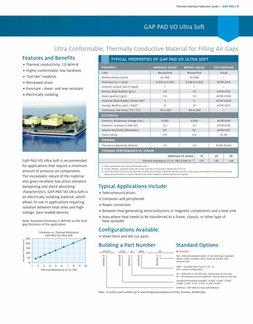
GAP PAD VO Ultra Soft
Ultra Conformable, Thermally Conductive Material for Filling Air GapsFeatures and Benefits• Thermal conductivity: 1.0 W/m-K
• Highly conformable, low hardness
• “Gel-like” modulus
• Decreased strain
• Puncture-, shear- and tear-resistant
• Electrically isolating
GAP PAD VO Ultra Soft is recommended for applications that require a minimum amount of pressure on components. The viscoelastic nature of the material also gives excellent low-stress vibration dampening and shock absorbing characteristics. GAP PAD VO Ultra Soft is an electrically isolating material, which allows its use in applications requiring isolation between heat sinks and high-voltage, bare-leaded devices.
Note: Resultant thickness is defined as the final gap thickness of the application.
1 2 3 5 84 6 97 10
250
200
150
100
50
0
Thickness vs. Thermal ResistanceGAP PAD VO Ultra Soft
Thermal Resistance (C-in.2/W)
Res
ulta
nt T
hick
ness
(mils
)
Typical Applications Include:• Telecommunications
• Computer and peripherals
• Power conversion
• Between heat-generating semiconductors or magnetic components and a heat sink
• Area where heat needs to be transferred to a frame, chassis, or other type of heat spreader
Configurations Available:• Sheet form and die-cut parts
Building a Part Number Standard Options
Sect
ion
A
Sect
ion
B
Sect
ion
C
Sect
ion
D
Sect
ion
E NA = Selected standard option. If not selecting a standardoption, insert company name, drawing number, andrevision level.
GPVOUS = GAP PAD VO Ultra Soft Material
GPVOUS 0.100 AC 0816 NA
Note: To build a part number, go to www.bergquistcompany.com/Part_Number_Builder.php.
Standard thicknesses available: 0.020", 0.040", 0.060",0.080", 0.100", 0.125", 0.160", 0.200", 0.250"
AC = Adhesive on SIL-PAD side, natural tack on one side01 = No pressure sensitive adhesive, natural tack on one side
0816 = Standard sheet size 8" x 16", or00 = custom configuration
– – – – || example
TYPICAL PROPERTIES OF GAP PAD VO ULTRA SOFT
PROPERTY IMPERIAL VALUE METRIC VALUE TEST METHOD
Color Mauve/Pink Mauve/Pink Visual
Reinforcement Carrier SIL PAD SIL PAD —
Thickness (in.) / (mm) 0.020 to 0.250 0.508 to 6.350 ASTM D374
Inherent Surface Tack (1-sided) 1 1 —
Density (Bulk Rubber) (g/cc) 1.6 1.6 ASTM D792
Heat Capacity ( J/g-K) 1.0 1.0 ASTM E1269
Hardness (Bulk Rubber) (Shore 00)(1) 5 5 ASTM D2240
Young’s Modulus (psi) / (kPa)(2) 8 55 ASTM D575
Continuous Use Temp. (°F) / (°C) -76 to 392 -60 to 200 —
ELECTRICAL
Dielectric Breakdown Voltage (Vac.) 6,000 6,000 ASTM D149
Dielectric Constant (1,000 Hz) 5.5 5.5 ASTM D150
Volume Resistivity (Ohmmeter) 1011 1011 ASTM D257
Flame Rating V-0 V-0 UL 94
THERMAL
Thermal Conductivity (W/m-K) 1.0 1.0 ASTM D5470
THERMAL PERFORMANCE VS. STRAIN
Deflection (% strain) 10 20 30
Thermal Impedance (°C-in.2/W) 0.040 in.(3) 1.97 1.87 1.68
1) Thirty-second delay value Shore 00 hardness scale.2) Young’s Modulus, calculated using 0.01 in./min. step rate of strain with a sample size of 0.79 in.2.3) The ASTM D5470 test fixture was used. The recorded value includes interfacial thermal resistance. These values are provided for reference only. Actual
application performance is directly related to the surface roughness, flatness and pressure applied.
12 | Thermal Interface Selection Guide — GAP PAD
GAP PAD HC 3.0
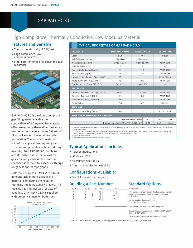
High-Compliance, Thermally Conductive, Low Modulus MaterialFeatures and Benefits• Thermal conductivity: 3.0 W/m-K
• High-compliance, low compression stress
• Fiberglass-reinforced for shear and tear resistance
GAP PAD HC 3.0 is a soft and compliant gap filling material with a thermal conductivity of 3.0 W/m-K. The material offers exceptional thermal performance at low pressures due to a unique 3.0 W/m-K filler package and low-modulus resin formulation. The enhanced material is ideal for applications requiring low stress on components and boards during assembly. GAP PAD HC 3.0 maintains a conformable nature that allows for quick recovery and excellent wet-out characteristics, even to surfaces with high roughness and/or topography.
GAP PAD HC 3.0 is offered with natural inherent tack on both sides of the material, eliminating the need for thermally impeding adhesive layers. The top side has minimal tack for ease of handling. GAP PAD HC 3.0 is supplied with protective liners on both sides.
.25 .50 .75 1.00 1.25 1.50 1.75 2.00
140
120
100
80
60
40
20
0
Thickness vs. Thermal ResistanceGAP PAD HC 3.0
Thermal Resistance (C-in.2/W)
Res
ulta
nt T
hick
ness
(mils
)
Typical Applications Include:• Telecommunications
• ASICs and DSPs
• Consumer electronics
• Thermal modules to heat sinks
Configurations Available:• Sheet form and die-cut parts
Building a Part Number Standard Options
Sect
ion
A
Sect
ion
B
Sect
ion
C
Sect
ion
D
Sect
ion
E NA = Selected standard option. If not selecting a standardoption, insert company name, drawing number, andrevision level.
GPHC3.0 = GAP PAD HC 3.0 Material with fiberglass
GPHC3.0 0.020 02 0816 NA
Note: To build a part number, go to www.bergquistcompany.com/Part_Number_Builder.php.
Standard thicknesses available: 0.020", 0.040", 0.060", 0.080", 0.100", 0.125"
02 = Natural tack, both sides (With fiberglass)
0816 = Standard sheet size 8" x 16", or00 = custom configuration
– – – – || example
TYPICAL PROPERTIES OF GAP PAD HC 3.0
PROPERTY IMPERIAL VALUE METRIC VALUE TEST METHOD
Color Blue Blue Visual
Reinforcement Carrier Fiberglass Fiberglass —
Thickness (in.) / (mm) 0.020 to 0.125 0.508 to 3.175 ASTM D374
Inherent Surface Tack 2 2 —
Density (Bulk Rubber) (g/cc) 3.1 3.1 ASTM D792
Heat Capacity ( J/g-K) 1.0 1.0 ASTM E1269
Hardness (Bulk Rubber) (Shore 00)(4) 15 15 ASTM D2240
Young’s Modulus (psi) / (kPa)(1) 16 110 ASTM D575
Continuous Use Temp. (°F) / (°C) -76 to 392 -60 to 200 —
ELECTRICAL
Dielectric Breakdown Voltage (Vac.)(3) >5,000 >5,000 ASTM D149
Dielectric Constant (1,000 Hz) 6.5 6.5 ASTM D150
Volume Resistivity (Ohmmeter) 1010 1010 ASTM D257
Flame Rating V-O V-O UL 94
THERMAL
Thermal Conductivity (W/m-K)(2) 3.0 3.0 ASTM D5470
THERMAL PERFORMANCE VS. STRAIN
Deflection (% strain) 10 20 30
Thermal Impedance (°C-in.2/W) 0.040 in.(2) 0.57 0.49 0.44
1) Young’s Modulus, calculated using 0.01 in./min. step rate of strain with a sample size of 0.79 in.2 after 5 minutes of compression at 10% strain on a 1 mm thickness material.
2) The ASTM D5470 test fixture was used. The recorded value includes interfacial thermal resistance. These values are provided for reference only. Actual application performance is directly related to the surface roughness, flatness and pressure applied.
3) Minimum value at 20 mil. 4) Thirty-second delay value on Shore 00 hardness scale.

Thermal Interface Selection Guide — GAP PAD | 13
GAP PAD HC 5.0
Highly Conformable, Thermally Conductive, Low Modulus Material
TYPICAL PROPERTIES OF GAP PAD HC 5.0
PROPERTY IMPERIAL VALUE METRIC VALUE TEST METHOD
Color Violet Violet Visual
Reinforcement Carrier Fiberglass Fiberglass —
Thickness (in.) / (mm)*0.020, 0.040, 0.060 0.080, 0.100, 0.125
0.508, 1.016, 1.524, 2.032, 2.540, 3.175
ASTM D374
Inherent Surface Tack 2 2 —
Density (Bulk Rubber) (g/cc) 3.2 3.2 ASTM D792
Heat Capacity ( J/g-K) 1.0 1.0 ASTM E1269
Hardness (Bulk Rubber) (Shore 00)(4) 35 35 ASTM D2240
Young’s Modulus (psi) / (kPa)(1) 17.5 121 ASTM D575
Typical Use Temp. (°F) / (°C) -76 to 392 -60 to 200 —
ELECTRICAL
Dielectric Breakdown Voltage (Vac.)(3) 5000 5000 ASTM D149
Dielectric Constant (1,000 Hz) 8.0 8.0 ASTM D150
Volume Resistivity (Ohmmeter) 1010 1010 ASTM D257
Flame Rating V-O V-O UL 94
THERMAL
Thermal Conductivity (W/m-K)(2) 5.0 5.0 ASTM D5470
THERMAL PERFORMANCE VS. STRAIN
Deflection (% strain) 10 20 30
Thermal Impedance (°C-in.2/W) 0.040 in.(2) 0.35 0.30 0.26
* Custom thicknesses available. Please contact your Henkel Sales Representative for more information.(1) Young’s Modulus, calculated using 0.01 in/min. step rate of strain with a sample size of 0.79 inch2 after 5 minutes of compression at 10% strain on a 1mm
thickness material.(2) The ASTM D5470 test fixture was used. The recorded value includes interfacial thermal resistance. These values are provided for reference only.
Actual application performance is directly related to the surface roughness, flatness and pressure applied.(3) Minimum value at 20 mil.(4) Thirty second delay value on Shore 00 hardness scale.
GAP PAD HC 5.0 is a soft and compliant gap filling material with a thermal conductivity of 5.0 W/m-K. The material offers exceptional thermal performance at low pressures due to a unique filler package and low-modulus resin formulation. The enhanced material is ideal for applications requiring low stress on components and boards during assembly. GAP PAD HC 5.0 maintains a conformable nature that allows for excellent interfacing and wet-out characteristics, even to surfaces with high roughness and/or topography.
GAP PAD HC 5.0 is offered with natural inherent tack on both sides of the material, eliminating the need for thermally-impeding adhesive layers. The top side has minimal tack for ease of handling. GAP PAD HC 5.0 is supplied with protective liners on both sides.
Typical Applications Include:• Telecommunications
• ASICs and DSPs
• Consumer electronics
• Thermal modules to heat sinks
Configurations Available:• Sheet form and die-cut parts
Building a Part Number Standard Options
Features and Benefits• Thermal onductivity: 5.0 W/m-K
• High-compliance, low compression stress
• Fiberglass reinforced for shear and tear resistance
0.2 0.4 0.6 0.8 1.0 1.2
140
120
100
80
60
40
20
0
Thickness vs. Thermal ResistanceGap Pad HC 5.0
Thermal Resistance (C-in2/W)
Res
ulta
nt T
hick
ness
(m
ils)
Sect
ion
A
Sect
ion
B
Sect
ion
C
Sect
ion
D
Sect
ion
E NA = Selected standard option. If not selecting a standardoption, insert company name, drawing number, andrevision level.
GPHC5.0 = Gap Pad HC 5.0 Material with fiberglass
GPHC5.0 0.020 02 0816 NA
Note: To build a part number, visit our website at www.henkel-adhesives.com/thermal.For any other custom thickness requirements, please contact your Henkel Representative.
Standard thicknesses available: 0.020", 0.040", 0.060", 0.080", 0.100", 0.125"
02 = Natural tack, both sides (With Fiberglass)
0816 = Standard sheet size 8" x 16", or00 = custom configuration
– – – –
Note: To build a part number, go to www.bergquistcompany.com/Part_Number_Builder.php.
14 | Thermal Interface Selection Guide — GAP PAD
GAP PAD 1000HD
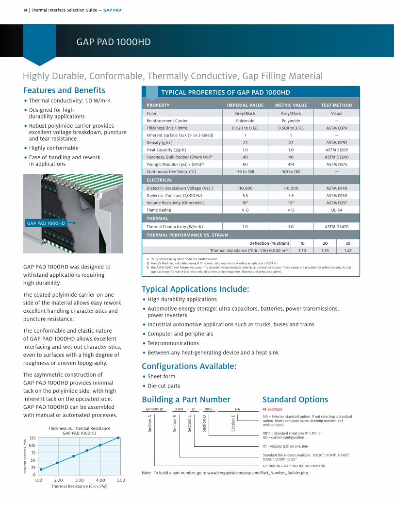
Highly Durable, Conformable, Thermally Conductive, Gap Filling MaterialFeatures and Benefits• Thermal conductivity: 1.0 W/m-K
• Designed for highdurability applications
• Robust polyimide carrier providesexcellent voltage breakdown, punctureand tear resistance
• Highly conformable
• Ease of handling and reworkin applications
GAP PAD 1000HD
GAP PAD 1000HD was designed to withstand applications requiring high durability.
The coated polyimide carrier on one side of the material allows easy rework, excellent handling characteristics and puncture resistance.
The conformable and elastic nature of GAP PAD 1000HD allows excellent interfacing and wet-out characteristics, even to surfaces with a high degree of roughness or uneven topography.
The asymmetric construction of GAP PAD 1000HD provides minimal tack on the polyimide side, with high inherent tack on the upcoated side. GAP PAD 1000HD can be assembled with manual or automated processes.
1.00 2.00 4.003.00 5.00
125
100
75
50
25
0
Thickness vs. Thermal ResistanceGAP PAD 1000HD
Thermal Resistance (C-in.2/W)
Res
ulta
nt T
hick
ness
(mils
)
Typical Applications Include:• High durability applications
• Automotive energy storage: ultra capacitors, batteries, power transmissions,power inverters
• Industrial automotive applications such as trucks, buses and trains
• Computer and peripherals
• Telecommunications
• Between any heat-generating device and a heat sink
Configurations Available:• Sheet form
• Die-cut parts
Building a Part Number Standard Options
Sect
ion
A
Sect
ion
B
Sect
ion
C
Sect
ion
D
Sect
ion
E NA = Selected standard option. If not selecting a standardoption, insert company name, drawing number, andrevision level.
GP1000HD = GAP PAD 1000HD Material
GP1000HD 0.100 01 0816 NA
Note: To build a part number, go to www.bergquistcompany.com/Part_Number_Builder.php.
Standard thicknesses available: 0.020", 0.040", 0.060",0.080", 0.100", 0.125"
01 = Natural tack on one side
0816 = Standard sheet size 8" x 16", or00 = custom configuration
– – – – || example
TYPICAL PROPERTIES OF GAP PAD 1000HD
PROPERTY IMPERIAL VALUE METRIC VALUE TEST METHOD
Color Grey/Black Grey/Black Visual
Reinforcement Carrier Polyimide Polyimide —
Thickness (in.) / (mm) 0.020 to 0.125 0.508 to 3.175 ASTM D374
Inherent Surface Tack (1- or 2-sided) 1 1 —
Density (g/cc) 2.1 2.1 ASTM D792
Heat Capacity ( J/g-K) 1.0 1.0 ASTM E1269
Hardness, Bulk Rubber (Shore 00)(1) 40 40 ASTM D2240
Young’s Modulus (psi) / (kPa)(2) 60 414 ASTM D575
Continuous Use Temp. (°C) -76 to 358 -60 to 180 —
ELECTRICAL
Dielectric Breakdown Voltage (Vac.) >10,000 >10,000 ASTM D149
Dielectric Constant (1,000 Hz) 5.5 5.5 ASTM D150
Volume Resistivity (Ohmmeter) 1011 1011 ASTM D257
Flame Rating V-O V-O UL 94
THERMAL
Thermal Conductivity (W/m-K) 1.0 1.0 ASTM D5470
THERMAL PERFORMANCE VS. STRAIN
Deflection (% strain) 10 20 30
Thermal Impedance (°C-in.2/W) 0.040 in.(3) 1.70 1.59 1.47
1) Thirty-second delay value Shore 00 hardness scale.2) Young’s Modulus, calculated using 0.01 in./min. step rate of strain with a sample size of 0.79 in.2.3) The ASTM D5470 test fixture was used. The recorded values includes interfacial thermal resistance. These values are provided for reference only. Actual
application performance is directly related to the surface roughness, flatness and pressure applied.
Thermal Interface Selection Guide — GAP PAD | 15
GAP PAD 1000SF
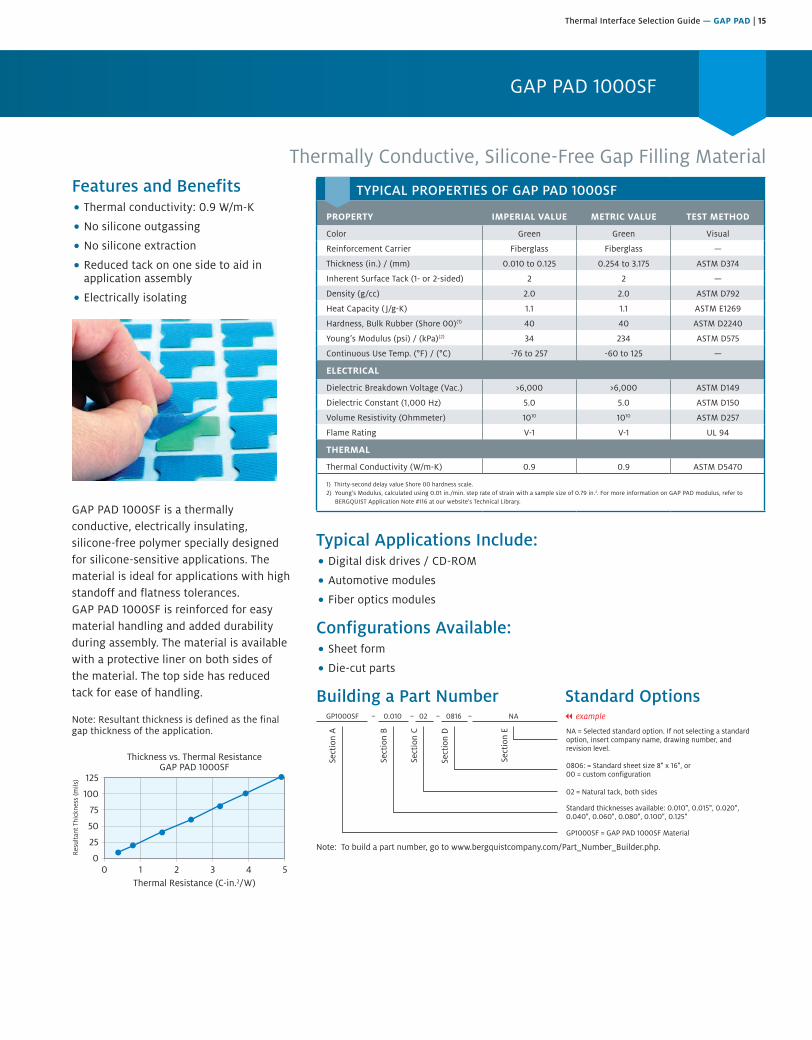
Thermally Conductive, Silicone-Free Gap Filling MaterialFeatures and Benefits• Thermal conductivity: 0.9 W/m-K
• No silicone outgassing
• No silicone extraction
• Reduced tack on one side to aid inapplication assembly
• Electrically isolating
GAP PAD 1000SF is a thermally conductive, electrically insulating, silicone-free polymer specially designed for silicone-sensitive applications. The material is ideal for applications with high standoff and flatness tolerances. GAP PAD 1000SF is reinforced for easy material handling and added durability during assembly. The material is available with a protective liner on both sides of the material. The top side has reduced tack for ease of handling.
Note: Resultant thickness is defined as the final gap thickness of the application.
0 1 2 43 5
125
100
75
50
25
0
Thickness vs. Thermal ResistanceGAP PAD 1000SF
Thermal Resistance (C-in.2/W)
Res
ulta
nt T
hick
ness
(mils
)
Typical Applications Include:• Digital disk drives / CD-ROM
• Automotive modules
• Fiber optics modules
Configurations Available:• Sheet form
• Die-cut parts
Building a Part Number Standard Options
Sect
ion
A
Sect
ion
B
Sect
ion
C
Sect
ion
D
Sect
ion
E NA = Selected standard option. If not selecting a standardoption, insert company name, drawing number, andrevision level.
GP1000SF = GAP PAD 1000SF Material
GP1000SF 0.010 02 0816 NA
Note: To build a part number, go to www.bergquistcompany.com/Part_Number_Builder.php.
Standard thicknesses available: 0.010", 0.015", 0.020",0.040", 0.060", 0.080", 0.100", 0.125"
02 = Natural tack, both sides
0806: = Standard sheet size 8" x 16", or00 = custom configuration
– – – – || example
TYPICAL PROPERTIES OF GAP PAD 1000SF
PROPERTY IMPERIAL VALUE METRIC VALUE TEST METHOD
Color Green Green Visual
Reinforcement Carrier Fiberglass Fiberglass —
Thickness (in.) / (mm) 0.010 to 0.125 0.254 to 3.175 ASTM D374
Inherent Surface Tack (1- or 2-sided) 2 2 —
Density (g/cc) 2.0 2.0 ASTM D792
Heat Capacity ( J/g-K) 1.1 1.1 ASTM E1269
Hardness, Bulk Rubber (Shore 00)(1) 40 40 ASTM D2240
Young’s Modulus (psi) / (kPa)(2) 34 234 ASTM D575
Continuous Use Temp. (°F) / (°C) -76 to 257 -60 to 125 —
ELECTRICAL
Dielectric Breakdown Voltage (Vac.) >6,000 >6,000 ASTM D149
Dielectric Constant (1,000 Hz) 5.0 5.0 ASTM D150
Volume Resistivity (Ohmmeter) 1010 1010 ASTM D257
Flame Rating V-1 V-1 UL 94
THERMAL
Thermal Conductivity (W/m-K) 0.9 0.9 ASTM D5470
1) Thirty-second delay value Shore 00 hardness scale.2) Young’s Modulus, calculated using 0.01 in./min. step rate of strain with a sample size of 0.79 in.2. For more information on GAP PAD modulus, refer to
BERGQUIST Application Note #116 at our website’s Technical Library.
16 | Thermal Interface Selection Guide — GAP PAD
GAP PAD HC1000
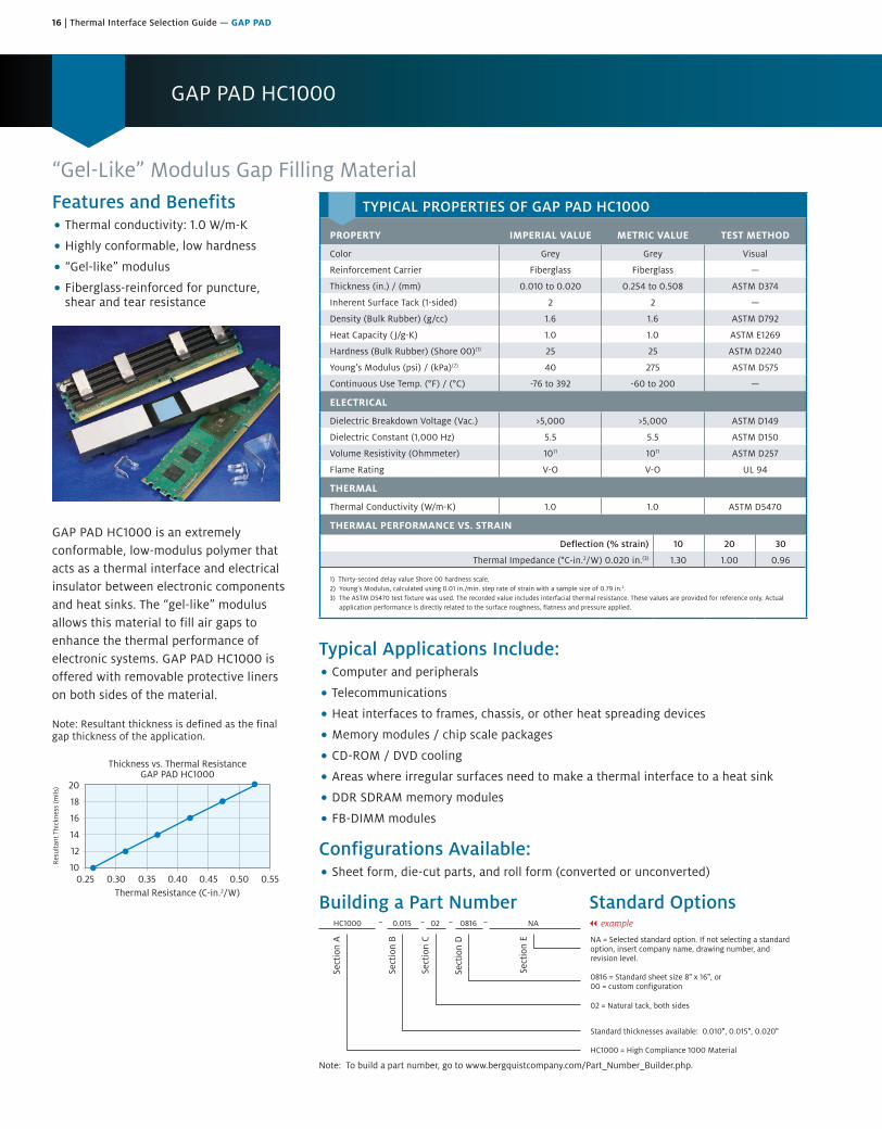
“Gel-Like” Modulus Gap Filling MaterialFeatures and Benefits• Thermal conductivity: 1.0 W/m-K
• Highly conformable, low hardness
• “Gel-like” modulus
• Fiberglass-reinforced for puncture,shear and tear resistance
GAP PAD HC1000 is an extremely conformable, low-modulus polymer that acts as a thermal interface and electrical insulator between electronic components and heat sinks. The “gel-like” modulus allows this material to fill air gaps to enhance the thermal performance of electronic systems. GAP PAD HC1000 is offered with removable protective liners on both sides of the material.
Note: Resultant thickness is defined as the final gap thickness of the application.
0.25 0.30 0.400.35 0.500.45 0.55
20
18
16
14
12
10
Thickness vs. Thermal ResistanceGAP PAD HC1000
Thermal Resistance (C-in.2/W)
Res
ulta
nt T
hick
ness
(mils
)
Typical Applications Include:• Computer and peripherals
• Telecommunications
• Heat interfaces to frames, chassis, or other heat spreading devices
• Memory modules / chip scale packages
• CD-ROM / DVD cooling
• Areas where irregular surfaces need to make a thermal interface to a heat sink
• DDR SDRAM memory modules
• FB-DIMM modules
Configurations Available:• Sheet form, die-cut parts, and roll form (converted or unconverted)
Building a Part Number Standard Options
Sect
ion
A
Sect
ion
B
Sect
ion
C
Sect
ion
D
Sect
ion
E NA = Selected standard option. If not selecting a standardoption, insert company name, drawing number, andrevision level.
HC1000 = High Compliance 1000 Material
HC1000 0.015 02 0816 NA
Note: To build a part number, go to www.bergquistcompany.com/Part_Number_Builder.php.
Standard thicknesses available: 0.010", 0.015", 0.020"
02 = Natural tack, both sides
0816 = Standard sheet size 8" x 16", or00 = custom configuration
– – – – || example
TYPICAL PROPERTIES OF GAP PAD HC1000
PROPERTY IMPERIAL VALUE METRIC VALUE TEST METHOD
Color Grey Grey Visual
Reinforcement Carrier Fiberglass Fiberglass —
Thickness (in.) / (mm) 0.010 to 0.020 0.254 to 0.508 ASTM D374
Inherent Surface Tack (1-sided) 2 2 —
Density (Bulk Rubber) (g/cc) 1.6 1.6 ASTM D792
Heat Capacity ( J/g-K) 1.0 1.0 ASTM E1269
Hardness (Bulk Rubber) (Shore 00)(1) 25 25 ASTM D2240
Young’s Modulus (psi) / (kPa)(2) 40 275 ASTM D575
Continuous Use Temp. (°F) / (°C) -76 to 392 -60 to 200 —
ELECTRICAL
Dielectric Breakdown Voltage (Vac.) >5,000 >5,000 ASTM D149
Dielectric Constant (1,000 Hz) 5.5 5.5 ASTM D150
Volume Resistivity (Ohmmeter) 1011 1011 ASTM D257
Flame Rating V-O V-O UL 94
THERMAL
Thermal Conductivity (W/m-K) 1.0 1.0 ASTM D5470
THERMAL PERFORMANCE VS. STRAIN
Deflection (% strain) 10 20 30
Thermal Impedance (°C-in.2/W) 0.020 in.(3) 1.30 1.00 0.96
1) Thirty-second delay value Shore 00 hardness scale.2) Young’s Modulus, calculated using 0.01 in./min. step rate of strain with a sample size of 0.79 in.2.3) The ASTM D5470 test fixture was used. The recorded value includes interfacial thermal resistance. These values are provided for reference only. Actual
application performance is directly related to the surface roughness, flatness and pressure applied.

Thermal Interface Selection Guide — GAP PAD | 17
GAP PAD 1450
Highly Conformable, Thermally Conductive, Reworkable Gap Filling MaterialFeatures and Benefits• Thermal conductivity: 1.3 W/m-K
(bulk rubber)
• PEN film reinforcement allows easyrework and resistance to puncture andtear resistance
• Highly conformable/low hardness
• Low strain on fragile components
GAP PAD 1450 is a highly compliant GAP PAD material that is ideal for fragile component leads. The material includes a PEN film, which facilitates rework and improves puncture resistance and handling characteristics. The tacky side of GAP PAD 1450 maintains a conformable, yet elastic nature that provides excellent interfacing and wet-out characteristics, even to surfaces with high roughness or uneven topography.
GAP PAD 1450 has inherent tack on one side of the material, eliminating the need for thermally impeding adhesive layers.
It is highly recommended that the PEN film be left intact. However, film removal will not have a significant impact on thermal performance.
Please contact your local Henkel Sales Representative for sample inquiries and additional product information.
Thermal Resistance (C-in.2/W)
Thickness vs. Thermal ResistanceGAP PAD 1450
Typical Applications:• Lighting and LED applications
• Low strain is required for fragile component leads
• Computer and peripherals
• Telecommunications
• Between any heat-generating semiconductor and a heat sink
Configurations Available:• Sheet form and die-cut parts
Building a Part Number Standard OptionsGP1450 01 08160.020 || example
Sect
ion
A
Sect
ion
B
Sect
ion
C
Sect
ion
D
Sect
ion
E
NA
NA = Selected standard option. If not selecting a standardoption, insert company name, drawing number, andrevision level.
0816 = Standard sheet size 8" x 16", or00 = custom configuration
01 = Natural tack, one side
Standard thickness available: 0.020", 0.040", 0.060"0.080", 0.100", 0.125"
GP1450 = GAP PAD 1450 Material
Note: To build a part number, go to www.bergquistcompany.com/Part_Number_Builder.php.
TYPICAL PROPERTIES OF GAP PAD 1450
PROPERTY IMPERIAL VALUE METRIC VALUE TEST METHOD
Color Light Pink Light Pink Visual
Reinforcement Carrier PEN film PEN film —
Thickness (in.) / (mm) 0.020 to 0.125 0.508 to 3.175 ASTM D374
Inherent Surface Tack (1-sided) 1 1 —
Density (Bulk Rubber) (g/cc) 1.8 1.8 ASTM D792
Heat Capacity ( J/g-K) 1.0 1.0 ASTM E1269
Hardness (Bulk Rubber) (Shore 00)(1) 30 30 ASTM D2240
Young’s Modulus (psi) / (kPa)(2) 16 110 ASTM D575
Continuous Use Temp. (°F) / (°C) -76 to 302 -60 to 150 —
ELECTRICAL
Dielectric Breakdown Voltage (Vac.) >6,000 >6,000 ASTM D149
Dielectric Constant (1,000 Hz) 5.0 5.0 ASTM D150
Volume Resistivity (Ohmmeter) 109 109 ASTM D257
Flame Rating V-0 V-0 UL 94
THERMAL
Thermal Conductivity (W/m-K) 1.3 1.3 ASTM D5470
1) Thirty-second delay value Shore 00 hardness scale.2) Young’s Modulus, calculated using 0.01 in./min. step rate of strain with a sample size of 0.79 in.2.

18 | Thermal Interface Selection Guide — GAP PAD
GAP PAD 1500
Thermally Conductive, Unreinforced Gap Filling MaterialFeatures and Benefits• Thermal conductivity: 1.5 W/m-K
• Unreinforced construction foradditional compliancy
• Conformable, low hardness
• Electrically isolating
GAP PAD 1500 has an ideal filler blend that gives it a low-modulus characteristic which maintains optimal thermal performance yet still allows for easy handling. The natural tack on both sides of the material allows for good compliance to adjacent surfaces of components, minimizing interfacial resistance.
Note: Resultant thickness is defined as the final gap thickness of the application.
0 1 32 54 6
200
150
100
50
0
Thickness vs. Thermal ResistanceGAP PAD 1500
Thermal Resistance (C-in.2/W)
Res
ulta
nt T
hick
ness
(mils
)
Typical Applications Include:• Telecommunications
• Computer and peripherals
• Power conversion
• Memory modules / chip scale packages
• Areas where heat needs to be transferred to a frame chassis or other typeof heat spreader
Configurations Available:• Sheet form and die-cut parts
Building a Part Number Standard Options
Sect
ion
A
Sect
ion
B
Sect
ion
C
Sect
ion
D
Sect
ion
E NA = Selected standard option. If not selecting a standardoption, insert company name, drawing number, andrevision level.
GP1500 = GAP PAD 1500 Material
GP1500 0.100 02 0816 NA
Note: To build a part number, go to www.bergquistcompany.com/Part_Number_Builder.php.
Standard thicknesses available: 0.020", 0.040", 0.060",0.080", 0.100", 0.125", 0.160", 0.200"
02 = Natural tack, both sides
0816 = Standard sheet size 8" x 16", or00 = custom configuration
– – – – || example
TYPICAL PROPERTIES OF GAP PAD 1500
PROPERTY IMPERIAL VALUE METRIC VALUE TEST METHOD
Color Black Black Visual
Reinforcement Carrier — — —
Thickness (in.) / (mm) 0.020 to 0.200 0.508 to 5.080 ASTM D374
Inherent Surface Tack (1-sided) 2 2 —
Density (Bulk Rubber) (g/cc) 2.1 2.1 ASTM D792
Heat Capacity ( J/g-K) 1.0 1.0 ASTM E1269
Hardness (Bulk Rubber) (Shore 00)(1) 40 40 ASTM D2240
Young’s Modulus (psi) / (kPa)(2) 45 310 ASTM D575
Continuous Use Temp. (°F) / (°C) -76 to 392 -60 to 200 —
ELECTRICAL
Dielectric Breakdown Voltage (Vac.) >6,000 >6,000 ASTM D149
Dielectric Constant (1,000 Hz) 5.5 5.5 ASTM D150
Volume Resistivity (Ohmmeter) 1011 1011 ASTM D257
Flame Rating V-O V-O UL 94
THERMAL
Thermal Conductivity (W/m-K) 1.5 1.5 ASTM D5470
THERMAL PERFORMANCE VS. STRAIN
Deflection (% strain) 10 20 30
Thermal Impedance (°C-in.2/W) 0.040 in.(3) 1.62 1.50 1.33
1) Thirty-second delay value Shore 00 hardness scale.2) Young’s Modulus, calculated using 0.01 in./min. step rate of strain with a sample size of 0.79 in.2.3) The ASTM D5470 test fixture was used. The recorded value includes interfacial thermal resistance. These values are provided for reference only. Actual
application performance is directly related to the surface roughness, flatness and pressure applied.

Thermal Interface Selection Guide — GAP PAD | 19
GAP PAD 1500R
Features and Benefits• Thermal conductivity: 1.5 W/m-K
• Fiberglass-reinforced for puncture,shear and tear resistance
• Easy release construction
• Electrically isolating
GAP PAD 1500R has the same highly conformable, low-modulus polymer as the standard GAP PAD 1500. The fiberglass reinforcement allows for easy material handling and enhances puncture, shear and tear resistance. The natural tack on both sides of the material allows for good compliance to mating surfaces of components, further reducing thermal resistance.
Note: Resultant thickness is defined as the final gap thickness of the application.
0.25 0.30 0.400.35 0.500.45 0.55
20
18
16
14
12
10
Thickness vs. Thermal ResistanceGAP PAD 1500R
Thermal Resistance (C-in.2/W)
Res
ulta
nt T
hick
ness
(mils
)
Thermally Conductive, Reinforced Gap Filling Material
Typical Applications Include:• Telecommunications
• Computer and peripherals
• Power conversion
• Memory modules / chip scale packages
• Areas where heat needs to be transferred to a frame chassis or other typeof heat spreader
Configurations Available:• Sheet form, die-cut parts, and roll form (converted or unconverted)
Building a Part Number Standard Options
Sect
ion
A
Sect
ion
B
Sect
ion
C
Sect
ion
D
Sect
ion
E NA = Selected standard option. If not selecting a standardoption, insert company name, drawing number, andrevision level.
GP1500R = GAP PAD 1500R Material
GP1500R 0.020 02 00 ACME10256 Rev. A
Note: To build a part number, go to www.bergquistcompany.com/Part_Number_Builder.php.
Standard thicknesses available: 0.010", 0.015", 0.020"
02 = Natural tack, both sides
0816 = Standard sheet size 8" x 16", or00 = custom configuration
– – – – || example
TYPICAL PROPERTIES OF GAP PAD 1500R
PROPERTY IMPERIAL VALUE METRIC VALUE TEST METHOD
Color Black Black Visual
Reinforcement Carrier Fiberglass Fiberglass —
Thickness (in.) / (mm) 0.010 to 0.020 0.254 to 0.508 ASTM D374
Inherent Surface Tack (1-sided) 2 2 —
Density (Bulk Rubber) (g/cc) 2.1 2.1 ASTM D792
Heat Capacity ( J/g-K) 1.3 1.3 ASTM E1269
Hardness (Bulk Rubber) (Shore 00)(1) 40 40 ASTM D2240
Young’s Modulus (psi) / (kPa)(2) 45 310 ASTM D575
Continuous Use Temp. (°F) / (°C) -76 to 392 -60 to 200 —
ELECTRICAL
Dielectric Breakdown Voltage (Vac.) >6,000 >6,000 ASTM D149
Dielectric Constant (1,000 Hz) 6.0 6.0 ASTM D150
Volume Resistivity (Ohmmeter) 1011 1011 ASTM D257
Flame Rating V-O V-O UL 94
THERMAL
Thermal Conductivity (W/m-K) 1.5 1.5 ASTM D5470
THERMAL PERFORMANCE VS. STRAIN
Deflection (% strain) 10 20 30
Thermal Impedance (°C-in.2/W) 0.020 in.(3) 1.07 0.88 0.82
1) Thirty-second delay value Shore 00 hardness scale.2) Young’s Modulus, calculated using 0.01 in./min. step rate of strain with a sample size of 0.79 in.2.3) The ASTM D5470 test fixture was used. The recorded value includes interfacial thermal resistance. These values are provided for reference only. Actual
application performance is directly related to the surface roughness, flatness and pressure applied.

20 | Thermal Interface Selection Guide — GAP PAD
GAP PAD 1500S30
Highly Conformable, Thermally Conductive, Reinforced “S-Class” Gap Filling MaterialFeatures and Benefits• Thermal conductivity: 1.3 W/m-K
• Highly conformable/low hardness
• Decreased strain on fragile components
• Fiberglass-reinforced for puncture,shear and tear resistance
• Quick rebound to original shape
GAP PAD 1500S30 is a highly compliant GAP PAD material that is ideal for fragile component leads. The material is fiberglass-reinforced for improved puncture resistance and handling characteristics. GAP PAD 1500S30 maintains a conformable, yet elastic nature that provides excellent interfacing and wet-out characteristics, even to surfaces with high roughness or uneven topography.
GAP PAD 1500S30 features an inherent tack on both sides of the material, eliminating the need for thermally impeding adhesive layers.
Note: Resultant thickness is defined as the final gap thickness of the application.
0.61 1.21 1.82 2.42 3.03 3.79 4.85 6.06 7.57
250200160125100806040200
Thickness vs. Thermal ResistanceGAP PAD 1500S30
Thermal Resistance (C-in.2/W)
Res
ulta
nt T
hick
ness
(mils
)
Typical Applications:• Any heat-generating component and a heat sink
• Computers and peripherals
• Telecommunications
• Between any heat-generating semiconductor and a heat sink
• Shielding devices
Configurations Available:• Sheet form and die-cut parts
Building a Part Number Standard OptionsGP1500S30
GP1500S30 = GAP PAD 1500S30 Material
02 08160.020
Note: To build a part number, go to www.bergquistcompany.com/Part_Number_Builder.php.
NA = Selected standard option. If not selecting a standardoption, insert company name, drawing number, andrevision level.
0816 = Standard sheet size 8" x 16", or00 = custom configuration
02 = Natural tack, both sides
Standard thicknesses available: 0.020", 0.040", 0.060"0.080", 0.100", 0.125", 0.160", 0.200", 0.250"
Sect
ion
A
Sect
ion
B
Sect
ion
C
Sect
ion
D
Sect
ion
E
|| example
TYPICAL PROPERTIES OF GAP PAD 1500S30
PROPERTY IMPERIAL VALUE METRIC VALUE TEST METHOD
Color Light Pink Light Pink Visual
Reinforcement Carrier Fiberglass Fiberglass ASTM D374
Thickness (in.) / (mm) 0.020 to 0.250 0.508 to 6.350 ASTM D374
Inherent Surface Tack (1-sided) 2 2 —
Density (Bulk Rubber) (g/cc) 1.8 1.8 ASTM D792
Heat Capacity ( J/g-K) 1.0 1.0 ASTM E1269
Hardness (Bulk Rubber) (Shore 00)(1) 30 30 ASTM D2240
Young’s Modulus (psi) / (kPa)(2) 16 110 ASTM D575
Continuous Use Temp. (°F) / (°C) -76 to 392 -60 to 200 —
ELECTRICAL
Dielectric Breakdown Voltage (Vac.) >6,000 >6,000 ASTM D149
Dielectric Constant (1,000 Hz) 5.0 5.0 ASTM D150
Volume Resistivity (Ohmmeter) 1011 1011 ASTM D257
Flame Rating V-O V-O UL 94
THERMAL
Thermal Conductivity (W/m-K) 1.3 1.3 ASTM D5470
THERMAL PERFORMANCE VS. STRAIN
Deflection (% strain) 10 20 30
Thermal Impedance (°C-in.2/W) 0.040 in.(3) 1.69 1.41 1.26
1) Thirty-second delay value Shore 00 hardness scale.2) Young’s Modulus, calculated using 0.01 in./min. step rate of strain with a sample size of 0.79 in.2.3) The ASTM D5470 test fixture was used. The recorded value includes interfacial thermal resistance. These values are provided for reference only. Actual
application performance is directly related to the surface roughness, flatness and pressure applied.

Thermal Interface Selection Guide — GAP PAD | 21
GAP PAD A2000
High Performance, Thermally Conductive Gap Filling MaterialFeatures and Benefits• Thermal conductivity: 2.0 W/m-K
• Fiberglass-reinforced for puncture,shear and tear resistance
• Electrically isolating
GAP PAD A2000 acts as a thermal interface and electrical insulator between electronic components and heat sinks. In the thickness range of 10 to 40 mil, GAP PAD A2000 is supplied with natural tack on both sides, allowing for excellent compliance to the adjacent surfaces of components. The 40 mil material thickness is supplied with lower tack on one side, allowing for burn-in processes and easy rework.
Note: Resultant thickness is defined as the final gap thickness of the application.
0.20 0.30 0.500.40 0.700.60 0.80
403530252015100
Thickness vs. Thermal ResistanceGAP PAD A2000
Thermal Resistance (C-in.2/W)
Res
ulta
nt T
hick
ness
(mils
)
Typical Applications Include:• Computer and peripherals; between CPU and heat spreader
• Telecommunications
• Heat pipe assemblies
• Memory modules
• CDROM / DVD cooling
• Areas where heat needs to be transferred to a frame chassis or other typeof heat spreader
• DDR SDRAM memory modules
Configurations Available:• Sheet form, die-cut parts and roll form (converted or unconverted)
Building a Part Number Standard Options
Sect
ion
A
Sect
ion
B
Sect
ion
C
Sect
ion
D
Sect
ion
E NA = Selected standard option. If not selecting a standardoption, insert company name, drawing number, andrevision level.
GPA2000 = GAP PAD A2000 Material
GPA2000 0.010 02 0816 NA
Note: To build a part number, go to www.bergquistcompany.com/Part_Number_Builder.php.
Standard thicknesses available: 0.010", 0.015", 0.020"0.040"
02 = Natural tack, both sides
0816 = Standard sheet size 8" x 16", or00 = custom configuration
– – – – || example
TYPICAL PROPERTIES OF GAP PAD A2000
PROPERTY IMPERIAL VALUE METRIC VALUE TEST METHOD
Color Grey Grey Visual
Reinforcement Carrier Fiberglass Fiberglass —
Thickness (in.) / (mm) 0.010 to 0.040 0.254 to 1.016 ASTM D374
Inherent Surface Tack (1-sided) 2 2 —
Density (Bulk Rubber) (g/cc) 2.9 2.9 ASTM D792
Heat Capacity ( J/g-K) 1.0 1.0 ASTM E1269
Hardness (Bulk Rubber) (Shore 00)(1) 80 80 ASTM D2240
Young’s Modulus (psi) / (kPa)(2) 55 379 ASTM D575
Continuous Use Temp. (°F) / (°C) -76 to 392 -60 to 200 —
ELECTRICAL
Dielectric Breakdown Voltage (Vac.) 4,000 4,000 ASTM D149
Dielectric Constant (1,000 Hz) 6.0 6.0 ASTM D150
Volume Resistivity (Ohmmeter) 1011 1011 ASTM D257
Flame Rating V-O V-O UL 94
THERMAL
Thermal Conductivity (W/m-K) 2.0 2.0 ASTM D5470
THERMAL PERFORMANCE VS. STRAIN
Deflection (% strain) 10 20 30
Thermal Impedance (°C-in.2/W) 0.040 in.(3) 1.04 1.00 0.95
1) Thirty-second delay value Shore 00 hardness scale.2) Young’s Modulus, calculated using 0.01 in./min. step rate of strain with a sample size of 0.79 in.2.3) The ASTM D5470 test fixture was used. The recorded value includes interfacial thermal resistance. These values are provided for reference only. Actual
application performance is directly related to the surface roughness, flatness and pressure applied.
22 | Thermal Interface Selection Guide — GAP PAD
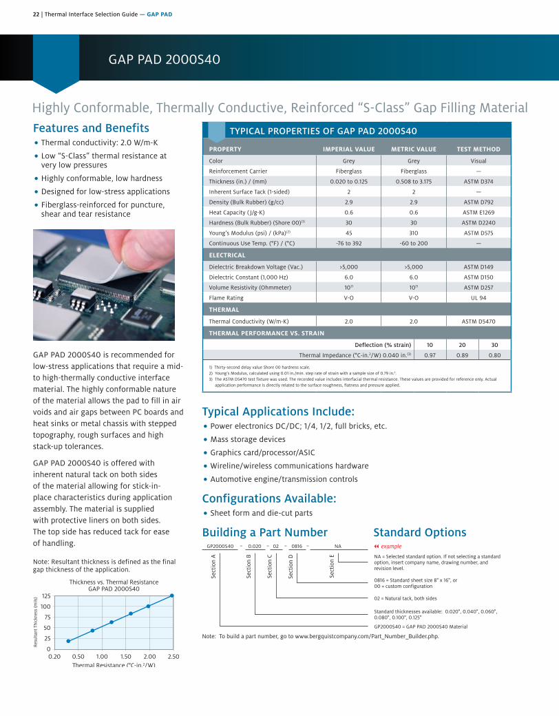
GAP PAD 2000S40
Highly Conformable, Thermally Conductive, Reinforced “S-Class” Gap Filling MaterialFeatures and Benefits• Thermal conductivity: 2.0 W/m-K
• Low “S-Class” thermal resistance atvery low pressures
• Highly conformable, low hardness
• Designed for low-stress applications
• Fiberglass-reinforced for puncture,shear and tear resistance
GAP PAD 2000S40 is recommended for low-stress applications that require a mid- to high-thermally conductive interface material. The highly conformable nature of the material allows the pad to fill in air voids and air gaps between PC boards and heat sinks or metal chassis with stepped topography, rough surfaces and high stack-up tolerances.
GAP PAD 2000S40 is offered with inherent natural tack on both sides of the material allowing for stick-in-place characteristics during application assembly. The material is supplied with protective liners on both sides. The top side has reduced tack for ease of handling.
Note: Resultant thickness is defined as the final gap thickness of the application.
0.20 0.50 1.501.00 2.00 2.50
125
100
75
50
25
0
Thickness vs. Thermal ResistanceGAP PAD 2000S40
Thermal Resistance (°C-in.2/W)
Res
ulta
nt T
hick
ness
(mils
)
Typical Applications Include:• Power electronics DC/DC; 1/4, 1/2, full bricks, etc.
• Mass storage devices
• Graphics card/processor/ASIC
• Wireline/wireless communications hardware
• Automotive engine/transmission controls
Configurations Available:• Sheet form and die-cut parts
Building a Part Number Standard Options
Sect
ion
A
Sect
ion
B
Sect
ion
C
Sect
ion
D
Sect
ion
E NA = Selected standard option. If not selecting a standardoption, insert company name, drawing number, andrevision level.
GP2000S40 = GAP PAD 2000S40 Material
GP2000S40 0.020 02 0816 NA
Note: To build a part number, go to www.bergquistcompany.com/Part_Number_Builder.php.
Standard thicknesses available: 0.020", 0.040", 0.060",0.080", 0.100", 0.125"
02 = Natural tack, both sides
0816 = Standard sheet size 8" x 16", or00 = custom configuration
– – – – || example
TYPICAL PROPERTIES OF GAP PAD 2000S40
PROPERTY IMPERIAL VALUE METRIC VALUE TEST METHOD
Color Grey Grey Visual
Reinforcement Carrier Fiberglass Fiberglass —
Thickness (in.) / (mm) 0.020 to 0.125 0.508 to 3.175 ASTM D374
Inherent Surface Tack (1-sided) 2 2 —
Density (Bulk Rubber) (g/cc) 2.9 2.9 ASTM D792
Heat Capacity ( J/g-K) 0.6 0.6 ASTM E1269
Hardness (Bulk Rubber) (Shore 00)(1) 30 30 ASTM D2240
Young’s Modulus (psi) / (kPa)(2) 45 310 ASTM D575
Continuous Use Temp. (°F) / (°C) -76 to 392 -60 to 200 —
ELECTRICAL
Dielectric Breakdown Voltage (Vac.) >5,000 >5,000 ASTM D149
Dielectric Constant (1,000 Hz) 6.0 6.0 ASTM D150
Volume Resistivity (Ohmmeter) 1011 1011 ASTM D257
Flame Rating V-O V-O UL 94
THERMAL
Thermal Conductivity (W/m-K) 2.0 2.0 ASTM D5470
THERMAL PERFORMANCE VS. STRAIN
Deflection (% strain) 10 20 30
Thermal Impedance (°C-in.2/W) 0.040 in.(3) 0.97 0.89 0.80
1) Thirty-second delay value Shore 00 hardness scale.2) Young’s Modulus, calculated using 0.01 in./min. step rate of strain with a sample size of 0.79 in.2.3) The ASTM D5470 test fixture was used. The recorded value includes interfacial thermal resistance. These values are provided for reference only. Actual
application performance is directly related to the surface roughness, flatness and pressure applied.

Thermal Interface Selection Guide — GAP PAD | 23
GAP PAD 2200SF
Thermally Conductive, Silicone-Free Gap Filling MaterialFeatures and Benefits• Thermal conductivity: 2.0 W/m-K
• Silicone-free formulation
• Medium compliance with easy handling
• Electrically isolating
GAP PAD 2200SF is a thermally conductive, electrically isolating, silicone-free polymer specially designed for silicone-sensitive applications. The material is ideal for applications with uneven topologies and high stack-up tolerances. GAP PAD 2200SF is reinforced for easy material handling and added durability during assembly. The material is available with a protective liner on both sides. GAP PAD 2200SF is supplied with reduced tack on one side, allowing for burn-in processes and easy rework.
Note: Resultant thickness is defined as the final gap thickness of the application.
GAP PAD 2200SF140
0 0.5 1.0 1.5 2.0 2.50
Thermal Resistance (°C-in.2/W)
Typical Applications:• Digital disk drives
• Proximity near electrical contacts (e.g., DC brush motors, connectors, relays)
• Fiber optics modules
Configurations Available:• Sheet form
• Die-cut parts
• Standard sheet size is 8 in. x 16 in.
Building a Part Number Standard Options
GP2200SF = GAP PAD 2200SF Material
Note: To build a part number, go to www.bergquistcompany.com/Part_Number_Builder.php.
Sect
ion
B
Sect
ion
D
Sect
ion
E
Sect
ion
A
Sect
ion
C
GP2200SF N– 02– – –0.010 0816
NA = Selected standard option. If not selecting a standardoption, insert company name, drawing number, andrevision level.
0816 = Standard sheet size 8" x 16", or00 = custom configuration
02 = Natural tack, both sides
Standard thicknesses available: 0.010", 0.015", 0.020",0.040", 0.060", 0.080", 0.100", 0.125"
|| example
TYPICAL PROPERTIES OF GAP PAD 2200SF
PROPERTY IMPERIAL VALUE METRIC VALUE TEST METHOD
Color Green Green Visual
Reinforcement Carrier Fiberglass Fiberglass —
Thickness (in.) / (mm) 0.010 to 0.125 0.254 to 3.175 ASTM D374
Inherent Surface Tack (1- or 2-sided) 2 2 —
Density (g/cc) 2.8 2.8 ASTM D792
Heat Capacity ( J/g-K) 1.0 1.0 ASTM E1269
Hardness, Bulk Rubber (Shore 00)(1) 70 70 ASTM D2240
Young’s Modulus (psi) / (kPa)(2) 33 228 ASTM D575
Continuous Use Temp. (°F) / (°C) -76 to 257 -60 to 125 —
ELECTRICAL
Dielectric Breakdown Voltage (Vac.) >5,000 >5,000 ASTM D149
Dielectric Constant (1,000 Hz) 6.0 6.0 ASTM D150
Volume Resistivity (Ohmmeter) 108 108 ASTM D257
Flame Rating V-O V-O UL 94
THERMAL
Thermal Conductivity (W/m-K) 2.0 2.0 ASTM D5470
1) Thirty-second delay value Shore 00 hardness scale.2) Young’s Modulus, calculated using 0.01 in./min. step rate of strain with a sample size of 0.79 in.2. For more information on GAP PAD modulus, refer to
BERGQUIST Application Note #116 at our website’s Technical Library.
24 | Thermal Interface Selection Guide — GAP PAD
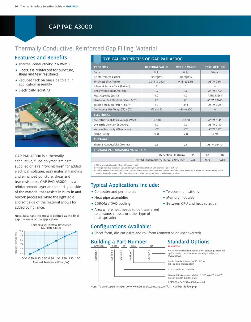
GAP PAD A3000
Thermally Conductive, Reinforced Gap Filling MaterialFeatures and Benefits• Thermal conductivity: 2.6 W/m-K
• Fiberglass-reinforced for puncture,shear and tear resistance
• Reduced tack on one side to aid inapplication assembly
• Electrically isolating
GAP PAD A3000 is a thermally conductive, filled-polymer laminate, supplied on a reinforcing mesh for added electrical isolation, easy material handling and enhanced puncture, shear and tear resistance. GAP PAD A3000 has a reinforcement layer on the dark gold side of the material that assists in burn-in and rework processes while the light gold and soft side of the material allows for added compliance.
Note: Resultant thickness is defined as the final gap thickness of the application.
0.10 0.30 0.50 0.70 1.100.90 1.501.30 1.70
125
115
95
75
55
35
Thickness vs. Thermal ResistanceGAP PAD A3000
Thermal Resistance (C-in.2/W)
Res
ulta
nt T
hick
ness
(mils
)
Typical Applications Include:• Computer and peripherals
• Heat pipe assemblies
• CDROM / DVD cooling
• Area where heat needs to be transferredto a frame, chassis or other type ofheat spreader
• Telecommunications
• Memory modules
• Between CPU and heat spreader
Configurations Available:• Sheet form, die-cut parts and roll form (converted or unconverted)
Building a Part Number Standard Options
Sect
ion
A
Sect
ion
B
Sect
ion
C
Sect
ion
D
Sect
ion
E NA = Selected standard option. If not selecting a standardoption, insert company name, drawing number, andrevision level.
GPA3000 = GAP PAD A3000 Material
GPA3000 0.015 01 0816 NA
Note: To build a part number, go to www.bergquistcompany.com/Part_Number_Builder.php.
Standard thicknesses available: 0.015", 0.020", 0.040",0.060", 0.080", 0.100", 0.125"
01 = Natural tack, one side
0816 = Standard sheet size 8" x 16", or00 = custom configuration
– – – – || example
TYPICAL PROPERTIES OF GAP PAD A3000
PROPERTY IMPERIAL VALUE METRIC VALUE TEST METHOD
Color Gold Gold Visual
Reinforcement Carrier Fiberglass Fiberglass —
Thickness (in.) / (mm) 0.015 to 0.125 0.381 to 3.175 ASTM D374
Inherent Surface Tack (1-sided) 1 1 —
Density (Bulk Rubber) (g/cc) 3.2 3.2 ASTM D792
Heat Capacity ( J/g-K) 1.0 1.0 ASTM E1269
Hardness (Bulk Rubber) (Shore 00)(1) 80 80 ASTM D2240
Young’s Modulus (psi) / (kPa)(2) 50 344 ASTM D575
Continuous Use Temp. (°F) / (°C) -76 to 392 -60 to 200 —
ELECTRICAL
Dielectric Breakdown Voltage (Vac.) >5,000 >5,000 ASTM D149
Dielectric Constant (1,000 Hz) 7.0 7.0 ASTM D150
Volume Resistivity (Ohmmeter) 1010 1010 ASTM D257
Flame Rating V-O V-O UL 94
THERMAL
Thermal Conductivity (W/m-K) 2.6 2.6 ASTM D5470
THERMAL PERFORMANCE VS. STRAIN
Deflection (% strain) 10 20 30
Thermal Impedance (°C-in.2/W) 0.040 in.(3) 0.78 0.73 0.68
1) Thirty-second delay value Shore 00 hardness scale.2) Young’s Modulus, calculated using 0.01 in./min. step rate of strain with a sample size of 0.79 in.2.3) The ASTM D5470 test fixture was used. The recorded value includes interfacial thermal resistance. These values are provided for reference only. Actual
application performance is directly related to the surface roughness, flatness and pressure applied.

Thermal Interface Selection Guide — GAP PAD | 25
GAP PAD 3500ULM
Highly Conformable, Thermally Conductive, Ultra-Low Modulus MaterialFeatures and Benefits• Thermal conductivity: 3.5 W/m-K
• Fiberglass-reinforced for shear and tearresistance
• Non-fiberglass option for applicationsthat require an additional reductionin stress
GAP PAD 3500ULM (ultra-low modulus) is an extremely soft gap filling material with a thermal conductivity of 3.5 W/m-K. The material offers exceptional thermal performance at low pressures due to a unique 3.5 W/m-K filler package and ultra-low modulus resin formulation. The enhanced material is well-suited for high performance applications requiring extremely low assembly stress. GAP PAD 3500ULM maintains a conformable nature that allows for excellent interfacing and wet-out characteristics, even to surfaces with high roughness and/or topography.
GAP PAD 3500ULM is offered with and without fiberglass and has higher natural inherent tack on one side of the material, eliminating the need for thermally impeding adhesive layers. The top side has minimal tack for ease of handling. GAP PAD 3500ULM is supplied with protective liners on both sides.
.25 .50 .75 1.00 1.25 1.50 1.75 2.00
140
120
100
80
60
40
20
0
Thickness vs. Thermal ResistanceGAP PAD 3500ULM
Thermal Resistance (°C-in.2/W)
Res
ulta
nt T
hick
ness
(mils
)
Typical Applications Include:• Consumer electronics
• Telecommunications
• ASICs and DSPs
• PC applications
Configurations Available:• Sheet form and die-cut parts
Building a Part Number Standard Options
Sect
ion
A
Sect
ion
B
Sect
ion
C
Sect
ion
D
Sect
ion
E NA = Selected standard option. If not selecting a standardoption, insert company name, drawing number, andrevision level.
GP3500ULM = GAP PAD 3500ULM Material without fiberglassGP3500ULM-G = GAP PAD 3500ULM Material with fiberglass(GP3500ULM and GP3500ULM-G are also offered in a NT, non-tack, version)
GP3500ULM 0.020 02 0816 NA
Note: To build a part number, go to www.bergquistcompany.com/Part_Number_Builder.php.
Standard thicknesses available: 0.020"(fiberglass only), 0.040", 0.060", 0.080", 0.100", 0.125"
02 = Natural tack, both sides (without fiberglass)12 = Natural tack, both sides (with fiberglass)05 = Non-tack, one side (without fiberglass), 7.87" x 15.75"15 = Non-tack, one side (with fiberglass), 7.87" x 15.75"
0816 = Standard sheet size 8" x 16", or00 = custom configuration
– – – – || example
TYPICAL PROPERTIES OF GAP PAD 3500ULM
PROPERTY IMPERIAL VALUE METRIC VALUE TEST METHOD
Color Grey Grey Visual
Reinforcement CarrierFiberglass or no fiberglass
Fiberglass or no fiberglass
—
Thickness (in.) / (mm) 0.020 to 0.125 0.508 to 3.175 ASTM D374
Inherent Surface Tack 2 2 —
Density (Bulk Rubber) (g/cc) 3.1 3.1 ASTM D792
Heat Capacity ( J/g-K) 1.0 1.0 ASTM E1269
Young’s Modulus (psi) / (kPa)(1)(2) 4 27.5 —
Continuous Use Temp. (°F) / (°C) -76 to 392 -60 to 200 —
ELECTRICAL
Dielectric Breakdown Voltage (Vac.) >5,000 >5,000 ASTM D149
Dielectric Constant (1,000 Hz)(3) 6.0 6.0 ASTM D150
Volume Resistivity (Ohmmeter) 1010 1010 ASTM D257
Flame Rating V-O V-O UL 94
THERMAL
Thermal Conductivity (W/m-K) 3.5 3.5 ASTM D5470
THERMAL PERFORMANCE VS. STRAIN
Deflection (% strain) 10 20 30
Thermal Impedance (°C-in.2/W) 0.040 in.(4) 0.50 0.44 0.39
1) Young’s Modulus, calculated using 0.01 in./min. step rate of strain with a sample size of 0.79 in.2 after 5 minutes of compression at 10% strain on a 1mm thickness material.
2) Thirty-second delay value Shore 000 hardness scale is 70 for 125 mil.3) Minimum value at 20 mil.4) The ASTM D5470 test fixture was used. The recorded value includes interfacial thermal resistance. These values are provided for reference only. Actual
application performance is directly related to the surface roughness, flatness and pressure applied.
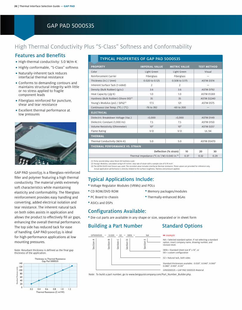
26 | Thermal Interface Selection Guide — GAP PAD
GAP PAD 5000S35 is a fiberglass-reinforced filler and polymer featuring a high thermal conductivity. The material yields extremely soft characteristics while maintaining elasticity and conformability. The fiberglass reinforcement provides easy handling and converting, added electrical isolation and tear resistance. The inherent natural tack on both sides assists in application and allows the product to effectively fill air gaps, enhancing the overall thermal performance. The top side has reduced tack for ease of handling. GAP PAD 5000S35 is ideal for high-performance applications at low mounting pressures.
Note: Resultant thickness is defined as the final gap thickness of the application.
Typical Applications Include:• Voltage Regulator Modules (VRMs) and POLs
• CD ROM/DVD ROM • Memory packages/modules
• PC Board to chassis • Thermally-enhanced BGAs
• ASICs and DSPs
Configurations Available:• Die-cut parts are available in any shape or size, separated or in sheet form
Building a Part Number Standard Options
Features and Benefits• High-thermal conductivity: 5.0 W/m-K
• Highly conformable, “S-Class” softness
• Naturally-inherent tack reducesinterfacial thermal resistance
• Conforms to demanding contours andmaintains structural integrity with littleor no stress applied to fragilecomponent leads
• Fiberglass reinforced for puncture,shear and tear resistance
• Excellent thermal performance atlow pressures
0.2 0.4 0.6 0.8 1.0 1.2
140
120
100
80
60
40
20
0
Thickness vs. Thermal ResistanceGap Pad 5000S35
Thermal Resistance (C-in2/W)
Res
ulta
nt T
hick
ness
(m
ils)
GAP PAD 5000S35
High Thermal Conductivity Plus “S-Class” Softness and Conformability
TYPICAL PROPERTIES OF GAP PAD 5000S35
PROPERTY IMPERIAL VALUE METRIC VALUE TEST METHOD
Color Light Green Light Green Visual
Reinforcement Carrier Fiberglass Fiberglass —
Thickness (in.) / (mm) 0.020 to 0.125 0.508 to 3.175 ASTM D374
Inherent Surface Tack (1-sided) 2 2 —
Density (Bulk Rubber) (g/cc) 3.6 3.6 ASTM D792
Heat Capacity ( J/g-K) 1.0 1.0 ASTM E1269
Hardness (Bulk Rubber) (Shore 00)(1) 35 35 ASTM D2240
Young’s Modulus (psi) / (kPa)(2) 17.5 121 ASTM D575
Continuous Use Temp. (°F) / (°C) -76 to 392 -60 to 200 —
ELECTRICAL
Dielectric Breakdown Voltage (Vac.) >5,000 >5,000 ASTM D149
Dielectric Constant (1,000 Hz) 7.5 7.5 ASTM D150
Volume Resistivity (Ohmmeter) 109 109 ASTM D257
Flame Rating V-O V-O UL 94
THERMAL
Thermal Conductivity (W/m-K) 5.0 5.0 ASTM D5470
THERMAL PERFORMANCE VS. STRAIN
Deflection (% strain) 10 20 30
Thermal Impedance (°C-in.2/W) 0.040 in.(3) 0.37 0.32 0.29
(1) Thirty second delay value Shore 00 hardness scale. (2) Young’s Modulus, calculated using 0.01 in/min. step rate of strain with a sample size of 0.79 inch2. (3) The ASTM D5470 test fixture was used. The recorded value includes interfacial thermal resistance. These values are provided for reference only.
Actual application performance is directly related to the surface roughness, flatness and pressure applied.
|| example
Sect
ion
A
Sect
ion
B
Sect
ion
C
Sect
ion
D
Sect
ion
E
Note: To build a part number, go to www.bergquistcompany.com/Part_Number_Builder.php.
GP5000S35 0.020 02 0816 NA
NA = Selected standard option. If not selecting a standardoption, insert company name, drawing number, andrevision level.
GPA5000S35 = GAP PAD 5000S35 Material
Standard thicknesses available: 0.020", 0.040", 0.060"0.080", 0.100", 0.125"
02 = Natural tack, both sides
0816 = Standard sheet size 8" x 16", or00 = custom configuration
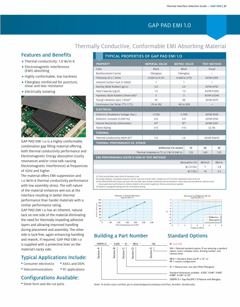
Thermal Interface Selection Guide — GAP PAD | 27
0 1.00 3.002.00 4.00 5.00 6.00
140
120
100
80
60
40
20
0
Thickness vs. Thermal ResistanceGap Pad EMI 1.0
Thermal Resistance (C-in2/W)
Res
ulta
nt T
hick
ness
(m
ils)
0 1 32 4 5 6 7 8
0
-2
-4
-6
-8
-10
-12
-14
-16
Absorption and Reflection (60 mil)Gap Pad EMI 1.0
Frequency (GHz)
dB
TYPICAL PROPERTIES OF GAP PAD EMI 1.O
PROPERTY IMPERIAL VALUE METRIC VALUE TEST METHOD
Color Black Black Visual
Reinforcement Carrier Fiberglass Fiberglass —
Thickness (in.) / (mm) 0.020 to 0.125 0.508 to 3.175 ASTM D374
Inherent Surface Tack (1-sided) 1 1 —
Density (Bulk Rubber) (g/cc) 2.4 2.4 ASTM D792
Heat Capacity ( J/g-K) 1.3 1.3 ASTM E1269
Hardness (Bulk Rubber) (Shore 00)(1) 5 5 ASTM D2240
Young’s Modulus (psi) / (kPa)(2) 10 69 ASTM D575
Continuous Use Temp. (°F) / (°C) -76 to 392 -60 to 200 —
ELECTRICAL
Dielectric Breakdown Voltage (Vac.) >1,700 >1,700 ASTM D149
Dielectric Constant (1,000 Hz) 6.0 6.0 ASTM D150
Volume Resistivity (Ohmmeter) 1010 1010 ASTM D257
Flame Rating V-O V-O UL 94
THERMAL
Thermal Conductivity (W/m-K)(3) 1.0 1.0 ASTM D5470
THERMAL PERFORMANCE VS. STRAIN
Deflection (% strain) 10 20 30
Thermal Impedance (°C-in.2/W) 0.040 in. 1.53 1.40 1.25
EMI PERFORMANCE (ASTM D-5568-01 TEST METHOD)
Absorption (4) dB/inch dB/cm
@ 2.4 Ghz -7 -2.8
@ 5 Ghz -14 -5.5
(1) Thirty second delay value Shore 00 hardness scale.(2) Young’s Modulus, calculated using 0.01 in/min. step rate of strain with a sample size of 0.79 inch2. Relaxation stress @ 40 mil.(3) The ASTM D5470 test fixture was used. The recorded value includes interfacial thermal resistance. These values are provided for reference only.
Actual application performance is directly related to the surface roughness, flatness and pressure applied.(4) Based on waveguide testing with 60 mil thickness testing
GAP PAD EMI 1.0 is a highly conformable,combination gap filling material offering both thermal conductivity performance andElectromagnetic Energy absorption (cavityresonances and/or cross-talk causingElectromagnetic Interference) at frequencies of 1GHz and higher.The material offers EMI suppression and1.0 W/m-K thermal conductivity performance with low assembly stress. The soft nature of the material enhances wet-out at the interface resulting in better thermal performance than harder materials with a similar performance rating.GAP PAD EMI 1.0 has an inherent, natural tack on one side of the material eliminating the need for thermally-impeding adhesive layers and allowing improved handling during placement and assembly. The other side is tack-free, again enhancing handling and rework, if required. GAP PAD EMI 1.0 is supplied with a protective liner on the material’s tacky side.
Building a Part Number Standard Options
Features and Benefits• Thermal onductivity: 1.0 W/m-K
• Electromagnetic Interference(EMI) absorbing
• Highly conformable, low hardness
• Fiberglass reinforced for puncture,shear and tear resistance
• Electrically isolating
Thermally Conductive, Conformable EMI Absorbing Material
GAP PAD EMI 1.0
Sect
ion
A
Sect
ion
B
Sect
ion
C
Sect
ion
D
Sect
ion
E NA = Selected standard option. If not selecting a standardoption, insert company name, drawing number, andrevision level.
GPEMI1.0 = Gap Pad EMI 1.0 Material with fiberglass
GPEMI1.0 0.020 01 0816 NA
Note: To build a part number, visit our website at www.bergquistcompany.com.
Standard thicknesses available: 0.020", 0.040", 0.060", 0.080", 0.100", 0.125"
01 = Natural tack, one side (With Fiberglass)
0816 = Standard sheet size 8" x 16", or00 = custom configuration
– – – –
Note: To build a part number, go to www.bergquistcompany.com/Part_Number_Builder.php.
Configurations Available:• Sheet form and die-cut parts
Typical Applications Include:• Consumer electronics • ASICs and DSPs
• Telecommunications • PC applications
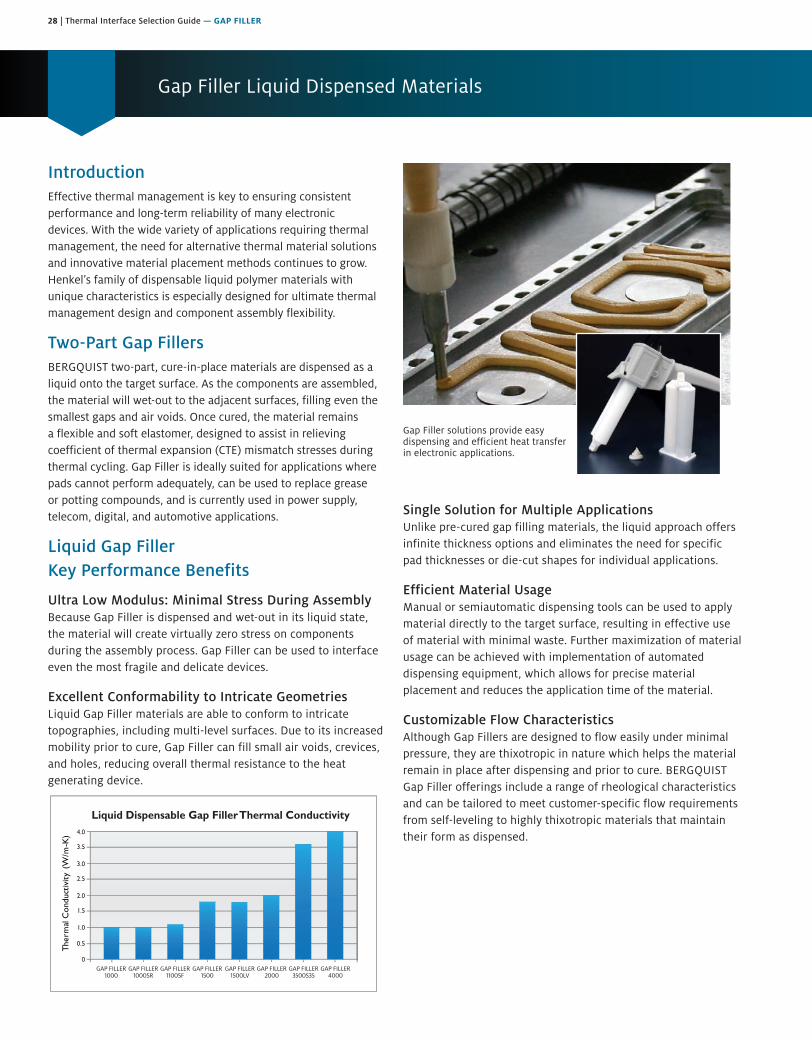
28 | Thermal Interface Selection Guide — GAP FILLER
Gap Filler Liquid Dispensed Materials
IntroductionEffective thermal management is key to ensuring consistent performance and long-term reliability of many electronic devices. With the wide variety of applications requiring thermal management, the need for alternative thermal material solutions and innovative material placement methods continues to grow. Henkel’s family of dispensable liquid polymer materials with unique characteristics is especially designed for ultimate thermal management design and component assembly flexibility.
Two-Part Gap FillersBERGQUIST two-part, cure-in-place materials are dispensed as a liquid onto the target surface. As the components are assembled, the material will wet-out to the adjacent surfaces, filling even the smallest gaps and air voids. Once cured, the material remains a flexible and soft elastomer, designed to assist in relieving coefficient of thermal expansion (CTE) mismatch stresses during thermal cycling. Gap Filler is ideally suited for applications where pads cannot perform adequately, can be used to replace grease or potting compounds, and is currently used in power supply, telecom, digital, and automotive applications.
Liquid Gap Filler Key Performance Benefits
Ultra Low Modulus: Minimal Stress During AssemblyBecause Gap Filler is dispensed and wet-out in its liquid state, the material will create virtually zero stress on components during the assembly process. Gap Filler can be used to interface even the most fragile and delicate devices.
Excellent Conformability to Intricate GeometriesLiquid Gap Filler materials are able to conform to intricate topographies, including multi-level surfaces. Due to its increased mobility prior to cure, Gap Filler can fill small air voids, crevices, and holes, reducing overall thermal resistance to the heat generating device.
GAP FILLER1000
0
0.5
1.5
1.0
2.0
2.5
3.5
3.0
4.0
GAP FILLER1000SR
Liquid Dispensable Gap Filler Thermal Conductivity
GAP FILLER4000
GAP FILLER3500S35
GAP FILLER2000
GAP FILLER1100SF
GAP FILLER1500LV
GAP FILLER1500
Gap Filler solutions provide easy dispensing and efficient heat transfer in electronic applications.
Single Solution for Multiple ApplicationsUnlike pre-cured gap filling materials, the liquid approach offers infinite thickness options and eliminates the need for specific pad thicknesses or die-cut shapes for individual applications.
Efficient Material Usage Manual or semiautomatic dispensing tools can be used to apply material directly to the target surface, resulting in effective use of material with minimal waste. Further maximization of material usage can be achieved with implementation of automated dispensing equipment, which allows for precise material placement and reduces the application time of the material.
Customizable Flow CharacteristicsAlthough Gap Fillers are designed to flow easily under minimal pressure, they are thixotropic in nature which helps the material remain in place after dispensing and prior to cure. BERGQUIST Gap Filler offerings include a range of rheological characteristics and can be tailored to meet customer-specific flow requirements from self-leveling to highly thixotropic materials that maintain their form as dispensed.

Thermal Interface Selection Guide — GAP FILLER | 29
Frequently Asked Questions
Q: How is viscosity measured?A: Due to the thixotropic characteristics of most Gap Fillers,
special consideration should be given to the test method(s) used to determine viscosity of these materials. Because the material viscosity is dependent on shear rate, different measurement equipment testing under varying shear rates will produce varied viscosity readings. When comparing apparent viscosities of multiple materials, it is important to ensure that the data was generated using the same test method and test conditions (therefore the same shear rate). Test methods and conditions for BERGQUIST products are noted in the individual Technical Data Sheets.
Q: How are pot life and cure time defined? A: Two-part Gap Filler systems begin curing once the two
components are mixed together. Henkel defines the pot life (working life) of a two-part system as the time for the viscosity to double after parts A and B are mixed. Henkel defines the cure time of a two-part material as the time to reach 90 percent cure after mixing. Two-part Gap Fillers will cure at room temperature (25°C), or cure time can be accelerated with exposure to elevated temperatures.
Q: Can I use my Gap Filler after the shelf life has expired?A: Henkel does not advocate using Gap Filler beyond
the recommended shelf life and is unable to recertify material that has expired. In order to ensure timely use of product, Henkel recommends a first-in-first-out (FIFO) inventory system.
Q: How should I store my Gap Filler?A: Unless otherwise indicated on Technical Data Sheets,
two-part Gap Fillers should be stored in the original sealed container in a climate-controlled environment at or below 25°C and 50% relative humidity. If stored at reduced temperatures, materials should be placed at room temperature and allowed to stabilize prior to use. Unless otherwise noted, all cartridges and tubes should be stored in Henkel-defined packaging with the nozzle end down.
Q: Do temperature excursions above 25°C affect the shelf life?
A: Short periods of time above the recommended storage temperature, such as during shipping, have not been shown to affect the material characteristics.
Q: Does Gap Filler have adhesive characteristics?A: Although Gap Fillers are not designed as structural adhesives,
when cured, they have a low level of natural tack, which will allow the material to adhere mildly to adjacent components. This aids in keeping the material in the interface throughout repeated temperature cycling and eliminates pump-out from the interface.
Q: Is Gap Filler reworkable?A: In many cases, Gap Filler can be reworked. The ease of
rework is highly dependent on the topography of the application as well as the coverage area.
Q: What container sizes are available for Gap Fillers?A: Two-part materials are available in several standard dual
cartridge sizes including 50 cc (25 cc each of parts A and B) and 400 cc (200 cc each of parts A and B). Gap Fillersare also available in kits of 1200 cc (two stand-alone 600cc containers, one of each part) and 10-gallon (two 5-gallonpails, one of each part) sizes for higher volume production.Other special and custom container sizes are availableupon request.
Q: How do I mix the two-part Gap Fillers?A: Disposable plastic static mixing nozzles are used to mix parts
A and B together at the desired ratio. Static mixers can be attached to the ends of cartridges or mounted on automated dispensing equipment. They are reliable, accurate and inexpensive to replace after extended down times. Unless otherwise indicated, mixing nozzles with a minimum of 21 mixing elements are recommended to achieve proper mixing.
Q: What is the tolerance on the mix ratio?A: Two-part materials should be mixed to the stated mix
ratio by volume within a +/-5% tolerance to ensure proper material characteristics. If light-colored streaks or marbling are present in the material, there has been inadequate mixing. Henkel recommends purging newly tapped containers through the static mixer until a uniform color is achieved. In order to ensure consistent material characteristics and performance, BERGQUIST two-part systems are to be used with matching part A and B lot numbers.
Q: What options are available for dispensing material onto my application?
A: Henkel can provide manual or pneumatic applicator guns for product supplied in dual cartridge form. Gap Filler supplied in high volume container kits can be dispensed via automated dispensing equipment for high-speed in-line manufacturing. Henkel and our other experienced automated dispensing equipment partners can further assist our customers in creating an optimized dispensing process. For information regarding dispensing equipment, contact your local Henkel representative. For some materials, screen or stencil application may be an option and should be evaluated on a case by case basis.
Q: Should I be concerned about Gap Filler compatibility with other materials in my application?
A: Although not common, it is possible to encounter materials that can affect the cure of two-part Gap Fillers. A list of general categories of compounds that may inhibit the rate of cure or poison the curing catalyst in Gap Filler products is available to help assist with material compatibility evaluation. Please contact your local Henkel representative for more details.
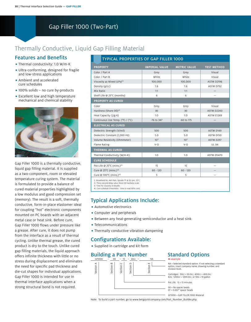
30 | Thermal Interface Selection Guide — GAP FILLER
Gap Filler 1000 (Two-Part)
Thermally Conductive, Liquid Gap Filling MaterialFeatures and Benefits• Thermal conductivity: 1.0 W/m-K
• Ultra-conforming, designed for fragileand low-stress applications
• Ambient and acceleratedcure schedules
• 100% solids – no cure by-products
• Excellent low and high temperaturemechanical and chemical stability
Gap Filler 1000 is a thermally conductive, liquid gap filling material. It is supplied as a two-component, room or elevated temperature curing system. The material is formulated to provide a balance of cured material properties highlighted by a low modulus and good compression set (memory). The result is a soft, thermally conductive, form-in-place elastomer ideal for coupling “hot” electronic components mounted on PC boards with an adjacent metal case or heat sink. Before cure, Gap Filler 1000 flows under pressure like a grease. After cure, it does not pump from the interface as a result of thermal cycling. Unlike thermal grease, the cured product is dry to the touch. Unlike cured gap filling materials, the liquid approach offers infinite thickness with little or no stress during displacement and eliminates the need for specific pad thickness and die-cut shapes for individual applications. Gap Filler 1000 is intended for use in thermal interface applications when a strong structural bond is not required.
Typical Applications Include:• Automotive electronics
• Computer and peripherals
• Between any heat-generating semiconductor and a heat sink
• Telecommunications
• Thermally conductive vibration dampening
Configurations Available:• Supplied in cartridge and kit form
Building a Part Number Standard Options
Sect
ion
A
Sect
ion
B
Sect
ion
C
Sect
ion
D
Sect
ion
E NA = Selected standard option. If not selecting a standardoption, insert company name, drawing number, andrevision level.
GF1000 = GAP FILLER 1000 Material
GF1000 00 15 50cc NA
Note: To build a part number, go to www.bergquistcompany.com/Part_Number_Builder.php.
00 = No spacer beads07 = 0.007" spacer beads
Pot Life: 15 = 15 minutes
Cartridges: 50cc = 50.0cc, 400cc = 400.0ccKits: 1200cc = 1200.0cc, or 10G = 10 gallon
– – – – || example
TYPICAL PROPERTIES OF GAP FILLER 1000
PROPERTY IMPERIAL VALUE METRIC VALUE TEST METHOD
Color / Part A Grey Grey Visual
Color / Part B White White Visual
Viscosity as Mixed (cPs)(1) 100,000 100,000 ASTM D2196
Density (g/cc) 1.6 1.6 ASTM D792
Mix Ratio 1:1 1:1 —
Shelf Life @ 25°C (months) 6 6 —
PROPERTY AS CURED
Color Grey Grey Visual
Hardness (Shore 00)(2) 30 30 ASTM D2240
Heat Capacity ( J/g-K) 1.0 1.0 ASTM E1269
Continuous Use Temp. (°F) / (°C) -76 to 347 -60 to 175 —
ELECTRICAL AS CURED
Dielectric Strength (V/mil) 500 500 ASTM D149
Dielectric Constant (1,000 Hz) 5.0 5.0 ASTM D150
Volume Resistivity (Ohmmeter) 1011 1011 ASTM D257
Flame Rating V-O V-O UL 94
THERMAL AS CURED
Thermal Conductivity (W/m-K) 1.0 1.0 ASTM D5470
CURE SCHEDULE
Pot Life @ 25°C (mins.)(3) 15 15 —
Cure @ 25°C (mins.)(4) 60 - 120 60 - 120 —
Cure @ 100°C (mins.)(4) 5 5 —
1) Brookfield RV, Heli-Path, Spindle TF @ 20 rpm, 25°C.2) Thirty-second delay value Shore 00 hardness scale.3) Time for viscosity to double.4) Cure schedule (rheometer - time to read 90% cure)
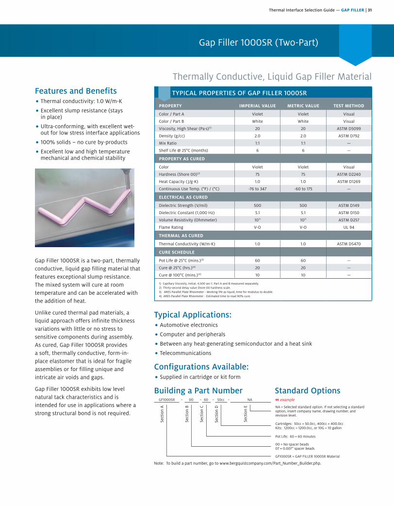
Thermal Interface Selection Guide — GAP FILLER | 31
Gap Filler 1000SR (Two-Part)
Thermally Conductive, Liquid Gap Filler MaterialFeatures and Benefits• Thermal conductivity: 1.0 W/m-K
• Excellent slump resistance (staysin place)
• Ultra-conforming, with excellent wet-out for low stress interface applications
• 100% solids – no cure by-products
• Excellent low and high temperaturemechanical and chemical stability
Gap Filler 1000SR is a two-part, thermally conductive, liquid gap filling material that features exceptional slump resistance. The mixed system will cure at room temperature and can be accelerated with the addition of heat.
Unlike cured thermal pad materials, a liquid approach offers infinite thickness variations with little or no stress to sensitive components during assembly. As cured, Gap Filler 1000SR provides a soft, thermally conductive, form-in-place elastomer that is ideal for fragile assemblies or for filling unique and intricate air voids and gaps.
Gap Filler 1000SR exhibits low level natural tack characteristics and is intended for use in applications where a strong structural bond is not required.
Typical Applications:• Automotive electronics
• Computer and peripherals
• Between any heat-generating semiconductor and a heat sink
• Telecommunications
Configurations Available:• Supplied in cartridge or kit form
Building a Part Number Standard Options
Sect
ion
A
Sect
ion
B
Sect
ion
C
Sect
ion
D
Sect
ion
E NA = Selected standard option. If not selecting a standardoption, insert company name, drawing number, andrevision level.
GF1000SR = GAP FILLER 1000SR Material
GF1000SR 00 60 50cc NA
Note: To build a part number, go to www.bergquistcompany.com/Part_Number_Builder.php.
00 = No spacer beads07 = 0.007" spacer beads
Pot Life: 60 = 60 minutes
Cartridges: 50cc = 50.0cc, 400cc = 400.0ccKits: 1200cc = 1200.0cc, or 10G = 10 gallon
– – – – || example
TYPICAL PROPERTIES OF GAP FILLER 1000SR
PROPERTY IMPERIAL VALUE METRIC VALUE TEST METHOD
Color / Part A Violet Violet Visual
Color / Part B White White Visual
Viscosity, High Shear (Pa·s)(1) 20 20 ASTM D5099
Density (g/cc) 2.0 2.0 ASTM D792
Mix Ratio 1:1 1:1 —
Shelf Life @ 25°C (months) 6 6 —
PROPERTY AS CURED
Color Violet Violet Visual
Hardness (Shore 00)(2) 75 75 ASTM D2240
Heat Capacity ( J/g-K) 1.0 1.0 ASTM D1269
Continuous Use Temp. (°F) / (°C) -76 to 347 -60 to 175 —
ELECTRICAL AS CURED
Dielectric Strength (V/mil) 500 500 ASTM D149
Dielectric Constant (1,000 Hz) 5.1 5.1 ASTM D150
Volume Resistivity (Ohmmeter) 1011 1011 ASTM D257
Flame Rating V-O V-O UL 94
THERMAL AS CURED
Thermal Conductivity (W/m-K) 1.0 1.0 ASTM D5470
CURE SCHEDULE
Pot Life @ 25°C (mins.)(3) 60 60 —
Cure @ 25°C (hrs.)(4) 20 20 —
Cure @ 100°C (mins.)(4) 10 10 —
1) Capillary Viscosity, Initial, 4,500 sec-1. Part A and B measured separately.2) Thirty-second delay value Shore 00 hardness scale.3) ARES Parallel Plate Rheometer - Working life as liquid, time for modulus to double.4) ARES Parallel Plate Rheometer - Estimated time to read 90% cure.
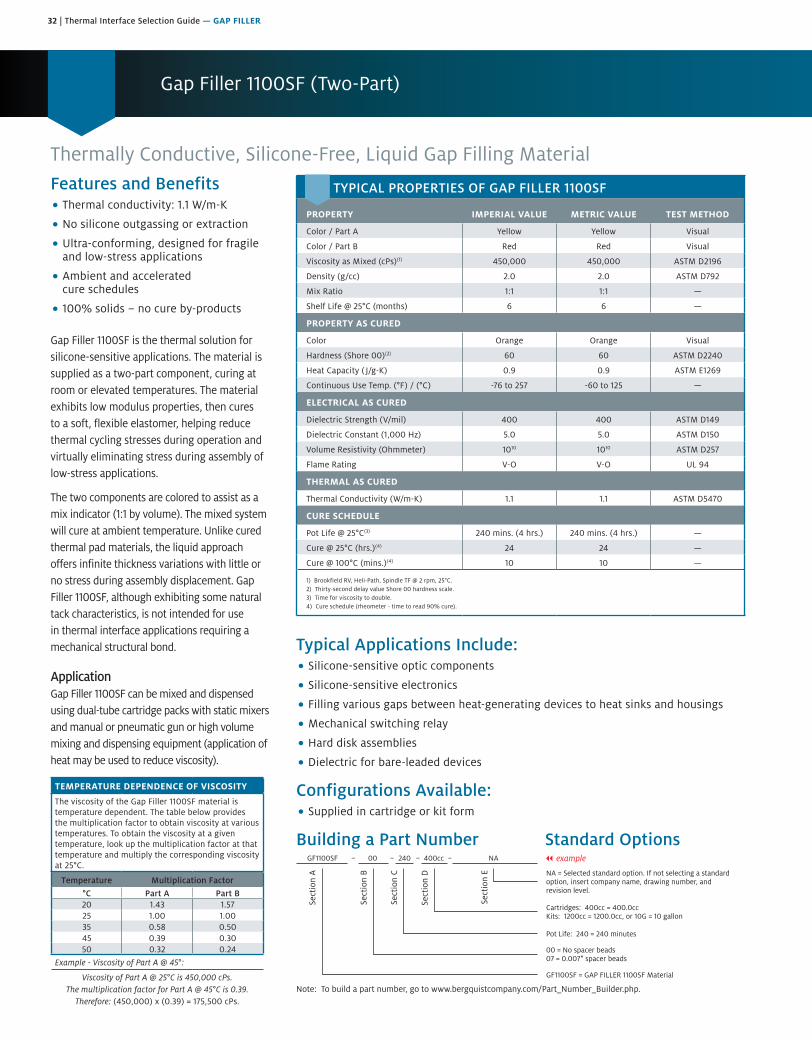
32 | Thermal Interface Selection Guide — GAP FILLER
Gap Filler 1100SF (Two-Part)
Thermally Conductive, Silicone-Free, Liquid Gap Filling MaterialFeatures and Benefits• Thermal conductivity: 1.1 W/m-K
• No silicone outgassing or extraction
• Ultra-conforming, designed for fragileand low-stress applications
• Ambient and acceleratedcure schedules
• 100% solids – no cure by-products
Gap Filler 1100SF is the thermal solution for silicone-sensitive applications. The material is supplied as a two-part component, curing at room or elevated temperatures. The material exhibits low modulus properties, then cures to a soft, flexible elastomer, helping reduce thermal cycling stresses during operation and virtually eliminating stress during assembly of low-stress applications.
The two components are colored to assist as a mix indicator (1:1 by volume). The mixed system will cure at ambient temperature. Unlike cured thermal pad materials, the liquid approach offers infinite thickness variations with little or no stress during assembly displacement. Gap Filler 1100SF, although exhibiting some natural tack characteristics, is not intended for use in thermal interface applications requiring a mechanical structural bond.
ApplicationGap Filler 1100SF can be mixed and dispensed using dual-tube cartridge packs with static mixers and manual or pneumatic gun or high volume mixing and dispensing equipment (application of heat may be used to reduce viscosity).
TEMPERATURE DEPENDENCE OF VISCOSITY
The viscosity of the Gap Filler 1100SF material is temperature dependent. The table below provides the multiplication factor to obtain viscosity at various temperatures. To obtain the viscosity at a given temperature, look up the multiplication factor at that temperature and multiply the corresponding viscosity at 25°C.
Temperature Multiplication Factor
°C Part A Part B20 1.43 1.5725 1.00 1.0035 0.58 0.5045 0.39 0.3050 0.32 0.24
Example - Viscosity of Part A @ 45°:
Viscosity of Part A @ 25°C is 450,000 cPs. The multiplication factor for Part A @ 45°C is 0.39.
Therefore: (450,000) x (0.39) = 175,500 cPs.
Typical Applications Include:• Silicone-sensitive optic components
• Silicone-sensitive electronics
• Filling various gaps between heat-generating devices to heat sinks and housings
• Mechanical switching relay
• Hard disk assemblies
• Dielectric for bare-leaded devices
Configurations Available:• Supplied in cartridge or kit form
Building a Part Number Standard Options
Sect
ion
A
Sect
ion
B
Sect
ion
C
Sect
ion
D
Sect
ion
E NA = Selected standard option. If not selecting a standardoption, insert company name, drawing number, andrevision level.
GF1100SF = GAP FILLER 1100SF Material
GF1100SF 00 240 400cc NA
Note: To build a part number, go to www.bergquistcompany.com/Part_Number_Builder.php.
00 = No spacer beads07 = 0.007" spacer beads
Pot Life: 240 = 240 minutes
Cartridges: 400cc = 400.0ccKits: 1200cc = 1200.0cc, or 10G = 10 gallon
– – – – || example
TYPICAL PROPERTIES OF GAP FILLER 1100SF
PROPERTY IMPERIAL VALUE METRIC VALUE TEST METHOD
Color / Part A Yellow Yellow Visual
Color / Part B Red Red Visual
Viscosity as Mixed (cPs)(1) 450,000 450,000 ASTM D2196
Density (g/cc) 2.0 2.0 ASTM D792
Mix Ratio 1:1 1:1 —
Shelf Life @ 25°C (months) 6 6 —
PROPERTY AS CURED
Color Orange Orange Visual
Hardness (Shore 00)(2) 60 60 ASTM D2240
Heat Capacity ( J/g-K) 0.9 0.9 ASTM E1269
Continuous Use Temp. (°F) / (°C) -76 to 257 -60 to 125 —
ELECTRICAL AS CURED
Dielectric Strength (V/mil) 400 400 ASTM D149
Dielectric Constant (1,000 Hz) 5.0 5.0 ASTM D150
Volume Resistivity (Ohmmeter) 1010 1010 ASTM D257
Flame Rating V-O V-O UL 94
THERMAL AS CURED
Thermal Conductivity (W/m-K) 1.1 1.1 ASTM D5470
CURE SCHEDULE
Pot Life @ 25°C(3) 240 mins. (4 hrs.) 240 mins. (4 hrs.) —
Cure @ 25°C (hrs.)(4) 24 24 —
Cure @ 100°C (mins.)(4) 10 10 —
1) Brookfield RV, Heli-Path, Spindle TF @ 2 rpm, 25°C.2) Thirty-second delay value Shore 00 hardness scale.3) Time for viscosity to double.4) Cure schedule (rheometer - time to read 90% cure).
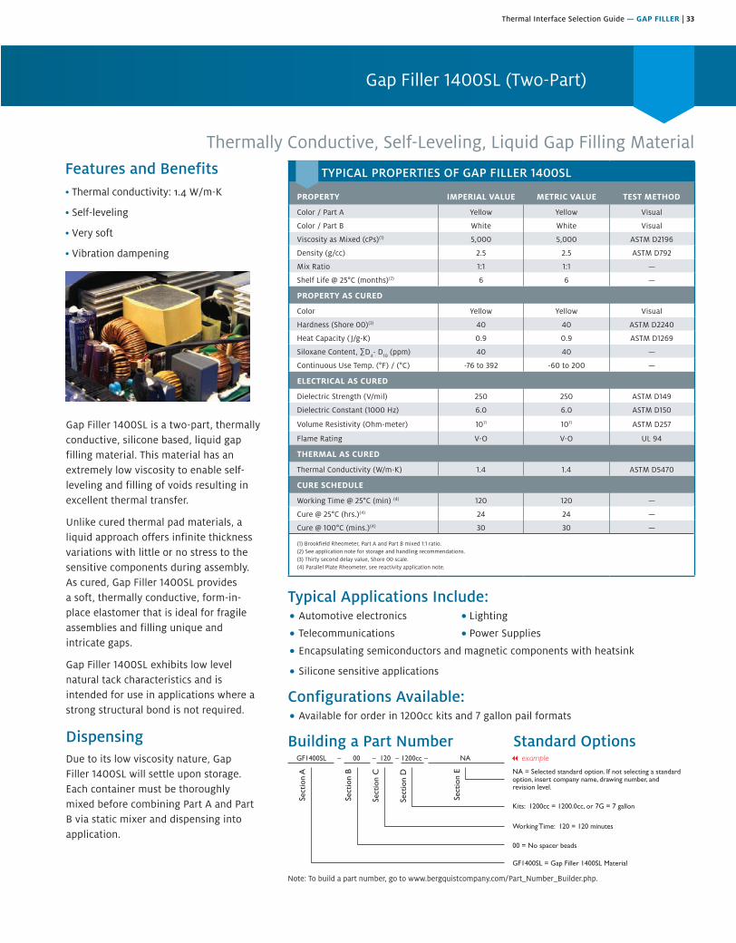
Thermal Interface Selection Guide — GAP FILLER | 33
Typical Applications Include:• Automotive electronics • Lighting
• Telecommunications • Power Supplies
• Encapsulating semiconductors and magnetic components with heatsink
• Silicone sensitive applications
Configurations Available:• Available for order in 1200cc kits and 7 gallon pail formats
Building a Part Number Standard Options
Sect
ion
A
Sect
ion
B
Sect
ion
C
Sect
ion
D
Sect
ion
E NA = Selected standard option. If not selecting a standardoption, insert company name, drawing number, andrevision level.
GF1400SL = Gap Filler 1400SL Material
GF1400SL 00 120 1200cc NA
Note: To build a part number, visit our website at www.bergquistcompany.com.
00 = No spacer beads
Working Time: 120 = 120 minutes
Kits: 1200cc = 1200.0cc, or 7G = 7 gallon
– – – –
TYPICAL PROPERTIES OF GAP FILLER 1400SL
PROPERTY IMPERIAL VALUE METRIC VALUE TEST METHOD
Color / Part A Yellow Yellow Visual
Color / Part B White White Visual
Viscosity as Mixed (cPs)(1) 5,000 5,000 ASTM D2196
Density (g/cc) 2.5 2.5 ASTM D792
Mix Ratio 1:1 1:1 —
Shelf Life @ 25°C (months)(2) 6 6 —
PROPERTY AS CURED
Color Yellow Yellow Visual
Hardness (Shore 00)(3) 40 40 ASTM D2240
Heat Capacity ( J/g-K) 0.9 0.9 ASTM D1269
Siloxane Content, ∑D4- D
10 (ppm) 40 40 —
Continuous Use Temp. (°F) / (°C) -76 to 392 -60 to 200 —
ELECTRICAL AS CURED
Dielectric Strength (V/mil) 250 250 ASTM D149
Dielectric Constant (1000 Hz) 6.0 6.0 ASTM D150
Volume Resistivity (Ohm-meter) 1011 1011 ASTM D257
Flame Rating V-O V-O UL 94
THERMAL AS CURED
Thermal Conductivity (W/m-K) 1.4 1.4 ASTM D5470
CURE SCHEDULE
Working Time @ 25°C (min) (4) 120 120 —
Cure @ 25°C (hrs.)(4) 24 24 —
Cure @ 100°C (mins.)(4) 30 30 —
(1) Brookfield Rheometer, Part A and Part B mixed 1:1 ratio. (2) See application note for storage and handling recommendations. (3) Thirty second delay value, Shore 00 scale.(4) Parallel Plate Rheometer, see reactivity application note.
Gap Filler 1400SL is a two-part, thermally conductive, silicone based, liquid gap filling material. This material has an extremely low viscosity to enable self-leveling and filling of voids resulting in excellent thermal transfer.
Unlike cured thermal pad materials, a liquid approach offers infinite thickness variations with little or no stress to the sensitive components during assembly. As cured, Gap Filler 1400SL provides a soft, thermally conductive, form-in-place elastomer that is ideal for fragile assemblies and filling unique and intricate gaps.
Gap Filler 1400SL exhibits low level natural tack characteristics and is intended for use in applications where a strong structural bond is not required.
DispensingDue to its low viscosity nature, Gap Filler 1400SL will settle upon storage. Each container must be thoroughly mixed before combining Part A and Part B via static mixer and dispensing into application.
Features and Benefits• Thermal onductivity: 1.4 W/m-K
• Self- eveling
• Very oft
• Vibration ampening
Gap Filler 1400SL (Two-Part)
Thermally Conductive, Self-Leveling, Liquid Gap Filling Material
Note: To build a part number, go to www.bergquistcompany.com/Part_Number_Builder.php.
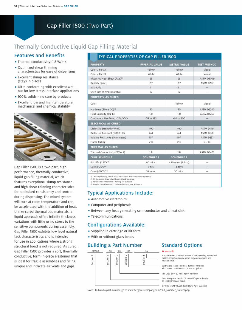
34 | Thermal Interface Selection Guide — GAP FILLER
Gap Filler 1500 (Two-Part)
Thermally Conductive Liquid Gap Filling MaterialFeatures and Benefits• Thermal conductivity: 1.8 W/mK
• Optimized shear thinningcharacteristics for ease of dispensing
• Excellent slump resistance(stays in place)
• Ultra-conforming with excellent wet-out for low stress interface applications
• 100% solids – no cure by-products
• Excellent low and high temperaturemechanical and chemical stability
Gap Filler 1500 is a two-part, high performance, thermally conductive, liquid gap filling material, which features exceptional slump resistance and high shear thinning characteristics for optimized consistency and control during dispensing. The mixed system will cure at room temperature and can be accelerated with the addition of heat. Unlike cured thermal pad materials, a liquid approach offers infinite thickness variations with little or no stress to the sensitive components during assembly. Gap Filler 1500 exhibits low level natural tack characteristics and is intended for use in applications where a strong structural bond is not required. As cured, Gap Filler 1500 provides a soft, thermally conductive, form-in-place elastomer that is ideal for fragile assemblies and filling unique and intricate air voids and gaps.
Typical Applications Include:• Automotive electronics
• Computer and peripherals
• Between any heat generating semiconductor and a heat sink
• Telecommunications
Configurations Available: • Supplied in cartridge or kit form
• With or without glass beads
Building a Part Number Standard Options
Sect
ion
A
Sect
ion
B
Sect
ion
C
Sect
ion
D
Sect
ion
E NA = Selected standard option. If not selecting a standardoption, insert company name, drawing number, andrevision level.
GF1500 = GAP FILLER 1500 (Two-Part) Material
GF1500 00 60 10G NA
Note: To build a part number, go to www.bergquistcompany.com/Part_Number_Builder.php.
00 = No spacer beads, 07 = 0.007" spacer beads,10 = 0.010" spacer beads
Pot Life: 60 = 60 min, 480 = 480 min
Cartridges: 50cc = 50.0cc, 400cc = 400.0ccKits: 1200cc = 1200.00cc, 10G = 10 gallon
– – – – || example
TYPICAL PROPERTIES OF GAP FILLER 1500
PROPERTY IMPERIAL VALUE METRIC VALUE TEST METHOD
Color / Part A Yellow Yellow Visual
Color / Part B White White Visual
Viscosity, High Shear (Pa·s)(1) 25 25 ASTM D5099
Density (g/cc) 2.7 2.7 ASTM D792
Mix Ratio 1:1 1:1 —
Shelf Life @ 25°C (months) 6 6 —
PROPERTY AS CURED
Color Yellow Yellow Visual
Hardness (Shore 00)(2) 50 50 ASTM D2240
Heat Capacity ( J/g-K) 1.0 1.0 ASTM D1269
Continuous Use Temp. (°F) / (°C) -76 to 392 -60 to 200 —
ELECTRICAL AS CURED
Dielectric Strength (V/mil) 400 400 ASTM D149
Dielectric Constant (1,000 Hz) 6.4 6.4 ASTM D150
Volume Resistivity (Ohmmeter) 1010 1010 ASTM D257
Flame Rating V-O V-O UL 94
THERMAL AS CURED
Thermal Conductivity (W/m-K) 1.8 1.8 ASTM D5470
CURE SCHEDULE SCHEDULE 1 SCHEDULE 2
Pot Life @ 25°C(3) 60 mins. 480 mins. (8 hrs.) —
Cure @ 25°C(4) 5 hrs. 3 days —
Cure @ 100°C(4) 10 mins. 30 mins. —
1) Capillary viscosity, initial, 3000 sec-1. Part A and B measured separately.2) Thirty-second delay value Shore 00 hardness scale.3) Parallel Plate Rheometer - Working life as liquid.4) Parallel Plate Rheometer - Estimated time to read 90% cure.
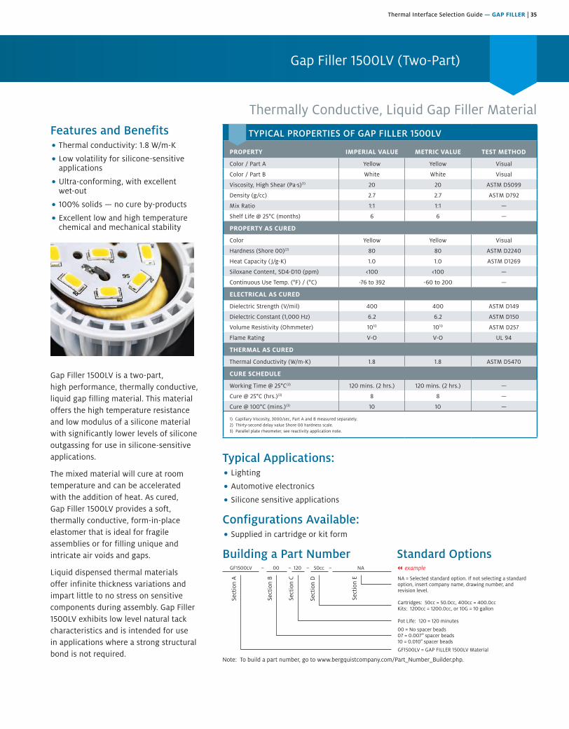
Thermal Interface Selection Guide — GAP FILLER | 35
Gap Filler 1500LV (Two-Part)
Thermally Conductive, Liquid Gap Filler MaterialFeatures and Benefits• Thermal conductivity: 1.8 W/m-K
• Low volatility for silicone-sensitiveapplications
• Ultra-conforming, with excellentwet-out
• 100% solids — no cure by-products
• Excellent low and high temperaturechemical and mechanical stability
Gap Filler 1500LV is a two-part, high performance, thermally conductive, liquid gap filling material. This material offers the high temperature resistance and low modulus of a silicone material with significantly lower levels of silicone outgassing for use in silicone-sensitive applications.
The mixed material will cure at room temperature and can be accelerated with the addition of heat. As cured, Gap Filler 1500LV provides a soft, thermally conductive, form-in-place elastomer that is ideal for fragile assemblies or for filling unique and intricate air voids and gaps.
Liquid dispensed thermal materials offer infinite thickness variations and impart little to no stress on sensitive components during assembly. Gap Filler 1500LV exhibits low level natural tack characteristics and is intended for use in applications where a strong structural bond is not required.
Typical Applications:• Lighting
• Automotive electronics
• Silicone sensitive applications
Configurations Available:• Supplied in cartridge or kit form
Building a Part Number Standard Options
Sect
ion
A
Sect
ion
B
Sect
ion
C
Sect
ion
D
Sect
ion
E NA = Selected standard option. If not selecting a standardoption, insert company name, drawing number, andrevision level.
GF1500LV = GAP FILLER 1500LV Material
GF1500LV 00 120 50cc NA
Note: To build a part number, go to www.bergquistcompany.com/Part_Number_Builder.php.
00 = No spacer beads07 = 0.007" spacer beads10 = 0.010" spacer beads
Pot Life: 120 = 120 minutes
Cartridges: 50cc = 50.0cc, 400cc = 400.0ccKits: 1200cc = 1200.0cc, or 10G = 10 gallon
– – – – || example
TYPICAL PROPERTIES OF GAP FILLER 1500LV
PROPERTY IMPERIAL VALUE METRIC VALUE TEST METHOD
Color / Part A Yellow Yellow Visual
Color / Part B White White Visual
Viscosity, High Shear (Pa·s)(1) 20 20 ASTM D5099
Density (g/cc) 2.7 2.7 ASTM D792
Mix Ratio 1:1 1:1 —
Shelf Life @ 25°C (months) 6 6 —
PROPERTY AS CURED
Color Yellow Yellow Visual
Hardness (Shore 00)(2) 80 80 ASTM D2240
Heat Capacity ( J/g-K) 1.0 1.0 ASTM D1269
Siloxane Content, SD4-D10 (ppm) <100 <100 —
Continuous Use Temp. (°F) / (°C) -76 to 392 -60 to 200 —
ELECTRICAL AS CURED
Dielectric Strength (V/mil) 400 400 ASTM D149
Dielectric Constant (1,000 Hz) 6.2 6.2 ASTM D150
Volume Resistivity (Ohmmeter) 1010 1010 ASTM D257
Flame Rating V-O V-O UL 94
THERMAL AS CURED
Thermal Conductivity (W/m-K) 1.8 1.8 ASTM D5470
CURE SCHEDULE
Working Time @ 25°C(3) 120 mins. (2 hrs.) 120 mins. (2 hrs.) —
Cure @ 25°C (hrs.)(3) 8 8 —
Cure @ 100°C (mins.)(3) 10 10 —
1) Capillary Viscosity, 3000/sec, Part A and B measured separately.2) Thirty-second delay value Shore 00 hardness scale.3) Parallel plate rheometer, see reactivity application note.
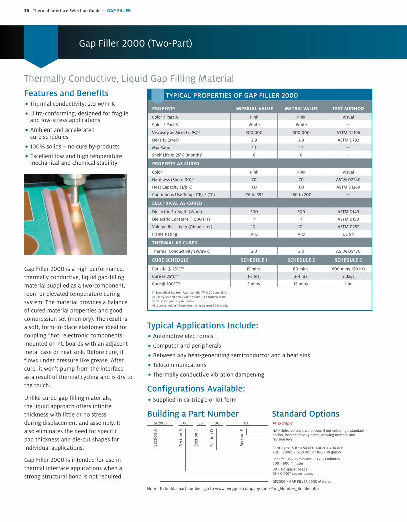
36 | Thermal Interface Selection Guide — GAP FILLER
Gap Filler 2000 (Two-Part)
Thermally Conductive, Liquid Gap Filling MaterialFeatures and Benefits• Thermal conductivity: 2.0 W/m-K
• Ultra-conforming, designed for fragileand low-stress applications
• Ambient and acceleratedcure schedules
• 100% solids – no cure by-products
• Excellent low and high temperaturemechanical and chemical stability
Gap Filler 2000 is a high performance, thermally conductive, liquid gap-filling material supplied as a two-component, room or elevated temperature curing system. The material provides a balance of cured material properties and good compression set (memory). The result is a soft, form-in-place elastomer ideal for coupling “hot” electronic components mounted on PC boards with an adjacent metal case or heat sink. Before cure, it flows under pressure like grease. After cure, it won’t pump from the interface as a result of thermal cycling and is dry to the touch.
Unlike cured gap filling materials, the liquid approach offers infinite thickness with little or no stress during displacement and assembly. It also eliminates the need for specific pad thickness and die-cut shapes for individual applications.
Gap Filler 2000 is intended for use in thermal interface applications when a strong structural bond is not required.
Typical Applications Include:• Automotive electronics
• Computer and peripherals
• Between any heat-generating semiconductor and a heat sink
• Telecommunications
• Thermally conductive vibration dampening
Configurations Available:• Supplied in cartridge or kit form
Building a Part Number Standard Options
Sect
ion
A
Sect
ion
B
Sect
ion
C
Sect
ion
D
Sect
ion
E NA = Selected standard option. If not selecting a standardoption, insert company name, drawing number, andrevision level.
GF2000 = GAP FILLER 2000 Material
GF2000 00 60 10G NA
Note: To build a part number, go to www.bergquistcompany.com/Part_Number_Builder.php.
00 = No spacer beads07 = 0.007" spacer beads
Pot Life: 15 = 15 minutes, 60 = 60 minutes600 = 600 minutes
Cartridges: 50cc = 50.0cc, 400cc = 400.0ccKits: 1200cc = 1200.0cc, or 10G = 10 gallon
– – – – || example
TYPICAL PROPERTIES OF GAP FILLER 2000
PROPERTY IMPERIAL VALUE METRIC VALUE TEST METHOD
Color / Part A Pink Pink Visual
Color / Part B White White —
Viscosity as Mixed (cPs)(1) 300,000 300,000 ASTM D2196
Density (g/cc) 2.9 2.9 ASTM D792
Mix Ratio 1:1 1:1 —
Shelf Life @ 25°C (months) 6 6 —
PROPERTY AS CURED
Color Pink Pink Visual
Hardness (Shore 00)(2) 70 70 ASTM D2240
Heat Capacity ( J/g-K) 1.0 1.0 ASTM D1269
Continuous Use Temp. (°F) / (°C) -76 to 392 -60 to 200 —
ELECTRICAL AS CURED
Dielectric Strength (V/mil) 500 500 ASTM D149
Dielectric Constant (1,000 Hz) 7 7 ASTM D150
Volume Resistivity (Ohmmeter) 1011 1011 ASTM D257
Flame Rating V-O V-O UL 94
THERMAL AS CURED
Thermal Conductivity (W/m-K) 2.0 2.0 ASTM D5470
CURE SCHEDULE SCHEDULE 1 SCHEDULE 2 SCHEDULE 3
Pot Life @ 25°C(3) 15 mins. 60 mins. 600 mins. (10 hr)
Cure @ 25°C(4) 1-2 hrs. 3-4 hrs. 3 days
Cure @ 100°C(4) 5 mins. 15 mins. 1 hr
1) Brookfield RV, Heli-Path, Spindle TF @ 20 rpm, 25°C.2) Thirty-second delay value Shore 00 hardness scale.3) Time for viscosity to double.4) Cure schedule (rheometer - time to read 90% cure).
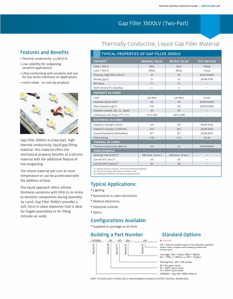
Thermal Interface Selection Guide — GAP FILLER | 37
Gap Filler 3500LV is a two-part, high thermal conductivity, liquid gap filling material. This material offers the mechanical property benefits of a silicone material with the additional feature of low outgassing.
The mixed material will cure at room temperature or can be accelerated with the addition of heat.
The liquid approach offers infinite thickness variations with little to no stress to sensitive components during assembly. As cured, Gap Filler 3500LV provides a soft, form-in-place elastomer that is ideal for fragile assemblies or for filling intricate air voids.
Typical Applications:• Lighting
• Automotive in-cabin electronics
• Medical electronics
• Industrial controls
• Optics
Configurations Available:• Supplied in cartridge or kit form
Building a Part Number Standard Options
Features and Benefits• Thermal onductivity: 3.5 W/m-K
• Low volatility for outgassingsensitive applications
• Ultra-conforming with excellent wet-outfor low stress interfaces on applications
• 100% solids - no cure by-products
Gap Filler 3500LV (Two-Part)
Thermally Conductive, Liquid Gap Filler Material
Sect
ion
A
Sect
ion
B
Sect
ion
C
Sect
ion
D
Sect
ion
E NA = Selected standard option. If not selecting a standardoption, insert company name, drawing number, andrevision level.
GF3500LV = Gap Filler 3500LV Material
GF3500LV 00 240 50cc NA
Note: To build a part number, visit our website at www.bergquistcompany.com.
00 = No spacer beads07 = 0.007" spacer beads10 = 0.010" spacer beads
Working Time: 240 = 240 minutes
Cartridges: 50cc = 50.0cc, 400cc = 400.0ccKits: 1200cc = 1200.0cc, or 10G = 10 gallon
– – – –
TYPICAL PROPERTIES OF GAP FILLER 3500LV
PROPERTY IMPERIAL VALUE METRIC VALUE TEST METHOD
Color / Part A Blue Blue Visual
Color / Part B White White Visual
Viscosity, High Shear (Pa·s)(1) 45 45 ASTM D5099
Density (g/cc) 3.1 3.1 ASTM D792
Mix Ratio 1:1 1:1 —
Shelf Life @ 25°C (months) 5 5 —
PROPERTY AS CURED
Color Lite Blue Lite Blue Visual
Hardness (Shore 00)(2) 40 40 ASTM D2240
Heat Capacity ( J/g-K) 0.8 0.8 ASTM D1269
Siloxane Content, ∑D4- D
10 (ppm) 40 40 —
Continuous Use Temp. (°F) / (°C) -76 to 392 -60 to 200 —
ELECTRICAL AS CURED
Dielectric Strength (V/mil) 275 275 ASTM D149
Dielectric Constant (1,000 Hz) 8.0 8.0 ASTM D150
Volume Resistivity (Ohmmeter) 1010 1010 ASTM D257
Flame Rating V-O V-O UL 94
THERMAL AS CURED
Thermal Conductivity (W/m-K) 3.5 3.5 ASTM D5470
CURE SCHEDULE
Working Time @ 25°C(3) 240 mins. (4 hrs.) 240 mins. (4 hrs.) —
Cure @ 25°C (hrs.)(3) 24 24 —
Cure @ 100°C (mins.)(3) 30 30 —
(1) Capillary Viscosity, 1,500/sec., Part A and B measured separately.(2) Thirty-second delay value Shore 00 hardness scale.(3) Parallel plate rheometer, see reactivity application note.
Note: To build a part number, go to www.bergquistcompany.com/Part_Number_Builder.php.

38 | Thermal Interface Selection Guide — GAP FILLER
Gap Filler 3500S35 (Two-Part)
Thermally Conductive Liquid Gap Filling MaterialFeatures and Benefits• Thermal conductivity: 3.6 W/m-K
• Thixotropic nature makes it easyto dispense
• Two-part formulation for easy storage
• Ultra-conforming – designed for fragileand low stress applications
• Ambient or accelerated cure schedules
Gap Filler 3500S35 is a two-component, liquid gap-filling material, cured at either room or elevated temperature, featuring ultra-high thermal performance and outstanding softness. Prior to curing, the material maintains good thixotropic characteristics as well as low viscosity. The result is a gel-like liquid material designed to fill air gaps and voids yet flow when acted upon by an external force (e.g., dispensing or assembly process). The material is an excellent solution for interfacing fragile components with high topography and/or stack-up tolerances to a universal heat sink or housing. Once cured, it remains a low modulus elastomer designed to assist in relieving CTE stresses during thermal cycling yet maintain enough modulus to prevent pump-out from the interface. Gap Filler 3500S35 will lightly adhere to surfaces, thus improving surface area contact. Gap Filler 3500S35 is not designed to be a structural adhesive.
Typical Applications Include:• Automotive electronics
• Discrete components to housing
• PCBA to housing
• Fiber optic telecommunications equipment
Configurations Available:• Supplied in cartridge or kit form
Building a Part Number Standard Options|| example
Sect
ion
A
Sect
ion
B
Sect
ion
C
Sect
ion
D
Sect
ion
E
Note: To build a part number, go to www.bergquistcompany.com/Part_Number_Builder.php.
GF3500S35 00 60 400cc NA
NA = Selected standard option. If not selecting a standardoption, insert company name, drawing number, andrevision level.
GP3500S35 = GAP PAD 3500S35 Material
00 = No spacer beads07 = 0.007" spacer beads
Pot Life: 60 = 60 minutes
Cartridges: 50cc = 50.0cc, 400cc = 400.0ccKits: 1200cc = 1200.0cc, or 6G = 6 gallon
TYPICAL PROPERTIES OF GAP FILLER 3500S35
PROPERTY IMPERIAL VALUE METRIC VALUE TEST METHOD
Color / Part A White White Visual
Color / Part B Blue Blue Visual
Viscosity as Mixed (cPs)(1) 150,000 150,000 ASTM D2196
Density (g/cc) 3.0 3.0 ASTM D792
Mix Ratio 1:1 1:1 —
Shelf Life @ 25°C (months) 5 5 —
PROPERTY AS CURED
Color Blue Blue Visual
Hardness (Shore 00)(2) 35 35 ASTM D2240
Continuous Use Temp. (°F) / (°C) -76 to 392 -60 to 200 —
ELECTRICAL AS CURED
Dielectric Strength (V/mil) 275 275 ASTM D149
Dielectric Constant (1,000 Hz) 8.0 8.0 ASTM D150
Volume Resistivity (Ohmmeter) 109 109 ASTM D257
Flame Rating V-O V-O UL 94
THERMAL AS CURED
Thermal Conductivity (W/m-K) 3.6 3.6 ASTM D5470
CURE SCHEDULE
Pot Life @ 25°C (mins.)(3) 60 60 —
Cure @ 25°C (hrs.)(4) 15 15 —
Cure @ 100°C (mins.)(4) 30 30 —
1) Brookfield RV, Heli-Path, Spindle TF @ 20 rpm, 25°C.2) Thirty-second delay value Shore 00 hardness scale.3) Time for viscosity to double.4) Cure schedule (rheometer - time to read 90% cure).
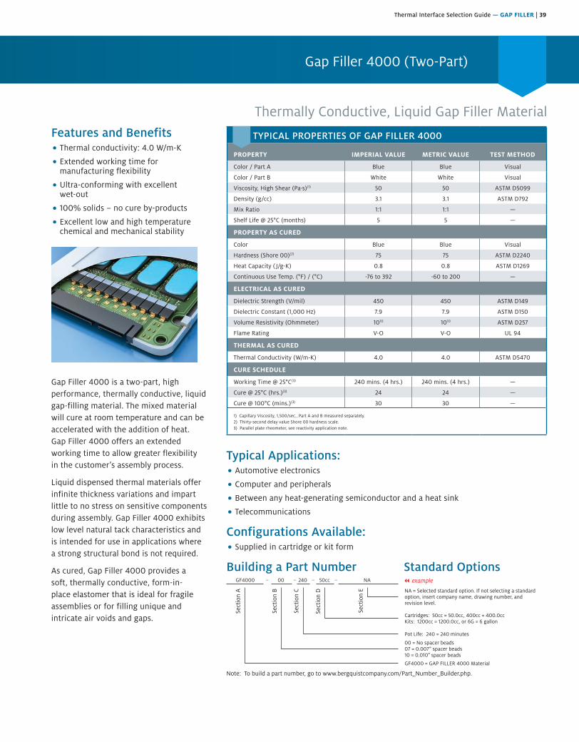
Thermal Interface Selection Guide — GAP FILLER | 39
Gap Filler 4000 (Two-Part)
Thermally Conductive, Liquid Gap Filler MaterialFeatures and Benefits• Thermal conductivity: 4.0 W/m-K
• Extended working time formanufacturing flexibility
• Ultra-conforming with excellentwet-out
• 100% solids – no cure by-products
• Excellent low and high temperaturechemical and mechanical stability
Gap Filler 4000 is a two-part, high performance, thermally conductive, liquid gap-filling material. The mixed material will cure at room temperature and can be accelerated with the addition of heat. Gap Filler 4000 offers an extended working time to allow greater flexibility in the customer’s assembly process.
Liquid dispensed thermal materials offer infinite thickness variations and impart little to no stress on sensitive components during assembly. Gap Filler 4000 exhibits low level natural tack characteristics and is intended for use in applications where a strong structural bond is not required.
As cured, Gap Filler 4000 provides a soft, thermally conductive, form-in-place elastomer that is ideal for fragile assemblies or for filling unique and intricate air voids and gaps.
Typical Applications:• Automotive electronics
• Computer and peripherals
• Between any heat-generating semiconductor and a heat sink
• Telecommunications
Configurations Available:• Supplied in cartridge or kit form
Building a Part Number Standard Options
Sect
ion
A
Sect
ion
B
Sect
ion
C
Sect
ion
D
Sect
ion
E NA = Selected standard option. If not selecting a standardoption, insert company name, drawing number, andrevision level.
GF4000 = GAP FILLER 4000 Material
GF4000 00 240 50cc NA
Note: To build a part number, go to www.bergquistcompany.com/Part_Number_Builder.php.
00 = No spacer beads07 = 0.007" spacer beads10 = 0.010" spacer beads
Pot Life: 240 = 240 minutes
Cartridges: 50cc = 50.0cc, 400cc = 400.0ccKits: 1200cc = 1200.0cc, or 6G = 6 gallon
– – – – || example
TYPICAL PROPERTIES OF GAP FILLER 4000
PROPERTY IMPERIAL VALUE METRIC VALUE TEST METHOD
Color / Part A Blue Blue Visual
Color / Part B White White Visual
Viscosity, High Shear (Pa·s)(1) 50 50 ASTM D5099
Density (g/cc) 3.1 3.1 ASTM D792
Mix Ratio 1:1 1:1 —
Shelf Life @ 25°C (months) 5 5 —
PROPERTY AS CURED
Color Blue Blue Visual
Hardness (Shore 00)(2) 75 75 ASTM D2240
Heat Capacity ( J/g-K) 0.8 0.8 ASTM D1269
Continuous Use Temp. (°F) / (°C) -76 to 392 -60 to 200 —
ELECTRICAL AS CURED
Dielectric Strength (V/mil) 450 450 ASTM D149
Dielectric Constant (1,000 Hz) 7.9 7.9 ASTM D150
Volume Resistivity (Ohmmeter) 1010 1010 ASTM D257
Flame Rating V-O V-O UL 94
THERMAL AS CURED
Thermal Conductivity (W/m-K) 4.0 4.0 ASTM D5470
CURE SCHEDULE
Working Time @ 25°C(3) 240 mins. (4 hrs.) 240 mins. (4 hrs.) —
Cure @ 25°C (hrs.)(3) 24 24 —
Cure @ 100°C (mins.)(3) 30 30 —
1) Capillary Viscosity, 1,500/sec., Part A and B measured separately.2) Thirty-second delay value Shore 00 hardness scale.3) Parallel plate rheometer, see reactivity application note.
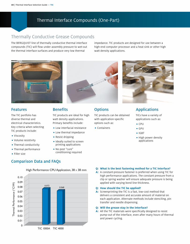
40 | Thermal Interface Selection Guide — TIC
Thermal Interface Compounds (One-Part)
Thermally Conductive Grease CompoundsThe BERGQUIST line of thermally conductive thermal interface compounds (TIC) will flow under assembly pressure to wet-out the thermal interface surfaces and produce very low thermal
impedance. TIC products are designed for use between a high-end computer processor and a heat sink or other high watt density applications.
FeaturesThe TIC portfolio has diverse thermal and electrical characteristics. Key criteria when selecting TIC products include:
• Viscosity
• Volume resistivity
• Thermal conductivity
• Thermal performance
• Filler size
BenefitsTIC products are ideal for high watt density applications. Primary benefits include:
• Low interfacial resistance
• Low thermal impedance
• Resist dripping
• Ideally suited to screenprinting applications
• No post “cure”conditioning required
OptionsTIC products can be obtained with application-specific options such as:
• Containers
ApplicationsTICs have a variety of applications such as:
• CPU
• GPU
• IGBT
• High power densityapplications
Comparison Data and FAQs
Q: What is the best fastening method for a TIC interface?A: A constant-pressure fastener is preferred when using TIC for
high performance applications. The constant pressure from a clip or spring washer will ensure adequate pressure is being applied with varying bond line thickness.
Q: How should the TIC be applied?A: Screenprinting the TIC is a fast, low-cost method that
delivers a consistent and accurate amount of material on each application. Alternate methods include stenciling, pin transfer and needle dispensing.
Q: Will the grease stay in the interface?A: All the TIC materials were specifically designed to resist
pump-out of the interface, even after many hours of thermal and power cycling.

Thermal Interface Selection Guide — TIC | 41
TIC 1000A
High Performance, Value Compound for High-End Computer ProcessorsFeatures and Benefits• High thermal performance:
0.32°C/W (@ 50 psi)
• Good screenability
• Room temperature storage
• No post “cure” required
• Exceptional value
TIC 1000A is a high performance, thermally conductive compound intended for use as a thermal interface material between a high-end computer processor and a heat sink. Other high watt density applications will also benefit from the extremely low thermal impedance of TIC 1000A.
TIC 1000A compound wets-out the thermal interface surfaces and flows to produce the lowest thermal impedance. The compound requires pressure of the assembly to cause flow. The TIC 1000A compound will resist dripping.
For microprocessor applications, traditional screw fastening or spring clamping methods will provide adequate force to optimize the thermal performance of TIC 1000A.
An optimized application would utilize the minimum volume of TIC 1000A material necessary to ensure complete wet-out of both mechanical interfaces.
Assembly – No Post-Screen CureTIC 1000A has good screenability. No solvent is used to reduce the viscosity, so no post “cure” conditioning is required.
Application Cleanliness1. Pre-clean heat sink and component interface with isopropyl alcohol prior
to assembly or repair. Ensure heat sink is dry before applying TIC 1000A.
Application Methods1. Dispense and/or screenprint TIC 1000A compound onto the processor or heat sink
surface like thermal grease (see a Henkel Representative for application information).
2. Assemble the processor and heat sink with spring clips orconstant-pressure fasteners.
Typical Applications Include:• High performance CPUs
• High performance GPUs
Building a Part Number Standard Options|| example
Note: To build a part number, go to www.bergquistcompany.com/Part_Number_Builder.php.
Sect
ion
A
Sect
ion
B
Sect
ion
C
Sect
ion
D
Sect
ion
E
TIC1000A 00 00 25cc NA
NA = Selected standard option. If not selecting a standardoption, insert company name, drawing number, andrevision level.
TIC1000A = Thermal Interface Compound 1000A
00 = No options
00 = No options
Containers: 5cc = 5.0cc, 25cc = 25.0cc, 200cc = 200.0ccCartridge: 600cc = 600.0cc
TYPICAL PROPERTIES OF TIC 1000A
PROPERTY IMPERIAL VALUE METRIC VALUE TEST METHOD
Color Grey Grey Visual
Density (g/cc) 2.1 2.1 ASTM D792
Continuous Use Temp. (°F) / (°C) 302 150 —
ELECTRICAL
Electrical Resistivity (Ohmmeter)(1) N/A N/A ASTM D257
THERMAL
Thermal Conductivity (W/m-K) 1.5 1.5 ASTM D5470
THERMAL PERFORMANCE VS. PRESSURE
Pressure (psi) 10 25 50 100 200
TO-220 Thermal Performance (°C/W)(2) 0.32 0.32 0.32 0.31 0.28
1) The compound contains an electrically conductive filler surrounded by electrically nonconductive resin.2) TO-220 performance data is provided as a reference to compare material thermal performance.

42 | Thermal Interface Selection Guide — TIC
TIC 4000
High Performance Thermal Interface Compound for Copper-Based Heat SinksFeatures and Benefits• Thermal conductivity: 4.0 W/m-K
• Exceptional thermal performance:0.19°C/W (@ 50 psi)
TIC 4000 is a thermally conductive grease compound designed for use as a thermal interface material between a computer processor and a copper-based heat sink. Other high watt density applications will benefit from the extremely low thermal impedance of TIC 4000.
TIC 4000 compound wets-out the thermal interface surfaces and flows to produce low thermal impedance. The compound requires pressure of the assembly to cause flow. TIC 4000 compound will not drip.
For a typical 0.5 in. x 0.5 in. application at 0.005 in. thick, Henkel estimates approximately 0.02 ml (cc) of TIC 4000.
Although Henkel estimates a 0.02 ml (cc) volumetric requirement for a 0.5 in. x 0.5 in. component interface, dispensed at a thickness of 0.005 in., Henkel also recognizes that an optimized application would use the minimum volume of TIC 4000 material necessary to ensure complete wet-out of both mechanical interfaces.
Application Methods1. Pre-clean heat sink and component interface with isopropyl alcohol prior to
assembly or repair. Ensure heat sink is dry before applying TIC 4000.
2. Dispense TIC 4000 compound onto the processor or heat sink surface likethermal grease.
3. Assemble the processor and heat sink with clip or constant-pressure fasteners.
Typical Applications Include:• High performance computer processors (traditional screw fastening or clamping
methods will provide adequate force to optimize the thermal performance ofTIC 4000)
• High watt density applications where the lowest thermal resistance interfaceis required
Building a Part Number Standard Options|| example
Note: To build a part number, go to www.bergquistcompany.com/Part_Number_Builder.php.
Sect
ion
A
Sect
ion
B
Sect
ion
C
Sect
ion
D
Sect
ion
E
TIC4000 00 00 200cc NA
NA = Selected standard option. If not selecting a standardoption, insert company name, drawing number, andrevision level.
TIC4000 = Thermal Interface Compound 4000
00 = No options
00 = No options
Containers: 5cc = 5.0cc, 25cc = 25.0cc, 200cc = 200.0cc
TYPICAL PROPERTIES OF TIC 4000
PROPERTY IMPERIAL VALUE METRIC VALUE TEST METHOD
Color Grey Grey Visual
Density (g/cc) 4.0 4.0 ASTM D792
Continuous Use Temp. (°F) / (°C) 302 150 —
ELECTRICAL
Electrical Resistivity (Ohmmeter)(1) N/A N/A ASTM D257
THERMAL
Thermal Conductivity (W/m-K) 4.0 4.0 ASTM D5470
THERMAL PERFORMANCE VS. PRESSURE
Pressure (psi) 10 25 50 100 200
TO-220 Thermal Performance (°C/W)(2) 0.21 0.20 0.19 0.19 0.18
1) The compound contains an electrically conductive filler surrounded by electrically nonconductive resin.2) TO-220 performance data is provided as a reference to compare material thermal performance.
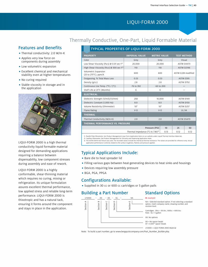
Thermal Interface Selection Guide — TIC | 43
LIQUI-FORM 2000
Thermally Conductive, One-Part, Liquid Formable MaterialFeatures and Benefits• Thermal conductivity: 2.0 W/m-K
• Applies very low force oncomponents during assembly
• Low volumetric expansion
• Excellent chemical and mechanicalstability even at higher temperatures
• No curing required
• Stable viscosity in storage and inthe application
LIQUI-FORM 2000 is a high thermal conductivity liquid formable material designed for demanding applications requiring a balance between dispensability, low component stresses during assembly and ease of rework.
LIQUI-FORM 2000 is a highly conformable, shear-thinning material which requires no curing, mixing or refrigeration. Its unique formulation assures excellent thermal performance, low applied stress and reliable long-term performance. LIQUI-FORM 2000 is thixotropic and has a natural tack, ensuring it forms around the component and stays in place in the application.
Typical Applications Include:• Bare die to heat spreader lid
• Filling various gaps between heat-generating devices to heat sinks and housings
• Devices requiring low assembly pressure
• BGA, PGA, PPGA
Configurations Available:• Supplied in 30 cc or 600 cc cartridges or 5 gallon pails
Building a Part Number Standard Options
Sect
ion
A
Sect
ion
B
Sect
ion
C
Sect
ion
D
Sect
ion
E NA = Selected standard option. If not selecting a standardoption, insert company name, drawing number, andrevision level.
LF2000 = LIQUI-FORM 2000 Material
LF2000 00 00 5G NA
Note: To build a part number, go to www.bergquistcompany.com/Part_Number_Builder.php.
00 = No spacer beads07 = 0.007" spacer beads
00: No options
Cartridges: 30cc = 30.0cc, 600cc = 600.0ccPails: 5G = 5 gallon
– – – – || example
TYPICAL PROPERTIES OF LIQUI-FORM 2000
PROPERTY IMPERIAL VALUE METRIC VALUE TEST METHOD
Color Grey Grey Visual
Low Shear Viscosity (Pa·s) @ 0.01 sec-1(1) 20,000 20,000 ASTM D4473
High Shear Viscosity (Pa·s) @ 300 sec-1(2) 110 110 ASTM D2196
Volumetric Expansion (25 to 275°C), ppm/K
600 600 ASTM E228 modified
Outgassing, % Total Mass Loss 0.53 0.53 ASTM E595
Density (g/cc) 2.8 2.8 ASTM D792
Continuous Use Temp. (°F) / (°C) -76 to 392 -60 to 200 —
Shelf Life at 25°C (Months) 6 6 —
ELECTRICAL
Dielectric Strength (V/mil)/(V/mm) 250 10,000 ASTM D149
Dielectric Constant (1,000 Hz) 8.0 8.0 ASTM D150
Volume Resistivity (Ohmmeter) 109 109 ASTM D257
Flame Rating V-O V-O UL 94
THERMAL
Thermal Conductivity (W/m-K) 2.0 2.0 ASTM D5470
THERMAL PERFORMANCE VS. PRESSURE
Pressure (PSI) 10 25 50
Thermal Impedance (°C-in.2/W)(3) 0.13 0.12 0.12
1) Parallel Plate Rheometer, See Product Management Liqui-Form Application Note on our website under Liquid Thermal Interface Materials.2) Capillary Rheometer, See Product Management for Viscosity and Dispensing Application Note.3) The ASTM D5470 test fixture was used. The recorded values include the interfacial thermal resistance. The values are provided for reference only. Actual
application performance is directly related to the surface roughness, flatness and pressure applied.

44 | Thermal Interface Selection Guide — TIC
LIQUI-FORM 3500 is a high conductivity gel thermal interface material designed for demanding applications that require a balance between dispensability and low component stress during assembly and also in the application.
LIQUI-FORM 3500 is a one-part, highly conformable gel with thixotropic properties. The material is precured and requires no curing, mixing or refrigeration. It’s unique formulation assures excellent thermal performance, low applied stress and reliable long-term performance.
LIQUI-FORM 3500 is thixotropic with a natural tack ensuring it will stay in place within the application.
Features and Benefits• Thermal Conductivity: 3.5 W/m-K
• Dispensable pre-cured gel
• Stable viscosity in storage and inthe application
• Excellent chemical stability andmechanical stability
Thermally Conductive, One-Part, Liquid Formable Gel Material
LIQUI-FORM 3500
Typical Applications Include:• Handheld devices
• Bare die to heat spreader lid
• Filling various gaps between heat-generating devices to heat sinks and housings
• Devices requiring low assembly pressure
• High value assemblies with rework
• BGA, PGA, PPGA
Configurations Available:• Supplied in 30cc, 150cc, 300cc, 600cc cartridges or 4.3 gallon pails
Building a Part Number Standard Options
TYPICAL PROPERTIES OF LIQUI-FORM 3500
PROPERTY IMPERIAL VALUE METRIC VALUE TEST METHOD
Color Gray Gray Visual
Dispense Rate (Grams/min)(1) 40 40 Henkel Test
Volumetric Expansion (25 to 275°C), ppm/K 200 200 ASTM E228 modified
Outgassing, % Total Mass Loss 0.14 0.14 ASTM E595
Density (g/cc) 3.1 3.1 ASTM D792
Continuous Use Temp (°F) / (°C) -76 to 392 -60 to 200 —
Shelf Life at 25°C (Months) 6 6 —
ELECTRICAL
Dielectric Strength (V/mil)/(V/mm) 250 10,000 ASTM D149
Dielectric Constant (1000 Hz) 8.1 8.1 ASTM D150
Volume Resistivity (Ohm-meter) 1011 1011 ASTM D257
Flame Rating V-O V-O U.L. 94
THERMAL
Thermal Conductivity (W/m-K) 3.5 3.5 ASTM D5470
THERMAL PERFORMANCE VS. PRESSURE
Pressure (PSI) 10 25 50
Thermal Impedance(°C-in2/W)(2) 0.07 0.07 0.06
(1) 30cc syringe, 90 psi (621 kPa), 0.100” orifice no attachment.(2) The ASTM D5470 test fixture was utilized. The recorded values include the interfacial thermal resistance. The values are provided for reference only. Actual
application performance is directly related to the surface roughness, flatness and pressure applied.
Sect
ion
A
Sect
ion
B
Sect
ion
C
Sect
ion
D
Sect
ion
E NA = Selected standard option. If not selecting a standardoption, insert company name, drawing number, andrevision level.
LF3500 = LIQUI-FORM 3500 Material
LF3500 00 00 4.3G NA
Note: To build a part number, visit our website at www.bergquistcompany.com/Part_Number_Builder.php.
00 = No spacer beads
00: No options
Cartridges: 30cc = 30.0cc, 150cc = 150.0cc, 300cc = 300.0ccPails: 4.3G = 4.3 gallon
– – – –

Thermal Interface Selection Guide — HI-FLOW | 45
HI-FLOW Phase Change Interface Materials
Solutions-Driven Thermal Management Products for Electronic DevicesUse phase change materials for excellent thermal performance without the mess of grease.
HI-FLOW phase change materials are an excellent replacement for grease as a thermal interface between a CPU or power device and a heat sink. The materials change from a solid at specific phase change temperatures and flow to assure a total wet-out of the interface without overflow. The result is a thermal interface comparable to grease, without the mess, contamination and hassle.
The HI-FLOW family of phase change thermal interface materials covers a wide range of applications. Henkel’s BERGQUIST brand offers leading thermal management solutions and we work closely with customers to ensure that the proper HI-FLOW material is specified.
FeaturesHI-FLOW handles like BERGQUIST SIL PAD materials at room temperature, but flows like grease at its designed phase change temperature. The following is an overview of the important features shared by the HI-FLOW family:
• Comparable thermalperformance to grease inmost applications
• Thermally conductive phasechange compound
• Aluminum, film or fiberglasscarriers and non-reinforcedversions
• Low volatility
• Easy to handle and applyin the manufacturingenvironment
• Tackified or tack-free atroom temperature
BenefitsUsing HI-FLOW materials instead of grease can save time and money without sacrificing thermal performance. Here are some other benefits:
• No mess – thixotropiccharacteristics of thematerials keep it fromflowing out of the interface
• Easier handling –tackified or tack-free atroom temperature
• No protective liner required
• High thermal performancehelps ensure CPU reliability
• Do not attract contaminants
• Easier material handling andshipping
• Simplified applicationprocess
OptionsThe broad HI-FLOW family offers a variety of choices to meet the customer’s performance, handling and process needs. Some of the choices include:
• Some HI-FLOW materials areavailable with orwithout adhesive
• Aluminum carrier forapplications not requiringelectrical isolation
• Film or fiberglass carrier forelectrical isolation
• Dry, non-reinforced material
• Tackified or tack-free atroom temperature
• Tabbed parts, die-cut parts,sheets or bulk rolls
• Adhesive specifically forcold application withoutpreheating heat sink
We produce thousands of specials. Tooling charges vary depending on the complexity of the part.
ApplicationsHI-FLOW materials are suited for consumer and industrial electronics, automotive, medical, aerospace and telecommunications applications such as:
• UPS and SMPS AC/DC, DC/DC or linear power supplies
• Between a CPU andheat sink
• Power conversion devices
• Fractional and integralmotor control
• Leaded, surface mount andpower module assemblies
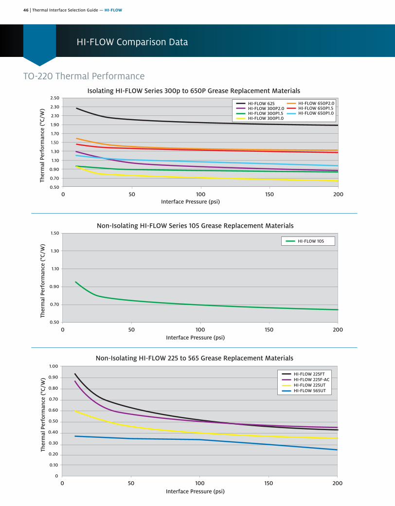
46 | Thermal Interface Selection Guide — HI-FLOW
HI-FLOW Comparison Data
TO-220 Thermal Performance
0 50 100 150 2000.50
0.70
0.90
1.10
1.30
1.50
HI-FLOW 105
Non-Isolating HI-FLOW Series 105 Grease Replacement Materials
Interface Pressure (psi)
Ther
mal
Per
form
ance
(°C
/W)
Isolating HI-FLOW Series 300p to 650P Grease Replacement Materials
HI-FLOW 625HI-FLOW 300P2.0HI-FLOW 300P1.5HI-FLOW 300P1.0
HI-FLOW 650P2.0HI-FLOW 650P1.5HI-FLOW 650P1.0
Interface Pressure (psi)
Ther
mal
Per
form
ance
(°C
/W)
0 50 100 150 2000.50
0.70
0.90
1.10
1.30
1.50
1.70
1.90
2.10
2.30
2.50
HI-FLOW 225FTHI-FLOW 225F-ACHI-FLOW 225UTHI-FLOW 565UT
0
0.10
0.20
0.30
0.40
0.50
0.60
0.70
0.80
0.90
1.00
Non-Isolating HI-FLOW 225 to 565 Grease Replacement Materials
Ther
mal
Per
form
ance
(°C
/W)
Interface Pressure (psi)0 50 100 150 200

Thermal Interface Selection Guide — HI-FLOW | 47
Frequently Asked Questions
Q: How is the ASTM D5470 test modified to characterize phase change thermal performance?
A: ASTM classifies a phase change as a Type 1, viscous liquid that exhibits unlimited deformation when a stress is applied. Henkel uses test equipment that is designed to meet ASTM D5470 specifications for Type 1, which requires a shim or mechanical stop to precisely control the thickness. The phase change material is conditioned at 5°C over the stated phase change temperature. Understanding that time is also a key variable for material flow, the over-temperature condition is limited to 10 minutes and then allowed to cool, prior to initiating the actual test at the given pressure. The 10-minute time has been demonstrated to be an acceptabletime period for the thermal mass inherent in the test setup.Note: Actual application testing may require more or lesstime to condition, depending upon the heat transfer andassociated thermal mass. The performance values arerecorded and published at 10, 25, 50, 100 and 200 psi togive the designer a broad-based understanding of HI-FLOWmaterial’s performance.
Q: What is the minimum pressure required to optimize the thermal performance of the HI-FLOW material?
A: Upon achieving phase change temperature (e.g., pre-conditioning), Henkel has demonstrated that 10 psi provides adequate pressure to achieve exceptional thermal performance. Henkel continues to research lower pressure wet-out characteristics in an effort to minimize interfacial losses associated with ultra-thin material interfaces.
Q: Will the HI-FLOW replace a mechanical fastener?A: Mechanical fasteners are required. Henkel recommends the
use of spring clips to maintain consistent pressure over time.
Q: Can I use screw-mount devices with HI-FLOW material?A: HI-FLOW works best with a clip or spring washer-mounted
assembly. The continuous force applied by these devices allows the HI-FLOW material to flow and reduce the cross sectional gap. Henkel suggests that design engineers evaluate whether a screw-mount assembly will have acceptable performance. See TO-220 Technical Note.
Q: Is the adhesive in HI-FLOW 225F-AC repositionable?A: The adhesive in the current construction does adhere more
to the heat sink aluminum than to the HI-FLOW material. There is the potential that the adhesive will be removed by the heat sink surface when it is removed to reposition on the heat sink. Time and/or pressure will increase the bond to the aluminum, increasing the potential for the adhesive to adhere to the heat sink.
Q: Is there any surface preparation required before applying the adhesive-backed HI-FLOW to the heat sink?
A: Standard electronics industry cleaning procedures apply. Remove dirt or other debris. Best results are attained when the HI-FLOW material is applied to a heat sink at a temperature of 25° +/- 10°C. If the heat sink has been surface treated (e.g., anodized or chromated), it is typically ready for assembly. For
bare aluminum, mild soap and water wash cleaning processes are typically used to eliminate machine oils and debris.
Q: Is HI-FLOW material reworkable?A: If the material has not gone through phase change, the
material will readily release from the device surface. For this situation, the HI-FLOW material will not likely have to be replaced.
If the material has gone through the phase change, it will adhere very well to both surfaces. In this case, Henkel suggests warming the heat sink to soften the HI-FLOW compound for easier removal from the processor. Replace with a new piece of HI-FLOW material.
Q: What is meant by “easy to handle” in manufacturing?A: Insulated HI-FLOW products are manufactured with inner
film support. This film stiffens the material, allowing parts to be more readily die-cut as well as making the material easier to handle in manual or automated assembly.
Q: What is meant by “tack-free” and why is this important?A: Many HI-FLOW materials have no surface tack at room
temperature. The softer materials will pick up dirt more readily. Softer resins are more difficult to clean if any dirt is on the surface. If you try to rub the dirt away, the dirt is easily pushed into the soft phase change materials. HI-FLOW coatings are typically hard at room temperature rendering them easier to clean off without embedding dirt.
Q: What does “more scratch resistance” mean on HI-FLOW 625?
A: HI-FLOW 625 does not require a protective film during shipment. HI-FLOW has a higher phase change temperature and remains hard to a higher temperature. The HI-FLOW material is harder and is not as easy to scratch or dent in shipping and handling.
Q: Why is HI-FLOW phase change temperature 65°C?A: The 65°C phase change temperature was selected for two
reasons. First, it was a low enough temperature for the phase change to occur in applications. Second, it would not phase change in transport. Studies show that shipping containers can reach 60°C in domestic and international shipments. The higher phase change temperature eliminates the possibility of a product being ruined in shipment. We offer a standard line of HI-FLOW 225 and 300 series products with 55°C phase change for those customers wanting the lower phase change temperature.
Q: In which applications should I avoid using HI-FLOW?A: Avoid using HI-FLOW in applications in which the device will
not reach operation at or above phase change temperature. Also avoid applications in which the operating temperature exceeds the maximum recommended operating temperature of the compound.
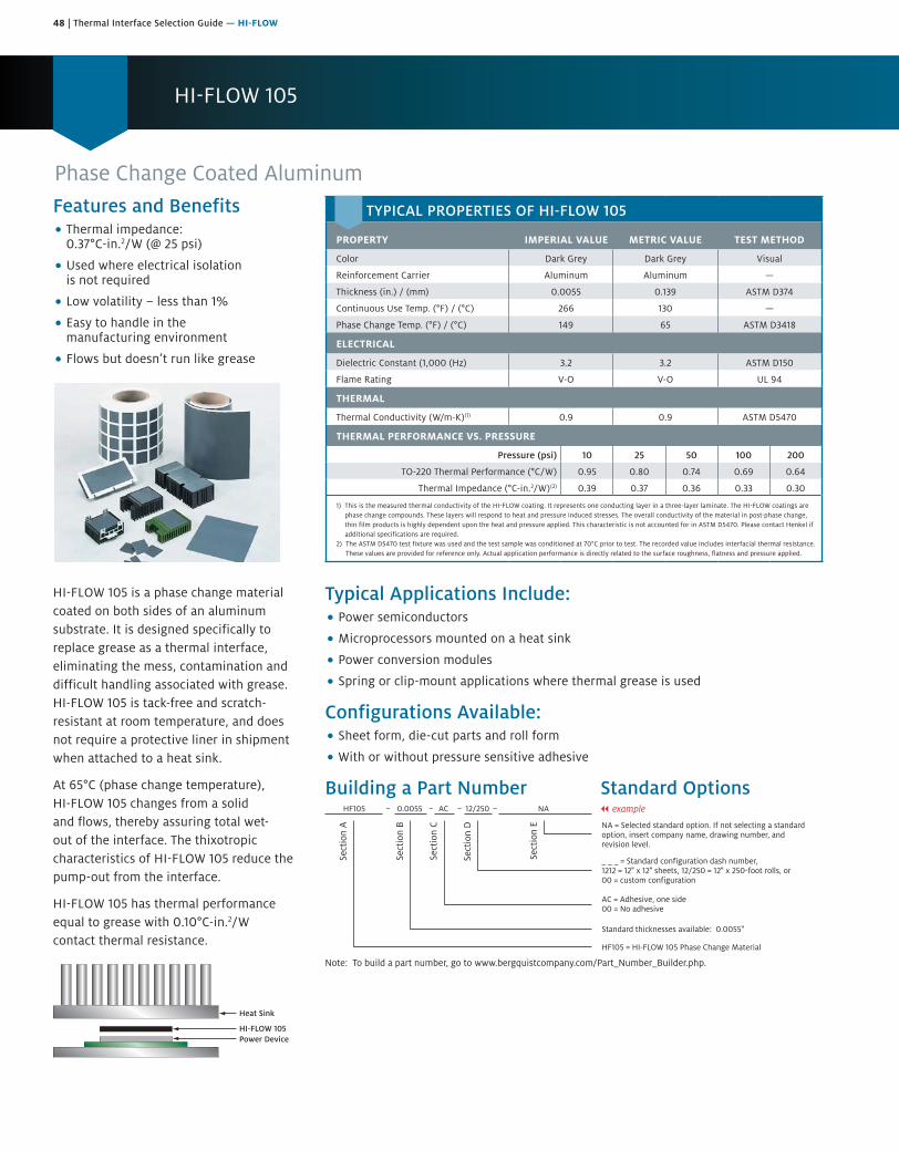
48 | Thermal Interface Selection Guide — HI-FLOW
HI-FLOW 105
Phase Change Coated AluminumFeatures and Benefits• Thermal impedance:
0.37°C-in.2/W (@ 25 psi)
• Used where electrical isolationis not required
• Low volatility – less than 1%
• Easy to handle in themanufacturing environment
• Flows but doesn’t run like grease
HI-FLOW 105 is a phase change material coated on both sides of an aluminum substrate. It is designed specifically to replace grease as a thermal interface, eliminating the mess, contamination and difficult handling associated with grease. HI-FLOW 105 is tack-free and scratch-resistant at room temperature, and does not require a protective liner in shipment when attached to a heat sink.
At 65°C (phase change temperature), HI-FLOW 105 changes from a solid and flows, thereby assuring total wet-out of the interface. The thixotropic characteristics of HI-FLOW 105 reduce the pump-out from the interface.
HI-FLOW 105 has thermal performance equal to grease with 0.10°C-in.2/W contact thermal resistance.
Heat Sink
HI-FLOW 105Power Device
Typical Applications Include:• Power semiconductors
• Microprocessors mounted on a heat sink
• Power conversion modules
• Spring or clip-mount applications where thermal grease is used
Configurations Available:• Sheet form, die-cut parts and roll form
• With or without pressure sensitive adhesive
Building a Part Number Standard Options
Sect
ion
A
Sect
ion
B
Sect
ion
C
Sect
ion
D
Sect
ion
E NA = Selected standard option. If not selecting a standardoption, insert company name, drawing number, andrevision level.
HF105 = HI-FLOW 105 Phase Change Material
HF105 0.0055 AC 12/250 NA
Note: To build a part number, go to www.bergquistcompany.com/Part_Number_Builder.php.
Standard thicknesses available: 0.0055"
AC = Adhesive, one side00 = No adhesive
_ _ _ = Standard configuration dash number,1212 = 12" x 12" sheets, 12/250 = 12" x 250-foot rolls, or00 = custom configuration
– – – – || example
TYPICAL PROPERTIES OF HI-FLOW 105
PROPERTY IMPERIAL VALUE METRIC VALUE TEST METHOD
Color Dark Grey Dark Grey Visual
Reinforcement Carrier Aluminum Aluminum —
Thickness (in.) / (mm) 0.0055 0.139 ASTM D374
Continuous Use Temp. (°F) / (°C) 266 130 —
Phase Change Temp. (°F) / (°C) 149 65 ASTM D3418
ELECTRICAL
Dielectric Constant (1,000 (Hz) 3.2 3.2 ASTM D150
Flame Rating V-O V-O UL 94
THERMAL
Thermal Conductivity (W/m-K)(1) 0.9 0.9 ASTM D5470
THERMAL PERFORMANCE VS. PRESSURE
Pressure (psi) 10 25 50 100 200
TO-220 Thermal Performance (°C/W) 0.95 0.80 0.74 0.69 0.64
Thermal Impedance (°C-in.2/W)(2) 0.39 0.37 0.36 0.33 0.30
1) This is the measured thermal conductivity of the HI-FLOW coating. It represents one conducting layer in a three-layer laminate. The HI-FLOW coatings are phase change compounds. These layers will respond to heat and pressure induced stresses. The overall conductivity of the material in post-phase change, thin film products is highly dependent upon the heat and pressure applied. This characteristic is not accounted for in ASTM D5470. Please contact Henkel if additional specifications are required.
2) The ASTM D5470 test fixture was used and the test sample was conditioned at 70°C prior to test. The recorded value includes interfacial thermal resistance. These values are provided for reference only. Actual application performance is directly related to the surface roughness, flatness and pressure applied.
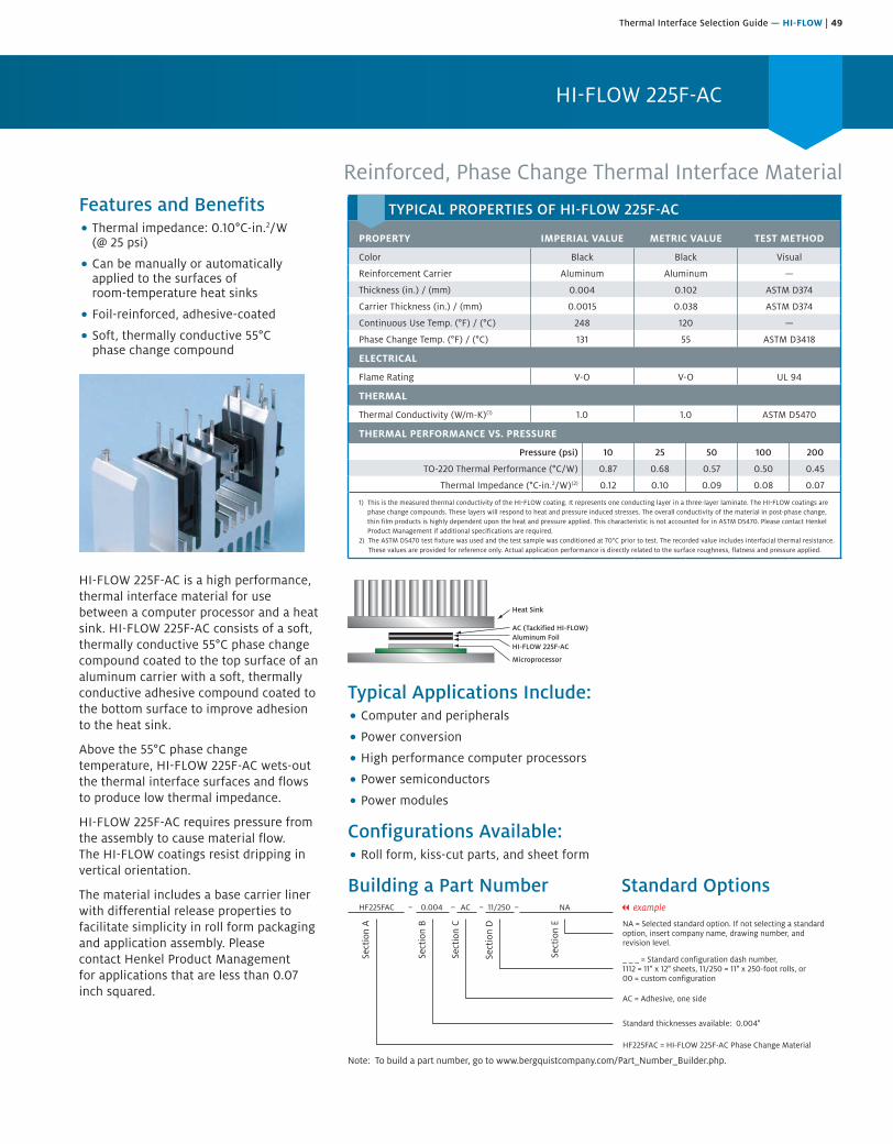
Thermal Interface Selection Guide — HI-FLOW | 49
HI-FLOW 225F-AC
Reinforced, Phase Change Thermal Interface MaterialFeatures and Benefits• Thermal impedance: 0.10°C-in.2/W
(@ 25 psi)
• Can be manually or automaticallyapplied to the surfaces ofroom-temperature heat sinks
• Foil-reinforced, adhesive-coated
• Soft, thermally conductive 55°Cphase change compound
HI-FLOW 225F-AC is a high performance, thermal interface material for use between a computer processor and a heat sink. HI-FLOW 225F-AC consists of a soft, thermally conductive 55°C phase change compound coated to the top surface of an aluminum carrier with a soft, thermally conductive adhesive compound coated to the bottom surface to improve adhesion to the heat sink.
Above the 55°C phase change temperature, HI-FLOW 225F-AC wets-out the thermal interface surfaces and flows to produce low thermal impedance.
HI-FLOW 225F-AC requires pressure from the assembly to cause material flow. The HI-FLOW coatings resist dripping in vertical orientation.
The material includes a base carrier liner with differential release properties to facilitate simplicity in roll form packaging and application assembly. Please contact Henkel Product Management for applications that are less than 0.07 inch squared.
Heat Sink
AC (Tackified HI-FLOW)Aluminum FoilHI-FLOW 225F-AC
Microprocessor
Typical Applications Include:• Computer and peripherals
• Power conversion
• High performance computer processors
• Power semiconductors
• Power modules
Configurations Available:• Roll form, kiss-cut parts, and sheet form
Building a Part Number Standard Options
Sect
ion
A
Sect
ion
B
Sect
ion
C
Sect
ion
D
Sect
ion
E NA = Selected standard option. If not selecting a standardoption, insert company name, drawing number, andrevision level.
HF225FAC = HI-FLOW 225F-AC Phase Change Material
HF225FAC 0.004 AC 11/250 NA
Note: To build a part number, go to www.bergquistcompany.com/Part_Number_Builder.php.
Standard thicknesses available: 0.004"
AC = Adhesive, one side
_ _ _ = Standard configuration dash number,1112 = 11" x 12" sheets, 11/250 = 11" x 250-foot rolls, or00 = custom configuration
– – – – || example
TYPICAL PROPERTIES OF HI-FLOW 225F-AC
PROPERTY IMPERIAL VALUE METRIC VALUE TEST METHOD
Color Black Black Visual
Reinforcement Carrier Aluminum Aluminum —
Thickness (in.) / (mm) 0.004 0.102 ASTM D374
Carrier Thickness (in.) / (mm) 0.0015 0.038 ASTM D374
Continuous Use Temp. (°F) / (°C) 248 120 —
Phase Change Temp. (°F) / (°C) 131 55 ASTM D3418
ELECTRICAL
Flame Rating V-O V-O UL 94
THERMAL
Thermal Conductivity (W/m-K)(1) 1.0 1.0 ASTM D5470
THERMAL PERFORMANCE VS. PRESSURE
Pressure (psi) 10 25 50 100 200
TO-220 Thermal Performance (°C/W) 0.87 0.68 0.57 0.50 0.45
Thermal Impedance (°C-in.2/W)(2) 0.12 0.10 0.09 0.08 0.07
1) This is the measured thermal conductivity of the HI-FLOW coating. It represents one conducting layer in a three-layer laminate. The HI-FLOW coatings are phase change compounds. These layers will respond to heat and pressure induced stresses. The overall conductivity of the material in post-phase change, thin film products is highly dependent upon the heat and pressure applied. This characteristic is not accounted for in ASTM D5470. Please contact Henkel Product Management if additional specifications are required.
2) The ASTM D5470 test fixture was used and the test sample was conditioned at 70°C prior to test. The recorded value includes interfacial thermal resistance. These values are provided for reference only. Actual application performance is directly related to the surface roughness, flatness and pressure applied.

50 | Thermal Interface Selection Guide — HI-FLOW
HI-FLOW 225UT
Unreinforced, Pressure Sensitive Phase Change Thermal Interface MaterialFeatures and Benefits• Thermal impedance: 0.08°C-in.2/W
(@ 25 psi)
• 55°C phase change composite withinherent tack characteristics
• High-visibility protective tabs
• Pressure sensitive phase changethermal interface material
HI-FLOW 225UT is designed as a pressure sensitive thermal interface material for use between a high performance processor and a heat sink. HI-FLOW 225UT is a thermally conductive 55°C phase change composite with inherent tack. The material is supplied on a polyester carrier liner and is available with high-visibility protective tabs.
Above its phase change temperature, HI-FLOW 225UT wets-out the thermal interface surfaces and flows to produce the lowest thermal impedance. The material requires pressure of the assembly to cause flow.
Application Methods:Hand-apply HI-FLOW 225UT to a room-temperature heat sink. The HI-FLOW 225UT pad exhibits inherent tack and can be hand-applied similar to an adhesive pad. The tab liner can remain on the heat sink and pad throughout shipping and handling until it is ready for final assembly.
Clear PolyesterCarrier Liner
HF 225UTRoll Form,
Kiss-Cut Parts
Clear/ColoredProtective Tab
Adhesive Strip
"Quick-Snap" High VisibilityTab for Removal
Typical Applications Include:• Computer and peripherals
• High performance computer processors
• Graphic cards
• Power modules
Configurations Available:• Roll form with tabs, kiss-cut parts – no holes
HI-FLOW 225UT is limited to a square or rectangular part design. Dimensional tolerance is +/- 0.020 in. (0.5 mm).
Building a Part Number Standard Options
Sect
ion
A
Sect
ion
B
Sect
ion
C
Sect
ion
D
Sect
ion
E
Note: To build a part number, go to www.bergquistcompany.com/Part_Number_Builder.php.
NA = Selected standard option. If not selecting a standardoption, insert company name, drawing number, andrevision level.
HF22UT = HI-FLOW 225UT Phase Change Material
Standard thicknesses available: 0.003"
00 = Pressure sensitive adhesive, one side
_ _ _ = Standard HI-FLOW 225UT configuration,10/250 = 10" x 250-foot rolls, or 00 = customconfiguration
HF225UT 0.003 01 10/250 NA
TYPICAL PROPERTIES OF HI-FLOW 225UT
PROPERTY IMPERIAL VALUE METRIC VALUE TEST METHOD
Color Black Black Visual
Reinforcement Carrier None None —
Thickness (in.) / (mm) 0.003 0.077 ASTM D374
Continuous Use Temp. (°F) / (°C) 248 120 —
Phase Change Temp. (°F) / (°C) 131 55 ASTM D3418
ELECTRICAL
Flame Rating V-O V-O UL 94
THERMAL
Thermal Conductivity (W/m-K)(1) 0.7 0.7 ASTM D5470
THERMAL PERFORMANCE VS. PRESSURE
Pressure (psi) 10 25 50 100 200
TO-220 Thermal Performance (°C/W) 0.60 0.53 0.46 0.40 0.35
Thermal Impedance (°C-in.2/W)(2) 0.09 0.08 0.07 0.06 0.05
1) This is the measured thermal conductivity of the HI-FLOW coating. It represents one conducting layer in a three-layer laminate. The HI-FLOW coatings are phase change compounds. These layers will respond to heat and pressure induced stresses. The overall conductivity of the material in post-phase change, thin film products is highly dependent upon the heat and pressure applied. This characteristic is not accounted for in ASTM D5470. Please contact Henkel Product Management if additional specifications are required.
2) The ASTM D5470 test fixture was used and the test sample was conditioned at 70°C prior to test. The recorded value includes interfacial thermal resistance. These values are provided for reference only. Actual application performance is directly related to the surface roughness, flatness and pressure applied.
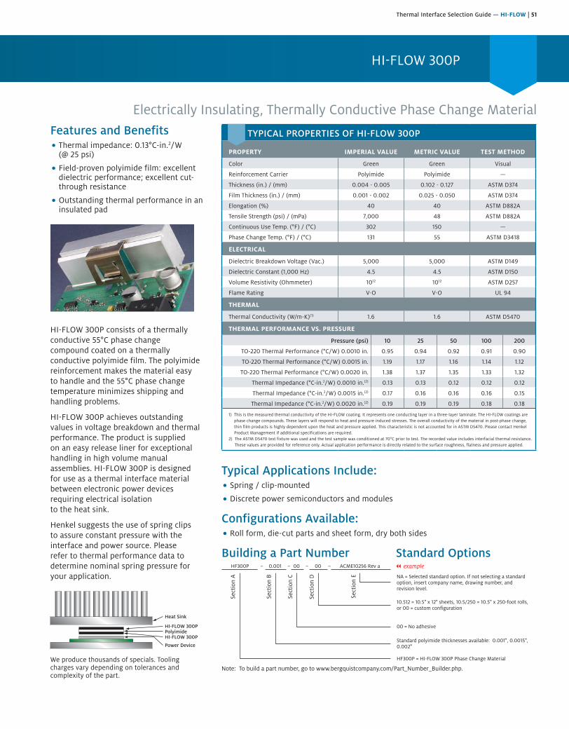
Thermal Interface Selection Guide — HI-FLOW | 51
HI-FLOW 300P
Electrically Insulating, Thermally Conductive Phase Change MaterialFeatures and Benefits• Thermal impedance: 0.13°C-in.2/W
(@ 25 psi)
• Field-proven polyimide film: excellentdielectric performance; excellent cut-through resistance
• Outstanding thermal performance in aninsulated pad
HI-FLOW 300P consists of a thermally conductive 55°C phase change compound coated on a thermally conductive polyimide film. The polyimide reinforcement makes the material easy to handle and the 55°C phase change temperature minimizes shipping and handling problems.
HI-FLOW 300P achieves outstanding values in voltage breakdown and thermal performance. The product is supplied on an easy release liner for exceptional handling in high volume manual assemblies. HI-FLOW 300P is designed for use as a thermal interface material between electronic power devices requiring electrical isolation to the heat sink.
Henkel suggests the use of spring clips to assure constant pressure with the interface and power source. Please refer to thermal performance data to determine nominal spring pressure for your application.
Heat Sink
HI-FLOW 300PPolyimideHI-FLOW 300P
Power Device
We produce thousands of specials. Tooling charges vary depending on tolerances and complexity of the part.
Typical Applications Include:• Spring / clip-mounted
• Discrete power semiconductors and modules
Configurations Available:• Roll form, die-cut parts and sheet form, dry both sides
Building a Part Number Standard Options
Sect
ion
A
Sect
ion
B
Sect
ion
C
Sect
ion
D
Sect
ion
E NA = Selected standard option. If not selecting a standardoption, insert company name, drawing number, andrevision level.
HF300P = HI-FLOW 300P Phase Change Material
HF300P 0.001 00– – – –00 ACME10256 Rev a
Note: To build a part number, go to www.bergquistcompany.com/Part_Number_Builder.php.
Standard polyimide thicknesses available: 0.001", 0.0015",0.002"
00 = No adhesive
10.512 = 10.5" x 12" sheets, 10.5/250 = 10.5" x 250-foot rolls,or 00 = custom configuration
|| example
TYPICAL PROPERTIES OF HI-FLOW 300P
PROPERTY IMPERIAL VALUE METRIC VALUE TEST METHOD
Color Green Green Visual
Reinforcement Carrier Polyimide Polyimide —
Thickness (in.) / (mm) 0.004 - 0.005 0.102 - 0.127 ASTM D374
Film Thickness (in.) / (mm) 0.001 - 0.002 0.025 - 0.050 ASTM D374
Elongation (%) 40 40 ASTM D882A
Tensile Strength (psi) / (mPa) 7,000 48 ASTM D882A
Continuous Use Temp. (°F) / (°C) 302 150 —
Phase Change Temp. (°F) / (°C) 131 55 ASTM D3418
ELECTRICAL
Dielectric Breakdown Voltage (Vac.) 5,000 5,000 ASTM D149
Dielectric Constant (1,000 Hz) 4.5 4.5 ASTM D150
Volume Resistivity (Ohmmeter) 1012 1012 ASTM D257
Flame Rating V-O V-O UL 94
THERMAL
Thermal Conductivity (W/m-K)(1) 1.6 1.6 ASTM D5470
THERMAL PERFORMANCE VS. PRESSURE
Pressure (psi) 10 25 50 100 200
TO-220 Thermal Performance (°C/W) 0.0010 in. 0.95 0.94 0.92 0.91 0.90
TO-220 Thermal Performance (°C/W) 0.0015 in. 1.19 1.17 1.16 1.14 1.12
TO-220 Thermal Performance (°C/W) 0.0020 in. 1.38 1.37 1.35 1.33 1.32
Thermal Impedance (°C-in.2/W) 0.0010 in.(2) 0.13 0.13 0.12 0.12 0.12
Thermal Impedance (°C-in.2/W) 0.0015 in.(2) 0.17 0.16 0.16 0.16 0.15
Thermal Impedance (°C-in.2/W) 0.0020 in.(2) 0.19 0.19 0.19 0.18 0.18
1) This is the measured thermal conductivity of the HI-FLOW coating. It represents one conducting layer in a three-layer laminate. The HI-FLOW coatings are phase change compounds. These layers will respond to heat and pressure induced stresses. The overall conductivity of the material in post-phase change, thin film products is highly dependent upon the heat and pressure applied. This characteristic is not accounted for in ASTM D5470. Please contact Henkel Product Management if additional specifications are required.
2) The ASTM D5470 test fixture was used and the test sample was conditioned at 70°C prior to test. The recorded value includes interfacial thermal resistance. These values are provided for reference only. Actual application performance is directly related to the surface roughness, flatness and pressure applied.
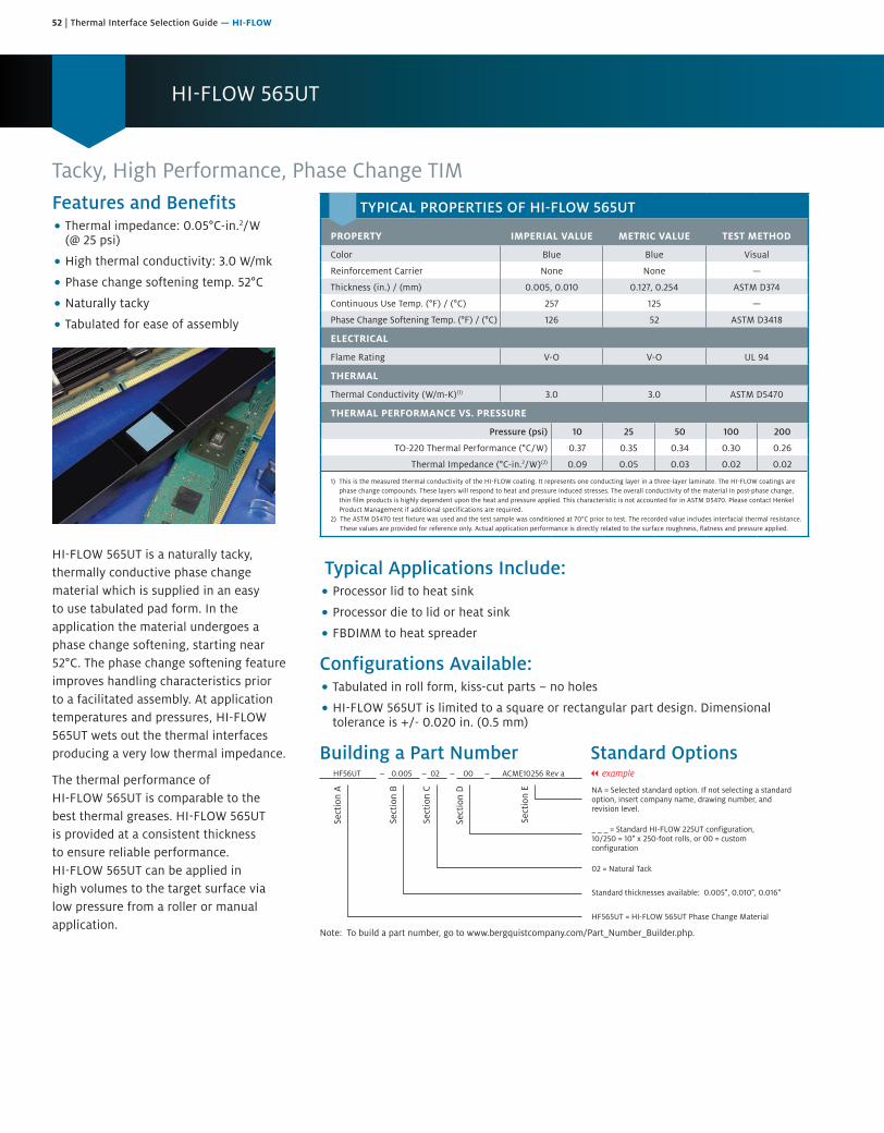
52 | Thermal Interface Selection Guide — HI-FLOW
HI-FLOW 565UT
Tacky, High Performance, Phase Change TIMFeatures and Benefits• Thermal impedance: 0.05°C-in.2/W
(@ 25 psi)
• High thermal conductivity: 3.0 W/mk
• Phase change softening temp. 52°C
• Naturally tacky
• Tabulated for ease of assembly
HI-FLOW 565UT is a naturally tacky, thermally conductive phase change material which is supplied in an easy to use tabulated pad form. In the application the material undergoes a phase change softening, starting near 52°C. The phase change softening feature improves handling characteristics prior to a facilitated assembly. At application temperatures and pressures, HI-FLOW 565UT wets out the thermal interfaces producing a very low thermal impedance.
The thermal performance of HI-FLOW 565UT is comparable to the best thermal greases. HI-FLOW 565UT is provided at a consistent thickness to ensure reliable performance. HI-FLOW 565UT can be applied in high volumes to the target surface via low pressure from a roller or manual application.
Typical Applications Include:• Processor lid to heat sink
• Processor die to lid or heat sink
• FBDIMM to heat spreader
Configurations Available:• Tabulated in roll form, kiss-cut parts – no holes
• HI-FLOW 565UT is limited to a square or rectangular part design. Dimensionaltolerance is +/- 0.020 in. (0.5 mm)
Building a Part Number Standard Options
Note: To build a part number, go to www.bergquistcompany.com/Part_Number_Builder.php.
Sect
ion
A
Sect
ion
B
Sect
ion
C
Sect
ion
D
Sect
ion
E
HF56UT 0.005 02 00 ACME10256 Rev a || example
NA = Selected standard option. If not selecting a standardoption, insert company name, drawing number, andrevision level.
HF565UT = HI-FLOW 565UT Phase Change Material
Standard thicknesses available: 0.005", 0.010", 0.016"
02 = Natural Tack
_ _ _ = Standard HI-FLOW 225UT configuration,10/250 = 10" x 250-foot rolls, or 00 = customconfiguration
TYPICAL PROPERTIES OF HI-FLOW 565UT
PROPERTY IMPERIAL VALUE METRIC VALUE TEST METHOD
Color Blue Blue Visual
Reinforcement Carrier None None —
Thickness (in.) / (mm) 0.005, 0.010 0.127, 0.254 ASTM D374
Continuous Use Temp. (°F) / (°C) 257 125 —
Phase Change Softening Temp. (°F) / (°C) 126 52 ASTM D3418
ELECTRICAL
Flame Rating V-O V-O UL 94
THERMAL
Thermal Conductivity (W/m-K)(1) 3.0 3.0 ASTM D5470
THERMAL PERFORMANCE VS. PRESSURE
Pressure (psi) 10 25 50 100 200
TO-220 Thermal Performance (°C/W) 0.37 0.35 0.34 0.30 0.26
Thermal Impedance (°C-in.2/W)(2) 0.09 0.05 0.03 0.02 0.02
1) This is the measured thermal conductivity of the HI-FLOW coating. It represents one conducting layer in a three-layer laminate. The HI-FLOW coatings are phase change compounds. These layers will respond to heat and pressure induced stresses. The overall conductivity of the material in post-phase change, thin film products is highly dependent upon the heat and pressure applied. This characteristic is not accounted for in ASTM D5470. Please contact Henkel Product Management if additional specifications are required.
2) The ASTM D5470 test fixture was used and the test sample was conditioned at 70°C prior to test. The recorded value includes interfacial thermal resistance. These values are provided for reference only. Actual application performance is directly related to the surface roughness, flatness and pressure applied.
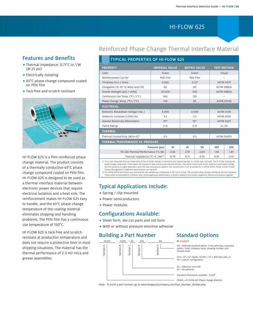
Thermal Interface Selection Guide — HI-FLOW | 53
HI-FLOW 625
Reinforced Phase Change Thermal Interface MaterialFeatures and Benefits• Thermal impedance: 0.71°C-in.2/W
(@ 25 psi)
• Electrically isolating
• 65°C phase change compound coatedon PEN film
• Tack-free and scratch-resistant
HI-FLOW 625 is a film-reinforced phase change material. The product consists of a thermally conductive 65°C phase change compound coated on PEN film. HI-FLOW 625 is designed to be used as a thermal interface material between electronic power devices that require electrical isolation and a heat sink. The reinforcement makes HI-FLOW 625 easy to handle, and the 65°C phase change temperature of the coating material eliminates shipping and handling problems. The PEN film has a continuous use temperature of 150°C.
HI-FLOW 625 is tack-free and scratch-resistant at production temperature and does not require a protective liner in most shipping situations. The material has the thermal performance of 2-3 mil mica and grease assemblies.
Typical Applications Include:• Spring / clip-mounted
• Power semiconductors
• Power modules
Configurations Available:• Sheet form, die-cut parts and roll form
• With or without pressure sensitive adhesive
Building a Part Number Standard Options
Sect
ion
A
Sect
ion
B
Sect
ion
C
Sect
ion
D
Sect
ion
E NA = Selected standard option. If not selecting a standardoption, insert company name, drawing number, andrevision level.
HF625 = HI-FLOW 625 Phase Change Material
HF625 0.005 AC– – – –1212 NA
Note: To build a part number, go to www.bergquistcompany.com/Part_Number_Builder.php.
Standard thicknesses available: 0.005"
AC = Adhesive, one side00 = No adhesive
1212 = 12" x 12" sheets, 12/200 = 12" x 200-foot rolls, or00 = custom configuration
|| example
TYPICAL PROPERTIES OF HI-FLOW 625
PROPERTY IMPERIAL VALUE METRIC VALUE TEST METHOD
Color Green Green Visual
Reinforcement Carrier PEN Film PEN Film —
Thickness (in.) / (mm) 0.005 0.127 ASTM D374
Elongation (% 45° to Warp and Fill) 60 60 ASTM D882A
Tensile Strength (psi) / (mPa) 30,000 206 ASTM D882A
Continuous Use Temp. (°F) / (°C) 302 150 —
Phase Change Temp. (°F) / (°C) 149 65 ASTM D3418
ELECTRICAL
Dielectric Breakdown Voltage (Vac.) 4,000 4,000 ASTM D149
Dielectric Constant (1,000 Hz) 3.5 3.5 ASTM D150
Volume Resistivity (Ohmmeter) 1010 1010 ASTM D257
Flame Rating V-O V-O UL 94
THERMAL
Thermal Conductivity (W/m-K)(1) 0.5 0.5 ASTM D5470
THERMAL PERFORMANCE VS. PRESSURE
Pressure (psi) 10 25 50 100 200
TO-220 Thermal Performance (°C/W) 2.26 2.10 2.00 1.93 1.87
Thermal Impedance (°C-in.2/W)(2) 0.79 0.71 0.70 0.67 0.61
1) This is the measured thermal conductivity of the HI-FLOW coating. It represents one conducting layer in a three-layer laminate. The HI-FLOW coatings are phase change compounds. These layers will respond to heat and pressure induced stresses. The overall conductivity of the material in post-phase change, thin film products is highly dependent upon the heat and pressure applied. This characteristic is not accounted for in ASTM D5470. Please contact Henkel Product Management if additional specifications are required.
2) The ASTM D5470 test fixture was used and the test sample was conditioned at 70°C prior to test. The recorded value includes interfacial thermal resistance. These values are provided for reference only. Actual application performance is directly related to the surface roughness, flatness and pressure applied.

54 | Thermal Interface Selection Guide — HI-FLOW
HI-FLOW 650P
Electrically Insulating, High Performance, Thermally Conductive Phase Change MaterialFeatures and Benefits• Thermal Impedance: 0.20°C-in.2/W
(@ 25 psi)
• 150°C high temperature reliability
• Natural tack on one side for ease ofassembly
• Exceptional thermal peformance inan insulated pad
HI-FLOW 650P is a thermally conductive phase change material, reinforced with a polyimide film that is naturally tacky on one side. The polyimide film provides a high dielectric strength and high cut through resistance. HI-FLOW 650P offers high temperature reliability ideal for automotive applications.
HI-FLOW 650P is designed for use between a high-power electrical device requiring electrical isolation from the heat sink and is ideal for automated dispensing systems.
Henkel recommends the use of spring clips to assure constant pressure with the component interface and the heat sink. Please refer to the TO-220 thermal performance data to determine the nominal spring pressure for your application.
Typical Applications• Spring / clip-mounted devices
• Discrete power semiconductors and modules
Configurations Available• Roll form, die-cut parts, sheet form
• Available with 1.0, 1.5 or 2.0 mil polyimide reinforcement carrier
Building a Part Number Standard Options|| example
Note: To build a part number, go to www.bergquistcompany.com/Part_Number_Builder.php.
Sect
ion
A
Sect
ion
B
Sect
ion
C
Sect
ion
D
Sect
ion
E
HF650P 0.001 01 00 ACME10256 Rev a
NA = Selected standard option. If not selecting a standardoption, insert company name, drawing number, andrevision level.
HF650P = HI-FLOW 650P Phase Change Material
Standard Polymide Thicknesses available: 0.001", 0.0015", 0.002"
01 = Natural tack
1112 = 11" x 12" sheets, 11/250 = 11/250 = 11" x 250" rolls,or 00 = custom configuration
TYPICAL PROPERTIES OF HI-FLOW 650P
PROPERTY IMPERIAL VALUE METRIC VALUE TEST METHOD
Color Gold Gold Visual
Reinforcement Carrier Polyimide Polyimide —
Thickness (in.) / (mm) 0.0045 - 0.0055 0.114 - 0.140 ASTM D374
Film Thickness (in.) / (mm) 0.001 - 0.002 0.025 - 0.050 ASTM D374
Inherent Surface Tack (1- or 2-sided) 1 1 —
Elongation (%) 40 40 ASTM D882A
Tensile Strength (psi) 7,000 7,000 ASTM D882A
Continuous Use Temp. (°F / °C) -40 to 302 -40 to 150 —
Phase Change Softening Temp. (°F / °C) 126 52 ASTM D3418
ELECTRICAL
Dielectric Breakdown Voltage (Vac.) 5,000 5,000 ASTM D149
Dielectric Constant (1,000 Hz) 4.5 4.5 ASTM D150
Volume Resistivity (Ohmmeter) 1012 1012 ASTM D257
Flame Rating V-O V-O UL 94
THERMAL
Thermal Conductivity (W/m-K)(1) 1.5 1.5 ASTM D5470
THERMAL PERFORMANCE VS. PRESSURE
Pressure (psi) 10 25 50 100 200
TO-220 Thermal Performance (°C/W) 0.0010 in. 1.20 1.15 1.11 1.06 1.00
TO-220 Thermal Performance (°C/W) 0.0015 in. 1.47 1.41 1.37 1.33 1.29
TO-220 Thermal Performance (°C/W) 0.0020 in. 1.59 1.48 1.43 1.38 1.35
Thermal Impedance (°C-in.2/W)(2) 0.0010 in. 0.21 0.20 0.19 0.18 0.17
Thermal Impedance (°C-in.2/W)(2) 0.0015 in. 0.23 0.22 0.21 0.20 0.20
Thermal Impedance (°C-in.2/W)(2) 0.0020 in. 0.27 0.27 0.26 0.25 0.24
1) This is the measured thermal conductivity of the HI-FLOW wax coating. It represents one conducting layer in a three-layer laminate. The HI-FLOW coatings are phase change compounds. These layers will respond to heat and pressure induced stresses. The overall conductivity of the material in post-phase change, thin film products is highly dependent upon the heat and pressure applied. This characteristic is not accounted for in ASTM D5470. Please contact Henkel Product Management if additional specifications are required.
2) The ASTM D5470 test fixture was used and the test sample was conditioned at 70°C for 5 minutes prior to test. The recorded value includes interfacial thermal resistance. These values are provided for reference only. Actual application performance is directly related to the surface roughness, flatness andpressure applied.

Thermal Interface Selection Guide — SIL PAD | 55
SIL PAD Thermally Conductive Insulators
Solutions-Driven Thermal Management Products for Electronic DevicesComprehensive choices for a cleaner and more efficient thermal interface
SIL PAD elastomeric thermal interface material was introduced more than 25 years ago. Today, a complete family of SIL PAD materials is available to meet the needs of a rapidly changing electronics industry.
SIL PAD thermally conductive insulators, in their many forms, continue to be a clean and efficient alternative to mica, ceramics or grease for a wide range of electronic applications. BERGQUIST brand application specialists work closely with customers to specify the proper SIL PAD material for each unique thermal management requirement.
FeaturesThe SIL PAD family encompasses dozens of products, each with its own unique construction, properties and performance. Here are some of the important features offered by the SIL PAD family:
• Proven siliconerubber binders
• Fiberglass, dielectric filmor polyester film carriers
• Special fillers to achievespecific performancecharacteristics
• Flexible and conformable
• Reinforcements to resistcut-through
• Variety of thicknesses
• Wide range of thermalconductivities anddielectric strengths
BenefitsChoosing SIL PAD thermal products saves time and money while maximizing an assembly’s performance and reliability. Specifically:
• Excellent thermalperformance
• Eliminates the messof grease
• More durable than mica
• Less costly than ceramic
• Resistant to electricalshorting
• Easier and cleaner to apply
• Under time and pressure,thermal resistance willdecrease
• Better performance fortoday’s high-heatcompacted assemblies
• A specific interfacialperformance thatmatches the need
• Efficient “total applied cost”
OptionsSome SIL PAD products have special features for particular applications. Options include:
• Available with orwithout adhesive
• Some configurationsare well-suited forautomated dispensingand/or placement
• Aluminum foil or embeddedgraphite construction forapplications not requiringelectrical insulation
• Copper shield layer
• Polyester binder materialfor silicone-sensitiveapplications
• Polyimide film carrierfor increased voltagebreakdown
• Materials with reducedmoisture sensitivity
• Available in rolls, sheets,tubes and customdie-cut parts
• Custom thicknessesand constructions
We produce thousands of specials. Tooling charges vary depending on the complexity of the part.
ApplicationsThe large family of SIL PAD thermally conductive insulators is extremely versatile. In today’s marketplace, SIL PAD materials are used in virtually every component of the electronics industry, including:
• Interface between a powertransistor, CPU or otherheat-generating componentand a heat sink or rail
• To isolate electricalcomponents and powersources from heat sink and/or mounting bracket
• As an interface fordiscrete semiconductorsrequiring low-pressurespring-clamp mounting
• Consumer electronics
• Automotive systems
• Telecommunications
• Aerospace
• Military
• Medical devices
• Industrial controls

56 | Thermal Interface Selection Guide — SIL PAD
Frequently Asked Questions
Q: What is the primary difference between SIL PAD A2000 and SIL PAD 2000 products?
A: SIL PAD A2000 uses a different filler package than SIL PAD 2000. This change results in a more compliant SIL PAD A2000 material that inherently lowers interfacial resistance losses. This reduction in interfacial resistance results in improved overall thermal performance when measured at lower pressures in standard ASTM D5470 and TO-220 testing.
Q: When should I choose SIL PAD A2000 versus SIL PAD 2000 for my application?
A: The answer is based on the assumption that the primary design intent is to increase thermal performance. If your application uses lower clamping pressures (e.g., 10 to 75 psi), you will find the SIL PAD A2000 to provide excellent thermal performance. In contrast, if you are designing for higher clamping pressures (e.g., 100 psi or greater), it is likely that you will require the thermal performance characteristics of the SIL PAD 2000.
Q: Are there differences in electrical characteristics between SIL PAD A2000 and SIL PAD 2000?
A: Yes. Henkel evaluates and publishes voltage breakdown, dielectric constant and volume resistivity data per ASTM standards for these materials. Due to differences between ASTM lab testing and actual application performance, for best results, these characteristics should be evaluated within the actual customer system.
Q: Can I get SIL PAD A2000 in roll form?A: Yes. With the environmentally responsible process
improvements added with the introduction of SIL PAD A2000 products, the materials are now available in roll form. The original SIL PAD 2000 material cannot be produced in continuous roll form.
Q: When should I choose SIL PAD 800 versus SIL PAD 900S for my application?
A: SIL PAD 800 is specifically formulated to provide excellent thermal performance for discrete semiconductor applications that use low clamping pressures (e.g., spring clips at 10 to 50 psi.). In contrast, if you are designing for higher clamping pressure applications using discrete semi-conductors (e.g., 50 to 100 psi.), it is likely that you will prefer the combination of high thermal performance and cut-through resistance inherent in SIL PAD 900S material.
Q: When should I choose SIL PAD 980 versus SIL PAD 900S for my application?
A: SIL PAD 980 is specifically formulated to provide exceptional cut-through and crush resistance in combination with excellent heat transfer and dielectric properties. SIL PAD 980 has a proven history of reliability in high-pressure applications where surface imperfections such as burrs and dents are inherently common. These applications often include heavily machined metal surfaces manufactured from extrusions or castings. SIL PAD 900S carries a high level of crush resistance and is more likely to be used in burr-free or controlled-surface finish applications.
Q: Is there an adhesive available for SIL PAD 1500ST and SIL PAD 1100ST?
A: SIL PAD 1500ST and SIL PAD 1100ST have an inherent tack on both sides of the material. This inherent tack is used instead of an adhesive. The tack provides sufficient adhesive for dispensing from the carrier liner and placement on the component. SIL PAD 1500ST and SIL PAD 1100ST can be repositioned after the initial placement.
Q: Why are the thermal performance curves of SIL PAD 1500ST and SIL PAD 1100ST so flat when compared to other SIL PAD materials?
A: SIL PAD 1500ST and SIL PAD 1100ST wet-out the application surfaces at a very low pressures. Optimal thermal performance is achieved at pressures as low as 50 psi.
Q: How do I know which SIL PAD is right for my specific application?
A: Each application has specific characteristics (e.g., surface finish, flatness tolerances, high pressure requirements, potential burrs, etc.) that determine which SIL PAD will optimize thermal performance. Select a minimum of two pads that best fit the application, then conduct testing to determine which material performs the best.
Q: What is IS09001:2008?A: The ISO certification is the adoption of a quality management
system that is a strategic decision of the organization. This International Standard specifies requirements for a quality management system where an organization: a) needs to demonstrate its ability to consistently provide product that meets customer and applicable regulatory requirements, and b) aims to enhance customer satisfaction through the effective application of the system, including processes for continual improvement of the system and the assurance of conformity to customer and regulatory requirements.

Thermal Interface Selection Guide — SIL PAD | 57
Choosing SIL PAD Thermally Conductive Insulators
Mica and GreaseMica insulators have been in use for over 35 years and are still commonly used as an insulator. Mica is inexpensive and has excellent dielectric strength, but it is brittle and is easily cracked or broken. Because mica used by itself has high thermal impedance, thermal grease is commonly applied to it. The grease flows easily and excludes air from the interface to reduce the interfacial thermal resistance. If the mica is also thin (2-3 mils [50-80 µm]), a low thermal impedance can be achieved.
However, thermal grease introduces a number of problems to the assembly process. It is time-consuming to apply, messy and difficult to clean. Once thermal grease has been applied to an electronic assembly, solder processes must be avoided to prevent contamination of the solder. Cleaning baths must also be avoided to prevent wash-out of the interface grease, causing a dry joint and contamination of the bath. Assembly, soldering and cleaning processes must be performed in one process while the greased insulators are installed off-line in a secondary process. If the grease is silicone-based, migration of silicone molecules occurs over time, drying out the grease and contaminating the assembly.
Polyimide FilmsPolyimide films can also be used as insulators and are often combined with wax or grease to achieve a low thermal impedance. These polyimide films are especially tough and have high dielectric strength. SIL PAD K-4, K-6 and K-10 incorporate polyimide film as the carrier material.
SIL PAD MaterialsSIL PAD thermally conductive insulators are designed to be clean, grease-free and flexible. The combination of a tough carrier material such as fiberglass and silicone rubber which is confirmable provides the engineer with a more versatile material than mica or ceramics and grease. SIL PAD products minimize the thermal resistance from the case of a power semiconductor to the heat sink. SIL PAD materials electrically isolate the semiconductor from the heat sink and have suffiicient dielectric strength to withstand high voltage. They are also strong enough to resist puncture by the facing metal surface.
Binders Most SIL PAD products use silicone rubber as the binder. Silicone rubber has a low dielectric constant, high dielectric strength, good chemical resistance and high thermal stability.
Silicone rubber also exhibits cold flow, which excludes air from the interface as it conforms to the mating surfaces. This flow eliminates the need for thermal grease. A rough-surface-textured insulator needs to flow more to exclude air than a smooth one. The smoother pads also need less pressure to wet-out the surfaces and obtain optimum thermal contact.
Carriers The carrier provides physical reinforcement and contributes to dielectric strength. High dielectric and physical strength are obtained by using a heavy, tight mesh, but thermal resistance will suffer. A light, open mesh reduces thermal resistance, dielectric strength and cut-through resistance. The carrier materials used in SIL PAD materials include fiberglass and dielectric film.
Fillers The thermal conductivity of SIL PAD products is improved by filling them with ingredients of high thermal conductivity. The fillers change the characteristics of the silicone rubber to enhance thermal and/or physical characteristics.
For instance, some fillers make the silicone rubber hard and tough while still retaining the ability to flow under pressure. A harder silicone helps the material resist cut-through. In other applications, a filler is used to make the silicone rubber softer and more conformable to rough surfaces. While the range in thermal resistance of greased mica is quite large, the average is comparable to elastomeric insulators filled with a blend of the appropriate ingredients.
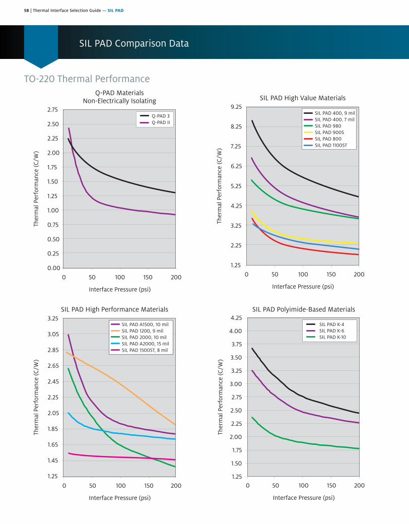
58 | Thermal Interface Selection Guide — SIL PAD
SIL PAD Comparison Data
TO-220 Thermal Performance
Ther
mal
Per
form
ance
(C/W
)
Interface Pressure (psi)
SIL PAD High Performance Materials
0 50 100 150 200
3.25
3.05
2.85
2.65
2.45
2.25
2.05
1.85
1.65
1.45
1.25
SIL PAD A1500, 10 milSIL PAD 1200, 9 milSIL PAD 2000, 10 milSIL PAD A2000, 15 milSIL PAD 1500ST, 8 mil
0.00
0.25
0.50
0.75
1.00
1.25
1.50
1.75
2.00
2.25
2.50
2.75
0 50 100 150 200
Ther
mal
Per
form
ance
(C/W
)
Interface Pressure (psi)
Q-PAD MaterialsNon-Electrically Isolating
Q-PAD 3Q-PAD II
1.25
2.25
3.25
4.25
5.25
6.25
7.25
8.25
9.25
0 50 100 150 200
Ther
mal
Per
form
ance
(C/W
)
Interface Pressure (psi)
SIL PAD High Value Materials
SIL PAD 400, 9 milSIL PAD 400, 7 milSIL PAD 980SIL PAD 900SSIL PAD 800SIL PAD 1100ST
SIL PAD Polyimide-Based Materials4.25
4.00
3.75
3.50
3.25
3.00
2.75
2.50
2.25
2.00
1.75
1.50
1.25
Ther
mal
Per
form
ance
(C/W
)
Interface Pressure (psi)
0 50 100 150 200
SIL PAD K-4SIL PAD K-6SIL PAD K-10
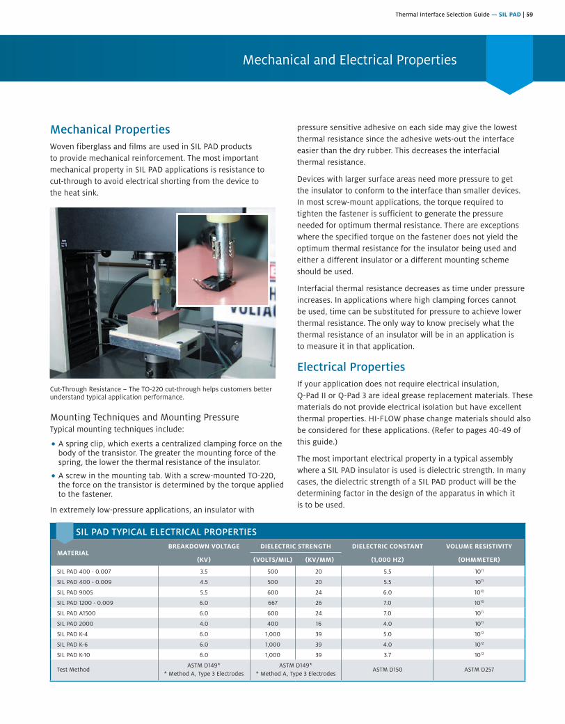
Thermal Interface Selection Guide — SIL PAD | 59
Mechanical and Electrical Properties
Mechanical PropertiesWoven fiberglass and films are used in SIL PAD products to provide mechanical reinforcement. The most important mechanical property in SIL PAD applications is resistance to cut-through to avoid electrical shorting from the device to the heat sink.
Cut-Through Resistance – The TO-220 cut-through helps customers better understand typical application performance.
Mounting Techniques and Mounting PressureTypical mounting techniques include:
• A spring clip, which exerts a centralized clamping force on thebody of the transistor. The greater the mounting force of thespring, the lower the thermal resistance of the insulator.
• A screw in the mounting tab. With a screw-mounted TO-220,the force on the transistor is determined by the torque appliedto the fastener.
In extremely low-pressure applications, an insulator with
pressure sensitive adhesive on each side may give the lowest thermal resistance since the adhesive wets-out the interface easier than the dry rubber. This decreases the interfacial thermal resistance.
Devices with larger surface areas need more pressure to get the insulator to conform to the interface than smaller devices. In most screw-mount applications, the torque required to tighten the fastener is sufficient to generate the pressure needed for optimum thermal resistance. There are exceptions where the specified torque on the fastener does not yield the optimum thermal resistance for the insulator being used and either a different insulator or a different mounting scheme should be used.
Interfacial thermal resistance decreases as time under pressure increases. In applications where high clamping forces cannot be used, time can be substituted for pressure to achieve lower thermal resistance. The only way to know precisely what the thermal resistance of an insulator will be in an application is to measure it in that application.
Electrical PropertiesIf your application does not require electrical insulation, Q-Pad II or Q-Pad 3 are ideal grease replacement materials. Thesematerials do not provide electrical isolation but have excellentthermal properties. HI-FLOW phase change materials should alsobe considered for these applications. (Refer to pages 40-49 ofthis guide.)
The most important electrical property in a typical assembly where a SIL PAD insulator is used is dielectric strength. In many cases, the dielectric strength of a SIL PAD product will be the determining factor in the design of the apparatus in which it is to be used.
SIL PAD TYPICAL ELECTRICAL PROPERTIES
MATERIALBREAKDOWN VOLTAGE DIELECTRIC STRENGTH DIELECTRIC CONSTANT VOLUME RESISTIVITY
(KV) (VOLTS/MIL) (KV/MM) (1,000 HZ) (OHMMETER)
SIL PAD 400 - 0.007 3.5 500 20 5.5 1011
SIL PAD 400 - 0.009 4.5 500 20 5.5 1011
SIL PAD 900S 5.5 600 24 6.0 1010
SIL PAD 1200 - 0.009 6.0 667 26 7.0 1010
SIL PAD A1500 6.0 600 24 7.0 1011
SIL PAD 2000 4.0 400 16 4.0 1011
SIL PAD K-4 6.0 1,000 39 5.0 1012
SIL PAD K-6 6.0 1,000 39 4.0 1012
SIL PAD K-10 6.0 1,000 39 3.7 1012
Test MethodASTM D149*
* Method A, Type 3 ElectrodesASTM D149*
* Method A, Type 3 ElectrodesASTM D150 ASTM D257

60 | Thermal Interface Selection Guide — SIL PAD
Thermal Properties
6.0
5.0
4.0
3.0
2.0
1.0
0.0
SIL PAD Thermal Performance Overview (TO-220 Test @ 50 psi)
BERGQUIST Material
Ther
mal
Per
form
ance
(°C
/W)
2.45
2.90
2.21
1.51
2.0
3.132.76
1.86 2.01
1.23
1.76
2.682.41
SP400(0.007)
SP800 SP900S SPA1500 SP1100ST SP1200 SP1500ST(0.008)
SP2000(0.010)
SP2000(0.015)
SPK-4 SPK-6 SPK-10 QP II QP 3
Here are some general guidelines regarding electrical properties to consider when selecting a SIL PAD material:
• Q-Pad II and Q-Pad 3 are used when electrical isolation isnot required.
• Dielectric breakdown voltage is the total voltage that adielectric material can withstand. When insulating electricalcomponents from each other and ground, it is desirable to usean insulator with a high breakdown voltage.
• Breakdown voltage decreases as the area of the electrodesincreases. This area effect is more pronounced as the thicknessof the insulator decreases.
• Breakdown voltage decreases as temperature increases.
• Breakdown voltage decreases as humidity increases.
• Breakdown voltage decreases in the presence ofpartial discharge.
• Breakdown voltage decreases as the size of the voltage source(kVA rating) increases.
• Breakdown voltage can be decreased by excessive mechanicalstress on the insulator.
Dielectric strength, dielectric constant and volume resistivity should all be taken into consideration when selecting a SIL PAD material. If your application requires specific electrical performance, please contact a Henkel Sales Representative for more detailed testing information.
Thermal Properties The thermal properties of a SIL PAD material and your requirements for thermal performance probably have more to do with your selection of a SIL PAD product than any other factor.
Discrete semiconductors, under normal operating conditions, dissipate waste power which raises the junction temperature of the device. Unless sufficient heat is conducted out of the device, its electrical performance and parameters are changed. A 10°C
rise in junction temperature can reduce the mean-time-to-failure of a device by a factor of two. Also, above 25°C, the semiconductor’s total power handling capability will be reduced by a derating factor inherent to the device.
The thermal properties of SIL PAD products are thermal impedance, thermal conductivity and thermal resistance. The thermal resistance and conductivity of SIL PAD products are inherent to the material and do not change. Thermal resistance and thermal conductivity are measured per ASTM D5470 and do not include the interfacial thermal resistance effects. Thermal impedance applies to the thermal transfer in an application and includes the effects of interfacial thermal resistance. As the material is applied in different ways, the thermal impedance values will vary from application to application.
• The original SIL PAD material, SIL PAD 400, continues tobe the BERGQUIST brand’s most popular material formany applications.
• SIL PAD A1500 is chosen when greater thermal performanceis required. SIL PAD A2000 is ideal for high performance,high reliability applications.
Beyond these standard materials, many things can contribute to the selection of the correct material for a particular application. Questions regarding the amount of torque and clamping pressure are often asked when selecting a SIL PAD material. Here are some guidelines:
• Interfacial thermal resistance decreases as clampingpressure increases.
• The clamping pressure required to minimize interfacial thermalresistance can vary with each type of insulator.
• SIL PAD products with smooth surface finishes (SIL PAD A1500,SIL PAD A2000, SIL PAD K-4, SIL PAD K-6 and SIL PAD K-10)are less sensitive to clamping pressure than SIL PAD materialswith rough surface finishes (SIL PAD 400) or smooth and tackyfinishes (SIL PAD 1500ST).

Thermal Interface Selection Guide — SIL PAD | 61
SIL PAD Thermally Conductive Insulator Selection Table
SIL PAD 400 .007 IN.
SIL PAD 400 .009 IN.
SIL PAD 800
SIL PAD 900S
SIL PAD 980
SIL PAD 1100ST
SIL PAD 1200
SIL PAD A1500
TEST METHOD
COLOR GREY GREY GOLD PINK MAUVE YELLOW BLACK GREEN VISUAL
Thickness (in./mm).007 ± .001 (.18 ± .025)
.009 ± .001 (.23 ± .025)
.005 ± .001 (.13 ± .025)
.009 ± .001 (.23 ± .025)
.009 ± .001 (.23 ± .025)
.012 ± .001 (.30 ± .025)
.009 ± .001 (.23 ± .025)
.010 ± .001 (.25 ± .025)
ASTM D374
Thermal Performance TO-220 Test @ 50 psi °C/W
5.14 6.61 2.45 2.90 4.52 2.68 2.41 2.21 ASTM D5470
Thermal Impedance (°C-in.2/W)
1.13 1.45 0.53 0.61 1.07 0.81 0.53 0.42 ASTM D5470
Thermal Conductivity (W/m-K nominal)
0.9 0.9 1.6 1.6 1.2 1.1 1.8 2.0 ASTM D5470
Voltage Breakdown (Vac.)
3,500 4,500 2,000 5,500 4,000 5,000 6,000 6,000 ASTM D149
Continuous Use Temperature (°C)
-60 to 180 -60 to 180 -60 to 180 -60 to 180 -40 to 150 -60 to 180 -60 to 180 -60 to 180 —
ConstructionSilicone/
FiberglassSilicone/
FiberglassSilicone/
FiberglassSilicone/
FiberglassSilicone/
FiberglassSilicone/
FiberglassSilicone/
FiberglassSilicone/
Fiberglass—
SIL PAD Applications
Here, SIL PAD 900S enhances the thermal transfer from this FR-4 circuit board with thermal vias to the metal base plate.
SIL PAD is available in over 100 standard configurations for common JEDEC package outlines.
The circuit board above shows punched parts interfacing screw-mounted transistors to a finned heat sink.
This application uses SIL PAD to isolate the mounting brackets from the assembly frame.
A common SIL PAD application includes TO-220 transistors mounted in a row on a heat rail.
These SIL PAD applications show clip mounting of transistors on the left and screw mounting to an aluminum bracket on the right.
Choose a SIL PAD that optimizes thermal performance for your mounting method — screw, clip, spring, bar, etc.
SIL PAD 980 is used extensively in industrial applications having excellent cut-through and abrasion resistance.
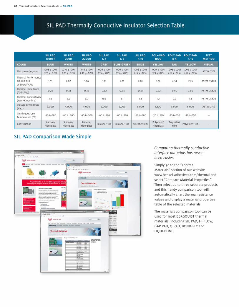
62 | Thermal Interface Selection Guide — SIL PAD
SIL PAD Comparison Made Simple
Comparing thermally conductive interface materials has never been easier.
Simply go to the “Thermal Materials” section of our website www.henkel-adhesives.com/thermal and select “Compare Material Properties.” Then select up to three separate products and this handy comparison tool will automatically chart thermal resistance values and display a material properties table of the selected materials.
The materials comparison tool can be used for most BERGQUIST thermal materials, including SIL PAD, HI-FLOW, GAP PAD, Q-PAD, BOND-PLY and LIQUI-BOND.
SIL PAD 1500ST
SIL PAD 2000
SIL PAD A2000
SIL PAD K-4
SIL PAD K-6
SIL PAD K-10
POLY-PAD 1000
POLY-PAD K-4
POLY-PAD K-10
TEST METHOD
COLOR BLUE WHITE WHITE GREY BLUE-GREEN BEIGE YELLOW TAN YELLOW VISUAL
Thickness (in./mm).008 ± .001(.20 ± .025)
.010 ± .001 (.25 ± .025)
.015 ± .001 (.38 ± .025)
.006 ± .001 (.15 ± .025)
.006 ± .001 (.15 ± .025)
.006 ± .001 (.15 ± .025)
.009 ± .001 (.23 ± .025)
.006 ± .001 (.15 ± .025)
.006 ± .001 (.15 ± .025)
ASTM D374
Thermal Performance TO-220 Test @ 50 psi °C/W
1.51 2.02 1.86 3.13 2.76 2.01 3.74 4.34 2.75 ASTM D5470
Thermal Impedance (°C-in.2/W)
0.23 0.33 0.32 0.62 0.64 0.41 0.82 0.95 0.60 ASTM D5470
Thermal Conductivity (W/m-K nominal)
1.8 3.5 3.0 0.9 1.1 1.3 1.2 0.9 1.3 ASTM D5470
Voltage Breakdown (Vac.)
3,000 4,000 4,000 6,000 6,000 6,000 1,300 5,500 6,000 ASTM D149
Continuous Use Temperature (°C)
-60 to 180 -60 to 200 -60 to 200 -60 to 180 -60 to 180 -60 to 180 -20 to 150 -20 to 150 -20 to 150 —
ConstructionSilicone/
FiberglassSilicone/
FiberglassSilicone/
FiberglassSilicone/Film Silicone/Film Silicone/Film
Polyester/ Fiberglass
Polyester/Film
Polyester/Film —
SIL PAD Thermally Conductive Insulator Selection Table

Thermal Interface Selection Guide — SIL PAD | 63
SIL PAD 400
The Original SIL PAD MaterialFeatures and Benefits• Thermal impedance: 1.13°C-in.2/W
(@ 50 psi)
• Original SIL PAD material
• Excellent mechanical andphysical characteristics
• Flame retardant
SIL PAD 400 is a composite of silicone rubber and fiberglass. The material is flame retardant and is specially formulated for use as a thermally conductive insulator. The primary use for SIL PAD 400 is to electrically isolate power sources from heat sinks.
SIL PAD 400 has excellent mechanical and physical characteristics. Surfaces are pliable and allow complete surface contact with excellent heat dissipation. SIL PAD 400 actually improves its thermal resistance with age. The reinforcing fiberglass provides excellent cut-through resistance. In addition, SIL PAD 400 is nontoxic and resists damage from cleaning agents.
Typical Applications Include:• Power supplies
• Power semiconductors
• Automotive electronics
• Motor controls
Configurations Available:• Sheet form, die-cut parts and roll form; with or without pressure sensitive adhesive
Building a Part Number Standard Options
Sect
ion
A
Sect
ion
B
Sect
ion
C
Sect
ion
D
Sect
ion
E NA = Selected standard option. If not selecting a standardoption, insert company name, drawing number, andrevision level.
SP400 = SIL-PAD 400 Material
SP400 0.007 AC 12/250 NA
Note: To build a part number, go to www.bergquistcompany.com/Part_Number_Builder.php.
Standard thicknesses available: 0.007", 0.009"
AC = Adhesive, one side; or00 = no adhesive
_ _ _ = Standard configuration dash number, 1212 = 12" x 12" sheets, 12/250 = 12" x 250-foot rolls, or00 = custom configuration
– – – – || example
TYPICAL PROPERTIES OF SIL PAD 400
PROPERTY IMPERIAL VALUE METRIC VALUE TEST METHOD
Color Grey Grey Visual
Reinforcement Carrier Fiberglass Fiberglass —
Thickness (in.) / (mm) 0.007, 0.009 0.178, 0.229 ASTM D374
Hardness (Shore A) 85 85 ASTM D2240
Breaking Strength (lbs./in.) / (kN/m) 30 5 ASTM D1458
Elongation (% at 45º to Warp and Fill) 54 54 ASTM D412
Tensile Strength (psi) / (mPa) 3,000 20 ASTM D412
Continuous Use Temp. (°F) / (°C) -76 to 356 -60 to 180 —
ELECTRICAL
Dielectric Breakdown Voltage (Vac.) 3,500, 4,500 3,500, 4,500 ASTM D149
Dielectric Constant (1,000 Hz) 5.5 5.5 ASTM D150
Volume Resistivity (Ohmmeter) 1011 1011 ASTM D257
Flame Rating V-O V-O UL 94
THERMAL
Thermal Conductivity (W/m-K) 0.9 0.9 ASTM D5470
THERMAL PERFORMANCE VS. PRESSURE
Pressure (psi) 10 25 50 100 200
TO-220 Thermal Performance (°C/W) 0.007 in. 6.62 5.93 5.14 4.38 3.61
TO-220 Thermal Performance (°C/W) 0.009 in. 8.51 7.62 6.61 5.63 4.64
Thermal Impedance (°C-in.2/W) 0.007 in.(1) 1.82 1.42 1.13 0.82 0.54
Thermal Impedance (°C-in.2/W) 0.009 in.(1) 2.34 1.83 1.45 1.05 0.69
1) The ASTM D5470 test fixture was used. The recorded value includes interfacial thermal resistance. These values are provided for reference only. Actual application performance is directly related to the surface roughness, flatness and pressure applied.
SIL PAD1500ST
SIL PAD2000
SIL PADA2000
SIL PADK-
SIL PADK-6
SIL PADK-10
POLY-PAD1000
POLY-PADK-
POLY-PADK-10
TESTMETHOD
COLOR BLUE WHITE WHITE GREY BLUE-GREEN BEIGE YELLOW TAN YELLOW VISUAL
Thickness (in./mm).008 ± .001(.20 ± .025)
.010 ± .001(.25 ± .025)
.015 ± .001(.38 ± .025)
.006 ± .001(.15 ± .025)
.006 ± .001(.15 ± .025)
.006 ± .001(.15 ± .025)
.009 ± .001(.23 ± .025)
.006 ± .001(.15 ± .025)
.006 ± .001(.15 ± .025)
ASTM D374
Thermal PerformanceTO-220 Test@ 50 psi °C/W
1.51 2.02 1.86 3.13 2.76 2.01 3.74 4.34 2.75 ASTM D5470
Thermal Impedance(°C-in.2/W)
0.23 0.33 0.32 0.62 0.64 0.41 0.82 0.95 0.60 ASTM D5470
Thermal Conductivity(W/m-K nominal)
1.8 3.5 3.0 0.9 1.1 1.3 1.2 0.9 1.3 ASTM D5470
Voltage Breakdown(Vac.)
3,000 4,000 4,000 6,000 6,000 6,000 1,300 5,500 6,000 ASTM D149
Continuous UseTemperature (°C)
-60 to 180 -60 to 200 -60 to 200 -60 to 180 -60 to 180 -60 to 180 -20 to 150 -20 to 150 -20 to 150 —
ConstructionSilicone/
FiberglassSilicone/
FiberglassSilicone/
FiberglassSilicone/Film Silicone/Film Silicone/Film
Polyester/Fiberglass
Polyester/Film
Polyester/Film —
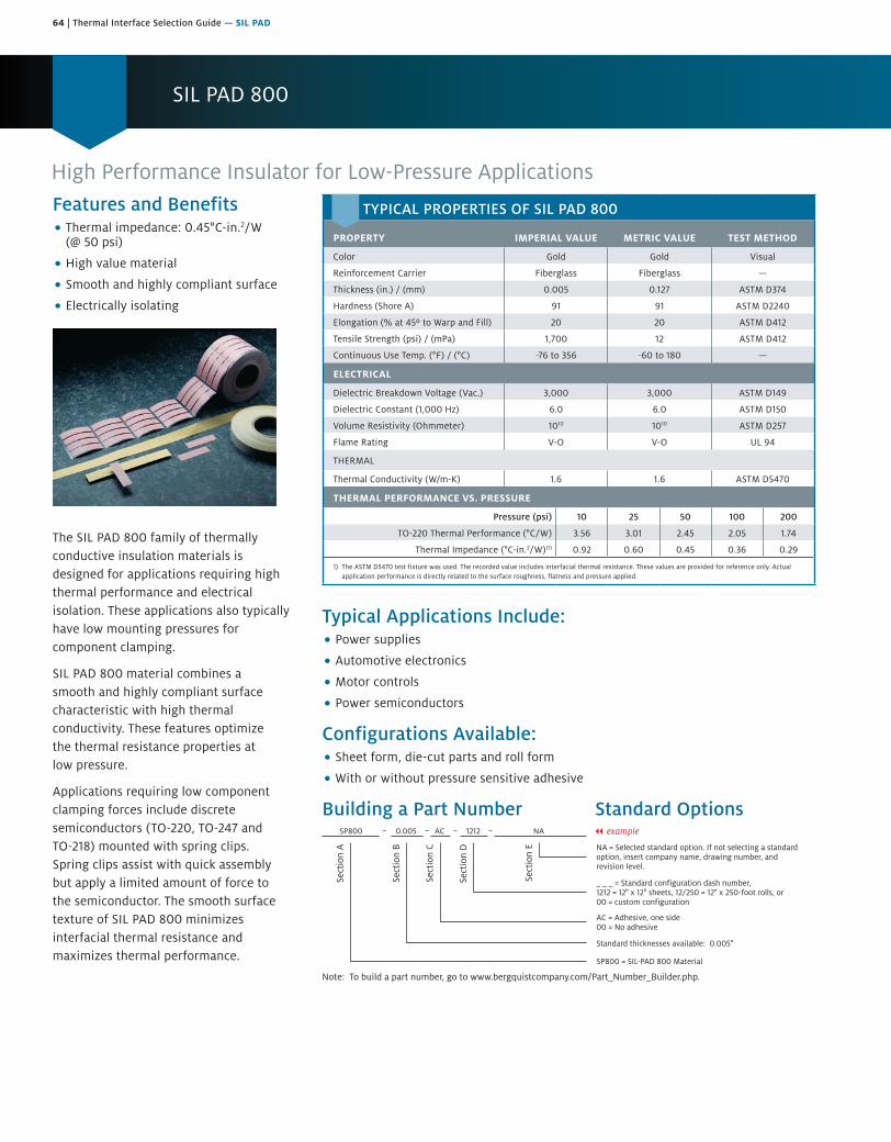
64 | Thermal Interface Selection Guide — SIL PAD
SIL PAD 800
Features and Benefits• Thermal impedance: 0.45°C-in.2/W
(@ 50 psi)
• High value material
• Smooth and highly compliant surface
• Electrically isolating
The SIL PAD 800 family of thermally conductive insulation materials is designed for applications requiring high thermal performance and electrical isolation. These applications also typically have low mounting pressures for component clamping.
SIL PAD 800 material combines a smooth and highly compliant surface characteristic with high thermal conductivity. These features optimize the thermal resistance properties at low pressure.
Applications requiring low component clamping forces include discrete semiconductors (TO-220, TO-247 and TO-218) mounted with spring clips. Spring clips assist with quick assembly but apply a limited amount of force to the semiconductor. The smooth surface texture of SIL PAD 800 minimizes interfacial thermal resistance and maximizes thermal performance.
High Performance Insulator for Low-Pressure Applications
Typical Applications Include:• Power supplies
• Automotive electronics
• Motor controls
• Power semiconductors
Configurations Available:• Sheet form, die-cut parts and roll form
• With or without pressure sensitive adhesive
Building a Part Number Standard Options
Sect
ion
A
Sect
ion
B
Sect
ion
C
Sect
ion
D
Sect
ion
E NA = Selected standard option. If not selecting a standardoption, insert company name, drawing number, andrevision level.
SP800 = SIL-PAD 800 Material
SP800 0.005 AC 1212 NA
Note: To build a part number, go to www.bergquistcompany.com/Part_Number_Builder.php.
Standard thicknesses available: 0.005"
AC = Adhesive, one side00 = No adhesive
_ _ _ = Standard configuration dash number, 1212 = 12" x 12" sheets, 12/250 = 12" x 250-foot rolls, or00 = custom configuration
– – – – || example
TYPICAL PROPERTIES OF SIL PAD 800
PROPERTY IMPERIAL VALUE METRIC VALUE TEST METHOD
Color Gold Gold Visual
Reinforcement Carrier Fiberglass Fiberglass —
Thickness (in.) / (mm) 0.005 0.127 ASTM D374
Hardness (Shore A) 91 91 ASTM D2240
Elongation (% at 45º to Warp and Fill) 20 20 ASTM D412
Tensile Strength (psi) / (mPa) 1,700 12 ASTM D412
Continuous Use Temp. (°F) / (°C) -76 to 356 -60 to 180 —
ELECTRICAL
Dielectric Breakdown Voltage (Vac.) 3,000 3,000 ASTM D149
Dielectric Constant (1,000 Hz) 6.0 6.0 ASTM D150
Volume Resistivity (Ohmmeter) 1010 1010 ASTM D257
Flame Rating V-O V-O UL 94
THERMAL
Thermal Conductivity (W/m-K) 1.6 1.6 ASTM D5470
THERMAL PERFORMANCE VS. PRESSURE
Pressure (psi) 10 25 50 100 200
TO-220 Thermal Performance (°C/W) 3.56 3.01 2.45 2.05 1.74
Thermal Impedance (°C-in.2/W)(1) 0.92 0.60 0.45 0.36 0.29
1) The ASTM D5470 test fixture was used. The recorded value includes interfacial thermal resistance. These values are provided for reference only. Actual application performance is directly related to the surface roughness, flatness and pressure applied.
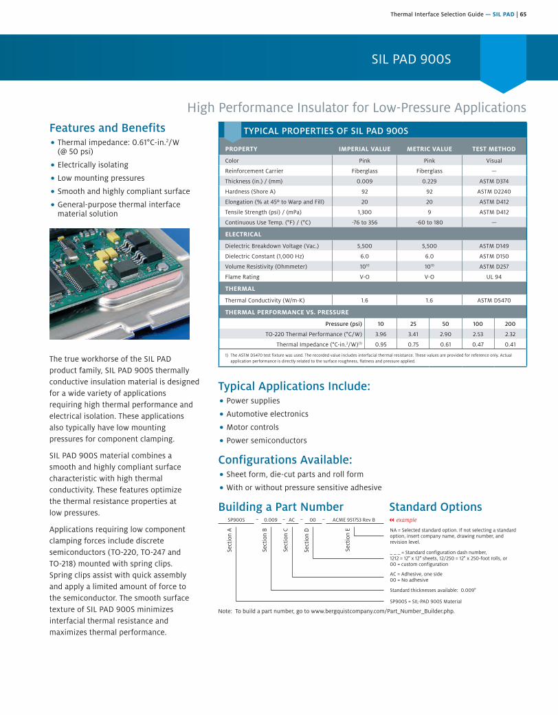
Thermal Interface Selection Guide — SIL PAD | 65
SIL PAD 900S
High Performance Insulator for Low-Pressure ApplicationsFeatures and Benefits• Thermal impedance: 0.61°C-in.2/W
(@ 50 psi)
• Electrically isolating
• Low mounting pressures
• Smooth and highly compliant surface
• General-purpose thermal interfacematerial solution
The true workhorse of the SIL PAD product family, SIL PAD 900S thermally conductive insulation material is designed for a wide variety of applications requiring high thermal performance and electrical isolation. These applications also typically have low mounting pressures for component clamping.
SIL PAD 900S material combines a smooth and highly compliant surface characteristic with high thermal conductivity. These features optimize the thermal resistance properties at low pressures.
Applications requiring low component clamping forces include discrete semiconductors (TO-220, TO-247 and TO-218) mounted with spring clips. Spring clips assist with quick assembly and apply a limited amount of force to the semiconductor. The smooth surface texture of SIL PAD 900S minimizes interfacial thermal resistance and maximizes thermal performance.
Typical Applications Include:• Power supplies
• Automotive electronics
• Motor controls
• Power semiconductors
Configurations Available:• Sheet form, die-cut parts and roll form
• With or without pressure sensitive adhesive
Building a Part Number Standard Options
Sect
ion
A
Sect
ion
B
Sect
ion
C
Sect
ion
D
Sect
ion
E NA = Selected standard option. If not selecting a standardoption, insert company name, drawing number, andrevision level.
SP900S = SIL-PAD 900S Material
SP900S 0.009 AC 00 ACME 951753 Rev B
Note: To build a part number, go to www.bergquistcompany.com/Part_Number_Builder.php.
Standard thicknesses available: 0.009"
AC = Adhesive, one side00 = No adhesive
_ _ _ = Standard configuration dash number, 1212 = 12" x 12" sheets, 12/250 = 12" x 250-foot rolls, or00 = custom configuration
– – – – || example
TYPICAL PROPERTIES OF SIL PAD 900S
PROPERTY IMPERIAL VALUE METRIC VALUE TEST METHOD
Color Pink Pink Visual
Reinforcement Carrier Fiberglass Fiberglass —
Thickness (in.) / (mm) 0.009 0.229 ASTM D374
Hardness (Shore A) 92 92 ASTM D2240
Elongation (% at 45º to Warp and Fill) 20 20 ASTM D412
Tensile Strength (psi) / (mPa) 1,300 9 ASTM D412
Continuous Use Temp. (°F) / (°C) -76 to 356 -60 to 180 —
ELECTRICAL
Dielectric Breakdown Voltage (Vac.) 5,500 5,500 ASTM D149
Dielectric Constant (1,000 Hz) 6.0 6.0 ASTM D150
Volume Resistivity (Ohmmeter) 1010 1010 ASTM D257
Flame Rating V-O V-O UL 94
THERMAL
Thermal Conductivity (W/m-K) 1.6 1.6 ASTM D5470
THERMAL PERFORMANCE VS. PRESSURE
Pressure (psi) 10 25 50 100 200
TO-220 Thermal Performance (°C/W) 3.96 3.41 2.90 2.53 2.32
Thermal Impedance (°C-in.2/W)(1) 0.95 0.75 0.61 0.47 0.41
1) The ASTM D5470 test fixture was used. The recorded value includes interfacial thermal resistance. These values are provided for reference only. Actual application performance is directly related to the surface roughness, flatness and pressure applied.
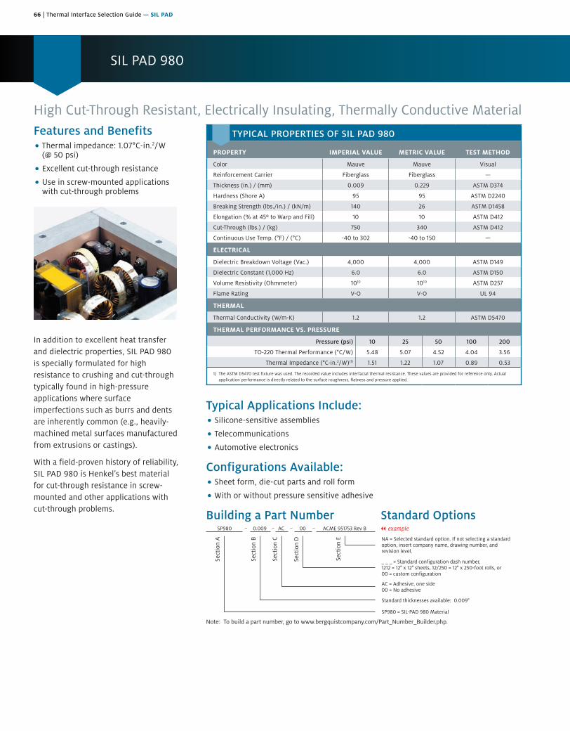
66 | Thermal Interface Selection Guide — SIL PAD
SIL PAD 980
Features and Benefits• Thermal impedance: 1.07°C-in.2/W
(@ 50 psi)
• Excellent cut-through resistance
• Use in screw-mounted applicationswith cut-through problems
In addition to excellent heat transfer and dielectric properties, SIL PAD 980 is specially formulated for high resistance to crushing and cut-through typically found in high-pressure applications where surface imperfections such as burrs and dents are inherently common (e.g., heavily-machined metal surfaces manufactured from extrusions or castings).
With a field-proven history of reliability, SIL PAD 980 is Henkel’s best material for cut-through resistance in screw-mounted and other applications with cut-through problems.
High Cut-Through Resistant, Electrically Insulating, Thermally Conductive Material
Typical Applications Include:• Silicone-sensitive assemblies
• Telecommunications
• Automotive electronics
Configurations Available:• Sheet form, die-cut parts and roll form
• With or without pressure sensitive adhesive
Building a Part Number Standard Options
Sect
ion
A
Sect
ion
B
Sect
ion
C
Sect
ion
D
Sect
ion
E NA = Selected standard option. If not selecting a standardoption, insert company name, drawing number, andrevision level.
SP980 = SIL-PAD 980 Material
SP980 0.009 AC 00 ACME 951753 Rev B
Note: To build a part number, go to www.bergquistcompany.com/Part_Number_Builder.php.
Standard thicknesses available: 0.009"
AC = Adhesive, one side00 = No adhesive
_ _ _ = Standard configuration dash number, 1212 = 12" x 12" sheets, 12/250 = 12" x 250-foot rolls, or00 = custom configuration
– – – – || example
TYPICAL PROPERTIES OF SIL PAD 980
PROPERTY IMPERIAL VALUE METRIC VALUE TEST METHOD
Color Mauve Mauve Visual
Reinforcement Carrier Fiberglass Fiberglass —
Thickness (in.) / (mm) 0.009 0.229 ASTM D374
Hardness (Shore A) 95 95 ASTM D2240
Breaking Strength (lbs./in.) / (kN/m) 140 26 ASTM D1458
Elongation (% at 45º to Warp and Fill) 10 10 ASTM D412
Cut-Through (lbs.) / (kg) 750 340 ASTM D412
Continuous Use Temp. (°F) / (°C) -40 to 302 -40 to 150 —
ELECTRICAL
Dielectric Breakdown Voltage (Vac.) 4,000 4,000 ASTM D149
Dielectric Constant (1,000 Hz) 6.0 6.0 ASTM D150
Volume Resistivity (Ohmmeter) 1010 1010 ASTM D257
Flame Rating V-O V-O UL 94
THERMAL
Thermal Conductivity (W/m-K) 1.2 1.2 ASTM D5470
THERMAL PERFORMANCE VS. PRESSURE
Pressure (psi) 10 25 50 100 200
TO-220 Thermal Performance (°C/W) 5.48 5.07 4.52 4.04 3.56
Thermal Impedance (°C-in.2/W)(1) 1.51 1.22 1.07 0.89 0.53
1) The ASTM D5470 test fixture was used. The recorded value includes interfacial thermal resistance. These values are provided for reference only. Actual application performance is directly related to the surface roughness, flatness and pressure applied.
Affordable, Electrically Insulating, Thermally Conductive, Soft Tack Elastomeric Material
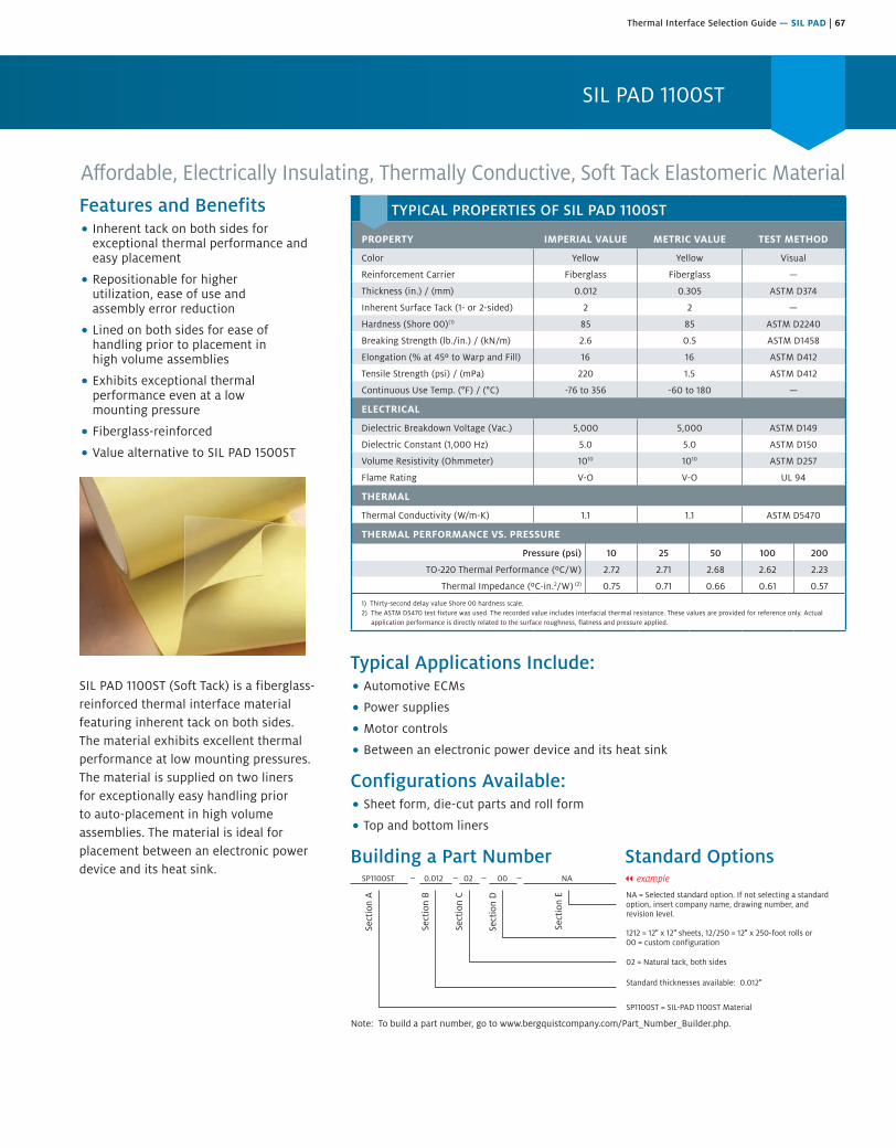
Thermal Interface Selection Guide — SIL PAD | 67
SIL PAD 1100ST
Affordable, Electrically Insulating, Thermally Conductive, Soft Tack Elastomeric MaterialFeatures and Benefits• Inherent tack on both sides for
exceptional thermal performance andeasy placement
• Repositionable for higherutilization, ease of use andassembly error reduction
• Lined on both sides for ease ofhandling prior to placement inhigh volume assemblies
• Exhibits exceptional thermalperformance even at a lowmounting pressure
• Fiberglass-reinforced
• Value alternative to SIL PAD 1500ST
SIL PAD 1100ST (Soft Tack) is a fiberglass-reinforced thermal interface material featuring inherent tack on both sides. The material exhibits excellent thermal performance at low mounting pressures. The material is supplied on two liners for exceptionally easy handling prior to auto-placement in high volume assemblies. The material is ideal for placement between an electronic power device and its heat sink.
Typical Applications Include:• Automotive ECMs
• Power supplies
• Motor controls
• Between an electronic power device and its heat sink
Configurations Available:• Sheet form, die-cut parts and roll form
• Top and bottom liners
Building a Part Number Standard Options
Sect
ion
A
Sect
ion
B
Sect
ion
C
Sect
ion
D
Sect
ion
E
Note: To build a part number, go to www.bergquistcompany.com/Part_Number_Builder.php.
SP1100ST 0.012 02 00 NA || example
NA = Selected standard option. If not selecting a standardoption, insert company name, drawing number, andrevision level.
SP1100ST = SIL-PAD 1100ST Material
Standard thicknesses available: 0.012"
02 = Natural tack, both sides
1212 = 12" x 12" sheets, 12/250 = 12" x 250-foot rolls or00 = custom configuration
TYPICAL PROPERTIES OF SIL PAD 1100ST
PROPERTY IMPERIAL VALUE METRIC VALUE TEST METHOD
Color Yellow Yellow Visual
Reinforcement Carrier Fiberglass Fiberglass —
Thickness (in.) / (mm) 0.012 0.305 ASTM D374
Inherent Surface Tack (1- or 2-sided) 2 2 —
Hardness (Shore 00)(1) 85 85 ASTM D2240
Breaking Strength (lb./in.) / (kN/m) 2.6 0.5 ASTM D1458
Elongation (% at 45º to Warp and Fill) 16 16 ASTM D412
Tensile Strength (psi) / (mPa) 220 1.5 ASTM D412
Continuous Use Temp. (°F) / (°C) -76 to 356 -60 to 180 —
ELECTRICAL
Dielectric Breakdown Voltage (Vac.) 5,000 5,000 ASTM D149
Dielectric Constant (1,000 Hz) 5.0 5.0 ASTM D150
Volume Resistivity (Ohmmeter) 1010 1010 ASTM D257
Flame Rating V-O V-O UL 94
THERMAL
Thermal Conductivity (W/m-K) 1.1 1.1 ASTM D5470
THERMAL PERFORMANCE VS. PRESSURE
Pressure (psi) 10 25 50 100 200
TO-220 Thermal Performance (ºC/W) 2.72 2.71 2.68 2.62 2.23
Thermal Impedance (ºC-in.2/W) (2) 0.75 0.71 0.66 0.61 0.57
1) Thirty-second delay value Shore 00 hardness scale.2) The ASTM D5470 test fixture was used. The recorded value includes interfacial thermal resistance. These values are provided for reference only. Actual
application performance is directly related to the surface roughness, flatness and pressure applied.
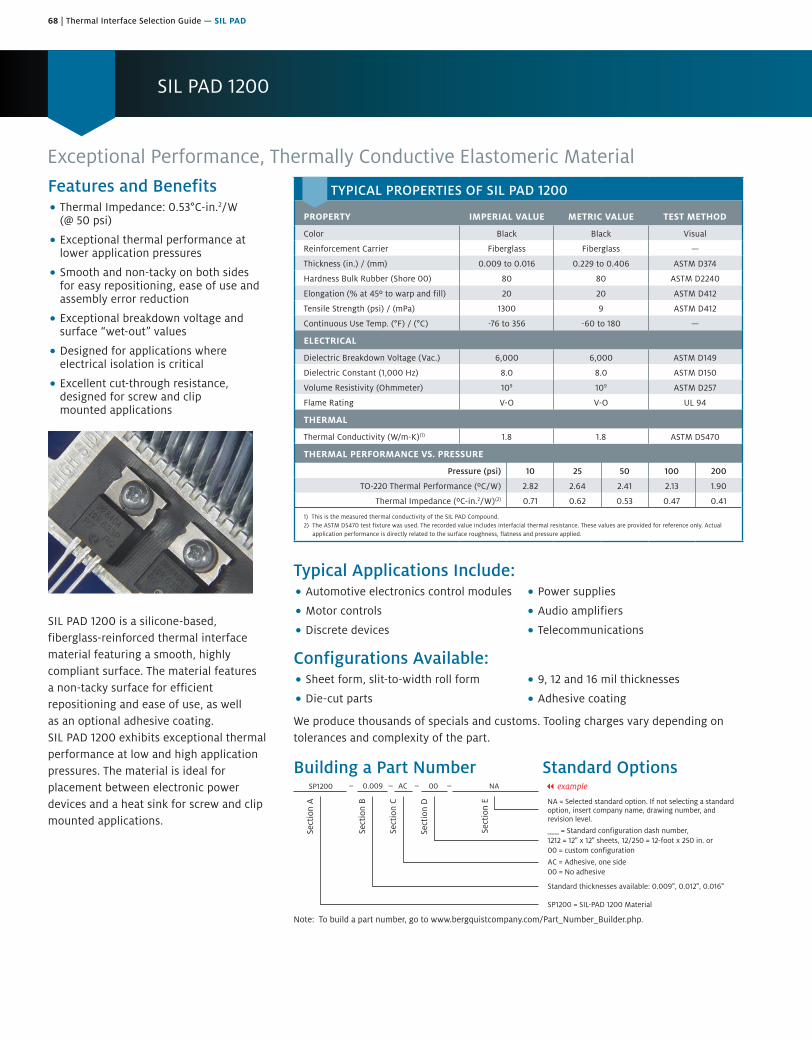
68 | Thermal Interface Selection Guide — SIL PAD
SIL PAD 1200
Exceptional Performance, Thermally Conductive Elastomeric MaterialFeatures and Benefits• Thermal Impedance: 0.53°C-in.2/W
(@ 50 psi)
• Exceptional thermal performance atlower application pressures
• Smooth and non-tacky on both sidesfor easy repositioning, ease of use andassembly error reduction
• Exceptional breakdown voltage andsurface “wet-out” values
• Designed for applications whereelectrical isolation is critical
• Excellent cut-through resistance,designed for screw and clipmounted applications
SIL PAD 1200 is a silicone-based, fiberglass-reinforced thermal interface material featuring a smooth, highly compliant surface. The material features a non-tacky surface for efficient repositioning and ease of use, as well as an optional adhesive coating. SIL PAD 1200 exhibits exceptional thermal performance at low and high application pressures. The material is ideal for placement between electronic power devices and a heat sink for screw and clip mounted applications.
Typical Applications Include:• Automotive electronics control modules
• Motor controls
• Discrete devices
• Power supplies
• Audio amplifiers
• Telecommunications
Configurations Available:• Sheet form, slit-to-width roll form
• Die-cut parts
• 9, 12 and 16 mil thicknesses
• Adhesive coating
We produce thousands of specials and customs. Tooling charges vary depending on tolerances and complexity of the part.
Building a Part Number Standard OptionsSP1200
AC = Adhesive, one side00 = No adhesive
SP1200 = SIL-PAD 1200 Material
Standard thicknesses available: 0.009", 0.012", 0.016"
AC
___ = Standard configuration dash number,1212 = 12" x 12" sheets, 12/250 = 12-foot x 250 in. or 00 = custom configuration
0.009 || example
Sect
ion
A
Sect
ion
B
Sect
ion
C
Sect
ion
D
Sect
ion
E
Note: To build a part number, go to www.bergquistcompany.com/Part_Number_Builder.php.
00 NA
NA = Selected standard option. If not selecting a standardoption, insert company name, drawing number, andrevision level.
TYPICAL PROPERTIES OF SIL PAD 1200
PROPERTY IMPERIAL VALUE METRIC VALUE TEST METHOD
Color Black Black Visual
Reinforcement Carrier Fiberglass Fiberglass —
Thickness (in.) / (mm) 0.009 to 0.016 0.229 to 0.406 ASTM D374
Hardness Bulk Rubber (Shore 00) 80 80 ASTM D2240
Elongation (% at 45º to warp and fill) 20 20 ASTM D412
Tensile Strength (psi) / (mPa) 1300 9 ASTM D412
Continuous Use Temp. (°F) / (°C) -76 to 356 -60 to 180 —
ELECTRICAL
Dielectric Breakdown Voltage (Vac.) 6,000 6,000 ASTM D149
Dielectric Constant (1,000 Hz) 8.0 8.0 ASTM D150
Volume Resistivity (Ohmmeter) 109 109 ASTM D257
Flame Rating V-O V-O UL 94
THERMAL
Thermal Conductivity (W/m-K)(1) 1.8 1.8 ASTM D5470
THERMAL PERFORMANCE VS. PRESSURE
Pressure (psi) 10 25 50 100 200
TO-220 Thermal Performance (ºC/W) 2.82 2.64 2.41 2.13 1.90
Thermal Impedance (ºC-in.2/W)(2) 0.71 0.62 0.53 0.47 0.41
1) This is the measured thermal conductivity of the SIL PAD Compound.2) The ASTM D5470 test fixture was used. The recorded value includes interfacial thermal resistance. These values are provided for reference only. Actual
application performance is directly related to the surface roughness, flatness and pressure applied.

Thermal Interface Selection Guide — SIL PAD | 69
SIL PAD A1500
Features and Benefits• Thermal impedance: 0.42°C-in.2/W
(@ 50 psi)
• Elastomeric compound coated onboth sides
SIL PAD A1500 is a silicone-based, thermally conductive and electrically insulating material. It consists of a cured silicone elastomeric compound coated on both sides of a fiberglass reinforcement layer.
SIL PAD A1500 performs well under clamping pressure up to 200 psi and is an excellent choice for high performance applications requiring electrical isolation and cut-through resistance.
Electrically Insulating, Thermally Conductive Elastomeric Material
Typical Applications Include:• Power supplies
• Automotive electronics
• Motor controls
• Power semiconductors
Configurations Available:• Sheet form, die-cut parts, and roll form
• With or without pressure sensitive adhesive
Building a Part Number Standard Options
Sect
ion
A
Sect
ion
B
Sect
ion
C
Sect
ion
D
Sect
ion
E NA = Selected standard option. If not selecting a standardoption, insert company name, drawing number, andrevision level.
SPA1500 = SIL-PAD A1500 Material
SPA1500 0.010 AC 12/250 NA
Note: To build a part number, go to www.bergquistcompany.com/Part_Number_Builder.php.
Standard thicknesses available: 0.010"
AC = Adhesive, one side00 = No adhesive
_ _ _ = Standard configuration dash number, 1212 = 12" x 12" sheets, 12/250 = 12" x 250' rolls, or00 = custom configuration
– – – – || example
TYPICAL PROPERTIES OF SIL PAD A1500
PROPERTY IMPERIAL VALUE METRIC VALUE TEST METHOD
Color Green Green Visual
Reinforcement Carrier Fiberglass Fiberglass —
Thickness (in.) / (mm) 0.010 0.254 ASTM D374
Hardness (Shore A) 80 80 ASTM D2240
Breaking Strength (lbs./in.) / (kN/m) 65 12 ASTM D1458
Elongation (% at 45° to Warp and Fill) 40 40 ASTM D412
Continuous Use Temp. (°F) / (°C) -76 to 356 -60 to 180 —
ELECTRICAL
Dielectric Breakdown Voltage (Vac.) 6,000 6,000 ASTM D149
Dielectric Constant (1,000 Hz) 7.0 7.0 ASTM D150
Volume Resistivity (Ohmmeter) 1011 1011 ASTM D257
Flame Rating V-O V-O UL 94
THERMAL
Thermal Conductivity (W/m-K) 2.0 2.0 ASTM D5470
THERMAL PERFORMANCE VS. PRESSURE
Pressure (psi) 10 25 50 100 200
TO-220 Thermal Performance (°C/W) 3.03 2.62 2.21 1.92 1.78
Thermal Impedance (°C-in.2/W)(1) 0.59 0.50 0.42 0.34 0.31
1) The ASTM D5470 test fixture was used. The recorded value includes interfacial thermal resistance. These values are provided for reference only. Actual application performance is directly related to the surface roughness, flatness and pressure applied.

70 | Thermal Interface Selection Guide — SIL PAD
SIL PAD 1500ST
Features and Benefits• Thermal impedance: 0.23°C-in.2/W
(@ 50 psi)
• Naturally tacky on both sides
• Pad is repositionable
• Excellent thermal performance
• Auto-placement and dispensable
SIL PAD 1500ST (Soft Tack) is a fiberglass-reinforced thermal interface material that is naturally tacky on both sides. SIL PAD 1500ST exhibits exceptional thermal performance.
SIL PAD 1500ST is supplied in sheet or roll form for outstanding auto-dispensing and auto-placement in high volume assemblies. SIL PAD 1500ST is intended for placement between an electronic power device and its heat sink.
Typical Applications Include:• Power supplies
• Power semiconductors
• Aerospace
• Motor controls
Configurations Available:• Sheet form, die-cut parts and slit-to-width roll form
Building a Part Number Standard Options
Sect
ion
A
Sect
ion
B
Sect
ion
C
Sect
ion
D
Sect
ion
E NA = Selected standard option. If not selecting a standardoption, insert company name, drawing number, andrevision level.
SP1500ST = SIL-PAD 1500ST Material
SP1500ST 0.008 02 1012 NA
Note: To build a part number, go to www.bergquistcompany.com/Part_Number_Builder.php.
Standard thicknesses available: 0.008"
02 = Natural tack, both sides
_ _ _ = Standard configuration dash number, 1012 = 10" x 12" sheets, 10/250 = 10" x 250-foot rolls, or 00 = custom configuration
– – – – || example
Electrically Insulating, Thermally Conductive, Soft Tack Elastomeric Material
TYPICAL PROPERTIES OF SIL PAD 1500ST
PROPERTY IMPERIAL VALUE METRIC VALUE TEST METHOD
Color Blue Blue Visual
Reinforcement Carrier Fiberglass Fiberglass —
Thickness (in.) / (mm) 0.008 0.203 ASTM D374
Hardness (Shore 00) 75 75 ASTM D2240
Breaking Strength (lbs./in.) / (kN/m) 1.9 0.34 ASTM D1458
Elongation (% at 45º to Warp and Fill) 22 22 ASTM D412
Tensile Strength (psi) / (mPa) 238 1.6 ASTM D412
Continuous Use Temp. (°F) / (°C) -76 to 356 -60 to 180 —
ELECTRICAL
Dielectric Breakdown Voltage (Vac.) 3,000 3,000 ASTM D149
Dielectric Constant (1,000 Hz) 6.1 6.1 ASTM D150
Volume Resistivity (Ohmmeter) 1011 1011 ASTM D257
Flame Rating V-O V-O UL 94
THERMAL
Thermal Conductivity (W/m-K) 1.8 1.8 ASTM D5470
THERMAL PERFORMANCE VS. PRESSURE
Pressure (psi) 10 25 50 100 200
TO-220 Thermal Performance (°C/W) 1.54 1.52 1.51 1.49 1.46
Thermal Impedance (°C-in.2/W)(1) 0.37 0.28 0.23 0.21 0.20
1) The ASTM D5470 test fixture was used. The recorded value includes interfacial thermal resistance. These values are provided for reference only. Actual application performance is directly related to the surface roughness, flatness and pressure applied.
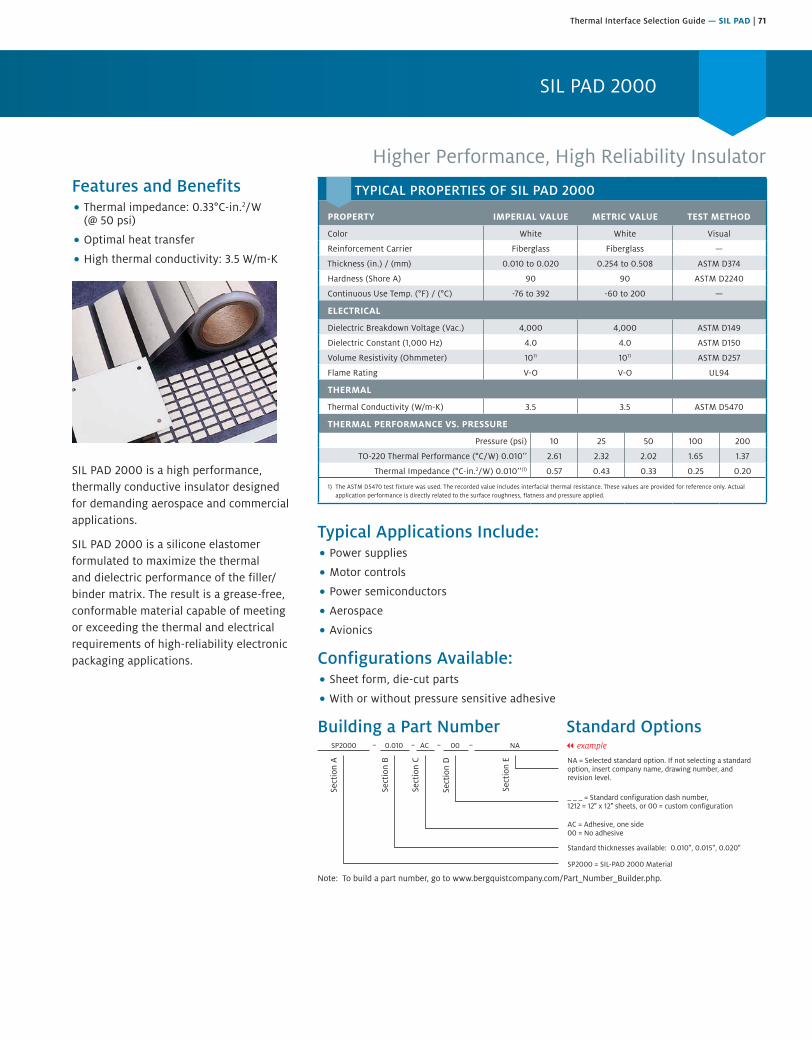
Thermal Interface Selection Guide — SIL PAD | 71
SIL PAD 2000
Higher Performance, High Reliability InsulatorFeatures and Benefits• Thermal impedance: 0.33°C-in.2/W
(@ 50 psi)
• Optimal heat transfer
• High thermal conductivity: 3.5 W/m-K
SIL PAD 2000 is a high performance, thermally conductive insulator designed for demanding aerospace and commercial applications.
SIL PAD 2000 is a silicone elastomer formulated to maximize the thermal and dielectric performance of the filler/binder matrix. The result is a grease-free, conformable material capable of meeting or exceeding the thermal and electrical requirements of high-reliability electronic packaging applications.
Typical Applications Include:• Power supplies
• Motor controls
• Power semiconductors
• Aerospace
• Avionics
Configurations Available:• Sheet form, die-cut parts
• With or without pressure sensitive adhesive
Building a Part Number Standard Options
Sect
ion
A
Sect
ion
B
Sect
ion
C
Sect
ion
D
Sect
ion
E NA = Selected standard option. If not selecting a standardoption, insert company name, drawing number, andrevision level.
SP2000 = SIL-PAD 2000 Material
SP2000 0.010 AC 00 NA
Note: To build a part number, go to www.bergquistcompany.com/Part_Number_Builder.php.
Standard thicknesses available: 0.010", 0.015", 0.020"
AC = Adhesive, one side00 = No adhesive
_ _ _ = Standard configuration dash number, 1212 = 12" x 12" sheets, or 00 = custom configuration
– – – – || example
TYPICAL PROPERTIES OF SIL PAD 2000
PROPERTY IMPERIAL VALUE METRIC VALUE TEST METHOD
Color White White Visual
Reinforcement Carrier Fiberglass Fiberglass —
Thickness (in.) / (mm) 0.010 to 0.020 0.254 to 0.508 ASTM D374
Hardness (Shore A) 90 90 ASTM D2240
Continuous Use Temp. (°F) / (°C) -76 to 392 -60 to 200 —
ELECTRICAL
Dielectric Breakdown Voltage (Vac.) 4,000 4,000 ASTM D149
Dielectric Constant (1,000 Hz) 4.0 4.0 ASTM D150
Volume Resistivity (Ohmmeter) 1011 1011 ASTM D257
Flame Rating V-O V-O UL94
THERMAL
Thermal Conductivity (W/m-K) 3.5 3.5 ASTM D5470
THERMAL PERFORMANCE VS. PRESSURE
Pressure (psi) 10 25 50 100 200
TO-220 Thermal Performance (°C/W) 0.010’’ 2.61 2.32 2.02 1.65 1.37
Thermal Impedance (°C-in.2/W) 0.010’’(1) 0.57 0.43 0.33 0.25 0.20
1) The ASTM D5470 test fixture was used. The recorded value includes interfacial thermal resistance. These values are provided for reference only. Actual application performance is directly related to the surface roughness, flatness and pressure applied.
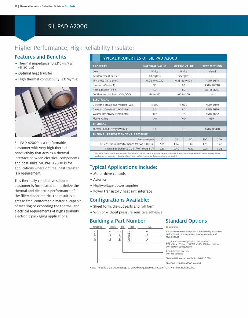
72 | Thermal Interface Selection Guide — SIL PAD
SIL PAD A2000
Features and Benefits• Thermal impedance: 0.32°C-in.2/W
(@ 50 psi)
• Optimal heat transfer
• High thermal conductivity: 3.0 W/m-K
SIL PAD A2000 is a conformable elastomer with very high thermal conductivity that acts as a thermal interface between electrical components and heat sinks. SIL PAD A2000 is for applications where optimal heat transfer is a requirement.
This thermally conductive silicone elastomer is formulated to maximize the thermal and dielectric performance of the filler/binder matrix. The result is a grease-free, conformable material capable of meeting or exceeding the thermal and electrical requirements of high reliability electronic packaging applications.
Higher Performance, High Reliability Insulator
Typical Applications Include:• Motor drive controls
• Avionics
• High-voltage power supplies
• Power transistor / heat sink interface
Configurations Available:• Sheet form, die-cut parts and roll form
• With or without pressure sensitive adhesive
Building a Part Number Standard Options
Sect
ion
A
Sect
ion
B
Sect
ion
C
Sect
ion
D
Sect
ion
E NA = Selected standard option. If not selecting a standardoption, insert company name, drawing number, andrevision level.
SPA2000 = SIL-PAD A2000 Material
SPA2000 0.015 00 1012 NA
Note: To build a part number, go to www.bergquistcompany.com/Part_Number_Builder.php.
Standard thicknesses available: 0.015", 0.020"
AC = Adhesive, one side00 = No adhesive
_ _ _ = Standard configuration dash number, 1012 = 10" x 12" sheets, 10/250 = 10" x 250-foot rolls, or00 = custom configuration
– – – – || example
TYPICAL PROPERTIES OF SIL PAD A2000
PROPERTY IMPERIAL VALUE METRIC VALUE TEST METHOD
Color White White Visual
Reinforcement Carrier Fiberglass Fiberglass —
Thickness (in.) / (mm) 0.015 to 0.020 0.381 to 0.508 ASTM D374
Hardness (Shore A) 90 90 ASTM D2240
Heat Capacity ( J/g-K) 1.0 1.0 ASTM E1269
Continuous Use Temp. (°F) / (°C) -76 to 392 -60 to 200 —
ELECTRICAL
Dielectric Breakdown Voltage (Vac.) 4,000 4,000 ASTM D149
Dielectric Constant (1,000 Hz) 7.0 7.0 ASTM D150
Volume Resistivity (Ohmmeter) 1011 1011 ASTM D257
Flame Rating V-O V-O UL94
THERMAL
Thermal Conductivity (W/m-K) 3.0 3.0 ASTM D5470
THERMAL PERFORMANCE VS. PRESSURE
Pressure (psi) 10 25 50 100 200
TO-220 Thermal Performance (°C/W) 0.015 in. 2.05 1.94 1.86 1.79 1.72
Thermal Impedance (°C-in.2/W) 0.015 in.(1) 0.53 0.40 0.32 0.28 0.26
1) The ASTM D5470 test fixture was used. The recorded value includes interfacial thermal resistance. These values are provided for reference only. Actual application performance is directly related to the surface roughness, flatness and pressure applied.

Thermal Interface Selection Guide — SIL PAD | 73
SIL PAD K-4
The Polyimide-Based InsulatorFeatures and Benefits• Thermal impedance: 0.48°C-in.2/W
(@ 50 psi)
• Withstands high voltages
• High dielectric strength
• Very durable
SIL PAD K-4 uses a specially developed film which has high thermal conductivity, high dielectric strength and is very durable. SIL PAD K-4 combines the thermal transfer properties of well-known SIL PAD rubber with the physical properties of a film.
SIL PAD K-4 is a durable insulator that withstands high voltages and requires no thermal grease to transfer heat. SIL PAD K-4 is available in customized shapes and sizes.
Typical Applications Include:• Power supplies
• Motor controls
• Power semiconductors
Configurations Available:• Sheet form, die-cut parts and roll form
• With or without pressure sensitive adhesive
Building a Part Number Standard Options
Sect
ion
A
Sect
ion
B
Sect
ion
C
Sect
ion
D
Sect
ion
E NA = Selected standard option. If not selecting a standardoption, insert company name, drawing number, andrevision level.
SPK4 = SIL-PAD K4 Material
SPK4 0.006 00 11.512 NA
Note: To build a part number, go to www.bergquistcompany.com/Part_Number_Builder.php.
Standard thicknesses available: 0.006"
AC = Adhesive, one side00 = No adhesive
_ _ _ = Standard configuration dash number, 11.512 = 11.5" x 12" sheets, 11.5/250 = 11.5" x 250-foot rolls,or 00 = custom configuration
– – – – || example
TYPICAL PROPERTIES OF SIL PAD K-4
PROPERTY IMPERIAL VALUE METRIC VALUE TEST METHOD
Color Grey Grey Visual
Reinforcement Carrier Polyimide Polyimide —
Thickness (in.) / (mm) 0.006 0.152 ASTM D374
Hardness (Shore A) 90 90 ASTM D2240
Breaking Strength (lbs./in.) / (kN/m) 30 5 ASTM D1458
Elongation (%) 40 40 ASTM D412
Tensile Strength (psi) / (mPa) 5,000 34 ASTM D412
Continuous Use Temp. (°F) / (°C) -76 to 356 -60 to 180 —
ELECTRICAL
Dielectric Breakdown Voltage (Vac.) 6,000 6,000 ASTM D149
Dielectric Constant (1,000 Hz) 5.0 5.0 ASTM D150
Volume Resistivity (Ohmmeter) 1012 1012 ASTM D257
Flame Rating VTM-O VTM-O UL 94
THERMAL
Thermal Conductivity (W/m-K) 0.9 0.9 ASTM D5470
THERMAL PERFORMANCE VS. PRESSURE
Pressure (psi) 10 25 50 100 200
TO-220 Thermal Performance (°C/W) 3.66 3.43 3.13 2.74 2.42
Thermal Impedance (°C-in.2/W)(1) 1.07 0.68 0.48 0.42 0.38
1) The ASTM D5470 test fixture was used. The recorded value includes interfacial thermal resistance. These values are provided for reference only. Actual application performance is directly related to the surface roughness, flatness and pressure applied.

74 | Thermal Interface Selection Guide — SIL PAD
SIL PAD K-6
Features and Benefits• Thermal impedance: 0.49°C-in.2/W
(@ 50 psi)
• Physically strong dielectric barrieragainst cut-through
• Medium performance film
SIL PAD K-6 is a medium performance, film-based thermally conductive insulator. The film is coated with a silicone elastomer to deliver high performance and provide a continuous, physically strong dielectric barrier against “cut-through” and resultant assembly failures.
The Medium Performance Polyimide-Based Insulator
Typical Applications Include:• Power supplies
• Motor controls
• Power semiconductors
Configurations Available:• Sheet form, die-cut parts and roll form
• With or without pressure sensitive adhesive
Building a Part Number Standard Options
Sect
ion
A
Sect
ion
B
Sect
ion
C
Sect
ion
D
Sect
ion
E NA = Selected standard option. If not selecting a standardoption, insert company name, drawing number, andrevision level.
SPK6 = SIL-PAD K6 Material
SPK6 0.006 AC 11.512 NA
Note: To build a part number, go to www.bergquistcompany.com/Part_Number_Builder.php.
Standard thicknesses available: 0.006"
AC = Adhesive, one side00 = No adhesive
_ _ _ = Standard configuration dash number, 11.512 = 11.5" x 12" sheets, 11.5/250 = 11.5" x 250-foot rolls,or 00 = custom configuration
– – – – || example
TYPICAL PROPERTIES OF SIL PAD K-6
PROPERTY IMPERIAL VALUE METRIC VALUE TEST METHOD
Color Blue-green Blue-green Visual
Reinforcement Carrier Polyimide Polyimide —
Thickness (in.) / (mm) 0.006 0.152 ASTM D374
Hardness (Shore A) 90 90 ASTM D2240
Breaking Strength (lbs./in.) / (kN/m) 30 5 ASTM D1458
Elongation (%) 40 40 ASTM D412
Tensile Strength (psi) / (mPa) 5,000 34 ASTM D412
Continuous Use Temp. (°F) / (°C) -76 to 356 -60 to 180 —
ELECTRICAL
Dielectric Breakdown Voltage (Vac.) 6,000 6,000 ASTM D149
Dielectric Constant (1,000 Hz) 4.0 4.0 ASTM D150
Volume Resistivity (Ohmmeter) 1012 1012 ASTM D257
Flame Rating VTM-O VTM-O UL 94
THERMAL
Thermal Conductivity (W/m-K) 1.1 1.1 ASTM D5470
THERMAL PERFORMANCE VS. PRESSURE
Pressure (psi) 10 25 50 100 200
TO-220 Thermal Performance (°C/W) 3.24 3.03 2.76 2.45 2.24
Thermal Impedance (°C-in.2/W)(1) 0.82 0.62 0.49 0.41 0.36
1) The ASTM D5470 test fixture was used. The recorded value includes interfacial thermal resistance. These values are provided for reference only. Actual application performance is directly related to the surface roughness, flatness and pressure applied.
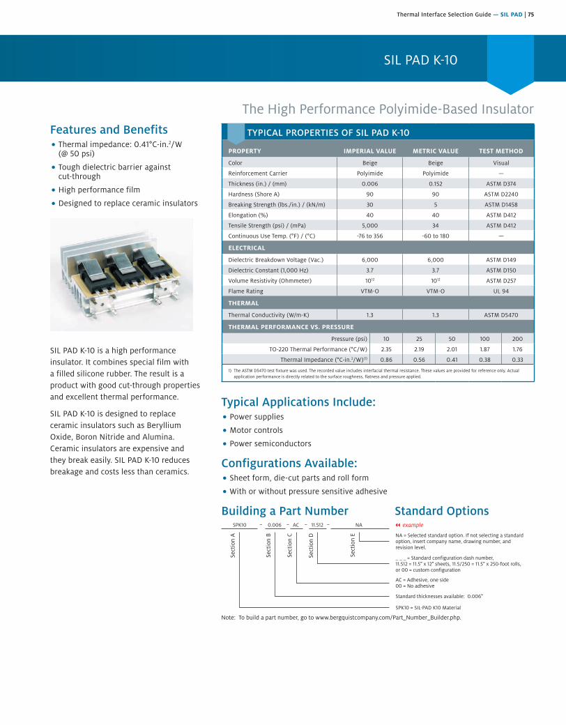
Thermal Interface Selection Guide — SIL PAD | 75
SIL PAD K-10
The High Performance Polyimide-Based InsulatorFeatures and Benefits• Thermal impedance: 0.41°C-in.2/W
(@ 50 psi)
• Tough dielectric barrier againstcut-through
• High performance film
• Designed to replace ceramic insulators
SIL PAD K-10 is a high performance insulator. It combines special film with a filled silicone rubber. The result is a product with good cut-through properties and excellent thermal performance.
SIL PAD K-10 is designed to replace ceramic insulators such as Beryllium Oxide, Boron Nitride and Alumina. Ceramic insulators are expensive and they break easily. SIL PAD K-10 reduces breakage and costs less than ceramics.
Typical Applications Include:• Power supplies
• Motor controls
• Power semiconductors
Configurations Available:• Sheet form, die-cut parts and roll form
• With or without pressure sensitive adhesive
Building a Part Number Standard Options
Sect
ion
A
Sect
ion
B
Sect
ion
C
Sect
ion
D
Sect
ion
E NA = Selected standard option. If not selecting a standardoption, insert company name, drawing number, andrevision level.
SPK10 = SIL-PAD K10 Material
SPK10 0.006 AC 11.512 NA
Note: To build a part number, go to www.bergquistcompany.com/Part_Number_Builder.php.
Standard thicknesses available: 0.006"
AC = Adhesive, one side00 = No adhesive
_ _ _ = Standard configuration dash number, 11.512 = 11.5" x 12" sheets, 11.5/250 = 11.5" x 250-foot rolls,or 00 = custom configuration
– – – – || example
TYPICAL PROPERTIES OF SIL PAD K-10
PROPERTY IMPERIAL VALUE METRIC VALUE TEST METHOD
Color Beige Beige Visual
Reinforcement Carrier Polyimide Polyimide —
Thickness (in.) / (mm) 0.006 0.152 ASTM D374
Hardness (Shore A) 90 90 ASTM D2240
Breaking Strength (lbs./in.) / (kN/m) 30 5 ASTM D1458
Elongation (%) 40 40 ASTM D412
Tensile Strength (psi) / (mPa) 5,000 34 ASTM D412
Continuous Use Temp. (°F) / (°C) -76 to 356 -60 to 180 —
ELECTRICAL
Dielectric Breakdown Voltage (Vac.) 6,000 6,000 ASTM D149
Dielectric Constant (1,000 Hz) 3.7 3.7 ASTM D150
Volume Resistivity (Ohmmeter) 1012 1012 ASTM D257
Flame Rating VTM-O VTM-O UL 94
THERMAL
Thermal Conductivity (W/m-K) 1.3 1.3 ASTM D5470
THERMAL PERFORMANCE VS. PRESSURE
Pressure (psi) 10 25 50 100 200
TO-220 Thermal Performance (°C/W) 2.35 2.19 2.01 1.87 1.76
Thermal Impedance (°C-in.2/W)(1) 0.86 0.56 0.41 0.38 0.33
1) The ASTM D5470 test fixture was used. The recorded value includes interfacial thermal resistance. These values are provided for reference only. Actual application performance is directly related to the surface roughness, flatness and pressure applied.

76 | Thermal Interface Selection Guide — Q-PAD
Q-PAD II
Features and Benefits• Thermal impedance: 0.22°C-in.2/W
(@ 50 psi)
• Maximum heat transfer
• Aluminum foil-coated both sides
• Designed to replace thermal grease
Q-Pad II is a composite of aluminumfoil-coated on both sides with thermally/electrically conductive SIL PAD rubber.The material is designed for thoseapplications in which maximum heattransfer is needed and electrical isolationis not required. Q-PAD II is the idealthermal interface material to replacemessy thermal grease compounds.
Q-PAD II eliminates problems associatedwith grease such as contamination ofreflow solder or cleaning operations.Unlike grease, Q-PAD II can be usedprior to these operations. Q-PAD IIalso eliminates dust collection whichcan cause possible surface shortingor heat buildup.
Foil-Format Grease Replacement for Maximum Heat Transfer
Typical Applications Include:• Between a transistor and a heat sink
• Between two large surfaces such as an L-bracket and the chassis of an assembly
• Between a heat sink and a chassis
• Under electrically isolated power modules or devices such as resistors,transformers and solid state relays
Configurations Available:• Sheet form, die-cut parts and roll form
• With or without pressure sensitive adhesive
Building a Part Number Standard Options|| example
Sect
ion
A
Sect
ion
B
Sect
ion
C
Sect
ion
D
Sect
ion
E
Note: To build a part number, go to www.bergquistcompany.com/Part_Number_Builder.php.
QII 0.006 AC 1212 NA
NA = Selected standard option. If not selecting a standardoption, insert company name, drawing number, andrevision level.
QII = Q-PAD II Material
Standard thicknesses available: 0.006"
AC = Adhesive, one side00 = No adhesive
_ _ _ = Standard configuration dash number, 1212 = 12" x 12" sheets, 12/250 = 12" x 250-foot rolls, or00 = custom configuration
TYPICAL PROPERTIES OF Q-PAD II
PROPERTY IMPERIAL VALUE METRIC VALUE TEST METHOD
Color Black Black Visual
Reinforcement Carrier Aluminum Aluminum —
Thickness (in.) / (mm) 0.006 0.152 ASTM D374
Hardness (Shore A) 93 93 ASTM D2240
Continuous Use Temp. (°F) / (°C) -76 to 356 -60 to 180 —
ELECTRICAL
Dielectric Breakdown Voltage (Vac.) Non-Insulating Non-Insulating ASTM D149
Dielectric Constant (1,000 Hz) N/A N/A ASTM D150
Volume Resistivity (Ohmmeter) 102 102 ASTM D257
Flame Rating V-O V-O UL 94
THERMAL
Thermal Conductivity (W/m-K) 2.5 2.5 ASTM D5470
THERMAL PERFORMANCE VS. PRESSURE
Pressure (psi) 10 25 50 100 200
TO-220 Thermal Performance (°C/W) 2.44 1.73 1.23 1.05 0.92
Thermal Impedance (°C-in.2/W)(1) 0.52 0.30 0.22 0.15 0.12
1) The ASTM D5470 test fixture was used. The recorded value includes interfacial thermal resistance. These values are provided for reference only. Actual application performance is directly related to the surface roughness, flatness and pressure applied.
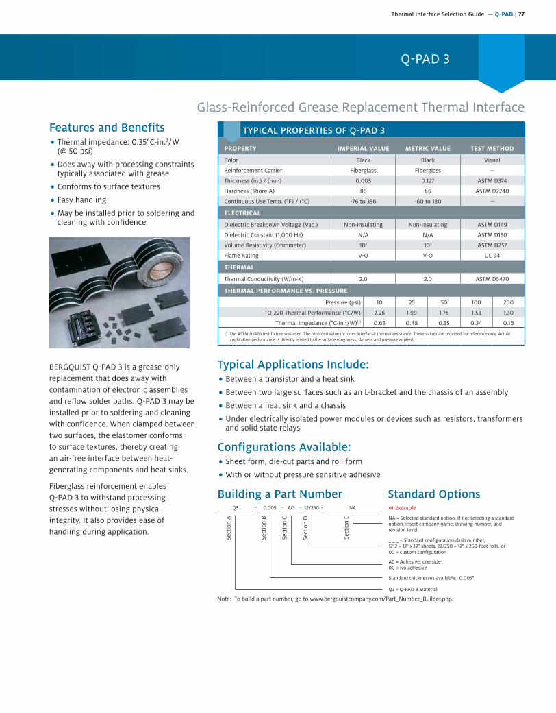
Thermal Interface Selection Guide — Q-PAD | 77
Q-PAD 3
Glass-Reinforced Grease Replacement Thermal InterfaceFeatures and Benefits• Thermal impedance: 0.35°C-in.2/W
(@ 50 psi)
• Does away with processing constraintstypically associated with grease
• Conforms to surface textures
• Easy handling
• May be installed prior to soldering andcleaning with confidence
BERGQUIST Q-PAD 3 is a grease-only replacement that does away with contamination of electronic assemblies and reflow solder baths. Q-PAD 3 may be installed prior to soldering and cleaning with confidence. When clamped between two surfaces, the elastomer conforms to surface textures, thereby creating an air-free interface between heat-generating components and heat sinks.
Fiberglass reinforcement enables Q-PAD 3 to withstand processingstresses without losing physicalintegrity. It also provides ease ofhandling during application.
Typical Applications Include:• Between a transistor and a heat sink
• Between two large surfaces such as an L-bracket and the chassis of an assembly
• Between a heat sink and a chassis
• Under electrically isolated power modules or devices such as resistors, transformersand solid state relays
Configurations Available:• Sheet form, die-cut parts and roll form
• With or without pressure sensitive adhesive
Building a Part Number Standard Options
Sect
ion
A
Sect
ion
B
Sect
ion
C
Sect
ion
D
Sect
ion
E NA = Selected standard option. If not selecting a standardoption, insert company name, drawing number, andrevision level.
Q3 = Q-PAD 3 Material
Q3 0.005 AC 12/250 NA
Note: To build a part number, go to www.bergquistcompany.com/Part_Number_Builder.php.
Standard thicknesses available: 0.005"
AC = Adhesive, one side00 = No adhesive
_ _ _ = Standard configuration dash number, 1212 = 12" x 12" sheets, 12/250 = 12" x 250-foot rolls, or00 = custom configuration
– – – – || example
TYPICAL PROPERTIES OF Q-PAD 3
PROPERTY IMPERIAL VALUE METRIC VALUE TEST METHOD
Color Black Black Visual
Reinforcement Carrier Fiberglass Fiberglass —
Thickness (in.) / (mm) 0.005 0.127 ASTM D374
Hardness (Shore A) 86 86 ASTM D2240
Continuous Use Temp. (°F) / (°C) -76 to 356 -60 to 180 —
ELECTRICAL
Dielectric Breakdown Voltage (Vac.) Non-Insulating Non-Insulating ASTM D149
Dielectric Constant (1,000 Hz) N/A N/A ASTM D150
Volume Resistivity (Ohmmeter) 102 102 ASTM D257
Flame Rating V-O V-O UL 94
THERMAL
Thermal Conductivity (W/m-K) 2.0 2.0 ASTM D5470
THERMAL PERFORMANCE VS. PRESSURE
Pressure (psi) 10 25 50 100 200
TO-220 Thermal Performance (°C/W) 2.26 1.99 1.76 1.53 1.30
Thermal Impedance (°C-in.2/W)(1) 0.65 0.48 0.35 0.24 0.16
1) The ASTM D5470 test fixture was used. The recorded value includes interfacial thermal resistance. These values are provided for reference only. Actual application performance is directly related to the surface roughness, flatness and pressure applied.

78 | Thermal Interface Selection Guide — POLY-PAD
POLY-PAD 400
Polyester-Based, Thermally Conductive Insulation MaterialFeatures and Benefits• Thermal impedance: 1.13°C-in.2/W
(@ 50 psi)
• Polyester-based
• For applications requiring conformalcoatings
• Designed for silicone-sensitive standardapplications
POLY-PAD 400 is a fiberglass-reinforced insulator coated with a filled polyester resin. POLY-PAD 400 is economical and designed for most standard applications.
Polyester-based, thermally conductive BERGQUIST insulators provide a complete family of materials for silicone-sensitive applications. POLY-PADs are ideally suited for applications requiring conformal coatings or applications where silicone contamination is a concern (telecomm and certain aerospace applications). POLY-PADs are constructed with ceramic-filled polyester resins coating either side of a fiberglass carrier or a film carrier. The POLY-PAD family offers a complete range of performance characteristics to match individual applications.
Typical Applications Include:• Power supplies
• Automotive electronics
• Motor controls
• Power semiconductors
Configurations Available:• Sheet form, die-cut parts and roll form
• With or without pressure sensitive adhesive
• We produce thousands of specials. Tooling charges vary depending on tolerancesand the complexity of the part.
Building a Part Number Standard Options
Sect
ion
A
Sect
ion
B
Sect
ion
C
Sect
ion
D
Sect
ion
E NA = Selected standard option. If not selecting a standardoption, insert company name, drawing number, andrevision level.
PP400 = POLY-PAD 400 Material
PP400 0.009 00 1212 NA
Note: To build a part number, go to www.bergquistcompany.com/Part_Number_Builder.php.
Standard thicknesses available: 0.009"
AC = Adhesive, one side00 = No adhesive
_ _ _ = Standard configuration dash number, 1212 = 12" x 12" sheets, 12/250 = 12" x 250-foot rolls, or00 = custom configuration
– – – – || example
TYPICAL PROPERTIES OF POLY-PAD 400
PROPERTY IMPERIAL VALUE METRIC VALUE TEST METHOD
Color Tan Tan Visual
Reinforcement Carrier Fiberglass Fiberglass —
Thickness (in.) / (mm) 0.009 0.229 ASTM D374
Hardness (Shore A) 90 90 ASTM D2240
Breaking Strength (lbs./in.)/(kN/m) 100 18 ASTM D1458
Elongation(% at 45° to Warp and Fill) 10 10 ASTM D412
Tensile Strength (psi) / (mPa) 7,000 48 ASTM D412
Continuous Use Temp. (°F) / (°C) -4 to 302 -20 to 150 —
ELECTRICAL
Dielectric Breakdown Voltage (Vac.) 2,500 2,500 ASTM D149
Dielectric Constant (1,000 Hz) 5.5 5.5 ASTM D150
Volume Resistivity (Ohmmeter) 1011 1011 ASTM D257
THERMAL
Thermal Conductivity (W/m-K) 0.9 0.9 ASTM D5470
Flame Rating V-O V-O UL 94
THERMAL PERFORMANCE VS. PRESSURE
Pressure (psi) 10 25 50 100 200
TO-220 Thermal Performance (°C/W) 5.85 5.61 5.13 4.59 4.12
Thermal Impedance (°C-in.2/W)(1) 1.62 1.35 1.13 0.86 0.61
1) The ASTM D5470 test fixture was used. The recorded value includes interfacial thermal resistance. These values are provided for reference only. Actual application performance is directly related to the surface roughness, flatness and pressure applied.
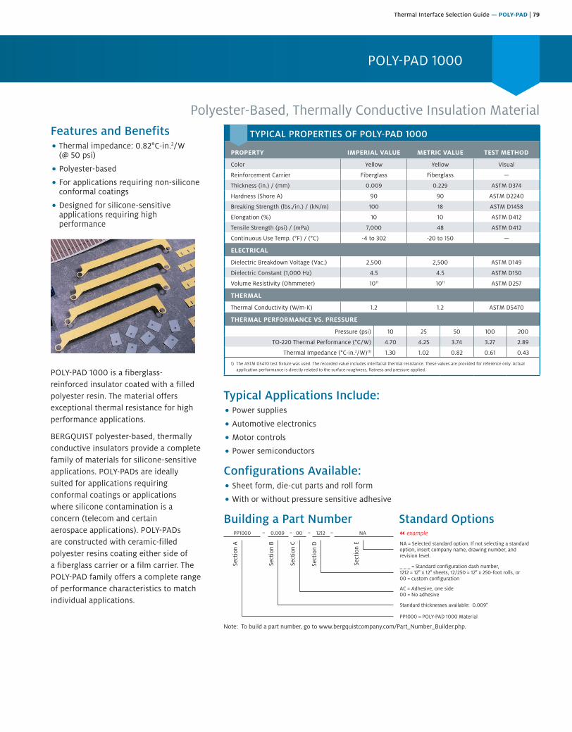
Thermal Interface Selection Guide — POLY-PAD | 79
POLY-PAD 1000
Polyester-Based, Thermally Conductive Insulation MaterialFeatures and Benefits• Thermal impedance: 0.82°C-in.2/W
(@ 50 psi)
• Polyester-based
• For applications requiring non-siliconeconformal coatings
• Designed for silicone-sensitiveapplications requiring highperformance
POLY-PAD 1000 is a fiberglass-reinforced insulator coated with a filled polyester resin. The material offers exceptional thermal resistance for high performance applications.
BERGQUIST polyester-based, thermally conductive insulators provide a complete family of materials for silicone-sensitive applications. POLY-PADs are ideally suited for applications requiring conformal coatings or applications where silicone contamination is a concern (telecom and certain aerospace applications). POLY-PADs are constructed with ceramic-filled polyester resins coating either side of a fiberglass carrier or a film carrier. The POLY-PAD family offers a complete range of performance characteristics to match individual applications.
Typical Applications Include:• Power supplies
• Automotive electronics
• Motor controls
• Power semiconductors
Configurations Available:• Sheet form, die-cut parts and roll form
• With or without pressure sensitive adhesive
Building a Part Number Standard Options
Sect
ion
A
Sect
ion
B
Sect
ion
C
Sect
ion
D
Sect
ion
E NA = Selected standard option. If not selecting a standardoption, insert company name, drawing number, andrevision level.
PP1000 = POLY-PAD 1000 Material
PP1000 0.009 00 1212 NA
Note: To build a part number, go to www.bergquistcompany.com/Part_Number_Builder.php.
Standard thicknesses available: 0.009"
AC = Adhesive, one side00 = No adhesive
_ _ _ = Standard configuration dash number, 1212 = 12" x 12" sheets, 12/250 = 12" x 250-foot rolls, or00 = custom configuration
– – – – || example
TYPICAL PROPERTIES OF POLY-PAD 1000
PROPERTY IMPERIAL VALUE METRIC VALUE TEST METHOD
Color Yellow Yellow Visual
Reinforcement Carrier Fiberglass Fiberglass —
Thickness (in.) / (mm) 0.009 0.229 ASTM D374
Hardness (Shore A) 90 90 ASTM D2240
Breaking Strength (lbs./in.) / (kN/m) 100 18 ASTM D1458
Elongation (%) 10 10 ASTM D412
Tensile Strength (psi) / (mPa) 7,000 48 ASTM D412
Continuous Use Temp. (°F) / (°C) -4 to 302 -20 to 150 —
ELECTRICAL
Dielectric Breakdown Voltage (Vac.) 2,500 2,500 ASTM D149
Dielectric Constant (1,000 Hz) 4.5 4.5 ASTM D150
Volume Resistivity (Ohmmeter) 1011 1011 ASTM D257
THERMAL
Thermal Conductivity (W/m-K) 1.2 1.2 ASTM D5470
THERMAL PERFORMANCE VS. PRESSURE
Pressure (psi) 10 25 50 100 200
TO-220 Thermal Performance (°C/W) 4.70 4.25 3.74 3.27 2.89
Thermal Impedance (°C-in.2/W)(1) 1.30 1.02 0.82 0.61 0.43
1) The ASTM D5470 test fixture was used. The recorded value includes interfacial thermal resistance. These values are provided for reference only. Actual application performance is directly related to the surface roughness, flatness and pressure applied.
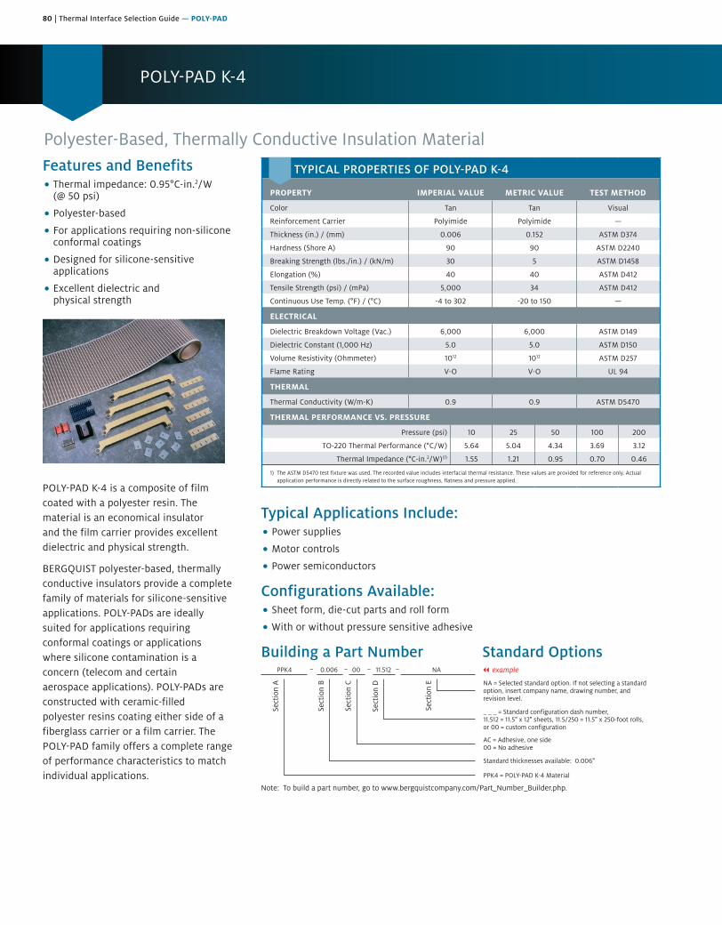
80 | Thermal Interface Selection Guide — POLY-PAD
POLY-PAD K-4
Features and Benefits• Thermal impedance: 0.95°C-in.2/W
(@ 50 psi)
• Polyester-based
• For applications requiring non-siliconeconformal coatings
• Designed for silicone-sensitiveapplications
• Excellent dielectric andphysical strength
POLY-PAD K-4 is a composite of film coated with a polyester resin. The material is an economical insulator and the film carrier provides excellent dielectric and physical strength.
BERGQUIST polyester-based, thermally conductive insulators provide a complete family of materials for silicone-sensitive applications. POLY-PADs are ideally suited for applications requiring conformal coatings or applications where silicone contamination is a concern (telecom and certain aerospace applications). POLY-PADs are constructed with ceramic-filled polyester resins coating either side of a fiberglass carrier or a film carrier. The POLY-PAD family offers a complete range of performance characteristics to match individual applications.
Polyester-Based, Thermally Conductive Insulation Material
Typical Applications Include:• Power supplies
• Motor controls
• Power semiconductors
Configurations Available:• Sheet form, die-cut parts and roll form
• With or without pressure sensitive adhesive
Building a Part Number Standard Options
Sect
ion
A
Sect
ion
B
Sect
ion
C
Sect
ion
D
Sect
ion
E NA = Selected standard option. If not selecting a standardoption, insert company name, drawing number, andrevision level.
PPK4 = POLY-PAD K-4 Material
PPK4 0.006 00 11.512 NA
Note: To build a part number, go to www.bergquistcompany.com/Part_Number_Builder.php.
Standard thicknesses available: 0.006"
AC = Adhesive, one side00 = No adhesive
_ _ _ = Standard configuration dash number, 11.512 = 11.5" x 12" sheets, 11.5/250 = 11.5" x 250-foot rolls,or 00 = custom configuration
– – – – || example
TYPICAL PROPERTIES OF POLY-PAD K-4
PROPERTY IMPERIAL VALUE METRIC VALUE TEST METHOD
Color Tan Tan Visual
Reinforcement Carrier Polyimide Polyimide —
Thickness (in.) / (mm) 0.006 0.152 ASTM D374
Hardness (Shore A) 90 90 ASTM D2240
Breaking Strength (lbs./in.) / (kN/m) 30 5 ASTM D1458
Elongation (%) 40 40 ASTM D412
Tensile Strength (psi) / (mPa) 5,000 34 ASTM D412
Continuous Use Temp. (°F) / (°C) -4 to 302 -20 to 150 —
ELECTRICAL
Dielectric Breakdown Voltage (Vac.) 6,000 6,000 ASTM D149
Dielectric Constant (1,000 Hz) 5.0 5.0 ASTM D150
Volume Resistivity (Ohmmeter) 1012 1012 ASTM D257
Flame Rating V-O V-O UL 94
THERMAL
Thermal Conductivity (W/m-K) 0.9 0.9 ASTM D5470
THERMAL PERFORMANCE VS. PRESSURE
Pressure (psi) 10 25 50 100 200
TO-220 Thermal Performance (°C/W) 5.64 5.04 4.34 3.69 3.12
Thermal Impedance (°C-in.2/W)(1) 1.55 1.21 0.95 0.70 0.46
1) The ASTM D5470 test fixture was used. The recorded value includes interfacial thermal resistance. These values are provided for reference only. Actual application performance is directly related to the surface roughness, flatness and pressure applied.
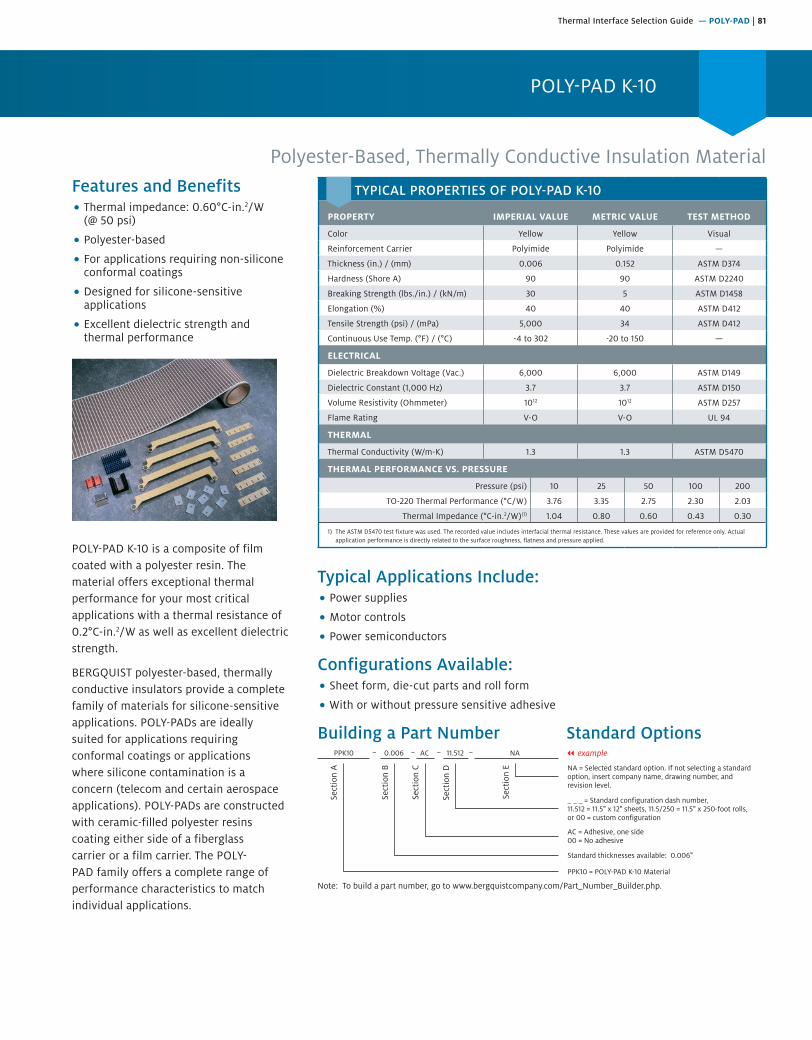
Thermal Interface Selection Guide — POLY-PAD | 81
POLY-PAD K-10
Polyester-Based, Thermally Conductive Insulation MaterialFeatures and Benefits• Thermal impedance: 0.60°C-in.2/W
(@ 50 psi)
• Polyester-based
• For applications requiring non-siliconeconformal coatings
• Designed for silicone-sensitiveapplications
• Excellent dielectric strength andthermal performance
POLY-PAD K-10 is a composite of film coated with a polyester resin. The material offers exceptional thermal performance for your most critical applications with a thermal resistance of 0.2°C-in.2/W as well as excellent dielectric strength.
BERGQUIST polyester-based, thermally conductive insulators provide a complete family of materials for silicone-sensitive applications. POLY-PADs are ideally suited for applications requiring conformal coatings or applications where silicone contamination is a concern (telecom and certain aerospace applications). POLY-PADs are constructed with ceramic-filled polyester resins coating either side of a fiberglass carrier or a film carrier. The POLY-PAD family offers a complete range of performance characteristics to match individual applications.
Typical Applications Include:• Power supplies
• Motor controls
• Power semiconductors
Configurations Available:• Sheet form, die-cut parts and roll form
• With or without pressure sensitive adhesive
Building a Part Number Standard Options
Sect
ion
A
Sect
ion
B
Sect
ion
C
Sect
ion
D
Sect
ion
E NA = Selected standard option. If not selecting a standardoption, insert company name, drawing number, andrevision level.
PPK10 = POLY-PAD K-10 Material
PPK10 0.006 AC 11.512 NA
Note: To build a part number, go to www.bergquistcompany.com/Part_Number_Builder.php.
Standard thicknesses available: 0.006"
AC = Adhesive, one side00 = No adhesive
_ _ _ = Standard configuration dash number, 11.512 = 11.5" x 12" sheets, 11.5/250 = 11.5" x 250-foot rolls,or 00 = custom configuration
– – – – || example
TYPICAL PROPERTIES OF POLY-PAD K-10
PROPERTY IMPERIAL VALUE METRIC VALUE TEST METHOD
Color Yellow Yellow Visual
Reinforcement Carrier Polyimide Polyimide —
Thickness (in.) / (mm) 0.006 0.152 ASTM D374
Hardness (Shore A) 90 90 ASTM D2240
Breaking Strength (lbs./in.) / (kN/m) 30 5 ASTM D1458
Elongation (%) 40 40 ASTM D412
Tensile Strength (psi) / (mPa) 5,000 34 ASTM D412
Continuous Use Temp. (°F) / (°C) -4 to 302 -20 to 150 —
ELECTRICAL
Dielectric Breakdown Voltage (Vac.) 6,000 6,000 ASTM D149
Dielectric Constant (1,000 Hz) 3.7 3.7 ASTM D150
Volume Resistivity (Ohmmeter) 1012 1012 ASTM D257
Flame Rating V-O V-O UL 94
THERMAL
Thermal Conductivity (W/m-K) 1.3 1.3 ASTM D5470
THERMAL PERFORMANCE VS. PRESSURE
Pressure (psi) 10 25 50 100 200
TO-220 Thermal Performance (°C/W) 3.76 3.35 2.75 2.30 2.03
Thermal Impedance (°C-in.2/W)(1) 1.04 0.80 0.60 0.43 0.30
1) The ASTM D5470 test fixture was used. The recorded value includes interfacial thermal resistance. These values are provided for reference only. Actual application performance is directly related to the surface roughness, flatness and pressure applied.

82 | Thermal Interface Selection Guide — SIL PAD Tubes
SIL PAD Tubes
Features and Benefits• Thermal conductivity: SPT 400 – 0.9
W/m-K SPT 1000 – 1.2 W/m-K
• For clip-mounted plasticpower packages
SPT 400 and SPT 1000 (SIL PAD Tubes) provide thermally conductive insulation for clip-mounted plastic power packages. SIL PAD Tubes are made of silicone rubber with high thermal conductivity.
SIL PAD Tube 1000 is best suited for higher thermal performance. SIL PAD Tube 400 is ideal for applications requiring average thermal conductivity and economy.
SIL PAD Tube 400 and SIL PAD Tube 1000 are designed to meet VDE, UL and TUV agency requirements.
Typical Applications Include:• Clip-mounted power semiconductors
• TO-220, TO-218, TO-247 and TO-3P
Configurations Available:• TO-220, TO-218, TO-247 and TO-3P
Silicone-Based, Thermally Conductive Tubes
Standard DimensionsA = Wall Thickness: .305 mm (.012 in.) + .10 mm/ -0.0 mm (+.004 in. / -0.0 in.)B = Inner Diameter: 11 mm (.433 in.) or 13.5 mm (.532 in.) ± 1.0 mm (± .039 in.)C = Length: 25 mm (.985 in.) or 30 mm (1.18 in.) +3.18 mm / -0.0 mm (+ .125 in. / - 0.0 in.)
Special lengths are available. For more information, contact a Henkel Sales Representative.
Ordering Procedure:
Sample: SPT 400 ___ - ___ - ___ “A” – “B” – “C”
A
B
C
TYPICAL PROPERTIES OF SIL PAD TUBE 400
PROPERTY IMPERIAL VALUE METRIC VALUE TEST METHOD
Color Grey/Green Grey/Green Visual
Thickness / Wall (in.) / (mm) 0.012 0.305 ASTM D374
Hardness (Shore A) 80 80 ASTM D2240
Breaking Strength (lbs./in.) / (kN/m) 6 1 ASTM D1458
Continuous Use Temp. (°F) / (°C) -76 to 356 -60 to 180 —
ELECTRICAL
Dielectric Breakdown Voltage (Vac.) 5,000 5,000 ASTM D149
Dielectric Constant (1,000 Hz) 5.5 5.5 ASTM D150
Volume Resistivity (Ohmmeter) 1011 1011 ASTM D257
Flame Rating V-O V-O UL 94
THERMAL
Thermal Conductivity (W/m-K) 0.9 0.9 ASTM D5470
Thermal Impedance (°C-in.2/W)(1) 0.6 0.6 ASTM D5470
TYPICAL PROPERTIES OF SIL PAD TUBE 1000
PROPERTY IMPERIAL VALUE METRIC VALUE TEST METHOD
Color Brown Brown Visual
Thickness / Wall (in.) / (mm) 0.012 0.30 ASTM D374
Hardness (Shore A) 80 80 ASTM D2240
Breaking Strength (lbs./in.) / (kN/m) 6 1 ASTM D1458
Continuous Use Temp. (°F) / (°C) -76 to 356 -60 to 180 —
ELECTRICAL
Dielectric Breakdown Voltage (Vac.) 5,000 5,000 ASTM D149
Dielectric Constant (1,000 Hz) 4.5 4.5 ASTM D150
Volume Resistivity (Ohmmeter) 1011 1011 ASTM D257
Flame Rating V-O V-O UL 94
THERMAL
Thermal Conductivity (W/m-K) 1.2 1.2 ASTM D5470
Thermal Impedance (°C-in.2/W)(1) 0.4 0.4 ASTM D5470
1) The ASTM D5470 test fixture was used. The recorded value includes interfacial thermal resistance. These values are provided for reference only. Actual application performance is directly related to the surface roughness, flatness and pressure applied.
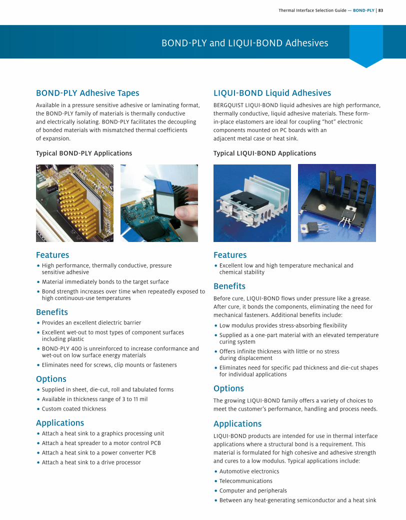
Thermal Interface Selection Guide — BOND-PLY | 83
BOND-PLY and LIQUI-BOND Adhesives
BOND-PLY Adhesive TapesAvailable in a pressure sensitive adhesive or laminating format, the BOND-PLY family of materials is thermally conductive and electrically isolating. BOND-PLY facilitates the decoupling of bonded materials with mismatched thermal coefficients of expansion.
Typical BOND-PLY Applications
Features• High performance, thermally conductive, pressure
sensitive adhesive
• Material immediately bonds to the target surface
• Bond strength increases over time when repeatedly exposed tohigh continuous-use temperatures
Benefits• Provides an excellent dielectric barrier
• Excellent wet-out to most types of component surfacesincluding plastic
• BOND-PLY 400 is unreinforced to increase conformance andwet-out on low surface energy materials
• Eliminates need for screws, clip mounts or fasteners
Options• Supplied in sheet, die-cut, roll and tabulated forms
• Available in thickness range of 3 to 11 mil
• Custom coated thickness
Applications• Attach a heat sink to a graphics processing unit
• Attach a heat spreader to a motor control PCB
• Attach a heat sink to a power converter PCB
• Attach a heat sink to a drive processor
LIQUI-BOND Liquid AdhesivesBERGQUIST LIQUI-BOND liquid adhesives are high performance, thermally conductive, liquid adhesive materials. These form-in-place elastomers are ideal for coupling “hot” electronic components mounted on PC boards with an adjacent metal case or heat sink.
Typical LIQUI-BOND Applications
Features• Excellent low and high temperature mechanical and
chemical stability
BenefitsBefore cure, LIQUI-BOND flows under pressure like a grease. After cure, it bonds the components, eliminating the need for mechanical fasteners. Additional benefits include:
• Low modulus provides stress-absorbing flexibility
• Supplied as a one-part material with an elevated temperaturecuring system
• Offers infinite thickness with little or no stressduring displacement
• Eliminates need for specific pad thickness and die-cut shapesfor individual applications
OptionsThe growing LIQUI-BOND family offers a variety of choices to meet the customer’s performance, handling and process needs.
ApplicationsLIQUI-BOND products are intended for use in thermal interface applications where a structural bond is a requirement. This material is formulated for high cohesive and adhesive strength and cures to a low modulus. Typical applications include:
• Automotive electronics
• Telecommunications
• Computer and peripherals
• Between any heat-generating semiconductor and a heat sink
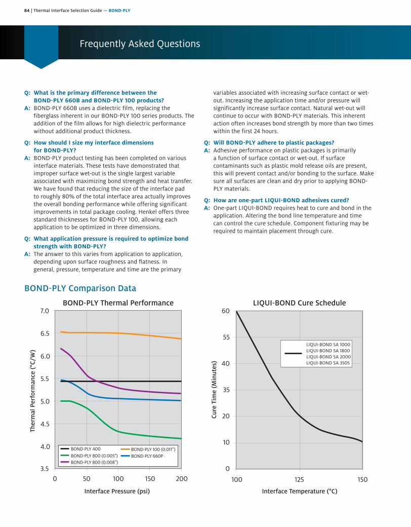
84 | Thermal Interface Selection Guide — BOND-PLY
Frequently Asked Questions
Q: What is the primary difference between the BOND-PLY 660B and BOND-PLY 100 products?
A: BOND-PLY 660B uses a dielectric film, replacing the fiberglass inherent in our BOND-PLY 100 series products. The addition of the film allows for high dielectric performance without additional product thickness.
Q: How should I size my interface dimensions for BOND-PLY?
A: BOND-PLY product testing has been completed on various interface materials. These tests have demonstrated that improper surface wet-out is the single largest variable associated with maximizing bond strength and heat transfer. We have found that reducing the size of the interface pad to roughly 80% of the total interface area actually improves the overall bonding performance while offering significant improvements in total package cooling. Henkel offers three standard thicknesses for BOND-PLY 100, allowing each application to be optimized in three dimensions.
Q: What application pressure is required to optimize bond strength with BOND-PLY?
A: The answer to this varies from application to application, depending upon surface roughness and flatness. In general, pressure, temperature and time are the primary
variables associated with increasing surface contact or wet-out. Increasing the application time and/or pressure will significantly increase surface contact. Natural wet-out will continue to occur with BOND-PLY materials. This inherent action often increases bond strength by more than two times within the first 24 hours.
Q: Will BOND-PLY adhere to plastic packages?A: Adhesive performance on plastic packages is primarily
a function of surface contact or wet-out. If surface contaminants such as plastic mold release oils are present, this will prevent contact and/or bonding to the surface. Make sure all surfaces are clean and dry prior to applying BOND-PLY materials.
Q: How are one-part LIQUI-BOND adhesives cured?A: One-part LIQUI-BOND requires heat to cure and bond in the
application. Altering the bond line temperature and time can control the cure schedule. Component fixturing may be required to maintain placement through cure.
BOND-PLY Comparison Data
3.5
4.0
4.5
5.0
5.5
6.0
6.5
7.0
0 50 100 150 200
BOND-PLY 800 (0.008”)BOND-PLY 800 (0.005”)BOND-PLY 400
LIQUI-BOND SA 1000LIQUI-BOND SA 1800LIQUI-BOND SA 2000LIQUI-BOND SA 3505
BOND-PLY 660PBOND-PLY 100 (0.011”)
Ther
mal
Per
form
ance
(°C
/W)
Cure
Tim
e (M
inut
es)
0
10
20
35
40
55
60
100 125 150
BOND-PLY Thermal Performance LIQUI-BOND Cure Schedule
Interface Pressure (psi) Interface Temperature (°C)
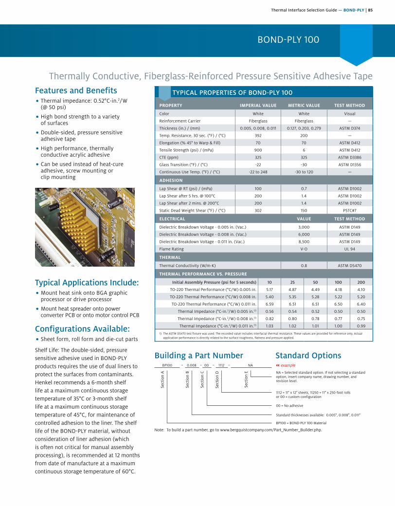
Thermal Interface Selection Guide — BOND-PLY | 85
BOND-PLY 100
Thermally Conductive, Fiberglass-Reinforced Pressure Sensitive Adhesive TapeFeatures and Benefits• Thermal impedance: 0.52°C-in.2/W
(@ 50 psi)
• High bond strength to a varietyof surfaces
• Double-sided, pressure sensitiveadhesive tape
• High performance, thermallyconductive acrylic adhesive
• Can be used instead of heat-cureadhesive, screw mounting orclip mounting
Typical Applications Include:• Mount heat sink onto BGA graphic
processor or drive processor
• Mount heat spreader onto powerconverter PCB or onto motor control PCB
Configurations Available:• Sheet form, roll form and die-cut parts
Shelf Life: The double-sided, pressure sensitive adhesive used in BOND-PLY products requires the use of dual liners to protect the surfaces from contaminants. Henkel recommends a 6-month shelf life at a maximum continuous storage temperature of 35°C or 3-month shelf life at a maximum continuous storage temperature of 45°C, for maintenance of controlled adhesion to the liner. The shelf life of the BOND-PLY material, without consideration of liner adhesion (which is often not critical for manual assembly processing), is recommended at 12 months from date of manufacture at a maximum continuous storage temperature of 60°C.
Building a Part Number Standard Options
Sect
ion
A
Sect
ion
B
Sect
ion
C
Sect
ion
D
Sect
ion
E NA = Selected standard option. If not selecting a standardoption, insert company name, drawing number, andrevision level.
BP100 = BOND-PLY 100 Material
BP100 0.008 00 1112 NA
Note: To build a part number, go to www.bergquistcompany.com/Part_Number_Builder.php.
Standard thicknesses available: 0.005", 0.008", 0.011"
00 = No adhesive
1112 = 11" x 12" sheets, 11250 = 11" x 250-foot rollsor 00 = custom configuration
– – – – || example
TYPICAL PROPERTIES OF BOND-PLY 100
PROPERTY IMPERIAL VALUE METRIC VALUE TEST METHOD
Color White White Visual
Reinforcement Carrier Fiberglass Fiberglass —
Thickness (in.) / (mm) 0.005, 0.008, 0.011 0.127, 0.203, 0.279 ASTM D374
Temp. Resistance, 30 sec. (°F) / (°C) 392 200 —
Elongation (% 45° to Warp & Fill) 70 70 ASTM D412
Tensile Strength (psi) / (mPa) 900 6 ASTM D412
CTE (ppm) 325 325 ASTM D3386
Glass Transition (°F) / (°C) -22 -30 ASTM D1356
Continuous Use Temp. (°F) / (°C) -22 to 248 -30 to 120 —
ADHESION
Lap Shear @ RT (psi) / (mPa) 100 0.7 ASTM D1002
Lap Shear after 5 hrs. @ 100°C 200 1.4 ASTM D1002
Lap Shear after 2 mins. @ 200°C 200 1.4 ASTM D1002
Static Dead Weight Shear (°F) / (°C) 302 150 PSTC#7
ELECTRICAL VALUE TEST METHOD
Dielectric Breakdown Voltage - 0.005 in. (Vac.) 3,000 ASTM D149
Dielectric Breakdown Voltage - 0.008 in. (Vac.) 6,000 ASTM D149
Dielectric Breakdown Voltage - 0.011 in. (Vac.) 8,500 ASTM D149
Flame Rating V-O UL 94
THERMAL
Thermal Conductivity (W/m-K) 0.8 ASTM D5470
THERMAL PERFORMANCE VS. PRESSURE
Initial Assembly Pressure (psi for 5 seconds) 10 25 50 100 200
TO-220 Thermal Performance (°C/W) 0.005 in. 5.17 4.87 4.49 4.18 4.10
TO-220 Thermal Performance (°C/W) 0.008 in. 5.40 5.35 5.28 5.22 5.20
TO-220 Thermal Performance (°C/W) 0.011 in. 6.59 6.51 6.51 6.50 6.40
Thermal Impedance (°C-in.2/W) 0.005 in.(1) 0.56 0.54 0.52 0.50 0.50
Thermal Impedance (°C-in.2/W) 0.008 in.(1) 0.82 0.80 0.78 0.77 0.75
Thermal Impedance (°C-in.2/W) 0.011 in.(1) 1.03 1.02 1.01 1.00 0.99
1) The ASTM D5470 test fixture was used. The recorded value includes interfacial thermal resistance. These values are provided for reference only. Actual application performance is directly related to the surface roughness, flatness and pressure applied.
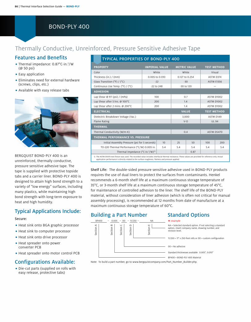
86 | Thermal Interface Selection Guide — BOND-PLY
BOND-PLY 400
Features and Benefits• Thermal impedance: 0.87°C-in.2/W
(@ 50 psi)
• Easy application
• Eliminates need for external hardware(screws, clips, etc.)
• Available with easy release tabs
BERGQUIST BOND-PLY 400 is an unreinforced, thermally conductive, pressure sensitive adhesive tape. The tape is supplied with protective topside tabs and a carrier liner. BOND-PLY 400 is designed to attain high bond strength to a variety of “low energy” surfaces, including many plastics, while maintaining high bond strength with long-term exposure to heat and high humidity.
Typical Applications Include:Secure:
• Heat sink onto BGA graphic processor
• Heat sink to computer processor
• Heat sink onto drive processor
• Heat spreader onto powerconverter PCB
• Heat spreader onto motor control PCB
Configurations Available:• Die-cut parts (supplied on rolls with
easy release, protective tabs)
Thermally Conductive, Unreinforced, Pressure Sensitive Adhesive Tape
Shelf Life: The double-sided pressure sensitive adhesive used in BOND-PLY products requires the use of dual liners to protect the surfaces from contaminants. Henkel recommends a 6-month shelf life at a maximum continuous storage temperature of 35°C, or 3-month shelf life at a maximum continuous storage temperature of 45°C, for maintenance of controlled adhesion to the liner. The shelf life of the BOND-PLY material, without consideration of liner adhesion (which is often not critical for manual assembly processing), is recommended at 12 months from date of manufacture at a maximum continuous storage temperature of 60°C.
Building a Part Number Standard Options
Sect
ion
A
Sect
ion
B
Sect
ion
C
Sect
ion
D
Sect
ion
E NA = Selected standard option. If not selecting a standardoption, insert company name, drawing number, andrevision level.
BP400 = BOND-PLY 400 Material
BP400 0.005 00 11/250 NA
Note: To build a part number, go to www.bergquistcompany.com/Part_Number_Builder.php.
Standard thicknesses available: 0.005", 0.010"
00 = No adhesive
11/250 = 11" x 250-foot rolls or 00 = custom configuration
– – – – || example
TYPICAL PROPERTIES OF BOND-PLY 400
PROPERTY IMPERIAL VALUE METRIC VALUE TEST METHOD
Color White White Visual
Thickness (in.) / (mm) 0.005 to 0.010 0.127 to 0.254 ASTM D374
Glass Transition (°F) / (°C) -22 -30 ASTM E1356
Continuous Use Temp. (°F) / (°C) -22 to 248 -30 to 120 —
ADHESION
Lap Shear @ RT (psi) / (mPa) 100 0.7 ASTM D1002
Lap Shear after 5 hrs. @ 100°C 200 1.4 ASTM D1002
Lap Shear after 2 mins. @ 200°C 200 1.4 ASTM D1002
ELECTRICAL VALUE TEST METHOD
Dielectric Breakdown Voltage (Vac.) 3,000 ASTM D149
Flame Rating V-O UL 94
THERMAL
Thermal Conductivity (W/m-K) 0.4 ASTM D5470
THERMAL PERFORMANCE VS. PRESSURE
Initial Assembly Pressure (psi for 5 seconds) 10 25 50 100 200
TO-220 Thermal Performance (°C/W) 0.005 in. 5.4 5.4 5.4 5.4 5.4
Thermal Impedance (°C-in.2/W)(1) 0.87
1) The ASTM D5470 test fixture was used. The recorded value includes interfacial thermal resistance. These values are provided for reference only. Actual application performance is directly related to the surface roughness, flatness and pressure applied.
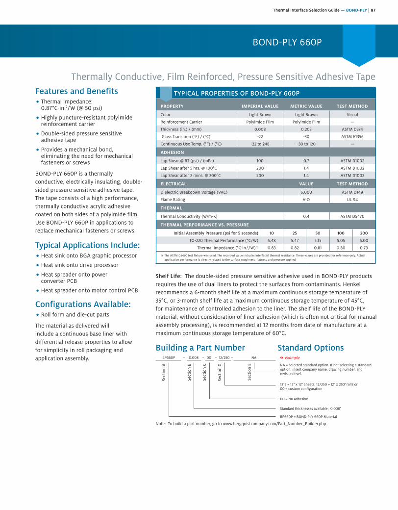
Thermal Interface Selection Guide — BOND-PLY | 87
BOND-PLY 660P
Features and Benefits• Thermal impedance:
0.87°C-in.2/W (@ 50 psi)
• Highly puncture-resistant polyimidereinforcement carrier
• Double-sided pressure sensitiveadhesive tape
• Provides a mechanical bond,eliminating the need for mechanicalfasteners or screws
BOND-PLY 660P is a thermally conductive, electrically insulating, double-sided pressure sensitive adhesive tape. The tape consists of a high performance, thermally conductive acrylic adhesive coated on both sides of a polyimide film. Use BOND-PLY 660P in applications to replace mechanical fasteners or screws.
Typical Applications Include:• Heat sink onto BGA graphic processor
• Heat sink onto drive processor
• Heat spreader onto powerconverter PCB
• Heat spreader onto motor control PCB
Configurations Available:• Roll form and die-cut parts
The material as delivered will include a continuous base liner with differential release properties to allow for simplicity in roll packaging and application assembly.
Thermally Conductive, Film Reinforced, Pressure Sensitive Adhesive Tape
Shelf Life: The double-sided pressure sensitive adhesive used in BOND-PLY products requires the use of dual liners to protect the surfaces from contaminants. Henkel recommends a 6-month shelf life at a maximum continuous storage temperature of 35°C, or 3-month shelf life at a maximum continuous storage temperature of 45°C, for maintenance of controlled adhesion to the liner. The shelf life of the BOND-PLY material, without consideration of liner adhesion (which is often not critical for manual assembly processing), is recommended at 12 months from date of manufacture at a maximum continuous storage temperature of 60°C.
Building a Part Number Standard Options
Sect
ion
A
Sect
ion
B
Sect
ion
C
Sect
ion
D
Sect
ion
E NA = Selected standard option. If not selecting a standardoption, insert company name, drawing number, andrevision level.
BP660P = BOND-PLY 660P Material
BP660P 0.008 00 12/250 NA
Note: To build a part number, go to www.bergquistcompany.com/Part_Number_Builder.php.
Standard thicknesses available: 0.008"
00 = No adhesive
1212 = 12" x 12" Sheets, 12/250 = 12" x 250' rolls or 00 = custom configuration
– – – – || example
TYPICAL PROPERTIES OF BOND-PLY 660P
PROPERTY IMPERIAL VALUE METRIC VALUE TEST METHOD
Color Light Brown Light Brown Visual
Reinforcement Carrier Polyimide Film Polyimide Film —
Thickness (in.) / (mm) 0.008 0.203 ASTM D374
Glass Transition (°F) / (°C) -22 -30 ASTM E1356
Continuous Use Temp. (°F) / (°C) -22 to 248 -30 to 120 —
ADHESION
Lap Shear @ RT (psi) / (mPa) 100 0.7 ASTM D1002
Lap Shear after 5 hrs. @ 100°C 200 1.4 ASTM D1002
Lap Shear after 2 mins. @ 200°C 200 1.4 ASTM D1002
ELECTRICAL VALUE TEST METHOD
Dielectric Breakdown Voltage (VAC) 6,000 ASTM D149
Flame Rating V-O UL 94
THERMAL
Thermal Conductivity (W/m-K) 0.4 ASTM D5470
THERMAL PERFORMANCE VS. PRESSURE
Initial Assembly Pressure (psi for 5 seconds) 10 25 50 100 200
TO-220 Thermal Performance (°C/W) 5.48 5.47 5.15 5.05 5.00
Thermal Impedance (°C-in.2/W)(1) 0.83 0.82 0.81 0.80 0.79
1) The ASTM D5470 test fixture was used. The recorded value includes interfacial thermal resistance. These values are provided for reference only. Actual application performance is directly related to the surface roughness, flatness and pressure applied.
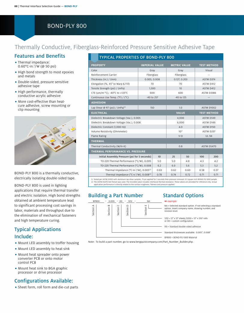
88 | Thermal Interface Selection Guide — BOND-PLY
BOND-PLY 800
Thermally Conductive, Fiberglass-Reinforced Pressure Sensitive Adhesive Tape
Building a Part Number Standard Options
Sect
ion
A
Sect
ion
B
Sect
ion
C
Sect
ion
D
Sect
ion
E NA = Selected standard option. If not selecting a standardoption, insert company name, drawing number, andrevision level.
BP800 = BOND-PLY 800 Material
BP800 0.005 00 1212 NA
Note: To build a part number, go to www.bergquistcompany.com/Part_Number_Builder.php.
Standard thicknesses available: 0.005", 0.008"
00 = Standard double-sided adhesive
1212 = 12" x 12" sheets,12250 = 12" x 250' rollsor 00 = custom configuration
– – – – || example
Features and Benefits• Thermal impedance:
0.60°C-in.2/W (@ 50 psi)
• High bond strength to most epoxiesand metals
• Double-sided, pressure sensitiveadhesive tape
• High performance, thermallyconductive acrylic adhesive
• More cost-effective than heat-cure adhesive, screw mounting orclip mounting
BOND-PLY 800 is a thermally conductive, electrically isolating double-sided tape.
BOND-PLY 800 is used in lighting applications that require thermal transfer and electric isolation. High bond strengths obtained at ambient temperature lead to significant processing cost savings in labor, materials and throughput due to the elimination of mechanical fasteners and high temperature curing.
Typical Applications Include:• Mount LED assembly to troffer housing
• Mount LED assembly to heat sink
• Mount heat spreader onto powerconverter PCB or onto motorcontrol PCB
• Mount heat sink to BGA graphicprocessor or drive processor
Configurations Available:• Sheet form, roll form and die-cut parts
TYPICAL PROPERTIES OF BOND-PLY 800
PROPERTY IMPERIAL VALUE METRIC VALUE TEST METHOD
Color Gray Gray Visual
Reinforcement Carrier Fiberglass Fiberglass —
Thickness (in.) / (mm) 0.005, 0.008 0.127, 0.203 ASTM D374
Elongation (%, 45° to Warp & Fill) 70 70 ASTM D412
Tensile Strength (psi) / (mPa) 1,500 10 ASTM D412
CTE (um/m-°C), -40°C to +125°C 600 600 ASTM D3386
Continuous Use Temp. (°F) / (°C) -40 to 257 -40 to 125 —
ADHESION
Lap Shear @ RT (psi) / (mPa)(1) 150 1.0 ASTM D1002
ELECTRICAL VALUE TEST METHOD
Dielectric Breakdown Voltage (Vac.), 0.005 4,000 ASTM D149
Dielectric Breakdown Voltage (Vac.), 0.008 6,000 ASTM D149
Dielectric Constant (1,000 Hz) 4.0 ASTM D150
Volume Resistivity (Ohmmeter) 1011 ASTM D257
Flame Rating V-O UL 94
THERMAL
Thermal Conductivity (W/m-K) 0.8 ASTM D5470
THERMAL PERFORMANCE VS. PRESSURE
Initial Assembly Pressure (psi for 5 seconds) 10 25 50 100 200
TO-220 Thermal Performance (°C/W), 0.005 5.0 5.0 4.8 4.3 4.2
TO-220 Thermal Performance (°C/W), 0.008 6.2 6.0 5.6 5.3 5.2
Thermal Impedance (°C-in.2/W), 0.005(2) 0.63 0.62 0.60 0.58 0.57
Thermal Impedance (°C-n.2/W), 0.008(2) 0.78 0.74 0.72 0.71 0.71
1) Tested per ASTM D1002 with aluminum lap shear samples, 75 psi applied for 5 seconds then pressure removed. 0.5 square inch BOND-PLY 800 sample.2) The ASTM D5470 test fixture was used. The recorded value includes interfacial thermal resistance. These values are provided for reference only. Actual
application performance is directly related to the surface roughness, flatness and pressure applied.

Thermal Interface Selection Guide — BOND-PLY | 89
BOND-PLY LMS-HD
Features and Benefits• TO-220 thermal performance: 2.3°C/W,
initial pressure only lamination
• Exceptional dielectric strength
• Very low interfacial resistance
• 200 psi adhesion strength
• Continuous use of -60 to 180°C
• Eliminates mechanical fasteners
BOND-PLY LMS-HD is a thermally conductive heat curable laminate material. The product consists of a high performance thermally conductive low modulus silicone compound coated on a cured core, and double lined with protective films. The low modulus silicone design effectively absorbs mechanical stresses induced by assembly-level CTE mismatch, shock and vibration while providing exceptional thermal performance (vs. PSA technologies) and long-term integrity. BOND-PLY LMS-HD will typically be used for structurally adhering power components and PCBs to a heat sink.
Liner
Liner
Uncured Silicone
DispersionFiberglass
Note: Not to scale
Cured CoreOverall
Thickness 10 or 12 mil
Typical Applications Include:• Discrete semiconductor packages
bonded to heat spreader or heat sink
Laminate Material – Silicone, High Durability, Optional Lamination Methods
Configurations Available:• Roll form
• Die-cut parts
• Sheet form
Shelf Life: BOND-PLY LMS-HD is a heat-cured material and should be stored in temperature controlled conditions. The recommended storage temperature range of 5-25°C should be used to maintain optimum characteristics for a 5-month shelf life.
Building a Part Number Standard Options
Sect
ion
A
Sect
ion
B
Sect
ion
C
Sect
ion
D
Sect
ion
E NA = Selected standard option. If not selecting a standardoption, insert company name, drawing number, andrevision level.
BPLMSHD = BOND-PLY LMS-HD Material
BPLMSHD 0.010 00 12/100 NA
Note: To build a part number, go to www.bergquistcompany.com/Part_Number_Builder.php.
Standard thicknesses available: 0.010", 0.012"
00 = No adhesive
1212 = 12" x 12" Sheets, 12/100 = 12" x 100' rolls
– – – – || example
TYPICAL PROPERTIES OF BOND-PLY LMS-HD
PROPERTY IMPERIAL VALUE METRIC VALUE TEST METHOD
Color Yellow Yellow Visual
Reinforcement Carrier Fiberglass Fiberglass —
Thickness (in.) / (mm) 0.010, 0.012 0.254, 0.305 ASTM D374
Continuous Use Temp. (°F) / (°C) -76 to 356 -60 to 180 —
ADHESION
Lap Shear @ RT (psi) / (mPa) 200 1.4 ASTM D1002
ELECTRICAL VALUE TEST METHOD
Breakdown Voltage, Sheet (Vac.)(1) 5,000 ASTM D149
Breakdown Voltage, Laminated (Vac.)(2) 4,000 ASTM D149
Dielectric Constant (1,000 Hz) 5.0 ASTM D150
Volume Resistivity (Ohmmeter) 1011 ASTM D257
Flame Rating V-O UL 94
THERMAL
Post-Cured Thermal Conductivity (W/m-K)(3) 1.4 ASTM D5470
THERMAL IMPEDANCE VS. LAMINATION METHOD
Lamination Pressure (75 psi)(4) Constant IPO
TO-220 Thermal Performance (°C/W) 2.1 2.3
CURE SCHEDULE
Cure @ 125°C (mins.)(5) 30 30
Cure @ 160°C (mins.)(5) 6 6
1) The ASTM D149 test method on cured LMS-HD material. No pressure was applied to the LMS-HD during the cure cycle. 2) A 1/2 in. diameter probe was laminated with LMS-HD to a 2 in. X 2 in. plate at 200 psi for 30 seconds, then cured with no pressure at 160°C for 6 minutes.
The cured assembly was then tested per ASTM D149. This LMS-HD sample resembles a typical lamination application. 3). The ASTM D5470 (Bergquist Modified) test procedure was used on post-cured LMS-HD material. The recorded value includes interfacial thermal resistance.
These values are given for customer reference only. 4). TO-220 Thermal Performance testing, per The Bergquist RD2010 specification for laminates, was completed on laminated TO-220 assemblies. Lamination
was completed at 75 psi for 30 seconds for “IPO” (Initial Pressure Only) and at a constant 75 psi during the lamination and curing process for “Constant.” No additional pressure was applied during TO-220 thermal performance testing.
5). Cure Schedule – time after cure temperature is achieved at the interface. Ramp time is application dependent.
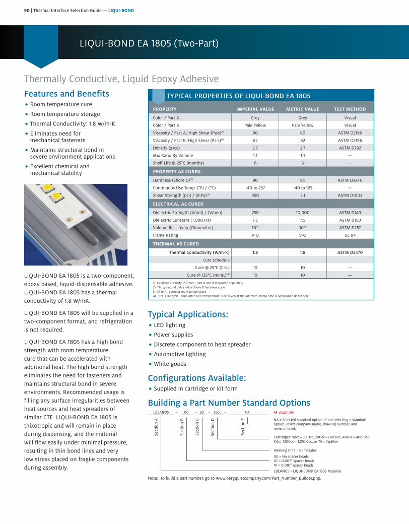
90 | Thermal Interface Selection Guide — LIQUI-BOND
LIQUI-BOND EA 1805 (Two-Part)
Thermally Conductive, Liquid Epoxy AdhesiveFeatures and Benefits• Room temperature cure
• Room temperature storage
• Thermal Conductivity: 1.8 W/m-K
• Eliminates need formechanical fasteners
• Maintains structural bond insevere environment applications
• Excellent chemical andmechanical stability
LIQUI-BOND EA 1805 is a two-component, epoxy based, liquid-dispensable adhesive. LIQUI-BOND EA 1805 has a thermal conductivity of 1.8 W/mK.
LIQUI-BOND EA 1805 will be supplied in a two-component format, and refrigeration is not required.
LIQUI-BOND EA 1805 has a high bond strength with room temperature cure that can be accelerated with additional heat. The high bond strength eliminates the need for fasteners and maintains structural bond in severe environments. Recommended usage is filling any surface irregularities between heat sources and heat spreaders of similar CTE. LIQUI-BOND EA 1805 is thixotropic and will remain in place during dispensing, and the material will flow easily under minimal pressure, resulting in thin bond lines and very low stress placed on fragile components during assembly.
Typical Applications:• LED lighting
• Power supplies
• Discrete component to heat spreader
• Automotive lighting
• White goods
Configurations Available:• Supplied in cartridge or kit form
Building a Part Number Standard Options
Sect
ion
A
Sect
ion
B
Sect
ion
C
Sect
ion
D
Sect
ion
E NA = Selected standard option. If not selecting a standardoption, insert company name, drawing number, andrevision level.
LBEA1805 = LIQUI-BOND EA 1805 Material
LBEA1805 00 30 50cc NA
Note: To build a part number, go to www.bergquistcompany.com/Part_Number_Builder.php.
00 = No spacer beads07 = 0.007" spacer beads10 = 0.010" spacer beads
Working time - 30 minutes
Cartridges: 50cc = 50.0cc, 200cc = 200.0cc, 400cc = 400.0ccKits: 1200cc = 1200.0cc, or 7G = 7 gallon
– – – – || example
TYPICAL PROPERTIES OF LIQUI-BOND EA 1805
PROPERTY IMPERIAL VALUE METRIC VALUE TEST METHOD
Color / Part A Grey Grey Visual
Color / Part B Pale Yellow Pale Yellow Visual
Viscosity / Part A, High Shear (Pa·s)(1) 60 60 ASTM D2196
Viscosity / Part B, High Shear (Pa·s)(1) 62 62 ASTM D2196
Density (g/cc) 2.7 2.7 ASTM D792
Mix Ratio By Volume 1:1 1:1 —
Shelf Life @ 25°C (months) 6 6 —
PROPERTY AS CURED
Hardness (Shore D)(2) 90 90 ASTM D2240
Continuous Use Temp. (°F) / (°C) -40 to 257 -40 to 125 —
Shear Strength (psi) / (mPa)(3) 450 3.1 ASTM D1002
ELECTRICAL AS CURED
Dielectric Strength (V/mil) / (V/mm) 250 10,000 ASTM D149
Dielectric Constant (1,000 Hz) 7.5 7.5 ASTM D150
Volume Resistivity (Ohmmeter) 1014 1014 ASTM D257
Flame Rating V-O V-O UL 94
THERMAL AS CURED
Thermal Conductivity (W/m-K) 1.8 1.8 ASTM D5470
cure schedule
Cure @ 25°C (hrs.) 10 10 —
Cure @ 125°C (mins.)(4) 10 10 —
1) Capillary Viscosity, 200/sec., Part A and B measured separately.2) Thirty-second delay value Shore D hardness scale.3) Al to Al, cured at room temperature4) 90% cure cycle - time after cure temperature is achieved at the interface. Ramp time is application dependent.

Thermal Interface Selection Guide — LIQUI-BOND | 91
LIQUI-BOND SA 1000 (One-Part)
Features and Benefits• High thermal performance
• Eliminates need formechanical fasteners
• Low viscosity for ease of screeningor stenciling
• Can achieve a very thin bond line
• Mechanical and chemical stability
• Maintains structural bond insevere environment applications
• Heat cure
LIQUI-BOND SA 1000 is a thermally conductive, one-part liquid silicone adhesive with a low viscosity for easy screenability. LIQUI-BOND SA 1000 features a high thermal performance and maintains its structure even in severe environment applications.
LIQUI-BOND SA 1000 features excellent low and high temperature mechanical and chemical stability. The material’s mild elastic properties assist in relieving CTE stresses during thermal cycling. LIQUI-BOND SA 1000 contains no cure by-products, cures at elevated temperatures and requires refrigeration storage at 10°C. The material is available in both tube and mid-sized container forms.
Typical Applications Include:• PCBA to housing
• Discrete component to heat spreader
Configurations Available:• With or without glass beads
Building a Part Number Standard Options
Sect
ion
A
Sect
ion
B
Sect
ion
C
Sect
ion
D
Sect
ion
E NA = Selected standard option. If not selecting a standardoption, insert company name, drawing number, andrevision level.
LBSA1000 = LIQUI-BOND SA 1000 Liquid AdhesiveMaterial
LBSA1000 00 00 30cc NA
Note: To build a part number, go to www.bergquistcompany.com/Part_Number_Builder.php.
00 = No spacer beads07 = 0.007" spacer beads
00 = No adhesive
Cartridges: 30cc = 30.0cc, 600cc = 600.0cc (ml)Pail: 0.85G = 0.85-gallon, 5G = 5-gallon
– – – – || example
Thermally Conductive, Liquid Silicone Adhesive
TYPICAL PROPERTIES OF LIQUI-BOND SA 1000
PROPERTY AS SUPPLIED IMPERIAL VALUE METRIC VALUE TEST METHOD
Color Black Black Visual
Viscosity (cPs)(1) 125,000 125,000 ASTM D2196
Density (g/cc) 2.4 2.4 ASTM D792
Shelf Life @ 10°C (months) 6 6 —
PROPERTY AS CURED – PHYSICAL
Hardness (Shore A) 75 75 ASTM D2240
Continuous Use Temp. (°F) / (°C) -76 to 392 -60 to 200 —
Shear Strength (psi) / (mPa) 200 1.4 ASTM D1002
PROPERTY AS CURED – ELECTRICAL
Dielectric Strength (V/mil) / (V/mm) 250 10,000 ASTM D149
Dielectric Constant (1,000 Hz) 5.5 5.5 ASTM D150
Volume Resistivity (Ohmmeter) 1010 1010 ASTM D257
Flame Rating V-O V-O UL 94
PROPERTY AS CURED – THERMAL
Thermal Conductivity (W/m-K) 1.0 1.0 ASTM D5470
CURE SCHEDULE
Pot Life @ 25°C (hrs.)(2) 10 10 —
Cure @ 125°C (mins.)(3) 20 20 —
Cure @ 150°C (mins.)(3) 10 10 —
1) Brookfield RV, Heli-path, Spindle TF @ 20 rpm, 25°C.2) Based on 1/8 in. diameter bead.3) Cure Schedule - time after cure temperature is achieved at the interface. Ramp time is application dependent.
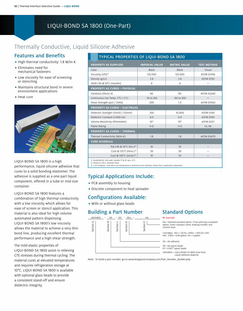
92 | Thermal Interface Selection Guide — LIQUI-BOND
LIQUI-BOND SA 1800 (One-Part)
Thermally Conductive, Liquid Silicone Adhesive
TYPICAL PROPERTIES OF LIQUI-BOND SA 1800
PROPERTY AS SUPPLIED IMPERIAL VALUE METRIC VALUE TEST METHOD
Color Black Black Visual
Viscosity (cPs)(1) 125,000 125,000 ASTM D2196
Density (g/cc) 2.8 2.8 ASTM D792
Shelf Life @ 10°C (months) 6 6 —
PROPERTY AS CURED – PHYSICAL
Hardness (Shore A) 80 80 ASTM D2240
Continuous Use Temp. (°F) / (°C) -76 to 392 -60 to 200 —
Shear Strength (psi) / (mPa) 200 1.4 ASTM D1002
PROPERTY AS CURED – ELECTRICAL
Dielectric Strength (V/mil) / (V/mm) 250 10,000 ASTM D149
Dielectric Constant (1,000 Hz) 6.0 6.0 ASTM D150
Volume Resistivity (Ohmmeter) 1011 1011 ASTM D257
Flame Rating V-O V-O UL 94
PROPERTY AS CURED – THERMAL
Thermal Conductivity (W/m-K) 1.8 1.8 ASTM D5470
CURE SCHEDULE
Pot Life @ 25°C (hrs.)(2) 10 10 —
Cure @ 125°C (mins.)(3) 20 20 —
Cure @ 150°C (mind.)(3) 10 10 —
1) Brookfield RV, Heli-path, Spindle TF @ 20 rpm, 25°C.2) Based on 1/8 in. diameter bead.3) Cure Schedule - time after cure temperature is achieved at the interface. Ramp time is application dependent.
Features and Benefits• High thermal conductivity: 1.8 W/m-K
• Eliminates need formechanical fasteners
• Low viscosity for ease of screeningor stenciling
• Maintains structural bond in severeenvironment applications
• Heat cure
LIQUI-BOND SA 1800 is a high performance, liquid silicone adhesive that cures to a solid bonding elastomer. The adhesive is supplied as a one-part liquid component, offered in a tube or mid-size container.
LIQUI-BOND SA 1800 features a combination of high thermal conductivity with a low viscosity which allows for ease of screen or stencil application. This material is also ideal for high volume automated pattern dispensing. LIQUI-BOND SA 1800’s low viscosity allows the material to achieve a very thin bond line, producing excellent thermal performance and a high shear strength.
The mild elastic properties of LIQUI-BOND SA 1800 assist in relieving CTE stresses during thermal cycling. The material cures at elevated temperatures and requires refrigeration storage at 10°C. LIQUI-BOND SA 1800 is available with optional glass beads to provide a consistent stand-off and ensure dielectric integrity.
Typical Applications Include:• PCB assembly to housing
• Discrete component to heat spreader
Configurations Available:• With or without glass beads
Building a Part Number Standard Options
Sect
ion
A
Sect
ion
B
Sect
ion
C
Sect
ion
D
Sect
ion
E NA = Selected standard option. If not selecting a standardoption, insert company name, drawing number, andrevision level.
LBSA1800 = LIQUI-BOND SA 1800 (One-Part)Liquid Adhesive Material
LBSA1800 00 00 30cc NA
Note: To build a part number, go to www.bergquistcompany.com/Part_Number_Builder.php.
00 = No spacer beads07 = 0.007" spacer beads
00 = No adhesive
Cartridges: 30cc = 30.0cc, 600cc = 600.0cc (ml)Pail: 0.85G = 0.85-gallon, 5G = 5-gallon
– – – – || example
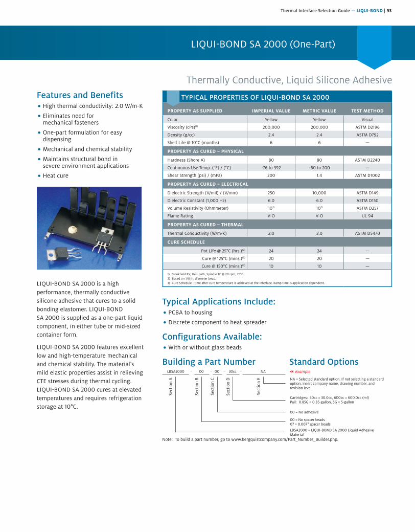
Thermal Interface Selection Guide — LIQUI-BOND | 93
LIQUI-BOND SA 2000 (One-Part)
Features and Benefits• High thermal conductivity: 2.0 W/m-K
• Eliminates need formechanical fasteners
• One-part formulation for easydispensing
• Mechanical and chemical stability
• Maintains structural bond insevere environment applications
• Heat cure
LIQUI-BOND SA 2000 is a high performance, thermally conductive silicone adhesive that cures to a solid bonding elastomer. LIQUI-BOND SA 2000 is supplied as a one-part liquid component, in either tube or mid-sized container form.
LIQUI-BOND SA 2000 features excellent low and high-temperature mechanical and chemical stability. The material’s mild elastic properties assist in relieving CTE stresses during thermal cycling. LIQUI-BOND SA 2000 cures at elevated temperatures and requires refrigeration storage at 10°C.
Typical Applications Include:• PCBA to housing
• Discrete component to heat spreader
Configurations Available:• With or without glass beads
Building a Part Number Standard Options
Sect
ion
A
Sect
ion
B
Sect
ion
C
Sect
ion
D
Sect
ion
E NA = Selected standard option. If not selecting a standardoption, insert company name, drawing number, andrevision level.
LBSA2000 = LIQUI-BOND SA 2000 Liquid AdhesiveMaterial
LBSA2000 00 00 30cc NA
Note: To build a part number, go to www.bergquistcompany.com/Part_Number_Builder.php.
00 = No spacer beads07 = 0.007" spacer beads
00 = No adhesive
Cartridges: 30cc = 30.0cc, 600cc = 600.0cc (ml)Pail: 0.85G = 0.85-gallon, 5G = 5-gallon
– – – – || example
Thermally Conductive, Liquid Silicone Adhesive
TYPICAL PROPERTIES OF LIQUI-BOND SA 2000
PROPERTY AS SUPPLIED IMPERIAL VALUE METRIC VALUE TEST METHOD
Color Yellow Yellow Visual
Viscosity (cPs)(1) 200,000 200,000 ASTM D2196
Density (g/cc) 2.4 2.4 ASTM D792
Shelf Life @ 10°C (months) 6 6 —
PROPERTY AS CURED – PHYSICAL
Hardness (Shore A) 80 80 ASTM D2240
Continuous Use Temp. (°F) / (°C) -76 to 392 -60 to 200 —
Shear Strength (psi) / (mPa) 200 1.4 ASTM D1002
PROPERTY AS CURED – ELECTRICAL
Dielectric Strength (V/mil) / (V/mm) 250 10,000 ASTM D149
Dielectric Constant (1,000 Hz) 6.0 6.0 ASTM D150
Volume Resistivity (Ohmmeter) 1011 1011 ASTM D257
Flame Rating V-O V-O UL 94
PROPERTY AS CURED – THERMAL
Thermal Conductivity (W/m-K) 2.0 2.0 ASTM D5470
CURE SCHEDULE
Pot Life @ 25°C (hrs.)(2) 24 24 —
Cure @ 125°C (mins.)(3) 20 20 —
Cure @ 150°C (mins.)(3) 10 10 —
1) Brookfield RV, Heli-path, Spindle TF @ 20 rpm, 25°C.2) Based on 1/8 in. diameter bead.3) Cure Schedule - time after cure temperature is achieved at the interface. Ramp time is application dependent.
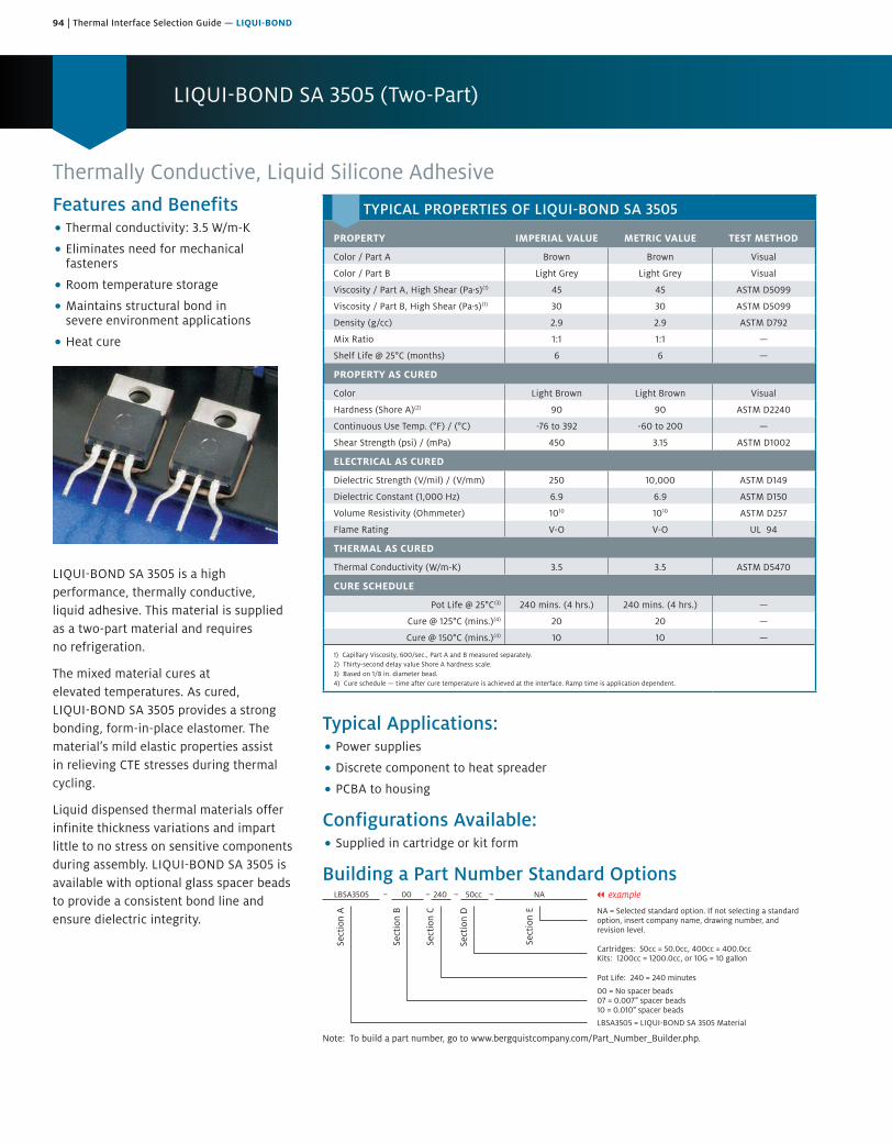
94 | Thermal Interface Selection Guide — LIQUI-BOND
LIQUI-BOND SA 3505 (Two-Part)
Thermally Conductive, Liquid Silicone AdhesiveFeatures and Benefits• Thermal conductivity: 3.5 W/m-K
• Eliminates need for mechanicalfasteners
• Room temperature storage
• Maintains structural bond insevere environment applications
• Heat cure
LIQUI-BOND SA 3505 is a high performance, thermally conductive, liquid adhesive. This material is supplied as a two-part material and requires no refrigeration.
The mixed material cures at elevated temperatures. As cured, LIQUI-BOND SA 3505 provides a strong bonding, form-in-place elastomer. The material’s mild elastic properties assist in relieving CTE stresses during thermal cycling.
Liquid dispensed thermal materials offer infinite thickness variations and impart little to no stress on sensitive components during assembly. LIQUI-BOND SA 3505 is available with optional glass spacer beads to provide a consistent bond line and ensure dielectric integrity.
Typical Applications:• Power supplies
• Discrete component to heat spreader
• PCBA to housing
Configurations Available:• Supplied in cartridge or kit form
Building a Part Number Standard Options
Sect
ion
A
Sect
ion
B
Sect
ion
C
Sect
ion
D
Sect
ion
E NA = Selected standard option. If not selecting a standardoption, insert company name, drawing number, andrevision level.
LBSA3505 = LIQUI-BOND SA 3505 Material
LBSA3505 00 240 50cc NA
Note: To build a part number, go to www.bergquistcompany.com/Part_Number_Builder.php.
00 = No spacer beads07 = 0.007" spacer beads10 = 0.010" spacer beads
Pot Life: 240 = 240 minutes
Cartridges: 50cc = 50.0cc, 400cc = 400.0ccKits: 1200cc = 1200.0cc, or 10G = 10 gallon
– – – – || example
TYPICAL PROPERTIES OF LIQUI-BOND SA 3505
PROPERTY IMPERIAL VALUE METRIC VALUE TEST METHOD
Color / Part A Brown Brown Visual
Color / Part B Light Grey Light Grey Visual
Viscosity / Part A, High Shear (Pa·s)(1) 45 45 ASTM D5099
Viscosity / Part B, High Shear (Pa·s)(1) 30 30 ASTM D5099
Density (g/cc) 2.9 2.9 ASTM D792
Mix Ratio 1:1 1:1 —
Shelf Life @ 25°C (months) 6 6 —
PROPERTY AS CURED
Color Light Brown Light Brown Visual
Hardness (Shore A)(2) 90 90 ASTM D2240
Continuous Use Temp. (°F) / (°C) -76 to 392 -60 to 200 —
Shear Strength (psi) / (mPa) 450 3.15 ASTM D1002
ELECTRICAL AS CURED
Dielectric Strength (V/mil) / (V/mm) 250 10,000 ASTM D149
Dielectric Constant (1,000 Hz) 6.9 6.9 ASTM D150
Volume Resistivity (Ohmmeter) 1010 1010 ASTM D257
Flame Rating V-O V-O UL 94
THERMAL AS CURED
Thermal Conductivity (W/m-K) 3.5 3.5 ASTM D5470
CURE SCHEDULE
Pot Life @ 25°C(3) 240 mins. (4 hrs.) 240 mins. (4 hrs.) —
Cure @ 125°C (mins.)(4) 20 20 —
Cure @ 150°C (mins.)(4) 10 10 —
1) Capillary Viscosity, 600/sec., Part A and B measured separately.2) Thirty-second delay value Shore A hardness scale.3) Based on 1/8 in. diameter bead.4) Cure schedule — time after cure temperature is achieved at the interface. Ramp time is application dependent.
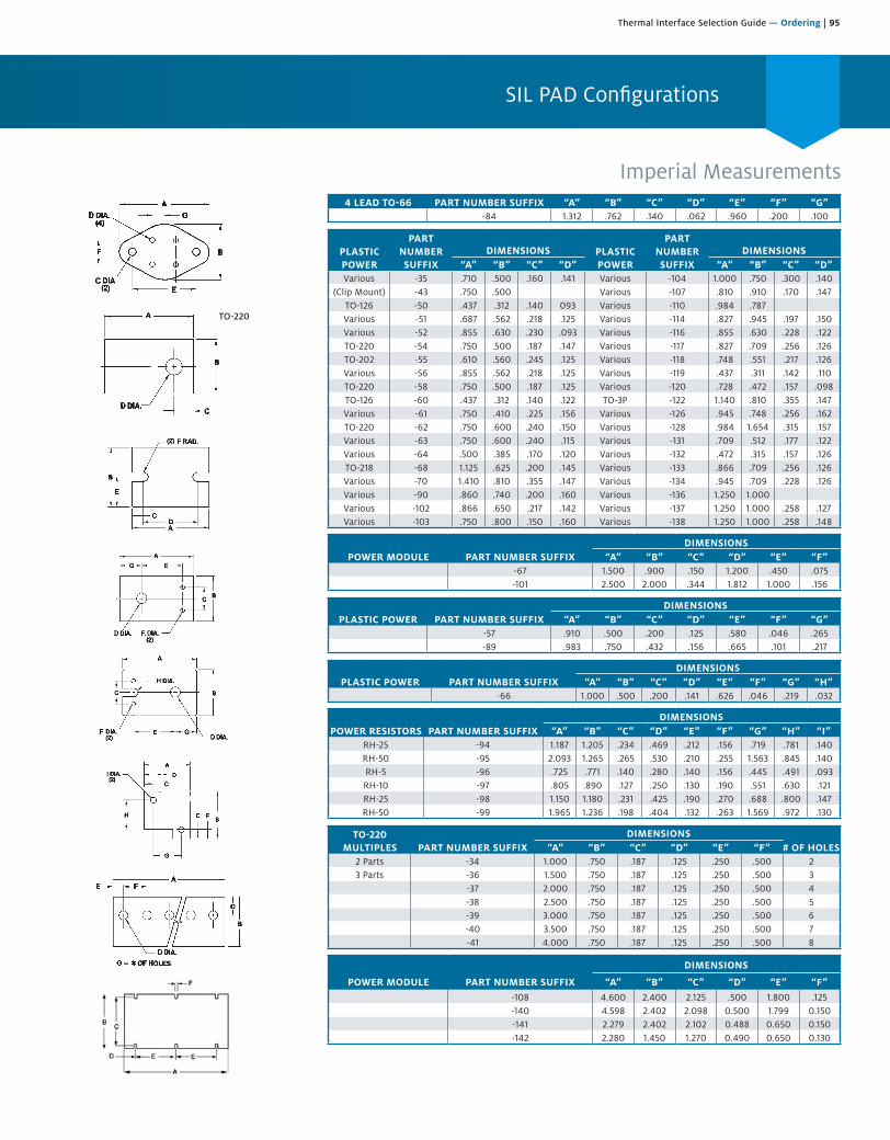
Thermal Interface Selection Guide — Ordering | 95
SIL PAD Configurations
TO-220
Imperial Measurements4 LEAD TO-66 PART NUMBER SUFFIX “A” “B” “C” “D” “E” “F” “G”
-84 1.312 .762 .140 .062 .960 .200 .100
PLASTIC POWER
PART NUMBERSUFFIX
DIMENSIONS PLASTIC POWER
PART NUMBERSUFFIX
DIMENSIONS“A” “B” “C” “D” “A” “B” “C” “D”
Various -35 .710 .500 .160 .141 Various -104 1.000 .750 .300 .140(Clip Mount) -43 .750 .500 Various -107 .810 .910 .170 .147
TO-126 -50 .437 .312 .140 093 Various -110 .984 .787Various -51 .687 .562 .218 .125 Various -114 .827 .945 .197 .150Various -52 .855 .630 .230 .093 Various -116 .855 .630 .228 .122TO-220 -54 .750 .500 .187 .147 Various -117 .827 .709 .256 .126TO-202 -55 .610 .560 .245 .125 Various -118 .748 .551 .217 .126Various -56 .855 .562 .218 .125 Various -119 .437 .311 .142 .110TO-220 -58 .750 .500 .187 .125 Various -120 .728 .472 .157 .098TO-126 -60 .437 .312 .140 .122 TO-3P -122 1.140 .810 .355 .147Various -61 .750 .410 .225 .156 Various -126 .945 .748 .256 .162TO-220 -62 .750 .600 .240 .150 Various -128 .984 1.654 .315 .157Various -63 .750 .600 .240 .115 Various -131 .709 .512 .177 .122Various -64 .500 .385 .170 .120 Various -132 .472 .315 .157 .126TO-218 -68 1.125 .625 .200 .145 Various -133 .866 .709 .256 .126Various -70 1.410 .810 .355 .147 Various -134 .945 .709 .228 .126Various -90 .860 .740 .200 .160 Various -136 1.250 1.000Various -102 .866 .650 .217 .142 Various -137 1.250 1.000 .258 .127Various -103 .750 .800 .150 .160 Various -138 1.250 1.000 .258 .148
POWER MODULE PART NUMBER SUFFIXDIMENSIONS
“A” “B” “C” “D” “E” “F”-67 1.500 .900 .150 1.200 .450 .075-101 2.500 2.000 .344 1.812 1.000 .156
PLASTIC POWER PART NUMBER SUFFIXDIMENSIONS
“A” “B” “C” “D” “E” “F” “G”-57 .910 .500 .200 .125 .580 .046 .265-89 .983 .750 .432 .156 .665 .101 .217
PLASTIC POWER PART NUMBER SUFFIXDIMENSIONS
“A” “B” “C” “D” “E” “F” “G” “H”-66 1.000 .500 .200 .141 .626 .046 .219 .032
POWER RESISTORS PART NUMBER SUFFIXDIMENSIONS
“A” “B” “C” “D” “E” “F” “G” “H” “I”RH-25 -94 1.187 1.205 .234 .469 .212 .156 .719 .781 .140RH-50 -95 2.093 1.265 .265 .530 .210 .255 1.563 .845 .140RH-5 -96 .725 .771 .140 .280 .140 .156 .445 .491 .093RH-10 -97 .805 .890 .127 .250 .130 .190 .551 .630 .121RH-25 -98 1.150 1.180 .231 .425 .190 .270 .688 .800 .147RH-50 -99 1.965 1.236 .198 .404 .132 .263 1.569 .972 .130
TO-220 MULTIPLES PART NUMBER SUFFIX
DIMENSIONS# OF HOLES“A” “B” “C” “D” “E” “F”
2 Parts -34 1.000 .750 .187 .125 .250 .500 23 Parts -36 1.500 .750 .187 .125 .250 .500 3
-37 2.000 .750 .187 .125 .250 .500 4-38 2.500 .750 .187 .125 .250 .500 5-39 3.000 .750 .187 .125 .250 .500 6-40 3.500 .750 .187 .125 .250 .500 7-41 4.000 .750 .187 .125 .250 .500 8
POWER MODULE PART NUMBER SUFFIX
DIMENSIONS
“A” “B” “C” “D” “E” “F”-108 4.600 2.400 2.125 .500 1.800 .125-140 4.598 2.402 2.098 0.500 1.799 0.150-141 2.279 2.402 2.102 0.488 0.650 0.150-142 2.280 1.450 1.270 0.490 0.650 0.130
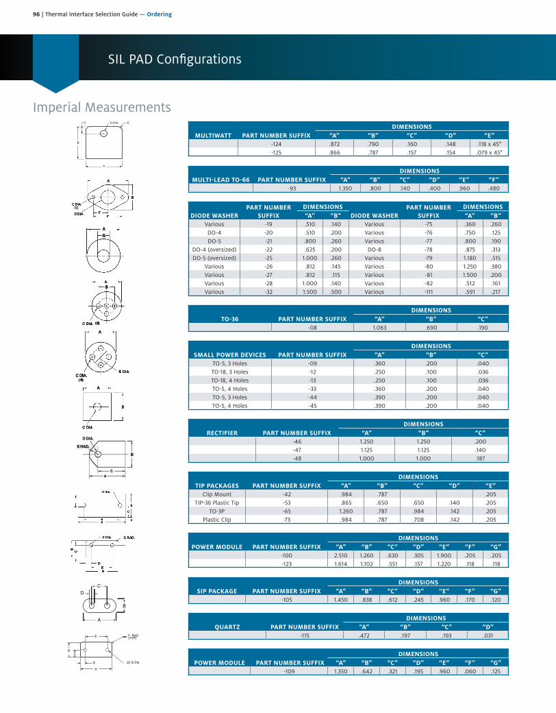
96 | Thermal Interface Selection Guide — Ordering
SIL PAD Configurations
Imperial Measurements
B
A
D-DIA EC
A
B
CD
A
D
CB
(2) G Dia
F RAD(TYP)E
MULTIWATT PART NUMBER SUFFIXDIMENSIONS
“A” “B” “C” “D” “E”-124 .872 .790 .160 .148 .118 x 45°-125 .866 .787 .157 .154 .079 x 45°
MULTI-LEAD TO-66 PART NUMBER SUFFIXDIMENSIONS
“A” “B” “C” “D” “E” “F”-93 1.350 .800 .140 .400 .960 .480
DIODE WASHERPART NUMBER
SUFFIXDIMENSIONS
DIODE WASHERPART NUMBER
SUFFIXDIMENSIONS
“A” “B” “A” “B”Various -19 .510 .140 Various -75 .360 .260DO-4 -20 .510 .200 Various -76 .750 .125DO-5 -21 .800 .260 Various -77 .800 .190
DO-4 (oversized) -22 .625 .200 DO-8 -78 .875 .313DO-5 (oversized) -25 1.000 .260 Various -79 1.180 .515
Various -26 .812 .145 Various -80 1.250 .380Various -27 .812 .115 Various -81 1.500 .200Various -28 1.000 .140 Various -82 .512 .161Various -32 1.500 .500 Various -111 .591 .217
TO-36 PART NUMBER SUFFIXDIMENSIONS
“A” “B” “C”-08 1.063 .690 .190
SMALL POWER DEVICES PART NUMBER SUFFIXDIMENSIONS
“A” “B” “C”TO-5, 3 Holes -09 .360 .200 .040TO-18, 3 Holes -12 .250 .100 .036TO-18, 4 Holes -13 .250 .100 .036TO-5, 4 Holes -33 .360 .200 .040TO-5, 3 Holes -44 .390 .200 .040TO-5, 4 Holes -45 .390 .200 .040
RECTIFIER PART NUMBER SUFFIXDIMENSIONS
“A” “B” “C”-46 1.250 1.250 .200-47 1.125 1.125 .140-48 1.000 1.000 .187
TIP PACKAGES PART NUMBER SUFFIXDIMENSIONS
“A” “B” “C” “D” “E”Clip Mount -42 .984 .787 .205
TIP-36 Plastic Tip -53 .865 .650 .650 .140 .205TO-3P -65 1.260 .787 .984 .142 .205
Plastic Clip -73 .984 .787 .708 .142 .205
POWER MODULE PART NUMBER SUFFIXDIMENSIONS
“A” “B” “C” “D” “E” “F” “G”-100 2.510 1.260 .630 .305 1.900 .205 .205-123 1.614 1.102 .551 .157 1.220 .118 .118
SIP PACKAGE PART NUMBER SUFFIXDIMENSIONS
“A” “B” “C” “D” “E” “F” “G”-105 1.450 .838 .612 .245 .960 .170 .120
QUARTZ PART NUMBER SUFFIXDIMENSIONS
“A” “B” “C” “D”-115 .472 .197 .193 .031
POWER MODULE PART NUMBER SUFFIXDIMENSIONS
“A” “B” “C” “D” “E” “F” “G”-109 1.350 .642 .321 .195 .960 .060 .125
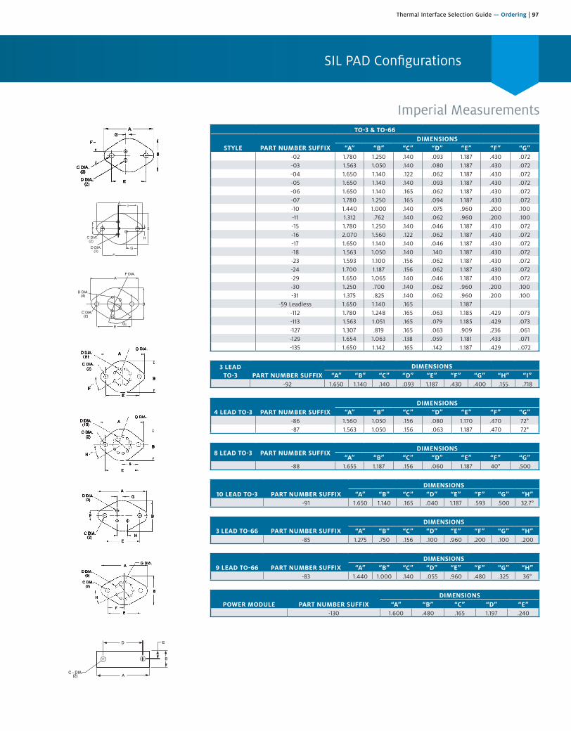
Thermal Interface Selection Guide — Ordering | 97
SIL PAD Configurations
Imperial Measurements
I
AF DIA.
B
E
C DIA. (2)
D DIA. (4)
18¡
G¡
A
B
ED
C - DIA. (2)
TO-3 & TO-66
STYLE PART NUMBER SUFFIXDIMENSIONS
“A” “B” “C” “D” “E” “F” “G”-02 1.780 1.250 .140 .093 1.187 .430 .072-03 1.563 1.050 .140 .080 1.187 .430 .072-04 1.650 1.140 .122 .062 1.187 .430 .072-05 1.650 1.140 .140 .093 1.187 .430 .072-06 1.650 1.140 .165 .062 1.187 .430 .072-07 1.780 1.250 .165 .094 1.187 .430 .072-10 1.440 1.000 .140 .075 .960 .200 .100-11 1.312 .762 .140 .062 .960 .200 .100-15 1.780 1.250 .140 .046 1.187 .430 .072-16 2.070 1.560 .122 .062 1.187 .430 .072-17 1.650 1.140 .140 .046 1.187 .430 .072-18 1.563 1.050 .140 .140 1.187 .430 .072-23 1.593 1.100 .156 .062 1.187 .430 .072-24 1.700 1.187 .156 .062 1.187 .430 .072-29 1.650 1.065 .140 .046 1.187 .430 .072-30 1.250 .700 .140 .062 .960 .200 .100-31 1.375 .825 .140 .062 .960 .200 .100
-59 Leadless 1.650 1.140 .165 1.187-112 1.780 1.248 .165 .063 1.185 .429 .073-113 1.563 1.051 .165 .079 1.185 .429 .073-127 1.307 .819 .165 .063 .909 .236 .061-129 1.654 1.063 .138 .059 1.181 .433 .071-135 1.650 1.142 .165 .142 1.187 .429 ..072
3 LEAD TO-3 PART NUMBER SUFFIX
DIMENSIONS“A” “B” “C” “D” “E” “F” “G” “H” “I”
-92 1.650 1.140 .140 .093 1.187 .430 .400 .155 .718
4 LEAD TO-3 PART NUMBER SUFFIXDIMENSIONS
“A” “B” “C” “D” “E” “F” “G”-86 1.560 1.050 .156 .080 1.170 .470 72°-87 1.563 1.050 .156 .063 1.187 .470 72°
8 LEAD TO-3 PART NUMBER SUFFIXDIMENSIONS
“A” “B” “C” “D” “E” “F” “G”-88 1.655 1.187 .156 .060 1.187 40° .500
10 LEAD TO-3 PART NUMBER SUFFIXDIMENSIONS
“A” “B” “C” “D” “E” “F” “G” “H”-91 1.650 1.140 .165 .040 1.187 .593 .500 32.7°
3 LEAD TO-66 PART NUMBER SUFFIXDIMENSIONS
“A” “B” “C” “D” “E” “F” “G” “H”-85 1.275 .750 .156 .100 .960 .200 .100 .200
9 LEAD TO-66 PART NUMBER SUFFIXDIMENSIONS
“A” “B” “C” “D” “E” “F” “G” “H”-83 1.440 1.000 .140 .055 .960 .480 .325 36°
POWER MODULE PART NUMBER SUFFIXDIMENSIONS
“A” “B” “C” “D” “E”-130 1.600 .480 .165 1.197 .240
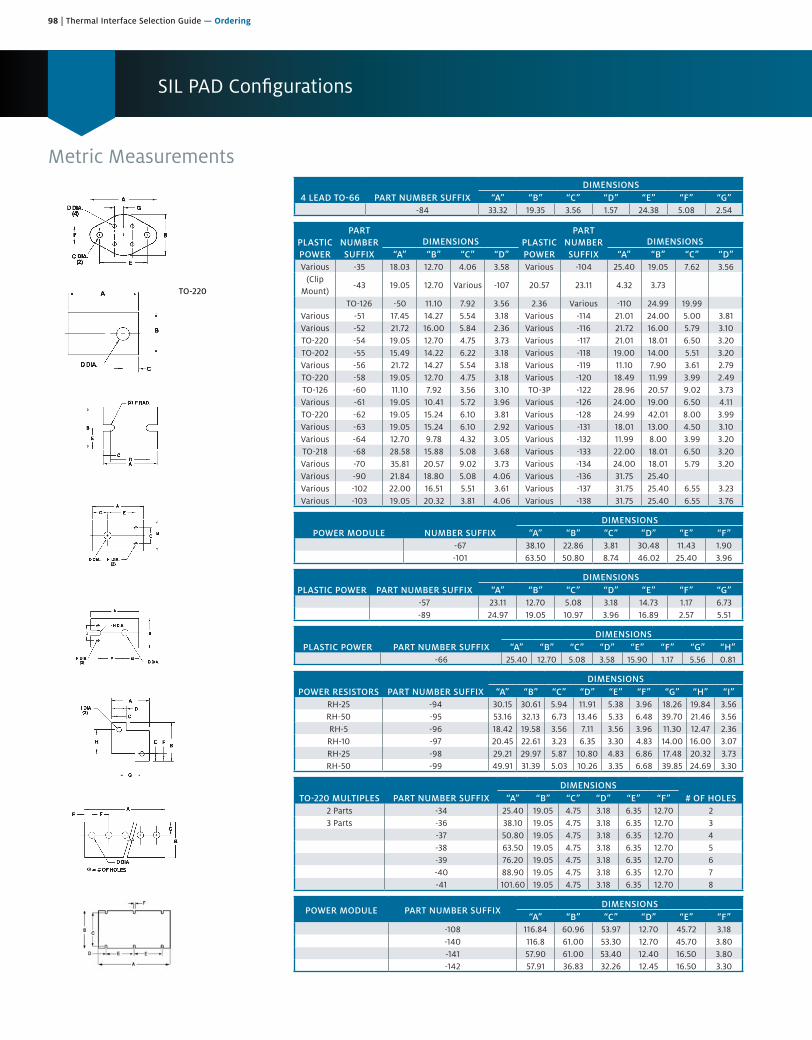
98 | Thermal Interface Selection Guide — Ordering
SIL PAD Configurations
Metric Measurements
TO-220
4 LEAD TO-66 PART NUMBER SUFFIXDIMENSIONS
“A” “B” “C” “D” “E” “F” “G”-84 33.32 19.35 3.56 1.57 24.38 5.08 2.54
PLASTIC POWER
PART NUMBER SUFFIX
DIMENSIONS PLASTIC POWER
PART NUMBER SUFFIX
DIMENSIONS“A” “B” “C” “D” “A” “B” “C” “D”
Various -35 18.03 12.70 4.06 3.58 Various -104 25.40 19.05 7.62 3.56(Clip
Mount)-43 19.05 12.70 Various -107 20.57 23.11 4.32 3.73
TO-126 -50 11.10 7.92 3.56 2.36 Various -110 24.99 19.99Various -51 17.45 14.27 5.54 3.18 Various -114 21.01 24.00 5.00 3.81Various -52 21.72 16.00 5.84 2.36 Various -116 21.72 16.00 5.79 3.10TO-220 -54 19.05 12.70 4.75 3.73 Various -117 21.01 18.01 6.50 3.20TO-202 -55 15.49 14.22 6.22 3.18 Various -118 19.00 14.00 5.51 3.20Various -56 21.72 14.27 5.54 3.18 Various -119 11.10 7.90 3.61 2.79TO-220 -58 19.05 12.70 4.75 3.18 Various -120 18.49 11.99 3.99 2.49TO-126 -60 11.10 7.92 3.56 3.10 TO-3P -122 28.96 20.57 9.02 3.73Various -61 19.05 10.41 5.72 3.96 Various -126 24.00 19.00 6.50 4.11TO-220 -62 19.05 15.24 6.10 3.81 Various -128 24.99 42.01 8.00 3.99Various -63 19.05 15.24 6.10 2.92 Various -131 18.01 13.00 4.50 3.10Various -64 12.70 9.78 4.32 3.05 Various -132 11.99 8.00 3.99 3.20TO-218 -68 28.58 15.88 5.08 3.68 Various -133 22.00 18.01 6.50 3.20Various -70 35.81 20.57 9.02 3.73 Various -134 24.00 18.01 5.79 3.20Various -90 21.84 18.80 5.08 4.06 Various -136 31.75 25.40Various -102 22.00 16.51 5.51 3.61 Various -137 31.75 25.40 6.55 3.23Various -103 19.05 20.32 3.81 4.06 Various -138 31.75 25.40 6.55 3.76
POWER MODULE NUMBER SUFFIXDIMENSIONS
“A” “B” “C” “D” “E” “F”-67 38.10 22.86 3.81 30.48 11.43 1.90-101 63.50 50.80 8.74 46.02 25.40 3.96
PLASTIC POWER PART NUMBER SUFFIXDIMENSIONS
“A” “B” “C” “D” “E” “F” “G”-57 23.11 12.70 5.08 3.18 14.73 1.17 6.73-89 24.97 19.05 10.97 3.96 16.89 2.57 5.51
PLASTIC POWER PART NUMBER SUFFIX DIMENSIONS
“A” “B” “C” “D” “E” “F” “G” “H”-66 25.40 12.70 5.08 3.58 15.90 1.17 5.56 0.81
POWER RESISTORS PART NUMBER SUFFIXDIMENSIONS
“A” “B” “C” “D” “E” “F” “G” “H” “I”RH-25 -94 30.15 30.61 5.94 11.91 5.38 3.96 18.26 19.84 3.56RH-50 -95 53.16 32.13 6.73 13.46 5.33 6.48 39.70 21.46 3.56RH-5 -96 18.42 19.58 3.56 7.11 3.56 3.96 11.30 12.47 2.36RH-10 -97 20.45 22.61 3.23 6.35 3.30 4.83 14.00 16.00 3.07RH-25 -98 29.21 29.97 5.87 10.80 4.83 6.86 17.48 20.32 3.73RH-50 -99 49.91 31.39 5.03 10.26 3.35 6.68 39.85 24.69 3.30
TO-220 MULTIPLES PART NUMBER SUFFIXDIMENSIONS
# OF HOLES“A” “B” “C” “D” “E” “F”2 Parts -34 25.40 19.05 4.75 3.18 6.35 12.70 23 Parts -36 38.10 19.05 4.75 3.18 6.35 12.70 3
-37 50.80 19.05 4.75 3.18 6.35 12.70 4-38 63.50 19.05 4.75 3.18 6.35 12.70 5-39 76.20 19.05 4.75 3.18 6.35 12.70 6-40 88.90 19.05 4.75 3.18 6.35 12.70 7-41 101.60 19.05 4.75 3.18 6.35 12.70 8
POWER MODULE PART NUMBER SUFFIXDIMENSIONS
“A” “B” “C” “D” “E” “F”-108 116.84 60.96 53.97 12.70 45.72 3.18-140 116.8 61.00 53.30 12.70 45.70 3.80-141 57.90 61.00 53.40 12.40 16.50 3.80-142 57.91 36.83 32.26 12.45 16.50 3.30
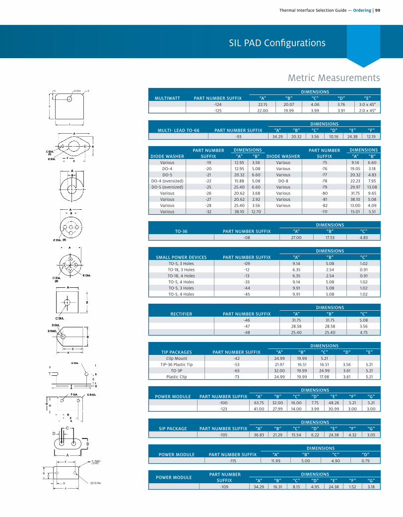
Thermal Interface Selection Guide — Ordering | 99
SIL PAD Configurations
Metric Measurements
B
A
D-DIA EC
A
B
CD
A
D
CB
(2) G Dia
F RAD(TYP)E
MULTIWATT PART NUMBER SUFFIXDIMENSIONS
“A” “B” “C” “D” “E”-124 22.15 20.07 4.06 3.76 3.0 x 45°-125 22.00 19.99 3.99 3.91 2.0 x 45°
MULTI- LEAD TO-66 PART NUMBER SUFFIXDIMENSIONS
“A” “B” “C” “D” “E” “F”-93 34.29 20.32 3.56 10.16 24.38 12.19
DIODE WASHERPART NUMBER
SUFFIXDIMENSIONS
DIODE WASHERPART NUMBER
SUFFIXDIMENSIONS
“A” “B” “A” “B”Various -19 12.95 3.56 Various -75 9.14 6.60DO-4 -20 12.95 5.08 Various -76 19.05 3.18DO-5 -21 20.32 6.60 Various -77 20.32 4.83
DO-4 (oversized) -22 15.88 5.08 DO-8 -78 22.23 7.95DO-5 (oversized) -25 25.40 6.60 Various -79 29.97 13.08
Various -26 20.62 3.68 Various -80 31.75 9.65Various -27 20.62 2.92 Various -81 38.10 5.08Various -28 25.40 3.56 Various -82 13.00 4.09Various -32 38.10 12.70 -111 15.01 5.51
TO-36 PART NUMBER SUFFIXDIMENSIONS
“A” “B” “C”-08 27.00 17.53 4.83
SMALL POWER DEVICES PART NUMBER SUFFIXDIMENSIONS
“A” “B” “C”TO-5, 3 Holes -09 9.14 5.08 1.02TO-18, 3 Holes -12 6.35 2.54 0.91TO-18, 4 Holes -13 6.35 2.54 0.91TO-5, 4 Holes -33 9.14 5.08 1.02TO-5, 3 Holes -44 9.91 5.08 1.02TO-5, 4 Holes -45 9.91 5.08 1.02
RECTIFIER PART NUMBER SUFFIXDIMENSIONS
“A” “B” “C”-46 31.75 31.75 5.08-47 28.58 28.58 3.56-48 25.40 25.40 4.75
TIP PACKAGES PART NUMBER SUFFIXDIMENSIONS
“A” “B” “C” “D” “E”Clip Mount -42 24.99 19.99 5.21
TIP-36 Plastic Tip -53 21.97 16.51 16.51 3.56 5.21TO-3P -65 32.00 19.99 24.99 3.61 5.21
Plastic Clip -73 24.99 19.99 17.98 3.61 5.21
POWER MODULE PART NUMBER SUFFIXDIMENSIONS
“A” “B” “C” “D” “E” “F” “G”-100 63.75 32.00 16.00 7.75 48.26 5.21 5.21-123 41.00 27.99 14.00 3.99 30.99 3.00 3.00
SIP PACKAGE PART NUMBER SUFFIXDIMENSIONS
“A” “B” “C” “D” “E” “F” “G”-105 36.83 21.29 15.54 6.22 24.38 4.32 3.05
POWER MODULE PART NUMBER SUFFIXDIMENSIONS
“A” “B” “C” “D”-115 11.99 5.00 4.90 0.79
POWER MODULE PART NUMBER
SUFFIXDIMENSIONS
“A” “B” “C” “D” “E” “F” “G”-109 34.29 16.31 8.15 4.95 24.38 1.52 3.18
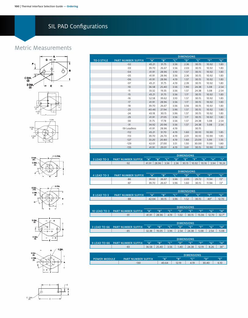
100 | Thermal Interface Selection Guide — Ordering
SIL PAD Configurations
Metric Measurements
I
AF DIA.
B
E
C DIA. (2)
D DIA. (4)
18¡
G¡
A
B
ED
C - DIA. (2)
TO-3 STYLE PART NUMBER SUFFIXDIMENSIONS
“A” “B” “C” “D” “E” “F” “G”-02 45.21 31.75 3.56 2.36 30.15 10.92 1.83-03 39.70 26.67 3.56 2.03 30.15 10.92 1.83-04 41.91 28.96 3.10 1.57 30.15 10.92 1.83-05 41.91 28.96 3.56 2.36 30.15 10.92 1.83-06 41.91 28.96 4.19 1.57 30.15 10.92 1.83-07 45.21 31.75 4.19 2.39 30.15 10.92 1.83-10 36.58 25.40 3.56 1.90 24.38 5.08 2.54-11 33.32 19.35 3.56 1.57 24.38 5.08 2.54-15 45.21 31.75 3.56 1.17 30.15 10.92 1.83-16 52.58 39.62 3.10 1.57 30.15 10.92 1.83-17 41.91 28.96 3.56 1.17 30.15 10.92 1.83-18 39.70 26.67 3.56 3.56 30.15 10.92 1.83-23 40.46 27.94 3.96 1.57 30.15 10.92 1.83-24 43.18 30.15 3.96 1.57 30.15 10.92 1.83-29 41.91 27.05 3.56 1.17 30.15 10.92 1.83-30 31.75 17.78 3.56 1.57 24.38 5.08 2.54-31 34.92 20.96 3.56 1.57 24.38 5.08 2.54
-59 Leadless 41.91 28.96 4.19 30.15-112 45.21 31.70 4.19 1.60 30.10 10.90 1.85-113 39.70 26.70 4.19 2.01 30.10 10.90 1.85-127 33.20 20.80 4.19 1.60 23.09 5.99 1.55-129 42.01 27.00 3.51 1.50 30.00 11.00 1.80-135 41.91 29.01 4.19 3.61 30.15 10.90 1.83
3 LEAD TO-3 PART NUMBER SUFFIXDIMENSIONS
“A” “B” “C” “D” “E” “F” “G” “H” “I”-92 41.91 28.96 3.56 2.36 30.15 10.92 10.16 3.94 18.24
4 LEAD TO-3 PART NUMBER SUFFIXDIMENSIONS
“A” “B” “C” “D” “E” “F” “G”-86 39.62 26.67 3.96 2.03 29.72 11.94 72°-87 39.70 26.67 3.96 1.60 30.15 11.94 72°
8 LEAD TO-3 PART NUMBER SUFFIXDIMENSIONS
“A” “B” “C” “D” “E” “F” “G”-88 42.04 30.15 3.96 1.52 30.15 40° 12.70
10 LEAD TO-3 PART NUMBER SUFFIXDIMENSIONS
“A” “B” “C” “D” “E” “F” “G” “H”-91 41.91 28.96 4.19 1.02 30.15 15.06 12.70 32.7°
3 LEAD TO-66 PART NUMBER SUFFIXDIMENSIONS
“A” “B” “C” “D” “E” “F” “G” “H”-85 32.38 19.05 3.96 2.54 24.38 5.08 2.54 5.08
9 LEAD TO-66 PART NUMBER SUFFIXDIMENSIONS
“A” “B” “C” “D” “E” “F” “G” “H”-83 36.58 25.40 3.56 1.40 24.38 12.19 8.26 36°
POWER MODULE PART NUMBER SUFFIXDIMENSIONS
“A” “B” “C” “D” “E”-130 40.64 12.19 4.19 30.40 6.10
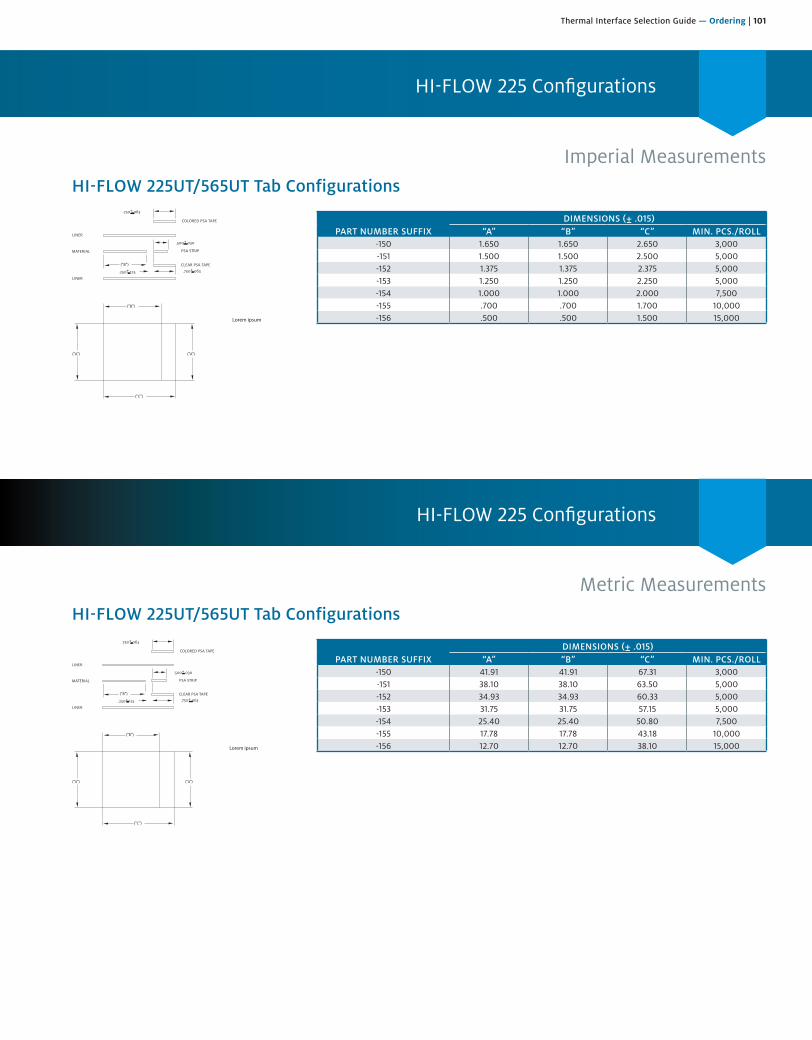
Thermal Interface Selection Guide — Ordering | 101
HI-FLOW 225 Configurations
HI-FLOW 225 Configurations
PART NUMBER SUFFIXDIMENSIONS (± .015)
“A” “B” “C” MIN. PCS./ROLL-150 41.91 41.91 67.31 3,000-151 38.10 38.10 63.50 5,000-152 34.93 34.93 60.33 5,000-153 31.75 31.75 57.15 5,000-154 25.40 25.40 50.80 7,500-155 17.78 17.78 43.18 10,000-156 12.70 12.70 38.10 15,000
HI-FLOW 225UT/565UT Tab Configurations
Imperial Measurements
Metric Measurements
PART NUMBER SUFFIX DIMENSIONS (± .015)
“A” “B” “C” MIN. PCS./ROLL-150 1.650 1.650 2.650 3,000-151 1.500 1.500 2.500 5,000-152 1.375 1.375 2.375 5,000-153 1.250 1.250 2.250 5,000-154 1.000 1.000 2.000 7,500-155 .700 .700 1.700 10,000-156 .500 .500 1.500 15,000
HI-FLOW 225UT/565UT Tab Configurations
COLORED PSA TAPE
CLEAR PSA TAPE
PSA STRIPMATERIAL
LINER
LINER
.750+.063
.750+.063
.500+.030
.250+.125
("B")
("B")
("C")
("A") ("A")
Lorem ipsum
COLORED PSA TAPE
CLEAR PSA TAPE
PSA STRIPMATERIAL
LINER
LINER
.750+.063
.750+.063
.500+.030
.250+.125
("B")
("B")
("C")
("A") ("A")
Lorem ipsum

102 | Thermal Interface Selection Guide — Ordering
Solutions for Surface Mount Applications
HI-FLOWThe HI-FLOW family of phase change materials offers an easy-to-apply thermal interface for many surface mount packages. At the phase change temperature, HI-FLOW materials change from a solid and flow with minimal applied pressure. This characteristic optimizes heat transfer by maximizing wet-out of the interface. HI-FLOW is commonly used to replace messy thermal grease.
BERGQUIST phase change materials are specially compounded to prevent pump-out of the interface area, which is often associated with thermal grease. Typical applications for HI-FLOW materials include:
• High performance CPUs and integrated circuits
• DC/DC converters
• Power modules
HI-FLOW materials are manufactured with or without film or foil carriers. Custom shapes and sizes for non-standard applications are also available.
High Power Application HI-FLOW without THERMAL CLAD
High Power Application HI-FLOW with THERMAL CLAD
Power Device
Processor
THERMAL CLAD
HI-FLOW
HI-FLOWHeat
Spreader
HeatSpreader
FR-4 Board
SIL PADSIL PAD sets a benchmark in thermal interface materials. The SIL PAD family of materials is thermally conductive and electrically insulating. Available in custom shapes, sheets, and rolls, SIL PAD materials come in a variety of thicknesses and are frequently used in SMT applications such as:
• Interface between thermal vias in a PCB, and a heat sink or casting
• Heat sink interface to many surface mount packages
Mid Power Application with BOND-PLY or SIL PAD
Power Device
SIL PAD or BOND-PLY FR-4 Heat
Spreader

Thermal Interface Selection Guide — Ordering | 103
Where Thermal Solutions Come Together
BOND-PLY and LIQUI-BONDThe BOND-PLY family of materials is thermally conductive and electrically isolating. BOND-PLY is available in a pressure sensitive adhesive or laminating format. BOND-PLY provides for the mechanical decoupling of bonded materials with mismatched thermal coefficients of expansion. LIQUI-BOND is a high thermal performance liquid silicone adhesive that cures to a solid bonding elastomer. Typical applications include:
• Bonding bus bars in a variety of electronic modules and sub-assemblies
• Attaching a metal-based component to a heat sink
• Bonding a heat sink to a variety of ASIC, graphic chip and CPU packages
• Bonding flexible circuits to a rigid heat spreader or thermal plane
• Assembly tapes for BGA heat spreader
• Attaching PCB assemblies to housings
GAP PAD and Gap FillerGAP PAD and Gap Filler product families are highly conformable, thermally conductive materials in pad or liquid dispensable format. Varying degrees of thermal conductivity and compression deflection characteristics are available. Typical applications include:
• On top of a semiconductor package such as a QFP or BGA. Often times, severalpackages with varying heights can use a common heat sink when using GAP PAD.
• Between a PCB or substrate and a chassis, frame, or other heat spreader
• Areas where heat needs to be transferred to any type of heat spreader
• For interfacing pressure sensitive devices
• Filling various gaps between heat-generating devices and heat sinks or housings
GAP PADs are available in thickness of 0.010 in. to 0.250 in., and in custom shapes, with or without adhesive. Gap Fillers are available in cartridge or kit form.
Lower Power Application with GAP PAD
GAP PAD or GAP FILLERPower Device
HeatSpreader
FR-4 Board
Top Efficiency In Thermal Materials For Today’s Changing Technology.Contact Henkel for additional information regarding our thermal solutions. We are constantly innovating to offer you the greatest selection of options and flexibility to meet today’s changing technology.

104 | Thermal Interface Selection Guide — Ordering
Ordering Information
Ordering Procedure:The last 2 or 3 digits define the part number selected. The “footprint” and dimensions are shown on pages 91-97.
Special Shapes:For applications requiring non-standard or custom SIL PAD configurations, contact your Henkel Sales Representative. We produce thousands of custom die shapes and designs.
Tolerances:Typical converting tolerances are held on length (L), width (W), hole diameter and hole location for most materials as noted below:
TYPICAL SIL PAD / HI-FLOW TOLERANCES
Part (1)Dimension
Length and Width Tolerance
Rule DefinedFeatures (2)
Hole Location and Diameter
<6 in. ± 0.010 in. (0.25 mm) ± 0.010 in. (0.25 mm) ± 0.005 in. (0.13 mm)
6 in. - 12 in. ± 0.015 in. (0.38 mm) ± 0.015 in. (0.38 mm) ± 0.010 in. (0.25 mm)
>12 in. ± 0.020 in. (0.51 mm) ± 0.020 in. (0.51 mm) ± 0.020 in. (0.51 mm)
TYPICAL GAP PAD TOLERANCES (3)
Material Thickness
Length and Width ToleranceHole Location and Diameter
10 mil ± 0.015 in. (0.38 mm) ± 0.015 in. (0.38 mm)
15 mil ± 0.015 in. (0.38 mm) ± 0.015 in. (0.38 mm)
20 mil ± 0.020 in. (0.51 mm) ± 0.020 in. (0.51 mm)
30 mil ± 0.030 in. (0.76 mm) ± 0.030 in. (0.76 mm)
40 mil ± 0.035 in. (0.89 mm) ± 0.035 in. (0.89 mm)
50 mil ± 0.040 in. (1.02 mm) ± 0.040 in. (1.02 mm)
60 mil ± 0.050 in. (1.27 mm) ± 0.050 in. (1.27 mm)
70 mil ± 0.050 in. (1.27 mm) ± 0.050 in. (1.27 mm)
80 mil ± 0.050 in. (1.27 mm) ± 0.050 in. (1.27 mm)
100 mil ± 0.060 in. (1.52 mm) ± 0.060 in. (1.52 mm)
125 mil ± 0.075 in. (1.91 mm) ± 0.075 in. (1.91 mm)
140 mil ± 0.100 in. (2.54 mm) ± 0.100 in. (2.54 mm)
160 mil ± 0.100 in. (2.54 mm) ± 0.100 in. (2.54 mm)
200 mil ± 0.125 in. (3.17 mm) ± 0.125 in. (3.17 mm)
225 mil ± 0.160 in. (4.06 mm) ± 0.160 in. (4.06 mm)
250 mil ± 0.160 in. (4.06 mm) ± 0.160 in. (4.06 mm)
1) Material thicknesses: <6 in. (152.4mm), 6-12 in. (152.4-304.8mm), >12 in. (304.8mm). 2) Rule defined by geometry can be notches, internal shapes not created by a punch or cutouts that are created by
a rule and not a punch.3) GAP PAD VO materials have a SIL PAD Side / Cutline tolerance of parts on the liner to within
± 0.020 in. (0.51mm) typically, GAP PAD may deform to the standard tolerances when handled or removed from the liner.
Note: Dependent upon material and application requirements, tighter tolerances may be feasible and available. Please contact Henkel Sales for these requests and additional information regarding tolerances.
Typical Configuration Tolerances:• Roll width: ±0.06 in. (1.6 mm) for standard widths
(2 in., 4 in., 6 in., etc.)
• SIL PAD sheet: -0.06 in. / +0.25 in. (-1.6 mm / +6.4 mm)
• GAP PAD sheet: -0.0 in. / +0.40 in. (-0.0 mm / +10.0 mm)
• Typical SIL PAD roll length: 250-foot to 300-foot
• Typical number of splices per roll: 3
• Typical butt splice: 2-sided colored tape
• Material thickness tolerances: SIL PAD ±0.001 in.(0.0254 mm) GAP PAD VO ±5% GAP PAD S-Class ±10%
Note: Tighter tolerances are available per factory review.
Sheets:Standard sheet size for most materials is 12 in. x 12 in., with or without adhesive as specified on the individual data sheet. When ordering sheets, please specify material type, thickness and include all dimensions. Contact Henkel Sales if other sizes are required.
Note: SIL PAD A2000 maximum sheet size is 10 in. x 12 in. GAP PAD standard sheet size is 8 in. x 16 in.
Rolls:SIL PAD materials are available in roll form, with or without adhesive, with the exception of SIL PAD 1750 and SIL PAD 2000. HI-FLOW materials are available in roll form. Certain GAP PAD materials are available in roll form. Please contact Henkel Sales for more information.
Color Matching:We identify product color as a reference product characteristic and/or specification for SIL PAD and GAP PAD products. Slight color variation is normal across lot-to-lot splicing due to the different variations in natural colorants used to achieve the desired hue and shade in these products. We continue to monitor and control incoming raw material specifications and production processes to ensure the highest possible consistency of quality and product performance. If you have any questions regarding color matching, please contact Henkel Product Management.

Thermal Interface Selection Guide — Ordering | 105
Ordering Information
Adhesives:BERGQUIST adhesives include:
SILICONE: (AC) - Unloaded(ACA) - Unloaded, Low Tack(TAC) - Loaded (Thermally Enhanced)
ACRYLIC: (AAC) - Unloaded(TAAC) - Thermally Loaded (EAAC) - Thermally Enhanced
THICKNESS: 0.0005 in. - 0.001 in., (12-25µm) (adhesive only)
Note: For non-symmetrical parts, please indicate on print which side the adhesive is on.
Peel Strength: See data below. POL = Peel-Off Liner (force per unit width of the liner to the adhesive)
QS = Quick Stick (simulated force per unit width of the adhesive to the heat sink) g/in. = Grams per inch
TYPICAL ADHESIVE PROPERTIES
ADHESIVE POL QS
Silicone AC 50-150 g/in. 50-150 g/in.
Silicone ACA 5-70 g/in. 5-150 g/in.
Silicone TAC 50-150 g/in. 50-150 g/in.
Acrylic AAC 5-70 g/in. 100-800 g/in.
Acrylic TAAC 5-70 g/in. 100-400 g/in.
Acrylic EAAC 5-60 g/in. 100-200 g/in.
Note: These values are typical after the material has aged for 2-3 weeks and are significantly different immediately after coating. Upon completion of coating, QS is 250-500 g/in. and POL is 3-20 g/in. for all silicone adhesives.
Shelf Life:Silicone Adhesives: Six (6) months from date of manufacture when stored in original packaging at 70°F (21°C) and 50% relative humidity.
Acrylic Adhesives: One (1) year from date of manufacture when stored in original packaging at 70°F (21°C) and 50% relative humidity.
Peel adhesion data is available upon request. Please contact Henkel Sales for more information.
PSA Characteristics:Standard pressure sensitive adhesive coated on one side of a SIL PAD will increase the thermal resistance (per ASTM D5470) by 0.2°C-in.2/W. Standard pressure sensitive adhesive on two sides increases the thermal impedance by 0.4°C-in.2/W.
Thermally conductive pressure sensitive adhesive on one side increases the thermal resistance by 0.05°C-in.2/W and on two sides by 0.1°C-in.2/W.
The effect of an adhesive layer on the thermal impedance in an application will vary. In low-pressure applications, the pressure sensitive adhesive will wet-out the interface easier and eliminate the interfacial thermal resistance.
UL Recognition:For information regarding the UL (Underwriters Laboratories, Inc.) recognition status of Henkel (BERGQUIST) SIL PAD, GAP PAD and HI-FLOW materials, the UL web site provides the most current information.
Using the URL: http://www.ul.com, select “Online Certification Directory.” You may then enter one of the following file numbers for the applicable BERGQUIST file:
QMFZ2.E59150: Plastics – Component. This category includes all SIL PAD, GAP PAD and HI-FLOW materials.
QOQW2.E81718: Polymeric Adhesive Systems, Electrical Equipment – Component. This category includes BOND-PLY adhesive only.
In each group there is a “Guide Information” section which gives a detailed description of the categories listed and all recognized materials will be listed with supporting data.
April 2017All statements, technical information and recommendations herein are based on tests we believe to be reliable, and THE FOLLOWING IS MADE IN LIEU OF ALL WARRANTIES, EXPRESSED OR IMPLIED, INCLUDING THE IMPLIED WARRANTIES OF MARKETABILITY AND FITNESS FOR PURPOSE. Sellers’ and manufacturers’ only obligation shall be to replace such quantity of the product proved to be defective. Before using, user shall determine the suitability of the product for its intended use, and the user assumes all risks and liability whatsoever in connection there-with. NEITHER SELLER NOR MANUFACTURER SHALL BE LIABLE EITHER IN TORT OR IN CONTRACT FOR ANY LOSS OR DAMAGE, DIRECT, INCIDENTAL, OR CONSEQUENTIAL, INCLUDING LOSS OF PROF-ITS OR REVENUE ARISING OUT OF THE USE OR THE INABILITY TO USE A PRODUCT. No statement, purchase order or recommendations by seller or purchaser not contained herein shall have any force or effect unless in an agreement signed by the officers of the seller and manufacturer.
© Copyright 201 7, Henkel Corporation. All rights reserved.

USA
Henkel Corporation
XX AFAFSFSDF
XXXXXXX XXXXXX
XXXXXXXXXXXXX
All marks used are trademarks and/or registered trademarks of Henkel and its affiliates in the U.S. and elsewhere. ® = registered in the U.S. Patent and Trademark Office. © 2014 Henkel Corporation. All rights reserved. XXXXX/LT-XXXX (XX-2014)
AMERICASHEADQUARTERS: UNITED STATES Henkel Electronic Materials, LLC14000 Jamboree RoadIrvine, CA 92606USA Tel: +1.888.943.6535Fax: +1.714.368.2265
Henkel Electronic Materials, LLC20021 Susana RoadRancho Dominguez, CA 90221USATel: +1.310.764.4600Fax: +1.310.605.2274
Henkel Electronic Materials, LLC18930 W. 78th StreetChanhassen, MN 55317USATel: +1.952.835.2322Tel: +1.800.347.4572Fax: +1.952.835.0430
BRAZILHenkel BrazilAv. Prof. Vernon Krieble, 9106690-070 Itapevi,Sao Paulo, BrazilTel: +55.11.3205.7001Fax: +55.11.3205.7100
ASIA-PACIFICCHINA No. 332 Meigui South RoadWaiGaoQiao Free Trade Zone, Pu DongShanghai 200131, P.R. ChinaTel: +86.21.3898.4800Fax: +86.21.5048.4169
Henkel Huawei Electronics CO. LTDSongtiao Industrial Park LianyungangJiangsu Province 222006 ChinaTel: +86.518.8515.5343Fax: +86.518.8515.3801
JAPANHenkel Japan Ltd.27-7, Shin Isogo-choIsogo-ku Yokohama, 235-0017JapanTel: +81.45.286.0161Email: [email protected]
KOREAHenkel Technologies (Korea) Ltd.6th FloorDae Ryung Techno Town II33-33 Gasan-dong,Geumcheon-gu, Seoul 153-771KoreaTel: +82.2.6675.8000Fax: +82.2.6675.8191
SINGAPOREHenkel Singapore Pte Ltd.401, Commonwealth Drive#03-01/02 Haw Par Technocentre,Singapore 149598Tel: +65.6266.0100Fax: +65.6472.8738 / +65.6266.1161
EUROPEBELGIUMHenkel Electronics Materials (Belgium)N.V. Nijverheidsstraat 7B-2260 WesterloBelgiumTel: +32.1457.5611Fax: +32.1458.5530
UNITED KINGDOMHenkel Ltd.Adhesives Limited Technologies HouseWood Lane EndHemel HempsteadHertfordshire HP2 4RQTel: +44.1442.278000Fax: +44.1442.278071henkel-adhesives.com/electronicstechnomelt-simply3.com
www.henkel-adhesives.com/thermal
Across the Board,Around the Globe.
All marks used are trademarks and/or registered trademarks of Henkel and its affiliates in the U.S., Germany and elsewhere. © 2017 Henkel Corporation. All rights reserved. 4282_US/LT-8116 (3/17)
®
Related Documents