Selecting Feature Detectors for Accurate Visual Odometry ALDO CUMANI and ANTONIO GUIDUCCI Istituto Nazionale di Ricerca Metrologica Str. delle Cacce, 91, I-10135 Torino ITALY [email protected], [email protected] Abstract: - This work analyzes the performances of different feature detectors/descriptors in the context of in- cremental path estimation from passive stereo vision (Visual Odometry). Several state-of-the-art approaches have been tested, including a fast Hessian-based feature detector/descriptor developed at INRIM. Tests on both syn- thetic image sequences and real data show that in this particular application our approach yields results of accuracy comparable to the others, while being substantially faster and much more reliable. Key–Words: - Robot localisation, Stereo vision, Visual odometry, Feature descriptors, Feature detectors 1 Introduction Research in autonomous sensor-based navigation has received considerable attention in recent years, partic- ularly in connection with planetary exploration tasks [1]. A mobile platform (rover) on, say, Mars must be capable of truly autonomous navigation in a mostly unknown environment, as its continuous teleopera- tion from an Earth station is clearly out of question. This requires that the rover be able to build, based on sensor measurements, a metric and topological model of its environment, while simultaneously estimating its position relative to the environment itself. This is the task of Simultaneous Localisation and Map- ping (SLAM) studies [2]. SLAM algorithms have been proposed, using various kinds of sensors; among these the vision sensor, being the one that provides the largest amount of information, has been extensively studied both in single-camera [3, 4, 5] and in multi- camera setups [6, 7, 8]. Some navigation tasks, however, may require ac- curate localisation, i.e. accurate estimation of the rover path. Indeed, pure dead reckoning (wheel odometry) usually yields quite poor estimates (due e.g. to wheel slippage); also, wheel odometry alone can at most yield a 2D path estimate, so it is not even sufficient in principle when navigating on a non- planar surface, and must be complemented by other independent inputs (e.g. an absolute orientation sen- sor as in [1]). On the other hand, vision-based path estimation (Visual Odometry) is able to yield accurate results while being intrinsically 3D. In this regard, it is im- portant to note the following points: • Any path estimate from onboard visual measure- ments is necessarily incremental, i.e. resulting from the sum of smaller motion estimates. It is therefore of utmost importance that each individ- ual step be as accurate as possible, to reduce er- ror accumulation. • Monocular vision is subject to scale uncertainty, so, in absence of landmarks of known size (as is the case in planetary exploration), stereo or other multi-camera setups are needed. • As error accumulation in the long run is unavoid- able, it is important that the rover be able to recognise places where it has been before, and to use such information to correct its pose esti- mate. In this context, our group at INRIM has devel- oped a visual odometry algorithm [9, 10, 11, 12] which relies on the tracking of pointwise image fea- tures extracted from the images acquired by an on- board binocular stereo head. At intervals along the rover trajectory, its motion is estimated by robust bun- dle adjustment of the tracked features in the four im- ages (two before and two after the motion). Sev- eral kinds of point features have been tested to this end, and a new Fast-Hessian based feature detec- tor/descriptor, similar to SURF [13] has been devel- oped. A d´ ej` a vu mechanism for exploiting cyclic paths has also been devised, by periodically storing ob- served features and pose estimates, and comparing currently observed features to stored ones when near a saved position. This work focusses on the problem of choosing the best feature detector/descriptor method, present- ing the results of several tests both on simulated and real image data. Sec. 2 summarizes the algorithm and the main sources of inaccuracy; Sec. 3 focusses on WSEAS TRANSACTIONS on CIRCUITS and SYSTEMS Aldo Cumani, Antonio Guiducci ISSN: 1109-2734 822 Issue 10, Volume 8, October 2009

Welcome message from author
This document is posted to help you gain knowledge. Please leave a comment to let me know what you think about it! Share it to your friends and learn new things together.
Transcript
Selecting Feature Detectors for Accurate Visual Odometry
ALDO CUMANI and ANTONIO GUIDUCCIIstituto Nazionale di Ricerca Metrologica
Str. delle Cacce, 91, I-10135 TorinoITALY
[email protected], [email protected]
Abstract: - This work analyzes the performances of different feature detectors/descriptors in the context of in-cremental path estimation from passive stereo vision (Visual Odometry). Several state-of-the-art approaches havebeen tested, including a fast Hessian-based feature detector/descriptor developed at INRIM. Tests on both syn-thetic image sequences and real data show that in this particular application our approach yields results of accuracycomparable to the others, while being substantially faster and much more reliable.
Key–Words: - Robot localisation, Stereo vision, Visual odometry, Feature descriptors, Feature detectors
1 Introduction
Research in autonomous sensor-based navigation hasreceived considerable attention in recent years, partic-ularly in connection with planetary exploration tasks[1]. A mobile platform (rover) on, say, Mars must becapable of truly autonomous navigation in a mostlyunknown environment, as its continuous teleopera-tion from an Earth station is clearly out of question.This requires that the rover be able to build, based onsensor measurements, a metric and topological modelof its environment, while simultaneously estimatingits position relative to the environment itself. Thisis the task of Simultaneous Localisation and Map-ping (SLAM) studies [2]. SLAM algorithms havebeen proposed, using various kinds of sensors; amongthese the vision sensor, being the one that provides thelargest amount of information, has been extensivelystudied both in single-camera [3, 4, 5] and in multi-camera setups [6, 7, 8].
Some navigation tasks, however, may require ac-curate localisation, i.e. accurate estimation of therover path. Indeed, pure dead reckoning (wheelodometry) usually yields quite poor estimates (duee.g. to wheel slippage); also, wheel odometry alonecan at most yield a 2D path estimate, so it is noteven sufficient in principle when navigating on a non-planar surface, and must be complemented by otherindependent inputs (e.g. an absolute orientation sen-sor as in [1]).
On the other hand, vision-based path estimation(Visual Odometry) is able to yield accurate resultswhile being intrinsically 3D. In this regard, it is im-portant to note the following points:
• Any path estimate from onboard visual measure-ments is necessarily incremental, i.e. resulting
from the sum of smaller motion estimates. It istherefore of utmost importance that each individ-ual step be as accurate as possible, to reduce er-ror accumulation.
• Monocular vision is subject to scale uncertainty,so, in absence of landmarks of known size (as isthe case in planetary exploration), stereo or othermulti-camera setups are needed.
• As error accumulation in the long run is unavoid-able, it is important that the rover be able torecognise places where it has been before, andto use such information to correct its pose esti-mate.
In this context, our group at INRIM has devel-oped a visual odometry algorithm [9, 10, 11, 12]which relies on the tracking of pointwise image fea-tures extracted from the images acquired by an on-board binocular stereo head. At intervals along therover trajectory, its motion is estimated by robust bun-dle adjustment of the tracked features in the four im-ages (two before and two after the motion). Sev-eral kinds of point features have been tested to thisend, and a new Fast-Hessian based feature detec-tor/descriptor, similar to SURF [13] has been devel-oped.
A deja vu mechanism for exploiting cyclic pathshas also been devised, by periodically storing ob-served features and pose estimates, and comparingcurrently observed features to stored ones when neara saved position.
This work focusses on the problem of choosingthe best feature detector/descriptor method, present-ing the results of several tests both on simulated andreal image data. Sec. 2 summarizes the algorithm andthe main sources of inaccuracy; Sec. 3 focusses on
WSEAS TRANSACTIONS on CIRCUITS and SYSTEMS Aldo Cumani, Antonio Guiducci
ISSN: 1109-2734 822 Issue 10, Volume 8, October 2009

feature detectors and descriptors; finally, Sec. 4 re-ports and discusses the performance of the algorithmon both simulated and real image sequences.
2 Visual odometry
Our algorithm relies on accumulating relative mo-tions, estimated from corresponding features in theimages acquired while the rover is moving. Suchestimates are computed at key frames, whose spacingis a compromise between larger intervals, desirableboth for numerical accuracy and for reducing compu-tations, and the need for a sufficiently large number offeatures, which naturally tend to be lost because go-ing out of view. The algorithm can be so summarized:
Feature extraction and tracking. Point fea-tures are extracted at each key frame and left-rightmatched. Matched features are then tracked in subse-quent frames.
Motion estimation. The relative motion of therover between the current frame and the last keyframe is estimated by robust bundle adjustment ofmatched feature points.
Deja vu correction. Features and pose estimatesare periodically saved. When the rover believesto be near a saved position, observed features arecompared to the stored ones, and a pose correction ispossibly computed by bundle adjustment.
The motion estimation and the deja vu mecha-nism are described in more detail elsewhere [14]. Tosummarize, the relative roto-translation (r, t) of therover between two keyframes is found by minimiz-ing a suitable function of the image-plane backpro-jection errors of the observed points. For robustness,a Lorentzian cost function f(e2) = log(1 + e2/σ2)is used, with σ chosen as a function of the ex-pected image-plane error. The residual errors are thencompared against a threshold θ (proportional to theLorentz σ), and those exceeding that threshold aremarked as outliers. Bundle adjustment is then runagain on the inliers only, using the standard sum-of-squares error function.
As concerns keyframe determination, in our ap-proach we have adopted the following strategy:
• start with a predefined maximum inter-framestep, say 20 frames;
• if the number of tracked points is enough, go on;else halve the step and retry.
This strategy can be used in a realtime application,provided that a sufficiently large memory buffer beavailable to store the incoming max number of imagesbetween two keyframes.
The above algorithm is subject to the accumula-tion of the errors made in each individual step. Sucherrors essentially come from three distinct sources:
Matching errors: feature points in distinct im-ages can be wrongly matched. As long as there areenough matched points, this problem can be allevi-ated by using a robust estimation method, able todetect such wrong matches (outliers), as explainedabove. It is anyway desirable to start with as manygood matches as possible, and this is influenced bythe choice of feature descriptors.
Localization errors: even neglecting mis-matches, feature points must be repeatable, i.e. theymust not disappear in different views, and robustagainst viewpoint changes, i.e. the image plane lo-cations of matched features must be the projectionsof the same 3D point. This problem can be tackled bya careful choice of feature detector.
Insufficient features: detected features mustboth be numerous and rich in 3D structure, i.e. thecorresponding 3D points must neither lie on some sin-gular configuration, nor be too spatially concentrated.The distribution of visual features in the scene is ob-viously not under control, but again the choice of fea-ture detector may heavily affect the result.
It must also be noted that each step estimates afull pose change of the robot (3D rotation r and 3Dtranslation t). The effects of errors in the rotationand translation parts are not the same, however, onthe subsequent estimated path. While an error in tat a particular step just induces an equivalent positionerror on the portion of path afterwards, an error in rinduces a position error which grows linearly with thedistance from that point. This means that rotation er-ror is generally more important than translation error.
It is clear from the above discussion that a key is-sue for getting reliable and accurate results is the wayimage features are detected and represented. This isthe subject of the next Section.
3 Feature detectors and descriptors
In general, (point) feature extraction consists of twosteps:
Detection, aiming at the localisation of visuallysalient points in the image, and at the determinationof the apparent size (scale) of the visual feature.
Description, aiming at representing in a compactform the image behaviour in the vicinity of thedetected point. This representation typically consistsof a fixed number N of values, that can be interpretedas points in a Euclidean space EN . This way, thesimilarity of features from different images can be
WSEAS TRANSACTIONS on CIRCUITS and SYSTEMS Aldo Cumani, Antonio Guiducci
ISSN: 1109-2734 823 Issue 10, Volume 8, October 2009
easily computed from Euclidean distance of theirrepresentations.
Good references on state-of-the-art detectors arein [15, 16]. Usually, detectors act by searching theimage for the extrema of some local function of thesmoothed luminance, such as the Harris operator orthe Hessian (though other criteria may be used, e.g.edge line intersections). The size (scale) of the featureis then found at the scale-space extrema of some otheroperator (e.g. the Laplacian), possibly followed by aniterative refinement aiming at finding the affine shapeof the feature, as in [17].
There is as well a vast literature on the subject offeature descriptors; again, a good reference is [18].
Following the terminology of [16] and [18], wehave tested the following detectors and descriptors(the italicized acronyms are for subsequent refer-ence):
Detectors:• Harris-Laplace detector (harlap)• Hessian-Laplace detector (heslap)• Harris-Affine detector (haraff)• Hessian-Affine detector (hesaff)• Harris-Hessian-Laplace detector (harhes)• Edge-Laplace detector (sedgelap)
Descriptors:• Freeman’s steerable filters (jla)• Lowe’s Scale Invariant Feature Transform (sift)• Gradient Location-Orientation Histogram (ex-
tended SIFT) (gloh)• Van Gool’s moment invariants (mom)• Spin image (spin)• cross-correlation of image patches (cc)
In addition to the above, we have as well testedSURF features [13] and our homebrew CVL features[19]. Speeded-Up Robust Features use the Hessianfor detecting interest points both in image space andin scale space. A rotation-invariant (but not affine-invariant) descriptor of size 64 or 128 is then com-puted by wavelet analysis of the luminance in an im-age patch, around the detected point. There is alsoa non-rotationally-invariant version (U-SURF) whichhas the advantage of faster computation.
Our own feature detector/descriptor [19] (in thefollowing referred to as CVL) is a simplified form ofSURF: detection is accomplished, as in the latter, bysearching for image (x, y) and scale (σ) extrema ofthe Hessian. A descriptor of size 64 is then computedby mapping a square image area of size 10σ around(x, y) to size 8 × 8, then normalizing these pixel val-ues to zero-mean and unit variance. This descriptoris somehow similar to the cross-correlation (cc) one
mentioned above; it is neither rotation- nor affine-invariant, but is quite fast to compute (four timesfaster than SURF) and has proven quite good for thevisual odometry application.
Figure 1: The ActivMedia P2AT rover with stereohead and acquisition PC.
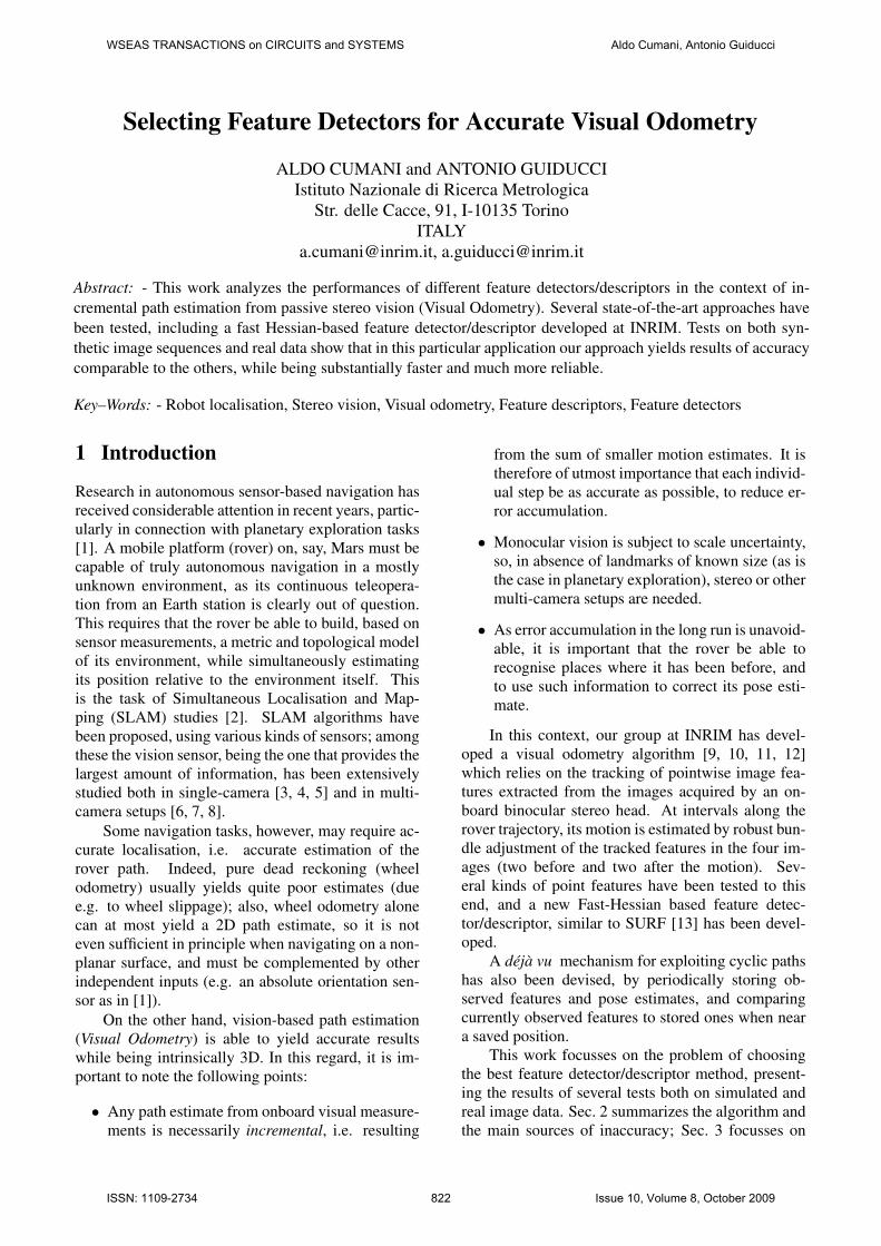
Figure 2: Sample stereo pair of the simulated envi-ronment.
-60
-40
-20
0
20
40
60
-50 0 50 100 150 200 250
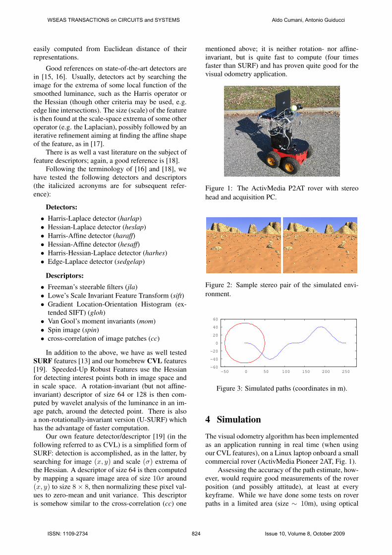
Figure 3: Simulated paths (coordinates in m).
4 Simulation
The visual odometry algorithm has been implementedas an application running in real time (when usingour CVL features), on a Linux laptop onboard a smallcommercial rover (ActivMedia Pioneer 2AT, Fig. 1).
Assessing the accuracy of the path estimate, how-ever, would require good measurements of the roverposition (and possibly attitude), at least at everykeyframe. While we have done some tests on roverpaths in a limited area (size ∼ 10m), using optical
WSEAS TRANSACTIONS on CIRCUITS and SYSTEMS Aldo Cumani, Antonio Guiducci
ISSN: 1109-2734 824 Issue 10, Volume 8, October 2009
0
0.5
1
1.5
2
2.5
3
3.5
4
4.5
5
0 50 100 150 200 250 300 350
cvlsurf
heslap/siftharaff/siftharlap/sifthesaff/siftharhes/sift
sedgelap/sift
0
0.01
0.02
0.03
0.04
0.05
0.06
0.07
0 50 100 150 200 250 300 350
cvlsurf
heslap/siftharaff/siftharlap/sifthesaff/siftharhes/sift
sedgelap/sift
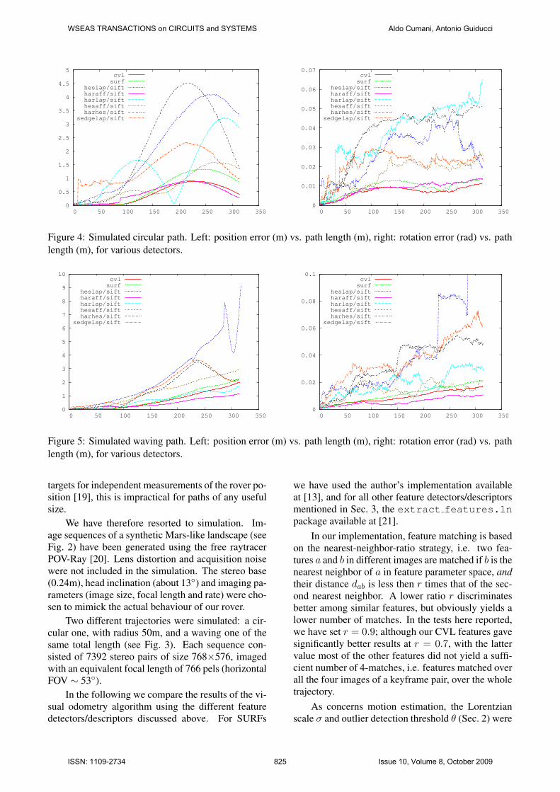
Figure 4: Simulated circular path. Left: position error (m) vs. path length (m), right: rotation error (rad) vs. pathlength (m), for various detectors.
0
1
2
3
4
5
6
7
8
9
10
0 50 100 150 200 250 300 350
cvlsurf
heslap/siftharaff/siftharlap/sifthesaff/siftharhes/sift
sedgelap/sift
0
0.02
0.04
0.06
0.08
0.1
0 50 100 150 200 250 300 350
cvlsurf
heslap/siftharaff/siftharlap/sifthesaff/siftharhes/sift
sedgelap/sift
Figure 5: Simulated waving path. Left: position error (m) vs. path length (m), right: rotation error (rad) vs. pathlength (m), for various detectors.
targets for independent measurements of the rover po-sition [19], this is impractical for paths of any usefulsize.
We have therefore resorted to simulation. Im-age sequences of a synthetic Mars-like landscape (seeFig. 2) have been generated using the free raytracerPOV-Ray [20]. Lens distortion and acquisition noisewere not included in the simulation. The stereo base(0.24m), head inclination (about 13◦) and imaging pa-rameters (image size, focal length and rate) were cho-sen to mimick the actual behaviour of our rover.
Two different trajectories were simulated: a cir-cular one, with radius 50m, and a waving one of thesame total length (see Fig. 3). Each sequence con-sisted of 7392 stereo pairs of size 768×576, imagedwith an equivalent focal length of 766 pels (horizontalFOV ∼ 53◦).
In the following we compare the results of the vi-sual odometry algorithm using the different featuredetectors/descriptors discussed above. For SURFs
we have used the author’s implementation availableat [13], and for all other feature detectors/descriptorsmentioned in Sec. 3, the extract features.lnpackage available at [21].
In our implementation, feature matching is basedon the nearest-neighbor-ratio strategy, i.e. two fea-tures a and b in different images are matched if b is thenearest neighbor of a in feature parameter space, andtheir distance dab is less then r times that of the sec-ond nearest neighbor. A lower ratio r discriminatesbetter among similar features, but obviously yields alower number of matches. In the tests here reported,we have set r = 0.9; although our CVL features gavesignificantly better results at r = 0.7, with the lattervalue most of the other features did not yield a suffi-cient number of 4-matches, i.e. features matched overall the four images of a keyframe pair, over the wholetrajectory.
As concerns motion estimation, the Lorentzianscale σ and outlier detection threshold θ (Sec. 2) were
WSEAS TRANSACTIONS on CIRCUITS and SYSTEMS Aldo Cumani, Antonio Guiducci
ISSN: 1109-2734 825 Issue 10, Volume 8, October 2009
0
0.5
1
1.5
2
2.5
0 50 100 150 200 250 300 350
cvlsurf
haraff/spinharaff/siftharaff/ccharaff/jlaharaff/mom
haraff/gloh
0
0.005
0.01
0.015
0.02
0.025
0 50 100 150 200 250 300 350
cvlsurf
haraff/spinharaff/siftharaff/ccharaff/jlaharaff/mom
haraff/gloh
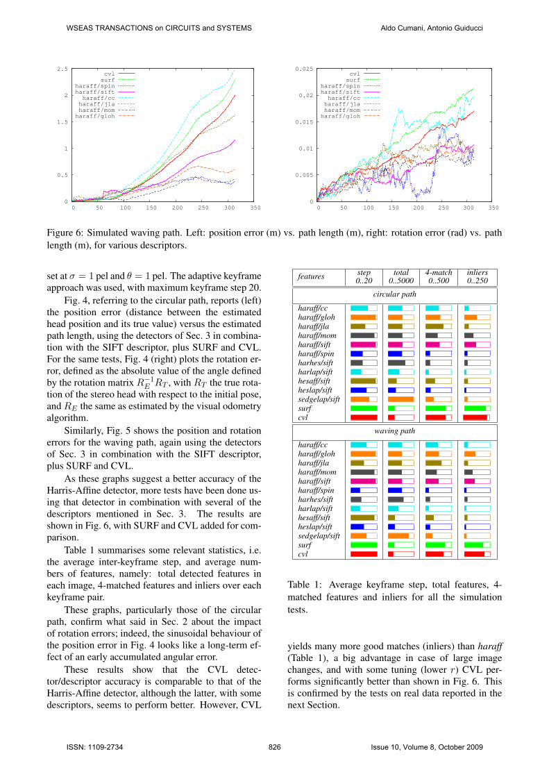
Figure 6: Simulated waving path. Left: position error (m) vs. path length (m), right: rotation error (rad) vs. pathlength (m), for various descriptors.
set at σ = 1 pel and θ = 1 pel. The adaptive keyframeapproach was used, with maximum keyframe step 20.
Fig. 4, referring to the circular path, reports (left)the position error (distance between the estimatedhead position and its true value) versus the estimatedpath length, using the detectors of Sec. 3 in combina-tion with the SIFT descriptor, plus SURF and CVL.For the same tests, Fig. 4 (right) plots the rotation er-ror, defined as the absolute value of the angle definedby the rotation matrix R−1
E RT , with RT the true rota-tion of the stereo head with respect to the initial pose,and RE the same as estimated by the visual odometryalgorithm.
Similarly, Fig. 5 shows the position and rotationerrors for the waving path, again using the detectorsof Sec. 3 in combination with the SIFT descriptor,plus SURF and CVL.
As these graphs suggest a better accuracy of theHarris-Affine detector, more tests have been done us-ing that detector in combination with several of thedescriptors mentioned in Sec. 3. The results areshown in Fig. 6, with SURF and CVL added for com-parison.
Table 1 summarises some relevant statistics, i.e.the average inter-keyframe step, and average num-bers of features, namely: total detected features ineach image, 4-matched features and inliers over eachkeyframe pair.
These graphs, particularly those of the circularpath, confirm what said in Sec. 2 about the impactof rotation errors; indeed, the sinusoidal behaviour ofthe position error in Fig. 4 looks like a long-term ef-fect of an early accumulated angular error.
These results show that the CVL detec-tor/descriptor accuracy is comparable to that of theHarris-Affine detector, although the latter, with somedescriptors, seems to perform better. However, CVL
features step0..20
total0..5000
4-match0..500
inliers0..250
circular path
haraff/ccharaff/glohharaff/jlaharaff/momharaff/siftharaff/spinharhes/siftharlap/sifthesaff/siftheslap/siftsedgelap/siftsurfcvl
waving path
haraff/ccharaff/glohharaff/jlaharaff/momharaff/siftharaff/spinharhes/siftharlap/sifthesaff/siftheslap/siftsedgelap/siftsurfcvl
Table 1: Average keyframe step, total features, 4-matched features and inliers for all the simulationtests.
yields many more good matches (inliers) than haraff(Table 1), a big advantage in case of large imagechanges, and with some tuning (lower r) CVL per-forms significantly better than shown in Fig. 6. Thisis confirmed by the tests on real data reported in thenext Section.
WSEAS TRANSACTIONS on CIRCUITS and SYSTEMS Aldo Cumani, Antonio Guiducci
ISSN: 1109-2734 826 Issue 10, Volume 8, October 2009
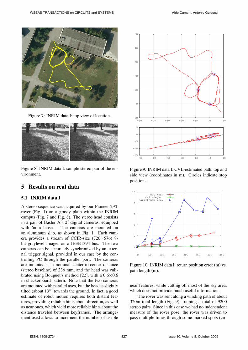
Figure 7: INRIM data I: top view of location.
Figure 8: INRIM data I: sample stereo pair of the en-vironment.
5 Results on real data
5.1 INRIM data I
A stereo sequence was acquired by our Pioneer 2ATrover (Fig. 1) on a grassy plain within the INRIMcampus (Fig. 7 and Fig. 8). The stereo head consistsin a pair of Basler A312f digital cameras, equippedwith 6mm lenses. The cameras are mounted onan aluminum slab, as shown in Fig. 1. Each cam-era provides a stream of CCIR-size (720×576) 8-bit graylevel images on a IEEE1394 bus. The twocameras can be accurately synchronized by an exter-nal trigger signal, provided in our case by the con-trolling PC through the parallel port. The camerasare mounted at a nominal center-to-center distance(stereo baseline) of 236 mm, and the head was cali-brated using Bouguet’s method [22], with a 0.6×0.6m checkerboard pattern. Note that the two camerasare mounted with parallel axes, but the head is slightlytilted (about 13◦) towards the ground. In fact, a goodestimate of robot motion requires both distant fea-tures, providing reliable hints about direction, as wellas near ones, which yield more reliable hints about thedistance traveled between keyframes. The arrange-ment used allows to increment the number of usable
-10
0
10
20
30
40
50
-50 -40 -30 -20 -10 0 10
-15
-10
-5
0
5
-50 -40 -30 -20 -10 0 10
Figure 9: INRIM data I: CVL-estimated path, top andside view (coordinates in m). Circles indicate stoppositions.
0
2
4
6
8
10
0 50 100 150 200 250 300 350
cvl (raw)cvl (dejavu)
haraff/mom (raw)
Figure 10: INRIM data I: return position error (m) vs.path length (m).
near features, while cutting off most of the sky area,which does not provide much useful information.
The rover was sent along a winding path of about320m total length (Fig. 9), framing a total of 9200stereo pairs. Since in this case we had no independentmeasure of the rover pose, the rover was driven topass multiple times through some marked spots (cir-
WSEAS TRANSACTIONS on CIRCUITS and SYSTEMS Aldo Cumani, Antonio Guiducci
ISSN: 1109-2734 827 Issue 10, Volume 8, October 2009
Figure 11: INRIM data II: top view of location.
Figure 12: INRIM data II: sample stereo pair of theenvironment.
cles in Fig. 9), and the algorithm was forced to put akeyframe at that positions. This allowed to computethe accumulated position error at each return to thesame spot. The latter is reported in Fig. 10 vs. the(estimated) length of path traversed before returning.
This plot compares the results obtained by ourCVL features (with r = 0.7, σ = 2 pel and θ = 1.5pel) against the best of the other detectors/descriptors,i.e. Harris-Affine + Moments, with r = 0.9 and thesame σ and θ. The reason for the different r is thatCVL features yield slightly better results at r = 0.7,while Harris-Affine+Mom does not work at all withthis value (too few good matches).
Note that the points in this graph have been joinedby lines only for the sake of readability, nearby pointson the plot are not necessarily near on the path, andthe error between successive points is simply un-known..
Fig. 10 also reports the results of applying thementioned deja vu loop-closure algorithm (again withCVL features).
5.2 INRIM data II
This data set comprises 13347 stereo pairs, collectedby our rover over a path of about 305 m, again withinthe INRIM area (Fig. 11). The main differences with
-20
-10
0
10
20
30
40
50
-10 0 10 20 30 40 50 60
-5
0
5
10
15
-10 0 10 20 30 40 50 60
Figure 13: INRIM data II: CVL-estimated path, topand side view (coordinates in m). Circles indicatestop positions.
0
2
4
6
8
10
12
14
0 50 100 150 200 250 300 350
cvl 0.7
haraff/mom 0.9
Figure 14: INRIM data II: return position error (m)vs. path length (m).
respect to the data presented above are the differ-ent season (longer shadows) and ground type (mainlypaved road, see Fig. 12). An even more importantfeature, when evaluating the results, is that for mostof its return travel the rover was driven to go approx-imately over the same path, running backwards. Thismeans that the images acquired in the forward and
WSEAS TRANSACTIONS on CIRCUITS and SYSTEMS Aldo Cumani, Antonio Guiducci
ISSN: 1109-2734 828 Issue 10, Volume 8, October 2009
features step0..20
total0..5000
4-match0..500
inliers0..250
INRIM path I
cvl (0.7)cvl (0.9)haraff/mom
INRIM path II
cvl (0.7)haraff/mom
Table 2: Average keyframe step, total features, 4-matched features and inliers for the real-world tests.
backward paths were much similar, so it may be ex-pected that some systematic errors (due e.g. to cali-bration) could compensate. This is indeed confirmedby the results in Fig. 14, where the return positionerror with CVL features is about 1/3 of that on thedata in Sec. 5.1 over a similar path length. However,the results with Harris-Affine + Moments are muchworse, even worse than with the other data set.
Finally, Table 2 summarises the relevant statistics(step size and numbers of features) for both tests onINRIM data.
5.3 Oxford data
We have done some test on the “New CollegeDataset”, kindly provided to the vision research com-munity by the Oxford Mobile Robotics Group [23,24]. The platform used to collect those data is atwo-wheeled vehicle (“Lisa”) built upon a SegwayRMP200 base. A Point Grey Bumblebee camera,placed at about 1 m over ground and tilted about 13◦
towards ground, provides a 20 Hz stream of greylevelstereo pairs, with a resolution of 512×384 pixels. Theplatform is also equipped with other sensors, amongwhich a GPS unit aimed at providing absolute posi-tioning data at more or less regular intervals.
The data set considered here was recorded inNovember, 2008, in New College, Oxford (see Figs.15 and 16) and comprises a total of 52478 stereopairs, collected in about 47 minutes over a total pathlength of about 2844 m (from dead reckoning data).
Actually, this data set has some undesirable fea-tures in view of applying our algorithm, namely:
• Camera calibration data are incomplete. Thedata set does provide software and data for recti-fying the images, and also some intrinsic and ex-trinsic camera parameters, but curiously enoughthe focal length is given in mm, instead of pixels- an information quite useless for processing dig-itized images. We converted this datum to pixels
Figure 15: Oxford data: aerial view of location (from[23]).
Figure 16: Oxford data: sample stereo pair.
using the nominal sensor pitch from the manu-facturer data sheet, yet we believe that the con-verted value is not accurate (we had to slightlyadjust that value in order to get reconstructed 3Dangles right).
• The Bumblebee camera has a rather limitedbase (0.12 m) and relatively low resolution(512×384), which do not contribute to accuracyin 3D estimation.
• The platform runs at a relatively high speed. Inspite of the 20Hz sampling rate, this may causea severe loss of correspondences, especially insharp turns. In the latter situation, moreover, theslow shutter speed of the camera yields stronglyblurred images, which sometimes cause a com-plete loss of image correspondences.
• There is no reliable ground truth position data.The dataset does provide GPS data, but we werenot able to find in the accompanying papers anyassessment of the accuracy of GPS data, whichcan sometimes be grossly wrong, as seen in theplot of Fig. 17. Moreover, there is no way to linkthe GPS reference to the robot’s one.
We have nevertheless tried to run our algorithmon the Oxford data. The results are shown in Fig. 17,
WSEAS TRANSACTIONS on CIRCUITS and SYSTEMS Aldo Cumani, Antonio Guiducci
ISSN: 1109-2734 829 Issue 10, Volume 8, October 2009

-100
-50
0
50
0 50 100 150 200
Figure 17: Oxford data: CVL-estimated path (solidred line) and GPS path (dotted blue line), top view.Coordinates in m.
where the visual odometry estimate, obtained usingCVL features, has been superimposed to GPS data,after a rough manual alignment. Only CVL resultsare reported, because none of the other competitorswere able to get outside Epoch A in Fig. 15; the bestwas again haraff/mom, reaching a path length of about732 m, with an average keyframe step of 9, beforealgorithm failure due to lack of useful features.
Note that also the CVL visual odometry is inter-rupted, but after an estimated path length of about1315m, and with an average keyframe step of 19.This interruption, due again to lack of good matches,happens in a sharp turn of the mobile platform. Itshould be noted that, in a real application, our visualodometry algorithm is not expected to be used alone,but supplemented with other modules able to catchand correct such situations using data from differentsensors (at worst, wheel odometry).
From Fig. 18 the difference between the CVL es-timate and GPS data for the first part (Epoch A inFig. 15) appears, on the average, well under 5m, i.e.the order of magnitude of a commercial GPS devicemounted on cars (the spikes are actually GPS errors,as can be seen from Fig. 17). The final rise of thecurve may be partly imputed to the misalignment ofvisual and GPS reference frames.
6 Discussion and conclusion
This work certainly does not pretend to be exhaustive.The number of tested sequences is too small to allowa reliable statistical assessment of the behaviour ofthe different algorithms. Nevertheless, some conclu-sion can already be drawn from the results reported
0
5
10
15
20
0 200 400 600 800 1000 1200 1400
Figure 18: Oxford data: distance (m) between CVL-estimated position and GPS position, vs. time (s).
above, in particular from the statistics in Tables 1 and2. In fact, while each error graph in Sec. 4 representsa global behaviour on a single sample of all possibletrajectories in all possible environments, the statis-tics in the Tables are averages over many differentkeyframe pairs, with different imaged scenes.
A first conclusion is that, in an application likeour visual odometry algorithm, a high degree of ge-ometric invariance (rotation, affine etc.) of featuresis not necessarily a merit. Indeed, the point of view(PoV) changes very little among the four images of akeyframe pair, and scale invariance is enough to takeinto account the scale change of near features with therover motion.
This is the reason why our CVL features (neitheraffine- nor even rotation-invariant) performs at a levelof accuracy comparable to the best affine-invariantdetectors, with the advantages of a much faster com-putation and greater reliability. The behaviour ofCVL features is quite similar to that of SURF ones,but with a considerable speedup.
In fact, from Table 1 CVL and SURF appear toyield both a lower number of initial detected features(total column, around 1000 per image) and a quitehigher number of useful ones (inliers column, around200), i.e. of features matched over all the four im-ages of a keyframe pair. A higher number of inlierscontributes to accuracy and reliability of the estimate,while a lower number of detected features alleviatesthe computational load. Indeed, feature extractionand matching is the most resource-consuming step ofthe algorithm; extraction time grows linearly with thenumber of features, and matching time is quadratic.
All this is confirmed by the real-world tests.While the usual caveats still apply, in Fig. 10 andFig. 14 cvl clearly outperforms haraff/mom. Table2 indicates that the latter yields a lower number ofusable features, and with a more frequent sampling(average step 6 against 14..16 for data set I, and 12against 20 for data set II) - neither of these contributeto accuracy, and the lower step size greatly increasescomputations.
Affinely invariant features could be of some help
WSEAS TRANSACTIONS on CIRCUITS and SYSTEMS Aldo Cumani, Antonio Guiducci
ISSN: 1109-2734 830 Issue 10, Volume 8, October 2009

in the deja vu loop-closure mechanism, where imagematching has to be done from much more differentpoints of view. However, our tests on other real imagesequences, not reported here, indicate that the num-ber of matches for quite different PoV’s is usuallynot enough for a reliable pose estimation with the ap-proach of Sec. 2. It could be enough, however, forplace recognition and subsequent pose re-estimationwith a different approach (e.g. map-matching).
Acknowledgment - This work has been partlysupported by Regione Piemonte in the framework ofthe STEPS Project, led by Thales Alenia Space Italia.
References:
[1] C. F. Olson, L. Matthies, M. Schoppers, and M. W.Maimone, “Robust stereo ego-motion for long dis-tance navigation.” in Proc. IEEE Conf. Computer Vi-sion and Pattern Recognition, 2000, pp. 2453–2458.
[2] S. Thrun, “Robotic mapping: A survey,” CarnegieMellon University, Tech. Rep. CMU-CS-02-111,2002.
[3] A. J. Davison, “Real-time simultaneous localisationand mapping with a single camera,” in Proceedingsof the 9th International Conference on Computer Vi-sion, Nice, 2003.
[4] J. Neira, M. I. Ribeiro, and J. D. Tardos, “Mobilerobot localization and map building using monocu-lar vision,” in Proc. 5th Int. Symp. Intelligent RoboticSystems ’97, 1997, pp. 275–284.
[5] A. Cumani, S. Denasi, A. Guiducci, and G. Quaglia,“Integration of visual cues for mobile robot localiza-tion and map building,” in Measurement and Controlin Robotics, M. A. Armada, P. Gonzales de Santos,and S. Tachi, Eds. Instituto de Automatica Indus-trial, Madrid, 2003.
[6] D. Murray and J. Little, “Using real-time stereo vi-sion for mobile robot navigation”,” in Proc. IEEEConf. on Computer Vision and Pattern Recognition,1998.
[7] H. Hirschmuller, “Real-time map building from astereo camera under unconstrained 3d motion,” DeMontfort University, Leicester,” Faculty ResearchConference, 2003.
[8] A. Cumani, S. Denasi, A. Guiducci, and G. Quaglia,“Robot localisation and mapping with stereo vision,”WSEAS Trans. Circuits and Systems, vol. 3, no. 10,pp. 2116–2121, 2004.
[9] A. Cumani and A. Guiducci, “Robot localisation er-ror reduction by stereo vision,” WSEAS Trans. Cir-cuits and Systems, vol. 4, no. 10, pp. 1239–1245,2005.
[10] ——, “Stereo-based visual odometry for robust rovernavigation,” WSEAS Trans. Circuits and Systems,vol. 5, no. 10, pp. 1556–1562, 2006.
[11] ——, “Visual odometry with SURFs and dejavu cor-rection,” in Proc. 8th Conf. Optical 3D MeasurementTechniques, 2007.
[12] ——, “Fast point features for accurate visual odom-etry,” in Proc. 12th WSEAS CSCC Multiconference,2008.
[13] H. Bay, T. Tuytelaars, and L. Van Gool, “SURF:Speeded up robust features,” in Proceedings 9th Eu-ropean Conference on Computer Vision, 2006, seealso http://www.vision.ee.ethz.ch/∼surf/.
[14] A. Cumani and A. Guiducci, “Robust and accu-rate visual odometry by stereo,” in Proceedings ofthe European Computing Conference, N. Mastorakis,V. Mladenov, and V. T. Kontargyri, Eds. Springer,June 2009, vol. II, pp. 485–494.
[15] K. Mikolajczyk, T. Tuytelaars, C. Schmid, A. Zis-serman, J. Matas, F. Schaffalitzky, T. Kadir, andL. Van Gool, “A comparison of affine region de-tectors,” International Journal of Computer Vision,vol. 65, no. 1/2, pp. 43–72, 2005.
[16] T. Tuytelaars and K. Mikolajczyk, “Local invariantfeature detectors: a survey,” Found. Trends. Comput.Graph. Vis., vol. 3, no. 3, pp. 177–280, 2008.
[17] K. Mikolajczyk and C. Schmid, “Scale & affine in-variant interest point detectors,” International Jour-nal of Computer Vision, vol. 60, no. 1, pp. 63–86,2004.
[18] ——, “A performance evaluation of local descrip-tors,” IEEE Transactions on Pattern Analysis andMachine Intelligence, vol. 27, no. 10, pp. 1615–1630,2005.
[19] A. Cumani and A. Guiducci, “Fast stereo-based vi-sual odometry for rover navigation,” WSEAS Trans.Circuits and Systems, vol. 7, no. 7, pp. 648–657,2008.
[20] Persistence of Vision Pty. Ltd.(http://www.povray.org/), 2004.
[21] http://www.robots.ox.ac.uk/∼vgg/research/affine/detectors.html.
[22] J. Y. Bouguet, “Complete camera calibration tool-box for MATLAB,” http://www.vision.caltech.edu/∼bouguetj/calib doc/index.html, Tech. Rep., 2004.
[23] M. Smith, I. Baldwin, W. Churchill, R. Paul, andP. Newman, “The new college vision and laser dataset,” International Journal for Robotics Research(IJRR), vol. 28, no. 5, pp. 595–599, May 2009.
[24] http://www.robots.ox.ac.uk/NewCollegeData/.
WSEAS TRANSACTIONS on CIRCUITS and SYSTEMS Aldo Cumani, Antonio Guiducci
ISSN: 1109-2734 831 Issue 10, Volume 8, October 2009
Related Documents