Selecting and Tailoring Design Methodologies in the Form of Roadmaps for a Specific Development Project. Friedrich Hagen Martin Nieberding Dissertation presented for the degree of Doctor of Engineering (Industrial) at the Stellenbosch University Promoters: Niek du Preez, Department of Industrial Engineering Anton Basson, Department of Mechanical Engineering January 2010

Welcome message from author
This document is posted to help you gain knowledge. Please leave a comment to let me know what you think about it! Share it to your friends and learn new things together.
Transcript
Selecting and Tailoring Design Methodologies inthe Form of Roadmaps for a Specific
Development Project.
Friedrich Hagen Martin Nieberding
Dissertation presented for the degree of Doctor of Engineering (Industrial)at the Stellenbosch University
Promoters:Niek du Preez, Department of Industrial Engineering
Anton Basson, Department of Mechanical Engineering
January 2010

Declaration
By submitting this dissertation electronically, I declare that the entirety of the work contained therein is my own,original work, that I am the owner of the copyright thereof (unless to the extent explicitly otherwise stated) andthat I have not previously in its entirety or in part submitted it for obtaining any qualification.
Copyright c©2010 Stellenbosch UniversityAll rights reserved
ii

Abstract
This dissertation investigates answers to the question: "How does one decide on the approach to implementwhen planning, managing and executing a development project?". By examining the prescriptive models ofthe development process, as proposed by design science, the principle characteristics are identified, thatthese models try to enforce. The need for tailoring the development process to the context of the project ishighlighted by contrasting these prescriptive models to industrial practice and the corresponding descriptivemodels of the development process. A framework of contextual variables is proposed, which facilitates thetailoring of the approach to the project by defining the project methodology. The usefulness of this contextualframework is verified by means of case studies. Finally the dissertation proposes the use of a roadmap todefine the project methodology at the beginning of the project. By packaging the project methodology in theform of a roadmap, implemented in a collaborative computer environment, it can be refined during the execu-tion of the project to suit the information requirements of the project.
iii

Samevatting
Hierdie verhandeling ondersoek antwoorde tot die vraag: "Hoe besluit ’n mens watter benadering om vir diebeplanning, bestuur en deurvoering van ’n ontwikkelingsprojek toe te pas?". Deur die voorskriftelike modellevan die ontwikkelingsproses wat deur die ontwikkelingswetenskap voorgestel word, te ondersoek, word diegrondbeginsels bepaal wat di modelle poog om af te dwing. Die behoefte om die ontwikkelingsproses by dieprojek se konteks aan te pas, word duidelik uitgebeeld deur die kontras tussen hierdie voorskriftelike modellevan die ontwikkelingsproses en industrile praktyk, sowel as die ooreenkomstige beskrywende modelle. ’nRaamwerk word voorgestel om die konteks van ’n projek te beskryf. Die aanpassing van die benadering totdie projek word sodoende deur die definisie van ’n projekmetodologie vergemaklik. Gevallestudies bevestigdie nuttigheid van hierdie raamwerk. Die verhandeling sluit met die slotsom af dat ’n padkaart gebruik kanword om die projekmetodologie aan die begin van die projek te bepaal. Deur die projekmetodologie in ’npadkaart te verpak wat in ’n rekenaargesteunde spanomgewing gebruik kan word, kan dit gedurende dieuitvoering van die projek gewysig word volgens die inligtingsbehoeftes van die projek.
iv
Preface
From the time that the author of this dissertation decided to study mechanical engineering, it was clear to himthat the focus would be design and development of products. What kind of products was always of secondaryimportance. The primary focus was, and still is, the process which starts as a desire in the heart, evolvesinto a picture in the mind and ends up as a physical object, that can be touched and operated. Consequentlythe author’s career has exposed him to a fairly wide range of industries, ranging from electrical switchgear,through a first tier supplier to the major automotive manufacturers, to the development and manufacture in thespecial automotive industry, which includes military, cash-in-transit and law-enforcement vehicles.
From a perspective of a broad overview, the development process in the various companies was very similar.And yet, it is the differences among these processes that is intriguing. Why are they different? Should orcould they be the same? If they are supposed to be different, how does one decide what the process shouldbe like, given a specific project? The need to understand more about design and development, answeringsome of these questions in the process, was the motivation to start the five year journey through the researchthat ended with this dissertation.
The first two chapters provide background for the reader to understand the context surrounding this work. Thefirst chapter discusses the research, its aims, its relationship to existing work in the field, and the structureof this document. The second one provides a broad overview of engineering design and development bydiscussing the typical characteristics of this process.
The second part of the dissertation engages the subject matter in more detail by analysing models of thedevelopment process (Chapter 3) that have been proposed over the last sixty years or so. The fourth chaptercontrasts these theoretical models against the reality of industrial practise and comes to the conclusion that itis sensible to tailor the development process to the context of each specific development project.
Having come to this conclusion, the next part of the dissertation, provides a means to crystallise the amor-phous concept of "project context" into a limited set of variables, which highlight the often conflicting re-quirements and characteristics of development projects. Chapter 5 discusses each of the variables of thiscontextual framework and their inter-relationships. To illustrate and verify the framework, the sixth chapterapplies the framework to a couple of case studies.
The fourth part of the dissertation (Chapter 7) proposes a way of applying the contextual framework in apractical manner. In accordance with the original intent for this work, the proposed implementation does notinvolve elaborate IT infrastructure. It can therefore benefit smaller companies as much as large ones.
The last part of the dissertation summarises the work described in the dissertation, by answering the specificresearch questions posed in Chapter 1, referring to the relevant sections of the dissertation where required.
A final comment regarding the scope of the research described in this dissertation: the words "product de-velopment" conjures up different images in the minds of different people. For one it is the legal process ofregistering patents and trademarks in order to prevent the product being copied. For another, it is the businessprocess of landing a deal, making it viable from a cash-flow perspective, ensuring it is profitable in the longrun, and finally executing the project. It is true - all of these are valid perspectives of "product development".However, in research like this one cannot address all aspects of a complex and intricate subject as "productdevelopment". The author has therefore decided, with intent, to concentrate on the engineering process,and how it is influenced by the context that surrounds it, including the legal, business, finance, resource andhuman aspects. In the world of engineering design and development, the engineering process in intrinsicallylinked to the management of the project. It is for this reason that the dissertation also addresses projectmanagement issues, especially in Chapter 7.
The following statement is the author’s perspective on engineering design and development and the theme ofthis research: "Product development is where design collides with reality".
v

Acknowledgements
Although my passion for and interest in engineering in general and product development in particular hascaused me to drive this project from conception to completion, it would not have been possible for me todo so without the assistance of so many other people. Some have played a very active role in the process,others have helped by just being there. It is impossible to mention all of the individuals and institutions thathave influenced this work by name, and therefore I ask for understanding and pardon of those which I do notmention explicitly.
First and foremost, I would like to thank my family, my wife, Cora, and my children, Gregor and Nadia, foraccepting my pre-occupation with this work for five long years with so much patience and grace. To quote aclassic: "I’ll be back!".
Also, I thank my parents, Fritz and Doris, who have made this journey possible by laying the foundationof my academic career by affording me the opportunity to achieve my bachelor’s and master’s degrees inmechanical engineering.
Staying in the realm of academia, I thank Niek du Preez and Anton Basson for their endless patience andguidance. Without their constant support it would not have been possible for me to get through the darktimes when the option of giving up seemed a very reasonable alternative. I am also extremely grateful for theassistance I have received from others at the University: Karina Smith, who always arranged my visits to Stel-lenbosch, Anel Uys, who assisted me with my bursary and related matters, Antje Gildenhuys, who tirelesslyobtained reference material from all corners of the globe for me, and Minnaar Pienaar, who was always willingto assist with all the administration related to my being a student at the University of Stellenbosch.
During the process of gathering information for my research, I have been extremely fortunate and grateful tohave obtained assistance from all over the world. First and foremost, Eric Lutters of the University of Twente,Netherlands, who was always willing to discuss the various topics of my research and provide valuable insight.Also Bernard Schlegel, a friend of the family, who provided me with access to much of the German literatureon the subject of product development.
At times I would come across a reference to a doctoral dissertation, which would be of interest to my work.On the off-chance that I might receive a reply, I would write to the author, asking for an electronic copy of theirdissertation. It amazed me that I would always get a positive response - without fail! A special thanks to thefollowing authors for their help: Graham Thompson, Denis Cavallucci, Lucienne Blessing and Crispin Hales.
Moving from academia to industry, there are three organisations that have played major roles in my research:BAE Land Systems OMC, Mechanology and Indutech. For allowing me to use actual industrial projects ascase studies for my research, my appreciation goes to the managers I reported to at BAE Land SystemsOMC and Mechanology. The owner of Mechanology, Craig Savides, has been particularly supportive andexceptionally patient, especially considering the large amount of study leave required to attend conferencesand regular visits to the University in Stellenbosch. Special thanks goes to Niek du Preez and his team atIndutech for all the assistance I have received over the years. Not only for the use of EDENTM to implementthe roadmaps I discuss in Chapter 7, but also for the friendship and support that was so crucial as a soundingboard for the concepts and ideas generated during the research described in this dissertation. In this respect,my sincere gratitude goes especially to Elna du Preez, Ursula Seconds, Louis Louw, Wilhelm Uys, RiaanBrand, Marc-Allen Johnson and Bernard Katz.
Lastly, but not least, I would like to thank the National Science Foundation for the bursary in support of mystudies at the University of Stellenbosch.
vi
Table Of Contents
1 Introduction 1
1.1 Background . . . . . . . . . . . . . . . . . . . . . . . . . . . . . . . . . . . . . . . . . . . . . 2
1.2 Definitions . . . . . . . . . . . . . . . . . . . . . . . . . . . . . . . . . . . . . . . . . . . . . . 2
1.3 Aim of the Research Project . . . . . . . . . . . . . . . . . . . . . . . . . . . . . . . . . . . . 3
1.4 Target Environment . . . . . . . . . . . . . . . . . . . . . . . . . . . . . . . . . . . . . . . . . 4
1.5 Research Questions . . . . . . . . . . . . . . . . . . . . . . . . . . . . . . . . . . . . . . . . . 4
1.6 Research Taxonomy . . . . . . . . . . . . . . . . . . . . . . . . . . . . . . . . . . . . . . . . 4
1.7 How and Where Does this Research Fit into Design Science? . . . . . . . . . . . . . . . . . . 5
1.7.1 Research Categories According to Cross . . . . . . . . . . . . . . . . . . . . . . . . . 5
1.7.2 The Taxonomical Framework of Horváth and Vergeest . . . . . . . . . . . . . . . . . . 5
1.7.3 The Research Areas of Design Science by Hubka and Eder . . . . . . . . . . . . . . . 7
1.8 Structure of this Dissertation . . . . . . . . . . . . . . . . . . . . . . . . . . . . . . . . . . . . 8
2 Engineering Design and Development 11
2.1 What is Design in General and Engineering Design in Particular? . . . . . . . . . . . . . . . . 12
2.2 Product Life-Cycles And Product Development . . . . . . . . . . . . . . . . . . . . . . . . . . 16
2.3 Product Life-cycles, Methodologies, and Design Methods . . . . . . . . . . . . . . . . . . . . 17
3 Theoretical Models of the Development Process 21
3.1 Prescriptive Models . . . . . . . . . . . . . . . . . . . . . . . . . . . . . . . . . . . . . . . . . 22
3.1.1 Similarities of Prescriptive Models of the Development Process . . . . . . . . . . . . . 22
3.1.2 Differences Among Prescriptive Development Process Models . . . . . . . . . . . . . . 24
3.1.3 Conclusions . . . . . . . . . . . . . . . . . . . . . . . . . . . . . . . . . . . . . . . . . 26
3.2 Principle Development Rules . . . . . . . . . . . . . . . . . . . . . . . . . . . . . . . . . . . . 28
3.3 Decsriptive Models . . . . . . . . . . . . . . . . . . . . . . . . . . . . . . . . . . . . . . . . . 28
3.3.1 Similarities of Descriptive Models of the Development Process . . . . . . . . . . . . . . 29
3.3.2 Differences Among Descriptive Models of the Development Process . . . . . . . . . . . 29
3.4 Prescriptive Models Versus Descriptive Models - Conclusions . . . . . . . . . . . . . . . . . . 29
4 Analysis of the Theoretical Models in the Light of Practical Application 31
4.1 What Happens in Practice? . . . . . . . . . . . . . . . . . . . . . . . . . . . . . . . . . . . . . 32
4.2 The Need for Tailoring or Adaptation of Development Models . . . . . . . . . . . . . . . . . . 34
4.3 Project Methodology: Planning, Managing and Executing Development Projects . . . . . . . . 36
5 Internal and External Influences on the Development Process 39
5.1 Existing Frameworks . . . . . . . . . . . . . . . . . . . . . . . . . . . . . . . . . . . . . . . . 40
vii
viii
5.2 Description of Factors Influencing the Development Process . . . . . . . . . . . . . . . . . . . 41
5.2.1 Variables Related to the Organisation . . . . . . . . . . . . . . . . . . . . . . . . . . . 41
5.2.2 Variables Related to the Project . . . . . . . . . . . . . . . . . . . . . . . . . . . . . . 46
5.2.3 Variables Related to the Product . . . . . . . . . . . . . . . . . . . . . . . . . . . . . . 50
5.2.4 Variables Related to the Personnel . . . . . . . . . . . . . . . . . . . . . . . . . . . . . 53
5.3 Framework for the Contextualisation of the Development Life-cycle . . . . . . . . . . . . . . . 55
5.3.1 Variables Related to Size . . . . . . . . . . . . . . . . . . . . . . . . . . . . . . . . . . 56
5.3.2 Variables Related to Type . . . . . . . . . . . . . . . . . . . . . . . . . . . . . . . . . . 56
5.3.3 Variables Related to Complexity . . . . . . . . . . . . . . . . . . . . . . . . . . . . . . 56
5.3.4 Variables Related to Maturity . . . . . . . . . . . . . . . . . . . . . . . . . . . . . . . . 58
5.3.5 Variables Related to Capacity and Capability . . . . . . . . . . . . . . . . . . . . . . . 58
5.4 Role players . . . . . . . . . . . . . . . . . . . . . . . . . . . . . . . . . . . . . . . . . . . . . 59
5.5 Summary and Conclusions . . . . . . . . . . . . . . . . . . . . . . . . . . . . . . . . . . . . . 59
6 Case Studies to Evaluate the Framework of Contextual Factors 61
6.1 Case Study A . . . . . . . . . . . . . . . . . . . . . . . . . . . . . . . . . . . . . . . . . . . . 62
6.1.1 Introduction to the Industry Project and its Context . . . . . . . . . . . . . . . . . . . . 62
6.1.2 Application of the Framework to the Development Project . . . . . . . . . . . . . . . . . 63
6.1.3 The Execution of the Project . . . . . . . . . . . . . . . . . . . . . . . . . . . . . . . . 67
6.1.4 Conclusion and Discussion . . . . . . . . . . . . . . . . . . . . . . . . . . . . . . . . . 70
6.2 Case Study B . . . . . . . . . . . . . . . . . . . . . . . . . . . . . . . . . . . . . . . . . . . . 71
6.2.1 Introduction to the Industry Project and its Context . . . . . . . . . . . . . . . . . . . . 71
6.2.2 Values Assigned to the Variables of the Framework . . . . . . . . . . . . . . . . . . . . 74
6.2.3 The Resulting Project Methodology . . . . . . . . . . . . . . . . . . . . . . . . . . . . 76
6.2.4 The Execution of the Project . . . . . . . . . . . . . . . . . . . . . . . . . . . . . . . . 77
6.2.5 Conclusion and Discussion . . . . . . . . . . . . . . . . . . . . . . . . . . . . . . . . . 78
6.3 Case Study C . . . . . . . . . . . . . . . . . . . . . . . . . . . . . . . . . . . . . . . . . . . . 79
6.4 Case Study D . . . . . . . . . . . . . . . . . . . . . . . . . . . . . . . . . . . . . . . . . . . . 80
6.5 Summary and Conclusions . . . . . . . . . . . . . . . . . . . . . . . . . . . . . . . . . . . . . 80
7 Generating a Formal Project Methodology 81
7.1 Process Orientation Versus Information Orientation . . . . . . . . . . . . . . . . . . . . . . . . 82
7.1.1 Process Orientated Integration and Control . . . . . . . . . . . . . . . . . . . . . . . . 82
7.1.2 Information Orientated Integration and Control . . . . . . . . . . . . . . . . . . . . . . 82
7.1.3 Conclusions and Summary . . . . . . . . . . . . . . . . . . . . . . . . . . . . . . . . . 83
7.2 The Process of Formulating a Formal Project Methodology . . . . . . . . . . . . . . . . . . . . 84
7.3 Using the Contextual Framework to Tailor the Methodology for a Specific Development Project 84
7.3.1 Project Background . . . . . . . . . . . . . . . . . . . . . . . . . . . . . . . . . . . . . 85
7.3.2 Project Enablers . . . . . . . . . . . . . . . . . . . . . . . . . . . . . . . . . . . . . . . 86
7.3.3 Project Structure . . . . . . . . . . . . . . . . . . . . . . . . . . . . . . . . . . . . . . . 86
7.4 Introduction to the Concept of a Roadmap . . . . . . . . . . . . . . . . . . . . . . . . . . . . . 90
7.5 A Formal Project Methodology as a Roadmap . . . . . . . . . . . . . . . . . . . . . . . . . . . 91
7.6 A Roadmap to Generate a Project Methodology . . . . . . . . . . . . . . . . . . . . . . . . . . 92
7.7 Conclusions . . . . . . . . . . . . . . . . . . . . . . . . . . . . . . . . . . . . . . . . . . . . . 92
ix
8 Research Findings and Conclusions 97
8.1 Answers to Research Questions . . . . . . . . . . . . . . . . . . . . . . . . . . . . . . . . . . 98
8.1.1 Given a Specific Project, with Specific Resources within a Given Environment, HowDoes One Select and Construct a Design Methodology from a Repository of Templates? 98
8.1.2 Can Benefit be Obtained by Combining Design Methods to Form a Project Methodology? 98
8.1.3 Can Methods be Established to Define a Methodology Optimised for a Specific Project? 99
8.1.4 How do I Specify, Choose and Construct a Development Methodology? . . . . . . . . . 99
8.1.5 How do I Measure the Success or Appropriateness of My Choices? . . . . . . . . . . . 99
8.1.6 How do I Comprehensively Quantify My Needs with Respect to a Development Method-ology? . . . . . . . . . . . . . . . . . . . . . . . . . . . . . . . . . . . . . . . . . . . . 99
8.1.7 Can a Methodology be Represented in a Roadmap? . . . . . . . . . . . . . . . . . . . 100
8.1.8 Can a Roadmap, Implemented in a Design Environment, Facilitate the Engineering De-velopment Process? . . . . . . . . . . . . . . . . . . . . . . . . . . . . . . . . . . . . . 100
8.1.9 What Attributes Must a Roadmap Have so That it Can Represent a Design Methodology?100
8.1.10 What Attributes Must a Design Environment Have so That a Roadmap Can be Appliedto a Development Project? . . . . . . . . . . . . . . . . . . . . . . . . . . . . . . . . . 100
8.2 Limitations of This Research . . . . . . . . . . . . . . . . . . . . . . . . . . . . . . . . . . . . 100
8.3 Applications . . . . . . . . . . . . . . . . . . . . . . . . . . . . . . . . . . . . . . . . . . . . . 101
8.4 Suggestions for Future Research . . . . . . . . . . . . . . . . . . . . . . . . . . . . . . . . . . 101
8.5 Overall Summary and Conclusions . . . . . . . . . . . . . . . . . . . . . . . . . . . . . . . . . 101
A Selection of Design Methods 103
A.1 Selection of Design Methods by Project Phase . . . . . . . . . . . . . . . . . . . . . . . . . . 104
A.2 Selection of Design Methods According to Need . . . . . . . . . . . . . . . . . . . . . . . . . 106
B An Overview of Various Prescriptive Models of the Development Process 115
B.1 Cross’s Model of the Design Process . . . . . . . . . . . . . . . . . . . . . . . . . . . . . . . 116
B.2 French’s Model of the Design Process . . . . . . . . . . . . . . . . . . . . . . . . . . . . . . . 116
B.3 Archer’s Model of the Design Process . . . . . . . . . . . . . . . . . . . . . . . . . . . . . . . 117
B.4 Development Model for Large Infrastructure Projects . . . . . . . . . . . . . . . . . . . . . . . 118
B.5 Suireg’s Model of the Design Process . . . . . . . . . . . . . . . . . . . . . . . . . . . . . . . 118
B.6 The Design Process According to Pahl and Beitz . . . . . . . . . . . . . . . . . . . . . . . . . 118
B.7 The Model of the Development Process as Defined by VDI 2221 . . . . . . . . . . . . . . . . . 119
B.8 Ullman’s Model of the Development Process . . . . . . . . . . . . . . . . . . . . . . . . . . . 121
B.9 The Systems Engineering Approach to the Development Process . . . . . . . . . . . . . . . . 123
B.9.1 Requirements Engineering . . . . . . . . . . . . . . . . . . . . . . . . . . . . . . . . . 125
B.10 Concurrent Engineering . . . . . . . . . . . . . . . . . . . . . . . . . . . . . . . . . . . . . . . 125
B.11 Integrated Product Development . . . . . . . . . . . . . . . . . . . . . . . . . . . . . . . . . . 126
B.12 Pugh’s Core-based Model . . . . . . . . . . . . . . . . . . . . . . . . . . . . . . . . . . . . . 127
C An Overview of Various Descriptive Models of the Development Process 129
C.1 Models of the Design Process by Hillier, Drake and March . . . . . . . . . . . . . . . . . . . . 130
C.2 Model by Hybs and Gero . . . . . . . . . . . . . . . . . . . . . . . . . . . . . . . . . . . . . . 130
C.3 Model by Johannes . . . . . . . . . . . . . . . . . . . . . . . . . . . . . . . . . . . . . . . . . 131
C.4 Model by Reymen . . . . . . . . . . . . . . . . . . . . . . . . . . . . . . . . . . . . . . . . . . 132
C.5 Model by Stempfle and Badke-Schaub . . . . . . . . . . . . . . . . . . . . . . . . . . . . . . . 133

x
C.6 Model by Günther and Ehrlenspiel . . . . . . . . . . . . . . . . . . . . . . . . . . . . . . . . . 134
C.7 Model by Hansen and Ahmed . . . . . . . . . . . . . . . . . . . . . . . . . . . . . . . . . . . 134
D Characteristics of Companies and Their Development Processes 137
D.1 Influences on a Design Project by Wallace and Hales . . . . . . . . . . . . . . . . . . . . . . . 138
D.2 Product Properties by Tjalve . . . . . . . . . . . . . . . . . . . . . . . . . . . . . . . . . . . . 138
D.3 Company Classification by Barber and Hollier . . . . . . . . . . . . . . . . . . . . . . . . . . . 138
D.4 The Seven Dimensions of a Company’s Product Development by Andreasen et al. . . . . . . . 141
D.5 Parameters Affecting the Design Process According to Ehrlenspiel . . . . . . . . . . . . . . . 141
D.6 Field Study of Design by Hykin and Laming . . . . . . . . . . . . . . . . . . . . . . . . . . . . 141
D.7 Company Classification by Maffin . . . . . . . . . . . . . . . . . . . . . . . . . . . . . . . . . 142
References 145
Index 151
List of Figures
1.1 Framework of Concepts Addressed in this Research . . . . . . . . . . . . . . . . . . . . . . . 5
1.2 Contextual Categories for Design Science [66] . . . . . . . . . . . . . . . . . . . . . . . . . . 6
1.3 Research Areas in Design Science According to Hubka and Eder [68] . . . . . . . . . . . . . 8
1.4 The Technical Process According to Hubka and Eder [68] . . . . . . . . . . . . . . . . . . . . 8
1.5 The Structure of this Dissertation . . . . . . . . . . . . . . . . . . . . . . . . . . . . . . . . . . 9
2.1 The Design Process According to Andreasen [9] . . . . . . . . . . . . . . . . . . . . . . . . . 12
2.2 Design Freedom and Knowledge During the Development Process [123] . . . . . . . . . . . . 13
2.3 Product Costs as a Function of Time During the Development Process According to Schulz [110] 14
2.4 The Inter-relationship of Synthesis and Analysis During the Development Process as Depictedby Bichlmaier [18] . . . . . . . . . . . . . . . . . . . . . . . . . . . . . . . . . . . . . . . . . . 14
2.5 The Product Life-Cycle Adopted from Krause [80] . . . . . . . . . . . . . . . . . . . . . . . . . 16
2.6 The Systems Engineering Product Life-cycle [19] . . . . . . . . . . . . . . . . . . . . . . . . . 17
2.7 Ullman’s Product Life-cycle [123] . . . . . . . . . . . . . . . . . . . . . . . . . . . . . . . . . . 18
3.1 Solution / Problem Hierarchy [125] . . . . . . . . . . . . . . . . . . . . . . . . . . . . . . . . . 23
3.2 Degree of "Structuredness" for Various Prescriptive Models of the Development Process . . . 25
3.3 Matrix Showing Which Phases of the Product Life-cycle are Addressed by Various PrescriptiveModels of the Development Process . . . . . . . . . . . . . . . . . . . . . . . . . . . . . . . . 26
3.4 The Need for a Prescriptive Model of the Development Process Increases as the Level ofNovelty, Risk and Complexity Increases . . . . . . . . . . . . . . . . . . . . . . . . . . . . . . 30
4.1 Productive Solution Generation [47] . . . . . . . . . . . . . . . . . . . . . . . . . . . . . . . . 32
4.2 Corrective Solution Generation [47] . . . . . . . . . . . . . . . . . . . . . . . . . . . . . . . . 33
4.3 Solution Strategies Adapted From Ehrlenspiel and Dylla [47] . . . . . . . . . . . . . . . . . . . 34
4.4 Relationship among Methodology, Methods and Models . . . . . . . . . . . . . . . . . . . . . 37
4.5 Establishing a Design Methodology According to Maffin [86] . . . . . . . . . . . . . . . . . . . 38
5.1 The Contextual Framework Adapted from Maffin [86] . . . . . . . . . . . . . . . . . . . . . . . 41
5.2 Innovation Continuum According to Thomond and Lettice [119] . . . . . . . . . . . . . . . . . 49
5.3 Level of Innovation According to Frost [53] . . . . . . . . . . . . . . . . . . . . . . . . . . . . . 50
5.4 Level of Complexity of Various Designed Entities According to Frost [53] . . . . . . . . . . . . 51
5.5 Correlation Between Project/Product Complexity and Design Strategy [86] . . . . . . . . . . . 52
5.6 Amenability of Some Designed Entities to Decomposition into Sub-systems According to Frost [53] 53
5.7 The Framework of Factors Affecting the Product Life-cycle . . . . . . . . . . . . . . . . . . . . 56
5.8 Relationship Between Complexity and Structuredness . . . . . . . . . . . . . . . . . . . . . . 58
6.1 The Development Process Adopted by Mechanology for this Project . . . . . . . . . . . . . . . 66
xi
xii
6.2 The Original Project Plan . . . . . . . . . . . . . . . . . . . . . . . . . . . . . . . . . . . . . . 68
6.3 The Project Plan Used for the Execution of the Project . . . . . . . . . . . . . . . . . . . . . . 68
6.4 The Process Followed for this Project . . . . . . . . . . . . . . . . . . . . . . . . . . . . . . . 77
6.5 The Author’s Proposed Development Process . . . . . . . . . . . . . . . . . . . . . . . . . . . 79
7.1 The Development Process . . . . . . . . . . . . . . . . . . . . . . . . . . . . . . . . . . . . . 83
7.2 The Process of Formulating a Project Methodology . . . . . . . . . . . . . . . . . . . . . . . . 85
7.3 Categories of Contextual Variables . . . . . . . . . . . . . . . . . . . . . . . . . . . . . . . . . 85
7.4 Roadmap Implemented in EDENTM . . . . . . . . . . . . . . . . . . . . . . . . . . . . . . . 91
A.1 Eder’s Method Matrix [46] . . . . . . . . . . . . . . . . . . . . . . . . . . . . . . . . . . . . . . 108
A.2 Methods for Analysis and Goal-setting Recommended by VDI 2221 [125] . . . . . . . . . . . . 109
A.3 Methods for Generation of Ideas Recommended by VDI 2221 [125] . . . . . . . . . . . . . . . 110
A.4 Methods for Cost Estimation Recommended by VDI 2221 [125] . . . . . . . . . . . . . . . . . 111
A.5 Methods for Assessment and Decision Making Recommended by VDI 2221 [125] . . . . . . . 112
A.6 Integrated Methods Recommended by VDI 2221 [125] . . . . . . . . . . . . . . . . . . . . . . 113
B.1 The Model of the Development Process by Cross [32] . . . . . . . . . . . . . . . . . . . . . . 116
B.2 French’s Model of the Product Development Process [32] . . . . . . . . . . . . . . . . . . . . 117
B.3 Archer’s Model of the Product Development Process [32] . . . . . . . . . . . . . . . . . . . . . 117
B.4 Development Process for a Construction Project According to the IDC [36] . . . . . . . . . . . 118
B.5 Suireg’s Model of the Product Development Process [117] . . . . . . . . . . . . . . . . . . . . 119
B.6 The Product Development Process According to Pahl and Beitz [97] . . . . . . . . . . . . . . . 120
B.7 The Product Development Process According to the VDI [125] . . . . . . . . . . . . . . . . . 120
B.8 The Mechanical Design Process According to Ullman [123] . . . . . . . . . . . . . . . . . . . 122
B.9 The Systems Engineering Product Acquisition Process [19] . . . . . . . . . . . . . . . . . . . 124
B.10 The Feedback in the Systems Engineering Process [19] . . . . . . . . . . . . . . . . . . . . . 125
B.11 Process of Integrated Product Development by Andreasen and Hein [9] . . . . . . . . . . . . . 126
B.12 The Product Synthesis Process According to Andreasen and Hein [9] . . . . . . . . . . . . . . 127
B.13 Pugh’s Core-based Model [102] . . . . . . . . . . . . . . . . . . . . . . . . . . . . . . . . . . 128
C.1 March’s Model of the Product Development Process [32] . . . . . . . . . . . . . . . . . . . . . 130
C.2 Model of Design Process According Hybs and Gero [70] . . . . . . . . . . . . . . . . . . . . . 131
C.3 A Design Situation as a State According to Reymen et al. [1] . . . . . . . . . . . . . . . . . . . 132
C.4 Transitions from One State to Another According to Reymen et al. [1] . . . . . . . . . . . . . . 132
C.5 Generic Model of Design Activities by Stempfle and Badke-Schaub [115] . . . . . . . . . . . . 133
C.6 Descriptive Models of the Development Process Presented by Stempfle and Badke-Schaub [115]134
C.7 Model of the Design Process by Hansen [63] . . . . . . . . . . . . . . . . . . . . . . . . . . . 135
D.1 The Context of a Design Project According to Wallace and Hales [127] . . . . . . . . . . . . . 139
D.2 Product Properties According to Tjalve [121] . . . . . . . . . . . . . . . . . . . . . . . . . . . 140
D.3 The Seven Dimensions of a Company’s Product Development System by Andreasen et al. [10] 141
D.4 Ehrlenspiel’s Parameters Influencing the Design Process [47] . . . . . . . . . . . . . . . . . . 142
D.5 Key Dimensions to Describe a Company by Maffin [87] . . . . . . . . . . . . . . . . . . . . . . 143

List of Tables
3.1 Equivalent Terminology of the Various Models of the Development Process . . . . . . . . . . . 24
3.2 Strengths and Focus Areas of Various Models of the Development Process . . . . . . . . . . . 27
5.1 Organisational Sizes According to Jones et al. [74] . . . . . . . . . . . . . . . . . . . . . . . . 42
5.2 Levels of Organisational Maturity [74] . . . . . . . . . . . . . . . . . . . . . . . . . . . . . . . 45
5.3 Project Sizes According to Jones et al. [74] . . . . . . . . . . . . . . . . . . . . . . . . . . . . 46
5.4 Project Phases for Various Project Types [125] . . . . . . . . . . . . . . . . . . . . . . . . . . 48
6.1 Framework Values for Case Study Project . . . . . . . . . . . . . . . . . . . . . . . . . . . . . 63
6.2 Framework Values for Case Study Project . . . . . . . . . . . . . . . . . . . . . . . . . . . . . 74
7.1 The Factors that Influenced the Development Project Discussed in Case Study B, Section 6.2 . 88
7.2 Numerical Values Assigned to the Various Contextual Variables . . . . . . . . . . . . . . . . . 89
7.3 The Steps of the Roadmap to Generate a Project Methodology . . . . . . . . . . . . . . . . . 93
7.4 Requirements for Development Support Facilities [100] and the Level that EDENTM Meetsthese Requirements . . . . . . . . . . . . . . . . . . . . . . . . . . . . . . . . . . . . . . . . . 94
7.5 Requirements for Development Support Facilities [20] and the Level that EDENTM Meets theseRequirements . . . . . . . . . . . . . . . . . . . . . . . . . . . . . . . . . . . . . . . . . . . . 95
A.1 Selection of Design Method by Project Phase according to Green [58] . . . . . . . . . . . . . 104
A.2 Selection of Design Method by Project Phase according to Maffin [86] . . . . . . . . . . . . . 105
A.3 Selection of Design Methods According to Matrin [90] . . . . . . . . . . . . . . . . . . . . . . 106
A.4 Selection of Design Methods According to Stetter [116] . . . . . . . . . . . . . . . . . . . . . . 107
D.1 Factors Influencing the Engineering Design Process by Wallace and Hales [127] . . . . . . . . 138
D.2 Defining Factors for Key Dimensions [87] . . . . . . . . . . . . . . . . . . . . . . . . . . . . . 144
xiii

xiv
Abbreviations
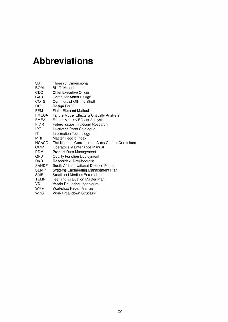
3D Three (3) DimensionalBOM Bill Of MaterialCEO Chief Executive OfficerCAD Computer Aided DesignCOTS Commercial Off-The-ShelfDFX Design For XFEM Finite Element MethodFMECA Failure Mode, Effects & Critically AnalysisFMEA Failure Mode & Effects AnalysisFIDR Future Issues In Design ResearchIPC Illustrated Parts CatalogueIT Information TechnologyMRI Master Record IndexNCACC The National Conventional Arms Control CommitteeOMM Operator’s Maintenance ManualPDM Product Data ManagementQFD Quality Function DeploymentR&D Research & DevelopmentSANDF South African National Defence ForceSEMP Systems Engineering Management PlanSME Small and Medium EnterprisesTEMP Test and Evaluation Master PlanVDI Verein Deutscher IngenieureWRM Workshop Repair ManualWBS Work Breakdown Structure
xv

xvi
Chapter 1
Introduction
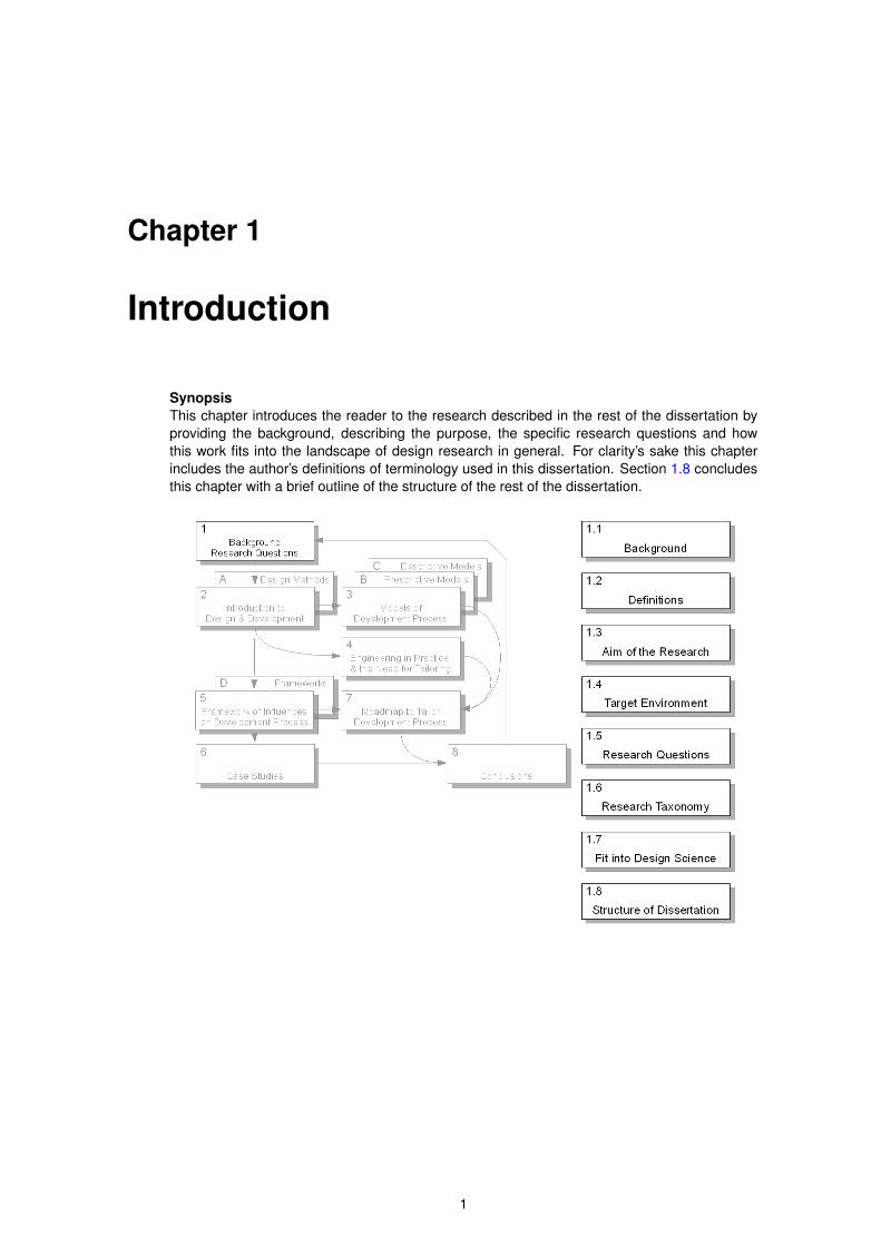
SynopsisThis chapter introduces the reader to the research described in the rest of the dissertation byproviding the background, describing the purpose, the specific research questions and howthis work fits into the landscape of design research in general. For clarity’s sake this chapterincludes the author’s definitions of terminology used in this dissertation. Section 1.8 concludesthis chapter with a brief outline of the structure of the rest of the dissertation.
1
2 1.1. Background
1.1 Background
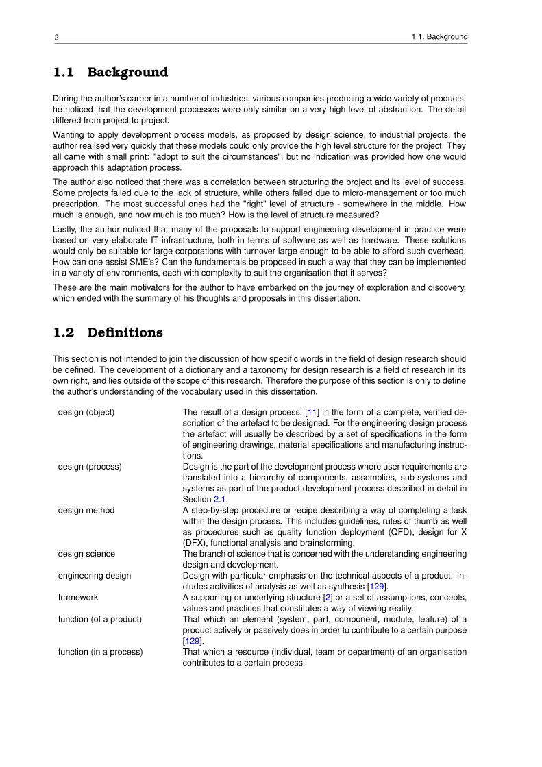
During the author’s career in a number of industries, various companies producing a wide variety of products,he noticed that the development processes were only similar on a very high level of abstraction. The detaildiffered from project to project.
Wanting to apply development process models, as proposed by design science, to industrial projects, theauthor realised very quickly that these models could only provide the high level structure for the project. Theyall came with small print: "adopt to suit the circumstances", but no indication was provided how one wouldapproach this adaptation process.
The author also noticed that there was a correlation between structuring the project and its level of success.Some projects failed due to the lack of structure, while others failed due to micro-management or too muchprescription. The most successful ones had the "right" level of structure - somewhere in the middle. Howmuch is enough, and how much is too much? How is the level of structure measured?
Lastly, the author noticed that many of the proposals to support engineering development in practice werebased on very elaborate IT infrastructure, both in terms of software as well as hardware. These solutionswould only be suitable for large corporations with turnover large enough to be able to afford such overhead.How can one assist SME’s? Can the fundamentals be proposed in such a way that they can be implementedin a variety of environments, each with complexity to suit the organisation that it serves?
These are the main motivators for the author to have embarked on the journey of exploration and discovery,which ended with the summary of his thoughts and proposals in this dissertation.
1.2 Definitions
This section is not intended to join the discussion of how specific words in the field of design research shouldbe defined. The development of a dictionary and a taxonomy for design research is a field of research in itsown right, and lies outside of the scope of this research. Therefore the purpose of this section is only to definethe author’s understanding of the vocabulary used in this dissertation.
design (object) The result of a design process, [11] in the form of a complete, verified de-scription of the artefact to be designed. For the engineering design processthe artefact will usually be described by a set of specifications in the formof engineering drawings, material specifications and manufacturing instruc-tions.
design (process) Design is the part of the development process where user requirements aretranslated into a hierarchy of components, assemblies, sub-systems andsystems as part of the product development process described in detail inSection 2.1.
design method A step-by-step procedure or recipe describing a way of completing a taskwithin the design process. This includes guidelines, rules of thumb as wellas procedures such as quality function deployment (QFD), design for X(DFX), functional analysis and brainstorming.
design science The branch of science that is concerned with the understanding engineeringdesign and development.
engineering design Design with particular emphasis on the technical aspects of a product. In-cludes activities of analysis as well as synthesis [129].
framework A supporting or underlying structure [2] or a set of assumptions, concepts,values and practices that constitutes a way of viewing reality.
function (of a product) That which an element (system, part, component, module, feature) of aproduct actively or passively does in order to contribute to a certain purpose[129].
function (in a process) That which a resource (individual, team or department) of an organisationcontributes to a certain process.
3Chapter 1. Introduction
industrial design The ideation, specification, and development of functions, properties andconcepts of industrially manufactured products and systems, mainly regard-ing aspects of user product interaction, aesthetics and identity, consideringa totality of ergonomic, usability, technical, economic, and social factors[129].
life-cycle The transformation process from need through production to disposal of theproduct as part of a business (see Figure 2.5). This is what Hein [64] callsa "superior product development model"
methodology i. The branch of logic dealing with the methods of accurate thinking [21].ii."is used for knowledge about practical steps and rules for the developmentand design of technical systems, based on the findings of design scienceand of practical experience in various applications." [17] oriii. "is a collection of procedures, tools and techniques for designers to usewhen designing." [49]
model of the developmentprocess
A description of the design process, often including flow-charts. This is notto be confused by models of the design (object) used during the designprocess.
model of the developmentprocess - prescriptive
A structured, systematic description of the design process, divided into sub-processes each generating a specific result. Also referred to as a step-orientated model of the development process [94]. See Section 3.1 formore detail.
model of the developmentprocess - descriptive
A description of the design process with emphasis on the cognitive pro-cesses within the development process, focussing on solving the main prob-lem first, and addressing all peripheral problems accordingly, and solutionsare generated early in the development process based on presuppositions.See Section 3.3 for more detail.
product The physical artefact manufactured according to the design. See "design(object)" above.
process A sequence of coordinated tasks aimed at achieving a specific goal.product development (pro-cess)
The process to generate a complete, verified description of the artefact tobe designed from a design brief or user requirement statement. Verifica-tion of the design, usually by means of the construction and evaluation ofa prototype, is considered part of the design process. Models of this pro-cess are discussed in Chapter 3. The process includes engineering designand industrial design shown as part of the product life-cycle in Figure 2.5.Hein [64] refers to this process as the "product synthesis model".
product innovation "Is the introduction of change from a strategic perspective", including "newproducts, new processes, new distribution networks, new marketing net-works" [91].
roadmap "a layout of descriptive paths that multidisciplinary teams can use as a guid-ing framework for collaboration efforts towards a common goal."[39]
structure With respect to a process, the term "structure" refers to a prescribed rigidprocedure, which is to be followed in order to complete the process.
Although this dissertation contributes to the methodology (in terms of definition i. above) related to engi-neering design, the word ’methodology’ is used in this dissertation with the second meaning in mind. To theauthor’s mind it incorporates more than merely a collection of tools and techniques. It includes an approachor philosophy towards the particular project being executed.
1.3 Aim of the Research Project
The author of this dissertation has come to realise during his involvement with product development for nearlytwenty years that no two projects are executed in an identical manner, even if they are executed in the sameenvironment by the same development team. He agrees with Dumas and Whitfield [45] that "industry, in itsrelationship with the design function, is not a uniform domain which can be addressed simply and directly;rather, it is segmented with each type exhibiting a unique culture/practice profile. As such, it argues against a
4 1.4. Target Environment
simplistic approach to the management of design within industry and suggests a greater need for tailor-madesolutions". In his article Cooper [30] confirms empirically that no "typical process model" for the developmentand commercialisation of a new product exists. Even very prescriptive process models such as the oneproposed by the Institute for German Engineers [125] suggest that the "standard" process should be adaptedto suit the given context.
Unfortunately not much guidance is provided regarding the required type or amount of adaptation for variousproject situations. The author agrees with Fulcher and Hills [55] that design research should enable designto practised "in a context of real people, real organisations and real markets, which are characterised bycomplexity, time pressure, limited resources and changing circumstances".
The aim of this research project was to provide the engineer responsible for the execution of a design projecta tool to configure his own specific development methodology for his specific circumstances. The word "con-figure" indicates that the process of establishing the methodology is one of adjusting a template to givencircumstances.
1.4 Target Environment
A large amount of research is funded by and aimed at the design processes and environment of largemulti-national corporations [34], mostly automotive and electronics manufacturers [87]. SME’s in generaland smaller suppliers to these industries in particular are generally assumed to be miniature copies of thelarge corporations. Radcliff et al. [104] confirm that although SME’s "comprise the bulk of the manufacturingindustry yet little account is taken of such firms in the literature on design theory and methodology".
Since the author of this dissertation has worked in SME’s, the research is aimed at providing affordable,effective support for product development in small and medium sized enterprises.
1.5 Research Questions
The main question that this research project wanted to answer is: "Given a specific project, with specificresources within a given environment, how does one select and construct a development methodology froma repository of templates?"
Secondary research questions are:
1 Can benefit be obtained by combining design methods to form a project methodology?
2 Can methods be established to define a methodology optimised for a specific project?
3 How do I specify, choose and construct a development methodology?
4 How do I measure the success or appropriateness of my choices?
5 How do I comprehensively quantify my needs with respect to a development methodology?
6 Can a methodology be represented in a roadmap?
7 Can a roadmap, implemented in a design environment, facilitate the engineering design process?
8 What attributes must a roadmap have so that it can represent a development methodology?
9 What attributes must a design environment have so that a roadmap can be applied to a developmentproject?
1.6 Research Taxonomy
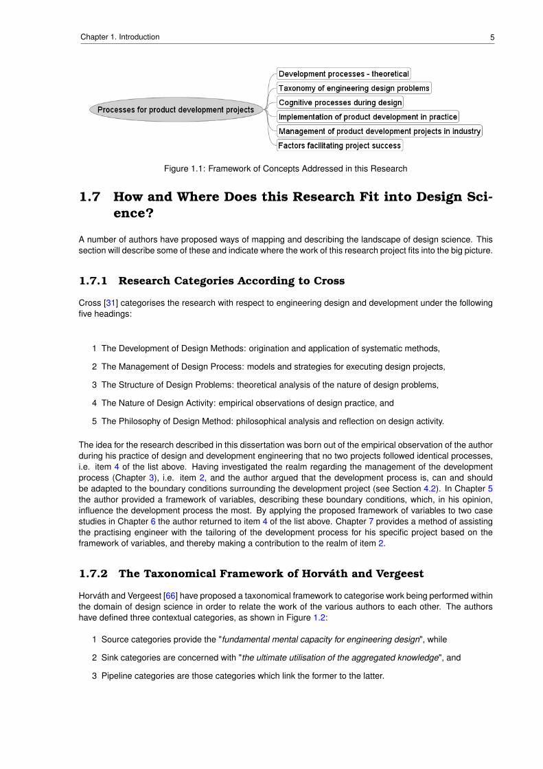
An analysis of the most relevant articles used as references in this research, as well as the text of thisdissertation, revealed the following framework of concepts. It is presented here to describe the scope of theresearch by providing the reader with an overview of the topics that are addresses in this dissertation.
5Chapter 1. Introduction
Figure 1.1: Framework of Concepts Addressed in this Research
1.7 How and Where Does this Research Fit into Design Sci-ence?
A number of authors have proposed ways of mapping and describing the landscape of design science. Thissection will describe some of these and indicate where the work of this research project fits into the big picture.
1.7.1 Research Categories According to Cross
Cross [31] categorises the research with respect to engineering design and development under the followingfive headings:
1 The Development of Design Methods: origination and application of systematic methods,
2 The Management of Design Process: models and strategies for executing design projects,
3 The Structure of Design Problems: theoretical analysis of the nature of design problems,
4 The Nature of Design Activity: empirical observations of design practice, and
5 The Philosophy of Design Method: philosophical analysis and reflection on design activity.
The idea for the research described in this dissertation was born out of the empirical observation of the authorduring his practice of design and development engineering that no two projects followed identical processes,i.e. item 4 of the list above. Having investigated the realm regarding the management of the developmentprocess (Chapter 3), i.e. item 2, and the author argued that the development process is, can and shouldbe adapted to the boundary conditions surrounding the development project (see Section 4.2). In Chapter 5the author provided a framework of variables, describing these boundary conditions, which, in his opinion,influence the development process the most. By applying the proposed framework of variables to two casestudies in Chapter 6 the author returned to item 4 of the list above. Chapter 7 provides a method of assistingthe practising engineer with the tailoring of the development process for his specific project based on theframework of variables, and thereby making a contribution to the realm of item 2.
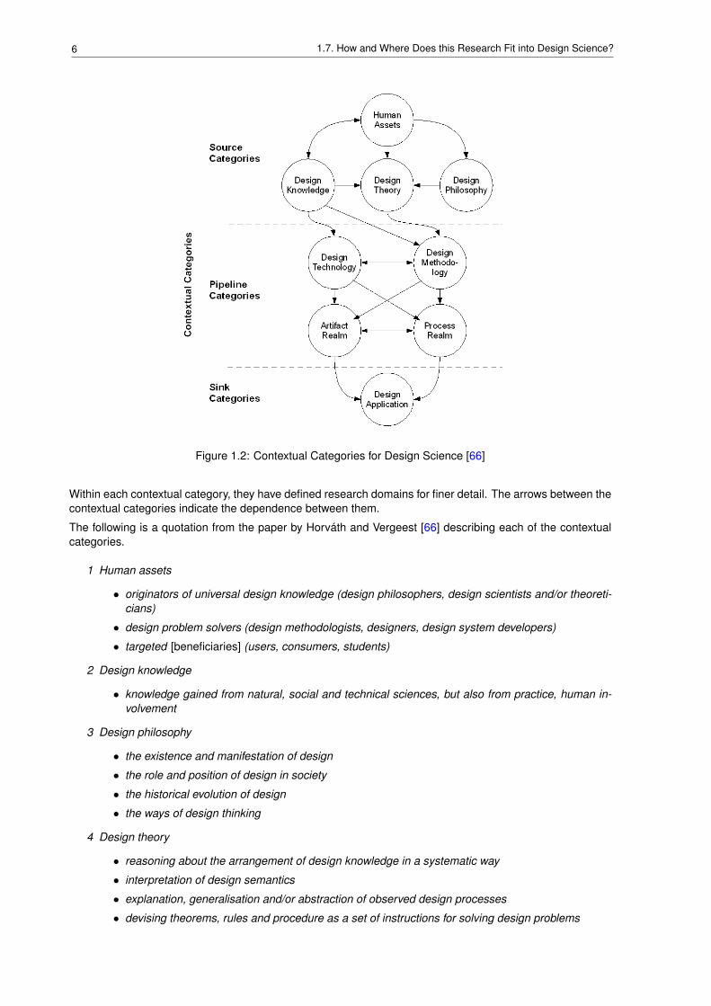
1.7.2 The Taxonomical Framework of Horváth and Vergeest
Horváth and Vergeest [66] have proposed a taxonomical framework to categorise work being performed withinthe domain of design science in order to relate the work of the various authors to each other. The authorshave defined three contextual categories, as shown in Figure 1.2:
1 Source categories provide the "fundamental mental capacity for engineering design", while
2 Sink categories are concerned with "the ultimate utilisation of the aggregated knowledge", and
3 Pipeline categories are those categories which link the former to the latter.
6 1.7. How and Where Does this Research Fit into Design Science?
Figure 1.2: Contextual Categories for Design Science [66]
Within each contextual category, they have defined research domains for finer detail. The arrows between thecontextual categories indicate the dependence between them.
The following is a quotation from the paper by Horváth and Vergeest [66] describing each of the contextualcategories.
1 Human assets
• originators of universal design knowledge (design philosophers, design scientists and/or theoreti-cians)
• design problem solvers (design methodologists, designers, design system developers)
• targeted [beneficiaries] (users, consumers, students)
2 Design knowledge
• knowledge gained from natural, social and technical sciences, but also from practice, human in-volvement
3 Design philosophy
• the existence and manifestation of design
• the role and position of design in society
• the historical evolution of design
• the ways of design thinking
4 Design theory
• reasoning about the arrangement of design knowledge in a systematic way
• interpretation of design semantics
• explanation, generalisation and/or abstraction of observed design processes
• devising theorems, rules and procedure as a set of instructions for solving design problems
7Chapter 1. Introduction
• working out approaches to exteriorise design for execution in synthetic environments
5 Design methodology
• understanding of design decision making
• methodological systemisation of design processes and/or activities
• design modelling and representations
• design analysis and simulation
6 Design technology
• application of specific human and artificial resources to support analysis, design problem solving,synthesis, representation and documentation
7 Realm of artefacts
• in their physical manifestation, the ultimate destination of design
8 Realm of processes
• understanding the synergy of artefacts and processes (natural, imaginary and artificial)
• design-related abstract and concrete processes
9 Design application
• putting design into operation
• industrial aspects of application and implementation
• setting and regulating its performance characteristics
This dissertation provides arguments for the appropriate configuration of the development process to its envi-ronment, and by investigating how the environment surrounding a project influences the development process,it indicates how to adapt the development process to suit given circumstances. With regard to the frameworkabove the focus of this dissertation is clearly in the "realm of processes" by discussing the theory and thoughtprocesses required to structure the development process. By providing an indication of how to implement thisstructuring process in practice, this research also makes a contribution to the category of "design applica-tion". Of course all of this can only be done by building on the existing knowledge in the categories of "designtheory" and "design methodology".
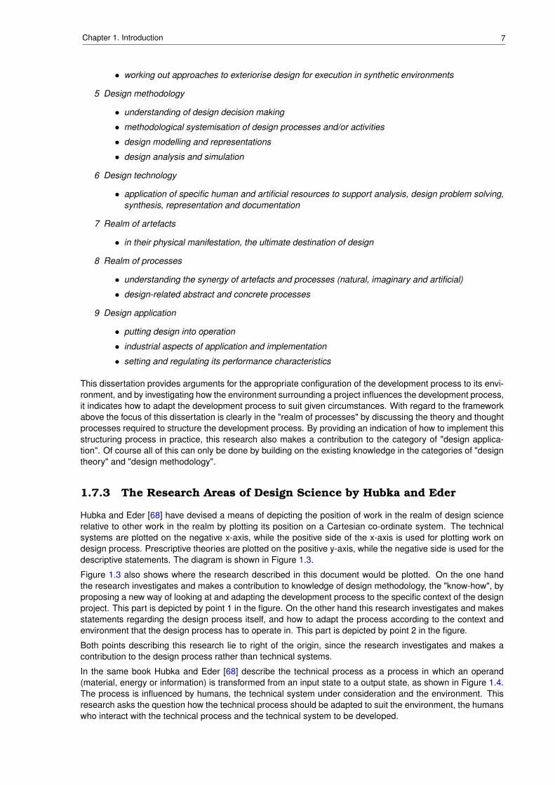
1.7.3 The Research Areas of Design Science by Hubka and Eder
Hubka and Eder [68] have devised a means of depicting the position of work in the realm of design sciencerelative to other work in the realm by plotting its position on a Cartesian co-ordinate system. The technicalsystems are plotted on the negative x-axis, while the positive side of the x-axis is used for plotting work ondesign process. Prescriptive theories are plotted on the positive y-axis, while the negative side is used for thedescriptive statements. The diagram is shown in Figure 1.3.
Figure 1.3 also shows where the research described in this document would be plotted. On the one handthe research investigates and makes a contribution to knowledge of design methodology, the "know-how", byproposing a new way of looking at and adapting the development process to the specific context of the designproject. This part is depicted by point 1 in the figure. On the other hand this research investigates and makesstatements regarding the design process itself, and how to adapt the process according to the context andenvironment that the design process has to operate in. This part is depicted by point 2 in the figure.
Both points describing this research lie to right of the origin, since the research investigates and makes acontribution to the design process rather than technical systems.
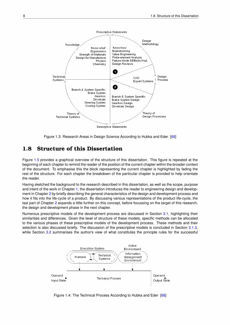
In the same book Hubka and Eder [68] describe the technical process as a process in which an operand(material, energy or information) is transformed from an input state to a output state, as shown in Figure 1.4.The process is influenced by humans, the technical system under consideration and the environment. Thisresearch asks the question how the technical process should be adapted to suit the environment, the humanswho interact with the technical process and the technical system to be developed.
8 1.8. Structure of this Dissertation
Figure 1.3: Research Areas in Design Science According to Hubka and Eder [68]
1.8 Structure of this Dissertation
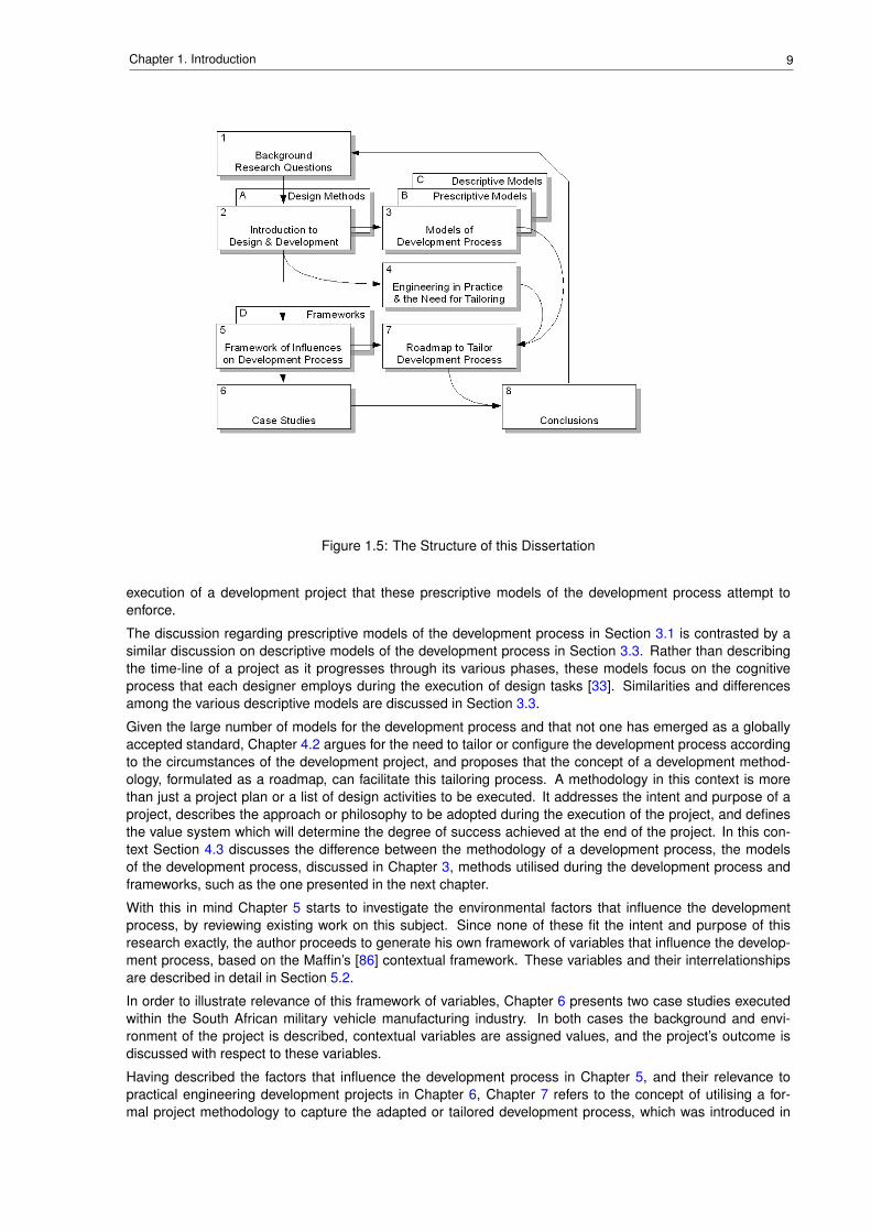
Figure 1.5 provides a graphical overview of the structure of this dissertation. This figure is repeated at thebeginning of each chapter to remind the reader of the position of the current chapter within the broader contextof the document. To emphasise this the block representing the current chapter is highlighted by fading therest of the structure. For each chapter the breakdown of the particular chapter is provided to help orientatethe reader.
Having sketched the background to the research described in this dissertation, as well as the scope, purposeand intent of the work in Chapter 1, the dissertation introduces the reader to engineering design and develop-ment in Chapter 2 by briefly describing the general characteristics of the design and development process andhow it fits into the life-cycle of a product. By discussing various representations of the product life-cycle, thelast part of Chapter 2 expands a little further on this concept, before focussing on the target of this research,the design and development phase in the next chapter.
Numerous prescriptive models of the development process are discussed in Section 3.1, highlighting theirsimilarities and differences. Given the level of structure of these models, specific methods can be allocatedto the various phases of these prescriptive models of the development process. These methods and theirselection is also discussed briefly. The discussion of the prescriptive models is concluded in Section 3.1.3,while Section 3.2 summarises the author’s view of what constitutes the principle rules for the successful
Figure 1.4: The Technical Process According to Hubka and Eder [68]
9Chapter 1. Introduction
Figure 1.5: The Structure of this Dissertation
execution of a development project that these prescriptive models of the development process attempt toenforce.
The discussion regarding prescriptive models of the development process in Section 3.1 is contrasted by asimilar discussion on descriptive models of the development process in Section 3.3. Rather than describingthe time-line of a project as it progresses through its various phases, these models focus on the cognitiveprocess that each designer employs during the execution of design tasks [33]. Similarities and differencesamong the various descriptive models are discussed in Section 3.3.
Given the large number of models for the development process and that not one has emerged as a globallyaccepted standard, Chapter 4.2 argues for the need to tailor or configure the development process accordingto the circumstances of the development project, and proposes that the concept of a development method-ology, formulated as a roadmap, can facilitate this tailoring process. A methodology in this context is morethan just a project plan or a list of design activities to be executed. It addresses the intent and purpose of aproject, describes the approach or philosophy to be adopted during the execution of the project, and definesthe value system which will determine the degree of success achieved at the end of the project. In this con-text Section 4.3 discusses the difference between the methodology of a development process, the modelsof the development process, discussed in Chapter 3, methods utilised during the development process andframeworks, such as the one presented in the next chapter.
With this in mind Chapter 5 starts to investigate the environmental factors that influence the developmentprocess, by reviewing existing work on this subject. Since none of these fit the intent and purpose of thisresearch exactly, the author proceeds to generate his own framework of variables that influence the develop-ment process, based on the Maffin’s [86] contextual framework. These variables and their interrelationshipsare described in detail in Section 5.2.
In order to illustrate relevance of this framework of variables, Chapter 6 presents two case studies executedwithin the South African military vehicle manufacturing industry. In both cases the background and envi-ronment of the project is described, contextual variables are assigned values, and the project’s outcome isdiscussed with respect to these variables.
Having described the factors that influence the development process in Chapter 5, and their relevance topractical engineering development projects in Chapter 6, Chapter 7 refers to the concept of utilising a for-mal project methodology to capture the adapted or tailored development process, which was introduced in

10 1.8. Structure of this Dissertation
Section 4.3. The first section discusses the differences between process orientated and content orientatedwork-flow, to provide the background to the following sections. Next the reader is introduced to the concept ofa roadmap, which the author suggests as a tool to guide the practising design engineer through the processof adapting the development process for his particular development project. The author’s implementation ofsuch a roadmap is presented in the last section of this chapter.
The last chapter of this dissertation answers the research questions posed in Section 1.5 by referring back tothe information presented in the previous chapters. The limitations of this research, as well as its applicationas discussed briefly, before indicating possible research work for the future.
Chapter 2
Engineering Design and Development
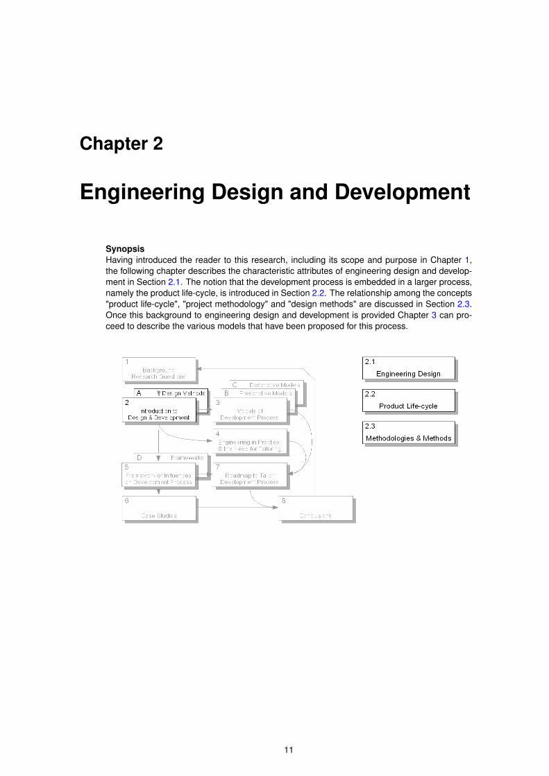
SynopsisHaving introduced the reader to this research, including its scope and purpose in Chapter 1,the following chapter describes the characteristic attributes of engineering design and develop-ment in Section 2.1. The notion that the development process is embedded in a larger process,namely the product life-cycle, is introduced in Section 2.2. The relationship among the concepts"product life-cycle", "project methodology" and "design methods" are discussed in Section 2.3.Once this background to engineering design and development is provided Chapter 3 can pro-ceed to describe the various models that have been proposed for this process.
11
12 2.1. What is Design in General and Engineering Design in Particular?
2.1 What is Design in General and Engineering Design inParticular?
The need and desire to be creative is an integral part of human nature. Certainly the practice of creating ormaking artefacts is as old as humanity, but the separation of the ’making’ process from the planning process,i.e. designing process is a fairly recent phenomenon, as part and parcel of the industrial revolution. In orderto increase the efficiency of the production process, the industrial factory required a description of how theproduct was to be produced, compared to the traditional craftsman, who knew, often on a gut-feel level, howhe would produce his goods.
The word "design" is not just used for the creation of technical systems. For instance, the term "graphicdesign" is used to describe the process of developing visual art as it is used in the entertainment and adver-tisement industries. While it would be conceivable to apply the research described in this dissertation to theartistic branches of design, the work described in the following chapters was conducted specifically with thedevelopment of technical systems in mind.
Cross [32] points out that designing, in the technical sense, "is the production of a final description of theartefact in a form that is understandable to those who will make the artefact."
Shigley [112] describes engineering design as "the decision-making processes which mechanical engineersuse in the formulation of plans for the physical realization of machines, devices and systems. These decision-making processes are applicable to the entire field of engineering design".
Evboumwan et al. defines design as "the process of establishing requirements based on human needs, trans-forming them into performance specification and functions, which are then mapped and converted (subject toconstraints) into design solutions (using creativity, scientific principles and technical knowledge) that can beeconomically manufactured and produced".
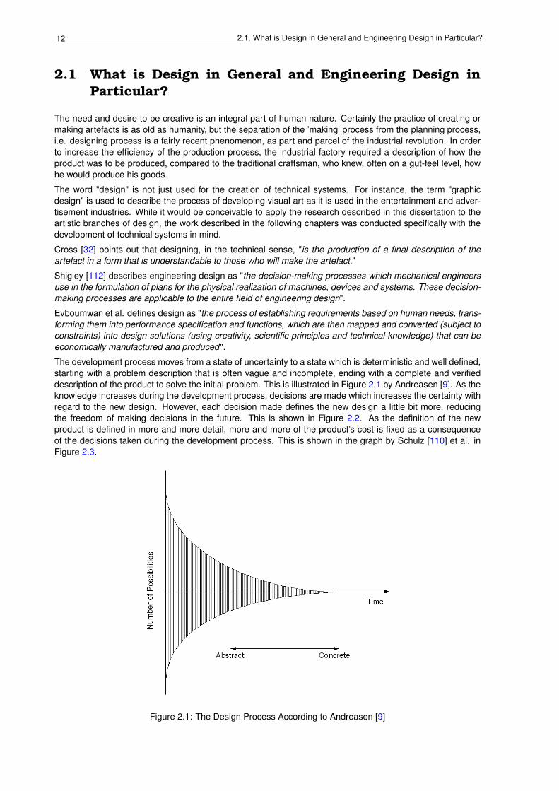
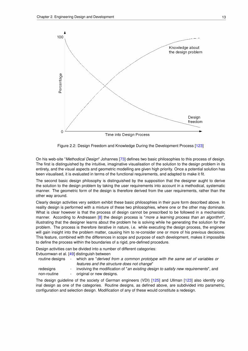
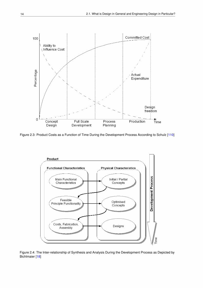
The development process moves from a state of uncertainty to a state which is deterministic and well defined,starting with a problem description that is often vague and incomplete, ending with a complete and verifieddescription of the product to solve the initial problem. This is illustrated in Figure 2.1 by Andreasen [9]. As theknowledge increases during the development process, decisions are made which increases the certainty withregard to the new design. However, each decision made defines the new design a little bit more, reducingthe freedom of making decisions in the future. This is shown in Figure 2.2. As the definition of the newproduct is defined in more and more detail, more and more of the product’s cost is fixed as a consequenceof the decisions taken during the development process. This is shown in the graph by Schulz [110] et al. inFigure 2.3.
Figure 2.1: The Design Process According to Andreasen [9]
13Chapter 2. Engineering Design and Development
Figure 2.2: Design Freedom and Knowledge During the Development Process [123]
On his web-site "Methodical Design" Johannes [73] defines two basic philosophies to this process of design.The first is distinguished by the intuitive, imaginative visualisation of the solution to the design problem in itsentirety, and the visual aspects and geometric modelling are given high priority. Once a potential solution hasbeen visualised, it is evaluated in terms of the functional requirements, and adapted to make it fit.
The second basic design philosophy is distinguished by the supposition that the designer aught to derivethe solution to the design problem by taking the user requirements into account in a methodical, systematicmanner. The geometric form of the design is therefore derived from the user requirements, rather than theother way around.
Clearly design activities very seldom exhibit these basic philosophies in their pure form described above. Inreality design is performed with a mixture of these two philosophies, where one or the other may dominate.What is clear however is that the process of design cannot be prescribed to be followed in a mechanisticmanner. According to Andreasen [8] the design process is "more a learning process than an algorithm",illustrating that the designer learns about the problem he is solving while he generating the solution for theproblem. The process is therefore iterative in nature, i.e. while executing the design process, the engineerwill gain insight into the problem matter, causing him to re-consider one or more of his previous decisions.This feature, combined with the differences in scope and purpose of each development, makes it impossibleto define the process within the boundaries of a rigid, pre-defined procedure.
Design activities can be divided into a number of different categories:Evbuomwan et al. [49] distinguish between
routine designs - which are "derived from a common prototype with the same set of variables orfeatures and the structure does not change"
redesigns - involving the modification of "an existing design to satisfy new requirements", andnon-routine - original or new designs.
The design guideline of the society of German engineers (VDI) [125] and Ullman [123] also identify orig-inal design as one of the categories. Routine designs, as defined above, are subdivided into parametric,configuration and selection design. Modification of any of these would constitute a redesign.
14 2.1. What is Design in General and Engineering Design in Particular?
Figure 2.3: Product Costs as a Function of Time During the Development Process According to Schulz [110]
Figure 2.4: The Inter-relationship of Synthesis and Analysis During the Development Process as Depicted byBichlmaier [18]
15Chapter 2. Engineering Design and Development
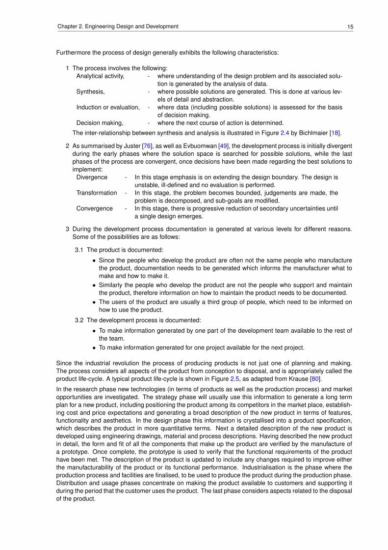
Furthermore the process of design generally exhibits the following characteristics:
1 The process involves the following:Analytical activity, - where understanding of the design problem and its associated solu-
tion is generated by the analysis of data.Synthesis, - where possible solutions are generated. This is done at various lev-
els of detail and abstraction.Induction or evaluation, - where data (including possible solutions) is assessed for the basis
of decision making.Decision making, - where the next course of action is determined.
The inter-relationship between synthesis and analysis is illustrated in Figure 2.4 by Bichlmaier [18].
2 As summarised by Juster [76], as well as Evbuomwan [49], the development process is initially divergentduring the early phases where the solution space is searched for possible solutions, while the lastphases of the process are convergent, once decisions have been made regarding the best solutions toimplement:
Divergence - In this stage emphasis is on extending the design boundary. The design isunstable, ill-defined and no evaluation is performed.
Transformation - In this stage, the problem becomes bounded, judgements are made, theproblem is decomposed, and sub-goals are modified.
Convergence - In this stage, there is progressive reduction of secondary uncertainties untila single design emerges.
3 During the development process documentation is generated at various levels for different reasons.Some of the possibilities are as follows:
3.1 The product is documented:
• Since the people who develop the product are often not the same people who manufacturethe product, documentation needs to be generated which informs the manufacturer what tomake and how to make it.
• Similarly the people who develop the product are not the people who support and maintainthe product, therefore information on how to maintain the product needs to be documented.
• The users of the product are usually a third group of people, which need to be informed onhow to use the product.
3.2 The development process is documented:
• To make information generated by one part of the development team available to the rest ofthe team.
• To make information generated for one project available for the next project.
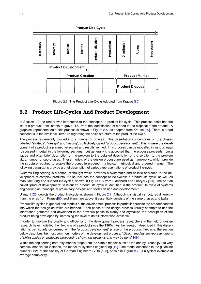
Since the industrial revolution the process of producing products is not just one of planning and making.The process considers all aspects of the product from conception to disposal, and is appropriately called theproduct life-cycle. A typical product life-cycle is shown in Figure 2.5, as adapted from Krause [80].
In the research phase new technologies (in terms of products as well as the production process) and marketopportunities are investigated. The strategy phase will usually use this information to generate a long termplan for a new product, including positioning the product among its competitors in the market place, establish-ing cost and price expectations and generating a broad description of the new product in terms of features,functionality and aesthetics. In the design phase this information is crystallised into a product specification,which describes the product in more quantitative terms. Next a detailed description of the new product isdeveloped using engineering drawings, material and process descriptions. Having described the new productin detail, the form and fit of all the components that make up the product are verified by the manufacture ofa prototype. Once complete, the prototype is used to verify that the functional requirements of the producthave been met. The description of the product is updated to include any changes required to improve eitherthe manufacturability of the product or its functional performance. Industrialisation is the phase where theproduction process and facilities are finalised, to be used to produce the product during the production phase.Distribution and usage phases concentrate on making the product available to customers and supporting itduring the period that the customer uses the product. The last phase considers aspects related to the disposalof the product.
16 2.2. Product Life-Cycles And Product Development
Figure 2.5: The Product Life-Cycle Adopted from Krause [80]
2.2 Product Life-Cycles And Product Development
In Section 1.2 the reader was introduced to the concept of a product life-cycle. This process describes thelife of a product from "cradle to grave", i.e. from the identification of a need to the disposal of the product. Agraphical representation of this process is shown in Figure 2.5, as adapted from Krause [80]. There is broadconsensus in the available literature regarding the basic structure of the product life-cycle.
The process is generally divided into a number of phases. This dissertation concentrates on the phaseslabelled "strategy", "design" and "testing", collectively called "product development". This is were the devel-opment of a product is planned, executed and results verified. This process can be modelled in various ways(discussed in detail in the following sections), but generally it is accepted that the process proceeds from avague and often brief description of the problem to the detailed description of the solution to the problemvia a number of sub-phases. These models of the design process are used as frameworks, which providethe structure required to enable the process to proceed in a logical, methodical and ordered manner. Thefollowing paragraphs provide a brief description of various representations of product life-cycle.
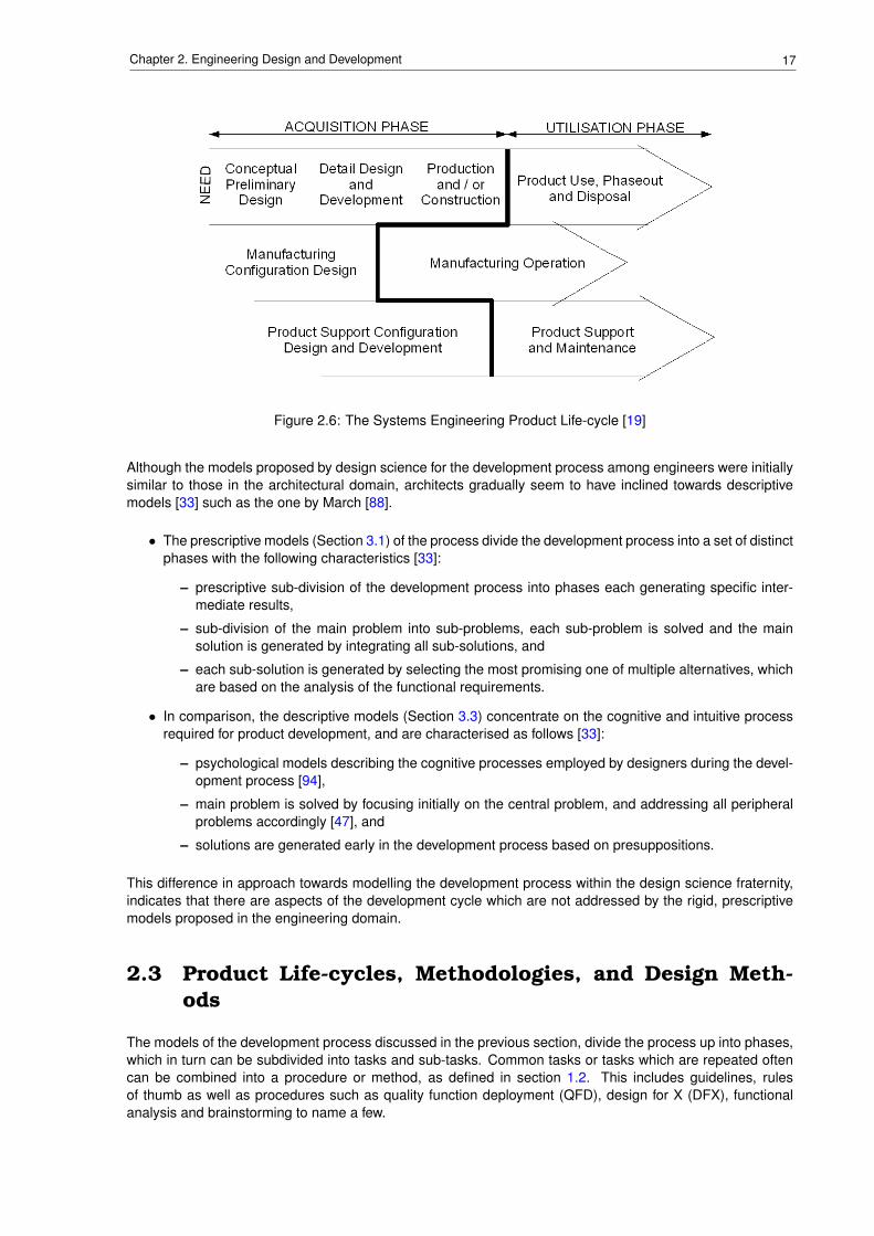
Systems Engineering is a school of thought which provides a systematic and holistic approach to the de-velopment of complex products, it also includes the concept of life-cycles: a product life-cycle, as well asmanufacturing and support life-cycles, shown in Figure 2.6 from Blanchard and Fabrycky [19]. The portioncalled "product development" in Krause’s product life-cycle is identified in the product life-cycle of systemsengineering as "conceptual preliminary design" and "detail design and development".
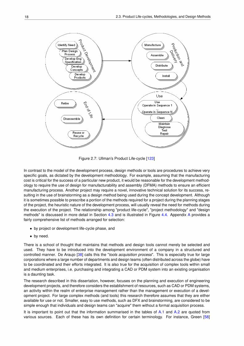
Ullman [123] depicts the product life-cycle as shown in Figure 2.7. Although it is visually structured differentlythan the ones from Krause[80] and Blanchard above, it essentially consists of the same phases and tasks.
Product life-cycles in general and models of the development process in particular provide the broader contextinto which the design activities are bedded. Each phase of the design process usually attempts to use theinformation gathered and developed in the previous phase to clarify and crystallise the description of theproduct being developed by increasing the level of detail information available.
In order to improve the quality and efficiency of the development process researchers in the field of designresearch have modelled the life-cycle of a product since the 1960’s. As the research described in this disser-tation is particularly concerned with the "product development" phase of the product’s life-cycle, the sectionbelow describes the most common models of the development process. "Design models are representationsof philosophies or strategies proposed to show how design is and may be done" [49].
Within the engineering fraternity models range from the simple models such as the one by French [52] to verycomplex models, for instance, the model for systems engineering [19]. The model described in the guidelinenumber 2221 of the Society of German Engineers (VDI) [125], shown in Figure B.7, is a typical example ofaverage complexity.
17Chapter 2. Engineering Design and Development
Figure 2.6: The Systems Engineering Product Life-cycle [19]
Although the models proposed by design science for the development process among engineers were initiallysimilar to those in the architectural domain, architects gradually seem to have inclined towards descriptivemodels [33] such as the one by March [88].
• The prescriptive models (Section 3.1) of the process divide the development process into a set of distinctphases with the following characteristics [33]:
– prescriptive sub-division of the development process into phases each generating specific inter-mediate results,
– sub-division of the main problem into sub-problems, each sub-problem is solved and the mainsolution is generated by integrating all sub-solutions, and
– each sub-solution is generated by selecting the most promising one of multiple alternatives, whichare based on the analysis of the functional requirements.
• In comparison, the descriptive models (Section 3.3) concentrate on the cognitive and intuitive processrequired for product development, and are characterised as follows [33]:
– psychological models describing the cognitive processes employed by designers during the devel-opment process [94],
– main problem is solved by focusing initially on the central problem, and addressing all peripheralproblems accordingly [47], and
– solutions are generated early in the development process based on presuppositions.
This difference in approach towards modelling the development process within the design science fraternity,indicates that there are aspects of the development cycle which are not addressed by the rigid, prescriptivemodels proposed in the engineering domain.
2.3 Product Life-cycles, Methodologies, and Design Meth-ods
The models of the development process discussed in the previous section, divide the process up into phases,which in turn can be subdivided into tasks and sub-tasks. Common tasks or tasks which are repeated oftencan be combined into a procedure or method, as defined in section 1.2. This includes guidelines, rulesof thumb as well as procedures such as quality function deployment (QFD), design for X (DFX), functionalanalysis and brainstorming to name a few.
18 2.3. Product Life-cycles, Methodologies, and Design Methods
Figure 2.7: Ullman’s Product Life-cycle [123]
In contrast to the model of the development process, design methods or tools are procedures to achieve veryspecific goals, as dictated by the development methodology. For example, assuming that the manufacturingcost is critical for the success of a particular new product, it would be reasonable for the development method-ology to require the use of design for manufacturability and assembly (DFMA) methods to ensure an efficientmanufacturing process. Another project may require a novel, innovative technical solution for its success, re-sulting in the use of brainstorming as a design method being used during the concept development. Althoughit is sometimes possible to prescribe a portion of the methods required for a project during the planning stagesof the project, the heuristic nature of the development process, will usually reveal the need for methods duringthe execution of the project. The relationship among "product life-cycle", "project methodology" and "designmethods" is discussed in more detail in Section 4.3 and is illustrated in Figure 4.4. Appendix A provides afairly comprehensive list of methods arranged for selection:
• by project or development life-cycle phase, and
• by need.
There is a school of thought that maintains that methods and design tools cannot merely be selected andused. They have to be introduced into the development environment of a company in a structured andcontrolled manner. De Araujo [38] calls this the "tools acquisition process". This is especially true for largecorporations where a large number of departments and design teams (often distributed across the globe) haveto be coordinated and their efforts integrated. It is also true for the acquisition of complex tools within smalland medium enterprises, i.e. purchasing and integrating a CAD or PDM system into an existing organisationis a daunting task.
The research described in this dissertation, however, focuses on the planning and execution of engineeringdevelopment projects, and therefore considers the establishment of resources, such as CAD or PDM systems,an activity within the realm of enterprise management rather than the management or execution of a devel-opment project. For large complex methods (and tools) this research therefore assumes that they are eitheravailable for use or not. Smaller, easy to use methods, such as DFX and brainstorming, are considered to besimple enough that individuals and design teams can "acquire" them without a formal acquisition process.
It is important to point out that the information summarised in the tables of A.1 and A.2 are quoted fromvarious sources. Each of these has its own definition for certain terminology. For instance, Green [58]

19Chapter 2. Engineering Design and Development
considers design reviews to be a method to be used during the embodiment and detail design phases of thedevelopment life-cycle, while in this research they are considered part of certain models of the developmentprocesses, e.g. Systems Engineering as shown in Figure B.9.

20 2.3. Product Life-cycles, Methodologies, and Design Methods
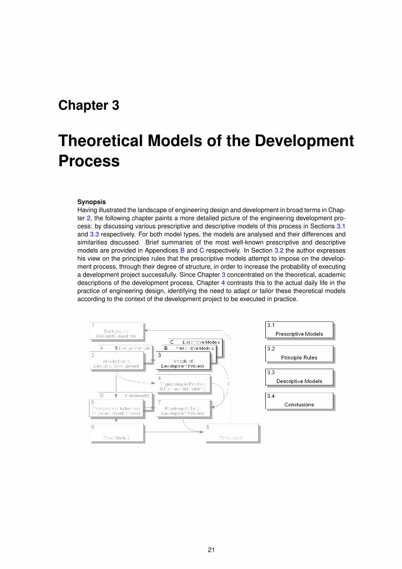
Chapter 3
Theoretical Models of the DevelopmentProcess
SynopsisHaving illustrated the landscape of engineering design and development in broad terms in Chap-ter 2, the following chapter paints a more detailed picture of the engineering development pro-cess: by discussing various prescriptive and descriptive models of this process in Sections 3.1and 3.3 respectively. For both model types, the models are analysed and their differences andsimilarities discussed. Brief summaries of the most well-known prescriptive and descriptivemodels are provided in Appendices B and C respectively. In Section 3.2 the author expresseshis view on the principles rules that the prescriptive models attempt to impose on the develop-ment process, through their degree of structure, in order to increase the probability of executinga development project successfully. Since Chapter 3 concentrated on the theoretical, academicdescriptions of the development process, Chapter 4 contrasts this to the actual daily life in thepractice of engineering design, identifying the need to adapt or tailor these theoretical modelsaccording to the context of the development project to be executed in practice.
21
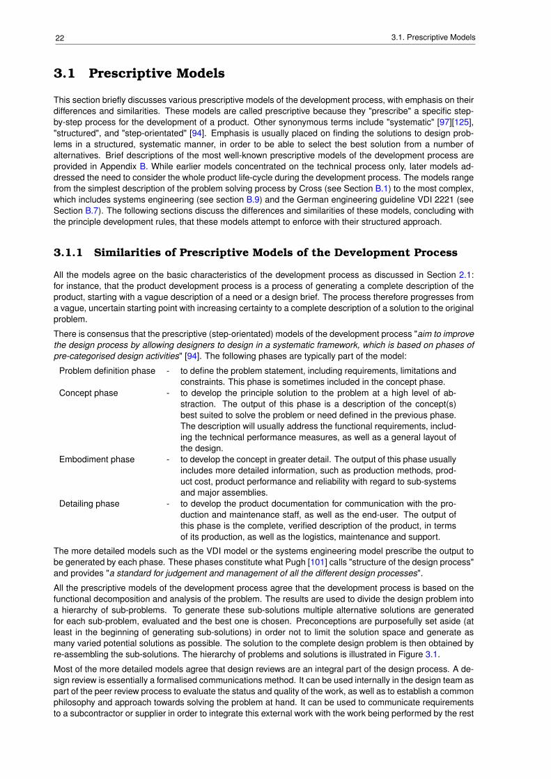
22 3.1. Prescriptive Models
3.1 Prescriptive Models
This section briefly discusses various prescriptive models of the development process, with emphasis on theirdifferences and similarities. These models are called prescriptive because they "prescribe" a specific step-by-step process for the development of a product. Other synonymous terms include "systematic" [97][125],"structured", and "step-orientated" [94]. Emphasis is usually placed on finding the solutions to design prob-lems in a structured, systematic manner, in order to be able to select the best solution from a number ofalternatives. Brief descriptions of the most well-known prescriptive models of the development process areprovided in Appendix B. While earlier models concentrated on the technical process only, later models ad-dressed the need to consider the whole product life-cycle during the development process. The models rangefrom the simplest description of the problem solving process by Cross (see Section B.1) to the most complex,which includes systems engineering (see section B.9) and the German engineering guideline VDI 2221 (seeSection B.7). The following sections discuss the differences and similarities of these models, concluding withthe principle development rules, that these models attempt to enforce with their structured approach.
3.1.1 Similarities of Prescriptive Models of the Development Process
All the models agree on the basic characteristics of the development process as discussed in Section 2.1:for instance, that the product development process is a process of generating a complete description of theproduct, starting with a vague description of a need or a design brief. The process therefore progresses froma vague, uncertain starting point with increasing certainty to a complete description of a solution to the originalproblem.
There is consensus that the prescriptive (step-orientated) models of the development process "aim to improvethe design process by allowing designers to design in a systematic framework, which is based on phases ofpre-categorised design activities" [94]. The following phases are typically part of the model:
Problem definition phase - to define the problem statement, including requirements, limitations andconstraints. This phase is sometimes included in the concept phase.
Concept phase - to develop the principle solution to the problem at a high level of ab-straction. The output of this phase is a description of the concept(s)best suited to solve the problem or need defined in the previous phase.The description will usually address the functional requirements, includ-ing the technical performance measures, as well as a general layout ofthe design.
Embodiment phase - to develop the concept in greater detail. The output of this phase usuallyincludes more detailed information, such as production methods, prod-uct cost, product performance and reliability with regard to sub-systemsand major assemblies.
Detailing phase - to develop the product documentation for communication with the pro-duction and maintenance staff, as well as the end-user. The output ofthis phase is the complete, verified description of the product, in termsof its production, as well as the logistics, maintenance and support.
The more detailed models such as the VDI model or the systems engineering model prescribe the output tobe generated by each phase. These phases constitute what Pugh [101] calls "structure of the design process"and provides "a standard for judgement and management of all the different design processes".
All the prescriptive models of the development process agree that the development process is based on thefunctional decomposition and analysis of the problem. The results are used to divide the design problem intoa hierarchy of sub-problems. To generate these sub-solutions multiple alternative solutions are generatedfor each sub-problem, evaluated and the best one is chosen. Preconceptions are purposefully set aside (atleast in the beginning of generating sub-solutions) in order not to limit the solution space and generate asmany varied potential solutions as possible. The solution to the complete design problem is then obtained byre-assembling the sub-solutions. The hierarchy of problems and solutions is illustrated in Figure 3.1.
Most of the more detailed models agree that design reviews are an integral part of the design process. A de-sign review is essentially a formalised communications method. It can be used internally in the design team aspart of the peer review process to evaluate the status and quality of the work, as well as to establish a commonphilosophy and approach towards solving the problem at hand. It can be used to communicate requirementsto a subcontractor or supplier in order to integrate this external work with the work being performed by the rest
23Chapter 3. Theoretical Models of the Development Process
Figure 3.1: Solution / Problem Hierarchy [125]
of the design team. Another option is to use a design review to communicate with the customer to providefeedback with regards to the status of the project, obtain inputs on the customer’s requirements and to verifythat requirements have been met. The main aims of a design review can therefore be summarised as:
• It is a formalised check of the performance of a system, sub-system or critical assembly relative to itsrequirements.
• It establishes a common baseline for the project by creating an understanding of the entire project bydesign and support staff. This baseline includes the philosophy and approach to solving the designproblem(s), the current status with regard to the quantity and quality of work, as well as resources,unforeseen problems.
• It provides a means of managing interfaces between sub-systems and assemblies developed by differ-ent sub-teams or suppliers and subcontractors.
• It is a formalised record of design decisions that influence the course of the project.
• Synergy is achieved by involving team members to evaluate work that they were not directly involved in.
Most of the prescriptive models of the development process state (the simpler models by implication, themore complex by explicit statements) that the process is not to be seen as rigid and should be adjusted to suiteach individual project. Pugh [101], for instance, states emphatically that "the structure" of the prescriptivemodels, "whilst imparting a discipline of systematic working, should nevertheless allow for variations to thatsystematic working, whilst retaining discipline and also imparting comprehensiveness. In other words, thesystem flexibility within a framework must not impose the rigidity and linearity suggested by many models".Unfortunately, none of the models identify how and under what circumstances the models are to be adjusted.
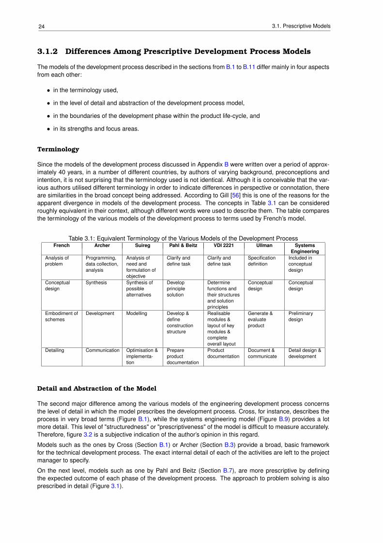
24 3.1. Prescriptive Models
3.1.2 Differences Among Prescriptive Development Process Models
The models of the development process described in the sections from B.1 to B.11 differ mainly in four aspectsfrom each other:
• in the terminology used,
• in the level of detail and abstraction of the development process model,
• in the boundaries of the development phase within the product life-cycle, and
• in its strengths and focus areas.
Terminology
Since the models of the development process discussed in Appendix B were written over a period of approx-imately 40 years, in a number of different countries, by authors of varying background, preconceptions andintention, it is not surprising that the terminology used is not identical. Although it is conceivable that the var-ious authors utilised different terminology in order to indicate differences in perspective or connotation, thereare similarities in the broad concept being addressed. According to Gill [56] this is one of the reasons for theapparent divergence in models of the development process. The concepts in Table 3.1 can be consideredroughly equivalent in their context, although different words were used to describe them. The table comparesthe terminology of the various models of the development process to terms used by French’s model.
Table 3.1: Equivalent Terminology of the Various Models of the Development ProcessFrench Archer Suireg Pahl & Beitz VDI 2221 Ullman Systems
EngineeringAnalysis ofproblem
Programming,data collection,analysis
Analysis ofneed andformulation ofobjective
Clarify anddefine task
Clarify anddefine task
Specificationdefinition
Included inconceptualdesign
Conceptualdesign
Synthesis Synthesis ofpossiblealternatives
Developprinciplesolution
Determinefunctions andtheir structuresand solutionprinciples
Conceptualdesign
Conceptualdesign
Embodiment ofschemes
Development Modelling Develop &defineconstructionstructure
Realisablemodules &layout of keymodules &completeoverall layout
Generate &evaluateproduct
Preliminarydesign
Detailing Communication Optimisation &implementa-tion
Prepareproductdocumentation
Productdocumentation
Document &communicate
Detail design &development
Detail and Abstraction of the Model
The second major difference among the various models of the engineering development process concernsthe level of detail in which the model prescribes the development process. Cross, for instance, describes theprocess in very broad terms (Figure B.1), while the systems engineering model (Figure B.9) provides a lotmore detail. This level of "structuredness" or "prescriptiveness" of the model is difficult to measure accurately.Therefore, figure 3.2 is a subjective indication of the author’s opinion in this regard.
Models such as the ones by Cross (Section B.1) or Archer (Section B.3) provide a broad, basic frameworkfor the technical development process. The exact internal detail of each of the activities are left to the projectmanager to specify.
On the next level, models such as one by Pahl and Beitz (Section B.7), are more prescriptive by definingthe expected outcome of each phase of the development process. The approach to problem solving is alsoprescribed in detail (Figure 3.1).
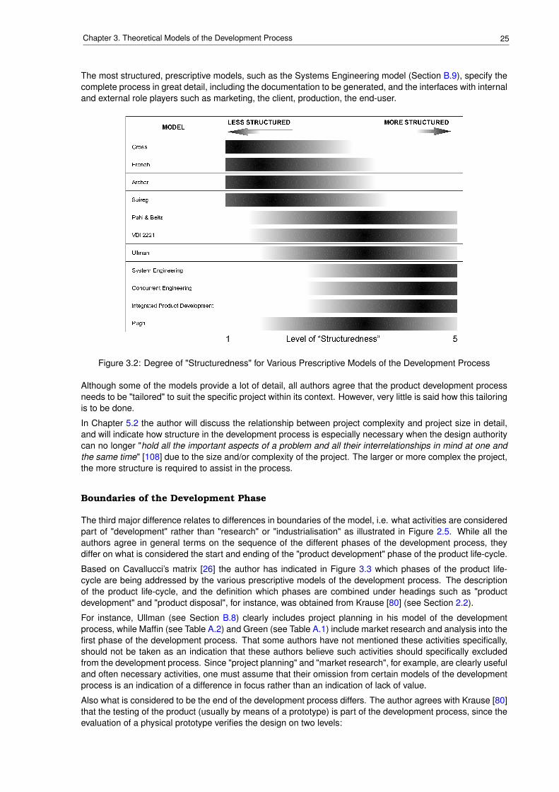
25Chapter 3. Theoretical Models of the Development Process
The most structured, prescriptive models, such as the Systems Engineering model (Section B.9), specify thecomplete process in great detail, including the documentation to be generated, and the interfaces with internaland external role players such as marketing, the client, production, the end-user.
Figure 3.2: Degree of "Structuredness" for Various Prescriptive Models of the Development Process
Although some of the models provide a lot of detail, all authors agree that the product development processneeds to be "tailored" to suit the specific project within its context. However, very little is said how this tailoringis to be done.
In Chapter 5.2 the author will discuss the relationship between project complexity and project size in detail,and will indicate how structure in the development process is especially necessary when the design authoritycan no longer "hold all the important aspects of a problem and all their interrelationships in mind at one andthe same time" [108] due to the size and/or complexity of the project. The larger or more complex the project,the more structure is required to assist in the process.
Boundaries of the Development Phase
The third major difference relates to differences in boundaries of the model, i.e. what activities are consideredpart of "development" rather than "research" or "industrialisation" as illustrated in Figure 2.5. While all theauthors agree in general terms on the sequence of the different phases of the development process, theydiffer on what is considered the start and ending of the "product development" phase of the product life-cycle.
Based on Cavallucci’s matrix [26] the author has indicated in Figure 3.3 which phases of the product life-cycle are being addressed by the various prescriptive models of the development process. The descriptionof the product life-cycle, and the definition which phases are combined under headings such as "productdevelopment" and "product disposal", for instance, was obtained from Krause [80] (see Section 2.2).
For instance, Ullman (see Section B.8) clearly includes project planning in his model of the developmentprocess, while Maffin (see Table A.2) and Green (see Table A.1) include market research and analysis into thefirst phase of the development process. That some authors have not mentioned these activities specifically,should not be taken as an indication that these authors believe such activities should specifically excludedfrom the development process. Since "project planning" and "market research", for example, are clearly usefuland often necessary activities, one must assume that their omission from certain models of the developmentprocess is an indication of a difference in focus rather than an indication of lack of value.
Also what is considered to be the end of the development process differs. The author agrees with Krause [80]that the testing of the product (usually by means of a prototype) is part of the development process, since theevaluation of a physical prototype verifies the design on two levels:
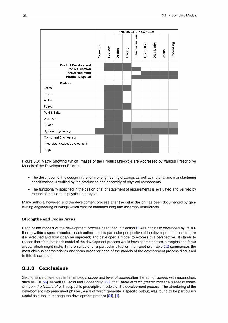
26 3.1. Prescriptive Models
Figure 3.3: Matrix Showing Which Phases of the Product Life-cycle are Addressed by Various PrescriptiveModels of the Development Process
• The description of the design in the form of engineering drawings as well as material and manufacturingspecifications is verified by the production and assembly of physical components.
• The functionality specified in the design brief or statement of requirements is evaluated and verified bymeans of tests on the physical prototype.
Many authors, however, end the development process after the detail design has been documented by gen-erating engineering drawings which capture manufacturing and assembly instructions.
Strengths and Focus Areas
Each of the models of the development process described in Section B was originally developed by its au-thor(s) within a specific context: each author had his particular perspective of the development process (howit is executed and how it can be improved) and developed a model to express this perspective. It stands toreason therefore that each model of the development process would have characteristics, strengths and focusareas, which might make it more suitable for a particular situation than another. Table 3.2 summarises themost obvious characteristics and focus areas for each of the models of the development process discussedin this dissertation.
3.1.3 Conclusions
Setting aside differences in terminology, scope and level of aggregation the author agrees with researcherssuch as Gill [56], as well as Cross and Roozenburg [33], that "there is much greater consensus than is appar-ent from the literature" with respect to prescriptive models of the development process. The structuring of thedevelopment into prescribed phases, each of which generate a specific output, was found to be particularlyuseful as a tool to manage the development process [94], [1].
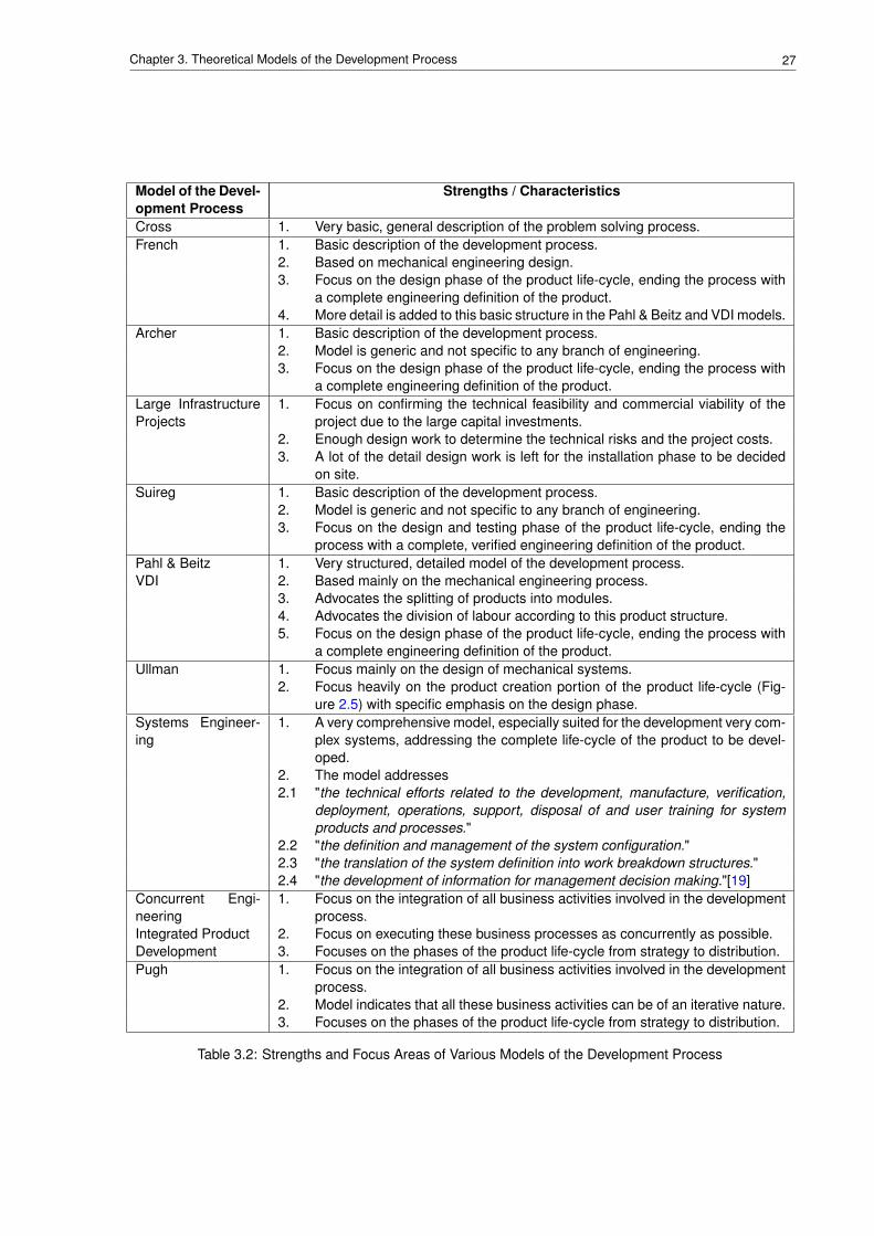
27Chapter 3. Theoretical Models of the Development Process
Model of the Devel-opment Process
Strengths / Characteristics
Cross 1. Very basic, general description of the problem solving process.French 1. Basic description of the development process.
2. Based on mechanical engineering design.3. Focus on the design phase of the product life-cycle, ending the process with
a complete engineering definition of the product.4. More detail is added to this basic structure in the Pahl & Beitz and VDI models.
Archer 1. Basic description of the development process.2. Model is generic and not specific to any branch of engineering.3. Focus on the design phase of the product life-cycle, ending the process with
a complete engineering definition of the product.Large InfrastructureProjects
1. Focus on confirming the technical feasibility and commercial viability of theproject due to the large capital investments.
2. Enough design work to determine the technical risks and the project costs.3. A lot of the detail design work is left for the installation phase to be decided
on site.Suireg 1. Basic description of the development process.
2. Model is generic and not specific to any branch of engineering.3. Focus on the design and testing phase of the product life-cycle, ending the
process with a complete, verified engineering definition of the product.Pahl & Beitz 1. Very structured, detailed model of the development process.VDI 2. Based mainly on the mechanical engineering process.
3. Advocates the splitting of products into modules.4. Advocates the division of labour according to this product structure.5. Focus on the design phase of the product life-cycle, ending the process with
a complete engineering definition of the product.Ullman 1. Focus mainly on the design of mechanical systems.
2. Focus heavily on the product creation portion of the product life-cycle (Fig-ure 2.5) with specific emphasis on the design phase.
Systems Engineer-ing
1. A very comprehensive model, especially suited for the development very com-plex systems, addressing the complete life-cycle of the product to be devel-oped.
2. The model addresses2.1 "the technical efforts related to the development, manufacture, verification,
deployment, operations, support, disposal of and user training for systemproducts and processes."
2.2 "the definition and management of the system configuration."2.3 "the translation of the system definition into work breakdown structures."2.4 "the development of information for management decision making."[19]
Concurrent Engi-neering
1. Focus on the integration of all business activities involved in the developmentprocess.
Integrated Product 2. Focus on executing these business processes as concurrently as possible.Development 3. Focuses on the phases of the product life-cycle from strategy to distribution.Pugh 1. Focus on the integration of all business activities involved in the development
process.2. Model indicates that all these business activities can be of an iterative nature.3. Focuses on the phases of the product life-cycle from strategy to distribution.
Table 3.2: Strengths and Focus Areas of Various Models of the Development Process
28 3.2. Principle Development Rules
The defining attributes of the prescriptive models are:
• a rigid, broadly linear sequence of phases from problem definition to detail design with an indication ofiterative feedback,
• a process structured in phases and therefore lending itself to planning and managing the developmentprocess [64], [1],
• concept development based on functional decomposition and analysis, without the use of preconcep-tions,
• a hierarchical structure of both the problem and the solution,
• resulting in a solution generating process based on disassembly of the problem space, finding solutionsfor the sub-problems and assembling all these solutions again in the solution space,
• best solution to each of the sub-problems chosen from a number of alternatives.
3.2 Principle Development Rules
When examining the intent of the prescriptive development models described in the previous sections, it be-comes evident that they attempt to force the designer or project manager to adhere to the following principles:
• Understand the real need or requirement that the new design is supposed to address.
• Increase participation of those involved in the project by making the development process visible andunderstandable so that all team members can visualise their contribution in the process. Therefore allteam members are aware of the requirements, and everyone’s effort is aligned to achieve the desiredoutcome.
• Consider various ways to address the requirements, so that the best one can be chosen for implemen-tation.
• Consider the whole product life-cycle during the development of a new product, manufacturing, use,maintenance, support, disposal.
3.3 Decsriptive Models
In their article, Cross and Roozenburg [33] describe the evolution of models of the development process.They state that "early models of the design process in architecture were often very similar to models ofthe engineering design process". As examples they refer to similarities of models developed by Marver etal. [92] for architectural design and Asimow [13] for engineering design respectively. Another example citedwere models presented by Jones and Thornley at the 1962 Conference on Design Methods [75], which weresimilar to the Archer’s model discussed in Section B.3.
According to Cross and Roozenburg [33], Hillier [65] was one of the first to criticise the engineering modelof the development process, and to propose a "conjecture-analysis model" where "the designer must firstgenerate a solution conjecture which is subjected to analysis and evaluation, rather than analysis precedingsynthesis" as in the prescriptive models of the development process discussed in the previous chapter. LaterDrake [42] proposed the "generator-conjecture-analysis model" which states that "very early in the designprocess the designer identifies a particular, strong generating concept or a particular set of design objectives".According to Cross and Roozenburg [33] "this again contradicts the view that the design process must beginwith an exhaustive problem specification, from which solution concepts may then be synthesised".
Besides the emphasis on "pre-structure" to solve design problems, descriptive models of the developmentprocess focus on the cognitive processes employed by the designers during the design work. Therefore theiterative and heuristic nature of the design process is often a central attribute of the model, resulting in a spiralstructure in the flowcharts describing the models, e.g. Hilier, Drake and March’s model in Figure C.1.
Brief descriptions of the most well-known descriptive models of the development process are provided inAppendix C. The following sections discuss the differences and similarities of these models, concluding thechapter with a brief comparison between the prescriptive and descriptive models.
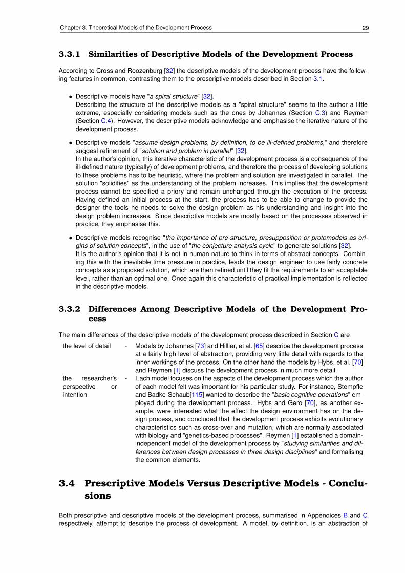
29Chapter 3. Theoretical Models of the Development Process
3.3.1 Similarities of Descriptive Models of the Development Process
According to Cross and Roozenburg [32] the descriptive models of the development process have the follow-ing features in common, contrasting them to the prescriptive models described in Section 3.1.
• Descriptive models have "a spiral structure" [32].Describing the structure of the descriptive models as a "spiral structure" seems to the author a littleextreme, especially considering models such as the ones by Johannes (Section C.3) and Reymen(Section C.4). However, the descriptive models acknowledge and emphasise the iterative nature of thedevelopment process.
• Descriptive models "assume design problems, by definition, to be ill-defined problems," and thereforesuggest refinement of "solution and problem in parallel" [32].In the author’s opinion, this iterative characteristic of the development process is a consequence of theill-defined nature (typically) of development problems, and therefore the process of developing solutionsto these problems has to be heuristic, where the problem and solution are investigated in parallel. Thesolution "solidifies" as the understanding of the problem increases. This implies that the developmentprocess cannot be specified a priory and remain unchanged through the execution of the process.Having defined an initial process at the start, the process has to be able to change to provide thedesigner the tools he needs to solve the design problem as his understanding and insight into thedesign problem increases. Since descriptive models are mostly based on the processes observed inpractice, they emphasise this.
• Descriptive models recognise "the importance of pre-structure, presupposition or protomodels as ori-gins of solution concepts", in the use of "the conjecture analysis cycle" to generate solutions [32].It is the author’s opinion that it is not in human nature to think in terms of abstract concepts. Combin-ing this with the inevitable time pressure in practice, leads the design engineer to use fairly concreteconcepts as a proposed solution, which are then refined until they fit the requirements to an acceptablelevel, rather than an optimal one. Once again this characteristic of practical implementation is reflectedin the descriptive models.
3.3.2 Differences Among Descriptive Models of the Development Pro-cess
The main differences of the descriptive models of the development process described in Section C are
the level of detail - Models by Johannes [73] and Hillier, et al. [65] describe the development processat a fairly high level of abstraction, providing very little detail with regards to theinner workings of the process. On the other hand the models by Hybs, et al. [70]and Reymen [1] discuss the development process in much more detail.
the researcher’sperspective orintention
- Each model focuses on the aspects of the development process which the authorof each model felt was important for his particular study. For instance, Stempfleand Badke-Schaub[115] wanted to describe the "basic cognitive operations" em-ployed during the development process. Hybs and Gero [70], as another ex-ample, were interested what the effect the design environment has on the de-sign process, and concluded that the development process exhibits evolutionarycharacteristics such as cross-over and mutation, which are normally associatedwith biology and "genetics-based processes". Reymen [1] established a domain-independent model of the development process by "studying similarities and dif-ferences between design processes in three design disciplines" and formalisingthe common elements.
3.4 Prescriptive Models Versus Descriptive Models - Conclu-sions
Both prescriptive and descriptive models of the development process, summarised in Appendices B and Crespectively, attempt to describe the process of development. A model, by definition, is an abstraction of
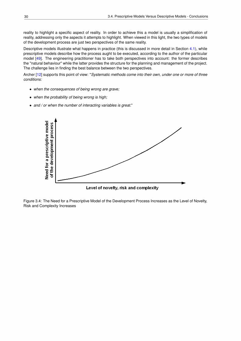
30 3.4. Prescriptive Models Versus Descriptive Models - Conclusions
reality to highlight a specific aspect of reality. In order to achieve this a model is usually a simplification ofreality, addressing only the aspects it attempts to highlight. When viewed in this light, the two types of modelsof the development process are just two perspectives of the same reality.
Descriptive models illustrate what happens in practice (this is discussed in more detail in Section 4.1), whileprescriptive models describe how the process aught to be executed, according to the author of the particularmodel [49]. The engineering practitioner has to take both perspectives into account: the former describesthe "natural behaviour" while the latter provides the structure for the planning and management of the project.The challenge lies in finding the best balance between the two perspectives.
Archer [12] supports this point of view: "Systematic methods come into their own, under one or more of threeconditions:
• when the consequences of being wrong are grave;
• when the probability of being wrong is high;
• and / or when the number of interacting variables is great."
Figure 3.4: The Need for a Prescriptive Model of the Development Process Increases as the Level of Novelty,Risk and Complexity Increases
Chapter 4
Analysis of the Theoretical Models inthe Light of Practical Application
SynopsisHaving described various prescriptive and descriptive models of the development process inChapter 3, Section 4.1 of this chapter starts by contrasting these theoretical descriptions withwhat happens in daily industrial practice. In Section 4.2 the author presents his case for theneed to tailor or adapt the development process to the circumstances surrounding the project tobe executed. The Section 4.3 discusses the application of a project methodology in the processof planning, managing and executing a development project. In order to provide a means ofdetermining which changes to make to the development process under specific circumstancesChapter 5 describes the factors that influence a development process.
31
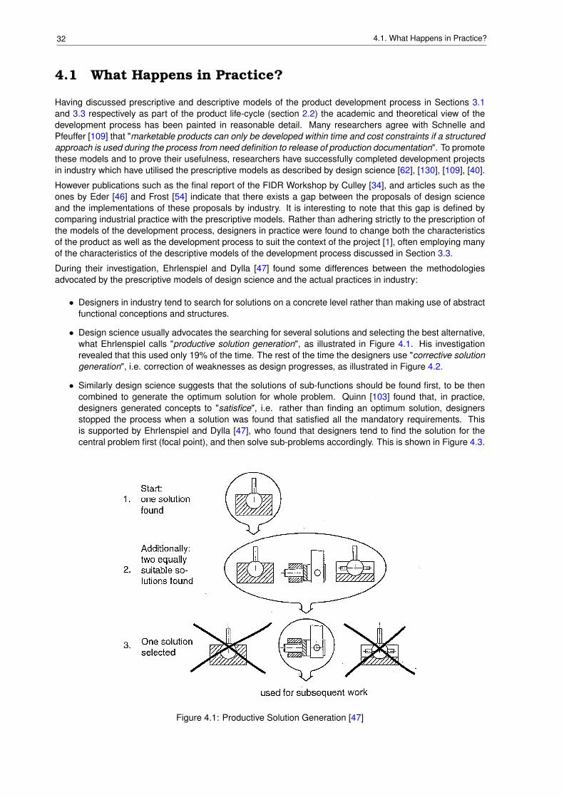
32 4.1. What Happens in Practice?
4.1 What Happens in Practice?
Having discussed prescriptive and descriptive models of the product development process in Sections 3.1and 3.3 respectively as part of the product life-cycle (section 2.2) the academic and theoretical view of thedevelopment process has been painted in reasonable detail. Many researchers agree with Schnelle andPfeuffer [109] that "marketable products can only be developed within time and cost constraints if a structuredapproach is used during the process from need definition to release of production documentation". To promotethese models and to prove their usefulness, researchers have successfully completed development projectsin industry which have utilised the prescriptive models as described by design science [62], [130], [109], [40].
However publications such as the final report of the FIDR Workshop by Culley [34], and articles such as theones by Eder [46] and Frost [54] indicate that there exists a gap between the proposals of design scienceand the implementations of these proposals by industry. It is interesting to note that this gap is defined bycomparing industrial practice with the prescriptive models. Rather than adhering strictly to the prescription ofthe models of the development process, designers in practice were found to change both the characteristicsof the product as well as the development process to suit the context of the project [1], often employing manyof the characteristics of the descriptive models of the development process discussed in Section 3.3.
During their investigation, Ehrlenspiel and Dylla [47] found some differences between the methodologiesadvocated by the prescriptive models of design science and the actual practices in industry:
• Designers in industry tend to search for solutions on a concrete level rather than making use of abstractfunctional conceptions and structures.
• Design science usually advocates the searching for several solutions and selecting the best alternative,what Ehrlenspiel calls "productive solution generation", as illustrated in Figure 4.1. His investigationrevealed that this used only 19% of the time. The rest of the time the designers use "corrective solutiongeneration", i.e. correction of weaknesses as design progresses, as illustrated in Figure 4.2.
• Similarly design science suggests that the solutions of sub-functions should be found first, to be thencombined to generate the optimum solution for whole problem. Quinn [103] found that, in practice,designers generated concepts to "satisfice", i.e. rather than finding an optimum solution, designersstopped the process when a solution was found that satisfied all the mandatory requirements. Thisis supported by Ehrlenspiel and Dylla [47], who found that designers tend to find the solution for thecentral problem first (focal point), and then solve sub-problems accordingly. This is shown in Figure 4.3.
Figure 4.1: Productive Solution Generation [47]
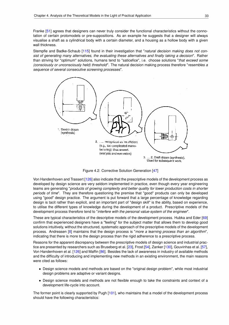
33Chapter 4. Analysis of the Theoretical Models in the Light of Practical Application
Franke [51] agrees that designers can never truly consider the functional characteristics without the conno-tation of certain protomodels or pre-suppositions. As an example he suggests that a designer will alwaysvisualise a shaft as a cylindrical body with a certain diameter, and a housing as a hollow body with a givenwall thickness.
Stempfle and Badke-Schaub [115] found in their investigation that "natural decision making does not con-sist of generating many alternatives, the evaluating these alternatives and finally taking a decision". Ratherthan striving for "optimum" solutions, humans tend to "saticefice", i.e. choose solutions "that exceed some(consciously or unconsciously held) threshold". The natural decision making process therefore "resembles asequence of several consecutive screening processes".
Figure 4.2: Corrective Solution Generation [47]
Von Handenhoven and Trassert [126] also indicate that the prescriptive models of the development process asdeveloped by design science are very seldom implemented in practice, even though every year engineeringteams are generating "products of growing complexity and better quality for lower production costs in shorterperiods of time". They are therefore questioning the premise that "good" products can only be developedusing "good" design practice. The argument is put forward that a large percentage of knowledge regardingdesign is tacit rather than explicit, and an important part of "design skill" is the ability, based on experience,to utilise the different types of knowledge during the development of a product. Prescriptive models of thedevelopment process therefore tend to "interfere with the personal value-system of the engineer".
These are typical characteristics of the descriptive models of the development process. Hubka and Eder [69]confirm that experienced designers have a "feeling" for the subject matter that allows them to develop goodsolutions intuitively, without the structured, systematic approach of the prescriptive models of the developmentprocess. Andreasen [8] maintains that the design process is "more a learning process than an algorithm",indicating that there is more to the design process than the rigid adherence to a prescriptive process.
Reasons for the apparent discrepancy between the prescriptive models of design science and industrial prac-tice are presented by researchers such as Bruseberg et al. [23], Frost [54], Zanker [130], Gouvinhas et al. [57],Von Handenhoven et al. [126] and Maffin [86]. Besides the lack of awareness in industry of available methodsand the difficulty of introducing and implementing new methods in an existing environment, the main reasonswere cited as follows:
• Design science models and methods are based on the "original design problem", while most industrialdesign problems are adaptive or variant designs.
• Design science models and methods are not flexible enough to take the constraints and context of adevelopment life-cycle into account.
The former point is clearly supported by Pugh [101], who maintains that a model of the development processshould have the following characteristics:
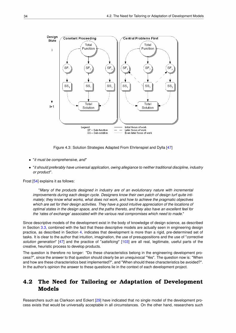
34 4.2. The Need for Tailoring or Adaptation of Development Models
Figure 4.3: Solution Strategies Adapted From Ehrlenspiel and Dylla [47]
• "it must be comprehensive, and"
• "it should preferably have universal application, owing allegiance to neither traditional discipline, industryor product".
Frost [54] explains it as follows:
"Many of the products designed in industry are of an evolutionary nature with incrementalimprovements during each design cycle. Designers know their own patch of design turf quite inti-mately; they know what works, what does not work, and how to achieve the pragmatic objectiveswhich are set for their design activities. They have a good intuitive appreciation of the locations ofoptimal states in the design space, and the paths thereto, and they also have an excellent feel forthe ’rates of exchange’ associated with the various real compromises which need to made."
Since descriptive models of the development exist in the body of knowledge of design science, as describedin Section 3.3, combined with the fact that these descriptive models are actually seen in engineering designpractice, as described in Section 4, indicates that development is more than a rigid, pre-determined set oftasks. It is clear to the author that intuition, imagination, the use of presuppositions and the use of "correctivesolution generation" [47] and the practice of "satisficing" [103] are all real, legitimate, useful parts of thecreative, heuristic process to develop products.
The question is therefore no longer: "Do these characteristics belong in the engineering development pro-cess?", since the answer to that question should clearly be an unequivocal "Yes". The question now is: "Whenand how are these characteristics best implemented?", and "When should these characteristics be avoided?".In the author’s opinion the answer to these questions lie in the context of each development project.
4.2 The Need for Tailoring or Adaptation of DevelopmentModels
Researchers such as Clarkson and Eckert [29] have indicated that no single model of the development pro-cess exists that would be universally acceptable in all circumstances. On the other hand, researchers such
35Chapter 4. Analysis of the Theoretical Models in the Light of Practical Application
as Frost [54] have indicated that the concepts of design science are actually being applied in industry, themodels and methods have just been adapted to suit the context of the specific organisation and project.
In their research regarding user-centred design methods, Bruseberg and McDonagh Philp [23] investigatedthe use of design methods during product development. She found that designers "tend not to use the formalmethods described in literature. This is mainly due to time constraints. Instead an intuitive approach, usingelements of most of the methods, is used." The investigations also showed that "there were considerabledifferences between individual designers’ preferences for methods. This is partly because design projectsvary in content and context. Also, each designer seemed to have a personal set of adapted methods, adjustedto particular circumstances and requirements."
Eder [46] confirms that each design method has to be adapted to the organisation in general and the devel-opment project in particular. Rohatynski [105] is also of the opinion that design methods "must be adapted ina coherent way to design practice nested in the given field and given company. Introduction of a new methodinto practice must not ruin the existing mode of engineer-designers proceeding. Evolution is possible andacceptable; revolution shall encounter resistance."
Suireg [117] maintains that although the design process "is not expected to have a rigid set of rules for aheuristic process" "there are general guidelines which constitute the basic structure of the design activity".Unfortunately the article does not discuss how the process could be adapted to suit varying circumstances.
According to Zanker [130] design science provides general, universal models of the development process,while the adaptation of these models to individual, specific context is only inadequately discussed. Thisleads to the notion that the models presented by design science are experienced as rigid and inflexible.Resistance to the academic theoretical models is due (among other reasons) to assistance being requiredto derive a "concrete problem-specific and individual" development methodology from the general, universalmethodologies presented by design science [59] by adaptation to suit the boundary conditions (context) ofthe specific development problem.
Fulcher and Hills [55] maintain that the development model must cater for projects "in a context of real people,real organisations and real markets which are characterised by complexity, time pressure, limited resourcesand changing circumstances".
Even in the project described by Hales [62], where a special effort was made to follow the prescriptive devel-opment model of Pahl and Beitz [97], the development process had to be adapted:
• additional "design activities" required accounted for 53% of the engineering design effort, and
• thirteen additional "methods and aids" were required, accounting for 74% of the engineering designeffort.
In their analysis regarding the difference in development practice when compared with the proposals of designscience, the following are some of the issues identified by Gouvinhas and Corbett [57]:
• Models of development process do not "consider the different cultures of various organisations and theeffect that this has on the development process".
• Development models should be tailored for each project to meet the requirements of each individualproject.
Even Franke, who in his article [51] is clearly in favour of a structured, methodical approach to development,concedes that there are instances where a less systematic approach has to be adopted for project undertime pressure. He also indicates that for projects where the performance and characteristics of the wholeproduct is very important, it is not advisable to utilise the dis-assembly and assembly approach advocated,for instance, in the VDI guideline [125] (see Section B.7). Under the circumstances it is important to considerthe product as a whole rather than an assembly of individual modules.
Günther and Ehrlenspiel [60] have also concluded that there are situations in practice where a structured,methodical approach to development might not be the solution for the success of the development project.Project with small design teams under severe time constraints are examples sited. On the other hand, projectswith high novelty content or where an optimum cost-effectiveness must be achieved to be competitive in themarket, are projects which would benefit from a more structured, methodical approach.
As discussed above, many of the researchers, who propose models of the development process, supportand even advocate the adaptation of their model to the context of the development project. How and under
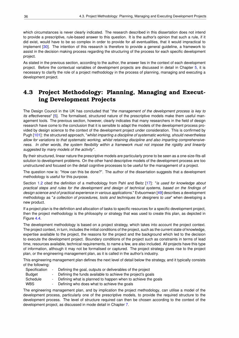
36 4.3. Project Methodology: Planning, Managing and Executing Development Projects
which circumstances is never clearly indicated. The research described in this dissertation does not intendto provide a prescriptive, rule-based answer to this question. It is the author’s opinion that such a rule, if itdid exist, would have to be so complex in order to provide for all eventualities, that it would impractical toimplement [30]. The intention of this research is therefore to provide a general guideline, a framework toassist in the decision making process regarding the structuring of the process for each specific developmentproject.
As stated in the previous section, according to the author, the answer lies in the context of each developmentproject. Before the contextual variables of development projects are discussed in detail in Chapter 5, it isnecessary to clarify the role of a project methodology in the process of planning, managing and executing adevelopment project.
4.3 Project Methodology: Planning, Managing and Execut-ing Development Projects
The Design Council in the UK has concluded that "the management of the development process is key toits effectiveness" [5]. The formalised, structured nature of the prescriptive models make them useful man-agement tools. The previous section, however, clearly indicates that many researchers in the field of designresearch have come to the conclusion that it is sensible to adapt the models of the development process pro-vided by design science to the context of the development project under consideration. This is confirmed byPugh [101]: the structured approach, "whilst imparting a discipline of systematic working, should neverthelessallow for variations to that systematic working, whilst retaining discipline and also imparting comprehensive-ness. In other words, the system flexibility within a framework must not impose the rigidity and linearitysuggested by many models of the activity".
By their structured, linear nature the prescriptive models are particularly prone to be seen as a one-size-fits-allsolution to development problems. On the other hand descriptive models of the development process are toounstructured and focused on the detail cognitive processes to be useful for the management of a project.
The question now is: "How can this be done?". The author of the dissertation suggests that a developmentmethodology is useful for this purpose.
Section 1.2 cited the definition of a methodology from Pahl and Beitz [17]: "is used for knowledge aboutpractical steps and rules for the development and design of technical systems, based on the findings ofdesign science and of practical experience in various applications." Evbuomwan [49] describes a developmentmethodology as "a collection of procedures, tools and techniques for designers to use" when developing anew product.
If a project plan is the definition and allocation of tasks to specific resources for a specific development project,then the project methodology is the philosophy or strategy that was used to create this plan, as depicted inFigure 4.4.
The development methodology is based on a project strategy, which takes into account the project context.The project context, in turn, includes the initial conditions of the project, such as the current state of knowledge,expertise available to the project, the reasons for the project and the background which led to the decisionto execute the development project. Boundary conditions of the project such as constraints in terms of leadtime, resources available, technical requirements, to name a few, are also included. All projects have this typeof information, although it may not be formalised or captured. The project strategy gives rise to the projectplan, or the engineering management plan, as it is called in the author’s industry.
This engineering management plan defines the next level of detail below the strategy, and it typically consistsof the following:
Specification - Defining the goal, outputs or deliverables of the projectBudget - Defining the funds available to achieve the project’s goalsSchedule - Defining what is planned to happen when to achieve the goalsWBS - Defining who does what to achieve the goals
The engineering management plan, and by implication the project methodology, can utilise a model of thedevelopment process, particularly one of the prescriptive models, to provide the required structure to thedevelopment process. The level of structure required can then be chosen according to the context of thedevelopment project, as discussed in mode detail in Chapter 7.
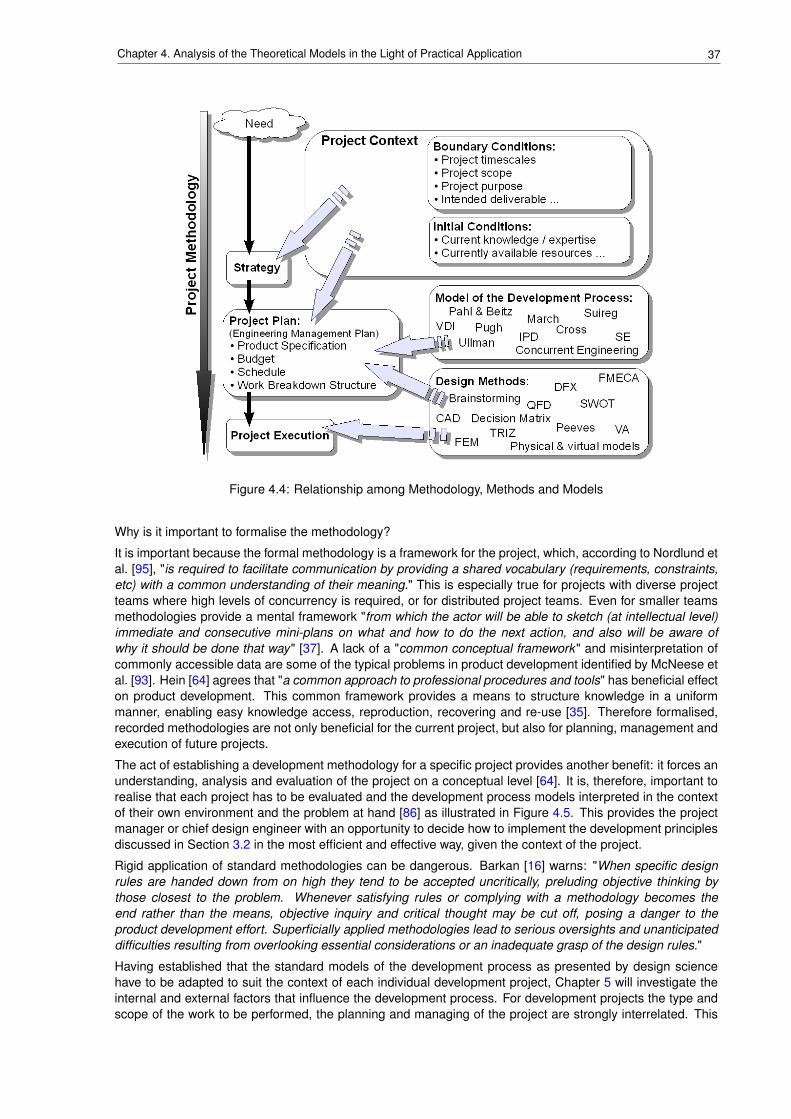
37Chapter 4. Analysis of the Theoretical Models in the Light of Practical Application
Figure 4.4: Relationship among Methodology, Methods and Models
Why is it important to formalise the methodology?
It is important because the formal methodology is a framework for the project, which, according to Nordlund etal. [95], "is required to facilitate communication by providing a shared vocabulary (requirements, constraints,etc) with a common understanding of their meaning." This is especially true for projects with diverse projectteams where high levels of concurrency is required, or for distributed project teams. Even for smaller teamsmethodologies provide a mental framework "from which the actor will be able to sketch (at intellectual level)immediate and consecutive mini-plans on what and how to do the next action, and also will be aware ofwhy it should be done that way" [37]. A lack of a "common conceptual framework" and misinterpretation ofcommonly accessible data are some of the typical problems in product development identified by McNeese etal. [93]. Hein [64] agrees that "a common approach to professional procedures and tools" has beneficial effecton product development. This common framework provides a means to structure knowledge in a uniformmanner, enabling easy knowledge access, reproduction, recovering and re-use [35]. Therefore formalised,recorded methodologies are not only beneficial for the current project, but also for planning, management andexecution of future projects.
The act of establishing a development methodology for a specific project provides another benefit: it forces anunderstanding, analysis and evaluation of the project on a conceptual level [64]. It is, therefore, important torealise that each project has to be evaluated and the development process models interpreted in the contextof their own environment and the problem at hand [86] as illustrated in Figure 4.5. This provides the projectmanager or chief design engineer with an opportunity to decide how to implement the development principlesdiscussed in Section 3.2 in the most efficient and effective way, given the context of the project.
Rigid application of standard methodologies can be dangerous. Barkan [16] warns: "When specific designrules are handed down from on high they tend to be accepted uncritically, preluding objective thinking bythose closest to the problem. Whenever satisfying rules or complying with a methodology becomes theend rather than the means, objective inquiry and critical thought may be cut off, posing a danger to theproduct development effort. Superficially applied methodologies lead to serious oversights and unanticipateddifficulties resulting from overlooking essential considerations or an inadequate grasp of the design rules."
Having established that the standard models of the development process as presented by design sciencehave to be adapted to suit the context of each individual development project, Chapter 5 will investigate theinternal and external factors that influence the development process. For development projects the type andscope of the work to be performed, the planning and managing of the project are strongly interrelated. This
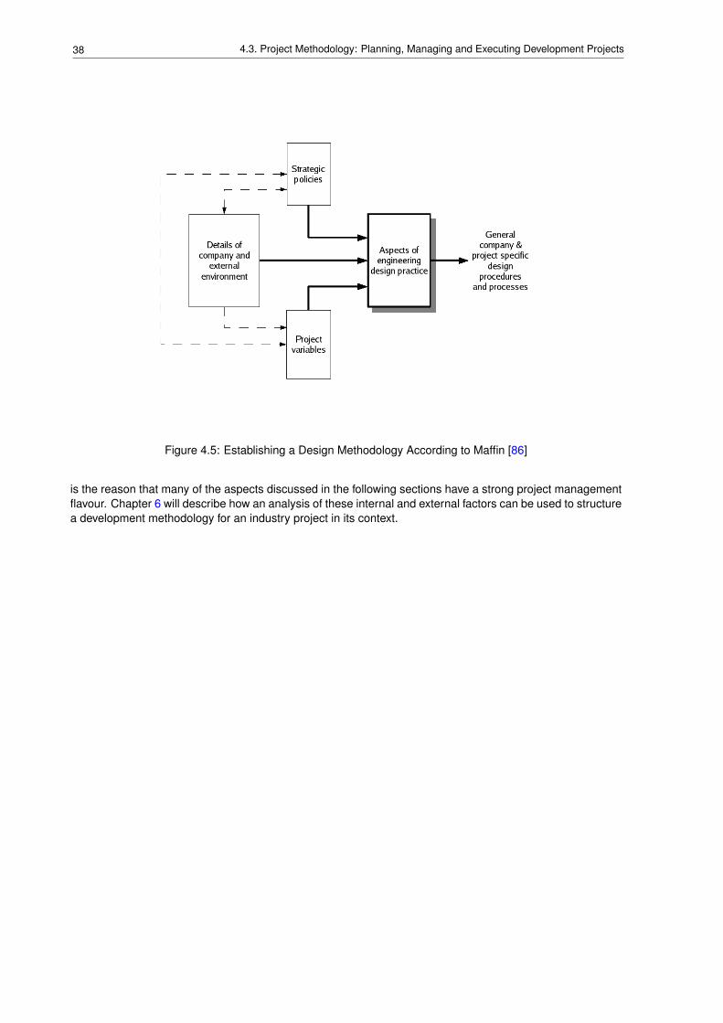
38 4.3. Project Methodology: Planning, Managing and Executing Development Projects
Figure 4.5: Establishing a Design Methodology According to Maffin [86]
is the reason that many of the aspects discussed in the following sections have a strong project managementflavour. Chapter 6 will describe how an analysis of these internal and external factors can be used to structurea development methodology for an industry project in its context.
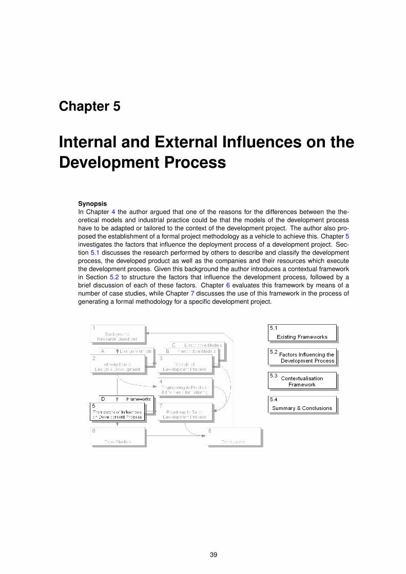
Chapter 5
Internal and External Influences on theDevelopment Process
SynopsisIn Chapter 4 the author argued that one of the reasons for the differences between the the-oretical models and industrial practice could be that the models of the development processhave to be adapted or tailored to the context of the development project. The author also pro-posed the establishment of a formal project methodology as a vehicle to achieve this. Chapter 5investigates the factors that influence the deployment process of a development project. Sec-tion 5.1 discusses the research performed by others to describe and classify the developmentprocess, the developed product as well as the companies and their resources which executethe development process. Given this background the author introduces a contextual frameworkin Section 5.2 to structure the factors that influence the development process, followed by abrief discussion of each of these factors. Chapter 6 evaluates this framework by means of anumber of case studies, while Chapter 7 discusses the use of this framework in the process ofgenerating a formal methodology for a specific development project.
39
40 5.1. Existing Frameworks
5.1 Existing Frameworks
Researchers such as Culley [34], Eder [46] and Frost [54] have indicated that the methods and modelsgenerated by design science to facilitate the development process are not being utilised by industry to theexpected degree. Among the reasons cited for this phenomenon is that "methods are not adapted to thegiven situation" [82]. The author agrees with Lindemann et al. [82] that "the designers, the product they haveto develop and the conditions they have to work with" should be the "central elements" when consideringfactors that influence product development projects. The research of Lindemann et al. [82] has led themto the realisation that "development processes are more strongly influenced by the content and by informalrelationships than by officially pre-determined schemes". Ernst and Young [48] agree that "best practice inone context can be ineffective in another ". According to Van de Ven [124] et al. "issues such as domain type,uncertainty, complexity and restrictiveness may play a role in determining whether a best practice is effective".Reymen et al. [1] that "the combination of the product being designed, the design process, and the designcontext was important".
Appendix D summarises the work of various researchers on parameters that characterise the developmentprocess and its context, which includes the product being designed, the designers and the organisation theywork for, as well as the circumstances surrounding the development project. Following the Pareto principle,the intent of this research was to focus on the factors with the greatest influence rather than providing acomprehensive list. Also the author intended to provide a practical toll that can be applied with relative ease,even in SME’s (refer to Section 1.4). None of the descriptions provided in Appendix D fitted the need forthis research exactly. The company classification scheme [87] and the resulting framework of Maffin [86](Section D.7) seemed the closest to what the author was searching for.
The context model of a design project according to Wallace and Hales[127] (see Figure D.1) is very detailedand comprehensive. In the author’s opinion it was the complexity of this model that made it unsuitable for thisresearch.
In comparison to the model by Wallace and Hales, the product properties by Tjalve[121] (see Figure D.2) weretoo much focussed on the product, i.e. the output of the development process, rather than the process itself.Similarly to the model of Wallace and Hales the list of product properties by Tjalve are comprehensive, andwould have made the framework that the author is looking for too complex.
Another complex classification scheme was presented by Barber and Hollier [15]. Although the use of nu-merical variables would have suited the author’s research, this classification scheme was too focused on themanagement of production in general and batch production specifically. For the purposes of the author’sresearch issues related to the project would have been missing from the model.
The framework by Andreasen also seemed, for the purposes of the author, incomplete: factors related to theproduction capability and the product to be developed were not included.
The parameters affecting the designer and the design process by Ehrlenspiel (see Figure D.4) focussedtoo much on factors related to the personnel involved in the design process. Issues such as value system,emotions and motivation are indeed very relevant, but difficult to quantify, and therefore it would be difficult touse these issues as an objective basis for generating a development methodology for a development project.Also, given that these variables are different for each team member, one would have generate an "average"for the whole development team, which is clearly not an easy task.
The field study by Hykin and Laming [71] was very valuable, and confirmed the author’s own experience: thatthe development process is greatly influenced by the intended production quantity of the product. However,in contrast to the comprehensive models and classification schemes described above, factors examined inthe field study by Hykin and Laming, did not seem comprehensive enough for the purposes of the author’sresearch.
Given the rationale described above, the author decided to adapt the contextual framework of Maffin [86]as a basis for generating a list of factors that influence the development process the most. The details aredescribed below.
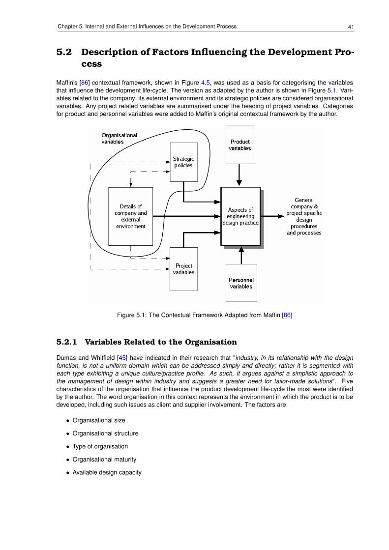
41Chapter 5. Internal and External Influences on the Development Process
5.2 Description of Factors Influencing the Development Pro-cess
Maffin’s [86] contextual framework, shown in Figure 4.5, was used as a basis for categorising the variablesthat influence the development life-cycle. The version as adapted by the author is shown in Figure 5.1. Vari-ables related to the company, its external environment and its strategic policies are considered organisationalvariables. Any project related variables are summarised under the heading of project variables. Categoriesfor product and personnel variables were added to Maffin’s original contextual framework by the author.
Figure 5.1: The Contextual Framework Adapted from Maffin [86]
5.2.1 Variables Related to the Organisation
Dumas and Whitfield [45] have indicated in their research that "industry, in its relationship with the designfunction, is not a uniform domain which can be addressed simply and directly; rather it is segmented witheach type exhibiting a unique culture/practice profile. As such, it argues against a simplistic approach tothe management of design within industry and suggests a greater need for tailor-made solutions". Fivecharacteristics of the organisation that influence the product development life-cycle the most were identifiedby the author. The word organisation in this context represents the environment in which the product is to bedeveloped, including such issues as client and supplier involvement. The factors are
• Organisational size
• Organisational structure
• Type of organisation
• Organisational maturity
• Available design capacity
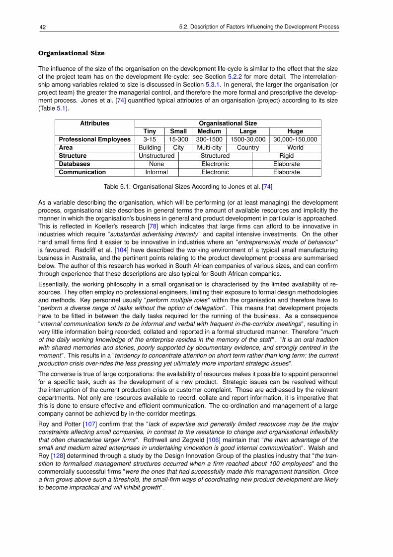
42 5.2. Description of Factors Influencing the Development Process
Organisational Size
The influence of the size of the organisation on the development life-cycle is similar to the effect that the sizeof the project team has on the development life-cycle: see Section 5.2.2 for more detail. The interrelation-ship among variables related to size is discussed in Section 5.3.1. In general, the larger the organisation (orproject team) the greater the managerial control, and therefore the more formal and prescriptive the develop-ment process. Jones et al. [74] quantified typical attributes of an organisation (project) according to its size(Table 5.1).
Attributes Organisational SizeTiny Small Medium Large Huge
Professional Employees 3-15 15-300 300-1500 1500-30,000 30,000-150,000Area Building City Multi-city Country WorldStructure Unstructured Structured RigidDatabases None Electronic ElaborateCommunication Informal Electronic Elaborate
Table 5.1: Organisational Sizes According to Jones et al. [74]
As a variable describing the organisation, which will be performing (or at least managing) the developmentprocess, organisational size describes in general terms the amount of available resources and implicitly themanner in which the organisation’s business in general and product development in particular is approached.This is reflected in Koeller’s research [78] which indicates that large firms can afford to be innovative inindustries which require "substantial advertising intensity" and capital intensive investments. On the otherhand small firms find it easier to be innovative in industries where an "entrepreneurial mode of behaviour "is favoured. Radcliff et al. [104] have described the working environment of a typical small manufacturingbusiness in Australia, and the pertinent points relating to the product development process are summarisedbelow. The author of this research has worked in South African companies of various sizes, and can confirmthrough experience that these descriptions are also typical for South African companies.
Essentially, the working philosophy in a small organisation is characterised by the limited availability of re-sources. They often employ no professional engineers, limiting their exposure to formal design methodologiesand methods. Key personnel usually "perform multiple roles" within the organisation and therefore have to"perform a diverse range of tasks without the option of delegation". This means that development projectshave to be fitted in between the daily tasks required for the running of the business. As a consequence"internal communication tends to be informal and verbal with frequent in-the-corridor meetings", resulting invery little information being recorded, collated and reported in a formal structured manner. Therefore "muchof the daily working knowledge of the enterprise resides in the memory of the staff ". "It is an oral traditionwith shared memories and stories, poorly supported by documentary evidence, and strongly centred in themoment". This results in a "tendency to concentrate attention on short term rather than long term: the currentproduction crisis over-rides the less pressing yet ultimately more important strategic issues".
The converse is true of large corporations: the availability of resources makes it possible to appoint personnelfor a specific task, such as the development of a new product. Strategic issues can be resolved withoutthe interruption of the current production crisis or customer complaint. Those are addressed by the relevantdepartments. Not only are resources available to record, collate and report information, it is imperative thatthis is done to ensure effective and efficient communication. The co-ordination and management of a largecompany cannot be achieved by in-the-corridor meetings.
Roy and Potter [107] confirm that the "lack of expertise and generally limited resources may be the majorconstraints affecting small companies, in contrast to the resistance to change and organisational inflexibilitythat often characterise larger firms". Rothwell and Zegveld [106] maintain that "the main advantage of thesmall and medium sized enterprises in undertaking innovation is good internal communication". Walsh andRoy [128] determined through a study by the Design Innovation Group of the plastics industry that "the tran-sition to formalised management structures occurred when a firm reached about 100 employees" and thecommercially successful firms "were the ones that had successfully made this management transition. Oncea firm grows above such a threshold, the small-firm ways of coordinating new product development are likelyto become impractical and will inhibit growth".
43Chapter 5. Internal and External Influences on the Development Process
Organisational Structure
Dumas et al. [45] have indicated how the existence of the position of design manager can influence the waythat product development is implemented. Companies employing a design manager seem to assign greaterimportance to the design function within the company. The design department is therefore often operated asa profit centre, accepting a high level of accountability for the designs developed. In comparison companieswithout the position of design manager prefer central control of design projects with very little accountabilityexpected from the designers. Accountability for design is therefore diffused among finance, engineering andmarketing.
Maffin [86] investigated the influences of company structure on the development life-cycle. The "degree ofautonomy over the strategy-making process" was found to be important: "an independent establishment willhave total autonomy over the process". The word "unit" in this context can refer to organisational structuresof various sizes. A department or team of a large organisation can be given authority to plan and executea project autonomously from the rest of the company. This can also apply to the local branch, divisionor subsidiary of a national (or multi-national) company. Conversely, if the unit is forced to operate withinthe constraints of the larger organisation, generally a homogeneous (and therefore prescriptive and static)approach will be followed, that fits the requirements and philosophy of the larger organisation, rather thanthose of the smaller one.
Autonomy over the development includes the freedom to adapt the development process according to thecontext and needs of the project. Autonomous units may decide to skip a formal concept stage, since theproduct has low complexity (see Section 5.2.3) or because the circumstances have made a concept studyredundant and the level of knowledge and understanding is such that the project can proceed with the em-bodiment stage. Large organisations may, on the other hand, require that all project follow a set programmeirrespective of the context of the project. On a more detailed level: an autonomous organisation (unit) maydecide that a FEM analysis is not required since the achievement of timescales has a higher priority andthe associated risks are at an acceptable level. A dependent unit within a larger structure may be procedu-rally required to perform certain actions (analyses) irrespective of the specific context of the project. Brownand Eisenhardt [22] call this autonomy "subtle control", where senior management communicates the visionfor the new product and then providing "enough autonomy to be motivated and creative". This, obviously,goes hand-in-hand with senior management support, which is required for the provision of both "financial andpolitical resources".
Organisational Type
Aspects of the organisational type that influence the development life-cycle are discussed in the followingsections.
PurposeThe first aspect is the organisation’s main purpose [86]: is it trying to be product leader, i.e. develop
products which excel in performance, quality and reliability, or an effective manufacturer, i.e. concentrateon effective manufacturing and cost minimisation? The first can be seen as a product developer with amanufacturing facility, while the second is a manufacturing plant with a design office to handle minor changesto improve efficiency and cost. Typically the former will concentrate on the initial part of the product life-cycleby generating the product definition and documentation, producing prototypes and assisting in the generationof pre-production models. The latter typically obtains the product definition from the former and produces theproduct in volume (the second half of the product life-cycle).
The industry sector seems to also influence the development process [45]. In the manufacturing sector thedesign function is dominated by engineering, internal design teams are utilised and accountability is retainedby the designers. In the service industry, on the other hand, the design process is dominated by marketingand is reliant on external consultants and design policy documentation.
Therefore the emphasis within the product development life-cycle shifts according to the main purpose ofthe organisation executing the project. Cooper [30] also describes how the development process is influ-enced by the way that organisations perceive themselves: is the development of a new product driven bythe demands and requirements of the market (market orientation) or opportunities enabled by technologicaladvances (design domination and/or prototype domination). For the former the development process is domi-nated by marketing activities (close to 75% of the project duration), while the latter is dominated technical and
44 5.2. Description of Factors Influencing the Development Process
production issues (up to 79% of the project duration).
The description above obviously shows the extremes of the spectrum in black and white, while in reality thereare shades of grey.
Production Size and Inventory PhilosophyThe second and third aspects of the type of organisation to influence the development life-cycle (production
size and inventory philosophy respectively) are clearly related to the organisations main purpose as discussedabove. Production size can either be unit, batch or mass production for discrete products [84]. Although thedevelopment of continuous product, such as in the petrochemical industry, for instance, is not considered inthis research, the plants to produce the continuous product are discrete products themselves, and thereforeconsidered as part of this research. The inventory philosophy can be one of four options: make-to-inventory,assemble-to-order, make-to-order or engineer-to-order [84]. Production size and inventory philosophy arerelated: generally products engineered-to-order are produced in unit or batch production, while make-to-inventory products lend themselves to mass production. As a parameter of the organisation, production sizeinfluences the development life-cycle by defining the norm for the company. The effect of production sizeon the development life-cycle as product related parameter is discussed in Section 5.2.3. The point beingthat a company accustomed to producing a specific product type, for instance engineer-to-order, will have tochange the development methodology, as discussed in Section 5.2.2, if it should decide to develop a made-for-inventory product.
Selling ProductsThe fourth aspect is concerned with the organisations mode of selling products:
• selling standard products through catalogues,
• selling customised products and competing through tenders or
• suppliers operating with the supply chains of a limited number of customers, establishing long termsales agreements.
These aspects are related to the production size and inventory philosophy. Products produced in massproduction lend themselves to long term sales agreements, since this agreement lowers the risk for investingin the establishment of capital intensive mass production facilities. Engineered-to-order products, on theother hand, are often customised products sold through tenders, since each customer has different, specificrequirements. As a third variant, make-to-inventory, assemble-to-order and make-to-order can be standardproducts which are sold through catalogues, where the customer can choose a specific configuration madeup of a combination of standard components. Just as with production size and inventory philosophy discussedabove, the product development methodology is chosen according to the product type (Section 5.2.3).
Organisational Maturity
Organisational maturity relates to the management of processes within the organisation. The various levelsas defined by Jones et al. [74] are shown in Table 5.2. Although Jones established this table specifically toindicate an organisation’s maturity to manage the process of identifying, analysing, verifying and validatingrequirements during the development process, the author feels that the maturity models also applies to themanagement of the development process as a whole.
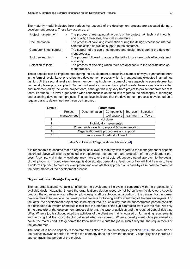
45Chapter 5. Internal and External Influences on the Development Process
The maturity model indicates how various key aspects of the development process are executed during adevelopment process. These key aspects are:
Project management - The process of managing all aspects of the project, i.e. technical integrityand quality, timescales, financial expenditure.
Documentation - The process of capturing information during the design process for internalcommunication as well as support to the customer.
Computer & tool support - The support of the use of computers and design tools during the develop-ment process.
Tool use learning - The process followed to acquire the skills to use new tools effectively andefficiently.
Selection of tools - The process of deciding which tools are applicable to the specific develop-ment process.
These aspects can be implemented during the development process in a number of ways, summarised herein the form of levels. Level one refers to a development process which is managed and executed in an ad hocfashion. At the second level each team member may implement some of these aspects to some degree, butno overall philosophy is applied. On the third level a common philosophy towards these aspects is acceptedand implemented by the whole project team, although this may vary from project to project and from team toteam. For the fourth level organisation wide consensus is obtained with regard to the philosophy of managingand executing development projects. The last level indicates that the development process is evaluated on aregular basis to determine how it can be improved.
Levels ParametersProject Documentation Computer & Tool use Selection
management tool support learning of Tools1 Not done2 Individually implemented3 Project wide selection, support & implementation4 Organisation-wide procedures and support5 Improvement method followed
Table 5.2: Levels of Organisational Maturity [74]
It is reasonable to assume that an organisation’s level of maturity with regard to the management of aspectsdescribed above will also be reflected in the planning, management and execution of the development pro-cess. A company at maturity level one, may have a very unstructured, uncoordinated approach to the designof their products. In comparison an organisation situated generally at level four or five, will find it easier to havea uniform approach to product development and evaluate this approach on a case-by-case basis to maximisethe performance of the development process.
Organisational Design Capacity
The last organisational variable to influence the development life-cycle is concerned with the organisation’savailable design capacity. Should the organisation’s design resource not be sufficient to develop a specificproduct, the organisation can either employ design staff or sub-contract a portion of the design. For the formerprovision has to be made in the development process for training and/or mentoring of the new employees. Forthe latter, the development project should be structured in such a way that the subcontracted portion consistsof a definable sub-system or module to facilitate the interface of the sub-contracted work with the rest. Not onlyis the structure of the development process different, the type of activities and the required capabilities alsodiffer. When a job is subcontracted the activities of the client are mainly focused on formulating requirementsand verifying that the subcontractor delivered what was agreed. When a development job is performed in-house the major effort is to generate the know-how to execute the job in such a way that the requirements ofthe job are met.
The issue of in-house capacity is therefore often linked to in-house capability (Section 5.2.4): the execution ofthe project involves a portion for which the company does not have the necessary capability, and therefore itsub-contracts that portion of the project.
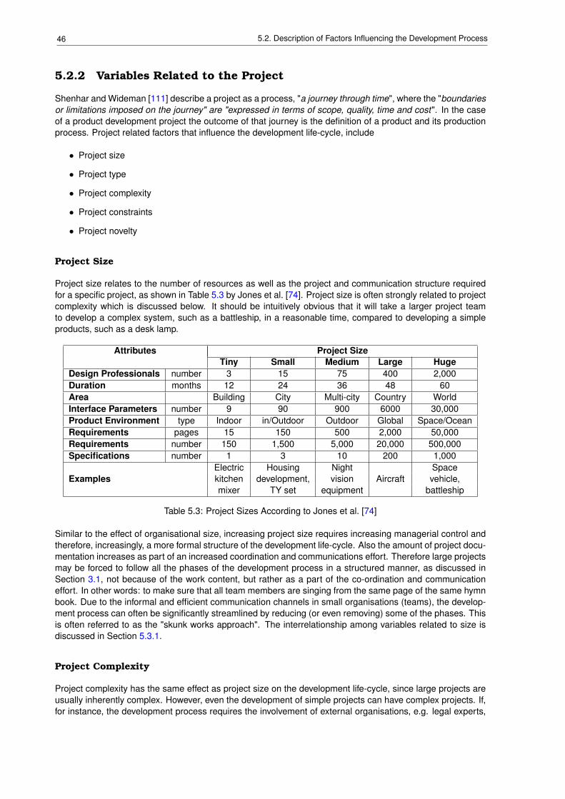
46 5.2. Description of Factors Influencing the Development Process
5.2.2 Variables Related to the Project
Shenhar and Wideman [111] describe a project as a process, "a journey through time", where the "boundariesor limitations imposed on the journey" are "expressed in terms of scope, quality, time and cost". In the caseof a product development project the outcome of that journey is the definition of a product and its productionprocess. Project related factors that influence the development life-cycle, include
• Project size
• Project type
• Project complexity
• Project constraints
• Project novelty
Project Size
Project size relates to the number of resources as well as the project and communication structure requiredfor a specific project, as shown in Table 5.3 by Jones et al. [74]. Project size is often strongly related to projectcomplexity which is discussed below. It should be intuitively obvious that it will take a larger project teamto develop a complex system, such as a battleship, in a reasonable time, compared to developing a simpleproducts, such as a desk lamp.
Attributes Project SizeTiny Small Medium Large Huge
Design Professionals number 3 15 75 400 2,000Duration months 12 24 36 48 60Area Building City Multi-city Country WorldInterface Parameters number 9 90 900 6000 30,000Product Environment type Indoor in/Outdoor Outdoor Global Space/OceanRequirements pages 15 150 500 2,000 50,000Requirements number 150 1,500 5,000 20,000 500,000Specifications number 1 3 10 200 1,000
Electric Housing Night SpaceExamples kitchen development, vision Aircraft vehicle,
mixer TY set equipment battleship
Table 5.3: Project Sizes According to Jones et al. [74]
Similar to the effect of organisational size, increasing project size requires increasing managerial control andtherefore, increasingly, a more formal structure of the development life-cycle. Also the amount of project docu-mentation increases as part of an increased coordination and communications effort. Therefore large projectsmay be forced to follow all the phases of the development process in a structured manner, as discussed inSection 3.1, not because of the work content, but rather as a part of the co-ordination and communicationeffort. In other words: to make sure that all team members are singing from the same page of the same hymnbook. Due to the informal and efficient communication channels in small organisations (teams), the develop-ment process can often be significantly streamlined by reducing (or even removing) some of the phases. Thisis often referred to as the "skunk works approach". The interrelationship among variables related to size isdiscussed in Section 5.3.1.
Project Complexity
Project complexity has the same effect as project size on the development life-cycle, since large projects areusually inherently complex. However, even the development of simple projects can have complex projects. If,for instance, the development process requires the involvement of external organisations, e.g. legal experts,
47Chapter 5. Internal and External Influences on the Development Process
approval authorities or independent test facilities. This is often related to the product complexity (see Sec-tion 5.2.3) and the level of product in the system hierarchy (see Section 5.2.3). According to Günther [59]complexity has the following attributes:
complicacy - a problem with a large number of variables is more complex,dynamics - complex problems are often time dependent, making it very important that the
intervention is performed at the right time,opacity - only a portion of the relationships among project variables are visible at any
time,interdependency - project variables are interrelated so that unintentional side-effects are created
by adjusting project variables with the aim of creating a beneficial effect, andmultiple objectives(German: Polytelie)
- striving for the achievement of multiple, often conflicting goals simultaneously.
Therefore complex projects may require a very formal and structured development process in order to in-tegrate the various aspects of the project. The interrelationship between project and product complexity isdiscussed in more detail in Section 5.3.3.
Project Type
Ullman [123] defines the project type as follows:
"original design - is a new development, which is not based on a previous product or idea;""parametric design - where parameters are adjusted to suit requirements;""configuration design - which requires mainly the packaging of existing modules or components;""selection design - where the correct standard component to suit the requirements is selected
from a catalogue and""redesign - which requires modifications to an existing product to meet new require-
ments."
Evbuomwan et al. [49] distinguish between
routine design - which is "derived from a common prototype with the same set of variables or fea-tures and the structure does not change",
redesigns - involving the modification of an "existing design to satisfy new requirements", andnon-routine - original or new designs.
According to Evbuomwan et al. [49] redesigns can be either adaptive or variant designs: the former involves"adapting a known system (solution principle remaining the same) to a changed task" by introducing "improve-ments and detail refinements", while the latter "follows a extrapolative or interpolative procedure" to generate"further geometrically similar designs of different capabilities".
Selection design typically requires the least amount of engineering effort, is technically quite simple, and thisshould be evident in the extreme simplicity and reduction of the development life-cycle. Parametric design,configuration design and redesign projects are typically more complex and technically challenging. Theyalso represent the majority of projects in practice. For these projects the concept phase would be limited toestablishing the new requirements and a brief investigation into the new aspects of the project. Although theemphasis during the embodiment and detail phases will also be on the new aspects, the original data willhave to be considered carefully to ensure alignment with the new requirements. Obviously the original designproblem requires the complete development life-cycle from concept phase to detail phase, as described indesign literature, such as the VDI 2221 [125] guideline. Table 5.4 shows how the development life-cycle canbe adjusted depending on project type, according to the VDI guideline [125].
It should be intuitively clear that project type and project novelty are strongly related. For instance, a non-routine or original design has a high novelty content since it is, by definition, not based on a previous productor idea. However, the relationship is not quite so obvious when redesign, parametric and configuration designsare considered. Although one might usually be inclined to assign a low novelty value to these type of projects,case study B (Section 6.2) presents a case which involved a design of a new product based on an existingone, i.e. redesign. In this case, however, the project novelty was estimated as "medium" since the userrequirements forced the design parameters outside of the accepted, normal range for this kind of product.
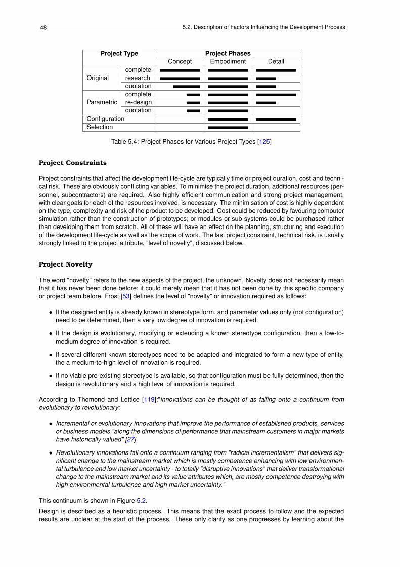
48 5.2. Description of Factors Influencing the Development Process
Project Type Project PhasesConcept Embodiment Detail
completeOriginal research
quotationcomplete
Parametric re-designquotation
ConfigurationSelection
Table 5.4: Project Phases for Various Project Types [125]
Project Constraints
Project constraints that affect the development life-cycle are typically time or project duration, cost and techni-cal risk. These are obviously conflicting variables. To minimise the project duration, additional resources (per-sonnel, subcontractors) are required. Also highly efficient communication and strong project management,with clear goals for each of the resources involved, is necessary. The minimisation of cost is highly dependenton the type, complexity and risk of the product to be developed. Cost could be reduced by favouring computersimulation rather than the construction of prototypes; or modules or sub-systems could be purchased ratherthan developing them from scratch. All of these will have an effect on the planning, structuring and executionof the development life-cycle as well as the scope of work. The last project constraint, technical risk, is usuallystrongly linked to the project attribute, "level of novelty", discussed below.
Project Novelty
The word "novelty" refers to the new aspects of the project, the unknown. Novelty does not necessarily meanthat it has never been done before; it could merely mean that it has not been done by this specific companyor project team before. Frost [53] defines the level of "novelty" or innovation required as follows:
• If the designed entity is already known in stereotype form, and parameter values only (not configuration)need to be determined, then a very low degree of innovation is required.
• If the design is evolutionary, modifying or extending a known stereotype configuration, then a low-to-medium degree of innovation is required.
• If several different known stereotypes need to be adapted and integrated to form a new type of entity,the a medium-to-high level of innovation is required.
• If no viable pre-existing stereotype is available, so that configuration must be fully determined, then thedesign is revolutionary and a high level of innovation is required.
According to Thomond and Lettice [119]:"innovations can be thought of as falling onto a continuum fromevolutionary to revolutionary:
• Incremental or evolutionary innovations that improve the performance of established products, servicesor business models "along the dimensions of performance that mainstream customers in major marketshave historically valued" [27]
• Revolutionary innovations fall onto a continuum ranging from "radical incrementalism" that delivers sig-nificant change to the mainstream market which is mostly competence enhancing with low environmen-tal turbulence and low market uncertainty - to totally "disruptive innovations" that deliver transformationalchange to the mainstream market and its value attributes which, are mostly competence destroying withhigh environmental turbulence and high market uncertainty."
This continuum is shown in Figure 5.2.
Design is described as a heuristic process. This means that the exact process to follow and the expectedresults are unclear at the start of the process. These only clarify as one progresses by learning about the
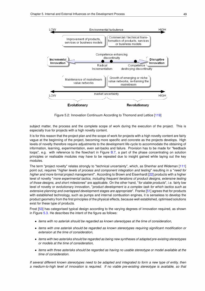
49Chapter 5. Internal and External Influences on the Development Process
Figure 5.2: Innovation Continuum According to Thomond and Lettice [119]
subject matter, the process and the complete scope of work during the execution of the project. This isespecially true for projects with a high novelty content.
It is for this reason that the project plan and the scope of work for projects with a high novelty content are fairlyvague at the beginning of the project, becoming more specific and concrete as the projects develops. Highlevels of novelty therefore require adjustments to the development life-cycle to accommodate the obtaining ofinformation, learning, experimentation, even set-backs and failure. Provision has to be made for "feedbackloops", e.g. with reference to the flowchart in Figure B.7, a part of the phase concentrating on solutionprinciples or realisable modules may have to be repeated due to insight gained while laying out the keymodules.
The term "project novelty" relates strongly to "technical uncertainty", which, as Shenhar and Wideman [111]point out, requires "higher levels of process and component integration and testing" resulting in a "need forhigher and more formal project management". According to Brown and Eisenhardt [22] products with a higherlevel of novelty "more experimental tactics, including frequent iterations of product designs, extensive testingof those designs, and short milestones" are applicable. On the other hand, "for stable products", i.e. fairly lowlevel of novelty or evolutionary innovation, "product development is a complex task for which tactics such asextensive planning and overlapped development stages are appropriate". Franke [51] agrees that for productswith established technology, such as pumps and internal combustion engines, it is senseless to develop theproduct geometry from the first principles of the physical effects, because well established, optimised solutionsexist for these type of products.
Frost [53] has categorised typical design according to the varying degrees of innovation required, as shownin Figure 5.3. He describes the intent of the figure as follows:
• items with no asterisk should be regarded as known stereotypes at the time of consideration,
• items with one asterisk should be regarded as known stereotypes requiring significant modification orextension at the time of consideration,
• items with two asterisks should be regarded as being new syntheses of adapted pre-existing stereotypesor models at the time of consideration,
• items with three asterisks should be regarded as having no usable stereotype or model available at thetime of consideration.
If several different known stereotypes need to be adapted and integrated to form a new type of entity, thena medium-to-high level of innovation is required. If no viable pre-existing stereotype is available, so that
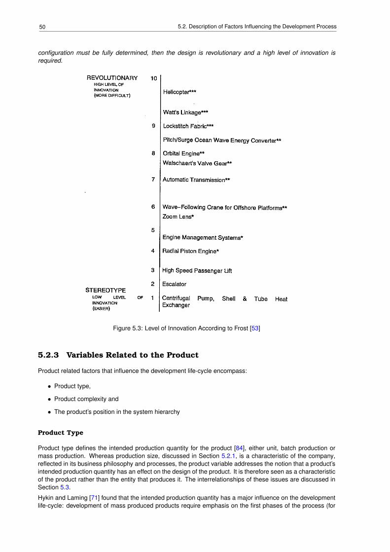
50 5.2. Description of Factors Influencing the Development Process
configuration must be fully determined, then the design is revolutionary and a high level of innovation isrequired.
Figure 5.3: Level of Innovation According to Frost [53]
5.2.3 Variables Related to the Product
Product related factors that influence the development life-cycle encompass:
• Product type,
• Product complexity and
• The product’s position in the system hierarchy
Product Type
Product type defines the intended production quantity for the product [84], either unit, batch production ormass production. Whereas production size, discussed in Section 5.2.1, is a characteristic of the company,reflected in its business philosophy and processes, the product variable addresses the notion that a product’sintended production quantity has an effect on the design of the product. It is therefore seen as a characteristicof the product rather than the entity that produces it. The interrelationships of these issues are discussed inSection 5.3.
Hykin and Laming [71] found that the intended production quantity has a major influence on the developmentlife-cycle: development of mass produced products require emphasis on the first phases of the process (for
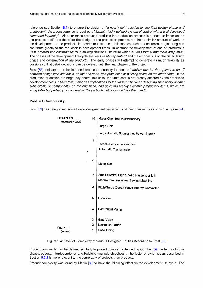
51Chapter 5. Internal and External Influences on the Development Process
reference see Section B.7) to ensure the design of "a nearly right solution for the final design phase andproduction". As a consequence it requires a "formal, rigidly defined system of control with a well-developedcommand hierarchy". Also, for mass-produced products the production process is at least as important asthe product itself, and therefore the design of the production process requires a similar amount of work asthe development of the product. In these circumstances philosophies such as concurrent engineering cancontribute greatly to the reduction in development times. In contrast the development of one-off products is"less ordered and constrained" with an organisational structure which is "less formal and more adaptable".The phases of the development life-cycle are "less easily separated" and the emphasis is on the "final designphase and construction of the product". The early phases will attempt to generate as much flexibility aspossible so that detail decisions can be delayed until the final phases of the project.
Frost [53] indicates that the intended production quantity introduces "implications for the optimal trade-offbetween design time and costs, on the one hand, and production or building costs, on the other hand". If theproduction quantities are large, say above 100 units, the units cost is not greatly affected by the amortiseddevelopment costs. "Therefore, it also has implications for the trade-off between designing specifically optimalsubsystems or components, on the one hand, and selecting readily available proprietary items, which areacceptable but probably not optimal for the particular situation, on the other hand".
Product Complexity
Frost [53] has categorised some typical designed entities in terms of their complexity as shown in Figure 5.4.
Figure 5.4: Level of Complexity of Various Designed Entities According to Frost [53]
Product complexity can be defined similarly to project complexity defined by Günther [59], in terms of com-plicacy, opacity, interdependency and Polytelie (multiple objectives). The factor of dynamics as described inSection 5.2.2 is more relevant to the complexity of projects than products.
Product complexity was found by Maffin [86] to have the following effect on the development life-cycle. The
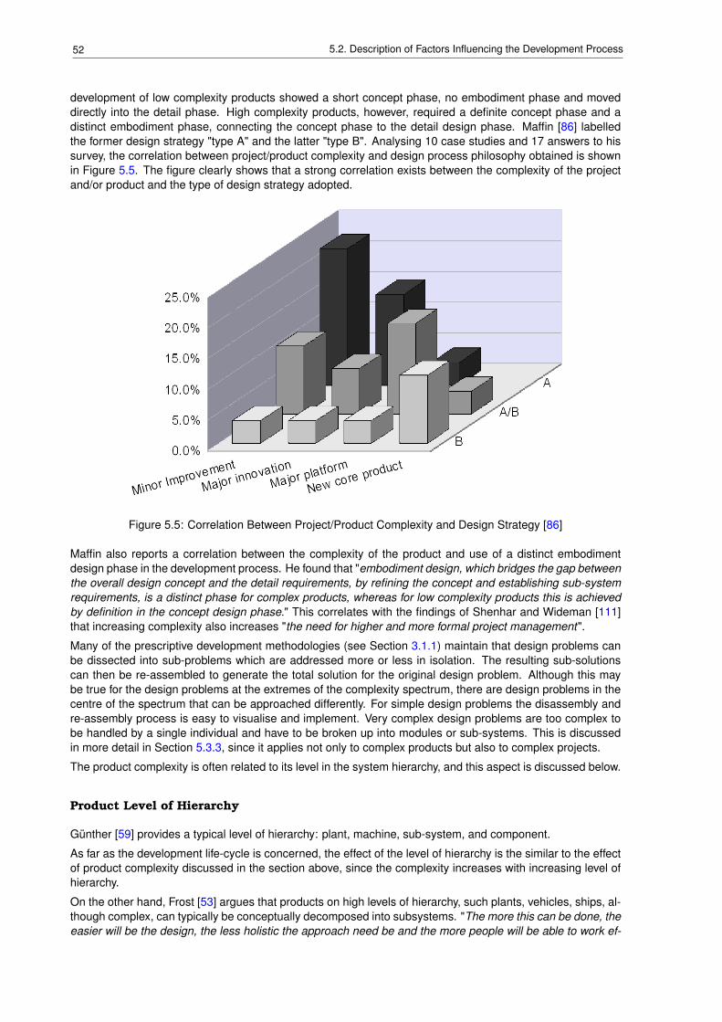
52 5.2. Description of Factors Influencing the Development Process
development of low complexity products showed a short concept phase, no embodiment phase and moveddirectly into the detail phase. High complexity products, however, required a definite concept phase and adistinct embodiment phase, connecting the concept phase to the detail design phase. Maffin [86] labelledthe former design strategy "type A" and the latter "type B". Analysing 10 case studies and 17 answers to hissurvey, the correlation between project/product complexity and design process philosophy obtained is shownin Figure 5.5. The figure clearly shows that a strong correlation exists between the complexity of the projectand/or product and the type of design strategy adopted.
Figure 5.5: Correlation Between Project/Product Complexity and Design Strategy [86]
Maffin also reports a correlation between the complexity of the product and use of a distinct embodimentdesign phase in the development process. He found that "embodiment design, which bridges the gap betweenthe overall design concept and the detail requirements, by refining the concept and establishing sub-systemrequirements, is a distinct phase for complex products, whereas for low complexity products this is achievedby definition in the concept design phase." This correlates with the findings of Shenhar and Wideman [111]that increasing complexity also increases "the need for higher and more formal project management".
Many of the prescriptive development methodologies (see Section 3.1.1) maintain that design problems canbe dissected into sub-problems which are addressed more or less in isolation. The resulting sub-solutionscan then be re-assembled to generate the total solution for the original design problem. Although this maybe true for the design problems at the extremes of the complexity spectrum, there are design problems in thecentre of the spectrum that can be approached differently. For simple design problems the disassembly andre-assembly process is easy to visualise and implement. Very complex design problems are too complex tobe handled by a single individual and have to be broken up into modules or sub-systems. This is discussedin more detail in Section 5.3.3, since it applies not only to complex products but also to complex projects.
The product complexity is often related to its level in the system hierarchy, and this aspect is discussed below.
Product Level of Hierarchy
Günther [59] provides a typical level of hierarchy: plant, machine, sub-system, and component.
As far as the development life-cycle is concerned, the effect of the level of hierarchy is the similar to the effectof product complexity discussed in the section above, since the complexity increases with increasing level ofhierarchy.
On the other hand, Frost [53] argues that products on high levels of hierarchy, such plants, vehicles, ships, al-though complex, can typically be conceptually decomposed into subsystems. "The more this can be done, theeasier will be the design, the less holistic the approach need be and the more people will be able to work ef-
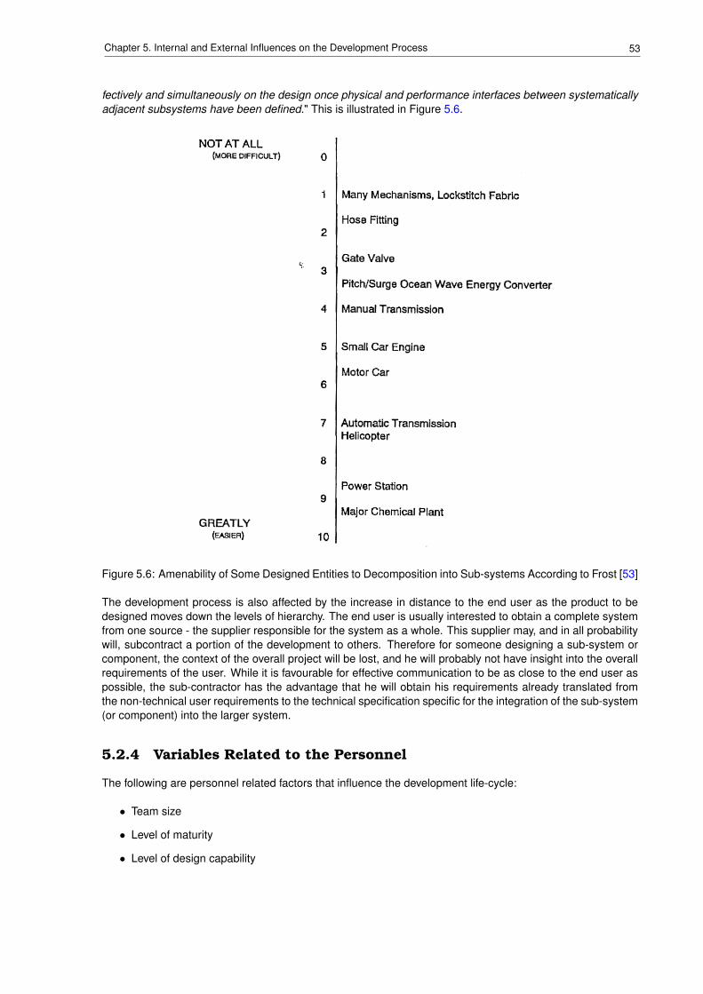
53Chapter 5. Internal and External Influences on the Development Process
fectively and simultaneously on the design once physical and performance interfaces between systematicallyadjacent subsystems have been defined." This is illustrated in Figure 5.6.
Figure 5.6: Amenability of Some Designed Entities to Decomposition into Sub-systems According to Frost [53]
The development process is also affected by the increase in distance to the end user as the product to bedesigned moves down the levels of hierarchy. The end user is usually interested to obtain a complete systemfrom one source - the supplier responsible for the system as a whole. This supplier may, and in all probabilitywill, subcontract a portion of the development to others. Therefore for someone designing a sub-system orcomponent, the context of the overall project will be lost, and he will probably not have insight into the overallrequirements of the user. While it is favourable for effective communication to be as close to the end user aspossible, the sub-contractor has the advantage that he will obtain his requirements already translated fromthe non-technical user requirements to the technical specification specific for the integration of the sub-system(or component) into the larger system.
5.2.4 Variables Related to the Personnel
The following are personnel related factors that influence the development life-cycle:
• Team size
• Level of maturity
• Level of design capability
54 5.2. Description of Factors Influencing the Development Process
Team Size
Team size is strongly related and has the same influence on the development life-cycle as the size of organi-sation and project size discussed in paragraphs 5.2.1 and 5.2.2 respectively.
These three variables are not necessarily identical, however, and this is discussed in more detail in Sec-tion 5.3.1. Organisational size influences the development project by transferring at least some of the man-agement philosophy from the organisation onto the project. While project size defines the resources that theproject requires to complete it in a given time-scale, team size defines the resources actually allocated to theproject. In the author’s experience the projects size usually exceeds the team size.
Level of Maturity
Ehrlenspiel and Dylla [47] defined a list of attributes that can be used to define the level of maturity of a designteam: mature designers
• are more precise and spend more time on analysis and formulation of requirements.
• increase the scope during search for solutions - reformulation and summary.
• approach problems strategically from important to less important sub-problems.
• generate variants especially in important problem areas.
• are more accurate during and spend more time on the analysis of solutions.
• have better spatial imagination.
• apply adequate and meaningful strategies for steering the design process based on thorough analysisof demands and solution properties.
These attributes influence the required detail and structure in the planning, management and execution ofthe development life-cycle. It is the author’s experience that mature, experienced personnel will use theirexperience to determine
• which parts of the design problem constitute the core of the design problem, requiring the main attention,and
• the level of "structuredness" for the design problem, dependent of the level of complexity and novelty(see 5.3.3).
To compensate for their lack of experience less mature designers will require a more structured approach. Anyproject may seem complex and novel, since they have very little experience to use as comparison. For thisreason the possibility exists that sub-problems and the core problem are addressed with the same approach,resulting in inefficiencies and longer development times.
During their investigation with respect to the differences between novice and experienced designers, Christi-aans, Dorst and Cross [28] found that increased experience resulted in an "increased awareness of problemareas", which probably contributed to the investigation concluding that expert designers spent more timesearching for information than they novice counterparts.
Badke-Schaub [14] has investigated the influence of the designer’s expertise on the success of the develop-ment project. She identified three types of "critical situations" in the design process, whose outcome wouldbe influenced by the level of expertise of the designer:
elaborations of goals - clarifying concept or embodiment related requirements and settinggoals
solution search - generating proposals and solution ideassolution analysis and decisions - analysing and evaluating solution ideas, selection of solutions or so-
lution principles
Her finding was that during goal elaboration experienced designers would tend to "follow their pre-establishedknowledge" increasing the potential of "insufficient goal elaboration". In comparison in-experienced designershave very little pre-established knowledge and are usually aware of this fact. Therefore they tend to "analyse
55Chapter 5. Internal and External Influences on the Development Process
goals in detail", increasing the probability of recognising new requirements. For the solution search situation,however, "the generation of ideas depends largely on the availability of information concerning different solu-tion principles". Therefore the experienced designer can draw on a larger pool of information to generate newsolution principles. Similarly, the solution elaboration situation "stand to benefit from routine expertise", sincethe "designer is able to access his experience base with different types of knowledge".
In the context of the current research the findings of Badke-Schaub indicate that experienced, meticulousdesigners are an asset to the development project especially in the concept and embodiment phases, wherethe requirements have to be defined and the goals of the development established. Projects benefit more fromthe expertise of experienced designers during the search and analysis of solutions. Referring the project typedescribed in Section 5.2.2, original designs benefit the most from the designer’s experience since it requiresthe most intensive search and analysis of solutions. Selection and configuration designs can be successfullynegotiated by designers with less experience, since it relies more on selecting the correct components orconfiguration based on the understanding of the clients requirements.
The paragraphs above have mainly focused on the maturity and experience of technical team involved inthe development process. Song et al. [114] make the point that the success of product development is alsoinfluenced by the maturity, experience and involvement of senior management: important support is obtainedfrom senior management "by granting authority to the project manager " and by "defining the (development)problem strategically".
Maturity, capability and experience are clearly inter-related concepts in the context of this research. In theauthor’s mind there is a subtle difference between maturity and capability, even though both of them are verydependant on experience. Maturity is related to general work experience, in the case of this research, in theengineering field. Capability in general and design capability is particular refers to the specific experiencerequired for the specific industry, industry sector, company or project. For instance, a person with much ex-perience in planning and managing projects may provide valuable maturity to the project team. A specialist inbrake system design may have no experience in managing projects and would therefore add design capabilitybut little maturity to the project.
Design Capability
The variable "design capability" is related to maturity and is defined by Günther [59] as a combination ofepistemic and heuristic competence. The former is defined as technical knowledge, composed of theoreticalknowledge (know what) and procedural knowledge (know how). The latter is defined as the capability todevelop and implement strategies in new and complex situations, i.e. to determine urgency and importanceof problems, to visualise the interdependency of sub-problems, and to plan and execute flexible strategiesaccording to the given context. One would therefore expect that "design capability" increases with increasing"maturity".
Cantamessa [25] describes the capabilities of an organisation "as a collection of decision rules and routinestied together by the firm’s internal language and communication code. Such routines not only describe theorganisation, but also constitute the knowledge base of the firm, thus suggesting that what the firm knows iswhat it does. Part of this knowledge may be "codifiable" and transmissible, whereas another part may be tacitand embedded in individuals; in the same way part of the knowledge may be formal, based on theoreticalunderstanding, whereas another part of the knowledge may be procedural and based on experience". Thisindicates that the organisation’s "design capabilities" are strongly related to the maturity or level of experienceof its personnel as described above.
5.3 Framework for the Contextualisation of the Develop-ment Life-cycle
To clarify the variables discussed in the previous sections, and their interrelationships, the author has arrangedthem in the form of a framework, as shown in Figure 5.7. The framework is aimed at making the engineer, whohas to plan, manage and implement a development project in practice, aware of the main context variablesthat influence the development life-cycle.
These main context variables have been discussed individually in the preceding sections. However, someof the variables are interrelated, and it is therefore important to consider these variables and the resulting
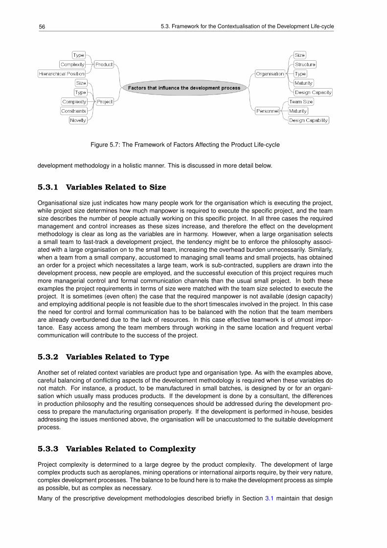
56 5.3. Framework for the Contextualisation of the Development Life-cycle
Figure 5.7: The Framework of Factors Affecting the Product Life-cycle
development methodology in a holistic manner. This is discussed in more detail below.
5.3.1 Variables Related to Size
Organisational size just indicates how many people work for the organisation which is executing the project,while project size determines how much manpower is required to execute the specific project, and the teamsize describes the number of people actually working on this specific project. In all three cases the requiredmanagement and control increases as these sizes increase, and therefore the effect on the developmentmethodology is clear as long as the variables are in harmony. However, when a large organisation selectsa small team to fast-track a development project, the tendency might be to enforce the philosophy associ-ated with a large organisation on to the small team, increasing the overhead burden unnecessarily. Similarly,when a team from a small company, accustomed to managing small teams and small projects, has obtainedan order for a project which necessitates a large team, work is sub-contracted, suppliers are drawn into thedevelopment process, new people are employed, and the successful execution of this project requires muchmore managerial control and formal communication channels than the usual small project. In both theseexamples the project requirements in terms of size were matched with the team size selected to execute theproject. It is sometimes (even often) the case that the required manpower is not available (design capacity)and employing additional people is not feasible due to the short timescales involved in the project. In this casethe need for control and formal communication has to be balanced with the notion that the team membersare already overburdened due to the lack of resources. In this case effective teamwork is of utmost impor-tance. Easy access among the team members through working in the same location and frequent verbalcommunication will contribute to the success of the project.
5.3.2 Variables Related to Type
Another set of related context variables are product type and organisation type. As with the examples above,careful balancing of conflicting aspects of the development methodology is required when these variables donot match. For instance, a product, to be manufactured in small batches, is designed by or for an organi-sation which usually mass produces products. If the development is done by a consultant, the differencesin production philosophy and the resulting consequences should be addressed during the development pro-cess to prepare the manufacturing organisation properly. If the development is performed in-house, besidesaddressing the issues mentioned above, the organisation will be unaccustomed to the suitable developmentprocess.
5.3.3 Variables Related to Complexity
Project complexity is determined to a large degree by the product complexity. The development of largecomplex products such as aeroplanes, mining operations or international airports require, by their very nature,complex development processes. The balance to be found here is to make the development process as simpleas possible, but as complex as necessary.
Many of the prescriptive development methodologies described briefly in Section 3.1 maintain that design
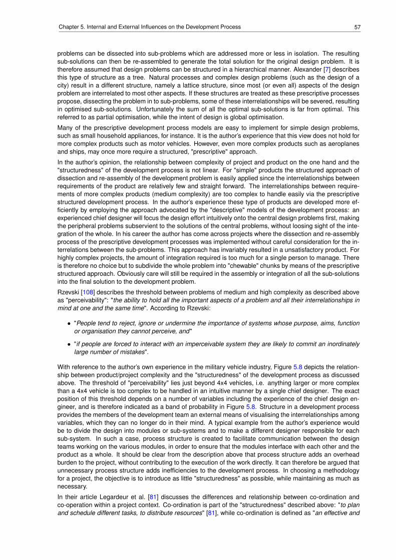
57Chapter 5. Internal and External Influences on the Development Process
problems can be dissected into sub-problems which are addressed more or less in isolation. The resultingsub-solutions can then be re-assembled to generate the total solution for the original design problem. It istherefore assumed that design problems can be structured in a hierarchical manner. Alexander [7] describesthis type of structure as a tree. Natural processes and complex design problems (such as the design of acity) result in a different structure, namely a lattice structure, since most (or even all) aspects of the designproblem are interrelated to most other aspects. If these structures are treated as these prescriptive processespropose, dissecting the problem in to sub-problems, some of these interrelationships will be severed, resultingin optimised sub-solutions. Unfortunately the sum of all the optimal sub-solutions is far from optimal. Thisreferred to as partial optimisation, while the intent of design is global optimisation.
Many of the prescriptive development process models are easy to implement for simple design problems,such as small household appliances, for instance. It is the author’s experience that this view does not hold formore complex products such as motor vehicles. However, even more complex products such as aeroplanesand ships, may once more require a structured, "prescriptive" approach.
In the author’s opinion, the relationship between complexity of project and product on the one hand and the"structuredness" of the development process is not linear. For "simple" products the structured approach ofdissection and re-assembly of the development problem is easily applied since the interrelationships betweenrequirements of the product are relatively few and straight forward. The interrelationships between require-ments of more complex products (medium complexity) are too complex to handle easily via the prescriptivestructured development process. In the author’s experience these type of products are developed more ef-ficiently by employing the approach advocated by the "descriptive" models of the development process: anexperienced chief designer will focus the design effort intuitively onto the central design problems first, makingthe peripheral problems subservient to the solutions of the central problems, without loosing sight of the inte-gration of the whole. In his career the author has come across projects where the dissection and re-assemblyprocess of the prescriptive development processes was implemented without careful consideration for the in-terrelations between the sub-problems. This approach has invariably resulted in a unsatisfactory product. Forhighly complex projects, the amount of integration required is too much for a single person to manage. Thereis therefore no choice but to subdivide the whole problem into "chewable" chunks by means of the prescriptivestructured approach. Obviously care will still be required in the assembly or integration of all the sub-solutionsinto the final solution to the development problem.
Rzevski [108] describes the threshold between problems of medium and high complexity as described aboveas "perceivability": "the ability to hold all the important aspects of a problem and all their interrelationships inmind at one and the same time". According to Rzevski:
• "People tend to reject, ignore or undermine the importance of systems whose purpose, aims, functionor organisation they cannot perceive, and"
• "if people are forced to interact with an imperceivable system they are likely to commit an inordinatelylarge number of mistakes".
With reference to the author’s own experience in the military vehicle industry, Figure 5.8 depicts the relation-ship between product/project complexity and the "structuredness" of the development process as discussedabove. The threshold of "perceivability" lies just beyond 4x4 vehicles, i.e. anything larger or more complexthan a 4x4 vehicle is too complex to be handled in an intuitive manner by a single chief designer. The exactposition of this threshold depends on a number of variables including the experience of the chief design en-gineer, and is therefore indicated as a band of probability in Figure 5.8. Structure in a development processprovides the members of the development team an external means of visualising the interrelationships amongvariables, which they can no longer do in their mind. A typical example from the author’s experience wouldbe to divide the design into modules or sub-systems and to make a different designer responsible for eachsub-system. In such a case, process structure is created to facilitate communication between the designteams working on the various modules, in order to ensure that the modules interface with each other and theproduct as a whole. It should be clear from the description above that process structure adds an overheadburden to the project, without contributing to the execution of the work directly. It can therefore be argued thatunnecessary process structure adds inefficiencies to the development process. In choosing a methodologyfor a project, the objective is to introduce as little "structuredness" as possible, while maintaining as much asnecessary.
In their article Legardeur et al. [81] discusses the differences and relationship between co-ordination andco-operation within a project context. Co-ordination is part of the "structuredness" described above: "to planand schedule different tasks, to distribute resources" [81], while co-ordination is defined as "an effective and
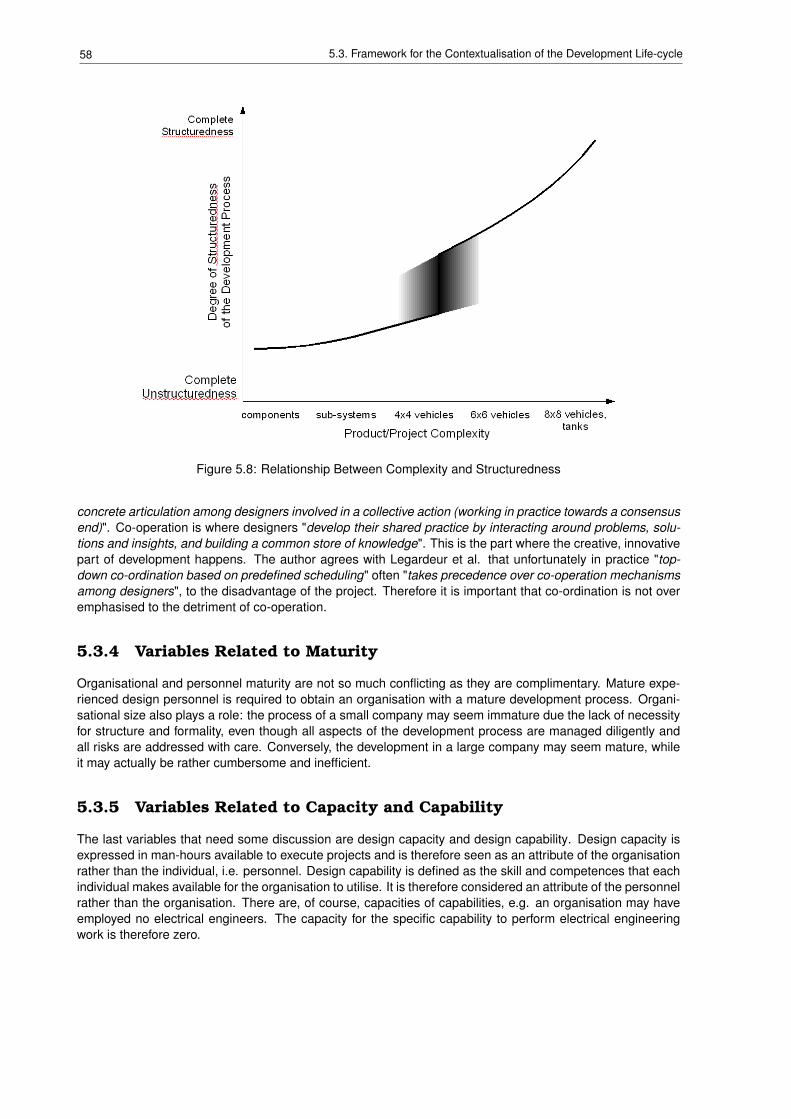
58 5.3. Framework for the Contextualisation of the Development Life-cycle
Figure 5.8: Relationship Between Complexity and Structuredness
concrete articulation among designers involved in a collective action (working in practice towards a consensusend)". Co-operation is where designers "develop their shared practice by interacting around problems, solu-tions and insights, and building a common store of knowledge". This is the part where the creative, innovativepart of development happens. The author agrees with Legardeur et al. that unfortunately in practice "top-down co-ordination based on predefined scheduling" often "takes precedence over co-operation mechanismsamong designers", to the disadvantage of the project. Therefore it is important that co-ordination is not overemphasised to the detriment of co-operation.
5.3.4 Variables Related to Maturity
Organisational and personnel maturity are not so much conflicting as they are complimentary. Mature expe-rienced design personnel is required to obtain an organisation with a mature development process. Organi-sational size also plays a role: the process of a small company may seem immature due the lack of necessityfor structure and formality, even though all aspects of the development process are managed diligently andall risks are addressed with care. Conversely, the development in a large company may seem mature, whileit may actually be rather cumbersome and inefficient.
5.3.5 Variables Related to Capacity and Capability
The last variables that need some discussion are design capacity and design capability. Design capacity isexpressed in man-hours available to execute projects and is therefore seen as an attribute of the organisationrather than the individual, i.e. personnel. Design capability is defined as the skill and competences that eachindividual makes available for the organisation to utilise. It is therefore considered an attribute of the personnelrather than the organisation. There are, of course, capacities of capabilities, e.g. an organisation may haveemployed no electrical engineers. The capacity for the specific capability to perform electrical engineeringwork is therefore zero.
59Chapter 5. Internal and External Influences on the Development Process
5.4 Role players
A number of role players can be identified, who affect the contextual variables described in the sections above.On the highest level of aggregation one would expect the client and the supplier, i.e. the organisation which iscontracted by the client to supply the engineering solution. Depending on the context of the project this mightnot be as clear-cut as it would seem. The client, although the contracting party, might not be the end-user. Anexample would be the Ministry of Defence in the UK, buying equipment for the Army or the Navy. On the otherhand the supplier, although the contracted party might only be a middle-man and not the actual creator of theengineering solution. The middle-man could be a party that funds the contract or just manages (coordinates)the project.
The project contextual variables (Section 5.2.2), constraints and complexity, are determined by the agreementbetween the client and the supplier, and include issues such as timescales and price. The other projectvariables, i.e. size, type and novelty are determined by the problem to solved and the proposed engineeringsolution. Project complexity might be increased if an external regulator is required due to inherent dangersassociated with the proposed engineering solution. An example might be the development of a nuclearpowerstation.
The product contextual variables (Section 5.2.3) are determined entirely by the proposed engineering solutionas response to the initial problem to be solved. For the problem of electrical power supply, the contextualvariables product type and product complexity differ substantially, depending on whether the power supply isintended for a single consumer or an entire nation.
Although most of the contextual variables related to the organisation (Section 5.2.1 are pre-determined given aspecific project. However, large organisations can sub-divide to decrease the effective size of the organisationthat is involved in and affected by the project. Similarly small organisations can supplement the size bycontracting other organisations or individuals as required. The personnel variables (Section 5.2.4) can beaddressed similarly. This was discussed in more detail in the sections above.
Clearly, decisions regarding the sub-devision of a business, the contracting of other organisations and/or indi-viduals involve the management of the organisation at various levels depending on the exact circumstances.The negotiation process of offering an engineering solution to a specific problem is complex and at timesinvolves a large number of role players (stakeholders) with divergent backgrounds and interests. LU andJing [83] have investigated this aspect of the product development process extensively for the software indus-try. This underscores the fact that the human interactions in all the engineering disciplines play a major roleand should not be neglected.
5.5 Summary and Conclusions
Chapter 4 discussed the need to tailor or configure the development process for each development projectappropriately according to the context and requirements of the project. The chapter also proposed the conceptof a "project methodology" to define the approach to and the structure of the process to be followed duringthe deployment of the project.
What can this configuration process be based on? How does one decide what the newly configured develop-ment process should look like?
The author decided that the development process for each project would have to be determined from theproject itself and its surrounding context. The preceding sections of this chapter describe the aspects ofthis context, which the author felt, by virtue of his experience, influenced the development process the most.Section 5.2 discussed each of the factors individually, while Section 5.3 concentrated on the interrelationshipsamong the variables.
By making these influences and their interrelationships visible to the chief design engineer or project managerresponsible for planning, managing and executing a development project, the development process can beconfigured to take these influences into account. This can be seen as a risk management activity, since riskmanagement is defined as "the identification, assessment and prioritisation of risks, followed by coordinatedand economical application of resources to minimise, monitor and control the probability and/or impact ofunfortunate events" [67]. By aligning the project methodology with the context of the project, it the authorsview, that the probability can be reduced of certain "unfortunate events" occurring.
Chapter 6 illustrates this by means of case studies, while Chapter 7 discusses the practical means of imple-

60 5.5. Summary and Conclusions
menting these concepts in daily engineering practice.
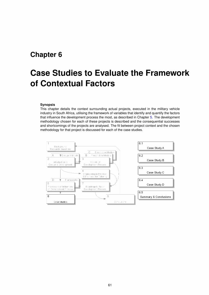
Chapter 6
Case Studies to Evaluate the Frameworkof Contextual Factors
SynopsisThis chapter details the context surrounding actual projects, executed in the military vehicleindustry in South Africa, utilising the framework of variables that identify and quantify the factorsthat influence the development process the most, as described in Chapter 5. The developmentmethodology chosen for each of these projects is described and the consequential successesand shortcomings of the projects are analysed. The fit between project context and the chosenmethodology for that project is discussed for each of the case studies.
61
62 6.1. Case Study A
6.1 Case Study A
6.1.1 Introduction to the Industry Project and its Context
Mechanology received an order in the middle of May 2006 to refurbish a number of military vehicles for a clientin Africa. These vehicles were made available by the South African National Defence Force for disposal by thematerial disposal department of Armscor and were consequently bought by Mechanology for the purposesof refurbishment and sale. This process was duly assessed by the National Conventional Arms ControlCommittee (NCACC).
Since the original engines were no longer produced and spare parts were difficult to obtain, it was decidedto integrate a new commercially available engine into the vehicle as part of the refurbishment. This decisionnecessitated that a number of the related subsystems to be changed to suit:
• The cooling system would have to be redesigned to fit the required cooling capacity for the new engine.
• Since the original vehicle was fitted with a 24Vdc electrical system, and the commercial engines of therequired size were only available in 12Vdc, changes to the electrical system would be necessary toaccommodate both voltages.
• The mounting frame for the engine would have to change since the new engine would have differentmounting arrangements, compared to the original engine.
• The vehicle bonnet and radiator louvre would have to change to accommodate a longer engine and alarger radiator.
Besides the re-engined vehicles, the list of deliverables included the following set of vehicle manuals:
IPC - to be able to define spares required for maintenance and repair in the future,WRM - to be able to execute the required maintenance correctly, andOMM - to be able to train operators for the vehicles.
The project therefore consisted of two portions:
• the refurbishment of existing components, and
• the integration of a new powerpack, as well as the sub-systems, updated to fit the new powerpackconfiguration.
The original proposal to the client had suggested the project plan shown in Figure 6.2 for the latter (i.e.development) portion of the project. The philosophy would have been as follows:
• design the components required to install the new engine into of the vehicle,
• purchase one set of the components,
• use them to build one prototype vehicle,
• evaluate the vehicle,
• make any changes required to the design,
• purchase the components for building the rest of the vehicles, and
• produce the rest of the vehicles to complete the contract.
In order to achieve the first delivery of vehicles at the required time, the order for this project should havebeen placed by the middle of March. Unfortunately, the order was only placed on Mechanology in May, and,as is usual in the engineering industry, the delivery dates were expected to remain fixed as per the originalproposal.
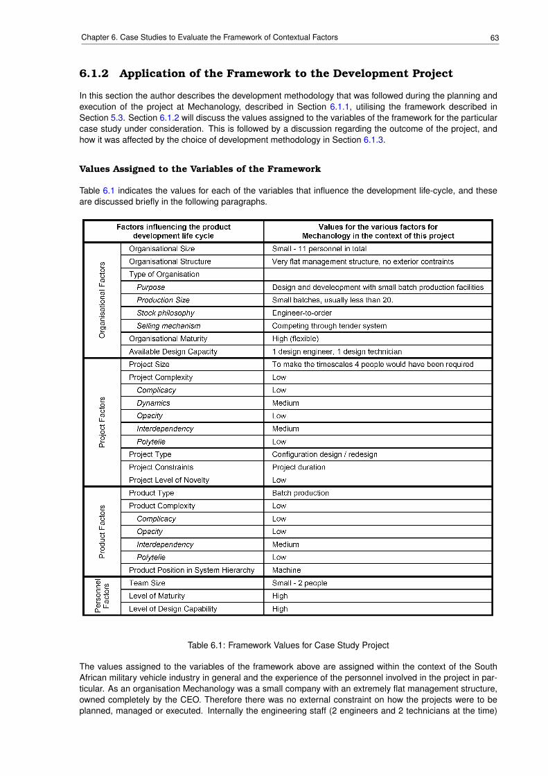
63Chapter 6. Case Studies to Evaluate the Framework of Contextual Factors
6.1.2 Application of the Framework to the Development Project
In this section the author describes the development methodology that was followed during the planning andexecution of the project at Mechanology, described in Section 6.1.1, utilising the framework described inSection 5.3. Section 6.1.2 will discuss the values assigned to the variables of the framework for the particularcase study under consideration. This is followed by a discussion regarding the outcome of the project, andhow it was affected by the choice of development methodology in Section 6.1.3.
Values Assigned to the Variables of the Framework
Table 6.1 indicates the values for each of the variables that influence the development life-cycle, and theseare discussed briefly in the following paragraphs.
Table 6.1: Framework Values for Case Study Project
The values assigned to the variables of the framework above are assigned within the context of the SouthAfrican military vehicle industry in general and the experience of the personnel involved in the project in par-ticular. As an organisation Mechanology was a small company with an extremely flat management structure,owned completely by the CEO. Therefore there was no external constraint on how the projects were to beplanned, managed or executed. Internally the engineering staff (2 engineers and 2 technicians at the time)
64 6.1. Case Study A
reported directly to the managing director, and project responsibilities were assigned on a matrix structure.This implied that an engineer would lead one project (his colleagues are reporting to him), while he was con-currently reporting to one of his colleagues on work he was performing on another project. Due to this internalcommunication was mainly informal and based on the close relationships among the staff. The company’spurpose was the design and development of mechanical systems, specialising in military vehicles and turrets.In support of the design and development function a small workshop for building and evaluating prototypeswas available. The niche market that Mechanology was addressing, required products in small batches (20items or less), engineered-to-order. Most orders were obtained through a tender process. Since Mechanol-ogy was active in the design and development of military equipment a system was in place to generate andmanage (under configuration control) the required documentation. This included inputs to the design process,documents generated during the design process as well as deliverables, such as manuals and catalogues.The system was flexible to enable the scaling up and down to support the differences in requirements fromlarge, complex projects such as the design of complete vehicle systems and turrets, to small jobs such as thedesign of single components. Therefore organisational maturity was considered to be somewhere betweenlevel 3 and 4, as shown in Figure 5.2: although the process of product development was defined on a organi-sation wide level, specific approaches, philosophies and practices were determined on a project level for eachproject.
The development part of the project was worth approximately R 1,200,000.00, and could have been executedby an engineer and a technician in the timescales as originally planned. To meet the timescales required by thecustomer, 4 people would have been required. Unfortunately only 2 people (the author and a technician) wereavailable for the design part of the project, since the other engineer was managing the refurbishment of thevehicles in parallel. The 2nd technician was busy with another project and could not be utilised. It is thereforeclear that the project constraint was definitely time (for the resources available). Although sub-contracting wasconsidered, it was decided that the design problem could not be split without generating more work to managethe subcontractor and the interface between the two packages of work than it would have taken to execute thewhole job in-house. The design work to be executed placed the project in the configuration design / redesigncategory - the philosophy was to take as many commercially off-the-shelf (COTS) components as possibleand integrate them into a powerpack for the existing vehicle. All the interfaces among the COTS componentsthemselves and the original vehicle would have to be designed. The project complexity was deemed low, forthe following reasons:
• Since the project was based on just two objectives, i.e. the refurbishment of the vehicle and the instal-lation of a new powerpack, the level of complicacy for the project was considered low.
• Dynamics was considered to be medium. Although the project requirements were not expected tochange during the execution period of the project, timing the various project tasks in order to achievethe required timescales would be both important and quite a challenge.
• Opacity was also considered to be low since Mechanology had previously refurbished and installed anew engine in a similar vehicle. Therefore all project variables were known and visible.
• Interdependency was deemed medium since many of the project tasks were dependent on the timelyand successful completion of previous tasks.
• "Polytelie" was also considered low since the main objective was to design and integrate the powerpackinside the required timescales. Given the timescales and the available resources it would be difficult toexceed the budget.
Project novelty was considered low since a similar project, to install a diesel engine into a variant of the vehicleunder consideration, had been successfully executed about six months earlier. It was intended to transfer thelessons learnt from the previous project onto the current project. Also both members of the project team hadfitted new engines to existing vehicles before.
The product being designed definitely fell into the batch production category.
The product complexity was considered low for the following reasons:
• Since the project scope was limited to a small part of the system hierarchy, i.e. the design and instal-lation of a sub-system, in this case the powerpack, in comparison to developing a complete weaponsystem, including vehicle and turret, complicacy for this product was deemed low.
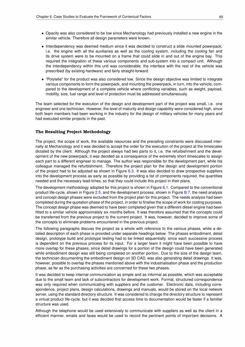
65Chapter 6. Case Studies to Evaluate the Framework of Contextual Factors
• Opacity was also considered to be low since Mechanology had previously installed a new engine in thesimilar vehicle. Therefore all design parameters were known.
• Interdependency was deemed medium since it was decided to construct a slide mounted powerpack,i.e. the engine with all the auxiliaries as well as the cooling system, including the cooling fan andits drive system were to be mounted on a frame that could slide in and out of the engine bay. Thisrequired the integration of these various components and sub-system into a compact unit. Althoughthe interdependency within this unit was considerable, the interface with the rest of the vehicle wasprescribed (by existing hardware) and fairly straight-forward.
• "Polytelie" for the product was also considered low. Since the design objective was limited to integratevarious components to form the powerpack, and mounting the powerpack, in turn, into the vehicle, com-pared to the development of a complete vehicle where conflicting variables, such as weight, payload,mobility, size, fuel range and level of protection must be addressed simultaneously.
The team selected for the execution of the design and development part of the project was small, i.e. oneengineer and one technician. However, the level of maturity and design capability were considered high, sinceboth team members had been working in the industry for the design of military vehicles for many years andhad executed similar projects in the past.
The Resulting Project Methodology
The project, the scope of work, the available resources and the prevailing constraints were discussed inter-nally at Mechanology and it was decided to accept the order for the execution of the project at the timescalesdictated by the client. Although the project always had two parts to it, i.e. the refurbishment and the devel-opment of the new powerpack, it was decided as a consequence of the extremely short timescales to assigneach part to a different engineer to manage. The author was responsible for the development part, while hiscolleague managed the refurbishment. Therefore the project plan for the design and development portionof the project had to be adjusted as shown in Figure 6.3. It was also decided to draw prospective suppliersinto the development process as early as possible by providing a list of components required, the quantitiesneeded and the necessary lead-times, so that they could include this project in their plans.
The development methodology adopted for this project is shown in Figure 6.1. Compared to the conventionalproduct life-cycle, shown in Figure 2.5, and the development process, shown in Figure B.7, the need analysisand concept design phases were excluded from the project plan for this project. The needs analysis had beencompleted during the quotation phase of the project, in order to finalise the scope of work for costing purposes.The concept design phase was deemed to have been completed given that a different diesel engine had beenfitted to a similar vehicle approximately six months before. It was therefore assumed that the concepts couldbe transferred from the previous project to the current project. It was, however, decided to improve some ofthe concepts to eliminate problems encountered in the previous project.
The following paragraphs discuss the project as a whole with reference to the various phases, while a de-tailed description of each phase is provided under separate headings below. The phases embodiment, detaildesign, prototype build and prototype testing had to be linked sequentially, since each successive processis dependent on the previous process for its input. For a larger team it might have been possible to havemore overlap for these phases, since detail drawings for a portion of the design could have been generatedwhile embodiment design was still being completed on another portion. Due to the size of the design team,the technician documenting the embodiment design on 3D CAD, was also generating detail drawings. It was,however, possible to overlap the phases mentioned above with the industrialisation phase and the productionphase, as far as the purchasing activities are concerned for these two phases.
It was decided to keep internal communication as simple and as informal as possible, which was acceptabledue to the small team and lack of subcontractors for development work. Formal, structured correspondencewas only required when communicating with suppliers and the customer. Electronic data, including corre-spondence, project plans, design calculations, drawings and manuals, would be stored on the local networkserver, using the standard directory structure. It was considered to change the directory structure to representa virtual product life-cycle, but it was decided that access time to documentation would be faster if a familiarstructure was used.
Although the telephone would be used extensively to communicate with suppliers as well as the client in aefficient manner, emails and faxes would be used to record the pertinent points of important decisions. A
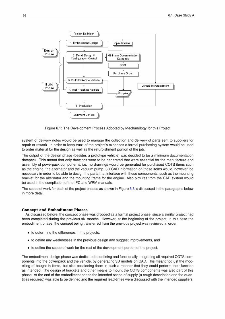
66 6.1. Case Study A
Figure 6.1: The Development Process Adopted by Mechanology for this Project
system of delivery notes would be used to manage the collection and delivery of parts sent to suppliers forrepair or rework. In order to keep track of the project’s expenses a formal purchasing system would be usedto order material for the design as well as the refurbishment portion of the job.
The output of the design phase (besides a prototype vehicle) was decided to be a minimum documentationdatapack. This meant that only drawings were to be generated that were essential for the manufacture andassembly of powerpack components, i.e. no drawings would be generated for purchased COTS items suchas the engine, the alternator and the vacuum pump. 3D CAD information on these items would, however, benecessary in order to be able to design the parts that interface with these components, such as the mountingbracket for the alternator and the mounting frame for the engine. Also pictures from the CAD system wouldbe used in the compilation of the IPC and WRM manuals.
The scope of work for each of the project phases as shown in Figure 6.3 is discussed in the paragraphs belowin more detail.
Concept and Embodiment PhasesAs discussed before, the concept phase was dropped as a formal project phase, since a similar project had
been completed during the previous six months. However, at the beginning of the project, in this case theembodiment phase, the concept being transferred from the previous project was reviewed in order
• to determine the differences in the projects,
• to define any weaknesses in the previous design and suggest improvements, and
• to define the scope of work for the rest of the development portion of the project.
The embodiment design phase was dedicated to defining and functionally integrating all required COTS com-ponents into the powerpack and the vehicle, by generating 3D models on CAD. This meant not just the mod-elling of bought-in items, but also positioning them in such a manner that they could perform their functionas intended. The design of brackets and other means to mount the COTS components was also part of thisphase. At the end of the embodiment phase the intended scope of supply (a rough description and the quan-tities required) was able to be defined and the required lead-times were discussed with the intended suppliers.
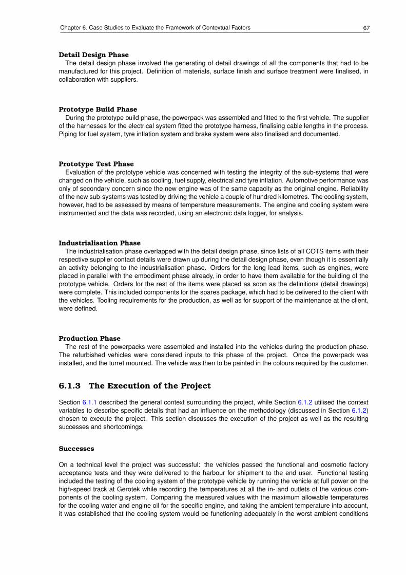
67Chapter 6. Case Studies to Evaluate the Framework of Contextual Factors
Detail Design PhaseThe detail design phase involved the generating of detail drawings of all the components that had to be
manufactured for this project. Definition of materials, surface finish and surface treatment were finalised, incollaboration with suppliers.
Prototype Build PhaseDuring the prototype build phase, the powerpack was assembled and fitted to the first vehicle. The supplier
of the harnesses for the electrical system fitted the prototype harness, finalising cable lengths in the process.Piping for fuel system, tyre inflation system and brake system were also finalised and documented.
Prototype Test PhaseEvaluation of the prototype vehicle was concerned with testing the integrity of the sub-systems that were
changed on the vehicle, such as cooling, fuel supply, electrical and tyre inflation. Automotive performance wasonly of secondary concern since the new engine was of the same capacity as the original engine. Reliabilityof the new sub-systems was tested by driving the vehicle a couple of hundred kilometres. The cooling system,however, had to be assessed by means of temperature measurements. The engine and cooling system wereinstrumented and the data was recorded, using an electronic data logger, for analysis.
Industrialisation PhaseThe industrialisation phase overlapped with the detail design phase, since lists of all COTS items with their
respective supplier contact details were drawn up during the detail design phase, even though it is essentiallyan activity belonging to the industrialisation phase. Orders for the long lead items, such as engines, wereplaced in parallel with the embodiment phase already, in order to have them available for the building of theprototype vehicle. Orders for the rest of the items were placed as soon as the definitions (detail drawings)were complete. This included components for the spares package, which had to be delivered to the client withthe vehicles. Tooling requirements for the production, as well as for support of the maintenance at the client,were defined.
Production PhaseThe rest of the powerpacks were assembled and installed into the vehicles during the production phase.
The refurbished vehicles were considered inputs to this phase of the project. Once the powerpack wasinstalled, and the turret mounted. The vehicle was then to be painted in the colours required by the customer.
6.1.3 The Execution of the Project
Section 6.1.1 described the general context surrounding the project, while Section 6.1.2 utilised the contextvariables to describe specific details that had an influence on the methodology (discussed in Section 6.1.2)chosen to execute the project. This section discusses the execution of the project as well as the resultingsuccesses and shortcomings.
Successes
On a technical level the project was successful: the vehicles passed the functional and cosmetic factoryacceptance tests and they were delivered to the harbour for shipment to the end user. Functional testingincluded the testing of the cooling system of the prototype vehicle by running the vehicle at full power on thehigh-speed track at Gerotek while recording the temperatures at all the in- and outlets of the various com-ponents of the cooling system. Comparing the measured values with the maximum allowable temperaturesfor the cooling water and engine oil for the specific engine, and taking the ambient temperature into account,it was established that the cooling system would be functioning adequately in the worst ambient conditions
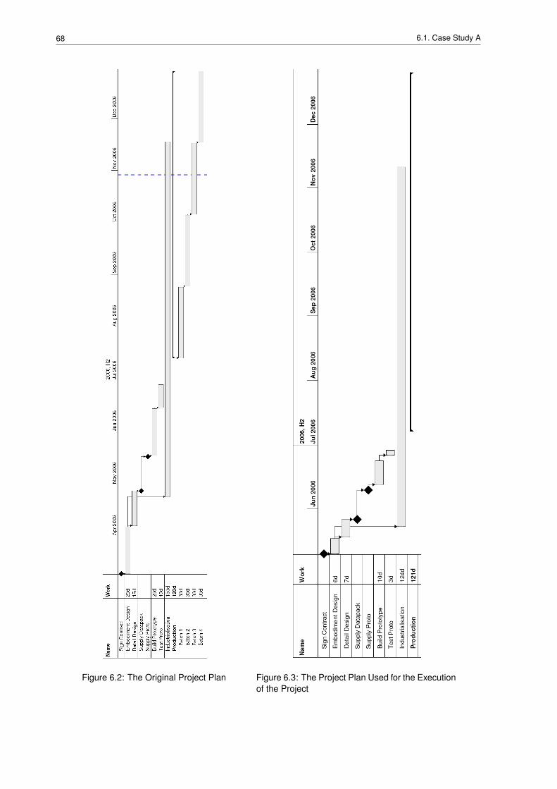
68 6.1. Case Study A
Figure 6.2: The Original Project Plan Figure 6.3: The Project Plan Used for the Executionof the Project
69Chapter 6. Case Studies to Evaluate the Framework of Contextual Factors
expected in the country of the end user. Reliability was confirmed by driving the vehicle for 500 km, whilemonitoring the condition of the powerpack and its components.
Another positive aspect was the effective internal and external communication:
• Management was informed on a weekly basis of the progress, risks, cost to date and expected cost tocompletion.
• Finance department were kept up to date regularly on orders placed, invoices received as well as costto date and expected cost to completion.
• The interface between the refurbishment part and the development part of the project was discussedevery second day or so.
• The information required for the generation of the manuals was being captured as it became available.
• Progress on manufactured components at the suppliers was monitored on a daily basis.
• The client was informed on a weekly basis of the progress of the project and any difficulties identified.
Shortcomings
The Delivery of Custom Manufactured PartsIn terms of adherence to the schedule arranged with the client, it was fortunate for the project that the
shipping date was postponed by a week due to the late arrival of the ship at the harbour. The biggest problemencountered was the delay in receiving components from suppliers. Most of the COTS components, such asstandard air filters, rubber hoses, cooling fans, bearings and pulleys were delivered on time. Delivery problemswere encountered with all the components that were specifically designed and manufactured for this project.These included the powerpack frame, the radiator, stainless steel pipes for the cooling system, and all thebrackets for mounting components such as alternators. The author and his colleague worked closely withthe manufacturers to facilitate the process, ensuring that they had all the information they required and thatthey understood the requirements and the timescales. Delays were caused by raw material suppliers notsupplying the raw material as promised, and by the manufacturers overestimating their own manufacturingcapacity, even though the author had attempted to verify the capacity by discussing the scope of work andthe timescales with all the manufacturers before placing orders. In one instance it was possible to split theorder for components between two manufacturers, but generally it was decided not to switch suppliers oncethe order was placed. It was argued that it would have taken longer for the second supplier to obtain materialand slot this new work into his schedule than it would take the first supplier to finish the job.
These delays had a major impact on the process of refurbishing and assembling the vehicles. The plan hadbeen to complete the mechanical refurbishment of the vehicle, while the powerpack was being assembled.The powerpack would be installed and the refurbishment of the vehicle would be completed by spray paintingthe vehicle in the colour specified by the end user. The delay in powerpack assembly necessitated that thevehicle was spray painted before the powerpack was fitted, resulting in the need to patch-up the paint workafterwards.
The Transfer of Knowledge from the Previous ProjectThe second problem encountered was caused by the approach adopted for this project, which was reliant
of the work done and understanding generated during a previous project. The design for this project wasbased on the concept work performed during a previous project six months earlier, where a similar vehiclewas also fitted with a new engine in a powerpack arrangement. Unfortunately, neither the author nor hiscolleagues working on this project had been involved in the previous project, and therefore they had no first-hand knowledge of the design.
Although the previous project was discussed with the colleagues who were involved with it, only generalinformation could be obtained, and therefore, in terms of detailed information, the author could depend onlyon the information that was stored on the company network server. Since the previous project was consideredto have been successfully completed, the CAD data was transferred to the new development. The extremelyshort timescales and the lack of resources prevented the quality of the data to be determined in detail. Someof the errors in the CAD data were discovered during the embodiment phase and could be corrected withoutany significant time or cost implication. Others, however, were only discovered during the assembly of the
70 6.1. Case Study A
prototype vehicle when components would not fit as expected. These errors, obviously, had major time andcost implications, and the corresponding re-work contributed to the capacity shortage experienced by themanufacturers.
Summary
This project achieved what it was meant to achieve: the refurbishment of the specific military vehicles, in-stallation of a new powerpack, including the associated sub-systems, and delivery of the complete vehicleto the harbour for delivery to the end user within budget and time constraints of the project. It did, however,experience two shortcomings: the difficulty of obtaining the custom designed parts on time, and problem oftransferring tacit knowledge across projects.
A more formal implementation of the "standard" "prescriptive" model of the development process as, forinstance, advocated by the VDI guideline [125], would not have shortened the time span between the startof the project and the receipt of the designed parts. No other approach to the project would have preventedthis problem from occurring; indicating that not all project related problems can be solved by the choiceof the correct methodology. The experience of this particular project has confirmed to the author that thetimescales of the design portion of the project can be manipulated fairly easily. For the building and testing ofthe prototype, timescales are much more rigid: beyond a certain threshold the reduction of timescales for themanipulation of physical material requires an exponentially increasing effort.
In retrospect it is clear that the latter of the two problems experienced during this project, was caused byunderestimating the level of project novelty. The reliance on data from a previous project, without any of therole players of this project having been involved in the previous project, should have warranted a stage in theprocess of the project to check and verify the data.
To illustrate how the approach to the project may have differed under other circumstances the following canbe considered. A larger organisation would probably have added resources to the project. Although thiswould possibly have lessened the time pressure of the project, it would have probably have required a moreformal and structured communication structure. Had the product been intended for mass production, moreattention would have been given to the ease of assembly, as well as the tooling requirements (jig and fixtures,cranes and pneumatic power tools for instance). If the project had been more complex, it would not have beenpossible to execute it successfully in the same timescales with the same resources. Depending on the type ofcomplexity the need for extensive sub-contracting could have been required. This would have increased themanagement overhead of the project.
6.1.4 Conclusion and Discussion
A development project in industry was introduced in Section 6.1.1, and the variables described in generalterms in Chapter 5 were discussed with respect to the specific project and its context in Section 6.1.2. Sec-tion 6.1.3 described the execution of the project by the author and his colleagues as part of the normalbusiness processes of the company called, Mechanology.
It was shown that the "standard" development process was adapted to suit the specific context surroundingthis specific project. It this case the development process could be streamlined by eliminating the needsanalysis and concept stages of the process. Also, in order to achieve the required timescales with the ex-tremely limited resources, the industrialisation phase and the detail design phase were conducted in parallelas shown in Figure 6.3. For the design part of the project the "standard" problem solving procedure as pro-posed by "prescriptive" development process models was not followed. Rather than dissecting the designproblem into sub-problems (refer to Figure 3.1), which are evaluated individually by analysis of their functionalrequirements, followed by the generation of a series of potential solutions of which the best one is chosen, itwas decided to generate solutions based on presuppositions, focussing initially on the central problem, andaddressing all peripheral problems accordingly, as per the "descriptive" models of the development process,as described in Section 3.3. The only sensible division, that could be implemented on this project, was tosplit the design portion from the "production" part of the project into different phases. Due to the extremetimescales the phases were intended to overlap.
This adaptation of the development process made it possible to successfully complete this project withinextremely short timescales with very limited resources.
71Chapter 6. Case Studies to Evaluate the Framework of Contextual Factors
6.2 Case Study B
6.2.1 Introduction to the Industry Project and its Context
Introduction to BAE Land Systems OMC
BAE Land Systems OMC is part of the international group of companies called BAE Systems. Accordingthe BAE Systems’ website [4], they are the "3rd largest global defence company" with "96,000 highly skilledpeople", "customers in over 100 countries", "annual sales exceed £15 billion" and "annual R&D exceeds £1.3billion". Businesses within BAE Systems worldwide include:
BAE Systems Australia - is a leading supplier of communications, electronic warfare sys-tems, military air support, air defence, mission support systemsand intelligence, surveillance and reconnaissance to the Aus-tralian Defence Force.
CS&S International - is responsible for the development of new market opportunitiesand the sustainment of business in the Middle East region in-cluding a long-term presence in Saudi Arabia.
Electronic and Integrated Solutions - designs, develops and manufactures a wide range of electronicsystems and subsystems for both military and commercial appli-cations.
Integrated System Technologies - is fully equipped to meet the demands of the rapidly evolvingmodern and future markets in defence, homeland security andcomplex, mission critical solutions.
Land and Armaments - is a global leader in the design, development, production, andservice support of armoured combat vehicles, major and minorcalibre naval guns and missile launchers, canisters, artillery sys-tems, and intelligent munitions.
Military Air Solutions - focuses on military air solutions to meet the through-life needs ofcustomers.
Regional Aircraft - is today a leading provider of regional aircraft and support ser-vices to regional airlines throughout the world.
Submarine Solutions - deliver high quality submarines and large naval ships, demon-strating value for money over a full range of contracts, systemintegration, design and build services.
Surface Fleet Solutions - is a business in transformation to become the through life surfacewarship capability partner of choice.
Underwater Systems - provides the capability to achieve full tactical advantage and dom-inance in the underwater battlespace.
BAE Land Systems OMC in South Africa is part of the Land and Armaments business, and specialises inhigh mobility wheeled armoured vehicles with high levels of protection against ballistic and landmine threats.According to the BAE Land Systems OMC website[3] the business "is South Africa’s primary military vehiclefacility, covering all disciplines of the military vehicle spectrum from conceptualisation through design anddevelopment, manufacture and production and in-service support".
The variety of companies that make up BAE Systems, and the fact that they are scattered all over the world,has prompted BAE System to introduce a common procedure to manage the life-cycle of its products uniformlyin a formal manner throughout the entire product range. This process is divided into two phases: the businesswinning and the contract execution phase. As such the process is not specifically aimed at the developmentof new products or technologies which do not have a definite customer yet. During the process a numberof phase and design reviews are conducted to determine the current status of a project and to define thestrategy for the next phase. Design reviews concentrate on the technical aspects, the maturity of the product,the technical risks and how well the technical requirements of the customer are met. Phase reviews, on theother hand, concentrate mainly the financial and schedule aspects of the project, taking the technical statusinto consideration, as well as interactions and communications with the customer.
72 6.2. Case Study B
Introduction to the Development Project
The project was started on the 27th of September 2007. The purpose of this project was to develop andbuild two almost identical concept demonstrator vehicles. Due to project constraints imposed by the client itwas intended to deliver the first vehicle to the client on the 12th of December 2007 after only the absoluteminimum of testing and evaluation. The purpose of the second vehicle was to perform in-house testing andevaluation, in order to verify that the functional requirements were met. It was envisioned that the customerwould evaluate the concept demonstrator vehicle from January to March 2008, and would then place an orderon BAE Land Systems OMC for production in April or May 2008.
The Company Environment at the Time of The ProjectAt the time of this development project the company was in the process of executing a very large production
order for an international client. The client had imposed a very tight delivery schedule, requiring the companyto increase the production rate from the typical two vehicle per week to six vehicles per day, i.e. a six-fold increase. Unfortunately, this vehicle had also been developed in very short timescales, necessitatingthe engineering (development) department to be intensively involved to fine-tune the design and implementdesign improvements on the production line.
The Technical RequirementsIntelligence from the client indicated that the client required a vehicle with a larger payload (both in terms
of volume and mass), and a more powerful engine than the vehicle in production, as described above. Theincrease of payload by 50% brought the gross vehicle weight of the fully laden vehicle into the abnormalcategory, making it illegal to travel the roads of South Africa in the laden condition without a special permit.Besides a new hull to increase the under-armour volume of the vehicle, these requirements necessitated thefollowing sub-systems to be changed:
Powerpack: - more powerful engine, larger cooling pack, larger transmissionDriveline: - larger transfer gearbox, axles and propshaftsRunning Gear: - larger tires, uprated steering, braking and suspension systems
At the same time it was decided to fit the concept demonstrator vehicles with a digital electrical system ratherthan the conventional analogue equivalent. These vehicles were the first vehicles to be fitted with such asystem at BAE Land Systems OMC.
Although sold to the client as a redesigned, upgraded version of the production model discussed above, thefact that each functional sub-system of the vehicle changed, indicates that this project entailed the develop-ment of a new vehicle rather than the redesign of an existing product. The high gross vehicle weight and thedigital electrical system introduced a high level of novelty to the project.
Besides sourcing the components for the above mentioned sub-systems, before the vehicle could be de-signed, most of the suppliers of these sub-systems were also supplying components to the production line. Insome instances the supplier did not have enough capacity to produce components for production as well asthe once-off components for the prototype.
The Design ProcessThe production process of an armoured vehicle is divided into fabrication (manufacture of the armoured
hull of the vehicle and all unique components that have to produced by a combination of welding and / ormachining) and assembly (the fitting of all components on the hull of the vehicle, including both bought-outand manufactured components). Given the extremely short timescales of the project it was decided not togenerate a complete datapack for the building of the first two vehicles. The initial "to-build" datapack wouldmainly contain component drawings (to be either manufactured or purchased), with very few assembly andweld-assembly drawings. This would mean that design personnel would have to participate and support thefabrication and assembly process.
During the process of building the two concept demonstrator vehicles, the fabrication and assembly informa-tion, as well as any changes required to the fabricated components, would be captured by hand, to be incorpo-rated in a "as-built" datapack. Any improvements highlighted through the testing of the concept demonstratorvehicles and changes to the design requested by the customer would also be incorporated into this datapack,which would be verified through the building of a prototype vehicle. Information from the building process ofthe prototype vehicle would be incorporated into a "to-build" production datapack.
73Chapter 6. Case Studies to Evaluate the Framework of Contextual Factors
Although it was suggested by the author to divorce this development project completely from the normal (de-sign, purchasing, fabrication and assembly) processes of the company by implementing the "skunk works"process [89], in was decided by management to follow the formal project structures for this project. This pro-cess entails the following:
• the engineering department generates the drawing(s) to define a component (to be purchased or man-ufactured) and books the drawing into the configuration department,
• the configuration department records the component on the MRI and releases the drawing(s) to thematerial handling department,
• the materials handling department loads the information regarding the component on a BOM and re-leases the drawing(s) to the purchasing department,
• the purchasing department places orders on suppliers for the components as defined on the drawing(s)and attempts to expedite the delivery process.
This was done for two reasons:
• Management wanted to retain "control" of the development process, and
• It would be easier to generate the "as-built" datapack, if the "to-build" datapack is already under con-figuration control. This was seen as critical since the production order was expected very quickly aftercompletion of the concept demonstrator vehicles.
The development of this vehicle was led and managed by an engineering manager, focussing on the technicalaspects as well as the timely execution of the project. Working on the project were two design engineers,responsible for specific sub-systems, and on average three CAD operators. Due to the high priority of theproduction project, mentioned at the beginning of this section, as well as other development projects, thesame CAD operators were not always available for the duration of the project. The author was responsible forthe running gear sub-system, i.e. brakes, steering, suspension and wheels, while a colleague was responsiblefor the powertrain, i.e. powerpack (cooling pack, engine and transmission packaged together as a module),transfer gearbox, propshafts and axles. All other sub-systems had to be managed by the engineering managerhimself.
The Build ProcessOnce the armour plates had arrived, the fabrication process could start, by placing them into a jig and
welding them together to form the hull of the vehicle. Any other weld assemblies, for instance brackets formounting components such as suspension, powerpack or transfer gearbox were also fabricated at this time.Once complete, the hull and all other components were delivered to the "proto area" where the vehicle wasassembled. In the "proto area" sub-assemblies were put together, before mounting them on the vehicle.Piping, hoses and cabling are very difficult to design on CAD accurately enough to fit in the vehicle thefirst time. Therefore it has always been the practice at BAE Land Systems OMC to reverse engineer thesecomponents on the first vehicle and record the design manually.
As mentioned above, the design engineering staff were intensively involved with these processes, since it wasdecided to generate a minimum of fabrication and assembly documentation.
The Evaluation ProcessThe second concept demonstrator vehicle was planned to undergo a two-stage evaluation program:
• The critical automotive functions were to be evaluated first: suspension, handling characteristics, brakes,steering and engine cooling.
• Secondly the vehicle was to be evaluated against each line of the client’s specification.
Errors or problems with the critical functions were to be corrected on the concept demonstrator vehicle imme-diately, while recording and correcting less critical problems in the next datapack and verifying the solutionsin the next vehicle.
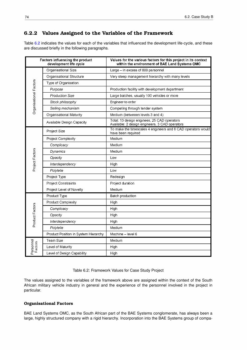
74 6.2. Case Study B
6.2.2 Values Assigned to the Variables of the Framework
Table 6.2 indicates the values for each of the variables that influenced the development life-cycle, and theseare discussed briefly in the following paragraphs.
Table 6.2: Framework Values for Case Study Project
The values assigned to the variables of the framework above are assigned within the context of the SouthAfrican military vehicle industry in general and the experience of the personnel involved in the project inparticular.
Organisational Factors
BAE Land Systems OMC, as the South African part of the BAE Systems conglomerate, has always been alarge, highly structured company with a rigid hierarchy. Incorporation into the BAE Systems group of compa-
75Chapter 6. Case Studies to Evaluate the Framework of Contextual Factors
nies has just increased the rigidity of the hierarchy structure of the company. The company philosophy is oneof division of labour into respective departments with strict managerial control.
The purpose of BAE Land Systems OMC is to manufacture vehicles, and the function of the engineeringdepartment is to feed the factory with definitions of vehicles to produce. Very little emphasis is thereforeplaced on product innovation and the development of technical know-how, activities commonly labelled asR&D.
BAE Land Systems OMC competes internationally through the tender system, producing vehicles on aengineered-to-order basis, usually in batches of 100 vehicles or more. However, batches as small as threeor six vehicles have been produced. These small batches are strictly manufactured-to-order, based on anexisting product definition. Orders for larger quantities of vehicles will usually include some engineer-to-orderaspects.
The organisational maturity of the company is estimated between level 3 and 4, as discussed in Table 5.2 inSection 5.2.1. Organisation wide procedures and support exists for project management and documentation,while procedures and support for selection, implementation and use of computer tools in engineering is eitherindividually implemented or on a project-by-project basis. These issues related to organisational maturity arestrongly related BAE Land Systems OMC’ focus on the production of vehicles rather than the development ofproducts, as discussed above.
Although BAE Land Systems OMC has a fairly large engineering office, employing approximately 50 peopleincluding section heads and managers, these resources were allocated to a number of projects at the timeof the development project described in this case study. Most of the resources were allocated to the currentproduction of vehicles discussed in 6.2.1. Four design engineers were allocated to this project, of which onlyone, the engineering manager for the project, could dedicate 100% of his time to the project. The three others,including the author could only make about two thirds of their time available. The number of CAD resourcesallocated to this project varied from two to five, with a average of three CAD operators for the duration of thisproject.
Project Factors
The most important project factor was the supposition that the concept demonstrator vehicles had to becompleted in extremely short timescales. Therefore project duration became the project constraint with thegreatest influence on the project. In order to achieve the timescales one of the prerequisites would have beenthe full-time allocation of the four engineers and six CAD operators to this project.
Project complexity was estimated to be medium. Client involvement would have increased the project com-plexity substantially. Unfortunately many people of different departments were involved, adding little valueto the development process since it was decided to utilise the company’s processes (as described in Sec-tion 6.2.1) even though these processes are aimed at supporting the production process rather than develop-ment projects with extremely tight timescales. This increased the number of project variables to be managed,and therefore the complicacy of the project was estimated to be medium.
Due to the tight timescales of the project, project dynamics was extremely important: technical issues had tobe addressed out of sequence in order to define and order components with long lead times, such as engine,transmission, radiator, axles. Often decisions had to be made in terms the definition of these components,without being able to ascertain the complete impact of these decisions on the rest of the design. It was forthis reason that the project dynamics was estimated to be medium for this project.
The complicacy of project variables, as discussed above, combined with the critical dynamics of the project,created a high interdependency of project variables for this project: a complicated, involved process had tobe managed under tight timescales.
Both opacity and Polytelie were estimated to be low for this project. Once the decision had been maderegarding the development process to be followed for this project, all project variables were clearly definedand visible. Due to the time pressure on the project, the primary objective was to define and build the conceptdemonstrator vehicles as quickly as humanly possible with the constraints of the company and the chosendevelopment process. All other project objectives, including costs were deemed to be secondary.
The level of novelty for this project was estimated to be medium. The development of a high mobility 4x4armoured vehicle within normal parameters would have been considered a project of low novelty. The re-quirement for payload increased the gross vehicle mass of the vehicle far above normal values, consequentlyincreasing the novelty factor for this project. The influence of the high vehicle mass on all major automotive
76 6.2. Case Study B
sub-systems as well as the performance of the complete vehicle, could only be estimated by extrapolation,and could only be determined with accuracy during the evaluation of the vehicle. This introduces an increasedlevel of risk to the project. The implementation of a digital electrical system rather than the conventional ana-logue equivalent, added novelty and risk to the project.
Product Factors
The vehicles would be manufactured in batch production. Given the large batch size and the high productionrate required for the current production of vehicles, it would be reasonable to assume that the vehicle underdevelopment for this project would have similar production requirements. It would therefore have been rea-sonable to consider aspects of mass production in the design of the vehicle, to assist with the achievementsof this high production rate. Unfortunately, the level of available resources combined with the tight timescalesmade it impossible to consider these aspects during the design phase.
Product complexity was estimated to be high for this product for the following reasons: a military vehiclehas a large number of interdependent and often conflicting user requirements to be met, resulting in a largenumber of interdependent product variables, and therefore high complicacy and interdependency. Since thedesign work was allocated to design engineers according to the sub-systems of the vehicle, without providinga means of taking the vehicle as a whole into account, the product variables falling outside the scope oftheir sub-system became invisible for each these design engineers. Therefore the opacity of the productvariables was considered high. Polytelie for this product was considered medium, since the main objectivewas to design a vehicle that could carry the prescribed gross vehicle mass. Secondary objectives includedthe achievement of the functional requirements for all the sub-systems under this constraint.
With regards to the level of the system hierarchy, the concept demonstrator vehicles were of the level of a ma-chine according to Günther [59] or level six according to Frost [53], as indicated in Figure 5.4 in Section 5.2.3.The vehicle was developed with the emphasis on automotive performance and payload, both in terms of massand volume. Integration of client furnished items (CFE’s), typically roof mounted gunrings or turrets, personalweapons and communication equipment, were to be considered once the client has evaluated the vehicle.
Personnel Factors
Although the number of personnel involved in the design activities was considered too low for the requiredtimescales (see Section 6.2.2), the broader team involved in the configuration management of information andthe purchasing of components was considered too large and cumbersome for this project (see Section 6.2.1above).
In terms of level of maturity and design capability all members of the development team were very dedicatedand experienced.
6.2.3 The Resulting Project Methodology
The development process for this project was based on the process suggested by the VDI [125], shownschematically in Figure B.7. A brief description of the process can be found in Section B.7.
The VDI model of the development process is based on the assumption that both the problem and the solu-tion can be divided into a hierarchical structure of sub-problems and sub-solutions respectively. The designprocess is therefore one of disassembling the problem (the design objective) into all its sub-problems. Thisapproach and the potential problems associated with it are discussed in more detail in Section 5.3.3.
This disassembly methodology was followed in this project by assigning the principle sub-systems of thevehicle to design engineers with the relevant design experience, as described in 6.2.1. However, due to a lackof available resources no provision was made for the re-assembly of the solution. The integration of vehiclesub-systems is quite complex since sub-systems can have physical interfaces to each other due to beingpackaged in the vehicle in close proximity to each other, without necessarily requiring functional interfaces. Asan example: the steering system and the air-intake system of the powerpack have no functional relationship,and therefore the designer of the steering system would not consider the air-intake system in its design andvice-versa. Since both these sub-systems are usually packaged in the engine bay of a vehicle, each sub-systems has to consider the other during the re-assembly of the solution, i.e. the integration of sub-systemsin to the vehicle. Another example would be that the placement of a sub-system within the vehicle can have an
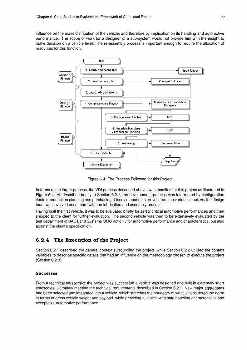
77Chapter 6. Case Studies to Evaluate the Framework of Contextual Factors
influence on the mass distribution of the vehicle, and therefore by implication on its handling and automotiveperformance. The scope of work for a designer of a sub-system would not provide him with the insight tomake decision on a vehicle level. The re-assembly process is important enough to require the allocation ofresources for this function.
Figure 6.4: The Process Followed for this Project
In terms of the larger process, the VDI process described above, was modified for this project as illustrated inFigure 6.4. As described briefly in Section 6.2.1, the development process was interrupted by configurationcontrol, production planning and purchasing. Once components arrived from the various suppliers, the designteam was involved once more with the fabrication and assembly process.
Having built the first vehicle, it was to be evaluated briefly for safety critical automotive performances and thenshipped to the client for further evaluation. The second vehicle was then to be extensively evaluated by thetest department of BAE Land Systems OMC not only for automotive performance and characteristics, but alsoagainst the client’s specification.
6.2.4 The Execution of the Project
Section 6.2.1 described the general context surrounding the project, while Section 6.2.2 utilised the contextvariables to describe specific details that had an influence on the methodology chosen to execute the project(Section 6.2.3).
Successes
From a technical perspective the project was successful: a vehicle was designed and built in extremely shorttimescales, ultimately meeting the technical requirements described in Section 6.2.1. New major aggregateshad been selected and integrated into a vehicle, which stretches the boundary of what is considered the normin terms of gross vehicle weight and payload, while providing a vehicle with safe handling characteristics andacceptable automotive performance.
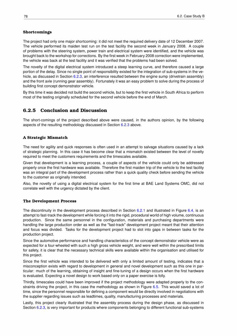
78 6.2. Case Study B
Shortcomings
The project had only one major shortcoming: it did not meet the required delivery date of 12 December 2007.The vehicle performed its maiden test run on the test facility the second week in January 2008. A coupleof problems with the steering system, power train and electrical system were identified, and the vehicle wasbrought back to the workshop for corrections. By the first week in February 2008 correction were implemented,the vehicle was back at the test facility and it was verified that the problems had been solved.
The novelty of the digital electrical system introduced a steep learning curve, and therefore caused a largeportion of the delay. Since no single point of responsibility existed for the integration of sub-systems in the ve-hicle, as discussed in Section 6.2.3, an interference resulted between the engine sump (drivetrain assembly)and the front axle (running gear assembly). Fortunately it was an easy problem to solve during the process ofbuilding first concept demonstrator vehicle.
By this time it was decided not build the second vehicle, but to keep the first vehicle in South Africa to performmost of the testing originally scheduled for the second vehicle before the end of March.
6.2.5 Conclusion and Discussion
The short-comings of the project described above were caused, in the authors opinion, by the followingaspects of the resulting methodology discussed in Section 6.2.3 above.
A Strategic Mismatch
The need for agility and quick responses is often used in an attempt to salvage situations caused by a lackof strategic planning. In this case it has become clear that a mismatch existed between the level of noveltyrequired to meet the customers requirements and the timescales available.
Given that development is a learning process, a couple of aspects of the vehicle could only be addressedproperly once the first hardware was available. Therefore the first maiden trip of the vehicle to the test facilitywas an integral part of the development process rather than a quick quality check before sending the vehicleto the customer as originally intended.
Also, the novelty of using a digital electrical system for the first time at BAE Land Systems OMC, did notcorrelate well with the urgency dictated by the client.
The Development Process
The discontinuity in the development process described in Section 6.2.1 and illustrated in Figure 6.4, is anattempt to fast-track the development while forcing it into the rigid, procedural world of high volume, continuousproduction. Since the same personnel in the configuration, materials and purchasing departments werehandling the large production order as well as the "fast-track" development project meant that their attentionand focus was divided. Tasks for the development project had to slot into gaps in between tasks for theproduction project.
Since the automotive performance and handling characteristics of the concept demonstrator vehicle were asexpected for a four-wheeled with such a high gross vehicle weight, and were well within the prescribed limitsfor safety, it is clear that the necessary technical skills were available within the organisation and utilised forthis project.
Since the first vehicle was intended to be delivered with only a limited amount of testing, indicates that amisconception exists with regard to development in general and novel development such as this one in par-ticular: much of the learning, obtaining of insight and fine-tuning of a design occurs when the first hardwareis evaluated. Expecting a novel design to work based only on a paper exercise is folly.
Thirdly, timescales could have been improved if the project methodology were adapted properly to the con-straints driving the project, in this case the methodology as shown in Figure 6.5. This would saved a lot oftime, since the personnel responsible for defining a component would be directly involved in negotiations withthe supplier regarding issues such as leadtimes, quality, manufacturing processes and materials.
Lastly, this project clearly illustrated that the assembly process during the design phase, as discussed inSection 6.2.3, is very important for products where components belonging to different functional sub-systems
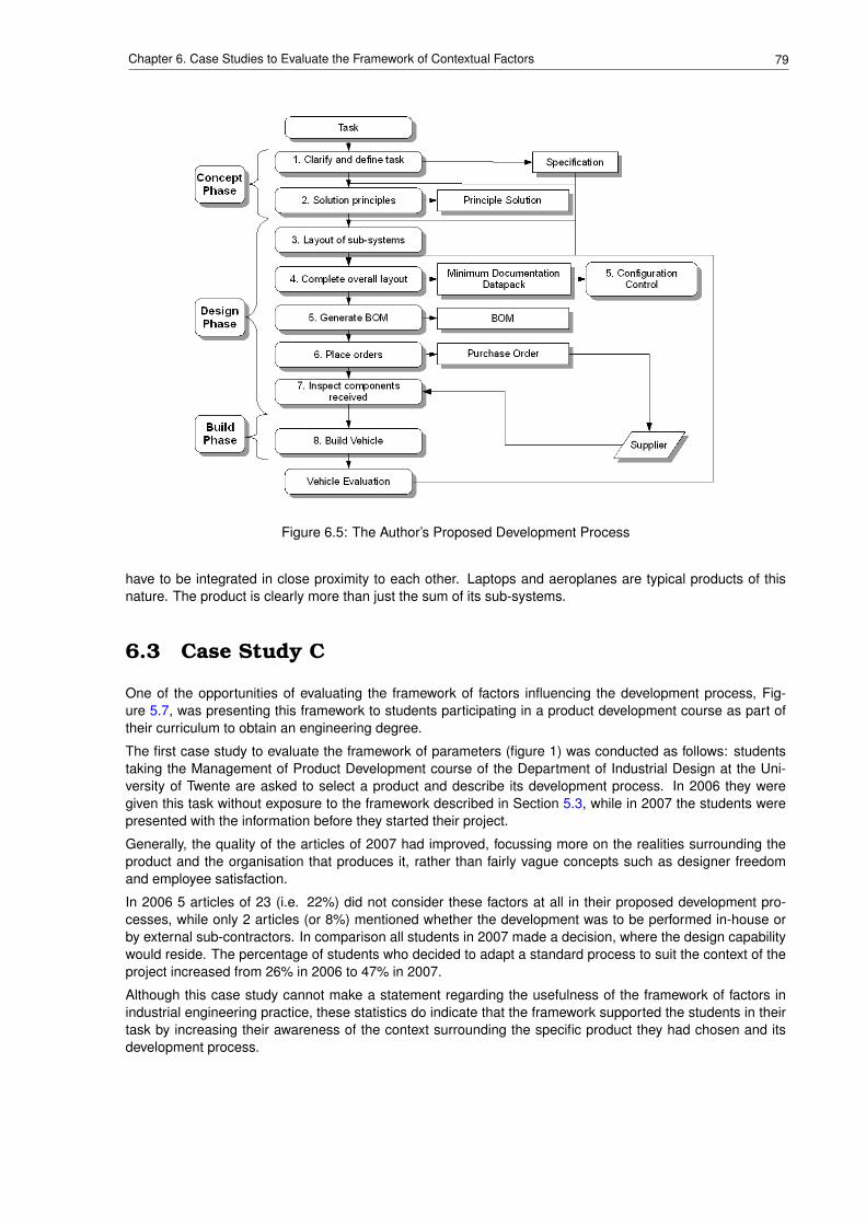
79Chapter 6. Case Studies to Evaluate the Framework of Contextual Factors
Figure 6.5: The Author’s Proposed Development Process
have to be integrated in close proximity to each other. Laptops and aeroplanes are typical products of thisnature. The product is clearly more than just the sum of its sub-systems.
6.3 Case Study C
One of the opportunities of evaluating the framework of factors influencing the development process, Fig-ure 5.7, was presenting this framework to students participating in a product development course as part oftheir curriculum to obtain an engineering degree.
The first case study to evaluate the framework of parameters (figure 1) was conducted as follows: studentstaking the Management of Product Development course of the Department of Industrial Design at the Uni-versity of Twente are asked to select a product and describe its development process. In 2006 they weregiven this task without exposure to the framework described in Section 5.3, while in 2007 the students werepresented with the information before they started their project.
Generally, the quality of the articles of 2007 had improved, focussing more on the realities surrounding theproduct and the organisation that produces it, rather than fairly vague concepts such as designer freedomand employee satisfaction.
In 2006 5 articles of 23 (i.e. 22%) did not consider these factors at all in their proposed development pro-cesses, while only 2 articles (or 8%) mentioned whether the development was to be performed in-house orby external sub-contractors. In comparison all students in 2007 made a decision, where the design capabilitywould reside. The percentage of students who decided to adapt a standard process to suit the context of theproject increased from 26% in 2006 to 47% in 2007.
Although this case study cannot make a statement regarding the usefulness of the framework of factors inindustrial engineering practice, these statistics do indicate that the framework supported the students in theirtask by increasing their awareness of the context surrounding the specific product they had chosen and itsdevelopment process.
80 6.4. Case Study D
6.4 Case Study D
When the author of this dissertation presented an article [43], describing the framework of factors that influ-ence the development process, to a fairly small audience at the PICMET ’08 conference in Cape Town, a livelydiscussion resulted among the author and some of the audience. It is interesting to note that the participantsin the discussion were academics as well as engineers from industry. This indicates to the author the valueof the framework, 5.7, to facilitate thought processes and therefore discussions regarding the developmentprocess in practice.
6.5 Summary and Conclusions
Chapter 3 provided the theoretical background with regards to the the engineering development process,while Section 4.1 compared these theories with the daily practice in industry. In light of the differencesbetween the theoretical models and industrial practice, Section 4.2 presents arguments for the adaptation ofthe theoretical models of the development process to suit the context of each specific development project.The role of methodologies, process models and design methods is described in Section 4.3.
Chapter 5 describes the internal and external factors that, in the author’s view, have the greatest influence onthe development process. The intention is that an understanding of these factors will lead the project manager,design engineer to construct a project methodology, which will suit the project context, and therefore facilitatethe successful execution of the project.
To illustrate how the factors, discussed in Chapter 5, and the resulting project methodology influences adevelopment project, this chapter presented case studies A and B in Sections 6.1 and 6.2 respectively. Theformer was conducted in a small company, where the freedom existed to adapt the project methodology to thecontext of the project. The latter was executed in a large company, with very rigid, prescriptive procedures,which govern development projects.
In case study A it was clear that no further improvements to the project could have been achieved through adifferent approach or strategy (see Section 6.1.4). In case study B, however, areas were identified where themethodology chosen for this project was hindering rather than facilitating the project (see Section 6.2.5).
The research summarised in this dissertation suggests that a better understanding of the relationship betweenthe factors influencing a development project, can lead to the construction of a project methodology whichis particularly suited for the circumstances surround the specific project. The prescriptive models of thedevelopment project can be utilised as building blocks or guidelines in this construction process.
Case studies C and D, in Sections 6.3 and 6.4 respectively, illustrate that the framework proposed in Sec-tion 5.3 provides a structure which increases the awareness of a project’s context and how it influences theproject. In case study C this helped the students to draw up more realistic plans for the proposed products andthe companies that would produce them. In case study D the structure provided by the framework facilitatedcommunication among engineering professionals from a wide variety of background by defining the topic ofdiscussion and its context concretely.
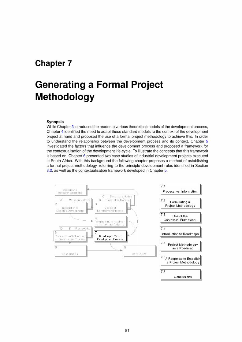
Chapter 7
Generating a Formal ProjectMethodology
SynopsisWhile Chapter 3 introduced the reader to various theoretical models of the development process,Chapter 4 identified the need to adapt these standard models to the context of the developmentproject at hand and proposed the use of a formal project methodology to achieve this. In orderto understand the relationship between the development process and its context, Chapter 5investigated the factors that influence the development process and proposed a framework forthe contextualisation of the development life-cycle. To illustrate the concepts that this frameworkis based on, Chapter 6 presented two case studies of industrial development projects executedin South Africa. With this background the following chapter proposes a method of establishinga formal project methodology, referring to the principle development rules identified in Section3.2, as well as the contextualisation framework developed in Chapter 5.
81
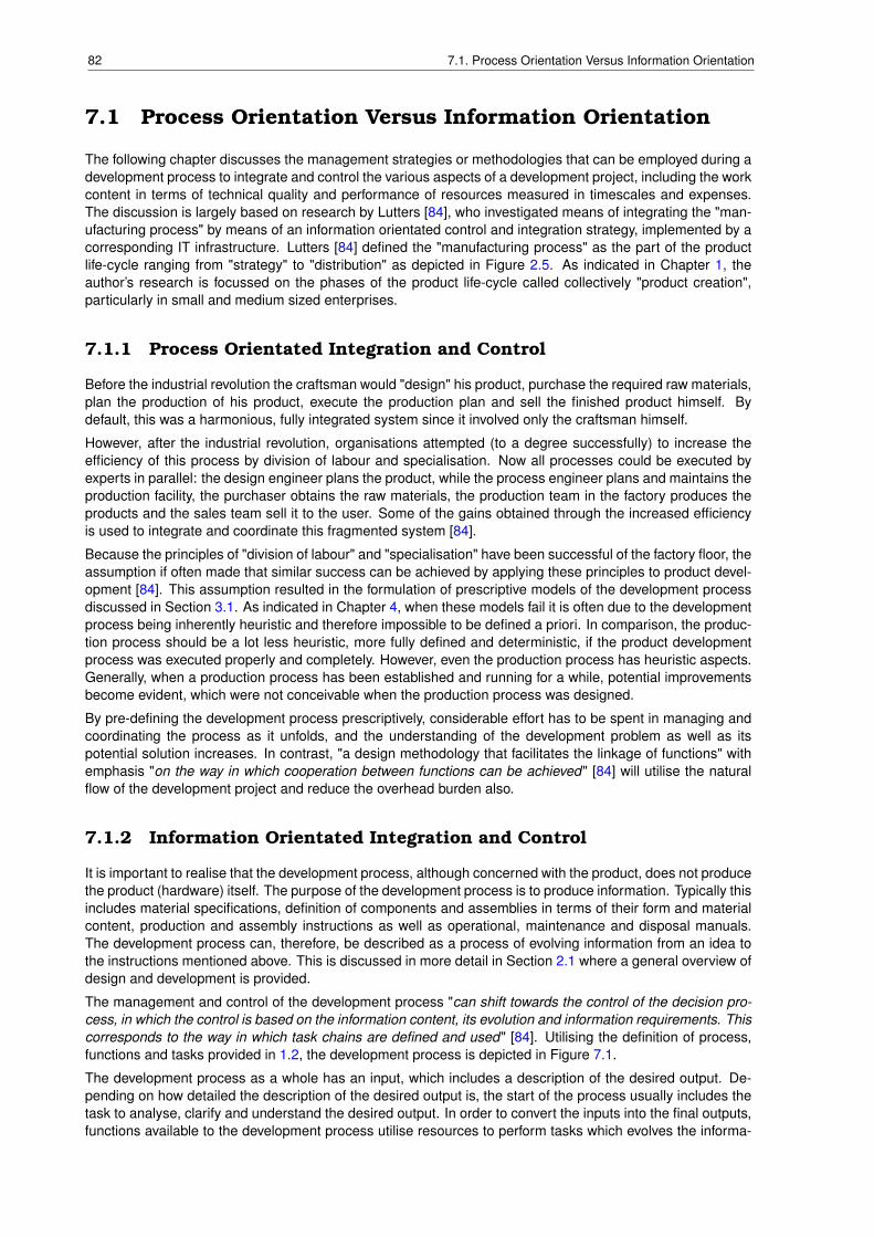
82 7.1. Process Orientation Versus Information Orientation
7.1 Process Orientation Versus Information Orientation
The following chapter discusses the management strategies or methodologies that can be employed during adevelopment process to integrate and control the various aspects of a development project, including the workcontent in terms of technical quality and performance of resources measured in timescales and expenses.The discussion is largely based on research by Lutters [84], who investigated means of integrating the "man-ufacturing process" by means of an information orientated control and integration strategy, implemented by acorresponding IT infrastructure. Lutters [84] defined the "manufacturing process" as the part of the productlife-cycle ranging from "strategy" to "distribution" as depicted in Figure 2.5. As indicated in Chapter 1, theauthor’s research is focussed on the phases of the product life-cycle called collectively "product creation",particularly in small and medium sized enterprises.
7.1.1 Process Orientated Integration and Control
Before the industrial revolution the craftsman would "design" his product, purchase the required raw materials,plan the production of his product, execute the production plan and sell the finished product himself. Bydefault, this was a harmonious, fully integrated system since it involved only the craftsman himself.
However, after the industrial revolution, organisations attempted (to a degree successfully) to increase theefficiency of this process by division of labour and specialisation. Now all processes could be executed byexperts in parallel: the design engineer plans the product, while the process engineer plans and maintains theproduction facility, the purchaser obtains the raw materials, the production team in the factory produces theproducts and the sales team sell it to the user. Some of the gains obtained through the increased efficiencyis used to integrate and coordinate this fragmented system [84].
Because the principles of "division of labour" and "specialisation" have been successful of the factory floor, theassumption if often made that similar success can be achieved by applying these principles to product devel-opment [84]. This assumption resulted in the formulation of prescriptive models of the development processdiscussed in Section 3.1. As indicated in Chapter 4, when these models fail it is often due to the developmentprocess being inherently heuristic and therefore impossible to be defined a priori. In comparison, the produc-tion process should be a lot less heuristic, more fully defined and deterministic, if the product developmentprocess was executed properly and completely. However, even the production process has heuristic aspects.Generally, when a production process has been established and running for a while, potential improvementsbecome evident, which were not conceivable when the production process was designed.
By pre-defining the development process prescriptively, considerable effort has to be spent in managing andcoordinating the process as it unfolds, and the understanding of the development problem as well as itspotential solution increases. In contrast, "a design methodology that facilitates the linkage of functions" withemphasis "on the way in which cooperation between functions can be achieved" [84] will utilise the naturalflow of the development project and reduce the overhead burden also.
7.1.2 Information Orientated Integration and Control
It is important to realise that the development process, although concerned with the product, does not producethe product (hardware) itself. The purpose of the development process is to produce information. Typically thisincludes material specifications, definition of components and assemblies in terms of their form and materialcontent, production and assembly instructions as well as operational, maintenance and disposal manuals.The development process can, therefore, be described as a process of evolving information from an idea tothe instructions mentioned above. This is discussed in more detail in Section 2.1 where a general overview ofdesign and development is provided.
The management and control of the development process "can shift towards the control of the decision pro-cess, in which the control is based on the information content, its evolution and information requirements. Thiscorresponds to the way in which task chains are defined and used" [84]. Utilising the definition of process,functions and tasks provided in 1.2, the development process is depicted in Figure 7.1.
The development process as a whole has an input, which includes a description of the desired output. De-pending on how detailed the description of the desired output is, the start of the process usually includes thetask to analyse, clarify and understand the desired output. In order to convert the inputs into the final outputs,functions available to the development process utilise resources to perform tasks which evolves the informa-
83Chapter 7. Generating a Formal Project Methodology
Figure 7.1: The Development Process
tion content of the project. Since development projects in practice are driven by a commercial perspective,the project will start off with a planned task chain, indicated in Figure 7.1 as a dotted line. As information andinsight into the development problem becomes available, the actual task chain will probably deviate from theplanned one as shown in Figure 7.1. Given the heuristic nature of the process, new information regardingthe development problem and its solution becomes available at each point in time during the developmentprocess. This implies that only a small part of the task chain can be planned into the future with certainty.This visibility (degree of certainty) of the project variables is indicated in Figure 7.1 by the shaded region. Thedarker the shading the higher the certainty.
7.1.3 Conclusions and Summary
Processes show, by definition, interdependency among their sub-processes. Structure enables the resolutionof conflict among sub-processes by establishing the priority according to the level of importance and urgencyassociated with each sub-process. This structure can be generic, provided that it "does not prescribe thepossible links" among sub-processes beforehand [84]. The information orientated approach described aboveoffers precisely such a structure.
Prescriptive models of the development process tend, by their nature, to reduce the human influence on thestructure of the development process. By utilising the human intelligence to adapt the process to suit the re-quirements of the project, the overhead burden of the project can be reduced, the efficiency and effectivenessof the process can be increased by applying resources where and when required, rather than by default in apre-programmed manner. This is exactly the kind of flexibility in the development process (as well as businessprocesses) that Bichlmaier [18] advocates.
Lutters proposed an information backbone, supported by the corresponding IT infrastructure in terms of bothhardware and software, as a means of utilising the information content to control the manufacturing pro-cess [84]. Since the research described in this dissertation is conducted with the intent to support SME’s(see Section 1.4), which may not be able to afford such investments, the author proposes that the principlesdiscussed in the previous sections are utilised and implemented under human control. Due to their smallersize and less formal internal structure (see Section 5.2.1), SME’s are particularly suited for this. The conceptof roadmaps, accessible in a collaborative work environment, are just one way to implement these principles.
84 7.2. The Process of Formulating a Formal Project Methodology
7.2 The Process of Formulating a Formal Project Metho-dology
As indicated in Figure 7.2 the planning process for a development project, should generate at least five piecesof information in order to enable a project manager to manage the project:
Schedule - A high level timing plan indicating when the major milestones of theproject need to be achieved.
Scope of Work - A description of the expected outputs and deliverables to be generatedby the project.
Work-flow Structure - A high level description of the major tasks to be performed during theproject.
Budget - The expected costs associated with the project.Work Break-down Structure - Allocation of resources to the work-flow structure.
The above mentioned documents provide the participants in a development project with a clear indicationof the objective to be achieved, the work that is required to achieve the objectives, who should execute thework, as well as how much time and money is available to achieve the objectives. Project management isthe process of ensuring that the objectives are achieved within the given constraints. Identification, assess-ment and strategies for the mitigation of risks should therefore, by definition, be an intrinsic part of projectmanagement [72]. It is the author’s view that the one of the most fundamental risks to a project would be themisalignment of the the project methodology (as captured in the five documents mentioned above) and thecontext of the project. For example: executing a project with a high novelty content without the correct level oftechnical support and opportunities for evaluation and verification, will introduce a probability of failure to theproject. The establishment of a project methodology, which acknowledges the context of a project is thereforevital to the success of a project, and a risk management activity in its own right.
It should be intuitively clear that these items are intrinsically linked: e.g. the schedule and the work break-down structure add timing constraints and resources to the work-flow structure respectively. The labour partof the budget is then defined by the hourly rate of these resources for the time spent on the project as per theschedule.
All five items described above are defined by the context of the development project. The schedule is usuallydictated by circumstances surrounding the project. For instance, the date of the show to exhibit the nextgeneration product, or the customer’s timescales for the deployment of the new product. The scope of workand its structuring depends largely on the information content of the project (see Section 7.1.2 above): i.e.what information (e.g. drawings, material specifications, assembly and maintenance instructions) needs tobe generated during the project in order to enable the efficient production of a product that will satisfy theneeds of the customer? Lastly, money and personnel resources enable the project: in principle, it is difficultto execute large, complex projects on a shoe-string budget, without people to execute the work.
Having defined the information necessary to manage a project, the next section discusses how the contex-tual framework can assist in generating this information by increasing the awareness of the project’s uniquecharacteristics and constraints.
7.3 Using the Contextual Framework to Tailor the Metho-dology for a Specific Development Project
Having established in Chapter 4 that no two development projects are ever the same and therefore thereexists a need to configure the development process according to the requirement and context of each specificdevelopment project, the author discussed the contextual variables that influence the development processin Chapter 5. The intended logic is as follows: if the personnel, tasked with the planning and executionof a development project, are aware of the context of the project, they will be able to structure the projectmethodology accordingly.
It is therefore necessary to translate the data in the contextual variables (see Tables 6.1 and 6.2 as examples)into one or more measures that will enable the project manager to establish a specific project methodologyfor the given context. With this in mind the author analysed the contextual variables and found that they fallinto three categories: project background, project enablers and project structure, as shown in Figure 7.3.
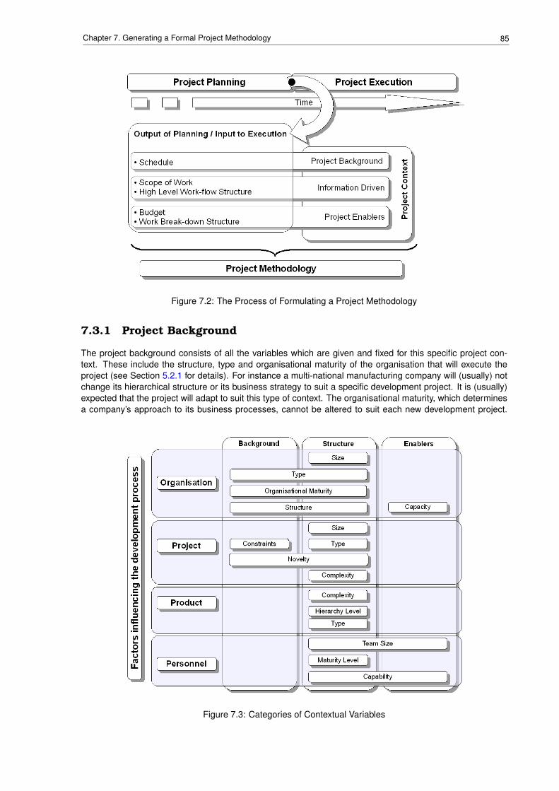
85Chapter 7. Generating a Formal Project Methodology
Figure 7.2: The Process of Formulating a Project Methodology
7.3.1 Project Background
The project background consists of all the variables which are given and fixed for this specific project con-text. These include the structure, type and organisational maturity of the organisation that will execute theproject (see Section 5.2.1 for details). For instance a multi-national manufacturing company will (usually) notchange its hierarchical structure or its business strategy to suit a specific development project. It is (usually)expected that the project will adapt to suit this type of context. The organisational maturity, which determinesa company’s approach to its business processes, cannot be altered to suit each new development project.
Figure 7.3: Categories of Contextual Variables
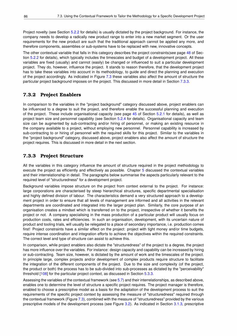
86 7.3. Using the Contextual Framework to Tailor the Methodology for a Specific Development Project
Project novelty (see Section 5.2.2 for details) is usually dictated by the project background. For instance, thecompany needs to develop a radically new product range to enter into a new market segment. Or the userrequirements for the new product are such that the traditional approach cannot be applied any more, andtherefore components, assemblies or sub-systems have to be replaced with new, innovative concepts.
The other contextual variable that falls in this category describes the project constraints(see page 48 of Sec-tion 5.2.2 for details), which typically includes the timescales and budget of a development project. All thesevariables are fixed (usually) and cannot (easily) be changed or influenced to suit a particular developmentproject. They do, however, influence the project. It stands to reason therefore, that the development projecthas to take these variables into account in its methodology, to guide and direct the planning and executionof the project accordingly. As indicated in Figure 7.3 these variables also affect the amount of structure theparticular project background imposes on the project. This discussed in more detail in Section 7.3.3.
7.3.2 Project Enablers
In comparison to the variables in the "project background" category discussed above, project enablers canbe influenced to a degree to suit the project, and therefore enable the successful planning and executionof the project. These include organisational capacity (see page 45 of Section 5.2.1 for details), as well asproject team size and personnel capability (see Section 5.2.4 for details). Organisational capacity and teamsize can be augmented by sub-contracting and/or hiring of personnel, or making an existing resource inthe company available to a project, without employing new personnel. Personnel capability is increased bysub-contracting to or hiring of personnel with the required skills for this project. Similar to the variables inthe "project background" category, discussed above, project enablers also affect the amount of structure theproject requires. This is discussed in more detail in the next section.
7.3.3 Project Structure
All the variables in this category influence the amount of structure required in the project methodology toexecute the project as efficiently and effectively as possible. Chapter 5 discussed the contextual variablesand their interrelationship in detail. The paragraphs below summarise the aspects particularly relevant to therequired level of "structuredness" for a development project.
Background variables impose structure on the project from context external to the project. For instance:large corporations are characterised by steep hierarchical structures, specific departmental specialisationand highly defined division of labour. The characteristics demand a very structured approach to a develop-ment project in order to ensure that all levels of management are informed and all activities in the relevantdepartments are coordinated and integrated into the larger project plan. Similarly, the core purpose of anorganisation creates a mindset which is transferred on to the project, irrespective of whether it benefits theproject or not. A company specialising in the mass production of a particular product will usually focus onproduction costs, rates and efficiencies. In such an organisation, development, with its uncertain nature ofproduct and tooling trials, will usually be relegated to a place of secondary importance, i.e. production comesfirst! Project constraints have a similar effect on the project: project with tight money and/or time budgets,require intense coordination and integration efforts to achieve the objectives within the required constraints.The correct level and type of structure can assist to achieve this.
In comparison, while project enablers also dictate the "structuredness" of the project to a degree, the projecthas more influence over the variables. For instance: design capacity and capability can be increased by hiringor sub-contracting. Team size, however, is dictated by the amount of work and the timescales of the project.In principle large, complex projects and/or development of complex products require structure to facilitatethe integration of the different components of the project. Due to the size and complexity (of the project,the product or both) the process has to be sub-divided into sub-processes as dictated by the "perceivability"threshold [108] for the particular project context, as discussed in Section 5.3.3.
Assessing the variables of the contextual framework (see 5.7) and their interrelationships, as described above,enables one to determine the level of structure a specific project requires. The project manager is therefore,enabled to choose a prescriptive model as a basis for the adaptation of the development process to suit therequirements of the specific project context by assessing the measure of "structuredness" required throughthe contextual framework (Figure 7.3), combined with the measure of "structuredness" provided by the variousprescriptive models of the development process (see Figure 3.2). As indicated in Section 3.1.3, prescriptive
87Chapter 7. Generating a Formal Project Methodology
models provide a good basis for project management and control due to their well-defined structure. It is forthis reason that it is sensible to use a prescriptive model of the development process as a basis for a projectmethodology.
The first step would be to evaluate the variables of the contextual framework, discussed in Section 5.2, re-sulting in a table such as those generated for case studies A and B (Table 6.1 and 6.2 respectively). As anexample, Table 7.1 shows the variables of the contextual framework and their specific values for case studyB, arranged in the format of Figure 7.3. In order to convert the values in the structure column to a measurewhich can be applied to Figure 3.2 to select a prescriptive model of the development process as a basis, thevalues "low", "medium" and "high" need to be converted into numerical values, as shown in Table 7.2. Foreach of the variables the value is multiplied by a contribution (weighting) factor, which is a measure of howmuch the particular variable affects the "structuredness" of the project. The resulting products are summed,and the result can be applied to Figure 3.2. For the example of case study B, the following would have beenacceptable choices: the models of Pahl & Beitz, VDI, Ullman and Pugh.
It is important to note when related factors of the framework, as discussed in Section 5.3, exhibit large differ-ences in score. For instance, in Table 7.1, a small project (score = 2) was executed by a small project team(score = 2) in a large organisation (score = 4). Taking into account that the constraint for the project was thetime available to complete it, the probability of failure, i.e. not meeting all the project objectives, was increasedby not addressing this discrepancy when the project methodology was established. Similarly, the discrepancybetween the company focussing on production on the one hand (score = 5), and producing products that areengineered-to-order on the other (score = 2), creates issues in the business process, which spill over intothe project. Consistent quality and production efficiency is best achieved by producing large quantities ofproducts with the same configuration, while engineering-to-order implies the production of "specials" in smallquantities.
This type of discrepancy is also evident on a higher level: for instance in Table 7.1, the personnel factorsrequire an unstructured project methodology (score = 1.33), due to the small number of capable and matureengineering professionals involved, while the product requires a fairly structured methodology (score = 4.33),due the large batch size and the high level of product complexity.The contribution factor is a means of findingan acceptable compromise between the variables which demand a high level of structure (scores of 4 or5) and those which require only little structure (scores of 1 and 2). In the example shown in Table 7.1 iswas decided that the demands of the organisational factors were more important than the product factors byapplying a contribution factor of 0.3 to the former and only 0.2 to the latter.
There are two other aspects that have to be considered when choosing a prescriptive model for a basis for aproject methodology: the model’s scope and its characteristics.
The Scope of the Prescriptive Model
As indicated in Figure 3.3 most prescriptive models of the development process start at the "strategy" phase ofthe product life-cycle (Figure 2.5). Of the prescriptive models considered during this research, only systemsengineering addresses "research" as a separate phase, which gathers data, investigates technology andproducts in order to be able to formulate the strategy in the next phase. Quite a number of the modelsaddress only the strategy and design phases of the product life-cycle. Cross, Suireg and Ullman address thenext phase where the new product is evaluated. Concurrent Engineering, Integrated Product Developmentand Pugh address the product life-cycle up to the distribution phase. Of the models considered in this researchonly Ullman and Systems Engineering include the disposal phase.
It is therefore important to realise which phases of the product life-cycle are required for a particular project,depending on the purpose of the project. The intent to bring a product to market could, for instance, be brokenup into a number of projects each lasting a financial year: the first year might address strategy and design,while the next year is dedicated to an extensive evaluation process, before industrialisation and productionare addressed in year three.
The Characteristics of the Prescriptive Model
Mixing and matching parts of various models of the development process, depending on their strengths andcharacteristics should also be considered. Table 3.2 provides a brief summary of the most obvious strengthsand focus areas for each of the prescriptive models considered in this research.
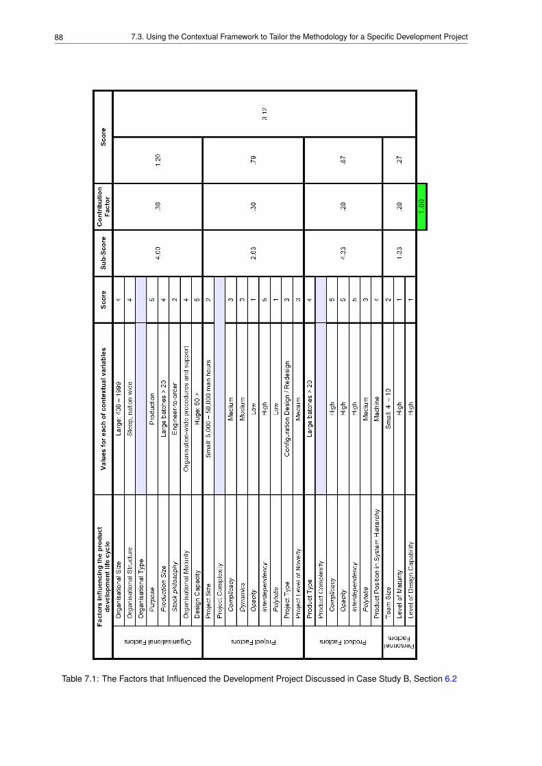
88 7.3. Using the Contextual Framework to Tailor the Methodology for a Specific Development Project
Table 7.1: The Factors that Influenced the Development Project Discussed in Case Study B, Section 6.2
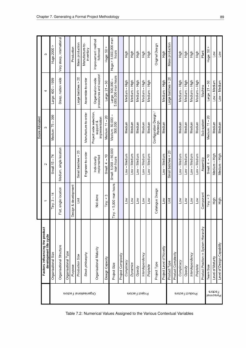
89Chapter 7. Generating a Formal Project Methodology
Table 7.2: Numerical Values Assigned to the Various Contextual Variables
90 7.4. Introduction to the Concept of a Roadmap
For the development of a relatively simple product with low levels of novelty and complexity, French’s orArcher’s model of the development process may be applicable. A project to develop a product with a specificrequirement for modularity might consider utilising the models of Pahl & Beitz or VDI as their frameworkfor the project. Very complex projects, where many organisations collaborate, might require the SystemsEngineering approach. In all cases it might be sensible to consider the concurrency aspects advocated byConcurrent Engineering and Integrated Product Development.
How can this be applied to industrial practice? In support of the answer to this question, Section 7.4 in-troduces the reader to the tool that the author proposes for this task: the concept of a roadmap. The endresult, i.e. the project methodology for a specific development project, tailored to suit the project context, isdiscussed in Section 7.5. Armed with this information, Section 7.6 discusses the means of generating theproject methodology in the from of a roadmap.
7.4 Introduction to the Concept of a Roadmap
Frameworks and roadmaps have become popular structures to represent procedures, life-cycles and pro-cesses [77], [79], [99]. Various definitions for these terms exist. For the context of the research describedin this dissertation, the author prefers the definition provided by the Industrial Engineering Department of theUniversity of Stellenbosch, which defines a roadmap as "a layout of descriptive paths that multidisciplinaryteams can use as a guiding framework for collaboration efforts towards a common goal." [39]. The emphasisin this definition is on "guiding framework", describing all aspects of the project, while providing an "environ-ment with enough freedom to innovate" [39].
Models of the development process such as those described in Section 3.1 easily deteriorate into prescriptivescripts or programs, since they intend to describe widely applicable, generic situations, rather than the specificproject embedded in its context. "Instead of demarcating the course" of a project "by imposing behaviourdriven by a design method" or model of the development process "roadmaps attempt to facilitate the courseof actions. A roadmap is a structured description of all aspects that constitute a project. It is used to guidethe team members in executing the project" [85].
A roadmap should contain the following descriptions:"Where" to go - a structured high-level framework of desired milestones."Who" is travelling - an allocation of a person or team to a milestone."How" to get there - descriptions and information guiding the user of the roadmap to his desti-
nation."When" to arrive - a target date for each of the milestones."What" goals to achieve - objective to achieve at each milestone.
In addition the computer environment which houses the roadmap and provides an interface for interaction tothe user in order to make it accessible and useful, should provide the following:
• controls in order to manage efficiency and effectiveness of the process of travelling down the path onthe roadmap, and
• an information repository to collect all the information relevant to the specific project under consideration.
This information should be able to be re-used by converting the most relevant information, methods, tools,techniques of the current project into the guiding information of the next, similar project. Knowledge manage-ment and storage for re-use have been recognised as a requirement to increase the effectiveness and effi-ciency of engineering development by organisations such as the G-SCOP Laboratory, Institute National Poly-technique de Grenoble (INPG), France and Integrated Manufacturing System Research Center (IMSRC),KingMongkutâAZs Institute of Technology North Bangkok (KMITNB), Thailand [24]. The topic of knowledge man-agement for engineering development is too large and complex to address within the scope of this researchproject. The author acknowledges the need and has presented a simple solution in keeping with the initialintent of providing solutions suitable for small enterprises.
Figure 7.4 shows the concept of a roadmap implemented in a collaborative software environment called,EDENTM . According to the developers of the software, a company called Indutech in Stellenbosch [6], SouthAfrica, EDENTM is a "enterprise-wide innovation management platform", providing the characteristics of aroadmap described above.
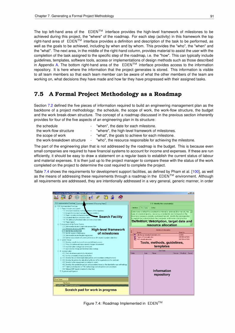
91Chapter 7. Generating a Formal Project Methodology
The top left-hand area of the EDENTM interface provides the high-level framework of milestones to beachieved during this project, the "where" of the roadmap. For each step (activity) in this framework the topright-hand area of EDENTM interface provides a definition and description of the task to be performed, aswell as the goals to be achieved, including by when and by whom. This provides the "who", the "when" andthe "what". The next area, in the middle of the right-hand column, provides material to assist the user with thecompletion of the task assigned to the specific step of the roadmap, i.e. the "how". This can typically includeguidelines, templates, software tools, access or implementations of design methods such as those describedin Appendix A. The bottom right-hand area of the EDENTM interface provides access to the informationrepository. It is here where the information that the project generates is stored. This information is visibleto all team members so that each team member can be aware of what the other members of the team areworking on, what decisions they have made and how far they have progressed with their assigned tasks.
7.5 A Formal Project Methodology as a Roadmap
Section 7.2 defined the five pieces of information required to build an engineering management plan as thebackbone of a project methodology: the schedule, the scope of work, the work-flow structure, the budgetand the work break-down structure. The concept of a roadmap discussed in the previous section inherentlyprovides for four of the five aspects of an engineering plan in its structure:
the schedule - "when", the date for each milestone.the work-flow structure - "where", the high-level framework of milestones.the scope of work - "what", the goals to achieve for each milestone.the work-breakdown structure - "who", the resource responsible for achieving the milestone.
The part of the engineering plan that is not addressed by the roadmap is the budget. This is because evensmall companies are required to have financial systems to account for income and expenses. If these are runefficiently, it should be easy to draw a statement on a regular basis to establish the current status of labourand material expenses. It is then just up to the project manager to compare these with the status of the workcompleted on the project to determine the cost required to complete the project.
Table 7.4 shows the requirements for development support facilities, as defined by Pham et al. [100], as wellas the means of addressing these requirements through a roadmap in the EDENTM environment. Althoughall requirements are addressed, they are intentionally addressed in a very general, generic manner, in order
Figure 7.4: Roadmap Implemented in EDENTM
92 7.6. A Roadmap to Generate a Project Methodology
to provide the designer, project manager or chief design engineer the freedom to add as much structure tohis project methodology as he deems appropriate for the given circumstances of his project. By contrast,the visualisation of individual design decisions and their effects on the design as a whole, for example, wasaddressed by Pham et al. [100] in a more formal, structured manner by generating an automated decisiontree. Should a project, company or industry require such a structured approach, the facility could be added tothe roadmap implemented in the EDENTM environment by making appropriate software available.
Blessing[20] defined very similar requirements for a design support system. In terms of the interaction be-tween the user and the system in general, the system needs to be "cooperative, subordinate, flexible anduseful". With regard to supporting the design activities specifically, it needs to be "comprising, assisting, guid-ing and structuring". Table 7.5 provides a description of each term, as provided by Blessing, the means bywhich a roadmap implemented in a software environment like EDENTM would address each requirement.
7.6 A Roadmap to Generate a Project Methodology
The author proposes the use of a roadmap to guide the project team, led by the project manager or chief de-sign engineer, through the process of generating a project methodology in the form of a roadmap itself, whichwould then be used to guide the project team through the execution of of the project. It is important to note thatthe process described below is not intended to be prescriptive. It is intended to provide means for the projectteam to visualise a large number of (often conflicting) variables, in order to obtain an approach to the project,which represents an acceptable compromise in addressing these variables. The EDENTM environment willeven enable to adaptation of this approach during the execution of the project to take into account new infor-mation obtained. Due to the heuristic nature of the design process, this particularly true for original designproblems.
Section 7.3 provided a mechanism to indicate the level of structure required for a particular project. It alsosuggested that a prescriptive model of the development process can be chosen as a basis for tailoring aspecific project methodology. Roadmaps for the EDENTM environment have been generated for a numberof these prescriptive models, thereby building a repository of roadmaps that can be used for product devel-opment. The facility exists in the EDENTM environment to build a new roadmap by copying either parts orcomplete roadmaps from this repository.
The proposed roadmap to generate the project methodology has the steps and sub-steps described in Ta-ble 7.3. Once a project has been executed its roadmap can be added to the repository for future reuse.
7.7 Conclusions
While this research has argued for the need to tailor the development process for each project according to itsspecific context in Section 4.2, Section 5.2 identified and described the factors that influence the developmentprocess most. By applying a scale from 0 to 1 to each of these factors, as described in Section 7.3.3, anindication can be obtained what level of structure is required for a given project. Taking the scope and char-acteristics of the prescriptive models of the development process into account, as discussed in Section 7.3,a model can be chosen as a basis for a project methodology. Finally, Sections 7.4 and 7.5 described howthe concept of a roadmap, implemented in a software environment such as EDENTM , can be utilised toformalise a tailored project methodology for a specific project.
The concept of a repository of available models of the development process within a collaborative designenvironment, that will support object oriented configuration and manipulation of roadmaps, will allow thedesign team to configure the development life-cycle "on the fly", based on past experience as well as all therequirements and parameters of the specific product, development project, enterprise and project team.
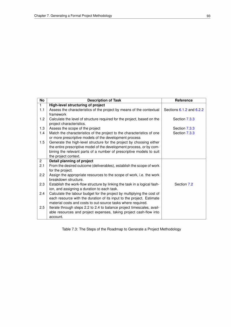
93Chapter 7. Generating a Formal Project Methodology
No Description of Task Reference1 High-level structuring of project1.1 Assess the characteristics of the project by means of the contextual
frameworkSections 6.1.2 and 6.2.2
1.2 Calculate the level of structure required for the project, based on theproject characteristics.
Section 7.3.3
1.3 Assess the scope of the project Section 7.3.31.4 Match the characteristics of the project to the characteristics of one
or more prescriptive models of the development processSection 7.3.3
1.5 Generate the high-level structure for the project by choosing eitherthe entire prescriptive model of the development process, or by com-bining the relevant parts of a number of prescriptive models to suitthe project context.
2 Detail planning of project2.1 From the desired outcome (deliverables), establish the scope of work
for the project.2.2 Assign the appropriate resources to the scope of work, i.e. the work
breakdown structure.2.3 Establish the work-flow structure by linking the task in a logical fash-
ion, and assigning a duration to each task.Section 7.2
2.4 Calculate the labour budget for the project by multiplying the cost ofeach resource with the duration of its input to the project. Estimatematerial costs and costs to out-source tasks where required.
2.5 Iterate through steps 2.2 to 2.4 to balance project timescales, avail-able resources and project expenses, taking project cash-flow intoaccount.
Table 7.3: The Steps of the Roadmap to Generate a Project Methodology
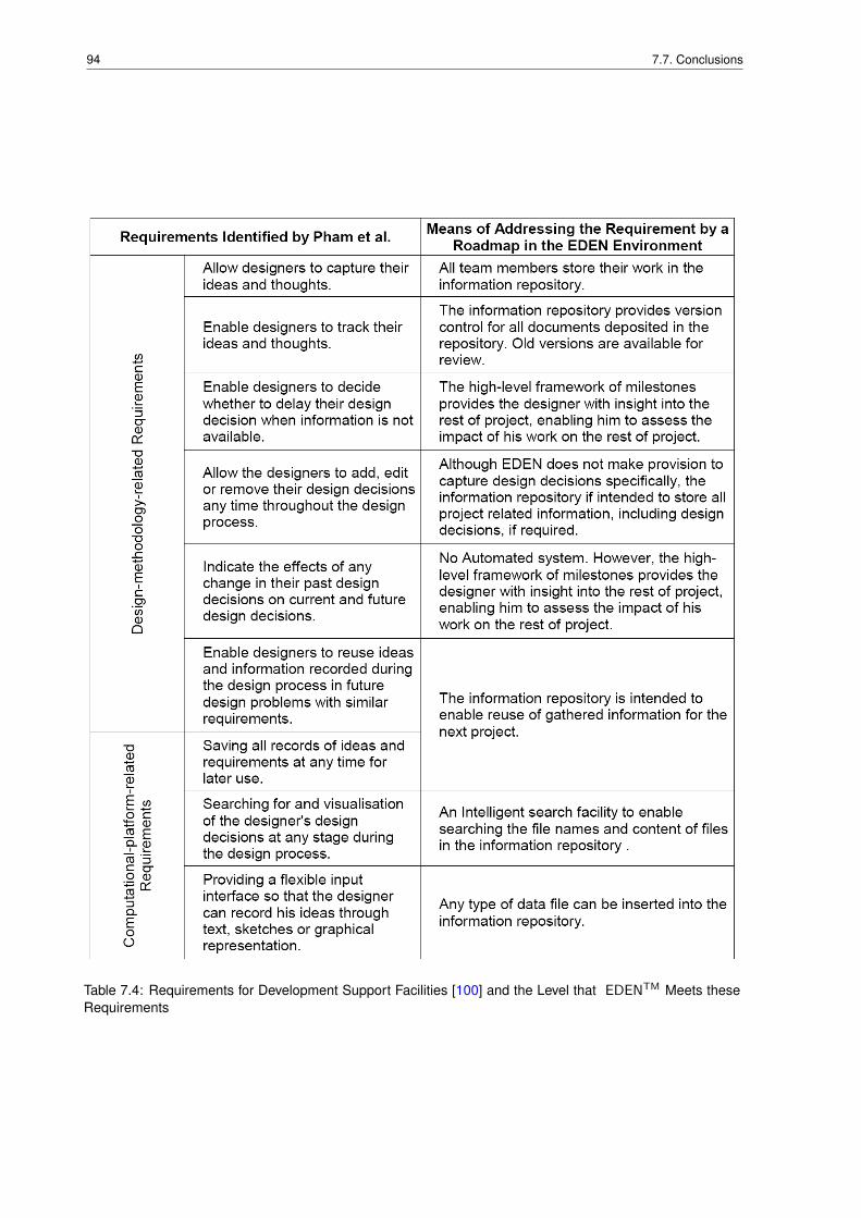
94 7.7. Conclusions
Table 7.4: Requirements for Development Support Facilities [100] and the Level that EDENTM Meets theseRequirements
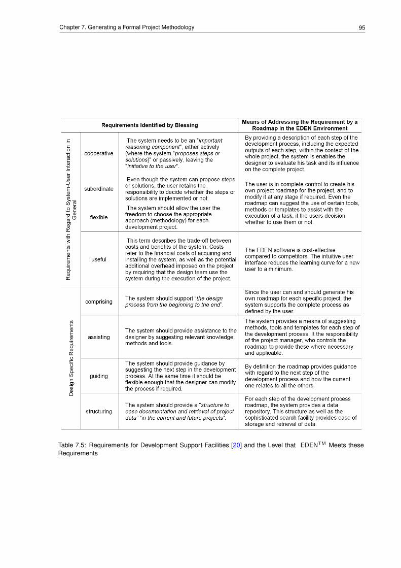
95Chapter 7. Generating a Formal Project Methodology
Table 7.5: Requirements for Development Support Facilities [20] and the Level that EDENTM Meets theseRequirements

96 7.7. Conclusions
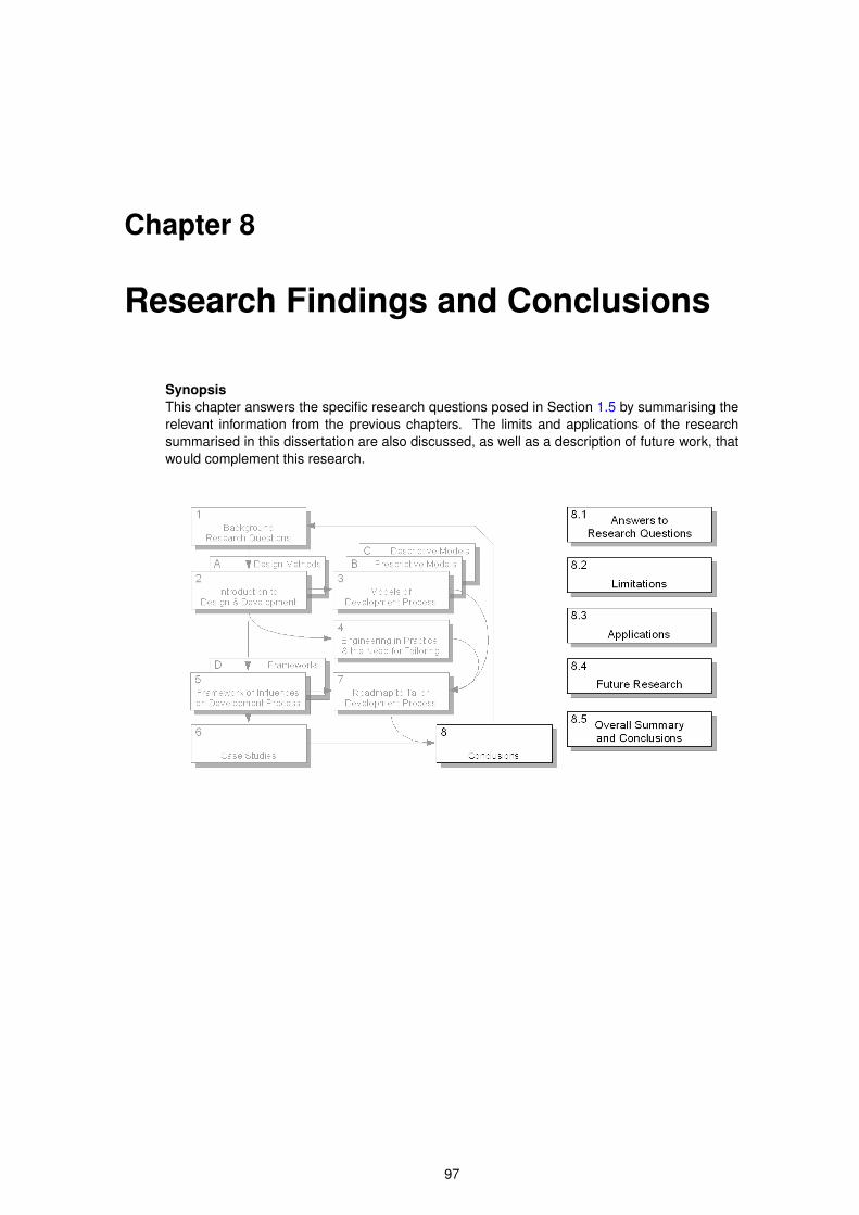
Chapter 8
Research Findings and Conclusions
SynopsisThis chapter answers the specific research questions posed in Section 1.5 by summarising therelevant information from the previous chapters. The limits and applications of the researchsummarised in this dissertation are also discussed, as well as a description of future work, thatwould complement this research.
97
98 8.1. Answers to Research Questions
8.1 Answers to Research Questions
The contrast between the prescriptive models of the development process proposed by design science andindustrial practice (see Section 4.1), has prompted the author to ask questions about the nature of the de-velopment process and its application in industry. This research project addressed the challenge of how toappropriately configure each design project within a product development life cycle according to a number offramework contexts. In execution of the project a number of significant contributions have been made thatlead to significant recognition within the design sciences domain culminating in a proposed solution, describedin Chapter 7, which facilitates the configuration of the development process to suit the context of the devel-opment project. This results in narrowing the gap between the proposals of design science and industrialpractice.
Firstly the landscape of product design methodologies has been documented to provide an extended catego-rization of a wide range of models and methodologies.
Secondly a framework for configuring a project methodology has been compiled. This framework has beentested in three industrial projects which the author participated in. It was also evaluated in a teaching environ-ment exposing some 120 students in a number of projects over a two year period.
Thirdly the project outcome was presented at two international conferences where significant interaction wasinitiated. The latter to such an extend that the paper for the design conference in Enschede in April 2008 wasselected to be published in the international CIRP addition on Design in 2008.
The subsequent EDENTM roadmap that supports the proposed methodology also makes available the resultsof this research to a wider design community and will contribute to further developments in the field of design.
At the onset of the project a number of research questions were identified (see Section 1.5), to be answeredduring the course of the research. All these questions have been answered indirectly in the preceding chap-ters of this dissertation. For the sake of completeness and clarity the answers are summarised below withreferences to the parts of the dissertation that discuss the particular topic.
8.1.1 Given a Specific Project, with Specific Resources within a GivenEnvironment, How Does One Select and Construct a Design Metho-dology from a Repository of Templates?
In addressing the preceding question, as described in more detail in Section 7.6, the author proposes thefollowing:
• Determine the characteristics of the project and its context by assigning values to each of the factorsof the contextual framework, as shown in Table 7.1, to indicate the level of structure required for theproject. By comparing the final score obtained with the level of "structuredness" of various prescriptivemodels of the development process, as shown in Figure 3.2, a first-order selection can be made of theprescriptive model to use as a basis for the project methodology.
• By comparing the scope of the prescriptive model (Figure 3.3), as well as the strengths and character-istics (Table 3.2) with the project’s requirements, a final choice of prescriptive model can be made. Itis conceivable that one might choose the concept phase from one model and the detail design phasefrom another, etc. depending on what suits the project the best.
• Utilising a software environment such as EDENTM and a repository of roadmaps for the various mod-els of the development process, one can generate a specific roadmap, tailored to suit the needs andcharacteristics of a specific development project. The roadmap would then be the project methodologyexpressed in a form that is beneficial to the execution of a project. Prototypes of such roadmaps areavailable at http://indutech.cust.iaf.nl/roadmaps. For access username and passwordneed to be requested via email from [email protected].
8.1.2 Can Benefit be Obtained by Combining Design Methods to Form aProject Methodology?
No. Design methods, as defined in Section 1.2, are rigid procedures aimed at obtaining specific results(outputs) from specific inputs. By merely stringing design methods together, even if they are relevant to the
99Chapter 8. Research Findings and Conclusions
design problem, will not equate to a project methodology. The relationship between the project methodology,the models of the development process and available design methods and tools, is illustrated in Section 4.3.A project methodology needs the flexibility to take the context of the project into account, which cannot becomprehensively accommodated by a design method. A project methodology is based on an approach or astrategy, which is more than the design methods it incorporates.
8.1.3 Can Methods be Established to Define a Methodology Optimisedfor a Specific Project?
With reference to the specific word "method" in this question, the answer is "No". The reason for this, is theimplication of a rigid, prescriptive procedure to be followed: provide some parameters, crank the handle andobtain an optimised methodology, ready for consumption. The decisions made during the establishment of aproject methodology, is based on the value system of the individual or group who are planning and executingthe development project. This value system differs from case to case.
However, if the question is changed to: "Can guidelines be established to define a methodology optimisedfor a specific project?", the answer would be "Yes". The influencing factors described in Chapter 5 are thebasis for such guidelines, and the roadmap described and illustrated in Chapter 7 provides the assistance togenerate an sufficient and comprehensive project methodology.
The author’s premiss is that it takes understanding of the project context to generate a project methodology,and it takes the understanding of both the context as well as the strategy behind the methodology to executeit properly. The same understanding would have to be generated by the person tasked to execute the project,even if the methodology could be obtained in an automated, mechanistic manner.
8.1.4 How do I Specify, Choose and Construct a Development Metho-dology?
Chapter 7 provides one way of generating a project (development) methodology. Since humanity has ex-ecuted many successful development projects, there must be innumerable ways of defining a developmentmethodology. Many of these will be intuitive, based on experience, and not formalised.
8.1.5 How do I Measure the Success or Appropriateness of My Choices?
The answer to this question is best described by the old adage that "the proof of the pudding is in the eating",i.e. during the execution of the project one can establish whether the project progresses according to plan.If not, the situation can be analysed to determine whether a change in the approach to the project, or a partof it, will improve the matter. The two case studies (Sections 6.1.4 and 6.2.5) and the concluding section ofChapter 6 illustrate this.
8.1.6 How do I Comprehensively Quantify My Needs with Respect to aDevelopment Methodology?
It is the author’s opinion that any project methodology should, at least, provide the five pieces of informationdiscussed in Section 7.2: schedule, scope of work, work-flow structure, budget and work break-down struc-ture. Furthermore, the level of structure, "prescriptiveness", of the project methodology should be aligned tothe needs of the project. An indication of this can be obtained by completing the matrix shown in Table 7.1.One should be aware of and address situations causing large variation in scores for related contextual vari-ables, as discussed in Section 7.3.3.
The scope and characteristics of the prescriptive model of the development process chosen as a basis for aproject methodology should also be aligned with the scope and requirements of the project, as discussed inSection 7.3.
The implementation of the project methodology, enabling it to be applied by the project team in the executionof the project should make provision for attributes such as those listed in Table 7.4.
100 8.2. Limitations of This Research
8.1.7 Can a Methodology be Represented in a Roadmap?
Yes, as discussed in Section 7.4 a roadmap can address all the needs of a project methodology. TheEDENTM software environment is a tool to implement the concept of a roadmap in a manner that it can be auseful instantiation of a specific development methodology for a specific development project. Prototypes ofsuch roadmaps are available at http://indutech.cust.iaf.nl/roadmaps. For access usernameand password need to be requested via email from [email protected].
8.1.8 Can a Roadmap, Implemented in a Design Environment, Facilitatethe Engineering Development Process?
Chapter 6 shows that the correct project methodology can facilitate the engineering development process.Therefore the remaining question is: "Will the implementation of the project methodology in a roadmap facili-tate the engineering development process?"
The work described in this dissertation does not include a case study where the project methodology wasimplemented in the form of a roadmap in a collaborative environment such as EDENTM , and thereforethis question cannot currently be answered with any certainty. However, the roadmap concept has beenutilised very successfully to implement an innovative project in the financial industry [44]: "Roadmaps arean excellent way of supporting innovation teams, but it is important for the team members to agree on theroadmap structure and to take ownership of the roadmap from the start". It is not unreasonable to expectsimilar benefits when the approach is applied to engineering development projects.
8.1.9 What Attributes Must a Roadmap Have so That it Can Represent aDesign Methodology?
This question was answered under the related Sections 8.1.6 and 8.1.7.
8.1.10 What Attributes Must a Design Environment Have so That a RoadmapCan be Applied to a Development Project?
The author agrees with Pham [100] and Blessing [20] that a design environment should address the aspectslisted in Tables 7.4 and 7.5. The most important of these would be the storage of shared information for re-useand an effective facility for searching through the information by means of keywords, phrases and concepts.
8.2 Limitations of This Research
The research summarised in this dissertation is limited by two aspects:
• the chosen scope for the research, and
• the perspective of the author.
As indicated in Section 7.2 each project needs a definition of its scope of work. For this research the scope ofwork was limited to the engineering and project management aspects of a development project, with emphasison the methodology required for planning, management and execution of the project. Although it is clear to theauthor that other issues, such as the legal, contracting and business aspects related to development projectare vitally important to its success, the author intentionally excluded these from the scope of this work.
The latter limitation is due to the context surrounding the author, his work experience, the industry he iscurrently serving and the country he is living in currently. Although the author has worked in various indus-tries and companies of varying sizes, the work described in this dissertation is strongly influenced by theauthor’s occupation in the special automotive industry, with an emphasis on the military, cash-in-transit andlaw enforcement sectors of that industry. This is clearly shown in the case studies in Chapter 6.
101Chapter 8. Research Findings and Conclusions
8.3 Applications
The work summarised in this dissertation is intended to be applicable to any engineering development project,irrespective of size or industry. It is the author’s opinion that the broad principles discussed in the dissertationshould be generally applicable. However, industry (and perhaps country) specific nuances will probably haveto be taken into account when applying these methodologies in practice. It was obviously not possible to testthis notion in practice within the scope of the work described in this dissertation.
The intent was also to make the work applicable to small companies as much as for large ones. It is for thisreason that the implementation of the principles, as discussed in Chapter 7, was not based on elaborate,complicated and specialised computer systems. The software environment, called EDENTM , was chosenas the implementation vehicle because it is so easy to install and use.
8.4 Suggestions for Future Research
The author can identify the following research questions for future work:
• How much benefit can be expected from the implementation of a project methodology by means of aroadmap in a collaborative design environment such as EDENTM ?
• How applicable are the suggestions made in this dissertation in other industries and/or other engineer-ing disciplines?
• How should the contextual framework shown in Figure 5.7 be expanded to include the legal, financialand commercial aspects of projects?
8.5 Overall Summary and Conclusions
The research described in this dissertation has been successful in a number of different ways. First andforemost it has achieved the objectives defined at the onset of the project: all the research questions posedin Chapter 1 have been answered. The preceding sections summarise these answers with reference to thespecific parts of the dissertation where the particular topic is discussed in more detail.
Secondly, the research has added another stone to the large mosaic that is design science, making thebig picture a bit more complete. By viewing the theoretical world of prescriptive models of the developmentprocess through the lenses shaped by years of industrial experience, the author provides a new perspectiveon the subject matter. Rather than forcing a project into the mould of a pre-defined prescriptive process, orproceeding on a gut-feel, experiential level, the author suggests an alternative where the project requirementsdetermine the approach to the development project (see Section 7.3). The development process thereforeexpands, including the development of the approach to the project (Section 7.5) as well as the developmentof the required product. By definition the process of developing the approach needs to precede the processof developing the product by a degree. However, it is important to realise that the heuristic nature of thedevelopment process, necessitates that both the approach and the process of developing the product beflexible enough to respond to the requirements of the development process as it is executed.
Thirdly, the research has provided a means of implementing these concepts in a simple, elegant manner,applicable to all levels of industry (see Section 7.5). For very small companies it may be appropriate toimplement these concepts via a paper-based system. Very large companies, at the other end of the spectrum,may want to integrate these concepts into their elaborate business management systems.
Lastly, the journey through this research has provided the author with a level of insight and understandingthat he could not have obtained by any other means. He intends to apply this insight in his own industrialpractice and, should the opportunities present themselves, he would want to assist his colleagues in theproduct development industry either through informal mentorship or formal educational processes.

102 8.5. Overall Summary and Conclusions
Appendix A
Selection of Design Methods
SynopsisSection 2.3 explains the author’s point of view on the relationship between product life-cycles,project methodologies and design methods. The author sees a design method as a tool toachieve a very specific outcome given a very specific input. Design methods can thereforebe classified according to the outputs, or the needs that they address. Alternatively, given thestructured nature of the prescriptive models of the development process, design methods canalso be classified according to the phases of the development process.
103
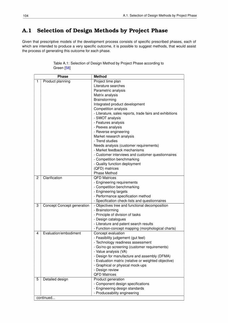
104 A.1. Selection of Design Methods by Project Phase
A.1 Selection of Design Methods by Project Phase
Given that prescriptive models of the development process consists of specific prescribed phases, each ofwhich are intended to produce a very specific outcome, it is possible to suggest methods, that would assistthe process of generating this outcome for each phase.
Table A.1: Selection of Design Method by Project Phase according toGreen [58]
Phase Method1 Product planning Project time plan
Literature searchesParametric analysisMatrix analysisBrainstormingIntegrated product developmentCompetition analysis- Literature, sales reports, trade fairs and exhibitions- SWOT analysis- Features analysis- Peeves analysis- Reverse engineeringMarket research analysis- Trend studiesNeeds analysis (customer requirements)- Market feedback mechanisms- Customer interviews and customer questionnaires- Competition benchmarking- Quality function deployment(QFD) matricesPhase Method
2 Clarification QFD Matrices- Engineering requirements- Competition benchmarking- Engineering targets- Performance specification method- Specification check-lists and questionnaires
3 Concept Concept generation - Objectives tree and functional decomposition- Brainstorming- Principle of division of tasks- Design catalogues- Literature and patent search results- Function-concept mapping (morphological charts)
4 Evaluation/embodiment Concept evaluation- Feasibility judgement (gut feel)- Technology readiness assessment- Go/no-go screening (customer requirements)- Value analysis (VA)- Design for manufacture and assembly (DFMA)- Evaluation matrix (relative or weighted objective)- Graphical or physical mock-ups- Design reviewQFD Matrices
5 Detailed design Product generation- Component design specifications- Engineering design standards- Produceability engineering
continued...
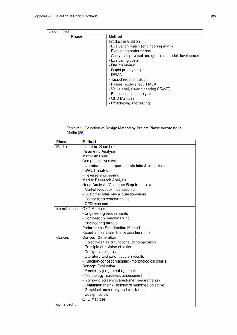
105Appendix A. Selection of Design Methods
...continuedPhase Method
Product evaluation- Evaluation matrix (engineering matrix)- Evaluating performance- Analytical, physical and graphical model development- Evaluating costs- Design review- Rapid prototyping- DFMA- Taguchi/robust design- Failure-mode-effect (FMEA)- Value analysis/engineering (VA/VE)- Functional cost analysis- QFD Matrices- Prototyping and testing
Table A.2: Selection of Design Method by Project Phase according toMaffin [86]
Phase MethodMarket Literature Searches
Parametric AnalysisMatrix AnalysisCompetition Analysis- Literature, sales reports, trade fairs & exhibitions- SWOT analysis- Reverse engineeringMarket Research AnalysisNeed Analysis (Customer Requirements)- Market feedback mechanisms- Customer interview & questionnaires- Competition benchmarking- QFD matrices
Specification QFD Matrices- Engineering requirements- Competition benchmarking- Engineering targetsPerformance Specification MethodSpecification check-lists & questionnaires
Concept Concept Generation- Objectives tree & functional decomposition- Principle of division of tasks- Design catalogues- Literature and patent search results- Function-concept mapping (morphological charts)Concept Evaluation- Feasibility judgement (gut feel)- Technology readiness assessment- Go/no-go screening (customer requirements)- Evaluation matrix (relative or weighted objective)- Graphical and/or physical mock-ups- Design reviewQFD Matrices
continued...
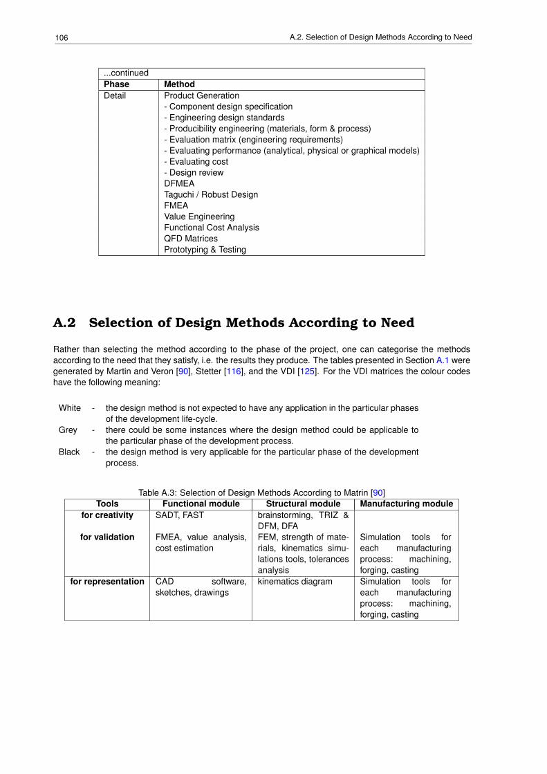
106 A.2. Selection of Design Methods According to Need
...continuedPhase MethodDetail Product Generation
- Component design specification- Engineering design standards- Producibility engineering (materials, form & process)- Evaluation matrix (engineering requirements)- Evaluating performance (analytical, physical or graphical models)- Evaluating cost- Design reviewDFMEATaguchi / Robust DesignFMEAValue EngineeringFunctional Cost AnalysisQFD MatricesPrototyping & Testing
A.2 Selection of Design Methods According to Need
Rather than selecting the method according to the phase of the project, one can categorise the methodsaccording to the need that they satisfy, i.e. the results they produce. The tables presented in Section A.1 weregenerated by Martin and Veron [90], Stetter [116], and the VDI [125]. For the VDI matrices the colour codeshave the following meaning:
White - the design method is not expected to have any application in the particular phasesof the development life-cycle.
Grey - there could be some instances where the design method could be applicable tothe particular phase of the development process.
Black - the design method is very applicable for the particular phase of the developmentprocess.
Table A.3: Selection of Design Methods According to Matrin [90]Tools Functional module Structural module Manufacturing module
for creativity SADT, FAST brainstorming, TRIZ &DFM, DFA
for validation FMEA, value analysis,cost estimation
FEM, strength of mate-rials, kinematics simu-lations tools, tolerancesanalysis
Simulation tools foreach manufacturingprocess: machining,forging, casting
for representation CAD software,sketches, drawings
kinematics diagram Simulation tools foreach manufacturingprocess: machining,forging, casting
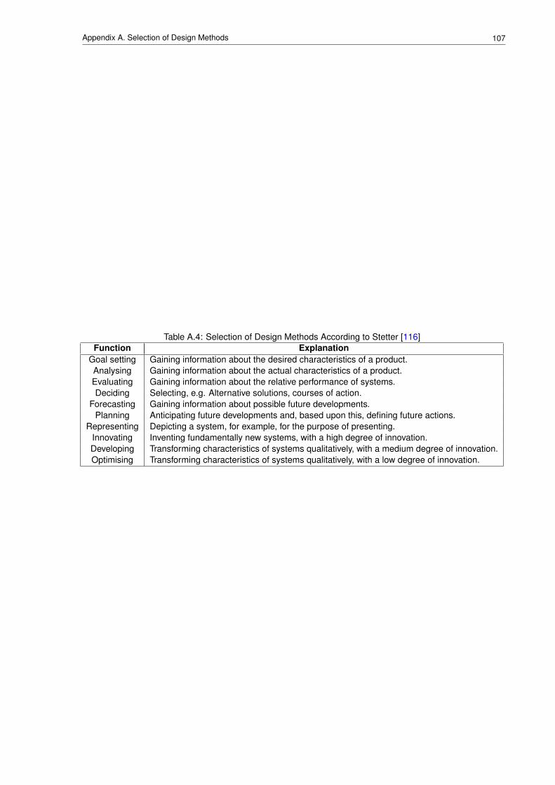
107Appendix A. Selection of Design Methods
Table A.4: Selection of Design Methods According to Stetter [116]Function Explanation
Goal setting Gaining information about the desired characteristics of a product.Analysing Gaining information about the actual characteristics of a product.Evaluating Gaining information about the relative performance of systems.Deciding Selecting, e.g. Alternative solutions, courses of action.
Forecasting Gaining information about possible future developments.Planning Anticipating future developments and, based upon this, defining future actions.
Representing Depicting a system, for example, for the purpose of presenting.Innovating Inventing fundamentally new systems, with a high degree of innovation.Developing Transforming characteristics of systems qualitatively, with a medium degree of innovation.Optimising Transforming characteristics of systems qualitatively, with a low degree of innovation.
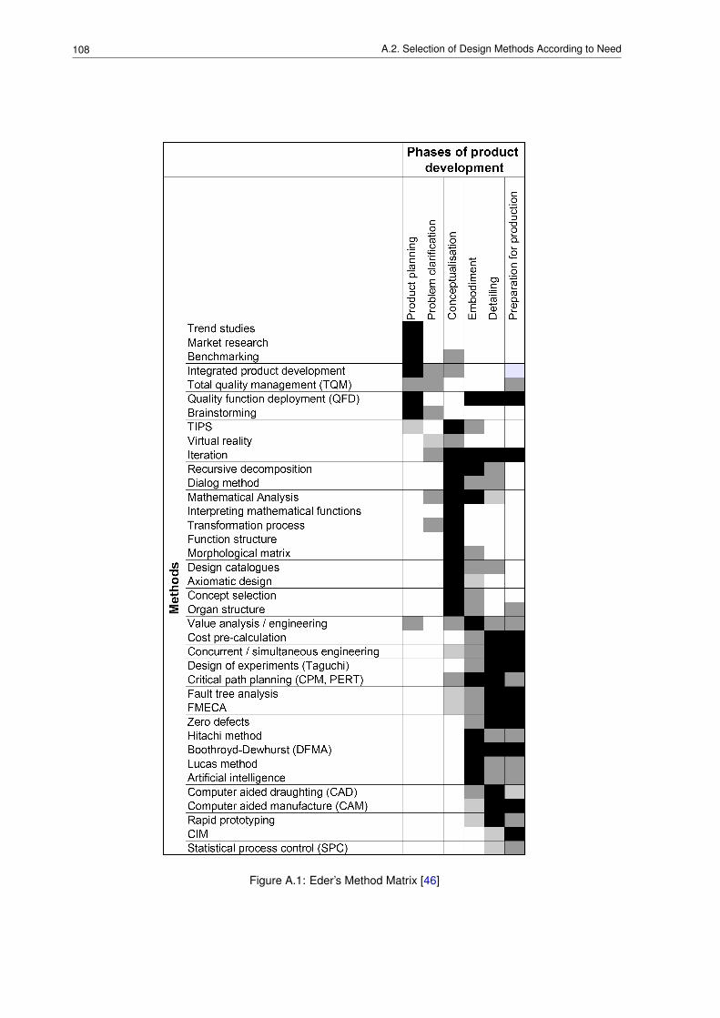
108 A.2. Selection of Design Methods According to Need
Figure A.1: Eder’s Method Matrix [46]
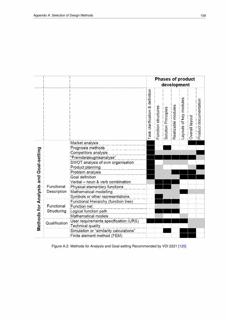
109Appendix A. Selection of Design Methods
Figure A.2: Methods for Analysis and Goal-setting Recommended by VDI 2221 [125]
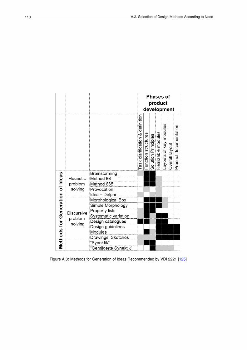
110 A.2. Selection of Design Methods According to Need
Figure A.3: Methods for Generation of Ideas Recommended by VDI 2221 [125]
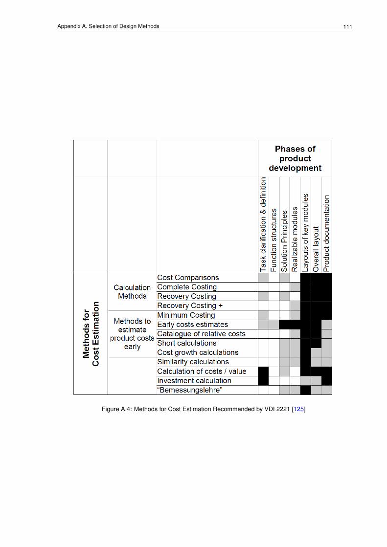
111Appendix A. Selection of Design Methods
Figure A.4: Methods for Cost Estimation Recommended by VDI 2221 [125]
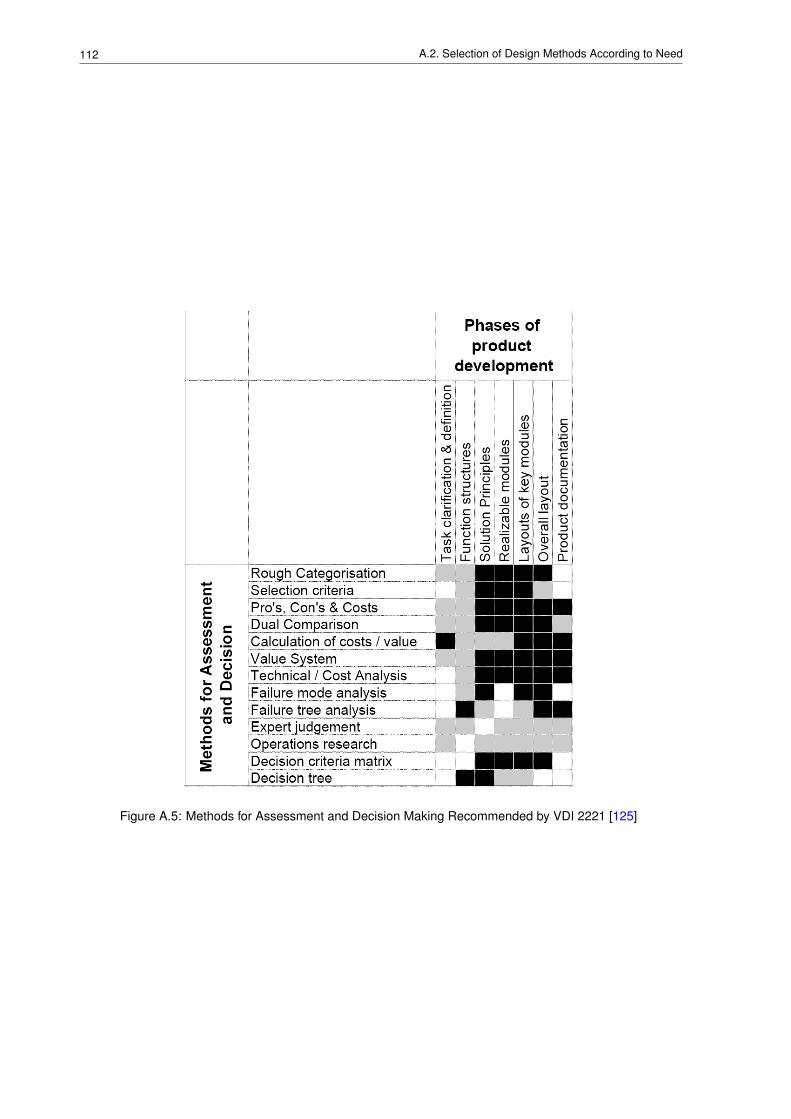
112 A.2. Selection of Design Methods According to Need
Figure A.5: Methods for Assessment and Decision Making Recommended by VDI 2221 [125]
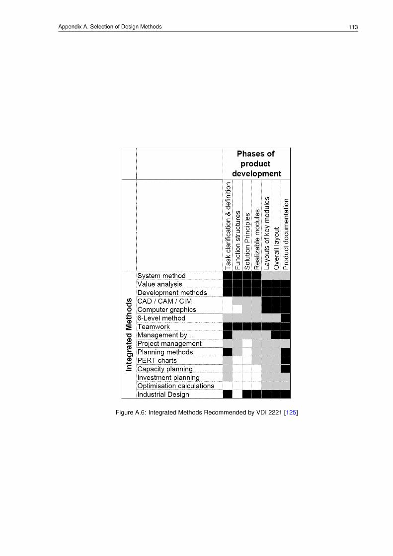
113Appendix A. Selection of Design Methods
Figure A.6: Integrated Methods Recommended by VDI 2221 [125]

114 A.2. Selection of Design Methods According to Need

Appendix B
An Overview of Various PrescriptiveModels of the Development Process
SynopsisIn support of Section 3.1, which discusses prescriptive models of the development process, thefollowing sections provide a brief summary for each of the more well-known models.
115
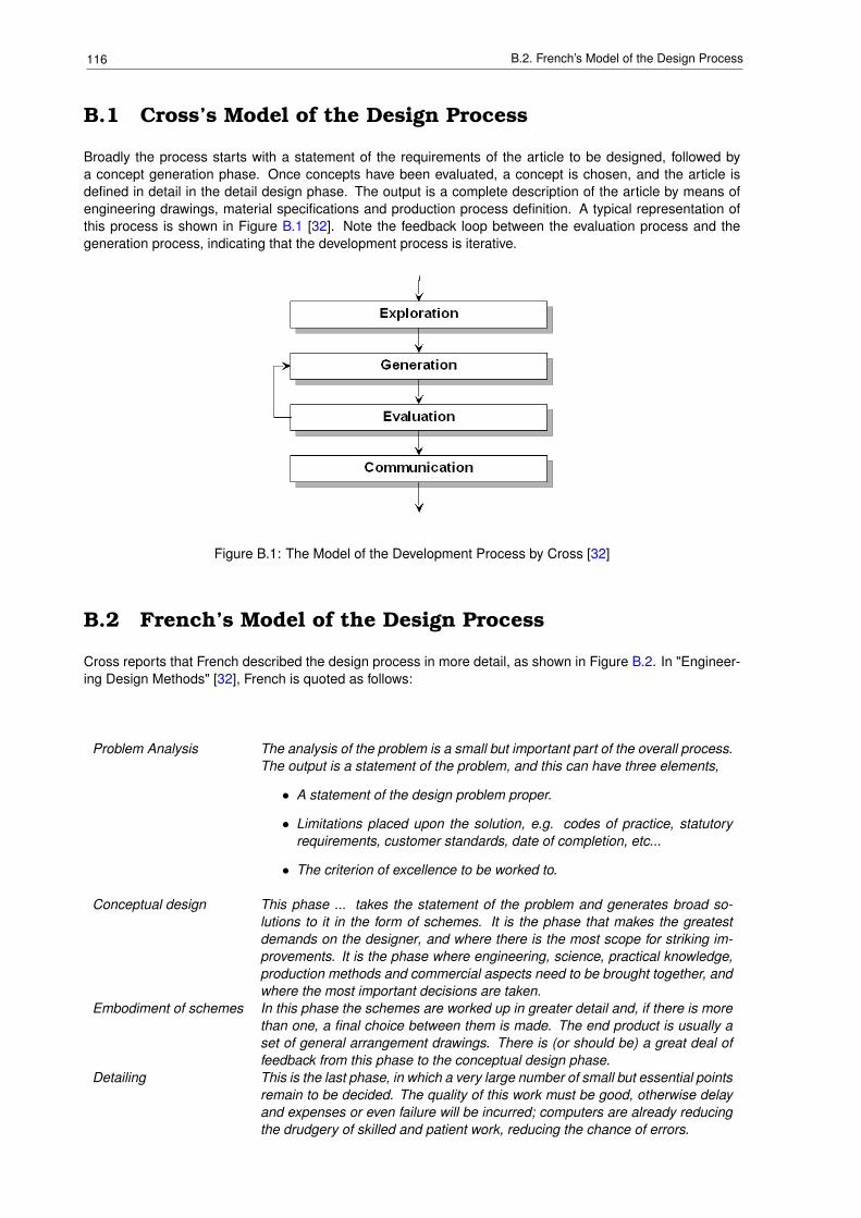
116 B.2. French’s Model of the Design Process
B.1 Cross’s Model of the Design Process
Broadly the process starts with a statement of the requirements of the article to be designed, followed bya concept generation phase. Once concepts have been evaluated, a concept is chosen, and the article isdefined in detail in the detail design phase. The output is a complete description of the article by means ofengineering drawings, material specifications and production process definition. A typical representation ofthis process is shown in Figure B.1 [32]. Note the feedback loop between the evaluation process and thegeneration process, indicating that the development process is iterative.
Figure B.1: The Model of the Development Process by Cross [32]
B.2 French’s Model of the Design Process
Cross reports that French described the design process in more detail, as shown in Figure B.2. In "Engineer-ing Design Methods" [32], French is quoted as follows:
Problem Analysis The analysis of the problem is a small but important part of the overall process.The output is a statement of the problem, and this can have three elements,
• A statement of the design problem proper.
• Limitations placed upon the solution, e.g. codes of practice, statutoryrequirements, customer standards, date of completion, etc...
• The criterion of excellence to be worked to.
Conceptual design This phase ... takes the statement of the problem and generates broad so-lutions to it in the form of schemes. It is the phase that makes the greatestdemands on the designer, and where there is the most scope for striking im-provements. It is the phase where engineering, science, practical knowledge,production methods and commercial aspects need to be brought together, andwhere the most important decisions are taken.
Embodiment of schemes In this phase the schemes are worked up in greater detail and, if there is morethan one, a final choice between them is made. The end product is usually aset of general arrangement drawings. There is (or should be) a great deal offeedback from this phase to the conceptual design phase.
Detailing This is the last phase, in which a very large number of small but essential pointsremain to be decided. The quality of this work must be good, otherwise delayand expenses or even failure will be incurred; computers are already reducingthe drudgery of skilled and patient work, reducing the chance of errors.
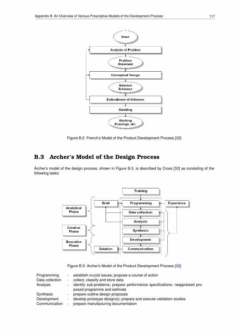
117Appendix B. An Overview of Various Prescriptive Models of the Development Process
Figure B.2: French’s Model of the Product Development Process [32]
B.3 Archer’s Model of the Design Process
Archer’s model of the design process, shown in Figure B.3, is described by Cross [32] as consisting of thefollowing tasks:
Figure B.3: Archer’s Model of the Product Development Process [32]
Programming - establish crucial issues; propose a course of actionData collection - collect, classify and store dataAnalysis - identify sub-problems; prepare performance specifications; reappraised pro-
posed programme and estimateSynthesis - prepare outline design proposalsDevelopment - develop prototype design(s); prepare and execute validation studiesCommunication - prepare manufacturing documentation
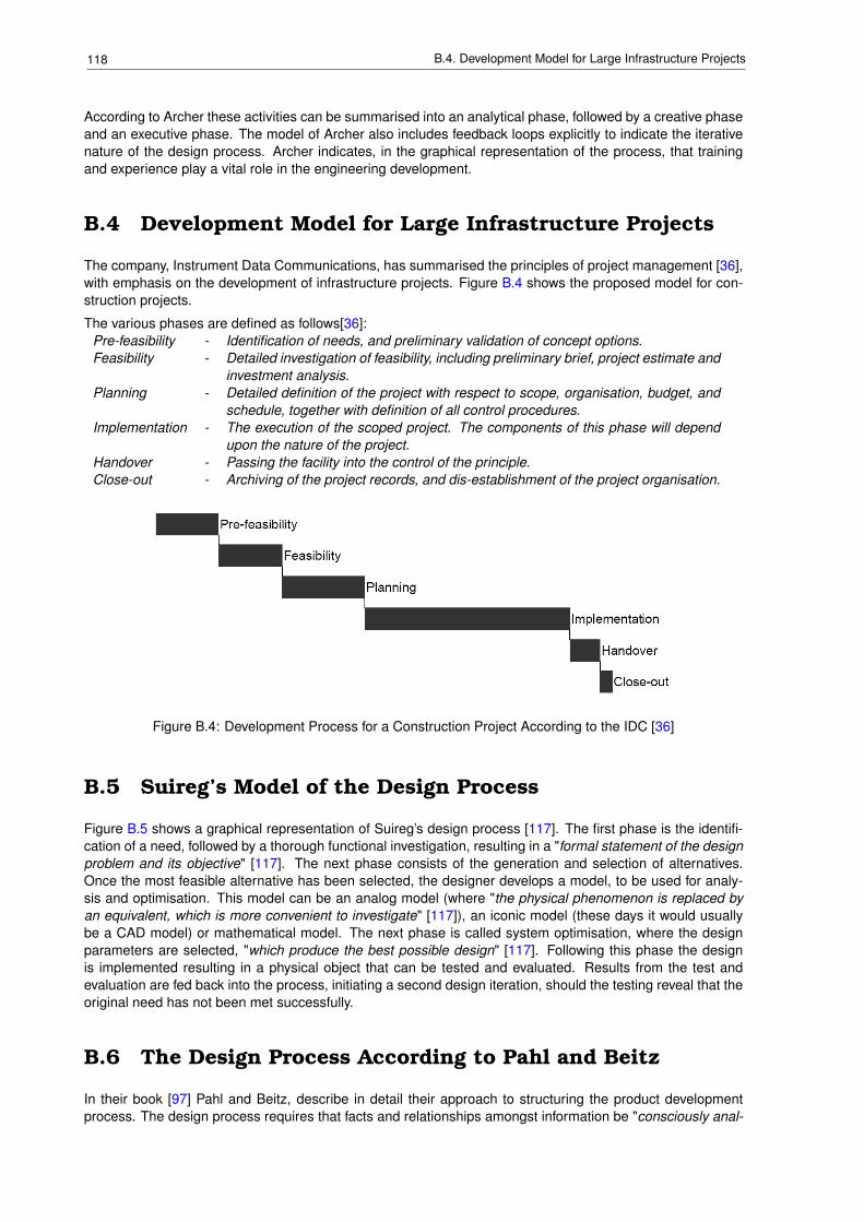
118 B.4. Development Model for Large Infrastructure Projects
According to Archer these activities can be summarised into an analytical phase, followed by a creative phaseand an executive phase. The model of Archer also includes feedback loops explicitly to indicate the iterativenature of the design process. Archer indicates, in the graphical representation of the process, that trainingand experience play a vital role in the engineering development.
B.4 Development Model for Large Infrastructure Projects
The company, Instrument Data Communications, has summarised the principles of project management [36],with emphasis on the development of infrastructure projects. Figure B.4 shows the proposed model for con-struction projects.
The various phases are defined as follows[36]:Pre-feasibility - Identification of needs, and preliminary validation of concept options.Feasibility - Detailed investigation of feasibility, including preliminary brief, project estimate and
investment analysis.Planning - Detailed definition of the project with respect to scope, organisation, budget, and
schedule, together with definition of all control procedures.Implementation - The execution of the scoped project. The components of this phase will depend
upon the nature of the project.Handover - Passing the facility into the control of the principle.Close-out - Archiving of the project records, and dis-establishment of the project organisation.
Figure B.4: Development Process for a Construction Project According to the IDC [36]
B.5 Suireg’s Model of the Design Process
Figure B.5 shows a graphical representation of Suireg’s design process [117]. The first phase is the identifi-cation of a need, followed by a thorough functional investigation, resulting in a "formal statement of the designproblem and its objective" [117]. The next phase consists of the generation and selection of alternatives.Once the most feasible alternative has been selected, the designer develops a model, to be used for analy-sis and optimisation. This model can be an analog model (where "the physical phenomenon is replaced byan equivalent, which is more convenient to investigate" [117]), an iconic model (these days it would usuallybe a CAD model) or mathematical model. The next phase is called system optimisation, where the designparameters are selected, "which produce the best possible design" [117]. Following this phase the designis implemented resulting in a physical object that can be tested and evaluated. Results from the test andevaluation are fed back into the process, initiating a second design iteration, should the testing reveal that theoriginal need has not been met successfully.
B.6 The Design Process According to Pahl and Beitz
In their book [97] Pahl and Beitz, describe in detail their approach to structuring the product developmentprocess. The design process requires that facts and relationships amongst information be "consciously anal-
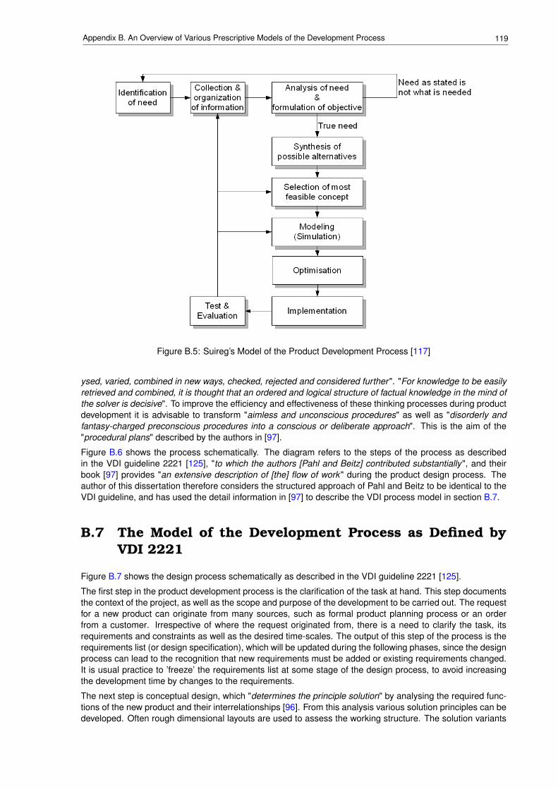
119Appendix B. An Overview of Various Prescriptive Models of the Development Process
Figure B.5: Suireg’s Model of the Product Development Process [117]
ysed, varied, combined in new ways, checked, rejected and considered further ". "For knowledge to be easilyretrieved and combined, it is thought that an ordered and logical structure of factual knowledge in the mind ofthe solver is decisive". To improve the efficiency and effectiveness of these thinking processes during productdevelopment it is advisable to transform "aimless and unconscious procedures" as well as "disorderly andfantasy-charged preconscious procedures into a conscious or deliberate approach". This is the aim of the"procedural plans" described by the authors in [97].
Figure B.6 shows the process schematically. The diagram refers to the steps of the process as describedin the VDI guideline 2221 [125], "to which the authors [Pahl and Beitz] contributed substantially", and theirbook [97] provides "an extensive description of [the] flow of work" during the product design process. Theauthor of this dissertation therefore considers the structured approach of Pahl and Beitz to be identical to theVDI guideline, and has used the detail information in [97] to describe the VDI process model in section B.7.
B.7 The Model of the Development Process as Defined byVDI 2221
Figure B.7 shows the design process schematically as described in the VDI guideline 2221 [125].
The first step in the product development process is the clarification of the task at hand. This step documentsthe context of the project, as well as the scope and purpose of the development to be carried out. The requestfor a new product can originate from many sources, such as formal product planning process or an orderfrom a customer. Irrespective of where the request originated from, there is a need to clarify the task, itsrequirements and constraints as well as the desired time-scales. The output of this step of the process is therequirements list (or design specification), which will be updated during the following phases, since the designprocess can lead to the recognition that new requirements must be added or existing requirements changed.It is usual practice to ’freeze’ the requirements list at some stage of the design process, to avoid increasingthe development time by changes to the requirements.
The next step is conceptual design, which "determines the principle solution" by analysing the required func-tions of the new product and their interrelationships [96]. From this analysis various solution principles can bedeveloped. Often rough dimensional layouts are used to assess the working structure. The solution variants
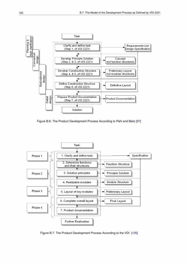
120 B.7. The Model of the Development Process as Defined by VDI 2221
Figure B.6: The Product Development Process According to Pahl and Beitz [97]
Figure B.7: The Product Development Process According to the VDI [125]
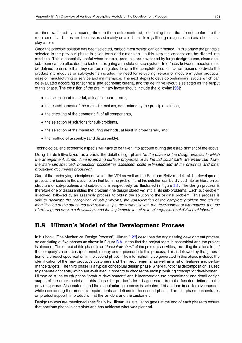
121Appendix B. An Overview of Various Prescriptive Models of the Development Process
are then evaluated by comparing them to the requirements list, eliminating those that do not conform to therequirements. The rest are then assessed mainly on a technical level, although rough cost criteria should alsoplay a role.
Once the principle solution has been selected, embodiment design can commence. In this phase the principleselected in the previous phase is given form and dimension. In this step the concept can be divided intomodules. This is especially useful when complex products are developed by large design teams, since eachsub-team can be allocated the task of designing a module or sub-system. Interfaces between modules mustbe defined to ensure that they can be integrated to form the complete product. Other reasons to divide theproduct into modules or sub-systems includes the need for re-cycling, re-use of module in other products,ease of manufacturing or service and maintenance. The next step is to develop preliminary layouts which canbe evaluated according to technical and economic criteria, and the definitive layout is selected as the outputof this phase. The definition of the preliminary layout should include the following [96]:
• the selection of material, at least in board terms,
• the establishment of the main dimensions, determined by the principle solution,
• the checking of the geometric fit of all components,
• the selection of solutions for sub-problems,
• the selection of the manufacturing methods, at least in broad terms, and
• the method of assembly (and disassembly).
Technological and economic aspects will have to be taken into account during the establishment of the above.
Using the definitive layout as a basis, the detail design phase "is the phase of the design process in whichthe arrangement, forms, dimensions and surface properties of all the individual parts are finally laid down,the materials specified, production possibilities assessed, costs estimated and all the drawings and otherproduction documents produced."
One of the underlying principles on which the VDI as well as the Pahl and Beitz models of the developmentprocess are based is the assumption that both the problem and the solution can be divided into an hierarchicalstructure of sub-problems and sub-solutions respectively, as illustrated in Figure 3.1. The design process istherefore one of disassembling the problem (the design objective) into all its sub-problems. Each sub-problemis solved, followed by an assembly process to obtain the solution to the original problem. This process issaid to "facilitate the recognition of sub-problems, the consideration of the complete problem through theidentification of the structures and relationships, the systemisation, the development of alternatives, the useof existing and proven sub-solutions and the implementation of rational organisational division of labour."
B.8 Ullman’s Model of the Development Process
In his book, "The Mechanical Design Process", Ullman [123] describes the engineering development processas consisting of five phases as shown in Figure B.8. In the first the project team is assembled and the projectis planned. The output of this phase is an "ideal flow chart" of the project’s activities, including the allocation ofthe company’s resources (personnel, money and equipment) to this process. This is followed by the genera-tion of a product specification in the second phase. The information to be generated in this phase includes theidentification of the new product’s customers and their requirements, as well as a list of features and perfor-mance targets. The third phase is a typical conceptual design phase, where functional decomposition is usedto generate concepts, which are evaluated in order to to choose the most promising concept for development.Ullman calls the fourth phase "product development" and it incorporates the embodiment and detail designstages of the other models. In this phase the product’s form is generated from the function defined in theprevious phase. Also material and the manufacturing process is selected. This is done in an iterative manner,while considering the product’s requirements as defined in the second phase. The fifth phase concentrateson product support, in production, at the vendors and the customer.
Design reviews are mentioned specifically by Ullman, as evaluation gates at the end of each phase to ensurethat previous phase is complete and has achieved what was planned.
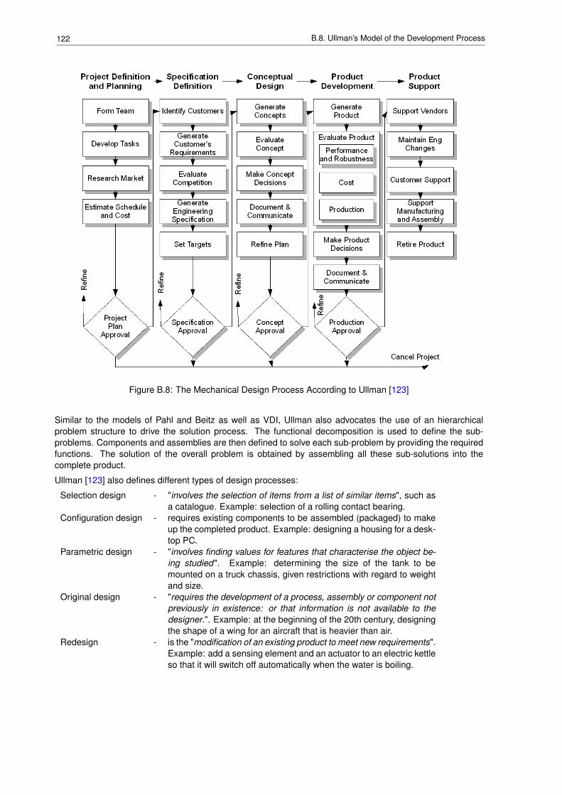
122 B.8. Ullman’s Model of the Development Process
Figure B.8: The Mechanical Design Process According to Ullman [123]
Similar to the models of Pahl and Beitz as well as VDI, Ullman also advocates the use of an hierarchicalproblem structure to drive the solution process. The functional decomposition is used to define the sub-problems. Components and assemblies are then defined to solve each sub-problem by providing the requiredfunctions. The solution of the overall problem is obtained by assembling all these sub-solutions into thecomplete product.
Ullman [123] also defines different types of design processes:
Selection design - "involves the selection of items from a list of similar items", such asa catalogue. Example: selection of a rolling contact bearing.
Configuration design - requires existing components to be assembled (packaged) to makeup the completed product. Example: designing a housing for a desk-top PC.
Parametric design - "involves finding values for features that characterise the object be-ing studied". Example: determining the size of the tank to bemounted on a truck chassis, given restrictions with regard to weightand size.
Original design - "requires the development of a process, assembly or component notpreviously in existence: or that information is not available to thedesigner.". Example: at the beginning of the 20th century, designingthe shape of a wing for an aircraft that is heavier than air.
Redesign - is the "modification of an existing product to meet new requirements".Example: add a sensing element and an actuator to an electric kettleso that it will switch off automatically when the water is boiling.
123Appendix B. An Overview of Various Prescriptive Models of the Development Process
B.9 The Systems Engineering Approach to the DevelopmentProcess
In their book, "Systems Engineering and Analysis", Blanchard and Fabrycky [19] defines systems engineeringas follows:
"An interdisciplinary approach encompassing the entire technical effort to evolve and verifyan integrated and life-cycle balanced set of system, people, product, and process solutions thatsatisfy customer needs. System engineering encompasses
• the technical efforts related to development, manufacturing, verification, deployment, opera-tions, support, disposal of, and user training for, system products and processes;
• the definition and management of the system configuration;
• the translation of the system definition into work breakdown structures; and
• development of information for management decision making."
With the advent of more and more complex products, such as automobiles, large ships for commercial andwarfare purposes, commercial and military aeroplanes to name a few, it was realised that complex systems aremore than the sum of their parts, i.e. local optimisation of the components and sub-systems does not provideoptimised system. Also the effort required to manage the development process increases with increasedproduct complexity, due to the increasing number of interrelationships between the various components of thesystem, and also due to the increased number of people of various disciplines required for the developmentof these complex systems. Blanchard and Fabrycky [19] summarises the focus of system engineering asfollows:
• "A top-down approach that views the system as a whole" providing "the necessary overview and under-standing of how these components effectively fit together ".
• "A life-cycle orientation that addresses all phases to include system design and development, produc-tion and/or construction, distribution, operation, maintenance and support, retirement, phaseout anddisposal".
• "A better more complete effort regarding the initial definition of system requirements, relating theserequirements to specific design criteria and the follow-on analysis effort to ensure the effectiveness ofearly decision making in the design process. The true system requirements need to be well definedand specified, and the traceability of these requirements from the system level downwards needs to bevisible".
• "An interdisciplinary or team approach throughout the system design and development process to en-sure that all design objectives are addressed in an effective and efficient manner ".
The systems engineering model for the development process is shown in Figure B.9. Note that for the pur-poses of this dissertation, we are interested in the process up to the point where the product baseline hasbeen established, i.e. the product is ready to be industrialised for production.
Note that the model indicates an iterative process within each development phase. This feedback mechanismis described in more detail by Blanchard [19] and Fabrycky, and is shown in Figure B.10.
During the concept phase the need is identified, together with the new product’s requirements in terms ofoperations, maintenance and support (including technical performance measures) to fulfil the need. Therequirements are used to generate the functional characteristics of the new product, which are in turn usedto generate a systems specification (type A). This constitutes the functional baseline of the new productand will be used to evaluate the design and prototype during the later stages of this process. In terms ofplanning activities the Systems Engineering Management Plan (SEMP) and the Test and Evaluation MasterPlan (TEMP) are developed. The phase ends with the Conceptual Design Review where "design informationis released and reviewed for compliance with the system requirements" [19].
The preliminary design phase takes the Functional Baseline as defined for the complete system in the conceptphase, and extends it to the sub-system, assembly and component levels of the product by analysing theindividual requirements and allocating the corresponding specifications (type B or C). A number of concepts
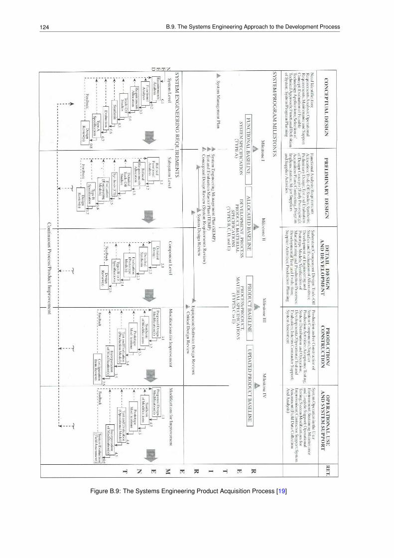
124 B.9. The Systems Engineering Approach to the Development Process
Figure B.9: The Systems Engineering Product Acquisition Process [19]
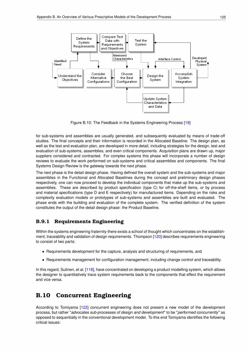
125Appendix B. An Overview of Various Prescriptive Models of the Development Process
Figure B.10: The Feedback in the Systems Engineering Process [19]
for sub-systems and assemblies are usually generated, and subsequently evaluated by means of trade-offstudies. The final concepts and their information is recorded in the Allocated Baseline. The design plan, aswell as the test and evaluation plan, are developed in more detail, including strategies for the design, test andevaluation of sub-systems, assemblies, and even critical components. Acquisition plans are drawn up, majorsuppliers considered and contracted. For complex systems this phase will incorporate a number of designreviews to evaluate the work performed on sub-systems and critical assemblies and components. The finalSystems Design Review is the gateway towards the next phase.
The next phase is the detail design phase. Having defined the overall system and the sub-systems and majorassemblies in the Functional and Allocated Baselines during the concept and preliminary design phasesrespectively, one can now proceed to develop the individual components that make up the sub-systems andassemblies. These are described by product specification (type C) for off-the-shelf items, or by processand material specifications (type D and E respectively) for manufactured items. Depending on the risks andcomplexity evaluation models or prototypes of sub-systems and assemblies are built and evaluated. Thephase ends with the building and evaluation of the complete system. The verified definition of the systemconstitutes the output of the detail design phase: the Product Baseline.
B.9.1 Requirements Engineering
Within the systems engineering fraternity there exists a school of thought which concentrates on the establish-ment, traceability and validation of design requirements. Thompson [120] describes requirements engineeringto consist of two parts:
• Requirements development for the capture, analysis and structuring of requirements, and
• Requirements management for configuration management, including change control and traceability.
In this regard, Sutinen, et al. [118], have concentrated on developing a product modelling system, which allowsthe designer to quantitatively trace system requirements back to the components that effect the requirementand vice versa.
B.10 Concurrent Engineering
According to Tomiyama [122] concurrent engineering does not present a new model of the developmentprocess, but rather "advocates sub-processes of design and development" to be "performed concurrently" asopposed to sequentially in the conventional development model. To this end Tomiyama identifies the followingcritical issues:
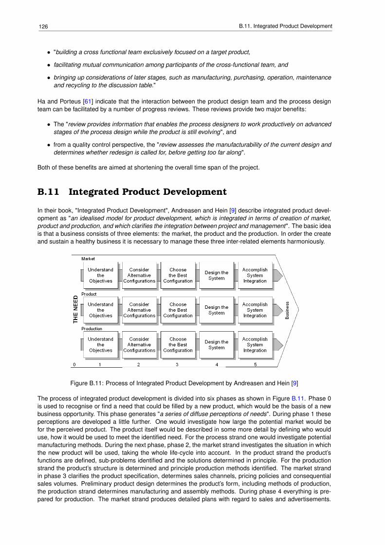
126 B.11. Integrated Product Development
• "building a cross functional team exclusively focused on a target product,
• facilitating mutual communication among participants of the cross-functional team, and
• bringing up considerations of later stages, such as manufacturing, purchasing, operation, maintenanceand recycling to the discussion table."
Ha and Porteus [61] indicate that the interaction between the product design team and the process designteam can be facilitated by a number of progress reviews. These reviews provide two major benefits:
• The "review provides information that enables the process designers to work productively on advancedstages of the process design while the product is still evolving", and
• from a quality control perspective, the "review assesses the manufacturability of the current design anddetermines whether redesign is called for, before getting too far along".
Both of these benefits are aimed at shortening the overall time span of the project.
B.11 Integrated Product Development
In their book, "Integrated Product Development", Andreasen and Hein [9] describe integrated product devel-opment as "an idealised model for product development, which is integrated in terms of creation of market,product and production, and which clarifies the integration between project and management". The basic ideais that a business consists of three elements: the market, the product and the production. In order the createand sustain a healthy business it is necessary to manage these three inter-related elements harmoniously.
Figure B.11: Process of Integrated Product Development by Andreasen and Hein [9]
The process of integrated product development is divided into six phases as shown in Figure B.11. Phase 0is used to recognise or find a need that could be filled by a new product, which would be the basis of a newbusiness opportunity. This phase generates "a series of diffuse perceptions of needs". During phase 1 theseperceptions are developed a little further. One would investigate how large the potential market would befor the perceived product. The product itself would be described in some more detail by defining who woulduse, how it would be used to meet the identified need. For the process strand one would investigate potentialmanufacturing methods. During the next phase, phase 2, the market strand investigates the situation in whichthe new product will be used, taking the whole life-cycle into account. In the product strand the product’sfunctions are defined, sub-problems identified and the solutions determined in principle. For the productionstrand the product’s structure is determined and principle production methods identified. The market strandin phase 3 clarifies the product specification, determines sales channels, pricing policies and consequentialsales volumes. Preliminary product design determines the product’s form, including methods of production,the production strand determines manufacturing and assembly methods. During phase 4 everything is pre-pared for production. The market strand produces detailed plans with regard to sales and advertisements.
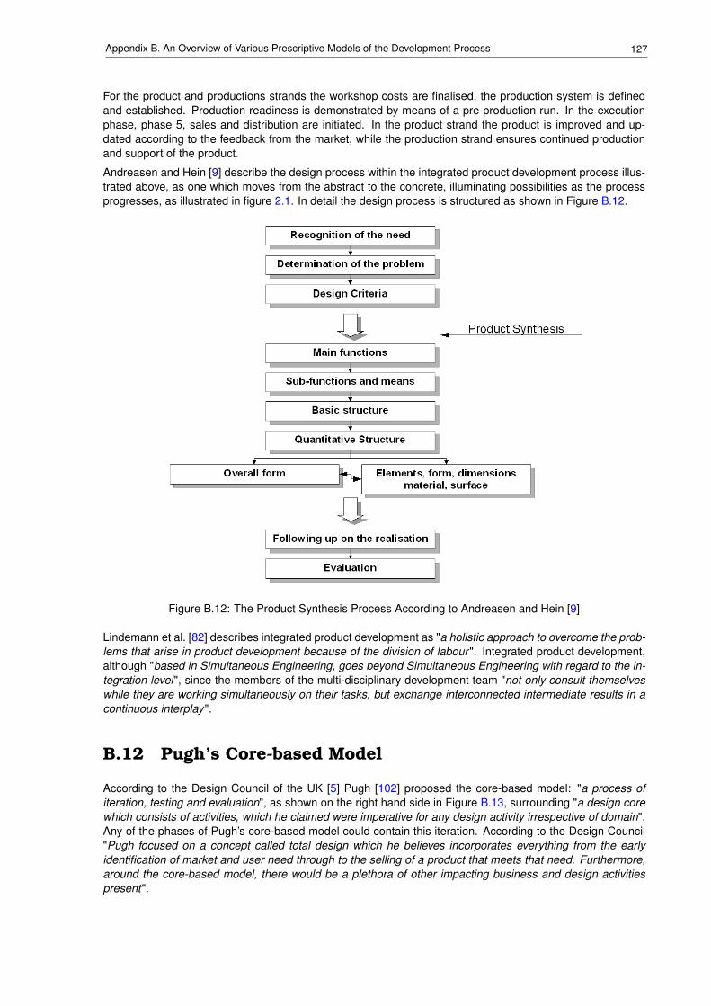
127Appendix B. An Overview of Various Prescriptive Models of the Development Process
For the product and productions strands the workshop costs are finalised, the production system is definedand established. Production readiness is demonstrated by means of a pre-production run. In the executionphase, phase 5, sales and distribution are initiated. In the product strand the product is improved and up-dated according to the feedback from the market, while the production strand ensures continued productionand support of the product.
Andreasen and Hein [9] describe the design process within the integrated product development process illus-trated above, as one which moves from the abstract to the concrete, illuminating possibilities as the processprogresses, as illustrated in figure 2.1. In detail the design process is structured as shown in Figure B.12.
Figure B.12: The Product Synthesis Process According to Andreasen and Hein [9]
Lindemann et al. [82] describes integrated product development as "a holistic approach to overcome the prob-lems that arise in product development because of the division of labour ". Integrated product development,although "based in Simultaneous Engineering, goes beyond Simultaneous Engineering with regard to the in-tegration level", since the members of the multi-disciplinary development team "not only consult themselveswhile they are working simultaneously on their tasks, but exchange interconnected intermediate results in acontinuous interplay".
B.12 Pugh’s Core-based Model
According to the Design Council of the UK [5] Pugh [102] proposed the core-based model: "a process ofiteration, testing and evaluation", as shown on the right hand side in Figure B.13, surrounding "a design corewhich consists of activities, which he claimed were imperative for any design activity irrespective of domain".Any of the phases of Pugh’s core-based model could contain this iteration. According to the Design Council"Pugh focused on a concept called total design which he believes incorporates everything from the earlyidentification of market and user need through to the selling of a product that meets that need. Furthermore,around the core-based model, there would be a plethora of other impacting business and design activitiespresent".
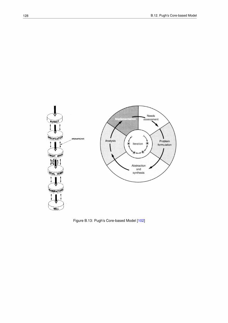
128 B.12. Pugh’s Core-based Model
Figure B.13: Pugh’s Core-based Model [102]

Appendix C
An Overview of Various DescriptiveModels of the Development Process
SynopsisIn support of Section 3.3, which discusses descriptive models of the development process, thefollowing sections provide a brief summary for each of the more well-known models.
129
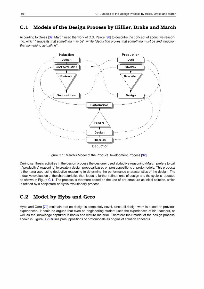
130 C.1. Models of the Design Process by Hillier, Drake and March
C.1 Models of the Design Process by Hillier, Drake and March
According to Cross [32] March used the work of C.S. Peirce [98] to describe the concept of abductive reason-ing, which "suggests that something may be", while "deduction proves that something must be and inductionthat something actually is".
Figure C.1: March’s Model of the Product Development Process [32]
During synthesis activities in the design process the designer used abductive reasoning (March prefers to callit "productive" reasoning) to create a design proposal based on presuppositions or protomodels. This proposalis then analysed using deductive reasoning to determine the performance characteristics of the design. Theinductive evaluation of the characteristics then leads to further refinements of design and the cycle is repeatedas shown in Figure C.1. The process is therefore based on the use of pre-structure as initial solution, whichis refined by a conjecture-analysis evolutionary process.
C.2 Model by Hybs and Gero
Hybs and Gero [70] maintain that no design is completely novel, since all design work is based on previousexperiences. It could be argued that even an engineering student uses the experiences of his teachers, aswell as the knowledge captured in books and lecture material. Therefore their model of the design process,shown in Figure C.2 utilises presuppositions or protomodels as origins of solution concepts.
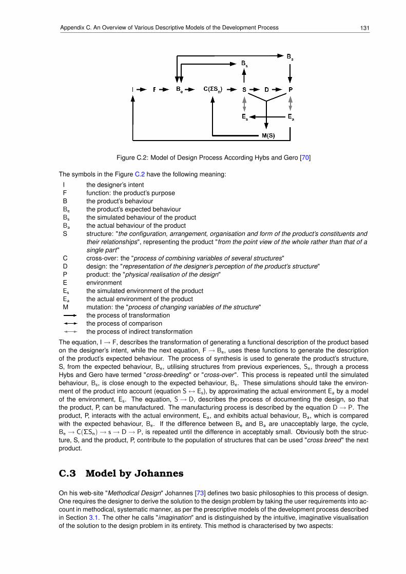
131Appendix C. An Overview of Various Descriptive Models of the Development Process
Figure C.2: Model of Design Process According Hybs and Gero [70]
The symbols in the Figure C.2 have the following meaning:
I the designer’s intentF function: the product’s purposeB the product’s behaviourBe the product’s expected behaviourBs the simulated behaviour of the productBa the actual behaviour of the productS structure: "the configuration, arrangement, organisation and form of the product’s constituents and
their relationships", representing the product "from the point view of the whole rather than that of asingle part"
C cross-over: the "process of combining variables of several structures"D design: the "representation of the designer’s perception of the product’s structure"P product: the "physical realisation of the design"E environmentEs the simulated environment of the productEa the actual environment of the productM mutation: the "process of changing variables of the structure"
the process of transformationthe process of comparisonthe process of indirect transformation
The equation, I→ F, describes the transformation of generating a functional description of the product basedon the designer’s intent, while the next equation, F→ Be, uses these functions to generate the descriptionof the product’s expected behaviour. The process of synthesis is used to generate the product’s structure,S, from the expected behaviour, Be, utilising structures from previous experiences, Sn, through a processHybs and Gero have termed "cross-breeding" or "cross-over ". This process is repeated until the simulatedbehaviour, Bs, is close enough to the expected behaviour, Be. These simulations should take the environ-ment of the product into account (equation S↔ Es), by approximating the actual environment Ea by a modelof the environment, Es. The equation, S→ D, describes the process of documenting the design, so thatthe product, P, can be manufactured. The manufacturing process is described by the equation D→ P. Theproduct, P, interacts with the actual environment, Ea, and exhibits actual behaviour, Ba, which is comparedwith the expected behaviour, Be. If the difference between Be and Ba are unacceptably large, the cycle,Be → C(ΣSn)→ s→ D→ P, is repeated until the difference in acceptably small. Obviously both the struc-ture, S, and the product, P, contribute to the population of structures that can be used "cross breed" the nextproduct.
C.3 Model by Johannes
On his web-site "Methodical Design" Johannes [73] defines two basic philosophies to this process of design.One requires the designer to derive the solution to the design problem by taking the user requirements into ac-count in methodical, systematic manner, as per the prescriptive models of the development process describedin Section 3.1. The other he calls "imagination" and is distinguished by the intuitive, imaginative visualisationof the solution to the design problem in its entirety. This method is characterised by two aspects:
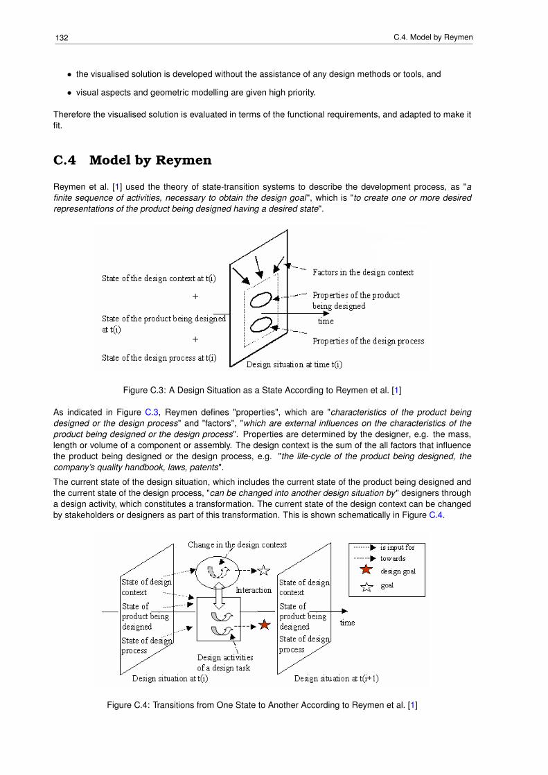
132 C.4. Model by Reymen
• the visualised solution is developed without the assistance of any design methods or tools, and
• visual aspects and geometric modelling are given high priority.
Therefore the visualised solution is evaluated in terms of the functional requirements, and adapted to make itfit.
C.4 Model by Reymen
Reymen et al. [1] used the theory of state-transition systems to describe the development process, as "afinite sequence of activities, necessary to obtain the design goal", which is "to create one or more desiredrepresentations of the product being designed having a desired state".
Figure C.3: A Design Situation as a State According to Reymen et al. [1]
As indicated in Figure C.3, Reymen defines "properties", which are "characteristics of the product beingdesigned or the design process" and "factors", "which are external influences on the characteristics of theproduct being designed or the design process". Properties are determined by the designer, e.g. the mass,length or volume of a component or assembly. The design context is the sum of the all factors that influencethe product being designed or the design process, e.g. "the life-cycle of the product being designed, thecompany’s quality handbook, laws, patents".
The current state of the design situation, which includes the current state of the product being designed andthe current state of the design process, "can be changed into another design situation by" designers througha design activity, which constitutes a transformation. The current state of the design context can be changedby stakeholders or designers as part of this transformation. This is shown schematically in Figure C.4.
Figure C.4: Transitions from One State to Another According to Reymen et al. [1]
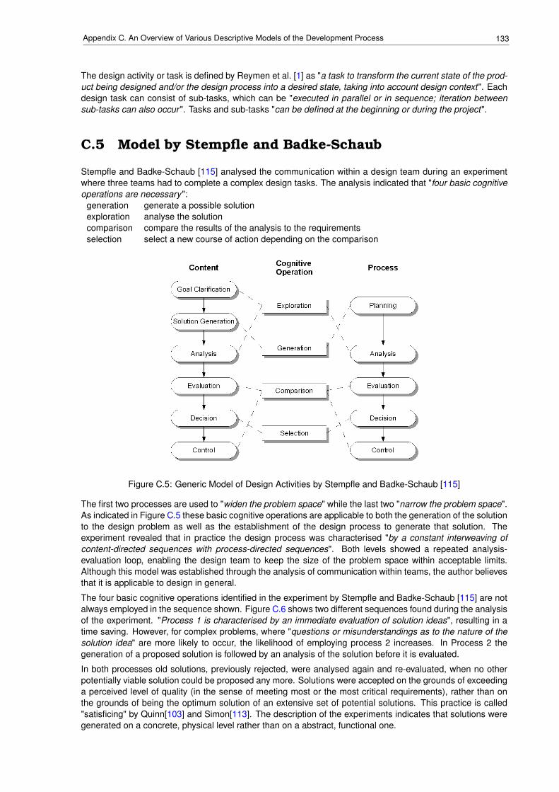
133Appendix C. An Overview of Various Descriptive Models of the Development Process
The design activity or task is defined by Reymen et al. [1] as "a task to transform the current state of the prod-uct being designed and/or the design process into a desired state, taking into account design context". Eachdesign task can consist of sub-tasks, which can be "executed in parallel or in sequence; iteration betweensub-tasks can also occur ". Tasks and sub-tasks "can be defined at the beginning or during the project".
C.5 Model by Stempfle and Badke-Schaub
Stempfle and Badke-Schaub [115] analysed the communication within a design team during an experimentwhere three teams had to complete a complex design tasks. The analysis indicated that "four basic cognitiveoperations are necessary":
generation generate a possible solutionexploration analyse the solutioncomparison compare the results of the analysis to the requirementsselection select a new course of action depending on the comparison
Figure C.5: Generic Model of Design Activities by Stempfle and Badke-Schaub [115]
The first two processes are used to "widen the problem space" while the last two "narrow the problem space".As indicated in Figure C.5 these basic cognitive operations are applicable to both the generation of the solutionto the design problem as well as the establishment of the design process to generate that solution. Theexperiment revealed that in practice the design process was characterised "by a constant interweaving ofcontent-directed sequences with process-directed sequences". Both levels showed a repeated analysis-evaluation loop, enabling the design team to keep the size of the problem space within acceptable limits.Although this model was established through the analysis of communication within teams, the author believesthat it is applicable to design in general.
The four basic cognitive operations identified in the experiment by Stempfle and Badke-Schaub [115] are notalways employed in the sequence shown. Figure C.6 shows two different sequences found during the analysisof the experiment. "Process 1 is characterised by an immediate evaluation of solution ideas", resulting in atime saving. However, for complex problems, where "questions or misunderstandings as to the nature of thesolution idea" are more likely to occur, the likelihood of employing process 2 increases. In Process 2 thegeneration of a proposed solution is followed by an analysis of the solution before it is evaluated.
In both processes old solutions, previously rejected, were analysed again and re-evaluated, when no otherpotentially viable solution could be proposed any more. Solutions were accepted on the grounds of exceedinga perceived level of quality (in the sense of meeting most or the most critical requirements), rather than onthe grounds of being the optimum solution of an extensive set of potential solutions. This practice is called"satisficing" by Quinn[103] and Simon[113]. The description of the experiments indicates that solutions weregenerated on a concrete, physical level rather than on a abstract, functional one.
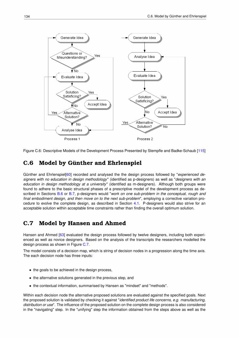
134 C.6. Model by Günther and Ehrlenspiel
Figure C.6: Descriptive Models of the Development Process Presented by Stempfle and Badke-Schaub [115]
C.6 Model by Günther and Ehrlenspiel
Günther and Ehrlenspiel[60] recorded and analysed the the design process followed by "experienced de-signers with no education in design methodology" (identified as p-designers) as well as "designers with aneducation in design methodology at a university" (identified as m-designers). Although both groups werefound to adhere to the basic structural phases of a prescriptive model of the development process as de-scribed in Sections B.6 or B.7, p-designers would "work on one sub-problem in the conceptual, rough andfinal embodiment design, and then move on to the next sub-problem", employing a corrective variation pro-cedure to evolve the complete design, as described in Section 4.1. P-designers would also strive for anacceptable solution within acceptable time constraints rather than finding the overall optimum solution.
C.7 Model by Hansen and Ahmed
Hansen and Ahmed [63] evaluated the design process followed by twelve designers, including both experi-enced as well as novice designers. Based on the analysis of the transcripts the researchers modelled thedesign process as shown in Figure C.7.
The model consists of a decision map, which is string of decision nodes in a progression along the time axis.The each decision node has three inputs:
• the goals to be achieved in the design process,
• the alternative solutions generated in the previous step, and
• the contextual information, summarised by Hansen as "mindset" and "methods".
Within each decision node the alternative proposed solutions are evaluated against the specified goals. Nextthe proposed solution is validated by checking it against "identified product life concerns, e.g. manufacturing,distribution or use". The influence of the proposed solution on the complete design process is also consideredin the "navigating" step. In the "unifying" step the information obtained from the steps above as well as the
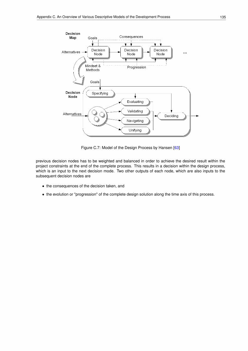
135Appendix C. An Overview of Various Descriptive Models of the Development Process
Figure C.7: Model of the Design Process by Hansen [63]
previous decision nodes has to be weighted and balanced in order to achieve the desired result within theproject constraints at the end of the complete process. This results in a decision within the design process,which is an input to the next decision mode. Two other outputs of each node, which are also inputs to thesubsequent decision nodes are
• the consequences of the decision taken, and
• the evolution or "progression" of the complete design solution along the time axis of this process.

136 C.7. Model by Hansen and Ahmed

Appendix D
Characteristics of Companies and TheirDevelopment Processes
SynopsisChapter 5 a framework of variables that describe the context and the characteristics of a devel-opment project. In the search for this framework the author came across various classificationschemes to describe companies, their products and their business environment. These aredescribed briefly in this appendix.
137
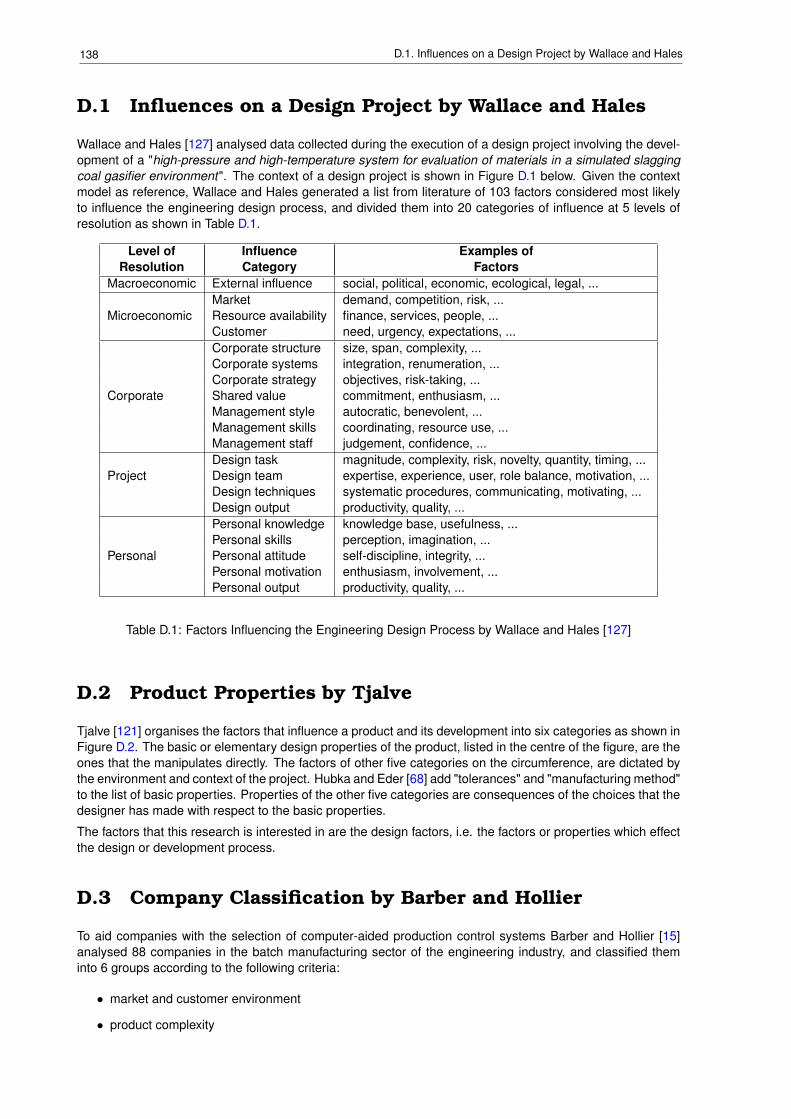
138 D.1. Influences on a Design Project by Wallace and Hales
D.1 Influences on a Design Project by Wallace and Hales
Wallace and Hales [127] analysed data collected during the execution of a design project involving the devel-opment of a "high-pressure and high-temperature system for evaluation of materials in a simulated slaggingcoal gasifier environment". The context of a design project is shown in Figure D.1 below. Given the contextmodel as reference, Wallace and Hales generated a list from literature of 103 factors considered most likelyto influence the engineering design process, and divided them into 20 categories of influence at 5 levels ofresolution as shown in Table D.1.
Level of Influence Examples ofResolution Category Factors
Macroeconomic External influence social, political, economic, ecological, legal, ...Market demand, competition, risk, ...
Microeconomic Resource availability finance, services, people, ...Customer need, urgency, expectations, ...Corporate structure size, span, complexity, ...Corporate systems integration, renumeration, ...Corporate strategy objectives, risk-taking, ...
Corporate Shared value commitment, enthusiasm, ...Management style autocratic, benevolent, ...Management skills coordinating, resource use, ...Management staff judgement, confidence, ...Design task magnitude, complexity, risk, novelty, quantity, timing, ...
Project Design team expertise, experience, user, role balance, motivation, ...Design techniques systematic procedures, communicating, motivating, ...Design output productivity, quality, ...Personal knowledge knowledge base, usefulness, ...Personal skills perception, imagination, ...
Personal Personal attitude self-discipline, integrity, ...Personal motivation enthusiasm, involvement, ...Personal output productivity, quality, ...
Table D.1: Factors Influencing the Engineering Design Process by Wallace and Hales [127]
D.2 Product Properties by Tjalve
Tjalve [121] organises the factors that influence a product and its development into six categories as shown inFigure D.2. The basic or elementary design properties of the product, listed in the centre of the figure, are theones that the manipulates directly. The factors of other five categories on the circumference, are dictated bythe environment and context of the project. Hubka and Eder [68] add "tolerances" and "manufacturing method"to the list of basic properties. Properties of the other five categories are consequences of the choices that thedesigner has made with respect to the basic properties.
The factors that this research is interested in are the design factors, i.e. the factors or properties which effectthe design or development process.
D.3 Company Classification by Barber and Hollier
To aid companies with the selection of computer-aided production control systems Barber and Hollier [15]analysed 88 companies in the batch manufacturing sector of the engineering industry, and classified theminto 6 groups according to the following criteria:
• market and customer environment
• product complexity
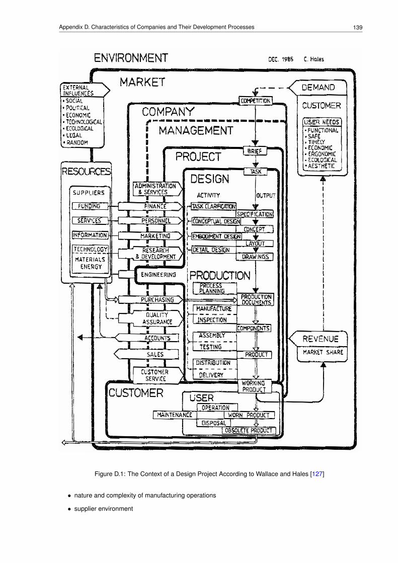
139Appendix D. Characteristics of Companies and Their Development Processes
Figure D.1: The Context of a Design Project According to Wallace and Hales [127]
• nature and complexity of manufacturing operations
• supplier environment
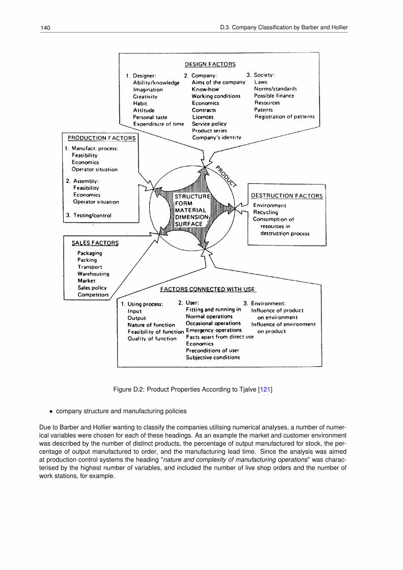
140 D.3. Company Classification by Barber and Hollier
Figure D.2: Product Properties According to Tjalve [121]
• company structure and manufacturing policies
Due to Barber and Hollier wanting to classify the companies utilising numerical analyses, a number of numer-ical variables were chosen for each of these headings. As an example the market and customer environmentwas described by the number of distinct products, the percentage of output manufactured for stock, the per-centage of output manufactured to order, and the manufacturing lead time. Since the analysis was aimedat production control systems the heading "nature and complexity of manufacturing operations" was charac-terised by the highest number of variables, and included the number of live shop orders and the number ofwork stations, for example.
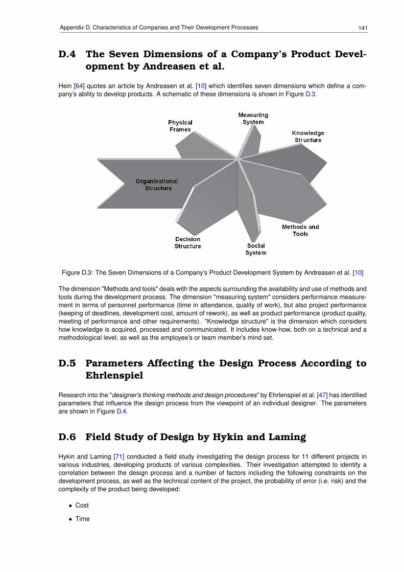
141Appendix D. Characteristics of Companies and Their Development Processes
D.4 The Seven Dimensions of a Company’s Product Devel-opment by Andreasen et al.
Hein [64] quotes an article by Andreasen et al. [10] which identifies seven dimensions which define a com-pany’s ability to develop products. A schematic of these dimensions is shown in Figure D.3.
Figure D.3: The Seven Dimensions of a Company’s Product Development System by Andreasen et al. [10]
The dimension "Methods and tools" deals with the aspects surrounding the availability and use of methods andtools during the development process. The dimension "measuring system" considers performance measure-ment in terms of personnel performance (time in attendance, quality of work), but also project performance(keeping of deadlines, development cost, amount of rework), as well as product performance (product quality,meeting of performance and other requirements). "Knowledge structure" is the dimension which considershow knowledge is acquired, processed and communicated. It includes know-how, both on a technical and amethodological level, as well as the employee’s or team member’s mind set.
D.5 Parameters Affecting the Design Process According toEhrlenspiel
Research into the "designer’s thinking methods and design procedures" by Ehrlenspiel et al. [47] has identifiedparameters that influence the design process from the viewpoint of an individual designer. The parametersare shown in Figure D.4.
D.6 Field Study of Design by Hykin and Laming
Hykin and Laming [71] conducted a field study investigating the design process for 11 different projects invarious industries, developing products of various complexities. Their investigation attempted to identify acorrelation between the design process and a number of factors including the following constraints on thedevelopment process, as well as the technical content of the project, the probability of error (i.e. risk) and thecomplexity of the product being developed:
• Cost
• Time
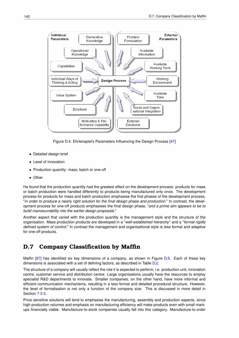
142 D.7. Company Classification by Maffin
Figure D.4: Ehrlenspiel’s Parameters Influencing the Design Process [47]
• Detailed design brief
• Level of innovation
• Production quantity: mass, batch or one-off
• Other
He found that the production quantity had the greatest effect on the development process: products for massor batch production were handled differently to products being manufactured only once. The developmentprocess for products for mass and batch production emphasise the first phases of the development process,"in order to produce a nearly right solution for the final design phase and production." In contrast, the devel-opment process for one-off products emphasises the final design phase, "and a prime aim appears to be tobuild manoeuvrability into the earlier design proposals."
Another aspect that varied with the production quantity is the management style and the structure of theorganisation. Mass production products are developed in a "well-established hierarchy" and a "formal rigidlydefined system of control." In contrast the management and organisational style is less formal and adaptivefor one-off products.
D.7 Company Classification by Maffin
Maffin [87] has identified six key dimensions of a company, as shown in Figure D.5. Each of these keydimensions is associated with a set of defining factors, as described in Table D.2.
The structure of a company will usually reflect the role it is expected to perform, i.e. production unit, innovationcentre, customer service and distribution centre. Large organisations usually have the resources to employspecialist R&D departments to innovate. Smaller companies, on the other hand, have more informal andefficient communication mechanisms, resulting in a less formal and detailed procedural structure. However,the level of formalisation is not only a function of the company size. This is discussed in more detail inSection 7.3.3.
Price sensitive solutions will tend to emphasise the manufacturing, assembly and production aspects, sincehigh production volumes and emphasis on manufacturing efficiency will make products even with small mark-ups financially viable. Manufacture-to-stock companies usually fall into this category. Manufacture-to-order
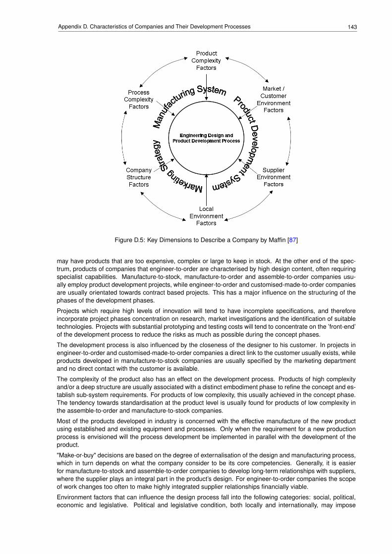
143Appendix D. Characteristics of Companies and Their Development Processes
Figure D.5: Key Dimensions to Describe a Company by Maffin [87]
may have products that are too expensive, complex or large to keep in stock. At the other end of the spec-trum, products of companies that engineer-to-order are characterised by high design content, often requiringspecialist capabilities. Manufacture-to-stock, manufacture-to-order and assemble-to-order companies usu-ally employ product development projects, while engineer-to-order and customised-made-to-order companiesare usually orientated towards contract based projects. This has a major influence on the structuring of thephases of the development phases.
Projects which require high levels of innovation will tend to have incomplete specifications, and thereforeincorporate project phases concentration on research, market investigations and the identification of suitabletechnologies. Projects with substantial prototyping and testing costs will tend to concentrate on the ’front-end’of the development process to reduce the risks as much as possible during the concept phases.
The development process is also influenced by the closeness of the designer to his customer. In projects inengineer-to-order and customised-made-to-order companies a direct link to the customer usually exists, whileproducts developed in manufacture-to-stock companies are usually specified by the marketing departmentand no direct contact with the customer is available.
The complexity of the product also has an effect on the development process. Products of high complexityand/or a deep structure are usually associated with a distinct embodiment phase to refine the concept and es-tablish sub-system requirements. For products of low complexity, this usually achieved in the concept phase.The tendency towards standardisation at the product level is usually found for products of low complexity inthe assemble-to-order and manufacture-to-stock companies.
Most of the products developed in industry is concerned with the effective manufacture of the new productusing established and existing equipment and processes. Only when the requirement for a new productionprocess is envisioned will the process development be implemented in parallel with the development of theproduct.
"Make-or-buy" decisions are based on the degree of externalisation of the design and manufacturing process,which in turn depends on what the company consider to be its core competencies. Generally, it is easierfor manufacture-to-stock and assemble-to-order companies to develop long-term relationships with suppliers,where the supplier plays an integral part in the product’s design. For engineer-to-order companies the scopeof work changes too often to make highly integrated supplier relationships financially viable.
Environment factors that can influence the design process fall into the following categories: social, political,economic and legislative. Political and legislative condition, both locally and internationally, may impose

144 D.7. Company Classification by Maffin
Dimension FactorsCompany Structure Size, Independence, CentralisationProcess Complexity, Flexibility, Constraints, Volume, Internal span of processSupplier Rationalisation, Degree of control, Collaboration, LocalityMarket Type, Size and share, Complexity, Infrastructure, Exports, Competi-
tors, Competitive criteriaProduct Type, Variety, Complexity, Structure, Status, Innovation rate, Design
capabilityEnvironment Labour market, Skills, Training, Support infrastructure, Financing
Table D.2: Defining Factors for Key Dimensions [87]
additional requirements on the design process and/or the product. The local environment may influence"make-or-buy" decisions when specific technologies or capabilities may not locally available.
References
[1]
[2] The Compact Oxford Dictionary. Retrieved Jun2 2008.
[3] Bae systems, land systems omc, website. internet: http://www.baesystemsomc.co.za/, September2007.
[4] BAE Systems, Website. internet: http://www.baesystems.com/, September 2007.
[5] Desk Research Report: Eleven Lessons: managing design in eleven global companies. Technicalreport, Design Council, United Kingdom, November 2007.
[6] Indutech, Website. www.indutech.co.za, 2008.
[7] C. Alexander. A City Is Not a Tree. Design, 206:46–55, 1966.
[8] M. M. Andreasen. Design Methodology. Journal of Engineering Design, 2(4):321–335, 1991.
[9] M. M. Andreasen and L. Hein. Integrated Product Development. IFS Publications Ltd., Springer Verlag,London, 1987.
[10] M. M. Andreasen, L. Hein, L. Kirkgard, and K. Sant. Product Development - Fundamentals of Innova-tion. 1989. via [64].
[11] M. M. Andreasen and N. H. Mortensen. Nature of Design Features, The. In 7. Symposium ’Fertigungs-gerechtes Konstruieren’, 1996.
[12] L. B. Archer. Systematic Method For Designers. 1984. via [32].
[13] M. Asimow. Introduction to Design. 1962.
[14] P. Badke-Schaub. Strategies of Experts in Engineering Design: Between Innovation and Routine Be-haviour. Journal of Design Research, 2, 2004.
[15] K. D. Barber and R. H. Hollier. Use of Numerical Analysis to Classify Companies According to Produc-tion Control Complexity, The. International Journal of Production Research, 24(1):203 – 222, 1986.
[16] P. Barkan. Benefits and Limitations of Structured Methodologies. In Management of Design: Engineer-ing and Management Perspectives, pages 163–178. Kluwer Academic Publishers, 1994.
[17] W. Beitz. Design Science - the Need For a Scientific Basis For Engineering Design Methodology.Journal of Engineering Design, (2), 1994.
[18] C. Bichlmaier. Methoden Zur Flexiblen Gestaltungvon Integrierten Entwicklungsprozessen. PhD thesis,Technische Univrsität München, 1999.
[19] B. S. Blanchard and W. J. Fabrycky. Systems Engineering and Analysis. Prentice Hall, 3rd edition,1998.
[20] L.T.M. Blessing. A process-based approach to computer-supported engineering design. May 1994.
[21] Lesley Brown, editor. Cassell Concise Dictionary, The. Nigel Wilcockson, 1962.
[22] S. L. Brown and Eisenhardt. K. M. Product Development: Past Research, Present Findings and FutureDirections. Academy of Management Review, 20(2):343–378, 1985.
145
[23] A. Bruseberg and D. McDonagh Philp. User-Centred Design Research Methods: The Designer’s Per-spective. In Childs PRN and Brodhurst E, editors, Integrating Design Education Beyond 2000 Confer-ence, pages 179–184. University of Sussex, September 2000.
[24] S. Butdee, C. Noomtong, F. Vignat, and G. Thomann. Methodology of Knowledge Library Manage-ment for Concurrent Cooperative Design. In Proceedings of the 24 th International ManufacturingConference, IMC 24, pages 711–718. Waterford Institute of Technology, Waterford, Ireland, 2007.
[25] M. Cantamessa. Design Best Practices At Work: an Emperical Research Upon the Effectiveness ofDesgin Support Tools. In Proceedings of the ICED 97, Tampere, pages 541–546, 1997.
[26] D. Cavallucci. Intuitive Design Method (IDM), a New Approach On Design Methods Integration. InProceedings of ICAD2000 First International Conference On Axiomatic Design, 2000.
[27] C.M. Christensen. The Innovators Dilemma: when new technologies cause great firms to fail. 1997.via [119].
[28] H. Christiaans, K. Dorst, and N. Cross. Levels of Competence in Product Designing. In Proceedings ofICED 93, pages 368–376. Zuerich: Edition Heurista, August 17-19 1993.
[29] P.J. Clarkson and C.M. Eckert. Design process improvement - a review of current practice. 2005. via [5].
[30] R. G. Cooper. New Product Process: An Empirical Based Classification Scheme. R & D Management,13:1–13, 1983.
[31] N. Cross. Science and Design Methodology: A Review. Research in Engineering Design, 5:63–69,1993.
[32] N. Cross. Engineering Design Methods, Strategies For Product Design. John Wiley and Sons, 2ndedition, 1994.
[33] N. Cross and N. Roozenburg. Modelling the Design Process in Engineering and in Architechture.Journal of Engineering Design, 3(4):325–337, 1992.
[34] S. J. Culley. Final Report. In Future Issues For Design Research (FIDR) Workshop, 1999.
[35] W. Dankwort, J. Ovtcharova, and R. Weidlich. A Concept of Engineering Objects For CollaborativeVirtual Engineering: Automotive Case Study. In ProStep Conference, 2003.
[36] Instrument Data Communications. Principles of Project Management. www.idc-online.com/technicalreferences, 2000.
[37] C. S. De Araujo. An Investigation of the Use of Design Methods. In Proceedings of the 2ND INTERNA-TIONAL CONGRESS OF INDUSTRIAL ENGINEERING, 1996.
[38] C. S. De Araujo. Acquisition of Product Development Tools in Industry: a Theoretical Contribution. PhDthesis, Technical University of Denmark, 2000.
[39] University of Stellenbosch Department of Industrial Engineering. Enterprise Engineering Handbook.
[40] O. Diederich. Methodik Und Praxis - Erfahrungen in Einem Mittelstaendischen Unternehmen. VDIBerichte, 953:237–250, 1992.
[41] K. Dooley, A. Subra, and J. Anderson. Best Practices in New Product Development: Adoption Rates,Patterns and Impact. Journal of Operations Management, 2000.
[42] J. Drake. Primary Generator and the Design Process, The. Chichester, Wiley, 1982.
[43] N. Du Preez, A. Basson, D. Lutters, and H. Nieberding. Roadmapping methodology for product devel-opment. In Proceedings of PICMET ’08, July 2008.
[44] N. Du Preez and B.R. Katz. Case study: The implementation of a radical innovation project. In Pro-ceedings of the International Conference on Competitive Manufacturing, 2007.
[45] A. Dumas and A. Whitfield. Why Design Is Difficult to Manage: a Survey of Attitudes and Practices inBritish Industry. European Management Journal, 7(1):50–56, 1989.
146
[46] W. E. Eder. Design Modelling - A Design Science Approach (and Why Does Industry Ignore It?). Journalof Engineering Design, 9(4):355–371, 1998.
[47] K. Ehrlenspiel and N. Dylla. Experimental Investigation of Designers’ Thinking Methods and DesignProcedures. Journal of Engineering Design, 4(3):201 – 212, 1993.
[48] Ernst and Young. International Quality Study. Technical report, 1992. via [41].
[49] N. F. O. Evbuomwan, S. Sivaloganathan, and A. Jebb. A Survey of Design Philosophies, Models,Methods and Systems. Porceedings of the Institution of Mechanical Engineers, pages 301–320, 1996.
[50] S. Finger and J. R. Dixon. A Review of Research in Mechanical Engineering Design. Part 1: Descriptive,Prescriptive and Computer-Based Models of Design Processes. Research in Engineering Design,1:51–67, 1989.
[51] H. J. Franke. Konstruktionsmethodik Und Konstruktionspraxis - Eine Kritische Betrachtung. In Proceed-ings of the ICED85, Hamburg, 1985. via [8].
[52] M. J. French. Engineering Design - The Conceptual Stage. Heinemann, 1971.
[53] R. B. Frost. A Suggested Taxonomy For Engineering Design Problems. Journal of Engineering Design,5(4):399–410, 1994.
[54] R. B. Frost. Why Does Industry Ignore Design Science? Journal of Engineering Design, 10(4):301–304,1999.
[55] A. J. Fulcher and P. Hills. Towards a Strategic Framework For Design Research. Journal of EngineeringDesign, 7(2):183–193, 1996.
[56] H. Gill. Adoption of Design Science By Industry - Why So Slow. Journal of Engineering Design,1(3):289–295, 1990.
[57] R. P. Gouvinhas and J. Corbett. A Discussion On Why Design Methods Have Not Been Widely UsedWithin Industry. In Proceedings of ICED99, pages 1167 – 1170, August 1999.
[58] L. N. Green and E. Bonollo. Development of a Suite of Design Methods Appropriate For TeachingProduct Design, The. Global J. of Engng. Educ., 6(1):45–51, 2002.
[59] J. Günther. Individuelle Einflüsse Auf Den Konstruktionsprozeß. PhD thesis, Technische UniversitätMünchen, 1998.
[60] J. Günther and K Ehrlenspiel. Comparing designers from practice and designers with systematic designeducation. Design Studies, 20:439 – 451, 1999.
[61] A. Y. Ha and E. L. Porteus. Optimal Timing of Reviews in Concurrent Design For Manufacturability.Management Science, 41(9):1431 – 1447, September 1995.
[62] C. Hales. Analysis of the Engineering Design Process in an Industrial Context. PhD thesis, Universityof Cambridge, 1987.
[63] C.T. Hansen and S. Ahmed. An Analysis of Design Decision-making in Industrial Practice. In Interna-tional Design Conference - Design 2002, May 14 - 17 2002.
[64] L. Hein. Design Methodology in Practice. Journal of Engineering Design, 5(2):165–181, 1994.
[65] W. Hillier, J. Musgrave, and P. O’Sullivan. Knowledge and Design. Chichester, Wiley, 1984.
[66] I. Horváth and J. S. M. Vergeest. Engineering Design Research: Anno 2000. In International DesignConference - Design 2000, 2000.
[67] D. Hubbard. The Failure of Risk Management: Why It’s Broken and How to Fix It. John Wiley & Sons,2009.
[68] V. Hubka and E. E. Eder. Theory of Technical Systems - A Total Concept Theory For EngineeringDesign. Springer-Verlag, Berlin Heidelberg, 1988. via [129].
147
[69] V. Hubka and W. E. Eder. Einführung in Die Konstruktionswissenschaft. Übersicht, Modell, Ableitungen.Springer, Berlin, 1992. via [59].
[70] I. Hybs and J.S. Gero. An Evolutionary Process Model of Design. Design Studies, 13(3):273 – 290,July 1992.
[71] D. H. W. Hykin and L. C. Laming. Design Case Histories: Report of a Field Study of Design in the UnitedKingdom Engineering Industry. Porceedings of the Institution of Mechanical Engineers, 189(23):203–211, 1975.
[72] International Organization for Standardization. ISO31000 Risk Management - Principles and Guidelineson Implementation, 2009.
[73] R. Johannes. Methodisches Entwerfen. internet: http://miless.uni-essen.de/servlets/DerivateServlet/Derivate-10361/umodell.htm, September 2003.
[74] D. A. Jones, D. M. York, J. F. Nallon, and J. Simpson. Factors Influencing Requirement ManagementToolset Selection. In Proceedings of the Fifth Annual Symposium of the National Council On SystemsEngineering, volume 2, July 1995.
[75] J. C. Jones and D. G. Thornley, editors. Proceedings of the Conference On Design Methods. Oxford,Pergamon, 1963.
[76] N. P. Juster. Design Process and Design Methodologies, The. Technical report, University of Leeds,May 1985. in [50].
[77] T.A. Kappel. Perspectives on Roadmaps: How Organisations Talk about the Future. Journal of ProdInnovation Management, 18:39–50, 2001.
[78] C. T. Koeller. Innovation, Market Structure and Firm Size: a Simultaneous Equations Model. Managerialand Decision Economics, 16:259–269, 1995.
[79] R. Kostoff and R. Schaller. Science and Technology Roadmaps. IEEE Transactions on EngineeringManagement, 48(2), May 2001.
[80] F. L. Krause. Virtual Product Creation 2013 - Objectives For the Enhancement of Virtual ProductCreation. Presentation, September 2003.
[81] J. Legardeur, J. F. Boujut, and H. Tiger. Innovating in a Routine Design Process - Empirical Study ofan Industrial Situation. In IDMME 2000, Montreal, May 16-19 2000.
[82] U. Lindemann and J. Wulf. Action Orientation in Design Methodology. In Proceedings of ICED01,August 21-23 2001.
[83] S.C.Y Lu and N. Jing. A socio-technical negotiation approach for collaborative design in softwareengineering. Int. J. Collaborative Engineering, 1(1/2):185–209, 2009.
[84] D. Lutters. MANUFACTURING INTEGRATION BASED ON INFORMATION MANAGEMENT. PhDthesis, University of Twente, May 2001.
[85] D. Lutters, M. Johnson, M.E. Toxopeus, and N.D. Du Preez. Introducing the roadmap concept toinexperienced users: a case study. In International Conference on Competitive Manufacturing, 2007.
[86] D. J. B. Maffin. Engineering Design Models: Context, Theory and Practice. Journal of EngineeringDesign, 9(4):315–327, 1998.
[87] D. J. B. Maffin, N. Alderman, P. Braiden, B. Hills, and A. Thwaites. Company Classification: A NewPerspective On Modelling the Engineering Design and Product Development Process. Journal of Engi-neering Design, 6(4):275–289, 1995.
[88] L. J. March. Logic of Design, The. 1984. via [32].
[89] Lockheed Martin. Skunk works. website: http://www.lockheedmartin.com/cgi-bin/pfv.pl, September2007.
148
[90] P. Martin and P. Veron. Training Experience On Multi-Site Collaborative Product Design. 2003. notcertain of the date.
[91] C. Marxt and F. Hacklin. Design, Product Development, Innovation: All the Same in the End? A ShortDiscussion On Terminology. International Design Conference - Design 2004, May 18-21 2004.
[92] T. W. Maver. Appraisal in the Building Design Process, pages 195–202. Cambridge, MA, MIT Press,1970.
[93] M. D. McNeese, B. S. Zaff, C. E. Brown, M. Citera, and A. R. Wellens. The role of a group-centeredapproach in the development of computer-supported collaborative design technologies. In Proceedingsof the 36th Annual Meeting of the Human Factors Society, pages 867–871, Santa Monica, CA, 1992.Human Factors Society.
[94] K.W. Ng. A critical analysis of current engineering design methodologies from a decision makingprespective. In Intelligent Production Machines and Systems, I*PROMS 2006 note=website: confer-ence.iproms.org, retrieved July 2008. I*PROMS, 2006.
[95] M. Nordlund, D. Tate, and N. P. Suh. Growth of Axiomatic Design Through Industrial Practice. In 3rdCIRP Workshop On Design and the Implementation of Intelligent Manufacturing Systems, June 1996.
[96] G. Pahl. Vorgehen Beim Entwerfen. In Proceedings of the International Conference On Engineering,ICED ’83, Copenhagen, volume 1, pages 209–219, 1983.
[97] G. Pahl and W. Beitz. Engineering Design - A Systematic Approach. 1988.
[98] C.S. Peirce. The Collected Papers of Charles Sanders Peirce. Cambridge MA: Harvard UniversityPress, 1931 - 1958.
[99] R. Phaal, C.J.P. Farrukh, and D.R. Probert. Technology roadmapping - a planning framework for evolu-tion and revolution. Technological Forecasting and Social Change, 71(1):5–26, January 2004.
[100] D.T. Pham, S. Dimov, and K.W. Ng. A framework for a novel descriptive product design methodology.In Innovative Production Machines and Systems, I*PROMS 2008. I*PROMS, 2008.
[101] S. Pugh. Design Activity Models: Worldwide Emergence and Convergence. Design Studies, 7(3):167–173, July 1986.
[102] S. Pugh. Total Design: Integrated Methods For Successful Product Engineering. Addison-WesleyPublishing Company, 1991.
[103] J.B. Quinn. Strategies for change: Logical incrementalism. R.D. Irwin, Homewood, Illinois, 1980.via [94].
[104] D. F. Radcliff and P. Harrison. Transforming Design Practice in a Small Manufacturing Enterprise. InProceedings of the ASME Conference 1994, Design Theory and Methodology, DTM-’94, pages 91–98.ASME, 1994.
[105] R. Rohatynski. Diagnosing the Gap Between Methodology of Engineering Design and Industrial Prac-tice. In Proceedings of the INTERNATIONAL CONFERENCE ON ENGINEERING DESIGN ICED 01GLASGOW, August 2001.
[106] R. Rothwell and W. Zegveld. Innovation and the Small and Medium Sized Firm. Francis Pinter, 1982.via [107].
[107] R. Roy and S. Potter. Managing Design Projects in Small and Medium-Sized Firms. TechnologyAnalysis and Strategic Management, 2(3):321–336, 1990.
[108] G. Rzevski. On the Design of a Design Methodology. Design: Science: Method, pages 6 – 17, 1981.
[109] E. Schnelle and R. Pfeuffer. Vorteile Und Grenzen der Konstruktionsmethodik Bei der Entwicklung vonProdukten der Medizientechnik. Konstruktion, 41:395–402, 1989.
[110] A. Schulz, D. Clausing, H. Negele, and E. Fricke. Shifting the View in Systems Development - Technol-ogy Development At the Fuzzy Front End As a Key to Success. In Proceedings of 1999 ASME DETC,11th International Conference On Design Theory and Methodology, Las Vegas,, September 1999.
149
[111] A. J. Shenhar and R. M. Wideman. Optimizing Success By Matching Management Style to ProjectType. website PMForum, September 2000.
[112] J. E. Shigley. Mechanical Engineering Design. McGraw-Hill Book Company, 1st Metric Edition edition,1986.
[113] H.A. Simon. The science of the artificial. MIT Press, Cambridge, MA, 1969.
[114] X. M. Song, Wm. E. Souder, and B. Dyer. A Causal Model of the Impact of Skills, Synergy and DesignSensitivity On New Product Performance. Journal of Prod Innovation Management, 14:88–101, 1997.
[115] J. Stempfle and P. Badke-Schaub. Thinking in design teams - an analysis of team communication.Design Studies, pages 473 – 496, 2002.
[116] R. Stetter. Method Implementation in Integrated Product Development. PhD thesis, Technische Univer-sität München, August 2000.
[117] A. Suireg. Methodology of Mechanical Systems Design. In Proc. ICED81: WDK-5, Review of DesignMethodology. Heurista, 1981.
[118] K. Sutinen, L. Almefelt, and J. Malmqvist. Supporting Concept Development Using Quantitative Re-quirements Traceability. 2001.
[119] P. Thomond and F. Lettice. Disruptive Innovation Explored. In R. Goncalves, R. Roy, and A. Steiger-Garcao, editors, Proceedings of 9th ISPE International Conference on Concurrent Engineering: Re-search and Applications: Advances in Concurrent Engineering, pages 1021–1025, July 2002.
[120] G. Thompson. Requirements Engineering - Laying the Foundations For Successful Design. In Pro-ceedings of the International Conference On Engineering Design, August 21-23 2001.
[121] E Tjalve. A Short Course in Industrial Design. Newnes-Butterworths, London, 1979. via [129].
[122] T. Tomiyama. A Note On Research Directions of Design Studies. In Proceedings of the ICED 97,Tampere, pages 29–34, 1997.
[123] D. G. Ullman. Mechanical Design Process, The. McGraw-Hill, 3rd edition, 2003.
[124] A. H. Van de Ven and D. L. Ferry. Measuring and Assessing Organizations. John Wiley and Sons, NewYork, 1980. via [41].
[125] VDI. VDI 2221, Systematic Approach to the Development and Design of Technical Systems and Prod-ucts, May 1993.
[126] E. Von Handenhoven and P. Trassnert. Design Knowledge and Design Skills - What Industry Tends toShow Us. In Proceedings of ICED99, pages 153–158, August 24-26 1999.
[127] K. M. Wallace and C. Hales. Detailed Analysis of an Engineering Design Project. Proceedings ofICED87, pages 94–101, August 17-20 1987.
[128] V. Walsh and R. Roy. Plastics Products: Good Design, Innovation and Business Success. Technicalreport, 1983. via [107].
[129] A. Warell. Industrial Design Elements: a Theoretical Foundation For Industrial Design Based On aDesign Science Perspective. Department of Mechanical Engineering, Linköpings Universitet, 1999.
[130] W. Zanker. Situative Anpassung Und Neukombination von ENtwicklungsmethoden. PhD thesis, Tech-nische Universität München, 1999.
150
Index
Ahmed, S., 134Alexander, C., 57analysis, 2, 4, 7, 15, 24, 28, 31, 35, 37, 38, 54, 55,
65, 67, 70, 118, 123, 133conjecture, 29, 130design, 7evaluation, 133functional, 2, 17, 22, 28, 119market, 25numerical, 140philosophical, 5problem, 116, 117requirements, 125theoretical, 5
Andreasen, M.M., 2, 12, 13, 33, 40, 126, 127, 141approach, 3, 4, 9, 17, 22–24, 35, 37, 41, 45, 52, 69,
70, 80, 99, 118, 123descriptive, unstructured, 45holistic, 127information orientated, 83prescriptive, structured, systematic, 16, 22, 32,
33, 35, 36, 43, 54, 57, 86, 92, 119skunk works, 46team, 123
Archer, L.B., 24, 28, 30, 90, 117, 118Asimow, M., 28
Badke-Schaub, P., 29, 33, 54, 55, 133BAE
Land Systems OMC, 71–75, 77, 78Systems, 71, 74
Barber, K.D., 40, 138, 140Barkan, P., 37Beitz, W., 3, 24, 27, 35, 36, 87, 90, 118, 121, 122Bichlmaier, C., 14, 15, 83Blanchard, B.S., 16, 123Blessing, L.T.M., 92Brown, S.L., 43, 49Bruseberg, A., 33, 35Butdee, S., 90
Cantamessa, M., 55capability, see personnelcapacity, see organisationcatalogue, 44, 64
design, 47, 122Cavallucci, D., 25Christensen, C.M., 48Christiaans, H., 54Clarkson, P.J., 34
company, 18, 35, 40–45, 48, 50, 55, 56, 58, 63, 64,69–75, 80, 86, 87, 92, see environment, or-ganisation, 121, 132, 140–143
complexity, 2, 4, 40, 47, 56, 57, 86, 90design problem, 54, 57design process, 16, 40, 56manufacturing, production, 139, 140product, 33, 43, 46–48, 51, 52, 56, 57, 64, 76,
87, 123, 125, 138, 141, 143project, 25, 35, 46, 47, 49, 51, 52, 54, 56, 57, 64,
70, 75concept, 28, 29, 32, 55
abstract, 29concrete, 29design, 24, 52, 65, 116, 121development, 18, 28phase, 22, 43, 47, 52, 66, 70, 98, 116, 123, 143solution, 130
configuration, 44, 48, 50, 87, 131control, 64, 73, 76, 77, 125design, 13, 47, 55, 64system, 27, 123
context, 16, 33, 35, 40, 98, 132project, 4, 7, 21, 25, 32, 34–39, 43, 53, 57, 67,
70, 77, 79, 80, 84–86, 90, 92, 99, 119, 137,138
variable, 55, 56, 67, 77, 84, 86, 89, 99Cooper, R.G., 4, 43Corbett, J., 35Cross, N., 5, 9, 12, 17, 22, 24, 26, 28, 29, 54, 87, 116,
117, 130Culley, S.J., 4, 32, 40customer, 15, 23, 42, 44, 45, 48, 65, 71, 72, 78, 84,
119, 121, 138, 142, 143requirement, 44, 64, 67, 78, 116, 121, 123
Dankwort, W., 37De Araujo, C.S., 18, 37descriptive, see developmentdesign, see catalogue, concept, configuration, detail,
phase, projectcapability, see personnelcapacity, see organisationengineering, 2–5, 8, 12, 28, 34, 35, 138environment, 4industrial, 3, 33science, 2, 5, 7, 17, 32, 33, 35, 37, 40
Design Council, UK, 36, 127designer, 3, 6, 9, 13, 17, 22, 28, 29, 32–36, 40, 43,
54, 55, 57, 58, 76, 79, 92, 116, 118, 122,
151
125, 126, 130–132, 134, 138, 141, 143detail
design, 26, 27, 65phase, 19, 24, 47, 52, 67, 70, 98, 116, 121, 125
development, 3, see life-cycle, model, see phasecost, 51, 141engineering, 2, 5, 8, 34environment, 18integrated product, 87, 90methodology, 4, 9, 18, 35–37, 40, 44, 52, 56, 63,
65, 99practice, 35principle rules, 28problem, 57, 82, 83process, 2–5, 7–10, 12, 15–18, 28, 32–37, 40,
42–47, 52, 53, 55–58, 65, 70, 75, 76, 78–80, 82, 83, 86, 87, 92, 98–100, 138, 141–143
descriptive, 3, 17, 28, 29, 33, 34, 129, 131,132
prescriptive, 3, 8, 9, 17, 22–25, 28, 36, 82, 90,98, 116, 118, 119, 121, 123, 125, 127
product, 3, 4, 16, 32, 37, 40, 42, 45, 49, 51, 64,75, 82
project, 4, 5, 9, 18, 32, 34–36, 40, 42, 46, 54–56, 63, 70, 72, 73, 75, 80, 82, 84–86, 92,98–101, 143
support, 91team, 3, 15, 40, 76, 127
Diederich, O., 32Dorst, K., 54Drake, J., 28Dumas, A., 3, 41, 43Dylla, N., 32, 34, 54
Eckert, C.M., 34Eder, E.E., 7, 33Eder, W.E., 32, 35, 40, 108, 138Ehrlenspiel, K., 17, 32, 34, 35, 40, 54, 134, 141, 142Eisenhardt, K.M., 43, 49embodiment, see phaseengineer, 5, 10, 12, 13, 29, 30, 33, 35, 37, 42, 55,
63–65, 75, 76, 80, 82, 87, 92engineer-to-order, 44, 64, 75, 87, 143engineering, 43, 62, 101, see design, development,
industrialcomputer, 100concurrent, 51, 87, 90, 125drawings, 15, 26, 116management, 36, 73, 75, 91, 100, 123plan, 91requirements, 125reverse, 73simultaneous, 127system, 16, 19, 22, 24, 87, 90, 123, 125
environmentcompany, 4, 33, 41, 42, 72, 137computer, 83, 90–92, 98, 100, 101development, 3, 7, 29, 41
factor, variable, 9product, 131project, 7, 9
Ernst, 40Evbuomwan, N.F.O., 3, 13, 15, 16, 36, 47
Fabrycky, W.J., 16, 123FIDR Workshop, 4, 32framework, 2–5, 16, 22, 23, 36, 37, 39–41, 63, 79–81,
84, 86, 87, 90, 91, 98variable, 55variables, 5, 9, 63, 74, 137
Franke, H.J., 33, 35, 49French, M.J., 16, 24, 90, 116Frost, R.B., 32–35, 40, 48–53, 76Fulcher, A.J., 4, 35
Günther, J., 35, 47, 51, 52, 55, 76, 134Gero, J.S., 29, 130, 131Gill, H., 24, 26Gouvinhas, R.P., 33, 35Green, L.N., 18, 25, 104
Ha, A.Y., 126Hales, C., 32, 35, 40, 138, 139Hansen, C.T., 134Hein, L., 3, 28, 37, 126, 127, 141Hillier, W., 28, 29Hills, P., 4, 35Hollier, R.H., 40, 138, 140Horváth, I., 5, 6Hubbard, D., 59Hubka, V., 7, 33, 138Hybs, I., 29, 130, 131Hykin, D.H.W., 40, 50, 141
industrialengineering, 79practice, 31–33, 80, 81project, 2
industrialisation, see phaseIndutech, 90information
content, 82–84orientated control, 83repository, 90, 91requirements, 82
information orientated control, 82innovation, 48, 49, 75, see project, 142–144
product, 3ISO 31000, 84
Jing, N., 59Johannes, R., 13, 29, 131Jones, D.A., 42, 44, 46Jones, J.C., 28Juster, N.P., 15
Kappel, T.A., 90Koeller, C.T., 42
152
Kostoff, R., 90Krause, F.L., 15, 16, 25
Laming, L.C., 40, 50, 141Legardeur, J., 57Lettice, F., 48, 49life-cycle, 3, 16, 90, 123, 126
development, 18, 19, 33, 41–55, 63, 74, 92product, 3, 8, 11, 15, 16, 18, 22, 24, 25, 27, 32,
43, 65, 71, 82, 87, 132Lindemann, U., 40, 127Lockheed Martin, 73Lu, S.C-Y., 59Lutters, D., 44, 50, 82, 83, 90
Maffin, D.J.B., 4, 9, 25, 33, 37, 38, 40, 41, 43, 51,105, 142–144
management, see engineeringrisk, 59, 84
manufacture-to-order, 75, 140, 142manufacture-to-stock, 142, 143manufacturing, 28, see production, 123, 126, 134,
142company, 42, 56, 85industry, 4, 9, 43, 138instructions, 2, 26, 117life-cycle, 16process, 18, 78, 83, 121, 126, 131, 139, 143specification, 26
March, L.J., 17, 28, 130Martin, P., 106Marver, T.W., 28Marxt, C., 3maturity, see organisation, personnelMcDonagh Philp, D., 35McNeese, M.D., 37method
design, 2, 18, 19, 35, 103, 104, 106methodology, 3, see development, 134
project, 4, 9, 36, 57, 70, 77, 78, 80, 84–87, 98,99
modelCAD, 66development process, 2–4, 8, 9, 16, 18, 21, 24,
26, 28–30, 33–35, 70, 76, 80, 82, 86, 87,90, 92, 98, 99, 121, 123, 125, 127, 129–131, 133, 134
product, 3, 72, 125
Ng, K.W., 3, 17, 22, 26Nordlund, M., 37novelty, see innovation, project
organisationcapability, 55design capacity, 45, 56, 58, 86maturity, 44, 58, 85size, 42, 54, 56structure, 43
type, 43, 56
Pahl, G., 24, 27, 35, 87, 90, 118, 119, 121, 122Peirce, C.S., 130personnel, see team
design capability, 55, 58, 86maturity, 54, 58team size, 54, 56
Pfeuffer, R., 32Phaal, R., 90Pham, D.T., 91phase, see concept, detail, development
design, 8, 15, 51, 52, 66, 78, 87detail, 22, 116development, 16, 18, 24, 27, 123disposal, 15, 87distribution, 15, 87embodiment, 22, 52, 55, 65, 66, 69, 116industrialisation, 15, 65, 67, 70, 87, 123production, 15, 51, 65, 67prototype build, 67prototype test, 67quotation, 65research, 15strategy, 15, 87usage, 15
Porteus, E.L., 126Potter, S., 42prescriptive, see developmentprocess, see development, manufacturing, model, pro-
ductionproduct, see complexity, development, environment,
innovation, life-cycle, modelhierarchy, 52type, 50, 56
production, 26, 40, 73, 75, 87, see manufacturingbatch, 44, 50, 64, 76control, 138cost, 33, 51, 86datapack, 72documentation, 32, 82, 121mass, 44, 50, 70, 76, 86, 142method, 22, 116, 126personnel, 22process, 12, 15, 46, 51, 72, 75, 82, 116, 143quantity, 40, 50, 51, 142size, 44, 50team, 82
project, 2, 3, 18, 23, 25, 30, 35, 36, 46, 83–86, 98, 99,see complexity, development, environment,industrial, methodology
complexity, 46constraints, 48design, 2novelty, 48size, 46, 56type, 47
Pugh, S., 22, 23, 33, 36, 87, 127
153
Quinn, J.B., 32, 34, 133
Radcliff, D.F., 4, 42repository, see informationrequirement, see analysis, customer, engineering, in-
formationresearch, 5, 7, 8, 16, 18, 36, 40, 80, 83, 100, 101,
see phasedesign, 4market, 25project, 4question, 4, 98
Reymen, I.M.M.J., 26, 28, 29, 32, 40, 132, 133Rohatynski, R., 35Roozenberg, N., 28Roozenburg, N., 9, 17, 26, 29Rothwell, R., 42Roy, R., 42Rzevski, G., 25, 57, 86
Schnelle, E., 32Schulz, A., 12Shenhar, A.J., 46, 49, 52Shigley, J.E., 12Simon, H.A., 133size, see organisation, personnel, production, projectSong, X.M., 55Stempfle, J., 29, 33, 133Stetter, R., 106Suireg, A., 35, 87, 118Sutinen, K., 125system, see configuration, engineering
team, see approach, development, personnel, pro-duction
Thomond, P., 48, 49Thompson, G., 125Thronley, D.G., 28Tjalve, E., 40, 138, 140Tomiyama, T., 125Trassert, P., 33type, see organisation, product, project
Ullman, D.G., 13, 16, 25, 47, 87, 121, 122
Van de Ven, A.H., 40variable, see contextVDI 2221, 4, 13, 16, 23, 35, 47, 70, 76, 106, 119, 120Vergeest, J.S.M, 5, 6Veron, P., 106Von Handenhoven, E., 33
Wallace, K.M., 40, 138, 139Walsh, V., 42Warell, A., 2, 3Whitfield, A.D., 3, 41Wideman, A., 52Wideman, R.M., 46, 49
Young, 40
Zanker, W., 32, 33, 35Zegveld, W., 42
154
Related Documents