Journal of KONES Powertrain and Transport, Vol. 18, No. 1 2011 SELECTED PROBLEMS OF ELECTRICAL DISCHARGE MACHINING (EDM) OF METAL COMPOSITE MATERIALS APPLIED IN MANUFACTURING OF MECHANICAL VEHICLES Jan PeroĔczyk University of Ecology and Management ul. Wawelska 14, 02-061 Warszawa, Poland tel.: +48 22 8258000, fax +48 22 8258031 e-mail: [email protected] Abstract The paper presents examples of applications for metal composite materials on Al matrix reinforced with ceramic particles in the form of grains, fibre or whiskers in the automotive industry. Highlighted are the advantages and drawbacks of such composite materials and issues involved in shaping complete parts. Presence of hard and brittle ceramic particles in the Al alloy (given their sufficient concentration) significantly impacts on the physical, chemical and mechanical properties of the material and its suitability for shaping complete parts and constituting a surface layer (SL) with required properties. In making metal composite materials of Al alloys, various (including the latest) methods of casting are applied, often in combination with press molding in semi-fluid state, as well as powder metallurgy (P/M) methods. The final machining of functionally significant surfaces is done by machining (by all ways and variants). With presence of more than 5% (by volume) ceramic reinforcing particles it becomes necessary to use cutting blades of the so-called super hard materials, including composites of polycristalline diamond and diamond. This considerably increases manufacturing costs. Electrical discharge machining has proved to be an effective way for shaping metal parts, in all its variants: sinker (EDM), wire erosion (WEDM), micromachining (μEDM), shaping by free electrode (REDM), discharge grinding (AEDM) and other. Cited in the paper are the results of own research connected with EDM and WEDM of Al alloys composite cast and reinforced with particles of Al 2 O 3 (AlSi7Mg + 20%Al 2 O 3 ) and a composite material produced by powder metallurgy methods (P/M) reinforced with various (maximum 10%) concentrations of Al 2 O 3 or SiC or Si 3 N 4 . EDM and WEDM technological characteristics were defined for the studied materials in the form of regressive dependencies as statistical models of given indicators allowing for defining impact of machining parameters on shaping the indicators. In addition, there are selected photos of metallographic structures, enabling observation and evaluation of surface layer phase changes and chemical composition after EDM. The highly enlarged SEM micro-photos which are included show the geometric structure of machined surface, micro-cracks on borders of the composite material grains, presence of minor reinforcement particles adhering to the surface. This confirms the complex nature of electrical discharge machining mechanism taking place locally after very high temperatures and in a very short time, in presence of cold dielectric. Keywords: vehicles, engines, metal composite materials, electrical discharge machining (EDM), electrical discharge cutting (WEDM), surface layer (SL) 1. Introduction The interest in practical use of metal composite materials in the automotive industry has been growing since the early 1980s. This was mainly connected with the application of aluminium alloys reinforced with ceramic particles (e.g. Al 2 O 3 , SiC, Si 3 N 4 , etc.) in the form of fine grains of regular or irregular shapes, short or long fibres, or the so-called whiskers. It is assumed that the first actual application of composite materials in the automotive industry took place in Toyota Motor Co. in 1982 [11]. At that time a piston of composite materials for a diesel engine, reinforced locally with a short Al 2 O 3 fibres pre-form was presented – which was also the first industrial application of press moulding metal composite materials in fluid state. There were earlier successful trials of applying

Welcome message from author
This document is posted to help you gain knowledge. Please leave a comment to let me know what you think about it! Share it to your friends and learn new things together.
Transcript
Journal of KONES Powertrain and Transport, Vol. 18, No. 1 2011
SELECTED PROBLEMS OF ELECTRICAL DISCHARGE MACHINING (EDM) OF METAL COMPOSITE MATERIALS APPLIED IN MANUFACTURING OF MECHANICAL VEHICLES
Jan Pero czyk
University of Ecology and Management
ul. Wawelska 14, 02-061 Warszawa, Poland tel.: +48 22 8258000, fax +48 22 8258031
e-mail: [email protected]
Abstract
The paper presents examples of applications for metal composite materials on Al matrix reinforced with ceramic particles in the form of grains, fibre or whiskers in the automotive industry. Highlighted are the advantages and drawbacks of such composite materials and issues involved in shaping complete parts. Presence of hard and brittle ceramic particles in the Al alloy (given their sufficient concentration) significantly impacts on the physical, chemical and mechanical properties of the material and its suitability for shaping complete parts and constituting a surface layer (SL) with required properties.
In making metal composite materials of Al alloys, various (including the latest) methods of casting are applied, often in combination with press molding in semi-fluid state, as well as powder metallurgy (P/M) methods. The final machining of functionally significant surfaces is done by machining (by all ways and variants). With presence of more than 5% (by volume) ceramic reinforcing particles it becomes necessary to use cutting blades of the so-called super hard materials, including composites of polycristalline diamond and diamond. This considerably increases manufacturing costs. Electrical discharge machining has proved to be an effective way for shaping metal parts, in all its variants: sinker (EDM), wire erosion (WEDM), micromachining (μEDM), shaping by free electrode (REDM), discharge grinding (AEDM) and other. Cited in the paper are the results of own research connected with EDM and WEDM of Al alloys composite cast and reinforced with particles of Al2O3 (AlSi7Mg + 20%Al2O3) and a composite material produced by powder metallurgy methods (P/M) reinforced with various (maximum 10%) concentrations of Al2O3 or SiC or Si3N4. EDM and WEDM technological characteristics were defined for the studied materials in the form of regressive dependencies as statistical models of given indicators allowing for defining impact of machining parameters on shaping the indicators. In addition, there are selected photos of metallographic structures, enabling observation and evaluation of surface layer phase changes and chemical composition after EDM. The highly enlarged SEM micro-photos which are included show the geometric structure of machined surface, micro-cracks on borders of the composite material grains, presence of minor reinforcement particles adhering to the surface. This confirms the complex nature of electrical discharge machining mechanism taking place locally after very high temperatures and in a very short time, in presence of cold dielectric. Keywords: vehicles, engines, metal composite materials, electrical discharge machining (EDM), electrical discharge
cutting (WEDM), surface layer (SL) 1. Introduction
The interest in practical use of metal composite materials in the automotive industry has been growing since the early 1980s. This was mainly connected with the application of aluminium alloys reinforced with ceramic particles (e.g. Al2O3, SiC, Si3N4, etc.) in the form of fine grains of regular or irregular shapes, short or long fibres, or the so-called whiskers. It is assumed that the first actual application of composite materials in the automotive industry took place in Toyota Motor Co. in 1982 [11]. At that time a piston of composite materials for a diesel engine, reinforced locally with a short Al2O3 fibres pre-form was presented – which was also the first industrial application of press moulding metal composite materials in fluid state. There were earlier successful trials of applying

J. Pero czyk
composite metal materials in such industrial sectors, as armament, aviation, missile, space – which was not a widely discussed topic in technical literature. Rapid growth of car making connected with the aim to provide ever better performance while ensuring high levels of reliability and safety of operation became the main driving force of quest for new, better materials and construction solutions. The application scope of various composite materials, including metal composite materials in the automotive industry is growing almost exponentially. This is due to the easier technology transfer from military and space industries to civilian industries.
Composite materials on metal matrix cover a broad range of materials successfully competing with traditional metal alloys. This is essential to the intended applications, which are demanding in terms of lightness, strength, rigidity, resistance to wear, etc. In order to significantly enhance such properties, particularly for operation in high temperature environments, it is necessary to supplement the material with a reinforcement phase, taking up at least 15% (by volume) [11]. The reinforcement phases in metal composite materials usually consist of ceramic-type particles, fibres or whiskers, based on oxides, carbides, nitrides, borides or similar materials characterized by good hardness. The list of materials used for matrix of metal composite materials is quite extensive [1], but dominated by aluminium alloys, both of the casting variety (Al. – Si) and those designed for plastic working (Al. – Cu, Al. – Mg) or produced using methods of powder metallurgy (P/M) [1, 4, 11]. One of the barriers inhibiting wider scale application of metal composite materials in industrial practice involves technological difficulties connected with their shaping and finishing. This is caused in part by the shortage of perfection ways used in shaping parts from composite materials, which do not ensure the required precision (frequently of final geometrical shape), roughness and required properties of the surface layer (SL), particularly on functionally significant surfaces (interacting with other surfaces). This is due to, inter alia, shrinkages, formation of the so-called skin and surface defects, difficulty in obtaining very complicated geometric shapes (particularly on the inside), difficulty in obtaining small dimension apertures and ports, etc. In effect, producing parts from such materials requires mechanical working, which is very difficult due to the presence of hard ceramic particles in the material. This requires using super hard materials for tool cutting edges, such as sintered carbides, polycrystalline diamond sinters – PCD, regular boron nitride – BN, and other), which compounds the difficulties involved in working and increase costs of producing parts. In many countries (including German, Japan, United States, France, United Kingdom and Russia) [1, 2, 4, 10, 11] there are sweeping and intensive research projects involving finding effective ways for machining, which would reduce production costs and allow for obtaining the required tolerances and properties of the surface layer (SL). One of the ways which allow for shaping parts of composite materials with metal matrix and for reducing manufacturing costs (compared with other methods which may be applied) is the electrical discharge machining in all its variants (EDM, WEDM, μEDM, REDM, etc.). Currently it is possible to obtain tolerances in the range of 1 to 5 μm and roughness Ra in the range of 0.1–2 μm and surfaces of mirror appearance, with significant reduction of cost compared to other methods of machining. 2. Examples of applying composite materials in automotive technology
In literature [1, 4, 11] there are several examples of the use of metal composite materials in construction of motor vehicles, both for body and chassis essebly parts and engine components. Here one could cite:
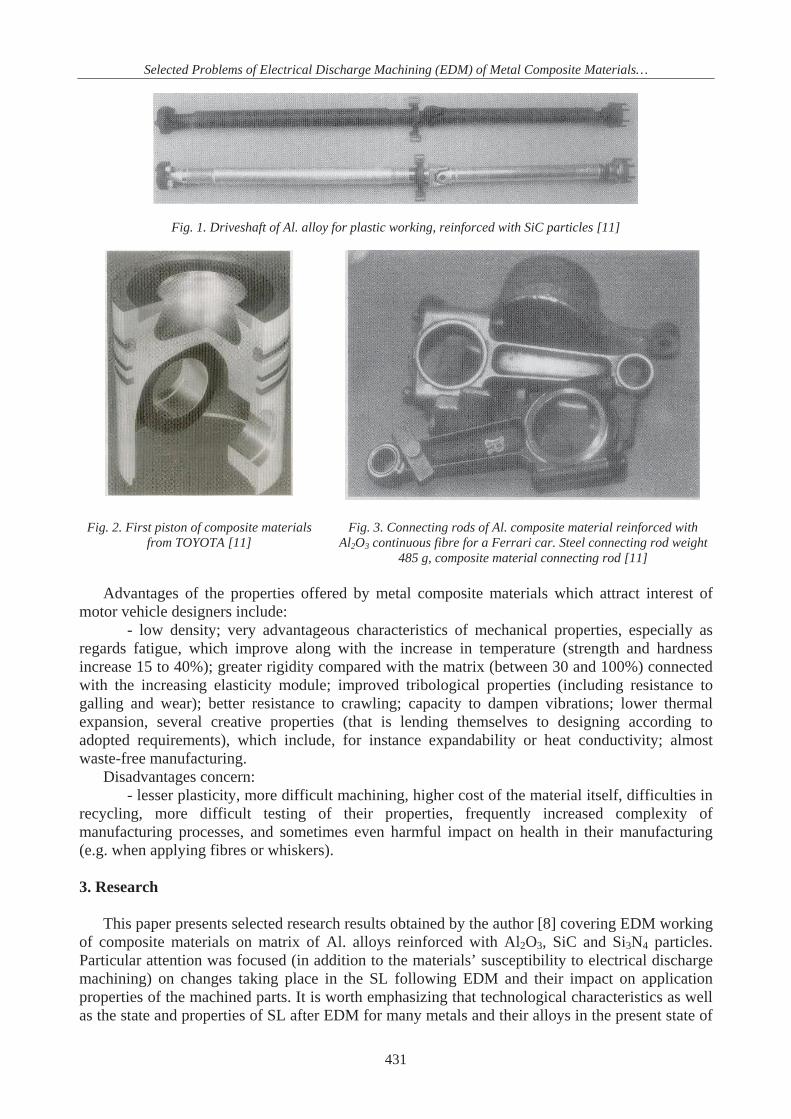
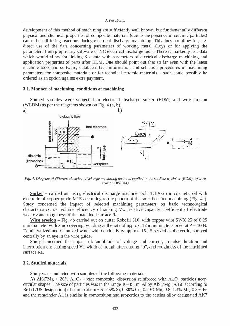
- in engines: pistons, connecting rods, cylinder sleeves, blocks and housings, pulleys, valve seats, crankshafts, camshafts and numerous other parts;
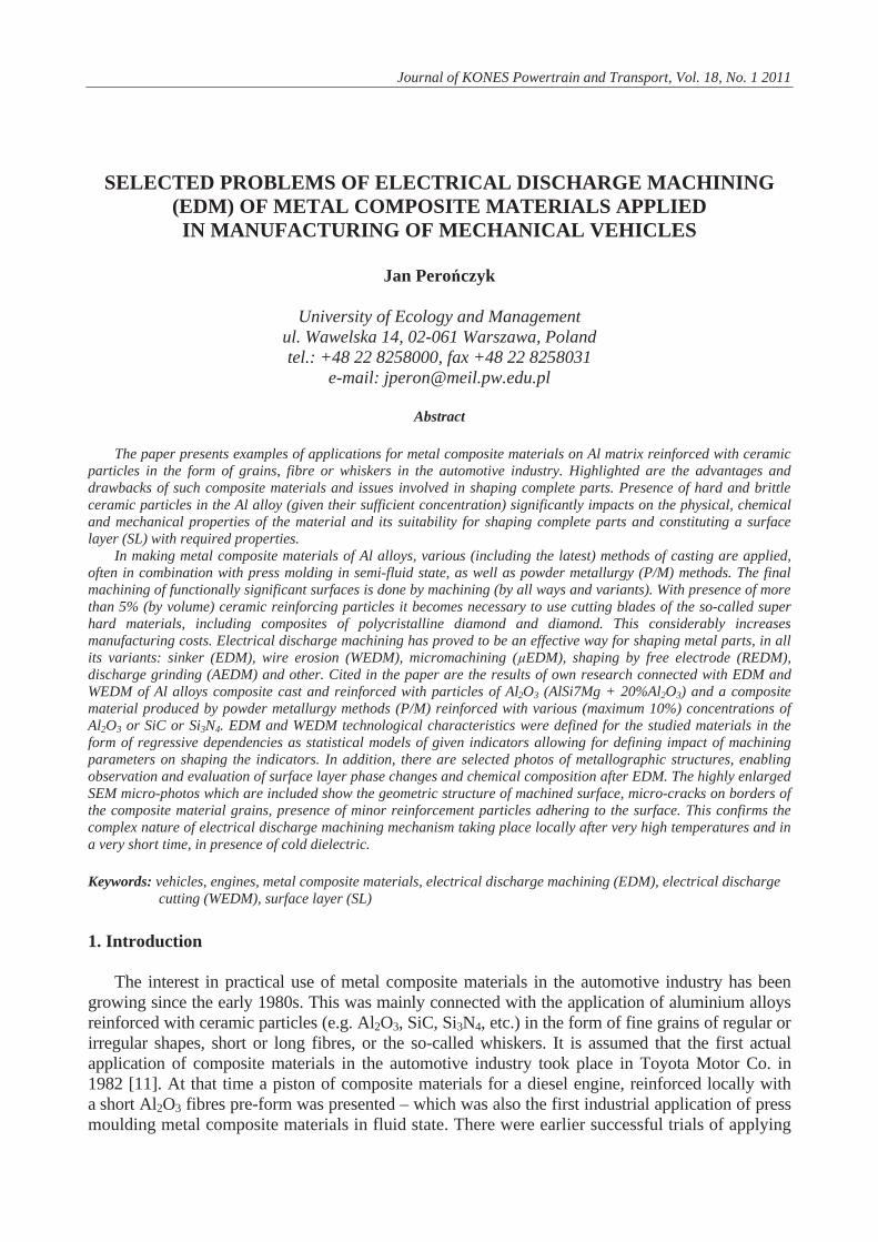
- in bodies and chassis essebly: drive shafts, shock absorber cylinders (along with numerous component elements), disc brakes and calipers, clutch discs, elements of the steering system and several other. In addition in the engine and vehicle control devices many of the miniature elements of these devices are made of composite materials or functional ceramic materials [5]. Fig. 1,2,3 shows examples of selected parts made of metal composite materials.
430
Selected Problems of Electrical Discharge Machining (EDM) of Metal Composite Materials…
Fig. 1. Driveshaft of Al. alloy for plastic working, reinforced with SiC particles [11]
Fig. 2. First piston of composite materials from TOYOTA [11]
Fig. 3. Connecting rods of Al. composite material reinforced with Al2O3 continuous fibre for a Ferrari car. Steel connecting rod weight
485 g, composite material connecting rod [11]
Advantages of the properties offered by metal composite materials which attract interest of motor vehicle designers include:
- low density; very advantageous characteristics of mechanical properties, especially as regards fatigue, which improve along with the increase in temperature (strength and hardness increase 15 to 40%); greater rigidity compared with the matrix (between 30 and 100%) connected with the increasing elasticity module; improved tribological properties (including resistance to galling and wear); better resistance to crawling; capacity to dampen vibrations; lower thermal expansion, several creative properties (that is lending themselves to designing according to adopted requirements), which include, for instance expandability or heat conductivity; almost waste-free manufacturing.
Disadvantages concern: - lesser plasticity, more difficult machining, higher cost of the material itself, difficulties in
recycling, more difficult testing of their properties, frequently increased complexity of manufacturing processes, and sometimes even harmful impact on health in their manufacturing (e.g. when applying fibres or whiskers).
3. Research
This paper presents selected research results obtained by the author [8] covering EDM working
of composite materials on matrix of Al. alloys reinforced with Al2O3, SiC and Si3N4 particles. Particular attention was focused (in addition to the materials’ susceptibility to electrical discharge machining) on changes taking place in the SL following EDM and their impact on application properties of the machined parts. It is worth emphasizing that technological characteristics as well as the state and properties of SL after EDM for many metals and their alloys in the present state of
431
J. Pero czyk
development of this method of machining are sufficiently well known, but fundamentally different physical and chemical properties of composite materials (due to the presence of ceramic particles) cause their differing reactions during electrical discharge machining. This does not allow for, e.g. direct use of the data concerning parameters of working metal alloys or for applying the parameters from proprietary software of NC electrical discharge tools. There is markedly less data which would allow for linking SL state with parameters of electrical discharge machining and application properties of parts after EDM. One should point out that so far even with the latest machine tools and software, databases lack information and selection procedures of machining parameters for composite materials or for technical ceramic materials – such could possibly be ordered as an option against extra payment.
3.1. Manner of machining, conditions of machining
Studied samples were subjected to electrical discharge sinker (EDM) and wire erosion
(WEDM) as per the diagrams shown on Fig. 4 (a, b). a) b)
Fig. 4. Diagram of different electrical discharge machining methods applied in the studies: a) sinker (EDM), b) wire
erosion (WEDM)
Sinker – carried out using electrical discharge machine tool EDEA-25 in cosmetic oil with electrode of copper grade M1E according to the pattern of the so-called free machining (Fig. 4a). Study concerned the impact of selected machining parameters on basic technological characteristics, i.e. volume efficiency of sinking Vw, relative capacity coefficient of electrode wear v and roughness of the machined surface Ra.
Wire erosion – Fig. 4b carried out on cutter Robofil 310, with copper wire SWX 25 of 0.25 mm diameter with zinc covering, winding at the rate of approx. 12 mm/min, tensioned at P = 10 N. Demineralized and deionized water with conductivity approx. 15 S served as dielectric, sprayed centrally by an eye in the wire guide.
Study concerned the impact of: amplitude of voltage and current, impulse duration and interruption on: cutting speed Vf, width of trough after cutting “b”, and roughness of the machined surface Ra.
3.2. Studied materials
Study was conducted with samples of the following materials: A) AlSi7Mg + 20% Al2O3 – cast composite, dispersion reinforced with Al2O3 particles near-
circular shapes. The size of particles was in the range 10–45 m. Alloy AlSi7Mg (A356 according to British/US designation) of composition: 6.5–7.5% Si, 0.30% Cu, 0.20% Mn, 0.8–1.3% Mg, 0.3% Fe and the remainder Al, is similar in composition and properties to the casting alloy designated AK7
432
Selected Problems of Electrical Discharge Machining (EDM) of Metal Composite Materials…
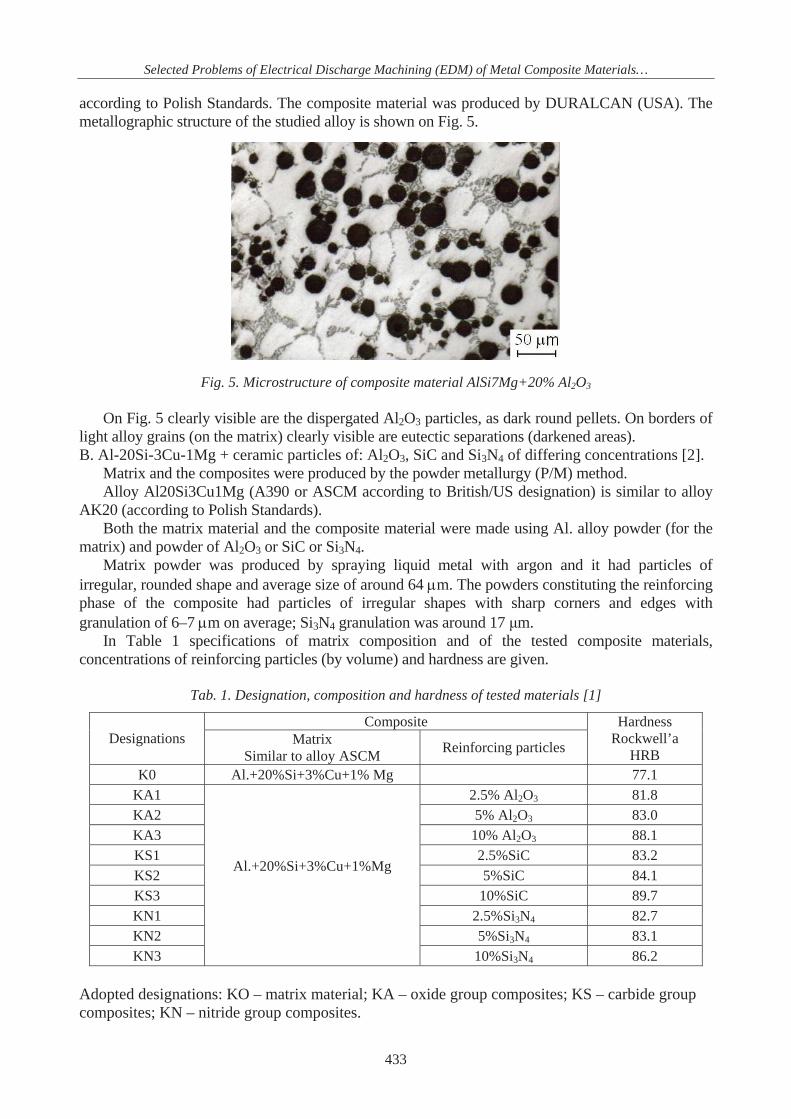
according to Polish Standards. The composite material was produced by DURALCAN (USA). The metallographic structure of the studied alloy is shown on Fig. 5.
Fig. 5. Microstructure of composite material AlSi7Mg+20% Al2O3
On Fig. 5 clearly visible are the dispergated Al2O3 particles, as dark round pellets. On borders of
light alloy grains (on the matrix) clearly visible are eutectic separations (darkened areas). B. Al-20Si-3Cu-1Mg + ceramic particles of: Al2O3, SiC and Si3N4 of differing concentrations [2].
Matrix and the composites were produced by the powder metallurgy (P/M) method. Alloy Al20Si3Cu1Mg (A390 or ASCM according to British/US designation) is similar to alloy
AK20 (according to Polish Standards). Both the matrix material and the composite material were made using Al. alloy powder (for the
matrix) and powder of Al2O3 or SiC or Si3N4. Matrix powder was produced by spraying liquid metal with argon and it had particles of
irregular, rounded shape and average size of around 64 m. The powders constituting the reinforcing phase of the composite had particles of irregular shapes with sharp corners and edges with granulation of 6–7 m on average; Si3N4 granulation was around 17 m.
In Table 1 specifications of matrix composition and of the tested composite materials, concentrations of reinforcing particles (by volume) and hardness are given.
Tab. 1. Designation, composition and hardness of tested materials [1]
Composite Designations Matrix
Similar to alloy ASCM Reinforcing particles
Hardness Rockwell’a
HRB K0 Al.+20%Si+3%Cu+1% Mg 77.1
KA1 2.5% Al2O3 81.8 KA2 5% Al2O3 83.0 KA3 10% Al2O3 88.1 KS1 2.5%SiC 83.2 KS2 5%SiC 84.1 KS3 10%SiC 89.7 KN1 2.5%Si3N4 82.7 KN2 5%Si3N4 83.1 KN3
Al.+20%Si+3%Cu+1%Mg
10%Si3N4 86.2 Adopted designations: KO – matrix material; KA – oxide group composites; KS – carbide group composites; KN – nitride group composites.
433

J. Pero czyk
Fig. 6 presents metallographic microsections of matrix and of selected composite materials [2].
a) Matrix Al-Si b) Composite Al-Si/10%Al2O3
c) Composite Al-Si/10%SiC d) Composite Al-Si/10%Si3N4
Fig. 6. Metallographic microsections of: (a) matrix (ASCM) –K0; (b) composite with 10% Al2O3 –KA3; (c) composite with 10%SiC– KS3; (d) composite with 10%Si3N4 – KN3 [1]
Production process of the composite material ensured obtaining a structure with full, 100% density and fairly uniform distribution of the reinforcing phase in the matrix. Along with the increase of the Al2O3 contents in the composite, its hardness increased too.
Studies of composite A sinker were carried out as the so-called planned experiment (according to Hartley Plan), assuming: constant power voltage Uo=100V, on-load voltage Ur=40V, impulse filling coefficient = ti/(ti+to) = 0.8. The variable parameters were: amplitude of set current I=2 – 16 A, duration of ti and time of impulse interruption in the range 8–2000 s.
The experiment carried out in this way yielded the following regressive dependencies, which are statistical models for the considered technological indicators.
Volume efficiency of sinker – (mm3/min), (1) 1071.03196.05828.11637.0 totiIVw
Relative volume coefficient of electrode wear – (%), (2) 0401.01538.01948.01867.0 totiIv
Roughness of the machined surface – ( m). (3) 0187.014990.04890.05897.1 totiIRaThe numbers defined for the above dependencies: R (coefficient of multi-dimensional
correlation); F (Fisher-Snedecor number) and t (t-Student number) have values higher (often considerably) than critical, which indicates that the adopted formulas are credible, and the adopted parameters impact significantly the experiment results.
Similar studies were carried out for material A, on electric discharge cutter Robofil 310 according to the scheme shown on Fig. 4b (WEDM). This allowed for determining the impact of: on-load voltage Ur; amplitude of current set I; duration of ti and; time of impulse interruption on:
434

Selected Problems of Electrical Discharge Machining (EDM) of Metal Composite Materials…
speed of cutting Vf; width of “b” formed through cutting (impacts on precision of dimensions) and roughness of the machined surface Ra or Rz.
Cutting speed – Vf=1.594 U0.230 I0.549 ti0.913 to-0.5434 (mm/min), (4)
Width of trough after cutting – b=0.2928 U-0.0454 I0.0862 ti0.0292 to0.0916 (mm), (5) Roughness of machined surface – Ra=4.733 U-0.052 I0.023 ti0.212 to-0.076 ( m). (6) Same as above, numbers R, F, t have values exceeding critical levels. The determined dependencies (1–6) allow for projecting results of EDM or WEDM machining,
which enable selecting machining parameters and strategy appropriate for the required precision and quality of the machined surface.
Experiments with sinker of the group B composites, as listed in Table 1, were also carried out on the sinker machine EDEA-25 with isofrequency generator GETB-63 according to Box-Benken Plan, with: Uo=100V, Ur = 50V. Variables were: amplitude of current I = 4 – 16 A, ti = 32 – 500 s), pulse filling coefficient = 0.4–0.8. An additional variable parameter was the content percentage of particles reinforcing the composite materials (concentration by volume) “C”.
Technical characteristics were determined similarly as for composite material A. For KO matrix:
383.00288.08184.21068.0 iw tIV (mm3/min), (7) 638.0687.9437.1311.293 iv tI (%), (8)
103.0172.0395.11557.0 itIRa ( m). (9)
For KA (oxide) group composites: 018.0657.0088.0882.2122.0 CtIV iw (mm3/min), (10)
133.0252.0639.0116.141.102 CtI iv (%), (11) 0175.018.0191.0237.12383.0 CtIRa i ( m). (12)
For KS (carbide) group composites: 0078.0726.0128.0031.3119.0 CtIV iw (mm3/min), (13)
147.0062.0666.0077.1753.123 CtI iv (%), (14) 0004.0152.0427.0351.127.0 CtIRa i ( m). (15)
For KN (nitride) group composites: 043,0642,0156,0919,21445,0 CtIV iw (mm3/min), (16) 157.00016.0637.0856.0957.72 CtI iv (%), (17)
004.0199.0142.0350.1232.0 CtIRa i ( m). (18)
The determined regressive dependencies 7–18 allow also for projecting results of sinker of this group of composites, and thus enable to select machining parameters appropriate for the technical requirements defined in construction documentation. 3.3. Studying changes in geometric and metallographic structure after machining
An interesting issue from the perspective of usable properties of EDM treated materials is the
knowledge of the impact of process parameters on changes taking place in SL, such as: changes in
435

J. Pero czyk
chemical composition of the material, change in metallographic structure, phase changes taking place, change in geometric structure, etc. Changes taking place in SL reflect directly in numerous application properties of parts, such as: fatigue resistance, resistance to wearing, resistance to corrosion, gloss, surface texture and is appearance, plus several other. EDM working is one of the so-called hot processes, something that implies given consequences for SL of the machined part.
One could say that SL in the EDM process is constituted through the impact of several inter-related processes taking place in the set-up connected with the inter-electrode gap (electrodes, dielectric liquid, polarity, characteristics of current feed, characteristic of advance control system, characteristics of dielectric feed).
Most important elements concern: - thermal processes connected with melting, evaporation, sublimation, cooling and
solidification; - processes of transporting the mass, mixing, convection, diffusion, chemical reactions; - processes connected with structural transformations, changes in chemical structure and
very fast cooling; - processes connected with generating residual stresses. In the monograph [4] treating extensively on erosion mechanisms taking place when machining
technical ceramic (containing also an extensive bibliography of technical literature on the subject from all over the world), four different erosion mechanisms were distingushed, cited below:
- melting and evaporation (common with EDM of metals); - scaling (peeling) due to thermal shock; - secondary scaling (peeling) of solidified metal; - detachment of grains by eliminating phase higher electrical conductivity.
In machining metal composites reinforced with ceramic particles it is possible to observe the presence of all the above-listed erosion mechanisms. The most frequent are melting and evaporation as well as detachment of grains through melting and evaporation of the matrix. Dominance of given erosion mechanisms will depend on the kind of reinforcing material (on its physical-mechanical properties) and its granularity, density and even distribution throughout the matrix, and on properties of the matrix itself. In writings [3, 6, 7, 9] and in many other sources it was demonstrated that on the machined surface one can frequently observe randomly distributed single ceramic elements from the reinforcement, which stick out lightly above the surface, or adhere to it strongly. Those works also brought up the issue of estimating thermal stresses developing during the electric discharges in the intra-electrode gap under EDM conditions. In a composite on Al. alloy matrix, grains of the reinforcing phase Al2O3 or Si3N4 act as electric insulators and are immune to EDM machining, hence their elimination from the metal matrix takes place through indirect operation of electric discharges. IN turn, machining a composite material reinforced with SiC particles proceeds in the same was as in the matrix, since SiC particles are characterized by electric conductivity similar to semiconductors.
In the process of eliminating ceramic particles which do not conduct current (insulators) the following mechanisms may be additionally distinguished:
- grains of reinforcing phase may be eliminated together with the matrix material which melts and even partially evaporates during electric discharges;
- due to differences in thermal expansion coefficients of, e.g. Al2O3 grain ( – 6.5 10-6 K-1) and metal matrix ( – 6,5 10-6 K-1), even with the same temperature of both phases high thermal stresses develop, usually exceeding the resistance of reinforcing grain bond with the metal matrix. This may cause grains to break off from the matrix, and next due to mechanical forces (such as shock wave, flow of dielectric, etc.) they are eliminated from the surface. A certain number of such elements may remain not completely exposed by the melted matrix and still affixed to the matrix, thus becoming exposed on the machined surface. A certain quantity of ceramic elements separated by the mechanism of breaking adherence with the matrix may re-adhere to the machined surface by metal of the cooling matrix between pulses. As evident from this, mechanisms of ceramic particles
436
Selected Problems of Electrical Discharge Machining (EDM) of Metal Composite Materials…
reinforced metal composites erosion during EDM are highly complex, depend on many factors and have the nature of chance phenomena.
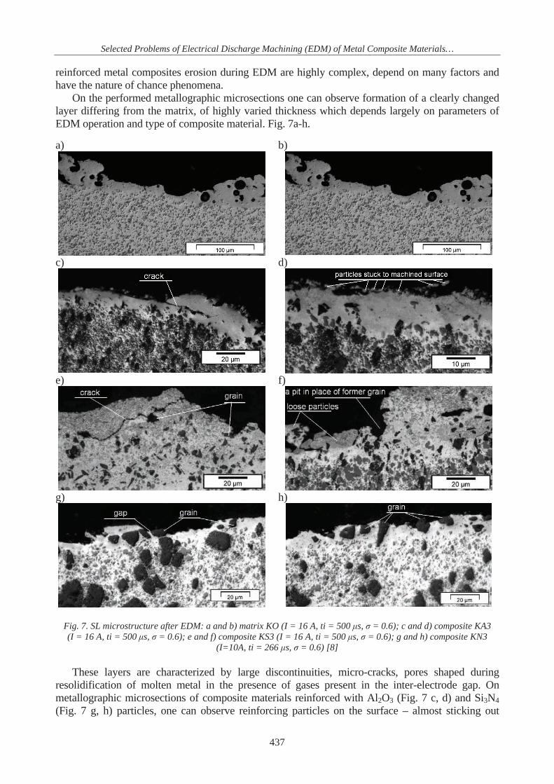
On the performed metallographic microsections one can observe formation of a clearly changed layer differing from the matrix, of highly varied thickness which depends largely on parameters of EDM operation and type of composite material. Fig. 7a-h.
a) b)
c) d)
e) f)
g) h)
Fig. 7. SL microstructure after EDM: a and b) matrix KO (I = 16 A, ti = 500 s, = 0.6); c and d) composite KA3 (I = 16 A, ti = 500 s, = 0.6); e and f) composite KS3 (I = 16 A, ti = 500 s, = 0.6); g and h) composite KN3
(I=10A, ti = 266 s, = 0.6) [8] These layers are characterized by large discontinuities, micro-cracks, pores shaped during
resolidification of molten metal in the presence of gases present in the inter-electrode gap. On metallographic microsections of composite materials reinforced with Al2O3 (Fig. 7 c, d) and Si3N4 (Fig. 7 g, h) particles, one can observe reinforcing particles on the surface – almost sticking out
437
J. Pero czyk
above the metal matrix or loosely bound to it, confirming the earlier described mechanisms of erosion by metal composite materials reinforced with ceramic particles. The nature and appearance of SL microstructure after EDM of the matrix (Fig. 7 a, b) and composite material reinforced with SiC particles (Fig. 7 e, f) are very similar and do not differ from the nature and appearance of structures typical of homogeneous metals.
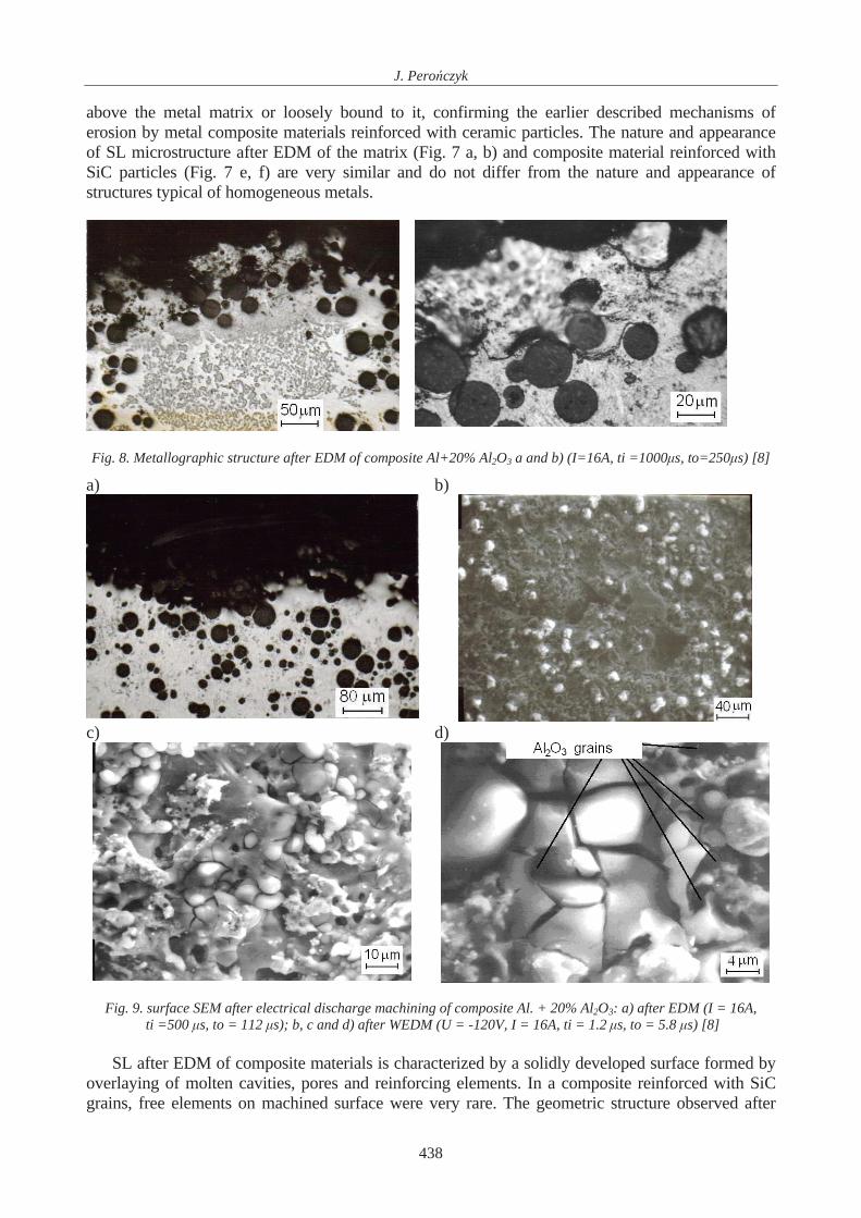
Fig. 8. Metallographic structure after EDM of composite Al+20% Al2O3 a and b) (I=16A, ti =1000 s, to=250 s) [8]
a) b)
c) d)
Fig. 9. surface SEM after electrical discharge machining of composite Al. + 20% Al2O3: a) after EDM (I = 16A, ti =500 s, to = 112 s); b, c and d) after WEDM (U = -120V, I = 16A, ti = 1.2 s, to = 5.8 s) [8]
SL after EDM of composite materials is characterized by a solidly developed surface formed by
overlaying of molten cavities, pores and reinforcing elements. In a composite reinforced with SiC grains, free elements on machined surface were very rare. The geometric structure observed after
438
Selected Problems of Electrical Discharge Machining (EDM) of Metal Composite Materials…
EDM of composite materials is similar to that after machining of metals and is of point non-directional nature. One clearly notes greater departure of cavities from spherical caps than in the case of machining metals. On surfaces machined with higher discharge energies or with longer pulse durations (with sufficient scale of enlargement) one sees SL microcracking – Fig. 7c, d, e, f, g ,h; 8b; 9c, d. This indicates formation in SL of very high tensile stresses, exceeding the matrix cohesion strength limit. Composite materials reinforced with Al2O3 and Si3N4 particles are more susceptible to formation of surface microcracks after EDM. These developments may be observed on the photos of surface topographies taken by a scanning microscope (SEM) and also often on the photos of metallographic microsections
EDM operation with lower energy of single discharges makes the differences in electro-erosion workability of different structures and phases more visible. Metallographic structure phases characterized by higher temperatures of melting are more often mechanically eliminated from the machined material rather than by their melting or evaporation. With high single discharge energies one notes clearly fewer particles adhering to the surface of the machined surface or sticking out only partly uncovered.
This indicates that the erosion mechanism of ceramic particles from composite materials changes with the applied energy (power) of single discharge. The higher the pulse energy, the more the erosion process takes place through processes of melting, evaporation and sublimation, namely becomes more similar to erosion processes in homogeneous metals.
a)
b)
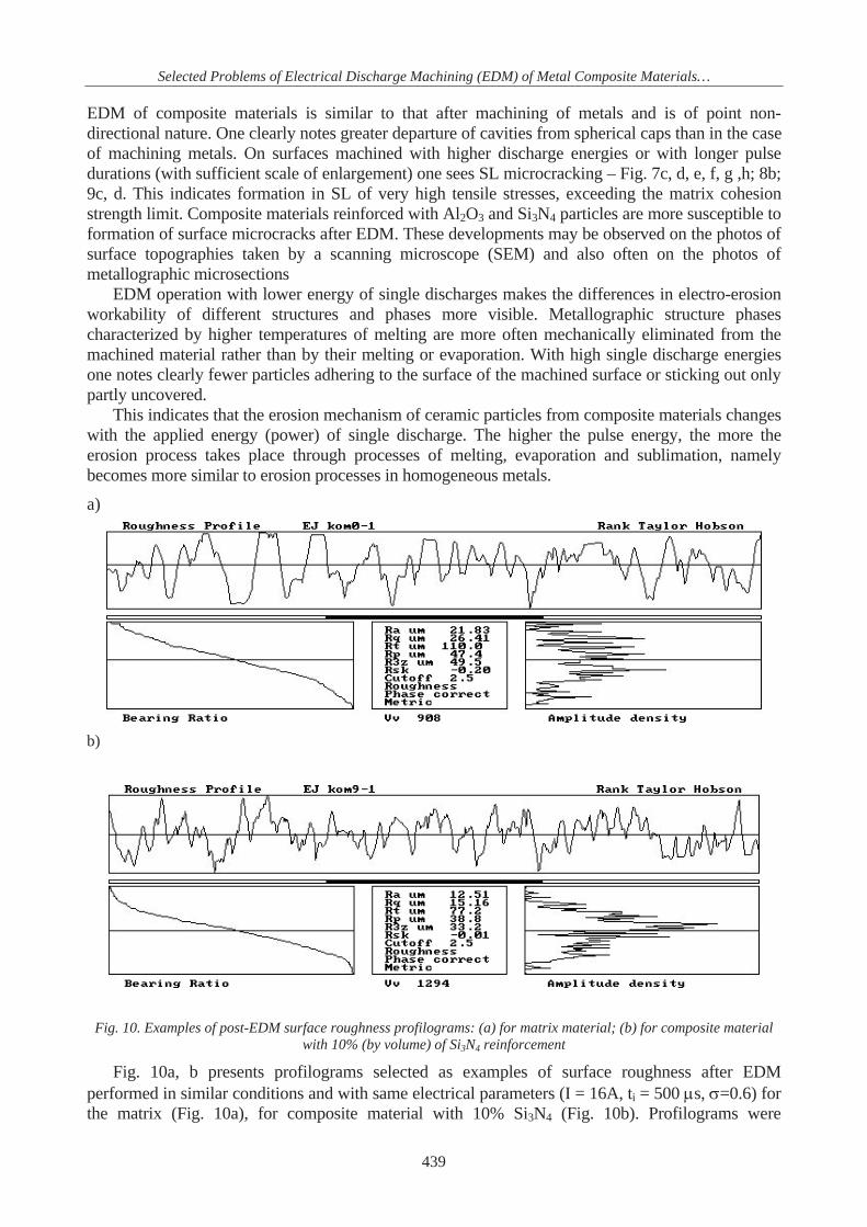
Fig. 10. Examples of post-EDM surface roughness profilograms: (a) for matrix material; (b) for composite material with 10% (by volume) of Si3N4 reinforcement
Fig. 10a, b presents profilograms selected as examples of surface roughness after EDM performed in similar conditions and with same electrical parameters (I = 16A, ti = 500 s, =0.6) for the matrix (Fig. 10a), for composite material with 10% Si3N4 (Fig. 10b). Profilograms were
439
J. Pero czyk
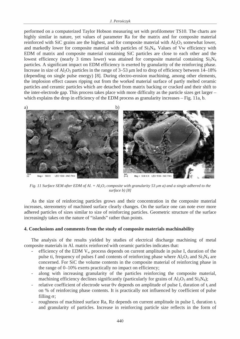
performed on a computerized Taylor Hobson measuring set with profilometer TS10. The charts are highly similar in nature, yet values of parameter Ra for the matrix and for composite material reinforced with SiC grains are the highest, and for composite material with Al2O3 somewhat lower, and markedly lower for composite material with particles of Si3N4. Values of Vw efficiency with EDM of matrix and composite material containing SiC particles are close to each other and the lowest efficiency (nearly 3 times lower) was attained for composite material containing Si3N4 particles. A significant impact on EDM efficiency is exerted by granularity of the reinforcing phase. Increase in size of Al2O3 particles in the range of 3–53 m led to drop of efficiency between 14–18% (depending on single pulse energy) [8]. During electro-erosion machining, among other elements, the implosion effect causes ripping out from the worked material surface of partly melted ceramic particles and ceramic particles which are detached from matrix backing or cracked and their shift to the inter-electrode gap. This process takes place with more difficulty as the particle sizes get larger – which explains the drop in efficiency of the EDM process as granularity increases – Fig. 11a, b. a) b)
Fig. 11 Surface SEM after EDM of Al. + Al2O3 composite with granularity 53 m a) and a single adhered to the surface b) [8]
As the size of reinforcing particles grows and their concentration in the composite material
increases, stereometry of machined surface clearly changes. On the surface one can note ever more adhered particles of sizes similar to size of reinforcing particles. Geometric structure of the surface increasingly takes on the nature of “islands” rather than points.
4. Conclusions and comments from the study of composite materials machinability
The analysis of the results yielded by studies of electrical discharge machining of metal
composite materials in Al. matrix reinforced with ceramic particles indicates that: - efficiency of the EDM Vw process depends on current amplitude in pulse I, duration of the
pulse ti, frequency of pulses f and contents of reinforcing phase where Al2O3 and Si3N4 are concerned. For SiC the volume contents in the composite material of reinforcing phase in the range of 0–10% exerts practically no impact on efficiency;
- along with increasing granularity of the particles reinforcing the composite material, machining efficiency declines significantly (particularly for grains of Al2O3 and Si3N4);
- relative coefficient of electrode wear v depends on amplitude of pulse I, duration of ti and on % of reinforcing phase contents. It is practically not influenced by coefficient of pulse filling ;
- roughness of machined surface Ra, Rz depends on current amplitude in pulse I, duration ti and granularity of particles. Increase in reinforcing particle size reflects in the form of
440
Selected Problems of Electrical Discharge Machining (EDM) of Metal Composite Materials…
greater roughness after EDM. Roughness after EDM is practically not influenced by coefficient of pulse filling and volume contents of the reinforcing phase;
- geometric structures of EDM (SGP) processed composite material surfaces are not fully similar to each other. SGP of a composite material with SiC particles is similar to the matrix structure. SGP of composite materials with Al2O3 or Si3N4 particles are similar to each other and different from appearance of matrix SGP. When larger pulse energies and longer discharge times are applied, SGP of composite materials with Al2O3 and Si3N4 differ significantly from point non-directional structures and becomes similar to “rash” structures. In SL of composites with Al2O3 and Si3N4 particles there are more frequent microcracks, which may be unacceptable due to fatigue resistance, and which is clearly indicative of tensile stresses formation in SL after EDM;
- one notes instances of SL with changed metallographic and phase structure, with non-uniform thickness as a consequence of chance course of developments during electrical discharges. Thickness of the layer, its chemical and phase composition, distribution of erosion traces on the surface will depend largely on parameters of the process and types of reinforcing particles;
- on EDM (WEDM) worked surfaces of composite materials reinforced with ceramic particles which do not conduct electricity (Al2O3, Si3N4) one frequently observes particles sticking out or strongly adhering to the bed, of sizes roughly similar to reinforcement in size, chemical composition and appearance
- in SL after EDM, and particularly on peaks of surface irregularities, one observes a clearly higher content of carbon from pyrolysis of the dielectric (hydrocarbon) and introduced through diffusion during discharges.
References [1] Bia o, D., Zu ycie tribologiczne kompozytów na osnowie stopów aluminium otrzymanych
z proszków, Prace Naukowe PW, Mechanika, z. 192, Oficyna Wydawnicza PW 2002. [2] Bunk, W., Esslinger, P., Keller, H., Aerospace Materials: trends end potential, Materials and
Processing-Move into the 90's, Elsevier Science Publisher B. V., pp 327-341, Amsterdam 1989.
[3] Le Roux, T., Wise, M. L. H., Aspinwall, D. K., Electric Discharge Machining of an Aluminium Alloy Silicon Carbide Reinforced Metal Matrix Composites, 30-th Int. Conf. M.T.D.R., Manchester UK 1993.
[4] Oczo , K. E., Kszta towanie ceramicznych materia ów technicznych, Oficyna Wydawnicza Politechniki Rzeszowskiej 1998.
[5] Pampuch, R., Wspó czesne Materia y Ceramiczne, AGH – Uczelniane Wydawnictwa Naukowo-Dydaktyczne, Kraków 2005.
[6] Pero czyk, J., Kozak, J., Obróbka elektroerozyjna kompozytu stopu Al z Al2O3. Przep ywowe Maszyny Wirnikowe, Zbiór prac VIII Mi dzynarodowej Konferencji pod redakcj K. E. Oczosia, Rzeszów 1998, Oficyna Wydawnicza Politechniki Rzeszowskiej 1998.
[7] Pero czyk, J., Kozak, J., Obróbka elektroerozyjna(EDM) i (WEDM) materia ów kompozytowych i o strukturze warstwowej, Materia y III Ogólnopolskiej Konferencji Naukowo-Technicznej pt. Post py w Technice Wytwarzania Maszyn, Kraków 14-15 pa dziernika 1999.
[8] Pero czyk, J., Obróbka elektroerozyjna kompozytów na osnowie metalowej i ceramiki technicznej, Rozprawa doktorska (Author s PhD Thesis), Politechnika Warszawska, Wydzia In ynierii Produkcji, Warszawa 2008.
[9] Poon, S. K., Lee, T. C., Electrical Discharge Machining of Particulate Metal – Matrix Composites, Proceedings of the ASME, 1993, Materials Congress, Pithsburgh Pennsylwania, October, pp 17-21, 1993.
441

J. Pero czyk
[10] Sobczak, J., Wojciechowski, S., Wspó czesne tendencje praktycznego zastosowania kompozytów metalowych, Kompozyty (Copmposites), Rocznik 2, pp 24-37, Nr 3 2002.
[11] Sobczak, J., Kompozyty metalowe, Wyd. Instytutu Odlewnictwa i Instytutu Transportu Samochodowego, Kraków-Warszawa 2001.
442
Related Documents