DECK HARD WARE Version 7 SELDÉN DECK HARD WARE 1

Welcome message from author
This document is posted to help you gain knowledge. Please leave a comment to let me know what you think about it! Share it to your friends and learn new things together.
Transcript

DECK HARD WARE
Vers
ion
7SE
LDÉN
DEC
K HA
RDW
ARE
1

pRoDuCt CAtALoguES
KEELBOATYACHT
SELDÉN DECK HARDWARE CATALOGUE, VERSION 7 Check out these pages for new products. New products in red.
DINGHY CARBON
59
5-8
12
-E 2
01
0-0
2-2
1
PRODUCT CATALOGUE
DINGHY
1
PRODUCT CATALOGUE
Version 1
KEELBOAT
Rig solutions for yachts ranging from 25 to 80 feet.
YACHTPRODUCT CATALOGUE
Edition 6
Rig systems and accessories for 18 to 26 feet boats.
Rig systems and accessories for 25 to 80 feet boats.
We hope this Seldén Deck hardware product catalogue will be helpful for you finding all the deck hardware you need for enjoyable sail handling. This is just one of five product catalogues covering our extensive range of Yacht, Keelboat, Dinghy, Carbon and Deck Hardware products. If you need any of the other catalogues you are welcome to pick them up from your local dealer or to download from www.seldenmast.com.
Rig systems and accessories for dinghies.
Carbon rig systems.
Art. No. 595-808-E Art. No. 595-950-E Art. No. 595-812-E Art. No. 595-823-E
CARBON SPARS
Page Supplemented product group Page Supplemented product group Page Supplemented product group Page Supplemented product group Page Supplemented product group
26 PBB 100 50 High load PBB 66 System 42 80 Complete sheet system 92 Fairlead
36 BBB 20 54 System 15 70 System 30 Perf 81 Tackles 93 Low friction shackle
38 BBB 30 57 Track 22 74 Main sheet system 84 Cam cleats 93 Block for 2:1 purchase
42 BBB 60 60 System 22 76 Genua system 92 Swivel lock 95 Low friction ring
46 MRB 60 62 System 30 78 Self tacking jib system 92 Sheet lead 95 Double fairlead
3
ALWAYS oN tHE RIgHt tRACK
Making the best rig systems in the world is more than a job at Seldén. It’s a passion.
Every Seldén rig is designed and carefully dimensioned for the particular boat.
In our search for perfection, no detail is considered too small. Setting our own deck
hardware standards is a natural step in this systematic approach to achieving the
best possible product for the given task. No matter the size of your boat, whether
you push your equipment to the very limit, or just enjoy leisurely cruising; when you
go Seldén, you’ll go first class, all the way.
Photo credit: Peter Gustafsson, page 10, 28, 30, 32, 48, 52, 64, 70, 80, 88. Seldén Mast AB, page 5, 23, 24, 26, 28, 29, 31, 51, 71. Dan Ljungsvik, page 8, 16, 18, 20, 34, 36, 42, 44, 46, 50, 54, 78, 82, 84, 86, 88, 90. Rick Tomlinson, page 84. Peter Szamer, page 26. John Patience, page 34, 54. Carol Baker, page 38. Roberto Vuilleumier, page 48. Billy Black, page 22. Ville Djurberg, page 22. Tommy Andersson, page 76. Max Alm (D.A.D. Sportsware), page 72. Arthur Smeets, page 66. Ola Stensby/Niklas Strandberg, page 14. Jonna Hautau, page 25, 27, 56, 66, 78. Jonas Granhed, cover, page 30, 40, 53, 58, 60, 61, 62, 63, 65, 74, 91. Pontus Ericsson, page 68. ANA Foto, page 10. Tjelvar Ericsson, page 95. Mats-Uno Fredrikson, page 50, 95. Lars Sandberg, page 12, 46. Steve Norbury, cover. Malcolm Hanes, cover. Leif Wiklund, studio images.
The information and specifications contained in this catalogue are subject to change without prior notice.

WItH pASSIoN. ALL tHE WAY fRom tHE DRAWINg boARD.
Sailing is a total experience. With superb sail handling the good experience easily turns into passion. There are many factors like wind, waves and currents a sailor can’t change. But you can do something about them. That’s why rig equipment should always be chosen with the outmost care, in order to get the most out of it and get the right feel for wind and tuning. The better the precision of your equipment, the better the feel. Sails, mast, standing and running rigging work together as one single
unit. If you want to be on top, you can’t afford to leave anything to chance.Seldén is the world’s leading manufacturer of rig systems. We have been working with boat yards and sail makers all over the world to power thou-sands upon thousands of sailing boats and yachts since 1960. In developing the Seldén deck hard-ware range we have drawn on our many years of rig building experience, our extensive experience of all possible types of sailing and, last but not least,
our own passion for sailing. We hope you will feel the same passion when you use a Seldén deck hardware product or just hold it in your hand. It’s a passion we have built in, all the way from the drawing board.

5

400 kg
400 kg
100 kg
800 kg
100 kg
400 kg
200 kg
600 kg600
600 kg
100 kg
CHooSE tHE RIgHt pRoDuCtBREAKING LOADS AND SAfE WORKING LOADSBreaking loads
Our definition of a breaking load is that load which causes any part of a product to break when it is subjected to successively increasing loads during laboratory testing.
Safe working loads
Our definition of safe working load is set at half the breaking load. We guarantee that products subjected to loads that are below or up to this limit will function satisfactorily.
Loads in the specification tables
The breaking load and safe working load values shown in the product tables are for the product itself (not for the line). The load exerted on the product depends on the load in the line and on the deflection angle of the lines around the sheave. For more information see page 96.
Purchase systems
A mechanical system can be used to increase the effect of human force required for a specific situation. Such systems are designed in several ways. A selection of typical mechanical systems are shown to the right.
6:1 purchase with triple blocks.
4:1 purchase with fiddle blocks.
8:1 purchase with cascade of single blocks.
LOW LOADS AND HIGH LOADSThe practical difference between high loads and low loads depends on the amount of force you must exert to handle them. In our definition, we set the dividing line between high loads and low loads at 100 kg. Even when the load is less than 100 kg, a normal person will require a mechanical system to deal with it, although the mechanical advantage may be relatively low.
A block and tackle with, say, a mechanical advan-tage of 4:1 converts a load of 100 kg into 25 kg, which can, of course, be easily managed by a single crew member. Using a block and tackle with a mechanical advantage of 4:1 means that four times the length of line must be pulled. In theory, this will take longer than it would take without any mechani-cal advantage.
The choice of mechanical advantage depends, therefore, on the load you feel able to manage and how quickly you want to do the job.
STATIC LOADS AND DYNAmIC LOADS Static loads
A static load is one that does not cause the block sheave to spin. Typical static loads are found in halyard turning blocks, where the sheave remains still under load for long periods of time.
Dynamic loads
A dynamic load is one that causes the block sheave to spin. Typical dynamic loads are found in main sheeting systems, where the sheave spins frequently when sailing.
6
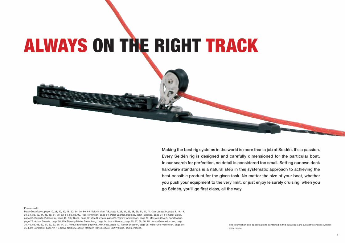
All Seldén blocks are of the same superb quality and are the best for their particular application. In order to make it easy to select the right block for your application, we have catego-rised them to suit four types of loads: low loads, high loads, static loads and dynamic loads.
SELDÉN DESIGNATIONSAll Seldéns deck hardware products have been given descriptive names. See below for the blocks designations.
Seldén blocks are designated in accordance with two main features of the block. The first part of the designation specifies the type of bearing system or other special feature. The second part of the designation tells you the sheave diameter. For example, the PBB 60 is a Plain Bearing Block with a sheave diameter of 60 mm.
THE BLOCK fAmILIES The blocks are divided into families. All the blocks in a specific family have the same sheave. The part numbers of the sheaves are the basis of the part numbers of the blocks. For example, the PBB 60 sheave is designated 406-001 and the PBB 60 single block is designated 406-001-01.
The part numbers of the sheaves are stamped on the side of each sheave.
High load
Static load
Dynamic load
Low load
Tracks and travellers are available in four sizes 15, 22, 30 and 42. This simplified model provides an indication about which system that can be used for which boatsize. For more information see Dimensioning guide page 98.
For more information about how to dimension the Seldén Deck hardware products, see page 96.
SYSTEM 30
30’ 45’
20’
SYSTEM 22
33’
Dinghie
SYSTEM 15
22’
SYSTEM 42
40’ 65’
7
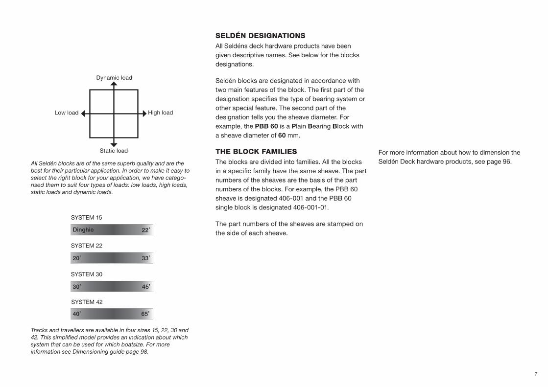
Winches,page 10
Roller bearing blocks,page 30
Eye swivel,page 88
The Seldén deck hardware range is
carefully desig ned, developed and
manufactured under the strict quality
control and attention to detail that is the
hallmark of Seldén. All Seldén deck
hardware is supplied with a 2-year
warranty.
Plain bearing blocks,page 16
Cam cleatspage 84
Valley cleats,page 86
bLoC
KS
WIN
CHES
CLEA
tS
& S
WIV
ELS
SELDÉN DECK HARDWARE
Deck swivel,page 89
8
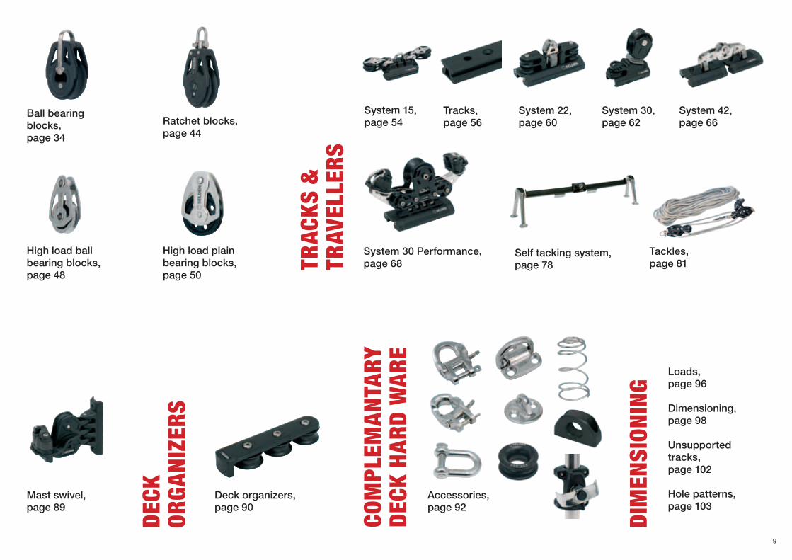
High load plain bearing blocks,page 50
High load ball bearing blocks,page 48
Ratchet blocks,page 44
Tracks,page 56
System 22,page 60
System 15,page 54
System 30,page 62
System 42,page 66
System 30 Performance, page 68
Tackles,page 81
Ball bearing blocks,page 34
Mast swivel,page 89
Accessories,page 92
Deck organizers,page 90
Com
pLEm
ANtA
RY
DECK
HAR
D W
ARE
DIm
ENSI
oNIN
g
DECK
oR
gAN
IzER
S
tRAC
KS &
tR
AVEL
LERS
Loads,page 96
Dimensioning,page 98
Unsupported tracks,page 102
Hole patterns,page 103
Self tacking system,page 78
9

SELDÉN REVERSIbLE WINCHES
Winner of DAME Awards 2010www.metstrade.com
Winner of Freeman K Pittman Innovation Award 2011, Racing gear category.
10

REVERSINg IS A bIg StEp foRWARD
Stainless drum. No chafe on the line.
Back-tailer
Self-tailer
Triangular handle for ergonomic grip.
Lock-in switch
Unique and patented reverse function operated with a push of your thumb.
Q
TW
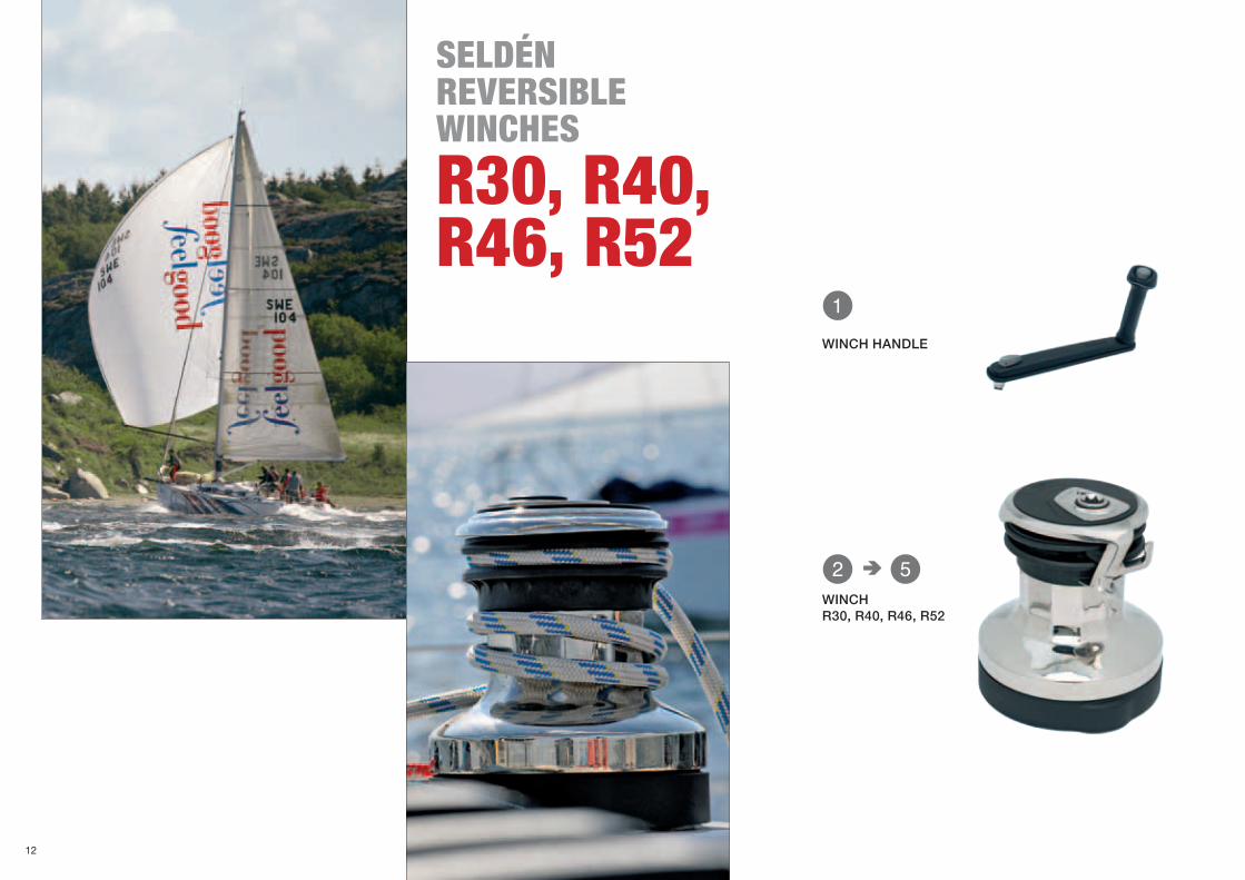
SELDÉN REVERSIbLE WINCHES
R30, R40, R46, R52
WINCH HANDLE
WINCHR30, R40, R46, R52
12

W
E
R
T
Q
Art. no. DescriptionBase diameter,
(mm)Weight,
(kg)Line size,
(mm)
Power ratio
FastenersHigh speed Low speed
470-530-10 R30 143 4.4 8-12 10:1 30:1 5xM6
470-540-10 R40 151 4.9 10:1 40:1 5xM6
470-546-10 R46 178 6.3 10-14 10:1 46:1 5xM8
470-552-10 R52 192 7.3 10:1 52:1 5xM8
Art. no.Length,
(mm)Weight,
(g)
533-927-10254 (10’’)
626
WINCH
WINCH HANDLE
The Seldén winches are manually operated and of self-tailing type with two gears forward. You start winching clock wise on the fast gear, shift down to low gear by rotating the winch handle anti clock wise. So far, exactly as we are all used to.
The ingenious feature with the new Seldén winches is that you can let the line out by rever-sing the winch drum. The purpose made winch handle has a button which is pushed down with your thumb to prepare the winch for reverse drive. The winch handle is rotated clock wise and the line is eased out. The line remains in the self-tailing jaws all the time which means it’s a one hand operation to trim the sheet, the halyard or the spinnaker guy.
Fast trim is a great advantage for the racing sailor! To ease out the sheet, just push the button on top of the handle and turn clock wise. There is no need to even touch the line. Instant trim makes for higher boat speed. For the family cruising sailor, one handed operation means safety – no hands are even close to the drum when easing out the line. In rough conditions you can hold on with your free hand. Single handed sailors can steer and trim at the same time.
• Unique and patented reverse function operated with a push of your thumb.
• Stainless drum with 10 flat faces makes for excellent grip and is kind to the line. It looks good too.
• Low weight. The centre tower is partly composite.
• Compatible with all winch handles on the market, but only the Seldén winch handle offers 2-speed forward and 1-speed reverse.
• 10” Seldén winch handle with lock-in switch.
• Smooth and well rounded reverse feeder. The sheet can be dumped fast when tacking.
13


bLoCKS mADE foR pERfECt INtERACtIoN
Seldén blocks give you the benefits of a high strength to
weight ratio. We only use top quality materials like glass fibre
reinforced composite and marine grade stainless steel. Each
com ponent is designed for top performance and perfect
interaction with the rig under all conditions. The Seldén block
range consists of plain bearing blocks, roller bearing blocks,
ball bearing blocks, high load ball bearing blocks, high load
plain bearing blocks and ratchet blocks.
Ball bearing blocks
High load ball bearing blocks
High load plain bearing blocks
Plain bearing blocks
Roller bearing blocks
Ratchet blocks
15
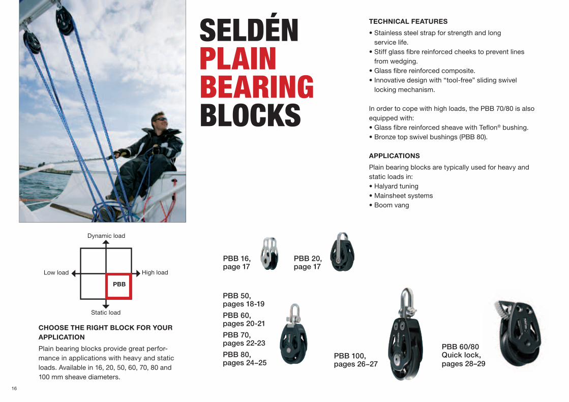
TECHNICAL FEATURES
•Stainlesssteelstrapforstrengthandlong service life.
•Stiffglassfibrereinforcedcheekstopreventlines from wedging.
•Glassfibrereinforcedcomposite.•Innovativedesignwith“tool-free”slidingswivel
locking mechanism.
In order to cope with high loads, the PBB 70/80 is also equipped with:•GlassfibrereinforcedsheavewithTeflon® bushing.•Bronzetopswivelbushings(PBB80).
APPLICATIONS
Plain bearing blocks are typically used for heavy and static loads in:•Halyardtuning•Mainsheetsystems•Boomvang
CHOOSE THE RIGHT BLOCK FOR YOUR APPLICATION
Plain bearing blocks provide great perfor-mance in applications with heavy and static loads. Available in 16, 20, 50, 60, 70, 80 and 100 mm sheave diameters.
SELDÉNpLAIN bEARINg bLoCKS
PBB 20,page 17
PBB 16,page 17
PBB 50,pages 18-19
PBB 60,pages 20-21
PBB 70,pages 22-23
PBB 80,pages 24−25
PBB 100,pages 26−27
PBB 60/80Quick lock,pages 28–29
High load
Static load
Dynamic load
Low load
PBB
16

Q W E
Q
E
W
Torsional rigid cheeks in glass fibre filled composite prevent jamming
Stainless steel straps for increased safety
Bronze bushing (PBB 80)
Glass fibre reinforced sheave with Teflon® bushing
Teflon® bushing
Practical switch from swivelling to fixed shackle
PBB 50/60
PBB 70/80
TECHNICAL FEATURES PBB 20
•Acetalsheave•Stiffglassfibrereinforcedcheeksto
prevent lines from wedging
TECHNICAL FEATURES PBB 16
•Asmallstainlessblockdesignedforflag lines, lazy jacks and similar applications.
•Fixedstrapforlashing.
•Availablewithtwoalternativesheaves, composite or brass.
pLAIN bEARINg bLoCK
16/20
Art. No. Description Weight(g)
Safe wor-king load
(kg)
Breaking load (kg)
Max line size (mm)
401-001-01R Single, Composite 4 70 140 6
401-001-02RSingle, Brass 10 100 200 6
Art. No. Description Weight(g)
Safe wor-king load
(kg)
Breaking load (kg)
Max line size (mm)
402-001-01R Single strap 6 70 140 6
PBB 20Single strap
PBB 16
PBB 20
PBB 16Single
17
Q W E
R T Y
U I O
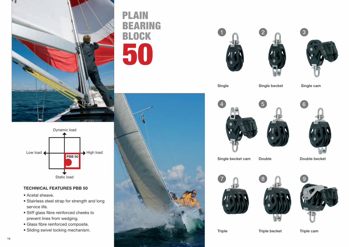
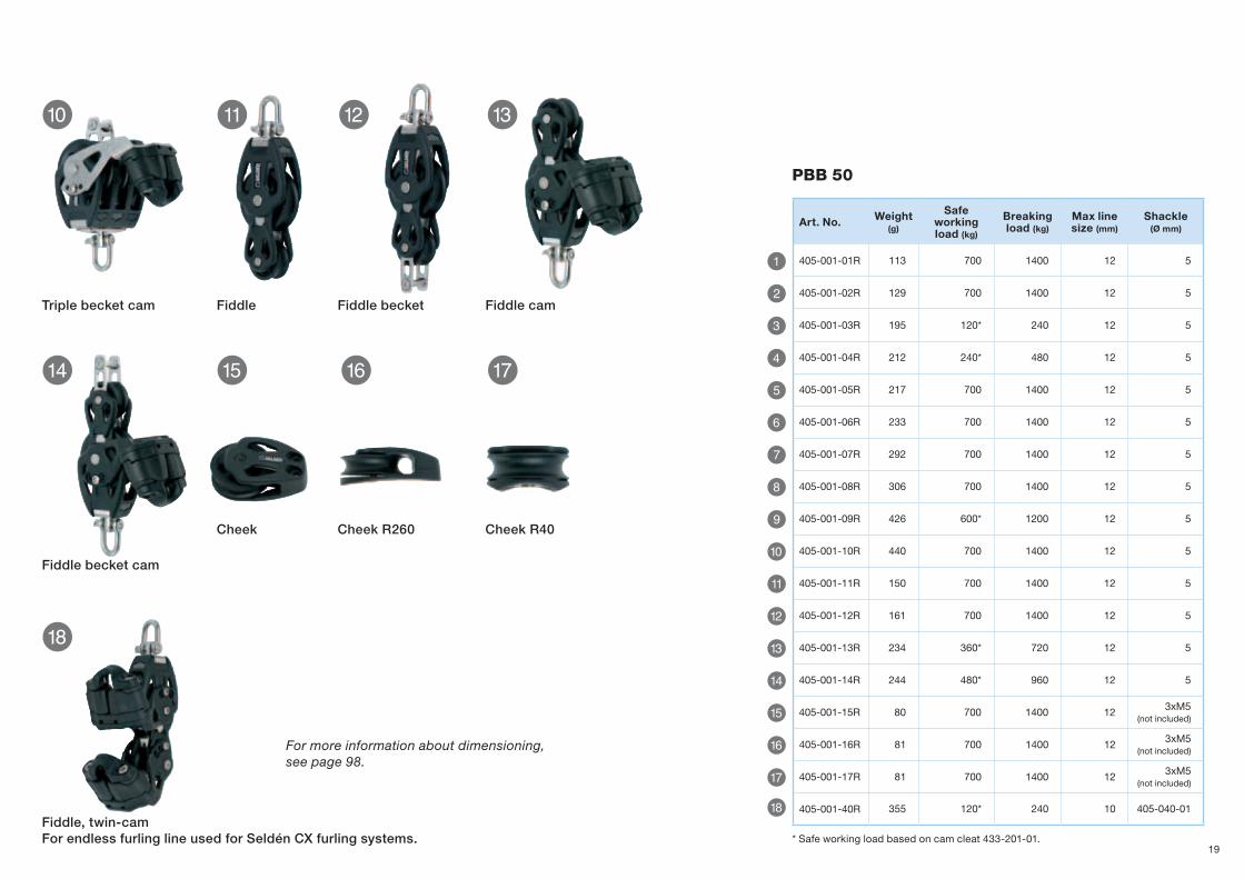
Triple Triple becket Triple cam
TECHNICAL FEATURES PBB 50
•Acetalsheave.•Stainlesssteelstrapforstrengthandlong
service life.•Stiffglassfibrereinforcedcheeksto
prevent lines from wedging.•Glassfibrereinforcedcomposite.•Slidingswivellockingmechanism.
Single Single becket Single cam
Single becket cam Double Double becket
pLAIN bEARINg bLoCK
50
High load
Static load
Dynamic load
Low loadPBB 50
18
P { } q
w
y
e r t
Q
W
E
R
T
Y
U
I
O
P
{
}
q
w
e
r
t
y
Triple becket cam Fiddle cam
Fiddle becket cam
Fiddle, twin-camFor endless furling line used for Seldén CX furling systems.
Cheek Cheek R260 Cheek R40
Fiddle Fiddle becket
PBB 50
Art. No. Weight(g)
Safe working load (kg)
Breaking load (kg)
Max line size (mm)
Shackle (Ø mm)
405-001-01R 113 700 1400 12 5
405-001-02R 129 700 1400 12 5
405-001-03R 195 120* 240 12 5
405-001-04R 212 240* 480 12 5
405-001-05R 217 700 1400 12 5
405-001-06R 233 700 1400 12 5
405-001-07R 292 700 1400 12 5
405-001-08R 306 700 1400 12 5
405-001-09R 426 600* 1200 12 5
405-001-10R 440 700 1400 12 5
405-001-11R 150 700 1400 12 5
405-001-12R 161 700 1400 12 5
405-001-13R 234 360* 720 12 5
405-001-14R 244 480* 960 12 5
405-001-15R 80 700 1400 12 3xM5 (not included)
405-001-16R 81 700 1400 12 3xM5 (not included)
405-001-17R 81 700 1400 12 3xM5 (not included)
405-001-40R 355 120* 240 10 405-040-01
For more information about dimensioning, see page 98.
* Safe working load based on cam cleat 433-201-01.19
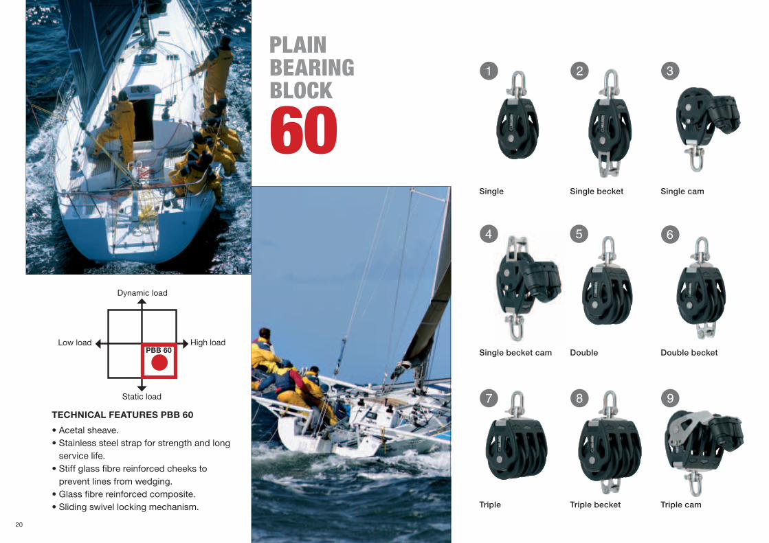
Q W E
R T Y
U I OTECHNICAL FEATURES PBB 60
•Acetalsheave.•Stainlesssteelstrapforstrengthandlong
service life.•Stiffglassfibrereinforcedcheeksto
prevent lines from wedging.•Glassfibrereinforcedcomposite.•Slidingswivellockingmechanism.
Static load
High load
Dynamic load
Low loadPBB 60
Triple Triple becket Triple cam
Single Single becket Single cam
Single becket cam Double Double becket
pLAIN bEARINg bLoCK
60
20

P { } q
e r t
w
y u
Q
W
E
R
T
Y
U
I
O
P
{
}
q
w
e
r
t
y
u
Triple becket cam Fiddle cam
Fiddle becket cam Cheek Cheek R345 Cheek R48
Fiddle Fiddle becket
PBB 60
Art. No. Weight(g)
Safe working load (kg)
Breaking load (kg)
Max line size (mm)
Shackle (Ø mm)
406-001-01R 189 1100 2200 14 6
406-001-02R 211 1100 2200 14 6
406-001-03R 286 120** 240 12 6
406-001-04R 308 240** 480 12 6
406-001-05R 357 1100 2200 14 6
406-001-06R 378 1100 2200 14 6
406-001-07R 500 1100 2200 14 6
406-001-08R 524 1100 2200 14 6
406-001-09R 658 600** 1200 12 6
406-001-10R 670 720** 1440 12 6
406-001-11R 254 1100 2200 14 6
406-001-12R 271 1100 2200 14 6
406-001-13R 350 360** 720 12 6
406-001-14R 369 480** 960 12 6
406-001-15R 141 1100 2200 14 3xM6 (not included)
406-001-16R 137 1100 2200 14 3xM6 (not included)
406-001-17R 145 1100 2200 14 3xM6 (not included)
406-001-20R 292 1100* 2200* 14 3xM6 (not included)
406-001-40R 500 120** 240 12 406-040-01R
* Upper sheave: Safe working load = 550 kg. Breaking load = 1100 kg. ** Safe working load based on cam cleat 433-201-01.
Double cheek Fiddle, twin-camFor endless furling line used for Seldén CX furling systems.
For more information about dimensioning, see page 98.
21
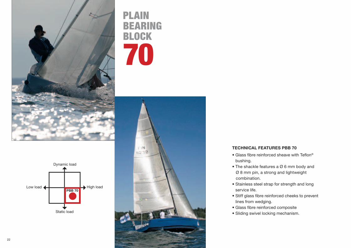
pLAIN bEARINg bLoCK
70
Static load
High load
Dynamic load
Low loadPBB 70
TECHNICAL FEATURES PBB 70
•GlassfibrereinforcedsheavewithTeflon® bushing.
•TheshacklefeaturesaØ6mmbodyandØ8mmpin,astrongandlightweight combination.•Stainlesssteelstrapforstrengthandlong
service life.•Stiffglassfibrereinforcedcheekstoprevent
lines from wedging.•Glassfibrereinforcedcomposite•Slidingswivellockingmechanism.
22

Q W E
R T
Q
W
R
E
T
PBB 70
Art. No. Weight(g)
Safe wor-king load
(kg)
Breaking load (kg)
Max line size (mm)
Shackle (Ø mm)
407-001-01R 254 1500 3000 14 6/8
407-001-02R 285 1500 3000 14 6/8
407-001-05R 495 1500 3000 14 6/8
407-001-11R 372 1500 3000 14 6/8
407-001-12R 395 1500 3000 14 6/8
Single Single becket Double
Fiddle Fiddle becket
PBB 70 double.
For more information about dimensioning, see page 98.
23

Q W
E R
T Y
Single Single becket
Double Double becket
Triple Triple becket
pLAIN bEARINg bLoCK
80
Static load
High load
Dynamic load
Low loadPBB 80
24

U I O
P
Q
W
E
R
T
Y
U
I
O
P
Fiddle
Fiddle becket
Single cheek
PBB 80
Art. No. Weight(g)
Safe working load (kg) Breaking load (kg)Max line size (mm)
Shackle (Ø mm)
408-001-01R 471 2000 4000 16 8/10
408-001-02R 524 2000 4000 16 8/10
408-001-05R 846 2000 4000 16 8/10
408-001-06R 901 2000 4000 16 8/10
408-001-07R 1154 2000 4000 16 8/10
408-001-08R 1204 2000 4000 16 8/10
408-001-11R 603 2000 4000 16 8/10
408-001-12R 638 2000 4000 16 8/10
408-001-15R 310 2000 4000 16 3xM8 (not included)
408-001-20R 628 2000 (lower sheave)1000 (upper sheave)
4000 (lower sheave)2000 (upper sheave) 16 3xM8 (not
included)
TECHNICAL FEATURES PBB 80
•Glassfibrereinforcedsheavewith polymer bushing.
•Bronzetopswivelbushings.•TheshacklefeaturesaØ8mmbodyandØ10
mm pin, a strong and lightweight combination.•Stainlesssteelstrapforstrengthandlong
service life.•Stiffglassfibrereinforcedcheeksto
prevent lines from wedging.•Glassfibrereinforcedcomposite.•Slidingswivellockingmechanism.
Double cheek
PBB 80 Triple
For more information about dimensioning, see page 98.
25

TECHNICAL FEATURES PBB 100
• A plain bearing block handling up to 4 ton load.
• The block features a plain bearing with acetal bushing and two axial Delrin® bearings. These stabilize the sheave when the rope enters or exits the block with an angle.
• Machined, black anodised aluminium sheave and cheeks.
• The swivel pin is hollow and chamfered to reduce weight and all stainless parts are insulated from aluminium to prevent corrosion.
• The blocks are quick and easy to dismantle for maintenance.
pLAIN bEARINg bLoCK
100
Machined, black anodised aluminium cheeks
Machined, black anodised aluminium sheave
Acetal bushing
Ø12mmshackle
Set screw. Switching from swivelling to fixed shackle
Delrin® ball bearings
High load
Static load
Dynamic load
Low load
PBB 100
Swivel pin is hollow toreduce weight
APPLICATIONS
• Outhaul arrangements • Sheets• Halyards• Backstay• Runners
26

T Y
RQ W
Q
W
E
T
R
Y
B1
E
Single Double
Double cheek
Single swivel becket
Single halyard
Cheek
PBB 100
Art. No. Weight(g)
Width B1
(mm)Safe
working load (kg)Breaking load (kg)
Max line size (mm)
Shackle (Ø mm)
410-001-01R 1030 - 4000 8000 20 12
410-001-02R 1100 - 4000 8000 20 12
410-001-03R 633 16.5 4000 8000 20 16 mm pin
410-001-04R 1750 - 4000 8000 20 12
410-001-15R 740 - 4000 8000 20 3xM10 (not included)
410-001-16R 1390 - 4000 (lower sheave)2000 (upper sheave)
8000 (lower sheave)4000 (upper sheave) 20 3xM10 (not
included)
PBB 100 Cheek
For more information about dimensioning, see page 98.
27
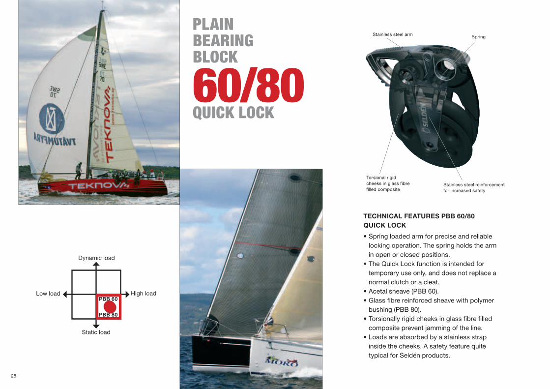
TECHNICAL FEATURES PBB 60/80 QUICK LOCK
•Springloadedarmforpreciseandreliable locking operation. The spring holds the arm in open or closed positions. •TheQuickLockfunctionisintendedfor temporary use only, and does not replace a normal clutch or a cleat. •Acetalsheave(PBB60).•Glassfibrereinforcedsheavewithpolymer bushing (PBB 80).•Torsionallyrigidcheeksinglassfibrefilled composite prevent jamming of the line. •Loadsareabsorbedbyastainlessstrap inside the cheeks. A safety feature quite typical for Seldén products.
pLAIN bEARINg bLoCK
60/80quICK LoCK
Spring
Stainless steel reinforcement for increased safety
Torsional rigid cheeks in glass fibre filled composite
Stainless steel arm
High load
Static load
Dynamic load
Low loadPBB 60
PBB 80
28

T
U
Y
I
Q
E
W
R
α/2 α/2
E
U
R
I
Q
T
W
Y
Single cheek with Quick lock, anti-clockwise
Single cheek with Quick lock, clockwise
Double cheek with two Quick lock, anti-clockwise
Double cheek with two Quick lock, clockwise
PBB 60 QUICK LOCK
PBB 80 QUICK LOCK
Art. No. Weight(g)
Safe working load (kg)Breaking load (kg)
Max line size (mm)
Fasteners
406-001-18R 198 1100 2200 14 3xM6 (not included)
406-001-19R 398 1100 (lower sheave) 550 (upper sheave)
2200 (lower sheave)1100 (upper sheave) 14 3xM6 (not
included)
406-001-21R 198 1100 2200 14 3xM6 (not included)
406-001-22R 398 1100 (lower sheave) 550 (upper sheave)
2200 (lower sheave)1100 (upper sheave) 14 3xM6 (not
included)
Art. No. Weight(g)
Safe working load (kg)Breaking load (kg)
Max line size (mm)
Fasteners
408-001-18R 395 2000 4000 16 3xM8 (not included)
408-001-19R 778 2000 (lower sheave) 1000 (upper sheave
4000 (lower sheave) 2000 (upper sheave 16 3xM8 (not
included)
408-001-21R 395 2000 4000 16 3xM8 (not included)
408-001-22R 778 2000 (lower sheave) 1000 (upper sheave
4000 (lower sheave) 2000 (upper sheave 16 3xM8 (not
included)
PBB Quick lock with spring loaded arm.
Fit cheek blocks so that they align with the direction of total load.
For more information about loads and hole patterns see page 96.
29
seldén ROlleR beaRing blOck
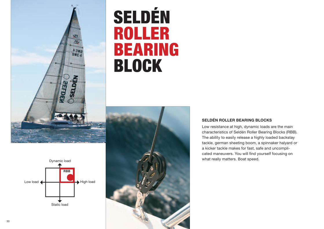
SELDÉN ROLLER BEARING BLOCKS
Low resistance at high, dynamic loads are the main characteristics of Seldén Roller Bearing Blocks (RBB). The ability to easily release a highly loaded backstay tackle, german sheeting boom, a spinnaker halyard or a kicker tackle makes for fast, safe and uncompli- cated maneuvers. You will find yourself focusing on what really matters. Boat speed.
High load
Static load
Dynamic load
Low load
RBB
30

TECHNICAL FEATURES RBB 60/80
•Designedforhighload,dynamicapplications.
•Machined,blackanodisedaluminiumcheeksand Torlon® roller bearings.
•PAwasherinsulatesstainlessfromaluminiumto prevent corrosion.
•TheshacklefeaturesaØ6/8mmbodyandØ8/10 mm pin, a strong and lightweight combination.
•Theswivelpinishollowandchamferedtoreduce weight.
•Acetalballbearingstabilizethesheavewhen subjected to side loads.
Machined,blackanodised aluminium cheeks.
Acetalballbearings
Torlon® rollers
Insulating washer
Machined,black anodised aluminium sheave
Ø6mmbody(RBB60)Ø8mmbody(RBB80)
Ø8mmpin(RBB60)Ø10mmpin(RBB80)
Swivel pin is hollow toreduce weight
Set screw. Switching from swivelling to fixed shackle.
The winch feeder is used for leading a line to a free winch.
31

Q W E
R T Y U
Q
W
E
R
T
Y
U
ROlleR beaRing blOck
60
Cheek Winch feeder Flip flop
RBB 60
Art. No. Weight(g)
Width B1 (mm)
Safe working load (kg)
Breaking load (kg)
Max line size (mm)
Shackle (Ø mm)
406-201-01R 205 - 1500 3000 12 6/8
406-201-02R 215 - 1500 3000 12 6/8
406-201-03R 135 14 1500 3000 12 8mmshaft
406-201-05R 330 - 1500 3000 12 6/8
406-201-07R 140 - 1500 3000 12 3xM6
406-201-08R 126 - 1500 3000 12 1xM10 countersunk
406-201-09R 274 - 1350 2700 12 4xM6
Single swivel
Single swivel becket
Single backstay/halyard
Double swivel
High load
Static load
Dynamic load
Low load
RBB 60RBB 80
The flip flop block is ideal for leading a vertical line aft. It is perfect for German sheeting. The deck attachments are well rounded machined aluminium. Leads and bushings between the shaft and the leads prevent rattling. The sheave is a RBB60 with Torlon roller bearings and Acetal ball bearings. The flip flop block has a great combination of low friction, flexibility and low chafe.
32

Q
W
E
R
T
E
Q W
R T
B1
Cheek
ROlleR beaRing blOck
80
RBB 80
Single swivel Single swivel becket
Single/halyard Double swivel
Art. No. Weight(g)
Width B1 (mm)
Safe working load (kg)
Breaking load (kg)
Max line size (mm)
Shackle/ fasteners
(Ø mm)
408-201-01R 417 - 2500 5000 14 8/10
408-201-02R 300 - 2500 5000 14 8/10
408-201-03R 282 14.5 2500 5000 14 10mmshaft
408-201-05R 667 - 2500 5000 14 8/10
408-201-07R 296 - 2500 5000 14 3xM8
RBB 80 Single swivel
RBB 60 and RBB 80 Single backstay/halyard
33

CHOOSE THE RIGHT BLOCK FOR YOUR APPLICATION
Ball bearing blocks are used where the loads are more moderate and dynamic. The ball bearings provide for good sheave rotation withthelowestpossiblefriction.Availablein20,30,40and60mmsheavediameters.
seldénball beaRing blOcks
BBB 30,pages 38-39
BBB 40,pages 40-41
BBB 60,pages 42-43
BBB 20,pages 36-37
ARB 45,pages 44-45
MRB 60,pages 45-47
High load
Static load
Dynamic load
Low load
BBB
Through deck block available in sizes BBB 20, BBB 30 and Suitable for dinghy and keelboat control lines, and also Furlex TD furling line.
34

BBB 30
BBB 40
BBB20
TECHNICAL FEATURES BBB 20/30/40
•Stainlesssteelballbearingraces,stainlesssteelballbearingsandAcetalsheaveforbestbearingstrengtheven under high dynamic loads.
•Acetalbearingcagestopreventball-to-ball friction and to reduce weight.
•Glassfibrereinforcedcomposite.
APPLICATIONS
Ball bearing blocks are typically used for medium and dynamic loads in:•Controllineapplications•Mainsailsheetsfordinghiesandkeelboats•Spinnakersheets,barberhaulers•Genoasheets•Dinghyapplications•Vangapplications
Cheekswithcomposite, 50/50glassfibre/polyamide
Stainless steel races
Big bearing diameter – less friction
Acetalball bearing cages
Stainless steel balls
CASCADE SYSTEMBBB 30/40
A special insert is used to locate the shackle at 0° or 90°. When removed the shackle spins freely. See page 92 for more information.
Fixed or swivelling shackle
35

Q W E
U
R T Y
I PO
Triple becket cam
ball beaRing blOck
20 Single strap
Triple becket
DoubleSingle becket strap
Double becket Triple
Triple cam Single tie onSingle fixed shackle
High load
Static load
Dynamic load
Low loadBBB 20
36

{
}
q
w e r
1. 2. 3.
Q
W
E
R
T
Y
U
I
O
}
P
q
e
{
w
r
wP
BBB 20
TECHNICAL FEATURES BBB 20
•Stainlesssteelstraptoensurehighstrengthandstiffsides.
•StainlesssteelballbearingsandAcetalsheaveforbest bearing strength even under high dynamic loads.
•Glassfibrereinforcedcomposite.
APPLICATIONS
•Controllinesondinghiesandkeelboats.•Leechlineapplications.
BBB 20
TIPS FOR FITTING BBB 20 TIE ON
BBB20tieoncanbefittedin three different ways. Note that the safe working load of the block is reducedby50%whentheBBB20isfitted as in picture 3.
Art. No. Weight(g)
Safe working load (kg)
Breaking load (kg)
Max line size (mm)
Shackle
402-101-01R 14 150 300 6 –
402-101-02R 16 150 300 6 –
402-101-03R 35 300 600 6 –
402-101-04R 36 300 600 6 –
402-101-05R 52 300 600 6 –
402-101-06R 54 300 600 6 –
402-101-07R 98 300 600 6 –
402-101-08R 100 300 600 6 –
402-101-09R 22 150 300 6 4
402-101-12R 7 100* 200* 6 –
402-101-13R 6 100 200 6 2xM4 (not included)
402-101-16R 8 100 200 6 2xM4 (not included)
402-101-17R 9 100 200 6 2xM4 (not included)
402-101-18R 17 100 200 6 2xM4 (not included)
402-101-19R 62 150 350 6 -
402-101-20R 17 150 300 6 1xM4(not included)
Single cheek
Single lead
Single through deck
Double through deck
Trapeze ring assy Single strap with tang
BBB 20 Cheek and single tie on are ideal for sail applications.
Compositeaxle Acetalballs
*Safeworkingload=50kg,breakingload=100kgwhentheBBB20isfittedasin picture 3 (to the left).
TECHNICAL FEATURES BBB 20, Pw
•Glassfibrereinforcedcomposite cheeks. •Acetalballbearingsforlightweight.•Acetalsheave.
37

Q W E
R
O
T Y
U I
Triple loop head becket cam
Single tie-on
Double loop head becket
Triple loop head
TECHNICAL FEATURES BBB 30
•Stainlesssteelballbearingraces,stainlesssteelballbearingsandAcetalsheaveforbestbearing strength even under high dynamic loads.
•Acetalbearingcagetopreventball-to-ball friction and to reduce weight.
•Glassfibrereinforcedcomposite.
ball beaRing blOck
30Single strap Single swivel/
fixed, becket
Double loop head
Single cheek
Single swivel/fixed
High load
Static load
Dynamic load
Low loadBBB 30
38

Q
I
W
O
E
P
R
{
T
}
e
Y
q
r
w
t
y
U
}
t
P q
y
w
{
re
Triple becket Single becket strap
Clew block Sheet block, swivel with slot. (Incl. in 403-101-12R and System 15)
Triple cam Single swivel, stand up
Art. No. Weight(g)
Safe working load (kg)
Breaking load (kg)
Max line size (mm)
Shackle (Ø mm)
403-101-01R 33 200 400 8 4
403-101-02R 24 200 400 8 –
403-101-03R 35 200 400 8 4
403-101-04R 49 400 800 8 –
403-101-05R 52 400 800 8 –
403-101-06R 77 600 1200 8 –
403-101-07R 130 540* 1080 7 –
403-101-08R 21 200 400 8 –
403-101-09R 22 200 400 8 2xM4 (not included)
403-101-10R 79 600 1200 8 –
403-101-11R 126 450* 900 7 –
403-101-12R 30 200 400 8 2xM4 (not included)
403-101-13R 29 200 400 8 –
403-101-14R 68 200 400 8 RingØ35x5
403-101-16R 26 200 400 8 -
403-101-22R 24 200 400 8 2xM5 (not included)
403-101-23R 22 200 400 8 2xM5 (not included)
403-101-24R 44 200 400 8 2xM5 (not included)
The centre hole can be used as a becket.
BBB 30
Single lead
Double through deck
Single through deck
*Safeworkingloadbasedoncamcleat433-101-01.39

Q W E
R T
I O P
Y
U {
Triple swivel
Single swivel/fixed becket
Single swivel/fixed cam
Single swivel/fixed becket cam
Triple swivel camTriple swivel becket
Single swivel/fixed Single strap. (The becket can be removed)
TECHNICAL FEATURES BBB 40
•Stainlesssteelballbearingraces,stainlesssteelballbearingsandAcetalsheaveforbestbearingstrength even under high dynamic loads.
•Acetalbearingcagetopreventball-to-ball friction and to reduce weight.
•Glassfibrereinforcedcomposite.
ball beaRing blOck
40
High load
Static load
Dynamic load
Low loadBBB 40
Double loop head
Double loop head becket
Triple swivel becket cam
For more information about dimensioning, see page 98.
404-040-01R Snap shackle 40 makes it easy to remove the block when needed It can be fitted to all Seldén BBB 40 blocks and. See page 92 for more information.
40

i
y
q
t
w e
o
u
}
p [
r
Q
W
E
R
T
Y
U
I
O
P
{
r
}
t
q
y
w
u
e
i
p
o
[
Single tie on
Fiddle swivel/fixed cam
Fiddle hook cam
Fiddle swivel/fixed becket cam
Fiddle hook cam eye
Fiddle swivel/fixed
Single becket strap(The becket can be removed)
Fiddle swivel/fixed, becket
Single cheek
Single lead Double through deck
Single through deck
BBB 40
Art. No. Weight(g)
Safeworkingload (kg)
Breakingload (kg)
Max linesize (mm)
Shackle(Ø mm)
404-101-01R 55 250 500 10 4
404-101-02R 45 250 500 10 –
404-101-03R 60 250 500 10 4
404-101-04R 100 90* 180 7 4
404-101-05R 104 180* 360 7 4
404-101-06R 98 500 1000 10 –
404-101-07R 102 500 1000 10 –
404-101-08R 168 750 1500 10 5
404-101-09R 171 750 1500 10 5
404-101-10R 216 450* 900 7 5
404-101-11R 220 540* 1080 7 5
404-101-12R 66 250 500 10 4
404-101-13R 70 250 500 10 4
404-101-14R 107 250 500 7 4
404-101-15R 115 250 500 7 4
404-101-16R 48 250 500 10 -
404-101-17R 49 250 500 10 2xM5 (not included)
404-101-18R 118 250 50 10 -
404-101-19R 120 250 500 10 -
404-101-20R 50 250 500 10 -
404-101-22R 53 250 500 10 2xM5 (not included)
404-101-23R 42 250 500 10 2xM5 (not included)
404-101-24R 93 250 500 10 2xM5 (not included)
*Safeworkingloadbasedoncamcleat433-101-01.41

Q W
E R
ball beaRing blOck
60These blocks are available both with ball bearings in Delrin as well as stainless steel. The Delrin version is a low weight alternative for moderate loads, whereas the “Heavy Duty” version is capable to handle higher loads.
TECHNICAL FEATURES BBB 60
• Ø5mmDelrinballbearingsandØ60mmAcetalsheave.
• Cheeksmadeofglassfibrereinforced composite.
TECHNICAL FEATURES BBB 60 HD (HEAVY DUTY)
• Ø5mmstainlessballbearingsandØ60mmAcetalsheave.
• Stainless steel ball bearing races
• Acetalbearingcagestopreventball-to-ballfriction and to reduce weight.
• Cheeksmadeofglassfibrereinforced composite.
Single becket
Single cam Single becket cam
Single
High load
Static load
Dynamic load
Low loadBBB 60
For more information about dimensioning, see page 98.
ABBB60HDblockcanbe distinguished from aregularBBB60bythegrey ball bearing cage.
42

Q
I
W
O
E
P
R
{
T
}
e
Y
q
w
U
O }
T
P
qw
Y
{
e
U I
Q
W
w
e
Art. No. Weight(g)
Safe working load (kg)
Breaking load (kg)
Max line size (mm)
Shackle (Ø mm)
406-601-01R 115 350 1000 10 5
406-601-02R 126 350 1000 10 5
406-601-03R 266 120 240 10 5
406-601-04R 276 240 480 10 5
406-601-05R 233 700 1400 10 5
406-601-06R 327 1000 2000 10 5
406-601-07R 337 1000 2000 10 5
406-601-08R 495 600 1200 10 5
406-601-09R 505 720 1440 10 5
406-601-10R 155 500 1000 10 5
406-601-11R 165 500 1000 10 5
406-601-12R 306 360 720 10 5
406-601-13R 316 480 960 10 5
406-601-14R 83 350 1000 10 -
406-601-15R 85 350 1000 10 3xM6(not included)
BBB 60
BBB 60, HEAVY DUTYStainless steel ball bearings
Triple becket Triple cam with becket for fine tuning
Double
Fiddle
Fiddle becket cam Single tie on Single cheek
Triple
Fiddle becketTriple becket cam
Fiddle cam with becket for fine tuning
Art. No. Weight(g)
Safe working load (kg)
Breaking load (kg)
406-601-51R 146 500 1000
406-601-52R 158 500 1000
406-601-64R 114 500 1000
406-601-65R 114 500 1000
43
seldénRaTcHeT blOcks
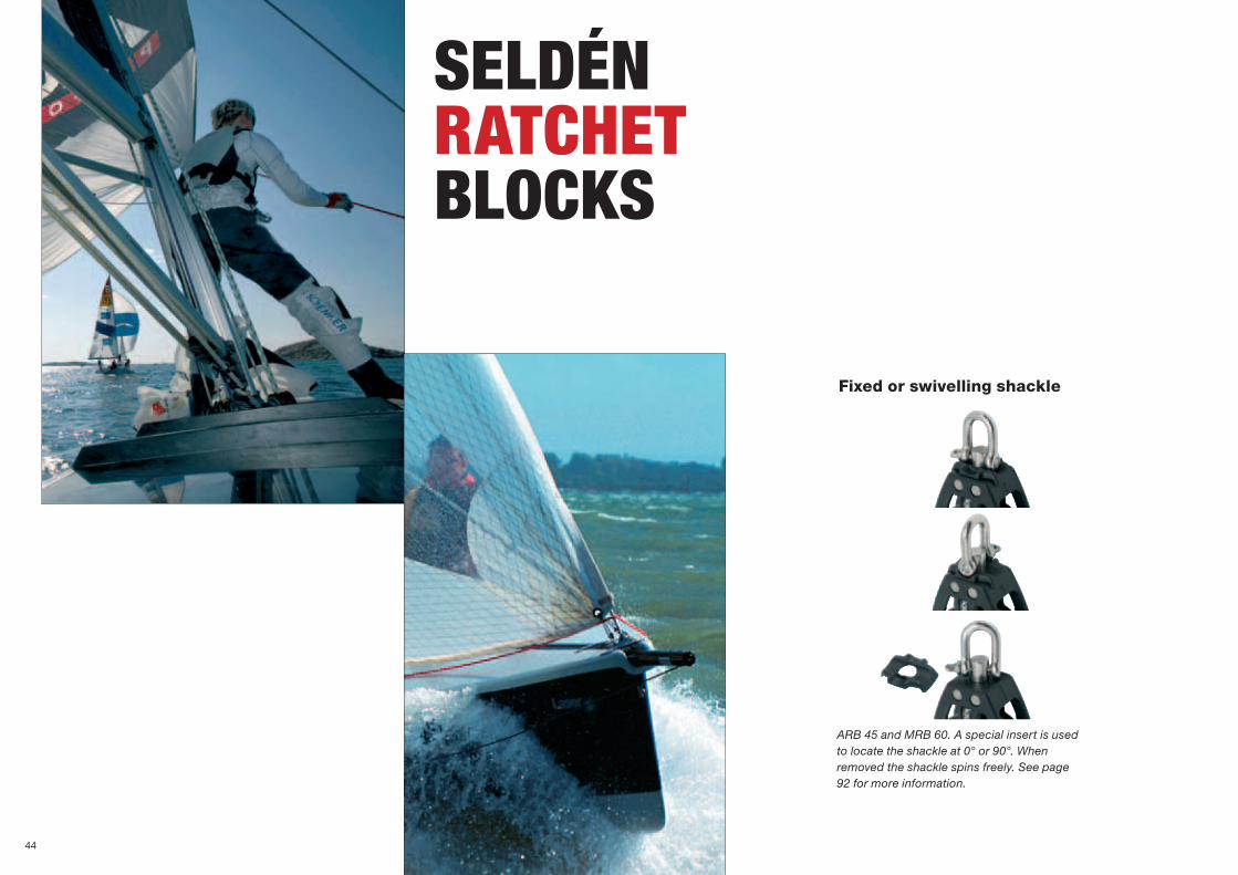
ARB 45 and MRB 60. A special insert is used to locate the shackle at 0° or 90°. When removed the shackle spins freely. See page 92 for more information.
Fixed or swivelling shackle
44
Q
Q
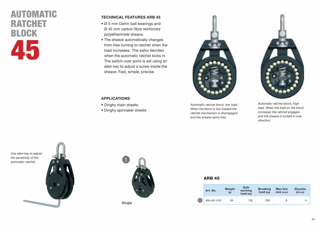
TECHNICAL FEATURES ARB 45
•Ø5mmDelrinballbearingsand Ø45mmcarbonfibrereinforcedpolyetherimide sheave.
•Thesheaveautomaticallychangesfrom free-turning to ratchet when the load increases. The sailor decides when the automatic ratchet kicks in. The switch-over point is set using an allen key to adjust a screw inside the sheave. Fast, simple, precise.
APPLICATIONS
•Dinghymainsheets.•Dinghyspinnakersheets
Automatic ratchet block, low load. When the block is low-loaded the ratchet mechanism is disengaged and the sheave spins free.
Automatic ratchet block, high load. When the load on the block increases the ratchet engages and the sheave is locked in one direction.
auTOmaTicRaTcHeT blOck
45
Use allen key to adjust the sensitivity of the automatic ratchet.
Art. No. Weight(g)
Safe working load (kg)
Breaking load (kg)
Max line size (mm)
Shackle (Ø mm)
404-401-01R 64 150 300 8 4Single
ARB 45
45

E
WQ
YT
R
Single swivel/fixed
Single swivel/fixed becket
Single swivel/fixed cam
Single swivel/fixed becket cam
Single cheek, clockwise
Single cheek, anti clockwise
High load
Static load
Dynamic load
Low load
For dinghy main or spinnaker sheets. Makesiteasytoadvance your grip when hauling in the sheet.Alsoeasierforaperson holding the sheet. The perfect combi nation of control and convenience.
manualRaTcHeT blOck
60
46
Q
Y
W
U
E
I
R
O
{
T
P
}
U I O
}{P
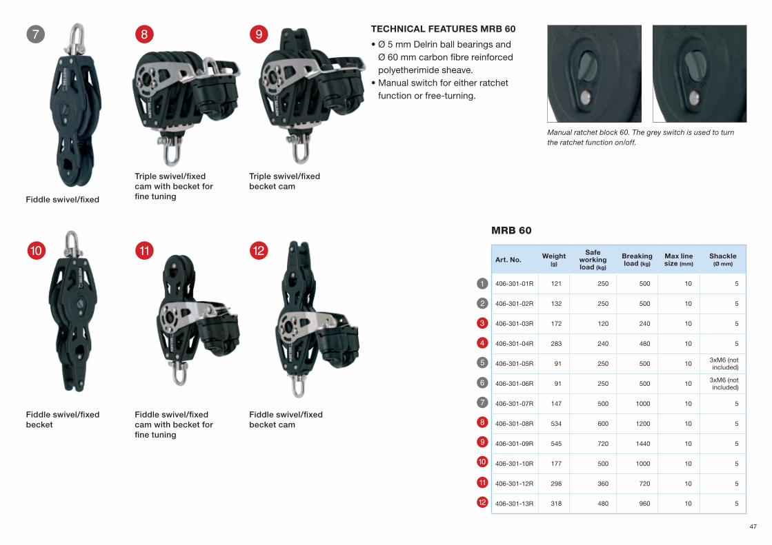
MRB 60
Art. No. Weight(g)
Safe working load (kg)
Breaking load (kg)
Max line size (mm)
Shackle (Ø mm)
406-301-01R 121 250 500 10 5
406-301-02R 132 250 500 10 5
406-301-03R 172 120 240 10 5
406-301-04R 283 240 480 10 5
406-301-05R 91 250 500 10 3xM6(notincluded)
406-301-06R 91 250 500 10 3xM6(notincluded)
406-301-07R 147 500 1000 10 5
406-301-08R 534 600 1200 10 5
406-301-09R 545 720 1440 10 5
406-301-10R 177 500 1000 10 5
406-301-12R 298 360 720 10 5
406-301-13R 318 480 960 10 5
Triple swivel/fixed cam with becket for fine tuning
Triple swivel/fixed becket cam
Fiddle swivel/fixed cam with becket for fine tuning
Fiddle swivel/fixed becket
Fiddle swivel/fixed becket cam
Fiddle swivel/fixed
Manual ratchet block 60. The grey switch is used to turn the ratchet function on/off.
TECHNICAL FEATURES MRB 60
•Ø5mmDelrinballbearingsand Ø60mmcarbonfibrereinforcedpolyetherimide sheave.
•Manualswitchforeitherratchetfunction or free-turning.
47

WQ
E R
Single becketSingle pin
SingleSingle loop
High load
Static load
Dynamic load
Low load
HIGH LOAD BBB 25
seldén HigH lOad ballbeaRingblOck
25
48

YT
U I
Q
W
E
R
T
Y
U
I
Triple becketTriple
HigH loAD BBB 25
Art. No. Weight(g)
Safe working load (kg)
Breaking load (kg)
Max line size (mm)
402-201-04R 36 400 800 5
402-201-05R 30 400 800 5
402-201-06R 32 400 800 5
402-201-07R 34 400 800 5
402-201-08R 58 400 800 5
402-201-09R 62 400 800 5
402-201-10R 84 400 800 5
402-201-11R 86 400 800 5
TECHNICAL FEATURES HIGH LOAD BBB 25
• Stainless steel sides to ensure high strength and stiffness.
•Onerowofstainlesssteelballbearings.•Ballcagetoreduceball-to-ballfrictionandweight.
APPLICATIONS
•Halyards•Tackles•Runners
Double Double becket
High load BBB 25 Purchase 3:1
49

TQ
seldén HigH lOadplain beaRing blOcks45/60/ 80/100/130
HIgH loADHigh load
Static load
Dynamic load
Low loadHIGH LOADPBB
50
B1
B2
Q
W
E
R
T
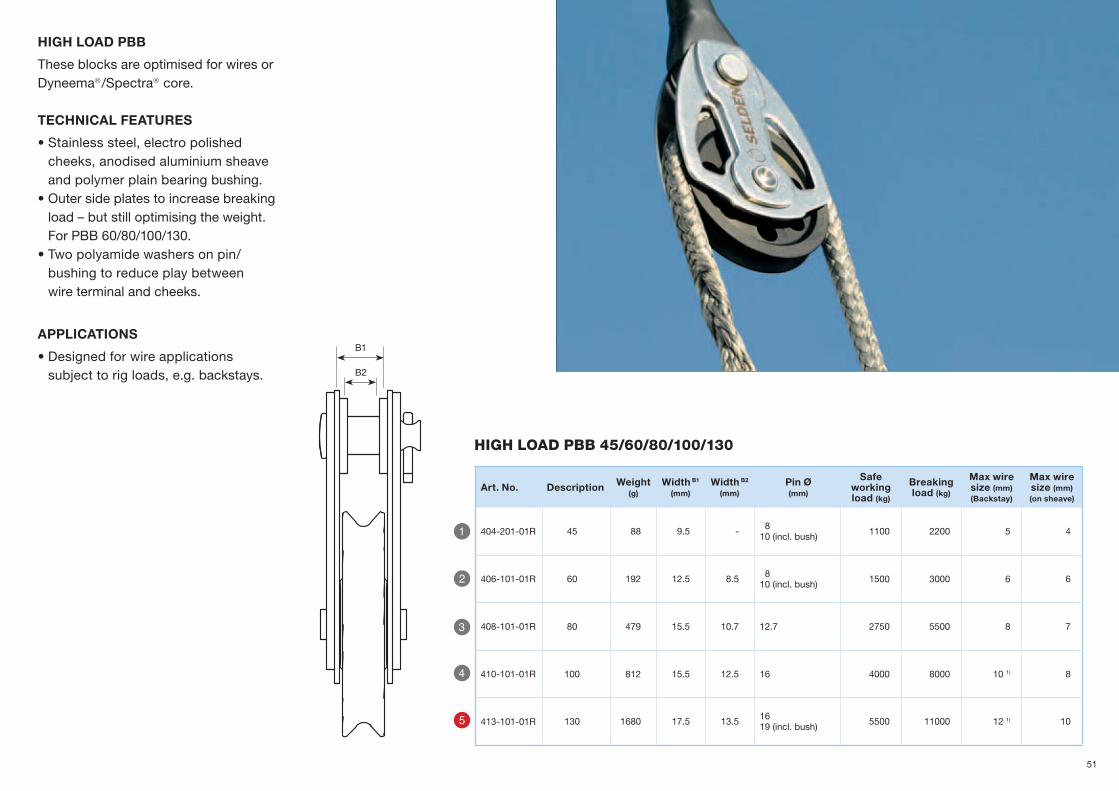
HIGH LOAD PBB
These blocks are optimised for wires or Dyneema/Spectra core.
TECHNICAL FEATURES
•Stainlesssteel,electropolishedcheeks, anodised aluminium sheave and polymer plain bearing bushing.
•Outersideplatestoincreasebreakingload – but still optimising the weight. ForPBB60/80/100/130.
•Twopolyamidewashersonpin/bushing to reduce play between wire terminal and cheeks.
APPLICATIONS
•Designedforwireapplications subject to rig loads, e.g. backstays.
Art. No. Description Weight(g)
Width B1 (mm)
Width B2
(mm)Pin Ø(mm)
Safe working load (kg)
Breaking load (kg)
Max wire size (mm)(Backstay)
Max wire size (mm)(on sheave)
404-201-01R 45 88 9.5 - 810(incl.bush) 1100 2200 5 4
406-101-01R 60 192 12.5 8.5 810(incl.bush) 1500 3000 6 6
408-101-01R 80 479 15.5 10.7 12.7 2750 5500 8 7
410-101-01R 100 812 15.5 12.5 16 4000 8000 101) 8
413-101-01R 130 1680 17.5 13.5 1619(incl.bush) 5500 11000 121) 10
HigH loAD PBB 45/60/80/100/130
51

seldén TRACKs And TRAVelleRs
TRACKSpages 56-57
TRAVELLERSYSTEM 22 pages 60-61
TRAVELLERSYSTEM 15 pages 54-55
TRAVELLERSYSTEM 30 pages 62-65
TRAVELLER SYSTEM 30 PERFORMANCEpages 68-71
TRAVELLER SYSTEM 42pages 66-67
COMBINATIONSpages 72-79
SELF TACKING JIB SYSTEMpage 78
COMPLETE SHEET SYSTEMSpage 80
TACKLESpage 81
52

Seldén’s tracks and travellers are designed with the same passion for sailing and attention to detail that has become a hall mark for Seldén. The ability to easily adjust the position of a traveller contributes to efficient and pleasant sailing both for the racing sailor as well as for the sailor out there just for pure pleasure. You simply manage active sailing for a longer period of time, which naturally influence the boat speed in a positive way. Ergonomics and low friction are key words for these products.
The systems are available in four sizes 15, 22, 30 and 42. System size selection is determined by boat size.For more information about dimensioning, see page 98.
SYSTEM 30
30’ 45’
20’
SYSTEM 22
33’
Dinghie
SYSTEM 15
22’
SYSTEM 42
40’ 65’
53
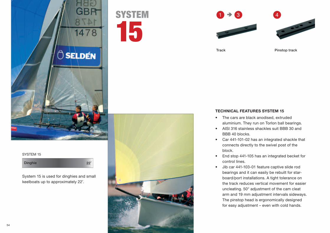
REQ sYsTeM
15
System 15 is used for dinghies and small keelboats up to approximately 22’.
Dinghie
SYSTEM 15
22’
TECHNICAL FEATURES SYSTEM 15
• The cars are black anodised, extruded aluminium. They run on Torlon ball bearings.
• AISI 316 stainless shackles suit BBB 30 and BBB 40 blocks.
• Car 441-101-02 has an integrated shackle that connects directly to the swivel post of the block.
• End stop 441-105 has an integrated becket for control lines.
• Jib car 441-103-01 feature captive slide rod bearings and it can easily be rebuilt for star-board/port installations. A tight tolerance on the track reduces vertical movement for easier uncleating. 50° adjustment of the cam cleat arm and 19 mm adjustment intervals sideways. The pinstop head is ergonomically designed for easy adjustment – even with cold hands.
Track Pinstop track
54

}
e
q
r t
{
w
U IY
O P
T
Y
I
P
}
q
U
O
{
w
r
e
t
Q
W
E
R
T
cars
tracks
accessories
Art. no. Weight(g)
Safe working load(kg)
Breaking load (kg)
Length(mm)
Width (mm)
441-101-01 84 120 400 112 42.5
441-101-02 109 120 400 112 42.5
441-101-03 60 120 400 68 42.5
441-101-04 50 120 400 57 42.5
441-102-01 40 120 400 56.6 42.5
441-103-01 165 120 240 68 7.5
441-103-02 165 120 240 68 7.5
441-105 5 - - 27 24
441-106 23 - - 20 20
Art. no. Weight(g)
Length(mm)
Width (mm)
Bolt
441-001-01 122 600 15 M4
441-001-02 205 1000 15 M4
441-001-03 302 1500 15 M4
441-002-01 59 300 15 M5
Art. no. Weight(g)
Safe working load(kg)
Breaking load(kg)
Length(mm)
Width (mm)
402-101-20R 17 150 300 46 20
403-101-16R 26 200 400 56 30
508-387R 5 - - 24 10
441-113R 5 200 400 25 7
Car with control block
Car with toggle and becket
Tie on car Jib car with pinstop located to starboard
Jib car with pinstop located to port
End cap Single strap with tang, BBB 20
Toggle main carSheet block, swivel with slot, BBB 30
Car with toggle
End stop for pinstop track
1-P eye
Car with block and control block
55

Q
W
E
R
QWER
TRACKsYsTeM
223042
Art. no. DescriptionWidth x height
(mm)
Track Art. no.
164-481 Washer M5Sliding bolt 10x1.2 442-003-0X
164-482 Washer M6Sliding bolt 18x1.6 442-011-0X
443-003-0X
164-483 Washer M8Sliding bolt 24x2 443-011-0X
444-003-0X
164-484 Washer M10Sliding bolt 30x2.5 444-011-0X
sealing washerHex bolt
Washer
Sealing
Sealing
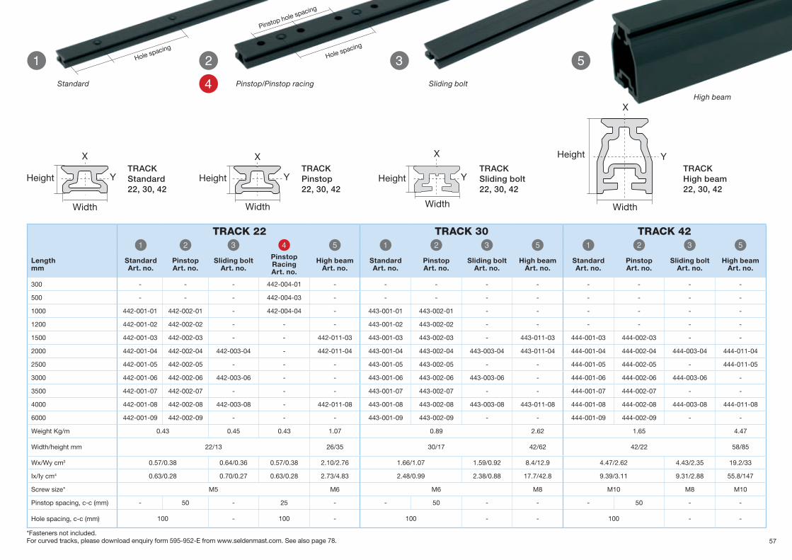
APPLICATIONS
• The standard track is used for cars adjusted with control lines and for self-tacking systems.
• The pinstop track is used for pinstop genoa cars. Pinstop is a spring loaded plunger fixing the genoa car on the purpose made track. The car is easy to relocate when not under load.
• The high beam track is used for unsupported main sheet systems and self tacking systems.
The bolt (DIN standard) is inserted in the track with the washer fitted. Sealing com-pound is applied between the flanges of the washer. The track turns up-side-down and is then mounted on deck.
Seldén tracks are available in three sizes. 22 mm, 30 mm and 42 mm width. Track size selection is deter-mined by boat size.
Width
Height
UPGRADING TO NEW TRACKS
The sliding bolt track is ideal for retrofit upgrades. The fasteners can be located according to the existing bolt holes. This track is also used for applications where the bolts are to be hidden.
For information about length of unsupported track, see page 102.
SYSTEM 30
30’ 45’
20’
SYSTEM 22
33’
SYSTEM 42
40’ 65’
56
Y
X Y
X
Y
X
Y
X
Q EW TR
TRACK Standard22, 30, 42
TRACK Pinstop22, 30, 42
TRACK Sliding bolt22, 30, 42
TRACK High beam22, 30, 42
*Fasteners not included. For curved tracks, please download enquiry form 595-952-E from www.seldenmast.com. See also page 78.
Width
Height
Width
Height
Width
Height
Width
Height
track 22 track 30 track 42Q W E R T Q W E T Q W E T
Lengthmm
StandardArt. no.
PinstopArt. no.
Sliding boltArt. no.
PinstopRacingArt. no.
High beamArt. no.
StandardArt. no.
PinstopArt. no.
Sliding boltArt. no.
High beamArt. no.
StandardArt. no.
PinstopArt. no.
Sliding boltArt. no.
High beamArt. no.
300 - - - 442-004-01 - - - - - - - - -
500 - - - 442-004-03 - - - - - - - - -
1000 442-001-01 442-002-01 - 442-004-04 - 443-001-01 443-002-01 - - - - - -
1200 442-001-02 442-002-02 - - - 443-001-02 443-002-02 - - - - - -
1500 442-001-03 442-002-03 - - 442-011-03 443-001-03 443-002-03 - 443-011-03 444-001-03 444-002-03 - -
2000 442-001-04 442-002-04 442-003-04 - 442-011-04 443-001-04 443-002-04 443-003-04 443-011-04 444-001-04 444-002-04 444-003-04 444-011-04
2500 442-001-05 442-002-05 - - - 443-001-05 443-002-05 - - 444-001-05 444-002-05 - 444-011-05
3000 442-001-06 442-002-06 442-003-06 - - 443-001-06 443-002-06 443-003-06 - 444-001-06 444-002-06 444-003-06 -
3500 442-001-07 442-002-07 - - - 443-001-07 443-002-07 - - 444-001-07 444-002-07 - -
4000 442-001-08 442-002-08 442-003-08 - 442-011-08 443-001-08 443-002-08 443-003-08 443-011-08 444-001-08 444-002-08 444-003-08 444-011-08
6000 442-001-09 442-002-09 - - - 443-001-09 443-002-09 - - 444-001-09 444-002-09 - -
Weight Kg/m 0.43 0.45 0.43 1.07 0.89 2.62 1.65 4.47
Width/height mm 22/13 26/35 30/17 42/62 42/22 58/85
Wx/Wy cm3 0.57/0.38 0.64/0.36 0.57/0.38 2.10/2.76 1.66/1.07 1.59/0.92 8.4/12.9 4.47/2.62 4.43/2.35 19.2/33
Ix/Iy cm4 0.63/0.28 0.70/0.27 0.63/0.28 2.73/4.83 2.48/0.99 2.38/0.88 17.7/42.8 9.39/3.11 9.31/2.88 55.8/147
Screw size* M5 M6 M6 M8 M10 M8 M10
Pinstop spacing, c-c (mm) - 50 - 25 - - 50 - - - 50 - -
Hole spacing, c-c (mm) 100 - 100 - 100 - - 100 - -
Hole spacing
Pinstop hole spacing
Hole spacing
Standard Pinstop/Pinstop racing Sliding bolt
High beam
57

10°10°
70°
α = 110°
70°
a = 110°
sYsTeM
223042
The load on a genoa car depends on yacht’s power and the sheet angle. A big overlapping 150% genoa has a flat angle of approximately 45º, and a 110% high performance jib will have a steep angle close to 80º. All safe working loads for Seldén genoa cars are based on 70° sheet angle, which gives a total deflection angle (a) of 110º. All safe working loads on Seldén main cars and self tacking cars are based on 10° sheet angle.
When developing the Seldén range of tracks and travellers, function, reliability and ease of use has been our main focus. But we also made them appealing to the eye. They will enhance the performance, looks and the quality of any boat. Available for 20’ keelboats up to 65’ yachts.
APPLICATIONS
• Main sheet systems• Genoa sheet systems• Self tacking systems
LOADS
Max working load for end controls are in line with corresponding main sheet car or genoa car.
58

The high beam adaptor can be used to finish off a high beam track. It fits together with all the end controls and end stops.
Rubber shock absorber.
The sheave house on a genoa car articulates 40° sideways, 8° aft/forward and can also twist to a certain extent. This enables the sheave to align correctly with the sheet direction. This is of great importance, particularly when the track is fitted on a curved surface between deck and cabin side.
Plain bearing Acetal sheaves for control lines.
Black laquered aluminium or glass fibre reinforced composite with rubber shock absorbers and integral beckets for control lines. Plain bearing Acetal sheaves in the sheave house in composite and 3:1, 4:1 or 6:1 purchase depending on size of system. Available with or without integrated cam cleats.
The toggle and sheet block are supported by a rubber stand-up collar to improve function and eliminate rattling.
AISI 316 mirror finished stainless toggles for Seldén PBB and RBB blocks.
The main sheet car is black anodised, extruded aluminium and runs on Torlon® ball bearings.
The toggle and sheet block are supported by a rubber stand-up collar to improve function and eliminate rattling.
End controls come with plain bearing Acetal sheaves and 3:1 or 4:1 purchase.
Shaft in 30° angle to track.
Sliderods in composite for low friction.
Genoa car comes with integral becket and sheave for control line.
Integral becket for control line.
The pinstop function is a spring loaded plunger fixing the genoa car on the purpose made track. The car is easy to relocate when not under load.
...and open.Pinstop switch in locked position…
MAIN SHEET SYSTEM
GENOA SHEET SYSTEM
59

Q W
q w
}
e
U
I O {P
YTRE
Main car
Genoa carMain car, pivoting sheaves, cam cleat
Genoa car, pinstop
Genoa end control End control End control, cam cleat, port
End control with cheek
End stop High beam adaptor
End control, cam cleat, starboard
End cap
Self tacking jib carJib car for use on Keelboats
sYsTeM
22
Seldén system 22 is used for keelboats and yachts up to approximately 33’. See all combinations at pages 72-79. For more information about dimensioning, see page 98.
Main car with cam
20’
SYSTEM 22
33’
60

T
U
O
{
Y
I
P
}
q
w
e
Q
W
E
R
sYsteM 22
Art. no Weight(g)
Safe working load 1), 2)
(kg)
Breaking load 2)
(kg)
Length(mm)
Width (mm)
Purchase
442-111-01 386 700 1400 140 60 4:1
442-111-02 3) 638 700 1400 250 60 5:1
442-144-01 393 500 1000 85 60 2:1
442-101-01 410 550 1100 108 49 3:1
442-102-01 401 550 1100 99 49 -
442-150-01 84 250 500 99 38 -
442-139-01 223 700 1400 90 60 -
442-103-01 4) 60 - - 64 30 4:1
442-112-01 4) 106 - - 89 39 4:1/5:1
442-112-02 4) 169 - - 89 85 4:1
442-112-03 4) 169 - - 89 85 4:1
442-112-04 4) 85 - - 89 39 2:1/3:1
442-105 4) 16 - - 35 33 -
442-138-01 4) 23 - - 51 40 -
442-135 19 - - 41 28 -
1) 70°sheet angle on genoa car. 2) Max working load for end controls are in line with corresponding main sheet car or genoa car. See system pages 72-79. 3) Fits only single, fiddle and becket blocks. 4) Fasteners not included. For more information about fasteners, see page 106.
When to use which end fitting: End controls for control lines and end stops with rubber shock absorbers. The function of the end cap is to keep the car on the track and to finish off the track. 443-135 is used when end controls, end caps or end stops are combined with High beam tracks.
TECHNICAL FEATURES SYSTEM 22
• The main sheet car and the self-tacking car are black anodised, extruded aluminium. They run on Torlon® ball bearings.
• The genoa car is black laquered aluminium with sliderods. Art. no. 442-150-01 is glass fibre reinforced composite.
• End fittings are glass fibre reinforced composite with rubber buffer bearings.
• Ø 30/40 mm plain bearing Acetal sheaves for control lines.
• Genoa cars available for pinstop operation and for control lines.
• AISI 316 mirror finished stainless toggles suit Seldén PBB50 blocks, BBB 60 blocks and the MRB 60 block.
• The toggle/sheet block is supported by a rubber stand-up collar.
• Ø 50 mm plain bearing Acetal sheave in the genoa car.
• Genoa car and end controls come with integral beckets for control lines.
• Suitable max size of control line is Ø 8 mm.• End controls with Cam cleat 27, control line Ø 7 mm.
Main sheet system
This pin stop car offers a 2:1 purchase for the jib sheet. Ideal for keelboat sailors who will benefit from instant trim possibilities and not always be dependent on a winch. The pin-stop plunger is neatly streamlined with the car and it’s easy to get a grip. The BBB 40 block is attached with a Dyneema lashing.
61

RE
Y I
T
U
WQsYsTeM
30Main car
Sheet lead
Main car with cam
Genoa car high load
Genoa carTriple main carDouble main car
Genoa car, pinstop
Seldén system 30 is used for yachts up to approximately 45’. See all combinations at pages 72-79. For more information about dimensioning, see page 98.
SYSTEM 30
30’ 45’
Tilt-absorber 444-151-01 for genoa car, see page 76. This prevents the unloaded sheave house chafing on the coach roof side.
62

Q
E
T
U
W
R
Y
I
O
{
P
}
P { }O
Genoa car ball bearing
Self tacking jib carGenoa car high load, pinstop
Double self tacking jib car
sYsteM 30
Art. no Weight(g)
Safe working load 1)
(kg)
Breaking load (kg)
Length(mm)
Width (mm)
Purchase
443-101-01 627 1500 3000 164 78 4:1
443-101-02 985 1500 3000 281 78 6:1
443-165-01 1224 2000 4000 284 78 4:1
443-165-02 1348 2000 4000 284 78 4:1
443-117-01 455 700 1400 107 60 3:1
443-126-01 432 700 1400 99 60 -
443-126-02 435 700 1400 99 60 -
443-130-01 822 1000 2000 170 60 4:1
443-148-01 790 1200 2400 180 78 4:1
443-151-01 806 1200 2400 165 60 -
443-139-01 403 1100 2200 117 78 -
443-139-02 929 2000 4000 237 78 -
1) 70°sheet angle on genoa car.
Genua car high load, pinstop.
TECHNICAL FEATURES SYSTEM 30
• The main sheet car and the self tacking car are black anodised, extruded aluminium. They run on Torlon® ball bearings.
• The genoa car is either black laquered aluminium with sliderods or an extruded and anodised aluminium car with Torlon® ballbearings.
• Ø 40 mm plain bearing Acetal sheaves for control lines.
• Genoa cars available for pinstop operation and for control lines.
• Main sheet car with Cam cleat 38. • AISI 316 mirror finished stainless toggles for
Seldén PBB 60, PBB 70 and RBB 60 blocks. Double self tacking car for PBB 80 and RBB 80.
• The toggle/sheet block is supported by a rubber stand-up collar.
• Ø 50/60 mm plain bearing Acetal sheave in the genoa car.
• Genoa car and end controls come with integral beckets for control lines.
• Suitable max size of control line is Ø 8 mm.
63

sYsTeM
30
Seldén system 30 is used for yachts up to approximately 45’. See all combinations at pages 72-79. For more information about dimensioning, see page 98.
TECHNICAL FEATURES SYSTEM 30 END FITTINGS
• Black laquered aluminium or glass fibre reinforced composite with rubber shock absorbers and integral beckets for control lines.
• Composite end caps. • Ø 40 mm plain bearing Acetal sheaves in the
composite sheave house. • Cam cleat 38 end controls.• End stop in Acetal.
The high beam adaptor can be used to finish off a high beam track. It fits together with all the end controls and end stops.
Rubber shock absorber.
Integral becket for control line.
The purchase of the genoa control line is doubled when adding a block and a 2-p eye.
SYSTEM 30
30’ 45’
64

Q
E
T
U
W
R
Y
I
O
Q
Y
W E
U
R T
I O
End control End control, Port End control, Starboard
Genoa end control
High beam adaptor End stop End stop self tacking
End control, single sheave
End cap
sYsteM 30
Art. no. Weight(g)
Length(mm)
Width (mm)
Purchase
443-112-01 225 99 52 4:1/5:1
443-112-02 330 99 92 4:1
443-112-03 330 99 92 4:1
443-112-04 206 99 52 3:1/ 4:1
443-124-01 91 81 45 4:1
443-125 28 40 40 -
443-135 43 39 50 -
443-142-01 74 61 52 2xM6
443-166-01 103 77 52 2xM8
End control with cam cleat
When to use which end fitting: End controls for control lines and end stops with rubber shock absorbers. The function of the end cap is to keep the car on the track and to finish off the track. 443-135 is used when end controls, end caps or end stops are combined with High beam tracks. Fasteners not included. For more information about fasteners, see page
106. Max working load for end controls are in line with corresponding main sheet car or genoa car. See system pages 72-79.
65

Q W
sYsTeM
42
Main car Double main car
Seldén system 42 can be used for boats up to approximately 65'. See all combinations at pages 72-79. For more information about dimensioning, see page 98.
TECHNICAL FEATURES SYSTEM 42
• The main sheet car and the self tacking car are black anodised, extruded aluminium. They run on Torlon® ball bearings.
• The genoa car is black anodized aluminium with slide rods and pinstop operated.
• The sheave house of the genoa car is AISI 316 mirror finished stainless steel.
• Ø 50 mm plain bearing Acetal sheaves and composite sheave houses for control lines.
• Ø 80 mm genoa sheave.• Cam cleat 38 used on end controls. • AISI 316 mirror finished stainless toggles for Seldén PBB
80 and RBB 80 blocks. Double self tacking car for PBB 100.
• The toggle/sheet block is supported by a rubber stand-up collar.
• End controls with rubber shock absorbers and integral beckets for control lines.
• Suitable max size of control line is Ø 10 mm.
SYSTEM 42
40’ 65’
When to use which end fitting: End controls for control lines and end stops with rubber shock absorbers. The function of the end cap is to keep the car on the track and to finish off the track. 443-135 is used when end controls, end caps or end stops are combined with High beam tracks.
66

T
U
O
Y
I
P
}
q
{
Q
W
E
R
E
Y U
I O P
T
R
} q{
Triple main carGenoa car, pinstop
Self tacking jib car End control
End control with cam, port End control with cam, starboard
High beam adaptor
End control with cheek
End stop End cap
Double self tacking jib car
Art. no. Weight(g)
Safe working load 1) 2)
(kg)
Breaking load 2)
(kg)
Length(mm)
Width (mm)
Purchase
444-101-01 1400 2500 5000 249 98 4:1
444-152-01 2594 3000 6000 384 98 4:1
444-152-02 2838 3000 6000 384 98 4:1
444-151-01 2050 2750 5500 220 69 -
444-139-01 740 2000 4000 144 98 -
444-139-02 1728 4000 8000 294 98 -
444-112-01 3) 510 - - 126 70 4:1/5:1
444-112-02 3) 626 - - 126 100 4:1
444-112-03 3) 626 - - 126 100 4:1
444-112-04 3) 440 - - 126 70 3:1/ 4:1
444-135 110 - - 64 70 -
444-138-01 3) 202 - - 78 70 -
444-127 38 - - 45 50 -
1) 70°sheet angle on genoa car. 2) Max working load for end controls are in line with corresponding main sheet car or genoa car. See system pages 72-79. 3) Fasteners not included. For more information about fasteners, see page 106.
To prevent over loading the system and to obtain the best function, a foot block should be used to lead the control line to the winch. Tilt-absorber for genoa car
444-151-01, see page 76.
sYsteM 42
67

sYsTeM
30peRfoRMAnCe
APPLICATIONS
• Main sheet systems• Genoa sheet systems
Seldén system 30 Performance can be used for boats up to approximately 45'. When low friction and high purchase ratios are key requirements, this is the system to chose. An extra bonus is the sophisticated look created by a fine composition of black anodised aluminium, Torlon® ball bearings and stainless steel.
Control line led to a vertical lead block and further to a cam cleat.
The cam cleat angle can be fine tuned vertically and horizontally, leading the control line straight to the trimmer.
68

The sheave house on a genoa car articulates 40° sideways, 8° aft/forward and can also twist to a certain extent. This enables the sheave to align correctly with the sheet direction. This is of great importance, particularly when the track is fitted on a curved surface between deck and cabin side. The low pivot-point reduces side loads and makes it easier to move the car under load.
Stainless stand-up spring.
Integral becket for rubber cord or to connect two genoa cars.
Ball bearing end controls. The purchase can be 2:1, 4:1, 6:1 or 7:1.
Rubber bushing eliminates rattling.
Rubber shock absorbers.
Aluminium sheaves with Torlon® ball bearings.
Stainless toggle.
Stainless stand-up spring.
Low pivot point handles side loads and the sheave house articulates to align correctly with the sheet direction. Easy operation with low friction.
The main sheet sheave has a plain bearing for vertical loads and Torlon® ball bearings stabilize the sheave when subjected to side loads. This system is for German sheeting. The control systems has a 6:1 purchase and aluminium
sheaves with Torlon® ball bearings. This makes for low friction and excellent ergonomics and helps the trimmer to sail actively for long periods of time. When boat speed really counts, this is the way to go.
Integral becket for control lines.
The cam cleat is angled towards the trimmer and the angle can be fine tuned by using wedges, 433-216-01R. It also has a horizontal adjustment. This results in excellent ergonomics and helps the trimmer to sail actively for long periods of time.
MAIN SHEET SYSTEM
GENOA SHEET SYSTEM
69

T
O {
Y U I
P
W
RE
Q
Main car fixed block Main car fixed block with cam
Main car with toggle
Genoa car with becketGenoa car single sheave
End control double sheaves Genoa car fiddle sheave
Genoa car double sheaves
End control single sheave
Main car with toggle and cam
Main car fixed double sheaves
SYSTEM
30pErforMancE
Seldén system 30 Performance can be used for boats up to approximately 45'. See all combinations at pages 72-79. For more inform-ation about dimensioning, see page 98.
SYSTEM 30
30’ 45’
70

O
{
q
w
P
}
Q
W
E
R
T
Y
U
I
} q w
End control double fiddle sheave
SYSTEM 30 PErforMancE
Art. no. Weight(g)
Safe working load 1) 2)
(kg)
Breaking load 2)
(kg)
Length(mm)
Width (mm)
Purchase
443-301-01 1140 1000 2000 164 78 6:1
443-301-02 1502 1000 2000 261 78 6:1
443-301-03 966 1500 3000 164 78 6:1
443-301-04 1318 1500 3000 261 78 6:1
443-301-05 1446 1000 2000 185 78 6:1
443-300-01 1063 1500 3000 203 78 2:1
443-300-02 1119 1500 3000 203 78 4:1
443-300-03 1038 1500 3000 203 78 1:1
443-302-02 1242 1500 3000 238 78 7:1
443-303-01 215 - - 88 53 2:1/3:1
443-303-02 274 - - 88 53 4:1/5:1
443-304-02 373 - - 124 53 7:1/8:1
443-125 3) 28 - - 40 40 -
443-135 43 - - 39 50 -
Genoa car fiddle sheave. Main car fixed block with cam
TECHNICAL FEATURES SYSTEM 30 PERFORMANCE
• Torlon® ball bearing cars.• All cars, end controls and sheave houses are
black anodised extruded aluminium.• Ø 30/40/50 mm trim sheaves with Torlon® ball
bearings. • Cam cleat 38 used for main sheet car and end
controls.• The toggle/sheet block is supported by a rubber
stand-up collar.• The main sheet sheave has a plain bearing for
vertical loads and Torlon® ball bearings stabilize the sheave when subjected to side loads.
• Ø 60 mm plain bearing Acetal sheave in the genoa car.
• Suitable max size of trim line is Ø 8 mm.• AISI 316 mirror finished stainless toggles for
Seldén PBB 60, PBB 70 and RBB 60 blocks. • End controls with rubber shock absorbers and
integral beckets for trim lines. • Genoa car has an integrated becket for rubber
cord or to connect two cars. • The sheave house of the genoa car is made of
AISI 316 mirror finished stainless steel. 1) 70°sheet angle on genoa car. 2) Max working load for end controls are in line with corresponding main sheet car or genoa car. See system pages 72-79. 3) Fasteners not included. For more information about fasteners, see page 106.
High beam adaptorEnd cap Tilt-absorber for genoa cars 443-300-01, 443-300-02, 443-300-03 and 443-302-02, see page 76.
Lubrication for Torlon® ball bearings, Art. No. 312-534.One drop will do!
71

Main SYSTEM 4:1
Size End controlArt. no.
Main carArt. no.
End controlArt. no.
System 22 442-112-01 442-111-01 442-112-01
System 30 443-112-01 443-101-01 443-112-01
System 42 444-112-01 444-101-01 444-112-01
Main SYSTEM 4:1, wiTh caM clEaT
Size End controlArt. no.
Main carArt. no.
End controlArt. no.
System 22 442-112-02 442-111-01 442-112-03
System 30 443-112-02 443-101-01 443-112-03
System 42 444-112-02 444-101-01 444-112-03
MainSYSTEM2230 30 pErforMancE
42
The control line is led to a separate cam cleat or winch, see page 67.
Operated with cam cleats fitted to the end controls. Suitable for coach roof installations in combination with mid sheeted booms.
Hint! Let the main sheet control line be endless and lead it through two rings. Each ring is fitted to the rail with rubber cord, each side of the cockpit. This way the leeward end of the control line can be released from windward.
SYSTEM 30
30’ 45’
SYSTEM 22
20’ 33’
SYSTEM 42
40’ 65’
A single lead block fitted to the cockpit side directs the control line to the trimmer, who locks it in a cam cleat. A convenient and common way to handle the traveller on keel boats.
72

Main SYSTEM 4:1 Main SYSTEM PErforMancE 6:1, fixEd block
Main SYSTEM PErforMancE 6:1
Size End controlArt. no.
Main carArt. no.
End controlArt. no.*
System 22 442-112-04 442-111-01 442-112-04
System 30 443-112-04 443-101-01 443-112-04
System 42 444-112-04 444-101-01 444-112-04
Size End controlArt. no.
Main carArt. no.
End controlArt. no.
System 30Performance 443-303-02 443-301-01 443-303-02
Size End controlArt. no.
Main carArt. no.
End controlArt. no.
System 30Performance
443-303-02 443-301-03 443-303-02
Main SYSTEM 5:1/6:1, caM clEaT on car Main SYSTEM PErforMancE 6:1,
caM clEaT fixEd blockMain SYSTEM PErforMancE 6:1, caM clEaT TogglE
Size End controlArt. no.
Main carArt. no.
End controlArt. no.
System 22 442-112-01 442-111-02 442-112-01
System 30 443-112-01 443-101-02 443-112-01
Size End controlArt. no.
Main carArt. no.
End controlArt. no.
System 30Performance
443-303-02 443-301-02 443-303-02
Size End controlArt. no.
Main carArt. no.
End controlArt. no.
System 30Performance
443-303-02 443-301-04 443-303-02
The cam cleat is angled towards the trimmer and the angle can be fine tuned by using wedges, 433-216-01R, see page 85. It also has a horizontal adjustment. This makes for excellent ergonomics and helps the trimmer to sail actively for long periods of time. This system is for German sheeting.
Lead block and cam cleat to be mounted separately in the cockpit, see page 72.
This system is for German sheeting. Lead block and cam cleat to be mounted separately in the cockpit, see page 67 and 72.
Lead block and cam cleat to be mounted separately in the cockpit. The toggle is suitable for PBB 60, PBB 70 and RBB 60 blocks.
The cam cleat is angled towards the trimmer and the angle can be fine tuned by using wedges, 433-116-01R and 433-216-01R, see page 85.
The cam cleat is angled towards the trimmer and the angle can be fine tuned by using wedges, 433-216-01R, see page 85. It also has a horizontal adjustment. This makes for excellent ergonomics and helps the trimmer to sail actively for long periods of time. The toggle is suitable for PBB 60, PBB 70 and RBB 60 blocks. Cam cleats angle adjustment, see page 68.
For a complete system, track and control line must be added.
73

MainSYSTEM30 30 pErforMancE
42
SYSTEM 30
30’ 45’
SYSTEM 22
20’ 33’
SYSTEM 42
40’ 65’
doublE/TriPlE Main SYSTEM 4:1, wiTh caM clEaT
Size End controlArt. no.
Main carArt. no.
End controlArt. no.
System 30 443-112-02 443-165-01 443-112-03
443-165-02
System 42 444-112-02 444-152-01 444-112-03
444-152-02
Operated with cam cleats fitted to the end controls. Suitable for coach roof installations in combination with mid sheeted booms.
Double main system
Triple main system
74

doublE/TriPlE Main SYSTEM 4:1 doublE/TriPlE Main SYSTEM 4:1 doublE Main SYSTEM PErforMancE 6:1, fixEd blockS
Size End controlArt. no.
Main carArt. no.
End controlArt. no.
System 30 443-112-01 443-165-01 443-112-01
443-165-02
System 42 444-112-01 444-152-01 444-112-01
444-152-02
Size End controlArt. no.
Main carArt. no.
End controlArt. no.*
System 30 443-112-04 443-165-01 443-112-04
443-165-02
System 42 444-112-04 444-152-01 444-112-04
444-152-02
Size End controlArt. no.
Main carArt. no.
End controlArt. no.
System 30Performance 443-301-02 443-301-05 443-301-02
Lead block and cam cleat to be mounted separately in the cockpit, see page 72.
Lead block and cam cleat to be mounted separately in the cockpit, see page 67 and 72.
The control line is led to a separate cam cleat.
75

gEnoa SYSTEM 3:1, Sliding rodS
gEnoa SYSTEM Pin SToP, Sliding rodS
SizeForward
End controlArt. no.
Genoa carArt. no.
AftEnd stopArt. no.
System 22 442-103-01 442-101-01 442-105
System 30 443-124-01 443-117-01 443-125
SizeForward End stopArt. no.
Genoa carArt. no.
Aft End stopArt. no.
System 22 442-105 442-102-01 442-105
442-150-01*
System 30 443-125 443-126-01 443-125
443-151-01
System 42 444-127 444-151-01 444-127
gEnoaSYSTEM2230 30 pErforMancE
42 Pin stop track to be used* 442-150-01 for 2:1 sheeting. For more information see page 92.
SYSTEM 30
30’ 45’
20’
SYSTEM 22
33’
SYSTEM 42
40’ 65’
TilT-abSorbEr for gEnoa carS
Art. No. Description Consists of Fits cars
443-155-01RGenoa tilt-absorber
2 x Tilt-absorber 3 x Screw M3x4 3 x Screw M4x5
443-148-01, 443-300-01, 443-300-02, 443-300-03, 443-302-02, 444-151-01
The tilt-absorber prevents the unloaded sheave house to chafe on the coach side.
76
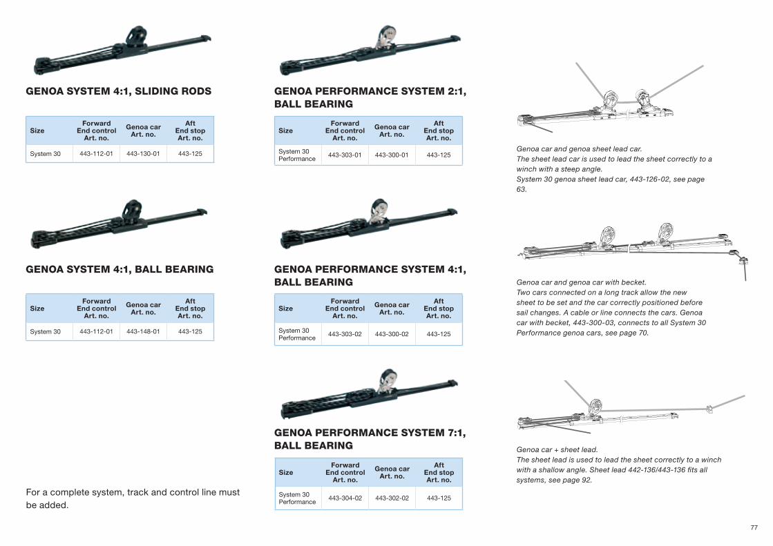
gEnoa SYSTEM 4:1, Sliding rodS gEnoa PErforMancE SYSTEM 2:1, ball bEaring
gEnoa PErforMancE SYSTEM 4:1, ball bEaring
gEnoa PErforMancE SYSTEM 7:1, ball bEaring
gEnoa SYSTEM 4:1, ball bEaring
SizeForward
End controlArt. no.
Genoa carArt. no.
AftEnd stopArt. no.
System 30 443-112-01 443-130-01 443-125
SizeForward
End controlArt. no.
Genoa carArt. no.
AftEnd stopArt. no.
System 30Performance
443-303-01 443-300-01 443-125
SizeForward
End controlArt. no.
Genoa carArt. no.
AftEnd stopArt. no.
System 30Performance
443-303-02 443-300-02 443-125
SizeForward
End controlArt. no.
Genoa carArt. no.
AftEnd stopArt. no.
System 30Performance
443-304-02 443-302-02 443-125
SizeForward
End controlArt. no.
Genoa carArt. no.
AftEnd stopArt. no.
System 30 443-112-01 443-148-01 443-125
Genoa car + sheet lead.The sheet lead is used to lead the sheet correctly to a winch with a shallow angle. Sheet lead 442-136/443-136 fits all systems, see page 92.
Genoa car and genoa car with becket. Two cars connected on a long track allow the new sheet to be set and the car correctly positioned before sail changes. A cable or line connects the cars. Genoa car with becket, 443-300-03, connects to all System 30 Performance genoa cars, see page 70.
Genoa car and genoa sheet lead car. The sheet lead car is used to lead the sheet correctly to a winch with a steep angle. System 30 genoa sheet lead car, 443-126-02, see page 63.
For a complete system, track and control line must be added.
77

SElfTackingJiBSYSTEM30
The ideal combination for convenience and performance - self tacking jib and Code 0.
Stainless steel AISI 316 side consols. Can be shortened if needed.
End stops with rubber shock absorbers.
2 brackets to secure the track to the deck ring or similar are included in each track assembly.
The cars run on Torlon® ball bearings.
Ball-joint for adjustment of the track angle and console angle.
Seldén provide customized curved tracks in sizes 22, 30 and 42 mm on request. An enquiry form, 595-952-E, is available at www.seldenmast.com.
78
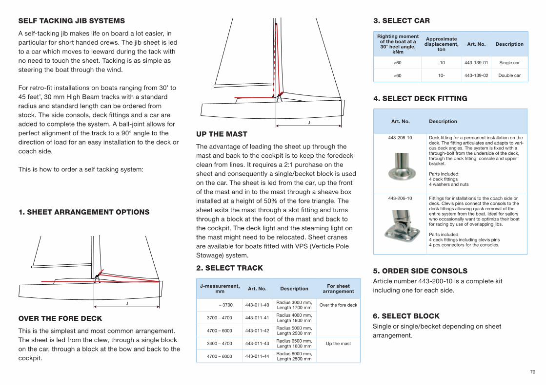
J
J
SElf Tacking jib SYSTEMS
ovEr ThE forE dEck
uP ThE MaST
1. ShEET arrangEMEnT oPTionS
2. SElEcT Track
3. SElEcT car
4. SElEcT dEck fiTTing
5. ordEr SidE conSolS Article number 443-200-10 is a complete kit including one for each side.
6. SElEcT blockSingle or single/becket depending on sheet arrangement.
A self-tacking jib makes life on board a lot easier, in particular for short handed crews. The jib sheet is led to a car which moves to leeward during the tack with no need to touch the sheet. Tacking is as simple as steering the boat through the wind.
For retro-fit installations on boats ranging from 30’ to 45 feet’, 30 mm High Beam tracks with a standard radius and standard length can be ordered from stock. The side consols, deck fittings and a car are added to complete the system. A ball-joint allows for perfect alignment of the track to a 90° angle to the direction of load for an easy installation to the deck or coach side.
This is how to order a self tacking system:
The advantage of leading the sheet up through the mast and back to the cockpit is to keep the foredeck clean from lines. It requires a 2:1 purchase on the sheet and consequently a single/becket block is used on the car. The sheet is led from the car, up the front of the mast and in to the mast through a sheave box installed at a height of 50% of the fore triangle. The sheet exits the mast through a slot fitting and turns through a block at the foot of the mast and back to the cockpit. The deck light and the steaming light on the mast might need to be relocated. Sheet cranes are available for boats fitted with VPS (Verticle Pole Stowage) system.
J-measurement, mm Art. No. Description For sheet
arrangement
– 3700 443-011-40 Radius 3000 mm, Length 1700 mm Over the fore deck
3700 – 4700 443-011-41 Radius 4000 mm, Length 1800 mm
4700 – 6000 443-011-42 Radius 5000 mm, Length 2500 mm
3400 – 4700 443-011-43 Radius 6500 mm, Length 1800 mm Up the mast
4700 – 6000 443-011-44 Radius 8000 mm, Length 2500 mm
Righting moment of the boat at a 30° heel angle,
kNm
Approximate displacement,
tonArt. No. Description
<60 -10 443-139-01 Single car
>60 10- 443-139-02 Double car
Art. No. Description
443-208-10 Deck fitting for a permanent installation on the deck. The fitting articulates and adapts to vari-ous deck angles. The system is fixed with a through-bolt from the underside of the deck, through the deck fitting, console and upper bracket.
Parts included:4 deck fittings4 washers and nuts
443-206-10 Fittings for installations to the coach side or deck. Clevis pins connect the consols to the deck fittings allowing quick removal of the entire system from the boat. Ideal for sailors who occasionally want to optimize their boat for racing by use of overlapping jibs.
Parts included:4 deck fittings including clevis pins 4 pcs connectors for the consoles.
This is the simplest and most common arrangement. The sheet is led from the clew, through a single block on the car, through a block at the bow and back to the cockpit.
79
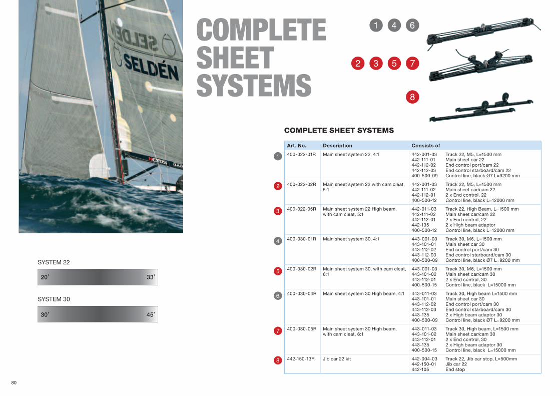
Q
R
W
T
E
Y
U
I
Q R Y
W E T U
I
SYSTEM 30
30’ 45’
20’
SYSTEM 22
33’
coMplETE ShEETSYSTEMS
Art. No. Description Consists of
400-022-01R Main sheet system 22, 4:1 442-001-03 442-111-01 442-112-02 442-112-03 400-500-09
Track 22, M5, L=1500 mm Main sheet car 22 End control port/cam 22 End control starboard/cam 22 Control line, black Ø7 L=9200 mm
400-022-02R Main sheet system 22 with cam cleat, 5:1
442-001-03 442-111-02 442-112-01 400-500-12
Track 22, M5, L=1500 mm Main sheet car/cam 22 2 x End control, 22 Control line, black L=12000 mm
400-022-05R Main sheet system 22 High beam, with cam cleat, 5:1
442-011-03 442-111-02 442-112-01 442-135 400-500-12
Track 22, High Beam, L=1500 mm Main sheet car/cam 22 2 x End control, 22 2 x High beam adaptor Control line, black L=12000 mm
400-030-01R Main sheet system 30, 4:1 443-001-03 443-101-01 443-112-02 443-112-03 400-500-09
Track 30, M6, L=1500 mm Main sheet car 30 End control port/cam 30 End control starboard/cam 30 Control line, black Ø7 L=9200 mm
400-030-02R Main sheet system 30, with cam cleat, 6:1
443-001-03 443-101-02 443-112-01 400-500-15
Track 30, M6, L=1500 mm Main sheet car/cam 30 2 x End control, 30 Control line, black L=15000 mm
400-030-04R Main sheet system 30 High beam, 4:1 443-011-03 443-101-01 443-112-02 443-112-03 443-135400-500-09
Track 30, High beam L=1500 mm Main sheet car 30 End control port/cam 30 End control starboard/cam 30 2 x High beam adaptor 30 Control line, black Ø7 L=9200 mm
400-030-05R Main sheet system 30 High beam, with cam cleat, 6:1
443-011-03 443-101-02 443-112-01 443-135 400-500-15
Track 30, High beam, L=1500 mm Main sheet car/cam 30 2 x End control, 30 2 x High beam adaptor 30 Control line, black L=15000 mm
442-150-13R Jib car 22 kit 442-004-03442-150-01442-105
Track 22, Jib car stop, L=500mmJib car 22End stop
coMPlETE ShEET SYSTEMS
80

UQ
{I
e}
R
I
}
Y
P
w
U
{
e
W
E
T
O
q
Q
Art. No. Description Block Line
400-004-01R Tackle 4:1 BBB40, Kick/aft 404-101-03 404-101-12 404-101-01
Single swivel/fixed becket Fiddle swivel/fixed Single swivel/fixed
400-503-12 Line, grey Ø7 L=12000 mm
400-005-01R Tackle 4:1 PBB50, Kick/aft 405-001-02 405-001-11 405-001-01
Single becket Fiddle Single
612-043-110
Line, grey Ø8 L=10000 mm
400-006-01R Tackle 4:1 PBB60, Kick/aft 405-001-02 406-001-11 405-001-01
Single becket Fiddle Single
612-053-112 Line, grey Ø10 L=12000 mm
400-006-11R Tackle 4:1 BBB60, Kick/aft 406-601-02 406-601-10 406-601-01
Single becket Fiddle Single
612-043-110 Line, grey Ø8 L=10000 mm
Art. No. Description Block Line
400-004-04R Tackle 6:1 BBB40, Cam 404-101-08 404-101-11
Triple swivel Triple swivel becket cam
400-503-18 Line, grey Ø7 L=18000 mm
400-005-04R Tackle 6:1 PBB50, Cam 405-001-07 405-001-10
Triple Triple becket cam
612-053-130 Line, grey Ø10 L=30000 mm
400-006-04R Tackle 6:1 PBB60, Cam 406-001-07 406-001-10
Triple Triple becket cam
612-053-130 Line, grey Ø10 L=30000 mm
400-006-14R Tackle 6:1 BBB60, Cam 406-601-06 406-601-09
Triple Triple becket cam
612-053-130 Line, grey Ø10 L=30000 mm
Art. No. Description Block Line
400-004-02R Tackle 4:1 BBB40, Cam 404-101-12 404-101-15
Fiddle swivel/fixed Fiddle swivel/fixed becket cam
400-503-12 Line, grey Ø7 L=12000 mm
400-004-03R Tackle 4:1 BBB40, Cam 404-101-12 404-101-15
Fiddle swivel/fixed Fiddle swivel/fixed becket cam
400-503-18 Line, grey Ø7 L=18000 mm
400-005-02R Tackle 4:1 PBB50, Cam 405-001-14 405-001-11
Fiddle becket cam Fiddle
612-043-110 Line, grey Ø8 L=10000 mm
400-005-03R Tackle 4:1 PBB50, Cam 405-001-11 405-001-14
Fiddle Fiddle becket cam
612-053-120 Line, grey Ø10 L=20000 mm
400-006-02R Tackle 4:1 PBB60, Cam 406-001-14 406-001-11
Fiddle becket cam Fiddle
612-053-112 Line, grey Ø10 L=12000 mm
400-006-03R Tackle 4:1 PBB60, Cam 406-001-14 406-001-11
Fiddle becket cam Fiddle
612-053-120 Line, grey Ø10 L=20000 mm
400-006-13R Tackle 4:1 BBB60, Cam 406-601-13 406-601-10
Fiddle becket cam Fiddle
612-053-120 Line, grey Ø10 L=20000 mm
TacklES 4:1 Operation from the cockpit
TacklES 6:1 Cam cleat operated. Can be used as kicker tackle, main sheet, backstay adjustment etc.
TacklES 4:1 Cam cleat operated. Can be used as kicker tackle, main sheet, backstay adjustment etc.TacklESUsing ready made tackles is an easy way to make noticeable improvements to fun-ction and looks on board. The line is a grey coloured, 24-plait Polyester line sewed to the block.
Examples of main sheet tackles with fine tuning.
81

SELDÉNCLEATS & SwivELS
Valley cleat, pages 86-87
Cam cleat,pages 84-85
Swivels,pages 88-89
82

CLEATS
Seldén produces Cam cleats in two sizes, together with all necessary accessories for efficient line handling. Valley cleats are also available in various sizes and for a wealth of different functions.
SWIVELS
The swivel range comprises deck swivels, mast swivels and eye swivels. The eye swivel features a unique combination of ball bearing (to improve stability) and plain bearing (to obtain optimal friction reduction).
The ten-step adjustment of the deck swivel is also unique, as are the horizontal angle adjustment and friction adjustment features.
Stainless steel ball bearings
Stop screws
Composite cam cleat 27
Composite arm
Stainless steel eye
Cam cleats with fairleads. Eye swivel
83

Q
W
E
R
Riser 27/38
Cam Cleat 27/38 CompositeCam Cleat 38 Aluminium
Top Guide 27/38
Fairlead 27/38CAm CLEATS
Seldén cam cleats are made of carbon fibre reinforced polyether imide. This material is selected for its high resistance to friction heat. There is also an aluminium version of cam cleat 38 available. The cleats have a compact design in order to save space.
CAM CLEATS27/38
84

U
I O P
T Y
Q
W
E
R
T
U
Y
I
O
Q
Q
W
E
R
T
Y
U
I
O
P
Cam Cleat 27Rope capacity 3-7 mm. Hole spacing c-c 27 mm.
Art. No. Weight(g)
Safe working load (kg)
433-101-01R 15 90
433-108-01R 3 –
433-110-01R 14 –
433-115R 9 –
433-116-01R 5 –
433-118R 3 –
433-119-01R 6 –
433-113-01R 4 –
319-844 1 –
Wedge Kit 27/38 Bull’s Eye 27/38Nut Recess 27/38
Line Guide 27/38 Curved Base 27/38 2-P Eye
Cam Cleat 38Rope capacity 4-12 mm. Hole spacing c-c 38 mm.
Art. No. Weight(g)
Safe working load (kg)
433-201-01R 32 120
433-301-01R 57 180
433-208-01R 9 –
433-210-01R 37 –
433-215R 21 –
433-216-01R 15 –
433-414R 5 –
433-219-01R 16 –
433-213-01R 11 –
319-823 3 –
508-019 14 –
Cam cleat with top guide.
85

Q
R
U
P
W
T
I
{
E
Y
O
}
Roller for lines coming from below (230) AL
Quick lock and release function for trapeze or vang (253) AL
Fine line application in sail, starboard (258) AL
Standard (201) PA
Fairlead (211 Mk2) AL
Rope entry from port (218 Mk1) AL
Standard (222) AL
”Fairlead. End of rope can be fixed under the cleat” (270) AL
Rope entry from port (218 Mk2) AL
Fairlead (211 Mk1) AL
Rope entry from starboard (217 Mk1) AL
Roller for lines coming from above (236) ALVALLEy CLEATS
This type of cleat is available in several versions for many different applications. Countersunk head screws or bolts of the recommended size should be used. The polyamide cleat is ideal for low load applications whereas the aluminium cleats prevent rope burn under higher load.
Seldén valley cleats are designed and produced by Clamcleat Ltd, UK.
vALLEY CLEATS
86

y
[ ]
u
w
i
eq
o p
r
t
Q
W
E
R
T
Y
U
I
O
P
{
}
q
u
w
i
e
o
r
p
t
[
]
yTapered pad. Aids rope alignment for 432-023 PA
Sail Line Starboard (CL241) AL
”Tapered pad. Aids rope alignment for 432-012, 432-015, 432-016, 432-018, 432-026” (818) PA
”Tapered pad. Aids rope alignment for 432-014, 432-025” (823) PA
Tapered pad. Aids rope alignment for 432-011 (802) PA
Standard (254) AL Fairlead (211 Mk2S2) AL
Fine line application in sail, port (259) AL
”Fairlead. End of rope can be fixed under the cleat” (704) AL
”Tapered pad. Aids rope alignment for 432-013, 432-024, 432-017” (819) PA
Sail Line Port (CL273) AL
Fairlead (268) AL
Art. No. Weight(g)
Rope capacity
(mm)Bolt Hole spacing
c-c, (mm)
432-010R 43 6-12 M6 72
432-011R 16 1-6 M4 36
432-012R 35 1-6 M5 66
432-013R 23 1-6 M4 27
432-014R 13 1-6 M3 24
432-015R 30 1-6 M5 66
432-016R 30 1-6 M5 66
432-017R 24 1-6 M4 27
432-018R 40 1-6 M5 66
432-019R 35 1-6 M5 66
432-020R 46 4-8 - 70
432-021R 19 3-6 M4 49
432-022R 19 3-6 M4 49
432-023R 38 4-8 M5 55
432-024R 21 1-6 M4 27
432-025R 11 1-6 M3 24
432-026R 34 1-6 M5 66
432-027R 4 - M3 -
432-028R 4 - M4 -
432-029R 8 - M4 -
432-030R 8 - M5 -
432-031R 14 - M5 -
432-033R 16 3-6 M4 49
432-034R 16 3-6 M4 49
Valley Cleat
87

W
Q
Eye Swivel 27/38
EyE SWIVELThe eye swivel is designed for control lines close to the deck, as with dinghy jib sheets. The swivel can also be used on bigger boats if the purchase of the tackle is sufficient. One eye swivel on each side of the coach roof is an ideal set-up for the vang. The crew on the rail can easily reach the vang to prevent a broach. The angle of articulation is easily adjusted with two screws. The swivel turns on stainless steel ball bearings for durability. The eye swivel is made of glass fibre filled polyamide with an electro polished, stainless steel line guide.
SWIVELS
Seldén provides three types of swivel – deck swivel, mast swivel and eye swivel.
DECk SwivEL 38EYE SwivEL 27/38 MAST SwivEL 27/38 Deck Swivel 38
88
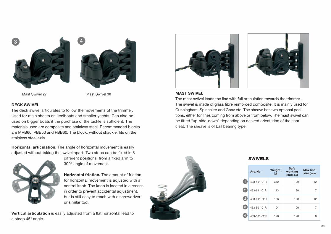
E R
Q
W
W
E
R
Mast Swivel 38Mast Swivel 27 mAST SWIVEL The mast swivel leads the line with full articulation towards the trimmer. The swivel is made of glass fibre reinforced composite. It is mainly used for Cunningham, Spinnaker and Gnav etc. The sheave has two optional posi-tions, either for lines coming from above or from below. The mast swivel can be fitted “up-side-down” depending on desired orientation of the cam cleat. The sheave is of ball bearing type.
SwiVelS
Art. No. Weight(g)
Safe working load (kg)
max line size (mm)
433-401-01R 362 120 12
433-611-01R 113 90 7
433-611-02R 166 120 12
433-501-01R 104 90 7
433-501-02R 126 120 8
Horizontal articulation. The angle of horizontal movement is easily adjusted without taking the swivel apart. Two stops can be fixed in 5
different positions, from a fixed arm to 300° angle of movement.
Horizontal friction. The amount of friction for horizontal move ment is adjusted with a control knob. The knob is located in a recess in order to prevent accidental adjustment, but is still easy to reach with a screwdriver or similar tool.
Vertical articulation is easily adjusted from a flat horizontal lead to a steep 45° angle.
DECK SWIVEL The deck swivel articulates to follow the movements of the trimmer. Used for main sheets on keelboats and smaller yachts. Can also be used on bigger boats if the purchase of the tackle is sufficient. The materials used are composite and stainless steel. Recommended blocks are MRB60, PBB50 and PBB60. The block, without shackle, fits on the stainless steel axle.
89

Y
U
O
I
P
R
T
E
Q
W
SELDÉNDECk orgANizEr40/50
DECK ORGANIZER
Seldén deck organizers keep the deck tidy and lead the ropes back to the cockpit. The acetal sheaves have acetal ball bearings absorbing side loads from a rope entering the organizer with a vertical angle. The result is low friction making hoisting and trimming of sails fast and easy. The organizers can be fitted to a slightly curved surface and two organizers can be stacked on top of each other. The deck organizers are made of glass fibre reinforced composite.
DECK ORGANIZER
2 sheaves
DECK ORGANIZER
3 sheaves
DECK ORGANIZER
4 sheaves
DECK ORGANIZER
5 sheaves
DECK ORGANIZER
6 sheaves
90

~50%
~50%
P
F
F
P
F
F
DeCK ORGaNiZeRS Ø 40 mmHole spacing c-c 47 mm
DeCK ORGaNiZeRS Ø 50 mmHole spacing c-c 58 mm
Y
R
T
E
U
O
I
P
Q
W
Safe working load is stated at 90º angles. * Safe working load and breaking load is reduced 50% for an organizer stacked on top of another.
* Safe working load and breaking load is reduced 50% for an organizer stacked on top of another.
Two organizers can be stacked on top of each other. Safe working load is stated at 90º angles. Safe working load and breaking load is reduced 50% for an organizer stacked on top of another.
Ball bearing sheaves absorbing side loads. For hole patterns, see page 105.
Fit the organizers so that they align with the direction of the total load. For more information, see page 97.
Art. No. Description Weight(g)
Safe working load* (kg)
Breaking load*
(kg)
max line size (mm)
Fasteners
420-001-02R 2 sheaves 100 700 1400 14 2xM6
420-001-03R 3 sheaves 154 700 1400 14 3xM6
420-001-04R 4 sheaves 194 700 1400 14 4xM6
420-001-05R 5 sheaves 238 700 1400 14 5xM6
420-001-06R 6 sheaves 292 700 1400 14 6xM6
Art. No. Description Weight(g)
Safe working load* (kg)
Breaking load*
(kg)
max line size (mm)
Fasteners
420-101-02R 2 sheaves 172 1000 2000 16 2xM8
420-101-03R 3 sheaves 258 1000 2000 16 3xM8
420-101-04R 4 sheaves 340 1000 2000 16 4xM8
420-101-05R 5 sheaves 420 1000 2000 16 5xM8
420-101-06R 6 sheaves 510 1000 2000 16 6xM8
91

U
T
Y
U
{
R
O
W
P
E
I
Q
}
w
q
e
}P OI
RQ
ew
YT
q
SELDÉN CoMPLEMENTArYHArD wArE
Art. No. Dimension Weight(g)
Safe working
load (kg)*
Breaking load (kg)
max line size (mm) Bolts
442-136R c-c 35 23 700 1400 10 2xM6
443-136R c-c 40 56 1100 2200 12 2xM8
443-162R c-c 40 103 1100 2200 8/12 2xM8
SHEET LEAD
Machined and black anodised sheet lead designed to lead lines over deck or to achieve correct angle to a winch. The smooth finish of this sheet lead gives minimal friction, allowing it to replace blocks in some applications. Works well as a lead on the windward spinnaker guy on boats up to 35’.
Art. No. Dimension Weight(g)
max line size (mm)
c-c(mm)
508-600R 25x10 1 5 15
508-601R 38x15 5 8 23
508-603R 25x10 4 5 15
508-604R 39x15 12 10 25
508-605R 52x20 30 14 34
508-609R 25x10 1 3 15
508-610R 25x10 3 4 15
508-611R 38x15 8 8 23
Art. No. Dimension Weight(g)
Combine with...
403-131R 20x16x7 1 BBB 30, Single/Fiddle
404-131R 26x18x5 1 BBB 40, Single/Fiddle, ARB 45 Single/Fiddle
406-610R 33x19x6 2 BBB 60, Single/Fiddle, MRB 60 Single/Fiddle
406-611R 30x22x10 2 BBB 60, Double/Triple, MRB 60 Triple
FaiRleaDPolyamide
SwiVel lOCK
Sheet leaDMachined aluminium
SWIVEL LOCK
An insert is used to locate the shackle at 0° or 90°. When removed the shackle spins freely. Used for BBB 30, BBB 40, BBB 60, ARB 45 and MRB 60.
Multi leadSheet lead
Genoa sheet
Control line
Main sheet (German sheeting)
92

}
w
r
{
q
e
t
y
u
e{
ur
R
Y
W
E
Q
T
U
O
I
P
Q R I
W E
O P
DW
L1
L2
Snap Shackle adaptorS/ low friction ShackleS Duplex 2205 stainless
SNAP SHACKLE ADAPTOR
A brilliant solution for any application you want to attach and remove quickly, for example runners and check stays. Just replace the stand-ard shackle with a snap shackle.
LOW FRICTION SHACKLE
This new snap shackel has a big, well rounded loop allowing the rope to slide with low friction. Compared to a regular snatch block, this shackle is lighter, easier to operate and lower cost. Typi-cal applications are barber haulers for spinnaker and jibs but also to tension a Seldén CX with 2:1 purchase. This not only makes for better perform-ance but it also makes it easier to connect the Seldén CX to a bowsprit, from the foredeck. The shackle is made of high strength Duplex steel and has a quality mirror finish.
Art. No. Dim. Weight(g)
Safe working load (kg)
Breaking load(kg)
Combine with...
404-040-01R 40 25 550 1100 BBB 40
405-040-01R 50 60 900 1800 PBB 50, Seldén CX10, GX7,5, GX10
406-040-01R 60 96 1500 3000 PBB 60, PBB 70, RBB 60, Seldén CX15, GX15
408-040-01R 80 232 2500 5000 PBB 80, RBB 80, Seldén CX25
410-040-01R 100 490 4000 8000 PBB 100, Seldén CX40
307-435-01R 50 70 900 1800 PBB 50, Seldén CX10, GX7,5, GX10
307-436-01R 60 118 1500 3000 PBB 60, PBB 70, RBB 60, Seldén CX15, GX15
307-437-01R 80 278 2500 5000 PBB 80, RBB 80, Seldén CX25
307-438-01R 100 540 4000 8000 PBB 100, Seldén CX40
LOW FRICTION SHACKLE
SNAP SHACKLE ADAPTOR
Low friction shackle for barber hauler and 2:1 purchase
This block is used for 2:1 purchase for a Code 0 or main halyard. The pin is captive. No risk dropping it over board.
Art. No. Dimension Weight(g)
Safe working load (kg)
Breaking load(kg)
Combine with...
307-004R Ø12x24x41 186 4000 8000 PBB 100
307-026R Ø8x16x35 56 1500 3000 PBB 70RBB 60
307-027R Ø10x19x41 126 2000 4000 PBB 80
307-080R Ø4 8 250 500 BBB 30 BBB 40
307-081R Ø5 16 700 1400 PBB 50, BBB 40*BBB 60**, MRB 60**
307-085R Ø8/10 76 2000 4000 PBB 80RBB 80
307-086R Ø6 26 1100 2200 PBB 60BBB 60**, MRB 60**
307-097R Ø6/8 40 1500 3000 PBB 70RBB 60
307-098R Ø5x11x26 18 700 1400 PBB 50
307-099R Ø6x12x33 32 1100 2200 PBB 60
Max working load/breaking load are valid when the shackle is fitted to appropriate Seldén block. *Only used on BBB40 triple. **Only used on BBB60/MRB60 double/triple.
forGed ShackleSStainless AISI 316, Duplex (307-004R)
Art. No. Dim. Weight(g)
L1 L2 W DSafe
working load (kg)
Breaking load(kg)
Max line size (mm)
Combine with...
403-501-01R 30 130 66 21 13 8 1500 3000 10 CX15
404-501-01R 40 245 83 26 18 10 2500 5000 12 CX25
405-501-01R 50 505 104 31 24 12 4000 8000 16 CX40
block for 2:1 purchaSe
93

qI
{
O
P
I
}
q
E U
E
R
T
Y
U
ew
w
e
Q W
Q
W
StaND-up SpRiNGSStainless AISI 316
Art. No. Dimension Weight(g)
Combine with...
308-074R Ø36.5x70 19PBB 50BBB 60MRB 60
308-085R Ø50x85 49PBB 60PBB 70 RBB 60
308-093R Ø60x100 76 PBB 80RBB 80
308-095R Ø72x145 153 PBB 100
403-123R Ø20/16-25 2 BBB 20BBB 30
433-411R Ø30/20-40 2 BBB 40
SELDÉN CoMPLEMENTArYHArD wArE
When supported by a stand-up spring, a deck mounted block is always ready for action.
Forged and electro polished fittings to attach tackles, cascades, halyard blocks and plenty of other items.
These foldable padeyes are used to attach life lines, stay sail furlers, blocks for down haul and barber haulers just to give a few examples. To be able to fold down the eye when not in use is a blessing for bare feet crew members.
FiXeD paD eyeSStainless AISI 316
*When the padeye is aligned with direction of load.
Art. No. Dimension Weight(g)
Safe working load (kg)*
Breaking load(kg)
FastenersCombine with...
Block Stand-up spring
508-815R Ø50 74 1000 2000 2xM6PBB 50BBB 60MRB 60
308-074R
508-816R Ø60 154 2000 4000 4xM6PBB 60PBB 70RBB 60
308-085R
508-817R Ø72 248 3000 6000 4xM8 PBB 80 308-093R
508-818R Ø86 460 4000 8000 4xM10 PBB 100 308-095R
508-347R 40x35 52 700 1400 4xM5 BBB 40 PBB 50 308-074R
FOlDable paD eyeSStainless AISI 316
Art. No. Dimension Weight(g)
Safe working load (kg)
Breaking load(kg)
Bolts
508-750-01R Ø6/42x42 74 1100 2200 3xM6
508-760-01R Ø8/54x54 154 2200 4400 3xM8
eye bOltS
Art. No. Dimension,bolt
Weight(g)
Safe working load (kg)
Breaking load (kg)
Combine with...
Block Stand up spring
508-352-01 M10x112 112 1000 2000 PBB 50 PBB 60 307-074R
508-357-01 M8x67 35 500 1000 BBB 40 PBB 50 -
For hole patterns, see page 103.
94
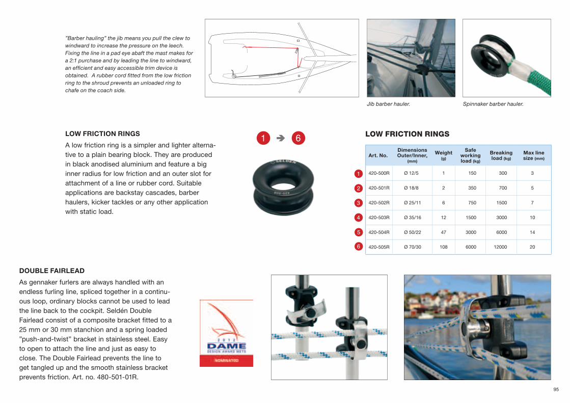
YQ
R
Y
W
E
T
Q
lOw FRiCtiON RiNGS
Art. No.DimensionsOuter/Inner,
(mm)
Weight(g)
Safe working load (kg)
Breaking load (kg)
max line size (mm)
420-500R Ø 12/5 1 150 300 3
420-501R Ø 18/8 2 350 700 5
420-502R Ø 25/11 6 750 1500 7
420-503R Ø 35/16 12 1500 3000 10
420-504R Ø 50/22 47 3000 6000 14
420-505R Ø 70/30 108 6000 12000 20
DOUBLE FAIRLEAD
As gennaker furlers are always handled with an endless furling line, spliced together in a continu-ous loop, ordinary blocks cannot be used to lead the line back to the cockpit. Seldén Double Fairlead consist of a composite bracket fitted to a 25 mm or 30 mm stanchion and a spring loaded ”push-and-twist” bracket in stainless steel. Easy to open to attach the line and just as easy to close. The Double Fairlead prevents the line to get tangled up and the smooth stainless bracket prevents friction. Art. no. 480-501-01R.
LOW FRICTION RINGS
A low friction ring is a simpler and lighter alterna-tive to a plain bearing block. They are produced in black anodised aluminium and feature a big inner radius for low friction and an outer slot for attachment of a line or rubber cord. Suitable applications are backstay cascades, barber haulers, kicker tackles or any other application with static load.
”Barber hauling” the jib means you pull the clew to windward to increase the pressure on the leech. Fixing the line in a pad eye abaft the mast makes for a 2:1 purchase and by leading the line to windward, an efficient and easy accessible trim device is obtained. A rubber cord fitted from the low friction ring to the shroud prevents an unloaded ring to chafe on the coach side.
Jib barber hauler. Spinnaker barber hauler.
95

α/2 α/2
~50%
~50%
P
F
F
P
F
F
400 kg
400 kg
100 kg
800 kg
100 kg
400 kg
200 kg
600 kg600
600 kg
100 kg
The deflection angle must be the same on both sides to guarantee safe working load.
LOADS 6:1 purchase with triple blocks.
4:1 purchase with fiddle blocks.
8:1 purchase with cascade of single blocks.
Breaking loads and safe working loadsBreaking loads
Our definition of a breaking load is that load which causes any part of a product to break when it is subjected to successively increasing loads during laboratory testing.
Safe working loads
Our definition of safe working load is set at half the breaking load. We guarantee that products subjected to loads that are below or up to this limit will function satisfactorily.
Loads in the specification tables
The breaking load and safe working load values shown in the product tables are for the product itself (not for the line). The load exerted on the product depends on the load in the line and on the deflection angle of the lines around the sheave.
PUrCHase sYsTeMsA mechanical system can be used to increase the effect of human force required for a specific situation. Such systems are designed in several ways. A selection of typical mechanical systems are shown to the right.
angles
Selecting the correct product for a specific purpose and an expected load is the only way to ensure safe sail handling and high perfor-mance. Always follow Seldén’s guidelines. If in doubt, please consult a Seldén dealer.
96

a [°] k
0 2,00
10 1,99
20 1,97
30 1,93
40 1,88
50 1,81
60 1,73
70 1,64
80 1,53
90 1,41
100 1,29
110 1,15
120 1,00
130 0,85
140 0,68
150 0,52
160 0,35
170 0,17
180 0
70°
α = 110°
P
F = 100 kg F = 100 kg
F
F
POrg
PBlock
Block
Org / 2
Org / 2α
α
α
FF
follow THe lineThe load (P) exerted on a product depends on the load in the line (F) and on the deflection angle (a) of the line around the sheave.
P = k x F P = the load on the block k = load factor F = the load in the line
This applies to blocks, organizers and travellers.
CHoosing THe rigHT BloCk, exaMPle:Assume a halyard load of 800 kg. While the load in the line remains constant over its entire length, the load on the sheaves depends on the individual deflection angle.
Mast base blockF = 800 kg ablock = 90º k = 1.41 Pblock = k x F = 1.41 x 800 = 1128 kg
Deck organizerF = 800 kg aorg = 140º k = 0.68 Porg = k x F = 0.68 x 800 = 544 kg
The block is exposed to a load of 1128 kg which means a PBB 70 or RBB 60 will do the job. The deck organizer is exposed to a load of 544 kg which makes us choose the deck organizer size 40.
The selection of block in this example is based on strength requirement only. Wear and friction is not taken into consideration. There-fore a bigger size can sometimes be prefer-able, see dimensioning guidelines for your application.
CalCUlaTed load on a genoa Car, exaMPle:Safe working load for a Seldén genoa car is calculated with sheet angle of 70º, equal to a deflection angle of 110º.
A high performance #3 Genoa might have a sheet angle up to 90º, which gives a deflection angle of 90º.
Example Assume a sheet load of 1000 kg and deflection angle 90°.
F = 1000 kg a = 90º a#3 Genoa = 110º k = 1.41/1.15 Pcar = k x F = 1.41/1.15 x 1000 = 1226 kg
Load on the traveller in this example will be 1226 kg.
97

E max
S
0 20 40 60 80 100 120 140 160
RM 30º (kNm)
RBB 80 36' 52'
RBB 60 30' 43'
PBB 100 43'
PBB 80 34' 48'
PBB 70 30' 43'
PBB 60 27' 38'
PBB 50 23' 32'
BBB 60 18' 25'
BBB 60 HD 20' 29'
BBB 40 16' 22'
MRB 60 18' 32'
0 20 40 60 80 100 120 140 160
RM 30º (kNm)
RBB 80 42'
RBB 60 35' 50'
PBB 100 51'
PBB 80 39'
PBB 70 35' 50'
PBB 60 31' 45'
PBB 50 26' 38'
BBB 60 20' 29'
BBB 60 HD 23' 33'
BBB 40 18' 26'
MRB 60 18' 32'
DimenSiOninG RM 30º
(kNm)
Displ.(tonnes)
6 1.28 1.6
10 2.012 2.414 2.816 3.218 3.620 4.025 5.030 5.735 6.340 7.045 7.750 8.255 9.060 1070 1180 1290 14
100 15110 16120 18130 19140 20150 22160 23
Main sHeeT BloCk, Mid sHeeTed BooM (s>50% of e)
Main sHeeT BloCk, end sHeeTed BooM (s>90% of e)
The guidelines are based on strength, function, wear and friction for yachts up to RM=160 kNm (approx 55 feet). For larger yachts please contact your Seldén dealer.
To select the correct block, traveller and track you need to know:
• E=foot length of the main sail.
• S=distance from aft side of the mast to the sheet attachment.
• If your boom is end sheeted or mid sheeted, i e the relation between E and S.
• The righting moment at 30°. If righting moment is not available an approximation can be made from displacement (tonnes) or boat length (feet).
Boat size
Boat size
98

Main sHeeT Car, end sHeeTed BooM (s>0,9*e)
0 20 40 60 80 100 120 140 160
RM 30º (kNm)
SYSTEM 42 43'
SYSTEM 30 Perf. toggle
35' 45'
SYSTEM 30Perf. fixed block
30' 43'
SYSTEM 30Standard
35' 44'
SYSTEM 22 27' 33'
Boat size
Main sHeeT Car, Mid sHeeTed BooM (s>0,50*e)
0 20 40 60 80 100 120 140 160
RM 30º (kNm)
SYSTEM 42 39'
SYSTEM 30 Perf. toggle
32' 45'
SYSTEM 30Perf. fixed block
28' 40'
SYSTEM 30Standard
32' 44'
SYSTEM 22 24' 33'
Boat size
self TaCking Car
0 20 40 60 80 100 120 140 160
RM 30º (kNm)
SYSTEM 42 Double
40'
SYSTEM 42 Single
31' 44'
SYSTEM 30 Double
31' 44'
SYSTEM 30Single
25' 36'
SYSTEM 22 21' 30'
Boat size
genoa sHeeT Car
0 20 40 60 80 100 120 140 160
RM 30º (kNm)
SYSTEM 42 40'
SYSTEM 30 Performance
34' 45'
SYSTEM 30 Ball bearing
32' 45'
SYSTEM 30 High load
30' 42'
SYSTEM 30 26' 37'
SYSTEM 22 24' 33'
Boat size
99

RBB 80 36' 52'
RBB 60 30' 43'
PBB 100 43'
PBB 80 33' 48'
PBB 70 30' 43'
PBB 60 27' 38'
PBB 50 23' 32'
BBB 60 18' 25'
BBB 60 HD 20' 29'
BBB 40 15' 22'
0 20 40 60 80 100 120 140 160
RM 30º (kNm)
0 20 40 60 80 100 120 140 160
RM 30º (kNm)
RBB 80 36' 51'
RBB 60 30' 42'
PBB 100 43'
PBB 80 33' 47'
PBB 70 30' 42'
PBB 60 26' 38'
PBB 50 22' 32'
BBB 60 18' 25'
BBB 60 HD 20' 28'
BBB 40 15' 22'
RBB 80 37' 53'
RBB 60 31' 44'
PBB 100 45' 64'
PBB 80 34' 49'
PBB 70 31' 44'
PBB 60 28' 39'
PBB 50 23' 33'
BBB 60 18' 26'
BBB 60 HD 20' 29'
BBB 40 16' 23'
0 20 40 60 80 100 120 140 160
RM 30º (kNm)
Mast base block
BloCk for sPinnaker HalYard, MasT Base
BloCk for genoa HalYard, MasT Base
BloCk for Main HalYard, MasT BaseBoat size Boat size
Boat size
100

0 20 40 60 80 100 120 140 160
RM 30º (kNm)
RBB 80 38' 54'
RBB 60 31' 44'
PBB 100 45'
PBB 80 35' 49'
PBB 70 31' 44'
PBB 60 28' 40'
PBB 50 23' 33'
BBB 60 18' 26'
BBB 60 HD 20' 29'
BBB 40 16' 23'
0 20 40 60 80 100 120 140 160
RM 30º (kNm)
0 20 40 60 80 100 120 140 160
RM 30º (kNm)
RBB 80 32' 46'
RBB 60 27' 39'
PBB 100 38' 54'
PBB 80 30' 43'
PBB 70 27' 39'
PBB 60 25' 35'
PBB 50 21' 31'
BBB 60 17' 24'
BBB 60 HD 20' 28'
BBB 40 15' 22'
MRB 60 15' 22'
0 20 40 60 80 100 120 140 160
RM 30º (kNm)
RBB 80 40'
RBB 60 33' 47'
PBB 100 48'
PBB 80 37' 53'
PBB 70 33' 47'
PBB 60 29' 42'
PBB 50 25' 36'
BBB 60 20' 28'
BBB 60 HD 22' 32'
BBB 40 17' 24'
0 20 40 60 80 100 120 140 160
RM 30º (kNm)
RBB 80 31' 44'
RBB 60 26' 36'
PBB 100 37' 53'
PBB 80 28' 41'
PBB 70 26' 36'
PBB 60 23' 33'
PBB 50 19' 27'
BBB 60 20' 28'
BBB 60 HD 17' 24'
BBB 40 13' 19'
Topmast block
BloCk for sPinnaker HalYard, ToPMasT
BloCk for sPinnaker sHeeT and gUY Line will turn 180 degrees
BloCk for rodkiCker TaCkle
BloCk for kiCking sTraPBoat size
Boat size
Boat size
Boat size
101

UnSUppOrteD trAckS
An unsupported high beam track will withstand the main sheet load if correctly dimensioned.
Max UnsUPPorTed lengTH, Usl
RM 30º kNm
HB 22USL (mm)
HB 30USL (mm)
HB 42USL (mm)
S=E S=0.5xE S=E S=0.5xE S=E S=0.5xE
5 866 800 1792 1540
10 800 500 1655 1310
15 727 375 1505 1195
20 613 305 1408 1120
30 462 235 1281 1016
40 378 1197 882
50 323 1137 755
60 284 1089 664
70 255 1051 600
80 232 1019 550
90 991 500 1495 1187
100 929 465 1459 1158
110 869 435 1427 1112
120 818 410 1398 1046
130 773 390 1372 989
140 734 365 1349 939
150 700 350 1327 895
160 1307 855
170 1289 820
180 1272 788
190 1256 758
200 1241 732
210 1227 707
220 1214 684
230 1201 663
240 1189 644
250 1178 626
260 1167 609
270 1157 593
280 1147 578
290 1128 564
300 1102 551
Unsupported length, USL
E = foot length of the main sail. S = distance from aft side of the mast to the sheet attachment.
102
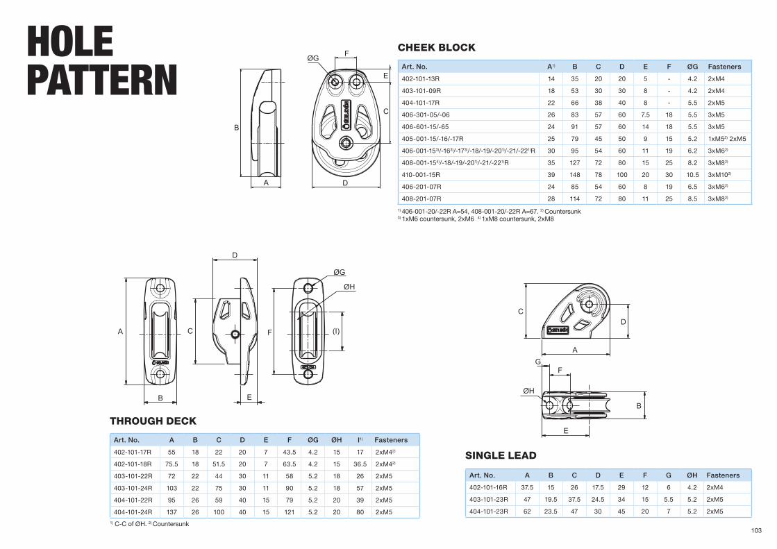
B
A D
C
E
FØG
CD
AG
F
ØH
E
B
A
B
C
D
E
F (I)
ØH
ØG
Art. No. A B C D E F G ØH Fasteners
402-101-16R 37.5 15 26 17.5 29 12 6 4.2 2xM4
403-101-23R 47 19.5 37.5 24.5 34 15 5.5 5.2 2xM5
404-101-23R 62 23.5 47 30 45 20 7 5.2 2xM5
single lead
Art. No. A1) B C D E F ØG Fasteners
402-101-13R 14 35 20 20 5 - 4.2 2xM4
403-101-09R 18 53 30 30 8 - 4.2 2xM4
404-101-17R 22 66 38 40 8 - 5.5 2xM5
406-301-05/-06 26 83 57 60 7.5 18 5.5 3xM5
406-601-15/-65 24 91 57 60 14 18 5.5 3xM5
405-001-15/-16/-17R 25 79 45 50 9 15 5.2 1xM52) 2xM5
406-001-153)/-163)/-173)/-18/-19/-201)/-21/-221)R 30 95 54 60 11 19 6.2 3xM62)
408-001-154)/-18/-19/-201)/-21/-221)R 35 127 72 80 15 25 8.2 3xM82)
410-001-15R 39 148 78 100 20 30 10.5 3xM102)
406-201-07R 24 85 54 60 8 19 6.5 3xM62)
408-201-07R 28 114 72 80 11 25 8.5 3xM82)
CHeek BloCk
1) 406-001-20/-22R A=54, 408-001-20/-22R A=67. 2) Countersunk 3) 1xM6 countersunk, 2xM6 4) 1xM8 countersunk, 2xM8
Art. No. A B C D E F ØG ØH I1) Fasteners
402-101-17R 55 18 22 20 7 43.5 4.2 15 17 2xM42)
402-101-18R 75.5 18 51.5 20 7 63.5 4.2 15 36.5 2xM42)
403-101-22R 72 22 44 30 11 58 5.2 18 26 2xM5
403-101-24R 103 22 75 30 11 90 5.2 18 57 2xM5
404-101-22R 95 26 59 40 15 79 5.2 20 39 2xM5
404-101-24R 137 26 100 40 15 121 5.2 20 80 2xM5
THroUgH deCk
1) C-C of ØH. 2) Countersunk
HOLe pAttern
103
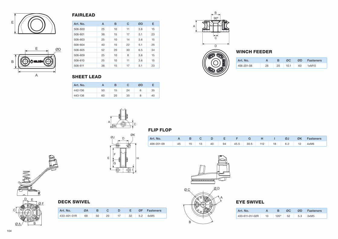
D EØ F
Ø A B
C
Ø C Ø D
A
B
BA
C
ØJ
EF
G
I
H
ØKD
A
C
B
90º
D
B
E
A
ØD
E
Art. No. A B ØC ØD Fasteners
433-611-01/-02R 13 120º 52 5.3 3xM5
eYe swiVel
Art. No. ØA B C D E ØF Fasteners
433-401-01R 68 50 20 17 32 5.2 4xM5
deCk swiVel
winCH feeder
fairlead
fliP floP
Art. No. A B ØC ØD Fasteners
406-201-08 26 20 10.1 60 1xM10
Art. No. A B C D E F G H I ØJ ØK Fasteners
406-201-09 45 15 13 40 94 45.5 30.5 112 18 6.2 12 4xM6
Art. No. A B C ØD E
508-600 25 10 11 3.6 15
508-601 38 15 17 5.1 23
508-603 25 10 14 3.6 15
508-604 40 15 22 5.1 25
508-605 52 20 30 6.5 34
508-609 25 10 8 3.6 15
508-610 25 10 11 3.6 15
508-611 38 15 17 5.1 23
sHeeT lead
Art. No. A B C ØD E
442-136 50 15 24 6 35
443-136 60 20 35 8 40
104

B
ØD
ØE
A
A
C
ØF
J
B C C
EF
GH
I
K
ØD
ØA
AE
ØD
C
B
A B
C
E
ØD
ØF
G
E
ØD
C
G
BA
ØF
Art. No. A B C ØD ØE ØF Fasteners2)
508-347R1) 20x25 25 6 35x40 5.2 13 4xM5
508-815R 30 26 8.5 50 6.5 11 2xM6
508-816R 30 34 11 60 6.5 14 4xM6
508-817R 35 41 13.5 72 9 16.5 4xM8
508-818R 42 52 17.5 86 11 20.5 4xM10
Art. No. A B C ØD ØE Fasteners2)
508-750-01R 49 43 27.5 7 24 3xM6
508-760-01R 65 56 34 8.7 32 3xM8
fixed Pad eYes
foldaBle Pad eYes
1) Squared base, see page 92. 2) Countersunk
2) Countersunk
System ØA B C ØD E F G H I J K
40 7 42 47 40 109 156 203 250 297 25 50
50 9 54 58 50 137 195 253 311 369 27 54
snaP sHaCkle adaPTor/low friCTion sHaCkle
deCk organiZers
Art. No. A B C ØD E ØF G
307-435-01 45.6 36.7 8.6 5 12.2 14.5 12.8
307-436-01 53.9 42.8 9.5 6 13.2 17.3 15.2
307-437-01 72 56.7 12.7 10 18.2 23.1 20.2
307-438-01 89 70 9.6 12 22.5 28.6 25
404-040-01 32.5 27 5.8 4 8.2 10 4.6
405-040-01 46.1 38.7 8.5 5 12.2 14 6
406-040-01 54 45.5 9.4 6 13.2 16.5 6.8
408-040-01 71.7 60.7 12.5 10 18.2 22 9.3
410-040-01 88.6 75 15.5 12 22.5 27.2 11.6
105

ØD
B
E
C
A
ØD
AE
B
C
ØD
AE
B
C
ØD
B
A
EC
C
B
A
EF
ØD
ØD
E
B
CA
Art. No. A B C ØD E Fasteners1)
442-105 36 33 14 5.2 8 1xM5
443-125 41 41 18 6.2 9 1xM6
444-127 44 51 30 10.2 13 1xM10
Art. No. A B C ØD E
443-303-01/-02 89 53 34 8,2 63
443-304-02 124 53 69 8,2 98
Art. No. A B C ØD E
442-135 40 37 30 5.2 20
443-135 36 50 15 7.2 6
444-135 64 70 41 10.2 25
Art. No. A B C ØD E Fasteners
442-112-01/-02/-03/-04 87 40 23 5.2 53 1xM5
443-112-01/-02/-03/-04 100 52 24 6.2 74 1xM61)
444-112-01/-02/-03/-04 126 70 31 10.2 81 1xM101)
Art. No. A B C ØD E F Fasteners
442-138-01 51 40 23 5.2 45 18 2xM5
443-142-01 70 52 32 6.2 66 22 2xM61)
443-166-01 77 51 29 8.2 71 22 2xM81)
444-138-01 90 70 42 10.2 56 30 2xM101)
end ConTrol
end sToP
HigH BeaM adaPTor
end ConTrol PerforManCe
end CaP
1) Countersunk
1) Countersunk1) Countersunk
Fasteners included. M8 screw to be threaded in the track.
Art. No. A B C ØD E Fasteners1)
442-103-01 60 30 4 5,5 53 1xM5
443-124-01 71 45 10 6,2 62 1xM6
end ConTrol genoa
1) Countersunk
106
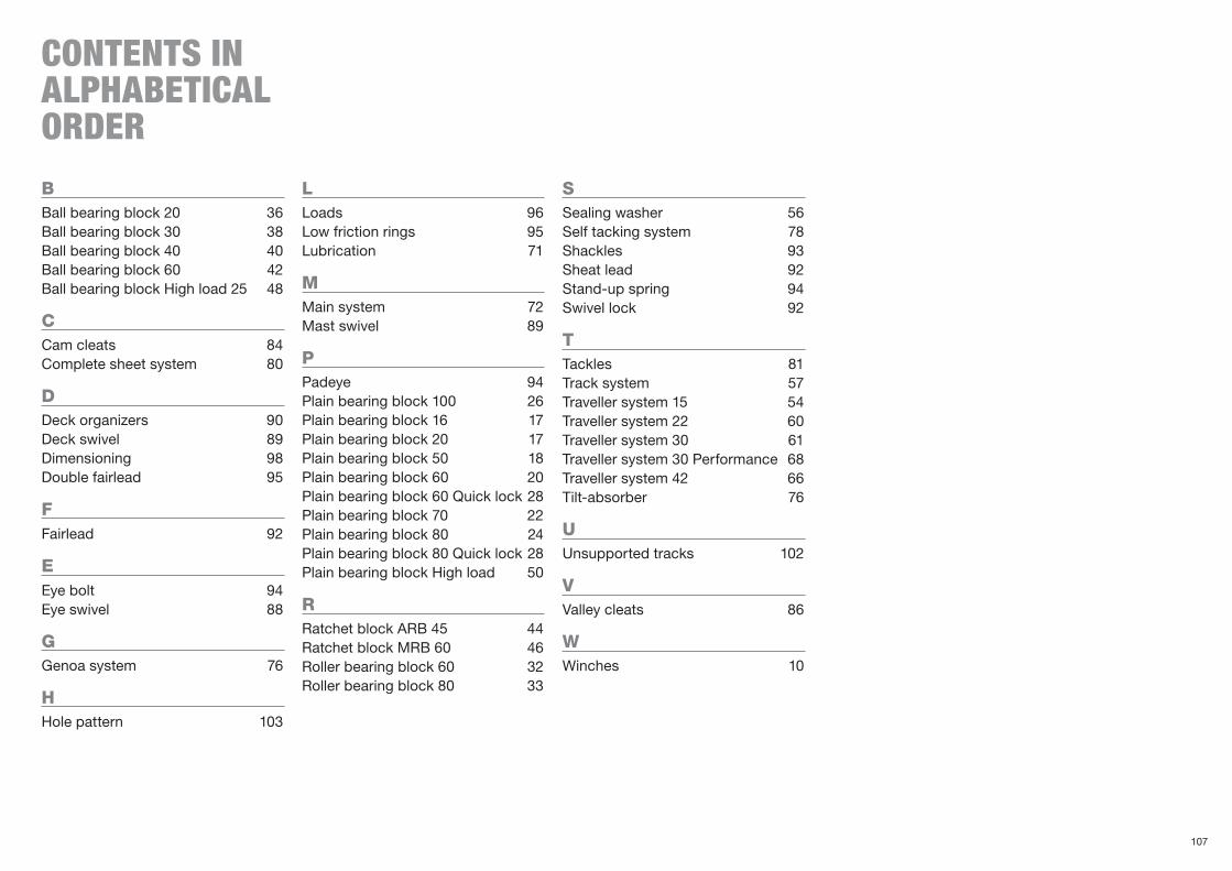
cOntentS in ALpHAbeticAL OrDer
BBall bearing block 20 36Ball bearing block 30 38Ball bearing block 40 40Ball bearing block 60 42Ball bearing block High load 25 48
CCam cleats 84Complete sheet system 80
dDeck organizers 90Deck swivel 89Dimensioning 98Double fairlead 95
fFairlead 92
eEye bolt 94Eye swivel 88
gGenoa system 76
HHole pattern 103
lLoads 96Low friction rings 95Lubrication 71
MMain system 72Mast swivel 89
PPadeye 94Plain bearing block 100 26Plain bearing block 16 17Plain bearing block 20 17Plain bearing block 50 18Plain bearing block 60 20Plain bearing block 60 Quick lock 28Plain bearing block 70 22Plain bearing block 80 24Plain bearing block 80 Quick lock 28Plain bearing block High load 50
rRatchet block ARB 45 44Ratchet block MRB 60 46Roller bearing block 60 32Roller bearing block 80 33
sSealing washer 56Self tacking system 78Shackles 93Sheat lead 92Stand-up spring 94Swivel lock 92
TTackles 81Track system 57Traveller system 15 54Traveller system 22 60Traveller system 30 61Traveller system 30 Performance 68Traveller system 42 66Tilt-absorber 76
UUnsupported tracks 102
VValley cleats 86
wWinches 10
107

,
Seldén Mast AB, Sweden Tel +46 (0)31 69 69 00 Fax +46 (0)31 29 71 37 e-mail [email protected]
Seldén Mast Limited, UK Tel +44 (0)1329 50 40 00 Fax +44 (0)1329 50 40 49 e-mail [email protected]
Seldén Mast Inc., USA Tel +1 843-760-6278 Fax +1 843-760-1220 e-mail [email protected]
Seldén Mast A/S, Denmark Tel +45 39 18 44 00 Fax +45 39 27 17 00 e-mail [email protected]
Seldén Mid Europe B.V., NetherlandsTel +31 (0)111-698 120 Fax +31 (0)111-698 130 e-mail [email protected]
Seldén Mast SAS, FranceTel +33 (0)251 362 110 Fax +33 (0)251 362 185 e-mail [email protected]
Seldén Mast Asia Ltd, Hong KongTel +852 3572 0613 Fax +852 3572 0623 e-mail [email protected]
www.seldenmast.com
59
5-9
05
-E 2
013
-10
-08
P
rinte
d in
Sw
eden
.
The Seldén Group is the world’s leading manufac-
turer of mast and rigging systems in carbon and
aluminium for dinghies, keelboats and yachts. The
range was extended with deck hardware in 2008.
The Group consists of Seldén Mast AB in Sweden,
Seldén Mast A/S in Denmark, Seldén Mast Ltd in
the UK, Seldén Mid Europe B.V. in the Nether lands,
Seldén Mast SAS in France, Seldén Mast Inc. in the
USA and Seldén Mast Asia Ltd in Hong Kong.
Our well known brands are Seldén and Furlex. The
worldwide success of Furlex has enabled us to
build a network of over 750 authorised dealers
covering the world’s marine markets. So wherever
you sail, you can be sure of fast access to our
service, spare parts and know-how.
SELDéN and FURLEx are registered trademarks of Seldén
Mast AB.
DINGHIESKEELBOATSYACHTS
108
Related Documents