SEL-751/A Feeder Protection Relays – APP 751 Each time the relay issues a trip signal, an event report is recorded. The event report shows exactly what the relay saw and how it responded. Section 11 – Event Analysis exactly what the relay saw and how it responded. The easiest way to retrieve and analyze event reports is to use ACSELERATOR QuickSet ® and ACSELERATOR Analytic Assistant ® SEL-5601 Software. In this section, we will: • Define event reporting formats and determine event retrieval methods • Examine the benefits of using event reports • Analyze and interpret a real-world SEL-751 event • Diagnose relay operations using Sequential Events Recorder (SER) reports • Configure settings for SER and automated event reporting 1 APP751_EventAnalysis_r6

Welcome message from author
This document is posted to help you gain knowledge. Please leave a comment to let me know what you think about it! Share it to your friends and learn new things together.
Transcript
SEL-751/A Feeder Protection Relays – APP 751
Each time the relay issues a trip signal, an event report is recorded. The event report shows exactly what the relay saw and how it responded.
Section 11 – Event Analysis
exactly what the relay saw and how it responded.
The easiest way to retrieve and analyze event reports is to use ACSELERATOR QuickSet® and ACSELERATOR Analytic Assistant® SEL-5601 Software.
In this section, we will:
• Define event reporting formats and determine event retrieval methods
• Examine the benefits of using event reports
• Analyze and interpret a real-world SEL-751 event
• Diagnose relay operations using Sequential Events Recorder (SER) reports
• Configure settings for SER and automated event reporting
1APP751_EventAnalysis_r6
SEL-751/A Feeder Protection Relays – APP 751
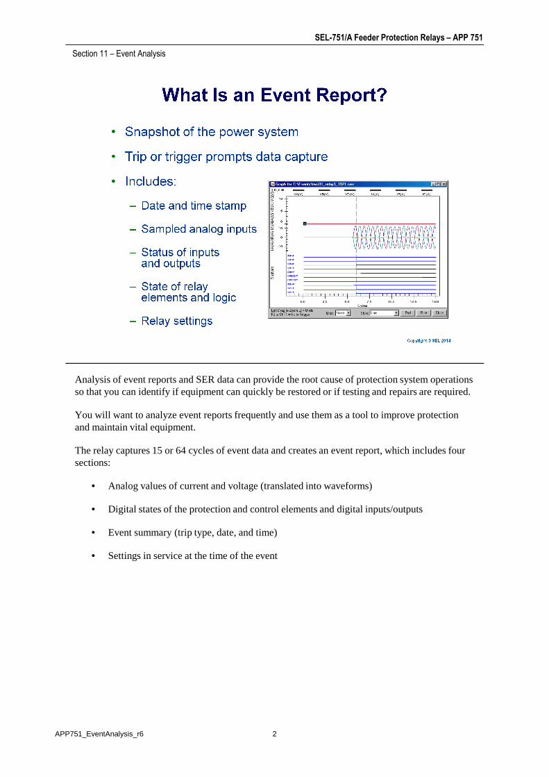
Analysis of event reports and SER data can provide the root cause of protection system operations so that you can identify if equipment can quickly be restored or if testing and repairs are required.
Section 11 – Event Analysis
so that you can identify if equipment can quickly be restored or if testing and repairs are required.
You will want to analyze event reports frequently and use them as a tool to improve protection and maintain vital equipment.
The relay captures 15 or 64 cycles of event data and creates an event report, which includes four sections:
• Analog values of current and voltage (translated into waveforms)
• Digital states of the protection and control elements and digital inputs/outputs
• Event summary (trip type, date, and time)
• Settings in service at the time of the event
2APP751_EventAnalysis_r6
SEL-751/A Feeder Protection Relays – APP 751
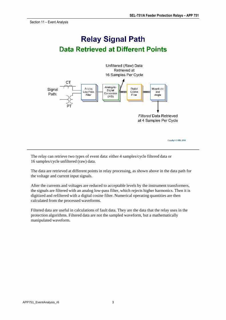
The relay can retrieve two types of event data: either 4 samples/cycle filtered data or 16samples/cycle unfiltered (raw) data.
Section 11 – Event Analysis
16samples/cycle unfiltered (raw) data.
The data are retrieved at different points in relay processing, as shown above in the data path for the voltage and current input signals.
After the currents and voltages are reduced to acceptable levels by the instrument transformers, the signals are filtered with an analog low-pass filter, which rejects higher harmonics. Then it is digitized and refiltered with a digital cosine filter. Numerical operating quantities are then calculated from the processed waveforms.
Filtered data are useful in calculations of fault data. They are the data that the relay uses in the protection algorithms. Filtered data are not the sampled waveform, but a mathematically manipulated waveform.
3APP751_EventAnalysis_r6

SEL-751/A Feeder Protection Relays – APP 751
The raw voltage and current waveforms generated during a power system fault are illustrated on the slide. These waveforms are the result of a fault on the power system at the end of the line with
Section 11 – Event Analysis
the slide. These waveforms are the result of a fault on the power system at the end of the line with no fault resistance. An inception angle of zero gives a full dc offset. The post-fault data are corrupted with noise, dc, and 2nd, 3rd, and 5th harmonics.
The filtered quantities should look clean without any harmonics, dc offset, or noise. The relay operates on filtered quantities. Analysis of these quantities will yield proper current and voltage phasors.
You will want to choose filtered event data for most of your event reporting needs because these are the signals the relay’s protection elements work from. The raw event reports, however, can also be useful since this unfiltered data shows what the relay actually “sees” from the power system. Raw event reports will show conditions such as:
• CT saturation
• Decaying dc offset (the difference between the symmetrical wave and the actual current wave during a transient condition)
• Power system harmonics (signals with atypical frequencies, creating waveform distortions)
• Input contact bounce
Raw event reports display one extra cycle of data at the beginning of the report.
4APP751_EventAnalysis_r6
SEL-751/A Feeder Protection Relays – APP 751
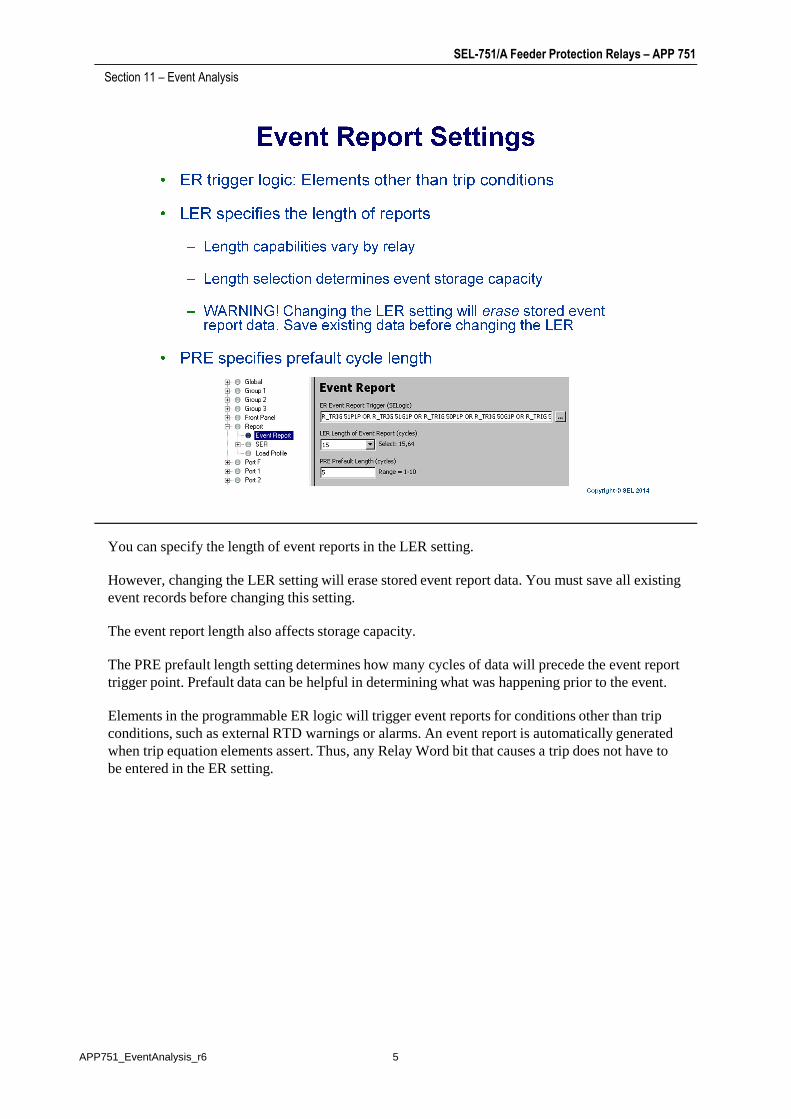
You can specify the length of event reports in the LER setting.
Section 11 – Event Analysis
However, changing the LER setting will erase stored event report data. You must save all existing event records before changing this setting.
The event report length also affects storage capacity.
The PRE prefault length setting determines how many cycles of data will precede the event report trigger point. Prefault data can be helpful in determining what was happening prior to the event.
Elements in the programmable ER logic will trigger event reports for conditions other than trip conditions, such as external RTD warnings or alarms. An event report is automatically generated when trip equation elements assert. Thus, any Relay Word bit that causes a trip does not have to be entered in the ER setting.
5APP751_EventAnalysis_r6
SEL-751/A Feeder Protection Relays – APP 751
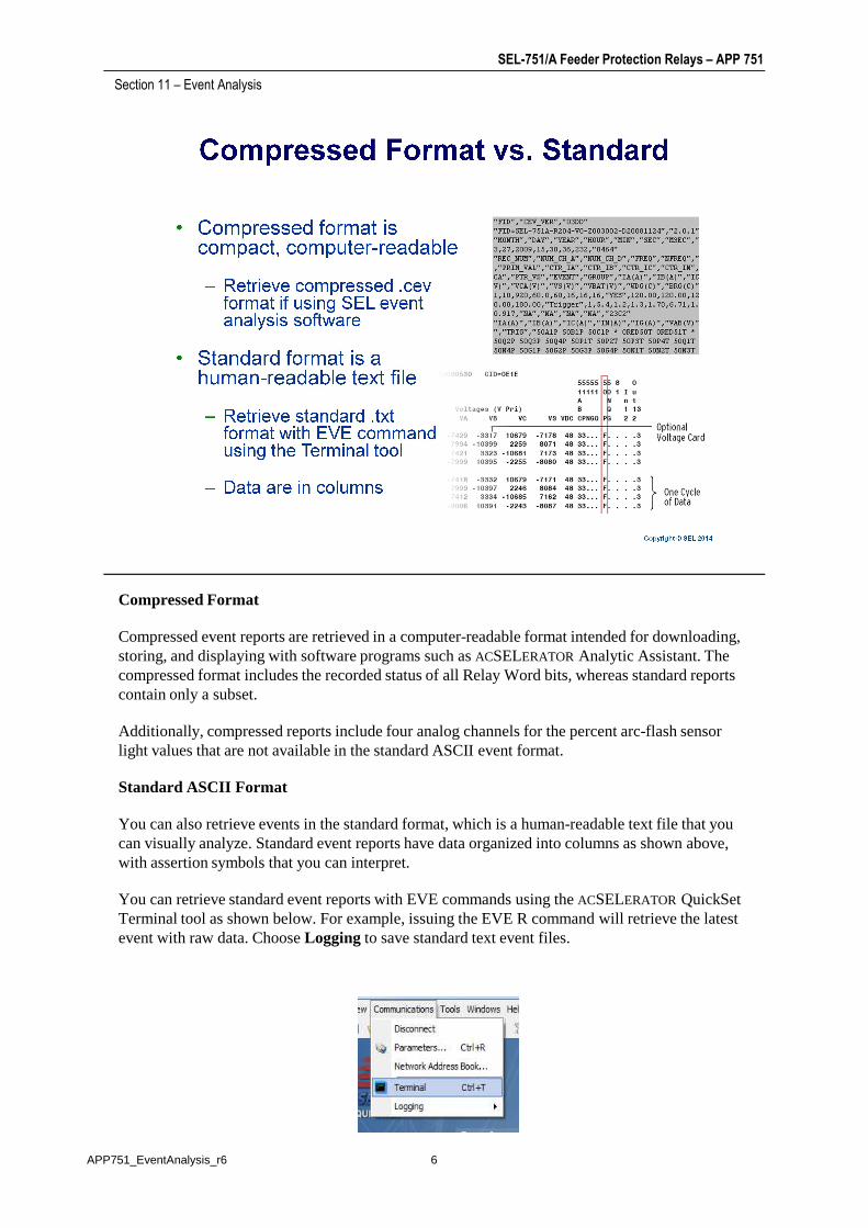
Compressed Format
Section 11 – Event Analysis
Compressed event reports are retrieved in a computer-readable format intended for downloading, storing, and displaying with software programs such asACSELERATOR Analytic Assistant. The compressed format includes the recorded status of all Relay Word bits, whereas standard reports contain only a subset.
Additionally, compressed reports include four analog channels for the percent arc-flash sensor light values that are not available in the standard ASCII event format.
Standard ASCII Format
You can also retrieve events in the standard format, which is a human-readable text file that you can visually analyze. Standard event reports have data organized into columns as shown above, with assertion symbols that you can interpret.
You can retrieve standard event reports with EVE commands using the ACSELERATOR QuickSet Terminal tool as shown below. For example, issuing the EVE R command will retrieve the latest event with raw data. Choose Logging to save standard text event files.
6APP751_EventAnalysis_r6
SEL-751/A Feeder Protection Relays – APP 751
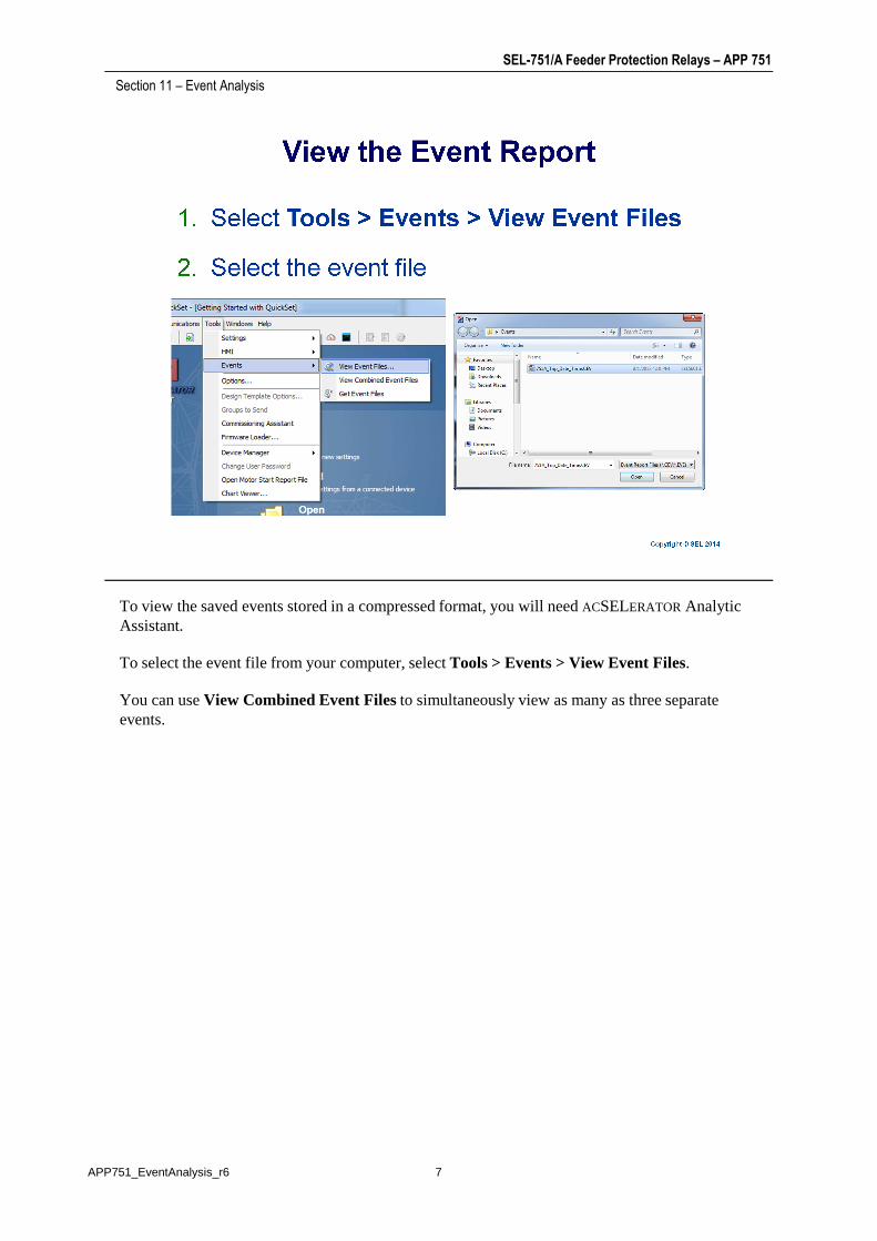
To view the saved events stored in a compressed format, you will need ACSELERATORAnalytic Assistant.
Section 11 – Event Analysis
Assistant.
To select the event file from your computer, select Tools > Events > View Event Files.
You can use View Combined Event Files to simultaneously view as many as three separate events.
7APP751_EventAnalysis_r6

SEL-751/A Feeder Protection Relays – APP 751
Section 11 – Event Analysis
8APP751_EventAnalysis_r6

SEL-751/A Feeder Protection Relays – APP 751
Section 11 – Event Analysis
9APP751_EventAnalysis_r6
SEL-751/A Feeder Protection Relays – APP 751
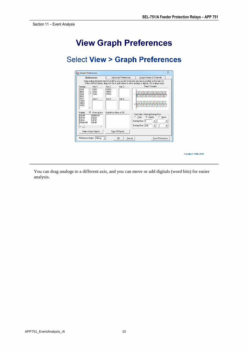
You can drag analogs to a different axis, and you can move or add digitals (word bits) for easier analysis.
Section 11 – Event Analysis
analysis.
10APP751_EventAnalysis_r6

SEL-751/A Feeder Protection Relays – APP 751
The Phasor view displays event report phasor data determined by a chosen reference point. You can increment the data selection bar to the time of the fault (in this example, 6.00 cycles).
Section 11 – Event Analysis
can increment the data selection bar to the time of the fault (in this example, 6.00 cycles).
To view phasors:
11APP751_EventAnalysis_r6
SEL-751/A Feeder Protection Relays – APP 751
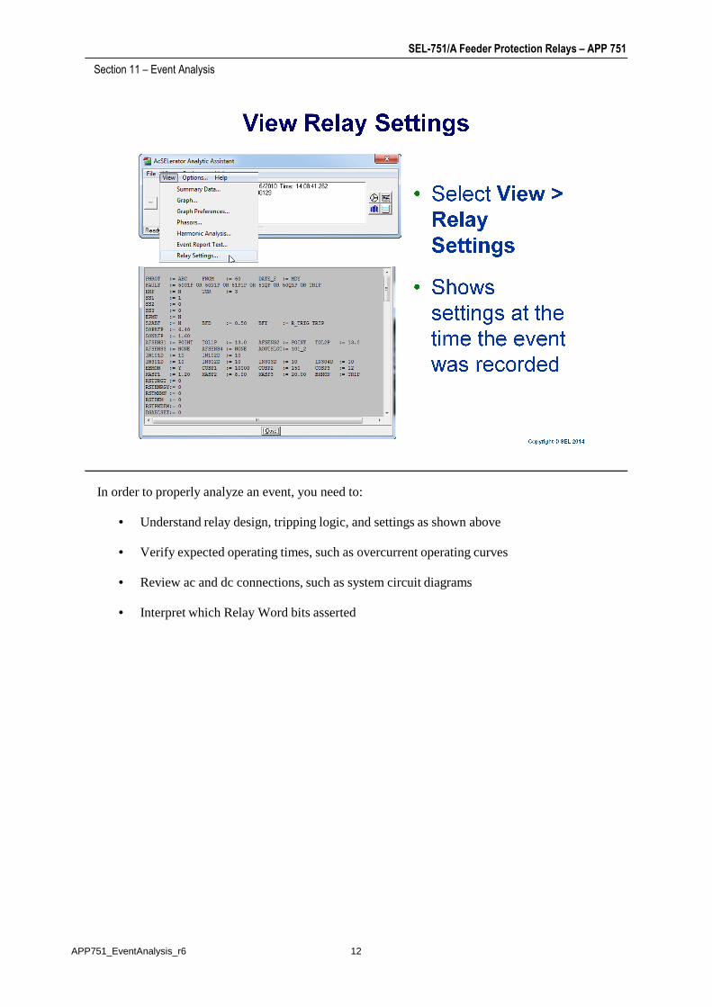
In order to properly analyze an event, you need to:
Section 11 – Event Analysis
• Understand relay design, tripping logic, and settings as shown above
• Verify expected operating times, such as overcurrent operating curves
• Review ac and dc connections, such as system circuit diagrams
• Interpret which Relay Word bits asserted
12APP751_EventAnalysis_r6

SEL-751/A Feeder Protection Relays – APP 751
Before analyzing the details of any event report, start with a basic understanding of what happened or what should have happened. This generally involves reviewing the relay settings and
Section 11 – Event Analysis
happened or what should have happened. This generally involves reviewing the relay settings and logic, obtaining the relay history report, and gathering any other information that may be helpful (known fault location, targets from other relays, breaker operations, SCADA, and personnel records).
It is important to review normal system operations, in order to more easily recognize problems and trends of failure.
Rather than guessing what occurred, retrieve the event data provided in the relay, and use the analysis process to determine root cause.
13APP751_EventAnalysis_r6

SEL-751/A Feeder Protection Relays – APP 751
It can be very helpful to obtain a dc control schematic using settings in the protective relay to understand the use of inputs and outputs. Normally, outputs connected to a breaker will be
Section 11 – Event Analysis
understand the use of inputs and outputs. Normally, outputs connected to a breaker will be controlled by the TRIP and CLOSE logic. These logic equations are functions of elements inside the relay. Relays contain many of these elements, many of which may not be related to the event. Save time by researching only the elements that are present in the TRIP logic.
14APP751_EventAnalysis_r6
SEL-751/A Feeder Protection Relays – APP 751
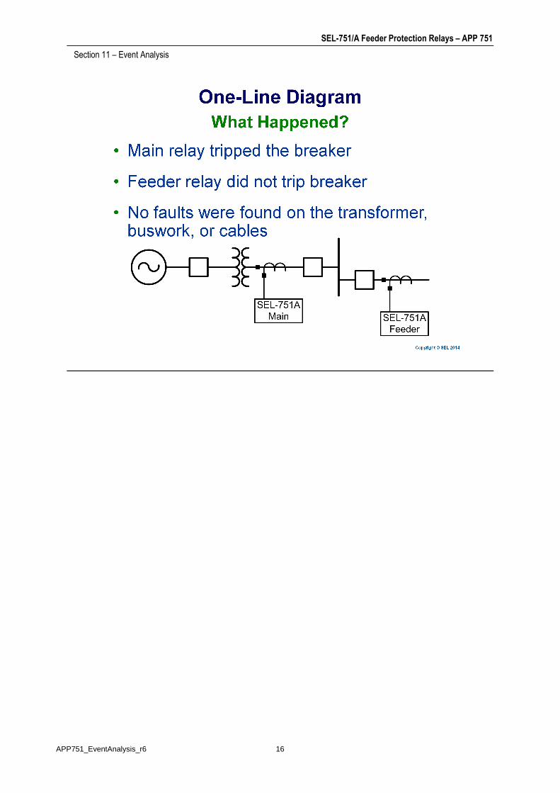
In this example event, the customer believed that a line-to-line fault (C-phase-to-A-phase fault) caused events to be generated in both the main and feeder SEL-751A Relays. A schematic of the
Section 11 – Event Analysis
caused events to be generated in both the main and feeder SEL-751A Relays. A schematic of the system is provided on the next slide. Upon inspection of the transformer, buswork, and cables, no fault evidence was found. SEL was contacted to identify what caused the event and why the main relay tripped the breaker but the feeder relay did not. The event reports from both relays were provided, along with the settings from each during the time of the event.
15APP751_EventAnalysis_r6
SEL-751/A Feeder Protection Relays – APP 751
Section 11 – Event Analysis
16APP751_EventAnalysis_r6
SEL-751/A Feeder Protection Relays – APP 751
It is known (or can be observed from system schematics) that OUT101 of each relay trips its respective breaker. Inspection of the settings inside each relay shows that OUT101 operates upon
Section 11 – Event Analysis
respective breaker. Inspection of the settings inside each relay shows that OUT101 operates upon the assertion of the TR SELOGIC® control equation, which is a function of instantaneous overcurrent (50), time-overcurrent (51), and arc-flash elements. The typical installation of arc-flash detection requires both overcurrent and arc-flash light sensors.
17APP751_EventAnalysis_r6
SEL-751/A Feeder Protection Relays – APP 751
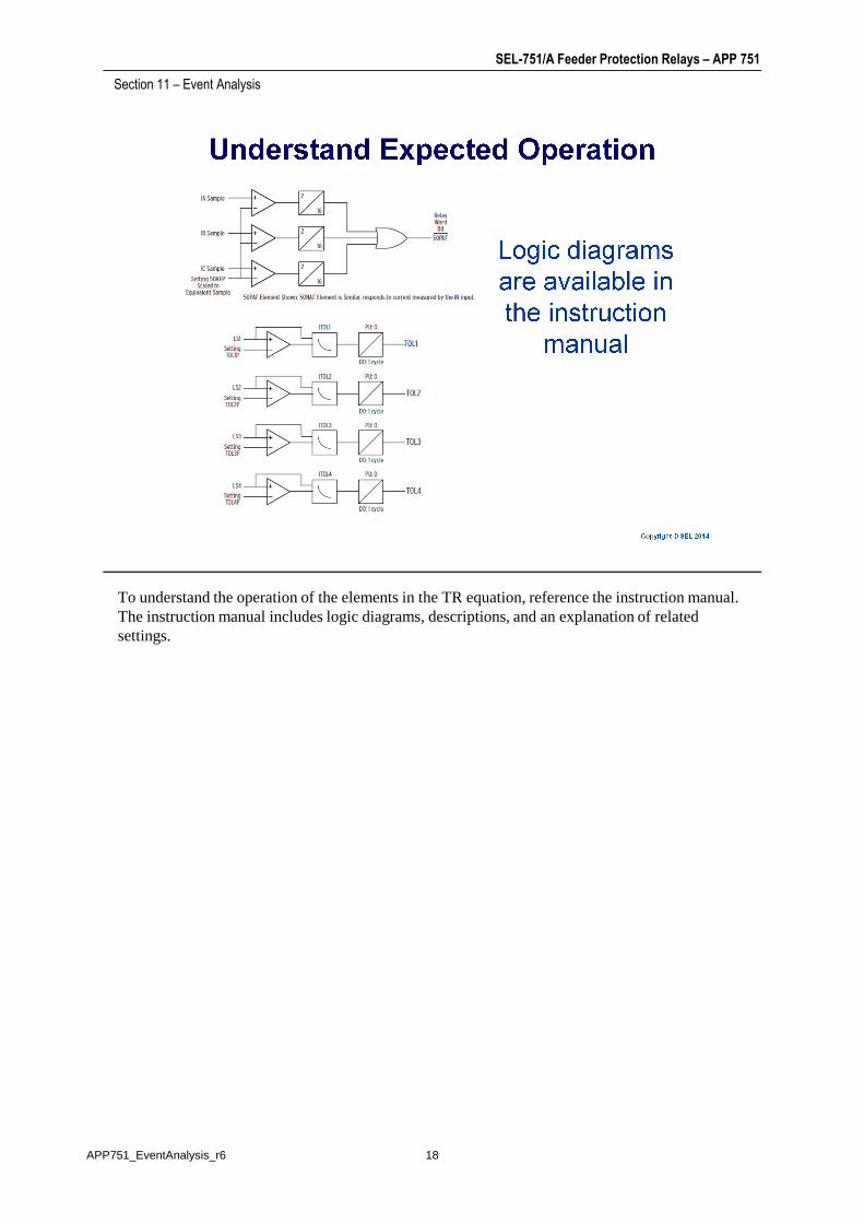
To understand the operation of the elements in the TR equation, reference the instruction manual. The instruction manual includes logic diagrams, descriptions, and an explanation of related
Section 11 – Event Analysis
The instruction manual includes logic diagrams, descriptions, and an explanation of related settings.
18APP751_EventAnalysis_r6
SEL-751/A Feeder Protection Relays – APP 751
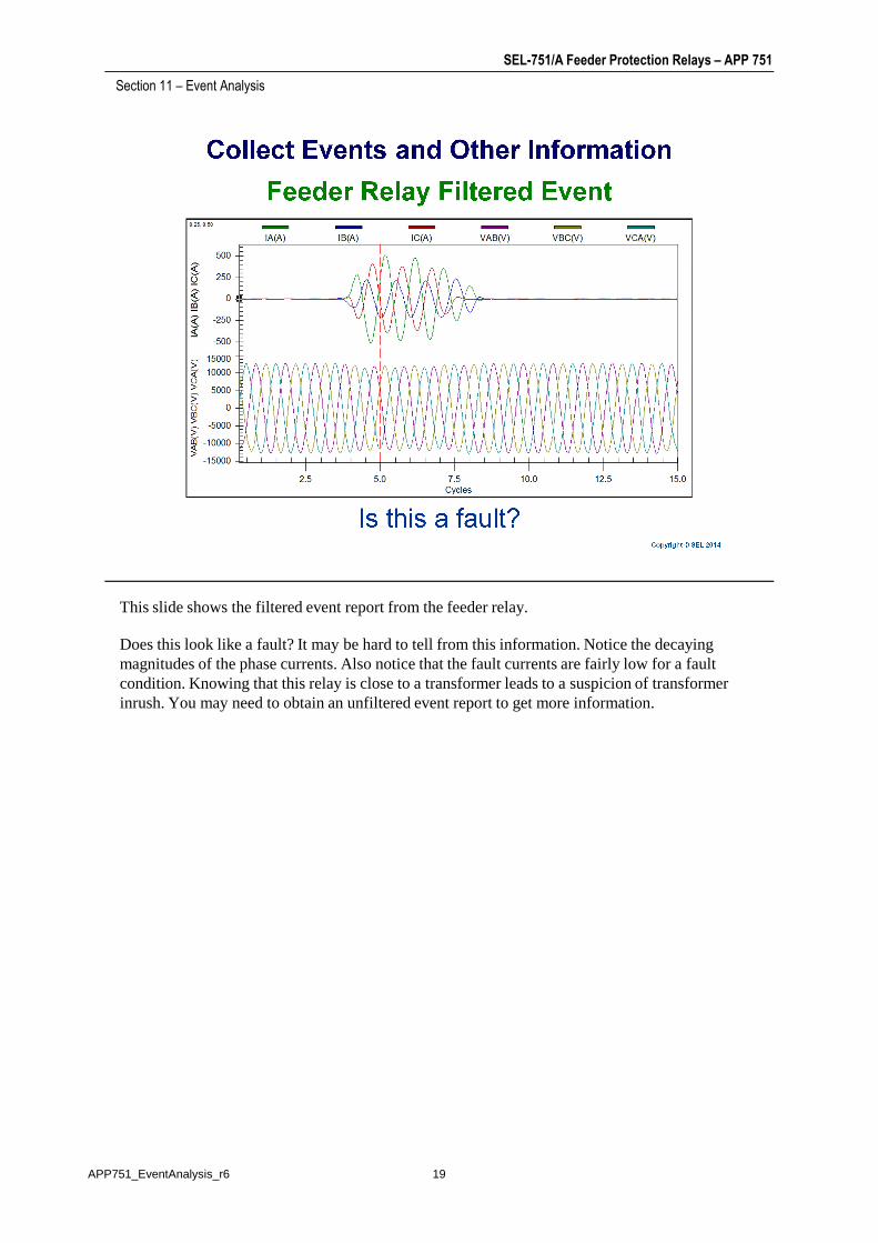
This slide shows the filtered event report from the feeder relay.
Section 11 – Event Analysis
Does this look like a fault? It may be hard to tell from this information. Notice the decaying magnitudes of the phase currents. Also notice that the fault currents are fairly low for a fault condition. Knowing that this relay is close to a transformer leads to a suspicion of transformer inrush. You may need to obtain an unfiltered event report to get more information.
19APP751_EventAnalysis_r6

SEL-751/A Feeder Protection Relays – APP 751
This slide shows the raw (unfiltered) event report seen by the main relay. This slide makes it more obvious that you are looking at transformer inrush instead of a fault.
Section 11 – Event Analysis
obvious that you are looking at transformer inrush instead of a fault.
20APP751_EventAnalysis_r6

SEL-751/A Feeder Protection Relays – APP 751
Generally, you do not want the relay to trip during transformer inrush. Even more so, you would not expect an arc-flash element to cause the trip because these elements are typically programmed
Section 11 – Event Analysis
not expect an arc-flash element to cause the trip because these elements are typically programmed to require both overcurrent and light from an arc flash.
21APP751_EventAnalysis_r6
SEL-751/A Feeder Protection Relays – APP 751
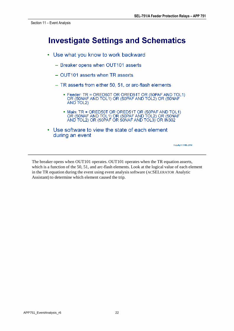
The breaker opens when OUT101 operates. OUT101 operates when the TR equation asserts, which is a function of the 50, 51, and arc-flash elements. Look at the logical value of each element
Section 11 – Event Analysis
which is a function of the 50, 51, and arc-flash elements. Look at the logical value of each element in the TR equation during the event using event analysis software (ACSELERATOR Analytic Assistant) to determine which element caused the trip.
22APP751_EventAnalysis_r6
SEL-751/A Feeder Protection Relays – APP 751
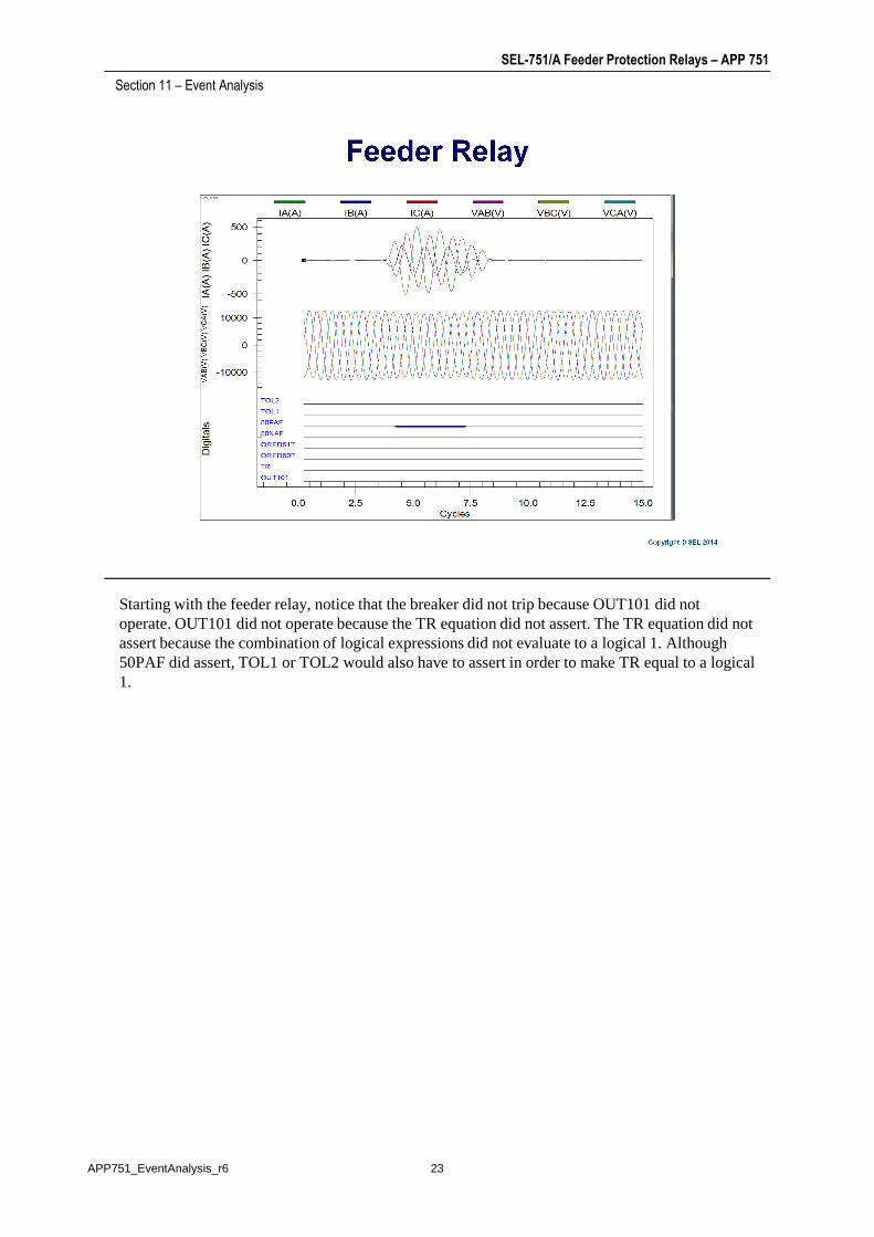
Starting with the feeder relay, notice that the breaker did not trip because OUT101 did not operate. OUT101 did not operate because the TR equation did not assert. The TR equation did not
Section 11 – Event Analysis
operate. OUT101 did not operate because the TR equation did not assert. The TR equation did not assert because the combination of logical expressions did not evaluate to a logical 1. Although 50PAF did assert, TOL1 or TOL2 would also have to assert in order to make TR equal to a logical 1.
23APP751_EventAnalysis_r6

SEL-751/A Feeder Protection Relays – APP 751
When inspecting the operation of the feeder relay, you can see that the arc-flash overcurrent element asserted but the light elements did not (as expected). Because the overcurrent elements
Section 11 – Event Analysis
element asserted but the light elements did not (as expected). Because the overcurrent elements and light elements are combined together with AND, the relay did not trip. The feeder relay operated as expected.
24APP751_EventAnalysis_r6
SEL-751/A Feeder Protection Relays – APP 751
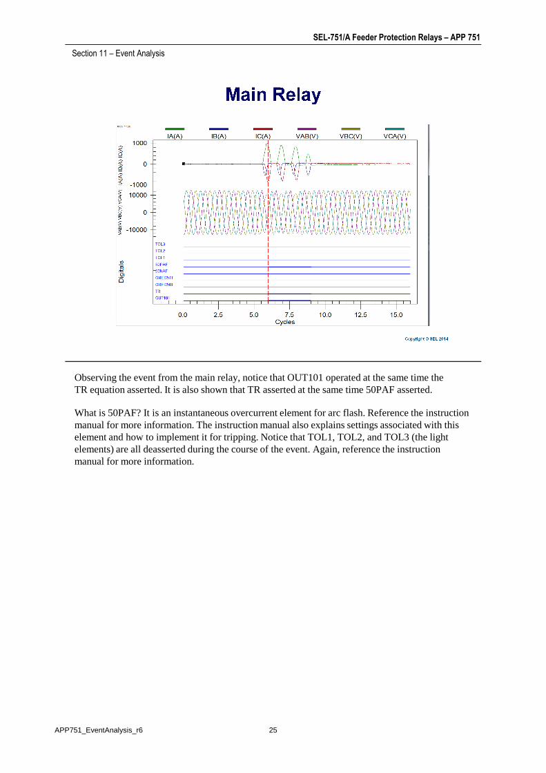
Observing the event from the main relay, notice that OUT101 operated at the same time the TR equation asserted. It is also shown that TR asserted at the same time 50PAF asserted.
Section 11 – Event Analysis
TR equation asserted. It is also shown that TR asserted at the same time 50PAF asserted.
What is 50PAF? It is an instantaneous overcurrent element for arc flash. Reference the instruction manual for more information. The instruction manual also explains settings associated with this element and how to implement it for tripping. Notice that TOL1, TOL2, and TOL3 (the light elements) are all deasserted during the course of the event. Again, reference the instruction manual for more information.
25APP751_EventAnalysis_r6
SEL-751/A Feeder Protection Relays – APP 751
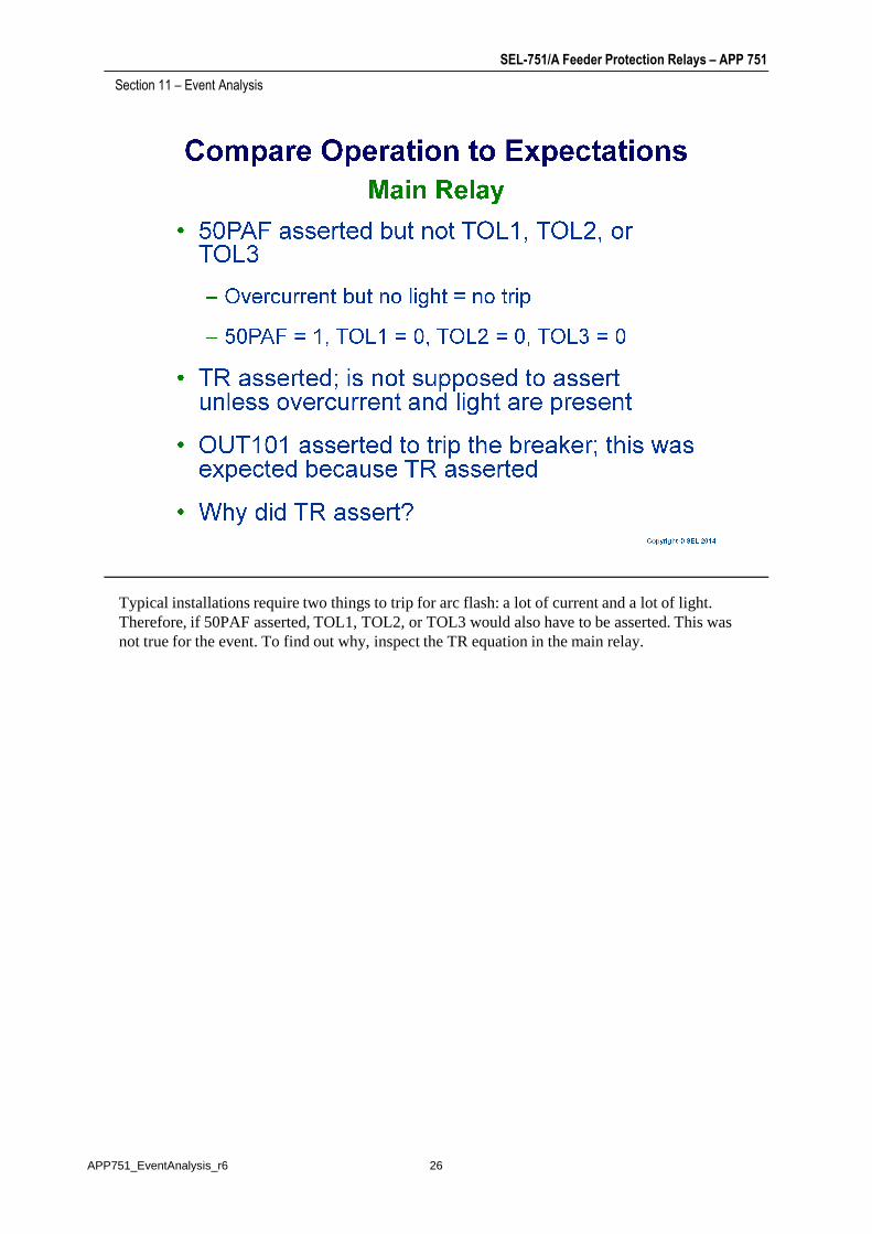
Typical installations require two things to trip for arc flash: a lot of current and a lot of light. Therefore, if 50PAF asserted, TOL1, TOL2, or TOL3 would also have to be asserted. This was
Section 11 – Event Analysis
Therefore, if 50PAF asserted, TOL1, TOL2, or TOL3 would also have to be asserted. This was not true for the event. To find out why, inspect the TR equation in the main relay.
26APP751_EventAnalysis_r6

SEL-751/A Feeder Protection Relays – APP 751
First, review the information on SELOGIC control equations in the instruction manual, such as the table shown on this slide that indicates the order of operations.
Section 11 – Event Analysis
table shown on this slide that indicates the order of operations.
27APP751_EventAnalysis_r6
SEL-751/A Feeder Protection Relays – APP 751
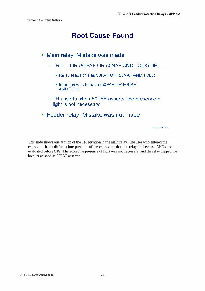
This slide shows one section of the TR equation in the main relay. The user who entered the expression had a different interpretation of the expression than the relay did because ANDs are
Section 11 – Event Analysis
expression had a different interpretation of the expression than the relay did because ANDs are evaluated before ORs. Therefore, the presence of light was not necessary, and the relay tripped the breaker as soon as 50PAF asserted.
28APP751_EventAnalysis_r6
SEL-751/A Feeder Protection Relays – APP 751
After finding root cause, the solution should be implemented and tested. Through the process of event analysis and troubleshooting, you can get a better understanding of your system, verify relay
Section 11 – Event Analysis
event analysis and troubleshooting, you can get a better understanding of your system, verify relay operation, find the cause of a misoperation, and correct settings or wiring errors when necessary. Proper testing during commissioning is important and can help reduce the frequency of unexpected operations, as well as limit the amount of time necessary to determine root cause.
29APP751_EventAnalysis_r6
SEL-751/A Feeder Protection Relays – APP 751
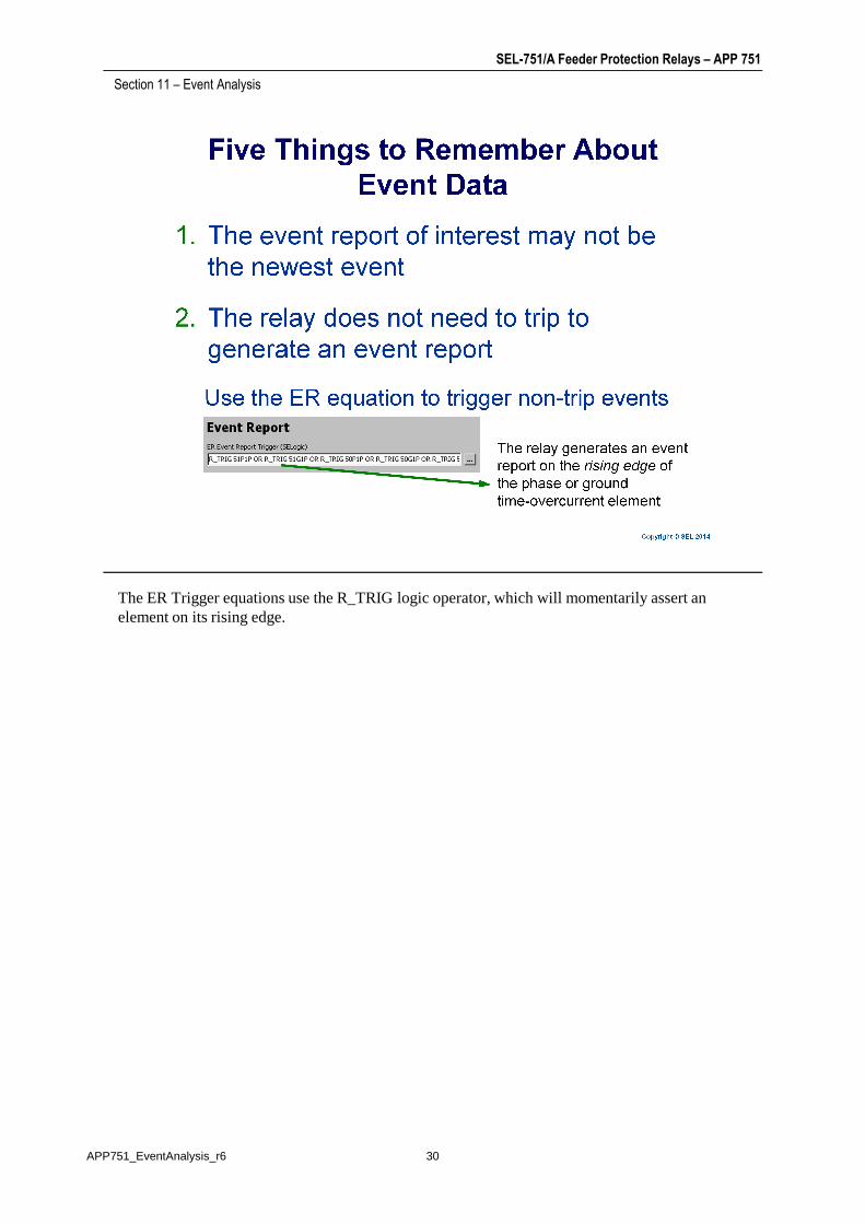
The ER Trigger equations use the R_TRIG logic operator, which will momentarily assert an element on its rising edge.
Section 11 – Event Analysis
element on its rising edge.
30APP751_EventAnalysis_r6

SEL-751/A Feeder Protection Relays – APP 751
You can be notified automatically of event captures using protocol setting AUTO = Y as shown below. This will automatically send unsolicited event history to a connected communications
Section 11 – Event Analysis
below. This will automatically send unsolicited event history to a connected communications processor on the specified port (such as Port F).
31APP751_EventAnalysis_r6
SEL-751/A Feeder Protection Relays – APP 751
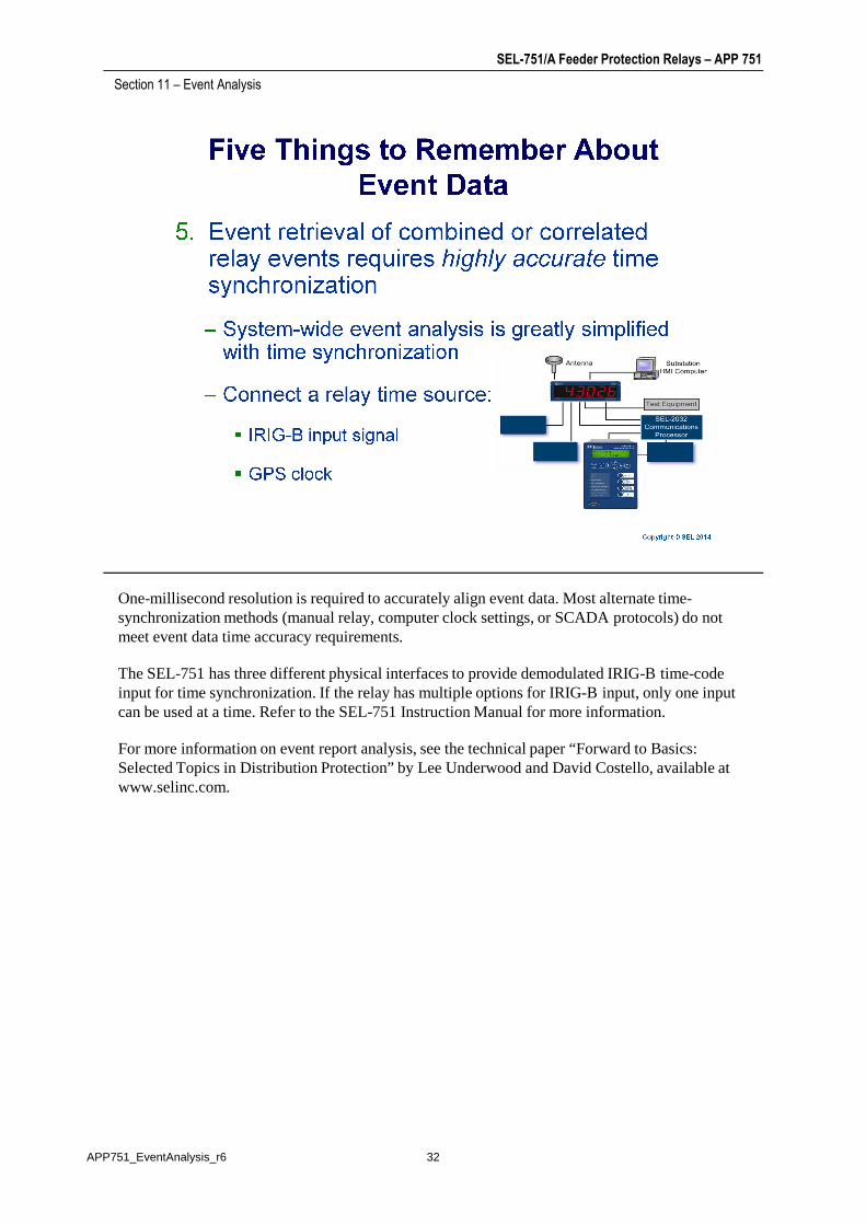
One-millisecond resolution is required to accurately align event data. Most alternate time-synchronization methods (manual relay, computer clock settings, or SCADA protocols) do not
Section 11 – Event Analysis
synchronization methods (manual relay, computer clock settings, or SCADA protocols) do not meet event data time accuracy requirements.
The SEL-751 has three different physical interfaces to provide demodulated IRIG-B time-code input for time synchronization. If the relay has multiple options for IRIG-B input, only one input can be used at a time. Refer to the SEL-751 Instruction Manual for more information.
For more information on event report analysis, see the technical paper “Forward to Basics: Selected Topics in Distribution Protection” by Lee Underwood and David Costello, available at www.selinc.com.
32APP751_EventAnalysis_r6
Related Documents