International Conference on Engineering and Applied Science Osaka, Japan, 7-9 November, 2013 Official Acceptance & Invitation Letter Dear Lecturer Mohammad Mohinuddin Ahmed, September 5, 2013 After a thorough anonymously reviewing process, we are very pleased to inform you that your manuscript, "Seismic Vulnerability Assessment of Concrete Pile Foundation"ID 1697 has been accepted for Oral session at International Conference on Engineering and Applied Science (ICEAS 2013) in Osaka, Japan. Decisions were made based on a double-blind review process. The exact time and room of your presentation session will be specified in the ICEAS 2013 Conference Program online at the beginning of October 2013. At this time, we kindly remind you to notify your co-authors(s) if there were any, and take care of the followings: 1. ICEAS 2013 policy and procedures require at least one author to register for and attend the meeting to present the paper when it is accepted. The registration deadline is September 30, 2013. If we do not receive your registration with payment by September 30, 2013, your paper will be withdrawn from the Proceedings. 2. Please exactly follow the ICEAS 2013 Proceedings Instructions (available on the conference website). The file name must be same as ID 1697 . The ICEAS 2013 Proceedings will be reproduced directly from data files you submit. Therefore, it is essential for you to follow exactly the instructions .Papers that deviate from the instruction may NOT be published. If you have any further questions, please do not hesitate to contact the secretariat of ICEAS 2013 by sending your email [email protected] with your manuscript ID number listed above on all communications. Again, congratulations on the acceptance of your paper. On behalf of the Program Committee, we look forward to your full participation in the ICEAS 2013 Conference. With best wishes and greetings to you, Program Committee of ICEAS 2013 Proudly Sponsored by Kwansei Gakuin University

Welcome message from author
This document is posted to help you gain knowledge. Please leave a comment to let me know what you think about it! Share it to your friends and learn new things together.
Transcript
International Conference on Engineering and Applied Science
Osaka, Japan, 7-9 November, 2013
Official Acceptance & Invitation Letter
Dear Lecturer Mohammad Mohinuddin Ahmed,
September 5, 2013
After a thorough anonymously reviewing process, we are very pleased to inform you that your
manuscript, "Seismic Vulnerability Assessment of Concrete Pile Foundation"ID 1697 has been
accepted for Oral session at International Conference on Engineering and Applied Science (ICEAS
2013) in Osaka, Japan. Decisions were made based on a double-blind review process. The exact
time and room of your presentation session will be specified in the ICEAS 2013 Conference
Program online at the beginning of October 2013. At this time, we kindly remind you to notify
your co-authors(s) if there were any, and take care of the followings:
1. ICEAS 2013 policy and procedures require at least one author to register for and attend the
meeting to present the paper when it is accepted. The registration deadline is September 30,
2013. If we do not receive your registration with payment by September 30, 2013, your paper
will be withdrawn from the Proceedings.
2. Please exactly follow the ICEAS 2013 Proceedings Instructions (available on the conference
website). The file name must be same as ID 1697 . The ICEAS 2013 Proceedings will be
reproduced directly from data files you submit. Therefore, it is essential for you to follow
exactly the instructions .Papers that deviate from the instruction may NOT be published.
If you have any further questions, please do not hesitate to contact the secretariat of ICEAS 2013
by sending your email [email protected] with your manuscript ID number listed above on all
communications. Again, congratulations on the acceptance of your paper. On behalf of the
Program Committee, we look forward to your full participation in the ICEAS 2013 Conference.
With best wishes and greetings to you,
Program Committee of ICEAS 2013
Proudly Sponsored by
Kwansei Gakuin University
1178
ICEAS-1697
Seismic Vulnerability Assessment of Concrete Pile Foundation
Mohammad Mohinuddin Ahmed
Department of Civil Engineering
University of Information Technology & Sciences, Chittagong, Bangladesh
Md. Jahangir Alam
Department of Civil Engineering,
Chittagong University of Engineering &Technology, Chittagong, Bangladesh
Ing Uwe E. Dorka
Department of Civil Engineering
University of Kassel, Kassel, Germany
Abstract
Assessment of liquefaction susceptibility is essential for seismically active area when pile
foundations are designed or existing under seismic loading. During the liquefaction soil loss
its strength and stiffness, thus remove the support from pile that can affect the overall
stability of the pile foundations. The main objective of this study is to investigate the extent
of the liquefaction zone that will make unsupported to pile and to assess the effect of the
liquefaction on the pile considering structural and geotechnical aspects. The simplified
empirical procedure of Seed & Idriss based on standard penetration test, liquefaction of soil is
predicted. Besides, a simple approach of Euler load to predict the buckling capacity of an
axially loaded partially embedded pile in sand is formulated using the conventional Davisson
and Robinson method combined with the ACI & area transform theory’s flexural stiffness
equation of the slender concrete column. Example solved as a case study based on above
analytical procedures that an axially loaded existing concrete pile under foundation can be
laterally unsupported in liquefied soils and susceptible to buckling failure and pointer towards
the inclusion of slenderness ratio limit of pile in the respective building code.
Keyword: Liquefaction, SPT-N value, Factor of safety, Concrete pile, Buckling.
1. Introduction
Ground failures generated by liquefaction had been responsible for tremendous amounts of
damage in historical earthquakes around the world, thus demonstrated the seismic
vulnerability of structures. During earthquake induced liquefaction, there is transformation
from a solid state of soil to liquefied state as a result of increased pore water pressure and
reduced effective stress. Thus, saturated soil deposit losses most of its strength and stiffness
that responsible for piles partially free-standing, where such piles are subjected to buckling.
Moreover, blessing of science and modern concrete technology advices to more application
on slender members to achieve economic one in which stability plays a dynamic character.
Assessment for pile foundation are usually implemented by the experts or civil engineer to
know whether the soil at the site is liquefiable or not and behavior of existing pile foundation
or designed one under any seismic conditions so that suitable methods can be adopted. The
1179
disasters investigation of the initiation of liquefaction is essential for foundation, because
liquefaction can cause large lateral loads on pile foundations that can affect the overall
stability of the pile foundations. But, the calculation of buckling loads is always a major
anxiety for practicing engineers due to most of the theoretical studies concentrate on
geotechnical aspects as well as most experimental investigations concerns mainly on
structural part of the pile purely as column. Incidentally, very few researchers were interested
to find out the stability performance of pile foundation due to the liquefaction induced soil
movements.
Aim of the present assessment is to analysis the subsurface soil data to determine the factor of
safety against liquefaction and predict the liquefied soil thickness and to analysis the stability
of partially embedded reinforced concrete pile during earthquake.
2. Case Study: 8 Storied Apartment Building
In this study, an existing 8 storied apartment building located at Kolatoli Mor, Cox’sBazar,
Bangladesh is considered as example case study for the investigation of pile foundation. As
per the proposed seismic map of Bangladesh [12], the site falls under Seismic Zone III, thus
PGA value 0.28 is considered. Total 38 number of Piles are constructed at the building site up
to the depth of 9.144 m from ground level having dia0.45m with f′c= 2800 psi, reinforced
with 6-D16 of fy=60000psi, supports total weight of the building 34393KN . Disturbed and
undisturbed soil samples are collected from the site up to the depth of 12.192 m from two
boreholes located in the site for laboratory tests. The water table is found at the depth of 1.25
m below the ground level. In order to determine the N-value, the SPT tests are conducted at
different depths of the soil strata. Based on different laboratory observations and field test
results the site soil is divided into two different layers of 7.0104m from ground and rest
5.4864m.
3. Analytical Approach
3.1 Liquefaction Susceptibility Assessment
At present there are a number of laboratory tests are in practice to estimate the liquefaction
potential of soils such as dynamic triaxial test, cyclic simple shear test and shaking table test.
Similarly, several empirical methods have been developed over the year based on standard
penetration test(SPT),cone penetration test(CPT) and shear wave velocity measurement for
the assessment of liquefaction potential as discussed by Seed and Idriss[5],Seed et
al.[6],Robertsion and Campanella[3],Youd and Idriss[7].However, in this study liquefaction
potential of selected location have been determined from soil characteristics and SPT based
procedure called Seed-Idriss simplified procedure that was originally proposed in 1971 and
updated over the years such as Seed et al.[6],Youd and Idriss[7],Cetin et al.[2].This procedure
consist of following steps:
3.1.1 Cyclic Shear Stress
According to Seed and Idriss[5] ,the CSRMw is a ratio of the equivalent uniform cyclic shear
stress τav to the initial effective overburden stress, ,at the same depth and expressed as:
CSRMw = ( 0.65 rd (1)
Where, g is the acceleration due to gravity, rd is the stress reduction factor (rd=1.0 for
rock), is peak horizontal acceleration at ground surface, is total overburden stress at
the depth (Z) in question, is initial effective overburden stress at the same depth. Based
on depth (Z) in meters, the value of rd as used in this method are:
Recommended by Youd and Idriss[7],) could be used,
1180
rd = 1.0 – 0.00765z for z 9.15 m (2)
rd = 1.174 – 0.0267z for 9.15m z 23 m (3)
Recommended by Robertson and Wride[4] may be used,
rd = 0.744-0.008z for 23m<z<30m (4)
Recommended by Youd and Idriss[8],
rd = 0.5 for z>30 m (5)
3.1.2 Cyclic Strength:
At first, corrected normalized SPT blow count (N1)60 is obtained from measured SPT blow
count with consideration of a number of factors. Following the modification, the soil
liquefaction behavior is accounted by converting the (N1)60 to equivalent clean sand (fine
content ≤ 5% SPT blow count, (N1)60cs .
Hence, the strength or capacity of clean sand under an initial effective overburden stress or
one atmosphere to resist liquefaction or the cyclic resistance ratio ,during an earthquake of
magnitude Mw = 7.5 is estimated by the following equation modified after Youd and
Idriss[7],is used to calculate the (CRR7.5)1 atm for a given (N1)60cs.
( CRR7.5) 1atm = (6)
To adjust the (CRR7.5)1 atm to magnitudes other than Mw=7.5,the calculated(CRR7.5)1 atm is
multiplied by magnitude scaling factor (MSF) corresponding to the design earthquake of
moment magnitude Mw. The recommended lower bound MSF values by (Idriss, 1995) and
given by the equation (7).
MSF = (7)
The upper bound MSF values recommended for Mw≤7.5 were originally proposed by Andrus
and Stokoe [1].
Other parameter to adjust the cyclic resistance ratio to initial effective overburden pressures
other than 1.0 tsf, the (CRR7.5)1 atm is multiplied by a correction factor Kσ. In Youd and
Idriss[7],, based on the works by Hynes and Olsen [9] recommended the equation 8 for
calculating Kσ.
Kσ = (8)
Where, is the atmospheric pressure in the same unit as the initial effective overburden
pressure and f is an exponent, which is the function of site conditions. The
recommended value of f is 0.8 for relative density,Dr≤40 and 0.7 for Dr=60.
3.1.3 Factor of Safety (F.S):
The liquefaction susceptibility is quantified in terms of factor of safety along the borehole
depths at available borehole locations using earthquake-induced cyclic stress on the soil and
the cyclic resistance of the soil to withstand the load. The factor of safety (F.S) against
liquefaction is calculated using the equation 1:
F.S = = * MSF * Kσ (9)
Where, (CRR7.5)1 atm is the cyclic resistance ration of the soil in question, CSRMw is the ratio
of the equivalent uniform cyclic shear stress, MSF is magnitude scaling factor, and Kσ is the
correction factor.
If F.S ≤ 1.0, liquefaction is said to occur otherwise liquefaction does not occur.
a. Discussion of liquefaction potentiality analysis & result:
1181
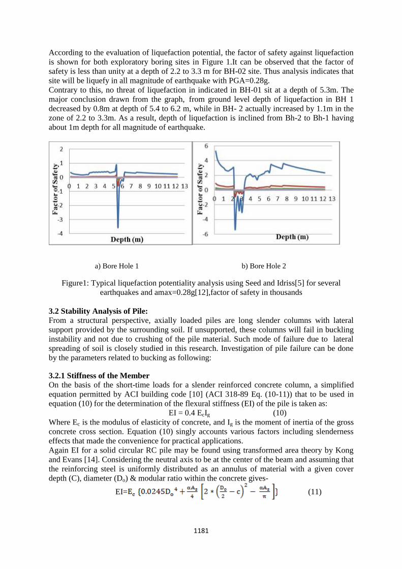
According to the evaluation of liquefaction potential, the factor of safety against liquefaction
is shown for both exploratory boring sites in Figure 1.It can be observed that the factor of
safety is less than unity at a depth of 2.2 to 3.3 m for BH-02 site. Thus analysis indicates that
site will be liquefy in all magnitude of earthquake with PGA=0.28g.
Contrary to this, no threat of liquefaction in indicated in BH-01 sit at a depth of 5.3m. The
major conclusion drawn from the graph, from ground level depth of liquefaction in BH 1
decreased by 0.8m at depth of 5.4 to 6.2 m, while in BH- 2 actually increased by 1.1m in the
zone of 2.2 to 3.3m. As a result, depth of liquefaction is inclined from Bh-2 to Bh-1 having
about 1m depth for all magnitude of earthquake.
a) Bore Hole 1 b) Bore Hole 2
Figure1: Typical liquefaction potentiality analysis using Seed and Idriss[5] for several
earthquakes and amax=0.28g[12],factor of safety in thousands
3.2 Stability Analysis of Pile:
From a structural perspective, axially loaded piles are long slender columns with lateral
support provided by the surrounding soil. If unsupported, these columns will fail in buckling
instability and not due to crushing of the pile material. Such mode of failure due to lateral
spreading of soil is closely studied in this research. Investigation of pile failure can be done
by the parameters related to bucking as following:
3.2.1 Stiffness of the Member
On the basis of the short-time loads for a slender reinforced concrete column, a simplified
equation permitted by ACI building code [10] (ACI 318-89 Eq. (10-11)) that to be used in
equation (10) for the determination of the flexural stiffness (EI) of the pile is taken as:
EI = 0.4 EcIg (10)
Where Ec is the modulus of elasticity of concrete, and Ig is the moment of inertia of the gross
concrete cross section. Equation (10) singly accounts various factors including slenderness
effects that made the convenience for practical applications.
Again EI for a solid circular RC pile may be found using transformed area theory by Kong
and Evans [14]. Considering the neutral axis to be at the center of the beam and assuming that
the reinforcing steel is uniformly distributed as an annulus of material with a given cover
depth (C), diameter (Do) & modular ratio within the concrete gives-
EI= (11)
1182
3.2.2 Equivalent Length of the Pile
The accurate determination of equivalent length of the pile (Le) is the important step for
stability analysis which is equal to unsupported length (Lu) plus the depth of fixity (ZF). In
equation (12), the depth of fixity (ZF) is determined by the method proposed by Davission
and Robinson [11], which is used for partially embedded piles in sand and measured from
ground.
= (12)
Where EI is the flexural stiffness of the pile, and is the coefficient of horizontal subgrade
modulus.
Based on beam-on-elastic-foundation theory Equation (12) was formulated as well as
proposed for partially embedded piles. For simplification and compromise, a coefficient 1.8
in equation (12) was advocated in such that the equation is applicable to both bending and
buckling behaviors.
3.2.3 Buckling Load
Euler load (Pcr) for an axially loaded partially embedded reinforced concrete pile is:
(13)
Equation (13) is applicable for the end conditions of K. At the present study that is
considered fixed at the base and at the top pinned and free respectively.
3.2.4 Buckling Resistance of Pile
For the determination of the buckling resistance of a compressive member, an equation
endorsed by Euro code [13](Eq.6.41) is taken as equation (14).
= (14)
Where, is Plastic ultimate load, is factor of safety for material and is the reduction
factor for the relevant buckling mode and corresponding values for the appropriate non-
dimensional slenderness may be obtained from buckling curve of figure 6.4, Euro code 3
[13].
Finally,as per Euro code [13](Eq.6.40) compression member shall be verified against
buckling as follows:
≤ 1.0 (15
Where, is the design value of the compressive force and is the design buckling
resistance of the compressive member.
3.2.5 Discussion of buckling analysis & result:
To assess buckling effect on pile, stability analysis of a pile has been conducted by knowing
equivalent length of pile and water table and considered as fixed parameter. However, such
parameters are varies in different season all the year.
Based on the summery of all stability analysis shown in Table 1 and it is seen that elastic
critical load is the destructive mode of failure and depends on the geometric properties of the
member, i.e. slenderness ratio, rather than the member stiffness. It is found that, pile with
identical length , diameter and support condition but having different stiffness(e.g16448.96
KN-m2
,20530.4 KN-m2) have buckle at similar axial load. Therefore, to prevent the buckling
failure, there should be a minimum pile diameter depending on the depth of liquefiable soil.

1183
Table -1: Summary of all stability analysis results Flexural stiffness (KN-m2) 16448.96 16448.96 20530.4 20530.4
Support Condition 2 0.707 2 0.707
Equivalent length of the pile(m) 7.625 7.625 7.625 7.625
Critical load for buckling (KN) 698.07 6059.15 860.72 6887.89
Ultimate load (KN) 3645 3645 3645 3645
Non –dimensional slenderness 2.28 0 .77563 2.05 0.727
Reduction factor 0.15 0.7 0.2 0.72
Buckling resistance (KN) 364.5192 1701.0896 486.0256 1749.6921
Compressive/axial force (KN) 905.09 905.09 905.09 905.09
Verification against buckling 2.48 0.579 1.86 0.56
4. Conclusion and Further Work
This study investigates the shortcoming of the procedure of assessment of pile foundation
under seismic loading. A detailed step-by step procedure for the evaluation of soil
liquefaction based on a standard penetration test N-value has been performed. Buckling
capacity of the partially embedded slender reinforced concrete pile may be predicted
conservatively using the proposed approach. It can be concluded from case study that fully
embedded end-bearing piles passing through loose to medium-dense sand can buckle under
axial load if the soil surrounding the pile liquefies.
Further studies/research is going on at CUET to determine allowable range or value of
slenderness ratio of pile in liquefaction based on the geotechnical centrifuge test to avoid
such failure during an earthquake.
5. Acknowledgments
The 1st author is supported with a DAAD scholarship by the University of Kassel, Germany
under “SEAN-DEE Medium Term Student” for research stay. The author gratefully
acknowledges this support.
References
[1] Andrus, R. D. and Stokoe, K. H., (1997). Liquefaction resistance based on shear wave
velocity,Proc., NCEER Workshop on Evaluation of Liquefaction Resistance of Soil,
National Centre for Earthquake Engineering Research, State University of New York at
Buffalo, pp.89~128.
[2] Cetin, K. O., Seed, R. B., Kiureghian, A. D., Tokimatsu, K., Harder, L. F., Kayen, R. E.,
and Moss, R. E. S. (2004). Standard penetration test based probabilistic and deterministic
assessment of seismic soil liquefaction potential, Journal of Geotechnical and
1184
Geoenvironmental Engineering, ASCE, Vol. 130, No. 12, pp. 1314~1340.
[3] Robertson, P. K. and Campanella, R. G. (1985). Liquefaction potential of sands using the
CPT, J.GED, ASCE, Vol. 111, No. 3, pp. 384~403.
[4] Robertson, P. K. and Wride, C. E. (1998). Evaluating cyclic liquefaction potential using
cone penetration test, Canadian Geotechnical Journal, Vol. 35, No. 3, pp. 442~459.
[5] Seed, H. B., and Idriss, I. M. (1971). Simplified procedure for evaluating soil liquefaction
Potential. Journal of the Soil Mechanics and Foundations Division, ASCE, Vol. 97,
No.SM9, Proceedings Paper 8371, pp. 1249~1273.
[6] Seed, H. B., Tokimatsu, K., Harder, L. F., and Chung, R. M., (1985). Influence of SPT
procedures in soil liquefaction resistance evaluations, Journal of Geotechnical
Engineering, American Society of Civil Engineers, Vol. III, No. 12, pp. 1425~1445.
[7] Youd, T. L. and Idriss, I. M. (2001). Liquefaction resistance of soils, Summary from the
1996 NCEER and 1998 NCEER/NSF Workshops on Evaluations of Liquefaction
Resistance of Soils, ASCE, Vol. 127 (4), pp. 297~313.
[8] Youd,T.L and Idriss,I.M.eds (1997),Proc.,NCEER Workshop on Evaluation of
Liquefection Resistance of Soil,Natioal Center for Earthquake Engineering Reserch, State
Univ.of New York at Bafallo.
[9] Hynes, M.E and Olsen, R.S.(1999),Influence of Confining Stress on Liquefaction
Resistance,Proc.,1st Workshop on Physics and Mechanics of Soil Liquefaction, Balkema,
Rotterdam, The Netherlands,pp.145~152.
[10] ACI Committee 318. 1989. Building code requirements for reinforced concrete and
commentary-ACI 318R-89. American Concrete Institute, Detroit.
[11] Davisson, M. T. and Robison, K. E. 1965. Bending and buckling of partially
embedded piles. Proceedings of 6th International Conference on Soil Mechanics and
Foundation Engineering, Canada, Vol. III, Div. 3-6, 243-246.
[12] Tahmmed M.Al-Hussain, Tahsin R.Hossain and M.Nayem Al-Noman.2012.Proposed
Changes to the Geotechnical Earthquake Engineering Provisions of the Bangladesh
national Building Code.Geotechnical Engineering Journal of the SEAGS & AGSSEA
vol.43 NO.2 June 2012 ISSN 0046-5828.
[13] Eurocode3, Design of steel structures-Part 1-1: General rules and rules for buildings.
EN1993-1-1:2005(E).Brussels, Belgium: Comite European de Normalisation; 2005
[14] Kong F.K., Evans R.H. (1987). Reinforced and prestressed concrete E&FN Spon,
London
Conference Proceedings November 2013
Osaka, Japan
LSBE
International Conference on
Life Science & Biological Engineering
ACCMES Asian Conference on
Civil, Material and Environmental Sciences
ICEAS International Conference on
Engineering and Applied Science

LSBE International Conference on
Life Science & Biological Engineering
ISBN: 978-986-89298-1-4
ACCMES Asian Conference on
Civil, Material and Environmental Sciences
ISBN: 978-986-89298-0-7
ICEAS International Conference on Engineering and Applied Science
ISSN: 2227-0299 ISBN: 978-986-87417-1-3

i
Content
General Information for Participants .................................................................................................. iii
LSBE Committee Board ......................................................................................................................... v
ACCMES Committee Board ................................................................................................................. vi
ICEAS Committee Board .................................................................................................................... viii
Conference Schedule ............................................................................................................................. x
Conference Venue Information .......................................................................................................... xiv
RIHGA Royal Hotel Floor Plan (6F) .................................................................................................. xv
Oral Sessions Agenda ........................................................................................................................... 1
Civil Engineering I ............................................................................................................................ 1
Computer and Information Sciences I .......................................................................................... 36
Life Sciences I .................................................................................................................................. 68
Biomedical Engineering I ............................................................................................................... 87
Environmental Sciences I ............................................................................................................. 120
Life Sciences II .............................................................................................................................. 149
Biological Engineering I ............................................................................................................... 183
Environmental Sciences II ........................................................................................................... 210
Computer and Information Sciences II ...................................................................................... 239
Life Sciences III ............................................................................................................................. 276
Chemical Engineering I/ Fundamental and Applied Sciences I ............................................... 291
Environmental Sciences III .......................................................................................................... 326
Material Sciences and Engineering I ........................................................................................... 362
Life Sciences IV ............................................................................................................................. 399
Environmental Sciences IV .......................................................................................................... 428
Mechanical Engineering I / Electrical and Electronic Engineering I ....................................... 455
Life Sciences V............................................................................................................................... 502
Environmental Science V ............................................................................................................. 600
Mechanical Engineering II ........................................................................................................... 637
Biological Engineering II .............................................................................................................. 676
Environmental Sciences VI/ Geosciences and Petroleum Engineering .................................... 721
Mechanical Engineering III ......................................................................................................... 748
Life Sciences VI ............................................................................................................................. 785
Material Sciences and Engineering II ......................................................................................... 900
ii
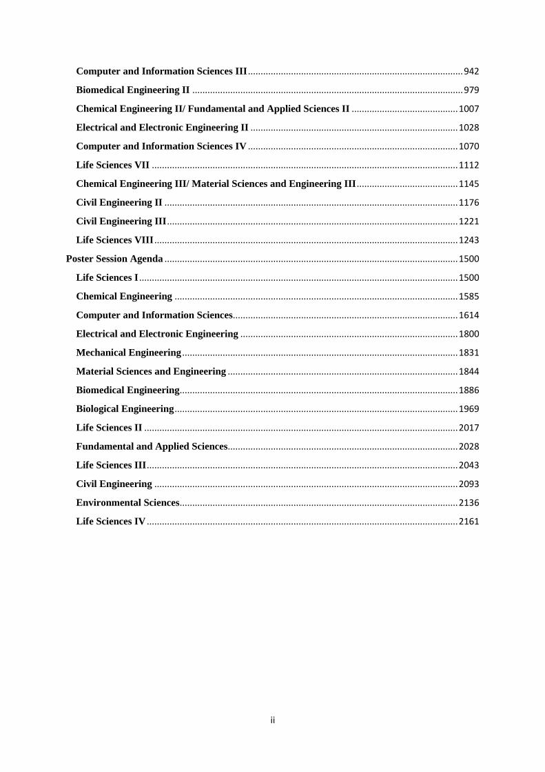
Computer and Information Sciences III ..................................................................................... 942
Biomedical Engineering II ........................................................................................................... 979
Chemical Engineering II/ Fundamental and Applied Sciences II .......................................... 1007
Electrical and Electronic Engineering II .................................................................................. 1028
Computer and Information Sciences IV ................................................................................... 1070
Life Sciences VII ......................................................................................................................... 1112
Chemical Engineering III/ Material Sciences and Engineering III ........................................ 1145
Civil Engineering II .................................................................................................................... 1176
Civil Engineering III ................................................................................................................... 1221
Life Sciences VIII ........................................................................................................................ 1243
Poster Session Agenda .................................................................................................................... 1500
Life Sciences I .............................................................................................................................. 1500
Chemical Engineering ................................................................................................................ 1585
Computer and Information Sciences......................................................................................... 1614
Electrical and Electronic Engineering ...................................................................................... 1800
Mechanical Engineering ............................................................................................................. 1831
Material Sciences and Engineering ........................................................................................... 1844
Biomedical Engineering .............................................................................................................. 1886
Biological Engineering ................................................................................................................ 1969
Life Sciences II ............................................................................................................................ 2017
Fundamental and Applied Sciences........................................................................................... 2028
Life Sciences III ........................................................................................................................... 2043
Civil Engineering ........................................................................................................................ 2093
Environmental Sciences .............................................................................................................. 2136
Life Sciences IV ........................................................................................................................... 2161
iii
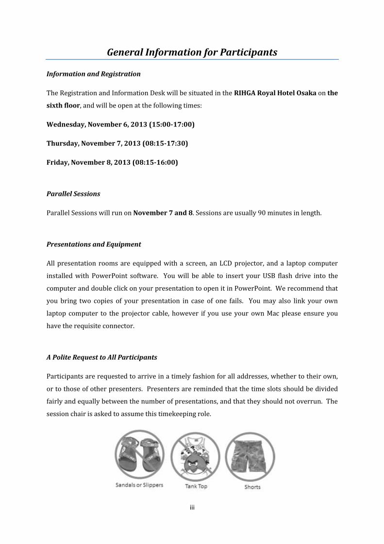
General Information for Participants
Information and Registration
The Registration and Information Desk will be situated in the RIHGA Royal Hotel Osaka on the
sixth floor, and will be open at the following times:
Wednesday, November 6, 2013 (15:00-17:00)
Thursday, November 7, 2013 (08:15-17:30)
Friday, November 8, 2013 (08:15-16:00)
Parallel Sessions
Parallel Sessions will run on November 7 and 8. Sessions are usually 90 minutes in length.
Presentations and Equipment
All presentation rooms are equipped with a screen, an LCD projector, and a laptop computer
installed with PowerPoint software. You will be able to insert your USB flash drive into the
computer and double click on your presentation to open it in PowerPoint. We recommend that
you bring two copies of your presentation in case of one fails. You may also link your own
laptop computer to the projector cable, however if you use your own Mac please ensure you
have the requisite connector.
A Polite Request to All Participants
Participants are requested to arrive in a timely fashion for all addresses, whether to their own,
or to those of other presenters. Presenters are reminded that the time slots should be divided
fairly and equally between the number of presentations, and that they should not overrun. The
session chair is asked to assume this timekeeping role.
iv
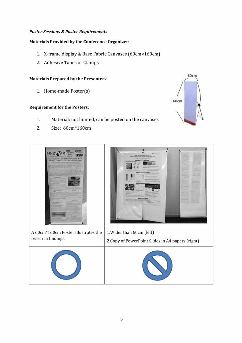
Poster Sessions & Poster Requirements
Materials Provided by the Conference Organizer:
1. X-frame display & Base Fabric Canvases (60cm×160cm)
2. Adhesive Tapes or Clamps
Materials Prepared by the Presenters:
1. Home-made Poster(s)
Requirement for the Posters:
1. Material: not limited, can be posted on the canvases
2. Size: 60cm*160cm
A 60cm*160cm Poster Illustrates the
research findings.
1.Wider than 60cm (left)
2.Copy of PowerPoint Slides in A4 papers (right)
v
LSBE Committee Board
Ahmad Zuhairi Abdullah Universiti Sains Malaysia
Fadzilah Adibah Abdul Majid Universiti Teknologi Malaysia
Mohd Farid bin Atan University of Sarawak Malaysia
Sue-Joan, Chang National Cheng Kung University
Yen-Chung, Chang National Tsing Hua University
Yun-Peng, Chao Feng Chia University
Pei-Jen, Chen National Taiwan University
H.M. El-Shora Mansoura University
I-Ming Hsing The Hong Kong University of Science and Technology
Shang-Da, Huang National Tsing Hua University
Bing Joe Hwang National Taiwan University of Science and Technology
Kondabagil K. Indian Institute of Technology Bombay
Sungjee Kim Sungkyunkwan University
Li-Fen, Lei National Taiwan University
Yunsheng, Lou Nanjing University of Information Science and
Technology
Mihir Kumar Purkait Indian Institute of Technology Guwahati
Chung-Sung, Tan National Tsing Hua University
Tewin Tencomnao Chulalongkorn University
S.K. Tripathi Indian Institute of Technology Poorkee
Henry N.C. Wong The Chinese University of Hong Kong
Yusri b. Yusup Universiti Sains Malaysia
Hasan Akhtar Zaidi Guru Gobind Singh Indraprastha University
vi
ACCMES Committee Board
Abhijeet K. Digalwar Birla Institute of Technology and Science
Alan K. T. Lau The Hong Kong Polytechnic University
Aminaton Marto Universiti Teknologi Malaysia
Ben Young The University of Hong Kong
C.C. Sorrell University of New South Wales
Cek Fauziah Ishak Universiti Putra Malaysia
Chacko Jacob Materials Science Centre
Choi Jaisung Yonsei University
Gianluca Ranzi The University of Sydney
Hannah Wan-Huan Zhou University of Macau
Kartini Kamaruddin Universiti Teknologi Mara
Jingsheng Chen National University of Singapore
Prof Jaisung Choi University of Seoul
K.W. Chau The Hong Kong Polytechnic University
Kanit Wattanavichien Chulalongkorn University
L.N.Pattanaik Birla Institute of Technology
M. Anusuyadevi Jayachandran Bharathidhasan University
Manoj S Soni The Birla Institute of Technology & Science
Mohd Razman Salim Universiti Teknologi Malaysia
Monica Sharma Malaviya National Institute of Technology Jaipur
Nasser Khalili University of New South Wales
Nilanchal Patel Birla Institute of Technology Mesra
Nilanjana Das University of Calcutta
Norhayati Ahmad MIMMMCSci Universiti Teknologi Malaysia
P.Sivaprakash Karpagam Institute of Technology
Pramod Kumar Jain Indian Institute of Technology Roorkee
PremRajP National Institute of Technology Calicut
Renu Pawels Cochin University of Science & Technology
S.Chandrakaran National Institute of Technology Karnataka
Saxena Ashok K Indian Institute of Technology
Sharad Chandra Srivastava B.I.T Mesra , Ranchi (Jharkhand)
vii
Siti Mariyam Shamsuddin Universiti Teknologi Malaysia
Sri Bandyopadhyay University of New South Wales
Tuty Asma Abu Bakar Universiti Teknologi Malaysia
V K Tewari Indian Institute of Technology Kharagpur
Wiboonluk Pungrasmi Chulalongkorn University
William K. Mohanty Indian Institute of Technology
viii
ICEAS Committee Board
Khalid M. Mosalam Khalid M. Mosalam
Chueerat Jaruskulchai University of California
M. Cheralathan Kasetsart University
J N Bandyopadhyay SRM University
S. Dhar Indian Institute of Technology Kharagpur
Poongothai Shankar University of Calcutta
Amit Agrawal Annamalai University
Cheng Li Indian Institute of Technology Bombay
T.M. Indra Mahlia The Hong Kong Polytechnic University
Kunal Ghosh University of Malaya
Narayanan Kulathuramaiyer Indian Institute of Technology Kanpur
Arup K. Sarma University of Sarawak Malaysia
Suresh K Bhargava Indian Institute of Technology Guwahati
Rapeepan Pitakaso School of Applied Sciences
Jie Liu Ubonratchthani University
Carlos Alejandro Figueroa Carleton University
Dong-Ho Ha Plasmar Tecnologia
Poul Vaeggemose Konkuk University
Maha M. O. Khayyat VIA University College Denmark
Kant Kanyarusoke Umm Al-Qura University
Paramita Bhattacharjee Cape Peninsula University of Technology
Nathalia Devina Widjaja Jadavpur University
C. M. Khalique Binus International University
Banerji P North-West UniversitySouth Africa
P.K. Ghosh Indian Institute of Technology Kharagpur
E George Dharma Prakash Raj Indian Institute of Technology Poorkee
R.P.Bhatnagar Bharathidasan University
V. Vijayagopal Birla Institute of Technology
Amit Awekar Annamalai University
Gustavo Carneiro Indian Institute of Technology Guwahati
Pui-In Mak University of Adelaide
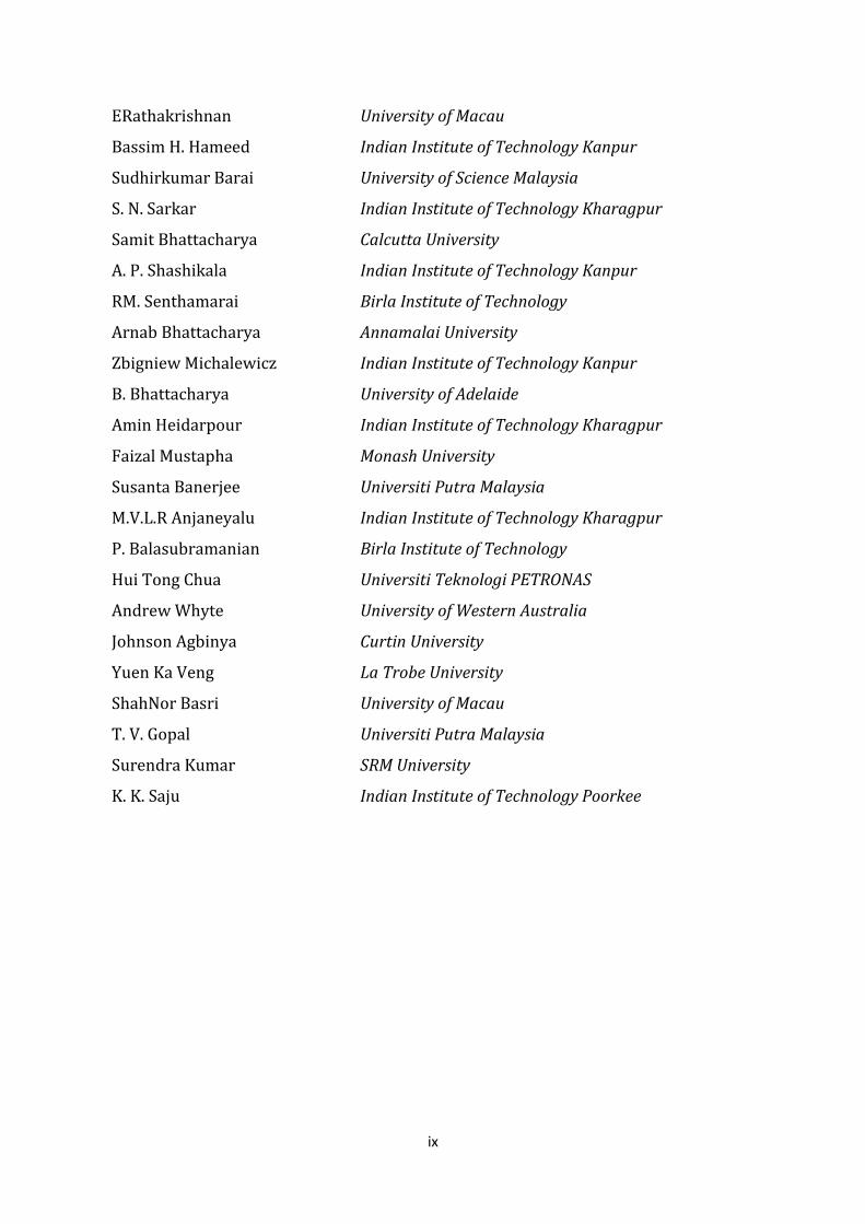
ix
ERathakrishnan University of Macau
Bassim H. Hameed Indian Institute of Technology Kanpur
Sudhirkumar Barai University of Science Malaysia
S. N. Sarkar Indian Institute of Technology Kharagpur
Samit Bhattacharya Calcutta University
A. P. Shashikala Indian Institute of Technology Kanpur
RM. Senthamarai Birla Institute of Technology
Arnab Bhattacharya Annamalai University
Zbigniew Michalewicz Indian Institute of Technology Kanpur
B. Bhattacharya University of Adelaide
Amin Heidarpour Indian Institute of Technology Kharagpur
Faizal Mustapha Monash University
Susanta Banerjee Universiti Putra Malaysia
M.V.L.R Anjaneyalu Indian Institute of Technology Kharagpur
P. Balasubramanian Birla Institute of Technology
Hui Tong Chua Universiti Teknologi PETRONAS
Andrew Whyte University of Western Australia
Johnson Agbinya Curtin University
Yuen Ka Veng La Trobe University
ShahNor Basri University of Macau
T. V. Gopal Universiti Putra Malaysia
Surendra Kumar SRM University
K. K. Saju Indian Institute of Technology Poorkee
x
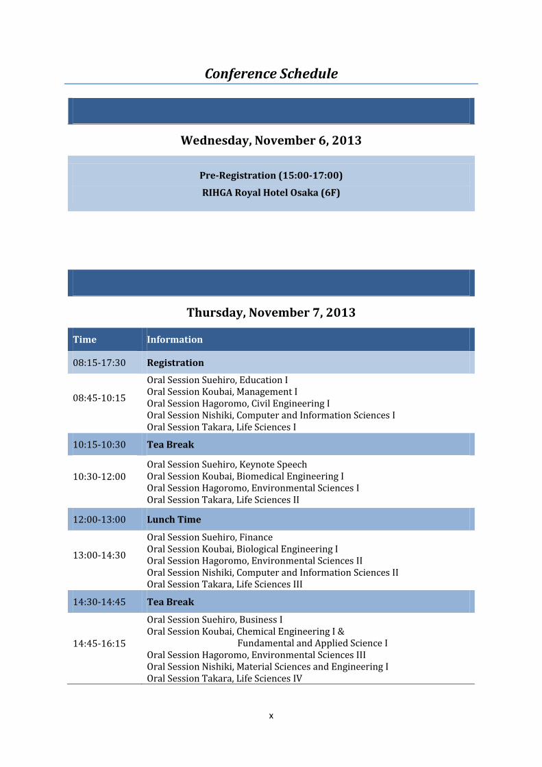
Conference Schedule
Wednesday, November 6, 2013
Pre-Registration (15:00-17:00)
RIHGA Royal Hotel Osaka (6F)
Thursday, November 7, 2013
Time Information
08:15-17:30 Registration
08:45-10:15
Oral Session Suehiro, Education I Oral Session Koubai, Management I Oral Session Hagoromo, Civil Engineering I Oral Session Nishiki, Computer and Information Sciences I Oral Session Takara, Life Sciences I
10:15-10:30 Tea Break
10:30-12:00 Oral Session Suehiro, Keynote Speech Oral Session Koubai, Biomedical Engineering I Oral Session Hagoromo, Environmental Sciences I Oral Session Takara, Life Sciences II
12:00-13:00 Lunch Time
13:00-14:30
Oral Session Suehiro, Finance Oral Session Koubai, Biological Engineering I Oral Session Hagoromo, Environmental Sciences II Oral Session Nishiki, Computer and Information Sciences II Oral Session Takara, Life Sciences III
14:30-14:45 Tea Break
14:45-16:15
Oral Session Suehiro, Business I Oral Session Koubai, Chemical Engineering I & Fundamental and Applied Science I Oral Session Hagoromo, Environmental Sciences III Oral Session Nishiki, Material Sciences and Engineering I Oral Session Takara, Life Sciences IV
xi
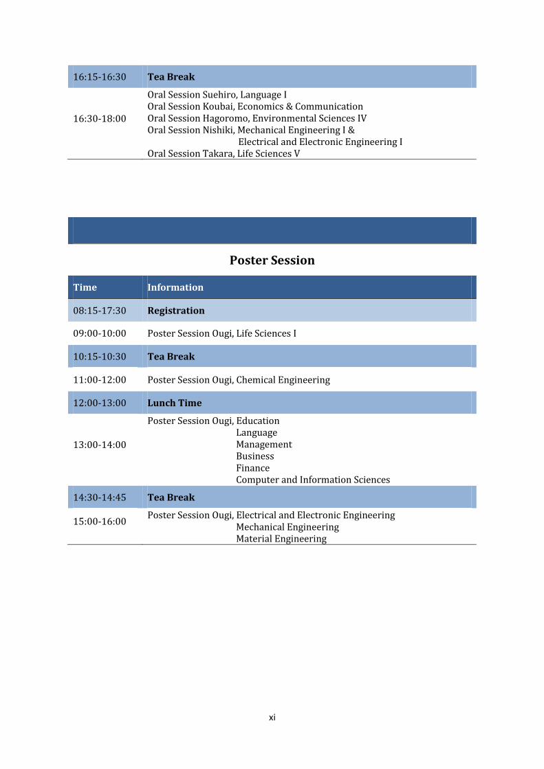
16:15-16:30 Tea Break
16:30-18:00
Oral Session Suehiro, Language I Oral Session Koubai, Economics & Communication Oral Session Hagoromo, Environmental Sciences IV Oral Session Nishiki, Mechanical Engineering I & Electrical and Electronic Engineering I Oral Session Takara, Life Sciences V
Poster Session
Time Information
08:15-17:30 Registration
09:00-10:00 Poster Session Ougi, Life Sciences I
10:15-10:30 Tea Break
11:00-12:00 Poster Session Ougi, Chemical Engineering
12:00-13:00 Lunch Time
13:00-14:00
Poster Session Ougi, Education Language Management Business Finance Computer and Information Sciences
14:30-14:45 Tea Break
15:00-16:00 Poster Session Ougi, Electrical and Electronic Engineering Mechanical Engineering Material Engineering
xii
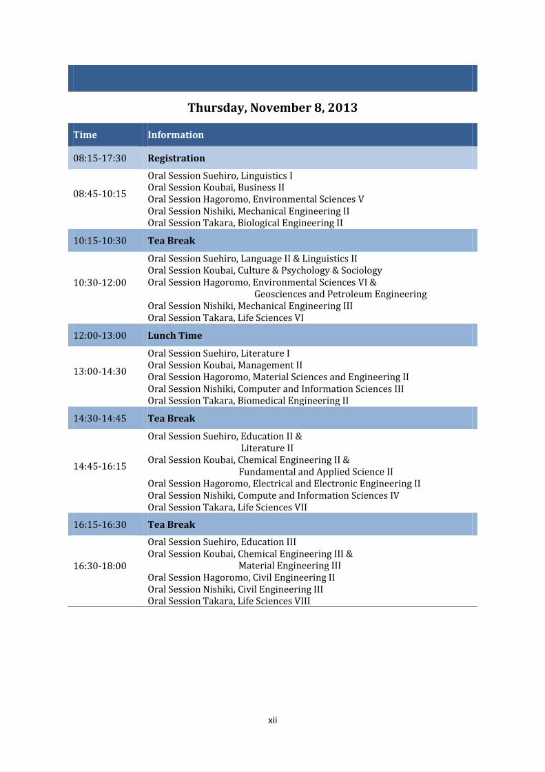
Thursday, November 8, 2013
Time Information
08:15-17:30 Registration
08:45-10:15
Oral Session Suehiro, Linguistics I Oral Session Koubai, Business II Oral Session Hagoromo, Environmental Sciences V Oral Session Nishiki, Mechanical Engineering II Oral Session Takara, Biological Engineering II
10:15-10:30 Tea Break
10:30-12:00
Oral Session Suehiro, Language II & Linguistics II Oral Session Koubai, Culture & Psychology & Sociology Oral Session Hagoromo, Environmental Sciences VI & Geosciences and Petroleum Engineering Oral Session Nishiki, Mechanical Engineering III Oral Session Takara, Life Sciences VI
12:00-13:00 Lunch Time
13:00-14:30
Oral Session Suehiro, Literature I Oral Session Koubai, Management II Oral Session Hagoromo, Material Sciences and Engineering II Oral Session Nishiki, Computer and Information Sciences III Oral Session Takara, Biomedical Engineering II
14:30-14:45 Tea Break
14:45-16:15
Oral Session Suehiro, Education II & Literature II Oral Session Koubai, Chemical Engineering II & Fundamental and Applied Science II Oral Session Hagoromo, Electrical and Electronic Engineering II Oral Session Nishiki, Compute and Information Sciences IV Oral Session Takara, Life Sciences VII
16:15-16:30 Tea Break
16:30-18:00
Oral Session Suehiro, Education III Oral Session Koubai, Chemical Engineering III &
Material Engineering III Oral Session Hagoromo, Civil Engineering II Oral Session Nishiki, Civil Engineering III Oral Session Takara, Life Sciences VIII

xiii
Poster Session
Time Information
08:15-17:30 Registration
09:00-10:00 Poster Session Ougi, Biomedical Engineering
10:15-10:30 Tea Break
11:00-12:00 Poster Session Ougi, Biological Engineering Life Sciences II Fundamental and Applied Sciences
12:00-13:00 Lunch Time
13:00-14:00 Poster Session Ougi, Life Sciences III
14:30-14:45 Tea Break
15:00-16:00 Poster Session Ougi, Civil Engineering Environmental Sciences Life Sciences IV
Saturday, November 9, 2013
Executive Committee Meeting (Committee Only)
xiv
Conference Venue Information
RIHGA Royal Hotel Osaka
5-3-68 Nakanoshima, Kita-ku, Osaka 530-0005 Japan
Phone: +81 (0)6-6448-1121 Fax: +81 (0)6-6448-4414
Website: http://www.rihga.com/osaka/
RIHGA Royal Hotel Osaka takes pride in being among the largest hotels in Japan. Featuring more
than twenty restaurants and bars serving food from around the world including Japanese
cuisine, the hotel functions as a complete town, filled with some sixty shops. Adjacent to an
international conference center, the RIHGA Royal Hotel Osaka is flanked by rivers and
surrounded by beautiful scenery. Conveniently located in a safe district, the RIHGA Royal Hotel
Osaka provides easy access to sightseeing spots in Kyoto, about one hour using the direct
subway that runs under the hotel. Provided with all the functions of a Western hotel, the hotel is
tastefully decorated in accordance with Japanese aesthetics including the use of washi. Even if
your sojourn is short, you can enjoy the elegance of Japan to your heart’s content. An excellent
recommendation is a dinner of traditional Japanese food under our artificial starry sky.
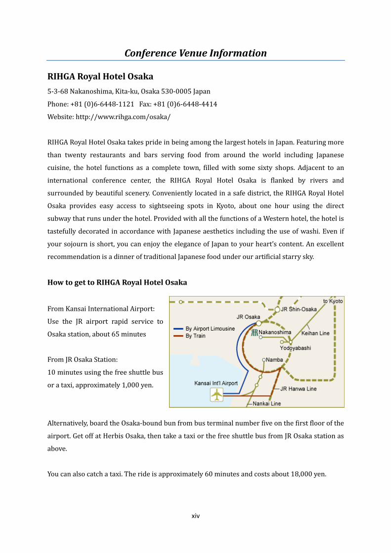
How to get to RIHGA Royal Hotel Osaka
From Kansai International Airport:
Use the JR airport rapid service to
Osaka station, about 65 minutes
From JR Osaka Station:
10 minutes using the free shuttle bus
or a taxi, approximately 1,000 yen.
Alternatively, board the Osaka-bound bun from bus terminal number five on the first floor of the
airport. Get off at Herbis Osaka, then take a taxi or the free shuttle bus from JR Osaka station as
above.
You can also catch a taxi. The ride is approximately 60 minutes and costs about 18,000 yen.
xv
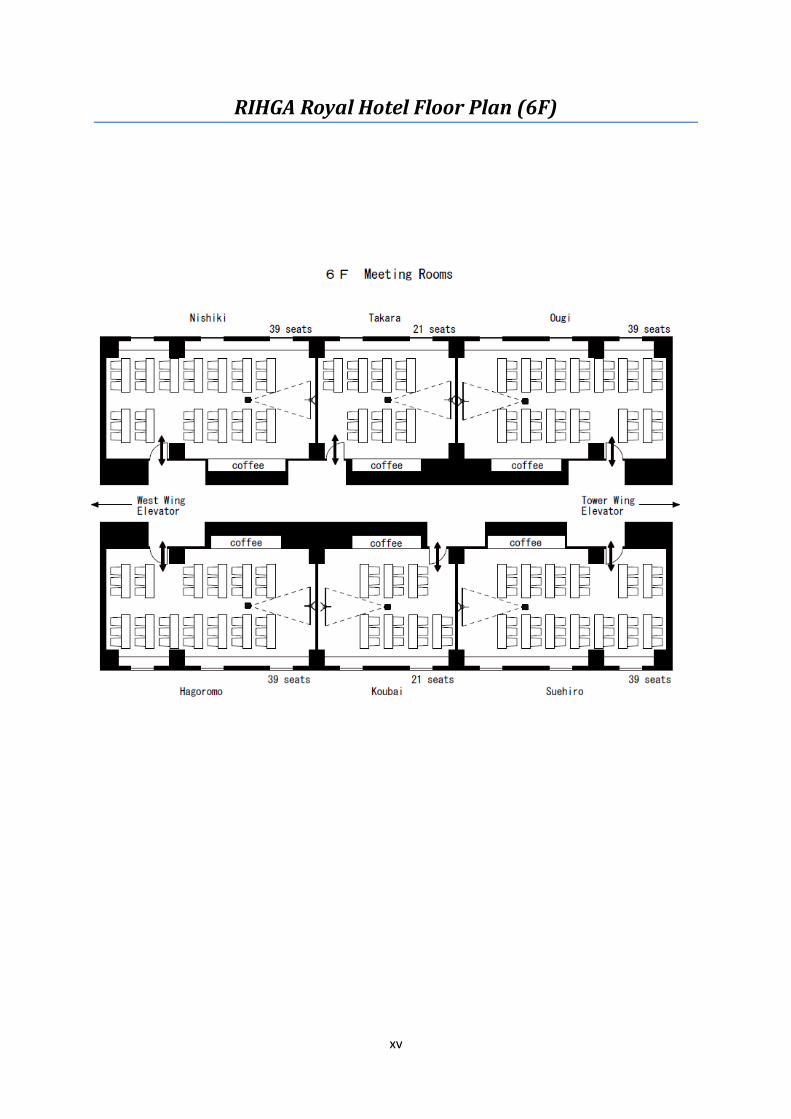
RIHGA Royal Hotel Floor Plan (6F)
Related Documents