SEISMIC UPGRADE STRATEGIES FOR A HISTORICAL BUILDING IN PLACERVILLE, CALIFORNIA A Project Presented to the faculty of the Department of Civil Engineering California State University, Sacramento Submitted in partial satisfaction of the requirements for the degree of MASTER OF SCIENCE in Civil Engineering (Structural Engineering) by Yash Kandhari FALL 2019

Welcome message from author
This document is posted to help you gain knowledge. Please leave a comment to let me know what you think about it! Share it to your friends and learn new things together.
Transcript

SEISMIC UPGRADE STRATEGIES FOR A HISTORICAL BUILDING IN
PLACERVILLE, CALIFORNIA
A Project
Presented to the faculty of the Department of Civil Engineering
California State University, Sacramento
Submitted in partial satisfaction of
the requirements for the degree of
MASTER OF SCIENCE
in
Civil Engineering
(Structural Engineering)
by
Yash Kandhari
FALL
2019

ii
© 2019
Yash Kandhari
ALL RIGHTS RESERVED

iii
SEISMIC UPGRADE STRATEGIES FOR A HISTORICAL BUILDING IN
PLACERVILLE, CALIFORNIA
A Project
by
Yash Kandhari
Approved by:
__________________________________, Committee Chair
Dr. Benjamin Fell, PE
____________________________
Date

iv
Student: Yash Kandhari
I certify that this student has met the requirements for format contained in the University
format manual, and this project is suitable for shelving in the library and credit is to be
awarded for the project.
__________________________, Graduate Coordinator ___________________
Dr. Ghazan Khan Date
Department of Civil Engineering

v
Abstract
of
SEISMIC UPGRADE STRATEGIES FOR A HISTORICAL BUILDING IN
PLACERVILLE, CALIFORNIA
by
Yash Kandhari
This report summarizes a seismic structural retrofit to an existing unreinforced masonry
(URM) building in Placerville, California, presenting two different structural systems as
alternatives. The first system is a more traditional approach using a Special Steel Moment
Resisting Frame (SMRF), while the second features a newer approach of coating the walls
in Fiber Reinforced Cementitious Matrix (FRCM). The various failure modes and concerns
of URM buildings or components subjected to earthquake excitation are presented, along
with the different design methodologies of the two retrofit strategies. A comprehensive
literature review is presented to establish the design methodology and material
characteristics for the FRCM to determine the upgraded strength of the masonry structure.
For both systems, the diaphragms are also detailed according to the varying seismic forces
developed from each lateral load resisting system.
_______________________, Committee Chair
Dr. Benjamin Fell, PE
________________________
Date

vi
ACKNOWLEDGEMENTS
I would like to thank Prof. Benjamin Fell, my project advisor for all the knowledge
and guidance he has provided me through this project. He has been very supportive and
has led me with care and caution throughout the project.
I would like to thank Burne Engineering for presenting this project which gave depth
to my understanding in many aspects.
I would also like to thank my parents, Pooja and Gopal for their constant support and
love and making me believe that I can accomplish anything when I put my mind to it and
always reminding me to chase my dreams.
I would also like to thank my friends for their support and for standing by my side in
worst times and let me up.
Lastly, I would like to thank the Department of Civil Engineering, Prof. Benjamin
Fell for giving me this wonderful opportunity to learn and grow and always encouraging
to do things which I never thought of doing.

vii
TABLE OF CONTENTS
Page
Acknowledgements .................................................................................................. vi
List of Tables ......................................................................................................... viii
List of Figures ........................................................................................................... x
Chapter
1. INTRODUCTION ................................................................................................. 1
2. BACKGROUND ................................................................................................... 3
3. FABRIC-REINFORCED CEMENTITIOUS MATRIX (FRCM) ........................... 5
4. NEW STEEL SPECIAL MOMENT FRAMES .................................................... 20
5. DIAPHRAGMS .................................................................................................. 31
6. SUMMARY ........................................................................................................ 43
Appendix A. Excel Calculations .............................................................................. 44
References ............................................................................................................... 64

viii
LIST OF TABLES
Tables Page
1. Vertical distribution of forces (FRCM)………………………………………... 7
2. Mechanical properties (FRCM)………………………………………………... 8
3. FRCM reinforcement properties……………………………………………….. 8
4. Loading information (1st story) ………………………………………………. 10
5. Loading information (2nd story) …………………………………………….... 10
6. Nominal shear capacity of the CMU wall panel (1st story) …………………... 12
7. Nominal shear capacity of the CMU wall panel (2nd story) ………………….. 13
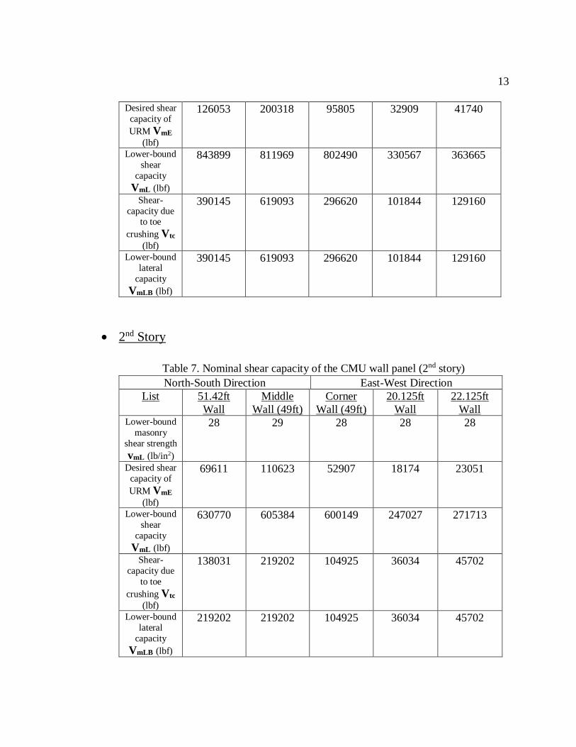
8. Shear capacity of the FRCM strengthened wall (1st story) …………………... 15
9. Shear capacity of the FRCM strengthened wall (2nd story) …………………. 16
10. Design shear strength of the strengthened wall (1st story) …………………... 17
11. Design shear strength of the strengthened wall (2nd story) …………………... 17
12. Dead load (roof)………………………………………………………………. 25
13. Dead load (floor)…………………………………………………………….... 26
14. Wall weights……………………………………………………………………26
15. Vertical distribution of forces (SMF)………………………………………..... 27
16. Story drift (building 1) ……………………………………………………….. 29
17. Story drift (building 2) ……………………………………………………….. 30
18. Diaphragm forces (FRCM-1st story)………………………………………….. 33
19. Diaphragm unit shear (FRCM-roof) …………………………………………. 34
20. Diaphragm unit shear (FRCM-2nd floor) …………………………………….. 35

ix
21. Diaphragm detailing (FRCM)………………………………………………… 36
22. Chord force & chord unit shear (FRCM-roof) ……………………………….. 36
23. Chord force & chord unit shear (FRCM-2nd floor) …………………………… 37
24. Diaphragm forces (SMF)……………………………………………………... 38
25. Diaphragm unit shear (SMF-roof) …………………………………………… 39
26. Diaphragm unit shear (SMF-2nd floor) ………………………………………. 40
27. Diaphragm detailing (SMF)…………………………………………………... 41
28. Chord force & chord unit shear (SMF-roof) ………………………………… 41
29. Chord force & chord unit shear (SMF-2nd floor) ……………………………... 42

x
LIST OF FIGURES
Figures Page
1. Building layout……………………………………………………………….. 3
2. Vertical distribution of forces (FRCM)……………………………………….. 7
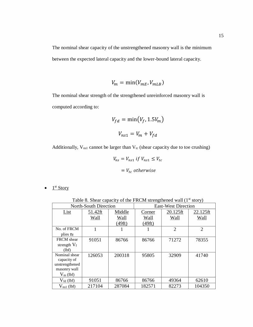
3. In-plane shear contribution (FRCM: north-south walls)
(a) 1st story (b) 2nd story…………………………………………………….... 18
4. In-plane shear contribution (FRCM: east-west walls)
(a) 1st story (b) 2nd story……………………………………………………….19
5. Typical local buckling of beam flanges and web……………………………...20
6. ATC hazards by location (seismic report) ……………………………….…...24
7. Vertical distribution of forces (SMF)………………………………………... 27
8. Confidence engine company hall mastan2 elastic analysis………………….. 29
9. Emigrant jane building mastan2 elastic analysis…………………………...... 30
10. Diaphragm behavior…………………………………………………………. 32
11. Diaphragm force resisting walls (FRCM)
(a)North-South Walls (b)East-West Walls…………………………………... 34
12. Diaphragm force resisting walls (SMF)
(a)north-south walls (b)east-west Walls………………………………………39
13. (a) Excel calculation sheet (20.125ft wall) (1st story) ……………………….. 44
(b) Continued excel calculation sheet (20.125ft wall) (1st story) ……………. 45
14. (a) Excel calculation sheet (20.125ft wall) (2nd story) ………………………. 46
(b) Continued excel calculation sheet (20.125ft wall) (2nd story) …………… 47

xi
15. (a) Excel calculation sheet (22.125ft wall) (1st story) ………………………. 48
(b) Continued excel calculation sheet (22.125ft wall) (1st story) ……………. 49
16. (a) Excel calculation sheet (22.125ft wall) (2nd story) ………………………. 50
(b) Continued excel calculation sheet (22.125ft wall) (2nd story) …………… 51
17. (a) Excel calculation sheet (51.42ft wall) (1st story) ………………………… 52
(b) Continued excel calculation sheet (51.42ft wall) (1st story) ……………... 53
18. (a) Excel calculation sheet (51.42ft wall) (2nd story) ………………………... 54
(b) Continued excel calculation sheet (51.42ft wall) (2nd story) …………….. 55
19. (a) Excel calculation sheet [middle wall (49ft)] (1st story) …………………. 56
(b) Continued excel calculation sheet [middle wall (49ft)] (1st story) ……… 57
20. (a) Excel calculation sheet [middle wall (49ft)] (2nd story) ……………….... 58
(b) Continued excel calculation sheet [middle wall (49ft)] (2nd story) ……… 59
21. (a) Excel calculation sheet [corner wall (49ft)] (1st story) …………………... 60
(b) Continued excel calculation sheet [corner wall (49ft)] (1st story) ………. 61
22. (a) Excel calculation sheet [corner wall (49ft)] (2nd story) …………………. 62
(b) Continued excel calculation sheet [corner wall (49ft)] (2nd story) ……… 63

1
1. INTRODUCTION
Unreinforced masonry (URM) structures are prevalent building types, but the
combination of their large seismic mass and lower tensile strength makes these structures
prone to earthquakes. Considering the large number of URMs in high seismic areas, this is
an important topic for the structural engineering community to assess the vulnerabilities of
the buildings and to develop economical methods to ensure life safety during an earthquake
event. The lack of reinforcement in these structures is the primary concern for seismic
behavior and can lead to a very brittle failure mechanism. Other issues include minimal
structural detailing at the connections between the floor system and walls, and weak
diaphragm systems to accommodate the full seismic load. Thus, the selected seismic
retrofit strategy for URMs should primarily focus on shear strengthening of the wall
systems but should also consider the full load transfer mechanism.
This study includes a historical building built in 1860’s, that requires retrofitting which
aims not just to evaluate seismic capacity of the existing masonry historical building
constructed, but to improve their capacity using different alternatives which would also
broaden our thinking over the traditional retrofitting techniques (moment frames, timber
shear walls, etc.). A new retrofitting material FRCM (Fabric-Reinforced Cementitious
matrix) has a different design approach compared to the traditional methods. FRCM design
is a modern-day design with new and different types of construction materials, design
procedures, workmanship, installation process with high nominal compressive strength.
On the other hand, new steel special moment frames are designed using equivalent lateral
force procedure and section designing is done in Mastan2. Thus, main motive of

2
considering two retrofit methods is to provide a better designing approach based on all the
aspects such as designing techniques, material properties and wall capacities obtained
through different systems.
This study also involves re-sheathing at the floor and roof levels, so diaphragm checks
were done with the same two methods FRCM and steel moment frames. Due to different
lateral forces affecting the buildings in both the systems, different sort of diaphragms such
as unblocked diaphragms, blocked diaphragms and blocked diaphragms (high load
diaphragms) were considered for full load transfer mechanism. Selection of diaphragms
involves common nail size, fastener penetrations, nominal panel thickness, nominal width
and nail spacing at diaphragm boundaries. All these factors are taken into consideration for
both the systems, performing required design calculations which provides the best
alternative for diaphragm design and re-sheathing at floor and roof levels.

3
2. BACKGROUND
Over the last few decades, traditional retrofit methods such as moment frames,
timber shear walls are into practice. So, to adapt a new method known as Fiber-
Reinforced Cementitious Matrix (FRCM) which may add a different outcome for
retrofitting is researched. By comparing the results achieved from moment frames and
FRCM, an effort is made to reach a better alternative for this project.
Historical buildings were provided by Burne Engineering which were Confidence
Engine Company Hall and Emigrant Jane Building built in 1860s, with an idea of three
retrofitting options which were rehabilitate and strengthen existing URM shear walls,
new timber shear walls and new steel special moment frames. Along with that a
requirement of re-sheathing was stated. Out of these three alternatives, one alternative
of new steel special moment frames was selected.
Figure 1. Building layout

4
A research was done to find a different material which has a different designing
style than the traditional retrofit methods. FRCM was considered as this new material
because of its high tensile strength, sprayable nature, fast installation and maybe a cost-
effective solution. FRCM is suitable to masonry as it matches substrate, provides
protective barrier and repairs walls while adding strength. Thus, benefits of FRCM, its
compatibility with masonry and its different or new age style of retrofitting persuaded
me to select this material as one of my retrofitting alternatives.
Many different design considerations were made for both the methods, as
information available for FRCM was limited. Moment frames were designed according
to the design provisions in ASCE 7-10, to select section properties and to check
deformations, moment frames were modelled in Mastan2. While, FRCM was designed
according to the design provisions in ACI 549.4r-13 and the material properties were
considered from AC 434. As FRCM has limited information, some assumptions were
made at the start to keep the buildings behavior elastic. Thus, some of these
considerations may lead to different results as seismic demand, story forces and wall
capacity obtained through these methods.
To fulfill the requirement of re-sheathing, diaphragm had to be designed to get the
required diaphragm shear force. Diaphragm design was provided with the same two
alternatives which is FRCM and steel moment frames to obtain a cost-effective
alternative. Diaphragms were designed using code AWC-SDPWS 2015. This code
helped to select which diaphragm is more suitable for the given buildings, as it provides
an idea of the cost for each method.

5
3. FIBER-REINFORCED CEMENTITIOUS MATRIX (FRCM)
3.1 INTRODUCTION
Unreinforced masonry historical buildings built without enough in-fill frame separation
have been consistently reported in reconnaissance reports to undergo in-plane shear
damage. Typical earthquake damage patterns in masonry infills include cracking along the
in-fill frame interface, toe crushing, diagonal cracking through masonry or mortar joints,
and bed joint sliding. It is widely accepted that cracking at infill-frame interface initiates
at low magnitude of lateral loading that leads to decrease in stiffness, following which it
continues to exhibit linear behavior until toe crushing leads to sudden stiffness
deterioration. It was noted from the review of structural drawings of existing buildings in
the Gulf, Asia, USA, Europe and New Zealand that majority of buildings built prior to the
introduction of modern seismic provisions in 1960s have unreinforced clay brick masonry
or hollow concrete masonry infill panels. These masonry panels, without strengthening,
exhibit low shear strength and are likely to undergo damage during a moderate to large
earthquake.
Therefore, a modified system is developed consisting of a cement-based matrix and a
dry fiber reinforced grid referred to as fabric reinforced cementitious matrix (FRCM) that,
when applied in a strengthening application, acts as externally bond reinforcement. The
dry fiber reinforced grids are made of two- or three-dimensional strands of individually
coated fibers rather than being bound together in an organic polymeric resin. The FRCM
system has also been referred to as textile-reinforced matrix or cementitious matrix grid

6
systems. FRCM is preferably applied on both sides of the wall to achieve symmetry and
effectiveness.
3.2 Vertical Distribution of forces
To find the lateral forces at each story for Fiber Reinforced Cementitious Matrix
(FRCM) there isn’t any specific method provided or stated, so in this report equivalent
lateral force procedure is followed to find the vertical distribution of forces.
Firstly, seismic response coefficient is calculated using the site coordinates, latitude:
38.72976389 and longitude: -120.7995222, risk category “II” and site class “D”. But for
FRCM, there are no design coefficients and factors available, so response modification
coefficient (R), overstrength factor (Ωo) and deflection amplification factor (Cd) all are
equal to one to keep the design elastic and avoid deformations. Once all the considerations
are made, we obtain a seismic response coefficient of 0.449.
Secondly, to calculate the base shear, effective seismic weight of the building is
calculated which accounts for dead loads and weight of the walls. Weight of the entire
building is calculated to obtain a force which can move the entire structure from the ground.
This force is the seismic demand according to which a retrofit method can be practiced,
and design can be proposed accordingly. Base shear of the FRCM system is:
Effective seismic weight = 850 kips
Seismic Response Coefficient = 0.449
𝑉 = 𝐶𝑠 ∗ 𝑊 (ASCE7-10: 12.8.1)

7
V= 382 kips
Base shear is distributed among the floors of the building which is also known as vertical
distribution of forces. This process helps to determine lateral forces affecting at each story
which will later affect the story displacements and story drifts which are basically designed
to make the floors in a building stronger and resistible.
• Vertical Distribution of Forces
K=1 as Ta < 0.5 sec
𝐶𝑣𝑥 = (𝑤𝑥ℎ𝑥𝑘)/(∑ 𝑤𝑖ℎ𝑖
𝑘)𝑛𝑖=1 (ASCE7-10: 12.8-12)
Table 1. Vertical distribution of forces (FRCM)
Level W (k) H (ft) WHK Cvx Fx (k)
Roof 247 29.52 7284 0.45 172
2nd Floor 603 14.76 8903 0.55 210
Total 850 16187 382
Figure 2. Vertical distribution of forces (FRCM)
172
kips
380 kips
210
kips
14
.76
ft
14.7
6ft
29
.52ft

8
3.3 Material Properties
Mechanical Properties
Table 2. Mechanical properties (FRCM)
Properties Strength References
Nominal Compressive strength
(f'm ) (lb/in2)
1500 ACI 530-11 (MSJC)
Compressive Ultimate Strength
(mu)
0.0025 (maximum usable
starin)
NCMA TEK 14-4B
Masonry elastic modulus
(Em=900fm’) (lb/in2)
1350000 NCMA TEK 14-4B
Lower-bound shear strength
(vtL=0.05fm’) (lb/in2)
7
5
NCMA TEK 14-4B
FRCM systems for wall shear are installed as:
C10: Carbon fiber fabric for masonry structural reinforcement
M25: Stabilized inorganic matrix for cementitious material
FRCM matrix reinforcement properties
Table 3. FRCM reinforcement properties
Properties Strength Reference Area of mesh reinforcement
by unit width (Af) (in2/ft)
0.022 AC 434
Tensile Modulus of elasticity (Ef) (ksi)
10061 AC 434
Ultimate Tesnile Strength (fd) 0.004 AC 434

9
Ultimate tensile strength
(ffd=Ef*fd) (ksi)
40.244 AC 434
3.4 In-plane Shear Design
The FRCM composite material bonded to surfaces of masonry are used to enhance the
design shear strength in the plane of the wall by acting as shear reinforcement. FRCM is
applied on both sides of the wall for symmetry and effectiveness. Nominal shear strength
is the contribution of unreinforced masonry and FRCM composite material.
In-plane shear design consists of following steps:
1. Loading information from the existing URM walls
2. Compute the nominal shear capacity of the CMU wall panel
3. Compute the nominal shear capacity of the FRCM strengthened wall
4. Compute the design shear strength of the strengthened wall
Step1. Loading information from the existing URM walls
Firstly, to check the wall capacity for each wall, new ultimate shear for every wall
should be calculated to meet the seismic demands.
Secondly, superimposed dead load is calculated for each wall using the arbitrary area
for each wall and considering the dead loads on that story. Once we get the dead load value
it is divided by the length of that wall to get per foot value for that wall.
Thirdly, lower bound axial compressive force due to gravity loads consider the dead
loads and live loads acting on each wall. Product of the dead/live loads and arbitrary area

10
for each wall gives us the axial compressive force on that wall and dividing that by the wall
length gives the axial force per foot value.
Afloor = 2123.80 ft2
Aroof = 2287.57 ft2
• 1st Story
Table 4. Loading information (1st story)
North-South Direction East-West Direction
List 51.42ft
Wall
Middle
Wall (49ft)
Corner
Wall (49ft)
20.125ft
Wall
22.125ft Wall
Tributary Area
(At) (ft2) 591 986 472 247 284ii8ufe3w2``
At/Af/r 0.278 0.464 0.222 0.116 0.134
New ultimate
shear force (Vu)
(kip)
106 177 85 44 51
Superimposed
dead load (PD)
(lbf/ft)
424 742 355 451 473
Lower-bound
axial
compressive
force due to
gravity load (QG)
(lbf/ft)
1183 2070 990 1260 1322
• 2nd Story
Table 5. Loading information (2nd story)
North-South Direction East-West Direction
List 51.42ft
Wall
Middle
Wall (49ft)
Corner Wall
(49ft)
20.125ft
Wall
22.125ft
Wall
Tributary Area
(At) (ft2)
591 986 472 247 284
At/Af/r 0.258 0.431 0.206 0.108 0.124
New ultimate
shear force
(Vu) (kip)
44 74 35 19 21

11
Superimposed
dead load (PD)
(lbf/ft)
234 410 196 249 262
Lower-bound
axial
compressive
force due to
gravity load
(QG) (lbf/ft)
418 732 350 445 467
Step 2. Compute the nominal shear capacity of the CMU Wall (ACI 549.4r-13)
Concrete masonry elements can be designed by several methods such as empirical
design, strength design or allowable stress design.
Lower-bound masonry shear strength
𝑣𝑚𝐿 = 0.75 ∗𝑣𝑡𝐿+(
𝑃𝐷𝐴𝑛
)
1.5
where,
vtL = lower-bound shear strength
PD = superimposed dead load
An = section area
Compute the desired lateral capacity of the wall
𝑉𝑚𝐸 = 0.9 ∗ 𝛼 ∗ 𝑃𝐷 ∗ 𝐿𝑊 ∗ (𝐿𝑤
ℎ𝑒𝑓𝑓)
where,
α = 1.0 is a factor accounting for boundary conditions
Lw = length of the wall

12
heff = clear height of the wall
Compute the lower-bound lateral capacity of the wall
Lower bound shear capacity is computed as:
𝑉𝑚𝐿 = 𝑣𝑚𝐿 ∗ 𝐴𝑛 ∗ 𝐿𝑤
The shear capacity due to toe crushing is computed as:
𝑉𝑡𝑐 = 𝛼 ∗ 𝑄𝐺 ∗ (𝐿𝑤
ℎ𝑒𝑓𝑓) ∗ (1 − (
𝑓𝑎
0.7𝑓𝑚′ )) ∗ 𝐿𝑤
where,
QG = lower-bound axial compressive force due to gravity loads
𝑓𝑎 = 𝑎𝑥𝑖𝑎𝑙 𝑐𝑜𝑚𝑝𝑟𝑒𝑠𝑠𝑖𝑣𝑒 𝑠𝑡𝑟𝑒𝑠𝑠 𝑑𝑢𝑒 𝑡𝑜 𝑔𝑟𝑎𝑣𝑖𝑡𝑦 𝑙𝑜𝑎𝑑𝑠 =𝑄𝐺
𝐴𝑛
fm’ = nominal compressive strength
The lower-bound lateral capacity is computed as:
𝑉𝑚𝐿𝐵 = min(𝑉𝑚𝐿 , 𝑉𝑡𝑐)
• 1st Story
Table 6. Nominal shear capacity of the CMU wall panel (1st story)
North-South Direction East-West Direction List 51.42ft
Wall Middle
Wall (49ft) Corner
Wall (49ft) 20.125ft
Wall 22.125ft
Wall Lower-bound
masonry
shear strength
vmL (lb/in2)
29 28 28 29 29
13
Desired shear
capacity of
URM VmE (lbf)
126053 200318 95805 32909 41740
Lower-bound
shear
capacity
VmL (lbf)
843899 811969 802490 330567 363665
Shear-
capacity due to toe
crushing Vtc (lbf)
390145 619093 296620 101844 129160
Lower-bound
lateral
capacity
VmLB (lbf)
390145 619093 296620 101844 129160
• 2nd Story
Table 7. Nominal shear capacity of the CMU wall panel (2nd story)
North-South Direction East-West Direction List 51.42ft
Wall Middle
Wall (49ft) Corner
Wall (49ft) 20.125ft
Wall 22.125ft
Wall Lower-bound
masonry
shear strength
vmL (lb/in2)
28 29 28 28 28
Desired shear
capacity of
URM VmE (lbf)
69611 110623 52907 18174 23051
Lower-bound
shear
capacity
VmL (lbf)
630770 605384 600149 247027 271713
Shear-
capacity due
to toe
crushing Vtc (lbf)
138031 219202 104925 36034 45702
Lower-bound
lateral
capacity
VmLB (lbf)
219202 219202 104925 36034 45702

14
Step3. Compute the shear capacity of the FRCM strengthened wall (ACI 549.4r-13)
Select the number of FRCM plies and width of the FRCM strip
The number of plies of FRCM should exceed the maximum number of plies to be used
for flexural strengthening.
Number of plies = nf
In this project, a width of 12in is considered.
Width of FRCM strip, wf = Lw
A continuous layer of FRCM reinforcement is applied on both sides of the wall.
Calculate the FRCM design tensile strain and strength
Design tensile strain, fv = min(fd,0.004)
Design tensile strength, 𝑓𝑓𝑣 = 𝜀𝑓𝑣 ∗ 𝐸𝑓
Calculate the FRCM design tensile strain and strength
The total force per unit width that the FRCM system can transfer to the masonry
substrate is computed as:
𝑉𝑓 = 2 ∗ 𝑛𝑓 ∗ (𝐴𝑓 ∗ 𝑓𝑓𝑣) ∗ 𝐿𝑤
Compute the nominal shear capacity of the strengthened wall
15
The nominal shear capacity of the unstrengthened masonry wall is the minimum
between the expected lateral capacity and the lower-bound lateral capacity.
𝑉𝑚 = min(𝑉𝑚𝐸 , 𝑉𝑚𝐿𝐵)
The nominal shear strength of the strengthened unreinforced masonry wall is
computed according to:
𝑉𝑓𝑑 = min(𝑉𝑓 , 1.5𝑉𝑚)
𝑉𝑛𝑠1 = 𝑉𝑚 + 𝑉𝑓𝑑
Additionally, Vns1 cannot be larger than Vtc (shear capacity due to toe crushing)
𝑉𝑛𝑠 = 𝑉𝑛𝑠1 𝑖𝑓 𝑉𝑛𝑠1 ≤ 𝑉𝑡𝑐
= 𝑉𝑡𝑐 𝑜𝑡ℎ𝑒𝑟𝑤𝑖𝑠𝑒
• 1st Story
Table 8. Shear capacity of the FRCM strengthened wall (1st story)
North-South Direction East-West Direction
List 51.42ft
Wall
Middle
Wall
(49ft)
Corner
Wall
(49ft)
20.125ft
Wall
22.125ft
Wall
No. of FRCM
plies nf
1 1 1 2 2
FRCM shear
strength Vf
(lbf)
91051 86766 86766 71272 78355
Nominal shear capacity of
unstrengthened
masonry wall
Vm (lbf)
126053 200318 95805 32909 41740
Vfd (lbf) 91051 86766 86766 49364 62610
Vns1 (lbf) 217104 287084 182571 82273 104350

16
Nominal shear strength of the strengthened unreinforced
masnry walls (Vns) (lbf)
217104 287084 182571 82273 104350
• 2nd Story
Table 9. Shear capacity of the FRCM strengthened wall (2nd story)
North-South Direction East-West Direction
List 51.42ft
Wall
Middle
Wall (49ft)
Corner
Wall (49ft)
20.125ft
Wall
22.125ft
Wall No. of FRCM
plies nf
1 1 1 1 1
FRCM shear
strength Vf
(lbf)
91051 86766 86766 35636 39178
Nominal shear
capacity of unstrengthened
masonry wall
Vm (lbf)
69611 110623 52907 18174 23051
Vfd (lbf) 91051 86766 79361 27261 34576
Vns1 (lbf) 160662 197390 132268 45434 57626 Nominal shear strength of the strengthened unreinforced
masonry wall
Vns (lbf)
138031 197390 104925 36034 45702
Step4. Compute the design shear strength of the strengthened wall (ACI 549.4r-13)
The nominal shear strength Vn, is obtained as the minimum of the nominal shear strength
as determined in previous step.
This nominal shear strength is the wall capacity for every wall which should meet the
seismic demand for every wall (new ultimate shear force) found in step1 to prove that the
shear check meets the designing requirements and is OK.
𝑉𝑢 = 𝛷𝑣 ∗ 𝑉𝑛𝑠

17
where,
Φv = strength reduction factor = 0.75
• 1st Story
Table 10. Design shear strength of the strengthened wall (1st story)
North-South Direction East-West Direction
List 51.42ft
Wall
Middle
Wall (49ft)
Corner
Wall (49ft)
20.125ft
Wall
22.125ft
Wall New ultimate
shear force Vu
(kips)
106 177 85 44 51
Design shear
strength of
strengthened
wall Vu (kips)
163 215 137 62 78
Check_Shear OK OK OK OK OK
• 2nd Story
Table 11. Design shear strength of the strengthened wall (2nd story)
North-South Direction East-West Direction
List 51.42ft
Wall
Middle
Wall (49ft)
Corner
Wall (49ft)
20.125ft
Wall
22.125ft
Wall New ultimate
shear force Vu
(kips)
44 74 35 19 21
Design shear
strength of
strengthened
wall Vu (kips)
104 148 79 27 34
Check_Shear OK OK OK OK OK
18
• North-South Walls
FRCM Strip
Wall Capacity
Seismic Demand
Figure 3. In-plane shear contribution (FRCM: north-south walls)

19
• East-West Walls
FRCM Strip
Wall Capacity
Seismic Demand
Figure 4. In-plane shear contribution (FRCM: east-west walls)

20
4. NEW STEEL SPECIAL MOMENT FRAMES
4.1 Introduction
Even in areas of very excessive seismic danger, like California and Alaska, extreme
earthquakes are rare activities, affecting usual buildings at common intervals of loads of
years. Given this, it's far economically impractical to layout systems to resist such extreme
however rare earthquakes without damage. Instead, the building codes have adopted a
design philosophy meant to offer protection by way of keeping off earthquake-prompted
fall apart in severe occasions, whilst allowing tremendous structural and nonstructural
harm. Inelastic behavior in steel special moment frames system is supposed to be
accommodated through the formation of plastic hinges at beam-column joints and column
bases. Plastic hinges form through flexural yielding of beams and columns and shear
yielding of panel zones. These modes are associated with frame behavior, include the
following criteria: beam behavior, joint panel zone behavior, column behavior, column
splices, column bases, structure P-delta effects and sideway collapse.
Figure 5. Typical local buckling of beam flanges and web
21
The most important advantage of moment frame structures is that they do no longer
have structural partitions or vertically oriented diagonal braces. They consequently provide
architectural freedom in layout, permitting open bays and unobstructed view lines. The
trade-off for those benefits is that second frames can be greater luxurious to assemble than
braced body or shear wall systems. The introduced price outcomes from the usage of
heavier sections within the moment resisting frames, requiring multiplied metal utilization
and more labor-intensive connections than is common in braced structures. However,
second frames usually impose smaller forces on foundations than do different structural
structures, ensuing in incredibly more most economical foundation systems.
Seismic design requirements are given in chapter 12 of the ASCE7-10 Code. For
computing the base shear of a building using the equivalent lateral force method, the code
gives an alternative way to compute the natural period of the system before the design.
However, the validity of this procedure needs to be checked for structures prone to high
seismic risks. Therefore, in this project the actual natural period is found to get the total
base shear to design a 2-D steel special moment frame (SMF) in high seismic zones. Steel
special moment frames are often used as a part of the seismic force resisting systems in
buildings designed to resist earthquakes with substantial inelastic energy dissipation.
Design requirements for steel special moment frames can be found in a series of U.S.
building codes. ASCE 7-10 sets the basic load requirements for special moment frames
with associated lateral drift limits. AISC 360 is the main AISC specification that provides
design and detailing requirements for all steel buildings. In addition, AISC 341-05 gives
detailed design requirements related to materials, framing members, connections, and

22
construction quality assurance and quality control. It is worth mentioning that the ASCE
7-10 permits to use three types of analyses to determine member design forces and design
drifts namely: equivalent lateral force, modal response spectrum, and seismic response
history analysis. Equivalent lateral force analysis is the simplest procedure; however, it can
lead to a conservative design.
4.2 Equivalent Lateral Force Procedure
The SMF is a part of a two-story historical buildings located in Placerville, CA, USA.
Four special moment frames (SMFs) are considered for the east-west direction of the
building. The building geometry is shown in Figure (). The bay width in the east west
direction is 20.125 ft while it is 49 ft for the north-south direction for Emigrant Jane
building. The bay width in the east west direction is 22.125 ft while it is 51.42 ft for the
north-south direction for Confidence Engine Company Hall. A typical 14.76 ft floor-to-
floor heights is considered. The first story height is 14.76 ft.
For the seismic analysis, the frame is analyzed according to the ELF to get the base
shear. The base shear calculations require finding the effective seismic weight of the
building and the seismic response coefficient. From a report on “Upper Broadway Bike
Lanes-City of Placerville, Vs30 value of 1164.70 ft/s is obtained and if the VS30 value is
between 600ft/s and 1200 ft/s, the soil conforms to site class D. The two buildings share a
common wall and a internal hallway and door and have been utilized as a single tenant
office buildings which falls under risk category “II”. The calculations are provided in detail
in this paper.
23
Equivalent Lateral Force Procedure (ELFP), as outlined in ASCE 7-10, is a technique
for developing and distributing equivalent lateral loads on a structure to account for the
horizontal seismic load effect.
Equivalent Lateral Force Procedure includes following steps:
1. Calculation of Seismic Response Coefficient
2. Seismic Base Shear
3. Vertical Distribution of Forces
Step1. Calculation of Seismic Response Coefficient
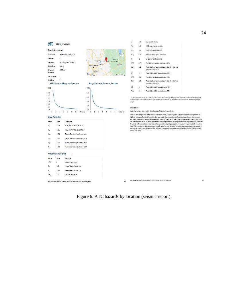
To start this procedure, firstly, a seismic site report is prepared with the help of ATC
hazards by location whose main purpose is to provide site-specific hazard information that
can be used to determine design loads for buildings and other structures using the following
site information:
1) Site Coordinates: latitude= 38.72976389 and longitude= -120.7995222
2) Reference Document: ASCE 7-10
3) Risk Category: II
4) Site Class: D
With the help of the above inputs, following report is generated specifying the site details:
24
Figure 6. ATC hazards by location (seismic report)
25
Response Modification Factor R=8
Overstrength Factor Ωo = 3.0
Deflection Amplification Factor = 5.5
Approximate Fundamental Period Ta = Ct * hnx = 0.468 sec (ASCE 7-10:Table 12.8-2)
Calculation of Seismic Response Coefficient consists of three equations:
1) 𝐶𝑠 =𝑆𝑑𝑠
𝑅
𝐼𝑒
= 0.056 (ASCE 7-10:Eqn. 12.8-2)
2) 𝐶𝑠𝑚𝑎𝑥 =𝑆𝑑1
𝑇(𝑅
𝐼𝑒) = 0.078 (Ta<TL) (ASCE 7-10:Eqn. 12.8-3)
3) 𝐶𝑠𝑚𝑖𝑛 = 0.044𝑆𝑑𝑠𝐼𝑒 = 0.020 (S1<0.6) (ASCE 7-10:Eqn. 12.8-5)
As, Csmin < Cs < Csmax
Cs = 0.056
Step2. Seismic Base Shear
Seismic Base shear is the force to move the whole structure from the ground. It is a product
of the seismic response coefficient and the total effective seismic weight of the building.
Total seismic weight of the building includes total dead load and weight of the walls.
• Dead Load (Roof)
Table 12. Dead load (roof)
List Dead load (psf)
Raptors 2*12” @ 16” o.c. 3.0
5/8” sheathing (gypsum sheathing) 2.0
1/4” shingles (asphalt shingles) 2.0
Other (mechanical/electrical) 3.0
Three ply ready roofing 1.0
Rigid insulation ½” 0.75
Balt Insulation 1.1

26
Ceiling (2 layers of gypsum board) 5.5
Miscellaneous 2
Total 20.35
(ASCE 7-10: Table C3.1)
• Dead Load (Floor)
Table 13. Dead load (floor)
List Dead Load (psf)
Joists 2*10 (16” spacing) 6
Tongue-and-groove paneling 1.5
MEP 3
Wood studs,2*4, unplastered 4
Miscellaneous 3
Total 16.5
(ASCE 7-10: Table C3.1)
• Live loads (floor) = 50 psf
• Live loads (roof) = 16psf
• Wall Weights
Table 14. Wall weights
List Weight (kips)
Roof 200.21
Floor 568.11
Total 768.32
Arearoof = 2287.57 ft2
Areafloor = 2123.80 ft2
Total effective seismic weight = (DLroof * Aroof) +(Wallsroof) + (DLfloor * Afloor)
+(Wallsfloor)
Total effective seismic weight = 849.91 kips
Seismic Base Shear = Cs*W (ASCE 7-10:
12.8-1)
Therefore, Seismic Base Shear V = 48 kips

27
Step3. Vertical Distribution of Forces
Once we obtain seismic base shear, vertical distribution of forces is done to distribute the
base shear among the floors of the structure.
Table 15. Vertical distribution of forces (SMF)
Level W (k) H (ft) WHK Cvx Fx (k)
Roof 247 29.52 7284 0.45 22
2nd Floor 603 14.76 8903 0.55 26
Total 850 16187 1.0 48
K=1 as Ta < 0.5 sec
Cvx = vertical distribution factor (ASCE 7-10: 12.8-12)
Figure 7. Vertical distribution of forces (SMF)
22
kips
48 kips
26
kips
14
.76
ft
14.7
6ft
29.5
2ft

28
4.3 Design
The lateral load is equally distributed among the four SMFs. The calculations are shown in
the subsequent sections. The drift limits are achieved by applying only the horizontal
seismic forces. The self-weight of the members is ignored for the analysis. The moment of
inertia of the beams is considered as the average of the positive and negative moment of
inertias according to AISC specification. The positive moment of inertia represents the
long-term moment of inertia for the composite beam section, while the negative moment
of inertia represents the moment of inertia of the steel section.
The analysis is done using Mastan2 and the elastic story drift for each story is exported.
The elastic drift is then multiplied by Cd/Ie to back calculate the plastic story drifts, where
Cd is the deflection amplification factor and Ie is the seismic importance factor. The
deflection amplification factor Cd is 5.5 for a steel special moment frame as per Table 12.2-
1 of ASCE 7-10 Code. The plastic story drifts are checked with the allowable story drifts
(Δa) provided by ASCE 7-10 Code, Table 12.12-1. Elastic analysis is applied in Mastan2
which is used to design beam/column sections which will give the most significant effects
on the drifts. This requires several iterations until the plastic story drift satisfy the allowable
story drift of ASCE 7-10.
Importance of story drift is to design partition or curtain walls, as they must be designed to
accommodate story drift, or they will be crack. Before getting story drift at every story,
story displacement is obtained at every story, which is the absolute value of displacement
of the story under action of lateral forces. Story drift is the difference of these displacements
obtained between two consecutive stories divided by the height of the story. This process

29
will give us a story drift in percentage which should be less than 0.025% from ASCE7-10
table 12.12-1.
Building1 (Confidence Engine Company Hall):
Beam 1: W30x99
Beam 2: W30x108
Columns: W21x147
Table 16. Story drift (building1)
Figure 8. Confidence engine company
hall mastan2 elastic analysis
Story () a () Check
1st
Story
0.023 0.025 OK
2nd
Story
0.008 0.025 OK
Beam 2
Co
lum
ns
Beam 1

30
Building2 (Emigrant Jane Building):
Beam 1: W30x90
Beam 2: W30x99
Columns: W21x132
Table 17. Story drift (building2)
Figure 9. Emigrant jane building
mastan2 elastic analysis
Story () a () Check
1st
Story
0.023 0.025 OK
2nd
Story
0.008 0.025 OK
Co
lum
ns
Beam 2
Beam 1

31
5. DIAPHRAGMS
5.1 Introduction
Diaphragm partitions are cellular walls composed of two wythes of masonry with a
massive hollow space or void, the wythes of that are bonded together with masonry ribs or
go partitions. The ribs are related to the wythes in this type of way that the two wythes act
compositely, thereby giving a completely composite section.
A diaphragm is a structural element designed to transfer in-plane shear forces to other
elements. Diaphragms connect exterior walls of a building providing rigidity against
racking and bowing from earthquakes and wind loads. Diaphragms are typically horizontal
but can be sloped such as in gable roof. They are like horizontal version of a shear wall.
All edges of a diaphragm shall be supported by a boundary element such as chords, drag
struts, collectors, shear walls and frames. Wall top plates typically function as both
diaphragm chords and drag struts.
Valuable characteristics of unreinforced diaphragm walls are that the net section
properties are easily calculated and that they have a large moment of inertia. Given that
they may be thick, unreinforced diaphragm partitions are powerful at resisting out-of-plane
loads and are inherently very stiff. Unreinforced walls, however, regularly crack before
deflections control the overall performance.

32
Figure 10. Diaphragm behavior
5.2 FRCM (Fiber-Reinforced Cementitious Matrix)
5.2.1 Diaphragm Force
Diaphragm forces are obtained from self-weight of the diaphragms and
element/component weights that depend on the diaphragm for lateral support. Roof and
floor diaphragms are designed to resist design seismic forces from the structural analysis
part. Forces shall not be less than the following equation:
𝐹𝑝𝑥 = (∑ 𝐹𝑖/ ∑ 𝑤𝑖𝑛𝑖=𝑥 ) ∗ 𝑊𝑝𝑥𝑛
𝑖=𝑥 (ASCE7-10: 12.10-1)
Minimum diaphragm force:
𝐹𝑝𝑥𝑚𝑖𝑛 = 0.2 ∗ 𝑆𝐷𝑆 ∗ 𝐼𝑒 ∗ 𝑊𝑝𝑥 (ASCE7-10: 12.10-2)
Maximum diaphragm force:
𝐹𝑝𝑥𝑚𝑎𝑥 = 0.4 ∗ 𝑆𝐷𝑆 ∗ 𝐼𝑒 ∗ 𝑊𝑝𝑥 (ASCE7-10: 12.10-3)

33
Table 18. Diaphragm forces (FRCM-1st story)
Level W (kips) Fx (kips) Fpx Fpxmin Fpxmax
Roof 247 172 172 22 44
2nd Floor 603 210 271 54 108
Total 850 382
The diaphragm design force at Roof and 2nd Floor is 172 kips and 271 kips respectively,
but it exceeds the maximum diaphragm design force. So, the design diaphragm force for
both the stories is the maximum diaphragm force.
Design Diaphragm Force: Roof = 44 kips
2nd Floor = 108 kips
5.2.2 Diaphragm Demand Shear
Diaphragms are transverse stiffeners which may serve many purposes like transverse
shear capacity.
Transverse shear capacity means diaphragms help in load sharing between different
girders, so reduced bending/shear demands on the girders is achieved due to not only
vertical loads but also horizontal loads.
Diaphragm Shear:
Max Shear = Diaphragm Reaction at Shear wall
Diaphragm Unit Shear = 𝑅𝑒𝑎𝑐𝑡𝑖𝑜𝑛
𝐿𝑒𝑛𝑔𝑡ℎ 𝑜𝑓 𝐷𝑖𝑎𝑝ℎ𝑟𝑎𝑔𝑚 (plf)

34
(a) north-south walls (b) east-west walls
Figure 11. Diaphragm force resisting walls (FRCM)
• Diaphragm Unit Shear
Roof
𝑓 =𝐹𝑝𝑥(𝑟𝑜𝑜𝑓)
𝐴𝑟𝑒𝑎
Table 19. Diaphragm unit shear (FRCM-roof)
North-South Direction East-West Direction
Diaphragm
Length
51.42ft Wall 49ft Wall 20.125ft Wall 22.125 Wall
Reaction
(RA/B) (kips)
11.95 10.35 10.36 11.93
Diaphragm
Unit Shear
(ra/b)
(k/ft)
0.232 0.211 0.515 0.539

35
2nd Floor
𝑓 =𝐹𝑝𝑥(2𝑛𝑑𝑓𝑙𝑜𝑜𝑟)
𝐴𝑟𝑒𝑎
Table 20. Diaphragm unit shear (FRCM-2nd floor)
North-South Direction East-West Direction
Diaphragm
Length
51.42ft Wall 49ft Wall 20.125ft Wall 22.125 Wall
Reaction
(RA/B) (kips)
29.02 25.15 25.14 29
Diaphragm
Unit Shear
(ra/b)
(k/ft)
0.564 0.513 1.249 1.310
Maximum shear is in the east-west direction at the second floor.
Therefore, Maximum shear = maximum reaction at shear wall = 29 kips
Diaphragm length = 22.125ft
Maximum Unit Shear = 𝑚𝑎𝑥𝑖𝑚𝑢𝑚 𝑟𝑒𝑎𝑐𝑡𝑖𝑜𝑛
𝑑𝑖𝑎𝑝ℎ𝑟𝑎𝑔𝑚 𝑙𝑒𝑛𝑔𝑡ℎ =
29 𝑘𝑖𝑝𝑠
22.125 𝑓𝑡
Maximum Unit Shear (Vs)= 1310 plf
According to AWC-SDPWS 2015, Table 4.2B, Blocked Diaphragms (high load
diaphragms), have diaphragm shear range of 605plf <Vs<1565plf.
Therefore, the Design Diaphragm Shear = 1320 plf
36
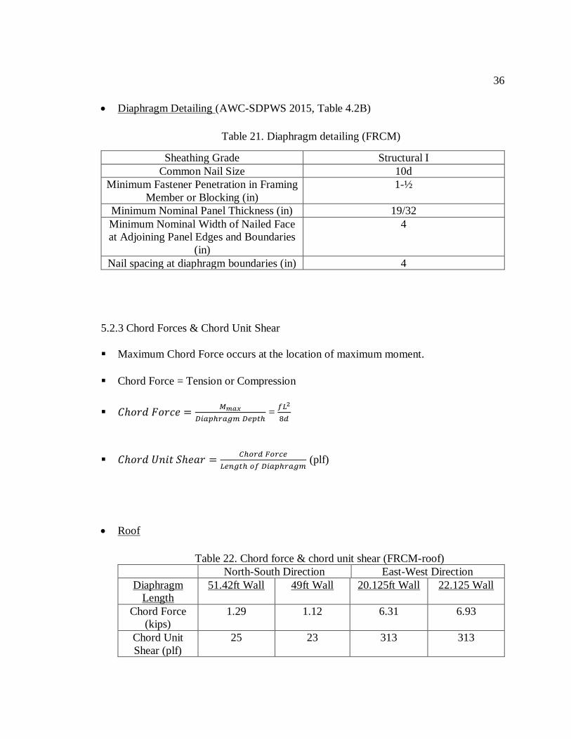
• Diaphragm Detailing (AWC-SDPWS 2015, Table 4.2B)
Table 21. Diaphragm detailing (FRCM)
Sheathing Grade Structural I
Common Nail Size 10d
Minimum Fastener Penetration in Framing
Member or Blocking (in)
1-½
Minimum Nominal Panel Thickness (in) 19/32
Minimum Nominal Width of Nailed Face
at Adjoining Panel Edges and Boundaries
(in)
4
Nail spacing at diaphragm boundaries (in) 4
5.2.3 Chord Forces & Chord Unit Shear
Maximum Chord Force occurs at the location of maximum moment.
Chord Force = Tension or Compression
𝐶ℎ𝑜𝑟𝑑 𝐹𝑜𝑟𝑐𝑒 =𝑀𝑚𝑎𝑥
𝐷𝑖𝑎𝑝ℎ𝑟𝑎𝑔𝑚 𝐷𝑒𝑝𝑡ℎ =
𝑓𝐿2
8𝑑
𝐶ℎ𝑜𝑟𝑑 𝑈𝑛𝑖𝑡 𝑆ℎ𝑒𝑎𝑟 =𝐶ℎ𝑜𝑟𝑑 𝐹𝑜𝑟𝑐𝑒
𝐿𝑒𝑛𝑔𝑡ℎ 𝑜𝑓 𝐷𝑖𝑎𝑝ℎ𝑟𝑎𝑔𝑚 (plf)
• Roof
Table 22. Chord force & chord unit shear (FRCM-roof)
North-South Direction East-West Direction
Diaphragm
Length
51.42ft Wall 49ft Wall 20.125ft Wall 22.125 Wall
Chord Force
(kips)
1.29 1.12 6.31 6.93
Chord Unit
Shear (plf)
25 23 313 313
37
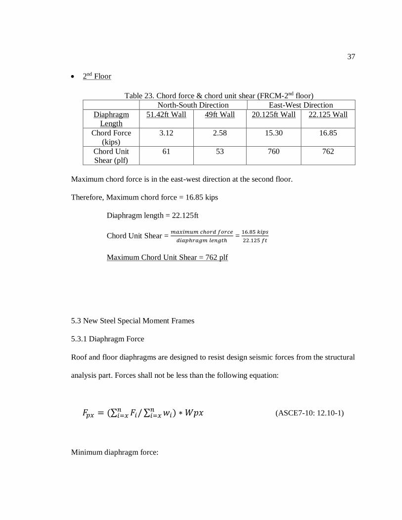
• 2nd Floor
Table 23. Chord force & chord unit shear (FRCM-2nd floor)
North-South Direction East-West Direction
Diaphragm
Length
51.42ft Wall 49ft Wall 20.125ft Wall 22.125 Wall
Chord Force
(kips)
3.12 2.58 15.30 16.85
Chord Unit
Shear (plf)
61 53 760 762
Maximum chord force is in the east-west direction at the second floor.
Therefore, Maximum chord force = 16.85 kips
Diaphragm length = 22.125ft
Chord Unit Shear = 𝑚𝑎𝑥𝑖𝑚𝑢𝑚 𝑐ℎ𝑜𝑟𝑑 𝑓𝑜𝑟𝑐𝑒
𝑑𝑖𝑎𝑝ℎ𝑟𝑎𝑔𝑚 𝑙𝑒𝑛𝑔𝑡ℎ =
16.85 𝑘𝑖𝑝𝑠
22.125 𝑓𝑡
Maximum Chord Unit Shear = 762 plf
5.3 New Steel Special Moment Frames
5.3.1 Diaphragm Force
Roof and floor diaphragms are designed to resist design seismic forces from the structural
analysis part. Forces shall not be less than the following equation:
𝐹𝑝𝑥 = (∑ 𝐹𝑖/ ∑ 𝑤𝑖𝑛𝑖=𝑥 ) ∗ 𝑊𝑝𝑥𝑛
𝑖=𝑥 (ASCE7-10: 12.10-1)
Minimum diaphragm force:

38
𝐹𝑝𝑥𝑚𝑖𝑛 = 0.2 ∗ 𝑆𝐷𝑆 ∗ 𝐼𝑒 ∗ 𝑊𝑝𝑥 (ASCE7-10: 12.10-2)
Maximum diaphragm force:
𝐹𝑝𝑥𝑚𝑎𝑥 = 0.4 ∗ 𝑆𝐷𝑆 ∗ 𝐼𝑒 ∗ 𝑊𝑝𝑥 (ASCE7-10: 12.10-3)
Table 24. Diaphragm forces (SMF)
Level W (kips) Fx (kips) Fpx Fpxmin Fpxmax
Roof 247 22 22 22 44
2nd Floor 603 26 34 54 108
Total 850 48
The diaphragm design force at Roof and 2nd Floor is 22 kips and 34 kips respectively, but
it is less than the minimum diaphragm design force. So, the design diaphragm force for
both the stories is the minimum diaphragm force.
Design Diaphragm Force: Roof = 22 kips
2nd Floor = 54 kips
5.3.2 Diaphragm Demand Shear
Diaphragms are transverse stiffeners which may serve many purposes like transverse
shear capacity.
Transverse shear capacity means diaphragms help in load sharing between different
girders, so reduced bending/shear demands on the girders is achieved due to not only
vertical loads but also horizontal loads.

39
Diaphragm Shear:
Maximum Shear=Diaphragm Reaction at Shear wall
Diaphragm Unit Shear = 𝑅𝑒𝑎𝑐𝑡𝑖𝑜𝑛
𝐿𝑒𝑛𝑔𝑡ℎ 𝑜𝑓 𝐷𝑖𝑎𝑝ℎ𝑟𝑎𝑔𝑚 (plf)
(a) north-south walls (b) east-west walls
Figure 12. Diaphragm force resisting walls (SMF)
• Diaphragm Unit Shear
Roof
𝑓 =𝐹𝑝𝑥(𝑟𝑜𝑜𝑓)
𝐴𝑟𝑒𝑎
Table 25. Diaphragm unit shear (SMF-roof)
North-South Direction East-West Direction
Diaphragm
Length
51.42ft Wall 49ft Wall 20.125ft Wall 22.125 Wall
Reaction
(RA/B) (kips)
5.69 4.93 4.93 5.68
40
Diaphragm
Unit Shear
(ra/b)
(k/ft)
0.111 0.101 0.245 0.257
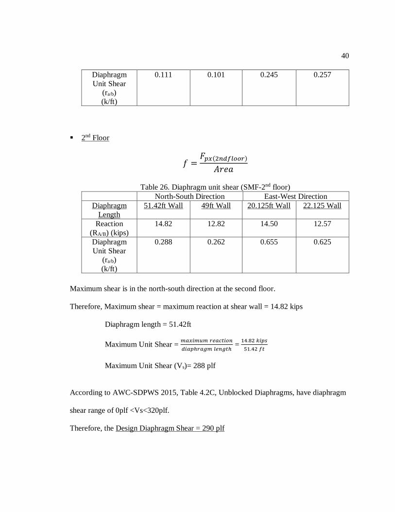
2nd Floor
𝑓 =𝐹𝑝𝑥(2𝑛𝑑𝑓𝑙𝑜𝑜𝑟)
𝐴𝑟𝑒𝑎
Table 26. Diaphragm unit shear (SMF-2nd floor)
North-South Direction East-West Direction
Diaphragm
Length
51.42ft Wall 49ft Wall 20.125ft Wall 22.125 Wall
Reaction
(RA/B) (kips)
14.82 12.82 14.50 12.57
Diaphragm
Unit Shear
(ra/b)
(k/ft)
0.288 0.262 0.655 0.625
Maximum shear is in the north-south direction at the second floor.
Therefore, Maximum shear = maximum reaction at shear wall = 14.82 kips
Diaphragm length = 51.42ft
Maximum Unit Shear = 𝑚𝑎𝑥𝑖𝑚𝑢𝑚 𝑟𝑒𝑎𝑐𝑡𝑖𝑜𝑛
𝑑𝑖𝑎𝑝ℎ𝑟𝑎𝑔𝑚 𝑙𝑒𝑛𝑔𝑡ℎ =
14.82 𝑘𝑖𝑝𝑠
51.42 𝑓𝑡
Maximum Unit Shear (Vs)= 288 plf
According to AWC-SDPWS 2015, Table 4.2C, Unblocked Diaphragms, have diaphragm
shear range of 0plf <Vs<320plf.
Therefore, the Design Diaphragm Shear = 290 plf

41
• Diaphragm Detailing (AWC-SDPWS 2015, Table 4.2B)
Table 27. Diaphragm detailing (SMF)
Sheathing Grade Sheathing and Single-Floor
Common Nail Size 10d
Minimum Fastener Penetration in
Framing Member or Blocking (in)
1-½
Minimum Nominal Panel Thickness (in) 15/32
Minimum Nominal Width of Nailed Face
at Adjoining Panel Edges and Boundaries
(in)
3
Nail spacing at diaphragm boundaries (in) 3
5.3.3. Chord Forces & Chord Unit Shear
Maximum Chord Force occurs at the location of maximum moment.
Chord Force = Tension or Compression
𝐶ℎ𝑜𝑟𝑑 𝐹𝑜𝑟𝑐𝑒 =𝑀𝑚𝑎𝑥
𝐷𝑖𝑎𝑝ℎ𝑟𝑎𝑔𝑚 𝐷𝑒𝑝𝑡ℎ =
𝑓𝐿2
8𝑑
𝐶ℎ𝑜𝑟𝑑 𝑈𝑛𝑖𝑡 𝑆ℎ𝑒𝑎𝑟 =𝐶ℎ𝑜𝑟𝑑 𝐹𝑜𝑟𝑐𝑒
𝐿𝑒𝑛𝑔𝑡ℎ 𝑜𝑓 𝐷𝑖𝑎𝑝ℎ𝑟𝑎𝑔𝑚 (plf)
• Roof
Table 28. Chord force & chord unit shear (SMF-roof)
North-South Direction East-West Direction
Diaphragm
Length
51.42ft Wall 49ft Wall 20.125ft Wall 22.125 Wall
Chord Force
(kips)
1.06 0.96 3.00 3.30
Chord Unit
Shear (plf)
21 20 149 149

42
• 2nd Floor
Table 29. Chord force & chord unit shear (SMF- 2nd floor)
North-South Direction East-West Direction
Diaphragm
Length
51.42ft Wall 49ft Wall 20.125ft Wall 22.125 Wall
Chord Force
(kips)
1.59 1.32 7.65 8.43
Chord Unit Shear
(plf)
31 27 380 381
Maximum chord force is in the east-west direction at the second floor.
Therefore, Maximum chord force = 8.43 kips
Diaphragm length = 22.125ft
Chord Unit Shear = 𝑚𝑎𝑥𝑖𝑚𝑢𝑚 𝑐ℎ𝑜𝑟𝑑 𝑓𝑜𝑟𝑐𝑒
𝑑𝑖𝑎𝑝ℎ𝑟𝑎𝑔𝑚 𝑙𝑒𝑛𝑔𝑡ℎ =
8.43 𝑘𝑖𝑝𝑠
22.125 𝑓𝑡
Maximum Chord Unit Shear = 381 plf

43
6. SUMMARY
6.1 Conclusions
In-plane shear checks with two different alternatives (moment frame v. FRCM) would
provide building owner with different alternatives to consider based on performance and
aesthetics. Diaphragm design illustrated a possible cost savings for moment frame
alternative due to lesser quantities of sheathing material (due to smaller forces).
Deformations are significant with moment frame design – which would lead to a worse
damage state during an earthquake.
6.2 Future Work
In depth cost analysis of FRCM versus Steel moment frames to be presented to the
building owners. To start a research on FRCM displacement codes and to learn design
accordingly, which would allow to design with different methods and sections. If allowed,
to perform an on-field material testing to obtain precise material and reinforcing properties
for this buildings.

44
Appendix A.
Excel Calculations
1. East-West Direction (20.125 ft wall - 1st Story)
Figure 13. (a) Excel calculation sheet (20.125ft wall) (1st story)

45
Figure 13. (b) Continued excel calculation sheet (20.125ft wall) (1st story)

46
2. East-West Direction (20.125 ft Wall – 2nd Story)
Figure 14. (a) Excel calculation sheet (20.125ft wall) (2nd story)

47
Figure 14. (b) Continued excel calculation sheet (20.125ft wall) (2nd story)

48
3. East-West Direction (22.125 ft Wall – 1st Story)
Figure 15. (a) Excel calculation sheet (22.125ft wall) (1st story)

49
Figure 15. (b) Continued excel calculation sheet (22.125ft wall) (1st story)

50
4. East-West Direction (22.125 ft Wall – 2nd Story)
Figure 16. (a) Excel calculation sheet (22.125ft wall) (2nd story)
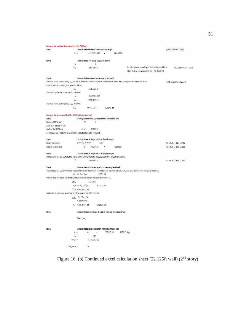
51
Figure 16. (b) Continued excel calculation sheet (22.125ft wall) (2nd story)

52
5. North-South Direction (51.42 ft Wall – 1st Story)
Figure 17. (a) Excel calculation sheet (51.42ft wall) (1st story)

53
Figure 17. (b) Continued excel calculation sheet (51.42ft wall) (1st story)

54
6. North-South Direction (51.42 ft Wall – 2nd Story)
Figure 18. (a) Excel calculation sheet (51.42ft wall) (2nd story)

55
Figure 18. (b) Continued excel calculation sheet (51.42ft wall) (2nd story)

56
7. North-South Direction [Middle Wall (49 ft) – 1st Story]
Figure 19. (a) Excel calculation sheet [middle wall(49ft)] (1st story)

57
Figure 19. (b) Continued excel calculation sheet [middle wall(49ft)] (1st story)

58
8. North-South Direction [Middle Wall (49 ft) – 2nd Story]
Figure 20. (a) Excel calculation sheet [middle wall(49ft)] (2nd story)

59
Figure 20. (b) Continued excel calculation sheet [middle wall(49ft)] (2nd story)

60
9. North-South Direction [Corner Wall (49 ft) – 1st Story]
Figure 21. (a) Excel calculation sheet [corner wall (49ft)] (1st story)

61
Figure 21. (b) Continued excel calculation sheet [corner wall (49ft)] (1st story)

62
10. North-South Direction [Corner Wall (49 ft) – 2nd Story]
Figure 22. (a) Excel calculation sheet [corner wall (49ft)] (2nd story)

63
Figure 22. (b) Continued excel calculation sheet [corner wall (49ft)] (2nd story)

64
References
1. Designing methods and in-plane shear checks using FRCM:
ACI 549.4r-13 Guide to design and construction of externally bonded fabric- reinforced
cementitious matrix (FRCM) systems for repair and strengthening concrete and masonry
structures.
2. Material properties for FRCM:
AC 434 Design criteria report for ruredil FRCM composite systems
3. Mechanical properties for Masonry:
ACI 530-11 Building code requirements and specification for masonry structures
4. FRCM behavior, application, benefits and webinar slides:
https://www.strongtie.com/products/rps/css/frcm-applications
5. Equivalent Lateral Force Procedure and Diaphragm Forces:
ASCE 7-10 Minimum design loads for buildings and other structures
6. Diaphragm Design:
AWC – SDPWS 2015 Special design provisions for wind and seismic
7. U.S. Seismic Design Maps. United States Geographical Survey.
http://earthquake.usgs.gov/designmaps/us/application.php
8. To find Vs30 which gives soil class for these buildings
https://www.cityofplacerville.org/upper-broadway-bike-lanes
Related Documents