Seismic Response of Masonry Arches Reinforced by Tie-Rods: Static Tests on a Scale Model Chiara Calderini 1 and Sergio Lagomarsino 2 Abstract: This article presents an experimental study on the seismic behavior of arch-pier systems reinforced with tie-rods. In particular, the role of the tie-rod stiffness is stressed, with the aim of proposing innovative tie-rods characterized by lower stiffness than traditional ones. The experimental campaign was performed by adopting the inclined plane static test on a 1:10 scaled model. It is demonstrated that prestress applied to tie-rods barely influences the seismic capacity of the system. Moreover, it is shown that larger tie-rod deformability induces larger displacement capacity at collapse. Finally, a comparison between experimental results and simple analytical models based on rigid block systems shows the fundamental role of overall system deformability on the seismic response. DOI: 10.1061/(ASCE)ST.1943-541X .0001079. © 2014 American Society of Civil Engineers. Author keywords: Seismic response; Masonry arch; Tie-rod; Displacement capacity; Seismic effects. Introduction In historic masonry buildings, tie-rods contribute to guaranteeing an efficient connection between the main components of the struc- ture, such as the walls and floor, and play a decisive role in the control of horizontal thrusts produced in arches and vaults by per- manent and seismic loadings. For this reason, still today they are widely used for reinforcement. In common practice, tie-rods are steel bars fixed to stonework by means of bolts or plates. In this paper, the adoption of more deformable elements, such as steel strands or polymeric ropes, is proposed. The idea comes from both mechanical and practical considerations. On the one hand, such elements may increase the horizontal displacement capacity of arched structures, improving their seismic response. On the other, they have the following two practical advantages: easy transport- ability (strands and ropes of limited radius may be rolled up and carried by a single man) and unlimited length (bars longer than 6 m are not available in standard production). The effectiveness of flexible tie-rods to improve the seismic re- sponse of arch-pillar systems is assessed here by means of exper- imental laboratory tests and simple analytical models developed in the framework of displacement-based design. It is worth noting that, despite the dynamic and seismic behavior of arches being widely studied in the literature (Oppenheim 1992; Clemente 1998; De Luca et al. 2004; De Jong and Ochsendorf 2006; De Lorenzis et al. 2007; De Jong et al. 2008; Rafiee et al. 2008; Dimitri et al. 2011), the role of tie-rods is almost totally unexplored. The only contributions clearly addressed to the seismic behavior are those by Como et al. (1995) and Abruzzese et al. (1996). A few works concern the identification of axial force in existing arches (Lagomarsino and Calderini 2005; Tullini and Laudiero 2008; Amabili et al. 2010), but they concern static conditions only. Just recently, some innovative solutions were proposed; as an example, within an FP7 research project funded by the European Union (SHARED 2010), devices to increase dissipation of arch-rod systems under seismic dynamic actions are to be developed. Description of the Test Campaign The experimental campaign was performed by adopting the inclined plane test (Giuffré 1999; Ceradini 2002; Restrepo Vélez and Magenes 2009). In this static testing technique, the specimen is set on a plane that is progressively inclined, producing horizontal inertial forces proportional to the masses (Fig. 1). Tests on a 1:10 specimen were performed (Fig. 2). The dimen- sions of the reference arch-pillar system were defined by consid- ering standard rules of building art (Heyman 1995) and proportions of real historic constructions (in particular, the cross-section of a single-nave church was considered). The tie-rod was connected at the springings of the arch. The model was composed of discrete blocks made of plastic material. Each block was made by a numerical control machine (precision 1=10 mm). The material adopted is a polymer named Polyamide 6 cast (PA 6 G). This choice derived from a compromise between stiffness, damage limitation, workability, and hydrother- mal stability requirements. In particular, the stiffness was calibrated in order to fulfill the theoretical hypothesis of a rigid block and guarantee the repeatability of tests by minimizing impact-induced damage. In Table 1, the mechanical properties of the material are reported. Due to the machine work of the blocks and the type of material adopted, the friction coefficient of the contact surfaces was very low (approximately 4°). Thin membranes of polyvinyl alcohol (PVA) soft tissue, 0.5 mm thick, were thus introduced (Table 1) to inhibit sliding. Such membranes have allowed us to increase the friction coefficient up to 35°. Moreover, they have had the further advantage of reducing the edge effects on the corners of the blocks (the contact area with the membranes was slightly larger than that between blocks). 1 Assistant Professor, Dept. of Civil, Chemical and Environmental Engineering, Univ. of Genoa, Via Montallegro 1, 16145 Genova, Italy (corresponding author). E-mail: [email protected] 2 Professor, Dept. of Civil, Chemical and Environmental Engineering, Univ. of Genoa, Via Montallegro 1, 16145 Genova, Italy. E-mail: sergio [email protected] Note. This manuscript was submitted on June 12, 2013; approved on March 20, 2014; published online on July 18, 2014. Discussion period open until December 18, 2014; separate discussions must be submitted for in- dividual papers. This paper is part of the Journal of Structural Engineer- ing, © ASCE, ISSN 0733-9445/04014137(8)/$25.00. © ASCE 04014137-1 J. Struct. Eng. J. Struct. Eng. Downloaded from ascelibrary.org by Universita degli Studi di Genova on 11/10/14. Copyright ASCE. For personal use only; all rights reserved.

Welcome message from author
This document is posted to help you gain knowledge. Please leave a comment to let me know what you think about it! Share it to your friends and learn new things together.
Transcript
Seismic Response of Masonry Arches Reinforcedby Tie-Rods Static Tests on a Scale Model
Chiara Calderini1 and Sergio Lagomarsino2
Abstract This article presents an experimental study on the seismic behavior of arch-pier systems reinforced with tie-rods In particularthe role of the tie-rod stiffness is stressed with the aim of proposing innovative tie-rods characterized by lower stiffness than traditional onesThe experimental campaign was performed by adopting the inclined plane static test on a 110 scaled model It is demonstrated that prestressapplied to tie-rods barely influences the seismic capacity of the system Moreover it is shown that larger tie-rod deformability induces largerdisplacement capacity at collapse Finally a comparison between experimental results and simple analytical models based on rigid blocksystems shows the fundamental role of overall system deformability on the seismic response DOI 101061(ASCE)ST1943-541X0001079 copy 2014 American Society of Civil Engineers
Author keywords Seismic response Masonry arch Tie-rod Displacement capacity Seismic effects
Introduction
In historic masonry buildings tie-rods contribute to guaranteeingan efficient connection between the main components of the struc-ture such as the walls and floor and play a decisive role in thecontrol of horizontal thrusts produced in arches and vaults by per-manent and seismic loadings For this reason still today they arewidely used for reinforcement In common practice tie-rods aresteel bars fixed to stonework by means of bolts or plates In thispaper the adoption of more deformable elements such as steelstrands or polymeric ropes is proposed The idea comes from bothmechanical and practical considerations On the one hand suchelements may increase the horizontal displacement capacity ofarched structures improving their seismic response On the otherthey have the following two practical advantages easy transport-ability (strands and ropes of limited radius may be rolled up andcarried by a single man) and unlimited length (bars longer than 6 mare not available in standard production)
The effectiveness of flexible tie-rods to improve the seismic re-sponse of arch-pillar systems is assessed here by means of exper-imental laboratory tests and simple analytical models developed inthe framework of displacement-based design It is worth notingthat despite the dynamic and seismic behavior of arches beingwidely studied in the literature (Oppenheim 1992 Clemente 1998De Luca et al 2004 De Jong and Ochsendorf 2006 De Lorenziset al 2007 De Jong et al 2008 Rafiee et al 2008 Dimitri et al2011) the role of tie-rods is almost totally unexplored The onlycontributions clearly addressed to the seismic behavior are thoseby Como et al (1995) and Abruzzese et al (1996) A few works
concern the identification of axial force in existing arches(Lagomarsino and Calderini 2005 Tullini and Laudiero 2008Amabili et al 2010) but they concern static conditions only Justrecently some innovative solutions were proposed as an examplewithin an FP7 research project funded by the European Union(SHARED 2010) devices to increase dissipation of arch-rodsystems under seismic dynamic actions are to be developed
Description of the Test Campaign
The experimental campaign was performed by adopting theinclined plane test (Giuffreacute 1999 Ceradini 2002 Restrepo Veacutelezand Magenes 2009) In this static testing technique the specimenis set on a plane that is progressively inclined producing horizontalinertial forces proportional to the masses (Fig 1)
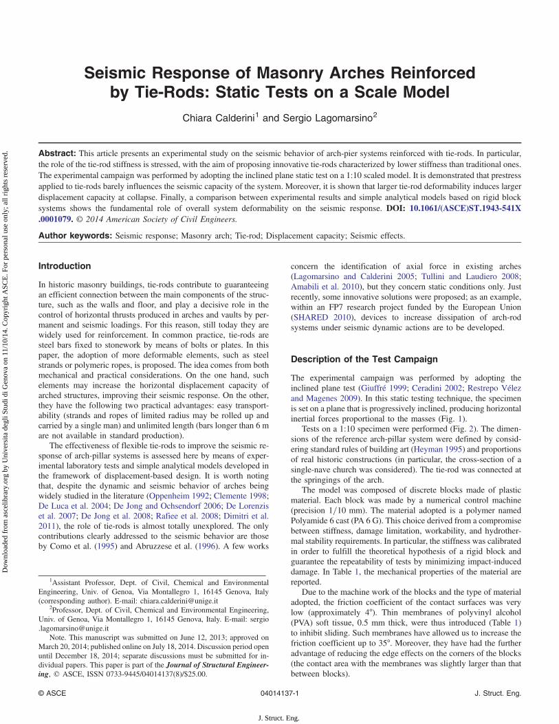
Tests on a 110 specimen were performed (Fig 2) The dimen-sions of the reference arch-pillar system were defined by consid-ering standard rules of building art (Heyman 1995) and proportionsof real historic constructions (in particular the cross-section of asingle-nave church was considered) The tie-rod was connected atthe springings of the arch
The model was composed of discrete blocks made of plasticmaterial Each block was made by a numerical control machine(precision 1=10 mm) The material adopted is a polymer namedPolyamide 6 cast (PA 6 G) This choice derived from a compromisebetween stiffness damage limitation workability and hydrother-mal stability requirements In particular the stiffness was calibratedin order to fulfill the theoretical hypothesis of a rigid block andguarantee the repeatability of tests by minimizing impact-induceddamage In Table 1 the mechanical properties of the material arereported
Due to the machine work of the blocks and the type of materialadopted the friction coefficient of the contact surfaces was verylow (approximately 4deg) Thin membranes of polyvinyl alcohol(PVA) soft tissue 05 mm thick were thus introduced (Table 1)to inhibit sliding Such membranes have allowed us to increase thefriction coefficient up to 35deg Moreover they have had the furtheradvantage of reducing the edge effects on the corners of the blocks(the contact area with the membranes was slightly larger than thatbetween blocks)
1Assistant Professor Dept of Civil Chemical and EnvironmentalEngineering Univ of Genoa Via Montallegro 1 16145 Genova Italy(corresponding author) E-mail chiaracalderiniunigeit
2Professor Dept of Civil Chemical and Environmental EngineeringUniv of Genoa Via Montallegro 1 16145 Genova Italy E-mail sergiolagomarsinounigeit
Note This manuscript was submitted on June 12 2013 approved onMarch 20 2014 published online on July 18 2014 Discussion period openuntil December 18 2014 separate discussions must be submitted for in-dividual papers This paper is part of the Journal of Structural Engineer-ing copy ASCE ISSN 0733-944504014137(8)$2500
copy ASCE 04014137-1 J Struct Eng
J Struct Eng
Dow
nloa
ded
from
asc
elib
rary
org
by
Uni
vers
ita d
egli
Stud
i di G
enov
a on
11
101
4 C
opyr
ight
ASC
E F
or p
erso
nal u
se o
nly
all
righ
ts r
eser
ved
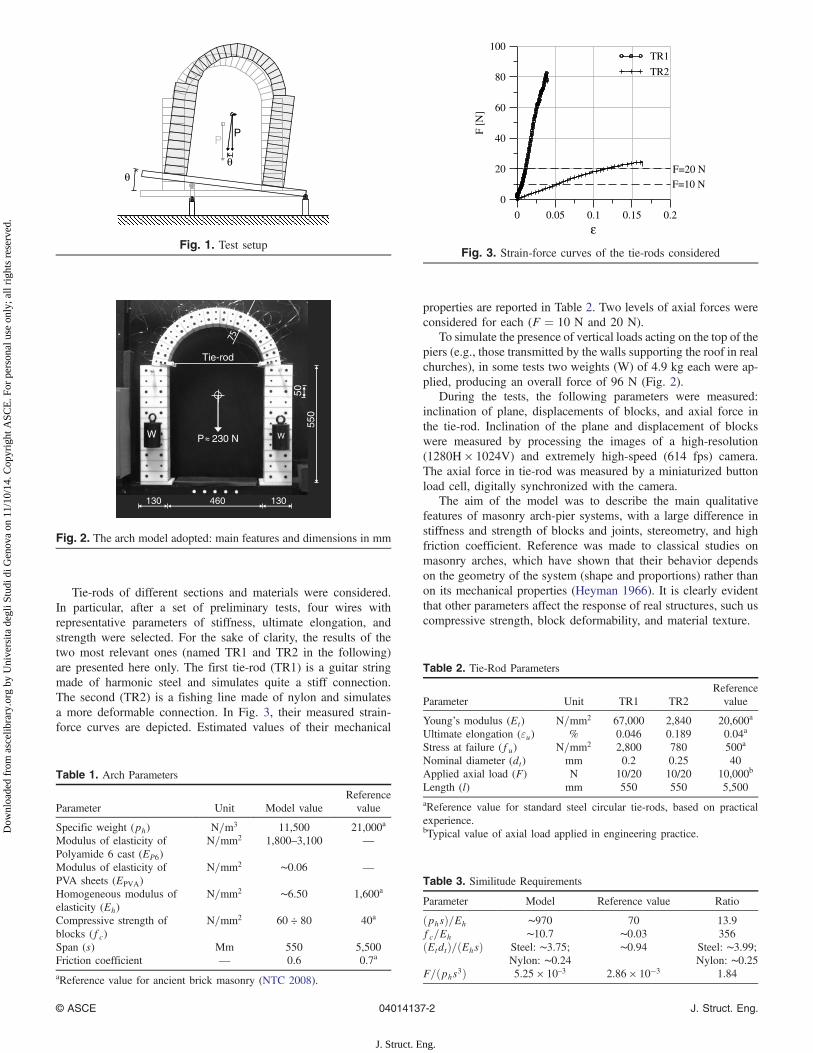
Tie-rods of different sections and materials were consideredIn particular after a set of preliminary tests four wires withrepresentative parameters of stiffness ultimate elongation andstrength were selected For the sake of clarity the results of thetwo most relevant ones (named TR1 and TR2 in the following)are presented here only The first tie-rod (TR1) is a guitar stringmade of harmonic steel and simulates quite a stiff connectionThe second (TR2) is a fishing line made of nylon and simulatesa more deformable connection In Fig 3 their measured strain-force curves are depicted Estimated values of their mechanical
properties are reported in Table 2 Two levels of axial forces wereconsidered for each (F frac14 10 N and 20 N)
To simulate the presence of vertical loads acting on the top of thepiers (eg those transmitted by the walls supporting the roof in realchurches) in some tests two weights (W) of 49 kg each were ap-plied producing an overall force of 96 N (Fig 2)
During the tests the following parameters were measuredinclination of plane displacements of blocks and axial force inthe tie-rod Inclination of the plane and displacement of blockswere measured by processing the images of a high-resolution(1280H times 1024V) and extremely high-speed (614 fps) cameraThe axial force in tie-rod was measured by a miniaturized buttonload cell digitally synchronized with the camera
The aim of the model was to describe the main qualitativefeatures of masonry arch-pier systems with a large difference instiffness and strength of blocks and joints stereometry and highfriction coefficient Reference was made to classical studies onmasonry arches which have shown that their behavior dependson the geometry of the system (shape and proportions) rather thanon its mechanical properties (Heyman 1966) It is clearly evidentthat other parameters affect the response of real structures such uscompressive strength block deformability and material texture
θ
PP
θ
Fig 1 Test setup
Tie-rod
130460130
W WP 230 N
5055
0
Fig 2 The arch model adopted main features and dimensions in mm
Table 1 Arch Parameters
Parameter Unit Model valueReferencevalue
Specific weight (ph) N=m3 11500 21000a
Modulus of elasticity ofPolyamide 6 cast (EP6)
N=mm2 1800ndash3100 mdash
Modulus of elasticity ofPVA sheets (EPVA)
N=mm2 sim006 mdash
Homogeneous modulus ofelasticity (Eh)
N=mm2 sim650 1600a
Compressive strength ofblocks (fc)
N=mm2 60 divide 80 40a
Span (s) Mm 550 5500Friction coefficient mdash 06 07a
aReference value for ancient brick masonry (NTC 2008)
0 005 01 015 02
ε
0
20
40
60
80
100
F[N
]
TR1
TR2
F=10 N
F=20 N
Fig 3 Strain-force curves of the tie-rods considered
Table 2 Tie-Rod Parameters
Parameter Unit TR1 TR2Referencevalue
Youngrsquos modulus (Et) N=mm2 67000 2840 20600a
Ultimate elongation (εu) 0046 0189 004a
Stress at failure (fu) N=mm2 2800 780 500a
Nominal diameter (dt) mm 02 025 40Applied axial load (F) N 1020 1020 10000b
Length (l) mm 550 550 5500aReference value for standard steel circular tie-rods based on practicalexperiencebTypical value of axial load applied in engineering practice
Table 3 Similitude Requirements
Parameter Model Reference value Ratio
ethphsTHORN=Eh sim970 70 139fc=Eh sim107 sim003 356ethEtdtTHORN=ethEhsTHORN Steel sim375
Nylon sim024sim094 Steel sim399
Nylon sim025F=ethphs3THORN 525 times 10ndash3 286 times 10minus3 184
copy ASCE 04014137-2 J Struct Eng
J Struct Eng
Dow
nloa
ded
from
asc
elib
rary
org
by
Uni
vers
ita d
egli
Stud
i di G
enov
a on
11
101
4 C
opyr
ight
ASC
E F
or p
erso
nal u
se o
nly
all
righ
ts r
eser
ved
The adoption of a scale model may also be debatable sincesimilitude requirements were only partially fulfilled (Table 3)The most evident disagreement concerns the compressive strengthwhich is much higher in the experimental model than in the realstructure Actually this point is not particularly meaningful sincethis parameter does not play a relevant role in the collapse behaviorof this type of structures Concerning the deformability of the tie-rods it is worth noting that the tests aimed at comparing the effectof tie-rods of different stiffness thus their absolute values were notso crucial
Finally also the reliability of the inclined plane test should bediscussed The main drawback of this type of test is that the totalforce is kept constant (thus the vertical inertial forces diminish asthe horizontal ones increase) In real structures subjected to anearthquake the vertical forces are rather constant (due to the neg-ligible and uncorrelated effect of the vertical component) while thehorizontal ones vary This could be a problem if failure mechanismsinvolving the strength of the material would be considered but notin the case of a rigid block structures where the geometry of thesystem is the more relevant factor determining the response
Experimental Results
Collapse Mechanisms and Multipliers
In Fig 4 the collapse multipliers and modes obtained are reportedCollapse modes are represented by showing the last photogram inwhich blocks were still in contact before failure It is worth notingthat the position of hinges at failure does not coincide with that atmechanism activation (see hinge c 0 and c 0 0 in Fig 5)
In free-standing arches the collapse was always producedby the formation of four hinges [Fig 6(a)] while in reinforcedarches the collapse was produced by the formation of five hinges[Fig 6(b)] It is worth noting that in a preliminary test carried outwith a thin copper wire the ultimate strength of the tie-rod wasattained before the arch collapsed In this case a four-hinge stablemechanism typical of tied arches was initially observed [Fig 7(a)]after the failure of the tie-rod the hinge at the base of the left pier
started to close and a new hinge opened in the arch producingthe typical four-hinge unstable mechanism of free-standing arches[Fig 7(b)] This behavior may be theoretically explained consid-ering that in reinforced arches tie-rods couple the relative dis-placements of the top of the piers Compared to free-standing
No overload With overload
Free
-sta
ndin
g ar
ch
λ=0035 λ=0048T = 10 N T = 20 N T = 10 N T = 20 N
TR
1
λ=0139 λ=0140 λ=0106 λ=0103
TR
2
λ=0138 λ=0137 λ=0103 λ=0101
Fig 4 Collapse multipliers and collapse modes in the arches tested
(a) (b)
a e
fb
crsquod
f
crsquo
a e
b
crsquorsquod
Fig 5 Hinge movement in mechanism evolution (focus on c 0 and c 0 0
hinges) (a) mechanism at activation (b) mechanism at collapse
(a) (b)
ab
c
d a
b
cd
e
f
Fig 6 (a) Recurrent collapse mechanisms in free-standing (b) rein-forced arches
copy ASCE 04014137-3 J Struct Eng
J Struct Eng
Dow
nloa
ded
from
asc
elib
rary
org
by
Uni
vers
ita d
egli
Stud
i di G
enov
a on
11
101
4 C
opyr
ight
ASC
E F
or p
erso
nal u
se o
nly
all
righ
ts r
eser
ved
arches they have one more internal constraint thus they need onemore hinge to collapse
The comparative analysis of the results in terms of col-lapse modes and collapse multipliers leads to the followingconsiderationsbull Tie-rods remarkably increase the collapse multipliers of free-
standing arches However their stiffness does not meaningfullyinfluence either the collapse multiplier (that is almost thesame for all the cases in which they were present) or the collapsemode
bull The axial force applied on the tie-rods barely influences thecollapse
bull The application of weights increases the collapse multiplier incase of free-standing arches only In reinforced arches the mul-tiplier decreases due to the increasing of the horizontal actions atthe springings of the arch
Force and Displacements Analysis
Fig 8 represents the variation of forces in tie-rods as a functionof the rotation angle (the plots with higher rotations correspond tothe tests in which the weights were applied on the top of the piersgray lines correspond to F frac14 10 N while black ones to F frac14 20 N)The plots end in correspondence of the photograms representedin Fig 4 (the collapse angles are clearly recognizable) It can beobserved that if F frac14 10 N the force in the tie-rod increases as thehorizontal loading of the structure increases whereas if F frac14 20 Nit decreases This can be explained by considering that on the basisof the static theorem the thrust of the arch under gravity loadsshould be comprised approximately between 77 N (minimumthrust) and 23 N (maximum thrust) This means that when F frac1410 N the thrust of the arch is only partially absorbed by the tie-rod the top of the piers being subjected to a residual outward hori-zontal force On the contrary when F frac14 20 N the thrust is fully
contrasted and the piers are subjected to inward horizontal forcesthe arch is thus close to collapse due to the force transmitted by thetie-rod Schemes in Fig 9 show the two limit conditions (the actualthrust lines should pass quite close to the specified hinges) Thetransition between such static conditions and those of collapseunder horizontal forces implies the following if F frac14 10 N thethrust in the arch must increase since the thrust line should becomemore horizontal if F frac14 20 N it must decrease since the thrust lineshould become more vertical The force at collapse for the two sys-tems tends to converge to sim1620 N for TR1 and sim1710 N forTR2 This shows that the collapse mechanism as well as the col-lapse multiplier is actually unique and quite independent of theforce applied on the tie-rod at the beginning of the test
By considering the five-hinge mechanism of Fig 6(b) and underthe hypothesis of infinite stiffness of the tie-rod the theoreticalvalue of the collapse multiplier of the seismic forces is λ frac14 0202while the force in the tie-rod equilibrating the system at collapse isFe frac14 1466 N that is 090 and 086 of the measured forces If themultiplier of the systems is calculated taking into account the actualposition of the hinges at collapse of the real system (see as an ex-ample Fig 10 showing the case of TR1 with F frac14 10 N) the valueof equilibrating force turns out to be approximately 1598 N forTR1 and 1726 N for TR2 that is 098 and 101 of the real onesThis highlights the relevant role of the elastic deformability of thesystem
Fig 7 Collapse mechanism evolution in arches with weak coppertie-rods (a) mechanism at tie-rod failure (b) evolution after failure
(a) (b)0 0025 005 0075 01 0125 015
Rotation angle [rad]
0
5
10
15
20
25
Forc
e[N
]
0 0025 005 0075 01 0125 015Rotation angle [rad]
0
5
10
15
20
25
Forc
e[N
]
Fig 8 Force in the tie-rod as a function of the rotation of the tilting plane (F frac14 10 N in gray F frac14 20 N in black) (a) TR1 (b) TR2
(a) (b)
Fig 9 Schemes of mechanisms under gravity (dashed line) and seis-mic loads (continuous line) (a) limit condition in which the force ap-plied by the tie-rod may produce under gravity loads the collapse ofthe arch with a inwards rotation of the piers (b) limit condition inwhich the arch under gravity loads and not reinforced by the tie-rodcollapses with an outwards rotation of the piers
copy ASCE 04014137-4 J Struct Eng
J Struct Eng
Dow
nloa
ded
from
asc
elib
rary
org
by
Uni
vers
ita d
egli
Stud
i di G
enov
a on
11
101
4 C
opyr
ight
ASC
E F
or p
erso
nal u
se o
nly
all
righ
ts r
eser
ved
In Fig 11 the deformation of the arch just before collapse(corresponding to the highest level of axial force in the tie-rod)is represented for the two systems with F frac14 10 N (a direct com-parison was not made with F frac14 20 N since in this case the axialforce in the tie-rod is closely decreasing at collapse and the exactcollapse point is almost unidentifiable) It can be observed that thesystem with TR2 is much more deformable than that with TR1 thecollapse multiplier being almost the same As expected the dis-tance between the top of the piers (thus the tie-rod length) is greaterin the case of TR2 owing to its larger deformability Furthermore itcan also be noted that the rotation of both piers is larger in the caseof TR2 This was not clear before experimental evidence
The arch movement was analyzed by processing digital imagesby means of the particle image velocimetry (PIV) technique In par-ticular the GeoPIV8 program developed byWhite et al (2003) wasadopted To this aim two markers were fixed on each ashlar Studyof the patch sizes was performed and a pixel size of 40 times 40 wasfound to be efficient in computing time without compromising ac-curacy much In Fig 12 the elongation of the tie-rods as a function
of the rotation of the tilting plane is represented for F frac14 10 N Thelarger elongation of TR2 is confirmed it is up to three times greaterthan TR1 In Fig 13 the elongation of the tie-rods is represented asa function of the horizontal displacement of the right pier It can beobserved that in general the tie-rods increase the ductility of thesystem TR2 allows greater rotation of the right pier from the be-ginning of the test When the collapse mechanism is activated TR1is able to rather maintain the force up to a sudden failure whileTR2 even if initially provides a faster force reduction (since thepiers get closer) is able to prevent the sudden failure of the systemfor higher displacements
Analytical Intepretations and Seismic Analysis
The arch is theoretically studied in the framework of the seis-mic displacement-based procedure of analysis described inLagomarsino (2014) and Lagomarsino and Resemini (2009) forrocking masonry structures and actually applied in the Italianguidelines (Guidelines for Evaluation and Mitigation of SeismicRisk to Cultural Heritage 2007)
Actual hinge position
Theoretical hinge position
Fig 10 Typical deformation of the system just before collapse (TR1)comparison of theoretical and experimentally defined position ofhinges
Fig 11 Deformation of arch with TR1 and TR2 at their highest levelof axial force (the most deformed one is that with TR2) with no over-load and F frac14 10 N
0135 0136 0137 0138 0139 014 0141Rotation angle [rad]
0
0005
001
0015
002
ε
Nylon φ=025 mm - F = 10 N
Steel φ=02 mm - F = 10 N
Fig 12 Elongation of TR1 and TR2 in reinforced arches (focus on thecollapse phase) as a function of the rotation of the tilting plane
0 50 100 150 200 250 300Horizontal disp of right pier [mm]
0
0005
001
0015
002
ε
Nylon φ=025 mm - F = 10 N
Steel φ=02 mm - F = 10 N
Fig 13 Elongation of the two tie-rods as a function of the horizontaldisplacement of the right pier
copy ASCE 04014137-5 J Struct Eng
J Struct Eng
Dow
nloa
ded
from
asc
elib
rary
org
by
Uni
vers
ita d
egli
Stud
i di G
enov
a on
11
101
4 C
opyr
ight
ASC
E F
or p
erso
nal u
se o
nly
all
righ
ts r
eser
ved
In general the procedure is based on the following typical stepsof capacity spectrum analysis (1) evaluation of the pushover curveof the system (2) evaluation of the capacity curve through theconversion to an equivalent SDOF system (3) definition of theseismic demand in terms of an overdamped elastic acceleration-displacement response spectrum (ADRS) and (4) comparison be-tween the capacity curve and the seismic demand consideringproper performance levels (typically in terms of displacementsthresholds and related values of the equivalent viscous damping)In this framework the pushover curve of the rocking masonry sys-tem is obtained by first reducing it to a SDOF mechanism (consti-tuted by the kinematic motion of n rigid blocks subjected to theirweight Wi and proportional horizontal forces αWi) and then cal-culating the collapse multiplier α that induces loss of equilibriumfor increasing finite values of the generalized coordinate ξ of theconsidered SDOF up to the value for which αethξuTHORN frac14 0 The capac-ity curve of the system is finally defined by converting it into anequivalent nonlinear SDOF system assuming as displacementshape the virtual displacements that are consistent with the mecha-nism considered Its seismic spectral acceleration a may be thuscalculated as
aethξTHORN frac14 αethξTHORNΣnifrac141Wi
M eth1THORN
where Wi is the weight of the ith block and M is the mass ofthe structure participating in the mechanism which can be calcu-lated as
M frac14 ethΣnifrac141WiδxiTHORN2
gΣnifrac141Wiδ2xi
eth2THORN
with g being the gravity acceleration and δxi being the horizontalvirtual displacement of the centroid of the ith block calculated withreference to the initial configuration of the system
The spectral displacement may be calculated as
dxethξTHORN frac14 dxPethξTHORNΣn
ifrac141Wδ2xiδxPΣn
ifrac141Wδxieth3THORN
where dxP is the finite horizontal displacement of a generic point Pof the system and δxP is its virtual horizontal displacement
For a given value of ξ it is possible to define an equivalentperiod of vibration of the structure as
TethξTHORN frac14 2π
ffiffiffiffiffidxa
reth4THORN
In order to take into account that before the activation of themechanisms the actual structure is not completely rigid but hasan almost linear elastic behavior (small cracks or slidings may pro-gressively reduce its stiffness) an initial linear branch is addeduntil the intersection with the capacity curve defined above by con-sidering its rigid block behavior which occurs for a value of thegeneralized coordinate ξ frac14 ξe The pseudo-elastic period of vibra-tion (Te) which is defined by considering the secant behavior ofthe structure before the mechanism activation is always lower thanthe inelastic one [Te le TethξTHORN ξ gt ξe]
The maximum displacement required to the structure for a givenseismic response spectrum is defined as
dmax frac14 maxethdxs dxsmaxTHORN eth5THORN
where dxs is the displacement demand obtained as the intersectionbetween the capacity curve and the acceleration-displacement re-sponse spectrum (ADRS) to which the period T
s correspondsand dxsmax is the maximum spectral displacement demand in therange Te le T lt T
s In Fig 14 the procedure is showed relatingto a single overturning rigid block In this case the rotation ϑ ofthe block around the point C may be assumed as the generalizedcoordinate ξ
In this paper the attention is focused on the definition of thepushover curve Static tests performed lead in practice to the def-inition of an experimental pushover curve of the system (even withthe already stated limits related to the adoption of the inclined planetests) The aim of the analyses here presented is to define theoreti-cal pushover curves and to compare them with the experimentalones in order to assess how and how much they are affected bythe presence of the tie-rod in terms of both strength and displace-ment capacity and to stress the capability of theoretical models todescribe the behavior of the tested arches
As already stated in the proposed seismic approach the defini-tion of the theoretical pushover curve is based on a set of simplelimit equilibrium analyses (performed for increasing finite values ofthe generalized coordinate ξ of the considered SDOF) This is agreat simplification that allows to connect the seismic analysis tothe huge amount of studies on the equilibrium of arches and vaults(Pippard et al 1936 Kooharian 1954 Heyman 1966 Livesley1978 Vilnay and Cheung 1986 Boothby and Brown 1992 1993Boothby 1996 1997)
(a) (b)
Fig 14 Scheme of the procedure of analysis (a) rigid block reference system (b) SDOF equivalent system
copy ASCE 04014137-6 J Struct Eng
J Struct Eng
Dow
nloa
ded
from
asc
elib
rary
org
by
Uni
vers
ita d
egli
Stud
i di G
enov
a on
11
101
4 C
opyr
ight
ASC
E F
or p
erso
nal u
se o
nly
all
righ
ts r
eser
ved
In this work the following classic assumptions of Heyman(1966) are considered rigid blocks no-tensile strength of jointsinfinite compressive strength and the absence of sliding betweenblocks Three different collapse mechanisms (Fig 15) are consid-ered The first one [Fig 15(a)] is that of a free-standing arch col-lapsing with a typical four-hinge mechanism [see Fig 7(a)] In thesecond [Fig 15(b)] a four-hinge mechanism is considered againbut the tie-rod effect is taken into account by applying two oppositeforces at the anchorages In the third [Fig 15(c)] the tie-rod isintroduced by kinematically constraining the two anchorage pointsa five-hinge mechanism is thus considered [see Fig 6(b)] For eachmechanism the exact hinge position was verified through a min-imization procedure of the multiplier
In Fig 16 the collapse multiplier of the system (inclinationof the plane) with F frac14 10 N is represented as a function of thehorizontal displacement of a control point (CP) chosen on the topof the right pier The theoretical pushover curves are based on theconfigurations of Fig 15 For the reinforced arches the point cor-responding to the highest force in the tie-rod is evidenced
It can be observed that the experimental collapse multiplier islower than the theoretical one (approximately 23 for reinforcedarches and less than 12 for free-standing ones) This may beexplained by considering both imperfection on the contacts be-tween blocks and global deformability of the system The role ofdeformability of blocks and joints on the collapse multiplier of ma-sonry structures has already been investigated by different authors
(Boothby 1997 Doherty et al 2002 De Felice 2011 Al Shawaet al 2012) In particular Boothby (1997) showed that underthe assumption of an associated flow rule joint controlled mech-anisms can be activated at lower loads than the plastic collapse loadfor a block controlled mechanism moreover he has shown that thejoint controlled mechanisms may be stable due to the effect of thehardening of the joints Doherty et al (2002) have proved (by ex-perimental static push-over tests on regular masonry walls) that it ismainly related to the deformation of compressed blocks and mortarjoints which results in (1) hinge points possessing finite dimen-sions (rather than being infinitesimally small) and (2) the wall pos-sessing finite lateral stiffness (rather than being rigid) prior toincipient rocking De Felice (2011) and Al Shawa et al (2012)showed that this phenomenon is particularly relevant in irregularstone masonry walls where the imperfection of contacts and thepresence of weak mortar induce a structural behavior far from thatof a rigid body In the arch-pier system considered in this paper thedeformability is mainly concentrated in PVA joints but significantcontributions may also derive from small slidings between blocksdue to finite friction
It is worth noting that for TR1 the displacement of the controlpoint associated with the highest level of stress in the tie-rod isclose to the intersection between the theoretical capacity curve andthe experimental one It should be noted that the theoretical capac-ity curve is obtained by considering infinite stiffness of the tie-rodthus TR1 is the one more consistent with this hypothesis For TR2the displacement associated with the highest axial stress is largerIt can be argued that the capacity curve of the actual five-hingemechanism (in which the tie-rod is far from being infinitely stiff)is associated with a larger displacement capacity
Conclusions
This paper presents the results of an experimental campaign on ma-sonry arch-pier systems In particular the influence of tie-rods intheir seismic behavior have been investigated The following pointshave been assessedbull Tie-rods are not only capable to significantly increase the capa-
city of arch-piers systems to bear vertical and horizontal seismicforces (as well known) but are also capable to increase theirhorizontal displacement capacity
bull The collapse of arch-pier systems with tie-rods occurs with five-hinge mechanisms instead of four-hinge mechanisms typicalof free-standing systems since the tie-rod introduces a furtherinternal constraint in the structure
bull The entity of the axial force applied on the tie-rod (prestress)does not significantly affect the seismic response of the systemand its collapse mode because in any case it increases due tothe moving away of springs as horizontal actions increase
bull The deformability of a tie-rod barely influences elastic stiffnessof the system and its collapse load but influences its displace-ment capacity at collapse
bull Comparisons between theoretical models and experimental testsshowed that the force and displacement capacity of the testedmodel is significantly lower than that predicted by theoreticalanalysis this may be attributed to the deformability of the sys-tem in both the elastic and inelastic range and to the presence ofimperfections in the contacts between blocks and
bull From a technical point of view the paper demonstrates thatin the framework of the seismic displacement-based capacitythe design of more deformable tie-rods may produce largerbenefits than those achievable through traditional ones Froman analytical point of view it shows as done by other authors
Free standing arch Reinforced arch
F+dF F+dF
4-hinge mechanisms 5-hinge mechanism
(a) (b) (c)
Fig 15 Mechanisms considered in the analytical models
0 002 004 006 008 01 012Horizontal displ of CP [m]
0
0025
005
0075
01
0125
015
0175
02
0225
025
Col
laps
em
ultip
lier
TR1 - Exp
TR2 - Exp
Free standing - Exp
5-hing rigid mech
4-hing mech (free st)
4-hing mech (TR1)
4-hing mec (TR2)
5-hing def mech (hyp)
Fig 16 Displacement-collapse multiplier curves for free and rein-forced arches (F frac14 10 N) comparison between experimental resultsand analytical models
copy ASCE 04014137-7 J Struct Eng
J Struct Eng
Dow
nloa
ded
from
asc
elib
rary
org
by
Uni
vers
ita d
egli
Stud
i di G
enov
a on
11
101
4 C
opyr
ight
ASC
E F
or p
erso
nal u
se o
nly
all
righ
ts r
eser
ved
the drawbacks related to the employment of perfectly rigidblock systems in the analysis of this type of structure
Acknowledgments
The results were achieved in the national reseach project ReLUIS-DPC 2010ndash2013 (httpwwwreluisit) supported by the ItalianCivil Protection Agency Special thanks to MsC student FrancescoNannini for technical development of the experimental tests
References
Abruzzese D Como M and Lanni G (1996) ldquoThe effects of steelreinforcing in the static analysis of masonry buildings under horizontalactionsrdquo Proc Eleventh World Conf on Earthquake EngineeringPaper No 1217 (CD-ROM) Pergamon Oxford
Al Shawa O De Felice G Mauro A and Sorrentino L (2012) ldquoOut-of-plane seismic behaviour of rocking masonry wallsrdquo EarthquakeEng Struct Dyn 41(5) 949ndash968
Amabili M Carra S Collini L Garziera R and Panno A (2010)ldquoEstimation of tensile force in tie-rods using a frequency-based iden-tification methodrdquo J Sound Vibr 329(11) 2057ndash2067
Boothby T E (1996) ldquoAnalytical approach to collapse mechanisms of cir-cular masonry archrdquo J Struct Eng 101061(ASCE)0733-9445(1996)1228(978) 978ndash979
Boothby T E (1997) ldquoElastic plastic stability of jointed masonry archesrdquoEng Struct 19(5) 345ndash351
Boothby T E and Brown C B (1992) ldquoStability of masonry piers andarchesrdquo J Eng Mech 101061(ASCE)0733-9399(1992)1182(367)367ndash383
Boothby T E and Brown C B (1993) ldquoA general lower and upper boundtheorem of static stabilityrdquo Eng Struct 15(3) 189ndash196
Ceradini V (2002) ldquoModels and experimental tests for the study ofhistorical masonryrdquo PhD dissertation Univ ldquoLa Sapienzardquo Rome(in Italian)
Clemente P (1998) ldquoIntroduction to dynamics of stone archesrdquo Earth-quake Eng Struct Dyn 27(5) 513ndash522
Como M Abruzzese D and Lanni G (1995) ldquoSome results on thestrength evaluation of vaulted masonry structuresrdquo Proc ArchitecturalStudies Materials and Analysis STREMA Computational MechanicsPublications Boston 431ndash440
De Felice G (2011) ldquoOut-of-plane seismic capacity of masonry dependingon wall section morphologyrdquo Int J Archit Heritage 5(4ndash5) 466ndash482
De Jong M J De Lorenzis L Adams S and Ochsendorf J A (2008)ldquoRocking stability of masonry arches in seismic regionsrdquo EarthquakeSpectra 24(4) 847ndash865
De Jong M J and Ochsendorf J A (2006) ldquoAnalysis of vaulted masonrystructures subjected to horizontal ground motionrdquo Proc StructuralAnalysis of Historical Constructions P Lourenco P Roca C Modenaand S Agrawal eds Macmillan India New Delhi 973ndash980
De Lorenzis L De Jong M J and Ochsendorf J A (2007) ldquoFailure ofmasonry arches under impulse base motionrdquo Earthquake Eng StructDyn 36(14) 2119ndash2136
De Luca A Giordano A and Mele E (2004) ldquoA simplified procedurefor assessing the seismic behaviour of masonry archesrdquo Eng Struct26(13) 1915ndash1929
Dimitri R De Lorenzis L and Zavarise G (2011) ldquoNumerical study onthe dynamic behavior of masonry columns and arches on buttresseswith the discrete element methodrdquo Eng Struct 33(12) 3172ndash3188
Doherty K Griffith M C Lam N and Wilson J (2002)ldquoDisplacement-based seismic analysis for out-of plane bending ofunreinforced masonry wallsrdquo Earthquake Eng Struct Dyn 31(4)833ndash850
Giuffregrave A (1999) Safety and preservation of historical centres TheOrtigia case Editori Laterza Bari (in Italian)
Guidelines for Evaluation and Mitigation of Seismic Risk to CulturalHeritage (2007) Directive of the Prime Minister 12102007GU n24 of 2912008 Gangemi Rome
Heyman J (1966) ldquoThe stone skeletonrdquo Int J Solids Struct 2(2)249ndash279
Heyman J (1995) The stone skeleton Structural engineering of masonryarchitecture Cambridge University Press Cambridge UK
Kooharian A (1954) ldquoLimit analysis of segmental and concrete archesrdquoProc Am Concr Inst 89 317ndash328
Lagomarsino S (2014) ldquoSeismic assessment of rocking masonry struc-turesrdquo Bull Earthquake Eng in press
Lagomarsino S and Calderini C (2005) ldquoThe dynamical identificationof the tensile force in ancient tie-rodsrdquo Eng Struct 27(6) 846ndash856
Lagomarsino S and Resemini S (2009) ldquoThe assessment of damagelimitation state in the seismic analysis of monumental buildingsrdquo Earth-quake Spectra 25(2) 323ndash346
Livesley R K (1978) ldquoLimit analysis of structures formed from rigidblocksrdquo Int J Numer Methods Eng 12(12) 1853ndash1871
Norme Tecniche per le Costruzioni (NTC) (2008) Italian Building CodeMinistry of Infrastructures and Transportations (in Italian)
Oppenheim I J (1992) ldquoThe masonry arch as a four-link mechanismunder base motionrdquo Earthquake Eng Struct Dyn 21(11) 1005ndash1017
Pippard A J S Tranter E and Chitty L (1936) ldquoThe mechanics of thevoussoir archrdquo J Inst Civ Eng 4 281ndash306
Rafiee A Vinches M and Bohatier C (2008) ldquoApplication of theNSCD method to analyse the dynamic behaviour of stone arched struc-turesrdquo Int J Solids Struct 45(25ndash26) 6269ndash6283
Restrepo Veacutelez L F and Magenes G (2009) ldquoStatic tests on dry stonemasonry and evaluation of static collapse multipliersrdquo Research RepROSE 200902 IUSS Press Pavia Italy
ldquoShaking table tests of historic architecture retrofitted with energy dissipa-tors (SHARED)rdquo (2010) Transitional Access (TA) to SERIES programfunded under the 7th Framework Programme Capacities ResearchInfrastructures Project No 227887
Tullini N and Laudiero F (2008) ldquoDynamic identification of beamaxial loads using one flexural mode shaperdquo J Sound Vibr 318(1ndash2)131ndash147
Vilnay O and Cheung S S (1986) ldquoStability of masonry archesrdquoJ Struct Eng 101061(ASCE)0733-9445(1986)11210(2185)2185ndash2199
White D J Take W A and Bolton M D (2003) ldquoSoil deformationmeasurement using particle image velocimetry (PIV) and photogram-metryrdquo Geacuteotechnique 53(7) 619ndash631
copy ASCE 04014137-8 J Struct Eng
J Struct Eng
Dow
nloa
ded
from
asc
elib
rary
org
by
Uni
vers
ita d
egli
Stud
i di G
enov
a on
11
101
4 C
opyr
ight
ASC
E F
or p
erso
nal u
se o
nly
all
righ
ts r
eser
ved
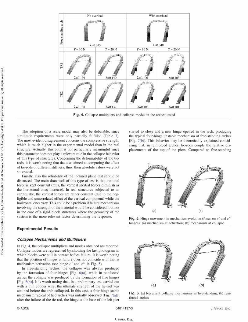
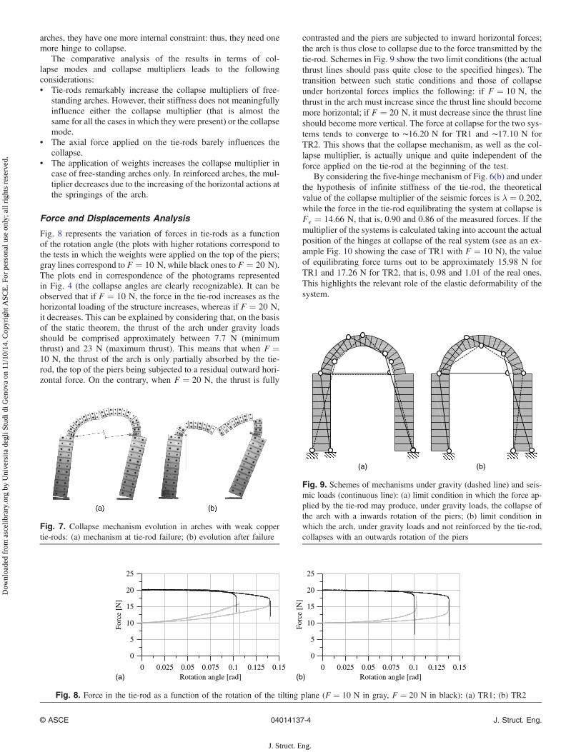
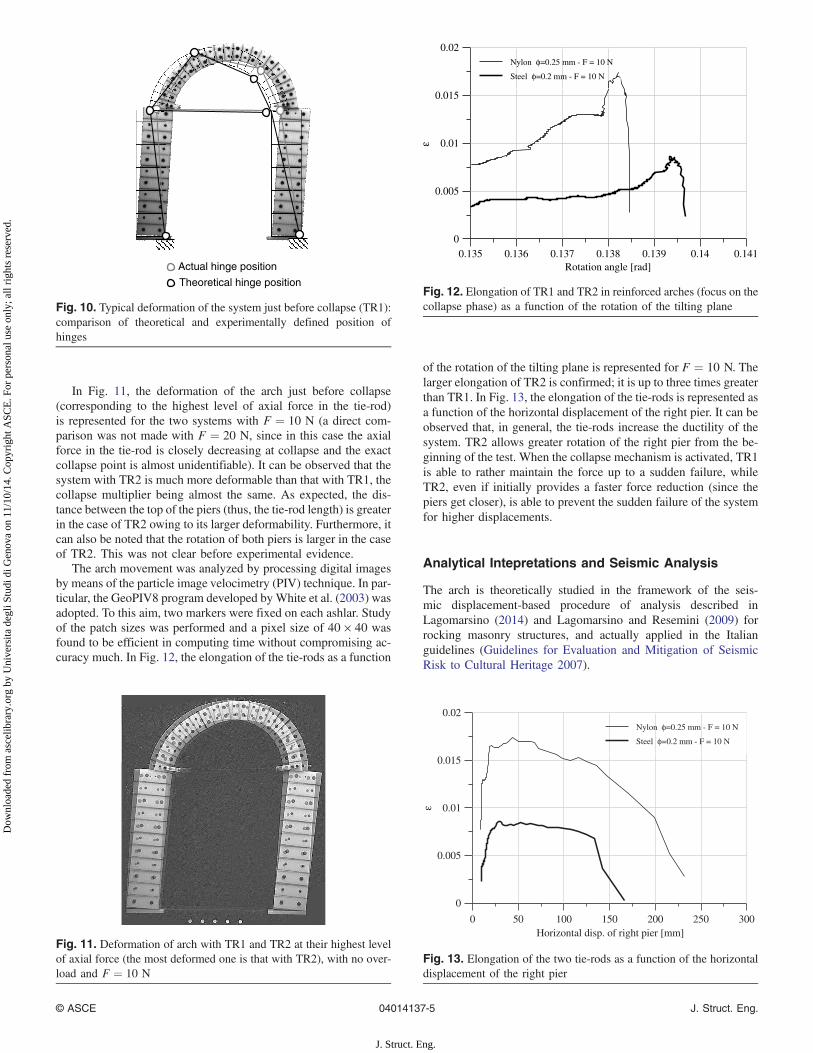
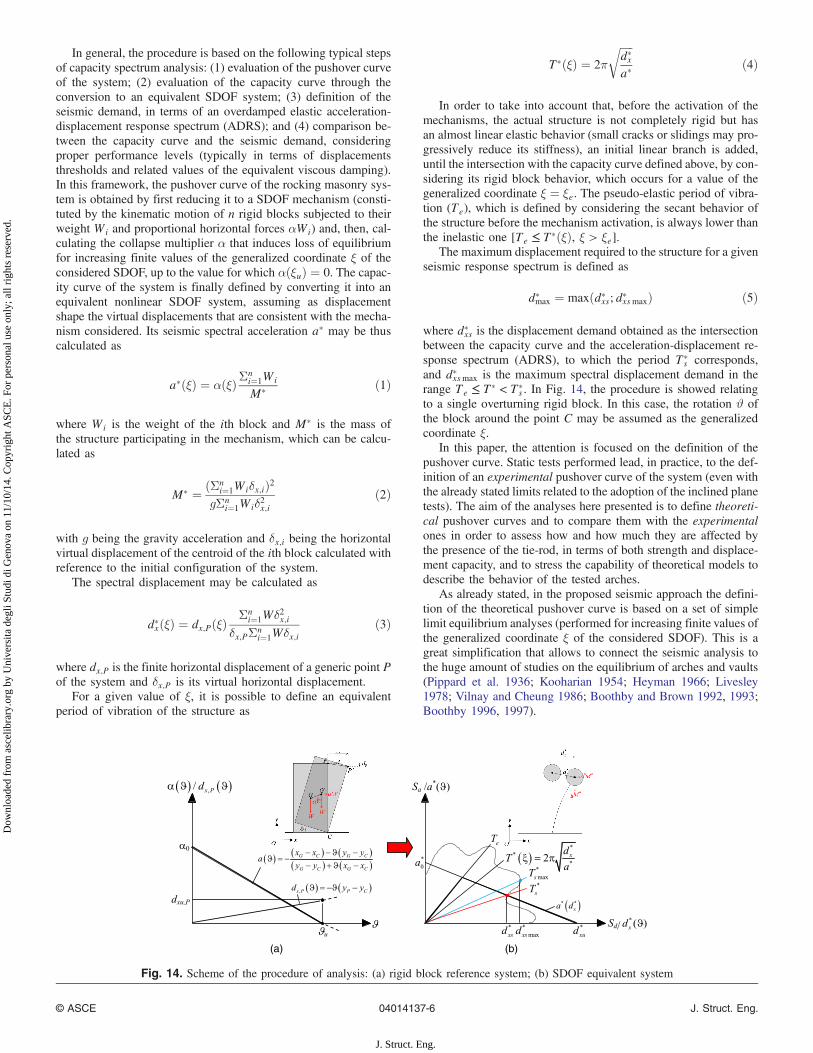
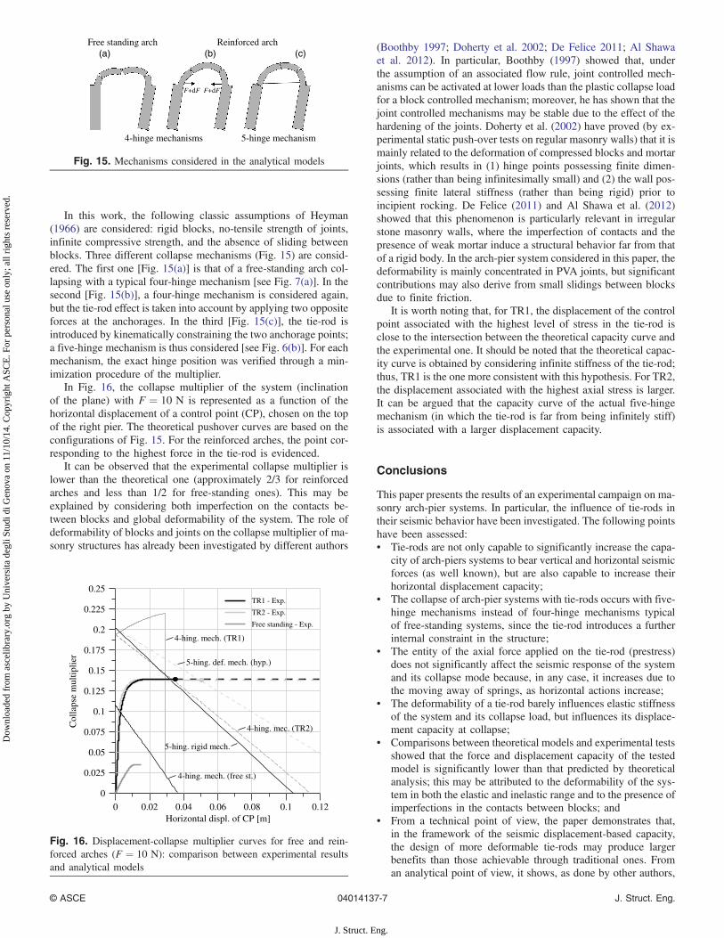
Related Documents