Seismic Performance of Square High-Strength Concrete Columns in FRP Stay-in-Place Formwork Togay Ozbakkaloglu 1 and Murat Saatcioglu, M.ASCE 2 Abstract: The use of high-strength concrete HSC in seismically active regions poses a major concern because of the brittle nature of the material. The confinement requirements for HSC columns may be prohibitively stringent since they require proportionately greater confinement than columns of normal-strength concrete. An alternative to conventional confinement reinforcement is the use of fiber reinforced polymer FRP casings, in the form of a stay-in-place formwork. This paper investigates the use of stay-in-place FRP formwork as concrete confinement reinforcement for HSC columns with square cross sections. Large scale HSC building columns, encased in FRP casings, were tested under simulated seismic loading. The columns had 270 mm square sections and concrete strengths up to 90 MPa. The casings were manufactured from carbon FRP and epoxy resin. The unique aspects of the test program were the introduction of the corner radius as a test parameter, and the presence of internally placed FRP crossties, integrally built with column casings, to improve the effectiveness of concrete confinement. Results indicate that the deformation capacity of HSC columns can be improved significantly by using FRP casings. The results further indicate that the confinement effectiveness of columns is significantly affected by the corner radius of casings. Additionally, the confinement efficiency can be improved with the use of FRP crossties. The columns developed inelastic drift capacities of up to 11%, demonstrating the usefulness of FRP stay-in-place formwork in improving deformability of HSC columns. DOI: 10.1061/ASCE0733-94452007133:144 CE Database subject headings: Concrete columns; Earthquakes; High strength concretes; Fiber reinforced polimers; Confinement; Ductility. Introduction The use of high-strength concrete HSC in building and bridge construction has increased over the last two decades. HSC offers advantages over normal-strength concrete in terms of increased strength and improved performance. The gain in strength, how- ever, is achieved at the expense of deformability. Indeed, HSC structural elements exhibit brittle behavior at failure, jeopardizing their use in seismically active regions where significant inelastic deformability and energy dissipation are required to resist seismic induced inertia forces. Inelastic deformability of concrete can be improved through confinement. Concrete confined by properly designed transverse reinforcement can develop adequate ductility to allow structures to develop sufficient lateral drift without sig- nificant strength degradation. However, the confinement require- ments become prohibitively stringent for HSC elements when normal-grade conventional steel ties, hoops, overlapping hoops or spirals are used. The excessive amount of conventional confine- ment reinforcement required for HSC columns leads to the congestion of column cages and resulting concrete placement problems. On the other hand, fiber reinforced polymer FRP ma- terials offer an attractive alternative to confine concrete. FRP preformed shapes, in the form of stay-in-place formwork with circular or square cross sections, offer multiple advantages of 1 light and effective formwork with superior handling characteris- tics, 2 efficient and durable transverse confinement reinforce- ment with ability to generate high lateral confinement pressures, and 3 protective shell against corrosion, weathering, and chemi- cal attacks. The performance of concrete-filled circular and rectangular FRP casings, under combined bending and axial load, has been studied extensively Mirmiran et al. 1998a, 1999, 2000; Fam and Rizkalla 2002; Fam et al. 2003, 2005. Furthermore, FRP wrap- ping of concrete columns as a seismic retrofit strategy has been studied by researchers in the past Seible et al. 1997; Sheikh and Yau 2002; Iacobucci et al. 2003. The use of FRP stay-in-place formwork for improved seismic performance of new columns was investigated by Seible et al. 1996, Shao 2003, Zhu 2004, and Ozbakkaloglu and Saatcioglu 2006. However, research on seismic performance of concrete filled square/rectangular FRP casings is limited, with the available research focusing on normal- strength concrete column behavior. The current paper has the objective of presenting the results of an experimental investiga- tion on the effectiveness of square stay-in-place FRP formwork for HSC columns, subjected to simulated seismic loading. Experimental Program HSC columns with square geometry were designed, constructed, and tested under simulated seismic loading. The columns were 1 Lecturer, School of Civil and Environmental Engineering, Univ. of Adelaide, Adelaide, SA, Australia 5005; formerly, Ph.D. Candidate, Dept. of Civil Engineering, Univ. of Ottawa, Ottawa, ON, Canada K1N 6N5. E-mail: [email protected] 2 Professor and Univ. Research Chair, Dept. of Civil Engineering, Univ. of Ottawa, Ottawa, ON, Canada K1N 6N5. E-mail: murat@ eng.uottawa.ca Note. Associate Editor: Reginald DesRoches. Discussion open until June 1, 2007. Separate discussions must be submitted for individual pa- pers. To extend the closing date by one month, a written request must be filed with the ASCE Managing Editor. The manuscript for this paper was submitted for review and possible publication on December 27, 2004; approved on July 17, 2006. This paper is part of the Journal of Struc- tural Engineering, Vol. 133, No. 1, January 1, 2007. ©ASCE, ISSN 0733-9445/2007/1-44–56/$25.00. 44 / JOURNAL OF STRUCTURAL ENGINEERING © ASCE / JANUARY 2007 J. Struct. Eng. 2007.133:44-56. Downloaded from ascelibrary.org by ADELAIDE, UNIVERSITY OF on 09/28/13. Copyright ASCE. For personal use only; all rights reserved.

Welcome message from author
This document is posted to help you gain knowledge. Please leave a comment to let me know what you think about it! Share it to your friends and learn new things together.
Transcript
Dow
nloa
ded
from
asc
elib
rary
.org
by
AD
EL
AID
E, U
NIV
ER
SIT
Y O
F on
09/
28/1
3. C
opyr
ight
ASC
E. F
or p
erso
nal u
se o
nly;
all
righ
ts r
eser
ved.
Seismic Performance of Square High-Strength ConcreteColumns in FRP Stay-in-Place Formwork
Togay Ozbakkaloglu1 and Murat Saatcioglu, M.ASCE2
Abstract: The use of high-strength concrete �HSC� in seismically active regions poses a major concern because of the brittle nature ofthe material. The confinement requirements for HSC columns may be prohibitively stringent since they require proportionately greaterconfinement than columns of normal-strength concrete. An alternative to conventional confinement reinforcement is the use of fiberreinforced polymer �FRP� casings, in the form of a stay-in-place formwork. This paper investigates the use of stay-in-place FRP formworkas concrete confinement reinforcement for HSC columns with square cross sections. Large scale HSC building columns, encased in FRPcasings, were tested under simulated seismic loading. The columns had 270 mm square sections and concrete strengths up to 90 MPa. Thecasings were manufactured from carbon FRP and epoxy resin. The unique aspects of the test program were the introduction of the cornerradius as a test parameter, and the presence of internally placed FRP crossties, integrally built with column casings, to improve theeffectiveness of concrete confinement. Results indicate that the deformation capacity of HSC columns can be improved significantly byusing FRP casings. The results further indicate that the confinement effectiveness of columns is significantly affected by the corner radiusof casings. Additionally, the confinement efficiency can be improved with the use of FRP crossties. The columns developed inelastic driftcapacities of up to 11%, demonstrating the usefulness of FRP stay-in-place formwork in improving deformability of HSC columns.
DOI: 10.1061/�ASCE�0733-9445�2007�133:1�44�
CE Database subject headings: Concrete columns; Earthquakes; High strength concretes; Fiber reinforced polimers; Confinement;Ductility.
Introduction
The use of high-strength concrete �HSC� in building and bridgeconstruction has increased over the last two decades. HSC offersadvantages over normal-strength concrete in terms of increasedstrength and improved performance. The gain in strength, how-ever, is achieved at the expense of deformability. Indeed, HSCstructural elements exhibit brittle behavior at failure, jeopardizingtheir use in seismically active regions where significant inelasticdeformability and energy dissipation are required to resist seismicinduced inertia forces. Inelastic deformability of concrete can beimproved through confinement. Concrete confined by properlydesigned transverse reinforcement can develop adequate ductilityto allow structures to develop sufficient lateral drift without sig-nificant strength degradation. However, the confinement require-ments become prohibitively stringent for HSC elements whennormal-grade conventional steel ties, hoops, overlapping hoops or
1Lecturer, School of Civil and Environmental Engineering, Univ. ofAdelaide, Adelaide, SA, Australia 5005; formerly, Ph.D. Candidate, Dept.of Civil Engineering, Univ. of Ottawa, Ottawa, ON, Canada K1N 6N5.E-mail: [email protected]
2Professor and Univ. Research Chair, Dept. of Civil Engineering,Univ. of Ottawa, Ottawa, ON, Canada K1N 6N5. E-mail: [email protected]
Note. Associate Editor: Reginald DesRoches. Discussion open untilJune 1, 2007. Separate discussions must be submitted for individual pa-pers. To extend the closing date by one month, a written request must befiled with the ASCE Managing Editor. The manuscript for this paper wassubmitted for review and possible publication on December 27, 2004;approved on July 17, 2006. This paper is part of the Journal of Struc-tural Engineering, Vol. 133, No. 1, January 1, 2007. ©ASCE, ISSN
0733-9445/2007/1-44–56/$25.00.44 / JOURNAL OF STRUCTURAL ENGINEERING © ASCE / JANUARY 2007
J. Struct. Eng. 2007
spirals are used. The excessive amount of conventional confine-ment reinforcement required for HSC columns leads to thecongestion of column cages and resulting concrete placementproblems. On the other hand, fiber reinforced polymer �FRP� ma-terials offer an attractive alternative to confine concrete. FRPpreformed shapes, in the form of stay-in-place formwork withcircular or square cross sections, offer multiple advantages of �1�light and effective formwork with superior handling characteris-tics, �2� efficient and durable transverse confinement reinforce-ment with ability to generate high lateral confinement pressures,and �3� protective shell against corrosion, weathering, and chemi-cal attacks.
The performance of concrete-filled circular and rectangularFRP casings, under combined bending and axial load, has beenstudied extensively �Mirmiran et al. 1998a, 1999, 2000; Fam andRizkalla 2002; Fam et al. 2003, 2005�. Furthermore, FRP wrap-ping of concrete columns as a seismic retrofit strategy has beenstudied by researchers in the past �Seible et al. 1997; Sheikh andYau 2002; Iacobucci et al. 2003�. The use of FRP stay-in-placeformwork for improved seismic performance of new columnswas investigated by Seible et al. �1996�, Shao �2003�, Zhu �2004�,and Ozbakkaloglu and Saatcioglu �2006�. However, research onseismic performance of concrete filled square/rectangular FRPcasings is limited, with the available research focusing on normal-strength concrete column behavior. The current paper has theobjective of presenting the results of an experimental investiga-tion on the effectiveness of square stay-in-place FRP formworkfor HSC columns, subjected to simulated seismic loading.
Experimental Program
HSC columns with square geometry were designed, constructed,
and tested under simulated seismic loading. The columns were.133:44-56.
Dow
nloa
ded
from
asc
elib
rary
.org
by
AD
EL
AID
E, U
NIV
ER
SIT
Y O
F on
09/
28/1
3. C
opyr
ight
ASC
E. F
or p
erso
nal u
se o
nly;
all
righ
ts r
eser
ved.
designed with due considerations given to the parameters thataffect the efficiency of confinement reinforcement. It has longbeen established that circular spirals are more effective in confin-ing concrete than rectilinear ties. Similarly, it has been reportedthat the effectiveness of FRP jackets is higher in circular columnsthan square columns �Mirmiran et al. 1998b; Rochette and Labos-siere 2000; Pessiki et al. 2001�. This may be explained by hooptension generated in circular columns, resulting in uniform pas-sive confinement pressure. Square jackets, on the other hand,develop high confining pressures at the corners due to high trans-verse forces generated in transverse FRP. Confinement diminishesquickly along the sides of a rectilinear section where the restraintis limited to the flexural rigidity of FRP jacket, which is very low.A similar phenomenon was observed in specimens confined withconventional rectilinear steel reinforcement �Saatcioglu and Razvi1992�. Increased corner radius �R� promotes hoop tension nearthe corners, thereby improving the effectiveness of confinement.Furthermore, the cross-sectional size �D� influences the flexuralrigidity of FRP casing between the corners, affecting confinementefficiency. These two parameters can be expressed in the form ofR /D ratio. The effect of R /D ratio on confinement effectivenesswas also reported by other researchers who conducted tests onFRP confined concrete specimens under concentric loading�Mirmiran et al. 1998b; Rochette and Labossiere 2000; Pessikiet al. 2001�. Two diameter-to-depth ratios �R /D� of 1/6 and 1/34were employed in the current experimental program. These valuesmay be viewed as a lower and a higher R /D ratio of a range thatmay be employed in practice.
An important parameter of confinement for square and rectan-gular columns is the use of internal crossties. Crossties are typi-cally required in conventionally reinforced columns and theyimprove the distribution of lateral restraints against concrete ex-pansion, improving the uniformity of confinement pressure. Asimilar improvement is anticipated in columns confined with FRPcasings if internal crossties can be provided. A new type of stay-in-place formwork was developed and verified in the experimen-tal program, consisting of exterior FRP casings and internal FRPcrossties, as further discussed under the section entitled “MaterialProperties.” Either one or two crossties in each cross-sectionaldirection were placed inside the casing, emulating 8 and 12 bararrangements while providing clamping forces to the exteriorshell. This was investigated as part of the test parameters.
Test Specimens
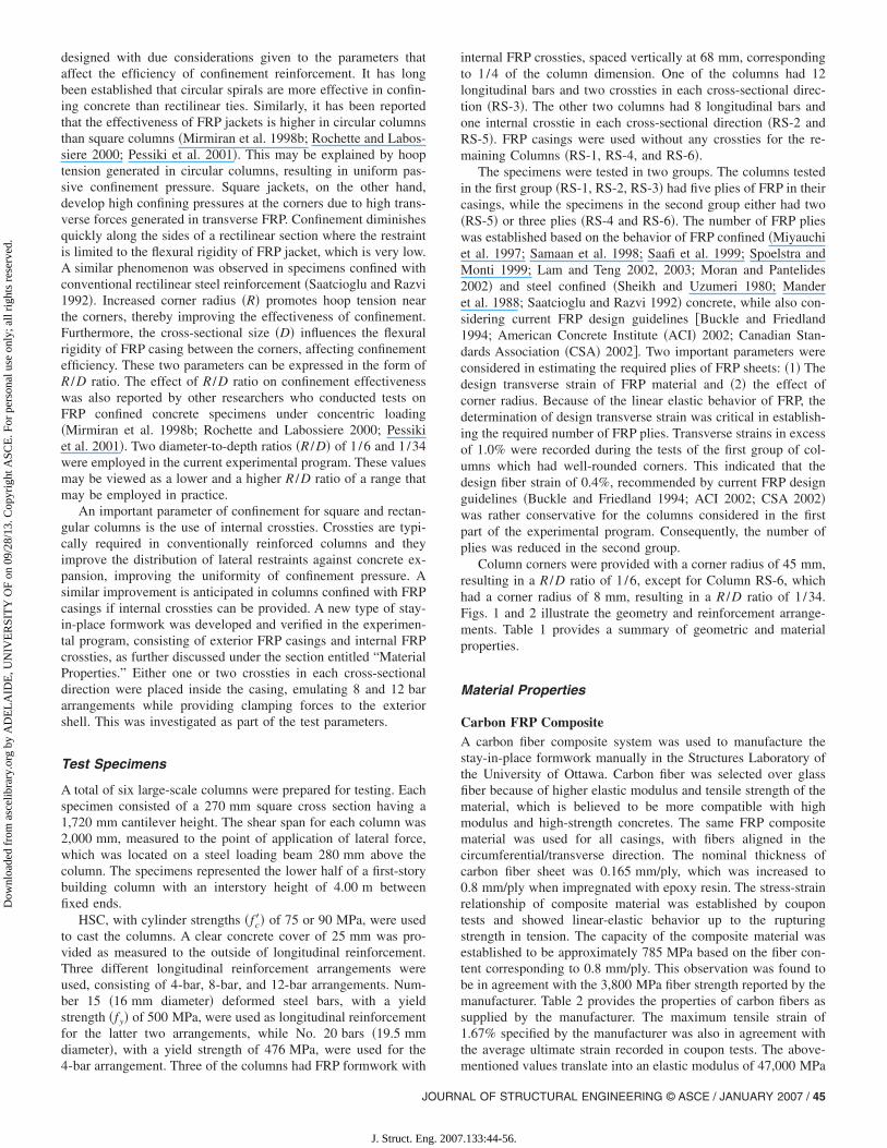
A total of six large-scale columns were prepared for testing. Eachspecimen consisted of a 270 mm square cross section having a1,720 mm cantilever height. The shear span for each column was2,000 mm, measured to the point of application of lateral force,which was located on a steel loading beam 280 mm above thecolumn. The specimens represented the lower half of a first-storybuilding column with an interstory height of 4.00 m betweenfixed ends.
HSC, with cylinder strengths �fc�� of 75 or 90 MPa, were usedto cast the columns. A clear concrete cover of 25 mm was pro-vided as measured to the outside of longitudinal reinforcement.Three different longitudinal reinforcement arrangements wereused, consisting of 4-bar, 8-bar, and 12-bar arrangements. Num-ber 15 �16 mm diameter� deformed steel bars, with a yieldstrength �fy� of 500 MPa, were used as longitudinal reinforcementfor the latter two arrangements, while No. 20 bars �19.5 mmdiameter�, with a yield strength of 476 MPa, were used for the
4-bar arrangement. Three of the columns had FRP formwork withJOURN
J. Struct. Eng. 2007
internal FRP crossties, spaced vertically at 68 mm, correspondingto 1/4 of the column dimension. One of the columns had 12longitudinal bars and two crossties in each cross-sectional direc-tion �RS-3�. The other two columns had 8 longitudinal bars andone internal crosstie in each cross-sectional direction �RS-2 andRS-5�. FRP casings were used without any crossties for the re-maining Columns �RS-1, RS-4, and RS-6�.
The specimens were tested in two groups. The columns testedin the first group �RS-1, RS-2, RS-3� had five plies of FRP in theircasings, while the specimens in the second group either had two�RS-5� or three plies �RS-4 and RS-6�. The number of FRP plieswas established based on the behavior of FRP confined �Miyauchiet al. 1997; Samaan et al. 1998; Saafi et al. 1999; Spoelstra andMonti 1999; Lam and Teng 2002, 2003; Moran and Pantelides2002� and steel confined �Sheikh and Uzumeri 1980; Manderet al. 1988; Saatcioglu and Razvi 1992� concrete, while also con-sidering current FRP design guidelines �Buckle and Friedland1994; American Concrete Institute �ACI� 2002; Canadian Stan-dards Association �CSA� 2002�. Two important parameters wereconsidered in estimating the required plies of FRP sheets: �1� Thedesign transverse strain of FRP material and �2� the effect ofcorner radius. Because of the linear elastic behavior of FRP, thedetermination of design transverse strain was critical in establish-ing the required number of FRP plies. Transverse strains in excessof 1.0% were recorded during the tests of the first group of col-umns which had well-rounded corners. This indicated that thedesign fiber strain of 0.4%, recommended by current FRP designguidelines �Buckle and Friedland 1994; ACI 2002; CSA 2002�was rather conservative for the columns considered in the firstpart of the experimental program. Consequently, the number ofplies was reduced in the second group.
Column corners were provided with a corner radius of 45 mm,resulting in a R /D ratio of 1 /6, except for Column RS-6, whichhad a corner radius of 8 mm, resulting in a R /D ratio of 1 /34.Figs. 1 and 2 illustrate the geometry and reinforcement arrange-ments. Table 1 provides a summary of geometric and materialproperties.
Material Properties
Carbon FRP CompositeA carbon fiber composite system was used to manufacture thestay-in-place formwork manually in the Structures Laboratory ofthe University of Ottawa. Carbon fiber was selected over glassfiber because of higher elastic modulus and tensile strength of thematerial, which is believed to be more compatible with highmodulus and high-strength concretes. The same FRP compositematerial was used for all casings, with fibers aligned in thecircumferential/transverse direction. The nominal thickness ofcarbon fiber sheet was 0.165 mm/ply, which was increased to0.8 mm/ply when impregnated with epoxy resin. The stress-strainrelationship of composite material was established by coupontests and showed linear-elastic behavior up to the rupturingstrength in tension. The capacity of the composite material wasestablished to be approximately 785 MPa based on the fiber con-tent corresponding to 0.8 mm/ply. This observation was found tobe in agreement with the 3,800 MPa fiber strength reported by themanufacturer. Table 2 provides the properties of carbon fibers assupplied by the manufacturer. The maximum tensile strain of1.67% specified by the manufacturer was also in agreement withthe average ultimate strain recorded in coupon tests. The above-
mentioned values translate into an elastic modulus of 47,000 MPaAL OF STRUCTURAL ENGINEERING © ASCE / JANUARY 2007 / 45
.133:44-56.
Dow
nloa
ded
from
asc
elib
rary
.org
by
AD
EL
AID
E, U
NIV
ER
SIT
Y O
F on
09/
28/1
3. C
opyr
ight
ASC
E. F
or p
erso
nal u
se o
nly;
all
righ
ts r
eser
ved.
for the composite material, which is in line with 227,000 MPareported for the modulus of elasticity of carbon fibers alone.
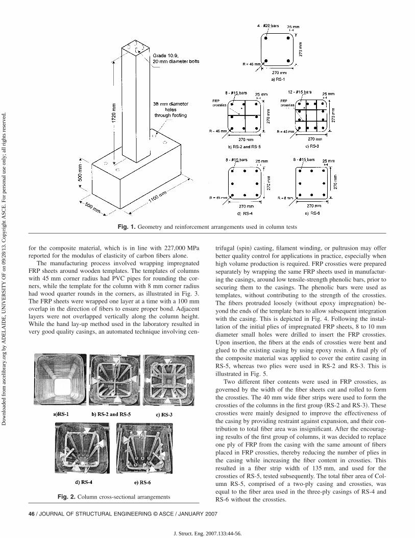
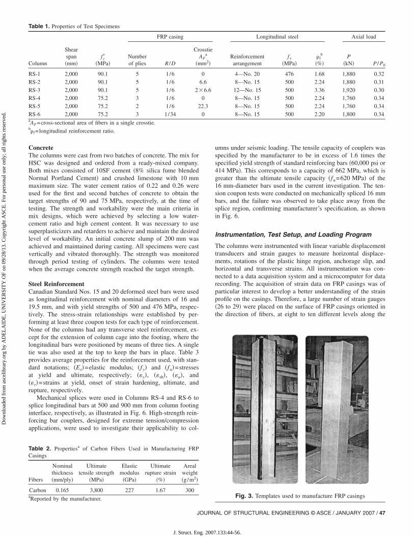
The manufacturing process involved wrapping impregnatedFRP sheets around wooden templates. The templates of columnswith 45 mm corner radius had PVC pipes for rounding the cor-ners, while the template for the column with 8 mm corner radiushad wood quarter rounds in the corners, as illustrated in Fig. 3.The FRP sheets were wrapped one layer at a time with a 100 mmoverlap in the direction of fibers to ensure proper bond. Adjacentlayers were not overlapped vertically along the column height.While the hand lay-up method used in the laboratory resulted invery good quality casings, an automated technique involving cen-
Fig. 1. Geometry and reinforcem
Fig. 2. Column cross-sectional arrangements
46 / JOURNAL OF STRUCTURAL ENGINEERING © ASCE / JANUARY 2007
J. Struct. Eng. 2007
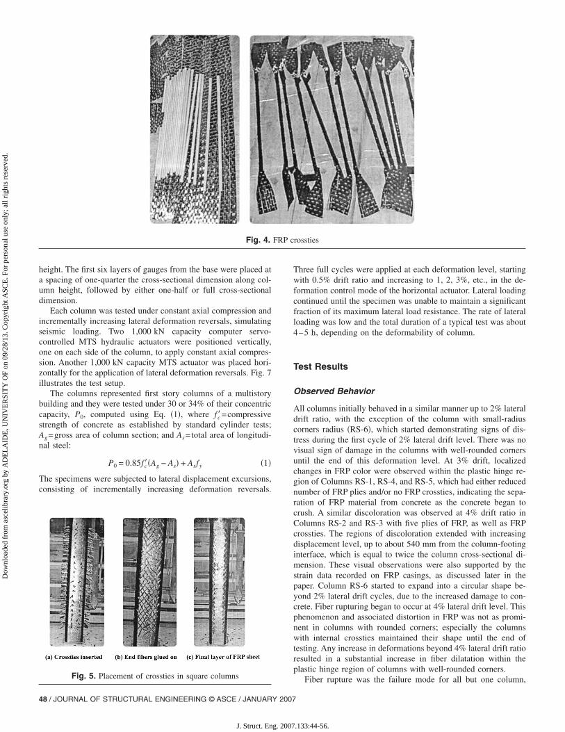
trifugal �spin� casting, filament winding, or pultrusion may offerbetter quality control for applications in practice, especially whenhigh volume production is required. FRP crossties were preparedseparately by wrapping the same FRP sheets used in manufactur-ing the casings, around low tensile-strength phenolic bars, prior tosecuring them to the casings. The phenolic bars were used astemplates, without contributing to the strength of the crossties.The fibers protruded loosely �without epoxy impregnation� be-yond the ends of the template bars to allow subsequent integrationwith the casing. This is depicted in Fig. 4. Following the instal-lation of the initial plies of impregnated FRP sheets, 8 to 10 mmdiameter small holes were drilled to insert the FRP crossties.Upon insertion, the fibers at the ends of crossties were bent andglued to the existing casing by using epoxy resin. A final ply ofthe composite material was applied to cover the entire casing inRS-5, whereas two plies were used in RS-2 and RS-3. This isillustrated in Fig. 5.
Two different fiber contents were used in FRP crossties, asgoverned by the width of the fiber sheets cut and rolled to formthe crossties. The 40 mm wide fiber strips were used to form thecrossties of the columns in the first group �RS-2 and RS-3�. Thesecrossties were mainly designed to improve the effectiveness ofthe casing by providing restraint against expansion, and their con-tribution to total fiber area was insignificant. After the encourag-ing results of the first group of columns, it was decided to replaceone ply of FRP from the casing with the same amount of fibersplaced in FRP crossties, thereby reducing the number of plies inthe casing while increasing the fiber content in crossties. Thisresulted in a fiber strip width of 135 mm, and used for thecrossties of RS-5, tested subsequently. The total fiber area of Col-umn RS-5, comprised of a two-ply casing and crossties, wasequal to the fiber area used in the three-ply casings of RS-4 and
rangements used in column tests
ent arRS-6 without the crossties.
.133:44-56.
Dow
nloa
ded
from
asc
elib
rary
.org
by
AD
EL
AID
E, U
NIV
ER
SIT
Y O
F on
09/
28/1
3. C
opyr
ight
ASC
E. F
or p
erso
nal u
se o
nly;
all
righ
ts r
eser
ved.
ConcreteThe columns were cast from two batches of concrete. The mix forHSC was designed and ordered from a ready-mixed company.Both mixes consisted of 10SF cement �8% silica fume blendedNormal Portland Cement� and crushed limestone with 10 mmmaximum size. The water cement ratios of 0.22 and 0.26 wereused for the first and second batches of concrete to obtain thetarget strengths of 90 and 75 MPa, respectively, at the time oftesting. The strength and workability were the main criteria inmix designs, which were achieved by selecting a low water-cement ratio and high cement content. It was necessary to usesuperplasticizers and retarders to achieve and maintain the desiredlevel of workability. An initial concrete slump of 200 mm wasachieved and maintained during casting. All specimens were castvertically and vibrated thoroughly. The strength was monitoredthrough period testing of cylinders. The columns were testedwhen the average concrete strength reached the target strength.
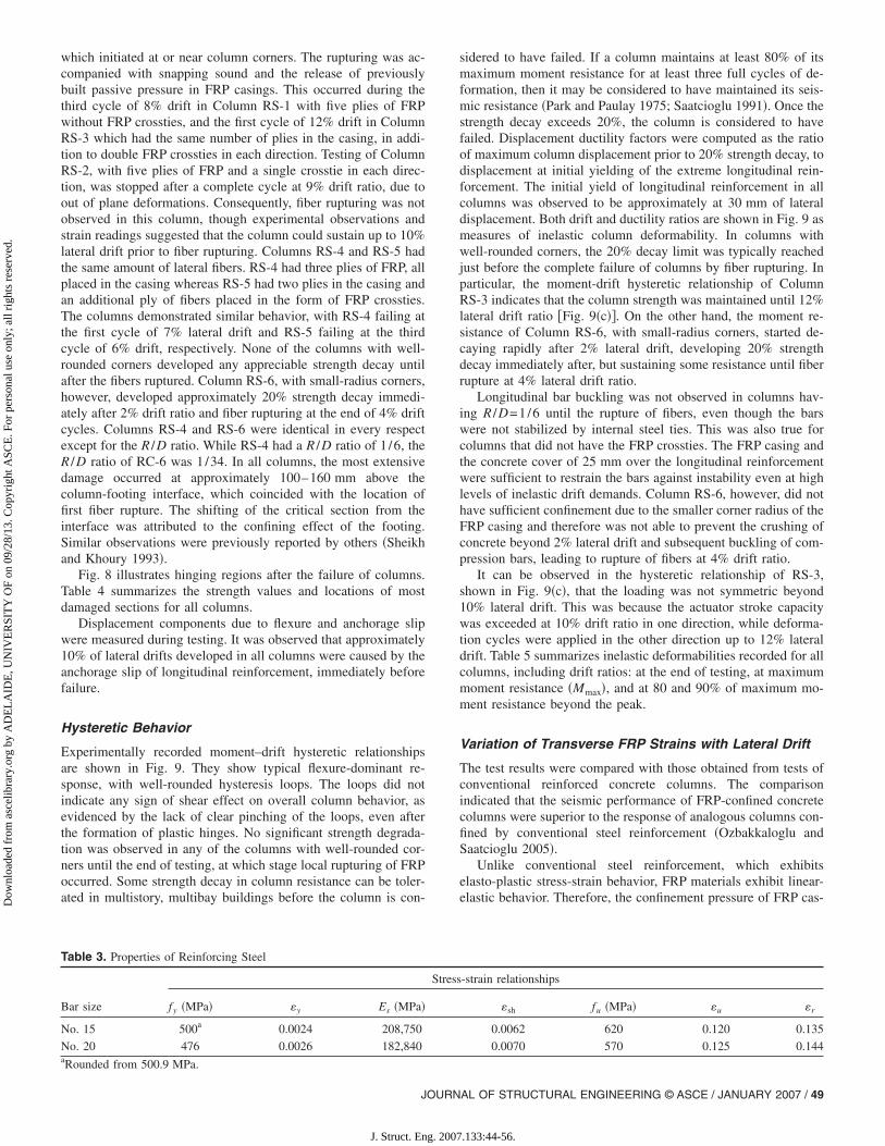
Steel ReinforcementCanadian Standard Nos. 15 and 20 deformed steel bars were usedas longitudinal reinforcement with nominal diameters of 16 and19.5 mm, and with yield strengths of 500 and 476 MPa, respec-tively. The stress-strain relationships were established by per-forming at least three coupon tests for each type of reinforcement.None of the columns had any transverse steel reinforcement, ex-cept for the extension of column cage into the footing, where thelongitudinal bars were positioned by means of three ties. A singletie was also used at the top to keep the bars in place. Table 3provides average properties for the reinforcement used, with stan-dard notations; �Es�=elastic modulus; �fy� and �fu�=stressesat yield and ultimate, respectively; ��y�, ��sh�, ��u�, and��r�=strains at yield, onset of strain hardening, ultimate, andrupture, respectively.
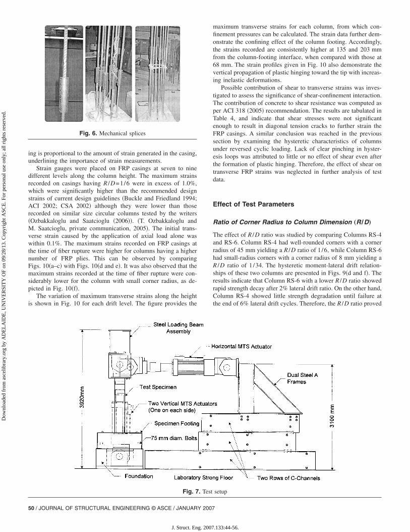
Mechanical splices were used in Columns RS-4 and RS-6 tosplice longitudinal bars at 500 and 900 mm from column footinginterface, respectively, as illustrated in Fig. 6. High-strength rein-forcing bar couplers, designed for extreme tension/compressionapplications, were used to investigate their applicability to col-
Table 1. Properties of Test Specimens
Column
Shearspan�mm�
fc��MPa�
FRP casing
Numberof plies R /D
CrA
�m
RS-1 2,000 90.1 5 1/6
RS-2 2,000 90.1 5 1/6
RS-3 2,000 90.1 5 1/6 2�
RS-4 2,000 75.2 3 1/6
RS-5 2,000 75.2 2 1/6 2
RS-6 2,000 75.2 3 1/34aAF=cross-sectional area of fibers in a single crosstie.b�l=longitudinal reinforcement ratio.
Table 2. Propertiesa of Carbon Fibers Used in Manufacturing FRPCasings
Fibers
Nominalthickness�mm/ply�
Ultimatetensile strength
�MPa�
Elasticmodulus�GPa�
Ultimaterupture strain
�%�
Arealweight�g/m2�
Carbon 0.165 3,800 227 1.67 300a
Reported by the manufacturer.JOURN
J. Struct. Eng. 2007
umns under seismic loading. The tensile capacity of couplers wasspecified by the manufacturer to be in excess of 1.6 times thespecified yield strength of standard reinforcing bars �60,000 psi or414 MPa�. This corresponds to a capacity of 662 MPa, which isgreater than the ultimate tensile capacity �fu=620 MPa� of the16 mm-diameter bars used in the current investigation. The ten-sion coupon tests were conducted on mechanically spliced 16 mmbars, and the failure was observed to take place away from thesplice region, confirming manufacturer’s specification, as shownin Fig. 6.
Instrumentation, Test Setup, and Loading Program
The columns were instrumented with linear variable displacementtransducers and strain gauges to measure horizontal displace-ments, rotations of the plastic hinge region, anchorage slip, andhorizontal and transverse strains. All instrumentation was con-nected to a data acquisition system and a microcomputer for datarecording. The acquisition of strain data on FRP casings was ofparticular interest to develop a better understanding of the strainprofile on the casings. Therefore, a large number of strain gauges�26 to 29� were placed on the surface of FRP casings oriented inthe direction of fibers, at eight to ten different levels along the
Longitudinal steel Axial load
Reinforcementarrangement
fy
�MPa��l
b
�%�P
�kN� P / P0
4—No. 20 476 1.68 1,880 0.32
8—No. 15 500 2.24 1,880 0.31
12—No. 15 500 3.36 1,920 0.30
8—No. 15 500 2.24 1,760 0.34
8—No. 15 500 2.24 1,760 0.34
8—No. 15 500 2.20 1,800 0.34
Fig. 3. Templates used to manufacture FRP casings
osstie
Fa
m2�
0
6.6
6.6
0
2.3
0
AL OF STRUCTURAL ENGINEERING © ASCE / JANUARY 2007 / 47
.133:44-56.
Dow
nloa
ded
from
asc
elib
rary
.org
by
AD
EL
AID
E, U
NIV
ER
SIT
Y O
F on
09/
28/1
3. C
opyr
ight
ASC
E. F
or p
erso
nal u
se o
nly;
all
righ
ts r
eser
ved.
height. The first six layers of gauges from the base were placed ata spacing of one-quarter the cross-sectional dimension along col-umn height, followed by either one-half or full cross-sectionaldimension.
Each column was tested under constant axial compression andincrementally increasing lateral deformation reversals, simulatingseismic loading. Two 1,000 kN capacity computer servo-controlled MTS hydraulic actuators were positioned vertically,one on each side of the column, to apply constant axial compres-sion. Another 1,000 kN capacity MTS actuator was placed hori-zontally for the application of lateral deformation reversals. Fig. 7illustrates the test setup.
The columns represented first story columns of a multistorybuilding and they were tested under 30 or 34% of their concentriccapacity, P0, computed using Eq. �1�, where fc�=compressivestrength of concrete as established by standard cylinder tests;Ag=gross area of column section; and As=total area of longitudi-nal steel:
P0 = 0.85fc��Ag − As� + Asfy �1�
The specimens were subjected to lateral displacement excursions,consisting of incrementally increasing deformation reversals.
Fig. 4.
Fig. 5. Placement of crossties in square columns
48 / JOURNAL OF STRUCTURAL ENGINEERING © ASCE / JANUARY 2007
J. Struct. Eng. 2007
Three full cycles were applied at each deformation level, startingwith 0.5% drift ratio and increasing to 1, 2, 3%, etc., in the de-formation control mode of the horizontal actuator. Lateral loadingcontinued until the specimen was unable to maintain a significantfraction of its maximum lateral load resistance. The rate of lateralloading was low and the total duration of a typical test was about4–5 h, depending on the deformability of column.
Test Results
Observed Behavior
All columns initially behaved in a similar manner up to 2% lateraldrift ratio, with the exception of the column with small-radiuscorners radius �RS-6�, which started demonstrating signs of dis-tress during the first cycle of 2% lateral drift level. There was novisual sign of damage in the columns with well-rounded cornersuntil the end of this deformation level. At 3% drift, localizedchanges in FRP color were observed within the plastic hinge re-gion of Columns RS-1, RS-4, and RS-5, which had either reducednumber of FRP plies and/or no FRP crossties, indicating the sepa-ration of FRP material from concrete as the concrete began tocrush. A similar discoloration was observed at 4% drift ratio inColumns RS-2 and RS-3 with five plies of FRP, as well as FRPcrossties. The regions of discoloration extended with increasingdisplacement level, up to about 540 mm from the column-footinginterface, which is equal to twice the column cross-sectional di-mension. These visual observations were also supported by thestrain data recorded on FRP casings, as discussed later in thepaper. Column RS-6 started to expand into a circular shape be-yond 2% lateral drift cycles, due to the increased damage to con-crete. Fiber rupturing began to occur at 4% lateral drift level. Thisphenomenon and associated distortion in FRP was not as promi-nent in columns with rounded corners; especially the columnswith internal crossties maintained their shape until the end oftesting. Any increase in deformations beyond 4% lateral drift ratioresulted in a substantial increase in fiber dilatation within theplastic hinge region of columns with well-rounded corners.
rossties
FRP cFiber rupture was the failure mode for all but one column,
.133:44-56.
Dow
nloa
ded
from
asc
elib
rary
.org
by
AD
EL
AID
E, U
NIV
ER
SIT
Y O
F on
09/
28/1
3. C
opyr
ight
ASC
E. F
or p
erso
nal u
se o
nly;
all
righ
ts r
eser
ved.
which initiated at or near column corners. The rupturing was ac-companied with snapping sound and the release of previouslybuilt passive pressure in FRP casings. This occurred during thethird cycle of 8% drift in Column RS-1 with five plies of FRPwithout FRP crossties, and the first cycle of 12% drift in ColumnRS-3 which had the same number of plies in the casing, in addi-tion to double FRP crossties in each direction. Testing of ColumnRS-2, with five plies of FRP and a single crosstie in each direc-tion, was stopped after a complete cycle at 9% drift ratio, due toout of plane deformations. Consequently, fiber rupturing was notobserved in this column, though experimental observations andstrain readings suggested that the column could sustain up to 10%lateral drift prior to fiber rupturing. Columns RS-4 and RS-5 hadthe same amount of lateral fibers. RS-4 had three plies of FRP, allplaced in the casing whereas RS-5 had two plies in the casing andan additional ply of fibers placed in the form of FRP crossties.The columns demonstrated similar behavior, with RS-4 failing atthe first cycle of 7% lateral drift and RS-5 failing at the thirdcycle of 6% drift, respectively. None of the columns with well-rounded corners developed any appreciable strength decay untilafter the fibers ruptured. Column RS-6, with small-radius corners,however, developed approximately 20% strength decay immedi-ately after 2% drift ratio and fiber rupturing at the end of 4% driftcycles. Columns RS-4 and RS-6 were identical in every respectexcept for the R /D ratio. While RS-4 had a R /D ratio of 1 /6, theR /D ratio of RC-6 was 1/34. In all columns, the most extensivedamage occurred at approximately 100–160 mm above thecolumn-footing interface, which coincided with the location offirst fiber rupture. The shifting of the critical section from theinterface was attributed to the confining effect of the footing.Similar observations were previously reported by others �Sheikhand Khoury 1993�.
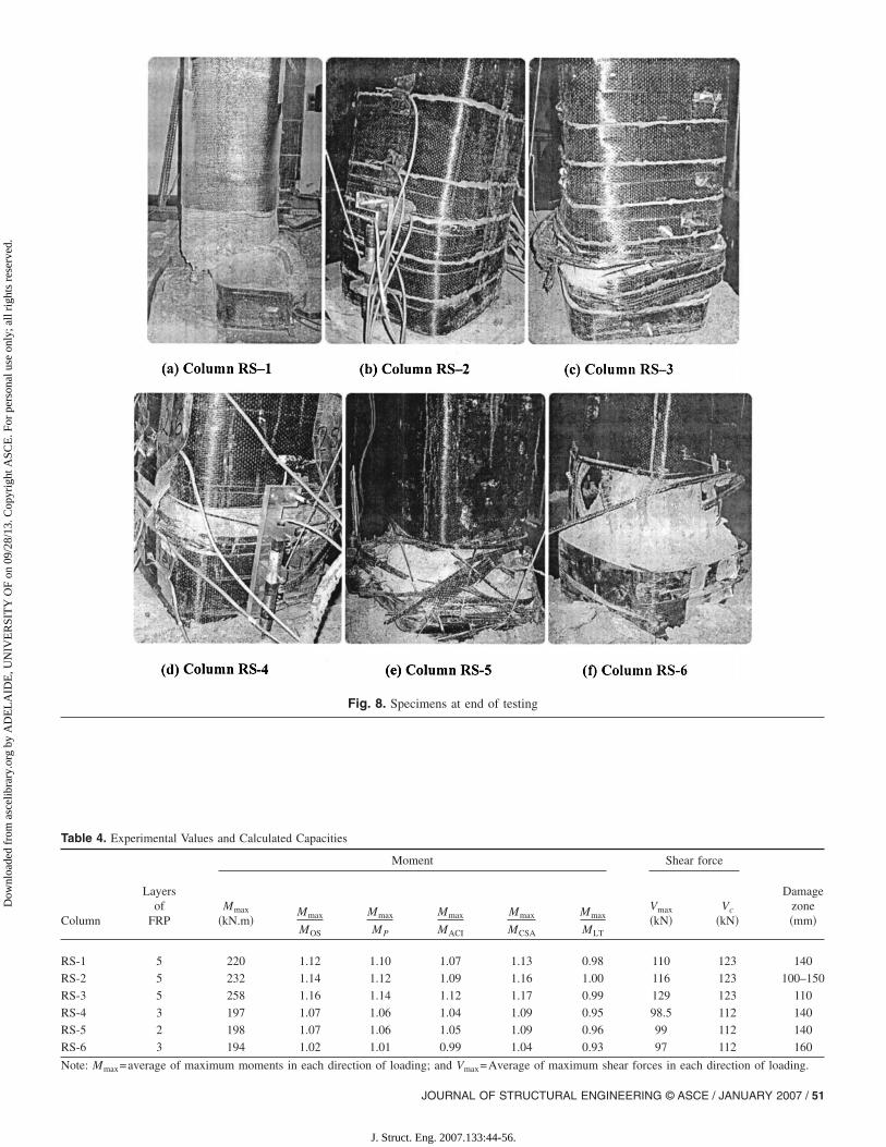
Fig. 8 illustrates hinging regions after the failure of columns.Table 4 summarizes the strength values and locations of mostdamaged sections for all columns.
Displacement components due to flexure and anchorage slipwere measured during testing. It was observed that approximately10% of lateral drifts developed in all columns were caused by theanchorage slip of longitudinal reinforcement, immediately beforefailure.
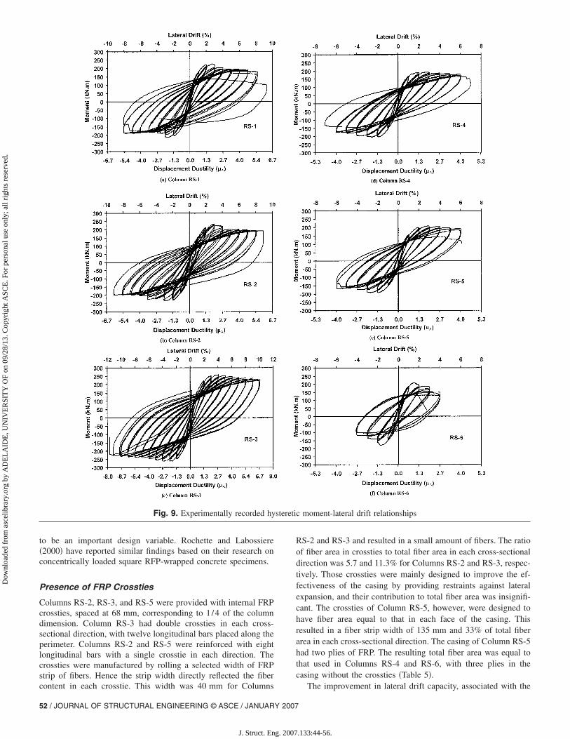
Hysteretic Behavior
Experimentally recorded moment–drift hysteretic relationshipsare shown in Fig. 9. They show typical flexure-dominant re-sponse, with well-rounded hysteresis loops. The loops did notindicate any sign of shear effect on overall column behavior, asevidenced by the lack of clear pinching of the loops, even afterthe formation of plastic hinges. No significant strength degrada-tion was observed in any of the columns with well-rounded cor-ners until the end of testing, at which stage local rupturing of FRPoccurred. Some strength decay in column resistance can be toler-ated in multistory, multibay buildings before the column is con-
Table 3. Properties of Reinforcing Steel
Bar size fy �MPa� �y Es �MPa�
No. 15 500a 0.0024 208,750
No. 20 476 0.0026 182,840a
Rounded from 500.9 MPa.JOURN
J. Struct. Eng. 2007
sidered to have failed. If a column maintains at least 80% of itsmaximum moment resistance for at least three full cycles of de-formation, then it may be considered to have maintained its seis-mic resistance �Park and Paulay 1975; Saatcioglu 1991�. Once thestrength decay exceeds 20%, the column is considered to havefailed. Displacement ductility factors were computed as the ratioof maximum column displacement prior to 20% strength decay, todisplacement at initial yielding of the extreme longitudinal rein-forcement. The initial yield of longitudinal reinforcement in allcolumns was observed to be approximately at 30 mm of lateraldisplacement. Both drift and ductility ratios are shown in Fig. 9 asmeasures of inelastic column deformability. In columns withwell-rounded corners, the 20% decay limit was typically reachedjust before the complete failure of columns by fiber rupturing. Inparticular, the moment-drift hysteretic relationship of ColumnRS-3 indicates that the column strength was maintained until 12%lateral drift ratio �Fig. 9�c��. On the other hand, the moment re-sistance of Column RS-6, with small-radius corners, started de-caying rapidly after 2% lateral drift, developing 20% strengthdecay immediately after, but sustaining some resistance until fiberrupture at 4% lateral drift ratio.
Longitudinal bar buckling was not observed in columns hav-ing R /D=1/6 until the rupture of fibers, even though the barswere not stabilized by internal steel ties. This was also true forcolumns that did not have the FRP crossties. The FRP casing andthe concrete cover of 25 mm over the longitudinal reinforcementwere sufficient to restrain the bars against instability even at highlevels of inelastic drift demands. Column RS-6, however, did nothave sufficient confinement due to the smaller corner radius of theFRP casing and therefore was not able to prevent the crushing ofconcrete beyond 2% lateral drift and subsequent buckling of com-pression bars, leading to rupture of fibers at 4% drift ratio.
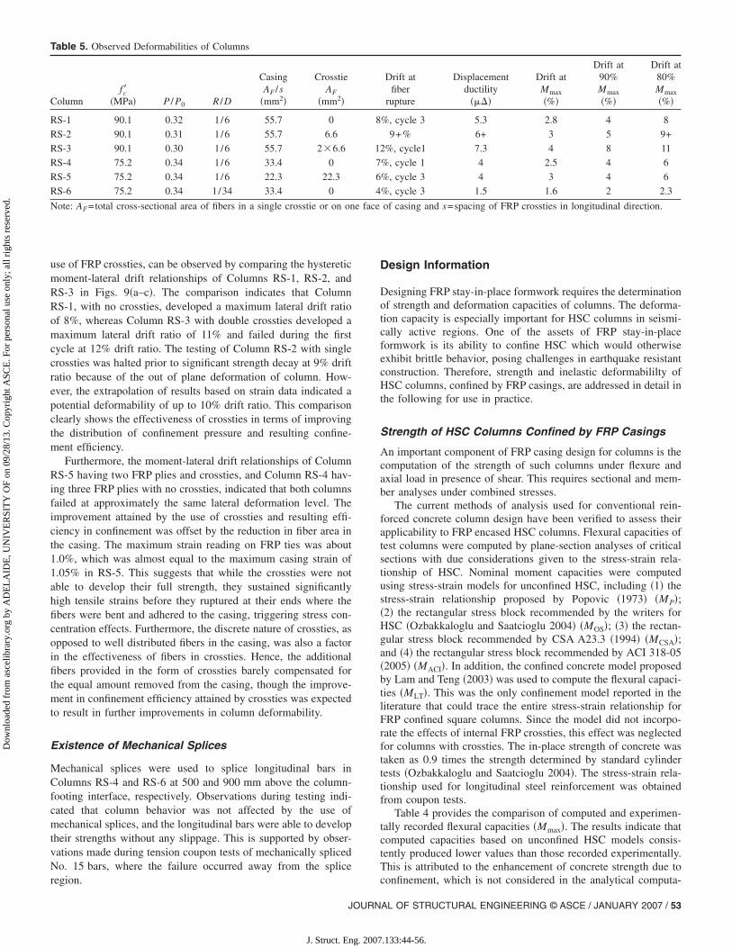
It can be observed in the hysteretic relationship of RS-3,shown in Fig. 9�c�, that the loading was not symmetric beyond10% lateral drift. This was because the actuator stroke capacitywas exceeded at 10% drift ratio in one direction, while deforma-tion cycles were applied in the other direction up to 12% lateraldrift. Table 5 summarizes inelastic deformabilities recorded for allcolumns, including drift ratios: at the end of testing, at maximummoment resistance �Mmax�, and at 80 and 90% of maximum mo-ment resistance beyond the peak.
Variation of Transverse FRP Strains with Lateral Drift
The test results were compared with those obtained from tests ofconventional reinforced concrete columns. The comparisonindicated that the seismic performance of FRP-confined concretecolumns were superior to the response of analogous columns con-fined by conventional steel reinforcement �Ozbakkaloglu andSaatcioglu 2005�.
Unlike conventional steel reinforcement, which exhibitselasto-plastic stress-strain behavior, FRP materials exhibit linear-elastic behavior. Therefore, the confinement pressure of FRP cas-
-strain relationships
�sh fu �MPa� �u �r
0.0062 620 0.120 0.135
0.0070 570 0.125 0.144
Stress
AL OF STRUCTURAL ENGINEERING © ASCE / JANUARY 2007 / 49
.133:44-56.
Dow
nloa
ded
from
asc
elib
rary
.org
by
AD
EL
AID
E, U
NIV
ER
SIT
Y O
F on
09/
28/1
3. C
opyr
ight
ASC
E. F
or p
erso
nal u
se o
nly;
all
righ
ts r
eser
ved.
ing is proportional to the amount of strain generated in the casing,underlining the importance of strain measurements.
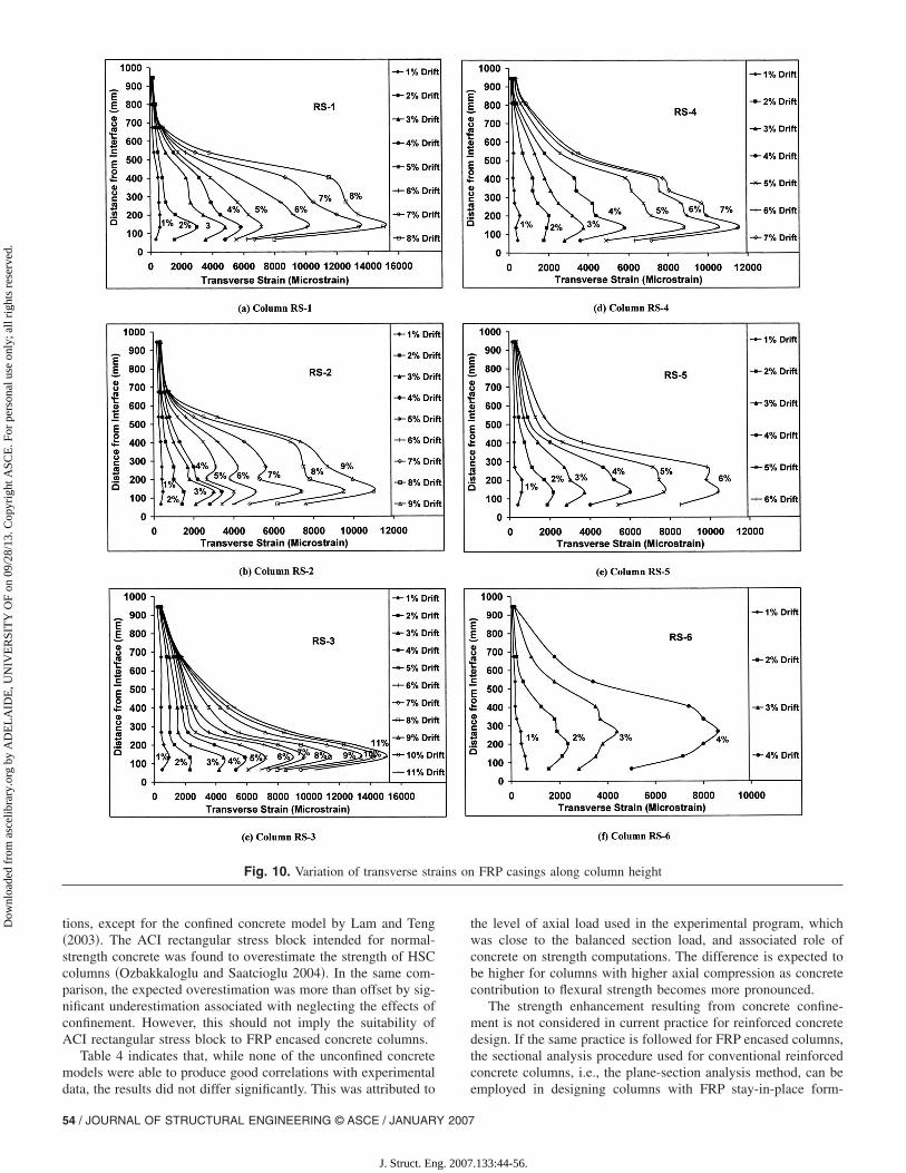
Strain gauges were placed on FRP casings at seven to ninedifferent levels along the column height. The maximum strainsrecorded on casings having R /D=1/6 were in excess of 1.0%,which were significantly higher than the recommended designstrains of current design guidelines �Buckle and Friedland 1994;ACI 2002; CSA 2002� although they were lower than thoserecorded on similar size circular columns tested by the writers�Ozbakkaloglu and Saatcioglu �2006��. �T. Ozbakkaloglu andM. Saatcioglu, private communication, 2005�. The initial trans-verse strain caused by the application of axial load alone waswithin 0.1%. The maximum strains recorded on FRP casings atthe time of fiber rupture were higher for columns having a highernumber of FRP plies. This can be observed by comparingFigs. 10�a–c� with Figs. 10�d and e�. It was also observed that themaximum strains recorded at the time of fiber rupture were con-siderably lower for the column with small corner radius, as de-picted in Fig. 10�f�.
The variation of maximum transverse strains along the heightis shown in Fig. 10 for each drift level. The figure provides the
Fig. 6. Mechanical splices
Fig. 7
50 / JOURNAL OF STRUCTURAL ENGINEERING © ASCE / JANUARY 2007
J. Struct. Eng. 2007
maximum transverse strains for each column, from which con-finement pressures can be calculated. The strain data further dem-onstrate the confining effect of the column footing. Accordingly,the strains recorded are consistently higher at 135 and 203 mmfrom the column-footing interface, when compared with those at68 mm. The strain profiles given in Fig. 10 also demonstrate thevertical propagation of plastic hinging toward the tip with increas-ing inelastic deformations.
Possible contribution of shear to transverse strains was inves-tigated to assess the significance of shear-confinement interaction.The contribution of concrete to shear resistance was computed asper ACI 318 �2005� recommendation. The results are tabulated inTable 4, and indicate that shear stresses were not significantenough to result in diagonal tension cracks to further strain theFRP casings. A similar conclusion was reached in the previoussection by examining the hysteretic characteristics of columnsunder reversed cyclic loading. Lack of clear pinching in hyster-esis loops was attributed to little or no effect of shear even afterthe formation of plastic hinging. Therefore, the effect of shear ontransverse FRP strains was neglected in further analysis of testdata.
Effect of Test Parameters
Ratio of Corner Radius to Column Dimension „R /D…
The effect of R /D ratio was studied by comparing Columns RS-4and RS-6. Column RS-4 had well-rounded corners with a cornerradius of 45 mm yielding a R /D ratio of 1 /6, while Column RS-6had small-radius corners with a corner radius of 8 mm yielding aR /D ratio of 1 /34. The hysteretic moment-lateral drift relation-ships of these two columns are presented in Figs. 9�d and f�. Theresults indicate that Column RS-6 with a lower R /D ratio showedrapid strength decay after 2% lateral drift ratio. On the other hand,Column RS-4 showed little strength degradation until failure atthe end of 6% lateral drift cycles. Therefore, the R /D ratio proved
setup
. Test.133:44-56.
Dow
nloa
ded
from
asc
elib
rary
.org
by
AD
EL
AID
E, U
NIV
ER
SIT
Y O
F on
09/
28/1
3. C
opyr
ight
ASC
E. F
or p
erso
nal u
se o
nly;
all
righ
ts r
eser
ved.
Table 4. Experimental Values and Calculated Capacities
Column
Layersof
FRP
Moment Shear force
Damagezone�mm�
Mmax
�kN.m�Mmax
MOS
Mmax
MP
Mmax
MACI
Mmax
MCSA
Mmax
MLT
Vmax
�kN�Vc
�kN�
RS-1 5 220 1.12 1.10 1.07 1.13 0.98 110 123 140
RS-2 5 232 1.14 1.12 1.09 1.16 1.00 116 123 100–150
RS-3 5 258 1.16 1.14 1.12 1.17 0.99 129 123 110
RS-4 3 197 1.07 1.06 1.04 1.09 0.95 98.5 112 140
RS-5 2 198 1.07 1.06 1.05 1.09 0.96 99 112 140
RS-6 3 194 1.02 1.01 0.99 1.04 0.93 97 112 160
Fig. 8. Specimens at end of testing
Note: Mmax=average of maximum moments in each direction of loading; and Vmax=Average of maximum shear forces in each direction of loading.
JOURNAL OF STRUCTURAL ENGINEERING © ASCE / JANUARY 2007 / 51
J. Struct. Eng. 2007.133:44-56.
Dow
nloa
ded
from
asc
elib
rary
.org
by
AD
EL
AID
E, U
NIV
ER
SIT
Y O
F on
09/
28/1
3. C
opyr
ight
ASC
E. F
or p
erso
nal u
se o
nly;
all
righ
ts r
eser
ved.
to be an important design variable. Rochette and Labossiere�2000� have reported similar findings based on their research onconcentrically loaded square RFP-wrapped concrete specimens.
Presence of FRP Crossties
Columns RS-2, RS-3, and RS-5 were provided with internal FRPcrossties, spaced at 68 mm, corresponding to 1/4 of the columndimension. Column RS-3 had double crossties in each cross-sectional direction, with twelve longitudinal bars placed along theperimeter. Columns RS-2 and RS-5 were reinforced with eightlongitudinal bars with a single crosstie in each direction. Thecrossties were manufactured by rolling a selected width of FRPstrip of fibers. Hence the strip width directly reflected the fiber
Fig. 9. Experimentally recorded hy
content in each crosstie. This width was 40 mm for Columns
52 / JOURNAL OF STRUCTURAL ENGINEERING © ASCE / JANUARY 2007
J. Struct. Eng. 2007
RS-2 and RS-3 and resulted in a small amount of fibers. The ratioof fiber area in crossties to total fiber area in each cross-sectionaldirection was 5.7 and 11.3% for Columns RS-2 and RS-3, respec-tively. Those crossties were mainly designed to improve the ef-fectiveness of the casing by providing restraints against lateralexpansion, and their contribution to total fiber area was insignifi-cant. The crossties of Column RS-5, however, were designed tohave fiber area equal to that in each face of the casing. Thisresulted in a fiber strip width of 135 mm and 33% of total fiberarea in each cross-sectional direction. The casing of Column RS-5had two plies of FRP. The resulting total fiber area was equal tothat used in Columns RS-4 and RS-6, with three plies in thecasing without the crossties �Table 5�.
c moment-lateral drift relationships
steretiThe improvement in lateral drift capacity, associated with the
.133:44-56.
Dow
nloa
ded
from
asc
elib
rary
.org
by
AD
EL
AID
E, U
NIV
ER
SIT
Y O
F on
09/
28/1
3. C
opyr
ight
ASC
E. F
or p
erso
nal u
se o
nly;
all
righ
ts r
eser
ved.
use of FRP crossties, can be observed by comparing the hystereticmoment-lateral drift relationships of Columns RS-1, RS-2, andRS-3 in Figs. 9�a–c�. The comparison indicates that ColumnRS-1, with no crossties, developed a maximum lateral drift ratioof 8%, whereas Column RS-3 with double crossties developed amaximum lateral drift ratio of 11% and failed during the firstcycle at 12% drift ratio. The testing of Column RS-2 with singlecrossties was halted prior to significant strength decay at 9% driftratio because of the out of plane deformation of column. How-ever, the extrapolation of results based on strain data indicated apotential deformability of up to 10% drift ratio. This comparisonclearly shows the effectiveness of crossties in terms of improvingthe distribution of confinement pressure and resulting confine-ment efficiency.
Furthermore, the moment-lateral drift relationships of ColumnRS-5 having two FRP plies and crossties, and Column RS-4 hav-ing three FRP plies with no crossties, indicated that both columnsfailed at approximately the same lateral deformation level. Theimprovement attained by the use of crossties and resulting effi-ciency in confinement was offset by the reduction in fiber area inthe casing. The maximum strain reading on FRP ties was about1.0%, which was almost equal to the maximum casing strain of1.05% in RS-5. This suggests that while the crossties were notable to develop their full strength, they sustained significantlyhigh tensile strains before they ruptured at their ends where thefibers were bent and adhered to the casing, triggering stress con-centration effects. Furthermore, the discrete nature of crossties, asopposed to well distributed fibers in the casing, was also a factorin the effectiveness of fibers in crossties. Hence, the additionalfibers provided in the form of crossties barely compensated forthe equal amount removed from the casing, though the improve-ment in confinement efficiency attained by crossties was expectedto result in further improvements in column deformability.
Existence of Mechanical Splices
Mechanical splices were used to splice longitudinal bars inColumns RS-4 and RS-6 at 500 and 900 mm above the column-footing interface, respectively. Observations during testing indi-cated that column behavior was not affected by the use ofmechanical splices, and the longitudinal bars were able to developtheir strengths without any slippage. This is supported by obser-vations made during tension coupon tests of mechanically splicedNo. 15 bars, where the failure occurred away from the splice
Table 5. Observed Deformabilities of Columns
Columnfc�
�MPa� P / P0 R /D
CasingAF /s
�mm2�
CrosstieAF
�mm2�
RS-1 90.1 0.32 1/6 55.7 0
RS-2 90.1 0.31 1/6 55.7 6.6
RS-3 90.1 0.30 1/6 55.7 2�6.6
RS-4 75.2 0.34 1/6 33.4 0
RS-5 75.2 0.34 1/6 22.3 22.3
RS-6 75.2 0.34 1/34 33.4 0
Note: AF=total cross-sectional area of fibers in a single crosstie or on on
region.
JOURN
J. Struct. Eng. 2007
Design Information
Designing FRP stay-in-place formwork requires the determinationof strength and deformation capacities of columns. The deforma-tion capacity is especially important for HSC columns in seismi-cally active regions. One of the assets of FRP stay-in-placeformwork is its ability to confine HSC which would otherwiseexhibit brittle behavior, posing challenges in earthquake resistantconstruction. Therefore, strength and inelastic deformabililty ofHSC columns, confined by FRP casings, are addressed in detail inthe following for use in practice.
Strength of HSC Columns Confined by FRP Casings
An important component of FRP casing design for columns is thecomputation of the strength of such columns under flexure andaxial load in presence of shear. This requires sectional and mem-ber analyses under combined stresses.
The current methods of analysis used for conventional rein-forced concrete column design have been verified to assess theirapplicability to FRP encased HSC columns. Flexural capacities oftest columns were computed by plane-section analyses of criticalsections with due considerations given to the stress-strain rela-tionship of HSC. Nominal moment capacities were computedusing stress-strain models for unconfined HSC, including �1� thestress-strain relationship proposed by Popovic �1973� �MP�;�2� the rectangular stress block recommended by the writers forHSC �Ozbakkaloglu and Saatcioglu 2004� �MOS�; �3� the rectan-gular stress block recommended by CSA A23.3 �1994� �MCSA�;and �4� the rectangular stress block recommended by ACI 318-05�2005� �MACI�. In addition, the confined concrete model proposedby Lam and Teng �2003� was used to compute the flexural capaci-ties �MLT�. This was the only confinement model reported in theliterature that could trace the entire stress-strain relationship forFRP confined square columns. Since the model did not incorpo-rate the effects of internal FRP crossties, this effect was neglectedfor columns with crossties. The in-place strength of concrete wastaken as 0.9 times the strength determined by standard cylindertests �Ozbakkaloglu and Saatcioglu 2004�. The stress-strain rela-tionship used for longitudinal steel reinforcement was obtainedfrom coupon tests.
Table 4 provides the comparison of computed and experimen-tally recorded flexural capacities �Mmax�. The results indicate thatcomputed capacities based on unconfined HSC models consis-tently produced lower values than those recorded experimentally.This is attributed to the enhancement of concrete strength due to
Drift atfiber
rupture
Displacementductility
����
Drift atMmax
�%�
Drift at90%Mmax
�%�
Drift at80%Mmax
�%�
%, cycle 3 5.3 2.8 4 8
9+% 6+ 3 5 9+
2%, cycle1 7.3 4 8 11
%, cycle 1 4 2.5 4 6
%, cycle 3 4 3 4 6
%, cycle 3 1.5 1.6 2 2.3
of casing and s=spacing of FRP crossties in longitudinal direction.
8
1
7
6
4
e face
confinement, which is not considered in the analytical computa-
AL OF STRUCTURAL ENGINEERING © ASCE / JANUARY 2007 / 53
.133:44-56.
Dow
nloa
ded
from
asc
elib
rary
.org
by
AD
EL
AID
E, U
NIV
ER
SIT
Y O
F on
09/
28/1
3. C
opyr
ight
ASC
E. F
or p
erso
nal u
se o
nly;
all
righ
ts r
eser
ved.
tions, except for the confined concrete model by Lam and Teng�2003�. The ACI rectangular stress block intended for normal-strength concrete was found to overestimate the strength of HSCcolumns �Ozbakkaloglu and Saatcioglu 2004�. In the same com-parison, the expected overestimation was more than offset by sig-nificant underestimation associated with neglecting the effects ofconfinement. However, this should not imply the suitability ofACI rectangular stress block to FRP encased concrete columns.
Table 4 indicates that, while none of the unconfined concretemodels were able to produce good correlations with experimental
Fig. 10. Variation of transverse stra
data, the results did not differ significantly. This was attributed to
54 / JOURNAL OF STRUCTURAL ENGINEERING © ASCE / JANUARY 2007
J. Struct. Eng. 2007
the level of axial load used in the experimental program, whichwas close to the balanced section load, and associated role ofconcrete on strength computations. The difference is expected tobe higher for columns with higher axial compression as concretecontribution to flexural strength becomes more pronounced.
The strength enhancement resulting from concrete confine-ment is not considered in current practice for reinforced concretedesign. If the same practice is followed for FRP encased columns,the sectional analysis procedure used for conventional reinforcedconcrete columns, i.e., the plane-section analysis method, can be
FRP casings along column height
ins onemployed in designing columns with FRP stay-in-place form-
.133:44-56.
Dow
nloa
ded
from
asc
elib
rary
.org
by
AD
EL
AID
E, U
NIV
ER
SIT
Y O
F on
09/
28/1
3. C
opyr
ight
ASC
E. F
or p
erso
nal u
se o
nly;
all
righ
ts r
eser
ved.
work, provided that an appropriate stress block is used. The ana-lytical predictions computed by the confined concrete model ofLam and Teng �2003� produced good agreements with experimen-tal values, especially for well confined columns. However, as thelevel of confinement diminished, the analytical results tended tooverestimate flexural strengths �Table 4�.
The test columns were designed to behave predominantly inthe flexure mode, and had shear capacities higher than those cor-responding to flexural capacities. Therefore, little or no effect ofshear was observed during testing. Table 4 includes computedconcrete contributions to shear �Vc� on the basis of ACI 318-05�2005�. These values indicate that, the concrete shear resistancealone was sufficient to resist the maximum shear force observedduring testing �Vmax�. Only for Column RS-3, the computed con-crete shear resistance was slightly below the maximum shearforce.
Deformability of HSC Columns Confinedby FRP Casings
The deformability of HSC columns is an important design con-sideration for earthquake resistant construction because of thebrittle nature of HSC, especially in the presence of high axialcompression. Therefore, the confinement of concrete by properlydesigned transverse reinforcement plays an important role in theseismic performance of HSC columns. FRP stay-in-place form-work provides a convenient alternative to conventional confine-ment reinforcement for improved deformability of earthquakeresistant HSC columns.
Inelastic deformability of HSC columns with FRP stay-in-place formwork is a topic which is currently under investigation.Therefore, very little data are available on the topic to suggest ageneralized design procedure. CSA Standard S806-02 �2002� in-cludes displacement-based design recommendations that are es-sentially intended for fiber wrapping concrete bridge columns forseismic retrofitting. These recommendations are based on experi-mental data generated on bridge columns with relatively lowlevels of axial compressions. The columns of the current investi-gation represent first story columns of a multistory building withaxial compression approaching that of a balanced section. Thislevel of axial compression increases the contribution of concreteto overall column behavior, resulting in the change of failuremode from longitudinal bar rupturing to concrete crushing. In-creased axial compression also improves the effectiveness of FRPas confinement reinforcement. Furthermore, the current investiga-tion includes the beneficial effects of corner rounding and the useof internal FRP crossties on confinement. Consequently, the ex-perimental results indicate superior inelastic column deformabili-ties than those suggested by CSA S806-02 �2002� expressions.
The hysteretic relationships observed during column tests in-dicate that the majority of columns showed very favorable defor-mation characteristics well into the inelastic range. Columns withfive plies of FRP developed in excess of 8% drift ratio withoutsignificant strength decay, when the corners were rounded to havea R /D ratio of 1 /6. The use of internal FRP crossties furtherimproved column drift capacity, resulting in drift ratios of up to11% when double crossties were used in each cross-sectional di-rection. The drift capacity was reduced to 6% in columns withthree plies of FRP. However, a severe reduction in drift capacitywas observed when the rounding of column corners was kept to aminimum, with R /D=1/34, developing only 2% lateral drift
ratio.JOURN
J. Struct. Eng. 2007
Conclusions
The following conclusions can be drawn from the experimentalinvestigation reported in this paper:• High-strength concrete columns confined by carbon FRP
stay-in-place formwork can develop ductile behavior undersimulated seismic loading. The use of FRP formwork as con-finement reinforcement substantially increases deformabilityof square columns. Column tests reported in this paper indi-cate that inelastic deformability of 90 MPa concrete squarecolumns can be increased up to 11% lateral drift ratio withFRP stay-in-place formwork.
• The increased confinement requirements for HSC columns canbe met by using FRP stay-in-place formwork. Unlike conven-tional steel reinforcement that only confines the core concrete,FRP stay-in-place formwork confines the entire column. Fur-thermore, unlike the discrete nature of conventional steel rein-forcement, FRP formwork provides continuous confinement,covering the entire column face, resulting in higher confine-ment efficiency.
• The strain data recorded during column tests indicate that thestrength of FRP stay-in-place formwork could be mobilized toa large extent, developing strains of up to 1.5%, approachingthe tensile capacity of material. The observed strains were con-sistently higher than the 0.4% used in current design recom-mendations as a safe design limit.
• The ratio of corner radius to column dimension �R /D� has asignificant influence on the effectiveness of FRP as confine-ment reinforcement. Increased corner radius promotes effec-tiveness of FRP, while preventing premature material failureassociated with sharp corners. Columns with three plies ofFRP, tested in the experimental program, were able to develop6% drift ratio prior to significant strength decay when the R /Dratio was 1/6, whereas the column with sharper corners�R /D=1/34� was able to develop a limited drift ratio ofabout 2%.
• The use of FRP crossties improves the efficiency of FRP stay-in-place formwork, in much the same manner as overlappinghoops and crossties used in conventional steel confinementreinforcement. Therefore, the concept of integrated crosstiesin FRP casings, introduced by the writers, has proven to beeffective.
• Flexural capacity of columns with FRP stay-in-place form-work can be computed using the plane-section analysis com-monly employed for reinforced concrete members, providedthat appropriate material models are incorporated.
• Additional confinement provided by a footing appears tostrengthen the column critical section at column-footing inter-face, resulting in the shifting of failure zone away from theinterface. This shift was observed to be approximately equal tohalf the column cross-sectional dimension for the level of axialcompression considered.
References
American Concrete Institute �ACI�. �2002�. Design and construction ofexternally bonded FRP systems for strengthening concrete structures(440.2R-02), Committee 440, Detroit.
American Concrete Institute �ACI�. �2005�. Building code requirementsfor structural concrete (ACI 318-05) and commentary (318R-05),Committee 318, Farmington Hills, Mich.
Buckle, I. G., and Friedland, I. M. �1994�. “Seismic retrofitting manual
AL OF STRUCTURAL ENGINEERING © ASCE / JANUARY 2007 / 55
.133:44-56.
Dow
nloa
ded
from
asc
elib
rary
.org
by
AD
EL
AID
E, U
NIV
ER
SIT
Y O
F on
09/
28/1
3. C
opyr
ight
ASC
E. F
or p
erso
nal u
se o
nly;
all
righ
ts r
eser
ved.
for highway bridges.” Rep. No. FHwA-94-052, U.S. Dept. of Trans-portation, Washington, D.C.
Canadian Standards Association �CSA�. �1994�. Design of concrete struc-tures (A23.3-94), Committee A23.3, Rexdale, Ont., Canada.
Canadian Standards Association �CSA�. �2002�. Design and constructionof building components with fibre-reinforced polymers (S806-02),Committee S806, Rexdale, Ont., Canada.
Fam, A., Flisak, B., and Rizkalla, S. �2003�. “Experimental and analyticalmodeling of concrete-filled FRP tubes subjected to combined bendingand axial loads.” ACI Struct. J., 100�4�, 499–509.
Fam, A., Mandal, S., and Rizkalla, S. �2005�. “Rectangular filament-wound GFRP tubes filled with concrete under flexural and axial load-ing: Experimental investigation.” J. Compos. Constr., 9�1�, 25–33.
Fam, A., and Rizkalla, S. �2002�. “Flexural behavior of concrete-filledfiber-reinforced polymer circular tubes.” J. Compos. Constr., 6�2�,123–132.
Iacobucci, R. D., Sheikh, S. A., and Bayrak, O. �2003�. “Retrofit ofsquare concrete columns with carbon fiber-reinforced polymer forseismic resistance.” ACI Struct. J., 100�6�, 785–794.
Lam, L., and Teng, J. �2002�. “Strength models for fiber-reinforcedplastic-confined concrete.” J. Struct. Eng., 128�5�, 612–623.
Lam, L., and Teng, J. G. �2003�. “Design-oriented stress-strain model forFRP-confined concrete in rectangular columns.” J. Reinf. Plast. Com-pos., 22�13�, 1149–1186.
Mander, J. B., Priestley, M. J. N., and Park, R. �1988�. “Theoreticalstress-strain model for confined concrete.” J. Struct. Eng., 114�8�,1804–1826.
Mirmiran, A., Cabrera, S., Samaan, M., and Shahawy, M. �1998a�. “De-sign, manufacture, and testing of a new hybrid column.” Constructionand building materials, Vol. 12, Elsevier, Amsterdam, 39–49.
Mirmiran, A., Shahawy, M., El Khoury, C., and Naguib, W. �2000�.“Large beam-column tests on concrete-filled composite tubes.” ACIStruct. J., 97�2�, 268–276.
Mirmiran, A., Shahawy, M., and Samaan, M. �1999�. “Strength and duc-tility of hybrid FRP-concrete beam-columns.” J. Struct. Eng.,125�10�, 1085–1093.
Mirmiran, A., Shahawy, M., Samaan, M., El Echary, H., Mastrapa, J. C.,and Pico, O. �1998b�. “Effect of column parameters on FRP-confinedconcrete.” J. Compos. Constr., 2�4�, 175–185.
Miyauchi, K., Nishibayashi, S., and Inoue, S. �1997�. “Estimation ofstrengthening effects with carbon fiber sheet for concrete column.”Proc., Nonmetallic (FRP) Reinforcement for Concrete Structures,Japan Concrete Institute, Sapporo, Japan, Vol. 1, 217–223.
Moran, A. M., and Pantelides, C. P. �2002�. “Stress-strain model forfiber-reinforced polymer-confined concrete.” J. Compos. Constr.,6�4�, 233–240.
Ozbakkaloglu, T., and Saatcioglu, M. �2004�. “Rectangular stress blockfor high-strength concrete.” ACI Struct. J., 101�4�, 475–483.
Ozbakkaloglu, T., and Saatcioglu, M. �2005�. “Comparisons of seismic
56 / JOURNAL OF STRUCTURAL ENGINEERING © ASCE / JANUARY 2007
J. Struct. Eng. 2007
performance of HSC square columns confined by FRP casings andconventional steel reinforcement.” Proc., 33rd CSCE Annual Conf.,Toronto, Ont., Canada.
Park, R., and Paulay, T. �1975�. Reinforced concrete structures, Wiley,New York.
Pessiki, S., Harries, K. A., Kestner, J. T., Sause, R., and Ricles, J.M.�2001�. “Axial behavior of reinforced concrete columns confined withFRP jackets.” J. Compos. Constr., 5�4�, 237–245.
Popovics, S. �1973�. “Analytical approach to complete stress-straincurves.” Cem. Concr. Res., 3�5�, 583–599.
Rochette, P., and Labossiere, P. �2000�. “Axial testing of rectangular col-umn models confined with composites.” J. Compos. Constr., 4�3�,129–136.
Saafi, M., Toutanji, H. A., and Li, Z. �1999�. “Behavior of concrete col-umns confined with fiber reinforced polymer tubes.” ACI Struct. J.,96�4�, 500–509.
Saatcioglu, M. �1991�. “Deformability of reinforced concrete columns.”Earthquake resistant concrete structures, inelastic response and de-sign, ACI SP-127-10, American Concrete Institute, Detroit, 421–452.
Saatcioglu, M., and Razvi, S. R. �1992�. “Strength and ductility of con-fined concrete.” J. Struct. Eng., 118�6�, 1590–1607.
Samaan, M., Mirmiran, A., and Shahawy, M. �1998�. “Model of concreteconfined by fiber composites.” J. Struct. Eng., 124�9�, 1025–1031.
Seible, F., Burgueño, R., Abdallah, M. G., and Nuismer, R. �1996�. “De-velopment of advanced composite carbon shell systems for concretecolumns in seismic zones.” Proc., 11th World Conf. Earthquake En-gineering, Pergamon, Elsevier Science, Oxford, Paper No. 1375.
Seible, F., Priestley, M. J. N., Hegemier, G. A., and Innamorato, D.�1997�. “Seismic retrofit of RC columns with continuous carbon fiberjackets.” J. Compos. Constr., 1�2�, 52–62.
Shao, Y. �2003�. “Behavior of FRP-concrete beam columns under cyclicloading.” Ph.D. thesis, North Carolina State Univ., Raleigh, N.C.
Sheikh, S. A., and Khoury, S. S. �1993�. “Confined concrete columnswith stubs.” ACI Struct. J., 90�4�, 414–431.
Sheikh, S. A., and Uzumeri, S. M. �1980�. “Strength and ductility of tiedconcrete columns.” J. Struct. Div., 106�5�, 1079–1102.
Sheikh, S. A., and Yau, G. �2002�. “Seismic behavior of concrete col-umns confined with steel and fiber-reinforced polymers.” ACI Struct.J., 99�1�, 72–80.
Spoelstra, M. R., and Monti, G. �1999�. “FRP-confined concrete model.”J. Compos. Constr., 3�3�, 143–150.
Zhu, Z. �2004�. “Joint construction and seismic performance of concrete-filled fiber reinforced polymer tubes.” Ph.D. thesis, North CarolinaState Univ., Raleigh, N.C.
Ozbakkaloglu, T., and Saatcioglu, M. �2006�. “Seismic Behavior of high-strength concrete columns confined by fiber-reinforced polymer
tubes.” J. Compos. Constr., in press..133:44-56.
Related Documents