Seismic Integration for Better Modeling of Rock Type Based Reservoir Characterization : A Field Case Example Bahar, A., SPE, Kelkar and Associates, Inc., Abdel-Aal, O., SPE, Ghani, A., Silva, F. P., SPE, ADCO, and Kelkar, M., SPE, The University of Tulsa Abstract This paper presents the result of a reservoir study where seismic data have been fully utilized to obtain a better rock type based reservoir characterization model. The study was conducted for a highly faulted carbonate reservoir in the Middle East. The available 3D Seismic data have been used to determine the structure map, fault and fracture network, and porosity distribution. Additionally, two seismic attributes (Energy Half Time and Max. Peak Amplitude) have also been used to assist the determination of stationarity regions used for geostatistical simulation. The reservoir characterization strategy for this study was started with the detailed development of a geological reservoir rock type (RRT) scheme. The RRT scheme was developed based on depositional facies, diagenetic overprints and petrophysical properties, including pore throat size distribution, porosity and permeability. Introduction Simplified models for describing reservoirs with complex geology are not able to adequately represent the reservoir heterogeneities and their impact on connectivity patterns and flow mechanisms. A critical step in the construction of reservoir simulation models is the description of the underlying reservoir geology. This is even more mandatory in the case of carbonate reservoirs, which is frequently characterized by an intensive diagenetic overprint of the original carbonates. This process frequently includes assessing the complex reservoir internal architecture reflected in the internal discontinuities within the lithological units, vertical and lateral variation of rock

Seismic Integration for Better Modeling of Rock Type Based Reservoir.docx
Dec 13, 2015
Welcome message from author
This document is posted to help you gain knowledge. Please leave a comment to let me know what you think about it! Share it to your friends and learn new things together.
Transcript

Seismic Integration for Better Modeling of Rock Type Based ReservoirCharacterization : A Field Case Example
Bahar, A., SPE, Kelkar and Associates, Inc., Abdel-Aal, O., SPE, Ghani, A., Silva, F. P., SPE, ADCO, and Kelkar, M.,
SPE, The University of Tulsa
AbstractThis paper presents the result of a reservoir study where seismic data have been fully utilized to obtain a better rock type based reservoir characterization model. The study was conducted for a highly faulted carbonate reservoir in the Middle East. The available 3D Seismic data have been used to determine the structure map, fault and fracture network, and porosity distribution. Additionally, two seismic attributes (Energy Half Time and Max. Peak Amplitude) have also been used to assist the determination of stationarity regions used for geostatistical simulation.
The reservoir characterization strategy for this study was started with the detailed development of a geological reservoir rock type (RRT) scheme. The RRT scheme was developed based on depositional facies, diagenetic overprints and petrophysical properties, including pore throat size distribution, porosity and permeability.
IntroductionSimplified models for describing reservoirs with complex geology are not able to adequately represent the reservoir heterogeneities and their impact on connectivity patterns and flow mechanisms. A critical step in the construction of reservoir simulation models is the description of the underlying reservoir geology. This is even more mandatory in the case of carbonate reservoirs, which is frequently characterized by an intensive diagenetic overprint of the original carbonates. This process frequently includes assessing the complex reservoir internal architecture reflected in the internal discontinuities within the lithological units, vertical and lateral variation of rock properties and similar heterogeneities within the reservoir layers.
Typically, once reservoir rock types were determined and distributed in the 3D volume, the next task is to generate properties, namely porosity, permeability, and saturation, based on the well data (log and core). The objective of this study is to provide a consistent property model by integrating geological based rock type, well log/core and seismic data. To satisfy this objective, seismic data are used to further improve porosity model, which was originally constrained to rock type and well log data only. Seismic data are also used to construct the structural model. We do not consider the structural modeling in this paper; instead, we only concentrate on integration of seismic data for porosity modeling.
Reservoir Rock Type CharacterizationReservoir Rock Types (RRTs) were established for the five zones of the reservoir. This paper presents the rock type charactersization of the most important zone only, i.e., Zone B. Detailed description for all other zones is not presented inthis paper.

Zone B is the top porous carbonate rock body in the Barremian-Aptian, Kharaib Formation. Four major Facies Units have been established, each of them subdivided into several Lithofacies Units. They extend as layer cake intervals over the entire field area, with variable thickness and reservoir properties. The Upper part is mainly skelletal-peloidal packstone-grainstone, while the Lower is slightly fossiliferous wackstone-mudstone facies.
The rocks have been subjected to several diagenetic events throughout the geological history, e.g. recrystallization, dissolution, compaction, pressure solution and cementation. Generally, better porosity and permeability have been observed in the crest of the reservoir while the lower part shows degradation in reservoir properties. Degradation of the porosity in the oil-bearing rocks is directly related to subsea depth, while in the water bearing rocks this trend does not exist.
Based on sedimentological, petrophysical and fluid flow characteristics, ten Reservoir Rock Types (RRTs) have been established. Types 1 to 7 are grain-dominated lime and Types 8 to 10 are mud dominated lime (Figure 1). Each rock type is characterized by a distinctive set of reservoir properties (Figure 2).
RRTs vary vertically and horizontally within the zone; generally the good quality rock types exist in the upper part and are downgraded into lower quality in the lower one. Generally, all RRTs in the crestal area change laterally (toward flanks and saddles), and gradually within a specific Lithofacies Unit into a lower quality rock type.
Seismic and Stationarity Regions DeterminationThe ultimate goal in performing property modeling is to simulate reservoir properties at inter-well locations. To achieve this result, we first need to assume that the data collected from the wells are representative of the inter-well region. This is a key assumption in any statistical model. This assumption is called an assumption of stationarity. This assumption requires that the well data are representative of the entire reservoir. Unless we can make this assumption, we will not be able to predict the reservoir properties at locations where we do not have any data.
In this study, we have used preliminary statistical analysis to determine the definition of region of stationarities. That is, the goal of stationarity analysis is to determine the region where we can make assumption that the data collected from the wells are representative of the inter-well region. Although many statistical parameters can be used to conduct a statistical analysis, we have restricted our analysis to Mean and Variance. The Mean represents the central tendency of the values; whereas, the Variance represents the spread of the data. For geostatistical analysis, only the stationarity with respect to Mean and Variance need to be satisfied.
Based on the result of stationarity analysis, it was found that there are 5 stationarity regions that need to be used for property modeling purposes (Figure 4). The boundary of each stationarity region was determined based on qualitative as well quantitative analysis. During the qualitative analysis, the initial boundary was drawn, whereas the final boundary waswas drawn using a quantitative approach.

The initial boundary between the stationarity regions was drawn with the help of two seismic attributes. Two seismic attributes, namely Energy Half Time and Max. Peak Amplitude were used in the qualitative analysis. Figure 5 shows the plot of those two seismic attributes. Based on these figures, an initial boundary was drawn to differentiate the 5 regions.
Seismic-Derived PorosityOne of the objectives of this study is to obtain seismic-derived porosity map based on the Accoustic Impedance (AI) data. This map will be used as one of the constraints during the 3D Property Modeling. The AI data is available for two of the five major reservoir units. However, the quality of the data is only good for one of the two units. Therefore, seismic derived porosity can only be made for one of the units only, i.e., Zone B.
Figure 6 shows the inverted AI map available for Zone B. This map represents the rock volume within the whole Zone B with the average thickness of 158 ft from top to bottom. The map clearly shows the presence of low AI (or high porosity) values around the crestal area and the degradation of reservoir quality toward the flank (East, West and North). However, compared to the other flank areas, the Southern part shows a better region. Considering that this region (i.e., Southern Part) is not yet fully developed, (the number of wells drilled is still limited), the presence of seismic data may be expected to improve the quality of reservoir description compared to using the well control only.
The average porosity at well location based on the well-log data for Zone B is shown in Figure 7. These maps were obtained after calculating arithmetic average of well-log porosity from top to bottom of this zone. Comparing Figure 6 and Figure 7, it can be seen that agreement exists between well log data and the AI. For example, higher well-log porosity data are observed at the crestal area which corresponds to the lower AI value, and vice versa, lower well log porosity at the North, East and West flank regions. For the Southern area, due to the sparseness of well distribution, the presence of better reservoir quality is not yet as clear as indicated by the seismic data.
The correlation coefficient for the relationship between well log porosity and inverted AI at well location is equal to – 0.81 (R2 = 0.65) (see Figure 8). The negative correlation indicates that porosity is inversely correlated with the AI data, i.e., higher porosity corresponds to the lower AI and vice versa, as discussed in the previous paragraphs. Note the relatively high correlation between the two variables.
Figure 9 shows the porosity map of Zone B generated using the cross-plot method. It can be seen that map is the mirror image of the AI map (Figure 6) only plotted with different scale.
Figure 10 shows the porosity map generated based on purely well log data via kriging. The figure shows smooth changes of porosity distribution, which is the characteristic of the kriging method. Comparing Figure 9 and Figure 10, it can be seen that missing information at the interwell location has significantly changed the overall distribution of porosity. However, certain global features of the map, e.g., high porosity at the crest and low at the North, are retained on the two maps.

One of the most important observations that was revealed from the seismic data is the presence of high porous region at the southern part (west-flank) of the field (see Figure 9), which is not detected from the current well log data (see Figure 10). This result was then proven true from the newly drilled well.
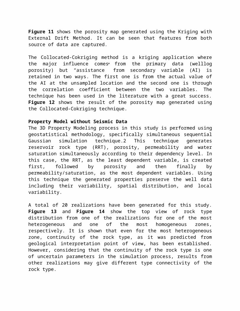
Figure 11 shows the porosity map generated using the Kriging with External Drift Method. It can be seen that features from both source of data are captured.
The Collocated-Cokriging method is a kriging application where the major influence comes from the primary data (welllog porosity) but “assistance” from secondary variable (AI) is retained in two ways. The first one is from the actual value of the AI at the unsampled location and the second one is through the correlation coefficient between the two variables. The technique has been used in the literature with a great success. Figure 12 shows the result of the porosity map generated using the Collocated-Cokriging technique.
Property Model without Seismic DataThe 3D Property Modeling process in this study is performed using geostatistical methodology, specifically simultaneous sequential Gaussian simulation technique.2 This technique generates reservoir rock type (RRT), porosity, permeability and water saturation simultaneously according to their dependency level. In this case, the RRT, as the least dependent variable, is created first, followed by porosity and then finally by permeability/saturation, as the most dependent variables. Using this technique the generated properties preserve the well data including their variability, spatial distribution, and local variability.
A total of 20 realizations have been generated for this study. Figure 13 and Figure 14 show the top view of rock type distribution from one of the realizations for one of the most heterogeneous and one of the most homogeneous zones, respectively. It is shown that even for the most heterogeneous zone, continuity of the rock type, as it was predicted from geological interpretation point of view, has been established. However, considering that the continuity of the rock type is one of uncertain parameters in the simulation process, results from other realizations may give different type connectivity of the rock type.
As previously mentioned, the reservoir property generated with this technique has been conditioned to the rock type distribution. Figure 15 shows the example of porosity and permeability which are consistent with the underlying rock type description. More detail results of this model has been previously published in other technical paper.3
Integration of Seismic into 3D Property ModelingSeismic data provides a dense lateral coverage but poor vertical coverage due to their low vertical resolution for earth models. Therefore, best earth models can be created by reconciling data at seismic and well log scales. In this study, each vertical column of cells in a simulated 3-D model is constrained to reproduce approximately a seismic-derived average value. For these purposes a sequential simulation procedure, which is based on a Bayesian updating of point kriging estimates, will be used. This technique was originally derived by Doyen et al.4

Bayes’ Rule is used to calculate the conditional probability of the additional information, i.e., seismic average porosities. It merely states that the posterior distribution in one cell is obtained by taking the product of the likelihood function, controlling the contribution of the seismic average information, and prior conditional distribution, representing the influence of previously simulated and original cell data. In this case,p(φi Si )α p(φi ). p(Si φi ) ……………………………..………………(1)where p (φi Si) is the posterior probability of porosity at location i, given that seismic attribute (average porosity) Si is observed; p (I φ ) is the prior probability for porosity based on hard data at well locations; p(Si φi ) is the probability of seismic attribute given hard data, which can be obtained from the correlation of seismic attribute with well-log data.
What is important to mention here is that, a simulated value for φ will be obtained by sampling at random from the local posterior distribution, and the simulations will be constrained to reproduce the vertical seismic average porosity within a tolerance ε ; that is,ε φ + =Σj j j S a…………………………………………………………………. (2)where the coefficients aj represent fixed averaging weights, the sum is over all cells in the column containing the cell to besimulated, and φ j represents the simulated cell values.
In above equation the error at each column is modeled as a realization of Gaussian white noise with zero mean and constant variance. Averaging weights (aj) can be selected equal for each cell in the column. On the other hand, if the seismic derived vertical averages are believed to be more sensitive to rock property values near the top of a layer, one can choose weights, which decrease with increasing depth in the layer.
The main steps of porosity simulation, including the Bayessian Update, can be summarized as follows,1. Select the grid block to be simulated at random.2. Apply point kriging using all original hard data, and previously simulated cell values3. Compute the mean and variance posterior distribution after Bayesian updating.4 (Equation 2)4. Obtain the simulated value, which is conditioned to seismic by sampling the posterior probability. As an additional constraint, the final porosity value must be within the limit of each rock type. This is to ensure that consistency between porosity and rock type is maintained.
Note that the first two steps represent the regular sequential Gaussian simulation using hard data only. The approach described has also been implemented in other nearby field study.5
Figure 16 and Figure 17 show comparison of vertical average porosity map for the whole Zone B for the case of without and with seismic data, respectively. The map of the difference between the two cases is shown Figure 18 and the histogram of this difference is shown in Figure 19. From the histogram, it can be seen that the mean of the difference is interval between –0.64 and 0.12. Thus, on the average, the maps are the same, which can be seen to occur in the area of dense well location. This is not surprising since the seismic porosity map was derived with collocated cokriging techniquethat honors the well data, so some influence of seismic data on a coarse scale is already incorporated. However, at the poor well coverage, the result shows the influence of seismic data
in the final distribution. Therefore, the integration of seismic data into the modeling process has helped the model in distributing the porosity at the poor well coverage.
ConclusionsThe conclusions of the study can be summarized as follows: 1. This paper presents the use of seismic data to improve the 3D property distribution of a rock type
based reservoir characterization study. Two applications of seismic data were presented, namely as the tool to determine the boundary of stationarity regions and to improve porosity distribution
2. Reservoir characterization of rock type has been established for the whole zones in the reservoir resulted in 10 different Reservoir Rock Types.
3. RRT vary vertically and horizontally. The vertical changes are mainly a function of depositional facies, texture, and to some extent diagenesis. The lateral changes are mainly controlled by diagenesis.
4. The determination of stationarity region boundaries was done using two seismic attributes, namely Energy Half Time and Max. Peak Amplitude.
5. Four different porosity maps using four different methods were derived to represent the average porosity of the whole Zone B. Each map represents different level of influence of seismic data.
6. Porosity map from collocated-cokriging technique has been selected to represent seismic-derived porosity. The selection is based on the level of correlation between well data and inverted AI data.
7. The integration of seismic-derived porosity into 3D Rocktype constrained property modeling was done using the Bayessian Updating principle implemented within the Sequential Gaussian Simulation system.
8. The use of seismic data has improved porosity distribution at the poor well coverage area but maintaining the distribution generated by purely well log data at the dense well coverage area.

Integrasi seismik Modeling Lebih Baik Rock Jenis Reservoir Berbasis Karakterisasi: Sebuah Contoh Kasus Lapangan
Bahar, A., SPE, Kelkar and Associates, Inc., Abdel-Aal, O., SPE, Ghani, A., Silva, F. P., SPE, ADCO, and Kelkar, M.,
SPE, The University of Tulsa
AbstrakMakalah ini menyajikan hasil studi waduk dimana data seismik telah dimanfaatkan sepenuhnya untuk mendapatkan rocktype model berbasis karakterisasi reservoir yang lebih baik. Penelitian ini dilakukan untuk reservoir karbonat. Data seismik 3D telah digunakan untuk menentukan peta struktur, kesalahan dan jaringan fraktur, dan distribusi porositas. Selain itu, dua atribut seismik (Energi Half Time dan Puncak Amplitudo Max.) Juga telah digunakan untuk membantu penentuan daerah stasioneritas digunakan untuk simulasi geostatistik.
Strategi karakterisasi reservoir untuk penelitian ini adalah dimulai dengan pengembangan rinci tentang geologi Jenis batuan reservoir (RRT) skema. Skema RRT adalah dikembangkan berdasarkan fasies pengendapan, diagenetic overprints dan sifat petrofisika, termasuk ukuran pori tenggorokan distribusi, porositas dan permeabilitas. Skema ini kemudian digunakan untuk membatasi model properti di dalam geologi Kerangka yang dibangun berdasarkan penafsiran seismik.
PengantarModel sederhana untuk mendeskripsikan reservoir dengan kompleks geologi tidak dapat cukup mewakili reservoir heterogenitas dan dampaknya terhadap pola konektivitas danmekanisme aliran. Sebuah langkah penting dalam pembangunan model simulasi reservoir adalah deskripsi mendasari geologi reservoar. Hal ini bahkan lebih wajib dalam kasus reservoir karbonat, yang sering ditandai dengan mencetak diagenetic intensif karbonat asli. Proses ini sering meliputi penilaian reservoir arsitektur internal yang kompleks tercermin dalam diskontinuitas internal dalam unit litologi, vertikal dan variasi lateral sifat batuan dan serupa heterogenitas dalam lapisan reservoar.
Biasanya, suatu jenis batuan reservoir ditentukan dan didistribusikan dalam volume 3D, tugas berikutnya adalah untuk menghasilkan sifat, yaitu porositas, permeabilitas, dan saturasi,berdasarkan data sumur (log dan inti). Tujuan dari penelitian ini adalah untuk memberikan Model properti konsisten dengan mengintegrasikan batu berbasis geologi jenis, baik log / inti dan data seismik. Untuk memenuhi tujuan ini, data seismik digunakan untuk lebih meningkatkan Model porositas, yang awalnya dibatasi untuk jenis batuan dan juga hanya data log. Data seismik juga digunakan untuk membangun struktur Model. Kami tidak menganggap pemodelan struktural dalam hal ini kertas, melainkan, kami hanya berkonsentrasi pada integrasi seismik data untuk pemodelan porositas.

Jenis Karakterisasi Batuan ReservoirJenis Reservoir Batu (RRTS) didirikan untuk lima zona reservoir. Makalah ini menyajikan jenis batuan charactersization dari zona yang paling penting saja, yaitu, Zona B. Keterangan rinci untuk semua zona lainnya tidak disajikan dalam makalah ini.
Zona B adalah atas karbonat berpori pada tubuh batuan di Barremian-Aptian, Formasi Kharaib. Empat utama fasies Unit telah didirikan, masing-masing dibagi menjadi beberapa litofasies Unit. Mereka memperpanjang interval sebagai layer cake di atas seluruh bidang daerah, dengan variabel ketebalan dan sifat reservoir. Itu Bagian atas terutama skelletal-peloidal packstone-grainstone, sementara Turunkan sedikit fossil wackstone-batulumpur fasies.
Batuan telah mengalami beberapa peristiwa diagenetic sepanjang sejarah geologi, misalnya rekristalisasi, pembubaran, pemadatan, solusi tekanan dan sementasi. Umumnya, porositas dan permeabilitas yang lebih baik telah diamati pada puncak reservoir sementara bagian bawahmenunjukkan degradasi dalam sifat reservoir. Degradasi porositas dalam batuan yang mengandung minyak secara langsung terkait dengan subsea mendalam, sementara di batuan pembawa air tren ini tidak ada.
Berdasarkan sedimentologi, petrofisika dan aliran fluida karakteristik, sepuluh Reservoir Jenis Batu (RRTS) telah didirikan. Tipe 1 sampai 7 adalah kapur didominasi butir-dan Jenis 8 sampai 10 adalah lumpur didominasi kapur (Gambar 1). Setiap jenis batuan ditandai dengan satu set khas sifat reservoir (Gambar 2).
RRTS bervariasi secara vertikal dan horizontal dalam zona; umumnya jenis batuan berkualitas baik yang ada di bagian atas dan diturunkan menjadi kualitas yang lebih rendah di bawah. Secara umum, semua RRTS di daerah crestal berubah lateral(Arah panggul dan sadel), dan secara bertahap dalam waktu tertentu Litofasies Satuan menjadi rendah jenis batuan berkualitas.
Seismik dan Penentuan Stasioneritas Daerah Tujuan utama dalam melakukan pemodelan properti adalah untuk mensimulasikan sifat reservoir di dalam lokasi sumur. Untuk mencapai hasil ini, pertama kita perlu berasumsi bahwa data dikumpulkan dari sumur mewakili daerah sumur. Ini adalah asumsi kunci dalam setiap model statistik. Asumsi ini disebut asumsi stasioneritas. Ini Asumsi mensyaratkan bahwa data dengan baik adalah wakil dari Seluruh waduk. Kecuali kita dapat membuat asumsi ini, kita akan tidak dapat memprediksi sifat reservoir yang berlokasi di mana kita tidak memiliki data apapun.
Dalam studi ini, kami telah menggunakan analisis statistik awal untuk menentukan definisi wilayah stationarities. Artinya, tujuan analisis stasioneritas adalah untuk menentukan daerah di mana kita bisa membuat asumsi bahwa data yang dikumpulkan dari sumur mewakili wilayah antar sumur. Meskipun banyak parameter statistik dapat digunakan untuk melakukan statistik analisis, kami telah membatasi analisis kami untuk Mean dan Variance. Mean merupakan kecenderungan sentral nilai, padahal Variance mewakili penyebaran data. Untuk analisis geostatistik, hanya dengan stasioneritas menghormati Berarti dan Variance harus dipenuhi.

Berdasarkan hasil analisis stasioneritas, ditemukan bahwa ada 5 wilayah stasioneritas yang perlu digunakan untuk tujuan pemodelan properti (Gambar 4). Batas masing-masing wilayah stasioneritas ditentukan berdasarkan kualitatif maupun analisis kuantitatif. Selama analisis kualitatif, batas awal digambar, sedangkan batas akhir adalah digambar dengan menggunakan pendekatan kuantitatif.
Batas awal antara daerah stasioneritas adalah digambar dengan bantuan dua atribut seismik. Dua seismik atribut, yaitu Energi Half Time dan Max. Puncak Amplitudo yang digunakan dalam analisis kualitatif. Gambar 5 menunjukkan plot dari dua atribut seismik. Berdasarkan ini angka, sebuah batas awal digambar untuk membedakan 5 daerah.
Seismik-Berasal PorositasSalah satu tujuan dari penelitian ini adalah untuk memperoleh seismik yang diturunkan porositas peta berdasarkan Akustik Impedansi (AI) data. Peta ini akan digunakan sebagai salah satu kendala selama Pemodelan properti 3D. Data AI yang tersedia untuk dua dari lima unit waduk utama. Namun, kualitas data hanya baik untuk salah satu dari dua unit. Oleh karena itu, gempa yang diturunkan porositas hanya dapat dibuat hanya untuk salah satu dari satu unit, yaitu, Zona B.
Gambar 6 menunjukkan peta AI terbalik tersedia untuk Zona B.Peta ini merupakan volume batu dalam seluruh Zona B dengan ketebalan rata-rata 158 meter dari atas ke bawah. Peta tersebut dengan jelas menunjukkan adanya AI rendah (atau porositas tinggi) dari nilai sekitar area crestal dan degradasi waduk kualitas terhadap panggul (Timur, Barat dan Utara). Namun, dibandingkan dengan daerah lain sisi, bagian selatan menunjukkan daerah yang lebih baik. Mengingat bahwa daerah ini (yaitu, Bagian Selatan) belum sepenuhnya dikembangkan, (jumlah sumur dibor masih terbatas), kehadiran data seismik dapat diharapkan untuk meningkatkan kualitas deskripsi waduk dibandingkan dengan menggunakan kontrol baik saja.
Porositas rata-rata di lokasi sumur berdasarkan sumur-log data untuk Zona B ditunjukkan pada Gambar 7. Peta ini adalah diperoleh setelah menghitung rata-rata aritmatika dari baik-log porositas dari atas ke bawah zona ini. Membandingkan Gambar 6 dan Gambar 7, dapat dilihat bahwa perjanjian yang ada antara data sumur dan AI. Sebagai contoh, lebih tinggi baik-log. Data porositas diamati di daerah yang crestal sesuai dengan nilai yang lebih rendah AI, dan sebaliknya, well log rendah di porositas Utara, Timur dan daerah panggul Barat. Untuk Daerah selatan, karena kekurangan distribusi dengan baik, Kehadiran kualitas reservoir yang baik belum sejelas ditunjukkan oleh data seismik.
Koefisien korelasi untuk hubungan antara well log porositas dan terbalik AI di lokasi juga sama dengan - 0,81 (R2 = 0,65) (lihat Gambar 8). Korelasi negatif menunjukkan bahwa porositas berkorelasi terbalik dengan data AI, yaitu, porositas tinggi sesuai dengan AI yang lebih rendah dan wakil versa, seperti yang dibahas pada paragraf sebelumnya. Perhatikan korelasi relatif tinggi antara kedua variabel.

Gambar 9 menunjukkan porositas peta Zona B dihasilkan dengan menggunakan metode cross-petak. Hal ini dapat dilihat Peta itu adalah bayangan cermin dari peta AI (Gambar 6) hanya diplot dengan skala yang berbeda.
Gambar 10 menunjukkan peta porositas yang dihasilkan berdasarkan murni baik data log melalui kriging. Angka ini menunjukkan perubahan kelancaran porositas distribusi, yang merupakan karakteristik dari metode kriging. Membandingkan Gambar 9 dan Gambar 10, dapat dilihat bahwa informasi yang hilang di lokasi Interwell memiliki signifikan mengubah distribusi keseluruhan porositas. Namun demikian, beberapa fitur global peta, misalnya, porositas tinggi di puncak dan rendah di Utara, yang dipertahankan pada dua peta.
Salah satu pengamatan yang paling penting yang terungkap dari data seismik adalah adanya wilayah berpori tinggi pada bagian selatan (barat-sayap) lapangan (lihat Gambar 9), yang tidak terdeteksi dari data log sumur saat ini (lihat Gambar 10). Hasil ini kemudian terbukti benar dari sumur bor baru. Gambar 11 menunjukkan porositas peta dihasilkan dengan menggunakan Kriging dengan Drift Eksternal Metode. Hal ini dapat dilihat bahwa fitur dari kedua sumber data ditangkap.
Metode Collocated-cokriging adalah aplikasi kriging dimana pengaruh besar berasal dari data primer (welllog porositas) tapi "bantuan" dari variabel sekunder (AI) adalah dipertahankan dalam dua cara. Yang pertama adalah dari nilai aktual AI di lokasi unsampled dan yang kedua adalah melalui koefisien korelasi antara dua variabel. Teknik tersebut telah digunakan dalam literatur dengan keberhasilan besar. Gambar 12 menunjukkan hasil peta porositas yang dihasilkan dengan menggunakan Teknik collocated-cokriging.
Properti Model tanpa data seismikProses Modeling Properti 3D dalam penelitian ini adalah dilakukan dengan menggunakan metodologi geostatistik, khususnya simultan Gaussian simulasi sekuensial technique. KeduaTeknik ini menghasilkan waduk jenis batuan (RRT), porositas, permeabilitas dan saturasi air secara bersamaan sesuai dengan tingkat ketergantungan mereka. Dalam hal ini, RRT, sebagai yang paling variabel dependen, dibuat pertama, diikuti oleh porositas dan kemudian akhirnya oleh permeabilitas / saturasi, sebagai yang paling bergantung variabel. Dengan menggunakan teknik ini sifat yang dihasilkan melestarikan data sumur termasuk variabilitas mereka, spasial distribusi, dan variabilitas lokal.
Sebanyak 20 realisasi telah dihasilkan untuk ini studi. Gambar 13 dan Gambar 14 menunjukkan pandangan atas batu Distribusi jenis dari salah satu wujud untuk salah satu paling heterogen dan salah satu zona yang paling homogen, masing-masing. Hal ini menunjukkan bahwa bahkan untuk yang paling heterogen zona, kelangsungan jenis batuan, seperti yang diperkirakan dari geologi titik interpretasi pandang, telah didirikan. Namun, mengingat bahwa kelangsungan jenis batuan salah satu parameter yang tidak pasti dalam proses simulasi, hasil dari realisasi lain mungkin memberikan konektivitas berbagai jenis jenis batuan. Seperti disebutkan sebelumnya, properti waduk yang dihasilkan dengan teknik ini telah dikondisikan dengan jenis batuan distribusi. Gambar 15 menunjukkan contoh porositas dan permeabilitas yang konsisten dengan batu yang mendasari ketik keterangan. Hasil lebih detail model ini telah sebelumnya diterbitkan dalam paper.3 teknis lainnya

Integrasi seismik ke 3D Modeling Properti Data seismik menyediakan cakupan lateral yang padat tapi sedikit cakupan vertikal karena resolusi vertikal rendah bagi model bumi. Oleh karena itu, model bumi terbaik dapat dibuat dengan rekonsiliasi data pada skala log seismik dan baik. Dalam studi ini, setiap kolom vertikal sel dalam model 3-D simulasi adalah dibatasi untuk mereproduksi kira-kira seismik yang diturunkan nilai rata-rata. Untuk tujuan ini simulasi sekuensial prosedur, yang didasarkan pada update Bayesian titik estimasi kriging, akan digunakan. Teknik ini awalnya diperoleh Doyen et al.
Aturan Bayes 'digunakan untuk menghitung probabilitas bersyarat dari informasi tambahan, yaitu, porositas rata seismik. Ini hanya menyatakan bahwa distribusi posterior dalam satu seldiperoleh dengan mengambil produk dari fungsi kemungkinan, mengendalikan kontribusi rata-rata seismik informasi, distribusi dan sebelum bersyarat, mewakili pengaruh sel data sebelumnya simulasi dan asli. Di kasus ini,
p(φi Si )α p(φi ). p(Si φi )………………………………………….(1)
di mana p (φi Si) adalah probabilitas posterior porositas pada lokasi saya, mengingat bahwa atribut seismik (porositas rata-rata) Si diamati; p(φ i)adalah probabilitas sebelumnya untuk porositas berdasarkan data di lokasi yang baik; p (Si φi) adalah probabilitas atribut seismik yang diberikan data keras, yang dapat diperoleh dari korelasi atribut seismik dengan data sumur-log.Yang penting untuk disebutkan di sini adalah bahwa, sebuah simulasi nilai φ akan diperoleh sampel secara acak dari distribusi posterior lokal, dan simulasi akan dibatasi untuk mereproduksi vertikal seismik porositas rata dalam ε toleransi, yaitu,
ε φ + =Σj j j S a………………………………………………………..….. (2)
dimana koefisien aj mewakili bobot rata-rata tetap, rangkuman atas semua sel dalam kolom yang berisi sel yang akan simulasi, dan φ j merupakan nilai sel simulasi.
Dalam persamaan di atas kesalahan di setiap kolom dimodelkan sebagai realisasi Gaussian white noise dengan mean nol dan varians konstan. Averaging bobot (aj) dapat dipilih sama bagi setiap sel dalam kolom. Di sisi lain, jika seismik vertikal rata-rata berasal diyakini lebih sensitif untuk rock nilai properti di dekat bagian atas lapisan, satu dapat memilih bobot, yang menurun dengan meningkatnya kedalaman dalam layer.
Langkah-langkah utama simulasi porositas, termasuk Bayesian Update, dapat diringkas sebagai berikut,
1. Pilih blok grid untuk disimulasikan secara acak.
2. Terapkan titik kriging menggunakan semua data keras asli, dan nilai sel sebelumnya disimulasikan
3. Hitunglah mean dan varians dari posterior distribusi setelah Bayesian updating.4 (Persamaan 2)

4. Memperoleh nilai simulasi, yang dikondisikan untuk seismik dengan sampling probabilitas posterior. Sebagai kendala tambahan, nilai porositas akhir harus dalam batas setiap jenis batuan. Hal ini untuk memastikan bahwa konsistensi antara porositas dan jenis batuan adalah dipertahankan.
Perhatikan bahwa dua langkah pertama mewakili reguler simulasi Gaussian berurutan menggunakan data keras saja. Itu Pendekatan dijelaskan juga telah diterapkan di lain di dekatnya lapangan study. Gambar 16 dan Gambar 17 menunjukkan perbandingan vertikal Rata-rata porositas peta untuk seluruh Zona B untuk kasus tanpa dan dengan data seismik, masing-masing. Peta dari perbedaan antara dua kasus ditunjukkan Gambar 18 dan histogram perbedaan ini ditunjukkan pada Gambar 19. Dari histogram, dapat dilihat bahwa rata-rata dari perbedaan ini adalah interval antara -0.64 dan 0,12. Dengan demikian, rata-rata, yang peta yang sama, yang dapat dilihat terjadi di daerah lokasi sumur padat. Hal ini tidak mengherankan karena seismik porositas peta berasal dengan teknik collocated cokriging yang menghormati data dengan baik, sehingga beberapa pengaruh data seismik pada skala kasar sudah dimasukkan. Namun, pada orang miskin baik cakupan, hasilnya menunjukkan pengaruh data seismik dalam distribusi akhir. Oleh karena itu, integrasi seismik data ke dalam proses pemodelan telah membantu model dalam mendistribusikan porositas pada cakupan baik miskin.
KesimpulanKesimpulan dari penelitian ini dapat disimpulkan sebagai berikut:1. Makalah ini menyajikan penggunaan data seismik untuk meningkatkan Pembagian harta 3D
dari batu jenis reservoir berbasis karakterisasi studi. Dua aplikasi data seismikdipresentasikan, yaitu sebagai alat untuk menentukan batas daerah stasioneritas dan untuk meningkatkan porositas distribusi
2. Karakterisasi reservoir dari jenis batuan telah didirikan untuk seluruh zona di reservoir mengakibatkan 10 Jenis berbeda Reservoir Rock.
3. RRT bervariasi secara vertikal dan horizontal. Vertikal Perubahan tersebut terutama fungsi dari fasies pengendapan, tekstur, dan sampai batas tertentu diagenesis. Lateralperubahan terutama dikendalikan oleh diagenesis.
4. Penentuan batas-batas wilayah adalah stasioneritas dilakukan dengan menggunakan dua atribut seismik, yaitu Energi Half Waktu dan Max. Amplitudo puncak.
5. Empat peta porositas yang berbeda dengan menggunakan empat metode yang berbedaberasal mewakili porositas rata-rata Seluruh Zona B. Setiap peta mewakili tingkat yang berbeda dari pengaruh data seismik.
6. Porositas peta dari teknik collocated cokriging-memiliki dipilih untuk mewakili seismik yang diturunkan porositas. Itu seleksi didasarkan pada tingkat korelasi antara baikdata dan AI terbalik.
7. Integrasi seismik yang diturunkan porositas menjadi 3D Rocktype pemodelan properti dibatasi dilakukan dengan menggunakan Prinsip Memperbarui Bayesian diterapkan dalam Sequential sistem Simulasi Gaussian.
8. Penggunaan data seismik telah meningkat porositas distribusi di sumur cakupan area miskin tapi mempertahankan distribusi yang dihasilkan oleh murni baik logData di sumur cakupan area padat.

Figure 1 Reservoir Rock Type (RRT)
Figure 2 Permeability vs. Porosity for different RRT
Figure 3 RRT Distribution in Axial Section of the Field

Figure 4 Definition of Stationarity Regions
Figure 2(b)
Figure 5 Two Seismic Attributes Used for Drawing the Initial Boundary of the Stationarity Regions.
Figure 2(a)
Figure 6 Accoustic Impedance (AI) Map
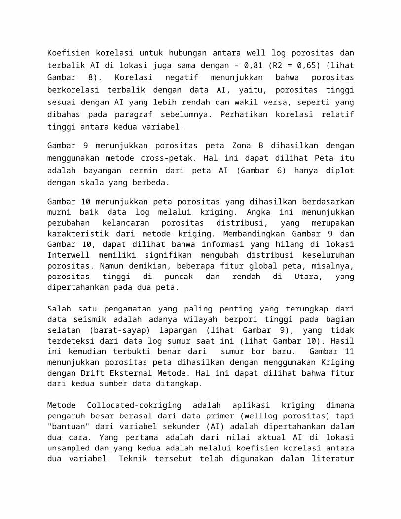
Figure 7 Average Well-Log Porosity at Well Location
Figure 9 Seismic-Derived Porosity Map – Cross PlotMeth
Figure 8 Correlation between Well Log Porosity andInverted Accoustic Impedance (AI) at Well Location.
Figure 10 Well-Log Based Porosity Map – Ordinary Kriging Method

Figure 11 Seismic and Well-Log Based Porosity Map – Kriging with External Drift Method
Figure 13 RRT Distribution (Heterogeneous Lay
Figure 12 Seismic and Well-Log Based Porosity Map – Collocated-Cokriging Method
Figure 14 RRT Distribution (Homogeneous Layer)

Figure 15 Consistency of RRT, Porosity and Permeability
Figure 16 Average Porosity Distribution for Zone B as the Result of 3D Property Modeling WITHOUT the use of Seismic Data
Figure 18 Distribution of the Difference between Porosity WITH and WITHOUT Seismic Data.
Figure 19 Histogram of the Difference of Porosity WITH and WITHOUT Seismic Data
Related Documents