A 7th Canadian Conference on Earthquake Engineering / Montreal / 1995 7ibme Conference canadienne sur le genie paraseismique / Montreal /1995 Seismic Behaviour of Ductile Concentric Steel X-Bracings R. Tremblay', M.-H. Archambaule and A. Filiatrault3 ABSTRACT The paper reports on a on-going experimental research project on the seismic performance of concentrically braced steel frames. Quasi-static cyclic testing has been performed on full scale specimens of single- and X-bracings made up of rectangular HSS bracing members. The results indicate that X-bracings can be very effective in dissipating seismic input energy because of the reduced slenderness of the bracing members. However, the research also revealed that tubular bracing members with small slenderness exhibit a lower fracture life. BACKGROUND AND OBJECTIVES Concentrically bracing is very popular for low-rise steel buildings because it is effective and simple to design, fabricate and erect. For this type of buildings, seismic loads often exceed wind loading in many regions of Canada. In this case, it appears desirable at first to use a bracing system that classifies under the Ductile Braced Frame (DBF) category (NRCC 1990) and therefore take advantage of the reduced design earthquake loads. Unfortunately, the cost of providing the required detailing for ductile behavior in DBFs, as prescribed in the 516.1 Canadian steel standard (CSA 1989), reduces and, most often, annihilates the expected savings. In DBFs, the applied storey shear in any planar frame must be shared between tension- and compression-acting braces. Stringent limitations are also prescribed to ensure that bracing members will exhibit a minimum energy dissipation capacity during a strong seismic event: maximum gross slenderness of the braces (L/r) and maximum width-to-thickness ratio (b/t) of the flat elements of the brace cross-sections. Because of their high efficiency in resisting compressive loads, hollow structural sections (HSS) are good candidates for bracing members acting both in tension and compression. For low-rise structures, however, the aforementioned limitations on L/r and b/t generally govern the design of the braces rather than strength-related requirements. Thus, oversized members have to be specified, which offsets the benefits of using a DBF system and lower seismic design loads. If, on the other hand, the effective brace slenderness (KL/r) could be used instead of the gross slenderness (L/r) when complying with ductility requirements, a X-bracing configuration including rectangular HSS bracing members would represent an attractive solution. In such a configuration, the slenderness of the compression brace is significantly lowered because the tension-acting brace can provide in-plane and out-of-plane supports for the compression brace 1 Assistant-Professor, Dept. of Civil Eng., Ecole Polytechnique, Montreal, Que. H3C 3A7 2 Research Assistant, Dept. of Civil Eng., Ecole Polytechnique, Montreal, Que. H3C 3A7 3 Associate Professor, Dept. of Civil Eng., Ecole Polytechnique, Montreal, Que. H3C 3A7 549

Welcome message from author
This document is posted to help you gain knowledge. Please leave a comment to let me know what you think about it! Share it to your friends and learn new things together.
Transcript

A
7th Canadian Conference on Earthquake Engineering / Montreal / 1995 7ibme Conference canadienne sur le genie paraseismique / Montreal /1995
Seismic Behaviour of Ductile Concentric Steel X-Bracings R. Tremblay', M.-H. Archambaule and A. Filiatrault3
ABSTRACT
The paper reports on a on-going experimental research project on the seismic performance of concentrically braced steel frames. Quasi-static cyclic testing has been performed on full scale specimens of single- and X-bracings made up of rectangular HSS bracing members. The results indicate that X-bracings can be very effective in dissipating seismic input energy because of the reduced slenderness of the bracing members. However, the research also revealed that tubular bracing members with small slenderness exhibit a lower fracture life.
BACKGROUND AND OBJECTIVES
Concentrically bracing is very popular for low-rise steel buildings because it is effective and simple to design, fabricate and erect. For this type of buildings, seismic loads often exceed wind loading in many regions of Canada. In this case, it appears desirable at first to use a bracing system that classifies under the Ductile Braced Frame (DBF) category (NRCC 1990) and therefore take advantage of the reduced design earthquake loads. Unfortunately, the cost of providing the required detailing for ductile behavior in DBFs, as prescribed in the 516.1 Canadian steel standard (CSA 1989), reduces and, most often, annihilates the expected savings.
In DBFs, the applied storey shear in any planar frame must be shared between tension-and compression-acting braces. Stringent limitations are also prescribed to ensure that bracing members will exhibit a minimum energy dissipation capacity during a strong seismic event: maximum gross slenderness of the braces (L/r) and maximum width-to-thickness ratio (b/t) of the flat elements of the brace cross-sections. Because of their high efficiency in resisting compressive loads, hollow structural sections (HSS) are good candidates for bracing members acting both in tension and compression. For low-rise structures, however, the aforementioned limitations on L/r and b/t generally govern the design of the braces rather than strength-related requirements. Thus, oversized members have to be specified, which offsets the benefits of using a DBF system and lower seismic design loads.
If, on the other hand, the effective brace slenderness (KL/r) could be used instead of the gross slenderness (L/r) when complying with ductility requirements, a X-bracing configuration including rectangular HSS bracing members would represent an attractive solution. In such a configuration, the slenderness of the compression brace is significantly lowered because the tension-acting brace can provide in-plane and out-of-plane supports for the compression brace
1 Assistant-Professor, Dept. of Civil Eng., Ecole Polytechnique, Montreal, Que. H3C 3A7
2 Research Assistant, Dept. of Civil Eng., Ecole Polytechnique, Montreal, Que. H3C 3A7
3 Associate Professor, Dept. of Civil Eng., Ecole Polytechnique, Montreal, Que. H3C 3A7
549

near its mid-length (Moffet 1986). Consequently, smaller bracing members selected for developing the required strength would most likely conform to the slenderness limitation for DBFs. For such small HSS sections, the maximum b/r ratio requirement for DBFs would also be easily satisfied and would generally not influence the choice of the brace sections.
Upon strong ground shaking, a ductile braced frame is expected to undergo reversals of inelastic lateral loads. Several experimental studies had been performed on isolated brace specimens subjected to successive inelastic buckling and tension yielding with different end conditions (e.g. Popov and Black 1981; Jain et al. 1980). These studies have shown that the effective length concept developed for the elastic theory can be transposed in the inelastic range and that the effective slenderness ratio can be employed in assessing the ability of a bracing member to dissipate energy during an earthquake. The validity of this conclusion for X-bracing configurations had, however, to be verified.
Previous research (Liu and Goel 1988; Tang and Goel 1989) had also shown that upon repeated inelastic buckling and tension yielding, rectangular HSS bracing members eventually fracture at the location of the plastic hinge forming near their mid-length. The unsupported length of braces in X-bracings being shorter, it was expected that compressive braces experience larger curvature subsequent to buckling for a given storey drift. Consequently, higher inelastic strains would develop in the plastic hinges, which could result in earlier brace fracture. Since bracing members must survive over the full duration of the expected design base earthquake, premature fracture of HSS braces in X-bracings would be unacceptable and could prohibit the use of this bracing configuration.
The main objectives of this experimental study were: i) to determine if the effective slenderness of bracing members could be used in describing the hysteretic behavior of X-bracings subjected to cyclic inelastic loading, and to investigate the adequacy of the fracture life of HSS bracing members in the X-bracing configuration.
TEST PROGRAM
To reach the objectives of this study, the behavior of similar bracing members in two different configurations was compared: X-bracing and single diagonal bracing (Fig. 1). For both configurations, the width and height of the bay were the same: 4877 mm and 3658 mm, respectively. The bracing members were selected so that buckling of the braces was constrained to the out-of-plane direction.
Experimental setup
A full scale testing rig was used for the experiments (Fig. 2). It was truly hinged at all four corners by means of high strength pins inserted in carefully machined bushings. Thus, the applied storey shear was entirely resisted by the bracing members. The rig was mounted horizontally on the strong floor of the Structures Laboratory at Ecole Polytechnique and the bottom end of each column was anchored to the floor. At the upper end, the beam was supported on sliding devices and could then be freely displaced in the lateral direction.
Fig. 2 shows a typical X-bracing specimen installed in the testing rig. The same testing setup was used for the single diagonal bracing layout. However, two successive tests were performed with only one brace being mounted in the frame for each test. For each pair of braces, the same displacement sequence (see below) was repeated in both tests and the total storey shear at any displacement level could be obtained by summing up the load applied in each test.
550
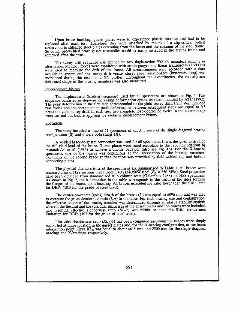
Upon brace buckling, gusset plates were to experience plastic rotation and had to be replaced after each test. Therefore, they were attached by means of a slip-critical bolted connection to stiffened steel plates extending from the beam and the columns of the steel frame. So doing, pre-welded brace-gusset assemblies could be easily installed in the testing frame and removed after the tests.
The storey drift sequence was applied by two single-action 900 IN actuators running in alternation. Member forces were monitored with strain gauges and linear transducers (LVDTs) were used to measure the drift of the frame. All measurements were recorded with a data acquisition system and the storey drift versus storey shear relationship (hysteresis loop) was monitored during the tests on a XY plotter. Throughout the experiments, the out-of-plane deformed shape of the bracing members was also measured.
Displacement history
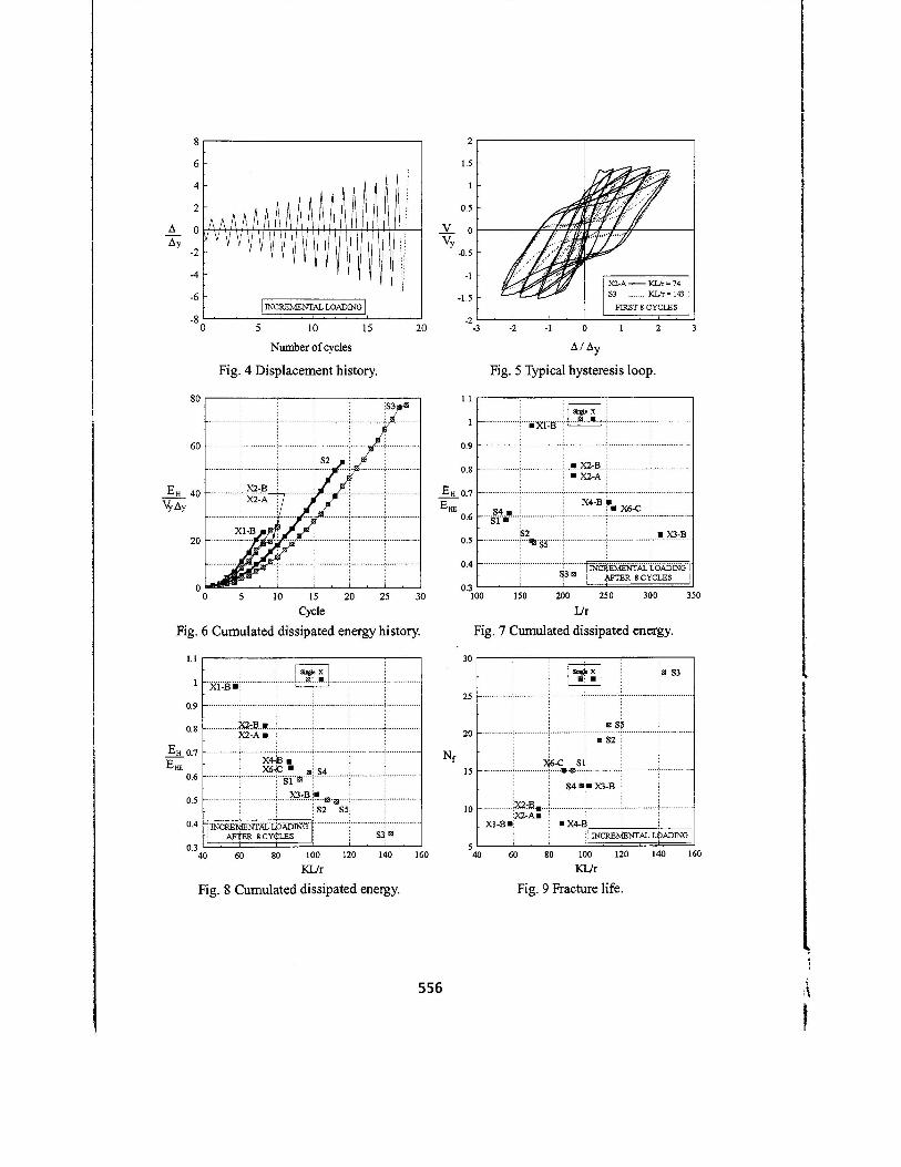
The displacement (loading) sequence used for all specimens are shown in Fig. 4. This sequence consisted in stepwise increasing deformation cycles, as recommended by ATC (1992). The peak deformation in the first step corresponded to the yield storey drift. Each step included two cycles and the increment in peak deformation between subsequent steps was equal to 0.5 times the yield storey drift. In each test, two complete load-controlled cycles in the elastic range were carried out before applying the inelastic displacement history.
Specimens
The study included a total of 11 specimens of which 5 were of the single diagonal bracing configuration (S) and 6 were X-bracings (X).
A welded brace-to-gusset connection was used for all specimens. It was designed to develop the full yield load of the brace. Gusset plates were sized according to the recommendations by Astaneh-Asl et aL (1985) to achieve a ductile behavior (also see Fig. 4b). For the X-bracing specimens, one of the braces was continuous at the intersection of the bracing members. Continuity of the second brace at that location was provided by field-welded top and bottom connecting plates.
The physical characteristics of the specimens are summarized in Table 1. All braces were standard class C HSS sections made from G40.21M-350W steel (F = 350 MPa). Steel properties have been obtained from standardized stub column tests (Galambos 1988) on HSS specimens. As shown in Fig. 2, the b dimension in the table corresponds to the width of the sides forming the flanges of the braces upon buckling. All braces exhibited b/t ratio lower than the S16.1 limit for DBFs (18.0 for the grade of steel used).
The center-on-center (gross) length of the braces (L) was equal to 6096 mm and was used to compute the gross slenderness ratio (L/r) in the table. For each bracing size and configuration, the effective length of the bracing member was determined through an elastic stability analysis wherein the flexural and the torsional stiffnesses of the gusset plates and the braces were included. The resulting effective slenderness ratio (KL/r) was within or near the 516.1 slenderness limitation for DBFs (102 for the grade of steel used).
The third slenderness ratio (KLy/r) has been computed assuming the braces were simply supported at hinge location in the gusset plates and, for the X-bracing configuration, at the brace intersection point. Thus, KLh was equal to about 4615 mm and 2500 mm for the single diagonal bracings and X-bracings, respectively.
551

Performance criteria
The performance criteria retained in this study in assessing the performance of the specimens are the cumulated dissipated energy and the number of inelastic cycles to failure (fracture life). The cumulated dissipated energy (EH) corresponds to the area enclosed by the measured storey shear-storey drift diagram of the specimens. The fracture life corresponds to the number of loading cycles sustained by a specimen prior fracture of the bracing member (Nf). For a given displacement sequence, the deformation capacity (maximum ductility) of a specimen can be associated to that parameter.
RESULTS
Overall behavior
All specimens behaved in a very similar manner. Upon loading, the braces underwent successive inelastic buckling (Fig. 3a) and tension yielding. Buckling of the braces took place in the out-of-plane direction and a plastic hinge formed in each gusset plate (Fig. 3b) and within the brace length. The bracing members exhibited significant residual elongation which could be readily observed by the deformed shape near the zero storey drift position.
For the X-bracing configuration, such residual elongation resulted in a temporary loss of support for the compression brace at the brace intersection point (Fig. 3c). That support was however restored as the tension brace straightened out under increasing storey drift (Fig. 3d).
For all specimens, severe local buckling of the bracing members eventually developed in the post-buckling range at the location of the plastic hinge. Upon reloading in tension, cracks initiated and propagated in the localized buckling region, which led to fracture of the bracing members.
Energy dissipation
In Fig. 5, the normalized load deformation diagram of two identical bracing members used in a different configuration is shown. It can be observed that the more slender brace (S3, single diagonal arrangement) exhibits more severe pinching and thereby dissipated less energy than same brace in the X-bracing configuration (X2-A).
Fig. 6 presents the history of the normalized cumulated energy for two bracing members sizes in both bracing configurations. The same brace was used for specimens Xl-B and S2. Similarly, specimens X2-A, X2-B and S3 included the same bracing member. Specimens X2-A and X-2B were identical but the loading pattern applied to X2-B was opposite in sign to the one used for X2-A. For both brace sizes, the amount of energy dissipated over the entire loading history in the X-bracing arrangement exceeded that in the single diagonal configuration with identical braces. The figure also shows that failure of the X-bracings occurred earlier. This result will be discussed further below.
In Figures 7 and 8, the normalized cumulated energy after 8 cycles (peak deformation reached is equal to 2.5 the yield storey drift) is given as a function of the gross and effective brace slendemesses, respectively. In these figures, the energy is normalized to the energy dissipated by an equivalent elasto-plastic system subjected to the same displacement history (EHE)-
552

In the first diagram, there is a strong discontinuity between the results obtained for the two bracing configurations. When using KL/r as the independant variable, a smooth transition between the two sets of results is achieved, which indicates that the effective slenderness ratio is a representative parameter in determining the energy dissipation capacity of bracing member, regardless of the bracing configuration.
As opposed to KL/r, no structural analysis is required to obtain the value of KLh/r. Thus, the latter would represent be a more convenient parameter than KL/r for design purposes. As shown in Table 1, there is little difference between these two parameters and it is believed that the KLh/r could also be used in practice in assessing the energy dissipation capacity of bracing members.
Fracture life of bracing members
The fracture life of all specimens is given in Fig. 9 as a function of KL/r. Once again, the number of cycles, and thereby, the deformation capacity of the bracing members, appears to be strongly related to the effective slenderness ratio of the braces. Of course, the fracture life certainly is influenced by other parameters such as the b/t and h/t ratios of the brace sections. Nevertheless, the results indicate that the number of cycles increases with the effective slenderness and that bracing members exhibiting slenderness ratio less than about 90 could not survive displacement ductility of 3 and more.
CONCLUSIONS AND RECOMMENDATIONS
The conclusions of this study can be summarized as follows:
1. The results clearly demonstrate that the effective slenderness is a representative parameter to assess the energy dissipation capability of bracing members. The fracture life of braces also appears to be strongly related to that parameter. When increasing the effective slenderness ratio of a brace, the amount of energy that can be dissipated decreases whereas its inelastic deformation capacity increases.
2. Rectangular HSS bracing members with small slenderness ratios may not have the ability to undergo the amount of inelastic deformation expected for the Ductile Braced Frame category.
It is therefore recommended that the brace slenderness limitation in the S16.1 Steel Standard be explicitly based on the effective slenderness ratio of the bracing members rather than L/r. A minimum value of KL/r should also be prescribed for HSS bracing members unless alternative measures are taken to improve the fracture life of such brace sections. Additional research is however needed to establish such a limit. Future research should also be devoted to the development of workable constructional schemes for preventing premature local buckling of rectangular tubular members.
ACKNOWLEDGEMENTS
This project was supported by the Natural Sciences and Engineering Research Council of Canada and the Government of Quebec (Fonds FCAR). The authors gratefully acknowledge the contribution of Royalcor Steel and Welded Tube of Canada for providing the HSS material and Canam Steel and Dominion Bridge (Quebec) for the fabrication of the specimens. The authors also wish to express their appreciation to the technical staff of the Structures Laboratory at Ecole Polytechnique for its invaluable assistance.
553

REFERENCES
Astaneh-Asl, A., Goel, S.C. and Hanson, R.D. 1985. Cyclic Out-of-Plane Buckling of Double-Angle Bracing. ASCE, Journal of Structural Engineering, 111: 1135-1153. ATC. 1992. ATC-24, Guidelines for Cyclic Seismic Testing of Components of Steel Structures. Applied Technology Council (ATC), Redwood City, Ca. CSA. 1989. CAN/CSA-S16.1-M89, Limit States Design of Steel Structures. Canadian Standard Association (CSA), Rexdale, Ontario. ECCS. 1986. Recommended Testing Procedure for Assessing the Behaviour of Structural Steel Elements under Cyclic Loads. European Convention for Constructional Steel (ECCS), Technical Committee 1 - Structural Safety and Loadings and Technical Working Group 1.3 - Seismic Design. Galambos, T.V. (editor). 1988. Guide to Stability Design Criteria for Metal Structures, 4th ed. John Wiley & Sons, New York, NY. Jain, A.K., Goel, S.C. and Hanson, R.D. 1980. Hysteretic Cycles of Axially Loaded Steel Members. ASCE, Journal of the Structural Division, 106: 1777-1795. Liu, Z. and Goel, S.C. 1988. Cyclic Load Behavior of Concrete-Filled Tubular Braces. ASCE, Journal of Structural Engineering, 114: 1488-1506. Moffet, P. 1986. Resistance au flambement de pieces comprimees supportees en divers points par des pieces tendues. These de maltrise, Faculte des Sciences et de Genie, Ecole des Gradues, Universite Laval, Quebec, Qc. NRCC 1990, National Building Code of Canada 1990 (NBCC), Associate Committee on the National Building Code, National Research Council of Canada (NRCC), 10th ed., Ottawa, Ont. Popov, E.P. and Black, R.G. 1981. Steel Struts Under Severe Cyclic Loadings. ASCE, Journal of the Structural Engineering Division, 107: 1857-1881. Tang, X. and Goel, S.C. 1989. Brace Fractures and Analysis of Phase I Structure. ASCE, Journal of Structural Engineering, 115: 1960-1976.
Table 1 Description of the specimens.
Specimen b x h x t (mm)
A (mm2)
E y (1) (103)
F y (2) (MPa)
b/t (3) L/r KL/r KLh/r
S1 76 x 127 x 4.8 1790 1760 395 12.8 133 92.7 101 S2 76 x 102 x 4.8 1550 1870 381 12.8 163 108 123 S3 76x 76 x 4.8 1310 1890 389 12.8 212 143 160 S4 64 x 127 x 4.8 1670 1780 386 10.3 137 97.7 103 S5 76 x 102 x 6.4 1990 2120 422 8.9 166 113 126
X 1-B 76 x 102 x 4.8 1550 1800 386 12.8 163 58.6 60.2 X2-A 76 x 76 x 4.8 1310 1890 389 12.8 212 74.0 76.8 X2-B 76 x 76 x 4.8 1310 1890 389 12.8 212 74.1 76.8 X3-B 76 x 51 x 4.8 1060 2070 414 12.8 311 102 110 X4-B 64x 64 x3.2 872 1910 393 13.8 253 87.4 91.3 X6-C 64 x 64 x 4.8 1060 2080 397 10.3 258 88.2 93.5
1 Tangent yield strain (ECCS 1986). 2 0.2% offset yield strength. 3 Equal to (b-3t)/t.
554

Fig. 1 Bracing configurations. Fig. 2 Testing set-up (X-Bracing).
PINNED JOINT SINGLE ACTION (TYP) 900 kN RAM GYP)
X-BRACING
DIAGONAL SINGLE BRACING
PINNED JOINT (TYP)
Fig. 3 Behavior of the specimens.
555
2 3
- ri 0 0CA0 'for, :
itell4;01- '' /
• •
•
_
#, Ailigfididi
X2-A --- KL/r = 74 53 Mir = 143
FIRST 8 CYCLES
-3 -2 0 1
A/AY
Fig. 5 Typical hysteresis loop.
2
1.5
1
0.5
V 0 Vy
-0.5
-1
-1.5
-2
y
INCREMENTAL LOADING
5 10 15
Number of cycles
Fig. 4 Displacement history.
-8 0 20
6
4
2
0
-2
-4
100 150 200 250
Ur
300 350 25 30
80
60
40
20
0 0 5 10 15 20 Cycle
Fig. 6 Cumulated dissipated energy history.
• • X2-A
X4-B i•• X6-C
1.1
1
0.9
0.8
EH 0.7 ERE
0.6
0.5
0.4
0.3
82 S5
33INCREMENTAL LOADING I
AFTER 8 CYCLES
• X3-B
84Si
_•
Fig. 7 Cumulated dissipated energy.
snle x 0.• •
1.1
1 X1-13
60 80 100 120 140
K Jr
X2-B • X2-A • • • • • • •
X443 ■ X6•C •
S1 lb -B El
S2 SS:
INCREMENTALIOADI140 -1
AFTER 8 CYCLES
0.9
0.8
EH 0.7
EHE 0.6
0.5
0.4
Nf
0.3 ao
Fig. 8 Cumulated dissipated energy.
160
556
• ip • S2
X6-c st tU
six • • S3
60 80 100 120 140 160 KUr
Fig. 9 Fracture life.
84 min X3-B
30
25
20
15
10 • X4-B
INCREMENTAL LOADING 5 40
Related Documents