Welcome message from author
This document is posted to help you gain knowledge. Please leave a comment to let me know what you think about it! Share it to your friends and learn new things together.
Transcript


Seismic Behavior and Design of Composite Steel Plate Shear Walls, by Abolhassan Astaneh-Asl 2
Seismic Behavior and Design of Composite Steel Plate Shear Walls By Abolhassan Astaneh-Asl This report presents information on cyclic behavior and seismic design of composite shear walls made of steel plate and reinforced concrete encasement walls connected to each other to act as a composite element. The cast-in-place composite shear walls have been used in a few structures in the United States and Japan. A hospital structure, where the composite shear walls are used is discussed and presented. Recently, the traditional and an innovative version of composite shear wall were studied and tested at the University of California at Berkeley by the author. The test results are summarized in this report. Using the available information, design guidelines for seismic design of composite shear walls made of steel plates connected to reinforced concrete walls were developed and are presented in this report. Finally, two configurations of composite shear walls that are believed to be efficient, economical and easy to fabricate are suggested at the end of the report. First Printing, May 2002 Figures by Abolhassan Astaneh-Asl unless otherwise indicated. COPYRIGHT 2002 by Abolhassan Astaneh-Asl. All rights reserved. _____________________________________________________________________________ Abolhassan Astaneh-Asl, Ph.D., P.E., Professor, 781 Davis Hall, University of California, Berkeley, CA 94720-1710, Campus Phone: (510) 642-4528, Home Office Phone and Fax: (925) 946-0903, E-mail: [email protected], Web page: www.ce.berkeley.edu/~astaneh
Disclaimer: The information presented in this publication has been prepared in accordance with recognized engineering principles and is for general information only. While it is believed to be accurate, this information should not be used or relied upon for any specific application without competent professional examination and verification of its accuracy, suitability, and applicability by a licensed professional engineer, designer or architect. The publication of the material contained herein is not intended as a representation or warranty on the part of the Structural Steel Educational Council or of any other person named herein, that this information is suitable for any general or particular use or of freedom from infringement of any patent or patents. Anyone making use of this information assumes all liability arising from such use. Caution must be exercised when relying upon specifications and codes developed by others and incorporated by reference herein since such material may be modified or amended from time to time subsequent to the printing of this document. The Structural Steel Educational Council or the author bears no responsibility for such material other than to refer to it and incorporate it by reference at the time of the initial publication of this document.

Seismic Behavior and Design of Composite Steel Plate Shear Walls, by Abolhassan Astaneh-Asl 3
ACKNOWLEDGMENTS The publication of this report was made possible in part by the support of the Structural Steel Educational Council (SSEC). The authors wish to thank all SSEC members for their valuable input and support. Particularly, special thanks are due to Brett Manning and James Putkey for their review comments.
The test summarized in Chapter 3 was part of a research project on “Seismic Studies of
Innovative and Traditional Composite Shear Walls” funded by the National Science Foundation, Directorate of Engineering, Civil and Mechanical Systems. The support and input received from Program Directors Dr. S. C. Liu and Dr. P. Chang at NSF were very valuable and greatly appreciated. Graduate student Qiuhong Zhao was the lead graduate student in conducting these tests. The efforts of Judy Liu, formerly graduate student at UC-Berkeley in developing and designing test set-up were very valuable and are sincerely appreciated. Ricky Hwa, undergraduate student research assistant participated in preparing specimens, instrumentation and testing and conducted material tests. His dedicated and valuable work was very helpful to success of the project. The author would like to thank James Malley of Degenkolb Engineers for providing information on the San Francisco hospital designed by Degenkolb Engineers with composite shear walls and for permission to include the design in this report. The opinions expressed in this report are solely those of the author and do not necessarily reflect the views of the National Science Foundation, the University of California, Berkeley, the Structural Steel Educational Council or other agencies and individuals whose names appear in this report.

Seismic Behavior and Design of Composite Steel Plate Shear Walls, by Abolhassan Astaneh-Asl 4
SEISMIC BEHAVIOR AND DESIGN OF COMPOSITE STEEL PLATE SHEAR WALLS By Dr. ABOLHASSAN ASTANEH-ASL, P.E. Professor Department of Civil and Environmental Engineering University of California, Berkeley
_____________________________________________ CONTENTS
ACKNOWLEDGMENTS / Page 3 TABLE OF CONTENTS / Page 4 NOTATIONS AND GLOSSARY / Page 5 1. INTRODUCTION / Page 7 2. BEHAVIOR OF COMPOSITE SHEAR WALLS / Page 15
3. RELEVANT CODE PROVISIONS / Page 28 4. SEISMIC DESIGN OF COMPOSITE SHEAR WALLS/ Page 33 REFERENCES/ Page 41 APPENDIX - SUGGESTED COMPOSITE STEEL PLATE SHEAR WALLS SYSTEMS / Page 43 ABOUT THE AUTHOR / Page 45 LIST OF PUBLISHED STEEL TIPS REPORTS /Page 46

Seismic Behavior and Design of Composite Steel Plate Shear Walls, by Abolhassan Astaneh-Asl 5
_________________________________________________________________________
Notations and Glossary _________________________________________________________________________
A. Notations In preparing the following notations, whenever possible, the definitions are taken with permission of the AISC, from the Seismic Provisions for Structural Steel Buildings (AISC, 1998). Such definitions are identified by (AISC, 1998) at the end of the definition. Asp Horizontal area of stiffened steel plate (AISC, 1997). a Height of story in tension field action equations (AISC, 1999). b Width of unstiffened element. Cd Deflection amplification factor . Cpr A factor to account for peak connection strength( FEMA, 2000). Cs Seismic coefficient given by IBC-2000. Cv Ratio of plate critical stress in shear buckling to shear yield stress( AISC, 1999). D The effect of dead load( IBC-2000). E Modulus of elasticity. E The combined effect of horizontal and vertical earthquake-induced forces (IBC-2000). Em The maximum seismic load effect (IBC-2000). Fy Specified minimum yield stress of the plate (AISC, 1997). Fye Expected yield Strength of steel to be used,(AISC, 1997). Fu Specified minimum tensile strength,(AISC, 1997) . IE The occupancy importance factor given by IBC-2000. kv Plate buckling coefficient (AISC, 1999). QE The effect of horizontal seismic forces (IBC-2000). R Response modification factor. Rn Nominal strength. (AISC, 1997). Ru Required strength. (AISC, 1997). RUS R-factor. Ry Ratio of the Expected Yield Strength Fye to the minimum specified yield strength Fy.
(AISC, 1998) .
maxr Maximum values of imaxr .
imaxr The ratio of the design story shear resisted by the most heavily loaded single element in the story to the total story shear, for a given direction of loading. For shear walls see Section 1617.2.2 of IBC-2000.
S1 The maximum considered earthquake spectral response acceleration at 1-second period (IBC-2000).

Seismic Behavior and Design of Composite Steel Plate Shear Walls, by Abolhassan Astaneh-Asl 6
SDS The design spectral response acceleration at short periods (IBC-2000). T The fundamental period. t Thickness of element. tf Thickness of flange. V Shear force, also base shear. Vns Nominal shear strength of a member or a plate. Vnse Expected shear capacity of a member or a plate. Vu Required shear strength on a member or a plate. Vy Shear yield capacity. W Weight of structure, IBC-2000. δy Yield displacement. φ Resistance factor. ρ Reliability factor based on system redundancy (IBC-2000). ρi Reliability factor for a given story (IBC-2000). σ Normal stress. Ω o System over-strength factor. B. Glossary In preparing the following glossary, whenever possible, the definitions are taken with permission of the AISC, from the Seismic Provisions for Structural Steel Buildings (AISC, 1998). Shear Wall. A vertical plates system with boundary columns and horizontal beams at floor levels
that resists lateral forces on the structural system. Connection. A combination of joints used to transmit forces between two or more members.
Connections are categorized by the type and amount of force transferred (moment, shear, end reaction).
Design Strength. Resistance (force, moment, stress, as appropriate) provided by element or connection; the product of the nominal strength and the resistance factor.
Dual System. A Dual System is a structural system with the following features: (1) an essentially complete space frame that provides support for gravity loads; (2) resistance to lateral load provided by moment resisting frames (SMF, IMF or OMF) that are capable of resisting at least 25 percent of the base shear and concrete or steel shear walls or steel braced frames (EBF, SCBF or OCBF); and, (3) each system designed to resist the total lateral load in proportion to its relative rigidity.
Expected Yield Strength. The Expected Yield Strength of steel in structural members is related to the Specified Yield Strength by the multiplier Ry.
Slip-critical Joint. A bolted joint in which slip resistance on the faying surface(s) of the connection is required. Structural System. An assemblage of load-carrying components that are joined together to
provide interaction or interdependence.

Seismic Behavior and Design of Composite Steel Plate Shear Walls, by Abolhassan Astaneh-Asl 7
1. INTRODUCTION 1.1. Introduction
The composite shear walls discussed in this report consist of a steel plate shear wall with reinforced concrete walls attached to one side or both sides of the steel plate using mechanical connectors such as shear studs or bolts. In the AISC Seismic Provisions (AISC, 1997) these systems are denoted as “Composite Steel Plate Shear Walls, (C-SPW). ” In the remainder of this report, whenever “composite shear wall” is mentioned, it refers to this system. Examples of the composite shear wall configurations are shown in Figure 1.1. The composite shear walls have been used in buildings in recent years although not as frequently as the other lateral load resisting systems.
From: (AISC, 1997)
Shear Connectors
Steel Plate Concrete Wall
Reinforceme
(a)
(b)
(c)
(d)
Figure 1.1. Examples of Composite Shear Walls Discussed in This Report

Seismic Behavior and Design of Composite Steel Plate Shear Walls, by Abolhassan Astaneh-Asl 8
This report attempts to provide information on the basic characteristics of composite shear walls, an example of their past applications, their actual seismic behavior, the current code provisions and additional recommendations on their design and a few examples of suggested configurations. The report is intended for the structural engineers, fabricators, architects and others involved in structural and earthquake engineering and construction of buildings.
1.2. Some Advantages of Composite Shear Walls
1. Compared to a reinforced concrete shear wall, a composite wall with the same shear
capacity, and most likely larger shear stiffness, will have smaller thickness and less weight. The smaller footprint of the composite shear wall is very advantageous from architectural point of view providing more useable floor space particularly in tall buildings. The lesser weight of composite shear wall will result in smaller foundations as well as smaller seismic forces.
2. A composite shear wall can have cast in place or pre-cast walls. Since steel plate shear walls can provide stiffness and stability during erection, the construction of reinforced concrete walls can be taken out of the critical path of field construction and done independent of fabrication and erection of steel structure. In particular, if pre-cast concrete walls are used, such walls can be bolted to the steel plate shear walls at any convenient time during construction.
3. In a steel shear wall, the story shear is carried by tension field action of the steel plate after buckling of diagonal compression. In a composite shear wall, the concrete wall restrains the steel plate and prevents its buckling before it yields. As a result, the steel plate resists the story shear by yielding in shears. The shear yield capacity of steel plate can be significantly greater than its capacity to resist shear in yielding of diagonal tension field. In addition, the reinforced concrete wall provides sound and temperature insulation as well as fire proofing to steel shear walls.
4. In the aftermath of a moderate and more frequent earthquake, steel shear walls develop buckling and reinforced concrete shear walls develop cracking, both needing some measure of repair. Such repairs can be costly not only because of the cost of construction, but also for disruption of functionality and occupancy use of the area to be repaired. However, as the tests summarized in Chapter 2 indicate, the damage to composite shear walls, particularly when the innovative system proposed herein is used, can be limited to shear yielding of steel plates with almost no cracks in the concrete wall or damage to other elements of the system. Such performance is very desirable since the building can continue its full functionality after such events.
1.3 Main Components of a Composite Shear Wall
Main components of composite shear walls shown in Figure 1.2 are steel wall, concrete wall; shear connectors, boundary columns, boundary beams, connection of steel wall to boundary

Seismic Behavior and Design of Composite Steel Plate Shear Walls, by Abolhassan Astaneh-Asl 9
beams and columns, and beam-to-column connections. These components and their role in overall performance of composite shear walls are discussed in the following sections. 1.3.a. Steel plate shear wall
This element is usually a relatively thin steel plate. Plates thinner than 3/8 inch are not
recommended since such thin plates cannot be easy to handle during fabrication and erection. In addition, as later will be discussed, such thin plates may require a large number of shear connectors to postpone plate buckling until yielding of the plate, a desirable mechanism, occurs. A36 and high strength steel plates can be used although A36 steel plate due to its low yield point is preferred to encourage yielding of steel plate. The main role of the steel plate in a composite shear wall is to provide shear strength and stiffness as well as shear ductility. It also participates to some limited extent to resist overturning moment. Figure 1.3(a) shows forces resisted by steel plate. In a composite shear wall the steel plate resists story shear by shear yielding, an advantage over the steel plate shear walls where story shear is resisted through development of diagonal tension field action (Astaneh-Asl, 2001) as shown in Figure 1.3(b). The reason in composite shear walls steel plate is able to almost reach its yield point in shear is that the concrete wall provided bracing to steel plate and prevents its buckling prior to reaching yielding. In other words, the concrete wall acts as stiffeners and prevents buckling of plate. Of course, concrete wall itself also carries some of the story shear by developing compression diagonal field.
Concrete Wall
Shear Connectors
Steel Plate Wall
Boundary Column
Connections of Steel Wall
Boundary Beam
Figure 1.2. Main Components of a Typical Composite Shear Wall

Seismic Behavior and Design of Composite Steel Plate Shear Walls, by Abolhassan Astaneh-Asl 10
1.3.b. Reinforced concrete (R/C) shear wall
Reinforced concrete walls can be connected to one side of a steel plate shear wall, Figure
1.1(a) or both sides of a steel plate shear wall, Figure 1.1(b and c) or the R/C wall can be sandwiched between two steel shear walls, Figure 1.1(d). In all of these cases, the R/C wall provides shear strength and stiffness, through its compression field as shown in Figure 1.4, and some ductility depending on the amount of reinforcement in the wall. The R/C wall also
a. Shear Wall Elements Under Pure Shear b. Shear Wall Elements Under Tension Field Action
Figure 1.3. Shear Resistance by Steel Plate in (a) Composite Shear Wall and (b) Steel Shear Wall
Figure 1.4. Shear Resisted by Diagonal Compression Field of Concrete

Seismic Behavior and Design of Composite Steel Plate Shear Walls, by Abolhassan Astaneh-Asl 11
participates in resisting overturning moment. The R/C wall can be cast-in-place wall or pre-cast. One of the important roles of the R/C wall is to prevent buckling of steel plate wall. This is done by connecting the steel plate to the R/C wall using shear connectors. 1.3.c. Shear connectors
Shear connectors are used to connect steel elements of the composite wall to concrete. For cast-in-place concrete usually welded shear studs are used. Of course other shear connectors such as channels can also be used although they may not be as economical as welded shear studs. For pre-cast concrete walls, bolts can be used to connect the R/C walls to steel plate walls. Tests of composite shear walls (Zhao and Astaneh-Asl, 2002) have shown that in composite shear walls, in some cases, shear studs not only are subjected to shear but also to a considerable tension due to local buckling of the steel plate. 1.3.d. Boundary columns
In addition to gravity loads, the columns on the sides of a composite shear wall resist the bulk of overturning moments. The columns also provide an anchor point for tension field action of the steel plate and bearing element for compression diagonal element of the concrete wall. In structures with relatively large columns, the columns can also transfer a considerable amount of story shear. 1.3.e. Boundary beams
The top and bottom beams in a composite shear wall act as anchor for tension field action of the steel plate and as compression bearing element for compression diagonal of the concrete wall. In addition, the beam resists its tributary gravity load from the floor. Due to overturning moment, the beams are subjected to relatively large shear flow at their ends.
1.3.f. Connections of shear wall to boundary members
The steel shear wall should be connected to boundary columns and beams either by bolts or welds. The main role of these connections is to transfer shear and tension. The concrete wall can also be connected to the boundary walls using mechanical connectors. These connections transfer shear that is resisted by the reinforcement inside the wall. 1.3.g. Beam-to-column connections
These connections play a major role in performance of the walls. In a dual system, where
the steel frame is the “back-up” system for the composite shear wall, the connections should be moment connections. 1.4. Structural Systems Using Composite Walls
Figure 1.5 shows a typical steel structural system with composite shear walls. Like reinforced concrete and steel shear walls, the composite shear walls are used to provide resistance

Seismic Behavior and Design of Composite Steel Plate Shear Walls, by Abolhassan Astaneh-Asl 12
to lateral loads. Figure 1.5(a) shows a composite shear wall used in a steel frame with simple supports. In this case, the composite wall is designed to carry the entire story shear. The wall provides the bulk of story shear and ductility through yielding of the steel shear wall and reinforcements inside the concrete wall as well as compressive crushing of concrete. The wall also acts as the web of the vertical “cantilever” beam that resists the overturning moment. The flanges of this cantilever beam are boundary columns.
The system shown in Figure 1.5(b) is a “dual” system where the shear wall is either inside a moment frame or is parallel to it. Although in reality, the shear wall and moment frame provide lateral load resistance together, in current practice, the shear wall is designed to resist total lateral load while the moment frame is designed as a “back-up” system to resist ¼ of the lateral load. More on design and code procedures are given in Chapter 3. The moment frame in this system does not have to be the “Special” ductile moment frame as defined by codes and FEMA 350 report. Based on test results, (see Chapter 2) it appears that because of the presence of shear wall the rotational demand on moment connections in this system is relatively small until the shear wall is severely damaged. Even after shear wall is heavily damaged, because of the presence of gusset like corner pieces of the steel plate above and below the moment connections, the connections are not subjected to large rotations.
The system in Figure 1.2(c) is also a dual system, which has two shear walls with a relatively short coupling beam between them. By adjusting bending and shear strength of the coupling beams, the designer can design the system such that the coupling beam acts as a ductile fuse and participates in not only providing strength and stiffness but also significant ductility and energy dissipation capability.
(b) Shear Wall Inside or in Parallel With a Moment Frame (Dual System)
(c) Coupled Shear Walls (a) Shear Wall Inside Simply-Supported Frame
Simple Supports
Moment Frame
Coupling Beams
Figure 1.5. Typical Steel Structure with Composite Shear Walls

Seismic Behavior and Design of Composite Steel Plate Shear Walls, by Abolhassan Astaneh-Asl 13
1.5. An Example of Application of Composite Shear Walls Degenkolb Engineers have used composite shear walls in a hospital in San Francisco (Dean et al., 1977). A plan view of the structure is shown in Figure 1.6. This structure is a good example of the early use of composite shear walls in a hospital building in an area of very high seismicity such as California. A view of the structure and a close up of the shear walls in this building are shown in Figure 1.7. The steel shear walls in this structure were covered on both sides with reinforced concrete shear walls making the wall a composite steel concrete shear wall. For information on steel shear walls the reader is referred to a previous Steel TIPS report: “Seismic Behavior and Design of Steel Shear Walls (Astaneh-Asl, 2001).
Composite Shear Walls
Plan
240’ (73.2 m)
75’ (22.9 m)
Figure 1.6. Plan view of 18-story hospital in San Francisco
(Photos: Courtesy of Degenkolb Engineers, San Francisco)
Figure 1.7. A view of 18-story hospital and close-up of a shear wall

Seismic Behavior and Design of Composite Steel Plate Shear Walls, by Abolhassan Astaneh-Asl 14
Because of this building being a hospital, the designers Dean et al., (1977) have used site-specific response spectra and dynamic analysis to establish seismic forces. The resulting seismic forces were relatively large. In selecting composite shear walls for this building, Dean et al, (1977) state that:
“The combination of force level and allowable stresses would have required shear wall thicknesses of over 4 feet if walls were of reinforced concrete only. This would have been unacceptable architecturally and the added weight would have increased the design forces substantially. It was therefore, necessary to introduce solid structural steel plate into the principal walls to resist high shears. The plates are enclosed in concrete to provide stiffening against plate buckling.”
The composite shear walls in this building consist of steel plates with concrete walls on
both sides. Boundary columns are rolled or welded built-up wide flange sections. Floor beams in the shear wall panels are welded plate girder. The shear connections consist of ties passing through holes in the steel plate and web of plate girder. Figure 1.8(a) shows typical cross section of the composite wall from Dean et al. (1977).
Figure 1.8(b) shows diagrammatic elevation of part of the shear wall. There are numerous
openings in the walls and plate girders as shown in Figure 1.8(b). Steel trim plates were used to reinforce boundaries of the openings. According to Dean et al. (1977) steel plates in the composite shear wall were designed to resist the entire applied shear and the role of the concrete was to prevent the steel plates from buckling. Of course, concrete provided stiffness to the structure as well. A typical reinforcement in the concrete is shown in Figure 1.8(a).
(a) (b) Figure 1.8. (a) Typical Cross Section of the Composite Walls; and (b) Partial Elevation of the Wall Prior to Adding Concrete Walls
(Ref.: Dean et al.(1977))

Seismic Behavior and Design of Composite Steel Plate Shear Walls, by Abolhassan Astaneh-Asl 15
2. BEHAVIOR OF COMPOSITE SHEAR WALLS 2.1.Seismic Behavior of Composite Shear Walls in Laboratories
During 1998-2001 periods, there were two parallel research projects conducted at the Department of Civil and Environmental Engineering of the University of California, Berkeley on shear walls. One was composite shear walls (Astaneh-Asl and Zhao, 1998-2000) and the other was on steel plate shear walls (Astaneh-Asl and Zhao, 2000-2001). The project on composite shear wall was funded by the National Science Foundation and the steel shear wall was funded by the General Services Administration and Skilling Ward Magnusson Barkshire. More information on the steel shear wall project can be found in (Astaneh-Asl and Zhao, 2002) and in Steel TIPS report (Astaneh-Asl, 2001). In the following, the discussion is limited to the composite shear wall tests at the University of California, Berkeley (Astaneh-Asl and Zhao, 2002).
The main objective of this project was to conduct cyclic testing of a traditional and an innovative composite shear wall and to develop the design and modeling recommendations. Our exploratory studies of an innovative version of the traditional composite shear wall systems showed a significant potential for this innovative system to become a very efficient and high performance lateral load resisting system. Figure 2.1 shows the basic attributes of traditional and innovative composite shear walls tested. Both traditional and innovative composite shear walls studies were “dual” system with composite shear walls placed within a moment frame, Figure 2.1(a).
The only difference between the traditional system and innovative one proposed and
studied herein is that in the innovative system there is a gap between the concrete wall and the boundary columns and beams, Figure 2.1(b). In the traditional composite shear wall there is no gap, and concrete is directly bearing against boundary columns and beams, Figure 2.1(c). As will be shown later, this seemingly simple difference resulted in significant improvements in the performance as well as increase in ductility and reduction in damage.

Seismic Behavior and Design of Composite Steel Plate Shear Walls, by Abolhassan Astaneh-Asl 16
The proposed innovative composite shear wall system was developed to exhibit two phases of behavior:
a. Behavior During More Frequent Low and Medium Size Seismic Events- During these events, because of the gap between the concrete wall and the boundary columns and beams, the concrete wall will not be engaged with the frame. As a result, the steel shear wall is the main element carrying shear and providing the bulk of the shear stiffness to control story drifts. For such small and moderate seismic events, the strength and stiffness of the steel plate alone will be more than sufficient to resist shear forces and limit story drift to acceptable levels. In this case, because of the concrete wall not being engaged with the boundary elements, it does not participate in carrying shear and is expected to remain essentially undamaged. During this “steel shear wall” phase of behavior of innovative shear wall, the main role of the concrete wall is to provide bracing for the steel plate and prevent buckling of the plate prior to its yielding.
Figure 2.1. Views of Traditional and "Innovative" Composite Shear Walls
Precast Conc.
Wall
No Gap
( b) Innovative Composite Wall
Precast Conc.
Wall
Bolts
Gap
Note: Steel shear wall is fillet-welded to steel tab plates on all four boundaries. The tab plates are fillet-welded to the boundary beam and column flanges.
Plate
(a) Composite Shear Wall Studied
(a)
( c) Traditional Composite Wall
Bolts

Seismic Behavior and Design of Composite Steel Plate Shear Walls, by Abolhassan Astaneh-Asl 17
b. Behavior During Relatively Large Earthquakes- During these large, but infrequent events, when story shear forces and story drifts are expected to be large, the gaps between the concrete wall and the boundary columns and beams in the innovative system close and concrete wall also participates in carrying shear force and providing shear stiffness. The shear strength of the engaged concrete wall is added to shear strength of the system and the stiffness of the engaged concrete wall adds to inter-story shear stiffness and helps to reduce inter-story drift.
2.2. Cyclic Tests of Composite Shear Walls
The test program consisted of subjecting two specimens of traditional and innovative composite shear wall to cyclic story shear. In the following the test program is summarized.
2.2.a. Test Specimens
The test specimens were ½-scale three stories, one bay structures. Figure 2.2 shows a typical test specimen. The specimens have identical properties except for a 1.25-inch gap provided between the concrete wall and the steel columns and beams in Specimen 1 representing the innovative composite shear wall. Table 2.1 shows the properties of test specimens. The details of the specimens are shown in Figures 2.3 and 2.4. More details of specimens and shop
Figure 2.2. A View of Test Specimen 2

Seismic Behavior and Design of Composite Steel Plate Shear Walls, by Abolhassan Astaneh-Asl 18
drawings can be found in Zhao and Astaneh-Asl (2002). The steel plate used in the specimen was A36. The beams and columns were A572 Grade 50 steel. The concrete wall in the specimens was a pre-cast concrete wall connected to the steel plate using ½ inch diameter A325 bolts.
The concrete used in the specimens was specified to have f’c of 4,000 psi. The steel part of the specimens were fabricated by Herrick Corporation and delivered to the University of California Civil Engineering laboratories on Campus where they were tested. The pre-cast concrete walls were cast in the lab. The beam-to-column connections in the specimens were moment connections.
Table 1. Properties of Test Specimens Concrete Wall
Spec. No.
Columns Beams Steel Plate Thickness Type of
Conc. Wall
Thickness of Conc.
Wall
Reinf., ρ In Each
Direction Innovative W12x120 W12x26 3/16 inch
(4.8 mm) Pre-cast 3 inches
(75mm) 0.92%
Traditional W12x120 W12x26 3/16 inches (4.8mm)
Pre-cast 3 inches (75 mm)
0.92%
Figure 2.3. View of the Reinforcement in the Specimen (Ref: A. Astaneh-Asl and Q. Zhao, 2002)
CORRESPONDS

Seismic Behavior and Design of Composite Steel Plate Shear Walls, by Abolhassan Astaneh-Asl 19
Figure 2.4. Details of Reinforcement, Shear Connectors (Bolts) and Connections of Steel Plate (Ref: A. Astaneh-Asl and Q. Zhao, 2002)

Seismic Behavior and Design of Composite Steel Plate Shear Walls, by Abolhassan Astaneh-Asl 20
2.2.b. Test Set-up
The test set-up used in the project is shown in Figure 2.5. The main components of test set-up are the 1500 kips (750 tons) actuator, the loading beam at the top and the reaction beam at the bottom supported on reaction blocks. The beam at mid-height of specimen was braced by two parallel beams, one on either side. The bracings were added to simulate the bracing effects of floors in actual buildings.
2.2.c. Instrumentation and Collection of Data
The specimens were instrumented to measure strain at the critical locations as well as the local and global deformations. The shear force applied to the specimen was measured by the load cell in the actuator. More than 230 channels in the data acquisition system were recording data from the instruments. For details of instrumentation and complete set of data, the reader is referred to the project report by Astaneh-Asl and Zhao (2002.
2.2.d. Test Procedures and Loading Sequence
The specimen to be tested was placed inside the set-up and was tightened to the top and bottom beams using one-inch diameter bolts. After application of a small cycle of displacement to check the instrumentation, the main test proceeded. The loading sequence applied to both specimens was the same and is shown in Figure 2.6. The loading sequence was developed using
Figure 2.5. Test Set-up and a Specimen in It

Seismic Behavior and Design of Composite Steel Plate Shear Walls, by Abolhassan Astaneh-Asl 21
the sequence suggested in the AISC Seismic Provisions (AISC, 1997). The loading sequence is set in terms of the total drift of the specimens calculated by dividing the horizontal displacement of the top of the specimen, measured by the actuator, by the total height of specimen. The total height of both specimens was 20ft- 4 inches. The actual inter-story drift was calculated later by dividing inter-story horizontal displacement by the story height.
2.2.e. Behavior of Specimens
In the following, a brief summary of the behavior of specimens is provided.
Behavior of Specimen One (Innovative Composite Shear Wall)-
Specimen One, with a gap around the concrete panel, behaved in a very ductile and desirable manner. The specimen tolerated 33 cycles of which 27 cycles were inelastic cycles. The maximum overall drift of 4.4% was reached. The specimen was elastic until an overall drift of 0.4% with only very slight yield lines was observed at the base of the specimen. As cyclic loading continued, at loading cycle corresponding to drift value of 0.6%, the specimen showed yielding of all three horizontal beams and some yielding at the column base. As predicted by the analyses and as observations confirmed, the drift value of 0.006 was established as yield point. The shear force at the yield point was about 300 kips. Figure 2.7 shows Specimen One at various stages of testing.
Cyclic loading continued and at the drift value of 0.012 the steel plate shear wall developed some local buckling in the compression diagonal strut and yielding in the tension diagonal strut, while the concrete panel started to separate from frames and be lifted from the steel panel underneath. The damage to concrete wall was very minimal and in the form of hair
6δy 7δy
5δy 4δy
3δy 2δy
7.5δy (limit of the set-up)
Cycles
Until Failure Total Drift of Specimen
δy
0.04
-0.04
-0.02
0.02
Note: δy for both specimens was predicted to be equal to 1.5 inch displacement corresponding to drift of 0.006. The specimens yielded at drift of 0.006 as predicted.
Figure 2.6. Loading Sequenced Applied to Specimens

Seismic Behavior and Design of Composite Steel Plate Shear Walls, by Abolhassan Astaneh-Asl 22
cracks. During the drift cycle of 0.024, the middle and bottom beams in the steel frame started to develop flange and web local buckling near the beam-column moment connections. In the meantime the concrete panel on the second story developed diagonal cracks. During the loading cycle of 0.03 drifts, the first punching failure of the bolts between the steel wall and the concrete wall happened, and the steel wall started to develop cracks at the corners. During this cycle, the specimen reached the peak value of its shear strength of about 625 kips. In the loading cycle of 0.036 drifts, the concrete walls developed major cracks and crushed at the corners. All the beams had noticeable web and flange local buckling near the moment-connections and the first beam web fracture occurred at the left end of the middle beam. At this time the columns had developed a plastic hinge up to halfway through the second story.
In Specimen One, during the loading cycle of 0.042 drifts, about 10% of the total bolts
Concrete Wall at 6δy (Drift of 3.6%)
Steel Plate at 5δy (Drift of 3.0%)
At 7.3 δy (Drift of 4.4%)
Ductile Behavior of Connection
Figure 2.7. Specimen One at Various Stages of Test (Astaneh-Asl and Zhao, 2022)

Seismic Behavior and Design of Composite Steel Plate Shear Walls, by Abolhassan Astaneh-Asl 23
connecting the steel plates to the concrete walls had been broken or punched through the steel wall. The top concrete walls had been lifted about 4 inches around their perimeter and had formed a “dish” shape geometry. Fractures developed from the places where beam flange local buckling had happened. During this cycle, the specimen failed in the form of fracture of steel plate emanating from the corner areas. As a result of this fracture, the shear load on the specimen dropped about 20%. Since the capacity of specimen at this time was less than 80% of its maximum capacity, the specimen was considered failed. However, a few cycles of 0.044 drifts was also applied.
During these 0.044 cycles there was obvious column flange local buckling and fracture on all beam webs. There was severe fracture of the steel wall panel near the middle south moment connection, while large portion of the concrete wall had crushed and spalled. The specimen lost another 20% of its shear capacity during this cycle.
Behavior of Specimen Two (Traditional Composite Shear Wall)-
Specimen Two did not have gap around the concrete wall. The specimen behaved in a less ductile manner than Specimen One with the gap. As mentioned earlier, the loading cycles of Specimens 1 and 2 were identical following the sequence shown in Figure 2.6 except that Specimen 2 did not have the last loading cycle and the maximum overall drift for this specimen was 0.042.
Specimen 2 remained elastic until an overall drift of 0.004 with only very slight yielding lines at the bottom beam web. Then, at loading cycle of 0.006 drifts yielding of steel was observed on the webs of the bottom and middle beams as well as on the column base plates. This drift value of 0.006 was established as the yield point of specimen. The pretest analytical pushover studies also had predicted the yield point to be at 0.006 drifts. The loading at the yield point was about 440 kips, which was more then 40% higher than the first specimen.
As cyclic loading continued, at an overall drift value of 0.012, some corner and perimeter yielding developed in the steel wall panels, but no buckling could be observed. The concrete wall started to separate from the frames with a gap of ¼ inch and lifted about ½ inch from the steel panel underneath. Widespread yielding occurred in the beam web and shear tab. In the loading cycle of 0.018 drifts, concrete panel started to have cracks around the edges and inside. The steel panel developed obvious buckling shapes as shown in Figure 2.7. Diagonal and vertical yield lines were observed near the beam-column moment connections. One bolt was broken and sheared off. In the loading cycle of 0.03 drifts, the first punching failure of bolts connecting the steel plates and concrete walls occurred. At this point the steel wall started to develop cracks around the corner locations. The specimen reached the peak value of it shear strength of about 625 kips.
During the loading cycle of 0.036 drifts, the concrete walls in both floors developed major cracks and crushed at the corners. All three horizontal beams had severe web and flange local buckling around the moment-connections, and the first beam web fracture occurred at the right end of the middle horizontal beam. At t his time, columns had developed a plastic hinge up

Seismic Behavior and Design of Composite Steel Plate Shear Walls, by Abolhassan Astaneh-Asl 24
Just After Yield Point At 4δy (Drift of 2.4%)
Steel Wall Buckling Plastic Hinge at the Base of Column
At 5δy (Drift of 3%) At the End of the Test at 7.3 δy (Drift of 4.4%)
Figure 2.8. Specimen Two at Various Stages of Behavior

Seismic Behavior and Design of Composite Steel Plate Shear Walls, by Abolhassan Astaneh-Asl 25
Lower Story, Innovative Specimen with Gap Around Concrete Wall
Lower Story, Traditional Specimen with no Gap Around Concrete Wall
Figure 2.9. Shear Force Drift Behavior of Specimens
to halfway through the second story. In the loading cycle of 0.042drift, more than 20% of the total bolts between the steel panel and the concrete panel had been broken or punched through the steel wall. The top concrete panels had been lifted about 4 inches. Fractures developed from the places where beam flange local buckling had happened. The specimen dropped more than 20% of its total shear strength and was considered failed. In the loading cycle of 0.044, there was obvious column flange local buckling and fractures on all beam webs. There was severe fracture of the steel wall panel near the middle south moment connection. Also the top steel shear wall had been separated from the right column along the entire length of the right side column. The concrete walls for both floors had been reduced to rubble as can be seen in Figure 2.8.
2.2.f. Test Results and Comparison of Two Specimens
Extensive data were obtained from these tests and are given in Zhao and Astaneh-Asl (2002). One of the important results was shear force drift plot for the specimens. These plots, shown in Figure 2.9, provide valuable information on stiffness, strength, ductility and energy dissipation capacity of the system, all parameters very important in design and analysis of structures. Both specimens were able to reach inter-story drifts of more than 4% without reduction in their strength and both were able to reach inter-story drift of at least 5% when their strength had dropped to about 80% of maximum strength attained during the tests.

Seismic Behavior and Design of Composite Steel Plate Shear Walls, by Abolhassan Astaneh-Asl 26
The maximum strength of the traditional wall (without any gap around the concrete wall) was slightly higher than the strength of the specimen with the gap. This is expected since in the specimen without a gap, the concrete was bearing against the columns and beams from beginning of the test and was adding to the shear capacity. However, it is interesting to note that the concrete wall, even when it was participating in carrying shear did not increase the capacity significantly. The stiffness of specimen without the gap around the concrete was slightly higher than the stiffness of the specimen with a gap. However, the difference was small and similar to the case of strength, it appears that the participation of concrete wall did not add to the stiffness of the system significantly.
In both specimens, the strength dropped when the steel plate walls started fracturing through their corner where there was a ½ inch by 2-inch gap between the wall and the moment connection. Learning from these tests, in our design recommendations we have suggested avoiding such discontinuities. In both specimens, concrete walls were able to brace the steel wall and prevent their buckling before yielding. During late cycles, steel plates buckled over the free length between the bolts connecting the steel plates to concrete walls. Continuation of cyclic loading beyond this point in both specimens caused tension fracture and punching shear failure of bolts through the steel plate.
The most important difference between the behaviors of these two specimens was the behavior of the concrete wall. In specimen without the wall, during relatively early cycles, the entire edge of the wall developed cracks and spalled as seen in Figure 2.10(a). However, the specimen with a gap around the concrete wall did not show any such damage for the same level of drift applications, Figure 2.10(b). During later cycles, the damage to the concrete wall of the traditional composite wall was very extensive with almost all of the concrete turned into rubble with reinforcement grid entirely being freed. However, in Innovative specimen with gap around the wall, the damage to concrete wall was relatively limited, Figure 2.10(a).
a. Innovative Composite Shear Wall b. Traditional Composite Shear Wall
Figure 2.10. Comparison of Damage to Concrete Wall in Innovative and Traditional System for Same Level of Drift of 7%

Seismic Behavior and Design of Composite Steel Plate Shear Walls, by Abolhassan Astaneh-Asl 27
In summary, the behavior of traditional and innovative composite shear walls that were tested indicated that both are excellent systems for lateral load resisting capable of exceeding inter-story drift values of 4% without reduction in their shear strength. In addition, both specimens were able to reach inter-story drifts of more than 5% and still maintain at least 80% of their maximum strength reached during the tests. In the innovative composite shear wall, the concrete wall remained essentially undamaged up to inter-story drift values of about 3% while bracing the steel plate wall, preventing it from buckling and enabling it to reach yielding and go beyond.

Seismic Behavior and Design of Composite Steel Plate Shear Walls, by Abolhassan Astaneh-Asl 28
3. RELEVANT CODE PROVISIONS 3.1. Introduction
The current U.S. code, such as the AISC Seismic Provisions (AISC, 1997) and the International Building Code (IBC, 2000) have considerable information on seismic design of composite shear walls. This chapter discusses the code provisions primarily from UBC-97 (ICBO, 1997), IBC-2000 (ICC, 2000), SEAOC Blue Book (SEAOC, 1999) and the AISC Seismic Provisions (AISC, 1997). The reader is assumed to be familiar with at least one of the UBC-97, SEAOC-99 or IBC-2000 codes and the AISC-97 Seismic Provisions. The code provisions quoted here are for discussion only. In actual seismic design, the reader should refer to the actual code document. The discussion in this chapter applies only to composite shear walls denoted by the AISC Seismic Provisions (AISC, 1997) as “Composite Steel Plate Shear Walls (C-SPW).” The C-SPW walls are defined by AISC (1997) as: “ … . structural walls consisting of steel plate with reinforced concrete encasement on one or both sides of the plate and structural steel or composite boundary members.” Figure 3.1 from the Commentary section of the AISC Seismic Provisions (AISC, 1997) shows examples of this system.
Figure 3.1. Composite Steel Plate Shear Wall Systems (AISC, 1997)

Seismic Behavior and Design of Composite Steel Plate Shear Walls, by Abolhassan Astaneh-Asl 29
3.2. Establishing Earthquake Loads for Composite Shear Walls Using US Codes The UBC-97, SEAOC-99 and IBC-2000 have seismic load effects E and Em that involve information related to the structural system. E and Em are used in IBC-2000 (as well as in other US codes) in load combinations that are specific to seismic design. Values of E and Em are given as follows. These are Equations 16-28, 29 and 30 of the IBC-2000.
DS2.0QE DSE ±ρ= (3.1)
DS2.0QE DSEm ±Ω= ο (3.2) In the above equations, negative sign should be used for the second term whenever the gravity and seismic effects counteract. For definition of terms in all equations in this report, see Notations on Page iv. All terms in the above equations, with the exception of ρ, QE and Ω ? , are independent of the structural system used. Therefore, only parameters that are specific to composite shear walls are discussed here. For other parameters the reader is referred to the codes. 3.2.a. Value of ρ for composite shear walls The parameter ρ, is a reliability factor based on the system redundancy and is given in IBC-2000 (as well as in UBC-97) as:
imaxi Ar
202
i
−=ρ (3.3)
Where,
imaxr and Ai for shear walls, composite shear walls being one, are defined by IBC-2000 (and UBC-97). For definition of these and other terms see Notations at the beginning of this report.
3.2.b. Value of QE (and R-factor) for composite shear walls The term QE , represents the effects of horizontal seismic forces. In establishing QE , if “Equivalent Lateral Force” procedure of the code is used, first the base shear V has to be established. Most seismic design codes have a procedure to establish V. The IBC-2000 provides the following equation for V: WCV s= (3.4) and;

Seismic Behavior and Design of Composite Steel Plate Shear Walls, by Abolhassan Astaneh-Asl 30
=
E
DSs
IR
SC (3.5)
For definition of terms in all equations in this report, see Notations at the beginning of the report. All terms in the above equations, with the exception of R, the response modification factor, are independent of the seismic-force-resisting system. The IBC-2000 (as well as UBC-97 and SEAOC-99) provides values of R for more than 70 different seismic-force-resisting systems including the composite shear walls. Table 4.1 shows values of R, Ω o and Cd for a number of seismic-force-resisting systems including composite shear walls (last line in the table). The values in the table are those given in a similar, but more extensive table in the IBC-2000 and by the UBC-97.
Table 4.1. Design Coefficients and Factors for Basic Seismic-force-resisting Systems (The values in the table are those given by the IBC-2000)
System Limitations and Building Height Limitations (feet) by Seismic Design Category as Determined in Section 1616.3 of IBC-2000
Basic Seismic-force-resisting System
Resp-onse
Modifi-cation Factor,
R
System Over-
Strength Factor
Ω o
Deflection Amplifi-
cation Factor,
Cd
A or B
C D E F
Steel eccentrically braced frames, moment-resisting connections at columns away from links
8 2 4 NL NL 160 160 100
Steel eccentrically braced frames, non-moment-resisting connections at columns away from links
7 2 4 NL NL 160 160 100
Special steel concentrically braced frames
6 2 4 NL NL 160 160 100
Ordinary steel concentrically braced frames
5 2 4 ½ NL NL 160 160 100
Special reinforced concrete shear walls
6 2 5 NL NL 160 160 100
Composite eccentrically braced frames
8 2 4 NL NL 160 160 100
Special steel moment frames 8 3 5 ½ NL NL NL NL NL
Special reinforced concrete moment frames
8 3 5 ½ NL NL NL NL NL
Dual system with special moment frames and special steel concentrically braced frames
8 2.5 6 ½
NL NL NL NL NL
Dual system with special moment frames and composite steel plate shear walls
8 2.5 6 ½
NL NL NL NL NL
Notes: 1. This table only shows few systems and should not be used in actual design. For design, refer to Table 1617.6 of the IBC-2000. 2. NL=No Limit 3. The values in the last line of the table are proposed by the author.
*
*

Seismic Behavior and Design of Composite Steel Plate Shear Walls, by Abolhassan Astaneh-Asl 31
3.2.c. Value of Ω o, for composite shear walls (C-SPW) The IBC-2000 (ICC, 2000) provides values of Ω o, the over strength factor, for a variety of seismic-force-resisting systems. The factor is used to amplify the seismic forces in design of specified structural elements and their connections to adjoining elements (SEAOC, 99). Values of Ω o ?for select systems are given in Table 3.1 above. For composite shear wall C-SPW system it is given as 2.5. 3.2.d. Value of Cd, for composite shear walls IBC-2000 gives a value of Cd, equal to 6.5 for composite shear walls, see Table 3.1 above.
3.3. Seismic Design Provisions for Composite Shear Walls in the Codes
The previous section discussed the issues related to the Demand side of the design equation: Demand < Capacity and how to establish earthquake loads for composite shear walls. This section discusses the issues related to Capacity side of the design equation. These issues for seismic design of steel and composite structures are currently addressed by “Seismic Provisions for Structural Steel Buildings”(AISC, 1997), developed and published by the American Institute of Steel Construction Inc. In the following sections, these provisions are discussed and some suggestions are provided that, after being subjected to the professional review and refinements, can be incorporated into the seismic design codes. The AISC Seismic Provisions (AISC, 1997) has Expected Yield Strength, Fye, defined by the following equation to be used in design of certain connections or related members. In the next chapter of this report, when design recommendations for composite shear walls are discussed, in some cases, instead of specified yield stress, the Expected Yield Strength given by following equation in the AISC (1997) is used. Fye = Ry Fy (3.6)
Where, Fye is the specified minimum yield strength and Ry is a factor ranging from 1.1 to 1.5 depending on the grade of steel and weather the element is a rolled shape or a plate. The provisions given by the AISC (1997) on Notch-toughness Steel (Section 6.3 of AISC, 97) equally applies to the steel elements of composite shear walls. The provisions of AISC (1997) on Connections, Joints and Fasteners (Section 7 of the AISC-97) and on Columns (Section 8 of the AISC 97) are equally applicable to composite shear walls. The composite shear wall system discussed here is a dual system where the composite wall is inside a special moment frame. The moment frames being “Special” should satisfy the requirements of Sections 9 of the AISC Seismic Provisions (AISC, 1997). The tests summarized in Chapter 2, demonstrated a very ductile and desirable performance for the dual system. Even after the composite shear wall had been severely damaged with the concrete wall completely

Seismic Behavior and Design of Composite Steel Plate Shear Walls, by Abolhassan Astaneh-Asl 32
crushed and the steel plate fractured, the moment frame along with remnants of the composite shear wall was able to behave in a very ductile manner. The moment frame at this stage was able to carry more than 50% of the maximum shear capacity of the dual system as shown in Figure 2.8. AISC Seismic Provisions (AISC, 1997) has provisions on Quality Assurance, which is equally applicable to composite shear walls.

Seismic Behavior and Design of Composite Steel Plate Shear Walls, by Abolhassan Astaneh-Asl 33
4. SEISMIC DESIGN OF COMPOSITE SHEAR WALLS
This chapter discusses seismic design and modeling of composite shear walls and provides seismic design recommendations. 4.1. Types of Composite Shear Wall Systems Three types of composite shear walls are discussed in the AISC Seismic Provisions (AISC, 1997). All three systems have steel framing. Two of the systems have Ordinary or Intermediate reinforced concrete shear wall and the third has a composite shear wall. The focus of this report and the following discussion is on the third type, shown earlier in Figure 3.1. 4.2. Design Criteria for Performance Based Design of Composite Shear Walls When a lateral load resisting system is designed using R, Ω o and Cd values given in the codes, the design and detailing should be such that the system is sufficiently ductile and has enough over-strength. In order to achieve such performance with high ductility and over-strength in design, the following design procedure is developed and proposed. The basis of this procedure in general is to ensure that the ductile failure modes occur before the brittle failure modes and inelasticity starts first in non-gravity carrying members of the system and then if necessary spreads into gravity load carrying elements towards the end of the seismic event and in a controlled manner such that progressive collapse does not occur. 4.3. Developing Seismic Design Procedures for Composite Steel Plate Shear Wall Systems The steps taken in developing seismic design procedures for composite steel plate shear walls are given below. The steps are similar to those taken by the author in developing design procedures for shear connections (Astaneh-Asl et al, 1989), bolted moment frames (Astaneh-Asl, 1995), column tree moment frames, (Astaneh-Asl, 1997), gusset plates (Astaneh-Asl, 1998) and steel shear walls (Astaneh-Asl, 2001).

Seismic Behavior and Design of Composite Steel Plate Shear Walls, by Abolhassan Astaneh-Asl 34
Steps in developing proposed design procedures:
1. Literature survey and actual tests (summarized in Chapter 2) were conducted to establish the actual cyclic behavior of the system
2. Failure modes (limit states) of the system were identified
3. The failure modes are grouped into “ductile” and “brittle.” The yield failure modes in general are considered ductile unless in rare occasions because of constraints on plastic flow, the yielding is not as ductile as desired. On the other hand the fracture failure modes are generally considered brittle. Buckling failure mode, depending on whether it is inelastic or elastic buckling, is considered ductile or brittle respectively. Slippage of bolts is considered ductile and the most desirable limit state for seismic design.
4. Failure modes are placed in a hierarchical order such that: (a) for members that can experience inelastic behavior, ductile failure modes should occur prior to brittle failure modes and; (b) non-gravity carrying elements, such as wall plate, reach their governing limit state prior to gravity carrying members do.
5. Design equations are developed for all failure modes such that the hierarchical order of the failure modes is materialized.
In the following the application of above steps to seismic design of steel shear walls is
explained. The resulting proposed design procedures are given at the end of this chapter.
4.3.a. Major failure modes
The failure modes of typical steel plate shear walls are:
Failure modes of composite shear walls
1. Slippage of bolts (ductile). 2. Yielding of the steel plate (ductile). 3. Buckling of the steel plate (ductile). 4. Cracking and spalling of the concrete wall (ductile/brittle) 5. Fracture of the shear connectors (brittle) 6. Fracture of the wall plate (brittle). 7. Fracture of the connections of steel wall to boundary columns and beams (brittle).
Failure modes of top and bottom beams
8. Shear yielding of the top and bottom beams (ductile). 9. Plastic hinge formation in the top and bottom beams (ductile). 10. Local buckling in the top and bottom beam flanges or web (ductile if b/t ≤ λp). 11. Fracture in beam-to-column moment connections (brittle).

Seismic Behavior and Design of Composite Steel Plate Shear Walls, by Abolhassan Astaneh-Asl 35
12. Overall or lateral-torsional buckling of beams (brittle). 13. Fracture of shear connections of beams (brittle).
Failure modes of Boundary Columns
14. Plastic hinge formation at the top and bottom of columns (ductile). 15. Local buckling of boundary columns (ductile if b/t ≤ λp). 16. Overall buckling of boundary columns (ductile if ≤ 1.0.) 17. Yielding of base plates of boundary columns in uplift (ductile) 18. Tension fracture of boundary columns or their splices (brittle). 19. Fracture of anchor bolts or base plates at the base of the columns in uplift (brittle) 20. Fracture of the column base plates in bending and/or uplift (brittle) 21. Failure of the foundations of the wall (brittle).
4.3.b. Hierarchical order of Failure modes
To obtain a desirable and ductile performance, the above failure modes can be listed with respect to their desirability. This hierarchical order of failure modes is shown in Figure 4.1. The hierarchical order is arranged such that the ductile failure modes of the wall itself, which is usually a non-gravity carrying element, occurs first followed by ductile failure modes of the top and bottom beams and finally by ductile failure modes of the boundary columns. The brittle failure modes are generally arranged to occur after ductile failure modes. Again, among brittle modes also, it is desired that the brittle failure modes of the wall govern over those for the beams and columns.
λc=(KL/πr)√(Fy / E)
Brittle Failure Modes Ductile Failure Modes
Load Exceeds Service
Load
Slippage of Bolts
Shear Yielding of Steel Plate
Fracture of Wall Connec-
tions
Yielding of Beams in
Shear
Yielding of Beams in Bending
Local Buckling of
Beams
Plastic Hinges In
the Columns
Local Buckling of
Columns
Fracture of Beam Moment Conns
Fracture of Beam
Shear Conns.
Buckling of Beams
Buckling of Gravity Columns
Fracture of Cols.
In Tension
Yielding of Base Plates
Failure of Foundations
Fracture of Anchor
Bolts or Base Pl.
Failure of Conc Wall
Figure 4.1. Major Failure Modes of Typical Composite Steel Plate Shear Walls

Seismic Behavior and Design of Composite Steel Plate Shear Walls, by Abolhassan Astaneh-Asl 36
yspns FAV 6.0=
Slippage of the wall boundary bolts or splices should not be considered a consequential failure mode. In fact, such slippage provides a mechanism of energy dissipation through friction and introduces some beneficial “semi-rigidity” to the structure. Of course the slippage should not occur under service lateral loads. Buckling of the plate in slender shear walls does not appear to be detrimental in performance and have no significant effect on the ultimate shear strength and overall performance of the wall. The fracture in tension or buckling in compression of the boundary columns should be avoided in design since such failures can have serious stability consequences as well as very high cost of post earthquake repairs
4.5. Design of Composite Wall Element
The AISC Seismic Provisions (AISC, 1997), give the following equation for nominal shear strength of a composite shear wall:
(4.1)
The above equation can be applied to cases in which the concrete wall provides adequate stiffening to prevent overall and local buckling of the steel plate prior to its shear yielding. In order to demonstrate that an adequate stiffening is provided to prevent the overall buckling of a composite shear wall, the AISC (1997) in its Commentary section recommends that “the overall buckling of the composite panel be checked using elastic buckling theory using a transformed section stiffness of the wall.” One approach to doing this is to transform the concrete wall to vertical and horizontal stiffeners as shown in Figure 4.2. Then by using elastic buckling theory of stiffened plates or orthotropic plates, the overall buckling of plate can be checked. For more information on overall buckling of stiffened plates the reader is referred to textbooks on mechanics such as Allen and Bulson (1980).
Stiffener with Area Equal to Transformed Area of Concrete
Area of Concrete Wall to Be Transformed
(a)
(b)
Figure 4.2. (a) Composite Wall and (b) After Transforming Concrete to Steel Stiffeners

Seismic Behavior and Design of Composite Steel Plate Shear Walls, by Abolhassan Astaneh-Asl 37
ywv FEktb
/10.1≤
The AISC Seismic Provisions (1997) states that for composite shear walls where concrete is only on one side of the steel plate, in order to ensure yielding of the steel plate before its local buckling between the studs, the b/t ratio of compact webs in plate girders, given by the following equation should be followed.
(4.2)
Where kv is given by:
2v (a/h)55k += (4.3)
For definition of terms see “Notations” at the beginning of this report.
In addition to above, the AISC Seismic Provisions (1997) has following requirements for composite shear walls:
1. The thickness of concrete should be a minimum of 4 inches if concrete is on both sides of steel plate and 8 inches if concrete is on one side only.
2. Headed shear studs or other mechanical connectors should be used to prevent local buckling of the plate.
3. Horizontal and vertical reinforcement should be provided in the concrete wall to meet the requirements of Section 14.3 of ACI-318 code. The reinforcement ratio in both directions should not be less than 0.0025.
4. Design of boundary members should satisfy requirements of Part I, Sections 5,6 and 8 of the AISC Seismic Provisions (AISC, 1997). These provisions are on satisfying drift limits in applicable codes, material specifications, and design of columns used in lateral load resisting systems.
5. When there are openings in the wall, adequate boundary members should be provided.
In current practice, and as the Equation 4.1 indicates, shear capacity of a composite shear wall is calculated based on the capacity of the steel plate alone. The shear capacity of the concrete wall is ignored. This approach is a conservative approach as far as strength is concerned. However, in calculating stiffness of the composite shear wall to be used in determining the period of vibration, it is recommended that the stiffness of concrete also be considered.

Seismic Behavior and Design of Composite Steel Plate Shear Walls, by Abolhassan Astaneh-Asl 38
After design of the steel plate, an “expected shear capacity of the steel plate”, Vnse, should be calculated. The expected shear capacity will be used in design of the connections of the steel plate to the boundary elements. The expected shear strength of a composite wall is greater than its nominal shear strength given by the above Equation 4.1. The main reason for the greater strength is strain hardening of the steel after yielding and the fact that today, the actual yield strength of steel is generally greater than the minimum specified value (i.e. 36 ksi for A36). The expected shear capacity of the steel plate, Vnse is given by: ny pr nse VRCV = (4.4)
For definition of all terms in this report, please refer to the “Notations” at the beginning of the report. Cpr is a factor, originally introduced by FEMA-350 (FEMA, 2001) for moment frames and here it is used to increase the shear yield capacity of the steel plate due to strain hardening. The strain-hardened material is assumed to have a yield point equal to the average of Fy and Fu. Therefore, Cpr can be written as: yuyu y pr /2FF1))/(2FFF(C +=+= (4.5) Ry is a factor to account for uncertainty in the specified value of Fy and is given by AISC (AISC, 1997). According to AISC (1997), Ry for steel plates can be taken as 1.1. 4.6. Resistance to Overturning Moment In composite shear walls a considerable percentage of over-turning moment can be resisted by the wall. In the analysis phase both steel and concrete walls can be modeled as parallel shell elements and forces acting on each are established as shown in Figure 4.3. To be consistent with the general philosophy of design of composite shear walls it is suggested that the following steps are taken:
1. Design steel plate to carry the entire shear applied to steel plate as well as concrete wall
2. Design concrete wall to resist the combination of vertical gravity force and bending moment.
4.7. Design of Connections of Steel Plate to Boundary Beams and Columns
Two typical details of connections of steel plate to boundary beams and columns using bolts and welds are shown in Figure 4.3. The welded connections should be designed such that the connection plates (fin plates) and welds develop the “expected shear yield” strength of the wall given in previous section as Cpr R y V n . If field-bolted connections are used, the bolts should be designed as slip critical to carry the calculated seismic load and checked to make sure they can carry the “expected shear yield strength” of the steel plate in bearing.

Seismic Behavior and Design of Composite Steel Plate Shear Walls, by Abolhassan Astaneh-Asl 39
4.8. Design of shear connectors
The main role of shear connectors is to restrain the steel plate and prevent its overall buckling. Shear connectors are suggested to be designed for two conditions:
a. Each shear connector should be able to resist a tension force resulting from inelastic local buckling of steel plate during late cycles of loading. The tension force in the shear connector can be established by considering equilibrium of forces shown in Figure 4.4.
b. The shear connectors collectively should be able to transfer shear capacity of steel plate or reinforced concrete wall, whichever is smaller.
4.9. Design of top and bottom beams and columns
In “dual” composite shear wall system discussed here, beams and columns are part of the special moment frames. Therefore, the provisions of special moment frames should apply to the design of these beams and columns. In addition, the boundary beams and columns of shear walls should satisfy the following b/t requirements given by the AISC Seismic Provisions (AISC, 1997):
Erection Bolts
Fillet Welds Fillet Welds
Slip Critical Bolts
Figure 4.3. Connection of Steel Plate to Boundary Beams and Columns
Mp of Plate
Tension in the Shear Connector
Figure 4.4. Tension Force in the Shear Connector

Seismic Behavior and Design of Composite Steel Plate Shear Walls, by Abolhassan Astaneh-Asl 40
yff F52/ /2tb ≤ (4.6)
The above equation in non-dimensional form can be written as:
yff E/F/31.0 /2tb ≤ (4.7)
And for the web:
ywc F520/ /th ≤ (4.8)
The above equation in non-dimensional form can be written as:
ywc E/F/10.3 /th ≤ (4.9)
For definition of terms please refer to “Notations” given at the beginning of this report. The SAC Joint Venture (SAC, 2000) suggests a limit of yF418/ for welded moment
connections instead of yF520/ given by the AISC (1997). The reason for choosing more
relaxed limit of yF520/ for web buckling of beams and columns in this system is due to the fact
that in the shear wall systems discussed here, webs of columns and beams are part of the shear wall and it is unlikely that the webs will buckle prior to buckling of the wall. It is recommended that the web thickness of beams and columns in an un-stiffened steel shear system be at least the same thickness as the wall plate.
4.10. Modeling Composite Steel Plate Shear Walls in the Analysis
In composite shear the steel plate is expected to yield in shear before buckling. Therefore in the analysis, the steel plate can be modeled using full shell elements and isotropic material. It is suggested that the mesh used to divide the steel plate to smaller shells is selected such that the corner nodes of the shells are on the shear connectors.
The reinforced concrete walls in a composite shear wall are expected to develop diagonal tension cracks. The cracking of concrete should be considered in the analysis by modeling the concrete walls using shell elements that can develop cracking. If the analysis software does not have the capability to consider the cracks in the shells, to simulate the cracking of concrete wall in its diagonal tension field, the concrete wall can be modeled full shell elements and anisotropic material. Using anisotropic materials enables the analyst to assign different moduli of elasticity and shear moduli to three principal directions of the wall such that the tension diagonal will have very small stiffness and will attract much less shear in proportion to its tension capacity along the tension diagonal. It is suggested that the concrete wall panel also have the same mesh configuration as the steel plate with corner nodes of shell elements located at the location of shear connectors. These common nodes can be located where the shear connectors are and the two shells (steel and concrete) having the same nodes can be connected at the node locations.

Seismic Behavior and Design of Composite Steel Plate Shear Walls, by Abolhassan Astaneh-Asl 41
________________________________________________________________________
REFERENCES _________________________________________________________________________ AISC (1994), Manual of Steel Construction- Load and Resistance Factor Design, 2nd Edition. 2
Volumes, American Institute of Steel Construction Inc., Chicago AISC (1999), Load and Resistance Factor Design Specification, American Institute of Steel
Construction Inc., Chicago AISC (1997), Seismic Provisions for Structural Steel Buildings, American Institute of Steel
Construction Inc., Chicago Allen, H.G. and Bulson, P.S. (1980), “Background to Buckling,” McGraw Hill Book Company,
U.K. Astaneh-Asl, A., (1995), “Seismic Behavior and Design of Bolted Steel Moment-Resisting
Frames,” Steel TIPS Report, Structural Steel Educational Council, Moraga, CA, July. ( A copy of this report can be downloaded free from www.aisc.org)
Astaneh-Asl, A., (1997), “Seismic Design of Steel Column-Tree Moment-Resisting Frames,”
Steel TIPS Report, Structural Steel Educational Council, Moraga, CA, April. ( A copy of this report can be downloaded free from www.aisc.org)
Astaneh-Asl, A., (1998), “Seismic Behavior and Design of Gusset Plates,” Steel TIPS Report,
Structural Steel Educational Council, Moraga, CA, December. (A copy of this report can be downloaded free from www.aisc.org)
Astaneh-Asl, A., (2001), “Seismic Behavior and Design of Steel Shear Walls, ” Steel TIPS
Report, Structural Steel Educational Council, Moraga, CA, January. (A copy of this report can be downloaded free from www.aisc.org)
Astaneh-Asl, A., (1998-2001), "Experimental and Analytical Studies of Composite (Steel-
Concrete) Shear Walls,” Research Project, Sponsored by the National Science Foundation, Department of Civil and Env. Engrg., Univ. of California, Berkeley.
Astaneh-Asl, A. and Zhao Q., (2002) “Cyclic Behavior of Traditional and an Innovative
Composite Shear Wall,” Report No. UCB-Steel-01/2002, Department of Civil and Env. Engineering, University of California, Berkeley.

Seismic Behavior and Design of Composite Steel Plate Shear Walls, by Abolhassan Astaneh-Asl 42
Dean, R.G., Canon, T.J. and Poland, C.D., (1977) , “Unusual Structural Aspects of H.C. Moffit Hospital,” Proceedings, 46th Annual Convention, SEAOC, Coronado, CA , October.
Driver, R.G., Kulak, G. L., Kennedy, D.J.L. and Elwi, A.E., (1996) “Seismic Performance of
Steel Plate shear Walls Based on a Large-Scale Multi-Storey Test,” Proceedings on CD-ROM, 11th World Conference on earthquake Engineering, Mexico, Paper No. 1876. 8pp.
Elgaaly, M. and Caccese, V., (1993) “Post-buckling Behavior of Steel- Plate Shear Walls under
Cyclic Loads,” J. of Str. Engrg. ASCE, 119, n. 2, pp. 588-605. FEMA-350 (2001), “Seismic Design Criteria for Steel Moment-Frame Structures”, Report,
Federal Emergency Management Agency, MD.
(This report can be downloaded free from www.fema.gov web site.)
ICBO, (1997), "The Uniform Building Code" Volume 2, The International Conference of
Building Officials, Whittier, CA. ICC, (2000), "The International Building Code, IBC-2000,” International Code Council, Falls
Church, VA. Liu, J. and Astaneh-Asl, A., (2000), “Cyclic Tests on Simple Connections Including Slab Effects”,
Proceedings, North American Steel Construction Conference, AISC, Las Vegas. Lubell, A.S., 1997, “Performance of Unstiffened Steel Plate Shear Walls under Cyclic Quasi-
Static Loading, ” M.A.Sc. Thesis, Department of Civil Engineering, University of British Columbia, Vancouver, BC, Canada.
Nakashima, M. et al., (1994), “Energy Dissipation Behavior of Shear Panels Made of Low Yield
Steel,” Earthquake Engineering and Structural Dynamics, Volume 23, pp. 1299-1313. Rezai, M., Ventura, C. E. Prion, H.G.L. and Lubbell, A.S., (1998).”Unstiffened Steel Plate Shear
Walls: Shake Table Testing,” Proceedings, Sixth U.S. National Conf. on Earthquake Engrg., Settle, May-31-June 4.
Sabouri-Ghomi, S., and Roberts, T.M., (1992) “Nonlinear Dynamic Analysis of Steel Plate Shear
Walls Including Shear and Bending Deformations”, Engineering Structures, 14, no.5, pp. 309-317.
SEAOC, (1999), “Recommended Lateral Force Requirements and Commentary,” Seventh Ed.,
Structural Engineers Association of California, Sacramento, CA. Timler, P. A. (1988) “Design Procedures Development, Analytical Verification, and Cost
Evaluation of Steel Plate Shear Wall Structures,” Technical Report No. 98-01, Earthquake Engrg. Research, Facility, Dept. of Civil Engineering, Univ. of British Columbia, Canada.

Seismic Behavior and Design of Composite Steel Plate Shear Walls, by Abolhassan Astaneh-Asl 43
_______________________________________________________________________
APPENDIX- SUGGESTED COMPOSITE STEEL PLATE SHEAR WALL SYSTEMS ______________________________________________________________________ Figures A.1 and A.2 show two suggested configurations for composite steel plate shear walls. Input from structural engineers, fabricators and erectors are used in developing the suggested systems to try to make the systems perform in a highly ductile and desirable manner as well as be economical and easy to construct. In both suggested cases, the concrete wall can be on one side or both sides of the steel plate and either cast-in-place or pre-cast. The system in Figure A.1, with pre-cast concrete walls bolted to one side of steel plate, was used in the specimens tested at UC-Berkeley by the authors and the results summarized in Chapter 2.
Figure A.1. A Suggested Composite Steel Plate Shear Wall System
Beam Section
Column Section
1-2 inch Gap
Fillet Welds
Beam-to-Column Moment Connection Elevation
Erection Bolts

Seismic Behavior and Design of Composite Steel Plate Shear Walls, by Abolhassan Astaneh-Asl 44
Column Splice
Special ductile moment connection for “dual systems”
Field Bolts or Welds to Connect Steel Plate to Beam and Columns
Field Bolts or Welds to Connect Steel Plate to Beam and Columns
Beam Section
Beam-to-Column Moment Connection
Column Section
1-2 inch Gap
Fillet Welds
Boundary Plate
Wall Plate
Bottom Flange Tee
Top Flange Tee
Butt Weld the Gap
See Beam-to-Column Moment Connection Detail on this Page
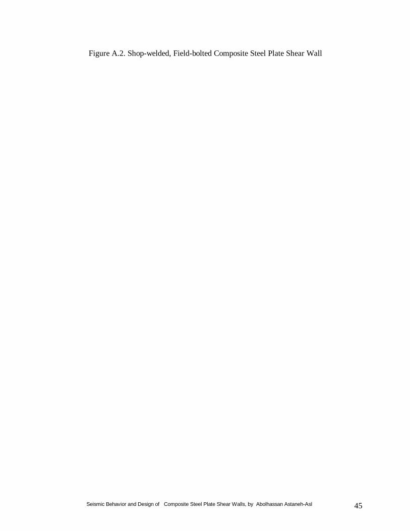
Seismic Behavior and Design of Composite Steel Plate Shear Walls, by Abolhassan Astaneh-Asl 45
Figure A.2. Shop-welded, Field-bolted Composite Steel Plate Shear Wall

Seismic Behavior and Design of Composite Steel Plate Shear Walls, by Abolhassan Astaneh-Asl 46
About the author… .
Abolhassan Astaneh-Asl, Ph.D., P.E., is professor of structural engineering at the University of California, Berkeley. He received a master of science and a doctoral degree, both in structural engineering from the University of Michigan in Ann Arbor in 1979 and 1982 respectively. After graduation, Dr. Astaneh-Asl joined the faculty of the University of Oklahoma at Norman and conducted his design-oriented research there for four years and taught courses on design of steel structures. In 1986, he joined the faculty of the University of California at Berkeley. Since then he has conducted a number of projects on seismic behavior and design of steel and composite building and bridge structures. He has published more than 140 papers and reports on various aspects of design of steel and composite structures with emphasis on seismic design. Since the 1989 Loma Prieta earthquake, he has conducted several major projects on studying seismic behavior and retrofit of major long span steel bridges and high-rise steel structures. He has been involved in design of major building and bridge structures and has been a consultant for major structures in US and overseas. In recent years, he has also been studying behavior of steel structures subjected to blasts and has been involved in development and testing of mechanisms that can be used in new and existing steel-framed buildings and bridges to prevent progressive collapse of the structures after an explosion attack. He is the winner of the 1998 AISC T.R. Higgins Award. He can be reached at: Abolhassan Astaneh-Asl, Ph.D., P.E., Professor Department of Civil and Env. Engineering 781 Davis Hall University of California, Berkeley, CA 94720-1710 Phone: (510) 642-4528 Home office Phone and Fax: (925) 946-0903 e-mail: [email protected], web page: www.ce.berkeley.edu/~astaneh

Seismic Behavior and Design of Composite Steel Plate Shear Walls, by Abolhassan Astaneh-Asl 47
List of Published Steel TIPS Reports*
------------------------------------------------------------------------------------------------------------------------------------------------
Sept. ’01: Notes on Design of Steel Parking Structures Including Seismic Effects, by Lanny J. Flynn, and
Abolhassan Astaneh-Asl. Jun '01: Metal Roof Construction On Large Warehouses or Distribution Centers, by John L. Mayo. Mar. '01: Large Seismic Steel Beam-to-Column Connections, by Egor P. Popov and Shakhzod M.Takhirov. Jan ’01: Seismic Behavior and Design of Steel Shear Walls, by Abolhassan Astaneh-Asl. Oct. '99: Welded Moment Frame Connections With Minimal Residual Stress, by Alvaro L. Collin and James J.
Putkey. Aug. '99: Design of Reduced Beam Section (RBS) Moment Frame Connections, by Kevin S. Moore, James O.
Malley and Michael D. Engelhardt. Jul. '99: Practical Design and Detailing of Steel Column Base Plates, by William C. Honeck & Derek Westphal. Dec. '98: Seismic Behavior and Design of Gusset Plates, by Abolhassan Astaneh-Asl. Mar. '98: Compatibility of Mixed Weld Metal, by Alvaro L. Collin & James J. Putkey. Aug. '97: Dynamic Tension Tests of Simulated Moment Resisting Frame Weld Joints, by Eric J. Kaufmann. Apr. '97: Seismic Design of Steel Column-Tree Moment-Resisting Frames, by Abolhassan Astaneh-Asl. Jan. '97: Reference Guide for Structural Steel Welding Practices. Dec. '96: Seismic Design Practice for Eccentrically Braced Frames (Based on the 1994 UBC), by Roy Becker &
Michael Ishler. Nov. '95: Seismic Design of Special Concentrically Braced Steel Frames, by Roy Becker. Jul. '95: Seismic Design of Bolted Steel Moment-Resisting Frames, by Abolhassan Astaneh-Asl. Apr. '95: Structural Details to Increase Ductility of Connections, by Omer W. Blodgett. Dec. '94: Use of Steel in the Seismic Retrofit of Historic Oakland City Hall, by William Honeck & Mason Walters. Dec '93: Common Steel Erection Problems and Suggested Solutions, by James J. Putkey. Oct. '93: Heavy Structural Shapes in Tension Applications. Mar. '93: Structural Steel Construction in the '90s, by F. Robert Preece & Alvaro L. Collin. Aug. '92: Value Engineering and Steel Economy, by David T. Ricker. Oct. '92: Economical Use of Cambered Steel Beams. Jul. '92: Slotted Bolted Connection Energy Dissipaters, by Carl E. Grigorian, Tzong-Shuoh Yang & Egor P.
Popov. Jun. '92: What Design Engineers Can Do to Reduce Fabrication Costs, by Bill Dyker & John D. Smith. Apr. '92: Designing for Cost Efficient Fabrication, by W.A. Thornton. Jan. '92: Steel Deck Construction. Sep. '91: Design Practice to Prevent Floor Vibrations, by Farzad Naeim. Mar. '91: LRFD-Composite Beam Design with Metal Deck, by Ron Vogel. Dec. '90: Design of Single Plate Shear Connections, by Abolhassan Astaneh-Asl, Steven M. Call and Kurt M.
McMullin. Nov. '90: Design of Small Base Plates for Wide Flange Columns, by W.A. Thornton. May '89: The Economies of LRFD in Composite Floor Beams, by Mark C. Zahn. Jan. '87: Composite Beam Design with Metal Deck. Feb. '86: UN Fire Protected Exposed Steel Parking Structures. Sep. '85: Fireproofing Open-Web Joists & Girders. Nov. '76: Steel High-Rise Building Fire. * The Steel TIPS are available at AISC website: www.aisc.org and can be downloaded free for personal use courtesy of the California Field Iron Workers Administrative Trust and the AISC.

Seismic Behavior and Design of Composite Steel Plate Shear Walls, by Abolhassan Astaneh-Asl 48
P.O. Box 6190 Moraga, CA 94570 Tel. (925) 631-1313 Fax. (925) 631-1112
Fred Boettler, Administrator
Steel TIPS may be viewed and downloaded at www.aisc.org
S P O N S O R S Adams & Smith Four Star Erectors Plas-Tal Manufacturing Co.
Bannister Steel, Inc. Gayle Manufacturing Reno Iron Works
Baresel Corp The Herrick Corporation SME Industries
Bethlehem Steel Corporation Hoertig Iron Works Schollenbarger-Borello, Inc.
Bickerton Industries, Inc Junior Steel Company Strocal Inc.
Bostrum Bergen. Martin Iron Works Inc. Templeton Steel Fabrication
California Erectors McLean Steel Inc. Trade Arbed
Eagle Iron Construction Nelson Stud Welding Co. Verco Manufacturing, Inc
Eandi Metal Works Oregon Steel Mills Vulcraft Sales Corp.
Western Steel & Metals,
Inc.
The local structural steel industry (above sponsors) stands ready to assist you in determining the most economical solution for your products. Our assistance can range from budget prices and estimated tonnage to cost comparisons, fabrication details and delivery schedules.
Steel
STRUCTURAL STEEL EDUCATIONAL COUNCIL

Seismic Behavior and Design of Composite Steel Plate Shear Walls, by Abolhassan Astaneh-Asl 49
Funding for this publication provided by the California Field Iron Workers Administrative Trust.
Related Documents