Research Article SeismicAnalysisofCoupledHigh-SpeedTrain-Bridgewiththe IsolationofFrictionPendulumBearing XinminHong,WenhuaGuo ,andZihaoWang School of Civil Engineering, Central South University, Tianxin District, Changsha 410075, China Correspondence should be addressed to Wenhua Guo; [email protected] Received 15 October 2019; Accepted 4 February 2020; Published 24 February 2020 Academic Editor: Valeria Vignali Copyright © 2020 Xinmin Hong et al. is is an open access article distributed under the Creative Commons Attribution License, which permits unrestricted use, distribution, and reproduction in any medium, provided the original work is properly cited. e paper presents a framework for the seismic analysis of the coupled high-speed train-bridge with the isolation of friction pendulum bearing (FPB). Taking the rail irregularities as system’s self-excitation with the seismic as external excitation, the equation of motion of the train-bridge coupled system under earthquake is built up. A five-span simple-supported railway bridge is taken as an example, and the computer simulation method is used to establish the dynamic model of the train-bridge system with the isolation of FPB under earthquake. A train composed of eight 4-axle coaches of 35 degrees-of-freedom (DOF) is considered, and FPB is simulated by a force element which includes both nonlinear spring and damper characteristics and a hysteresis function. Backward differentiation formula and the mode superposition method are adopted in the calculation of coupling vibration of the train-bridge system. e dynamic responses of the train running on the bridge with the isolation of FPB and with the common spherical bearing (CSB) under earthquake are studied. e results show that FPB with a friction coefficient no less than 0.05, instead of CSB, can reduce the dynamic response of the train greatly; the faster the train speed and the higher the pier, the greater the effect of FPB. However, FPB may increase the dynamic response of the train when the seismic intensity exceeds 0.14g. 1.Introduction By the end of 2018, China has over 29,000 km of high-speed railway (HSR) lines in service [1]. With the upgrade of railway design standards, elevated bridges stretching tens of kilometers are built to ensure the smoothness of the track and the safety and stability of running trains, which greatly increased the probability of trains traveling on the bridge when earthquakes occur. Even earthquakes that do not threat the safety of bridges can jeopardize the operation of trains [2]. As shown in Figure 1, in the short decades of HSR, there have been three train derailments due to earthquake action when the trains are running on bridges [3–5]. e safety of HSR trains traveling on bridges during earthquakes is an issue of great study interest in many countries, espe- cially those in earthquake-prone regions, such as China and Japan. However, most of the previous studies have been focused on the influence of bridge parameters on the safety of trains running on bridges under earthquake [6, 7] or the effect of seismic intensity on the safety of trains running on bridges [8–10] and without considering the isolation of FPB. FPB was put forward by Zays, professor of the University of California, in 1985. FPB is widely used on bridges, thanks to their isolation period independent of the superstructure mass, their high dissipation and recentering capacity, and their longevity and durability characteristics [11, 12]. e seismic performance of FPB has been investigated in many experimental and numerical studies [13, 14]. Most of these studies have been concerned on highway bridges rather than high-speed railway bridges [15–17] or the seismic response of bridges isolated by FPB under earthquake without the trains [18, 19]. Very little information is publicly available of seismic responses of trains traveling on the bridge with the isolation of FPB under earthquake action. To ensure the safety of running trains, such as a complicated dynamic interaction among vehicles, seismic and bridge with the Hindawi Advances in Civil Engineering Volume 2020, Article ID 8714174, 15 pages https://doi.org/10.1155/2020/8714174

Welcome message from author
This document is posted to help you gain knowledge. Please leave a comment to let me know what you think about it! Share it to your friends and learn new things together.
Transcript
Research ArticleSeismic Analysis of Coupled High-Speed Train-Bridge with theIsolation of Friction Pendulum Bearing
Xinmin Hong Wenhua Guo and Zihao Wang
School of Civil Engineering Central South University Tianxin District Changsha 410075 China
Correspondence should be addressed to Wenhua Guo gwh_work163com
Received 15 October 2019 Accepted 4 February 2020 Published 24 February 2020
Academic Editor Valeria Vignali
Copyright copy 2020 XinminHong et alis is an open access article distributed under the Creative Commons Attribution Licensewhich permits unrestricted use distribution and reproduction in any medium provided the original work is properly cited
e paper presents a framework for the seismic analysis of the coupled high-speed train-bridge with the isolation of frictionpendulum bearing (FPB) Taking the rail irregularities as systemrsquos self-excitation with the seismic as external excitation theequation of motion of the train-bridge coupled system under earthquake is built up A five-span simple-supported railway bridgeis taken as an example and the computer simulation method is used to establish the dynamic model of the train-bridge systemwith the isolation of FPB under earthquake A train composed of eight 4-axle coaches of 35 degrees-of-freedom (DOF) isconsidered and FPB is simulated by a force element which includes both nonlinear spring and damper characteristics and ahysteresis function Backward differentiation formula and the mode superposition method are adopted in the calculation ofcoupling vibration of the train-bridge systeme dynamic responses of the train running on the bridge with the isolation of FPBand with the common spherical bearing (CSB) under earthquake are studied e results show that FPB with a friction coefficientno less than 005 instead of CSB can reduce the dynamic response of the train greatly the faster the train speed and the higher thepier the greater the effect of FPB However FPB may increase the dynamic response of the train when the seismic intensityexceeds 014 g
1 Introduction
By the end of 2018 China has over 29000 km of high-speedrailway (HSR) lines in service [1] With the upgrade ofrailway design standards elevated bridges stretching tens ofkilometers are built to ensure the smoothness of the trackand the safety and stability of running trains which greatlyincreased the probability of trains traveling on the bridgewhen earthquakes occur Even earthquakes that do notthreat the safety of bridges can jeopardize the operation oftrains [2] As shown in Figure 1 in the short decades of HSRthere have been three train derailments due to earthquakeaction when the trains are running on bridges [3ndash5] esafety of HSR trains traveling on bridges during earthquakesis an issue of great study interest in many countries espe-cially those in earthquake-prone regions such as China andJapan However most of the previous studies have beenfocused on the influence of bridge parameters on the safety
of trains running on bridges under earthquake [6 7] or theeffect of seismic intensity on the safety of trains running onbridges [8ndash10] and without considering the isolation of FPBFPB was put forward by Zays professor of the University ofCalifornia in 1985 FPB is widely used on bridges thanks totheir isolation period independent of the superstructuremass their high dissipation and recentering capacity andtheir longevity and durability characteristics [11 12] eseismic performance of FPB has been investigated in manyexperimental and numerical studies [13 14] Most of thesestudies have been concerned on highway bridges rather thanhigh-speed railway bridges [15ndash17] or the seismic responseof bridges isolated by FPB under earthquake without thetrains [18 19] Very little information is publicly available ofseismic responses of trains traveling on the bridge with theisolation of FPB under earthquake action To ensure thesafety of running trains such as a complicated dynamicinteraction among vehicles seismic and bridge with the
HindawiAdvances in Civil EngineeringVolume 2020 Article ID 8714174 15 pageshttpsdoiorg10115520208714174
isolation of FPB should be carefully and timely investigatedBased on the multibody dynamics theory and the finite
element method a three-dimensional train-bridge interac-tion model considering the isolation of FPB under earth-quake is present in this study A five-span simply supportedgirder bridge and a group high-speed train consisting ofeight vehicles are selected as study objects the influence oftrain speed seismic intensity and pier height on the dy-namic responses of train running on bridge with the iso-lation of FPB or with CSB under earthquake is calculatede sensitivity of the friction coefficient and the curvatureradius of FPB to the dynamic response of the trains areanalyzed e main goal of this study is to clarify the dy-namic characteristics of trains running on the bridge withthe isolation of FPB under earthquake and provide someuseful values for the seismic isolation design of FPB of thesimply supported girder bridge in HSR
2 Model of the Coupled System of Train-Bridge
21 Model of the Train e train subsystem model iscomposed of several locomotives and passenger cars Eachvehicle model is a multi-degrees-of-freedom vibration sys-tem composed of a car body two bogies four wheel sets andthe spring-damper suspensions [20] e car body and thebogies are linked by the second suspension system and thebogies and the wheels are linked by the primary suspensionsystem Each rigid body has five DOFs including lateralswing vertical floating rolling yawing and pitchingmovements In total each single vehicle has 35 DOFs asshown in Figure 2
e following assumptions are adopted in modeling thevehicle subsystem
(1) e car body bogies and wheel sets are regarded asrigid components neglecting their elastic deforma-tion during vibration
(2) e vehicle element is a linear system namely themass damping and stiffness matrices of the vehicleelement are regarded as constant matrices in theanalysis process
(3) e train runs on the bridge at a constant speedwhile the movement of the train under startingbraking or accelerating state is neglected thus theDOFs in the longitudinal direction for the car bodybogies and wheel sets are not considered
(4) e wheel set bogie and car body are all subjected tomicrovibration
(5) All springs are linear and all dampings are calculatedby viscous damping and creep force is calculated bylinear
22 Model of the Bridge System
221 Model of the Bridge e simply supported railwaybridge is composed of piers girders rails and accessorystructures Spatial beam element model is used for girdersrails and piers and the rails are regarded as Euler beamsupported by discrete elastic pointse connection betweenthe track and the main girder is regarded as the fastenerforce which is considered in the form of a spring-damper
(a) (b)
(c)
Figure 1 Derailment of HSR trains on bridges due to earthquakes (a) Niigata Chuetsu earthquake in Japan (b) Jiashian earthquake inTaiwan (c) Kumamoto earthquake in Japan
2 Advances in Civil Engineering
element in the horizontal and vertical directions estiffness of the pier foundation is superimposed on thecorresponding joints e damping of the bridge system isconsidered as Rayleigh damping generally the corre-sponding damping ratio of low-order frequency is 2sim5e mass of accessory structures is added into the mass ofthe girders
222 Model of the Bearing
(1) Common Spherical Bearing Spherical steel bearings arecommonly used in railway bridges e rigidity of thebearings is large and can meet the rigidity requirements ofrailway bridges very well e degrees of freedom in themovable direction of the spherical steel bearing are released
zw zw
zt
kx2 cx2
kz1 cz1
kx1 cx1
kz2 cz2
φczc
φt
xc
(a)
h1
h2
h3
2b1
ky2 cy2
ky1 cy1
kz2 cz2
kz1 cz1
2a1
θczc
yc
θt
θw
zt
zt
yt
yw
(b)
yw yw
ψc
yc
xcψw ψt ψw
kx2 cx2
ky1 cy1
kx1 cx1
ky2 cy2
2d1
2d2
(c)
Figure 2 Side bottom and rear view of the vehicle model exhibiting 35 DOFs
Upper support plate
Slider chamber
Articulated slider
Limiting device
Low-friction material
Lower bearing plateSilding sphere
Figure 3 Structural sketch of FPB
Advances in Civil Engineering 3
and the degrees of freedom in the nonmovable direction arerealized by master-slave restraint
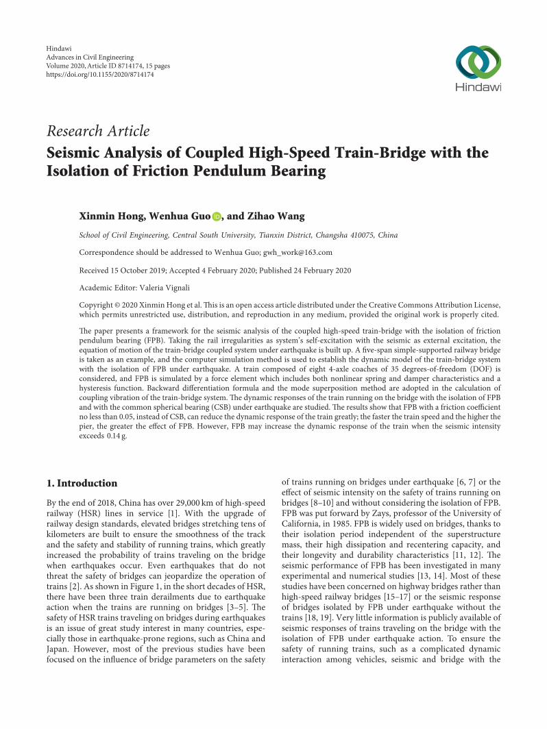
(2) Model of FPB e FPB as shown in Figure 3 is de-veloped on the basis of spherical steel bearings it is a vi-bration isolation device which dissipates energy by friction[21] Based on the principle of pendulum a simple pen-dulum motion occurs in the upper structure through themotion of spherical friction pairs and energy is dissipated byfriction damping during the swing process e restoringforce provided by the swing device can make the bearingreturn to the central positione schematic diagram of FPBis shown in Figure 4
e restoring force F of the bearing can be approximatelyexpressed as
F WD
R cos θ+μNsgn _θcos θ
(1)
where W is the vertical load supported by the bearing D isthe horizontal displacement of the bearing and is equal to therelative horizontal displacement between the upper andlower bearing plates for a FPB and θ and _θ are sliding angleand sliding angular velocities respectively R is the curvatureradius and is the distance between the centers of thespherical rotation surface and the spherical sliding surface μ
is the friction coefficient of the friction pairs on the slidingspherical surface andN is the compressive force between theupper plate and the slider and is perpendicular to thespherical sliding surface and points to the center of theslider sgn _θ is the sign function given as
sgn _θ 1 _θgt 0
minus 1 _θlt 0
⎧⎨
⎩ (2)
In practical engineering when θlt 5∘ equation (1) can bewritten in a simplified form as
F WD
R+ μW sgn _θ (3)
e lateral stiffness of the bearing Kfps is almost un-changed after the surfaces begin to slide and is given as
Kfps W
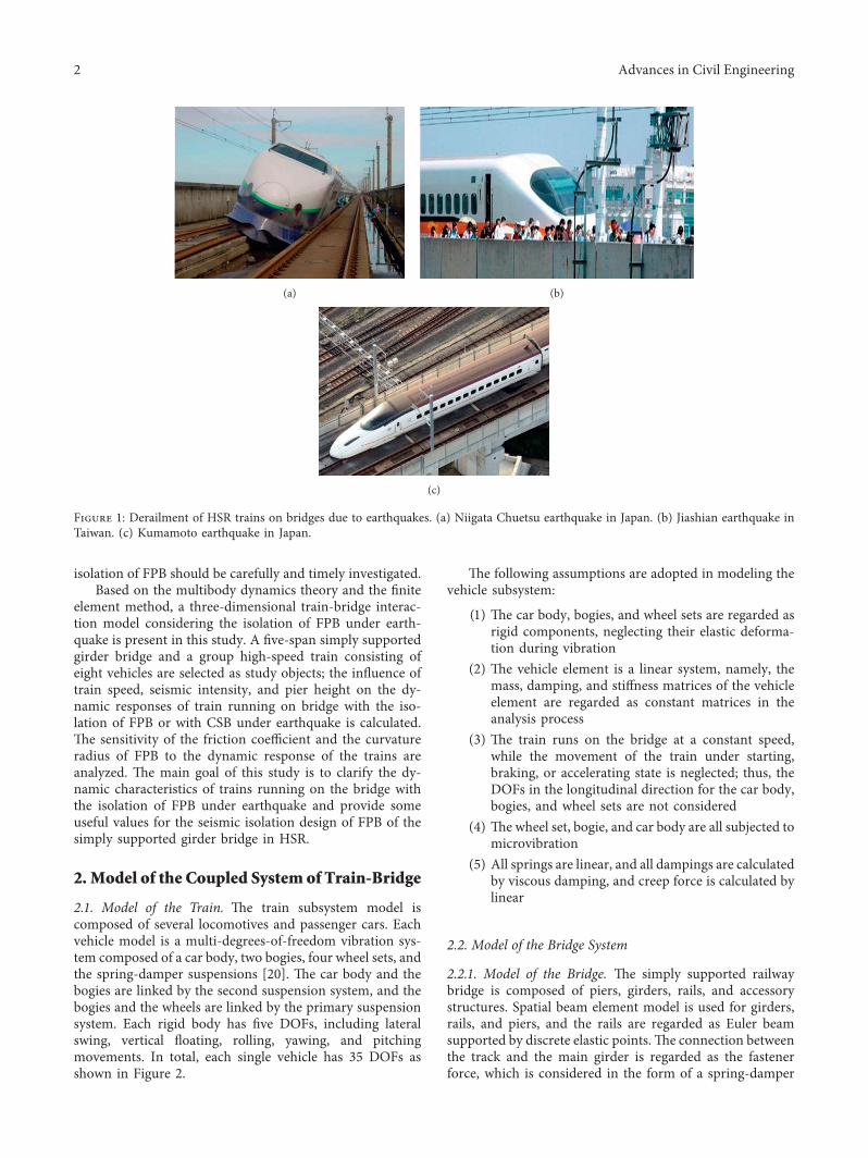
R (4)
As displayed in Figure 5 the restoring force F in the load-displacement hysteresis curve model of FPB can be regardedas the effect of a nonlinear spring combined with a constanthysteresis force
e parameters of the nonlinear spring and the constanthysteresis force can be given as
θR
RcosθW
DSliding sphere
Articulatedslider
N fθ
Figure 4 Schematic diagram of the simple pendulum model
F
d
μWKfps
Ki Keff
Dy Dd
F
Kfps
d
F
Fhys
VDd
εv
εvndashFhys
(a) (b) (c)
Figure 5 Load-displacement hysteresis curve of FPB
4 Advances in Civil Engineering
Keff F
Dd
W
R+μW
Dd
K1 Kfps W
R
Fhys μW
εv _Dy
v R middot _θ
F
WD
Rplusmn μW if |v|ge εv
WD
R+
v
εv
μW if |v|lt εv
⎧⎪⎪⎪⎪⎪⎨
⎪⎪⎪⎪⎪⎩
(5)
where Dy is the initial yield displacement of the bearing εv
is the sliding velocity corresponding to the Dy of thebearing v is the sliding velocity K1 is the stiffness of thespring Fhys is the constant hysteresis force Dd is the ul-timate displacement of the bearing Ki is the initial stiffnessof the bearing and Keff is the equivalent stiffness of thebearing
Seismic energy is dissipated by the friction action ofthe friction pairs e capacity of seismic energy dissi-pation is evaluated by the factor of the effective dampingratio βeff
βeff 2μ
π(DR + μ) (6)
23 Model of Rail Irregularity Rail irregularities are a majorsource of train vibrations and play a very important role onthe dynamic interaction analysis of the train-bridge systemwhich may enlarge the trainrsquos derailment during seismicloading At present based on the statistical analysis of a largenumber of measured data scholars have fitted the powerspectral density (PSD) functions of various types of railirregularities and Zhai [22] analyzed and compared thetypical rail spectra at home and abroad e rail irregularityspectra in German high-speed railways are currently appliedin European railways which are also adopted in China toanalyze the running stability of trains according to theoverall technical conditions for high-speed trains eGerman track irregularity spectra are expressed as
Sv(Ω) AvΩ2c
Ω2 +Ω2r( 1113857 Ω2 +Ω2c( 1113857
Sa(Ω) AaΩ2c
Ω2 +Ω2r( 1113857 Ω2 +Ω2c( 1113857
Sc(Ω) Av middot bminus 2 middotΩ2c middotΩ2
Ω2 +Ω2r( 1113857 Ω2 +Ω2c( 1113857 Ω2 +Ω2s( 1113857
Sg(Ω) AgΩ2cΩ
2
Ω2 +Ω2r( 1113857 Ω2 +Ω2c( 1113857 Ω2 +Ω2s( 1113857
(7)
Acc
eler
atio
n (m
s2 )
ndash4
ndash2
0
2
4
10 20 30 40 500Time (S)
(a)
Acc
eler
atio
n (m
s2 )
10 20 30 40 500Time (S)
ndash4
ndash2
0
2
4
(b)
Vel
ocity
(ms
)
ndash04
ndash02
00
02
04
10 20 30 40 500Time (S)
(c)
Disp
lace
men
t (m
)ndash02
ndash01
00
01
02
10 20 30 40 500Time (S)
(d)
Figure 6 Acceleration velocity and displacement time histories of the seismic wave (a) Original acceleration time history of the seismicwave (b) Modified acceleration time history of the seismic wave (c) Modified velocity time history of the seismic wave (d) Modifieddisplacement time history of the seismic wave
Advances in Civil Engineering 5
where Sv(Ω) Sa(Ω) and Sg(Ω) are the PSD functions ofvertical profile alignment and gauge irregularities (m2(radm))and Sc(Ω) is the PSD function of cross-level irregularity(1(radm)) Ωc Ωr and Ωs are the cutoff frequencies (radm)Aa Av and Ag are the roughness coefficients (m2 middotradm) b isthe half of the distance between the right and left rail centersand Ω is the spatial frequency of rail irregularity (radm)
3 Coupled System of Train-Bridgeunder Earthquake
31ModificationofEarthquakeExcitation In the calculationof spatial vibration of the train-bridge interaction system
under seismic load besides the acceleration time history ofthe seismic wave the velocity and displacement time historyof the seismic wave should also be known in advance [23]However at present the velocity and displacement timehistory of the seismic wave are obtained by integrating theacceleration of the seismic wave Some low-frequency noisemakes the seismograph deviate in recording the accelerationof the seismic wave e displacement time histories willdrift when it is obtained directly by quadratic integration ofthe acceleration time histories Using such displacementtime histories to calculate the seismic response will lead todistortion of calculation results [24] On the basis of pre-decessorsrsquo study on the time-domain optimization
16m
326m 326m 326m 326m 326m
Abutment 0 Pier 1 Pier 2 Pier 3 Pier 4 Abutment 5
Fastener
Sliding FPB Antiseismic fixed bearing
Rail
Girder
Pier
z
x
y
o
Figure 7 Schematic of the five-span simply supported bridge
Ver
tical
pro
file
irreg
ular
ity (m
m)
200 400 600 800 10000Distance (m)
ndash6
ndash4
ndash2
0
2
4
6
(a)
200 400 600 800 10000Distance (m)
ndash9
ndash6
ndash3
0
3
6
9
Alig
nmen
t irr
egul
arity
(mm
)
(b)
Cros
s-le
vel
irreg
ular
ity (m
m)
ndash4
ndash2
0
2
4
200 400 600 800 10000Distance (m)
(c)
Figure 8 Irregularity sample of the rail (a) Vertical profile irregularity (b) Alignment irregularity (c) Cross-level irregularity
6 Advances in Civil Engineering
correction algorithm the paper adopted the least squaremethod to modify and fit the acceleration time histories [25]Shown in Figure 6 are the original acceleration modifiedacceleration velocity and displacement time histories of ElCentro seismic wave which illustrate that the velocity anddisplacement are approaching zeros at the end of theearthquake
32 Equation of Motion of the Train-Bridge Coupling Systemunder Earthquake In the vibration analysis of the train-bridge interaction system under seismic loads the train andbridge are regarded as an overall superstructure e finiteelement method is used to establish the dynamic model ofthe bridge structure the components of the bridge structureare discretized reasonably at first and the appropriate dis-placement mode is selected to calculate the potential energyand strain energy of each element According to the prin-ciple of total potential energy with stationary value in elasticsystem dynamics and the ldquoset in right positionrdquo rule forformulating system matrixes [26] and taking the rail ir-regularities as systemrsquos self-excitation source with the seis-mic as external excitation the coupling vibration equation ofthe train-bridge system under earthquake is built up eseismic ground motions at various supports of the bridge areconsidered to be nonuniforme equation of motion of thewhole train-bridge system can be divided into blocks
according to the nonsupporting nodes of the structure andthe supporting nodes of the ground given as [27]
Mss Msb
Mbs Mbb
⎡⎢⎣ ⎤⎥⎦eurous
euroub
⎧⎨
⎩
⎫⎬
⎭ +Css Csb
Cbs Cbb
⎡⎢⎣ ⎤⎥⎦_us
_ub
⎧⎨
⎩
⎫⎬
⎭+
Kss Ksb
Kbs Kbb
⎡⎢⎣ ⎤⎥⎦us
ub
⎧⎨
⎩
⎫⎬
⎭ Fs
Fb
⎧⎨
⎩
⎫⎬
⎭
(8)
where M C and K are the mass damping and stiffnessmatrices respectively subscripts s and b denote the su-perstructure and bridge supports respectively and eurou _u andu are the absolute acceleration velocity and displacementvectors respectively Fs is the external load vectors of thesuperstructure and Fb is the reaction vectors of the supports
When equation (8) is solved using the direct solutionmethod the first term on the left side of the equation isexpanded and the motion equations of the train-bridgesubsystem in the absolute coordinates can be written as
Mss eurous + Msb euroub + Css _us + Csb _ub + Kssus + Ksbub Fs
(9)
Mbs eurous + Mbb euroub + Cbs _us + Cbb _ub + Kbsus + Kbbub Fb
(10)
Equation (9) can be written as
Table 1 Main parameters of vehicles used in the case study
Parameters Unit Value of MC Value of TCDistance of wheel sets 2d1 m 25 25Distance of bogies 2d2 m 175 175Transverse span of primary suspension 2b1 m 20 20Transverse span of secondary suspension 2a1 m 20 20Car body to secondary suspension h1 m 054 080Secondary suspension to bogie h2 m 047 030Bogie to wheel set h3 m 008 014Wheel radius rw m 046 046Car body mass mc t 480 440Car body x-inertia Ixc tmiddotm2 115 100Car body y-inertia Iyc tmiddotm2 2700 2700Car body z-inertia Izc tmiddotm2 2700 2700Bogie mass mt t 32 24Bogie x-inertia Ixt tmiddotm2 32 18Bogie y-inertia Iyt tmiddotm2 72 22Bogie z-inertia Izt tmiddotm2 68 22Wheel set mass mw t 24 24Wheel set x-inertia Ixw tmiddotm2 12 11Primary suspension x-dampside cx1 kNmiddotsm 0 0Primary suspension y-dampside cy1 kNmiddotsm 0 0Primary suspension z-dampside cz1 kNmiddotsm 10 10Secondary suspension x-dampside cx2 kNmiddotsm 450 450Secondary suspension y-dampside cy2 kNmiddotsm 45 45Secondary suspension z-dampside cz2 kNmiddotsm 20 20Primary suspension x-springside kx1 MNm 90 150Primary suspension y-springside ky1 MNm 30 50Primary suspension z-springside kz1 MNm 104 07Secondary suspension x-springside kx2 MNm 024 028Secondary suspension y-springside ky2 MNm 024 028Secondary suspension z-springside kz2 MNm 040 030
Advances in Civil Engineering 7
Mss eurous + Css _us + Kssus Fs minus Feq (11)
Feq Msb euroub + Csb _ub + Ksbub (12)
where Feq is the seismic loads and euroub _ub and ub are ac-celeration velocity and displacement vectors of the seismic
Usually the influence of the term with Msbis signifi-cantly smaller than that with Ksb and the influence of theterm with Csb is also small and difficult to be determined sothis term with Msband Csbis not taken into account enequation (11) can be written as
Mss eurous + Css _us + Kssus Fs minus Ksbub (13)
33 Criteria for TrainRunning Safety In the current Chinesecodes the criteria for evaluating train running safety includederailment factor offload factor and lateral wheel-rail force[28] e three train running safety indices can be obtainedby in situ measurements or from train-bridge couplingdynamic analysis
331 Derailment Factor Derailment factor is an index toevaluate the safety of the vehicle wheel against derailment
Derailment factor is defined as QP the ratio of the lateralforce to the dynamic wheel load e maximum wheelderailment factor (QP) from all the wheel sets of a train iscalculated as [29]
Q
P Max
Qi
Pi
1113888 1113889 i 1 n (14)
where Qi and Pi are the horizontal and vertical forces of theith wheel set and n means the total number of wheel sets forthe train
e limits for derailment factor are given in variouscountries as follows (1) Western Europe QPlt 08 (2)Japan QPlt 08 (3) North America QPlt 10 and (4)China QPlt 08 In this study the China standards areadopted to evaluate the train derailment factor
332 Offload Factor e offload factor is used to checkwhether the vehicle will derail due to overlarge offload at oneside of the wheel set It is adopted as an important index inevaluating the vertical dynamic performance of the train-bridge system Offload factor is defined as ΔPP the ratio ofwheel load reduction at the offloaded side to the average loadof the two wheels in which
Der
ailm
ent f
acto
r
ndash04
ndash02
00
02
04
1 2 3 4 5 6 7 80Time (s)
CSBFPB
(a)
Off
load
fact
or
ndash04
ndash02
00
02
04
1 2 3 4 5 6 7 80Time (s)
CSBFPB
(b)
Late
ral w
heel
-rai
l for
ce (k
N)
ndash60
ndash40
ndash20
0
20
40
1 2 3 4 5 6 7 80Time (s)
CSBFPB
(c)
Figure 9 e comparison of the dynamic response of the train between FPB and CSB (a) Derailment factor (b) Offload factor (c) Lateralwheel-rail force
8 Advances in Civil Engineering
P P1 + P2( 1113857
2
ΔP P minus Pi (i 1 2)
(15)
where P1 and P2 are the static loads of the wheels on bothsides of the train respectively When the train is unbiasedP P1 P2 while Pi is the wheel load on the unloading sideof the train
e limits for offload factor of HSR in China are given asΔPPle 065 hazard limit
ΔPPle 060 allowable limit
⎧⎪⎪⎪⎪⎪⎨
⎪⎪⎪⎪⎪⎩
(16)
e limit for offload factor adopted in this study isΔPPle 060
333 Lateral Wheel-Rail Force e criterion for wheel-raillateral force is recommended to evaluate whether it willenlarge the gauge or seriously deform the track e lateralwheel-rail force can be interpreted as the sum of the wheel
lateral forces on both sides of the wheel set Chinarsquos standardlimits for lateral wheel-rail force are given as
Qle 10 +P0
3 (17)
where Q is the lateral wheel-rail force and P0 is the staticwheel-rail load of the wheel set and the unit is kN In thisstudy Qle 62 kN is adopted as the limit value of the lateralwheel-rail force
4 Realization of Numerical Simulation
Train-bridge coupling vibration involves two subsystems ofthe vehicle and the bridge In the preprocessing of ANSYSthe bridge model can be saved as a cdb file that only containthe node information of elements and the subfile thatcontains the stiffness matrix and mass matrix information ofthe bridge is generated by the substructure analysis enthe subfile is imported into SIMPACK to generate the (fbi)file of the flexible body which can be used to realize thegirder-rail relationship with rails e simulation of FPB isrealized through the No104 force element of SIMPACKwhich has the characteristics of nonlinear elasticity as dis-played in Figure 5 and the CSB is simulated master-slave
M-CSBT-CSB
M-FPBT-FPB
Der
ailm
ent f
acto
r
00
02
04
06
08
10
15 20 25 30 35 4010Curvature radius (m)
(a)
M-CSBT-CSB
M-FPBT-FPB
Off
load
fact
or
15 20 25 30 35 4010Curvature radius (m)
03
04
05
06
07
08
(b)
M-CSBT-CSB
M-FPBT-FPB
Late
ral w
heel
-rai
l for
ce (k
N)
0
20
40
60
80
100
15 20 25 30 35 4010Curvature radius (m)
(c)
Figure 10 Distributions of running safety indices of the train versus curvature radius (a) Derailment factor (b) Offload factor (c) Lateralwheel-rail force
Advances in Civil Engineering 9
restraint in ANSYS In the SIMPACK the rigid bodies andsuspension systems of the train model are simulated by thebodies hinge joints force element and other elements theflexible rail model is established by the flexible rail infor-mation file invoking and fitting the standard input file of theflexible body and the rail irregularity is defined by incentivefactors and generated by the track module and the seismicexcitation is realized by inputting the u-vectors of the ac-celeration velocity and displacement time histories of theseismic wave to a special virtual rigid body with the 35thhinge that is adopted to simulate the pier foundation edynamic interaction between the vehicle and the bridge isrealized by data exchange at discrete information points ofthe wheel-rail contact surface [30]
In the calculation of coupling vibration of the train-bridge system the vehicle and the bridge are regarded as twosystems and solved in turn iteration in the time step eabsolute error of the solver is 1times 10minus 5 and the calculationtime step is 00001 s e motion equations of the rigid bodymodel and the flexible body model are solved by differentalgorithms e rigid body model is solved by the backwarddifferentiation formula while the flexible body is solved bythe mode superposition method In this paper Hertznonlinear contact theory is used to calculate the wheelrail
normal force and the simplified Kalker creep assumption isused to calculate the wheelrail tangential creep force [31]
5 Case Study
51 Parameters Used in Calculation Multispan simply sup-ported girder bridges are often constructed in HSR A 5times 32mdouble-track PC box-girders with piers of 16m in height isselected in this case study as shown in Figure 7 e absoluteglobal coordinate system is adopted in which the x-axis isdefined as the longitudinal direction of the bridge the y-axisthe lateral direction and the z-axis the vertical direction elength of each box-girder is 326m the width of the girder is134m at the top and 575m at the bottom and the height is305m e piers have a full-height hollow rectangular crosssection of 68m (lateral bridge direction)times 33m (along thebridge direction) with 05m wall thickness C50 concrete andC30 concrete are adopted for the girders and piers respectivelye load of accessory structures is 184 kNm e dampingratio of the bridge structure is assumed to be 2 for all in-terested modes e bridge is equipped with FPBs for seismicisolation e modal characteristics of the bridge are analyzedand the first 300 modes are used in the dynamic analysis andthe integration time step is 10minus 4 s
M-CSBT-CSB
M-FPBT-FPB
Der
ailm
ent f
acto
r
00
02
04
06
08
10
002 003 004 005 006 007 008 009001Friction coefficient
(a)
M-CSBT-CSB
M-FPBT-FPB
Off
load
fact
or
002 003 004 005 006 007 008 009001Friction coefficient
03
04
05
06
07
(b)
M-CSBT-CSB
M-FPBT-FPB
Late
ral w
heel
-rai
l for
ce (k
N)
002 003 004 005 006 007 008 009001Friction coefficient
0
20
40
60
80
100
(c)
Figure 11 Distributions of running safety indices of the train versus friction coefficient (a) Derailment factor (b) Offload factor (c) Lateralwheel-rail force
10 Advances in Civil Engineering
e JIS-60-kg type rail with a length of 7434m isadopted in the case e lateral stiffness vertical stiffnesslateral damping and vertical damping of fasteners are06times108Nm 12times108Nm 12times105NmiddotSm and15times105NmiddotSm respectively In this study the German lowdisturbing track spectra are selected as the rail irregularities[32] with wavelengths ranging from 1m to 120m and aspace step of 02 meters as shown in Figure 8e frequencynumber of the track spectrum is set to 2000 and the fre-quency range is 100ndash200Hz
As shown in Figure 6 the modified El Centro seismicwave is applied to the pier foundation as lateral earthquakeactions and half magnitude of them are as the verticalearthquake actions [28]e seismic intensity is described bythe amplitude of lateral bridge acceleration and the seismicintensity is 01 g (g is the gravity acceleration g 98ms2)It is assumed that the earthquake occurs when the trainmoves just onto the bridge
e ICE3 high-speed train is used in the case [28] whichconsists of eight vehicles with the first third fifth andseventh vehicles being motor cars (MC) and the secondfourth sixth and eighth vehicles being trailer cars (TC) elength of each car is 25 meters e main parameters of thevehicle are shown in Table 1 [33]e trains run at a speed of
300 kmh Each vehicle is treated as an independent dynamicsystem without modeling the coupling device consideringthe analytical conditions that the train is running on astraight line and the inertia force due to the ground motionis simultaneously acting on the cars without phasedifference
52 Characteristic of Seismic Isolation of FPB To analyze thecharacteristic of seismic isolation of FPB the dynamic re-sponses of the coupled train-bridge with the isolation of FPBand CSB are calculated According the ldquoTJGZ-FPBrdquo that hasbeen applied in engineering at present [34] the parametersof FPB in the case are given as the friction coefficient is 003and the curvature radius is 15m Displayed in Figure 9 arethe derailment factor offload factor and lateral wheel-railforce time histories of the first wheel set of the train runningat 300 kmh in which 318 s is the time when the train justgot on the bridge
As illustrated in Figure 9 when the train arrived on thebridge FPB increased the derailment factor of the first wheelset of the train from 0146 to 0354 at the moment of theearthquake occurred which is about 221 times of that ofCSB and increased the lateral wheel-rail force of the train
M-CSBM-FPB
T-CSB T-FPB
Der
ailm
ent f
acto
r
200 225 250 275 300 325 350 375175Speed (kmh)
00
02
04
06
08
10
(a)
M-CSBM-FPB
T-CSB T-FPB
Off
load
fact
or
200 225 250 275 300 325 350 375175Speed (kmh)
02
03
04
05
06
07
(b)
M-CSBM-FPB
T-CSB T-FPB
Late
ral w
heel
-rai
l for
ce (k
N)
0
20
40
60
80
200 225 250 275 300 325 350 375175Speed (kmh)
(c)
Figure 12 Distributions of running safety indices of the train versus train speed (a) Derailment factor (b) Offload factor (c) Lateral wheel-rail force
Advances in Civil Engineering 11
from 198 kN to 450 kN which is about 227 times of that ofCSB Although FPB increased the derailment factor andlateral wheel-rail force of trains the value still meets thelimits of codeere is no significant difference between FPBand CBS in the offload factor of the train
53 Sensitivity of FPB Parameters on Dynamic Responses ofthe Train As mentioned previously the key factors thataffected the seismic performance of FPB are the frictioncoefficient and the curvature radius In this section with thesame bridge seismic intensity and rail irregularity pa-rameters given in Section 51 a further calculation is per-formed by extending the range of friction coefficient andcurvature radius of FPB to study the sensitivity of them ondynamic responses of the train under seismic loads emaximum values of running safety indices which are takenfrom the corresponding time histories of all wheel setsduring passage of the train on the bridge are used tocompare and evaluate the safety of trains e dynamic re-sponses of the coupled vehicle-bridge with CSB underearthquake are also calculated
531 Sensitivity of Curvature Radius e curvature radiusrange is extended from 1m to 4m with an interval of 05mand the friction coefficient remains unchanged at 003
Displayed in Figure 10 are the distribution curves of therunning safety indices of trains versus curvature radius ofFPB e horizontal dashed lines represent the related al-lowance values
As illustrated in Figure 10 the derailment factor offloadfactor and lateral wheel-rail force of the train change veryslightly along with the increase of curvature radius of FPBe results illustrate that the dynamic responses of trains areinsensitive to the curvature radius of FPB FPB with afriction coefficient of 003 increased the dynamic responsesof the train e maximum derailment factor offload factorand lateral wheel-rail force of the train increased to 461times 171 times and 265 times of those of CSB respec-tively e maximum offload factor and lateral wheel-railforce of MC exceed the allowance values other dynamicindexes of trains below the allowance values
532 Sensitivity of Friction Coefficient e range of thefriction coefficient is 002 to 008 with an interval of 001 andthe curvature radius is kept at 15m Displayed in Figure 11are the distribution curves of the running safety indices oftrains versus friction coefficient of FPB e horizontaldashed lines are the related allowance values
As illustrated in Figure 11 the derailment factor offloadfactor and lateral wheel-rail force of the train decreased
Der
ailm
ent f
acto
r
00
03
06
09
12
15
18
006 008 010 012 014 016 018 020 022004Seismic intensity (g)
M-CSBM-FPB
T-CSB T-FPB
(a)
Offl
oad
fact
or
006 008 010 012 014 016 018 020 022004Seismic intensity (g)
02
04
06
08
10
12
M-CSBM-FPB
T-CSB T-FPB
(b)
006 008 010 012 014 016 018 020 022004Seismic intensity (g)
0
40
80
120
160
200
240
Late
ral w
heel
-rai
l for
ce (k
N)
M-CSBM-FPB
T-CSB T-FPB
(c)
Figure 13 Distributions of running safety indices of the train versus seismic intensity (a) Derailment factor (b) Offload factor (c) Lateralwheel-rail force
12 Advances in Civil Engineering
rapidly along with the increase of friction coefficient of FPBbelow 005 and those of trains change very slightly when itexceeds 005When the friction coefficient of FPB is less than005 the dynamic responses of trains exceed the allowancevalues which is dangerous to the safety of running trainsWhen the friction coefficient reaches 005 FPB can reducethe dynamic responses of trains and the maximum de-railment factor offload factor and lateral wheel-rail force ofthe train decreased to 19 61 and 27 of those of CSBrespectively ese results illustrate that the dynamic re-sponses of the train are sensitive to the friction coefficient ofFPB For the sake of train safety the friction coefficient ofFPB should be more than 005
54 Analysis of Influencing Factors of Dynamic Response ofTrains Section 532 shows that the friction coefficient ofFPB should be more than 005 in seismic isolation design ofthe simply supported girder bridge of HSR In this sectionwith the same bridge and rail irregularity parameters givenin Section 51 the friction coefficient and curvature radius ofFPB are given as 005 and 15m respectively e dynamicresponse of the high-speed train traveling on the bridge withisolation of FPB or with CSB under earthquake is
investigated by considering different train speeds seismicintensities and pier heights
541 Influence of Train Speed e parameters of the bridgeFPB rail irregularity seismic intensity and the ICE3 trainare kept unchanged the train speed is varied from 200 kmhto 350 kmh with an interval of 25 kmh e distributioncurves of the running safety indices of train speed aredepicted in Figure 12 in which the horizontal dashed linesrepresent the related allowance values As illustrated inFigure 12 whether CSB or FPB is considered the derailmentfactor offload factor and lateral wheel-rail force of the trainincrease slowly along with the increase of train speed below300 kmh and those of the train increase rapidly when itexceeds 300 kmh When the train speed is more than325 kmh the maximum lateral wheel-rail force of the trainexceeds the allowable value e derailment factor andlateral wheel-rail force of the train can be reduced by FPBreplacing CSB Generally the faster the train speed the betterthe effect of FPB When the train speed reaches 350 kmh themaximum derailment factor and lateral wheel-rail force oftrain are reduced to 43 and 52 of those of CSB respec-tively FPB can reduce the offload factor of trains with the
Der
ailm
ent f
acto
r
8 10 12 14 16 18 20 22 24 266Pier height (m)
00
02
04
06
08
10
M-CSBM-FPB
T-CSB T-FPB
(a)
Offl
oad
fact
or
8 10 12 14 16 18 20 22 24 266Pier height (m)
035
040
045
050
055
060
065
M-CSBM-FPB
T-CSB T-FPB
(b)
Late
ral w
heel
-rai
l for
ce (k
N)
8 10 12 14 16 18 20 22 24 266Pier height (m)
10
20
30
40
50
60
70
M-CSBM-FPB
T-CSB T-FPB
(c)
Figure 14 Distributions of running safety indices of the train versus pier height (a) Derailment factor (b) Offload factor (c) Lateral wheel-rail force
Advances in Civil Engineering 13
train speed below 325 kmh however FPB will increase theoffload factor of trains when it exceeds 325 kmh
542 Influence of Seismic Intensity Keeping the parametersof the bridge FPB rail irregularity seismic intensity andtrains unchanged and the trains to run at 300 kmh theinfluence of seismic intensity on dynamic responses ofrunning trains is analyzed by considering the seismic in-tensities from 006 g to 020 g with an interval of 002 g edistribution curves of the maximum running safety indicesof trains versus seismic intensity are depicted in Figure 13 inwhich the horizontal dashed lines are the related allowancevalues
As illustrated in Figure 13 the dynamic responses ofrunning trains increased along with the increase of seismicintensity whether CSB or FPB is considered When theseismic intensity is below 014 g after FPB instead of CSBthe derailment factor offload factor and lateral wheel-railforce of the train increased slowly along with the increase ofseismic intensity and the maximum derailment factoroffload factor and lateral wheel-rail force of MC are reducedto 25 83 and 40 of those of CSB respectively FPB hasno obvious effect on reducing the dynamic responses of TCWhen the seismic intensity exceeds 014 g the dynamicresponses of the train increased rapidly and exceed the al-lowable value FPB increased the dynamic responses of thetrain and raised the risk and probability of derailment of thetrain
543 Influence of Pier Height Depicted in Figure 14 are thedistribution curves of the maximum running safety indicesof trains versus pier height by considering pier heights variedfrom 8m to 24m with an interval of 2m in which thehorizontal dashed lines represent the related allowancevaluese parameters of FPB rail irregularity and the ICE3train remain unchanged the seismic intensity is 01 g andthe train runs at 300 kmh
From the figures it can be seen that when CSB isconsidered the derailment factor lateral wheel-rail forceand offload factor of the train increased along with theincrease of pier height especially when the pier height ex-ceeds 18m the dynamic response of the train increasesrapidly When pier heights varied from 8m to 24m thevalue of dynamic response of trains is all below the allowablevalue Dynamic response of the trains can be reduced by FPBinstead of CSB the higher the pier the better the effect ofFPB When the pier height reaches 24m the maximumderailment factor and lateral wheel-rail force of the train aredecreased to 25 and 50 of those of CSB respectively FPBhas no obvious effect on reducing offload factor of trains
6 Conclusion
e following conclusions can be drawn from the study
(1) In the calculation of coupling vibration of the train-bridge system the vehicle and the bridge areregarded as two systems and solved in turn iteration
in the time step e motion equations of the rigidbody model and the flexible body model can besolved by the backward differentiation formula andthe mode superposition method respectively
(2) e friction coefficient of FPB has an obvious effecton the dynamic responses of the running train edynamic responses of the train decrease rapidlyalong with the increase of friction coefficient of FPBbelow 005 while those of the train change veryslightly when it exceeds 005 For the safety of trainoperation it is suggested that the friction coefficientshould be more than 005 in the design of FPB for thehigh-speed railway simple-supported girder bridge
(3) e dynamic responses of the train are insensitive tothe curvature radius of FPB e curvature radius ofFPB can only be selected according to the stiffnessrequirement of the bearing
(4) e derailment factor lateral wheel-rail force andoffload factor of trains increased along with theincrease of the train speed the seismic intensity andthe pier height FPB can reduce the dynamic re-sponse of the train the faster the train speed and thehigher the pier the greater the effect of FPBHowever FPBmay increase the dynamic response ofthe train when the seismic intensity exceeds 014 g
Data Availability
e data generated during andor analyzed during thecurrent study are available from the corresponding authoron reasonable request
Conflicts of Interest
e authors declare that they have no conflicts of interest
Acknowledgments
is study was supported by the National Natural ScienceFoundation of China (Project no 51078356) and the MajorTechnology Research and Development Program of theMinistry of Railway of China (Project no 2008G031-Q) towhich the authors are most grateful
References
[1] 2019 httpfinancesinacomcnroll2019-01-02doc-ihqfskcn3310957shtml
[2] Q Zeng and E G Dimitrakopoulos ldquoSeismic responseanalysis of an interacting curved bridge-train system underfrequent earthquakesrdquo Earthquake Engineering amp StructuralDynamics vol 45 no 7 pp 1129ndash1148 2016
[3] M Ogura ldquoe Niigata Chuetsu earthquake-railway responseand reconstructionrdquo Japan Railway and Transport Reviewvol 43 no 44 pp 46ndash63 2006
[4] S H Ju ldquoNonlinear analysis of high-speed trains moving onbridges during earthquakesrdquo Nonlinear Dynamics vol 69no 1-2 pp 173ndash183 2012
[5] 2016 httpwwwxinhuanetcomworld2016-0415c_128898878htm
14 Advances in Civil Engineering
[6] S H Ju ldquoImprovement of bridge structures to increase thesafety of moving trains during earthquakesrdquo EngineeringStructures vol 56 pp 501ndash508 2013
[7] L K Chen Seismic responses of high-speed railway train-ballastless track-bridge system and train-running safetyduring earthquake Doctoral dissertation Central SouthUniversity Changsha China 2012 in Chinese
[8] H Xia Y Han N Zhang and W Guo ldquoDynamic analysis oftrain-bridge system subjected to non-uniform seismic exci-tationsrdquo Earthquake Engineering amp Structural Dynamicsvol 35 no 12 pp 1563ndash1579 2006
[9] K Nishimura Y Terumichi T Morimura and K SogabeldquoAnalytical study on the safety of high speed railway vehicleon excited tracksrdquo Journal of System Design and Dynamicsvol 4 no 1 pp 211ndash225 2010
[10] H J Lei X Z Li and D J Liu ldquoTrain running safety analysisof high-pier rigid-frame bridge under earthquake actionrdquoEarthquake Engineering and Engineering Vibration vol 34no 5 pp 87ndash93 2014
[11] L Su G Ahmadi and I G Tadjbakhsh ldquoComparative studyof base isolation systemsrdquo Journal of Engineering Mechanicsvol 115 no 9 pp 1976ndash1992 1989
[12] V A Zayas S S Low and S A Mahin ldquoA simple pendulumtechnique for achieving seismic isolationrdquo EarthquakeSpectra vol 6 no 2 pp 317ndash333 1990
[13] G Mosqueda A S Whittaker and G L Fenves ldquoCharac-terization and modeling of friction pendulum bearings sub-jected to multiple components of excitationrdquo Journal ofStructural Engineering vol 130 no 3 pp 433ndash442 2004
[14] L Landi G Grazi and P P Diotallevi ldquoComparison ofdifferent models for friction pendulum isolators in structuressubjected to horizontal and vertical ground motionsrdquo SoilDynamics and Earthquake Engineering vol 81 pp 75ndash832016
[15] P Castaldo and R Lo Priore ldquoSeismic performance assess-ment of isolated bridges for different limit statesrdquo Journal ofCivil Structural Health Monitoring vol 8 no 1 pp 17ndash322018
[16] C Wang J Zhao L Zhu and Y Bao ldquoEffects of verticalexcitation on the seismic performance of a seismically isolatedbridge with sliding friction bearingsrdquo Earthquake Engineeringand Engineering Vibration vol 15 no 1 pp 187ndash196 2016
[17] S Purnachandra ldquoSeismic control of benchmark cable-stayedbridges using variable friction pendulum isolatorrdquo in Ad-vances in Structural Engineering pp 1271ndash1282 SpringerBerlin Germany 2015
[18] Y L Zhan L Zhang Q Zhang et al ldquoEffects of parameters offriction pendulum bearings on seismic response of seismicallyisolated bridgerdquo Bridge Construction vol 48 no 3 pp 45ndash492018 in Chinese
[19] C Y Zhang T Y Zhong and H Y Yang ldquoA study on seismicenergy responses of a continuous girder bridge isolated by afriction pendulum systemrdquo Journal of Vibration and Shockvol 36 no 16 pp 63ndash67 2017 in Chinese
[20] W M Zhai Vehicle-Track Coupling Dynamics China RailwayPress Beijing China 3rd edition 2007 in Chinese
[21] Y Zhou and P Chen ldquoShaking table tests and numericalstudies on the effect of viscous dampers on an isolated RCbuilding by friction pendulum bearingsrdquo Soil Dynamics andEarthquake Engineering vol 100 pp 330ndash344 2017
[22] W M Zhai Vehicle-Track Coupled Dynamics China RailwayPress Beijing China 2nd edition 2002 in Chinese
[23] ZM Deng X R Guo and Z Y Zhang ldquoCoupled vibration oftrain-bridge system of steel truss bridge with seismic effectrdquo
Journal of Central South University (Science and Technology)vol 42 no 1 pp 184ndash191 2011 in Chinese
[24] Y N Zhou W B Zhang and H Y Yu ldquoAnalysis of long-period error for accelerograms recorded by digital seismo-graphsrdquo Earthquake Engineering and Engineering Vibrationvol 17 no 2 pp 1ndash9 1997 in Chinese
[25] Y T Zhang and Y M Jia ldquoAnalysis and program imple-mentation of least squares polynomial curve fittingrdquo Com-puter and Digital Engineering vol 45 no 4 pp 637ndash6392017 in Chinese
[26] Q Y Zeng and X R GuoFeory and Application of VibrationAnalysis for Time-Varying System of Train and Bridge ChinaRailway Press Beijing China 1999 in Chinese
[27] Z H Wang Study of the effect of friction pendulum bearingon coupled vibration of train-track-bridge under earthquakesMS thesis Central South University Changsha China 2018in Chinese
[28] W M Zhai and H Xia Train-Track-Bridge Dynamic Inter-action Feory and Engineering Application Science PressBeijing China 2011 in Chinese
[29] J Xiang and Q Y Zeng ldquoA study on mechanical mechanismof train derailment and preventive measures for derailmentrdquoVehicle System Dynamics vol 43 no 2 pp 121ndash147 2005
[30] W Zhu T Qi and L Jia ldquoDynamic performance analysis ofvehicle-bridge system for a cable-stayed bridge with steel trussgirder based on SIMPACKrdquo Railway Standard Design vol 58no 7 pp 89ndash94 2014 in Chinese
[31] X T Du Y L Xu and H Xia ldquoDynamic interaction ofbridge-train system under non-uniform seismic groundmotionrdquo Earthquake Engineering amp Structural Dynamicsvol 41 no 1 pp 139ndash157 2012
[32] N Zhang H Xia and G De Roeck ldquoDynamic analysis of atrain-bridge system under multi-support seismic excitationsrdquoJournal of Mechanical Science and Technology vol 24 no 11pp 2181ndash2188 2010
[33] C X Chen ldquoVibration response analysis of train-rail-bridgecoupling system for high-speed train intersection under crosswindrdquo MS thesis Central South University ChangshaChina 2019
[34] X L Zhen and Y X Jin ldquoDesign and seismic isolationperformance analysis of friction pendulum bearingsrdquo Journalof Railway Engineering Society vol 4 pp 81ndash87 2014 inChinese
Advances in Civil Engineering 15
isolation of FPB should be carefully and timely investigatedBased on the multibody dynamics theory and the finite
element method a three-dimensional train-bridge interac-tion model considering the isolation of FPB under earth-quake is present in this study A five-span simply supportedgirder bridge and a group high-speed train consisting ofeight vehicles are selected as study objects the influence oftrain speed seismic intensity and pier height on the dy-namic responses of train running on bridge with the iso-lation of FPB or with CSB under earthquake is calculatede sensitivity of the friction coefficient and the curvatureradius of FPB to the dynamic response of the trains areanalyzed e main goal of this study is to clarify the dy-namic characteristics of trains running on the bridge withthe isolation of FPB under earthquake and provide someuseful values for the seismic isolation design of FPB of thesimply supported girder bridge in HSR
2 Model of the Coupled System of Train-Bridge
21 Model of the Train e train subsystem model iscomposed of several locomotives and passenger cars Eachvehicle model is a multi-degrees-of-freedom vibration sys-tem composed of a car body two bogies four wheel sets andthe spring-damper suspensions [20] e car body and thebogies are linked by the second suspension system and thebogies and the wheels are linked by the primary suspensionsystem Each rigid body has five DOFs including lateralswing vertical floating rolling yawing and pitchingmovements In total each single vehicle has 35 DOFs asshown in Figure 2
e following assumptions are adopted in modeling thevehicle subsystem
(1) e car body bogies and wheel sets are regarded asrigid components neglecting their elastic deforma-tion during vibration
(2) e vehicle element is a linear system namely themass damping and stiffness matrices of the vehicleelement are regarded as constant matrices in theanalysis process
(3) e train runs on the bridge at a constant speedwhile the movement of the train under startingbraking or accelerating state is neglected thus theDOFs in the longitudinal direction for the car bodybogies and wheel sets are not considered
(4) e wheel set bogie and car body are all subjected tomicrovibration
(5) All springs are linear and all dampings are calculatedby viscous damping and creep force is calculated bylinear
22 Model of the Bridge System
221 Model of the Bridge e simply supported railwaybridge is composed of piers girders rails and accessorystructures Spatial beam element model is used for girdersrails and piers and the rails are regarded as Euler beamsupported by discrete elastic pointse connection betweenthe track and the main girder is regarded as the fastenerforce which is considered in the form of a spring-damper
(a) (b)
(c)
Figure 1 Derailment of HSR trains on bridges due to earthquakes (a) Niigata Chuetsu earthquake in Japan (b) Jiashian earthquake inTaiwan (c) Kumamoto earthquake in Japan
2 Advances in Civil Engineering
element in the horizontal and vertical directions estiffness of the pier foundation is superimposed on thecorresponding joints e damping of the bridge system isconsidered as Rayleigh damping generally the corre-sponding damping ratio of low-order frequency is 2sim5e mass of accessory structures is added into the mass ofthe girders
222 Model of the Bearing
(1) Common Spherical Bearing Spherical steel bearings arecommonly used in railway bridges e rigidity of thebearings is large and can meet the rigidity requirements ofrailway bridges very well e degrees of freedom in themovable direction of the spherical steel bearing are released
zw zw
zt
kx2 cx2
kz1 cz1
kx1 cx1
kz2 cz2
φczc
φt
xc
(a)
h1
h2
h3
2b1
ky2 cy2
ky1 cy1
kz2 cz2
kz1 cz1
2a1
θczc
yc
θt
θw
zt
zt
yt
yw
(b)
yw yw
ψc
yc
xcψw ψt ψw
kx2 cx2
ky1 cy1
kx1 cx1
ky2 cy2
2d1
2d2
(c)
Figure 2 Side bottom and rear view of the vehicle model exhibiting 35 DOFs
Upper support plate
Slider chamber
Articulated slider
Limiting device
Low-friction material
Lower bearing plateSilding sphere
Figure 3 Structural sketch of FPB
Advances in Civil Engineering 3
and the degrees of freedom in the nonmovable direction arerealized by master-slave restraint
(2) Model of FPB e FPB as shown in Figure 3 is de-veloped on the basis of spherical steel bearings it is a vi-bration isolation device which dissipates energy by friction[21] Based on the principle of pendulum a simple pen-dulum motion occurs in the upper structure through themotion of spherical friction pairs and energy is dissipated byfriction damping during the swing process e restoringforce provided by the swing device can make the bearingreturn to the central positione schematic diagram of FPBis shown in Figure 4
e restoring force F of the bearing can be approximatelyexpressed as
F WD
R cos θ+μNsgn _θcos θ
(1)
where W is the vertical load supported by the bearing D isthe horizontal displacement of the bearing and is equal to therelative horizontal displacement between the upper andlower bearing plates for a FPB and θ and _θ are sliding angleand sliding angular velocities respectively R is the curvatureradius and is the distance between the centers of thespherical rotation surface and the spherical sliding surface μ
is the friction coefficient of the friction pairs on the slidingspherical surface andN is the compressive force between theupper plate and the slider and is perpendicular to thespherical sliding surface and points to the center of theslider sgn _θ is the sign function given as
sgn _θ 1 _θgt 0
minus 1 _θlt 0
⎧⎨
⎩ (2)
In practical engineering when θlt 5∘ equation (1) can bewritten in a simplified form as
F WD
R+ μW sgn _θ (3)
e lateral stiffness of the bearing Kfps is almost un-changed after the surfaces begin to slide and is given as
Kfps W
R (4)
As displayed in Figure 5 the restoring force F in the load-displacement hysteresis curve model of FPB can be regardedas the effect of a nonlinear spring combined with a constanthysteresis force
e parameters of the nonlinear spring and the constanthysteresis force can be given as
θR
RcosθW
DSliding sphere
Articulatedslider
N fθ
Figure 4 Schematic diagram of the simple pendulum model
F
d
μWKfps
Ki Keff
Dy Dd
F
Kfps
d
F
Fhys
VDd
εv
εvndashFhys
(a) (b) (c)
Figure 5 Load-displacement hysteresis curve of FPB
4 Advances in Civil Engineering
Keff F
Dd
W
R+μW
Dd
K1 Kfps W
R
Fhys μW
εv _Dy
v R middot _θ
F
WD
Rplusmn μW if |v|ge εv
WD
R+
v
εv
μW if |v|lt εv
⎧⎪⎪⎪⎪⎪⎨
⎪⎪⎪⎪⎪⎩
(5)
where Dy is the initial yield displacement of the bearing εv
is the sliding velocity corresponding to the Dy of thebearing v is the sliding velocity K1 is the stiffness of thespring Fhys is the constant hysteresis force Dd is the ul-timate displacement of the bearing Ki is the initial stiffnessof the bearing and Keff is the equivalent stiffness of thebearing
Seismic energy is dissipated by the friction action ofthe friction pairs e capacity of seismic energy dissi-pation is evaluated by the factor of the effective dampingratio βeff
βeff 2μ
π(DR + μ) (6)
23 Model of Rail Irregularity Rail irregularities are a majorsource of train vibrations and play a very important role onthe dynamic interaction analysis of the train-bridge systemwhich may enlarge the trainrsquos derailment during seismicloading At present based on the statistical analysis of a largenumber of measured data scholars have fitted the powerspectral density (PSD) functions of various types of railirregularities and Zhai [22] analyzed and compared thetypical rail spectra at home and abroad e rail irregularityspectra in German high-speed railways are currently appliedin European railways which are also adopted in China toanalyze the running stability of trains according to theoverall technical conditions for high-speed trains eGerman track irregularity spectra are expressed as
Sv(Ω) AvΩ2c
Ω2 +Ω2r( 1113857 Ω2 +Ω2c( 1113857
Sa(Ω) AaΩ2c
Ω2 +Ω2r( 1113857 Ω2 +Ω2c( 1113857
Sc(Ω) Av middot bminus 2 middotΩ2c middotΩ2
Ω2 +Ω2r( 1113857 Ω2 +Ω2c( 1113857 Ω2 +Ω2s( 1113857
Sg(Ω) AgΩ2cΩ
2
Ω2 +Ω2r( 1113857 Ω2 +Ω2c( 1113857 Ω2 +Ω2s( 1113857
(7)
Acc
eler
atio
n (m
s2 )
ndash4
ndash2
0
2
4
10 20 30 40 500Time (S)
(a)
Acc
eler
atio
n (m
s2 )
10 20 30 40 500Time (S)
ndash4
ndash2
0
2
4
(b)
Vel
ocity
(ms
)
ndash04
ndash02
00
02
04
10 20 30 40 500Time (S)
(c)
Disp
lace
men
t (m
)ndash02
ndash01
00
01
02
10 20 30 40 500Time (S)
(d)
Figure 6 Acceleration velocity and displacement time histories of the seismic wave (a) Original acceleration time history of the seismicwave (b) Modified acceleration time history of the seismic wave (c) Modified velocity time history of the seismic wave (d) Modifieddisplacement time history of the seismic wave
Advances in Civil Engineering 5
where Sv(Ω) Sa(Ω) and Sg(Ω) are the PSD functions ofvertical profile alignment and gauge irregularities (m2(radm))and Sc(Ω) is the PSD function of cross-level irregularity(1(radm)) Ωc Ωr and Ωs are the cutoff frequencies (radm)Aa Av and Ag are the roughness coefficients (m2 middotradm) b isthe half of the distance between the right and left rail centersand Ω is the spatial frequency of rail irregularity (radm)
3 Coupled System of Train-Bridgeunder Earthquake
31ModificationofEarthquakeExcitation In the calculationof spatial vibration of the train-bridge interaction system
under seismic load besides the acceleration time history ofthe seismic wave the velocity and displacement time historyof the seismic wave should also be known in advance [23]However at present the velocity and displacement timehistory of the seismic wave are obtained by integrating theacceleration of the seismic wave Some low-frequency noisemakes the seismograph deviate in recording the accelerationof the seismic wave e displacement time histories willdrift when it is obtained directly by quadratic integration ofthe acceleration time histories Using such displacementtime histories to calculate the seismic response will lead todistortion of calculation results [24] On the basis of pre-decessorsrsquo study on the time-domain optimization
16m
326m 326m 326m 326m 326m
Abutment 0 Pier 1 Pier 2 Pier 3 Pier 4 Abutment 5
Fastener
Sliding FPB Antiseismic fixed bearing
Rail
Girder
Pier
z
x
y
o
Figure 7 Schematic of the five-span simply supported bridge
Ver
tical
pro
file
irreg
ular
ity (m
m)
200 400 600 800 10000Distance (m)
ndash6
ndash4
ndash2
0
2
4
6
(a)
200 400 600 800 10000Distance (m)
ndash9
ndash6
ndash3
0
3
6
9
Alig
nmen
t irr
egul
arity
(mm
)
(b)
Cros
s-le
vel
irreg
ular
ity (m
m)
ndash4
ndash2
0
2
4
200 400 600 800 10000Distance (m)
(c)
Figure 8 Irregularity sample of the rail (a) Vertical profile irregularity (b) Alignment irregularity (c) Cross-level irregularity
6 Advances in Civil Engineering
correction algorithm the paper adopted the least squaremethod to modify and fit the acceleration time histories [25]Shown in Figure 6 are the original acceleration modifiedacceleration velocity and displacement time histories of ElCentro seismic wave which illustrate that the velocity anddisplacement are approaching zeros at the end of theearthquake
32 Equation of Motion of the Train-Bridge Coupling Systemunder Earthquake In the vibration analysis of the train-bridge interaction system under seismic loads the train andbridge are regarded as an overall superstructure e finiteelement method is used to establish the dynamic model ofthe bridge structure the components of the bridge structureare discretized reasonably at first and the appropriate dis-placement mode is selected to calculate the potential energyand strain energy of each element According to the prin-ciple of total potential energy with stationary value in elasticsystem dynamics and the ldquoset in right positionrdquo rule forformulating system matrixes [26] and taking the rail ir-regularities as systemrsquos self-excitation source with the seis-mic as external excitation the coupling vibration equation ofthe train-bridge system under earthquake is built up eseismic ground motions at various supports of the bridge areconsidered to be nonuniforme equation of motion of thewhole train-bridge system can be divided into blocks
according to the nonsupporting nodes of the structure andthe supporting nodes of the ground given as [27]
Mss Msb
Mbs Mbb
⎡⎢⎣ ⎤⎥⎦eurous
euroub
⎧⎨
⎩
⎫⎬
⎭ +Css Csb
Cbs Cbb
⎡⎢⎣ ⎤⎥⎦_us
_ub
⎧⎨
⎩
⎫⎬
⎭+
Kss Ksb
Kbs Kbb
⎡⎢⎣ ⎤⎥⎦us
ub
⎧⎨
⎩
⎫⎬
⎭ Fs
Fb
⎧⎨
⎩
⎫⎬
⎭
(8)
where M C and K are the mass damping and stiffnessmatrices respectively subscripts s and b denote the su-perstructure and bridge supports respectively and eurou _u andu are the absolute acceleration velocity and displacementvectors respectively Fs is the external load vectors of thesuperstructure and Fb is the reaction vectors of the supports
When equation (8) is solved using the direct solutionmethod the first term on the left side of the equation isexpanded and the motion equations of the train-bridgesubsystem in the absolute coordinates can be written as
Mss eurous + Msb euroub + Css _us + Csb _ub + Kssus + Ksbub Fs
(9)
Mbs eurous + Mbb euroub + Cbs _us + Cbb _ub + Kbsus + Kbbub Fb
(10)
Equation (9) can be written as
Table 1 Main parameters of vehicles used in the case study
Parameters Unit Value of MC Value of TCDistance of wheel sets 2d1 m 25 25Distance of bogies 2d2 m 175 175Transverse span of primary suspension 2b1 m 20 20Transverse span of secondary suspension 2a1 m 20 20Car body to secondary suspension h1 m 054 080Secondary suspension to bogie h2 m 047 030Bogie to wheel set h3 m 008 014Wheel radius rw m 046 046Car body mass mc t 480 440Car body x-inertia Ixc tmiddotm2 115 100Car body y-inertia Iyc tmiddotm2 2700 2700Car body z-inertia Izc tmiddotm2 2700 2700Bogie mass mt t 32 24Bogie x-inertia Ixt tmiddotm2 32 18Bogie y-inertia Iyt tmiddotm2 72 22Bogie z-inertia Izt tmiddotm2 68 22Wheel set mass mw t 24 24Wheel set x-inertia Ixw tmiddotm2 12 11Primary suspension x-dampside cx1 kNmiddotsm 0 0Primary suspension y-dampside cy1 kNmiddotsm 0 0Primary suspension z-dampside cz1 kNmiddotsm 10 10Secondary suspension x-dampside cx2 kNmiddotsm 450 450Secondary suspension y-dampside cy2 kNmiddotsm 45 45Secondary suspension z-dampside cz2 kNmiddotsm 20 20Primary suspension x-springside kx1 MNm 90 150Primary suspension y-springside ky1 MNm 30 50Primary suspension z-springside kz1 MNm 104 07Secondary suspension x-springside kx2 MNm 024 028Secondary suspension y-springside ky2 MNm 024 028Secondary suspension z-springside kz2 MNm 040 030
Advances in Civil Engineering 7
Mss eurous + Css _us + Kssus Fs minus Feq (11)
Feq Msb euroub + Csb _ub + Ksbub (12)
where Feq is the seismic loads and euroub _ub and ub are ac-celeration velocity and displacement vectors of the seismic
Usually the influence of the term with Msbis signifi-cantly smaller than that with Ksb and the influence of theterm with Csb is also small and difficult to be determined sothis term with Msband Csbis not taken into account enequation (11) can be written as
Mss eurous + Css _us + Kssus Fs minus Ksbub (13)
33 Criteria for TrainRunning Safety In the current Chinesecodes the criteria for evaluating train running safety includederailment factor offload factor and lateral wheel-rail force[28] e three train running safety indices can be obtainedby in situ measurements or from train-bridge couplingdynamic analysis
331 Derailment Factor Derailment factor is an index toevaluate the safety of the vehicle wheel against derailment
Derailment factor is defined as QP the ratio of the lateralforce to the dynamic wheel load e maximum wheelderailment factor (QP) from all the wheel sets of a train iscalculated as [29]
Q
P Max
Qi
Pi
1113888 1113889 i 1 n (14)
where Qi and Pi are the horizontal and vertical forces of theith wheel set and n means the total number of wheel sets forthe train
e limits for derailment factor are given in variouscountries as follows (1) Western Europe QPlt 08 (2)Japan QPlt 08 (3) North America QPlt 10 and (4)China QPlt 08 In this study the China standards areadopted to evaluate the train derailment factor
332 Offload Factor e offload factor is used to checkwhether the vehicle will derail due to overlarge offload at oneside of the wheel set It is adopted as an important index inevaluating the vertical dynamic performance of the train-bridge system Offload factor is defined as ΔPP the ratio ofwheel load reduction at the offloaded side to the average loadof the two wheels in which
Der
ailm
ent f
acto
r
ndash04
ndash02
00
02
04
1 2 3 4 5 6 7 80Time (s)
CSBFPB
(a)
Off
load
fact
or
ndash04
ndash02
00
02
04
1 2 3 4 5 6 7 80Time (s)
CSBFPB
(b)
Late
ral w
heel
-rai
l for
ce (k
N)
ndash60
ndash40
ndash20
0
20
40
1 2 3 4 5 6 7 80Time (s)
CSBFPB
(c)
Figure 9 e comparison of the dynamic response of the train between FPB and CSB (a) Derailment factor (b) Offload factor (c) Lateralwheel-rail force
8 Advances in Civil Engineering
P P1 + P2( 1113857
2
ΔP P minus Pi (i 1 2)
(15)
where P1 and P2 are the static loads of the wheels on bothsides of the train respectively When the train is unbiasedP P1 P2 while Pi is the wheel load on the unloading sideof the train
e limits for offload factor of HSR in China are given asΔPPle 065 hazard limit
ΔPPle 060 allowable limit
⎧⎪⎪⎪⎪⎪⎨
⎪⎪⎪⎪⎪⎩
(16)
e limit for offload factor adopted in this study isΔPPle 060
333 Lateral Wheel-Rail Force e criterion for wheel-raillateral force is recommended to evaluate whether it willenlarge the gauge or seriously deform the track e lateralwheel-rail force can be interpreted as the sum of the wheel
lateral forces on both sides of the wheel set Chinarsquos standardlimits for lateral wheel-rail force are given as
Qle 10 +P0
3 (17)
where Q is the lateral wheel-rail force and P0 is the staticwheel-rail load of the wheel set and the unit is kN In thisstudy Qle 62 kN is adopted as the limit value of the lateralwheel-rail force
4 Realization of Numerical Simulation
Train-bridge coupling vibration involves two subsystems ofthe vehicle and the bridge In the preprocessing of ANSYSthe bridge model can be saved as a cdb file that only containthe node information of elements and the subfile thatcontains the stiffness matrix and mass matrix information ofthe bridge is generated by the substructure analysis enthe subfile is imported into SIMPACK to generate the (fbi)file of the flexible body which can be used to realize thegirder-rail relationship with rails e simulation of FPB isrealized through the No104 force element of SIMPACKwhich has the characteristics of nonlinear elasticity as dis-played in Figure 5 and the CSB is simulated master-slave
M-CSBT-CSB
M-FPBT-FPB
Der
ailm
ent f
acto
r
00
02
04
06
08
10
15 20 25 30 35 4010Curvature radius (m)
(a)
M-CSBT-CSB
M-FPBT-FPB
Off
load
fact
or
15 20 25 30 35 4010Curvature radius (m)
03
04
05
06
07
08
(b)
M-CSBT-CSB
M-FPBT-FPB
Late
ral w
heel
-rai
l for
ce (k
N)
0
20
40
60
80
100
15 20 25 30 35 4010Curvature radius (m)
(c)
Figure 10 Distributions of running safety indices of the train versus curvature radius (a) Derailment factor (b) Offload factor (c) Lateralwheel-rail force
Advances in Civil Engineering 9
restraint in ANSYS In the SIMPACK the rigid bodies andsuspension systems of the train model are simulated by thebodies hinge joints force element and other elements theflexible rail model is established by the flexible rail infor-mation file invoking and fitting the standard input file of theflexible body and the rail irregularity is defined by incentivefactors and generated by the track module and the seismicexcitation is realized by inputting the u-vectors of the ac-celeration velocity and displacement time histories of theseismic wave to a special virtual rigid body with the 35thhinge that is adopted to simulate the pier foundation edynamic interaction between the vehicle and the bridge isrealized by data exchange at discrete information points ofthe wheel-rail contact surface [30]
In the calculation of coupling vibration of the train-bridge system the vehicle and the bridge are regarded as twosystems and solved in turn iteration in the time step eabsolute error of the solver is 1times 10minus 5 and the calculationtime step is 00001 s e motion equations of the rigid bodymodel and the flexible body model are solved by differentalgorithms e rigid body model is solved by the backwarddifferentiation formula while the flexible body is solved bythe mode superposition method In this paper Hertznonlinear contact theory is used to calculate the wheelrail
normal force and the simplified Kalker creep assumption isused to calculate the wheelrail tangential creep force [31]
5 Case Study
51 Parameters Used in Calculation Multispan simply sup-ported girder bridges are often constructed in HSR A 5times 32mdouble-track PC box-girders with piers of 16m in height isselected in this case study as shown in Figure 7 e absoluteglobal coordinate system is adopted in which the x-axis isdefined as the longitudinal direction of the bridge the y-axisthe lateral direction and the z-axis the vertical direction elength of each box-girder is 326m the width of the girder is134m at the top and 575m at the bottom and the height is305m e piers have a full-height hollow rectangular crosssection of 68m (lateral bridge direction)times 33m (along thebridge direction) with 05m wall thickness C50 concrete andC30 concrete are adopted for the girders and piers respectivelye load of accessory structures is 184 kNm e dampingratio of the bridge structure is assumed to be 2 for all in-terested modes e bridge is equipped with FPBs for seismicisolation e modal characteristics of the bridge are analyzedand the first 300 modes are used in the dynamic analysis andthe integration time step is 10minus 4 s
M-CSBT-CSB
M-FPBT-FPB
Der
ailm
ent f
acto
r
00
02
04
06
08
10
002 003 004 005 006 007 008 009001Friction coefficient
(a)
M-CSBT-CSB
M-FPBT-FPB
Off
load
fact
or
002 003 004 005 006 007 008 009001Friction coefficient
03
04
05
06
07
(b)
M-CSBT-CSB
M-FPBT-FPB
Late
ral w
heel
-rai
l for
ce (k
N)
002 003 004 005 006 007 008 009001Friction coefficient
0
20
40
60
80
100
(c)
Figure 11 Distributions of running safety indices of the train versus friction coefficient (a) Derailment factor (b) Offload factor (c) Lateralwheel-rail force
10 Advances in Civil Engineering
e JIS-60-kg type rail with a length of 7434m isadopted in the case e lateral stiffness vertical stiffnesslateral damping and vertical damping of fasteners are06times108Nm 12times108Nm 12times105NmiddotSm and15times105NmiddotSm respectively In this study the German lowdisturbing track spectra are selected as the rail irregularities[32] with wavelengths ranging from 1m to 120m and aspace step of 02 meters as shown in Figure 8e frequencynumber of the track spectrum is set to 2000 and the fre-quency range is 100ndash200Hz
As shown in Figure 6 the modified El Centro seismicwave is applied to the pier foundation as lateral earthquakeactions and half magnitude of them are as the verticalearthquake actions [28]e seismic intensity is described bythe amplitude of lateral bridge acceleration and the seismicintensity is 01 g (g is the gravity acceleration g 98ms2)It is assumed that the earthquake occurs when the trainmoves just onto the bridge
e ICE3 high-speed train is used in the case [28] whichconsists of eight vehicles with the first third fifth andseventh vehicles being motor cars (MC) and the secondfourth sixth and eighth vehicles being trailer cars (TC) elength of each car is 25 meters e main parameters of thevehicle are shown in Table 1 [33]e trains run at a speed of
300 kmh Each vehicle is treated as an independent dynamicsystem without modeling the coupling device consideringthe analytical conditions that the train is running on astraight line and the inertia force due to the ground motionis simultaneously acting on the cars without phasedifference
52 Characteristic of Seismic Isolation of FPB To analyze thecharacteristic of seismic isolation of FPB the dynamic re-sponses of the coupled train-bridge with the isolation of FPBand CSB are calculated According the ldquoTJGZ-FPBrdquo that hasbeen applied in engineering at present [34] the parametersof FPB in the case are given as the friction coefficient is 003and the curvature radius is 15m Displayed in Figure 9 arethe derailment factor offload factor and lateral wheel-railforce time histories of the first wheel set of the train runningat 300 kmh in which 318 s is the time when the train justgot on the bridge
As illustrated in Figure 9 when the train arrived on thebridge FPB increased the derailment factor of the first wheelset of the train from 0146 to 0354 at the moment of theearthquake occurred which is about 221 times of that ofCSB and increased the lateral wheel-rail force of the train
M-CSBM-FPB
T-CSB T-FPB
Der
ailm
ent f
acto
r
200 225 250 275 300 325 350 375175Speed (kmh)
00
02
04
06
08
10
(a)
M-CSBM-FPB
T-CSB T-FPB
Off
load
fact
or
200 225 250 275 300 325 350 375175Speed (kmh)
02
03
04
05
06
07
(b)
M-CSBM-FPB
T-CSB T-FPB
Late
ral w
heel
-rai
l for
ce (k
N)
0
20
40
60
80
200 225 250 275 300 325 350 375175Speed (kmh)
(c)
Figure 12 Distributions of running safety indices of the train versus train speed (a) Derailment factor (b) Offload factor (c) Lateral wheel-rail force
Advances in Civil Engineering 11
from 198 kN to 450 kN which is about 227 times of that ofCSB Although FPB increased the derailment factor andlateral wheel-rail force of trains the value still meets thelimits of codeere is no significant difference between FPBand CBS in the offload factor of the train
53 Sensitivity of FPB Parameters on Dynamic Responses ofthe Train As mentioned previously the key factors thataffected the seismic performance of FPB are the frictioncoefficient and the curvature radius In this section with thesame bridge seismic intensity and rail irregularity pa-rameters given in Section 51 a further calculation is per-formed by extending the range of friction coefficient andcurvature radius of FPB to study the sensitivity of them ondynamic responses of the train under seismic loads emaximum values of running safety indices which are takenfrom the corresponding time histories of all wheel setsduring passage of the train on the bridge are used tocompare and evaluate the safety of trains e dynamic re-sponses of the coupled vehicle-bridge with CSB underearthquake are also calculated
531 Sensitivity of Curvature Radius e curvature radiusrange is extended from 1m to 4m with an interval of 05mand the friction coefficient remains unchanged at 003
Displayed in Figure 10 are the distribution curves of therunning safety indices of trains versus curvature radius ofFPB e horizontal dashed lines represent the related al-lowance values
As illustrated in Figure 10 the derailment factor offloadfactor and lateral wheel-rail force of the train change veryslightly along with the increase of curvature radius of FPBe results illustrate that the dynamic responses of trains areinsensitive to the curvature radius of FPB FPB with afriction coefficient of 003 increased the dynamic responsesof the train e maximum derailment factor offload factorand lateral wheel-rail force of the train increased to 461times 171 times and 265 times of those of CSB respec-tively e maximum offload factor and lateral wheel-railforce of MC exceed the allowance values other dynamicindexes of trains below the allowance values
532 Sensitivity of Friction Coefficient e range of thefriction coefficient is 002 to 008 with an interval of 001 andthe curvature radius is kept at 15m Displayed in Figure 11are the distribution curves of the running safety indices oftrains versus friction coefficient of FPB e horizontaldashed lines are the related allowance values
As illustrated in Figure 11 the derailment factor offloadfactor and lateral wheel-rail force of the train decreased
Der
ailm
ent f
acto
r
00
03
06
09
12
15
18
006 008 010 012 014 016 018 020 022004Seismic intensity (g)
M-CSBM-FPB
T-CSB T-FPB
(a)
Offl
oad
fact
or
006 008 010 012 014 016 018 020 022004Seismic intensity (g)
02
04
06
08
10
12
M-CSBM-FPB
T-CSB T-FPB
(b)
006 008 010 012 014 016 018 020 022004Seismic intensity (g)
0
40
80
120
160
200
240
Late
ral w
heel
-rai
l for
ce (k
N)
M-CSBM-FPB
T-CSB T-FPB
(c)
Figure 13 Distributions of running safety indices of the train versus seismic intensity (a) Derailment factor (b) Offload factor (c) Lateralwheel-rail force
12 Advances in Civil Engineering
rapidly along with the increase of friction coefficient of FPBbelow 005 and those of trains change very slightly when itexceeds 005When the friction coefficient of FPB is less than005 the dynamic responses of trains exceed the allowancevalues which is dangerous to the safety of running trainsWhen the friction coefficient reaches 005 FPB can reducethe dynamic responses of trains and the maximum de-railment factor offload factor and lateral wheel-rail force ofthe train decreased to 19 61 and 27 of those of CSBrespectively ese results illustrate that the dynamic re-sponses of the train are sensitive to the friction coefficient ofFPB For the sake of train safety the friction coefficient ofFPB should be more than 005
54 Analysis of Influencing Factors of Dynamic Response ofTrains Section 532 shows that the friction coefficient ofFPB should be more than 005 in seismic isolation design ofthe simply supported girder bridge of HSR In this sectionwith the same bridge and rail irregularity parameters givenin Section 51 the friction coefficient and curvature radius ofFPB are given as 005 and 15m respectively e dynamicresponse of the high-speed train traveling on the bridge withisolation of FPB or with CSB under earthquake is
investigated by considering different train speeds seismicintensities and pier heights
541 Influence of Train Speed e parameters of the bridgeFPB rail irregularity seismic intensity and the ICE3 trainare kept unchanged the train speed is varied from 200 kmhto 350 kmh with an interval of 25 kmh e distributioncurves of the running safety indices of train speed aredepicted in Figure 12 in which the horizontal dashed linesrepresent the related allowance values As illustrated inFigure 12 whether CSB or FPB is considered the derailmentfactor offload factor and lateral wheel-rail force of the trainincrease slowly along with the increase of train speed below300 kmh and those of the train increase rapidly when itexceeds 300 kmh When the train speed is more than325 kmh the maximum lateral wheel-rail force of the trainexceeds the allowable value e derailment factor andlateral wheel-rail force of the train can be reduced by FPBreplacing CSB Generally the faster the train speed the betterthe effect of FPB When the train speed reaches 350 kmh themaximum derailment factor and lateral wheel-rail force oftrain are reduced to 43 and 52 of those of CSB respec-tively FPB can reduce the offload factor of trains with the
Der
ailm
ent f
acto
r
8 10 12 14 16 18 20 22 24 266Pier height (m)
00
02
04
06
08
10
M-CSBM-FPB
T-CSB T-FPB
(a)
Offl
oad
fact
or
8 10 12 14 16 18 20 22 24 266Pier height (m)
035
040
045
050
055
060
065
M-CSBM-FPB
T-CSB T-FPB
(b)
Late
ral w
heel
-rai
l for
ce (k
N)
8 10 12 14 16 18 20 22 24 266Pier height (m)
10
20
30
40
50
60
70
M-CSBM-FPB
T-CSB T-FPB
(c)
Figure 14 Distributions of running safety indices of the train versus pier height (a) Derailment factor (b) Offload factor (c) Lateral wheel-rail force
Advances in Civil Engineering 13
train speed below 325 kmh however FPB will increase theoffload factor of trains when it exceeds 325 kmh
542 Influence of Seismic Intensity Keeping the parametersof the bridge FPB rail irregularity seismic intensity andtrains unchanged and the trains to run at 300 kmh theinfluence of seismic intensity on dynamic responses ofrunning trains is analyzed by considering the seismic in-tensities from 006 g to 020 g with an interval of 002 g edistribution curves of the maximum running safety indicesof trains versus seismic intensity are depicted in Figure 13 inwhich the horizontal dashed lines are the related allowancevalues
As illustrated in Figure 13 the dynamic responses ofrunning trains increased along with the increase of seismicintensity whether CSB or FPB is considered When theseismic intensity is below 014 g after FPB instead of CSBthe derailment factor offload factor and lateral wheel-railforce of the train increased slowly along with the increase ofseismic intensity and the maximum derailment factoroffload factor and lateral wheel-rail force of MC are reducedto 25 83 and 40 of those of CSB respectively FPB hasno obvious effect on reducing the dynamic responses of TCWhen the seismic intensity exceeds 014 g the dynamicresponses of the train increased rapidly and exceed the al-lowable value FPB increased the dynamic responses of thetrain and raised the risk and probability of derailment of thetrain
543 Influence of Pier Height Depicted in Figure 14 are thedistribution curves of the maximum running safety indicesof trains versus pier height by considering pier heights variedfrom 8m to 24m with an interval of 2m in which thehorizontal dashed lines represent the related allowancevaluese parameters of FPB rail irregularity and the ICE3train remain unchanged the seismic intensity is 01 g andthe train runs at 300 kmh
From the figures it can be seen that when CSB isconsidered the derailment factor lateral wheel-rail forceand offload factor of the train increased along with theincrease of pier height especially when the pier height ex-ceeds 18m the dynamic response of the train increasesrapidly When pier heights varied from 8m to 24m thevalue of dynamic response of trains is all below the allowablevalue Dynamic response of the trains can be reduced by FPBinstead of CSB the higher the pier the better the effect ofFPB When the pier height reaches 24m the maximumderailment factor and lateral wheel-rail force of the train aredecreased to 25 and 50 of those of CSB respectively FPBhas no obvious effect on reducing offload factor of trains
6 Conclusion
e following conclusions can be drawn from the study
(1) In the calculation of coupling vibration of the train-bridge system the vehicle and the bridge areregarded as two systems and solved in turn iteration
in the time step e motion equations of the rigidbody model and the flexible body model can besolved by the backward differentiation formula andthe mode superposition method respectively
(2) e friction coefficient of FPB has an obvious effecton the dynamic responses of the running train edynamic responses of the train decrease rapidlyalong with the increase of friction coefficient of FPBbelow 005 while those of the train change veryslightly when it exceeds 005 For the safety of trainoperation it is suggested that the friction coefficientshould be more than 005 in the design of FPB for thehigh-speed railway simple-supported girder bridge
(3) e dynamic responses of the train are insensitive tothe curvature radius of FPB e curvature radius ofFPB can only be selected according to the stiffnessrequirement of the bearing
(4) e derailment factor lateral wheel-rail force andoffload factor of trains increased along with theincrease of the train speed the seismic intensity andthe pier height FPB can reduce the dynamic re-sponse of the train the faster the train speed and thehigher the pier the greater the effect of FPBHowever FPBmay increase the dynamic response ofthe train when the seismic intensity exceeds 014 g
Data Availability
e data generated during andor analyzed during thecurrent study are available from the corresponding authoron reasonable request
Conflicts of Interest
e authors declare that they have no conflicts of interest
Acknowledgments
is study was supported by the National Natural ScienceFoundation of China (Project no 51078356) and the MajorTechnology Research and Development Program of theMinistry of Railway of China (Project no 2008G031-Q) towhich the authors are most grateful
References
[1] 2019 httpfinancesinacomcnroll2019-01-02doc-ihqfskcn3310957shtml
[2] Q Zeng and E G Dimitrakopoulos ldquoSeismic responseanalysis of an interacting curved bridge-train system underfrequent earthquakesrdquo Earthquake Engineering amp StructuralDynamics vol 45 no 7 pp 1129ndash1148 2016
[3] M Ogura ldquoe Niigata Chuetsu earthquake-railway responseand reconstructionrdquo Japan Railway and Transport Reviewvol 43 no 44 pp 46ndash63 2006
[4] S H Ju ldquoNonlinear analysis of high-speed trains moving onbridges during earthquakesrdquo Nonlinear Dynamics vol 69no 1-2 pp 173ndash183 2012
[5] 2016 httpwwwxinhuanetcomworld2016-0415c_128898878htm
14 Advances in Civil Engineering
[6] S H Ju ldquoImprovement of bridge structures to increase thesafety of moving trains during earthquakesrdquo EngineeringStructures vol 56 pp 501ndash508 2013
[7] L K Chen Seismic responses of high-speed railway train-ballastless track-bridge system and train-running safetyduring earthquake Doctoral dissertation Central SouthUniversity Changsha China 2012 in Chinese
[8] H Xia Y Han N Zhang and W Guo ldquoDynamic analysis oftrain-bridge system subjected to non-uniform seismic exci-tationsrdquo Earthquake Engineering amp Structural Dynamicsvol 35 no 12 pp 1563ndash1579 2006
[9] K Nishimura Y Terumichi T Morimura and K SogabeldquoAnalytical study on the safety of high speed railway vehicleon excited tracksrdquo Journal of System Design and Dynamicsvol 4 no 1 pp 211ndash225 2010
[10] H J Lei X Z Li and D J Liu ldquoTrain running safety analysisof high-pier rigid-frame bridge under earthquake actionrdquoEarthquake Engineering and Engineering Vibration vol 34no 5 pp 87ndash93 2014
[11] L Su G Ahmadi and I G Tadjbakhsh ldquoComparative studyof base isolation systemsrdquo Journal of Engineering Mechanicsvol 115 no 9 pp 1976ndash1992 1989
[12] V A Zayas S S Low and S A Mahin ldquoA simple pendulumtechnique for achieving seismic isolationrdquo EarthquakeSpectra vol 6 no 2 pp 317ndash333 1990
[13] G Mosqueda A S Whittaker and G L Fenves ldquoCharac-terization and modeling of friction pendulum bearings sub-jected to multiple components of excitationrdquo Journal ofStructural Engineering vol 130 no 3 pp 433ndash442 2004
[14] L Landi G Grazi and P P Diotallevi ldquoComparison ofdifferent models for friction pendulum isolators in structuressubjected to horizontal and vertical ground motionsrdquo SoilDynamics and Earthquake Engineering vol 81 pp 75ndash832016
[15] P Castaldo and R Lo Priore ldquoSeismic performance assess-ment of isolated bridges for different limit statesrdquo Journal ofCivil Structural Health Monitoring vol 8 no 1 pp 17ndash322018
[16] C Wang J Zhao L Zhu and Y Bao ldquoEffects of verticalexcitation on the seismic performance of a seismically isolatedbridge with sliding friction bearingsrdquo Earthquake Engineeringand Engineering Vibration vol 15 no 1 pp 187ndash196 2016
[17] S Purnachandra ldquoSeismic control of benchmark cable-stayedbridges using variable friction pendulum isolatorrdquo in Ad-vances in Structural Engineering pp 1271ndash1282 SpringerBerlin Germany 2015
[18] Y L Zhan L Zhang Q Zhang et al ldquoEffects of parameters offriction pendulum bearings on seismic response of seismicallyisolated bridgerdquo Bridge Construction vol 48 no 3 pp 45ndash492018 in Chinese
[19] C Y Zhang T Y Zhong and H Y Yang ldquoA study on seismicenergy responses of a continuous girder bridge isolated by afriction pendulum systemrdquo Journal of Vibration and Shockvol 36 no 16 pp 63ndash67 2017 in Chinese
[20] W M Zhai Vehicle-Track Coupling Dynamics China RailwayPress Beijing China 3rd edition 2007 in Chinese
[21] Y Zhou and P Chen ldquoShaking table tests and numericalstudies on the effect of viscous dampers on an isolated RCbuilding by friction pendulum bearingsrdquo Soil Dynamics andEarthquake Engineering vol 100 pp 330ndash344 2017
[22] W M Zhai Vehicle-Track Coupled Dynamics China RailwayPress Beijing China 2nd edition 2002 in Chinese
[23] ZM Deng X R Guo and Z Y Zhang ldquoCoupled vibration oftrain-bridge system of steel truss bridge with seismic effectrdquo
Journal of Central South University (Science and Technology)vol 42 no 1 pp 184ndash191 2011 in Chinese
[24] Y N Zhou W B Zhang and H Y Yu ldquoAnalysis of long-period error for accelerograms recorded by digital seismo-graphsrdquo Earthquake Engineering and Engineering Vibrationvol 17 no 2 pp 1ndash9 1997 in Chinese
[25] Y T Zhang and Y M Jia ldquoAnalysis and program imple-mentation of least squares polynomial curve fittingrdquo Com-puter and Digital Engineering vol 45 no 4 pp 637ndash6392017 in Chinese
[26] Q Y Zeng and X R GuoFeory and Application of VibrationAnalysis for Time-Varying System of Train and Bridge ChinaRailway Press Beijing China 1999 in Chinese
[27] Z H Wang Study of the effect of friction pendulum bearingon coupled vibration of train-track-bridge under earthquakesMS thesis Central South University Changsha China 2018in Chinese
[28] W M Zhai and H Xia Train-Track-Bridge Dynamic Inter-action Feory and Engineering Application Science PressBeijing China 2011 in Chinese
[29] J Xiang and Q Y Zeng ldquoA study on mechanical mechanismof train derailment and preventive measures for derailmentrdquoVehicle System Dynamics vol 43 no 2 pp 121ndash147 2005
[30] W Zhu T Qi and L Jia ldquoDynamic performance analysis ofvehicle-bridge system for a cable-stayed bridge with steel trussgirder based on SIMPACKrdquo Railway Standard Design vol 58no 7 pp 89ndash94 2014 in Chinese
[31] X T Du Y L Xu and H Xia ldquoDynamic interaction ofbridge-train system under non-uniform seismic groundmotionrdquo Earthquake Engineering amp Structural Dynamicsvol 41 no 1 pp 139ndash157 2012
[32] N Zhang H Xia and G De Roeck ldquoDynamic analysis of atrain-bridge system under multi-support seismic excitationsrdquoJournal of Mechanical Science and Technology vol 24 no 11pp 2181ndash2188 2010
[33] C X Chen ldquoVibration response analysis of train-rail-bridgecoupling system for high-speed train intersection under crosswindrdquo MS thesis Central South University ChangshaChina 2019
[34] X L Zhen and Y X Jin ldquoDesign and seismic isolationperformance analysis of friction pendulum bearingsrdquo Journalof Railway Engineering Society vol 4 pp 81ndash87 2014 inChinese
Advances in Civil Engineering 15
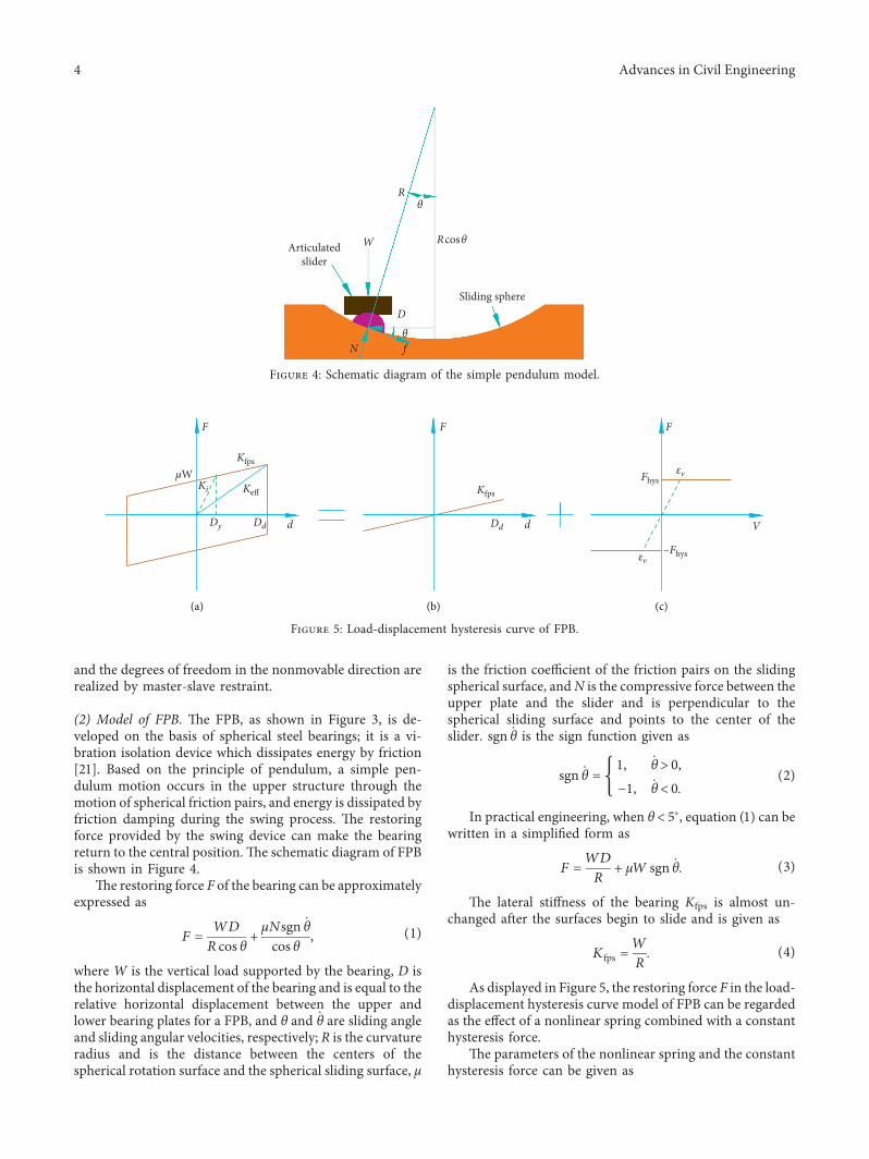
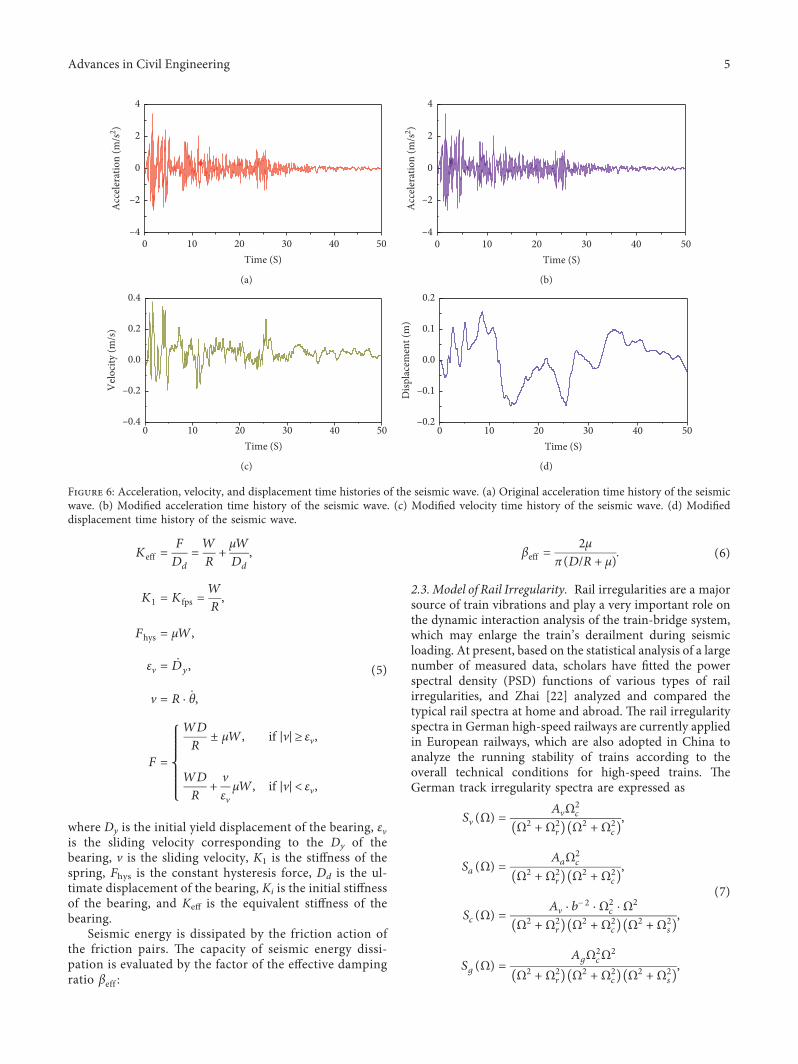
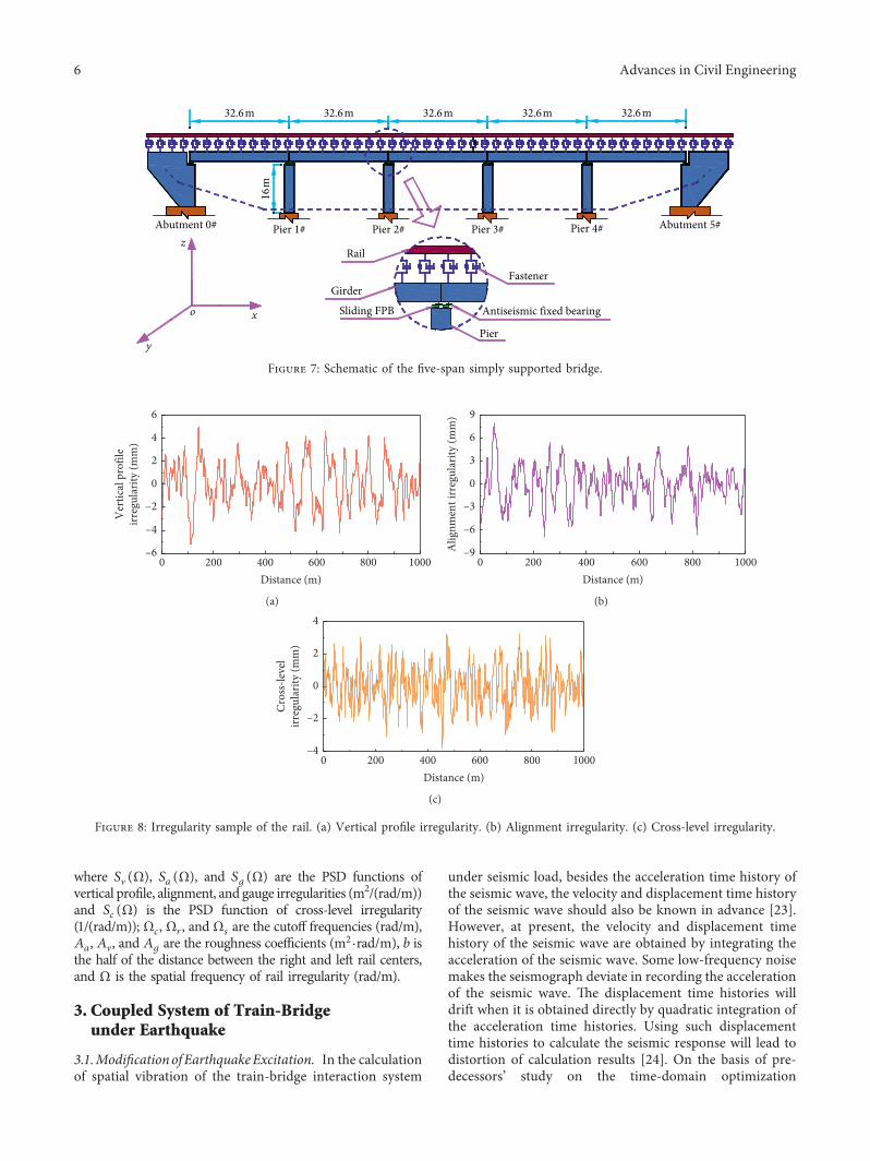
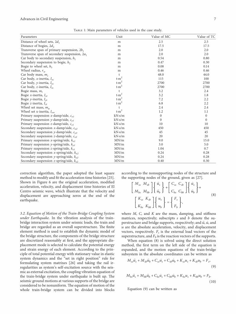
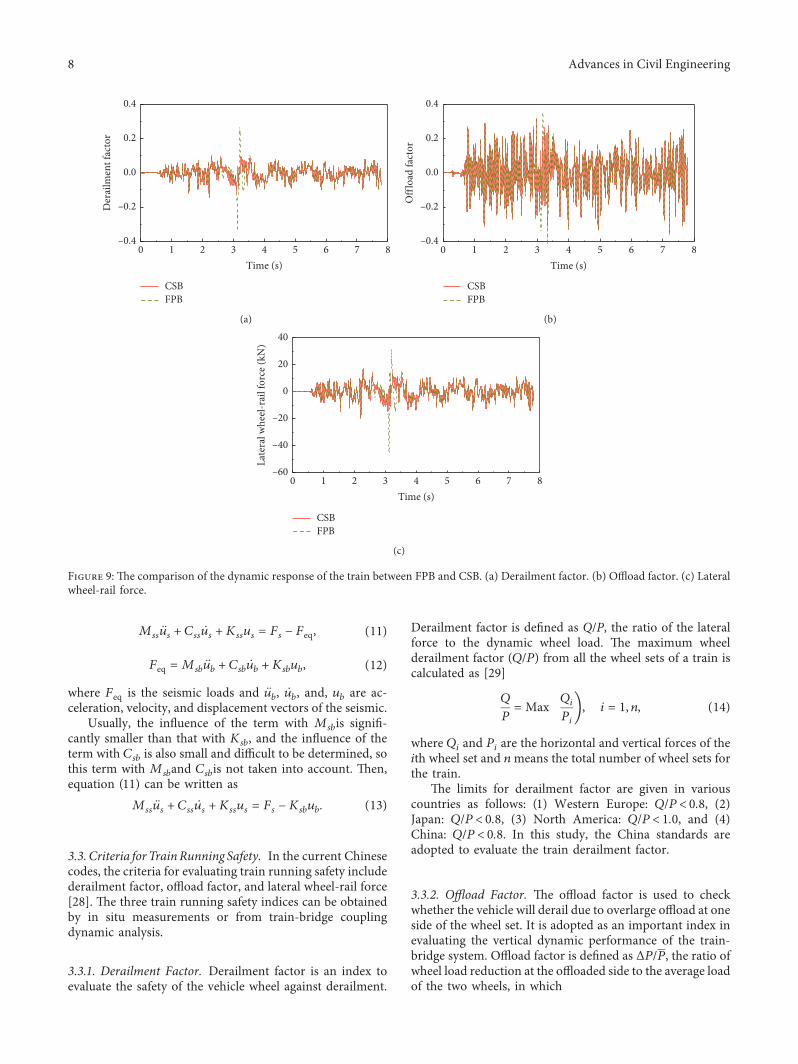
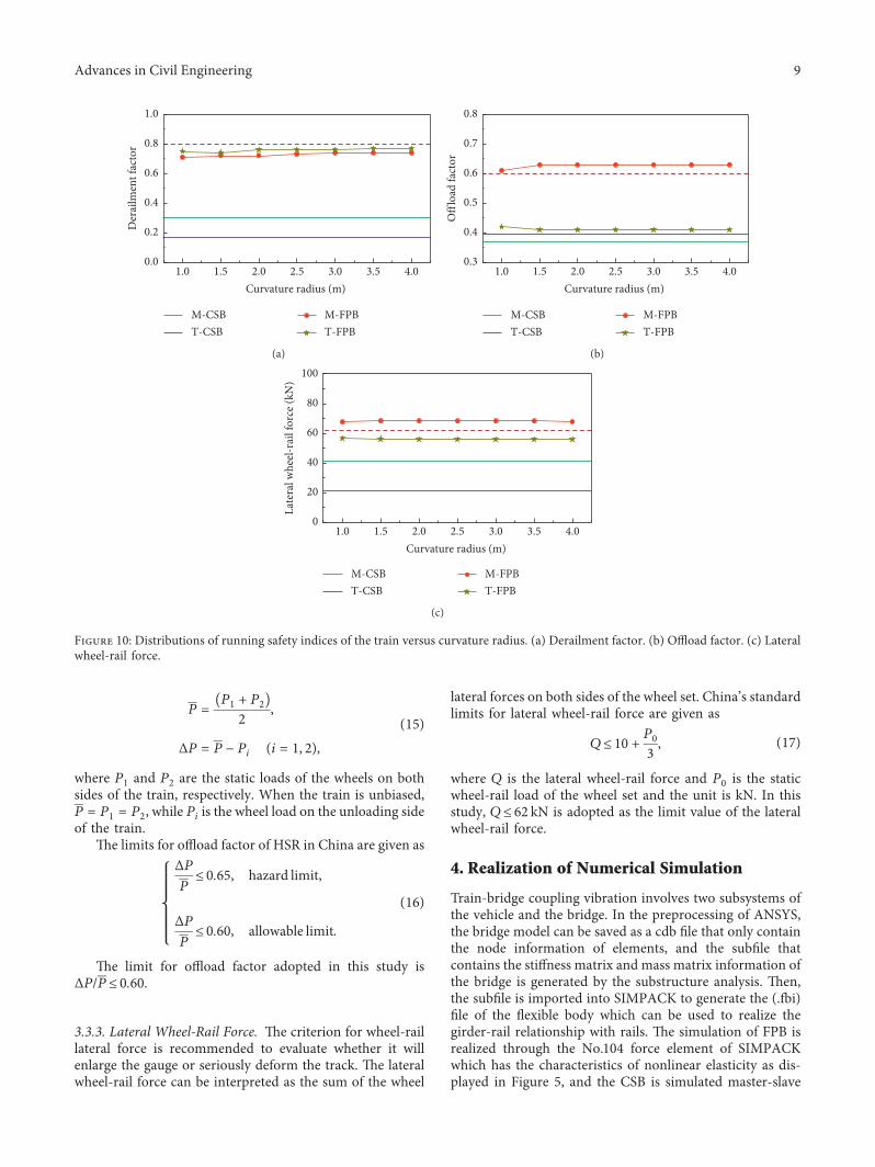
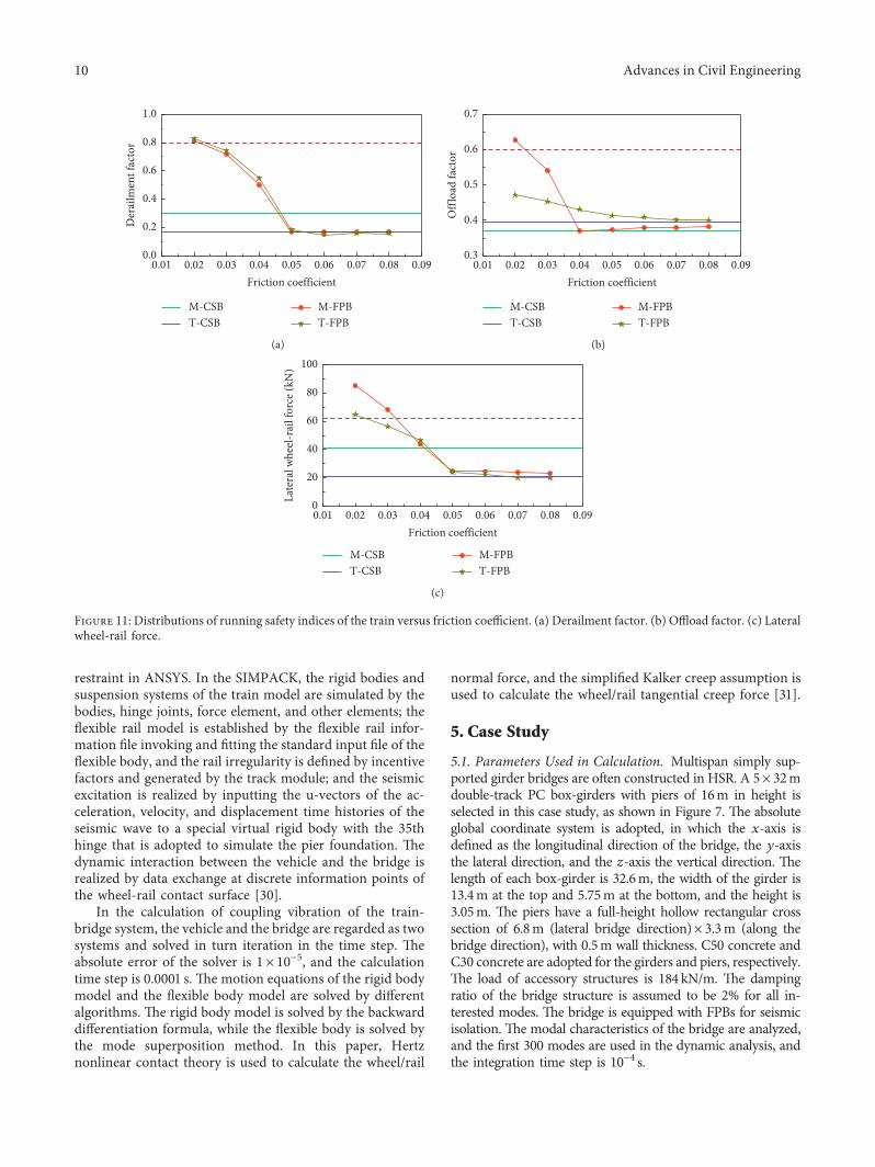
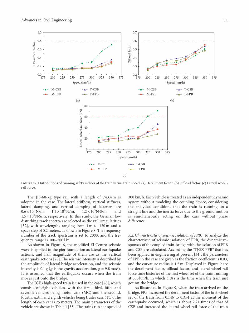
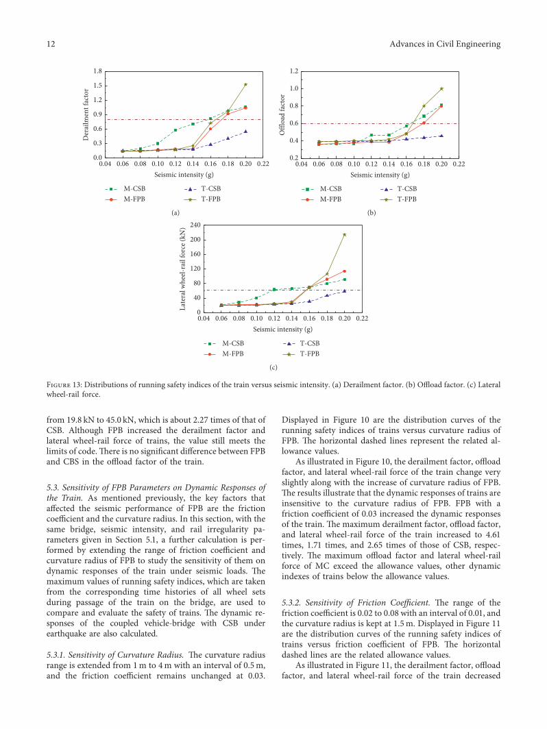
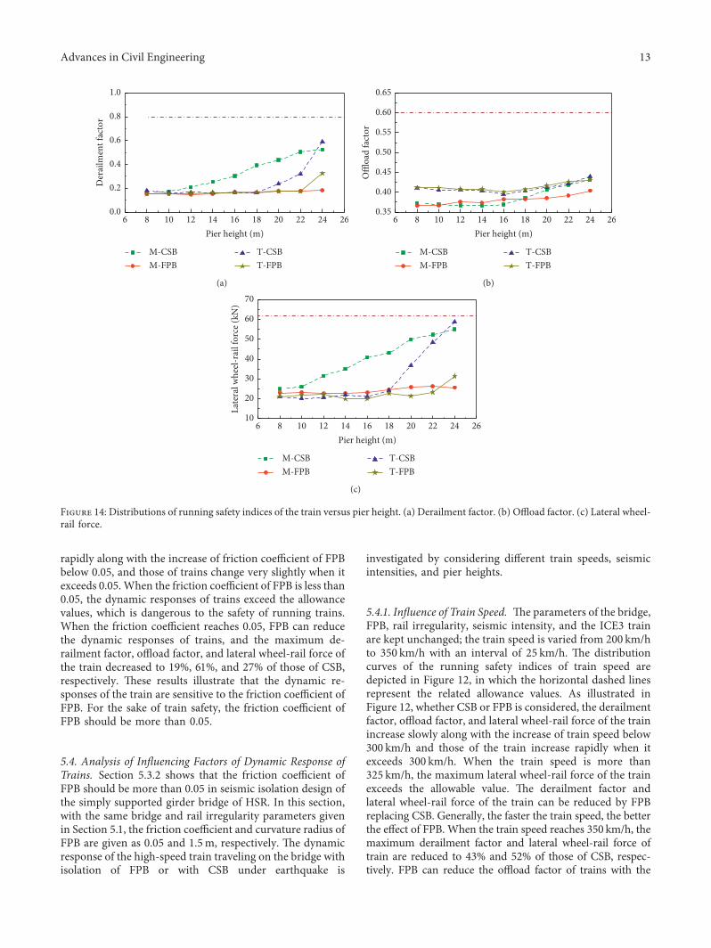
Related Documents