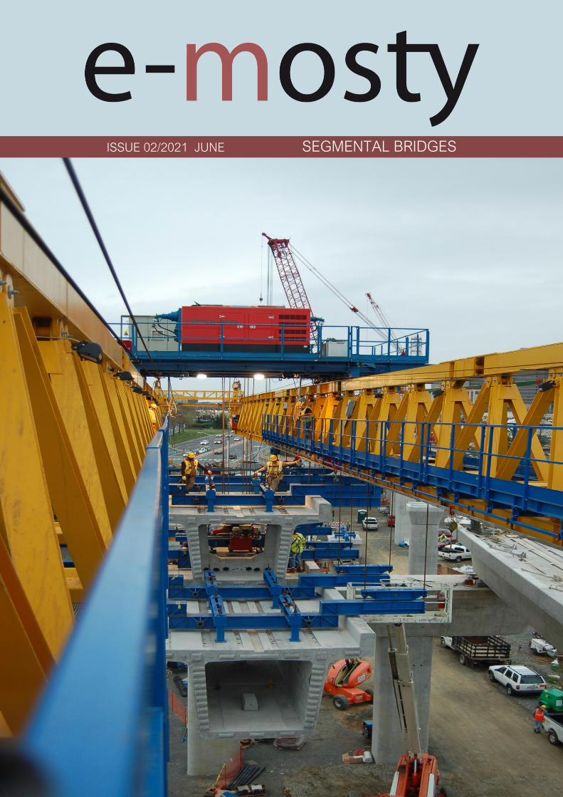
ISSUE 02/2021 JUNE SEGMENTAL BRIDGES

Welcome message from author
This document is posted to help you gain knowledge. Please leave a comment to let me know what you think about it! Share it to your friends and learn new things together.
Transcript
ISSUE 022021 JUNE SEGMENTAL BRIDGES
22021
International interactive magazine about bridges
e-mosty (ldquoe-bridgesrdquo)
It is published at wwwe-mostycz Open Access
Released quarterly
20 March 20 June 20 September and 20 December
Peer-reviewed
Number 022021 June
Year VII
copyAll rights reserved Please respect copyright When referring to any information contained herein please use the title
of the magazine bdquoe-mostyldquo volume author and page In case of any doubts please contact us Thank you
Chief Editor Magdaleacutena Sobotkovaacute
Contact infoprofessional-englishcz
Editorial Board
The Publisher PROF-ENG s r o (Ltd) Velkaacute Hraštice 112 262 03 Czech Republic
VAT Id Number CZ02577933
E-MOSTY ISSN 2336-8179
Geometry Control for Precast Segmental Construction
Joakim Dupleix CaSE International (formerly VSL) Martin Pircher ABES
Precast Segmental Bridge Construction Using Lifting Frame in Qatar
Joakim Dupleix CaSE International (formerly VSL)
German A Pardo R VSL International Ltd
Constructability Segmental Bridge Details
Jeremy Johannesen McNary Bergeron amp Associates
Photo on the Front Cover L57 Gantry Erecting the Dulles Corridor Metrorail in Reston Virginia
Credit Matthew Williams McNary Bergeron amp Associates
Photo on the Back Cover Final Segment Erection of the Cantilever Al Bustan South Project Qatar
Credit VSL International
page 07
LIST OF CONTENTS
page 27
page 36
Design Considerations for Gantry Erected Bridges
Matthew Williams Jeremy Johannesen McNary Bergeron amp Associates
page 41
22021
Dear Readers
This issue focuses on segmental bridges
The topic of the first article of this issue which was prepared by Jeremy Johannesen from McNary
Bergeron amp Associates is Constructability Segmental Bridge Details The material presented here has
been mined from a wide range of designers and builders on bridges going back many years The
article attempts to highlight and share some examples of the best practices that have been found
in use around the industry
For the first time we publish a 3D model which can be read as pdf We trust that it is useful and we are
going to bring more content of this type in the future
The next article was prepared by Matthew Williams and Jeremy Johannesen from McNary Bergeron amp
Associates It deals with Design Considerations for Gantry Erected Bridges and brings a breakdown of
the typical construction loads a bridge has to accommodate during gantry operation
Joakim Dupleix from Case International (formerly VSL) and Martin Pircher from ABES in their article
Geometry Control for Precast Segmental Construction describe using a specially developed software
suite dedicated to managing the geometry control of segmental construction at every stage of the
construction process
The last article of this issue Precast Segmental Bridge Construction Using Lifting Frame in Qatar is
presented by Joakim Dupleix from Case International (formerly VSL) and German A Pardo R from
VSL International In Qatar VSL designed and operated two very different types of lifting frames as
part of the Al Bustan corridor upgrade project
I would like to thank all authors and companies involved for their cooperation and also Juan C Gray
(T Y Lin) and Richard Cooke for reviewing this issue and Guillermo Muntildeoz-Cobo Cique (Arup) for his
final check I would like to thank Jason Hatcher from Hatcher Technical for his assistance with the 3D
model
I would also like to thank our partners for their continuous support And many thanks to Joseacute Calisto
da Silva from Biggs Cardosa Associates who has decided to financially support our magazine
September 2021 Edition of e-mosty will be about BIM for Infrastructure Projects and Ports We still
welcome your articles especially with a focus on BIM for port operations and maritime projects Please
contact us here And also for this Issue Edinson Guanchez Associate Professor at Universidad
Politeacutecnica de Cataluntildea (UPC) and CEO at Siacutesmica Institute SL Barcelona Spain has prepared an
article about Caissons for Bridges over Water
December 2021 Edition will be about American Bridges And we are already working on a special
edition of e-mosty June 2022 which we would like to dedicate to the 1915 Ccedilanakkale Bridge Project
This suspension bridge with a total length of 4608m and 2023m of a middle span is currently under
construction in Turkey
With our other magazine e-maritime we go on focussing on maritime construction projects design
and construction of ports and docks e-maritime June 2021 will be about Shipyards and Maritime
industry and construction in Malta and will be released on 30 June at wwwe-maritimecz with open
access
Magdaleacutena Sobotkovaacute
Chief Editor
INTERNATIONAL ONLINE PEER-REVIEWED MAGAZINE ABOUT BRIDGES
OUR PARTNERS
The magazine e-mosty (ldquoe-bridgesrdquo)
is an international interactive
peer-reviewed magazine about bridges
It is published at wwwe-mostycz and can be read
free of charge (open access)
with possibility to subscribe
It is published quarterly 20 March 20 June
20 September and 20 December
The magazines stay available online
on our website as pdf
The magazine brings original articles about bridges
and bridge engineers from around the world
Its electronic form enables publishing of high-quality
photos videos drawings links etc
We aim to include all important and technical
information and show the grace and beauty
of the structures
We are happy to provide media support for important
bridge conferences educational activities charitable
projects books etc
Our Editorial Board comprises bridge engineers
and experts mainly from the UK US and Australia
The readers are mainly bridge engineers designers
constructors and managers of construction
companies university lecturers and students
or people who just love bridges
ISSN E-MOSTY 2336-8179
SUBSCRIBE
INTERNATIONAL ONLINE PEER-REVIEWED MAGAZINE
ABOUT PORTS DOCKS VESSELS AND MARITIME EQUIPMENT
OUR PARTNERS
The magazine e-maritime is an international interactive
peer-reviewed magazine about ports docks vessels
and maritime equipment
It is published at wwwe-maritimecz three times a year
30 March 30 June and 30 November
September Issue is shared with the magazine e-mosty
(ldquoe-bridgesrdquo) ldquoBIM Vessels and Equipment for Bridge
Constructionrdquo which is published on 20 September
at wwwe-mostycz
It can be read free of charge (open access)
with possibility to subscribe
The magazines stay available online
on our website as pdf
The magazine brings original articles about design
construction operation and maintenance of ports docks
vessels and maritime equipment from around the world
Its electronic form enables publishing of high-quality
photos videos drawings links etc
We aim to include all important and technical information
and show the grace and beauty of the structures
and vessels as well
ISSN 2571-3914
SUBSCRIBE
READ OUR LATEST ISSUES
Portsmouth Port ndash Haifa Port
ndash Sesimbra Port
Monaco Land Projects
New Coastal Road in Reacuteunion
ndash Bidston Lighthouse in UK
Partnership can be arranged with both magazines or with each magazine separately
We can also agree on partnership covering only one specific issue
The partnership scheme typically involves
- Your logo on the main page of our website
- 1 page interactive presentation of your company
- Your logo and or the name of your company on every publication
and output we release
- Continuous promotion of your company and projects in our social media
- Publication of one technical article during the year
(which we can help you prepare)
More information conditions and the price can be found here Both the price and the extent of cooperation are fully negotiable
Please contact us for more details and partnership arrangement
Offer of partnership and promotion of your company
in our magazines e-mosty and e-maritime
The magazine e-mosty was established in April 2015 and its first issue was released on 20 June 2015 as a bilingual
English ndash Czech magazine aimed mainly for Czech and Slovak bridge engineers
Very quickly it reached an international readership
In 2016 we extended the already existing Czech and Slovak Editorial Board by two bridge experts from the UK and
since then four more colleagues ndash from the USA Australia and The Netherlands ndash have joined us
Since December 2016 the magazine has been published solely in English
Each issue now has thousands of readers worldwide
Many of our readers share the magazine in their companies and among their colleagues
so the final number of readers is much higher
Most importantly the readership covers our target segment ndash managers in construction
companies bridge designers and engineers universities and other bridge related experts
The magazine e-maritime was established in 2018 and its first issue was released on 30 March 2019
The magazine is published in English It is going to cover a vast range of topics related to vessels maritime equipment
ports docks piers and jetties - their design construction operation and maintenance and various maritime and
construction related projects
The Editorial Board already has two members ndash from the UK and the Netherlands
Both magazines are with Open Access with possibility to subscribe (free of charge)
In January 2019 we established their own pages on LinkedIn with constantly increasing number of their followers
Number of subscribers of both magazines is also increasing
We also know that the readers usually go back to older issues of both magazines
Bridge Design Construction Maintenance Vessels Ports Docks Maritime Equipment
22021
CONSTRUCTABILITY SEGMENTAL BRIDGE DETAILS
Jeremy Johannesen McNary Bergeron amp Associates
I INTRODUCTION
If any of these topics sound familiar you are in
good company The material presented here
has been mined from a wide range of designers
and builders on bridges going back many years
From the vantage point of a construction
engineer there are a number of common
avoidable problems that we encounter
Sometimes the problems are obvious Other
times rooting out these problems requires
getting immersed in complexities that no one
else would care to understand
Detailing is tedious and for that reason good-
detailing is rarely recognized and clever ideas
get lost
This paper attempts to highlight and share some
examples of the best practices that we have
found in use around the industry
II SEGMENT GEOMETRY AND CONVENTIONS
The key principles for segment geometry are
commonly accepted and understood within the
industry Geometry in curved alignments is
achieved by chording the individual segments
In plan segment joints are perpendicular to the
chord of the segment being cast In profile
joints are vertical at the time of casting
While it is understood that these rules provide a
basis for survey control it is more important to
know that these are based on the practical
limitations of the formwork system
Figure 1 Segment Geometry
22021
III CROSS-SECTION
As a starting point for any design the AASHTO-
PCI-ASBI standards provide solid examples of
cross sections and basic segment details
When adapting those details to specific project
requirements consider the following
DECK SLAB In a structure where the
construction method or loads require dual
cantilever anchors at each web the anchors
should straddle the web reinforcement This is a
simple solution and avoids many reinforcing
conflicts However large anchors (larger than
12 strands) often do not fit in the deck haunch
The top of the web is an appealing spot for a
single large anchor Be aware however that
placing the anchor in the web creates some
reinforcing challenges and may require adding
concrete to provide flexibility in bar placement
Refer to Section X on the following pages for
details to help evaluate the most practical
anchor arrangement
BOTTOM SLAB There are two schools of
thought on how best to detail the bottom slab
transverse profile One is to use a constant
thickness from web to web and the other is to
use a haunched profile
Each has its advantages (see Section X for
reinforcement examples)
For either the case verify that the ducts near
the web pass cleanly over the horizontal legs of
the web rebar In some cases it is worth raising
the ducts near the web slightly
When using a haunched slab extend the fillet far
enough to prevent conflicts between the top mat
rebar and the ducts
CORE FORM A successful design is based on
a realistic understanding of the formwork
system Standardization and simplicity should
be the goal To be specific
Use consistent anchor block geometry to
eliminate formwork modifications from
the casting cycle
Proportion anchor blocks to allow the
formwork to collapse and retract
Avoid using continuity tendons in the top
slab because the anchor blocks make
the operation of the core form
complicated History shows that
balanced cantilever bridges will work
without top slab continuity tendons
Figure 2 Cross Section Comparison All the dimensions on this figure are in imperial feet and inches
22021
IV REBAR LAYOUT amp SPACING
Often designs are prepared in a divide-and-
conquer approach where the PT and reinforcing
designs are done without close coordination
One simple method to better integrate details is
to adopt an assumed reinforcement layout early
in the design This establishes dedicated lanes
for the reinforcement to integrate everything
else around
Once that is established it is preferable to
maintain the reinforcing layout and vary bar
sizes as demands require The benefits of this
approach become evident when integrating the
girder reinforcing with anchor blocks etc
LAYOUT Commonly used rebar spacings are
15 or 20cm (6rdquo or 8rdquo) Note that a 15cm
spacing is adequate to fit transverse tendons
between bars and also allows the use of 30cm
spacings when demands are less
CURVATURE In ldquostraightrdquo bridges where
segments are effectively rectangular the layout
is simple (offset the first bar-set half of the
nominal spacing from the bulkhead face and
then repeat at the nominal spacing) For
segments in curves space the bars parallel to
the bulkhead until beyond the anchor block
reinforcement (or other details requiring
integration)
Then vary the spacing in an accordion fashion
near the match cast face
This approach is similar to timber framing in
house construction where rather than spacing
the studs uniformly along each wall the studs
are spaced at 40cm (16rdquo) as much as is
practical and any remainder is left as a single
short spacing
This is a well understood technique and it is
based on a practical approach to integrating
different building components For example a
12 x 24m sheet of plywood in multiples of
40cm thus the sheeting aligns with the framing
studs
MINIMUM SPACINGS Knowing that the web on
the outside of the curve will be longer than the
centerline length of the segment the designer
should decide if it is acceptable for the bar
spacings in the lsquoaccordion zonersquo to exceed the
nominal spacing
Where spacings are already relatively tight it is
preferable to increase the spacings locally since
the lsquoaverage spacing is effectively unchanged
Where the bar spacing is larger (30cm for
example) it may be reasonable to add an lsquoextrarsquo
bar-set to take up this variation
Figure 3 Rebar Layout Methodology All the dimensions on this figure are in imperial feet and inches
22021
Figure 4 Rebar Layouts in Curved Segments
DECK REINFORCEMENT Deck reinforcement
should either be spaced with or spaced between
the lanes established by the web reinforcement
On several projects the deck reinforcement has
been pre-tied and then mated to the webs in the
forms This has been a successful approach
and is most effective when the deck bars can be
arranged to fall between the web rebar
V TRANSVERSE PT
LAYOUT Space the transverse tendons around
the nominal reinforcing lanes Locating
transverse tendons without regard for the
reinforcement results in non-uniform rebar
spacings and sometimes additional reinforcing
to cover those gaps created by the tendons
For best results establish a reinforcing layout
and then put the tendons in the gaps
POURBACKS There are numerous opinions as
to the best way to detail the pourbacks at the
anchorages
On some projects a variety of different details
have been tried with no clear consensus on
which was best
Anchor pourbacks located under a travel lane
are by default closed-top or better yet dead-end
anchors with no blockouts
The trickier question becomes what to do with
anchors under barriers and how best to patch
them ldquoASBIPTI M50rdquo contains relevant
examples and guidance
As long as the details provide adequate
protection to the anchor it is worth being
flexible to the contractorrsquos preferences
22021
Figure 5 Deck
Reinforcement
Figure 6 Transverse PT
Integrated with
Reinforcing Lanes
22021
STRAND INSTALLATION In dual box girders
transverse tendons are sometimes used across the
in-situ closure This detail has complications and
should be discouraged Strands cannot be reliably
fed through a flat duct after is has been cast in
concrete because the duct is often flattened (even
flatter) during concreting
Secondly accumulated tolerances between the
segments create significant misalignments across
the closure If a bridge deck really requires post-
tensioning between two barrels consider round
duct to address both of these challenges with what
is ultimately a modest difference in duct size
Figure 7 Dual Box Structure with in-situ Closure Veterans Memorial Causeway Courtesy of Reed amp Reed Construction
VI LONGITUDINAL PT TOP SLAB TENDONS
Avoiding or minimizing the number of tendons in
the deck slab can improve a bridgersquos lifespan
Similarly the details related to the top slab PT
are equally important in the structurersquos
durability
BLOCKOUTS The most common example of
longitudinal tendons in the top deck slab are
cantilever tendons These tendons are typically
anchored at the joint face In order to orient the
tendon to the bulkhead anchorages are
mounted to a recessed blockout
Figure 8 Cantilever Anchor Layout
22021
This recess should be deep enough to contain
the entire grout cap consequently it consumes
a significant amount of space on the bulkhead
Just as with a duct located along any other face
it is important to provide adequate clear cover to
the blockout to prevent water or grout leakage
to and from the ducts
LAYOUT Set the cantilever anchorage low
enough to clear the transverse tendon In some
cases anchor spirals have been found to conflict
with the first transverse tendon
This is a problem for a number of reasons including
the reduction in anchor confinement the potential
to crush the transverse tendon and the sheer
nuisance to the builder
TOP CONTINUITY Avoid the use of top slab
continuity tendons and associated anchor
blocks
This is particularly relevant in form traveller
construction where the core-form beams are
typically larger longer and may extend into the
previous segments at a skew
REINFORCEMENT The duct layout should
consider the reinforcement and related
fabrication tolerances As outlined in Section X
below lowering the ducts in and around the web
reinforcing addresses a number of problems
with a minimal effect on the tendon eccentricity
Figure 9 Web Rebar Tolerances
22021
Figure 10 Web Rebar Tolerances Upper Ducts lowered (slightly) at full Height Stirrups for rebar
tolerances Hong Kong Mtr South Island Line Courtesy of Leighton Construction
VII LONGITUDINAL PT BOTTOM SLAB
TENDONS
LAYOUT While there are exceptions to every
rule fixing the bottom slab tendon layout and
anchor block geometry from the inside corner of
the box girder can standardize many details
With this approach the relative geometry
between the anchor block and the duct-runs
remains consistent while the depth of the girder
varies
SLAB THICKNESS Consider making the
bottom slab thickness constant through the
anchor block segments In variable depth box
girders specifically balanced cantilever with
form travellers there is a natural instinct to vary
the bottom slab thickness in parallel with the
girder depth
However tapering the bottom slab down to its
minimum thickness prior to the anchor blocks is
an effective approach in simplifying the design
Figure 11 Bottom Duct Setout
22021
REINFORCEMENT Check for conflicts between
the web reinforcement and the duct layout The
webs typically require larger diameter rebar than
the bottom slab For that reason it may be
necessary to raise the ducts located over the
web bar legs
Finally verify that the first duct is set far enough
from the web to allow for any plan curvature at
the anchor
DUCT GEOMETRY Aim the anchorage slightly
inboard for jack access This is important in
curved bridges where the web in the next
segment may encroach on the jack envelope
The tendon profile at the anchor block should
allow for PT system radius and tangent
requirements The bend radius should be
measured in the plane of the curve
Fitting the requisite tangent and radius for a 19
strand tendon into a 3m long segment can be
challenging Specify lsquotight radiusrsquo duct where
needed
This duct has corrugations that permit smaller
bending radii without buckling and caving
Some ducts can also be heat-bent to achieve
small radii
The last resort is using pre-bent steel pipes
Being aware of and designing within the radii
that can be achieved with corrugated plastic
duct should be the goal for cost-effective
design
Figure 12 Bottom Duct Profile
22021
VIII LONGITUDINAL PT WEB TENDONS
While very common in traditional post-tensioned
construction web tendons are not often used in
precast segmental bridges However there are
two situations where web tendons are
sometimes used
First is to supplement or eliminate bottom slab
continuity tendons Second is to provide some
form of bonded continuity steel across the entire
span ndash seismic requirements for example
In these cases the most practical approach is to
anchor the web tendons in pier or expansion
segments and run them pier-to-pier thereby
avoiding unique anchor blocks
In order to have a rational duct arrangement on
the bulkhead the tendons should use an
angular or lsquodeviatedrsquo profile ndash not draped
profiles Furthermore use a profile that is
coordinated with the shear key arrangement or
coordinate the shear keys with the duct holes to
avoid altering the bulkhead during casting
In the situation where web tendons are used in
conjunction with anchor blocks avoid locating
anchor blocks in-plane with the web tendons
The web and bottom slab tendon will inevitably
slope at different angles which prevents the
anchor block reinforcement development into
the web
Figure 13 Web Tendon Profile and Bottom Blocks
IX LONGITUDINAL PT EXTERNAL TENDONS
For those wanting potentially replaceable post-
tensioning external tendons are the answer
The Florida DOT Bridge Design Manual provides
some of the best advice for these details
DEVIATOR A point of debate between experts
is diabolos vs pipes For smaller quantities
pipes may be more economical Pipes are also
smaller On the other hand pipes can and do
get placed incorrectly which requires expensive
re-work to correct
When laying out the tendon paths be aware that
diabolos require more space since they flare out
in 360 degrees
Furthermore diabolos without stay-in-place
plastic formers require more stringent clear
cover requirements between rebar and the
diabolos That said a well thought out design
with diabolos is relatively fool-proof with only the
up-front cost of the formers
CONFLICTS One consideration for any design
with external tendons is to verify that the
external tendons have a clear line-of-sight
between deviation points Confirm that the
tendons do not hit other anchor blocks
In curved structures check that the tendons do
not hit the web walls Where structures are on
tight radii it may be necessary to add an
additional deviator to guide the tendons around
the curved span
X BOX GIRDER REINFORCEMENT
To paraphrase the theme of Section IV above
ldquoUse Common Denominatorsrdquo Simply spacing
the reinforcement together at regular intervals
goes a long way to simplifying construction
The answer to ldquowhy not mix spacings if it saves
a few barsrdquo is that it becomes necessary to shift
some bars out of their nominal spacings to mesh
with the other set leading to localized
congestion and conflicts
22021
Space rebar at common denominators ie 15
and 30cm work together but not 15 and 20cm
Once the reinforcing lanes are established the
key to constructability is the web reinforcement
PT anchors anchor blocks transverse tendons
and construction embeds all gravitate to the
webs
Furthermore the web reinforcement is a full-
height shear stirrup which is sensitive to bending
and placing tolerances
TOLERANCES Rebar fabrication tolerances
should be a primary consideration in detailing
The fabricated bending tolerance on most bars
is +-25mm per leg Tighter tolerances can be
specified but keep in mind that there is no
magic tolerance setting on the bending
machine If the design requires tighter
tolerances this translates to more rejected bar
and associated cost
If a bar is constrained by clear cover at each
end the logical approach is to detail the bar
25mm short of the nominal length and verify that
the details can accommodate the tolerance
Sometimes the clear cover tolerances help And
sometimes the bar tolerances can be absorbed
at two faces and the effects are minor With
web reinforcing however the bars are typically
supported on chairs on the soffit slab which
requires all of the tolerance to be taken up at
the top face where the bar legs are constrained
between the clear cover and the cantilever
ducts
A simple solution is to lower the ducts within this
area to clear the bar tolerance envelope While
this lowers the eccentricity of some tendons
consider that it is likely a small number of the
tendons moving a small percentage of the
overall depth so the effect is minor
NESTING BARS Give consideration to the
bends and orientation of the web bar tails In
order to minimize congestion and make room for
other reinforcement it preferable to keep the
web bars in-plane with each other Use 180
degree hooks where appropriate to avoid
bundled legs
RE-ENTRANT CORNERS Be thoughtful when
detailing reinforcement at re-entrant corners
For example the inside web face often has a
fillet Reinforcing this face with a single bar is not
advisable
Figure 14 Re-entrant
Corners
22021
Consider that when this bar is in tension it will
want to straighten and pop-out the cover
concrete at the corner It is preferable to use
crossing-bars which develop beyond the corner
TENDON PASS-THRU Where tendons pass
thru reinforcing mats the design should specify
how Note that the tendons in anchor blocks
typically slope at 12-15 degrees At this angle
the duct can conflict with rebar over a length of
60-90cm
Simply shifting bars longitudinally to clear the
conflict is not practical because it displaces too
many bars and leaves a large gap
In most cases it is preferable that the cross-thru
details are modifications (by moving bending or
cutting) to the typical reinforcing as opposed to
introducing unique bars at specific locations
Figure 15 Top Mat Bars at Cross-Thru (with fillet)
Figure 16 Top Mat Bars at Cross-Thru (flat slab)
22021
LONGITUDINAL REINFORCING An additional
topic to highlight is the treatment of longitudinal
reinforcing in curved segments In cast-in-place
construction the bars are detailed long enough
to satisfy the lap splice requirements on the
outside of the curve and the extra length on the
short side is taken up in the lap splice
In precast segments the detailing of longitudinal
reinforcement becomes complicated
Longitudinal bars are broken into sub-sets in
order to graduate the lengths across the width
of the segment
Otherwise identical reinforcing cages but with
slightly different plan-view geometry become
different reinforcing types requiring additional
drawings and submittals not to mention more
time spent sorting bars on-site
Given that segment cages are pre-tied in jigs it
would be reasonable to detail all the bars long
tie them in the cage and then cut them to
match the pie-shape of the specific segment
This would streamline shop drawing process and
potentially simplify fabrication
Figure 17 Treatment of Longitudinal Bars
XI ANCHOR BLOCK REINFORCEMENT
Before reading any further prepare to go lsquodeep
in the weedsrsquo In order to lessen the headache
refer directly to the appendix for an example of
an anchor block that addresses the challenges
CONGESTION Anchor blocks typically have
two sets of bars (outer confinement + inner tie
for curvature) which mesh together with the
web reinforcement (2 faces) and slab
reinforcement (2 faces)
Altogether this can translate to six bars which
must pass each other Many of these bars may
have legs on the same face creating lsquowallsrsquo of
bundled rebar
These zones of bars are problematic for placing
concrete prone to spalling and do nothing to
develop the reinforcement There are several
techniques to address this
Place the web reinforcement in the same
plane Turn the leg on the inside-face
web bar toward centerline of segment If
the leg on the outside-face web bar
contacts the inside-face reinforcement
consider using a 180deg hook
Place bottom slab reinforcement in the
same plane If the legs happen to
conflict shorten or place the top-mat bar
to nest inside the bottom-mat bar
22021
Turn the legs of the outer anchor block
reinforcement away from the web Full
360deg or even 270deg confinement of the
anchor block is not necessary as the
bottom slab and web reinforcement
already exist on these faces and are
waiting to be put to work
Consider the direction of the legs on the
inner anchor block bars (ie the in-plane
pullout reinforcement) Turning both legs
the same direction andor using 180
degree hooks may be helpful
TENDON GEOMETRY Anchor block
reinforcement should be organized with thought
to the actual tendon geometry In most cases
the other tendons in and around the anchor
block are not running parallel to the web
Tendon paths should not be altered to snake
thru the reinforcement Instead configure the
reinforcement to the lanes between the ducts
There are several techniques to address this
Begin by designing the reinforcement
around the typical (probably deviating)
tendon arrangement
Slope the inside face of the anchor block
By varying the clear cover the outer
block reinforcement may be detailed to
follow either straight or deviating tendon
paths
Adjust the width of the in-plane pullout
reinforcement as needed Where these
bars are tall use a wide bar in order to
straddle ducts running below Where
these bars are short a narrow top-hat
bar is appropriate to avoid clashing with
other ducts
Figure 18 Anchor Block Reinforcement (see Appendix)
22021
XII DIAPHRAGM REINFORCEMENT
There are a number of different approaches to
diaphragm design and this paper will not go into
depth on the possibilities However the
challenges found in diaphragm reinforcement
are variations on others already identified
When presented a problem engineers are good at
finding fixes For that reason simply being aware
of these issues goes a long way
Rebar Fabrication Tolerances
Rebar Placing Tolerances
Actual Size of Rebar and PT
Actual Size of Bar Bend Radii
Congestion (see Figure 19)
Uniformity Standardization
Finally just to give the contractor a sporting
chance identify all of the intersecting bars ducts
and other elements (with their overall sizes) and
verify that they do indeed fit inside of the concrete
An allowance for placing tolerances is
recommended too Incorporating this analysis into
the design process should be standard practice
Figure 19
lsquoRealrsquo Rebar
Diameter
larr Figure 20
Example of
Congestion
Too Many Bars
in Same Plane
22021
In cast-in-place construction headed anchor
studs may be a good option provided again
that the stud layout is integrated with the
reinforcement
INTEGRAL STRADDLE BEAMS Precast
segments are sometimes cantilevered from
straddle beams or similar CIP elements In this
configuration set the first precast segment just
off the straddle beam with a short closure
avoiding a complicated cast-in-place starter
Minor skews can be absorbed in the closure
Larger skews can be cast into the starter
segment In the case of cantilever construction
most if not all of the post-tensioning ducts are in
the top slab Rather than trying to cast ducts in
precise locations in the straddle beam set the
segment slightly higher than the top of beam
and cast the deck slab after the segments have
been placed
This avoids complications with tolerances as
well as conflicts between the straddle beam
stirrups and PT ducts
XIII SUBSTRUCTURE CONNECTIONS
The details associated with the superstructure
connection to the substructure have a
significant impact on the constructability This
interface is typically at the bearings and in some
cases the superstructure may frame into other
types of construction
Short closures are used to connect segments
which are not match cast However when a
segment is taken from one form and mated up
with one from a different form you can expect
some degree of misalignment in the cross
section and ducts
BEARINGS In precast segmental where the
structure requires fixity through the bearings it
is preferable to use a limited number of large
pintles to transfer horizontal load to the
bearings
In these situations the void for the pintle should
be oversized to allow for grade and
superelevation as well as reasonable fabrication
and placing tolerances
These voids may be formed using lsquocansrsquo or it
may be practical to void out a rectangular
volume in and around the reinforcement using
foam block In either case the pintles must be
integrated with the reinforcement
Figure 21 Straddle Beam Connection
22021
Figure 23 Straddle Beam Connection Top of Beam held low to allow Cantilever Tendons to pass over without conflict
Hong Kong Mtr South Island Line Courtesy of Leighton Construction
Figure 22 Straddle Beam Connection Top of Beam held low to allow Cantilever Tendons to pass over without conflict
Hong Kong Mtr South Island Line Courtesy of Leighton Construction
22021
INTEGRAL PIER COLUMNS Making precast
segments integral with pier columns presents
challenges but there are a number of benefits
Integral connections can eliminate bearings and
associated maintenance provide robust
connection for lateral loads (ie seismic) and
can eliminate the need for temporary stability
shoring
Integral connections can be achieved several
ways Similar to the previous straddle beam
example the conventional approach is to
construct cast-in-place pier segments and erect
precast segments on either side with short
closures
This requires realistic expectations for the
construction tolerances involved For example
it may be prudent to thicken the in-situ cross
section to minimize misalignments in the cross
section in addition to incorporating means to
accommodate duct misalignments
XIV PLAN PRESENTATION
Efficient construction requires good drawings
BRIM and 3D CAD tools allow us to create some
amazing work but as this is being written there
are still a lot of us humans involved in the
process
Modern drafting tools allow us to make drawing
easier and to balance that it is important to be
disciplined in minimizing drawings and details
Figure 24 PT Layout Example
22021
SYMMETRY If something is symmetric or even
close to it use half views Showing redundant
information invites confusion and errors This
also allows views to be larger and show details
more clearly
PT LAYOUTS All longitudinal PT for a given
segment should be shown on the same drawing
sheet Scale plan views in the transverse
direction to better illustrate tendon geometry
and neglect horizontal curvature Last ndash call out
each end of each tendon
APPENDIX 3D MODEL
The following page is a 3D pdf to illustrate some
of the points discussed in this document
The source DGN file is attached here
I hope you find this document useful and Good Bridgebuilding
22021
International interactive magazine about bridges
e-mosty (ldquoe-bridgesrdquo)
It is published at wwwe-mostycz Open Access
Released quarterly
20 March 20 June 20 September and 20 December
Peer-reviewed
Number 022021 June
Year VII
copyAll rights reserved Please respect copyright When referring to any information contained herein please use the title
of the magazine bdquoe-mostyldquo volume author and page In case of any doubts please contact us Thank you
Chief Editor Magdaleacutena Sobotkovaacute
Contact infoprofessional-englishcz
Editorial Board
The Publisher PROF-ENG s r o (Ltd) Velkaacute Hraštice 112 262 03 Czech Republic
VAT Id Number CZ02577933
E-MOSTY ISSN 2336-8179
Geometry Control for Precast Segmental Construction
Joakim Dupleix CaSE International (formerly VSL) Martin Pircher ABES
Precast Segmental Bridge Construction Using Lifting Frame in Qatar
Joakim Dupleix CaSE International (formerly VSL)
German A Pardo R VSL International Ltd
Constructability Segmental Bridge Details
Jeremy Johannesen McNary Bergeron amp Associates
Photo on the Front Cover L57 Gantry Erecting the Dulles Corridor Metrorail in Reston Virginia
Credit Matthew Williams McNary Bergeron amp Associates
Photo on the Back Cover Final Segment Erection of the Cantilever Al Bustan South Project Qatar
Credit VSL International
page 07
LIST OF CONTENTS
page 27
page 36
Design Considerations for Gantry Erected Bridges
Matthew Williams Jeremy Johannesen McNary Bergeron amp Associates
page 41
22021
Dear Readers
This issue focuses on segmental bridges
The topic of the first article of this issue which was prepared by Jeremy Johannesen from McNary
Bergeron amp Associates is Constructability Segmental Bridge Details The material presented here has
been mined from a wide range of designers and builders on bridges going back many years The
article attempts to highlight and share some examples of the best practices that have been found
in use around the industry
For the first time we publish a 3D model which can be read as pdf We trust that it is useful and we are
going to bring more content of this type in the future
The next article was prepared by Matthew Williams and Jeremy Johannesen from McNary Bergeron amp
Associates It deals with Design Considerations for Gantry Erected Bridges and brings a breakdown of
the typical construction loads a bridge has to accommodate during gantry operation
Joakim Dupleix from Case International (formerly VSL) and Martin Pircher from ABES in their article
Geometry Control for Precast Segmental Construction describe using a specially developed software
suite dedicated to managing the geometry control of segmental construction at every stage of the
construction process
The last article of this issue Precast Segmental Bridge Construction Using Lifting Frame in Qatar is
presented by Joakim Dupleix from Case International (formerly VSL) and German A Pardo R from
VSL International In Qatar VSL designed and operated two very different types of lifting frames as
part of the Al Bustan corridor upgrade project
I would like to thank all authors and companies involved for their cooperation and also Juan C Gray
(T Y Lin) and Richard Cooke for reviewing this issue and Guillermo Muntildeoz-Cobo Cique (Arup) for his
final check I would like to thank Jason Hatcher from Hatcher Technical for his assistance with the 3D
model
I would also like to thank our partners for their continuous support And many thanks to Joseacute Calisto
da Silva from Biggs Cardosa Associates who has decided to financially support our magazine
September 2021 Edition of e-mosty will be about BIM for Infrastructure Projects and Ports We still
welcome your articles especially with a focus on BIM for port operations and maritime projects Please
contact us here And also for this Issue Edinson Guanchez Associate Professor at Universidad
Politeacutecnica de Cataluntildea (UPC) and CEO at Siacutesmica Institute SL Barcelona Spain has prepared an
article about Caissons for Bridges over Water
December 2021 Edition will be about American Bridges And we are already working on a special
edition of e-mosty June 2022 which we would like to dedicate to the 1915 Ccedilanakkale Bridge Project
This suspension bridge with a total length of 4608m and 2023m of a middle span is currently under
construction in Turkey
With our other magazine e-maritime we go on focussing on maritime construction projects design
and construction of ports and docks e-maritime June 2021 will be about Shipyards and Maritime
industry and construction in Malta and will be released on 30 June at wwwe-maritimecz with open
access
Magdaleacutena Sobotkovaacute
Chief Editor
INTERNATIONAL ONLINE PEER-REVIEWED MAGAZINE ABOUT BRIDGES
OUR PARTNERS
The magazine e-mosty (ldquoe-bridgesrdquo)
is an international interactive
peer-reviewed magazine about bridges
It is published at wwwe-mostycz and can be read
free of charge (open access)
with possibility to subscribe
It is published quarterly 20 March 20 June
20 September and 20 December
The magazines stay available online
on our website as pdf
The magazine brings original articles about bridges
and bridge engineers from around the world
Its electronic form enables publishing of high-quality
photos videos drawings links etc
We aim to include all important and technical
information and show the grace and beauty
of the structures
We are happy to provide media support for important
bridge conferences educational activities charitable
projects books etc
Our Editorial Board comprises bridge engineers
and experts mainly from the UK US and Australia
The readers are mainly bridge engineers designers
constructors and managers of construction
companies university lecturers and students
or people who just love bridges
ISSN E-MOSTY 2336-8179
SUBSCRIBE
INTERNATIONAL ONLINE PEER-REVIEWED MAGAZINE
ABOUT PORTS DOCKS VESSELS AND MARITIME EQUIPMENT
OUR PARTNERS
The magazine e-maritime is an international interactive
peer-reviewed magazine about ports docks vessels
and maritime equipment
It is published at wwwe-maritimecz three times a year
30 March 30 June and 30 November
September Issue is shared with the magazine e-mosty
(ldquoe-bridgesrdquo) ldquoBIM Vessels and Equipment for Bridge
Constructionrdquo which is published on 20 September
at wwwe-mostycz
It can be read free of charge (open access)
with possibility to subscribe
The magazines stay available online
on our website as pdf
The magazine brings original articles about design
construction operation and maintenance of ports docks
vessels and maritime equipment from around the world
Its electronic form enables publishing of high-quality
photos videos drawings links etc
We aim to include all important and technical information
and show the grace and beauty of the structures
and vessels as well
ISSN 2571-3914
SUBSCRIBE
READ OUR LATEST ISSUES
Portsmouth Port ndash Haifa Port
ndash Sesimbra Port
Monaco Land Projects
New Coastal Road in Reacuteunion
ndash Bidston Lighthouse in UK
Partnership can be arranged with both magazines or with each magazine separately
We can also agree on partnership covering only one specific issue
The partnership scheme typically involves
- Your logo on the main page of our website
- 1 page interactive presentation of your company
- Your logo and or the name of your company on every publication
and output we release
- Continuous promotion of your company and projects in our social media
- Publication of one technical article during the year
(which we can help you prepare)
More information conditions and the price can be found here Both the price and the extent of cooperation are fully negotiable
Please contact us for more details and partnership arrangement
Offer of partnership and promotion of your company
in our magazines e-mosty and e-maritime
The magazine e-mosty was established in April 2015 and its first issue was released on 20 June 2015 as a bilingual
English ndash Czech magazine aimed mainly for Czech and Slovak bridge engineers
Very quickly it reached an international readership
In 2016 we extended the already existing Czech and Slovak Editorial Board by two bridge experts from the UK and
since then four more colleagues ndash from the USA Australia and The Netherlands ndash have joined us
Since December 2016 the magazine has been published solely in English
Each issue now has thousands of readers worldwide
Many of our readers share the magazine in their companies and among their colleagues
so the final number of readers is much higher
Most importantly the readership covers our target segment ndash managers in construction
companies bridge designers and engineers universities and other bridge related experts
The magazine e-maritime was established in 2018 and its first issue was released on 30 March 2019
The magazine is published in English It is going to cover a vast range of topics related to vessels maritime equipment
ports docks piers and jetties - their design construction operation and maintenance and various maritime and
construction related projects
The Editorial Board already has two members ndash from the UK and the Netherlands
Both magazines are with Open Access with possibility to subscribe (free of charge)
In January 2019 we established their own pages on LinkedIn with constantly increasing number of their followers
Number of subscribers of both magazines is also increasing
We also know that the readers usually go back to older issues of both magazines
Bridge Design Construction Maintenance Vessels Ports Docks Maritime Equipment
22021
CONSTRUCTABILITY SEGMENTAL BRIDGE DETAILS
Jeremy Johannesen McNary Bergeron amp Associates
I INTRODUCTION
If any of these topics sound familiar you are in
good company The material presented here
has been mined from a wide range of designers
and builders on bridges going back many years
From the vantage point of a construction
engineer there are a number of common
avoidable problems that we encounter
Sometimes the problems are obvious Other
times rooting out these problems requires
getting immersed in complexities that no one
else would care to understand
Detailing is tedious and for that reason good-
detailing is rarely recognized and clever ideas
get lost
This paper attempts to highlight and share some
examples of the best practices that we have
found in use around the industry
II SEGMENT GEOMETRY AND CONVENTIONS
The key principles for segment geometry are
commonly accepted and understood within the
industry Geometry in curved alignments is
achieved by chording the individual segments
In plan segment joints are perpendicular to the
chord of the segment being cast In profile
joints are vertical at the time of casting
While it is understood that these rules provide a
basis for survey control it is more important to
know that these are based on the practical
limitations of the formwork system
Figure 1 Segment Geometry
22021
III CROSS-SECTION
As a starting point for any design the AASHTO-
PCI-ASBI standards provide solid examples of
cross sections and basic segment details
When adapting those details to specific project
requirements consider the following
DECK SLAB In a structure where the
construction method or loads require dual
cantilever anchors at each web the anchors
should straddle the web reinforcement This is a
simple solution and avoids many reinforcing
conflicts However large anchors (larger than
12 strands) often do not fit in the deck haunch
The top of the web is an appealing spot for a
single large anchor Be aware however that
placing the anchor in the web creates some
reinforcing challenges and may require adding
concrete to provide flexibility in bar placement
Refer to Section X on the following pages for
details to help evaluate the most practical
anchor arrangement
BOTTOM SLAB There are two schools of
thought on how best to detail the bottom slab
transverse profile One is to use a constant
thickness from web to web and the other is to
use a haunched profile
Each has its advantages (see Section X for
reinforcement examples)
For either the case verify that the ducts near
the web pass cleanly over the horizontal legs of
the web rebar In some cases it is worth raising
the ducts near the web slightly
When using a haunched slab extend the fillet far
enough to prevent conflicts between the top mat
rebar and the ducts
CORE FORM A successful design is based on
a realistic understanding of the formwork
system Standardization and simplicity should
be the goal To be specific
Use consistent anchor block geometry to
eliminate formwork modifications from
the casting cycle
Proportion anchor blocks to allow the
formwork to collapse and retract
Avoid using continuity tendons in the top
slab because the anchor blocks make
the operation of the core form
complicated History shows that
balanced cantilever bridges will work
without top slab continuity tendons
Figure 2 Cross Section Comparison All the dimensions on this figure are in imperial feet and inches
22021
IV REBAR LAYOUT amp SPACING
Often designs are prepared in a divide-and-
conquer approach where the PT and reinforcing
designs are done without close coordination
One simple method to better integrate details is
to adopt an assumed reinforcement layout early
in the design This establishes dedicated lanes
for the reinforcement to integrate everything
else around
Once that is established it is preferable to
maintain the reinforcing layout and vary bar
sizes as demands require The benefits of this
approach become evident when integrating the
girder reinforcing with anchor blocks etc
LAYOUT Commonly used rebar spacings are
15 or 20cm (6rdquo or 8rdquo) Note that a 15cm
spacing is adequate to fit transverse tendons
between bars and also allows the use of 30cm
spacings when demands are less
CURVATURE In ldquostraightrdquo bridges where
segments are effectively rectangular the layout
is simple (offset the first bar-set half of the
nominal spacing from the bulkhead face and
then repeat at the nominal spacing) For
segments in curves space the bars parallel to
the bulkhead until beyond the anchor block
reinforcement (or other details requiring
integration)
Then vary the spacing in an accordion fashion
near the match cast face
This approach is similar to timber framing in
house construction where rather than spacing
the studs uniformly along each wall the studs
are spaced at 40cm (16rdquo) as much as is
practical and any remainder is left as a single
short spacing
This is a well understood technique and it is
based on a practical approach to integrating
different building components For example a
12 x 24m sheet of plywood in multiples of
40cm thus the sheeting aligns with the framing
studs
MINIMUM SPACINGS Knowing that the web on
the outside of the curve will be longer than the
centerline length of the segment the designer
should decide if it is acceptable for the bar
spacings in the lsquoaccordion zonersquo to exceed the
nominal spacing
Where spacings are already relatively tight it is
preferable to increase the spacings locally since
the lsquoaverage spacing is effectively unchanged
Where the bar spacing is larger (30cm for
example) it may be reasonable to add an lsquoextrarsquo
bar-set to take up this variation
Figure 3 Rebar Layout Methodology All the dimensions on this figure are in imperial feet and inches
22021
Figure 4 Rebar Layouts in Curved Segments
DECK REINFORCEMENT Deck reinforcement
should either be spaced with or spaced between
the lanes established by the web reinforcement
On several projects the deck reinforcement has
been pre-tied and then mated to the webs in the
forms This has been a successful approach
and is most effective when the deck bars can be
arranged to fall between the web rebar
V TRANSVERSE PT
LAYOUT Space the transverse tendons around
the nominal reinforcing lanes Locating
transverse tendons without regard for the
reinforcement results in non-uniform rebar
spacings and sometimes additional reinforcing
to cover those gaps created by the tendons
For best results establish a reinforcing layout
and then put the tendons in the gaps
POURBACKS There are numerous opinions as
to the best way to detail the pourbacks at the
anchorages
On some projects a variety of different details
have been tried with no clear consensus on
which was best
Anchor pourbacks located under a travel lane
are by default closed-top or better yet dead-end
anchors with no blockouts
The trickier question becomes what to do with
anchors under barriers and how best to patch
them ldquoASBIPTI M50rdquo contains relevant
examples and guidance
As long as the details provide adequate
protection to the anchor it is worth being
flexible to the contractorrsquos preferences
22021
Figure 5 Deck
Reinforcement
Figure 6 Transverse PT
Integrated with
Reinforcing Lanes
22021
STRAND INSTALLATION In dual box girders
transverse tendons are sometimes used across the
in-situ closure This detail has complications and
should be discouraged Strands cannot be reliably
fed through a flat duct after is has been cast in
concrete because the duct is often flattened (even
flatter) during concreting
Secondly accumulated tolerances between the
segments create significant misalignments across
the closure If a bridge deck really requires post-
tensioning between two barrels consider round
duct to address both of these challenges with what
is ultimately a modest difference in duct size
Figure 7 Dual Box Structure with in-situ Closure Veterans Memorial Causeway Courtesy of Reed amp Reed Construction
VI LONGITUDINAL PT TOP SLAB TENDONS
Avoiding or minimizing the number of tendons in
the deck slab can improve a bridgersquos lifespan
Similarly the details related to the top slab PT
are equally important in the structurersquos
durability
BLOCKOUTS The most common example of
longitudinal tendons in the top deck slab are
cantilever tendons These tendons are typically
anchored at the joint face In order to orient the
tendon to the bulkhead anchorages are
mounted to a recessed blockout
Figure 8 Cantilever Anchor Layout
22021
This recess should be deep enough to contain
the entire grout cap consequently it consumes
a significant amount of space on the bulkhead
Just as with a duct located along any other face
it is important to provide adequate clear cover to
the blockout to prevent water or grout leakage
to and from the ducts
LAYOUT Set the cantilever anchorage low
enough to clear the transverse tendon In some
cases anchor spirals have been found to conflict
with the first transverse tendon
This is a problem for a number of reasons including
the reduction in anchor confinement the potential
to crush the transverse tendon and the sheer
nuisance to the builder
TOP CONTINUITY Avoid the use of top slab
continuity tendons and associated anchor
blocks
This is particularly relevant in form traveller
construction where the core-form beams are
typically larger longer and may extend into the
previous segments at a skew
REINFORCEMENT The duct layout should
consider the reinforcement and related
fabrication tolerances As outlined in Section X
below lowering the ducts in and around the web
reinforcing addresses a number of problems
with a minimal effect on the tendon eccentricity
Figure 9 Web Rebar Tolerances
22021
Figure 10 Web Rebar Tolerances Upper Ducts lowered (slightly) at full Height Stirrups for rebar
tolerances Hong Kong Mtr South Island Line Courtesy of Leighton Construction
VII LONGITUDINAL PT BOTTOM SLAB
TENDONS
LAYOUT While there are exceptions to every
rule fixing the bottom slab tendon layout and
anchor block geometry from the inside corner of
the box girder can standardize many details
With this approach the relative geometry
between the anchor block and the duct-runs
remains consistent while the depth of the girder
varies
SLAB THICKNESS Consider making the
bottom slab thickness constant through the
anchor block segments In variable depth box
girders specifically balanced cantilever with
form travellers there is a natural instinct to vary
the bottom slab thickness in parallel with the
girder depth
However tapering the bottom slab down to its
minimum thickness prior to the anchor blocks is
an effective approach in simplifying the design
Figure 11 Bottom Duct Setout
22021
REINFORCEMENT Check for conflicts between
the web reinforcement and the duct layout The
webs typically require larger diameter rebar than
the bottom slab For that reason it may be
necessary to raise the ducts located over the
web bar legs
Finally verify that the first duct is set far enough
from the web to allow for any plan curvature at
the anchor
DUCT GEOMETRY Aim the anchorage slightly
inboard for jack access This is important in
curved bridges where the web in the next
segment may encroach on the jack envelope
The tendon profile at the anchor block should
allow for PT system radius and tangent
requirements The bend radius should be
measured in the plane of the curve
Fitting the requisite tangent and radius for a 19
strand tendon into a 3m long segment can be
challenging Specify lsquotight radiusrsquo duct where
needed
This duct has corrugations that permit smaller
bending radii without buckling and caving
Some ducts can also be heat-bent to achieve
small radii
The last resort is using pre-bent steel pipes
Being aware of and designing within the radii
that can be achieved with corrugated plastic
duct should be the goal for cost-effective
design
Figure 12 Bottom Duct Profile
22021
VIII LONGITUDINAL PT WEB TENDONS
While very common in traditional post-tensioned
construction web tendons are not often used in
precast segmental bridges However there are
two situations where web tendons are
sometimes used
First is to supplement or eliminate bottom slab
continuity tendons Second is to provide some
form of bonded continuity steel across the entire
span ndash seismic requirements for example
In these cases the most practical approach is to
anchor the web tendons in pier or expansion
segments and run them pier-to-pier thereby
avoiding unique anchor blocks
In order to have a rational duct arrangement on
the bulkhead the tendons should use an
angular or lsquodeviatedrsquo profile ndash not draped
profiles Furthermore use a profile that is
coordinated with the shear key arrangement or
coordinate the shear keys with the duct holes to
avoid altering the bulkhead during casting
In the situation where web tendons are used in
conjunction with anchor blocks avoid locating
anchor blocks in-plane with the web tendons
The web and bottom slab tendon will inevitably
slope at different angles which prevents the
anchor block reinforcement development into
the web
Figure 13 Web Tendon Profile and Bottom Blocks
IX LONGITUDINAL PT EXTERNAL TENDONS
For those wanting potentially replaceable post-
tensioning external tendons are the answer
The Florida DOT Bridge Design Manual provides
some of the best advice for these details
DEVIATOR A point of debate between experts
is diabolos vs pipes For smaller quantities
pipes may be more economical Pipes are also
smaller On the other hand pipes can and do
get placed incorrectly which requires expensive
re-work to correct
When laying out the tendon paths be aware that
diabolos require more space since they flare out
in 360 degrees
Furthermore diabolos without stay-in-place
plastic formers require more stringent clear
cover requirements between rebar and the
diabolos That said a well thought out design
with diabolos is relatively fool-proof with only the
up-front cost of the formers
CONFLICTS One consideration for any design
with external tendons is to verify that the
external tendons have a clear line-of-sight
between deviation points Confirm that the
tendons do not hit other anchor blocks
In curved structures check that the tendons do
not hit the web walls Where structures are on
tight radii it may be necessary to add an
additional deviator to guide the tendons around
the curved span
X BOX GIRDER REINFORCEMENT
To paraphrase the theme of Section IV above
ldquoUse Common Denominatorsrdquo Simply spacing
the reinforcement together at regular intervals
goes a long way to simplifying construction
The answer to ldquowhy not mix spacings if it saves
a few barsrdquo is that it becomes necessary to shift
some bars out of their nominal spacings to mesh
with the other set leading to localized
congestion and conflicts
22021
Space rebar at common denominators ie 15
and 30cm work together but not 15 and 20cm
Once the reinforcing lanes are established the
key to constructability is the web reinforcement
PT anchors anchor blocks transverse tendons
and construction embeds all gravitate to the
webs
Furthermore the web reinforcement is a full-
height shear stirrup which is sensitive to bending
and placing tolerances
TOLERANCES Rebar fabrication tolerances
should be a primary consideration in detailing
The fabricated bending tolerance on most bars
is +-25mm per leg Tighter tolerances can be
specified but keep in mind that there is no
magic tolerance setting on the bending
machine If the design requires tighter
tolerances this translates to more rejected bar
and associated cost
If a bar is constrained by clear cover at each
end the logical approach is to detail the bar
25mm short of the nominal length and verify that
the details can accommodate the tolerance
Sometimes the clear cover tolerances help And
sometimes the bar tolerances can be absorbed
at two faces and the effects are minor With
web reinforcing however the bars are typically
supported on chairs on the soffit slab which
requires all of the tolerance to be taken up at
the top face where the bar legs are constrained
between the clear cover and the cantilever
ducts
A simple solution is to lower the ducts within this
area to clear the bar tolerance envelope While
this lowers the eccentricity of some tendons
consider that it is likely a small number of the
tendons moving a small percentage of the
overall depth so the effect is minor
NESTING BARS Give consideration to the
bends and orientation of the web bar tails In
order to minimize congestion and make room for
other reinforcement it preferable to keep the
web bars in-plane with each other Use 180
degree hooks where appropriate to avoid
bundled legs
RE-ENTRANT CORNERS Be thoughtful when
detailing reinforcement at re-entrant corners
For example the inside web face often has a
fillet Reinforcing this face with a single bar is not
advisable
Figure 14 Re-entrant
Corners
22021
Consider that when this bar is in tension it will
want to straighten and pop-out the cover
concrete at the corner It is preferable to use
crossing-bars which develop beyond the corner
TENDON PASS-THRU Where tendons pass
thru reinforcing mats the design should specify
how Note that the tendons in anchor blocks
typically slope at 12-15 degrees At this angle
the duct can conflict with rebar over a length of
60-90cm
Simply shifting bars longitudinally to clear the
conflict is not practical because it displaces too
many bars and leaves a large gap
In most cases it is preferable that the cross-thru
details are modifications (by moving bending or
cutting) to the typical reinforcing as opposed to
introducing unique bars at specific locations
Figure 15 Top Mat Bars at Cross-Thru (with fillet)
Figure 16 Top Mat Bars at Cross-Thru (flat slab)
22021
LONGITUDINAL REINFORCING An additional
topic to highlight is the treatment of longitudinal
reinforcing in curved segments In cast-in-place
construction the bars are detailed long enough
to satisfy the lap splice requirements on the
outside of the curve and the extra length on the
short side is taken up in the lap splice
In precast segments the detailing of longitudinal
reinforcement becomes complicated
Longitudinal bars are broken into sub-sets in
order to graduate the lengths across the width
of the segment
Otherwise identical reinforcing cages but with
slightly different plan-view geometry become
different reinforcing types requiring additional
drawings and submittals not to mention more
time spent sorting bars on-site
Given that segment cages are pre-tied in jigs it
would be reasonable to detail all the bars long
tie them in the cage and then cut them to
match the pie-shape of the specific segment
This would streamline shop drawing process and
potentially simplify fabrication
Figure 17 Treatment of Longitudinal Bars
XI ANCHOR BLOCK REINFORCEMENT
Before reading any further prepare to go lsquodeep
in the weedsrsquo In order to lessen the headache
refer directly to the appendix for an example of
an anchor block that addresses the challenges
CONGESTION Anchor blocks typically have
two sets of bars (outer confinement + inner tie
for curvature) which mesh together with the
web reinforcement (2 faces) and slab
reinforcement (2 faces)
Altogether this can translate to six bars which
must pass each other Many of these bars may
have legs on the same face creating lsquowallsrsquo of
bundled rebar
These zones of bars are problematic for placing
concrete prone to spalling and do nothing to
develop the reinforcement There are several
techniques to address this
Place the web reinforcement in the same
plane Turn the leg on the inside-face
web bar toward centerline of segment If
the leg on the outside-face web bar
contacts the inside-face reinforcement
consider using a 180deg hook
Place bottom slab reinforcement in the
same plane If the legs happen to
conflict shorten or place the top-mat bar
to nest inside the bottom-mat bar
22021
Turn the legs of the outer anchor block
reinforcement away from the web Full
360deg or even 270deg confinement of the
anchor block is not necessary as the
bottom slab and web reinforcement
already exist on these faces and are
waiting to be put to work
Consider the direction of the legs on the
inner anchor block bars (ie the in-plane
pullout reinforcement) Turning both legs
the same direction andor using 180
degree hooks may be helpful
TENDON GEOMETRY Anchor block
reinforcement should be organized with thought
to the actual tendon geometry In most cases
the other tendons in and around the anchor
block are not running parallel to the web
Tendon paths should not be altered to snake
thru the reinforcement Instead configure the
reinforcement to the lanes between the ducts
There are several techniques to address this
Begin by designing the reinforcement
around the typical (probably deviating)
tendon arrangement
Slope the inside face of the anchor block
By varying the clear cover the outer
block reinforcement may be detailed to
follow either straight or deviating tendon
paths
Adjust the width of the in-plane pullout
reinforcement as needed Where these
bars are tall use a wide bar in order to
straddle ducts running below Where
these bars are short a narrow top-hat
bar is appropriate to avoid clashing with
other ducts
Figure 18 Anchor Block Reinforcement (see Appendix)
22021
XII DIAPHRAGM REINFORCEMENT
There are a number of different approaches to
diaphragm design and this paper will not go into
depth on the possibilities However the
challenges found in diaphragm reinforcement
are variations on others already identified
When presented a problem engineers are good at
finding fixes For that reason simply being aware
of these issues goes a long way
Rebar Fabrication Tolerances
Rebar Placing Tolerances
Actual Size of Rebar and PT
Actual Size of Bar Bend Radii
Congestion (see Figure 19)
Uniformity Standardization
Finally just to give the contractor a sporting
chance identify all of the intersecting bars ducts
and other elements (with their overall sizes) and
verify that they do indeed fit inside of the concrete
An allowance for placing tolerances is
recommended too Incorporating this analysis into
the design process should be standard practice
Figure 19
lsquoRealrsquo Rebar
Diameter
larr Figure 20
Example of
Congestion
Too Many Bars
in Same Plane
22021
In cast-in-place construction headed anchor
studs may be a good option provided again
that the stud layout is integrated with the
reinforcement
INTEGRAL STRADDLE BEAMS Precast
segments are sometimes cantilevered from
straddle beams or similar CIP elements In this
configuration set the first precast segment just
off the straddle beam with a short closure
avoiding a complicated cast-in-place starter
Minor skews can be absorbed in the closure
Larger skews can be cast into the starter
segment In the case of cantilever construction
most if not all of the post-tensioning ducts are in
the top slab Rather than trying to cast ducts in
precise locations in the straddle beam set the
segment slightly higher than the top of beam
and cast the deck slab after the segments have
been placed
This avoids complications with tolerances as
well as conflicts between the straddle beam
stirrups and PT ducts
XIII SUBSTRUCTURE CONNECTIONS
The details associated with the superstructure
connection to the substructure have a
significant impact on the constructability This
interface is typically at the bearings and in some
cases the superstructure may frame into other
types of construction
Short closures are used to connect segments
which are not match cast However when a
segment is taken from one form and mated up
with one from a different form you can expect
some degree of misalignment in the cross
section and ducts
BEARINGS In precast segmental where the
structure requires fixity through the bearings it
is preferable to use a limited number of large
pintles to transfer horizontal load to the
bearings
In these situations the void for the pintle should
be oversized to allow for grade and
superelevation as well as reasonable fabrication
and placing tolerances
These voids may be formed using lsquocansrsquo or it
may be practical to void out a rectangular
volume in and around the reinforcement using
foam block In either case the pintles must be
integrated with the reinforcement
Figure 21 Straddle Beam Connection
22021
Figure 23 Straddle Beam Connection Top of Beam held low to allow Cantilever Tendons to pass over without conflict
Hong Kong Mtr South Island Line Courtesy of Leighton Construction
Figure 22 Straddle Beam Connection Top of Beam held low to allow Cantilever Tendons to pass over without conflict
Hong Kong Mtr South Island Line Courtesy of Leighton Construction
22021
INTEGRAL PIER COLUMNS Making precast
segments integral with pier columns presents
challenges but there are a number of benefits
Integral connections can eliminate bearings and
associated maintenance provide robust
connection for lateral loads (ie seismic) and
can eliminate the need for temporary stability
shoring
Integral connections can be achieved several
ways Similar to the previous straddle beam
example the conventional approach is to
construct cast-in-place pier segments and erect
precast segments on either side with short
closures
This requires realistic expectations for the
construction tolerances involved For example
it may be prudent to thicken the in-situ cross
section to minimize misalignments in the cross
section in addition to incorporating means to
accommodate duct misalignments
XIV PLAN PRESENTATION
Efficient construction requires good drawings
BRIM and 3D CAD tools allow us to create some
amazing work but as this is being written there
are still a lot of us humans involved in the
process
Modern drafting tools allow us to make drawing
easier and to balance that it is important to be
disciplined in minimizing drawings and details
Figure 24 PT Layout Example
22021
SYMMETRY If something is symmetric or even
close to it use half views Showing redundant
information invites confusion and errors This
also allows views to be larger and show details
more clearly
PT LAYOUTS All longitudinal PT for a given
segment should be shown on the same drawing
sheet Scale plan views in the transverse
direction to better illustrate tendon geometry
and neglect horizontal curvature Last ndash call out
each end of each tendon
APPENDIX 3D MODEL
The following page is a 3D pdf to illustrate some
of the points discussed in this document
The source DGN file is attached here
I hope you find this document useful and Good Bridgebuilding

22021
Dear Readers
This issue focuses on segmental bridges
The topic of the first article of this issue which was prepared by Jeremy Johannesen from McNary
Bergeron amp Associates is Constructability Segmental Bridge Details The material presented here has
been mined from a wide range of designers and builders on bridges going back many years The
article attempts to highlight and share some examples of the best practices that have been found
in use around the industry
For the first time we publish a 3D model which can be read as pdf We trust that it is useful and we are
going to bring more content of this type in the future
The next article was prepared by Matthew Williams and Jeremy Johannesen from McNary Bergeron amp
Associates It deals with Design Considerations for Gantry Erected Bridges and brings a breakdown of
the typical construction loads a bridge has to accommodate during gantry operation
Joakim Dupleix from Case International (formerly VSL) and Martin Pircher from ABES in their article
Geometry Control for Precast Segmental Construction describe using a specially developed software
suite dedicated to managing the geometry control of segmental construction at every stage of the
construction process
The last article of this issue Precast Segmental Bridge Construction Using Lifting Frame in Qatar is
presented by Joakim Dupleix from Case International (formerly VSL) and German A Pardo R from
VSL International In Qatar VSL designed and operated two very different types of lifting frames as
part of the Al Bustan corridor upgrade project
I would like to thank all authors and companies involved for their cooperation and also Juan C Gray
(T Y Lin) and Richard Cooke for reviewing this issue and Guillermo Muntildeoz-Cobo Cique (Arup) for his
final check I would like to thank Jason Hatcher from Hatcher Technical for his assistance with the 3D
model
I would also like to thank our partners for their continuous support And many thanks to Joseacute Calisto
da Silva from Biggs Cardosa Associates who has decided to financially support our magazine
September 2021 Edition of e-mosty will be about BIM for Infrastructure Projects and Ports We still
welcome your articles especially with a focus on BIM for port operations and maritime projects Please
contact us here And also for this Issue Edinson Guanchez Associate Professor at Universidad
Politeacutecnica de Cataluntildea (UPC) and CEO at Siacutesmica Institute SL Barcelona Spain has prepared an
article about Caissons for Bridges over Water
December 2021 Edition will be about American Bridges And we are already working on a special
edition of e-mosty June 2022 which we would like to dedicate to the 1915 Ccedilanakkale Bridge Project
This suspension bridge with a total length of 4608m and 2023m of a middle span is currently under
construction in Turkey
With our other magazine e-maritime we go on focussing on maritime construction projects design
and construction of ports and docks e-maritime June 2021 will be about Shipyards and Maritime
industry and construction in Malta and will be released on 30 June at wwwe-maritimecz with open
access
Magdaleacutena Sobotkovaacute
Chief Editor
INTERNATIONAL ONLINE PEER-REVIEWED MAGAZINE ABOUT BRIDGES
OUR PARTNERS
The magazine e-mosty (ldquoe-bridgesrdquo)
is an international interactive
peer-reviewed magazine about bridges
It is published at wwwe-mostycz and can be read
free of charge (open access)
with possibility to subscribe
It is published quarterly 20 March 20 June
20 September and 20 December
The magazines stay available online
on our website as pdf
The magazine brings original articles about bridges
and bridge engineers from around the world
Its electronic form enables publishing of high-quality
photos videos drawings links etc
We aim to include all important and technical
information and show the grace and beauty
of the structures
We are happy to provide media support for important
bridge conferences educational activities charitable
projects books etc
Our Editorial Board comprises bridge engineers
and experts mainly from the UK US and Australia
The readers are mainly bridge engineers designers
constructors and managers of construction
companies university lecturers and students
or people who just love bridges
ISSN E-MOSTY 2336-8179
SUBSCRIBE
INTERNATIONAL ONLINE PEER-REVIEWED MAGAZINE
ABOUT PORTS DOCKS VESSELS AND MARITIME EQUIPMENT
OUR PARTNERS
The magazine e-maritime is an international interactive
peer-reviewed magazine about ports docks vessels
and maritime equipment
It is published at wwwe-maritimecz three times a year
30 March 30 June and 30 November
September Issue is shared with the magazine e-mosty
(ldquoe-bridgesrdquo) ldquoBIM Vessels and Equipment for Bridge
Constructionrdquo which is published on 20 September
at wwwe-mostycz
It can be read free of charge (open access)
with possibility to subscribe
The magazines stay available online
on our website as pdf
The magazine brings original articles about design
construction operation and maintenance of ports docks
vessels and maritime equipment from around the world
Its electronic form enables publishing of high-quality
photos videos drawings links etc
We aim to include all important and technical information
and show the grace and beauty of the structures
and vessels as well
ISSN 2571-3914
SUBSCRIBE
READ OUR LATEST ISSUES
Portsmouth Port ndash Haifa Port
ndash Sesimbra Port
Monaco Land Projects
New Coastal Road in Reacuteunion
ndash Bidston Lighthouse in UK
Partnership can be arranged with both magazines or with each magazine separately
We can also agree on partnership covering only one specific issue
The partnership scheme typically involves
- Your logo on the main page of our website
- 1 page interactive presentation of your company
- Your logo and or the name of your company on every publication
and output we release
- Continuous promotion of your company and projects in our social media
- Publication of one technical article during the year
(which we can help you prepare)
More information conditions and the price can be found here Both the price and the extent of cooperation are fully negotiable
Please contact us for more details and partnership arrangement
Offer of partnership and promotion of your company
in our magazines e-mosty and e-maritime
The magazine e-mosty was established in April 2015 and its first issue was released on 20 June 2015 as a bilingual
English ndash Czech magazine aimed mainly for Czech and Slovak bridge engineers
Very quickly it reached an international readership
In 2016 we extended the already existing Czech and Slovak Editorial Board by two bridge experts from the UK and
since then four more colleagues ndash from the USA Australia and The Netherlands ndash have joined us
Since December 2016 the magazine has been published solely in English
Each issue now has thousands of readers worldwide
Many of our readers share the magazine in their companies and among their colleagues
so the final number of readers is much higher
Most importantly the readership covers our target segment ndash managers in construction
companies bridge designers and engineers universities and other bridge related experts
The magazine e-maritime was established in 2018 and its first issue was released on 30 March 2019
The magazine is published in English It is going to cover a vast range of topics related to vessels maritime equipment
ports docks piers and jetties - their design construction operation and maintenance and various maritime and
construction related projects
The Editorial Board already has two members ndash from the UK and the Netherlands
Both magazines are with Open Access with possibility to subscribe (free of charge)
In January 2019 we established their own pages on LinkedIn with constantly increasing number of their followers
Number of subscribers of both magazines is also increasing
We also know that the readers usually go back to older issues of both magazines
Bridge Design Construction Maintenance Vessels Ports Docks Maritime Equipment
22021
CONSTRUCTABILITY SEGMENTAL BRIDGE DETAILS
Jeremy Johannesen McNary Bergeron amp Associates
I INTRODUCTION
If any of these topics sound familiar you are in
good company The material presented here
has been mined from a wide range of designers
and builders on bridges going back many years
From the vantage point of a construction
engineer there are a number of common
avoidable problems that we encounter
Sometimes the problems are obvious Other
times rooting out these problems requires
getting immersed in complexities that no one
else would care to understand
Detailing is tedious and for that reason good-
detailing is rarely recognized and clever ideas
get lost
This paper attempts to highlight and share some
examples of the best practices that we have
found in use around the industry
II SEGMENT GEOMETRY AND CONVENTIONS
The key principles for segment geometry are
commonly accepted and understood within the
industry Geometry in curved alignments is
achieved by chording the individual segments
In plan segment joints are perpendicular to the
chord of the segment being cast In profile
joints are vertical at the time of casting
While it is understood that these rules provide a
basis for survey control it is more important to
know that these are based on the practical
limitations of the formwork system
Figure 1 Segment Geometry
22021
III CROSS-SECTION
As a starting point for any design the AASHTO-
PCI-ASBI standards provide solid examples of
cross sections and basic segment details
When adapting those details to specific project
requirements consider the following
DECK SLAB In a structure where the
construction method or loads require dual
cantilever anchors at each web the anchors
should straddle the web reinforcement This is a
simple solution and avoids many reinforcing
conflicts However large anchors (larger than
12 strands) often do not fit in the deck haunch
The top of the web is an appealing spot for a
single large anchor Be aware however that
placing the anchor in the web creates some
reinforcing challenges and may require adding
concrete to provide flexibility in bar placement
Refer to Section X on the following pages for
details to help evaluate the most practical
anchor arrangement
BOTTOM SLAB There are two schools of
thought on how best to detail the bottom slab
transverse profile One is to use a constant
thickness from web to web and the other is to
use a haunched profile
Each has its advantages (see Section X for
reinforcement examples)
For either the case verify that the ducts near
the web pass cleanly over the horizontal legs of
the web rebar In some cases it is worth raising
the ducts near the web slightly
When using a haunched slab extend the fillet far
enough to prevent conflicts between the top mat
rebar and the ducts
CORE FORM A successful design is based on
a realistic understanding of the formwork
system Standardization and simplicity should
be the goal To be specific
Use consistent anchor block geometry to
eliminate formwork modifications from
the casting cycle
Proportion anchor blocks to allow the
formwork to collapse and retract
Avoid using continuity tendons in the top
slab because the anchor blocks make
the operation of the core form
complicated History shows that
balanced cantilever bridges will work
without top slab continuity tendons
Figure 2 Cross Section Comparison All the dimensions on this figure are in imperial feet and inches
22021
IV REBAR LAYOUT amp SPACING
Often designs are prepared in a divide-and-
conquer approach where the PT and reinforcing
designs are done without close coordination
One simple method to better integrate details is
to adopt an assumed reinforcement layout early
in the design This establishes dedicated lanes
for the reinforcement to integrate everything
else around
Once that is established it is preferable to
maintain the reinforcing layout and vary bar
sizes as demands require The benefits of this
approach become evident when integrating the
girder reinforcing with anchor blocks etc
LAYOUT Commonly used rebar spacings are
15 or 20cm (6rdquo or 8rdquo) Note that a 15cm
spacing is adequate to fit transverse tendons
between bars and also allows the use of 30cm
spacings when demands are less
CURVATURE In ldquostraightrdquo bridges where
segments are effectively rectangular the layout
is simple (offset the first bar-set half of the
nominal spacing from the bulkhead face and
then repeat at the nominal spacing) For
segments in curves space the bars parallel to
the bulkhead until beyond the anchor block
reinforcement (or other details requiring
integration)
Then vary the spacing in an accordion fashion
near the match cast face
This approach is similar to timber framing in
house construction where rather than spacing
the studs uniformly along each wall the studs
are spaced at 40cm (16rdquo) as much as is
practical and any remainder is left as a single
short spacing
This is a well understood technique and it is
based on a practical approach to integrating
different building components For example a
12 x 24m sheet of plywood in multiples of
40cm thus the sheeting aligns with the framing
studs
MINIMUM SPACINGS Knowing that the web on
the outside of the curve will be longer than the
centerline length of the segment the designer
should decide if it is acceptable for the bar
spacings in the lsquoaccordion zonersquo to exceed the
nominal spacing
Where spacings are already relatively tight it is
preferable to increase the spacings locally since
the lsquoaverage spacing is effectively unchanged
Where the bar spacing is larger (30cm for
example) it may be reasonable to add an lsquoextrarsquo
bar-set to take up this variation
Figure 3 Rebar Layout Methodology All the dimensions on this figure are in imperial feet and inches
22021
Figure 4 Rebar Layouts in Curved Segments
DECK REINFORCEMENT Deck reinforcement
should either be spaced with or spaced between
the lanes established by the web reinforcement
On several projects the deck reinforcement has
been pre-tied and then mated to the webs in the
forms This has been a successful approach
and is most effective when the deck bars can be
arranged to fall between the web rebar
V TRANSVERSE PT
LAYOUT Space the transverse tendons around
the nominal reinforcing lanes Locating
transverse tendons without regard for the
reinforcement results in non-uniform rebar
spacings and sometimes additional reinforcing
to cover those gaps created by the tendons
For best results establish a reinforcing layout
and then put the tendons in the gaps
POURBACKS There are numerous opinions as
to the best way to detail the pourbacks at the
anchorages
On some projects a variety of different details
have been tried with no clear consensus on
which was best
Anchor pourbacks located under a travel lane
are by default closed-top or better yet dead-end
anchors with no blockouts
The trickier question becomes what to do with
anchors under barriers and how best to patch
them ldquoASBIPTI M50rdquo contains relevant
examples and guidance
As long as the details provide adequate
protection to the anchor it is worth being
flexible to the contractorrsquos preferences
22021
Figure 5 Deck
Reinforcement
Figure 6 Transverse PT
Integrated with
Reinforcing Lanes
22021
STRAND INSTALLATION In dual box girders
transverse tendons are sometimes used across the
in-situ closure This detail has complications and
should be discouraged Strands cannot be reliably
fed through a flat duct after is has been cast in
concrete because the duct is often flattened (even
flatter) during concreting
Secondly accumulated tolerances between the
segments create significant misalignments across
the closure If a bridge deck really requires post-
tensioning between two barrels consider round
duct to address both of these challenges with what
is ultimately a modest difference in duct size
Figure 7 Dual Box Structure with in-situ Closure Veterans Memorial Causeway Courtesy of Reed amp Reed Construction
VI LONGITUDINAL PT TOP SLAB TENDONS
Avoiding or minimizing the number of tendons in
the deck slab can improve a bridgersquos lifespan
Similarly the details related to the top slab PT
are equally important in the structurersquos
durability
BLOCKOUTS The most common example of
longitudinal tendons in the top deck slab are
cantilever tendons These tendons are typically
anchored at the joint face In order to orient the
tendon to the bulkhead anchorages are
mounted to a recessed blockout
Figure 8 Cantilever Anchor Layout
22021
This recess should be deep enough to contain
the entire grout cap consequently it consumes
a significant amount of space on the bulkhead
Just as with a duct located along any other face
it is important to provide adequate clear cover to
the blockout to prevent water or grout leakage
to and from the ducts
LAYOUT Set the cantilever anchorage low
enough to clear the transverse tendon In some
cases anchor spirals have been found to conflict
with the first transverse tendon
This is a problem for a number of reasons including
the reduction in anchor confinement the potential
to crush the transverse tendon and the sheer
nuisance to the builder
TOP CONTINUITY Avoid the use of top slab
continuity tendons and associated anchor
blocks
This is particularly relevant in form traveller
construction where the core-form beams are
typically larger longer and may extend into the
previous segments at a skew
REINFORCEMENT The duct layout should
consider the reinforcement and related
fabrication tolerances As outlined in Section X
below lowering the ducts in and around the web
reinforcing addresses a number of problems
with a minimal effect on the tendon eccentricity
Figure 9 Web Rebar Tolerances
22021
Figure 10 Web Rebar Tolerances Upper Ducts lowered (slightly) at full Height Stirrups for rebar
tolerances Hong Kong Mtr South Island Line Courtesy of Leighton Construction
VII LONGITUDINAL PT BOTTOM SLAB
TENDONS
LAYOUT While there are exceptions to every
rule fixing the bottom slab tendon layout and
anchor block geometry from the inside corner of
the box girder can standardize many details
With this approach the relative geometry
between the anchor block and the duct-runs
remains consistent while the depth of the girder
varies
SLAB THICKNESS Consider making the
bottom slab thickness constant through the
anchor block segments In variable depth box
girders specifically balanced cantilever with
form travellers there is a natural instinct to vary
the bottom slab thickness in parallel with the
girder depth
However tapering the bottom slab down to its
minimum thickness prior to the anchor blocks is
an effective approach in simplifying the design
Figure 11 Bottom Duct Setout
22021
REINFORCEMENT Check for conflicts between
the web reinforcement and the duct layout The
webs typically require larger diameter rebar than
the bottom slab For that reason it may be
necessary to raise the ducts located over the
web bar legs
Finally verify that the first duct is set far enough
from the web to allow for any plan curvature at
the anchor
DUCT GEOMETRY Aim the anchorage slightly
inboard for jack access This is important in
curved bridges where the web in the next
segment may encroach on the jack envelope
The tendon profile at the anchor block should
allow for PT system radius and tangent
requirements The bend radius should be
measured in the plane of the curve
Fitting the requisite tangent and radius for a 19
strand tendon into a 3m long segment can be
challenging Specify lsquotight radiusrsquo duct where
needed
This duct has corrugations that permit smaller
bending radii without buckling and caving
Some ducts can also be heat-bent to achieve
small radii
The last resort is using pre-bent steel pipes
Being aware of and designing within the radii
that can be achieved with corrugated plastic
duct should be the goal for cost-effective
design
Figure 12 Bottom Duct Profile
22021
VIII LONGITUDINAL PT WEB TENDONS
While very common in traditional post-tensioned
construction web tendons are not often used in
precast segmental bridges However there are
two situations where web tendons are
sometimes used
First is to supplement or eliminate bottom slab
continuity tendons Second is to provide some
form of bonded continuity steel across the entire
span ndash seismic requirements for example
In these cases the most practical approach is to
anchor the web tendons in pier or expansion
segments and run them pier-to-pier thereby
avoiding unique anchor blocks
In order to have a rational duct arrangement on
the bulkhead the tendons should use an
angular or lsquodeviatedrsquo profile ndash not draped
profiles Furthermore use a profile that is
coordinated with the shear key arrangement or
coordinate the shear keys with the duct holes to
avoid altering the bulkhead during casting
In the situation where web tendons are used in
conjunction with anchor blocks avoid locating
anchor blocks in-plane with the web tendons
The web and bottom slab tendon will inevitably
slope at different angles which prevents the
anchor block reinforcement development into
the web
Figure 13 Web Tendon Profile and Bottom Blocks
IX LONGITUDINAL PT EXTERNAL TENDONS
For those wanting potentially replaceable post-
tensioning external tendons are the answer
The Florida DOT Bridge Design Manual provides
some of the best advice for these details
DEVIATOR A point of debate between experts
is diabolos vs pipes For smaller quantities
pipes may be more economical Pipes are also
smaller On the other hand pipes can and do
get placed incorrectly which requires expensive
re-work to correct
When laying out the tendon paths be aware that
diabolos require more space since they flare out
in 360 degrees
Furthermore diabolos without stay-in-place
plastic formers require more stringent clear
cover requirements between rebar and the
diabolos That said a well thought out design
with diabolos is relatively fool-proof with only the
up-front cost of the formers
CONFLICTS One consideration for any design
with external tendons is to verify that the
external tendons have a clear line-of-sight
between deviation points Confirm that the
tendons do not hit other anchor blocks
In curved structures check that the tendons do
not hit the web walls Where structures are on
tight radii it may be necessary to add an
additional deviator to guide the tendons around
the curved span
X BOX GIRDER REINFORCEMENT
To paraphrase the theme of Section IV above
ldquoUse Common Denominatorsrdquo Simply spacing
the reinforcement together at regular intervals
goes a long way to simplifying construction
The answer to ldquowhy not mix spacings if it saves
a few barsrdquo is that it becomes necessary to shift
some bars out of their nominal spacings to mesh
with the other set leading to localized
congestion and conflicts
22021
Space rebar at common denominators ie 15
and 30cm work together but not 15 and 20cm
Once the reinforcing lanes are established the
key to constructability is the web reinforcement
PT anchors anchor blocks transverse tendons
and construction embeds all gravitate to the
webs
Furthermore the web reinforcement is a full-
height shear stirrup which is sensitive to bending
and placing tolerances
TOLERANCES Rebar fabrication tolerances
should be a primary consideration in detailing
The fabricated bending tolerance on most bars
is +-25mm per leg Tighter tolerances can be
specified but keep in mind that there is no
magic tolerance setting on the bending
machine If the design requires tighter
tolerances this translates to more rejected bar
and associated cost
If a bar is constrained by clear cover at each
end the logical approach is to detail the bar
25mm short of the nominal length and verify that
the details can accommodate the tolerance
Sometimes the clear cover tolerances help And
sometimes the bar tolerances can be absorbed
at two faces and the effects are minor With
web reinforcing however the bars are typically
supported on chairs on the soffit slab which
requires all of the tolerance to be taken up at
the top face where the bar legs are constrained
between the clear cover and the cantilever
ducts
A simple solution is to lower the ducts within this
area to clear the bar tolerance envelope While
this lowers the eccentricity of some tendons
consider that it is likely a small number of the
tendons moving a small percentage of the
overall depth so the effect is minor
NESTING BARS Give consideration to the
bends and orientation of the web bar tails In
order to minimize congestion and make room for
other reinforcement it preferable to keep the
web bars in-plane with each other Use 180
degree hooks where appropriate to avoid
bundled legs
RE-ENTRANT CORNERS Be thoughtful when
detailing reinforcement at re-entrant corners
For example the inside web face often has a
fillet Reinforcing this face with a single bar is not
advisable
Figure 14 Re-entrant
Corners
22021
Consider that when this bar is in tension it will
want to straighten and pop-out the cover
concrete at the corner It is preferable to use
crossing-bars which develop beyond the corner
TENDON PASS-THRU Where tendons pass
thru reinforcing mats the design should specify
how Note that the tendons in anchor blocks
typically slope at 12-15 degrees At this angle
the duct can conflict with rebar over a length of
60-90cm
Simply shifting bars longitudinally to clear the
conflict is not practical because it displaces too
many bars and leaves a large gap
In most cases it is preferable that the cross-thru
details are modifications (by moving bending or
cutting) to the typical reinforcing as opposed to
introducing unique bars at specific locations
Figure 15 Top Mat Bars at Cross-Thru (with fillet)
Figure 16 Top Mat Bars at Cross-Thru (flat slab)
22021
LONGITUDINAL REINFORCING An additional
topic to highlight is the treatment of longitudinal
reinforcing in curved segments In cast-in-place
construction the bars are detailed long enough
to satisfy the lap splice requirements on the
outside of the curve and the extra length on the
short side is taken up in the lap splice
In precast segments the detailing of longitudinal
reinforcement becomes complicated
Longitudinal bars are broken into sub-sets in
order to graduate the lengths across the width
of the segment
Otherwise identical reinforcing cages but with
slightly different plan-view geometry become
different reinforcing types requiring additional
drawings and submittals not to mention more
time spent sorting bars on-site
Given that segment cages are pre-tied in jigs it
would be reasonable to detail all the bars long
tie them in the cage and then cut them to
match the pie-shape of the specific segment
This would streamline shop drawing process and
potentially simplify fabrication
Figure 17 Treatment of Longitudinal Bars
XI ANCHOR BLOCK REINFORCEMENT
Before reading any further prepare to go lsquodeep
in the weedsrsquo In order to lessen the headache
refer directly to the appendix for an example of
an anchor block that addresses the challenges
CONGESTION Anchor blocks typically have
two sets of bars (outer confinement + inner tie
for curvature) which mesh together with the
web reinforcement (2 faces) and slab
reinforcement (2 faces)
Altogether this can translate to six bars which
must pass each other Many of these bars may
have legs on the same face creating lsquowallsrsquo of
bundled rebar
These zones of bars are problematic for placing
concrete prone to spalling and do nothing to
develop the reinforcement There are several
techniques to address this
Place the web reinforcement in the same
plane Turn the leg on the inside-face
web bar toward centerline of segment If
the leg on the outside-face web bar
contacts the inside-face reinforcement
consider using a 180deg hook
Place bottom slab reinforcement in the
same plane If the legs happen to
conflict shorten or place the top-mat bar
to nest inside the bottom-mat bar
22021
Turn the legs of the outer anchor block
reinforcement away from the web Full
360deg or even 270deg confinement of the
anchor block is not necessary as the
bottom slab and web reinforcement
already exist on these faces and are
waiting to be put to work
Consider the direction of the legs on the
inner anchor block bars (ie the in-plane
pullout reinforcement) Turning both legs
the same direction andor using 180
degree hooks may be helpful
TENDON GEOMETRY Anchor block
reinforcement should be organized with thought
to the actual tendon geometry In most cases
the other tendons in and around the anchor
block are not running parallel to the web
Tendon paths should not be altered to snake
thru the reinforcement Instead configure the
reinforcement to the lanes between the ducts
There are several techniques to address this
Begin by designing the reinforcement
around the typical (probably deviating)
tendon arrangement
Slope the inside face of the anchor block
By varying the clear cover the outer
block reinforcement may be detailed to
follow either straight or deviating tendon
paths
Adjust the width of the in-plane pullout
reinforcement as needed Where these
bars are tall use a wide bar in order to
straddle ducts running below Where
these bars are short a narrow top-hat
bar is appropriate to avoid clashing with
other ducts
Figure 18 Anchor Block Reinforcement (see Appendix)
22021
XII DIAPHRAGM REINFORCEMENT
There are a number of different approaches to
diaphragm design and this paper will not go into
depth on the possibilities However the
challenges found in diaphragm reinforcement
are variations on others already identified
When presented a problem engineers are good at
finding fixes For that reason simply being aware
of these issues goes a long way
Rebar Fabrication Tolerances
Rebar Placing Tolerances
Actual Size of Rebar and PT
Actual Size of Bar Bend Radii
Congestion (see Figure 19)
Uniformity Standardization
Finally just to give the contractor a sporting
chance identify all of the intersecting bars ducts
and other elements (with their overall sizes) and
verify that they do indeed fit inside of the concrete
An allowance for placing tolerances is
recommended too Incorporating this analysis into
the design process should be standard practice
Figure 19
lsquoRealrsquo Rebar
Diameter
larr Figure 20
Example of
Congestion
Too Many Bars
in Same Plane
22021
In cast-in-place construction headed anchor
studs may be a good option provided again
that the stud layout is integrated with the
reinforcement
INTEGRAL STRADDLE BEAMS Precast
segments are sometimes cantilevered from
straddle beams or similar CIP elements In this
configuration set the first precast segment just
off the straddle beam with a short closure
avoiding a complicated cast-in-place starter
Minor skews can be absorbed in the closure
Larger skews can be cast into the starter
segment In the case of cantilever construction
most if not all of the post-tensioning ducts are in
the top slab Rather than trying to cast ducts in
precise locations in the straddle beam set the
segment slightly higher than the top of beam
and cast the deck slab after the segments have
been placed
This avoids complications with tolerances as
well as conflicts between the straddle beam
stirrups and PT ducts
XIII SUBSTRUCTURE CONNECTIONS
The details associated with the superstructure
connection to the substructure have a
significant impact on the constructability This
interface is typically at the bearings and in some
cases the superstructure may frame into other
types of construction
Short closures are used to connect segments
which are not match cast However when a
segment is taken from one form and mated up
with one from a different form you can expect
some degree of misalignment in the cross
section and ducts
BEARINGS In precast segmental where the
structure requires fixity through the bearings it
is preferable to use a limited number of large
pintles to transfer horizontal load to the
bearings
In these situations the void for the pintle should
be oversized to allow for grade and
superelevation as well as reasonable fabrication
and placing tolerances
These voids may be formed using lsquocansrsquo or it
may be practical to void out a rectangular
volume in and around the reinforcement using
foam block In either case the pintles must be
integrated with the reinforcement
Figure 21 Straddle Beam Connection
22021
Figure 23 Straddle Beam Connection Top of Beam held low to allow Cantilever Tendons to pass over without conflict
Hong Kong Mtr South Island Line Courtesy of Leighton Construction
Figure 22 Straddle Beam Connection Top of Beam held low to allow Cantilever Tendons to pass over without conflict
Hong Kong Mtr South Island Line Courtesy of Leighton Construction
22021
INTEGRAL PIER COLUMNS Making precast
segments integral with pier columns presents
challenges but there are a number of benefits
Integral connections can eliminate bearings and
associated maintenance provide robust
connection for lateral loads (ie seismic) and
can eliminate the need for temporary stability
shoring
Integral connections can be achieved several
ways Similar to the previous straddle beam
example the conventional approach is to
construct cast-in-place pier segments and erect
precast segments on either side with short
closures
This requires realistic expectations for the
construction tolerances involved For example
it may be prudent to thicken the in-situ cross
section to minimize misalignments in the cross
section in addition to incorporating means to
accommodate duct misalignments
XIV PLAN PRESENTATION
Efficient construction requires good drawings
BRIM and 3D CAD tools allow us to create some
amazing work but as this is being written there
are still a lot of us humans involved in the
process
Modern drafting tools allow us to make drawing
easier and to balance that it is important to be
disciplined in minimizing drawings and details
Figure 24 PT Layout Example
22021
SYMMETRY If something is symmetric or even
close to it use half views Showing redundant
information invites confusion and errors This
also allows views to be larger and show details
more clearly
PT LAYOUTS All longitudinal PT for a given
segment should be shown on the same drawing
sheet Scale plan views in the transverse
direction to better illustrate tendon geometry
and neglect horizontal curvature Last ndash call out
each end of each tendon
APPENDIX 3D MODEL
The following page is a 3D pdf to illustrate some
of the points discussed in this document
The source DGN file is attached here
I hope you find this document useful and Good Bridgebuilding
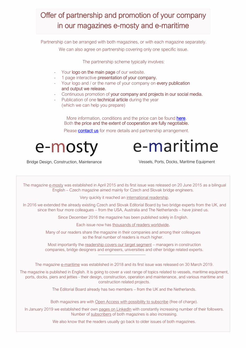
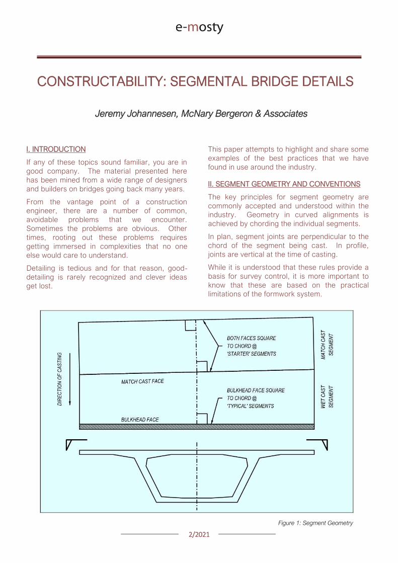
22021
CONSTRUCTABILITY SEGMENTAL BRIDGE DETAILS
Jeremy Johannesen McNary Bergeron amp Associates
I INTRODUCTION
If any of these topics sound familiar you are in
good company The material presented here
has been mined from a wide range of designers
and builders on bridges going back many years
From the vantage point of a construction
engineer there are a number of common
avoidable problems that we encounter
Sometimes the problems are obvious Other
times rooting out these problems requires
getting immersed in complexities that no one
else would care to understand
Detailing is tedious and for that reason good-
detailing is rarely recognized and clever ideas
get lost
This paper attempts to highlight and share some
examples of the best practices that we have
found in use around the industry
II SEGMENT GEOMETRY AND CONVENTIONS
The key principles for segment geometry are
commonly accepted and understood within the
industry Geometry in curved alignments is
achieved by chording the individual segments
In plan segment joints are perpendicular to the
chord of the segment being cast In profile
joints are vertical at the time of casting
While it is understood that these rules provide a
basis for survey control it is more important to
know that these are based on the practical
limitations of the formwork system
Figure 1 Segment Geometry
22021
III CROSS-SECTION
As a starting point for any design the AASHTO-
PCI-ASBI standards provide solid examples of
cross sections and basic segment details
When adapting those details to specific project
requirements consider the following
DECK SLAB In a structure where the
construction method or loads require dual
cantilever anchors at each web the anchors
should straddle the web reinforcement This is a
simple solution and avoids many reinforcing
conflicts However large anchors (larger than
12 strands) often do not fit in the deck haunch
The top of the web is an appealing spot for a
single large anchor Be aware however that
placing the anchor in the web creates some
reinforcing challenges and may require adding
concrete to provide flexibility in bar placement
Refer to Section X on the following pages for
details to help evaluate the most practical
anchor arrangement
BOTTOM SLAB There are two schools of
thought on how best to detail the bottom slab
transverse profile One is to use a constant
thickness from web to web and the other is to
use a haunched profile
Each has its advantages (see Section X for
reinforcement examples)
For either the case verify that the ducts near
the web pass cleanly over the horizontal legs of
the web rebar In some cases it is worth raising
the ducts near the web slightly
When using a haunched slab extend the fillet far
enough to prevent conflicts between the top mat
rebar and the ducts
CORE FORM A successful design is based on
a realistic understanding of the formwork
system Standardization and simplicity should
be the goal To be specific
Use consistent anchor block geometry to
eliminate formwork modifications from
the casting cycle
Proportion anchor blocks to allow the
formwork to collapse and retract
Avoid using continuity tendons in the top
slab because the anchor blocks make
the operation of the core form
complicated History shows that
balanced cantilever bridges will work
without top slab continuity tendons
Figure 2 Cross Section Comparison All the dimensions on this figure are in imperial feet and inches
22021
IV REBAR LAYOUT amp SPACING
Often designs are prepared in a divide-and-
conquer approach where the PT and reinforcing
designs are done without close coordination
One simple method to better integrate details is
to adopt an assumed reinforcement layout early
in the design This establishes dedicated lanes
for the reinforcement to integrate everything
else around
Once that is established it is preferable to
maintain the reinforcing layout and vary bar
sizes as demands require The benefits of this
approach become evident when integrating the
girder reinforcing with anchor blocks etc
LAYOUT Commonly used rebar spacings are
15 or 20cm (6rdquo or 8rdquo) Note that a 15cm
spacing is adequate to fit transverse tendons
between bars and also allows the use of 30cm
spacings when demands are less
CURVATURE In ldquostraightrdquo bridges where
segments are effectively rectangular the layout
is simple (offset the first bar-set half of the
nominal spacing from the bulkhead face and
then repeat at the nominal spacing) For
segments in curves space the bars parallel to
the bulkhead until beyond the anchor block
reinforcement (or other details requiring
integration)
Then vary the spacing in an accordion fashion
near the match cast face
This approach is similar to timber framing in
house construction where rather than spacing
the studs uniformly along each wall the studs
are spaced at 40cm (16rdquo) as much as is
practical and any remainder is left as a single
short spacing
This is a well understood technique and it is
based on a practical approach to integrating
different building components For example a
12 x 24m sheet of plywood in multiples of
40cm thus the sheeting aligns with the framing
studs
MINIMUM SPACINGS Knowing that the web on
the outside of the curve will be longer than the
centerline length of the segment the designer
should decide if it is acceptable for the bar
spacings in the lsquoaccordion zonersquo to exceed the
nominal spacing
Where spacings are already relatively tight it is
preferable to increase the spacings locally since
the lsquoaverage spacing is effectively unchanged
Where the bar spacing is larger (30cm for
example) it may be reasonable to add an lsquoextrarsquo
bar-set to take up this variation
Figure 3 Rebar Layout Methodology All the dimensions on this figure are in imperial feet and inches
22021
Figure 4 Rebar Layouts in Curved Segments
DECK REINFORCEMENT Deck reinforcement
should either be spaced with or spaced between
the lanes established by the web reinforcement
On several projects the deck reinforcement has
been pre-tied and then mated to the webs in the
forms This has been a successful approach
and is most effective when the deck bars can be
arranged to fall between the web rebar
V TRANSVERSE PT
LAYOUT Space the transverse tendons around
the nominal reinforcing lanes Locating
transverse tendons without regard for the
reinforcement results in non-uniform rebar
spacings and sometimes additional reinforcing
to cover those gaps created by the tendons
For best results establish a reinforcing layout
and then put the tendons in the gaps
POURBACKS There are numerous opinions as
to the best way to detail the pourbacks at the
anchorages
On some projects a variety of different details
have been tried with no clear consensus on
which was best
Anchor pourbacks located under a travel lane
are by default closed-top or better yet dead-end
anchors with no blockouts
The trickier question becomes what to do with
anchors under barriers and how best to patch
them ldquoASBIPTI M50rdquo contains relevant
examples and guidance
As long as the details provide adequate
protection to the anchor it is worth being
flexible to the contractorrsquos preferences
22021
Figure 5 Deck
Reinforcement
Figure 6 Transverse PT
Integrated with
Reinforcing Lanes
22021
STRAND INSTALLATION In dual box girders
transverse tendons are sometimes used across the
in-situ closure This detail has complications and
should be discouraged Strands cannot be reliably
fed through a flat duct after is has been cast in
concrete because the duct is often flattened (even
flatter) during concreting
Secondly accumulated tolerances between the
segments create significant misalignments across
the closure If a bridge deck really requires post-
tensioning between two barrels consider round
duct to address both of these challenges with what
is ultimately a modest difference in duct size
Figure 7 Dual Box Structure with in-situ Closure Veterans Memorial Causeway Courtesy of Reed amp Reed Construction
VI LONGITUDINAL PT TOP SLAB TENDONS
Avoiding or minimizing the number of tendons in
the deck slab can improve a bridgersquos lifespan
Similarly the details related to the top slab PT
are equally important in the structurersquos
durability
BLOCKOUTS The most common example of
longitudinal tendons in the top deck slab are
cantilever tendons These tendons are typically
anchored at the joint face In order to orient the
tendon to the bulkhead anchorages are
mounted to a recessed blockout
Figure 8 Cantilever Anchor Layout
22021
This recess should be deep enough to contain
the entire grout cap consequently it consumes
a significant amount of space on the bulkhead
Just as with a duct located along any other face
it is important to provide adequate clear cover to
the blockout to prevent water or grout leakage
to and from the ducts
LAYOUT Set the cantilever anchorage low
enough to clear the transverse tendon In some
cases anchor spirals have been found to conflict
with the first transverse tendon
This is a problem for a number of reasons including
the reduction in anchor confinement the potential
to crush the transverse tendon and the sheer
nuisance to the builder
TOP CONTINUITY Avoid the use of top slab
continuity tendons and associated anchor
blocks
This is particularly relevant in form traveller
construction where the core-form beams are
typically larger longer and may extend into the
previous segments at a skew
REINFORCEMENT The duct layout should
consider the reinforcement and related
fabrication tolerances As outlined in Section X
below lowering the ducts in and around the web
reinforcing addresses a number of problems
with a minimal effect on the tendon eccentricity
Figure 9 Web Rebar Tolerances
22021
Figure 10 Web Rebar Tolerances Upper Ducts lowered (slightly) at full Height Stirrups for rebar
tolerances Hong Kong Mtr South Island Line Courtesy of Leighton Construction
VII LONGITUDINAL PT BOTTOM SLAB
TENDONS
LAYOUT While there are exceptions to every
rule fixing the bottom slab tendon layout and
anchor block geometry from the inside corner of
the box girder can standardize many details
With this approach the relative geometry
between the anchor block and the duct-runs
remains consistent while the depth of the girder
varies
SLAB THICKNESS Consider making the
bottom slab thickness constant through the
anchor block segments In variable depth box
girders specifically balanced cantilever with
form travellers there is a natural instinct to vary
the bottom slab thickness in parallel with the
girder depth
However tapering the bottom slab down to its
minimum thickness prior to the anchor blocks is
an effective approach in simplifying the design
Figure 11 Bottom Duct Setout
22021
REINFORCEMENT Check for conflicts between
the web reinforcement and the duct layout The
webs typically require larger diameter rebar than
the bottom slab For that reason it may be
necessary to raise the ducts located over the
web bar legs
Finally verify that the first duct is set far enough
from the web to allow for any plan curvature at
the anchor
DUCT GEOMETRY Aim the anchorage slightly
inboard for jack access This is important in
curved bridges where the web in the next
segment may encroach on the jack envelope
The tendon profile at the anchor block should
allow for PT system radius and tangent
requirements The bend radius should be
measured in the plane of the curve
Fitting the requisite tangent and radius for a 19
strand tendon into a 3m long segment can be
challenging Specify lsquotight radiusrsquo duct where
needed
This duct has corrugations that permit smaller
bending radii without buckling and caving
Some ducts can also be heat-bent to achieve
small radii
The last resort is using pre-bent steel pipes
Being aware of and designing within the radii
that can be achieved with corrugated plastic
duct should be the goal for cost-effective
design
Figure 12 Bottom Duct Profile
22021
VIII LONGITUDINAL PT WEB TENDONS
While very common in traditional post-tensioned
construction web tendons are not often used in
precast segmental bridges However there are
two situations where web tendons are
sometimes used
First is to supplement or eliminate bottom slab
continuity tendons Second is to provide some
form of bonded continuity steel across the entire
span ndash seismic requirements for example
In these cases the most practical approach is to
anchor the web tendons in pier or expansion
segments and run them pier-to-pier thereby
avoiding unique anchor blocks
In order to have a rational duct arrangement on
the bulkhead the tendons should use an
angular or lsquodeviatedrsquo profile ndash not draped
profiles Furthermore use a profile that is
coordinated with the shear key arrangement or
coordinate the shear keys with the duct holes to
avoid altering the bulkhead during casting
In the situation where web tendons are used in
conjunction with anchor blocks avoid locating
anchor blocks in-plane with the web tendons
The web and bottom slab tendon will inevitably
slope at different angles which prevents the
anchor block reinforcement development into
the web
Figure 13 Web Tendon Profile and Bottom Blocks
IX LONGITUDINAL PT EXTERNAL TENDONS
For those wanting potentially replaceable post-
tensioning external tendons are the answer
The Florida DOT Bridge Design Manual provides
some of the best advice for these details
DEVIATOR A point of debate between experts
is diabolos vs pipes For smaller quantities
pipes may be more economical Pipes are also
smaller On the other hand pipes can and do
get placed incorrectly which requires expensive
re-work to correct
When laying out the tendon paths be aware that
diabolos require more space since they flare out
in 360 degrees
Furthermore diabolos without stay-in-place
plastic formers require more stringent clear
cover requirements between rebar and the
diabolos That said a well thought out design
with diabolos is relatively fool-proof with only the
up-front cost of the formers
CONFLICTS One consideration for any design
with external tendons is to verify that the
external tendons have a clear line-of-sight
between deviation points Confirm that the
tendons do not hit other anchor blocks
In curved structures check that the tendons do
not hit the web walls Where structures are on
tight radii it may be necessary to add an
additional deviator to guide the tendons around
the curved span
X BOX GIRDER REINFORCEMENT
To paraphrase the theme of Section IV above
ldquoUse Common Denominatorsrdquo Simply spacing
the reinforcement together at regular intervals
goes a long way to simplifying construction
The answer to ldquowhy not mix spacings if it saves
a few barsrdquo is that it becomes necessary to shift
some bars out of their nominal spacings to mesh
with the other set leading to localized
congestion and conflicts
22021
Space rebar at common denominators ie 15
and 30cm work together but not 15 and 20cm
Once the reinforcing lanes are established the
key to constructability is the web reinforcement
PT anchors anchor blocks transverse tendons
and construction embeds all gravitate to the
webs
Furthermore the web reinforcement is a full-
height shear stirrup which is sensitive to bending
and placing tolerances
TOLERANCES Rebar fabrication tolerances
should be a primary consideration in detailing
The fabricated bending tolerance on most bars
is +-25mm per leg Tighter tolerances can be
specified but keep in mind that there is no
magic tolerance setting on the bending
machine If the design requires tighter
tolerances this translates to more rejected bar
and associated cost
If a bar is constrained by clear cover at each
end the logical approach is to detail the bar
25mm short of the nominal length and verify that
the details can accommodate the tolerance
Sometimes the clear cover tolerances help And
sometimes the bar tolerances can be absorbed
at two faces and the effects are minor With
web reinforcing however the bars are typically
supported on chairs on the soffit slab which
requires all of the tolerance to be taken up at
the top face where the bar legs are constrained
between the clear cover and the cantilever
ducts
A simple solution is to lower the ducts within this
area to clear the bar tolerance envelope While
this lowers the eccentricity of some tendons
consider that it is likely a small number of the
tendons moving a small percentage of the
overall depth so the effect is minor
NESTING BARS Give consideration to the
bends and orientation of the web bar tails In
order to minimize congestion and make room for
other reinforcement it preferable to keep the
web bars in-plane with each other Use 180
degree hooks where appropriate to avoid
bundled legs
RE-ENTRANT CORNERS Be thoughtful when
detailing reinforcement at re-entrant corners
For example the inside web face often has a
fillet Reinforcing this face with a single bar is not
advisable
Figure 14 Re-entrant
Corners
22021
Consider that when this bar is in tension it will
want to straighten and pop-out the cover
concrete at the corner It is preferable to use
crossing-bars which develop beyond the corner
TENDON PASS-THRU Where tendons pass
thru reinforcing mats the design should specify
how Note that the tendons in anchor blocks
typically slope at 12-15 degrees At this angle
the duct can conflict with rebar over a length of
60-90cm
Simply shifting bars longitudinally to clear the
conflict is not practical because it displaces too
many bars and leaves a large gap
In most cases it is preferable that the cross-thru
details are modifications (by moving bending or
cutting) to the typical reinforcing as opposed to
introducing unique bars at specific locations
Figure 15 Top Mat Bars at Cross-Thru (with fillet)
Figure 16 Top Mat Bars at Cross-Thru (flat slab)
22021
LONGITUDINAL REINFORCING An additional
topic to highlight is the treatment of longitudinal
reinforcing in curved segments In cast-in-place
construction the bars are detailed long enough
to satisfy the lap splice requirements on the
outside of the curve and the extra length on the
short side is taken up in the lap splice
In precast segments the detailing of longitudinal
reinforcement becomes complicated
Longitudinal bars are broken into sub-sets in
order to graduate the lengths across the width
of the segment
Otherwise identical reinforcing cages but with
slightly different plan-view geometry become
different reinforcing types requiring additional
drawings and submittals not to mention more
time spent sorting bars on-site
Given that segment cages are pre-tied in jigs it
would be reasonable to detail all the bars long
tie them in the cage and then cut them to
match the pie-shape of the specific segment
This would streamline shop drawing process and
potentially simplify fabrication
Figure 17 Treatment of Longitudinal Bars
XI ANCHOR BLOCK REINFORCEMENT
Before reading any further prepare to go lsquodeep
in the weedsrsquo In order to lessen the headache
refer directly to the appendix for an example of
an anchor block that addresses the challenges
CONGESTION Anchor blocks typically have
two sets of bars (outer confinement + inner tie
for curvature) which mesh together with the
web reinforcement (2 faces) and slab
reinforcement (2 faces)
Altogether this can translate to six bars which
must pass each other Many of these bars may
have legs on the same face creating lsquowallsrsquo of
bundled rebar
These zones of bars are problematic for placing
concrete prone to spalling and do nothing to
develop the reinforcement There are several
techniques to address this
Place the web reinforcement in the same
plane Turn the leg on the inside-face
web bar toward centerline of segment If
the leg on the outside-face web bar
contacts the inside-face reinforcement
consider using a 180deg hook
Place bottom slab reinforcement in the
same plane If the legs happen to
conflict shorten or place the top-mat bar
to nest inside the bottom-mat bar
22021
Turn the legs of the outer anchor block
reinforcement away from the web Full
360deg or even 270deg confinement of the
anchor block is not necessary as the
bottom slab and web reinforcement
already exist on these faces and are
waiting to be put to work
Consider the direction of the legs on the
inner anchor block bars (ie the in-plane
pullout reinforcement) Turning both legs
the same direction andor using 180
degree hooks may be helpful
TENDON GEOMETRY Anchor block
reinforcement should be organized with thought
to the actual tendon geometry In most cases
the other tendons in and around the anchor
block are not running parallel to the web
Tendon paths should not be altered to snake
thru the reinforcement Instead configure the
reinforcement to the lanes between the ducts
There are several techniques to address this
Begin by designing the reinforcement
around the typical (probably deviating)
tendon arrangement
Slope the inside face of the anchor block
By varying the clear cover the outer
block reinforcement may be detailed to
follow either straight or deviating tendon
paths
Adjust the width of the in-plane pullout
reinforcement as needed Where these
bars are tall use a wide bar in order to
straddle ducts running below Where
these bars are short a narrow top-hat
bar is appropriate to avoid clashing with
other ducts
Figure 18 Anchor Block Reinforcement (see Appendix)
22021
XII DIAPHRAGM REINFORCEMENT
There are a number of different approaches to
diaphragm design and this paper will not go into
depth on the possibilities However the
challenges found in diaphragm reinforcement
are variations on others already identified
When presented a problem engineers are good at
finding fixes For that reason simply being aware
of these issues goes a long way
Rebar Fabrication Tolerances
Rebar Placing Tolerances
Actual Size of Rebar and PT
Actual Size of Bar Bend Radii
Congestion (see Figure 19)
Uniformity Standardization
Finally just to give the contractor a sporting
chance identify all of the intersecting bars ducts
and other elements (with their overall sizes) and
verify that they do indeed fit inside of the concrete
An allowance for placing tolerances is
recommended too Incorporating this analysis into
the design process should be standard practice
Figure 19
lsquoRealrsquo Rebar
Diameter
larr Figure 20
Example of
Congestion
Too Many Bars
in Same Plane
22021
In cast-in-place construction headed anchor
studs may be a good option provided again
that the stud layout is integrated with the
reinforcement
INTEGRAL STRADDLE BEAMS Precast
segments are sometimes cantilevered from
straddle beams or similar CIP elements In this
configuration set the first precast segment just
off the straddle beam with a short closure
avoiding a complicated cast-in-place starter
Minor skews can be absorbed in the closure
Larger skews can be cast into the starter
segment In the case of cantilever construction
most if not all of the post-tensioning ducts are in
the top slab Rather than trying to cast ducts in
precise locations in the straddle beam set the
segment slightly higher than the top of beam
and cast the deck slab after the segments have
been placed
This avoids complications with tolerances as
well as conflicts between the straddle beam
stirrups and PT ducts
XIII SUBSTRUCTURE CONNECTIONS
The details associated with the superstructure
connection to the substructure have a
significant impact on the constructability This
interface is typically at the bearings and in some
cases the superstructure may frame into other
types of construction
Short closures are used to connect segments
which are not match cast However when a
segment is taken from one form and mated up
with one from a different form you can expect
some degree of misalignment in the cross
section and ducts
BEARINGS In precast segmental where the
structure requires fixity through the bearings it
is preferable to use a limited number of large
pintles to transfer horizontal load to the
bearings
In these situations the void for the pintle should
be oversized to allow for grade and
superelevation as well as reasonable fabrication
and placing tolerances
These voids may be formed using lsquocansrsquo or it
may be practical to void out a rectangular
volume in and around the reinforcement using
foam block In either case the pintles must be
integrated with the reinforcement
Figure 21 Straddle Beam Connection
22021
Figure 23 Straddle Beam Connection Top of Beam held low to allow Cantilever Tendons to pass over without conflict
Hong Kong Mtr South Island Line Courtesy of Leighton Construction
Figure 22 Straddle Beam Connection Top of Beam held low to allow Cantilever Tendons to pass over without conflict
Hong Kong Mtr South Island Line Courtesy of Leighton Construction
22021
INTEGRAL PIER COLUMNS Making precast
segments integral with pier columns presents
challenges but there are a number of benefits
Integral connections can eliminate bearings and
associated maintenance provide robust
connection for lateral loads (ie seismic) and
can eliminate the need for temporary stability
shoring
Integral connections can be achieved several
ways Similar to the previous straddle beam
example the conventional approach is to
construct cast-in-place pier segments and erect
precast segments on either side with short
closures
This requires realistic expectations for the
construction tolerances involved For example
it may be prudent to thicken the in-situ cross
section to minimize misalignments in the cross
section in addition to incorporating means to
accommodate duct misalignments
XIV PLAN PRESENTATION
Efficient construction requires good drawings
BRIM and 3D CAD tools allow us to create some
amazing work but as this is being written there
are still a lot of us humans involved in the
process
Modern drafting tools allow us to make drawing
easier and to balance that it is important to be
disciplined in minimizing drawings and details
Figure 24 PT Layout Example
22021
SYMMETRY If something is symmetric or even
close to it use half views Showing redundant
information invites confusion and errors This
also allows views to be larger and show details
more clearly
PT LAYOUTS All longitudinal PT for a given
segment should be shown on the same drawing
sheet Scale plan views in the transverse
direction to better illustrate tendon geometry
and neglect horizontal curvature Last ndash call out
each end of each tendon
APPENDIX 3D MODEL
The following page is a 3D pdf to illustrate some
of the points discussed in this document
The source DGN file is attached here
I hope you find this document useful and Good Bridgebuilding
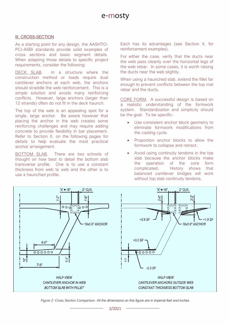
22021
III CROSS-SECTION
As a starting point for any design the AASHTO-
PCI-ASBI standards provide solid examples of
cross sections and basic segment details
When adapting those details to specific project
requirements consider the following
DECK SLAB In a structure where the
construction method or loads require dual
cantilever anchors at each web the anchors
should straddle the web reinforcement This is a
simple solution and avoids many reinforcing
conflicts However large anchors (larger than
12 strands) often do not fit in the deck haunch
The top of the web is an appealing spot for a
single large anchor Be aware however that
placing the anchor in the web creates some
reinforcing challenges and may require adding
concrete to provide flexibility in bar placement
Refer to Section X on the following pages for
details to help evaluate the most practical
anchor arrangement
BOTTOM SLAB There are two schools of
thought on how best to detail the bottom slab
transverse profile One is to use a constant
thickness from web to web and the other is to
use a haunched profile
Each has its advantages (see Section X for
reinforcement examples)
For either the case verify that the ducts near
the web pass cleanly over the horizontal legs of
the web rebar In some cases it is worth raising
the ducts near the web slightly
When using a haunched slab extend the fillet far
enough to prevent conflicts between the top mat
rebar and the ducts
CORE FORM A successful design is based on
a realistic understanding of the formwork
system Standardization and simplicity should
be the goal To be specific
Use consistent anchor block geometry to
eliminate formwork modifications from
the casting cycle
Proportion anchor blocks to allow the
formwork to collapse and retract
Avoid using continuity tendons in the top
slab because the anchor blocks make
the operation of the core form
complicated History shows that
balanced cantilever bridges will work
without top slab continuity tendons
Figure 2 Cross Section Comparison All the dimensions on this figure are in imperial feet and inches
22021
IV REBAR LAYOUT amp SPACING
Often designs are prepared in a divide-and-
conquer approach where the PT and reinforcing
designs are done without close coordination
One simple method to better integrate details is
to adopt an assumed reinforcement layout early
in the design This establishes dedicated lanes
for the reinforcement to integrate everything
else around
Once that is established it is preferable to
maintain the reinforcing layout and vary bar
sizes as demands require The benefits of this
approach become evident when integrating the
girder reinforcing with anchor blocks etc
LAYOUT Commonly used rebar spacings are
15 or 20cm (6rdquo or 8rdquo) Note that a 15cm
spacing is adequate to fit transverse tendons
between bars and also allows the use of 30cm
spacings when demands are less
CURVATURE In ldquostraightrdquo bridges where
segments are effectively rectangular the layout
is simple (offset the first bar-set half of the
nominal spacing from the bulkhead face and
then repeat at the nominal spacing) For
segments in curves space the bars parallel to
the bulkhead until beyond the anchor block
reinforcement (or other details requiring
integration)
Then vary the spacing in an accordion fashion
near the match cast face
This approach is similar to timber framing in
house construction where rather than spacing
the studs uniformly along each wall the studs
are spaced at 40cm (16rdquo) as much as is
practical and any remainder is left as a single
short spacing
This is a well understood technique and it is
based on a practical approach to integrating
different building components For example a
12 x 24m sheet of plywood in multiples of
40cm thus the sheeting aligns with the framing
studs
MINIMUM SPACINGS Knowing that the web on
the outside of the curve will be longer than the
centerline length of the segment the designer
should decide if it is acceptable for the bar
spacings in the lsquoaccordion zonersquo to exceed the
nominal spacing
Where spacings are already relatively tight it is
preferable to increase the spacings locally since
the lsquoaverage spacing is effectively unchanged
Where the bar spacing is larger (30cm for
example) it may be reasonable to add an lsquoextrarsquo
bar-set to take up this variation
Figure 3 Rebar Layout Methodology All the dimensions on this figure are in imperial feet and inches
22021
Figure 4 Rebar Layouts in Curved Segments
DECK REINFORCEMENT Deck reinforcement
should either be spaced with or spaced between
the lanes established by the web reinforcement
On several projects the deck reinforcement has
been pre-tied and then mated to the webs in the
forms This has been a successful approach
and is most effective when the deck bars can be
arranged to fall between the web rebar
V TRANSVERSE PT
LAYOUT Space the transverse tendons around
the nominal reinforcing lanes Locating
transverse tendons without regard for the
reinforcement results in non-uniform rebar
spacings and sometimes additional reinforcing
to cover those gaps created by the tendons
For best results establish a reinforcing layout
and then put the tendons in the gaps
POURBACKS There are numerous opinions as
to the best way to detail the pourbacks at the
anchorages
On some projects a variety of different details
have been tried with no clear consensus on
which was best
Anchor pourbacks located under a travel lane
are by default closed-top or better yet dead-end
anchors with no blockouts
The trickier question becomes what to do with
anchors under barriers and how best to patch
them ldquoASBIPTI M50rdquo contains relevant
examples and guidance
As long as the details provide adequate
protection to the anchor it is worth being
flexible to the contractorrsquos preferences
22021
Figure 5 Deck
Reinforcement
Figure 6 Transverse PT
Integrated with
Reinforcing Lanes
22021
STRAND INSTALLATION In dual box girders
transverse tendons are sometimes used across the
in-situ closure This detail has complications and
should be discouraged Strands cannot be reliably
fed through a flat duct after is has been cast in
concrete because the duct is often flattened (even
flatter) during concreting
Secondly accumulated tolerances between the
segments create significant misalignments across
the closure If a bridge deck really requires post-
tensioning between two barrels consider round
duct to address both of these challenges with what
is ultimately a modest difference in duct size
Figure 7 Dual Box Structure with in-situ Closure Veterans Memorial Causeway Courtesy of Reed amp Reed Construction
VI LONGITUDINAL PT TOP SLAB TENDONS
Avoiding or minimizing the number of tendons in
the deck slab can improve a bridgersquos lifespan
Similarly the details related to the top slab PT
are equally important in the structurersquos
durability
BLOCKOUTS The most common example of
longitudinal tendons in the top deck slab are
cantilever tendons These tendons are typically
anchored at the joint face In order to orient the
tendon to the bulkhead anchorages are
mounted to a recessed blockout
Figure 8 Cantilever Anchor Layout
22021
This recess should be deep enough to contain
the entire grout cap consequently it consumes
a significant amount of space on the bulkhead
Just as with a duct located along any other face
it is important to provide adequate clear cover to
the blockout to prevent water or grout leakage
to and from the ducts
LAYOUT Set the cantilever anchorage low
enough to clear the transverse tendon In some
cases anchor spirals have been found to conflict
with the first transverse tendon
This is a problem for a number of reasons including
the reduction in anchor confinement the potential
to crush the transverse tendon and the sheer
nuisance to the builder
TOP CONTINUITY Avoid the use of top slab
continuity tendons and associated anchor
blocks
This is particularly relevant in form traveller
construction where the core-form beams are
typically larger longer and may extend into the
previous segments at a skew
REINFORCEMENT The duct layout should
consider the reinforcement and related
fabrication tolerances As outlined in Section X
below lowering the ducts in and around the web
reinforcing addresses a number of problems
with a minimal effect on the tendon eccentricity
Figure 9 Web Rebar Tolerances
22021
Figure 10 Web Rebar Tolerances Upper Ducts lowered (slightly) at full Height Stirrups for rebar
tolerances Hong Kong Mtr South Island Line Courtesy of Leighton Construction
VII LONGITUDINAL PT BOTTOM SLAB
TENDONS
LAYOUT While there are exceptions to every
rule fixing the bottom slab tendon layout and
anchor block geometry from the inside corner of
the box girder can standardize many details
With this approach the relative geometry
between the anchor block and the duct-runs
remains consistent while the depth of the girder
varies
SLAB THICKNESS Consider making the
bottom slab thickness constant through the
anchor block segments In variable depth box
girders specifically balanced cantilever with
form travellers there is a natural instinct to vary
the bottom slab thickness in parallel with the
girder depth
However tapering the bottom slab down to its
minimum thickness prior to the anchor blocks is
an effective approach in simplifying the design
Figure 11 Bottom Duct Setout
22021
REINFORCEMENT Check for conflicts between
the web reinforcement and the duct layout The
webs typically require larger diameter rebar than
the bottom slab For that reason it may be
necessary to raise the ducts located over the
web bar legs
Finally verify that the first duct is set far enough
from the web to allow for any plan curvature at
the anchor
DUCT GEOMETRY Aim the anchorage slightly
inboard for jack access This is important in
curved bridges where the web in the next
segment may encroach on the jack envelope
The tendon profile at the anchor block should
allow for PT system radius and tangent
requirements The bend radius should be
measured in the plane of the curve
Fitting the requisite tangent and radius for a 19
strand tendon into a 3m long segment can be
challenging Specify lsquotight radiusrsquo duct where
needed
This duct has corrugations that permit smaller
bending radii without buckling and caving
Some ducts can also be heat-bent to achieve
small radii
The last resort is using pre-bent steel pipes
Being aware of and designing within the radii
that can be achieved with corrugated plastic
duct should be the goal for cost-effective
design
Figure 12 Bottom Duct Profile
22021
VIII LONGITUDINAL PT WEB TENDONS
While very common in traditional post-tensioned
construction web tendons are not often used in
precast segmental bridges However there are
two situations where web tendons are
sometimes used
First is to supplement or eliminate bottom slab
continuity tendons Second is to provide some
form of bonded continuity steel across the entire
span ndash seismic requirements for example
In these cases the most practical approach is to
anchor the web tendons in pier or expansion
segments and run them pier-to-pier thereby
avoiding unique anchor blocks
In order to have a rational duct arrangement on
the bulkhead the tendons should use an
angular or lsquodeviatedrsquo profile ndash not draped
profiles Furthermore use a profile that is
coordinated with the shear key arrangement or
coordinate the shear keys with the duct holes to
avoid altering the bulkhead during casting
In the situation where web tendons are used in
conjunction with anchor blocks avoid locating
anchor blocks in-plane with the web tendons
The web and bottom slab tendon will inevitably
slope at different angles which prevents the
anchor block reinforcement development into
the web
Figure 13 Web Tendon Profile and Bottom Blocks
IX LONGITUDINAL PT EXTERNAL TENDONS
For those wanting potentially replaceable post-
tensioning external tendons are the answer
The Florida DOT Bridge Design Manual provides
some of the best advice for these details
DEVIATOR A point of debate between experts
is diabolos vs pipes For smaller quantities
pipes may be more economical Pipes are also
smaller On the other hand pipes can and do
get placed incorrectly which requires expensive
re-work to correct
When laying out the tendon paths be aware that
diabolos require more space since they flare out
in 360 degrees
Furthermore diabolos without stay-in-place
plastic formers require more stringent clear
cover requirements between rebar and the
diabolos That said a well thought out design
with diabolos is relatively fool-proof with only the
up-front cost of the formers
CONFLICTS One consideration for any design
with external tendons is to verify that the
external tendons have a clear line-of-sight
between deviation points Confirm that the
tendons do not hit other anchor blocks
In curved structures check that the tendons do
not hit the web walls Where structures are on
tight radii it may be necessary to add an
additional deviator to guide the tendons around
the curved span
X BOX GIRDER REINFORCEMENT
To paraphrase the theme of Section IV above
ldquoUse Common Denominatorsrdquo Simply spacing
the reinforcement together at regular intervals
goes a long way to simplifying construction
The answer to ldquowhy not mix spacings if it saves
a few barsrdquo is that it becomes necessary to shift
some bars out of their nominal spacings to mesh
with the other set leading to localized
congestion and conflicts
22021
Space rebar at common denominators ie 15
and 30cm work together but not 15 and 20cm
Once the reinforcing lanes are established the
key to constructability is the web reinforcement
PT anchors anchor blocks transverse tendons
and construction embeds all gravitate to the
webs
Furthermore the web reinforcement is a full-
height shear stirrup which is sensitive to bending
and placing tolerances
TOLERANCES Rebar fabrication tolerances
should be a primary consideration in detailing
The fabricated bending tolerance on most bars
is +-25mm per leg Tighter tolerances can be
specified but keep in mind that there is no
magic tolerance setting on the bending
machine If the design requires tighter
tolerances this translates to more rejected bar
and associated cost
If a bar is constrained by clear cover at each
end the logical approach is to detail the bar
25mm short of the nominal length and verify that
the details can accommodate the tolerance
Sometimes the clear cover tolerances help And
sometimes the bar tolerances can be absorbed
at two faces and the effects are minor With
web reinforcing however the bars are typically
supported on chairs on the soffit slab which
requires all of the tolerance to be taken up at
the top face where the bar legs are constrained
between the clear cover and the cantilever
ducts
A simple solution is to lower the ducts within this
area to clear the bar tolerance envelope While
this lowers the eccentricity of some tendons
consider that it is likely a small number of the
tendons moving a small percentage of the
overall depth so the effect is minor
NESTING BARS Give consideration to the
bends and orientation of the web bar tails In
order to minimize congestion and make room for
other reinforcement it preferable to keep the
web bars in-plane with each other Use 180
degree hooks where appropriate to avoid
bundled legs
RE-ENTRANT CORNERS Be thoughtful when
detailing reinforcement at re-entrant corners
For example the inside web face often has a
fillet Reinforcing this face with a single bar is not
advisable
Figure 14 Re-entrant
Corners
22021
Consider that when this bar is in tension it will
want to straighten and pop-out the cover
concrete at the corner It is preferable to use
crossing-bars which develop beyond the corner
TENDON PASS-THRU Where tendons pass
thru reinforcing mats the design should specify
how Note that the tendons in anchor blocks
typically slope at 12-15 degrees At this angle
the duct can conflict with rebar over a length of
60-90cm
Simply shifting bars longitudinally to clear the
conflict is not practical because it displaces too
many bars and leaves a large gap
In most cases it is preferable that the cross-thru
details are modifications (by moving bending or
cutting) to the typical reinforcing as opposed to
introducing unique bars at specific locations
Figure 15 Top Mat Bars at Cross-Thru (with fillet)
Figure 16 Top Mat Bars at Cross-Thru (flat slab)
22021
LONGITUDINAL REINFORCING An additional
topic to highlight is the treatment of longitudinal
reinforcing in curved segments In cast-in-place
construction the bars are detailed long enough
to satisfy the lap splice requirements on the
outside of the curve and the extra length on the
short side is taken up in the lap splice
In precast segments the detailing of longitudinal
reinforcement becomes complicated
Longitudinal bars are broken into sub-sets in
order to graduate the lengths across the width
of the segment
Otherwise identical reinforcing cages but with
slightly different plan-view geometry become
different reinforcing types requiring additional
drawings and submittals not to mention more
time spent sorting bars on-site
Given that segment cages are pre-tied in jigs it
would be reasonable to detail all the bars long
tie them in the cage and then cut them to
match the pie-shape of the specific segment
This would streamline shop drawing process and
potentially simplify fabrication
Figure 17 Treatment of Longitudinal Bars
XI ANCHOR BLOCK REINFORCEMENT
Before reading any further prepare to go lsquodeep
in the weedsrsquo In order to lessen the headache
refer directly to the appendix for an example of
an anchor block that addresses the challenges
CONGESTION Anchor blocks typically have
two sets of bars (outer confinement + inner tie
for curvature) which mesh together with the
web reinforcement (2 faces) and slab
reinforcement (2 faces)
Altogether this can translate to six bars which
must pass each other Many of these bars may
have legs on the same face creating lsquowallsrsquo of
bundled rebar
These zones of bars are problematic for placing
concrete prone to spalling and do nothing to
develop the reinforcement There are several
techniques to address this
Place the web reinforcement in the same
plane Turn the leg on the inside-face
web bar toward centerline of segment If
the leg on the outside-face web bar
contacts the inside-face reinforcement
consider using a 180deg hook
Place bottom slab reinforcement in the
same plane If the legs happen to
conflict shorten or place the top-mat bar
to nest inside the bottom-mat bar
22021
Turn the legs of the outer anchor block
reinforcement away from the web Full
360deg or even 270deg confinement of the
anchor block is not necessary as the
bottom slab and web reinforcement
already exist on these faces and are
waiting to be put to work
Consider the direction of the legs on the
inner anchor block bars (ie the in-plane
pullout reinforcement) Turning both legs
the same direction andor using 180
degree hooks may be helpful
TENDON GEOMETRY Anchor block
reinforcement should be organized with thought
to the actual tendon geometry In most cases
the other tendons in and around the anchor
block are not running parallel to the web
Tendon paths should not be altered to snake
thru the reinforcement Instead configure the
reinforcement to the lanes between the ducts
There are several techniques to address this
Begin by designing the reinforcement
around the typical (probably deviating)
tendon arrangement
Slope the inside face of the anchor block
By varying the clear cover the outer
block reinforcement may be detailed to
follow either straight or deviating tendon
paths
Adjust the width of the in-plane pullout
reinforcement as needed Where these
bars are tall use a wide bar in order to
straddle ducts running below Where
these bars are short a narrow top-hat
bar is appropriate to avoid clashing with
other ducts
Figure 18 Anchor Block Reinforcement (see Appendix)
22021
XII DIAPHRAGM REINFORCEMENT
There are a number of different approaches to
diaphragm design and this paper will not go into
depth on the possibilities However the
challenges found in diaphragm reinforcement
are variations on others already identified
When presented a problem engineers are good at
finding fixes For that reason simply being aware
of these issues goes a long way
Rebar Fabrication Tolerances
Rebar Placing Tolerances
Actual Size of Rebar and PT
Actual Size of Bar Bend Radii
Congestion (see Figure 19)
Uniformity Standardization
Finally just to give the contractor a sporting
chance identify all of the intersecting bars ducts
and other elements (with their overall sizes) and
verify that they do indeed fit inside of the concrete
An allowance for placing tolerances is
recommended too Incorporating this analysis into
the design process should be standard practice
Figure 19
lsquoRealrsquo Rebar
Diameter
larr Figure 20
Example of
Congestion
Too Many Bars
in Same Plane
22021
In cast-in-place construction headed anchor
studs may be a good option provided again
that the stud layout is integrated with the
reinforcement
INTEGRAL STRADDLE BEAMS Precast
segments are sometimes cantilevered from
straddle beams or similar CIP elements In this
configuration set the first precast segment just
off the straddle beam with a short closure
avoiding a complicated cast-in-place starter
Minor skews can be absorbed in the closure
Larger skews can be cast into the starter
segment In the case of cantilever construction
most if not all of the post-tensioning ducts are in
the top slab Rather than trying to cast ducts in
precise locations in the straddle beam set the
segment slightly higher than the top of beam
and cast the deck slab after the segments have
been placed
This avoids complications with tolerances as
well as conflicts between the straddle beam
stirrups and PT ducts
XIII SUBSTRUCTURE CONNECTIONS
The details associated with the superstructure
connection to the substructure have a
significant impact on the constructability This
interface is typically at the bearings and in some
cases the superstructure may frame into other
types of construction
Short closures are used to connect segments
which are not match cast However when a
segment is taken from one form and mated up
with one from a different form you can expect
some degree of misalignment in the cross
section and ducts
BEARINGS In precast segmental where the
structure requires fixity through the bearings it
is preferable to use a limited number of large
pintles to transfer horizontal load to the
bearings
In these situations the void for the pintle should
be oversized to allow for grade and
superelevation as well as reasonable fabrication
and placing tolerances
These voids may be formed using lsquocansrsquo or it
may be practical to void out a rectangular
volume in and around the reinforcement using
foam block In either case the pintles must be
integrated with the reinforcement
Figure 21 Straddle Beam Connection
22021
Figure 23 Straddle Beam Connection Top of Beam held low to allow Cantilever Tendons to pass over without conflict
Hong Kong Mtr South Island Line Courtesy of Leighton Construction
Figure 22 Straddle Beam Connection Top of Beam held low to allow Cantilever Tendons to pass over without conflict
Hong Kong Mtr South Island Line Courtesy of Leighton Construction
22021
INTEGRAL PIER COLUMNS Making precast
segments integral with pier columns presents
challenges but there are a number of benefits
Integral connections can eliminate bearings and
associated maintenance provide robust
connection for lateral loads (ie seismic) and
can eliminate the need for temporary stability
shoring
Integral connections can be achieved several
ways Similar to the previous straddle beam
example the conventional approach is to
construct cast-in-place pier segments and erect
precast segments on either side with short
closures
This requires realistic expectations for the
construction tolerances involved For example
it may be prudent to thicken the in-situ cross
section to minimize misalignments in the cross
section in addition to incorporating means to
accommodate duct misalignments
XIV PLAN PRESENTATION
Efficient construction requires good drawings
BRIM and 3D CAD tools allow us to create some
amazing work but as this is being written there
are still a lot of us humans involved in the
process
Modern drafting tools allow us to make drawing
easier and to balance that it is important to be
disciplined in minimizing drawings and details
Figure 24 PT Layout Example
22021
SYMMETRY If something is symmetric or even
close to it use half views Showing redundant
information invites confusion and errors This
also allows views to be larger and show details
more clearly
PT LAYOUTS All longitudinal PT for a given
segment should be shown on the same drawing
sheet Scale plan views in the transverse
direction to better illustrate tendon geometry
and neglect horizontal curvature Last ndash call out
each end of each tendon
APPENDIX 3D MODEL
The following page is a 3D pdf to illustrate some
of the points discussed in this document
The source DGN file is attached here
I hope you find this document useful and Good Bridgebuilding
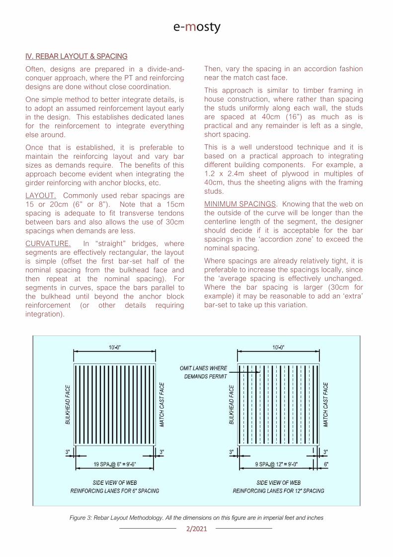
22021
IV REBAR LAYOUT amp SPACING
Often designs are prepared in a divide-and-
conquer approach where the PT and reinforcing
designs are done without close coordination
One simple method to better integrate details is
to adopt an assumed reinforcement layout early
in the design This establishes dedicated lanes
for the reinforcement to integrate everything
else around
Once that is established it is preferable to
maintain the reinforcing layout and vary bar
sizes as demands require The benefits of this
approach become evident when integrating the
girder reinforcing with anchor blocks etc
LAYOUT Commonly used rebar spacings are
15 or 20cm (6rdquo or 8rdquo) Note that a 15cm
spacing is adequate to fit transverse tendons
between bars and also allows the use of 30cm
spacings when demands are less
CURVATURE In ldquostraightrdquo bridges where
segments are effectively rectangular the layout
is simple (offset the first bar-set half of the
nominal spacing from the bulkhead face and
then repeat at the nominal spacing) For
segments in curves space the bars parallel to
the bulkhead until beyond the anchor block
reinforcement (or other details requiring
integration)
Then vary the spacing in an accordion fashion
near the match cast face
This approach is similar to timber framing in
house construction where rather than spacing
the studs uniformly along each wall the studs
are spaced at 40cm (16rdquo) as much as is
practical and any remainder is left as a single
short spacing
This is a well understood technique and it is
based on a practical approach to integrating
different building components For example a
12 x 24m sheet of plywood in multiples of
40cm thus the sheeting aligns with the framing
studs
MINIMUM SPACINGS Knowing that the web on
the outside of the curve will be longer than the
centerline length of the segment the designer
should decide if it is acceptable for the bar
spacings in the lsquoaccordion zonersquo to exceed the
nominal spacing
Where spacings are already relatively tight it is
preferable to increase the spacings locally since
the lsquoaverage spacing is effectively unchanged
Where the bar spacing is larger (30cm for
example) it may be reasonable to add an lsquoextrarsquo
bar-set to take up this variation
Figure 3 Rebar Layout Methodology All the dimensions on this figure are in imperial feet and inches
22021
Figure 4 Rebar Layouts in Curved Segments
DECK REINFORCEMENT Deck reinforcement
should either be spaced with or spaced between
the lanes established by the web reinforcement
On several projects the deck reinforcement has
been pre-tied and then mated to the webs in the
forms This has been a successful approach
and is most effective when the deck bars can be
arranged to fall between the web rebar
V TRANSVERSE PT
LAYOUT Space the transverse tendons around
the nominal reinforcing lanes Locating
transverse tendons without regard for the
reinforcement results in non-uniform rebar
spacings and sometimes additional reinforcing
to cover those gaps created by the tendons
For best results establish a reinforcing layout
and then put the tendons in the gaps
POURBACKS There are numerous opinions as
to the best way to detail the pourbacks at the
anchorages
On some projects a variety of different details
have been tried with no clear consensus on
which was best
Anchor pourbacks located under a travel lane
are by default closed-top or better yet dead-end
anchors with no blockouts
The trickier question becomes what to do with
anchors under barriers and how best to patch
them ldquoASBIPTI M50rdquo contains relevant
examples and guidance
As long as the details provide adequate
protection to the anchor it is worth being
flexible to the contractorrsquos preferences
22021
Figure 5 Deck
Reinforcement
Figure 6 Transverse PT
Integrated with
Reinforcing Lanes
22021
STRAND INSTALLATION In dual box girders
transverse tendons are sometimes used across the
in-situ closure This detail has complications and
should be discouraged Strands cannot be reliably
fed through a flat duct after is has been cast in
concrete because the duct is often flattened (even
flatter) during concreting
Secondly accumulated tolerances between the
segments create significant misalignments across
the closure If a bridge deck really requires post-
tensioning between two barrels consider round
duct to address both of these challenges with what
is ultimately a modest difference in duct size
Figure 7 Dual Box Structure with in-situ Closure Veterans Memorial Causeway Courtesy of Reed amp Reed Construction
VI LONGITUDINAL PT TOP SLAB TENDONS
Avoiding or minimizing the number of tendons in
the deck slab can improve a bridgersquos lifespan
Similarly the details related to the top slab PT
are equally important in the structurersquos
durability
BLOCKOUTS The most common example of
longitudinal tendons in the top deck slab are
cantilever tendons These tendons are typically
anchored at the joint face In order to orient the
tendon to the bulkhead anchorages are
mounted to a recessed blockout
Figure 8 Cantilever Anchor Layout
22021
This recess should be deep enough to contain
the entire grout cap consequently it consumes
a significant amount of space on the bulkhead
Just as with a duct located along any other face
it is important to provide adequate clear cover to
the blockout to prevent water or grout leakage
to and from the ducts
LAYOUT Set the cantilever anchorage low
enough to clear the transverse tendon In some
cases anchor spirals have been found to conflict
with the first transverse tendon
This is a problem for a number of reasons including
the reduction in anchor confinement the potential
to crush the transverse tendon and the sheer
nuisance to the builder
TOP CONTINUITY Avoid the use of top slab
continuity tendons and associated anchor
blocks
This is particularly relevant in form traveller
construction where the core-form beams are
typically larger longer and may extend into the
previous segments at a skew
REINFORCEMENT The duct layout should
consider the reinforcement and related
fabrication tolerances As outlined in Section X
below lowering the ducts in and around the web
reinforcing addresses a number of problems
with a minimal effect on the tendon eccentricity
Figure 9 Web Rebar Tolerances
22021
Figure 10 Web Rebar Tolerances Upper Ducts lowered (slightly) at full Height Stirrups for rebar
tolerances Hong Kong Mtr South Island Line Courtesy of Leighton Construction
VII LONGITUDINAL PT BOTTOM SLAB
TENDONS
LAYOUT While there are exceptions to every
rule fixing the bottom slab tendon layout and
anchor block geometry from the inside corner of
the box girder can standardize many details
With this approach the relative geometry
between the anchor block and the duct-runs
remains consistent while the depth of the girder
varies
SLAB THICKNESS Consider making the
bottom slab thickness constant through the
anchor block segments In variable depth box
girders specifically balanced cantilever with
form travellers there is a natural instinct to vary
the bottom slab thickness in parallel with the
girder depth
However tapering the bottom slab down to its
minimum thickness prior to the anchor blocks is
an effective approach in simplifying the design
Figure 11 Bottom Duct Setout
22021
REINFORCEMENT Check for conflicts between
the web reinforcement and the duct layout The
webs typically require larger diameter rebar than
the bottom slab For that reason it may be
necessary to raise the ducts located over the
web bar legs
Finally verify that the first duct is set far enough
from the web to allow for any plan curvature at
the anchor
DUCT GEOMETRY Aim the anchorage slightly
inboard for jack access This is important in
curved bridges where the web in the next
segment may encroach on the jack envelope
The tendon profile at the anchor block should
allow for PT system radius and tangent
requirements The bend radius should be
measured in the plane of the curve
Fitting the requisite tangent and radius for a 19
strand tendon into a 3m long segment can be
challenging Specify lsquotight radiusrsquo duct where
needed
This duct has corrugations that permit smaller
bending radii without buckling and caving
Some ducts can also be heat-bent to achieve
small radii
The last resort is using pre-bent steel pipes
Being aware of and designing within the radii
that can be achieved with corrugated plastic
duct should be the goal for cost-effective
design
Figure 12 Bottom Duct Profile
22021
VIII LONGITUDINAL PT WEB TENDONS
While very common in traditional post-tensioned
construction web tendons are not often used in
precast segmental bridges However there are
two situations where web tendons are
sometimes used
First is to supplement or eliminate bottom slab
continuity tendons Second is to provide some
form of bonded continuity steel across the entire
span ndash seismic requirements for example
In these cases the most practical approach is to
anchor the web tendons in pier or expansion
segments and run them pier-to-pier thereby
avoiding unique anchor blocks
In order to have a rational duct arrangement on
the bulkhead the tendons should use an
angular or lsquodeviatedrsquo profile ndash not draped
profiles Furthermore use a profile that is
coordinated with the shear key arrangement or
coordinate the shear keys with the duct holes to
avoid altering the bulkhead during casting
In the situation where web tendons are used in
conjunction with anchor blocks avoid locating
anchor blocks in-plane with the web tendons
The web and bottom slab tendon will inevitably
slope at different angles which prevents the
anchor block reinforcement development into
the web
Figure 13 Web Tendon Profile and Bottom Blocks
IX LONGITUDINAL PT EXTERNAL TENDONS
For those wanting potentially replaceable post-
tensioning external tendons are the answer
The Florida DOT Bridge Design Manual provides
some of the best advice for these details
DEVIATOR A point of debate between experts
is diabolos vs pipes For smaller quantities
pipes may be more economical Pipes are also
smaller On the other hand pipes can and do
get placed incorrectly which requires expensive
re-work to correct
When laying out the tendon paths be aware that
diabolos require more space since they flare out
in 360 degrees
Furthermore diabolos without stay-in-place
plastic formers require more stringent clear
cover requirements between rebar and the
diabolos That said a well thought out design
with diabolos is relatively fool-proof with only the
up-front cost of the formers
CONFLICTS One consideration for any design
with external tendons is to verify that the
external tendons have a clear line-of-sight
between deviation points Confirm that the
tendons do not hit other anchor blocks
In curved structures check that the tendons do
not hit the web walls Where structures are on
tight radii it may be necessary to add an
additional deviator to guide the tendons around
the curved span
X BOX GIRDER REINFORCEMENT
To paraphrase the theme of Section IV above
ldquoUse Common Denominatorsrdquo Simply spacing
the reinforcement together at regular intervals
goes a long way to simplifying construction
The answer to ldquowhy not mix spacings if it saves
a few barsrdquo is that it becomes necessary to shift
some bars out of their nominal spacings to mesh
with the other set leading to localized
congestion and conflicts
22021
Space rebar at common denominators ie 15
and 30cm work together but not 15 and 20cm
Once the reinforcing lanes are established the
key to constructability is the web reinforcement
PT anchors anchor blocks transverse tendons
and construction embeds all gravitate to the
webs
Furthermore the web reinforcement is a full-
height shear stirrup which is sensitive to bending
and placing tolerances
TOLERANCES Rebar fabrication tolerances
should be a primary consideration in detailing
The fabricated bending tolerance on most bars
is +-25mm per leg Tighter tolerances can be
specified but keep in mind that there is no
magic tolerance setting on the bending
machine If the design requires tighter
tolerances this translates to more rejected bar
and associated cost
If a bar is constrained by clear cover at each
end the logical approach is to detail the bar
25mm short of the nominal length and verify that
the details can accommodate the tolerance
Sometimes the clear cover tolerances help And
sometimes the bar tolerances can be absorbed
at two faces and the effects are minor With
web reinforcing however the bars are typically
supported on chairs on the soffit slab which
requires all of the tolerance to be taken up at
the top face where the bar legs are constrained
between the clear cover and the cantilever
ducts
A simple solution is to lower the ducts within this
area to clear the bar tolerance envelope While
this lowers the eccentricity of some tendons
consider that it is likely a small number of the
tendons moving a small percentage of the
overall depth so the effect is minor
NESTING BARS Give consideration to the
bends and orientation of the web bar tails In
order to minimize congestion and make room for
other reinforcement it preferable to keep the
web bars in-plane with each other Use 180
degree hooks where appropriate to avoid
bundled legs
RE-ENTRANT CORNERS Be thoughtful when
detailing reinforcement at re-entrant corners
For example the inside web face often has a
fillet Reinforcing this face with a single bar is not
advisable
Figure 14 Re-entrant
Corners
22021
Consider that when this bar is in tension it will
want to straighten and pop-out the cover
concrete at the corner It is preferable to use
crossing-bars which develop beyond the corner
TENDON PASS-THRU Where tendons pass
thru reinforcing mats the design should specify
how Note that the tendons in anchor blocks
typically slope at 12-15 degrees At this angle
the duct can conflict with rebar over a length of
60-90cm
Simply shifting bars longitudinally to clear the
conflict is not practical because it displaces too
many bars and leaves a large gap
In most cases it is preferable that the cross-thru
details are modifications (by moving bending or
cutting) to the typical reinforcing as opposed to
introducing unique bars at specific locations
Figure 15 Top Mat Bars at Cross-Thru (with fillet)
Figure 16 Top Mat Bars at Cross-Thru (flat slab)
22021
LONGITUDINAL REINFORCING An additional
topic to highlight is the treatment of longitudinal
reinforcing in curved segments In cast-in-place
construction the bars are detailed long enough
to satisfy the lap splice requirements on the
outside of the curve and the extra length on the
short side is taken up in the lap splice
In precast segments the detailing of longitudinal
reinforcement becomes complicated
Longitudinal bars are broken into sub-sets in
order to graduate the lengths across the width
of the segment
Otherwise identical reinforcing cages but with
slightly different plan-view geometry become
different reinforcing types requiring additional
drawings and submittals not to mention more
time spent sorting bars on-site
Given that segment cages are pre-tied in jigs it
would be reasonable to detail all the bars long
tie them in the cage and then cut them to
match the pie-shape of the specific segment
This would streamline shop drawing process and
potentially simplify fabrication
Figure 17 Treatment of Longitudinal Bars
XI ANCHOR BLOCK REINFORCEMENT
Before reading any further prepare to go lsquodeep
in the weedsrsquo In order to lessen the headache
refer directly to the appendix for an example of
an anchor block that addresses the challenges
CONGESTION Anchor blocks typically have
two sets of bars (outer confinement + inner tie
for curvature) which mesh together with the
web reinforcement (2 faces) and slab
reinforcement (2 faces)
Altogether this can translate to six bars which
must pass each other Many of these bars may
have legs on the same face creating lsquowallsrsquo of
bundled rebar
These zones of bars are problematic for placing
concrete prone to spalling and do nothing to
develop the reinforcement There are several
techniques to address this
Place the web reinforcement in the same
plane Turn the leg on the inside-face
web bar toward centerline of segment If
the leg on the outside-face web bar
contacts the inside-face reinforcement
consider using a 180deg hook
Place bottom slab reinforcement in the
same plane If the legs happen to
conflict shorten or place the top-mat bar
to nest inside the bottom-mat bar
22021
Turn the legs of the outer anchor block
reinforcement away from the web Full
360deg or even 270deg confinement of the
anchor block is not necessary as the
bottom slab and web reinforcement
already exist on these faces and are
waiting to be put to work
Consider the direction of the legs on the
inner anchor block bars (ie the in-plane
pullout reinforcement) Turning both legs
the same direction andor using 180
degree hooks may be helpful
TENDON GEOMETRY Anchor block
reinforcement should be organized with thought
to the actual tendon geometry In most cases
the other tendons in and around the anchor
block are not running parallel to the web
Tendon paths should not be altered to snake
thru the reinforcement Instead configure the
reinforcement to the lanes between the ducts
There are several techniques to address this
Begin by designing the reinforcement
around the typical (probably deviating)
tendon arrangement
Slope the inside face of the anchor block
By varying the clear cover the outer
block reinforcement may be detailed to
follow either straight or deviating tendon
paths
Adjust the width of the in-plane pullout
reinforcement as needed Where these
bars are tall use a wide bar in order to
straddle ducts running below Where
these bars are short a narrow top-hat
bar is appropriate to avoid clashing with
other ducts
Figure 18 Anchor Block Reinforcement (see Appendix)
22021
XII DIAPHRAGM REINFORCEMENT
There are a number of different approaches to
diaphragm design and this paper will not go into
depth on the possibilities However the
challenges found in diaphragm reinforcement
are variations on others already identified
When presented a problem engineers are good at
finding fixes For that reason simply being aware
of these issues goes a long way
Rebar Fabrication Tolerances
Rebar Placing Tolerances
Actual Size of Rebar and PT
Actual Size of Bar Bend Radii
Congestion (see Figure 19)
Uniformity Standardization
Finally just to give the contractor a sporting
chance identify all of the intersecting bars ducts
and other elements (with their overall sizes) and
verify that they do indeed fit inside of the concrete
An allowance for placing tolerances is
recommended too Incorporating this analysis into
the design process should be standard practice
Figure 19
lsquoRealrsquo Rebar
Diameter
larr Figure 20
Example of
Congestion
Too Many Bars
in Same Plane
22021
In cast-in-place construction headed anchor
studs may be a good option provided again
that the stud layout is integrated with the
reinforcement
INTEGRAL STRADDLE BEAMS Precast
segments are sometimes cantilevered from
straddle beams or similar CIP elements In this
configuration set the first precast segment just
off the straddle beam with a short closure
avoiding a complicated cast-in-place starter
Minor skews can be absorbed in the closure
Larger skews can be cast into the starter
segment In the case of cantilever construction
most if not all of the post-tensioning ducts are in
the top slab Rather than trying to cast ducts in
precise locations in the straddle beam set the
segment slightly higher than the top of beam
and cast the deck slab after the segments have
been placed
This avoids complications with tolerances as
well as conflicts between the straddle beam
stirrups and PT ducts
XIII SUBSTRUCTURE CONNECTIONS
The details associated with the superstructure
connection to the substructure have a
significant impact on the constructability This
interface is typically at the bearings and in some
cases the superstructure may frame into other
types of construction
Short closures are used to connect segments
which are not match cast However when a
segment is taken from one form and mated up
with one from a different form you can expect
some degree of misalignment in the cross
section and ducts
BEARINGS In precast segmental where the
structure requires fixity through the bearings it
is preferable to use a limited number of large
pintles to transfer horizontal load to the
bearings
In these situations the void for the pintle should
be oversized to allow for grade and
superelevation as well as reasonable fabrication
and placing tolerances
These voids may be formed using lsquocansrsquo or it
may be practical to void out a rectangular
volume in and around the reinforcement using
foam block In either case the pintles must be
integrated with the reinforcement
Figure 21 Straddle Beam Connection
22021
Figure 23 Straddle Beam Connection Top of Beam held low to allow Cantilever Tendons to pass over without conflict
Hong Kong Mtr South Island Line Courtesy of Leighton Construction
Figure 22 Straddle Beam Connection Top of Beam held low to allow Cantilever Tendons to pass over without conflict
Hong Kong Mtr South Island Line Courtesy of Leighton Construction
22021
INTEGRAL PIER COLUMNS Making precast
segments integral with pier columns presents
challenges but there are a number of benefits
Integral connections can eliminate bearings and
associated maintenance provide robust
connection for lateral loads (ie seismic) and
can eliminate the need for temporary stability
shoring
Integral connections can be achieved several
ways Similar to the previous straddle beam
example the conventional approach is to
construct cast-in-place pier segments and erect
precast segments on either side with short
closures
This requires realistic expectations for the
construction tolerances involved For example
it may be prudent to thicken the in-situ cross
section to minimize misalignments in the cross
section in addition to incorporating means to
accommodate duct misalignments
XIV PLAN PRESENTATION
Efficient construction requires good drawings
BRIM and 3D CAD tools allow us to create some
amazing work but as this is being written there
are still a lot of us humans involved in the
process
Modern drafting tools allow us to make drawing
easier and to balance that it is important to be
disciplined in minimizing drawings and details
Figure 24 PT Layout Example
22021
SYMMETRY If something is symmetric or even
close to it use half views Showing redundant
information invites confusion and errors This
also allows views to be larger and show details
more clearly
PT LAYOUTS All longitudinal PT for a given
segment should be shown on the same drawing
sheet Scale plan views in the transverse
direction to better illustrate tendon geometry
and neglect horizontal curvature Last ndash call out
each end of each tendon
APPENDIX 3D MODEL
The following page is a 3D pdf to illustrate some
of the points discussed in this document
The source DGN file is attached here
I hope you find this document useful and Good Bridgebuilding
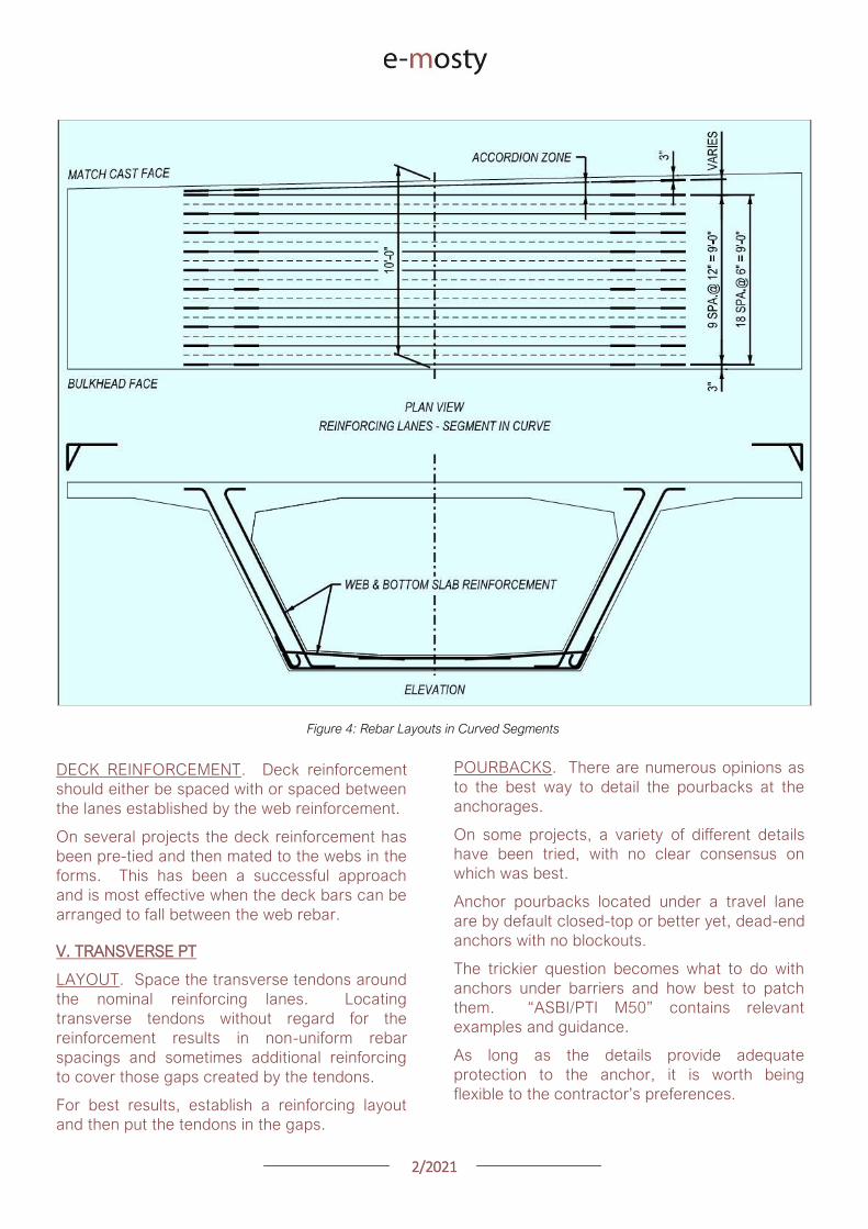
22021
Figure 4 Rebar Layouts in Curved Segments
DECK REINFORCEMENT Deck reinforcement
should either be spaced with or spaced between
the lanes established by the web reinforcement
On several projects the deck reinforcement has
been pre-tied and then mated to the webs in the
forms This has been a successful approach
and is most effective when the deck bars can be
arranged to fall between the web rebar
V TRANSVERSE PT
LAYOUT Space the transverse tendons around
the nominal reinforcing lanes Locating
transverse tendons without regard for the
reinforcement results in non-uniform rebar
spacings and sometimes additional reinforcing
to cover those gaps created by the tendons
For best results establish a reinforcing layout
and then put the tendons in the gaps
POURBACKS There are numerous opinions as
to the best way to detail the pourbacks at the
anchorages
On some projects a variety of different details
have been tried with no clear consensus on
which was best
Anchor pourbacks located under a travel lane
are by default closed-top or better yet dead-end
anchors with no blockouts
The trickier question becomes what to do with
anchors under barriers and how best to patch
them ldquoASBIPTI M50rdquo contains relevant
examples and guidance
As long as the details provide adequate
protection to the anchor it is worth being
flexible to the contractorrsquos preferences
22021
Figure 5 Deck
Reinforcement
Figure 6 Transverse PT
Integrated with
Reinforcing Lanes
22021
STRAND INSTALLATION In dual box girders
transverse tendons are sometimes used across the
in-situ closure This detail has complications and
should be discouraged Strands cannot be reliably
fed through a flat duct after is has been cast in
concrete because the duct is often flattened (even
flatter) during concreting
Secondly accumulated tolerances between the
segments create significant misalignments across
the closure If a bridge deck really requires post-
tensioning between two barrels consider round
duct to address both of these challenges with what
is ultimately a modest difference in duct size
Figure 7 Dual Box Structure with in-situ Closure Veterans Memorial Causeway Courtesy of Reed amp Reed Construction
VI LONGITUDINAL PT TOP SLAB TENDONS
Avoiding or minimizing the number of tendons in
the deck slab can improve a bridgersquos lifespan
Similarly the details related to the top slab PT
are equally important in the structurersquos
durability
BLOCKOUTS The most common example of
longitudinal tendons in the top deck slab are
cantilever tendons These tendons are typically
anchored at the joint face In order to orient the
tendon to the bulkhead anchorages are
mounted to a recessed blockout
Figure 8 Cantilever Anchor Layout
22021
This recess should be deep enough to contain
the entire grout cap consequently it consumes
a significant amount of space on the bulkhead
Just as with a duct located along any other face
it is important to provide adequate clear cover to
the blockout to prevent water or grout leakage
to and from the ducts
LAYOUT Set the cantilever anchorage low
enough to clear the transverse tendon In some
cases anchor spirals have been found to conflict
with the first transverse tendon
This is a problem for a number of reasons including
the reduction in anchor confinement the potential
to crush the transverse tendon and the sheer
nuisance to the builder
TOP CONTINUITY Avoid the use of top slab
continuity tendons and associated anchor
blocks
This is particularly relevant in form traveller
construction where the core-form beams are
typically larger longer and may extend into the
previous segments at a skew
REINFORCEMENT The duct layout should
consider the reinforcement and related
fabrication tolerances As outlined in Section X
below lowering the ducts in and around the web
reinforcing addresses a number of problems
with a minimal effect on the tendon eccentricity
Figure 9 Web Rebar Tolerances
22021
Figure 10 Web Rebar Tolerances Upper Ducts lowered (slightly) at full Height Stirrups for rebar
tolerances Hong Kong Mtr South Island Line Courtesy of Leighton Construction
VII LONGITUDINAL PT BOTTOM SLAB
TENDONS
LAYOUT While there are exceptions to every
rule fixing the bottom slab tendon layout and
anchor block geometry from the inside corner of
the box girder can standardize many details
With this approach the relative geometry
between the anchor block and the duct-runs
remains consistent while the depth of the girder
varies
SLAB THICKNESS Consider making the
bottom slab thickness constant through the
anchor block segments In variable depth box
girders specifically balanced cantilever with
form travellers there is a natural instinct to vary
the bottom slab thickness in parallel with the
girder depth
However tapering the bottom slab down to its
minimum thickness prior to the anchor blocks is
an effective approach in simplifying the design
Figure 11 Bottom Duct Setout
22021
REINFORCEMENT Check for conflicts between
the web reinforcement and the duct layout The
webs typically require larger diameter rebar than
the bottom slab For that reason it may be
necessary to raise the ducts located over the
web bar legs
Finally verify that the first duct is set far enough
from the web to allow for any plan curvature at
the anchor
DUCT GEOMETRY Aim the anchorage slightly
inboard for jack access This is important in
curved bridges where the web in the next
segment may encroach on the jack envelope
The tendon profile at the anchor block should
allow for PT system radius and tangent
requirements The bend radius should be
measured in the plane of the curve
Fitting the requisite tangent and radius for a 19
strand tendon into a 3m long segment can be
challenging Specify lsquotight radiusrsquo duct where
needed
This duct has corrugations that permit smaller
bending radii without buckling and caving
Some ducts can also be heat-bent to achieve
small radii
The last resort is using pre-bent steel pipes
Being aware of and designing within the radii
that can be achieved with corrugated plastic
duct should be the goal for cost-effective
design
Figure 12 Bottom Duct Profile
22021
VIII LONGITUDINAL PT WEB TENDONS
While very common in traditional post-tensioned
construction web tendons are not often used in
precast segmental bridges However there are
two situations where web tendons are
sometimes used
First is to supplement or eliminate bottom slab
continuity tendons Second is to provide some
form of bonded continuity steel across the entire
span ndash seismic requirements for example
In these cases the most practical approach is to
anchor the web tendons in pier or expansion
segments and run them pier-to-pier thereby
avoiding unique anchor blocks
In order to have a rational duct arrangement on
the bulkhead the tendons should use an
angular or lsquodeviatedrsquo profile ndash not draped
profiles Furthermore use a profile that is
coordinated with the shear key arrangement or
coordinate the shear keys with the duct holes to
avoid altering the bulkhead during casting
In the situation where web tendons are used in
conjunction with anchor blocks avoid locating
anchor blocks in-plane with the web tendons
The web and bottom slab tendon will inevitably
slope at different angles which prevents the
anchor block reinforcement development into
the web
Figure 13 Web Tendon Profile and Bottom Blocks
IX LONGITUDINAL PT EXTERNAL TENDONS
For those wanting potentially replaceable post-
tensioning external tendons are the answer
The Florida DOT Bridge Design Manual provides
some of the best advice for these details
DEVIATOR A point of debate between experts
is diabolos vs pipes For smaller quantities
pipes may be more economical Pipes are also
smaller On the other hand pipes can and do
get placed incorrectly which requires expensive
re-work to correct
When laying out the tendon paths be aware that
diabolos require more space since they flare out
in 360 degrees
Furthermore diabolos without stay-in-place
plastic formers require more stringent clear
cover requirements between rebar and the
diabolos That said a well thought out design
with diabolos is relatively fool-proof with only the
up-front cost of the formers
CONFLICTS One consideration for any design
with external tendons is to verify that the
external tendons have a clear line-of-sight
between deviation points Confirm that the
tendons do not hit other anchor blocks
In curved structures check that the tendons do
not hit the web walls Where structures are on
tight radii it may be necessary to add an
additional deviator to guide the tendons around
the curved span
X BOX GIRDER REINFORCEMENT
To paraphrase the theme of Section IV above
ldquoUse Common Denominatorsrdquo Simply spacing
the reinforcement together at regular intervals
goes a long way to simplifying construction
The answer to ldquowhy not mix spacings if it saves
a few barsrdquo is that it becomes necessary to shift
some bars out of their nominal spacings to mesh
with the other set leading to localized
congestion and conflicts
22021
Space rebar at common denominators ie 15
and 30cm work together but not 15 and 20cm
Once the reinforcing lanes are established the
key to constructability is the web reinforcement
PT anchors anchor blocks transverse tendons
and construction embeds all gravitate to the
webs
Furthermore the web reinforcement is a full-
height shear stirrup which is sensitive to bending
and placing tolerances
TOLERANCES Rebar fabrication tolerances
should be a primary consideration in detailing
The fabricated bending tolerance on most bars
is +-25mm per leg Tighter tolerances can be
specified but keep in mind that there is no
magic tolerance setting on the bending
machine If the design requires tighter
tolerances this translates to more rejected bar
and associated cost
If a bar is constrained by clear cover at each
end the logical approach is to detail the bar
25mm short of the nominal length and verify that
the details can accommodate the tolerance
Sometimes the clear cover tolerances help And
sometimes the bar tolerances can be absorbed
at two faces and the effects are minor With
web reinforcing however the bars are typically
supported on chairs on the soffit slab which
requires all of the tolerance to be taken up at
the top face where the bar legs are constrained
between the clear cover and the cantilever
ducts
A simple solution is to lower the ducts within this
area to clear the bar tolerance envelope While
this lowers the eccentricity of some tendons
consider that it is likely a small number of the
tendons moving a small percentage of the
overall depth so the effect is minor
NESTING BARS Give consideration to the
bends and orientation of the web bar tails In
order to minimize congestion and make room for
other reinforcement it preferable to keep the
web bars in-plane with each other Use 180
degree hooks where appropriate to avoid
bundled legs
RE-ENTRANT CORNERS Be thoughtful when
detailing reinforcement at re-entrant corners
For example the inside web face often has a
fillet Reinforcing this face with a single bar is not
advisable
Figure 14 Re-entrant
Corners
22021
Consider that when this bar is in tension it will
want to straighten and pop-out the cover
concrete at the corner It is preferable to use
crossing-bars which develop beyond the corner
TENDON PASS-THRU Where tendons pass
thru reinforcing mats the design should specify
how Note that the tendons in anchor blocks
typically slope at 12-15 degrees At this angle
the duct can conflict with rebar over a length of
60-90cm
Simply shifting bars longitudinally to clear the
conflict is not practical because it displaces too
many bars and leaves a large gap
In most cases it is preferable that the cross-thru
details are modifications (by moving bending or
cutting) to the typical reinforcing as opposed to
introducing unique bars at specific locations
Figure 15 Top Mat Bars at Cross-Thru (with fillet)
Figure 16 Top Mat Bars at Cross-Thru (flat slab)
22021
LONGITUDINAL REINFORCING An additional
topic to highlight is the treatment of longitudinal
reinforcing in curved segments In cast-in-place
construction the bars are detailed long enough
to satisfy the lap splice requirements on the
outside of the curve and the extra length on the
short side is taken up in the lap splice
In precast segments the detailing of longitudinal
reinforcement becomes complicated
Longitudinal bars are broken into sub-sets in
order to graduate the lengths across the width
of the segment
Otherwise identical reinforcing cages but with
slightly different plan-view geometry become
different reinforcing types requiring additional
drawings and submittals not to mention more
time spent sorting bars on-site
Given that segment cages are pre-tied in jigs it
would be reasonable to detail all the bars long
tie them in the cage and then cut them to
match the pie-shape of the specific segment
This would streamline shop drawing process and
potentially simplify fabrication
Figure 17 Treatment of Longitudinal Bars
XI ANCHOR BLOCK REINFORCEMENT
Before reading any further prepare to go lsquodeep
in the weedsrsquo In order to lessen the headache
refer directly to the appendix for an example of
an anchor block that addresses the challenges
CONGESTION Anchor blocks typically have
two sets of bars (outer confinement + inner tie
for curvature) which mesh together with the
web reinforcement (2 faces) and slab
reinforcement (2 faces)
Altogether this can translate to six bars which
must pass each other Many of these bars may
have legs on the same face creating lsquowallsrsquo of
bundled rebar
These zones of bars are problematic for placing
concrete prone to spalling and do nothing to
develop the reinforcement There are several
techniques to address this
Place the web reinforcement in the same
plane Turn the leg on the inside-face
web bar toward centerline of segment If
the leg on the outside-face web bar
contacts the inside-face reinforcement
consider using a 180deg hook
Place bottom slab reinforcement in the
same plane If the legs happen to
conflict shorten or place the top-mat bar
to nest inside the bottom-mat bar
22021
Turn the legs of the outer anchor block
reinforcement away from the web Full
360deg or even 270deg confinement of the
anchor block is not necessary as the
bottom slab and web reinforcement
already exist on these faces and are
waiting to be put to work
Consider the direction of the legs on the
inner anchor block bars (ie the in-plane
pullout reinforcement) Turning both legs
the same direction andor using 180
degree hooks may be helpful
TENDON GEOMETRY Anchor block
reinforcement should be organized with thought
to the actual tendon geometry In most cases
the other tendons in and around the anchor
block are not running parallel to the web
Tendon paths should not be altered to snake
thru the reinforcement Instead configure the
reinforcement to the lanes between the ducts
There are several techniques to address this
Begin by designing the reinforcement
around the typical (probably deviating)
tendon arrangement
Slope the inside face of the anchor block
By varying the clear cover the outer
block reinforcement may be detailed to
follow either straight or deviating tendon
paths
Adjust the width of the in-plane pullout
reinforcement as needed Where these
bars are tall use a wide bar in order to
straddle ducts running below Where
these bars are short a narrow top-hat
bar is appropriate to avoid clashing with
other ducts
Figure 18 Anchor Block Reinforcement (see Appendix)
22021
XII DIAPHRAGM REINFORCEMENT
There are a number of different approaches to
diaphragm design and this paper will not go into
depth on the possibilities However the
challenges found in diaphragm reinforcement
are variations on others already identified
When presented a problem engineers are good at
finding fixes For that reason simply being aware
of these issues goes a long way
Rebar Fabrication Tolerances
Rebar Placing Tolerances
Actual Size of Rebar and PT
Actual Size of Bar Bend Radii
Congestion (see Figure 19)
Uniformity Standardization
Finally just to give the contractor a sporting
chance identify all of the intersecting bars ducts
and other elements (with their overall sizes) and
verify that they do indeed fit inside of the concrete
An allowance for placing tolerances is
recommended too Incorporating this analysis into
the design process should be standard practice
Figure 19
lsquoRealrsquo Rebar
Diameter
larr Figure 20
Example of
Congestion
Too Many Bars
in Same Plane
22021
In cast-in-place construction headed anchor
studs may be a good option provided again
that the stud layout is integrated with the
reinforcement
INTEGRAL STRADDLE BEAMS Precast
segments are sometimes cantilevered from
straddle beams or similar CIP elements In this
configuration set the first precast segment just
off the straddle beam with a short closure
avoiding a complicated cast-in-place starter
Minor skews can be absorbed in the closure
Larger skews can be cast into the starter
segment In the case of cantilever construction
most if not all of the post-tensioning ducts are in
the top slab Rather than trying to cast ducts in
precise locations in the straddle beam set the
segment slightly higher than the top of beam
and cast the deck slab after the segments have
been placed
This avoids complications with tolerances as
well as conflicts between the straddle beam
stirrups and PT ducts
XIII SUBSTRUCTURE CONNECTIONS
The details associated with the superstructure
connection to the substructure have a
significant impact on the constructability This
interface is typically at the bearings and in some
cases the superstructure may frame into other
types of construction
Short closures are used to connect segments
which are not match cast However when a
segment is taken from one form and mated up
with one from a different form you can expect
some degree of misalignment in the cross
section and ducts
BEARINGS In precast segmental where the
structure requires fixity through the bearings it
is preferable to use a limited number of large
pintles to transfer horizontal load to the
bearings
In these situations the void for the pintle should
be oversized to allow for grade and
superelevation as well as reasonable fabrication
and placing tolerances
These voids may be formed using lsquocansrsquo or it
may be practical to void out a rectangular
volume in and around the reinforcement using
foam block In either case the pintles must be
integrated with the reinforcement
Figure 21 Straddle Beam Connection
22021
Figure 23 Straddle Beam Connection Top of Beam held low to allow Cantilever Tendons to pass over without conflict
Hong Kong Mtr South Island Line Courtesy of Leighton Construction
Figure 22 Straddle Beam Connection Top of Beam held low to allow Cantilever Tendons to pass over without conflict
Hong Kong Mtr South Island Line Courtesy of Leighton Construction
22021
INTEGRAL PIER COLUMNS Making precast
segments integral with pier columns presents
challenges but there are a number of benefits
Integral connections can eliminate bearings and
associated maintenance provide robust
connection for lateral loads (ie seismic) and
can eliminate the need for temporary stability
shoring
Integral connections can be achieved several
ways Similar to the previous straddle beam
example the conventional approach is to
construct cast-in-place pier segments and erect
precast segments on either side with short
closures
This requires realistic expectations for the
construction tolerances involved For example
it may be prudent to thicken the in-situ cross
section to minimize misalignments in the cross
section in addition to incorporating means to
accommodate duct misalignments
XIV PLAN PRESENTATION
Efficient construction requires good drawings
BRIM and 3D CAD tools allow us to create some
amazing work but as this is being written there
are still a lot of us humans involved in the
process
Modern drafting tools allow us to make drawing
easier and to balance that it is important to be
disciplined in minimizing drawings and details
Figure 24 PT Layout Example
22021
SYMMETRY If something is symmetric or even
close to it use half views Showing redundant
information invites confusion and errors This
also allows views to be larger and show details
more clearly
PT LAYOUTS All longitudinal PT for a given
segment should be shown on the same drawing
sheet Scale plan views in the transverse
direction to better illustrate tendon geometry
and neglect horizontal curvature Last ndash call out
each end of each tendon
APPENDIX 3D MODEL
The following page is a 3D pdf to illustrate some
of the points discussed in this document
The source DGN file is attached here
I hope you find this document useful and Good Bridgebuilding
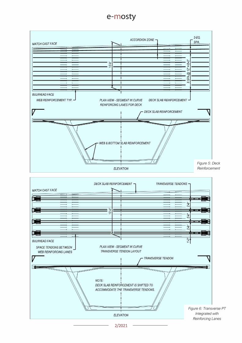
22021
Figure 5 Deck
Reinforcement
Figure 6 Transverse PT
Integrated with
Reinforcing Lanes
22021
STRAND INSTALLATION In dual box girders
transverse tendons are sometimes used across the
in-situ closure This detail has complications and
should be discouraged Strands cannot be reliably
fed through a flat duct after is has been cast in
concrete because the duct is often flattened (even
flatter) during concreting
Secondly accumulated tolerances between the
segments create significant misalignments across
the closure If a bridge deck really requires post-
tensioning between two barrels consider round
duct to address both of these challenges with what
is ultimately a modest difference in duct size
Figure 7 Dual Box Structure with in-situ Closure Veterans Memorial Causeway Courtesy of Reed amp Reed Construction
VI LONGITUDINAL PT TOP SLAB TENDONS
Avoiding or minimizing the number of tendons in
the deck slab can improve a bridgersquos lifespan
Similarly the details related to the top slab PT
are equally important in the structurersquos
durability
BLOCKOUTS The most common example of
longitudinal tendons in the top deck slab are
cantilever tendons These tendons are typically
anchored at the joint face In order to orient the
tendon to the bulkhead anchorages are
mounted to a recessed blockout
Figure 8 Cantilever Anchor Layout
22021
This recess should be deep enough to contain
the entire grout cap consequently it consumes
a significant amount of space on the bulkhead
Just as with a duct located along any other face
it is important to provide adequate clear cover to
the blockout to prevent water or grout leakage
to and from the ducts
LAYOUT Set the cantilever anchorage low
enough to clear the transverse tendon In some
cases anchor spirals have been found to conflict
with the first transverse tendon
This is a problem for a number of reasons including
the reduction in anchor confinement the potential
to crush the transverse tendon and the sheer
nuisance to the builder
TOP CONTINUITY Avoid the use of top slab
continuity tendons and associated anchor
blocks
This is particularly relevant in form traveller
construction where the core-form beams are
typically larger longer and may extend into the
previous segments at a skew
REINFORCEMENT The duct layout should
consider the reinforcement and related
fabrication tolerances As outlined in Section X
below lowering the ducts in and around the web
reinforcing addresses a number of problems
with a minimal effect on the tendon eccentricity
Figure 9 Web Rebar Tolerances
22021
Figure 10 Web Rebar Tolerances Upper Ducts lowered (slightly) at full Height Stirrups for rebar
tolerances Hong Kong Mtr South Island Line Courtesy of Leighton Construction
VII LONGITUDINAL PT BOTTOM SLAB
TENDONS
LAYOUT While there are exceptions to every
rule fixing the bottom slab tendon layout and
anchor block geometry from the inside corner of
the box girder can standardize many details
With this approach the relative geometry
between the anchor block and the duct-runs
remains consistent while the depth of the girder
varies
SLAB THICKNESS Consider making the
bottom slab thickness constant through the
anchor block segments In variable depth box
girders specifically balanced cantilever with
form travellers there is a natural instinct to vary
the bottom slab thickness in parallel with the
girder depth
However tapering the bottom slab down to its
minimum thickness prior to the anchor blocks is
an effective approach in simplifying the design
Figure 11 Bottom Duct Setout
22021
REINFORCEMENT Check for conflicts between
the web reinforcement and the duct layout The
webs typically require larger diameter rebar than
the bottom slab For that reason it may be
necessary to raise the ducts located over the
web bar legs
Finally verify that the first duct is set far enough
from the web to allow for any plan curvature at
the anchor
DUCT GEOMETRY Aim the anchorage slightly
inboard for jack access This is important in
curved bridges where the web in the next
segment may encroach on the jack envelope
The tendon profile at the anchor block should
allow for PT system radius and tangent
requirements The bend radius should be
measured in the plane of the curve
Fitting the requisite tangent and radius for a 19
strand tendon into a 3m long segment can be
challenging Specify lsquotight radiusrsquo duct where
needed
This duct has corrugations that permit smaller
bending radii without buckling and caving
Some ducts can also be heat-bent to achieve
small radii
The last resort is using pre-bent steel pipes
Being aware of and designing within the radii
that can be achieved with corrugated plastic
duct should be the goal for cost-effective
design
Figure 12 Bottom Duct Profile
22021
VIII LONGITUDINAL PT WEB TENDONS
While very common in traditional post-tensioned
construction web tendons are not often used in
precast segmental bridges However there are
two situations where web tendons are
sometimes used
First is to supplement or eliminate bottom slab
continuity tendons Second is to provide some
form of bonded continuity steel across the entire
span ndash seismic requirements for example
In these cases the most practical approach is to
anchor the web tendons in pier or expansion
segments and run them pier-to-pier thereby
avoiding unique anchor blocks
In order to have a rational duct arrangement on
the bulkhead the tendons should use an
angular or lsquodeviatedrsquo profile ndash not draped
profiles Furthermore use a profile that is
coordinated with the shear key arrangement or
coordinate the shear keys with the duct holes to
avoid altering the bulkhead during casting
In the situation where web tendons are used in
conjunction with anchor blocks avoid locating
anchor blocks in-plane with the web tendons
The web and bottom slab tendon will inevitably
slope at different angles which prevents the
anchor block reinforcement development into
the web
Figure 13 Web Tendon Profile and Bottom Blocks
IX LONGITUDINAL PT EXTERNAL TENDONS
For those wanting potentially replaceable post-
tensioning external tendons are the answer
The Florida DOT Bridge Design Manual provides
some of the best advice for these details
DEVIATOR A point of debate between experts
is diabolos vs pipes For smaller quantities
pipes may be more economical Pipes are also
smaller On the other hand pipes can and do
get placed incorrectly which requires expensive
re-work to correct
When laying out the tendon paths be aware that
diabolos require more space since they flare out
in 360 degrees
Furthermore diabolos without stay-in-place
plastic formers require more stringent clear
cover requirements between rebar and the
diabolos That said a well thought out design
with diabolos is relatively fool-proof with only the
up-front cost of the formers
CONFLICTS One consideration for any design
with external tendons is to verify that the
external tendons have a clear line-of-sight
between deviation points Confirm that the
tendons do not hit other anchor blocks
In curved structures check that the tendons do
not hit the web walls Where structures are on
tight radii it may be necessary to add an
additional deviator to guide the tendons around
the curved span
X BOX GIRDER REINFORCEMENT
To paraphrase the theme of Section IV above
ldquoUse Common Denominatorsrdquo Simply spacing
the reinforcement together at regular intervals
goes a long way to simplifying construction
The answer to ldquowhy not mix spacings if it saves
a few barsrdquo is that it becomes necessary to shift
some bars out of their nominal spacings to mesh
with the other set leading to localized
congestion and conflicts
22021
Space rebar at common denominators ie 15
and 30cm work together but not 15 and 20cm
Once the reinforcing lanes are established the
key to constructability is the web reinforcement
PT anchors anchor blocks transverse tendons
and construction embeds all gravitate to the
webs
Furthermore the web reinforcement is a full-
height shear stirrup which is sensitive to bending
and placing tolerances
TOLERANCES Rebar fabrication tolerances
should be a primary consideration in detailing
The fabricated bending tolerance on most bars
is +-25mm per leg Tighter tolerances can be
specified but keep in mind that there is no
magic tolerance setting on the bending
machine If the design requires tighter
tolerances this translates to more rejected bar
and associated cost
If a bar is constrained by clear cover at each
end the logical approach is to detail the bar
25mm short of the nominal length and verify that
the details can accommodate the tolerance
Sometimes the clear cover tolerances help And
sometimes the bar tolerances can be absorbed
at two faces and the effects are minor With
web reinforcing however the bars are typically
supported on chairs on the soffit slab which
requires all of the tolerance to be taken up at
the top face where the bar legs are constrained
between the clear cover and the cantilever
ducts
A simple solution is to lower the ducts within this
area to clear the bar tolerance envelope While
this lowers the eccentricity of some tendons
consider that it is likely a small number of the
tendons moving a small percentage of the
overall depth so the effect is minor
NESTING BARS Give consideration to the
bends and orientation of the web bar tails In
order to minimize congestion and make room for
other reinforcement it preferable to keep the
web bars in-plane with each other Use 180
degree hooks where appropriate to avoid
bundled legs
RE-ENTRANT CORNERS Be thoughtful when
detailing reinforcement at re-entrant corners
For example the inside web face often has a
fillet Reinforcing this face with a single bar is not
advisable
Figure 14 Re-entrant
Corners
22021
Consider that when this bar is in tension it will
want to straighten and pop-out the cover
concrete at the corner It is preferable to use
crossing-bars which develop beyond the corner
TENDON PASS-THRU Where tendons pass
thru reinforcing mats the design should specify
how Note that the tendons in anchor blocks
typically slope at 12-15 degrees At this angle
the duct can conflict with rebar over a length of
60-90cm
Simply shifting bars longitudinally to clear the
conflict is not practical because it displaces too
many bars and leaves a large gap
In most cases it is preferable that the cross-thru
details are modifications (by moving bending or
cutting) to the typical reinforcing as opposed to
introducing unique bars at specific locations
Figure 15 Top Mat Bars at Cross-Thru (with fillet)
Figure 16 Top Mat Bars at Cross-Thru (flat slab)
22021
LONGITUDINAL REINFORCING An additional
topic to highlight is the treatment of longitudinal
reinforcing in curved segments In cast-in-place
construction the bars are detailed long enough
to satisfy the lap splice requirements on the
outside of the curve and the extra length on the
short side is taken up in the lap splice
In precast segments the detailing of longitudinal
reinforcement becomes complicated
Longitudinal bars are broken into sub-sets in
order to graduate the lengths across the width
of the segment
Otherwise identical reinforcing cages but with
slightly different plan-view geometry become
different reinforcing types requiring additional
drawings and submittals not to mention more
time spent sorting bars on-site
Given that segment cages are pre-tied in jigs it
would be reasonable to detail all the bars long
tie them in the cage and then cut them to
match the pie-shape of the specific segment
This would streamline shop drawing process and
potentially simplify fabrication
Figure 17 Treatment of Longitudinal Bars
XI ANCHOR BLOCK REINFORCEMENT
Before reading any further prepare to go lsquodeep
in the weedsrsquo In order to lessen the headache
refer directly to the appendix for an example of
an anchor block that addresses the challenges
CONGESTION Anchor blocks typically have
two sets of bars (outer confinement + inner tie
for curvature) which mesh together with the
web reinforcement (2 faces) and slab
reinforcement (2 faces)
Altogether this can translate to six bars which
must pass each other Many of these bars may
have legs on the same face creating lsquowallsrsquo of
bundled rebar
These zones of bars are problematic for placing
concrete prone to spalling and do nothing to
develop the reinforcement There are several
techniques to address this
Place the web reinforcement in the same
plane Turn the leg on the inside-face
web bar toward centerline of segment If
the leg on the outside-face web bar
contacts the inside-face reinforcement
consider using a 180deg hook
Place bottom slab reinforcement in the
same plane If the legs happen to
conflict shorten or place the top-mat bar
to nest inside the bottom-mat bar
22021
Turn the legs of the outer anchor block
reinforcement away from the web Full
360deg or even 270deg confinement of the
anchor block is not necessary as the
bottom slab and web reinforcement
already exist on these faces and are
waiting to be put to work
Consider the direction of the legs on the
inner anchor block bars (ie the in-plane
pullout reinforcement) Turning both legs
the same direction andor using 180
degree hooks may be helpful
TENDON GEOMETRY Anchor block
reinforcement should be organized with thought
to the actual tendon geometry In most cases
the other tendons in and around the anchor
block are not running parallel to the web
Tendon paths should not be altered to snake
thru the reinforcement Instead configure the
reinforcement to the lanes between the ducts
There are several techniques to address this
Begin by designing the reinforcement
around the typical (probably deviating)
tendon arrangement
Slope the inside face of the anchor block
By varying the clear cover the outer
block reinforcement may be detailed to
follow either straight or deviating tendon
paths
Adjust the width of the in-plane pullout
reinforcement as needed Where these
bars are tall use a wide bar in order to
straddle ducts running below Where
these bars are short a narrow top-hat
bar is appropriate to avoid clashing with
other ducts
Figure 18 Anchor Block Reinforcement (see Appendix)
22021
XII DIAPHRAGM REINFORCEMENT
There are a number of different approaches to
diaphragm design and this paper will not go into
depth on the possibilities However the
challenges found in diaphragm reinforcement
are variations on others already identified
When presented a problem engineers are good at
finding fixes For that reason simply being aware
of these issues goes a long way
Rebar Fabrication Tolerances
Rebar Placing Tolerances
Actual Size of Rebar and PT
Actual Size of Bar Bend Radii
Congestion (see Figure 19)
Uniformity Standardization
Finally just to give the contractor a sporting
chance identify all of the intersecting bars ducts
and other elements (with their overall sizes) and
verify that they do indeed fit inside of the concrete
An allowance for placing tolerances is
recommended too Incorporating this analysis into
the design process should be standard practice
Figure 19
lsquoRealrsquo Rebar
Diameter
larr Figure 20
Example of
Congestion
Too Many Bars
in Same Plane
22021
In cast-in-place construction headed anchor
studs may be a good option provided again
that the stud layout is integrated with the
reinforcement
INTEGRAL STRADDLE BEAMS Precast
segments are sometimes cantilevered from
straddle beams or similar CIP elements In this
configuration set the first precast segment just
off the straddle beam with a short closure
avoiding a complicated cast-in-place starter
Minor skews can be absorbed in the closure
Larger skews can be cast into the starter
segment In the case of cantilever construction
most if not all of the post-tensioning ducts are in
the top slab Rather than trying to cast ducts in
precise locations in the straddle beam set the
segment slightly higher than the top of beam
and cast the deck slab after the segments have
been placed
This avoids complications with tolerances as
well as conflicts between the straddle beam
stirrups and PT ducts
XIII SUBSTRUCTURE CONNECTIONS
The details associated with the superstructure
connection to the substructure have a
significant impact on the constructability This
interface is typically at the bearings and in some
cases the superstructure may frame into other
types of construction
Short closures are used to connect segments
which are not match cast However when a
segment is taken from one form and mated up
with one from a different form you can expect
some degree of misalignment in the cross
section and ducts
BEARINGS In precast segmental where the
structure requires fixity through the bearings it
is preferable to use a limited number of large
pintles to transfer horizontal load to the
bearings
In these situations the void for the pintle should
be oversized to allow for grade and
superelevation as well as reasonable fabrication
and placing tolerances
These voids may be formed using lsquocansrsquo or it
may be practical to void out a rectangular
volume in and around the reinforcement using
foam block In either case the pintles must be
integrated with the reinforcement
Figure 21 Straddle Beam Connection
22021
Figure 23 Straddle Beam Connection Top of Beam held low to allow Cantilever Tendons to pass over without conflict
Hong Kong Mtr South Island Line Courtesy of Leighton Construction
Figure 22 Straddle Beam Connection Top of Beam held low to allow Cantilever Tendons to pass over without conflict
Hong Kong Mtr South Island Line Courtesy of Leighton Construction
22021
INTEGRAL PIER COLUMNS Making precast
segments integral with pier columns presents
challenges but there are a number of benefits
Integral connections can eliminate bearings and
associated maintenance provide robust
connection for lateral loads (ie seismic) and
can eliminate the need for temporary stability
shoring
Integral connections can be achieved several
ways Similar to the previous straddle beam
example the conventional approach is to
construct cast-in-place pier segments and erect
precast segments on either side with short
closures
This requires realistic expectations for the
construction tolerances involved For example
it may be prudent to thicken the in-situ cross
section to minimize misalignments in the cross
section in addition to incorporating means to
accommodate duct misalignments
XIV PLAN PRESENTATION
Efficient construction requires good drawings
BRIM and 3D CAD tools allow us to create some
amazing work but as this is being written there
are still a lot of us humans involved in the
process
Modern drafting tools allow us to make drawing
easier and to balance that it is important to be
disciplined in minimizing drawings and details
Figure 24 PT Layout Example
22021
SYMMETRY If something is symmetric or even
close to it use half views Showing redundant
information invites confusion and errors This
also allows views to be larger and show details
more clearly
PT LAYOUTS All longitudinal PT for a given
segment should be shown on the same drawing
sheet Scale plan views in the transverse
direction to better illustrate tendon geometry
and neglect horizontal curvature Last ndash call out
each end of each tendon
APPENDIX 3D MODEL
The following page is a 3D pdf to illustrate some
of the points discussed in this document
The source DGN file is attached here
I hope you find this document useful and Good Bridgebuilding
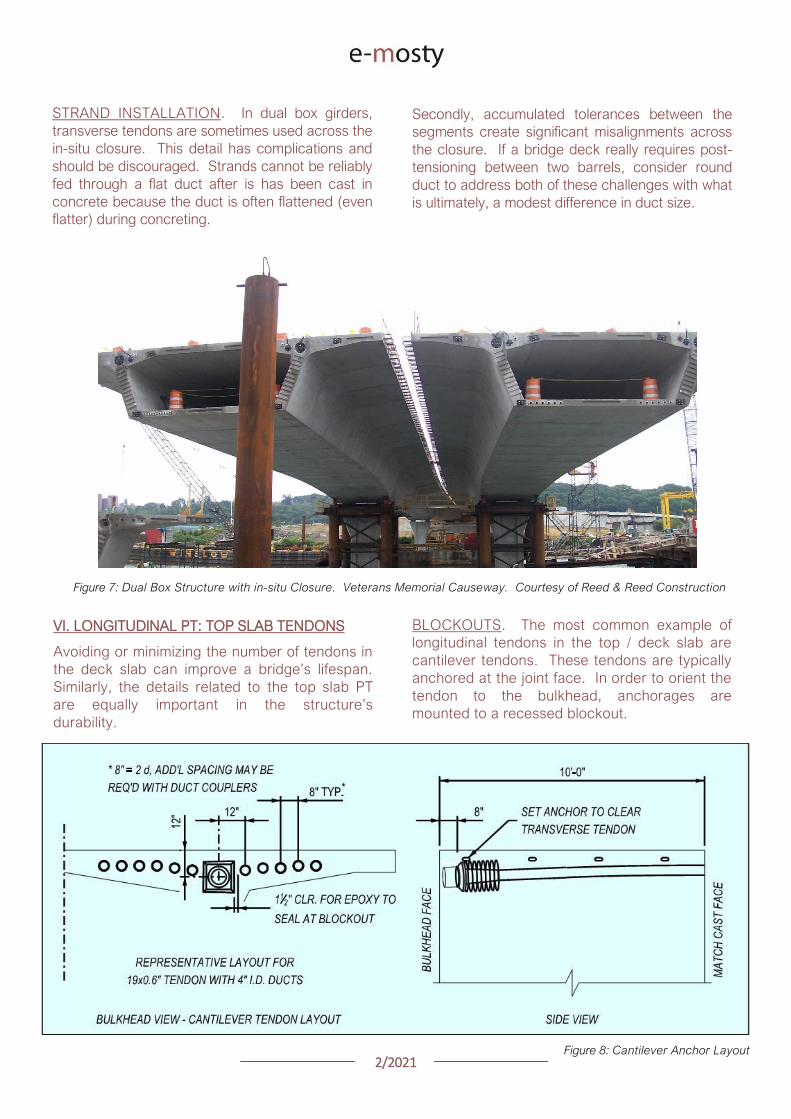
22021
STRAND INSTALLATION In dual box girders
transverse tendons are sometimes used across the
in-situ closure This detail has complications and
should be discouraged Strands cannot be reliably
fed through a flat duct after is has been cast in
concrete because the duct is often flattened (even
flatter) during concreting
Secondly accumulated tolerances between the
segments create significant misalignments across
the closure If a bridge deck really requires post-
tensioning between two barrels consider round
duct to address both of these challenges with what
is ultimately a modest difference in duct size
Figure 7 Dual Box Structure with in-situ Closure Veterans Memorial Causeway Courtesy of Reed amp Reed Construction
VI LONGITUDINAL PT TOP SLAB TENDONS
Avoiding or minimizing the number of tendons in
the deck slab can improve a bridgersquos lifespan
Similarly the details related to the top slab PT
are equally important in the structurersquos
durability
BLOCKOUTS The most common example of
longitudinal tendons in the top deck slab are
cantilever tendons These tendons are typically
anchored at the joint face In order to orient the
tendon to the bulkhead anchorages are
mounted to a recessed blockout
Figure 8 Cantilever Anchor Layout
22021
This recess should be deep enough to contain
the entire grout cap consequently it consumes
a significant amount of space on the bulkhead
Just as with a duct located along any other face
it is important to provide adequate clear cover to
the blockout to prevent water or grout leakage
to and from the ducts
LAYOUT Set the cantilever anchorage low
enough to clear the transverse tendon In some
cases anchor spirals have been found to conflict
with the first transverse tendon
This is a problem for a number of reasons including
the reduction in anchor confinement the potential
to crush the transverse tendon and the sheer
nuisance to the builder
TOP CONTINUITY Avoid the use of top slab
continuity tendons and associated anchor
blocks
This is particularly relevant in form traveller
construction where the core-form beams are
typically larger longer and may extend into the
previous segments at a skew
REINFORCEMENT The duct layout should
consider the reinforcement and related
fabrication tolerances As outlined in Section X
below lowering the ducts in and around the web
reinforcing addresses a number of problems
with a minimal effect on the tendon eccentricity
Figure 9 Web Rebar Tolerances
22021
Figure 10 Web Rebar Tolerances Upper Ducts lowered (slightly) at full Height Stirrups for rebar
tolerances Hong Kong Mtr South Island Line Courtesy of Leighton Construction
VII LONGITUDINAL PT BOTTOM SLAB
TENDONS
LAYOUT While there are exceptions to every
rule fixing the bottom slab tendon layout and
anchor block geometry from the inside corner of
the box girder can standardize many details
With this approach the relative geometry
between the anchor block and the duct-runs
remains consistent while the depth of the girder
varies
SLAB THICKNESS Consider making the
bottom slab thickness constant through the
anchor block segments In variable depth box
girders specifically balanced cantilever with
form travellers there is a natural instinct to vary
the bottom slab thickness in parallel with the
girder depth
However tapering the bottom slab down to its
minimum thickness prior to the anchor blocks is
an effective approach in simplifying the design
Figure 11 Bottom Duct Setout
22021
REINFORCEMENT Check for conflicts between
the web reinforcement and the duct layout The
webs typically require larger diameter rebar than
the bottom slab For that reason it may be
necessary to raise the ducts located over the
web bar legs
Finally verify that the first duct is set far enough
from the web to allow for any plan curvature at
the anchor
DUCT GEOMETRY Aim the anchorage slightly
inboard for jack access This is important in
curved bridges where the web in the next
segment may encroach on the jack envelope
The tendon profile at the anchor block should
allow for PT system radius and tangent
requirements The bend radius should be
measured in the plane of the curve
Fitting the requisite tangent and radius for a 19
strand tendon into a 3m long segment can be
challenging Specify lsquotight radiusrsquo duct where
needed
This duct has corrugations that permit smaller
bending radii without buckling and caving
Some ducts can also be heat-bent to achieve
small radii
The last resort is using pre-bent steel pipes
Being aware of and designing within the radii
that can be achieved with corrugated plastic
duct should be the goal for cost-effective
design
Figure 12 Bottom Duct Profile
22021
VIII LONGITUDINAL PT WEB TENDONS
While very common in traditional post-tensioned
construction web tendons are not often used in
precast segmental bridges However there are
two situations where web tendons are
sometimes used
First is to supplement or eliminate bottom slab
continuity tendons Second is to provide some
form of bonded continuity steel across the entire
span ndash seismic requirements for example
In these cases the most practical approach is to
anchor the web tendons in pier or expansion
segments and run them pier-to-pier thereby
avoiding unique anchor blocks
In order to have a rational duct arrangement on
the bulkhead the tendons should use an
angular or lsquodeviatedrsquo profile ndash not draped
profiles Furthermore use a profile that is
coordinated with the shear key arrangement or
coordinate the shear keys with the duct holes to
avoid altering the bulkhead during casting
In the situation where web tendons are used in
conjunction with anchor blocks avoid locating
anchor blocks in-plane with the web tendons
The web and bottom slab tendon will inevitably
slope at different angles which prevents the
anchor block reinforcement development into
the web
Figure 13 Web Tendon Profile and Bottom Blocks
IX LONGITUDINAL PT EXTERNAL TENDONS
For those wanting potentially replaceable post-
tensioning external tendons are the answer
The Florida DOT Bridge Design Manual provides
some of the best advice for these details
DEVIATOR A point of debate between experts
is diabolos vs pipes For smaller quantities
pipes may be more economical Pipes are also
smaller On the other hand pipes can and do
get placed incorrectly which requires expensive
re-work to correct
When laying out the tendon paths be aware that
diabolos require more space since they flare out
in 360 degrees
Furthermore diabolos without stay-in-place
plastic formers require more stringent clear
cover requirements between rebar and the
diabolos That said a well thought out design
with diabolos is relatively fool-proof with only the
up-front cost of the formers
CONFLICTS One consideration for any design
with external tendons is to verify that the
external tendons have a clear line-of-sight
between deviation points Confirm that the
tendons do not hit other anchor blocks
In curved structures check that the tendons do
not hit the web walls Where structures are on
tight radii it may be necessary to add an
additional deviator to guide the tendons around
the curved span
X BOX GIRDER REINFORCEMENT
To paraphrase the theme of Section IV above
ldquoUse Common Denominatorsrdquo Simply spacing
the reinforcement together at regular intervals
goes a long way to simplifying construction
The answer to ldquowhy not mix spacings if it saves
a few barsrdquo is that it becomes necessary to shift
some bars out of their nominal spacings to mesh
with the other set leading to localized
congestion and conflicts
22021
Space rebar at common denominators ie 15
and 30cm work together but not 15 and 20cm
Once the reinforcing lanes are established the
key to constructability is the web reinforcement
PT anchors anchor blocks transverse tendons
and construction embeds all gravitate to the
webs
Furthermore the web reinforcement is a full-
height shear stirrup which is sensitive to bending
and placing tolerances
TOLERANCES Rebar fabrication tolerances
should be a primary consideration in detailing
The fabricated bending tolerance on most bars
is +-25mm per leg Tighter tolerances can be
specified but keep in mind that there is no
magic tolerance setting on the bending
machine If the design requires tighter
tolerances this translates to more rejected bar
and associated cost
If a bar is constrained by clear cover at each
end the logical approach is to detail the bar
25mm short of the nominal length and verify that
the details can accommodate the tolerance
Sometimes the clear cover tolerances help And
sometimes the bar tolerances can be absorbed
at two faces and the effects are minor With
web reinforcing however the bars are typically
supported on chairs on the soffit slab which
requires all of the tolerance to be taken up at
the top face where the bar legs are constrained
between the clear cover and the cantilever
ducts
A simple solution is to lower the ducts within this
area to clear the bar tolerance envelope While
this lowers the eccentricity of some tendons
consider that it is likely a small number of the
tendons moving a small percentage of the
overall depth so the effect is minor
NESTING BARS Give consideration to the
bends and orientation of the web bar tails In
order to minimize congestion and make room for
other reinforcement it preferable to keep the
web bars in-plane with each other Use 180
degree hooks where appropriate to avoid
bundled legs
RE-ENTRANT CORNERS Be thoughtful when
detailing reinforcement at re-entrant corners
For example the inside web face often has a
fillet Reinforcing this face with a single bar is not
advisable
Figure 14 Re-entrant
Corners
22021
Consider that when this bar is in tension it will
want to straighten and pop-out the cover
concrete at the corner It is preferable to use
crossing-bars which develop beyond the corner
TENDON PASS-THRU Where tendons pass
thru reinforcing mats the design should specify
how Note that the tendons in anchor blocks
typically slope at 12-15 degrees At this angle
the duct can conflict with rebar over a length of
60-90cm
Simply shifting bars longitudinally to clear the
conflict is not practical because it displaces too
many bars and leaves a large gap
In most cases it is preferable that the cross-thru
details are modifications (by moving bending or
cutting) to the typical reinforcing as opposed to
introducing unique bars at specific locations
Figure 15 Top Mat Bars at Cross-Thru (with fillet)
Figure 16 Top Mat Bars at Cross-Thru (flat slab)
22021
LONGITUDINAL REINFORCING An additional
topic to highlight is the treatment of longitudinal
reinforcing in curved segments In cast-in-place
construction the bars are detailed long enough
to satisfy the lap splice requirements on the
outside of the curve and the extra length on the
short side is taken up in the lap splice
In precast segments the detailing of longitudinal
reinforcement becomes complicated
Longitudinal bars are broken into sub-sets in
order to graduate the lengths across the width
of the segment
Otherwise identical reinforcing cages but with
slightly different plan-view geometry become
different reinforcing types requiring additional
drawings and submittals not to mention more
time spent sorting bars on-site
Given that segment cages are pre-tied in jigs it
would be reasonable to detail all the bars long
tie them in the cage and then cut them to
match the pie-shape of the specific segment
This would streamline shop drawing process and
potentially simplify fabrication
Figure 17 Treatment of Longitudinal Bars
XI ANCHOR BLOCK REINFORCEMENT
Before reading any further prepare to go lsquodeep
in the weedsrsquo In order to lessen the headache
refer directly to the appendix for an example of
an anchor block that addresses the challenges
CONGESTION Anchor blocks typically have
two sets of bars (outer confinement + inner tie
for curvature) which mesh together with the
web reinforcement (2 faces) and slab
reinforcement (2 faces)
Altogether this can translate to six bars which
must pass each other Many of these bars may
have legs on the same face creating lsquowallsrsquo of
bundled rebar
These zones of bars are problematic for placing
concrete prone to spalling and do nothing to
develop the reinforcement There are several
techniques to address this
Place the web reinforcement in the same
plane Turn the leg on the inside-face
web bar toward centerline of segment If
the leg on the outside-face web bar
contacts the inside-face reinforcement
consider using a 180deg hook
Place bottom slab reinforcement in the
same plane If the legs happen to
conflict shorten or place the top-mat bar
to nest inside the bottom-mat bar
22021
Turn the legs of the outer anchor block
reinforcement away from the web Full
360deg or even 270deg confinement of the
anchor block is not necessary as the
bottom slab and web reinforcement
already exist on these faces and are
waiting to be put to work
Consider the direction of the legs on the
inner anchor block bars (ie the in-plane
pullout reinforcement) Turning both legs
the same direction andor using 180
degree hooks may be helpful
TENDON GEOMETRY Anchor block
reinforcement should be organized with thought
to the actual tendon geometry In most cases
the other tendons in and around the anchor
block are not running parallel to the web
Tendon paths should not be altered to snake
thru the reinforcement Instead configure the
reinforcement to the lanes between the ducts
There are several techniques to address this
Begin by designing the reinforcement
around the typical (probably deviating)
tendon arrangement
Slope the inside face of the anchor block
By varying the clear cover the outer
block reinforcement may be detailed to
follow either straight or deviating tendon
paths
Adjust the width of the in-plane pullout
reinforcement as needed Where these
bars are tall use a wide bar in order to
straddle ducts running below Where
these bars are short a narrow top-hat
bar is appropriate to avoid clashing with
other ducts
Figure 18 Anchor Block Reinforcement (see Appendix)
22021
XII DIAPHRAGM REINFORCEMENT
There are a number of different approaches to
diaphragm design and this paper will not go into
depth on the possibilities However the
challenges found in diaphragm reinforcement
are variations on others already identified
When presented a problem engineers are good at
finding fixes For that reason simply being aware
of these issues goes a long way
Rebar Fabrication Tolerances
Rebar Placing Tolerances
Actual Size of Rebar and PT
Actual Size of Bar Bend Radii
Congestion (see Figure 19)
Uniformity Standardization
Finally just to give the contractor a sporting
chance identify all of the intersecting bars ducts
and other elements (with their overall sizes) and
verify that they do indeed fit inside of the concrete
An allowance for placing tolerances is
recommended too Incorporating this analysis into
the design process should be standard practice
Figure 19
lsquoRealrsquo Rebar
Diameter
larr Figure 20
Example of
Congestion
Too Many Bars
in Same Plane
22021
In cast-in-place construction headed anchor
studs may be a good option provided again
that the stud layout is integrated with the
reinforcement
INTEGRAL STRADDLE BEAMS Precast
segments are sometimes cantilevered from
straddle beams or similar CIP elements In this
configuration set the first precast segment just
off the straddle beam with a short closure
avoiding a complicated cast-in-place starter
Minor skews can be absorbed in the closure
Larger skews can be cast into the starter
segment In the case of cantilever construction
most if not all of the post-tensioning ducts are in
the top slab Rather than trying to cast ducts in
precise locations in the straddle beam set the
segment slightly higher than the top of beam
and cast the deck slab after the segments have
been placed
This avoids complications with tolerances as
well as conflicts between the straddle beam
stirrups and PT ducts
XIII SUBSTRUCTURE CONNECTIONS
The details associated with the superstructure
connection to the substructure have a
significant impact on the constructability This
interface is typically at the bearings and in some
cases the superstructure may frame into other
types of construction
Short closures are used to connect segments
which are not match cast However when a
segment is taken from one form and mated up
with one from a different form you can expect
some degree of misalignment in the cross
section and ducts
BEARINGS In precast segmental where the
structure requires fixity through the bearings it
is preferable to use a limited number of large
pintles to transfer horizontal load to the
bearings
In these situations the void for the pintle should
be oversized to allow for grade and
superelevation as well as reasonable fabrication
and placing tolerances
These voids may be formed using lsquocansrsquo or it
may be practical to void out a rectangular
volume in and around the reinforcement using
foam block In either case the pintles must be
integrated with the reinforcement
Figure 21 Straddle Beam Connection
22021
Figure 23 Straddle Beam Connection Top of Beam held low to allow Cantilever Tendons to pass over without conflict
Hong Kong Mtr South Island Line Courtesy of Leighton Construction
Figure 22 Straddle Beam Connection Top of Beam held low to allow Cantilever Tendons to pass over without conflict
Hong Kong Mtr South Island Line Courtesy of Leighton Construction
22021
INTEGRAL PIER COLUMNS Making precast
segments integral with pier columns presents
challenges but there are a number of benefits
Integral connections can eliminate bearings and
associated maintenance provide robust
connection for lateral loads (ie seismic) and
can eliminate the need for temporary stability
shoring
Integral connections can be achieved several
ways Similar to the previous straddle beam
example the conventional approach is to
construct cast-in-place pier segments and erect
precast segments on either side with short
closures
This requires realistic expectations for the
construction tolerances involved For example
it may be prudent to thicken the in-situ cross
section to minimize misalignments in the cross
section in addition to incorporating means to
accommodate duct misalignments
XIV PLAN PRESENTATION
Efficient construction requires good drawings
BRIM and 3D CAD tools allow us to create some
amazing work but as this is being written there
are still a lot of us humans involved in the
process
Modern drafting tools allow us to make drawing
easier and to balance that it is important to be
disciplined in minimizing drawings and details
Figure 24 PT Layout Example
22021
SYMMETRY If something is symmetric or even
close to it use half views Showing redundant
information invites confusion and errors This
also allows views to be larger and show details
more clearly
PT LAYOUTS All longitudinal PT for a given
segment should be shown on the same drawing
sheet Scale plan views in the transverse
direction to better illustrate tendon geometry
and neglect horizontal curvature Last ndash call out
each end of each tendon
APPENDIX 3D MODEL
The following page is a 3D pdf to illustrate some
of the points discussed in this document
The source DGN file is attached here
I hope you find this document useful and Good Bridgebuilding
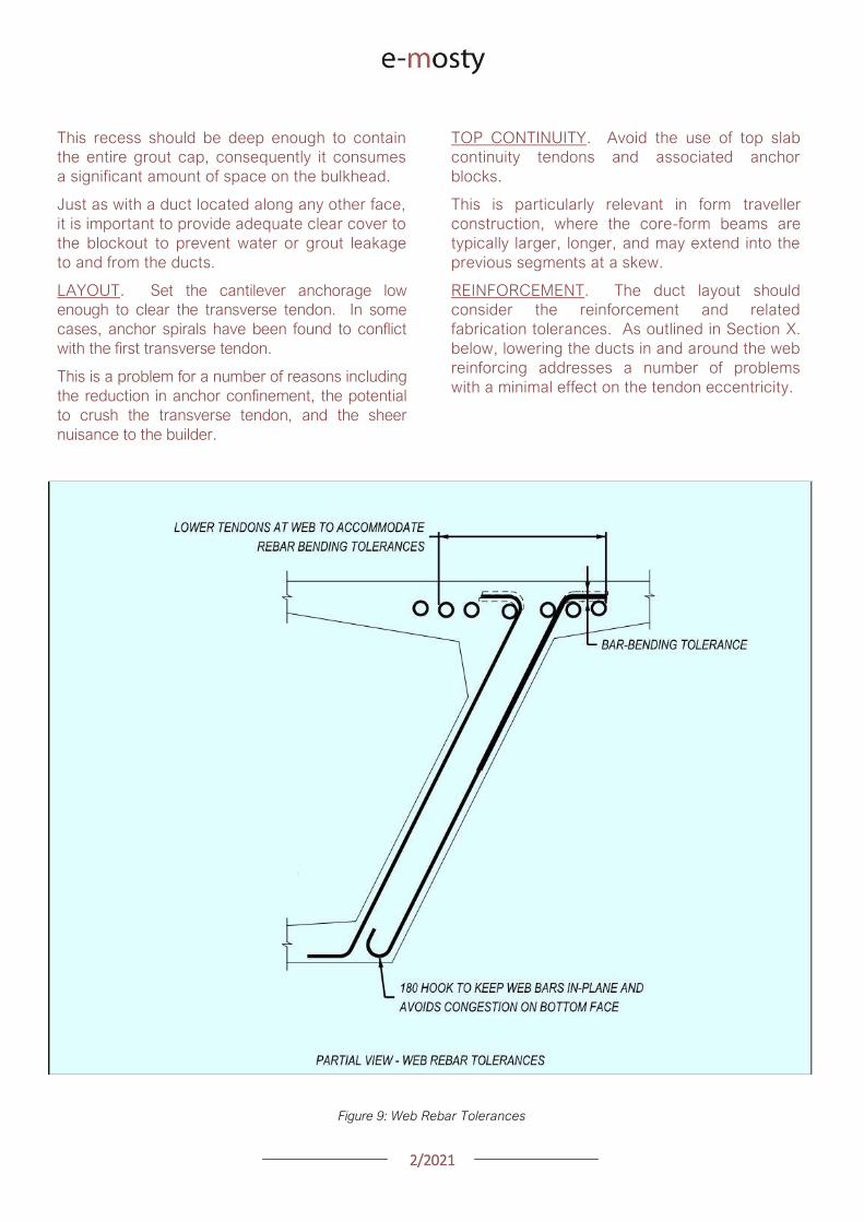
22021
This recess should be deep enough to contain
the entire grout cap consequently it consumes
a significant amount of space on the bulkhead
Just as with a duct located along any other face
it is important to provide adequate clear cover to
the blockout to prevent water or grout leakage
to and from the ducts
LAYOUT Set the cantilever anchorage low
enough to clear the transverse tendon In some
cases anchor spirals have been found to conflict
with the first transverse tendon
This is a problem for a number of reasons including
the reduction in anchor confinement the potential
to crush the transverse tendon and the sheer
nuisance to the builder
TOP CONTINUITY Avoid the use of top slab
continuity tendons and associated anchor
blocks
This is particularly relevant in form traveller
construction where the core-form beams are
typically larger longer and may extend into the
previous segments at a skew
REINFORCEMENT The duct layout should
consider the reinforcement and related
fabrication tolerances As outlined in Section X
below lowering the ducts in and around the web
reinforcing addresses a number of problems
with a minimal effect on the tendon eccentricity
Figure 9 Web Rebar Tolerances
22021
Figure 10 Web Rebar Tolerances Upper Ducts lowered (slightly) at full Height Stirrups for rebar
tolerances Hong Kong Mtr South Island Line Courtesy of Leighton Construction
VII LONGITUDINAL PT BOTTOM SLAB
TENDONS
LAYOUT While there are exceptions to every
rule fixing the bottom slab tendon layout and
anchor block geometry from the inside corner of
the box girder can standardize many details
With this approach the relative geometry
between the anchor block and the duct-runs
remains consistent while the depth of the girder
varies
SLAB THICKNESS Consider making the
bottom slab thickness constant through the
anchor block segments In variable depth box
girders specifically balanced cantilever with
form travellers there is a natural instinct to vary
the bottom slab thickness in parallel with the
girder depth
However tapering the bottom slab down to its
minimum thickness prior to the anchor blocks is
an effective approach in simplifying the design
Figure 11 Bottom Duct Setout
22021
REINFORCEMENT Check for conflicts between
the web reinforcement and the duct layout The
webs typically require larger diameter rebar than
the bottom slab For that reason it may be
necessary to raise the ducts located over the
web bar legs
Finally verify that the first duct is set far enough
from the web to allow for any plan curvature at
the anchor
DUCT GEOMETRY Aim the anchorage slightly
inboard for jack access This is important in
curved bridges where the web in the next
segment may encroach on the jack envelope
The tendon profile at the anchor block should
allow for PT system radius and tangent
requirements The bend radius should be
measured in the plane of the curve
Fitting the requisite tangent and radius for a 19
strand tendon into a 3m long segment can be
challenging Specify lsquotight radiusrsquo duct where
needed
This duct has corrugations that permit smaller
bending radii without buckling and caving
Some ducts can also be heat-bent to achieve
small radii
The last resort is using pre-bent steel pipes
Being aware of and designing within the radii
that can be achieved with corrugated plastic
duct should be the goal for cost-effective
design
Figure 12 Bottom Duct Profile
22021
VIII LONGITUDINAL PT WEB TENDONS
While very common in traditional post-tensioned
construction web tendons are not often used in
precast segmental bridges However there are
two situations where web tendons are
sometimes used
First is to supplement or eliminate bottom slab
continuity tendons Second is to provide some
form of bonded continuity steel across the entire
span ndash seismic requirements for example
In these cases the most practical approach is to
anchor the web tendons in pier or expansion
segments and run them pier-to-pier thereby
avoiding unique anchor blocks
In order to have a rational duct arrangement on
the bulkhead the tendons should use an
angular or lsquodeviatedrsquo profile ndash not draped
profiles Furthermore use a profile that is
coordinated with the shear key arrangement or
coordinate the shear keys with the duct holes to
avoid altering the bulkhead during casting
In the situation where web tendons are used in
conjunction with anchor blocks avoid locating
anchor blocks in-plane with the web tendons
The web and bottom slab tendon will inevitably
slope at different angles which prevents the
anchor block reinforcement development into
the web
Figure 13 Web Tendon Profile and Bottom Blocks
IX LONGITUDINAL PT EXTERNAL TENDONS
For those wanting potentially replaceable post-
tensioning external tendons are the answer
The Florida DOT Bridge Design Manual provides
some of the best advice for these details
DEVIATOR A point of debate between experts
is diabolos vs pipes For smaller quantities
pipes may be more economical Pipes are also
smaller On the other hand pipes can and do
get placed incorrectly which requires expensive
re-work to correct
When laying out the tendon paths be aware that
diabolos require more space since they flare out
in 360 degrees
Furthermore diabolos without stay-in-place
plastic formers require more stringent clear
cover requirements between rebar and the
diabolos That said a well thought out design
with diabolos is relatively fool-proof with only the
up-front cost of the formers
CONFLICTS One consideration for any design
with external tendons is to verify that the
external tendons have a clear line-of-sight
between deviation points Confirm that the
tendons do not hit other anchor blocks
In curved structures check that the tendons do
not hit the web walls Where structures are on
tight radii it may be necessary to add an
additional deviator to guide the tendons around
the curved span
X BOX GIRDER REINFORCEMENT
To paraphrase the theme of Section IV above
ldquoUse Common Denominatorsrdquo Simply spacing
the reinforcement together at regular intervals
goes a long way to simplifying construction
The answer to ldquowhy not mix spacings if it saves
a few barsrdquo is that it becomes necessary to shift
some bars out of their nominal spacings to mesh
with the other set leading to localized
congestion and conflicts
22021
Space rebar at common denominators ie 15
and 30cm work together but not 15 and 20cm
Once the reinforcing lanes are established the
key to constructability is the web reinforcement
PT anchors anchor blocks transverse tendons
and construction embeds all gravitate to the
webs
Furthermore the web reinforcement is a full-
height shear stirrup which is sensitive to bending
and placing tolerances
TOLERANCES Rebar fabrication tolerances
should be a primary consideration in detailing
The fabricated bending tolerance on most bars
is +-25mm per leg Tighter tolerances can be
specified but keep in mind that there is no
magic tolerance setting on the bending
machine If the design requires tighter
tolerances this translates to more rejected bar
and associated cost
If a bar is constrained by clear cover at each
end the logical approach is to detail the bar
25mm short of the nominal length and verify that
the details can accommodate the tolerance
Sometimes the clear cover tolerances help And
sometimes the bar tolerances can be absorbed
at two faces and the effects are minor With
web reinforcing however the bars are typically
supported on chairs on the soffit slab which
requires all of the tolerance to be taken up at
the top face where the bar legs are constrained
between the clear cover and the cantilever
ducts
A simple solution is to lower the ducts within this
area to clear the bar tolerance envelope While
this lowers the eccentricity of some tendons
consider that it is likely a small number of the
tendons moving a small percentage of the
overall depth so the effect is minor
NESTING BARS Give consideration to the
bends and orientation of the web bar tails In
order to minimize congestion and make room for
other reinforcement it preferable to keep the
web bars in-plane with each other Use 180
degree hooks where appropriate to avoid
bundled legs
RE-ENTRANT CORNERS Be thoughtful when
detailing reinforcement at re-entrant corners
For example the inside web face often has a
fillet Reinforcing this face with a single bar is not
advisable
Figure 14 Re-entrant
Corners
22021
Consider that when this bar is in tension it will
want to straighten and pop-out the cover
concrete at the corner It is preferable to use
crossing-bars which develop beyond the corner
TENDON PASS-THRU Where tendons pass
thru reinforcing mats the design should specify
how Note that the tendons in anchor blocks
typically slope at 12-15 degrees At this angle
the duct can conflict with rebar over a length of
60-90cm
Simply shifting bars longitudinally to clear the
conflict is not practical because it displaces too
many bars and leaves a large gap
In most cases it is preferable that the cross-thru
details are modifications (by moving bending or
cutting) to the typical reinforcing as opposed to
introducing unique bars at specific locations
Figure 15 Top Mat Bars at Cross-Thru (with fillet)
Figure 16 Top Mat Bars at Cross-Thru (flat slab)
22021
LONGITUDINAL REINFORCING An additional
topic to highlight is the treatment of longitudinal
reinforcing in curved segments In cast-in-place
construction the bars are detailed long enough
to satisfy the lap splice requirements on the
outside of the curve and the extra length on the
short side is taken up in the lap splice
In precast segments the detailing of longitudinal
reinforcement becomes complicated
Longitudinal bars are broken into sub-sets in
order to graduate the lengths across the width
of the segment
Otherwise identical reinforcing cages but with
slightly different plan-view geometry become
different reinforcing types requiring additional
drawings and submittals not to mention more
time spent sorting bars on-site
Given that segment cages are pre-tied in jigs it
would be reasonable to detail all the bars long
tie them in the cage and then cut them to
match the pie-shape of the specific segment
This would streamline shop drawing process and
potentially simplify fabrication
Figure 17 Treatment of Longitudinal Bars
XI ANCHOR BLOCK REINFORCEMENT
Before reading any further prepare to go lsquodeep
in the weedsrsquo In order to lessen the headache
refer directly to the appendix for an example of
an anchor block that addresses the challenges
CONGESTION Anchor blocks typically have
two sets of bars (outer confinement + inner tie
for curvature) which mesh together with the
web reinforcement (2 faces) and slab
reinforcement (2 faces)
Altogether this can translate to six bars which
must pass each other Many of these bars may
have legs on the same face creating lsquowallsrsquo of
bundled rebar
These zones of bars are problematic for placing
concrete prone to spalling and do nothing to
develop the reinforcement There are several
techniques to address this
Place the web reinforcement in the same
plane Turn the leg on the inside-face
web bar toward centerline of segment If
the leg on the outside-face web bar
contacts the inside-face reinforcement
consider using a 180deg hook
Place bottom slab reinforcement in the
same plane If the legs happen to
conflict shorten or place the top-mat bar
to nest inside the bottom-mat bar
22021
Turn the legs of the outer anchor block
reinforcement away from the web Full
360deg or even 270deg confinement of the
anchor block is not necessary as the
bottom slab and web reinforcement
already exist on these faces and are
waiting to be put to work
Consider the direction of the legs on the
inner anchor block bars (ie the in-plane
pullout reinforcement) Turning both legs
the same direction andor using 180
degree hooks may be helpful
TENDON GEOMETRY Anchor block
reinforcement should be organized with thought
to the actual tendon geometry In most cases
the other tendons in and around the anchor
block are not running parallel to the web
Tendon paths should not be altered to snake
thru the reinforcement Instead configure the
reinforcement to the lanes between the ducts
There are several techniques to address this
Begin by designing the reinforcement
around the typical (probably deviating)
tendon arrangement
Slope the inside face of the anchor block
By varying the clear cover the outer
block reinforcement may be detailed to
follow either straight or deviating tendon
paths
Adjust the width of the in-plane pullout
reinforcement as needed Where these
bars are tall use a wide bar in order to
straddle ducts running below Where
these bars are short a narrow top-hat
bar is appropriate to avoid clashing with
other ducts
Figure 18 Anchor Block Reinforcement (see Appendix)
22021
XII DIAPHRAGM REINFORCEMENT
There are a number of different approaches to
diaphragm design and this paper will not go into
depth on the possibilities However the
challenges found in diaphragm reinforcement
are variations on others already identified
When presented a problem engineers are good at
finding fixes For that reason simply being aware
of these issues goes a long way
Rebar Fabrication Tolerances
Rebar Placing Tolerances
Actual Size of Rebar and PT
Actual Size of Bar Bend Radii
Congestion (see Figure 19)
Uniformity Standardization
Finally just to give the contractor a sporting
chance identify all of the intersecting bars ducts
and other elements (with their overall sizes) and
verify that they do indeed fit inside of the concrete
An allowance for placing tolerances is
recommended too Incorporating this analysis into
the design process should be standard practice
Figure 19
lsquoRealrsquo Rebar
Diameter
larr Figure 20
Example of
Congestion
Too Many Bars
in Same Plane
22021
In cast-in-place construction headed anchor
studs may be a good option provided again
that the stud layout is integrated with the
reinforcement
INTEGRAL STRADDLE BEAMS Precast
segments are sometimes cantilevered from
straddle beams or similar CIP elements In this
configuration set the first precast segment just
off the straddle beam with a short closure
avoiding a complicated cast-in-place starter
Minor skews can be absorbed in the closure
Larger skews can be cast into the starter
segment In the case of cantilever construction
most if not all of the post-tensioning ducts are in
the top slab Rather than trying to cast ducts in
precise locations in the straddle beam set the
segment slightly higher than the top of beam
and cast the deck slab after the segments have
been placed
This avoids complications with tolerances as
well as conflicts between the straddle beam
stirrups and PT ducts
XIII SUBSTRUCTURE CONNECTIONS
The details associated with the superstructure
connection to the substructure have a
significant impact on the constructability This
interface is typically at the bearings and in some
cases the superstructure may frame into other
types of construction
Short closures are used to connect segments
which are not match cast However when a
segment is taken from one form and mated up
with one from a different form you can expect
some degree of misalignment in the cross
section and ducts
BEARINGS In precast segmental where the
structure requires fixity through the bearings it
is preferable to use a limited number of large
pintles to transfer horizontal load to the
bearings
In these situations the void for the pintle should
be oversized to allow for grade and
superelevation as well as reasonable fabrication
and placing tolerances
These voids may be formed using lsquocansrsquo or it
may be practical to void out a rectangular
volume in and around the reinforcement using
foam block In either case the pintles must be
integrated with the reinforcement
Figure 21 Straddle Beam Connection
22021
Figure 23 Straddle Beam Connection Top of Beam held low to allow Cantilever Tendons to pass over without conflict
Hong Kong Mtr South Island Line Courtesy of Leighton Construction
Figure 22 Straddle Beam Connection Top of Beam held low to allow Cantilever Tendons to pass over without conflict
Hong Kong Mtr South Island Line Courtesy of Leighton Construction
22021
INTEGRAL PIER COLUMNS Making precast
segments integral with pier columns presents
challenges but there are a number of benefits
Integral connections can eliminate bearings and
associated maintenance provide robust
connection for lateral loads (ie seismic) and
can eliminate the need for temporary stability
shoring
Integral connections can be achieved several
ways Similar to the previous straddle beam
example the conventional approach is to
construct cast-in-place pier segments and erect
precast segments on either side with short
closures
This requires realistic expectations for the
construction tolerances involved For example
it may be prudent to thicken the in-situ cross
section to minimize misalignments in the cross
section in addition to incorporating means to
accommodate duct misalignments
XIV PLAN PRESENTATION
Efficient construction requires good drawings
BRIM and 3D CAD tools allow us to create some
amazing work but as this is being written there
are still a lot of us humans involved in the
process
Modern drafting tools allow us to make drawing
easier and to balance that it is important to be
disciplined in minimizing drawings and details
Figure 24 PT Layout Example
22021
SYMMETRY If something is symmetric or even
close to it use half views Showing redundant
information invites confusion and errors This
also allows views to be larger and show details
more clearly
PT LAYOUTS All longitudinal PT for a given
segment should be shown on the same drawing
sheet Scale plan views in the transverse
direction to better illustrate tendon geometry
and neglect horizontal curvature Last ndash call out
each end of each tendon
APPENDIX 3D MODEL
The following page is a 3D pdf to illustrate some
of the points discussed in this document
The source DGN file is attached here
I hope you find this document useful and Good Bridgebuilding
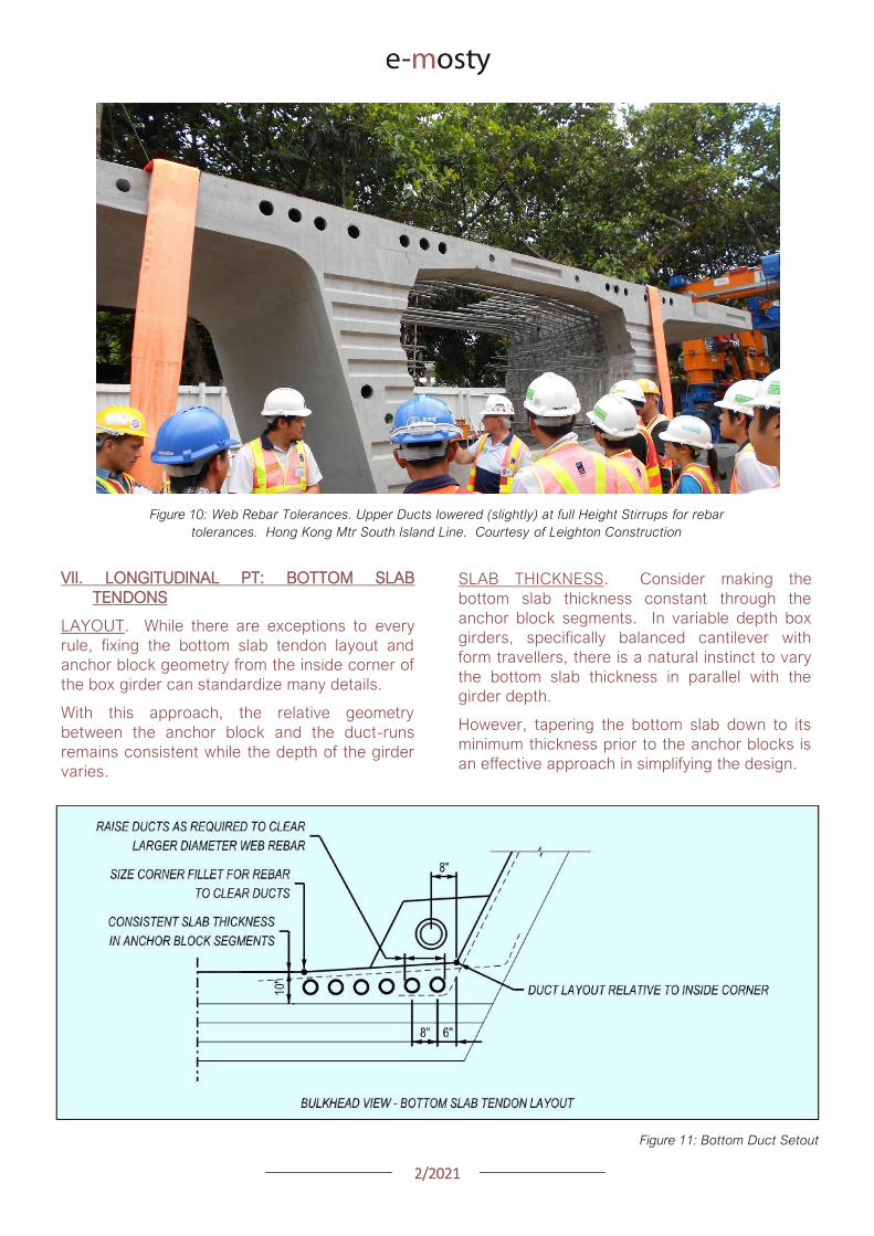
22021
Figure 10 Web Rebar Tolerances Upper Ducts lowered (slightly) at full Height Stirrups for rebar
tolerances Hong Kong Mtr South Island Line Courtesy of Leighton Construction
VII LONGITUDINAL PT BOTTOM SLAB
TENDONS
LAYOUT While there are exceptions to every
rule fixing the bottom slab tendon layout and
anchor block geometry from the inside corner of
the box girder can standardize many details
With this approach the relative geometry
between the anchor block and the duct-runs
remains consistent while the depth of the girder
varies
SLAB THICKNESS Consider making the
bottom slab thickness constant through the
anchor block segments In variable depth box
girders specifically balanced cantilever with
form travellers there is a natural instinct to vary
the bottom slab thickness in parallel with the
girder depth
However tapering the bottom slab down to its
minimum thickness prior to the anchor blocks is
an effective approach in simplifying the design
Figure 11 Bottom Duct Setout
22021
REINFORCEMENT Check for conflicts between
the web reinforcement and the duct layout The
webs typically require larger diameter rebar than
the bottom slab For that reason it may be
necessary to raise the ducts located over the
web bar legs
Finally verify that the first duct is set far enough
from the web to allow for any plan curvature at
the anchor
DUCT GEOMETRY Aim the anchorage slightly
inboard for jack access This is important in
curved bridges where the web in the next
segment may encroach on the jack envelope
The tendon profile at the anchor block should
allow for PT system radius and tangent
requirements The bend radius should be
measured in the plane of the curve
Fitting the requisite tangent and radius for a 19
strand tendon into a 3m long segment can be
challenging Specify lsquotight radiusrsquo duct where
needed
This duct has corrugations that permit smaller
bending radii without buckling and caving
Some ducts can also be heat-bent to achieve
small radii
The last resort is using pre-bent steel pipes
Being aware of and designing within the radii
that can be achieved with corrugated plastic
duct should be the goal for cost-effective
design
Figure 12 Bottom Duct Profile
22021
VIII LONGITUDINAL PT WEB TENDONS
While very common in traditional post-tensioned
construction web tendons are not often used in
precast segmental bridges However there are
two situations where web tendons are
sometimes used
First is to supplement or eliminate bottom slab
continuity tendons Second is to provide some
form of bonded continuity steel across the entire
span ndash seismic requirements for example
In these cases the most practical approach is to
anchor the web tendons in pier or expansion
segments and run them pier-to-pier thereby
avoiding unique anchor blocks
In order to have a rational duct arrangement on
the bulkhead the tendons should use an
angular or lsquodeviatedrsquo profile ndash not draped
profiles Furthermore use a profile that is
coordinated with the shear key arrangement or
coordinate the shear keys with the duct holes to
avoid altering the bulkhead during casting
In the situation where web tendons are used in
conjunction with anchor blocks avoid locating
anchor blocks in-plane with the web tendons
The web and bottom slab tendon will inevitably
slope at different angles which prevents the
anchor block reinforcement development into
the web
Figure 13 Web Tendon Profile and Bottom Blocks
IX LONGITUDINAL PT EXTERNAL TENDONS
For those wanting potentially replaceable post-
tensioning external tendons are the answer
The Florida DOT Bridge Design Manual provides
some of the best advice for these details
DEVIATOR A point of debate between experts
is diabolos vs pipes For smaller quantities
pipes may be more economical Pipes are also
smaller On the other hand pipes can and do
get placed incorrectly which requires expensive
re-work to correct
When laying out the tendon paths be aware that
diabolos require more space since they flare out
in 360 degrees
Furthermore diabolos without stay-in-place
plastic formers require more stringent clear
cover requirements between rebar and the
diabolos That said a well thought out design
with diabolos is relatively fool-proof with only the
up-front cost of the formers
CONFLICTS One consideration for any design
with external tendons is to verify that the
external tendons have a clear line-of-sight
between deviation points Confirm that the
tendons do not hit other anchor blocks
In curved structures check that the tendons do
not hit the web walls Where structures are on
tight radii it may be necessary to add an
additional deviator to guide the tendons around
the curved span
X BOX GIRDER REINFORCEMENT
To paraphrase the theme of Section IV above
ldquoUse Common Denominatorsrdquo Simply spacing
the reinforcement together at regular intervals
goes a long way to simplifying construction
The answer to ldquowhy not mix spacings if it saves
a few barsrdquo is that it becomes necessary to shift
some bars out of their nominal spacings to mesh
with the other set leading to localized
congestion and conflicts
22021
Space rebar at common denominators ie 15
and 30cm work together but not 15 and 20cm
Once the reinforcing lanes are established the
key to constructability is the web reinforcement
PT anchors anchor blocks transverse tendons
and construction embeds all gravitate to the
webs
Furthermore the web reinforcement is a full-
height shear stirrup which is sensitive to bending
and placing tolerances
TOLERANCES Rebar fabrication tolerances
should be a primary consideration in detailing
The fabricated bending tolerance on most bars
is +-25mm per leg Tighter tolerances can be
specified but keep in mind that there is no
magic tolerance setting on the bending
machine If the design requires tighter
tolerances this translates to more rejected bar
and associated cost
If a bar is constrained by clear cover at each
end the logical approach is to detail the bar
25mm short of the nominal length and verify that
the details can accommodate the tolerance
Sometimes the clear cover tolerances help And
sometimes the bar tolerances can be absorbed
at two faces and the effects are minor With
web reinforcing however the bars are typically
supported on chairs on the soffit slab which
requires all of the tolerance to be taken up at
the top face where the bar legs are constrained
between the clear cover and the cantilever
ducts
A simple solution is to lower the ducts within this
area to clear the bar tolerance envelope While
this lowers the eccentricity of some tendons
consider that it is likely a small number of the
tendons moving a small percentage of the
overall depth so the effect is minor
NESTING BARS Give consideration to the
bends and orientation of the web bar tails In
order to minimize congestion and make room for
other reinforcement it preferable to keep the
web bars in-plane with each other Use 180
degree hooks where appropriate to avoid
bundled legs
RE-ENTRANT CORNERS Be thoughtful when
detailing reinforcement at re-entrant corners
For example the inside web face often has a
fillet Reinforcing this face with a single bar is not
advisable
Figure 14 Re-entrant
Corners
22021
Consider that when this bar is in tension it will
want to straighten and pop-out the cover
concrete at the corner It is preferable to use
crossing-bars which develop beyond the corner
TENDON PASS-THRU Where tendons pass
thru reinforcing mats the design should specify
how Note that the tendons in anchor blocks
typically slope at 12-15 degrees At this angle
the duct can conflict with rebar over a length of
60-90cm
Simply shifting bars longitudinally to clear the
conflict is not practical because it displaces too
many bars and leaves a large gap
In most cases it is preferable that the cross-thru
details are modifications (by moving bending or
cutting) to the typical reinforcing as opposed to
introducing unique bars at specific locations
Figure 15 Top Mat Bars at Cross-Thru (with fillet)
Figure 16 Top Mat Bars at Cross-Thru (flat slab)
22021
LONGITUDINAL REINFORCING An additional
topic to highlight is the treatment of longitudinal
reinforcing in curved segments In cast-in-place
construction the bars are detailed long enough
to satisfy the lap splice requirements on the
outside of the curve and the extra length on the
short side is taken up in the lap splice
In precast segments the detailing of longitudinal
reinforcement becomes complicated
Longitudinal bars are broken into sub-sets in
order to graduate the lengths across the width
of the segment
Otherwise identical reinforcing cages but with
slightly different plan-view geometry become
different reinforcing types requiring additional
drawings and submittals not to mention more
time spent sorting bars on-site
Given that segment cages are pre-tied in jigs it
would be reasonable to detail all the bars long
tie them in the cage and then cut them to
match the pie-shape of the specific segment
This would streamline shop drawing process and
potentially simplify fabrication
Figure 17 Treatment of Longitudinal Bars
XI ANCHOR BLOCK REINFORCEMENT
Before reading any further prepare to go lsquodeep
in the weedsrsquo In order to lessen the headache
refer directly to the appendix for an example of
an anchor block that addresses the challenges
CONGESTION Anchor blocks typically have
two sets of bars (outer confinement + inner tie
for curvature) which mesh together with the
web reinforcement (2 faces) and slab
reinforcement (2 faces)
Altogether this can translate to six bars which
must pass each other Many of these bars may
have legs on the same face creating lsquowallsrsquo of
bundled rebar
These zones of bars are problematic for placing
concrete prone to spalling and do nothing to
develop the reinforcement There are several
techniques to address this
Place the web reinforcement in the same
plane Turn the leg on the inside-face
web bar toward centerline of segment If
the leg on the outside-face web bar
contacts the inside-face reinforcement
consider using a 180deg hook
Place bottom slab reinforcement in the
same plane If the legs happen to
conflict shorten or place the top-mat bar
to nest inside the bottom-mat bar
22021
Turn the legs of the outer anchor block
reinforcement away from the web Full
360deg or even 270deg confinement of the
anchor block is not necessary as the
bottom slab and web reinforcement
already exist on these faces and are
waiting to be put to work
Consider the direction of the legs on the
inner anchor block bars (ie the in-plane
pullout reinforcement) Turning both legs
the same direction andor using 180
degree hooks may be helpful
TENDON GEOMETRY Anchor block
reinforcement should be organized with thought
to the actual tendon geometry In most cases
the other tendons in and around the anchor
block are not running parallel to the web
Tendon paths should not be altered to snake
thru the reinforcement Instead configure the
reinforcement to the lanes between the ducts
There are several techniques to address this
Begin by designing the reinforcement
around the typical (probably deviating)
tendon arrangement
Slope the inside face of the anchor block
By varying the clear cover the outer
block reinforcement may be detailed to
follow either straight or deviating tendon
paths
Adjust the width of the in-plane pullout
reinforcement as needed Where these
bars are tall use a wide bar in order to
straddle ducts running below Where
these bars are short a narrow top-hat
bar is appropriate to avoid clashing with
other ducts
Figure 18 Anchor Block Reinforcement (see Appendix)
22021
XII DIAPHRAGM REINFORCEMENT
There are a number of different approaches to
diaphragm design and this paper will not go into
depth on the possibilities However the
challenges found in diaphragm reinforcement
are variations on others already identified
When presented a problem engineers are good at
finding fixes For that reason simply being aware
of these issues goes a long way
Rebar Fabrication Tolerances
Rebar Placing Tolerances
Actual Size of Rebar and PT
Actual Size of Bar Bend Radii
Congestion (see Figure 19)
Uniformity Standardization
Finally just to give the contractor a sporting
chance identify all of the intersecting bars ducts
and other elements (with their overall sizes) and
verify that they do indeed fit inside of the concrete
An allowance for placing tolerances is
recommended too Incorporating this analysis into
the design process should be standard practice
Figure 19
lsquoRealrsquo Rebar
Diameter
larr Figure 20
Example of
Congestion
Too Many Bars
in Same Plane
22021
In cast-in-place construction headed anchor
studs may be a good option provided again
that the stud layout is integrated with the
reinforcement
INTEGRAL STRADDLE BEAMS Precast
segments are sometimes cantilevered from
straddle beams or similar CIP elements In this
configuration set the first precast segment just
off the straddle beam with a short closure
avoiding a complicated cast-in-place starter
Minor skews can be absorbed in the closure
Larger skews can be cast into the starter
segment In the case of cantilever construction
most if not all of the post-tensioning ducts are in
the top slab Rather than trying to cast ducts in
precise locations in the straddle beam set the
segment slightly higher than the top of beam
and cast the deck slab after the segments have
been placed
This avoids complications with tolerances as
well as conflicts between the straddle beam
stirrups and PT ducts
XIII SUBSTRUCTURE CONNECTIONS
The details associated with the superstructure
connection to the substructure have a
significant impact on the constructability This
interface is typically at the bearings and in some
cases the superstructure may frame into other
types of construction
Short closures are used to connect segments
which are not match cast However when a
segment is taken from one form and mated up
with one from a different form you can expect
some degree of misalignment in the cross
section and ducts
BEARINGS In precast segmental where the
structure requires fixity through the bearings it
is preferable to use a limited number of large
pintles to transfer horizontal load to the
bearings
In these situations the void for the pintle should
be oversized to allow for grade and
superelevation as well as reasonable fabrication
and placing tolerances
These voids may be formed using lsquocansrsquo or it
may be practical to void out a rectangular
volume in and around the reinforcement using
foam block In either case the pintles must be
integrated with the reinforcement
Figure 21 Straddle Beam Connection
22021
Figure 23 Straddle Beam Connection Top of Beam held low to allow Cantilever Tendons to pass over without conflict
Hong Kong Mtr South Island Line Courtesy of Leighton Construction
Figure 22 Straddle Beam Connection Top of Beam held low to allow Cantilever Tendons to pass over without conflict
Hong Kong Mtr South Island Line Courtesy of Leighton Construction
22021
INTEGRAL PIER COLUMNS Making precast
segments integral with pier columns presents
challenges but there are a number of benefits
Integral connections can eliminate bearings and
associated maintenance provide robust
connection for lateral loads (ie seismic) and
can eliminate the need for temporary stability
shoring
Integral connections can be achieved several
ways Similar to the previous straddle beam
example the conventional approach is to
construct cast-in-place pier segments and erect
precast segments on either side with short
closures
This requires realistic expectations for the
construction tolerances involved For example
it may be prudent to thicken the in-situ cross
section to minimize misalignments in the cross
section in addition to incorporating means to
accommodate duct misalignments
XIV PLAN PRESENTATION
Efficient construction requires good drawings
BRIM and 3D CAD tools allow us to create some
amazing work but as this is being written there
are still a lot of us humans involved in the
process
Modern drafting tools allow us to make drawing
easier and to balance that it is important to be
disciplined in minimizing drawings and details
Figure 24 PT Layout Example
22021
SYMMETRY If something is symmetric or even
close to it use half views Showing redundant
information invites confusion and errors This
also allows views to be larger and show details
more clearly
PT LAYOUTS All longitudinal PT for a given
segment should be shown on the same drawing
sheet Scale plan views in the transverse
direction to better illustrate tendon geometry
and neglect horizontal curvature Last ndash call out
each end of each tendon
APPENDIX 3D MODEL
The following page is a 3D pdf to illustrate some
of the points discussed in this document
The source DGN file is attached here
I hope you find this document useful and Good Bridgebuilding
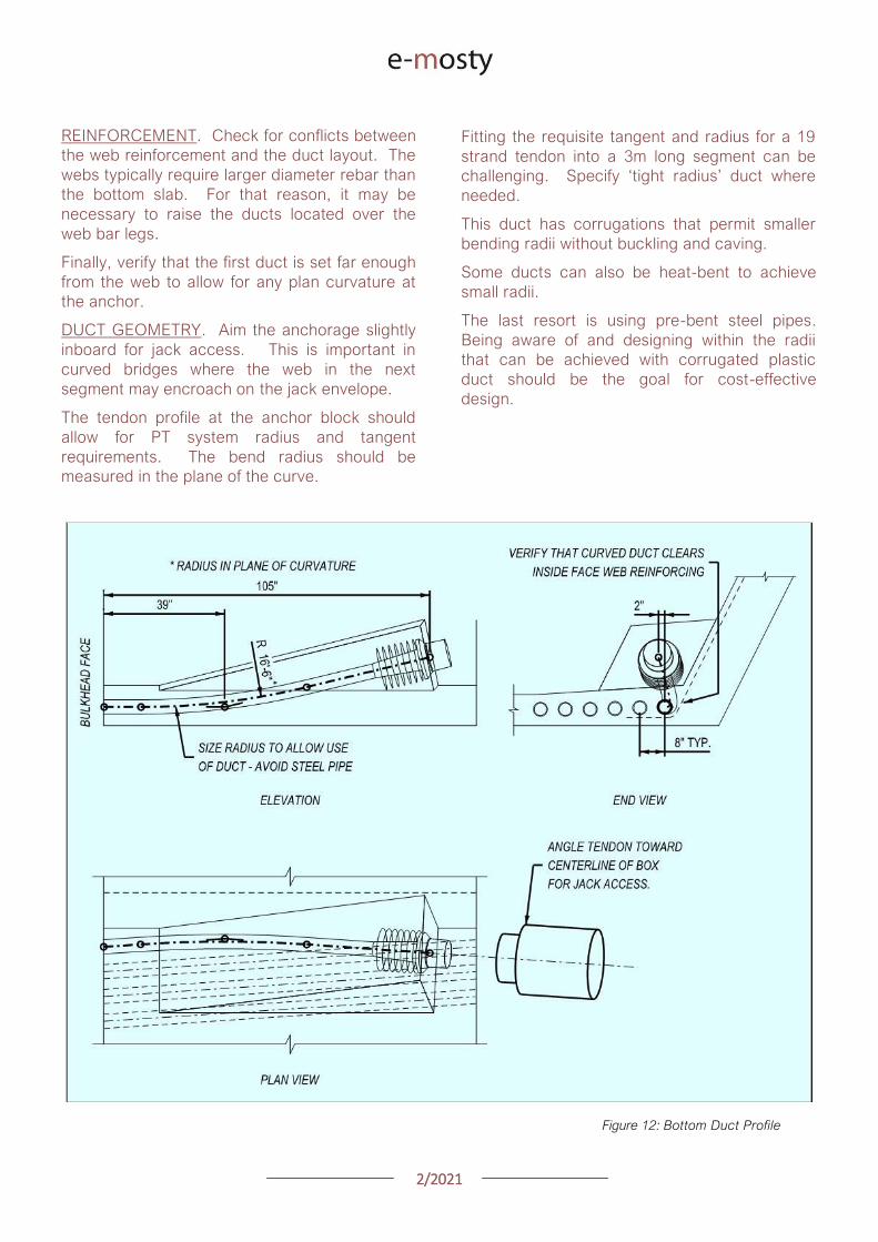
22021
REINFORCEMENT Check for conflicts between
the web reinforcement and the duct layout The
webs typically require larger diameter rebar than
the bottom slab For that reason it may be
necessary to raise the ducts located over the
web bar legs
Finally verify that the first duct is set far enough
from the web to allow for any plan curvature at
the anchor
DUCT GEOMETRY Aim the anchorage slightly
inboard for jack access This is important in
curved bridges where the web in the next
segment may encroach on the jack envelope
The tendon profile at the anchor block should
allow for PT system radius and tangent
requirements The bend radius should be
measured in the plane of the curve
Fitting the requisite tangent and radius for a 19
strand tendon into a 3m long segment can be
challenging Specify lsquotight radiusrsquo duct where
needed
This duct has corrugations that permit smaller
bending radii without buckling and caving
Some ducts can also be heat-bent to achieve
small radii
The last resort is using pre-bent steel pipes
Being aware of and designing within the radii
that can be achieved with corrugated plastic
duct should be the goal for cost-effective
design
Figure 12 Bottom Duct Profile
22021
VIII LONGITUDINAL PT WEB TENDONS
While very common in traditional post-tensioned
construction web tendons are not often used in
precast segmental bridges However there are
two situations where web tendons are
sometimes used
First is to supplement or eliminate bottom slab
continuity tendons Second is to provide some
form of bonded continuity steel across the entire
span ndash seismic requirements for example
In these cases the most practical approach is to
anchor the web tendons in pier or expansion
segments and run them pier-to-pier thereby
avoiding unique anchor blocks
In order to have a rational duct arrangement on
the bulkhead the tendons should use an
angular or lsquodeviatedrsquo profile ndash not draped
profiles Furthermore use a profile that is
coordinated with the shear key arrangement or
coordinate the shear keys with the duct holes to
avoid altering the bulkhead during casting
In the situation where web tendons are used in
conjunction with anchor blocks avoid locating
anchor blocks in-plane with the web tendons
The web and bottom slab tendon will inevitably
slope at different angles which prevents the
anchor block reinforcement development into
the web
Figure 13 Web Tendon Profile and Bottom Blocks
IX LONGITUDINAL PT EXTERNAL TENDONS
For those wanting potentially replaceable post-
tensioning external tendons are the answer
The Florida DOT Bridge Design Manual provides
some of the best advice for these details
DEVIATOR A point of debate between experts
is diabolos vs pipes For smaller quantities
pipes may be more economical Pipes are also
smaller On the other hand pipes can and do
get placed incorrectly which requires expensive
re-work to correct
When laying out the tendon paths be aware that
diabolos require more space since they flare out
in 360 degrees
Furthermore diabolos without stay-in-place
plastic formers require more stringent clear
cover requirements between rebar and the
diabolos That said a well thought out design
with diabolos is relatively fool-proof with only the
up-front cost of the formers
CONFLICTS One consideration for any design
with external tendons is to verify that the
external tendons have a clear line-of-sight
between deviation points Confirm that the
tendons do not hit other anchor blocks
In curved structures check that the tendons do
not hit the web walls Where structures are on
tight radii it may be necessary to add an
additional deviator to guide the tendons around
the curved span
X BOX GIRDER REINFORCEMENT
To paraphrase the theme of Section IV above
ldquoUse Common Denominatorsrdquo Simply spacing
the reinforcement together at regular intervals
goes a long way to simplifying construction
The answer to ldquowhy not mix spacings if it saves
a few barsrdquo is that it becomes necessary to shift
some bars out of their nominal spacings to mesh
with the other set leading to localized
congestion and conflicts
22021
Space rebar at common denominators ie 15
and 30cm work together but not 15 and 20cm
Once the reinforcing lanes are established the
key to constructability is the web reinforcement
PT anchors anchor blocks transverse tendons
and construction embeds all gravitate to the
webs
Furthermore the web reinforcement is a full-
height shear stirrup which is sensitive to bending
and placing tolerances
TOLERANCES Rebar fabrication tolerances
should be a primary consideration in detailing
The fabricated bending tolerance on most bars
is +-25mm per leg Tighter tolerances can be
specified but keep in mind that there is no
magic tolerance setting on the bending
machine If the design requires tighter
tolerances this translates to more rejected bar
and associated cost
If a bar is constrained by clear cover at each
end the logical approach is to detail the bar
25mm short of the nominal length and verify that
the details can accommodate the tolerance
Sometimes the clear cover tolerances help And
sometimes the bar tolerances can be absorbed
at two faces and the effects are minor With
web reinforcing however the bars are typically
supported on chairs on the soffit slab which
requires all of the tolerance to be taken up at
the top face where the bar legs are constrained
between the clear cover and the cantilever
ducts
A simple solution is to lower the ducts within this
area to clear the bar tolerance envelope While
this lowers the eccentricity of some tendons
consider that it is likely a small number of the
tendons moving a small percentage of the
overall depth so the effect is minor
NESTING BARS Give consideration to the
bends and orientation of the web bar tails In
order to minimize congestion and make room for
other reinforcement it preferable to keep the
web bars in-plane with each other Use 180
degree hooks where appropriate to avoid
bundled legs
RE-ENTRANT CORNERS Be thoughtful when
detailing reinforcement at re-entrant corners
For example the inside web face often has a
fillet Reinforcing this face with a single bar is not
advisable
Figure 14 Re-entrant
Corners
22021
Consider that when this bar is in tension it will
want to straighten and pop-out the cover
concrete at the corner It is preferable to use
crossing-bars which develop beyond the corner
TENDON PASS-THRU Where tendons pass
thru reinforcing mats the design should specify
how Note that the tendons in anchor blocks
typically slope at 12-15 degrees At this angle
the duct can conflict with rebar over a length of
60-90cm
Simply shifting bars longitudinally to clear the
conflict is not practical because it displaces too
many bars and leaves a large gap
In most cases it is preferable that the cross-thru
details are modifications (by moving bending or
cutting) to the typical reinforcing as opposed to
introducing unique bars at specific locations
Figure 15 Top Mat Bars at Cross-Thru (with fillet)
Figure 16 Top Mat Bars at Cross-Thru (flat slab)
22021
LONGITUDINAL REINFORCING An additional
topic to highlight is the treatment of longitudinal
reinforcing in curved segments In cast-in-place
construction the bars are detailed long enough
to satisfy the lap splice requirements on the
outside of the curve and the extra length on the
short side is taken up in the lap splice
In precast segments the detailing of longitudinal
reinforcement becomes complicated
Longitudinal bars are broken into sub-sets in
order to graduate the lengths across the width
of the segment
Otherwise identical reinforcing cages but with
slightly different plan-view geometry become
different reinforcing types requiring additional
drawings and submittals not to mention more
time spent sorting bars on-site
Given that segment cages are pre-tied in jigs it
would be reasonable to detail all the bars long
tie them in the cage and then cut them to
match the pie-shape of the specific segment
This would streamline shop drawing process and
potentially simplify fabrication
Figure 17 Treatment of Longitudinal Bars
XI ANCHOR BLOCK REINFORCEMENT
Before reading any further prepare to go lsquodeep
in the weedsrsquo In order to lessen the headache
refer directly to the appendix for an example of
an anchor block that addresses the challenges
CONGESTION Anchor blocks typically have
two sets of bars (outer confinement + inner tie
for curvature) which mesh together with the
web reinforcement (2 faces) and slab
reinforcement (2 faces)
Altogether this can translate to six bars which
must pass each other Many of these bars may
have legs on the same face creating lsquowallsrsquo of
bundled rebar
These zones of bars are problematic for placing
concrete prone to spalling and do nothing to
develop the reinforcement There are several
techniques to address this
Place the web reinforcement in the same
plane Turn the leg on the inside-face
web bar toward centerline of segment If
the leg on the outside-face web bar
contacts the inside-face reinforcement
consider using a 180deg hook
Place bottom slab reinforcement in the
same plane If the legs happen to
conflict shorten or place the top-mat bar
to nest inside the bottom-mat bar
22021
Turn the legs of the outer anchor block
reinforcement away from the web Full
360deg or even 270deg confinement of the
anchor block is not necessary as the
bottom slab and web reinforcement
already exist on these faces and are
waiting to be put to work
Consider the direction of the legs on the
inner anchor block bars (ie the in-plane
pullout reinforcement) Turning both legs
the same direction andor using 180
degree hooks may be helpful
TENDON GEOMETRY Anchor block
reinforcement should be organized with thought
to the actual tendon geometry In most cases
the other tendons in and around the anchor
block are not running parallel to the web
Tendon paths should not be altered to snake
thru the reinforcement Instead configure the
reinforcement to the lanes between the ducts
There are several techniques to address this
Begin by designing the reinforcement
around the typical (probably deviating)
tendon arrangement
Slope the inside face of the anchor block
By varying the clear cover the outer
block reinforcement may be detailed to
follow either straight or deviating tendon
paths
Adjust the width of the in-plane pullout
reinforcement as needed Where these
bars are tall use a wide bar in order to
straddle ducts running below Where
these bars are short a narrow top-hat
bar is appropriate to avoid clashing with
other ducts
Figure 18 Anchor Block Reinforcement (see Appendix)
22021
XII DIAPHRAGM REINFORCEMENT
There are a number of different approaches to
diaphragm design and this paper will not go into
depth on the possibilities However the
challenges found in diaphragm reinforcement
are variations on others already identified
When presented a problem engineers are good at
finding fixes For that reason simply being aware
of these issues goes a long way
Rebar Fabrication Tolerances
Rebar Placing Tolerances
Actual Size of Rebar and PT
Actual Size of Bar Bend Radii
Congestion (see Figure 19)
Uniformity Standardization
Finally just to give the contractor a sporting
chance identify all of the intersecting bars ducts
and other elements (with their overall sizes) and
verify that they do indeed fit inside of the concrete
An allowance for placing tolerances is
recommended too Incorporating this analysis into
the design process should be standard practice
Figure 19
lsquoRealrsquo Rebar
Diameter
larr Figure 20
Example of
Congestion
Too Many Bars
in Same Plane
22021
In cast-in-place construction headed anchor
studs may be a good option provided again
that the stud layout is integrated with the
reinforcement
INTEGRAL STRADDLE BEAMS Precast
segments are sometimes cantilevered from
straddle beams or similar CIP elements In this
configuration set the first precast segment just
off the straddle beam with a short closure
avoiding a complicated cast-in-place starter
Minor skews can be absorbed in the closure
Larger skews can be cast into the starter
segment In the case of cantilever construction
most if not all of the post-tensioning ducts are in
the top slab Rather than trying to cast ducts in
precise locations in the straddle beam set the
segment slightly higher than the top of beam
and cast the deck slab after the segments have
been placed
This avoids complications with tolerances as
well as conflicts between the straddle beam
stirrups and PT ducts
XIII SUBSTRUCTURE CONNECTIONS
The details associated with the superstructure
connection to the substructure have a
significant impact on the constructability This
interface is typically at the bearings and in some
cases the superstructure may frame into other
types of construction
Short closures are used to connect segments
which are not match cast However when a
segment is taken from one form and mated up
with one from a different form you can expect
some degree of misalignment in the cross
section and ducts
BEARINGS In precast segmental where the
structure requires fixity through the bearings it
is preferable to use a limited number of large
pintles to transfer horizontal load to the
bearings
In these situations the void for the pintle should
be oversized to allow for grade and
superelevation as well as reasonable fabrication
and placing tolerances
These voids may be formed using lsquocansrsquo or it
may be practical to void out a rectangular
volume in and around the reinforcement using
foam block In either case the pintles must be
integrated with the reinforcement
Figure 21 Straddle Beam Connection
22021
Figure 23 Straddle Beam Connection Top of Beam held low to allow Cantilever Tendons to pass over without conflict
Hong Kong Mtr South Island Line Courtesy of Leighton Construction
Figure 22 Straddle Beam Connection Top of Beam held low to allow Cantilever Tendons to pass over without conflict
Hong Kong Mtr South Island Line Courtesy of Leighton Construction
22021
INTEGRAL PIER COLUMNS Making precast
segments integral with pier columns presents
challenges but there are a number of benefits
Integral connections can eliminate bearings and
associated maintenance provide robust
connection for lateral loads (ie seismic) and
can eliminate the need for temporary stability
shoring
Integral connections can be achieved several
ways Similar to the previous straddle beam
example the conventional approach is to
construct cast-in-place pier segments and erect
precast segments on either side with short
closures
This requires realistic expectations for the
construction tolerances involved For example
it may be prudent to thicken the in-situ cross
section to minimize misalignments in the cross
section in addition to incorporating means to
accommodate duct misalignments
XIV PLAN PRESENTATION
Efficient construction requires good drawings
BRIM and 3D CAD tools allow us to create some
amazing work but as this is being written there
are still a lot of us humans involved in the
process
Modern drafting tools allow us to make drawing
easier and to balance that it is important to be
disciplined in minimizing drawings and details
Figure 24 PT Layout Example
22021
SYMMETRY If something is symmetric or even
close to it use half views Showing redundant
information invites confusion and errors This
also allows views to be larger and show details
more clearly
PT LAYOUTS All longitudinal PT for a given
segment should be shown on the same drawing
sheet Scale plan views in the transverse
direction to better illustrate tendon geometry
and neglect horizontal curvature Last ndash call out
each end of each tendon
APPENDIX 3D MODEL
The following page is a 3D pdf to illustrate some
of the points discussed in this document
The source DGN file is attached here
I hope you find this document useful and Good Bridgebuilding
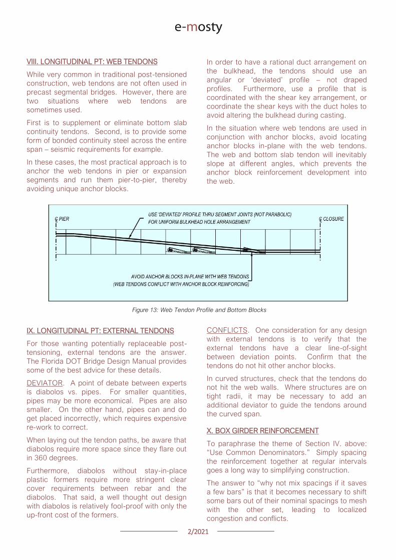
22021
VIII LONGITUDINAL PT WEB TENDONS
While very common in traditional post-tensioned
construction web tendons are not often used in
precast segmental bridges However there are
two situations where web tendons are
sometimes used
First is to supplement or eliminate bottom slab
continuity tendons Second is to provide some
form of bonded continuity steel across the entire
span ndash seismic requirements for example
In these cases the most practical approach is to
anchor the web tendons in pier or expansion
segments and run them pier-to-pier thereby
avoiding unique anchor blocks
In order to have a rational duct arrangement on
the bulkhead the tendons should use an
angular or lsquodeviatedrsquo profile ndash not draped
profiles Furthermore use a profile that is
coordinated with the shear key arrangement or
coordinate the shear keys with the duct holes to
avoid altering the bulkhead during casting
In the situation where web tendons are used in
conjunction with anchor blocks avoid locating
anchor blocks in-plane with the web tendons
The web and bottom slab tendon will inevitably
slope at different angles which prevents the
anchor block reinforcement development into
the web
Figure 13 Web Tendon Profile and Bottom Blocks
IX LONGITUDINAL PT EXTERNAL TENDONS
For those wanting potentially replaceable post-
tensioning external tendons are the answer
The Florida DOT Bridge Design Manual provides
some of the best advice for these details
DEVIATOR A point of debate between experts
is diabolos vs pipes For smaller quantities
pipes may be more economical Pipes are also
smaller On the other hand pipes can and do
get placed incorrectly which requires expensive
re-work to correct
When laying out the tendon paths be aware that
diabolos require more space since they flare out
in 360 degrees
Furthermore diabolos without stay-in-place
plastic formers require more stringent clear
cover requirements between rebar and the
diabolos That said a well thought out design
with diabolos is relatively fool-proof with only the
up-front cost of the formers
CONFLICTS One consideration for any design
with external tendons is to verify that the
external tendons have a clear line-of-sight
between deviation points Confirm that the
tendons do not hit other anchor blocks
In curved structures check that the tendons do
not hit the web walls Where structures are on
tight radii it may be necessary to add an
additional deviator to guide the tendons around
the curved span
X BOX GIRDER REINFORCEMENT
To paraphrase the theme of Section IV above
ldquoUse Common Denominatorsrdquo Simply spacing
the reinforcement together at regular intervals
goes a long way to simplifying construction
The answer to ldquowhy not mix spacings if it saves
a few barsrdquo is that it becomes necessary to shift
some bars out of their nominal spacings to mesh
with the other set leading to localized
congestion and conflicts
22021
Space rebar at common denominators ie 15
and 30cm work together but not 15 and 20cm
Once the reinforcing lanes are established the
key to constructability is the web reinforcement
PT anchors anchor blocks transverse tendons
and construction embeds all gravitate to the
webs
Furthermore the web reinforcement is a full-
height shear stirrup which is sensitive to bending
and placing tolerances
TOLERANCES Rebar fabrication tolerances
should be a primary consideration in detailing
The fabricated bending tolerance on most bars
is +-25mm per leg Tighter tolerances can be
specified but keep in mind that there is no
magic tolerance setting on the bending
machine If the design requires tighter
tolerances this translates to more rejected bar
and associated cost
If a bar is constrained by clear cover at each
end the logical approach is to detail the bar
25mm short of the nominal length and verify that
the details can accommodate the tolerance
Sometimes the clear cover tolerances help And
sometimes the bar tolerances can be absorbed
at two faces and the effects are minor With
web reinforcing however the bars are typically
supported on chairs on the soffit slab which
requires all of the tolerance to be taken up at
the top face where the bar legs are constrained
between the clear cover and the cantilever
ducts
A simple solution is to lower the ducts within this
area to clear the bar tolerance envelope While
this lowers the eccentricity of some tendons
consider that it is likely a small number of the
tendons moving a small percentage of the
overall depth so the effect is minor
NESTING BARS Give consideration to the
bends and orientation of the web bar tails In
order to minimize congestion and make room for
other reinforcement it preferable to keep the
web bars in-plane with each other Use 180
degree hooks where appropriate to avoid
bundled legs
RE-ENTRANT CORNERS Be thoughtful when
detailing reinforcement at re-entrant corners
For example the inside web face often has a
fillet Reinforcing this face with a single bar is not
advisable
Figure 14 Re-entrant
Corners
22021
Consider that when this bar is in tension it will
want to straighten and pop-out the cover
concrete at the corner It is preferable to use
crossing-bars which develop beyond the corner
TENDON PASS-THRU Where tendons pass
thru reinforcing mats the design should specify
how Note that the tendons in anchor blocks
typically slope at 12-15 degrees At this angle
the duct can conflict with rebar over a length of
60-90cm
Simply shifting bars longitudinally to clear the
conflict is not practical because it displaces too
many bars and leaves a large gap
In most cases it is preferable that the cross-thru
details are modifications (by moving bending or
cutting) to the typical reinforcing as opposed to
introducing unique bars at specific locations
Figure 15 Top Mat Bars at Cross-Thru (with fillet)
Figure 16 Top Mat Bars at Cross-Thru (flat slab)
22021
LONGITUDINAL REINFORCING An additional
topic to highlight is the treatment of longitudinal
reinforcing in curved segments In cast-in-place
construction the bars are detailed long enough
to satisfy the lap splice requirements on the
outside of the curve and the extra length on the
short side is taken up in the lap splice
In precast segments the detailing of longitudinal
reinforcement becomes complicated
Longitudinal bars are broken into sub-sets in
order to graduate the lengths across the width
of the segment
Otherwise identical reinforcing cages but with
slightly different plan-view geometry become
different reinforcing types requiring additional
drawings and submittals not to mention more
time spent sorting bars on-site
Given that segment cages are pre-tied in jigs it
would be reasonable to detail all the bars long
tie them in the cage and then cut them to
match the pie-shape of the specific segment
This would streamline shop drawing process and
potentially simplify fabrication
Figure 17 Treatment of Longitudinal Bars
XI ANCHOR BLOCK REINFORCEMENT
Before reading any further prepare to go lsquodeep
in the weedsrsquo In order to lessen the headache
refer directly to the appendix for an example of
an anchor block that addresses the challenges
CONGESTION Anchor blocks typically have
two sets of bars (outer confinement + inner tie
for curvature) which mesh together with the
web reinforcement (2 faces) and slab
reinforcement (2 faces)
Altogether this can translate to six bars which
must pass each other Many of these bars may
have legs on the same face creating lsquowallsrsquo of
bundled rebar
These zones of bars are problematic for placing
concrete prone to spalling and do nothing to
develop the reinforcement There are several
techniques to address this
Place the web reinforcement in the same
plane Turn the leg on the inside-face
web bar toward centerline of segment If
the leg on the outside-face web bar
contacts the inside-face reinforcement
consider using a 180deg hook
Place bottom slab reinforcement in the
same plane If the legs happen to
conflict shorten or place the top-mat bar
to nest inside the bottom-mat bar
22021
Turn the legs of the outer anchor block
reinforcement away from the web Full
360deg or even 270deg confinement of the
anchor block is not necessary as the
bottom slab and web reinforcement
already exist on these faces and are
waiting to be put to work
Consider the direction of the legs on the
inner anchor block bars (ie the in-plane
pullout reinforcement) Turning both legs
the same direction andor using 180
degree hooks may be helpful
TENDON GEOMETRY Anchor block
reinforcement should be organized with thought
to the actual tendon geometry In most cases
the other tendons in and around the anchor
block are not running parallel to the web
Tendon paths should not be altered to snake
thru the reinforcement Instead configure the
reinforcement to the lanes between the ducts
There are several techniques to address this
Begin by designing the reinforcement
around the typical (probably deviating)
tendon arrangement
Slope the inside face of the anchor block
By varying the clear cover the outer
block reinforcement may be detailed to
follow either straight or deviating tendon
paths
Adjust the width of the in-plane pullout
reinforcement as needed Where these
bars are tall use a wide bar in order to
straddle ducts running below Where
these bars are short a narrow top-hat
bar is appropriate to avoid clashing with
other ducts
Figure 18 Anchor Block Reinforcement (see Appendix)
22021
XII DIAPHRAGM REINFORCEMENT
There are a number of different approaches to
diaphragm design and this paper will not go into
depth on the possibilities However the
challenges found in diaphragm reinforcement
are variations on others already identified
When presented a problem engineers are good at
finding fixes For that reason simply being aware
of these issues goes a long way
Rebar Fabrication Tolerances
Rebar Placing Tolerances
Actual Size of Rebar and PT
Actual Size of Bar Bend Radii
Congestion (see Figure 19)
Uniformity Standardization
Finally just to give the contractor a sporting
chance identify all of the intersecting bars ducts
and other elements (with their overall sizes) and
verify that they do indeed fit inside of the concrete
An allowance for placing tolerances is
recommended too Incorporating this analysis into
the design process should be standard practice
Figure 19
lsquoRealrsquo Rebar
Diameter
larr Figure 20
Example of
Congestion
Too Many Bars
in Same Plane
22021
In cast-in-place construction headed anchor
studs may be a good option provided again
that the stud layout is integrated with the
reinforcement
INTEGRAL STRADDLE BEAMS Precast
segments are sometimes cantilevered from
straddle beams or similar CIP elements In this
configuration set the first precast segment just
off the straddle beam with a short closure
avoiding a complicated cast-in-place starter
Minor skews can be absorbed in the closure
Larger skews can be cast into the starter
segment In the case of cantilever construction
most if not all of the post-tensioning ducts are in
the top slab Rather than trying to cast ducts in
precise locations in the straddle beam set the
segment slightly higher than the top of beam
and cast the deck slab after the segments have
been placed
This avoids complications with tolerances as
well as conflicts between the straddle beam
stirrups and PT ducts
XIII SUBSTRUCTURE CONNECTIONS
The details associated with the superstructure
connection to the substructure have a
significant impact on the constructability This
interface is typically at the bearings and in some
cases the superstructure may frame into other
types of construction
Short closures are used to connect segments
which are not match cast However when a
segment is taken from one form and mated up
with one from a different form you can expect
some degree of misalignment in the cross
section and ducts
BEARINGS In precast segmental where the
structure requires fixity through the bearings it
is preferable to use a limited number of large
pintles to transfer horizontal load to the
bearings
In these situations the void for the pintle should
be oversized to allow for grade and
superelevation as well as reasonable fabrication
and placing tolerances
These voids may be formed using lsquocansrsquo or it
may be practical to void out a rectangular
volume in and around the reinforcement using
foam block In either case the pintles must be
integrated with the reinforcement
Figure 21 Straddle Beam Connection
22021
Figure 23 Straddle Beam Connection Top of Beam held low to allow Cantilever Tendons to pass over without conflict
Hong Kong Mtr South Island Line Courtesy of Leighton Construction
Figure 22 Straddle Beam Connection Top of Beam held low to allow Cantilever Tendons to pass over without conflict
Hong Kong Mtr South Island Line Courtesy of Leighton Construction
22021
INTEGRAL PIER COLUMNS Making precast
segments integral with pier columns presents
challenges but there are a number of benefits
Integral connections can eliminate bearings and
associated maintenance provide robust
connection for lateral loads (ie seismic) and
can eliminate the need for temporary stability
shoring
Integral connections can be achieved several
ways Similar to the previous straddle beam
example the conventional approach is to
construct cast-in-place pier segments and erect
precast segments on either side with short
closures
This requires realistic expectations for the
construction tolerances involved For example
it may be prudent to thicken the in-situ cross
section to minimize misalignments in the cross
section in addition to incorporating means to
accommodate duct misalignments
XIV PLAN PRESENTATION
Efficient construction requires good drawings
BRIM and 3D CAD tools allow us to create some
amazing work but as this is being written there
are still a lot of us humans involved in the
process
Modern drafting tools allow us to make drawing
easier and to balance that it is important to be
disciplined in minimizing drawings and details
Figure 24 PT Layout Example
22021
SYMMETRY If something is symmetric or even
close to it use half views Showing redundant
information invites confusion and errors This
also allows views to be larger and show details
more clearly
PT LAYOUTS All longitudinal PT for a given
segment should be shown on the same drawing
sheet Scale plan views in the transverse
direction to better illustrate tendon geometry
and neglect horizontal curvature Last ndash call out
each end of each tendon
APPENDIX 3D MODEL
The following page is a 3D pdf to illustrate some
of the points discussed in this document
The source DGN file is attached here
I hope you find this document useful and Good Bridgebuilding
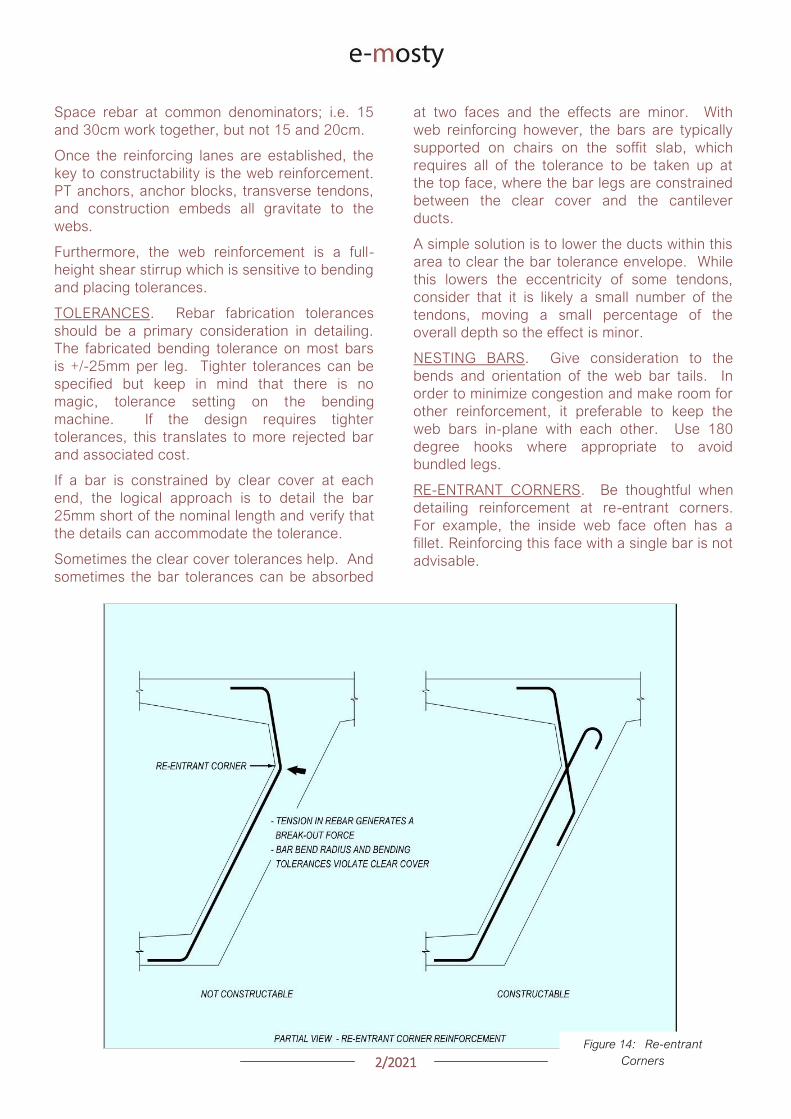
22021
Space rebar at common denominators ie 15
and 30cm work together but not 15 and 20cm
Once the reinforcing lanes are established the
key to constructability is the web reinforcement
PT anchors anchor blocks transverse tendons
and construction embeds all gravitate to the
webs
Furthermore the web reinforcement is a full-
height shear stirrup which is sensitive to bending
and placing tolerances
TOLERANCES Rebar fabrication tolerances
should be a primary consideration in detailing
The fabricated bending tolerance on most bars
is +-25mm per leg Tighter tolerances can be
specified but keep in mind that there is no
magic tolerance setting on the bending
machine If the design requires tighter
tolerances this translates to more rejected bar
and associated cost
If a bar is constrained by clear cover at each
end the logical approach is to detail the bar
25mm short of the nominal length and verify that
the details can accommodate the tolerance
Sometimes the clear cover tolerances help And
sometimes the bar tolerances can be absorbed
at two faces and the effects are minor With
web reinforcing however the bars are typically
supported on chairs on the soffit slab which
requires all of the tolerance to be taken up at
the top face where the bar legs are constrained
between the clear cover and the cantilever
ducts
A simple solution is to lower the ducts within this
area to clear the bar tolerance envelope While
this lowers the eccentricity of some tendons
consider that it is likely a small number of the
tendons moving a small percentage of the
overall depth so the effect is minor
NESTING BARS Give consideration to the
bends and orientation of the web bar tails In
order to minimize congestion and make room for
other reinforcement it preferable to keep the
web bars in-plane with each other Use 180
degree hooks where appropriate to avoid
bundled legs
RE-ENTRANT CORNERS Be thoughtful when
detailing reinforcement at re-entrant corners
For example the inside web face often has a
fillet Reinforcing this face with a single bar is not
advisable
Figure 14 Re-entrant
Corners
22021
Consider that when this bar is in tension it will
want to straighten and pop-out the cover
concrete at the corner It is preferable to use
crossing-bars which develop beyond the corner
TENDON PASS-THRU Where tendons pass
thru reinforcing mats the design should specify
how Note that the tendons in anchor blocks
typically slope at 12-15 degrees At this angle
the duct can conflict with rebar over a length of
60-90cm
Simply shifting bars longitudinally to clear the
conflict is not practical because it displaces too
many bars and leaves a large gap
In most cases it is preferable that the cross-thru
details are modifications (by moving bending or
cutting) to the typical reinforcing as opposed to
introducing unique bars at specific locations
Figure 15 Top Mat Bars at Cross-Thru (with fillet)
Figure 16 Top Mat Bars at Cross-Thru (flat slab)
22021
LONGITUDINAL REINFORCING An additional
topic to highlight is the treatment of longitudinal
reinforcing in curved segments In cast-in-place
construction the bars are detailed long enough
to satisfy the lap splice requirements on the
outside of the curve and the extra length on the
short side is taken up in the lap splice
In precast segments the detailing of longitudinal
reinforcement becomes complicated
Longitudinal bars are broken into sub-sets in
order to graduate the lengths across the width
of the segment
Otherwise identical reinforcing cages but with
slightly different plan-view geometry become
different reinforcing types requiring additional
drawings and submittals not to mention more
time spent sorting bars on-site
Given that segment cages are pre-tied in jigs it
would be reasonable to detail all the bars long
tie them in the cage and then cut them to
match the pie-shape of the specific segment
This would streamline shop drawing process and
potentially simplify fabrication
Figure 17 Treatment of Longitudinal Bars
XI ANCHOR BLOCK REINFORCEMENT
Before reading any further prepare to go lsquodeep
in the weedsrsquo In order to lessen the headache
refer directly to the appendix for an example of
an anchor block that addresses the challenges
CONGESTION Anchor blocks typically have
two sets of bars (outer confinement + inner tie
for curvature) which mesh together with the
web reinforcement (2 faces) and slab
reinforcement (2 faces)
Altogether this can translate to six bars which
must pass each other Many of these bars may
have legs on the same face creating lsquowallsrsquo of
bundled rebar
These zones of bars are problematic for placing
concrete prone to spalling and do nothing to
develop the reinforcement There are several
techniques to address this
Place the web reinforcement in the same
plane Turn the leg on the inside-face
web bar toward centerline of segment If
the leg on the outside-face web bar
contacts the inside-face reinforcement
consider using a 180deg hook
Place bottom slab reinforcement in the
same plane If the legs happen to
conflict shorten or place the top-mat bar
to nest inside the bottom-mat bar
22021
Turn the legs of the outer anchor block
reinforcement away from the web Full
360deg or even 270deg confinement of the
anchor block is not necessary as the
bottom slab and web reinforcement
already exist on these faces and are
waiting to be put to work
Consider the direction of the legs on the
inner anchor block bars (ie the in-plane
pullout reinforcement) Turning both legs
the same direction andor using 180
degree hooks may be helpful
TENDON GEOMETRY Anchor block
reinforcement should be organized with thought
to the actual tendon geometry In most cases
the other tendons in and around the anchor
block are not running parallel to the web
Tendon paths should not be altered to snake
thru the reinforcement Instead configure the
reinforcement to the lanes between the ducts
There are several techniques to address this
Begin by designing the reinforcement
around the typical (probably deviating)
tendon arrangement
Slope the inside face of the anchor block
By varying the clear cover the outer
block reinforcement may be detailed to
follow either straight or deviating tendon
paths
Adjust the width of the in-plane pullout
reinforcement as needed Where these
bars are tall use a wide bar in order to
straddle ducts running below Where
these bars are short a narrow top-hat
bar is appropriate to avoid clashing with
other ducts
Figure 18 Anchor Block Reinforcement (see Appendix)
22021
XII DIAPHRAGM REINFORCEMENT
There are a number of different approaches to
diaphragm design and this paper will not go into
depth on the possibilities However the
challenges found in diaphragm reinforcement
are variations on others already identified
When presented a problem engineers are good at
finding fixes For that reason simply being aware
of these issues goes a long way
Rebar Fabrication Tolerances
Rebar Placing Tolerances
Actual Size of Rebar and PT
Actual Size of Bar Bend Radii
Congestion (see Figure 19)
Uniformity Standardization
Finally just to give the contractor a sporting
chance identify all of the intersecting bars ducts
and other elements (with their overall sizes) and
verify that they do indeed fit inside of the concrete
An allowance for placing tolerances is
recommended too Incorporating this analysis into
the design process should be standard practice
Figure 19
lsquoRealrsquo Rebar
Diameter
larr Figure 20
Example of
Congestion
Too Many Bars
in Same Plane
22021
In cast-in-place construction headed anchor
studs may be a good option provided again
that the stud layout is integrated with the
reinforcement
INTEGRAL STRADDLE BEAMS Precast
segments are sometimes cantilevered from
straddle beams or similar CIP elements In this
configuration set the first precast segment just
off the straddle beam with a short closure
avoiding a complicated cast-in-place starter
Minor skews can be absorbed in the closure
Larger skews can be cast into the starter
segment In the case of cantilever construction
most if not all of the post-tensioning ducts are in
the top slab Rather than trying to cast ducts in
precise locations in the straddle beam set the
segment slightly higher than the top of beam
and cast the deck slab after the segments have
been placed
This avoids complications with tolerances as
well as conflicts between the straddle beam
stirrups and PT ducts
XIII SUBSTRUCTURE CONNECTIONS
The details associated with the superstructure
connection to the substructure have a
significant impact on the constructability This
interface is typically at the bearings and in some
cases the superstructure may frame into other
types of construction
Short closures are used to connect segments
which are not match cast However when a
segment is taken from one form and mated up
with one from a different form you can expect
some degree of misalignment in the cross
section and ducts
BEARINGS In precast segmental where the
structure requires fixity through the bearings it
is preferable to use a limited number of large
pintles to transfer horizontal load to the
bearings
In these situations the void for the pintle should
be oversized to allow for grade and
superelevation as well as reasonable fabrication
and placing tolerances
These voids may be formed using lsquocansrsquo or it
may be practical to void out a rectangular
volume in and around the reinforcement using
foam block In either case the pintles must be
integrated with the reinforcement
Figure 21 Straddle Beam Connection
22021
Figure 23 Straddle Beam Connection Top of Beam held low to allow Cantilever Tendons to pass over without conflict
Hong Kong Mtr South Island Line Courtesy of Leighton Construction
Figure 22 Straddle Beam Connection Top of Beam held low to allow Cantilever Tendons to pass over without conflict
Hong Kong Mtr South Island Line Courtesy of Leighton Construction
22021
INTEGRAL PIER COLUMNS Making precast
segments integral with pier columns presents
challenges but there are a number of benefits
Integral connections can eliminate bearings and
associated maintenance provide robust
connection for lateral loads (ie seismic) and
can eliminate the need for temporary stability
shoring
Integral connections can be achieved several
ways Similar to the previous straddle beam
example the conventional approach is to
construct cast-in-place pier segments and erect
precast segments on either side with short
closures
This requires realistic expectations for the
construction tolerances involved For example
it may be prudent to thicken the in-situ cross
section to minimize misalignments in the cross
section in addition to incorporating means to
accommodate duct misalignments
XIV PLAN PRESENTATION
Efficient construction requires good drawings
BRIM and 3D CAD tools allow us to create some
amazing work but as this is being written there
are still a lot of us humans involved in the
process
Modern drafting tools allow us to make drawing
easier and to balance that it is important to be
disciplined in minimizing drawings and details
Figure 24 PT Layout Example
22021
SYMMETRY If something is symmetric or even
close to it use half views Showing redundant
information invites confusion and errors This
also allows views to be larger and show details
more clearly
PT LAYOUTS All longitudinal PT for a given
segment should be shown on the same drawing
sheet Scale plan views in the transverse
direction to better illustrate tendon geometry
and neglect horizontal curvature Last ndash call out
each end of each tendon
APPENDIX 3D MODEL
The following page is a 3D pdf to illustrate some
of the points discussed in this document
The source DGN file is attached here
I hope you find this document useful and Good Bridgebuilding
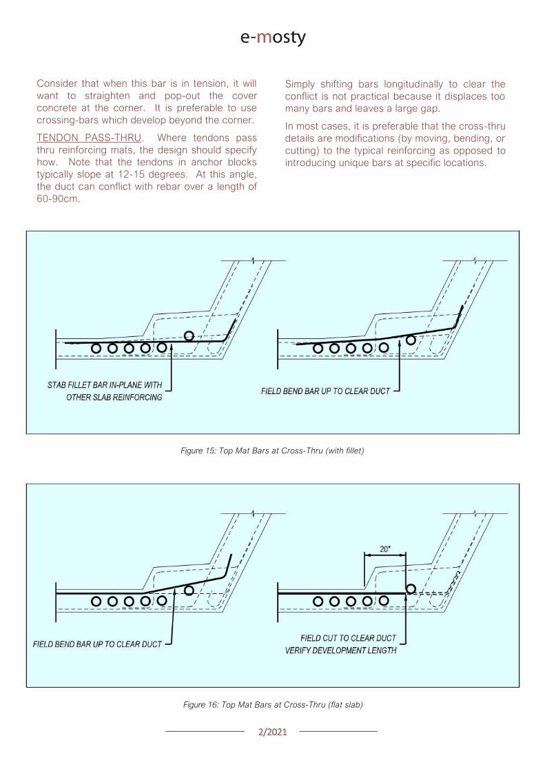
22021
Consider that when this bar is in tension it will
want to straighten and pop-out the cover
concrete at the corner It is preferable to use
crossing-bars which develop beyond the corner
TENDON PASS-THRU Where tendons pass
thru reinforcing mats the design should specify
how Note that the tendons in anchor blocks
typically slope at 12-15 degrees At this angle
the duct can conflict with rebar over a length of
60-90cm
Simply shifting bars longitudinally to clear the
conflict is not practical because it displaces too
many bars and leaves a large gap
In most cases it is preferable that the cross-thru
details are modifications (by moving bending or
cutting) to the typical reinforcing as opposed to
introducing unique bars at specific locations
Figure 15 Top Mat Bars at Cross-Thru (with fillet)
Figure 16 Top Mat Bars at Cross-Thru (flat slab)
22021
LONGITUDINAL REINFORCING An additional
topic to highlight is the treatment of longitudinal
reinforcing in curved segments In cast-in-place
construction the bars are detailed long enough
to satisfy the lap splice requirements on the
outside of the curve and the extra length on the
short side is taken up in the lap splice
In precast segments the detailing of longitudinal
reinforcement becomes complicated
Longitudinal bars are broken into sub-sets in
order to graduate the lengths across the width
of the segment
Otherwise identical reinforcing cages but with
slightly different plan-view geometry become
different reinforcing types requiring additional
drawings and submittals not to mention more
time spent sorting bars on-site
Given that segment cages are pre-tied in jigs it
would be reasonable to detail all the bars long
tie them in the cage and then cut them to
match the pie-shape of the specific segment
This would streamline shop drawing process and
potentially simplify fabrication
Figure 17 Treatment of Longitudinal Bars
XI ANCHOR BLOCK REINFORCEMENT
Before reading any further prepare to go lsquodeep
in the weedsrsquo In order to lessen the headache
refer directly to the appendix for an example of
an anchor block that addresses the challenges
CONGESTION Anchor blocks typically have
two sets of bars (outer confinement + inner tie
for curvature) which mesh together with the
web reinforcement (2 faces) and slab
reinforcement (2 faces)
Altogether this can translate to six bars which
must pass each other Many of these bars may
have legs on the same face creating lsquowallsrsquo of
bundled rebar
These zones of bars are problematic for placing
concrete prone to spalling and do nothing to
develop the reinforcement There are several
techniques to address this
Place the web reinforcement in the same
plane Turn the leg on the inside-face
web bar toward centerline of segment If
the leg on the outside-face web bar
contacts the inside-face reinforcement
consider using a 180deg hook
Place bottom slab reinforcement in the
same plane If the legs happen to
conflict shorten or place the top-mat bar
to nest inside the bottom-mat bar
22021
Turn the legs of the outer anchor block
reinforcement away from the web Full
360deg or even 270deg confinement of the
anchor block is not necessary as the
bottom slab and web reinforcement
already exist on these faces and are
waiting to be put to work
Consider the direction of the legs on the
inner anchor block bars (ie the in-plane
pullout reinforcement) Turning both legs
the same direction andor using 180
degree hooks may be helpful
TENDON GEOMETRY Anchor block
reinforcement should be organized with thought
to the actual tendon geometry In most cases
the other tendons in and around the anchor
block are not running parallel to the web
Tendon paths should not be altered to snake
thru the reinforcement Instead configure the
reinforcement to the lanes between the ducts
There are several techniques to address this
Begin by designing the reinforcement
around the typical (probably deviating)
tendon arrangement
Slope the inside face of the anchor block
By varying the clear cover the outer
block reinforcement may be detailed to
follow either straight or deviating tendon
paths
Adjust the width of the in-plane pullout
reinforcement as needed Where these
bars are tall use a wide bar in order to
straddle ducts running below Where
these bars are short a narrow top-hat
bar is appropriate to avoid clashing with
other ducts
Figure 18 Anchor Block Reinforcement (see Appendix)
22021
XII DIAPHRAGM REINFORCEMENT
There are a number of different approaches to
diaphragm design and this paper will not go into
depth on the possibilities However the
challenges found in diaphragm reinforcement
are variations on others already identified
When presented a problem engineers are good at
finding fixes For that reason simply being aware
of these issues goes a long way
Rebar Fabrication Tolerances
Rebar Placing Tolerances
Actual Size of Rebar and PT
Actual Size of Bar Bend Radii
Congestion (see Figure 19)
Uniformity Standardization
Finally just to give the contractor a sporting
chance identify all of the intersecting bars ducts
and other elements (with their overall sizes) and
verify that they do indeed fit inside of the concrete
An allowance for placing tolerances is
recommended too Incorporating this analysis into
the design process should be standard practice
Figure 19
lsquoRealrsquo Rebar
Diameter
larr Figure 20
Example of
Congestion
Too Many Bars
in Same Plane
22021
In cast-in-place construction headed anchor
studs may be a good option provided again
that the stud layout is integrated with the
reinforcement
INTEGRAL STRADDLE BEAMS Precast
segments are sometimes cantilevered from
straddle beams or similar CIP elements In this
configuration set the first precast segment just
off the straddle beam with a short closure
avoiding a complicated cast-in-place starter
Minor skews can be absorbed in the closure
Larger skews can be cast into the starter
segment In the case of cantilever construction
most if not all of the post-tensioning ducts are in
the top slab Rather than trying to cast ducts in
precise locations in the straddle beam set the
segment slightly higher than the top of beam
and cast the deck slab after the segments have
been placed
This avoids complications with tolerances as
well as conflicts between the straddle beam
stirrups and PT ducts
XIII SUBSTRUCTURE CONNECTIONS
The details associated with the superstructure
connection to the substructure have a
significant impact on the constructability This
interface is typically at the bearings and in some
cases the superstructure may frame into other
types of construction
Short closures are used to connect segments
which are not match cast However when a
segment is taken from one form and mated up
with one from a different form you can expect
some degree of misalignment in the cross
section and ducts
BEARINGS In precast segmental where the
structure requires fixity through the bearings it
is preferable to use a limited number of large
pintles to transfer horizontal load to the
bearings
In these situations the void for the pintle should
be oversized to allow for grade and
superelevation as well as reasonable fabrication
and placing tolerances
These voids may be formed using lsquocansrsquo or it
may be practical to void out a rectangular
volume in and around the reinforcement using
foam block In either case the pintles must be
integrated with the reinforcement
Figure 21 Straddle Beam Connection
22021
Figure 23 Straddle Beam Connection Top of Beam held low to allow Cantilever Tendons to pass over without conflict
Hong Kong Mtr South Island Line Courtesy of Leighton Construction
Figure 22 Straddle Beam Connection Top of Beam held low to allow Cantilever Tendons to pass over without conflict
Hong Kong Mtr South Island Line Courtesy of Leighton Construction
22021
INTEGRAL PIER COLUMNS Making precast
segments integral with pier columns presents
challenges but there are a number of benefits
Integral connections can eliminate bearings and
associated maintenance provide robust
connection for lateral loads (ie seismic) and
can eliminate the need for temporary stability
shoring
Integral connections can be achieved several
ways Similar to the previous straddle beam
example the conventional approach is to
construct cast-in-place pier segments and erect
precast segments on either side with short
closures
This requires realistic expectations for the
construction tolerances involved For example
it may be prudent to thicken the in-situ cross
section to minimize misalignments in the cross
section in addition to incorporating means to
accommodate duct misalignments
XIV PLAN PRESENTATION
Efficient construction requires good drawings
BRIM and 3D CAD tools allow us to create some
amazing work but as this is being written there
are still a lot of us humans involved in the
process
Modern drafting tools allow us to make drawing
easier and to balance that it is important to be
disciplined in minimizing drawings and details
Figure 24 PT Layout Example
22021
SYMMETRY If something is symmetric or even
close to it use half views Showing redundant
information invites confusion and errors This
also allows views to be larger and show details
more clearly
PT LAYOUTS All longitudinal PT for a given
segment should be shown on the same drawing
sheet Scale plan views in the transverse
direction to better illustrate tendon geometry
and neglect horizontal curvature Last ndash call out
each end of each tendon
APPENDIX 3D MODEL
The following page is a 3D pdf to illustrate some
of the points discussed in this document
The source DGN file is attached here
I hope you find this document useful and Good Bridgebuilding
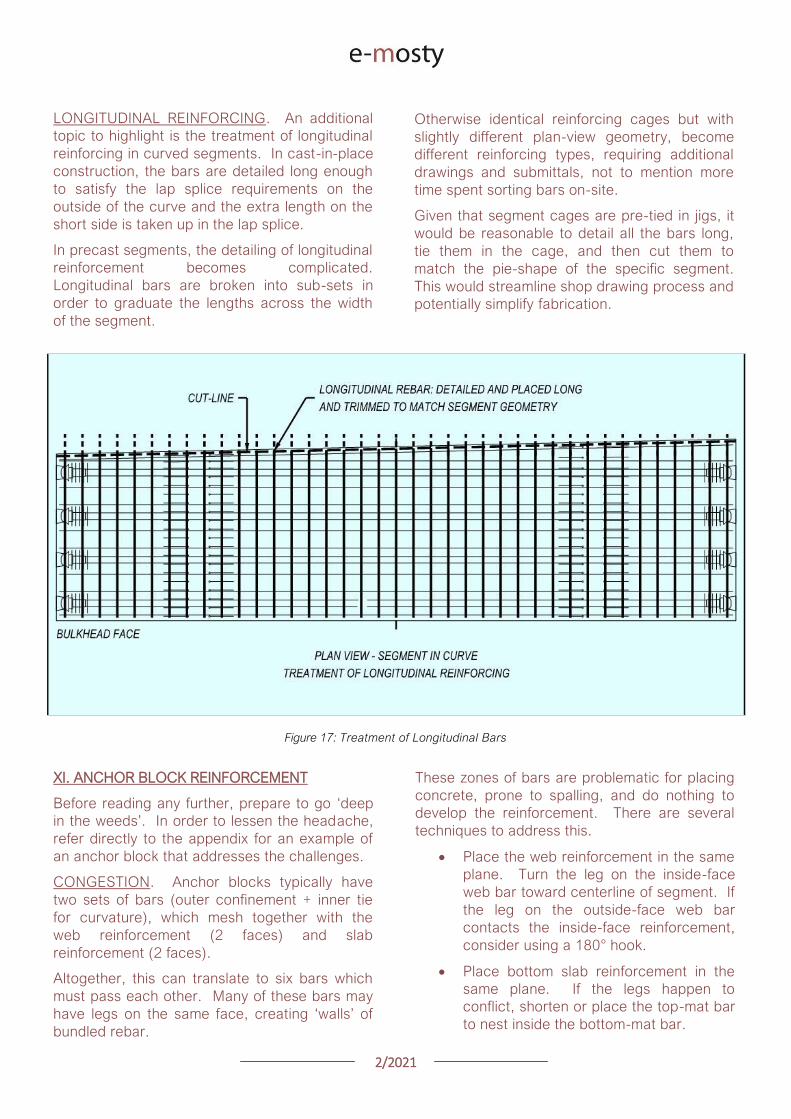
22021
LONGITUDINAL REINFORCING An additional
topic to highlight is the treatment of longitudinal
reinforcing in curved segments In cast-in-place
construction the bars are detailed long enough
to satisfy the lap splice requirements on the
outside of the curve and the extra length on the
short side is taken up in the lap splice
In precast segments the detailing of longitudinal
reinforcement becomes complicated
Longitudinal bars are broken into sub-sets in
order to graduate the lengths across the width
of the segment
Otherwise identical reinforcing cages but with
slightly different plan-view geometry become
different reinforcing types requiring additional
drawings and submittals not to mention more
time spent sorting bars on-site
Given that segment cages are pre-tied in jigs it
would be reasonable to detail all the bars long
tie them in the cage and then cut them to
match the pie-shape of the specific segment
This would streamline shop drawing process and
potentially simplify fabrication
Figure 17 Treatment of Longitudinal Bars
XI ANCHOR BLOCK REINFORCEMENT
Before reading any further prepare to go lsquodeep
in the weedsrsquo In order to lessen the headache
refer directly to the appendix for an example of
an anchor block that addresses the challenges
CONGESTION Anchor blocks typically have
two sets of bars (outer confinement + inner tie
for curvature) which mesh together with the
web reinforcement (2 faces) and slab
reinforcement (2 faces)
Altogether this can translate to six bars which
must pass each other Many of these bars may
have legs on the same face creating lsquowallsrsquo of
bundled rebar
These zones of bars are problematic for placing
concrete prone to spalling and do nothing to
develop the reinforcement There are several
techniques to address this
Place the web reinforcement in the same
plane Turn the leg on the inside-face
web bar toward centerline of segment If
the leg on the outside-face web bar
contacts the inside-face reinforcement
consider using a 180deg hook
Place bottom slab reinforcement in the
same plane If the legs happen to
conflict shorten or place the top-mat bar
to nest inside the bottom-mat bar
22021
Turn the legs of the outer anchor block
reinforcement away from the web Full
360deg or even 270deg confinement of the
anchor block is not necessary as the
bottom slab and web reinforcement
already exist on these faces and are
waiting to be put to work
Consider the direction of the legs on the
inner anchor block bars (ie the in-plane
pullout reinforcement) Turning both legs
the same direction andor using 180
degree hooks may be helpful
TENDON GEOMETRY Anchor block
reinforcement should be organized with thought
to the actual tendon geometry In most cases
the other tendons in and around the anchor
block are not running parallel to the web
Tendon paths should not be altered to snake
thru the reinforcement Instead configure the
reinforcement to the lanes between the ducts
There are several techniques to address this
Begin by designing the reinforcement
around the typical (probably deviating)
tendon arrangement
Slope the inside face of the anchor block
By varying the clear cover the outer
block reinforcement may be detailed to
follow either straight or deviating tendon
paths
Adjust the width of the in-plane pullout
reinforcement as needed Where these
bars are tall use a wide bar in order to
straddle ducts running below Where
these bars are short a narrow top-hat
bar is appropriate to avoid clashing with
other ducts
Figure 18 Anchor Block Reinforcement (see Appendix)
22021
XII DIAPHRAGM REINFORCEMENT
There are a number of different approaches to
diaphragm design and this paper will not go into
depth on the possibilities However the
challenges found in diaphragm reinforcement
are variations on others already identified
When presented a problem engineers are good at
finding fixes For that reason simply being aware
of these issues goes a long way
Rebar Fabrication Tolerances
Rebar Placing Tolerances
Actual Size of Rebar and PT
Actual Size of Bar Bend Radii
Congestion (see Figure 19)
Uniformity Standardization
Finally just to give the contractor a sporting
chance identify all of the intersecting bars ducts
and other elements (with their overall sizes) and
verify that they do indeed fit inside of the concrete
An allowance for placing tolerances is
recommended too Incorporating this analysis into
the design process should be standard practice
Figure 19
lsquoRealrsquo Rebar
Diameter
larr Figure 20
Example of
Congestion
Too Many Bars
in Same Plane
22021
In cast-in-place construction headed anchor
studs may be a good option provided again
that the stud layout is integrated with the
reinforcement
INTEGRAL STRADDLE BEAMS Precast
segments are sometimes cantilevered from
straddle beams or similar CIP elements In this
configuration set the first precast segment just
off the straddle beam with a short closure
avoiding a complicated cast-in-place starter
Minor skews can be absorbed in the closure
Larger skews can be cast into the starter
segment In the case of cantilever construction
most if not all of the post-tensioning ducts are in
the top slab Rather than trying to cast ducts in
precise locations in the straddle beam set the
segment slightly higher than the top of beam
and cast the deck slab after the segments have
been placed
This avoids complications with tolerances as
well as conflicts between the straddle beam
stirrups and PT ducts
XIII SUBSTRUCTURE CONNECTIONS
The details associated with the superstructure
connection to the substructure have a
significant impact on the constructability This
interface is typically at the bearings and in some
cases the superstructure may frame into other
types of construction
Short closures are used to connect segments
which are not match cast However when a
segment is taken from one form and mated up
with one from a different form you can expect
some degree of misalignment in the cross
section and ducts
BEARINGS In precast segmental where the
structure requires fixity through the bearings it
is preferable to use a limited number of large
pintles to transfer horizontal load to the
bearings
In these situations the void for the pintle should
be oversized to allow for grade and
superelevation as well as reasonable fabrication
and placing tolerances
These voids may be formed using lsquocansrsquo or it
may be practical to void out a rectangular
volume in and around the reinforcement using
foam block In either case the pintles must be
integrated with the reinforcement
Figure 21 Straddle Beam Connection
22021
Figure 23 Straddle Beam Connection Top of Beam held low to allow Cantilever Tendons to pass over without conflict
Hong Kong Mtr South Island Line Courtesy of Leighton Construction
Figure 22 Straddle Beam Connection Top of Beam held low to allow Cantilever Tendons to pass over without conflict
Hong Kong Mtr South Island Line Courtesy of Leighton Construction
22021
INTEGRAL PIER COLUMNS Making precast
segments integral with pier columns presents
challenges but there are a number of benefits
Integral connections can eliminate bearings and
associated maintenance provide robust
connection for lateral loads (ie seismic) and
can eliminate the need for temporary stability
shoring
Integral connections can be achieved several
ways Similar to the previous straddle beam
example the conventional approach is to
construct cast-in-place pier segments and erect
precast segments on either side with short
closures
This requires realistic expectations for the
construction tolerances involved For example
it may be prudent to thicken the in-situ cross
section to minimize misalignments in the cross
section in addition to incorporating means to
accommodate duct misalignments
XIV PLAN PRESENTATION
Efficient construction requires good drawings
BRIM and 3D CAD tools allow us to create some
amazing work but as this is being written there
are still a lot of us humans involved in the
process
Modern drafting tools allow us to make drawing
easier and to balance that it is important to be
disciplined in minimizing drawings and details
Figure 24 PT Layout Example
22021
SYMMETRY If something is symmetric or even
close to it use half views Showing redundant
information invites confusion and errors This
also allows views to be larger and show details
more clearly
PT LAYOUTS All longitudinal PT for a given
segment should be shown on the same drawing
sheet Scale plan views in the transverse
direction to better illustrate tendon geometry
and neglect horizontal curvature Last ndash call out
each end of each tendon
APPENDIX 3D MODEL
The following page is a 3D pdf to illustrate some
of the points discussed in this document
The source DGN file is attached here
I hope you find this document useful and Good Bridgebuilding
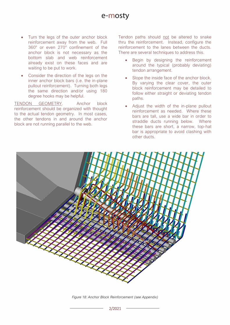
22021
Turn the legs of the outer anchor block
reinforcement away from the web Full
360deg or even 270deg confinement of the
anchor block is not necessary as the
bottom slab and web reinforcement
already exist on these faces and are
waiting to be put to work
Consider the direction of the legs on the
inner anchor block bars (ie the in-plane
pullout reinforcement) Turning both legs
the same direction andor using 180
degree hooks may be helpful
TENDON GEOMETRY Anchor block
reinforcement should be organized with thought
to the actual tendon geometry In most cases
the other tendons in and around the anchor
block are not running parallel to the web
Tendon paths should not be altered to snake
thru the reinforcement Instead configure the
reinforcement to the lanes between the ducts
There are several techniques to address this
Begin by designing the reinforcement
around the typical (probably deviating)
tendon arrangement
Slope the inside face of the anchor block
By varying the clear cover the outer
block reinforcement may be detailed to
follow either straight or deviating tendon
paths
Adjust the width of the in-plane pullout
reinforcement as needed Where these
bars are tall use a wide bar in order to
straddle ducts running below Where
these bars are short a narrow top-hat
bar is appropriate to avoid clashing with
other ducts
Figure 18 Anchor Block Reinforcement (see Appendix)
22021
XII DIAPHRAGM REINFORCEMENT
There are a number of different approaches to
diaphragm design and this paper will not go into
depth on the possibilities However the
challenges found in diaphragm reinforcement
are variations on others already identified
When presented a problem engineers are good at
finding fixes For that reason simply being aware
of these issues goes a long way
Rebar Fabrication Tolerances
Rebar Placing Tolerances
Actual Size of Rebar and PT
Actual Size of Bar Bend Radii
Congestion (see Figure 19)
Uniformity Standardization
Finally just to give the contractor a sporting
chance identify all of the intersecting bars ducts
and other elements (with their overall sizes) and
verify that they do indeed fit inside of the concrete
An allowance for placing tolerances is
recommended too Incorporating this analysis into
the design process should be standard practice
Figure 19
lsquoRealrsquo Rebar
Diameter
larr Figure 20
Example of
Congestion
Too Many Bars
in Same Plane
22021
In cast-in-place construction headed anchor
studs may be a good option provided again
that the stud layout is integrated with the
reinforcement
INTEGRAL STRADDLE BEAMS Precast
segments are sometimes cantilevered from
straddle beams or similar CIP elements In this
configuration set the first precast segment just
off the straddle beam with a short closure
avoiding a complicated cast-in-place starter
Minor skews can be absorbed in the closure
Larger skews can be cast into the starter
segment In the case of cantilever construction
most if not all of the post-tensioning ducts are in
the top slab Rather than trying to cast ducts in
precise locations in the straddle beam set the
segment slightly higher than the top of beam
and cast the deck slab after the segments have
been placed
This avoids complications with tolerances as
well as conflicts between the straddle beam
stirrups and PT ducts
XIII SUBSTRUCTURE CONNECTIONS
The details associated with the superstructure
connection to the substructure have a
significant impact on the constructability This
interface is typically at the bearings and in some
cases the superstructure may frame into other
types of construction
Short closures are used to connect segments
which are not match cast However when a
segment is taken from one form and mated up
with one from a different form you can expect
some degree of misalignment in the cross
section and ducts
BEARINGS In precast segmental where the
structure requires fixity through the bearings it
is preferable to use a limited number of large
pintles to transfer horizontal load to the
bearings
In these situations the void for the pintle should
be oversized to allow for grade and
superelevation as well as reasonable fabrication
and placing tolerances
These voids may be formed using lsquocansrsquo or it
may be practical to void out a rectangular
volume in and around the reinforcement using
foam block In either case the pintles must be
integrated with the reinforcement
Figure 21 Straddle Beam Connection
22021
Figure 23 Straddle Beam Connection Top of Beam held low to allow Cantilever Tendons to pass over without conflict
Hong Kong Mtr South Island Line Courtesy of Leighton Construction
Figure 22 Straddle Beam Connection Top of Beam held low to allow Cantilever Tendons to pass over without conflict
Hong Kong Mtr South Island Line Courtesy of Leighton Construction
22021
INTEGRAL PIER COLUMNS Making precast
segments integral with pier columns presents
challenges but there are a number of benefits
Integral connections can eliminate bearings and
associated maintenance provide robust
connection for lateral loads (ie seismic) and
can eliminate the need for temporary stability
shoring
Integral connections can be achieved several
ways Similar to the previous straddle beam
example the conventional approach is to
construct cast-in-place pier segments and erect
precast segments on either side with short
closures
This requires realistic expectations for the
construction tolerances involved For example
it may be prudent to thicken the in-situ cross
section to minimize misalignments in the cross
section in addition to incorporating means to
accommodate duct misalignments
XIV PLAN PRESENTATION
Efficient construction requires good drawings
BRIM and 3D CAD tools allow us to create some
amazing work but as this is being written there
are still a lot of us humans involved in the
process
Modern drafting tools allow us to make drawing
easier and to balance that it is important to be
disciplined in minimizing drawings and details
Figure 24 PT Layout Example
22021
SYMMETRY If something is symmetric or even
close to it use half views Showing redundant
information invites confusion and errors This
also allows views to be larger and show details
more clearly
PT LAYOUTS All longitudinal PT for a given
segment should be shown on the same drawing
sheet Scale plan views in the transverse
direction to better illustrate tendon geometry
and neglect horizontal curvature Last ndash call out
each end of each tendon
APPENDIX 3D MODEL
The following page is a 3D pdf to illustrate some
of the points discussed in this document
The source DGN file is attached here
I hope you find this document useful and Good Bridgebuilding
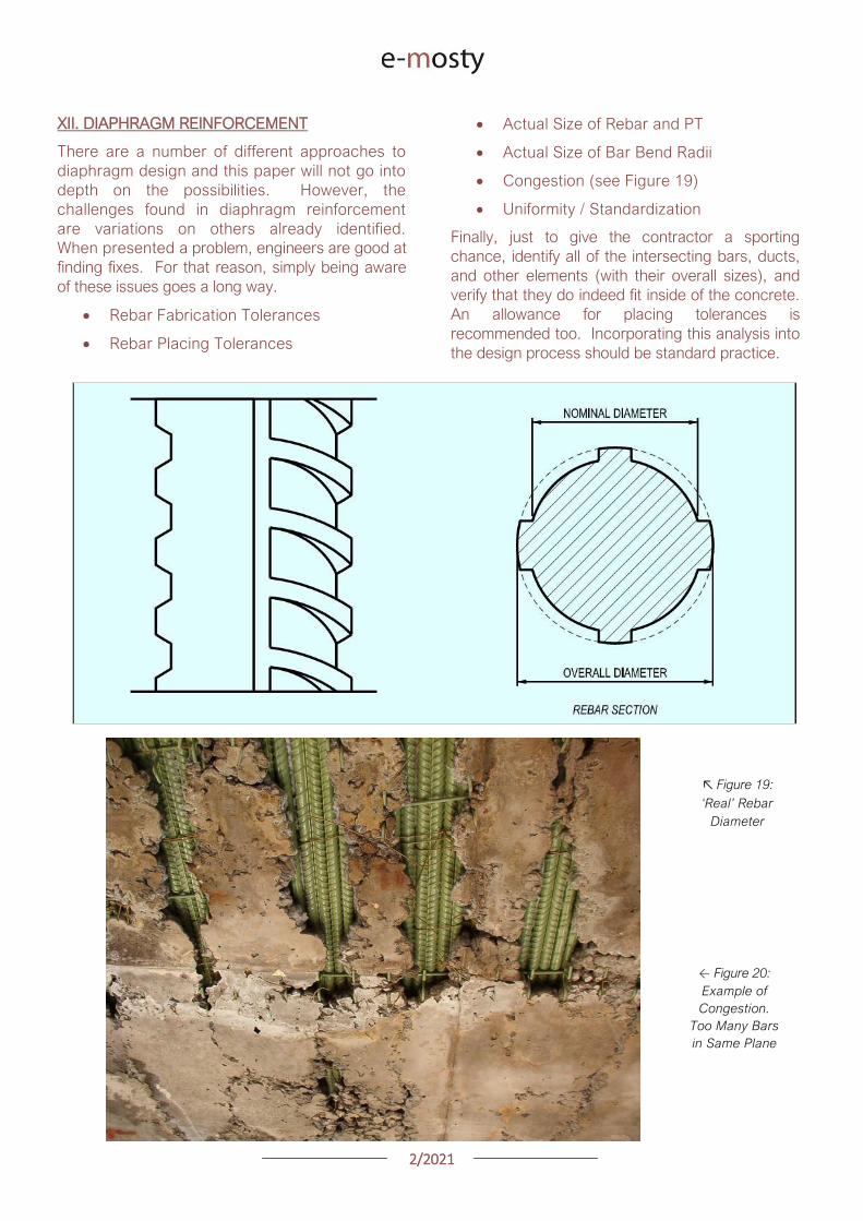
22021
XII DIAPHRAGM REINFORCEMENT
There are a number of different approaches to
diaphragm design and this paper will not go into
depth on the possibilities However the
challenges found in diaphragm reinforcement
are variations on others already identified
When presented a problem engineers are good at
finding fixes For that reason simply being aware
of these issues goes a long way
Rebar Fabrication Tolerances
Rebar Placing Tolerances
Actual Size of Rebar and PT
Actual Size of Bar Bend Radii
Congestion (see Figure 19)
Uniformity Standardization
Finally just to give the contractor a sporting
chance identify all of the intersecting bars ducts
and other elements (with their overall sizes) and
verify that they do indeed fit inside of the concrete
An allowance for placing tolerances is
recommended too Incorporating this analysis into
the design process should be standard practice
Figure 19
lsquoRealrsquo Rebar
Diameter
larr Figure 20
Example of
Congestion
Too Many Bars
in Same Plane
22021
In cast-in-place construction headed anchor
studs may be a good option provided again
that the stud layout is integrated with the
reinforcement
INTEGRAL STRADDLE BEAMS Precast
segments are sometimes cantilevered from
straddle beams or similar CIP elements In this
configuration set the first precast segment just
off the straddle beam with a short closure
avoiding a complicated cast-in-place starter
Minor skews can be absorbed in the closure
Larger skews can be cast into the starter
segment In the case of cantilever construction
most if not all of the post-tensioning ducts are in
the top slab Rather than trying to cast ducts in
precise locations in the straddle beam set the
segment slightly higher than the top of beam
and cast the deck slab after the segments have
been placed
This avoids complications with tolerances as
well as conflicts between the straddle beam
stirrups and PT ducts
XIII SUBSTRUCTURE CONNECTIONS
The details associated with the superstructure
connection to the substructure have a
significant impact on the constructability This
interface is typically at the bearings and in some
cases the superstructure may frame into other
types of construction
Short closures are used to connect segments
which are not match cast However when a
segment is taken from one form and mated up
with one from a different form you can expect
some degree of misalignment in the cross
section and ducts
BEARINGS In precast segmental where the
structure requires fixity through the bearings it
is preferable to use a limited number of large
pintles to transfer horizontal load to the
bearings
In these situations the void for the pintle should
be oversized to allow for grade and
superelevation as well as reasonable fabrication
and placing tolerances
These voids may be formed using lsquocansrsquo or it
may be practical to void out a rectangular
volume in and around the reinforcement using
foam block In either case the pintles must be
integrated with the reinforcement
Figure 21 Straddle Beam Connection
22021
Figure 23 Straddle Beam Connection Top of Beam held low to allow Cantilever Tendons to pass over without conflict
Hong Kong Mtr South Island Line Courtesy of Leighton Construction
Figure 22 Straddle Beam Connection Top of Beam held low to allow Cantilever Tendons to pass over without conflict
Hong Kong Mtr South Island Line Courtesy of Leighton Construction
22021
INTEGRAL PIER COLUMNS Making precast
segments integral with pier columns presents
challenges but there are a number of benefits
Integral connections can eliminate bearings and
associated maintenance provide robust
connection for lateral loads (ie seismic) and
can eliminate the need for temporary stability
shoring
Integral connections can be achieved several
ways Similar to the previous straddle beam
example the conventional approach is to
construct cast-in-place pier segments and erect
precast segments on either side with short
closures
This requires realistic expectations for the
construction tolerances involved For example
it may be prudent to thicken the in-situ cross
section to minimize misalignments in the cross
section in addition to incorporating means to
accommodate duct misalignments
XIV PLAN PRESENTATION
Efficient construction requires good drawings
BRIM and 3D CAD tools allow us to create some
amazing work but as this is being written there
are still a lot of us humans involved in the
process
Modern drafting tools allow us to make drawing
easier and to balance that it is important to be
disciplined in minimizing drawings and details
Figure 24 PT Layout Example
22021
SYMMETRY If something is symmetric or even
close to it use half views Showing redundant
information invites confusion and errors This
also allows views to be larger and show details
more clearly
PT LAYOUTS All longitudinal PT for a given
segment should be shown on the same drawing
sheet Scale plan views in the transverse
direction to better illustrate tendon geometry
and neglect horizontal curvature Last ndash call out
each end of each tendon
APPENDIX 3D MODEL
The following page is a 3D pdf to illustrate some
of the points discussed in this document
The source DGN file is attached here
I hope you find this document useful and Good Bridgebuilding
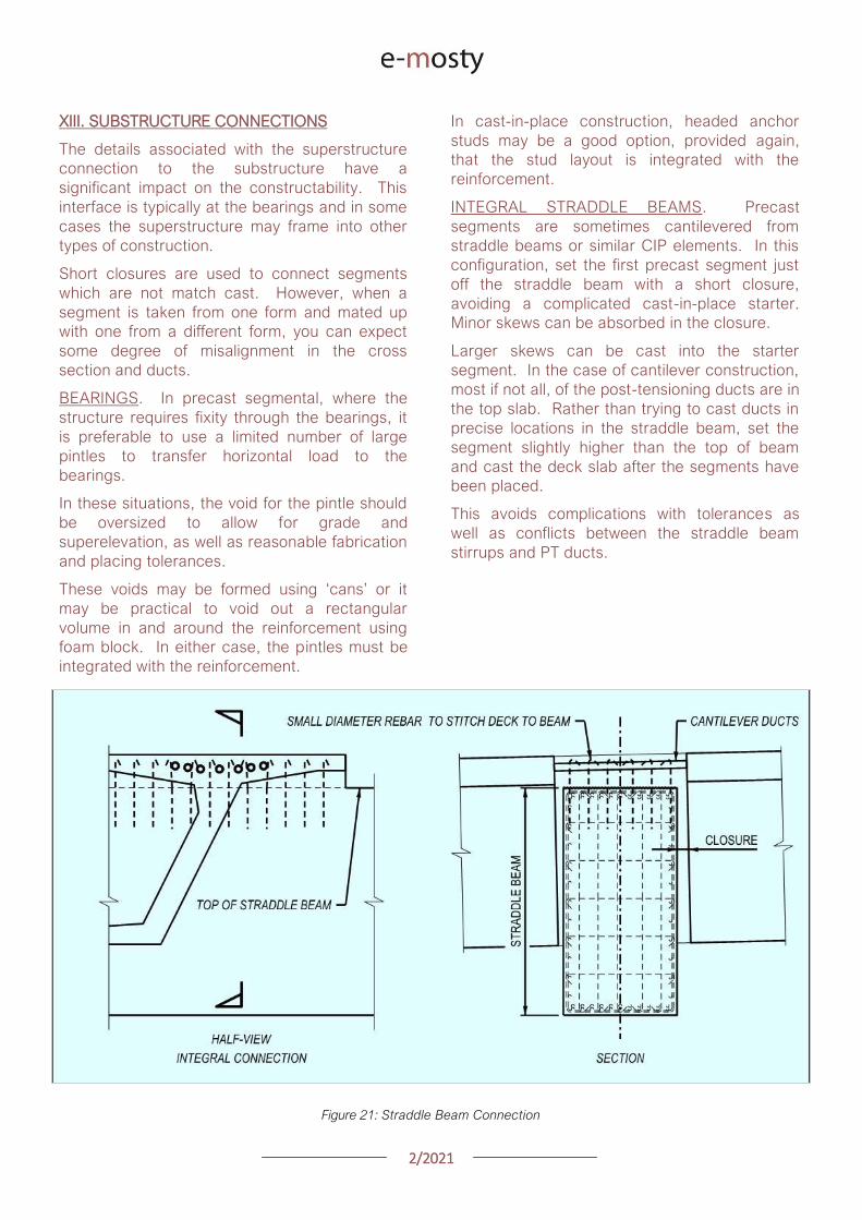
22021
In cast-in-place construction headed anchor
studs may be a good option provided again
that the stud layout is integrated with the
reinforcement
INTEGRAL STRADDLE BEAMS Precast
segments are sometimes cantilevered from
straddle beams or similar CIP elements In this
configuration set the first precast segment just
off the straddle beam with a short closure
avoiding a complicated cast-in-place starter
Minor skews can be absorbed in the closure
Larger skews can be cast into the starter
segment In the case of cantilever construction
most if not all of the post-tensioning ducts are in
the top slab Rather than trying to cast ducts in
precise locations in the straddle beam set the
segment slightly higher than the top of beam
and cast the deck slab after the segments have
been placed
This avoids complications with tolerances as
well as conflicts between the straddle beam
stirrups and PT ducts
XIII SUBSTRUCTURE CONNECTIONS
The details associated with the superstructure
connection to the substructure have a
significant impact on the constructability This
interface is typically at the bearings and in some
cases the superstructure may frame into other
types of construction
Short closures are used to connect segments
which are not match cast However when a
segment is taken from one form and mated up
with one from a different form you can expect
some degree of misalignment in the cross
section and ducts
BEARINGS In precast segmental where the
structure requires fixity through the bearings it
is preferable to use a limited number of large
pintles to transfer horizontal load to the
bearings
In these situations the void for the pintle should
be oversized to allow for grade and
superelevation as well as reasonable fabrication
and placing tolerances
These voids may be formed using lsquocansrsquo or it
may be practical to void out a rectangular
volume in and around the reinforcement using
foam block In either case the pintles must be
integrated with the reinforcement
Figure 21 Straddle Beam Connection
22021
Figure 23 Straddle Beam Connection Top of Beam held low to allow Cantilever Tendons to pass over without conflict
Hong Kong Mtr South Island Line Courtesy of Leighton Construction
Figure 22 Straddle Beam Connection Top of Beam held low to allow Cantilever Tendons to pass over without conflict
Hong Kong Mtr South Island Line Courtesy of Leighton Construction
22021
INTEGRAL PIER COLUMNS Making precast
segments integral with pier columns presents
challenges but there are a number of benefits
Integral connections can eliminate bearings and
associated maintenance provide robust
connection for lateral loads (ie seismic) and
can eliminate the need for temporary stability
shoring
Integral connections can be achieved several
ways Similar to the previous straddle beam
example the conventional approach is to
construct cast-in-place pier segments and erect
precast segments on either side with short
closures
This requires realistic expectations for the
construction tolerances involved For example
it may be prudent to thicken the in-situ cross
section to minimize misalignments in the cross
section in addition to incorporating means to
accommodate duct misalignments
XIV PLAN PRESENTATION
Efficient construction requires good drawings
BRIM and 3D CAD tools allow us to create some
amazing work but as this is being written there
are still a lot of us humans involved in the
process
Modern drafting tools allow us to make drawing
easier and to balance that it is important to be
disciplined in minimizing drawings and details
Figure 24 PT Layout Example
22021
SYMMETRY If something is symmetric or even
close to it use half views Showing redundant
information invites confusion and errors This
also allows views to be larger and show details
more clearly
PT LAYOUTS All longitudinal PT for a given
segment should be shown on the same drawing
sheet Scale plan views in the transverse
direction to better illustrate tendon geometry
and neglect horizontal curvature Last ndash call out
each end of each tendon
APPENDIX 3D MODEL
The following page is a 3D pdf to illustrate some
of the points discussed in this document
The source DGN file is attached here
I hope you find this document useful and Good Bridgebuilding
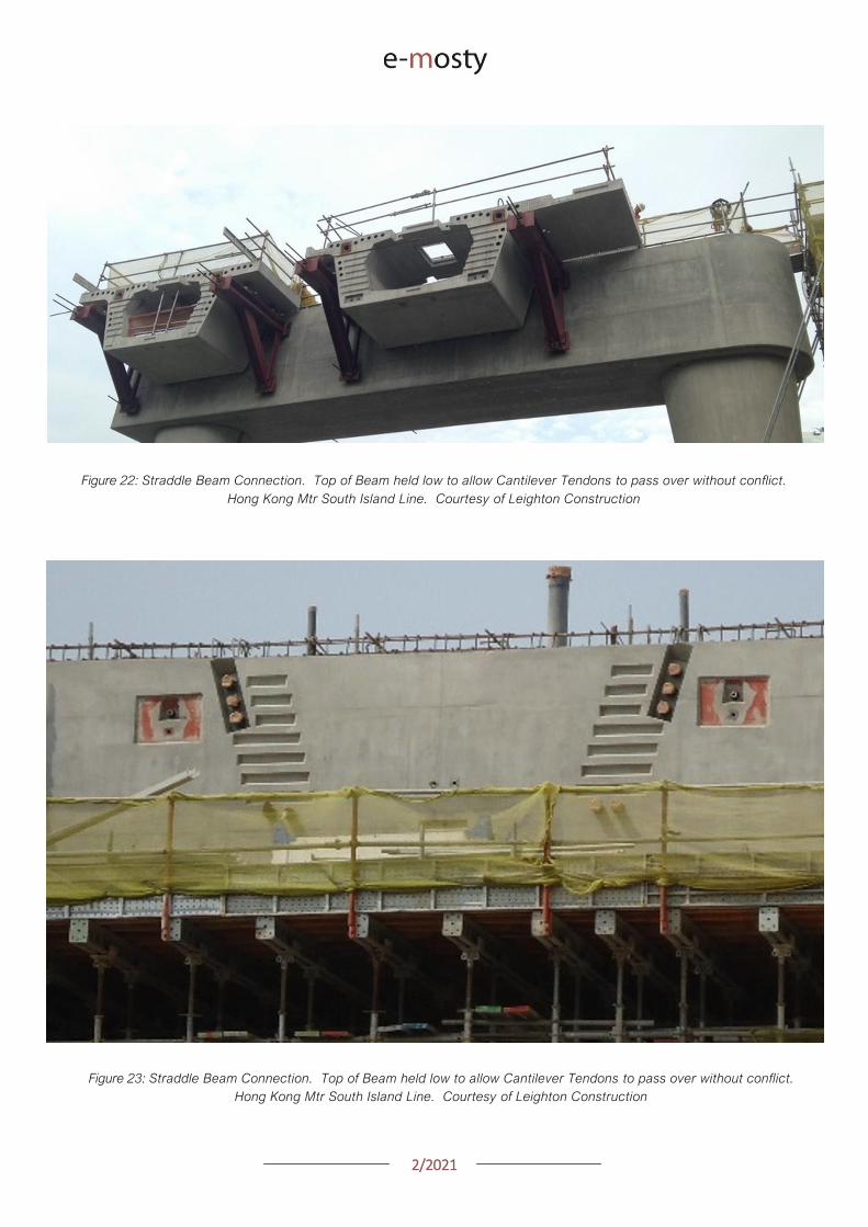
22021
Figure 23 Straddle Beam Connection Top of Beam held low to allow Cantilever Tendons to pass over without conflict
Hong Kong Mtr South Island Line Courtesy of Leighton Construction
Figure 22 Straddle Beam Connection Top of Beam held low to allow Cantilever Tendons to pass over without conflict
Hong Kong Mtr South Island Line Courtesy of Leighton Construction
22021
INTEGRAL PIER COLUMNS Making precast
segments integral with pier columns presents
challenges but there are a number of benefits
Integral connections can eliminate bearings and
associated maintenance provide robust
connection for lateral loads (ie seismic) and
can eliminate the need for temporary stability
shoring
Integral connections can be achieved several
ways Similar to the previous straddle beam
example the conventional approach is to
construct cast-in-place pier segments and erect
precast segments on either side with short
closures
This requires realistic expectations for the
construction tolerances involved For example
it may be prudent to thicken the in-situ cross
section to minimize misalignments in the cross
section in addition to incorporating means to
accommodate duct misalignments
XIV PLAN PRESENTATION
Efficient construction requires good drawings
BRIM and 3D CAD tools allow us to create some
amazing work but as this is being written there
are still a lot of us humans involved in the
process
Modern drafting tools allow us to make drawing
easier and to balance that it is important to be
disciplined in minimizing drawings and details
Figure 24 PT Layout Example
22021
SYMMETRY If something is symmetric or even
close to it use half views Showing redundant
information invites confusion and errors This
also allows views to be larger and show details
more clearly
PT LAYOUTS All longitudinal PT for a given
segment should be shown on the same drawing
sheet Scale plan views in the transverse
direction to better illustrate tendon geometry
and neglect horizontal curvature Last ndash call out
each end of each tendon
APPENDIX 3D MODEL
The following page is a 3D pdf to illustrate some
of the points discussed in this document
The source DGN file is attached here
I hope you find this document useful and Good Bridgebuilding
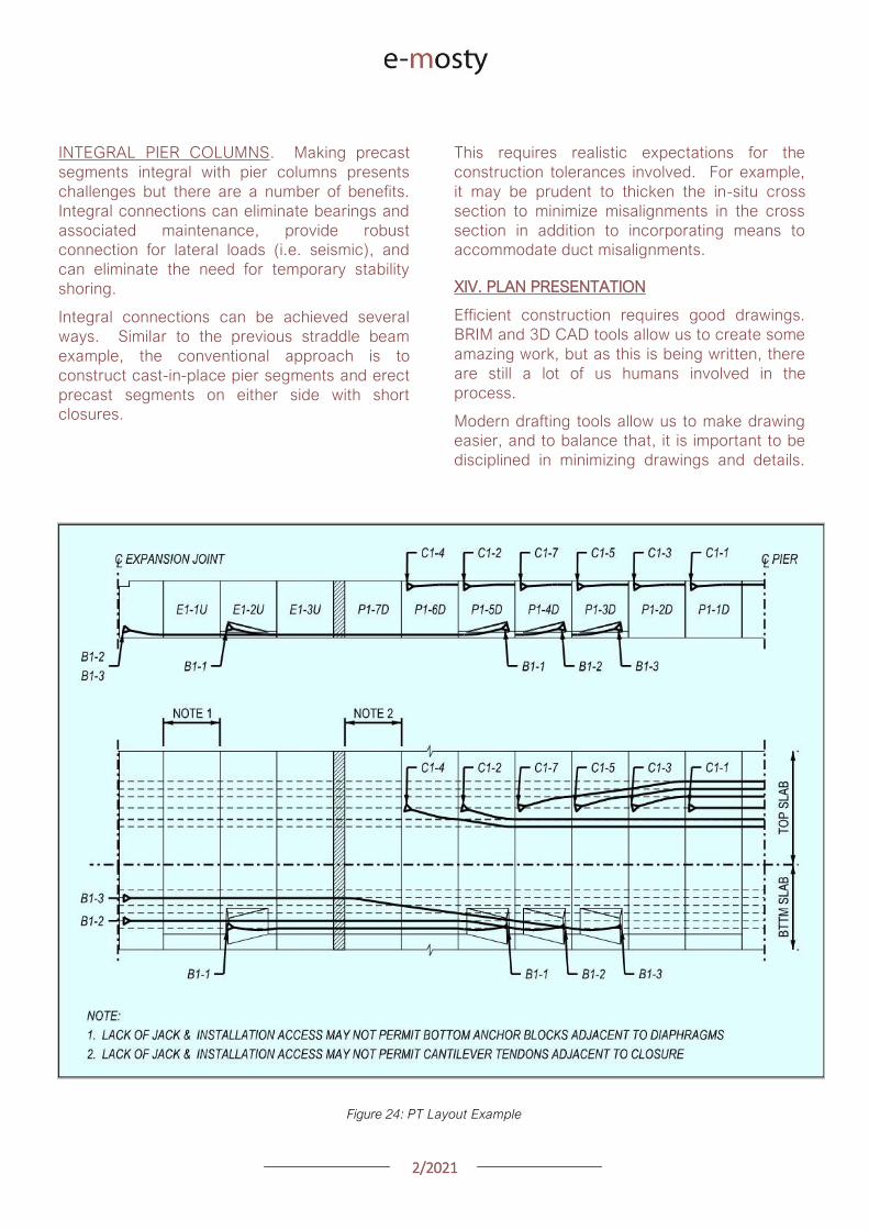
22021
DESIGN CONSIDERATIONS
FOR GANTRY ERECTED BRIDGES
Matthew Williams Jeremy Johannesen
McNary Bergeron amp Associates
Figure 1 The L53 launching gantry erecting pre-cast segments up to the cable stayed portion
of the Port Mann bridge in Vancouver Canada
INTRODUCTION
Bridge gantries provide many benefits to pre-cast
concrete bridge construction such as top down
construction where everything is fed to the gantry
from behind so that it never has to touch the
ground as well as span erection cycles that are as
short as a few days
At the same time launching gantries can also pose
interesting challenges and unique loads for bridge
designers
Gantry loads are unique in two ways First the
loads are unlike any other in-service loads given
the size of the construction loads and their
placement
Second gantry loads are being applied to an
incomplete structure
Both of these conditions can lead to novel loads
and load paths that may govern the design of
some bridge components
The better these loads are understood during the
design phase of a project the less redesign will be
required during construction
What follows here is a breakdown of the typical
construction loads a bridge will have to
accommodate organized by gantry operation
22021
GANTRY TYPES
The two most common types of launching gantries
are overhead and underslung gantries Overhead
gantries stand on top of the superstructure and the
leading pier
All launching takes place on top of the bridge and
pre-cast segments or girders are suspended
beneath the gantry
Underslung gantries are supported by brackets
mounted to the piers and support segments by the
wings on top of the gantry
Overhead gantries may be broken down further
into conventional and articulating gantries
Figure 2 Underslung gantry erecting the Susquehana River Bridge in Pennsylvania
Conventional gantries are generally comprised of
two ldquomain girdersrdquo that are parallel to one another
Articulating gantries have a main girder used to
hang segments from and a support beam that is
used for launching the gantry
The benefit of articulating gantries is their ability to
launch through tight radius curves
The L122 articulating gantry (designed by DEAL) is
shown in Figure 4 on the following page navigating
a 124m (407ft) radius horizontal curve on the
HART Light Rail project in Honolulu Hawaii
22021
Figure 3 Conventional Gantry Erecting Red Line North in Doha Qatar DEAL L107 Gantry
Figure 4 Articulating Gantry erecting the HART Light Rail in Honolulu Hawaii DEAL L122 Gantry
22021
GANTRY ERECTION
The first loads imparted by a launching gantry
occur during the assembly of the equipment
Launching gantries are typically erected with the
front support on the leading pier and the rear
support on either a previously erected span or on
falsework
The falsework tower shown here on the Seattle
Sound Transit project is tied to the rear pier to
ensure longitudinal stability of the tower and
gantry
Figure 5 A conventional lattice gantry with the rear support on falsework for the erection of the first span
DEAL L81 Gantry Seattle Sound Transit Seattle Washington
SEGMENTAL CONSTRUCTION SEGMENT
ERECTION
Once the gantry is assembled and ready to use the
construction can begin with the hanging of the
segments Segments are lifted via lifting holes in
the top slab
These can be either between the webs of a
segment or outside the webs in the wings
Lifting between the webs can induce top slab
tension at the center of the segment which can be
exacerbated by transverse post-tensioning in the
deck
22021
Figure 6 Segment lifting during the static winch load test where the winch is loaded to the weight of the heaviest
segment plus 25
The segment shown here has several spools of post-tensioning strand to increase the weight of the pick
DEAL L107 launching gantry Doha Qatar
Another troublesome spot can be the tops of the
webs
The secondary PT demand due to transverse post-
tensioning adds to the moment from lifting the
segment and can lead to cracking in the webs
Usually the cracks form on the inside face of the
web protected from the elements and can be self-
healing once under service loading
COMPLETING THE SPAN
After hanging all the segments in the first span a
load test will be performed
A typical load test involves overloading the gantry
to 10 above the weight of the heaviest span to
be erected by the gantry
Once the load test is complete the segments are
epoxied together and stressed with temporary
post-tensioning
Stressing the permanent post-tensioning presents
a challenge for controlling stresses in the
suspended span due to the continuous support of
the launching gantry
As the tendons are stressed the span immediately
begins to pick up in the middle This upward
movement allows the gantry to recover from the
deflection it underwent while hanging segments
A spangantry analysis is necessary to understand
how the stresses in the span change throughout
the stressing sequence
In this analysis a model is developed that includes
the span being erected the launching gantry and
the hanging bars used to suspend the segments
To control stresses during this process the gantry
can be incrementally lowered in order to shed the
span self-weight from the gantry into the bearings
22021
Figure 7 The L121 conventional launching gantry from DEAL completing a span on the HART Light Rail in Honolulu Hawaii
This increases compression in the top slab as the
span becomes self supporting
Another approach is to change the tendon
stressing order to better control top fiber tension
Some spans require both methods to be used
together
While it is not possible to avoid top fiber tension
completely given the continuous support provided
by the gantry during stressing it is possible to keep
them within a reasonable limit
LAUNCHING
With span construction complete the gantry is now
ready to launch itself to the next span
Different gantries launch in different ways
Conventional gantries typically have three
supports a front support rear support and an
auxiliary support that are maneuvered beneath the
girder for launching
Every effort is made to keep support placement
over the webs in segments adjacent to the pier
segments
However on tight radius horizontal curves it may
be necessary to place supports along the span to
allow the gantry to navigate the curve
Placing supports at midspan on a small radius
curved span can lead to span stability concerns as
the center of the loading could potentially be
outside the footprint of the bearings
This risk can be mitigated by providing optional tie-
downs to hold the span down at the piers
22021
Figure 8 The L100 conventional launching gantry completing a launch in Riyadh Saudi Arabia
Articulating gantries have a different method of
launching A front leg suspended from the support
beam is placed onto the leading pier and then the
rear support rolls along the superstructure
When the rear support has reached the end of the
span the front support and support girders are
launched forward
The wheels of the rear support are meant to ride
directly over the webs however it is possible to
get off-course and start loading the wings or
haunch of a pre-cast segment
Any offset from the center of the web induces a
moment in the top of the web as well and may be
compounded by the presence of transverse post-
tensioning
A steering tolerance should be checked with a
transverse analysis of the segments
Much of the loading from a launching gantry goes
into the previously erected superstructure
However the front support of a launching gantry
typically sits on the up-station side of the leading
pier during span erection
Large moments can develop in the pier as a result
of the following factors
1 Front supports are placed ahead of the
pier centerline to ensure that therersquos room
to set the span being erected
2 The slope of gantry as it follows the bridge
slope imparts a longitudinal load on the
leading pier at the top of the front support
several meters above the top of the pier
3 The slope load is increased by the gantry
deflection under the weight of suspended
segments This can be as much as 2
4 Friction in the front support roller group
can add another 1 of the vertical load
acting longitudinally
22021
Figure 9 Gantry front support showing forward offset from pier centerline and the roller group supporting the main girders
DEAL L57 Gantry Tysonrsquos Corner Virginia
Thus if the gantry is erecting ldquoup-hillrdquo the slope of
the bridge deflection of the gantry and friction in
the roller group are all additive
Conventional gantries have rollers on the front
support to avoid being statically indeterminate
Longitudinal fixity is at the rear support
As such all of the moment inducing forces listed
above must be resisted by the flexural capacity of
the leading pier alone
These loads can be significant and can potentially
govern the design of taller piers
Another concern with the longitudinal loads is the
deflection of the pier itself This can lead to locked-
in deflection if the span is set directly on
permanent bearings that arenrsquot free to slide
longitudinally (elastomeric bearings for example)
NON-TYPICAL SPANS
Erecting typical length spans with gentle horizontal
curves produces predictable construction loads
Where launching gets tricky and therefore applies
loads on the permanent structure is where span
lengths vary widely from one span to the next
Often gantries will have to set their supports at
several locations along the length of the span to
get set up for either a short or long launch
Another launching concern is walkovers This is
where a gantry erects up to another span that has
been erected with another method or at another
time and launches over the completed span to
arrive at the next span to begin erecting again
Typically this occurs where bridges have spans
that exceed the design length for the gantry and
have been previously erected by other means
During walkovers supports will often be placed on
typical segments away from the pier segments in
order to make the launch
Any time supports are placed on typical segments
and not pier segments the span should be
designed to take the flexural shear and principal
tension demands of the launch
22021
Figure 10 The L120 launching gantry (by DEAL) lifts the pre-cast concrete segments of the first span
WIND LOADS
A common concern among bridge owners and
designers is with regards to the applicable wind
loads that a gantry and bridge should be designed
for Bridge design codes require specific wind
speeds and pressures to be considered while
launching gantries are typically designed to
overhead crane design codes that have a different
set of requirements
The launching gantry should be designed for the
wind loads specified by the applicable crane codes
while the bridge should consider the gantry as an
appurtenance affixed to the permanent structure
and use the applicable bridge wind loads in the
design of the bridge
On the Harbor Bridge project in Corpus Christi
Texas there is the potential for large wind loads
given that the bridge is located on the Gulf of
Mexico and the piers are upwards 45m tall
The L120 launching gantry (designed by DEAL) is
160m long and 3m tall giving it a large projected
wind area
The two major concerns that arise are the lateral
loads on the pier columns and the stability of the
span when the gantry is tied down for wind events
To accommodate the large out of service
(hurricane) wind loading the designers opted to
design specific locations along the bridge for
hurricane winds on the structure and gantry
together
The piers and superstructure have increased
capacity to accommodate the gantry should it
need to be tied down a wind event
This was a more economical solution than
designing every pier for the out of service winds
In the event of an approaching hurricane the
gantry does not have far to back launch to get to a
safe place to tie-down
CONCLUSION
In conclusion launching gantries apply unique
loads on both the super and substructures of
bridges
Wind and longitudinal loads on the piers can
sometimes govern the design and stability checks
of the bridge Considering these loads during the
design phase of a bridge project can eliminate
costly redesigns later
22021
GEOMETRY CONTROL FOR PRECAST
SEGMENTAL CONSTRUCTION
Joakim Dupleix CaSE International (formerly VSL)
Martin Pircher ABES
Figure 1 Closing of Mesaimeer Bridge main stay cable span Qatar
PRECAST SEGMENTAL CONSTRUCTION
Precast segmental construction is a great method
to limit the impact of the works on a bridge
construction site
By fabricating the concrete elements in a
controlled environment many of the unpleasant
by-products of the construction site are also
exported
However a key challenge of constructing elements
remotely is to ensure they will achieve the required
bridge geometry once erected on site
Furthermore the fact that the bridge is built ldquopiece-
by-piecerdquo in segments means that the geometry
needs to be controlled and forecasted at every
stage during construction anticipating and
forecasting movements and deflections during the
temporary stages of the construction process
Often bridges have varying curvature and
superelevation which require tools to capture the
geometry in all dimensions
These tools must allow efficient and accurate ways
to correct geometry imperfections such as
correction in setting out in the precast yard or
shimming of segment joints during balanced
cantilever erection on site
22021
ABES SOFTWARE SOLUTION
ABES Pircher amp Partner GmbH is an independent
software house providing solutions for bridge
engineering topics
Together with VSL they have developed a
software suite dedicated to managing the
geometry control of segmental construction at
every stage of the construction process
The software is split in 3 components which are all
interrelated
geoDes to be used in the design office to
model the intended theoretical geometry of
the bridge
geoCon to be used in the casting yard
providing setting out and casting error
compensation for any yard setup
assemCon to be used on site to forecast
the as-built geometry during balanced
cantilever construction based on real time
survey results
Figure 2 Balanced cantilever construction
The software works fully in 3D with a visual
interface which means it can control geometry in
all directions not only vertically
Figure 3 Snapshot of 3D model within ABES geoDes
22021
The Figure below illustrates an example of a cross-
section modeled in geoDes
Figure 4 Cross section (inner void omitted)
KEY PRINCIPLES
The geometry control principles used by ABES are
as follows
The theoretical modelling of the bridge
defines a casting curve in 3D which is the
ldquoperfectrdquo geometry of the bridge This
includes the camber of the bridge if defined
by the designer
Each segment is recorded in its entire
three-dimensional shape and identified by a
minimum of 4 control points which are
physical survey items to be cast anywhere
on the segment
Segment shapes are prepared considering
the specific requirements of the casting
machines used in the yard
The position of control points in the wet
concrete which may vary due to placing
error defines the setting out curve
When segments are cast movement of the
formwork the bulkhead or the conjugate
segment may induce deviations from the
theoretical shape this defines the ldquoas castrdquo
curve
Segment imperfections are compensated
for during casting of sub-sequent
segments This is true for both short-line
and long-line casting or the combination
thereof
During balanced cantilever erection each
construction stage must be monitored and
compared to the deflected position of the
entire bridge as defined by the designer
Again geometric deviations need to be
corrected for during sub-sequent
construction stages
Figure 5 3D interface showing theoretical
(red) and as cast segments (green)
MAIN ADVANTAGES
Modelling
By modelling the bridge from base alignments and
with geometric rules derived from the specific
capabilities of the casting cells the software
achieves the best constructable theoretical fit
Multiple alignments can be accommodated
including deviation from the main alignment such
as for ramps or train stations as required Refer to
Figure 3 above
In the precast yard
When using geoCon the software automatically
compensates for the user the required setting out
according to the survey data of the previous
segment
This is key to ensure seamless casting operation
and minimize operator error Besides benefitting
from the 3D modelling it always works in all three
dimensions
22021
There is no limit to the number of control points
per segment ensuring high accuracy
Another key feature for a stay cable bridge pipes
must be cast in advance into the segment in the
yard to achieve the final geometry after all
deformations have occurred
The software can transform the theoretical pipe
coordinates adjust them for cambers and
segment imperfections and display them in the
local coordinate system which can be processed
by the surveyor in the yard
Figure 6 Gewan Island bridge 3D modelling
with plan radius of less than 125m
Figure 8 Precasting of segments with cable stay pipes
On site for balanced cantilever erection
On site assemCon gives two key insights to the
user
Forecast the position of the bridge at any
construction stage in 3D considering the
as-built data the as-cast curve and the
calculated deflections for each
construction stage
Assist in finding an optimal shimming
strategy to correct the forecasted position
and to target a final as-built structure as
close as possible to the theoretical
geometry
Figure 7 3D view of a cantilever being built
22021
Figure 9 Definition of shimming
strategy to reduce differences
CONCLUSIONS
Pre-cast segmental bridge construction is applied
to increasingly complex and geometrically
challenging structures
Efficient geometry control is essential for the
success of such projects
Geometry control already starts during the
planning process where individual segments need
to be laid out to suit the available equipment in the
casting yard
Segment casting needs to be tightly controlled and
monitored and geometric imperfections need to
be identified and compensated for
And finally bridge construction at the construction
site requires monitoring of individual construction
stages and optimised strategies for correcting for
possible geometry deviations of the bridge
structure during construction
VSL in cooperation with ABES have developed a
suite of software tools to assist in all these tasks
The software is heavily influenced by practical
experience during numerous pre-cast segmental
projects of all sizes and shapes across Asia and
principally Qatar and India and feedback from
ongoing projects continues to inform the
development work
Figure 12 Al Bustan North bridge during construction
above traffic Qatar
Figure 11 Gewan Island Bridge being built Qatar
Figure 10 Karimnagar cable stay bridge India
Photos Credit VSL
22021
PRECAST SEGMENTAL BRIDGE CONSTRUCTION
USING LIFTING FRAME IN QATAR
Joakim Dupleix CaSE International (formerly VSL)
German A Pardo R VSL International Ltd
Figure 1 Overview of Al Bustan North construction site
PRECAST SEGMENTAL CONSTRUCTION
One of the most advantageous construction
methods enabled by segmental construction is the
balanced cantilever method
In a busy brownfield environment pre-casting the
segments off-site is the best solution to minimize
disrupting the existing traffic flow
In these environments access is often limited and
restricted and cranage may not be able to reach
the whole site
In these conditions lifting frame equipment are
often the solution to enable the erection of
segments on the bridge
In Qatar VSL designed and operated two very
different types of lifting frames as part of the Al
Bustan corridor upgrade project
The lifting frames responded to different needs and
segment delivery methods carefully studied during
the construction planning phase of the project
SABAH AL AHMAD CORRIDOR
(previously called Al Bustan)
Sabah al Ahmad or Al Bustan Corridor is part of
the Qatar Expressway Programme and aims to
provide an alternative to the existing expressway
with free flow traffic on a length of 14 km from the
North of Central Doha to the South to improve
connectivity to the FIFA World Cup stadiums
22021
The project involved upgrading the existing main
road by constructing various overhead bridges
over existing crossroads as well as connecting
ramps to remove traffic lights
The construction of this corridor was split into three
main packages
Al Bustan North project now known as
Umm Lekhba Interchange
Al Bustan South project
Mesaimeer Road project
Al Bustan North consists of the major upgrade of a
major interchange with Qatar main highway Al
Shamal Road to become a 4 level interchange
Al Bustan South required the construction of large
overhead bridges up to 26 km long with overhead
ramps connecting to crossroads
Mesaimeer Road upgraded the existing road with 2
large bridges up to 12 km long with a cable stay
section
PRECAST SEGMENTAL BALANCED
CANTILEVER METHOD
Because of the existing brownfield environment in
which the bridges are being built and to minimize
the impact on the existing traffic the precast
segment balanced cantilever method was chosen
for design and construction
It avoids installing large falsework structures on
site where space is limited and enables quick
fabrication of the bridge but requires relatively
large lifting equipment
As a matter of fact as the heavy concrete bridge
segments are to be transported and erected into
position with limited space the key is to
Figure 2 Key map of the corridor in Doha
22021
understand which areas are available where
possible if lifting equipment such as cranes can be
positioned and how to deliver the segments to
their final position
For very heavy segments or if cranes cannot be
used due to site constraints it may be required to
design custom made lifting frame machines
placed on top of the bridge already built and fitted
with their own lifting device to erect the segments
in their final position
These machines typically have a limited range and
segments must be first transported precisely near
their final position
On the Al Bustan Corridor two different delivery
situations were identified
For Al Bustan South and Mesaimeer the
large weight of the segments made it
prohibitively costly to use a crane
However assisted by a temporary
diversion of the existing road during
construction and the flat terrain every
segment could always be delivered directly
below their final position
For Al Bustan North the multi-level
interchange the existing highway Al
Shamal Road could only be closed to traffic
for a very limited time and the existing road
environment did not allow for flexible
segment delivery below each new bridge
ramp
A crane could be positioned near the piers
which allowed for segments to be lifted
onto the already erected deck
To position the segment into its final
position a special lifting frame was
designed to pick up the segment ldquofrom
behindrdquo and bring them forward into their
final position
LIFTING FRAME WITH DELIVERY FROM
BEHIND
As mentioned previously a lifting frame (LF) able
to pick up a segment from behind was required for
this project
A few options for the trajectory of the segment
were considered
Symmetrical Lifting Frame segment
crossing the lifting frame is rotated at 90
degrees in plan lifted and moved through
the middle of the machine longitudinally
Once at the front it can be rotated 90
degrees and lowered in position
Asymmetrical Lifting Frame segment is
delivered 180 degrees from its final
orientation
The segment is picked up rotated 90
degrees moved through the LF
longitudinally rotated again and then
lowered in position
Figure 3 Al Bustan North lifting frame
For this project the bridges are quite narrow with a
web spacing of 6 and 4 m and therefore passing a
32 m long segment between two legs of the LF
was not possible
As shown in Figure 4 on the next page a C shape
was adopted to allow the segment to be rotated on
the free side and moved forward
22021
Figure 4 Segment delivery methodology Click on the image to open it in full size
Description of Lifting Frame
The lifting Frame had the following key
specifications
1 Self-weight of 70 tonnes
2 Lifting capacity of 80 tonnes
3 Lifting speed of 12 mh [02 mmin]
4 Longitudinal launching speed of 3 mh
[005 mmin]
The lifting frame is made of a few key
components
Upper Cross Beam (UCB) transverse
beam carrying the strand lifting unit as
well as the stressing platform lifting
mast Adjustment capability of +-
200 mm
Main Beams (MB) Longitudinal beams
supporting the UCB The UCB is
moved on wheels with a bogie
connected to 2 chain pulling units
Figure 5 3D view of lifting frame model
22021
Support Frame (SF) asymmetric frame in a
C shape supporting the MB The frame is
supported on the deck by adjustable screw
jacks located over the webs
Tie down beams (TDB) during erection
the SF is tie down to the deck with 4 no
40 mm diameter stressbars anchored in
TDB The TDB allows for longitudinal
adjustment in the position of the bars as
the segment length varies
Rail beams (RB) two rail beams on each
side of the SF are fitted with a hydraulic
launching system able to move the entire
frame forward in steps of 700 mm
Segment lifting beam (SLB) the SLB is
stressed to the segment being lifted and is
fitted with hydraulic jacks able to adjust the
segment to the required crossfall and
gradient as well as rotated the segment in
plan to pass through the SF
Stressing platform (SP) to complete the
balance cantilever construction a SP is
required to be positioned each newly
erected segment to provide access for
personnel to complete the permanent post-
tensioning operation
Figure 6 Segment delivered at the rear of the LF
Figure 8 Segment rotated to its final orientation
rarr Figure 9 Segment lowered into
position and load transferred
Figure 7 Segment rotated and moved longitudinally
SEGMENT ERECTION PHOTOS
The photo sequence below shows the segment
delivery process
22021
Challenges
Because of the limited width of the deck and the
congested site area with existing roads one of the
key challenges was to find a suitable storage
position for the SP when not in use which would
not block the segment passage
A rotation mast or davit arm was designed to lift
and position the 6 tonnes platform The mast was
rotated up to 120 degrees with a small horizontal
hydraulic jack
The concept and design itself of the Lifting Frame
required a solution which provided the minimum
required space for manipulating the segment and
the stressing platform in a very tight area while
having enough stiffness and capacity to cover the
demands
LIFTING FRAME WITH DELIVERY FROM
BELOW
Typical configuration for a Lifting Frame is such
that segment can be lifted directly from below
This was the case of Al Bustan South and
Mesaimeer projects
MESAIMEER LIFTING FRAME
Segments to be lifted by this lifting frame were the
heaviest and widest on the project for this reason
a stiffer structure composed of rigid frames at the
supporting areas was chosen taking advantage of
the fact that there was no restriction in height and
section of the bridge
The delivery of the segments in this project could
be conducted almost at is final position in plan
which facilitated the configuration of the lifting
equipment at the cantilever of the lifting frame
For this purpose the lifting frame was provided
with a couple of Winches that could pick up the
segment from the ground with minimum rotation in
plan lifted to required level and conduct final
adjustment in the longitudinal and transverse
directions
Description of Lifting Frame
The Lifting Frame had the following key
specifications
1 Self-weight of 92 tonnes
2 Lifting capacity of 185 tonnes
3 Lifting speed of 60 mh [1 mmin]
4 Longitudinal launching speed of 3mh [005
mmin)
Figure 10 segment delivered at the rear of the LF
The lifting frame is made of a few key components
Upper Cross Beam (UCB) transverse
beam carrying the main lifting equipment
(Winch) as well as the stressing platform
Adjustment capability +- 1325
Cantilever Beam (CTB) the 2 main
longitudinal beams supporting the UCB and
Stressing Platform at front and the Tie
Down Beam at the rear
Lower Cross Beam (LCB) main Frames
underneath the CTB transferring all load to
the bridge
Rail Beams (RB) two rail beams on each
side of the LCB are fitted with a hydraulic
launching system able to move the entire
frame forward in steps of 850 mm
22021
Connection Beams (CB) beams
connecting the hook blocks of the Winches
directly to the segment They are provided
with jacks for segment gradient adjustment
Crossfall is adjusted directly by the
Winches
Stressing Platform (SP) it is positioned at
the tip of the CTB and move backward for
conducting stressing of bridge post-
tensioning tendons It is provided with 2
levels customized for this project
Tie Down Beam (TDB) the Support frame
is provided with a set of tie down beams at
the rear which are the main stability
system
TDB can be adjusted in the longitudinal
direction to suit the different segment
lengths and their respective tie down holes
position
Tie down bars are of 75mm and 47mm in
diameter and pre-stressed against the
segment
Challenges
To accommodate the supporting area in a
very limited length since there was
insufficient space near the pylons
This created big reactions to be taken by
the tie down elements due the big
cantilever at front and heavy segments to
be lifted
To be able to move all the way back the
lifting equipment (Winch) and UCB to
provide enough stability during the
launching procedure Space at rear of the
lifting frame was very limited
Provide a Stressing Platform with 2
different configurations (1 or 2 levels) that
could be adapted for specific
configurations
SEGMENT ERECTION PHOTOS
Figure 11 Mesaimeer Lifting Frame
Figure 12 Segment lifting
Figure 13 Segment permanent post-tensioning in progress
22021
AL BUSTAN SOUTH LIFTING FRAME
For this project the lifting frame had to
accommodate few main requirements to suit the
space constraints of the project and the bridge
capacity
Height A limit of 6m for total height the lifting
frame was to be assured since the bridge had
to pass under an existing viaduct
Load introduction The bridge section is
provided with 3 webs and middle web capacity
was to be respected by limiting the reactions at
this point Additionally the total weight of the
Lifting Frame was also limited
Segment delivered below could not be
positioned in its final orientation due to space
constraints It had to be rotated up to 90deg once
hanging from the lifting frame
To overcome the limitations described the lifting
frame concept developed considered the following
aspects
Main lifting equipment (Winch) was
positioned at the bottom rear area of the
lifting frame to reduce the total height
The three webs of the segment were
loaded and the Lifting Frame elements
were studied in such a way that the total
weight of the Lifting Frame and loading of
central web were not exceeded
A single Winch and the hook block with
rotation device were provided to allow
rotation of the segment while hanging from
the Lifting Frame
Description of Lifting Frame
The Lifting Frame had the following key
specifications
1 Self-weight of 81 tonnes
2 Lifting capacity of 170 tonnes
3 Lifting speed of 36 mh [06 mmin]
4 Longitudinal launching speed of 3mh [005
mmin
The lifting frame is made of the following key
components
Upper Cross Beam (UCB) uppermost
element carrying the Winch Trolley It can
slide longitudinally to accommodate the
segment in length Transverse adjustment
is done by sliding of the Winch Trolley over
the UCB
Main Frame (MF) the Lifting Frame is
provided with 2 Main Frames in section that
support the UCB and Stressing Platform on
top and transfers the vertical load to the
lower elements of the Lifting Frame At
bottom level it also receives the Tie Down
Beam
Lower Cross Beam (LCB) spreader beam
in the transverse direction located at front
and rear that transfer all loads to the
segment webs through 6 screw jacks (3 at
the front and 3 at the rear)
Tie Down Beam (TDB) located at rear part
of the Lifting Frame and contain the tie
down bars stressed down against the
segment in order to assure the stability of
the Lifting Frame It contains a couple of
back-up bars that provide redundancy to
the system
Segment Lifting Beam (SLB) connecting
element between the hook block of the
winch and the segment It is provided with
a rotational device that allows full rotation
of the segment in plan
Figure 14 Segment delivered at the rear of the LF
22021
Stressing Platform (SP) it hangs from the
tip of the Main Frame cantilever beam It is
moved backwards after segment
installation to conduct the stressing of the
permanent post-tensioning system
Rail Beam (RB) two rail beams on each
side of the LCB are fitted with a hydraulic
launching system able it to move the entire
frame forward in steps of 850 mm
Figure 14 Lifting Frame installation on deck
Figure 15 Lifting of segment
Figure 16 Stressing of post-tensioning tendons
Figure 17 Lifting Frame crossing under existing viaduct
SEGMENT ERECTION PHOTOS
Challenges
To develop a concept and design that did
not exceed the limitations given regarding
total weight and height
Allow full rotation of the segment while
hanging
Provide redundancy to the Lifting Frame
Tie Down system and to the Stressing
Platform while under operation
22021
CONCLUSIONS
Precast segmental construction in a congested
environment often requires the use of custom
designed lifting frames
These machines must always consider the
segment delivery methods as well as the bridge
characteristics in order to achieve the most cost-
efficient methods of erection
The more requirements a project has the more
customized the Lifting Frame will be
For this reason it is of key importance to integrate
the development of the Temporary Structures (like
Lifting Frames) as early as possible in the design
process
By doing this some of the constraints can be
solved in earlier stages which will improve the
efficiency of the full process and the interfaces
between the different parts involved Permanent
Works Designer Temporary Works Designer and
Main Contractor
Figure 18 Al Bustan North Figure 19 Al Bustan North
Figure 20 Al Bustan South
Figure 21 Mesaimeer
Photos 18 ndash 20 Credit Ashghal (Qatar Road Authority)
We design and produceformwork equipmentfor in-place casting of bridgesN25 New Ross Bypass (Ireland)
FOLLOW US
INNOVATIVE | SAFE | SUSTAINABLE | FAST
SOLUTIONS FOR BRIDGE CONSTRUCTION
MSS M1-70-S BRATISLAVA BYPASS | IN SITU CONSTRUCTION
LG 36-S CAIRO METRO LINE 3 EXTENSION | PRECAST SEGMENTAL
WWWBERDEU
Photo Credits D4R7
Photo Credits Stephane Ciccolini
Arup works in active partnership with clients to understand their needs so
that the solutions make their bridge aspirations possible mdashbig and small
The Arup global specialist technical skills blended with essential local
knowledge adds unexpected benefits
wwwarupcom
Whether to span nations make a statement or
improve everyday links Arup crafts better bridges
Naeem Hussain Richard Hornby Steve Kite Deepak Jayaram
naeemhussainarupcom richardhornbyarupcom stevekitearupcom deepakjayaramarupcom
Global UK Middle East amp Africa East Asia UK Middle East India
and Africa
Peter Burnton Marcos Sanchez Matt Carter
peterburntonarupcom marcossanchezarupcom mattcarterarupcom
Australasia Europe Americas
Queensferry Crossing Scotland
SANTANDERMADRIDLIMABOGOTAacuteBUENOS AIRES
Calle Marqueacutes de la Ensenada 11 - 3ordm 39009
Calle Bravo Murillo 101 - 4ordm 28020
Calle Coronel Inclaacuten 235 - Oficina 313 Lima 18
Cra 14 94a - 24 Oficina 307 Edificio ACO 94
Calle Rodriacuteguez Pentildea 681 - 4ordm Dpto 8 1020
Tfno +34 942 31 99 60
Tfno +34 91 702 54 78
Tfno +51 1 637 56 47
Tfno +57 1 467 48 10
Tfno +54 911 5709 3252
wwwarenasingcom
ARCHING THE WORLD
CODE-BASED DESIGN
DETAILINGDR AWING PRODUCTION
PAR AM ETRIC MODELING
STRUCTUR AL ANALYSIS
DOWNLOAD A FREE TRIALallplancombridge2021
THE WORLDrsquoS FIRST COMPLETE SOLUTIONFOR BRIDGE ENGINEERS
Allplan Bridge 2021 maps the complete BIM process in bridge projects The new version enables bridge engineers to work with one single solution from the creation of a parametric 4D model to structural analysis reinforcement design and detailing This further improves the design process in terms of both time and quality
ALLPLAN BRIDGE
Join Bridges to Prosperity in helping isolated
communities gain safe access to healthcare
education jobs and markets through simple
sustainable trailbridges Together we can
build more than a bridge we can build a
pathway out of poverty
We envision a world wherepoverty caused by ruralisolation no longer exists
bridgestoprosperityorg
infobridgestoprosperityorgbridgestoprosperity
bridgestoprosperity
b2p
+60Women Entering the Labor Force
+75Farmer
Profitability
+358Labor Market
Income
Corporate Partners make this
vision possible
Wyatt Brooks and Kevin Donovan - Eliminating Uncertainty in Market Access
The Impact of New Bridges in Rural Nicaragua 2017
SEGMENTAL BRIDGES
ISSUE 022021 JUNE
- 1 arenas_v2
-
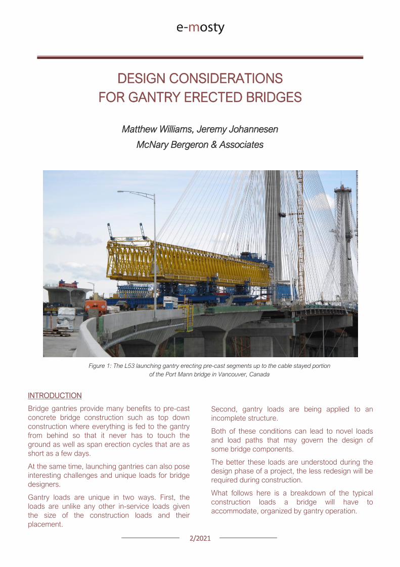
22021
GANTRY TYPES
The two most common types of launching gantries
are overhead and underslung gantries Overhead
gantries stand on top of the superstructure and the
leading pier
All launching takes place on top of the bridge and
pre-cast segments or girders are suspended
beneath the gantry
Underslung gantries are supported by brackets
mounted to the piers and support segments by the
wings on top of the gantry
Overhead gantries may be broken down further
into conventional and articulating gantries
Figure 2 Underslung gantry erecting the Susquehana River Bridge in Pennsylvania
Conventional gantries are generally comprised of
two ldquomain girdersrdquo that are parallel to one another
Articulating gantries have a main girder used to
hang segments from and a support beam that is
used for launching the gantry
The benefit of articulating gantries is their ability to
launch through tight radius curves
The L122 articulating gantry (designed by DEAL) is
shown in Figure 4 on the following page navigating
a 124m (407ft) radius horizontal curve on the
HART Light Rail project in Honolulu Hawaii
22021
Figure 3 Conventional Gantry Erecting Red Line North in Doha Qatar DEAL L107 Gantry
Figure 4 Articulating Gantry erecting the HART Light Rail in Honolulu Hawaii DEAL L122 Gantry
22021
GANTRY ERECTION
The first loads imparted by a launching gantry
occur during the assembly of the equipment
Launching gantries are typically erected with the
front support on the leading pier and the rear
support on either a previously erected span or on
falsework
The falsework tower shown here on the Seattle
Sound Transit project is tied to the rear pier to
ensure longitudinal stability of the tower and
gantry
Figure 5 A conventional lattice gantry with the rear support on falsework for the erection of the first span
DEAL L81 Gantry Seattle Sound Transit Seattle Washington
SEGMENTAL CONSTRUCTION SEGMENT
ERECTION
Once the gantry is assembled and ready to use the
construction can begin with the hanging of the
segments Segments are lifted via lifting holes in
the top slab
These can be either between the webs of a
segment or outside the webs in the wings
Lifting between the webs can induce top slab
tension at the center of the segment which can be
exacerbated by transverse post-tensioning in the
deck
22021
Figure 6 Segment lifting during the static winch load test where the winch is loaded to the weight of the heaviest
segment plus 25
The segment shown here has several spools of post-tensioning strand to increase the weight of the pick
DEAL L107 launching gantry Doha Qatar
Another troublesome spot can be the tops of the
webs
The secondary PT demand due to transverse post-
tensioning adds to the moment from lifting the
segment and can lead to cracking in the webs
Usually the cracks form on the inside face of the
web protected from the elements and can be self-
healing once under service loading
COMPLETING THE SPAN
After hanging all the segments in the first span a
load test will be performed
A typical load test involves overloading the gantry
to 10 above the weight of the heaviest span to
be erected by the gantry
Once the load test is complete the segments are
epoxied together and stressed with temporary
post-tensioning
Stressing the permanent post-tensioning presents
a challenge for controlling stresses in the
suspended span due to the continuous support of
the launching gantry
As the tendons are stressed the span immediately
begins to pick up in the middle This upward
movement allows the gantry to recover from the
deflection it underwent while hanging segments
A spangantry analysis is necessary to understand
how the stresses in the span change throughout
the stressing sequence
In this analysis a model is developed that includes
the span being erected the launching gantry and
the hanging bars used to suspend the segments
To control stresses during this process the gantry
can be incrementally lowered in order to shed the
span self-weight from the gantry into the bearings
22021
Figure 7 The L121 conventional launching gantry from DEAL completing a span on the HART Light Rail in Honolulu Hawaii
This increases compression in the top slab as the
span becomes self supporting
Another approach is to change the tendon
stressing order to better control top fiber tension
Some spans require both methods to be used
together
While it is not possible to avoid top fiber tension
completely given the continuous support provided
by the gantry during stressing it is possible to keep
them within a reasonable limit
LAUNCHING
With span construction complete the gantry is now
ready to launch itself to the next span
Different gantries launch in different ways
Conventional gantries typically have three
supports a front support rear support and an
auxiliary support that are maneuvered beneath the
girder for launching
Every effort is made to keep support placement
over the webs in segments adjacent to the pier
segments
However on tight radius horizontal curves it may
be necessary to place supports along the span to
allow the gantry to navigate the curve
Placing supports at midspan on a small radius
curved span can lead to span stability concerns as
the center of the loading could potentially be
outside the footprint of the bearings
This risk can be mitigated by providing optional tie-
downs to hold the span down at the piers
22021
Figure 8 The L100 conventional launching gantry completing a launch in Riyadh Saudi Arabia
Articulating gantries have a different method of
launching A front leg suspended from the support
beam is placed onto the leading pier and then the
rear support rolls along the superstructure
When the rear support has reached the end of the
span the front support and support girders are
launched forward
The wheels of the rear support are meant to ride
directly over the webs however it is possible to
get off-course and start loading the wings or
haunch of a pre-cast segment
Any offset from the center of the web induces a
moment in the top of the web as well and may be
compounded by the presence of transverse post-
tensioning
A steering tolerance should be checked with a
transverse analysis of the segments
Much of the loading from a launching gantry goes
into the previously erected superstructure
However the front support of a launching gantry
typically sits on the up-station side of the leading
pier during span erection
Large moments can develop in the pier as a result
of the following factors
1 Front supports are placed ahead of the
pier centerline to ensure that therersquos room
to set the span being erected
2 The slope of gantry as it follows the bridge
slope imparts a longitudinal load on the
leading pier at the top of the front support
several meters above the top of the pier
3 The slope load is increased by the gantry
deflection under the weight of suspended
segments This can be as much as 2
4 Friction in the front support roller group
can add another 1 of the vertical load
acting longitudinally
22021
Figure 9 Gantry front support showing forward offset from pier centerline and the roller group supporting the main girders
DEAL L57 Gantry Tysonrsquos Corner Virginia
Thus if the gantry is erecting ldquoup-hillrdquo the slope of
the bridge deflection of the gantry and friction in
the roller group are all additive
Conventional gantries have rollers on the front
support to avoid being statically indeterminate
Longitudinal fixity is at the rear support
As such all of the moment inducing forces listed
above must be resisted by the flexural capacity of
the leading pier alone
These loads can be significant and can potentially
govern the design of taller piers
Another concern with the longitudinal loads is the
deflection of the pier itself This can lead to locked-
in deflection if the span is set directly on
permanent bearings that arenrsquot free to slide
longitudinally (elastomeric bearings for example)
NON-TYPICAL SPANS
Erecting typical length spans with gentle horizontal
curves produces predictable construction loads
Where launching gets tricky and therefore applies
loads on the permanent structure is where span
lengths vary widely from one span to the next
Often gantries will have to set their supports at
several locations along the length of the span to
get set up for either a short or long launch
Another launching concern is walkovers This is
where a gantry erects up to another span that has
been erected with another method or at another
time and launches over the completed span to
arrive at the next span to begin erecting again
Typically this occurs where bridges have spans
that exceed the design length for the gantry and
have been previously erected by other means
During walkovers supports will often be placed on
typical segments away from the pier segments in
order to make the launch
Any time supports are placed on typical segments
and not pier segments the span should be
designed to take the flexural shear and principal
tension demands of the launch
22021
Figure 10 The L120 launching gantry (by DEAL) lifts the pre-cast concrete segments of the first span
WIND LOADS
A common concern among bridge owners and
designers is with regards to the applicable wind
loads that a gantry and bridge should be designed
for Bridge design codes require specific wind
speeds and pressures to be considered while
launching gantries are typically designed to
overhead crane design codes that have a different
set of requirements
The launching gantry should be designed for the
wind loads specified by the applicable crane codes
while the bridge should consider the gantry as an
appurtenance affixed to the permanent structure
and use the applicable bridge wind loads in the
design of the bridge
On the Harbor Bridge project in Corpus Christi
Texas there is the potential for large wind loads
given that the bridge is located on the Gulf of
Mexico and the piers are upwards 45m tall
The L120 launching gantry (designed by DEAL) is
160m long and 3m tall giving it a large projected
wind area
The two major concerns that arise are the lateral
loads on the pier columns and the stability of the
span when the gantry is tied down for wind events
To accommodate the large out of service
(hurricane) wind loading the designers opted to
design specific locations along the bridge for
hurricane winds on the structure and gantry
together
The piers and superstructure have increased
capacity to accommodate the gantry should it
need to be tied down a wind event
This was a more economical solution than
designing every pier for the out of service winds
In the event of an approaching hurricane the
gantry does not have far to back launch to get to a
safe place to tie-down
CONCLUSION
In conclusion launching gantries apply unique
loads on both the super and substructures of
bridges
Wind and longitudinal loads on the piers can
sometimes govern the design and stability checks
of the bridge Considering these loads during the
design phase of a bridge project can eliminate
costly redesigns later
22021
GEOMETRY CONTROL FOR PRECAST
SEGMENTAL CONSTRUCTION
Joakim Dupleix CaSE International (formerly VSL)
Martin Pircher ABES
Figure 1 Closing of Mesaimeer Bridge main stay cable span Qatar
PRECAST SEGMENTAL CONSTRUCTION
Precast segmental construction is a great method
to limit the impact of the works on a bridge
construction site
By fabricating the concrete elements in a
controlled environment many of the unpleasant
by-products of the construction site are also
exported
However a key challenge of constructing elements
remotely is to ensure they will achieve the required
bridge geometry once erected on site
Furthermore the fact that the bridge is built ldquopiece-
by-piecerdquo in segments means that the geometry
needs to be controlled and forecasted at every
stage during construction anticipating and
forecasting movements and deflections during the
temporary stages of the construction process
Often bridges have varying curvature and
superelevation which require tools to capture the
geometry in all dimensions
These tools must allow efficient and accurate ways
to correct geometry imperfections such as
correction in setting out in the precast yard or
shimming of segment joints during balanced
cantilever erection on site
22021
ABES SOFTWARE SOLUTION
ABES Pircher amp Partner GmbH is an independent
software house providing solutions for bridge
engineering topics
Together with VSL they have developed a
software suite dedicated to managing the
geometry control of segmental construction at
every stage of the construction process
The software is split in 3 components which are all
interrelated
geoDes to be used in the design office to
model the intended theoretical geometry of
the bridge
geoCon to be used in the casting yard
providing setting out and casting error
compensation for any yard setup
assemCon to be used on site to forecast
the as-built geometry during balanced
cantilever construction based on real time
survey results
Figure 2 Balanced cantilever construction
The software works fully in 3D with a visual
interface which means it can control geometry in
all directions not only vertically
Figure 3 Snapshot of 3D model within ABES geoDes
22021
The Figure below illustrates an example of a cross-
section modeled in geoDes
Figure 4 Cross section (inner void omitted)
KEY PRINCIPLES
The geometry control principles used by ABES are
as follows
The theoretical modelling of the bridge
defines a casting curve in 3D which is the
ldquoperfectrdquo geometry of the bridge This
includes the camber of the bridge if defined
by the designer
Each segment is recorded in its entire
three-dimensional shape and identified by a
minimum of 4 control points which are
physical survey items to be cast anywhere
on the segment
Segment shapes are prepared considering
the specific requirements of the casting
machines used in the yard
The position of control points in the wet
concrete which may vary due to placing
error defines the setting out curve
When segments are cast movement of the
formwork the bulkhead or the conjugate
segment may induce deviations from the
theoretical shape this defines the ldquoas castrdquo
curve
Segment imperfections are compensated
for during casting of sub-sequent
segments This is true for both short-line
and long-line casting or the combination
thereof
During balanced cantilever erection each
construction stage must be monitored and
compared to the deflected position of the
entire bridge as defined by the designer
Again geometric deviations need to be
corrected for during sub-sequent
construction stages
Figure 5 3D interface showing theoretical
(red) and as cast segments (green)
MAIN ADVANTAGES
Modelling
By modelling the bridge from base alignments and
with geometric rules derived from the specific
capabilities of the casting cells the software
achieves the best constructable theoretical fit
Multiple alignments can be accommodated
including deviation from the main alignment such
as for ramps or train stations as required Refer to
Figure 3 above
In the precast yard
When using geoCon the software automatically
compensates for the user the required setting out
according to the survey data of the previous
segment
This is key to ensure seamless casting operation
and minimize operator error Besides benefitting
from the 3D modelling it always works in all three
dimensions
22021
There is no limit to the number of control points
per segment ensuring high accuracy
Another key feature for a stay cable bridge pipes
must be cast in advance into the segment in the
yard to achieve the final geometry after all
deformations have occurred
The software can transform the theoretical pipe
coordinates adjust them for cambers and
segment imperfections and display them in the
local coordinate system which can be processed
by the surveyor in the yard
Figure 6 Gewan Island bridge 3D modelling
with plan radius of less than 125m
Figure 8 Precasting of segments with cable stay pipes
On site for balanced cantilever erection
On site assemCon gives two key insights to the
user
Forecast the position of the bridge at any
construction stage in 3D considering the
as-built data the as-cast curve and the
calculated deflections for each
construction stage
Assist in finding an optimal shimming
strategy to correct the forecasted position
and to target a final as-built structure as
close as possible to the theoretical
geometry
Figure 7 3D view of a cantilever being built
22021
Figure 9 Definition of shimming
strategy to reduce differences
CONCLUSIONS
Pre-cast segmental bridge construction is applied
to increasingly complex and geometrically
challenging structures
Efficient geometry control is essential for the
success of such projects
Geometry control already starts during the
planning process where individual segments need
to be laid out to suit the available equipment in the
casting yard
Segment casting needs to be tightly controlled and
monitored and geometric imperfections need to
be identified and compensated for
And finally bridge construction at the construction
site requires monitoring of individual construction
stages and optimised strategies for correcting for
possible geometry deviations of the bridge
structure during construction
VSL in cooperation with ABES have developed a
suite of software tools to assist in all these tasks
The software is heavily influenced by practical
experience during numerous pre-cast segmental
projects of all sizes and shapes across Asia and
principally Qatar and India and feedback from
ongoing projects continues to inform the
development work
Figure 12 Al Bustan North bridge during construction
above traffic Qatar
Figure 11 Gewan Island Bridge being built Qatar
Figure 10 Karimnagar cable stay bridge India
Photos Credit VSL
22021
PRECAST SEGMENTAL BRIDGE CONSTRUCTION
USING LIFTING FRAME IN QATAR
Joakim Dupleix CaSE International (formerly VSL)
German A Pardo R VSL International Ltd
Figure 1 Overview of Al Bustan North construction site
PRECAST SEGMENTAL CONSTRUCTION
One of the most advantageous construction
methods enabled by segmental construction is the
balanced cantilever method
In a busy brownfield environment pre-casting the
segments off-site is the best solution to minimize
disrupting the existing traffic flow
In these environments access is often limited and
restricted and cranage may not be able to reach
the whole site
In these conditions lifting frame equipment are
often the solution to enable the erection of
segments on the bridge
In Qatar VSL designed and operated two very
different types of lifting frames as part of the Al
Bustan corridor upgrade project
The lifting frames responded to different needs and
segment delivery methods carefully studied during
the construction planning phase of the project
SABAH AL AHMAD CORRIDOR
(previously called Al Bustan)
Sabah al Ahmad or Al Bustan Corridor is part of
the Qatar Expressway Programme and aims to
provide an alternative to the existing expressway
with free flow traffic on a length of 14 km from the
North of Central Doha to the South to improve
connectivity to the FIFA World Cup stadiums
22021
The project involved upgrading the existing main
road by constructing various overhead bridges
over existing crossroads as well as connecting
ramps to remove traffic lights
The construction of this corridor was split into three
main packages
Al Bustan North project now known as
Umm Lekhba Interchange
Al Bustan South project
Mesaimeer Road project
Al Bustan North consists of the major upgrade of a
major interchange with Qatar main highway Al
Shamal Road to become a 4 level interchange
Al Bustan South required the construction of large
overhead bridges up to 26 km long with overhead
ramps connecting to crossroads
Mesaimeer Road upgraded the existing road with 2
large bridges up to 12 km long with a cable stay
section
PRECAST SEGMENTAL BALANCED
CANTILEVER METHOD
Because of the existing brownfield environment in
which the bridges are being built and to minimize
the impact on the existing traffic the precast
segment balanced cantilever method was chosen
for design and construction
It avoids installing large falsework structures on
site where space is limited and enables quick
fabrication of the bridge but requires relatively
large lifting equipment
As a matter of fact as the heavy concrete bridge
segments are to be transported and erected into
position with limited space the key is to
Figure 2 Key map of the corridor in Doha
22021
understand which areas are available where
possible if lifting equipment such as cranes can be
positioned and how to deliver the segments to
their final position
For very heavy segments or if cranes cannot be
used due to site constraints it may be required to
design custom made lifting frame machines
placed on top of the bridge already built and fitted
with their own lifting device to erect the segments
in their final position
These machines typically have a limited range and
segments must be first transported precisely near
their final position
On the Al Bustan Corridor two different delivery
situations were identified
For Al Bustan South and Mesaimeer the
large weight of the segments made it
prohibitively costly to use a crane
However assisted by a temporary
diversion of the existing road during
construction and the flat terrain every
segment could always be delivered directly
below their final position
For Al Bustan North the multi-level
interchange the existing highway Al
Shamal Road could only be closed to traffic
for a very limited time and the existing road
environment did not allow for flexible
segment delivery below each new bridge
ramp
A crane could be positioned near the piers
which allowed for segments to be lifted
onto the already erected deck
To position the segment into its final
position a special lifting frame was
designed to pick up the segment ldquofrom
behindrdquo and bring them forward into their
final position
LIFTING FRAME WITH DELIVERY FROM
BEHIND
As mentioned previously a lifting frame (LF) able
to pick up a segment from behind was required for
this project
A few options for the trajectory of the segment
were considered
Symmetrical Lifting Frame segment
crossing the lifting frame is rotated at 90
degrees in plan lifted and moved through
the middle of the machine longitudinally
Once at the front it can be rotated 90
degrees and lowered in position
Asymmetrical Lifting Frame segment is
delivered 180 degrees from its final
orientation
The segment is picked up rotated 90
degrees moved through the LF
longitudinally rotated again and then
lowered in position
Figure 3 Al Bustan North lifting frame
For this project the bridges are quite narrow with a
web spacing of 6 and 4 m and therefore passing a
32 m long segment between two legs of the LF
was not possible
As shown in Figure 4 on the next page a C shape
was adopted to allow the segment to be rotated on
the free side and moved forward
22021
Figure 4 Segment delivery methodology Click on the image to open it in full size
Description of Lifting Frame
The lifting Frame had the following key
specifications
1 Self-weight of 70 tonnes
2 Lifting capacity of 80 tonnes
3 Lifting speed of 12 mh [02 mmin]
4 Longitudinal launching speed of 3 mh
[005 mmin]
The lifting frame is made of a few key
components
Upper Cross Beam (UCB) transverse
beam carrying the strand lifting unit as
well as the stressing platform lifting
mast Adjustment capability of +-
200 mm
Main Beams (MB) Longitudinal beams
supporting the UCB The UCB is
moved on wheels with a bogie
connected to 2 chain pulling units
Figure 5 3D view of lifting frame model
22021
Support Frame (SF) asymmetric frame in a
C shape supporting the MB The frame is
supported on the deck by adjustable screw
jacks located over the webs
Tie down beams (TDB) during erection
the SF is tie down to the deck with 4 no
40 mm diameter stressbars anchored in
TDB The TDB allows for longitudinal
adjustment in the position of the bars as
the segment length varies
Rail beams (RB) two rail beams on each
side of the SF are fitted with a hydraulic
launching system able to move the entire
frame forward in steps of 700 mm
Segment lifting beam (SLB) the SLB is
stressed to the segment being lifted and is
fitted with hydraulic jacks able to adjust the
segment to the required crossfall and
gradient as well as rotated the segment in
plan to pass through the SF
Stressing platform (SP) to complete the
balance cantilever construction a SP is
required to be positioned each newly
erected segment to provide access for
personnel to complete the permanent post-
tensioning operation
Figure 6 Segment delivered at the rear of the LF
Figure 8 Segment rotated to its final orientation
rarr Figure 9 Segment lowered into
position and load transferred
Figure 7 Segment rotated and moved longitudinally
SEGMENT ERECTION PHOTOS
The photo sequence below shows the segment
delivery process
22021
Challenges
Because of the limited width of the deck and the
congested site area with existing roads one of the
key challenges was to find a suitable storage
position for the SP when not in use which would
not block the segment passage
A rotation mast or davit arm was designed to lift
and position the 6 tonnes platform The mast was
rotated up to 120 degrees with a small horizontal
hydraulic jack
The concept and design itself of the Lifting Frame
required a solution which provided the minimum
required space for manipulating the segment and
the stressing platform in a very tight area while
having enough stiffness and capacity to cover the
demands
LIFTING FRAME WITH DELIVERY FROM
BELOW
Typical configuration for a Lifting Frame is such
that segment can be lifted directly from below
This was the case of Al Bustan South and
Mesaimeer projects
MESAIMEER LIFTING FRAME
Segments to be lifted by this lifting frame were the
heaviest and widest on the project for this reason
a stiffer structure composed of rigid frames at the
supporting areas was chosen taking advantage of
the fact that there was no restriction in height and
section of the bridge
The delivery of the segments in this project could
be conducted almost at is final position in plan
which facilitated the configuration of the lifting
equipment at the cantilever of the lifting frame
For this purpose the lifting frame was provided
with a couple of Winches that could pick up the
segment from the ground with minimum rotation in
plan lifted to required level and conduct final
adjustment in the longitudinal and transverse
directions
Description of Lifting Frame
The Lifting Frame had the following key
specifications
1 Self-weight of 92 tonnes
2 Lifting capacity of 185 tonnes
3 Lifting speed of 60 mh [1 mmin]
4 Longitudinal launching speed of 3mh [005
mmin)
Figure 10 segment delivered at the rear of the LF
The lifting frame is made of a few key components
Upper Cross Beam (UCB) transverse
beam carrying the main lifting equipment
(Winch) as well as the stressing platform
Adjustment capability +- 1325
Cantilever Beam (CTB) the 2 main
longitudinal beams supporting the UCB and
Stressing Platform at front and the Tie
Down Beam at the rear
Lower Cross Beam (LCB) main Frames
underneath the CTB transferring all load to
the bridge
Rail Beams (RB) two rail beams on each
side of the LCB are fitted with a hydraulic
launching system able to move the entire
frame forward in steps of 850 mm
22021
Connection Beams (CB) beams
connecting the hook blocks of the Winches
directly to the segment They are provided
with jacks for segment gradient adjustment
Crossfall is adjusted directly by the
Winches
Stressing Platform (SP) it is positioned at
the tip of the CTB and move backward for
conducting stressing of bridge post-
tensioning tendons It is provided with 2
levels customized for this project
Tie Down Beam (TDB) the Support frame
is provided with a set of tie down beams at
the rear which are the main stability
system
TDB can be adjusted in the longitudinal
direction to suit the different segment
lengths and their respective tie down holes
position
Tie down bars are of 75mm and 47mm in
diameter and pre-stressed against the
segment
Challenges
To accommodate the supporting area in a
very limited length since there was
insufficient space near the pylons
This created big reactions to be taken by
the tie down elements due the big
cantilever at front and heavy segments to
be lifted
To be able to move all the way back the
lifting equipment (Winch) and UCB to
provide enough stability during the
launching procedure Space at rear of the
lifting frame was very limited
Provide a Stressing Platform with 2
different configurations (1 or 2 levels) that
could be adapted for specific
configurations
SEGMENT ERECTION PHOTOS
Figure 11 Mesaimeer Lifting Frame
Figure 12 Segment lifting
Figure 13 Segment permanent post-tensioning in progress
22021
AL BUSTAN SOUTH LIFTING FRAME
For this project the lifting frame had to
accommodate few main requirements to suit the
space constraints of the project and the bridge
capacity
Height A limit of 6m for total height the lifting
frame was to be assured since the bridge had
to pass under an existing viaduct
Load introduction The bridge section is
provided with 3 webs and middle web capacity
was to be respected by limiting the reactions at
this point Additionally the total weight of the
Lifting Frame was also limited
Segment delivered below could not be
positioned in its final orientation due to space
constraints It had to be rotated up to 90deg once
hanging from the lifting frame
To overcome the limitations described the lifting
frame concept developed considered the following
aspects
Main lifting equipment (Winch) was
positioned at the bottom rear area of the
lifting frame to reduce the total height
The three webs of the segment were
loaded and the Lifting Frame elements
were studied in such a way that the total
weight of the Lifting Frame and loading of
central web were not exceeded
A single Winch and the hook block with
rotation device were provided to allow
rotation of the segment while hanging from
the Lifting Frame
Description of Lifting Frame
The Lifting Frame had the following key
specifications
1 Self-weight of 81 tonnes
2 Lifting capacity of 170 tonnes
3 Lifting speed of 36 mh [06 mmin]
4 Longitudinal launching speed of 3mh [005
mmin
The lifting frame is made of the following key
components
Upper Cross Beam (UCB) uppermost
element carrying the Winch Trolley It can
slide longitudinally to accommodate the
segment in length Transverse adjustment
is done by sliding of the Winch Trolley over
the UCB
Main Frame (MF) the Lifting Frame is
provided with 2 Main Frames in section that
support the UCB and Stressing Platform on
top and transfers the vertical load to the
lower elements of the Lifting Frame At
bottom level it also receives the Tie Down
Beam
Lower Cross Beam (LCB) spreader beam
in the transverse direction located at front
and rear that transfer all loads to the
segment webs through 6 screw jacks (3 at
the front and 3 at the rear)
Tie Down Beam (TDB) located at rear part
of the Lifting Frame and contain the tie
down bars stressed down against the
segment in order to assure the stability of
the Lifting Frame It contains a couple of
back-up bars that provide redundancy to
the system
Segment Lifting Beam (SLB) connecting
element between the hook block of the
winch and the segment It is provided with
a rotational device that allows full rotation
of the segment in plan
Figure 14 Segment delivered at the rear of the LF
22021
Stressing Platform (SP) it hangs from the
tip of the Main Frame cantilever beam It is
moved backwards after segment
installation to conduct the stressing of the
permanent post-tensioning system
Rail Beam (RB) two rail beams on each
side of the LCB are fitted with a hydraulic
launching system able it to move the entire
frame forward in steps of 850 mm
Figure 14 Lifting Frame installation on deck
Figure 15 Lifting of segment
Figure 16 Stressing of post-tensioning tendons
Figure 17 Lifting Frame crossing under existing viaduct
SEGMENT ERECTION PHOTOS
Challenges
To develop a concept and design that did
not exceed the limitations given regarding
total weight and height
Allow full rotation of the segment while
hanging
Provide redundancy to the Lifting Frame
Tie Down system and to the Stressing
Platform while under operation
22021
CONCLUSIONS
Precast segmental construction in a congested
environment often requires the use of custom
designed lifting frames
These machines must always consider the
segment delivery methods as well as the bridge
characteristics in order to achieve the most cost-
efficient methods of erection
The more requirements a project has the more
customized the Lifting Frame will be
For this reason it is of key importance to integrate
the development of the Temporary Structures (like
Lifting Frames) as early as possible in the design
process
By doing this some of the constraints can be
solved in earlier stages which will improve the
efficiency of the full process and the interfaces
between the different parts involved Permanent
Works Designer Temporary Works Designer and
Main Contractor
Figure 18 Al Bustan North Figure 19 Al Bustan North
Figure 20 Al Bustan South
Figure 21 Mesaimeer
Photos 18 ndash 20 Credit Ashghal (Qatar Road Authority)
We design and produceformwork equipmentfor in-place casting of bridgesN25 New Ross Bypass (Ireland)
FOLLOW US
INNOVATIVE | SAFE | SUSTAINABLE | FAST
SOLUTIONS FOR BRIDGE CONSTRUCTION
MSS M1-70-S BRATISLAVA BYPASS | IN SITU CONSTRUCTION
LG 36-S CAIRO METRO LINE 3 EXTENSION | PRECAST SEGMENTAL
WWWBERDEU
Photo Credits D4R7
Photo Credits Stephane Ciccolini
Arup works in active partnership with clients to understand their needs so
that the solutions make their bridge aspirations possible mdashbig and small
The Arup global specialist technical skills blended with essential local
knowledge adds unexpected benefits
wwwarupcom
Whether to span nations make a statement or
improve everyday links Arup crafts better bridges
Naeem Hussain Richard Hornby Steve Kite Deepak Jayaram
naeemhussainarupcom richardhornbyarupcom stevekitearupcom deepakjayaramarupcom
Global UK Middle East amp Africa East Asia UK Middle East India
and Africa
Peter Burnton Marcos Sanchez Matt Carter
peterburntonarupcom marcossanchezarupcom mattcarterarupcom
Australasia Europe Americas
Queensferry Crossing Scotland
SANTANDERMADRIDLIMABOGOTAacuteBUENOS AIRES
Calle Marqueacutes de la Ensenada 11 - 3ordm 39009
Calle Bravo Murillo 101 - 4ordm 28020
Calle Coronel Inclaacuten 235 - Oficina 313 Lima 18
Cra 14 94a - 24 Oficina 307 Edificio ACO 94
Calle Rodriacuteguez Pentildea 681 - 4ordm Dpto 8 1020
Tfno +34 942 31 99 60
Tfno +34 91 702 54 78
Tfno +51 1 637 56 47
Tfno +57 1 467 48 10
Tfno +54 911 5709 3252
wwwarenasingcom
ARCHING THE WORLD
CODE-BASED DESIGN
DETAILINGDR AWING PRODUCTION
PAR AM ETRIC MODELING
STRUCTUR AL ANALYSIS
DOWNLOAD A FREE TRIALallplancombridge2021
THE WORLDrsquoS FIRST COMPLETE SOLUTIONFOR BRIDGE ENGINEERS
Allplan Bridge 2021 maps the complete BIM process in bridge projects The new version enables bridge engineers to work with one single solution from the creation of a parametric 4D model to structural analysis reinforcement design and detailing This further improves the design process in terms of both time and quality
ALLPLAN BRIDGE
Join Bridges to Prosperity in helping isolated
communities gain safe access to healthcare
education jobs and markets through simple
sustainable trailbridges Together we can
build more than a bridge we can build a
pathway out of poverty
We envision a world wherepoverty caused by ruralisolation no longer exists
bridgestoprosperityorg
infobridgestoprosperityorgbridgestoprosperity
bridgestoprosperity
b2p
+60Women Entering the Labor Force
+75Farmer
Profitability
+358Labor Market
Income
Corporate Partners make this
vision possible
Wyatt Brooks and Kevin Donovan - Eliminating Uncertainty in Market Access
The Impact of New Bridges in Rural Nicaragua 2017
SEGMENTAL BRIDGES
ISSUE 022021 JUNE
- 1 arenas_v2
-
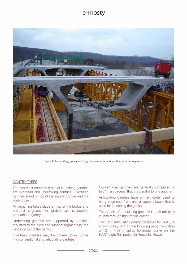
22021
Figure 3 Conventional Gantry Erecting Red Line North in Doha Qatar DEAL L107 Gantry
Figure 4 Articulating Gantry erecting the HART Light Rail in Honolulu Hawaii DEAL L122 Gantry
22021
GANTRY ERECTION
The first loads imparted by a launching gantry
occur during the assembly of the equipment
Launching gantries are typically erected with the
front support on the leading pier and the rear
support on either a previously erected span or on
falsework
The falsework tower shown here on the Seattle
Sound Transit project is tied to the rear pier to
ensure longitudinal stability of the tower and
gantry
Figure 5 A conventional lattice gantry with the rear support on falsework for the erection of the first span
DEAL L81 Gantry Seattle Sound Transit Seattle Washington
SEGMENTAL CONSTRUCTION SEGMENT
ERECTION
Once the gantry is assembled and ready to use the
construction can begin with the hanging of the
segments Segments are lifted via lifting holes in
the top slab
These can be either between the webs of a
segment or outside the webs in the wings
Lifting between the webs can induce top slab
tension at the center of the segment which can be
exacerbated by transverse post-tensioning in the
deck
22021
Figure 6 Segment lifting during the static winch load test where the winch is loaded to the weight of the heaviest
segment plus 25
The segment shown here has several spools of post-tensioning strand to increase the weight of the pick
DEAL L107 launching gantry Doha Qatar
Another troublesome spot can be the tops of the
webs
The secondary PT demand due to transverse post-
tensioning adds to the moment from lifting the
segment and can lead to cracking in the webs
Usually the cracks form on the inside face of the
web protected from the elements and can be self-
healing once under service loading
COMPLETING THE SPAN
After hanging all the segments in the first span a
load test will be performed
A typical load test involves overloading the gantry
to 10 above the weight of the heaviest span to
be erected by the gantry
Once the load test is complete the segments are
epoxied together and stressed with temporary
post-tensioning
Stressing the permanent post-tensioning presents
a challenge for controlling stresses in the
suspended span due to the continuous support of
the launching gantry
As the tendons are stressed the span immediately
begins to pick up in the middle This upward
movement allows the gantry to recover from the
deflection it underwent while hanging segments
A spangantry analysis is necessary to understand
how the stresses in the span change throughout
the stressing sequence
In this analysis a model is developed that includes
the span being erected the launching gantry and
the hanging bars used to suspend the segments
To control stresses during this process the gantry
can be incrementally lowered in order to shed the
span self-weight from the gantry into the bearings
22021
Figure 7 The L121 conventional launching gantry from DEAL completing a span on the HART Light Rail in Honolulu Hawaii
This increases compression in the top slab as the
span becomes self supporting
Another approach is to change the tendon
stressing order to better control top fiber tension
Some spans require both methods to be used
together
While it is not possible to avoid top fiber tension
completely given the continuous support provided
by the gantry during stressing it is possible to keep
them within a reasonable limit
LAUNCHING
With span construction complete the gantry is now
ready to launch itself to the next span
Different gantries launch in different ways
Conventional gantries typically have three
supports a front support rear support and an
auxiliary support that are maneuvered beneath the
girder for launching
Every effort is made to keep support placement
over the webs in segments adjacent to the pier
segments
However on tight radius horizontal curves it may
be necessary to place supports along the span to
allow the gantry to navigate the curve
Placing supports at midspan on a small radius
curved span can lead to span stability concerns as
the center of the loading could potentially be
outside the footprint of the bearings
This risk can be mitigated by providing optional tie-
downs to hold the span down at the piers
22021
Figure 8 The L100 conventional launching gantry completing a launch in Riyadh Saudi Arabia
Articulating gantries have a different method of
launching A front leg suspended from the support
beam is placed onto the leading pier and then the
rear support rolls along the superstructure
When the rear support has reached the end of the
span the front support and support girders are
launched forward
The wheels of the rear support are meant to ride
directly over the webs however it is possible to
get off-course and start loading the wings or
haunch of a pre-cast segment
Any offset from the center of the web induces a
moment in the top of the web as well and may be
compounded by the presence of transverse post-
tensioning
A steering tolerance should be checked with a
transverse analysis of the segments
Much of the loading from a launching gantry goes
into the previously erected superstructure
However the front support of a launching gantry
typically sits on the up-station side of the leading
pier during span erection
Large moments can develop in the pier as a result
of the following factors
1 Front supports are placed ahead of the
pier centerline to ensure that therersquos room
to set the span being erected
2 The slope of gantry as it follows the bridge
slope imparts a longitudinal load on the
leading pier at the top of the front support
several meters above the top of the pier
3 The slope load is increased by the gantry
deflection under the weight of suspended
segments This can be as much as 2
4 Friction in the front support roller group
can add another 1 of the vertical load
acting longitudinally
22021
Figure 9 Gantry front support showing forward offset from pier centerline and the roller group supporting the main girders
DEAL L57 Gantry Tysonrsquos Corner Virginia
Thus if the gantry is erecting ldquoup-hillrdquo the slope of
the bridge deflection of the gantry and friction in
the roller group are all additive
Conventional gantries have rollers on the front
support to avoid being statically indeterminate
Longitudinal fixity is at the rear support
As such all of the moment inducing forces listed
above must be resisted by the flexural capacity of
the leading pier alone
These loads can be significant and can potentially
govern the design of taller piers
Another concern with the longitudinal loads is the
deflection of the pier itself This can lead to locked-
in deflection if the span is set directly on
permanent bearings that arenrsquot free to slide
longitudinally (elastomeric bearings for example)
NON-TYPICAL SPANS
Erecting typical length spans with gentle horizontal
curves produces predictable construction loads
Where launching gets tricky and therefore applies
loads on the permanent structure is where span
lengths vary widely from one span to the next
Often gantries will have to set their supports at
several locations along the length of the span to
get set up for either a short or long launch
Another launching concern is walkovers This is
where a gantry erects up to another span that has
been erected with another method or at another
time and launches over the completed span to
arrive at the next span to begin erecting again
Typically this occurs where bridges have spans
that exceed the design length for the gantry and
have been previously erected by other means
During walkovers supports will often be placed on
typical segments away from the pier segments in
order to make the launch
Any time supports are placed on typical segments
and not pier segments the span should be
designed to take the flexural shear and principal
tension demands of the launch
22021
Figure 10 The L120 launching gantry (by DEAL) lifts the pre-cast concrete segments of the first span
WIND LOADS
A common concern among bridge owners and
designers is with regards to the applicable wind
loads that a gantry and bridge should be designed
for Bridge design codes require specific wind
speeds and pressures to be considered while
launching gantries are typically designed to
overhead crane design codes that have a different
set of requirements
The launching gantry should be designed for the
wind loads specified by the applicable crane codes
while the bridge should consider the gantry as an
appurtenance affixed to the permanent structure
and use the applicable bridge wind loads in the
design of the bridge
On the Harbor Bridge project in Corpus Christi
Texas there is the potential for large wind loads
given that the bridge is located on the Gulf of
Mexico and the piers are upwards 45m tall
The L120 launching gantry (designed by DEAL) is
160m long and 3m tall giving it a large projected
wind area
The two major concerns that arise are the lateral
loads on the pier columns and the stability of the
span when the gantry is tied down for wind events
To accommodate the large out of service
(hurricane) wind loading the designers opted to
design specific locations along the bridge for
hurricane winds on the structure and gantry
together
The piers and superstructure have increased
capacity to accommodate the gantry should it
need to be tied down a wind event
This was a more economical solution than
designing every pier for the out of service winds
In the event of an approaching hurricane the
gantry does not have far to back launch to get to a
safe place to tie-down
CONCLUSION
In conclusion launching gantries apply unique
loads on both the super and substructures of
bridges
Wind and longitudinal loads on the piers can
sometimes govern the design and stability checks
of the bridge Considering these loads during the
design phase of a bridge project can eliminate
costly redesigns later
22021
GEOMETRY CONTROL FOR PRECAST
SEGMENTAL CONSTRUCTION
Joakim Dupleix CaSE International (formerly VSL)
Martin Pircher ABES
Figure 1 Closing of Mesaimeer Bridge main stay cable span Qatar
PRECAST SEGMENTAL CONSTRUCTION
Precast segmental construction is a great method
to limit the impact of the works on a bridge
construction site
By fabricating the concrete elements in a
controlled environment many of the unpleasant
by-products of the construction site are also
exported
However a key challenge of constructing elements
remotely is to ensure they will achieve the required
bridge geometry once erected on site
Furthermore the fact that the bridge is built ldquopiece-
by-piecerdquo in segments means that the geometry
needs to be controlled and forecasted at every
stage during construction anticipating and
forecasting movements and deflections during the
temporary stages of the construction process
Often bridges have varying curvature and
superelevation which require tools to capture the
geometry in all dimensions
These tools must allow efficient and accurate ways
to correct geometry imperfections such as
correction in setting out in the precast yard or
shimming of segment joints during balanced
cantilever erection on site
22021
ABES SOFTWARE SOLUTION
ABES Pircher amp Partner GmbH is an independent
software house providing solutions for bridge
engineering topics
Together with VSL they have developed a
software suite dedicated to managing the
geometry control of segmental construction at
every stage of the construction process
The software is split in 3 components which are all
interrelated
geoDes to be used in the design office to
model the intended theoretical geometry of
the bridge
geoCon to be used in the casting yard
providing setting out and casting error
compensation for any yard setup
assemCon to be used on site to forecast
the as-built geometry during balanced
cantilever construction based on real time
survey results
Figure 2 Balanced cantilever construction
The software works fully in 3D with a visual
interface which means it can control geometry in
all directions not only vertically
Figure 3 Snapshot of 3D model within ABES geoDes
22021
The Figure below illustrates an example of a cross-
section modeled in geoDes
Figure 4 Cross section (inner void omitted)
KEY PRINCIPLES
The geometry control principles used by ABES are
as follows
The theoretical modelling of the bridge
defines a casting curve in 3D which is the
ldquoperfectrdquo geometry of the bridge This
includes the camber of the bridge if defined
by the designer
Each segment is recorded in its entire
three-dimensional shape and identified by a
minimum of 4 control points which are
physical survey items to be cast anywhere
on the segment
Segment shapes are prepared considering
the specific requirements of the casting
machines used in the yard
The position of control points in the wet
concrete which may vary due to placing
error defines the setting out curve
When segments are cast movement of the
formwork the bulkhead or the conjugate
segment may induce deviations from the
theoretical shape this defines the ldquoas castrdquo
curve
Segment imperfections are compensated
for during casting of sub-sequent
segments This is true for both short-line
and long-line casting or the combination
thereof
During balanced cantilever erection each
construction stage must be monitored and
compared to the deflected position of the
entire bridge as defined by the designer
Again geometric deviations need to be
corrected for during sub-sequent
construction stages
Figure 5 3D interface showing theoretical
(red) and as cast segments (green)
MAIN ADVANTAGES
Modelling
By modelling the bridge from base alignments and
with geometric rules derived from the specific
capabilities of the casting cells the software
achieves the best constructable theoretical fit
Multiple alignments can be accommodated
including deviation from the main alignment such
as for ramps or train stations as required Refer to
Figure 3 above
In the precast yard
When using geoCon the software automatically
compensates for the user the required setting out
according to the survey data of the previous
segment
This is key to ensure seamless casting operation
and minimize operator error Besides benefitting
from the 3D modelling it always works in all three
dimensions
22021
There is no limit to the number of control points
per segment ensuring high accuracy
Another key feature for a stay cable bridge pipes
must be cast in advance into the segment in the
yard to achieve the final geometry after all
deformations have occurred
The software can transform the theoretical pipe
coordinates adjust them for cambers and
segment imperfections and display them in the
local coordinate system which can be processed
by the surveyor in the yard
Figure 6 Gewan Island bridge 3D modelling
with plan radius of less than 125m
Figure 8 Precasting of segments with cable stay pipes
On site for balanced cantilever erection
On site assemCon gives two key insights to the
user
Forecast the position of the bridge at any
construction stage in 3D considering the
as-built data the as-cast curve and the
calculated deflections for each
construction stage
Assist in finding an optimal shimming
strategy to correct the forecasted position
and to target a final as-built structure as
close as possible to the theoretical
geometry
Figure 7 3D view of a cantilever being built
22021
Figure 9 Definition of shimming
strategy to reduce differences
CONCLUSIONS
Pre-cast segmental bridge construction is applied
to increasingly complex and geometrically
challenging structures
Efficient geometry control is essential for the
success of such projects
Geometry control already starts during the
planning process where individual segments need
to be laid out to suit the available equipment in the
casting yard
Segment casting needs to be tightly controlled and
monitored and geometric imperfections need to
be identified and compensated for
And finally bridge construction at the construction
site requires monitoring of individual construction
stages and optimised strategies for correcting for
possible geometry deviations of the bridge
structure during construction
VSL in cooperation with ABES have developed a
suite of software tools to assist in all these tasks
The software is heavily influenced by practical
experience during numerous pre-cast segmental
projects of all sizes and shapes across Asia and
principally Qatar and India and feedback from
ongoing projects continues to inform the
development work
Figure 12 Al Bustan North bridge during construction
above traffic Qatar
Figure 11 Gewan Island Bridge being built Qatar
Figure 10 Karimnagar cable stay bridge India
Photos Credit VSL
22021
PRECAST SEGMENTAL BRIDGE CONSTRUCTION
USING LIFTING FRAME IN QATAR
Joakim Dupleix CaSE International (formerly VSL)
German A Pardo R VSL International Ltd
Figure 1 Overview of Al Bustan North construction site
PRECAST SEGMENTAL CONSTRUCTION
One of the most advantageous construction
methods enabled by segmental construction is the
balanced cantilever method
In a busy brownfield environment pre-casting the
segments off-site is the best solution to minimize
disrupting the existing traffic flow
In these environments access is often limited and
restricted and cranage may not be able to reach
the whole site
In these conditions lifting frame equipment are
often the solution to enable the erection of
segments on the bridge
In Qatar VSL designed and operated two very
different types of lifting frames as part of the Al
Bustan corridor upgrade project
The lifting frames responded to different needs and
segment delivery methods carefully studied during
the construction planning phase of the project
SABAH AL AHMAD CORRIDOR
(previously called Al Bustan)
Sabah al Ahmad or Al Bustan Corridor is part of
the Qatar Expressway Programme and aims to
provide an alternative to the existing expressway
with free flow traffic on a length of 14 km from the
North of Central Doha to the South to improve
connectivity to the FIFA World Cup stadiums
22021
The project involved upgrading the existing main
road by constructing various overhead bridges
over existing crossroads as well as connecting
ramps to remove traffic lights
The construction of this corridor was split into three
main packages
Al Bustan North project now known as
Umm Lekhba Interchange
Al Bustan South project
Mesaimeer Road project
Al Bustan North consists of the major upgrade of a
major interchange with Qatar main highway Al
Shamal Road to become a 4 level interchange
Al Bustan South required the construction of large
overhead bridges up to 26 km long with overhead
ramps connecting to crossroads
Mesaimeer Road upgraded the existing road with 2
large bridges up to 12 km long with a cable stay
section
PRECAST SEGMENTAL BALANCED
CANTILEVER METHOD
Because of the existing brownfield environment in
which the bridges are being built and to minimize
the impact on the existing traffic the precast
segment balanced cantilever method was chosen
for design and construction
It avoids installing large falsework structures on
site where space is limited and enables quick
fabrication of the bridge but requires relatively
large lifting equipment
As a matter of fact as the heavy concrete bridge
segments are to be transported and erected into
position with limited space the key is to
Figure 2 Key map of the corridor in Doha
22021
understand which areas are available where
possible if lifting equipment such as cranes can be
positioned and how to deliver the segments to
their final position
For very heavy segments or if cranes cannot be
used due to site constraints it may be required to
design custom made lifting frame machines
placed on top of the bridge already built and fitted
with their own lifting device to erect the segments
in their final position
These machines typically have a limited range and
segments must be first transported precisely near
their final position
On the Al Bustan Corridor two different delivery
situations were identified
For Al Bustan South and Mesaimeer the
large weight of the segments made it
prohibitively costly to use a crane
However assisted by a temporary
diversion of the existing road during
construction and the flat terrain every
segment could always be delivered directly
below their final position
For Al Bustan North the multi-level
interchange the existing highway Al
Shamal Road could only be closed to traffic
for a very limited time and the existing road
environment did not allow for flexible
segment delivery below each new bridge
ramp
A crane could be positioned near the piers
which allowed for segments to be lifted
onto the already erected deck
To position the segment into its final
position a special lifting frame was
designed to pick up the segment ldquofrom
behindrdquo and bring them forward into their
final position
LIFTING FRAME WITH DELIVERY FROM
BEHIND
As mentioned previously a lifting frame (LF) able
to pick up a segment from behind was required for
this project
A few options for the trajectory of the segment
were considered
Symmetrical Lifting Frame segment
crossing the lifting frame is rotated at 90
degrees in plan lifted and moved through
the middle of the machine longitudinally
Once at the front it can be rotated 90
degrees and lowered in position
Asymmetrical Lifting Frame segment is
delivered 180 degrees from its final
orientation
The segment is picked up rotated 90
degrees moved through the LF
longitudinally rotated again and then
lowered in position
Figure 3 Al Bustan North lifting frame
For this project the bridges are quite narrow with a
web spacing of 6 and 4 m and therefore passing a
32 m long segment between two legs of the LF
was not possible
As shown in Figure 4 on the next page a C shape
was adopted to allow the segment to be rotated on
the free side and moved forward
22021
Figure 4 Segment delivery methodology Click on the image to open it in full size
Description of Lifting Frame
The lifting Frame had the following key
specifications
1 Self-weight of 70 tonnes
2 Lifting capacity of 80 tonnes
3 Lifting speed of 12 mh [02 mmin]
4 Longitudinal launching speed of 3 mh
[005 mmin]
The lifting frame is made of a few key
components
Upper Cross Beam (UCB) transverse
beam carrying the strand lifting unit as
well as the stressing platform lifting
mast Adjustment capability of +-
200 mm
Main Beams (MB) Longitudinal beams
supporting the UCB The UCB is
moved on wheels with a bogie
connected to 2 chain pulling units
Figure 5 3D view of lifting frame model
22021
Support Frame (SF) asymmetric frame in a
C shape supporting the MB The frame is
supported on the deck by adjustable screw
jacks located over the webs
Tie down beams (TDB) during erection
the SF is tie down to the deck with 4 no
40 mm diameter stressbars anchored in
TDB The TDB allows for longitudinal
adjustment in the position of the bars as
the segment length varies
Rail beams (RB) two rail beams on each
side of the SF are fitted with a hydraulic
launching system able to move the entire
frame forward in steps of 700 mm
Segment lifting beam (SLB) the SLB is
stressed to the segment being lifted and is
fitted with hydraulic jacks able to adjust the
segment to the required crossfall and
gradient as well as rotated the segment in
plan to pass through the SF
Stressing platform (SP) to complete the
balance cantilever construction a SP is
required to be positioned each newly
erected segment to provide access for
personnel to complete the permanent post-
tensioning operation
Figure 6 Segment delivered at the rear of the LF
Figure 8 Segment rotated to its final orientation
rarr Figure 9 Segment lowered into
position and load transferred
Figure 7 Segment rotated and moved longitudinally
SEGMENT ERECTION PHOTOS
The photo sequence below shows the segment
delivery process
22021
Challenges
Because of the limited width of the deck and the
congested site area with existing roads one of the
key challenges was to find a suitable storage
position for the SP when not in use which would
not block the segment passage
A rotation mast or davit arm was designed to lift
and position the 6 tonnes platform The mast was
rotated up to 120 degrees with a small horizontal
hydraulic jack
The concept and design itself of the Lifting Frame
required a solution which provided the minimum
required space for manipulating the segment and
the stressing platform in a very tight area while
having enough stiffness and capacity to cover the
demands
LIFTING FRAME WITH DELIVERY FROM
BELOW
Typical configuration for a Lifting Frame is such
that segment can be lifted directly from below
This was the case of Al Bustan South and
Mesaimeer projects
MESAIMEER LIFTING FRAME
Segments to be lifted by this lifting frame were the
heaviest and widest on the project for this reason
a stiffer structure composed of rigid frames at the
supporting areas was chosen taking advantage of
the fact that there was no restriction in height and
section of the bridge
The delivery of the segments in this project could
be conducted almost at is final position in plan
which facilitated the configuration of the lifting
equipment at the cantilever of the lifting frame
For this purpose the lifting frame was provided
with a couple of Winches that could pick up the
segment from the ground with minimum rotation in
plan lifted to required level and conduct final
adjustment in the longitudinal and transverse
directions
Description of Lifting Frame
The Lifting Frame had the following key
specifications
1 Self-weight of 92 tonnes
2 Lifting capacity of 185 tonnes
3 Lifting speed of 60 mh [1 mmin]
4 Longitudinal launching speed of 3mh [005
mmin)
Figure 10 segment delivered at the rear of the LF
The lifting frame is made of a few key components
Upper Cross Beam (UCB) transverse
beam carrying the main lifting equipment
(Winch) as well as the stressing platform
Adjustment capability +- 1325
Cantilever Beam (CTB) the 2 main
longitudinal beams supporting the UCB and
Stressing Platform at front and the Tie
Down Beam at the rear
Lower Cross Beam (LCB) main Frames
underneath the CTB transferring all load to
the bridge
Rail Beams (RB) two rail beams on each
side of the LCB are fitted with a hydraulic
launching system able to move the entire
frame forward in steps of 850 mm
22021
Connection Beams (CB) beams
connecting the hook blocks of the Winches
directly to the segment They are provided
with jacks for segment gradient adjustment
Crossfall is adjusted directly by the
Winches
Stressing Platform (SP) it is positioned at
the tip of the CTB and move backward for
conducting stressing of bridge post-
tensioning tendons It is provided with 2
levels customized for this project
Tie Down Beam (TDB) the Support frame
is provided with a set of tie down beams at
the rear which are the main stability
system
TDB can be adjusted in the longitudinal
direction to suit the different segment
lengths and their respective tie down holes
position
Tie down bars are of 75mm and 47mm in
diameter and pre-stressed against the
segment
Challenges
To accommodate the supporting area in a
very limited length since there was
insufficient space near the pylons
This created big reactions to be taken by
the tie down elements due the big
cantilever at front and heavy segments to
be lifted
To be able to move all the way back the
lifting equipment (Winch) and UCB to
provide enough stability during the
launching procedure Space at rear of the
lifting frame was very limited
Provide a Stressing Platform with 2
different configurations (1 or 2 levels) that
could be adapted for specific
configurations
SEGMENT ERECTION PHOTOS
Figure 11 Mesaimeer Lifting Frame
Figure 12 Segment lifting
Figure 13 Segment permanent post-tensioning in progress
22021
AL BUSTAN SOUTH LIFTING FRAME
For this project the lifting frame had to
accommodate few main requirements to suit the
space constraints of the project and the bridge
capacity
Height A limit of 6m for total height the lifting
frame was to be assured since the bridge had
to pass under an existing viaduct
Load introduction The bridge section is
provided with 3 webs and middle web capacity
was to be respected by limiting the reactions at
this point Additionally the total weight of the
Lifting Frame was also limited
Segment delivered below could not be
positioned in its final orientation due to space
constraints It had to be rotated up to 90deg once
hanging from the lifting frame
To overcome the limitations described the lifting
frame concept developed considered the following
aspects
Main lifting equipment (Winch) was
positioned at the bottom rear area of the
lifting frame to reduce the total height
The three webs of the segment were
loaded and the Lifting Frame elements
were studied in such a way that the total
weight of the Lifting Frame and loading of
central web were not exceeded
A single Winch and the hook block with
rotation device were provided to allow
rotation of the segment while hanging from
the Lifting Frame
Description of Lifting Frame
The Lifting Frame had the following key
specifications
1 Self-weight of 81 tonnes
2 Lifting capacity of 170 tonnes
3 Lifting speed of 36 mh [06 mmin]
4 Longitudinal launching speed of 3mh [005
mmin
The lifting frame is made of the following key
components
Upper Cross Beam (UCB) uppermost
element carrying the Winch Trolley It can
slide longitudinally to accommodate the
segment in length Transverse adjustment
is done by sliding of the Winch Trolley over
the UCB
Main Frame (MF) the Lifting Frame is
provided with 2 Main Frames in section that
support the UCB and Stressing Platform on
top and transfers the vertical load to the
lower elements of the Lifting Frame At
bottom level it also receives the Tie Down
Beam
Lower Cross Beam (LCB) spreader beam
in the transverse direction located at front
and rear that transfer all loads to the
segment webs through 6 screw jacks (3 at
the front and 3 at the rear)
Tie Down Beam (TDB) located at rear part
of the Lifting Frame and contain the tie
down bars stressed down against the
segment in order to assure the stability of
the Lifting Frame It contains a couple of
back-up bars that provide redundancy to
the system
Segment Lifting Beam (SLB) connecting
element between the hook block of the
winch and the segment It is provided with
a rotational device that allows full rotation
of the segment in plan
Figure 14 Segment delivered at the rear of the LF
22021
Stressing Platform (SP) it hangs from the
tip of the Main Frame cantilever beam It is
moved backwards after segment
installation to conduct the stressing of the
permanent post-tensioning system
Rail Beam (RB) two rail beams on each
side of the LCB are fitted with a hydraulic
launching system able it to move the entire
frame forward in steps of 850 mm
Figure 14 Lifting Frame installation on deck
Figure 15 Lifting of segment
Figure 16 Stressing of post-tensioning tendons
Figure 17 Lifting Frame crossing under existing viaduct
SEGMENT ERECTION PHOTOS
Challenges
To develop a concept and design that did
not exceed the limitations given regarding
total weight and height
Allow full rotation of the segment while
hanging
Provide redundancy to the Lifting Frame
Tie Down system and to the Stressing
Platform while under operation
22021
CONCLUSIONS
Precast segmental construction in a congested
environment often requires the use of custom
designed lifting frames
These machines must always consider the
segment delivery methods as well as the bridge
characteristics in order to achieve the most cost-
efficient methods of erection
The more requirements a project has the more
customized the Lifting Frame will be
For this reason it is of key importance to integrate
the development of the Temporary Structures (like
Lifting Frames) as early as possible in the design
process
By doing this some of the constraints can be
solved in earlier stages which will improve the
efficiency of the full process and the interfaces
between the different parts involved Permanent
Works Designer Temporary Works Designer and
Main Contractor
Figure 18 Al Bustan North Figure 19 Al Bustan North
Figure 20 Al Bustan South
Figure 21 Mesaimeer
Photos 18 ndash 20 Credit Ashghal (Qatar Road Authority)
We design and produceformwork equipmentfor in-place casting of bridgesN25 New Ross Bypass (Ireland)
FOLLOW US
INNOVATIVE | SAFE | SUSTAINABLE | FAST
SOLUTIONS FOR BRIDGE CONSTRUCTION
MSS M1-70-S BRATISLAVA BYPASS | IN SITU CONSTRUCTION
LG 36-S CAIRO METRO LINE 3 EXTENSION | PRECAST SEGMENTAL
WWWBERDEU
Photo Credits D4R7
Photo Credits Stephane Ciccolini
Arup works in active partnership with clients to understand their needs so
that the solutions make their bridge aspirations possible mdashbig and small
The Arup global specialist technical skills blended with essential local
knowledge adds unexpected benefits
wwwarupcom
Whether to span nations make a statement or
improve everyday links Arup crafts better bridges
Naeem Hussain Richard Hornby Steve Kite Deepak Jayaram
naeemhussainarupcom richardhornbyarupcom stevekitearupcom deepakjayaramarupcom
Global UK Middle East amp Africa East Asia UK Middle East India
and Africa
Peter Burnton Marcos Sanchez Matt Carter
peterburntonarupcom marcossanchezarupcom mattcarterarupcom
Australasia Europe Americas
Queensferry Crossing Scotland
SANTANDERMADRIDLIMABOGOTAacuteBUENOS AIRES
Calle Marqueacutes de la Ensenada 11 - 3ordm 39009
Calle Bravo Murillo 101 - 4ordm 28020
Calle Coronel Inclaacuten 235 - Oficina 313 Lima 18
Cra 14 94a - 24 Oficina 307 Edificio ACO 94
Calle Rodriacuteguez Pentildea 681 - 4ordm Dpto 8 1020
Tfno +34 942 31 99 60
Tfno +34 91 702 54 78
Tfno +51 1 637 56 47
Tfno +57 1 467 48 10
Tfno +54 911 5709 3252
wwwarenasingcom
ARCHING THE WORLD
CODE-BASED DESIGN
DETAILINGDR AWING PRODUCTION
PAR AM ETRIC MODELING
STRUCTUR AL ANALYSIS
DOWNLOAD A FREE TRIALallplancombridge2021
THE WORLDrsquoS FIRST COMPLETE SOLUTIONFOR BRIDGE ENGINEERS
Allplan Bridge 2021 maps the complete BIM process in bridge projects The new version enables bridge engineers to work with one single solution from the creation of a parametric 4D model to structural analysis reinforcement design and detailing This further improves the design process in terms of both time and quality
ALLPLAN BRIDGE
Join Bridges to Prosperity in helping isolated
communities gain safe access to healthcare
education jobs and markets through simple
sustainable trailbridges Together we can
build more than a bridge we can build a
pathway out of poverty
We envision a world wherepoverty caused by ruralisolation no longer exists
bridgestoprosperityorg
infobridgestoprosperityorgbridgestoprosperity
bridgestoprosperity
b2p
+60Women Entering the Labor Force
+75Farmer
Profitability
+358Labor Market
Income
Corporate Partners make this
vision possible
Wyatt Brooks and Kevin Donovan - Eliminating Uncertainty in Market Access
The Impact of New Bridges in Rural Nicaragua 2017
SEGMENTAL BRIDGES
ISSUE 022021 JUNE
- 1 arenas_v2
-
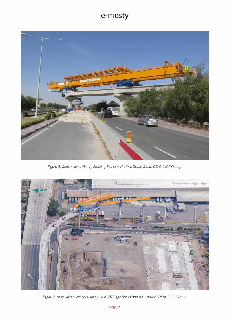
22021
GANTRY ERECTION
The first loads imparted by a launching gantry
occur during the assembly of the equipment
Launching gantries are typically erected with the
front support on the leading pier and the rear
support on either a previously erected span or on
falsework
The falsework tower shown here on the Seattle
Sound Transit project is tied to the rear pier to
ensure longitudinal stability of the tower and
gantry
Figure 5 A conventional lattice gantry with the rear support on falsework for the erection of the first span
DEAL L81 Gantry Seattle Sound Transit Seattle Washington
SEGMENTAL CONSTRUCTION SEGMENT
ERECTION
Once the gantry is assembled and ready to use the
construction can begin with the hanging of the
segments Segments are lifted via lifting holes in
the top slab
These can be either between the webs of a
segment or outside the webs in the wings
Lifting between the webs can induce top slab
tension at the center of the segment which can be
exacerbated by transverse post-tensioning in the
deck
22021
Figure 6 Segment lifting during the static winch load test where the winch is loaded to the weight of the heaviest
segment plus 25
The segment shown here has several spools of post-tensioning strand to increase the weight of the pick
DEAL L107 launching gantry Doha Qatar
Another troublesome spot can be the tops of the
webs
The secondary PT demand due to transverse post-
tensioning adds to the moment from lifting the
segment and can lead to cracking in the webs
Usually the cracks form on the inside face of the
web protected from the elements and can be self-
healing once under service loading
COMPLETING THE SPAN
After hanging all the segments in the first span a
load test will be performed
A typical load test involves overloading the gantry
to 10 above the weight of the heaviest span to
be erected by the gantry
Once the load test is complete the segments are
epoxied together and stressed with temporary
post-tensioning
Stressing the permanent post-tensioning presents
a challenge for controlling stresses in the
suspended span due to the continuous support of
the launching gantry
As the tendons are stressed the span immediately
begins to pick up in the middle This upward
movement allows the gantry to recover from the
deflection it underwent while hanging segments
A spangantry analysis is necessary to understand
how the stresses in the span change throughout
the stressing sequence
In this analysis a model is developed that includes
the span being erected the launching gantry and
the hanging bars used to suspend the segments
To control stresses during this process the gantry
can be incrementally lowered in order to shed the
span self-weight from the gantry into the bearings
22021
Figure 7 The L121 conventional launching gantry from DEAL completing a span on the HART Light Rail in Honolulu Hawaii
This increases compression in the top slab as the
span becomes self supporting
Another approach is to change the tendon
stressing order to better control top fiber tension
Some spans require both methods to be used
together
While it is not possible to avoid top fiber tension
completely given the continuous support provided
by the gantry during stressing it is possible to keep
them within a reasonable limit
LAUNCHING
With span construction complete the gantry is now
ready to launch itself to the next span
Different gantries launch in different ways
Conventional gantries typically have three
supports a front support rear support and an
auxiliary support that are maneuvered beneath the
girder for launching
Every effort is made to keep support placement
over the webs in segments adjacent to the pier
segments
However on tight radius horizontal curves it may
be necessary to place supports along the span to
allow the gantry to navigate the curve
Placing supports at midspan on a small radius
curved span can lead to span stability concerns as
the center of the loading could potentially be
outside the footprint of the bearings
This risk can be mitigated by providing optional tie-
downs to hold the span down at the piers
22021
Figure 8 The L100 conventional launching gantry completing a launch in Riyadh Saudi Arabia
Articulating gantries have a different method of
launching A front leg suspended from the support
beam is placed onto the leading pier and then the
rear support rolls along the superstructure
When the rear support has reached the end of the
span the front support and support girders are
launched forward
The wheels of the rear support are meant to ride
directly over the webs however it is possible to
get off-course and start loading the wings or
haunch of a pre-cast segment
Any offset from the center of the web induces a
moment in the top of the web as well and may be
compounded by the presence of transverse post-
tensioning
A steering tolerance should be checked with a
transverse analysis of the segments
Much of the loading from a launching gantry goes
into the previously erected superstructure
However the front support of a launching gantry
typically sits on the up-station side of the leading
pier during span erection
Large moments can develop in the pier as a result
of the following factors
1 Front supports are placed ahead of the
pier centerline to ensure that therersquos room
to set the span being erected
2 The slope of gantry as it follows the bridge
slope imparts a longitudinal load on the
leading pier at the top of the front support
several meters above the top of the pier
3 The slope load is increased by the gantry
deflection under the weight of suspended
segments This can be as much as 2
4 Friction in the front support roller group
can add another 1 of the vertical load
acting longitudinally
22021
Figure 9 Gantry front support showing forward offset from pier centerline and the roller group supporting the main girders
DEAL L57 Gantry Tysonrsquos Corner Virginia
Thus if the gantry is erecting ldquoup-hillrdquo the slope of
the bridge deflection of the gantry and friction in
the roller group are all additive
Conventional gantries have rollers on the front
support to avoid being statically indeterminate
Longitudinal fixity is at the rear support
As such all of the moment inducing forces listed
above must be resisted by the flexural capacity of
the leading pier alone
These loads can be significant and can potentially
govern the design of taller piers
Another concern with the longitudinal loads is the
deflection of the pier itself This can lead to locked-
in deflection if the span is set directly on
permanent bearings that arenrsquot free to slide
longitudinally (elastomeric bearings for example)
NON-TYPICAL SPANS
Erecting typical length spans with gentle horizontal
curves produces predictable construction loads
Where launching gets tricky and therefore applies
loads on the permanent structure is where span
lengths vary widely from one span to the next
Often gantries will have to set their supports at
several locations along the length of the span to
get set up for either a short or long launch
Another launching concern is walkovers This is
where a gantry erects up to another span that has
been erected with another method or at another
time and launches over the completed span to
arrive at the next span to begin erecting again
Typically this occurs where bridges have spans
that exceed the design length for the gantry and
have been previously erected by other means
During walkovers supports will often be placed on
typical segments away from the pier segments in
order to make the launch
Any time supports are placed on typical segments
and not pier segments the span should be
designed to take the flexural shear and principal
tension demands of the launch
22021
Figure 10 The L120 launching gantry (by DEAL) lifts the pre-cast concrete segments of the first span
WIND LOADS
A common concern among bridge owners and
designers is with regards to the applicable wind
loads that a gantry and bridge should be designed
for Bridge design codes require specific wind
speeds and pressures to be considered while
launching gantries are typically designed to
overhead crane design codes that have a different
set of requirements
The launching gantry should be designed for the
wind loads specified by the applicable crane codes
while the bridge should consider the gantry as an
appurtenance affixed to the permanent structure
and use the applicable bridge wind loads in the
design of the bridge
On the Harbor Bridge project in Corpus Christi
Texas there is the potential for large wind loads
given that the bridge is located on the Gulf of
Mexico and the piers are upwards 45m tall
The L120 launching gantry (designed by DEAL) is
160m long and 3m tall giving it a large projected
wind area
The two major concerns that arise are the lateral
loads on the pier columns and the stability of the
span when the gantry is tied down for wind events
To accommodate the large out of service
(hurricane) wind loading the designers opted to
design specific locations along the bridge for
hurricane winds on the structure and gantry
together
The piers and superstructure have increased
capacity to accommodate the gantry should it
need to be tied down a wind event
This was a more economical solution than
designing every pier for the out of service winds
In the event of an approaching hurricane the
gantry does not have far to back launch to get to a
safe place to tie-down
CONCLUSION
In conclusion launching gantries apply unique
loads on both the super and substructures of
bridges
Wind and longitudinal loads on the piers can
sometimes govern the design and stability checks
of the bridge Considering these loads during the
design phase of a bridge project can eliminate
costly redesigns later
22021
GEOMETRY CONTROL FOR PRECAST
SEGMENTAL CONSTRUCTION
Joakim Dupleix CaSE International (formerly VSL)
Martin Pircher ABES
Figure 1 Closing of Mesaimeer Bridge main stay cable span Qatar
PRECAST SEGMENTAL CONSTRUCTION
Precast segmental construction is a great method
to limit the impact of the works on a bridge
construction site
By fabricating the concrete elements in a
controlled environment many of the unpleasant
by-products of the construction site are also
exported
However a key challenge of constructing elements
remotely is to ensure they will achieve the required
bridge geometry once erected on site
Furthermore the fact that the bridge is built ldquopiece-
by-piecerdquo in segments means that the geometry
needs to be controlled and forecasted at every
stage during construction anticipating and
forecasting movements and deflections during the
temporary stages of the construction process
Often bridges have varying curvature and
superelevation which require tools to capture the
geometry in all dimensions
These tools must allow efficient and accurate ways
to correct geometry imperfections such as
correction in setting out in the precast yard or
shimming of segment joints during balanced
cantilever erection on site
22021
ABES SOFTWARE SOLUTION
ABES Pircher amp Partner GmbH is an independent
software house providing solutions for bridge
engineering topics
Together with VSL they have developed a
software suite dedicated to managing the
geometry control of segmental construction at
every stage of the construction process
The software is split in 3 components which are all
interrelated
geoDes to be used in the design office to
model the intended theoretical geometry of
the bridge
geoCon to be used in the casting yard
providing setting out and casting error
compensation for any yard setup
assemCon to be used on site to forecast
the as-built geometry during balanced
cantilever construction based on real time
survey results
Figure 2 Balanced cantilever construction
The software works fully in 3D with a visual
interface which means it can control geometry in
all directions not only vertically
Figure 3 Snapshot of 3D model within ABES geoDes
22021
The Figure below illustrates an example of a cross-
section modeled in geoDes
Figure 4 Cross section (inner void omitted)
KEY PRINCIPLES
The geometry control principles used by ABES are
as follows
The theoretical modelling of the bridge
defines a casting curve in 3D which is the
ldquoperfectrdquo geometry of the bridge This
includes the camber of the bridge if defined
by the designer
Each segment is recorded in its entire
three-dimensional shape and identified by a
minimum of 4 control points which are
physical survey items to be cast anywhere
on the segment
Segment shapes are prepared considering
the specific requirements of the casting
machines used in the yard
The position of control points in the wet
concrete which may vary due to placing
error defines the setting out curve
When segments are cast movement of the
formwork the bulkhead or the conjugate
segment may induce deviations from the
theoretical shape this defines the ldquoas castrdquo
curve
Segment imperfections are compensated
for during casting of sub-sequent
segments This is true for both short-line
and long-line casting or the combination
thereof
During balanced cantilever erection each
construction stage must be monitored and
compared to the deflected position of the
entire bridge as defined by the designer
Again geometric deviations need to be
corrected for during sub-sequent
construction stages
Figure 5 3D interface showing theoretical
(red) and as cast segments (green)
MAIN ADVANTAGES
Modelling
By modelling the bridge from base alignments and
with geometric rules derived from the specific
capabilities of the casting cells the software
achieves the best constructable theoretical fit
Multiple alignments can be accommodated
including deviation from the main alignment such
as for ramps or train stations as required Refer to
Figure 3 above
In the precast yard
When using geoCon the software automatically
compensates for the user the required setting out
according to the survey data of the previous
segment
This is key to ensure seamless casting operation
and minimize operator error Besides benefitting
from the 3D modelling it always works in all three
dimensions
22021
There is no limit to the number of control points
per segment ensuring high accuracy
Another key feature for a stay cable bridge pipes
must be cast in advance into the segment in the
yard to achieve the final geometry after all
deformations have occurred
The software can transform the theoretical pipe
coordinates adjust them for cambers and
segment imperfections and display them in the
local coordinate system which can be processed
by the surveyor in the yard
Figure 6 Gewan Island bridge 3D modelling
with plan radius of less than 125m
Figure 8 Precasting of segments with cable stay pipes
On site for balanced cantilever erection
On site assemCon gives two key insights to the
user
Forecast the position of the bridge at any
construction stage in 3D considering the
as-built data the as-cast curve and the
calculated deflections for each
construction stage
Assist in finding an optimal shimming
strategy to correct the forecasted position
and to target a final as-built structure as
close as possible to the theoretical
geometry
Figure 7 3D view of a cantilever being built
22021
Figure 9 Definition of shimming
strategy to reduce differences
CONCLUSIONS
Pre-cast segmental bridge construction is applied
to increasingly complex and geometrically
challenging structures
Efficient geometry control is essential for the
success of such projects
Geometry control already starts during the
planning process where individual segments need
to be laid out to suit the available equipment in the
casting yard
Segment casting needs to be tightly controlled and
monitored and geometric imperfections need to
be identified and compensated for
And finally bridge construction at the construction
site requires monitoring of individual construction
stages and optimised strategies for correcting for
possible geometry deviations of the bridge
structure during construction
VSL in cooperation with ABES have developed a
suite of software tools to assist in all these tasks
The software is heavily influenced by practical
experience during numerous pre-cast segmental
projects of all sizes and shapes across Asia and
principally Qatar and India and feedback from
ongoing projects continues to inform the
development work
Figure 12 Al Bustan North bridge during construction
above traffic Qatar
Figure 11 Gewan Island Bridge being built Qatar
Figure 10 Karimnagar cable stay bridge India
Photos Credit VSL
22021
PRECAST SEGMENTAL BRIDGE CONSTRUCTION
USING LIFTING FRAME IN QATAR
Joakim Dupleix CaSE International (formerly VSL)
German A Pardo R VSL International Ltd
Figure 1 Overview of Al Bustan North construction site
PRECAST SEGMENTAL CONSTRUCTION
One of the most advantageous construction
methods enabled by segmental construction is the
balanced cantilever method
In a busy brownfield environment pre-casting the
segments off-site is the best solution to minimize
disrupting the existing traffic flow
In these environments access is often limited and
restricted and cranage may not be able to reach
the whole site
In these conditions lifting frame equipment are
often the solution to enable the erection of
segments on the bridge
In Qatar VSL designed and operated two very
different types of lifting frames as part of the Al
Bustan corridor upgrade project
The lifting frames responded to different needs and
segment delivery methods carefully studied during
the construction planning phase of the project
SABAH AL AHMAD CORRIDOR
(previously called Al Bustan)
Sabah al Ahmad or Al Bustan Corridor is part of
the Qatar Expressway Programme and aims to
provide an alternative to the existing expressway
with free flow traffic on a length of 14 km from the
North of Central Doha to the South to improve
connectivity to the FIFA World Cup stadiums
22021
The project involved upgrading the existing main
road by constructing various overhead bridges
over existing crossroads as well as connecting
ramps to remove traffic lights
The construction of this corridor was split into three
main packages
Al Bustan North project now known as
Umm Lekhba Interchange
Al Bustan South project
Mesaimeer Road project
Al Bustan North consists of the major upgrade of a
major interchange with Qatar main highway Al
Shamal Road to become a 4 level interchange
Al Bustan South required the construction of large
overhead bridges up to 26 km long with overhead
ramps connecting to crossroads
Mesaimeer Road upgraded the existing road with 2
large bridges up to 12 km long with a cable stay
section
PRECAST SEGMENTAL BALANCED
CANTILEVER METHOD
Because of the existing brownfield environment in
which the bridges are being built and to minimize
the impact on the existing traffic the precast
segment balanced cantilever method was chosen
for design and construction
It avoids installing large falsework structures on
site where space is limited and enables quick
fabrication of the bridge but requires relatively
large lifting equipment
As a matter of fact as the heavy concrete bridge
segments are to be transported and erected into
position with limited space the key is to
Figure 2 Key map of the corridor in Doha
22021
understand which areas are available where
possible if lifting equipment such as cranes can be
positioned and how to deliver the segments to
their final position
For very heavy segments or if cranes cannot be
used due to site constraints it may be required to
design custom made lifting frame machines
placed on top of the bridge already built and fitted
with their own lifting device to erect the segments
in their final position
These machines typically have a limited range and
segments must be first transported precisely near
their final position
On the Al Bustan Corridor two different delivery
situations were identified
For Al Bustan South and Mesaimeer the
large weight of the segments made it
prohibitively costly to use a crane
However assisted by a temporary
diversion of the existing road during
construction and the flat terrain every
segment could always be delivered directly
below their final position
For Al Bustan North the multi-level
interchange the existing highway Al
Shamal Road could only be closed to traffic
for a very limited time and the existing road
environment did not allow for flexible
segment delivery below each new bridge
ramp
A crane could be positioned near the piers
which allowed for segments to be lifted
onto the already erected deck
To position the segment into its final
position a special lifting frame was
designed to pick up the segment ldquofrom
behindrdquo and bring them forward into their
final position
LIFTING FRAME WITH DELIVERY FROM
BEHIND
As mentioned previously a lifting frame (LF) able
to pick up a segment from behind was required for
this project
A few options for the trajectory of the segment
were considered
Symmetrical Lifting Frame segment
crossing the lifting frame is rotated at 90
degrees in plan lifted and moved through
the middle of the machine longitudinally
Once at the front it can be rotated 90
degrees and lowered in position
Asymmetrical Lifting Frame segment is
delivered 180 degrees from its final
orientation
The segment is picked up rotated 90
degrees moved through the LF
longitudinally rotated again and then
lowered in position
Figure 3 Al Bustan North lifting frame
For this project the bridges are quite narrow with a
web spacing of 6 and 4 m and therefore passing a
32 m long segment between two legs of the LF
was not possible
As shown in Figure 4 on the next page a C shape
was adopted to allow the segment to be rotated on
the free side and moved forward
22021
Figure 4 Segment delivery methodology Click on the image to open it in full size
Description of Lifting Frame
The lifting Frame had the following key
specifications
1 Self-weight of 70 tonnes
2 Lifting capacity of 80 tonnes
3 Lifting speed of 12 mh [02 mmin]
4 Longitudinal launching speed of 3 mh
[005 mmin]
The lifting frame is made of a few key
components
Upper Cross Beam (UCB) transverse
beam carrying the strand lifting unit as
well as the stressing platform lifting
mast Adjustment capability of +-
200 mm
Main Beams (MB) Longitudinal beams
supporting the UCB The UCB is
moved on wheels with a bogie
connected to 2 chain pulling units
Figure 5 3D view of lifting frame model
22021
Support Frame (SF) asymmetric frame in a
C shape supporting the MB The frame is
supported on the deck by adjustable screw
jacks located over the webs
Tie down beams (TDB) during erection
the SF is tie down to the deck with 4 no
40 mm diameter stressbars anchored in
TDB The TDB allows for longitudinal
adjustment in the position of the bars as
the segment length varies
Rail beams (RB) two rail beams on each
side of the SF are fitted with a hydraulic
launching system able to move the entire
frame forward in steps of 700 mm
Segment lifting beam (SLB) the SLB is
stressed to the segment being lifted and is
fitted with hydraulic jacks able to adjust the
segment to the required crossfall and
gradient as well as rotated the segment in
plan to pass through the SF
Stressing platform (SP) to complete the
balance cantilever construction a SP is
required to be positioned each newly
erected segment to provide access for
personnel to complete the permanent post-
tensioning operation
Figure 6 Segment delivered at the rear of the LF
Figure 8 Segment rotated to its final orientation
rarr Figure 9 Segment lowered into
position and load transferred
Figure 7 Segment rotated and moved longitudinally
SEGMENT ERECTION PHOTOS
The photo sequence below shows the segment
delivery process
22021
Challenges
Because of the limited width of the deck and the
congested site area with existing roads one of the
key challenges was to find a suitable storage
position for the SP when not in use which would
not block the segment passage
A rotation mast or davit arm was designed to lift
and position the 6 tonnes platform The mast was
rotated up to 120 degrees with a small horizontal
hydraulic jack
The concept and design itself of the Lifting Frame
required a solution which provided the minimum
required space for manipulating the segment and
the stressing platform in a very tight area while
having enough stiffness and capacity to cover the
demands
LIFTING FRAME WITH DELIVERY FROM
BELOW
Typical configuration for a Lifting Frame is such
that segment can be lifted directly from below
This was the case of Al Bustan South and
Mesaimeer projects
MESAIMEER LIFTING FRAME
Segments to be lifted by this lifting frame were the
heaviest and widest on the project for this reason
a stiffer structure composed of rigid frames at the
supporting areas was chosen taking advantage of
the fact that there was no restriction in height and
section of the bridge
The delivery of the segments in this project could
be conducted almost at is final position in plan
which facilitated the configuration of the lifting
equipment at the cantilever of the lifting frame
For this purpose the lifting frame was provided
with a couple of Winches that could pick up the
segment from the ground with minimum rotation in
plan lifted to required level and conduct final
adjustment in the longitudinal and transverse
directions
Description of Lifting Frame
The Lifting Frame had the following key
specifications
1 Self-weight of 92 tonnes
2 Lifting capacity of 185 tonnes
3 Lifting speed of 60 mh [1 mmin]
4 Longitudinal launching speed of 3mh [005
mmin)
Figure 10 segment delivered at the rear of the LF
The lifting frame is made of a few key components
Upper Cross Beam (UCB) transverse
beam carrying the main lifting equipment
(Winch) as well as the stressing platform
Adjustment capability +- 1325
Cantilever Beam (CTB) the 2 main
longitudinal beams supporting the UCB and
Stressing Platform at front and the Tie
Down Beam at the rear
Lower Cross Beam (LCB) main Frames
underneath the CTB transferring all load to
the bridge
Rail Beams (RB) two rail beams on each
side of the LCB are fitted with a hydraulic
launching system able to move the entire
frame forward in steps of 850 mm
22021
Connection Beams (CB) beams
connecting the hook blocks of the Winches
directly to the segment They are provided
with jacks for segment gradient adjustment
Crossfall is adjusted directly by the
Winches
Stressing Platform (SP) it is positioned at
the tip of the CTB and move backward for
conducting stressing of bridge post-
tensioning tendons It is provided with 2
levels customized for this project
Tie Down Beam (TDB) the Support frame
is provided with a set of tie down beams at
the rear which are the main stability
system
TDB can be adjusted in the longitudinal
direction to suit the different segment
lengths and their respective tie down holes
position
Tie down bars are of 75mm and 47mm in
diameter and pre-stressed against the
segment
Challenges
To accommodate the supporting area in a
very limited length since there was
insufficient space near the pylons
This created big reactions to be taken by
the tie down elements due the big
cantilever at front and heavy segments to
be lifted
To be able to move all the way back the
lifting equipment (Winch) and UCB to
provide enough stability during the
launching procedure Space at rear of the
lifting frame was very limited
Provide a Stressing Platform with 2
different configurations (1 or 2 levels) that
could be adapted for specific
configurations
SEGMENT ERECTION PHOTOS
Figure 11 Mesaimeer Lifting Frame
Figure 12 Segment lifting
Figure 13 Segment permanent post-tensioning in progress
22021
AL BUSTAN SOUTH LIFTING FRAME
For this project the lifting frame had to
accommodate few main requirements to suit the
space constraints of the project and the bridge
capacity
Height A limit of 6m for total height the lifting
frame was to be assured since the bridge had
to pass under an existing viaduct
Load introduction The bridge section is
provided with 3 webs and middle web capacity
was to be respected by limiting the reactions at
this point Additionally the total weight of the
Lifting Frame was also limited
Segment delivered below could not be
positioned in its final orientation due to space
constraints It had to be rotated up to 90deg once
hanging from the lifting frame
To overcome the limitations described the lifting
frame concept developed considered the following
aspects
Main lifting equipment (Winch) was
positioned at the bottom rear area of the
lifting frame to reduce the total height
The three webs of the segment were
loaded and the Lifting Frame elements
were studied in such a way that the total
weight of the Lifting Frame and loading of
central web were not exceeded
A single Winch and the hook block with
rotation device were provided to allow
rotation of the segment while hanging from
the Lifting Frame
Description of Lifting Frame
The Lifting Frame had the following key
specifications
1 Self-weight of 81 tonnes
2 Lifting capacity of 170 tonnes
3 Lifting speed of 36 mh [06 mmin]
4 Longitudinal launching speed of 3mh [005
mmin
The lifting frame is made of the following key
components
Upper Cross Beam (UCB) uppermost
element carrying the Winch Trolley It can
slide longitudinally to accommodate the
segment in length Transverse adjustment
is done by sliding of the Winch Trolley over
the UCB
Main Frame (MF) the Lifting Frame is
provided with 2 Main Frames in section that
support the UCB and Stressing Platform on
top and transfers the vertical load to the
lower elements of the Lifting Frame At
bottom level it also receives the Tie Down
Beam
Lower Cross Beam (LCB) spreader beam
in the transverse direction located at front
and rear that transfer all loads to the
segment webs through 6 screw jacks (3 at
the front and 3 at the rear)
Tie Down Beam (TDB) located at rear part
of the Lifting Frame and contain the tie
down bars stressed down against the
segment in order to assure the stability of
the Lifting Frame It contains a couple of
back-up bars that provide redundancy to
the system
Segment Lifting Beam (SLB) connecting
element between the hook block of the
winch and the segment It is provided with
a rotational device that allows full rotation
of the segment in plan
Figure 14 Segment delivered at the rear of the LF
22021
Stressing Platform (SP) it hangs from the
tip of the Main Frame cantilever beam It is
moved backwards after segment
installation to conduct the stressing of the
permanent post-tensioning system
Rail Beam (RB) two rail beams on each
side of the LCB are fitted with a hydraulic
launching system able it to move the entire
frame forward in steps of 850 mm
Figure 14 Lifting Frame installation on deck
Figure 15 Lifting of segment
Figure 16 Stressing of post-tensioning tendons
Figure 17 Lifting Frame crossing under existing viaduct
SEGMENT ERECTION PHOTOS
Challenges
To develop a concept and design that did
not exceed the limitations given regarding
total weight and height
Allow full rotation of the segment while
hanging
Provide redundancy to the Lifting Frame
Tie Down system and to the Stressing
Platform while under operation
22021
CONCLUSIONS
Precast segmental construction in a congested
environment often requires the use of custom
designed lifting frames
These machines must always consider the
segment delivery methods as well as the bridge
characteristics in order to achieve the most cost-
efficient methods of erection
The more requirements a project has the more
customized the Lifting Frame will be
For this reason it is of key importance to integrate
the development of the Temporary Structures (like
Lifting Frames) as early as possible in the design
process
By doing this some of the constraints can be
solved in earlier stages which will improve the
efficiency of the full process and the interfaces
between the different parts involved Permanent
Works Designer Temporary Works Designer and
Main Contractor
Figure 18 Al Bustan North Figure 19 Al Bustan North
Figure 20 Al Bustan South
Figure 21 Mesaimeer
Photos 18 ndash 20 Credit Ashghal (Qatar Road Authority)
We design and produceformwork equipmentfor in-place casting of bridgesN25 New Ross Bypass (Ireland)
FOLLOW US
INNOVATIVE | SAFE | SUSTAINABLE | FAST
SOLUTIONS FOR BRIDGE CONSTRUCTION
MSS M1-70-S BRATISLAVA BYPASS | IN SITU CONSTRUCTION
LG 36-S CAIRO METRO LINE 3 EXTENSION | PRECAST SEGMENTAL
WWWBERDEU
Photo Credits D4R7
Photo Credits Stephane Ciccolini
Arup works in active partnership with clients to understand their needs so
that the solutions make their bridge aspirations possible mdashbig and small
The Arup global specialist technical skills blended with essential local
knowledge adds unexpected benefits
wwwarupcom
Whether to span nations make a statement or
improve everyday links Arup crafts better bridges
Naeem Hussain Richard Hornby Steve Kite Deepak Jayaram
naeemhussainarupcom richardhornbyarupcom stevekitearupcom deepakjayaramarupcom
Global UK Middle East amp Africa East Asia UK Middle East India
and Africa
Peter Burnton Marcos Sanchez Matt Carter
peterburntonarupcom marcossanchezarupcom mattcarterarupcom
Australasia Europe Americas
Queensferry Crossing Scotland
SANTANDERMADRIDLIMABOGOTAacuteBUENOS AIRES
Calle Marqueacutes de la Ensenada 11 - 3ordm 39009
Calle Bravo Murillo 101 - 4ordm 28020
Calle Coronel Inclaacuten 235 - Oficina 313 Lima 18
Cra 14 94a - 24 Oficina 307 Edificio ACO 94
Calle Rodriacuteguez Pentildea 681 - 4ordm Dpto 8 1020
Tfno +34 942 31 99 60
Tfno +34 91 702 54 78
Tfno +51 1 637 56 47
Tfno +57 1 467 48 10
Tfno +54 911 5709 3252
wwwarenasingcom
ARCHING THE WORLD
CODE-BASED DESIGN
DETAILINGDR AWING PRODUCTION
PAR AM ETRIC MODELING
STRUCTUR AL ANALYSIS
DOWNLOAD A FREE TRIALallplancombridge2021
THE WORLDrsquoS FIRST COMPLETE SOLUTIONFOR BRIDGE ENGINEERS
Allplan Bridge 2021 maps the complete BIM process in bridge projects The new version enables bridge engineers to work with one single solution from the creation of a parametric 4D model to structural analysis reinforcement design and detailing This further improves the design process in terms of both time and quality
ALLPLAN BRIDGE
Join Bridges to Prosperity in helping isolated
communities gain safe access to healthcare
education jobs and markets through simple
sustainable trailbridges Together we can
build more than a bridge we can build a
pathway out of poverty
We envision a world wherepoverty caused by ruralisolation no longer exists
bridgestoprosperityorg
infobridgestoprosperityorgbridgestoprosperity
bridgestoprosperity
b2p
+60Women Entering the Labor Force
+75Farmer
Profitability
+358Labor Market
Income
Corporate Partners make this
vision possible
Wyatt Brooks and Kevin Donovan - Eliminating Uncertainty in Market Access
The Impact of New Bridges in Rural Nicaragua 2017
SEGMENTAL BRIDGES
ISSUE 022021 JUNE
- 1 arenas_v2
-
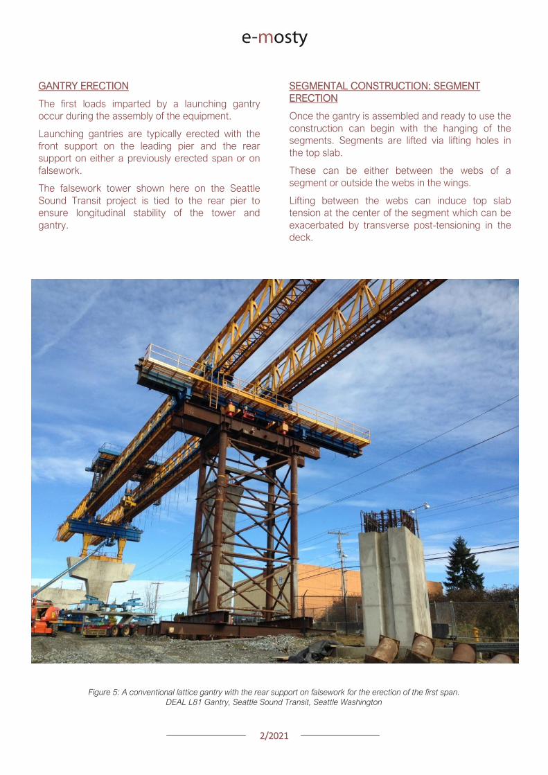
22021
Figure 6 Segment lifting during the static winch load test where the winch is loaded to the weight of the heaviest
segment plus 25
The segment shown here has several spools of post-tensioning strand to increase the weight of the pick
DEAL L107 launching gantry Doha Qatar
Another troublesome spot can be the tops of the
webs
The secondary PT demand due to transverse post-
tensioning adds to the moment from lifting the
segment and can lead to cracking in the webs
Usually the cracks form on the inside face of the
web protected from the elements and can be self-
healing once under service loading
COMPLETING THE SPAN
After hanging all the segments in the first span a
load test will be performed
A typical load test involves overloading the gantry
to 10 above the weight of the heaviest span to
be erected by the gantry
Once the load test is complete the segments are
epoxied together and stressed with temporary
post-tensioning
Stressing the permanent post-tensioning presents
a challenge for controlling stresses in the
suspended span due to the continuous support of
the launching gantry
As the tendons are stressed the span immediately
begins to pick up in the middle This upward
movement allows the gantry to recover from the
deflection it underwent while hanging segments
A spangantry analysis is necessary to understand
how the stresses in the span change throughout
the stressing sequence
In this analysis a model is developed that includes
the span being erected the launching gantry and
the hanging bars used to suspend the segments
To control stresses during this process the gantry
can be incrementally lowered in order to shed the
span self-weight from the gantry into the bearings
22021
Figure 7 The L121 conventional launching gantry from DEAL completing a span on the HART Light Rail in Honolulu Hawaii
This increases compression in the top slab as the
span becomes self supporting
Another approach is to change the tendon
stressing order to better control top fiber tension
Some spans require both methods to be used
together
While it is not possible to avoid top fiber tension
completely given the continuous support provided
by the gantry during stressing it is possible to keep
them within a reasonable limit
LAUNCHING
With span construction complete the gantry is now
ready to launch itself to the next span
Different gantries launch in different ways
Conventional gantries typically have three
supports a front support rear support and an
auxiliary support that are maneuvered beneath the
girder for launching
Every effort is made to keep support placement
over the webs in segments adjacent to the pier
segments
However on tight radius horizontal curves it may
be necessary to place supports along the span to
allow the gantry to navigate the curve
Placing supports at midspan on a small radius
curved span can lead to span stability concerns as
the center of the loading could potentially be
outside the footprint of the bearings
This risk can be mitigated by providing optional tie-
downs to hold the span down at the piers
22021
Figure 8 The L100 conventional launching gantry completing a launch in Riyadh Saudi Arabia
Articulating gantries have a different method of
launching A front leg suspended from the support
beam is placed onto the leading pier and then the
rear support rolls along the superstructure
When the rear support has reached the end of the
span the front support and support girders are
launched forward
The wheels of the rear support are meant to ride
directly over the webs however it is possible to
get off-course and start loading the wings or
haunch of a pre-cast segment
Any offset from the center of the web induces a
moment in the top of the web as well and may be
compounded by the presence of transverse post-
tensioning
A steering tolerance should be checked with a
transverse analysis of the segments
Much of the loading from a launching gantry goes
into the previously erected superstructure
However the front support of a launching gantry
typically sits on the up-station side of the leading
pier during span erection
Large moments can develop in the pier as a result
of the following factors
1 Front supports are placed ahead of the
pier centerline to ensure that therersquos room
to set the span being erected
2 The slope of gantry as it follows the bridge
slope imparts a longitudinal load on the
leading pier at the top of the front support
several meters above the top of the pier
3 The slope load is increased by the gantry
deflection under the weight of suspended
segments This can be as much as 2
4 Friction in the front support roller group
can add another 1 of the vertical load
acting longitudinally
22021
Figure 9 Gantry front support showing forward offset from pier centerline and the roller group supporting the main girders
DEAL L57 Gantry Tysonrsquos Corner Virginia
Thus if the gantry is erecting ldquoup-hillrdquo the slope of
the bridge deflection of the gantry and friction in
the roller group are all additive
Conventional gantries have rollers on the front
support to avoid being statically indeterminate
Longitudinal fixity is at the rear support
As such all of the moment inducing forces listed
above must be resisted by the flexural capacity of
the leading pier alone
These loads can be significant and can potentially
govern the design of taller piers
Another concern with the longitudinal loads is the
deflection of the pier itself This can lead to locked-
in deflection if the span is set directly on
permanent bearings that arenrsquot free to slide
longitudinally (elastomeric bearings for example)
NON-TYPICAL SPANS
Erecting typical length spans with gentle horizontal
curves produces predictable construction loads
Where launching gets tricky and therefore applies
loads on the permanent structure is where span
lengths vary widely from one span to the next
Often gantries will have to set their supports at
several locations along the length of the span to
get set up for either a short or long launch
Another launching concern is walkovers This is
where a gantry erects up to another span that has
been erected with another method or at another
time and launches over the completed span to
arrive at the next span to begin erecting again
Typically this occurs where bridges have spans
that exceed the design length for the gantry and
have been previously erected by other means
During walkovers supports will often be placed on
typical segments away from the pier segments in
order to make the launch
Any time supports are placed on typical segments
and not pier segments the span should be
designed to take the flexural shear and principal
tension demands of the launch
22021
Figure 10 The L120 launching gantry (by DEAL) lifts the pre-cast concrete segments of the first span
WIND LOADS
A common concern among bridge owners and
designers is with regards to the applicable wind
loads that a gantry and bridge should be designed
for Bridge design codes require specific wind
speeds and pressures to be considered while
launching gantries are typically designed to
overhead crane design codes that have a different
set of requirements
The launching gantry should be designed for the
wind loads specified by the applicable crane codes
while the bridge should consider the gantry as an
appurtenance affixed to the permanent structure
and use the applicable bridge wind loads in the
design of the bridge
On the Harbor Bridge project in Corpus Christi
Texas there is the potential for large wind loads
given that the bridge is located on the Gulf of
Mexico and the piers are upwards 45m tall
The L120 launching gantry (designed by DEAL) is
160m long and 3m tall giving it a large projected
wind area
The two major concerns that arise are the lateral
loads on the pier columns and the stability of the
span when the gantry is tied down for wind events
To accommodate the large out of service
(hurricane) wind loading the designers opted to
design specific locations along the bridge for
hurricane winds on the structure and gantry
together
The piers and superstructure have increased
capacity to accommodate the gantry should it
need to be tied down a wind event
This was a more economical solution than
designing every pier for the out of service winds
In the event of an approaching hurricane the
gantry does not have far to back launch to get to a
safe place to tie-down
CONCLUSION
In conclusion launching gantries apply unique
loads on both the super and substructures of
bridges
Wind and longitudinal loads on the piers can
sometimes govern the design and stability checks
of the bridge Considering these loads during the
design phase of a bridge project can eliminate
costly redesigns later
22021
GEOMETRY CONTROL FOR PRECAST
SEGMENTAL CONSTRUCTION
Joakim Dupleix CaSE International (formerly VSL)
Martin Pircher ABES
Figure 1 Closing of Mesaimeer Bridge main stay cable span Qatar
PRECAST SEGMENTAL CONSTRUCTION
Precast segmental construction is a great method
to limit the impact of the works on a bridge
construction site
By fabricating the concrete elements in a
controlled environment many of the unpleasant
by-products of the construction site are also
exported
However a key challenge of constructing elements
remotely is to ensure they will achieve the required
bridge geometry once erected on site
Furthermore the fact that the bridge is built ldquopiece-
by-piecerdquo in segments means that the geometry
needs to be controlled and forecasted at every
stage during construction anticipating and
forecasting movements and deflections during the
temporary stages of the construction process
Often bridges have varying curvature and
superelevation which require tools to capture the
geometry in all dimensions
These tools must allow efficient and accurate ways
to correct geometry imperfections such as
correction in setting out in the precast yard or
shimming of segment joints during balanced
cantilever erection on site
22021
ABES SOFTWARE SOLUTION
ABES Pircher amp Partner GmbH is an independent
software house providing solutions for bridge
engineering topics
Together with VSL they have developed a
software suite dedicated to managing the
geometry control of segmental construction at
every stage of the construction process
The software is split in 3 components which are all
interrelated
geoDes to be used in the design office to
model the intended theoretical geometry of
the bridge
geoCon to be used in the casting yard
providing setting out and casting error
compensation for any yard setup
assemCon to be used on site to forecast
the as-built geometry during balanced
cantilever construction based on real time
survey results
Figure 2 Balanced cantilever construction
The software works fully in 3D with a visual
interface which means it can control geometry in
all directions not only vertically
Figure 3 Snapshot of 3D model within ABES geoDes
22021
The Figure below illustrates an example of a cross-
section modeled in geoDes
Figure 4 Cross section (inner void omitted)
KEY PRINCIPLES
The geometry control principles used by ABES are
as follows
The theoretical modelling of the bridge
defines a casting curve in 3D which is the
ldquoperfectrdquo geometry of the bridge This
includes the camber of the bridge if defined
by the designer
Each segment is recorded in its entire
three-dimensional shape and identified by a
minimum of 4 control points which are
physical survey items to be cast anywhere
on the segment
Segment shapes are prepared considering
the specific requirements of the casting
machines used in the yard
The position of control points in the wet
concrete which may vary due to placing
error defines the setting out curve
When segments are cast movement of the
formwork the bulkhead or the conjugate
segment may induce deviations from the
theoretical shape this defines the ldquoas castrdquo
curve
Segment imperfections are compensated
for during casting of sub-sequent
segments This is true for both short-line
and long-line casting or the combination
thereof
During balanced cantilever erection each
construction stage must be monitored and
compared to the deflected position of the
entire bridge as defined by the designer
Again geometric deviations need to be
corrected for during sub-sequent
construction stages
Figure 5 3D interface showing theoretical
(red) and as cast segments (green)
MAIN ADVANTAGES
Modelling
By modelling the bridge from base alignments and
with geometric rules derived from the specific
capabilities of the casting cells the software
achieves the best constructable theoretical fit
Multiple alignments can be accommodated
including deviation from the main alignment such
as for ramps or train stations as required Refer to
Figure 3 above
In the precast yard
When using geoCon the software automatically
compensates for the user the required setting out
according to the survey data of the previous
segment
This is key to ensure seamless casting operation
and minimize operator error Besides benefitting
from the 3D modelling it always works in all three
dimensions
22021
There is no limit to the number of control points
per segment ensuring high accuracy
Another key feature for a stay cable bridge pipes
must be cast in advance into the segment in the
yard to achieve the final geometry after all
deformations have occurred
The software can transform the theoretical pipe
coordinates adjust them for cambers and
segment imperfections and display them in the
local coordinate system which can be processed
by the surveyor in the yard
Figure 6 Gewan Island bridge 3D modelling
with plan radius of less than 125m
Figure 8 Precasting of segments with cable stay pipes
On site for balanced cantilever erection
On site assemCon gives two key insights to the
user
Forecast the position of the bridge at any
construction stage in 3D considering the
as-built data the as-cast curve and the
calculated deflections for each
construction stage
Assist in finding an optimal shimming
strategy to correct the forecasted position
and to target a final as-built structure as
close as possible to the theoretical
geometry
Figure 7 3D view of a cantilever being built
22021
Figure 9 Definition of shimming
strategy to reduce differences
CONCLUSIONS
Pre-cast segmental bridge construction is applied
to increasingly complex and geometrically
challenging structures
Efficient geometry control is essential for the
success of such projects
Geometry control already starts during the
planning process where individual segments need
to be laid out to suit the available equipment in the
casting yard
Segment casting needs to be tightly controlled and
monitored and geometric imperfections need to
be identified and compensated for
And finally bridge construction at the construction
site requires monitoring of individual construction
stages and optimised strategies for correcting for
possible geometry deviations of the bridge
structure during construction
VSL in cooperation with ABES have developed a
suite of software tools to assist in all these tasks
The software is heavily influenced by practical
experience during numerous pre-cast segmental
projects of all sizes and shapes across Asia and
principally Qatar and India and feedback from
ongoing projects continues to inform the
development work
Figure 12 Al Bustan North bridge during construction
above traffic Qatar
Figure 11 Gewan Island Bridge being built Qatar
Figure 10 Karimnagar cable stay bridge India
Photos Credit VSL
22021
PRECAST SEGMENTAL BRIDGE CONSTRUCTION
USING LIFTING FRAME IN QATAR
Joakim Dupleix CaSE International (formerly VSL)
German A Pardo R VSL International Ltd
Figure 1 Overview of Al Bustan North construction site
PRECAST SEGMENTAL CONSTRUCTION
One of the most advantageous construction
methods enabled by segmental construction is the
balanced cantilever method
In a busy brownfield environment pre-casting the
segments off-site is the best solution to minimize
disrupting the existing traffic flow
In these environments access is often limited and
restricted and cranage may not be able to reach
the whole site
In these conditions lifting frame equipment are
often the solution to enable the erection of
segments on the bridge
In Qatar VSL designed and operated two very
different types of lifting frames as part of the Al
Bustan corridor upgrade project
The lifting frames responded to different needs and
segment delivery methods carefully studied during
the construction planning phase of the project
SABAH AL AHMAD CORRIDOR
(previously called Al Bustan)
Sabah al Ahmad or Al Bustan Corridor is part of
the Qatar Expressway Programme and aims to
provide an alternative to the existing expressway
with free flow traffic on a length of 14 km from the
North of Central Doha to the South to improve
connectivity to the FIFA World Cup stadiums
22021
The project involved upgrading the existing main
road by constructing various overhead bridges
over existing crossroads as well as connecting
ramps to remove traffic lights
The construction of this corridor was split into three
main packages
Al Bustan North project now known as
Umm Lekhba Interchange
Al Bustan South project
Mesaimeer Road project
Al Bustan North consists of the major upgrade of a
major interchange with Qatar main highway Al
Shamal Road to become a 4 level interchange
Al Bustan South required the construction of large
overhead bridges up to 26 km long with overhead
ramps connecting to crossroads
Mesaimeer Road upgraded the existing road with 2
large bridges up to 12 km long with a cable stay
section
PRECAST SEGMENTAL BALANCED
CANTILEVER METHOD
Because of the existing brownfield environment in
which the bridges are being built and to minimize
the impact on the existing traffic the precast
segment balanced cantilever method was chosen
for design and construction
It avoids installing large falsework structures on
site where space is limited and enables quick
fabrication of the bridge but requires relatively
large lifting equipment
As a matter of fact as the heavy concrete bridge
segments are to be transported and erected into
position with limited space the key is to
Figure 2 Key map of the corridor in Doha
22021
understand which areas are available where
possible if lifting equipment such as cranes can be
positioned and how to deliver the segments to
their final position
For very heavy segments or if cranes cannot be
used due to site constraints it may be required to
design custom made lifting frame machines
placed on top of the bridge already built and fitted
with their own lifting device to erect the segments
in their final position
These machines typically have a limited range and
segments must be first transported precisely near
their final position
On the Al Bustan Corridor two different delivery
situations were identified
For Al Bustan South and Mesaimeer the
large weight of the segments made it
prohibitively costly to use a crane
However assisted by a temporary
diversion of the existing road during
construction and the flat terrain every
segment could always be delivered directly
below their final position
For Al Bustan North the multi-level
interchange the existing highway Al
Shamal Road could only be closed to traffic
for a very limited time and the existing road
environment did not allow for flexible
segment delivery below each new bridge
ramp
A crane could be positioned near the piers
which allowed for segments to be lifted
onto the already erected deck
To position the segment into its final
position a special lifting frame was
designed to pick up the segment ldquofrom
behindrdquo and bring them forward into their
final position
LIFTING FRAME WITH DELIVERY FROM
BEHIND
As mentioned previously a lifting frame (LF) able
to pick up a segment from behind was required for
this project
A few options for the trajectory of the segment
were considered
Symmetrical Lifting Frame segment
crossing the lifting frame is rotated at 90
degrees in plan lifted and moved through
the middle of the machine longitudinally
Once at the front it can be rotated 90
degrees and lowered in position
Asymmetrical Lifting Frame segment is
delivered 180 degrees from its final
orientation
The segment is picked up rotated 90
degrees moved through the LF
longitudinally rotated again and then
lowered in position
Figure 3 Al Bustan North lifting frame
For this project the bridges are quite narrow with a
web spacing of 6 and 4 m and therefore passing a
32 m long segment between two legs of the LF
was not possible
As shown in Figure 4 on the next page a C shape
was adopted to allow the segment to be rotated on
the free side and moved forward
22021
Figure 4 Segment delivery methodology Click on the image to open it in full size
Description of Lifting Frame
The lifting Frame had the following key
specifications
1 Self-weight of 70 tonnes
2 Lifting capacity of 80 tonnes
3 Lifting speed of 12 mh [02 mmin]
4 Longitudinal launching speed of 3 mh
[005 mmin]
The lifting frame is made of a few key
components
Upper Cross Beam (UCB) transverse
beam carrying the strand lifting unit as
well as the stressing platform lifting
mast Adjustment capability of +-
200 mm
Main Beams (MB) Longitudinal beams
supporting the UCB The UCB is
moved on wheels with a bogie
connected to 2 chain pulling units
Figure 5 3D view of lifting frame model
22021
Support Frame (SF) asymmetric frame in a
C shape supporting the MB The frame is
supported on the deck by adjustable screw
jacks located over the webs
Tie down beams (TDB) during erection
the SF is tie down to the deck with 4 no
40 mm diameter stressbars anchored in
TDB The TDB allows for longitudinal
adjustment in the position of the bars as
the segment length varies
Rail beams (RB) two rail beams on each
side of the SF are fitted with a hydraulic
launching system able to move the entire
frame forward in steps of 700 mm
Segment lifting beam (SLB) the SLB is
stressed to the segment being lifted and is
fitted with hydraulic jacks able to adjust the
segment to the required crossfall and
gradient as well as rotated the segment in
plan to pass through the SF
Stressing platform (SP) to complete the
balance cantilever construction a SP is
required to be positioned each newly
erected segment to provide access for
personnel to complete the permanent post-
tensioning operation
Figure 6 Segment delivered at the rear of the LF
Figure 8 Segment rotated to its final orientation
rarr Figure 9 Segment lowered into
position and load transferred
Figure 7 Segment rotated and moved longitudinally
SEGMENT ERECTION PHOTOS
The photo sequence below shows the segment
delivery process
22021
Challenges
Because of the limited width of the deck and the
congested site area with existing roads one of the
key challenges was to find a suitable storage
position for the SP when not in use which would
not block the segment passage
A rotation mast or davit arm was designed to lift
and position the 6 tonnes platform The mast was
rotated up to 120 degrees with a small horizontal
hydraulic jack
The concept and design itself of the Lifting Frame
required a solution which provided the minimum
required space for manipulating the segment and
the stressing platform in a very tight area while
having enough stiffness and capacity to cover the
demands
LIFTING FRAME WITH DELIVERY FROM
BELOW
Typical configuration for a Lifting Frame is such
that segment can be lifted directly from below
This was the case of Al Bustan South and
Mesaimeer projects
MESAIMEER LIFTING FRAME
Segments to be lifted by this lifting frame were the
heaviest and widest on the project for this reason
a stiffer structure composed of rigid frames at the
supporting areas was chosen taking advantage of
the fact that there was no restriction in height and
section of the bridge
The delivery of the segments in this project could
be conducted almost at is final position in plan
which facilitated the configuration of the lifting
equipment at the cantilever of the lifting frame
For this purpose the lifting frame was provided
with a couple of Winches that could pick up the
segment from the ground with minimum rotation in
plan lifted to required level and conduct final
adjustment in the longitudinal and transverse
directions
Description of Lifting Frame
The Lifting Frame had the following key
specifications
1 Self-weight of 92 tonnes
2 Lifting capacity of 185 tonnes
3 Lifting speed of 60 mh [1 mmin]
4 Longitudinal launching speed of 3mh [005
mmin)
Figure 10 segment delivered at the rear of the LF
The lifting frame is made of a few key components
Upper Cross Beam (UCB) transverse
beam carrying the main lifting equipment
(Winch) as well as the stressing platform
Adjustment capability +- 1325
Cantilever Beam (CTB) the 2 main
longitudinal beams supporting the UCB and
Stressing Platform at front and the Tie
Down Beam at the rear
Lower Cross Beam (LCB) main Frames
underneath the CTB transferring all load to
the bridge
Rail Beams (RB) two rail beams on each
side of the LCB are fitted with a hydraulic
launching system able to move the entire
frame forward in steps of 850 mm
22021
Connection Beams (CB) beams
connecting the hook blocks of the Winches
directly to the segment They are provided
with jacks for segment gradient adjustment
Crossfall is adjusted directly by the
Winches
Stressing Platform (SP) it is positioned at
the tip of the CTB and move backward for
conducting stressing of bridge post-
tensioning tendons It is provided with 2
levels customized for this project
Tie Down Beam (TDB) the Support frame
is provided with a set of tie down beams at
the rear which are the main stability
system
TDB can be adjusted in the longitudinal
direction to suit the different segment
lengths and their respective tie down holes
position
Tie down bars are of 75mm and 47mm in
diameter and pre-stressed against the
segment
Challenges
To accommodate the supporting area in a
very limited length since there was
insufficient space near the pylons
This created big reactions to be taken by
the tie down elements due the big
cantilever at front and heavy segments to
be lifted
To be able to move all the way back the
lifting equipment (Winch) and UCB to
provide enough stability during the
launching procedure Space at rear of the
lifting frame was very limited
Provide a Stressing Platform with 2
different configurations (1 or 2 levels) that
could be adapted for specific
configurations
SEGMENT ERECTION PHOTOS
Figure 11 Mesaimeer Lifting Frame
Figure 12 Segment lifting
Figure 13 Segment permanent post-tensioning in progress
22021
AL BUSTAN SOUTH LIFTING FRAME
For this project the lifting frame had to
accommodate few main requirements to suit the
space constraints of the project and the bridge
capacity
Height A limit of 6m for total height the lifting
frame was to be assured since the bridge had
to pass under an existing viaduct
Load introduction The bridge section is
provided with 3 webs and middle web capacity
was to be respected by limiting the reactions at
this point Additionally the total weight of the
Lifting Frame was also limited
Segment delivered below could not be
positioned in its final orientation due to space
constraints It had to be rotated up to 90deg once
hanging from the lifting frame
To overcome the limitations described the lifting
frame concept developed considered the following
aspects
Main lifting equipment (Winch) was
positioned at the bottom rear area of the
lifting frame to reduce the total height
The three webs of the segment were
loaded and the Lifting Frame elements
were studied in such a way that the total
weight of the Lifting Frame and loading of
central web were not exceeded
A single Winch and the hook block with
rotation device were provided to allow
rotation of the segment while hanging from
the Lifting Frame
Description of Lifting Frame
The Lifting Frame had the following key
specifications
1 Self-weight of 81 tonnes
2 Lifting capacity of 170 tonnes
3 Lifting speed of 36 mh [06 mmin]
4 Longitudinal launching speed of 3mh [005
mmin
The lifting frame is made of the following key
components
Upper Cross Beam (UCB) uppermost
element carrying the Winch Trolley It can
slide longitudinally to accommodate the
segment in length Transverse adjustment
is done by sliding of the Winch Trolley over
the UCB
Main Frame (MF) the Lifting Frame is
provided with 2 Main Frames in section that
support the UCB and Stressing Platform on
top and transfers the vertical load to the
lower elements of the Lifting Frame At
bottom level it also receives the Tie Down
Beam
Lower Cross Beam (LCB) spreader beam
in the transverse direction located at front
and rear that transfer all loads to the
segment webs through 6 screw jacks (3 at
the front and 3 at the rear)
Tie Down Beam (TDB) located at rear part
of the Lifting Frame and contain the tie
down bars stressed down against the
segment in order to assure the stability of
the Lifting Frame It contains a couple of
back-up bars that provide redundancy to
the system
Segment Lifting Beam (SLB) connecting
element between the hook block of the
winch and the segment It is provided with
a rotational device that allows full rotation
of the segment in plan
Figure 14 Segment delivered at the rear of the LF
22021
Stressing Platform (SP) it hangs from the
tip of the Main Frame cantilever beam It is
moved backwards after segment
installation to conduct the stressing of the
permanent post-tensioning system
Rail Beam (RB) two rail beams on each
side of the LCB are fitted with a hydraulic
launching system able it to move the entire
frame forward in steps of 850 mm
Figure 14 Lifting Frame installation on deck
Figure 15 Lifting of segment
Figure 16 Stressing of post-tensioning tendons
Figure 17 Lifting Frame crossing under existing viaduct
SEGMENT ERECTION PHOTOS
Challenges
To develop a concept and design that did
not exceed the limitations given regarding
total weight and height
Allow full rotation of the segment while
hanging
Provide redundancy to the Lifting Frame
Tie Down system and to the Stressing
Platform while under operation
22021
CONCLUSIONS
Precast segmental construction in a congested
environment often requires the use of custom
designed lifting frames
These machines must always consider the
segment delivery methods as well as the bridge
characteristics in order to achieve the most cost-
efficient methods of erection
The more requirements a project has the more
customized the Lifting Frame will be
For this reason it is of key importance to integrate
the development of the Temporary Structures (like
Lifting Frames) as early as possible in the design
process
By doing this some of the constraints can be
solved in earlier stages which will improve the
efficiency of the full process and the interfaces
between the different parts involved Permanent
Works Designer Temporary Works Designer and
Main Contractor
Figure 18 Al Bustan North Figure 19 Al Bustan North
Figure 20 Al Bustan South
Figure 21 Mesaimeer
Photos 18 ndash 20 Credit Ashghal (Qatar Road Authority)
We design and produceformwork equipmentfor in-place casting of bridgesN25 New Ross Bypass (Ireland)
FOLLOW US
INNOVATIVE | SAFE | SUSTAINABLE | FAST
SOLUTIONS FOR BRIDGE CONSTRUCTION
MSS M1-70-S BRATISLAVA BYPASS | IN SITU CONSTRUCTION
LG 36-S CAIRO METRO LINE 3 EXTENSION | PRECAST SEGMENTAL
WWWBERDEU
Photo Credits D4R7
Photo Credits Stephane Ciccolini
Arup works in active partnership with clients to understand their needs so
that the solutions make their bridge aspirations possible mdashbig and small
The Arup global specialist technical skills blended with essential local
knowledge adds unexpected benefits
wwwarupcom
Whether to span nations make a statement or
improve everyday links Arup crafts better bridges
Naeem Hussain Richard Hornby Steve Kite Deepak Jayaram
naeemhussainarupcom richardhornbyarupcom stevekitearupcom deepakjayaramarupcom
Global UK Middle East amp Africa East Asia UK Middle East India
and Africa
Peter Burnton Marcos Sanchez Matt Carter
peterburntonarupcom marcossanchezarupcom mattcarterarupcom
Australasia Europe Americas
Queensferry Crossing Scotland
SANTANDERMADRIDLIMABOGOTAacuteBUENOS AIRES
Calle Marqueacutes de la Ensenada 11 - 3ordm 39009
Calle Bravo Murillo 101 - 4ordm 28020
Calle Coronel Inclaacuten 235 - Oficina 313 Lima 18
Cra 14 94a - 24 Oficina 307 Edificio ACO 94
Calle Rodriacuteguez Pentildea 681 - 4ordm Dpto 8 1020
Tfno +34 942 31 99 60
Tfno +34 91 702 54 78
Tfno +51 1 637 56 47
Tfno +57 1 467 48 10
Tfno +54 911 5709 3252
wwwarenasingcom
ARCHING THE WORLD
CODE-BASED DESIGN
DETAILINGDR AWING PRODUCTION
PAR AM ETRIC MODELING
STRUCTUR AL ANALYSIS
DOWNLOAD A FREE TRIALallplancombridge2021
THE WORLDrsquoS FIRST COMPLETE SOLUTIONFOR BRIDGE ENGINEERS
Allplan Bridge 2021 maps the complete BIM process in bridge projects The new version enables bridge engineers to work with one single solution from the creation of a parametric 4D model to structural analysis reinforcement design and detailing This further improves the design process in terms of both time and quality
ALLPLAN BRIDGE
Join Bridges to Prosperity in helping isolated
communities gain safe access to healthcare
education jobs and markets through simple
sustainable trailbridges Together we can
build more than a bridge we can build a
pathway out of poverty
We envision a world wherepoverty caused by ruralisolation no longer exists
bridgestoprosperityorg
infobridgestoprosperityorgbridgestoprosperity
bridgestoprosperity
b2p
+60Women Entering the Labor Force
+75Farmer
Profitability
+358Labor Market
Income
Corporate Partners make this
vision possible
Wyatt Brooks and Kevin Donovan - Eliminating Uncertainty in Market Access
The Impact of New Bridges in Rural Nicaragua 2017
SEGMENTAL BRIDGES
ISSUE 022021 JUNE
- 1 arenas_v2
-
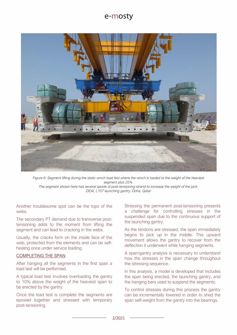
22021
Figure 7 The L121 conventional launching gantry from DEAL completing a span on the HART Light Rail in Honolulu Hawaii
This increases compression in the top slab as the
span becomes self supporting
Another approach is to change the tendon
stressing order to better control top fiber tension
Some spans require both methods to be used
together
While it is not possible to avoid top fiber tension
completely given the continuous support provided
by the gantry during stressing it is possible to keep
them within a reasonable limit
LAUNCHING
With span construction complete the gantry is now
ready to launch itself to the next span
Different gantries launch in different ways
Conventional gantries typically have three
supports a front support rear support and an
auxiliary support that are maneuvered beneath the
girder for launching
Every effort is made to keep support placement
over the webs in segments adjacent to the pier
segments
However on tight radius horizontal curves it may
be necessary to place supports along the span to
allow the gantry to navigate the curve
Placing supports at midspan on a small radius
curved span can lead to span stability concerns as
the center of the loading could potentially be
outside the footprint of the bearings
This risk can be mitigated by providing optional tie-
downs to hold the span down at the piers
22021
Figure 8 The L100 conventional launching gantry completing a launch in Riyadh Saudi Arabia
Articulating gantries have a different method of
launching A front leg suspended from the support
beam is placed onto the leading pier and then the
rear support rolls along the superstructure
When the rear support has reached the end of the
span the front support and support girders are
launched forward
The wheels of the rear support are meant to ride
directly over the webs however it is possible to
get off-course and start loading the wings or
haunch of a pre-cast segment
Any offset from the center of the web induces a
moment in the top of the web as well and may be
compounded by the presence of transverse post-
tensioning
A steering tolerance should be checked with a
transverse analysis of the segments
Much of the loading from a launching gantry goes
into the previously erected superstructure
However the front support of a launching gantry
typically sits on the up-station side of the leading
pier during span erection
Large moments can develop in the pier as a result
of the following factors
1 Front supports are placed ahead of the
pier centerline to ensure that therersquos room
to set the span being erected
2 The slope of gantry as it follows the bridge
slope imparts a longitudinal load on the
leading pier at the top of the front support
several meters above the top of the pier
3 The slope load is increased by the gantry
deflection under the weight of suspended
segments This can be as much as 2
4 Friction in the front support roller group
can add another 1 of the vertical load
acting longitudinally
22021
Figure 9 Gantry front support showing forward offset from pier centerline and the roller group supporting the main girders
DEAL L57 Gantry Tysonrsquos Corner Virginia
Thus if the gantry is erecting ldquoup-hillrdquo the slope of
the bridge deflection of the gantry and friction in
the roller group are all additive
Conventional gantries have rollers on the front
support to avoid being statically indeterminate
Longitudinal fixity is at the rear support
As such all of the moment inducing forces listed
above must be resisted by the flexural capacity of
the leading pier alone
These loads can be significant and can potentially
govern the design of taller piers
Another concern with the longitudinal loads is the
deflection of the pier itself This can lead to locked-
in deflection if the span is set directly on
permanent bearings that arenrsquot free to slide
longitudinally (elastomeric bearings for example)
NON-TYPICAL SPANS
Erecting typical length spans with gentle horizontal
curves produces predictable construction loads
Where launching gets tricky and therefore applies
loads on the permanent structure is where span
lengths vary widely from one span to the next
Often gantries will have to set their supports at
several locations along the length of the span to
get set up for either a short or long launch
Another launching concern is walkovers This is
where a gantry erects up to another span that has
been erected with another method or at another
time and launches over the completed span to
arrive at the next span to begin erecting again
Typically this occurs where bridges have spans
that exceed the design length for the gantry and
have been previously erected by other means
During walkovers supports will often be placed on
typical segments away from the pier segments in
order to make the launch
Any time supports are placed on typical segments
and not pier segments the span should be
designed to take the flexural shear and principal
tension demands of the launch
22021
Figure 10 The L120 launching gantry (by DEAL) lifts the pre-cast concrete segments of the first span
WIND LOADS
A common concern among bridge owners and
designers is with regards to the applicable wind
loads that a gantry and bridge should be designed
for Bridge design codes require specific wind
speeds and pressures to be considered while
launching gantries are typically designed to
overhead crane design codes that have a different
set of requirements
The launching gantry should be designed for the
wind loads specified by the applicable crane codes
while the bridge should consider the gantry as an
appurtenance affixed to the permanent structure
and use the applicable bridge wind loads in the
design of the bridge
On the Harbor Bridge project in Corpus Christi
Texas there is the potential for large wind loads
given that the bridge is located on the Gulf of
Mexico and the piers are upwards 45m tall
The L120 launching gantry (designed by DEAL) is
160m long and 3m tall giving it a large projected
wind area
The two major concerns that arise are the lateral
loads on the pier columns and the stability of the
span when the gantry is tied down for wind events
To accommodate the large out of service
(hurricane) wind loading the designers opted to
design specific locations along the bridge for
hurricane winds on the structure and gantry
together
The piers and superstructure have increased
capacity to accommodate the gantry should it
need to be tied down a wind event
This was a more economical solution than
designing every pier for the out of service winds
In the event of an approaching hurricane the
gantry does not have far to back launch to get to a
safe place to tie-down
CONCLUSION
In conclusion launching gantries apply unique
loads on both the super and substructures of
bridges
Wind and longitudinal loads on the piers can
sometimes govern the design and stability checks
of the bridge Considering these loads during the
design phase of a bridge project can eliminate
costly redesigns later
22021
GEOMETRY CONTROL FOR PRECAST
SEGMENTAL CONSTRUCTION
Joakim Dupleix CaSE International (formerly VSL)
Martin Pircher ABES
Figure 1 Closing of Mesaimeer Bridge main stay cable span Qatar
PRECAST SEGMENTAL CONSTRUCTION
Precast segmental construction is a great method
to limit the impact of the works on a bridge
construction site
By fabricating the concrete elements in a
controlled environment many of the unpleasant
by-products of the construction site are also
exported
However a key challenge of constructing elements
remotely is to ensure they will achieve the required
bridge geometry once erected on site
Furthermore the fact that the bridge is built ldquopiece-
by-piecerdquo in segments means that the geometry
needs to be controlled and forecasted at every
stage during construction anticipating and
forecasting movements and deflections during the
temporary stages of the construction process
Often bridges have varying curvature and
superelevation which require tools to capture the
geometry in all dimensions
These tools must allow efficient and accurate ways
to correct geometry imperfections such as
correction in setting out in the precast yard or
shimming of segment joints during balanced
cantilever erection on site
22021
ABES SOFTWARE SOLUTION
ABES Pircher amp Partner GmbH is an independent
software house providing solutions for bridge
engineering topics
Together with VSL they have developed a
software suite dedicated to managing the
geometry control of segmental construction at
every stage of the construction process
The software is split in 3 components which are all
interrelated
geoDes to be used in the design office to
model the intended theoretical geometry of
the bridge
geoCon to be used in the casting yard
providing setting out and casting error
compensation for any yard setup
assemCon to be used on site to forecast
the as-built geometry during balanced
cantilever construction based on real time
survey results
Figure 2 Balanced cantilever construction
The software works fully in 3D with a visual
interface which means it can control geometry in
all directions not only vertically
Figure 3 Snapshot of 3D model within ABES geoDes
22021
The Figure below illustrates an example of a cross-
section modeled in geoDes
Figure 4 Cross section (inner void omitted)
KEY PRINCIPLES
The geometry control principles used by ABES are
as follows
The theoretical modelling of the bridge
defines a casting curve in 3D which is the
ldquoperfectrdquo geometry of the bridge This
includes the camber of the bridge if defined
by the designer
Each segment is recorded in its entire
three-dimensional shape and identified by a
minimum of 4 control points which are
physical survey items to be cast anywhere
on the segment
Segment shapes are prepared considering
the specific requirements of the casting
machines used in the yard
The position of control points in the wet
concrete which may vary due to placing
error defines the setting out curve
When segments are cast movement of the
formwork the bulkhead or the conjugate
segment may induce deviations from the
theoretical shape this defines the ldquoas castrdquo
curve
Segment imperfections are compensated
for during casting of sub-sequent
segments This is true for both short-line
and long-line casting or the combination
thereof
During balanced cantilever erection each
construction stage must be monitored and
compared to the deflected position of the
entire bridge as defined by the designer
Again geometric deviations need to be
corrected for during sub-sequent
construction stages
Figure 5 3D interface showing theoretical
(red) and as cast segments (green)
MAIN ADVANTAGES
Modelling
By modelling the bridge from base alignments and
with geometric rules derived from the specific
capabilities of the casting cells the software
achieves the best constructable theoretical fit
Multiple alignments can be accommodated
including deviation from the main alignment such
as for ramps or train stations as required Refer to
Figure 3 above
In the precast yard
When using geoCon the software automatically
compensates for the user the required setting out
according to the survey data of the previous
segment
This is key to ensure seamless casting operation
and minimize operator error Besides benefitting
from the 3D modelling it always works in all three
dimensions
22021
There is no limit to the number of control points
per segment ensuring high accuracy
Another key feature for a stay cable bridge pipes
must be cast in advance into the segment in the
yard to achieve the final geometry after all
deformations have occurred
The software can transform the theoretical pipe
coordinates adjust them for cambers and
segment imperfections and display them in the
local coordinate system which can be processed
by the surveyor in the yard
Figure 6 Gewan Island bridge 3D modelling
with plan radius of less than 125m
Figure 8 Precasting of segments with cable stay pipes
On site for balanced cantilever erection
On site assemCon gives two key insights to the
user
Forecast the position of the bridge at any
construction stage in 3D considering the
as-built data the as-cast curve and the
calculated deflections for each
construction stage
Assist in finding an optimal shimming
strategy to correct the forecasted position
and to target a final as-built structure as
close as possible to the theoretical
geometry
Figure 7 3D view of a cantilever being built
22021
Figure 9 Definition of shimming
strategy to reduce differences
CONCLUSIONS
Pre-cast segmental bridge construction is applied
to increasingly complex and geometrically
challenging structures
Efficient geometry control is essential for the
success of such projects
Geometry control already starts during the
planning process where individual segments need
to be laid out to suit the available equipment in the
casting yard
Segment casting needs to be tightly controlled and
monitored and geometric imperfections need to
be identified and compensated for
And finally bridge construction at the construction
site requires monitoring of individual construction
stages and optimised strategies for correcting for
possible geometry deviations of the bridge
structure during construction
VSL in cooperation with ABES have developed a
suite of software tools to assist in all these tasks
The software is heavily influenced by practical
experience during numerous pre-cast segmental
projects of all sizes and shapes across Asia and
principally Qatar and India and feedback from
ongoing projects continues to inform the
development work
Figure 12 Al Bustan North bridge during construction
above traffic Qatar
Figure 11 Gewan Island Bridge being built Qatar
Figure 10 Karimnagar cable stay bridge India
Photos Credit VSL
22021
PRECAST SEGMENTAL BRIDGE CONSTRUCTION
USING LIFTING FRAME IN QATAR
Joakim Dupleix CaSE International (formerly VSL)
German A Pardo R VSL International Ltd
Figure 1 Overview of Al Bustan North construction site
PRECAST SEGMENTAL CONSTRUCTION
One of the most advantageous construction
methods enabled by segmental construction is the
balanced cantilever method
In a busy brownfield environment pre-casting the
segments off-site is the best solution to minimize
disrupting the existing traffic flow
In these environments access is often limited and
restricted and cranage may not be able to reach
the whole site
In these conditions lifting frame equipment are
often the solution to enable the erection of
segments on the bridge
In Qatar VSL designed and operated two very
different types of lifting frames as part of the Al
Bustan corridor upgrade project
The lifting frames responded to different needs and
segment delivery methods carefully studied during
the construction planning phase of the project
SABAH AL AHMAD CORRIDOR
(previously called Al Bustan)
Sabah al Ahmad or Al Bustan Corridor is part of
the Qatar Expressway Programme and aims to
provide an alternative to the existing expressway
with free flow traffic on a length of 14 km from the
North of Central Doha to the South to improve
connectivity to the FIFA World Cup stadiums
22021
The project involved upgrading the existing main
road by constructing various overhead bridges
over existing crossroads as well as connecting
ramps to remove traffic lights
The construction of this corridor was split into three
main packages
Al Bustan North project now known as
Umm Lekhba Interchange
Al Bustan South project
Mesaimeer Road project
Al Bustan North consists of the major upgrade of a
major interchange with Qatar main highway Al
Shamal Road to become a 4 level interchange
Al Bustan South required the construction of large
overhead bridges up to 26 km long with overhead
ramps connecting to crossroads
Mesaimeer Road upgraded the existing road with 2
large bridges up to 12 km long with a cable stay
section
PRECAST SEGMENTAL BALANCED
CANTILEVER METHOD
Because of the existing brownfield environment in
which the bridges are being built and to minimize
the impact on the existing traffic the precast
segment balanced cantilever method was chosen
for design and construction
It avoids installing large falsework structures on
site where space is limited and enables quick
fabrication of the bridge but requires relatively
large lifting equipment
As a matter of fact as the heavy concrete bridge
segments are to be transported and erected into
position with limited space the key is to
Figure 2 Key map of the corridor in Doha
22021
understand which areas are available where
possible if lifting equipment such as cranes can be
positioned and how to deliver the segments to
their final position
For very heavy segments or if cranes cannot be
used due to site constraints it may be required to
design custom made lifting frame machines
placed on top of the bridge already built and fitted
with their own lifting device to erect the segments
in their final position
These machines typically have a limited range and
segments must be first transported precisely near
their final position
On the Al Bustan Corridor two different delivery
situations were identified
For Al Bustan South and Mesaimeer the
large weight of the segments made it
prohibitively costly to use a crane
However assisted by a temporary
diversion of the existing road during
construction and the flat terrain every
segment could always be delivered directly
below their final position
For Al Bustan North the multi-level
interchange the existing highway Al
Shamal Road could only be closed to traffic
for a very limited time and the existing road
environment did not allow for flexible
segment delivery below each new bridge
ramp
A crane could be positioned near the piers
which allowed for segments to be lifted
onto the already erected deck
To position the segment into its final
position a special lifting frame was
designed to pick up the segment ldquofrom
behindrdquo and bring them forward into their
final position
LIFTING FRAME WITH DELIVERY FROM
BEHIND
As mentioned previously a lifting frame (LF) able
to pick up a segment from behind was required for
this project
A few options for the trajectory of the segment
were considered
Symmetrical Lifting Frame segment
crossing the lifting frame is rotated at 90
degrees in plan lifted and moved through
the middle of the machine longitudinally
Once at the front it can be rotated 90
degrees and lowered in position
Asymmetrical Lifting Frame segment is
delivered 180 degrees from its final
orientation
The segment is picked up rotated 90
degrees moved through the LF
longitudinally rotated again and then
lowered in position
Figure 3 Al Bustan North lifting frame
For this project the bridges are quite narrow with a
web spacing of 6 and 4 m and therefore passing a
32 m long segment between two legs of the LF
was not possible
As shown in Figure 4 on the next page a C shape
was adopted to allow the segment to be rotated on
the free side and moved forward
22021
Figure 4 Segment delivery methodology Click on the image to open it in full size
Description of Lifting Frame
The lifting Frame had the following key
specifications
1 Self-weight of 70 tonnes
2 Lifting capacity of 80 tonnes
3 Lifting speed of 12 mh [02 mmin]
4 Longitudinal launching speed of 3 mh
[005 mmin]
The lifting frame is made of a few key
components
Upper Cross Beam (UCB) transverse
beam carrying the strand lifting unit as
well as the stressing platform lifting
mast Adjustment capability of +-
200 mm
Main Beams (MB) Longitudinal beams
supporting the UCB The UCB is
moved on wheels with a bogie
connected to 2 chain pulling units
Figure 5 3D view of lifting frame model
22021
Support Frame (SF) asymmetric frame in a
C shape supporting the MB The frame is
supported on the deck by adjustable screw
jacks located over the webs
Tie down beams (TDB) during erection
the SF is tie down to the deck with 4 no
40 mm diameter stressbars anchored in
TDB The TDB allows for longitudinal
adjustment in the position of the bars as
the segment length varies
Rail beams (RB) two rail beams on each
side of the SF are fitted with a hydraulic
launching system able to move the entire
frame forward in steps of 700 mm
Segment lifting beam (SLB) the SLB is
stressed to the segment being lifted and is
fitted with hydraulic jacks able to adjust the
segment to the required crossfall and
gradient as well as rotated the segment in
plan to pass through the SF
Stressing platform (SP) to complete the
balance cantilever construction a SP is
required to be positioned each newly
erected segment to provide access for
personnel to complete the permanent post-
tensioning operation
Figure 6 Segment delivered at the rear of the LF
Figure 8 Segment rotated to its final orientation
rarr Figure 9 Segment lowered into
position and load transferred
Figure 7 Segment rotated and moved longitudinally
SEGMENT ERECTION PHOTOS
The photo sequence below shows the segment
delivery process
22021
Challenges
Because of the limited width of the deck and the
congested site area with existing roads one of the
key challenges was to find a suitable storage
position for the SP when not in use which would
not block the segment passage
A rotation mast or davit arm was designed to lift
and position the 6 tonnes platform The mast was
rotated up to 120 degrees with a small horizontal
hydraulic jack
The concept and design itself of the Lifting Frame
required a solution which provided the minimum
required space for manipulating the segment and
the stressing platform in a very tight area while
having enough stiffness and capacity to cover the
demands
LIFTING FRAME WITH DELIVERY FROM
BELOW
Typical configuration for a Lifting Frame is such
that segment can be lifted directly from below
This was the case of Al Bustan South and
Mesaimeer projects
MESAIMEER LIFTING FRAME
Segments to be lifted by this lifting frame were the
heaviest and widest on the project for this reason
a stiffer structure composed of rigid frames at the
supporting areas was chosen taking advantage of
the fact that there was no restriction in height and
section of the bridge
The delivery of the segments in this project could
be conducted almost at is final position in plan
which facilitated the configuration of the lifting
equipment at the cantilever of the lifting frame
For this purpose the lifting frame was provided
with a couple of Winches that could pick up the
segment from the ground with minimum rotation in
plan lifted to required level and conduct final
adjustment in the longitudinal and transverse
directions
Description of Lifting Frame
The Lifting Frame had the following key
specifications
1 Self-weight of 92 tonnes
2 Lifting capacity of 185 tonnes
3 Lifting speed of 60 mh [1 mmin]
4 Longitudinal launching speed of 3mh [005
mmin)
Figure 10 segment delivered at the rear of the LF
The lifting frame is made of a few key components
Upper Cross Beam (UCB) transverse
beam carrying the main lifting equipment
(Winch) as well as the stressing platform
Adjustment capability +- 1325
Cantilever Beam (CTB) the 2 main
longitudinal beams supporting the UCB and
Stressing Platform at front and the Tie
Down Beam at the rear
Lower Cross Beam (LCB) main Frames
underneath the CTB transferring all load to
the bridge
Rail Beams (RB) two rail beams on each
side of the LCB are fitted with a hydraulic
launching system able to move the entire
frame forward in steps of 850 mm
22021
Connection Beams (CB) beams
connecting the hook blocks of the Winches
directly to the segment They are provided
with jacks for segment gradient adjustment
Crossfall is adjusted directly by the
Winches
Stressing Platform (SP) it is positioned at
the tip of the CTB and move backward for
conducting stressing of bridge post-
tensioning tendons It is provided with 2
levels customized for this project
Tie Down Beam (TDB) the Support frame
is provided with a set of tie down beams at
the rear which are the main stability
system
TDB can be adjusted in the longitudinal
direction to suit the different segment
lengths and their respective tie down holes
position
Tie down bars are of 75mm and 47mm in
diameter and pre-stressed against the
segment
Challenges
To accommodate the supporting area in a
very limited length since there was
insufficient space near the pylons
This created big reactions to be taken by
the tie down elements due the big
cantilever at front and heavy segments to
be lifted
To be able to move all the way back the
lifting equipment (Winch) and UCB to
provide enough stability during the
launching procedure Space at rear of the
lifting frame was very limited
Provide a Stressing Platform with 2
different configurations (1 or 2 levels) that
could be adapted for specific
configurations
SEGMENT ERECTION PHOTOS
Figure 11 Mesaimeer Lifting Frame
Figure 12 Segment lifting
Figure 13 Segment permanent post-tensioning in progress
22021
AL BUSTAN SOUTH LIFTING FRAME
For this project the lifting frame had to
accommodate few main requirements to suit the
space constraints of the project and the bridge
capacity
Height A limit of 6m for total height the lifting
frame was to be assured since the bridge had
to pass under an existing viaduct
Load introduction The bridge section is
provided with 3 webs and middle web capacity
was to be respected by limiting the reactions at
this point Additionally the total weight of the
Lifting Frame was also limited
Segment delivered below could not be
positioned in its final orientation due to space
constraints It had to be rotated up to 90deg once
hanging from the lifting frame
To overcome the limitations described the lifting
frame concept developed considered the following
aspects
Main lifting equipment (Winch) was
positioned at the bottom rear area of the
lifting frame to reduce the total height
The three webs of the segment were
loaded and the Lifting Frame elements
were studied in such a way that the total
weight of the Lifting Frame and loading of
central web were not exceeded
A single Winch and the hook block with
rotation device were provided to allow
rotation of the segment while hanging from
the Lifting Frame
Description of Lifting Frame
The Lifting Frame had the following key
specifications
1 Self-weight of 81 tonnes
2 Lifting capacity of 170 tonnes
3 Lifting speed of 36 mh [06 mmin]
4 Longitudinal launching speed of 3mh [005
mmin
The lifting frame is made of the following key
components
Upper Cross Beam (UCB) uppermost
element carrying the Winch Trolley It can
slide longitudinally to accommodate the
segment in length Transverse adjustment
is done by sliding of the Winch Trolley over
the UCB
Main Frame (MF) the Lifting Frame is
provided with 2 Main Frames in section that
support the UCB and Stressing Platform on
top and transfers the vertical load to the
lower elements of the Lifting Frame At
bottom level it also receives the Tie Down
Beam
Lower Cross Beam (LCB) spreader beam
in the transverse direction located at front
and rear that transfer all loads to the
segment webs through 6 screw jacks (3 at
the front and 3 at the rear)
Tie Down Beam (TDB) located at rear part
of the Lifting Frame and contain the tie
down bars stressed down against the
segment in order to assure the stability of
the Lifting Frame It contains a couple of
back-up bars that provide redundancy to
the system
Segment Lifting Beam (SLB) connecting
element between the hook block of the
winch and the segment It is provided with
a rotational device that allows full rotation
of the segment in plan
Figure 14 Segment delivered at the rear of the LF
22021
Stressing Platform (SP) it hangs from the
tip of the Main Frame cantilever beam It is
moved backwards after segment
installation to conduct the stressing of the
permanent post-tensioning system
Rail Beam (RB) two rail beams on each
side of the LCB are fitted with a hydraulic
launching system able it to move the entire
frame forward in steps of 850 mm
Figure 14 Lifting Frame installation on deck
Figure 15 Lifting of segment
Figure 16 Stressing of post-tensioning tendons
Figure 17 Lifting Frame crossing under existing viaduct
SEGMENT ERECTION PHOTOS
Challenges
To develop a concept and design that did
not exceed the limitations given regarding
total weight and height
Allow full rotation of the segment while
hanging
Provide redundancy to the Lifting Frame
Tie Down system and to the Stressing
Platform while under operation
22021
CONCLUSIONS
Precast segmental construction in a congested
environment often requires the use of custom
designed lifting frames
These machines must always consider the
segment delivery methods as well as the bridge
characteristics in order to achieve the most cost-
efficient methods of erection
The more requirements a project has the more
customized the Lifting Frame will be
For this reason it is of key importance to integrate
the development of the Temporary Structures (like
Lifting Frames) as early as possible in the design
process
By doing this some of the constraints can be
solved in earlier stages which will improve the
efficiency of the full process and the interfaces
between the different parts involved Permanent
Works Designer Temporary Works Designer and
Main Contractor
Figure 18 Al Bustan North Figure 19 Al Bustan North
Figure 20 Al Bustan South
Figure 21 Mesaimeer
Photos 18 ndash 20 Credit Ashghal (Qatar Road Authority)
We design and produceformwork equipmentfor in-place casting of bridgesN25 New Ross Bypass (Ireland)
FOLLOW US
INNOVATIVE | SAFE | SUSTAINABLE | FAST
SOLUTIONS FOR BRIDGE CONSTRUCTION
MSS M1-70-S BRATISLAVA BYPASS | IN SITU CONSTRUCTION
LG 36-S CAIRO METRO LINE 3 EXTENSION | PRECAST SEGMENTAL
WWWBERDEU
Photo Credits D4R7
Photo Credits Stephane Ciccolini
Arup works in active partnership with clients to understand their needs so
that the solutions make their bridge aspirations possible mdashbig and small
The Arup global specialist technical skills blended with essential local
knowledge adds unexpected benefits
wwwarupcom
Whether to span nations make a statement or
improve everyday links Arup crafts better bridges
Naeem Hussain Richard Hornby Steve Kite Deepak Jayaram
naeemhussainarupcom richardhornbyarupcom stevekitearupcom deepakjayaramarupcom
Global UK Middle East amp Africa East Asia UK Middle East India
and Africa
Peter Burnton Marcos Sanchez Matt Carter
peterburntonarupcom marcossanchezarupcom mattcarterarupcom
Australasia Europe Americas
Queensferry Crossing Scotland
SANTANDERMADRIDLIMABOGOTAacuteBUENOS AIRES
Calle Marqueacutes de la Ensenada 11 - 3ordm 39009
Calle Bravo Murillo 101 - 4ordm 28020
Calle Coronel Inclaacuten 235 - Oficina 313 Lima 18
Cra 14 94a - 24 Oficina 307 Edificio ACO 94
Calle Rodriacuteguez Pentildea 681 - 4ordm Dpto 8 1020
Tfno +34 942 31 99 60
Tfno +34 91 702 54 78
Tfno +51 1 637 56 47
Tfno +57 1 467 48 10
Tfno +54 911 5709 3252
wwwarenasingcom
ARCHING THE WORLD
CODE-BASED DESIGN
DETAILINGDR AWING PRODUCTION
PAR AM ETRIC MODELING
STRUCTUR AL ANALYSIS
DOWNLOAD A FREE TRIALallplancombridge2021
THE WORLDrsquoS FIRST COMPLETE SOLUTIONFOR BRIDGE ENGINEERS
Allplan Bridge 2021 maps the complete BIM process in bridge projects The new version enables bridge engineers to work with one single solution from the creation of a parametric 4D model to structural analysis reinforcement design and detailing This further improves the design process in terms of both time and quality
ALLPLAN BRIDGE
Join Bridges to Prosperity in helping isolated
communities gain safe access to healthcare
education jobs and markets through simple
sustainable trailbridges Together we can
build more than a bridge we can build a
pathway out of poverty
We envision a world wherepoverty caused by ruralisolation no longer exists
bridgestoprosperityorg
infobridgestoprosperityorgbridgestoprosperity
bridgestoprosperity
b2p
+60Women Entering the Labor Force
+75Farmer
Profitability
+358Labor Market
Income
Corporate Partners make this
vision possible
Wyatt Brooks and Kevin Donovan - Eliminating Uncertainty in Market Access
The Impact of New Bridges in Rural Nicaragua 2017
SEGMENTAL BRIDGES
ISSUE 022021 JUNE
- 1 arenas_v2
-
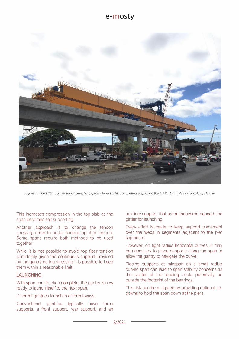
22021
Figure 8 The L100 conventional launching gantry completing a launch in Riyadh Saudi Arabia
Articulating gantries have a different method of
launching A front leg suspended from the support
beam is placed onto the leading pier and then the
rear support rolls along the superstructure
When the rear support has reached the end of the
span the front support and support girders are
launched forward
The wheels of the rear support are meant to ride
directly over the webs however it is possible to
get off-course and start loading the wings or
haunch of a pre-cast segment
Any offset from the center of the web induces a
moment in the top of the web as well and may be
compounded by the presence of transverse post-
tensioning
A steering tolerance should be checked with a
transverse analysis of the segments
Much of the loading from a launching gantry goes
into the previously erected superstructure
However the front support of a launching gantry
typically sits on the up-station side of the leading
pier during span erection
Large moments can develop in the pier as a result
of the following factors
1 Front supports are placed ahead of the
pier centerline to ensure that therersquos room
to set the span being erected
2 The slope of gantry as it follows the bridge
slope imparts a longitudinal load on the
leading pier at the top of the front support
several meters above the top of the pier
3 The slope load is increased by the gantry
deflection under the weight of suspended
segments This can be as much as 2
4 Friction in the front support roller group
can add another 1 of the vertical load
acting longitudinally
22021
Figure 9 Gantry front support showing forward offset from pier centerline and the roller group supporting the main girders
DEAL L57 Gantry Tysonrsquos Corner Virginia
Thus if the gantry is erecting ldquoup-hillrdquo the slope of
the bridge deflection of the gantry and friction in
the roller group are all additive
Conventional gantries have rollers on the front
support to avoid being statically indeterminate
Longitudinal fixity is at the rear support
As such all of the moment inducing forces listed
above must be resisted by the flexural capacity of
the leading pier alone
These loads can be significant and can potentially
govern the design of taller piers
Another concern with the longitudinal loads is the
deflection of the pier itself This can lead to locked-
in deflection if the span is set directly on
permanent bearings that arenrsquot free to slide
longitudinally (elastomeric bearings for example)
NON-TYPICAL SPANS
Erecting typical length spans with gentle horizontal
curves produces predictable construction loads
Where launching gets tricky and therefore applies
loads on the permanent structure is where span
lengths vary widely from one span to the next
Often gantries will have to set their supports at
several locations along the length of the span to
get set up for either a short or long launch
Another launching concern is walkovers This is
where a gantry erects up to another span that has
been erected with another method or at another
time and launches over the completed span to
arrive at the next span to begin erecting again
Typically this occurs where bridges have spans
that exceed the design length for the gantry and
have been previously erected by other means
During walkovers supports will often be placed on
typical segments away from the pier segments in
order to make the launch
Any time supports are placed on typical segments
and not pier segments the span should be
designed to take the flexural shear and principal
tension demands of the launch
22021
Figure 10 The L120 launching gantry (by DEAL) lifts the pre-cast concrete segments of the first span
WIND LOADS
A common concern among bridge owners and
designers is with regards to the applicable wind
loads that a gantry and bridge should be designed
for Bridge design codes require specific wind
speeds and pressures to be considered while
launching gantries are typically designed to
overhead crane design codes that have a different
set of requirements
The launching gantry should be designed for the
wind loads specified by the applicable crane codes
while the bridge should consider the gantry as an
appurtenance affixed to the permanent structure
and use the applicable bridge wind loads in the
design of the bridge
On the Harbor Bridge project in Corpus Christi
Texas there is the potential for large wind loads
given that the bridge is located on the Gulf of
Mexico and the piers are upwards 45m tall
The L120 launching gantry (designed by DEAL) is
160m long and 3m tall giving it a large projected
wind area
The two major concerns that arise are the lateral
loads on the pier columns and the stability of the
span when the gantry is tied down for wind events
To accommodate the large out of service
(hurricane) wind loading the designers opted to
design specific locations along the bridge for
hurricane winds on the structure and gantry
together
The piers and superstructure have increased
capacity to accommodate the gantry should it
need to be tied down a wind event
This was a more economical solution than
designing every pier for the out of service winds
In the event of an approaching hurricane the
gantry does not have far to back launch to get to a
safe place to tie-down
CONCLUSION
In conclusion launching gantries apply unique
loads on both the super and substructures of
bridges
Wind and longitudinal loads on the piers can
sometimes govern the design and stability checks
of the bridge Considering these loads during the
design phase of a bridge project can eliminate
costly redesigns later
22021
GEOMETRY CONTROL FOR PRECAST
SEGMENTAL CONSTRUCTION
Joakim Dupleix CaSE International (formerly VSL)
Martin Pircher ABES
Figure 1 Closing of Mesaimeer Bridge main stay cable span Qatar
PRECAST SEGMENTAL CONSTRUCTION
Precast segmental construction is a great method
to limit the impact of the works on a bridge
construction site
By fabricating the concrete elements in a
controlled environment many of the unpleasant
by-products of the construction site are also
exported
However a key challenge of constructing elements
remotely is to ensure they will achieve the required
bridge geometry once erected on site
Furthermore the fact that the bridge is built ldquopiece-
by-piecerdquo in segments means that the geometry
needs to be controlled and forecasted at every
stage during construction anticipating and
forecasting movements and deflections during the
temporary stages of the construction process
Often bridges have varying curvature and
superelevation which require tools to capture the
geometry in all dimensions
These tools must allow efficient and accurate ways
to correct geometry imperfections such as
correction in setting out in the precast yard or
shimming of segment joints during balanced
cantilever erection on site
22021
ABES SOFTWARE SOLUTION
ABES Pircher amp Partner GmbH is an independent
software house providing solutions for bridge
engineering topics
Together with VSL they have developed a
software suite dedicated to managing the
geometry control of segmental construction at
every stage of the construction process
The software is split in 3 components which are all
interrelated
geoDes to be used in the design office to
model the intended theoretical geometry of
the bridge
geoCon to be used in the casting yard
providing setting out and casting error
compensation for any yard setup
assemCon to be used on site to forecast
the as-built geometry during balanced
cantilever construction based on real time
survey results
Figure 2 Balanced cantilever construction
The software works fully in 3D with a visual
interface which means it can control geometry in
all directions not only vertically
Figure 3 Snapshot of 3D model within ABES geoDes
22021
The Figure below illustrates an example of a cross-
section modeled in geoDes
Figure 4 Cross section (inner void omitted)
KEY PRINCIPLES
The geometry control principles used by ABES are
as follows
The theoretical modelling of the bridge
defines a casting curve in 3D which is the
ldquoperfectrdquo geometry of the bridge This
includes the camber of the bridge if defined
by the designer
Each segment is recorded in its entire
three-dimensional shape and identified by a
minimum of 4 control points which are
physical survey items to be cast anywhere
on the segment
Segment shapes are prepared considering
the specific requirements of the casting
machines used in the yard
The position of control points in the wet
concrete which may vary due to placing
error defines the setting out curve
When segments are cast movement of the
formwork the bulkhead or the conjugate
segment may induce deviations from the
theoretical shape this defines the ldquoas castrdquo
curve
Segment imperfections are compensated
for during casting of sub-sequent
segments This is true for both short-line
and long-line casting or the combination
thereof
During balanced cantilever erection each
construction stage must be monitored and
compared to the deflected position of the
entire bridge as defined by the designer
Again geometric deviations need to be
corrected for during sub-sequent
construction stages
Figure 5 3D interface showing theoretical
(red) and as cast segments (green)
MAIN ADVANTAGES
Modelling
By modelling the bridge from base alignments and
with geometric rules derived from the specific
capabilities of the casting cells the software
achieves the best constructable theoretical fit
Multiple alignments can be accommodated
including deviation from the main alignment such
as for ramps or train stations as required Refer to
Figure 3 above
In the precast yard
When using geoCon the software automatically
compensates for the user the required setting out
according to the survey data of the previous
segment
This is key to ensure seamless casting operation
and minimize operator error Besides benefitting
from the 3D modelling it always works in all three
dimensions
22021
There is no limit to the number of control points
per segment ensuring high accuracy
Another key feature for a stay cable bridge pipes
must be cast in advance into the segment in the
yard to achieve the final geometry after all
deformations have occurred
The software can transform the theoretical pipe
coordinates adjust them for cambers and
segment imperfections and display them in the
local coordinate system which can be processed
by the surveyor in the yard
Figure 6 Gewan Island bridge 3D modelling
with plan radius of less than 125m
Figure 8 Precasting of segments with cable stay pipes
On site for balanced cantilever erection
On site assemCon gives two key insights to the
user
Forecast the position of the bridge at any
construction stage in 3D considering the
as-built data the as-cast curve and the
calculated deflections for each
construction stage
Assist in finding an optimal shimming
strategy to correct the forecasted position
and to target a final as-built structure as
close as possible to the theoretical
geometry
Figure 7 3D view of a cantilever being built
22021
Figure 9 Definition of shimming
strategy to reduce differences
CONCLUSIONS
Pre-cast segmental bridge construction is applied
to increasingly complex and geometrically
challenging structures
Efficient geometry control is essential for the
success of such projects
Geometry control already starts during the
planning process where individual segments need
to be laid out to suit the available equipment in the
casting yard
Segment casting needs to be tightly controlled and
monitored and geometric imperfections need to
be identified and compensated for
And finally bridge construction at the construction
site requires monitoring of individual construction
stages and optimised strategies for correcting for
possible geometry deviations of the bridge
structure during construction
VSL in cooperation with ABES have developed a
suite of software tools to assist in all these tasks
The software is heavily influenced by practical
experience during numerous pre-cast segmental
projects of all sizes and shapes across Asia and
principally Qatar and India and feedback from
ongoing projects continues to inform the
development work
Figure 12 Al Bustan North bridge during construction
above traffic Qatar
Figure 11 Gewan Island Bridge being built Qatar
Figure 10 Karimnagar cable stay bridge India
Photos Credit VSL
22021
PRECAST SEGMENTAL BRIDGE CONSTRUCTION
USING LIFTING FRAME IN QATAR
Joakim Dupleix CaSE International (formerly VSL)
German A Pardo R VSL International Ltd
Figure 1 Overview of Al Bustan North construction site
PRECAST SEGMENTAL CONSTRUCTION
One of the most advantageous construction
methods enabled by segmental construction is the
balanced cantilever method
In a busy brownfield environment pre-casting the
segments off-site is the best solution to minimize
disrupting the existing traffic flow
In these environments access is often limited and
restricted and cranage may not be able to reach
the whole site
In these conditions lifting frame equipment are
often the solution to enable the erection of
segments on the bridge
In Qatar VSL designed and operated two very
different types of lifting frames as part of the Al
Bustan corridor upgrade project
The lifting frames responded to different needs and
segment delivery methods carefully studied during
the construction planning phase of the project
SABAH AL AHMAD CORRIDOR
(previously called Al Bustan)
Sabah al Ahmad or Al Bustan Corridor is part of
the Qatar Expressway Programme and aims to
provide an alternative to the existing expressway
with free flow traffic on a length of 14 km from the
North of Central Doha to the South to improve
connectivity to the FIFA World Cup stadiums
22021
The project involved upgrading the existing main
road by constructing various overhead bridges
over existing crossroads as well as connecting
ramps to remove traffic lights
The construction of this corridor was split into three
main packages
Al Bustan North project now known as
Umm Lekhba Interchange
Al Bustan South project
Mesaimeer Road project
Al Bustan North consists of the major upgrade of a
major interchange with Qatar main highway Al
Shamal Road to become a 4 level interchange
Al Bustan South required the construction of large
overhead bridges up to 26 km long with overhead
ramps connecting to crossroads
Mesaimeer Road upgraded the existing road with 2
large bridges up to 12 km long with a cable stay
section
PRECAST SEGMENTAL BALANCED
CANTILEVER METHOD
Because of the existing brownfield environment in
which the bridges are being built and to minimize
the impact on the existing traffic the precast
segment balanced cantilever method was chosen
for design and construction
It avoids installing large falsework structures on
site where space is limited and enables quick
fabrication of the bridge but requires relatively
large lifting equipment
As a matter of fact as the heavy concrete bridge
segments are to be transported and erected into
position with limited space the key is to
Figure 2 Key map of the corridor in Doha
22021
understand which areas are available where
possible if lifting equipment such as cranes can be
positioned and how to deliver the segments to
their final position
For very heavy segments or if cranes cannot be
used due to site constraints it may be required to
design custom made lifting frame machines
placed on top of the bridge already built and fitted
with their own lifting device to erect the segments
in their final position
These machines typically have a limited range and
segments must be first transported precisely near
their final position
On the Al Bustan Corridor two different delivery
situations were identified
For Al Bustan South and Mesaimeer the
large weight of the segments made it
prohibitively costly to use a crane
However assisted by a temporary
diversion of the existing road during
construction and the flat terrain every
segment could always be delivered directly
below their final position
For Al Bustan North the multi-level
interchange the existing highway Al
Shamal Road could only be closed to traffic
for a very limited time and the existing road
environment did not allow for flexible
segment delivery below each new bridge
ramp
A crane could be positioned near the piers
which allowed for segments to be lifted
onto the already erected deck
To position the segment into its final
position a special lifting frame was
designed to pick up the segment ldquofrom
behindrdquo and bring them forward into their
final position
LIFTING FRAME WITH DELIVERY FROM
BEHIND
As mentioned previously a lifting frame (LF) able
to pick up a segment from behind was required for
this project
A few options for the trajectory of the segment
were considered
Symmetrical Lifting Frame segment
crossing the lifting frame is rotated at 90
degrees in plan lifted and moved through
the middle of the machine longitudinally
Once at the front it can be rotated 90
degrees and lowered in position
Asymmetrical Lifting Frame segment is
delivered 180 degrees from its final
orientation
The segment is picked up rotated 90
degrees moved through the LF
longitudinally rotated again and then
lowered in position
Figure 3 Al Bustan North lifting frame
For this project the bridges are quite narrow with a
web spacing of 6 and 4 m and therefore passing a
32 m long segment between two legs of the LF
was not possible
As shown in Figure 4 on the next page a C shape
was adopted to allow the segment to be rotated on
the free side and moved forward
22021
Figure 4 Segment delivery methodology Click on the image to open it in full size
Description of Lifting Frame
The lifting Frame had the following key
specifications
1 Self-weight of 70 tonnes
2 Lifting capacity of 80 tonnes
3 Lifting speed of 12 mh [02 mmin]
4 Longitudinal launching speed of 3 mh
[005 mmin]
The lifting frame is made of a few key
components
Upper Cross Beam (UCB) transverse
beam carrying the strand lifting unit as
well as the stressing platform lifting
mast Adjustment capability of +-
200 mm
Main Beams (MB) Longitudinal beams
supporting the UCB The UCB is
moved on wheels with a bogie
connected to 2 chain pulling units
Figure 5 3D view of lifting frame model
22021
Support Frame (SF) asymmetric frame in a
C shape supporting the MB The frame is
supported on the deck by adjustable screw
jacks located over the webs
Tie down beams (TDB) during erection
the SF is tie down to the deck with 4 no
40 mm diameter stressbars anchored in
TDB The TDB allows for longitudinal
adjustment in the position of the bars as
the segment length varies
Rail beams (RB) two rail beams on each
side of the SF are fitted with a hydraulic
launching system able to move the entire
frame forward in steps of 700 mm
Segment lifting beam (SLB) the SLB is
stressed to the segment being lifted and is
fitted with hydraulic jacks able to adjust the
segment to the required crossfall and
gradient as well as rotated the segment in
plan to pass through the SF
Stressing platform (SP) to complete the
balance cantilever construction a SP is
required to be positioned each newly
erected segment to provide access for
personnel to complete the permanent post-
tensioning operation
Figure 6 Segment delivered at the rear of the LF
Figure 8 Segment rotated to its final orientation
rarr Figure 9 Segment lowered into
position and load transferred
Figure 7 Segment rotated and moved longitudinally
SEGMENT ERECTION PHOTOS
The photo sequence below shows the segment
delivery process
22021
Challenges
Because of the limited width of the deck and the
congested site area with existing roads one of the
key challenges was to find a suitable storage
position for the SP when not in use which would
not block the segment passage
A rotation mast or davit arm was designed to lift
and position the 6 tonnes platform The mast was
rotated up to 120 degrees with a small horizontal
hydraulic jack
The concept and design itself of the Lifting Frame
required a solution which provided the minimum
required space for manipulating the segment and
the stressing platform in a very tight area while
having enough stiffness and capacity to cover the
demands
LIFTING FRAME WITH DELIVERY FROM
BELOW
Typical configuration for a Lifting Frame is such
that segment can be lifted directly from below
This was the case of Al Bustan South and
Mesaimeer projects
MESAIMEER LIFTING FRAME
Segments to be lifted by this lifting frame were the
heaviest and widest on the project for this reason
a stiffer structure composed of rigid frames at the
supporting areas was chosen taking advantage of
the fact that there was no restriction in height and
section of the bridge
The delivery of the segments in this project could
be conducted almost at is final position in plan
which facilitated the configuration of the lifting
equipment at the cantilever of the lifting frame
For this purpose the lifting frame was provided
with a couple of Winches that could pick up the
segment from the ground with minimum rotation in
plan lifted to required level and conduct final
adjustment in the longitudinal and transverse
directions
Description of Lifting Frame
The Lifting Frame had the following key
specifications
1 Self-weight of 92 tonnes
2 Lifting capacity of 185 tonnes
3 Lifting speed of 60 mh [1 mmin]
4 Longitudinal launching speed of 3mh [005
mmin)
Figure 10 segment delivered at the rear of the LF
The lifting frame is made of a few key components
Upper Cross Beam (UCB) transverse
beam carrying the main lifting equipment
(Winch) as well as the stressing platform
Adjustment capability +- 1325
Cantilever Beam (CTB) the 2 main
longitudinal beams supporting the UCB and
Stressing Platform at front and the Tie
Down Beam at the rear
Lower Cross Beam (LCB) main Frames
underneath the CTB transferring all load to
the bridge
Rail Beams (RB) two rail beams on each
side of the LCB are fitted with a hydraulic
launching system able to move the entire
frame forward in steps of 850 mm
22021
Connection Beams (CB) beams
connecting the hook blocks of the Winches
directly to the segment They are provided
with jacks for segment gradient adjustment
Crossfall is adjusted directly by the
Winches
Stressing Platform (SP) it is positioned at
the tip of the CTB and move backward for
conducting stressing of bridge post-
tensioning tendons It is provided with 2
levels customized for this project
Tie Down Beam (TDB) the Support frame
is provided with a set of tie down beams at
the rear which are the main stability
system
TDB can be adjusted in the longitudinal
direction to suit the different segment
lengths and their respective tie down holes
position
Tie down bars are of 75mm and 47mm in
diameter and pre-stressed against the
segment
Challenges
To accommodate the supporting area in a
very limited length since there was
insufficient space near the pylons
This created big reactions to be taken by
the tie down elements due the big
cantilever at front and heavy segments to
be lifted
To be able to move all the way back the
lifting equipment (Winch) and UCB to
provide enough stability during the
launching procedure Space at rear of the
lifting frame was very limited
Provide a Stressing Platform with 2
different configurations (1 or 2 levels) that
could be adapted for specific
configurations
SEGMENT ERECTION PHOTOS
Figure 11 Mesaimeer Lifting Frame
Figure 12 Segment lifting
Figure 13 Segment permanent post-tensioning in progress
22021
AL BUSTAN SOUTH LIFTING FRAME
For this project the lifting frame had to
accommodate few main requirements to suit the
space constraints of the project and the bridge
capacity
Height A limit of 6m for total height the lifting
frame was to be assured since the bridge had
to pass under an existing viaduct
Load introduction The bridge section is
provided with 3 webs and middle web capacity
was to be respected by limiting the reactions at
this point Additionally the total weight of the
Lifting Frame was also limited
Segment delivered below could not be
positioned in its final orientation due to space
constraints It had to be rotated up to 90deg once
hanging from the lifting frame
To overcome the limitations described the lifting
frame concept developed considered the following
aspects
Main lifting equipment (Winch) was
positioned at the bottom rear area of the
lifting frame to reduce the total height
The three webs of the segment were
loaded and the Lifting Frame elements
were studied in such a way that the total
weight of the Lifting Frame and loading of
central web were not exceeded
A single Winch and the hook block with
rotation device were provided to allow
rotation of the segment while hanging from
the Lifting Frame
Description of Lifting Frame
The Lifting Frame had the following key
specifications
1 Self-weight of 81 tonnes
2 Lifting capacity of 170 tonnes
3 Lifting speed of 36 mh [06 mmin]
4 Longitudinal launching speed of 3mh [005
mmin
The lifting frame is made of the following key
components
Upper Cross Beam (UCB) uppermost
element carrying the Winch Trolley It can
slide longitudinally to accommodate the
segment in length Transverse adjustment
is done by sliding of the Winch Trolley over
the UCB
Main Frame (MF) the Lifting Frame is
provided with 2 Main Frames in section that
support the UCB and Stressing Platform on
top and transfers the vertical load to the
lower elements of the Lifting Frame At
bottom level it also receives the Tie Down
Beam
Lower Cross Beam (LCB) spreader beam
in the transverse direction located at front
and rear that transfer all loads to the
segment webs through 6 screw jacks (3 at
the front and 3 at the rear)
Tie Down Beam (TDB) located at rear part
of the Lifting Frame and contain the tie
down bars stressed down against the
segment in order to assure the stability of
the Lifting Frame It contains a couple of
back-up bars that provide redundancy to
the system
Segment Lifting Beam (SLB) connecting
element between the hook block of the
winch and the segment It is provided with
a rotational device that allows full rotation
of the segment in plan
Figure 14 Segment delivered at the rear of the LF
22021
Stressing Platform (SP) it hangs from the
tip of the Main Frame cantilever beam It is
moved backwards after segment
installation to conduct the stressing of the
permanent post-tensioning system
Rail Beam (RB) two rail beams on each
side of the LCB are fitted with a hydraulic
launching system able it to move the entire
frame forward in steps of 850 mm
Figure 14 Lifting Frame installation on deck
Figure 15 Lifting of segment
Figure 16 Stressing of post-tensioning tendons
Figure 17 Lifting Frame crossing under existing viaduct
SEGMENT ERECTION PHOTOS
Challenges
To develop a concept and design that did
not exceed the limitations given regarding
total weight and height
Allow full rotation of the segment while
hanging
Provide redundancy to the Lifting Frame
Tie Down system and to the Stressing
Platform while under operation
22021
CONCLUSIONS
Precast segmental construction in a congested
environment often requires the use of custom
designed lifting frames
These machines must always consider the
segment delivery methods as well as the bridge
characteristics in order to achieve the most cost-
efficient methods of erection
The more requirements a project has the more
customized the Lifting Frame will be
For this reason it is of key importance to integrate
the development of the Temporary Structures (like
Lifting Frames) as early as possible in the design
process
By doing this some of the constraints can be
solved in earlier stages which will improve the
efficiency of the full process and the interfaces
between the different parts involved Permanent
Works Designer Temporary Works Designer and
Main Contractor
Figure 18 Al Bustan North Figure 19 Al Bustan North
Figure 20 Al Bustan South
Figure 21 Mesaimeer
Photos 18 ndash 20 Credit Ashghal (Qatar Road Authority)
We design and produceformwork equipmentfor in-place casting of bridgesN25 New Ross Bypass (Ireland)
FOLLOW US
INNOVATIVE | SAFE | SUSTAINABLE | FAST
SOLUTIONS FOR BRIDGE CONSTRUCTION
MSS M1-70-S BRATISLAVA BYPASS | IN SITU CONSTRUCTION
LG 36-S CAIRO METRO LINE 3 EXTENSION | PRECAST SEGMENTAL
WWWBERDEU
Photo Credits D4R7
Photo Credits Stephane Ciccolini
Arup works in active partnership with clients to understand their needs so
that the solutions make their bridge aspirations possible mdashbig and small
The Arup global specialist technical skills blended with essential local
knowledge adds unexpected benefits
wwwarupcom
Whether to span nations make a statement or
improve everyday links Arup crafts better bridges
Naeem Hussain Richard Hornby Steve Kite Deepak Jayaram
naeemhussainarupcom richardhornbyarupcom stevekitearupcom deepakjayaramarupcom
Global UK Middle East amp Africa East Asia UK Middle East India
and Africa
Peter Burnton Marcos Sanchez Matt Carter
peterburntonarupcom marcossanchezarupcom mattcarterarupcom
Australasia Europe Americas
Queensferry Crossing Scotland
SANTANDERMADRIDLIMABOGOTAacuteBUENOS AIRES
Calle Marqueacutes de la Ensenada 11 - 3ordm 39009
Calle Bravo Murillo 101 - 4ordm 28020
Calle Coronel Inclaacuten 235 - Oficina 313 Lima 18
Cra 14 94a - 24 Oficina 307 Edificio ACO 94
Calle Rodriacuteguez Pentildea 681 - 4ordm Dpto 8 1020
Tfno +34 942 31 99 60
Tfno +34 91 702 54 78
Tfno +51 1 637 56 47
Tfno +57 1 467 48 10
Tfno +54 911 5709 3252
wwwarenasingcom
ARCHING THE WORLD
CODE-BASED DESIGN
DETAILINGDR AWING PRODUCTION
PAR AM ETRIC MODELING
STRUCTUR AL ANALYSIS
DOWNLOAD A FREE TRIALallplancombridge2021
THE WORLDrsquoS FIRST COMPLETE SOLUTIONFOR BRIDGE ENGINEERS
Allplan Bridge 2021 maps the complete BIM process in bridge projects The new version enables bridge engineers to work with one single solution from the creation of a parametric 4D model to structural analysis reinforcement design and detailing This further improves the design process in terms of both time and quality
ALLPLAN BRIDGE
Join Bridges to Prosperity in helping isolated
communities gain safe access to healthcare
education jobs and markets through simple
sustainable trailbridges Together we can
build more than a bridge we can build a
pathway out of poverty
We envision a world wherepoverty caused by ruralisolation no longer exists
bridgestoprosperityorg
infobridgestoprosperityorgbridgestoprosperity
bridgestoprosperity
b2p
+60Women Entering the Labor Force
+75Farmer
Profitability
+358Labor Market
Income
Corporate Partners make this
vision possible
Wyatt Brooks and Kevin Donovan - Eliminating Uncertainty in Market Access
The Impact of New Bridges in Rural Nicaragua 2017
SEGMENTAL BRIDGES
ISSUE 022021 JUNE
- 1 arenas_v2
-
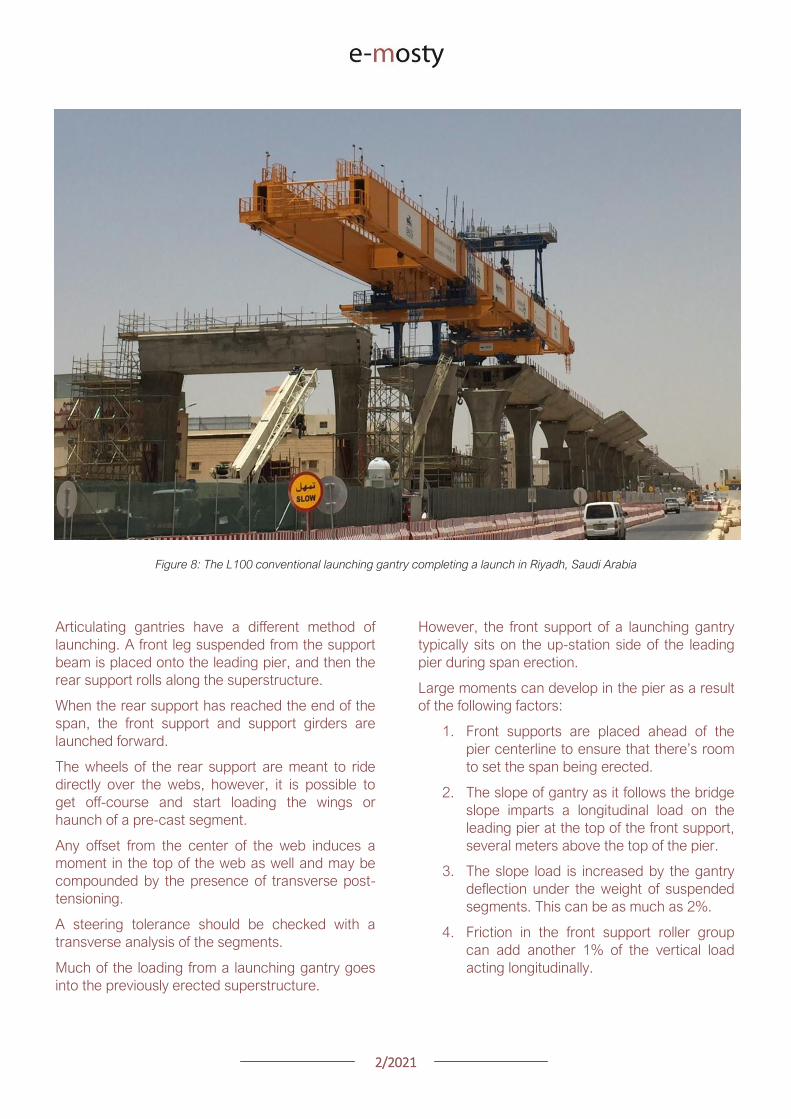
22021
Figure 9 Gantry front support showing forward offset from pier centerline and the roller group supporting the main girders
DEAL L57 Gantry Tysonrsquos Corner Virginia
Thus if the gantry is erecting ldquoup-hillrdquo the slope of
the bridge deflection of the gantry and friction in
the roller group are all additive
Conventional gantries have rollers on the front
support to avoid being statically indeterminate
Longitudinal fixity is at the rear support
As such all of the moment inducing forces listed
above must be resisted by the flexural capacity of
the leading pier alone
These loads can be significant and can potentially
govern the design of taller piers
Another concern with the longitudinal loads is the
deflection of the pier itself This can lead to locked-
in deflection if the span is set directly on
permanent bearings that arenrsquot free to slide
longitudinally (elastomeric bearings for example)
NON-TYPICAL SPANS
Erecting typical length spans with gentle horizontal
curves produces predictable construction loads
Where launching gets tricky and therefore applies
loads on the permanent structure is where span
lengths vary widely from one span to the next
Often gantries will have to set their supports at
several locations along the length of the span to
get set up for either a short or long launch
Another launching concern is walkovers This is
where a gantry erects up to another span that has
been erected with another method or at another
time and launches over the completed span to
arrive at the next span to begin erecting again
Typically this occurs where bridges have spans
that exceed the design length for the gantry and
have been previously erected by other means
During walkovers supports will often be placed on
typical segments away from the pier segments in
order to make the launch
Any time supports are placed on typical segments
and not pier segments the span should be
designed to take the flexural shear and principal
tension demands of the launch
22021
Figure 10 The L120 launching gantry (by DEAL) lifts the pre-cast concrete segments of the first span
WIND LOADS
A common concern among bridge owners and
designers is with regards to the applicable wind
loads that a gantry and bridge should be designed
for Bridge design codes require specific wind
speeds and pressures to be considered while
launching gantries are typically designed to
overhead crane design codes that have a different
set of requirements
The launching gantry should be designed for the
wind loads specified by the applicable crane codes
while the bridge should consider the gantry as an
appurtenance affixed to the permanent structure
and use the applicable bridge wind loads in the
design of the bridge
On the Harbor Bridge project in Corpus Christi
Texas there is the potential for large wind loads
given that the bridge is located on the Gulf of
Mexico and the piers are upwards 45m tall
The L120 launching gantry (designed by DEAL) is
160m long and 3m tall giving it a large projected
wind area
The two major concerns that arise are the lateral
loads on the pier columns and the stability of the
span when the gantry is tied down for wind events
To accommodate the large out of service
(hurricane) wind loading the designers opted to
design specific locations along the bridge for
hurricane winds on the structure and gantry
together
The piers and superstructure have increased
capacity to accommodate the gantry should it
need to be tied down a wind event
This was a more economical solution than
designing every pier for the out of service winds
In the event of an approaching hurricane the
gantry does not have far to back launch to get to a
safe place to tie-down
CONCLUSION
In conclusion launching gantries apply unique
loads on both the super and substructures of
bridges
Wind and longitudinal loads on the piers can
sometimes govern the design and stability checks
of the bridge Considering these loads during the
design phase of a bridge project can eliminate
costly redesigns later
22021
GEOMETRY CONTROL FOR PRECAST
SEGMENTAL CONSTRUCTION
Joakim Dupleix CaSE International (formerly VSL)
Martin Pircher ABES
Figure 1 Closing of Mesaimeer Bridge main stay cable span Qatar
PRECAST SEGMENTAL CONSTRUCTION
Precast segmental construction is a great method
to limit the impact of the works on a bridge
construction site
By fabricating the concrete elements in a
controlled environment many of the unpleasant
by-products of the construction site are also
exported
However a key challenge of constructing elements
remotely is to ensure they will achieve the required
bridge geometry once erected on site
Furthermore the fact that the bridge is built ldquopiece-
by-piecerdquo in segments means that the geometry
needs to be controlled and forecasted at every
stage during construction anticipating and
forecasting movements and deflections during the
temporary stages of the construction process
Often bridges have varying curvature and
superelevation which require tools to capture the
geometry in all dimensions
These tools must allow efficient and accurate ways
to correct geometry imperfections such as
correction in setting out in the precast yard or
shimming of segment joints during balanced
cantilever erection on site
22021
ABES SOFTWARE SOLUTION
ABES Pircher amp Partner GmbH is an independent
software house providing solutions for bridge
engineering topics
Together with VSL they have developed a
software suite dedicated to managing the
geometry control of segmental construction at
every stage of the construction process
The software is split in 3 components which are all
interrelated
geoDes to be used in the design office to
model the intended theoretical geometry of
the bridge
geoCon to be used in the casting yard
providing setting out and casting error
compensation for any yard setup
assemCon to be used on site to forecast
the as-built geometry during balanced
cantilever construction based on real time
survey results
Figure 2 Balanced cantilever construction
The software works fully in 3D with a visual
interface which means it can control geometry in
all directions not only vertically
Figure 3 Snapshot of 3D model within ABES geoDes
22021
The Figure below illustrates an example of a cross-
section modeled in geoDes
Figure 4 Cross section (inner void omitted)
KEY PRINCIPLES
The geometry control principles used by ABES are
as follows
The theoretical modelling of the bridge
defines a casting curve in 3D which is the
ldquoperfectrdquo geometry of the bridge This
includes the camber of the bridge if defined
by the designer
Each segment is recorded in its entire
three-dimensional shape and identified by a
minimum of 4 control points which are
physical survey items to be cast anywhere
on the segment
Segment shapes are prepared considering
the specific requirements of the casting
machines used in the yard
The position of control points in the wet
concrete which may vary due to placing
error defines the setting out curve
When segments are cast movement of the
formwork the bulkhead or the conjugate
segment may induce deviations from the
theoretical shape this defines the ldquoas castrdquo
curve
Segment imperfections are compensated
for during casting of sub-sequent
segments This is true for both short-line
and long-line casting or the combination
thereof
During balanced cantilever erection each
construction stage must be monitored and
compared to the deflected position of the
entire bridge as defined by the designer
Again geometric deviations need to be
corrected for during sub-sequent
construction stages
Figure 5 3D interface showing theoretical
(red) and as cast segments (green)
MAIN ADVANTAGES
Modelling
By modelling the bridge from base alignments and
with geometric rules derived from the specific
capabilities of the casting cells the software
achieves the best constructable theoretical fit
Multiple alignments can be accommodated
including deviation from the main alignment such
as for ramps or train stations as required Refer to
Figure 3 above
In the precast yard
When using geoCon the software automatically
compensates for the user the required setting out
according to the survey data of the previous
segment
This is key to ensure seamless casting operation
and minimize operator error Besides benefitting
from the 3D modelling it always works in all three
dimensions
22021
There is no limit to the number of control points
per segment ensuring high accuracy
Another key feature for a stay cable bridge pipes
must be cast in advance into the segment in the
yard to achieve the final geometry after all
deformations have occurred
The software can transform the theoretical pipe
coordinates adjust them for cambers and
segment imperfections and display them in the
local coordinate system which can be processed
by the surveyor in the yard
Figure 6 Gewan Island bridge 3D modelling
with plan radius of less than 125m
Figure 8 Precasting of segments with cable stay pipes
On site for balanced cantilever erection
On site assemCon gives two key insights to the
user
Forecast the position of the bridge at any
construction stage in 3D considering the
as-built data the as-cast curve and the
calculated deflections for each
construction stage
Assist in finding an optimal shimming
strategy to correct the forecasted position
and to target a final as-built structure as
close as possible to the theoretical
geometry
Figure 7 3D view of a cantilever being built
22021
Figure 9 Definition of shimming
strategy to reduce differences
CONCLUSIONS
Pre-cast segmental bridge construction is applied
to increasingly complex and geometrically
challenging structures
Efficient geometry control is essential for the
success of such projects
Geometry control already starts during the
planning process where individual segments need
to be laid out to suit the available equipment in the
casting yard
Segment casting needs to be tightly controlled and
monitored and geometric imperfections need to
be identified and compensated for
And finally bridge construction at the construction
site requires monitoring of individual construction
stages and optimised strategies for correcting for
possible geometry deviations of the bridge
structure during construction
VSL in cooperation with ABES have developed a
suite of software tools to assist in all these tasks
The software is heavily influenced by practical
experience during numerous pre-cast segmental
projects of all sizes and shapes across Asia and
principally Qatar and India and feedback from
ongoing projects continues to inform the
development work
Figure 12 Al Bustan North bridge during construction
above traffic Qatar
Figure 11 Gewan Island Bridge being built Qatar
Figure 10 Karimnagar cable stay bridge India
Photos Credit VSL
22021
PRECAST SEGMENTAL BRIDGE CONSTRUCTION
USING LIFTING FRAME IN QATAR
Joakim Dupleix CaSE International (formerly VSL)
German A Pardo R VSL International Ltd
Figure 1 Overview of Al Bustan North construction site
PRECAST SEGMENTAL CONSTRUCTION
One of the most advantageous construction
methods enabled by segmental construction is the
balanced cantilever method
In a busy brownfield environment pre-casting the
segments off-site is the best solution to minimize
disrupting the existing traffic flow
In these environments access is often limited and
restricted and cranage may not be able to reach
the whole site
In these conditions lifting frame equipment are
often the solution to enable the erection of
segments on the bridge
In Qatar VSL designed and operated two very
different types of lifting frames as part of the Al
Bustan corridor upgrade project
The lifting frames responded to different needs and
segment delivery methods carefully studied during
the construction planning phase of the project
SABAH AL AHMAD CORRIDOR
(previously called Al Bustan)
Sabah al Ahmad or Al Bustan Corridor is part of
the Qatar Expressway Programme and aims to
provide an alternative to the existing expressway
with free flow traffic on a length of 14 km from the
North of Central Doha to the South to improve
connectivity to the FIFA World Cup stadiums
22021
The project involved upgrading the existing main
road by constructing various overhead bridges
over existing crossroads as well as connecting
ramps to remove traffic lights
The construction of this corridor was split into three
main packages
Al Bustan North project now known as
Umm Lekhba Interchange
Al Bustan South project
Mesaimeer Road project
Al Bustan North consists of the major upgrade of a
major interchange with Qatar main highway Al
Shamal Road to become a 4 level interchange
Al Bustan South required the construction of large
overhead bridges up to 26 km long with overhead
ramps connecting to crossroads
Mesaimeer Road upgraded the existing road with 2
large bridges up to 12 km long with a cable stay
section
PRECAST SEGMENTAL BALANCED
CANTILEVER METHOD
Because of the existing brownfield environment in
which the bridges are being built and to minimize
the impact on the existing traffic the precast
segment balanced cantilever method was chosen
for design and construction
It avoids installing large falsework structures on
site where space is limited and enables quick
fabrication of the bridge but requires relatively
large lifting equipment
As a matter of fact as the heavy concrete bridge
segments are to be transported and erected into
position with limited space the key is to
Figure 2 Key map of the corridor in Doha
22021
understand which areas are available where
possible if lifting equipment such as cranes can be
positioned and how to deliver the segments to
their final position
For very heavy segments or if cranes cannot be
used due to site constraints it may be required to
design custom made lifting frame machines
placed on top of the bridge already built and fitted
with their own lifting device to erect the segments
in their final position
These machines typically have a limited range and
segments must be first transported precisely near
their final position
On the Al Bustan Corridor two different delivery
situations were identified
For Al Bustan South and Mesaimeer the
large weight of the segments made it
prohibitively costly to use a crane
However assisted by a temporary
diversion of the existing road during
construction and the flat terrain every
segment could always be delivered directly
below their final position
For Al Bustan North the multi-level
interchange the existing highway Al
Shamal Road could only be closed to traffic
for a very limited time and the existing road
environment did not allow for flexible
segment delivery below each new bridge
ramp
A crane could be positioned near the piers
which allowed for segments to be lifted
onto the already erected deck
To position the segment into its final
position a special lifting frame was
designed to pick up the segment ldquofrom
behindrdquo and bring them forward into their
final position
LIFTING FRAME WITH DELIVERY FROM
BEHIND
As mentioned previously a lifting frame (LF) able
to pick up a segment from behind was required for
this project
A few options for the trajectory of the segment
were considered
Symmetrical Lifting Frame segment
crossing the lifting frame is rotated at 90
degrees in plan lifted and moved through
the middle of the machine longitudinally
Once at the front it can be rotated 90
degrees and lowered in position
Asymmetrical Lifting Frame segment is
delivered 180 degrees from its final
orientation
The segment is picked up rotated 90
degrees moved through the LF
longitudinally rotated again and then
lowered in position
Figure 3 Al Bustan North lifting frame
For this project the bridges are quite narrow with a
web spacing of 6 and 4 m and therefore passing a
32 m long segment between two legs of the LF
was not possible
As shown in Figure 4 on the next page a C shape
was adopted to allow the segment to be rotated on
the free side and moved forward
22021
Figure 4 Segment delivery methodology Click on the image to open it in full size
Description of Lifting Frame
The lifting Frame had the following key
specifications
1 Self-weight of 70 tonnes
2 Lifting capacity of 80 tonnes
3 Lifting speed of 12 mh [02 mmin]
4 Longitudinal launching speed of 3 mh
[005 mmin]
The lifting frame is made of a few key
components
Upper Cross Beam (UCB) transverse
beam carrying the strand lifting unit as
well as the stressing platform lifting
mast Adjustment capability of +-
200 mm
Main Beams (MB) Longitudinal beams
supporting the UCB The UCB is
moved on wheels with a bogie
connected to 2 chain pulling units
Figure 5 3D view of lifting frame model
22021
Support Frame (SF) asymmetric frame in a
C shape supporting the MB The frame is
supported on the deck by adjustable screw
jacks located over the webs
Tie down beams (TDB) during erection
the SF is tie down to the deck with 4 no
40 mm diameter stressbars anchored in
TDB The TDB allows for longitudinal
adjustment in the position of the bars as
the segment length varies
Rail beams (RB) two rail beams on each
side of the SF are fitted with a hydraulic
launching system able to move the entire
frame forward in steps of 700 mm
Segment lifting beam (SLB) the SLB is
stressed to the segment being lifted and is
fitted with hydraulic jacks able to adjust the
segment to the required crossfall and
gradient as well as rotated the segment in
plan to pass through the SF
Stressing platform (SP) to complete the
balance cantilever construction a SP is
required to be positioned each newly
erected segment to provide access for
personnel to complete the permanent post-
tensioning operation
Figure 6 Segment delivered at the rear of the LF
Figure 8 Segment rotated to its final orientation
rarr Figure 9 Segment lowered into
position and load transferred
Figure 7 Segment rotated and moved longitudinally
SEGMENT ERECTION PHOTOS
The photo sequence below shows the segment
delivery process
22021
Challenges
Because of the limited width of the deck and the
congested site area with existing roads one of the
key challenges was to find a suitable storage
position for the SP when not in use which would
not block the segment passage
A rotation mast or davit arm was designed to lift
and position the 6 tonnes platform The mast was
rotated up to 120 degrees with a small horizontal
hydraulic jack
The concept and design itself of the Lifting Frame
required a solution which provided the minimum
required space for manipulating the segment and
the stressing platform in a very tight area while
having enough stiffness and capacity to cover the
demands
LIFTING FRAME WITH DELIVERY FROM
BELOW
Typical configuration for a Lifting Frame is such
that segment can be lifted directly from below
This was the case of Al Bustan South and
Mesaimeer projects
MESAIMEER LIFTING FRAME
Segments to be lifted by this lifting frame were the
heaviest and widest on the project for this reason
a stiffer structure composed of rigid frames at the
supporting areas was chosen taking advantage of
the fact that there was no restriction in height and
section of the bridge
The delivery of the segments in this project could
be conducted almost at is final position in plan
which facilitated the configuration of the lifting
equipment at the cantilever of the lifting frame
For this purpose the lifting frame was provided
with a couple of Winches that could pick up the
segment from the ground with minimum rotation in
plan lifted to required level and conduct final
adjustment in the longitudinal and transverse
directions
Description of Lifting Frame
The Lifting Frame had the following key
specifications
1 Self-weight of 92 tonnes
2 Lifting capacity of 185 tonnes
3 Lifting speed of 60 mh [1 mmin]
4 Longitudinal launching speed of 3mh [005
mmin)
Figure 10 segment delivered at the rear of the LF
The lifting frame is made of a few key components
Upper Cross Beam (UCB) transverse
beam carrying the main lifting equipment
(Winch) as well as the stressing platform
Adjustment capability +- 1325
Cantilever Beam (CTB) the 2 main
longitudinal beams supporting the UCB and
Stressing Platform at front and the Tie
Down Beam at the rear
Lower Cross Beam (LCB) main Frames
underneath the CTB transferring all load to
the bridge
Rail Beams (RB) two rail beams on each
side of the LCB are fitted with a hydraulic
launching system able to move the entire
frame forward in steps of 850 mm
22021
Connection Beams (CB) beams
connecting the hook blocks of the Winches
directly to the segment They are provided
with jacks for segment gradient adjustment
Crossfall is adjusted directly by the
Winches
Stressing Platform (SP) it is positioned at
the tip of the CTB and move backward for
conducting stressing of bridge post-
tensioning tendons It is provided with 2
levels customized for this project
Tie Down Beam (TDB) the Support frame
is provided with a set of tie down beams at
the rear which are the main stability
system
TDB can be adjusted in the longitudinal
direction to suit the different segment
lengths and their respective tie down holes
position
Tie down bars are of 75mm and 47mm in
diameter and pre-stressed against the
segment
Challenges
To accommodate the supporting area in a
very limited length since there was
insufficient space near the pylons
This created big reactions to be taken by
the tie down elements due the big
cantilever at front and heavy segments to
be lifted
To be able to move all the way back the
lifting equipment (Winch) and UCB to
provide enough stability during the
launching procedure Space at rear of the
lifting frame was very limited
Provide a Stressing Platform with 2
different configurations (1 or 2 levels) that
could be adapted for specific
configurations
SEGMENT ERECTION PHOTOS
Figure 11 Mesaimeer Lifting Frame
Figure 12 Segment lifting
Figure 13 Segment permanent post-tensioning in progress
22021
AL BUSTAN SOUTH LIFTING FRAME
For this project the lifting frame had to
accommodate few main requirements to suit the
space constraints of the project and the bridge
capacity
Height A limit of 6m for total height the lifting
frame was to be assured since the bridge had
to pass under an existing viaduct
Load introduction The bridge section is
provided with 3 webs and middle web capacity
was to be respected by limiting the reactions at
this point Additionally the total weight of the
Lifting Frame was also limited
Segment delivered below could not be
positioned in its final orientation due to space
constraints It had to be rotated up to 90deg once
hanging from the lifting frame
To overcome the limitations described the lifting
frame concept developed considered the following
aspects
Main lifting equipment (Winch) was
positioned at the bottom rear area of the
lifting frame to reduce the total height
The three webs of the segment were
loaded and the Lifting Frame elements
were studied in such a way that the total
weight of the Lifting Frame and loading of
central web were not exceeded
A single Winch and the hook block with
rotation device were provided to allow
rotation of the segment while hanging from
the Lifting Frame
Description of Lifting Frame
The Lifting Frame had the following key
specifications
1 Self-weight of 81 tonnes
2 Lifting capacity of 170 tonnes
3 Lifting speed of 36 mh [06 mmin]
4 Longitudinal launching speed of 3mh [005
mmin
The lifting frame is made of the following key
components
Upper Cross Beam (UCB) uppermost
element carrying the Winch Trolley It can
slide longitudinally to accommodate the
segment in length Transverse adjustment
is done by sliding of the Winch Trolley over
the UCB
Main Frame (MF) the Lifting Frame is
provided with 2 Main Frames in section that
support the UCB and Stressing Platform on
top and transfers the vertical load to the
lower elements of the Lifting Frame At
bottom level it also receives the Tie Down
Beam
Lower Cross Beam (LCB) spreader beam
in the transverse direction located at front
and rear that transfer all loads to the
segment webs through 6 screw jacks (3 at
the front and 3 at the rear)
Tie Down Beam (TDB) located at rear part
of the Lifting Frame and contain the tie
down bars stressed down against the
segment in order to assure the stability of
the Lifting Frame It contains a couple of
back-up bars that provide redundancy to
the system
Segment Lifting Beam (SLB) connecting
element between the hook block of the
winch and the segment It is provided with
a rotational device that allows full rotation
of the segment in plan
Figure 14 Segment delivered at the rear of the LF
22021
Stressing Platform (SP) it hangs from the
tip of the Main Frame cantilever beam It is
moved backwards after segment
installation to conduct the stressing of the
permanent post-tensioning system
Rail Beam (RB) two rail beams on each
side of the LCB are fitted with a hydraulic
launching system able it to move the entire
frame forward in steps of 850 mm
Figure 14 Lifting Frame installation on deck
Figure 15 Lifting of segment
Figure 16 Stressing of post-tensioning tendons
Figure 17 Lifting Frame crossing under existing viaduct
SEGMENT ERECTION PHOTOS
Challenges
To develop a concept and design that did
not exceed the limitations given regarding
total weight and height
Allow full rotation of the segment while
hanging
Provide redundancy to the Lifting Frame
Tie Down system and to the Stressing
Platform while under operation
22021
CONCLUSIONS
Precast segmental construction in a congested
environment often requires the use of custom
designed lifting frames
These machines must always consider the
segment delivery methods as well as the bridge
characteristics in order to achieve the most cost-
efficient methods of erection
The more requirements a project has the more
customized the Lifting Frame will be
For this reason it is of key importance to integrate
the development of the Temporary Structures (like
Lifting Frames) as early as possible in the design
process
By doing this some of the constraints can be
solved in earlier stages which will improve the
efficiency of the full process and the interfaces
between the different parts involved Permanent
Works Designer Temporary Works Designer and
Main Contractor
Figure 18 Al Bustan North Figure 19 Al Bustan North
Figure 20 Al Bustan South
Figure 21 Mesaimeer
Photos 18 ndash 20 Credit Ashghal (Qatar Road Authority)
We design and produceformwork equipmentfor in-place casting of bridgesN25 New Ross Bypass (Ireland)
FOLLOW US
INNOVATIVE | SAFE | SUSTAINABLE | FAST
SOLUTIONS FOR BRIDGE CONSTRUCTION
MSS M1-70-S BRATISLAVA BYPASS | IN SITU CONSTRUCTION
LG 36-S CAIRO METRO LINE 3 EXTENSION | PRECAST SEGMENTAL
WWWBERDEU
Photo Credits D4R7
Photo Credits Stephane Ciccolini
Arup works in active partnership with clients to understand their needs so
that the solutions make their bridge aspirations possible mdashbig and small
The Arup global specialist technical skills blended with essential local
knowledge adds unexpected benefits
wwwarupcom
Whether to span nations make a statement or
improve everyday links Arup crafts better bridges
Naeem Hussain Richard Hornby Steve Kite Deepak Jayaram
naeemhussainarupcom richardhornbyarupcom stevekitearupcom deepakjayaramarupcom
Global UK Middle East amp Africa East Asia UK Middle East India
and Africa
Peter Burnton Marcos Sanchez Matt Carter
peterburntonarupcom marcossanchezarupcom mattcarterarupcom
Australasia Europe Americas
Queensferry Crossing Scotland
SANTANDERMADRIDLIMABOGOTAacuteBUENOS AIRES
Calle Marqueacutes de la Ensenada 11 - 3ordm 39009
Calle Bravo Murillo 101 - 4ordm 28020
Calle Coronel Inclaacuten 235 - Oficina 313 Lima 18
Cra 14 94a - 24 Oficina 307 Edificio ACO 94
Calle Rodriacuteguez Pentildea 681 - 4ordm Dpto 8 1020
Tfno +34 942 31 99 60
Tfno +34 91 702 54 78
Tfno +51 1 637 56 47
Tfno +57 1 467 48 10
Tfno +54 911 5709 3252
wwwarenasingcom
ARCHING THE WORLD
CODE-BASED DESIGN
DETAILINGDR AWING PRODUCTION
PAR AM ETRIC MODELING
STRUCTUR AL ANALYSIS
DOWNLOAD A FREE TRIALallplancombridge2021
THE WORLDrsquoS FIRST COMPLETE SOLUTIONFOR BRIDGE ENGINEERS
Allplan Bridge 2021 maps the complete BIM process in bridge projects The new version enables bridge engineers to work with one single solution from the creation of a parametric 4D model to structural analysis reinforcement design and detailing This further improves the design process in terms of both time and quality
ALLPLAN BRIDGE
Join Bridges to Prosperity in helping isolated
communities gain safe access to healthcare
education jobs and markets through simple
sustainable trailbridges Together we can
build more than a bridge we can build a
pathway out of poverty
We envision a world wherepoverty caused by ruralisolation no longer exists
bridgestoprosperityorg
infobridgestoprosperityorgbridgestoprosperity
bridgestoprosperity
b2p
+60Women Entering the Labor Force
+75Farmer
Profitability
+358Labor Market
Income
Corporate Partners make this
vision possible
Wyatt Brooks and Kevin Donovan - Eliminating Uncertainty in Market Access
The Impact of New Bridges in Rural Nicaragua 2017
SEGMENTAL BRIDGES
ISSUE 022021 JUNE
- 1 arenas_v2
-
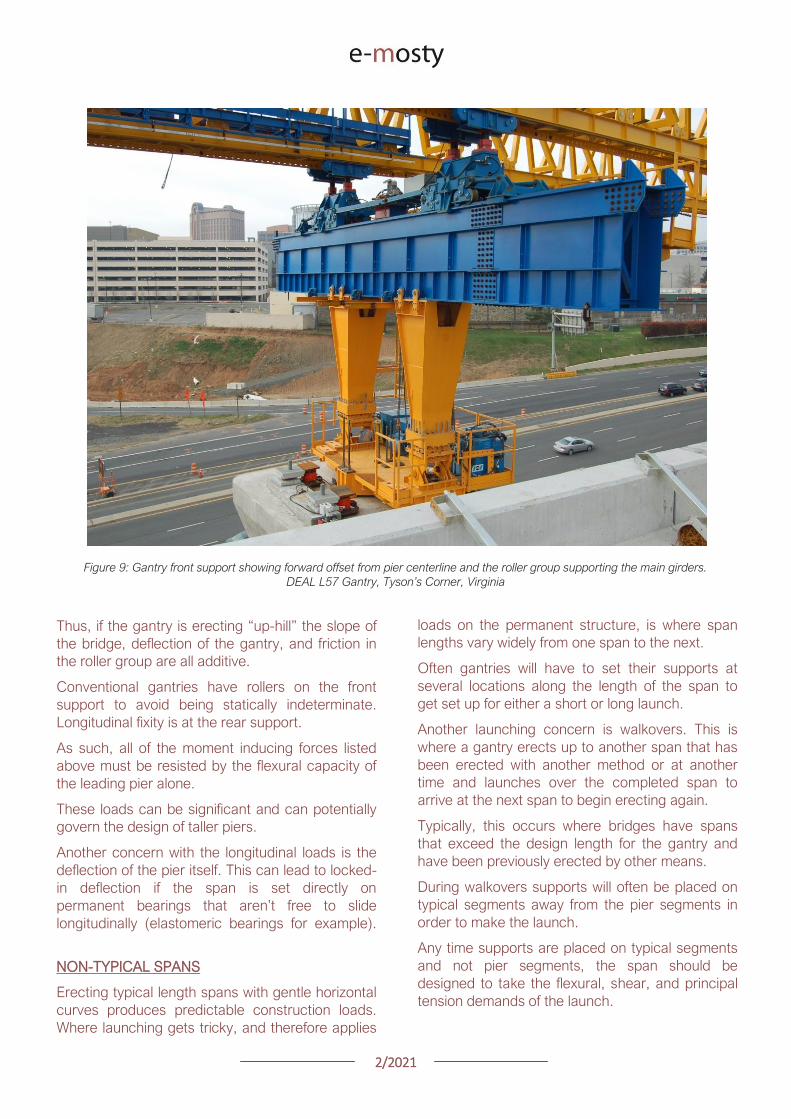
22021
Figure 10 The L120 launching gantry (by DEAL) lifts the pre-cast concrete segments of the first span
WIND LOADS
A common concern among bridge owners and
designers is with regards to the applicable wind
loads that a gantry and bridge should be designed
for Bridge design codes require specific wind
speeds and pressures to be considered while
launching gantries are typically designed to
overhead crane design codes that have a different
set of requirements
The launching gantry should be designed for the
wind loads specified by the applicable crane codes
while the bridge should consider the gantry as an
appurtenance affixed to the permanent structure
and use the applicable bridge wind loads in the
design of the bridge
On the Harbor Bridge project in Corpus Christi
Texas there is the potential for large wind loads
given that the bridge is located on the Gulf of
Mexico and the piers are upwards 45m tall
The L120 launching gantry (designed by DEAL) is
160m long and 3m tall giving it a large projected
wind area
The two major concerns that arise are the lateral
loads on the pier columns and the stability of the
span when the gantry is tied down for wind events
To accommodate the large out of service
(hurricane) wind loading the designers opted to
design specific locations along the bridge for
hurricane winds on the structure and gantry
together
The piers and superstructure have increased
capacity to accommodate the gantry should it
need to be tied down a wind event
This was a more economical solution than
designing every pier for the out of service winds
In the event of an approaching hurricane the
gantry does not have far to back launch to get to a
safe place to tie-down
CONCLUSION
In conclusion launching gantries apply unique
loads on both the super and substructures of
bridges
Wind and longitudinal loads on the piers can
sometimes govern the design and stability checks
of the bridge Considering these loads during the
design phase of a bridge project can eliminate
costly redesigns later
22021
GEOMETRY CONTROL FOR PRECAST
SEGMENTAL CONSTRUCTION
Joakim Dupleix CaSE International (formerly VSL)
Martin Pircher ABES
Figure 1 Closing of Mesaimeer Bridge main stay cable span Qatar
PRECAST SEGMENTAL CONSTRUCTION
Precast segmental construction is a great method
to limit the impact of the works on a bridge
construction site
By fabricating the concrete elements in a
controlled environment many of the unpleasant
by-products of the construction site are also
exported
However a key challenge of constructing elements
remotely is to ensure they will achieve the required
bridge geometry once erected on site
Furthermore the fact that the bridge is built ldquopiece-
by-piecerdquo in segments means that the geometry
needs to be controlled and forecasted at every
stage during construction anticipating and
forecasting movements and deflections during the
temporary stages of the construction process
Often bridges have varying curvature and
superelevation which require tools to capture the
geometry in all dimensions
These tools must allow efficient and accurate ways
to correct geometry imperfections such as
correction in setting out in the precast yard or
shimming of segment joints during balanced
cantilever erection on site
22021
ABES SOFTWARE SOLUTION
ABES Pircher amp Partner GmbH is an independent
software house providing solutions for bridge
engineering topics
Together with VSL they have developed a
software suite dedicated to managing the
geometry control of segmental construction at
every stage of the construction process
The software is split in 3 components which are all
interrelated
geoDes to be used in the design office to
model the intended theoretical geometry of
the bridge
geoCon to be used in the casting yard
providing setting out and casting error
compensation for any yard setup
assemCon to be used on site to forecast
the as-built geometry during balanced
cantilever construction based on real time
survey results
Figure 2 Balanced cantilever construction
The software works fully in 3D with a visual
interface which means it can control geometry in
all directions not only vertically
Figure 3 Snapshot of 3D model within ABES geoDes
22021
The Figure below illustrates an example of a cross-
section modeled in geoDes
Figure 4 Cross section (inner void omitted)
KEY PRINCIPLES
The geometry control principles used by ABES are
as follows
The theoretical modelling of the bridge
defines a casting curve in 3D which is the
ldquoperfectrdquo geometry of the bridge This
includes the camber of the bridge if defined
by the designer
Each segment is recorded in its entire
three-dimensional shape and identified by a
minimum of 4 control points which are
physical survey items to be cast anywhere
on the segment
Segment shapes are prepared considering
the specific requirements of the casting
machines used in the yard
The position of control points in the wet
concrete which may vary due to placing
error defines the setting out curve
When segments are cast movement of the
formwork the bulkhead or the conjugate
segment may induce deviations from the
theoretical shape this defines the ldquoas castrdquo
curve
Segment imperfections are compensated
for during casting of sub-sequent
segments This is true for both short-line
and long-line casting or the combination
thereof
During balanced cantilever erection each
construction stage must be monitored and
compared to the deflected position of the
entire bridge as defined by the designer
Again geometric deviations need to be
corrected for during sub-sequent
construction stages
Figure 5 3D interface showing theoretical
(red) and as cast segments (green)
MAIN ADVANTAGES
Modelling
By modelling the bridge from base alignments and
with geometric rules derived from the specific
capabilities of the casting cells the software
achieves the best constructable theoretical fit
Multiple alignments can be accommodated
including deviation from the main alignment such
as for ramps or train stations as required Refer to
Figure 3 above
In the precast yard
When using geoCon the software automatically
compensates for the user the required setting out
according to the survey data of the previous
segment
This is key to ensure seamless casting operation
and minimize operator error Besides benefitting
from the 3D modelling it always works in all three
dimensions
22021
There is no limit to the number of control points
per segment ensuring high accuracy
Another key feature for a stay cable bridge pipes
must be cast in advance into the segment in the
yard to achieve the final geometry after all
deformations have occurred
The software can transform the theoretical pipe
coordinates adjust them for cambers and
segment imperfections and display them in the
local coordinate system which can be processed
by the surveyor in the yard
Figure 6 Gewan Island bridge 3D modelling
with plan radius of less than 125m
Figure 8 Precasting of segments with cable stay pipes
On site for balanced cantilever erection
On site assemCon gives two key insights to the
user
Forecast the position of the bridge at any
construction stage in 3D considering the
as-built data the as-cast curve and the
calculated deflections for each
construction stage
Assist in finding an optimal shimming
strategy to correct the forecasted position
and to target a final as-built structure as
close as possible to the theoretical
geometry
Figure 7 3D view of a cantilever being built
22021
Figure 9 Definition of shimming
strategy to reduce differences
CONCLUSIONS
Pre-cast segmental bridge construction is applied
to increasingly complex and geometrically
challenging structures
Efficient geometry control is essential for the
success of such projects
Geometry control already starts during the
planning process where individual segments need
to be laid out to suit the available equipment in the
casting yard
Segment casting needs to be tightly controlled and
monitored and geometric imperfections need to
be identified and compensated for
And finally bridge construction at the construction
site requires monitoring of individual construction
stages and optimised strategies for correcting for
possible geometry deviations of the bridge
structure during construction
VSL in cooperation with ABES have developed a
suite of software tools to assist in all these tasks
The software is heavily influenced by practical
experience during numerous pre-cast segmental
projects of all sizes and shapes across Asia and
principally Qatar and India and feedback from
ongoing projects continues to inform the
development work
Figure 12 Al Bustan North bridge during construction
above traffic Qatar
Figure 11 Gewan Island Bridge being built Qatar
Figure 10 Karimnagar cable stay bridge India
Photos Credit VSL
22021
PRECAST SEGMENTAL BRIDGE CONSTRUCTION
USING LIFTING FRAME IN QATAR
Joakim Dupleix CaSE International (formerly VSL)
German A Pardo R VSL International Ltd
Figure 1 Overview of Al Bustan North construction site
PRECAST SEGMENTAL CONSTRUCTION
One of the most advantageous construction
methods enabled by segmental construction is the
balanced cantilever method
In a busy brownfield environment pre-casting the
segments off-site is the best solution to minimize
disrupting the existing traffic flow
In these environments access is often limited and
restricted and cranage may not be able to reach
the whole site
In these conditions lifting frame equipment are
often the solution to enable the erection of
segments on the bridge
In Qatar VSL designed and operated two very
different types of lifting frames as part of the Al
Bustan corridor upgrade project
The lifting frames responded to different needs and
segment delivery methods carefully studied during
the construction planning phase of the project
SABAH AL AHMAD CORRIDOR
(previously called Al Bustan)
Sabah al Ahmad or Al Bustan Corridor is part of
the Qatar Expressway Programme and aims to
provide an alternative to the existing expressway
with free flow traffic on a length of 14 km from the
North of Central Doha to the South to improve
connectivity to the FIFA World Cup stadiums
22021
The project involved upgrading the existing main
road by constructing various overhead bridges
over existing crossroads as well as connecting
ramps to remove traffic lights
The construction of this corridor was split into three
main packages
Al Bustan North project now known as
Umm Lekhba Interchange
Al Bustan South project
Mesaimeer Road project
Al Bustan North consists of the major upgrade of a
major interchange with Qatar main highway Al
Shamal Road to become a 4 level interchange
Al Bustan South required the construction of large
overhead bridges up to 26 km long with overhead
ramps connecting to crossroads
Mesaimeer Road upgraded the existing road with 2
large bridges up to 12 km long with a cable stay
section
PRECAST SEGMENTAL BALANCED
CANTILEVER METHOD
Because of the existing brownfield environment in
which the bridges are being built and to minimize
the impact on the existing traffic the precast
segment balanced cantilever method was chosen
for design and construction
It avoids installing large falsework structures on
site where space is limited and enables quick
fabrication of the bridge but requires relatively
large lifting equipment
As a matter of fact as the heavy concrete bridge
segments are to be transported and erected into
position with limited space the key is to
Figure 2 Key map of the corridor in Doha
22021
understand which areas are available where
possible if lifting equipment such as cranes can be
positioned and how to deliver the segments to
their final position
For very heavy segments or if cranes cannot be
used due to site constraints it may be required to
design custom made lifting frame machines
placed on top of the bridge already built and fitted
with their own lifting device to erect the segments
in their final position
These machines typically have a limited range and
segments must be first transported precisely near
their final position
On the Al Bustan Corridor two different delivery
situations were identified
For Al Bustan South and Mesaimeer the
large weight of the segments made it
prohibitively costly to use a crane
However assisted by a temporary
diversion of the existing road during
construction and the flat terrain every
segment could always be delivered directly
below their final position
For Al Bustan North the multi-level
interchange the existing highway Al
Shamal Road could only be closed to traffic
for a very limited time and the existing road
environment did not allow for flexible
segment delivery below each new bridge
ramp
A crane could be positioned near the piers
which allowed for segments to be lifted
onto the already erected deck
To position the segment into its final
position a special lifting frame was
designed to pick up the segment ldquofrom
behindrdquo and bring them forward into their
final position
LIFTING FRAME WITH DELIVERY FROM
BEHIND
As mentioned previously a lifting frame (LF) able
to pick up a segment from behind was required for
this project
A few options for the trajectory of the segment
were considered
Symmetrical Lifting Frame segment
crossing the lifting frame is rotated at 90
degrees in plan lifted and moved through
the middle of the machine longitudinally
Once at the front it can be rotated 90
degrees and lowered in position
Asymmetrical Lifting Frame segment is
delivered 180 degrees from its final
orientation
The segment is picked up rotated 90
degrees moved through the LF
longitudinally rotated again and then
lowered in position
Figure 3 Al Bustan North lifting frame
For this project the bridges are quite narrow with a
web spacing of 6 and 4 m and therefore passing a
32 m long segment between two legs of the LF
was not possible
As shown in Figure 4 on the next page a C shape
was adopted to allow the segment to be rotated on
the free side and moved forward
22021
Figure 4 Segment delivery methodology Click on the image to open it in full size
Description of Lifting Frame
The lifting Frame had the following key
specifications
1 Self-weight of 70 tonnes
2 Lifting capacity of 80 tonnes
3 Lifting speed of 12 mh [02 mmin]
4 Longitudinal launching speed of 3 mh
[005 mmin]
The lifting frame is made of a few key
components
Upper Cross Beam (UCB) transverse
beam carrying the strand lifting unit as
well as the stressing platform lifting
mast Adjustment capability of +-
200 mm
Main Beams (MB) Longitudinal beams
supporting the UCB The UCB is
moved on wheels with a bogie
connected to 2 chain pulling units
Figure 5 3D view of lifting frame model
22021
Support Frame (SF) asymmetric frame in a
C shape supporting the MB The frame is
supported on the deck by adjustable screw
jacks located over the webs
Tie down beams (TDB) during erection
the SF is tie down to the deck with 4 no
40 mm diameter stressbars anchored in
TDB The TDB allows for longitudinal
adjustment in the position of the bars as
the segment length varies
Rail beams (RB) two rail beams on each
side of the SF are fitted with a hydraulic
launching system able to move the entire
frame forward in steps of 700 mm
Segment lifting beam (SLB) the SLB is
stressed to the segment being lifted and is
fitted with hydraulic jacks able to adjust the
segment to the required crossfall and
gradient as well as rotated the segment in
plan to pass through the SF
Stressing platform (SP) to complete the
balance cantilever construction a SP is
required to be positioned each newly
erected segment to provide access for
personnel to complete the permanent post-
tensioning operation
Figure 6 Segment delivered at the rear of the LF
Figure 8 Segment rotated to its final orientation
rarr Figure 9 Segment lowered into
position and load transferred
Figure 7 Segment rotated and moved longitudinally
SEGMENT ERECTION PHOTOS
The photo sequence below shows the segment
delivery process
22021
Challenges
Because of the limited width of the deck and the
congested site area with existing roads one of the
key challenges was to find a suitable storage
position for the SP when not in use which would
not block the segment passage
A rotation mast or davit arm was designed to lift
and position the 6 tonnes platform The mast was
rotated up to 120 degrees with a small horizontal
hydraulic jack
The concept and design itself of the Lifting Frame
required a solution which provided the minimum
required space for manipulating the segment and
the stressing platform in a very tight area while
having enough stiffness and capacity to cover the
demands
LIFTING FRAME WITH DELIVERY FROM
BELOW
Typical configuration for a Lifting Frame is such
that segment can be lifted directly from below
This was the case of Al Bustan South and
Mesaimeer projects
MESAIMEER LIFTING FRAME
Segments to be lifted by this lifting frame were the
heaviest and widest on the project for this reason
a stiffer structure composed of rigid frames at the
supporting areas was chosen taking advantage of
the fact that there was no restriction in height and
section of the bridge
The delivery of the segments in this project could
be conducted almost at is final position in plan
which facilitated the configuration of the lifting
equipment at the cantilever of the lifting frame
For this purpose the lifting frame was provided
with a couple of Winches that could pick up the
segment from the ground with minimum rotation in
plan lifted to required level and conduct final
adjustment in the longitudinal and transverse
directions
Description of Lifting Frame
The Lifting Frame had the following key
specifications
1 Self-weight of 92 tonnes
2 Lifting capacity of 185 tonnes
3 Lifting speed of 60 mh [1 mmin]
4 Longitudinal launching speed of 3mh [005
mmin)
Figure 10 segment delivered at the rear of the LF
The lifting frame is made of a few key components
Upper Cross Beam (UCB) transverse
beam carrying the main lifting equipment
(Winch) as well as the stressing platform
Adjustment capability +- 1325
Cantilever Beam (CTB) the 2 main
longitudinal beams supporting the UCB and
Stressing Platform at front and the Tie
Down Beam at the rear
Lower Cross Beam (LCB) main Frames
underneath the CTB transferring all load to
the bridge
Rail Beams (RB) two rail beams on each
side of the LCB are fitted with a hydraulic
launching system able to move the entire
frame forward in steps of 850 mm
22021
Connection Beams (CB) beams
connecting the hook blocks of the Winches
directly to the segment They are provided
with jacks for segment gradient adjustment
Crossfall is adjusted directly by the
Winches
Stressing Platform (SP) it is positioned at
the tip of the CTB and move backward for
conducting stressing of bridge post-
tensioning tendons It is provided with 2
levels customized for this project
Tie Down Beam (TDB) the Support frame
is provided with a set of tie down beams at
the rear which are the main stability
system
TDB can be adjusted in the longitudinal
direction to suit the different segment
lengths and their respective tie down holes
position
Tie down bars are of 75mm and 47mm in
diameter and pre-stressed against the
segment
Challenges
To accommodate the supporting area in a
very limited length since there was
insufficient space near the pylons
This created big reactions to be taken by
the tie down elements due the big
cantilever at front and heavy segments to
be lifted
To be able to move all the way back the
lifting equipment (Winch) and UCB to
provide enough stability during the
launching procedure Space at rear of the
lifting frame was very limited
Provide a Stressing Platform with 2
different configurations (1 or 2 levels) that
could be adapted for specific
configurations
SEGMENT ERECTION PHOTOS
Figure 11 Mesaimeer Lifting Frame
Figure 12 Segment lifting
Figure 13 Segment permanent post-tensioning in progress
22021
AL BUSTAN SOUTH LIFTING FRAME
For this project the lifting frame had to
accommodate few main requirements to suit the
space constraints of the project and the bridge
capacity
Height A limit of 6m for total height the lifting
frame was to be assured since the bridge had
to pass under an existing viaduct
Load introduction The bridge section is
provided with 3 webs and middle web capacity
was to be respected by limiting the reactions at
this point Additionally the total weight of the
Lifting Frame was also limited
Segment delivered below could not be
positioned in its final orientation due to space
constraints It had to be rotated up to 90deg once
hanging from the lifting frame
To overcome the limitations described the lifting
frame concept developed considered the following
aspects
Main lifting equipment (Winch) was
positioned at the bottom rear area of the
lifting frame to reduce the total height
The three webs of the segment were
loaded and the Lifting Frame elements
were studied in such a way that the total
weight of the Lifting Frame and loading of
central web were not exceeded
A single Winch and the hook block with
rotation device were provided to allow
rotation of the segment while hanging from
the Lifting Frame
Description of Lifting Frame
The Lifting Frame had the following key
specifications
1 Self-weight of 81 tonnes
2 Lifting capacity of 170 tonnes
3 Lifting speed of 36 mh [06 mmin]
4 Longitudinal launching speed of 3mh [005
mmin
The lifting frame is made of the following key
components
Upper Cross Beam (UCB) uppermost
element carrying the Winch Trolley It can
slide longitudinally to accommodate the
segment in length Transverse adjustment
is done by sliding of the Winch Trolley over
the UCB
Main Frame (MF) the Lifting Frame is
provided with 2 Main Frames in section that
support the UCB and Stressing Platform on
top and transfers the vertical load to the
lower elements of the Lifting Frame At
bottom level it also receives the Tie Down
Beam
Lower Cross Beam (LCB) spreader beam
in the transverse direction located at front
and rear that transfer all loads to the
segment webs through 6 screw jacks (3 at
the front and 3 at the rear)
Tie Down Beam (TDB) located at rear part
of the Lifting Frame and contain the tie
down bars stressed down against the
segment in order to assure the stability of
the Lifting Frame It contains a couple of
back-up bars that provide redundancy to
the system
Segment Lifting Beam (SLB) connecting
element between the hook block of the
winch and the segment It is provided with
a rotational device that allows full rotation
of the segment in plan
Figure 14 Segment delivered at the rear of the LF
22021
Stressing Platform (SP) it hangs from the
tip of the Main Frame cantilever beam It is
moved backwards after segment
installation to conduct the stressing of the
permanent post-tensioning system
Rail Beam (RB) two rail beams on each
side of the LCB are fitted with a hydraulic
launching system able it to move the entire
frame forward in steps of 850 mm
Figure 14 Lifting Frame installation on deck
Figure 15 Lifting of segment
Figure 16 Stressing of post-tensioning tendons
Figure 17 Lifting Frame crossing under existing viaduct
SEGMENT ERECTION PHOTOS
Challenges
To develop a concept and design that did
not exceed the limitations given regarding
total weight and height
Allow full rotation of the segment while
hanging
Provide redundancy to the Lifting Frame
Tie Down system and to the Stressing
Platform while under operation
22021
CONCLUSIONS
Precast segmental construction in a congested
environment often requires the use of custom
designed lifting frames
These machines must always consider the
segment delivery methods as well as the bridge
characteristics in order to achieve the most cost-
efficient methods of erection
The more requirements a project has the more
customized the Lifting Frame will be
For this reason it is of key importance to integrate
the development of the Temporary Structures (like
Lifting Frames) as early as possible in the design
process
By doing this some of the constraints can be
solved in earlier stages which will improve the
efficiency of the full process and the interfaces
between the different parts involved Permanent
Works Designer Temporary Works Designer and
Main Contractor
Figure 18 Al Bustan North Figure 19 Al Bustan North
Figure 20 Al Bustan South
Figure 21 Mesaimeer
Photos 18 ndash 20 Credit Ashghal (Qatar Road Authority)
We design and produceformwork equipmentfor in-place casting of bridgesN25 New Ross Bypass (Ireland)
FOLLOW US
INNOVATIVE | SAFE | SUSTAINABLE | FAST
SOLUTIONS FOR BRIDGE CONSTRUCTION
MSS M1-70-S BRATISLAVA BYPASS | IN SITU CONSTRUCTION
LG 36-S CAIRO METRO LINE 3 EXTENSION | PRECAST SEGMENTAL
WWWBERDEU
Photo Credits D4R7
Photo Credits Stephane Ciccolini
Arup works in active partnership with clients to understand their needs so
that the solutions make their bridge aspirations possible mdashbig and small
The Arup global specialist technical skills blended with essential local
knowledge adds unexpected benefits
wwwarupcom
Whether to span nations make a statement or
improve everyday links Arup crafts better bridges
Naeem Hussain Richard Hornby Steve Kite Deepak Jayaram
naeemhussainarupcom richardhornbyarupcom stevekitearupcom deepakjayaramarupcom
Global UK Middle East amp Africa East Asia UK Middle East India
and Africa
Peter Burnton Marcos Sanchez Matt Carter
peterburntonarupcom marcossanchezarupcom mattcarterarupcom
Australasia Europe Americas
Queensferry Crossing Scotland
SANTANDERMADRIDLIMABOGOTAacuteBUENOS AIRES
Calle Marqueacutes de la Ensenada 11 - 3ordm 39009
Calle Bravo Murillo 101 - 4ordm 28020
Calle Coronel Inclaacuten 235 - Oficina 313 Lima 18
Cra 14 94a - 24 Oficina 307 Edificio ACO 94
Calle Rodriacuteguez Pentildea 681 - 4ordm Dpto 8 1020
Tfno +34 942 31 99 60
Tfno +34 91 702 54 78
Tfno +51 1 637 56 47
Tfno +57 1 467 48 10
Tfno +54 911 5709 3252
wwwarenasingcom
ARCHING THE WORLD
CODE-BASED DESIGN
DETAILINGDR AWING PRODUCTION
PAR AM ETRIC MODELING
STRUCTUR AL ANALYSIS
DOWNLOAD A FREE TRIALallplancombridge2021
THE WORLDrsquoS FIRST COMPLETE SOLUTIONFOR BRIDGE ENGINEERS
Allplan Bridge 2021 maps the complete BIM process in bridge projects The new version enables bridge engineers to work with one single solution from the creation of a parametric 4D model to structural analysis reinforcement design and detailing This further improves the design process in terms of both time and quality
ALLPLAN BRIDGE
Join Bridges to Prosperity in helping isolated
communities gain safe access to healthcare
education jobs and markets through simple
sustainable trailbridges Together we can
build more than a bridge we can build a
pathway out of poverty
We envision a world wherepoverty caused by ruralisolation no longer exists
bridgestoprosperityorg
infobridgestoprosperityorgbridgestoprosperity
bridgestoprosperity
b2p
+60Women Entering the Labor Force
+75Farmer
Profitability
+358Labor Market
Income
Corporate Partners make this
vision possible
Wyatt Brooks and Kevin Donovan - Eliminating Uncertainty in Market Access
The Impact of New Bridges in Rural Nicaragua 2017
SEGMENTAL BRIDGES
ISSUE 022021 JUNE
- 1 arenas_v2
-
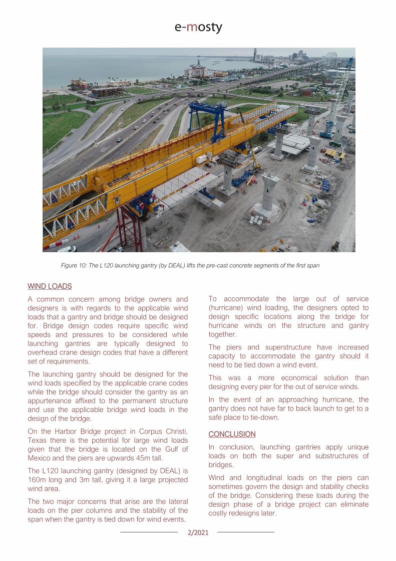
22021
GEOMETRY CONTROL FOR PRECAST
SEGMENTAL CONSTRUCTION
Joakim Dupleix CaSE International (formerly VSL)
Martin Pircher ABES
Figure 1 Closing of Mesaimeer Bridge main stay cable span Qatar
PRECAST SEGMENTAL CONSTRUCTION
Precast segmental construction is a great method
to limit the impact of the works on a bridge
construction site
By fabricating the concrete elements in a
controlled environment many of the unpleasant
by-products of the construction site are also
exported
However a key challenge of constructing elements
remotely is to ensure they will achieve the required
bridge geometry once erected on site
Furthermore the fact that the bridge is built ldquopiece-
by-piecerdquo in segments means that the geometry
needs to be controlled and forecasted at every
stage during construction anticipating and
forecasting movements and deflections during the
temporary stages of the construction process
Often bridges have varying curvature and
superelevation which require tools to capture the
geometry in all dimensions
These tools must allow efficient and accurate ways
to correct geometry imperfections such as
correction in setting out in the precast yard or
shimming of segment joints during balanced
cantilever erection on site
22021
ABES SOFTWARE SOLUTION
ABES Pircher amp Partner GmbH is an independent
software house providing solutions for bridge
engineering topics
Together with VSL they have developed a
software suite dedicated to managing the
geometry control of segmental construction at
every stage of the construction process
The software is split in 3 components which are all
interrelated
geoDes to be used in the design office to
model the intended theoretical geometry of
the bridge
geoCon to be used in the casting yard
providing setting out and casting error
compensation for any yard setup
assemCon to be used on site to forecast
the as-built geometry during balanced
cantilever construction based on real time
survey results
Figure 2 Balanced cantilever construction
The software works fully in 3D with a visual
interface which means it can control geometry in
all directions not only vertically
Figure 3 Snapshot of 3D model within ABES geoDes
22021
The Figure below illustrates an example of a cross-
section modeled in geoDes
Figure 4 Cross section (inner void omitted)
KEY PRINCIPLES
The geometry control principles used by ABES are
as follows
The theoretical modelling of the bridge
defines a casting curve in 3D which is the
ldquoperfectrdquo geometry of the bridge This
includes the camber of the bridge if defined
by the designer
Each segment is recorded in its entire
three-dimensional shape and identified by a
minimum of 4 control points which are
physical survey items to be cast anywhere
on the segment
Segment shapes are prepared considering
the specific requirements of the casting
machines used in the yard
The position of control points in the wet
concrete which may vary due to placing
error defines the setting out curve
When segments are cast movement of the
formwork the bulkhead or the conjugate
segment may induce deviations from the
theoretical shape this defines the ldquoas castrdquo
curve
Segment imperfections are compensated
for during casting of sub-sequent
segments This is true for both short-line
and long-line casting or the combination
thereof
During balanced cantilever erection each
construction stage must be monitored and
compared to the deflected position of the
entire bridge as defined by the designer
Again geometric deviations need to be
corrected for during sub-sequent
construction stages
Figure 5 3D interface showing theoretical
(red) and as cast segments (green)
MAIN ADVANTAGES
Modelling
By modelling the bridge from base alignments and
with geometric rules derived from the specific
capabilities of the casting cells the software
achieves the best constructable theoretical fit
Multiple alignments can be accommodated
including deviation from the main alignment such
as for ramps or train stations as required Refer to
Figure 3 above
In the precast yard
When using geoCon the software automatically
compensates for the user the required setting out
according to the survey data of the previous
segment
This is key to ensure seamless casting operation
and minimize operator error Besides benefitting
from the 3D modelling it always works in all three
dimensions
22021
There is no limit to the number of control points
per segment ensuring high accuracy
Another key feature for a stay cable bridge pipes
must be cast in advance into the segment in the
yard to achieve the final geometry after all
deformations have occurred
The software can transform the theoretical pipe
coordinates adjust them for cambers and
segment imperfections and display them in the
local coordinate system which can be processed
by the surveyor in the yard
Figure 6 Gewan Island bridge 3D modelling
with plan radius of less than 125m
Figure 8 Precasting of segments with cable stay pipes
On site for balanced cantilever erection
On site assemCon gives two key insights to the
user
Forecast the position of the bridge at any
construction stage in 3D considering the
as-built data the as-cast curve and the
calculated deflections for each
construction stage
Assist in finding an optimal shimming
strategy to correct the forecasted position
and to target a final as-built structure as
close as possible to the theoretical
geometry
Figure 7 3D view of a cantilever being built
22021
Figure 9 Definition of shimming
strategy to reduce differences
CONCLUSIONS
Pre-cast segmental bridge construction is applied
to increasingly complex and geometrically
challenging structures
Efficient geometry control is essential for the
success of such projects
Geometry control already starts during the
planning process where individual segments need
to be laid out to suit the available equipment in the
casting yard
Segment casting needs to be tightly controlled and
monitored and geometric imperfections need to
be identified and compensated for
And finally bridge construction at the construction
site requires monitoring of individual construction
stages and optimised strategies for correcting for
possible geometry deviations of the bridge
structure during construction
VSL in cooperation with ABES have developed a
suite of software tools to assist in all these tasks
The software is heavily influenced by practical
experience during numerous pre-cast segmental
projects of all sizes and shapes across Asia and
principally Qatar and India and feedback from
ongoing projects continues to inform the
development work
Figure 12 Al Bustan North bridge during construction
above traffic Qatar
Figure 11 Gewan Island Bridge being built Qatar
Figure 10 Karimnagar cable stay bridge India
Photos Credit VSL
22021
PRECAST SEGMENTAL BRIDGE CONSTRUCTION
USING LIFTING FRAME IN QATAR
Joakim Dupleix CaSE International (formerly VSL)
German A Pardo R VSL International Ltd
Figure 1 Overview of Al Bustan North construction site
PRECAST SEGMENTAL CONSTRUCTION
One of the most advantageous construction
methods enabled by segmental construction is the
balanced cantilever method
In a busy brownfield environment pre-casting the
segments off-site is the best solution to minimize
disrupting the existing traffic flow
In these environments access is often limited and
restricted and cranage may not be able to reach
the whole site
In these conditions lifting frame equipment are
often the solution to enable the erection of
segments on the bridge
In Qatar VSL designed and operated two very
different types of lifting frames as part of the Al
Bustan corridor upgrade project
The lifting frames responded to different needs and
segment delivery methods carefully studied during
the construction planning phase of the project
SABAH AL AHMAD CORRIDOR
(previously called Al Bustan)
Sabah al Ahmad or Al Bustan Corridor is part of
the Qatar Expressway Programme and aims to
provide an alternative to the existing expressway
with free flow traffic on a length of 14 km from the
North of Central Doha to the South to improve
connectivity to the FIFA World Cup stadiums
22021
The project involved upgrading the existing main
road by constructing various overhead bridges
over existing crossroads as well as connecting
ramps to remove traffic lights
The construction of this corridor was split into three
main packages
Al Bustan North project now known as
Umm Lekhba Interchange
Al Bustan South project
Mesaimeer Road project
Al Bustan North consists of the major upgrade of a
major interchange with Qatar main highway Al
Shamal Road to become a 4 level interchange
Al Bustan South required the construction of large
overhead bridges up to 26 km long with overhead
ramps connecting to crossroads
Mesaimeer Road upgraded the existing road with 2
large bridges up to 12 km long with a cable stay
section
PRECAST SEGMENTAL BALANCED
CANTILEVER METHOD
Because of the existing brownfield environment in
which the bridges are being built and to minimize
the impact on the existing traffic the precast
segment balanced cantilever method was chosen
for design and construction
It avoids installing large falsework structures on
site where space is limited and enables quick
fabrication of the bridge but requires relatively
large lifting equipment
As a matter of fact as the heavy concrete bridge
segments are to be transported and erected into
position with limited space the key is to
Figure 2 Key map of the corridor in Doha
22021
understand which areas are available where
possible if lifting equipment such as cranes can be
positioned and how to deliver the segments to
their final position
For very heavy segments or if cranes cannot be
used due to site constraints it may be required to
design custom made lifting frame machines
placed on top of the bridge already built and fitted
with their own lifting device to erect the segments
in their final position
These machines typically have a limited range and
segments must be first transported precisely near
their final position
On the Al Bustan Corridor two different delivery
situations were identified
For Al Bustan South and Mesaimeer the
large weight of the segments made it
prohibitively costly to use a crane
However assisted by a temporary
diversion of the existing road during
construction and the flat terrain every
segment could always be delivered directly
below their final position
For Al Bustan North the multi-level
interchange the existing highway Al
Shamal Road could only be closed to traffic
for a very limited time and the existing road
environment did not allow for flexible
segment delivery below each new bridge
ramp
A crane could be positioned near the piers
which allowed for segments to be lifted
onto the already erected deck
To position the segment into its final
position a special lifting frame was
designed to pick up the segment ldquofrom
behindrdquo and bring them forward into their
final position
LIFTING FRAME WITH DELIVERY FROM
BEHIND
As mentioned previously a lifting frame (LF) able
to pick up a segment from behind was required for
this project
A few options for the trajectory of the segment
were considered
Symmetrical Lifting Frame segment
crossing the lifting frame is rotated at 90
degrees in plan lifted and moved through
the middle of the machine longitudinally
Once at the front it can be rotated 90
degrees and lowered in position
Asymmetrical Lifting Frame segment is
delivered 180 degrees from its final
orientation
The segment is picked up rotated 90
degrees moved through the LF
longitudinally rotated again and then
lowered in position
Figure 3 Al Bustan North lifting frame
For this project the bridges are quite narrow with a
web spacing of 6 and 4 m and therefore passing a
32 m long segment between two legs of the LF
was not possible
As shown in Figure 4 on the next page a C shape
was adopted to allow the segment to be rotated on
the free side and moved forward
22021
Figure 4 Segment delivery methodology Click on the image to open it in full size
Description of Lifting Frame
The lifting Frame had the following key
specifications
1 Self-weight of 70 tonnes
2 Lifting capacity of 80 tonnes
3 Lifting speed of 12 mh [02 mmin]
4 Longitudinal launching speed of 3 mh
[005 mmin]
The lifting frame is made of a few key
components
Upper Cross Beam (UCB) transverse
beam carrying the strand lifting unit as
well as the stressing platform lifting
mast Adjustment capability of +-
200 mm
Main Beams (MB) Longitudinal beams
supporting the UCB The UCB is
moved on wheels with a bogie
connected to 2 chain pulling units
Figure 5 3D view of lifting frame model
22021
Support Frame (SF) asymmetric frame in a
C shape supporting the MB The frame is
supported on the deck by adjustable screw
jacks located over the webs
Tie down beams (TDB) during erection
the SF is tie down to the deck with 4 no
40 mm diameter stressbars anchored in
TDB The TDB allows for longitudinal
adjustment in the position of the bars as
the segment length varies
Rail beams (RB) two rail beams on each
side of the SF are fitted with a hydraulic
launching system able to move the entire
frame forward in steps of 700 mm
Segment lifting beam (SLB) the SLB is
stressed to the segment being lifted and is
fitted with hydraulic jacks able to adjust the
segment to the required crossfall and
gradient as well as rotated the segment in
plan to pass through the SF
Stressing platform (SP) to complete the
balance cantilever construction a SP is
required to be positioned each newly
erected segment to provide access for
personnel to complete the permanent post-
tensioning operation
Figure 6 Segment delivered at the rear of the LF
Figure 8 Segment rotated to its final orientation
rarr Figure 9 Segment lowered into
position and load transferred
Figure 7 Segment rotated and moved longitudinally
SEGMENT ERECTION PHOTOS
The photo sequence below shows the segment
delivery process
22021
Challenges
Because of the limited width of the deck and the
congested site area with existing roads one of the
key challenges was to find a suitable storage
position for the SP when not in use which would
not block the segment passage
A rotation mast or davit arm was designed to lift
and position the 6 tonnes platform The mast was
rotated up to 120 degrees with a small horizontal
hydraulic jack
The concept and design itself of the Lifting Frame
required a solution which provided the minimum
required space for manipulating the segment and
the stressing platform in a very tight area while
having enough stiffness and capacity to cover the
demands
LIFTING FRAME WITH DELIVERY FROM
BELOW
Typical configuration for a Lifting Frame is such
that segment can be lifted directly from below
This was the case of Al Bustan South and
Mesaimeer projects
MESAIMEER LIFTING FRAME
Segments to be lifted by this lifting frame were the
heaviest and widest on the project for this reason
a stiffer structure composed of rigid frames at the
supporting areas was chosen taking advantage of
the fact that there was no restriction in height and
section of the bridge
The delivery of the segments in this project could
be conducted almost at is final position in plan
which facilitated the configuration of the lifting
equipment at the cantilever of the lifting frame
For this purpose the lifting frame was provided
with a couple of Winches that could pick up the
segment from the ground with minimum rotation in
plan lifted to required level and conduct final
adjustment in the longitudinal and transverse
directions
Description of Lifting Frame
The Lifting Frame had the following key
specifications
1 Self-weight of 92 tonnes
2 Lifting capacity of 185 tonnes
3 Lifting speed of 60 mh [1 mmin]
4 Longitudinal launching speed of 3mh [005
mmin)
Figure 10 segment delivered at the rear of the LF
The lifting frame is made of a few key components
Upper Cross Beam (UCB) transverse
beam carrying the main lifting equipment
(Winch) as well as the stressing platform
Adjustment capability +- 1325
Cantilever Beam (CTB) the 2 main
longitudinal beams supporting the UCB and
Stressing Platform at front and the Tie
Down Beam at the rear
Lower Cross Beam (LCB) main Frames
underneath the CTB transferring all load to
the bridge
Rail Beams (RB) two rail beams on each
side of the LCB are fitted with a hydraulic
launching system able to move the entire
frame forward in steps of 850 mm
22021
Connection Beams (CB) beams
connecting the hook blocks of the Winches
directly to the segment They are provided
with jacks for segment gradient adjustment
Crossfall is adjusted directly by the
Winches
Stressing Platform (SP) it is positioned at
the tip of the CTB and move backward for
conducting stressing of bridge post-
tensioning tendons It is provided with 2
levels customized for this project
Tie Down Beam (TDB) the Support frame
is provided with a set of tie down beams at
the rear which are the main stability
system
TDB can be adjusted in the longitudinal
direction to suit the different segment
lengths and their respective tie down holes
position
Tie down bars are of 75mm and 47mm in
diameter and pre-stressed against the
segment
Challenges
To accommodate the supporting area in a
very limited length since there was
insufficient space near the pylons
This created big reactions to be taken by
the tie down elements due the big
cantilever at front and heavy segments to
be lifted
To be able to move all the way back the
lifting equipment (Winch) and UCB to
provide enough stability during the
launching procedure Space at rear of the
lifting frame was very limited
Provide a Stressing Platform with 2
different configurations (1 or 2 levels) that
could be adapted for specific
configurations
SEGMENT ERECTION PHOTOS
Figure 11 Mesaimeer Lifting Frame
Figure 12 Segment lifting
Figure 13 Segment permanent post-tensioning in progress
22021
AL BUSTAN SOUTH LIFTING FRAME
For this project the lifting frame had to
accommodate few main requirements to suit the
space constraints of the project and the bridge
capacity
Height A limit of 6m for total height the lifting
frame was to be assured since the bridge had
to pass under an existing viaduct
Load introduction The bridge section is
provided with 3 webs and middle web capacity
was to be respected by limiting the reactions at
this point Additionally the total weight of the
Lifting Frame was also limited
Segment delivered below could not be
positioned in its final orientation due to space
constraints It had to be rotated up to 90deg once
hanging from the lifting frame
To overcome the limitations described the lifting
frame concept developed considered the following
aspects
Main lifting equipment (Winch) was
positioned at the bottom rear area of the
lifting frame to reduce the total height
The three webs of the segment were
loaded and the Lifting Frame elements
were studied in such a way that the total
weight of the Lifting Frame and loading of
central web were not exceeded
A single Winch and the hook block with
rotation device were provided to allow
rotation of the segment while hanging from
the Lifting Frame
Description of Lifting Frame
The Lifting Frame had the following key
specifications
1 Self-weight of 81 tonnes
2 Lifting capacity of 170 tonnes
3 Lifting speed of 36 mh [06 mmin]
4 Longitudinal launching speed of 3mh [005
mmin
The lifting frame is made of the following key
components
Upper Cross Beam (UCB) uppermost
element carrying the Winch Trolley It can
slide longitudinally to accommodate the
segment in length Transverse adjustment
is done by sliding of the Winch Trolley over
the UCB
Main Frame (MF) the Lifting Frame is
provided with 2 Main Frames in section that
support the UCB and Stressing Platform on
top and transfers the vertical load to the
lower elements of the Lifting Frame At
bottom level it also receives the Tie Down
Beam
Lower Cross Beam (LCB) spreader beam
in the transverse direction located at front
and rear that transfer all loads to the
segment webs through 6 screw jacks (3 at
the front and 3 at the rear)
Tie Down Beam (TDB) located at rear part
of the Lifting Frame and contain the tie
down bars stressed down against the
segment in order to assure the stability of
the Lifting Frame It contains a couple of
back-up bars that provide redundancy to
the system
Segment Lifting Beam (SLB) connecting
element between the hook block of the
winch and the segment It is provided with
a rotational device that allows full rotation
of the segment in plan
Figure 14 Segment delivered at the rear of the LF
22021
Stressing Platform (SP) it hangs from the
tip of the Main Frame cantilever beam It is
moved backwards after segment
installation to conduct the stressing of the
permanent post-tensioning system
Rail Beam (RB) two rail beams on each
side of the LCB are fitted with a hydraulic
launching system able it to move the entire
frame forward in steps of 850 mm
Figure 14 Lifting Frame installation on deck
Figure 15 Lifting of segment
Figure 16 Stressing of post-tensioning tendons
Figure 17 Lifting Frame crossing under existing viaduct
SEGMENT ERECTION PHOTOS
Challenges
To develop a concept and design that did
not exceed the limitations given regarding
total weight and height
Allow full rotation of the segment while
hanging
Provide redundancy to the Lifting Frame
Tie Down system and to the Stressing
Platform while under operation
22021
CONCLUSIONS
Precast segmental construction in a congested
environment often requires the use of custom
designed lifting frames
These machines must always consider the
segment delivery methods as well as the bridge
characteristics in order to achieve the most cost-
efficient methods of erection
The more requirements a project has the more
customized the Lifting Frame will be
For this reason it is of key importance to integrate
the development of the Temporary Structures (like
Lifting Frames) as early as possible in the design
process
By doing this some of the constraints can be
solved in earlier stages which will improve the
efficiency of the full process and the interfaces
between the different parts involved Permanent
Works Designer Temporary Works Designer and
Main Contractor
Figure 18 Al Bustan North Figure 19 Al Bustan North
Figure 20 Al Bustan South
Figure 21 Mesaimeer
Photos 18 ndash 20 Credit Ashghal (Qatar Road Authority)
We design and produceformwork equipmentfor in-place casting of bridgesN25 New Ross Bypass (Ireland)
FOLLOW US
INNOVATIVE | SAFE | SUSTAINABLE | FAST
SOLUTIONS FOR BRIDGE CONSTRUCTION
MSS M1-70-S BRATISLAVA BYPASS | IN SITU CONSTRUCTION
LG 36-S CAIRO METRO LINE 3 EXTENSION | PRECAST SEGMENTAL
WWWBERDEU
Photo Credits D4R7
Photo Credits Stephane Ciccolini
Arup works in active partnership with clients to understand their needs so
that the solutions make their bridge aspirations possible mdashbig and small
The Arup global specialist technical skills blended with essential local
knowledge adds unexpected benefits
wwwarupcom
Whether to span nations make a statement or
improve everyday links Arup crafts better bridges
Naeem Hussain Richard Hornby Steve Kite Deepak Jayaram
naeemhussainarupcom richardhornbyarupcom stevekitearupcom deepakjayaramarupcom
Global UK Middle East amp Africa East Asia UK Middle East India
and Africa
Peter Burnton Marcos Sanchez Matt Carter
peterburntonarupcom marcossanchezarupcom mattcarterarupcom
Australasia Europe Americas
Queensferry Crossing Scotland
SANTANDERMADRIDLIMABOGOTAacuteBUENOS AIRES
Calle Marqueacutes de la Ensenada 11 - 3ordm 39009
Calle Bravo Murillo 101 - 4ordm 28020
Calle Coronel Inclaacuten 235 - Oficina 313 Lima 18
Cra 14 94a - 24 Oficina 307 Edificio ACO 94
Calle Rodriacuteguez Pentildea 681 - 4ordm Dpto 8 1020
Tfno +34 942 31 99 60
Tfno +34 91 702 54 78
Tfno +51 1 637 56 47
Tfno +57 1 467 48 10
Tfno +54 911 5709 3252
wwwarenasingcom
ARCHING THE WORLD
CODE-BASED DESIGN
DETAILINGDR AWING PRODUCTION
PAR AM ETRIC MODELING
STRUCTUR AL ANALYSIS
DOWNLOAD A FREE TRIALallplancombridge2021
THE WORLDrsquoS FIRST COMPLETE SOLUTIONFOR BRIDGE ENGINEERS
Allplan Bridge 2021 maps the complete BIM process in bridge projects The new version enables bridge engineers to work with one single solution from the creation of a parametric 4D model to structural analysis reinforcement design and detailing This further improves the design process in terms of both time and quality
ALLPLAN BRIDGE
Join Bridges to Prosperity in helping isolated
communities gain safe access to healthcare
education jobs and markets through simple
sustainable trailbridges Together we can
build more than a bridge we can build a
pathway out of poverty
We envision a world wherepoverty caused by ruralisolation no longer exists
bridgestoprosperityorg
infobridgestoprosperityorgbridgestoprosperity
bridgestoprosperity
b2p
+60Women Entering the Labor Force
+75Farmer
Profitability
+358Labor Market
Income
Corporate Partners make this
vision possible
Wyatt Brooks and Kevin Donovan - Eliminating Uncertainty in Market Access
The Impact of New Bridges in Rural Nicaragua 2017
SEGMENTAL BRIDGES
ISSUE 022021 JUNE
- 1 arenas_v2
-
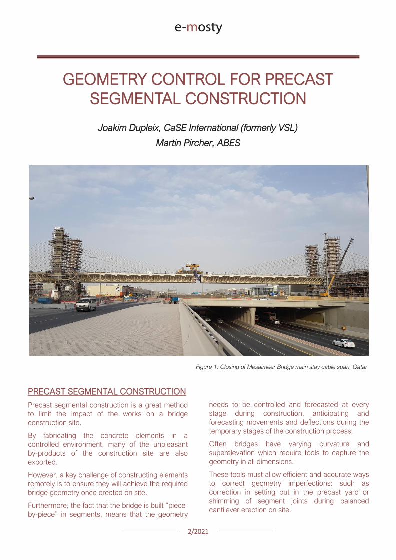
22021
ABES SOFTWARE SOLUTION
ABES Pircher amp Partner GmbH is an independent
software house providing solutions for bridge
engineering topics
Together with VSL they have developed a
software suite dedicated to managing the
geometry control of segmental construction at
every stage of the construction process
The software is split in 3 components which are all
interrelated
geoDes to be used in the design office to
model the intended theoretical geometry of
the bridge
geoCon to be used in the casting yard
providing setting out and casting error
compensation for any yard setup
assemCon to be used on site to forecast
the as-built geometry during balanced
cantilever construction based on real time
survey results
Figure 2 Balanced cantilever construction
The software works fully in 3D with a visual
interface which means it can control geometry in
all directions not only vertically
Figure 3 Snapshot of 3D model within ABES geoDes
22021
The Figure below illustrates an example of a cross-
section modeled in geoDes
Figure 4 Cross section (inner void omitted)
KEY PRINCIPLES
The geometry control principles used by ABES are
as follows
The theoretical modelling of the bridge
defines a casting curve in 3D which is the
ldquoperfectrdquo geometry of the bridge This
includes the camber of the bridge if defined
by the designer
Each segment is recorded in its entire
three-dimensional shape and identified by a
minimum of 4 control points which are
physical survey items to be cast anywhere
on the segment
Segment shapes are prepared considering
the specific requirements of the casting
machines used in the yard
The position of control points in the wet
concrete which may vary due to placing
error defines the setting out curve
When segments are cast movement of the
formwork the bulkhead or the conjugate
segment may induce deviations from the
theoretical shape this defines the ldquoas castrdquo
curve
Segment imperfections are compensated
for during casting of sub-sequent
segments This is true for both short-line
and long-line casting or the combination
thereof
During balanced cantilever erection each
construction stage must be monitored and
compared to the deflected position of the
entire bridge as defined by the designer
Again geometric deviations need to be
corrected for during sub-sequent
construction stages
Figure 5 3D interface showing theoretical
(red) and as cast segments (green)
MAIN ADVANTAGES
Modelling
By modelling the bridge from base alignments and
with geometric rules derived from the specific
capabilities of the casting cells the software
achieves the best constructable theoretical fit
Multiple alignments can be accommodated
including deviation from the main alignment such
as for ramps or train stations as required Refer to
Figure 3 above
In the precast yard
When using geoCon the software automatically
compensates for the user the required setting out
according to the survey data of the previous
segment
This is key to ensure seamless casting operation
and minimize operator error Besides benefitting
from the 3D modelling it always works in all three
dimensions
22021
There is no limit to the number of control points
per segment ensuring high accuracy
Another key feature for a stay cable bridge pipes
must be cast in advance into the segment in the
yard to achieve the final geometry after all
deformations have occurred
The software can transform the theoretical pipe
coordinates adjust them for cambers and
segment imperfections and display them in the
local coordinate system which can be processed
by the surveyor in the yard
Figure 6 Gewan Island bridge 3D modelling
with plan radius of less than 125m
Figure 8 Precasting of segments with cable stay pipes
On site for balanced cantilever erection
On site assemCon gives two key insights to the
user
Forecast the position of the bridge at any
construction stage in 3D considering the
as-built data the as-cast curve and the
calculated deflections for each
construction stage
Assist in finding an optimal shimming
strategy to correct the forecasted position
and to target a final as-built structure as
close as possible to the theoretical
geometry
Figure 7 3D view of a cantilever being built
22021
Figure 9 Definition of shimming
strategy to reduce differences
CONCLUSIONS
Pre-cast segmental bridge construction is applied
to increasingly complex and geometrically
challenging structures
Efficient geometry control is essential for the
success of such projects
Geometry control already starts during the
planning process where individual segments need
to be laid out to suit the available equipment in the
casting yard
Segment casting needs to be tightly controlled and
monitored and geometric imperfections need to
be identified and compensated for
And finally bridge construction at the construction
site requires monitoring of individual construction
stages and optimised strategies for correcting for
possible geometry deviations of the bridge
structure during construction
VSL in cooperation with ABES have developed a
suite of software tools to assist in all these tasks
The software is heavily influenced by practical
experience during numerous pre-cast segmental
projects of all sizes and shapes across Asia and
principally Qatar and India and feedback from
ongoing projects continues to inform the
development work
Figure 12 Al Bustan North bridge during construction
above traffic Qatar
Figure 11 Gewan Island Bridge being built Qatar
Figure 10 Karimnagar cable stay bridge India
Photos Credit VSL
22021
PRECAST SEGMENTAL BRIDGE CONSTRUCTION
USING LIFTING FRAME IN QATAR
Joakim Dupleix CaSE International (formerly VSL)
German A Pardo R VSL International Ltd
Figure 1 Overview of Al Bustan North construction site
PRECAST SEGMENTAL CONSTRUCTION
One of the most advantageous construction
methods enabled by segmental construction is the
balanced cantilever method
In a busy brownfield environment pre-casting the
segments off-site is the best solution to minimize
disrupting the existing traffic flow
In these environments access is often limited and
restricted and cranage may not be able to reach
the whole site
In these conditions lifting frame equipment are
often the solution to enable the erection of
segments on the bridge
In Qatar VSL designed and operated two very
different types of lifting frames as part of the Al
Bustan corridor upgrade project
The lifting frames responded to different needs and
segment delivery methods carefully studied during
the construction planning phase of the project
SABAH AL AHMAD CORRIDOR
(previously called Al Bustan)
Sabah al Ahmad or Al Bustan Corridor is part of
the Qatar Expressway Programme and aims to
provide an alternative to the existing expressway
with free flow traffic on a length of 14 km from the
North of Central Doha to the South to improve
connectivity to the FIFA World Cup stadiums
22021
The project involved upgrading the existing main
road by constructing various overhead bridges
over existing crossroads as well as connecting
ramps to remove traffic lights
The construction of this corridor was split into three
main packages
Al Bustan North project now known as
Umm Lekhba Interchange
Al Bustan South project
Mesaimeer Road project
Al Bustan North consists of the major upgrade of a
major interchange with Qatar main highway Al
Shamal Road to become a 4 level interchange
Al Bustan South required the construction of large
overhead bridges up to 26 km long with overhead
ramps connecting to crossroads
Mesaimeer Road upgraded the existing road with 2
large bridges up to 12 km long with a cable stay
section
PRECAST SEGMENTAL BALANCED
CANTILEVER METHOD
Because of the existing brownfield environment in
which the bridges are being built and to minimize
the impact on the existing traffic the precast
segment balanced cantilever method was chosen
for design and construction
It avoids installing large falsework structures on
site where space is limited and enables quick
fabrication of the bridge but requires relatively
large lifting equipment
As a matter of fact as the heavy concrete bridge
segments are to be transported and erected into
position with limited space the key is to
Figure 2 Key map of the corridor in Doha
22021
understand which areas are available where
possible if lifting equipment such as cranes can be
positioned and how to deliver the segments to
their final position
For very heavy segments or if cranes cannot be
used due to site constraints it may be required to
design custom made lifting frame machines
placed on top of the bridge already built and fitted
with their own lifting device to erect the segments
in their final position
These machines typically have a limited range and
segments must be first transported precisely near
their final position
On the Al Bustan Corridor two different delivery
situations were identified
For Al Bustan South and Mesaimeer the
large weight of the segments made it
prohibitively costly to use a crane
However assisted by a temporary
diversion of the existing road during
construction and the flat terrain every
segment could always be delivered directly
below their final position
For Al Bustan North the multi-level
interchange the existing highway Al
Shamal Road could only be closed to traffic
for a very limited time and the existing road
environment did not allow for flexible
segment delivery below each new bridge
ramp
A crane could be positioned near the piers
which allowed for segments to be lifted
onto the already erected deck
To position the segment into its final
position a special lifting frame was
designed to pick up the segment ldquofrom
behindrdquo and bring them forward into their
final position
LIFTING FRAME WITH DELIVERY FROM
BEHIND
As mentioned previously a lifting frame (LF) able
to pick up a segment from behind was required for
this project
A few options for the trajectory of the segment
were considered
Symmetrical Lifting Frame segment
crossing the lifting frame is rotated at 90
degrees in plan lifted and moved through
the middle of the machine longitudinally
Once at the front it can be rotated 90
degrees and lowered in position
Asymmetrical Lifting Frame segment is
delivered 180 degrees from its final
orientation
The segment is picked up rotated 90
degrees moved through the LF
longitudinally rotated again and then
lowered in position
Figure 3 Al Bustan North lifting frame
For this project the bridges are quite narrow with a
web spacing of 6 and 4 m and therefore passing a
32 m long segment between two legs of the LF
was not possible
As shown in Figure 4 on the next page a C shape
was adopted to allow the segment to be rotated on
the free side and moved forward
22021
Figure 4 Segment delivery methodology Click on the image to open it in full size
Description of Lifting Frame
The lifting Frame had the following key
specifications
1 Self-weight of 70 tonnes
2 Lifting capacity of 80 tonnes
3 Lifting speed of 12 mh [02 mmin]
4 Longitudinal launching speed of 3 mh
[005 mmin]
The lifting frame is made of a few key
components
Upper Cross Beam (UCB) transverse
beam carrying the strand lifting unit as
well as the stressing platform lifting
mast Adjustment capability of +-
200 mm
Main Beams (MB) Longitudinal beams
supporting the UCB The UCB is
moved on wheels with a bogie
connected to 2 chain pulling units
Figure 5 3D view of lifting frame model
22021
Support Frame (SF) asymmetric frame in a
C shape supporting the MB The frame is
supported on the deck by adjustable screw
jacks located over the webs
Tie down beams (TDB) during erection
the SF is tie down to the deck with 4 no
40 mm diameter stressbars anchored in
TDB The TDB allows for longitudinal
adjustment in the position of the bars as
the segment length varies
Rail beams (RB) two rail beams on each
side of the SF are fitted with a hydraulic
launching system able to move the entire
frame forward in steps of 700 mm
Segment lifting beam (SLB) the SLB is
stressed to the segment being lifted and is
fitted with hydraulic jacks able to adjust the
segment to the required crossfall and
gradient as well as rotated the segment in
plan to pass through the SF
Stressing platform (SP) to complete the
balance cantilever construction a SP is
required to be positioned each newly
erected segment to provide access for
personnel to complete the permanent post-
tensioning operation
Figure 6 Segment delivered at the rear of the LF
Figure 8 Segment rotated to its final orientation
rarr Figure 9 Segment lowered into
position and load transferred
Figure 7 Segment rotated and moved longitudinally
SEGMENT ERECTION PHOTOS
The photo sequence below shows the segment
delivery process
22021
Challenges
Because of the limited width of the deck and the
congested site area with existing roads one of the
key challenges was to find a suitable storage
position for the SP when not in use which would
not block the segment passage
A rotation mast or davit arm was designed to lift
and position the 6 tonnes platform The mast was
rotated up to 120 degrees with a small horizontal
hydraulic jack
The concept and design itself of the Lifting Frame
required a solution which provided the minimum
required space for manipulating the segment and
the stressing platform in a very tight area while
having enough stiffness and capacity to cover the
demands
LIFTING FRAME WITH DELIVERY FROM
BELOW
Typical configuration for a Lifting Frame is such
that segment can be lifted directly from below
This was the case of Al Bustan South and
Mesaimeer projects
MESAIMEER LIFTING FRAME
Segments to be lifted by this lifting frame were the
heaviest and widest on the project for this reason
a stiffer structure composed of rigid frames at the
supporting areas was chosen taking advantage of
the fact that there was no restriction in height and
section of the bridge
The delivery of the segments in this project could
be conducted almost at is final position in plan
which facilitated the configuration of the lifting
equipment at the cantilever of the lifting frame
For this purpose the lifting frame was provided
with a couple of Winches that could pick up the
segment from the ground with minimum rotation in
plan lifted to required level and conduct final
adjustment in the longitudinal and transverse
directions
Description of Lifting Frame
The Lifting Frame had the following key
specifications
1 Self-weight of 92 tonnes
2 Lifting capacity of 185 tonnes
3 Lifting speed of 60 mh [1 mmin]
4 Longitudinal launching speed of 3mh [005
mmin)
Figure 10 segment delivered at the rear of the LF
The lifting frame is made of a few key components
Upper Cross Beam (UCB) transverse
beam carrying the main lifting equipment
(Winch) as well as the stressing platform
Adjustment capability +- 1325
Cantilever Beam (CTB) the 2 main
longitudinal beams supporting the UCB and
Stressing Platform at front and the Tie
Down Beam at the rear
Lower Cross Beam (LCB) main Frames
underneath the CTB transferring all load to
the bridge
Rail Beams (RB) two rail beams on each
side of the LCB are fitted with a hydraulic
launching system able to move the entire
frame forward in steps of 850 mm
22021
Connection Beams (CB) beams
connecting the hook blocks of the Winches
directly to the segment They are provided
with jacks for segment gradient adjustment
Crossfall is adjusted directly by the
Winches
Stressing Platform (SP) it is positioned at
the tip of the CTB and move backward for
conducting stressing of bridge post-
tensioning tendons It is provided with 2
levels customized for this project
Tie Down Beam (TDB) the Support frame
is provided with a set of tie down beams at
the rear which are the main stability
system
TDB can be adjusted in the longitudinal
direction to suit the different segment
lengths and their respective tie down holes
position
Tie down bars are of 75mm and 47mm in
diameter and pre-stressed against the
segment
Challenges
To accommodate the supporting area in a
very limited length since there was
insufficient space near the pylons
This created big reactions to be taken by
the tie down elements due the big
cantilever at front and heavy segments to
be lifted
To be able to move all the way back the
lifting equipment (Winch) and UCB to
provide enough stability during the
launching procedure Space at rear of the
lifting frame was very limited
Provide a Stressing Platform with 2
different configurations (1 or 2 levels) that
could be adapted for specific
configurations
SEGMENT ERECTION PHOTOS
Figure 11 Mesaimeer Lifting Frame
Figure 12 Segment lifting
Figure 13 Segment permanent post-tensioning in progress
22021
AL BUSTAN SOUTH LIFTING FRAME
For this project the lifting frame had to
accommodate few main requirements to suit the
space constraints of the project and the bridge
capacity
Height A limit of 6m for total height the lifting
frame was to be assured since the bridge had
to pass under an existing viaduct
Load introduction The bridge section is
provided with 3 webs and middle web capacity
was to be respected by limiting the reactions at
this point Additionally the total weight of the
Lifting Frame was also limited
Segment delivered below could not be
positioned in its final orientation due to space
constraints It had to be rotated up to 90deg once
hanging from the lifting frame
To overcome the limitations described the lifting
frame concept developed considered the following
aspects
Main lifting equipment (Winch) was
positioned at the bottom rear area of the
lifting frame to reduce the total height
The three webs of the segment were
loaded and the Lifting Frame elements
were studied in such a way that the total
weight of the Lifting Frame and loading of
central web were not exceeded
A single Winch and the hook block with
rotation device were provided to allow
rotation of the segment while hanging from
the Lifting Frame
Description of Lifting Frame
The Lifting Frame had the following key
specifications
1 Self-weight of 81 tonnes
2 Lifting capacity of 170 tonnes
3 Lifting speed of 36 mh [06 mmin]
4 Longitudinal launching speed of 3mh [005
mmin
The lifting frame is made of the following key
components
Upper Cross Beam (UCB) uppermost
element carrying the Winch Trolley It can
slide longitudinally to accommodate the
segment in length Transverse adjustment
is done by sliding of the Winch Trolley over
the UCB
Main Frame (MF) the Lifting Frame is
provided with 2 Main Frames in section that
support the UCB and Stressing Platform on
top and transfers the vertical load to the
lower elements of the Lifting Frame At
bottom level it also receives the Tie Down
Beam
Lower Cross Beam (LCB) spreader beam
in the transverse direction located at front
and rear that transfer all loads to the
segment webs through 6 screw jacks (3 at
the front and 3 at the rear)
Tie Down Beam (TDB) located at rear part
of the Lifting Frame and contain the tie
down bars stressed down against the
segment in order to assure the stability of
the Lifting Frame It contains a couple of
back-up bars that provide redundancy to
the system
Segment Lifting Beam (SLB) connecting
element between the hook block of the
winch and the segment It is provided with
a rotational device that allows full rotation
of the segment in plan
Figure 14 Segment delivered at the rear of the LF
22021
Stressing Platform (SP) it hangs from the
tip of the Main Frame cantilever beam It is
moved backwards after segment
installation to conduct the stressing of the
permanent post-tensioning system
Rail Beam (RB) two rail beams on each
side of the LCB are fitted with a hydraulic
launching system able it to move the entire
frame forward in steps of 850 mm
Figure 14 Lifting Frame installation on deck
Figure 15 Lifting of segment
Figure 16 Stressing of post-tensioning tendons
Figure 17 Lifting Frame crossing under existing viaduct
SEGMENT ERECTION PHOTOS
Challenges
To develop a concept and design that did
not exceed the limitations given regarding
total weight and height
Allow full rotation of the segment while
hanging
Provide redundancy to the Lifting Frame
Tie Down system and to the Stressing
Platform while under operation
22021
CONCLUSIONS
Precast segmental construction in a congested
environment often requires the use of custom
designed lifting frames
These machines must always consider the
segment delivery methods as well as the bridge
characteristics in order to achieve the most cost-
efficient methods of erection
The more requirements a project has the more
customized the Lifting Frame will be
For this reason it is of key importance to integrate
the development of the Temporary Structures (like
Lifting Frames) as early as possible in the design
process
By doing this some of the constraints can be
solved in earlier stages which will improve the
efficiency of the full process and the interfaces
between the different parts involved Permanent
Works Designer Temporary Works Designer and
Main Contractor
Figure 18 Al Bustan North Figure 19 Al Bustan North
Figure 20 Al Bustan South
Figure 21 Mesaimeer
Photos 18 ndash 20 Credit Ashghal (Qatar Road Authority)
We design and produceformwork equipmentfor in-place casting of bridgesN25 New Ross Bypass (Ireland)
FOLLOW US
INNOVATIVE | SAFE | SUSTAINABLE | FAST
SOLUTIONS FOR BRIDGE CONSTRUCTION
MSS M1-70-S BRATISLAVA BYPASS | IN SITU CONSTRUCTION
LG 36-S CAIRO METRO LINE 3 EXTENSION | PRECAST SEGMENTAL
WWWBERDEU
Photo Credits D4R7
Photo Credits Stephane Ciccolini
Arup works in active partnership with clients to understand their needs so
that the solutions make their bridge aspirations possible mdashbig and small
The Arup global specialist technical skills blended with essential local
knowledge adds unexpected benefits
wwwarupcom
Whether to span nations make a statement or
improve everyday links Arup crafts better bridges
Naeem Hussain Richard Hornby Steve Kite Deepak Jayaram
naeemhussainarupcom richardhornbyarupcom stevekitearupcom deepakjayaramarupcom
Global UK Middle East amp Africa East Asia UK Middle East India
and Africa
Peter Burnton Marcos Sanchez Matt Carter
peterburntonarupcom marcossanchezarupcom mattcarterarupcom
Australasia Europe Americas
Queensferry Crossing Scotland
SANTANDERMADRIDLIMABOGOTAacuteBUENOS AIRES
Calle Marqueacutes de la Ensenada 11 - 3ordm 39009
Calle Bravo Murillo 101 - 4ordm 28020
Calle Coronel Inclaacuten 235 - Oficina 313 Lima 18
Cra 14 94a - 24 Oficina 307 Edificio ACO 94
Calle Rodriacuteguez Pentildea 681 - 4ordm Dpto 8 1020
Tfno +34 942 31 99 60
Tfno +34 91 702 54 78
Tfno +51 1 637 56 47
Tfno +57 1 467 48 10
Tfno +54 911 5709 3252
wwwarenasingcom
ARCHING THE WORLD
CODE-BASED DESIGN
DETAILINGDR AWING PRODUCTION
PAR AM ETRIC MODELING
STRUCTUR AL ANALYSIS
DOWNLOAD A FREE TRIALallplancombridge2021
THE WORLDrsquoS FIRST COMPLETE SOLUTIONFOR BRIDGE ENGINEERS
Allplan Bridge 2021 maps the complete BIM process in bridge projects The new version enables bridge engineers to work with one single solution from the creation of a parametric 4D model to structural analysis reinforcement design and detailing This further improves the design process in terms of both time and quality
ALLPLAN BRIDGE
Join Bridges to Prosperity in helping isolated
communities gain safe access to healthcare
education jobs and markets through simple
sustainable trailbridges Together we can
build more than a bridge we can build a
pathway out of poverty
We envision a world wherepoverty caused by ruralisolation no longer exists
bridgestoprosperityorg
infobridgestoprosperityorgbridgestoprosperity
bridgestoprosperity
b2p
+60Women Entering the Labor Force
+75Farmer
Profitability
+358Labor Market
Income
Corporate Partners make this
vision possible
Wyatt Brooks and Kevin Donovan - Eliminating Uncertainty in Market Access
The Impact of New Bridges in Rural Nicaragua 2017
SEGMENTAL BRIDGES
ISSUE 022021 JUNE
- 1 arenas_v2
-
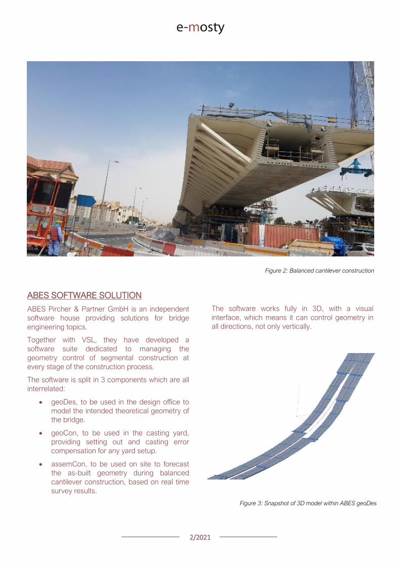
22021
The Figure below illustrates an example of a cross-
section modeled in geoDes
Figure 4 Cross section (inner void omitted)
KEY PRINCIPLES
The geometry control principles used by ABES are
as follows
The theoretical modelling of the bridge
defines a casting curve in 3D which is the
ldquoperfectrdquo geometry of the bridge This
includes the camber of the bridge if defined
by the designer
Each segment is recorded in its entire
three-dimensional shape and identified by a
minimum of 4 control points which are
physical survey items to be cast anywhere
on the segment
Segment shapes are prepared considering
the specific requirements of the casting
machines used in the yard
The position of control points in the wet
concrete which may vary due to placing
error defines the setting out curve
When segments are cast movement of the
formwork the bulkhead or the conjugate
segment may induce deviations from the
theoretical shape this defines the ldquoas castrdquo
curve
Segment imperfections are compensated
for during casting of sub-sequent
segments This is true for both short-line
and long-line casting or the combination
thereof
During balanced cantilever erection each
construction stage must be monitored and
compared to the deflected position of the
entire bridge as defined by the designer
Again geometric deviations need to be
corrected for during sub-sequent
construction stages
Figure 5 3D interface showing theoretical
(red) and as cast segments (green)
MAIN ADVANTAGES
Modelling
By modelling the bridge from base alignments and
with geometric rules derived from the specific
capabilities of the casting cells the software
achieves the best constructable theoretical fit
Multiple alignments can be accommodated
including deviation from the main alignment such
as for ramps or train stations as required Refer to
Figure 3 above
In the precast yard
When using geoCon the software automatically
compensates for the user the required setting out
according to the survey data of the previous
segment
This is key to ensure seamless casting operation
and minimize operator error Besides benefitting
from the 3D modelling it always works in all three
dimensions
22021
There is no limit to the number of control points
per segment ensuring high accuracy
Another key feature for a stay cable bridge pipes
must be cast in advance into the segment in the
yard to achieve the final geometry after all
deformations have occurred
The software can transform the theoretical pipe
coordinates adjust them for cambers and
segment imperfections and display them in the
local coordinate system which can be processed
by the surveyor in the yard
Figure 6 Gewan Island bridge 3D modelling
with plan radius of less than 125m
Figure 8 Precasting of segments with cable stay pipes
On site for balanced cantilever erection
On site assemCon gives two key insights to the
user
Forecast the position of the bridge at any
construction stage in 3D considering the
as-built data the as-cast curve and the
calculated deflections for each
construction stage
Assist in finding an optimal shimming
strategy to correct the forecasted position
and to target a final as-built structure as
close as possible to the theoretical
geometry
Figure 7 3D view of a cantilever being built
22021
Figure 9 Definition of shimming
strategy to reduce differences
CONCLUSIONS
Pre-cast segmental bridge construction is applied
to increasingly complex and geometrically
challenging structures
Efficient geometry control is essential for the
success of such projects
Geometry control already starts during the
planning process where individual segments need
to be laid out to suit the available equipment in the
casting yard
Segment casting needs to be tightly controlled and
monitored and geometric imperfections need to
be identified and compensated for
And finally bridge construction at the construction
site requires monitoring of individual construction
stages and optimised strategies for correcting for
possible geometry deviations of the bridge
structure during construction
VSL in cooperation with ABES have developed a
suite of software tools to assist in all these tasks
The software is heavily influenced by practical
experience during numerous pre-cast segmental
projects of all sizes and shapes across Asia and
principally Qatar and India and feedback from
ongoing projects continues to inform the
development work
Figure 12 Al Bustan North bridge during construction
above traffic Qatar
Figure 11 Gewan Island Bridge being built Qatar
Figure 10 Karimnagar cable stay bridge India
Photos Credit VSL
22021
PRECAST SEGMENTAL BRIDGE CONSTRUCTION
USING LIFTING FRAME IN QATAR
Joakim Dupleix CaSE International (formerly VSL)
German A Pardo R VSL International Ltd
Figure 1 Overview of Al Bustan North construction site
PRECAST SEGMENTAL CONSTRUCTION
One of the most advantageous construction
methods enabled by segmental construction is the
balanced cantilever method
In a busy brownfield environment pre-casting the
segments off-site is the best solution to minimize
disrupting the existing traffic flow
In these environments access is often limited and
restricted and cranage may not be able to reach
the whole site
In these conditions lifting frame equipment are
often the solution to enable the erection of
segments on the bridge
In Qatar VSL designed and operated two very
different types of lifting frames as part of the Al
Bustan corridor upgrade project
The lifting frames responded to different needs and
segment delivery methods carefully studied during
the construction planning phase of the project
SABAH AL AHMAD CORRIDOR
(previously called Al Bustan)
Sabah al Ahmad or Al Bustan Corridor is part of
the Qatar Expressway Programme and aims to
provide an alternative to the existing expressway
with free flow traffic on a length of 14 km from the
North of Central Doha to the South to improve
connectivity to the FIFA World Cup stadiums
22021
The project involved upgrading the existing main
road by constructing various overhead bridges
over existing crossroads as well as connecting
ramps to remove traffic lights
The construction of this corridor was split into three
main packages
Al Bustan North project now known as
Umm Lekhba Interchange
Al Bustan South project
Mesaimeer Road project
Al Bustan North consists of the major upgrade of a
major interchange with Qatar main highway Al
Shamal Road to become a 4 level interchange
Al Bustan South required the construction of large
overhead bridges up to 26 km long with overhead
ramps connecting to crossroads
Mesaimeer Road upgraded the existing road with 2
large bridges up to 12 km long with a cable stay
section
PRECAST SEGMENTAL BALANCED
CANTILEVER METHOD
Because of the existing brownfield environment in
which the bridges are being built and to minimize
the impact on the existing traffic the precast
segment balanced cantilever method was chosen
for design and construction
It avoids installing large falsework structures on
site where space is limited and enables quick
fabrication of the bridge but requires relatively
large lifting equipment
As a matter of fact as the heavy concrete bridge
segments are to be transported and erected into
position with limited space the key is to
Figure 2 Key map of the corridor in Doha
22021
understand which areas are available where
possible if lifting equipment such as cranes can be
positioned and how to deliver the segments to
their final position
For very heavy segments or if cranes cannot be
used due to site constraints it may be required to
design custom made lifting frame machines
placed on top of the bridge already built and fitted
with their own lifting device to erect the segments
in their final position
These machines typically have a limited range and
segments must be first transported precisely near
their final position
On the Al Bustan Corridor two different delivery
situations were identified
For Al Bustan South and Mesaimeer the
large weight of the segments made it
prohibitively costly to use a crane
However assisted by a temporary
diversion of the existing road during
construction and the flat terrain every
segment could always be delivered directly
below their final position
For Al Bustan North the multi-level
interchange the existing highway Al
Shamal Road could only be closed to traffic
for a very limited time and the existing road
environment did not allow for flexible
segment delivery below each new bridge
ramp
A crane could be positioned near the piers
which allowed for segments to be lifted
onto the already erected deck
To position the segment into its final
position a special lifting frame was
designed to pick up the segment ldquofrom
behindrdquo and bring them forward into their
final position
LIFTING FRAME WITH DELIVERY FROM
BEHIND
As mentioned previously a lifting frame (LF) able
to pick up a segment from behind was required for
this project
A few options for the trajectory of the segment
were considered
Symmetrical Lifting Frame segment
crossing the lifting frame is rotated at 90
degrees in plan lifted and moved through
the middle of the machine longitudinally
Once at the front it can be rotated 90
degrees and lowered in position
Asymmetrical Lifting Frame segment is
delivered 180 degrees from its final
orientation
The segment is picked up rotated 90
degrees moved through the LF
longitudinally rotated again and then
lowered in position
Figure 3 Al Bustan North lifting frame
For this project the bridges are quite narrow with a
web spacing of 6 and 4 m and therefore passing a
32 m long segment between two legs of the LF
was not possible
As shown in Figure 4 on the next page a C shape
was adopted to allow the segment to be rotated on
the free side and moved forward
22021
Figure 4 Segment delivery methodology Click on the image to open it in full size
Description of Lifting Frame
The lifting Frame had the following key
specifications
1 Self-weight of 70 tonnes
2 Lifting capacity of 80 tonnes
3 Lifting speed of 12 mh [02 mmin]
4 Longitudinal launching speed of 3 mh
[005 mmin]
The lifting frame is made of a few key
components
Upper Cross Beam (UCB) transverse
beam carrying the strand lifting unit as
well as the stressing platform lifting
mast Adjustment capability of +-
200 mm
Main Beams (MB) Longitudinal beams
supporting the UCB The UCB is
moved on wheels with a bogie
connected to 2 chain pulling units
Figure 5 3D view of lifting frame model
22021
Support Frame (SF) asymmetric frame in a
C shape supporting the MB The frame is
supported on the deck by adjustable screw
jacks located over the webs
Tie down beams (TDB) during erection
the SF is tie down to the deck with 4 no
40 mm diameter stressbars anchored in
TDB The TDB allows for longitudinal
adjustment in the position of the bars as
the segment length varies
Rail beams (RB) two rail beams on each
side of the SF are fitted with a hydraulic
launching system able to move the entire
frame forward in steps of 700 mm
Segment lifting beam (SLB) the SLB is
stressed to the segment being lifted and is
fitted with hydraulic jacks able to adjust the
segment to the required crossfall and
gradient as well as rotated the segment in
plan to pass through the SF
Stressing platform (SP) to complete the
balance cantilever construction a SP is
required to be positioned each newly
erected segment to provide access for
personnel to complete the permanent post-
tensioning operation
Figure 6 Segment delivered at the rear of the LF
Figure 8 Segment rotated to its final orientation
rarr Figure 9 Segment lowered into
position and load transferred
Figure 7 Segment rotated and moved longitudinally
SEGMENT ERECTION PHOTOS
The photo sequence below shows the segment
delivery process
22021
Challenges
Because of the limited width of the deck and the
congested site area with existing roads one of the
key challenges was to find a suitable storage
position for the SP when not in use which would
not block the segment passage
A rotation mast or davit arm was designed to lift
and position the 6 tonnes platform The mast was
rotated up to 120 degrees with a small horizontal
hydraulic jack
The concept and design itself of the Lifting Frame
required a solution which provided the minimum
required space for manipulating the segment and
the stressing platform in a very tight area while
having enough stiffness and capacity to cover the
demands
LIFTING FRAME WITH DELIVERY FROM
BELOW
Typical configuration for a Lifting Frame is such
that segment can be lifted directly from below
This was the case of Al Bustan South and
Mesaimeer projects
MESAIMEER LIFTING FRAME
Segments to be lifted by this lifting frame were the
heaviest and widest on the project for this reason
a stiffer structure composed of rigid frames at the
supporting areas was chosen taking advantage of
the fact that there was no restriction in height and
section of the bridge
The delivery of the segments in this project could
be conducted almost at is final position in plan
which facilitated the configuration of the lifting
equipment at the cantilever of the lifting frame
For this purpose the lifting frame was provided
with a couple of Winches that could pick up the
segment from the ground with minimum rotation in
plan lifted to required level and conduct final
adjustment in the longitudinal and transverse
directions
Description of Lifting Frame
The Lifting Frame had the following key
specifications
1 Self-weight of 92 tonnes
2 Lifting capacity of 185 tonnes
3 Lifting speed of 60 mh [1 mmin]
4 Longitudinal launching speed of 3mh [005
mmin)
Figure 10 segment delivered at the rear of the LF
The lifting frame is made of a few key components
Upper Cross Beam (UCB) transverse
beam carrying the main lifting equipment
(Winch) as well as the stressing platform
Adjustment capability +- 1325
Cantilever Beam (CTB) the 2 main
longitudinal beams supporting the UCB and
Stressing Platform at front and the Tie
Down Beam at the rear
Lower Cross Beam (LCB) main Frames
underneath the CTB transferring all load to
the bridge
Rail Beams (RB) two rail beams on each
side of the LCB are fitted with a hydraulic
launching system able to move the entire
frame forward in steps of 850 mm
22021
Connection Beams (CB) beams
connecting the hook blocks of the Winches
directly to the segment They are provided
with jacks for segment gradient adjustment
Crossfall is adjusted directly by the
Winches
Stressing Platform (SP) it is positioned at
the tip of the CTB and move backward for
conducting stressing of bridge post-
tensioning tendons It is provided with 2
levels customized for this project
Tie Down Beam (TDB) the Support frame
is provided with a set of tie down beams at
the rear which are the main stability
system
TDB can be adjusted in the longitudinal
direction to suit the different segment
lengths and their respective tie down holes
position
Tie down bars are of 75mm and 47mm in
diameter and pre-stressed against the
segment
Challenges
To accommodate the supporting area in a
very limited length since there was
insufficient space near the pylons
This created big reactions to be taken by
the tie down elements due the big
cantilever at front and heavy segments to
be lifted
To be able to move all the way back the
lifting equipment (Winch) and UCB to
provide enough stability during the
launching procedure Space at rear of the
lifting frame was very limited
Provide a Stressing Platform with 2
different configurations (1 or 2 levels) that
could be adapted for specific
configurations
SEGMENT ERECTION PHOTOS
Figure 11 Mesaimeer Lifting Frame
Figure 12 Segment lifting
Figure 13 Segment permanent post-tensioning in progress
22021
AL BUSTAN SOUTH LIFTING FRAME
For this project the lifting frame had to
accommodate few main requirements to suit the
space constraints of the project and the bridge
capacity
Height A limit of 6m for total height the lifting
frame was to be assured since the bridge had
to pass under an existing viaduct
Load introduction The bridge section is
provided with 3 webs and middle web capacity
was to be respected by limiting the reactions at
this point Additionally the total weight of the
Lifting Frame was also limited
Segment delivered below could not be
positioned in its final orientation due to space
constraints It had to be rotated up to 90deg once
hanging from the lifting frame
To overcome the limitations described the lifting
frame concept developed considered the following
aspects
Main lifting equipment (Winch) was
positioned at the bottom rear area of the
lifting frame to reduce the total height
The three webs of the segment were
loaded and the Lifting Frame elements
were studied in such a way that the total
weight of the Lifting Frame and loading of
central web were not exceeded
A single Winch and the hook block with
rotation device were provided to allow
rotation of the segment while hanging from
the Lifting Frame
Description of Lifting Frame
The Lifting Frame had the following key
specifications
1 Self-weight of 81 tonnes
2 Lifting capacity of 170 tonnes
3 Lifting speed of 36 mh [06 mmin]
4 Longitudinal launching speed of 3mh [005
mmin
The lifting frame is made of the following key
components
Upper Cross Beam (UCB) uppermost
element carrying the Winch Trolley It can
slide longitudinally to accommodate the
segment in length Transverse adjustment
is done by sliding of the Winch Trolley over
the UCB
Main Frame (MF) the Lifting Frame is
provided with 2 Main Frames in section that
support the UCB and Stressing Platform on
top and transfers the vertical load to the
lower elements of the Lifting Frame At
bottom level it also receives the Tie Down
Beam
Lower Cross Beam (LCB) spreader beam
in the transverse direction located at front
and rear that transfer all loads to the
segment webs through 6 screw jacks (3 at
the front and 3 at the rear)
Tie Down Beam (TDB) located at rear part
of the Lifting Frame and contain the tie
down bars stressed down against the
segment in order to assure the stability of
the Lifting Frame It contains a couple of
back-up bars that provide redundancy to
the system
Segment Lifting Beam (SLB) connecting
element between the hook block of the
winch and the segment It is provided with
a rotational device that allows full rotation
of the segment in plan
Figure 14 Segment delivered at the rear of the LF
22021
Stressing Platform (SP) it hangs from the
tip of the Main Frame cantilever beam It is
moved backwards after segment
installation to conduct the stressing of the
permanent post-tensioning system
Rail Beam (RB) two rail beams on each
side of the LCB are fitted with a hydraulic
launching system able it to move the entire
frame forward in steps of 850 mm
Figure 14 Lifting Frame installation on deck
Figure 15 Lifting of segment
Figure 16 Stressing of post-tensioning tendons
Figure 17 Lifting Frame crossing under existing viaduct
SEGMENT ERECTION PHOTOS
Challenges
To develop a concept and design that did
not exceed the limitations given regarding
total weight and height
Allow full rotation of the segment while
hanging
Provide redundancy to the Lifting Frame
Tie Down system and to the Stressing
Platform while under operation
22021
CONCLUSIONS
Precast segmental construction in a congested
environment often requires the use of custom
designed lifting frames
These machines must always consider the
segment delivery methods as well as the bridge
characteristics in order to achieve the most cost-
efficient methods of erection
The more requirements a project has the more
customized the Lifting Frame will be
For this reason it is of key importance to integrate
the development of the Temporary Structures (like
Lifting Frames) as early as possible in the design
process
By doing this some of the constraints can be
solved in earlier stages which will improve the
efficiency of the full process and the interfaces
between the different parts involved Permanent
Works Designer Temporary Works Designer and
Main Contractor
Figure 18 Al Bustan North Figure 19 Al Bustan North
Figure 20 Al Bustan South
Figure 21 Mesaimeer
Photos 18 ndash 20 Credit Ashghal (Qatar Road Authority)
We design and produceformwork equipmentfor in-place casting of bridgesN25 New Ross Bypass (Ireland)
FOLLOW US
INNOVATIVE | SAFE | SUSTAINABLE | FAST
SOLUTIONS FOR BRIDGE CONSTRUCTION
MSS M1-70-S BRATISLAVA BYPASS | IN SITU CONSTRUCTION
LG 36-S CAIRO METRO LINE 3 EXTENSION | PRECAST SEGMENTAL
WWWBERDEU
Photo Credits D4R7
Photo Credits Stephane Ciccolini
Arup works in active partnership with clients to understand their needs so
that the solutions make their bridge aspirations possible mdashbig and small
The Arup global specialist technical skills blended with essential local
knowledge adds unexpected benefits
wwwarupcom
Whether to span nations make a statement or
improve everyday links Arup crafts better bridges
Naeem Hussain Richard Hornby Steve Kite Deepak Jayaram
naeemhussainarupcom richardhornbyarupcom stevekitearupcom deepakjayaramarupcom
Global UK Middle East amp Africa East Asia UK Middle East India
and Africa
Peter Burnton Marcos Sanchez Matt Carter
peterburntonarupcom marcossanchezarupcom mattcarterarupcom
Australasia Europe Americas
Queensferry Crossing Scotland
SANTANDERMADRIDLIMABOGOTAacuteBUENOS AIRES
Calle Marqueacutes de la Ensenada 11 - 3ordm 39009
Calle Bravo Murillo 101 - 4ordm 28020
Calle Coronel Inclaacuten 235 - Oficina 313 Lima 18
Cra 14 94a - 24 Oficina 307 Edificio ACO 94
Calle Rodriacuteguez Pentildea 681 - 4ordm Dpto 8 1020
Tfno +34 942 31 99 60
Tfno +34 91 702 54 78
Tfno +51 1 637 56 47
Tfno +57 1 467 48 10
Tfno +54 911 5709 3252
wwwarenasingcom
ARCHING THE WORLD
CODE-BASED DESIGN
DETAILINGDR AWING PRODUCTION
PAR AM ETRIC MODELING
STRUCTUR AL ANALYSIS
DOWNLOAD A FREE TRIALallplancombridge2021
THE WORLDrsquoS FIRST COMPLETE SOLUTIONFOR BRIDGE ENGINEERS
Allplan Bridge 2021 maps the complete BIM process in bridge projects The new version enables bridge engineers to work with one single solution from the creation of a parametric 4D model to structural analysis reinforcement design and detailing This further improves the design process in terms of both time and quality
ALLPLAN BRIDGE
Join Bridges to Prosperity in helping isolated
communities gain safe access to healthcare
education jobs and markets through simple
sustainable trailbridges Together we can
build more than a bridge we can build a
pathway out of poverty
We envision a world wherepoverty caused by ruralisolation no longer exists
bridgestoprosperityorg
infobridgestoprosperityorgbridgestoprosperity
bridgestoprosperity
b2p
+60Women Entering the Labor Force
+75Farmer
Profitability
+358Labor Market
Income
Corporate Partners make this
vision possible
Wyatt Brooks and Kevin Donovan - Eliminating Uncertainty in Market Access
The Impact of New Bridges in Rural Nicaragua 2017
SEGMENTAL BRIDGES
ISSUE 022021 JUNE
- 1 arenas_v2
-
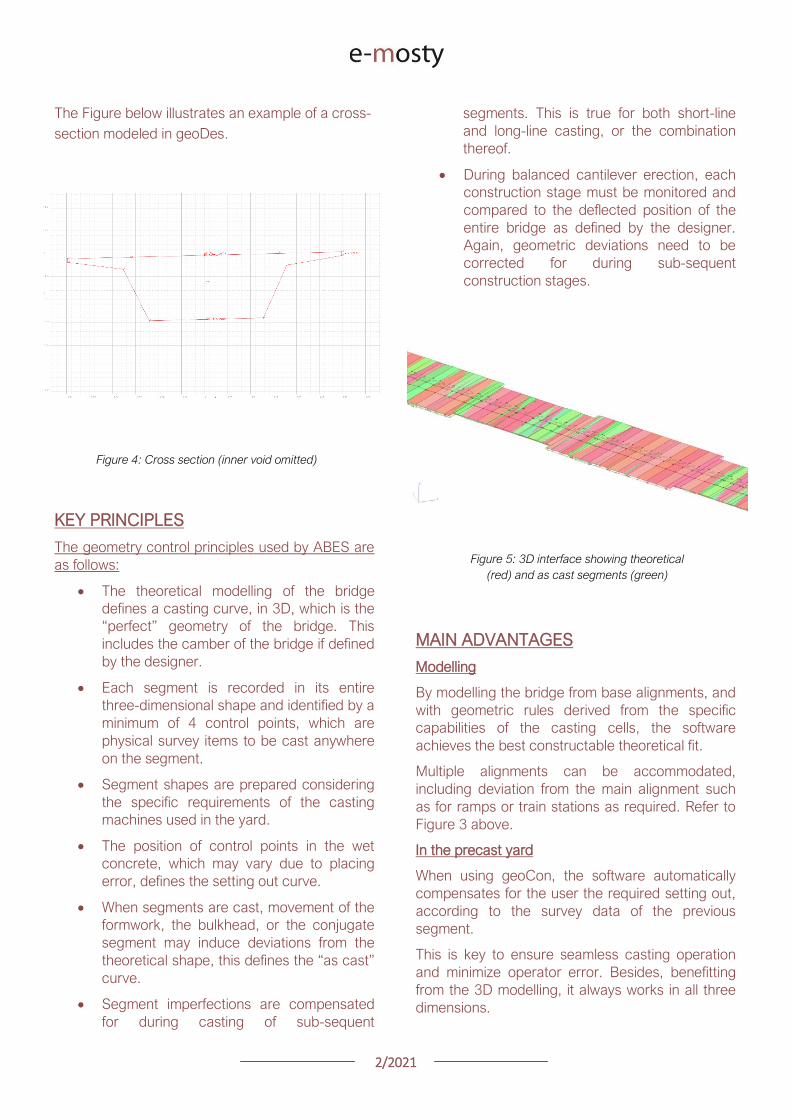
22021
There is no limit to the number of control points
per segment ensuring high accuracy
Another key feature for a stay cable bridge pipes
must be cast in advance into the segment in the
yard to achieve the final geometry after all
deformations have occurred
The software can transform the theoretical pipe
coordinates adjust them for cambers and
segment imperfections and display them in the
local coordinate system which can be processed
by the surveyor in the yard
Figure 6 Gewan Island bridge 3D modelling
with plan radius of less than 125m
Figure 8 Precasting of segments with cable stay pipes
On site for balanced cantilever erection
On site assemCon gives two key insights to the
user
Forecast the position of the bridge at any
construction stage in 3D considering the
as-built data the as-cast curve and the
calculated deflections for each
construction stage
Assist in finding an optimal shimming
strategy to correct the forecasted position
and to target a final as-built structure as
close as possible to the theoretical
geometry
Figure 7 3D view of a cantilever being built
22021
Figure 9 Definition of shimming
strategy to reduce differences
CONCLUSIONS
Pre-cast segmental bridge construction is applied
to increasingly complex and geometrically
challenging structures
Efficient geometry control is essential for the
success of such projects
Geometry control already starts during the
planning process where individual segments need
to be laid out to suit the available equipment in the
casting yard
Segment casting needs to be tightly controlled and
monitored and geometric imperfections need to
be identified and compensated for
And finally bridge construction at the construction
site requires monitoring of individual construction
stages and optimised strategies for correcting for
possible geometry deviations of the bridge
structure during construction
VSL in cooperation with ABES have developed a
suite of software tools to assist in all these tasks
The software is heavily influenced by practical
experience during numerous pre-cast segmental
projects of all sizes and shapes across Asia and
principally Qatar and India and feedback from
ongoing projects continues to inform the
development work
Figure 12 Al Bustan North bridge during construction
above traffic Qatar
Figure 11 Gewan Island Bridge being built Qatar
Figure 10 Karimnagar cable stay bridge India
Photos Credit VSL
22021
PRECAST SEGMENTAL BRIDGE CONSTRUCTION
USING LIFTING FRAME IN QATAR
Joakim Dupleix CaSE International (formerly VSL)
German A Pardo R VSL International Ltd
Figure 1 Overview of Al Bustan North construction site
PRECAST SEGMENTAL CONSTRUCTION
One of the most advantageous construction
methods enabled by segmental construction is the
balanced cantilever method
In a busy brownfield environment pre-casting the
segments off-site is the best solution to minimize
disrupting the existing traffic flow
In these environments access is often limited and
restricted and cranage may not be able to reach
the whole site
In these conditions lifting frame equipment are
often the solution to enable the erection of
segments on the bridge
In Qatar VSL designed and operated two very
different types of lifting frames as part of the Al
Bustan corridor upgrade project
The lifting frames responded to different needs and
segment delivery methods carefully studied during
the construction planning phase of the project
SABAH AL AHMAD CORRIDOR
(previously called Al Bustan)
Sabah al Ahmad or Al Bustan Corridor is part of
the Qatar Expressway Programme and aims to
provide an alternative to the existing expressway
with free flow traffic on a length of 14 km from the
North of Central Doha to the South to improve
connectivity to the FIFA World Cup stadiums
22021
The project involved upgrading the existing main
road by constructing various overhead bridges
over existing crossroads as well as connecting
ramps to remove traffic lights
The construction of this corridor was split into three
main packages
Al Bustan North project now known as
Umm Lekhba Interchange
Al Bustan South project
Mesaimeer Road project
Al Bustan North consists of the major upgrade of a
major interchange with Qatar main highway Al
Shamal Road to become a 4 level interchange
Al Bustan South required the construction of large
overhead bridges up to 26 km long with overhead
ramps connecting to crossroads
Mesaimeer Road upgraded the existing road with 2
large bridges up to 12 km long with a cable stay
section
PRECAST SEGMENTAL BALANCED
CANTILEVER METHOD
Because of the existing brownfield environment in
which the bridges are being built and to minimize
the impact on the existing traffic the precast
segment balanced cantilever method was chosen
for design and construction
It avoids installing large falsework structures on
site where space is limited and enables quick
fabrication of the bridge but requires relatively
large lifting equipment
As a matter of fact as the heavy concrete bridge
segments are to be transported and erected into
position with limited space the key is to
Figure 2 Key map of the corridor in Doha
22021
understand which areas are available where
possible if lifting equipment such as cranes can be
positioned and how to deliver the segments to
their final position
For very heavy segments or if cranes cannot be
used due to site constraints it may be required to
design custom made lifting frame machines
placed on top of the bridge already built and fitted
with their own lifting device to erect the segments
in their final position
These machines typically have a limited range and
segments must be first transported precisely near
their final position
On the Al Bustan Corridor two different delivery
situations were identified
For Al Bustan South and Mesaimeer the
large weight of the segments made it
prohibitively costly to use a crane
However assisted by a temporary
diversion of the existing road during
construction and the flat terrain every
segment could always be delivered directly
below their final position
For Al Bustan North the multi-level
interchange the existing highway Al
Shamal Road could only be closed to traffic
for a very limited time and the existing road
environment did not allow for flexible
segment delivery below each new bridge
ramp
A crane could be positioned near the piers
which allowed for segments to be lifted
onto the already erected deck
To position the segment into its final
position a special lifting frame was
designed to pick up the segment ldquofrom
behindrdquo and bring them forward into their
final position
LIFTING FRAME WITH DELIVERY FROM
BEHIND
As mentioned previously a lifting frame (LF) able
to pick up a segment from behind was required for
this project
A few options for the trajectory of the segment
were considered
Symmetrical Lifting Frame segment
crossing the lifting frame is rotated at 90
degrees in plan lifted and moved through
the middle of the machine longitudinally
Once at the front it can be rotated 90
degrees and lowered in position
Asymmetrical Lifting Frame segment is
delivered 180 degrees from its final
orientation
The segment is picked up rotated 90
degrees moved through the LF
longitudinally rotated again and then
lowered in position
Figure 3 Al Bustan North lifting frame
For this project the bridges are quite narrow with a
web spacing of 6 and 4 m and therefore passing a
32 m long segment between two legs of the LF
was not possible
As shown in Figure 4 on the next page a C shape
was adopted to allow the segment to be rotated on
the free side and moved forward
22021
Figure 4 Segment delivery methodology Click on the image to open it in full size
Description of Lifting Frame
The lifting Frame had the following key
specifications
1 Self-weight of 70 tonnes
2 Lifting capacity of 80 tonnes
3 Lifting speed of 12 mh [02 mmin]
4 Longitudinal launching speed of 3 mh
[005 mmin]
The lifting frame is made of a few key
components
Upper Cross Beam (UCB) transverse
beam carrying the strand lifting unit as
well as the stressing platform lifting
mast Adjustment capability of +-
200 mm
Main Beams (MB) Longitudinal beams
supporting the UCB The UCB is
moved on wheels with a bogie
connected to 2 chain pulling units
Figure 5 3D view of lifting frame model
22021
Support Frame (SF) asymmetric frame in a
C shape supporting the MB The frame is
supported on the deck by adjustable screw
jacks located over the webs
Tie down beams (TDB) during erection
the SF is tie down to the deck with 4 no
40 mm diameter stressbars anchored in
TDB The TDB allows for longitudinal
adjustment in the position of the bars as
the segment length varies
Rail beams (RB) two rail beams on each
side of the SF are fitted with a hydraulic
launching system able to move the entire
frame forward in steps of 700 mm
Segment lifting beam (SLB) the SLB is
stressed to the segment being lifted and is
fitted with hydraulic jacks able to adjust the
segment to the required crossfall and
gradient as well as rotated the segment in
plan to pass through the SF
Stressing platform (SP) to complete the
balance cantilever construction a SP is
required to be positioned each newly
erected segment to provide access for
personnel to complete the permanent post-
tensioning operation
Figure 6 Segment delivered at the rear of the LF
Figure 8 Segment rotated to its final orientation
rarr Figure 9 Segment lowered into
position and load transferred
Figure 7 Segment rotated and moved longitudinally
SEGMENT ERECTION PHOTOS
The photo sequence below shows the segment
delivery process
22021
Challenges
Because of the limited width of the deck and the
congested site area with existing roads one of the
key challenges was to find a suitable storage
position for the SP when not in use which would
not block the segment passage
A rotation mast or davit arm was designed to lift
and position the 6 tonnes platform The mast was
rotated up to 120 degrees with a small horizontal
hydraulic jack
The concept and design itself of the Lifting Frame
required a solution which provided the minimum
required space for manipulating the segment and
the stressing platform in a very tight area while
having enough stiffness and capacity to cover the
demands
LIFTING FRAME WITH DELIVERY FROM
BELOW
Typical configuration for a Lifting Frame is such
that segment can be lifted directly from below
This was the case of Al Bustan South and
Mesaimeer projects
MESAIMEER LIFTING FRAME
Segments to be lifted by this lifting frame were the
heaviest and widest on the project for this reason
a stiffer structure composed of rigid frames at the
supporting areas was chosen taking advantage of
the fact that there was no restriction in height and
section of the bridge
The delivery of the segments in this project could
be conducted almost at is final position in plan
which facilitated the configuration of the lifting
equipment at the cantilever of the lifting frame
For this purpose the lifting frame was provided
with a couple of Winches that could pick up the
segment from the ground with minimum rotation in
plan lifted to required level and conduct final
adjustment in the longitudinal and transverse
directions
Description of Lifting Frame
The Lifting Frame had the following key
specifications
1 Self-weight of 92 tonnes
2 Lifting capacity of 185 tonnes
3 Lifting speed of 60 mh [1 mmin]
4 Longitudinal launching speed of 3mh [005
mmin)
Figure 10 segment delivered at the rear of the LF
The lifting frame is made of a few key components
Upper Cross Beam (UCB) transverse
beam carrying the main lifting equipment
(Winch) as well as the stressing platform
Adjustment capability +- 1325
Cantilever Beam (CTB) the 2 main
longitudinal beams supporting the UCB and
Stressing Platform at front and the Tie
Down Beam at the rear
Lower Cross Beam (LCB) main Frames
underneath the CTB transferring all load to
the bridge
Rail Beams (RB) two rail beams on each
side of the LCB are fitted with a hydraulic
launching system able to move the entire
frame forward in steps of 850 mm
22021
Connection Beams (CB) beams
connecting the hook blocks of the Winches
directly to the segment They are provided
with jacks for segment gradient adjustment
Crossfall is adjusted directly by the
Winches
Stressing Platform (SP) it is positioned at
the tip of the CTB and move backward for
conducting stressing of bridge post-
tensioning tendons It is provided with 2
levels customized for this project
Tie Down Beam (TDB) the Support frame
is provided with a set of tie down beams at
the rear which are the main stability
system
TDB can be adjusted in the longitudinal
direction to suit the different segment
lengths and their respective tie down holes
position
Tie down bars are of 75mm and 47mm in
diameter and pre-stressed against the
segment
Challenges
To accommodate the supporting area in a
very limited length since there was
insufficient space near the pylons
This created big reactions to be taken by
the tie down elements due the big
cantilever at front and heavy segments to
be lifted
To be able to move all the way back the
lifting equipment (Winch) and UCB to
provide enough stability during the
launching procedure Space at rear of the
lifting frame was very limited
Provide a Stressing Platform with 2
different configurations (1 or 2 levels) that
could be adapted for specific
configurations
SEGMENT ERECTION PHOTOS
Figure 11 Mesaimeer Lifting Frame
Figure 12 Segment lifting
Figure 13 Segment permanent post-tensioning in progress
22021
AL BUSTAN SOUTH LIFTING FRAME
For this project the lifting frame had to
accommodate few main requirements to suit the
space constraints of the project and the bridge
capacity
Height A limit of 6m for total height the lifting
frame was to be assured since the bridge had
to pass under an existing viaduct
Load introduction The bridge section is
provided with 3 webs and middle web capacity
was to be respected by limiting the reactions at
this point Additionally the total weight of the
Lifting Frame was also limited
Segment delivered below could not be
positioned in its final orientation due to space
constraints It had to be rotated up to 90deg once
hanging from the lifting frame
To overcome the limitations described the lifting
frame concept developed considered the following
aspects
Main lifting equipment (Winch) was
positioned at the bottom rear area of the
lifting frame to reduce the total height
The three webs of the segment were
loaded and the Lifting Frame elements
were studied in such a way that the total
weight of the Lifting Frame and loading of
central web were not exceeded
A single Winch and the hook block with
rotation device were provided to allow
rotation of the segment while hanging from
the Lifting Frame
Description of Lifting Frame
The Lifting Frame had the following key
specifications
1 Self-weight of 81 tonnes
2 Lifting capacity of 170 tonnes
3 Lifting speed of 36 mh [06 mmin]
4 Longitudinal launching speed of 3mh [005
mmin
The lifting frame is made of the following key
components
Upper Cross Beam (UCB) uppermost
element carrying the Winch Trolley It can
slide longitudinally to accommodate the
segment in length Transverse adjustment
is done by sliding of the Winch Trolley over
the UCB
Main Frame (MF) the Lifting Frame is
provided with 2 Main Frames in section that
support the UCB and Stressing Platform on
top and transfers the vertical load to the
lower elements of the Lifting Frame At
bottom level it also receives the Tie Down
Beam
Lower Cross Beam (LCB) spreader beam
in the transverse direction located at front
and rear that transfer all loads to the
segment webs through 6 screw jacks (3 at
the front and 3 at the rear)
Tie Down Beam (TDB) located at rear part
of the Lifting Frame and contain the tie
down bars stressed down against the
segment in order to assure the stability of
the Lifting Frame It contains a couple of
back-up bars that provide redundancy to
the system
Segment Lifting Beam (SLB) connecting
element between the hook block of the
winch and the segment It is provided with
a rotational device that allows full rotation
of the segment in plan
Figure 14 Segment delivered at the rear of the LF
22021
Stressing Platform (SP) it hangs from the
tip of the Main Frame cantilever beam It is
moved backwards after segment
installation to conduct the stressing of the
permanent post-tensioning system
Rail Beam (RB) two rail beams on each
side of the LCB are fitted with a hydraulic
launching system able it to move the entire
frame forward in steps of 850 mm
Figure 14 Lifting Frame installation on deck
Figure 15 Lifting of segment
Figure 16 Stressing of post-tensioning tendons
Figure 17 Lifting Frame crossing under existing viaduct
SEGMENT ERECTION PHOTOS
Challenges
To develop a concept and design that did
not exceed the limitations given regarding
total weight and height
Allow full rotation of the segment while
hanging
Provide redundancy to the Lifting Frame
Tie Down system and to the Stressing
Platform while under operation
22021
CONCLUSIONS
Precast segmental construction in a congested
environment often requires the use of custom
designed lifting frames
These machines must always consider the
segment delivery methods as well as the bridge
characteristics in order to achieve the most cost-
efficient methods of erection
The more requirements a project has the more
customized the Lifting Frame will be
For this reason it is of key importance to integrate
the development of the Temporary Structures (like
Lifting Frames) as early as possible in the design
process
By doing this some of the constraints can be
solved in earlier stages which will improve the
efficiency of the full process and the interfaces
between the different parts involved Permanent
Works Designer Temporary Works Designer and
Main Contractor
Figure 18 Al Bustan North Figure 19 Al Bustan North
Figure 20 Al Bustan South
Figure 21 Mesaimeer
Photos 18 ndash 20 Credit Ashghal (Qatar Road Authority)
We design and produceformwork equipmentfor in-place casting of bridgesN25 New Ross Bypass (Ireland)
FOLLOW US
INNOVATIVE | SAFE | SUSTAINABLE | FAST
SOLUTIONS FOR BRIDGE CONSTRUCTION
MSS M1-70-S BRATISLAVA BYPASS | IN SITU CONSTRUCTION
LG 36-S CAIRO METRO LINE 3 EXTENSION | PRECAST SEGMENTAL
WWWBERDEU
Photo Credits D4R7
Photo Credits Stephane Ciccolini
Arup works in active partnership with clients to understand their needs so
that the solutions make their bridge aspirations possible mdashbig and small
The Arup global specialist technical skills blended with essential local
knowledge adds unexpected benefits
wwwarupcom
Whether to span nations make a statement or
improve everyday links Arup crafts better bridges
Naeem Hussain Richard Hornby Steve Kite Deepak Jayaram
naeemhussainarupcom richardhornbyarupcom stevekitearupcom deepakjayaramarupcom
Global UK Middle East amp Africa East Asia UK Middle East India
and Africa
Peter Burnton Marcos Sanchez Matt Carter
peterburntonarupcom marcossanchezarupcom mattcarterarupcom
Australasia Europe Americas
Queensferry Crossing Scotland
SANTANDERMADRIDLIMABOGOTAacuteBUENOS AIRES
Calle Marqueacutes de la Ensenada 11 - 3ordm 39009
Calle Bravo Murillo 101 - 4ordm 28020
Calle Coronel Inclaacuten 235 - Oficina 313 Lima 18
Cra 14 94a - 24 Oficina 307 Edificio ACO 94
Calle Rodriacuteguez Pentildea 681 - 4ordm Dpto 8 1020
Tfno +34 942 31 99 60
Tfno +34 91 702 54 78
Tfno +51 1 637 56 47
Tfno +57 1 467 48 10
Tfno +54 911 5709 3252
wwwarenasingcom
ARCHING THE WORLD
CODE-BASED DESIGN
DETAILINGDR AWING PRODUCTION
PAR AM ETRIC MODELING
STRUCTUR AL ANALYSIS
DOWNLOAD A FREE TRIALallplancombridge2021
THE WORLDrsquoS FIRST COMPLETE SOLUTIONFOR BRIDGE ENGINEERS
Allplan Bridge 2021 maps the complete BIM process in bridge projects The new version enables bridge engineers to work with one single solution from the creation of a parametric 4D model to structural analysis reinforcement design and detailing This further improves the design process in terms of both time and quality
ALLPLAN BRIDGE
Join Bridges to Prosperity in helping isolated
communities gain safe access to healthcare
education jobs and markets through simple
sustainable trailbridges Together we can
build more than a bridge we can build a
pathway out of poverty
We envision a world wherepoverty caused by ruralisolation no longer exists
bridgestoprosperityorg
infobridgestoprosperityorgbridgestoprosperity
bridgestoprosperity
b2p
+60Women Entering the Labor Force
+75Farmer
Profitability
+358Labor Market
Income
Corporate Partners make this
vision possible
Wyatt Brooks and Kevin Donovan - Eliminating Uncertainty in Market Access
The Impact of New Bridges in Rural Nicaragua 2017
SEGMENTAL BRIDGES
ISSUE 022021 JUNE
- 1 arenas_v2
-
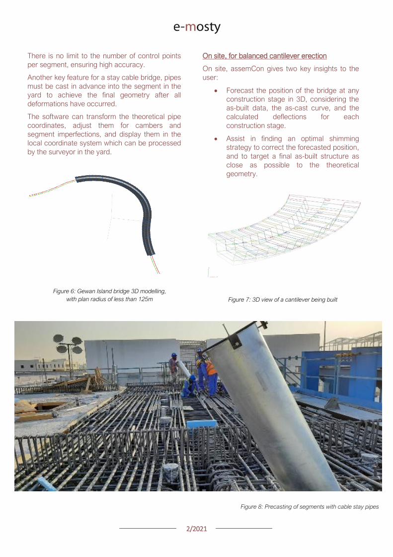
22021
Figure 9 Definition of shimming
strategy to reduce differences
CONCLUSIONS
Pre-cast segmental bridge construction is applied
to increasingly complex and geometrically
challenging structures
Efficient geometry control is essential for the
success of such projects
Geometry control already starts during the
planning process where individual segments need
to be laid out to suit the available equipment in the
casting yard
Segment casting needs to be tightly controlled and
monitored and geometric imperfections need to
be identified and compensated for
And finally bridge construction at the construction
site requires monitoring of individual construction
stages and optimised strategies for correcting for
possible geometry deviations of the bridge
structure during construction
VSL in cooperation with ABES have developed a
suite of software tools to assist in all these tasks
The software is heavily influenced by practical
experience during numerous pre-cast segmental
projects of all sizes and shapes across Asia and
principally Qatar and India and feedback from
ongoing projects continues to inform the
development work
Figure 12 Al Bustan North bridge during construction
above traffic Qatar
Figure 11 Gewan Island Bridge being built Qatar
Figure 10 Karimnagar cable stay bridge India
Photos Credit VSL
22021
PRECAST SEGMENTAL BRIDGE CONSTRUCTION
USING LIFTING FRAME IN QATAR
Joakim Dupleix CaSE International (formerly VSL)
German A Pardo R VSL International Ltd
Figure 1 Overview of Al Bustan North construction site
PRECAST SEGMENTAL CONSTRUCTION
One of the most advantageous construction
methods enabled by segmental construction is the
balanced cantilever method
In a busy brownfield environment pre-casting the
segments off-site is the best solution to minimize
disrupting the existing traffic flow
In these environments access is often limited and
restricted and cranage may not be able to reach
the whole site
In these conditions lifting frame equipment are
often the solution to enable the erection of
segments on the bridge
In Qatar VSL designed and operated two very
different types of lifting frames as part of the Al
Bustan corridor upgrade project
The lifting frames responded to different needs and
segment delivery methods carefully studied during
the construction planning phase of the project
SABAH AL AHMAD CORRIDOR
(previously called Al Bustan)
Sabah al Ahmad or Al Bustan Corridor is part of
the Qatar Expressway Programme and aims to
provide an alternative to the existing expressway
with free flow traffic on a length of 14 km from the
North of Central Doha to the South to improve
connectivity to the FIFA World Cup stadiums
22021
The project involved upgrading the existing main
road by constructing various overhead bridges
over existing crossroads as well as connecting
ramps to remove traffic lights
The construction of this corridor was split into three
main packages
Al Bustan North project now known as
Umm Lekhba Interchange
Al Bustan South project
Mesaimeer Road project
Al Bustan North consists of the major upgrade of a
major interchange with Qatar main highway Al
Shamal Road to become a 4 level interchange
Al Bustan South required the construction of large
overhead bridges up to 26 km long with overhead
ramps connecting to crossroads
Mesaimeer Road upgraded the existing road with 2
large bridges up to 12 km long with a cable stay
section
PRECAST SEGMENTAL BALANCED
CANTILEVER METHOD
Because of the existing brownfield environment in
which the bridges are being built and to minimize
the impact on the existing traffic the precast
segment balanced cantilever method was chosen
for design and construction
It avoids installing large falsework structures on
site where space is limited and enables quick
fabrication of the bridge but requires relatively
large lifting equipment
As a matter of fact as the heavy concrete bridge
segments are to be transported and erected into
position with limited space the key is to
Figure 2 Key map of the corridor in Doha
22021
understand which areas are available where
possible if lifting equipment such as cranes can be
positioned and how to deliver the segments to
their final position
For very heavy segments or if cranes cannot be
used due to site constraints it may be required to
design custom made lifting frame machines
placed on top of the bridge already built and fitted
with their own lifting device to erect the segments
in their final position
These machines typically have a limited range and
segments must be first transported precisely near
their final position
On the Al Bustan Corridor two different delivery
situations were identified
For Al Bustan South and Mesaimeer the
large weight of the segments made it
prohibitively costly to use a crane
However assisted by a temporary
diversion of the existing road during
construction and the flat terrain every
segment could always be delivered directly
below their final position
For Al Bustan North the multi-level
interchange the existing highway Al
Shamal Road could only be closed to traffic
for a very limited time and the existing road
environment did not allow for flexible
segment delivery below each new bridge
ramp
A crane could be positioned near the piers
which allowed for segments to be lifted
onto the already erected deck
To position the segment into its final
position a special lifting frame was
designed to pick up the segment ldquofrom
behindrdquo and bring them forward into their
final position
LIFTING FRAME WITH DELIVERY FROM
BEHIND
As mentioned previously a lifting frame (LF) able
to pick up a segment from behind was required for
this project
A few options for the trajectory of the segment
were considered
Symmetrical Lifting Frame segment
crossing the lifting frame is rotated at 90
degrees in plan lifted and moved through
the middle of the machine longitudinally
Once at the front it can be rotated 90
degrees and lowered in position
Asymmetrical Lifting Frame segment is
delivered 180 degrees from its final
orientation
The segment is picked up rotated 90
degrees moved through the LF
longitudinally rotated again and then
lowered in position
Figure 3 Al Bustan North lifting frame
For this project the bridges are quite narrow with a
web spacing of 6 and 4 m and therefore passing a
32 m long segment between two legs of the LF
was not possible
As shown in Figure 4 on the next page a C shape
was adopted to allow the segment to be rotated on
the free side and moved forward
22021
Figure 4 Segment delivery methodology Click on the image to open it in full size
Description of Lifting Frame
The lifting Frame had the following key
specifications
1 Self-weight of 70 tonnes
2 Lifting capacity of 80 tonnes
3 Lifting speed of 12 mh [02 mmin]
4 Longitudinal launching speed of 3 mh
[005 mmin]
The lifting frame is made of a few key
components
Upper Cross Beam (UCB) transverse
beam carrying the strand lifting unit as
well as the stressing platform lifting
mast Adjustment capability of +-
200 mm
Main Beams (MB) Longitudinal beams
supporting the UCB The UCB is
moved on wheels with a bogie
connected to 2 chain pulling units
Figure 5 3D view of lifting frame model
22021
Support Frame (SF) asymmetric frame in a
C shape supporting the MB The frame is
supported on the deck by adjustable screw
jacks located over the webs
Tie down beams (TDB) during erection
the SF is tie down to the deck with 4 no
40 mm diameter stressbars anchored in
TDB The TDB allows for longitudinal
adjustment in the position of the bars as
the segment length varies
Rail beams (RB) two rail beams on each
side of the SF are fitted with a hydraulic
launching system able to move the entire
frame forward in steps of 700 mm
Segment lifting beam (SLB) the SLB is
stressed to the segment being lifted and is
fitted with hydraulic jacks able to adjust the
segment to the required crossfall and
gradient as well as rotated the segment in
plan to pass through the SF
Stressing platform (SP) to complete the
balance cantilever construction a SP is
required to be positioned each newly
erected segment to provide access for
personnel to complete the permanent post-
tensioning operation
Figure 6 Segment delivered at the rear of the LF
Figure 8 Segment rotated to its final orientation
rarr Figure 9 Segment lowered into
position and load transferred
Figure 7 Segment rotated and moved longitudinally
SEGMENT ERECTION PHOTOS
The photo sequence below shows the segment
delivery process
22021
Challenges
Because of the limited width of the deck and the
congested site area with existing roads one of the
key challenges was to find a suitable storage
position for the SP when not in use which would
not block the segment passage
A rotation mast or davit arm was designed to lift
and position the 6 tonnes platform The mast was
rotated up to 120 degrees with a small horizontal
hydraulic jack
The concept and design itself of the Lifting Frame
required a solution which provided the minimum
required space for manipulating the segment and
the stressing platform in a very tight area while
having enough stiffness and capacity to cover the
demands
LIFTING FRAME WITH DELIVERY FROM
BELOW
Typical configuration for a Lifting Frame is such
that segment can be lifted directly from below
This was the case of Al Bustan South and
Mesaimeer projects
MESAIMEER LIFTING FRAME
Segments to be lifted by this lifting frame were the
heaviest and widest on the project for this reason
a stiffer structure composed of rigid frames at the
supporting areas was chosen taking advantage of
the fact that there was no restriction in height and
section of the bridge
The delivery of the segments in this project could
be conducted almost at is final position in plan
which facilitated the configuration of the lifting
equipment at the cantilever of the lifting frame
For this purpose the lifting frame was provided
with a couple of Winches that could pick up the
segment from the ground with minimum rotation in
plan lifted to required level and conduct final
adjustment in the longitudinal and transverse
directions
Description of Lifting Frame
The Lifting Frame had the following key
specifications
1 Self-weight of 92 tonnes
2 Lifting capacity of 185 tonnes
3 Lifting speed of 60 mh [1 mmin]
4 Longitudinal launching speed of 3mh [005
mmin)
Figure 10 segment delivered at the rear of the LF
The lifting frame is made of a few key components
Upper Cross Beam (UCB) transverse
beam carrying the main lifting equipment
(Winch) as well as the stressing platform
Adjustment capability +- 1325
Cantilever Beam (CTB) the 2 main
longitudinal beams supporting the UCB and
Stressing Platform at front and the Tie
Down Beam at the rear
Lower Cross Beam (LCB) main Frames
underneath the CTB transferring all load to
the bridge
Rail Beams (RB) two rail beams on each
side of the LCB are fitted with a hydraulic
launching system able to move the entire
frame forward in steps of 850 mm
22021
Connection Beams (CB) beams
connecting the hook blocks of the Winches
directly to the segment They are provided
with jacks for segment gradient adjustment
Crossfall is adjusted directly by the
Winches
Stressing Platform (SP) it is positioned at
the tip of the CTB and move backward for
conducting stressing of bridge post-
tensioning tendons It is provided with 2
levels customized for this project
Tie Down Beam (TDB) the Support frame
is provided with a set of tie down beams at
the rear which are the main stability
system
TDB can be adjusted in the longitudinal
direction to suit the different segment
lengths and their respective tie down holes
position
Tie down bars are of 75mm and 47mm in
diameter and pre-stressed against the
segment
Challenges
To accommodate the supporting area in a
very limited length since there was
insufficient space near the pylons
This created big reactions to be taken by
the tie down elements due the big
cantilever at front and heavy segments to
be lifted
To be able to move all the way back the
lifting equipment (Winch) and UCB to
provide enough stability during the
launching procedure Space at rear of the
lifting frame was very limited
Provide a Stressing Platform with 2
different configurations (1 or 2 levels) that
could be adapted for specific
configurations
SEGMENT ERECTION PHOTOS
Figure 11 Mesaimeer Lifting Frame
Figure 12 Segment lifting
Figure 13 Segment permanent post-tensioning in progress
22021
AL BUSTAN SOUTH LIFTING FRAME
For this project the lifting frame had to
accommodate few main requirements to suit the
space constraints of the project and the bridge
capacity
Height A limit of 6m for total height the lifting
frame was to be assured since the bridge had
to pass under an existing viaduct
Load introduction The bridge section is
provided with 3 webs and middle web capacity
was to be respected by limiting the reactions at
this point Additionally the total weight of the
Lifting Frame was also limited
Segment delivered below could not be
positioned in its final orientation due to space
constraints It had to be rotated up to 90deg once
hanging from the lifting frame
To overcome the limitations described the lifting
frame concept developed considered the following
aspects
Main lifting equipment (Winch) was
positioned at the bottom rear area of the
lifting frame to reduce the total height
The three webs of the segment were
loaded and the Lifting Frame elements
were studied in such a way that the total
weight of the Lifting Frame and loading of
central web were not exceeded
A single Winch and the hook block with
rotation device were provided to allow
rotation of the segment while hanging from
the Lifting Frame
Description of Lifting Frame
The Lifting Frame had the following key
specifications
1 Self-weight of 81 tonnes
2 Lifting capacity of 170 tonnes
3 Lifting speed of 36 mh [06 mmin]
4 Longitudinal launching speed of 3mh [005
mmin
The lifting frame is made of the following key
components
Upper Cross Beam (UCB) uppermost
element carrying the Winch Trolley It can
slide longitudinally to accommodate the
segment in length Transverse adjustment
is done by sliding of the Winch Trolley over
the UCB
Main Frame (MF) the Lifting Frame is
provided with 2 Main Frames in section that
support the UCB and Stressing Platform on
top and transfers the vertical load to the
lower elements of the Lifting Frame At
bottom level it also receives the Tie Down
Beam
Lower Cross Beam (LCB) spreader beam
in the transverse direction located at front
and rear that transfer all loads to the
segment webs through 6 screw jacks (3 at
the front and 3 at the rear)
Tie Down Beam (TDB) located at rear part
of the Lifting Frame and contain the tie
down bars stressed down against the
segment in order to assure the stability of
the Lifting Frame It contains a couple of
back-up bars that provide redundancy to
the system
Segment Lifting Beam (SLB) connecting
element between the hook block of the
winch and the segment It is provided with
a rotational device that allows full rotation
of the segment in plan
Figure 14 Segment delivered at the rear of the LF
22021
Stressing Platform (SP) it hangs from the
tip of the Main Frame cantilever beam It is
moved backwards after segment
installation to conduct the stressing of the
permanent post-tensioning system
Rail Beam (RB) two rail beams on each
side of the LCB are fitted with a hydraulic
launching system able it to move the entire
frame forward in steps of 850 mm
Figure 14 Lifting Frame installation on deck
Figure 15 Lifting of segment
Figure 16 Stressing of post-tensioning tendons
Figure 17 Lifting Frame crossing under existing viaduct
SEGMENT ERECTION PHOTOS
Challenges
To develop a concept and design that did
not exceed the limitations given regarding
total weight and height
Allow full rotation of the segment while
hanging
Provide redundancy to the Lifting Frame
Tie Down system and to the Stressing
Platform while under operation
22021
CONCLUSIONS
Precast segmental construction in a congested
environment often requires the use of custom
designed lifting frames
These machines must always consider the
segment delivery methods as well as the bridge
characteristics in order to achieve the most cost-
efficient methods of erection
The more requirements a project has the more
customized the Lifting Frame will be
For this reason it is of key importance to integrate
the development of the Temporary Structures (like
Lifting Frames) as early as possible in the design
process
By doing this some of the constraints can be
solved in earlier stages which will improve the
efficiency of the full process and the interfaces
between the different parts involved Permanent
Works Designer Temporary Works Designer and
Main Contractor
Figure 18 Al Bustan North Figure 19 Al Bustan North
Figure 20 Al Bustan South
Figure 21 Mesaimeer
Photos 18 ndash 20 Credit Ashghal (Qatar Road Authority)
We design and produceformwork equipmentfor in-place casting of bridgesN25 New Ross Bypass (Ireland)
FOLLOW US
INNOVATIVE | SAFE | SUSTAINABLE | FAST
SOLUTIONS FOR BRIDGE CONSTRUCTION
MSS M1-70-S BRATISLAVA BYPASS | IN SITU CONSTRUCTION
LG 36-S CAIRO METRO LINE 3 EXTENSION | PRECAST SEGMENTAL
WWWBERDEU
Photo Credits D4R7
Photo Credits Stephane Ciccolini
Arup works in active partnership with clients to understand their needs so
that the solutions make their bridge aspirations possible mdashbig and small
The Arup global specialist technical skills blended with essential local
knowledge adds unexpected benefits
wwwarupcom
Whether to span nations make a statement or
improve everyday links Arup crafts better bridges
Naeem Hussain Richard Hornby Steve Kite Deepak Jayaram
naeemhussainarupcom richardhornbyarupcom stevekitearupcom deepakjayaramarupcom
Global UK Middle East amp Africa East Asia UK Middle East India
and Africa
Peter Burnton Marcos Sanchez Matt Carter
peterburntonarupcom marcossanchezarupcom mattcarterarupcom
Australasia Europe Americas
Queensferry Crossing Scotland
SANTANDERMADRIDLIMABOGOTAacuteBUENOS AIRES
Calle Marqueacutes de la Ensenada 11 - 3ordm 39009
Calle Bravo Murillo 101 - 4ordm 28020
Calle Coronel Inclaacuten 235 - Oficina 313 Lima 18
Cra 14 94a - 24 Oficina 307 Edificio ACO 94
Calle Rodriacuteguez Pentildea 681 - 4ordm Dpto 8 1020
Tfno +34 942 31 99 60
Tfno +34 91 702 54 78
Tfno +51 1 637 56 47
Tfno +57 1 467 48 10
Tfno +54 911 5709 3252
wwwarenasingcom
ARCHING THE WORLD
CODE-BASED DESIGN
DETAILINGDR AWING PRODUCTION
PAR AM ETRIC MODELING
STRUCTUR AL ANALYSIS
DOWNLOAD A FREE TRIALallplancombridge2021
THE WORLDrsquoS FIRST COMPLETE SOLUTIONFOR BRIDGE ENGINEERS
Allplan Bridge 2021 maps the complete BIM process in bridge projects The new version enables bridge engineers to work with one single solution from the creation of a parametric 4D model to structural analysis reinforcement design and detailing This further improves the design process in terms of both time and quality
ALLPLAN BRIDGE
Join Bridges to Prosperity in helping isolated
communities gain safe access to healthcare
education jobs and markets through simple
sustainable trailbridges Together we can
build more than a bridge we can build a
pathway out of poverty
We envision a world wherepoverty caused by ruralisolation no longer exists
bridgestoprosperityorg
infobridgestoprosperityorgbridgestoprosperity
bridgestoprosperity
b2p
+60Women Entering the Labor Force
+75Farmer
Profitability
+358Labor Market
Income
Corporate Partners make this
vision possible
Wyatt Brooks and Kevin Donovan - Eliminating Uncertainty in Market Access
The Impact of New Bridges in Rural Nicaragua 2017
SEGMENTAL BRIDGES
ISSUE 022021 JUNE
- 1 arenas_v2
-
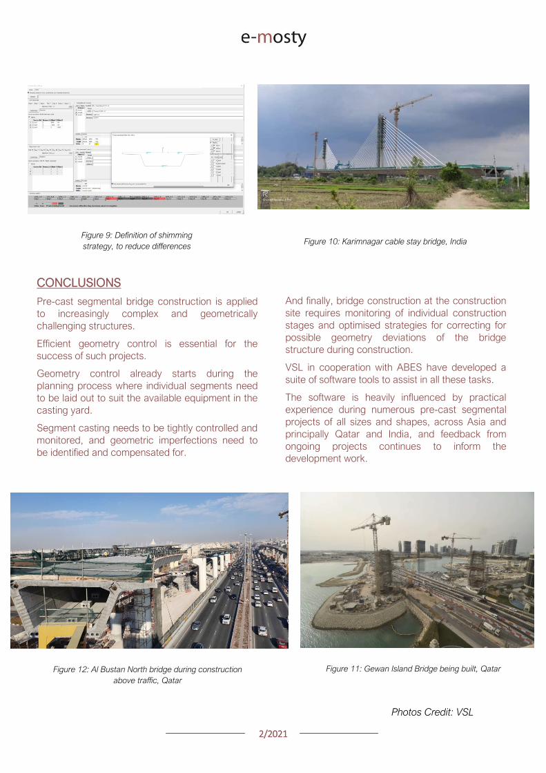
22021
PRECAST SEGMENTAL BRIDGE CONSTRUCTION
USING LIFTING FRAME IN QATAR
Joakim Dupleix CaSE International (formerly VSL)
German A Pardo R VSL International Ltd
Figure 1 Overview of Al Bustan North construction site
PRECAST SEGMENTAL CONSTRUCTION
One of the most advantageous construction
methods enabled by segmental construction is the
balanced cantilever method
In a busy brownfield environment pre-casting the
segments off-site is the best solution to minimize
disrupting the existing traffic flow
In these environments access is often limited and
restricted and cranage may not be able to reach
the whole site
In these conditions lifting frame equipment are
often the solution to enable the erection of
segments on the bridge
In Qatar VSL designed and operated two very
different types of lifting frames as part of the Al
Bustan corridor upgrade project
The lifting frames responded to different needs and
segment delivery methods carefully studied during
the construction planning phase of the project
SABAH AL AHMAD CORRIDOR
(previously called Al Bustan)
Sabah al Ahmad or Al Bustan Corridor is part of
the Qatar Expressway Programme and aims to
provide an alternative to the existing expressway
with free flow traffic on a length of 14 km from the
North of Central Doha to the South to improve
connectivity to the FIFA World Cup stadiums
22021
The project involved upgrading the existing main
road by constructing various overhead bridges
over existing crossroads as well as connecting
ramps to remove traffic lights
The construction of this corridor was split into three
main packages
Al Bustan North project now known as
Umm Lekhba Interchange
Al Bustan South project
Mesaimeer Road project
Al Bustan North consists of the major upgrade of a
major interchange with Qatar main highway Al
Shamal Road to become a 4 level interchange
Al Bustan South required the construction of large
overhead bridges up to 26 km long with overhead
ramps connecting to crossroads
Mesaimeer Road upgraded the existing road with 2
large bridges up to 12 km long with a cable stay
section
PRECAST SEGMENTAL BALANCED
CANTILEVER METHOD
Because of the existing brownfield environment in
which the bridges are being built and to minimize
the impact on the existing traffic the precast
segment balanced cantilever method was chosen
for design and construction
It avoids installing large falsework structures on
site where space is limited and enables quick
fabrication of the bridge but requires relatively
large lifting equipment
As a matter of fact as the heavy concrete bridge
segments are to be transported and erected into
position with limited space the key is to
Figure 2 Key map of the corridor in Doha
22021
understand which areas are available where
possible if lifting equipment such as cranes can be
positioned and how to deliver the segments to
their final position
For very heavy segments or if cranes cannot be
used due to site constraints it may be required to
design custom made lifting frame machines
placed on top of the bridge already built and fitted
with their own lifting device to erect the segments
in their final position
These machines typically have a limited range and
segments must be first transported precisely near
their final position
On the Al Bustan Corridor two different delivery
situations were identified
For Al Bustan South and Mesaimeer the
large weight of the segments made it
prohibitively costly to use a crane
However assisted by a temporary
diversion of the existing road during
construction and the flat terrain every
segment could always be delivered directly
below their final position
For Al Bustan North the multi-level
interchange the existing highway Al
Shamal Road could only be closed to traffic
for a very limited time and the existing road
environment did not allow for flexible
segment delivery below each new bridge
ramp
A crane could be positioned near the piers
which allowed for segments to be lifted
onto the already erected deck
To position the segment into its final
position a special lifting frame was
designed to pick up the segment ldquofrom
behindrdquo and bring them forward into their
final position
LIFTING FRAME WITH DELIVERY FROM
BEHIND
As mentioned previously a lifting frame (LF) able
to pick up a segment from behind was required for
this project
A few options for the trajectory of the segment
were considered
Symmetrical Lifting Frame segment
crossing the lifting frame is rotated at 90
degrees in plan lifted and moved through
the middle of the machine longitudinally
Once at the front it can be rotated 90
degrees and lowered in position
Asymmetrical Lifting Frame segment is
delivered 180 degrees from its final
orientation
The segment is picked up rotated 90
degrees moved through the LF
longitudinally rotated again and then
lowered in position
Figure 3 Al Bustan North lifting frame
For this project the bridges are quite narrow with a
web spacing of 6 and 4 m and therefore passing a
32 m long segment between two legs of the LF
was not possible
As shown in Figure 4 on the next page a C shape
was adopted to allow the segment to be rotated on
the free side and moved forward
22021
Figure 4 Segment delivery methodology Click on the image to open it in full size
Description of Lifting Frame
The lifting Frame had the following key
specifications
1 Self-weight of 70 tonnes
2 Lifting capacity of 80 tonnes
3 Lifting speed of 12 mh [02 mmin]
4 Longitudinal launching speed of 3 mh
[005 mmin]
The lifting frame is made of a few key
components
Upper Cross Beam (UCB) transverse
beam carrying the strand lifting unit as
well as the stressing platform lifting
mast Adjustment capability of +-
200 mm
Main Beams (MB) Longitudinal beams
supporting the UCB The UCB is
moved on wheels with a bogie
connected to 2 chain pulling units
Figure 5 3D view of lifting frame model
22021
Support Frame (SF) asymmetric frame in a
C shape supporting the MB The frame is
supported on the deck by adjustable screw
jacks located over the webs
Tie down beams (TDB) during erection
the SF is tie down to the deck with 4 no
40 mm diameter stressbars anchored in
TDB The TDB allows for longitudinal
adjustment in the position of the bars as
the segment length varies
Rail beams (RB) two rail beams on each
side of the SF are fitted with a hydraulic
launching system able to move the entire
frame forward in steps of 700 mm
Segment lifting beam (SLB) the SLB is
stressed to the segment being lifted and is
fitted with hydraulic jacks able to adjust the
segment to the required crossfall and
gradient as well as rotated the segment in
plan to pass through the SF
Stressing platform (SP) to complete the
balance cantilever construction a SP is
required to be positioned each newly
erected segment to provide access for
personnel to complete the permanent post-
tensioning operation
Figure 6 Segment delivered at the rear of the LF
Figure 8 Segment rotated to its final orientation
rarr Figure 9 Segment lowered into
position and load transferred
Figure 7 Segment rotated and moved longitudinally
SEGMENT ERECTION PHOTOS
The photo sequence below shows the segment
delivery process
22021
Challenges
Because of the limited width of the deck and the
congested site area with existing roads one of the
key challenges was to find a suitable storage
position for the SP when not in use which would
not block the segment passage
A rotation mast or davit arm was designed to lift
and position the 6 tonnes platform The mast was
rotated up to 120 degrees with a small horizontal
hydraulic jack
The concept and design itself of the Lifting Frame
required a solution which provided the minimum
required space for manipulating the segment and
the stressing platform in a very tight area while
having enough stiffness and capacity to cover the
demands
LIFTING FRAME WITH DELIVERY FROM
BELOW
Typical configuration for a Lifting Frame is such
that segment can be lifted directly from below
This was the case of Al Bustan South and
Mesaimeer projects
MESAIMEER LIFTING FRAME
Segments to be lifted by this lifting frame were the
heaviest and widest on the project for this reason
a stiffer structure composed of rigid frames at the
supporting areas was chosen taking advantage of
the fact that there was no restriction in height and
section of the bridge
The delivery of the segments in this project could
be conducted almost at is final position in plan
which facilitated the configuration of the lifting
equipment at the cantilever of the lifting frame
For this purpose the lifting frame was provided
with a couple of Winches that could pick up the
segment from the ground with minimum rotation in
plan lifted to required level and conduct final
adjustment in the longitudinal and transverse
directions
Description of Lifting Frame
The Lifting Frame had the following key
specifications
1 Self-weight of 92 tonnes
2 Lifting capacity of 185 tonnes
3 Lifting speed of 60 mh [1 mmin]
4 Longitudinal launching speed of 3mh [005
mmin)
Figure 10 segment delivered at the rear of the LF
The lifting frame is made of a few key components
Upper Cross Beam (UCB) transverse
beam carrying the main lifting equipment
(Winch) as well as the stressing platform
Adjustment capability +- 1325
Cantilever Beam (CTB) the 2 main
longitudinal beams supporting the UCB and
Stressing Platform at front and the Tie
Down Beam at the rear
Lower Cross Beam (LCB) main Frames
underneath the CTB transferring all load to
the bridge
Rail Beams (RB) two rail beams on each
side of the LCB are fitted with a hydraulic
launching system able to move the entire
frame forward in steps of 850 mm
22021
Connection Beams (CB) beams
connecting the hook blocks of the Winches
directly to the segment They are provided
with jacks for segment gradient adjustment
Crossfall is adjusted directly by the
Winches
Stressing Platform (SP) it is positioned at
the tip of the CTB and move backward for
conducting stressing of bridge post-
tensioning tendons It is provided with 2
levels customized for this project
Tie Down Beam (TDB) the Support frame
is provided with a set of tie down beams at
the rear which are the main stability
system
TDB can be adjusted in the longitudinal
direction to suit the different segment
lengths and their respective tie down holes
position
Tie down bars are of 75mm and 47mm in
diameter and pre-stressed against the
segment
Challenges
To accommodate the supporting area in a
very limited length since there was
insufficient space near the pylons
This created big reactions to be taken by
the tie down elements due the big
cantilever at front and heavy segments to
be lifted
To be able to move all the way back the
lifting equipment (Winch) and UCB to
provide enough stability during the
launching procedure Space at rear of the
lifting frame was very limited
Provide a Stressing Platform with 2
different configurations (1 or 2 levels) that
could be adapted for specific
configurations
SEGMENT ERECTION PHOTOS
Figure 11 Mesaimeer Lifting Frame
Figure 12 Segment lifting
Figure 13 Segment permanent post-tensioning in progress
22021
AL BUSTAN SOUTH LIFTING FRAME
For this project the lifting frame had to
accommodate few main requirements to suit the
space constraints of the project and the bridge
capacity
Height A limit of 6m for total height the lifting
frame was to be assured since the bridge had
to pass under an existing viaduct
Load introduction The bridge section is
provided with 3 webs and middle web capacity
was to be respected by limiting the reactions at
this point Additionally the total weight of the
Lifting Frame was also limited
Segment delivered below could not be
positioned in its final orientation due to space
constraints It had to be rotated up to 90deg once
hanging from the lifting frame
To overcome the limitations described the lifting
frame concept developed considered the following
aspects
Main lifting equipment (Winch) was
positioned at the bottom rear area of the
lifting frame to reduce the total height
The three webs of the segment were
loaded and the Lifting Frame elements
were studied in such a way that the total
weight of the Lifting Frame and loading of
central web were not exceeded
A single Winch and the hook block with
rotation device were provided to allow
rotation of the segment while hanging from
the Lifting Frame
Description of Lifting Frame
The Lifting Frame had the following key
specifications
1 Self-weight of 81 tonnes
2 Lifting capacity of 170 tonnes
3 Lifting speed of 36 mh [06 mmin]
4 Longitudinal launching speed of 3mh [005
mmin
The lifting frame is made of the following key
components
Upper Cross Beam (UCB) uppermost
element carrying the Winch Trolley It can
slide longitudinally to accommodate the
segment in length Transverse adjustment
is done by sliding of the Winch Trolley over
the UCB
Main Frame (MF) the Lifting Frame is
provided with 2 Main Frames in section that
support the UCB and Stressing Platform on
top and transfers the vertical load to the
lower elements of the Lifting Frame At
bottom level it also receives the Tie Down
Beam
Lower Cross Beam (LCB) spreader beam
in the transverse direction located at front
and rear that transfer all loads to the
segment webs through 6 screw jacks (3 at
the front and 3 at the rear)
Tie Down Beam (TDB) located at rear part
of the Lifting Frame and contain the tie
down bars stressed down against the
segment in order to assure the stability of
the Lifting Frame It contains a couple of
back-up bars that provide redundancy to
the system
Segment Lifting Beam (SLB) connecting
element between the hook block of the
winch and the segment It is provided with
a rotational device that allows full rotation
of the segment in plan
Figure 14 Segment delivered at the rear of the LF
22021
Stressing Platform (SP) it hangs from the
tip of the Main Frame cantilever beam It is
moved backwards after segment
installation to conduct the stressing of the
permanent post-tensioning system
Rail Beam (RB) two rail beams on each
side of the LCB are fitted with a hydraulic
launching system able it to move the entire
frame forward in steps of 850 mm
Figure 14 Lifting Frame installation on deck
Figure 15 Lifting of segment
Figure 16 Stressing of post-tensioning tendons
Figure 17 Lifting Frame crossing under existing viaduct
SEGMENT ERECTION PHOTOS
Challenges
To develop a concept and design that did
not exceed the limitations given regarding
total weight and height
Allow full rotation of the segment while
hanging
Provide redundancy to the Lifting Frame
Tie Down system and to the Stressing
Platform while under operation
22021
CONCLUSIONS
Precast segmental construction in a congested
environment often requires the use of custom
designed lifting frames
These machines must always consider the
segment delivery methods as well as the bridge
characteristics in order to achieve the most cost-
efficient methods of erection
The more requirements a project has the more
customized the Lifting Frame will be
For this reason it is of key importance to integrate
the development of the Temporary Structures (like
Lifting Frames) as early as possible in the design
process
By doing this some of the constraints can be
solved in earlier stages which will improve the
efficiency of the full process and the interfaces
between the different parts involved Permanent
Works Designer Temporary Works Designer and
Main Contractor
Figure 18 Al Bustan North Figure 19 Al Bustan North
Figure 20 Al Bustan South
Figure 21 Mesaimeer
Photos 18 ndash 20 Credit Ashghal (Qatar Road Authority)
We design and produceformwork equipmentfor in-place casting of bridgesN25 New Ross Bypass (Ireland)
FOLLOW US
INNOVATIVE | SAFE | SUSTAINABLE | FAST
SOLUTIONS FOR BRIDGE CONSTRUCTION
MSS M1-70-S BRATISLAVA BYPASS | IN SITU CONSTRUCTION
LG 36-S CAIRO METRO LINE 3 EXTENSION | PRECAST SEGMENTAL
WWWBERDEU
Photo Credits D4R7
Photo Credits Stephane Ciccolini
Arup works in active partnership with clients to understand their needs so
that the solutions make their bridge aspirations possible mdashbig and small
The Arup global specialist technical skills blended with essential local
knowledge adds unexpected benefits
wwwarupcom
Whether to span nations make a statement or
improve everyday links Arup crafts better bridges
Naeem Hussain Richard Hornby Steve Kite Deepak Jayaram
naeemhussainarupcom richardhornbyarupcom stevekitearupcom deepakjayaramarupcom
Global UK Middle East amp Africa East Asia UK Middle East India
and Africa
Peter Burnton Marcos Sanchez Matt Carter
peterburntonarupcom marcossanchezarupcom mattcarterarupcom
Australasia Europe Americas
Queensferry Crossing Scotland
SANTANDERMADRIDLIMABOGOTAacuteBUENOS AIRES
Calle Marqueacutes de la Ensenada 11 - 3ordm 39009
Calle Bravo Murillo 101 - 4ordm 28020
Calle Coronel Inclaacuten 235 - Oficina 313 Lima 18
Cra 14 94a - 24 Oficina 307 Edificio ACO 94
Calle Rodriacuteguez Pentildea 681 - 4ordm Dpto 8 1020
Tfno +34 942 31 99 60
Tfno +34 91 702 54 78
Tfno +51 1 637 56 47
Tfno +57 1 467 48 10
Tfno +54 911 5709 3252
wwwarenasingcom
ARCHING THE WORLD
CODE-BASED DESIGN
DETAILINGDR AWING PRODUCTION
PAR AM ETRIC MODELING
STRUCTUR AL ANALYSIS
DOWNLOAD A FREE TRIALallplancombridge2021
THE WORLDrsquoS FIRST COMPLETE SOLUTIONFOR BRIDGE ENGINEERS
Allplan Bridge 2021 maps the complete BIM process in bridge projects The new version enables bridge engineers to work with one single solution from the creation of a parametric 4D model to structural analysis reinforcement design and detailing This further improves the design process in terms of both time and quality
ALLPLAN BRIDGE
Join Bridges to Prosperity in helping isolated
communities gain safe access to healthcare
education jobs and markets through simple
sustainable trailbridges Together we can
build more than a bridge we can build a
pathway out of poverty
We envision a world wherepoverty caused by ruralisolation no longer exists
bridgestoprosperityorg
infobridgestoprosperityorgbridgestoprosperity
bridgestoprosperity
b2p
+60Women Entering the Labor Force
+75Farmer
Profitability
+358Labor Market
Income
Corporate Partners make this
vision possible
Wyatt Brooks and Kevin Donovan - Eliminating Uncertainty in Market Access
The Impact of New Bridges in Rural Nicaragua 2017
SEGMENTAL BRIDGES
ISSUE 022021 JUNE
- 1 arenas_v2
-
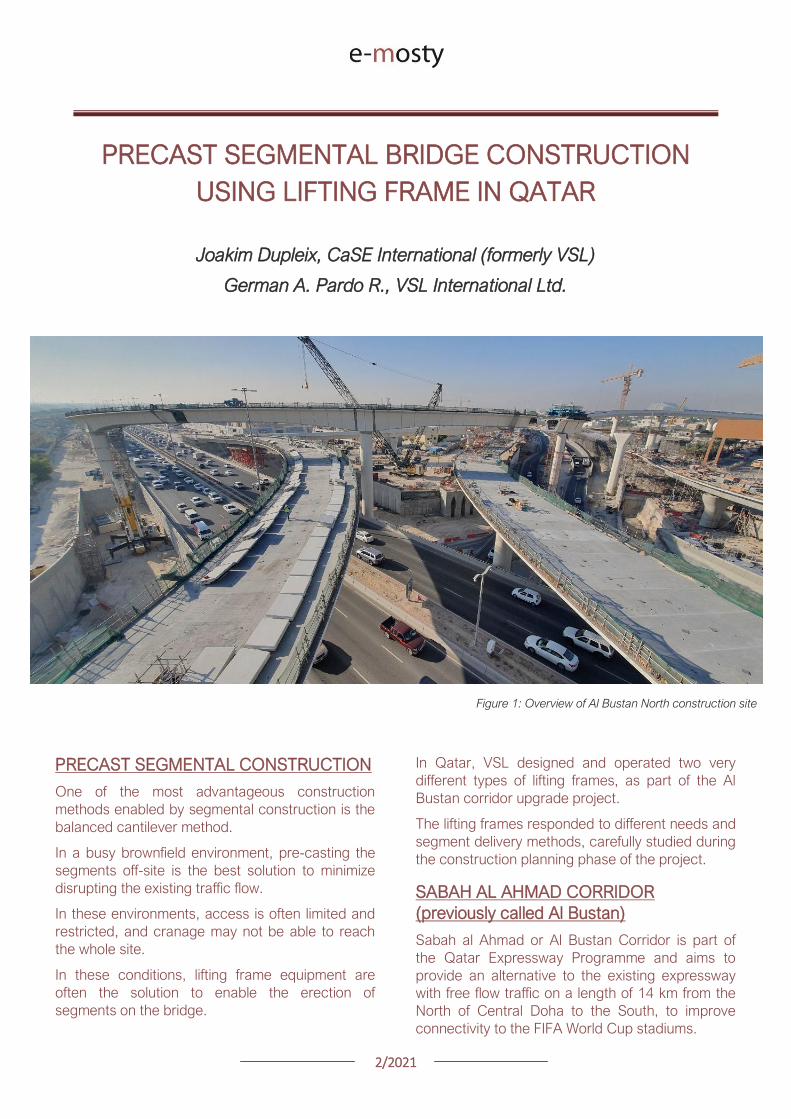
22021
The project involved upgrading the existing main
road by constructing various overhead bridges
over existing crossroads as well as connecting
ramps to remove traffic lights
The construction of this corridor was split into three
main packages
Al Bustan North project now known as
Umm Lekhba Interchange
Al Bustan South project
Mesaimeer Road project
Al Bustan North consists of the major upgrade of a
major interchange with Qatar main highway Al
Shamal Road to become a 4 level interchange
Al Bustan South required the construction of large
overhead bridges up to 26 km long with overhead
ramps connecting to crossroads
Mesaimeer Road upgraded the existing road with 2
large bridges up to 12 km long with a cable stay
section
PRECAST SEGMENTAL BALANCED
CANTILEVER METHOD
Because of the existing brownfield environment in
which the bridges are being built and to minimize
the impact on the existing traffic the precast
segment balanced cantilever method was chosen
for design and construction
It avoids installing large falsework structures on
site where space is limited and enables quick
fabrication of the bridge but requires relatively
large lifting equipment
As a matter of fact as the heavy concrete bridge
segments are to be transported and erected into
position with limited space the key is to
Figure 2 Key map of the corridor in Doha
22021
understand which areas are available where
possible if lifting equipment such as cranes can be
positioned and how to deliver the segments to
their final position
For very heavy segments or if cranes cannot be
used due to site constraints it may be required to
design custom made lifting frame machines
placed on top of the bridge already built and fitted
with their own lifting device to erect the segments
in their final position
These machines typically have a limited range and
segments must be first transported precisely near
their final position
On the Al Bustan Corridor two different delivery
situations were identified
For Al Bustan South and Mesaimeer the
large weight of the segments made it
prohibitively costly to use a crane
However assisted by a temporary
diversion of the existing road during
construction and the flat terrain every
segment could always be delivered directly
below their final position
For Al Bustan North the multi-level
interchange the existing highway Al
Shamal Road could only be closed to traffic
for a very limited time and the existing road
environment did not allow for flexible
segment delivery below each new bridge
ramp
A crane could be positioned near the piers
which allowed for segments to be lifted
onto the already erected deck
To position the segment into its final
position a special lifting frame was
designed to pick up the segment ldquofrom
behindrdquo and bring them forward into their
final position
LIFTING FRAME WITH DELIVERY FROM
BEHIND
As mentioned previously a lifting frame (LF) able
to pick up a segment from behind was required for
this project
A few options for the trajectory of the segment
were considered
Symmetrical Lifting Frame segment
crossing the lifting frame is rotated at 90
degrees in plan lifted and moved through
the middle of the machine longitudinally
Once at the front it can be rotated 90
degrees and lowered in position
Asymmetrical Lifting Frame segment is
delivered 180 degrees from its final
orientation
The segment is picked up rotated 90
degrees moved through the LF
longitudinally rotated again and then
lowered in position
Figure 3 Al Bustan North lifting frame
For this project the bridges are quite narrow with a
web spacing of 6 and 4 m and therefore passing a
32 m long segment between two legs of the LF
was not possible
As shown in Figure 4 on the next page a C shape
was adopted to allow the segment to be rotated on
the free side and moved forward
22021
Figure 4 Segment delivery methodology Click on the image to open it in full size
Description of Lifting Frame
The lifting Frame had the following key
specifications
1 Self-weight of 70 tonnes
2 Lifting capacity of 80 tonnes
3 Lifting speed of 12 mh [02 mmin]
4 Longitudinal launching speed of 3 mh
[005 mmin]
The lifting frame is made of a few key
components
Upper Cross Beam (UCB) transverse
beam carrying the strand lifting unit as
well as the stressing platform lifting
mast Adjustment capability of +-
200 mm
Main Beams (MB) Longitudinal beams
supporting the UCB The UCB is
moved on wheels with a bogie
connected to 2 chain pulling units
Figure 5 3D view of lifting frame model
22021
Support Frame (SF) asymmetric frame in a
C shape supporting the MB The frame is
supported on the deck by adjustable screw
jacks located over the webs
Tie down beams (TDB) during erection
the SF is tie down to the deck with 4 no
40 mm diameter stressbars anchored in
TDB The TDB allows for longitudinal
adjustment in the position of the bars as
the segment length varies
Rail beams (RB) two rail beams on each
side of the SF are fitted with a hydraulic
launching system able to move the entire
frame forward in steps of 700 mm
Segment lifting beam (SLB) the SLB is
stressed to the segment being lifted and is
fitted with hydraulic jacks able to adjust the
segment to the required crossfall and
gradient as well as rotated the segment in
plan to pass through the SF
Stressing platform (SP) to complete the
balance cantilever construction a SP is
required to be positioned each newly
erected segment to provide access for
personnel to complete the permanent post-
tensioning operation
Figure 6 Segment delivered at the rear of the LF
Figure 8 Segment rotated to its final orientation
rarr Figure 9 Segment lowered into
position and load transferred
Figure 7 Segment rotated and moved longitudinally
SEGMENT ERECTION PHOTOS
The photo sequence below shows the segment
delivery process
22021
Challenges
Because of the limited width of the deck and the
congested site area with existing roads one of the
key challenges was to find a suitable storage
position for the SP when not in use which would
not block the segment passage
A rotation mast or davit arm was designed to lift
and position the 6 tonnes platform The mast was
rotated up to 120 degrees with a small horizontal
hydraulic jack
The concept and design itself of the Lifting Frame
required a solution which provided the minimum
required space for manipulating the segment and
the stressing platform in a very tight area while
having enough stiffness and capacity to cover the
demands
LIFTING FRAME WITH DELIVERY FROM
BELOW
Typical configuration for a Lifting Frame is such
that segment can be lifted directly from below
This was the case of Al Bustan South and
Mesaimeer projects
MESAIMEER LIFTING FRAME
Segments to be lifted by this lifting frame were the
heaviest and widest on the project for this reason
a stiffer structure composed of rigid frames at the
supporting areas was chosen taking advantage of
the fact that there was no restriction in height and
section of the bridge
The delivery of the segments in this project could
be conducted almost at is final position in plan
which facilitated the configuration of the lifting
equipment at the cantilever of the lifting frame
For this purpose the lifting frame was provided
with a couple of Winches that could pick up the
segment from the ground with minimum rotation in
plan lifted to required level and conduct final
adjustment in the longitudinal and transverse
directions
Description of Lifting Frame
The Lifting Frame had the following key
specifications
1 Self-weight of 92 tonnes
2 Lifting capacity of 185 tonnes
3 Lifting speed of 60 mh [1 mmin]
4 Longitudinal launching speed of 3mh [005
mmin)
Figure 10 segment delivered at the rear of the LF
The lifting frame is made of a few key components
Upper Cross Beam (UCB) transverse
beam carrying the main lifting equipment
(Winch) as well as the stressing platform
Adjustment capability +- 1325
Cantilever Beam (CTB) the 2 main
longitudinal beams supporting the UCB and
Stressing Platform at front and the Tie
Down Beam at the rear
Lower Cross Beam (LCB) main Frames
underneath the CTB transferring all load to
the bridge
Rail Beams (RB) two rail beams on each
side of the LCB are fitted with a hydraulic
launching system able to move the entire
frame forward in steps of 850 mm
22021
Connection Beams (CB) beams
connecting the hook blocks of the Winches
directly to the segment They are provided
with jacks for segment gradient adjustment
Crossfall is adjusted directly by the
Winches
Stressing Platform (SP) it is positioned at
the tip of the CTB and move backward for
conducting stressing of bridge post-
tensioning tendons It is provided with 2
levels customized for this project
Tie Down Beam (TDB) the Support frame
is provided with a set of tie down beams at
the rear which are the main stability
system
TDB can be adjusted in the longitudinal
direction to suit the different segment
lengths and their respective tie down holes
position
Tie down bars are of 75mm and 47mm in
diameter and pre-stressed against the
segment
Challenges
To accommodate the supporting area in a
very limited length since there was
insufficient space near the pylons
This created big reactions to be taken by
the tie down elements due the big
cantilever at front and heavy segments to
be lifted
To be able to move all the way back the
lifting equipment (Winch) and UCB to
provide enough stability during the
launching procedure Space at rear of the
lifting frame was very limited
Provide a Stressing Platform with 2
different configurations (1 or 2 levels) that
could be adapted for specific
configurations
SEGMENT ERECTION PHOTOS
Figure 11 Mesaimeer Lifting Frame
Figure 12 Segment lifting
Figure 13 Segment permanent post-tensioning in progress
22021
AL BUSTAN SOUTH LIFTING FRAME
For this project the lifting frame had to
accommodate few main requirements to suit the
space constraints of the project and the bridge
capacity
Height A limit of 6m for total height the lifting
frame was to be assured since the bridge had
to pass under an existing viaduct
Load introduction The bridge section is
provided with 3 webs and middle web capacity
was to be respected by limiting the reactions at
this point Additionally the total weight of the
Lifting Frame was also limited
Segment delivered below could not be
positioned in its final orientation due to space
constraints It had to be rotated up to 90deg once
hanging from the lifting frame
To overcome the limitations described the lifting
frame concept developed considered the following
aspects
Main lifting equipment (Winch) was
positioned at the bottom rear area of the
lifting frame to reduce the total height
The three webs of the segment were
loaded and the Lifting Frame elements
were studied in such a way that the total
weight of the Lifting Frame and loading of
central web were not exceeded
A single Winch and the hook block with
rotation device were provided to allow
rotation of the segment while hanging from
the Lifting Frame
Description of Lifting Frame
The Lifting Frame had the following key
specifications
1 Self-weight of 81 tonnes
2 Lifting capacity of 170 tonnes
3 Lifting speed of 36 mh [06 mmin]
4 Longitudinal launching speed of 3mh [005
mmin
The lifting frame is made of the following key
components
Upper Cross Beam (UCB) uppermost
element carrying the Winch Trolley It can
slide longitudinally to accommodate the
segment in length Transverse adjustment
is done by sliding of the Winch Trolley over
the UCB
Main Frame (MF) the Lifting Frame is
provided with 2 Main Frames in section that
support the UCB and Stressing Platform on
top and transfers the vertical load to the
lower elements of the Lifting Frame At
bottom level it also receives the Tie Down
Beam
Lower Cross Beam (LCB) spreader beam
in the transverse direction located at front
and rear that transfer all loads to the
segment webs through 6 screw jacks (3 at
the front and 3 at the rear)
Tie Down Beam (TDB) located at rear part
of the Lifting Frame and contain the tie
down bars stressed down against the
segment in order to assure the stability of
the Lifting Frame It contains a couple of
back-up bars that provide redundancy to
the system
Segment Lifting Beam (SLB) connecting
element between the hook block of the
winch and the segment It is provided with
a rotational device that allows full rotation
of the segment in plan
Figure 14 Segment delivered at the rear of the LF
22021
Stressing Platform (SP) it hangs from the
tip of the Main Frame cantilever beam It is
moved backwards after segment
installation to conduct the stressing of the
permanent post-tensioning system
Rail Beam (RB) two rail beams on each
side of the LCB are fitted with a hydraulic
launching system able it to move the entire
frame forward in steps of 850 mm
Figure 14 Lifting Frame installation on deck
Figure 15 Lifting of segment
Figure 16 Stressing of post-tensioning tendons
Figure 17 Lifting Frame crossing under existing viaduct
SEGMENT ERECTION PHOTOS
Challenges
To develop a concept and design that did
not exceed the limitations given regarding
total weight and height
Allow full rotation of the segment while
hanging
Provide redundancy to the Lifting Frame
Tie Down system and to the Stressing
Platform while under operation
22021
CONCLUSIONS
Precast segmental construction in a congested
environment often requires the use of custom
designed lifting frames
These machines must always consider the
segment delivery methods as well as the bridge
characteristics in order to achieve the most cost-
efficient methods of erection
The more requirements a project has the more
customized the Lifting Frame will be
For this reason it is of key importance to integrate
the development of the Temporary Structures (like
Lifting Frames) as early as possible in the design
process
By doing this some of the constraints can be
solved in earlier stages which will improve the
efficiency of the full process and the interfaces
between the different parts involved Permanent
Works Designer Temporary Works Designer and
Main Contractor
Figure 18 Al Bustan North Figure 19 Al Bustan North
Figure 20 Al Bustan South
Figure 21 Mesaimeer
Photos 18 ndash 20 Credit Ashghal (Qatar Road Authority)
We design and produceformwork equipmentfor in-place casting of bridgesN25 New Ross Bypass (Ireland)
FOLLOW US
INNOVATIVE | SAFE | SUSTAINABLE | FAST
SOLUTIONS FOR BRIDGE CONSTRUCTION
MSS M1-70-S BRATISLAVA BYPASS | IN SITU CONSTRUCTION
LG 36-S CAIRO METRO LINE 3 EXTENSION | PRECAST SEGMENTAL
WWWBERDEU
Photo Credits D4R7
Photo Credits Stephane Ciccolini
Arup works in active partnership with clients to understand their needs so
that the solutions make their bridge aspirations possible mdashbig and small
The Arup global specialist technical skills blended with essential local
knowledge adds unexpected benefits
wwwarupcom
Whether to span nations make a statement or
improve everyday links Arup crafts better bridges
Naeem Hussain Richard Hornby Steve Kite Deepak Jayaram
naeemhussainarupcom richardhornbyarupcom stevekitearupcom deepakjayaramarupcom
Global UK Middle East amp Africa East Asia UK Middle East India
and Africa
Peter Burnton Marcos Sanchez Matt Carter
peterburntonarupcom marcossanchezarupcom mattcarterarupcom
Australasia Europe Americas
Queensferry Crossing Scotland
SANTANDERMADRIDLIMABOGOTAacuteBUENOS AIRES
Calle Marqueacutes de la Ensenada 11 - 3ordm 39009
Calle Bravo Murillo 101 - 4ordm 28020
Calle Coronel Inclaacuten 235 - Oficina 313 Lima 18
Cra 14 94a - 24 Oficina 307 Edificio ACO 94
Calle Rodriacuteguez Pentildea 681 - 4ordm Dpto 8 1020
Tfno +34 942 31 99 60
Tfno +34 91 702 54 78
Tfno +51 1 637 56 47
Tfno +57 1 467 48 10
Tfno +54 911 5709 3252
wwwarenasingcom
ARCHING THE WORLD
CODE-BASED DESIGN
DETAILINGDR AWING PRODUCTION
PAR AM ETRIC MODELING
STRUCTUR AL ANALYSIS
DOWNLOAD A FREE TRIALallplancombridge2021
THE WORLDrsquoS FIRST COMPLETE SOLUTIONFOR BRIDGE ENGINEERS
Allplan Bridge 2021 maps the complete BIM process in bridge projects The new version enables bridge engineers to work with one single solution from the creation of a parametric 4D model to structural analysis reinforcement design and detailing This further improves the design process in terms of both time and quality
ALLPLAN BRIDGE
Join Bridges to Prosperity in helping isolated
communities gain safe access to healthcare
education jobs and markets through simple
sustainable trailbridges Together we can
build more than a bridge we can build a
pathway out of poverty
We envision a world wherepoverty caused by ruralisolation no longer exists
bridgestoprosperityorg
infobridgestoprosperityorgbridgestoprosperity
bridgestoprosperity
b2p
+60Women Entering the Labor Force
+75Farmer
Profitability
+358Labor Market
Income
Corporate Partners make this
vision possible
Wyatt Brooks and Kevin Donovan - Eliminating Uncertainty in Market Access
The Impact of New Bridges in Rural Nicaragua 2017
SEGMENTAL BRIDGES
ISSUE 022021 JUNE
- 1 arenas_v2
-
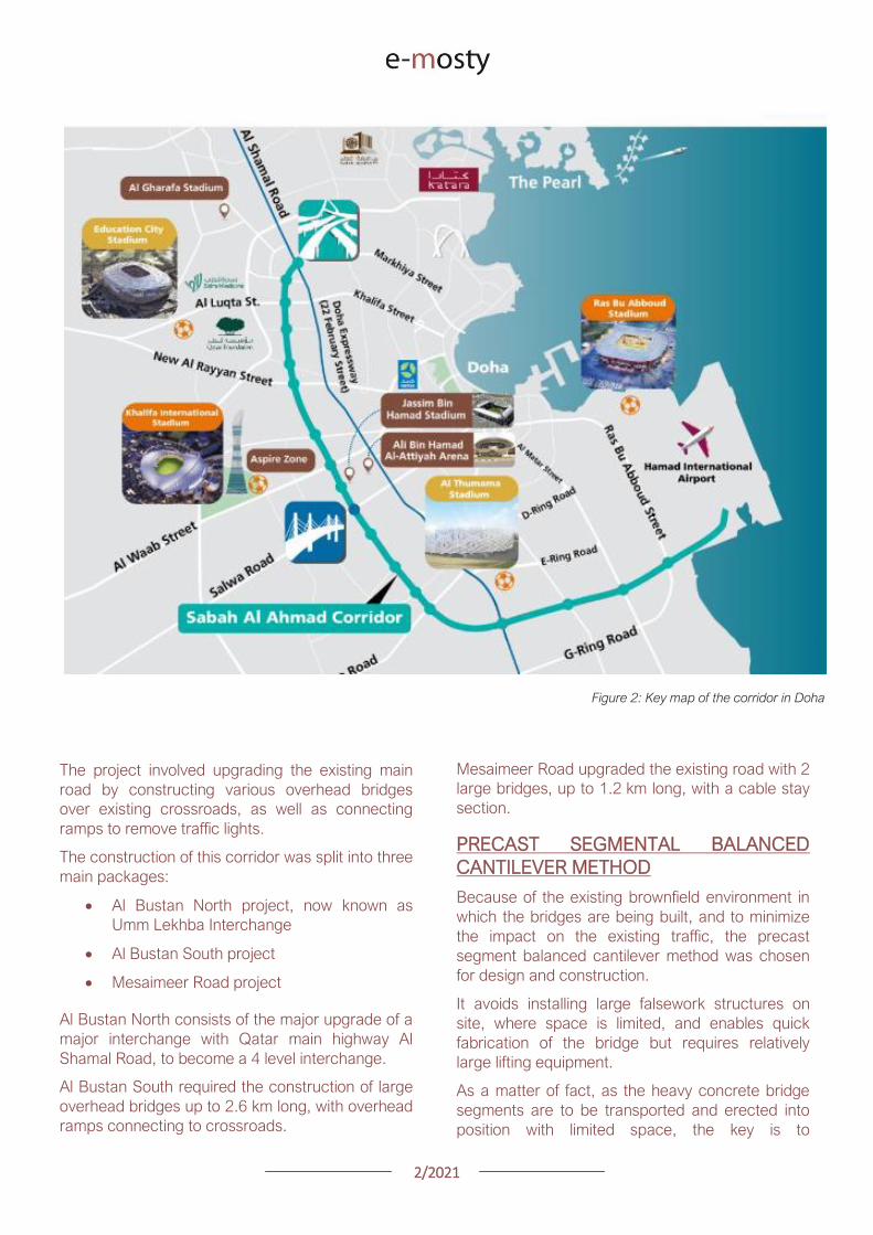
22021
understand which areas are available where
possible if lifting equipment such as cranes can be
positioned and how to deliver the segments to
their final position
For very heavy segments or if cranes cannot be
used due to site constraints it may be required to
design custom made lifting frame machines
placed on top of the bridge already built and fitted
with their own lifting device to erect the segments
in their final position
These machines typically have a limited range and
segments must be first transported precisely near
their final position
On the Al Bustan Corridor two different delivery
situations were identified
For Al Bustan South and Mesaimeer the
large weight of the segments made it
prohibitively costly to use a crane
However assisted by a temporary
diversion of the existing road during
construction and the flat terrain every
segment could always be delivered directly
below their final position
For Al Bustan North the multi-level
interchange the existing highway Al
Shamal Road could only be closed to traffic
for a very limited time and the existing road
environment did not allow for flexible
segment delivery below each new bridge
ramp
A crane could be positioned near the piers
which allowed for segments to be lifted
onto the already erected deck
To position the segment into its final
position a special lifting frame was
designed to pick up the segment ldquofrom
behindrdquo and bring them forward into their
final position
LIFTING FRAME WITH DELIVERY FROM
BEHIND
As mentioned previously a lifting frame (LF) able
to pick up a segment from behind was required for
this project
A few options for the trajectory of the segment
were considered
Symmetrical Lifting Frame segment
crossing the lifting frame is rotated at 90
degrees in plan lifted and moved through
the middle of the machine longitudinally
Once at the front it can be rotated 90
degrees and lowered in position
Asymmetrical Lifting Frame segment is
delivered 180 degrees from its final
orientation
The segment is picked up rotated 90
degrees moved through the LF
longitudinally rotated again and then
lowered in position
Figure 3 Al Bustan North lifting frame
For this project the bridges are quite narrow with a
web spacing of 6 and 4 m and therefore passing a
32 m long segment between two legs of the LF
was not possible
As shown in Figure 4 on the next page a C shape
was adopted to allow the segment to be rotated on
the free side and moved forward
22021
Figure 4 Segment delivery methodology Click on the image to open it in full size
Description of Lifting Frame
The lifting Frame had the following key
specifications
1 Self-weight of 70 tonnes
2 Lifting capacity of 80 tonnes
3 Lifting speed of 12 mh [02 mmin]
4 Longitudinal launching speed of 3 mh
[005 mmin]
The lifting frame is made of a few key
components
Upper Cross Beam (UCB) transverse
beam carrying the strand lifting unit as
well as the stressing platform lifting
mast Adjustment capability of +-
200 mm
Main Beams (MB) Longitudinal beams
supporting the UCB The UCB is
moved on wheels with a bogie
connected to 2 chain pulling units
Figure 5 3D view of lifting frame model
22021
Support Frame (SF) asymmetric frame in a
C shape supporting the MB The frame is
supported on the deck by adjustable screw
jacks located over the webs
Tie down beams (TDB) during erection
the SF is tie down to the deck with 4 no
40 mm diameter stressbars anchored in
TDB The TDB allows for longitudinal
adjustment in the position of the bars as
the segment length varies
Rail beams (RB) two rail beams on each
side of the SF are fitted with a hydraulic
launching system able to move the entire
frame forward in steps of 700 mm
Segment lifting beam (SLB) the SLB is
stressed to the segment being lifted and is
fitted with hydraulic jacks able to adjust the
segment to the required crossfall and
gradient as well as rotated the segment in
plan to pass through the SF
Stressing platform (SP) to complete the
balance cantilever construction a SP is
required to be positioned each newly
erected segment to provide access for
personnel to complete the permanent post-
tensioning operation
Figure 6 Segment delivered at the rear of the LF
Figure 8 Segment rotated to its final orientation
rarr Figure 9 Segment lowered into
position and load transferred
Figure 7 Segment rotated and moved longitudinally
SEGMENT ERECTION PHOTOS
The photo sequence below shows the segment
delivery process
22021
Challenges
Because of the limited width of the deck and the
congested site area with existing roads one of the
key challenges was to find a suitable storage
position for the SP when not in use which would
not block the segment passage
A rotation mast or davit arm was designed to lift
and position the 6 tonnes platform The mast was
rotated up to 120 degrees with a small horizontal
hydraulic jack
The concept and design itself of the Lifting Frame
required a solution which provided the minimum
required space for manipulating the segment and
the stressing platform in a very tight area while
having enough stiffness and capacity to cover the
demands
LIFTING FRAME WITH DELIVERY FROM
BELOW
Typical configuration for a Lifting Frame is such
that segment can be lifted directly from below
This was the case of Al Bustan South and
Mesaimeer projects
MESAIMEER LIFTING FRAME
Segments to be lifted by this lifting frame were the
heaviest and widest on the project for this reason
a stiffer structure composed of rigid frames at the
supporting areas was chosen taking advantage of
the fact that there was no restriction in height and
section of the bridge
The delivery of the segments in this project could
be conducted almost at is final position in plan
which facilitated the configuration of the lifting
equipment at the cantilever of the lifting frame
For this purpose the lifting frame was provided
with a couple of Winches that could pick up the
segment from the ground with minimum rotation in
plan lifted to required level and conduct final
adjustment in the longitudinal and transverse
directions
Description of Lifting Frame
The Lifting Frame had the following key
specifications
1 Self-weight of 92 tonnes
2 Lifting capacity of 185 tonnes
3 Lifting speed of 60 mh [1 mmin]
4 Longitudinal launching speed of 3mh [005
mmin)
Figure 10 segment delivered at the rear of the LF
The lifting frame is made of a few key components
Upper Cross Beam (UCB) transverse
beam carrying the main lifting equipment
(Winch) as well as the stressing platform
Adjustment capability +- 1325
Cantilever Beam (CTB) the 2 main
longitudinal beams supporting the UCB and
Stressing Platform at front and the Tie
Down Beam at the rear
Lower Cross Beam (LCB) main Frames
underneath the CTB transferring all load to
the bridge
Rail Beams (RB) two rail beams on each
side of the LCB are fitted with a hydraulic
launching system able to move the entire
frame forward in steps of 850 mm
22021
Connection Beams (CB) beams
connecting the hook blocks of the Winches
directly to the segment They are provided
with jacks for segment gradient adjustment
Crossfall is adjusted directly by the
Winches
Stressing Platform (SP) it is positioned at
the tip of the CTB and move backward for
conducting stressing of bridge post-
tensioning tendons It is provided with 2
levels customized for this project
Tie Down Beam (TDB) the Support frame
is provided with a set of tie down beams at
the rear which are the main stability
system
TDB can be adjusted in the longitudinal
direction to suit the different segment
lengths and their respective tie down holes
position
Tie down bars are of 75mm and 47mm in
diameter and pre-stressed against the
segment
Challenges
To accommodate the supporting area in a
very limited length since there was
insufficient space near the pylons
This created big reactions to be taken by
the tie down elements due the big
cantilever at front and heavy segments to
be lifted
To be able to move all the way back the
lifting equipment (Winch) and UCB to
provide enough stability during the
launching procedure Space at rear of the
lifting frame was very limited
Provide a Stressing Platform with 2
different configurations (1 or 2 levels) that
could be adapted for specific
configurations
SEGMENT ERECTION PHOTOS
Figure 11 Mesaimeer Lifting Frame
Figure 12 Segment lifting
Figure 13 Segment permanent post-tensioning in progress
22021
AL BUSTAN SOUTH LIFTING FRAME
For this project the lifting frame had to
accommodate few main requirements to suit the
space constraints of the project and the bridge
capacity
Height A limit of 6m for total height the lifting
frame was to be assured since the bridge had
to pass under an existing viaduct
Load introduction The bridge section is
provided with 3 webs and middle web capacity
was to be respected by limiting the reactions at
this point Additionally the total weight of the
Lifting Frame was also limited
Segment delivered below could not be
positioned in its final orientation due to space
constraints It had to be rotated up to 90deg once
hanging from the lifting frame
To overcome the limitations described the lifting
frame concept developed considered the following
aspects
Main lifting equipment (Winch) was
positioned at the bottom rear area of the
lifting frame to reduce the total height
The three webs of the segment were
loaded and the Lifting Frame elements
were studied in such a way that the total
weight of the Lifting Frame and loading of
central web were not exceeded
A single Winch and the hook block with
rotation device were provided to allow
rotation of the segment while hanging from
the Lifting Frame
Description of Lifting Frame
The Lifting Frame had the following key
specifications
1 Self-weight of 81 tonnes
2 Lifting capacity of 170 tonnes
3 Lifting speed of 36 mh [06 mmin]
4 Longitudinal launching speed of 3mh [005
mmin
The lifting frame is made of the following key
components
Upper Cross Beam (UCB) uppermost
element carrying the Winch Trolley It can
slide longitudinally to accommodate the
segment in length Transverse adjustment
is done by sliding of the Winch Trolley over
the UCB
Main Frame (MF) the Lifting Frame is
provided with 2 Main Frames in section that
support the UCB and Stressing Platform on
top and transfers the vertical load to the
lower elements of the Lifting Frame At
bottom level it also receives the Tie Down
Beam
Lower Cross Beam (LCB) spreader beam
in the transverse direction located at front
and rear that transfer all loads to the
segment webs through 6 screw jacks (3 at
the front and 3 at the rear)
Tie Down Beam (TDB) located at rear part
of the Lifting Frame and contain the tie
down bars stressed down against the
segment in order to assure the stability of
the Lifting Frame It contains a couple of
back-up bars that provide redundancy to
the system
Segment Lifting Beam (SLB) connecting
element between the hook block of the
winch and the segment It is provided with
a rotational device that allows full rotation
of the segment in plan
Figure 14 Segment delivered at the rear of the LF
22021
Stressing Platform (SP) it hangs from the
tip of the Main Frame cantilever beam It is
moved backwards after segment
installation to conduct the stressing of the
permanent post-tensioning system
Rail Beam (RB) two rail beams on each
side of the LCB are fitted with a hydraulic
launching system able it to move the entire
frame forward in steps of 850 mm
Figure 14 Lifting Frame installation on deck
Figure 15 Lifting of segment
Figure 16 Stressing of post-tensioning tendons
Figure 17 Lifting Frame crossing under existing viaduct
SEGMENT ERECTION PHOTOS
Challenges
To develop a concept and design that did
not exceed the limitations given regarding
total weight and height
Allow full rotation of the segment while
hanging
Provide redundancy to the Lifting Frame
Tie Down system and to the Stressing
Platform while under operation
22021
CONCLUSIONS
Precast segmental construction in a congested
environment often requires the use of custom
designed lifting frames
These machines must always consider the
segment delivery methods as well as the bridge
characteristics in order to achieve the most cost-
efficient methods of erection
The more requirements a project has the more
customized the Lifting Frame will be
For this reason it is of key importance to integrate
the development of the Temporary Structures (like
Lifting Frames) as early as possible in the design
process
By doing this some of the constraints can be
solved in earlier stages which will improve the
efficiency of the full process and the interfaces
between the different parts involved Permanent
Works Designer Temporary Works Designer and
Main Contractor
Figure 18 Al Bustan North Figure 19 Al Bustan North
Figure 20 Al Bustan South
Figure 21 Mesaimeer
Photos 18 ndash 20 Credit Ashghal (Qatar Road Authority)
We design and produceformwork equipmentfor in-place casting of bridgesN25 New Ross Bypass (Ireland)
FOLLOW US
INNOVATIVE | SAFE | SUSTAINABLE | FAST
SOLUTIONS FOR BRIDGE CONSTRUCTION
MSS M1-70-S BRATISLAVA BYPASS | IN SITU CONSTRUCTION
LG 36-S CAIRO METRO LINE 3 EXTENSION | PRECAST SEGMENTAL
WWWBERDEU
Photo Credits D4R7
Photo Credits Stephane Ciccolini
Arup works in active partnership with clients to understand their needs so
that the solutions make their bridge aspirations possible mdashbig and small
The Arup global specialist technical skills blended with essential local
knowledge adds unexpected benefits
wwwarupcom
Whether to span nations make a statement or
improve everyday links Arup crafts better bridges
Naeem Hussain Richard Hornby Steve Kite Deepak Jayaram
naeemhussainarupcom richardhornbyarupcom stevekitearupcom deepakjayaramarupcom
Global UK Middle East amp Africa East Asia UK Middle East India
and Africa
Peter Burnton Marcos Sanchez Matt Carter
peterburntonarupcom marcossanchezarupcom mattcarterarupcom
Australasia Europe Americas
Queensferry Crossing Scotland
SANTANDERMADRIDLIMABOGOTAacuteBUENOS AIRES
Calle Marqueacutes de la Ensenada 11 - 3ordm 39009
Calle Bravo Murillo 101 - 4ordm 28020
Calle Coronel Inclaacuten 235 - Oficina 313 Lima 18
Cra 14 94a - 24 Oficina 307 Edificio ACO 94
Calle Rodriacuteguez Pentildea 681 - 4ordm Dpto 8 1020
Tfno +34 942 31 99 60
Tfno +34 91 702 54 78
Tfno +51 1 637 56 47
Tfno +57 1 467 48 10
Tfno +54 911 5709 3252
wwwarenasingcom
ARCHING THE WORLD
CODE-BASED DESIGN
DETAILINGDR AWING PRODUCTION
PAR AM ETRIC MODELING
STRUCTUR AL ANALYSIS
DOWNLOAD A FREE TRIALallplancombridge2021
THE WORLDrsquoS FIRST COMPLETE SOLUTIONFOR BRIDGE ENGINEERS
Allplan Bridge 2021 maps the complete BIM process in bridge projects The new version enables bridge engineers to work with one single solution from the creation of a parametric 4D model to structural analysis reinforcement design and detailing This further improves the design process in terms of both time and quality
ALLPLAN BRIDGE
Join Bridges to Prosperity in helping isolated
communities gain safe access to healthcare
education jobs and markets through simple
sustainable trailbridges Together we can
build more than a bridge we can build a
pathway out of poverty
We envision a world wherepoverty caused by ruralisolation no longer exists
bridgestoprosperityorg
infobridgestoprosperityorgbridgestoprosperity
bridgestoprosperity
b2p
+60Women Entering the Labor Force
+75Farmer
Profitability
+358Labor Market
Income
Corporate Partners make this
vision possible
Wyatt Brooks and Kevin Donovan - Eliminating Uncertainty in Market Access
The Impact of New Bridges in Rural Nicaragua 2017
SEGMENTAL BRIDGES
ISSUE 022021 JUNE
- 1 arenas_v2
-
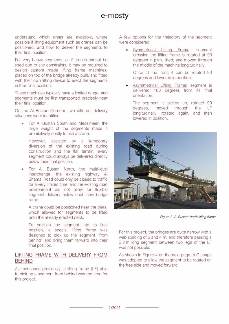
22021
Figure 4 Segment delivery methodology Click on the image to open it in full size
Description of Lifting Frame
The lifting Frame had the following key
specifications
1 Self-weight of 70 tonnes
2 Lifting capacity of 80 tonnes
3 Lifting speed of 12 mh [02 mmin]
4 Longitudinal launching speed of 3 mh
[005 mmin]
The lifting frame is made of a few key
components
Upper Cross Beam (UCB) transverse
beam carrying the strand lifting unit as
well as the stressing platform lifting
mast Adjustment capability of +-
200 mm
Main Beams (MB) Longitudinal beams
supporting the UCB The UCB is
moved on wheels with a bogie
connected to 2 chain pulling units
Figure 5 3D view of lifting frame model
22021
Support Frame (SF) asymmetric frame in a
C shape supporting the MB The frame is
supported on the deck by adjustable screw
jacks located over the webs
Tie down beams (TDB) during erection
the SF is tie down to the deck with 4 no
40 mm diameter stressbars anchored in
TDB The TDB allows for longitudinal
adjustment in the position of the bars as
the segment length varies
Rail beams (RB) two rail beams on each
side of the SF are fitted with a hydraulic
launching system able to move the entire
frame forward in steps of 700 mm
Segment lifting beam (SLB) the SLB is
stressed to the segment being lifted and is
fitted with hydraulic jacks able to adjust the
segment to the required crossfall and
gradient as well as rotated the segment in
plan to pass through the SF
Stressing platform (SP) to complete the
balance cantilever construction a SP is
required to be positioned each newly
erected segment to provide access for
personnel to complete the permanent post-
tensioning operation
Figure 6 Segment delivered at the rear of the LF
Figure 8 Segment rotated to its final orientation
rarr Figure 9 Segment lowered into
position and load transferred
Figure 7 Segment rotated and moved longitudinally
SEGMENT ERECTION PHOTOS
The photo sequence below shows the segment
delivery process
22021
Challenges
Because of the limited width of the deck and the
congested site area with existing roads one of the
key challenges was to find a suitable storage
position for the SP when not in use which would
not block the segment passage
A rotation mast or davit arm was designed to lift
and position the 6 tonnes platform The mast was
rotated up to 120 degrees with a small horizontal
hydraulic jack
The concept and design itself of the Lifting Frame
required a solution which provided the minimum
required space for manipulating the segment and
the stressing platform in a very tight area while
having enough stiffness and capacity to cover the
demands
LIFTING FRAME WITH DELIVERY FROM
BELOW
Typical configuration for a Lifting Frame is such
that segment can be lifted directly from below
This was the case of Al Bustan South and
Mesaimeer projects
MESAIMEER LIFTING FRAME
Segments to be lifted by this lifting frame were the
heaviest and widest on the project for this reason
a stiffer structure composed of rigid frames at the
supporting areas was chosen taking advantage of
the fact that there was no restriction in height and
section of the bridge
The delivery of the segments in this project could
be conducted almost at is final position in plan
which facilitated the configuration of the lifting
equipment at the cantilever of the lifting frame
For this purpose the lifting frame was provided
with a couple of Winches that could pick up the
segment from the ground with minimum rotation in
plan lifted to required level and conduct final
adjustment in the longitudinal and transverse
directions
Description of Lifting Frame
The Lifting Frame had the following key
specifications
1 Self-weight of 92 tonnes
2 Lifting capacity of 185 tonnes
3 Lifting speed of 60 mh [1 mmin]
4 Longitudinal launching speed of 3mh [005
mmin)
Figure 10 segment delivered at the rear of the LF
The lifting frame is made of a few key components
Upper Cross Beam (UCB) transverse
beam carrying the main lifting equipment
(Winch) as well as the stressing platform
Adjustment capability +- 1325
Cantilever Beam (CTB) the 2 main
longitudinal beams supporting the UCB and
Stressing Platform at front and the Tie
Down Beam at the rear
Lower Cross Beam (LCB) main Frames
underneath the CTB transferring all load to
the bridge
Rail Beams (RB) two rail beams on each
side of the LCB are fitted with a hydraulic
launching system able to move the entire
frame forward in steps of 850 mm
22021
Connection Beams (CB) beams
connecting the hook blocks of the Winches
directly to the segment They are provided
with jacks for segment gradient adjustment
Crossfall is adjusted directly by the
Winches
Stressing Platform (SP) it is positioned at
the tip of the CTB and move backward for
conducting stressing of bridge post-
tensioning tendons It is provided with 2
levels customized for this project
Tie Down Beam (TDB) the Support frame
is provided with a set of tie down beams at
the rear which are the main stability
system
TDB can be adjusted in the longitudinal
direction to suit the different segment
lengths and their respective tie down holes
position
Tie down bars are of 75mm and 47mm in
diameter and pre-stressed against the
segment
Challenges
To accommodate the supporting area in a
very limited length since there was
insufficient space near the pylons
This created big reactions to be taken by
the tie down elements due the big
cantilever at front and heavy segments to
be lifted
To be able to move all the way back the
lifting equipment (Winch) and UCB to
provide enough stability during the
launching procedure Space at rear of the
lifting frame was very limited
Provide a Stressing Platform with 2
different configurations (1 or 2 levels) that
could be adapted for specific
configurations
SEGMENT ERECTION PHOTOS
Figure 11 Mesaimeer Lifting Frame
Figure 12 Segment lifting
Figure 13 Segment permanent post-tensioning in progress
22021
AL BUSTAN SOUTH LIFTING FRAME
For this project the lifting frame had to
accommodate few main requirements to suit the
space constraints of the project and the bridge
capacity
Height A limit of 6m for total height the lifting
frame was to be assured since the bridge had
to pass under an existing viaduct
Load introduction The bridge section is
provided with 3 webs and middle web capacity
was to be respected by limiting the reactions at
this point Additionally the total weight of the
Lifting Frame was also limited
Segment delivered below could not be
positioned in its final orientation due to space
constraints It had to be rotated up to 90deg once
hanging from the lifting frame
To overcome the limitations described the lifting
frame concept developed considered the following
aspects
Main lifting equipment (Winch) was
positioned at the bottom rear area of the
lifting frame to reduce the total height
The three webs of the segment were
loaded and the Lifting Frame elements
were studied in such a way that the total
weight of the Lifting Frame and loading of
central web were not exceeded
A single Winch and the hook block with
rotation device were provided to allow
rotation of the segment while hanging from
the Lifting Frame
Description of Lifting Frame
The Lifting Frame had the following key
specifications
1 Self-weight of 81 tonnes
2 Lifting capacity of 170 tonnes
3 Lifting speed of 36 mh [06 mmin]
4 Longitudinal launching speed of 3mh [005
mmin
The lifting frame is made of the following key
components
Upper Cross Beam (UCB) uppermost
element carrying the Winch Trolley It can
slide longitudinally to accommodate the
segment in length Transverse adjustment
is done by sliding of the Winch Trolley over
the UCB
Main Frame (MF) the Lifting Frame is
provided with 2 Main Frames in section that
support the UCB and Stressing Platform on
top and transfers the vertical load to the
lower elements of the Lifting Frame At
bottom level it also receives the Tie Down
Beam
Lower Cross Beam (LCB) spreader beam
in the transverse direction located at front
and rear that transfer all loads to the
segment webs through 6 screw jacks (3 at
the front and 3 at the rear)
Tie Down Beam (TDB) located at rear part
of the Lifting Frame and contain the tie
down bars stressed down against the
segment in order to assure the stability of
the Lifting Frame It contains a couple of
back-up bars that provide redundancy to
the system
Segment Lifting Beam (SLB) connecting
element between the hook block of the
winch and the segment It is provided with
a rotational device that allows full rotation
of the segment in plan
Figure 14 Segment delivered at the rear of the LF
22021
Stressing Platform (SP) it hangs from the
tip of the Main Frame cantilever beam It is
moved backwards after segment
installation to conduct the stressing of the
permanent post-tensioning system
Rail Beam (RB) two rail beams on each
side of the LCB are fitted with a hydraulic
launching system able it to move the entire
frame forward in steps of 850 mm
Figure 14 Lifting Frame installation on deck
Figure 15 Lifting of segment
Figure 16 Stressing of post-tensioning tendons
Figure 17 Lifting Frame crossing under existing viaduct
SEGMENT ERECTION PHOTOS
Challenges
To develop a concept and design that did
not exceed the limitations given regarding
total weight and height
Allow full rotation of the segment while
hanging
Provide redundancy to the Lifting Frame
Tie Down system and to the Stressing
Platform while under operation
22021
CONCLUSIONS
Precast segmental construction in a congested
environment often requires the use of custom
designed lifting frames
These machines must always consider the
segment delivery methods as well as the bridge
characteristics in order to achieve the most cost-
efficient methods of erection
The more requirements a project has the more
customized the Lifting Frame will be
For this reason it is of key importance to integrate
the development of the Temporary Structures (like
Lifting Frames) as early as possible in the design
process
By doing this some of the constraints can be
solved in earlier stages which will improve the
efficiency of the full process and the interfaces
between the different parts involved Permanent
Works Designer Temporary Works Designer and
Main Contractor
Figure 18 Al Bustan North Figure 19 Al Bustan North
Figure 20 Al Bustan South
Figure 21 Mesaimeer
Photos 18 ndash 20 Credit Ashghal (Qatar Road Authority)
We design and produceformwork equipmentfor in-place casting of bridgesN25 New Ross Bypass (Ireland)
FOLLOW US
INNOVATIVE | SAFE | SUSTAINABLE | FAST
SOLUTIONS FOR BRIDGE CONSTRUCTION
MSS M1-70-S BRATISLAVA BYPASS | IN SITU CONSTRUCTION
LG 36-S CAIRO METRO LINE 3 EXTENSION | PRECAST SEGMENTAL
WWWBERDEU
Photo Credits D4R7
Photo Credits Stephane Ciccolini
Arup works in active partnership with clients to understand their needs so
that the solutions make their bridge aspirations possible mdashbig and small
The Arup global specialist technical skills blended with essential local
knowledge adds unexpected benefits
wwwarupcom
Whether to span nations make a statement or
improve everyday links Arup crafts better bridges
Naeem Hussain Richard Hornby Steve Kite Deepak Jayaram
naeemhussainarupcom richardhornbyarupcom stevekitearupcom deepakjayaramarupcom
Global UK Middle East amp Africa East Asia UK Middle East India
and Africa
Peter Burnton Marcos Sanchez Matt Carter
peterburntonarupcom marcossanchezarupcom mattcarterarupcom
Australasia Europe Americas
Queensferry Crossing Scotland
SANTANDERMADRIDLIMABOGOTAacuteBUENOS AIRES
Calle Marqueacutes de la Ensenada 11 - 3ordm 39009
Calle Bravo Murillo 101 - 4ordm 28020
Calle Coronel Inclaacuten 235 - Oficina 313 Lima 18
Cra 14 94a - 24 Oficina 307 Edificio ACO 94
Calle Rodriacuteguez Pentildea 681 - 4ordm Dpto 8 1020
Tfno +34 942 31 99 60
Tfno +34 91 702 54 78
Tfno +51 1 637 56 47
Tfno +57 1 467 48 10
Tfno +54 911 5709 3252
wwwarenasingcom
ARCHING THE WORLD
CODE-BASED DESIGN
DETAILINGDR AWING PRODUCTION
PAR AM ETRIC MODELING
STRUCTUR AL ANALYSIS
DOWNLOAD A FREE TRIALallplancombridge2021
THE WORLDrsquoS FIRST COMPLETE SOLUTIONFOR BRIDGE ENGINEERS
Allplan Bridge 2021 maps the complete BIM process in bridge projects The new version enables bridge engineers to work with one single solution from the creation of a parametric 4D model to structural analysis reinforcement design and detailing This further improves the design process in terms of both time and quality
ALLPLAN BRIDGE
Join Bridges to Prosperity in helping isolated
communities gain safe access to healthcare
education jobs and markets through simple
sustainable trailbridges Together we can
build more than a bridge we can build a
pathway out of poverty
We envision a world wherepoverty caused by ruralisolation no longer exists
bridgestoprosperityorg
infobridgestoprosperityorgbridgestoprosperity
bridgestoprosperity
b2p
+60Women Entering the Labor Force
+75Farmer
Profitability
+358Labor Market
Income
Corporate Partners make this
vision possible
Wyatt Brooks and Kevin Donovan - Eliminating Uncertainty in Market Access
The Impact of New Bridges in Rural Nicaragua 2017
SEGMENTAL BRIDGES
ISSUE 022021 JUNE
- 1 arenas_v2
-
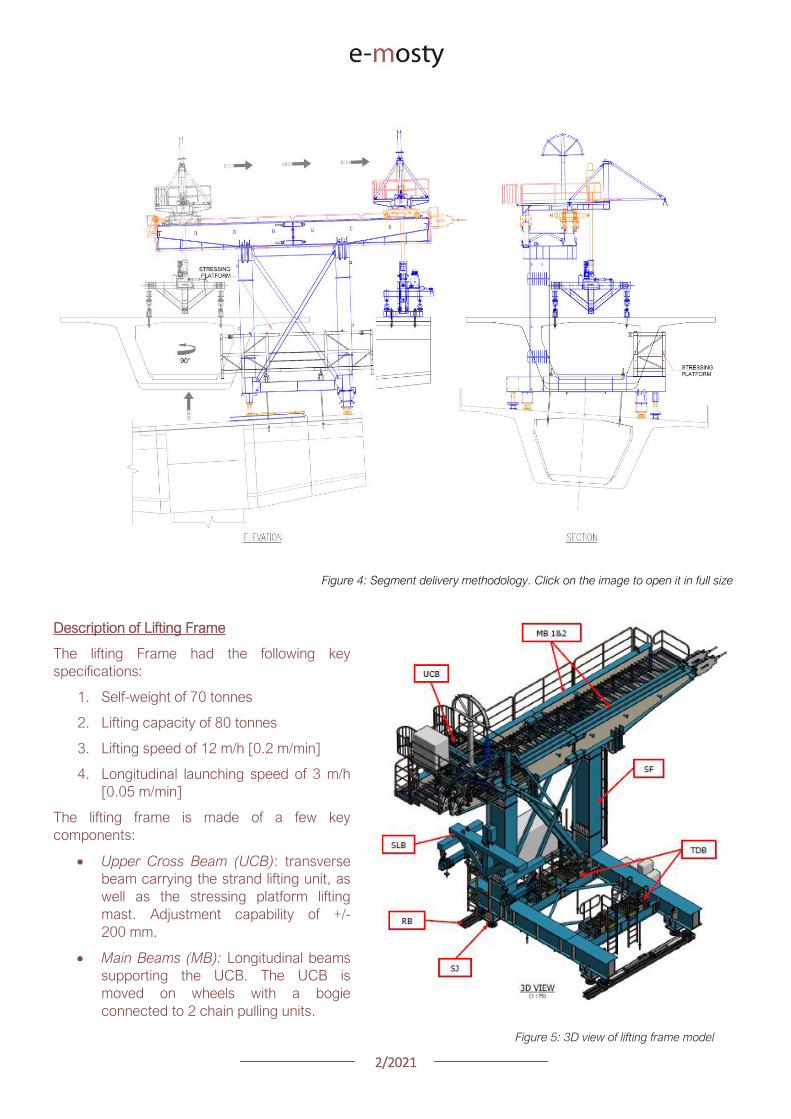
22021
Support Frame (SF) asymmetric frame in a
C shape supporting the MB The frame is
supported on the deck by adjustable screw
jacks located over the webs
Tie down beams (TDB) during erection
the SF is tie down to the deck with 4 no
40 mm diameter stressbars anchored in
TDB The TDB allows for longitudinal
adjustment in the position of the bars as
the segment length varies
Rail beams (RB) two rail beams on each
side of the SF are fitted with a hydraulic
launching system able to move the entire
frame forward in steps of 700 mm
Segment lifting beam (SLB) the SLB is
stressed to the segment being lifted and is
fitted with hydraulic jacks able to adjust the
segment to the required crossfall and
gradient as well as rotated the segment in
plan to pass through the SF
Stressing platform (SP) to complete the
balance cantilever construction a SP is
required to be positioned each newly
erected segment to provide access for
personnel to complete the permanent post-
tensioning operation
Figure 6 Segment delivered at the rear of the LF
Figure 8 Segment rotated to its final orientation
rarr Figure 9 Segment lowered into
position and load transferred
Figure 7 Segment rotated and moved longitudinally
SEGMENT ERECTION PHOTOS
The photo sequence below shows the segment
delivery process
22021
Challenges
Because of the limited width of the deck and the
congested site area with existing roads one of the
key challenges was to find a suitable storage
position for the SP when not in use which would
not block the segment passage
A rotation mast or davit arm was designed to lift
and position the 6 tonnes platform The mast was
rotated up to 120 degrees with a small horizontal
hydraulic jack
The concept and design itself of the Lifting Frame
required a solution which provided the minimum
required space for manipulating the segment and
the stressing platform in a very tight area while
having enough stiffness and capacity to cover the
demands
LIFTING FRAME WITH DELIVERY FROM
BELOW
Typical configuration for a Lifting Frame is such
that segment can be lifted directly from below
This was the case of Al Bustan South and
Mesaimeer projects
MESAIMEER LIFTING FRAME
Segments to be lifted by this lifting frame were the
heaviest and widest on the project for this reason
a stiffer structure composed of rigid frames at the
supporting areas was chosen taking advantage of
the fact that there was no restriction in height and
section of the bridge
The delivery of the segments in this project could
be conducted almost at is final position in plan
which facilitated the configuration of the lifting
equipment at the cantilever of the lifting frame
For this purpose the lifting frame was provided
with a couple of Winches that could pick up the
segment from the ground with minimum rotation in
plan lifted to required level and conduct final
adjustment in the longitudinal and transverse
directions
Description of Lifting Frame
The Lifting Frame had the following key
specifications
1 Self-weight of 92 tonnes
2 Lifting capacity of 185 tonnes
3 Lifting speed of 60 mh [1 mmin]
4 Longitudinal launching speed of 3mh [005
mmin)
Figure 10 segment delivered at the rear of the LF
The lifting frame is made of a few key components
Upper Cross Beam (UCB) transverse
beam carrying the main lifting equipment
(Winch) as well as the stressing platform
Adjustment capability +- 1325
Cantilever Beam (CTB) the 2 main
longitudinal beams supporting the UCB and
Stressing Platform at front and the Tie
Down Beam at the rear
Lower Cross Beam (LCB) main Frames
underneath the CTB transferring all load to
the bridge
Rail Beams (RB) two rail beams on each
side of the LCB are fitted with a hydraulic
launching system able to move the entire
frame forward in steps of 850 mm
22021
Connection Beams (CB) beams
connecting the hook blocks of the Winches
directly to the segment They are provided
with jacks for segment gradient adjustment
Crossfall is adjusted directly by the
Winches
Stressing Platform (SP) it is positioned at
the tip of the CTB and move backward for
conducting stressing of bridge post-
tensioning tendons It is provided with 2
levels customized for this project
Tie Down Beam (TDB) the Support frame
is provided with a set of tie down beams at
the rear which are the main stability
system
TDB can be adjusted in the longitudinal
direction to suit the different segment
lengths and their respective tie down holes
position
Tie down bars are of 75mm and 47mm in
diameter and pre-stressed against the
segment
Challenges
To accommodate the supporting area in a
very limited length since there was
insufficient space near the pylons
This created big reactions to be taken by
the tie down elements due the big
cantilever at front and heavy segments to
be lifted
To be able to move all the way back the
lifting equipment (Winch) and UCB to
provide enough stability during the
launching procedure Space at rear of the
lifting frame was very limited
Provide a Stressing Platform with 2
different configurations (1 or 2 levels) that
could be adapted for specific
configurations
SEGMENT ERECTION PHOTOS
Figure 11 Mesaimeer Lifting Frame
Figure 12 Segment lifting
Figure 13 Segment permanent post-tensioning in progress
22021
AL BUSTAN SOUTH LIFTING FRAME
For this project the lifting frame had to
accommodate few main requirements to suit the
space constraints of the project and the bridge
capacity
Height A limit of 6m for total height the lifting
frame was to be assured since the bridge had
to pass under an existing viaduct
Load introduction The bridge section is
provided with 3 webs and middle web capacity
was to be respected by limiting the reactions at
this point Additionally the total weight of the
Lifting Frame was also limited
Segment delivered below could not be
positioned in its final orientation due to space
constraints It had to be rotated up to 90deg once
hanging from the lifting frame
To overcome the limitations described the lifting
frame concept developed considered the following
aspects
Main lifting equipment (Winch) was
positioned at the bottom rear area of the
lifting frame to reduce the total height
The three webs of the segment were
loaded and the Lifting Frame elements
were studied in such a way that the total
weight of the Lifting Frame and loading of
central web were not exceeded
A single Winch and the hook block with
rotation device were provided to allow
rotation of the segment while hanging from
the Lifting Frame
Description of Lifting Frame
The Lifting Frame had the following key
specifications
1 Self-weight of 81 tonnes
2 Lifting capacity of 170 tonnes
3 Lifting speed of 36 mh [06 mmin]
4 Longitudinal launching speed of 3mh [005
mmin
The lifting frame is made of the following key
components
Upper Cross Beam (UCB) uppermost
element carrying the Winch Trolley It can
slide longitudinally to accommodate the
segment in length Transverse adjustment
is done by sliding of the Winch Trolley over
the UCB
Main Frame (MF) the Lifting Frame is
provided with 2 Main Frames in section that
support the UCB and Stressing Platform on
top and transfers the vertical load to the
lower elements of the Lifting Frame At
bottom level it also receives the Tie Down
Beam
Lower Cross Beam (LCB) spreader beam
in the transverse direction located at front
and rear that transfer all loads to the
segment webs through 6 screw jacks (3 at
the front and 3 at the rear)
Tie Down Beam (TDB) located at rear part
of the Lifting Frame and contain the tie
down bars stressed down against the
segment in order to assure the stability of
the Lifting Frame It contains a couple of
back-up bars that provide redundancy to
the system
Segment Lifting Beam (SLB) connecting
element between the hook block of the
winch and the segment It is provided with
a rotational device that allows full rotation
of the segment in plan
Figure 14 Segment delivered at the rear of the LF
22021
Stressing Platform (SP) it hangs from the
tip of the Main Frame cantilever beam It is
moved backwards after segment
installation to conduct the stressing of the
permanent post-tensioning system
Rail Beam (RB) two rail beams on each
side of the LCB are fitted with a hydraulic
launching system able it to move the entire
frame forward in steps of 850 mm
Figure 14 Lifting Frame installation on deck
Figure 15 Lifting of segment
Figure 16 Stressing of post-tensioning tendons
Figure 17 Lifting Frame crossing under existing viaduct
SEGMENT ERECTION PHOTOS
Challenges
To develop a concept and design that did
not exceed the limitations given regarding
total weight and height
Allow full rotation of the segment while
hanging
Provide redundancy to the Lifting Frame
Tie Down system and to the Stressing
Platform while under operation
22021
CONCLUSIONS
Precast segmental construction in a congested
environment often requires the use of custom
designed lifting frames
These machines must always consider the
segment delivery methods as well as the bridge
characteristics in order to achieve the most cost-
efficient methods of erection
The more requirements a project has the more
customized the Lifting Frame will be
For this reason it is of key importance to integrate
the development of the Temporary Structures (like
Lifting Frames) as early as possible in the design
process
By doing this some of the constraints can be
solved in earlier stages which will improve the
efficiency of the full process and the interfaces
between the different parts involved Permanent
Works Designer Temporary Works Designer and
Main Contractor
Figure 18 Al Bustan North Figure 19 Al Bustan North
Figure 20 Al Bustan South
Figure 21 Mesaimeer
Photos 18 ndash 20 Credit Ashghal (Qatar Road Authority)
We design and produceformwork equipmentfor in-place casting of bridgesN25 New Ross Bypass (Ireland)
FOLLOW US
INNOVATIVE | SAFE | SUSTAINABLE | FAST
SOLUTIONS FOR BRIDGE CONSTRUCTION
MSS M1-70-S BRATISLAVA BYPASS | IN SITU CONSTRUCTION
LG 36-S CAIRO METRO LINE 3 EXTENSION | PRECAST SEGMENTAL
WWWBERDEU
Photo Credits D4R7
Photo Credits Stephane Ciccolini
Arup works in active partnership with clients to understand their needs so
that the solutions make their bridge aspirations possible mdashbig and small
The Arup global specialist technical skills blended with essential local
knowledge adds unexpected benefits
wwwarupcom
Whether to span nations make a statement or
improve everyday links Arup crafts better bridges
Naeem Hussain Richard Hornby Steve Kite Deepak Jayaram
naeemhussainarupcom richardhornbyarupcom stevekitearupcom deepakjayaramarupcom
Global UK Middle East amp Africa East Asia UK Middle East India
and Africa
Peter Burnton Marcos Sanchez Matt Carter
peterburntonarupcom marcossanchezarupcom mattcarterarupcom
Australasia Europe Americas
Queensferry Crossing Scotland
SANTANDERMADRIDLIMABOGOTAacuteBUENOS AIRES
Calle Marqueacutes de la Ensenada 11 - 3ordm 39009
Calle Bravo Murillo 101 - 4ordm 28020
Calle Coronel Inclaacuten 235 - Oficina 313 Lima 18
Cra 14 94a - 24 Oficina 307 Edificio ACO 94
Calle Rodriacuteguez Pentildea 681 - 4ordm Dpto 8 1020
Tfno +34 942 31 99 60
Tfno +34 91 702 54 78
Tfno +51 1 637 56 47
Tfno +57 1 467 48 10
Tfno +54 911 5709 3252
wwwarenasingcom
ARCHING THE WORLD
CODE-BASED DESIGN
DETAILINGDR AWING PRODUCTION
PAR AM ETRIC MODELING
STRUCTUR AL ANALYSIS
DOWNLOAD A FREE TRIALallplancombridge2021
THE WORLDrsquoS FIRST COMPLETE SOLUTIONFOR BRIDGE ENGINEERS
Allplan Bridge 2021 maps the complete BIM process in bridge projects The new version enables bridge engineers to work with one single solution from the creation of a parametric 4D model to structural analysis reinforcement design and detailing This further improves the design process in terms of both time and quality
ALLPLAN BRIDGE
Join Bridges to Prosperity in helping isolated
communities gain safe access to healthcare
education jobs and markets through simple
sustainable trailbridges Together we can
build more than a bridge we can build a
pathway out of poverty
We envision a world wherepoverty caused by ruralisolation no longer exists
bridgestoprosperityorg
infobridgestoprosperityorgbridgestoprosperity
bridgestoprosperity
b2p
+60Women Entering the Labor Force
+75Farmer
Profitability
+358Labor Market
Income
Corporate Partners make this
vision possible
Wyatt Brooks and Kevin Donovan - Eliminating Uncertainty in Market Access
The Impact of New Bridges in Rural Nicaragua 2017
SEGMENTAL BRIDGES
ISSUE 022021 JUNE
- 1 arenas_v2
-
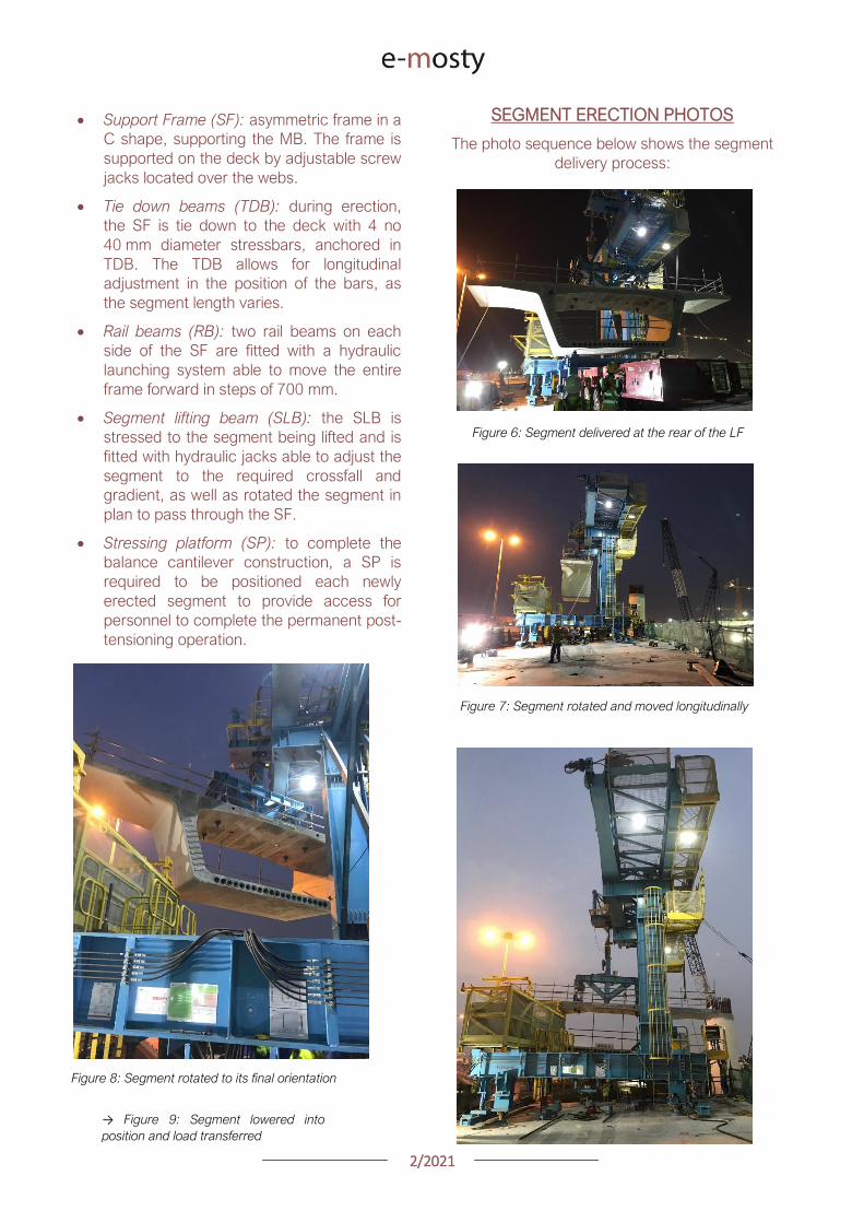
22021
Challenges
Because of the limited width of the deck and the
congested site area with existing roads one of the
key challenges was to find a suitable storage
position for the SP when not in use which would
not block the segment passage
A rotation mast or davit arm was designed to lift
and position the 6 tonnes platform The mast was
rotated up to 120 degrees with a small horizontal
hydraulic jack
The concept and design itself of the Lifting Frame
required a solution which provided the minimum
required space for manipulating the segment and
the stressing platform in a very tight area while
having enough stiffness and capacity to cover the
demands
LIFTING FRAME WITH DELIVERY FROM
BELOW
Typical configuration for a Lifting Frame is such
that segment can be lifted directly from below
This was the case of Al Bustan South and
Mesaimeer projects
MESAIMEER LIFTING FRAME
Segments to be lifted by this lifting frame were the
heaviest and widest on the project for this reason
a stiffer structure composed of rigid frames at the
supporting areas was chosen taking advantage of
the fact that there was no restriction in height and
section of the bridge
The delivery of the segments in this project could
be conducted almost at is final position in plan
which facilitated the configuration of the lifting
equipment at the cantilever of the lifting frame
For this purpose the lifting frame was provided
with a couple of Winches that could pick up the
segment from the ground with minimum rotation in
plan lifted to required level and conduct final
adjustment in the longitudinal and transverse
directions
Description of Lifting Frame
The Lifting Frame had the following key
specifications
1 Self-weight of 92 tonnes
2 Lifting capacity of 185 tonnes
3 Lifting speed of 60 mh [1 mmin]
4 Longitudinal launching speed of 3mh [005
mmin)
Figure 10 segment delivered at the rear of the LF
The lifting frame is made of a few key components
Upper Cross Beam (UCB) transverse
beam carrying the main lifting equipment
(Winch) as well as the stressing platform
Adjustment capability +- 1325
Cantilever Beam (CTB) the 2 main
longitudinal beams supporting the UCB and
Stressing Platform at front and the Tie
Down Beam at the rear
Lower Cross Beam (LCB) main Frames
underneath the CTB transferring all load to
the bridge
Rail Beams (RB) two rail beams on each
side of the LCB are fitted with a hydraulic
launching system able to move the entire
frame forward in steps of 850 mm
22021
Connection Beams (CB) beams
connecting the hook blocks of the Winches
directly to the segment They are provided
with jacks for segment gradient adjustment
Crossfall is adjusted directly by the
Winches
Stressing Platform (SP) it is positioned at
the tip of the CTB and move backward for
conducting stressing of bridge post-
tensioning tendons It is provided with 2
levels customized for this project
Tie Down Beam (TDB) the Support frame
is provided with a set of tie down beams at
the rear which are the main stability
system
TDB can be adjusted in the longitudinal
direction to suit the different segment
lengths and their respective tie down holes
position
Tie down bars are of 75mm and 47mm in
diameter and pre-stressed against the
segment
Challenges
To accommodate the supporting area in a
very limited length since there was
insufficient space near the pylons
This created big reactions to be taken by
the tie down elements due the big
cantilever at front and heavy segments to
be lifted
To be able to move all the way back the
lifting equipment (Winch) and UCB to
provide enough stability during the
launching procedure Space at rear of the
lifting frame was very limited
Provide a Stressing Platform with 2
different configurations (1 or 2 levels) that
could be adapted for specific
configurations
SEGMENT ERECTION PHOTOS
Figure 11 Mesaimeer Lifting Frame
Figure 12 Segment lifting
Figure 13 Segment permanent post-tensioning in progress
22021
AL BUSTAN SOUTH LIFTING FRAME
For this project the lifting frame had to
accommodate few main requirements to suit the
space constraints of the project and the bridge
capacity
Height A limit of 6m for total height the lifting
frame was to be assured since the bridge had
to pass under an existing viaduct
Load introduction The bridge section is
provided with 3 webs and middle web capacity
was to be respected by limiting the reactions at
this point Additionally the total weight of the
Lifting Frame was also limited
Segment delivered below could not be
positioned in its final orientation due to space
constraints It had to be rotated up to 90deg once
hanging from the lifting frame
To overcome the limitations described the lifting
frame concept developed considered the following
aspects
Main lifting equipment (Winch) was
positioned at the bottom rear area of the
lifting frame to reduce the total height
The three webs of the segment were
loaded and the Lifting Frame elements
were studied in such a way that the total
weight of the Lifting Frame and loading of
central web were not exceeded
A single Winch and the hook block with
rotation device were provided to allow
rotation of the segment while hanging from
the Lifting Frame
Description of Lifting Frame
The Lifting Frame had the following key
specifications
1 Self-weight of 81 tonnes
2 Lifting capacity of 170 tonnes
3 Lifting speed of 36 mh [06 mmin]
4 Longitudinal launching speed of 3mh [005
mmin
The lifting frame is made of the following key
components
Upper Cross Beam (UCB) uppermost
element carrying the Winch Trolley It can
slide longitudinally to accommodate the
segment in length Transverse adjustment
is done by sliding of the Winch Trolley over
the UCB
Main Frame (MF) the Lifting Frame is
provided with 2 Main Frames in section that
support the UCB and Stressing Platform on
top and transfers the vertical load to the
lower elements of the Lifting Frame At
bottom level it also receives the Tie Down
Beam
Lower Cross Beam (LCB) spreader beam
in the transverse direction located at front
and rear that transfer all loads to the
segment webs through 6 screw jacks (3 at
the front and 3 at the rear)
Tie Down Beam (TDB) located at rear part
of the Lifting Frame and contain the tie
down bars stressed down against the
segment in order to assure the stability of
the Lifting Frame It contains a couple of
back-up bars that provide redundancy to
the system
Segment Lifting Beam (SLB) connecting
element between the hook block of the
winch and the segment It is provided with
a rotational device that allows full rotation
of the segment in plan
Figure 14 Segment delivered at the rear of the LF
22021
Stressing Platform (SP) it hangs from the
tip of the Main Frame cantilever beam It is
moved backwards after segment
installation to conduct the stressing of the
permanent post-tensioning system
Rail Beam (RB) two rail beams on each
side of the LCB are fitted with a hydraulic
launching system able it to move the entire
frame forward in steps of 850 mm
Figure 14 Lifting Frame installation on deck
Figure 15 Lifting of segment
Figure 16 Stressing of post-tensioning tendons
Figure 17 Lifting Frame crossing under existing viaduct
SEGMENT ERECTION PHOTOS
Challenges
To develop a concept and design that did
not exceed the limitations given regarding
total weight and height
Allow full rotation of the segment while
hanging
Provide redundancy to the Lifting Frame
Tie Down system and to the Stressing
Platform while under operation
22021
CONCLUSIONS
Precast segmental construction in a congested
environment often requires the use of custom
designed lifting frames
These machines must always consider the
segment delivery methods as well as the bridge
characteristics in order to achieve the most cost-
efficient methods of erection
The more requirements a project has the more
customized the Lifting Frame will be
For this reason it is of key importance to integrate
the development of the Temporary Structures (like
Lifting Frames) as early as possible in the design
process
By doing this some of the constraints can be
solved in earlier stages which will improve the
efficiency of the full process and the interfaces
between the different parts involved Permanent
Works Designer Temporary Works Designer and
Main Contractor
Figure 18 Al Bustan North Figure 19 Al Bustan North
Figure 20 Al Bustan South
Figure 21 Mesaimeer
Photos 18 ndash 20 Credit Ashghal (Qatar Road Authority)
We design and produceformwork equipmentfor in-place casting of bridgesN25 New Ross Bypass (Ireland)
FOLLOW US
INNOVATIVE | SAFE | SUSTAINABLE | FAST
SOLUTIONS FOR BRIDGE CONSTRUCTION
MSS M1-70-S BRATISLAVA BYPASS | IN SITU CONSTRUCTION
LG 36-S CAIRO METRO LINE 3 EXTENSION | PRECAST SEGMENTAL
WWWBERDEU
Photo Credits D4R7
Photo Credits Stephane Ciccolini
Arup works in active partnership with clients to understand their needs so
that the solutions make their bridge aspirations possible mdashbig and small
The Arup global specialist technical skills blended with essential local
knowledge adds unexpected benefits
wwwarupcom
Whether to span nations make a statement or
improve everyday links Arup crafts better bridges
Naeem Hussain Richard Hornby Steve Kite Deepak Jayaram
naeemhussainarupcom richardhornbyarupcom stevekitearupcom deepakjayaramarupcom
Global UK Middle East amp Africa East Asia UK Middle East India
and Africa
Peter Burnton Marcos Sanchez Matt Carter
peterburntonarupcom marcossanchezarupcom mattcarterarupcom
Australasia Europe Americas
Queensferry Crossing Scotland
SANTANDERMADRIDLIMABOGOTAacuteBUENOS AIRES
Calle Marqueacutes de la Ensenada 11 - 3ordm 39009
Calle Bravo Murillo 101 - 4ordm 28020
Calle Coronel Inclaacuten 235 - Oficina 313 Lima 18
Cra 14 94a - 24 Oficina 307 Edificio ACO 94
Calle Rodriacuteguez Pentildea 681 - 4ordm Dpto 8 1020
Tfno +34 942 31 99 60
Tfno +34 91 702 54 78
Tfno +51 1 637 56 47
Tfno +57 1 467 48 10
Tfno +54 911 5709 3252
wwwarenasingcom
ARCHING THE WORLD
CODE-BASED DESIGN
DETAILINGDR AWING PRODUCTION
PAR AM ETRIC MODELING
STRUCTUR AL ANALYSIS
DOWNLOAD A FREE TRIALallplancombridge2021
THE WORLDrsquoS FIRST COMPLETE SOLUTIONFOR BRIDGE ENGINEERS
Allplan Bridge 2021 maps the complete BIM process in bridge projects The new version enables bridge engineers to work with one single solution from the creation of a parametric 4D model to structural analysis reinforcement design and detailing This further improves the design process in terms of both time and quality
ALLPLAN BRIDGE
Join Bridges to Prosperity in helping isolated
communities gain safe access to healthcare
education jobs and markets through simple
sustainable trailbridges Together we can
build more than a bridge we can build a
pathway out of poverty
We envision a world wherepoverty caused by ruralisolation no longer exists
bridgestoprosperityorg
infobridgestoprosperityorgbridgestoprosperity
bridgestoprosperity
b2p
+60Women Entering the Labor Force
+75Farmer
Profitability
+358Labor Market
Income
Corporate Partners make this
vision possible
Wyatt Brooks and Kevin Donovan - Eliminating Uncertainty in Market Access
The Impact of New Bridges in Rural Nicaragua 2017
SEGMENTAL BRIDGES
ISSUE 022021 JUNE
- 1 arenas_v2
-
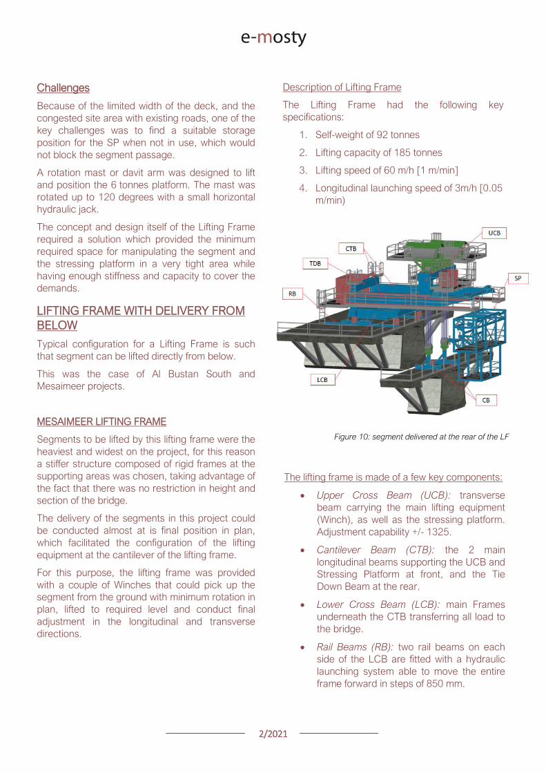
22021
Connection Beams (CB) beams
connecting the hook blocks of the Winches
directly to the segment They are provided
with jacks for segment gradient adjustment
Crossfall is adjusted directly by the
Winches
Stressing Platform (SP) it is positioned at
the tip of the CTB and move backward for
conducting stressing of bridge post-
tensioning tendons It is provided with 2
levels customized for this project
Tie Down Beam (TDB) the Support frame
is provided with a set of tie down beams at
the rear which are the main stability
system
TDB can be adjusted in the longitudinal
direction to suit the different segment
lengths and their respective tie down holes
position
Tie down bars are of 75mm and 47mm in
diameter and pre-stressed against the
segment
Challenges
To accommodate the supporting area in a
very limited length since there was
insufficient space near the pylons
This created big reactions to be taken by
the tie down elements due the big
cantilever at front and heavy segments to
be lifted
To be able to move all the way back the
lifting equipment (Winch) and UCB to
provide enough stability during the
launching procedure Space at rear of the
lifting frame was very limited
Provide a Stressing Platform with 2
different configurations (1 or 2 levels) that
could be adapted for specific
configurations
SEGMENT ERECTION PHOTOS
Figure 11 Mesaimeer Lifting Frame
Figure 12 Segment lifting
Figure 13 Segment permanent post-tensioning in progress
22021
AL BUSTAN SOUTH LIFTING FRAME
For this project the lifting frame had to
accommodate few main requirements to suit the
space constraints of the project and the bridge
capacity
Height A limit of 6m for total height the lifting
frame was to be assured since the bridge had
to pass under an existing viaduct
Load introduction The bridge section is
provided with 3 webs and middle web capacity
was to be respected by limiting the reactions at
this point Additionally the total weight of the
Lifting Frame was also limited
Segment delivered below could not be
positioned in its final orientation due to space
constraints It had to be rotated up to 90deg once
hanging from the lifting frame
To overcome the limitations described the lifting
frame concept developed considered the following
aspects
Main lifting equipment (Winch) was
positioned at the bottom rear area of the
lifting frame to reduce the total height
The three webs of the segment were
loaded and the Lifting Frame elements
were studied in such a way that the total
weight of the Lifting Frame and loading of
central web were not exceeded
A single Winch and the hook block with
rotation device were provided to allow
rotation of the segment while hanging from
the Lifting Frame
Description of Lifting Frame
The Lifting Frame had the following key
specifications
1 Self-weight of 81 tonnes
2 Lifting capacity of 170 tonnes
3 Lifting speed of 36 mh [06 mmin]
4 Longitudinal launching speed of 3mh [005
mmin
The lifting frame is made of the following key
components
Upper Cross Beam (UCB) uppermost
element carrying the Winch Trolley It can
slide longitudinally to accommodate the
segment in length Transverse adjustment
is done by sliding of the Winch Trolley over
the UCB
Main Frame (MF) the Lifting Frame is
provided with 2 Main Frames in section that
support the UCB and Stressing Platform on
top and transfers the vertical load to the
lower elements of the Lifting Frame At
bottom level it also receives the Tie Down
Beam
Lower Cross Beam (LCB) spreader beam
in the transverse direction located at front
and rear that transfer all loads to the
segment webs through 6 screw jacks (3 at
the front and 3 at the rear)
Tie Down Beam (TDB) located at rear part
of the Lifting Frame and contain the tie
down bars stressed down against the
segment in order to assure the stability of
the Lifting Frame It contains a couple of
back-up bars that provide redundancy to
the system
Segment Lifting Beam (SLB) connecting
element between the hook block of the
winch and the segment It is provided with
a rotational device that allows full rotation
of the segment in plan
Figure 14 Segment delivered at the rear of the LF
22021
Stressing Platform (SP) it hangs from the
tip of the Main Frame cantilever beam It is
moved backwards after segment
installation to conduct the stressing of the
permanent post-tensioning system
Rail Beam (RB) two rail beams on each
side of the LCB are fitted with a hydraulic
launching system able it to move the entire
frame forward in steps of 850 mm
Figure 14 Lifting Frame installation on deck
Figure 15 Lifting of segment
Figure 16 Stressing of post-tensioning tendons
Figure 17 Lifting Frame crossing under existing viaduct
SEGMENT ERECTION PHOTOS
Challenges
To develop a concept and design that did
not exceed the limitations given regarding
total weight and height
Allow full rotation of the segment while
hanging
Provide redundancy to the Lifting Frame
Tie Down system and to the Stressing
Platform while under operation
22021
CONCLUSIONS
Precast segmental construction in a congested
environment often requires the use of custom
designed lifting frames
These machines must always consider the
segment delivery methods as well as the bridge
characteristics in order to achieve the most cost-
efficient methods of erection
The more requirements a project has the more
customized the Lifting Frame will be
For this reason it is of key importance to integrate
the development of the Temporary Structures (like
Lifting Frames) as early as possible in the design
process
By doing this some of the constraints can be
solved in earlier stages which will improve the
efficiency of the full process and the interfaces
between the different parts involved Permanent
Works Designer Temporary Works Designer and
Main Contractor
Figure 18 Al Bustan North Figure 19 Al Bustan North
Figure 20 Al Bustan South
Figure 21 Mesaimeer
Photos 18 ndash 20 Credit Ashghal (Qatar Road Authority)
We design and produceformwork equipmentfor in-place casting of bridgesN25 New Ross Bypass (Ireland)
FOLLOW US
INNOVATIVE | SAFE | SUSTAINABLE | FAST
SOLUTIONS FOR BRIDGE CONSTRUCTION
MSS M1-70-S BRATISLAVA BYPASS | IN SITU CONSTRUCTION
LG 36-S CAIRO METRO LINE 3 EXTENSION | PRECAST SEGMENTAL
WWWBERDEU
Photo Credits D4R7
Photo Credits Stephane Ciccolini
Arup works in active partnership with clients to understand their needs so
that the solutions make their bridge aspirations possible mdashbig and small
The Arup global specialist technical skills blended with essential local
knowledge adds unexpected benefits
wwwarupcom
Whether to span nations make a statement or
improve everyday links Arup crafts better bridges
Naeem Hussain Richard Hornby Steve Kite Deepak Jayaram
naeemhussainarupcom richardhornbyarupcom stevekitearupcom deepakjayaramarupcom
Global UK Middle East amp Africa East Asia UK Middle East India
and Africa
Peter Burnton Marcos Sanchez Matt Carter
peterburntonarupcom marcossanchezarupcom mattcarterarupcom
Australasia Europe Americas
Queensferry Crossing Scotland
SANTANDERMADRIDLIMABOGOTAacuteBUENOS AIRES
Calle Marqueacutes de la Ensenada 11 - 3ordm 39009
Calle Bravo Murillo 101 - 4ordm 28020
Calle Coronel Inclaacuten 235 - Oficina 313 Lima 18
Cra 14 94a - 24 Oficina 307 Edificio ACO 94
Calle Rodriacuteguez Pentildea 681 - 4ordm Dpto 8 1020
Tfno +34 942 31 99 60
Tfno +34 91 702 54 78
Tfno +51 1 637 56 47
Tfno +57 1 467 48 10
Tfno +54 911 5709 3252
wwwarenasingcom
ARCHING THE WORLD
CODE-BASED DESIGN
DETAILINGDR AWING PRODUCTION
PAR AM ETRIC MODELING
STRUCTUR AL ANALYSIS
DOWNLOAD A FREE TRIALallplancombridge2021
THE WORLDrsquoS FIRST COMPLETE SOLUTIONFOR BRIDGE ENGINEERS
Allplan Bridge 2021 maps the complete BIM process in bridge projects The new version enables bridge engineers to work with one single solution from the creation of a parametric 4D model to structural analysis reinforcement design and detailing This further improves the design process in terms of both time and quality
ALLPLAN BRIDGE
Join Bridges to Prosperity in helping isolated
communities gain safe access to healthcare
education jobs and markets through simple
sustainable trailbridges Together we can
build more than a bridge we can build a
pathway out of poverty
We envision a world wherepoverty caused by ruralisolation no longer exists
bridgestoprosperityorg
infobridgestoprosperityorgbridgestoprosperity
bridgestoprosperity
b2p
+60Women Entering the Labor Force
+75Farmer
Profitability
+358Labor Market
Income
Corporate Partners make this
vision possible
Wyatt Brooks and Kevin Donovan - Eliminating Uncertainty in Market Access
The Impact of New Bridges in Rural Nicaragua 2017
SEGMENTAL BRIDGES
ISSUE 022021 JUNE
- 1 arenas_v2
-
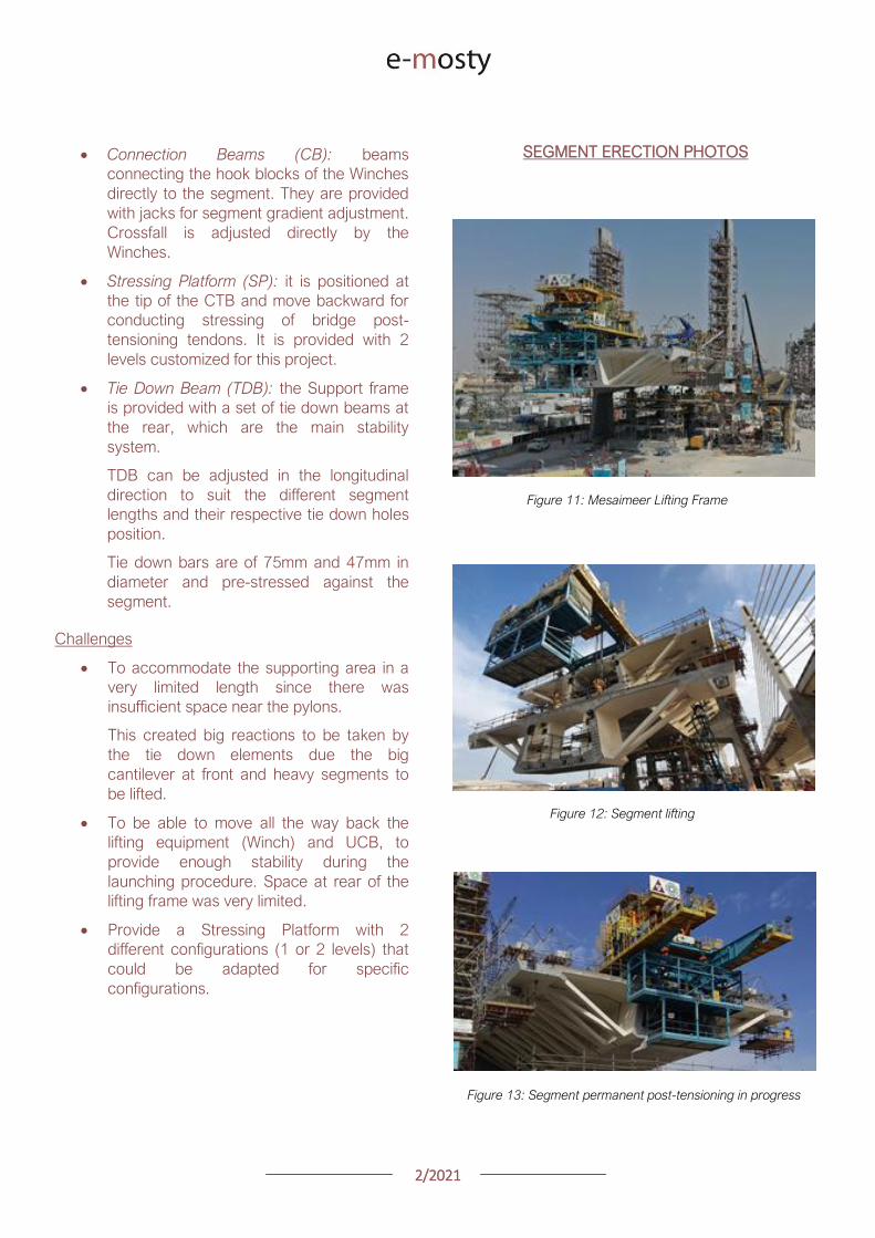
22021
AL BUSTAN SOUTH LIFTING FRAME
For this project the lifting frame had to
accommodate few main requirements to suit the
space constraints of the project and the bridge
capacity
Height A limit of 6m for total height the lifting
frame was to be assured since the bridge had
to pass under an existing viaduct
Load introduction The bridge section is
provided with 3 webs and middle web capacity
was to be respected by limiting the reactions at
this point Additionally the total weight of the
Lifting Frame was also limited
Segment delivered below could not be
positioned in its final orientation due to space
constraints It had to be rotated up to 90deg once
hanging from the lifting frame
To overcome the limitations described the lifting
frame concept developed considered the following
aspects
Main lifting equipment (Winch) was
positioned at the bottom rear area of the
lifting frame to reduce the total height
The three webs of the segment were
loaded and the Lifting Frame elements
were studied in such a way that the total
weight of the Lifting Frame and loading of
central web were not exceeded
A single Winch and the hook block with
rotation device were provided to allow
rotation of the segment while hanging from
the Lifting Frame
Description of Lifting Frame
The Lifting Frame had the following key
specifications
1 Self-weight of 81 tonnes
2 Lifting capacity of 170 tonnes
3 Lifting speed of 36 mh [06 mmin]
4 Longitudinal launching speed of 3mh [005
mmin
The lifting frame is made of the following key
components
Upper Cross Beam (UCB) uppermost
element carrying the Winch Trolley It can
slide longitudinally to accommodate the
segment in length Transverse adjustment
is done by sliding of the Winch Trolley over
the UCB
Main Frame (MF) the Lifting Frame is
provided with 2 Main Frames in section that
support the UCB and Stressing Platform on
top and transfers the vertical load to the
lower elements of the Lifting Frame At
bottom level it also receives the Tie Down
Beam
Lower Cross Beam (LCB) spreader beam
in the transverse direction located at front
and rear that transfer all loads to the
segment webs through 6 screw jacks (3 at
the front and 3 at the rear)
Tie Down Beam (TDB) located at rear part
of the Lifting Frame and contain the tie
down bars stressed down against the
segment in order to assure the stability of
the Lifting Frame It contains a couple of
back-up bars that provide redundancy to
the system
Segment Lifting Beam (SLB) connecting
element between the hook block of the
winch and the segment It is provided with
a rotational device that allows full rotation
of the segment in plan
Figure 14 Segment delivered at the rear of the LF
22021
Stressing Platform (SP) it hangs from the
tip of the Main Frame cantilever beam It is
moved backwards after segment
installation to conduct the stressing of the
permanent post-tensioning system
Rail Beam (RB) two rail beams on each
side of the LCB are fitted with a hydraulic
launching system able it to move the entire
frame forward in steps of 850 mm
Figure 14 Lifting Frame installation on deck
Figure 15 Lifting of segment
Figure 16 Stressing of post-tensioning tendons
Figure 17 Lifting Frame crossing under existing viaduct
SEGMENT ERECTION PHOTOS
Challenges
To develop a concept and design that did
not exceed the limitations given regarding
total weight and height
Allow full rotation of the segment while
hanging
Provide redundancy to the Lifting Frame
Tie Down system and to the Stressing
Platform while under operation
22021
CONCLUSIONS
Precast segmental construction in a congested
environment often requires the use of custom
designed lifting frames
These machines must always consider the
segment delivery methods as well as the bridge
characteristics in order to achieve the most cost-
efficient methods of erection
The more requirements a project has the more
customized the Lifting Frame will be
For this reason it is of key importance to integrate
the development of the Temporary Structures (like
Lifting Frames) as early as possible in the design
process
By doing this some of the constraints can be
solved in earlier stages which will improve the
efficiency of the full process and the interfaces
between the different parts involved Permanent
Works Designer Temporary Works Designer and
Main Contractor
Figure 18 Al Bustan North Figure 19 Al Bustan North
Figure 20 Al Bustan South
Figure 21 Mesaimeer
Photos 18 ndash 20 Credit Ashghal (Qatar Road Authority)
We design and produceformwork equipmentfor in-place casting of bridgesN25 New Ross Bypass (Ireland)
FOLLOW US
INNOVATIVE | SAFE | SUSTAINABLE | FAST
SOLUTIONS FOR BRIDGE CONSTRUCTION
MSS M1-70-S BRATISLAVA BYPASS | IN SITU CONSTRUCTION
LG 36-S CAIRO METRO LINE 3 EXTENSION | PRECAST SEGMENTAL
WWWBERDEU
Photo Credits D4R7
Photo Credits Stephane Ciccolini
Arup works in active partnership with clients to understand their needs so
that the solutions make their bridge aspirations possible mdashbig and small
The Arup global specialist technical skills blended with essential local
knowledge adds unexpected benefits
wwwarupcom
Whether to span nations make a statement or
improve everyday links Arup crafts better bridges
Naeem Hussain Richard Hornby Steve Kite Deepak Jayaram
naeemhussainarupcom richardhornbyarupcom stevekitearupcom deepakjayaramarupcom
Global UK Middle East amp Africa East Asia UK Middle East India
and Africa
Peter Burnton Marcos Sanchez Matt Carter
peterburntonarupcom marcossanchezarupcom mattcarterarupcom
Australasia Europe Americas
Queensferry Crossing Scotland
SANTANDERMADRIDLIMABOGOTAacuteBUENOS AIRES
Calle Marqueacutes de la Ensenada 11 - 3ordm 39009
Calle Bravo Murillo 101 - 4ordm 28020
Calle Coronel Inclaacuten 235 - Oficina 313 Lima 18
Cra 14 94a - 24 Oficina 307 Edificio ACO 94
Calle Rodriacuteguez Pentildea 681 - 4ordm Dpto 8 1020
Tfno +34 942 31 99 60
Tfno +34 91 702 54 78
Tfno +51 1 637 56 47
Tfno +57 1 467 48 10
Tfno +54 911 5709 3252
wwwarenasingcom
ARCHING THE WORLD
CODE-BASED DESIGN
DETAILINGDR AWING PRODUCTION
PAR AM ETRIC MODELING
STRUCTUR AL ANALYSIS
DOWNLOAD A FREE TRIALallplancombridge2021
THE WORLDrsquoS FIRST COMPLETE SOLUTIONFOR BRIDGE ENGINEERS
Allplan Bridge 2021 maps the complete BIM process in bridge projects The new version enables bridge engineers to work with one single solution from the creation of a parametric 4D model to structural analysis reinforcement design and detailing This further improves the design process in terms of both time and quality
ALLPLAN BRIDGE
Join Bridges to Prosperity in helping isolated
communities gain safe access to healthcare
education jobs and markets through simple
sustainable trailbridges Together we can
build more than a bridge we can build a
pathway out of poverty
We envision a world wherepoverty caused by ruralisolation no longer exists
bridgestoprosperityorg
infobridgestoprosperityorgbridgestoprosperity
bridgestoprosperity
b2p
+60Women Entering the Labor Force
+75Farmer
Profitability
+358Labor Market
Income
Corporate Partners make this
vision possible
Wyatt Brooks and Kevin Donovan - Eliminating Uncertainty in Market Access
The Impact of New Bridges in Rural Nicaragua 2017
SEGMENTAL BRIDGES
ISSUE 022021 JUNE
- 1 arenas_v2
-
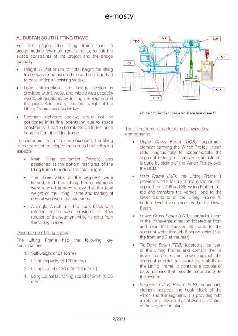
22021
Stressing Platform (SP) it hangs from the
tip of the Main Frame cantilever beam It is
moved backwards after segment
installation to conduct the stressing of the
permanent post-tensioning system
Rail Beam (RB) two rail beams on each
side of the LCB are fitted with a hydraulic
launching system able it to move the entire
frame forward in steps of 850 mm
Figure 14 Lifting Frame installation on deck
Figure 15 Lifting of segment
Figure 16 Stressing of post-tensioning tendons
Figure 17 Lifting Frame crossing under existing viaduct
SEGMENT ERECTION PHOTOS
Challenges
To develop a concept and design that did
not exceed the limitations given regarding
total weight and height
Allow full rotation of the segment while
hanging
Provide redundancy to the Lifting Frame
Tie Down system and to the Stressing
Platform while under operation
22021
CONCLUSIONS
Precast segmental construction in a congested
environment often requires the use of custom
designed lifting frames
These machines must always consider the
segment delivery methods as well as the bridge
characteristics in order to achieve the most cost-
efficient methods of erection
The more requirements a project has the more
customized the Lifting Frame will be
For this reason it is of key importance to integrate
the development of the Temporary Structures (like
Lifting Frames) as early as possible in the design
process
By doing this some of the constraints can be
solved in earlier stages which will improve the
efficiency of the full process and the interfaces
between the different parts involved Permanent
Works Designer Temporary Works Designer and
Main Contractor
Figure 18 Al Bustan North Figure 19 Al Bustan North
Figure 20 Al Bustan South
Figure 21 Mesaimeer
Photos 18 ndash 20 Credit Ashghal (Qatar Road Authority)
We design and produceformwork equipmentfor in-place casting of bridgesN25 New Ross Bypass (Ireland)
FOLLOW US
INNOVATIVE | SAFE | SUSTAINABLE | FAST
SOLUTIONS FOR BRIDGE CONSTRUCTION
MSS M1-70-S BRATISLAVA BYPASS | IN SITU CONSTRUCTION
LG 36-S CAIRO METRO LINE 3 EXTENSION | PRECAST SEGMENTAL
WWWBERDEU
Photo Credits D4R7
Photo Credits Stephane Ciccolini
Arup works in active partnership with clients to understand their needs so
that the solutions make their bridge aspirations possible mdashbig and small
The Arup global specialist technical skills blended with essential local
knowledge adds unexpected benefits
wwwarupcom
Whether to span nations make a statement or
improve everyday links Arup crafts better bridges
Naeem Hussain Richard Hornby Steve Kite Deepak Jayaram
naeemhussainarupcom richardhornbyarupcom stevekitearupcom deepakjayaramarupcom
Global UK Middle East amp Africa East Asia UK Middle East India
and Africa
Peter Burnton Marcos Sanchez Matt Carter
peterburntonarupcom marcossanchezarupcom mattcarterarupcom
Australasia Europe Americas
Queensferry Crossing Scotland
SANTANDERMADRIDLIMABOGOTAacuteBUENOS AIRES
Calle Marqueacutes de la Ensenada 11 - 3ordm 39009
Calle Bravo Murillo 101 - 4ordm 28020
Calle Coronel Inclaacuten 235 - Oficina 313 Lima 18
Cra 14 94a - 24 Oficina 307 Edificio ACO 94
Calle Rodriacuteguez Pentildea 681 - 4ordm Dpto 8 1020
Tfno +34 942 31 99 60
Tfno +34 91 702 54 78
Tfno +51 1 637 56 47
Tfno +57 1 467 48 10
Tfno +54 911 5709 3252
wwwarenasingcom
ARCHING THE WORLD
CODE-BASED DESIGN
DETAILINGDR AWING PRODUCTION
PAR AM ETRIC MODELING
STRUCTUR AL ANALYSIS
DOWNLOAD A FREE TRIALallplancombridge2021
THE WORLDrsquoS FIRST COMPLETE SOLUTIONFOR BRIDGE ENGINEERS
Allplan Bridge 2021 maps the complete BIM process in bridge projects The new version enables bridge engineers to work with one single solution from the creation of a parametric 4D model to structural analysis reinforcement design and detailing This further improves the design process in terms of both time and quality
ALLPLAN BRIDGE
Join Bridges to Prosperity in helping isolated
communities gain safe access to healthcare
education jobs and markets through simple
sustainable trailbridges Together we can
build more than a bridge we can build a
pathway out of poverty
We envision a world wherepoverty caused by ruralisolation no longer exists
bridgestoprosperityorg
infobridgestoprosperityorgbridgestoprosperity
bridgestoprosperity
b2p
+60Women Entering the Labor Force
+75Farmer
Profitability
+358Labor Market
Income
Corporate Partners make this
vision possible
Wyatt Brooks and Kevin Donovan - Eliminating Uncertainty in Market Access
The Impact of New Bridges in Rural Nicaragua 2017
SEGMENTAL BRIDGES
ISSUE 022021 JUNE
- 1 arenas_v2
-
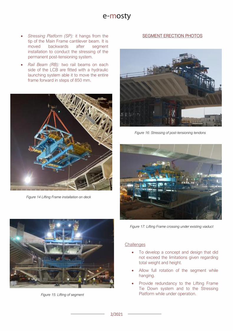
22021
CONCLUSIONS
Precast segmental construction in a congested
environment often requires the use of custom
designed lifting frames
These machines must always consider the
segment delivery methods as well as the bridge
characteristics in order to achieve the most cost-
efficient methods of erection
The more requirements a project has the more
customized the Lifting Frame will be
For this reason it is of key importance to integrate
the development of the Temporary Structures (like
Lifting Frames) as early as possible in the design
process
By doing this some of the constraints can be
solved in earlier stages which will improve the
efficiency of the full process and the interfaces
between the different parts involved Permanent
Works Designer Temporary Works Designer and
Main Contractor
Figure 18 Al Bustan North Figure 19 Al Bustan North
Figure 20 Al Bustan South
Figure 21 Mesaimeer
Photos 18 ndash 20 Credit Ashghal (Qatar Road Authority)
We design and produceformwork equipmentfor in-place casting of bridgesN25 New Ross Bypass (Ireland)
FOLLOW US
INNOVATIVE | SAFE | SUSTAINABLE | FAST
SOLUTIONS FOR BRIDGE CONSTRUCTION
MSS M1-70-S BRATISLAVA BYPASS | IN SITU CONSTRUCTION
LG 36-S CAIRO METRO LINE 3 EXTENSION | PRECAST SEGMENTAL
WWWBERDEU
Photo Credits D4R7
Photo Credits Stephane Ciccolini
Arup works in active partnership with clients to understand their needs so
that the solutions make their bridge aspirations possible mdashbig and small
The Arup global specialist technical skills blended with essential local
knowledge adds unexpected benefits
wwwarupcom
Whether to span nations make a statement or
improve everyday links Arup crafts better bridges
Naeem Hussain Richard Hornby Steve Kite Deepak Jayaram
naeemhussainarupcom richardhornbyarupcom stevekitearupcom deepakjayaramarupcom
Global UK Middle East amp Africa East Asia UK Middle East India
and Africa
Peter Burnton Marcos Sanchez Matt Carter
peterburntonarupcom marcossanchezarupcom mattcarterarupcom
Australasia Europe Americas
Queensferry Crossing Scotland
SANTANDERMADRIDLIMABOGOTAacuteBUENOS AIRES
Calle Marqueacutes de la Ensenada 11 - 3ordm 39009
Calle Bravo Murillo 101 - 4ordm 28020
Calle Coronel Inclaacuten 235 - Oficina 313 Lima 18
Cra 14 94a - 24 Oficina 307 Edificio ACO 94
Calle Rodriacuteguez Pentildea 681 - 4ordm Dpto 8 1020
Tfno +34 942 31 99 60
Tfno +34 91 702 54 78
Tfno +51 1 637 56 47
Tfno +57 1 467 48 10
Tfno +54 911 5709 3252
wwwarenasingcom
ARCHING THE WORLD
CODE-BASED DESIGN
DETAILINGDR AWING PRODUCTION
PAR AM ETRIC MODELING
STRUCTUR AL ANALYSIS
DOWNLOAD A FREE TRIALallplancombridge2021
THE WORLDrsquoS FIRST COMPLETE SOLUTIONFOR BRIDGE ENGINEERS
Allplan Bridge 2021 maps the complete BIM process in bridge projects The new version enables bridge engineers to work with one single solution from the creation of a parametric 4D model to structural analysis reinforcement design and detailing This further improves the design process in terms of both time and quality
ALLPLAN BRIDGE
Join Bridges to Prosperity in helping isolated
communities gain safe access to healthcare
education jobs and markets through simple
sustainable trailbridges Together we can
build more than a bridge we can build a
pathway out of poverty
We envision a world wherepoverty caused by ruralisolation no longer exists
bridgestoprosperityorg
infobridgestoprosperityorgbridgestoprosperity
bridgestoprosperity
b2p
+60Women Entering the Labor Force
+75Farmer
Profitability
+358Labor Market
Income
Corporate Partners make this
vision possible
Wyatt Brooks and Kevin Donovan - Eliminating Uncertainty in Market Access
The Impact of New Bridges in Rural Nicaragua 2017
SEGMENTAL BRIDGES
ISSUE 022021 JUNE
- 1 arenas_v2
-
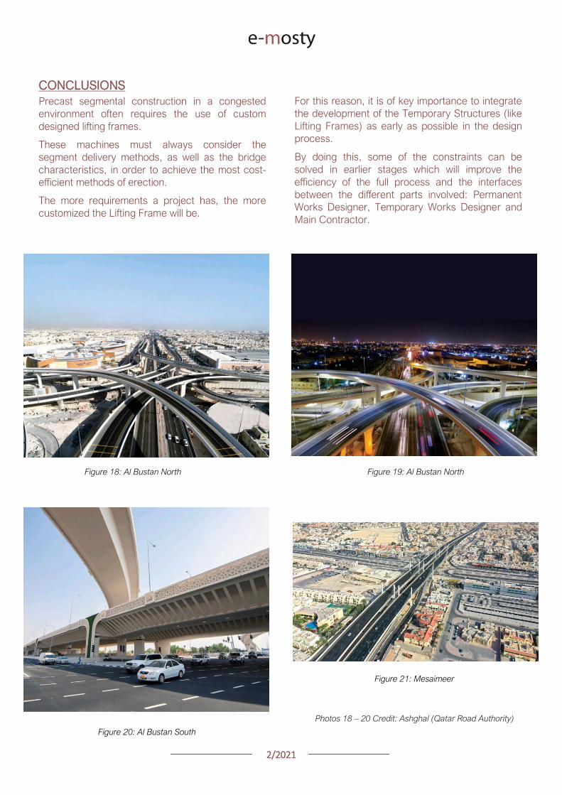

SEGMENTAL BRIDGES
ISSUE 022021 JUNE
- 1 arenas_v2
-
Related Documents