SEGCG/M490/G 1/266 Document Reference: SEGCG/M490/G – version 4.1 1 2 3 4 5 6 7 CEN-CENELEC-ETSI Coordination Group on Smart Energy Grids (CG-SEG) 8 9 Date: Jan 6th 2017 10 11 Secretariat: CCMC 12 13 14 15 16 17 18 19 20 21 SEGCG/M490/G_Smart Grid Set of Standards 22 Version 4.1 23 24 25 26 27 28 29 30 31 32 33 34 35 36 37 38 39

Welcome message from author
This document is posted to help you gain knowledge. Please leave a comment to let me know what you think about it! Share it to your friends and learn new things together.
Transcript

SEGCG/M490/G 1/266
Document Reference: SEGCG/M490/G – version 4.1 1 2 3 4 5
6 7
CEN-CENELEC-ETSI Coordination Group on Smart Energy Grids (CG-SEG) 8
9
Date: Jan 6th 2017 10
11
Secretariat: CCMC 12
13 14 15 16 17
18
19
20
21
SEGCG/M490/G_Smart Grid Set of Standards 22
Version 4.1 23
24
25
26
27
28
29
30
31
32
33
34
35
36 37 38 39
SEGCG/M490/G_Smart Grid Set of Standards 4.1 draft v0; Jan 6th 2017
SEGCG/M490/G 2/266
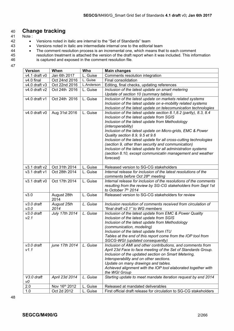
Change tracking 40
Note : 41
Versions noted in italic are internal to the “Set of Standards” team 42
Versions noted in italic are intermediate internal one to the editorial team 43
The comment resolution process is an incremental one, which means that to each comment 44 resolution treatment is attached the version of the draft report when it was included. This information 45 is captured and exposed in the comment resolution file. 46
47
Version When Who Main changes
v4.1 draft v0 Jan 6th 2017 L. Guise Comments resolution integration
v4.0 final Oct 24nd 2016 L. Guise Final consolidation
v4.0 draft v3 Oct 22nd 2016 L.Anderson Editing, final checks, updating references
v4.0 draft v2 Oct 24th 2016 L. Guise Inclusion of the latest update on smart metering Update of section 10 (summary tables)
v4.0 draft v1 Oct 24th 2016 L. Guise Inclusion of the latest update on markets related systems Inclusion of the latest update on e-mobility related systems Inclusion of the latest update on telecomunication technologies
v4.0 draft v0 Aug 31st 2016 L. Guise Inclusion of the latest update section 8.1,8.2 (partly), 8.3, 8.4 Inclusion of the latest update from SGIS Inclusion of the latest update from Methodology (interoperability) Inclusion of the latest update on Micro-grids, EMC & Power Quality section 8.9, 9.5 et 9.6 Inclusion of the latest update for all cross-cutting technologies (section 9, other than security and communication) Inclusion of the latest update for all administration systems (section 8.10, except communicatin management and weather forecast)
v3.1 draft v2 Oct 31th 2014 L. Guise Released version to SG-CG stakeholders
v3.1 draft v1 Oct 28th 2014 L. Guise Internal release for inclusion of the latest resolutions of the comments before Oct 28th meeting
v3.1 draft v0 Oct 17th 2014 L. Guise Internal release for inclusion of the resolutions of the comments resulting from the review by SG-CG stakeholders from Sept 1st to October 7th 2014
v3.0 August 28th 2014
L. Guise Released version to SG-CG stakeholders for review
v3.0 draft v3.0
August 25th 2014
L. Guise Inclusion resolution of comments received from circulation of “final draft v2.1” to WG members
v3.0 draft v2.1
July 17th 2014 L. Guise Inclusion of the latest update from EMC & Power Quality Inclusion of the latest update from SGIS Inclusion of the latest update from Methodology (communication, modeling) Inclusion of the latest update from ITU Tables at the end of this report come from the IOP tool from SGCG-WGI (updated consequently)
v3.0 draft v1.1
june 17th 2014 L. Guise Inclusion of AMI and other contributions, and comments from April 23d Face to face meeting of the Set of Standards Group. Inclusion of the updated section on Smart Metering, Interoperability and on other sections. Update on many drawings and tables. Achieved alignment with the IOP tool elaborated together with the WGI Group
V3.0 draft v0
April 23d 2014 L. Guise Starting update to meet mandate iteration request by end 2014
2.0 Nov 16th 2012 L. Guise Released at mandated deliverables
1.0 Oct 2d 2012 L. Guise First official draft release for circulation to SG-CG stakeholders
48

SEGCG/M490/G_Smart Grid Set of Standards 4.1 draft v0; Jan 6th 2017
SEGCG/M490/G 3/266
Contents 49
50 1 Scope ......................................................................................................................................................... 9 51
2 References ................................................................................................................................................ 9 52
3 Terms and definitions ............................................................................................................................ 11 53
4 Abbreviations .......................................................................................................................................... 16 54
5 Executive Summary ............................................................................................................................... 19 55
5.1 Report summary ................................................................................................................................ 19 56 5.2 Core Standards ................................................................................................................................. 19 57 5.3 Other highly important standards ...................................................................................................... 20 58
6 Objectives, rules and expected usage of this report .......................................................................... 20 59
6.1 Limits of scope and usage ................................................................................................................ 20 60 6.2 How to select standards? .................................................................................................................. 21 61
6.2.1 Standardization body ranking ...................................................................................................... 21 62 6.2.2 Maturity level ................................................................................................................................ 21 63 6.2.3 Release management .................................................................................................................. 21 64 6.2.4 Standards naming convention ..................................................................................................... 22 65
6.3 Process for "List of Standards" update ............................................................................................. 22 66 6.4 Mapping chart (use of) ...................................................................................................................... 22 67
6.4.1 Motivation ..................................................................................................................................... 22 68 6.4.2 Chart content ............................................................................................................................... 23 69
6.5 Towards seamless interoperability .................................................................................................... 25 70 6.5.1 What does interoperability mean? ............................................................................................... 25 71 6.5.2 Summary of the IOP Methodology of SEG-CG WG Interoperability ........................................... 25 72 6.5.3 Linkages to the work undertaken by SEG-CG WG Methodology and SGTF EG1 ...................... 27 73 6.5.4 From Standards to Interoperability and Test Profiles .................................................................. 28 74
7 Main guidelines ....................................................................................................................................... 33 75
7.1 Smart Grid Conceptual Model ........................................................................................................... 33 76 7.1.1 Smart Grid Conceptual Model principles ..................................................................................... 33 77 7.1.2 Conceptual Model Domains ......................................................................................................... 34 78
7.2 General method used for presenting Smart Grids standards ........................................................... 36 79 7.3 SGAM introduction ............................................................................................................................ 37 80
7.3.1 SGAM Smart Grid Plane .............................................................................................................. 37 81 7.3.2 SGAM Interoperability Layers ...................................................................................................... 37 82 7.3.3 SGAM Framework ....................................................................................................................... 38 83
7.4 List of systems ................................................................................................................................... 39 84 7.5 Mapping of systems on SGAM Smart Grid Plane ............................................................................. 40 85
7.5.1 Overview ...................................................................................................................................... 40 86 7.5.2 Specific usage of the SGAM in the current document ................................................................. 41 87 7.5.3 Conventions used to draw the component layer of a system mapping ....................................... 41 88 7.5.4 Conventions used to draw the communication layer of a system mapping ................................ 42 89 7.5.5 Conventions used to draw the information layer of a system mapping ....................................... 43 90
7.6 Smart Grid Generic use cases .......................................................................................................... 43 91 7.6.1 List of Generic Use cases ............................................................................................................ 43 92 7.6.2 Coverage of use cases by standards (C, I, CI, X) ....................................................................... 47 93
7.7 Inputs from the IEC Smart Grid Standardization Roadmap – The Smart Grid Component plane ... 48 94 7.7.1 Cluster descriptions ..................................................................................................................... 48 95 7.7.2 List of components ....................................................................................................................... 49 96
8 Per systems standards mapping .......................................................................................................... 54 97
8.1 Generation ......................................................................................................................................... 54 98 8.1.1 Generation management system................................................................................................. 54 99
8.2 Transmission management domain .................................................................................................. 63 100 8.2.1 Substation automation system (Transmission & Distribution) ..................................................... 63 101 8.2.2 Blackout Prevention System - Wide Area Measurement Protection and Control System 102 (WAMPAC) ............................................................................................................................................... 70 103 8.2.3 EMS SCADA system ................................................................................................................... 76 104 8.2.4 Flexible AC Transmission Systems (FACTS) .............................................................................. 83 105

SEGCG/M490/G_Smart Grid Set of Standards 4.1 draft v0; Jan 6th 2017
SEGCG/M490/G 4/266
8.3 Distribution management systems .................................................................................................... 89 106 8.3.1 Substation Automation System.................................................................................................... 89 107 8.3.2 Feeder automation system (including smart field switching device and distributed Power Quality 108 system) ..................................................................................................................................................... 89 109 8.3.3 Advanced Distribution Management System (ADMS) ................................................................. 97 110 8.3.4 FACTS (Distribution) .................................................................................................................. 104 111
8.4 Distributed Energy Resources Operation System (including storage) ............................................ 106 112 8.4.1 System description .................................................................................................................... 106 113 8.4.2 Set of use cases ........................................................................................................................ 106 114 8.4.3 Mapping on SGAM .................................................................................................................... 107 115 8.4.4 List of Standards ........................................................................................................................ 110 116
8.5 Smart Metering systems ................................................................................................................. 114 117 8.5.1 AMI system (M/441 scope) ........................................................................................................ 114 118 8.5.2 Metering-related Back Office systems ....................................................................................... 124 119
8.6 Demand and production (generation) flexibility systems ................................................................ 130 120 8.6.1 Aggregated prosumers management system ............................................................................ 130 121
8.7 Marketplace system ........................................................................................................................ 136 122 8.7.1 Market places............................................................................................................................. 136 123 8.7.2 Trading systems......................................................................................................................... 143 124
8.8 E-mobility System............................................................................................................................ 148 125 8.8.1 System description .................................................................................................................... 148 126 8.8.2 Mapping on SGAM .................................................................................................................... 149 127 8.8.3 List of Standards ........................................................................................................................ 151 128
8.9 Micro-grid systems .......................................................................................................................... 154 129 8.9.1 System description .................................................................................................................... 154 130 8.9.2 Set of use cases ........................................................................................................................ 155 131 8.9.3 Mapping on SGAM .................................................................................................................... 156 132 8.9.4 List of Standards ........................................................................................................................ 156 133
8.10 Administration systems .............................................................................................................. 158 134 8.10.1 Asset and Maintenance Management system ....................................................................... 158 135 8.10.2 Communication network management system ...................................................................... 163 136 8.10.3 Clock reference system ......................................................................................................... 168 137 8.10.4 Authentication, Authorization, Accounting Systems .............................................................. 172 138 8.10.5 Device remote management system ..................................................................................... 182 139 8.10.6 Weather forecast and observation system ............................................................................ 182 140
9 Cross-cutting technologies and methods ......................................................................................... 188 141
9.1 System approach ............................................................................................................................ 188 142 9.1.1 Use cases approach .................................................................................................................. 188 143 9.1.2 Product Identification ................................................................................................................. 190 144
9.2 Data modeling (Information layer) ................................................................................................... 191 145 9.2.1 Description ................................................................................................................................. 191 146 9.2.2 List of Standards ........................................................................................................................ 192 147
9.3 Communication (Communication layer) .......................................................................................... 193 148 9.3.1 Description ................................................................................................................................. 193 149 9.3.2 Communication network type breakdown .................................................................................. 193 150 9.3.3 Applicability of communication standards to Smart Grid networks ............................................ 195 151 9.3.4 List of Standards ........................................................................................................................ 197 152 9.3.5 Higher layer communication protocols ...................................................................................... 204 153
9.4 Security ........................................................................................................................................... 206 154 9.4.1 Cyber Security Standardization landscape ................................................................................ 206 155 9.4.2 List of standards......................................................................................................................... 210 156
9.5 Connection to the grid and installation of DER (Distributed Energy Resources – Component layer))157 216 158
9.5.1 Context description .................................................................................................................... 216 159 9.5.2 List of Standards ........................................................................................................................ 216 160
9.6 EMC & Power Quality ..................................................................................................................... 218 161 9.6.1 Definitions .................................................................................................................................. 218 162 9.6.2 General ...................................................................................................................................... 218 163 9.6.3 List of standards......................................................................................................................... 220 164
9.7 Functional Safety............................................................................................................................. 222 165 10 List of standards ............................................................................................................................... 224 166
SEGCG/M490/G_Smart Grid Set of Standards 4.1 draft v0; Jan 6th 2017
SEGCG/M490/G 5/266
10.1 CEN/CENELEC ......................................................................................................................... 224 167 10.2 ETSI ........................................................................................................................................... 236 168 10.3 IEC ............................................................................................................................................. 241 169 10.4 ITU ............................................................................................................................................. 248 170 10.5 ISO ............................................................................................................................................. 252 171 10.6 Other bodies .............................................................................................................................. 254 172
Annex A Detailed list of abbreviations ...................................................................................................... 263 173
174 175
SEGCG/M490/G_Smart Grid Set of Standards 4.1 draft v0; Jan 6th 2017
SEGCG/M490/G 6/266
List of figures 176
Figure 1 - Smart Grid mapping chart ............................................................................................................... 24 177 Figure 2 Interoperability process ..................................................................................................................... 26 178 Figure 3: V-Model including BAP and BAIOP.................................................................................................. 29 179 Figure 4: Process from Use Case to Interoperability on SGAM function layer ............................................... 29 180 Figure 5 - Workflow of standardization process .............................................................................................. 30 181 Figure 6: European Conceptual Model for the Smart Grid .............................................................................. 34 182 Figure 7: Smart Grid plane - domains and hierarchical zones ........................................................................ 37 183 Figure 8: Grouping into interoperability layers ................................................................................................. 38 184 Figure 9: the SGAM framework ....................................................................................................................... 38 185 Figure 10 - Mapping of Smart Grids systems to the SGAM model ................................................................. 40 186 Figure 11 - Generation management system - Component layer ................................................................... 57 187 Figure 12 - Generation management system - Communication layer ............................................................. 58 188 Figure 13 - Generation management system - Information layer .................................................................... 59 189 Figure 14 - Substation automation system - Component layer ....................................................................... 66 190 Figure 15 - Substation automation system - Communication layer ................................................................. 67 191 Figure 16 - Substation automation system - Information layer ........................................................................ 68 192 Figure 17 - WAMPAC - Component layer ....................................................................................................... 72 193 Figure 18 - WAMPAC - Communication layer ................................................................................................. 73 194 Figure 19 - WAMPAC - Information layer ........................................................................................................ 74 195 Figure 20 - EMS SCADA system - Component layer ...................................................................................... 78 196 Figure 21 - EMS SCADA system - Communication layer ............................................................................... 79 197 Figure 22 - EMS SCADA system - Information layer ...................................................................................... 80 198 Figure 23 - FACTS - Component layer ............................................................................................................ 85 199 Figure 24 - FACTS - Communication layer ..................................................................................................... 86 200 Figure 25- FACTS - Information layer ............................................................................................................. 87 201 Figure 26 - Feeder automation system - Component layer ............................................................................. 91 202 Figure 27 - Feeder automation system - Communication layer ...................................................................... 92 203 Figure 28 - Feeder automation system - Information layer ............................................................................. 93 204 Figure 29 - Advanced Distribution Management System (ADMS) - Component layer ................................... 99 205 Figure 30 - Advanced Distribution Management System (ADMS) - Communication layer ........................... 100 206 Figure 31 - Advanced Distribution Management System (ADMS) - Information layer .................................. 101 207 Figure 32 - DER Operation system - Component layer ................................................................................. 108 208 Figure 33 - DER Operation system - Communication layer .......................................................................... 109 209 Figure 34 - DER operation system - Information layer .................................................................................. 110 210 Figure 35: Smart Metering architecture according to CLC TR 50572 ........................................................... 116 211 Figure 36: Smart Metering architecture (example) mapped to the SGAM component layer. ....................... 117 212 Figure 37: Smart Metering architecture (example) mapped to the SGAM communication layer. ................. 118 213 Figure 38: Smart Metering architecture (example) mapped to the SGAM information layer. ....................... 119 214 Figure 39 - Typical applications hosted by a metering-related back-office system ....................................... 124 215 Figure 40 - Metering-related Back Office system - Component layer ........................................................... 126 216 Figure 41 - Metering-related Back Office system - Communication layer ..................................................... 127 217 Figure 42 - Metering-related Back Office system - Information layer ............................................................ 128 218 Figure 43 - Aggregated prosumers management system (example) - Component layer ............................. 132 219 Figure 44 - Aggregated prosumers management system (example) - Communication layer ....................... 133 220 Figure 45 - Aggregated prosumers management system (example) - Information layer .............................. 134 221 Figure 46 - Marketplace system - Component layer ..................................................................................... 138 222 Figure 47 - Marketplace system - Communication layer ............................................................................... 139 223 Figure 48 - Marketplace system - Information layer ...................................................................................... 140 224 Figure 49 - Trading system - Component layer ............................................................................................. 144 225 Figure 50 - Trading system - Communication layer ...................................................................................... 145 226 Figure 51 - Trading system - Information layer ............................................................................................. 146 227 Figure 52 – E-mobility system (example) - Component layer ....................................................................... 150 228 Figure 53 – E-mobility system (example) and link to E-mobility standards ................................................... 151 229 Figure 54 – Micro-grids – possible domains and systems breakdown .......................................................... 155 230 Figure 55 - Assets and maintenance management system - Component layer ........................................... 159 231 Figure 56 - Assets and maintenance management system - Communication layer ..................................... 160 232 Figure 57 - Assets and maintenance management system - Information layer ............................................ 161 233 Figure 58 – Communication network management - Component layer ........................................................ 164 234 Figure 59 - Communication network management - Communication layer .................................................. 165 235 Figure 60 - Communication network management - Information layer ......................................................... 166 236
SEGCG/M490/G_Smart Grid Set of Standards 4.1 draft v0; Jan 6th 2017
SEGCG/M490/G 7/266
Figure 61 – Clock reference system - Component layer ............................................................................... 169 237 Figure 62 – Clock reference system - Communication layer......................................................................... 170 238 Figure 63 – Clock reference system - Information layer ................................................................................ 170 239 Figure 64: AAA Example in a Substation Automation Use Case .................................................................. 173 240 Figure 65: EAP Overview .............................................................................................................................. 174 241 Figure 66 - Mapping of Standards used in the AAA Example on SGAM - Component Layer ...................... 177 242 Figure 67 - Mapping of Standards used in the AAA Example on SGAM - Communication Layer ................ 179 243 Figure 68 - Mapping of Standards used in the AAA Example on SGAM - Information Layer ....................... 180 244 Figure 69 - Weather forecast and observation system - Component layer ................................................... 184 245 Figure 70 - Weather forecast and observation system - Communication layer ............................................ 185 246 Figure 71 - Weather forecast and observation system - Information layer ................................................... 186 247 Figure 72 - Data modelling and harmonization work (Information layer) mapping........................................ 192 248 Figure 73 - Mapping of communication networks on SGAM ......................................................................... 195 249 Figure 74 - SGIS Standards Areas ................................................................................................................ 208 250 Figure 75: Security Standard Coverage ........................................................................................................ 209 251 Figure 76: Security standard applicability ...................................................................................................... 210 252 253
List of tables 254
255 Table 1 – Network typology abbreviations....................................................................................................... 16 256 Table 2 – Abbreviations list extract .................................................................................................................. 16 257 Table 3 - Smart Grids – Core standards .......................................................................................................... 19 258 Table 4 - Smart Grids – Other highly important standards .............................................................................. 20 259 Table 5 - Smart Grids - list of the main systems ............................................................................................. 39 260 Table 6 - Typical components used for system mapping on SGAM ............................................................... 41 261 Table 7 - Typical links used for system mapping on SGAM ............................................................................ 42 262 Table 8 – Example in binding system standards and low OSI layer communication standards ..................... 43 263 Table 9 – Summary list of Smart Grid Generic use cases .............................................................................. 44 264 Table 10 - Use case coverage example .......................................................................................................... 48 265 Table 11 - Smart Grids – Mapping Chart clusters description ......................................................................... 48 266 Table 12 - Smart Grid Component list (extracted from [a3]) ........................................................................... 49 267 Table 13 - Generation Management systems - use cases .............................................................................. 54 268 Table 14 - Generation management system - Available standards ................................................................ 59 269 Table 15 - Generation management system - Coming standards .................................................................. 61 270 Table 16 - Substation automation system - Use cases ................................................................................... 63 271 Table 17 - Substation automation system (Transmission & Distribution) - Available standards ..................... 68 272 Table 18 - Substation automation system (Transmission & Distribution) - Coming standards ....................... 69 273 Table 19 - WAMPAC - Use cases ................................................................................................................... 71 274 Table 20 - WAMPAC - Available standards..................................................................................................... 74 275 Table 21 - WAMPAC - Coming standards ....................................................................................................... 75 276 Table 22 - EMS SCADA system - Use cases .................................................................................................. 77 277 Table 23 - EMS SCADA system - Available standards ................................................................................... 81 278 Table 24 - EMS SCADA system - Coming standards ..................................................................................... 81 279 Table 25 - FACTS - Use cases ........................................................................................................................ 84 280 Table 26- FACTS - Available standards .......................................................................................................... 88 281 Table 27 - FACTS - Coming standards ........................................................................................................... 88 282 Table 28 - Feeder Automation System - Use cases ........................................................................................ 89 283 Table 29 - Feeder automation system - Available standards .......................................................................... 93 284 Table 30 - Feeder automation system - Coming standards ............................................................................ 95 285 Table 31 - Advanced Distribution Management System (ADMS) – Use cases .............................................. 97 286 Table 32 - Advanced Distribution Management System (ADMS) - Available standards .............................. 102 287 Table 33 - Advanced Distribution Management System (ADMS) - Coming standards ................................. 102 288 Table 34 - FACTS (Distribution) - use cases ................................................................................................. 104 289 Table 35 - FACTS (Distribution) – Available standards ................................................................................. 105 290 Table 36 - FACTS (Distribution) – Coming standards ................................................................................... 105 291 Table 37 – DER Operation system – use cases ........................................................................................... 106 292 Table 38 – DER Operation system – Available standards ............................................................................ 110 293 Table 39 – DER Operation system – Coming standards .............................................................................. 112 294 Table 40 – AMI system – Use cases ............................................................................................................. 114 295 Table 41 – AMI system – Standards (outside M/441 scope) ......................................................................... 120 296 Table 42 – AMI system – Standards (within M/441 scope) ........................................................................... 120 297

SEGCG/M490/G_Smart Grid Set of Standards 4.1 draft v0; Jan 6th 2017
SEGCG/M490/G 8/266
Table 43 - Metering-related Back Office system - use cases ........................................................................ 124 298 Table 44 - Metering-related Back Office system – Available standards ........................................................ 128 299 Table 45 - Metering-related Back Office system – Coming standards .......................................................... 129 300 Table 46 - Aggregated prosumers management system - use cases ........................................................... 130 301 Table 47 - Aggregated prosumers management system – Available standards........................................... 135 302 Table 48 - Aggregated prosumers management system– Coming standards .............................................. 135 303 Table 49 - Marketplace system - use cases .................................................................................................. 136 304 Table 50 - Marketplace system – Available standards .................................................................................. 140 305 Table 51 - Marketplace system – Coming standards .................................................................................... 142 306 Table 52 - Trading system - use cases ......................................................................................................... 143 307 Table 53 - Trading system – Available standards ......................................................................................... 147 308 Table 54 - Trading system – Coming standards ........................................................................................... 148 309 Table 55 - E-mobility system - Available standards ...................................................................................... 151 310 Table 56 - E-mobility system - Coming standards ......................................................................................... 153 311 Table 57 – Industrial automation system - Use cases ................................................................................... 155 312 Table 58 - Micro-Grids system - Available standards .................................................................................... 156 313 Table 59 - Micro-Grids system - Coming standards ...................................................................................... 156 314 Table 60 – Assets and maintenance management system - use cases ....................................................... 158 315 Table 61 – Assets and maintenance management system – Available standards ....................................... 161 316 Table 62 – Assets and maintenance management system – Coming standards ......................................... 162 317 Table 63 - Communication network management - Available standards ...................................................... 166 318 Table 64 - Communication network management - Coming standards ........................................................ 167 319 Table 65 - Clock reference system – use cases ........................................................................................... 168 320 Table 66 - Clock reference system – Available standards ............................................................................ 171 321 Table 67 - Clock reference system – Coming standards .............................................................................. 171 322 Table 68 - AAA systems - Use cases ............................................................................................................ 175 323 Table 69 - AAA system - Available standards ............................................................................................... 181 324 Table 70 - AAA system - Coming standards ................................................................................................. 181 325 Table 71 - Weather forecast and observation system - Use cases ............................................................... 182 326 Table 72 - Weather forecast and observation system - Available standards ................................................ 186 327 Table 73 - Weather forecast and observation system - Coming standards .................................................. 187 328 Table 74 – 9.1.1 Use cases approach - Available standards ................................................................... 188 329 Table 75 – Use cases approach - Coming standards ................................................................................... 188 330 Table 76 – Product Identification and Classification - Available standards ................................................... 190 331 Table 77 - Identification and Classification of objects - Coming standards ................................................... 191 332 Table 78 - Data modeling - Available standards ........................................................................................... 192 333 Table 79 - Data modeling - Coming standards .............................................................................................. 192 334 Table 80 - Applicability statement of the communication technologies to the smart grid sub-networks ....... 196 335 Table 81 - Communication - Available standards .......................................................................................... 197 336 Table 82 - Communication - Coming standards ............................................................................................ 203 337 Table 83 - Higher level communication protocols - Available........................................................................ 205 338 Table 84 - Higher level communication protocols - Coming .......................................................................... 206 339 Table 85 - Security - Available standards ...................................................................................................... 210 340 Table 86 - Security - Coming standards ........................................................................................................ 215 341 Table 87 - Connection to the grid and installation of DER - Available standards.......................................... 216 342 Table 88 - Connection to the grid and installation of DER - Coming standards ............................................ 217 343 Table 89 - EMC - Power Quality - Available standards ................................................................................. 220 344 Table 90 - EMC - Power Quality - Coming standards ................................................................................... 222 345 Table 91 - Functional safety - Available standards ....................................................................................... 222 346 Table 92 - Abbreviations list - complete ........................................................................................................ 263 347 348
349
SEGCG/M490/G_Smart Grid Set of Standards 4.1 draft v0; Jan 6th 2017
SEGCG/M490/G 9/266
1 Scope 350
On March 1st 2011, The European Commission issued a Mandate [1] for Smart Grids standards to the 351 European Standardization Organizations. 352 Through this mandate, the EC requested CEN, CENELEC, and ETSI to develop or update a set of consistent 353 standards within a common European framework of communication and electrical architectures and 354 associated processes, that will enable or facilitate the implementation in Europe of the different high level 355
Smart Grid services1 and functionalities as defined by the Smart Grid Task Force that will be flexible enough 356 to accommodate future developments. 357 Building, Industry, Appliances and Home automation are out of the scope of this mandate; however, their 358 interfaces with the Smart Grid and related services have to be treated under this mandate. 359 360 The mandate stated that “a set of consistent standards”, which will support the information exchange 361 (communication protocols and data models) and the integration of all users into the electric system operation 362 shall be provided. 363 The current report fulfills this mandated work, as part of the framework delivered in [2]. It is the new release 364 of the original “first set of standards” and proposes an updated framework of standards which can support 365 Smart Grids deployment in Europe. 366 367 It provides a selection guide setting out, for the most common Smart Grid systems the relevant set of existing 368 and upcoming standards to be considered, from CEN, CENELEC, ETSI and further from IEC, ISO, ITU or 369 even coming from other bodies when needed. 370 It also explains how these are able to be used, where, and for which purpose. 371 372 It should be noted that this set of existing and upcoming standards may not fully support all systems and use 373 cases. Standardization gaps have been identified [7] and the related standardization work program has been 374 defined [8]. The results of these activities will be included in future releases of this report. 375
376
2 References 377
Reference documents : 378
[1] M/490 EN - Smart Grid Mandate - Standardization Mandate to European Standardization 379 Organizations (ESOs) to support European Smart Grid deployment; 380
[2] CEN-CENELEC-ETSI Smart Grid Coordination Group, ‘Framework for Smart Grid Standardization’, 381 Brussels, 2012 382
[3] M/441 EN - Standardisation mandate to CEN, CENELEC and ETSI in the field of measuring 383 instruments for the development of an open architecture for utility meters involving communication 384 protocols enabling interoperability. 385
[4] CEN/CENELEC/ETSI TR 50572 - Functional reference architecture for communications in smart 386 metering systems - prepared by CEN/CENELEC/ETSI Smart Meters Coordination Group (SM-CG) 387 and published in December 2011 & Introduction and Guide to the work undertaken under the M/441 388 mandate (report published December 2012) 389
[5] CEN-CENELEC-ETSI Smart Metering Coordination Group - M/441 – Work Program 390 (SMCG_Sec0074_DC_M441WP-1 (V0.6)) 391
[6] CEN-CENELEC-ETSI Smart Grid Coordination Group, ‘Rules for establishing the “first set of 392 standards” report’ (SGCG_0040_DC), Brussels, 2012 393
[7] CEN-CENELEC-ETSI Smart Grid Coordination Group, 'Standardization Gaps Prioritization for the 394 Smart Grid', (SGCG_Sec0060_DC v0.1 2014-06-30), Brussels, 2014. 395
[8] CEN-CENELEC-ETSI Smart Grid Coordination Group, ' Programme of standardisation work for the 396 Smart Grid' (SGCG_Sec0032_05_DC (version 2.01)), Brussels, 2014 397
[9] CEN-CENELEC-ETSI Smart Grid Working Group Reference Architecture, 'Reference Architecture for 398 the Smart Grid' (SGCG/M490/C_Smart Grid Reference Architecture), Brussels, 2012 399
1 The 6 high level services the Smart Grids Task Force defined are: • Enabling the network to integrate users with new requirements • Enhancing efficiency in day-to-day grid operation • Ensuring network security, system control and quality of supply • Enabling better planning of future network investment • Improving market functioning and customer service • Enabling and encouraging stronger and more direct involvement of consumers in their energy usage and management

SEGCG/M490/G_Smart Grid Set of Standards 4.1 draft v0; Jan 6th 2017
SEGCG/M490/G 10/266
[10] CEN-CENELEC-ETSI Smart Grid Working Group Sustainable Processes 'Use Case Collection, 400 Management, Repository, Analysis and Harmonization' (SGCG/M490/E_Smart Grid Use Cases 401 Management Process), Brussels, 2012 402
[11] CEN-CENELEC-ETSI Smart Grid Working Group Smart Grid Information Security, 'Smart Grid 403 Information Security' (SGCG/M490/D_Smart Grid Information Security), Brussels, 2012– completed 404 by the SG-CG/M490/H_Smart Grid Information Security published end 2014 405
[12] Regulation (Eu) No 1025/2012 of the European Parliament and of The Council of 25 October 2012 on 406 European standardisation, amending Council Directives 89/686/EEC and 93/15/EEC and Directives 407 94/9/EC, 94/25/EC, 95/16/EC, 97/23/EC, 98/34/EC, 2004/22/EC, 2007/23/EC, 2009/23/EC and 408 2009/105/EC of the European Parliament and of the Council and repealing Council Decision 409 87/95/EEC and Decision No 1673/2006/EC of the European Parliament and of the Council 410
[13] Regulation on EU standardization – adopted Oct 4th 2012 - PE-CONS 32/12 and 13876/12 ADD1. 411 [14] SG-CG/M490/J_Conceptual model - market models published end 2014 412 [15] SG-CG/M490/I_Smart Grid Interoperability published end 2014 413 [16] European Smart Grids Task Force EG1 Standards and Interoperability, ‘Interoperability of interfaces 414
for the large scale roll out of smart metering systems in EU Member States’, August 2016 415 416
417
Other documents : 418
[a1] Final Report of the CEN/CENELEC/ETSI Joint Working Group on standards for smart grids V1.12 419 approved by the CEN/CENELEC/ETSI Joint Presidents Group (JPG) on 4 May 2011, and by the 420 individual ESOs by 2011-06-05. 421
[a2] GridWise Interoperability Context-Setting Framework (March 2008), GridWise Architecture Council, 422 online: www.gridwiseac.org/pdfs/ 423
[a3] IEC Smart Grid Standardization Roadmap - Prepared by IEC SMB Smart Grid Strategic Group (SG3) - 424 June 2010; Edition 1.0 – a new release prepared by the newly created IEC System Committee Smart 425 Energy should be available by beginning of 2017. A draft document (v3.0e) already circulated to IEC 426 National Committees in March 2016. 427
[a4] IEV : International Electrotechnical Vocabulary – published as IEC 60050 428 [a5] IEC 62357 : Reference Architecture – Power System management. 429 [a6] The Harmonized Electricity Market Role Model (January 2015), ENTSO-E/EFET/ebIX, online: 430
https://www.entsoe.eu/publications/electronic-data-interchange-edi-431 library/work%20products/harmonised_electricity_role_model/Pages/default.aspx 432
433

SEGCG/M490/G_Smart Grid Set of Standards 4.1 draft v0; Jan 6th 2017
SEGCG/M490/G 11/266
3 Terms and definitions 434
Note : Definitions of Smart grid components (shown in the Smart Grid system mappings) are given in 7.7.2. 435
436 3.1. 437 architecture 438 Fundamental concepts or properties of a system in its environment embodied in its elements, 439 relationships, and in the principles of its design and evolution [ISO/IEC 42010]. 440
3.2. 441 AVAILABLE 442 a standard is identified as “AVAILABLE” when it has reached its final stage (IS, TS or TR, …) by 443 Dec 31st 2015 444
3.3. 445 architecture framework 446 Conventions, principles and practices for the description of architectures established within a specific 447 domain of application and/or community of stakeholders [ISO/IEC 42010]. 448
3.4. 449 COMING 450 a standard is identified as “COMING” when it has successfully passed the NWIP process ( or any 451 formal equivalent work item adoption process) by Dec 31st 2015 452
3.5. 453 conceptual domain 454 A conceptual domain highlights the key areas of the conceptual model from the point of view of 455 responsibility. It groups (market) roles and their associated responsibilities present in the European 456 electricity markets and the electricity system as a whole. 457
3.6. 458 conceptual model 459 The Smart Grid is a complex system of systems for which a common understanding of its major 460 building blocks and how they interrelate must be broadly shared. SG-CG has developed a conceptual 461 architectural reference model to facilitate this shared view. The European conceptual model of Smart 462 Grids clusters (European harmonized) roles and system actors, in line with the Europe an electricity 463 market and electricity system as whole. This model provides a means to analyze use cases, identify 464 interfaces for which interoperability standards are needed, and to facilitate development of a cyber 465 security strategy. Adopted from [NIST 2009] 466
3.7. 467 Customer Energy Manager (CEM) 468 The internal automation function of the customer role for optimizations according to the preferences 469 of the customer, based on signals from outside and internal flexibilities. Refer also to 7.7.2 470 EXAMPLE A demand response approach uses variable tariffs to motivate the customer to shift 471 consumption in a different time horizon (i.e. load shifting). On customer side the signals are 472 automatically evaluated according to the preset customer preferences like cost optimization or CO2 473 savings and appropriate functions of one or more connected devices are initiated. 474
3.8. 475 Demand Response (DR), 476 A concept describing an incentivizing of customers by costs, ecological information or others in order 477 to initiate a change in their consumption or feed-in pattern (“bottom-up approach” = Customer 478 decides). 479 Alternative.as defined in [IEV 617-04-15] as: action resulting from management of the electricity 480 demand in response to supply conditions. 481
3.9. 482 Demand Side Management (DSM) 483 The measures taken by market roles (e.g. utilities, aggregator) controlling electricity demand as 484 measure for operating the grid (“Top-down approach”). 485 Alternative as defined in [IEV 617-04-15] as: process that is intended to influence the quantity or 486 patterns of use of electric energy consumed by end-use customers. 487
SEGCG/M490/G_Smart Grid Set of Standards 4.1 draft v0; Jan 6th 2017
SEGCG/M490/G 12/266
3.10. 488 domain 489 In the rest of the document (and its annexes), this term may refer to two different concepts. In order 490 to avoid ambiguity, the full names 'conceptual domain' or 'SGAM domain' (as defined below) will be 491 used systematically. 492
3.11. 493 energy services (conceptual domain) 494 (according to [14] - §6.3) -The Energy Services conceptual domain is defined by roles and actors 495 involved in providing energy services to the Grid Users conceptual domain. These services include 496 trading in the electricity generated, used or stored by the Grid Users conceptual domain, and 497 ensuring that the activities in the Grid Users conceptual domain are coordinated in e.g. the system 498 balancing mechanisms and Customer Information Systems. More details are available in 7.1.2.3. 499
3.12. 500 flexibility 501 The general concept of elasticity of resource deployment (demand, storage, generation) providing 502 ancillary services for the grid stability and / or market optimization (change o f power consumption, 503 reduction of power feed-in, reactive power supply, etc.). 504
3.13. 505 flexibility offer (short: Flex-offer) 506 An offer issued by roles connected to the grid and providing flexibility profiles in a fine -grained manner 507 dynamically scheduled in near real-time, e.g. in case when the energy production from renewable 508 energy sources deviates from the forecasted production of the energy system. 509 NOTE Flexibility offer starts a negotiation process. 510
3.14. 511 flexibility operator 512 A generic role which links the role customer and its possibility to provide flexibilities to the roles 513
market and grid; generic role that could be taken by many stakeholders, such as a DSO company, an 514
Energy Service Company (ESCO) or an energy supplier. 515
3.15. 516 grid users (conceptual domain) 517 (according to [14] - §6.3) -The Grid Users conceptual domain is defined by roles and actors involved 518 in the generation, usage and possibly storage of elec tricity; from bulk generation and commercial 519 and industrial loads down to distributed energy resources, domestic loads, etc. The roles and actors 520 in this domain use the grid to transmit and distribute power from generation to the loads. Apart from 521 roles related to the generation, load and storage assets, the Grid Users conceptual domain includes 522 system actors such as (customer) energy management and process control systems . More details 523 are available in 7.1.2.2. 524
3.16. 525 intelligent load shedding 526 A modified Load Shedding process where the selection of loads, which have to be disconnected, can 527 be selected in a finer granularity using advanced control possib ilities of the connected loads based 528 on communication infrastructures. 529
3.17. 530 interoperability 531 The ability of two or more networks, systems, devices, applications, or components to interwork, to 532 exchange and use information in order to perform required functions.. 533
3.18. 534 IOP tool - interoperability 535 Spreadsheet, built originaly by the SG-CG/WGI and SG-SS groups and which contains the same list 536 of standards than in this report, however, which provides further information related to interoperability 537 on a per standard basis. Refer to section 10 of [15] 538
3.19. 539 load management 540
See Demand Side Management. 541

SEGCG/M490/G_Smart Grid Set of Standards 4.1 draft v0; Jan 6th 2017
SEGCG/M490/G 13/266
3.20. 542 load shedding 543 The process of deliberately disconnecting preselected loads from a power system in response to an 544 abnormal condition in order to maintain the integrity of the remainder of the system [SOURCE: IEC 545 IEV Electropedia: reference 603-04-32]. 546
3.21. 547 market 548 An open platform operated by a market operator trading energy and power on requests of market 549 participants placing orders and offers, where accepted offers are decided in a clearing process, 550 usually by the market operator. 551 EXAMPLES Trading platform. 552
3.22. 553 markets (conceptual domain) 554 (according to [14] - §6.3) -The Market conceptual domain is defined by roles and actors that support 555 the trade in electricity (e.g. on day-ahead power exchanges) and other electricity products (e.g. grid 556 capacity, ancillary services). Sub domains which are identified in this domain are: Energy Market, 557 Grid Capacity Market, and Flexibility Market. Activities in the Market conceptual domain are 558 coordinated by the Operations conceptual domain to ensure the stable and safe operation of the 559
power system. More details are available in 7.1.2.4. 560
3.23. 561 microgrid 562 A low-voltage and/or medium-voltage grid equipped with additional installations aggregating and 563 managing largely autonomously its own supply- and demand-side resources, optionally also in case 564 of islanding. 565
3.24. 566 operations (conceptual domain) 567 (according to [14] - §6.3) - The Operations conceptual domain is defined by market roles and actors 568 related to the stable and safe operations of the power system. The domain ensures the usage of the 569 grid is within its operational constraints and facilitates the activities in the market. More details are 570 available in 7.1.2.1. 571
3.25. 572 reference architecture 573 A Reference Architecture describes the structure of a system with its element types and their 574 structures, as well as their interaction types, among each other and with their environment. A 575 Reference Architecture defines restrictions for an instantiation (c oncrete architecture). Through 576 abstraction from individual details, a Reference Architecture is universally valid within a specific 577 domain. Further architectures with the same functional requirements can be constructed based on 578 the reference architecture. Along with reference architectures comes a recommendation, based on 579 experiences from existing developments as well as from a wide acceptance and recognition by its 580 users or per definition. [ISO/IEC 42010] 581
3.26. 582 SGAM domain 583 One dimension of the Smart Grid Plane covers the complete electrical energy conversion chain, 584 partitioned into 5 domains: Bulk Generation, Transmission, Distribution, DER and Customers 585 Premises. 586
3.27. 587 SGAM interoperability layer 588 In order to allow a clear presentation and simple handling of the architecture model, the 589 interoperability categories described in the GridWise Architecture model are aggregated in SGAM 590 into five abstract interoperability layers: Business, Function, Information, Communication and 591 Component. 592
3.28. 593 SGAM smart grid plane 594 The Smart Grid Plane is defined from the application to the Smart Grid Conceptual Model of the 595 principle of separating the Electrical Process viewpoint (partitioning into the physical domains of the 596
SEGCG/M490/G_Smart Grid Set of Standards 4.1 draft v0; Jan 6th 2017
SEGCG/M490/G 14/266
electrical energy conversion chain) and the Information Management viewpoint (partitioning into the 597 hierarchical zones (or levels) for the management of the electrical process. [IEC62357 -2011, IEC 598 62264-2003] 599
3.29. 600 SGAM zone 601 One dimension of the Smart Grid Plane represents the hierarchical levels of power system 602 management, partitioned into 6 zones: Process, Field, Station, Operation, Enterprise and Market [IEC 603 62357 2011]. 604
3.30. 605 Smart Grid Connection Point (SGCP) 606 The borderline between the area of grid and markets towards the customer role (e.g. households, 607
building, industry). 608
3.31. 609 smart grids 610 Refer to [1]. an electricity network that can cost efficiently integrate the behavior and actions of all 611 users connected to it – generators, consumers and those that do both – in order to ensure 612 economically efficient, sustainable power system with low losses and high levels of quality and 613 security of supply and safety 614
3.32. 615 standard 616 a standard is a technical specification approved by a recognized standardization body, with which 617 compliance is not compulsory (According to [12] – Article 2). Please refer to 6.2 for further details 618
3.33. 619 system 620 Set of interrelated objects considered in a defined context as a whole and separated f rom their 621 environment performing tasks under behave of a service. 622 However, in the context of this report, it has been considered in addition as a typical industry 623 arrangement of components and systems, based on a single architecture, serving a specific set of 624 use cases. 625
3.34. 626 traffic light concept 627 On the one hand, a concept which describes the relationship between the use of flexibilities on the 628 grid side (red phase) and the market side (green phase) and the interrelation between both (yellow 629 phase). 630 On the other hand, a use case which evaluate the grid status (red, yellow, green) and provides the 631 information towards the relevant market roles. 632
3.35. 633 use case - generic 634 A use case that is broadly accepted for standardization, usually collecting and harmonizing diff erent 635 real use cases without being based on a project or technological specific solution. 636
3.36. 637 use case - high level 638 A use case that describes a general requirement, idea or concept independently from a specific 639 technical realization like an architectural solution. 640
3.37. 641 use case - individual 642
A use case that is used specific for a project or within a company / organization. 643
3.38. 644 use cases - involved tc 645
A Technical Committee within a standardization organization with an interest in a generic use case. 646
3.39. 647
SEGCG/M490/G_Smart Grid Set of Standards 4.1 draft v0; Jan 6th 2017
SEGCG/M490/G 15/266
use case - primary 648 A use case that describes in details the functionality of (a part of) a business process. 649 NOTE Primary use cases can be related to a primary goal or function, which can be mapped to one 650 architectural solution. 651
3.40. 652 use cases repository 653
A place where information like use cases can be stored (see Use Case Management Repository). 654
3.41. 655 use case scenario 656 A possible sequence of interactions. 657 NOTE Scenario is used in the use case template defining one of several possible routes in the detailed 658 description of sequences 659
3.42. 660 use case - secondary 661 An elementary use case that may be used by several other primary use cases. 662 EXAMPLE Communication functions 663
3.43. 664 use case - specialized 665 A use case that is using specific technological solutions / implementations. 666 EXAMPLE Use case with a specific interface protocol 667
3.44. 668 use case 669 Class specification of a sequence of actions, including variants, that a system (or other entity) can 670 perform interacting with actors of the system [SOURCE: IEC 62559, ed.1 2008-01 - IEC 62390, ed 671 1.0:2005-01]. 672 Alternative. Description of the possible sequences of interactions between the system under 673 discussion and its external actors, related to a particular goal [Cockburn]. 674
675
SEGCG/M490/G_Smart Grid Set of Standards 4.1 draft v0; Jan 6th 2017
SEGCG/M490/G 16/266
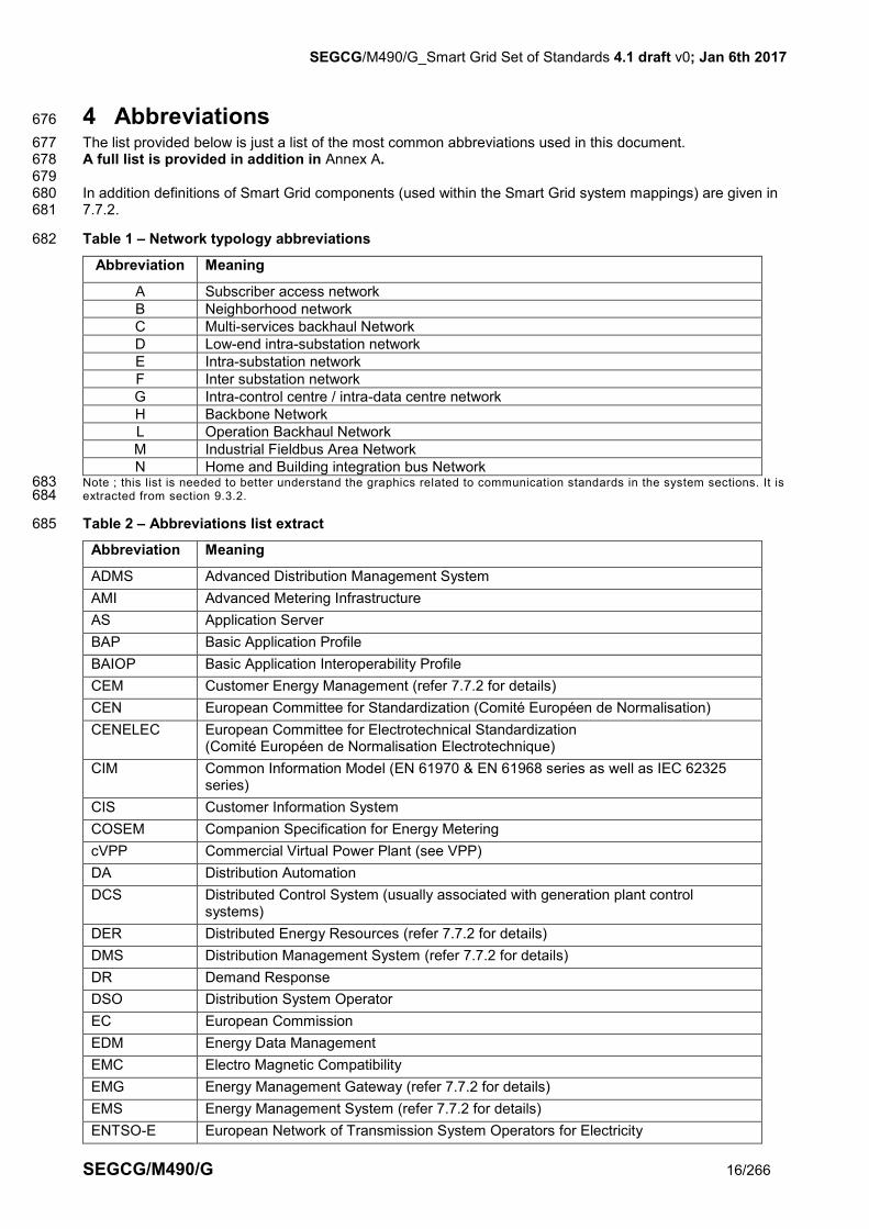
4 Abbreviations 676
The list provided below is just a list of the most common abbreviations used in this document. 677 A full list is provided in addition in Annex A. 678 679 In addition definitions of Smart Grid components (used within the Smart Grid system mappings) are given in 680 7.7.2. 681
Table 1 – Network typology abbreviations 682
Abbreviation Meaning
A Subscriber access network
B Neighborhood network
C Multi-services backhaul Network
D Low-end intra-substation network
E Intra-substation network
F Inter substation network
G Intra-control centre / intra-data centre network
H Backbone Network
L Operation Backhaul Network
M Industrial Fieldbus Area Network
N Home and Building integration bus Network Note ; this list is needed to better understand the graphics related to communication standards in the system sections. It is 683 extracted from section 9.3.2. 684
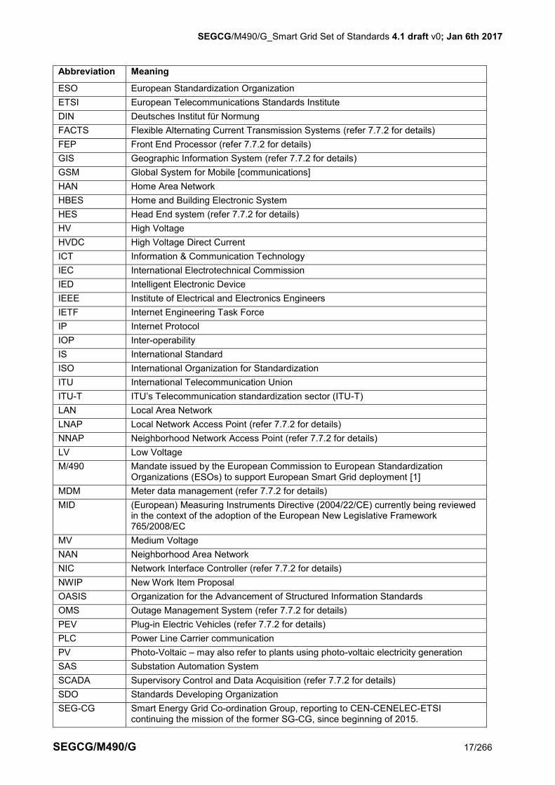
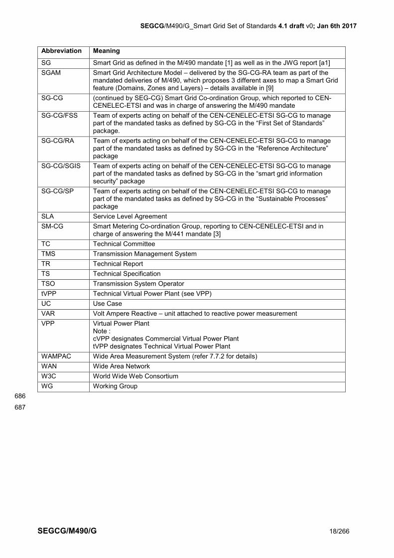
Table 2 – Abbreviations list extract 685
Abbreviation Meaning
ADMS Advanced Distribution Management System
AMI Advanced Metering Infrastructure
AS Application Server
BAP Basic Application Profile
BAIOP Basic Application Interoperability Profile
CEM Customer Energy Management (refer 7.7.2 for details)
CEN European Committee for Standardization (Comité Européen de Normalisation)
CENELEC European Committee for Electrotechnical Standardization (Comité Européen de Normalisation Electrotechnique)
CIM Common Information Model (EN 61970 & EN 61968 series as well as IEC 62325 series)
CIS Customer Information System
COSEM Companion Specification for Energy Metering
cVPP Commercial Virtual Power Plant (see VPP)
DA Distribution Automation
DCS Distributed Control System (usually associated with generation plant control systems)
DER Distributed Energy Resources (refer 7.7.2 for details)
DMS Distribution Management System (refer 7.7.2 for details)
DR Demand Response
DSO Distribution System Operator
EC European Commission
EDM Energy Data Management
EMC Electro Magnetic Compatibility
EMG Energy Management Gateway (refer 7.7.2 for details)
EMS Energy Management System (refer 7.7.2 for details)
ENTSO-E European Network of Transmission System Operators for Electricity
SEGCG/M490/G_Smart Grid Set of Standards 4.1 draft v0; Jan 6th 2017
SEGCG/M490/G 17/266
Abbreviation Meaning
ESO European Standardization Organization
ETSI European Telecommunications Standards Institute
DIN Deutsches Institut für Normung
FACTS Flexible Alternating Current Transmission Systems (refer 7.7.2 for details)
FEP Front End Processor (refer 7.7.2 for details)
GIS Geographic Information System (refer 7.7.2 for details)
GSM Global System for Mobile [communications]
HAN Home Area Network
HBES Home and Building Electronic System
HES Head End system (refer 7.7.2 for details)
HV High Voltage
HVDC High Voltage Direct Current
ICT Information & Communication Technology
IEC International Electrotechnical Commission
IED Intelligent Electronic Device
IEEE Institute of Electrical and Electronics Engineers
IETF Internet Engineering Task Force
IP Internet Protocol
IOP Inter-operability
IS International Standard
ISO International Organization for Standardization
ITU International Telecommunication Union
ITU-T ITU’s Telecommunication standardization sector (ITU-T)
LAN Local Area Network
LNAP Local Network Access Point (refer 7.7.2 for details)
NNAP Neighborhood Network Access Point (refer 7.7.2 for details)
LV Low Voltage
M/490 Mandate issued by the European Commission to European Standardization Organizations (ESOs) to support European Smart Grid deployment [1]
MDM Meter data management (refer 7.7.2 for details)
MID (European) Measuring Instruments Directive (2004/22/CE) currently being reviewed in the context of the adoption of the European New Legislative Framework 765/2008/EC
MV Medium Voltage
NAN Neighborhood Area Network
NIC Network Interface Controller (refer 7.7.2 for details)
NWIP New Work Item Proposal
OASIS Organization for the Advancement of Structured Information Standards
OMS Outage Management System (refer 7.7.2 for details)
PEV Plug-in Electric Vehicles (refer 7.7.2 for details)
PLC Power Line Carrier communication
PV Photo-Voltaic – may also refer to plants using photo-voltaic electricity generation
SAS Substation Automation System
SCADA Supervisory Control and Data Acquisition (refer 7.7.2 for details)
SDO Standards Developing Organization
SEG-CG Smart Energy Grid Co-ordination Group, reporting to CEN-CENELEC-ETSI continuing the mission of the former SG-CG, since beginning of 2015.
SEGCG/M490/G_Smart Grid Set of Standards 4.1 draft v0; Jan 6th 2017
SEGCG/M490/G 18/266
Abbreviation Meaning
SG Smart Grid as defined in the M/490 mandate [1] as well as in the JWG report [a1]
SGAM Smart Grid Architecture Model – delivered by the SG-CG-RA team as part of the mandated deliveries of M/490, which proposes 3 different axes to map a Smart Grid feature (Domains, Zones and Layers) – details available in [9]
SG-CG (continued by SEG-CG) Smart Grid Co-ordination Group, which reported to CEN-CENELEC-ETSI and was in charge of answering the M/490 mandate
SG-CG/FSS Team of experts acting on behalf of the CEN-CENELEC-ETSI SG-CG to manage part of the mandated tasks as defined by SG-CG in the “First Set of Standards” package.
SG-CG/RA Team of experts acting on behalf of the CEN-CENELEC-ETSI SG-CG to manage part of the mandated tasks as defined by SG-CG in the “Reference Architecture” package
SG-CG/SGIS Team of experts acting on behalf of the CEN-CENELEC-ETSI SG-CG to manage part of the mandated tasks as defined by SG-CG in the “smart grid information security” package
SG-CG/SP Team of experts acting on behalf of the CEN-CENELEC-ETSI SG-CG to manage part of the mandated tasks as defined by SG-CG in the “Sustainable Processes” package
SLA Service Level Agreement
SM-CG Smart Metering Co-ordination Group, reporting to CEN-CENELEC-ETSI and in charge of answering the M/441 mandate [3]
TC Technical Committee
TMS Transmission Management System
TR Technical Report
TS Technical Specification
TSO Transmission System Operator
tVPP Technical Virtual Power Plant (see VPP)
UC Use Case
VAR Volt Ampere Reactive – unit attached to reactive power measurement
VPP Virtual Power Plant Note : cVPP designates Commercial Virtual Power Plant tVPP designates Technical Virtual Power Plant
WAMPAC Wide Area Measurement System (refer 7.7.2 for details)
WAN Wide Area Network
W3C World Wide Web Consortium
WG Working Group
686
687
SEGCG/M490/G_Smart Grid Set of Standards 4.1 draft v0; Jan 6th 2017
SEGCG/M490/G 19/266
5 Executive Summary 688
689
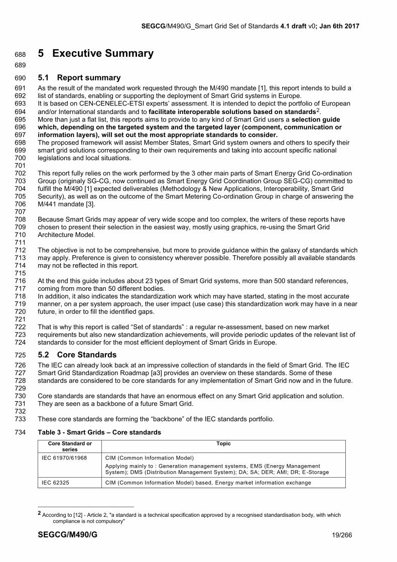
5.1 Report summary 690
As the result of the mandated work requested through the M/490 mandate [1], this report intends to build a 691 list of standards, enabling or supporting the deployment of Smart Grid systems in Europe. 692 It is based on CEN-CENELEC-ETSI experts’ assessment. It is intended to depict the portfolio of European 693
and/or International standards and to facilitate interoperable solutions based on standards2. 694 More than just a flat list, this reports aims to provide to any kind of Smart Grid users a selection guide 695 which, depending on the targeted system and the targeted layer (component, communication or 696 information layers), will set out the most appropriate standards to consider. 697 The proposed framework will assist Member States, Smart Grid system owners and others to specify their 698 smart grid solutions corresponding to their own requirements and taking into account specific national 699 legislations and local situations. 700 701 This report fully relies on the work performed by the 3 other main parts of Smart Energy Grid Co-ordination 702 Group (originaly SG-CG, now continued as Smart Energy Grid Coordination Group SEG-CG) committed to 703 fulfill the M/490 [1] expected deliverables (Methodology & New Applications, Interoperability, Smart Grid 704 Security), as well as on the outcome of the Smart Metering Co-ordination Group in charge of answering the 705 M/441 mandate [3]. 706 707 Because Smart Grids may appear of very wide scope and too complex, the writers of these reports have 708 chosen to present their selection in the easiest way, mostly using graphics, re-using the Smart Grid 709 Architecture Model. 710 711 The objective is not to be comprehensive, but more to provide guidance within the galaxy of standards which 712 may apply. Preference is given to consistency wherever possible. Therefore possibly all available standards 713 may not be reflected in this report. 714 715 At the end this guide includes about 23 types of Smart Grid systems, more than 500 standard references, 716 coming from more than 50 different bodies. 717 In addition, it also indicates the standardization work which may have started, stating in the most accurate 718 manner, on a per system approach, the user impact (use case) this standardization work may have in a near 719 future, in order to fill the identified gaps. 720 721 That is why this report is called “Set of standards” : a regular re-assessment, based on new market 722 requirements but also new standardization achievements, will provide periodic updates of the relevant list of 723 standards to consider for the most efficient deployment of Smart Grids in Europe. 724
5.2 Core Standards 725
The IEC can already look back at an impressive collection of standards in the field of Smart Grid. The IEC 726 Smart Grid Standardization Roadmap [a3] provides an overview on these standards. Some of these 727 standards are considered to be core standards for any implementation of Smart Grid now and in the future. 728 729 Core standards are standards that have an enormous effect on any Smart Grid application and solution. 730 They are seen as a backbone of a future Smart Grid. 731 732 These core standards are forming the “backbone” of the IEC standards portfolio. 733
Table 3 - Smart Grids – Core standards 734
Core Standard or series
Topic
IEC 61970/61968 CIM (Common Information Model)
Applying mainly to : Generation management systems, EMS (Energy Management System); DMS (Distribution Management System); DA; SA; DER; AMI; DR; E -Storage
IEC 62325 CIM (Common Information Model) based, Energy market information exchange
2 According to [12] - Article 2, "a standard is a technical specification approved by a recognised standardisation body, with which
compliance is not compulsory"
SEGCG/M490/G_Smart Grid Set of Standards 4.1 draft v0; Jan 6th 2017
SEGCG/M490/G 20/266
Applying mainly to : Generation management systems, EMS (Energy Management System); DMS (Distribution Management System); DER; AMI; DR; meter-related back-office systems; E-Storage
IEC 61850 Power Utility Automation, Hydro Energy Communication, Distributed Energy Resources Communication
Applying mainly to : Generation management systems, EMS; DMS; DA; SA; DER E-Storage; E-mobility
IEC 62056 COSEM
Applying mainly to : DMS; DER; AMI; DR; Smart Home; E-Storage; E-mobility
Data exchange for meter reading, tariff and load control
IEC 62351 Applying mainly to : Security for all systems
IEC 61508 Applying mainly to : Functional safety of electrical/electronic/programmable electronic safety-related systems
5.3 Other highly important standards 735
Besides the core standards, IEC also offers a number of highly important standards for Smart Grid. 736
Table 4 - Smart Grids – Other highly important standards 737
Standard or series Topic
IEC 62357 Power utilities Reference Architecture – SOA
Applying mainly to : Energy Management Systems; Distribution Management Systems; DER operation systems, market & trading systems, DR systems, meter-related back-office systems
IEC 60870-5 Telecontrol
Applying mainly to : EMS; DMS; DA; SA
IEC 60870-6 TASE2 Inter Control Center Communication
Applying mainly to : EMS; DMS
IEC/TR 61334 “DLMS” Distribution Line Message Specification
Applying mainly to : AMI
IEC 61400-25 Wind Power Communication
Applying mainly to : DER operation systems (Wind farms); EMS; DMS;
IEC 61851 EV-Communication
Applying mainly to : E-mobility; Home&Building management systems;
IEC 62051-54/58-59 Metering Standards Applying mainly to : DMS; DER; AMI; DR; Smart Home; E-Storage; E-mobility
738
6 Objectives, rules and expected usage of this report 739
Note : Sub sections 6.1 and 6.2 are mostly replicating the content of [6], previously validated in July 2012 by SG-CG 740 stakeholders. 741
6.1 Limits of scope and usage 742
743 Here are some limits the reader of this report should be aware of: 744 745
The list of Generic Use Cases (UCs) per sub-system cannot be exhaustive. 746
The standards listed in this report represent a selection according to the rules set in section 6.2.1 and 747 6.2.2. The list is not comprehensive. 748
Detailed “application notes” for the standards are not in the scope of this document. 749
The generic Ucs are limited to “typical” applications. Customer specific applications are not considered. 750
Proprietary or non-standardized solutions covering the generic UCs are not considered in this report. 751
This report represents the current status of the available standards (considering their “maturity” level 752 indicated in 6.2.2). Standards gaps are identified [7], and standardization activities to fix the gaps are 753 listed, ranked and monitored in [8]. 754
Standardization projects which do not fulfill the maturity-time constraints defined in section 6.2.2 are not 755 part of this report. 756
SEGCG/M490/G_Smart Grid Set of Standards 4.1 draft v0; Jan 6th 2017
SEGCG/M490/G 21/266
6.2 How to select standards? 757
All standards identified in this report have been selected applying the rules defined in this section, and 758 presented below. 759
These rules are also compliant with the Regulation on EU standardization [12]3. 760
6.2.1 Standardization body ranking 761
In order to identify a standard fulfilling a defined set of requirements, the following procedure has been 762 adopted: 763
1. Standards from the European Organizations, CEN, CENELEC or ETSI, are identified and available, 764 2. where no standards were available from 1, then ISO, IEC or ITU standards are considered 765 3. If no standards from either 1 or 2 were available to support a particular set of requirements, then 766
“open specification“(see criteria below) can be considered. 767
768
“Open specifications” that are considered applicable from a CEN CENELEC ETSI point of view, are 769 complying with the following criteria, in compliance with the EU regulation [12] as defined for ICT technical 770
specifications4: 771 1. the specification is developed and/or approved, and maintained by a collaborative consensus-based 772
process; 773 2. such process is transparent; 774 3. materially affected and interested parties are not excluded from such process; 775 4. the specification is subject to RAND/FRAND Intellectual Property Right (IPR) policies in accordance 776
with the “EU Competition rules”, 777 5. the specification is published and made available to the general public under reasonable terms 778
(including for reasonable fee or for free). 779 Note : considering the purpose of this report, i.e a selection guide, technical reports are also considered in the list of 780 applicable smart grid standards, as soon as they followed a neutral review and voting process, by the bodies listed above. 781
6.2.2 Maturity level 782
Two maturity levels of the standards are considered: 783
A standard that has reached its final stage (IS, TS or TR, …) by Dec 31st 2015, is identified as 784 “AVAILABLE” 785
A standard that has successfully passed the NWIP process (or any formal equivalent work item adoption 786 process) before Dec 31st 2015, is identified as “COMING” 787
Further sets of standards (including newly developed ones) should be available in due course. 788 789 Note: 790
"COMING" standards listed are presented with a brief summary of their scope. 791
The same standard reference may appear in both AVAILABLE and COMING tables, when a release of this 792 standard is available as such (fitting the rules defined above for AVAILABLE standards) , but a new revision is in 793 preparation (fitting the rules defined above for COMING standards) . 794
6.2.3 Release management 795
Should several releases of a standard exist then – if not explicitly stated differently – the latest release is 796 considered in this report. 797
3 Chapter IV of Regulation [12] on “ICT technical specifications”,article13 says that: “Either on proposal from a Member State or on its own initiative the Commission may decide to identify ICT technical specifications that
are not nationals, European or international standards, but meet the requirements set out in Annex II, which may be referred, primary to enable interoperability, in public procurement.
Either on proposal from a Member State or on its own initiative, when an ICT technical specified in accordance with paragraph 1 is modified, withdrawn, or no longer meet the requirements set out in Annex II, the Commission may decide to identify the modified ICT technical specification or to withdraw the identification.
The decisions provide for in paragraphs 1 and 2 shall be adopted after consultation of the European multi-stakeholder platform on ICT standardization, which includes ESOs, Member States and relevant stakeholders, and after the consultation of the committee set up by the corresponding Union legislation, if it exists, or after other forms of consultation of sector experts, if such a committee does not exist”.
The ICT technical specifications referred to in article 13 of this Regulation shall constitute common technical specifications referred to in Directives 2004/17/EC, 2004/18/EC, 2009/81/EC and Regulation 2342/2002”.
4 Article 14 of the Regulation [12] says: “Annex II prescribes the criteria required in article 13.1: market acceptance; not conflict with European Standards; developed by a non-
profit organization; openness; consensus based; transparency; meeting FRAND criteria on licensing; relevance; neutrality, stability and quality.

SEGCG/M490/G_Smart Grid Set of Standards 4.1 draft v0; Jan 6th 2017
SEGCG/M490/G 22/266
6.2.4 Standards naming convention 798
It appears that standard naming conventions may differ from one body to another. For the sake of harmony 799 within this report we propose the here-under rules : 800 801 CEN-CENELEC standards, specifications and reports will be named : 802
EN xxxxx for CEN-CENELEC European Standards number xxxxx 803
TS xxxxx for CEN-CENELEC European technical specification number xxxxx 804
TR xxxxx for CEN-CENELEC European technical report number xxxxx 805
prEN xxxxx for draft CEN-CENELEC European Standards number xxxxx 806
prTS xxxxx for draft CEN-CENELEC European technical specification number xxxxx 807
prTR xxxxx for draft CEN-CENELEC European technical report number xxxxx 808 809 For all other bodies, and to avoid possible conflicts with the above, the rule will be to name standard this 810 way: 811
the name of the concerned body (typically ETSI, IEC, ITU, …) 812
a unique identifier within this body 813
6.3 Process for "List of Standards" update 814
The mandate [1] originally requested the ESOs to anticipate the expected long term duration of Smart Grid 815 deployment. This therefore suggests the ESOs should set up a framework that is: 816
Comprehensive and integrated enough to embrace the whole variety of Smart Grid actors and ensure 817 communications between them. 818
In-depth enough to guarantee interoperability of Smart Grids from basic connectivity to complex 819 distributed business applications, including a unified set of definitions so that all Member States have a 820 common understanding of the various components of the Smart Grid. 821
Flexible and fast enough to take advantage of the existing telecommunications infrastructure and 822 services as well as the emergence of new technologies while enhancing competitiveness of the markets. 823
Flexible enough to accommodate some differences between EU Member State approaches to Smart 824 Grids deployment. 825
Then the current document is the new release of the original “first set of standards” and proposes an updated 826 framework of standards which can support Smart Grids deployment in Europe. 827 This update tries also to state in the clearest way what is available and what is coming (based on the known 828 standardization work and the triggers defined above). 829 830 The current report may be further updated. 831
6.4 Mapping chart (use of) 832
6.4.1 Motivation 833
The IEC currently provides the large majority of all standards needed to build the smart grid, with new 834 standards being brought into the portfolio on an ongoing basis. The IEC is bringing relevant national or 835 regional standards via a fast track system into the international consensus process. The increased dynamic 836 in the field of standardization creates the demand for a better transparency in the work of IEC to give a better 837 overview which standards are already available and suitable for smart grid and how they can be applied. 838 This will speed up the implementation of smart grid and avoid waste of resources due to double work. 839 “The smart grid represents a technical challenge beyond building infrastructure, and can’t reach its potential 840 if every country and company is building it based on different standards,” said Jacques Régis, the former IEC 841 President. “Our international set of standards ensures the smart grid industry can grow and function as one 842 coordinated entity, relying on optimal compatibility and the ability of one system or device to communicate 843 with others.” 844 845 To satisfy this demand for better transparency IEC Strategic Group 3 on Smart Grid (now transferred to IEC 846 System Committee Smart Energy SYC1) creates the idea of the so called “Mapping Tool”. This 847 multidimensional interactive tool creates a map of the smart grid and enable smart grid managers around the 848 world to quickly identify IEC and other international smart grid standards, positions them in relation to 849 technical components and systems in the smart grid, and verifies the feasibility of workflows and use cases 850 (see also chapter 1.4.2.1.2). The Mapping Tool is an open resource and helps reducing the complexity of 851 building smart grids by simplifying the identification and application of smart grid standards. 852 853 This mapping chart is freely available following the here-under link: 854
SEGCG/M490/G_Smart Grid Set of Standards 4.1 draft v0; Jan 6th 2017
SEGCG/M490/G 23/266
http://smartgridstandardsmap.com/ 855 856 The IEC Smart Grid Standard Mapping Chart will help smart grid project managers to easily identify the 857 standards they need in their smart grid. Currently, this process must be done manually, often by reading 858 through thousands of pages of standard documents , leading to non-reproducible results with the danger of 859 creating more problems than are solved The chart will be constantly updated, new use cases and standards 860 will be continuously fed into the open source database. It will allow users to search by pointing to areas or 861 links between elements of the electric system. 862
6.4.2 Chart content 863
The mapping chart gives a visualization of the generic Smart Grid landscape covering all areas from 864 generation to consumption (horizontal axis) and from the process equipment up to market applications 865 (vertical axis). Its presentation structure is aligned with the SGAM plane. 866 867 The typical components (devices, applications, etc.) of the Smart Grid are visualized as boxes which are 868 clustered according to their organizational or topological togetherness. E.g. the components of a substation 869 can be found in the Generic substation cluster or the components typically used for grid operation are 870 clustered und “Electric System Operation”. 871 872 Components within one cluster typically have a direct data connection, utilizing some kind of Local Area 873 Network marked as “Integration Bus” in the chart. The external communication links of clusters are 874 symbolized by a small cloud icon, while the color of this icon shows the type of external communication 875 network. For the network connections it is distinguished between for types, the backbone network, the 876 backhaul network, the access network and the home automation network. Typically the components are not 877 directly connected to a network but utilize a router or network interface controller (NIC) to bridge from the 878 local network segment to a wide area connection. 879 880 Moving the mouse cursor over a component it will open a pop up showing all Standards identified as relevant 881 for the component. All components involved in at least one use case have a small yellow bubble in their 882 lower left corner. Moving the mouse cursor over this bubble will open a pop up showing all use cases which 883 are affiliated with the component. 884 A filtering function permits components or standards to be shown according to defined groups or SDOs. 885

SEGCG/M490/G_Smart Grid Set of Standards 4.1 draft v0; Jan 6th 2017
SEGCG/M490/G 24/266
886
Figure 1 - Smart Grid mapping chart 887

SEGCG/M490/G_Smart Grid Set of Standards; 4.1 draft v0; Jan 6th 2017
SEGCG/M490/G 25/266
6.5 Towards seamless interoperability 888
6.5.1 What does interoperability mean? 889
A smart grid consists of numerous components provided by different actors, working together to provide a 890 smart power system. For such a system to operate and the desired services and functionalities to be 891 provided in a sustainable way, interoperability of components, systems and attached processes to 892 demonstrate such interoperability become of major importance. Interoperability shall be envisaged between 893 two or more components of the same system, or between systems. 894 It means (derived from GridWise Architecture Council (GWAC) work [a2]): 895
exchange of meaningful information 896
a shared understanding of the exchanged information, 897
a consistent behavior complying with system rules, and 898
a requisite quality of service: reliability, time performance, privacy, and security. 899
Many levels of interoperability can be considered, but in all cases smart grids require interoperability at the 900 highest level, i.e. at information semantic level. 901 The “Set of standards” is a path towards seamless interoperability. 902 903 However, further standardization steps shall be considered to reach the ultimate goal, such as 904
ensure an accurate definition of the semantic of any exchanged information, with no risk of ambiguity, 905
define the behavior of the object which implements the standard (state machine), consistently with the 906 system behavior, 907
define profiles which would restrict the options offered by the standards, in order to ensure a minimum 908 set of functionalities, to support a predefined set of Use cases 909
include a conformance statement, to check the implementation of the standard against the standard 910 specification and 911
offer profile testing means and procedures. 912
The absence of answers to the above expectations mostly means additional complexity for setting up and 913 maintaining Smart Grids systems. 914
The Smart Grid as a system cannot be engineered from the ground up. Instead, Smart Grid development is 915 most likely to follow a transformation process. This means that business models and market roles on the one 916 hand, and technical components and architectural structures on the other hand, are to be transformed from 917 the current “legacy” state into the “Smart Grid”. Due to the scale of the system and its economic importance, 918 failures in operation and especially architectural and functional planning of the system, potentially induce 919 high costs. In order to enable a well-structured migration process, the requirements for the Smart Grid and 920 the current system have to be decomposed using an appropriate model. Although the majority of Smart Grid 921 equipment is based on (inter)national standards, this has not resulted in an interoperable Smart Grid 922 infrastructure yet. This is partly due to misunderstanding of what interoperability means, what can be 923 expected from it and what should be done to realize it. 924 925 As more and more ICT components are being connected to the physical electrical infrastructure, 926 interoperability is a key requirement for a robust, reliable and secure Smart Grid infrastructure. Key to 927 reaching Smart Grid system interoperability is through detailed specification of use cases, selection of 928 applicable standards and technical specifications, profiling and testing. Nevertheless, it is also important that 929 interoperability will be maintained over the complete system life cycle. 930 931
6.5.2 Summary of the IOP Methodology of SEG-CG WG Interoperability 932
Developing an understanding of and paving the way for progress in this area has been the focus of the 933 Working Group Interoperability (WGI). In essence, their report [15], which is summarised in this section, 934 provides methodologies related to these aspects, in order to reach the desired level of interoperability. The 935 methodology introduced essentially describes how these aspects will contribute towards achieving 936

SEGCG/M490/G_Smart Grid Set of Standards; 4.1 draft v0; Jan 6th 2017
SEGCG/M490/G 26/266
interoperability, with a focus on Smart Grids (incl. smart metering) and is generic in that it can be applied to 937 all kind of Smart Grid standards. It seeks to achieve this by focusing on five different aspects and therefore 938 associated tasks as described below in Figure 2: 939 940
941
Figure 2 Interoperability process 942
943
Functional analysis and creation/selection of use case 944 945 Interoperability normally starts with defining the functionality of information exchange - in other words: what 946 data will be exchanged and how. Use cases describe the information exchange in terms of the interactions 947 between actors and components of the smart grid system. 948 949 The interfaces between different components in the smart grid infrastructure can therefore be identified and 950 the layer(s) on which interoperability is required (functional, information, communication and component). 951 952 With respect to system design, the IT Software/System Development Life Cycle provides a widely used 953 methodology for system development, which ensures to deliver high quality software or system effectively 954 and efficiently. Use cases provide a basis for the specification of functional requirements, non-functional 955 requirements, test cases and test profiles. As a starting point, the system interoperability must be considered 956 and well specified in the use cases in order to develop interoperable Smart Grid system by design. It is for 957 this reason that the WGI selected the V-model to describe the different kind of specifications and related 958 tests possible to perform in order to reach and demonstrate interoperability. 959 960
Selection of standards and specifications 961 962 Once the relevant use cases are defined, appropriate standards and technical specifications for the considered 963 interoperability layers can be selected. 964 965 The selection of appropriate standards for any layers and individual interfaces is supported by this report and 966 the “IOP Tool” of the WGI [15]. 967 968
Profiling 969 970

SEGCG/M490/G_Smart Grid Set of Standards; 4.1 draft v0; Jan 6th 2017
SEGCG/M490/G 27/266
A profile describes how standards or specifications are deployed to support the requirements of a particular 971 application or function. This means that on top of the selection of e.g. communication standards such as IEC 972 61850, an additional specification has to be developed which describes the way a standard will be used, and 973 fixes the options. These additional definitions are called BAPs (Basic Application Profiles). BAPs shall 974 identify relevant parts of the applicable standards and specifications and are intended to be used as building 975 blocks for interoperable specifications, e.g. by specifying the requirements according to the different layers. 976 977 The definition of a BAP is an important step in achieving interoperability as it reduces the number of options 978 and complexity of the full standard(s) referring to. Interoperability in the Smart Grid domain is further 979 facilitated by usage of the SGAM model for Smart Grid systems. The WGI report sets out to define the 980 various terms related to interoperability, such as conformity, compatibility and interchangeability. It then 981 defines the various types of standards that exist. 982 983
Testing 984 985 In order to prove interoperability a BAP has to be extended to describe a testing process. Testing is one of the 986 most important phases in reaching interoperability. A BAP Test Specification named BAIOP (Basic Application 987 Interoperability Profile) specifies the detailed setup to test the individual technical requirements of a BAP. 988 989 Although many types of tests exist, the two main types of testing to demonstrate interoperability are 990 conformance testing and interoperability testing. 991 992 Conformance testing verifies the correct implementation of the standards and technical specifications: the 993 system/component concerned is tested against a test tool or reference implementation of the standard. The 994 test also verifies what part of the standard is implemented if it is not a full scope implementation. Conformance 995 testing is a prerequisite for interoperability testing, which means after the conformance test, the 996 system/component will be interconnected with other systems in the Smart Grid and interoperability test will be 997 performed to ensure that functionalities over the system boundaries are working correctly. 998 999 Interoperability testing is performed to verify that components within a system are interoperable, i.e. they are 1000 able to exchange information according to the final defined functionalities (use cases). During interoperability 1001 testing, components are tested in their final configuration together with other components of the total 1002 architecture known to be correct (according to a BAIOP). This is necessary because it is possible for two 1003 components that individually comply with a standard (resulting is a positive conformance test) to be still unable 1004 to interoperate, for example when components have implemented different or conflicting options or cover a 1005 different part of the standard(s). The interoperability test is therefore based on the BAP that describes the way 1006 the standards are used. 1007 1008 Therefore, the task of developing a “Conformance testing map” undertaken by WGI represented a more 1009 detailed exploration of the item ‘Conformance testing’ and ‘interoperability testing’ in the Interoperability 1010 methodology. 1011 1012
Maintaining interoperability 1013 1014 It should be recognised that use cases, components, systems and standards will evolve over time, and that a 1015 management process for companion documents and profiles should be put in place to ensure that the 1016 required levels of interoperability are maintained. 1017 1018 Therefore the general WGI recommendation is that user groups should take ownership of creating and 1019 managing profiles, which includes the responsibility of maintaining interoperability over the lifetime of 1020 associated components and systems. 1021
6.5.3 Linkages to the work undertaken by SEG-CG WG Methodology and SGTF EG1 1022
1023 It is important to recognise that how and where the methodologies described in this document are applied, 1024 depends on the business needs. Therefore, in essence, the WGI report is describing the methodology how to 1025 improve interoperability and how to deploy these methodologies under leadership of user groups for specific 1026 smart grid applications. 1027 1028
SEGCG/M490/G_Smart Grid Set of Standards; 4.1 draft v0; Jan 6th 2017
SEGCG/M490/G 28/266
However, it is important to pin-point to key relationship between the output of the WG Methodology and WG 1029 Interoperability, particularly in the area of use case development and usage. In essence the degree and 1030 precision to which the methodology discussed in this particular report is executed has a direct bearing on the 1031 quality, accuracy and usefulness of the output of the WGI methodology. Put simply, in order for IOP 1032 methodology to be fully utilised a clearly articulated use case, following IEC 62559 template, is required 1033 coupled with the graphical representation on the SGAM as illustrated by the WG-SS. Conversely, if no use 1034 case is currently defined, but interoperability is required by a key stakeholder community, then the use case 1035 needs to be established using the methodology and tool kit described in section 7 of this report. Once this 1036 has been achieved, the IOP Methodology can then be followed. 1037 1038 Another practical implementation of the WGI methodology supporting the rollout of smart metering systems in 1039 Europe has been promoted mid 2016 by the Smart Grid Task Force (SGTF) EG1 in their repor t[16], focusing 1040 on the interfaces in and with the metering infrastructure from the Head End System to the Smart Meter and on 1041 the provision of interoperability profiles for the interfaces H1 and H2 according to CLC TR 50572, required for 1042 the provision of energy services and Demand Side Flexibility (DSF). These interfaces incl. applicable standards 1043 are also described in this report in section 8.5. 1044
6.5.4 From Standards to Interoperability and Test Profiles 1045
1046 As is explained in their report [15], WGI observes that in general, profiling within a standard and between 1047 standards and specification helps to both improve interoperability and meet expectations of different projects 1048 where these will be implemented. To reach the goal of interoperability a common understanding and 1049 interpretation of the related standard and the identical use of functional elements and data representation for 1050 a given domain specific application function has to be achieved by defining profiles. 1051 1052 As defined in the glossary an IOP profile is a document that describes how standards or specifications are 1053 deployed to support the requirements of a particular application, function, community, or context, a profile 1054 defines a subset of an entity (e.g. standard, model, rules). It may contain a selection of Data models and 1055 Services. Furthermore a profile may define Instances (e.g. specific device types) and Procedures (e.g. 1056 programmable logics, message sequences). 1057 1058 The objective of profiles is to reduce complexity, clarify vague or ambiguous specifications and so aims to 1059 improve interoperability. These do generally apply for both sides of the V-Model in terms of Basic Application 1060 Profiles (BAP) for the design phase and as extended BAP test specifications (BAIOP) in the testing phase. 1061 1062
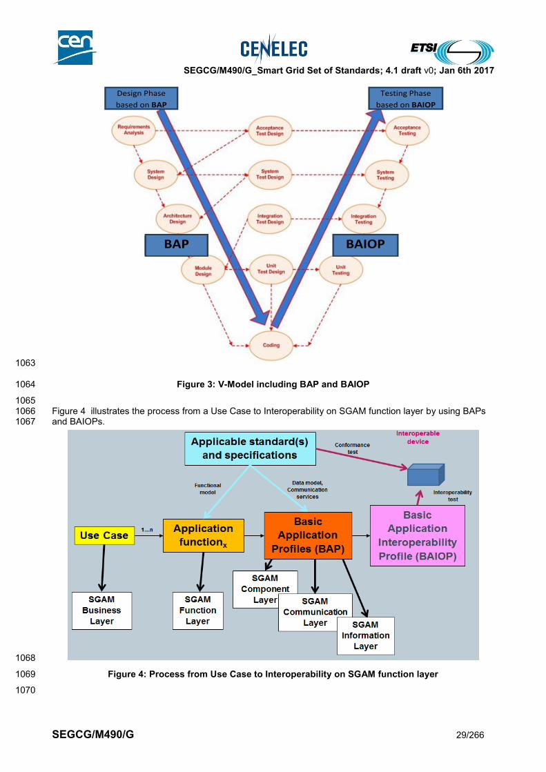
SEGCG/M490/G_Smart Grid Set of Standards; 4.1 draft v0; Jan 6th 2017
SEGCG/M490/G 29/266
1063
Figure 3: V-Model including BAP and BAIOP 1064
1065 Figure 4 illustrates the process from a Use Case to Interoperability on SGAM function layer by using BAPs 1066 and BAIOPs. 1067
1068
Figure 4: Process from Use Case to Interoperability on SGAM function layer 1069
1070
Design Phase
based on BAP
Testing Phase
based on BAIOP
BAP BAIOP
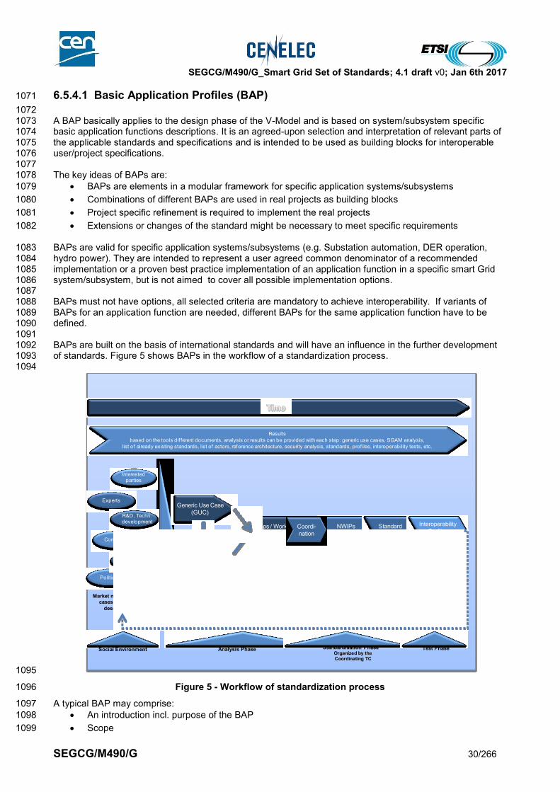
SEGCG/M490/G_Smart Grid Set of Standards; 4.1 draft v0; Jan 6th 2017
SEGCG/M490/G 30/266
6.5.4.1 Basic Application Profiles (BAP) 1071
1072 A BAP basically applies to the design phase of the V-Model and is based on system/subsystem specific 1073 basic application functions descriptions. It is an agreed-upon selection and interpretation of relevant parts of 1074 the applicable standards and specifications and is intended to be used as building blocks for interoperable 1075 user/project specifications. 1076 1077 The key ideas of BAPs are: 1078
BAPs are elements in a modular framework for specific application systems/subsystems 1079
Combinations of different BAPs are used in real projects as building blocks 1080
Project specific refinement is required to implement the real projects 1081
Extensions or changes of the standard might be necessary to meet specific requirements 1082
BAPs are valid for specific application systems/subsystems (e.g. Substation automation, DER operation, 1083 hydro power). They are intended to represent a user agreed common denominator of a recommended 1084 implementation or a proven best practice implementation of an application function in a specific smart Grid 1085 system/subsystem, but is not aimed to cover all possible implementation options. 1086 1087 BAPs must not have options, all selected criteria are mandatory to achieve interoperability. If variants of 1088 BAPs for an application function are needed, different BAPs for the same application function have to be 1089 defined. 1090 1091 BAPs are built on the basis of international standards and will have an influence in the further development 1092 of standards. Figure 5 shows BAPs in the workflow of a standardization process. 1093 1094
1095
Figure 5 - Workflow of standardization process 1096
A typical BAP may comprise: 1097
An introduction incl. purpose of the BAP 1098
Scope 1099
NWIPs
Maintenance
Standard
develop.
Organized by the Coordinating TC
Generic Use Case
(GUC)
Smart Grid
Architecture ModelSGAM
Gaps / Work
Program
Interoperability
Profiles(BAP, BAIOP)
Analysis Phase Standardisation Phase Test PhaseSocial Environment
Politics
NGO
Interested parties
Experts
Companies
R&D, Techn. development
Market needs, Business cases, conceptual
description, …
Time
Results
based on the tools dif ferent documents, analysis or results can be provided with each step: generic use cases, SGAM analysis,
list of already existing standards, list of actors, reference architecture, security analysis, standards, prof iles, interoperability tests, etc.
Tools
Various tools can be used in the dif ferent steps: SGAM, use cases, prioritisation, gap list, work program, etc.
Coordi-
nation

SEGCG/M490/G_Smart Grid Set of Standards; 4.1 draft v0; Jan 6th 2017
SEGCG/M490/G 31/266
Terms, definitions & abbreviations 1100
Referenced documents, e.g. to other companion documents 1101
System architecture 1102
Use case definitions for different interoperability layers, starting with the functional layer, including 1103
standards and implementation details i.e. 1104
o functional layer incl. 1105
use cases to be covered, which should be described in such detail that the test cases 1106
can be derived from it. 1107
a list of standards used to support the use cases 1108
o information layer 1109
o communication layer 1110
o component layer 1111
Security 1112
BAPs should furthermore be created under consideration of the following general rules: 1113
Only existing standards shall be referenced 1114
A BAP should not contain any conflict to the referenced standards (i.e. a device passing the BAP 1115
testing shall also pass the conformance test of the referenced standard) 1116
A BAP should only contain statements which are testable at the accessible interfaces 1117
Specifications should be precise enough that its implementation can be tested with a unique verdict: 1118
“passed” or “not passed” 1119
Options should be avoided (the options chosen in theses sections must be identified and specified in 1120
detail, but the standard should not be modified). All selected criteria are mandatory to achieve 1121
interoperability 1122
Where available, formal language should be used for the specifications 1123
The sections of the standard used have to be identified - no new options should be introduced into the 1124 standard. 1125
1126 The definition and common use of BAPs should lead to a win-win situation for all stakeholders involved in a 1127 smart Grid project in general, e.g.: 1128
The benefit for utilities and User Associations is the chance to harmonize the various company 1129
specific application function variants to a common denominator / best practice implementation for 1130
each basic application function. This reduces the risk of interoperability problems caused by 1131
products/systems as these may be selected from standardized BAP frameworks and tested 1132
according to BAIOPs. 1133
The benefit for vendors which will use standardized BAP‘s in their products is the reduction of project 1134
specific or utility specific implementation variants of application functions and therefore reduce 1135
product complexity, development costs and parameterization efforts. BAIOPs can be used for 1136
internal tests before the product will be placed on the market. 1137
The benefit for Certification Bodies / Test Labs is the ability to perform interoperability tests based on 1138
BAIOPs and create a new business case. 1139
The benefit for system integrators is that they can specifically select products conformant with BAP’s 1140
and tested according to BAIOPs. This significantly reduces the efforts for integration of subsystems 1141
or devices. 1142
1143
6.5.4.2 Basic Application Interoperability Profile (BAIOP) 1144
1145 To reach interoperability a BAP has to be extended for interoperability testing. The extended BAP is referred 1146 to as BAIOP. For interoperability testing a BAP has to be extended by e.g. 1147
Device configuration 1148
Test configuration with communication infrastructure (topology) 1149

SEGCG/M490/G_Smart Grid Set of Standards; 4.1 draft v0; Jan 6th 2017
SEGCG/M490/G 32/266
BAP related test cases 1150
specific capability descriptions (e.g. PICS, PIXIT, MICS in case of IEC 61850) 1151
Engineering framework for data modeling (instances) and communication infrastructure (topology, 1152
communication service mapping) 1153
A typical BAIOP may comprise: 1154
An introduction incl. purpose of the BAIOP 1155
Scope 1156
Terms, definitions & abbreviations 1157
Referenced documents e.g. to the related BAP and any other companion documents 1158
Description of the test procedure and test architecture (incl. requirements for conformance testing) 1159
List of test cases 1160
o for Test case N 1161
identify section in BAP which is tested 1162
specify purpose of the test 1163
specify pre-conditions for the test 1164
describe the test 1165
specify expected results and requirements for passing the test 1166
Security 1167
Documentation of testing 1168
1169 1170
BAIOPs should be created under consideration of the following general rules: 1171
The verdict of the test must be “passed” or “failed” (i.e. not “passed but …”) 1172
The tests must be reproducible in time (the same device tested several times must result in the 1173 same verdict) 1174
It must be possible to perform the tests without the support of the manufacturer of the device under 1175 test 1176
for Conformance testing 1177 o the test cases should follow the applicable standards/specification (what is specified is 1178
tested; what is not specified is not tested) 1179 o the tests should be as far as possible automated with minimal human interference. 1180
for Interoperability testing: 1181 o the test cases should follow the use cases defined in the BAP 1182 o the tests should be as far as possible automated with minimal human interference 1183
the test cases should be described to such detail that a programmer can write a program performing 1184
these tests. 1185
1186 Further explanation can be found in section 8.5 of the WGI report [15]. 1187

SEGCG/M490/G_Smart Grid Set of Standards; 4.1 draft v0; Jan 6th 2017
SEGCG/M490/G 33/266
7 Main guidelines 1188
7.1 Smart Grid Conceptual Model 1189
(according to [14] - §6.3. More details can be found in [14]) 1190
7.1.1 Smart Grid Conceptual Model principles 1191
During the coming years the power system will undergo fundamental changes. In order to define standards 1192 that support, in a consistent way, this transition, applicable in all European markets, a generic European 1193 conceptual model is required. This European conceptual model is to be regarded as the starting point for all 1194 modeling activities, and for all other models, frameworks and architectures, which are used to arrive at 1195 standards required for smart grids and smart markets. 1196 1197 The conceptual model aims to highlight the key areas of attention – conceptual domains and subdomains – 1198 from the point of view of responsibility. The model consists of four main conceptual domains: Operations, 1199 Grid Users, Markets, and Energy Services. Each of these conceptual domains contains one or more 1200 subdomains which group market roles from the European electricity market. 1201 1202 Its main underpinning is the analysis of market roles and responsibilities from [a6]. While this model is based 1203 on the electricity market structures of the EU member states, their roles and responsibilities are defined in a 1204 clear manner and provide a solid basis; new parties may enter certain markets, responsibilities may be 1205 redistributed, but the fundamental market roles and responsibilities are expected to remain constant. 1206 1207 Operations and Grid Users are conceptual domains that are directly involved in the physical processes of the 1208 power system: electricity generation, transport/distribution and electricity usage. Also, these domains include 1209 (embedded) ICT enabled system actors. The Markets and Energy Services conceptual domains are defined 1210 by market roles and (business and system) actors and their activities in trade of electricity products and 1211 services (markets), and the participation in the processes of trade and system operations representing grid 1212 users (energy services). 1213 1214
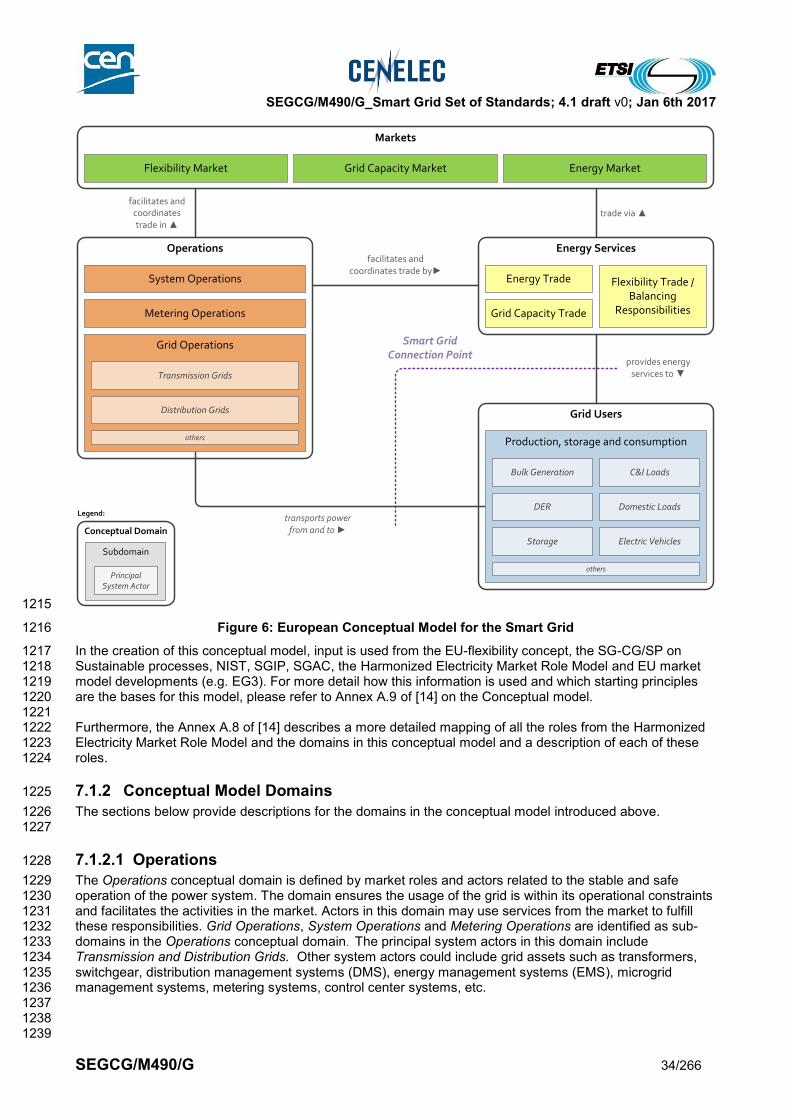
SEGCG/M490/G_Smart Grid Set of Standards; 4.1 draft v0; Jan 6th 2017
SEGCG/M490/G 34/266
1215
Figure 6: European Conceptual Model for the Smart Grid 1216
In the creation of this conceptual model, input is used from the EU-flexibility concept, the SG-CG/SP on 1217 Sustainable processes, NIST, SGIP, SGAC, the Harmonized Electricity Market Role Model and EU market 1218 model developments (e.g. EG3). For more detail how this information is used and which starting principles 1219 are the bases for this model, please refer to Annex A.9 of [14] on the Conceptual model. 1220 1221 Furthermore, the Annex A.8 of [14] describes a more detailed mapping of all the roles from the Harmonized 1222 Electricity Market Role Model and the domains in this conceptual model and a description of each of these 1223 roles. 1224
7.1.2 Conceptual Model Domains 1225
The sections below provide descriptions for the domains in the conceptual model introduced above. 1226 1227
7.1.2.1 Operations 1228
The Operations conceptual domain is defined by market roles and actors related to the stable and safe 1229 operation of the power system. The domain ensures the usage of the grid is within its operational constraints 1230 and facilitates the activities in the market. Actors in this domain may use services from the market to fulfill 1231 these responsibilities. Grid Operations, System Operations and Metering Operations are identified as sub-1232 domains in the Operations conceptual domain. The principal system actors in this domain include 1233 Transmission and Distribution Grids. Other system actors could include grid assets such as transformers, 1234 switchgear, distribution management systems (DMS), energy management systems (EMS), microgrid 1235 management systems, metering systems, control center systems, etc. 1236 1237 1238 1239
Energy ServicesOperations
Grid Users
Markets
provides energyservices to ▼
facilitates andcoordinates trade in ▲
transports powerfrom and to ►
System Operations
Grid Operations
Metering Operations Grid Capacity Trade
Energy Trade Flexibility Trade / Balancing
Responsibilities
Production, storage and consumption
Transmission Grids
Distribution Grids
others
Bulk Generation C&I Loads
others
DER Domestic Loads
Electric VehiclesStorage
Energy MarketGrid Capacity MarketFlexibility Market
trade via ▲
facilitates andcoordinates trade by►
Smart GridConnection Point
Conceptual Domain
Subdomain
Legend:
Principal System Actor

SEGCG/M490/G_Smart Grid Set of Standards; 4.1 draft v0; Jan 6th 2017
SEGCG/M490/G 35/266
Typical roles in the Operations conceptual domain are: 1240 1241
Subdomain Harmonized role
System Operations System Operator, Control Area Operator, Control Block Operator, Coordination
Center Operator, Imbalance Settlement Responsible, Reconciliation
Responsible
Metering Operations Meter Administrator, Meter Operator, Metering Point Administrator, Metered
Data Aggregator, Metered Data Collector, Metered Data Responsible
Grid Operations Grid Operator, Grid Access Provider
1242
7.1.2.2 Grid Users 1243
The Grid Users conceptual domain is defined by market roles and actors involved in the generation, usage 1244 and possibly storage of electricity; from bulk generation and commercial and industrial loads down to 1245 distributed energy resources, domestic loads, etc. The market roles and actors in this domain use the grid to 1246 transmit and distribute power from generation to the loads. Apart from market roles related to the generation, 1247 load and storage assets, the Grid Users conceptual domain includes system actors such as (customer) 1248 energy management and process control systems. Grid users also provide flexibility, as they become an 1249 active participant of the energy system. 1250 1251 Roles in the Grid Users conceptual domain are: 1252 1253
Subdomain Harmonized role
Production, storage and
consumption
Party Connected to the Grid, Consumer, Producer
1254
7.1.2.3 Energy Services 1255
The Energy Services conceptual domain is defined by market roles and actors involved in providing energy 1256 services to the Grid Users conceptual domain. These services include balancing & trading in the electricity 1257 generated, used or stored by the Grid Users domain, and ensuring that the activities in the Grid Users 1258 domain are coordinated in e.g. the system balancing mechanisms and customer information services (CIS) 1259 systems. 1260 1261 Through the Energy Services conceptual domain the Grid Users conceptual domain is connected to activities 1262 such as trade and system balancing. From the Grid Users domain, flexibility in power supply and demand is 1263 provided. This flexibility is used for system balancing (through e.g. ancillary services, demand response, etc.) 1264 and trading on the market. Also roles are included which are related to trade in grid capacity (as currently is 1265 traded on the transmission level). 1266 1267 The roles and actors from the Energy Services conceptual domain facilitate participation in the electricity 1268 system, by representing the Grid Users conceptual domain in operations (e.g. balance responsibility) and 1269 markets (trading). 1270 1271 Roles in the Energy Services conceptual domain are: 1272 1273
Subdomain Harmonized role
Energy Trade Balance Supplier, Block Energy Trader, Reconciliation Accountable
Grid Capacity Trade Capacity Trader, Interconnection Trade Responsible
Flexibility Trade /
Balancing
Responsibilities
Balance Responsible Party, Consumption Responsible Party, Production
Responsible Party, Trade Responsible Party, Scheduling Coordinator,
Resource Provider
1274

SEGCG/M490/G_Smart Grid Set of Standards; 4.1 draft v0; Jan 6th 2017
SEGCG/M490/G 36/266
7.1.2.4 Markets 1275
The Markets conceptual domain is defined by the market roles and actors that support the trade in electricity 1276 (e.g. on day ahead power exchanges) and other electricity products (e.g. grid capacity, ancillary services). It 1277 is reflecting the market operations possible along the energy conversion chain, e.g. energy trading, 1278 wholesale market, retail market. Sub domains which are identified in this domain are: Energy Market (e.g. 1279 commodity market), Grid Capacity Market (e.g. Transmission capacity market), and Flexibility Market (e.g. 1280 Imbalance market). Activities in the Market domain are coordinated by the Operations domain to ensure the 1281 stable and safe operation of the power system. Examples of (system) actors in this domain are trading 1282 platforms. 1283 1284 Roles in the Markets conceptual domain are: 1285 1286
Subdomain Harmonized role
Flexibility Market Reserve Allocator, Merit Order List Responsible
Grid Capacity Market Capacity Coordinator, Transmission Capacity Allocator, Nomination Validator
Energy Market Market Information Aggregator, Market Operator
1287 1288
7.2 General method used for presenting Smart Grids standards 1289
Considering the main expectation of readers of this report, i.e. to get a standards selection guide, the entry 1290 points considered for presenting the “Set of standards” are the Smart Grid systems as introduced in the 1291 report “Reference Architecture for the Smart Grid” – functional architecture [9]. 1292 1293 The list of considered systems is provided in section 7.4. 1294 Note : 1295
This list represents today's optimum, based on today's requirement, regulation and technologies, then this may change in 1296 the future for future reasons - technology evolution, new regulation, new market needs. 1297
These systems are just to be considered as typical example. 1298
This list is considered as complete enough as soon as all major standards are exposed in a meaningful and appropriate 1299 context. 1300
1301 Then systems are mapped on the SGAM reference model (see section 7.5.2). This mapping shows which 1302 standards are to be considered and where to use them. 1303 1304 Standards are selected from Standardization bodies, following the ranking method proposed in section 6.2. 1305 For each of the listed standards “maturity information” according to section 6.2.2 and 6.2.3 is provided. 1306 This approach will be used as a template for any system-related section of this report. 1307 1308 Some cross-cutting domains (such as EMC, power quality, functional safety, security or 1309 communication) are treated separately in section 9 to avoid too many repetitions and/or provide a global, 1310 higher level picture. 1311 1312 This means that cross-cutting standards may also apply to dedicated systems. Please refer to each system 1313 details for more details. More specifically, section 7.5.4 indicates how the upper OSI layers of 1314 communication, presented in each system, are bound to the lower OSI layers of communication (present in 1315 the cross-cutting section 9.3 dealing with communication). 1316 1317 At the end of the document, in section 10, tables sorted by standardization bodies, containing all currently 1318 proposed standards, their maturity levels and the systems where the standards may be used, are provided. 1319 1320
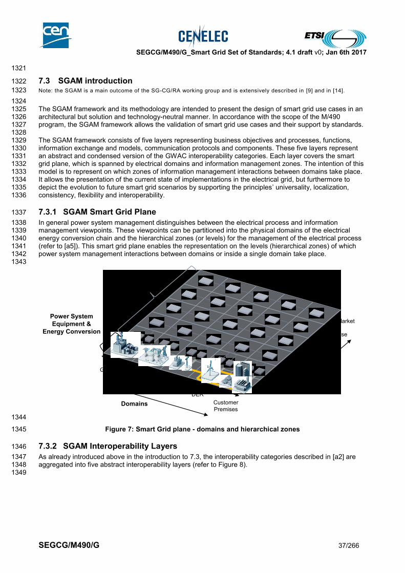
SEGCG/M490/G_Smart Grid Set of Standards; 4.1 draft v0; Jan 6th 2017
SEGCG/M490/G 37/266
1321
7.3 SGAM introduction 1322
Note: the SGAM is a main outcome of the SG-CG/RA working group and is extensively described in [9] and in [14]. 1323
1324 The SGAM framework and its methodology are intended to present the design of smart grid use cases in an 1325 architectural but solution and technology-neutral manner. In accordance with the scope of the M/490 1326 program, the SGAM framework allows the validation of smart grid use cases and their support by standards. 1327 1328 The SGAM framework consists of five layers representing business objectives and processes, functions, 1329 information exchange and models, communication protocols and components. These five layers represent 1330 an abstract and condensed version of the GWAC interoperability categories. Each layer covers the smart 1331 grid plane, which is spanned by electrical domains and information management zones. The intention of this 1332 model is to represent on which zones of information management interactions between domains take place. 1333 It allows the presentation of the current state of implementations in the electrical grid, but furthermore to 1334 depict the evolution to future smart grid scenarios by supporting the principles’ universality, localization, 1335 consistency, flexibility and interoperability. 1336
7.3.1 SGAM Smart Grid Plane 1337
In general power system management distinguishes between the electrical process and information 1338 management viewpoints. These viewpoints can be partitioned into the physical domains of the electrical 1339 energy conversion chain and the hierarchical zones (or levels) for the management of the electrical process 1340 (refer to [a5]). This smart grid plane enables the representation on the levels (hierarchical zones) of which 1341 power system management interactions between domains or inside a single domain take place. 1342 1343
1344
Figure 7: Smart Grid plane - domains and hierarchical zones 1345
7.3.2 SGAM Interoperability Layers 1346
As already introduced above in the introduction to 7.3, the interoperability categories described in [a2] are 1347 aggregated into five abstract interoperability layers (refer to Figure 8). 1348 1349
Generation
Transmission
Distribution
DER
Customer
Premises
Process
Field
Station
Operation
Enterprise
Market
Domains
Zones
Information
Management
Power System
Equipment &
Energy Conversion
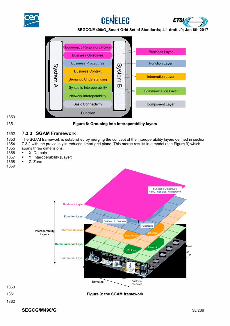
SEGCG/M490/G_Smart Grid Set of Standards; 4.1 draft v0; Jan 6th 2017
SEGCG/M490/G 38/266
1350
Figure 8: Grouping into interoperability layers 1351
7.3.3 SGAM Framework 1352
The SGAM framework is established by merging the concept of the interoperability layers defined in section 1353 7.3.2 with the previously introduced smart grid plane. This merge results in a model (see Figure 9) which 1354 spans three dimensions: 1355 X: Domain 1356 Y: Interoperability (Layer) 1357 Z: Zone 1358 1359
1360
Figure 9: the SGAM framework 1361
1362
Syste
m A
Business Context
Semantic Understanding
Network Interoperability
Syntactic Interoperability
Basic Connectivity
Business Procedures
Business Objectives
Economic / Regulatory Policy
FunctionS
yste
m B
Business Layer
Function Layer
Information Layer
Communication Layer
Component Layer
Generation
Transmission
Distribution
DER
Customer
Premises
Process
Field
Station
Operation
Enterprise
Market
Domains
Zones
Component Layer
Communication Layer
Information Layer
Function Layer
ProtocolProtocol
Data Model
Data Model
Outline of Usecase
Functions
Business Layer
Business Objectives
Polit. / Regulat.. Framework
Interoperability
Layers

SEGCG/M490/G_Smart Grid Set of Standards; 4.1 draft v0; Jan 6th 2017
SEGCG/M490/G 39/266
7.4 List of systems 1363
Here are the systems which have been considered in this document, and which de facto form the set of the 1364 Smart Grid systems. 1365 The guidelines mentioned in 7.1 indicate the purpose and limits associated to system definition and 1366 completeness of the considered list. 1367 1368 This list is actually made of three types of systems: 1369
Domain specific systems (Generation, Transmission, Distribution, DER, Customer Premises). 1370
Function specific systems (usually crossing domain borders) (Marketplace systems, Demand flexibility 1371 systems, Smart metering systems, Weather observation and forecast systems). 1372
Other systems usually focusing on administration features (asset management, clock reference, 1373 communication management, device management, etc). 1374 These so-called “Administration systems” are usually present in all the above ones, but are generally 1375 implemented to co-habit with the domain or function specific domains. Depending on the implementation 1376 such cohabitation may lead to really separated systems and roles, or completely integrated systems and 1377 roles. 1378
1379
Table 5 - Smart Grids - list of the main systems 1380
Domain or Function Systems
Generation Generation management system
Transmission management system Substation automation system
Blackout Prevention System - Wide Area Measurement Protection and Control System (WAMPAC)
EMS SCADA system
Flexible AC Transmission Systems FACTS
Distribution management systems Substation automation system
Feeder automation system
Advanced Distribution Management System (ADMS)
FACTS system
DER operation systems DER operation system
Smart Metering systems AMI system
Metering-related back office system
Demand and production (generation) flexibility systems
Aggregated prosumers management system
Micro-grid Micro-grid systems
Marketplace system Marketplace system
Trading system
E-mobility (connection to grid) E-mobility systems
Administration systems Asset and Maintenance Management system
Communication network management system
Clock reference system
Authentication, Authorization, Accounting system
Device remote Management system
Weather forecast and observation system
1381 Note 1: So called “Administration systems” can/may be implemented in superposition of previous “operational systems”. 1382 There are in most of the cases re-using communication capabilities already present in the “operational system”. 1383
Note 2: HVDC systems will be considered in further revisions of the present document. 1384
Note 3: Specificities of offshore systems will be considered in further revisions of the present document. 1385
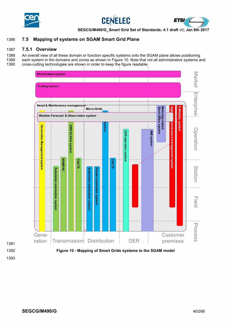
SEGCG/M490/G_Smart Grid Set of Standards; 4.1 draft v0; Jan 6th 2017
SEGCG/M490/G 40/266
7.5 Mapping of systems on SGAM Smart Grid Plane 1386
7.5.1 Overview 1387
An overall view of all these domain or function specific systems onto the SGAM plane allows positioning 1388 each system in the domains and zones as shown in Figure 10. Note that not all administrative systems and 1389 cross-cutting technologies are shown in order to keep the figure readable. 1390
1391
Figure 10 - Mapping of Smart Grids systems to the SGAM model 1392
1393
Asset & Maintenance management systemMicro-Grids
En
terp
rise
Ma
rke
tO
pe
ratio
nS
tatio
nP
roce
ss
Fie
ld
Gene-
ration Transmission Distribution DERCustomer
premises
Ge
ne
ratio
n M
an
ag
em
en
t sys
tem S
ub
sta
tion
au
tom
atio
n s
ys
tem
WA
MP
AC
EM
S S
CA
DA
sys
tem
FA
CT
S Su
bs
tatio
n a
uto
ma
tion
sys
tem
Fe
ed
er a
uto
ma
tion
sys
tem
AD
MS
sys
tem A
MI s
ys
tem
DE
R o
pe
ratio
n s
ys
tem
Ag
gre
ga
ted
pro
su
me
rs m
an
ag
em
en
t sys
tem
Market place system
Trading system
FA
CT
SWeather Forecast & Observation system
Me
terin
g-re
late
dB
ac
k O
ffice
sys
tem
E-M
ob
ility s
ys
tem
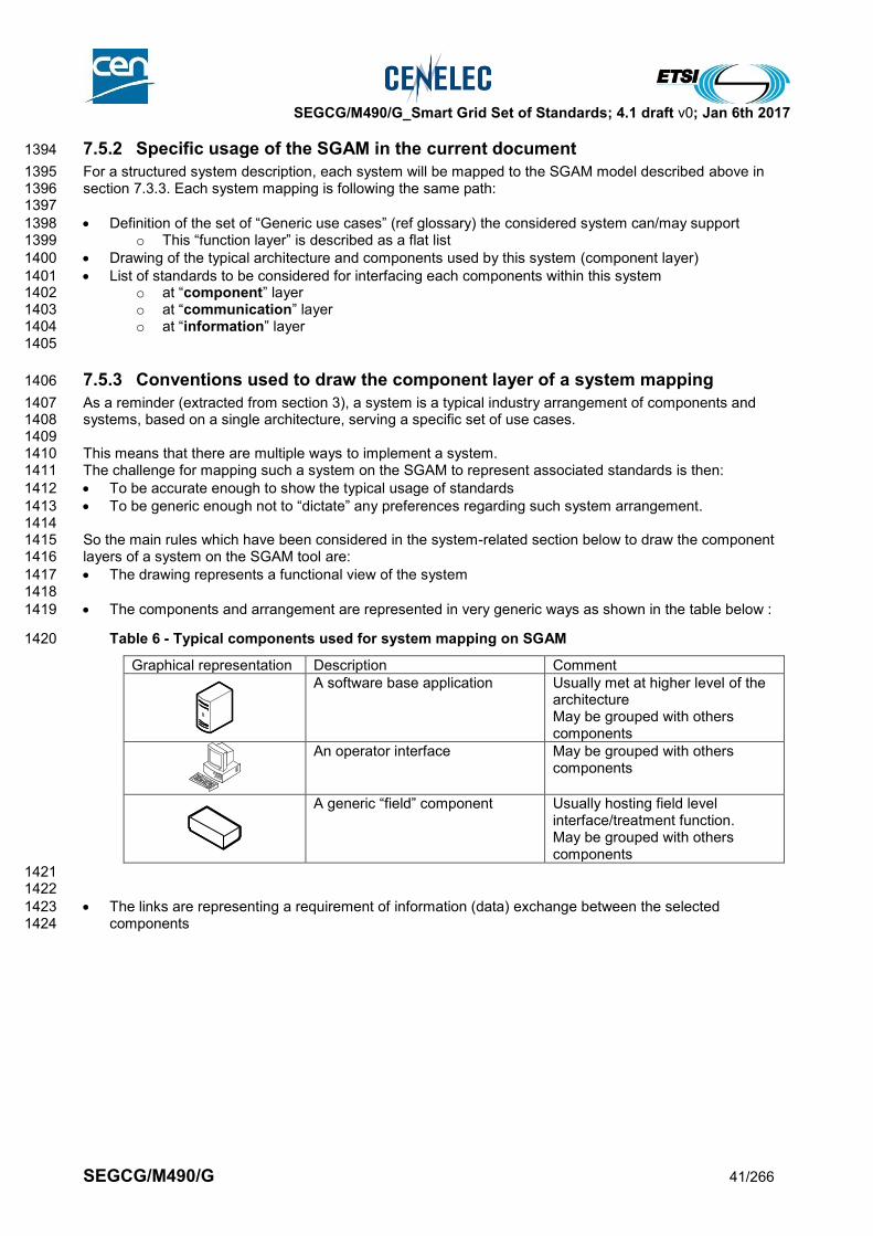
SEGCG/M490/G_Smart Grid Set of Standards; 4.1 draft v0; Jan 6th 2017
SEGCG/M490/G 41/266
7.5.2 Specific usage of the SGAM in the current document 1394
For a structured system description, each system will be mapped to the SGAM model described above in 1395 section 7.3.3. Each system mapping is following the same path: 1396 1397
Definition of the set of “Generic use cases” (ref glossary) the considered system can/may support 1398 o This “function layer” is described as a flat list 1399
Drawing of the typical architecture and components used by this system (component layer) 1400
List of standards to be considered for interfacing each components within this system 1401 o at “component” layer 1402 o at “communication” layer 1403 o at “information” layer 1404
1405
7.5.3 Conventions used to draw the component layer of a system mapping 1406
As a reminder (extracted from section 3), a system is a typical industry arrangement of components and 1407 systems, based on a single architecture, serving a specific set of use cases. 1408 1409 This means that there are multiple ways to implement a system. 1410 The challenge for mapping such a system on the SGAM to represent associated standards is then: 1411
To be accurate enough to show the typical usage of standards 1412
To be generic enough not to “dictate” any preferences regarding such system arrangement. 1413 1414 So the main rules which have been considered in the system-related section below to draw the component 1415 layers of a system on the SGAM tool are: 1416
The drawing represents a functional view of the system 1417 1418
The components and arrangement are represented in very generic ways as shown in the table below : 1419
Table 6 - Typical components used for system mapping on SGAM 1420
Graphical representation Description Comment
A software base application Usually met at higher level of the architecture May be grouped with others components
An operator interface May be grouped with others components
A generic “field” component Usually hosting field level interface/treatment function. May be grouped with others components
1421 1422
The links are representing a requirement of information (data) exchange between the selected 1423 components 1424

SEGCG/M490/G_Smart Grid Set of Standards; 4.1 draft v0; Jan 6th 2017
SEGCG/M490/G 42/266
Table 7 - Typical links used for system mapping on SGAM 1425
Graphical representation Description Comment
Electrical connection between process level component
Showing the presence of an electrical network
Communication path between two (or more) components
Showing the presence of a communication network
Communication between a component and another system
Expressing the potentiality for one system to contribute to UCs hosted by another one. Showing the presence of a communication network, when noted in a level different than the “process” zone level
7.5.4 Conventions used to draw the communication layer of a system mapping 1426
When a communication path appears between two (or more) components, then it has to be represented on 1427 the communication layer. 1428 The following rules for drawing the communication layer of a system are: 1429
System-related section (listed in chapter 8) and associated standards mostly focuses on application 1430 layers (layer 5 to 7 of the OSI model) 1431
Upper layers of communication are represented on the mapping using a large green arrow. 1432 Typically this will appear as follows: 1433
1434 where NN indicates the standardisation body5, and XXXX indicates the standard reference 1435
Communication technologies corresponding more to OSI layers 1 to 4 are described in section 9.3 1436 11 types of networks have been identified, which are noted by letters from “A” to “N”. 1437 More specifically the communication standards categories able to fulfill the requirement of the 1438 considered type(s) of network are listed in the Table 80 (on a ‘per type of network’ basis). The 1439 detailed list of communication standards, related to each standard categories, are given in Table 81 1440 and Table 82. 1441
The two parts mentioned above are bound graphically by adding to the communication network 1442 representation (a green arrow which appears on each SGAM mapping of the communication layer of 1443 the corresponding system) a blue disk showing the type of network to consider. 1444
The tag used to express this connection is . 1445 1446 Then, when a communication dataflow is mapped on the SGAM, for a selected system, it will be shown 1447 with a green large arrow, but close to this arrow a blue disk is placed, including a letter (from A to M) 1448 indicating which type(s) of network is this dataflow relying on. 1449 1450 An example is provided below. 1451
5 For some of the EN standards, the IEC body is mentioned on the graphics. The numbering of the standard remains the same. The
standards tables define precisely which body to consider
NN XXXXNN XXXX
E

SEGCG/M490/G_Smart Grid Set of Standards; 4.1 draft v0; Jan 6th 2017
SEGCG/M490/G 43/266
Table 8 – Example in binding system standards and low OSI layer communication standards 1452
Representation of a communication flow
Meaning Relationship with lower OSI
layers of communication
Such a drawing means that for this communication dataflow:
IEC 61968-100 may be considered for the OSI layers 5 to 7,
and that the network said of type “G” may be considered as the lower OSI layers 1 to 4, i.e. “Intra-control centre / intra-data centre network” as explained in section 9.3.2. Then the Table 80 in section 9.3.3 indicates which standard(s) category may support the lower OSI layers of a communication network of type “G”. In that example, Table 80 indicates that the categories IEEE 802.3/1, IPv4 … standards may fit (the screenshot on the right shows how to understand the usage of Table 80).
The figure above shows how Table 80 may contribute to select the appropriate lower OSI layer communication standards category for a given type of network
7.5.5 Conventions used to draw the information layer of a system mapping 1453
When a communication path appears between two (or more) components, then it has to be represented on 1454 the information layer, in order to express which standard data model is considered for this data exchange. 1455 1456 The following rules for drawing the information layer of a system are: 1457
Data modeling standards mostly focus on OSI layers greater than 7 1458
Data modeling primitives (like, “Binary”, “Analog”, “String”, …) are not considered as such. Only semantic 1459 level modeling is considered 1460
Data modeling standards are shown on the drawing using a yellow ellipse such as 1461
1462 where NN indicates the standard body6, and ZZZZ indicates the standard reference. 1463
1464 1465
7.6 Smart Grid Generic use cases 1466
7.6.1 List of Generic Use cases 1467
De facto, many Smart Grid systems host or contribute to implementing one or more Smart Grid Use cases. 1468 1469 The way Smart Grid Generic use cases (UCs) are broken down and sorted is described in [10]. 1470 A summary list of the considered Smart Grid use cases is provided in Table 9. 1471 This list is non exhaustive and will be progressively completed. 1472 Then further in the document, for each system (refer to the list above in Table 5), a specific section will 1473 describe the detailed list of supported UCs. 1474
6 For some of the EN standards, the IEC body is mentioned on the graphics. The numbering of the standard remains the same. The
standards tables define precisely which body to consider
IEC 61968-100
NN ZZZZNN ZZZZ
G
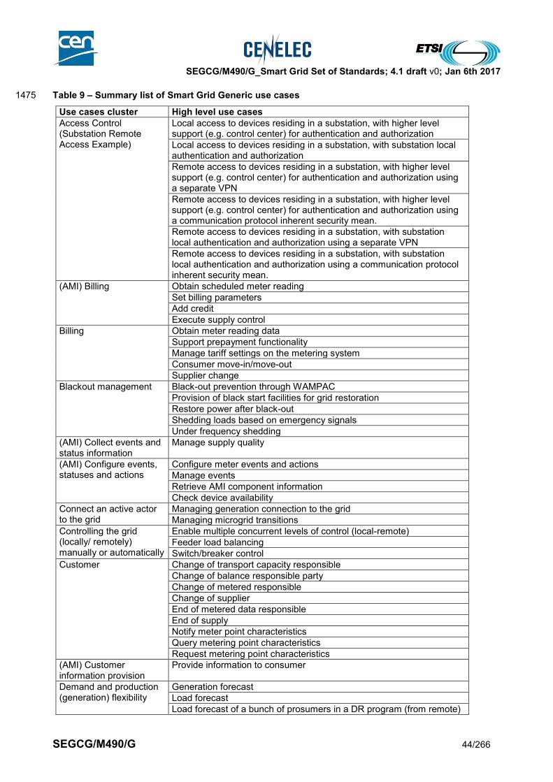
SEGCG/M490/G_Smart Grid Set of Standards; 4.1 draft v0; Jan 6th 2017
SEGCG/M490/G 44/266
Table 9 – Summary list of Smart Grid Generic use cases 1475
Use cases cluster High level use cases
Access Control (Substation Remote Access Example)
Local access to devices residing in a substation, with higher level support (e.g. control center) for authentication and authorization
Local access to devices residing in a substation, with substation local authentication and authorization
Remote access to devices residing in a substation, with higher level support (e.g. control center) for authentication and authorization using a separate VPN
Remote access to devices residing in a substation, with higher level support (e.g. control center) for authentication and authorization using a communication protocol inherent security mean.
Remote access to devices residing in a substation, with substation local authentication and authorization using a separate VPN
Remote access to devices residing in a substation, with substation local authentication and authorization using a communication protocol inherent security mean.
(AMI) Billing Obtain scheduled meter reading
Set billing parameters
Add credit
Execute supply control
Billing Obtain meter reading data
Support prepayment functionality
Manage tariff settings on the metering system
Consumer move-in/move-out
Supplier change
Blackout management Black-out prevention through WAMPAC
Provision of black start facilities for grid restoration
Restore power after black-out
Shedding loads based on emergency signals
Under frequency shedding
(AMI) Collect events and status information
Manage supply quality
(AMI) Configure events, statuses and actions
Configure meter events and actions
Manage events
Retrieve AMI component information
Check device availability
Connect an active actor to the grid
Managing generation connection to the grid
Managing microgrid transitions
Controlling the grid (locally/ remotely) manually or automatically
Enable multiple concurrent levels of control (local-remote)
Feeder load balancing
Switch/breaker control
Customer Change of transport capacity responsible
Change of balance responsible party
Change of metered responsible
Change of supplier
End of metered data responsible
End of supply
Notify meter point characteristics
Query metering point characteristics
Request metering point characteristics
(AMI) Customer information provision
Provide information to consumer
Demand and production (generation) flexibility
Generation forecast
Load forecast
Load forecast of a bunch of prosumers in a DR program (from remote)
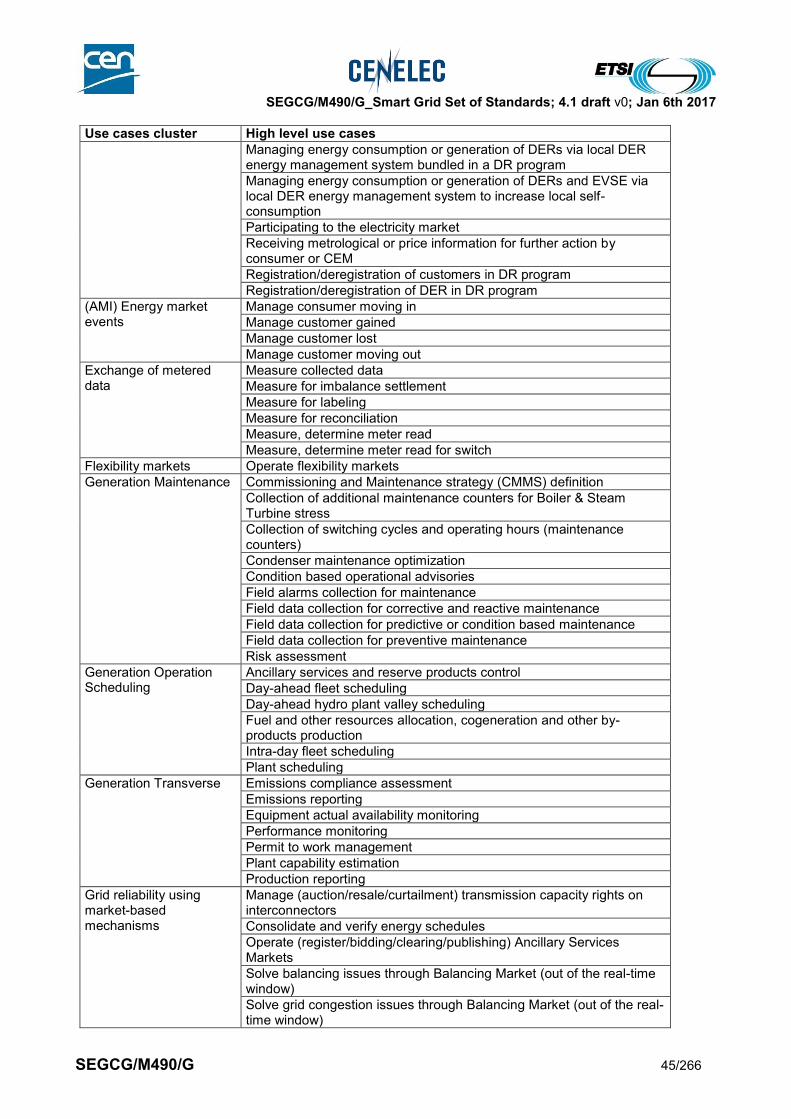
SEGCG/M490/G_Smart Grid Set of Standards; 4.1 draft v0; Jan 6th 2017
SEGCG/M490/G 45/266
Use cases cluster High level use cases
Managing energy consumption or generation of DERs via local DER energy management system bundled in a DR program
Managing energy consumption or generation of DERs and EVSE via local DER energy management system to increase local self-consumption
Participating to the electricity market
Receiving metrological or price information for further action by consumer or CEM
Registration/deregistration of customers in DR program
Registration/deregistration of DER in DR program
(AMI) Energy market events
Manage consumer moving in
Manage customer gained
Manage customer lost
Manage customer moving out
Exchange of metered data
Measure collected data
Measure for imbalance settlement
Measure for labeling
Measure for reconciliation
Measure, determine meter read
Measure, determine meter read for switch
Flexibility markets Operate flexibility markets
Generation Maintenance Commissioning and Maintenance strategy (CMMS) definition
Collection of additional maintenance counters for Boiler & Steam Turbine stress
Collection of switching cycles and operating hours (maintenance counters)
Condenser maintenance optimization
Condition based operational advisories
Field alarms collection for maintenance
Field data collection for corrective and reactive maintenance
Field data collection for predictive or condition based maintenance
Field data collection for preventive maintenance
Risk assessment
Generation Operation Scheduling
Ancillary services and reserve products control
Day-ahead fleet scheduling
Day-ahead hydro plant valley scheduling
Fuel and other resources allocation, cogeneration and other by-products production
Intra-day fleet scheduling
Plant scheduling
Generation Transverse Emissions compliance assessment
Emissions reporting
Equipment actual availability monitoring
Performance monitoring
Permit to work management
Plant capability estimation
Production reporting
Grid reliability using market-based mechanisms
Manage (auction/resale/curtailment) transmission capacity rights on interconnectors
Consolidate and verify energy schedules
Operate (register/bidding/clearing/publishing) Ancillary Services Markets
Solve balancing issues through Balancing Market (out of the real-time window)
Solve grid congestion issues through Balancing Market (out of the real-time window)

SEGCG/M490/G_Smart Grid Set of Standards; 4.1 draft v0; Jan 6th 2017
SEGCG/M490/G 46/266
Use cases cluster High level use cases
Grid stability Monitoring and reduce harmonic mitigation
Monitoring and reduce power oscillation damping
Monitoring and reduce voltage flicker
Stabilizing network by reducing sub-synchronous resonance (Sub synchronous damping)
Stabilizing network after fault condition (Post-fault handling)
(AMI) Installation & configuration
AMI component discovery & communication setup
Clock synchronization
Configure AMI device
Security (Configuration) Management
Maintaining grid assets Archive maintenance information
Monitoring assets conditions
Optimize field crew operation
Supporting periodic maintenance (and planning)
Manage commercial relationship for electricity supply
Further from ESMIG
Further suggestions to market
Invoicing customers
Registration/deregistration of customers
Managing power quality Frequency support
Voltage regulation
VAR regulation
Market Settlements Perform measurement and validation (M&V)
Perform settlements
Monitor AMI event Install, configure and maintain the metering system
Manage power quality data
Manage outage data
Manage the network using metering system data
Manage interference to metering system
Enable and disable the metering system
Display messages
Facilitate der for network operation
Facilitate demand response actions
Interact with devices at the premises
Manage efficiency measures at the premise using metering system data
Demand side management
Monitoring the grid flows Archive operation information
Capture, expose and analyze disturbance events
Monitoring electrical flows
Monitoring power quality for operation (locally)
Producing, exposing and logging time-stamped events
Supporting time-stamped alarms management at all levels
Operate DER(s) Aggregate DER as commercial VPP
Aggregate DER as technical VPP
DER performance management
DER process management
DER process management with reduced power output
DER remote control (dispatch)
Registration/deregistration of DER in VPP
Store energy from the grid
Operate wholesale electricity market
Receive energy offers and bids
Clear day-ahead market
Clear intraday market
Clear real-time market
Publish market results
Protecting the grid assets Perform networked protection logic (Intertripping, logic selectivity...)
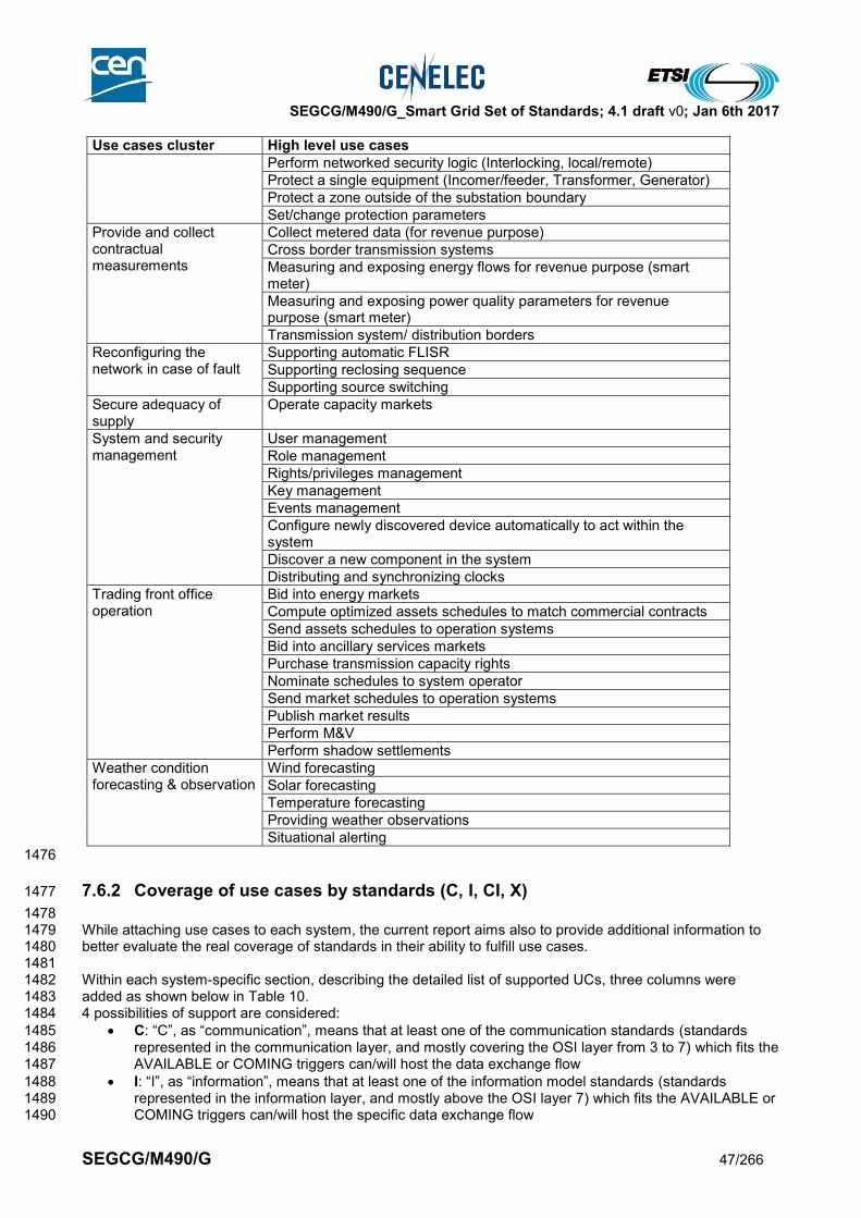
SEGCG/M490/G_Smart Grid Set of Standards; 4.1 draft v0; Jan 6th 2017
SEGCG/M490/G 47/266
Use cases cluster High level use cases
Perform networked security logic (Interlocking, local/remote)
Protect a single equipment (Incomer/feeder, Transformer, Generator)
Protect a zone outside of the substation boundary
Set/change protection parameters
Provide and collect contractual measurements
Collect metered data (for revenue purpose)
Cross border transmission systems
Measuring and exposing energy flows for revenue purpose (smart meter)
Measuring and exposing power quality parameters for revenue purpose (smart meter)
Transmission system/ distribution borders
Reconfiguring the network in case of fault
Supporting automatic FLISR
Supporting reclosing sequence
Supporting source switching
Secure adequacy of supply
Operate capacity markets
System and security management
User management
Role management
Rights/privileges management
Key management
Events management
Configure newly discovered device automatically to act within the system
Discover a new component in the system
Distributing and synchronizing clocks
Trading front office operation
Bid into energy markets
Compute optimized assets schedules to match commercial contracts
Send assets schedules to operation systems
Bid into ancillary services markets
Purchase transmission capacity rights
Nominate schedules to system operator
Send market schedules to operation systems
Publish market results
Perform M&V
Perform shadow settlements
Weather condition forecasting & observation
Wind forecasting
Solar forecasting
Temperature forecasting
Providing weather observations
Situational alerting
1476
7.6.2 Coverage of use cases by standards (C, I, CI, X) 1477
1478 While attaching use cases to each system, the current report aims also to provide additional information to 1479 better evaluate the real coverage of standards in their ability to fulfill use cases. 1480 1481 Within each system-specific section, describing the detailed list of supported UCs, three columns were 1482 added as shown below in Table 10. 1483 4 possibilities of support are considered: 1484
C: “C”, as “communication”, means that at least one of the communication standards (standards 1485 represented in the communication layer, and mostly covering the OSI layer from 3 to 7) which fits the 1486 AVAILABLE or COMING triggers can/will host the data exchange flow 1487
I: “I”, as “information”, means that at least one of the information model standards (standards 1488 represented in the information layer, and mostly above the OSI layer 7) which fits the AVAILABLE or 1489 COMING triggers can/will host the specific data exchange flow 1490
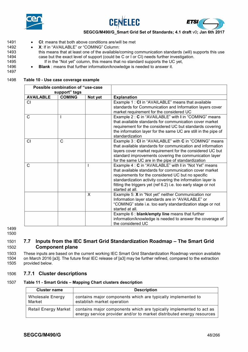
SEGCG/M490/G_Smart Grid Set of Standards; 4.1 draft v0; Jan 6th 2017
SEGCG/M490/G 48/266
CI: means that both above conditions are/will be met 1491
X: If in “AVAILABLE” or “COMING” Column: 1492 this means that at least one of the available/coming communication standards (will) supports this use 1493 case but the exact level of support (could be C or I or CI) needs further investigation. 1494 If in the “Not yet” column, this means that no standard supports the UC yet, 1495
Blank : means that further information/knowledge is needed to answer it. 1496 1497
Table 10 - Use case coverage example 1498
Possible combination of “use-case support” tags
AVAILABLE COMING Not yet Explanation
CI Example 1 : CI in “AVAILABLE” means that available standards for Communication and Information layers cover market requirement for the considered UC
C I Example 2 : C in “AVAILABLE” with I in “COMING” means that available standards for communication cover market requirement for the considered UC but standards covering the information layer for the same UC are still in the pipe of standardization
CI C Example 3 : CI in “AVAILABLE” with C in “COMING” means that available standards for communication and information layers cover market requirement for the considered UC but standard improvements covering the communication layer for the same UC are in the pipe of standardization
C I Example 4 : C in “AVAILABLE” with I in “Not Yet” means that available standards for communication cover market requirements for the considered UC but no specific standardization activity covering the information layer is fitting the triggers yet (ref 6.2) i.e. too early stage or not started at all.
X Example 5: X in “Not yet” neither Communication nor Information layer standards are in “AVAILABLE” or “COMING” state i.e. too early standardization stage or not started at all.
Example 6 : blank/empty line means that further information/knowledge is needed to answer the coverage of the considered UC
1499 1500
7.7 Inputs from the IEC Smart Grid Standardization Roadmap – The Smart Grid 1501
Component plane 1502
These inputs are based on the current working IEC Smart Grid Standardization Roadmap version available 1503 on March 2016 [a3]. The future final IEC release of [a3] may be further refined, compared to the extraction 1504 provided below. 1505
7.7.1 Cluster descriptions 1506
Table 11 - Smart Grids – Mapping Chart clusters description 1507
Cluster name Description
Wholesale Energy Market
contains major components which are typically implemented to establish market operation
Retail Energy Market contains major components which are typically implemented to act as energy service provider and/or to market distributed energy resources
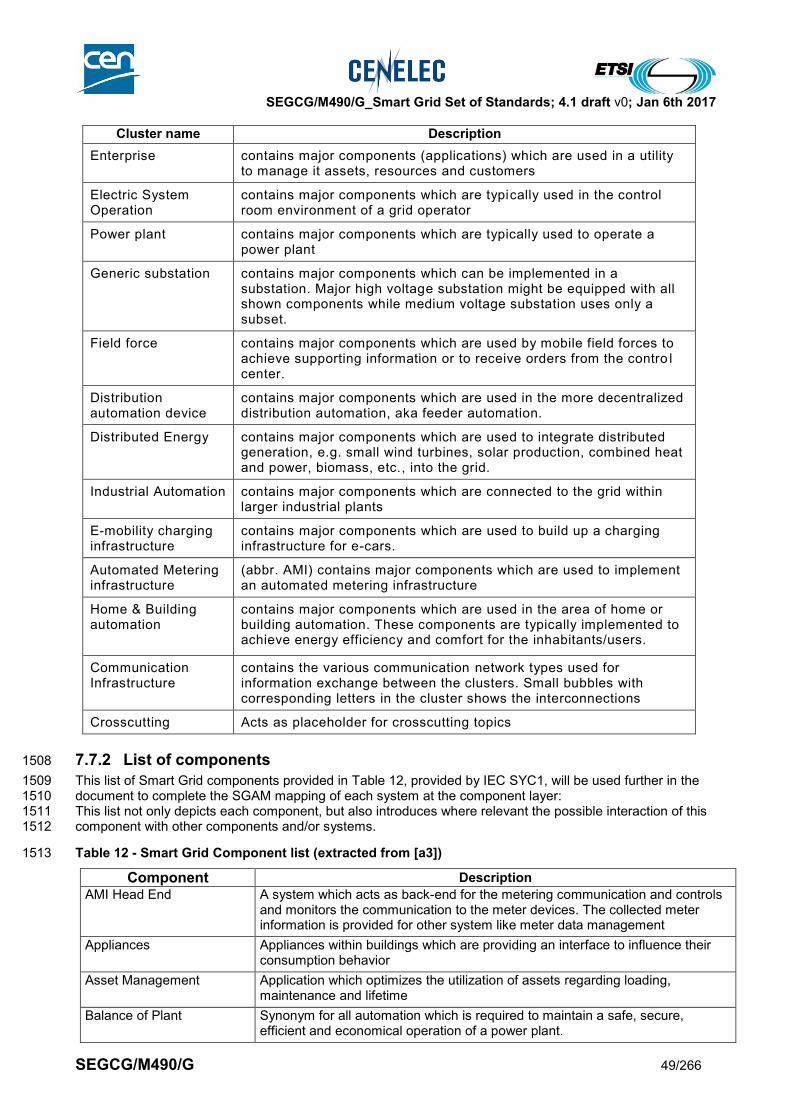
SEGCG/M490/G_Smart Grid Set of Standards; 4.1 draft v0; Jan 6th 2017
SEGCG/M490/G 49/266
Cluster name Description
Enterprise contains major components (applications) which are used in a utility to manage it assets, resources and customers
Electric System Operation
contains major components which are typically used in the control room environment of a grid operator
Power plant contains major components which are typically used to operate a power plant
Generic substation contains major components which can be implemented in a substation. Major high voltage substation might be equipped with all shown components while medium voltage substation uses only a subset.
Field force contains major components which are used by mobile field forces to achieve supporting information or to receive orders from the contro l center.
Distribution automation device
contains major components which are used in the more decentralized distribution automation, aka feeder automation.
Distributed Energy contains major components which are used to integrate distributed generation, e.g. small wind turbines, solar production, combined heat and power, biomass, etc., into the grid.
Industrial Automation contains major components which are connected to the grid within larger industrial plants
E-mobility charging infrastructure
contains major components which are used to build up a charging infrastructure for e-cars.
Automated Metering infrastructure
(abbr. AMI) contains major components which are used to implement an automated metering infrastructure
Home & Building automation
contains major components which are used in the area of home or building automation. These components are typically implemented to achieve energy efficiency and comfort for the inhabitants/users.
Communication Infrastructure
contains the various communication network types used for information exchange between the clusters. Small bubbles with corresponding letters in the cluster shows the interconnections
Crosscutting Acts as placeholder for crosscutting topics
7.7.2 List of components 1508
This list of Smart Grid components provided in Table 12, provided by IEC SYC1, will be used further in the 1509 document to complete the SGAM mapping of each system at the component layer: 1510 This list not only depicts each component, but also introduces where relevant the possible interaction of this 1511 component with other components and/or systems. 1512
Table 12 - Smart Grid Component list (extracted from [a3]) 1513
Component Description
AMI Head End A system which acts as back-end for the metering communication and controls and monitors the communication to the meter devices. The collected meter information is provided for other system like meter data management
Appliances Appliances within buildings which are providing an interface to influence their consumption behavior
Asset Management Application which optimizes the utilization of assets regarding loading, maintenance and lifetime
Balance of Plant Synonym for all automation which is required to maintain a safe, secure, efficient and economical operation of a power plant.
SEGCG/M490/G_Smart Grid Set of Standards; 4.1 draft v0; Jan 6th 2017
SEGCG/M490/G 50/266
Component Description
Balance Scheduling Application which plants the energy procurement of a balance responsible energy retailer to satisfy the energy demand its customer
Bay Controller A device or application which communicates with the substation to provide status information of the field equipment and to receive switching commands an control their execution
Billing Application which creates the energy bill information based on received metering information
Building Management System
A system consisting of several decentralized controllers and a centralized management system to monitor and control the heating, ventilation, air conditioning, light and other facilities within a building.
Cap Bank Controller Device or application which controls the reactive power generation of a controllable capacitor bank, typically to maintain the voltage at a certain node in the grid
Capacitor Two-terminal device characterized essentially by its capacitance (ref IEV [a4])
Charging Control Controls the charging of one car at a residential customer side according to set points received from the customer’s energy management
Charging Station Single or multiple power outlets specially designed to charge the battery of cars. Typically including also facilities meter the energy consumption and to authenticate the owner of the car to be charged for settlement reasons.
Communication Front End Application or system providing communication with the substations to monitor and control the grid
Conditioning Monitoring Application or system which monitors the 'health' of grid equipment to detect upcoming failure in advance to extend the lifetime of the equipment
Customer Energy Management System
Energy management system for energy customers to optimize the utilization of energy according to supply contracts or other economic targets
Customer Information System (CIS)
System or application which maintains all needed information for energy customers. Typically associated with call center software to provide customer services like hot-line etc.
Customer Portal Web-server application which allows utility customers to register and login to retrieve information about their tariffs, consumption and other information
Demand Response Management System
(abbr. DRMS) Demand Response Management System; a system or an application which maintains the control of many load devices to curtail their energy consumption in response to energy shortages or high energy prices.
A DMS may have interfaces to other DMS.
DER Control Control of a DER the allows the adjustment of its active or reactive power output according to a received set point
Digital Sensors Sensors for voltage, current, etc. with a digital interface that allows connecting the sensor directly to the substation integration bus
Distributed Energy Resource
(abbr. DER) Distributed Energy Resource; a small unit which generates energy and which is connected to the distribution grid. Loads which could modify their consumption according to external set points are often also considered as DER
Distribution Management System (application server)
(abbr. DMS) Application server of a Distribution Management System which hosts applications to monitor and control a distribution grid from a centralized location, typically the control center. A DMS typically has interfaces to other systems, like an GIS or an OMS
Energy Management Gateway
(Functional) Gateway used to interface the private area with remote service provider and also with smart metering system.
Energy Management System (application server)
(abbr. EMS) Application server of an Energy Management System which hosts applications to monitor and control a transmission grid and the output of the connected power plants from a centralized location, typically the control center. An EMS may have interfaces to other EMS.

SEGCG/M490/G_Smart Grid Set of Standards; 4.1 draft v0; Jan 6th 2017
SEGCG/M490/G 51/266
Component Description
Energy Market Management
Application of system which manages all transactions and workflows necessary to implement an energy market
Energy Storage An electrical energy storage which is installed within the distribution grid or DER site and operated either by a utility or energy producer
Energy Trading Application Application(s) which are used to trade energy in corresponding markets, supports the dispatcher in the decision to buy, sell or to self-produce energy and also provides facilities to exchange the necessary information with the energy market IT systems.
Enterprise Resource Planning
(abbr. ERP) “Enterprise resource planning systems integrate internal and external management information across an entire organization, embracing finance/accounting, manufacturing, sales and service, customer relationship management, etc.” (source: Wikipedia)
FACTS “Flexible Alternating Current Transmission System is a system composed of static equipment used for the AC transmission of electrical energy. It is meant to enhance controllability and increase power transfer capability of the network. It is generally a power electronics-based system.” (source Wikipedia).
Despite their name, FACTS are also possibly used in Distribution.
FACTS controller Control for FACTS in a way that the active or reactive power flow is adjusted according to received set points
Fault Detector Special devices typically mounted on distribution lines to detect whether a high current caused by a network failure has passed the supervised distribution line.
Feeder controller Distributed Automation within a distribution feeder controlling typically voltage profile and providing fault restoration logic
Front End Processor (abbr. FEP) System component in charge of interfacing widely spread remote sub/systems or component usually communicating over WAN, to a central database,
Geographic Information System (application server)
(abbr. GIS) “Geographic Information System” application server is a server which hosts an application designed to capture, store, manipulate, analyze, manage, and present all types of geographical data. In the simplest terms, GIS is the merging of cartography, statistical analysis, and database technology.
Grid Meter Device which meters the energy exchange between neighboring grid operators or between grid operator and large energy producer/consumer
HAN Gateway A specialized gateway device or application which establishes the communication between external systems and the Home Automation Network (HAN) devices
Head End System (abbr. HES) Central data system exchanging data via the AMI of various meters in its service area
High Speed Bus Communication bus within a control center system providing sufficient bandwidth and short latency to fulfill energy automation requirements
HVDC controller Control for HVDC lines in a way that the active or reactive power flow is adjusted according to received set points
Integration Bus Middleware supporting the information exchange between the various applications within a control center.
Laptop Synonym for a mobile PC with keyboard, monitor and sufficient CPU power to run similar user interface clients as typically used in control rooms. Used by mobile workforces to work more independent from control room dispatcher.
Load Energy consuming devices at customer site which might become subject for energy management
Load controller Control the energy consumption of a load according to an received set point without jeopardizing the desired process of the load
Local Network Access Point (abbr. LNAP) (Functional) Specialized Network Interface controller between the Local Network (within the private area) and the AMI system
SEGCG/M490/G_Smart Grid Set of Standards; 4.1 draft v0; Jan 6th 2017
SEGCG/M490/G 52/266
Component Description
Local Storage An electrical energy storage which is installed behind the meter point an operated by the energy consumer/produce and not by the utility
Meter Data Concentrator Device or application typically in a substation which establishes the communication to smart meters to collect the metered information and send it in concentrated form to an AMI head end
Meter Data Management System
(abbr. MDMS) Meter Data Management System is a system or an application which maintains all information to be able to calculate the energy bill for a customer based on the meter data retrieved from AMI head end(s). The energy bill information is typically forwarded to consumer relationship and billing systems
MID meter Revenue Meter compliant with the European MID directive (2004/22/CE) currently being reviewed in the context of the adoption of the European New Legislative Framework 765/2008/EC
Mobile Device Synonym for a mobile hand held device with limited CPU power to run specialized user interface clients. Used by mobile workforces to work more independent from control room dispatcher
Model Exchange Platform Data warehouse system or application which enables the interchange of information described using the operation data model.
Neighborhood Network Access Point
(abbr. NNAP) (Functional) Specialized Network Interface Controller between the Neighborhood Network and Wide Area Network (WAN) connecting the Head End Systems
Network Interface Controller
(abbr. NIC) “A network interface controller (also known as a network interface card, network adapter, LAN adapter and by similar terms) is a computer hardware component that connects a computer to a computer network.” (source: Wikipedia)
Operation Meter Device which monitors the energy consumption for operational and control reasons. The meter values are not used for commercial purposes
Outage Management System
(abbr. OMS) System or application which intends to help a network operator to handle outage in optimizing the fix depending on many criteria (number of customer minutes lost, number of affected customer, capability of the network, …)
Phasor Data Concentrator Specialized data concentrator collecting the information from Phasor measurement units (PMU) within a substation and forwarding this information in concentrated form to a system on higher level.
Phasor Measurement Units (abbr. PMU) A Phasor measurement unit is a device which measures the electrical waves on an electricity grid, using a common time source for synchronization. Time synchronization allows synchronized real-time measurements of multiple remote measurement points
Plug-In Electric Vehicles (abbr. PEV) A vehicle with an electric drive (as only drive or in combination with a fuel engine) and a battery which can be charged at a charging station.
Power Electronics Generation which uses power electronics to inject electrical energy, typically resulting from renewable resources, into the grid
Power Scheduling Application deriving the optimal schedule to run the power plants to minimize costs
Primary Generation Control Device or application within a power plant monitoring actual frequency and adjust generation if frequency deviates from desired value
Process Automation System
Automation system to monitor and control industrial production plants.
Protection Relay Devices or application which monitors voltage and current at the terminals of grid devices to detect failures of this equipment and than issuing tripping commands to circuit breaker to avoid further damages.
Radio Synonym for wireless communication

SEGCG/M490/G_Smart Grid Set of Standards; 4.1 draft v0; Jan 6th 2017
SEGCG/M490/G 53/266
Component Description
Reactor (also named inductor) Two-terminal device characterized essentially by its inductance (ref IEV [a4])
Recloser Special switch for distribution feeder typically combined with some automation logic to execute automated restoration after a failure in the corresponding feeder.
Registration Application within an energy market system which handles the user registration for the market and monitors its transaction at the market.
Remote Terminal Unit (abbr. RTU) A remote terminal unit is a microprocessor-controlled electronic device that interfaces objects in the physical world to a distributed control system or SCADA by transmitting telemetry data to the system, and by using messages from the supervisory system to control connected objects
Revenue Meter Device which measures the energy consumption within predefined cycles. The metered energy consumption is used to determine the energy bill
Router TCP/IP communication device which typically interconnects an internal network with the public network infrastructure.
Secondary Generation Control
Application which monitors the frequency and the energy exchange over tie-line and generates set points for a controlled generating unit to maintain the desired values.
Settlement Application within an energy market system which maintains the commercial information from the executed energy transactions
Smart Plug Synonym for a load switch which can be controlled by the customer energy management via the home automation network
Station controller Automation system monitoring and controlling the devices in a substation. Provides interface to network control center.
Substation Integration Bus Intercommunication system for all intelligent electronic devices (IED) within a substation
Supervisory Control And Data Acquisition (abbr. SCADA).
Supervisory Control And Data Acquisition system provides the basic functionality for implementing EMS or DMS, especially provides the communication with the substations to monitor and control the grid
Switchgear A general term covering switching devices and their combination with associated control, measuring, protective and regulating equipment, also assemblies of such devices and equipment with associated interconnections, accessories, enclosures and supporting structures, intended in principle for use in connection with generation, transmission, distribution and conversion of electric energy (ref IEV [a4]).
Switches and breaker may vary reading their switching automation and breaking capability.
Transformer Electric energy converter without moving parts that changes voltages and currents associated with electric energy without change of frequency (ref IEV [a4])
Voltage Regulator (abbr. VR) Device or application within the substation automation or a power plant to control the voltage at busbar(s) within the substation
Wide Area Monitoring System (application server)
(abbr. WAMPAC) application server which host the management of Wide Area Monitoring System i.e. which evaluates incoming information from PMUs to derive information about the dynamic stability of the grid
1514
1515

SEGCG/M490/G_Smart Grid Set of Standards; 4.1 draft v0; Jan 6th 2017
SEGCG/M490/G 54/266
8 Per systems standards mapping 1516
8.1 Generation 1517
8.1.1 Generation management system 1518
8.1.1.1 System Description 1519
1520 Generation management system refers to the real-time information system and all the elements needed to 1521 support all the relevant operational activities and functions used in day to day operation of the Generation 1522 system, including the control of generation assets under normal and abnormal operating conditions. It 1523 enables implementing generating programs that are prepared for a certain period, improves the information 1524 made available to operators at the control room, field and crew personnel, customer service representatives 1525 and management. It may thus support or help in making operational decisions. 1526 Such a system is usually made of one or many interconnected IT systems, connected to field generation 1527 operation systems, through the use of LAN/WAN communication systems. It may also include the 1528 components needed to enable field crew to operate the generation system from the field. 1529 A generation management system usually provides following major functions: 1530
EMS/SCADA, real time monitoring and control of the (geographically localized) generation system at the 1531 Transmission Operator level 1532
DCS, real time monitoring and control of the generation assets at the station/field level 1533
Scheduling, monitoring and control of the (scattered) generation fleet at the generation company level for 1534 the production of energy, ancillary services and by-products in close relation to the Asset Management 1535 System 1536
Advanced generation management applications 1537
Work management 1538
Support of trading functions 1539
Black start facilities 1540 1541
8.1.1.2 Set of high level use cases 1542
1543 Here is a set of high level use cases which may be supported by a generation management system. 1544 The meanings of the three last columns (AVAILABLE, COMING, Not Yet) and of the “C”, “I”, “CI”, “X” 1545 conventions are given in section 7.6.2. 1546 1547
Table 13 - Generation Management systems - use cases 1548
Supported by standards
Use cases cluster
High level use cases AVAILABLE COMING Not yet
Maintaining grid assets
Monitoring assets conditions CI
Supporting periodic maintenance (and planning)
CI
Optimize field crew operation X
Archive maintenance information CI
Managing power quality
VAR regulation CI
Frequency support CI
Provide and collect contractual measurements
Collect metered data (for revenue purpose)
Connect an active actor to the grid
Managing generation connection to the grid CI
Blackout management
Restore power after black-out CI
Under frequency shedding

SEGCG/M490/G_Smart Grid Set of Standards; 4.1 draft v0; Jan 6th 2017
SEGCG/M490/G 55/266
Supported by standards
Use cases cluster
High level use cases AVAILABLE COMING Not yet
Demand and production (generation) flexibility
Receiving metrological or price information for further action by consumer or CEM
X
Load forecast (from local) CI
Generation forecast (from remote) CI
Generation forecast (from local) CI
Participating to the electricity market
Registration/deregistration of customers in DR program
X
Grid stability Stabilizing the network after fault condition (Post-fault handling)
Monitoring and reduce power oscillation damping
Stabilizing network by reducing sub-synchronous resonance (Sub synchronous damping)
Monitoring and reduce harmonic mitigation I
Monitoring and reduce voltage flicker I
Generation Operation Scheduling
Day-ahead fleet scheduling X
Intra-day fleet scheduling X
Plant scheduling X
Ancillary services and reserve products control
X
Fuel and other resources allocation, cogeneration and other by-products production
X
Day-ahead hydro plant valley scheduling X
Generation Maintenance
Commissioning and maintenance strategy definition
X
Field data collection for corrective and reactive maintenance
X
Field data collection for preventive maintenance
X
Field alarms collection for maintenance CI
Collection of switching cycles and operating hours (maintenance counters)
X
Field data collection for predictive or condition based maintenance
CI
Collection of additional maintenance counters for boiler & steam turbine stress
X
Risk assessment I
Condition based operational advisories X
Condenser maintenance optimization X
Generation Transverse
Permit To Work management X
Plant capability estimation X
Equipment actual availability monitoring CI
Performance monitoring CI
Production reporting X
Emissions reporting X
Emissions compliance assessment X
1549
8.1.1.3 Mapping on SGAM 1550
8.1.1.3.1 Preamble 1551

SEGCG/M490/G_Smart Grid Set of Standards; 4.1 draft v0; Jan 6th 2017
SEGCG/M490/G 56/266
1552 The European Commission’s Energy Roadmap 2050 has pointed out that the EU will see a growing share of 1553 renewable energy sources connected to the power grid and a steady transition towards a complex 1554 combination of a few large centralized power plants and a great number of small and decentralized power 1555 generating facilities. Integrating these facilities into a reliable and affordable power system will require an 1556 unprecedented level of co-operative action within the electric industry and between the industry and states. 1557 The power grid has existing flexibility in the system to cost-effectively integrate wind and solar resources but, 1558 as operated today, that flexibility is largely unused. The Generation management system will address such 1559 challenges as: 1560
expand sub-hourly dispatch and intra-hour scheduling 1561
improve reserves management 1562
access greater flexibility in the dispatch of existing generating plants 1563
focus on flexibility for new generating plants 1564 1565 Addressing these challenges requires process-level and Asset management system constraints to be more 1566 closely integrated within the higher levels of the Generation management system. 1567 1568
8.1.1.3.2 Component layer 1569
1570 The Generation operation component architecture involves all Zones from Process to Enterprise levels, 1571 which may be interconnected through wires or communication. 1572 The lower level components are easily identified as Generation related or not. The higher level components 1573 are more tightly integrated with Market, Asset Management & Transmission related components. 1574 1575 The Process level is populated with: 1576
electrical equipment, sensors and actuators (such as current and voltage transformers, breakers or 1577 switches) 1578
electro-mechanical machines with associated sensors and actuators (turbines and generators) 1579
industrial equipment with general purpose sensors and actuators (typically hydro or thermal plant) 1580 The Field level is in charge of protection, monitoring and control. It is mostly based on PLCs, which can be 1581 replaced by IEDs for electrical equipment. 1582 1583 Above the DCS HMI, higher level components are to be integrated with Market, Asset Management & 1584 Transmission related components. 1585 The Transmission EMS/SCADA system communicates with the Generation Management System RTU to 1586 implement the Secondary Generation Control. 1587
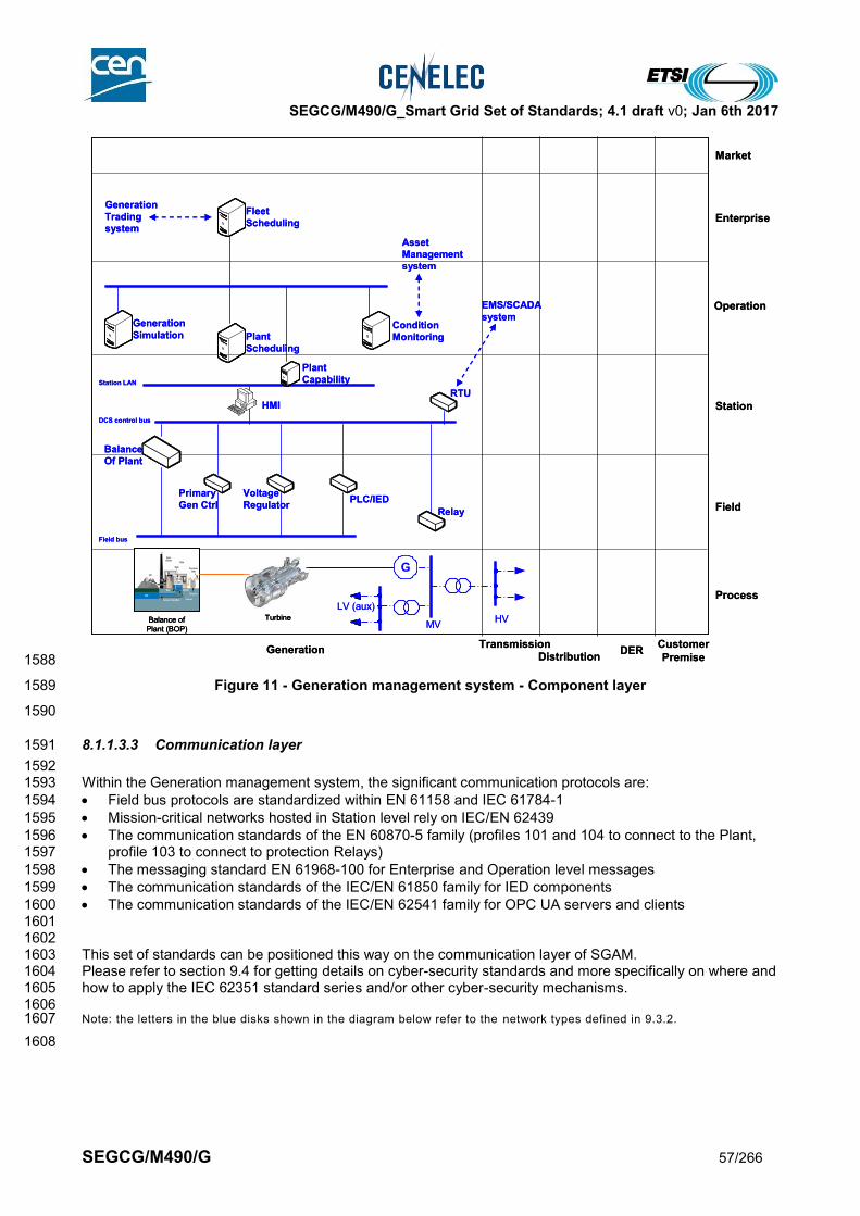
SEGCG/M490/G_Smart Grid Set of Standards; 4.1 draft v0; Jan 6th 2017
SEGCG/M490/G 57/266
1588
Figure 11 - Generation management system - Component layer 1589
1590
8.1.1.3.3 Communication layer 1591
1592 Within the Generation management system, the significant communication protocols are: 1593
Field bus protocols are standardized within EN 61158 and IEC 61784-1 1594
Mission-critical networks hosted in Station level rely on IEC/EN 62439 1595
The communication standards of the EN 60870-5 family (profiles 101 and 104 to connect to the Plant, 1596 profile 103 to connect to protection Relays) 1597
The messaging standard EN 61968-100 for Enterprise and Operation level messages 1598
The communication standards of the IEC/EN 61850 family for IED components 1599
The communication standards of the IEC/EN 62541 family for OPC UA servers and clients 1600 1601 1602 This set of standards can be positioned this way on the communication layer of SGAM. 1603 Please refer to section 9.4 for getting details on cyber-security standards and more specifically on where and 1604 how to apply the IEC 62351 standard series and/or other cyber-security mechanisms. 1605 1606 Note: the letters in the blue disks shown in the diagram below refer to the network types defined in 9.3.2. 1607
1608
GenerationTransmission
DistributionCustomer
PremiseDER
Process
Field
Station
Enterprise
Market
Operation
LV (aux)
MVHV
G
TurbineBalance of
Plant (BOP)
Field bus
DCS control bus
Station LAN
RTU
HMI
PLC/IED
Relay
Voltage
Regulator
Primary
Gen Ctrl
Balance
Of Plant
Plant
Capability
Condition
MonitoringPlant
Scheduling
Fleet
Scheduling
Generation
Simulation
EMS/SCADA
system
Generation
Trading
system
Asset
Management
system
GenerationTransmission
DistributionCustomer
PremiseDER
Process
Field
Station
Enterprise
Market
Operation
LV (aux)
MVHV
G
TurbineTurbineBalance of
Plant (BOP)
Balance of
Plant (BOP)
Field bus
DCS control bus
Station LAN
RTU
HMI
PLC/IED
Relay
Voltage
Regulator
Primary
Gen Ctrl
Balance
Of Plant
Plant
Capability
Condition
MonitoringPlant
Scheduling
Fleet
Scheduling
Generation
Simulation
EMS/SCADA
system
Generation
Trading
system
Asset
Management
system

SEGCG/M490/G_Smart Grid Set of Standards; 4.1 draft v0; Jan 6th 2017
SEGCG/M490/G 58/266
1609
Figure 12 - Generation management system - Communication layer 1610
1611
8.1.1.3.4 Information (Data) layer 1612
1613 The information layer of Generation management is based on the following families of information models: 1614
Field devices are standardized within EN 61131, with associated work in progress IEC 61499 and IEC 1615 61804 1616
Plant electrical devices are standardized within the IEC/EN 61850 family, with standards for specific 1617 generation types: EN 61400-25 series for Wind turbines, EN 61850-7-410 for Hydro power plants, IEC 1618 61850-90-13 for steam and gas turbines 1619
Industrial plants information models are standardized in the following family: IEC 62264 (ISA 95), IEC 1620 61512 (ISA 88), IEC 61987 and EN 61360. Their relevance to the Generation management system is at 1621 the Station level 1622
Operation and Enterprise level information models are standardized in the CIM family: EN 61968, EN 61970, 1623 IEC 62325 and IEC 62361. EN 61968 parts relevance to Generation has not been formally assessed yet. 1624 Few parts are fully appropriate for Generation domain, but most parts can be extended to become relevant to 1625 Generation domain. 1626 Mappings between most of these information models and the IEC/EN 62541 address space are defined or in 1627 progress. 1628 1629
IEC 61158
IEC 61784-1
IEC 62439
IEC
60
87
0-5
-10
1
IEC
60
87
0-5
-10
4
IEC 61968-100
IEC
62
54
1
IEC
60
87
0-5
-10
3
IEC
61
85
0
LV (aux)
MVHV
G
TurbineBalance of
Plant (BOP)
GenerationTransmission
DistributionCustomer
PremiseDER
Process
Field
Station
Enterprise
Market
Operation
IEC 61158
IEC 61784-1
IEC 62439
IEC
60
87
0-5
-10
1
IEC
60
87
0-5
-10
4
IEC 61968-100
IEC
62
54
1IE
C 6
254
1
IEC
60
87
0-5
-10
3
IEC
61
85
0
LV (aux)
MVHV
G
TurbineTurbineBalance of
Plant (BOP)
Balance of
Plant (BOP)
GenerationTransmission
DistributionCustomer
PremiseDER
Process
Field
Station
Enterprise
Market
Operation
E
L
G H
M
M
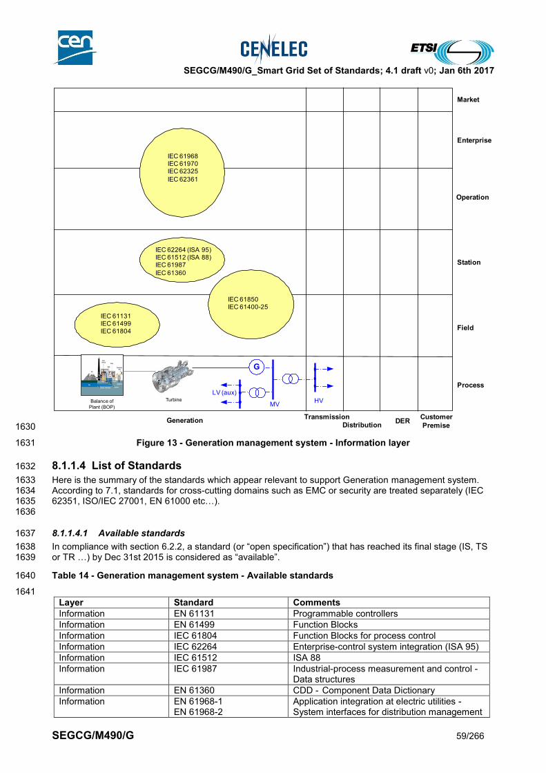
SEGCG/M490/G_Smart Grid Set of Standards; 4.1 draft v0; Jan 6th 2017
SEGCG/M490/G 59/266
1630
Figure 13 - Generation management system - Information layer 1631
8.1.1.4 List of Standards 1632
Here is the summary of the standards which appear relevant to support Generation management system. 1633 According to 7.1, standards for cross-cutting domains such as EMC or security are treated separately (IEC 1634 62351, ISO/IEC 27001, EN 61000 etc…). 1635 1636
8.1.1.4.1 Available standards 1637
In compliance with section 6.2.2, a standard (or “open specification”) that has reached its final stage (IS, TS 1638 or TR …) by Dec 31st 2015 is considered as “available”. 1639
Table 14 - Generation management system - Available standards 1640
1641
Layer Standard Comments
Information EN 61131 Programmable controllers
Information EN 61499 Function Blocks
Information IEC 61804 Function Blocks for process control
Information IEC 62264 Enterprise-control system integration (ISA 95)
Information IEC 61512 ISA 88
Information IEC 61987 Industrial-process measurement and control - Data structures
Information EN 61360 CDD - Component Data Dictionary
Information EN 61968-1 EN 61968-2
Application integration at electric utilities - System interfaces for distribution management
LV (aux)
MVHV
G
TurbineBalance of
Plant (BOP)
IEC 61850IEC 61400-25
IEC 61131IEC 61499IEC 61804
IEC 62264 (ISA 95)IEC 61512 (ISA 88)IEC 61987
IEC 61360
IEC 61968IEC 61970IEC 62325
IEC 62361
GenerationTransmission
DistributionCustomer
PremiseDER
Process
Field
Station
Enterprise
Market
Operation

SEGCG/M490/G_Smart Grid Set of Standards; 4.1 draft v0; Jan 6th 2017
SEGCG/M490/G 60/266
Layer Standard Comments
EN 61968-3 EN 61968-4 EN 61968-6 EN 61968-9 EN 61968-11
Information EN 61970-1 EN 61970-2 EN 61970-301 EN 61970-401 EN 61970-452 EN 61970-453 EN 61970-456 EN 61970-501 EN 61970-552
Energy management system Application Program Interface
Information EN 61850-6 EN 61850-7-4 EN 61850-7-3 EN 61850-7-2
Core Information model for the IEC/EN 61850 series
Information EN 61850-7-410 Hydro power plants
Information EN 61400-25-1 EN 61400-25-2 EN 61400-25-3 EN 61400-25-4
Wind farms
Information EN 62541-1 EN 62541-2 EN 62541-3 EN 62541-5 EN 62541-8 EN 62541-9 EN 62541-10 OPC UA part 11 OPC UA part PLCopen
IEC/EN standards for OPC UA OPC foundation open specifications for OPC UA parts 11 and PLCopen are not yet announced in the IEC SC65E work program
Information EN 62325-301 EN 62325-351 EN 62325-450 EN 62325-451-1 EN 62325-451-2 EN 62325-451-3 EN 62325-451-4 EN 62325-451-5 EN 62325-503 EN 62325-504
CIM information model (Market profiles)
Information IEC 62361-100 CIM information model (profiling rules)
General IEC 62746-3 Systems interface between customer energy management system and the power management system - Part 3: Architecture
Communication EN 61158 (all parts) IEC 61784-1
Industrial communication networks - Fieldbus specifications – Profiles
Communication EN 62439 Industrial communication networks - High availability automation networks
Communication EN 62541-4 EN 62541-6 EN 62541-7
IEC standards for OPC UA
Communication EN 61850-8-1 IEC/EN 61850 communication except sample values
Communication IEC 61850-90-1 Use of IEC/EN 61850 for the communication between substations
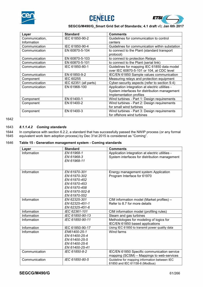
SEGCG/M490/G_Smart Grid Set of Standards; 4.1 draft v0; Jan 6th 2017
SEGCG/M490/G 61/266
Layer Standard Comments
Communication, Information
IEC 61850-90-2 Guidelines for communication to control centers
Communication IEC 61850-90-4 Guidelines for communication within substation
Communication EN 60870-5-104 to connect to the Plant (standard transport protocol)
Communication EN 60870-5-103 to connect to protection Relays
Communication EN 60870-5-101 to connect to the Plant (serial link)
Communication IEC 61850-80-1 Guidelines for mapping IEC 61850 data model over IEC 60870-5-101 or 104, at CDC level
Communication EN 61850-9-2 IEC/EN 61850 Sample values communication
Component IEC 60255 Measuring relays and protection equipment
Communication IEC 62351 (all parts) Cyber-security aspects (refer to section 9.4)
Communication EN 61968-100 Application integration at electric utilities - System interfaces for distribution management Implementation profiles
Component EN 61400-1 Wind turbines - Part 1: Design requirements
Component EN 61400-2 Wind turbines - Part 2: Design requirements for small wind turbines
Component EN 61400-3 Wind turbines - Part 3: Design requirements for offshore wind turbines
1642
8.1.1.4.2 Coming standards 1643
In compliance with section 6.2.2, a standard that has successfully passed the NWIP process (or any formal 1644 equivalent work item adoption process) by Dec 31st 2015 is considered as “Coming”. 1645
Table 15 - Generation management system - Coming standards 1646
Layer Standard Comments
Information EN 61968-1 EN 61968-3 EN 61968-11
Application integration at electric utilities - System interfaces for distribution management
Information EN 61970-301 EN 61970-302 EN 61970-452 EN 61970-453 EN 61970-458 EN 61970-502-8 EN 61970-552
Energy management system Application Program Interface for 61970
Information EN 62325-301 EN 62325-451-1 EN 62325-451-6
CIM information model (Market profiles) – Refer to 8.7 for more details
Information IEC 62361-101 CIM information model (profiling rules)
Information IEC 61850-90-13 Steam and gas turbines
Information IEC 61850-90-11 Methodologies for modeling of logics for IEC/EN 61850 based applications
Information IEC 61850-90-17 Using IEC 61850 to transmit power quality data
Information EN61400-25-1 EN 61400-25-4 EN 61400-25-5 EN 61400-25-6 EN 61400-25-41
Wind farms
Communication IEC 61850-8-2 IEC/EN 61850 Specific communication service mapping (SCSM) – Mappings to web-services
Communication IEC 61850-80-5 Guideline for mapping information between IEC
61850 and IEC 61158-6 (Modbus)
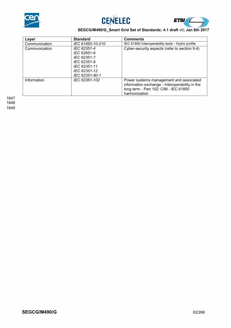
SEGCG/M490/G_Smart Grid Set of Standards; 4.1 draft v0; Jan 6th 2017
SEGCG/M490/G 62/266
Layer Standard Comments
Communication IEC 61850-10-210 IEC 61850 Interoperability tests - Hydro profile
Communication IEC 62351-4 IEC 62651-6 IEC 62351-7 IEC 62351-9 IEC 62351-11 IEC 62351-12 IEC 62351-90-1
Cyber-security aspects (refer to section 9.4)
Information IEC 62361-102 Power systems management and associated information exchange - Interoperability in the long term - Part 102: CIM - IEC 61850 harmonization
1647 1648
1649

SEGCG/M490/G_Smart Grid Set of Standards; 4.1 draft v0; Jan 6th 2017
SEGCG/M490/G 63/266
8.2 Transmission management domain 1650
The transmission domain of a power grid consists of 4 main systems in order to transmit electrical 1651 energy from generation to consumption over longer distances. 1652
Substation Automation System – elements needed to perform automated operation 1653 remotely or local of a substation, and of connected assets (grid lines, loads...). 1654
Blackout Prevention System (WAMPAC) – protect power systems from instability and collapse, 1655 whilst accommodating continuous load growth and with reduced operational margins within stability 1656 limits. 1657
EMS SCADA System – real-time information system and all the elements needed to support all the 1658 relevant operational activities and functions used in transmission automation at dispatch centers and 1659 control rooms. 1660
Flexible AC Transmission System (FACTS) – covers several power electronics based systems 1661 utilized in AC power transmission and distribution. FACTS solutions are particularly justifiable in 1662 applications requiring rapid dynamic response, ability for frequent variations in output, and/or 1663 smoothly adjustable output 1664
1665
8.2.1 Substation automation system (Transmission & Distribution) 1666
8.2.1.1 System description 1667
The Substation Automation System refers to the system and all the elements needed to perform protection, 1668 monitoring and control of a substation, and of connected assets (inside the substation such as transformers, 1669 busbar, etc or outside the substation such as grid lines, loads, etc). 1670 Substation automation system may also act as remote terminal for upper levels of grid monitoring and control 1671 for operation and/or maintenance. 1672 Some of the capabilities are fully automatic, i.e. are providing a spontaneous response of the system 1673 triggered by external events. Some others are in support of remote and/or manual operation. 1674 1675 Substation automation systems are often implemented in the Distribution, Transmission and Generation 1676 domains. They can also be implemented on large industrial sites or infrastructure. 1677 As a particular simplified case, Substation Automation System may be used for Automated MV/LV 1678 transformer Substation System, where the automated operations may include also LV feeders placed on the 1679 MV/LV transformer substation and typically (but not limited to) MV-switching elements connected to the 1680 MV/LV transformer, (controllable) MV/LV transformers and automated low-voltage boards. 1681 1682
8.2.1.2 Set of use cases 1683
Here is a set of high level use cases which may be supported by a substation automation system. 1684 The meanings of the three last columns (AVAILABLE, COMING, Not Yet) and of the “C”, “I”, “CI”, “X” 1685 conventions are given in section 7.6.2. 1686 1687
Table 16 - Substation automation system - Use cases 1688
Supported by standards
Use cases cluster
High level use cases AVAILABLE COMING Not yet
Protecting the grid assets
Protect a single equipment (incomer/feeder, transformer, generator)
CI
Protect a zone outside of the substation boundary CI
Perform networked protection logic (intertripping, logic selectivity...)
CI
Perform networked security logic (interlocking, local/remote)
CI
Set/change protection parameters CI
Monitoring electrical flows CI
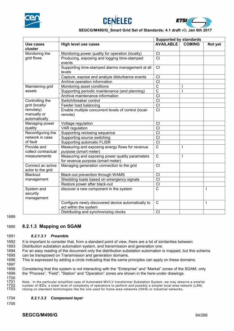
SEGCG/M490/G_Smart Grid Set of Standards; 4.1 draft v0; Jan 6th 2017
SEGCG/M490/G 64/266
Supported by standards
Use cases cluster
High level use cases AVAILABLE COMING Not yet
Monitoring the grid flows
Monitoring power quality for operation (locally) CI
Producing, exposing and logging time-stamped events
CI
Supporting time-stamped alarms management at all levels
CI
Capture, expose and analyze disturbance events CI
Archive operation information CI
Maintaining grid assets
Monitoring asset conditions C I
Supporting periodic maintenance (and planning) C I
Archive maintenance information CI
Controlling the grid (locally/ remotely) manually or automatically
Switch/breaker control CI
Feeder load balancing CI
Enable multiple concurrent levels of control (local-remote)
CI
Managing power quality
Voltage regulation CI
VAR regulation CI
Reconfiguring the network in case of fault
Supporting reclosing sequence CI
Supporting source switching CI
Supporting automatic FLISR CI
Provide and collect contractual measurements
Measuring and exposing energy flows for revenue purpose (smart meter)
C I
Measuring and exposing power quality parameters for revenue purpose (smart meter)
C I
Connect an active actor to the grid
Managing generation connection to the grid CI
Blackout management
Black-out prevention through WAMS CI
Shedding loads based on emergency signals CI
Restore power after black-out CI
System and security management
discover a new component in the system C I
Configure newly discovered device automatically to act within the system
C I
Distributing and synchronizing clocks CI
1689
8.2.1.3 Mapping on SGAM 1690
8.2.1.3.1 Preamble 1691
It is important to consider that, from a standard point of view, there are a lot of similarities between 1692 Distribution substation automation system, and transmission and generation one. 1693 For an easy reading of the document only the distribution substation automation is mapped, but this schema 1694 can be transposed on Transmission and generation domains. 1695 This is expressed by adding a circle indicating that the same principles can apply on these domains. 1696 1697 Considering that this system is not interacting with the “Enterprise” and “Market” zones of the SGAM, only 1698 the “Process”, “Field”, “Station” and “Operation” zones are shown in the here-under drawings. 1699 1700 Note : In the particular simplified case of Automated MV/LV transformer Substation System, we may observe a smal ler 1701 number of IEDs, a lower level of complexity of operations to perform and possibly a simpler local area network (LAN) 1702 relying on standard technologies like the one used for home area networks (HA N) or industrial networks. 1703
8.2.1.3.2 Component layer 1704
1705

SEGCG/M490/G_Smart Grid Set of Standards; 4.1 draft v0; Jan 6th 2017
SEGCG/M490/G 65/266
The substation automation component architecture is mostly made of 3 zones of components, which may be 1706 interconnected through wires or communication. 1707
The Process zone includes the primary equipment of the substation mainly switching (i.e. circuit-1708 breakers, switches and disconnectors), power transformer regulator and measuring elements (i.e. 1709 current and voltage sensors/transformers). 1710 Referring to the component list shown in 7.7.2, here are the most common “smart” components used at 1711 that level: 1712
o Digital sensors 1713
The Field zone includes equipment to protect, control and monitor the process of the substation, mainly 1714 through IEDs, and controllers. 1715
o IED is a generic representation covering components such as (but not limited to): 1716
Protection relays 1717
Operation, Revenue and Grid meters 1718
Fault detectors 1719
Reclosers 1720
Bay controller 1721
Generic I/O interface 1722
Switch controller 1723 o Field Controller is a generic representation covering components such as (but not limited to): 1724
Feeder controller (connecting/disconnecting/reclosing sequences) 1725
Voltage Regulator controller 1726
Network Interface Controller (NIC) 1727
Router (remote connection interface sometimes integrated in NIC) 1728
The Station zone supports the aggregation level which interface with other elements and systems of the 1729 electrical network. It is mostly supporting 4 main technical functions, which can be grouped or separated 1730 in different components, which are: 1731
o RTU which serves as terminal for remote activities, the Station controller, which is in charge of 1732 performing automatic functions, 1733
o Possibly HMI/archiving which offers the local operators capabilities of visualizing and archive 1734 local data. 1735
o Controller such as (but not limited to): 1736
Station controller 1737
Feeder controller 1738
Capacitor bank controller 1739
Load tap changer controller 1740 o Communication which can be 1741
a Network Interface Controller (NIC) 1742
and/or just a Router function 1743 1744 1745
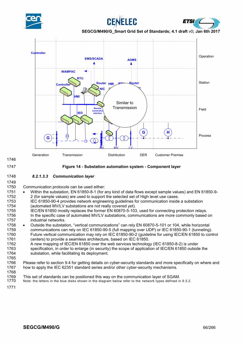
SEGCG/M490/G_Smart Grid Set of Standards; 4.1 draft v0; Jan 6th 2017
SEGCG/M490/G 66/266
1746
Figure 14 - Substation automation system - Component layer 1747
8.2.1.3.3 Communication layer 1748
1749 Communication protocols can be used either: 1750
Within the substation, EN 61850-8-1 (for any kind of data flows except sample values) and EN 61850-9-1751 2 (for sample values) are used to support the selected set of High level use cases. 1752 IEC 61850-90-4 provides network engineering guidelines for communication inside a substation 1753 (automated MV/LV substations are not really covered yet). 1754 IEC/EN 61850 mostly replaces the former EN 60870-5-103, used for connecting protection relays. 1755 In the specific case of automated MV/LV substations, communications are more commonly based on 1756 industrial networks. 1757
Outside the substation, “vertical communications” can rely EN 60870-5-101 or 104, while horizontal 1758 communications can rely on IEC 61850-90-5 (full mapping over UDP) or IEC 61850-90-1 (tunneling). 1759 Future vertical communication may rely on IEC 61850-90-2 (guideline for using IEC/EN 61850 to control 1760 centers) to provide a seamless architecture, based on IEC 61850. 1761 A new mapping of IEC/EN 61850 over the web services technology (IEC 61850-8-2) is under 1762 specification, in order to enlarge (in security) the scope of application of IEC/EN 61850 outside the 1763 substation, while facilitating its deployment. 1764
1765 Please refer to section 9.4 for getting details on cyber-security standards and more specifically on where and 1766 how to apply the IEC 62351 standard series and/or other cyber-security mechanisms. 1767 1768 This set of standards can be positioned this way on the communication layer of SGAM. 1769 Note: the letters in the blue disks shown in the diagram below refer to the network types defined in 9.3.2. 1770
1771
Generation Transmission Distribution Customer PremiseDER
Process
Field
Station
Operation
Enterprise
Market
HV MV LV
G H
ADMS
Controller
HMI
NIC
IED
Remote
connection
interface
HMI
RTU
IED
Remote
connection
interface
Controller RTU Router
EMS/SCADA
WAMPAC
Router
NIC
Similar to
Transmission
G

SEGCG/M490/G_Smart Grid Set of Standards; 4.1 draft v0; Jan 6th 2017
SEGCG/M490/G 67/266
1772
1773
Figure 15 - Substation automation system - Communication layer 1774
8.2.1.3.4 Information (Data) layer 1775
1776 The information layer of substation automation is mostly based on the IEC/EN 61850 information model. 1777 We have indicated that the EN 61850-7-4 is the core part depicting this model, however other “namespaces” 1778 of the IEC/EN 61850 series can be used such as: 1779
EN 61850-7-410: Hydro power plants 1780
EN 61850-7-420: DER 1781
EN 61400-25: Wind farms 1782
IEC 61850-90-2: Communication to control centers 1783
IEC 61850-90-3: Condition monitoring 1784
IEC 61850-90-4: Network management 1785
IEC 61850-90-5: Synchrophasors 1786
IEC 61850-90-7: PV inverters 1787 1788 For automated MV/LV substation IEC 61850-90-6 should also be considered, which is expected to be a 1789 guide for the implementation of IEC/EN 61850 on distribution automation. 1790 1791 For protocols which are not IEC/EN 61850 native such as the EN 60870-5-101 or 104, a mapping of IEC/EN 1792 61850 information model is possible using the IEC 61850-80-1, enabling users of these technologies to use 1793 the power of data model driven engineering (and then more seamless integration) without changing of 1794 communication technologies. 1795 1796
Generation Transmission Distribution Customer PremiseDER
Process
Field
Station
Operation
Enterprise
Market
IEC 61850-8-1
IEC
61
85
0-8
-1
IEC
60
87
0-5
-10
1
IEC
60
87
0-5
-10
4
IEC
61
85
0-9
0-2
IEC 61850-9-2
IEC
61
85
0-9
-2
Similar to
TransmissionIEC 61850-90-5
E
E
E
F
L F

SEGCG/M490/G_Smart Grid Set of Standards; 4.1 draft v0; Jan 6th 2017
SEGCG/M490/G 68/266
1797
1798
Figure 16 - Substation automation system - Information layer 1799
8.2.1.4 List of Standards 1800
Here is the summary of the standards which appear relevant to support substation automation system: 1801
8.2.1.4.1 Available standards 1802
In compliance with section 6.2.2, a standard (or “open specification”) that has reached its final stage (IS, TS 1803 or TR …) by Dec 31st 2015 is considered as “available”. 1804
Table 17 - Substation automation system (Transmission & Distribution) - Available standards 1805
Layer Standard Comments
Information EN 61850-7-4 EN 61850-7-3 EN 61850-7-2 EN 61850-6
Core Information model and language for the IEC/EN 61850 series
Information EN 61850-7-410 Hydro power plants
Information EN 61850-7-420 DER
Information IEC 61850-80-1 Mapping of IEC/EN 61850 data model over 60870-5-101 and 104
Information IEC 61850-80-4 Mapping between the DLMS/COSEM (IEC 62056) data models and the IEC 61850 data models
Information IEC 61850-90-3 Condition monitoring
Information IEC 61850-90-7 inverter-based DER interface
Information EN 61400-25 Wind farms
Information EN 61968 (all parts) Common Information Model (System Interfaces For Distribution Management)
Information EN 61970 (all parts) Common Information Model (System Interfaces For Energy Management)
Generation Transmission Distribution Customer PremiseDER
Process
Field
Station
Operation
Enterprise
Market
IEC 61850-7-4*
IEC 61850-7-4*
* : IEC 61850 contains also other namespaces which
can be of interest :
IEC 61850-7-410 : Hydro powerplants
IEC 61850-7-420 : DER
IEC 61400-25 : Wind farms
IEC 61850-90-5 : synchrophasors
IEC 61850-90-2 : communication to control centers
IEC 61850-90-4 : Network management
IEC 61850-90-3 : condition monitoring
IEC 61850-90-7 : PV inverters
IEC
61
85
0-7
-4*
IEC
61
85
0-7
-4*
IEC
61
85
0-8
0-1
IEC
61850-7-
4*
IEC 61968
IEC 61970
Similar to
Transmission

SEGCG/M490/G_Smart Grid Set of Standards; 4.1 draft v0; Jan 6th 2017
SEGCG/M490/G 69/266
Layer Standard Comments
Communication EN 61850-8-1 IEC/EN 61850 communication except Sample values
Communication EN 61850-9-2 IEC/EN 61850 Sample values communication
Communication IEC 61850-90-1 Use of IEC/EN 61850 for the communication between substations
Information, Communication
IEC 61850-90-2 Guidelines for communication to control centers
Information, Communication
IEC 61850-90-4 Guidelines for communication within substation
Communication IEC 61850-90-5 Use of IEC/EN 61850 to transmit synchrophasor information according to IEEE C37.118. May also be relevant for use between substations
Communication IEC 61850-90-12 Use of IEC 61850 over WAN
Communication EN 60870-5-101 Telecontrol equipment and systems – Part 5-101: Transmission protocols – Companion standard for basic telecontrol tasks
Communication EN 60870-5-103 Telecontrol equipment and systems – Part 5-103: Transmission protocols – Companion standard for the informative interface of protection equipment
Communication EN 60870-5-104 Telecontrol equipment and systems – Part 5-104: Transmission protocols – Network access for EN 60870-5-101 using standard transport profiles
Communication IEC 60255-24 Electrical relays - Part 24: Common format for transient data exchange (COMTRADE) for power systems
Communication EN 62439 High availability automation Networks (PRP y HSR)
Component IEC 62271-3 High-voltage switchgear and controlgear; Part 3:Digital interfaces based on IEC 61850
Component EN 61850-3 General requirements for Power utility automation systems
Component EN 61869 Instrument transformers
Communication IEC 62351 (all parts) Cyber-security aspects (refer to section 9.4)
Communication IEC 61158 (all parts) This standards series includes many industrial communication protocols which may partly answer substation automation systems requirements
8.2.1.4.2 Coming standards 1806
In compliance with section 6.2.2, a standard that has successfully passed the NWIP process (or any formal 1807 equivalent work item adoption process) by Dec 31st 2015 is considered as “Coming”. 1808
Table 18 - Substation automation system (Transmission & Distribution) - Coming standards 1809
Layer Standard Comments
Information EN 61850-7-4 EN 61850-7-3 EN 61850-7-2 EN 61850-6
Core Information model and language for the IEC/EN 61850 series
Information, Communication
IEC 61850-90-6 Guideline for use of IEC/EN 61850 on Distribution automation
Information IEC 61850-90-11 Methodologies for modeling of logics for IEC/EN 61850 based applications
Information EN 61968-1 EN61689-3
Common Information Model (System Interfaces For Distribution Management)

SEGCG/M490/G_Smart Grid Set of Standards; 4.1 draft v0; Jan 6th 2017
SEGCG/M490/G 70/266
Layer Standard Comments
EN 61968-11 EN61689-13
Information EN 61970-301 Common Information Model (System Interfaces For Energy Management)
Information IEC 61850-90-17 Using IEC 61850 to transmit power quality data
Communication IEC 61850-8-2 IEC/EN 61850 Specific communication service mapping (SCSM) – Mappings to web-services
Communication EN 61850-9-2 IEC/EN 61850 Sample values communication
Communication IEC 61850-80-5 Guideline for mapping information between IEC 61850 and IEC 61158-6 (Modbus)
Component IEC 62271-3 High-voltage switchgear and controlgear; Part 3:Digital interfaces based on IEC 61850
Component IEC 62689-1 IEC 62689-2
Current and Voltage sensors or detectors, to be used for fault passage indication purposes
Component IEC 62689-3 IEC 62689-4 IEC 62689-100
Current and Voltage sensors or detectors, to be used for fault passage indication purposes
Component IEC 62689-3 IEC 62689-4 IEC 62689-100
Instrument transformers Part 6 – Additional general requirements for Low power IT Part 9 – Digital interface
Communication IEC 62351-4 IEC 62651-6 IEC 62351-7 IEC 62351-9 IEC 62351-11 IEC 62351-12 IEC 62351-90-1
Cyber-security aspects (refer to section 9.4)
Information IEC 62361-102 Power systems management and associated information exchange - Interoperability in the long term - Part 102: CIM - IEC 61850 harmonization
1810
8.2.2 Blackout Prevention System - Wide Area Measurement Protection and Control 1811
System (WAMPAC) 1812
8.2.2.1 Context description 1813
The challenge posed by Smart Grid implementation and the increased unpredictable intermittency of 1814 generation; the more sophisticated and automated adaptation of consumption based on market and/or local 1815 conditions; combined with the use of grids closer to their limits, leads to a change from the quasi-static state 1816 of the grid to a more complex and highly dynamic behaviour. Therefore the current available supervision, 1817 management and control functions will need to be adapted, in addition to the implementation of some 1818 specific systems put in place to prevent black-out or at least to reduce the size of the impact of blackouts. 1819 1820 State estimation, for example, will have to include the transient behaviour of the grid. In addition, the 1821 traditional power, voltage and current measurements must be extended to phasor measurement provided by 1822 PMUs (Phasor Measurement Units). 1823 1824 An optimal representation and visualization as well as decision-supporting tools must be developed in order 1825 to support the operator of such complex systems. Massive amounts of data must be transmitted, 1826 synchronized and represented in a way to safeguard the system integrity of the overall transmission grid. 1827 1828 Although it is not possible to avoid multiple contingency blackouts, the probability, size, and impact of 1829 widespread outages could be reduced. Investment strategies in strengthening the electrical grid 1830 infrastructure, such as rebuilding the T&D grid, installing new generation and control systems (e.g. reactive 1831

SEGCG/M490/G_Smart Grid Set of Standards; 4.1 draft v0; Jan 6th 2017
SEGCG/M490/G 71/266
power devices, Flexible AC Transmission Systems (FACTSs) and High-Voltage DC (HVDC)) should be 1832 emphasized. The use of Wide-Area Monitoring, Protection And Control (WAMPAC) schemes should be 1833 viewed as a cost-effective solution to further improve grid reliability and should be considered as a 1834 complement to other vital grid enhancement investment strategies. 1835
8.2.2.2 System description 1836
The objectives of a WAMPAC system are to protect power systems from instabilities and collapses with 1837 continuous load growth and with reduced operational margins within stability limits. In contrast to 1838 conventional protection devices which provide local protection of individual equipment (transformer, 1839 generator, line, etc…), the WAMPAC provides comprehensive protection covering the whole power system. 1840 The system utilizes phasors, which are measured with high time accuracy along with PMU units installed in 1841 the power system. WAMPAC can be seen as a complement to SCADA, FACTS and Substation Automation 1842 systems for a region/country power network. 1843
8.2.2.3 Set of use cases 1844
Here is a set of high level use cases which may be supported by a WAMPAC. 1845 The meanings of the three last columns (AVAILABLE, COMING, Not Yet) and of the “C”, “I”, “CI”, “X” 1846 conventions are given in section 7.6.2. 1847 1848
Table 19 - WAMPAC - Use cases 1849
Supported by standards
Use cases cluster
High level use cases AVAILABLE COMING Not yet
Blackout management
Black-out prevention through WAMPAC C
System and security management
Distributing and synchronizing clocks C
1850
8.2.2.4 Mapping on SGAM 1851
8.2.2.4.1 Preamble 1852
Considering that this system is not interacting with the “Enterprise” and “Market” zones of the SGAM, only 1853 the “Process”, “Field”, “Station” and “Operation” zones are shown in the following drawings. 1854
8.2.2.4.2 Component layer 1855
The WAMPAC component architecture is mostly present on 3 zones, which may be interconnected through 1856 wired connection and digital communication link. 1857
The Process zone is mostly (but not only) made of sensors (such as current and voltage transformers) 1858 and of actuators (such as breakers or switches) 1859
1860
The Field zone is made of PMUs/IEDs, which mostly handle equipment protection, monitoring and 1861 control features, and for data streaming of the measurements from the power system 1862
1863
The Station/Operation zone is mostly supporting three main technical functions, which can be grouped 1864 separated in different components: WAMPAC application (e.g. SIPS) based on phasor measurements 1865 collected from the PMUs/IEDs in the power system, SCADA application based on phasor measurements 1866 and substation automation systems for monitoring and control. 1867
1868 1869

SEGCG/M490/G_Smart Grid Set of Standards; 4.1 draft v0; Jan 6th 2017
SEGCG/M490/G 72/266
1870
Figure 17 - WAMPAC - Component layer 1871
1872
Generation Transmission Distribution Customer PremiseDER
Process
Field
Station
Operation
Enterprise
Market
HV MV
WAMS
(Application Server)
Phasor
Data
concentrator
PMU
Remote
connection
interface
Remote
connection
interface
EMS/
SCADA
system
Substation
Automation
System
PMU

SEGCG/M490/G_Smart Grid Set of Standards; 4.1 draft v0; Jan 6th 2017
SEGCG/M490/G 73/266
8.2.2.4.3 Communication layer 1873
1874 Communication protocols can be used either: 1875
Within the WAMPAC, EN 61850-8-1 (for any kind of data flows except sample values) is used to support 1876 the selected set of generic Use cases. 1877 IEC 61850-90-4 provides detailed guidelines for communication inside a substation. 1878 IEC/EN 61850 mostly replaces the former EN 60870-5-103, used for connecting PMUs/IEDs. 1879
Vertical communications can rely EN 60870-5-101 or 104, while horizontal communications can rely on 1880 IEC 61850-90-5 (full mapping over UDP) or IEC 61850-90-1 (tunneling). 1881 Future vertical communication may rely on IEC 61850-90-2 (guideline for using IEC/EN 61850 to control 1882 centers) to provide a seamless architecture, based on IEC 61850. 1883
1884 Please refer to section 9.4 for getting details on cyber-security standards and more specifically on where and 1885 how to apply the IEC 62351 standard series and/or other cyber-security mechanisms. 1886 1887 The set of standards can be positioned as follows on the communication layer of SGAM. 1888 Note: the letters in the blue disks shown in the diagram below refer to the network types defined in 9.3.2. 1889
1890 1891
1892
Figure 18 - WAMPAC - Communication layer 1893
1894
Generation Transmission Distribution Customer PremiseDER
Process
Field
Station
Operation
Enterprise
Market
HV MV
WAMS
(Application Server)
Phasor
Data
concentrator
PMU
Remote
connection
interface
Remote
connection
interface
EMS/
SCADA
system
Substation
Automation
System
PMU
IEC 61850-90-5/1 IEC 61850-90-2
IEC 60870-5-101 IEC 60870-5-104
IEC 61850-8-1 IEC 61850-90-5
IEC 61850-90-5
EN 61850-8-1
IEC 61968-100
E
FL
E

SEGCG/M490/G_Smart Grid Set of Standards; 4.1 draft v0; Jan 6th 2017
SEGCG/M490/G 74/266
8.2.2.4.4 Information (Data) layer 1895
1896 The information layer is mostly based on the IEC/EN 61850 information model: 1897
IEC 61850-90-2: Communication to control centers 1898
IEC 61850-90-3: Condition monitoring 1899
IEC 61850-90-5: Synchrophasors 1900 1901 For protocols which are not IEC/EN 61850 native such as the EN 60870-5-101 or 104, a mapping of IEC/EN 1902 61850 information model is possible using the IEC 61850-80-1, enabling users of these technologies to use 1903 the power of data modeling (and then more seamless integration) without changing communication 1904 technologies. 1905 1906
1907
Figure 19 - WAMPAC - Information layer 1908
8.2.2.5 List of Standards 1909
1910 Here is the summary of the standards which appear relevant to WAMPAC: 1911
8.2.2.5.1 Available standards 1912
1913 In compliance with section 6.2.2, a standard (or “open specification”) that has reached its final stage (IS, TS 1914 or TR …) by Dec 31st 2015 is considered as “available”. 1915
Table 20 - WAMPAC - Available standards 1916
Generation Transmission Distribution Customer PremiseDER
Process
Field
Station
Operation
Enterprise
Market
HV MV
WAMS
(Application Server)
Phasor
Data
concentrator
PMU
Remote
connection
interface
Remote
connection
interface
EMS/
SCADA
system
Substation
Automation
System
PMU
IEC 61850-90-2: communication to control centers IEC 61850-90-3: Conditioned monitoring IEC 61850-90-5: Synchrophasers
IEC 61850-90-2 IEC 61850-90-3 IEC 61850-90-5
IEC 61850-90-5

SEGCG/M490/G_Smart Grid Set of Standards; 4.1 draft v0; Jan 6th 2017
SEGCG/M490/G 75/266
Layer Standard Comments
Information EN 61850-7-4 EN 61850-7-3 EN 61850-7-2 EN 61850-6
Core Information model and language for the IEC/EN 61850 series
Information IEC 61850-80-1 Mapping of IEC/EN 61850 data model over 60870-5-101 and 104
Information IEC 61850-90-4 Network Engineering Guidelines for IEC/EN 61850 based system (including clock synchronization guidelines)
Communication EN 61850-8-1 IEC/EN 61850 communication except Sample values
Communication IEC 61850-90-1 Use of IEC/EN 61850 for the communication between substations
Communication EN 60870-5-101 Telecontrol equipment and systems – Part 5-101: Transmission protocols – Companion standard for basic telecontrol tasks
Communication EN 60870-5-103 Telecontrol equipment and systems – Part 5-103: Transmission protocols – Companion standard for the informative interface of protection equipment
Communication EN 60870-5-104 Telecontrol equipment and systems – Part 5-104: Transmission protocols – Network access for EN 60870-5-101 using standard transport profiles
Communication EN 61850-9-2 IEC/EN 61850 Sample values communication
Communication IEC 61850-90-5 Use of IEC/EN 61850 to transmit synchrophasor information according to IEEE C37.118.
Communication IEEE C37.118 Synchrophasors for power systems
Communication IEEE 1344 IRIG-B extension
Communication IEC 61588 (IEEE 1588) PTP (Precision Time protocol)
Information ISO 8601 (IEC 28601) Data elements and interchange format – Representation of dates and times Coordinated Universal Time (UTC)
Component EN 61869 Instrument transformers
Communication IEC 62351 (all parts) Cyber-security aspects (refer to section 9.4)
1917
8.2.2.5.2 Coming standards 1918
In compliance with section 6.2.2, a standard that has successfully passed the NWIP process (or any formal 1919 equivalent work item adoption process) by Dec 31st 2015 is considered as “Coming”. 1920
Table 21 - WAMPAC - Coming standards 1921
Layer Standard Comments
Communication, Information
IEC 61850-90-2 Communication to control centers
Information IEC 61850-90-3 Condition monitoring
Communication IEC 61850-8-2 IEC/EN 61850 Specific communication service mapping (SCSM) – Mappings to web-services
Component EN 61869
Instrument transformers Part 6 – Additional general requirements for Low power IT Part 9 – Digital interface
Communication IEC 62351 (all parts) Cyber-security aspects (refer to section 9.4)

SEGCG/M490/G_Smart Grid Set of Standards; 4.1 draft v0; Jan 6th 2017
SEGCG/M490/G 76/266
8.2.3 EMS SCADA system 1922
8.2.3.1 System description 1923
The nature of transmission networks will change and grow in importance due to Smart Grid. The increased 1924 distance of bulk power generation and load centres will result in a tendency to interconnect systems that 1925 used to be independent. Furthermore the exchange and trade of power over long distances will grow in the 1926 future. 1927 Information exchange may be necessary across large geographical areas and across traditional systems 1928 operation boundaries. 1929 Transmission networks are equipped for obtaining a large number of measurement values; they are able to 1930 determine the current load flow situation by means of estimation algorithms. In an estimate, the algorithm 1931 uses a numerical network model to try to find a load flow solution in which the root mean square value of the 1932 difference between the load flow solution and measurement values is minimal. The estimation of the network 1933 state supplies the operator with a complete load flow solution for supervising the network, including those 1934 sections of the network for which no measurement values are transmitted to the control system. 1935 The network state estimation is generally followed by a limit value monitoring process that compares the 1936 result of the estimation with the operating limits of the individual operational equipment, in order to inform the 1937 operator about overloads or other limit value infringements in a timely fashion. 1938 The load flow solution of the network state estimation is then used for ongoing functions such as outage 1939 analysis, short-circuit analysis or optimizing load flow as a basic solution for further calculations. 1940 The outage analysis carries out “What if?” studies in which the failure of one or more items of operational 1941 equipment is simulated. The results of these load flow calculations are then compared with the operational 1942 equipment limits in order to be able to detect secondary faults resulting from an operational equipment 1943 failure. If such violations of the so-called (n-1) security are detected, an attempt can be made by, for 1944 example, using a bottleneck management application to define measures with which (n-1) security can be 1945 reestablished. 1946 The short-circuit analysis simulates short-circuit situations for all kinds of different network nodes on the 1947 basis of numerical model calculations. It checks whether the ensuing short-circuit currents are within the 1948 operational equipment limits. The quantities to be checked are the breaking power of the circuit breakers and 1949 the peak short-circuit current strength of the systems. Here again, the operator is informed about any limit 1950 violations so that suitable remedial action can be taken in a timely fashion. 1951 The optimizing load flow attempts to determine an optimum network state by varying the controlled variables 1952 in the power supply system. The following target functions for “optimum” are possible: 1953 The voltage/reactive power optimization attempts to minimize the reactive power flow in the network in order 1954 to reduce transmission losses. In particular, the reactive power generation of the generators or compensation 1955 equipment and the setting levels of the in-phase regulator act as controlled variables. 1956 The active power optimization system tries to minimize the transmission losses by re-dispatching the 1957 incoming supplies from the generator. Any available quadrature or phase-angle regulators can also be used 1958 for optimization. 1959 If system reliability has been selected as the target function of the optimization, the optimizing load flow tries 1960 to find a system state in which the capacity of all operational equipment is utilized as evenly as possible. The 1961 purpose of this is to avoid further secondary failures in the event of failure of heavily utilized resources. 1962 The challenge posed by Smart Grid implementation and the increased use of bulk power transmission will be 1963 a change from the quasi-static state of the transmission grid to a more complex and dynamic behaviour. 1964 Therefore the current available supervision, management and control functions will need to be adapted. 1965 State estimation, for example, will have to include the transient behaviour of the net. In addition, the 1966 traditional power, voltage and current measurements must be extended to phasor measurement provided by 1967 PMUs (Phasor Measurement Units). 1968 An optimal representation and visualization as well as decision-supporting tools must be developed in order 1969 to support the operator of such complex systems. The massive amount of data must be transmitted, 1970 synchronized and represented in a way to safeguard the system integrity of the overall transmission net. 1971 1972 EMS SCADA System refers to the real-time information system and all the elements needed to support all 1973 the relevant operational activities and functions used in transmission automation at dispatch centers and 1974 control rooms. It improves the information made available to operators at control room, field and crew 1975 personnel, management and in certain cases to parties connected to the transmission system, i.e. 1976 distribution network operators, power producers, etc. 1977

SEGCG/M490/G_Smart Grid Set of Standards; 4.1 draft v0; Jan 6th 2017
SEGCG/M490/G 77/266
Such system is usually made of one or many interconnected IT systems, connected to field communicating 1978 devices or sub-systems, through the use of WAN communication systems. It may also include the 1979 components needed to enable field crew to operate the network from the field. 1980 EMS SCADA provides following major functions: 1981
SCADA, real time monitoring and control of the generation system 1982
advanced network applications including network modeling 1983
outage management including crew & resource management 1984
work management 1985
geographical information system (GIS) 1986 1987
8.2.3.2 Set of high level use cases 1988
Here is the set of high level use cases which may be supported by a EMS SCADA System.: 1989 The meanings of the three last columns (AVAILABLE, COMING, Not Yet) and of the “C”, “I”, “CI”, “X” 1990 conventions are given in section 7.6.2. 1991
Table 22 - EMS SCADA system - Use cases 1992
Supported by standards
Use cases cluster
High level use cases AVAILABLE COMING Not yet
Monitoring the grid flows
Monitoring electrical flows CI
Monitoring power quality for operation (locally) CI
Producing, exposing and logging time-stamped events
Supporting time-stamped alarms management at all levels
Capture, expose and analyze disturbance events
Archive operation information CI
Maintaining grid assets
Monitoring assets conditions CI X
Supporting periodic maintenance (and planning) X
Optimize field crew operation X
Archive maintenance information CI
Controlling the grid (locally/ remotely) manually or automatically
Switch/breaker control CI
Enable multiple concurrent levels of control (local-remote)
Managing power quality
VAR regulation CI
Operate DER(s) DER remote control (dispatch) X
Connect an active actor to the grid
Managing microgrid transitions X
Managing generation connection to the grid CI
Blackout management
Black-out prevention through WAMPAC
Shedding loads based on emergency signals
Demand and production (generation) flexibility
Receiving metrological or price information for further action by consumer or CEM
Load forecast (from remote based on revenue metering)
CI
Generation forecast (from remote) CI
System and security management
Distributing and synchronizing clocks
1993 1994

SEGCG/M490/G_Smart Grid Set of Standards; 4.1 draft v0; Jan 6th 2017
SEGCG/M490/G 78/266
8.2.3.3 Mapping on SGAM 1995
8.2.3.3.1 Preamble: 1996
1997 The EMS SCADA interacts with the GIS, the field force management system as well as the asset 1998 management system. The EMS SCADA is managing the on-line operation of the transmission assets and 1999 the transmission system as a whole. Regarding the network stability and balancing between production and 2000 demand there is the necessary interaction with distribution and power plants connected to the transmission 2001 system. 2002 2003
8.2.3.3.2 Component layer 2004
2005 The EMS SCADA component architecture is given in the diagram below. Data and information of the actual 2006 status of the transmission system is available on-line through the RTUs of all substations and transformer 2007 stations in the network. The transmission network is operated and controlled from the dispatch centers by 2008 remote controlled circuit breakers in all relevant fields of the network. These circuit breakers are controlled by 2009 the operators in the network dispatch centers. The operators are supported (coached and controlled) by the 2010 EMS SCADA system regarding energy flows in the network, during normal, maintenance and emergency 2011 operation of (parts) of the network. 2012 2013
2014
Figure 20 - EMS SCADA system - Component layer 2015
Generation Transmission Distribution Customer PremiseDER
Process
Field
Station
Enterprise
Market
Operation
RTU
Field
Devices
Generation
Management
System
Asset
Management
system
Market Place
system
Communication
Front-end
SCADA
GIS
Substation automation system
FACTS
DMS/SCADA
system
WAMS
Generation Transmission Distribution Customer PremiseDER
Process
Field
Station
Enterprise
Market
Operation
RTU
Field
Devices
Generation
Management
System
Asset
Management
system
Market Place
system
Communication
Front-end
SCADA
GIS
Substation automation system
FACTS
DMS/SCADA
system
WAMS
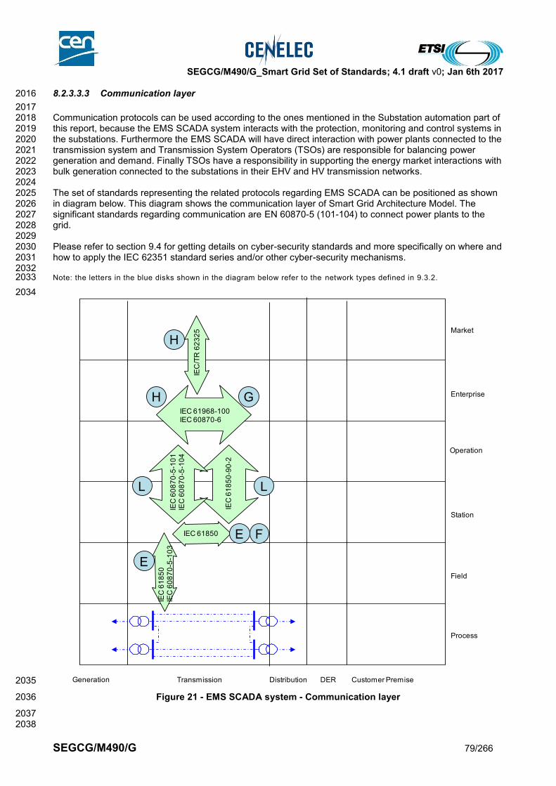
SEGCG/M490/G_Smart Grid Set of Standards; 4.1 draft v0; Jan 6th 2017
SEGCG/M490/G 79/266
8.2.3.3.3 Communication layer 2016
2017 Communication protocols can be used according to the ones mentioned in the Substation automation part of 2018 this report, because the EMS SCADA system interacts with the protection, monitoring and control systems in 2019 the substations. Furthermore the EMS SCADA will have direct interaction with power plants connected to the 2020 transmission system and Transmission System Operators (TSOs) are responsible for balancing power 2021 generation and demand. Finally TSOs have a responsibility in supporting the energy market interactions with 2022 bulk generation connected to the substations in their EHV and HV transmission networks. 2023 2024 The set of standards representing the related protocols regarding EMS SCADA can be positioned as shown 2025 in diagram below. This diagram shows the communication layer of Smart Grid Architecture Model. The 2026 significant standards regarding communication are EN 60870-5 (101-104) to connect power plants to the 2027 grid. 2028 2029 Please refer to section 9.4 for getting details on cyber-security standards and more specifically on where and 2030 how to apply the IEC 62351 standard series and/or other cyber-security mechanisms. 2031 2032 Note: the letters in the blue disks shown in the diagram below refer to the network types defined in 9.3.2. 2033
2034
2035
Figure 21 - EMS SCADA system - Communication layer 2036
2037 2038
Generation Transmission Distribution Customer PremiseDER
Process
Field
Station
Enterprise
Market
Operation
IEC 61850
IEC
61
85
0-9
0-2
IEC
/TR
62
32
5
IEC 61968-100IEC 60870-6
IEC
60
87
0-5
-10
1IE
C 6
08
70
-5-1
04
IEC
61
85
0IE
C 6
08
70
-5-1
03
L L
E
E
F
H G
H
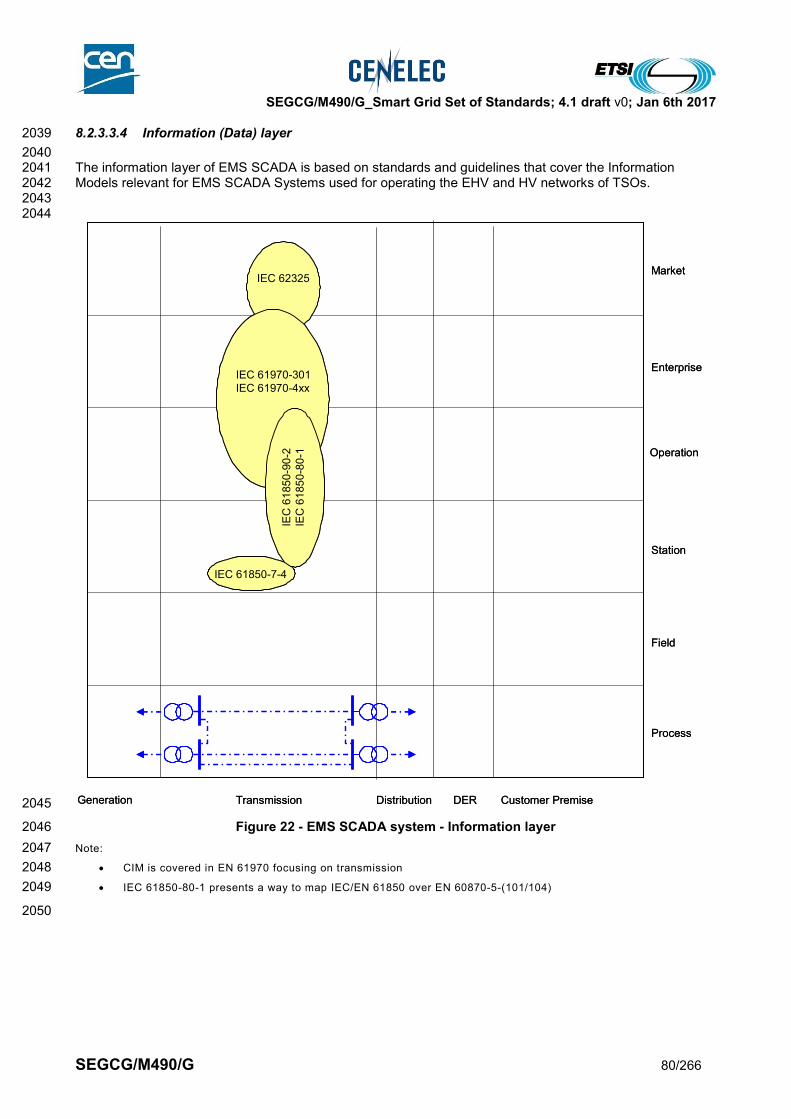
SEGCG/M490/G_Smart Grid Set of Standards; 4.1 draft v0; Jan 6th 2017
SEGCG/M490/G 80/266
8.2.3.3.4 Information (Data) layer 2039
2040 The information layer of EMS SCADA is based on standards and guidelines that cover the Information 2041 Models relevant for EMS SCADA Systems used for operating the EHV and HV networks of TSOs. 2042 2043 2044
2045
Figure 22 - EMS SCADA system - Information layer 2046
Note: 2047
CIM is covered in EN 61970 focusing on transmission 2048
IEC 61850-80-1 presents a way to map IEC/EN 61850 over EN 60870-5-(101/104) 2049
2050
Generation Transmission Distribution Customer PremiseDER
Process
Field
Station
Enterprise
Market
Operation
IEC 61850-7-4
IEC 62325
IEC 61970-301
IEC 61970-4xx
IEC
61
85
0-9
0-2
IEC
61
85
0-8
0-1
Generation Transmission Distribution Customer PremiseDER
Process
Field
Station
Enterprise
Market
Operation
IEC 61850-7-4
IEC 62325
IEC 61970-301
IEC 61970-4xx
IEC
61
85
0-9
0-2
IEC
61
85
0-8
0-1

SEGCG/M490/G_Smart Grid Set of Standards; 4.1 draft v0; Jan 6th 2017
SEGCG/M490/G 81/266
8.2.3.4 List of Standards 2051
Here is the summary of the standards which appear relevant to support EMS SCADA System. According to 2052 section 6.2.2, standards for cross-cutting issues such as EMC, security are treated separately (IEC 62351, 2053 ISO/IEC 27001, EN 61000 etc.) 2054
8.2.3.4.1 Available standards 2055
In compliance with section 6.2.2, a standard (or “open specification”) that has reached its final stage (IS, TS 2056 or TR …) by Dec 31st 2015 is considered as “available”. 2057
Table 23 - EMS SCADA system - Available standards 2058
Layer Standard Comments
Information EN 61970-1 EN 61970-2 EN 61970-301 EN 61970-401 EN 61970-453 EN 61970-501 EN 61970-552
Energy management system Application Program Interface
Information IEC 61970-452 Energy management system Application Program Interface (EMS-API) - Part 452: CIM Static Transmission Network Model Profiles
Information IEC 61970-456 Energy management system application program interface (EMS-API) - Part 456: Solved power system state profiles
Communication, Information
IEC 62325 Framework market communication
Communication EN 60870-5-101 EN 60870-5-104 EN 60870-6 series EN 60870-6-2 EN 60870-6-501 EN 60870-6-502 EN 60870-6-503 EN 60870-6-601 EN 60870-6-701 EN 60870-6-702 EN 60870-6-802
Telecontrol equipment and systems - Part 6: Telecontrol protocols compatible with ISO standards and ITU-T recommendations
Information IEC/EN 61850 (all parts) See substation automation system in 8.3.1
Information IEC 62361-100 Harmonization of quality codes
General IEC 62357 Reference architecture power system information exchange
Communication IEC 62351 (all parts) Cyber-security aspects (refer to section 9.4)
2059
8.2.3.4.2 Coming standards 2060
In compliance with section 6.2.2, a standard that has successfully passed the NWIP process (or any formal 2061 equivalent work item adoption process) by Dec 31st 2015 is considered as “Coming”. 2062 2063 The list below is closely related with the substation automation system paragraph (ref 8.3.1) for the 2064 communication and information exchange within substations and from substation to the dispatch centers. 2065 2066
Table 24 - EMS SCADA system - Coming standards 2067
Layer Standard Comments
Information & Communication
IEC/EN 61850 See Substation automation paragraph
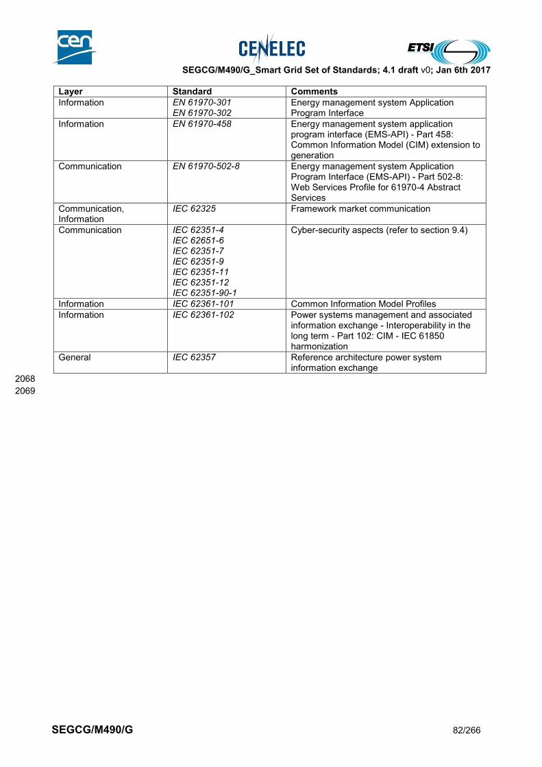
SEGCG/M490/G_Smart Grid Set of Standards; 4.1 draft v0; Jan 6th 2017
SEGCG/M490/G 82/266
Layer Standard Comments
Information EN 61970-301 EN 61970-302
Energy management system Application Program Interface
Information EN 61970-458 Energy management system application program interface (EMS-API) - Part 458: Common Information Model (CIM) extension to generation
Communication EN 61970-502-8 Energy management system Application Program Interface (EMS-API) - Part 502-8: Web Services Profile for 61970-4 Abstract Services
Communication, Information
IEC 62325 Framework market communication
Communication IEC 62351-4 IEC 62651-6 IEC 62351-7 IEC 62351-9 IEC 62351-11 IEC 62351-12 IEC 62351-90-1
Cyber-security aspects (refer to section 9.4)
Information IEC 62361-101 Common Information Model Profiles
Information IEC 62361-102 Power systems management and associated information exchange - Interoperability in the long term - Part 102: CIM - IEC 61850 harmonization
General IEC 62357 Reference architecture power system information exchange
2068
2069
SEGCG/M490/G_Smart Grid Set of Standards; 4.1 draft v0; Jan 6th 2017
SEGCG/M490/G 83/266
8.2.4 Flexible AC Transmission Systems (FACTS) 2070
8.2.4.1 Context description 2071
Today’s power transmission systems have the task of transmitting power from point A to point B reliably, 2072 safely and efficiently. It is also necessary to transmit power in a manner that is not harmful to the 2073 environment. 2074 Typical transmission applications are FACTS (Flexible AC Transmission Systems) and HVDC (High Voltage 2075 Direct Current). 2076 The use cases for FACTS include fast voltage control, increased transmission capacity over long lines, 2077 power flow control in meshed systems and power oscillation damping. With FACTS, more power can be 2078 transmitted within the power system. When the technical or economical feasibility of the conventional three 2079 phase technology reaches its limit, HVDC will be a solution. Its main application areas are economical 2080 transmission of bulk power over long distances and interconnection of asynchronous power grids. 2081 The new system of voltage-sourced converters (VSC) includes a compact layout of the converter stations 2082 and advanced control features such as independent active and reactive power control and black start 2083 capability. 2084 The main types of HVDC converters are distinguished by their DC circuit arrangements, as follows: 2085
Back-to-back: 2086 Indicates that the rectifier and inverter are located in the same station. These converters are mainly used: 2087
To connect asynchronous high-voltage power systems or systems with different frequencies 2088
To stabilize weak AC links or to supply even more active power where the AC system reaches the limit 2089 of short circuit capability 2090
Grid power flow control within synchronous AC systems 2091
Cable transmission: 2092 The most feasible solution for transmitting power across the sea with cables to supply islands/offshore 2093 platforms from the mainland and vice versa. 2094
Long-distance transmission: 2095 For transmission of bulk power over long distances (beyond approximately 600 km, considered as the break-2096 even distance). This includes voltage levels of 800kV and higher. 2097 2098 Flexible AC Transmission Systems (FACTS) have been evolving into a mature technology with high power 2099 ratings. This technology, proven in various applications requiring rapid dynamic response, ability for frequent 2100 variations in output, and/or smoothly adjustable output, has become a first-rate, highly reliable one. FACTS, 2101 based on power electronics, have been developed to improve the performance of weak AC systems and to 2102 make long distance AC transmission feasible. FACTS can also help solve technical problems in the 2103 interconnected power systems. 2104 FACTS are available in parallel connection: 2105
Static Var Compensator (SVC) 2106
Static Synchronous Compensator (STATCOM) 2107 or in series connection: 2108
Fixed Series Compensation (FSC) 2109
Thyristor Controlled/Protected Series Compensation (TCSC/TPSC) 2110
8.2.4.2 System description 2111
“FACTS” (Flexible AC Transmission Systems) covers several power electronics based systems utilized in AC 2112 power transmission and distribution. FACTS solutions are particularly justifiable in applications requiring 2113 rapid dynamic response, ability for frequent variations in output, and/or smoothly adjustable output. Under 2114 such conditions, FACTS is a highly useful option for enabling or increasing the utilization of transmission and 2115 distribution grids. With FACTS, a number of benefits can be attained in power systems, such as dynamic 2116 voltage control, increased power transmission capability and stability, facilitating grid integration of renewable 2117 power, and maintaining power quality in grids dominated by heavy and complex industrial loads. 2118 2119 FACTS devices can be sub-divided into two groups: 2120
Shunt devices such as SVC and STATCOM 2121
Series Capacitors 2122 2123
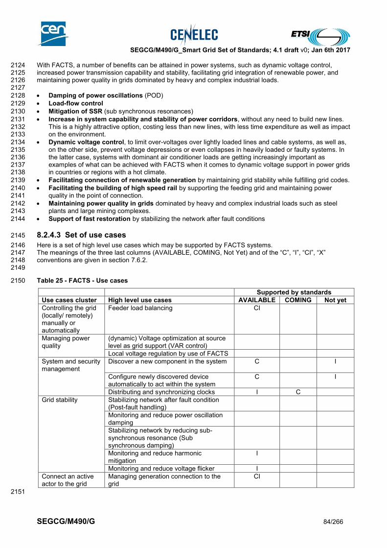
SEGCG/M490/G_Smart Grid Set of Standards; 4.1 draft v0; Jan 6th 2017
SEGCG/M490/G 84/266
With FACTS, a number of benefits can be attained in power systems, such as dynamic voltage control, 2124 increased power transmission capability and stability, facilitating grid integration of renewable power, and 2125 maintaining power quality in grids dominated by heavy and complex industrial loads. 2126 2127
Damping of power oscillations (POD) 2128
Load-flow control 2129
Mitigation of SSR (sub synchronous resonances) 2130
Increase in system capability and stability of power corridors, without any need to build new lines. 2131 This is a highly attractive option, costing less than new lines, with less time expenditure as well as impact 2132 on the environment. 2133
Dynamic voltage control, to limit over-voltages over lightly loaded lines and cable systems, as well as, 2134 on the other side, prevent voltage depressions or even collapses in heavily loaded or faulty systems. In 2135 the latter case, systems with dominant air conditioner loads are getting increasingly important as 2136 examples of what can be achieved with FACTS when it comes to dynamic voltage support in power grids 2137 in countries or regions with a hot climate. 2138
Facilitating connection of renewable generation by maintaining grid stability while fulfilling grid codes. 2139
Facilitating the building of high speed rail by supporting the feeding grid and maintaining power 2140 quality in the point of connection. 2141
Maintaining power quality in grids dominated by heavy and complex industrial loads such as steel 2142 plants and large mining complexes. 2143
Support of fast restoration by stabilizing the network after fault conditions 2144
8.2.4.3 Set of use cases 2145
Here is a set of high level use cases which may be supported by FACTS systems. 2146 The meanings of the three last columns (AVAILABLE, COMING, Not Yet) and of the “C”, “I”, “CI”, “X” 2147 conventions are given in section 7.6.2. 2148 2149
Table 25 - FACTS - Use cases 2150
Supported by standards
Use cases cluster High level use cases AVAILABLE COMING Not yet
Controlling the grid (locally/ remotely) manually or automatically
Feeder load balancing CI
Managing power quality
(dynamic) Voltage optimization at source level as grid support (VAR control)
Local voltage regulation by use of FACTS
System and security management
Discover a new component in the system C I
Configure newly discovered device automatically to act within the system
C I
Distributing and synchronizing clocks I C
Grid stability Stabilizing network after fault condition (Post-fault handling)
Monitoring and reduce power oscillation damping
Stabilizing network by reducing sub-synchronous resonance (Sub synchronous damping)
Monitoring and reduce harmonic mitigation
I
Monitoring and reduce voltage flicker I
Connect an active actor to the grid
Managing generation connection to the grid
CI
2151
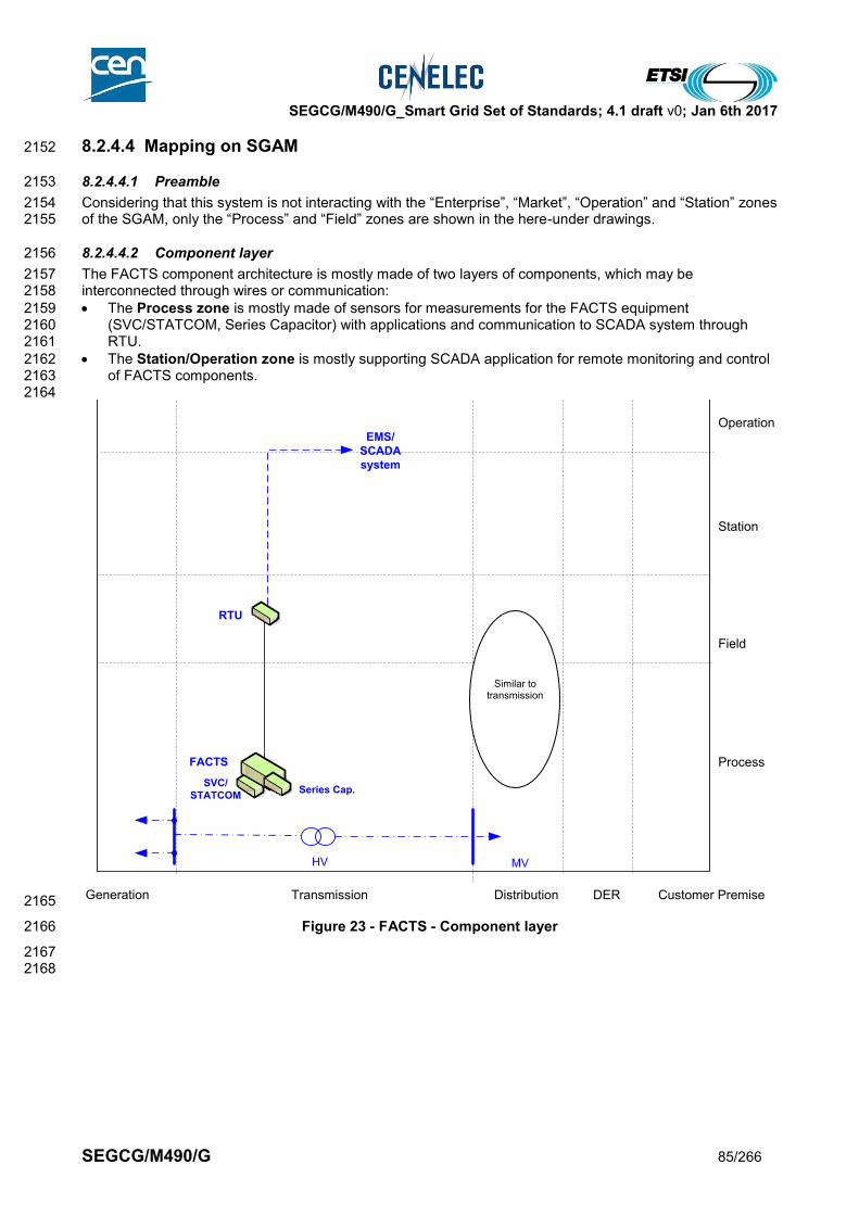
SEGCG/M490/G_Smart Grid Set of Standards; 4.1 draft v0; Jan 6th 2017
SEGCG/M490/G 85/266
8.2.4.4 Mapping on SGAM 2152
8.2.4.4.1 Preamble 2153
Considering that this system is not interacting with the “Enterprise”, “Market”, “Operation” and “Station” zones 2154 of the SGAM, only the “Process” and “Field” zones are shown in the here-under drawings. 2155
8.2.4.4.2 Component layer 2156
The FACTS component architecture is mostly made of two layers of components, which may be 2157 interconnected through wires or communication: 2158
The Process zone is mostly made of sensors for measurements for the FACTS equipment 2159 (SVC/STATCOM, Series Capacitor) with applications and communication to SCADA system through 2160 RTU. 2161
The Station/Operation zone is mostly supporting SCADA application for remote monitoring and control 2162 of FACTS components. 2163
2164
2165
Figure 23 - FACTS - Component layer 2166
2167 2168
Generation Transmission Distribution Customer PremiseDER
Process
Field
Station
Operation
Enterprise
Market
HV MV
EMS/
SCADA
system
FACTS
RTU
SVC/
STATCOMSeries Cap.
Similar to transmission

SEGCG/M490/G_Smart Grid Set of Standards; 4.1 draft v0; Jan 6th 2017
SEGCG/M490/G 86/266
8.2.4.4.3 Communication layer 2169
2170 Vertical communication protocols can be EN 60870-5-101 or 104 from FACTS equipment (FACTS controller) 2171 via RTU to SCADA. 2172 2173 Please refer to section 9.4 for getting details on cyber-security standards and more specifically on where and 2174 how to apply the IEC 62351 standard series and/or other cyber-security mechanisms. 2175 2176 Note: the letters in the blue disks shown in the diagram below refer to the network types defined in 9.3.2. 2177
2178 2179
2180
Figure 24 - FACTS - Communication layer 2181
2182 2183
Generation Transmission Distribution Customer PremiseDER
Process
Field
Station
Operation
Enterprise
Market
HV MV
EMS/
SCADA
system
FACTS
RTU
SVC/
STATCOMSeries Cap.
L
E
IEC 60870-5-101 IEC 60870-5-104
IEC 60870-5-101 IEC 60870-5-104
Similar to transmission
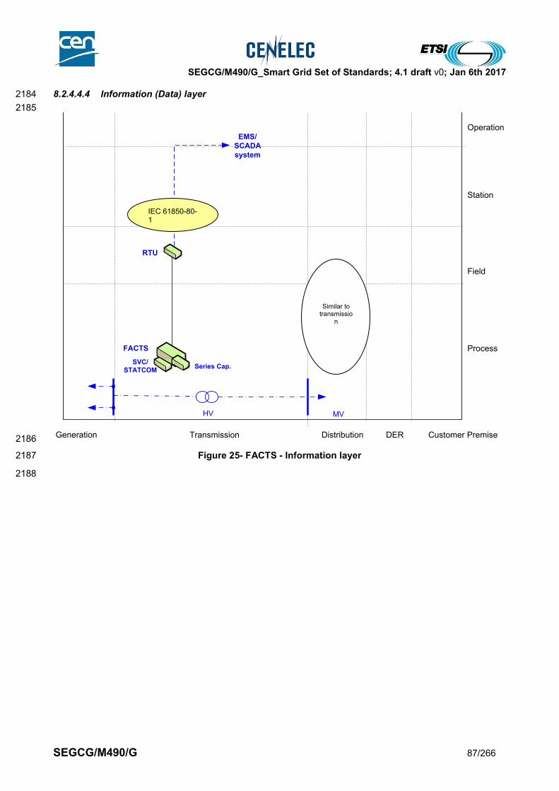
SEGCG/M490/G_Smart Grid Set of Standards; 4.1 draft v0; Jan 6th 2017
SEGCG/M490/G 87/266
8.2.4.4.4 Information (Data) layer 2184
2185
2186
Figure 25- FACTS - Information layer 2187
2188
Generation Transmission Distribution Customer PremiseDER
Process
Field
Station
Operation
Enterprise
Market
HV MV
EMS/
SCADA
system
FACTS
RTU
SVC/
STATCOMSeries Cap.
Similar to transmissio
n
IEC 61850-80-1

SEGCG/M490/G_Smart Grid Set of Standards; 4.1 draft v0; Jan 6th 2017
SEGCG/M490/G 88/266
8.2.4.5 List of Standards 2189
8.2.4.5.1 Available standards 2190
In compliance with section 6.2.2, a standard (or “open specification”) that has reached its final stage (IS, TS 2191 or TR …) by Dec 31st 2015 is considered as “available”. 2192
Table 26- FACTS - Available standards 2193
Layer Standard Comments
Information IEC 61850-80-1 Mapping of IEC/EN 61850 data model over 60870-5-101 and 104
Information EN 61850-7-4 EN 61850-7-3 EN 61850-7-2 EN 61850-6
Core Information model and language for the IEC/EN 61850 series
Information IEC 61850-90-3 Using IEC/EN 61850 for condition monitoring
Communication, information
IEC 61850-90-2 Substation to control center communication
Communication EN 60870-5-101 Telecontrol equipment and systems – Part 5-101: Transmission protocols – Companion standard for basic telecontrol tasks
Communication EN 60870-5-104 Telecontrol equipment and systems – Part 5-104: Transmission protocols – Network access for EN 60870-5-101 using standard transport profiles
General IEC 60633 Ed. 2.0, Terminology for high-voltage direct current (HVDC) transmission
Component IEC 60919 Performance of high-voltage direct current (HVDC) systems with line-commutated converters
Component IEC 60700-1 Ed.1.2, Thyristor valves for high voltage direct current (HVDC) power transmission - Part 1: Electrical testing
Component IEC 61954 Ed.1.1, Power electronics for electrical transmission and distribution systems - Testing of thyristor valves for static VAR compensators
Component IEC 61803 Ed.1, Determination of power losses in high-voltage direct current (HVDC) converter stations
Communication IEC 62351 (all parts) Cyber-security aspects (refer to section 9.4)
2194
8.2.4.5.2 Coming standards 2195
In compliance with section 6.2.2, a standard that has successfully passed the NWIP process (or any formal 2196 equivalent work item adoption process) by Dec 31st 2015 is considered as “Coming”. 2197
Table 27 - FACTS - Coming standards 2198
Layer Standard Comments
Information IEC 61850-90-14 Using IEC 61850 for FACTS modelling
Communication IEC 62351-4 IEC 62651-6 IEC 62351-7 IEC 62351-9 IEC 62351-11 IEC 62351-12 IEC 62351-90-1
Cyber-security aspects (refer to section 9.4)
2199
2200

SEGCG/M490/G_Smart Grid Set of Standards; 4.1 draft v0; Jan 6th 2017
SEGCG/M490/G 89/266
8.3 Distribution management systems 2201
8.3.1 Substation Automation System 2202
Refer to section 8.2.1. 2203
8.3.2 Feeder automation system (including smart field switching device and 2204
distributed Power Quality system) 2205
8.3.2.1 System description 2206
A Feeder automation system refers to the system and all the elements needed to perform automated 2207 operation of components placed along the MV network itself (feeders), including (but not limited to) fault 2208 detectors, pole or ground mounted MV-switches, MV-disconnectors and MV-circuit-breakers - without or with 2209 reclosing functionality (also called reclosers) between the HV/MV substation (MV side included) and the 2210 MV/LV substations. 2211 The typical considered operations are protection functionalities (from upwards and/or distributed), service 2212 restoration (after fault conditions), feeder reconfiguration, monitoring of quality control parameters (i.e. V, I, f, 2213 THD, dips, surges,…) as well as automated distributed Power Quality regulation (Volt/VAR and frequency/W) 2214 through active control, on the MV side and/or on the LV side. 2215 2216 Note: Feeder automation functionalities that are usually included in a MV/LV substation are included on this sub-clause 2217 but not in “MV/LV automated substation system”. 2218
2219
8.3.2.2 Set of use cases 2220
Here is a set of use cases which may be supported by Feeder automation system and smart reclosers 2221 system. 2222 The meanings of the three last columns (AVAILABLE, COMING, Not Yet) and of the “C”, “I”, “CI”, “X” 2223 conventions are given in section 7.6.2. 2224
Table 28 - Feeder Automation System - Use cases 2225
Supported by standards
Use cases cluster High level use cases AVAILABLE COMING
(CI7)
Not yet
Protecting the grid assets
Protect a zone outside of the substation boundary
CI
Perform networked protection logic (Intertripping, logic selectivity...)
CI
Perform networked security logic (Interlocking, local/remote)
CI
Set/change protection parameters CI
Monitoring the grid flows
Monitoring electrical flows CI
Producing, exposing and logging time-stamped events
CI
Supporting time-stamped alarms management at all levels
CI
Archive operation information CI
Maintaining grid assets
Archive maintenance information CI
Controlling the grid (locally/ remotely)
manually or automatically
Switch/breaker control CI
Enable multiple concurrent levels of control (local-remote)
CI
Supporting reclosing sequence CI
7 IEC 61850-90-6, IEC 61850-8-2 as well as EN 61869 may provide some enhancement of the current set of standards to better fit
Feeder automation scope, both at communication and information levels

SEGCG/M490/G_Smart Grid Set of Standards; 4.1 draft v0; Jan 6th 2017
SEGCG/M490/G 90/266
Supported by standards
Use cases cluster High level use cases AVAILABLE COMING
(CI7)
Not yet
Reconfiguring the network in case of
fault
Supporting source switching CI
Supporting automatic FLISR CI
Managing power quality
Monitoring Power Quality criteria CI
Voltage regulation CI
VAR regulation CI
2226
8.3.2.3 Mapping on SGAM 2227
8.3.2.3.1 Preamble 2228
Most parts of the functions (High level use cases) represented are covered by the same standards than for 2229 other systems being part of distribution networks; the differences being mainly in the customization of the 2230 applications and the specific functionalities used. 2231 2232 Considering that this system is not interacting with the “Enterprise” and “Market” zones of the SGAM, only 2233 the “Process”, “Field”, “Station” and “Operation” zones are shown in the here-under drawings. 2234 2235 2236

SEGCG/M490/G_Smart Grid Set of Standards; 4.1 draft v0; Jan 6th 2017
SEGCG/M490/G 91/266
8.3.2.3.2 Component layer 2237
On the SGAM representation of the component layer, the current transformer, the switching element and the 2238 voltage transformer are supposed to be placed along the feeder normally at switching places, and/or in the 2239 derivation to the MV/LV transformer, and possibly in the LV lines. 2240 2241 The feeder automation and smart reclosers component architecture is mostly made of 3 zones of 2242 components, which may be interconnected through wires or communication. 2243
The Process zone includes the primary equipment of the electrical network such as switching (i.e. 2244 circuit-breakers, switches and disconnectors), VAR regulator, MV/LV transformer regulator and 2245 measuring elements (i.e. current and voltage sensors/transformers). The representation on the SGAM is 2246 generic and doesn’t correspond necessarily to any specific example. Note that volt/VAR and frequency 2247 control of DERs (represented as G in Figure 26) would be done by the DER operation system, mostly via 2248 the DMS and DER EMS/VPP (technical VPP) systems. 2249
The Field zone includes equipment to protect, control and monitor the process of the electrical network, 2250 mainly IEDs (which mostly handle protection, monitoring and control features like reclosing sequences), 2251 NIC (the controller of the LAN or HAN) and Router (the remote connection interface). 2252
The Station zone includes the aggregation level which interface with other elements and systems of the 2253 distribution network. It is mostly supporting 3 main technical functions, which can be grouped or 2254 separated in different components, which are: the RTU which serves as terminal for remote activities, the 2255 local controller, which is in charge of performing automatic functions, and possibly an HMI/archiving 2256 component which offers the local operators capabilities of visualizing and archive local data. 2257
2258 2259
2260
Figure 26 - Feeder automation system - Component layer 2261
2262
Generation Transmission Distribution Customer
Premise DER
Process
Field
Station
Enterprise
Market
HV MV LV
G H
NIC
RTU
IED
Router
Operation
IED
Local
Controller
LAN/HAN
IED
DMS/SCADA & GIS system
IED IED
IEC 61869 IEC 62689
IEC 62271-3
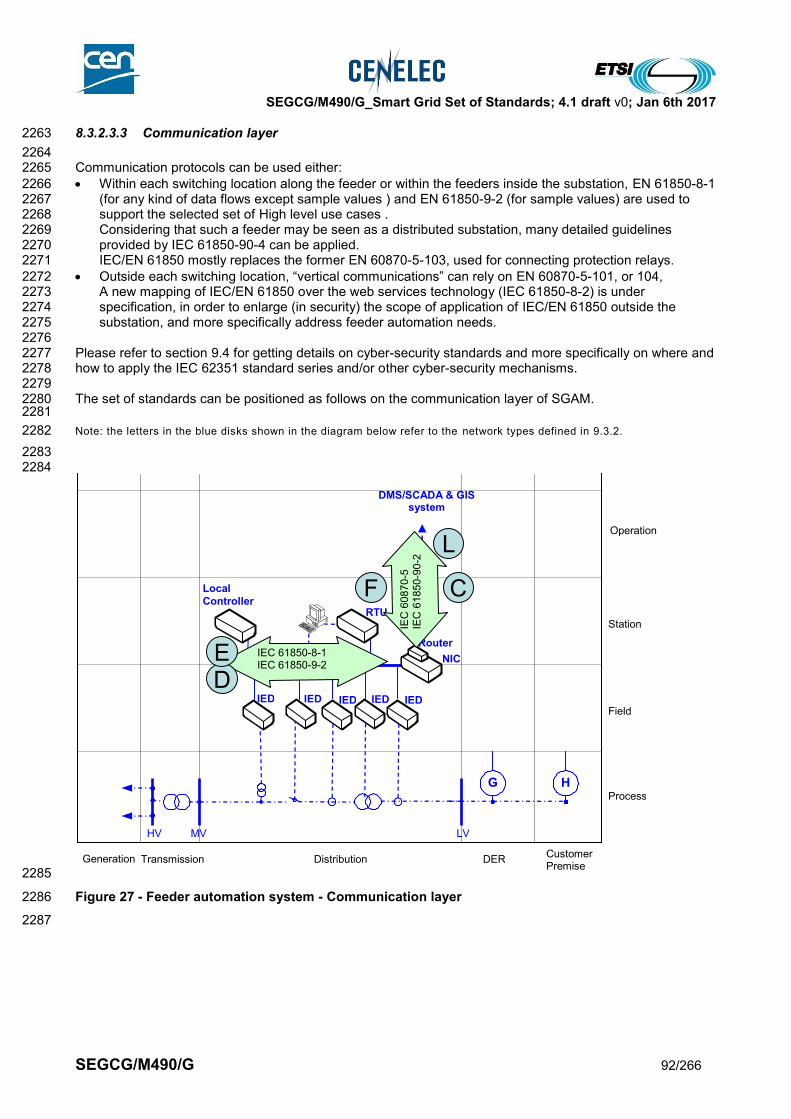
SEGCG/M490/G_Smart Grid Set of Standards; 4.1 draft v0; Jan 6th 2017
SEGCG/M490/G 92/266
8.3.2.3.3 Communication layer 2263
2264 Communication protocols can be used either: 2265
Within each switching location along the feeder or within the feeders inside the substation, EN 61850-8-1 2266 (for any kind of data flows except sample values ) and EN 61850-9-2 (for sample values) are used to 2267 support the selected set of High level use cases . 2268 Considering that such a feeder may be seen as a distributed substation, many detailed guidelines 2269 provided by IEC 61850-90-4 can be applied. 2270 IEC/EN 61850 mostly replaces the former EN 60870-5-103, used for connecting protection relays. 2271
Outside each switching location, “vertical communications” can rely on EN 60870-5-101, or 104, 2272 A new mapping of IEC/EN 61850 over the web services technology (IEC 61850-8-2) is under 2273 specification, in order to enlarge (in security) the scope of application of IEC/EN 61850 outside the 2274 substation, and more specifically address feeder automation needs. 2275
2276 Please refer to section 9.4 for getting details on cyber-security standards and more specifically on where and 2277 how to apply the IEC 62351 standard series and/or other cyber-security mechanisms. 2278 2279 The set of standards can be positioned as follows on the communication layer of SGAM. 2280 2281
Note: the letters in the blue disks shown in the diagram below refer to the network types defined in 9.3.2. 2282
2283 2284
2285
Figure 27 - Feeder automation system - Communication layer 2286
2287
Generation Transmission Distribution Customer
Premise DER
Process
Field
Station
Enterprise
Market
HV MV LV
G H
NIC
RTU
IED
Router
Operation
IED
Local
Controller
LAN/HAN
IED
DMS/SCADA & GIS system
IED IED
IEC 61850-8-1 IEC 61850-9-2
IEC
60870
-5
IEC
61850
-90-2
L
F
DE
C

SEGCG/M490/G_Smart Grid Set of Standards; 4.1 draft v0; Jan 6th 2017
SEGCG/M490/G 93/266
8.3.2.3.4 Information (Data) layer 2288
The information layer of feeder automation or smart reclosers (including distributed Power Quality 2289 capabilities) is mostly based on the IEC/EN 61850 information model. 2290 We have indicated that the EN 61850-7-4 is the core part depicting this model for each location along each 2291 feeder, and IEC 61850-90-2 for the communication to the control center; however other parts of the IEC/EN 2292 61850 series can be also be used. 2293 IEC 61850-90-6 is also indicated on the SGAM, which is expected to be a guide for the implementation of 2294 IEC/EN 61850 on feeder automation. 2295 2296 For protocols which are not IEC/EN 61850 native such as the EN 60870-5-101 or 104, a mapping of IEC/EN 2297 61850 information model is possible using the IEC 61850-80-1, enabling users of these technologies to use 2298 the power of data modeling (and then more seamless integration) without changing of communication 2299 technologies. 2300 2301
2302
Figure 28 - Feeder automation system - Information layer 2303
8.3.2.4 List of Standards 2304
8.3.2.4.1 Available standards 2305
In compliance with section 6.2.2, a standard (or “open specification”) that has reached its final stage (IS, TS 2306 or TR …) by Dec 31st 2015 is considered as “available”. 2307
Table 29 - Feeder automation system - Available standards 2308
Generation Transmission Distribution Customer
Premise DER
Process
Field
Station
Enterprise
Market
HV MV LV
G H
NIC
RTU
I E D
Router
Operation
IED
Local Controller
LAN/HAN
IED
DMS/SCADA & GIS system
IED IED
IEC 61850-7-4 IEC 61850-90-6
IEC
61850-9
0-2
IEC
61850-8
0-1
IEC 61970 IEC 61968
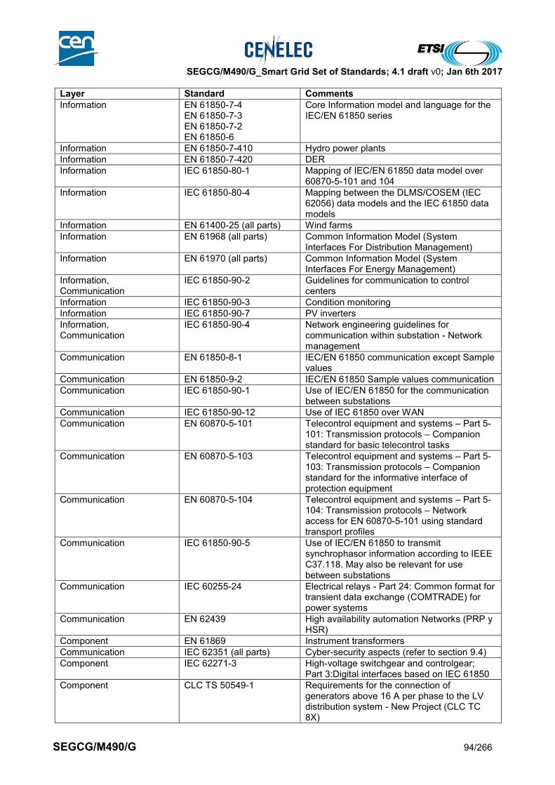
SEGCG/M490/G_Smart Grid Set of Standards; 4.1 draft v0; Jan 6th 2017
SEGCG/M490/G 94/266
Layer Standard Comments
Information EN 61850-7-4 EN 61850-7-3 EN 61850-7-2 EN 61850-6
Core Information model and language for the IEC/EN 61850 series
Information EN 61850-7-410 Hydro power plants
Information EN 61850-7-420 DER
Information IEC 61850-80-1 Mapping of IEC/EN 61850 data model over 60870-5-101 and 104
Information IEC 61850-80-4 Mapping between the DLMS/COSEM (IEC 62056) data models and the IEC 61850 data models
Information EN 61400-25 (all parts) Wind farms
Information EN 61968 (all parts) Common Information Model (System Interfaces For Distribution Management)
Information EN 61970 (all parts) Common Information Model (System Interfaces For Energy Management)
Information, Communication
IEC 61850-90-2 Guidelines for communication to control centers
Information IEC 61850-90-3 Condition monitoring
Information IEC 61850-90-7 PV inverters
Information, Communication
IEC 61850-90-4 Network engineering guidelines for communication within substation - Network management
Communication EN 61850-8-1 IEC/EN 61850 communication except Sample values
Communication EN 61850-9-2 IEC/EN 61850 Sample values communication
Communication IEC 61850-90-1 Use of IEC/EN 61850 for the communication between substations
Communication IEC 61850-90-12 Use of IEC 61850 over WAN
Communication EN 60870-5-101 Telecontrol equipment and systems – Part 5-101: Transmission protocols – Companion standard for basic telecontrol tasks
Communication EN 60870-5-103 Telecontrol equipment and systems – Part 5-103: Transmission protocols – Companion standard for the informative interface of protection equipment
Communication EN 60870-5-104 Telecontrol equipment and systems – Part 5-104: Transmission protocols – Network access for EN 60870-5-101 using standard transport profiles
Communication IEC 61850-90-5 Use of IEC/EN 61850 to transmit synchrophasor information according to IEEE C37.118. May also be relevant for use between substations
Communication IEC 60255-24 Electrical relays - Part 24: Common format for transient data exchange (COMTRADE) for power systems
Communication EN 62439 High availability automation Networks (PRP y HSR)
Component EN 61869 Instrument transformers
Communication IEC 62351 (all parts) Cyber-security aspects (refer to section 9.4)
Component IEC 62271-3 High-voltage switchgear and controlgear; Part 3:Digital interfaces based on IEC 61850
Component CLC TS 50549-1 Requirements for the connection of generators above 16 A per phase to the LV distribution system - New Project (CLC TC 8X)
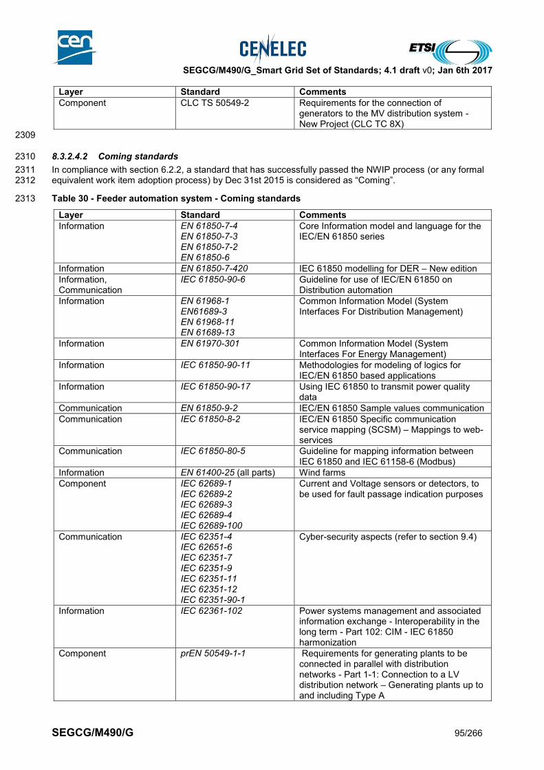
SEGCG/M490/G_Smart Grid Set of Standards; 4.1 draft v0; Jan 6th 2017
SEGCG/M490/G 95/266
Layer Standard Comments
Component CLC TS 50549-2 Requirements for the connection of generators to the MV distribution system - New Project (CLC TC 8X)
2309
8.3.2.4.2 Coming standards 2310
In compliance with section 6.2.2, a standard that has successfully passed the NWIP process (or any formal 2311 equivalent work item adoption process) by Dec 31st 2015 is considered as “Coming”. 2312
Table 30 - Feeder automation system - Coming standards 2313
Layer Standard Comments
Information EN 61850-7-4 EN 61850-7-3 EN 61850-7-2 EN 61850-6
Core Information model and language for the IEC/EN 61850 series
Information EN 61850-7-420 IEC 61850 modelling for DER – New edition
Information, Communication
IEC 61850-90-6 Guideline for use of IEC/EN 61850 on Distribution automation
Information EN 61968-1 EN61689-3 EN 61968-11 EN 61689-13
Common Information Model (System Interfaces For Distribution Management)
Information EN 61970-301 Common Information Model (System Interfaces For Energy Management)
Information IEC 61850-90-11 Methodologies for modeling of logics for IEC/EN 61850 based applications
Information IEC 61850-90-17 Using IEC 61850 to transmit power quality data
Communication EN 61850-9-2 IEC/EN 61850 Sample values communication
Communication IEC 61850-8-2 IEC/EN 61850 Specific communication service mapping (SCSM) – Mappings to web-services
Communication IEC 61850-80-5 Guideline for mapping information between IEC 61850 and IEC 61158-6 (Modbus)
Information EN 61400-25 (all parts) Wind farms
Component IEC 62689-1 IEC 62689-2 IEC 62689-3 IEC 62689-4 IEC 62689-100
Current and Voltage sensors or detectors, to be used for fault passage indication purposes
Communication IEC 62351-4 IEC 62651-6 IEC 62351-7 IEC 62351-9 IEC 62351-11 IEC 62351-12 IEC 62351-90-1
Cyber-security aspects (refer to section 9.4)
Information IEC 62361-102 Power systems management and associated information exchange - Interoperability in the long term - Part 102: CIM - IEC 61850 harmonization
Component prEN 50549-1-1 Requirements for generating plants to be connected in parallel with distribution networks - Part 1-1: Connection to a LV distribution network – Generating plants up to and including Type A

SEGCG/M490/G_Smart Grid Set of Standards; 4.1 draft v0; Jan 6th 2017
SEGCG/M490/G 96/266
Layer Standard Comments
Component prEN 50549-1-2 Requirements for generating plants to be connected in parallel with distribution networks - Part 1-2: Connection to a LV distribution network – Generating plants of Type B
Component prEN 50549-1-2 Requirements for generating plants to be connected in parallel with distribution networks - Part 2: Connection to a MV distribution network
Component prEN 50549-10 Requirements for generating plants to be connected in parallel with distribution networks - Part 10 Tests demonstrating compliance of units
2314
2315

SEGCG/M490/G_Smart Grid Set of Standards; 4.1 draft v0; Jan 6th 2017
SEGCG/M490/G 97/266
8.3.3 Advanced Distribution Management System (ADMS) 2316
8.3.3.1 System Description 2317
2318 Advanced Distribution Management System refers to the real-time information system and all the elements 2319 needed to support all the relevant operational activities and functions used in distribution automation at 2320 dispatch centers and control rooms. It improves the information made available to operators, field and crew 2321 personnel, customer service representatives, management and, ultimately, to the end customers. 2322 Such system is usually made of one or many interconnected IT systems, connected to field communicating 2323 devices or sub-systems, through the use of WAN communication systems. It may also include the needed 2324 components to enable the field crew to operate the network from the field. 2325 An Advanced Distribution Management System provides following major functions: 2326
SCADA, real time monitoring and control 2327
Advanced network applications including network modeling 2328
Outage management including crew & resource management 2329
Work management 2330 2331 Geographical information system refers to the information system and all the elements needed to capture, 2332 store, manipulate, analyze, manage and present all types of geographical data and information to support 2333 the network operator / asset manager regarding decision making in the operation of the energy 2334 infrastructure. The system supports all kind of processes, from planning and design to the day-to-day 2335 operation and maintenance activities. It provides the operator and planner with the Asset location and other 2336 relevant Asset specifications and dimensions. 2337 2338
8.3.3.2 Set of high level use cases 2339
2340 The set of high level use cases which may be supported by an Advanced Distribution Management System 2341 are given in the table below. The GIS system doesn’t host a specific use case, but contributes to several use 2342 cases as a supplier for the network model as listed below. 2343 The meanings of the three last columns (AVAILABLE, COMING, Not Yet) and of the “C”, “I”, “CI”, “X” 2344 conventions are given in section 7.6.2. 2345 2346
Table 31 - Advanced Distribution Management System (ADMS) – Use cases 2347
Supported by standards
Use cases cluster
High level use cases AVAILABLE COMING Not yet
Monitoring the grid flows
Monitoring electrical flows CI
Monitoring power quality for operation (locally) CI
Producing, exposing and logging time-stamped events
X
Supporting time-stamped alarms management at all levels
X
Capture, expose and analyze disturbance events X
Archive operation information CI
Maintaining grid assets
Monitoring assets conditions CX
Supporting periodic maintenance and planning X
Optimize field crew operation X
Manage Commercial relationship for electricity supply
Registration/deregistration of customers C I
Operate DER(s) Registration/deregistration of DER in VPP CI
Aggregate DER as technical VPP CI
Aggregate DER as commercial VPP CI
Switch/breaker control CI

SEGCG/M490/G_Smart Grid Set of Standards; 4.1 draft v0; Jan 6th 2017
SEGCG/M490/G 98/266
Supported by standards
Use cases cluster
High level use cases AVAILABLE COMING Not yet
Controlling the grid (locally/ remotely) manually or automatically
Feeder load balancing X
Enable multiple concurrent levels of control (local-remote)
X
Managing power quality
Voltage regulation CI
VAR regulation CI
Reconfiguring the network in case of fault
Supporting reclosing sequence X
Supporting source switching X
Supporting automatic FLISR
Connect an active actor to the grid
Managing microgrid transitions X
Managing generation connection to the grid X
Demand and production (generation) flexibility
Receiving metrological or price information for further action by consumer or CEM
X
Load forecast (from remote based on revenue metering)
X
Generation forecast (from remote) X
Participating to electricity market X
System and security management
Distributing and synchronizing clocks X
2348
8.3.3.3 Mapping on SGAM 2349
8.3.3.3.1 Preamble: 2350
The Advanced Distribution Management System is supported by substation automation, protection and 2351 control. It is less advanced than the EMS SCADA used in Transmission. But the amount of automation is 2352 growing in distribution systems certainly with the increasing role of distributed generation and distributed 2353 storage. Furthermore focus is on further decrease of outage minutes by support of remote sensing and 2354 switching in the network. Remote control and operation of distribution networks will have a positive influence 2355 on network management during normal and emergency situations, dependency of fieldworkers will be less. 2356 With the growing amount of distributed generation, distribution networks have to support balancing 2357 generation and demand at regional level. Hierarchically this system is covering the station and operational 2358 zones within the Distribution System operation. 2359 The GIS system interacts with the Advanced Distribution Management System, Asset and Maintenance 2360 management system (GMAO), the CIS and EMS/VPP system. 2361 2362 2363
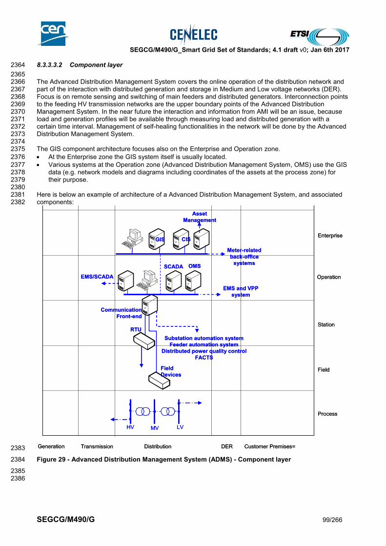
SEGCG/M490/G_Smart Grid Set of Standards; 4.1 draft v0; Jan 6th 2017
SEGCG/M490/G 99/266
8.3.3.3.2 Component layer 2364
2365 The Advanced Distribution Management System covers the online operation of the distribution network and 2366 part of the interaction with distributed generation and storage in Medium and Low voltage networks (DER). 2367 Focus is on remote sensing and switching of main feeders and distributed generators. Interconnection points 2368 to the feeding HV transmission networks are the upper boundary points of the Advanced Distribution 2369 Management System. In the near future the interaction and information from AMI will be an issue, because 2370 load and generation profiles will be available through measuring load and distributed generation with a 2371 certain time interval. Management of self-healing functionalities in the network will be done by the Advanced 2372 Distribution Management System. 2373 2374 The GIS component architecture focuses also on the Enterprise and Operation zone. 2375
At the Enterprise zone the GIS system itself is usually located. 2376
Various systems at the Operation zone (Advanced Distribution Management System, OMS) use the GIS 2377 data (e.g. network models and diagrams including coordinates of the assets at the process zone) for 2378 their purpose. 2379
2380 Here is below an example of architecture of a Advanced Distribution Management System, and associated 2381 components: 2382
2383
Figure 29 - Advanced Distribution Management System (ADMS) - Component layer 2384
2385 2386
Generation Transmission Distribution Customer Premises=DER
Process
Field
Station
Enterprise
Market
HV MV
Operation
LV
RTU
Field
Devices
EMS/SCADA
Asset
Management
Communication
Front-end
SCADA OMS
GIS CIS
Substation automation system
Feeder automation system
Distributed power quality control
FACTS
Meter-related
back-office
systems
EMS and VPP
system

SEGCG/M490/G_Smart Grid Set of Standards; 4.1 draft v0; Jan 6th 2017
SEGCG/M490/G 100/266
8.3.3.3.3 Communication layer 2387
2388 Communication protocols mentioned under Substation Automation will be applied for retrieving necessary 2389 information and control of the network. 2390 2391 This set of standards regarding Advanced Distribution Management System can be positioned as is shown in 2392 the diagram below representing the communication layer of SGAM. 2393 2394 Please refer to section 9.4 for getting details on cyber-security standards and more specifically on where and 2395 how to apply the IEC 62351 standard series and/or other cyber-security mechanisms. 2396 2397 Note: the letters in the blue disks shown in the diagram below refer to the network types defined in 9.3.2. 2398
2399
2400
Figure 30 - Advanced Distribution Management System (ADMS) - Communication layer 2401
2402 2403
Generation Transmission Distribution Customer PremiseDER
Process
Field
Station
Operation
Enterprise
Market
HV MV LV
IEC 61850
IEC
61
85
0-9
0-2
IEC 61968-100
IEC 60870-6
IEC
60
87
0-5
-10
1
IEC
60
87
0-5
-10
4
IEC
61
85
0
IEC
60
87
0-5
-10
3
Generation Transmission Distribution Customer PremiseDER
Process
Field
Station
Operation
Enterprise
Market
HV MV LV
IEC 61850
IEC
61
85
0-9
0-2
IEC 61968-100
IEC 60870-6
IEC
60
87
0-5
-10
1
IEC
60
87
0-5
-10
4
IEC
61
85
0
IEC
60
87
0-5
-10
3
E
E
L L
GH

SEGCG/M490/G_Smart Grid Set of Standards; 4.1 draft v0; Jan 6th 2017
SEGCG/M490/G 101/266
8.3.3.3.4 Information (Data) layer 2404
2405 Advanced Distribution Management System makes use of the information models at station and operation 2406 level of course. For Advanced Distribution Management System most of the parts of EN 61968 (and EN 2407 61970) are applicable. It describes the Common Information Model CIM for distribution management and it 2408 covers most of the interfaces between the different applications and the head-end level of the utility. GIS 2409 related information is defined in IEC 61698-4 and IEC 61968-13. 2410 2411
2412
Figure 31 - Advanced Distribution Management System (ADMS) - Information layer 2413
2414 Standards Identified for Substation Automation are also relevant for the application of the Advanced 2415 Distribution Management System, because the Advanced Distribution Management System will retrieve 2416 online information from the substations in the Distribution Networks 2417
2418
8.3.3.4 List of Standards 2419
2420 Here is the summary of the standards which appear relevant to support The Advanced Distribution 2421 Management System (ADMS): 2422 2423
8.3.3.4.1 Available standards 2424
In compliance with section 6.2.2, a standard (or “open specification”) that has reached its final stage (IS, TS 2425 or TR …) by Dec 31st 2015 is considered as “available”. 2426 2427
Generation Transmission Distribution Customer PremiseDER
Process
Field
Station
Operation
Enterprise
Market
IEC 61850-7-4
IEC 61968
IEC 61970 IE
C 6
185
0-9
0-2
IEC
61
85
0-8
0-1
HV MV LV
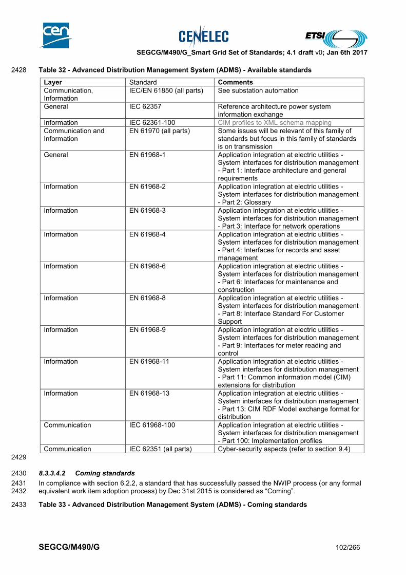
SEGCG/M490/G_Smart Grid Set of Standards; 4.1 draft v0; Jan 6th 2017
SEGCG/M490/G 102/266
Table 32 - Advanced Distribution Management System (ADMS) - Available standards 2428
Layer Standard Comments
Communication, Information
IEC/EN 61850 (all parts) See substation automation
General IEC 62357 Reference architecture power system information exchange
Information IEC 62361-100 CIM profiles to XML schema mapping
Communication and Information
EN 61970 (all parts) Some issues will be relevant of this family of standards but focus in this family of standards is on transmission
General EN 61968-1 Application integration at electric utilities - System interfaces for distribution management - Part 1: Interface architecture and general requirements
Information EN 61968-2 Application integration at electric utilities - System interfaces for distribution management - Part 2: Glossary
Information EN 61968-3 Application integration at electric utilities - System interfaces for distribution management - Part 3: Interface for network operations
Information EN 61968-4 Application integration at electric utilities - System interfaces for distribution management - Part 4: Interfaces for records and asset management
Information EN 61968-6 Application integration at electric utilities - System interfaces for distribution management - Part 6: Interfaces for maintenance and construction
Information
EN 61968-8 Application integration at electric utilities - System interfaces for distribution management - Part 8: Interface Standard For Customer Support
Information EN 61968-9 Application integration at electric utilities - System interfaces for distribution management - Part 9: Interfaces for meter reading and control
Information EN 61968-11 Application integration at electric utilities - System interfaces for distribution management - Part 11: Common information model (CIM) extensions for distribution
Information EN 61968-13 Application integration at electric utilities - System interfaces for distribution management - Part 13: CIM RDF Model exchange format for distribution
Communication IEC 61968-100 Application integration at electric utilities - System interfaces for distribution management - Part 100: Implementation profiles
Communication IEC 62351 (all parts) Cyber-security aspects (refer to section 9.4)
2429
8.3.3.4.2 Coming standards 2430
In compliance with section 6.2.2, a standard that has successfully passed the NWIP process (or any formal 2431 equivalent work item adoption process) by Dec 31st 2015 is considered as “Coming”. 2432
Table 33 - Advanced Distribution Management System (ADMS) - Coming standards 2433
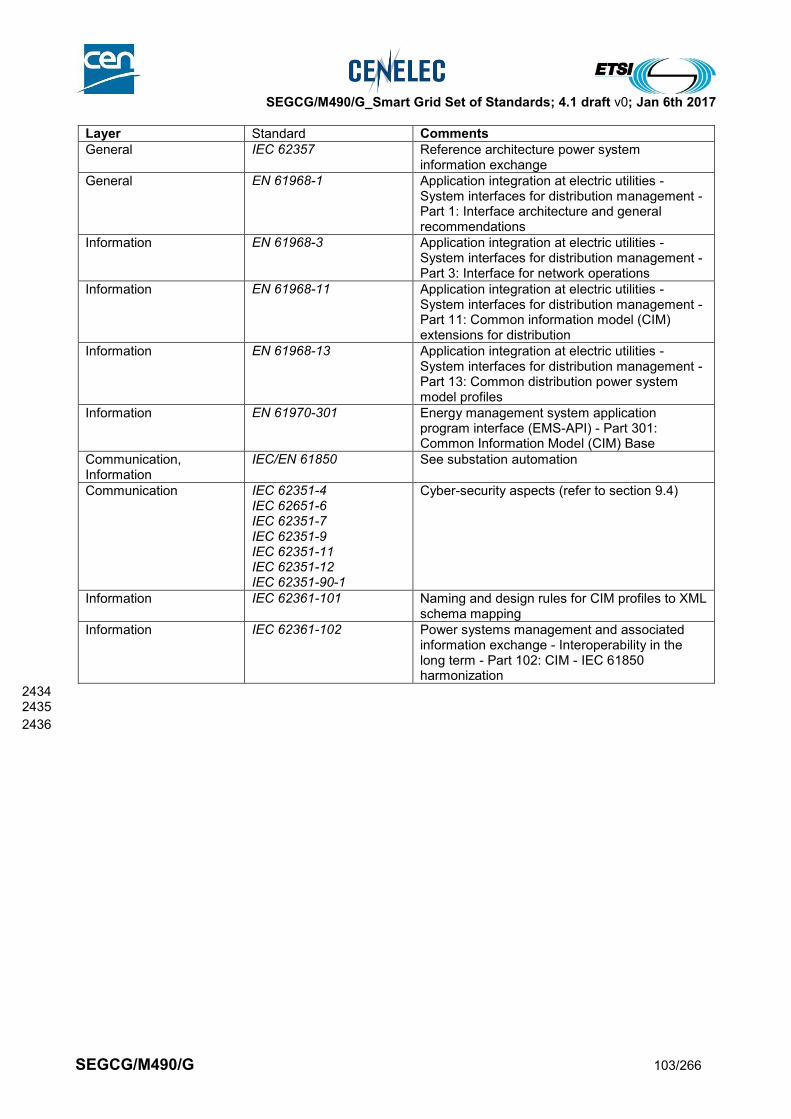
SEGCG/M490/G_Smart Grid Set of Standards; 4.1 draft v0; Jan 6th 2017
SEGCG/M490/G 103/266
Layer Standard Comments
General IEC 62357 Reference architecture power system information exchange
General EN 61968-1 Application integration at electric utilities - System interfaces for distribution management - Part 1: Interface architecture and general recommendations
Information EN 61968-3 Application integration at electric utilities - System interfaces for distribution management - Part 3: Interface for network operations
Information EN 61968-11 Application integration at electric utilities - System interfaces for distribution management - Part 11: Common information model (CIM) extensions for distribution
Information EN 61968-13 Application integration at electric utilities - System interfaces for distribution management - Part 13: Common distribution power system model profiles
Information EN 61970-301 Energy management system application program interface (EMS-API) - Part 301: Common Information Model (CIM) Base
Communication, Information
IEC/EN 61850 See substation automation
Communication IEC 62351-4 IEC 62651-6 IEC 62351-7 IEC 62351-9 IEC 62351-11 IEC 62351-12 IEC 62351-90-1
Cyber-security aspects (refer to section 9.4)
Information IEC 62361-101
Naming and design rules for CIM profiles to XML schema mapping
Information IEC 62361-102 Power systems management and associated information exchange - Interoperability in the long term - Part 102: CIM - IEC 61850 harmonization
2434 2435
2436

SEGCG/M490/G_Smart Grid Set of Standards; 4.1 draft v0; Jan 6th 2017
SEGCG/M490/G 104/266
8.3.4 FACTS (Distribution) 2437
8.3.4.1 System description 2438
The system description is similar to the one used in for Transmission as described in 8.2.4. 2439
8.3.4.2 Set of use cases 2440
Here is a set of high level use cases which may be supported by FACTS. 2441 The meanings of the three last columns (AVAILABLE, COMING, Not Yet) and of the “C”, “I”, “CI”, “X” 2442 conventions are given in section 7.6.2. 2443 2444
Table 34 - FACTS (Distribution) - use cases 2445
Supported by standards
Use cases cluster High level use cases AVAILABLE COMING Not yet
Controlling the grid (locally/ remotely) manually or automatically
Feeder load balancing CI
Managing power quality
(Dynamic) Voltage optimization at source level as grid support (VAR control)
Local Voltage regulation by use of Facts
System and security management
Discover a new component in the system C I
Configure newly discovered device automatically to act within the system
C I
Distributing and synchronizing clocks I C
Grid stability Stabilizing network after fault condition (Post-fault handling)
Monitoring and reduce power oscillation damping
Stabilizing network by reducing sub-synchronous resonance (Sub synchronous damping)
Monitoring and reduce harmonic mitigation I
Monitoring and reduce voltage flicker I
Connect an active actor to the grid
Managing generation connection to the grid CI
2446
8.3.4.3 Mapping on SGAM 2447
8.3.4.3.1 Preamble 2448
Considering that this system is not interacting with the “Enterprise”, “Market”, “Operation” and “Station” zones 2449 of the SGAM, only the “Process” and “Field” zones are shown in the here-under drawings. 2450
8.3.4.3.2 Component layer 2451
Mapping is similar to the one presented in 8.2.4.4.2 for FACTS in Transmission 2452
8.3.4.3.3 Communication layer 2453
Mapping is similar to the one presented in 8.2.4.4.3 for FACTS in Transmission 2454 2455
8.3.4.3.4 Information (Data) layer 2456
Mapping is similar to the one presented in 8.2.4.4.4 for FACTS in Transmission 2457 2458

SEGCG/M490/G_Smart Grid Set of Standards; 4.1 draft v0; Jan 6th 2017
SEGCG/M490/G 105/266
8.3.4.4 List of Standards 2459
8.3.4.4.1 Available standards 2460
In compliance with section 6.2.2, a standard (or “open specification”) that has reached its final stage (IS, TS 2461 or TR …) by Dec 31st 2015 is considered as “available”. 2462
Table 35 - FACTS (Distribution) – Available standards 2463
Layer Standard Comments
Information IEC 61850-80-1 Mapping of IEC/EN 61850 data model over 60870-5-101 and 104
Information EN 61850-7-4 Core Information model
Information IEC 61850-90-3 Using IEC/EN 61850 for condition monitoring
Communication, information
IEC 61850-90-2 Substation to control center communication
Communication EN 60870-5-101 Telecontrol equipment and systems – Part 5-101: Transmission protocols – Companion standard for basic telecontrol tasks
Communication EN 60870-5-104 Telecontrol equipment and systems – Part 5-104: Transmission protocols – Network access for EN 60870-5-101 using standard transport profiles
Communication IEC 62351 (all parts) Cyber-security aspects (refer to section 9.4)
2464
8.3.4.4.2 Coming standards 2465
In compliance with section 6.2.2, a standard that has successfully passed the NWIP process (or any formal 2466 equivalent work item adoption process) by Dec 31st 2015 is considered as “Coming”. 2467
Table 36 - FACTS (Distribution) – Coming standards 2468
Layer Standard Comments
Information IEC 61850-90-14 Using IEC 61850 for FACTS modelling
Communication IEC 62351-4 IEC 62651-6 IEC 62351-7 IEC 62351-9 IEC 62351-11 IEC 62351-12 IEC 62351-90-1
Cyber-security aspects (refer to section 9.4)
2469
2470

SEGCG/M490/G_Smart Grid Set of Standards; 4.1 draft v0; Jan 6th 2017
SEGCG/M490/G 106/266
8.4 Distributed Energy Resources Operation System (including storage) 2471
2472
8.4.1 System description 2473
DER system is responsible for operation and enterprise level management of the DER assets. It performs 2474 supervision and maintenance of the components, provides information to the operators and field crew 2475 personnel and controls of actual generation. It can act as a technical VPP (tVPP) interacting directly with the 2476 DSO or as a commercial VPP (cVPP) interacting with the energy market. The system may control one or 2477 more DERs which can be geographically distributed. These DERs could be single generation plants or could 2478 be combined with VPPs. The system provides information on the generation capabilities of the DER/VPP 2479 and the expected generation (forecast). It controls the actual generation and storage including VAR 2480 regulation and frequency support based on requests and schedules received from the market or DSO. 2481
8.4.2 Set of use cases 2482
The following high level use cases might be supported by a DER Operation systems. 2483 The meanings of the three last columns (AVAILABLE, COMING, Not Yet) and of the “C”, “I”, “CI”, “X” 2484 conventions are given in section 7.6.2. 2485 2486
Table 37 – DER Operation system – use cases 2487
Supported by standards
Use cases cluster
High level use cases AVAILABLE COMING Not yet
Monitoring the grid flows
Monitoring electrical flows CI
Monitoring power quality for operation (locally)
C I
Producing, exposing and logging time-stamped events
CI
Supporting time-stamped alarms management at all levels
CI
Capture, expose and analyse disturbance events
CI
Archive operation information I C
Maintaining grid assets
Monitoring assets conditions CI C
Supporting periodic maintenance (and planning)
CI
Optimise field crew operation C C I
Archive maintenance information CI
Managing power quality
VAR regulation CI
Frequency support CI
Operate DER(s)
DER process management with reduced power output
CI
DER performance management CI
DER remote control (dispatch) CI
Registration/deregistration of DER in VPP
CI
Aggregate DER as technical VPP CI
Aggregate DER as commercial VPP CI
Connect an active actor to the grid
Managing microgrid transitions CI
Managing generation connection to the grid
CI
Blackout management
Black-out prevention through WAMPAC
CI (PMU) ?
Shedding loads based on emergency signals
CX I
Restore power after black-out X
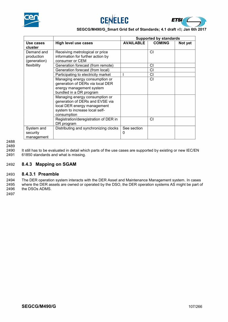
SEGCG/M490/G_Smart Grid Set of Standards; 4.1 draft v0; Jan 6th 2017
SEGCG/M490/G 107/266
Supported by standards
Use cases cluster
High level use cases AVAILABLE COMING Not yet
Demand and production (generation) flexibility
Receiving metrological or price information for further action by consumer or CEM
CI
Generation forecast (from remote) CI
Generation forecast (from local) CI
Participating to electricity market I CI
Managing energy consumption or generation of DERs via local DER energy management system bundled in a DR program
CI
Managing energy consumption or generation of DERs and EVSE via local DER energy management system to increase local self-consumption
Registration/deregistration of DER in DR program
CI
System and security management
Distributing and synchronizing clocks See section 0
2488 2489 It still has to be evaluated in detail which parts of the use cases are supported by existing or new IEC/EN 2490 61850 standards and what is missing. 2491
8.4.3 Mapping on SGAM 2492
8.4.3.1 Preamble 2493
The DER operation system interacts with the DER Asset and Maintenance Management system. In cases 2494 where the DER assets are owned or operated by the DSO, the DER operation systems AS might be part of 2495 the DSOs ADMS. 2496
2497

SEGCG/M490/G_Smart Grid Set of Standards; 4.1 draft v0; Jan 6th 2017
SEGCG/M490/G 108/266
8.4.3.2 Component layer 2498
2499 The component zone architecture covers all zones. 2500
the Process zone with the DERs, inverters and related sensors and actors 2501
The Field zone with the DER unit controller 2502
The Station zone with the DER plant controller 2503
The Operation zone with the tVPP/EMS which may interact with the DSOs DMS in case of tVPP 2504
The Enterprise zone with the cVPP which interacts with the market platform or directly with an energy 2505 retailer. 2506
2507
Generation Transmission Distribution Customer PremiseDER
Process
Field
Station
Operation
Enterprise
Market
DER Unit
Controller
G
MV/LV
DER System
Controller
G B
DER
EMS
AS
DMS/
SCADA
& GIS
cVPP
AS
Trading
System
Market
places
tVPP
DER operations
AS
EN 50438
EN 50549-1
EN 50549-2
Communicaton
Front End
2508 2509
Figure 32 - DER Operation system - Component layer 2510
2511
2512
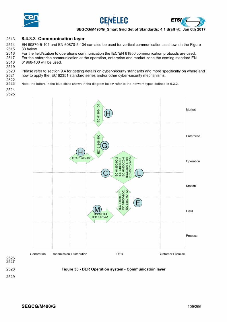
SEGCG/M490/G_Smart Grid Set of Standards; 4.1 draft v0; Jan 6th 2017
SEGCG/M490/G 109/266
8.4.3.3 Communication layer 2513
EN 60870-5-101 and EN 60870-5-104 can also be used for vertical communication as shown in the Figure 2514 33 below. 2515 For the field/station to operations communication the IEC/EN 61850 communication protocols are used. 2516 For the enterprise communication at the operation, enterprise and market zone the coming standard EN 2517 61968-100 will be used. 2518 2519 Please refer to section 9.4 for getting details on cyber-security standards and more specifically on where and 2520 how to apply the IEC 62351 standard series and/or other cyber-security mechanisms. 2521 2522 Note: the letters in the blue disks shown in the diagram below refer to the network types defined in 9.3.2. 2523
2524 2525
Generation Transmission Distribution Customer PremiseDER
Process
Field
Station
Operation
Enterprise
Market
IEC
61
85
0-9
0-2
IEC
61
85
0-8
-2
IEC
61
40
0-2
5-4
IEC
60
87
0-5
-10
1
IEC
60
87
0-5
-10
4
IEC
61
85
0-8
-1IE
C 6
18
50
-90
-2IE
C 6
85
0-9
0-1
2
IEC
61
96
8-1
00
IEC 61968-100
IEC 61158
IEC 61784-1
IEC
61
96
8-1
00
2526 2527
Figure 33 - DER Operation system - Communication layer 2528
2529
E
L
GH
M
C
H
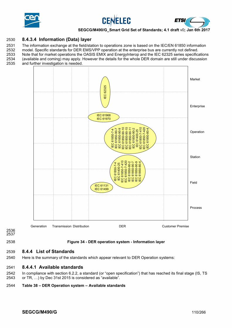
SEGCG/M490/G_Smart Grid Set of Standards; 4.1 draft v0; Jan 6th 2017
SEGCG/M490/G 110/266
8.4.3.4 Information (Data) layer 2530
The information exchange at the field/station to operations zone is based on the IEC/EN 61850 information 2531 model. Specific standards for DER EMS/VPP operation at the enterprise bus are currently not defined. 2532 Note that for market operations the OASIS EMIX and EnergyInterop and the IEC 62325 series specifications 2533 (available and coming) may apply. However the details for the whole DER domain are still under discussion 2534 and further investigation is needed. 2535
Generation Transmission Distribution Customer PremiseDER
Process
Field
Station
Operation
Enterprise
Market
IEC
61
85
0-7
-4
IEC
61
40
0-2
5
IEC
61
85
0-7
-41
0
IEC
61
85
0-7
-42
0
IEC
61
85
0-9
0-2
IEC
61
85
0-9
0-7
IEC
61
85
0-9
0-9
IEC
61
85
0-8
0-4
IEC
61
85
0-7
-4
IEC
61
85
0-9
0-7
IEC
61
85
0-9
0-9
IEC
61
85
0-9
0-1
0
IEC
61
85
0-9
0-1
5
IEC
61
85
0-9
0-1
1
IEC
61
85
0-9
0-2
IEC
61
40
0-2
5
IEC
61
85
0-7
-41
0
IEC
61
85
0-7
-42
0
IEC
61
85
0-8
0-4
IEC 61968
IEC 61970
IEC 61131
IEC 61499
IEC
62
32
5
2536 2537
Figure 34 - DER operation system - Information layer 2538
8.4.4 List of Standards 2539
Here is the summary of the standards which appear relevant to DER Operation systems: 2540
8.4.4.1 Available standards 2541
In compliance with section 6.2.2, a standard (or “open specification”) that has reached its final stage (IS, TS 2542 or TR, …) by Dec 31st 2015 is considered as “available”. 2543
Table 38 – DER Operation system – Available standards 2544

SEGCG/M490/G_Smart Grid Set of Standards; 4.1 draft v0; Jan 6th 2017
SEGCG/M490/G 111/266
Layer Standard Comments
Information EN 61850-7-4 EN 61850-7-3 EN 61850-7-2 EN 61850-6
Core Information model and language for the IEC/EN 61850 series
Information EN 61400-25-1, EN 61400-25-2, EN 61400-25-3, EN 61400-25-4
Wind farms
Information EN 61850-7-410 Hydroelectric power plants
Information EN 61850-7-420 DER
Information IEC 61850-80-4 mapping of COSEM over IEC 61850
Communication, information
IEC 61850-90-2 Substation to control center communication
Information IEC 61850-90-7 DER inverters
Communication IEC 61850-90-12 Use of IEC 61850 over WAN
Information EN 61131 Programmable controllers
Information EN 61499 Distributed control and automation
Information EN 61968 (all parts) Distribution CIM
Information EN 61970 (all parts) Transmission CIM
Communication, Information
EN 62325 (all parts) Framework market communication
Communication EN 60870-5-101 Telecontrol equipment and systems – Part 5-101: Transmission protocols – Companion standard for basic telecontrol tasks
Communication EN 60870-5-104 Telecontrol equipment and systems – Part 5-104: Transmission protocols – Network access for EN 60870-5-101 using standard transport profiles
Communication EN 61850-8-1 IEC/EN 61850 communication except Sample values
Communication EN 61158 Field bus
Communication EN 62439 High availability automation Networks (PRP y HSR)
Communication IEC 61784-1 Field bus
Communication IEC 62351 (all parts) Cyber-security aspects (refer to section 9.4)
Communication EN 61968-100 Defines profiles for the communication of CIM messages using Web Services or Java Messaging System.
Component IEC 60904 (all parts) Photovoltaic devices
Component IEC 61194 Characteristic parameters of stand-alone photovoltaic (PV) systems
Component EN 61724 Photovoltaic system performance monitoring - Guidelines for measurement, data exchange and analysis
Component EN 61730 Photovoltaic (PV) module safety qualification
Component EN 61400-1 Wind turbines - Part 1: Design requirements
Component EN 61400-2 Wind turbines - Part 2: Design requirements for small wind turbines
Component EN 61400-3 Wind turbines - Part 3: Design requirements for offshore wind turbines
Component IEC 62282 Fuel cell technologies
Component IEC 62600 series Marine energy
Component EN 50438 Requirements for the connection of micro-generators in parallel with public low-voltage distribution networks Maintenance of an existing standard (CLC TC 8X)
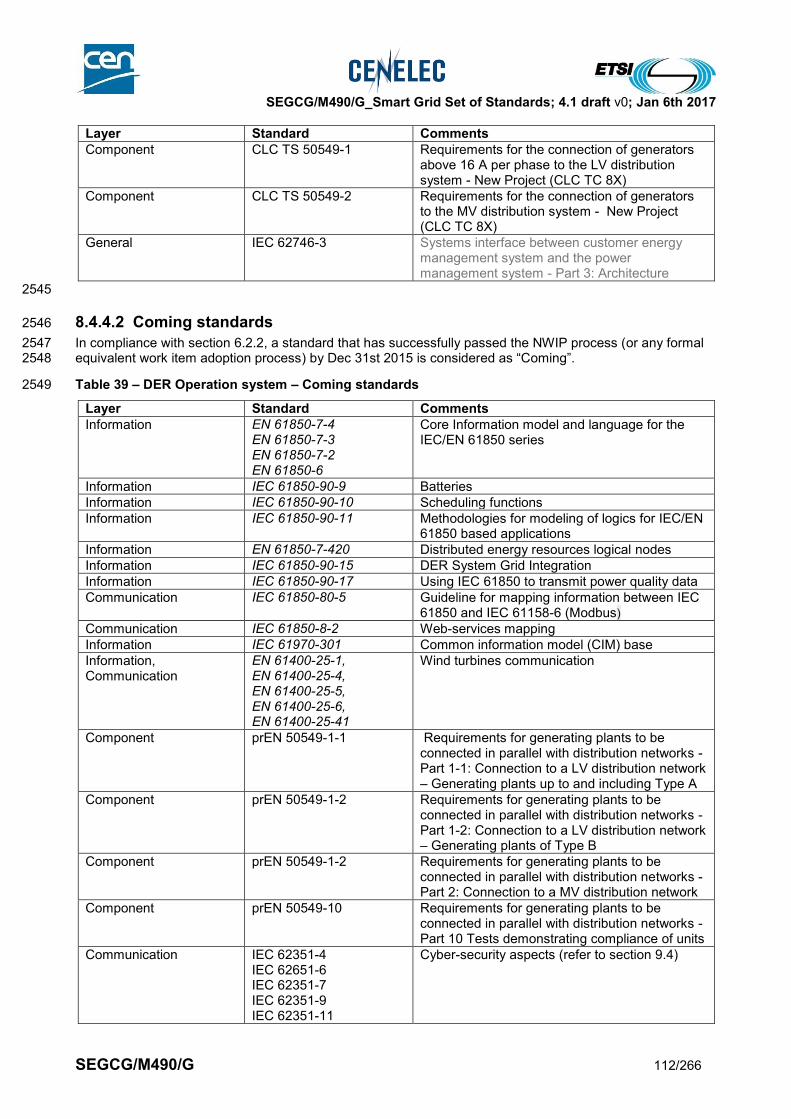
SEGCG/M490/G_Smart Grid Set of Standards; 4.1 draft v0; Jan 6th 2017
SEGCG/M490/G 112/266
Layer Standard Comments
Component CLC TS 50549-1 Requirements for the connection of generators above 16 A per phase to the LV distribution system - New Project (CLC TC 8X)
Component CLC TS 50549-2 Requirements for the connection of generators to the MV distribution system - New Project (CLC TC 8X)
General IEC 62746-3 Systems interface between customer energy management system and the power management system - Part 3: Architecture
2545
8.4.4.2 Coming standards 2546
In compliance with section 6.2.2, a standard that has successfully passed the NWIP process (or any formal 2547 equivalent work item adoption process) by Dec 31st 2015 is considered as “Coming”. 2548
Table 39 – DER Operation system – Coming standards 2549
Layer Standard Comments
Information EN 61850-7-4 EN 61850-7-3 EN 61850-7-2 EN 61850-6
Core Information model and language for the IEC/EN 61850 series
Information IEC 61850-90-9 Batteries
Information IEC 61850-90-10 Scheduling functions
Information IEC 61850-90-11 Methodologies for modeling of logics for IEC/EN 61850 based applications
Information EN 61850-7-420 Distributed energy resources logical nodes
Information IEC 61850-90-15 DER System Grid Integration
Information IEC 61850-90-17 Using IEC 61850 to transmit power quality data
Communication IEC 61850-80-5 Guideline for mapping information between IEC 61850 and IEC 61158-6 (Modbus)
Communication IEC 61850-8-2 Web-services mapping
Information IEC 61970-301 Common information model (CIM) base
Information, Communication
EN 61400-25-1, EN 61400-25-4, EN 61400-25-5, EN 61400-25-6, EN 61400-25-41
Wind turbines communication
Component prEN 50549-1-1 Requirements for generating plants to be connected in parallel with distribution networks - Part 1-1: Connection to a LV distribution network – Generating plants up to and including Type A
Component prEN 50549-1-2 Requirements for generating plants to be connected in parallel with distribution networks - Part 1-2: Connection to a LV distribution network – Generating plants of Type B
Component prEN 50549-1-2 Requirements for generating plants to be connected in parallel with distribution networks - Part 2: Connection to a MV distribution network
Component prEN 50549-10 Requirements for generating plants to be connected in parallel with distribution networks - Part 10 Tests demonstrating compliance of units
Communication IEC 62351-4 IEC 62651-6 IEC 62351-7 IEC 62351-9 IEC 62351-11
Cyber-security aspects (refer to section 9.4)
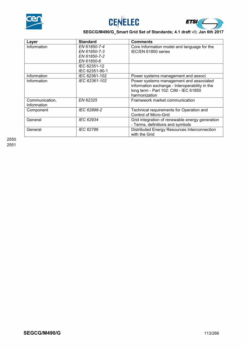
SEGCG/M490/G_Smart Grid Set of Standards; 4.1 draft v0; Jan 6th 2017
SEGCG/M490/G 113/266
Layer Standard Comments
Information EN 61850-7-4 EN 61850-7-3 EN 61850-7-2 EN 61850-6
Core Information model and language for the IEC/EN 61850 series
IEC 62351-12 IEC 62351-90-1
Information IEC 62361-102 Power systems management and associ
Information IEC 62361-102 Power systems management and associated information exchange - Interoperability in the long term - Part 102: CIM - IEC 61850 harmonization
Communication, Information
EN 62325 Framework market communication
Component IEC 62898-2 Technical requirements for Operation and Control of Micro-Grid
General IEC 62934 Grid integration of renewable energy generation - Terms, definitions and symbols
General IEC 62786 Distributed Energy Resources Interconnection with the Grid
2550
2551

SEGCG/M490/G_Smart Grid Set of Standards; 4.1 draft v0; Jan 6th 2017
SEGCG/M490/G 114/266
8.5 Smart Metering systems 2552
8.5.1 AMI system (M/441 scope) 2553
The standardization supporting the Advanced Metering Infrastructure is covered under mandate M/441 [3] 2554 and co-ordinated by the Smart Metering Coordination Group (SM-CG). The following sections represent a 2555 summary of the results achieved, based exclusively on the SM-CG technical report TR 50572 [4] “Functional 2556 reference architecture for communications in smart metering systems”, the further SM-CG report at the end 2557 of 2012, and the latest SM-CG work programme. 2558 2559 The referred set of SM-CG standards is widely accepted, but the work of the SM-CG is ongoing, including 2560 work on smart metering use cases. Extensions considering new use cases and the evolution of new 2561 technologies will follow the rules set by SM-CG and be documented in subsequent reports. 2562 2563 In this report and particularly in this section, all references to standards related to the M/441 mandate [3] 2564 remain under the responsibility of the SM-CG, without excluding relevant standards which may be developed 2565 in other contexts. 2566
8.5.1.1 System description 2567
The AMI system refers to the whole advanced metering infrastructure covered by the M/441 mandate [3] 2568 supporting the deployment of smart meters. It includes the smart meter itself and external display device, in-2569 home gateway (Local Network Access Point or LNAP), meter data concentrator (Neighborhood Network 2570 Access Point – NNAP), and Head-End System (HES). 2571 2572 The AMI provides services for the customer, the supplier and network operator and is used for automated 2573 meter reading and billing and a range of other activities which are considered in detail in the work of the 2574 M/441 mandate by the Smart Meter Co-ordination Group (SM-CG). 2575 2576 Within a smart grid, the AMI may also be used for network monitoring and control. Furthermore it might be 2577 used for demand response / demand side management in connection with demand and production 2578 (generation) flexibility systems. As stated in the SM-CG Technical Report (TR 50572) [4], this latter 2579 functionality is not in the M/441 scope [3] and can also be offered through alternative channels. 2580 2581 It should be noted that there may be revenue and operational meters further up the grid system (e.g. at the 2582 generation, transmission or distribution level). These are not considered part of the AMI system, which is 2583 focused on revenue metering at the customer premises level. 2584 2585
8.5.1.2 Set of use cases 2586
Here is a set of high level use cases developed under the M/441 [3] which Member States may wish to 2587 implement via their AMI systems. The columns then consider relevant available or coming standards 2588 necessary to support these use cases. 2589 To the extent that the AMI is used in connection with demand and production flexibility, these use cases 2590 should be read in conjunction with the use cases shown in this report under section 8.6.1.2 for the 2591 Aggregated prosumers management system. 2592 The meanings of the three last columns (AVAILABLE, COMING, Not Yet) and of the “C”, “I”, “CI”, “X” 2593 conventions are given in section 7.6.2. 2594 2595
Table 40 – AMI system – Use cases 2596
Supported by standards
Use cases cluster High level use cases AVAILABLE COMING Not yet
(AMI) Billing Obtain scheduled meter reading CI
Set billing parameters CI
Add credit C
Execute supply control CI

SEGCG/M490/G_Smart Grid Set of Standards; 4.1 draft v0; Jan 6th 2017
SEGCG/M490/G 115/266
Supported by standards
Use cases cluster High level use cases AVAILABLE COMING Not yet
(AMI) Customer information provision
Provide information to consumer
CI
(AMI) Configure events, statuses and actions
Configure meter events and actions
CI
Manage events CI
Retrieve AMI component information
CI
Check device availability CI
(AMI) installation & configuration
AMI component discovery & communication setup
CI
Clock synchronization CI
Configure AMI device CI
Security (Configuration) Management
CI
(AMI) Energy market events
Manage consumer moving in CI
Manage customer moving out CI
Manage customer gained CI
Manage customer lost CI
(AMI) Collect events and status information
Manage supply quality CI
2597
8.5.1.3 Mapping on SGAM 2598
8.5.1.3.1 Preamble 2599
The smart metering functional reference architecture is specified in CLC TR 50572 [4] according to Figure 2600 35. In the following sections the smart metering architecture of Figure 35 is mapped into the SGAM 2601 architecture. Note that in the architecture in Figure 35 the Head End System is at the bottom of the diagram, 2602 in contrast to the order of the component layers in the SGAM architecture diagrams. 2603 The objective of this section is to report on SM-CG conclusions, mandated by the M/441 [3]. 2604 Should any difference appear between the here-under section and current and subsequent SM-CG 2605 publications, then SM-CG one shall remain the reference. 2606

SEGCG/M490/G_Smart Grid Set of Standards; 4.1 draft v0; Jan 6th 2017
SEGCG/M490/G 116/266
2607
Figure 35: Smart Metering architecture according to CLC TR 50572 2608
The diagrams in the sections below give examples of a mapping of a typical configuration based on the 2609 smart metering reference architecture on the SGAM. 2610 2611 Both in these diagrams of this section 8.5.1 and in similar ones in section 8.6.1, the split of the “customer 2612 premises” domain on the right is intended to illustrate a typical market model where assets in the 2613 home/building are not owned/operated by the electricity service supplier. However Member State market 2614 models vary e.g. as regards meter ownership and operation, and are subject to national structures and 2615 regulation, so this representation should not be seen as definitive. 2616
8.5.1.3.2 Component layer 2617
2618 The exact composition of the AMI will depend on the configuration chosen. The following figure shows the 2619 components that may be part of the Advanced Metering Infrastructure. Meters for different media (Electricity, 2620 Gas, Heat and Water) represent the end devices on process and filed level. We distinguish between meters 2621
at (residential) customer premises (which are subject to metrological approvals -> MID8) and meters used in 2622 industrial, commercial environments or for grid automation purposes. The meter may have an interface to a 2623 simple display unit or, it may be interfaced to a proper home automation system. 2624 2625 Meters and home/building automation end devices may be interconnected via LNAPs (Local Network Access 2626 Point). 2627 2628 The NNAP (Neighborhood Network Access Point) is typically located at distribution station level. The NNAP 2629 may be part of a simple communication gateway or of a data concentrator offering comprehensive data 2630 processing features. 2631 2632 The meters are connected (directly or via LNAP and/or NNAP) to the HES (Head End System). The HES 2633 manages the data exchange with the meters and supervises the WAN/LAN communication. 2634
8 See Abbreviations Table 2
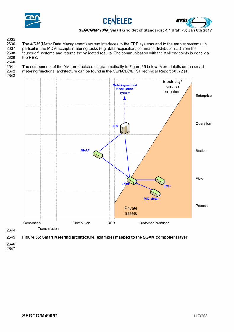
SEGCG/M490/G_Smart Grid Set of Standards; 4.1 draft v0; Jan 6th 2017
SEGCG/M490/G 117/266
2635 The MDM (Meter Data Management) system interfaces to the ERP systems and to the market systems. In 2636 particular, the MDM accepts metering tasks (e.g. data acquisition, command distribution,…) from the 2637 “superior” systems and returns the validated results. The communication with the AMI endpoints is done via 2638 the HES. 2639 2640 The components of the AMI are depicted diagrammatically in Figure 36 below. More details on the smart 2641 metering functional architecture can be found in the CEN/CLC/ETSI Technical Report 50572 [4]. 2642 2643
2644
Figure 36: Smart Metering architecture (example) mapped to the SGAM component layer. 2645
2646 2647
Generation
Transmission
Distribution DER
Process
Field
Station
Operation
Enterprise
Market
Customer Premises
Metering-related
Back Office
system
NNAP
HES
LNAP
MID Meter
EMG
Private
assets
Electricity/
service
supplier
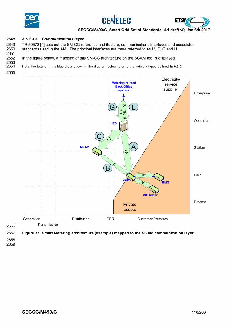
SEGCG/M490/G_Smart Grid Set of Standards; 4.1 draft v0; Jan 6th 2017
SEGCG/M490/G 118/266
8.5.1.3.3 Communications layer 2648
TR 50572 [4] sets out the SM-CG reference architecture, communications interfaces and associated 2649 standards used in the AMI. The principal interfaces are there referred to as M, C, G and H. 2650 2651 In the figure below, a mapping of this SM-CG architecture on the SGAM tool is displayed. 2652 2653 Note: the letters in the blue disks shown in the diagram below refer to the network types defined in 9.3.2. 2654
2655
2656
Figure 37: Smart Metering architecture (example) mapped to the SGAM communication layer. 2657
2658 2659
Generation
Transmission
Distribution DER
Process
Field
Station
Operation
Enterprise
Market
Customer Premises
Metering-related
Back Office
system
NNAP
HES
LNAP
MID Meter
EMG
Private
assets
Electricity/
service
supplier
C
M
H2
IEC
61
96
8-1
00
G1
G2
A
LG
B
C
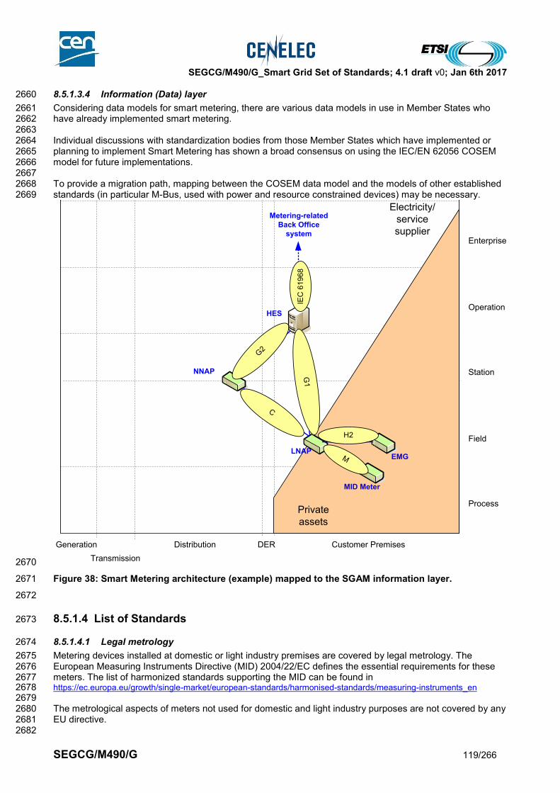
SEGCG/M490/G_Smart Grid Set of Standards; 4.1 draft v0; Jan 6th 2017
SEGCG/M490/G 119/266
8.5.1.3.4 Information (Data) layer 2660
Considering data models for smart metering, there are various data models in use in Member States who 2661 have already implemented smart metering. 2662 2663 Individual discussions with standardization bodies from those Member States which have implemented or 2664 planning to implement Smart Metering has shown a broad consensus on using the IEC/EN 62056 COSEM 2665 model for future implementations. 2666 2667 To provide a migration path, mapping between the COSEM data model and the models of other established 2668 standards (in particular M-Bus, used with power and resource constrained devices) may be necessary. 2669
2670
Figure 38: Smart Metering architecture (example) mapped to the SGAM information layer. 2671
2672
8.5.1.4 List of Standards 2673
8.5.1.4.1 Legal metrology 2674
Metering devices installed at domestic or light industry premises are covered by legal metrology. The 2675 European Measuring Instruments Directive (MID) 2004/22/EC defines the essential requirements for these 2676 meters. The list of harmonized standards supporting the MID can be found in 2677 https://ec.europa.eu/growth/single-market/european-standards/harmonised-standards/measuring-instruments_en 2678 2679 The metrological aspects of meters not used for domestic and light industry purposes are not covered by any 2680 EU directive. 2681 2682
Generation
Transmission
Distribution DER
Process
Field
Station
Operation
Enterprise
Market
Customer Premises
Metering-related
Back Office
system
NNAP
HES
LNAP
MID Meter
EMG
Private
assets
Electricity/
service
supplier
G1
C
H2
M
IEC
61
96
8
G2

SEGCG/M490/G_Smart Grid Set of Standards; 4.1 draft v0; Jan 6th 2017
SEGCG/M490/G 120/266
Non-metrological aspects (e.g. communication protocols, data models, interoperability…) of smart meters 2683 are not covered by any EU directive. 2684 2685 In the following sections the metrological aspects of smart metering are not considered. 2686 2687
8.5.1.4.2 List of standards 2688
In compliance with section 6.2.2, a standard (or “open specification”) that has reached its final stage (IS, TS 2689 or TR, …) by Dec 31st 2015 is considered as “available”, meanwhile a standard that has successfully passed 2690 the NWIP process (or any formal equivalent work item adoption process) by Dec 31st 2015 is considered as 2691 “Coming”. 2692 2693 A list of communication standards which appeared relevant to support an AMI system were given in TR 2694 50572 [4]. This list has been updated to reflect the M/441 report at the end of 2012 and the most recent SM-2695 CG work programme (December 2013)[5] and subsequent updates, and completed with the coming 2696 standards. 2697 2698 Additional columns are provided to indicate which interface type is envisaged, with letters referring to the 2699 functional architecture given in Figure 35 (C, G1, G2, H2, M). 2700 2701 Note : Some standards contained in Table 41 and Table 42 may also support use cases of “Metering-related Back Office 2702 systems” (section 8.5.2) and of “Demand and production (generation) flexibility systems” as stated in section 8.6 below. 2703
2704 Because of the tight connection of this system with telecommunication standards, the tables below also 2705 include the list of appropriate communication standards (OSI layers 1 to 3). 2706
Table 41 – AMI system – Standards (outside M/441 scope) 2707
Layer Available Standard Coming Standard Comments
Information EN 61968 (all parts) EN 61968-9
EN 61968-9 For the link between HES and MDM, CIM Payload definition only. Interface for meter reading and control. Standard for interface between metering systems and other systems within the scope of EN 61968
2708
Table 42 – AMI system – Standards (within M/441 scope) 2709
Extract from SM-CG reports [4] & [5] and subsequent updates as well as the latest SM-CG work programme 2710
AVAILABLE STANDARDS
Available Coming M H1 H2/H3 C G1 G2 L N
CLC/TS 50568-4 X x x x
CLC/TS 50568-8 X x x x
CLC/TS 50590 X x x x
CLC/TS 52056-8-4 X x
CLC/TS 52056-8-5 X x
CLC/TS 52056-8-7 X x x x
EN 50065-1 X x x x x x x x
EN 50090-3-1 X x x
EN 50090-3-2 X x x
EN 50090-3-3 X x x
EN 50090-4-1 X x x
EN 50090-4-2 X x x
EN 50090-4-3 X x x
EN 50090-5-1 X x x
EN 50090-5-2 X x x
EN 50090-5-3 X x x
EN 50090-7-1 X x x
CEN-CLC-ETSI/TR 50572
X x x x x x x x x
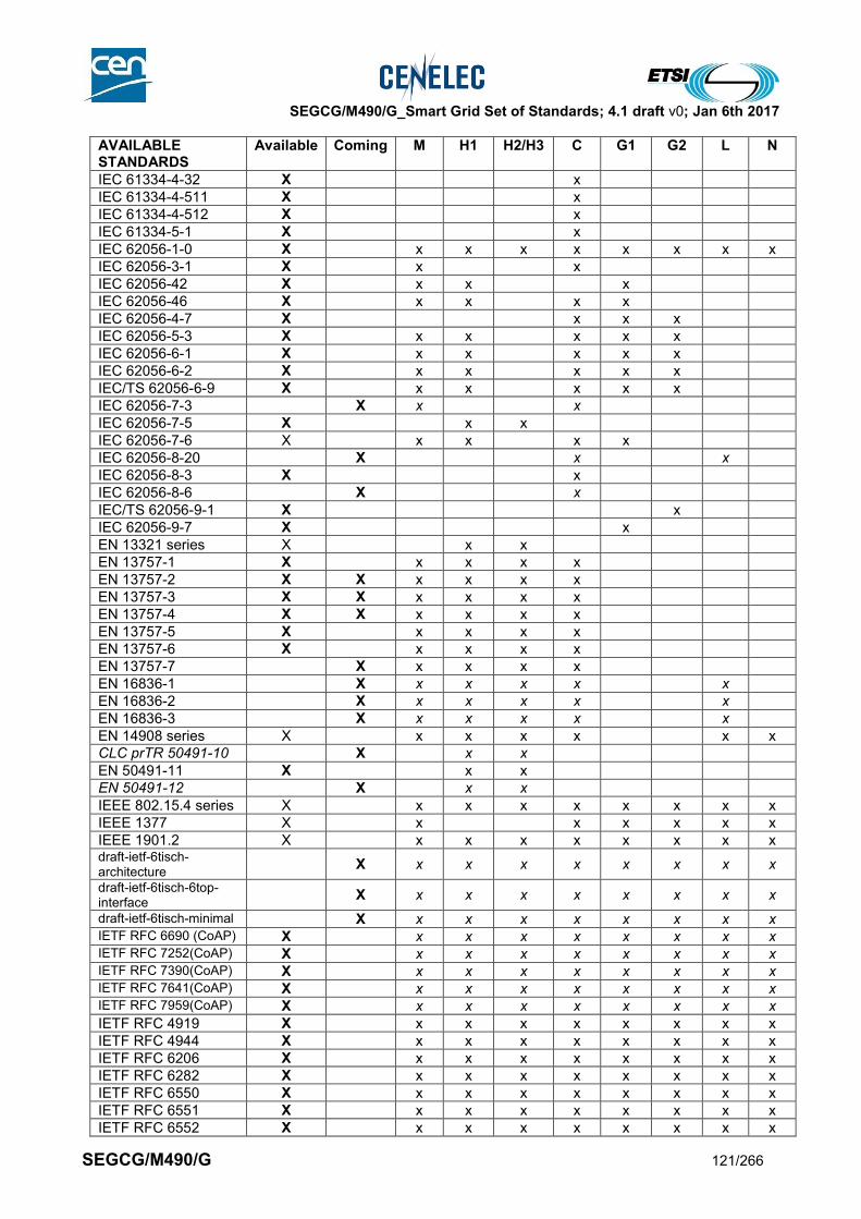
SEGCG/M490/G_Smart Grid Set of Standards; 4.1 draft v0; Jan 6th 2017
SEGCG/M490/G 121/266
AVAILABLE STANDARDS
Available Coming M H1 H2/H3 C G1 G2 L N
IEC 61334-4-32 X x
IEC 61334-4-511 X x
IEC 61334-4-512 X x
IEC 61334-5-1 X x
IEC 62056-1-0 X x x x x x x x x
IEC 62056-3-1 X x x
IEC 62056-42 X x x x
IEC 62056-46 X x x x x
IEC 62056-4-7 X x x x
IEC 62056-5-3 X x x x x x
IEC 62056-6-1 X x x x x x
IEC 62056-6-2 X x x x x x
IEC/TS 62056-6-9 X x x x x x
IEC 62056-7-3 X x x
IEC 62056-7-5 X x x
IEC 62056-7-6 X x x x x
IEC 62056-8-20 X x x
IEC 62056-8-3 X x
IEC 62056-8-6 X x
IEC/TS 62056-9-1 X x
IEC 62056-9-7 X x
EN 13321 series X x x
EN 13757-1 X x x x x
EN 13757-2 X X x x x x
EN 13757-3 X X x x x x
EN 13757-4 X X x x x x
EN 13757-5 X x x x x
EN 13757-6 X x x x x
EN 13757-7 X x x x x
EN 16836-1 X x x x x x
EN 16836-2 X x x x x x
EN 16836-3 X x x x x x
EN 14908 series X x x x x x x
CLC prTR 50491-10 X x x
EN 50491-11 X x x
EN 50491-12 X x x
IEEE 802.15.4 series X x x x x x x x x
IEEE 1377 X x x x x x x
IEEE 1901.2 X x x x x x x x x draft-ietf-6tisch-architecture
X x x x x x x x x
draft-ietf-6tisch-6top-interface
X x x x x x x x x
draft-ietf-6tisch-minimal X x x x x x x x x IETF RFC 6690 (CoAP) X x x x x x x x x IETF RFC 7252(CoAP) X x x x x x x x x IETF RFC 7390(CoAP) X x x x x x x x x IETF RFC 7641(CoAP) X x x x x x x x x IETF RFC 7959(CoAP) X x x x x x x x x
IETF RFC 4919 X x x x x x x x x
IETF RFC 4944 X x x x x x x x x
IETF RFC 6206 X x x x x x x x x
IETF RFC 6282 X x x x x x x x x
IETF RFC 6550 X x x x x x x x x
IETF RFC 6551 X x x x x x x x x
IETF RFC 6552 X x x x x x x x x
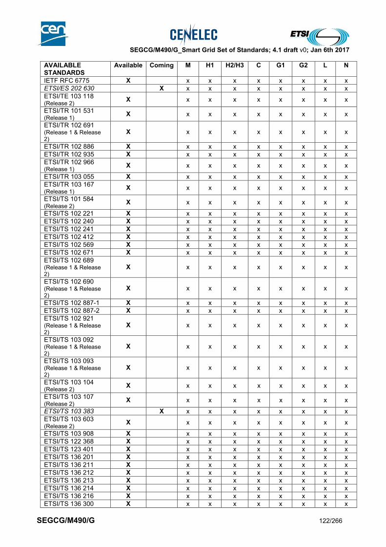
SEGCG/M490/G_Smart Grid Set of Standards; 4.1 draft v0; Jan 6th 2017
SEGCG/M490/G 122/266
AVAILABLE STANDARDS
Available Coming M H1 H2/H3 C G1 G2 L N
IETF RFC 6775 X x x x x x x x x
ETSI/ES 202 630 X x x x x x x x x
ETSI/TE 103 118 (Release 2)
X x x x x x x x x
ETSI/TR 101 531 (Release 1)
X x x x x x x x x
ETSI/TR 102 691 (Release 1 & Release 2)
X x x x x x x x x
ETSI/TR 102 886 X x x x x x x x x
ETSI/TR 102 935 X x x x x x x x x
ETSI/TR 102 966 (Release 1)
X x x x x x x x x
ETSI/TR 103 055 X x x x x x x x x
ETSI/TR 103 167 (Release 1)
X x x x x x x x x
ETSI/TS 101 584 (Release 2)
X x x x x x x x x
ETSI/TS 102 221 X x x x x x x x x
ETSI/TS 102 240 X x x x x x x x x
ETSI/TS 102 241 X x x x x x x x x
ETSI/TS 102 412 X x x x x x x x x
ETSI/TS 102 569 X x x x x x x x x
ETSI/TS 102 671 X x x x x x x x x
ETSI/TS 102 689 (Release 1 & Release 2)
X x x x x x x x x
ETSI/TS 102 690 (Release 1 & Release 2)
X x x x x x x x x
ETSI/TS 102 887-1 X x x x x x x x x
ETSI/TS 102 887-2 X x x x x x x x x
ETSI/TS 102 921 (Release 1 & Release 2)
X x x x x x x x x
ETSI/TS 103 092 (Release 1 & Release 2)
X x x x x x x x x
ETSI/TS 103 093 (Release 1 & Release 2)
X x x x x x x x x
ETSI/TS 103 104 (Release 2)
X x x x x x x x x
ETSI/TS 103 107 (Release 2)
X x x x x x x x x
ETSI/TS 103 383 X x x x x x x x x
ETSI/TS 103 603 (Release 2)
X x x x x x x x x
ETSI/TS 103 908 X x x x x x x x x
ETSI/TS 122 368 X x x x x x x x x
ETSI/TS 123 401 X x x x x x x x x
ETSI/TS 136 201 X x x x x x x x x
ETSI/TS 136 211 X x x x x x x x x
ETSI/TS 136 212 X x x x x x x x x
ETSI/TS 136 213 X x x x x x x x x
ETSI/TS 136 214 X x x x x x x x x
ETSI/TS 136 216 X x x x x x x x x
ETSI/TS 136 300 X x x x x x x x x
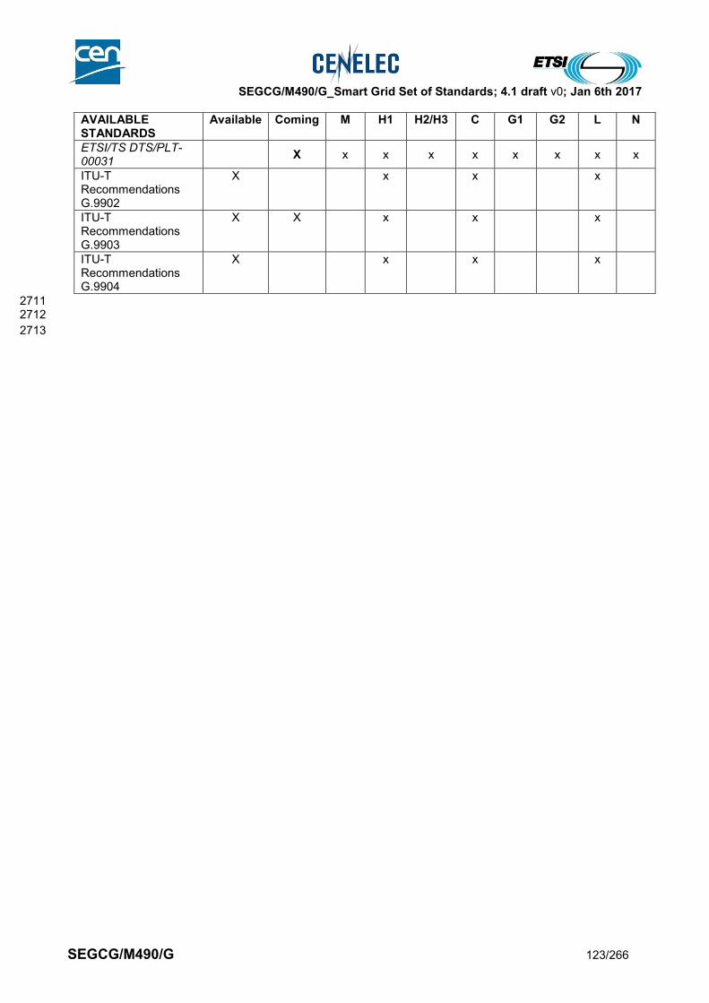
SEGCG/M490/G_Smart Grid Set of Standards; 4.1 draft v0; Jan 6th 2017
SEGCG/M490/G 123/266
AVAILABLE STANDARDS
Available Coming M H1 H2/H3 C G1 G2 L N
ETSI/TS DTS/PLT-00031
X x x x x x x x x
ITU-T Recommendations G.9902
X x x x
ITU-T Recommendations G.9903
X X x x x
ITU-T Recommendations G.9904
X x x x
2711 2712
2713

SEGCG/M490/G_Smart Grid Set of Standards; 4.1 draft v0; Jan 6th 2017
SEGCG/M490/G 124/266
8.5.2 Metering-related Back Office systems 2714
2715
8.5.2.1 System description 2716
Metering-related Back Office systems refer to a range of back-office systems employed to use and manage 2717 data deriving from smart metering, mostly referring to the Meter data management (MDM) related 2718 application. 2719 2720 The drawing behind shows the typical hosted applications: 2721
2722
Figure 39 - Typical applications hosted by a metering-related back-office system 2723
2724
8.5.2.2 Set of use cases 2725
Here is a set of Generic Use-Cases developed by ESMIG which may be supported by a Metering-related 2726 Back Office system. 2727 The meanings of the three last columns (AVAILABLE, COMING, Not Yet) and of the “C”, “I”, “CI”, “X” 2728 conventions are given in section 7.6.2. 2729 Work is in hand to integrate these use cases with those identified for the AMI in section 8.5.1.2. 2730
Table 43 - Metering-related Back Office system - use cases 2731
Supported by standards
Use cases cluster
High level use cases AVAILABLE COMING Not yet
Monitor AMI event
Install, configure and maintain the metering system
CI
Manage power quality data CI
C
C
C
C
AMAMI HeadEndSystem
Technical asset management
Real -time applications
Distribution Grid Management System
Outage Management
Workforce Management
Custumer Relationship & Billing
Enterprise Asset Management
Energy Capital Management
Intercompany Data Exchange
Other Industry Players
Technical Systems Business Systems
Geographic Information System
AMAMI HeadEndSystem
Scope of theUse Cases inthis section
Customer Communications Management
C
C
C
C
AMAMI HeadEndSystem
Technical asset management
Real -time applications
Distribution Grid Management System
Outage Management
Workforce Management
Custumer Relationship & Billing
Enterprise Asset Management
Energy Capital Management
Intercompany Data Exchange
Other Industry Players
Technical Systems Business Systems
Geographic Information System
AMAMI HeadEndSystem
Scope of theUse Cases inthis section
Customer Communications Management
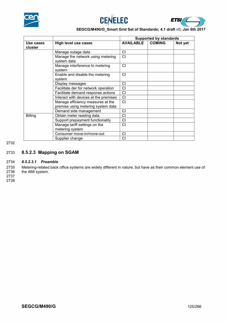
SEGCG/M490/G_Smart Grid Set of Standards; 4.1 draft v0; Jan 6th 2017
SEGCG/M490/G 125/266
Supported by standards
Use cases cluster
High level use cases AVAILABLE COMING Not yet
Manage outage data CI
Manage the network using metering system data
CI
Manage interference to metering system
CI
Enable and disable the metering system
CI
Display messages CI
Facilitate der for network operation CI
Facilitate demand response actions CI
Interact with devices at the premises CI
Manage efficiency measures at the premise using metering system data
CI
Demand side management CI
Billing Obtain meter reading data CI
Support prepayment functionality CI
Manage tariff settings on the metering system
CI
Consumer move-in/move-out CI
Supplier change CI
2732
8.5.2.3 Mapping on SGAM 2733
8.5.2.3.1 Preamble 2734
Metering-related back office systems are widely different in nature, but have as their common element use of 2735 the AMI system. 2736 2737 2738
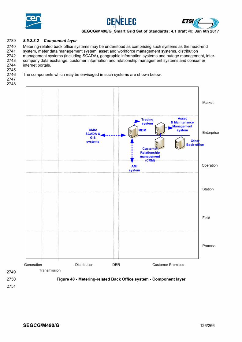
SEGCG/M490/G_Smart Grid Set of Standards; 4.1 draft v0; Jan 6th 2017
SEGCG/M490/G 126/266
8.5.2.3.2 Component layer 2739
Metering-related back office systems may be understood as comprising such systems as the head-end 2740 system, meter data management system, asset and workforce management systems, distribution 2741 management systems (including SCADA), geographic information systems and outage management, inter-2742 company data exchange, customer information and relationship management systems and consumer 2743 internet portals. 2744 2745 The components which may be envisaged in such systems are shown below. 2746 2747 2748
2749
Figure 40 - Metering-related Back Office system - Component layer 2750
2751
Generation
Transmission
Distribution DER
Process
Field
Station
Operation
Enterprise
Market
Customer Premises
MDM
AMI
system
Trading
system
DMS/
SCADA &
GIS
systems
Customer
Relationship
management
(CRM)
Other
Back-office
Asset
& Maintenance
Management
system

SEGCG/M490/G_Smart Grid Set of Standards; 4.1 draft v0; Jan 6th 2017
SEGCG/M490/G 127/266
8.5.2.3.3 Communications layer 2752
The main communication standard likely to be applicable to such back-office systems is EN 61968-100. 2753 2754 Please refer to section 9.4 for getting details on cyber-security standards and more specifically on where and 2755 how to apply the IEC 62351 standard series and/or other cyber-security mechanisms. 2756 2757 Note: the letters in the blue disks shown in the diagram below refer to the network types defined in 9.3.2. 2758
2759
2760
Figure 41 - Metering-related Back Office system - Communication layer 2761
2762
Generation
Transmission
Distribution DER
Process
Field
Station
Operation
Enterprise
Market
Customer Premises
MDM
AMI
system
Trading
system
DMS/
SCADA &
GIS
systems
Customer
Relationship
management
(CRM)
Other
Back-office
IEC
61
96
8-1
00
Asset
& Maintenance
Management
system
IEC 61968-100IEC 61968-100
IEC
61968-100
GH
H G
H G
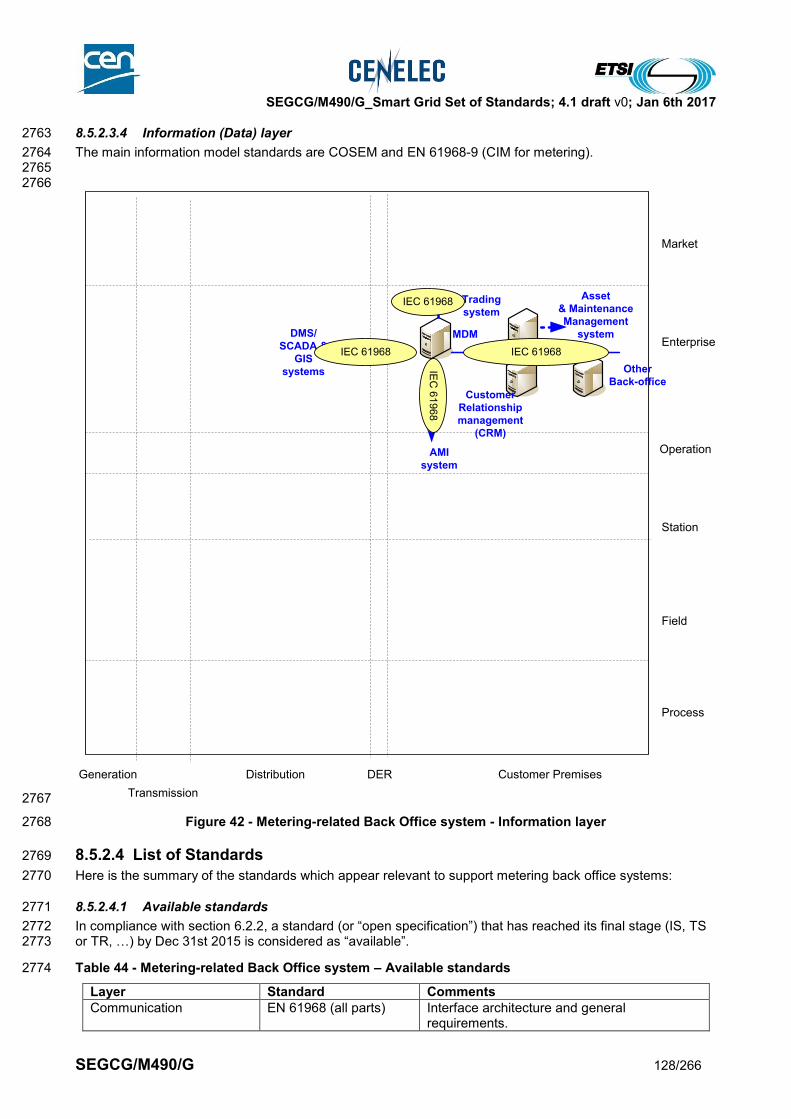
SEGCG/M490/G_Smart Grid Set of Standards; 4.1 draft v0; Jan 6th 2017
SEGCG/M490/G 128/266
8.5.2.3.4 Information (Data) layer 2763
The main information model standards are COSEM and EN 61968-9 (CIM for metering). 2764 2765 2766
2767
Figure 42 - Metering-related Back Office system - Information layer 2768
8.5.2.4 List of Standards 2769
Here is the summary of the standards which appear relevant to support metering back office systems: 2770
8.5.2.4.1 Available standards 2771
In compliance with section 6.2.2, a standard (or “open specification”) that has reached its final stage (IS, TS 2772 or TR, …) by Dec 31st 2015 is considered as “available”. 2773
Table 44 - Metering-related Back Office system – Available standards 2774
Layer Standard Comments
Communication EN 61968 (all parts) Interface architecture and general requirements.
Generation
Transmission
Distribution DER
Process
Field
Station
Operation
Enterprise
Market
Customer Premises
MDM
AMI
system
Trading
system
DMS/
SCADA &
GIS
systems
Customer
Relationship
management
(CRM)
Other
Back-office
Asset
& Maintenance
Management
system
IEC 61968IEC 61968IE
C 6
196
8
IEC 61968

SEGCG/M490/G_Smart Grid Set of Standards; 4.1 draft v0; Jan 6th 2017
SEGCG/M490/G 129/266
Layer Standard Comments
Information EN 61968-9 Interfaces for meter reading and control
Communication EN 61968-100 Application integration at electric utilities - System interfaces for distribution management - Part 100: Implementation profiles
Communication IEC 62351 (all parts) Cyber-security aspects (refer to section 9.4)
2775
8.5.2.4.2 Coming standards 2776
In compliance with section 6.2.2, a standard that has successfully passed the NWIP process (or any formal 2777 equivalent work item adoption process) by Dec 31st 2015 is considered as “Coming”. 2778
Table 45 - Metering-related Back Office system – Coming standards 2779
Layer Standard Comments
Communication IEC 62351 (all parts) Cyber-security aspects (refer to section 9.4)
2780
2781
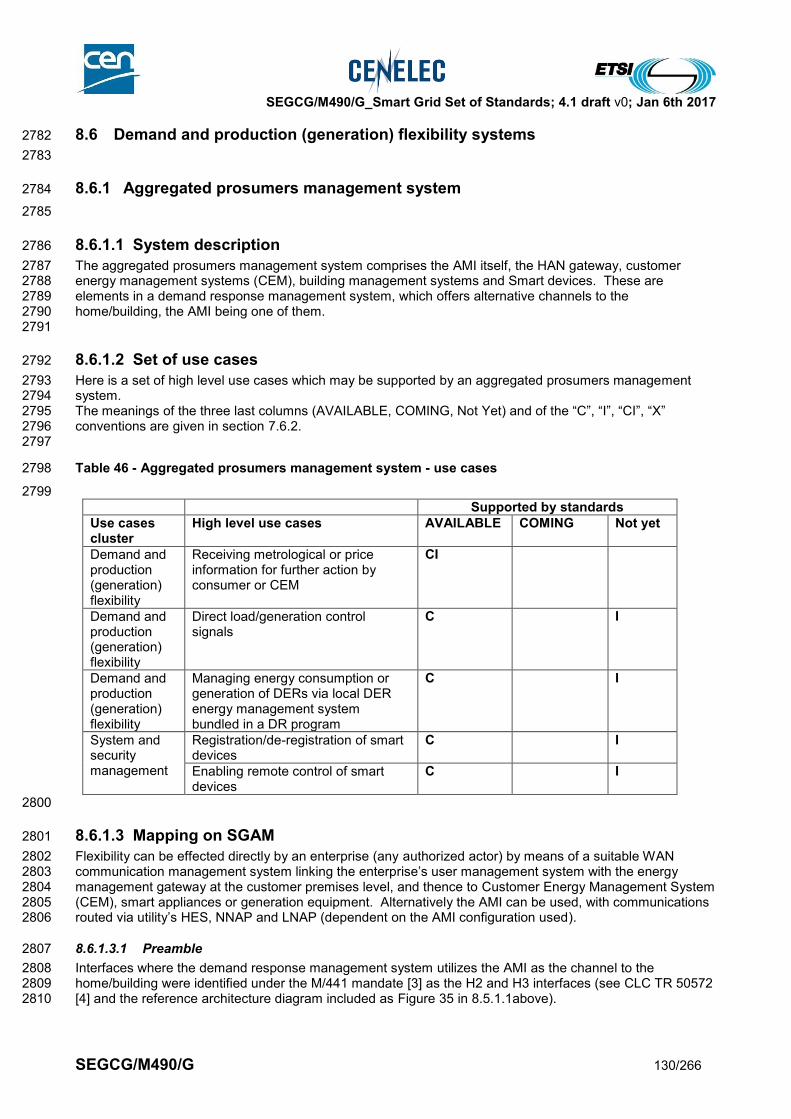
SEGCG/M490/G_Smart Grid Set of Standards; 4.1 draft v0; Jan 6th 2017
SEGCG/M490/G 130/266
8.6 Demand and production (generation) flexibility systems 2782
2783
8.6.1 Aggregated prosumers management system 2784
2785
8.6.1.1 System description 2786
The aggregated prosumers management system comprises the AMI itself, the HAN gateway, customer 2787 energy management systems (CEM), building management systems and Smart devices. These are 2788 elements in a demand response management system, which offers alternative channels to the 2789 home/building, the AMI being one of them. 2790 2791
8.6.1.2 Set of use cases 2792
Here is a set of high level use cases which may be supported by an aggregated prosumers management 2793 system. 2794 The meanings of the three last columns (AVAILABLE, COMING, Not Yet) and of the “C”, “I”, “CI”, “X” 2795 conventions are given in section 7.6.2. 2796 2797
Table 46 - Aggregated prosumers management system - use cases 2798
2799
Supported by standards
Use cases cluster
High level use cases AVAILABLE COMING Not yet
Demand and production (generation) flexibility
Receiving metrological or price information for further action by consumer or CEM
CI
Demand and production (generation) flexibility
Direct load/generation control signals
C I
Demand and production (generation) flexibility
Managing energy consumption or generation of DERs via local DER energy management system bundled in a DR program
C I
System and security management
Registration/de-registration of smart devices
C I
Enabling remote control of smart devices
C I
2800
8.6.1.3 Mapping on SGAM 2801
Flexibility can be effected directly by an enterprise (any authorized actor) by means of a suitable WAN 2802 communication management system linking the enterprise’s user management system with the energy 2803 management gateway at the customer premises level, and thence to Customer Energy Management System 2804 (CEM), smart appliances or generation equipment. Alternatively the AMI can be used, with communications 2805 routed via utility’s HES, NNAP and LNAP (dependent on the AMI configuration used). 2806
8.6.1.3.1 Preamble 2807
Interfaces where the demand response management system utilizes the AMI as the channel to the 2808 home/building were identified under the M/441 mandate [3] as the H2 and H3 interfaces (see CLC TR 50572 2809 [4] and the reference architecture diagram included as Figure 35 in 8.5.1.1above). 2810
SEGCG/M490/G_Smart Grid Set of Standards; 4.1 draft v0; Jan 6th 2017
SEGCG/M490/G 131/266
H2 refers to communication between the Local Network Access Point (LNAP) and the Energy Management 2811 Gateway. H3 refers to communication between the Neighborhood Network Access Point (NNAP) and the 2812 Energy Management Gateway. 2813 2814 These links are being addressed by IEC TC57 WG21 and CLC TC 205 WG18. Their work program also 2815 considers the interface with the CEM and from there to connected devices – smart appliances, displays etc, 2816 which are not within the scope of M/490. 2817 2818 Note that the Energy Management Gateway and the Customer Energy Management System may be 2819 integrated. 2820 2821 The diagrams in the sections below give examples of a mapping of a typical configuration based on the 2822 smart metering reference architecture on the SGAM. 2823 2824 Both in these diagrams in section 8.6.1 and in similar ones in section 8.5.1, the split of the “customer 2825 premises” domain on the right is intended to illustrate a typical market model where assets in the 2826 home/building are not owned/operated by the electricity service supplier. However Member State market 2827 models vary e.g. as regards meter ownership and operation, and are subject to national structures and 2828 regulation, so this representation should not be seen as definitive. 2829 2830 The blue zone indicates that such a system may rely on the AMI system to carry some data. 2831 2832 2833
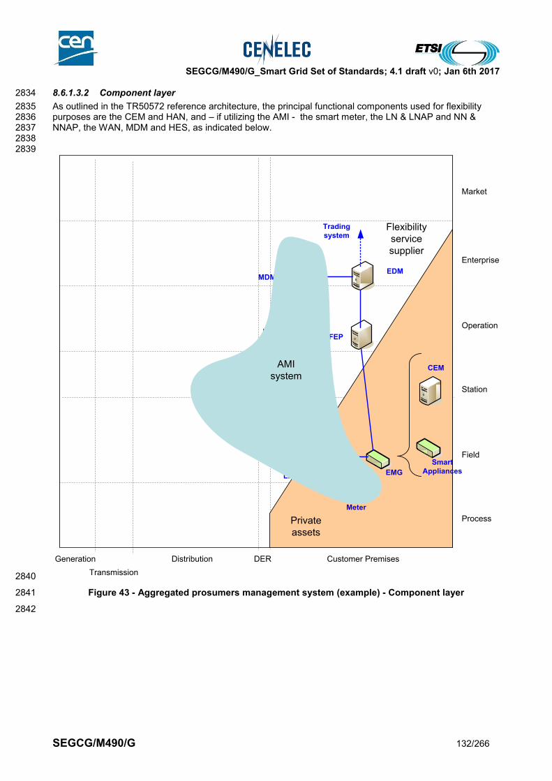
SEGCG/M490/G_Smart Grid Set of Standards; 4.1 draft v0; Jan 6th 2017
SEGCG/M490/G 132/266
8.6.1.3.2 Component layer 2834
As outlined in the TR50572 reference architecture, the principal functional components used for flexibility 2835 purposes are the CEM and HAN, and – if utilizing the AMI - the smart meter, the LN & LNAP and NN & 2836 NNAP, the WAN, MDM and HES, as indicated below. 2837 2838 2839
2840
Figure 43 - Aggregated prosumers management system (example) - Component layer 2841
2842
Generation
Transmission
Distribution DER
Process
Field
Station
Operation
Enterprise
Market
Customer Premises
MDM
NNAP
HES
LNAP
MID
Meter
CEM
EDM
FEP
EMG
Flexibility
service
supplier
Smart
Appliances
Trading
system
AMI
system
Private
assets

SEGCG/M490/G_Smart Grid Set of Standards; 4.1 draft v0; Jan 6th 2017
SEGCG/M490/G 133/266
8.6.1.3.3 Communications layer 2843
TR 50572 sets out the relevant communications layers for these components and applications. 2844 2845 Further work is underway in IEC TC57 WG21 and CLC TC 205 WG18 to develop these. 2846 2847 Please refer to section 9.4 for getting details on cyber-security standards and more specifically on where and 2848 how to apply the IEC 62351 standard series and/or other cyber-security mechanisms. 2849 2850 Note: the letters in the blue disks shown in the diagram below refer to the network types defined in 9.3.2. 2851
2852
2853
Figure 44 - Aggregated prosumers management system (example) - Communication layer 2854
2855 2856
Generation
Transmission
Distribution DER
Process
Field
Station
Operation
Enterprise
Market
Customer Premises
MDM
NNAP
HES
LNAP
MID
Meter
CEM
EDM
FEP
EMG
Flexibility
service
supplier
Smart
Appliances
Trading
system
G2
M
IEC
62746
C
IEC
61
96
8-1
00
H2
IEC
61968-100
G1
IEC
61
96
8- 1
00
AMI
system
Private
assets
IEC
62
32
5
A
G
B
L
G
H
C
A

SEGCG/M490/G_Smart Grid Set of Standards; 4.1 draft v0; Jan 6th 2017
SEGCG/M490/G 134/266
8.6.1.3.4 Information (Data) layer 2857
2858
2859
Figure 45 - Aggregated prosumers management system (example) - Information layer 2860
8.6.1.4 List of Standards 2861
Here is the summary of the principal standards which appear relevant to support aggregated prosumers 2862 management systems: 2863 The list below should also be read in conjunction with those “available” or “coming” cross-cutting standards 2864 supporting the telecommunication technologies detailed in section 9, attached to the network types 2865 presented above (identified with their letter in the blue disks in Figure 44). 2866 2867
8.6.1.4.1 Available standards 2868
In compliance with section 6.2.2, a standard (or “open specification”) that has reached its final stage (IS, TS 2869 or TR, …) by Dec 31st 2015 is considered as “available”. 2870 As for AMI system, which may participate to the building-up of such a system, we will rely on CLC TR 50572 2871 set of standards definition. 2872 2873
Generation
Transmission
Distribution DER
Process
Field
Station
Operation
Enterprise
Market
Customer Premises
MDM
NNAP
HES
LNAP
MID
Meter
CEM
EDM
FEP
EMG
Flexibility
service
supplier
Smart
Appliances
Trading
system
G2
M
IEC
62746
G2
M
IEC
62746
C
IEC
61
96
8-1
00
H2
IEC
61968-100
G1
IEC
61
96
8- 1
00
G1
C
H2
IEC
61
96
8
IEC 61968
IEC
61
96
8
AMI
system
Private
assets
IEC
62
32
5

SEGCG/M490/G_Smart Grid Set of Standards; 4.1 draft v0; Jan 6th 2017
SEGCG/M490/G 135/266
Table 47 - Aggregated prosumers management system – Available standards 2874
Layer Standard Comments
Information, Communication
EN 61968 (all parts)
Information, Communication
(refer to 8.5.1.4) Refer to AMI system section 8.5.1.4
Communication IEC 62351 (all parts) Cyber-security aspects (refer to section 9.4)
Communication, Information
IEC 62746-10-1 IEC/PAS based on OpenADR9
Communication, Information
EN 62325 Framework market communication
8.6.1.4.2 Coming standards 2875
In compliance with section 6.2.2, a standard that has successfully passed the NWIP process (or any formal 2876 equivalent work item adoption process) by Dec 31st 2015 is considered as “Coming”. 2877
Table 48 - Aggregated prosumers management system– Coming standards 2878
Layer Standard Comments
Information EN 50491-12 (pr) (fits CLC TR 50572 type H2/H3 needs) - Smart grid - Application specification. Interface and framework for customer energy management
Communication IEC 6274610 System interfaces and communication protocol profiles relevant for systems connected to the Smart Grid
Information, Communication
(refer to 8.5.1.4) Refer to AMI system section 8.5.1.4
Communication IEC 62351 (all parts) Cyber-security aspects (refer to section 9.4)
Communication, Information
EN 62325 Framework market communication
2879 2880
2881
9 Note : The cross-check between what Europe has considered as main use cases for DR and what IEC 62746-10-1(OpenADR) is
offering is on-going. This IEC/PAS 62746-10-1 is first proposed over simple HTTP transport layer, or over XMPP– refer to 9.3.5
10 IEC 62746 is “transport” communication neutral in principle, but first mappingshould be proposed over XMPP at least – refer to 9.3.5
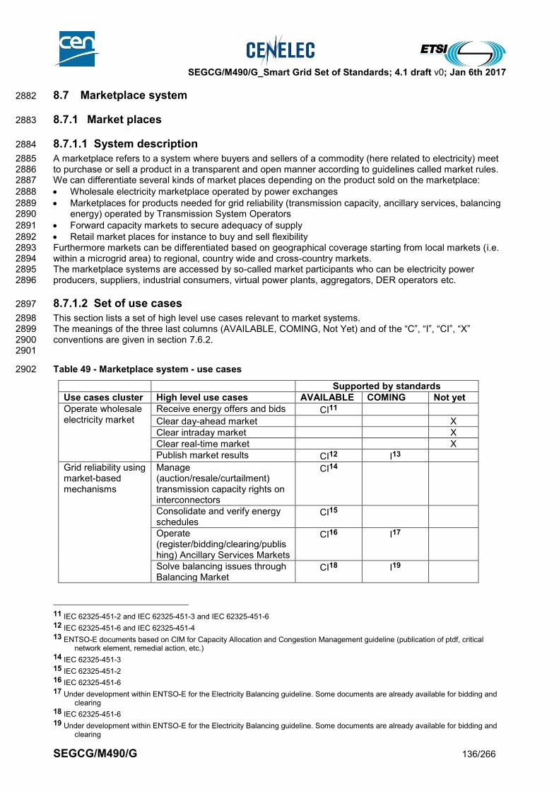
SEGCG/M490/G_Smart Grid Set of Standards; 4.1 draft v0; Jan 6th 2017
SEGCG/M490/G 136/266
8.7 Marketplace system 2882
8.7.1 Market places 2883
8.7.1.1 System description 2884
A marketplace refers to a system where buyers and sellers of a commodity (here related to electricity) meet 2885 to purchase or sell a product in a transparent and open manner according to guidelines called market rules. 2886 We can differentiate several kinds of market places depending on the product sold on the marketplace: 2887
Wholesale electricity marketplace operated by power exchanges 2888
Marketplaces for products needed for grid reliability (transmission capacity, ancillary services, balancing 2889 energy) operated by Transmission System Operators 2890
Forward capacity markets to secure adequacy of supply 2891
Retail market places for instance to buy and sell flexibility 2892 Furthermore markets can be differentiated based on geographical coverage starting from local markets (i.e. 2893 within a microgrid area) to regional, country wide and cross-country markets. 2894 The marketplace systems are accessed by so-called market participants who can be electricity power 2895 producers, suppliers, industrial consumers, virtual power plants, aggregators, DER operators etc. 2896
8.7.1.2 Set of use cases 2897
This section lists a set of high level use cases relevant to market systems. 2898 The meanings of the three last columns (AVAILABLE, COMING, Not Yet) and of the “C”, “I”, “CI”, “X” 2899 conventions are given in section 7.6.2. 2900 2901
Table 49 - Marketplace system - use cases 2902
Supported by standards
Use cases cluster High level use cases AVAILABLE COMING Not yet
Operate wholesale electricity market
Receive energy offers and bids CI11
Clear day-ahead market X
Clear intraday market X
Clear real-time market X
Publish market results CI12 I13
Grid reliability using market-based mechanisms
Manage (auction/resale/curtailment) transmission capacity rights on interconnectors
CI14
Consolidate and verify energy schedules
CI15
Operate (register/bidding/clearing/publishing) Ancillary Services Markets
CI16 I17
Solve balancing issues through Balancing Market
CI18 I19
11 IEC 62325-451-2 and IEC 62325-451-3 and IEC 62325-451-6 12 IEC 62325-451-6 and IEC 62325-451-4 13 ENTSO-E documents based on CIM for Capacity Allocation and Congestion Management guideline (publication of ptdf, critical
network element, remedial action, etc.) 14 IEC 62325-451-3 15 IEC 62325-451-2 16 IEC 62325-451-6 17 Under development within ENTSO-E for the Electricity Balancing guideline. Some documents are already available for bidding and
clearing 18 IEC 62325-451-6 19 Under development within ENTSO-E for the Electricity Balancing guideline. Some documents are already available for bidding and
clearing
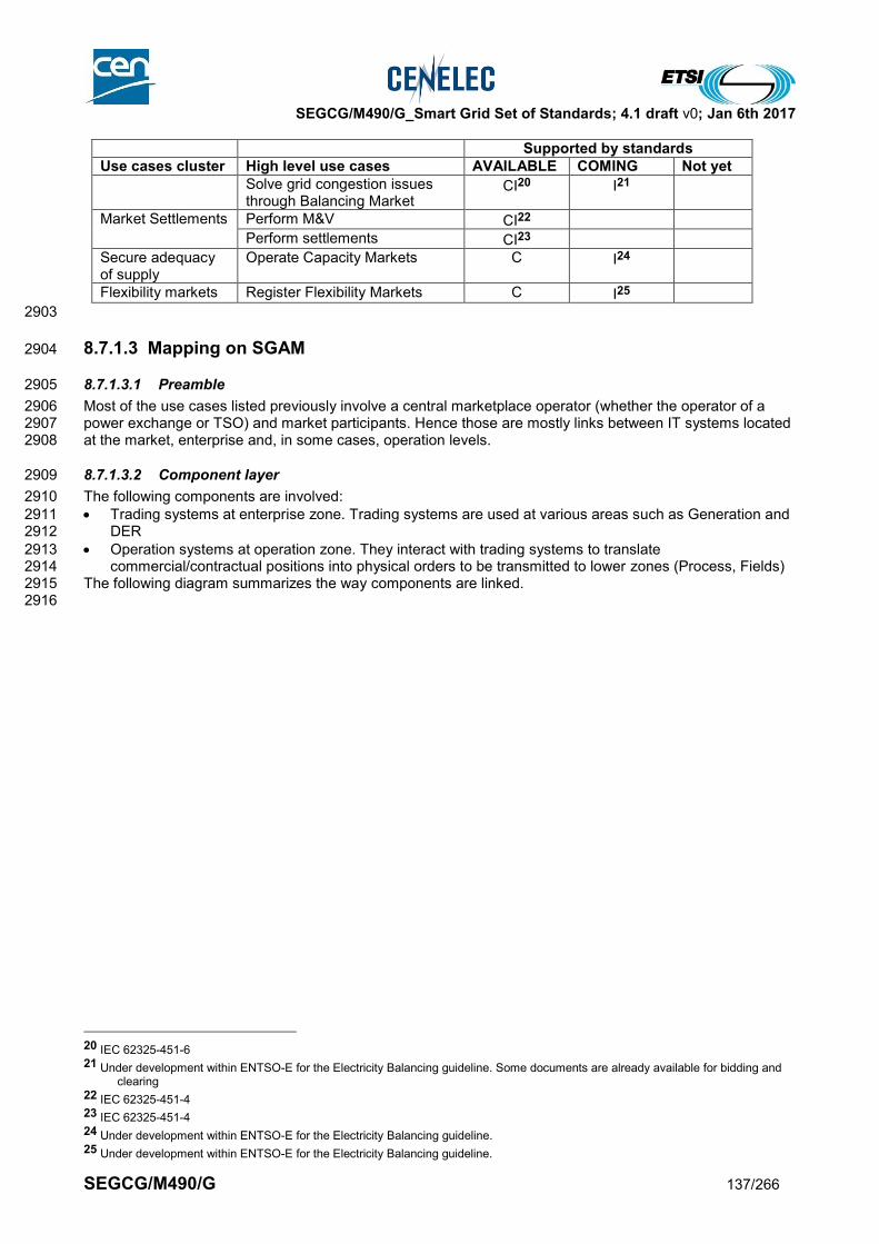
SEGCG/M490/G_Smart Grid Set of Standards; 4.1 draft v0; Jan 6th 2017
SEGCG/M490/G 137/266
Supported by standards
Use cases cluster High level use cases AVAILABLE COMING Not yet
Solve grid congestion issues through Balancing Market
CI20 I21
Market Settlements Perform M&V CI22
Perform settlements CI23
Secure adequacy of supply
Operate Capacity Markets C I24
Flexibility markets Register Flexibility Markets C I25
2903
8.7.1.3 Mapping on SGAM 2904
8.7.1.3.1 Preamble 2905
Most of the use cases listed previously involve a central marketplace operator (whether the operator of a 2906 power exchange or TSO) and market participants. Hence those are mostly links between IT systems located 2907 at the market, enterprise and, in some cases, operation levels. 2908
8.7.1.3.2 Component layer 2909
The following components are involved: 2910
Trading systems at enterprise zone. Trading systems are used at various areas such as Generation and 2911 DER 2912
Operation systems at operation zone. They interact with trading systems to translate 2913 commercial/contractual positions into physical orders to be transmitted to lower zones (Process, Fields) 2914
The following diagram summarizes the way components are linked. 2915 2916
20 IEC 62325-451-6 21 Under development within ENTSO-E for the Electricity Balancing guideline. Some documents are already available for bidding and
clearing 22 IEC 62325-451-4 23 IEC 62325-451-4 24 Under development within ENTSO-E for the Electricity Balancing guideline. 25 Under development within ENTSO-E for the Electricity Balancing guideline.

SEGCG/M490/G_Smart Grid Set of Standards; 4.1 draft v0; Jan 6th 2017
SEGCG/M490/G 138/266
2917
Figure 46 - Marketplace system - Component layer 2918
2919
Generation Transmission Distribution Customer PremiseDER
Process
Field
Station
Operation
Enterprise
Market
Generation
Trading
System
Markets
place
system
EMS/
SCADA
DER EMS
and VPP
Trading
System
Electricity
supplier
Trading
System

SEGCG/M490/G_Smart Grid Set of Standards; 4.1 draft v0; Jan 6th 2017
SEGCG/M490/G 139/266
8.7.1.3.3 Communication layer 2920
Markets involve data exchange between the central market place systems and market participants’ IT 2921 systems (trading systems). 2922 The communication layer is mostly around EN 62325-450 and 62325-451-1. 2923 Worldwide standards such as SOA, XML, SOAP etc … are leveraged as much as possible according to 2924 Enterprise Service Bus pattern. 2925 2926 Please refer to section 9.4 for getting details on cyber-security standards and more specifically on where and 2927 how to apply the IEC 62351 standard series and/or other cyber-security mechanisms. 2928 2929 This set of standards can be positioned this way on the communication layer of SGAM. 2930 2931 Note: the letters in the blue disks shown in the diagram below refer to the network types defined in 9.3.2. 2932
2933
2934
Figure 47 - Marketplace system - Communication layer 2935
2936
Generation Transmission Distribution Customer PremiseDER
Process
Field
Station
Operation
Enterprise
Market
EN
TS
O-E
EC
AN
, E
SS
,
ER
RP
, E
SP
IEC
62
32
5-4
51
H

SEGCG/M490/G_Smart Grid Set of Standards; 4.1 draft v0; Jan 6th 2017
SEGCG/M490/G 140/266
8.7.1.3.4 Information (Data) layer 2937
Markets involve information exchange between the central market place systems and market participants IT 2938 systems (trading systems). 2939 The information layer is mostly around IEC 62325-301 and 62325-351 using the ENTSO-E Market Data 2940 Exchange Standard (MADES) as a reference. 2941 This set of standards can be positioned this way on the communication layer of SGAM. 2942
2943
Figure 48 - Marketplace system - Information layer 2944
8.7.1.4 List of Standards 2945
The summary of the standards which appear relevant to support marketplace systems are listed hereafter 2946
8.7.1.4.1 Available standards 2947
In compliance with section 6.2.2, a standard (or “open specification”) that has reached its final stage (IS, TS 2948 or TR, …) by Dec 31st 2015 is considered as “available”. 2949
Table 50 - Marketplace system – Available standards 2950
Generation Transmission Distribution Customer PremiseDER
Process
Field
Station
Operation
Enterprise
MarketIEC 62325-301
IEC 62325-351
ENTSO-E role model
IEC 61970-301
IEC 61968-11
IEC 62351
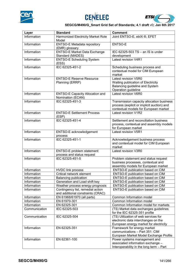
SEGCG/M490/G_Smart Grid Set of Standards; 4.1 draft v0; Jan 6th 2017
SEGCG/M490/G 141/266
Layer Standard Comment
Information Harmonized Electricity Market Role Model
Joint ENTSO-E, ebIX ®, EFET
Information ENTSO-E Metadata repository (EMR) glossary
ENTSO-E
Information ENTSO-E Market Data Exchange Standard (MADES)
IEC 62325-503 TS – an IS is under development
Information ENTSO-E Scheduling System (ESS)
Latest revision V4R1
Information IEC 62325-451-2 Scheduling business process and contextual model for CIM European market
Information ENTSO-E Reserve Resource Planning (ERRP)
Latest revision V5R0 Waiting publication of Electricity Balancing guideline and System Operation guideline
Information ENTSO-E Capacity Allocation and Nomination (ECAN)
Latest revision V6R0
Information IEC 62325-451-3 Transmission capacity allocation business process (explicit or implicit auction) and contextual models for European market
Information ENTSO-E Settlement Process (ESP)
Latest revision V1R2
Information IEC 62325-451-4 Settlement and reconciliation business process, contextual and assembly models for European market
Information ENTSO-E acknowledgement process
Latest revision V5R1
Information IEC 62325-451-1 Acknowledgement business process and contextual model for CIM European market
Information ENTSO-E problem statement process and status request
Latest revision V3R0
Information IEC 62325-451-5 Problem statement and status request business processes, contextual and assembly models for European market
Information HVDC link process ENTSO-E publication based on CIM
Information Critical network element ENTSO-E publication based on CIM
Information Balancing publication ENTSO-E publication based on CIM
Information Generation and Load shift key ENTSO-E publication based on CIM
Information Weather process energy prognosis ENTSO-E publication based on CIM
Information Contingency list, remedial action and additional constraints (CRAC)
ENTSO-E publication based on CIM
Information EN 61968/61970 (all parts) Common Information model
Information EN 61970-301 Common Information model
Information EN 62325-301 Common Information model for markets
Communication IEC 62325-503 (TS) Market data exchanges guidelines for the IEC 62325-351 profile
Communication IEC 62325-504 (TS) Utilization of web services for electronic data interchanges on the European energy market for electricity
Information EN 62325-351 Framework for energy market communications – Part 351: CIM European Market Model Exchange Profile
Information EN 62361-100 Power systems management and associated information exchange – Interoperability in the long term – Part

SEGCG/M490/G_Smart Grid Set of Standards; 4.1 draft v0; Jan 6th 2017
SEGCG/M490/G 142/266
Layer Standard Comment
100: Naming and design rules for CIM profiles to XML schema mapping
Information EN 62325-450 Framework for energy market communications - Part 450: Profile and context modeling rules
2951
8.7.1.4.2 Coming standards 2952
In compliance with section 6.2.2, a standard that has successfully passed the NWIP process (or any formal 2953 equivalent work item adoption process) by Dec 31st 2015 is considered as “Coming”. 2954
Table 51 - Marketplace system – Coming standards 2955
Layer Standard Comment
Information EN 61968/61970 (all parts) New CIM edition
Information EN 62325-301 Framework for energy market communications – Part 301: Common Information Model (CIM) Extensions for Markets
Information EN 62325-351 (available 2016-01-15) Framework for energy market communications – Part 351: CIM European Market Model Exchange Profile
Information EN 62325-451-1 (Available 2016-07-29)
Information IEC/EN 62325-451-6
(Available 2016-05-04) Transparency Regulation
Information IEC 62361-101 Common Information Model Profiles
2956
2957

SEGCG/M490/G_Smart Grid Set of Standards; 4.1 draft v0; Jan 6th 2017
SEGCG/M490/G 143/266
8.7.2 Trading systems 2958
8.7.2.1 System description 2959
Trading systems are used by market participants to interact with other market participants or with central 2960 market places. Trading Systems encompass various functions which cover but are not limited to front-office 2961 (contract management, deal capture, bidding, risk management etc.) and back-office (settlements). Market 2962 participants are generators, suppliers, industrial consumers, virtual power plants, aggregators, DER 2963 operators etc. 2964
8.7.2.2 Set of use cases 2965
This section lists a set of high level use cases relevant to trading systems. 2966 The meanings of the three last columns (AVAILABLE, COMING, Not Yet) and of the “C”, “I”, “CI”, “X” 2967 conventions are given in section 7.6.2. 2968 2969
Table 52 - Trading system - use cases 2970
Supported by standards
Use cases cluster High level use cases AVAILABLE COMING Not yet
Trading front office operation
Capture and manage contracts X
Bid into energy markets X
Compute optimized assets schedules to match commercial contracts
X
Send assets schedules to operation systems
X
Bid into ancillary services markets
X
Purchase transmission capacity rights
CI
Nominate schedules to system operator
CI
Send market schedules to operation systems
X
Publish market results X
Trading back office operation
Perform measurement and validation (M&V)
X
Perform shadow settlements X
8.7.2.3 Mapping on SGAM 2971
8.7.2.3.1 Preamble 2972
Most of the use cases listed previously involve market participants and interactions between them or with 2973 central market places. Hence those are mostly links between IT systems located at the Market, Enterprise 2974 and some cases Operation levels. 2975 Communication with physical process is assumed to be performed via EMS, DMS, DER operation desk etc. 2976 2977
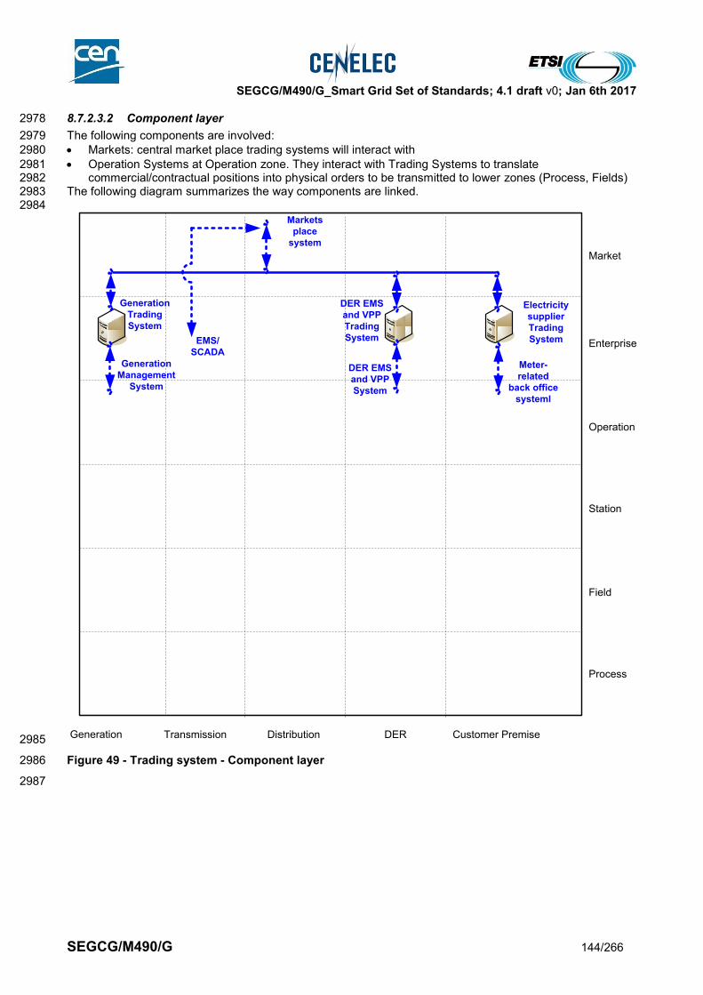
SEGCG/M490/G_Smart Grid Set of Standards; 4.1 draft v0; Jan 6th 2017
SEGCG/M490/G 144/266
8.7.2.3.2 Component layer 2978
The following components are involved: 2979
Markets: central market place trading systems will interact with 2980
Operation Systems at Operation zone. They interact with Trading Systems to translate 2981 commercial/contractual positions into physical orders to be transmitted to lower zones (Process, Fields) 2982
The following diagram summarizes the way components are linked. 2983 2984
2985
Figure 49 - Trading system - Component layer 2986
2987
Generation Transmission Distribution Customer PremiseDER
Process
Field
Station
Operation
Enterprise
Market
Generation
Trading
System
Markets
place
system
EMS/
SCADA
DER EMS
and VPP
Trading
System
DER EMS
and VPP
System
Electricity
supplier
Trading
System
Generation
Management
System
Meter-
related
back office
systeml
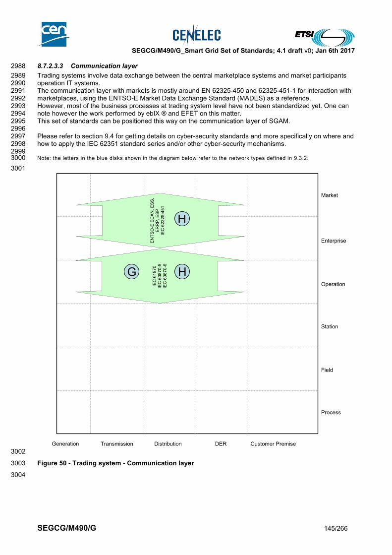
SEGCG/M490/G_Smart Grid Set of Standards; 4.1 draft v0; Jan 6th 2017
SEGCG/M490/G 145/266
8.7.2.3.3 Communication layer 2988
Trading systems involve data exchange between the central marketplace systems and market participants 2989 operation IT systems. 2990 The communication layer with markets is mostly around EN 62325-450 and 62325-451-1 for interaction with 2991 marketplaces, using the ENTSO-E Market Data Exchange Standard (MADES) as a reference. 2992 However, most of the business processes at trading system level have not been standardized yet. One can 2993 note however the work performed by ebIX ® and EFET on this matter. 2994 This set of standards can be positioned this way on the communication layer of SGAM. 2995 2996 Please refer to section 9.4 for getting details on cyber-security standards and more specifically on where and 2997 how to apply the IEC 62351 standard series and/or other cyber-security mechanisms. 2998 2999 Note: the letters in the blue disks shown in the diagram below refer to the network types defined in 9.3.2. 3000
3001
3002
Figure 50 - Trading system - Communication layer 3003
3004
Generation Transmission Distribution Customer PremiseDER
Process
Field
Station
Operation
Enterprise
Market
EN
TS
O-E
EC
AN
, E
SS
,
ER
RP
, E
SP
IEC
62
32
5-4
51
IEC
61
97
0
IEC
60
87
0-5
IEC
60
87
0-6
G H
H
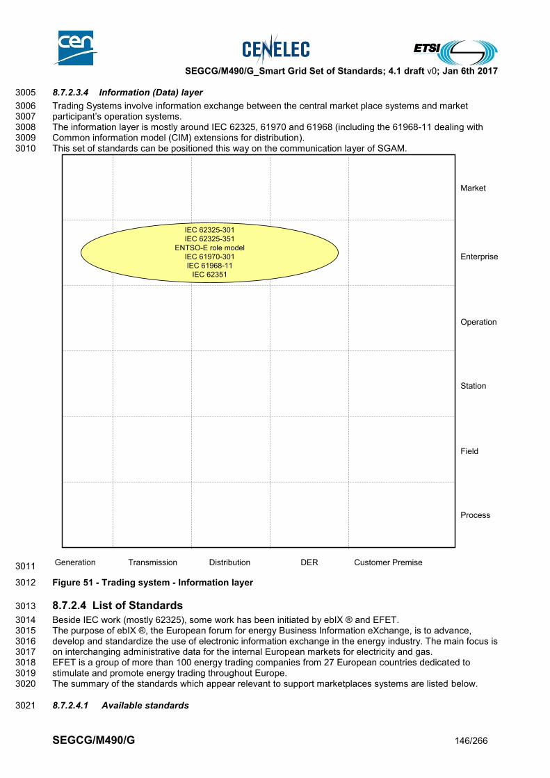
SEGCG/M490/G_Smart Grid Set of Standards; 4.1 draft v0; Jan 6th 2017
SEGCG/M490/G 146/266
8.7.2.3.4 Information (Data) layer 3005
Trading Systems involve information exchange between the central market place systems and market 3006 participant’s operation systems. 3007 The information layer is mostly around IEC 62325, 61970 and 61968 (including the 61968-11 dealing with 3008 Common information model (CIM) extensions for distribution). 3009 This set of standards can be positioned this way on the communication layer of SGAM. 3010
3011
Figure 51 - Trading system - Information layer 3012
8.7.2.4 List of Standards 3013
Beside IEC work (mostly 62325), some work has been initiated by ebIX ® and EFET. 3014 The purpose of ebIX ®, the European forum for energy Business Information eXchange, is to advance, 3015 develop and standardize the use of electronic information exchange in the energy industry. The main focus is 3016 on interchanging administrative data for the internal European markets for electricity and gas. 3017 EFET is a group of more than 100 energy trading companies from 27 European countries dedicated to 3018 stimulate and promote energy trading throughout Europe. 3019 The summary of the standards which appear relevant to support marketplaces systems are listed below. 3020
8.7.2.4.1 Available standards 3021
Generation Transmission Distribution Customer PremiseDER
Process
Field
Station
Operation
Enterprise
Market
IEC 62325-301
IEC 62325-351
ENTSO-E role model
IEC 61970-301
IEC 61968-11
IEC 62351

SEGCG/M490/G_Smart Grid Set of Standards; 4.1 draft v0; Jan 6th 2017
SEGCG/M490/G 147/266
In compliance with section 6.2.2, a standard (or “open specification”) that has reached its final stage (IS, TS 3022 or TR, …) by Dec 31st 2015 is considered as “available”. 3023
Table 53 - Trading system – Available standards 3024
Layer Standard Comment
Information Harmonized Electricity Market Role Model
Joint ENTSO-E, ebIX ®, EFET
Information ENTSO-E Metadata repository (EMR) glossary
ENTSO-e
Information ENTSO-E Market Data Exchange Standard (MADES)
IEC 62325-503 TS – an IS is under development
Information ENTSO-E Scheduling System (ESS)
Latest revision V4R1
Information IEC 62325-451-2 Scheduling business process and contextual model for CIM European market
Information ENTSO-E Reserve Resource Planning (ERRP)
Latest revision V5R0 Waiting publication of Electricity Balancing guideline and System Operation guideline
Information ENTSO-E Capacity Allocation and Nomination (ECAN)
Latest revision V6R0
Information IEC 62325-451-3 Transmission capacity allocation business process (explicit or implicit auction) and contextual models for European market
Information ENTSO-E Settlement Process (ESP)
Latest revision V1R2
Information IEC 62325-451-4 Settlement and reconciliation business process, contextual and assembly models for European market
Information ENTSO-E acknowledgement process
Latest revision V5R1
Information IEC 62325-451-1 Acknowledgement business process and contextual model for CIM European market
Information ENTSO-E problem statement process and status request
Latest revision V3R0
Information IEC 62325-451-5 Problem statement and status request business processes, contextual and assembly models for European market
Information HVDC link process ENTSO-E publication based on CIM
Information Critical network element ENTSO-E publication based on CIM
Information Balancing publication ENTSO-E publication based on CIM
Information Generation and Load shift key
ENTSO-E publication based on CIM
Information Weather process energy prognosis
ENTSO-E publication based on CIM
Information Contingency list, remedial action and additional constraints (CRAC)
ENTSO-E publication based on CIM
Information EN 61968/61970 (all parts) Common Information model
Information EN 61970-301 Common Information model
Information EN 62325-301 Common Information model for markets
Communication IEC 62325-503 (TS) Market data exchanges guidelines for the IEC 62325-351 profile
Communication IEC 62325-504 (TS) Utilization of web services for electronic data interchanges on the European energy market for electricity
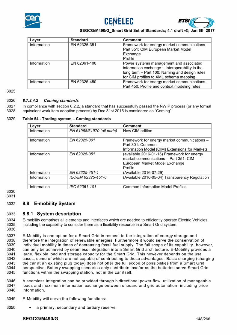
SEGCG/M490/G_Smart Grid Set of Standards; 4.1 draft v0; Jan 6th 2017
SEGCG/M490/G 148/266
Layer Standard Comment
Information EN 62325-351 Framework for energy market communications – Part 351: CIM European Market Model Exchange Profile
Information EN 62361-100 Power systems management and associated information exchange – Interoperability in the long term – Part 100: Naming and design rules for CIM profiles to XML schema mapping
Information EN 62325-450 Framework for energy market communications - Part 450: Profile and context modeling rules
3025
8.7.2.4.2 Coming standards 3026
In compliance with section 6.2.2,¸a standard that has successfully passed the NWIP process (or any formal 3027 equivalent work item adoption process) by Dec 31st 2015 is considered as “Coming”. 3028
Table 54 - Trading system – Coming standards 3029
Layer Standard Comment
Information EN 61968/61970 (all parts)
New CIM edition
Information EN 62325-301 Framework for energy market communications – Part 301: Common Information Model (CIM) Extensions for Markets
Information EN 62325-351 (available 2016-01-15) Framework for energy market communications – Part 351: CIM European Market Model Exchange Profile
Information EN 62325-451-1 (Available 2016-07-29)
Information IEC/EN 62325-451-6
(Available 2016-05-04) Transparency Regulation
Information IEC 62361-101 Common Information Model Profiles
3030 3031
8.8 E-mobility System 3032
8.8.1 System description 3033
E-mobility comprises all elements and interfaces which are needed to efficiently operate Electric Vehicles 3034 including the capability to consider them as a flexibility resource in a Smart Grid system. 3035 3036
E-Mobility is one option for a Smart Grid in respect to the integration of energy storage and 3037 therefore the integration of renewable energies. Furthermore it would serve the conservation of 3038 individual mobility in times of decreasing fossil fuel supply. The full scope of its capability , however, 3039 can only be achieved by seamless integration into a Smart Grid architecture. E-Mobility provides a 3040 large, flexible load and storage capacity for the Smart Grid. This however depends on the use 3041 cases, some of which are not capable of contributing to these advantages. Basic charging (charging 3042 the car at an existing plug today) does not offer the full scope of possibilities from a Smart Grid 3043 perspective. Battery swapping scenarios only contribute insofar as the batteries serve Smart Grid 3044 functions within the swapping station, not in the car itself. 3045
A seamless integration can be provided through bidirectional power flow, utilization of manageable 3046 loads and maximum information exchange between onboard and grid automation , including price 3047 information. 3048
E-Mobility will serve the following functions: 3049
a primary, secondary and tertiary reserve 3050
SEGCG/M490/G_Smart Grid Set of Standards; 4.1 draft v0; Jan 6th 2017
SEGCG/M490/G 149/266
a manageable load 3051
power system stabilization 3052
power quality 3053
load leveling 3054
load shedding 3055
individual mobility (not relevant for Smart Grid) 3056
energy conservation (increased efficiency compared to combustion engines) 3057
under the constraint of fulfilling environmental constraints 3058
Total electrification of vehicles will furthermore promote the role of IEC standards in the vehicle 3059 domain. This must urgently be dealt with, however it is not within the scope of a Smart Grid 3060 discussion. 3061
3062
8.8.2 Mapping on SGAM 3063
8.8.2.1 Preamble 3064
There are many different cases on how e-mobility systems may be architectured, and also many 3065 possibilities for having such systems interfaced to the Grid (operator, supplier, e-mobility service 3066 provider). The drawings given below are just here to depict the possible usage of the considered 3067 standards. 3068
3069
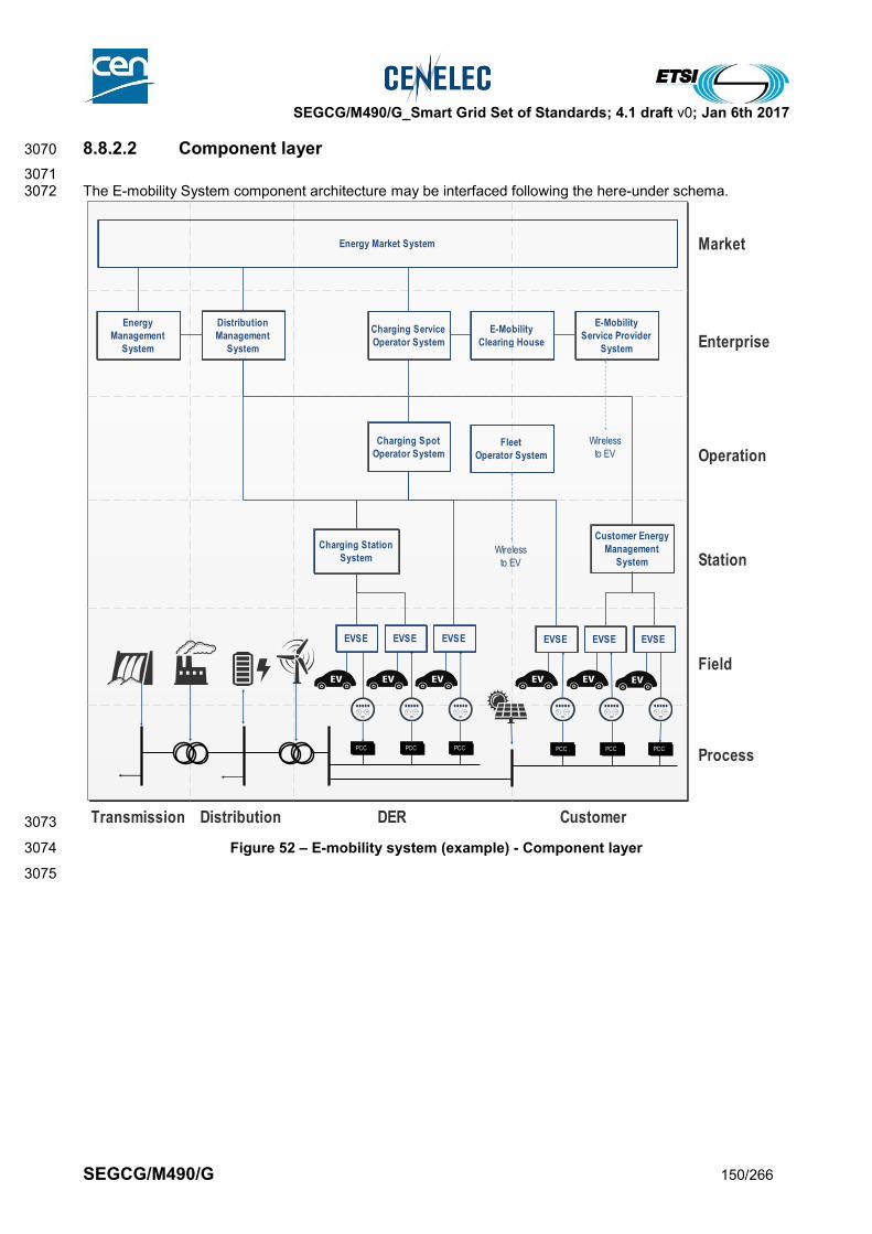
SEGCG/M490/G_Smart Grid Set of Standards; 4.1 draft v0; Jan 6th 2017
SEGCG/M490/G 150/266
8.8.2.2 Component layer 3070
3071 The E-mobility System component architecture may be interfaced following the here-under schema. 3072
3073
Figure 52 – E-mobility system (example) - Component layer 3074
3075
Transmission Distribution DER Customer
Market
Enterprise
Operation
Station
Field
ProcessPCC PCC PCC PCC PCC PCC
EVSE EVSE EVSE EVSE EVSE EVSE
Charging Station
System
Charging Service
Operator System
Charging Spot
Operator System
Distribution
Management
System
Customer Energy
Management
System
Energy
Management
System
Energy Market System
E-Mobility
Clearing House
E-Mobility
Service Provider
System
Fleet
Operator System
Wireless
to EV
Wireless
to EV

SEGCG/M490/G_Smart Grid Set of Standards; 4.1 draft v0; Jan 6th 2017
SEGCG/M490/G 151/266
8.8.2.3 Link between SGAM and E-mobility standardization groups 3076
3077 Different standardization groups are working directly or in-directly with E-mobility on top-level close to market 3078 and energy management, on a medium-level for operation and management of systems or on the very 3079 detailed level close to the process and the Electric Vehicle. 3080 3081 Figure 52 gives and overview of the different E-mobility standards and the general mapping to the SGAM 3082 zones. 3083 3084
3085
Figure 53 – E-mobility system (example) and link to E-mobility standards 3086
3087 For a more detailed list of E-Mobility standards and mapping to the SGAM layers, see section 8.8.3 3088
8.8.3 List of Standards 3089
3090
8.8.3.1 Available standards 3091
Please refer to section 6.2.2 for the definition of the criteria considered in this report for stating that a 3092 standard is “available”. 3093
Table 55 - E-mobility system - Available standards 3094
Layer Standard Comments
Information, Communication
EN 61968 (all parts) Common Information Model (CIM) / Distribution Management
Information, Communication
EN 61970 (all parts) Energy management system application Program interface (EMS-API
Information, Communication
EN 61850-7-420 Communication networks and systems for power utility automation
IEC 62746 series
IEC TR 61850-90-8, IEC62351
IEC 61851, IEC61980, IEC62196
Transmission Distribution DER Customer
Market
Enterprise
Operation
Station
Field
ProcessPCC PCC PCC PCC PCC PCC
EVSE EVSE EVSE EVSE EVSE EVSE
Charging Station
System
Charging Service
Operator System
Charging Spot
Operator System
Distribution
Management
System
Customer Energy
Management
System
Energy
Management
System
Energy Market System
E-Mobility
Clearing House
E-Mobility
Service Provider
System
Fleet
Operator System
Wireless
to EV
Wireless
to EV
IEC 61968 / IEC 61970
EVSE Management(OCPP)
EN 60364 series
ISO/IEC 15118 series
Electrically propelled vehicles(ISO TC22/SC37)
1
2
3
4
5
6
7
8
1
2 3
4
56
7
8
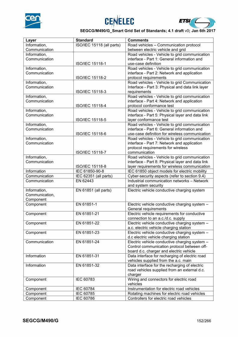
SEGCG/M490/G_Smart Grid Set of Standards; 4.1 draft v0; Jan 6th 2017
SEGCG/M490/G 152/266
Layer Standard Comments
Information, Communication
ISO/IEC 15118 (all parts) Road vehicles – Communication protocol between electric vehicle and grid
Information, Communication
ISO/IEC 15118-1
Road vehicles - Vehicle to grid communication interface - Part 1: General information and use-case definition
Information, Communication
ISO/IEC 15118-2
Road vehicles - Vehicle to grid communication interface - Part 2: Network and application protocol requirements
Information, Communication
ISO/IEC 15118-3
Road vehicles - Vehicle to grid Communication Interface - Part 3: Physical and data link layer requirements
Information, Communication
ISO/IEC 15118-4
Road vehicles - Vehicle to grid communication interface - Part 4: Network and application protocol conformance test
Information, Communication
ISO/IEC 15118-5
Road vehicles - Vehicle to grid communication interface - Part 5: Physical layer and data link layer conformance test
Information, Communication
ISO/IEC 15118-6
Road vehicles - Vehicle to grid communication interface - Part 6: General information and use-case definition for wireless communication
Information, Communication
ISO/IEC 15118-7
Road vehicles - Vehicle to grid communication interface - Part 7: Network and application protocol requirements for wireless communication
Information, Communication
ISO/IEC 15118-8
Road vehicles - Vehicle to grid communication interface - Part 8: Physical layer and data link layer requirements for wireless communication
Information IEC 61850-90-8 IEC 61850 object models for electric mobility
Communication IEC 62351 (all parts) Cyber-security aspects (refer to section 9.4)
Communication EN 62443 Industrial communication networks – Network and system security
Information, Communication, Component
EN 61851 (all parts) Electric vehicle conductive charging system
Component EN 61851-1 Electric vehicle conductive charging system – General requirements
Component EN 61851-21 Electric vehicle requirements for conductive connection to an a.c./d.c. supply
Component EN 61851-22 Electric vehicle conductive charging system – a.c. electric vehicle charging station
Component EN 61851-23 Electric vehicle conductive charging system – d.c electric vehicle charging station
Communication EN 61851-24 Electric vehicle conductive charging system – Control communication protocol between off-board d.c. charger and electric vehicle
Information EN 61851-31 Data interface for recharging of electric road vehicles supplied from the a.c. main
Information EN 61851-32 Data interface for the recharging of electric road vehicles supplied from an external d.c. charger
Component IEC 60783 Wiring and connectors for electric road vehicles
Component IEC 60784 Instrumentation for electric road vehicles
Component IEC 60785 Rotating machines for electric road vehicles
Component IEC 60786 Controllers for electric road vehicles

SEGCG/M490/G_Smart Grid Set of Standards; 4.1 draft v0; Jan 6th 2017
SEGCG/M490/G 153/266
Layer Standard Comments
Component EN 60364-4-41 Low-voltage electrical installations – Part 4-41: Protection for safety – Protection against electric shock
Component EN 60364-5-53 Selection and erection of electrical equipment - Isolation, switching and control
Component EN 60364-5-55 Selection and erection of electrical equipment - Other equipment - Clause 551: Low-voltage generating set
Component EN 60364-7-712 Requirements for special installations or locations – Solar photovoltaic (PV) power supply systems
Component EN 60364-7-722 Requirements for special installations or locations - Supply of Electrical Vehicle
Component ISO 8713 Electrically propelled road vehicles - Terminology
Component IEC 61894 Preferred sizes and voltages of battery monoblocs for electric vehicle applications
Component EN 61980 (all parts) Electric equipment for the supply of energy to electric road vehicles using an inductive coupling
Component IEC 61981 On board electric power equipment for electric road vehicles
Component EN 61982 (all parts) Secondary batteries for the propulsion of electric road vehicles
Component EN 62196 Plugs, socket-outlets, vehicle couplers and vehicle inlets – Conductive charging of electric vehicles
Component ISO 6469 Electrically propelled road vehicles - Safety specifications
3095
Note: standards related to clock management, safety, or EMC are mentioned in further dedicated sections. 3096
3097 Other standards: 3098 Many standards from SAE J series may apply to this domain. 3099
8.8.3.2 Coming standards 3100
Please refer to section 6.2.2 for the definition of the criteria considered in this report for stating that a 3101 standard is “coming” up. 3102
Table 56 - E-mobility system - Coming standards 3103
Layer Standard Comments
Information, Communication
EN 61968 (all parts) Common Information Model (CIM) / Distribution Management
Information, Communication
EN 61970 (all parts) Energy management system application Program interface (EMS-API
Information, Communication, Component
IEC 62351 Cyber-security aspects (refer to section 9.4)
3104
3105
SEGCG/M490/G_Smart Grid Set of Standards; 4.1 draft v0; Jan 6th 2017
SEGCG/M490/G 154/266
8.9 Micro-grid systems 3106
8.9.1 System description 3107
A micro-grid system refers to the real-time information system and all the elements needed to support all the 3108 relevant operational activities and functions needed to run a micro-grid. It improves the information made 3109 available to operators at control room, as well as to micro-grid users. It improves the overall efficiency of 3110 operation of the micro-grid, as well as it may optimize the use of related assets. 3111 3112 Such system is usually made of one or many interconnected IT systems, connected to field communicating 3113 devices or sub-systems, through the use of communication systems. It may also include the components 3114 needed to enable field crew to operate the micro-grid from the field. 3115 A micro-grid system provides following major functions: 3116
SCADA, real time monitoring and control of the micro-grid 3117
Capabilities to distributed electricity to any micro-grid users 3118
Capabilities to protect and maintain the related micro-grid assets 3119
Automation capabilities to ensure balance of demand and supply 3120
Automation capabilities to handle islanding, connection and disconnection 3121 3122 It may also include “commercial related activities”, and then may also include: 3123
Trading capabilities 3124
Electricity supply and associated metered related backoffice capabilities 3125 3126 Based on local DER’s and micro-grid primary devices, a micro-grid system needs to maintain its stability, 3127 voltage, frequency and reliability. 3128 While in the grid connected mode a micro-grid system may interface to an EMS or DMS to perform various 3129 grid support functions such as: 3130
1. Peak Management 3131
2. Responsive Reserves 3132
3. Peak Management 3133
4. Ancillary Services 3134
5. Grid Voltage Support (VARS) 3135
6. Backup Emergency Power 3136
While in the islanded mode a micro-grid system may be called on to perform the following functions: 3137 1. Islanding on requests 3138
2. Islanding on emergency 3139
3. Grid Synchronizing & (re-) Connection 3140
4. Balancing Supply & Demand 3141
5. Black Start in islanding mode 3142
6. Network Configuration 3143
7. Active/Reactive Power Compensation/Voltage Control 3144
8. Economic Dispatch 3145
9. Load Control 3146
From a domain prospective, micro-grids are “Smart Grids in small” and may cover 3 main domains – 3147 Distribution, DER and Customer premises, and then encompass systems from these same 3148 domains.Figure 54 below outlines the components, subsystems, and interfaces which make up a 3149 micro-grid system. With these interfaces defined, a set of standards can be identified. 3150

SEGCG/M490/G_Smart Grid Set of Standards; 4.1 draft v0; Jan 6th 2017
SEGCG/M490/G 155/266
3151
Figure 54 – Micro-grids – possible domains and systems breakdown 3152
3153
8.9.2 Set of use cases 3154
3155 Here is a set of high level use cases which may be supported by a substation automation system. 3156 The meanings of the three last columns (AVAILABLE, COMING, Not Yet) and of the “C”, “I”, “CI”, “X” 3157 conventions are given in section 7.6.2. 3158
Table 57 – Industrial automation system - Use cases 3159
Supported by standards
Use cases cluster
High level use cases AVAILABLE COMING Not yet
Handling Micro-grid scenarios
Islanding on requests C I
Islanding on emergency C I
Grid Synchronizing & (re-) Connection C I
Balancing Supply & Demand C I
Weather Forecast & Observation system
Asset & Maintenance management system
Micro-Grids
En
terp
rise
Ma
rke
tO
pe
ratio
nS
tatio
nP
roce
ss
Fie
ld
Gene-
ration Transmission Distribution DERCustomer
premises
Su
bs
tatio
n a
uto
ma
tion
sys
tem
Fe
ed
er a
uto
ma
tion
sys
tem
AD
MS
sys
tem A
MI s
ys
tem
DE
R o
pe
ratio
n s
ys
tem
Ag
gre
ga
ted
pro
su
me
rs m
an
ag
em
en
t sys
tem
Market place system
Trading system
FA
CT
S
Me
terin
g-re
late
dB
ac
k O
ffice
sys
tem
E-M
ob
ility s
ys
tem
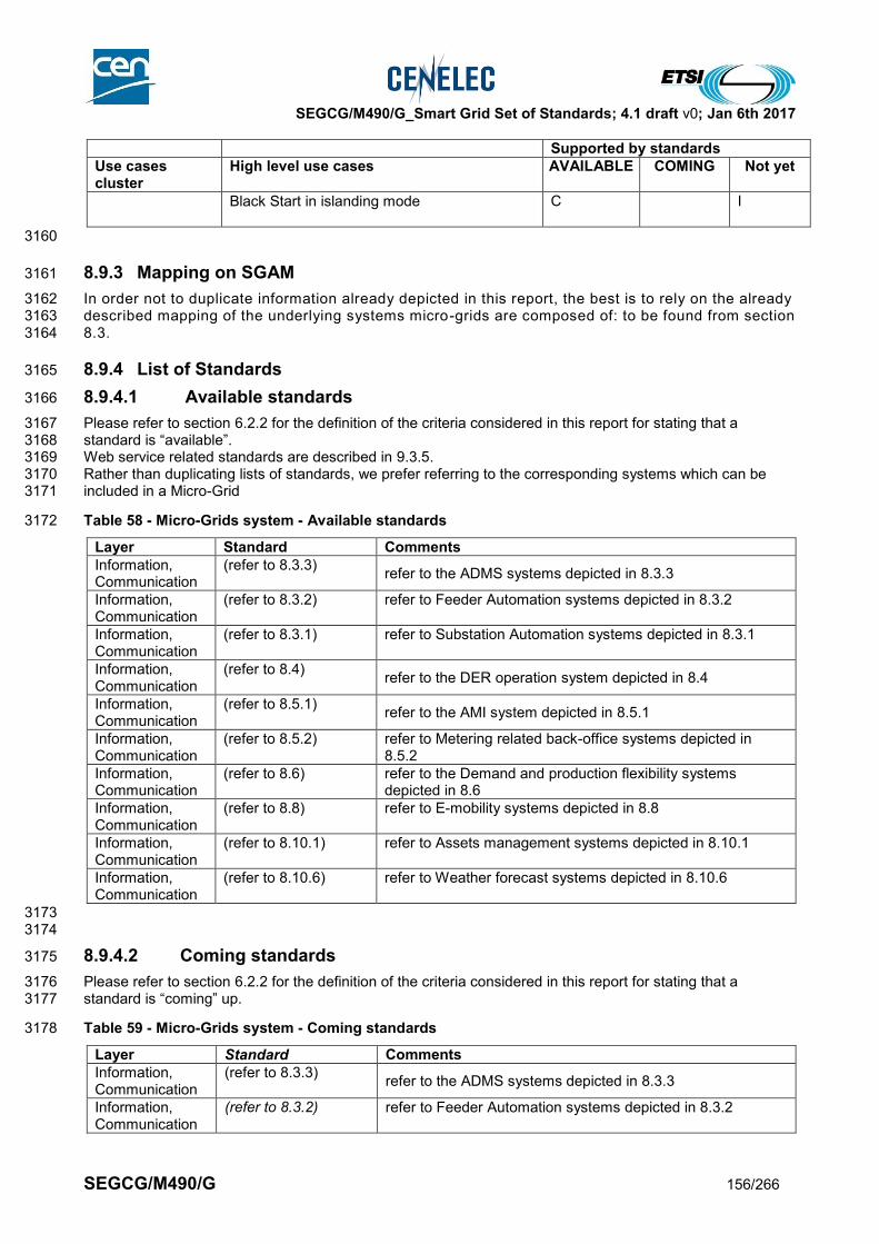
SEGCG/M490/G_Smart Grid Set of Standards; 4.1 draft v0; Jan 6th 2017
SEGCG/M490/G 156/266
Supported by standards
Use cases cluster
High level use cases AVAILABLE COMING Not yet
Black Start in islanding mode C I
3160
8.9.3 Mapping on SGAM 3161
In order not to duplicate information already depicted in this report, the best is to rely on the already 3162 described mapping of the underlying systems micro-grids are composed of: to be found from section 3163 8.3. 3164
8.9.4 List of Standards 3165
8.9.4.1 Available standards 3166
Please refer to section 6.2.2 for the definition of the criteria considered in this report for stating that a 3167 standard is “available”. 3168 Web service related standards are described in 9.3.5. 3169 Rather than duplicating lists of standards, we prefer referring to the corresponding systems which can be 3170 included in a Micro-Grid 3171
Table 58 - Micro-Grids system - Available standards 3172
Layer Standard Comments
Information, Communication
(refer to 8.3.3) refer to the ADMS systems depicted in 8.3.3
Information, Communication
(refer to 8.3.2) refer to Feeder Automation systems depicted in 8.3.2
Information, Communication
(refer to 8.3.1) refer to Substation Automation systems depicted in 8.3.1
Information, Communication
(refer to 8.4) refer to the DER operation system depicted in 8.4
Information, Communication
(refer to 8.5.1) refer to the AMI system depicted in 8.5.1
Information, Communication
(refer to 8.5.2) refer to Metering related back-office systems depicted in 8.5.2
Information, Communication
(refer to 8.6) refer to the Demand and production flexibility systems depicted in 8.6
Information, Communication
(refer to 8.8) refer to E-mobility systems depicted in 8.8
Information, Communication
(refer to 8.10.1) refer to Assets management systems depicted in 8.10.1
Information, Communication
(refer to 8.10.6) refer to Weather forecast systems depicted in 8.10.6
3173 3174
8.9.4.2 Coming standards 3175
Please refer to section 6.2.2 for the definition of the criteria considered in this report for stating that a 3176 standard is “coming” up. 3177
Table 59 - Micro-Grids system - Coming standards 3178
Layer Standard Comments
Information, Communication
(refer to 8.3.3) refer to the ADMS systems depicted in 8.3.3
Information, Communication
(refer to 8.3.2) refer to Feeder Automation systems depicted in 8.3.2

SEGCG/M490/G_Smart Grid Set of Standards; 4.1 draft v0; Jan 6th 2017
SEGCG/M490/G 157/266
Information, Communication
(refer to 8.3.1) refer to Substation Automation systems depicted in 8.3.1
Information, Communication
(refer to 8.4) refer to the DER operation system depicted in 8.4
Information, Communication
(refer to 8.5.1) refer to the AMI system depicted in 8.5.1
Information, Communication
(refer to 8.5.2) refer to Metering related back-office systems depicted in 8.5.2
Information, Communication
(refer to 8.6) refer to the Demand and production flexibility systems depicted in 8.6
Information, Communication
(refer to 8.8) refer to E-mobility systems depicted in 8.8
Information, Communication
(refer to 8.10.1) refer to Assets management systems depicted in 8.10.1
Information, Communication
(refer to 8.10.6) refer to Weather forecast systems depicted in 8.10.6
Component IEC 62898-1 Microgrids - Guidelines for planning and design
Component IEC 62898-2 Microgrids - Guidelines for operation and control
Component IEC 62898-3-1 Microgrids - Technical Requirements - Protection requirements in microgrids
Component IEC 60364-8-2 Low voltage electrical installation – prosumer’s installation
3179
3180

SEGCG/M490/G_Smart Grid Set of Standards; 4.1 draft v0; Jan 6th 2017
SEGCG/M490/G 158/266
8.10 Administration systems 3181
8.10.1 Asset and Maintenance Management system 3182
8.10.1.1 System description 3183
Asset and Maintenance Management system refers to the information system and all the elements needed 3184 to support the team in charge of managing the system assets along its total lifecycle. It is used to help 3185 maximize the value of the related assets over their lifecycles, and help preparing future plans (long term 3186 planning, mid-term optimization, extension, refurbishment) and also the associated maintenance work. 3187 3188 Such a system is usually made of one or many interconnected IT systems, possibly connected to field 3189 communicating devices or sub-systems, through the use of LAN/WAN communication systems. 3190 The Application covers the different business processes containing the different maintenance methods 3191 (corrective, periodic and condition based) and maintenance models of related assets. 3192 Asset and maintenance management systems are used in the Generation, Transmission, Distribution and 3193 DER domain. 3194
8.10.1.2 Set of use cases 3195
The following high level use cases might be support by an asset and maintenance management system. 3196 The meanings of the three last columns (AVAILABLE, COMING, Not Yet) and of the “C”, “I”, “CI”, “X” 3197 conventions are given in section 7.6.2. 3198
Table 60 – Assets and maintenance management system - use cases 3199
Supported by standards
Use cases cluster
High level use cases AVAILABLE COMING Not yet
Monitoring the grid flows
Producing, exposing and logging time-stamped events
CI
Maintaining grid assets
Monitoring assets conditions C CI I
Supporting periodic maintenance (and planning) CI C I
Optimise field crew operation C C I
Archive maintenance information CI C I
System and security management
Discover a new component in the system C I
Distributing and synchronizing clocks CI
Note that for some domains standards are already available or under development (i.e. Distribution) while for 3200 other Domains standards are under development or are not yet available (i.e. Transmission, DER) 3201
8.10.1.3 Mapping on SGAM 3202
8.10.1.3.1 Preamble 3203
A single entity of an Asset and maintenance management system is shown as an overlay that can be applied 3204 to the specific domains. It should be noted that the specific standards especially at the information layer may 3205 be different for the different domains. 3206 The Asset Management System interacts with the domain management and operation systems (e.g. EMS, 3207 DMS), GIS and SCADA systems. Condition monitoring and field force management is shown as part of the 3208 Asset Management System with the related interaction with the field components. 3209 Most information regarding maintenance and condition of components is captured by the field force workers 3210 and the laptops they use in the field. Detailed condition assessment (information) models of assets are not 3211 (yet) available in standards. 3212 3213 Generation distinctive feature: an important part of condition monitoring is related to rotating machines 3214 vibration monitoring. Appropriate information and communication solutions are different than those that are 3215 used for control, monitoring and common condition monitoring. The existing standard IEC 61400-25-6 is an 3216 excellent example of the possibility to use existing wind turbines control and monitoring solutions to support 3217
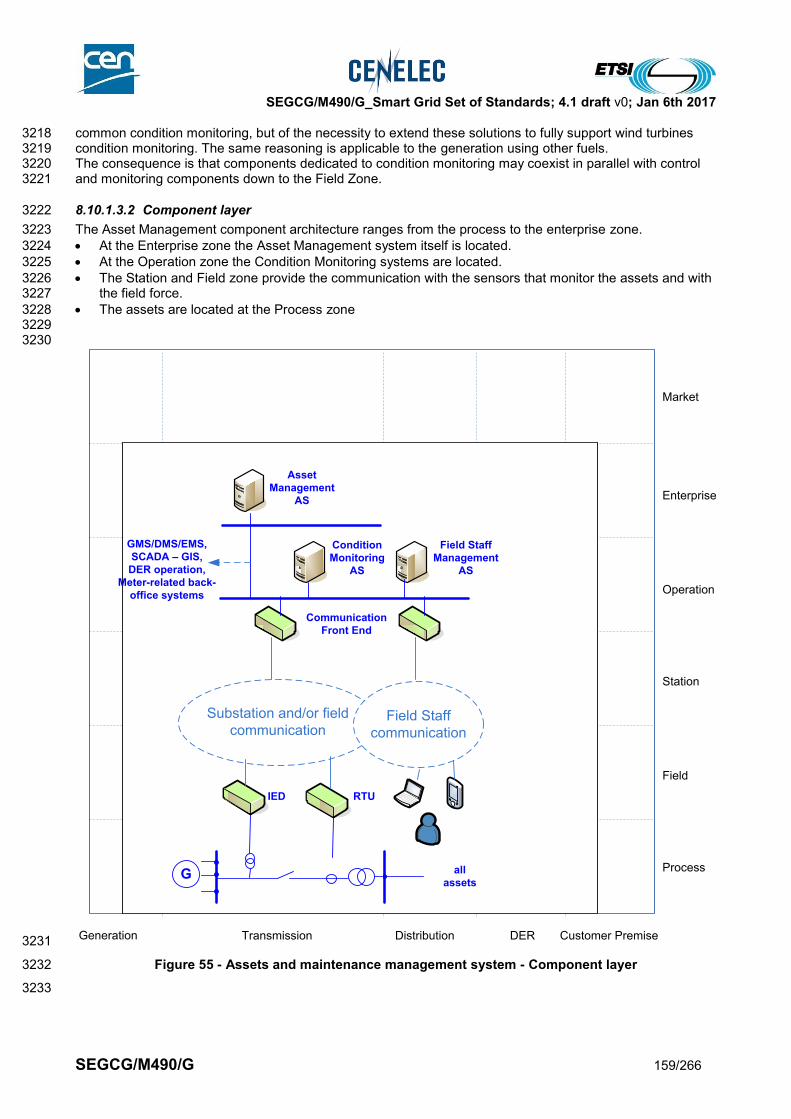
SEGCG/M490/G_Smart Grid Set of Standards; 4.1 draft v0; Jan 6th 2017
SEGCG/M490/G 159/266
common condition monitoring, but of the necessity to extend these solutions to fully support wind turbines 3218 condition monitoring. The same reasoning is applicable to the generation using other fuels. 3219 The consequence is that components dedicated to condition monitoring may coexist in parallel with control 3220 and monitoring components down to the Field Zone. 3221
8.10.1.3.2 Component layer 3222
The Asset Management component architecture ranges from the process to the enterprise zone. 3223
At the Enterprise zone the Asset Management system itself is located. 3224
At the Operation zone the Condition Monitoring systems are located. 3225
The Station and Field zone provide the communication with the sensors that monitor the assets and with 3226 the field force. 3227
The assets are located at the Process zone 3228 3229 3230
3231
Figure 55 - Assets and maintenance management system - Component layer 3232
3233
Generation Transmission Distribution Customer PremiseDER
Process
Field
Station
Operation
Enterprise
Market
G
Condition
Monitoring
AS
Asset
Management
AS
Communication
Front End
RTUIED
Substation and/or field
communicationField Staff
communication
Field Staff
Management
AS
all
assets
GMS/DMS/EMS,
SCADA – GIS,
DER operation,
Meter-related back-
office systems
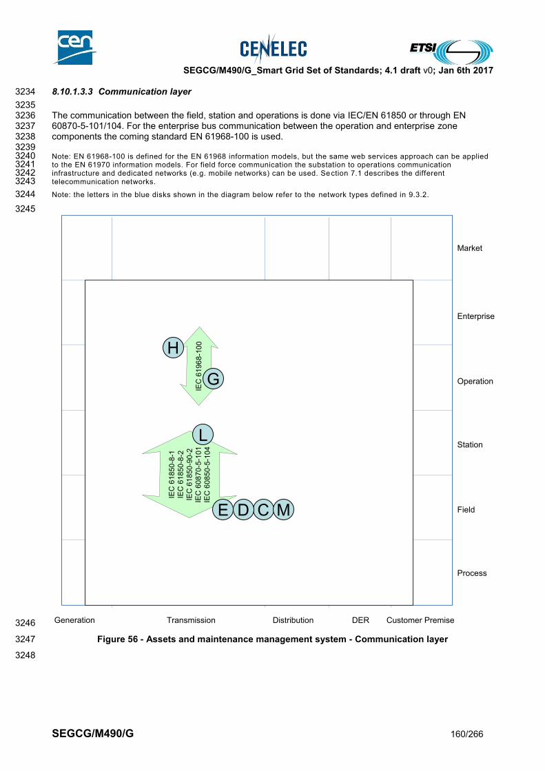
SEGCG/M490/G_Smart Grid Set of Standards; 4.1 draft v0; Jan 6th 2017
SEGCG/M490/G 160/266
8.10.1.3.3 Communication layer 3234
3235 The communication between the field, station and operations is done via IEC/EN 61850 or through EN 3236 60870-5-101/104. For the enterprise bus communication between the operation and enterprise zone 3237 components the coming standard EN 61968-100 is used. 3238 3239 Note: EN 61968-100 is defined for the EN 61968 information models, but the same web services approach can be applied 3240 to the EN 61970 information models. For field force communication the substation to operations communication 3241 infrastructure and dedicated networks (e.g. mobile networks) can be used. Section 7.1 describes the different 3242 telecommunication networks. 3243
Note: the letters in the blue disks shown in the diagram below refer to the network types defined in 9.3.2. 3244
3245
3246
Figure 56 - Assets and maintenance management system - Communication layer 3247
3248
Generation Transmission Distribution Customer PremiseDER
Process
Field
Station
Operation
Enterprise
Market
IEC
61
96
8-1
00
IEC
61
850
- 8-1
IEC
61
85
0- 8
-2I E
C 6
185
0-9
0-2
IEC
60
870
-5- 1
01
IEC
60
850
-5- 1
04
E
L
G
H
CD M

SEGCG/M490/G_Smart Grid Set of Standards; 4.1 draft v0; Jan 6th 2017
SEGCG/M490/G 161/266
8.10.1.3.4 Information (Data) layer 3249
For the condition monitoring information exchange between the field/station and operations zone the coming 3250 standard IEC 61850-90-3 will be used. EN 61968 and EN 61970 standards in general apply for providing 3251 asset management related information. Specifically IEC 61698-4 and the coming standard EN 61968-6 3252 define CIM interfaces for asset and maintenance management for the distribution domain. For the other 3253 domains no specific asset and maintenance management standards exist. 3254
3255
Figure 57 - Assets and maintenance management system - Information layer 3256
8.10.1.4 List of Standards 3257
Here is the summary of the standards which appear relevant to transmission asset management systems: 3258
8.10.1.4.1 Available standards 3259
In compliance with section 6.2.2, a standard (or “open specification”) that has reached its final stage (IS, TS 3260 or TR, …) by Dec 31st 2015 is considered as “available”. 3261
Table 61 – Assets and maintenance management system – Available standards 3262
Layer Standard Comments
Information IEC 61360 Common Data Dictionary
Generation Transmission Distribution Customer PremiseDER
Process
Field
Station
Operation
Enterprise
Market
IEC
61
85
0-9
0-3
IEC 61968
IEC 61970
IEC 61968-4
IEC 61968-6
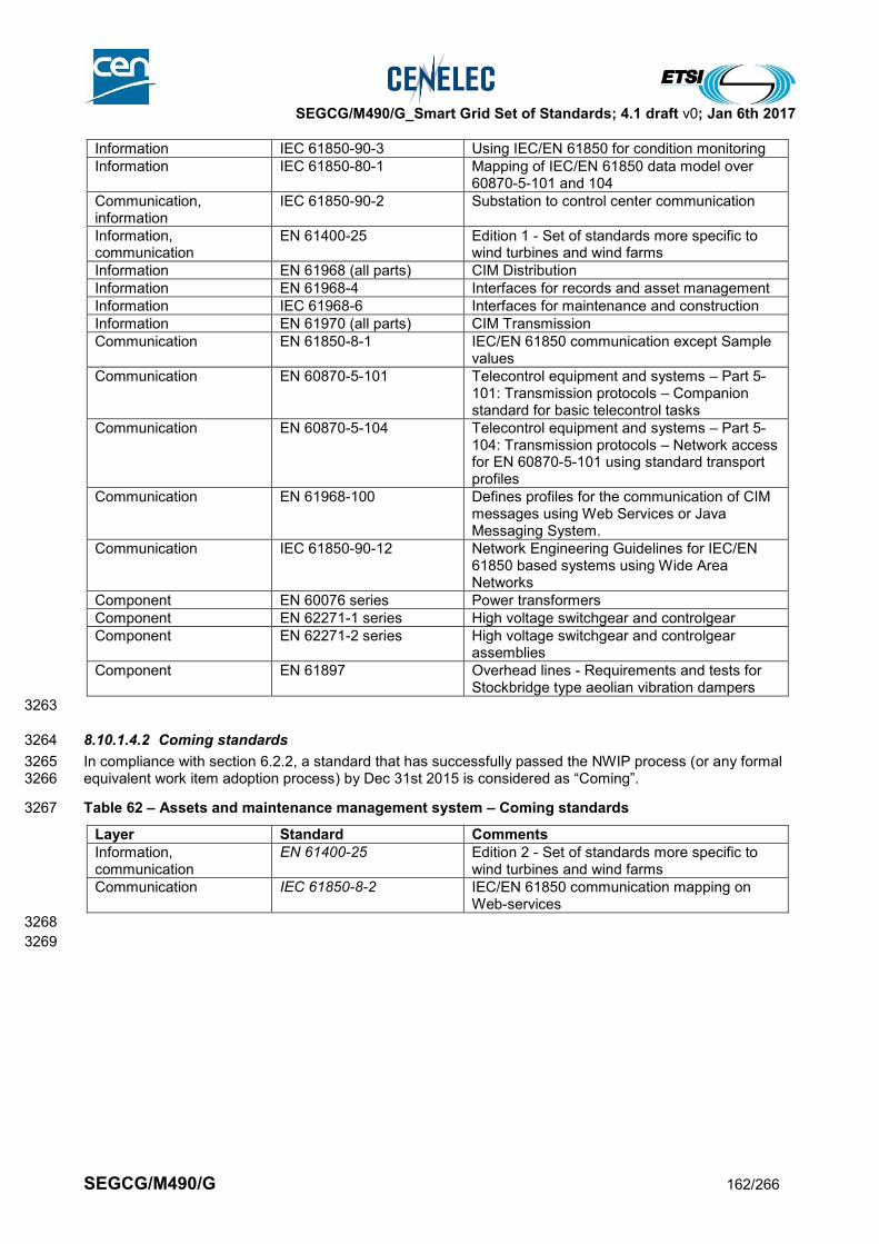
SEGCG/M490/G_Smart Grid Set of Standards; 4.1 draft v0; Jan 6th 2017
SEGCG/M490/G 162/266
Information IEC 61850-90-3 Using IEC/EN 61850 for condition monitoring
Information IEC 61850-80-1 Mapping of IEC/EN 61850 data model over 60870-5-101 and 104
Communication, information
IEC 61850-90-2 Substation to control center communication
Information, communication
EN 61400-25 Edition 1 - Set of standards more specific to wind turbines and wind farms
Information EN 61968 (all parts) CIM Distribution
Information EN 61968-4 Interfaces for records and asset management
Information IEC 61968-6 Interfaces for maintenance and construction
Information EN 61970 (all parts) CIM Transmission
Communication EN 61850-8-1 IEC/EN 61850 communication except Sample values
Communication EN 60870-5-101 Telecontrol equipment and systems – Part 5-101: Transmission protocols – Companion standard for basic telecontrol tasks
Communication EN 60870-5-104 Telecontrol equipment and systems – Part 5-104: Transmission protocols – Network access for EN 60870-5-101 using standard transport profiles
Communication EN 61968-100 Defines profiles for the communication of CIM messages using Web Services or Java Messaging System.
Communication IEC 61850-90-12 Network Engineering Guidelines for IEC/EN 61850 based systems using Wide Area Networks
Component EN 60076 series Power transformers
Component EN 62271-1 series High voltage switchgear and controlgear
Component EN 62271-2 series High voltage switchgear and controlgear assemblies
Component EN 61897 Overhead lines - Requirements and tests for Stockbridge type aeolian vibration dampers
3263
8.10.1.4.2 Coming standards 3264
In compliance with section 6.2.2, a standard that has successfully passed the NWIP process (or any formal 3265 equivalent work item adoption process) by Dec 31st 2015 is considered as “Coming”. 3266
Table 62 – Assets and maintenance management system – Coming standards 3267
Layer Standard Comments
Information, communication
EN 61400-25 Edition 2 - Set of standards more specific to wind turbines and wind farms
Communication IEC 61850-8-2 IEC/EN 61850 communication mapping on Web-services
3268
3269
SEGCG/M490/G_Smart Grid Set of Standards; 4.1 draft v0; Jan 6th 2017
SEGCG/M490/G 163/266
8.10.2 Communication network management system 3270
8.10.2.1 System description 3271
Communication Network management systems are concerned with the management of the communication 3272 networks used for Smart Grid communication. These are for example wide area (WAN), local area (LAN), 3273 access and Neighborhood area (NAN) networks. For more details on communication networks see clause 0. 3274 3275 When communicating devices, including the communication functions of end devices, have the ability to be 3276 managed remotely regarding their communication capabilities, they are usually called “managed devices”, 3277 and the network having this property is called “managed network” 3278 3279 A managed network consists of two key components: 3280
Manager device with network management system 3281
Managed device with agent 3282 3283 A network management system executes applications that monitor and control managed devices. The 3284 network management systems provide the bulk of the processing and memory resources required for 3285 network management. One or more network management systems may exist on any managed network and 3286 different management systems might be used for different network domains and zones. 3287 3288 Various network management standards exist for the different communication network technologies. In this 3289 clause we focus on management of the IP layer and can only provide a rough overview. For other 3290 communication network technologies and more details please refer to the specific technologies. 3291 3292 It should be noted that the responsibility for network management usually is with the network owner. A 3293 distribution network operator for example will manage its own enterprise and control center LAN while in 3294 case of leased line or VPN services the management of the underlying network providing these services is 3295 the responsibility of the communication service provider who owns the underlying network. 3296 3297
8.10.2.2 Set of use cases 3298
Possibly any Use Cases which is supported by communicating features is possibly concerned with managing 3299 the health of the communication system it is using. 3300 3301 Practically any IP based system may support a communication network management system encompassing 3302 part or all communicating devices. 3303
8.10.2.3 Mapping on SGAM 3304
8.10.2.3.1 Preamble 3305
It is mostly not possible to map a communication network management system onto the SGAM, as such 3306 systems being independent from the Smart Grid domains and zones and have their own architectural 3307 structure. It is therefore shown as a simple overlay on the SGAM. 3308 3309 3310

SEGCG/M490/G_Smart Grid Set of Standards; 4.1 draft v0; Jan 6th 2017
SEGCG/M490/G 164/266
8.10.2.3.2 Component layer 3311
The managed devices can be any type of communication device, including end devices (e.g. routers, access 3312 servers, switches, bridges, hubs, IP telephones, IP video cameras and computer hosts). It is also 3313 recommended that most of communicating end devices which serve a smart grid function such as IEDs, 3314 controllers, computers, HMIs, to be “manageable” from a communication point of view. 3315 A managed device is a network node that implements an SNMP interface that allows unidirectional or 3316 bidirectional access to node-specific information. Managed devices exchange node-specific information with 3317 the network management system. An agent is a network-management software module that resides on a 3318 managed device. An agent has local knowledge of management information and translates that information 3319 to or from an SNMP specific form. 3320 3321
3322
Figure 58 – Communication network management - Component layer 3323
3324 3325
Generation Transmission Distribution Customer PremiseDER
Process
Field
Station
Operation
Enterprise
Market
Generic model
Managed
device
Managed
device
Managed
device
Managed
device
Managed
device
Network
management
system (NMS)
Manager
device
Agent
Agent
Agent
Agent
Agent
Network
management
system (NMS)
Manager
device
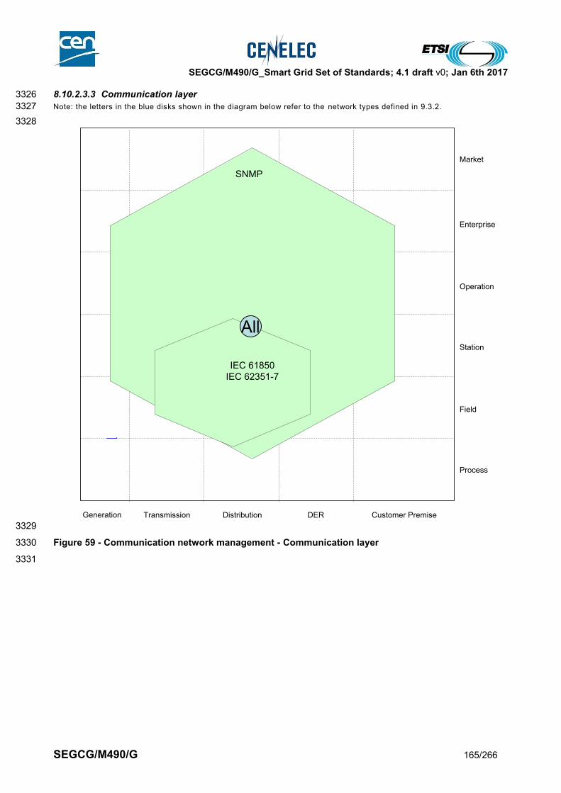
SEGCG/M490/G_Smart Grid Set of Standards; 4.1 draft v0; Jan 6th 2017
SEGCG/M490/G 165/266
8.10.2.3.3 Communication layer 3326
Note: the letters in the blue disks shown in the diagram below refer to the network types defined in 9.3.2. 3327
3328
3329
Figure 59 - Communication network management - Communication layer 3330
3331
Generation Transmission Distribution Customer PremiseDER
Process
Field
Station
Operation
Enterprise
Market
SNMP
IEC 61850
IEC 62351-7
1
All
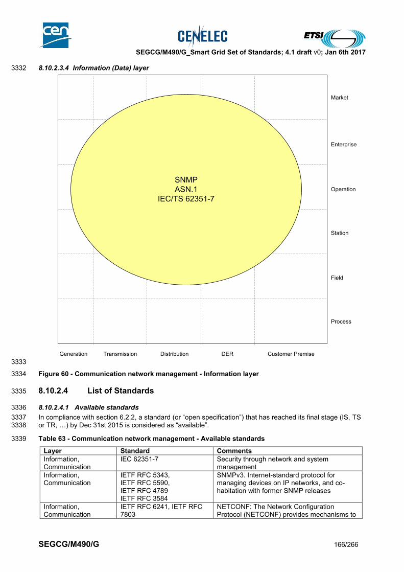
SEGCG/M490/G_Smart Grid Set of Standards; 4.1 draft v0; Jan 6th 2017
SEGCG/M490/G 166/266
8.10.2.3.4 Information (Data) layer 3332
3333
Figure 60 - Communication network management - Information layer 3334
8.10.2.4 List of Standards 3335
8.10.2.4.1 Available standards 3336
In compliance with section 6.2.2, a standard (or “open specification”) that has reached its final stage (IS, TS 3337 or TR, …) by Dec 31st 2015 is considered as “available”. 3338
Table 63 - Communication network management - Available standards 3339
Layer Standard Comments
Information, Communication
IEC 62351-7 Security through network and system management
Information, Communication
IETF RFC 5343, IETF RFC 5590, IETF RFC 4789 IETF RFC 3584
SNMPv3. Internet-standard protocol for managing devices on IP networks, and co-habitation with former SNMP releases
Information, Communication
IETF RFC 6241, IETF RFC 7803
NETCONF: The Network Configuration Protocol (NETCONF) provides mechanisms to
Generation Transmission Distribution Customer PremiseDER
Process
Field
Station
Operation
Enterprise
Market
SNMP
ASN.1
IEC/TS 62351-7

SEGCG/M490/G_Smart Grid Set of Standards; 4.1 draft v0; Jan 6th 2017
SEGCG/M490/G 167/266
Layer Standard Comments
install, manipulate, and delete the configuration of network devices
Information, Communication
IETF RFC 6020 YANG [1] is a data modeling language for the definition of data sent over the NETCONF network configuration protocol
Communication IETF RFC 768 UDP/IP
Communication, Information
IEC 61850-90-4 Network Engineering Guidelines for IEC/EN 61850 based systems (including Ethernet technology, network topology, redundancy, traffic latency, traffic management by multicast and VLAN). This document also proposes a data model /SCL extension to expose information related to network management onto IEC 61850, mostly based on SNMP tags
3340
8.10.2.4.2 Coming standards 3341
In compliance with section 6.2.2, a standard that has successfully passed the NWIP process (or any formal 3342 equivalent work item adoption process) by Dec 31st 2015 is considered as “Coming”. 3343
Table 64 - Communication network management - Coming standards 3344
Layer Standard Comments
Communication, Information
IEC 61850-90-12 Network Engineering Guidelines for IEC/EN 61850 based systems using Wide Area Networks
3345
3346
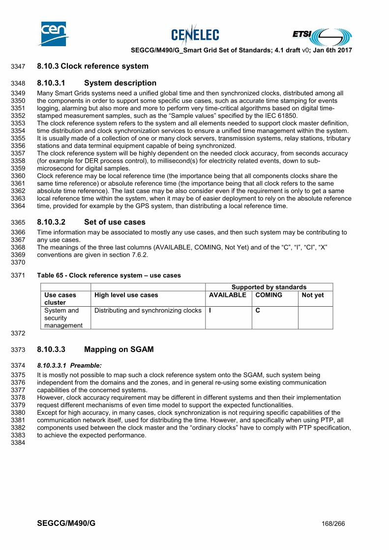
SEGCG/M490/G_Smart Grid Set of Standards; 4.1 draft v0; Jan 6th 2017
SEGCG/M490/G 168/266
8.10.3 Clock reference system 3347
8.10.3.1 System description 3348
Many Smart Grids systems need a unified global time and then synchronized clocks, distributed among all 3349 the components in order to support some specific use cases, such as accurate time stamping for events 3350 logging, alarming but also more and more to perform very time-critical algorithms based on digital time-3351 stamped measurement samples, such as the “Sample values” specified by the IEC 61850. 3352 The clock reference system refers to the system and all elements needed to support clock master definition, 3353 time distribution and clock synchronization services to ensure a unified time management within the system. 3354 It is usually made of a collection of one or many clock servers, transmission systems, relay stations, tributary 3355 stations and data terminal equipment capable of being synchronized. 3356 The clock reference system will be highly dependent on the needed clock accuracy, from seconds accuracy 3357 (for example for DER process control), to millisecond(s) for electricity related events, down to sub-3358 microsecond for digital samples. 3359 Clock reference may be local reference time (the importance being that all components clocks share the 3360 same time reference) or absolute reference time (the importance being that all clock refers to the same 3361 absolute time reference). The last case may be also consider even if the requirement is only to get a same 3362 local reference time within the system, when it may be of easier deployment to rely on the absolute reference 3363 time, provided for example by the GPS system, than distributing a local reference time. 3364
8.10.3.2 Set of use cases 3365
Time information may be associated to mostly any use cases, and then such system may be contributing to 3366 any use cases. 3367 The meanings of the three last columns (AVAILABLE, COMING, Not Yet) and of the “C”, “I”, “CI”, “X” 3368 conventions are given in section 7.6.2. 3369 3370
Table 65 - Clock reference system – use cases 3371
Supported by standards
Use cases cluster
High level use cases AVAILABLE COMING Not yet
System and security management
Distributing and synchronizing clocks I C
3372
8.10.3.3 Mapping on SGAM 3373
8.10.3.3.1 Preamble: 3374
It is mostly not possible to map such a clock reference system onto the SGAM, such system being 3375 independent from the domains and the zones, and in general re-using some existing communication 3376 capabilities of the concerned systems. 3377 However, clock accuracy requirement may be different in different systems and then their implementation 3378 request different mechanisms of even time model to support the expected functionalities. 3379 Except for high accuracy, in many cases, clock synchronization is not requiring specific capabilities of the 3380 communication network itself, used for distributing the time. However, and specifically when using PTP, all 3381 components used between the clock master and the “ordinary clocks” have to comply with PTP specification, 3382 to achieve the expected performance. 3383 3384

SEGCG/M490/G_Smart Grid Set of Standards; 4.1 draft v0; Jan 6th 2017
SEGCG/M490/G 169/266
8.10.3.3.2 Component layer 3385
3386
Figure 61 – Clock reference system - Component layer 3387
8.10.3.3.3 Communication layer 3388
Note: the letters in the blue disks shown in the diagram below refer to the network types defined in 9.3.2. 3389
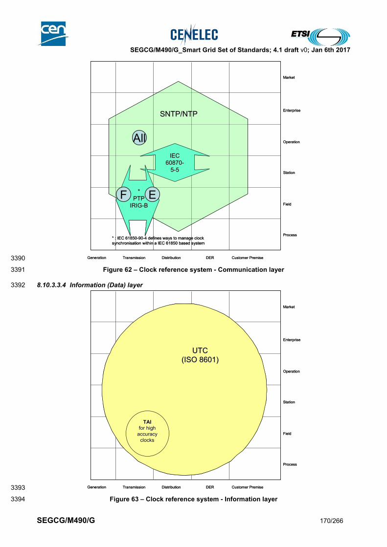
SEGCG/M490/G_Smart Grid Set of Standards; 4.1 draft v0; Jan 6th 2017
SEGCG/M490/G 170/266
3390
Figure 62 – Clock reference system - Communication layer 3391
8.10.3.3.4 Information (Data) layer 3392
3393
Figure 63 – Clock reference system - Information layer 3394
Generation Transmission Distribution Customer PremiseDER
Process
Field
Station
Operation
Enterprise
Market
SNTP/NTPSNTP/NTP
IEC IEC
6087060870--
55--55
**
PTPPTP
IRIGIRIG--BB
* : IEC 61850-90-4 defines ways to manage clock
synchronisation within a IEC 61850 based system
Generation Transmission Distribution Customer PremiseDER
Process
Field
Station
Operation
Enterprise
Market
SNTP/NTPSNTP/NTP
IEC IEC
6087060870--
55--55
**
PTPPTP
IRIGIRIG--BB
* : IEC 61850-90-4 defines ways to manage clock
synchronisation within a IEC 61850 based system
Generation Transmission Distribution Customer PremiseDER
Process
Field
Station
Operation
Enterprise
Market
UTCUTC
(ISO 8601)(ISO 8601)
TAITAI
for for highhigh
accuracyaccuracy
clocksclocks
Generation Transmission Distribution Customer PremiseDER
Process
Field
Station
Operation
Enterprise
Market
UTCUTC
(ISO 8601)(ISO 8601)
TAITAI
for for highhigh
accuracyaccuracy
clocksclocks
EF
All
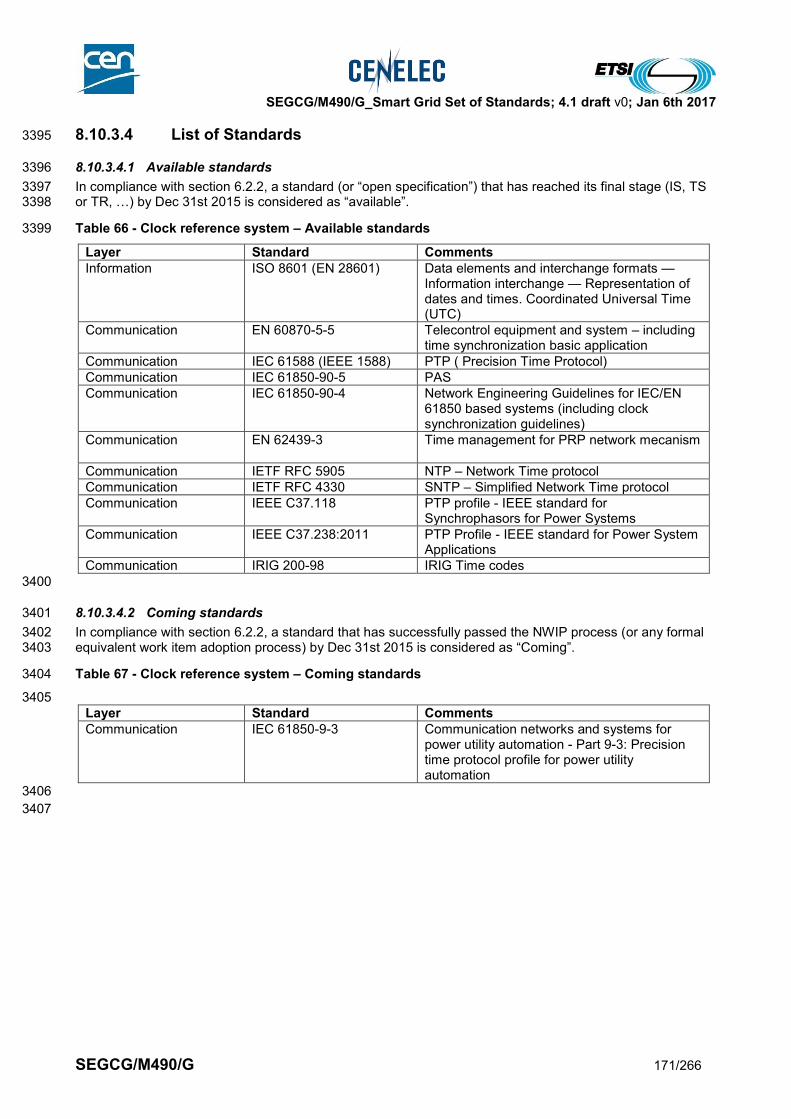
SEGCG/M490/G_Smart Grid Set of Standards; 4.1 draft v0; Jan 6th 2017
SEGCG/M490/G 171/266
8.10.3.4 List of Standards 3395
8.10.3.4.1 Available standards 3396
In compliance with section 6.2.2, a standard (or “open specification”) that has reached its final stage (IS, TS 3397 or TR, …) by Dec 31st 2015 is considered as “available”. 3398
Table 66 - Clock reference system – Available standards 3399
Layer Standard Comments
Information ISO 8601 (EN 28601) Data elements and interchange formats — Information interchange — Representation of dates and times. Coordinated Universal Time (UTC)
Communication EN 60870-5-5 Telecontrol equipment and system – including time synchronization basic application
Communication IEC 61588 (IEEE 1588) PTP ( Precision Time Protocol)
Communication IEC 61850-90-5 PAS
Communication IEC 61850-90-4
Network Engineering Guidelines for IEC/EN 61850 based systems (including clock synchronization guidelines)
Communication EN 62439-3
Time management for PRP network mecanism
Communication IETF RFC 5905 NTP – Network Time protocol
Communication IETF RFC 4330 SNTP – Simplified Network Time protocol
Communication IEEE C37.118 PTP profile - IEEE standard for Synchrophasors for Power Systems
Communication IEEE C37.238:2011 PTP Profile - IEEE standard for Power System Applications
Communication IRIG 200-98 IRIG Time codes
3400
8.10.3.4.2 Coming standards 3401
In compliance with section 6.2.2, a standard that has successfully passed the NWIP process (or any formal 3402 equivalent work item adoption process) by Dec 31st 2015 is considered as “Coming”. 3403
Table 67 - Clock reference system – Coming standards 3404
3405
Layer Standard Comments
Communication
IEC 61850-9-3 Communication networks and systems for power utility automation - Part 9-3: Precision time protocol profile for power utility automation
3406
3407

SEGCG/M490/G_Smart Grid Set of Standards; 4.1 draft v0; Jan 6th 2017
SEGCG/M490/G 172/266
8.10.4 Authentication, Authorization, Accounting Systems 3408
3409
8.10.4.1 System Description 3410
3411 Authentication, Authorization, Accounting (AAA) refers to information systems used to grant granular access 3412 to a device or a service by controlling what a given user or system can access and how. 3413 3414 Authentication is the process to authenticate an identity (a user or a system). The process verifies that the 3415 person or system is really the one it claims to be by verifying evidence. This is usually done using credentials 3416 such as login/passwords, one-time-passwords, digital certificates… 3417 3418 Authorization is the process to identify what a given identity is allowed to perform on a given system. It 3419 describes what the “rights” of the identity over the system are. In other words it describes to what extent the 3420 identity is allowed to manipulate the system. For example, the rights of an Operating System user on the file 3421 system (what can be read, what can be modified, what can be executed) or access rights of a system over 3422 the network (what the system is allowed to connect to). 3423 3424 Accounting is the process that measures the resources consumed by the identity for billing, auditing and 3425 reporting. Accounting systems is also used to record events. Usually the following type of information is 3426 recorded: Identity, Authentication success/failure, Authorization success/failure, what is accessed, when the 3427 access starts, when the access stops and any other relevant information related to the service delivered. 3428 3429 The technical discussion of an AAA system should always be done in the context of a target scenario for 3430 which a security threat and risk analysis has been done. This builds the base for deriving security 3431 requirements for access control for users, machines, and processes (applications). Analyzing the way a user 3432 is granted access locally to an operating system is different even if there are similarities than analyzing the 3433 way a user can remotely access a system or the way a system can access a system on Local Area Network 3434 or over the Internet thru a Virtual Private Network. 3435 3436 The choice has been made in the present chapter to consider the scenario of a remote access to a 3437 Substation Automation System as defined in section 8.3.1. 3438 3439 The following picture is taken from IEC/TR 62351-10 and shows such a substation automation scenario. As 3440 shown in the figure, access is controlled using a remote access server (circled in red in the figure below). 3441 3442
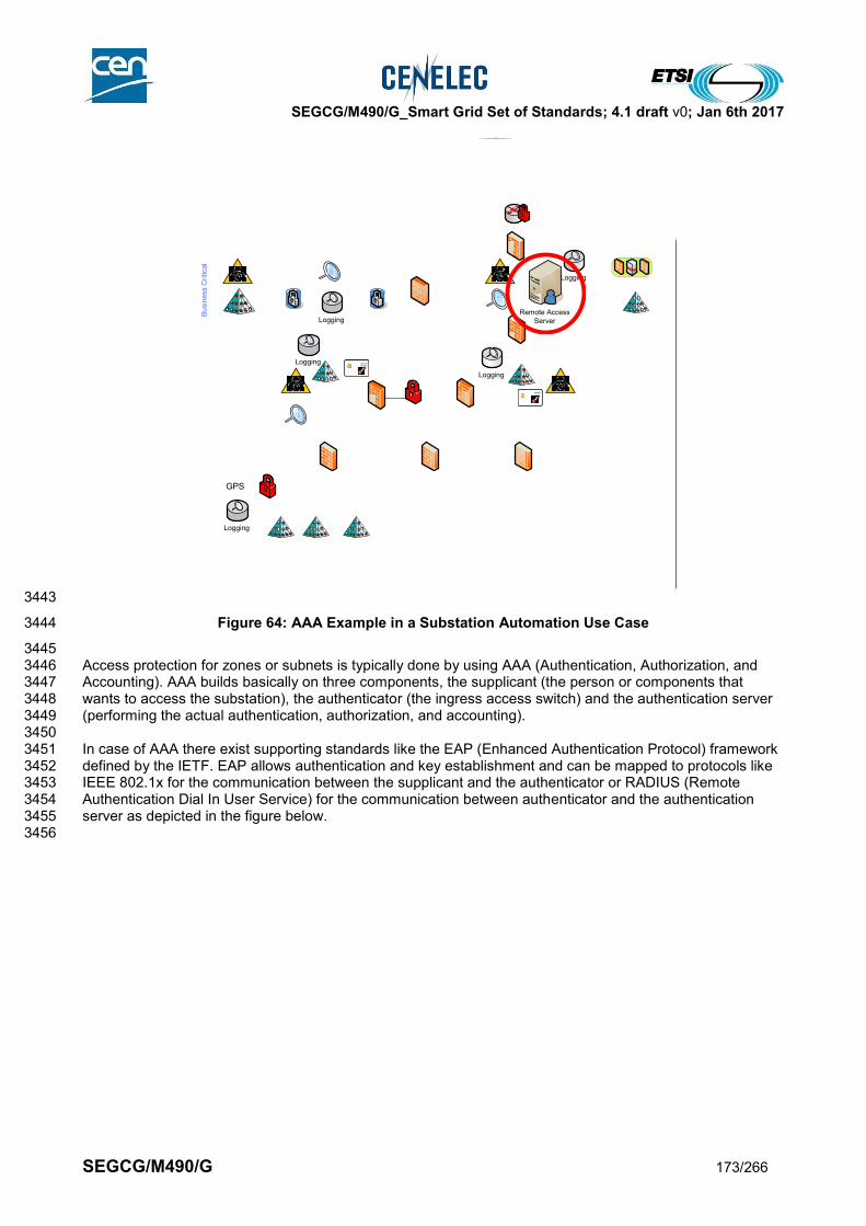
SEGCG/M490/G_Smart Grid Set of Standards; 4.1 draft v0; Jan 6th 2017
SEGCG/M490/G 173/266
3443
Figure 64: AAA Example in a Substation Automation Use Case 3444
3445 Access protection for zones or subnets is typically done by using AAA (Authentication, Authorization, and 3446 Accounting). AAA builds basically on three components, the supplicant (the person or components that 3447 wants to access the substation), the authenticator (the ingress access switch) and the authentication server 3448 (performing the actual authentication, authorization, and accounting). 3449 3450 In case of AAA there exist supporting standards like the EAP (Enhanced Authentication Protocol) framework 3451 defined by the IETF. EAP allows authentication and key establishment and can be mapped to protocols like 3452 IEEE 802.1x for the communication between the supplicant and the authenticator or RADIUS (Remote 3453 Authentication Dial In User Service) for the communication between authenticator and the authentication 3454 server as depicted in the figure below. 3455 3456
Terminal
Server
Remote Serial
Configuration Zone
Physical Substation Security Perimeter
PMU
RTU
Syste
m O
pe
ratio
n C
ritica
l
Automation Zone Remote Access Zone
IP Switch
Station Bus Zone
Serial Server
/ Switch
Serial IED Process Zone
IEC 61850
DCF 77PMUIED
IED IED IED IED IED
Serial Server / Switch
`
Local HMISubstation
Controller
Communication, e.g., via:
- IEC 61850
- IEC 60870-5-104
- IEC 60870-6 TASE2
Utility Communications Network
Historian
DM
Z
File Server Web Navigator
`
Local HMI
Bu
sin
ess C
ritica
l
Logging
Logging
Logging
Logging
Logging
Remote Access
Server
GPS

SEGCG/M490/G_Smart Grid Set of Standards; 4.1 draft v0; Jan 6th 2017
SEGCG/M490/G 174/266
3457
Figure 65: EAP Overview 3458
3459 There exist also further means for the communication between the authenticator and the authentication 3460 server. One example is TACACS+ (Terminal Access Controller Access-Control System). In contrast to 3461 RADIUS, it uses TCP for communication. 3462 3463 The current approach used for remotely accessing a substation often relies on the application of a VPN 3464 connection based on IPSec. The termination of the VPN in the substation is connected with the AAA 3465 infrastructure to ensure that only authenticated and authorized connections are possible. This may be 3466 achieved by using a dedicated component, a VPN gateway. 3467 3468 In the future, the security may be enhanced especially for connections using IEC 61850 or IEC 60870-5-104. 3469 For these protocols IEC 62351 defines specific security means, which can be directly applied to protect the 3470 communication, allowing for an end-to-end security relationship terminating in the substation. Hence, this 3471 protection does not necessarily require a specific VPN connection to protect the communication. It is 3472 expected that VPN connections will still provide a value as there are other connections, e.g., Voice over IP, 3473 which can be protected using the VPN tunnel. Also, as IEC 62351 allows to protect the communication 3474 regarding integrity and/or confidentiality the combination of IEC 62351 security measures with a dedicated 3475 VPN may contribute to a security in depth model, providing multiple layer of defense. 3476 3477 Additional possibilities, which may be used to further support remote access control, are provided by IEC 3478 62351-8 (RBAC, Role based Access Control) in conjunction with IEC 61850. IEC 62351-8 allows fine grained 3479 role based access control using X.509 certificates and corresponding private keys. This allows extension of 3480 access control also within the substation. Hence, it allows further restriction of access or rights for operative 3481 or management actions within the substation. Note that IEC 62351-8 may be used in conjunction with LDAP 3482 to fetch RBAC specific credentials from a repository. 3483 3484 The report of the Cyber Security and Privacy Group of the SEG-CG specifically addresses the topic of 3485 access control with respect to users and software processes for local and remote authentication for 3486 substation control. Here the focus lies on different measures for authentication and access control to cope 3487 with the security levels in IEC 62443-3-3. 3488 3489 3490
Authentication Server
with Database
Password
Authentication
Database
X.509
Directory
Kerberos
Ticket
Granting
Server
EAP over
Ethernet
EAP Method
The authenticator acts as AAA
client to the authentication server
Radius,
Kerberos, PKI,
OTP, SecurID
Supplicants Authenticator
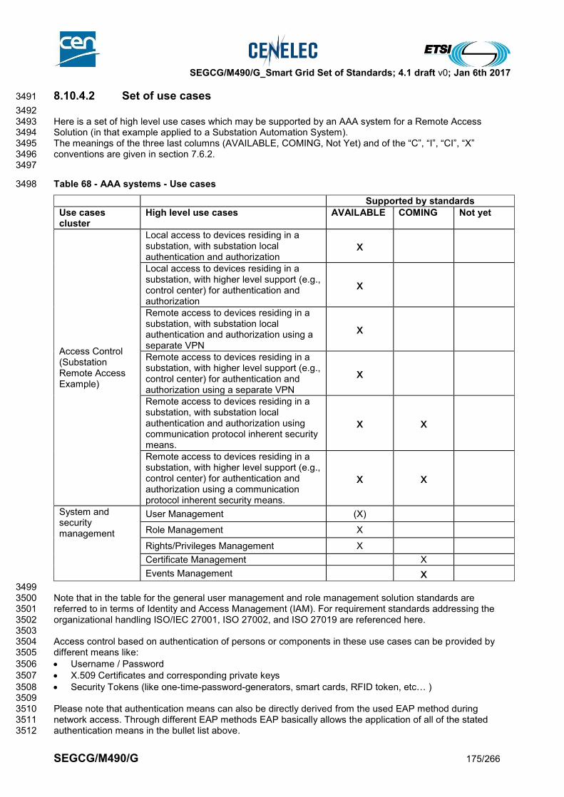
SEGCG/M490/G_Smart Grid Set of Standards; 4.1 draft v0; Jan 6th 2017
SEGCG/M490/G 175/266
8.10.4.2 Set of use cases 3491
3492 Here is a set of high level use cases which may be supported by an AAA system for a Remote Access 3493 Solution (in that example applied to a Substation Automation System). 3494 The meanings of the three last columns (AVAILABLE, COMING, Not Yet) and of the “C”, “I”, “CI”, “X” 3495 conventions are given in section 7.6.2. 3496 3497
Table 68 - AAA systems - Use cases 3498
Supported by standards
Use cases cluster
High level use cases AVAILABLE COMING Not yet
Access Control (Substation Remote Access Example)
Local access to devices residing in a substation, with substation local authentication and authorization
x
Local access to devices residing in a substation, with higher level support (e.g., control center) for authentication and authorization
x
Remote access to devices residing in a substation, with substation local authentication and authorization using a separate VPN
x
Remote access to devices residing in a substation, with higher level support (e.g., control center) for authentication and authorization using a separate VPN
x
Remote access to devices residing in a substation, with substation local authentication and authorization using communication protocol inherent security means.
x x
Remote access to devices residing in a substation, with higher level support (e.g., control center) for authentication and authorization using a communication protocol inherent security means.
x x
System and security management
User Management (X) Role Management X Rights/Privileges Management X Certificate Management X
Events Management x
3499 Note that in the table for the general user management and role management solution standards are 3500 referred to in terms of Identity and Access Management (IAM). For requirement standards addressing the 3501 organizational handling ISO/IEC 27001, ISO 27002, and ISO 27019 are referenced here. 3502 3503 Access control based on authentication of persons or components in these use cases can be provided by 3504 different means like: 3505
Username / Password 3506
X.509 Certificates and corresponding private keys 3507
Security Tokens (like one-time-password-generators, smart cards, RFID token, etc… ) 3508 3509 Please note that authentication means can also be directly derived from the used EAP method during 3510 network access. Through different EAP methods EAP basically allows the application of all of the stated 3511 authentication means in the bullet list above. 3512
SEGCG/M490/G_Smart Grid Set of Standards; 4.1 draft v0; Jan 6th 2017
SEGCG/M490/G 176/266
3513 Depending on the use case, these means may be applied just locally, requiring the authorization handling to 3514 be performed locally as well. This may include the local management of accessing peers (persons or 3515 devices), roles, and associated rights. Moreover, these means may be used as part of the communication 3516 protocols on different OSI layers. A further option is to delegate the access control from the station level to 3517 the operation level. This leads to access control decisions by an AAA server residing in a control center for 3518 example. 3519 3520
8.10.4.3 Mapping on SGAM 3521
8.10.4.3.1 Preamble 3522
3523 It is important to consider that, from a standard point of view there are a lot of similarities between distribution 3524 substation automation system, transmission and generation substations, especially when it comes to remote 3525 access. For an easy reading of the document only the distribution substation automation is mapped as 3526 example use case. The general approach can also be applied to other scenarios, like transmission or 3527 generation and also to remotely access smart metering systems like data collection points, which constitute 3528 the first layer of data accumulation. 3529 3530 Considering that this system is not interacting with the “Enterprise” and “Market” zones of the SGAM, only 3531 the “Process”, “Field”, “Station” and “Operation” zones will be shown. 3532 3533 3534
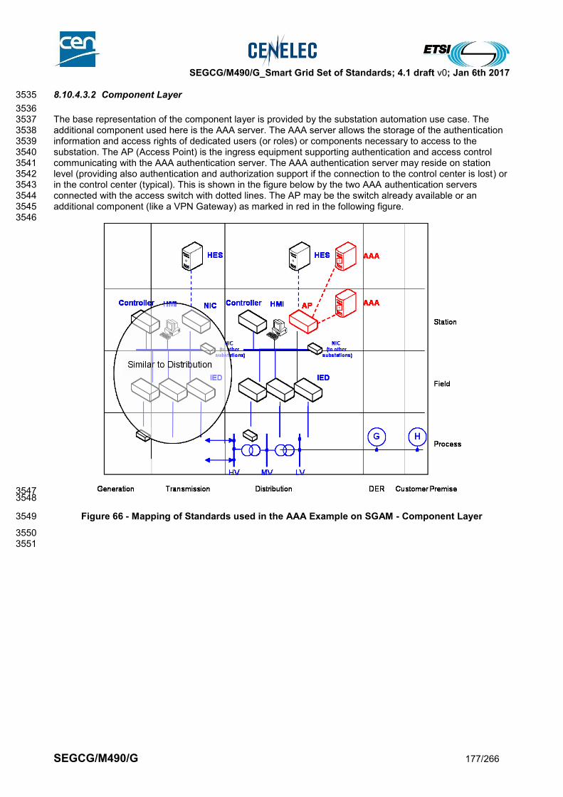
SEGCG/M490/G_Smart Grid Set of Standards; 4.1 draft v0; Jan 6th 2017
SEGCG/M490/G 177/266
8.10.4.3.2 Component Layer 3535
3536 The base representation of the component layer is provided by the substation automation use case. The 3537 additional component used here is the AAA server. The AAA server allows the storage of the authentication 3538 information and access rights of dedicated users (or roles) or components necessary to access to the 3539 substation. The AP (Access Point) is the ingress equipment supporting authentication and access control 3540 communicating with the AAA authentication server. The AAA authentication server may reside on station 3541 level (providing also authentication and authorization support if the connection to the control center is lost) or 3542 in the control center (typical). This is shown in the figure below by the two AAA authentication servers 3543 connected with the access switch with dotted lines. The AP may be the switch already available or an 3544 additional component (like a VPN Gateway) as marked in red in the following figure. 3545 3546
3547 3548
Figure 66 - Mapping of Standards used in the AAA Example on SGAM - Component Layer 3549
3550 3551

SEGCG/M490/G_Smart Grid Set of Standards; 4.1 draft v0; Jan 6th 2017
SEGCG/M490/G 178/266
8.10.4.3.3 Communication Layer 3552
3553 As stated before, there are two main options for remotely accessing a substation. Either using a separate 3554 VPN connection or protocol specific security features. 3555 3556 For the VPN connection IPSec is assumed to be applied. Network access control is often performed, before 3557 the IPSec connection is actually established (e.g., using EAP (Encapsulated Authentication Protocol) on OSI 3558 layer 2. Examples can be given by dial-up connections using PPP. 3559 3560 EAP is a container protocol allowing the transport of different authentication methods which provide different 3561 functionality. The base protocol is defined in RFC 3748. EAP allows the specification of dedicated methods 3562 to be used within the container. The functionality supported ranges from plain unilateral authentication to 3563 mutual authentication with session key establishment. From the cryptographic strength of the authentication, 3564 there is also a range from plain passwords to X.509 certificate based authentication. 3565 3566 Examples for EAP authentication methods include (not complete) for instance: EAP-MD5, EAP-MS-CHAP2, 3567 EAP-TLS, EAP-TTLS, EAP-FAST, EAP-PSK, EAP-PAX, EAP-IKEv2, EAP-AKA, EAP-MD5, EAP-LEAP, 3568 EAP-PEAP, EAP-SIM, EAP-Double-TLS, EAP-SAKE and EAP-POTP. These methods are typically defined 3569 in separate IETF documents. 3570 3571 While EAP is typically used for network access authentication, there may be the need to further distinguish 3572 access within the substation. For example to access certain protection devices or a substation controller, 3573 also considering the role of the accessing entity is necessary to determine the allowed actions connected 3574 with the role. IEC 62351-8 provides a solution to support role based access control based on specific 3575 credentials (e.g., enhanced X.509 public key certificates or X.509 attribute certificates), which can be applied 3576 in the context of applied security protocols. An example is given by the application of these credentials in 3577 TLS, which can be used according to IEC 62351-3 and IEC 62351-4 to protect the IEC 61850 3578 communication performed over TCP connections. Here, the X.509 certificates are used in the context of 3579 authentication and session key negotiation to protect the TCP channel using the T-profile. This approach 3580 may be followed within a substation but also to access the substation from outside, with or without relying on 3581 a VPN connection. In fact, in the latter case, TLS provides the secure channel and thus works as a VPN for 3582 the TCP connection. In contrast to IPSec here only the specific protocol employing TLS is protected, while 3583 IPSec basically provides a secure tunnel between the substation and the remote point allowing tunneling 3584 different protocols. If IPSec is used it is assumed that it will be terminated at the ingress point of the 3585 substation. If used combined with TLS, the TLS protection reaches deeper into the substation. Moreover, 3586 IEC 62351-4 (currently under revision) also provides different application layer security mechanisms (A-3587 profiles), allowing for application of the X.509 credential within the context of an MMS session. This allows 3588 for an even more application oriented access control. 3589 3590 For the use case shown here, two protocol families build the base namely IEC 61850 and IEC 60870-5. 3591 Especially for the outside communication the TCP based variants are applied allowing an easy application of 3592 IEC 62351 functionality. Note that the main focus here is on IEC 62351-8 as it supports the access control 3593 functionality: 3594
Within the substation, IEC 61850-8-1 (for any kind of data flows except sample values) and IEC 61850-3595 9-2 (for sample values) are used to support the selected set of generic Use Cases. 3596 IEC 61850-90-4 provides detailed guidelines for communication inside a substation. 3597 IEC 61850 is used for connecting protection relays. 3598
Outside the substation, “vertical communications” uses IEC 60870-5-104 or IEC 61850, while horizontal 3599 communications can rely on IEC 61850-90-5 (full mapping over UDP) or IEC 61850-90-1 (tunneling). 3600 3601
Future vertical communication may rely on IEC 61850-90-2 (guideline for using IEC 61850 to control centers) 3602 to provide a seamless architecture, based on IEC 61850. A new mapping of IEC 61850 over the web 3603 services technology (IEC 61850-8-2) is under specification, in order to enlarge (in security) the scope of 3604 application of IEC 61850 outside the substation, while facilitating its deployment. 3605 3606 This set of standards can be positioned this way on the communication layer of SGAM. 3607 3608

SEGCG/M490/G_Smart Grid Set of Standards; 4.1 draft v0; Jan 6th 2017
SEGCG/M490/G 179/266
3609 3610
Figure 67 - Mapping of Standards used in the AAA Example on SGAM - Communication Layer 3611
3612
3613
E
E
L F
F
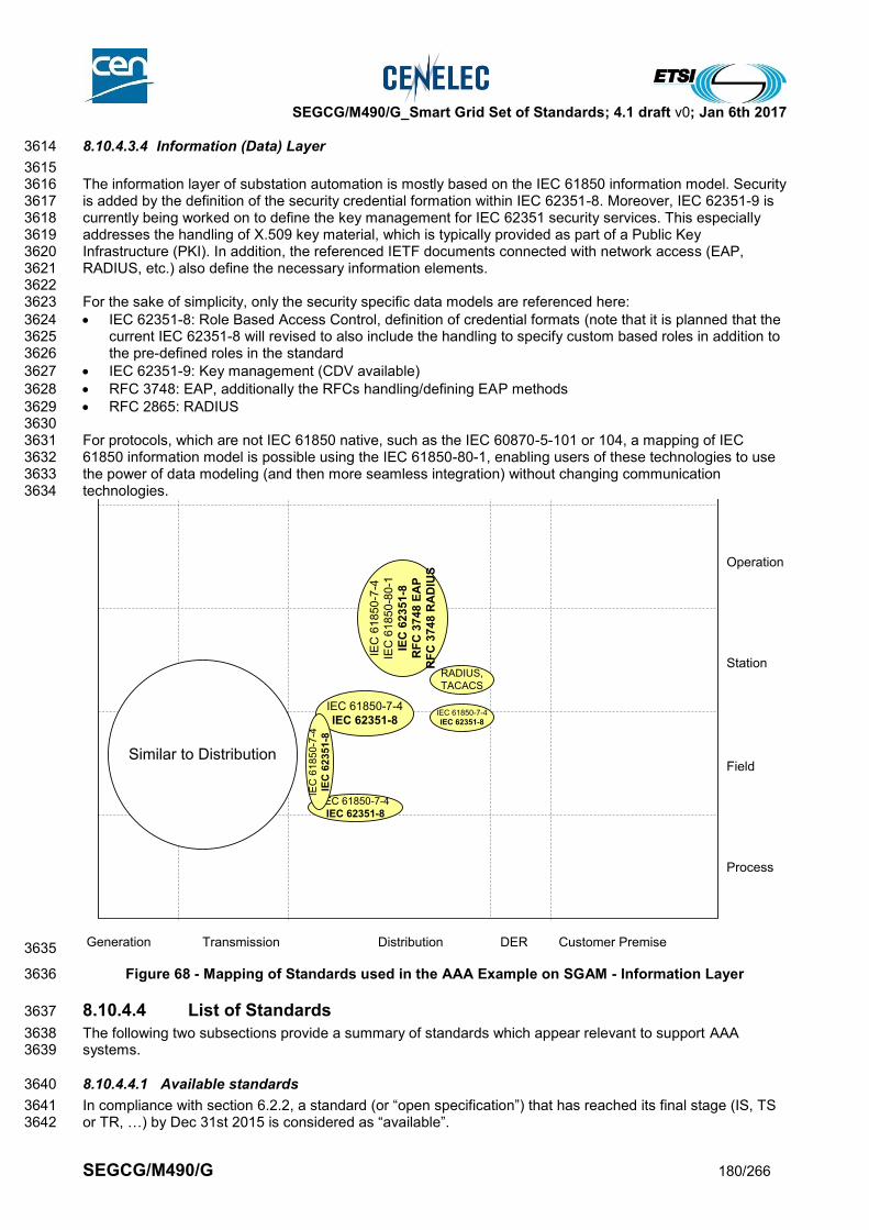
SEGCG/M490/G_Smart Grid Set of Standards; 4.1 draft v0; Jan 6th 2017
SEGCG/M490/G 180/266
8.10.4.3.4 Information (Data) Layer 3614
3615 The information layer of substation automation is mostly based on the IEC 61850 information model. Security 3616 is added by the definition of the security credential formation within IEC 62351-8. Moreover, IEC 62351-9 is 3617 currently being worked on to define the key management for IEC 62351 security services. This especially 3618 addresses the handling of X.509 key material, which is typically provided as part of a Public Key 3619 Infrastructure (PKI). In addition, the referenced IETF documents connected with network access (EAP, 3620 RADIUS, etc.) also define the necessary information elements. 3621 3622 For the sake of simplicity, only the security specific data models are referenced here: 3623
IEC 62351-8: Role Based Access Control, definition of credential formats (note that it is planned that the 3624 current IEC 62351-8 will revised to also include the handling to specify custom based roles in addition to 3625 the pre-defined roles in the standard 3626
IEC 62351-9: Key management (CDV available) 3627
RFC 3748: EAP, additionally the RFCs handling/defining EAP methods 3628
RFC 2865: RADIUS 3629 3630 For protocols, which are not IEC 61850 native, such as the IEC 60870-5-101 or 104, a mapping of IEC 3631 61850 information model is possible using the IEC 61850-80-1, enabling users of these technologies to use 3632 the power of data modeling (and then more seamless integration) without changing communication 3633 technologies. 3634
3635
Figure 68 - Mapping of Standards used in the AAA Example on SGAM - Information Layer 3636
8.10.4.4 List of Standards 3637
The following two subsections provide a summary of standards which appear relevant to support AAA 3638 systems. 3639
8.10.4.4.1 Available standards 3640
In compliance with section 6.2.2, a standard (or “open specification”) that has reached its final stage (IS, TS 3641 or TR, …) by Dec 31st 2015 is considered as “available”. 3642
Generation Transmission Distribution Customer PremiseDER
Process
Field
Station
Operation
Enterprise
Market
IEC 61850-7-4
IEC 62351-8
IEC 61850-7-4
IEC 62351-8
IEC
61
85
0-7
-4
IEC
62
35
1-8
IEC
61
85
0-7
-4
IEC
61
85
0-8
0-1
IEC
62
35
1-8
RF
C 3
74
8 E
AP
RF
C 3
74
8 R
AD
IUS
IEC 61850-7-4
IEC 62351-8
Similar to Distribution
RADIUS,
TACACS

SEGCG/M490/G_Smart Grid Set of Standards; 4.1 draft v0; Jan 6th 2017
SEGCG/M490/G 181/266
The following list provides an overview of applicable standards for AAA. Note that the list does not claim to 3643 be complete. 3644
Table 69 - AAA system - Available standards 3645
Layer Standard Comments
Information IEC 62351-8 Definition of Role Based Access Credentials
Information IETF RFC 4962 Guidance for Authentication, Authorization, and Accounting (AAA) Key Management
Communication IEC 62351-3 + IEC 62351-4 + IEC 62351-8
Protection of TCP-based IEC 61850 with RBAC on transport (TLS) or application (MMS) layer
Communication IEC 62351-3 + IEC 62351-5 + IEC 62351-8
Protection of TCP-based IEC 60870-5-104 with RBAC on transport (TLS) layer
Information IETF RFC 2865 RADIUS (Remote Authentication Dial In User Service)
Communication IETF RFC 2759 EAP MS-CHAP2
Communication IETF RFC 3748 EAP Base Protocol (includes EAP MD5)
Communication IETF RFC 4764 EAP PSK (Pre-Shared Key)
Communication IETF RFC 5106 EAP IKEv2
Communication IETF RFC 5216 EAP TLS
Communication IETF RFC 5281 EAP TTLSv1.0
Information, Communication
IEC 61850-90-4 Guidelines for communication within substation
3646 3647
8.10.4.4.2 Coming standards 3648
3649 In compliance with section 6.2.2, a standard that has successfully passed the NWIP process (or any formal 3650 equivalent work item adoption process) by Dec 31st 2015Dec 31st 2015 is considered as “Coming”. 3651
Table 70 - AAA system - Coming standards 3652
Layer Standard Comments
Information, Communication
IEC 62351-90-1
Definition of categories of actions to be associated with a role/right to ease the administrative handling of rights and role associations. (DC in 08/2016)
Information, Communication
IEC 62351-7 Revision of the existing part 7 to support fine grained monitoring utilizing SNMP to support AAA (CDV in 05/2016)
Information, Communication
IEC 62351-8 Revision of the existing part 8 to include more profiles for RBAC as well as the possibility to define custom based roles.
Information, Communication
IEC 62351-9
(CDV in 02/2016) Key Management for IEC 62351 security services, targeting the management of asymmetric and symmetric as well as group based security credentials.
Information, Communication
IEC 62351-14 New part targeting the support of fine grained eventing and logging utilizing syslog SNMP to support AAA (CD in 03/2017)
Information, Communication
IEC 61850-90-2 Guidelines for communication to control centers
Communication IEC 61850-8-2 IEC 61850 Specific communication service mapping (SCSM) – Mappings to web-services
3653

SEGCG/M490/G_Smart Grid Set of Standards; 4.1 draft v0; Jan 6th 2017
SEGCG/M490/G 182/266
8.10.5 Device remote management system 3654
The device management system is a system helping system users to manage 3655 connection/disconnection/firmware update and maintenance of devices in a system. It can be used as a 3656 configuration server to store device configuration and helping changing a failed device with a new one, 3657 ensuring the exact same setting used in this new devices. 3658 End 2015 no specific standard is really supporting such features, which however may become crucial in the 3659 future with extended use of complex electronic devices on the field. Some pre-work seems to have started in 3660 IEC TC57, but no clear outcome is planned yet. 3661
8.10.6 Weather forecast and observation system 3662
8.10.6.1 System description 3663
3664 A weather forecast and observation system refers to the system and all elements needed to perform weather 3665 forecast and observation calculation and to distribute the calculated geospatially referenced information to all 3666 connected other systems such as Distribution management systems, Transmission management systems, 3667 DER/Generation management systems, EMS or VPPs systems for DER, … enabling in many cases 3668 optimized decision processes or automation. 3669 It generally comprises a secured IT system, usually relying on an SOA infrastructure, possibly interconnected 3670 to international weather observation and/or connected to a number of weather sensors. 3671
3672
8.10.6.2 Set of use cases 3673
3674 A weather forecast system is generally capable of providing forecast updates, in a solicited or unsolicited 3675 manner, such as: 3676
General atmospheric forecast 3677
Watches/Warnings (future) 3678 3679 In addition, it may also provide weather observations which can be solicited or unsolicited, and may or will 3680 cover information such as: 3681
Observed lightning (future) 3682
Current Conditions 3683
Storm approaching data (future) such as : 3684 o Precipitation timer 3685 o Future lightning (currently US only) 3686 o Storm corridors (currently US only) 3687
Consequently here is the list of high level use cases possibly supported by a Weather forecast and 3688 observation system. 3689 The meanings of the three last columns (AVAILABLE, COMING, Not Yet) and of the “C”, “I”, “CI”, “X” 3690 conventions are given in section 7.6.2. 3691
Table 71 - Weather forecast and observation system - Use cases 3692
Supported by standards
Use cases cluster
High level use cases AVAILABLE COMING Not yet
Demand and production (generation) flexibility
Load forecasting I
Weather condition forecasting & observation
Wind forecasting C I
Solar forecasting I
Temperature forecasting I
Providing weather observations I I
Situational alerting X

SEGCG/M490/G_Smart Grid Set of Standards; 4.1 draft v0; Jan 6th 2017
SEGCG/M490/G 183/266
8.10.6.3 Mapping on SGAM 3693
8.10.6.3.1 Preamble 3694
A weather forecast system is not really attached to any SGAM domains or zones, so its mapping over SGAM 3695 is not providing real value. 3696 However breaking down such a system using the SGAM layers is useful: 3697 3698
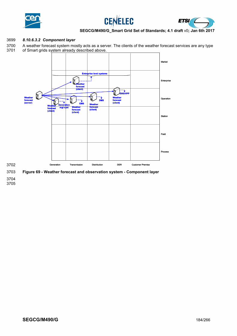
SEGCG/M490/G_Smart Grid Set of Standards; 4.1 draft v0; Jan 6th 2017
SEGCG/M490/G 184/266
8.10.6.3.2 Component layer 3699
A weather forecast system mostly acts as a server. The clients of the weather forecast services are any type 3700 of Smart grids system already described above. 3701
3702
Figure 69 - Weather forecast and observation system - Component layer 3703
3704 3705
Generation Transmission Distribution Customer PremiseDER
Process
Field
Station
Operation
Enterprise
Market
Weather
forecast
(client)
Weather
forecast
(server)
Weather
forecast
(client)
Weather
forecast
(client)
Weather
forecast
(client)
Weather
forecast
(client)
Generation
mgt syst
EMS
DMS
EMS/VPP
Entreprise level systems

SEGCG/M490/G_Smart Grid Set of Standards; 4.1 draft v0; Jan 6th 2017
SEGCG/M490/G 185/266
8.10.6.3.3 Communication layer 3706
The most common communication protocol used for handling exchange with a weather forecast system for a 3707 request/response based service is web services (please refer to section 9.3.5 for further details) 3708 3709 Supporting subscribe and publish service for unsolicited data may request to get a network connection 3710 available from registration to receiving the data. 3711 3712 Note: the letters in the blue disks shown in the diagram below refer to the network types defined in 9.3.2. 3713
3714
3715
Figure 70 - Weather forecast and observation system - Communication layer 3716
3717 3718
Generation Transmission Distribution Customer PremiseDER
Process
Field
Station
Operation
Enterprise
Market
Web servicesWeb services
Generation Transmission Distribution Customer PremiseDER
Process
Field
Station
Operation
Enterprise
Market
Web servicesWeb services
G
H
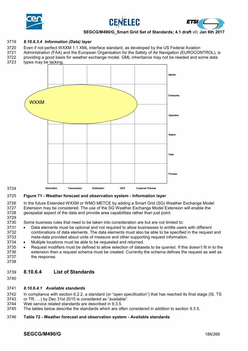
SEGCG/M490/G_Smart Grid Set of Standards; 4.1 draft v0; Jan 6th 2017
SEGCG/M490/G 186/266
8.10.6.3.4 Information (Data) layer 3719
Even if not perfect WXXM 1.1 XML interface standard, as developed by the US Federal Aviation 3720 Administration (FAA) and the European Organisation for the Safety of Air Navigation (EUROCONTROL), is 3721 providing a good basis for weather exchange model. GML inheritance may not be needed and some data 3722 types may be lacking. 3723
3724
Figure 71 - Weather forecast and observation system - Information layer 3725
In the future Extended WXXM or WMO METCE by adding a Smart Grid (SG) Weather Exchange Model 3726 Extension may be considered. The use of the SG Weather Exchange Model Extension will enable the 3727 geospatial aspect of the data and provide area capabilities rather than just point. 3728 3729 Some business rules that need to be taken into consideration are but are not limited to: 3730
Data elements must be optional and not required to allow businesses to entitle users with different 3731 combinations of data elements. The data elements must also be able to be specified in the request and 3732 meta-data provided about units of measure and other supporting request information. 3733
Multiple locations must be able to be requested and returned. 3734
Request modifiers must be defined to allow selection of datasets to be queried. If this doesn’t fit in to the 3735 extension then a request schema must be created. Currently the schema defines the request as well as 3736 the response. 3737
3738
8.10.6.4 List of Standards 3739
3740
8.10.6.4.1 Available standards 3741
In compliance with section 6.2.2, a standard (or “open specification”) that has reached its final stage (IS, TS 3742 or TR, …) by Dec 31st 2015 is considered as “available”. 3743 Web service related standards are described in 9.3.5. 3744 The tables below describe the standards which are often considered in addition to section 9.3.5. 3745
Table 72 - Weather forecast and observation system - Available standards 3746
Generation Transmission Distribution Customer PremiseDER
Process
Field
Station
Operation
Enterprise
Market
WXXMWXXM
Generation Transmission Distribution Customer PremiseDER
Process
Field
Station
Operation
Enterprise
Market
WXXMWXXM
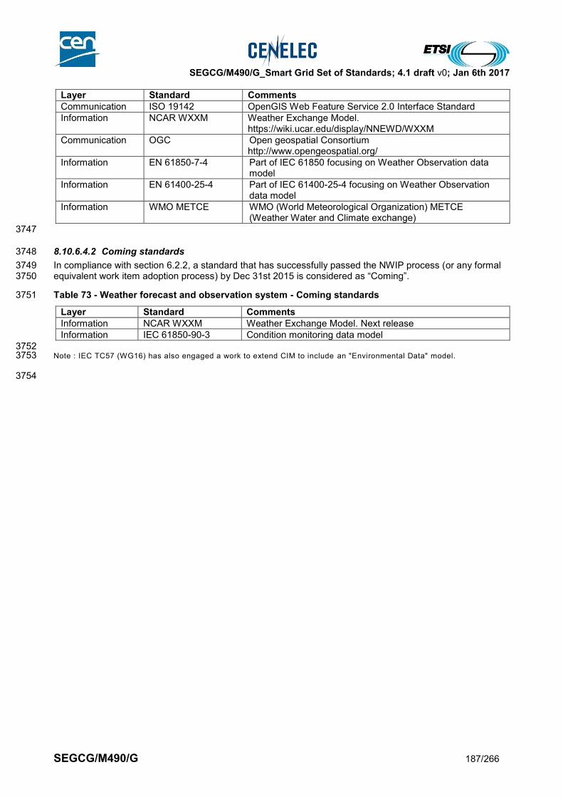
SEGCG/M490/G_Smart Grid Set of Standards; 4.1 draft v0; Jan 6th 2017
SEGCG/M490/G 187/266
Layer Standard Comments
Communication ISO 19142 OpenGIS Web Feature Service 2.0 Interface Standard
Information NCAR WXXM Weather Exchange Model. https://wiki.ucar.edu/display/NNEWD/WXXM
Communication OGC Open geospatial Consortium http://www.opengeospatial.org/
Information EN 61850-7-4 Part of IEC 61850 focusing on Weather Observation data model
Information EN 61400-25-4 Part of IEC 61400-25-4 focusing on Weather Observation data model
Information WMO METCE
WMO (World Meteorological Organization) METCE (Weather Water and Climate exchange)
3747
8.10.6.4.2 Coming standards 3748
In compliance with section 6.2.2, a standard that has successfully passed the NWIP process (or any formal 3749 equivalent work item adoption process) by Dec 31st 2015 is considered as “Coming”. 3750
Table 73 - Weather forecast and observation system - Coming standards 3751
Layer Standard Comments
Information NCAR WXXM Weather Exchange Model. Next release
Information IEC 61850-90-3 Condition monitoring data model
3752 Note : IEC TC57 (WG16) has also engaged a work to extend CIM to include an "Environmental Data" model. 3753
3754
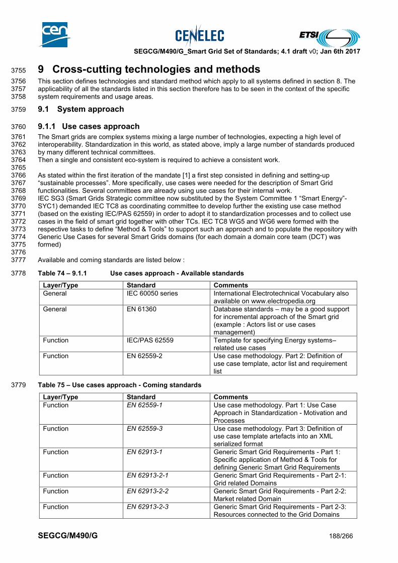
SEGCG/M490/G_Smart Grid Set of Standards; 4.1 draft v0; Jan 6th 2017
SEGCG/M490/G 188/266
9 Cross-cutting technologies and methods 3755
This section defines technologies and standard method which apply to all systems defined in section 8. The 3756 applicability of all the standards listed in this section therefore has to be seen in the context of the specific 3757 system requirements and usage areas. 3758
9.1 System approach 3759
9.1.1 Use cases approach 3760
The Smart grids are complex systems mixing a large number of technologies, expecting a high level of 3761 interoperability. Standardization in this world, as stated above, imply a large number of standards produced 3762 by many different technical committees. 3763 Then a single and consistent eco-system is required to achieve a consistent work. 3764 3765 As stated within the first iteration of the mandate [1] a first step consisted in defining and setting-up 3766 “sustainable processes”. More specifically, use cases were needed for the description of Smart Grid 3767 functionalities. Several committees are already using use cases for their internal work. 3768 IEC SG3 (Smart Grids Strategic committee now substituted by the System Committee 1 “Smart Energy”-3769 SYC1) demanded IEC TC8 as coordinating committee to develop further the existing use case method 3770 (based on the existing IEC/PAS 62559) in order to adopt it to standardization processes and to collect use 3771 cases in the field of smart grid together with other TCs. IEC TC8 WG5 and WG6 were formed with the 3772 respective tasks to define “Method & Tools” to support such an approach and to populate the repository with 3773 Generic Use Cases for several Smart Grids domains (for each domain a domain core team (DCT) was 3774 formed) 3775 3776 Available and coming standards are listed below : 3777
Table 74 – 9.1.1 Use cases approach - Available standards 3778
Layer/Type Standard Comments
General IEC 60050 series International Electrotechnical Vocabulary also available on www.electropedia.org
General EN 61360 Database standards – may be a good support for incremental approach of the Smart grid (example : Actors list or use cases management)
Function IEC/PAS 62559 Template for specifying Energy systems–related use cases
Function EN 62559-2 Use case methodology. Part 2: Definition of use case template, actor list and requirement list
Table 75 – Use cases approach - Coming standards 3779
Layer/Type Standard Comments
Function EN 62559-1 Use case methodology. Part 1: Use Case Approach in Standardization - Motivation and Processes
Function EN 62559-3 Use case methodology. Part 3: Definition of use case template artefacts into an XML serialized format
Function EN 62913-1 Generic Smart Grid Requirements - Part 1: Specific application of Method & Tools for defining Generic Smart Grid Requirements
Function EN 62913-2-1 Generic Smart Grid Requirements - Part 2-1: Grid related Domains
Function EN 62913-2-2 Generic Smart Grid Requirements - Part 2-2: Market related Domain
Function EN 62913-2-3 Generic Smart Grid Requirements - Part 2-3: Resources connected to the Grid Domains
SEGCG/M490/G_Smart Grid Set of Standards; 4.1 draft v0; Jan 6th 2017
SEGCG/M490/G 189/266
Function EN 62913-2-4 Generic Smart Grid Requirements - Part 2-4: Electric Transportation Domain
Function EN 62913-2-5 Generic Smart Grid Requirements - Part 2-5: Support Functions Domains
3780
SEGCG/M490/G_Smart Grid Set of Standards; 4.1 draft v0; Jan 6th 2017
SEGCG/M490/G 190/266
9.1.2 Product Identification 3781
With reference to the (unambiguous) identification of products in the network, it is important to consider the 3782 standards which establish the general principles for the structuring of systems including structuring of the 3783 information about systems (Reference Designation System, RDS). 3784 3785 By applying the structuring principles very large sets of information in a complex installation can be handled 3786 efficiently to support asset management. The structuring principles and the rules for reference designations 3787 are applicable to objects of both physical and non-physical character. The principles laid down are general 3788 and are applicable to all technical areas. They can be used for systems based on different technologies or 3789 for systems combining several technologies. 3790 3791 Furthermore, rules and guidance are given for the formulation of unambiguous reference designations for 3792 objects in any system, where also requirements for a product data structure are already included. 3793 3794 The reference designation identifies objects for the purpose of correlating information about an object among 3795 different kinds of documents, and for labelling of components corresponding to the objects. 3796 3797 Based on these basic principles, VGB PowerTech association further developed a globally applied 3798 Reference Designation System for Power Plants (RDS-PP) which is already widely used in the area of wind 3799 energy and associated asset management systems and documentation, but the same principles also 3800 generally apply for all distributed energy resources in the Smart Grid. In addition, German IG EVU 3801 association developed application rules for a designation system (IG EVU-001-A ) especially for grid related 3802 objects based on these principles. 3803 3804 There is also a technical guideline for the designation and management of Technical Plant Data which was 3805 developed by VGB PowerTech association (VGB-S-821-00, VGB B102 and VGB-S-831-00) which may be 3806 relevant for this gap in addition. 3807 VGB PowerTech is currently working on application guidelines for grids and new technologies in order to 3808 further support planning, operation and asset management. 3809 3810 We therefore aim that already existing and applied work, applicable for all technical domains, systems and 3811 products as specifically mentioned in this gap, need to be appropriately considered to support asset 3812 management as specifically mentioned. 3813
Table 76 – Product Identification and Classification - Available standards 3814
Layer/Type Standard Comments
General - Identification EN 81346-1 Industrial systems, installations and equipment and industrial products - Structuring principles and reference designations - Part 1: Basic rules
General - Classification EN 81346-2 Industrial systems, installations and equipment and industrial products - Structuring principles and reference designations - Part 2: Classification of objects and codes for classes
General - Classification EN 81346-3 Industrial systems, installations and equipment and industrial products - Structuring principles and reference designations - Part 3: Application rules for a reference designation system
General - Classification EN 81346-10 Industrial systems, installations and equipment and industrial products - Structuring principles and reference designation - Part 10: Power plants
General - Identification EN 62507-1 Requirements for identification systems enabling unambiguous information interchange – Part 1: Principles and methods
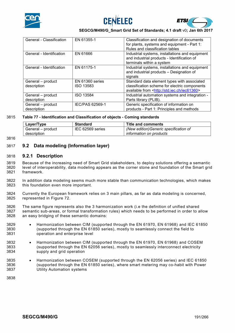
SEGCG/M490/G_Smart Grid Set of Standards; 4.1 draft v0; Jan 6th 2017
SEGCG/M490/G 191/266
General - Classification EN 61355-1 Classification and designation of documents for plants, systems and equipment - Part 1: Rules and classification tables
General - Identification EN 61666 Industrial systems, installations and equipment and industrial products - Identification of terminals within a system
General - Identification EN 61175-1 Industrial systems, installations and equipment and industrial products – Designation of signals
General – product description
EN 61360 series ISO 13583
Standard data element types with associated classification scheme for electric components available from <http://std.iec.ch/iec61360>
General – product description
ISO 13584 Industrial automation systems and integration - Parts library (PLIB).
General – product description
IEC/PAS 62569-1 Generic specification of information on products - Part 1: Principles and methods
Table 77 - Identification and Classification of objects - Coming standards 3815
Layer/Type Standard Title and comments
General – product description
IEC 62569 series (New edition)Generic specification of information on products
3816
9.2 Data modeling (Information layer) 3817
9.2.1 Description 3818
Because of the increasing need of Smart Grid stakeholders, to deploy solutions offering a semantic 3819 level of interoperability, data modeling appears as the corner stone and foundation of the Smart grid 3820 framework. 3821
In addition data modeling seems much more stable than communication technologies, which makes 3822 this foundation even more important. 3823
Currently the European framework relies on 3 main pillars, as far as data modeling is concerned, 3824 represented in Figure 72. 3825
The same figure represents also the 3 harmonization work (i.e the definition of unified shared 3826 semantic sub-areas, or formal transformation rules) which needs to be performed in order to allow 3827 an easy bridging of these semantic domains: 3828
Harmonization between CIM (supported through the EN 61970, EN 61968) and IEC 61850 3829 (supported through the EN 61850 series), mostly to seamlessly connect the field to 3830 operation and enterprise level 3831
Harmonization between CIM (supported through the EN 61970, EN 61968) and COSEM 3832 (supported through the EN 62056 series) , mostly to seamlessly interconnect electricity 3833 supply and grid operation 3834
Harmonization between COSEM (supported through the EN 62056 series) and IEC 61850 3835 (supported through the EN 61850 series) , where smart metering may co-habit with Power 3836 Utility Automation systems 3837
3838
SEGCG/M490/G_Smart Grid Set of Standards; 4.1 draft v0; Jan 6th 2017
SEGCG/M490/G 192/266
3839
Figure 72 - Data modelling and harmonization work (Information layer) mapping 3840
9.2.2 List of Standards 3841
9.2.2.1 Available standards 3842
In compliance with section 6.2.2, a standard (or “open specification”) that has reached its final stage (IS, TS 3843 or TR, …) by Dec 31st 2015 is considered as “available”. 3844 3845
Table 78 - Data modeling - Available standards 3846
Layer Standard Comments
Information IEC/EN 61850 (all parts)
Information EN 62056 (parts: 6-1 and 6-2)
COSEM
Information EN 61970 (all parts) Part of the CIM family
Information EN 61968 (all parts) Part of the CIM family
Information IEC 62361 (all parts) Rules for Power Utilities data model
Information EN 62325 (all parts) CIM derived data model for Energy Market information exchange
Information IEC 61850-80-4 mapping of COSEM over IEC 61850
9.2.2.2 Coming standards 3847
In compliance with section 6.2.2,¸a standard that has successfully passed the NWIP process (or any formal 3848 equivalent work item adoption process) by Dec 31st 2015 is considered as “Coming”. 3849 3850
Table 79 - Data modeling - Coming standards 3851
Layer Standard Comments
Information IEC 62056-6-9 mapping between the Common Information Model CIM (IEC 61968-9) and DLMS/COSEM (IEC 62056) data models and message profiles
Market
Enterprise
Operation
Station
Field
Process
Generation Transmission Distribution DERCustomer premise
• IEC 61850 data model
• CIM data model
• COSEM data model (smart metering)
12
3
1 • CIM/IEC 61850 harmonisation
2
3
• CIM/COSEM harmonisation
• COSEM/IEC 61850 harmonisation

SEGCG/M490/G_Smart Grid Set of Standards; 4.1 draft v0; Jan 6th 2017
SEGCG/M490/G 193/266
Layer Standard Comments
Information IEC 62361-102 harmonisation of data models between CIM and IEC 61850
9.3 Communication (Communication layer) 3852
9.3.1 Description 3853
A secure, reliable and economic power supply is closely linked to fast, efficient and dependable 3854 telecommunication services. 3855
A telecommunication service is any service provided by a telecommunication network through a 3856 communications system. A communications system is a collection of individual communications networks 3857 and communication end points capable of interconnection and interoperation to form an integrated whole. 3858
The planning and implementation of communications systems, needed to support the expected 3859 services mentioned above, requires the same care as the installation of the power supply systems 3860 themselves. 3861
3862 One way to categorize the different types of telecommunications networks is by means of transmission: 3863
Wireless: communication through the air 3864
Wire line: communication through cable dedicated to telecommunications services 3865
Power line: communication through cable designed for electric power transmission, but used for carrying 3866 data too. 3867
3868 Wireless communications may have to comply with local or regional regulations (such as the Radio 3869 Equipment Directive (RED) 2014/53/EU for Europe and FERC in USA). 3870 3871 For Smart Grid communication architecture/technology, products based on specifications from various 3872 bodies (e.g. the IETF, IEEE, W3C) have been deployed widely, notably in the area of IP protocols and web 3873 services. In the below section, the list of standards/specifications takes into account the ones which fulfill 3874 market requirements. 3875 3876
9.3.2 Communication network type breakdown 3877
Depending on the Smart Grid target applications, different types of communication networks and also 3878 collections of communication networks using different transmission technologies may be selected in order to 3879 transmit and deliver Smart Grid data. 3880
The following network types could be defined for the Smart Grids26: 3881 3882 • (A) Subscriber Access Network 3883
networks that provide general broadband access (including but not limited to the internet) for the 3884 customer premises (homes, building, facilities). They are usually not part of the utility infrastructure 3885 and provided by communication service providers, but can be used to provide communication 3886 service for Smart Grid systems covering the customer premises like Smart Metering and Aggregated 3887 prosumers management. 3888
3889 • (B) Neighborhood network 3890
networks at the distribution level between distribution substations and end users. It is composed of 3891 any number of purpose-built networks that operate at what is often viewed as the “last mile” or 3892 Neighborhood Network level. These networks may service metering, distribution automation, and 3893 public infrastructure for electric vehicle charging, for example. 3894
3895 • (C) Multi-services backhaul Network 3896
networks at the distribution level upper tier, which is a multi-services tier that integrates the various 3897
26 Notes :
1 - Home and building automation systems are not covered in this document as they are outside of the scope of the mandate. Only the interface to such systems are in the scope 2 - for specific security requirements, please refer to 9.4 and SG-CG/SGIS report [11]

SEGCG/M490/G_Smart Grid Set of Standards; 4.1 draft v0; Jan 6th 2017
SEGCG/M490/G 194/266
sub layer networks and provides backhaul connectivity in two ways: directly back to control centers 3898 or directly to primary substations to facilitate substation level distributed intelligence. It also provides 3899 peer-to-peer connectivity or hub and spoke connectivity for distributed intelligence in the distribution 3900 level. This network may serve Advanced Metering or Distribution Automation types of services. 3901
3902 • (D) Low-end intra-substation network 3903
Network inside secondary substations or MV/LV transformer station. It usually connects RTUs, circuit 3904 breakers and different power quality sensors. 3905
3906 • (E) Intra-substation network 3907
Network inside a primary distribution substation or inside a transmission substation. It is involved in 3908 low latency critical functions such as tele-protection. Internally to the substation, the networks may 3909 comprise from one to three buses (system bus, process bus, and multi-services bus). 3910
3911 • (F) Inter substation network 3912 Networks that interconnect substations with each other and with control centers. These networks are 3913
wide area networks and the high end performance requirements for them can be stringent in terms 3914 of latency and burst response. In addition, these networks require very flexible scalability and due to 3915 geographic challenges they can require mixed physical media and multiple aggregation topologies. 3916 System control tier networks provide networking for SCADA, SIPS, event messaging, and remote 3917 asset monitoring telemetry traffic, as well as peer-to-peer connectivity for tele-protection and 3918 substation-level distributed intelligence. 3919
3920 • (G) Intra-Control Centre / Intra-Data Centre network 3921
Networks inside two different types of facilities in the utility: utility data centers and utility control 3922 centers. They are at the same logical tier level, but they are not the same networks, as control 3923 centers have very different requirements for connection to real time systems and for security, as 3924 compared to enterprise data centers, which do not connect to real time systems. Each type provides 3925 connectivity for systems inside the facility and connections to external networks, such as system 3926 control and utility tier networks. 3927
3928 • (H) Backbone Network 3929
Inter-enterprise or campus networks, including backbone Internet network, as well as inter-control 3930 centre networks.. 3931
3932 • (L) Operation Backhaul Network 3933
Networks that can use public or private infrastructures, mostly to support remote operation.. They 3934 usually inter-connect network devices and/or subsystems to the “Operation level” over a wide area 3935 (region or country). 3936
3937 • (N) Home and Building integration bus Network 3938
Networks that interconnect home / building communicating components and sub-systems to form a 3939 home or building management sub-system or system 3940
3941 • (M) Industrial Fieldbus Area Network 3942
Networks that interconnect process control equipment mainly in power generation (bulk or 3943 distributed) in the scope of smart grids. 3944
3945 Figure 73 below provides a mapping of the different Smart Grid networks to the SGAM model. 3946 Note : where a circle is tangent to a zone, this means that the corresponding network type can support the interface with 3947 the tangent zone. 3948

SEGCG/M490/G_Smart Grid Set of Standards; 4.1 draft v0; Jan 6th 2017
SEGCG/M490/G 195/266
3949
Figure 73 - Mapping of communication networks on SGAM 3950
Note 1: These areas are a mapping example and cannot be normative to all business models. 3951
Note 2: It is assumed that that sub-networks depicted in the above figure are interconnected (where needed) to provide 3952 end-to-end connectivity to applications they support. VPNs, Gateways and firewalls could provide means to ensure 3953 network security or virtualization. 3954
9.3.3 Applicability of communication standards to Smart Grid networks 3955
The following table provides an applicability statement indicating the standardised communication 3956 technologies to the Smart Grid sub-networks depicted in the previous sub-clause. The choice of a technology 3957 for a sub-network is left to implementations, which need to take into account a variety of deployment 3958 constraints. 3959 3960 Note: This report addresses communication technologies related to smart grid deployment. It includes communication 3961 architecture and protocols that could be used in smart metering deployments as well as other use cases (like feeder 3962 automation, FLISR etc.). For AMI only specific standards, please refer more specifically to CEN/CLC/ETSI TR 50572 [4] 3963 and other future deliverables as listed in SMCG_Sec0074_DC_M441WP-1 (V0.6) Work Program [5]. 3964
3965 Each line in the Table 80 identifies a family of communication standards. These families are used to classify 3966 the standards in the table below. 3967 3968 More information on these families and associated technologies could be found in the Annex F of the 3969 Reference Architecture report [9]. 3970 3971
Market
Enterprise
Operation
Station
Field
Process
GenerationTransmissio
nDistribution DER
Customer premise • (A) Subscriber Access Network
• (B) Neighborhood Network
• (C) Multi-services Backhaul
Network
• (E) Intra-substation network
• (D) Low-end intra-substation
network
• (F) Inter-substation Network
• (H) Backbone network
• (L) Operation Backhaul Network
• (M) Industrial Fieldbus Area
Network
Backbone
Backhaul
Neighbor-hood/ Horizontal
network
Integration
bus
• (G) Intra-centre network
• (N) Home & Building
integration bus network

SEGCG/M490/G_Smart Grid Set of Standards 4.1 draft v0; Jan 6th 2017
SEGCG/M490/G 196/266
Table 80 - Applicability statement of the communication technologies to the smart grid sub-networks 3972
3973 * : refer to the set of protocols presented in section 9.3.53974
*
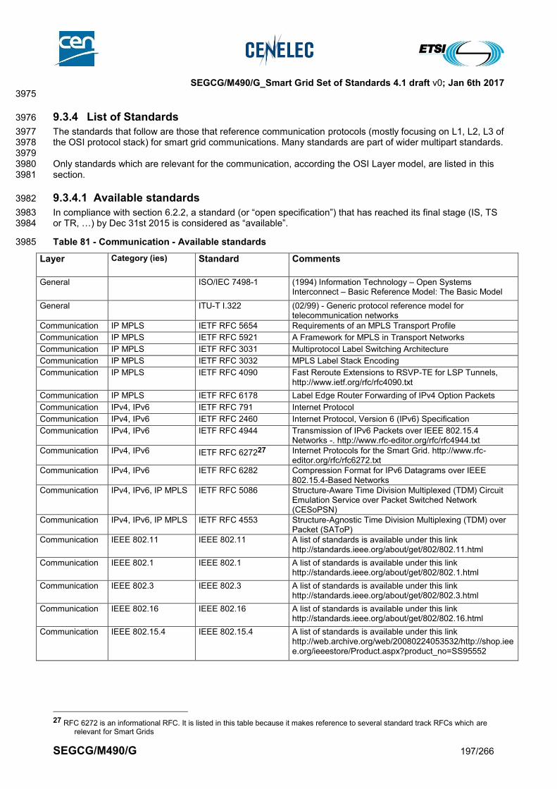
SEGCG/M490/G_Smart Grid Set of Standards 4.1 draft v0; Jan 6th 2017
SEGCG/M490/G 197/266
3975
9.3.4 List of Standards 3976
The standards that follow are those that reference communication protocols (mostly focusing on L1, L2, L3 of 3977 the OSI protocol stack) for smart grid communications. Many standards are part of wider multipart standards. 3978 3979 Only standards which are relevant for the communication, according the OSI Layer model, are listed in this 3980 section. 3981
9.3.4.1 Available standards 3982
In compliance with section 6.2.2, a standard (or “open specification”) that has reached its final stage (IS, TS 3983 or TR, …) by Dec 31st 2015 is considered as “available”. 3984
Table 81 - Communication - Available standards 3985
Layer Category (ies) Standard Comments
General ISO/IEC 7498-1 (1994) Information Technology – Open Systems Interconnect – Basic Reference Model: The Basic Model
General ITU-T I.322 (02/99) - Generic protocol reference model for telecommunication networks
Communication IP MPLS IETF RFC 5654 Requirements of an MPLS Transport Profile
Communication IP MPLS IETF RFC 5921 A Framework for MPLS in Transport Networks
Communication IP MPLS IETF RFC 3031 Multiprotocol Label Switching Architecture
Communication IP MPLS IETF RFC 3032 MPLS Label Stack Encoding
Communication IP MPLS IETF RFC 4090 Fast Reroute Extensions to RSVP-TE for LSP Tunnels, http://www.ietf.org/rfc/rfc4090.txt
Communication IP MPLS IETF RFC 6178 Label Edge Router Forwarding of IPv4 Option Packets
Communication IPv4, IPv6 IETF RFC 791 Internet Protocol
Communication IPv4, IPv6 IETF RFC 2460 Internet Protocol, Version 6 (IPv6) Specification
Communication IPv4, IPv6 IETF RFC 4944 Transmission of IPv6 Packets over IEEE 802.15.4 Networks -. http://www.rfc-editor.org/rfc/rfc4944.txt
Communication IPv4, IPv6 IETF RFC 627227 Internet Protocols for the Smart Grid. http://www.rfc-editor.org/rfc/rfc6272.txt
Communication IPv4, IPv6 IETF RFC 6282 Compression Format for IPv6 Datagrams over IEEE 802.15.4-Based Networks
Communication IPv4, IPv6, IP MPLS IETF RFC 5086 Structure-Aware Time Division Multiplexed (TDM) Circuit Emulation Service over Packet Switched Network (CESoPSN)
Communication IPv4, IPv6, IP MPLS IETF RFC 4553 Structure-Agnostic Time Division Multiplexing (TDM) over Packet (SAToP)
Communication IEEE 802.11 IEEE 802.11 A list of standards is available under this link http://standards.ieee.org/about/get/802/802.11.html
Communication IEEE 802.1 IEEE 802.1 A list of standards is available under this link http://standards.ieee.org/about/get/802/802.1.html
Communication IEEE 802.3 IEEE 802.3 A list of standards is available under this link http://standards.ieee.org/about/get/802/802.3.html
Communication IEEE 802.16 IEEE 802.16 A list of standards is available under this link http://standards.ieee.org/about/get/802/802.16.html
Communication IEEE 802.15.4 IEEE 802.15.4 A list of standards is available under this link http://web.archive.org/web/20080224053532/http://shop.ieee.org/ieeestore/Product.aspx?product_no=SS95552
27 RFC 6272 is an informational RFC. It is listed in this table because it makes reference to several standard track RFCs which are
relevant for Smart Grids
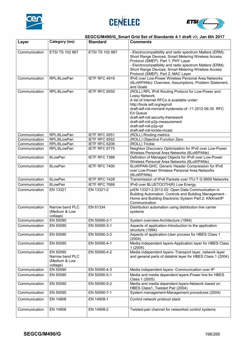
SEGCG/M490/G_Smart Grid Set of Standards 4.1 draft v0; Jan 6th 2017
SEGCG/M490/G 198/266
Layer Category (ies) Standard Comments
Communication ETSI TS 102 887 ETSI TS 102 887 - Electrocompatibility and radio spectrum Matters (ERM); Short Range Devices; Smart Metering Wireless Access Protocol (SMEP). Part 1; PHY Layer - Electrocompatibility and radio spectrum Matters (ERM); Short Range Devices; Smart Metering Wireless Access Protocol (SMEP). Part 2; MAC Layer
Communication RPL/6LowPan IETF RFC 4919 IPv6 over Low-Power Wireless Personal Area Networks (6LoWPANs): Overview, Assumptions, Problem Statement, and Goals
Communication RPL/6LowPan IETF RFC 6550 (ROLL) RPL IPv6 Routing Protocol for Low-Power and Lossy Network. A list of Internet RFCs is available under: http://tools.ietf.org/wg/roll draft-ietf-roll-minrank-hysteresis-of -11 2012-06-30 RFC Ed Queue draft-ietf-roll-security-framework draft-ietf-roll-p2p-measurement draft-ietf-roll-p2p-rpl draft-ietf-roll-trickle-mcast
Communication RPL/6LowPan IETF RFC 6551 (ROLL) Routing metrics
Communication RPL/6LowPan IETF RFC 6552 (ROLL) Objective Function Zero
Communication RPL/6LowPan IETF RFC 6206 (ROLL) Trickle
Communication RPL/6LowPan IETF RFC 6775 Neighbor Discovery Optimization for IPv6 over Low-Power Wireless Personal Area Networks (6LoWPANs)
Communication 6LowPan IETF RFC 7388 Definition of Managed Objects for IPv6 over Low-Power Wireless Personal Area Networks (6LoWPANs)
Communication 6LowPan IETF RFC 7400 6LoWPAN-GHC: Generic Header Compression for IPv6 over Low-Power Wireless Personal Area Networks (6LoWPANs)
Communication 6LowPan IETF RFC 7428 Transmission of IPv6 Packets over ITU-T G.9959 Networks
Communication 6LowPan IETF RFC 7668 IPv6 over BLUETOOTH(R) Low Energy
Communication EN 13321 EN 13321-2 prEN 13321-2:2012-02: Open Data Communication in Building Automation, Controls and Building Management - Home and Building Electronic System Part 2: KNXnet/IP Communication
Communication Narrow band PLC (Medium & Low voltage)
EN 61334 Distribution automation using distribution line carrier systems
Communication EN 50090 EN 50090-2-1 System overview-Architecture (1994)
Communication EN 50090 EN 50090-3-1 Aspects of application-Introduction to the application structure (1994)
Communication EN 50090 EN 50090-3-2 Aspects of application-User process for HBES Class 1 (2004)
Communication EN 50090 EN 50090-4-1 Media independent layers-Application layer for HBES Class 1 (2004)
Communication EN 50090 Narrow band PLC (Medium & Low voltage)
EN 50090-4-2 Media independent layers–Transport layer, network layer and general parts of datalink layer for HBES Class 1 (2004)
Communication EN 50090 EN 50090-4-3 Media independent layers -Communication over IP
Communication EN 50090 EN 50090-5-1 Media and media dependent layers-Power line for HBES Class 1 (2005)
Communication EN 50090 EN 50090-5-2 Media and media dependent layers-Network based on HBES Class1, Twisted Pair (2004)
Communication EN 50090 EN 50090-7-1 System management-Management procedures (2004)
Communication EN 14908 EN 14908-1 Control network protocol stack
Communication EN 14908 EN 14908-2 Twisted-pair channel for networked control systems
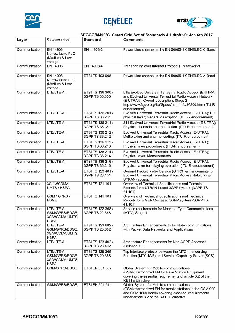
SEGCG/M490/G_Smart Grid Set of Standards 4.1 draft v0; Jan 6th 2017
SEGCG/M490/G 199/266
Layer Category (ies) Standard Comments
Communication EN 14908 Narrow band PLC (Medium & Low voltage)
EN 14908-3 Power Line channel in the EN 50065-1 CENELEC C-Band
Communication EN 14908 EN 14908-4 Transporting over Internet Protocol (IP) networks
Communication EN 14908 Narrow band PLC (Medium & Low voltage)
ETSI TS 103 908 Power Line channel in the EN 50065-1 CENELEC A-Band
Communication LTE/LTE-A ETSI TS 136 300 / 3GPP TS 36.300
LTE Evolved Universal Terrestrial Radio Access (E-UTRA) and Evolved Universal Terrestrial Radio Access Network (E-UTRAN); Overall description; Stage 2 http://www.3gpp.org/ftp/Specs/html-info/36300.htm (ITU-R endorsement)
Communication LTE/LTE-A ETSI TS 136 201 / 3GPP TS 36.201
Evolved Universal Terrestrial Radio Access (E-UTRA); LTE physical layer; General description. (ITU-R endorsement)
Communication LTE/LTE-A ETSI TS 136 211 / 3GPP TS 36. 211
211 Evolved Universal Terrestrial Radio Access (E-UTRA); Physical channels and modulation. (ITU-R endorsement)
Communication LTE/LTE-A ETSI TS 136 212 / 3GPP TS 36.212
Evolved Universal Terrestrial Radio Access (E-UTRA); Multiplexing and channel coding. (ITU-R endorsement)
Communication LTE/LTE-A ETSI TS 136 213 / 3GPP TS 36.213
Evolved Universal Terrestrial Radio Access (E-UTRA); Physical layer procedures. (ITU-R endorsement)
Communication LTE/LTE-A ETSI TS 136 214 / 3GPP TS 36.214
Evolved Universal Terrestrial Radio Access (E-UTRA); Physical layer; Measurements.
Communication LTE/LTE-A ETSI TS 136 216 / 3GPP TS 36.216
Evolved Universal Terrestrial Radio Access (E-UTRA); Physical layer for relaying operation (ITU-R endorsement)
Communication LTE/LTE-A ETSI TS 123 401 / 3GPP TS 23.401
General Packet Radio Service (GPRS) enhancements for Evolved Universal Terrestrial Radio Access Network (E-UTRAN) access
Communication 3G / WCDMA / UMTS / HSPA
ETSI TS 121 101
Overview of Technical Specifications and Technical Reports for a UTRAN-based 3GPP system (3GPP TS 21.101)
Communication GSM / GPRS / EDGE
ETSI TS 141 101
Overview of Technical Specifications and Technical Reports for a GERAN-based 3GPP system (3GPP TS 41.101)
Communication LTE/LTE-A, GSM/GPRS/EDGE, 3G/WCDMA/UMTS/HSPA
ETSI TS 122 368 / 3GPP TS 22.368
Service requirements for Machine-Type Communications (MTC); Stage 1
Communication LTE/LTE-A, GSM/GPRS/EDGE, 3G/WCDMA/UMTS/HSPA
ETSI TS 123 682 / 3GPP TS 23.682
Architecture Enhancements to facilitate communications with Packet Data Networks and Applications
Communication LTE/LTE-A ETSI TS 123 402 / 3GPP TS 23.402
Architecture Enhancements for Non-3GPP Accesses (Release 10)
Communication LTE/LTE-A, GSM/GPRS/EDGE, 3G/WCDMA/UMTS/HSPA
ETSI TS 129 368 3GPP TS 29.368
Tsp interface protocol between the MTC Interworking Function (MTC-IWF) and Service Capability Server (SCS)
Communication GSM/GPRS/EDGE ETSI EN 301 502 Global System for Mobile communications (GSM);Harmonized EN for Base Station Equipment covering the essential requirements of article 3.2 of the R&TTE Directive
Communication GSM/GPRS/EDGE, ETSI EN 301 511 Global System for Mobile communications (GSM);Harmonized EN for mobile stations in the GSM 900 and GSM 1800 bands covering essential requirements under article 3.2 of the R&TTE directive

SEGCG/M490/G_Smart Grid Set of Standards 4.1 draft v0; Jan 6th 2017
SEGCG/M490/G 200/266
Layer Category (ies) Standard Comments
Communication LTE/LTE-A, 3G/WCDMA/UMTS/HSPA
ETSI EN 301 908 Parts 1,2,3,6,7,3,11,13, 14,15,18 - IMT cellular networks;Harmonized EN covering the essential requirements of article 3.2 of the R&TTE Directive
Communication CDMA2000/UMB ETSI EN 301 908 Parts 4, 5, 12, 16, 17 - IMT cellular networks;Harmonized EN covering the essential requirements of article 3.2 of the R&TTE Directive
Communication DSL/PON IEEE 802.3 802.3 application for GEPON
Communication DSL/PON IEEE 802.3av 802.3av application for 10GEPON
Communication DSL/PON ITU-T G.991.1 High bit rate digital subscriber line (HDSL) transceivers
Communication DSL/PON ITU-T G.991.2 Single-pair high-speed digital subscriber line (SHDSL) transceivers
Communication DSL/PON ITU-T G.992.1 Asymmetric digital subscriber line (ADSL) transceivers
Communication DSL/PON ITU-T G.992.2 Splitterless asymmetric digital subscriber line (ADSL) transceivers
Communication DSL/PON ITU-T G.992.3 Asymmetric digital subscriber line transceivers 2 (ADSL2)
Communication DSL/PON ITU-T G.992.4 Splitterless asymmetric digital subscriber line transceivers 2 (splitterless ADSL2)
Communication DSL/PON ITU-T G.993.1 Very high speed digital subscriber line transceivers (VDSL)
Communication DSL/PON ITU-T G.993.2 Very high speed digital subscriber line transceivers 2 (VDSL2)
Communication DSL/PON ITU-T G.993.5 Self-FEXT cancellation (vectoring) for use with VDSL2 transceivers
Communication DSL/PON ITU-T G.994.1 Handshake procedures for digital subscriber line (DSL) transceivers
Communication DSL/PON ITU-T G.995.1 Overview of digital subscriber line (DSL) Recommendations
Communication DSL/PON ITU-T G.996.1 Test procedures for digital subscriber line (DSL) transceivers
Communication DSL/PON ITU-T G.996.2 Single-ended line testing for digital subscriber lines (DSL)
Communication DSL/PON ITU-T G.997.1 Physical layer management for digital subscriber line (DSL) transceivers
Communication DSL/PON ITU-T G.998.1 ATM-based multi-pair bonding
Communication DSL/PON ITU-T G.998.2 Ethernet-based multi-pair bonding
Communication DSL/PON ITU-T G.998.3 Multi-pair bonding using time-division inverse multiplexing
Communication DSL/PON ITU-T G.999.1 Interface between the link layer and the physical layer for digital subscriber line (DSL) transceivers
Communication DSL/PON ITU-T G.998.4 Improved Impulse Noise Protection (INP) for DSL Transceivers
Communication DSL/PON ITU-T G.983.1 Broadband optical access systems based on Passive Optical Networks (PON)
Communication DSL/PON ITU-T G.983.2 ONT management and control interface specification for B-PON
Communication DSL/PON ITU-T G.983.3 A broadband optical access system with increased service capability by wavelength allocation
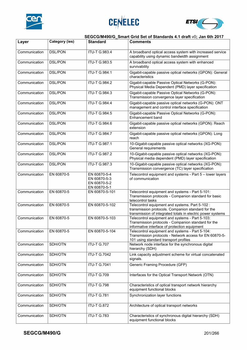
SEGCG/M490/G_Smart Grid Set of Standards 4.1 draft v0; Jan 6th 2017
SEGCG/M490/G 201/266
Layer Category (ies) Standard Comments
Communication DSL/PON ITU-T G.983.4 A broadband optical access system with increased service capability using dynamic bandwidth assignment
Communication DSL/PON ITU-T G.983.5 A broadband optical access system with enhanced survivability
Communication DSL/PON ITU-T G.984.1 Gigabit-capable passive optical networks (GPON): General characteristics
Communication DSL/PON ITU-T G.984.2 Gigabit-capable Passive Optical Networks (G-PON): Physical Media Dependent (PMD) layer specification
Communication DSL/PON ITU-T G.984.3 Gigabit-capable Passive Optical Networks (G-PON): Transmission convergence layer specification
Communication DSL/PON ITU-T G.984.4 Gigabit-capable passive optical networks (G-PON): ONT management and control interface specification
Communication DSL/PON ITU-T G.984.5 Gigabit-capable Passive Optical Networks (G-PON): Enhancement band
Communication DSL/PON ITU-T G.984.6 Gigabit-capable passive optical networks (GPON): Reach extension
Communication DSL/PON ITU-T G.984.7 Gigabit-capable passive optical networks (GPON): Long reach
Communication DSL/PON ITU-T G.987.1 10-Gigabit-capable passive optical networks (XG-PON): General requirements
Communication DSL/PON ITU-T G.987.2 10-Gigabit-capable passive optical networks (XG-PON): Physical media dependent (PMD) layer specification
Communication DSL/PON ITU-T G.987.3 10-Gigabit-capable passive optical networks (XG-PON): Transmission convergence (TC) layer specification
Communication EN 60870-5 EN 60870-5-4 EN 60870-5-3 EN 60870-5-2 EN 60870-5-1
Telecontrol equipment and systems - Part 5 – lower layers of communication
Communication EN 60870-5 EN 60870-5-101 Telecontrol equipment and systems - Part 5-101: Transmission protocols - Companion standard for basic telecontrol tasks
Communication EN 60870-5 EN 60870-5-102 Telecontrol equipment and systems. Part 5-102 : transmission protocols. Companion standard for the transmission of integrated totals in electric power systems
Communication EN 60870-5 EN 60870-5-103 Telecontrol equipment and systems - Part 5-103: Transmission protocols - Companion standard for the informative interface of protection equipment
Communication EN 60870-5 EN 60870-5-104 Telecontrol equipment and systems - Part 5-104: Transmission protocols - Network access for EN 60870-5-101 using standard transport profiles
Communication SDH/OTN ITU-T G.707 Network node interface for the synchronous digital hierarchy (SDH)
Communication SDH/OTN ITU-T G.7042 Link capacity adjustment scheme for virtual concatenated signals.
Communication SDH/OTN ITU-T G.7041 Generic Framing Procedure (GFP)
Communication SDH/OTN ITU-T G.709 Interfaces for the Optical Transport Network (OTN)
Communication SDH/OTN ITU-T G.798 Characteristics of optical transport network hierarchy equipment functional blocks
Communication SDH/OTN ITU-T G.781 Synchronization layer functions
Communication SDH/OTN ITU-T G.872 Architecture of optical transport networks
Communication SDH/OTN ITU-T G.783 Characteristics of synchronous digital hierarchy (SDH) equipment functional blocks

SEGCG/M490/G_Smart Grid Set of Standards 4.1 draft v0; Jan 6th 2017
SEGCG/M490/G 202/266
Layer Category (ies) Standard Comments
Communication SDH/OTN ITU-T G.803 Architecture of transport networks based on the synchronous digital hierarchy (SDH)
Communication IEC 61850 EN 61850-8-1 Ed. 2.0 2011- Communication networks and systems for power utility automation - Part 8-1: Specific communication service mapping (SCSM) - Mappings to MMS (ISO 9506-1 and ISO 9506-2) and to ISO/IEC 8802-3
Communication IEC 61850 EN 61850-9-2 Ed. 2.0:2011- Communication networks and systems in substations - Part 9-2: Specific Communication Service Mapping (SCSM) - Sampled values over ISO/IEC 8802-3
Communication IEC 61850 IEC 61850-90-1 Ed. 1.0:2010 - Communication networks and systems for power utility automation - Part 90-1: Use of IEC/EN 61850 for the communication between substations
Communication IEC 61850 IEC 61850-90-4 Communication networks and systems for power utility automation - Network engineering guidelines
Communication IEC 61850 IEC 61850-90-5 Ed. 1.0:2012 - Communication networks and systems for power utility automation - Part 90-5: Use of IEC/EN 61850 to transmit synchrophasor information according to IEEE C37.118
Communication, Information
IEC 61850 EN 61850-7-1 Ed. 2.0:2011- Communication networks and systems for power utility automation - Part 7-1: Basic communication structure - Principles and models
Communication EN 13757 EN 13757-4 Communication systems for meters and remote reading of meters – Part 4: wireless meter readout (radio meter reading for operation in SRD bands)
Communication EN 13757 EN 13757-5 Communication systems for meters and remote reading of meters – Part 5: wireless relaying
Communication Narrow band PLC (High & very High voltage)
IEC 62488-1 (Formerly EN60663) - Part 1
Planning of analogue and digital power line carrier systems operating over EHV/HV/MV electricity grids.
Communication Broadband PLC ISO/IEC 12139-1 Telecommunications and information exchange between systems — Powerline communication (PLC) — High speed PLC medium access control (MAC) and physical layer (PHY)
Communication Broadband PLC ITU-T G.9960 ITU-T G.9961 ITU-T G.9962 ITU-T G.9963 ITU-T G.9964
Unified high-speed wireline-based home networking : ITU-T G.9960 (PHY) ITU-T G.9961 (DLL) ITU-T G.9962 (MIMO) ITU-T G.9963 (MIMO G.hn) ITU-T G.9964 (PSD)
Communication Narrow band PLC (Medium & Low voltage)
ITU-T G.9901
ITU-T G.9901 (NB-PLC PSD)
Communication Narrow band PLC (Medium & Low voltage)
ITU-T G.9902 ITU-T G.9902 (G.hnem)
Communication Narrow band PLC (Medium & Low voltage)
ITU-T G.9903 ITU-T G.9903 (G3-PLC)
Communication Narrow band PLC (Medium & Low voltage)
ITU-T G.9904 ITU-T G.9904 (PRIME)
Communication Narrow band PLC (Medium & Low voltage)
ITU-T G.9905 ITU-T G.9905 (Routing)
Communication Narrowband wireless”
ITU-T G.9959 ITU-T G.9959 (Z-Wave) Short range narrowband digital radio communication transceivers – PHY & MAC layer specifications
Communication G.fast ITU-T G.9700 Fast access to subscriber terminals (FAST) - Power spectral density specification (G.fast PSD)
Communication Broadband PLC IEEE 1901 Broadband over Power Line Networks

SEGCG/M490/G_Smart Grid Set of Standards 4.1 draft v0; Jan 6th 2017
SEGCG/M490/G 203/266
Layer Category (ies) Standard Comments
Communication Broadband PLC IEEE 1901.2 Standard for Low Frequency (less than 500 kHz) Narrow Band Power Line Communications for Smart Grid Applications
Communication M2M ETSI TR 101 531 Machine-to-Machine communications (M2M); Reuse of Core Network Functionality by M2M Service Capabilities -
Communication M2M ETSI TR 102 935 Machine-to-Machine communications (M2M);. Applicability of M2M architecture to Smart Grid Networks
Communication M2M ETSI TR 102 966 Machine-to-Machine communications (M2M); Interworking between the M2M Architecture and M2M Area Network technologies
Communication M2M ETSI TR 103 167 Machine-to-Machine Communications (M2M); Threat analysis and counter-measures to M2M service layer
Communication M2M ETSI TS 101 584 Machine-to-Machine Communications (M2M);. Study on Semantic support for M2M Data
Communication M2M ETSI TS 102 689 Machine-to-Machine communications (M2M); M2M service requirements
Communication M2M ETSI TS 103 092 Machine-to-Machine communications (M2M); OMA DM compatible Management Objects for ETSI M2M
Communication M2M ETSI TS 103 093 Machine-to-Machine communications (M2M); BBF TR-069 compatible Management Objects for ETSI M2M
Communication M2M ETSI TS 103 104 Machine-to-Machine communications (M2M); Interoperability Test Specification for CoAP Binding of ETSI M2M Primitives
Communication M2M ETSI TS 103 107 ETSI TS 103 107 Machine-to-Machine communications (M2M); Service layer interworking with 3GPP2 networks
Communication M2M ETSI TS 103 603 Machine-to-Machine communications (M2M); Service layer interworking with 3GPP networks
Communication LPWA LoRaWAN Specification 1.0
LoRaWAN™ Specification
Communication LPWA 3GPP Release 13 NB-IOT
Narrow Band IOT
Communication LPWA GS LTN 001 Low Throughput Networks (LTN); Use Cases for Low Throughput Networks
Communication LPWA GS LTN 002 Low Throughput Networks (LTN); Functional Architecture
Communication LPWA GS LTN 003 Low Throughput Networks (LTN); Protocols and Interfaces
3986
9.3.4.2 Coming standards 3987
In compliance with section 6.2.2, a standard that has successfully passed the NWIP process (or any formal 3988 equivalent work item adoption process) by Dec 31st 2015 is considered as “Coming”. 3989 3990
Table 82 - Communication - Coming standards 3991
Layer Standard Comments
Communication EN 50491-12 Smart Grid interface and framework for Customer Energy Management
Communication IEC 62746 IEC 62746- x: Systems Interface between Customer Energy Management and the Power management Systems
Communication CLC prTS 50586 CENELEC/prTS 50586: OSGP (Open Smart Grid Protocol) - Communication protocols, data structures and procedures
Communication CLC prTS 50568-4 CENELEC/prTS 50568-4 ‘Electricity metering data exchange - The Smart Metering Information Tables and
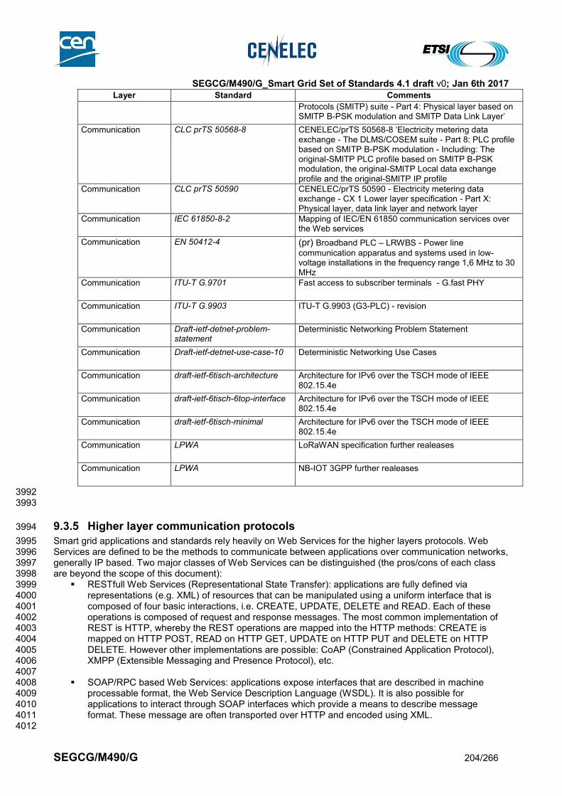
SEGCG/M490/G_Smart Grid Set of Standards 4.1 draft v0; Jan 6th 2017
SEGCG/M490/G 204/266
Layer Standard Comments
Protocols (SMITP) suite - Part 4: Physical layer based on SMITP B-PSK modulation and SMITP Data Link Layer’
Communication CLC prTS 50568-8 CENELEC/prTS 50568-8 ‘Electricity metering data exchange - The DLMS/COSEM suite - Part 8: PLC profile based on SMITP B-PSK modulation - Including: The original-SMITP PLC profile based on SMITP B-PSK modulation, the original-SMITP Local data exchange profile and the original-SMITP IP profile
Communication CLC prTS 50590 CENELEC/prTS 50590 - Electricity metering data exchange - CX 1 Lower layer specification - Part X: Physical layer, data link layer and network layer
Communication IEC 61850-8-2 Mapping of IEC/EN 61850 communication services over the Web services
Communication EN 50412-4 (pr) Broadband PLC – LRWBS - Power line
communication apparatus and systems used in low-voltage installations in the frequency range 1,6 MHz to 30 MHz
Communication ITU-T G.9701 Fast access to subscriber terminals - G.fast PHY
Communication ITU-T G.9903 ITU-T G.9903 (G3-PLC) - revision
Communication Draft-ietf-detnet-problem-statement
Deterministic Networking Problem Statement
Communication Draft-ietf-detnet-use-case-10 Deterministic Networking Use Cases
Communication draft-ietf-6tisch-architecture Architecture for IPv6 over the TSCH mode of IEEE 802.15.4e
Communication draft-ietf-6tisch-6top-interface Architecture for IPv6 over the TSCH mode of IEEE 802.15.4e
Communication draft-ietf-6tisch-minimal Architecture for IPv6 over the TSCH mode of IEEE 802.15.4e
Communication LPWA LoRaWAN specification further realeases
Communication LPWA NB-IOT 3GPP further realeases
3992 3993
9.3.5 Higher layer communication protocols 3994
Smart grid applications and standards rely heavily on Web Services for the higher layers protocols. Web 3995 Services are defined to be the methods to communicate between applications over communication networks, 3996 generally IP based. Two major classes of Web Services can be distinguished (the pros/cons of each class 3997 are beyond the scope of this document): 3998
RESTfull Web Services (Representational State Transfer): applications are fully defined via 3999 representations (e.g. XML) of resources that can be manipulated using a uniform interface that is 4000 composed of four basic interactions, i.e. CREATE, UPDATE, DELETE and READ. Each of these 4001 operations is composed of request and response messages. The most common implementation of 4002 REST is HTTP, whereby the REST operations are mapped into the HTTP methods: CREATE is 4003 mapped on HTTP POST, READ on HTTP GET, UPDATE on HTTP PUT and DELETE on HTTP 4004 DELETE. However other implementations are possible: CoAP (Constrained Application Protocol), 4005 XMPP (Extensible Messaging and Presence Protocol), etc. 4006
4007 SOAP/RPC based Web Services: applications expose interfaces that are described in machine 4008
processable format, the Web Service Description Language (WSDL). It is also possible for 4009 applications to interact through SOAP interfaces which provide a means to describe message 4010 format. These message are often transported over HTTP and encoded using XML. 4011
4012

SEGCG/M490/G_Smart Grid Set of Standards 4.1 draft v0; Jan 6th 2017
SEGCG/M490/G 205/266
More information on these two classes of Web Services is provided by the W3C under this link: 4013 http://www.w3.org/TR/ws-arch/#relwwwrest 4014 4015 NOTE: This section focuses on Web Service as a general technology for information exchange between 4016 Smart Grid applications over communication networks. Other more system specific solutions like MMS/ACSE 4017 which are part of the relevant standards (e.g. IEC 61850-8-1) of the specific systems listed in section 8. Also 4018 the specific usage of web services is defined by the system relevant upcoming standards in section 8 (i.e. 4019 IEC 61850-8-2, IEC 61968-100). 4020 4021
9.3.5.1 List of Standards 4022
9.3.5.1.1 Available standards 4023
In compliance with section 6.2.2, a standard (or “open specification”) that has reached its final stage (IS, TS 4024 or TR, …) by Dec 31st 2015 is considered as “available”. 4025
Table 83 - Higher level communication protocols - Available 4026
Layer Category (ies) Standard Title
Communication XML W3C REC-xml-20001006 W3C, Extensible Markup Language (XML) 1.0
Communication Web Services (general)
W3C WD-ws-arch-20021114
W3C, Web Services Architecture
Communication XML W3C REC-xml-names Name spaces in XML
Communication HTTP IETF RFC 2616 Hypertext Transfer Protocol -- HTTP/1.1
Communication SOAP W3C RECsoap12-part1-20070427
SOAP Version 1.2 Part 1: Messaging Framework
Communication SOAP W3C REC-soap12-part2-20070427
SOAP Version 1.2 Part 2: Adjuncts, Section 7: SOAP HTTP Binding,
Communication SOAP OASIS, wsdd-soapoverudp-1.1-spec-pr-01
OASIS Standard, SOAP-over-UDP
Communication Web Services (general)
IETF RFC 5246 The TLS Protocol, Version 1.2
Communication Web Services (general)
W3C, REC-ws-addrcore-20060509
Web Services Addressing 1.0
Communication SOAP W3C, RECws-addr-soap-20060509,
Web Services Addressing 1.0 - SOAP Binding
Communication Web Services (general)
OASIS, wsdd-discovery-1.1-spec-os
Web Services Dynamic Discovery (WS-Discovery)
Communication Web Services (general)
W3C, SUBM-WSEventing-20060315
Web Services Eventing (WS-Eventing)
Communication WSDL W3C, NOTEwsdl-20010315 Web Services Description Language (WSDL) 1.1,
Communication WSDL W3C, SUBM-wsdl11soap12-20060405
WSDL 1.1 Binding Extension for SOAP 1.2
Communication REST ETSI TS 102 690 Machine-to-Machine communications (M2M); Functional architecture
Communication REST ETSI TS 102 921 Machine-to-Machine communications (M2M); mIa, dIa and mId interfaces
Communication XMPP IETF RFC 6120 Extensible Messaging and Presence Protocol
Communication XMPP IETF RFC 6121 Extensible Messaging and Presence Protocol : Instant Messaging and Presence
Communication XMPP IETF RFC 6122 Extensible Messaging and Presence Protocol : Address Format
Communication XMPP IEC 62746-10-1 IEC PAS – openADR for demand-response

SEGCG/M490/G_Smart Grid Set of Standards 4.1 draft v0; Jan 6th 2017
SEGCG/M490/G 206/266
Layer Category (ies) Standard Title
Communication CoAP IETF RFC 6690 The Constrained Application Protocol (CoAP)
Communication CoAP IETF RFC 7252 The Constrained Application Protocol (CoAP)
Communication CoAP IETF RFC 7390 The Constrained Application Protocol (CoAP)
Communication CoAP IETF RFC 7641 The Constrained Application Protocol (CoAP)
Communication CoAP IETF RFC 7959 The Constrained Application Protocol (CoAP)
Communication Secured communication
W3C XML Digital Signature
XML Signature Syntax and Processing
Communication Secured communication
W3C XML Encryption XML Encryption Syntax and Processing
9.3.5.1.2 Coming standards 4027
In compliance with section 6.2.2, a standard that has successfully passed the NWIP process (or any formal 4028 equivalent work item adoption process) by Dec 31st 2015 is considered as “Coming”. 4029
Table 84 - Higher level communication protocols - Coming 4030
Layer Standard Comments
Communication CoAP draft-ietf-core Follow up / update of CoAP protocol
4031
9.4 Security 4032
This section is summarizing the main outcomes of the SGIS report [11], related to standards and 4033 standardization. 4034
9.4.1 Cyber Security Standardization landscape 4035
4036 Smart Grid Set of Security Standards investigated into selected standards and followed the identified gaps 4037 regarding their resolution in the associated standardization committees. 4038 4039 The Smart Grid Set of Security Standards investigates into selected standards along the work already been 4040 done as part of the SG-CG SGIS in the phase 1 (2011-2012) and phase 2 (2013-2014). The goal of the 4041 current working period (2015-2016) is to follow the already identified standards as well as investigating into 4042 new, upcoming standards, to discuss their applicability and suitability for smart grid scenarios and use cases. 4043 As in the past, the goal, besides the discussion of applicability is the identification of potential gaps and 4044 based on this the interworking with the associated standardization committee in terms of feedback and 4045 proposals as far as possible. 4046 4047 The security standards focused in this working period are distinguished into requirements standards (type 1) 4048 and solution standards (type 2 and type 3) as listed below. Please note that the distinction in requirements 4049 standards and solution standards is a simplification of the type1, 2 and 3 standards from SGIS phase 1 [11]. 4050 In the following the requirement standards summarize the abstract security requirements, while the solution 4051 standards describe a realization targeting interoperability between different vendor’s products. 4052
Requirement standards considered (The ‘What’) 4053
ISO/IEC 27001: Information technology — Security techniques — Information security management 4054 systems — Requirements 4055
ISO/IEC 27002: Information technology — Security techniques — Code of practice for information 4056 security management ISO/IEC TR 27001 4057
ISO/IEC TR 27019: Information technology - Security techniques - Information security management 4058 guidelines based on ISO/IEC 27002 for process control systems specific to the energy utility industry 4059
SEGCG/M490/G_Smart Grid Set of Standards 4.1 draft v0; Jan 6th 2017
SEGCG/M490/G 207/266
IEC 62443-2-4: Security for industrial automation and control systems - Network and system security 4060 - Part 2-4: Requirements for Industrial Automation Control Systems (IACS) solution suppliers 4061
IEC 62443-3-3: Security for industrial automation and control systems, Part 3-3: System security 4062 requirements and security levels 4063
IEC 62443-4-2: Security for industrial automation and control systems, Part 4-2: Technical Security 4064 Requirements for IACS Components 4065
IEEE 1686: Substation Intelligent Electronic Devices (IED) Cyber Security Capabilities 4066
IEEE C37.240: Cyber Security Requirements for Substation Automation, Protection and Control 4067 Systems 4068
Solution standards considered (The ‘How’) 4069
ISO /IEC 15118: Road vehicles – Vehicle-to-Grid Communication Interface, Part 8: Physical and data 4070 link layer requirements for wireless communication 4071
ISO / IEC 61850-8-2: Communication networks and systems for power utility automation - Part 8-2: 4072 Specific communication service mapping (SCSM) - Mapping to Extensible Messaging Presence 4073 Protocol (XMPP) 4074
IEC 62351-x: Power systems management and associated information exchange – Data and 4075 communication security 4076
IEC 62743: Industrial communication networks – Wireless communication network and 4077 communication profiles - ISA 100.11a 4078
IETF draft-weis-gdoi-iec62351-9: IEC 62351 Security Protocol support for the Group Domain of 4079 Interpretation (GDOI) 4080
IETF draft-TLS1.3: TLS Version 1.3 4081
4082 4083 Note: This section below has not been written to specifically include the Smart Metering related standards. 4084 Some specific requirements and standards may be needed to implement a smart metering AMI system 4085 The detailed and specific list of standards to consider for deploying such a system is defined and given by 4086 the SM-CG in [4] and subsequent reports. 4087 4088 . 4089 4090 Standards were analyzed through two axes as illustrated in the figure hereunder. The first one is their 4091 relevance for Organizations (Smart Grid operators) and products and services (product manufacturer and 4092 service providers). The second one is their relevance from a technical point of view and their relevance from 4093 an organizational point of view. 4094
4095
4096

SEGCG/M490/G_Smart Grid Set of Standards 4.1 draft v0; Jan 6th 2017
SEGCG/M490/G 208/266
4097
Figure 74 - SGIS Standards Areas 4098
4099 4100
While mapping a standard to the diagram in the figure above, it is shown on an abstract level, which scope 4101 and to what level of detail the standards addresses each of the four quadrants. Moreover, also addressed is 4102 the relevance of the standards for organizations (Smart Grid operators) as well as products and services 4103 (product manufacturer and service providers). 4104
Figure 75 below shows the mapping of the selected standards to the standards areas under the following 4105 terms: 4106
Details for Operation: The standard addresses organizational and procedural means applicable for all 4107 or selected actors. It may have implicit requirements for systems and components without addressing 4108 implementation options. 4109
Relevance for Products: The standard directly influences component and/or system functionality and 4110 needs to be considered during product design and/or development. It addresses technology to be used 4111 to integrate a security measure. 4112
Design Details: The standard describes the implementation of security means in details sufficient to 4113 achieve interoperability between different vendor’s products for standards on a technical level and/or 4114 procedures to be followed for standards addressing organizational means. 4115
Completeness: The standard addresses not only one specific security measure but addresses the 4116 complete security framework, including technical and organizational means. 4117
The color code in the Figure 75 shows the origin domain of the considered standards. What can be clearly 4118 seen, based on the coloring, is that for Smart Grids standards from different domains are applicable. 4119
4120

SEGCG/M490/G_Smart Grid Set of Standards 4.1 draft v0; Jan 6th 2017
SEGCG/M490/G 209/266
4121
Figure 75: Security Standard Coverage 4122
The following drawing shows the applicability and scope of each of the standards considered as part of this 4123 working period of the SGIS from a somewhat different perspective. The differentiation in the drawing is as 4124 following: 4125
Guideline: The document provides guidelines and best practice for security implementations. This may 4126 also comprise pre-requisites to be available for the implementation. 4127
Requirement: The document contains generic requirements for products, solutions or processes. No 4128 implementation specified. 4129
Realization: The document defines implementation of security measures (specific realizations). Note, if 4130 distinction possible, the level of detail of the document raises from left to right side of the column. 4131
Vendor: Standard addresses technical aspects relevant for products or components 4132
Integrator: Standard addresses integration aspects, which have implications on the technical design, 4133 are relevant for vendor processes (require certain features to be supported), or require product 4134 interoperability (e.g., protocol implementations). 4135
Operator: Standard addresses operational and/or procedural aspects, which are mainly focused on the 4136 service realization and provisioning on an operator site. 4137
The color code from Figure 75 is kept also in the following picture. Some of the standards only cover partly a 4138 certain vertical area. The interpretation of a partly coverage is that the standard may not provide explicit 4139 requirements for the vendor / integrator / operator. Standards covering multiple horizontal areas address 4140 requirements and also provide solution approaches on an abstract level. For the implementation additional 4141 standards or guidelines may be necessary. 4142

SEGCG/M490/G_Smart Grid Set of Standards 4.1 draft v0; Jan 6th 2017
SEGCG/M490/G 210/266
4143
4144 4145
Figure 76: Security standard applicability 4146
The conclusion of this study is key information for the Smart Grid Information Security Landscape. As shown 4147 above (Figure 75 and Figure 76) there are several standards available and mature to be utilized in Smart 4148 Energy Grid applications. Nevertheless there is still a need for investigating in further standards and their 4149 coverage of Smart Energy Grid specific needs. Hence, this exercise (standards gap analysis) is a continuous 4150 process, which will require further investigation into existing and upcoming standards addressing the 4151 evolution of the Smart Grid information security needs. This evolution is especially driven through new use 4152 cases, incorporating communication interactions between new Smart Energy Grid roles and entities. 4153 4154 Besides the investigation into the standard directly, the report focuses on the applicability of specific 4155 standards in the context of access to DER and access to substations. Especially the latter is investigated in 4156 the context of the IEC 62443 framework. The advantage here is the direct application of defined security 4157 levels that cope with the strength of a specific attacker and thus require certain technical means. In 4158 combination with IEC 62351, this allows a comprehensive protection concept on cyber security in the 4159 implementation and offers a reference model to address cyber security on system level. 4160 4161 Also, the SGIS security impact levels (SGIS-SL) from the last SGIS report [11], which have been defined with 4162 the objective to create a bridge between electrical grid operations and information security, have been 4163 investigated together with the security impact levels defined in NISTIR 7628 Rev1. This approach provides a 4164 better base for “translating” between specific scenarios for North America and Europe in the context of 4165 information security. 4166
4167
9.4.2 List of standards 4168
9.4.2.1 Available standards 4169
In compliance with section 6.2.2, a standard (or “open specification”) that has reached its final stage (IS, TS 4170 or TR, …) by Dec 31st 2015 is considered as “available”. 4171
Table 85 - Security - Available standards 4172
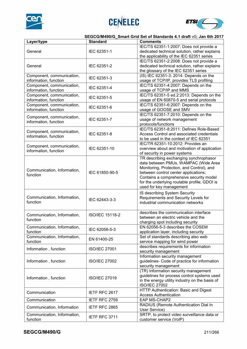
SEGCG/M490/G_Smart Grid Set of Standards 4.1 draft v0; Jan 6th 2017
SEGCG/M490/G 211/266
Layer/type Standard Comments
General IEC 62351-1 IEC/TS 62351-1:2007: Does not provide a dedicated technical solution, rather explains the applicability of the IEC 62351 series
General IEC 62351-2 IEC/TS 62351-2:2008: Does not provide a dedicated technical solution, rather explains the glossary of the IEC 62351 series
Component, communication, information, function
IEC 62351-3 (IS) IEC 62351-3: 2014: Depends on the usage of TCP/IP, provides TLS profiling
Component, communication, information, function
IEC 62351-4 IEC/TS 62351-4:2007: Depends on the usage of TCP/IP and MMS
Component, communication, information, function
IEC 62351-5 IEC/TS 62351-5 ed.2:2013: Depends on the usage of EN 60870-5 and serial protocols
Component, communication, information, function
IEC 62351-6 IEC/TS 62351-6:2007: Depends on the usage of GOOSE and SMV
Component, communication, information, function
IEC 62351-7 IEC/TS 62351-7:2010: Depends on the usage of network management protocols/functions
Component, communication, information, function
IEC 62351-8 IEC/TS 62351-8:2011: Defines Role-Based Access Control and associated credentials to be used in the context of IEC 62351
Component, communication, information, function
IEC 62351-10 IEC/TR 62351-10:2012: Provides an overview about and motivation of application of security in power systems
Communication, Information, function
IEC 61850-90-5
TR describing exchanging synchrophasor data between PMUs, WAMPAC (Wide Area Monitoring, Protection, and Control), and between control center applications; Contains a comprehensive security model for the underlying routable profile; GDOI is used for key management
Communication, Information, function
IEC 62443-3-3
IS describing System Security Requirements and Security Levels for industrial communication networks
Communication, Information, function
ISO/IEC 15118-2
describes the communication interface between an electric vehicle and the charging spot including security
Communication, Information, function
IEC 62056-5-3 EN 62056-5-3 describes the COSEM application layer, including security
Communication, Information, function
EN 61400-25 Set of standards describing also web service mapping for wind power
Information , function ISO/IEC 27001 describes requirements for information security management
Information , function ISO/IEC 27002 Information security management guidelines- Code of practice for information security management
Information , function ISO/IEC 27019
(TR) Information security management guidelines for process control systems used in the energy utility industry on the basis of ISO/IEC 27002
Communication IETF RFC 2617 HTTP Authentication: Basic and Digest Access Authentication
Communication IETF RFC 2759 EAP MS-CHAP2
Communication, Information IETF RFC 2865 RADIUS (Remote Authentication Dial In User Service)
Communication, Information, function
IETF RFC 3711 SRTP, to protect video surveillance data or customer service (VoIP)

SEGCG/M490/G_Smart Grid Set of Standards 4.1 draft v0; Jan 6th 2017
SEGCG/M490/G 212/266
Layer/type Standard Comments
Communication, Information IETF RFC 3748 EAP Base Protocol (includes EAP MD5)
Communication, Information IETF RFC 3923 End-to-End Signing and Object Encryption for XMPP
Communication, Information, function
IETF RFC 4210 Certificate Management Protocol
Communication, Information, function
IETF RFC 4211 Certificate Request Message Format
Communication, Information, function
IETF RFC 4301 IPSec, may be used to realizes VPNs, Or for any other type of IPSec based security mechanisms
Communication, Information, function
IETF RFC 4302 IPSec, may be used to realizes VPNs, Or for any other type of IPSec based security mechanisms
Communication, Information, function
IETF RFC 4303 IPSec, may be used to realizes VPNs; Or for any other type of IPSec based security mechanisms
Communication IETF RFC 4422 SASL Security
Communication, Information, function
IETF RFC 4962 AAA, Network Access, e.g., for service or remote access
Communication IETF RFC 5106 EAP IKEv2
Communication IETF RFC 5216 EAP TLS
Communication, Information, function
IETF RFC 5246 TLS, can be applied, whenever point-to-point TCP/IP needs to be protected
Communication, Information, function
IETF RFC 5247
EAP Framework, Framework for key management, can be used for any type of endpoint, Network Access, e.g., for service or remote access
Communication, Information, function
IETF RFC 5272 Certificate Management over CMS
Communication, Information, function
IETF RFC 5274 CMC Compliance Requirements
Communication, Information, function
IETF RFC 5280
Internet X.509 Public Key Infrastructure Certificate and Certificate Revocation List (CRL) Profile, Base specification for X.509 certificates and certificate handling
Communication IETF RFC 5281 EAP TTLSv1.0
Communication, Information, function
IETF RFC 6272 Identifies the key infrastructure protocols of the Internet Protocol Suite for use in the Smart Grid
Communication, Information, function
IETF RFC 6347
DTLS, Alternative to TLS in UDP-based; meshed-type of networks; can be applied, whenever point-to-point UDP/IP needs to be protected
Communication, Information, function
IETF RFC 6407 GDOI, used, e.g., to provide key management for IEC 61850-90-5
Communication IETF RFC 6749 The OAuth 2.0 Authorization Framework
Communication IETF RFC 6750 The OAuth 2.0 Authorization Framework: Bearer Token Usage
Communication, Information IEEE 802.1X
Specifies port based access control, allowing the restrictive access decisions to networks based on dedicated credentials. It defines the encapsulation of EAP over IEEE 802, also known as EAP over LAN or EAPOL. Includes also the key management, formally specified in IEEE 802.1AF
Communication, Information IEEE 802.1AE Specifies security functionality in terms of connectionless data confidentiality and

SEGCG/M490/G_Smart Grid Set of Standards 4.1 draft v0; Jan 6th 2017
SEGCG/M490/G 213/266
Layer/type Standard Comments
integrity for media access independent protocols. Specifies a security frame format similar to Ethernet
Communication, Information IEEE 802.1AR Specifies unique per-device identifiers and the management and cryptographic binding of a device to its identifiers
General IEEE 1686
defines functions and features that must be provided in substation intelligent electronic devices to accommodate critical infrastructure protection programs
General IEEE P2030
provides a Guide for Smart Grid Interoperability of Energy Technology and Information Technology Operation with the Electric Power System
Communication, Information, function
ETSI TCRTR 029 General overview of features specified on ETSI side
Communication, Information, function
ETSI ETR 332 Security Techniques Advisory Group (STAG); Security requirements capture
Communication, Information, function
ETSI ETR 237
Security Techniques Advisory Group (STAG); Baseline security standards; Features and mechanisms
Communication, Information, function
ETSI ES 202 382
Telecommunications and Internet converged Services and Protocols for Advanced Networking (TISPAN); Security Design Guide; Method and proforma for defining Protection Profiles
Communication, Information, function
ETSI ES 202 383
Telecommunications and Internet converged Services and Protocols for Advanced Networking (TISPAN); Security Design Guide; Method and proforma for defining Security Targets
Communication, Information, function
ETSI EG 202 387
Telecommunications and Internet converged Services and Protocols for Advanced Networking (TISPAN); Security Design Guide; Method for application of Common Criteria to ETSI deliverables
Communication, Information, function
ETSI TS 102 165-1
Telecommunications and Internet converged Services and Protocols for Advanced Networking (TISPAN); Methods and protocols; Part 1: Method and proforma for Threat, Risk, Vulnerability Analysis
Communication, Information, function
ETSI TS 102 165-2
Telecommunications and Internet converged Services and Protocols for Advanced Networking (TISPAN); Methods and protocols; Part 2: Protocol Framework Definition; Security Counter Measures
Communication, Information, function
ETSI EG 202 549
Telecommunications and Internet converged Services and Protocols for Advanced Networking (TISPAN); Design Guide; Application of security countermeasures
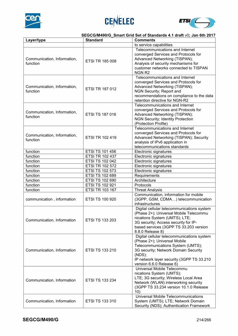
SEGCG/M490/G_Smart Grid Set of Standards 4.1 draft v0; Jan 6th 2017
SEGCG/M490/G 214/266
Layer/type Standard Comments
to service capabilities
Communication, Information, function
ETSI TR 185 008
Telecommunications and Internet converged Services and Protocols for Advanced Networking (TISPAN); Analysis of security mechanisms for customer networks connected to TISPAN NGN R2
Communication, Information, function
ETSI TR 187 012
Telecommunications and Internet converged Services and Protocols for Advanced Networking (TISPAN); NGN Security; Report and recommendations on compliance to the data retention directive for NGN-R2
Communication, Information, function
ETSI TS 187 016
Telecommunications and Internet converged Services and Protocols for Advanced Networking (TISPAN); NGN Security; Identity Protection (Protection Profile)
Communication, Information, function
ETSI TR 102 419
Telecommunications and Internet converged Services and Protocols for Advanced Networking (TISPAN); Security analysis of IPv6 application in telecommunications standards
function ETSI TS 101 456 Electronic signatures
function ETSI TR 102 437 Electronic signatures
function ETSI TS 102 042 Electronic signatures
function ETSI TR 102 572 Electronic signatures
function ETSI TS 102 573 Electronic signatures
function ETSI TS 102 689 Requirements
function ETSI TS 102 690 Architecture
function ETSI TS 102 921 Protocols
function ETSI TR 103 167 Threat Analysis
communication , information ETSI TS 100 920 Communication, information for mobile (3GPP, GSM, CDMA…) telecommunication infrastructures
Communication, Information ETSI TS 133 203
Digital cellular telecommunications system (Phase 2+); Universal Mobile Telecommu nications System (UMTS); LTE; 3G security; Access security for IP- based services (3GPP TS 33.203 version 8.8.0 Release 8)
Communication, Information ETSI TS 133 210
Digital cellular telecommunications system (Phase 2+); Universal Mobile Telecommunications System (UMTS); 3G security; Network Domain Security (NDS); IP network layer security (3GPP TS 33.210 version 6.6.0 Release 6)
Communication, Information ETSI TS 133 234
Universal Mobile Telecommu nications System (UMTS); LTE; 3G security; Wireless Local Area Network (WLAN) interworking security (3GPP TS 33.234 version 10.1.0 Release 10)
Communication, Information ETSI TS 133 310 Universal Mobile Telecommunications System (UMTS); LTE; Network Domain Security (NDS); Authentication Framework
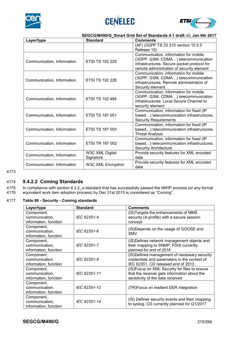
SEGCG/M490/G_Smart Grid Set of Standards 4.1 draft v0; Jan 6th 2017
SEGCG/M490/G 215/266
Layer/type Standard Comments
(AF) (3GPP TS 33.310 version 10.5.0 Release 10)
Communication, Information ETSI TS 102 225
Communication, information for mobile (3GPP, GSM, CDMA…) telecommunication infrastructures. Secure packet protocol for remote administration of security element
Communication, Information ETSI TS 102 226
Communication, information for mobile (3GPP, GSM, CDMA…) telecommunication infrastructures. Remote administration of Security element
Communication, Information ETSI TS 102 484
Communication, information for mobile (3GPP, GSM, CDMA…) telecommunication infrastructures. Local Secure Channel to security element
Communication, Information ETSI TS 187 001 Communication, information for fixed (IP based…) telecommunication infrastructures. Security Requirements
Communication, Information ETSI TS 187 003 Communication, information for fixed (IP based…) telecommunication infrastructures. Threat Analysis
Communication, Information ETSI TR 187 002 Communication, information for fixed (IP based…) telecommunication infrastructures. Security Architecture
Communication, Information W3C XML Digital Signature
Provide security features for XML encoded data
Communication, Information W3C XML Encryption Provide security features for XML encoded data
4173
9.4.2.2 Coming Standards 4174
In compliance with section 6.2.2,¸a standard that has successfully passed the NWIP process (or any formal 4175 equivalent work item adoption process) by Dec 31st 2015 is considered as “Coming”. 4176
Table 86 - Security - Coming standards 4177
Layer/type Standard Comments
Component, communication, information, function
IEC 62351-4 (IS)Targets the enhancements of MMS security (A-profile) with a secure session concept
Component, communication, information, function
IEC 62351-6 (IS)Depends on the usage of GOOSE and SMV
Component, communication, information, function
IEC 62351-7 (IS)Defines network management objects and their mapping to SNMP, FDIS currently planned for end of 2016
Component, communication, information, function
IEC 62351-9 (IS)Defines management of necessary security credentials and parameters in the context of IEC 62351, CD released end of 2013
Component, communication, information, function
IEC 62351-11 (IS)Focus on XML Security for files to ensure that the receiver gets information about the sensitivity of the data received
Component, communication, information, function
IEC 62351-12 (TR)Focus on resilient DER integration
Component, communication, information, function
IEC 62351-14 (IS) Defines security events and their mapping to syslog, CD currently planned for Q1/2017
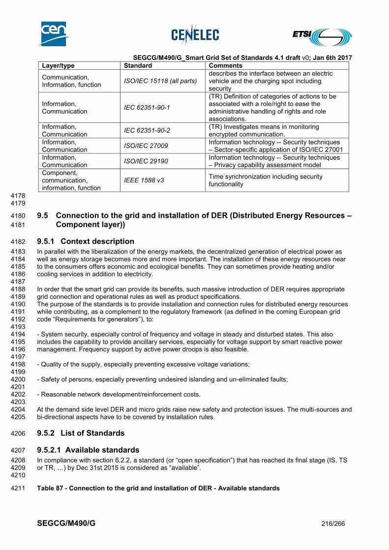
SEGCG/M490/G_Smart Grid Set of Standards 4.1 draft v0; Jan 6th 2017
SEGCG/M490/G 216/266
Layer/type Standard Comments
Communication, Information, function
ISO/IEC 15118 (all parts) describes the interface between an electric vehicle and the charging spot including security
Information, Communication
IEC 62351-90-1
(TR) Definition of categories of actions to be associated with a role/right to ease the administrative handling of rights and role associations.
Information, Communication
IEC 62351-90-2 (TR) Investigates means in monitoring encrypted communication.
Information, Communication
ISO/IEC 27009 Information technology -- Security techniques – Sector-specific application of ISO/IEC 27001
Information, Communication
ISO/IEC 29190 Information technology -- Security techniques – Privacy capability assessment model
Component, communication, information, function
IEEE 1588 v3 Time synchronization including security functionality
4178 4179
9.5 Connection to the grid and installation of DER (Distributed Energy Resources – 4180
Component layer)) 4181
9.5.1 Context description 4182
In parallel with the liberalization of the energy markets, the decentralized generation of electrical power as 4183 well as energy storage becomes more and more important. The installation of these energy resources near 4184 to the consumers offers economic and ecological benefits. They can sometimes provide heating and/or 4185 cooling services in addition to electricity. 4186 4187 In order that the smart grid can provide its benefits, such massive introduction of DER requires appropriate 4188 grid connection and operational rules as well as product specifications. 4189 The purpose of the standards is to provide installation and connection rules for distributed energy resources 4190 while contributing, as a complement to the regulatory framework (as defined in the coming European grid 4191 code “Requirements for generators”), to: 4192 4193 - System security, especially control of frequency and voltage in steady and disturbed states. This also 4194 includes the capability to provide ancillary services, especially for voltage support by smart reactive power 4195 management. Frequency support by active power droops is also feasible. 4196 4197 - Quality of the supply, especially preventing excessive voltage variations; 4198 4199 - Safety of persons, especially preventing undesired islanding and un-eliminated faults; 4200 4201 - Reasonable network development/reinforcement costs. 4202 4203 At the demand side level DER and micro grids raise new safety and protection issues. The multi-sources and 4204 bi-directional aspects have to be covered by installation rules. 4205
9.5.2 List of Standards 4206
9.5.2.1 Available standards 4207
In compliance with section 6.2.2, a standard (or “open specification”) that has reached its final stage (IS, TS 4208 or TR, …) by Dec 31st 2015 is considered as “available”. 4209 4210
Table 87 - Connection to the grid and installation of DER - Available standards 4211

SEGCG/M490/G_Smart Grid Set of Standards 4.1 draft v0; Jan 6th 2017
SEGCG/M490/G 217/266
Layer Standard Comments
Component EN 62446 Grid connected photovoltaic systems - Minimum requirements for system documentation, commissioning tests and inspection
Component EN 61000-4-30 Electromagnetic compatibility (EMC) - Part 4-30: Testing and measurement techniques - Power quality measurement methods
Component IEC 62257 (all parts) (TS) Recommendations for small renewable energy and hybrid systems for rural Electrification
Component EN 60364 (all parts) Electrical installations of buildings – Selection and erection of electrical equipment – Other equipment– generating set Note: Especially the two following parts - 551.6 Additional requirements for installations where the generating set provides a supply as a switched alternative to the public supply (stand-by systems) - 551.7 Additional requirements for installations where the generating set may operate in parallel with the public supply system
Component EN 61400 (all parts) Wind turbines
Component EN 50438 Requirements for the connection of micro-generators in parallel with public low-voltage distribution networks Note: In Europe EN 50438 provide with requirements for connection of micro-generators (currently under revision).
Component TS 50549-1 Requirements for generating plants to be connected in parallel with distribution networks - Part 1: Connection to a LV distribution network, above 16 A
Component TS 50549-2 Requirements for generating plants to be connected in parallel with distribution networks - Part 2: Connection to a MV distribution network
Information IEC 61850-90-7 Object models for Inverter based DER – including ancillary services interface
Component EN 50110-1 Operation of electrical installations
Component IEC 62749 (TS) Characteristics of electricity at supply terminals of public networks: power quality assessment
4212
9.5.2.2 Coming standards 4213
In compliance with section 6.2.2,¸a standard that has successfully passed the NWIP process (or any formal 4214 equivalent work item adoption process) by Dec 31st 2015 is considered as “Coming”. 4215 4216
Table 88 - Connection to the grid and installation of DER - Coming standards 4217
Layer Standard Comments
Component IEC 62786 DER interconnection with the grid
Component IEC 61400-21 Wind turbines - Part 21: Measurement and assessment of power quality characteristics of grid connected wind turbines
Component IEC 61400-27-1 Wind Turbines - Part 27-1: Electrical simulation models for wind power generation
Component EN 50438 Requirements for the connection of micro-generators in parallel with public low-voltage distribution networks Note: In Europe EN 50438 provide with requirements for connection of micro-generators (currently under revision).
Component *prEN 50549-1-1 Requirements for generating plants to be connected in parallel with distribution networks - Part 1-1: Connection to a LV distribution network – Generating plants up to and including Type A

SEGCG/M490/G_Smart Grid Set of Standards 4.1 draft v0; Jan 6th 2017
SEGCG/M490/G 218/266
Layer Standard Comments
Component *prEN 50549-1-2 Requirements for generating plants to be connected in parallel with distribution networks - Part 1-2: Connection to a LV distribution network – Generating plants of Type B
Component *prEN 50549-2 Requirements for generating plants to be connected in parallel with distribution networks - Part 2: Connection to a MV distribution network
Component *prEN 50549-10 Requirements for generating plants to be connected in parallel with distribution networks - Part 10 Tests demonstrating compliance of units
4218 *These standards are intended to be used as a technical reference for connection agreements between DNOs and 4219 electricity producers and to demonstrate compliance with COMMISSION REGULATION (EU) 2016/631 (Requirements 4220 for Generators). They are intended to supersede EN 50438 and TS 50549. 4221 4222
9.6 EMC & Power Quality 4223
4224
9.6.1 Definitions 4225
4226 Electromagnetic compatibility (EMC) is the ability of an equipment or system to function satisfactorily in its 4227 electromagnetic environment without introducing intolerable electromagnetic disturbances to anything in that 4228 environment. 4229 4230 Power quality (PQ) encompasses characteristics of the electric current, voltage and frequencies at a given 4231 point in an electric power system, evaluated against a set of reference technical parameters. 4232 NOTE - These parameters might, in some cases, relate to the compatibility between electricity supplied in an electric power system and 4233 the loads connected to that electric power system. 4234 4235
9.6.2 General 4236
9.6.2.1 Power Quality 4237
4238 Power quality refers usually to the obligations of the Network Operators. 4239 4240 The power quality levels given in standards can be used for customer relationship or for reporting towards 4241 the Authorities. When comparable, the specified levels are close to the Compatibility levels given in the EMC 4242 standards. They cover appropriately the huge majority of locations under acceptable economic conditions, 4243 despite the differences in situations, provided that: 4244
For mass-market products, emission requirements in standards are regularly and appropriately 4245 updated to take into account the development of markets and changes in technologies, 4246
For large installations, emission levels are effectively controlled, e.g. through connection 4247 agreements, 4248
Network operators make use of appropriate methodologies and engineering practices, e.g. based on 4249 planning levels and IEC TR 61000-3-6, 3-7, 3-13 and/or 3-14. 4250
4251 Massive introduction of Distributed Energy Resources can impact the quality of supply experienced by 4252 network users in a number of ways. Examples like magnitude of the supply voltage, harmonic emission and 4253 resonances, increased level of flicker and single rapid voltage changes, increased number of interruptions 4254 due to incorrect operation of the protection are being discussed in several publications. Some impacts are 4255 local, others are global; some impacts are minor and occur only for extreme locations, other impacts are 4256 major and more general. 4257 4258 EN 50160:2010 specifies the characteristics of electricity supplied to customers (at the entry point of user’s 4259 installation) up to 150 kV. 4260 4261

SEGCG/M490/G_Smart Grid Set of Standards 4.1 draft v0; Jan 6th 2017
SEGCG/M490/G 219/266
9.6.2.2 EMC 4262
4263 Electromagnetic Compatibility is a prerequisite for all applications and products and is therefore not limited 4264 and not unique to Smart Grids. It is governed by the Directive 2014/30/EU relating to electromagnetic 4265 compatibility. 4266 For the Smart Grid to function properly and coexist with other electrical and electronic systems, it must be 4267 designed with due consideration for electromagnetic emissions and for immunity to various electromagnetic 4268 phenomena. 4269 4270 EMC must be addressed effectively if the Smart Grid is to achieve its potential and provide its benefits when 4271 deployed. 4272 4273 The design and operation of a Smart Grid shall be consistent with relevant EMC Standards and, in particular 4274 with the EMC Compatibility Standards EN 61000-2-2 (LV) and EN 61000-2-12 (MV). 4275 4276 For a number of “smart” applications (e.g. Electric Vehicle or PLC in the metering domain), EMC will be a 4277 major issue. This will then include compliance with the EN 61000 and 550XX series, besides specific product 4278 standards, if any. 4279 4280 When designing a Smart Grid that utilizes equipment operating in the frequency range 9kHz to 400Ghz, the 4281 user shall show that equipment complies also with the relevant emission requirements of standards such as 4282 EN 55011, EN 55022 or EN 55032. 4283 In terms of equipment immunity, IT equipment used within a Smart Grid shall comply with the requirements 4284 of EN 55024 or prEN 55035 (to be published). 4285 4286 If no product standard (or product family standard) comprising of EMC part(s) exists, the requirements of the 4287 relevant generic EMC standards apply. Particular attention will be paid to prEN 61000-6-5 (Generic 4288 standards – Immunity for equipment used in power station and substation environment), standard under 4289 development, succeeding IEC TS 61000-6-5. It is the task of this generic standard to specify a set of 4290 essential requirements, test procedures and generalized performance criteria applicable to products or 4291 systems operating in this electromagnetic environment. 4292 4293 4294
9.6.2.3 Immunity and emission in the frequency range from 2 kHz to 150 kHz 4295
4296 The change in use of the electricity, especially by the introduction of power electronics equipment (Active 4297 Infeed Converters (AIC) are contributing to many solutions for smart grids) in residential or commercial 4298 environment, increasing the occurrence of voltage components above the frequency range of harmonics up 4299 to 150 kHz, requires the consideration of this frequency range for ensuring EMC. It appeared to be advisable 4300 to urge EMC Committees, as well as those Product Committees defining EMC requirements in their product 4301 standards (TC 22, TC 13, TC57, SC205A …), to review the existing standards or develop new ones in view 4302 of covering the abovementioned gap in EMC standardization. 4303 4304 Technical input in this domain can be found in several reports/publications such as CLC SC205A Study 4305 Report on Electromagnetic Interference between Electrical Equipment / Systems in the Frequency Range 4306 below 150 kHz ed. 2 (SC205A/Sec0339/R, April 2013 ). Nevertheless, further studies are necessary before a 4307 full set of standards providing with immunity and emission requirements can be established. 4308 4309 On the basis of the data available at present, basic publications such as those dealing with Compatibility 4310 Levels (EN 61000-2-2 and EN 61000-2-12) are in progress. Immunity test methods and levels are included 4311 in EN 61000-4-19. Emission limits will follow. 4312 4313
9.6.2.4 Power Quality in a smart grid context 4314
4315
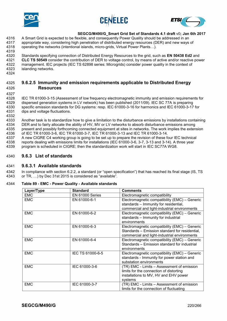
SEGCG/M490/G_Smart Grid Set of Standards 4.1 draft v0; Jan 6th 2017
SEGCG/M490/G 220/266
A Smart Grid is expected to be flexible, and consequently Power Quality should be addressed in an 4316 appropriate way, considering high penetration of distributed energy resources (DER) and new ways of 4317 operating the networks (intentional islands, micro-grids, Virtual Power Plants…). 4318 4319 Standards specifying connection of Distributed Energy Resources to the grid, such as EN 50438 Ed2 and 4320 CLC TS 50549 consider the contribution of DER to voltage control, by means of active and/or reactive power 4321 management. IEC projects (IEC TS 62898 series: Microgrids) consider power quality in the context of 4322 islanding networks. 4323 4324
9.6.2.5 Immunity and emission requirements applicable to Distributed Energy 4325
Resources 4326
4327 IEC TR 61000-3-15 (Assessment of low frequency electromagnetic immunity and emission requirements for 4328 dispersed generation systems in LV network) has been published (2011/09). IEC SC 77A is preparing 4329 specific emission standards for DG systems: resp. IEC 61000-3-16 for harmonics and IEC 61000-3-17 for 4330 dips and voltage fluctuations. 4331 4332 Another task is to standardize how to give a limitation to the disturbance emissions by installations containing 4333 DER and to fairly allocate the ability of HV, MV or LV networks to absorb disturbance emissions among 4334 present and possibly forthcoming connected equipment at sites in networks. The work implies the extension 4335 of IEC TR 61000-3-6, IEC TR 61000-3-7, IEC TR 61000-3-13 and IEC TR 61000-3-14. 4336 A new CIGRE C4 working group is going to be set up to prepare the revision of these four IEC technical 4337 reports dealing with emissions limits for installations (IEC 61000-3-6, 3-7, 3-13 and 3-14). A three year 4338 program is scheduled in CIGRE; then the standardization work will start in IEC SC77A WG8. 4339
9.6.3 List of standards 4340
9.6.3.1 Available standards 4341
In compliance with section 6.2.2, a standard (or “open specification”) that has reached its final stage (IS, TS 4342 or TR, …) by Dec 31st 2015 is considered as “available”. 4343
Table 89 - EMC - Power Quality - Available standards 4344
Layer/Type Standard Comments
EMC EN 61000 Series Electromagnetic compatibility
EMC EN 61000-6-1 Electromagnetic compatibility (EMC) – Generic standards – Immunity for residential, commercial and light-industrial environments
EMC EN 61000-6-2 Electromagnetic compatibility (EMC) – Generic standards – Immunity for industrial environments
EMC EN 61000-6-3 Electromagnetic compatibility (EMC) – Generic Standards – Emission standard for residential, commercial and light-industrial environments
EMC EN 61000-6-4 Electromagnetic compatibility (EMC) – Generic Standards – Emission standard for industrial environments
EMC IEC TS 61000-6-5 Electromagnetic compatibility (EMC) – Generic standards - Immunity for power station and substation environments
EMC IEC 61000-3-6 (TR) EMC - Limits – Assessment of emission limits for the connection of distorting installations to MV, HV and EHV power systems
EMC IEC 61000-3-7 (TR) EMC - Limits – Assessment of emission limits for the connection of fluctuating

SEGCG/M490/G_Smart Grid Set of Standards 4.1 draft v0; Jan 6th 2017
SEGCG/M490/G 221/266
Layer/Type Standard Comments
installations to MV, HV and EHV power systems
EMC IEC 61000-3-13 (TR) EMC - Limits – Assessment of emission limits for the connection of unbalanced installations to MV, HV and EHV power systems
EMC IEC 61000-3-14 (TR) EMC - Assessment of emission limits for the connection of disturbing installations to LV power systems
EMC IEC 61000-3-15 (TR) Assessment of low frequency electromagnetic immunity and emission requirements for dispersed generation systems in LV network
EMC EN 55011 Industrial, scientific and medical equipment — Radio-frequency disturbance characteristics — Limits and methods of measurement.
EMC EN 55022 Information technology equipment - Radio disturbance characteristics - Limits and methods of measurement
EMC EN 55032 Electromagnetic compatibility of multimedia equipment - Emission requirements
EMC EN 55024 Information technology equipment - Immunity characteristics - Limits and methods of measurement
EMC EN 50065-2-3 Signaling on low-voltage electrical installations in the frequency range 3 kHz to 148,5 kHz -- Part 2-3: Immunity requirements for mains communications equipment and systems operating in the range of frequencies 3 kHz to 95 kHz and intended for use by electricity suppliers and distributors
EMC EN 50065-7 Signaling on low-voltage electrical installations in the frequency range 3 kHz to 148,5 kHz - Part 7: Equipment impedance
EMC CLC TR 50579 Electricity metering equipment - Severity levels, immunity requirements and test methods for conducted disturbances in the frequency range 2 -150 kHz
Power Quality EN 50160 Voltage characteristics of electricity supplied by public electricity networks
Power Quality CLC TR 50422 Application Guide for EN 50160 - Maintenance of an existing report, including (informative) annexes on impact of DER and voltage/current components in the 2-150kHz range
EMC EN 61000-6-5 Electromagnetic compatibility (EMC) – Generic standards - Immunity for power station and substation environments
EMC EN 61000-4-30 Power Quality measurement methods including an (informative) annex for measurement methods in the 2-150kHz range
EMC EN 61000-4-19 Immunity to conducted, differential mode disturbances in the frequency 2 – 150 kHz at a.c. ports.
4345
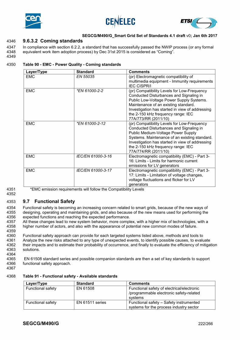
SEGCG/M490/G_Smart Grid Set of Standards 4.1 draft v0; Jan 6th 2017
SEGCG/M490/G 222/266
9.6.3.2 Coming standards 4346
In compliance with section 6.2.2, a standard that has successfully passed the NWIP process (or any formal 4347 equivalent work item adoption process) by Dec 31st 2015 is considered as “Coming”. 4348 4349
Table 90 - EMC - Power Quality - Coming standards 4350
Layer/Type Standard Comments
EMC EN 55035 (pr) Electromagnetic compatibility of multimedia equipment - Immunity requirements IEC CISPR/I
EMC *EN 61000-2-2 (pr) Compatibility Levels for Low-Frequency Conducted Disturbances and Signaling in Public Low-Voltage Power Supply Systems. Maintenance of an existing standard. Investigation has started in view of addressing the 2-150 kHz frequency range: IEC 77A/773/RR (2011/10)
EMC *EN 61000-2-12 (pr) Compatibility Levels for Low-Frequency Conducted Disturbances and Signaling in Public Medium-Voltage Power Supply Systems. Maintenance of an existing standard. Investigation has started in view of addressing the 2-150 kHz frequency range: IEC 77A/774/RR (2011/10)
EMC IEC/EN 61000-3-16 Electromagnetic compatibility (EMC) - Part 3-16: Limits - Limits for harmonic current emissions for LV generators
EMC IEC/EN 61000-3-17 Electromagnetic compatibility (EMC) - Part 3-17: Limits - Limitation of voltage changes, voltage fluctuations and flicker for LV generators
*EMC emission requirements will follow the Compatibility Levels 4351 4352
9.7 Functional Safety 4353
Functional safety is becoming an increasing concern related to smart grids, because of the new ways of 4354 designing, operating and maintaining grids, and also because of the new means used for performing the 4355 expected functions and reaching the expected performance. 4356 All these changes lead to new system behavior, more complex, with a higher mix of technologies, with a 4357 higher number of actors, and also with the appearance of potential new common modes of failure. 4358 4359 Functional safety approach can provide for each targeted systems listed above, methods and tools to 4360 Analyze the new risks attached to any type of unexpected events, to identify possible causes, to evaluate 4361 their impacts and to estimate their probability of occurrence, and finally to evaluate the efficiency of mitigation 4362 solutions. 4363 4364 EN 61508 standard series and possible companion standards are then a set of key standards to support 4365 functional safety approach. 4366 4367
Table 91 - Functional safety - Available standards 4368
Layer/Type Standard Comments
Functional safety EN 61508 Functional safety of electrical/electronic /programmable electronic safety-related systems
Functional safety EN 61511 series Functional safety – Safety instrumented systems for the process industry sector

SEGCG/M490/G_Smart Grid Set of Standards 4.1 draft v0; Jan 6th 2017
SEGCG/M490/G 223/266
Functional safety EN 61010-2-201 Safety requirements for electrical equipment for measurement, control and laboratory use - Part 2-201: Particular requirements for control equipment
4369 4370
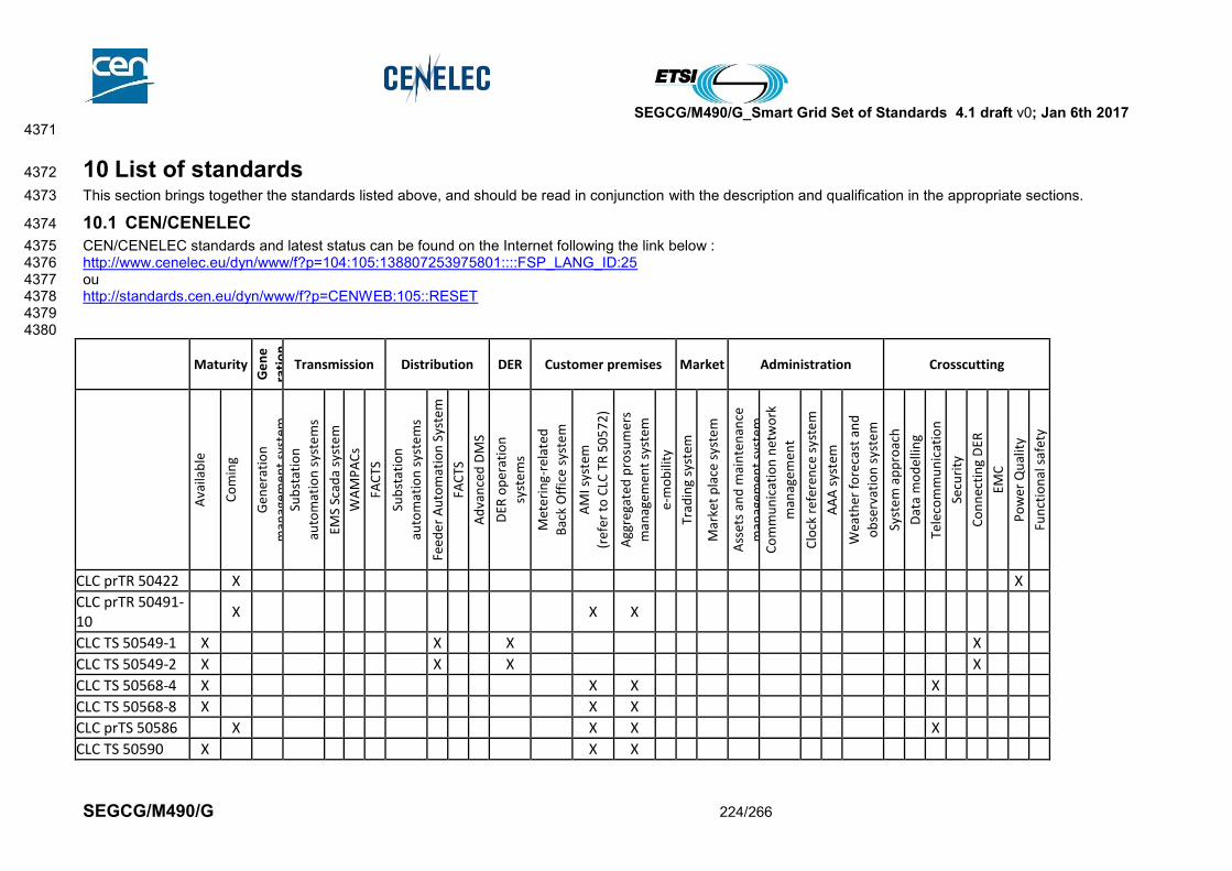
SEGCG/M490/G_Smart Grid Set of Standards 4.1 draft v0; Jan 6th 2017
SEGCG/M490/G 224/266
4371
10 List of standards 4372
This section brings together the standards listed above, and should be read in conjunction with the description and qualification in the appropriate sections. 4373
10.1 CEN/CENELEC 4374
CEN/CENELEC standards and latest status can be found on the Internet following the link below : 4375 http://www.cenelec.eu/dyn/www/f?p=104:105:138807253975801::::FSP_LANG_ID:25 4376 ou 4377 http://standards.cen.eu/dyn/www/f?p=CENWEB:105::RESET 4378 4379 4380
Maturity
Ge
ne
rati
on
Transmission Distribution DER Customer premises Market Administration Crosscutting
Ava
ilab
le
Co
min
g
Gen
erat
ion
man
agem
ent
syst
em
Sub
stat
ion
auto
mat
ion
sys
tem
s
EMS
Scad
a sy
ste
m
WA
MP
AC
s
FAC
TS
Sub
stat
ion
auto
mat
ion
sys
tem
s
Feed
er
Au
tom
atio
n S
yste
m
FAC
TS
Ad
van
ced
DM
S
DER
op
erat
ion
syst
em
s
Met
erin
g-re
late
d
Bac
k O
ffic
e sy
ste
m
AM
I sys
tem
(ref
er t
o C
LC T
R 5
05
72
)
Agg
rega
ted
pro
sum
ers
man
agem
ent
syst
em
e-m
ob
ility
Trad
ing
syst
em
Mar
ket
pla
ce s
yste
m
Ass
ets
and
mai
nte
nan
ce
man
agem
ent
syst
em
Co
mm
un
icat
ion
net
wo
rk
man
agem
ent
Clo
ck r
efer
ence
sys
tem
AA
A s
yste
m
Wea
ther
fo
reca
st a
nd
ob
serv
atio
n s
yste
m
Syst
em
ap
pro
ach
Dat
a m
od
ellin
g
Tele
com
mu
nic
atio
n
Secu
rity
Co
nn
ecti
ng
DER
EMC
Po
wer
Qu
alit
y
Fun
ctio
nal
saf
ety
CLC prTR 50422 X X
CLC prTR 50491-10
X X X
CLC TS 50549-1 X X X X
CLC TS 50549-2 X X X X
CLC TS 50568-4 X X X X
CLC TS 50568-8 X X X
CLC prTS 50586 X X X X
CLC TS 50590 X X X
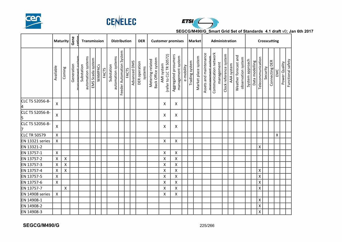
SEGCG/M490/G_Smart Grid Set of Standards 4.1 draft v0; Jan 6th 2017
SEGCG/M490/G 225/266
Maturity
Ge
ne
rati
on
Transmission Distribution DER Customer premises Market Administration Crosscutting
Ava
ilab
le
Co
min
g
Gen
erat
ion
man
agem
ent
syst
em
Sub
stat
ion
auto
mat
ion
sys
tem
s
EMS
Scad
a sy
ste
m
WA
MP
AC
s
FAC
TS
Sub
stat
ion
auto
mat
ion
sys
tem
s
Feed
er
Au
tom
atio
n S
yste
m
FAC
TS
Ad
van
ced
DM
S
DER
op
erat
ion
syst
em
s
Met
erin
g-re
late
d
Bac
k O
ffic
e sy
ste
m
AM
I sys
tem
(ref
er t
o C
LC T
R 5
05
72
)
Agg
rega
ted
pro
sum
ers
man
agem
ent
syst
em
e-m
ob
ility
Trad
ing
syst
em
Mar
ket
pla
ce s
yste
m
Ass
ets
and
mai
nte
nan
ce
man
agem
ent
syst
em
Co
mm
un
icat
ion
net
wo
rk
man
agem
ent
Clo
ck r
efer
ence
sys
tem
AA
A s
yste
m
Wea
ther
fo
reca
st a
nd
ob
serv
atio
n s
yste
m
Syst
em
ap
pro
ach
Dat
a m
od
ellin
g
Tele
com
mu
nic
atio
n
Secu
rity
Co
nn
ecti
ng
DER
EMC
Po
wer
Qu
alit
y
Fun
ctio
nal
saf
ety
CLC TS 52056-8-4
X X X
CLC TS 52056-8-5
X X X
CLC TS 52056-8-7
X X X
CLC TR 50579 X X
EN 13321 series X X X
EN 13321-2 X
EN 13757-1 X X X
EN 13757-2 X X X X
EN 13757-3 X X X X
EN 13757-4 X X X X X
EN 13757-5 X X X X
EN 13757-6 X X X X
EN 13757-7 X X X X
EN 14908 series X X X
EN 14908-1 X
EN 14908-2 X
EN 14908-3 X
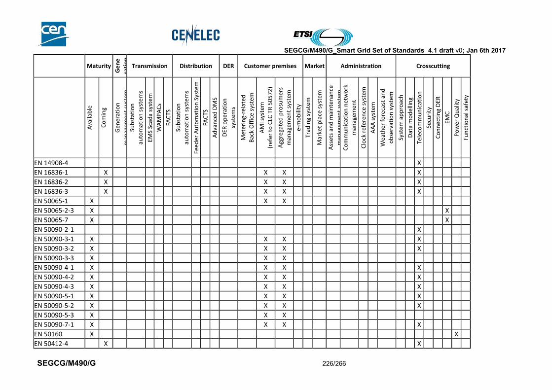
SEGCG/M490/G_Smart Grid Set of Standards 4.1 draft v0; Jan 6th 2017
SEGCG/M490/G 226/266
Maturity
Ge
ne
rati
on
Transmission Distribution DER Customer premises Market Administration Crosscutting
Ava
ilab
le
Co
min
g
Gen
erat
ion
man
agem
ent
syst
em
Sub
stat
ion
auto
mat
ion
sys
tem
s
EMS
Scad
a sy
ste
m
WA
MP
AC
s
FAC
TS
Sub
stat
ion
auto
mat
ion
sys
tem
s
Feed
er
Au
tom
atio
n S
yste
m
FAC
TS
Ad
van
ced
DM
S
DER
op
erat
ion
syst
em
s
Met
erin
g-re
late
d
Bac
k O
ffic
e sy
ste
m
AM
I sys
tem
(ref
er t
o C
LC T
R 5
05
72
)
Agg
rega
ted
pro
sum
ers
man
agem
ent
syst
em
e-m
ob
ility
Trad
ing
syst
em
Mar
ket
pla
ce s
yste
m
Ass
ets
and
mai
nte
nan
ce
man
agem
ent
syst
em
Co
mm
un
icat
ion
net
wo
rk
man
agem
ent
Clo
ck r
efer
ence
sys
tem
AA
A s
yste
m
Wea
ther
fo
reca
st a
nd
ob
serv
atio
n s
yste
m
Syst
em
ap
pro
ach
Dat
a m
od
ellin
g
Tele
com
mu
nic
atio
n
Secu
rity
Co
nn
ecti
ng
DER
EMC
Po
wer
Qu
alit
y
Fun
ctio
nal
saf
ety
EN 14908-4 X
EN 16836-1 X X X X
EN 16836-2 X X X X
EN 16836-3 X X X X
EN 50065-1 X X X
EN 50065-2-3 X X
EN 50065-7 X X
EN 50090-2-1 X
EN 50090-3-1 X X X X
EN 50090-3-2 X X X X
EN 50090-3-3 X X X
EN 50090-4-1 X X X X
EN 50090-4-2 X X X X
EN 50090-4-3 X X X X
EN 50090-5-1 X X X X
EN 50090-5-2 X X X X
EN 50090-5-3 X X X
EN 50090-7-1 X X X X
EN 50160 X X
EN 50412-4 X X
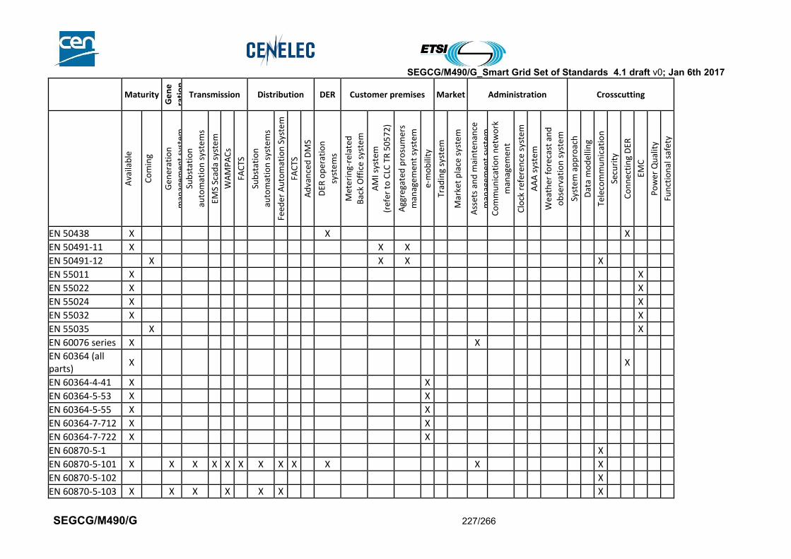
SEGCG/M490/G_Smart Grid Set of Standards 4.1 draft v0; Jan 6th 2017
SEGCG/M490/G 227/266
Maturity
Ge
ne
rati
on
Transmission Distribution DER Customer premises Market Administration Crosscutting
Ava
ilab
le
Co
min
g
Gen
erat
ion
man
agem
ent
syst
em
Sub
stat
ion
auto
mat
ion
sys
tem
s
EMS
Scad
a sy
ste
m
WA
MP
AC
s
FAC
TS
Sub
stat
ion
auto
mat
ion
sys
tem
s
Feed
er
Au
tom
atio
n S
yste
m
FAC
TS
Ad
van
ced
DM
S
DER
op
erat
ion
syst
em
s
Met
erin
g-re
late
d
Bac
k O
ffic
e sy
ste
m
AM
I sys
tem
(ref
er t
o C
LC T
R 5
05
72
)
Agg
rega
ted
pro
sum
ers
man
agem
ent
syst
em
e-m
ob
ility
Trad
ing
syst
em
Mar
ket
pla
ce s
yste
m
Ass
ets
and
mai
nte
nan
ce
man
agem
ent
syst
em
Co
mm
un
icat
ion
net
wo
rk
man
agem
ent
Clo
ck r
efer
ence
sys
tem
AA
A s
yste
m
Wea
ther
fo
reca
st a
nd
ob
serv
atio
n s
yste
m
Syst
em
ap
pro
ach
Dat
a m
od
ellin
g
Tele
com
mu
nic
atio
n
Secu
rity
Co
nn
ecti
ng
DER
EMC
Po
wer
Qu
alit
y
Fun
ctio
nal
saf
ety
EN 50438 X X X
EN 50491-11 X X X
EN 50491-12 X X X X
EN 55011 X X
EN 55022 X X
EN 55024 X X
EN 55032 X X
EN 55035 X X
EN 60076 series X X
EN 60364 (all parts)
X X
EN 60364-4-41 X X
EN 60364-5-53 X X
EN 60364-5-55 X X
EN 60364-7-712 X X
EN 60364-7-722 X X
EN 60870-5-1 X
EN 60870-5-101 X X X X X X X X X X X X
EN 60870-5-102 X
EN 60870-5-103 X X X X X X X

SEGCG/M490/G_Smart Grid Set of Standards 4.1 draft v0; Jan 6th 2017
SEGCG/M490/G 228/266
Maturity
Ge
ne
rati
on
Transmission Distribution DER Customer premises Market Administration Crosscutting
Ava
ilab
le
Co
min
g
Gen
erat
ion
man
agem
ent
syst
em
Sub
stat
ion
auto
mat
ion
sys
tem
s
EMS
Scad
a sy
ste
m
WA
MP
AC
s
FAC
TS
Sub
stat
ion
auto
mat
ion
sys
tem
s
Feed
er
Au
tom
atio
n S
yste
m
FAC
TS
Ad
van
ced
DM
S
DER
op
erat
ion
syst
em
s
Met
erin
g-re
late
d
Bac
k O
ffic
e sy
ste
m
AM
I sys
tem
(ref
er t
o C
LC T
R 5
05
72
)
Agg
rega
ted
pro
sum
ers
man
agem
ent
syst
em
e-m
ob
ility
Trad
ing
syst
em
Mar
ket
pla
ce s
yste
m
Ass
ets
and
mai
nte
nan
ce
man
agem
ent
syst
em
Co
mm
un
icat
ion
net
wo
rk
man
agem
ent
Clo
ck r
efer
ence
sys
tem
AA
A s
yste
m
Wea
ther
fo
reca
st a
nd
ob
serv
atio
n s
yste
m
Syst
em
ap
pro
ach
Dat
a m
od
ellin
g
Tele
com
mu
nic
atio
n
Secu
rity
Co
nn
ecti
ng
DER
EMC
Po
wer
Qu
alit
y
Fun
ctio
nal
saf
ety
EN 60870-5-104 X X X X X X X X X X X X
EN 60870-5-2 X
EN 60870-5-3 X
EN 60870-5-4 X
EN 60870-5-5 X
EN 60870-6 X X
EN 60870-6-2 X X
EN 60870-6-501 X X
EN 60870-6-502 X X
EN 60870-6-503 X X
EN 60870-6-601 X X
EN 60870-6-701 X X
EN 60870-6-702 X X
EN 60870-6-802 X X
EN 61000 Series X X
EN 61000-2-12 X X
EN 61000-2-2 X X
EN 61000-4-19 X X
EN 61000-4-30 X X X
EN 61000-6-1 X X

SEGCG/M490/G_Smart Grid Set of Standards 4.1 draft v0; Jan 6th 2017
SEGCG/M490/G 229/266
Maturity
Ge
ne
rati
on
Transmission Distribution DER Customer premises Market Administration Crosscutting
Ava
ilab
le
Co
min
g
Gen
erat
ion
man
agem
ent
syst
em
Sub
stat
ion
auto
mat
ion
sys
tem
s
EMS
Scad
a sy
ste
m
WA
MP
AC
s
FAC
TS
Sub
stat
ion
auto
mat
ion
sys
tem
s
Feed
er
Au
tom
atio
n S
yste
m
FAC
TS
Ad
van
ced
DM
S
DER
op
erat
ion
syst
em
s
Met
erin
g-re
late
d
Bac
k O
ffic
e sy
ste
m
AM
I sys
tem
(ref
er t
o C
LC T
R 5
05
72
)
Agg
rega
ted
pro
sum
ers
man
agem
ent
syst
em
e-m
ob
ility
Trad
ing
syst
em
Mar
ket
pla
ce s
yste
m
Ass
ets
and
mai
nte
nan
ce
man
agem
ent
syst
em
Co
mm
un
icat
ion
net
wo
rk
man
agem
ent
Clo
ck r
efer
ence
sys
tem
AA
A s
yste
m
Wea
ther
fo
reca
st a
nd
ob
serv
atio
n s
yste
m
Syst
em
ap
pro
ach
Dat
a m
od
ellin
g
Tele
com
mu
nic
atio
n
Secu
rity
Co
nn
ecti
ng
DER
EMC
Po
wer
Qu
alit
y
Fun
ctio
nal
saf
ety
EN 61000-6-2 X X
EN 61000-6-3 X X
EN 61000-6-4 X X
EN 61000-6-5 X X
EN 61131 X X X
EN 61158 X X X X X
EN 61175-1 X X
EN 61334 X X
EN 61355-1 X X
EN 61360 X X X X
EN 61400 (all parts)
X X X
EN 61400-1 X X X
EN 61400-2 X X X
EN 61400-25 (all parts)
X X X X X
EN 61400-25-1 X X X X
EN 61400-25-2 X X X
EN 61400-25-3 X X X
EN 61400-25-4 X X X X X
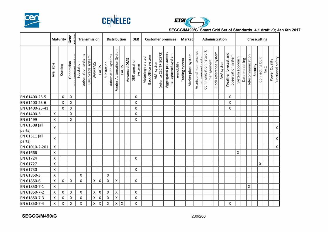
SEGCG/M490/G_Smart Grid Set of Standards 4.1 draft v0; Jan 6th 2017
SEGCG/M490/G 230/266
Maturity
Ge
ne
rati
on
Transmission Distribution DER Customer premises Market Administration Crosscutting
Ava
ilab
le
Co
min
g
Gen
erat
ion
man
agem
ent
syst
em
Sub
stat
ion
auto
mat
ion
sys
tem
s
EMS
Scad
a sy
ste
m
WA
MP
AC
s
FAC
TS
Sub
stat
ion
auto
mat
ion
sys
tem
s
Feed
er
Au
tom
atio
n S
yste
m
FAC
TS
Ad
van
ced
DM
S
DER
op
erat
ion
syst
em
s
Met
erin
g-re
late
d
Bac
k O
ffic
e sy
ste
m
AM
I sys
tem
(ref
er t
o C
LC T
R 5
05
72
)
Agg
rega
ted
pro
sum
ers
man
agem
ent
syst
em
e-m
ob
ility
Trad
ing
syst
em
Mar
ket
pla
ce s
yste
m
Ass
ets
and
mai
nte
nan
ce
man
agem
ent
syst
em
Co
mm
un
icat
ion
net
wo
rk
man
agem
ent
Clo
ck r
efer
ence
sys
tem
AA
A s
yste
m
Wea
ther
fo
reca
st a
nd
ob
serv
atio
n s
yste
m
Syst
em
ap
pro
ach
Dat
a m
od
ellin
g
Tele
com
mu
nic
atio
n
Secu
rity
Co
nn
ecti
ng
DER
EMC
Po
wer
Qu
alit
y
Fun
ctio
nal
saf
ety
EN 61400-25-5 X X X X
EN 61400-25-6 X X X X
EN 61400-25-41 X X X X
EN 61400-3 X X X
EN 61499 X X X
EN 61508 (all parts)
X X
EN 61511 (all parts)
X X
EN 61010-2-201 X X
EN 61666 X X
EN 61724 X X
EN 61727 X X
EN 61730 X X
EN 61850-3 X X X
EN 61850-6 X X X X X X X X X
EN 61850-7-1 X X
EN 61850-7-2 X X X X X X X X X
EN 61850-7-3 X X X X X X X X X
EN 61850-7-4 X X X X X X X X X X X
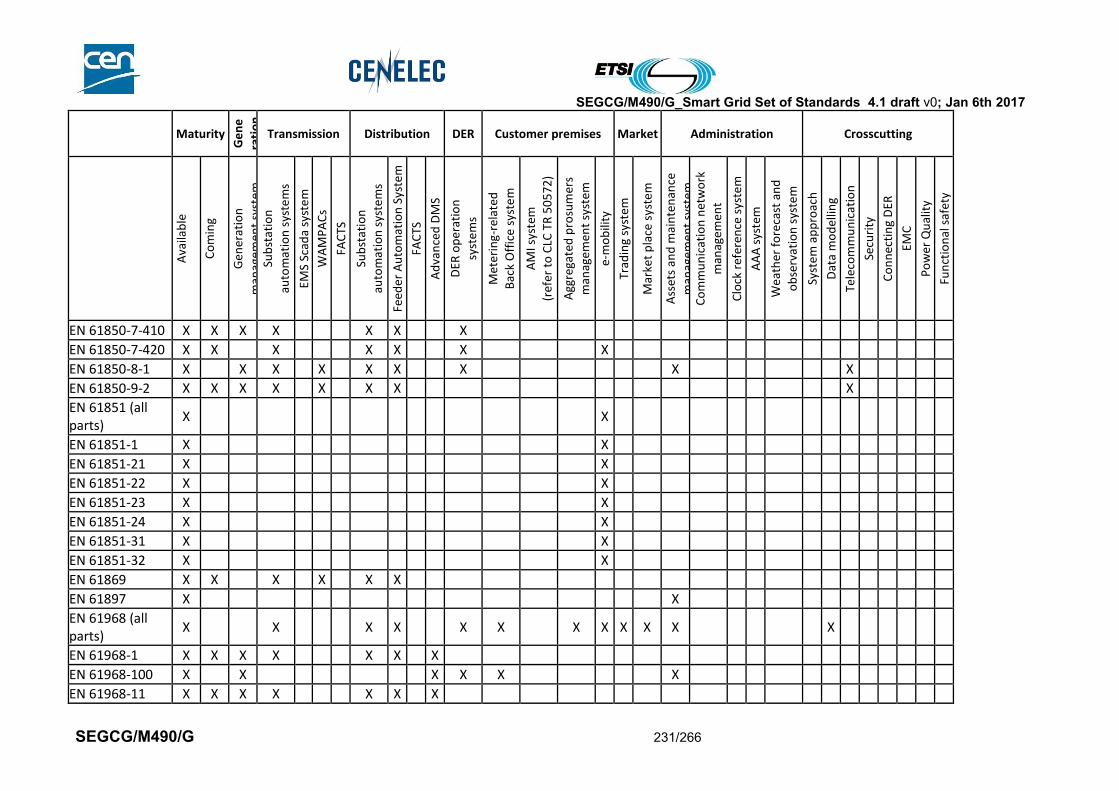
SEGCG/M490/G_Smart Grid Set of Standards 4.1 draft v0; Jan 6th 2017
SEGCG/M490/G 231/266
Maturity
Ge
ne
rati
on
Transmission Distribution DER Customer premises Market Administration Crosscutting
Ava
ilab
le
Co
min
g
Gen
erat
ion
man
agem
ent
syst
em
Sub
stat
ion
auto
mat
ion
sys
tem
s
EMS
Scad
a sy
ste
m
WA
MP
AC
s
FAC
TS
Sub
stat
ion
auto
mat
ion
sys
tem
s
Feed
er
Au
tom
atio
n S
yste
m
FAC
TS
Ad
van
ced
DM
S
DER
op
erat
ion
syst
em
s
Met
erin
g-re
late
d
Bac
k O
ffic
e sy
ste
m
AM
I sys
tem
(ref
er t
o C
LC T
R 5
05
72
)
Agg
rega
ted
pro
sum
ers
man
agem
ent
syst
em
e-m
ob
ility
Trad
ing
syst
em
Mar
ket
pla
ce s
yste
m
Ass
ets
and
mai
nte
nan
ce
man
agem
ent
syst
em
Co
mm
un
icat
ion
net
wo
rk
man
agem
ent
Clo
ck r
efer
ence
sys
tem
AA
A s
yste
m
Wea
ther
fo
reca
st a
nd
ob
serv
atio
n s
yste
m
Syst
em
ap
pro
ach
Dat
a m
od
ellin
g
Tele
com
mu
nic
atio
n
Secu
rity
Co
nn
ecti
ng
DER
EMC
Po
wer
Qu
alit
y
Fun
ctio
nal
saf
ety
EN 61850-7-410 X X X X X X X
EN 61850-7-420 X X X X X X X
EN 61850-8-1 X X X X X X X X X
EN 61850-9-2 X X X X X X X X
EN 61851 (all parts)
X X
EN 61851-1 X X
EN 61851-21 X X
EN 61851-22 X X
EN 61851-23 X X
EN 61851-24 X X
EN 61851-31 X X
EN 61851-32 X X
EN 61869 X X X X X X
EN 61897 X X
EN 61968 (all parts)
X X X X X X X X X X X X
EN 61968-1 X X X X X X X
EN 61968-100 X X X X X X
EN 61968-11 X X X X X X X
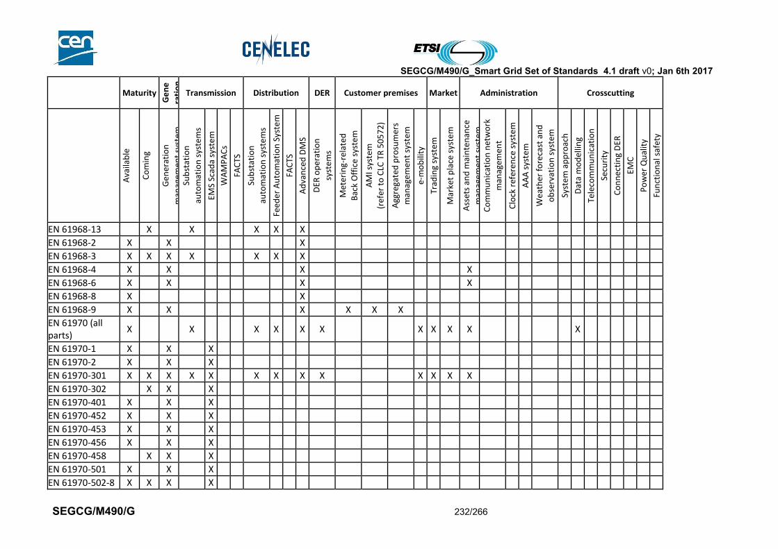
SEGCG/M490/G_Smart Grid Set of Standards 4.1 draft v0; Jan 6th 2017
SEGCG/M490/G 232/266
Maturity
Ge
ne
rati
on
Transmission Distribution DER Customer premises Market Administration Crosscutting
Ava
ilab
le
Co
min
g
Gen
erat
ion
man
agem
ent
syst
em
Sub
stat
ion
auto
mat
ion
sys
tem
s
EMS
Scad
a sy
ste
m
WA
MP
AC
s
FAC
TS
Sub
stat
ion
auto
mat
ion
sys
tem
s
Feed
er
Au
tom
atio
n S
yste
m
FAC
TS
Ad
van
ced
DM
S
DER
op
erat
ion
syst
em
s
Met
erin
g-re
late
d
Bac
k O
ffic
e sy
ste
m
AM
I sys
tem
(ref
er t
o C
LC T
R 5
05
72
)
Agg
rega
ted
pro
sum
ers
man
agem
ent
syst
em
e-m
ob
ility
Trad
ing
syst
em
Mar
ket
pla
ce s
yste
m
Ass
ets
and
mai
nte
nan
ce
man
agem
ent
syst
em
Co
mm
un
icat
ion
net
wo
rk
man
agem
ent
Clo
ck r
efer
ence
sys
tem
AA
A s
yste
m
Wea
ther
fo
reca
st a
nd
ob
serv
atio
n s
yste
m
Syst
em
ap
pro
ach
Dat
a m
od
ellin
g
Tele
com
mu
nic
atio
n
Secu
rity
Co
nn
ecti
ng
DER
EMC
Po
wer
Qu
alit
y
Fun
ctio
nal
saf
ety
EN 61968-13 X X X X X
EN 61968-2 X X X
EN 61968-3 X X X X X X X
EN 61968-4 X X X X
EN 61968-6 X X X X
EN 61968-8 X X
EN 61968-9 X X X X X X
EN 61970 (all parts)
X X X X X X X X X X X
EN 61970-1 X X X
EN 61970-2 X X X
EN 61970-301 X X X X X X X X X X X X X
EN 61970-302 X X X
EN 61970-401 X X X
EN 61970-452 X X X
EN 61970-453 X X X
EN 61970-456 X X X
EN 61970-458 X X X
EN 61970-501 X X X
EN 61970-502-8 X X X X
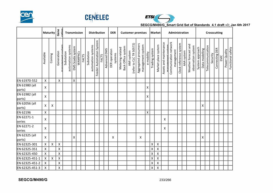
SEGCG/M490/G_Smart Grid Set of Standards 4.1 draft v0; Jan 6th 2017
SEGCG/M490/G 233/266
Maturity
Ge
ne
rati
on
Transmission Distribution DER Customer premises Market Administration Crosscutting
Ava
ilab
le
Co
min
g
Gen
erat
ion
man
agem
ent
syst
em
Sub
stat
ion
auto
mat
ion
sys
tem
s
EMS
Scad
a sy
ste
m
WA
MP
AC
s
FAC
TS
Sub
stat
ion
auto
mat
ion
sys
tem
s
Feed
er
Au
tom
atio
n S
yste
m
FAC
TS
Ad
van
ced
DM
S
DER
op
erat
ion
syst
em
s
Met
erin
g-re
late
d
Bac
k O
ffic
e sy
ste
m
AM
I sys
tem
(ref
er t
o C
LC T
R 5
05
72
)
Agg
rega
ted
pro
sum
ers
man
agem
ent
syst
em
e-m
ob
ility
Trad
ing
syst
em
Mar
ket
pla
ce s
yste
m
Ass
ets
and
mai
nte
nan
ce
man
agem
ent
syst
em
Co
mm
un
icat
ion
net
wo
rk
man
agem
ent
Clo
ck r
efer
ence
sys
tem
AA
A s
yste
m
Wea
ther
fo
reca
st a
nd
ob
serv
atio
n s
yste
m
Syst
em
ap
pro
ach
Dat
a m
od
ellin
g
Tele
com
mu
nic
atio
n
Secu
rity
Co
nn
ecti
ng
DER
EMC
Po
wer
Qu
alit
y
Fun
ctio
nal
saf
ety
EN 61970-552 X X X
EN 61980 (all parts)
X X
EN 61982 (all parts)
X X
EN 62056 (all parts)
X X X
EN 62196 X X
EN 62271-1 series
X X
EN 62271-2 series
X X
EN 62325 (all parts)
X X X X X
EN 62325-301 X X X X X
EN 62325-351 X X X X
EN 62325-450 X X X X
EN 62325-451-1 X X X X X
EN 62325-451-2 X X X X
EN 62325-451-3 X X X X

SEGCG/M490/G_Smart Grid Set of Standards 4.1 draft v0; Jan 6th 2017
SEGCG/M490/G 234/266
Maturity
Ge
ne
rati
on
Transmission Distribution DER Customer premises Market Administration Crosscutting
Ava
ilab
le
Co
min
g
Gen
erat
ion
man
agem
ent
syst
em
Sub
stat
ion
auto
mat
ion
sys
tem
s
EMS
Scad
a sy
ste
m
WA
MP
AC
s
FAC
TS
Sub
stat
ion
auto
mat
ion
sys
tem
s
Feed
er
Au
tom
atio
n S
yste
m
FAC
TS
Ad
van
ced
DM
S
DER
op
erat
ion
syst
em
s
Met
erin
g-re
late
d
Bac
k O
ffic
e sy
ste
m
AM
I sys
tem
(ref
er t
o C
LC T
R 5
05
72
)
Agg
rega
ted
pro
sum
ers
man
agem
ent
syst
em
e-m
ob
ility
Trad
ing
syst
em
Mar
ket
pla
ce s
yste
m
Ass
ets
and
mai
nte
nan
ce
man
agem
ent
syst
em
Co
mm
un
icat
ion
net
wo
rk
man
agem
ent
Clo
ck r
efer
ence
sys
tem
AA
A s
yste
m
Wea
ther
fo
reca
st a
nd
ob
serv
atio
n s
yste
m
Syst
em
ap
pro
ach
Dat
a m
od
ellin
g
Tele
com
mu
nic
atio
n
Secu
rity
Co
nn
ecti
ng
DER
EMC
Po
wer
Qu
alit
y
Fun
ctio
nal
saf
ety
EN 62325-451-4 X X X X
EN 62325-451-5 X X X X
EN 62325-451-6 X X X X
EN 62325-503 X X X X
EN 62325-504 X X X X
EN 62439 X X X X X X
EN 62439-3 X X X
EN 62443 X X
EN 62446 X X
EN 62507-1 X X
EN 62541-1 X X
EN 62541-10 X X
EN 62541-2 X X
EN 62541-3 X X
EN 62541-4 X X
EN 62541-5 X X
EN 62541-6 X X
EN 62541-7 X X
EN 62541-8 X X
EN 62541-9 X X
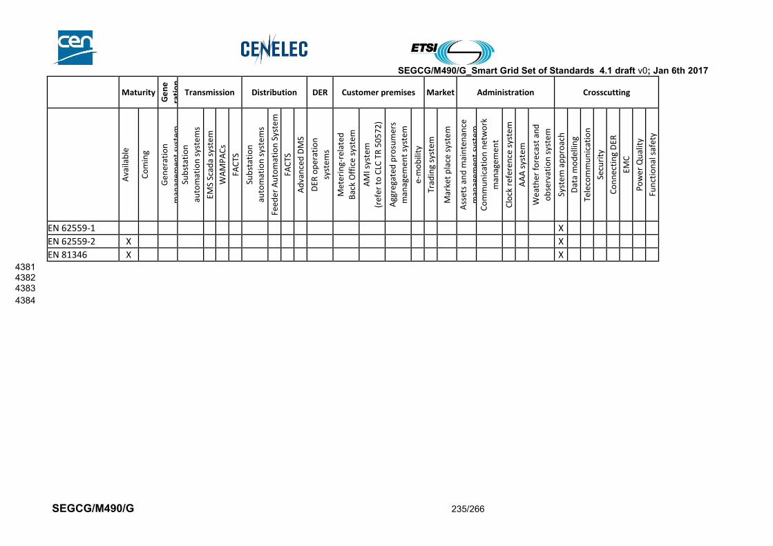
SEGCG/M490/G_Smart Grid Set of Standards 4.1 draft v0; Jan 6th 2017
SEGCG/M490/G 235/266
Maturity
Ge
ne
rati
on
Transmission Distribution DER Customer premises Market Administration Crosscutting
Ava
ilab
le
Co
min
g
Gen
erat
ion
man
agem
ent
syst
em
Sub
stat
ion
auto
mat
ion
sys
tem
s
EMS
Scad
a sy
ste
m
WA
MP
AC
s
FAC
TS
Sub
stat
ion
auto
mat
ion
sys
tem
s
Feed
er
Au
tom
atio
n S
yste
m
FAC
TS
Ad
van
ced
DM
S
DER
op
erat
ion
syst
em
s
Met
erin
g-re
late
d
Bac
k O
ffic
e sy
ste
m
AM
I sys
tem
(ref
er t
o C
LC T
R 5
05
72
)
Agg
rega
ted
pro
sum
ers
man
agem
ent
syst
em
e-m
ob
ility
Trad
ing
syst
em
Mar
ket
pla
ce s
yste
m
Ass
ets
and
mai
nte
nan
ce
man
agem
ent
syst
em
Co
mm
un
icat
ion
net
wo
rk
man
agem
ent
Clo
ck r
efer
ence
sys
tem
AA
A s
yste
m
Wea
ther
fo
reca
st a
nd
ob
serv
atio
n s
yste
m
Syst
em
ap
pro
ach
Dat
a m
od
ellin
g
Tele
com
mu
nic
atio
n
Secu
rity
Co
nn
ecti
ng
DER
EMC
Po
wer
Qu
alit
y
Fun
ctio
nal
saf
ety
EN 62559-1 X
EN 62559-2 X X
EN 81346 X X 4381 4382 4383
4384

SEGCG/M490/G_Smart Grid Set of Standards 4.1 draft v0; Jan 6th 2017
SEGCG/M490/G 236/266
10.2 ETSI 4385
ETSI standards and latest status can be found on the Internet following the link below : 4386 http://www.etsi.org/standards-search 4387 4388
Maturity
Ge
ne
rati
on
Transmission Distribution DER Customer premises Market Administration Crosscutting
Ava
ilab
le
Co
min
g
Gen
erat
ion
man
agem
ent
syst
em
Sub
stat
ion
auto
mat
ion
sys
tem
s
EMS
Scad
a sy
ste
m
WA
MP
AC
s
FAC
TS
Sub
stat
ion
auto
mat
ion
sys
tem
s
Feed
er
Au
tom
atio
n S
yste
m
FAC
TS
Ad
van
ced
DM
S
DER
op
erat
ion
syst
em
s
Met
erin
g-re
late
d
Bac
k O
ffic
e sy
ste
m
AM
I sys
tem
(ref
er t
o C
LC T
R 5
05
72
)
Agg
rega
ted
pro
sum
ers
man
agem
ent
syst
em
e-m
ob
ility
Trad
ing
syst
em
Mar
ket
pla
ce s
yste
m
Ass
ets
and
mai
nte
nan
ce
man
agem
ent
syst
em
Co
mm
un
icat
ion
net
wo
rk
man
agem
ent
Clo
ck r
efer
ence
sys
tem
AA
A s
yste
m
Wea
ther
fo
reca
st a
nd
ob
serv
atio
n s
yste
m
Syst
em
ap
pro
ach
Dat
a m
od
ellin
g
Tele
com
mu
nic
atio
n
Secu
rity
Co
nn
ecti
ng
DER
EMC
Po
wer
Qu
alit
y
Fun
ctio
nal
saf
ety
ETSI EG 202 387 X X
ETSI EG 202 549 X X
ETSI EN 301 502 X X
ETSI EN 301 511 X X
ETSI EN 301 908 X X
ETSI EN 303 204 X X
ETSI ES 202 382 X X
ETSI ES 202 383 X X
ETSI ES 202 630 X X X
ETSI ETR 237 X X
ETSI ETR 332 X X
ETSI TCRTR 029 X X
ETSI TE 103 118 X X X X
ETSI TR 101 531 X X X
ETSI TR 102 419 X X
ETSI TR 102 437 X X

SEGCG/M490/G_Smart Grid Set of Standards 4.1 draft v0; Jan 6th 2017
SEGCG/M490/G 237/266
Maturity
Ge
ne
rati
on
Transmission Distribution DER Customer premises Market Administration Crosscutting
Ava
ilab
le
Co
min
g
Gen
erat
ion
man
agem
ent
syst
em
Sub
stat
ion
auto
mat
ion
sys
tem
s
EMS
Scad
a sy
ste
m
WA
MP
AC
s
FAC
TS
Sub
stat
ion
auto
mat
ion
sys
tem
s
Feed
er
Au
tom
atio
n S
yste
m
FAC
TS
Ad
van
ced
DM
S
DER
op
erat
ion
syst
em
s
Met
erin
g-re
late
d
Bac
k O
ffic
e sy
ste
m
AM
I sys
tem
(ref
er t
o C
LC T
R 5
05
72
)
Agg
rega
ted
pro
sum
ers
man
agem
ent
syst
em
e-m
ob
ility
Trad
ing
syst
em
Mar
ket
pla
ce s
yste
m
Ass
ets
and
mai
nte
nan
ce
man
agem
ent
syst
em
Co
mm
un
icat
ion
net
wo
rk
man
agem
ent
Clo
ck r
efer
ence
sys
tem
AA
A s
yste
m
Wea
ther
fo
reca
st a
nd
ob
serv
atio
n s
yste
m
Syst
em
ap
pro
ach
Dat
a m
od
ellin
g
Tele
com
mu
nic
atio
n
Secu
rity
Co
nn
ecti
ng
DER
EMC
Po
wer
Qu
alit
y
Fun
ctio
nal
saf
ety
ETSI TR 102 572 X X
ETSI TR 102 691 X X
ETSI TR 102 886 X X
ETSI TR 102 935 X X X
ETSI TR 102 966 X X X
ETSI TR 103 055 X X
ETSI TR 103 167 X X X X
ETSI TR 185 008 X X
ETSI TR 187 002 X X
ETSI TR 187 012 X X
ETSI TS 100 920 X X
ETSI TS 101 456 X X
ETSI TS 101 584 X X X
ETSI TS 102 042 X X
ETSI TS 102 165-1
X X
ETSI TS 102 165-2
X X
ETSI TS 102 221 X X
ETSI TS 102 225 X X
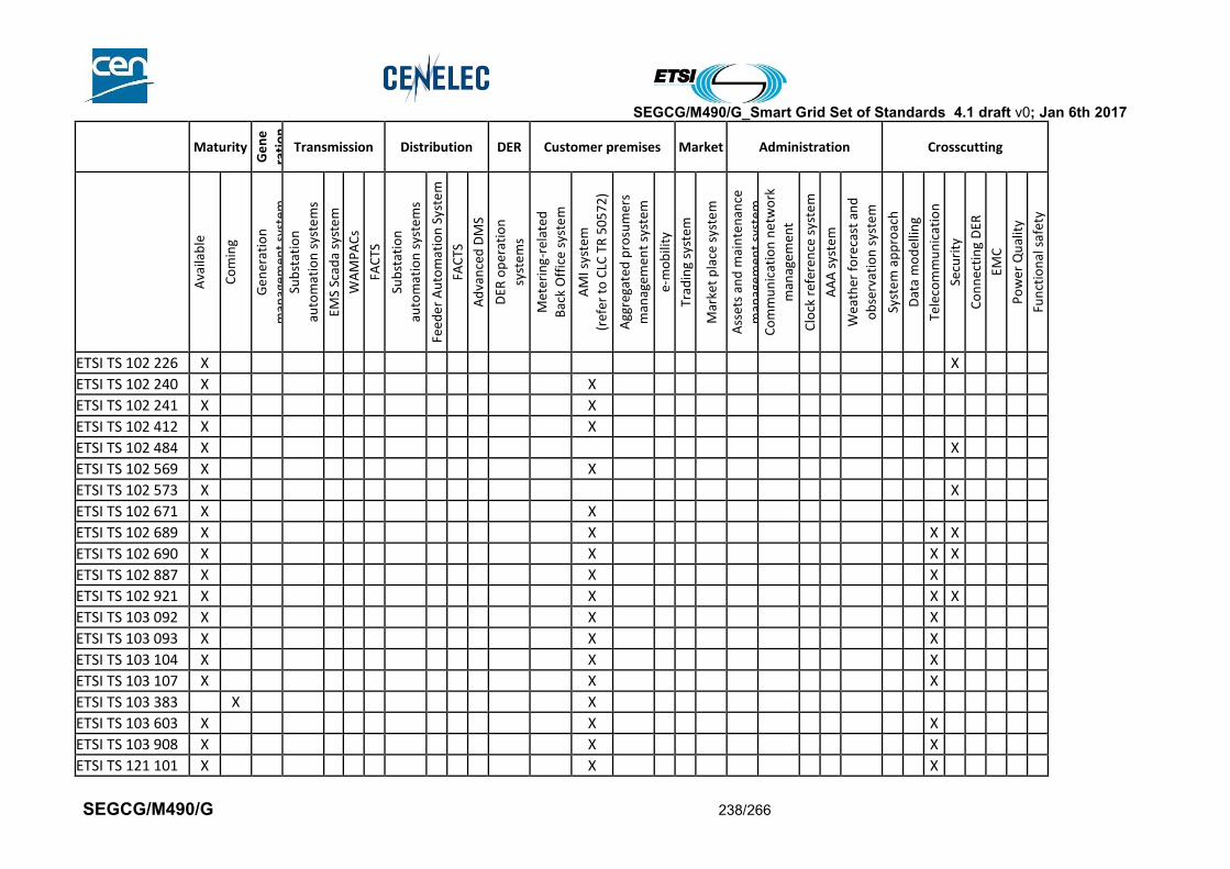
SEGCG/M490/G_Smart Grid Set of Standards 4.1 draft v0; Jan 6th 2017
SEGCG/M490/G 238/266
Maturity
Ge
ne
rati
on
Transmission Distribution DER Customer premises Market Administration Crosscutting
Ava
ilab
le
Co
min
g
Gen
erat
ion
man
agem
ent
syst
em
Sub
stat
ion
auto
mat
ion
sys
tem
s
EMS
Scad
a sy
ste
m
WA
MP
AC
s
FAC
TS
Sub
stat
ion
auto
mat
ion
sys
tem
s
Feed
er
Au
tom
atio
n S
yste
m
FAC
TS
Ad
van
ced
DM
S
DER
op
erat
ion
syst
em
s
Met
erin
g-re
late
d
Bac
k O
ffic
e sy
ste
m
AM
I sys
tem
(ref
er t
o C
LC T
R 5
05
72
)
Agg
rega
ted
pro
sum
ers
man
agem
ent
syst
em
e-m
ob
ility
Trad
ing
syst
em
Mar
ket
pla
ce s
yste
m
Ass
ets
and
mai
nte
nan
ce
man
agem
ent
syst
em
Co
mm
un
icat
ion
net
wo
rk
man
agem
ent
Clo
ck r
efer
ence
sys
tem
AA
A s
yste
m
Wea
ther
fo
reca
st a
nd
ob
serv
atio
n s
yste
m
Syst
em
ap
pro
ach
Dat
a m
od
ellin
g
Tele
com
mu
nic
atio
n
Secu
rity
Co
nn
ecti
ng
DER
EMC
Po
wer
Qu
alit
y
Fun
ctio
nal
saf
ety
ETSI TS 102 226 X X
ETSI TS 102 240 X X
ETSI TS 102 241 X X
ETSI TS 102 412 X X
ETSI TS 102 484 X X
ETSI TS 102 569 X X
ETSI TS 102 573 X X
ETSI TS 102 671 X X
ETSI TS 102 689 X X X X
ETSI TS 102 690 X X X X
ETSI TS 102 887 X X X
ETSI TS 102 921 X X X X
ETSI TS 103 092 X X X
ETSI TS 103 093 X X X
ETSI TS 103 104 X X X
ETSI TS 103 107 X X X
ETSI TS 103 383 X X
ETSI TS 103 603 X X X
ETSI TS 103 908 X X N X
ETSI TS 121 101 X X X
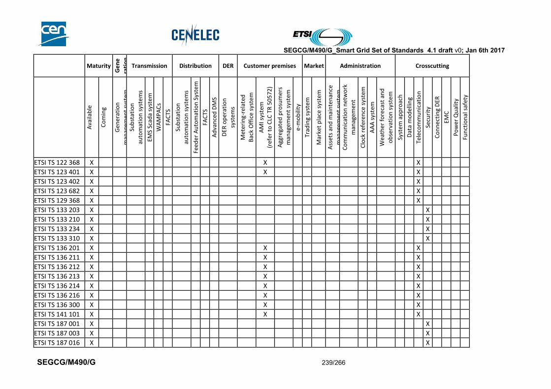
SEGCG/M490/G_Smart Grid Set of Standards 4.1 draft v0; Jan 6th 2017
SEGCG/M490/G 239/266
Maturity
Ge
ne
rati
on
Transmission Distribution DER Customer premises Market Administration Crosscutting
Ava
ilab
le
Co
min
g
Gen
erat
ion
man
agem
ent
syst
em
Sub
stat
ion
auto
mat
ion
sys
tem
s
EMS
Scad
a sy
ste
m
WA
MP
AC
s
FAC
TS
Sub
stat
ion
auto
mat
ion
sys
tem
s
Feed
er
Au
tom
atio
n S
yste
m
FAC
TS
Ad
van
ced
DM
S
DER
op
erat
ion
syst
em
s
Met
erin
g-re
late
d
Bac
k O
ffic
e sy
ste
m
AM
I sys
tem
(ref
er t
o C
LC T
R 5
05
72
)
Agg
rega
ted
pro
sum
ers
man
agem
ent
syst
em
e-m
ob
ility
Trad
ing
syst
em
Mar
ket
pla
ce s
yste
m
Ass
ets
and
mai
nte
nan
ce
man
agem
ent
syst
em
Co
mm
un
icat
ion
net
wo
rk
man
agem
ent
Clo
ck r
efer
ence
sys
tem
AA
A s
yste
m
Wea
ther
fo
reca
st a
nd
ob
serv
atio
n s
yste
m
Syst
em
ap
pro
ach
Dat
a m
od
ellin
g
Tele
com
mu
nic
atio
n
Secu
rity
Co
nn
ecti
ng
DER
EMC
Po
wer
Qu
alit
y
Fun
ctio
nal
saf
ety
ETSI TS 122 368 X X X
ETSI TS 123 401 X X X
ETSI TS 123 402 X X
ETSI TS 123 682 X X
ETSI TS 129 368 X X
ETSI TS 133 203 X X
ETSI TS 133 210 X X
ETSI TS 133 234 X X
ETSI TS 133 310 X X
ETSI TS 136 201 X X X
ETSI TS 136 211 X X X
ETSI TS 136 212 X X X
ETSI TS 136 213 X X X
ETSI TS 136 214 X X X
ETSI TS 136 216 X X X
ETSI TS 136 300 X X X
ETSI TS 141 101 X X X
ETSI TS 187 001 X X
ETSI TS 187 003 X X
ETSI TS 187 016 X X
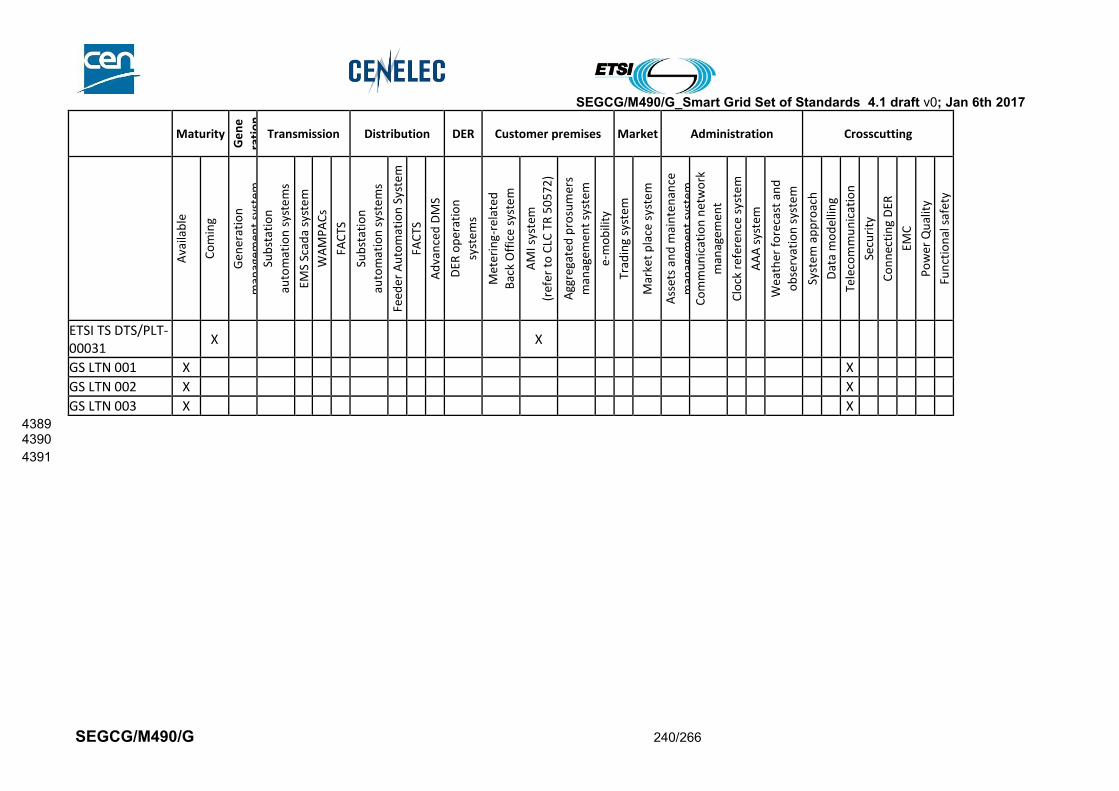
SEGCG/M490/G_Smart Grid Set of Standards 4.1 draft v0; Jan 6th 2017
SEGCG/M490/G 240/266
Maturity
Ge
ne
rati
on
Transmission Distribution DER Customer premises Market Administration Crosscutting
Ava
ilab
le
Co
min
g
Gen
erat
ion
man
agem
ent
syst
em
Sub
stat
ion
auto
mat
ion
sys
tem
s
EMS
Scad
a sy
ste
m
WA
MP
AC
s
FAC
TS
Sub
stat
ion
auto
mat
ion
sys
tem
s
Feed
er
Au
tom
atio
n S
yste
m
FAC
TS
Ad
van
ced
DM
S
DER
op
erat
ion
syst
em
s
Met
erin
g-re
late
d
Bac
k O
ffic
e sy
ste
m
AM
I sys
tem
(ref
er t
o C
LC T
R 5
05
72
)
Agg
rega
ted
pro
sum
ers
man
agem
ent
syst
em
e-m
ob
ility
Trad
ing
syst
em
Mar
ket
pla
ce s
yste
m
Ass
ets
and
mai
nte
nan
ce
man
agem
ent
syst
em
Co
mm
un
icat
ion
net
wo
rk
man
agem
ent
Clo
ck r
efer
ence
sys
tem
AA
A s
yste
m
Wea
ther
fo
reca
st a
nd
ob
serv
atio
n s
yste
m
Syst
em
ap
pro
ach
Dat
a m
od
ellin
g
Tele
com
mu
nic
atio
n
Secu
rity
Co
nn
ecti
ng
DER
EMC
Po
wer
Qu
alit
y
Fun
ctio
nal
saf
ety
ETSI TS DTS/PLT-00031
X X
GS LTN 001 X X
GS LTN 002 X X
GS LTN 003 X X 4389 4390
4391

SEGCG/M490/G_Smart Grid Set of Standards 4.1 draft v0; Jan 6th 2017
SEGCG/M490/G 241/266
10.3 IEC 4392
IEC standards and latest status can be found on the Internet following the link below : 4393 http://www.iec.ch/dyn/www/f?p=103:105:0::::FSP_LANG_ID:25 4394 4395
Maturity
Ge
ne
rati
on
Transmission Distribution DER Customer premises Market Administration Crosscutting
Ava
ilab
le
Co
min
g
Gen
erat
ion
man
agem
ent
syst
em
Sub
stat
ion
auto
mat
ion
sys
tem
s
EMS
Scad
a sy
ste
m
WA
MP
AC
s
FAC
TS
Sub
stat
ion
auto
mat
ion
sys
tem
s
Feed
er
Au
tom
atio
n S
yste
m
FAC
TS
Ad
van
ced
DM
S
DER
op
erat
ion
syst
em
s
Met
erin
g-re
late
d
Bac
k O
ffic
e sy
ste
m
AM
I sys
tem
(ref
er t
o C
LC T
R 5
05
72
)
Agg
rega
ted
pro
sum
ers
man
agem
ent
syst
em
e-m
ob
ility
Trad
ing
syst
em
Mar
ket
pla
ce s
yste
m
Ass
ets
and
mai
nte
nan
ce
man
agem
ent
syst
em
Co
mm
un
icat
ion
net
wo
rk
man
agem
ent
Clo
ck r
efer
ence
sys
tem
AA
A s
yste
m
Wea
ther
fo
reca
st a
nd
ob
serv
atio
n s
yste
m
Syst
em
ap
pro
ach
Dat
a m
od
ellin
g
Tele
com
mu
nic
atio
n
Secu
rity
Co
nn
ecti
ng
DER
EMC
Po
wer
Qu
alit
y
Fun
ctio
nal
saf
ety
IEC 61400-21 X X
IEC 61400-27-1 X X
IEC 60050 series X
IEC 60255 X X
IEC 60255-24 X X X X
IEC 60633 X X
IEC 60700-1 X X
IEC 60783 X X
IEC 60784 X X
IEC 60785 X X
IEC 60786 X X
IEC 60904 series X X
IEC 60919 X X
IEC 61000-3-13 X X
IEC 61000-3-14 X X
IEC 61000-3-15 X X
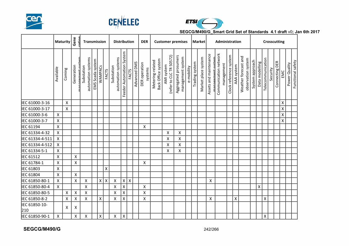
SEGCG/M490/G_Smart Grid Set of Standards 4.1 draft v0; Jan 6th 2017
SEGCG/M490/G 242/266
Maturity
Ge
ne
rati
on
Transmission Distribution DER Customer premises Market Administration Crosscutting
Ava
ilab
le
Co
min
g
Gen
erat
ion
man
agem
ent
syst
em
Sub
stat
ion
auto
mat
ion
sys
tem
s
EMS
Scad
a sy
ste
m
WA
MP
AC
s
FAC
TS
Sub
stat
ion
auto
mat
ion
sys
tem
s
Feed
er
Au
tom
atio
n S
yste
m
FAC
TS
Ad
van
ced
DM
S
DER
op
erat
ion
syst
em
s
Met
erin
g-re
late
d
Bac
k O
ffic
e sy
ste
m
AM
I sys
tem
(ref
er t
o C
LC T
R 5
05
72
)
Agg
rega
ted
pro
sum
ers
man
agem
ent
syst
em
e-m
ob
ility
Trad
ing
syst
em
Mar
ket
pla
ce s
yste
m
Ass
ets
and
mai
nte
nan
ce
man
agem
ent
syst
em
Co
mm
un
icat
ion
net
wo
rk
man
agem
ent
Clo
ck r
efer
ence
sys
tem
AA
A s
yste
m
Wea
ther
fo
reca
st a
nd
ob
serv
atio
n s
yste
m
Syst
em
ap
pro
ach
Dat
a m
od
ellin
g
Tele
com
mu
nic
atio
n
Secu
rity
Co
nn
ecti
ng
DER
EMC
Po
wer
Qu
alit
y
Fun
ctio
nal
saf
ety
IEC 61000-3-16 X X
IEC 61000-3-17 X X
IEC 61000-3-6 X X
IEC 61000-3-7 X X
IEC 61194 X X
IEC 61334-4-32 X X X
IEC 61334-4-511 X X X
IEC 61334-4-512 X X X
IEC 61334-5-1 X X X
IEC 61512 X X
IEC 61784-1 X X X
IEC 61803 X X
IEC 61804 X X
IEC 61850-80-1 X X X X X X X X X
IEC 61850-80-4 X X X X X X
IEC 61850-80-5 X X X X X X
IEC 61850-8-2 X X X X X X X X X X
IEC 61850-10-210
X X
IEC 61850-90-1 X X X X X X X
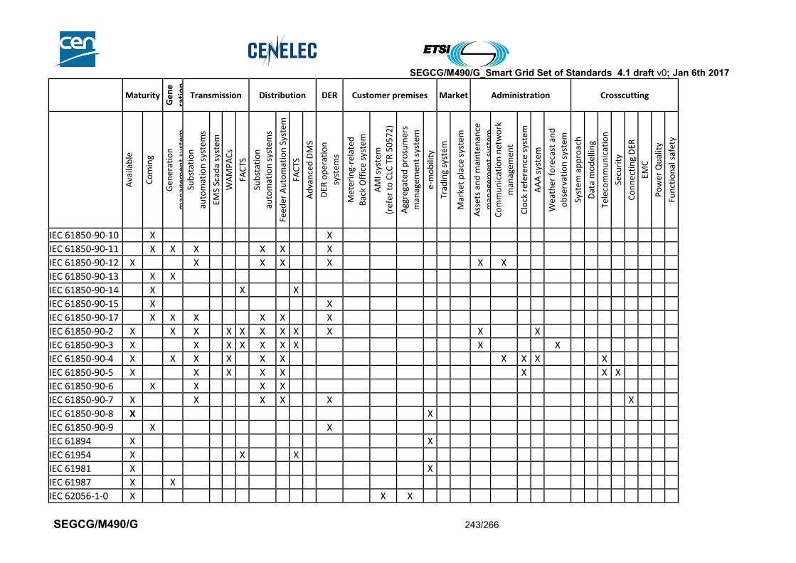
SEGCG/M490/G_Smart Grid Set of Standards 4.1 draft v0; Jan 6th 2017
SEGCG/M490/G 243/266
Maturity
Ge
ne
rati
on
Transmission Distribution DER Customer premises Market Administration Crosscutting
Ava
ilab
le
Co
min
g
Gen
erat
ion
man
agem
ent
syst
em
Sub
stat
ion
auto
mat
ion
sys
tem
s
EMS
Scad
a sy
ste
m
WA
MP
AC
s
FAC
TS
Sub
stat
ion
auto
mat
ion
sys
tem
s
Feed
er
Au
tom
atio
n S
yste
m
FAC
TS
Ad
van
ced
DM
S
DER
op
erat
ion
syst
em
s
Met
erin
g-re
late
d
Bac
k O
ffic
e sy
ste
m
AM
I sys
tem
(ref
er t
o C
LC T
R 5
05
72
)
Agg
rega
ted
pro
sum
ers
man
agem
ent
syst
em
e-m
ob
ility
Trad
ing
syst
em
Mar
ket
pla
ce s
yste
m
Ass
ets
and
mai
nte
nan
ce
man
agem
ent
syst
em
Co
mm
un
icat
ion
net
wo
rk
man
agem
ent
Clo
ck r
efer
ence
sys
tem
AA
A s
yste
m
Wea
ther
fo
reca
st a
nd
ob
serv
atio
n s
yste
m
Syst
em
ap
pro
ach
Dat
a m
od
ellin
g
Tele
com
mu
nic
atio
n
Secu
rity
Co
nn
ecti
ng
DER
EMC
Po
wer
Qu
alit
y
Fun
ctio
nal
saf
ety
IEC 61850-90-10 X X
IEC 61850-90-11 X X X X X X
IEC 61850-90-12 X X X X X X X
IEC 61850-90-13 X X
IEC 61850-90-14 X X X
IEC 61850-90-15 X X
IEC 61850-90-17 X X X X X X
IEC 61850-90-2 X X X X X X X X X X X
IEC 61850-90-3 X X X X X X X X X
IEC 61850-90-4 X X X X X X X X X X
IEC 61850-90-5 X X X X X X X X
IEC 61850-90-6 X X X X
IEC 61850-90-7 X X X X X X
IEC 61850-90-8 X X
IEC 61850-90-9 X X
IEC 61894 X X
IEC 61954 X X X
IEC 61981 X X
IEC 61987 X X
IEC 62056-1-0 X X X

SEGCG/M490/G_Smart Grid Set of Standards 4.1 draft v0; Jan 6th 2017
SEGCG/M490/G 244/266
Maturity
Ge
ne
rati
on
Transmission Distribution DER Customer premises Market Administration Crosscutting
Ava
ilab
le
Co
min
g
Gen
erat
ion
man
agem
ent
syst
em
Sub
stat
ion
auto
mat
ion
sys
tem
s
EMS
Scad
a sy
ste
m
WA
MP
AC
s
FAC
TS
Sub
stat
ion
auto
mat
ion
sys
tem
s
Feed
er
Au
tom
atio
n S
yste
m
FAC
TS
Ad
van
ced
DM
S
DER
op
erat
ion
syst
em
s
Met
erin
g-re
late
d
Bac
k O
ffic
e sy
ste
m
AM
I sys
tem
(ref
er t
o C
LC T
R 5
05
72
)
Agg
rega
ted
pro
sum
ers
man
agem
ent
syst
em
e-m
ob
ility
Trad
ing
syst
em
Mar
ket
pla
ce s
yste
m
Ass
ets
and
mai
nte
nan
ce
man
agem
ent
syst
em
Co
mm
un
icat
ion
net
wo
rk
man
agem
ent
Clo
ck r
efer
ence
sys
tem
AA
A s
yste
m
Wea
ther
fo
reca
st a
nd
ob
serv
atio
n s
yste
m
Syst
em
ap
pro
ach
Dat
a m
od
ellin
g
Tele
com
mu
nic
atio
n
Secu
rity
Co
nn
ecti
ng
DER
EMC
Po
wer
Qu
alit
y
Fun
ctio
nal
saf
ety
IEC 62056-3-1 X X X
IEC 62056-42 X X X
IEC 62056-46 X X X
IEC 62056-4-7 X X X
IEC 62056-5-3 X X X X
IEC 62056-6-1 X X X
IEC 62056-6-2 X X X
IEC 62056-6-9 X X X X
IEC 62056-7-3 X X X
IEC 62056-7-5 X X X
IEC 62056-7-6 X X X
IEC 62056-8-20 X X X
IEC 62056-8-3 X X X
IEC 62056-8-6 X X X
IEC 62056-9-1 X X X
IEC 62056-9-7 X X X
IEC 62257 (all parts)
X X
IEC 62264 X X
IEC 62271-3 X X X X X

SEGCG/M490/G_Smart Grid Set of Standards 4.1 draft v0; Jan 6th 2017
SEGCG/M490/G 245/266
Maturity
Ge
ne
rati
on
Transmission Distribution DER Customer premises Market Administration Crosscutting
Ava
ilab
le
Co
min
g
Gen
erat
ion
man
agem
ent
syst
em
Sub
stat
ion
auto
mat
ion
sys
tem
s
EMS
Scad
a sy
ste
m
WA
MP
AC
s
FAC
TS
Sub
stat
ion
auto
mat
ion
sys
tem
s
Feed
er
Au
tom
atio
n S
yste
m
FAC
TS
Ad
van
ced
DM
S
DER
op
erat
ion
syst
em
s
Met
erin
g-re
late
d
Bac
k O
ffic
e sy
ste
m
AM
I sys
tem
(ref
er t
o C
LC T
R 5
05
72
)
Agg
rega
ted
pro
sum
ers
man
agem
ent
syst
em
e-m
ob
ility
Trad
ing
syst
em
Mar
ket
pla
ce s
yste
m
Ass
ets
and
mai
nte
nan
ce
man
agem
ent
syst
em
Co
mm
un
icat
ion
net
wo
rk
man
agem
ent
Clo
ck r
efer
ence
sys
tem
AA
A s
yste
m
Wea
ther
fo
reca
st a
nd
ob
serv
atio
n s
yste
m
Syst
em
ap
pro
ach
Dat
a m
od
ellin
g
Tele
com
mu
nic
atio
n
Secu
rity
Co
nn
ecti
ng
DER
EMC
Po
wer
Qu
alit
y
Fun
ctio
nal
saf
ety
IEC 62282 X
IEC 62351 -all parts)
X X X X X X X X X X X X X X X X
IEC 62351-1 X X
IEC 62351-10 X X
IEC 62351-11 X X X X X X X X X X X X
IEC 62351-12 X X X X X X X X X X X X
IEC 62351-2 X X
IEC 62351-3 X X X
IEC 62351-4 X X X X X X X X X X X X X X
IEC 62351-5 X X
IEC 62351-6 X X X X X X X X X X X X X
IEC 62351-7 X X X X X X X X X X X X X
IEC 62351-8 X X X
IEC 62351-9 X X X X X X X X X X X X X
IEC 62351-90-1 X X X X X X X X X X X X X
IEC 62357 X X X
IEC 62361 (all parts)
X X X
IEC 62361-100 X X X X
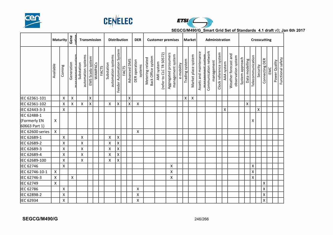
SEGCG/M490/G_Smart Grid Set of Standards 4.1 draft v0; Jan 6th 2017
SEGCG/M490/G 246/266
Maturity
Ge
ne
rati
on
Transmission Distribution DER Customer premises Market Administration Crosscutting
Ava
ilab
le
Co
min
g
Gen
erat
ion
man
agem
ent
syst
em
Sub
stat
ion
auto
mat
ion
sys
tem
s
EMS
Scad
a sy
ste
m
WA
MP
AC
s
FAC
TS
Sub
stat
ion
auto
mat
ion
sys
tem
s
Feed
er
Au
tom
atio
n S
yste
m
FAC
TS
Ad
van
ced
DM
S
DER
op
erat
ion
syst
em
s
Met
erin
g-re
late
d
Bac
k O
ffic
e sy
ste
m
AM
I sys
tem
(ref
er t
o C
LC T
R 5
05
72
)
Agg
rega
ted
pro
sum
ers
man
agem
ent
syst
em
e-m
ob
ility
Trad
ing
syst
em
Mar
ket
pla
ce s
yste
m
Ass
ets
and
mai
nte
nan
ce
man
agem
ent
syst
em
Co
mm
un
icat
ion
net
wo
rk
man
agem
ent
Clo
ck r
efer
ence
sys
tem
AA
A s
yste
m
Wea
ther
fo
reca
st a
nd
ob
serv
atio
n s
yste
m
Syst
em
ap
pro
ach
Dat
a m
od
ellin
g
Tele
com
mu
nic
atio
n
Secu
rity
Co
nn
ecti
ng
DER
EMC
Po
wer
Qu
alit
y
Fun
ctio
nal
saf
ety
IEC 62361-101 X X X X X X
IEC 62361-102 X X X X X X X X X
IEC 62443-3-3 X X X
IEC 62488-1 (Formerly EN 60663 Part 1)
X X
IEC 62600 series X X
IEC 62689-1 X X X X
IEC 62689-2 X X X X
IEC 62689-3 X X X X
IEC 62689-4 X X X X
IEC 62689-100 X X X X
IEC 62746 X X X
IEC 62746-10-1 X X X
IEC 62746-3 X X X X
IEC 62749 X X
IEC 62786 X X X
IEC 62898-2 X X X
IEC 62934 X X X
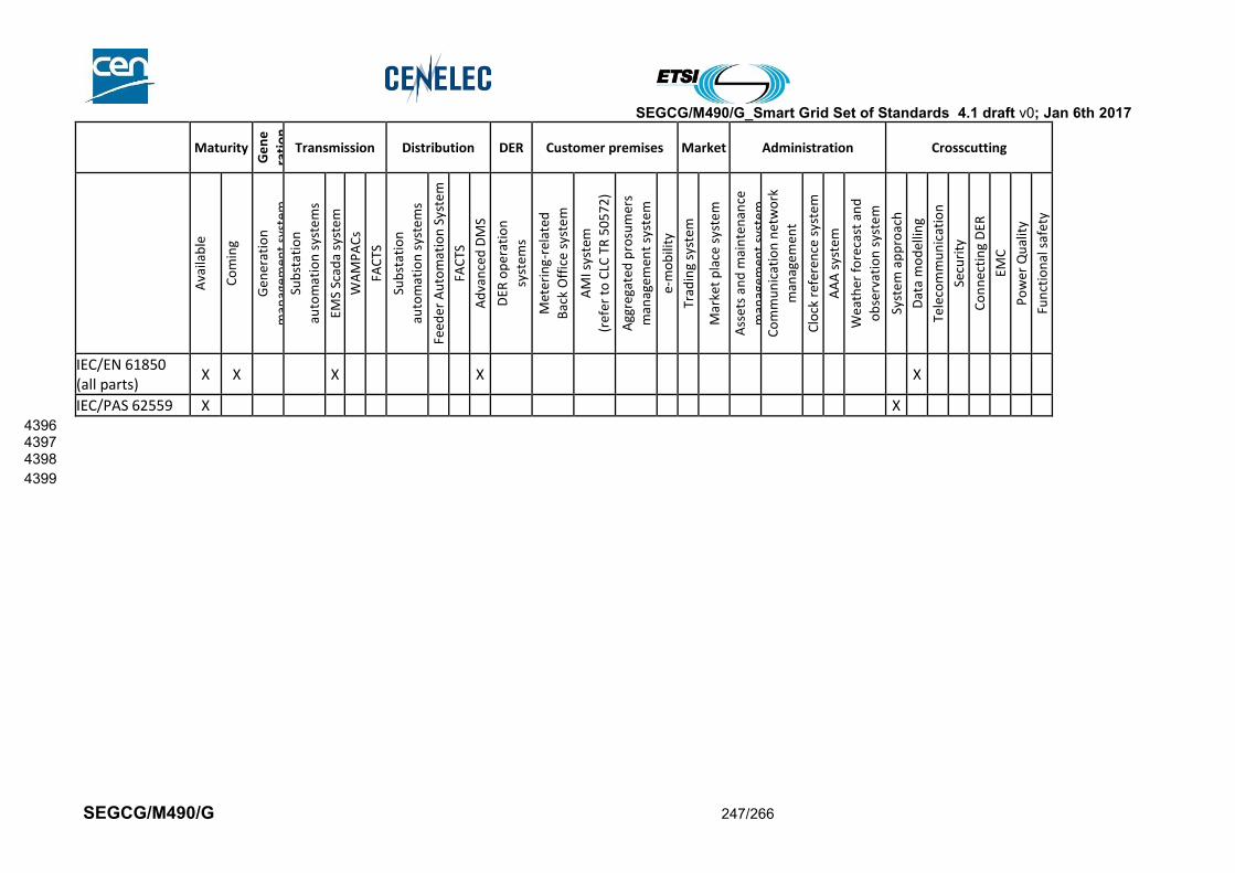
SEGCG/M490/G_Smart Grid Set of Standards 4.1 draft v0; Jan 6th 2017
SEGCG/M490/G 247/266
Maturity
Ge
ne
rati
on
Transmission Distribution DER Customer premises Market Administration Crosscutting
Ava
ilab
le
Co
min
g
Gen
erat
ion
man
agem
ent
syst
em
Sub
stat
ion
auto
mat
ion
sys
tem
s
EMS
Scad
a sy
ste
m
WA
MP
AC
s
FAC
TS
Sub
stat
ion
auto
mat
ion
sys
tem
s
Feed
er
Au
tom
atio
n S
yste
m
FAC
TS
Ad
van
ced
DM
S
DER
op
erat
ion
syst
em
s
Met
erin
g-re
late
d
Bac
k O
ffic
e sy
ste
m
AM
I sys
tem
(ref
er t
o C
LC T
R 5
05
72
)
Agg
rega
ted
pro
sum
ers
man
agem
ent
syst
em
e-m
ob
ility
Trad
ing
syst
em
Mar
ket
pla
ce s
yste
m
Ass
ets
and
mai
nte
nan
ce
man
agem
ent
syst
em
Co
mm
un
icat
ion
net
wo
rk
man
agem
ent
Clo
ck r
efer
ence
sys
tem
AA
A s
yste
m
Wea
ther
fo
reca
st a
nd
ob
serv
atio
n s
yste
m
Syst
em
ap
pro
ach
Dat
a m
od
ellin
g
Tele
com
mu
nic
atio
n
Secu
rity
Co
nn
ecti
ng
DER
EMC
Po
wer
Qu
alit
y
Fun
ctio
nal
saf
ety
IEC/EN 61850 (all parts)
X X X X X
IEC/PAS 62559 X X 4396 4397 4398
4399
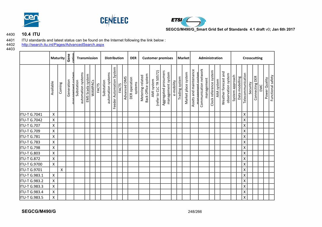
SEGCG/M490/G_Smart Grid Set of Standards 4.1 draft v0; Jan 6th 2017
SEGCG/M490/G 248/266
10.4 ITU 4400
ITU standards and latest status can be found on the Internet following the link below : 4401 http://search.itu.int/Pages/AdvancedSearch.aspx 4402 4403
Maturity
Ge
ne
rati
on
Transmission Distribution DER Customer premises Market Administration Crosscutting
Ava
ilab
le
Co
min
g
Gen
erat
ion
man
agem
ent
syst
em
Sub
stat
ion
auto
mat
ion
sys
tem
s
EMS
Scad
a sy
ste
m
WA
MP
AC
s
FAC
TS
Sub
stat
ion
auto
mat
ion
sys
tem
s
Feed
er
Au
tom
atio
n S
yste
m
FAC
TS
Ad
van
ced
DM
S
DER
op
erat
ion
syst
em
s
Met
erin
g-re
late
d
Bac
k O
ffic
e sy
ste
m
AM
I sys
tem
(ref
er t
o C
LC T
R 5
05
72
)
Agg
rega
ted
pro
sum
ers
man
agem
ent
syst
em
e-m
ob
ility
Trad
ing
syst
em
Mar
ket
pla
ce s
yste
m
Ass
ets
and
mai
nte
nan
ce
man
agem
ent
syst
em
Co
mm
un
icat
ion
net
wo
rk
man
agem
ent
Clo
ck r
efer
ence
sys
tem
AA
A s
yste
m
Wea
ther
fo
reca
st a
nd
ob
serv
atio
n s
yste
m
Syst
em
ap
pro
ach
Dat
a m
od
ellin
g
Tele
com
mu
nic
atio
n
Secu
rity
Co
nn
ecti
ng
DER
EMC
Po
wer
Qu
alit
y
Fun
ctio
nal
saf
ety
ITU-T G.7041 X X
ITU-T G.7042 X X
ITU-T G.707 X X
ITU-T G.709 X X
ITU-T G.781 X X
ITU-T G.783 X X
ITU-T G.798 X X
ITU-T G.803 X X
ITU-T G.872 X X
ITU-T G.9700 X X
ITU-T G.9701 X X
ITU-T G.983.1 X X
ITU-T G.983.2 X X
ITU-T G.983.3 X X
ITU-T G.983.4 X X
ITU-T G.983.5 X X

SEGCG/M490/G_Smart Grid Set of Standards 4.1 draft v0; Jan 6th 2017
SEGCG/M490/G 249/266
Maturity
Ge
ne
rati
on
Transmission Distribution DER Customer premises Market Administration Crosscutting
Ava
ilab
le
Co
min
g
Gen
erat
ion
man
agem
ent
syst
em
Sub
stat
ion
auto
mat
ion
sys
tem
s
EMS
Scad
a sy
ste
m
WA
MP
AC
s
FAC
TS
Sub
stat
ion
auto
mat
ion
sys
tem
s
Feed
er
Au
tom
atio
n S
yste
m
FAC
TS
Ad
van
ced
DM
S
DER
op
erat
ion
syst
em
s
Met
erin
g-re
late
d
Bac
k O
ffic
e sy
ste
m
AM
I sys
tem
(ref
er t
o C
LC T
R 5
05
72
)
Agg
rega
ted
pro
sum
ers
man
agem
ent
syst
em
e-m
ob
ility
Trad
ing
syst
em
Mar
ket
pla
ce s
yste
m
Ass
ets
and
mai
nte
nan
ce
man
agem
ent
syst
em
Co
mm
un
icat
ion
net
wo
rk
man
agem
ent
Clo
ck r
efer
ence
sys
tem
AA
A s
yste
m
Wea
ther
fo
reca
st a
nd
ob
serv
atio
n s
yste
m
Syst
em
ap
pro
ach
Dat
a m
od
ellin
g
Tele
com
mu
nic
atio
n
Secu
rity
Co
nn
ecti
ng
DER
EMC
Po
wer
Qu
alit
y
Fun
ctio
nal
saf
ety
ITU-T G.984.1 X X
ITU-T G.984.2 X X
ITU-T G.984.3 X X
ITU-T G.984.4 X X
ITU-T G.984.5 X X
ITU-T G.984.6 X X
ITU-T G.984.7 X X
ITU-T G.987.1 X X
ITU-T G.987.2 X X
ITU-T G.987.3 X X
ITU-T G.9901 X X
ITU-T G.9902 X X
ITU-T G.9903 X X X X X
ITU-T G.9904 X X X X
ITU-T G.9905 X X X X
ITU-T G.991.1 X X
ITU-T G.991.2 X X
ITU-T G.992.1 X X
ITU-T G.992.2 X X
ITU-T G.992.3 X X

SEGCG/M490/G_Smart Grid Set of Standards 4.1 draft v0; Jan 6th 2017
SEGCG/M490/G 250/266
Maturity
Ge
ne
rati
on
Transmission Distribution DER Customer premises Market Administration Crosscutting
Ava
ilab
le
Co
min
g
Gen
erat
ion
man
agem
ent
syst
em
Sub
stat
ion
auto
mat
ion
sys
tem
s
EMS
Scad
a sy
ste
m
WA
MP
AC
s
FAC
TS
Sub
stat
ion
auto
mat
ion
sys
tem
s
Feed
er
Au
tom
atio
n S
yste
m
FAC
TS
Ad
van
ced
DM
S
DER
op
erat
ion
syst
em
s
Met
erin
g-re
late
d
Bac
k O
ffic
e sy
ste
m
AM
I sys
tem
(ref
er t
o C
LC T
R 5
05
72
)
Agg
rega
ted
pro
sum
ers
man
agem
ent
syst
em
e-m
ob
ility
Trad
ing
syst
em
Mar
ket
pla
ce s
yste
m
Ass
ets
and
mai
nte
nan
ce
man
agem
ent
syst
em
Co
mm
un
icat
ion
net
wo
rk
man
agem
ent
Clo
ck r
efer
ence
sys
tem
AA
A s
yste
m
Wea
ther
fo
reca
st a
nd
ob
serv
atio
n s
yste
m
Syst
em
ap
pro
ach
Dat
a m
od
ellin
g
Tele
com
mu
nic
atio
n
Secu
rity
Co
nn
ecti
ng
DER
EMC
Po
wer
Qu
alit
y
Fun
ctio
nal
saf
ety
ITU-T G.992.4 X X
ITU-T G.993.1 X X
ITU-T G.993.2 X X
ITU-T G.993.5 X X
ITU-T G.994.1 X X
ITU-T G.995.1 X X
ITU-T G.9959 X X X X
ITU-T G.996.1 X X
ITU-T G.996.2 X X
ITU-T G.9960 X X
ITU-T G.9961 X X
ITU-T G.9962 X X
ITU-T G.9963 X X
ITU-T G.9964 X X
ITU-T G.997.1 X
ITU-T G.998.1 X
ITU-T G.998.2 X
ITU-T G.998.3 X
ITU-T G.998.4 X
ITU-T G.999.1 X
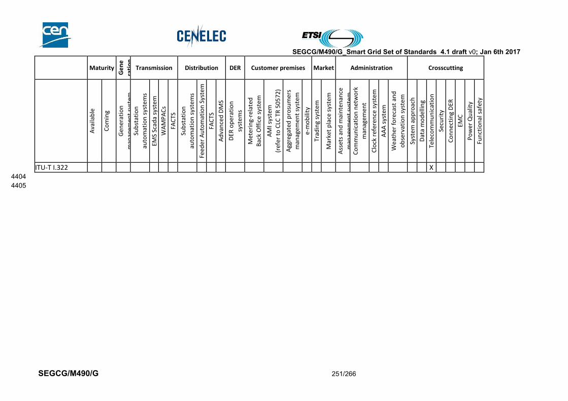
SEGCG/M490/G_Smart Grid Set of Standards 4.1 draft v0; Jan 6th 2017
SEGCG/M490/G 251/266
Maturity
Ge
ne
rati
on
Transmission Distribution DER Customer premises Market Administration Crosscutting
Ava
ilab
le
Co
min
g
Gen
erat
ion
man
agem
ent
syst
em
Sub
stat
ion
auto
mat
ion
sys
tem
s
EMS
Scad
a sy
ste
m
WA
MP
AC
s
FAC
TS
Sub
stat
ion
auto
mat
ion
sys
tem
s
Feed
er
Au
tom
atio
n S
yste
m
FAC
TS
Ad
van
ced
DM
S
DER
op
erat
ion
syst
em
s
Met
erin
g-re
late
d
Bac
k O
ffic
e sy
ste
m
AM
I sys
tem
(ref
er t
o C
LC T
R 5
05
72
)
Agg
rega
ted
pro
sum
ers
man
agem
ent
syst
em
e-m
ob
ility
Trad
ing
syst
em
Mar
ket
pla
ce s
yste
m
Ass
ets
and
mai
nte
nan
ce
man
agem
ent
syst
em
Co
mm
un
icat
ion
net
wo
rk
man
agem
ent
Clo
ck r
efer
ence
sys
tem
AA
A s
yste
m
Wea
ther
fo
reca
st a
nd
ob
serv
atio
n s
yste
m
Syst
em
ap
pro
ach
Dat
a m
od
ellin
g
Tele
com
mu
nic
atio
n
Secu
rity
Co
nn
ecti
ng
DER
EMC
Po
wer
Qu
alit
y
Fun
ctio
nal
saf
ety
ITU-T I.322 X 4404
4405
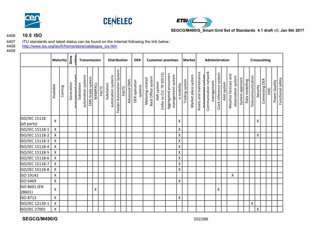
SEGCG/M490/G_Smart Grid Set of Standards 4.1 draft v0; Jan 6th 2017
SEGCG/M490/G 252/266
10.5 ISO 4406
ITU standards and latest status can be found on the Internet following the link below : 4407 http://www.iso.org/iso/fr/home/store/catalogue_ics.htm 4408 4409
Maturity
Ge
ne
rati
on
Transmission Distribution DER Customer premises Market Administration Crosscutting
Ava
ilab
le
Co
min
g
Gen
erat
ion
man
agem
ent
syst
em
Sub
stat
ion
auto
mat
ion
sys
tem
s
EMS
Scad
a sy
ste
m
WA
MP
AC
s
FAC
TS
Sub
stat
ion
auto
mat
ion
sys
tem
s
Feed
er
Au
tom
atio
n S
yste
m
FAC
TS
Ad
van
ced
DM
S
DER
op
erat
ion
syst
em
s
Met
erin
g-re
late
d
Bac
k O
ffic
e sy
ste
m
AM
I sys
tem
(ref
er t
o C
LC T
R 5
05
72
)
Agg
rega
ted
pro
sum
ers
man
agem
ent
syst
em
e-m
ob
ility
Trad
ing
syst
em
Mar
ket
pla
ce s
yste
m
Ass
ets
and
mai
nte
nan
ce
man
agem
ent
syst
em
Co
mm
un
icat
ion
net
wo
rk
man
agem
ent
Clo
ck r
efer
ence
sys
tem
AA
A s
yste
m
Wea
ther
fo
reca
st a
nd
ob
serv
atio
n s
yste
m
Syst
em
ap
pro
ach
Dat
a m
od
ellin
g
Tele
com
mu
nic
atio
n
Secu
rity
Co
nn
ecti
ng
DER
EMC
Po
wer
Qu
alit
y
Fun
ctio
nal
saf
ety
ISO/IEC 15118 (all parts)
X X X
ISO/IEC 15118-1 X X
ISO/IEC 15118-2 X X X
ISO/IEC 15118-3 X X
ISO/IEC 15118-4 X X
ISO/IEC 15118-5 X X
ISO/IEC 15118-6 X X
ISO/IEC 15118-7 X X
ISO/IEC 15118-8 X X
ISO 19142 X X
ISO 6469 X X
ISO 8601 (EN 28601)
X X X
ISO 8713 X X
ISO/IEC 12139-1 X X
ISO/IEC 27001 X X
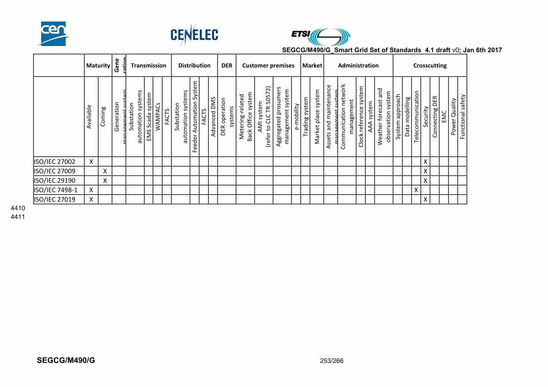
SEGCG/M490/G_Smart Grid Set of Standards 4.1 draft v0; Jan 6th 2017
SEGCG/M490/G 253/266
Maturity
Ge
ne
rati
on
Transmission Distribution DER Customer premises Market Administration Crosscutting
Ava
ilab
le
Co
min
g
Gen
erat
ion
man
agem
ent
syst
em
Sub
stat
ion
auto
mat
ion
sys
tem
s
EMS
Scad
a sy
ste
m
WA
MP
AC
s
FAC
TS
Sub
stat
ion
auto
mat
ion
sys
tem
s
Feed
er
Au
tom
atio
n S
yste
m
FAC
TS
Ad
van
ced
DM
S
DER
op
erat
ion
syst
em
s
Met
erin
g-re
late
d
Bac
k O
ffic
e sy
ste
m
AM
I sys
tem
(ref
er t
o C
LC T
R 5
05
72
)
Agg
rega
ted
pro
sum
ers
man
agem
ent
syst
em
e-m
ob
ility
Trad
ing
syst
em
Mar
ket
pla
ce s
yste
m
Ass
ets
and
mai
nte
nan
ce
man
agem
ent
syst
em
Co
mm
un
icat
ion
net
wo
rk
man
agem
ent
Clo
ck r
efer
ence
sys
tem
AA
A s
yste
m
Wea
ther
fo
reca
st a
nd
ob
serv
atio
n s
yste
m
Syst
em
ap
pro
ach
Dat
a m
od
ellin
g
Tele
com
mu
nic
atio
n
Secu
rity
Co
nn
ecti
ng
DER
EMC
Po
wer
Qu
alit
y
Fun
ctio
nal
saf
ety
ISO/IEC 27002 X X
ISO/IEC 27009 X X
ISO/IEC 29190 X X
ISO/IEC 7498-1 X X
ISO/IEC 27019 X X 4410
4411

SEGCG/M490/G_Smart Grid Set of Standards 4.1 draft v0; Jan 6th 2017
SEGCG/M490/G 254/266
10.6 Other bodies 4412
4413
Maturity
Ge
ne
rati
on
Transmission Distribution DER Customer premises Market Administration Crosscutting
Ava
ilab
le
Co
min
g
Gen
erat
ion
man
agem
ent
syst
em
Sub
stat
ion
auto
mat
ion
sys
tem
s
EMS
Scad
a sy
ste
m
WA
MP
AC
s
FAC
TS
Sub
stat
ion
auto
mat
ion
sys
tem
s
Feed
er
Au
tom
atio
n S
yste
m
FAC
TS
Ad
van
ced
DM
S
DER
op
erat
ion
syst
em
s
Met
erin
g-re
late
d
Bac
k O
ffic
e sy
ste
m
AM
I sys
tem
(ref
er t
o C
LC T
R 5
05
72
)
Agg
rega
ted
pro
sum
ers
man
agem
ent
syst
em
e-m
ob
ility
Trad
ing
syst
em
Mar
ket
pla
ce s
yste
m
Ass
ets
and
mai
nte
nan
ce
man
agem
ent
syst
em
Co
mm
un
icat
ion
net
wo
rk
man
agem
ent
Clo
ck r
efer
ence
sys
tem
AA
A s
yste
m
Wea
ther
fo
reca
st a
nd
ob
serv
atio
n s
yste
m
Syst
em
ap
pro
ach
Dat
a m
od
ellin
g
Tele
com
mu
nic
atio
n
Secu
rity
Co
nn
ecti
ng
DER
EMC
Po
wer
Qu
alit
y
Fun
ctio
nal
saf
ety
ENTSO-E acknowledgement process
X X X
ENTSO-E Capacity Allocation and Nomination (ECAN)
X X X
Harmonized Electricity Market Role Model
X X X
ENTSO-E Market Data Exchange Standard (MADES)
X X X
ENTSO-E Reserve Resource Planning (ERRP)
X X X
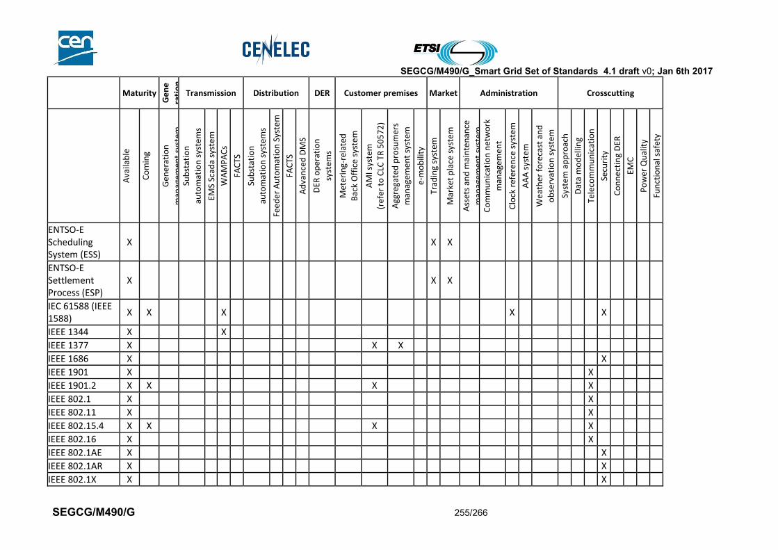
SEGCG/M490/G_Smart Grid Set of Standards 4.1 draft v0; Jan 6th 2017
SEGCG/M490/G 255/266
Maturity
Ge
ne
rati
on
Transmission Distribution DER Customer premises Market Administration Crosscutting
Ava
ilab
le
Co
min
g
Gen
erat
ion
man
agem
ent
syst
em
Sub
stat
ion
auto
mat
ion
sys
tem
s
EMS
Scad
a sy
ste
m
WA
MP
AC
s
FAC
TS
Sub
stat
ion
auto
mat
ion
sys
tem
s
Feed
er
Au
tom
atio
n S
yste
m
FAC
TS
Ad
van
ced
DM
S
DER
op
erat
ion
syst
em
s
Met
erin
g-re
late
d
Bac
k O
ffic
e sy
ste
m
AM
I sys
tem
(ref
er t
o C
LC T
R 5
05
72
)
Agg
rega
ted
pro
sum
ers
man
agem
ent
syst
em
e-m
ob
ility
Trad
ing
syst
em
Mar
ket
pla
ce s
yste
m
Ass
ets
and
mai
nte
nan
ce
man
agem
ent
syst
em
Co
mm
un
icat
ion
net
wo
rk
man
agem
ent
Clo
ck r
efer
ence
sys
tem
AA
A s
yste
m
Wea
ther
fo
reca
st a
nd
ob
serv
atio
n s
yste
m
Syst
em
ap
pro
ach
Dat
a m
od
ellin
g
Tele
com
mu
nic
atio
n
Secu
rity
Co
nn
ecti
ng
DER
EMC
Po
wer
Qu
alit
y
Fun
ctio
nal
saf
ety
ENTSO-E Scheduling System (ESS)
X X X
ENTSO-E Settlement Process (ESP)
X X X
IEC 61588 (IEEE 1588)
X X X X X
IEEE 1344 X X
IEEE 1377 X X X
IEEE 1686 X X
IEEE 1901 X X
IEEE 1901.2 X X X X
IEEE 802.1 X X
IEEE 802.11 X X
IEEE 802.15.4 X X X X
IEEE 802.16 X X
IEEE 802.1AE X X
IEEE 802.1AR X X
IEEE 802.1X X X

SEGCG/M490/G_Smart Grid Set of Standards 4.1 draft v0; Jan 6th 2017
SEGCG/M490/G 256/266
Maturity
Ge
ne
rati
on
Transmission Distribution DER Customer premises Market Administration Crosscutting
Ava
ilab
le
Co
min
g
Gen
erat
ion
man
agem
ent
syst
em
Sub
stat
ion
auto
mat
ion
sys
tem
s
EMS
Scad
a sy
ste
m
WA
MP
AC
s
FAC
TS
Sub
stat
ion
auto
mat
ion
sys
tem
s
Feed
er
Au
tom
atio
n S
yste
m
FAC
TS
Ad
van
ced
DM
S
DER
op
erat
ion
syst
em
s
Met
erin
g-re
late
d
Bac
k O
ffic
e sy
ste
m
AM
I sys
tem
(ref
er t
o C
LC T
R 5
05
72
)
Agg
rega
ted
pro
sum
ers
man
agem
ent
syst
em
e-m
ob
ility
Trad
ing
syst
em
Mar
ket
pla
ce s
yste
m
Ass
ets
and
mai
nte
nan
ce
man
agem
ent
syst
em
Co
mm
un
icat
ion
net
wo
rk
man
agem
ent
Clo
ck r
efer
ence
sys
tem
AA
A s
yste
m
Wea
ther
fo
reca
st a
nd
ob
serv
atio
n s
yste
m
Syst
em
ap
pro
ach
Dat
a m
od
ellin
g
Tele
com
mu
nic
atio
n
Secu
rity
Co
nn
ecti
ng
DER
EMC
Po
wer
Qu
alit
y
Fun
ctio
nal
saf
ety
IEEE 802.3 X X
IEEE 802.3av X X
IEEE C37.118 X X X
IEEE C37.238:2011
X X
IEEE P2030 X X
IETF RFC 7388 X X
IETF RFC 7400 X X
IETF RFC 7428 X X
IETF RFC 7668 X X
IETF RFC 6690 X X X
IETF RFC 7252 X X X
IETF RFC 7390 X X X
IETF RFC 7641 X X X
IETF RFC 7959 X X X
IETF RFC 2460 X X
IETF RFC 2616 X X
IETF RFC 2617 X X
IETF RFC 2759 X X X
IETF RFC 2865 X X X
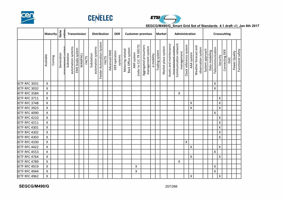
SEGCG/M490/G_Smart Grid Set of Standards 4.1 draft v0; Jan 6th 2017
SEGCG/M490/G 257/266
Maturity
Ge
ne
rati
on
Transmission Distribution DER Customer premises Market Administration Crosscutting
Ava
ilab
le
Co
min
g
Gen
erat
ion
man
agem
ent
syst
em
Sub
stat
ion
auto
mat
ion
sys
tem
s
EMS
Scad
a sy
ste
m
WA
MP
AC
s
FAC
TS
Sub
stat
ion
auto
mat
ion
sys
tem
s
Feed
er
Au
tom
atio
n S
yste
m
FAC
TS
Ad
van
ced
DM
S
DER
op
erat
ion
syst
em
s
Met
erin
g-re
late
d
Bac
k O
ffic
e sy
ste
m
AM
I sys
tem
(ref
er t
o C
LC T
R 5
05
72
)
Agg
rega
ted
pro
sum
ers
man
agem
ent
syst
em
e-m
ob
ility
Trad
ing
syst
em
Mar
ket
pla
ce s
yste
m
Ass
ets
and
mai
nte
nan
ce
man
agem
ent
syst
em
Co
mm
un
icat
ion
net
wo
rk
man
agem
ent
Clo
ck r
efer
ence
sys
tem
AA
A s
yste
m
Wea
ther
fo
reca
st a
nd
ob
serv
atio
n s
yste
m
Syst
em
ap
pro
ach
Dat
a m
od
ellin
g
Tele
com
mu
nic
atio
n
Secu
rity
Co
nn
ecti
ng
DER
EMC
Po
wer
Qu
alit
y
Fun
ctio
nal
saf
ety
IETF RFC 3031 X X
IETF RFC 3032 X X
IETF RFC 3584 X X
IETF RFC 3711 X X
IETF RFC 3748 X X X
IETF RFC 3923 X X X
IETF RFC 4090 X X
IETF RFC 4210 X X
IETF RFC 4211 X X
IETF RFC 4301 X X
IETF RFC 4302 X X
IETF RFC 4303 X X
IETF RFC 4330 X X
IETF RFC 4422 X X X
IETF RFC 4553 X X
IETF RFC 4764 X X X
IETF RFC 4789 X X
IETF RFC 4919 X X X
IETF RFC 4944 X X X
IETF RFC 4962 X X X
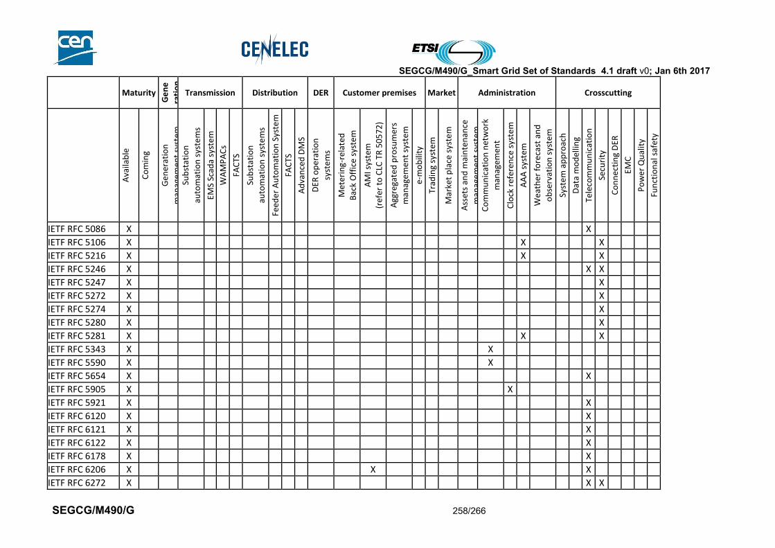
SEGCG/M490/G_Smart Grid Set of Standards 4.1 draft v0; Jan 6th 2017
SEGCG/M490/G 258/266
Maturity
Ge
ne
rati
on
Transmission Distribution DER Customer premises Market Administration Crosscutting
Ava
ilab
le
Co
min
g
Gen
erat
ion
man
agem
ent
syst
em
Sub
stat
ion
auto
mat
ion
sys
tem
s
EMS
Scad
a sy
ste
m
WA
MP
AC
s
FAC
TS
Sub
stat
ion
auto
mat
ion
sys
tem
s
Feed
er
Au
tom
atio
n S
yste
m
FAC
TS
Ad
van
ced
DM
S
DER
op
erat
ion
syst
em
s
Met
erin
g-re
late
d
Bac
k O
ffic
e sy
ste
m
AM
I sys
tem
(ref
er t
o C
LC T
R 5
05
72
)
Agg
rega
ted
pro
sum
ers
man
agem
ent
syst
em
e-m
ob
ility
Trad
ing
syst
em
Mar
ket
pla
ce s
yste
m
Ass
ets
and
mai
nte
nan
ce
man
agem
ent
syst
em
Co
mm
un
icat
ion
net
wo
rk
man
agem
ent
Clo
ck r
efer
ence
sys
tem
AA
A s
yste
m
Wea
ther
fo
reca
st a
nd
ob
serv
atio
n s
yste
m
Syst
em
ap
pro
ach
Dat
a m
od
ellin
g
Tele
com
mu
nic
atio
n
Secu
rity
Co
nn
ecti
ng
DER
EMC
Po
wer
Qu
alit
y
Fun
ctio
nal
saf
ety
IETF RFC 5086 X X
IETF RFC 5106 X X X
IETF RFC 5216 X X X
IETF RFC 5246 X X X
IETF RFC 5247 X X
IETF RFC 5272 X X
IETF RFC 5274 X X
IETF RFC 5280 X X
IETF RFC 5281 X X X
IETF RFC 5343 X X
IETF RFC 5590 X X
IETF RFC 5654 X X
IETF RFC 5905 X X
IETF RFC 5921 X X
IETF RFC 6120 X X
IETF RFC 6121 X X
IETF RFC 6122 X X
IETF RFC 6178 X X
IETF RFC 6206 X X X
IETF RFC 6272 X X X
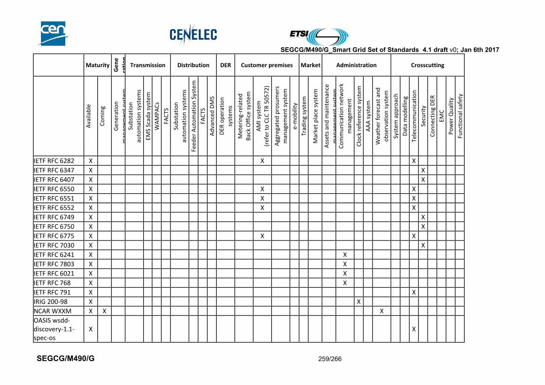
SEGCG/M490/G_Smart Grid Set of Standards 4.1 draft v0; Jan 6th 2017
SEGCG/M490/G 259/266
Maturity
Ge
ne
rati
on
Transmission Distribution DER Customer premises Market Administration Crosscutting
Ava
ilab
le
Co
min
g
Gen
erat
ion
man
agem
ent
syst
em
Sub
stat
ion
auto
mat
ion
sys
tem
s
EMS
Scad
a sy
ste
m
WA
MP
AC
s
FAC
TS
Sub
stat
ion
auto
mat
ion
sys
tem
s
Feed
er
Au
tom
atio
n S
yste
m
FAC
TS
Ad
van
ced
DM
S
DER
op
erat
ion
syst
em
s
Met
erin
g-re
late
d
Bac
k O
ffic
e sy
ste
m
AM
I sys
tem
(ref
er t
o C
LC T
R 5
05
72
)
Agg
rega
ted
pro
sum
ers
man
agem
ent
syst
em
e-m
ob
ility
Trad
ing
syst
em
Mar
ket
pla
ce s
yste
m
Ass
ets
and
mai
nte
nan
ce
man
agem
ent
syst
em
Co
mm
un
icat
ion
net
wo
rk
man
agem
ent
Clo
ck r
efer
ence
sys
tem
AA
A s
yste
m
Wea
ther
fo
reca
st a
nd
ob
serv
atio
n s
yste
m
Syst
em
ap
pro
ach
Dat
a m
od
ellin
g
Tele
com
mu
nic
atio
n
Secu
rity
Co
nn
ecti
ng
DER
EMC
Po
wer
Qu
alit
y
Fun
ctio
nal
saf
ety
IETF RFC 6282 X X X
IETF RFC 6347 X X
IETF RFC 6407 X X
IETF RFC 6550 X X X
IETF RFC 6551 X X X
IETF RFC 6552 X X X
IETF RFC 6749 X X
IETF RFC 6750 X X
IETF RFC 6775 X X X
IETF RFC 7030 X X
IETF RFC 6241 X X
IETF RFC 7803 X X
IETF RFC 6021 X X
IETF RFC 768 X X
IETF RFC 791 X X
IRIG 200-98 X X
NCAR WXXM X X X
OASIS wsdd-discovery-1.1-spec-os
X X
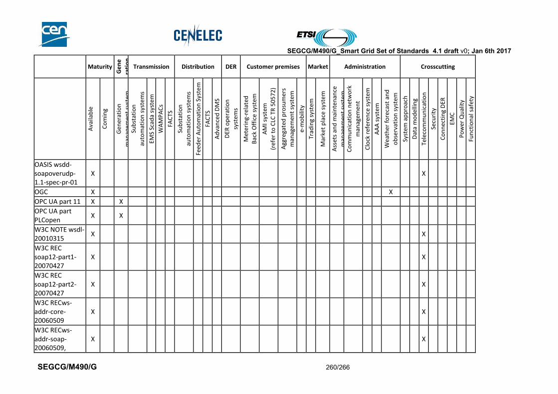
SEGCG/M490/G_Smart Grid Set of Standards 4.1 draft v0; Jan 6th 2017
SEGCG/M490/G 260/266
Maturity
Ge
ne
rati
on
Transmission Distribution DER Customer premises Market Administration Crosscutting
Ava
ilab
le
Co
min
g
Gen
erat
ion
man
agem
ent
syst
em
Sub
stat
ion
auto
mat
ion
sys
tem
s
EMS
Scad
a sy
ste
m
WA
MP
AC
s
FAC
TS
Sub
stat
ion
auto
mat
ion
sys
tem
s
Feed
er
Au
tom
atio
n S
yste
m
FAC
TS
Ad
van
ced
DM
S
DER
op
erat
ion
syst
em
s
Met
erin
g-re
late
d
Bac
k O
ffic
e sy
ste
m
AM
I sys
tem
(ref
er t
o C
LC T
R 5
05
72
)
Agg
rega
ted
pro
sum
ers
man
agem
ent
syst
em
e-m
ob
ility
Trad
ing
syst
em
Mar
ket
pla
ce s
yste
m
Ass
ets
and
mai
nte
nan
ce
man
agem
ent
syst
em
Co
mm
un
icat
ion
net
wo
rk
man
agem
ent
Clo
ck r
efer
ence
sys
tem
AA
A s
yste
m
Wea
ther
fo
reca
st a
nd
ob
serv
atio
n s
yste
m
Syst
em
ap
pro
ach
Dat
a m
od
ellin
g
Tele
com
mu
nic
atio
n
Secu
rity
Co
nn
ecti
ng
DER
EMC
Po
wer
Qu
alit
y
Fun
ctio
nal
saf
ety
OASIS wsdd-soapoverudp-1.1-spec-pr-01
X X
OGC X X
OPC UA part 11 X X
OPC UA part PLCopen
X X
W3C NOTE wsdl-20010315
X X
W3C REC soap12-part1-20070427
X X
W3C REC soap12-part2-20070427
X X
W3C RECws-addr-core-20060509
X X
W3C RECws-addr-soap-20060509,
X X

SEGCG/M490/G_Smart Grid Set of Standards 4.1 draft v0; Jan 6th 2017
SEGCG/M490/G 261/266
Maturity
Ge
ne
rati
on
Transmission Distribution DER Customer premises Market Administration Crosscutting
Ava
ilab
le
Co
min
g
Gen
erat
ion
man
agem
ent
syst
em
Sub
stat
ion
auto
mat
ion
sys
tem
s
EMS
Scad
a sy
ste
m
WA
MP
AC
s
FAC
TS
Sub
stat
ion
auto
mat
ion
sys
tem
s
Feed
er
Au
tom
atio
n S
yste
m
FAC
TS
Ad
van
ced
DM
S
DER
op
erat
ion
syst
em
s
Met
erin
g-re
late
d
Bac
k O
ffic
e sy
ste
m
AM
I sys
tem
(ref
er t
o C
LC T
R 5
05
72
)
Agg
rega
ted
pro
sum
ers
man
agem
ent
syst
em
e-m
ob
ility
Trad
ing
syst
em
Mar
ket
pla
ce s
yste
m
Ass
ets
and
mai
nte
nan
ce
man
agem
ent
syst
em
Co
mm
un
icat
ion
net
wo
rk
man
agem
ent
Clo
ck r
efer
ence
sys
tem
AA
A s
yste
m
Wea
ther
fo
reca
st a
nd
ob
serv
atio
n s
yste
m
Syst
em
ap
pro
ach
Dat
a m
od
ellin
g
Tele
com
mu
nic
atio
n
Secu
rity
Co
nn
ecti
ng
DER
EMC
Po
wer
Qu
alit
y
Fun
ctio
nal
saf
ety
W3C REC-xml-20001006
X X
W3C REC-xml-names
X X
W3C SUBM wsdl11soap12-20060405
X X
W3C SUBM WSEventing-20060315
X X
W3C WD-ws arch-20021114
X X
LoRaWAN Specification 1.0
X X X
3GPP Release 13- NB-IOT
X X X
Draft-ietf-detnet-problem-statement
X X
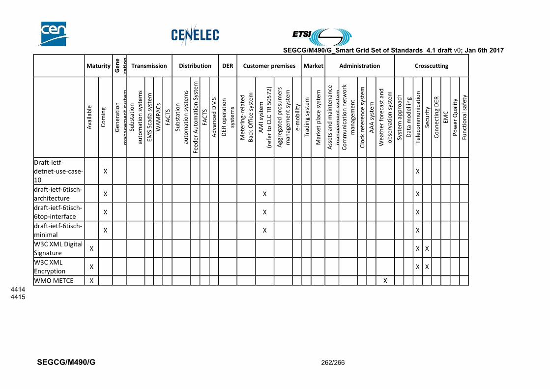
SEGCG/M490/G_Smart Grid Set of Standards 4.1 draft v0; Jan 6th 2017
SEGCG/M490/G 262/266
Maturity
Ge
ne
rati
on
Transmission Distribution DER Customer premises Market Administration Crosscutting
Ava
ilab
le
Co
min
g
Gen
erat
ion
man
agem
ent
syst
em
Sub
stat
ion
auto
mat
ion
sys
tem
s
EMS
Scad
a sy
ste
m
WA
MP
AC
s
FAC
TS
Sub
stat
ion
auto
mat
ion
sys
tem
s
Feed
er
Au
tom
atio
n S
yste
m
FAC
TS
Ad
van
ced
DM
S
DER
op
erat
ion
syst
em
s
Met
erin
g-re
late
d
Bac
k O
ffic
e sy
ste
m
AM
I sys
tem
(ref
er t
o C
LC T
R 5
05
72
)
Agg
rega
ted
pro
sum
ers
man
agem
ent
syst
em
e-m
ob
ility
Trad
ing
syst
em
Mar
ket
pla
ce s
yste
m
Ass
ets
and
mai
nte
nan
ce
man
agem
ent
syst
em
Co
mm
un
icat
ion
net
wo
rk
man
agem
ent
Clo
ck r
efer
ence
sys
tem
AA
A s
yste
m
Wea
ther
fo
reca
st a
nd
ob
serv
atio
n s
yste
m
Syst
em
ap
pro
ach
Dat
a m
od
ellin
g
Tele
com
mu
nic
atio
n
Secu
rity
Co
nn
ecti
ng
DER
EMC
Po
wer
Qu
alit
y
Fun
ctio
nal
saf
ety
Draft-ietf-detnet-use-case-10
X X
draft-ietf-6tisch-architecture
X X X
draft-ietf-6tisch-6top-interface
X X X
draft-ietf-6tisch-minimal
X X X
W3C XML Digital Signature
X X X
W3C XML Encryption
X X X
WMO METCE X X 4414 4415

SEGCG/M490/G_Smart Grid Set of Standards 4.1 draft v0; Jan 6th 2017
SEGCG/M490/G 263/266
Annex A Detailed list of abbreviations 4416
Table 92 - Abbreviations list - complete 4417
Abbreviation Meaning
3GPP 3rd Generation Partnership Project
6LoWPAN IPv6 over Low power Wireless Personal Area Networks
ADMS Advanced Distribution Management System
ADSL Asymmetric digital subscriber line
AMI Advanced Metering Infrastructure
AMR Advanced Meter Reading
AN Access Network
ANSI American National Standard Institute
AS Application server
CA Certificate Authority
CC Control Center
CEM Customer Energy Management (refer 7.7.2 for details)
CEN European Committee for Standardization (Comité Européen de Normalisation)
CENELEC European Committee for Electrotechnical Standardization
(Comité Européen de Normalisation Electrotechnique)
CHP Combined Heat and Power
CIM Common Information Model (EN 61970 & EN 61968 series)
CIS Customer Information System
CMC Certificate Management over CMS
CMP Certificate Management Protocol
CMS Certificate Management Syntax
COMTRADE Common Format for Transient Data Exchange (IEC 60255-24)
COSEM Companion Specification for Energy Metering
CT Current Transformer
cVPP Commercial Virtual Power Plant
DA Distribution Automation
DCS Distributed Control System (usually associated with generation plant control systems)
DER Distributed Energy Resources (refer 7.7.2 for details)
DIN Deutsches Institut für Normung
DLMS Distribution Line Message Specification
DMS Distribution Management System (refer 7.7.2 for details)
DR Demand Response
DSO Distribution System Operator
eBIX® (European forum for) energy Business Information Exchange
EC European Commission
ECP Electrical Connection Point
EDM Energy Data Management
EFET European Federation of Energy Traders
EGx EU Smart Grid Task Force Expert Group x (1 to 3)
EMC Electro Magnetic Compatibility
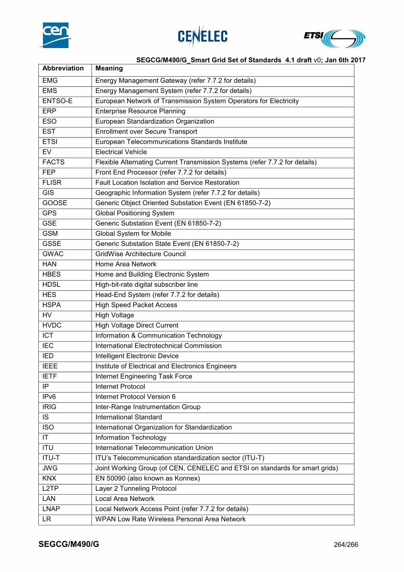
SEGCG/M490/G_Smart Grid Set of Standards 4.1 draft v0; Jan 6th 2017
SEGCG/M490/G 264/266
Abbreviation Meaning
EMG Energy Management Gateway (refer 7.7.2 for details)
EMS Energy Management System (refer 7.7.2 for details)
ENTSO-E European Network of Transmission System Operators for Electricity
ERP Enterprise Resource Planning
ESO European Standardization Organization
EST Enrollment over Secure Transport
ETSI European Telecommunications Standards Institute
EV Electrical Vehicle
FACTS Flexible Alternating Current Transmission Systems (refer 7.7.2 for details)
FEP Front End Processor (refer 7.7.2 for details)
FLISR Fault Location Isolation and Service Restoration
GIS Geographic Information System (refer 7.7.2 for details)
GOOSE Generic Object Oriented Substation Event (EN 61850-7-2)
GPS Global Positioning System
GSE Generic Substation Event (EN 61850-7-2)
GSM Global System for Mobile
GSSE Generic Substation State Event (EN 61850-7-2)
GWAC GridWise Architecture Council
HAN Home Area Network
HBES Home and Building Electronic System
HDSL High-bit-rate digital subscriber line
HES Head-End System (refer 7.7.2 for details)
HSPA High Speed Packet Access
HV High Voltage
HVDC High Voltage Direct Current
ICT Information & Communication Technology
IEC International Electrotechnical Commission
IED Intelligent Electronic Device
IEEE Institute of Electrical and Electronics Engineers
IETF Internet Engineering Task Force
IP Internet Protocol
IPv6 Internet Protocol Version 6
IRIG Inter-Range Instrumentation Group
IS International Standard
ISO International Organization for Standardization
IT Information Technology
ITU International Telecommunication Union
ITU-T ITU’s Telecommunication standardization sector (ITU-T)
JWG Joint Working Group (of CEN, CENELEC and ETSI on standards for smart grids)
KNX EN 50090 (also known as Konnex)
L2TP Layer 2 Tunneling Protocol
LAN Local Area Network
LNAP Local Network Access Point (refer 7.7.2 for details)
LR WPAN Low Rate Wireless Personal Area Network
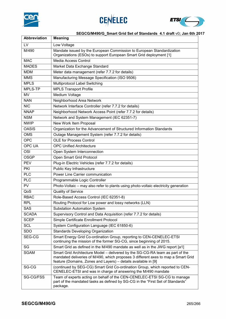
SEGCG/M490/G_Smart Grid Set of Standards 4.1 draft v0; Jan 6th 2017
SEGCG/M490/G 265/266
Abbreviation Meaning
LV Low Voltage
M/490 Mandate issued by the European Commission to European Standardization Organizations (ESOs) to support European Smart Grid deployment [1]
MAC Media Access Control
MADES Market Data Exchange Standard
MDM Meter data management (refer 7.7.2 for details)
MMS Manufacturing Message Specification (ISO 9506)
MPLS Multiprotocol Label Switching
MPLS-TP MPLS Transport Profile
MV Medium Voltage
NAN Neighborhood Area Network
NIC Network Interface Controller (refer 7.7.2 for details)
NNAP Neighborhood Network Access Point (refer 7.7.2 for details)
NSM Network and System Management (IEC 62351-7)
NWIP New Work Item Proposal
OASIS Organization for the Advancement of Structured Information Standards
OMS Outage Management System (refer 7.7.2 for details)
OPC OLE for Process Control
OPC UA OPC Unified Architecture
OSI Open System Interconnection
OSGP Open Smart Grid Protocol
PEV Plug-in Electric Vehicles (refer 7.7.2 for details)
PKI Public Key Infrastructure
PLC Power Line Carrier communication
PLC Programmable Logic Controller
PV Photo-Voltaic – may also refer to plants using photo-voltaic electricity generation
QoS Quality of Service
RBAC Role-Based Access Control (IEC 62351-8)
RPL Routing Protocol for Low power and lossy networks (LLN)
SAS Substation Automation System
SCADA Supervisory Control and Data Acquisition (refer 7.7.2 for details)
SCEP Simple Certificate Enrollment Protocol
SCL System Configuration Language (IEC 61850-6)
SDO Standards Developing Organization
SEG-CG Smart Energy Grid Co-ordination Group, reporting to CEN-CENELEC-ETSI continuing the mission of the former SG-CG, since beginning of 2015.
SG Smart Grid as defined in the M/490 mandate as well as in the JWG report [a1]
SGAM Smart Grid Architecture Model – delivered by the SG-CG-RA team as part of the mandated deliveries of M/490, which proposes 3 different axes to map a Smart Grid feature (Domains, Zones and Layers) – details available in [9]
SG-CG (continued by SEG-CG) Smart Grid Co-ordination Group, which reported to CEN-CENELEC-ETSI and was in charge of answering the M/490 mandate
SG-CG/FSS Team of experts acting on behalf of the CEN-CENELEC-ETSI SG-CG to manage part of the mandated tasks as defined by SG-CG in the “First Set of Standards” package.
SEGCG/M490/G_Smart Grid Set of Standards 4.1 draft v0; Jan 6th 2017
SEGCG/M490/G 266/266
Abbreviation Meaning
SG-CG/RA Team of experts acting on behalf of the CEN-CENELEC-ETSI SG-CG to manage part of the mandated tasks as defined by SG-CG in the “Reference Architecture” package
SG-CG/SGIS Team of experts acting on behalf of the CEN-CENELEC-ETSI SG-CG to manage part of the mandated tasks as defined by SG-CG in the “smart grid information security” package
SG-CG/SP Team of experts acting on behalf of the CEN-CENELEC-ETSI SG-CG to manage part of the mandated tasks as defined by SG-CG in the “Sustainable Processes” package
SM-CG Smart Metering Co-ordination Group, reporting to CEN-CENELEC-ETSI and in charge of answering the M/4441 mandate
SLA Service Level Agreement
SNMP Simple Network Management Protocol
SOA Service Oriented Architecture (IEC/TR 62357)
SIPS System Integrity Protection System
SyC System Committee (IEC)
TC Technical Committee
TDM Time Division Multiplexing
TF Task Force
TMS Transmission Management System
TR Technical Report
TS Technical Specification
TSO Transmission System Operator
tVPP Technical Virtual Power Plant
UC use case
UMTS Universal Mobile Telecommunications System
VAR Volt Ampere Reactive – unit attached to reactive power measurement
VLAN Virtual Local Area Network
VoIP Voice over IP
VPP Virtual Power Plant
VT Voltage Transformer
WAMPAC Wide Area Measurement System (refer 7.7.2 for details)
WAN Wide Area Network
WG Working Group
WPAN Wireless Personal Area Network
xDSL Digital Subscriber Line
XML Extensible Markup Language
4418
Related Documents