SECTION 1 SEFIVICE MANUAL TABLE OF CONTENTS I. TECHNICAL DATA .... .. ........ 2, II. DISMANTLING O F U N I T. . ., , ..... 4 ÍII. CONTROLS .......... 5 IV. PRINCIPAL PÁRTS IOCATIONS ............... 5 V. VÀRACTOR TUNER AND PRESET TUNING SYSTEM .... ............ ,.,. 6 l. VARACTOR TUNER . . . . . . . . ............. ó 2. PRESET TUNING SYSTEM . . , . ,.-.,..,.,.-,9 VI. TUNER ADJUSTMENT ............ I0 I. F MS E C T I O N ADJUSTMENT . . . . , ........ I0 2. LW SECTION ADJUSTMENT . . ,.,.,,..,12 3. MW SECTION ADJUSTMENT . . . .......... I3 VII. MAIN AMP ADJUSTMENT , ... . , . , . , , . , . . . . . . . 14 VIII. TUNING CORD THREADING .. . , . , . , . . . . . . . . . . I5 IX. CLASSIFICATION OFVARÍOUS P.C BOARD . . . . . . . . ....... 16 I. RELATION OF P,C BOARD TITLE AND IDENT]FICATION NUMBER . . . , , . , . , . , , , , . , . I ó 2. COMPOSITION OFVARIOUS P.CBOARD ...... _ ........ _17 FoÍ baÍc adjusimênrs, ne.suring nerhoG, 6d operari.g prin.iptes, reter to CENEÍ|ÀL OPERÁTING PRINCIPLES AND ADJUSTMENTS.

Welcome message from author
This document is posted to help you gain knowledge. Please leave a comment to let me know what you think about it! Share it to your friends and learn new things together.
Transcript

SECTION 1
SEFIVICE MANUAL
TABLE OF CONTENTS
I . T E C H N I C A L D A T A . . . . . . . . . . . . . . 2 ,I I . D I S M A N T L I N G O F U N I T . . . , , . . . . . 4Í I I . C O N T R O L S . . . . . . . . . . 5I V . P R I N C I P A L P Á R T S I O C A T I O N S . . . . . . . . . . . . . . . 5V . V À R A C T O R T U N E R A N D P R E S E T T U N I N G S Y S T E M . . . . . . . . . . . . . . . . , . , . 6
l . V A R A C T O R T U N E R . . . . . . . . . . . . . . . . . . . . . ó2 . P R E S E T T U N I N G S Y S T E M . . , . , . - . , . . , . , . - , 9
V I . T U N E R A D J U S T M E N T . . . . . . . . . . . . I 0I . F M S E C T I O N A D J U S T M E N T . . . . , . . . . . . . . I 02 . L W S E C T I O N A D J U S T M E N T . . , . , . , , . . , 1 23 . M W S E C T I O N A D J U S T M E N T . . . . . . . . . . . . . I 3
VII . MAIN AMP ADJUSTMENT ,. . . . , . , . , , . , . . . . . . . 14VIII. TUNING CORD THREADING .. . , . , . , . . . . . . . . . . I5I X . C L A S S I F I C A T I O N O F V A R Í O U S P . C B O A R D . . . . . . . . . . . . . . . 1 6
I. RELATION OF P,C BOARD TITLE AND IDENT]FICATION NUMBER . . . , , . , . , . , , , , . , . I ó2 . C O M P O S I T I O N O F V A R I O U S P . C B O A R D . . . . . . _ . . . . . . . . _ 1 7
FoÍ baÍc adjusimênrs, ne.suring nerhoG, 6d operari.g prin.iptes, reter to CENEÍ|ÀL OPERÁTING PRINCIPLES AND
ADJUSTMENTS.

I. TECHNICAL DATA
PoWER AMPLIFIER SECTION
CONTINUOUS POWER OUTPUT2{HÁNNELS DRIVEN 14 Watts per chdnel, nininun RMS, at 8 ohms from 40 to 20,000 Hzwilh no
more thm 0-8% lotal tamonic distoilio..
POWER BANDWIDTH OHF)SIGNAL TO NOISE RATIO OHF)
RESIDUÀLNOISE
CHÀNNEL SEPÀRATION íHF)
l5 Hz to40 tHzl8 ohns. dislortion withiÍ 0.8%
PHONO
AUX
SPEAKERSHEADPHONE
PHONO Betler rhan50 dB at 1,000 HzLes rhán 0.8 nV al 8 onns
More than 30 (l kHz.8 ohmt
A, B (4 to 16 ohmt/Á+B (8 ro 16 ohm9
PIN: 150 nV/100 k óhnsDIN: l0 nv/180 k ohms
P I N : 1 5 0 ó V / l 0 0 k o h n sDIN: 150 mv/r00 k ohms30 Hz lo 15 kgz ll dBl0 Hz lo ?0 kHz +0 dB, 2 dB
+10 dB at 100 Hz, +5 dB at 10 kHz(Volume conbol setal -30d8 position)
INPUT SENSIÏVITY/IMPEDANCE
PHONO
AUX
TAPE MONITOR
DAMPINC FACTOR
ottrPuT
PRE ÁMPLIFIER SECTION
OTITPUT I'EVEL/IMPEDANCE
TONE CONTROL
LOT'DNESS CINTROL
FREQUENCY RANCE
SENSITIVITY OHF)CAPTURE RATIO
SELECTIVITY (IHF)
IMÀGE REJECTION
IF RE.'ECTION
SPURIOUS REJECTION
AM STJPPRESSION
SIGNAL TO NOISE RATIO
HÁRMONIC DISTORTION
TT'NING INDICATOR
STEREO SEPARATION
SUBCARRIER SUPPRESSION
ANTENNA INPUT IMPEDANCE
88 MHz ro 108 MHz
1.5 dB
TAPE REC
FREQT'ENCY RESPONSE PIIONO (RIAA)
TUNER/AUX/'TAPE MONITOR
BASSTREBLE
More rhan 5 t dB (98 MHz)
More than 70 dB (98 MÈz)Móre than ?0 dB (98 MHz)
50 dB60dB
MONO
STEREO
Le$ thàn 0,3% i 100% nodtlation)
Les ihan 0,6% (1009', modulÁ1ion)
C€nter Turiq meter a FMore than 40 dB (l tHz)
300 ohns balanced, ?5 ohms unbabnced
FM TUNER SECTTON

AM TUNER SECTION
FREQUENCY RANGE
SENSITIVITY (IHF)
SELECTIVITY OHF)
SICNAL TO NOISE RATIO
IMAGE REJECTION
IF REJECTION
SEMI{ONDUCTORSPOWER REQUIRDMENTS
DIMENSIONS
520 kHz 10 1 ,605 kgz150 kHz to 350 kHz '200 Àrv/n (tEr anl€nna) 20liv (ext. antêntu)300 lrv/h (bar antenna) 30llv {ext. antÈnM)
MW: More than 30 dBLW: More than 30 tlB
More than 55 dB (l MHz)More tho 35 dB (240 ktlz)
MW: Moie than 45 dB,Lwr More thd 50dB
TÍaÍníors: 27, Diodes: 25, FET!: 2,CSÁ, ULa.d LA hodelsr l20V,60HzCEE nodeh: 220V, 50 HzOlher nodels: 110/220l240V, 50/60 Hz swilchable440(w) x l2s(H) x 26s(D)nm (17.3 x 4.9 x r0.4")
WETGHT 6.2 ke ( l I T lb t
' Forimprovem€nl purposes, specilications and d€sisn are snbj.ct tóchanse{nhost nolic€,

DISMANTL ING OF UNIT
In case of lrouble, e1c. necessilaring disassembly. pleáse
disassemble in the order show. in pholos.aphs. Reassemble
scREws
scREws
. . - : .
| = = = = = = a l= i l Ê E E ë l
a iË . - iÊE=E . - . - .a l" t

I I I . CONTROLS
-n r= FIl
VOLI]ME
IV. PRINCIPAL PARTS LOCATION
Fis. 1 Controls
[.lr "t4. - l f .
r--Eïl Ê . ' Il9g!)
**."" Enn6U
Fig.2 Top View

V,R PC EOARDaÁ-5t57
IC FC EOARDAÁ-5r56
TOUC|I SW|ÍCHPC BOARo ÁA-5r58
Fig.6 Block Dias.am
t :
L
t - -
3) Acrual Operation
Fig. 5 is a cÍcuit diagram of the high fr€qu€ncyamplifier stase only of a circuit which is actuallyused. Condenser Cl and varactor diode Dl inthe diagram are equivalent to the variable con,denser of an ordinary FM fÍont end. As can beunderstood from Fig. 3, Dl varies the capacitancein a 4 to 16 PF ranSe by means oí inverse biasvoltage. This capacitance and condenser Clcombined caFcitance forÍns the Íesonance circuitwith coil LA. Consequently, it is satisfactoryif at low.esonance íÍ€quency, the voltage suppliedto the varactoÍ diode d€clines, and at hid re-sonanc€ frequency, the voltage supplied to th€varactor diod€ increas€s. This voltage variationmethod with variabl€ resistor, êtc., op€ratesin the sam€ way as a regulaÍ variable cordenser.
FiE.7
This method uses a local oscillator circuit andfrequency mixer circuit, and bias voltage is appliedto the varactor diode for starioo selection and iscalled a varactor tuneÍ. Pleas€ r€fer to the scheÍ,a-tic diagran foi actuai circuit drawing.
I IV

\/. \'ARACTOR TUNERAND PRESET TUNING SYSTEM
I. VARACTOR TUNER
A varactor tuner is th€ luner system in which varáctordiode junction capacitance is varied by means of theinverse bias value applied to the diode for stationselection. By employing a varactor diode. tuningwhich is same a! ordinary vaÍiable condenseÍ s),stemcán bê mad€ without using a variable condenser bychanging control voltage only.
l) Featuresa) When used in an FM tuner, th€ front end can
be made small€r than \{hen compaÍed with avariable condenser.
b) Station selector butaon positioning is notlimited.
c) Slation sel€ction by remote control is possible.d) Ideal voltage can be set for a certain reception
frequency beforehand, and preset tuning canb€ efect€d by successively switching the
e) If control voltsg€ sweep is at ideal speed,automatic tuning (seàÍch tuning) is posible-
0 Pow€r consumption is about the same as avariable condenseÍ system.
ïf,g
q
Fig. 3
Fig. 4 Tuning circuit employing a vaÍactor diode
Fig. 5 Example ofHigh Frequency
Amplifier Stage Cncuit
+ INVERSE VOLTÀCE
2) VaÍactor Diode CharacteristicsAs foÍ varactor diode characteristics, as shownin Frg. 3, cápacitance c r( changed by chm8e ininverse voltage VR. Further, ifthis varactor diodeis used jn a tuning circuit, the following conditions
Cmax + CD
Cmin + CD
Cmai, Cmin arc th€ maximum and minimumvalues of varactor diode capacitánce change. CDis the sum of stray capacitance and trinmercapacitance. K is over l_5 b€cause FM broadcastfrequency range is 88 to t08 MHa Fig.s 4(a)and 4(b) show the actual usage method.
I

iti!È! ruMre
\ . t t i i' i i lt I
t r i
Fig. 8
lcr lJPclo09cTERMTNAL@@@@
TO VÀRIABLE CAPACITOR
Fig. 9

2. PRESET TUNING SYSTEMl) Preset Station Selecrion
For preset íatio. selection, there is a mechanicaland an eleclrical merhod. These are memoryequipme.t and seiection equipment enablingdesÍed station s€lection beforehand and selectingthes€ pre-set srations by simply d€pressing therespective switches.An ordinary car redio, etc. utilizes a mechanicalstation selection system wherein mechanicalvariation is by mea.s of a variable condenser orposilioning ofa dust corc inside a coil.Model AA,1010L utilizes an electrical srálionselection system and employs the varacror tunerexplained in a previous item.
2) An example of a stllion selection system employ"ing a varactor tuner is shown in Fig. 6. For skrionselection, push switches are used for s€lecuonof voltage supply to the varactor tun€r. However,in the AA.10I0L, these station selection pushswitches are puÍe electronic system sensi.touch
3) Sensi-touch Employed Preset Station SelectionSystem OperationThe circult shown in Fig. 7 is th€ conlrol voltagegenêratinS pres€l volume and sensi-touch circuir.Fig. 8 sho'rrs the inside of circuit sensi-touch ICFPCI009C which include the 4 channel circuitry.Terminals 14 thÍou8h 17 are the input teminals;. e r m i n a l s @ , @ , @ , - a @ a r ê t h e s t a t i o nselection output terminals; and terminals O ,@ , @ , and O are rhe pilot outpul terminals.When channêl I sensor electrode is louched,voltage is snpplied to the IC as rhe input signalthrough fmger (body) resistance at t€rminal @ .Then, the impedance is lowered at IC stationselector output terminal @ and current flowsai shown by the arrow marks in Fig. 9. Consequ-enlly, because the supply voltage 10 the varactorruner diode is changed by the dividing ratio ofRb and Rc, station selection is possible bym€ans of setting the pr€set volumes beforehandaccoÍdrng to the deri Íed broadcarl t Íequen.res.

tVI- TUNER ADJUSTMENT
IIIJLTI FUNCTIOI{ PC BOARD AA-5I59À
" @
@
@
Ë E@ a D
o
@. @ .o.
FM IUNING METER ÀOJ (LO*ER CORE)FM OISTORTION ÁDJ (I]PPEN CONEI
aà.o;
K-lt :J
rkHÍr I Ei " t rca
@. @"TP.o
FREOUENCY ÀOJ
i:ió'" Á0
€Ío lH: tró",,1"R?".1-,
7 { A ^\<9r
p"@.@ "op@ @ @*@oo
ro rà aà(à
@ o @ ( s )à EÈ 5 .À,.À.n
a Ë
Fic. l0 Multi Function P.C Board AÀ-515941. FM SECTION ADJUSTMENT (RefeÍ to Fig. l0)
IF CoilIF Cóil
Tune oÍly noise withour
inlerfereÍce of hroadcasls.
2
3108 MHz,ó0 dB (mono) input,Lers than 0.3% distoition
t 0

I f Tunins M€ler iÍdicalion
is nol al @ler posilion,
rep€tl íeps 2 a.d 3 above.
108 MHz,60 dB(moÍo) input.
EÍor: within !250 kgz.
108 MHz, L6s than l2 dB
vR3,5 tB88 MHz, ó0 dB (nono) inpul.
Eror: WÍhin 1250 kHz.
888 Mttz, Les ihan 12dB
9
98 MHz. Less than 12 dB
EÍor: Within 1250 kHz.
l 0
v R l , I k B
19.00 kHzConnect Frequency Counter
l l
98 MHz.60 dB Gt€reó) input.When ihe Í€r€o i.dicatorràils to light, this mans thalbroadcast n nol beins Íeceiv€d
t 2vR2, I kB
40 dB
98 MHz,60 dB G1€r€o) l€ftchannel inpul. DistortionFaclor ruí be less than
0.6%.
t l40 dB
98 MHz,60 dB Glereo)
Distortion factor musl be
NOTE I.
NOTE 2.NOTE 3.
Chart I
ln the event that the distortion facrors in Steps 8 and 9 are not tess than 3%, re-adjust FroÍt End TrimÍn€.Condensers TCR.nd TCA to obtain a miniÍnum average dislortion factor at 88,98, and 108 MHz (san€distortion factor at all thÍee Doints).PLL IC Free Running Frequenry Ínust be an exact 19.00 kHz.Ifthe distortion factor is not less than 0.ó%, tuÍn IF Coil in Step I wjthin 1/2 turn rnd adjusr.
VII- MAIN AMP ADJUSTMENT
i-*i i-*i'ÍxI' '[[ro. @
.(a7
Á @
. @
" @
-CF+:C.o3 @
m Q€ ? l I
" l l
p p/z=\ n.= _ En!* (( "," )) =*H@v
mP{JSH swrrcH Pr soaRD aÀ-5l55 @. Ul
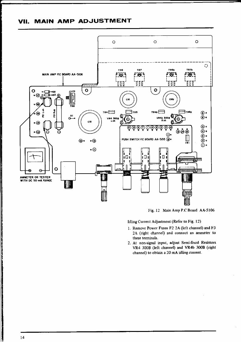
Fig. 12 Main Anp P.C BoaÍd AA'5106
ldling Cuíent Adjultment (RefeÍ to Fig. l2)
l� Remove Power Fuses F2 2A (left channel) and F32A Gight channel) and connect an aÍuneter to
2. At non.signal input, adj$t Senifixed ResistonVR4 3008 o€ft channel) aíd VR4b 3008 (Íiehtchannel) to obtain a 20 mA idling cuÍÍent.
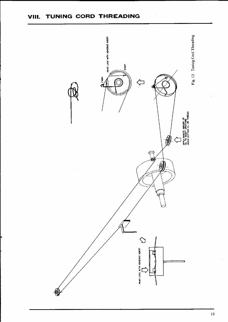
VIII . TUNING GORD THRTADING
!EsX E ;
:EE
F€
ë
tgz
15

I
IX. CLASSIFICATION OF VARIOUS P.C BOARD
I. RELATION OF P.C BOARD TITLE AND IDENTIFICATION NUMBER
P.C Board Number ofP.C Board
MFC P.C Board À4.5159À
Main Amp P.C Board AA-5106
Touch Switch P.C Board A A 5 1 5 8
Volume P.C Board A A - 5 1 5 7
IC P.C Board A Á . 5 1 5 6
Push Switch P.C BoaÍd AA-5155
LED P.C Board AA-5159C
Chart 4

2. COMPOSITION OF VARIOUS P.C BOARD
I) MFC P.C BOARD AA.5I59A & JUMPER P.C BOARD AA.5'59B
." . '" t- ^"r 1.1o.) t�
- r , _ -
! Á s o & O j ! É
- l
cti
+e*.sïi6i:ï ^ *!_1o-M 5 É ? ( 9 -
-

r t r " - . r - , ,o ï
IL n -
6).
ÀÁ - 5,6r 4,G).:
o r
@ @ Fnn

2) I tÀrN AMPP.C EOARD AAslOó
@ 0 9 e @ 9
II
3i TOUCH SWITCH P,C BOARD AA.5I58

,1) VOLUME P.C BOARD AA-5t57
5) IC P.C BOARD AA.5156
a a - 5 1 5 8
an-s os@
M E T E R { + )
I
E S E T Í U N I N G
l^^.,,"l
@@
@o@@
na s rss @
; o@@@
ÁEf rqB@ á Í á á
Á À - 5 1 5 8
o@@e@@q q q q ' r q
l 9

ó) PUSH SWITCH P,C BOARD AA-5I55 & LED P,C BOARD AA-5T59C
9 P
d I Áa-to6Á
t-, t-f t7 \l
aa-srosn@
Ë
urrItopE I
o @ 9 @ @ @ o @ o o
UE E EI
)o

,l t, lt t.'::
()rJo'Is (s6sls-rív) oxvo{ J d uadnnf)I€:" t" t€" " " xJo]s (v6tÍs-w) cuvos J d NotIJNru tfiru{.G":"''''' ' 'Jsn sf,uvd auvds g:IqNennoJÍru
,.ó1II{!IJ.I{O) dO gltrVI
I
IEil'r SItlVGlz t{olrtas -

2.3 .
HOW TO USE THIS PARTS LIST
This parts lÈt is compiled by various indMdual blocks based on assembly processWh€n ord€riog paÍs, please describe paÍts number, serial numb€I, and model nunber in delail.How to read list.
The Íef€r€nce numbeÍ corresponds with illustration oÍ photo number of thal paíicularpaÍts list.
This numbeÍ coÍÍesponds wilh .he Figul€ Number.This numb€r corÍesponds with the individual parts index numbeÍ
A small "x" indicates the inability to show that particulaÍ paí
in tl€ Photo or lllustration.Schematic Diagram NumbeÍ of individual
(not requn€d foÍ parts ordet-Quantity of paniculár part requjred.It
in ttut figure.
FLFvI|EEL BLocK #llr2- l I sx 3oo42s Flyvneel Blo.k asy.conp. RDorr312 lló 244so6 Flywheel Onlyl 2 - r r ?x 244754 F .h , F l ywhe . l
Mlin M.r,l C$er2 - l r 9 2s3030 M . i n M . t . l
4. The synbol numb€rs shown on the P-C. Board list can be matched w h the Conposite Viewsofcompon€nts cfthe Sch€matic Diagram or Service Manual.
5. Please utilize sepaíàte "Common List for Senice Parts" for Resistor parts orders.6. The shape ofthe parts and paÍts name, etc. can be confirmed by compa.ing them ivith the paÍs
shown on the Electrical Parts Table ofP.C. Board.7. Both the kind of part and installation position can be determined by the Parts Number. To
determine wh€re a parts numbeÍ is listed, utilize Pans Index at end of Pans List.It is necessary first of all to find th€ PaÍts Number. This can be accomplished by using theReference Number listed at right of parts number in the Parts Index. (meani.g of ref. no.outlined in Item 3 above).
8. Utilize separate "Price List fo. PaÍs" to det€rmine unit price- The mosl simple method offinding parts Price is to utilte the ref€r€nce number.
CAUTIONT l .
2.
When placing an order for paÍs, be su.e to list the paÍs no. model no., anddescÍiption. There aÍe instances in which ifany ofthis informaiion is omitted,paÍts cannot be shipped or the wÍong parts will be delivered.
Please be cáreful nol to make a mistak€ in the pads no. Ifthe paÍsno.isi.eÍror, a part different trom the one ordered may be delivered.

6Z
0t0t-vv se àtuBs00002-J.tc-r^lr\l lroJ roreuruu)src8090s909
ralan Buunl las-árdI I€O'ZÍ^{:I
n6-qAtz1>l r313t{SuIUnJLZLSggVIS
(zxru/urOg9) yu O0r Arl (ád,iJ pro)) dtue-lt6I0s9'I:I
Itref r3à?ads d,s89999m
VOSEEV'] JI16S0S9I:I
Joft,rr Jlz9€0s9If
ZZIIYI JII L8 L69Tg
0I0r'vY s" eu€sZOIZIV I JILno699rZ
J6ooIJdt JItnn6zzlz
u\-IlÀlt1u ?uusruYrEStro0rzÁz
À\[0I-]as aporcsnoullrln'ltz9€s9(I4
gz 90à eporo ráu.z€08622(Ig
(Jrglzoà aporcràu3z99€.OnZAS
cds I (IIz'ÀJJ rasuapuoJ ràurnrlabLsL9Jg
lt9z9J uo) ur^S6ZOiZJS
stz.Hnt surrl Jso À,\'I920€t9ts
aaJ0I0I-YY su au?sl.-toI0I-vY suerJ JaÀodt€l sIzJs
0l0I-vv s? 3tLrEss'mlol Yv surrl rsnods08669JS
duoJ Irotg Iaued ruorc8t0s€zc{
0t0I-vv sP aurEstzls-YY raurqEJe8/669Js
8SI9'YV duoJ pl?og 3 d ,{S q.noI0l.Is€zvs
gSIS-yV druoJ preog J d f,I50z9tzY8
l.Slg-yy duoJ pr€og J d to^zsIgtzY8
ESIt-yy druoJ prEog J d lts qsnd9tisgzvS
SgOIS-yy druoJ prRog J d (g'ILnzgtzYa
V6S ls-vv druoJ pr?og J d uorcunJ lltnw8SZ9€ZVS
agJV90t S-W duroJ pr?og J d duv urel,{9tz9tzYs
v9OIg-yV druoJ prEog J A druv urBt{szzstzvsJION'oN *rEd
'sur4l srled ál?ds papu.ruluooau
àsárll {.ols noÍ t€qr lso8Êns à^\'poqsnduo.re aq uEr rrBdar Áur tsorup'pt!?q uo alr aotaq parsl srrpd àqrJr'àsnm3g
rsI'I sJuvd auvds c3dNalu4lolgà I

Parts No. Note
EO645838 OSC Coil RWR41497A
EO650373 AM-IF Trans. RLC41543A 468 kHz Same as AA-1010
EOó50384 AMIF Trans. CFU-085-D 468 kHz
ES24035s Rotary SW. SR26N l-3-5 30KC
Ê,s240287 Rotary SW. SR26N 30 KC
8S240096 Push Sw. 3FT-0001FF2120
85240276 Pushsw. 5FT-0001DF3620
EV24U34 Double axial 2 thÍow Vol(FR) DJ80D 250 kBx2
8V240445 Single aixal 2 throw Vol. CM70R 20 kcx2
8YL299 ts Pre-set Vol. (w/knob) LFQDRS04 I00 kB
8V499364 Semifixed Vol. V10K8-4-2 5kB $me as AA-1010
8V484863 Semifixed Vol. V10K84.2 I kB
E2655t8'�7 5P Àntenna Têrminal Plate
s8607t38 Push Knob C A5-5022
sK6468 t 7 Single Knob AA.5250
sK644670 Double Knob (Upp€D ÀA-s3ss Same asAA-1010
sK645208 Double Knob (Lowet AÁ-s3s3
sK646828 Tuning Knob (Snall ) AÁ-5252
s2645243 CirculaÍ Foot A CA.60l4
TA240300 VaractorTuner VFT-22MH-21

I'
r ?t-9l9t
tt?-9-9? ozIzrl I000llf À\s qsnd 96oo?zstzt+\t lc)gr?oÈ àporc r.uàz 99rorzaa
3le.t-sr (r{x,I)r/9asrrorscu?tJ 99t99913
sxe peàq wd iaàDs gaozznszv a$s duz,I i90rrzvr
cxsor"tSs os r r60i69(I:rprÈóslJat1 19|lrtva
prsos J d as qsnd 9rr9€?vs
O3o'ts (f,6s Is-w) ouvog J d osl))Jo'rs (ssIs-vy) oàvos J d Ms Hsnd .1.
Jó00 r3dt lr €"6zrl?
'deoc p[og Jd JI eoa9€zvil
^"o.o"l{,*
)Jo'Is (9sIs-vy) (uvog I d JI .9
9 l.lt,gi (qour/À)
'to^ r.}.rd 9r66zz^3 sorrd^.9
apord uo.rts fo6ra9c3 9oracI s
z0z.3.sJ
uold0Jsào
3?-t-9t
sporo jàuáz ros6zaciII l"?l-9r (89)vo€)Sz .Lgl rs0r6rfgz I3-r-9t (sxx)(Oxd)9rócsz
rolsrurJ ecr9tsrS a,rtI9r (r9rr vv)
duoJ Èroa J d .to^ Lsrg€zvg r.9
",o,,,,1:^*,.uoudF6.C .oN ïrrdroqu^s
)JO'IA (ZStg-W) CUVOA J'd'.IO I
I (8sr9-vv) duo:)lreog J.d.]l{s qinol 0Lr teevsvg
^"o,,,11,otJo'Is (8slg-\.v) ouvo8 J d Ms HJnoI '
p$oq J.d !d!Io ásnl ,09a6rÍ3 , rr 3?'t-0r r9osN s
prsoe cd ràptoH.snj zzSrrslgor l-3I9t uu9 zr
prsos c d.al!|i|ràdunl !o39992Wa Z4ln (adrl rrà^)
^Àor (l{)lr 1,s.o .J/dnnruntv plrosa z'51-lz (adíl 1r:^)
^^{92 (N).{í r'O 'clrnu!unlv p!ros
, r-sr'rz (ad,{r sro) ̂^{sz(t^t)lt I 0 J/un|erusr
z &n-$ ()J srqó 09r ̂{z 't/urrt àprxo le!.nt 3t-91_9t ()) suqo L'o Àz
lorldw.È/àrPld tDtàwz II- -gt Vu 001(X) sut{o or
l{t/ r orNxl t/asítIzt-z-tN rrst d€
0{?'01-$ (ersuqó o0€ z'r'8y0I^'ro^/p.rrt-rr.s t3nro9^3 rt^ €
a zz-a-gt zxJr oz xol,t{5 'lo^ aor'{r z IErxE aFurs s''orz^3 e.e)I^-€Ít,O.u-r,s uoDdrJs.c
rqep !! DqutrN lápot/[ pur !uotór*.O lDqunN srrod àq|$rp detd.3rnd rllnplo uêqM
I !^/-l-91 zxglosz c03fq( ul).lo^/àrqnoo
z /'01-!t zzzro^ ioNrE^a i.z-sr zcor àporc uorltsI '9È!t O€I Z]{r.pólo Du.zI s0r.I-st GXs)€r€asz rors'slrrlz g??-I-9r (r{)(1)909gsa ror$uErJz 3lt-1.9r ( Ítx])r,9csa rorqsusrlz !a-r-gr (!{xl)soessz rórÍsuerrt 0tr-r-gr Gxs)ízzrJsz rorssudrrI (sa)) (veo rs w) duo:)
PreogJdouvureNI {veors w) duoJ
prDog J.d duv urDl^r
r 8!r-I-nr 6fl-t Itr 09? 0l-91
r 09? 0I-9[
r tz t.l-st
)JO'�IA (V90lS-Vy) OUVOS l d dÍ[V NMr '€
r (s6srs'vv)'duoJprdoqIdr.du.r
9r l'91-9t uu9 zrpreog J d áI^,\ ràdunf
r ?-6I-r? ^Á\9 r ln)lí/,r'o'J/unurunlv
PllosI ll-II-tZ (:drl !.^) ^,$Os
(r)rao0sLJ/ror,trsI l.IIr? (á"Ír'!à^) ^ÀOs
(Í)ldorn J/torÁlsr 9€?'9-!? O?grldrooo'Ilg
' ^1S qsnda st-z)z Jdsr
cra ^IJ J/ràuutrl
I IU-l-t? ())Hda z lroJSuUradz tl?-l-tz (tHNó€ ^r9rr rorJnpurr 0lz,l-t? (rHr3r z,Irtt roÉnPUII rtz-I4? zHr 39r o s8o.nlJ
Tuerf lr.wvI ?r?-l-lí zHr 39r v€Èsr'-J'lt
\u3rIjtr,{vI Sl_t li vl6rrru,1\d tróJ JSOI gt?-l-t? 9 rZ.Hrt iurrl Jso À-1r ''?.t-t? 00002.J,1t.'^or
I'oJ ucsroz zot-t-t9 2.3-vw L.or gls
ráIrl rrusràJz &-t4t [I,rzsr aporc uótrllga tÈ?,-r-91 (HxC)dNrrs rJsz
rorsNurrlr EÍr-9r (sxuxó)(d)s'6Jsz
lorsnU?lI
r 8ru-r.gr (Hxr) dNrrrrrszroNruerl
r 9H-9r (sxxxoxd)srórsa
| 9ll-r-st (rxs)0r6Jsz rorstsurrlr [9I-3-9t sose€.vr JrI M'0-!l JotJdt JrI stl4-sr zzr€'v-lJrI 9,t-&9t zo€rz-vlJrI (vótls w) 'luo:)
prsos Jd uotrfunl orntil
()Jo1s (s6srs-w) (uyos Jd àadnnÍ))lo'Ia (Y6sts-w)
(UYOS J'd NOIDNNC II'INW 'Z

8. ILLUSTRATION OF ASSEMBLY BLOCK
i l á t à 5 : à a . È , - è Ê F ë $ S 3 3 e
, /
32
BS: ' -SAg S : SS t

€€'trtlop u'ráqunNlàpol puE '� uolrdusác 'DquÍN srrud áq|tsáp óeáu "rnd tuFpro !.qiÁ
0tl-1"31 (:ISJ).-JOrOr'VV ruerl DAod €rrtlars
lltt,St 9..Loroí w susrr ràaod 9o3669Js
dr 'leuruFf turddsi^r 9€or95IÍ 3t-366-r-0r (3sJ)
0lrus) r.tpoH.snj az zrrs rzÍaN9,l-m .l'trJ d€ ràploH asnl olfzgqzs
dz trurui.J. qut? 1ft6€5r:IrnN IJet I I6I0rZ^{7
60Is v! sird )irDÍ .uoqdtràH 09or69vr6009.16 s ràrroll a990rsxr4l ?r'3l'n-!? (.xu/dose) vu o0r
^rr (.dIr prór) drdt eóroselgv Martrs r.ltou fl,9oÊ9sz
v rálloà I59oasnt{rJo'ls À'lahl?ssv
91-r.Z ràploH euuJruv Lnlsz9vJ 8e.s9t-t.99
iÈr.rtt9 tl
(3.�3) p,"r rv ooqele,$3M'r-gi ors z ( rnJ) proJ Jv €zro'9/r\l
I -r-rt zci9I s 'rln ràrJos Jv I9zos9Í3I* r '^l rnN 99r€rt'{\z
Br€ peàq urd arr)S orlralSZt9I-í! rirct rrteàds d' €399s9t36J1-Z t N' XS t)lrau uP4S Sróra9zfl
I# 'hl rnN 93r€I',1\z
(uorÁN) sq$^\ .seozr^rzrr! raqsP,$ tuudS rr6rlzmZ
09!i pr.q und Ààirs oo9rsssz(rJ3rs) (us)ex€
(F Àrrs 8u'JdrIr l"-Lttsl670g.ri lduur,tJ |,,u)ruv 0 roors\ I
I z9-z It
z t9-r.61
a
I 'I'9I.?
I rl-z-19
| otnt?1 z1'lt
àrPld rtururàt r.r?.dàl(s.qr)prBosJdbr?adàl
v loor I'lntrIJareld uouoq
(5drl I o)N3s).snl
(ádÁJ j o)N3S) asnl
(àdÁ1. J. o)t^lgs) àsnl^o5z va êsnl
Í ,tou]{ uolrnÍI qsnd
(n) FqsslÀ rsn(pv
(n) óq*/{ rsnÍpv
(n) DqsÉ,{\ rsnlpv
(n) ràqsen.rsnÍpY
(o) rà'rsB]\t rs.rp9
(n) É{sP^\ lsnÍpvs Énnr.}I àrtld árhsv ÉnrRr.x àr3ld áltrs
u9r90cpsarq.Ltáàq^ Ielosuxds lero
v ár8u .leJs
r.unI rorrtrs^A9z9C J/.tqExB^
'Itd) álEld t.1
(rds) DqsÀ ronzse^rz
lnu,uDI:uuáruvdj r3rsslzrUIE.YV (33J) L làued iPàU 96óolzds xót 3?I19 VV
IJO'�IS llNvd tv3t
t0t-È9? (r3JJ Jr 0fN9zÈS ,!!S Irtloà !Saorzss x.tll
z0l+qz J:{orscrNgzns,!!S Íroroà Srrorzss 91 3
3r[ pràr] usd airtrs 9031?rsz xgt Ià1tld r0r ̂rs qsnd Illlrzvt rl I
I r.3r ro raqfÀ 409019À\z zr 3
I.aql{surunl orc369tN
t. .9t?-rr-9ft-z-
()IdNj) rà^Iu uotÁN 3o€36e^tz
'oN lisd .,:Ï
z* Íarrs surddcl rozggrsz or-Bt
I-9r r.taí{ uïunl r.*ard rrtorzrlrs ó30Í-t 9t
rarar{ àurunJ LzL999N3tl"tl't zs99 oN
'oN iurqsnq raqqnu Lrro99ÍIllflzg-vv rroddns làu?d rLs9i9vl
tJo rs srssvH:) INox't
grc pD.q ued ÀaDS 9aozztsz
9re z# Àêris:urddst 9ór9zcsz na901-I-r't (lX3)€I€CSzrotsrsuerJ Ie9z9tJs xe.s
eYÍ PBJ'{ uEa $r'trs 05f6rfszll-9l-St r{ qsnÍI $qseÀ brqnsur ezzalg,r,\z rr 3
tJo'ls )NIs rvlH
)JO-IS ^1trítÍSSY 8
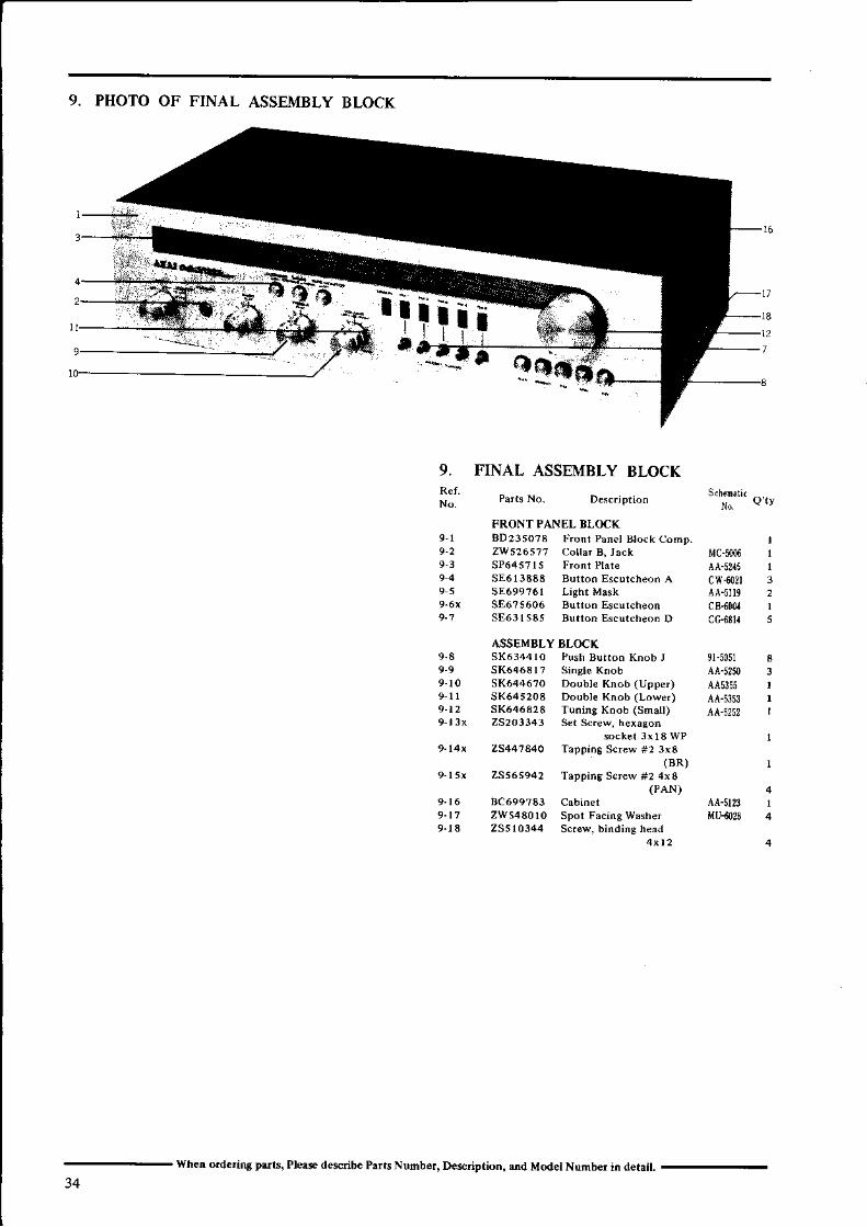
9. PHOTO OF FINAL ASSEMBLY BLOCK
iI
iIt
I
a
9. FINAL ASSEMBLY BLOCK
t
FRONTPANEL ELOC(9 r BD235O?3 FroÍi Panêt Btó.k Conp.9 2 2W526577 Co l l a r B i Jàck9 3 SP6457 l s F ro f , r P t r i e9 4 SE6 l333a Bu l t on Escu t cheo . A9 s SEó99?ól Light Mask
SE6?5606 Bu Ío .Escu l cheon9 .1 SE63 lS35 Bu Íon Escu rcbeon D
ASSEMBLY BL(rcX9-3 SKó34410 Push Buttoó Knob J
5K64ó317 S ing le Knob9 l0 SKó446?o Double Knob (Upper)
sK645203 Double xnob (Lowê.)9.12 SK6 6323 Tuning Kóob (Sdoll)
25203343 Set Sc.ew, hèxagonsocke l 3x l 3 wP
9.14x ZS44'7340 Tapping Scr€w *2 3x3(BR)
ZSs6s942 Tàpp ing Sc rew #2 4x3(PAN)
8c699733 C rb ine tZWs430l0 Spol FàcingWasberZSsl0344 Sc.e*, binding herd
Mc-ioo6 i
34when ord.ring Ddq Plqe descnbe Plrrs Number, DêÉnÉioí, md Model Numb.r i, dêtait.

s6z0l.sqa€066IZOA
e00rN rcsldcv90rg-vYSnsrzatf,zcol
€r609904Ln LSg(]i]
SA€L"SI889tSI
zsI9-wvs6Is-vvt06'u 9(atLnzsI
LI6SWTltcrvOt)szI,SIS-YVÍs0I6tJg(à5)V0€)SZ
Itsz9'Ja(O(drreoszss Is-vv
v90r9.vv99t9S9r:I(r{Xtrrscsz
€09t gfJa89S€6€JA
(JXdreorcsz(o)G)"zoszv90I s-vYItszstJg(rxd€rrdsz
0l869tJ:I($(Ozzzrf,szv6s Ig-vv9tn€zzLs(HXc)dNIr.9rJsz
,ztno9rg(HXc)rr€tf,szY9OIS-YY0I86tlI3(rXs)zzzrJSz
t€808rJE
9t89ftLA
(arr rassz(HXDXdXa)9€sosz
asrs-wY6SIS-VVcelsr 9I:r
(sXàX0Xd)t9t6JSZ
99€l6SJg()XOrsrJszVóSIS.vv€1,88r9I:r(cXOor6f,sz
9€rlssJa(àXo)ozr.vszv90I9'VV9'€ES9JA(r,{X-Dsogssz
'sIStsra0029I sJg
(D(ohesvsz(JXaXOszevszv6st g-vvzat6tsra(dXoxd)rÍYsz
oN slreduondurse(pr?og J A SulzIIIrn'oN slr?duorldursa(
sU€d àtqEàSuDqrrarulsrrrd I?uÉ!O
'páln[sqns 0q ue.^\ol3q pàrsn su€d atq"a9ueqrr3lur 3ql '�peuEtqo àq louu?c swd plnSuo eql às?. uÍ'p3umruoo ur à.rÀràs se r?J sV
SUODNqNOJINIIS A'IBV:ICNYHJàAJNI .{O ISI'I'OÍ

INDEX
2-T3
F R s s 2 7 r 2 l R 2 4 , 2 5
SECTION 3
SCHEMAÏIG DIAGIFIAMAA,IOlOL CONNECTION DIAGRAMAA.'OIOL MFC SCHDMAïTC DIAGRAM
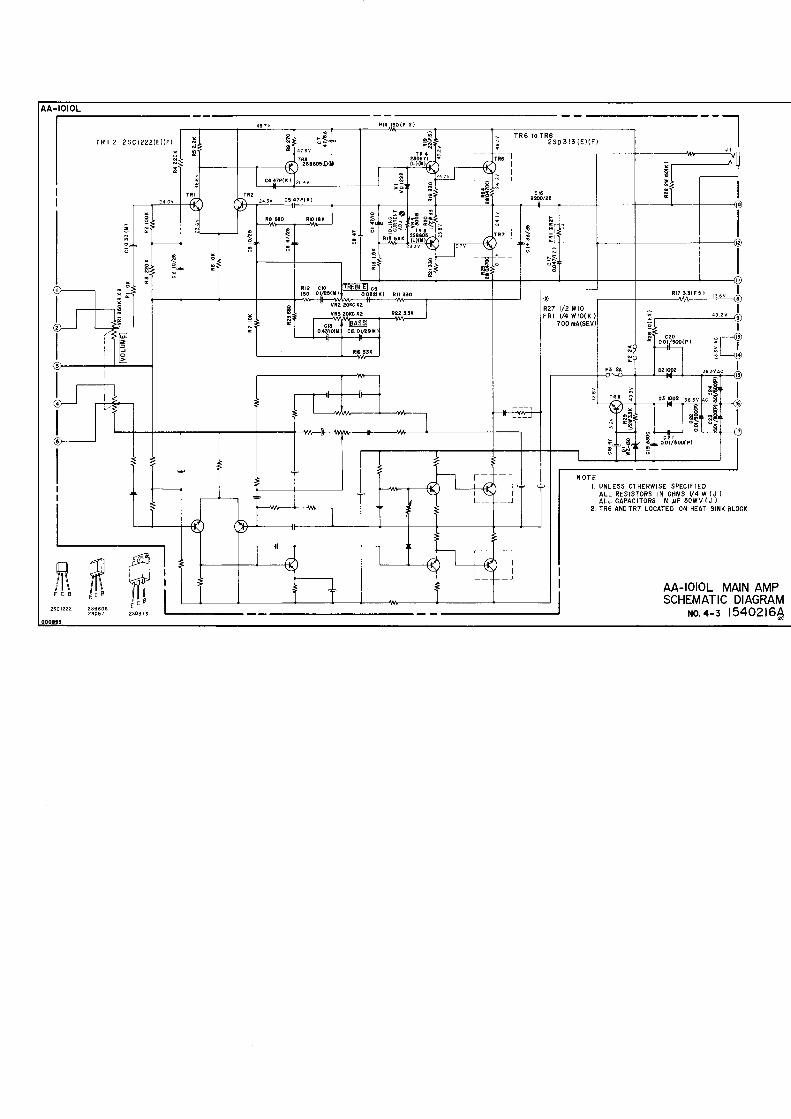
AA,IOIOL MAIN AMP.SCHEMATIC DIAGRAM
AA-IOIOL VARACTOR TUNERSCHEMATIC DIAGRAM
l �2 .3.
P"*N. 5;lilïftR e r \ ^ & - . . F r Í \ n . a R e r N n &i . - . . : D r L N L '
: P r b l \ " .s l m b . r \ 4 , - " s y m b a r \ , .Ref No . &
Pd ís No . s r mb4 t Nn
36

TP rr t--_ ll R E c | @- _ - ll A u x I O
_ li PHoNo I o- T
I
I- ' - ---- . - . ---- ll P 8 I @
.--- - - - ._ lL i E r l O_ - - - ll a u x l @
.--_-_-------_lI PHoNo I @
MULÏI FUNCTION PC BOARD
a a - 5 t 0 5
I/ó-è\(F--@)\ag/
- rI DTSTANCE I- L
- - TI L 0 c a L l- L
A M
_ - l
II9O2 PRESET TUNIN6
I voLUMEP.C BOARD AA-5157
PUSH SWIÏCH PC BOARD
! l-TÀtrE Mo-nlro-Rl foFF-l (J ttÍ l @l -
I s ïL l -5 rr lilopÊ i LqtEEqo I Cl i-iloF-dll s w * -I rrnriï-FE<IL faF" ló m"*l _
l C . | . , J P C 1 0 0 9 C l C . 2 ! P c 1 0 0 9 c
t MANUA r l
TOUCH SWITCHtFM:ll tFM-tPC BOARD AA-srso
lTil3 tFM:4 I l-Frí-s l or-I P R E S E T ï u N r N G I
s E L

LOUDNESS
L . C H
souRcE
MAINE
SOURC E
R . C H
LOUDNE SS
+ lzv
+ 4 8 V
6 N D
AMP PC BOADA C
A A - 5 1 0 6 AG N O
T 9 0 l
f ^^ - 'o-,ot-o I
LAMP
II
l - - - - - i r g o r 2 A 2 3 o v
= lt o o v A R E I
F 9 0 t t l 2 6 0 v
200v ^REA
F 9 0 2 . ? t O 3 2 ^ 2 ó O V
P i 0 Í E c ï t 0 t
s w
s w 9 0 |S P Ê A K E R SO F F ( P O W E R )
OFFB
A + B
o o o
@ o @8 1 9 0 1 - c
UNLESS OTHERWISE SPECIFIEDaLL RES|SToRS tN oHMS t /4 tv (J )ALL CAPACITORS lN r rF 50WV (J )POWER TRANSFORMER IS DIFFERENTACCORDING TO AREA
l sFaÀr (ERi lL R
+ -
tsPiliER-ftl
S P E A K E R O U T
AA-t0t0LCONNECTION DIAGRAM
No.4-r 1540214A
llc orEilFal
I N D 9 0 l - 9 0 3
S E VT 9 0 1
f. l";;-t| Á Á - r 0 r 0 Í - 7l,!Eo -E
I
l s r x
r y l
RED
P C B O A R D A A - 5 r s 5
foFFl ctr fon_l -- -.hiïïoát'
rc-pï BoARDa a - 5 t 5 6
D 6 t 3 2 4 7 3
l C . 2 . , r P C 1 0 0 9 C

r - v - - 9 - - v - - v v vI
I tcr la- tzsoz
,un-rll-"*<=tre{-r-Ë
*3iiLJi
I rc : pecsoc
F L I , F L ?sFE-r07XA-8-Z
z7x
Ta22ScgrL(PxoxRxst
Í5CFU-O35-O €KHz
lr iai :3v,HtT I5,*'*"
''iá--ó1,"'"iï tP l' 'Bi dJ ro 18
r 2 l o o r e
r r l q l Í P l a
,oi dl lb l.'t l
9 f O O t 2 2
! i 9r rP tazl dJ tb lx6 i o o i ë' i ï P l *al dJ | lc |2t
" l o o i 26' l ï tP l o'Lqi__rb__jb
*r- í
UE

PHoNo I
Àux il n c r r
REc I
P B I
J 2
i.: ']"'
'oià--á-1'"'oi ï f l ' 'r3i dJ a 16rz l o o r re" i ï rP l .ol dJ lb iz l
" l o o ' ,u.l qr ÍP i.zl dt rb la€ i o o i à" i ï ÍP i *a l d J t b r 2 7
. l o o i 2 €" i ï ÍP i "'Lq__'rr__j*
U@
" [ó--á- l ,ol l
s l c i Í P t r l'l dl 15 1,.6 i o o i r !5 : G ó r r {
i i l i l !4 i d a r r 5
3 l o o i 1 6' l ï ÍP l ' ',11_! l'"
U@
,|q, ól 'o" l dJ t b i , ,r i " o i P6 l ï ÍP i ' 3r i dr rb
l r r4 t o O l 6r l q ,p I 'ezl dl tb I ' r'1"3"_-lj "
Ef
E
n, t t
2SC945
2SCr57l2SA733
iII
r i o o j r' i ï rP I ''11__o_i"
UtFHóNo'l
.i;-;'1.' l ï f l oi t d J t b 1 6
" i l : ; -
U@
IOTEt. rrf{LEss on€RwtsE gEctFt€D
aLL RES|SIORS tr{ OIS t,//rw(JtALL CÀPAC|ÍORS ti !F Sorví,r)
2.IÍARK IiIOICAÍES LOT LEAI(AG€CAPACIÍORS
AA-IOIOL MFCSCHEMATIC DIAGRAM
No.4-2 15402154
9
co
I
T R 6 l o T R 82 S 0 3 r 3 { E ) ( F )
il-r\ l
:i
ÈF
e
I U N L E S S O T H E R W I S E S P E C I F I E DaLL RES|SÍoRS rN oHMS r/4 "V (J )A L L C A P A C I Í O R S I N I F s O W V ( J )
2 ÍR6 ANDTRT LOCAÍEO ON HEAT SINK ELOCK
ln trlr R wI t [ t f l l/ l \ , f l \E C B i r v
zsc t222 2s8505
AA-IOIOL MAIN AMPSCHEMATIC DIAGRAM
No, 4-3 15402164

UI{LESS OTHERIVI SE SPECIFI EDALL RESISTORS IN OHMS I, /4 W (J )A L L C A P A C I Í o R S l N / F 5 0 W V ( J )ÍR6 ANDTRT LOCATED ON HEAT SINI( ELOCK
AA-IOIOL MAIN AMPSCHEMATIC DIAGRAM
No,4-3 l5402l64
R
----t
r F r I---t I
,l--i-óJ l b ! Yr t+ íó--- i T
IF OUÍnHs
'TD
AA-IOIOL VARACTORÍUNERSCHEMATIC DIAGRAM no,+-r l54O2l7A
Related Documents