AUTHORS Jack E. Deibert Geosciences, Austin Peay State University, P.O. Box 4418, Clarksville, Tennessee 37044; [email protected] Jack Deibert is an associate professor of ge- ology at Austin Peay State University with research interests in clastic sedimentology, se- quence stratigraphy, basin analysis, and sedi- mentation and tectonics. He received his B.S. degree from Sonoma State University, his M.S. degree from the University of Nevada– Las Vegas, and his Ph.D. from the University of Wyoming. Phyllis A. Camilleri Geosciences, Austin Peay State University, P.O. Box 4418, Clarksville, Tennessee 37044; [email protected] Phyllis Camilleri is a professor of geology at Austin Peay State University with research in- terests in the structure, tectonics, and meta- morphism of continental rifts and convergent orogens. She received her B.S. degree from San Diego State University, her M.S. degree from Oregon State University, and her Ph.D. from the University of Wyoming. ACKNOWLEDGEMENTS This study was partially supported by Austin Peay State University Tower Research Grants. We thank reviewers Stephen Cumella, Richard Moiola, and Colin North for helpful suggestions and comments. We also thank Alicia Stanfill for editorial assistance on an earlier version of this manuscript. Sedimentologic and tectonic origin of an incised-valley-fill sequence along an extensional marginal-lacustrine system in the Basin and Range province, United States: Implications for predictive models of the location of incised valleys Jack E. Deibert and Phyllis A. Camilleri ABSTRACT Incised valleys in extensional lacustrine systems should be common and significant petroleum targets, yet documentation and analysis of these systems are limited and, hence, so are predictive models for their location. Geologic mapping of the Miocene–Pliocene Humboldt Formation in Knoll basin, northeastern Nevada, has re- vealed a significant incised-valley system formed along the lacus- trine margins of an extensional basin. The valley formed during a relative lake-level fall and incised into lacustrine shoreface and offshore sandstone and subsequently was filled with fluvial and eolian sediment as lake level rose. The valley’s location was tec- tonically influenced; it is situated in the hinge zone of a syncline near the tip of the range-bounding fault system. Folding of the syncline was broadly synchronous with incision and filling, and it appears to have localized the valley along the topographically low hinge zone. Furthermore, the large relative lake-level change that produced the valley is only recorded in strata in the syncline area, suggesting that the location and cause of incision was greatly in- fluenced by tectonics. Thus, the location of similar incised valleys AAPG Bulletin, v. 90, no. 2 (February 2006), pp. 209–235 209 Copyright #2006. The American Association of Petroleum Geologists. All rights reserved. Manuscript received February 28, 2005; provisional acceptance May 17, 2005; revised manuscript received August 25, 2005; final acceptance September 14, 2005. DOI:10.1306/09140505028

Welcome message from author
This document is posted to help you gain knowledge. Please leave a comment to let me know what you think about it! Share it to your friends and learn new things together.
Transcript
AUTHORS
Jack E. Deibert � Geosciences, Austin PeayState University, P.O. Box 4418, Clarksville,Tennessee 37044; [email protected]
Jack Deibert is an associate professor of ge-ology at Austin Peay State University withresearch interests in clastic sedimentology, se-quence stratigraphy, basin analysis, and sedi-mentation and tectonics. He received his B.S.degree from Sonoma State University, hisM.S. degree from the University of Nevada–Las Vegas, and his Ph.D. from the Universityof Wyoming.
Phyllis A. Camilleri � Geosciences, AustinPeay State University, P.O. Box 4418, Clarksville,Tennessee 37044; [email protected]
Phyllis Camilleri is a professor of geology atAustin Peay State University with research in-terests in the structure, tectonics, and meta-morphism of continental rifts and convergentorogens. She received her B.S. degree fromSan Diego State University, her M.S. degreefrom Oregon State University, and her Ph.D.from the University of Wyoming.
ACKNOWLEDGEMENTS
This study was partially supported by AustinPeay State University Tower Research Grants.We thank reviewers Stephen Cumella, RichardMoiola, and Colin North for helpful suggestionsand comments. We also thank Alicia Stanfillfor editorial assistance on an earlier versionof this manuscript.
Sedimentologic and tectonicorigin of an incised-valley-fillsequence along an extensionalmarginal-lacustrine systemin the Basin and Rangeprovince, United States:Implications for predictivemodels of the location ofincised valleysJack E. Deibert and Phyllis A. Camilleri
ABSTRACT
Incised valleys in extensional lacustrine systems should be common
and significant petroleum targets, yet documentation and analysis
of these systems are limited and, hence, so are predictive models
for their location. Geologic mapping of the Miocene–Pliocene
Humboldt Formation in Knoll basin, northeastern Nevada, has re-
vealed a significant incised-valley system formed along the lacus-
trine margins of an extensional basin. The valley formed during a
relative lake-level fall and incised into lacustrine shoreface and
offshore sandstone and subsequently was filled with fluvial and
eolian sediment as lake level rose. The valley’s location was tec-
tonically influenced; it is situated in the hinge zone of a syncline
near the tip of the range-bounding fault system. Folding of the
syncline was broadly synchronous with incision and filling, and it
appears to have localized the valley along the topographically low
hinge zone. Furthermore, the large relative lake-level change that
produced the valley is only recorded in strata in the syncline area,
suggesting that the location and cause of incision was greatly in-
fluenced by tectonics. Thus, the location of similar incised valleys
AAPG Bulletin, v. 90, no. 2 (February 2006), pp. 209–235 209
Copyright #2006. The American Association of Petroleum Geologists. All rights reserved.
Manuscript received February 28, 2005; provisional acceptance May 17, 2005; revised manuscriptreceived August 25, 2005; final acceptance September 14, 2005.
DOI:10.1306/09140505028
in other extensional basins may be predictable if com-
parable tectonic features and processes are recognized.
Our study suggests that the best locations to de-
velop and preserve incised valleys are near the tips of
normal faults during periods of overall high tectonic
subsidence. Specific areas along basin-bounding faults
where tectonically influenced incised valleys are more
likely to form include fault-propagation folds, syn-
thetic relay ramps near transfer faults, and areas that
have large changes in fault slip. Although lake volume
changes caused predominantly by climate change can
be an important factor in producing incised valleys,
tectonically influenced incised valleys are likely to be
larger, better preserved, and more petroleum prone
compared to climate-controlled incised valleys.
INTRODUCTION
Incised valleys form by fluvial erosion during a drop of
relative base level and fill with sediment as relative
base level rises (Dalrymple et al., 1994). Although
incised-valley-fill sequences comprise a volumetrical-
ly small part of the stratigraphic record, they are ex-
tremely important as petroleum exploration targets
(VanWagoner et al., 1990;Dalrymple et al., 1994). The
nature and origin of valley-fill sequences formed along
marginal-marine settings (coastal plain to shelf areas)
are well documented (e.g., Dalrymple et al., 1994). In
contrast, valley-fill strata in marginal-lacustrine systems
(alluvial to shallow lacustrine areas) have received little
attention and consequently are poorly understood. In
fact, ancient examples in outcrops have yet to be docu-
mented in detail. This article focuses on the origin and
sedimentologic architecture of an incised-valley se-
quence formed along the margin of a lacustrine system
in an extensional basin and its implications for petro-
leum exploration.
Previous work on incised-valley-fill sequences
formed in marginal-lacustrine systems is limited. Stud-
ies thatmention the occurrence of such sequences focus
on large-scale stratigraphic architecture in extensional
basins (mostly half grabens) using seismic and well data
(e.g., Scholz and Rosendahl, 1990; Xue and Galloway,
1993; Changsong et al., 2001) and computer or con-
ceptual modeling (e.g., Olsen, 1990; Gawthorpe and
Leeder, 2000; Contreras and Scholz, 2001). In addi-
tion, incised-valley-fill sequences have been inferred in
some sequence-stratigraphic models (e.g., Cohen,
1990; Bohacs et al., 2000). These studies provide only
broad, cursory information about incised valleys and
their fills and do not specifically address incised-valley
systems with regard to petroleum exploration.
Our geologic mapping in Knoll basin, Nevada, an
extensional basin in the Basin and Range province,
United States (Figure 1), has revealed a spectacular
three-dimensional exposure of a Miocene–Pliocene
marginal-lacustrine incised-valley system. This study
documents the stratigraphic architecture of this sys-
tem and assesses the origin of incision and filling. Be-
cause incised valleys and their fills heretofore have
largely been inferred from subsurface data (e.g., Scholz
and Rosendahl, 1990;Xue andGalloway, 1993; Chang-
song et al., 2001), this article provides the first de-
tailed analog that may be used for petroleum ex-
ploration and provides a better sedimentologic and
tectonic understanding of incised valleys and their fills
in extensional-lacustrine settings. Moreover, we pre-
sent models to help predict the positions of incised
valleys that could be viable exploration targets in ex-
tensional basins.
GEOLOGIC SETTING
Knoll basin is an informal term that we apply to an
unnamed Tertiary basin bounded by Knoll Mountain
(originally called ‘‘HD’’ range by Riva, 1970) on the
east, the Granite Mountains to the north, and the
Snake Mountains to the west (Figure 1). This and
other Cenozoic basins in the region are products of a
protracted extension (rifting) beginning as early as the
Paleocene or Eocene and continuing to the Holocene
(e.g., Snoke and Lush, 1984; Thorman et al., 1990;
Mueller and Snoke, 1993a, b;Wright and Snoke, 1993;
McGrew and Snee, 1994; Camilleri, 1996; Camilleri
and Chamberlain 1997; Mueller et al., 1999). Rocks in
the region include Proterozoic to Triassic strata locally
intruded by Mesozoic granite (Coats, 1987). In Knoll
basin, these rocks are unconformably overlain by the
Cenozoic Humboldt Formation, which is the focus of
this study. Regionally, the Humboldt Formation is
composed of conglomerate, sandstone, shale, minor
limestone, and volcanic tuff deposited in lacustrine,
alluvial-fan, and fluvial environments in extensional
basins (e.g., Schrader, 1912; Sharp, 1939; VanHouten,
1956; Riva, 1962;Mueller and Snoke, 1993b). In Knoll
basin, the Humboldt Formation is at least middle
Miocene to Pliocene in age based on the occurrence of
the 10.5–12.5-Ma (Perkins et al., 1998) Cougar Point
210 Sedimentologic and Tectonic Origin of an Incised-Valley-Fill Sequence
Tuff (P. A. Camilleri and J. E. Deibert, unpublished
data) and the presence of Pliocene vertebrate fauna
(Stirton, 1940). The Humboldt Formation in Knoll
basin is presently well exposed at the surface because
of significant erosion by modern streams of the Snake
River drainage system.
STRATIGRAPHIC AND STRUCTURALARCHITECTURE OF KNOLL BASIN
Knoll basin is a north-trending half graben bounded
on the east by north- to northeast-trending,west-dipping
normal faults and locally by a southeast-dipping nor-
mal fault along its northern margin (Figures 1, 2). The
Humboldt Formation fills the basin and overall dips
east (Figure 2).
Our study focuses on the northeastern part of the
Knoll basin (Figure 2). The Humboldt Formation in
this area was previously mapped by Schrader (1912)
and Riva (1962, 1970) as a single unit. In Riva’s recon-
naissance study of the Humboldt Formation, he noted
the presence of large cross-beds, an angular unconfor-
mity, and minor folding. He also inferred that most of
the contacts between the Humboldt Formation and
Paleozoic strata were depositional. We have mapped
the northeastern part of the basin in detail, and what
follows is a new stratigraphic and structural framework
that we have established for the Humboldt Formation
in this area.
Three basin-bounding faults—the down-to-the-
west Knoll Mountain, Hice, and Valder faults—are
present along the eastern margin of the basin (Figure 2).
The 24-km (14.9-mi)-long Knoll Mountain fault is
the main range-bounding fault, whereas the Hice and
Valder faults are restricted to the northern margin of
the basin and are likely synthetic faults related to the
Knoll Mountain fault. The Hice fault is 6 km (3.7 mi)
long, and the 3-km (1.9-mi )-long Valder fault appears
to be a small splay of the Hice fault (Figures 2, 3); for
simplicity, we will refer to this basin-bounding fault
as the Hice-Valder fault.
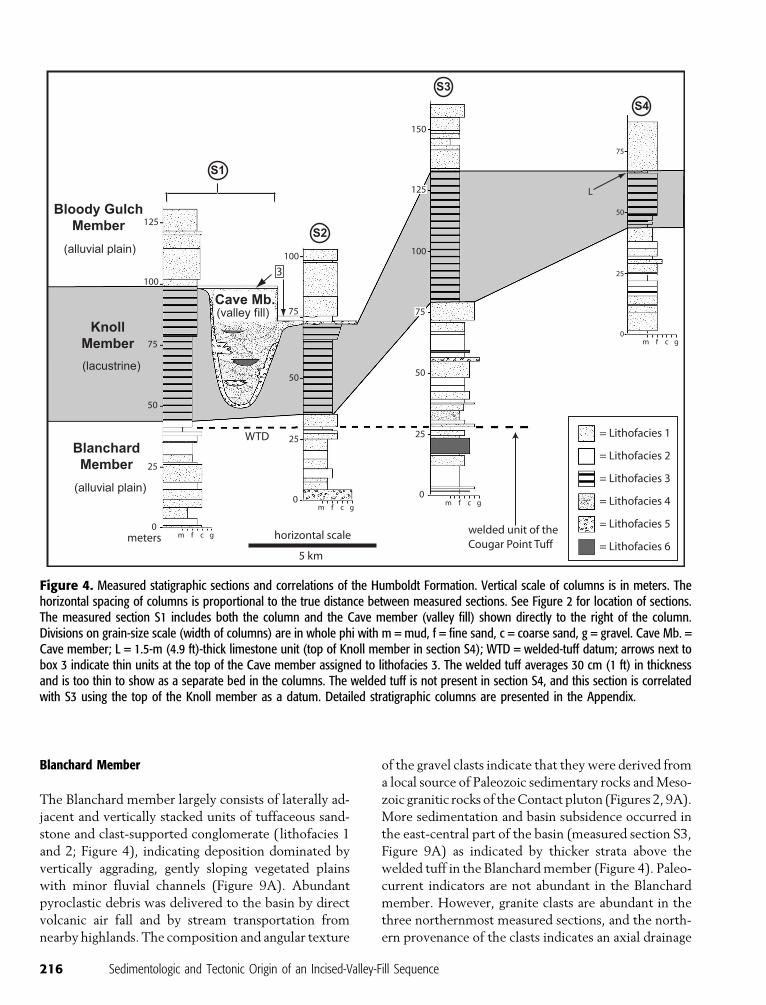
We have divided the Humboldt Formation into
four informal members. From oldest to youngest, they
are the Blanchard, Knoll, Cave, and Bloody Gulch
members (Figures 4, 5). The Blanchard member con-
sists of tuffaceous sandstone, conglomerate, and vol-
canic tuff. The base of the member is not defined, and
only the upper 80 m (262 ft) of the member is de-
scribed. A distinctive welded-tuff unit of the Cougar
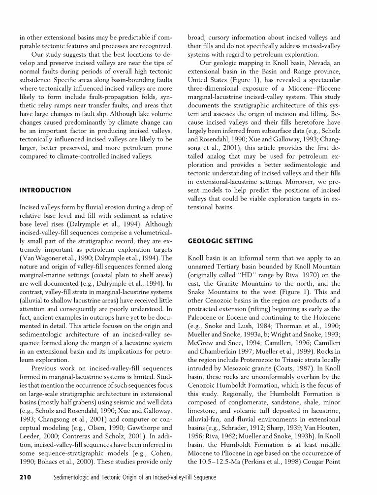
Figure 1. Maps showing location of the Basin and Rangeprovince, study area, incised-valley system, and range-boundingnormal faults in the region. The Basin and Range province isan area of overall east–west extension. Range-bounding nor-mal faults are shown as bold lines with a ball and bar on thehanging wall. EHR = East Humboldt Range; GM = GraniteMountains; KM = Knoll Mountain; MRV = Mary’s River Valley;SCR = Summer Camp Ridge; SM = Snake Mountains; WH =Wood Hills; I 80 = Interstate 80; US 93 = United States High-way 93. Data for faults shown in Knoll Mountain are simplifiedfrom unpublished mapping by P. A. Camilleri; elsewhere, dataare modified from Coats (1987).
Deibert and Camilleri 211
Point Tuff occurs near the top of the Blanchard mem-
ber (Figure 4). The tuff is the only welded tuff in the
eastern part of the basin, and it serves as an important
regional isochronous marker bed that enables accurate
chronostratigraphic correlations between isolated out-
crops of the Humboldt Formation. The Knoll member
consists dominantly of tuffaceous sandstone with mi-
nor amounts of limestone and ranges in thickness from
24 to 54 m (79 to 177 ft). The Cave member consists
mostly of large-scale, cross-stratified, tuffaceous sand-
stone with minor conglomerate and occupies a 50-m
(164-ft)-deep incised valley cut into the Blanchard and
Knoll members. The Bloody Gulch member overlies
both the Knoll and Cave members and consists of tuff-
aceous sandstone with minor conglomerate. The top
of the member is not defined, and only the lower 30m
(98 ft) of the member is described.
The stratigraphic and structural geometry of the
Humboldt Formation in the east-central part of the ba-
sin is relatively simple. There, the members of the
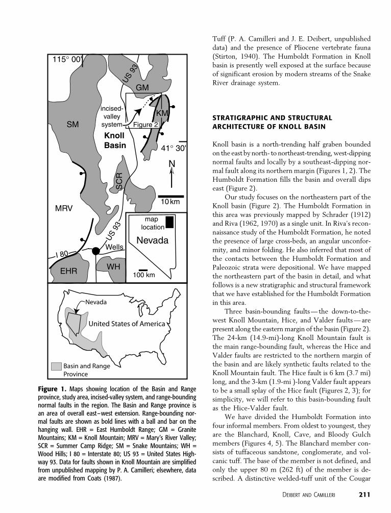
Figure 2. Simplifiedgeologic map and crosssection of the northeast-ern corner of Knoll basin(see Figure 1 for loca-tion). Strike and dip sym-bols represent attitudesof bedding. Data de-rived from 1:24,000 to1:8000 scale unpublishedmapping by P. A. Camil-leri and J. E. Deibert.
212 Sedimentologic and Tectonic Origin of an Incised-Valley-Fill Sequence
Humboldt Formation are conformable and, in general,
dip 15–20j east in the center of the basin and then re-
verse dip direction and dip gently west near the Knoll
Mountain fault (see cross section AA0 in Figure 2).
The stratigraphic and structural geometry of the
Humboldt Formation in the northeastern corner of the
basin is complex. There, all members of the Humboldt
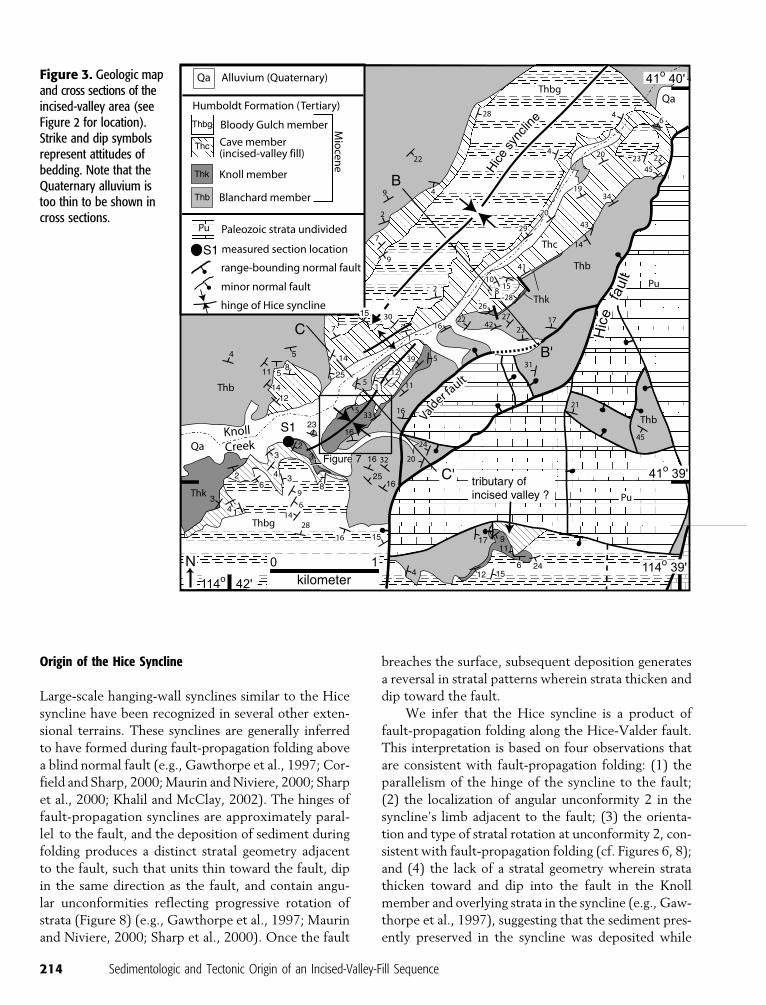
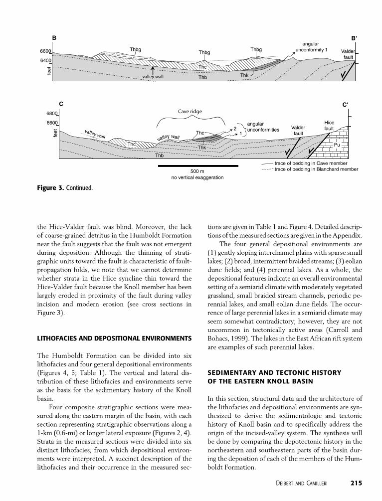
Formation overall define a broad syncline (Hice syn-
cline; Figure 3) in the hanging wall of the Hice-Valder
fault, with bedding adjacent to the fault dipping in the
same direction as the fault (see cross section BB0 in
Figure 3). The hinge of the syncline trends northeast,
and to the south, it locally steps east across a small,
gentle anticlinal flexure (Figure 3). Threemajor erosion
surfaces consisting of two tectonically tilted angular
unconformities and one incised valley are present in
the Humboldt Formation in the syncline (Figure 6).
From oldest to youngest, angular unconformity 1 forms
the base of the Knoll member; angular unconformity 2
is within the Knoll member; and the youngest ero-
sion surface (unconformity 3) is an elongate, north-
east-trending, concave-upward surface that truncates
the Knoll member and the upper Blanchard member
(Figure 6). We interpret the latter surface to be an
incised valley formed by fluvial erosion. The incised
valley is located approximately along the syncline’s
hinge (Figure 3). A similar but smaller erosive surface
is exposed 2 km (1.2 mi) southeast of the syncline
and may represent a small tributary of the larger val-
ley (Figure 3).
SYNTECTONIC RELATIONSHIPS BETWEENFOLDING AND VALLEY INCISION AND FILLING
The position of the incised valley along the hinge of
the Hice syncline suggests a possible syntectonic re-
lationship between these two features. To evaluate
this relationship, we assess the origin of the Hice syn-
cline and its age relative to valley incision and filling.
The timing of folding relative to the age of the mem-
bers of the Humboldt Formation can be determined
in part by structurally assessing the two tilted angular
unconformities in the syncline. Both unconformities
are exceptionally well exposed along a 2-km (1.2-mi)-
long, northeast-trending ridge (Cave ridge; Figure 7A)
that straddles the syncline’s hinge (Figure 6A–E).
Cave ridge contains the most complete stratigraphic
section in the syncline; therefore, it is the data from
this ridge that we have analyzed to determine the
relative age of the syncline.
Relative Age of Folding
Structural data indicate that the Hice syncline began
to form before, and folding continued after, incision
and filling of the valley. Assessment of angular un-
conformity 1 indicates that the syncline began to form
after the development of this unconformity. Uncon-
formity 1 is only present in the southeastern limb and
hinge area of the Hice syncline, where it forms the
contact between the Blanchard and Knoll members
(Figure 6A–C; 7A, B). This unconformity and the
Knoll member are not present on the northwestern
limb of the syncline because they were erosionally
removed during valley incision (see cross sections in
Figure 3). To determine if the syncline began to form
before the tilting of unconformity 1, bedding attitudes
of strata beneath the unconformity were rotated to
their pretilt orientation using standard stereographical
methods (see Figure 7 for details). The results indicate
that prior to the tilting of the unconformity, the Blan-
chard member had an overall east to northeasterly
dip punctuated by a few small flexures with northwest-
to north-northeast–trending hinges (Figure 7C). From
these data, it is clear that pretilt attitudes do not de-
fine the syncline, and therefore, the syncline had not
begun to form prior to the development of angular
unconformity 1.
Assessment of angular unconformity 2 in the Knoll
member indicates that the Hice syncline clearly started
to form before the development of this unconformity
and, hence, before valley incision. Unconformity 2 is
only present in the central part of the southeastern limb
of the syncline. Strata above and below the unconfor-
mity become conformable toward the hinge of the syn-
cline and along strike to the southwest; to the northeast,
this unconformity was erosionally removed during valley
incision (Figure 7A). The strata immediately above and
below the unconformity both dip to the northwest with
little variance in strike; however, an angular dip dis-
cordance of 7–10j is present (Figure 7D). The stereo-
graphic determination of pretilt attitudes of strata be-
neath unconformity 2 indicates that strata dipped gently
to the northwest and defined the southeastern limb
of the syncline prior to tilting of this unconformity
(Figure 7D). These data indicate that the syncline began
to form during the deposition of the Knoll member.
Moreover, folding must have continued through, or at
least after, the deposition of the Cave and overlapping
Bloody Gulch members because they also are folded
(Figure 3). In summary, the data imply that valley in-
cision and filling were broadly coeval with folding.
Deibert and Camilleri 213
Origin of the Hice Syncline
Large-scale hanging-wall synclines similar to the Hice
syncline have been recognized in several other exten-
sional terrains. These synclines are generally inferred
to have formed during fault-propagation folding above
a blind normal fault (e.g., Gawthorpe et al., 1997; Cor-
field and Sharp, 2000;Maurin andNiviere, 2000; Sharp
et al., 2000; Khalil and McClay, 2002). The hinges of
fault-propagation synclines are approximately paral-
lel to the fault, and the deposition of sediment during
folding produces a distinct stratal geometry adjacent
to the fault, such that units thin toward the fault, dip
in the same direction as the fault, and contain angu-
lar unconformities reflecting progressive rotation of
strata (Figure 8) (e.g., Gawthorpe et al., 1997; Maurin
and Niviere, 2000; Sharp et al., 2000). Once the fault
breaches the surface, subsequent deposition generates
a reversal in stratal patterns wherein strata thicken and
dip toward the fault.
We infer that the Hice syncline is a product of
fault-propagation folding along the Hice-Valder fault.
This interpretation is based on four observations that
are consistent with fault-propagation folding: (1) the
parallelism of the hinge of the syncline to the fault;
(2) the localization of angular unconformity 2 in the
syncline’s limb adjacent to the fault; (3) the orienta-
tion and type of stratal rotation at unconformity 2, con-
sistent with fault-propagation folding (cf. Figures 6, 8);
and (4) the lack of a stratal geometry wherein strata
thicken toward and dip into the fault in the Knoll
member and overlying strata in the syncline (e.g., Gaw-
thorpe et al., 1997), suggesting that the sediment pres-
ently preserved in the syncline was deposited while
Figure 3. Geologic mapand cross sections of theincised-valley area (seeFigure 2 for location).Strike and dip symbolsrepresent attitudes ofbedding. Note that theQuaternary alluvium istoo thin to be shown incross sections.
214 Sedimentologic and Tectonic Origin of an Incised-Valley-Fill Sequence
the Hice-Valder fault was blind. Moreover, the lack
of coarse-grained detritus in the Humboldt Formation
near the fault suggests that the fault was not emergent
during deposition. Although the thinning of strati-
graphic units toward the fault is characteristic of fault-
propagation folds, we note that we cannot determine
whether strata in the Hice syncline thin toward the
Hice-Valder fault because the Knoll member has been
largely eroded in proximity of the fault during valley
incision and modern erosion (see cross sections in
Figure 3).
LITHOFACIES AND DEPOSITIONAL ENVIRONMENTS
The Humboldt Formation can be divided into six
lithofacies and four general depositional environments
(Figures 4, 5; Table 1). The vertical and lateral dis-
tribution of these lithofacies and environments serve
as the basis for the sedimentary history of the Knoll
basin.
Four composite stratigraphic sections were mea-
sured along the eastern margin of the basin, with each
section representing stratigraphic observations along a
1-km (0.6-mi) or longer lateral exposure (Figures 2, 4).
Strata in the measured sections were divided into six
distinct lithofacies, from which depositional environ-
ments were interpreted. A succinct description of the
lithofacies and their occurrence in the measured sec-
tions are given in Table 1 and Figure 4. Detailed descrip-
tions of themeasured sections are given in theAppendix.
The four general depositional environments are
(1) gently sloping interchannel plains with sparse small
lakes; (2) broad, intermittent braided streams; (3) eolian
dune fields; and (4) perennial lakes. As a whole, the
depositional features indicate an overall environmental
setting of a semiarid climate withmoderately vegetated
grassland, small braided stream channels, periodic pe-
rennial lakes, and small eolian dune fields. The occur-
rence of large perennial lakes in a semiarid climate may
seem somewhat contradictory; however, they are not
uncommon in tectonically active areas (Carroll and
Bohacs, 1999). The lakes in the East African rift system
are examples of such perennial lakes.
SEDIMENTARY AND TECTONIC HISTORYOF THE EASTERN KNOLL BASIN
In this section, structural data and the architecture of
the lithofacies and depositional environments are syn-
thesized to derive the sedimentologic and tectonic
history of Knoll basin and to specifically address the
origin of the incised-valley system. The synthesis will
be done by comparing the depotectonic history in the
northeastern and southeastern parts of the basin dur-
ing the deposition of each of the members of the Hum-
boldt Formation.
Figure 3. Continued.
Deibert and Camilleri 215
Blanchard Member
The Blanchard member largely consists of laterally ad-
jacent and vertically stacked units of tuffaceous sand-
stone and clast-supported conglomerate (lithofacies 1
and 2; Figure 4), indicating deposition dominated by
vertically aggrading, gently sloping vegetated plains
with minor fluvial channels (Figure 9A). Abundant
pyroclastic debris was delivered to the basin by direct
volcanic air fall and by stream transportation from
nearby highlands. The composition and angular texture
of the gravel clasts indicate that theywere derived from
a local source of Paleozoic sedimentary rocks andMeso-
zoic granitic rocks of theContact pluton (Figures 2, 9A).
More sedimentation and basin subsidence occurred in
the east-central part of the basin (measured section S3,
Figure 9A) as indicated by thicker strata above the
welded tuff in the Blanchardmember (Figure 4). Paleo-
current indicators are not abundant in the Blanchard
member. However, granite clasts are abundant in the
three northernmost measured sections, and the north-
ern provenance of the clasts indicates an axial drainage
Figure 4. Measured statigraphic sections and correlations of the Humboldt Formation. Vertical scale of columns is in meters. Thehorizontal spacing of columns is proportional to the true distance between measured sections. See Figure 2 for location of sections.The measured section S1 includes both the column and the Cave member (valley fill) shown directly to the right of the column.Divisions on grain-size scale (width of columns) are in whole phi with m = mud, f = fine sand, c = coarse sand, g = gravel. Cave Mb. =Cave member; L = 1.5-m (4.9 ft)-thick limestone unit (top of Knoll member in section S4); WTD = welded-tuff datum; arrows next tobox 3 indicate thin units at the top of the Cave member assigned to lithofacies 3. The welded tuff averages 30 cm (1 ft) in thicknessand is too thin to show as a separate bed in the columns. The welded tuff is not present in section S4, and this section is correlatedwith S3 using the top of the Knoll member as a datum. Detailed stratigraphic columns are presented in the Appendix.
216 Sedimentologic and Tectonic Origin of an Incised-Valley-Fill Sequence
system flowing to the south. Furthermore, evidence for
large, long-lived lakes are absent from the Blanchard
member, indicating that sedimentation was greater
than subsidence, and that the fluvial system flowed
through the basin. We infer that the Knoll Mountain
fault was probably active at this time and produced
relatively slow subsidence of the basin.
The angular unconformity at the top of the Blan-
chard member in the northeastern part of the basin
indicates tectonic rotation and subaerial erosion (angu-
lar unconformity 1) before the deposition of the Knoll
member (Figure 9B). This event produced a general
easterly dip of the Blanchardmember. Not enough data
are available to link stratal rotation to a specific struc-
ture; however, it may reflect the rotation of the strata
toward an emergent Knoll Mountain fault. Alterna-
tively, strata may have been rotated above a blind fault
(e.g., as in Figure 8).
Knoll Member
The Knoll member consists of laterally continuous
beds of very fine- to medium-grained sandstone and
minor beds of limestone (lithofacies 3) and is inter-
preted to represent deposition in a regional shallow-
lacustrine environment (Figure 9C). The presence of
abundant gastropods and bivalves in limestone units
and the lack of evaporites and subaerial exposure
features suggest a perennial freshwater environment.
The basal contact of the Knoll member is sharp and
erosional, and the finest grained beds and the lowest
energy bedforms occur in the lower parts of the mem-
ber, suggesting a rapid lake formation over the entire
eastern part of the basin. The rapid transition from the
throughgoing fluvial system of the Blanchard mem-
ber to a regional long-lived lacustrine system indi-
cates a change in relative subsidence rates, with the
rate of subsidence being greater than the rate of sedi-
mentation. Increased slip on the Knoll Mountain fault
may have caused this relative increase in subsidence
rate. Subsidence may have been less in the southern
part of the basin (see measured section S4, Figure 4)
because of the relatively thin amount of lacustrine
sediment deposited there. Moreover, the southern part
of the basin is the only area that contains limestone
units, suggesting that the clastic input into this area
was significantly lower relative to other parts of the
basin.
In the northeastern part of the basin, the Hice
syncline began to form during the deposition of the
lower part of the Knoll member (Figure 9C). Ero-
sional truncation of lacustrine strata in the syncline’s
southeastern limb, and subsequent continuation of la-
custrine deposition, produced angular unconformity 2.
There is no clear evidence that the erosional surface
formed subareally or subaqueously. Furthermore, we
infer that the Hice-Valder fault had not breached the
surface during the deposition of the Knoll or overlying
members.
The middle and upper parts of the Knoll member
contain an overall coarsening-upward sequence, sug-
gesting that the shoreline gradually regressed. The
regression in the northeast part of the basin was fol-
lowed by 50 m (164 ft) of vertical fluvial erosion, i.e.,
valley incision (Figure 4). The axis (i.e., trunk stream)
of the fluvial system was located directly along the
hinge of the syncline and parallel to the blind Hice-
Valder fault (Figures 9D, 10). The axis of the fluvial
system was localized in the fold’s hinge area because
of the topographic low created during syncline devel-
opment. Valley incision occurred in response to a low-
ering of relative lake level, which resulted in a signifi-
cant basinward shift in depositional facies (Figure 9D).
The vertical magnitude of the relative lake-level drop
was more than 50 m (164 ft), which is on the scale of
the entire thickness of the lacustrine deposits of the
Knoll member. Surprisingly, this large-magnitude ba-
sinward shift in facies and the resulting erosional event
are not recognized in the southeastern parts of the
basin (see measured sections S3 and S4, Figure 4). In-
stead, a gradual shoreline regression and a conform-
able transition to a vegetated-plain environment are
observed in these areas. These data suggest that the
large drop in relative lake level occurred only in the
northeast corner of the basin.
Cave Member
The Cave member fills the aforementioned incised
valley. The incised valley is at least 50 m (164 ft) deep,
1 km (0.6 mi) wide, and a minimum of 6 km (3.7 mi)
long (Figures 3, 9E, 10). Part of a small northwest-
trending incised valley, 10m (32 ft) deep, at least 150m
(492 ft) wide, and 400 m (1312 ft) long, is present to
the southeast of the main incised valley (Figure 3). The
smaller valley could have been a tributary of the main
incised valley based on its orientation and position in
the basin.
In general, the lower 0.5–2 m (1.6–6.6 ft) of the
Cave member is composed of fluvial conglomerate
Deibert and Camilleri 217
218 Sedimentologic and Tectonic Origin of an Incised-Valley-Fill Sequence
(lithofacies 5). The middle parts of member are domi-
nantly composed of large-scale cross-stratified eolian
sandstone (sets up to 11 m [36 ft] thick; lithofacies 4),
except for a few areas in the valley where intercalated
fluvial conglomerate and sandstone beds (lithofacies 5
and 6) form units up to 100 m (329 ft) wide and 25 m
(82 ft) thick. Paleocurrents of eolian strata are domi-
nantly to the northeast, and paleocurrents of fluvial
strata are dominantly to the southwest (Figure 10). The
upper part of the member contains a laterally contin-
uous, 0.5–2.2-m (1.6–7.2-ft)-thick bed of lacustrine
sandstone (lithofacies 3) that overlaps the top of the
valley fill (Figure 5E).
The distribution of lithofacies and environments
indicate that after incision, deposition of fluvial con-
glomerate occurred in the lower parts of the valley.
Paleocurrents indicate that the fluvial system was flow-
ing to the southwest, presumably issuing into the lake
in the east-central part of the basin. As deposition con-
tinued, eolian dune fields with small interdune ponds
developed adjacent to the fluvial system, and these
two systems filled most of the valley with sediment.
Paleocurrents indicate that the source of the eolian
sand lie southwest of the incised valley. The relatively
low lake level in this area of the basin may have sub-
aerially exposed a large area of lacustrine sediment be-
longing to the Knoll member and, hence, provided an
abundant source of unlithified volcaniclastic sand for
eolian transport. Eolian environments may have been
common along the margin of the basin; however, their
potential for preservation was limited because of re-
working by lake and stream processes. The thick ac-
cumulation of eolian deposits in the valley fill was the
result of the uncommonly deep subaerial accommo-
dation space created by the incised valley. The filling
of the valley with sediment deposited in two contrast-
ing environments, fluvial and eolian, in a well-defined
concave-upward erosional surface is clear evidence that
the strata represent a filled valley instead of a large
fluvial channel associated with the conformable pro-
gradation of marginal-lacustrine sediment over open-
lacustrine sediment.
Filling of the valley was followed by a lake shore-
line transgression across the northeastern part of the
basin that deposited a thin layer of sand over the top of
the incised-valley fill. The thin deposit (Figure 5E)
suggests that the duration of lake deposition was rela-
tively short after valley filling. Lacustrine deposition
directly before and after valley incision and filling in-
dicates that the formation of the incised-valley system
was directly linked to relative lake-level changes.
No direct evidence of continued folding in the syn-
cline during filling of the valley exists. However, beds
of the upper Cave member and the overlying strata
in the Bloody Gulch member are folded, suggesting
that folding of the syncline may have continued during
valley incision and deposition.
The large cycle of relative fall and rise of the lake
level that produced the incised valley and overlying la-
custrine deposits is present only in the northeastern
part of the basin, indicating a dominantly local tectonic
control of this cycle instead of a lake-volume (climatic)
control. The local tectonic control may be a result of
differential subsidence along the Knoll Mountain fault
with greater slip or subsidence in the central part of
the basin, which would locally increase the depth of
the lake adjacent to the fault and force the regression
of the lake’s northern shoreline. The subsequent trans-
gression of the lake over the incised valley may have
been caused by an increased slip along faults in the
northeastern part of the basin relative to slip along
faults to the south.
Bloody Gulch Member
The Bloody Gulch member is dominantly composed
of laterally and vertically stacked units of massive
fine- to coarse-grained sandstone (lithofacies 1 and 2;
Figure 4). This architecture above the lacustrine units
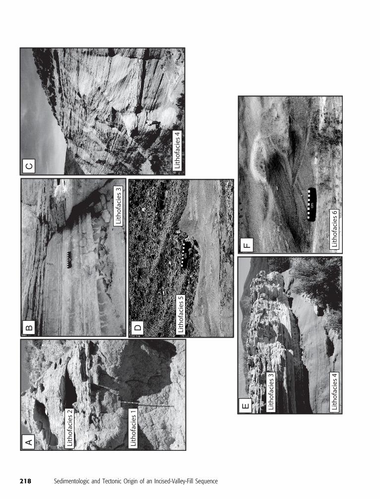
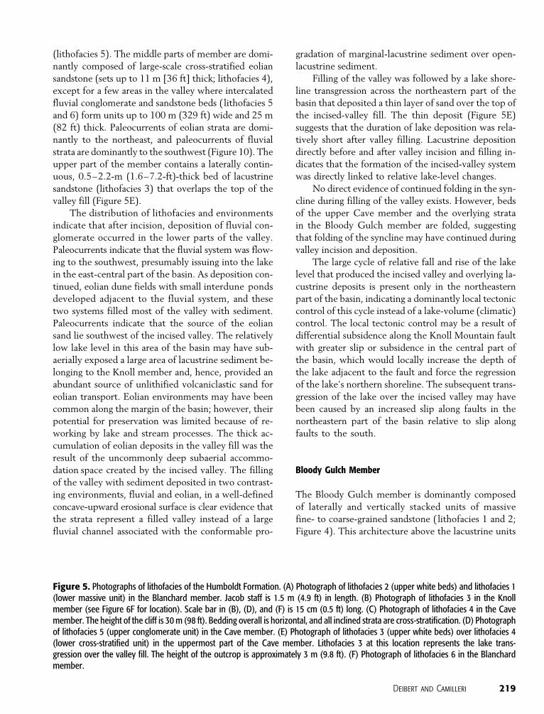
Figure 5. Photographs of lithofacies of the Humboldt Formation. (A) Photograph of lithofacies 2 (upper white beds) and lithofacies 1(lower massive unit) in the Blanchard member. Jacob staff is 1.5 m (4.9 ft) in length. (B) Photograph of lithofacies 3 in the Knollmember (see Figure 6F for location). Scale bar in (B), (D), and (F) is 15 cm (0.5 ft) long. (C) Photograph of lithofacies 4 in the Cavemember. The height of the cliff is 30 m (98 ft). Bedding overall is horizontal, and all inclined strata are cross-stratification. (D) Photographof lithofacies 5 (upper conglomerate unit) in the Cave member. (E) Photograph of lithofacies 3 (upper white beds) over lithofacies 4(lower cross-stratified unit) in the uppermost part of the Cave member. Lithofacies 3 at this location represents the lake trans-gression over the valley fill. The height of the outcrop is approximately 3 m (9.8 ft). (F) Photograph of lithofacies 6 in the Blanchardmember.
Deibert and Camilleri 219
220 Sedimentologic and Tectonic Origin of an Incised-Valley-Fill Sequence
of the Knoll and Cave members indicates that gently
sloping vegetated plain and fluvial systems prograded
over the lake along the entire eastern part of the basin
(Figure 9F). Granite clasts are abundant in the Bloody
Gulch member in the three northernmost measured
sections, indicating an axial drainage system flowing to
the south and that the basin returned to an overfilled
state. The Bloody Gulch member does not contain dis-
tinct, laterally traceable units, and therefore, it is not
possible to evaluate relative subsidence and sedimen-
tation rates.
The Bloody Gulch member in the northeastern
part of the basin is folded in the Hice syncline, and in
the south-central part of the basin, it is significantly
tectonically rotated toward the Knoll Mountain fault.
This suggests that the folding and faulting occurred
after and possibly during the deposition of the Bloody
Gulch member.
IMPLICATIONS FOR THE LOCATION OFINCISED-VALLEY SYSTEMS AND THEIRROLE IN PETROLEUM EXPLORATIONAND PRODUCTION
The origin of the incised-valley system in Knoll basin
has broad implications for the understanding of
marginal-lacustrine systems in an extensional setting
and their petroleum potential. The incised-valley fill
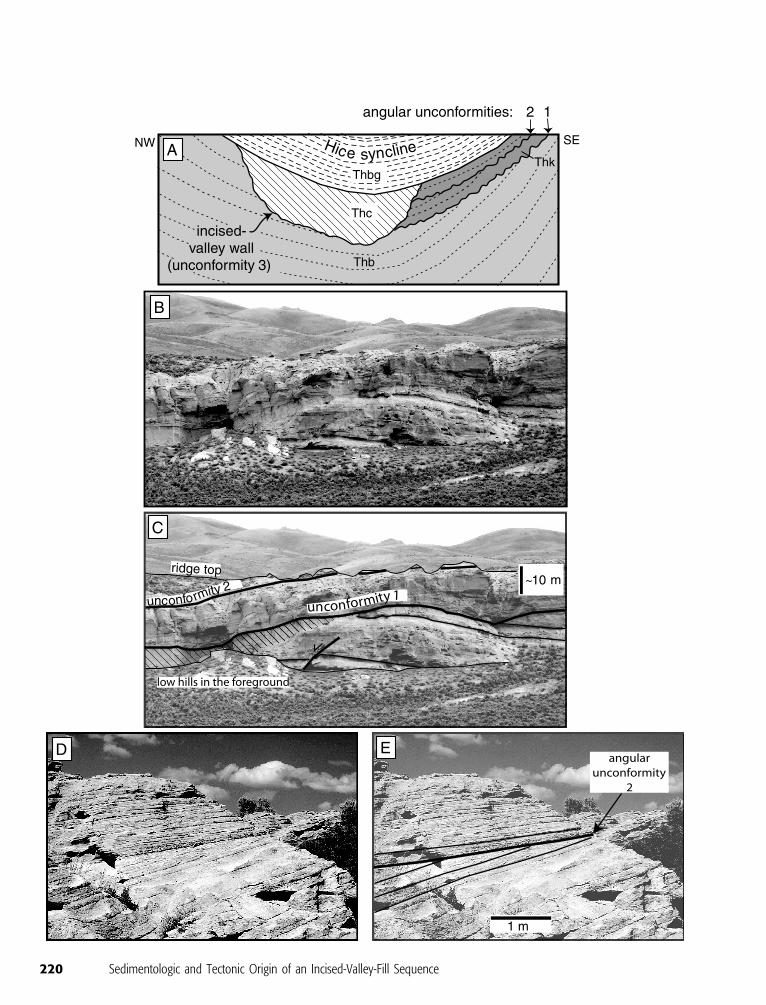
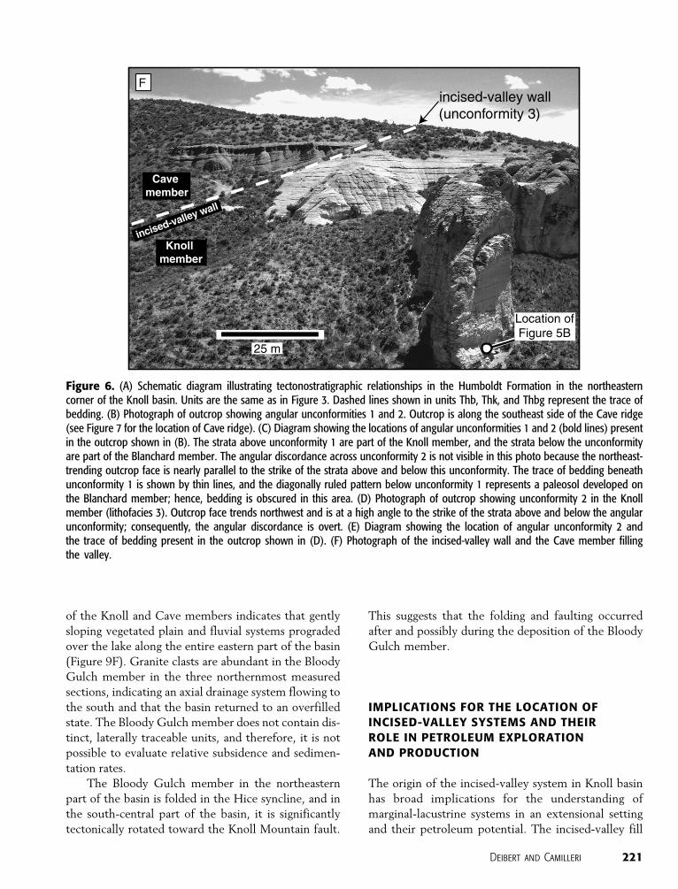
Figure 6. (A) Schematic diagram illustrating tectonostratigraphic relationships in the Humboldt Formation in the northeasterncorner of the Knoll basin. Units are the same as in Figure 3. Dashed lines shown in units Thb, Thk, and Thbg represent the trace ofbedding. (B) Photograph of outcrop showing angular unconformities 1 and 2. Outcrop is along the southeast side of the Cave ridge(see Figure 7 for the location of Cave ridge). (C) Diagram showing the locations of angular unconformities 1 and 2 (bold lines) presentin the outcrop shown in (B). The strata above unconformity 1 are part of the Knoll member, and the strata below the unconformityare part of the Blanchard member. The angular discordance across unconformity 2 is not visible in this photo because the northeast-trending outcrop face is nearly parallel to the strike of the strata above and below this unconformity. The trace of bedding beneathunconformity 1 is shown by thin lines, and the diagonally ruled pattern below unconformity 1 represents a paleosol developed onthe Blanchard member; hence, bedding is obscured in this area. (D) Photograph of outcrop showing unconformity 2 in the Knollmember (lithofacies 3). Outcrop face trends northwest and is at a high angle to the strike of the strata above and below the angularunconformity; consequently, the angular discordance is overt. (E) Diagram showing the location of angular unconformity 2 andthe trace of bedding present in the outcrop shown in (D). (F) Photograph of the incised-valley wall and the Cave member fillingthe valley.
Deibert and Camilleri 221
in Knoll basin has the characteristics of, and is large
enough to be, a significant petroleum reservoir. Fur-
thermore, it is appreciably larger than most reservoirs
in rift lake systems that are typically less than 15 m
(49 ft) thick (Sladen, 1994). The processes that formed
the valley may have been operative in other larger ex-
tensional basins, creating bigger incised valleys. Al-
though the strata of the Knoll basin are mostly vol-
caniclastic sandstone and are not typical of sediment
containing petroleum deposits, this depositional sys-
tem can contain the more typical petroleum-related
rocks, such as quartz sandstone and shale. Therefore,
the incised-valley system in the Knoll basin can serve as
an analog for petroleum exploration and production.
The two most important aspects of this study con-
cern the control on the location of the incised valley
and the lithofacies architecture produced by the for-
mation and filling of the valley. The location of the
valley was not an arbitrary place along the margin
of the basin where a fluvial system entered the basin;
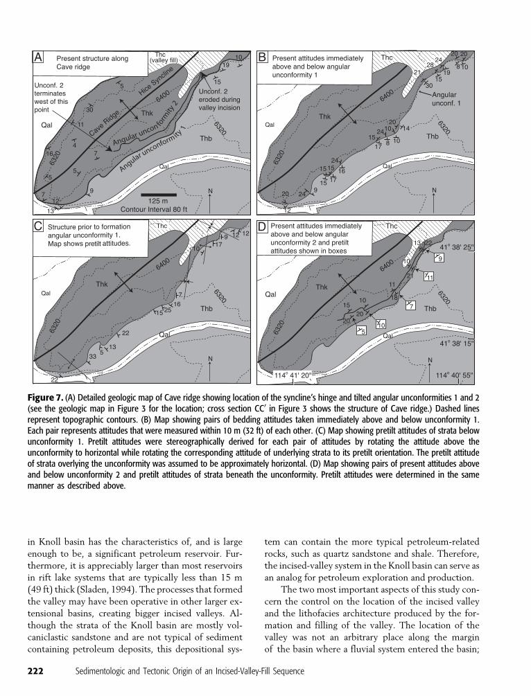
Figure 7. (A) Detailed geologic map of Cave ridge showing location of the syncline’s hinge and tilted angular unconformities 1 and 2(see the geologic map in Figure 3 for the location; cross section CC0 in Figure 3 shows the structure of Cave ridge.) Dashed linesrepresent topographic contours. (B) Map showing pairs of bedding attitudes taken immediately above and below unconformity 1.Each pair represents attitudes that were measured within 10 m (32 ft) of each other. (C) Map showing pretilt attitudes of strata belowunconformity 1. Pretilt attitudes were stereographically derived for each pair of attitudes by rotating the attitude above theunconformity to horizontal while rotating the corresponding attitude of underlying strata to its pretilt orientation. The pretilt attitudeof strata overlying the unconformity was assumed to be approximately horizontal. (D) Map showing pairs of present attitudes aboveand below unconformity 2 and pretilt attitudes of strata beneath the unconformity. Pretilt attitudes were determined in the samemanner as described above.
222 Sedimentologic and Tectonic Origin of an Incised-Valley-Fill Sequence
instead, the location was controlled by specific tectonic
features. Thus, the location of other incised-valley sys-
tems could be predicted by recognizing similar tectonic
features.
An important aspect in the exploration of lacus-
trine petroleum deposits is the presence of a lithofacies
architecturewhere reservoir rocks are directly juxtaposed
against source and seal rocks (Scholz and Rosendahl,
1990; Sladen, 1994). In lacustrine basins, typical clastic
reservoir rocks (littoral and fluvial sandstone) are not
commonly found directly next to source and seal rocks
(open-lacustrine shale), making it difficult to estab-
lish the critical elements of source, reservoir, and seal.
The large relative lake-level change associated with the
incised-valley sequence in the Knoll basin produced
dramatic basinward and landward shifts in facies. This
allowed coarse-grained fluvial conglomerate and eolian
sandstone to be vertically and laterally encased in la-
custrine deposits. In a similar depositional system, the
lacustrine rocks could be open-lacustrine organic-rich
shale that could act as both petroleum source and seal,
and the coarse-grained valley-fill strata would serve as
a reservoir.
Presently, few recognized petroleum accumula-
tions exist in incised valleys in extensional lacustrine
systems. Incised valleys have been documented in the
Jurassic–Cretaceous Songliao and Erlian extensional
lacustrine basins of northeast China (Xue and Gallo-
way, 1993; Changsong et al., 2001), and they produce
significant quantities of petroleum. For example, the
largest oil field in China, one of the few giant non-
marine oil fields in the world, occurs in the Songliao
basin, where incised-valley deposits are a principal res-
ervoir; and the adjacent open-lacustrine shale serves as
source and seal rock (Xue and Galloway, 1993). The
limited number of recognized incised-valley systems in
theworld suggests that theymaybe an underrecognized
and unrealized exploration target in nonmarine exten-
sional basins. More incised valleys may be recognized
if geologists specifically look for them and gather high-
quality seismic data over areas specifically prone to
incised-valley formation.
PREDICTIVE MODELS FOR LOCATINGPETROLEUM-SIGNIFICANT INCISEDVALLEYS IN MARGINAL-LACUSTRINEEXTENSIONAL SYSTEMS
Incised-valley systems can form anywhere along the
margin of an extensional-lacustrine basin as streams
erode and deposit sediment in response to changes in
relative base level. However, specific locations are
present in extensional basins, where incised valleys are
more likely to form and would be preserved, that are
more advantageous with regard to petroleum explo-
ration. Significant factors that make an incised valley a
potential exploration target include a volumetrically
large valley and fill; large shifts in depositional facies
such that coarse valley fill is encased in fine-grained,
organic-rich lacustrine strata; and long-term preserva-
tion of the incised valley in the basin.
We have developed general and specific concep-
tual models for predicting the location of petroleum-
significant incised valleys using previous work as well
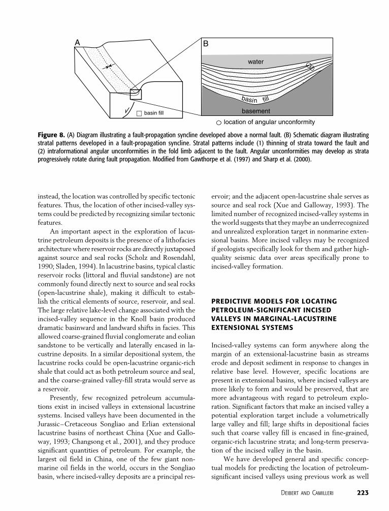
Figure 8. (A) Diagram illustrating a fault-propagation syncline developed above a normal fault. (B) Schematic diagram illustratingstratal patterns developed in a fault-propagation syncline. Stratal patterns include (1) thinning of strata toward the fault and(2) intraformational angular unconformities in the fold limb adjacent to the fault. Angular unconformities may develop as strataprogressively rotate during fault propagation. Modified from Gawthorpe et al. (1997) and Sharp et al. (2000).
Deibert and Camilleri 223
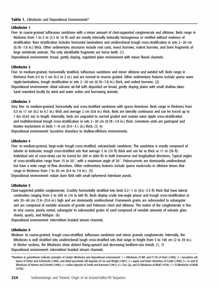
Table 1. Lithofacies and Depositional Environments*
Lithofacies 1Fine- to coarse-grained tuffaceous sandstone with a minor amount of clast-supported conglomerate and siltstone. Beds range in
thickness from 1 to 5 m (3.3 to 16 ft) and are mostly internally texturally homogenous or mottled without evidence of
stratification. Rare stratification includes horizontal laminations and unidirectional trough cross-stratification in sets 2–20 cm
(0.78–7.8 in.) thick. Other sedimentary structures include root casts, insect burrows, rodent burrows, and bone fragments of
large vertebrate animals. The only identifiable fragments are horse teeth. (1)
Depositional environment: broad, gently sloping, vegetated plain environment with minor fluvial channels.
Lithofacies 2Fine- to medium-grained, horizontally stratified, tuffaceous sandstone and minor siltstone and welded tuff. Beds range in
thickness from 0.5 to 5 cm (0.2 to 2 in.) and are normal to reverse graded. Other sedimentary features include sparse wave
ripple-laminations, trough stratification in sets 2–20 cm (0.78–7.8 in.) thick, and rodent burrows. (2)
Depositional environment: distal volcanic air-fall tuffs deposited on broad, gently sloping plains with small shallow lakes.
Sand reworked locally by wind and water action and burrowing animals.
Lithofacies 3Very fine- to medium-grained, horizontally and cross-stratified sandstone with sparse limestone. Beds range in thickness from
0.5 to 17 cm (0.2 to 6.7 in.) thick and average 2 cm (0.8 in.) thick. Beds are laterally continuous and can be traced up to
1 km (0.62 mi) in length. Internally, beds are ungraded to normal graded and contain wave ripple cross-stratification
and multidirectional trough cross-stratification in sets 2–20 cm (0.78–7.8 in.) thick. Limestone units are gastropod and
bivalve wackestone in beds 1–8 cm (0.4–3.1 in.) thick. (3, 4)
Depositional environment: lacustrine shoreface to shallow-offshore environments.
Lithofacies 4Fine- to medium-grained, large-scale trough cross-stratified, volcaniclastic sandstone. The sandstone is mostly composed of
tabular to lenticular, trough cross-stratified sets that average 3 m (10 ft) thick and can be as thick as 11 m (36 ft).
Individual sets of cross-strata can be traced for 200 m (660 ft) in both transverse and longitudinal directions. Typical angles
of cross-stratification range from 15 to 20j, with a maximum angle of 30j. Paleocurrents are dominantly unidirectional
but have a wide range of flow directions. Other sedimentary features include sparse mudcracks in siltstone lenses that
range in thickness from 1 to 20 cm (0.4 to 7.8 in.). (5)
Depositional environment: eolian dune field with small ephemeral interdune ponds.
Lithofacies 5Clast-supported pebble conglomerate. Crudely horizontally stratified into beds 0.2–1 m (0.6–3.3 ft) thick that have lateral
continuities ranging from 5 to 200 m (16 to 660 ft). Beds display crude low-angle planar and trough cross-stratification in
sets 20–60 cm (7.8–23.6 in.) high and are dominantly unidirectional. Framework grains are subrounded to subangular
and are composed of variable amounts of granite and Paleozoic chert and siltstone. The matrix of the conglomerate is fine
to very coarse, poorly sorted, subangular to subrounded grains of sand composed of variable amounts of volcanic glass
shards, quartz, and feldspar. (6)
Depositional environment: intermittent braided stream channels.
Lithofacies 6Medium- to coarse-grained, trough cross-stratified, tuffaceous sandstone and minor granule conglomerate. Internally, the
lithofacies is well stratified into unidirectional tough cross-stratified sets that range in height from 5 to 100 cm (2 to 39 in.).
In thicker sections, the lithofacies show distinct fining-upward and decreasing bedform-size trends. (1, 7)
Depositional environment: intermittent braided stream channels.
*Numbers in parentheses indicate examples of similar lithofacies and depositional environment: 1 = lithofacies F2-MS and F1-XS of Hunt (1990); 2 = lacustrine ashlayers of Fisher and Schmincke (1984), and distal pyroclastic fall deposits of Cas and Wright (1987); 3 = upper and lower shoreface of Castle (1990); 4 = Sr and Stlithofacies of Horton and Schmitt (1996); 5 = eolian deposits of Smith and Katzman (1991); 6 = Gm, Gp, and Gt lithofacies of Miall (1978); 7 = St lithofacies of Miall(1978).
224 Sedimentologic and Tectonic Origin of an Incised-Valley-Fill Sequence
as our own studies of extensional basins. The models
are intended to aid in the exploration of incised valleys
and to call attention to these features that theoretically
should be common in extensional-lacustrine basins but
are rarely recognized.
Depotectonic Framework for Predictive Models
The following generalized depotectonic framework
of extensional basins serves as the foundation for our
predictive models for the occurrence of petroleum-
significant incised valleys. The framework is devel-
oped from studies that have addressed the complex
sedimentary and tectonic development of extensional
basins (e.g., Leeder and Gawthorpe, 1987; Cohen,
1990; Olsen, 1990; Scholz and Rosendahl, 1990;
Prosser, 1993; Gawthorpe and Leeder, 2000; Chang-
song et al., 2001; Contreras and Scholz, 2001). From
the aforementioned studies, three main principles con-
cerning valley-fill sequences in marginal-lacustrine
systems can be inferred. First, incised valleys form
during falls of relative lake level as river systems shift
basinward and erode into older marginal-lacustrine
deposits. Incised valleys are subsequently filled with
sediment when relative lake level rises enough to pro-
duce deposition in the valley. Second, changes in rel-
ative lake level and stratal architecture are largely
controlled by the combined effects of tectonic sub-
sidence and climate, with climate principally affecting
the amount of precipitation and consequently con-
trolling changes in lake volume. Furthermore, climate
change can be an important factor in creating incised
valleys because it can cause rapid and large changes in
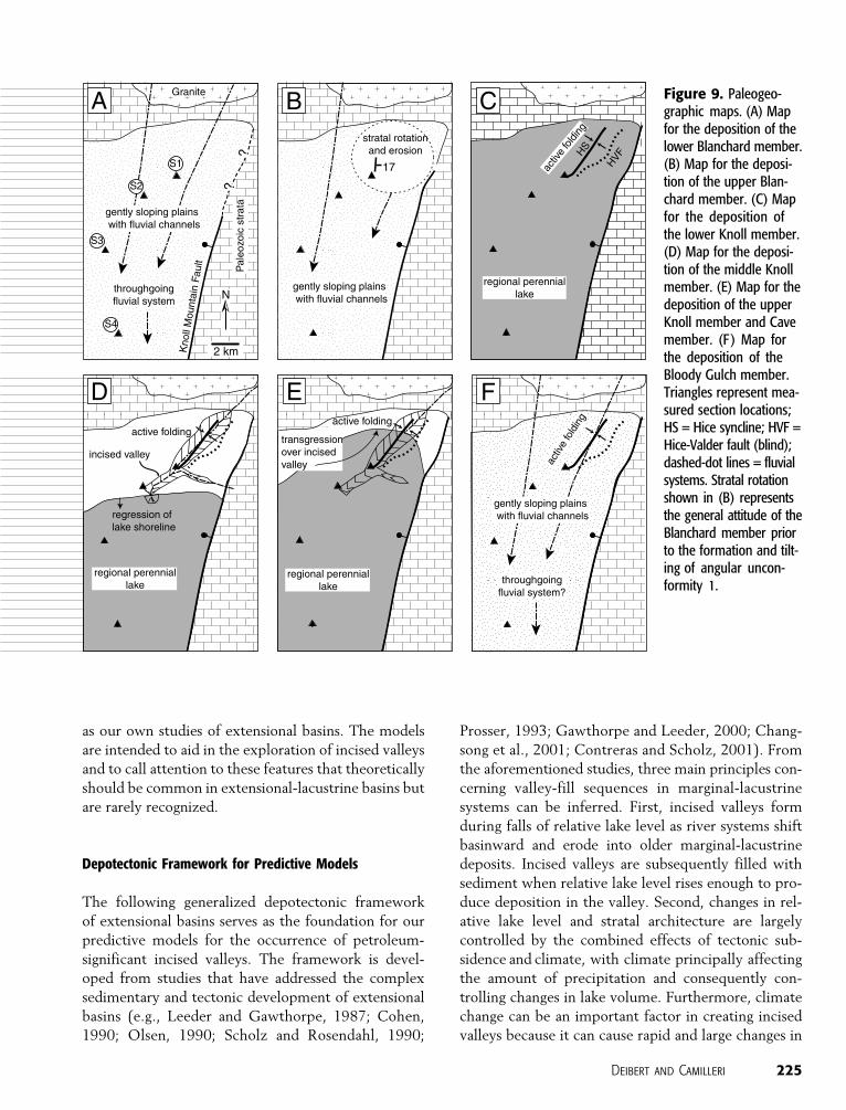
Figure 9. Paleogeo-graphic maps. (A) Mapfor the deposition of thelower Blanchard member.(B) Map for the deposi-tion of the upper Blan-chard member. (C) Mapfor the deposition ofthe lower Knoll member.(D) Map for the deposi-tion of the middle Knollmember. (E) Map for thedeposition of the upperKnoll member and Cavemember. (F ) Map forthe deposition of theBloody Gulch member.Triangles represent mea-sured section locations;HS = Hice syncline; HVF =Hice-Valder fault (blind);dashed-dot lines = fluvialsystems. Stratal rotationshown in (B) representsthe general attitude of theBlanchard member priorto the formation and tilt-ing of angular uncon-formity 1.
Deibert and Camilleri 225
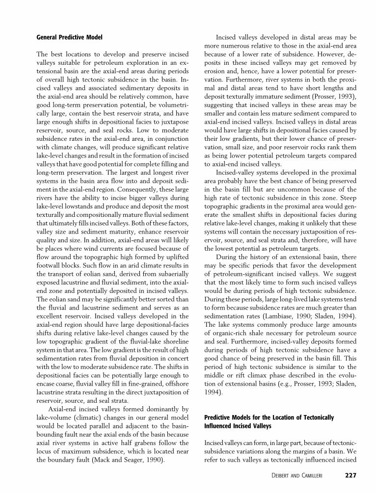
lake levels. Third, large river systems tend to flow
around footwall blocks and enter the lake and de-
posit sediment along the axis of the basin, parallel to
the basin-bounding fault (Figure 11). These three prin-
cipal factors influence the formation of incised valleys
differently in the proximal, distal, and axial-end areas
of extensional basins. In proximal areas (Figure 11),
high tectonic subsidence along the basin-bounding
fault tends to overwhelm the effects of small lake-
volume reductions, producing a stratigraphic record
of nearly continuous relative lake-level rise. Conse-
quently, incised valleys in proximal areas will be
sparse and, if present, are generally produced from
large changes in the rate of tectonic subsidence.
Conversely, in distal areas (Figure 11), incised valleys
and subaerial erosional truncation of strata are com-
mon because small changes in lake volume produce
a greater amount of relative base-level change be-
cause of lower tectonic subsidence. Axial-end areas
(Figure 11) have relatively low to moderate rates of
tectonic subsidence, and incised valleys here will be
common and a product of changes in climate and tec-
tonic subsidence.
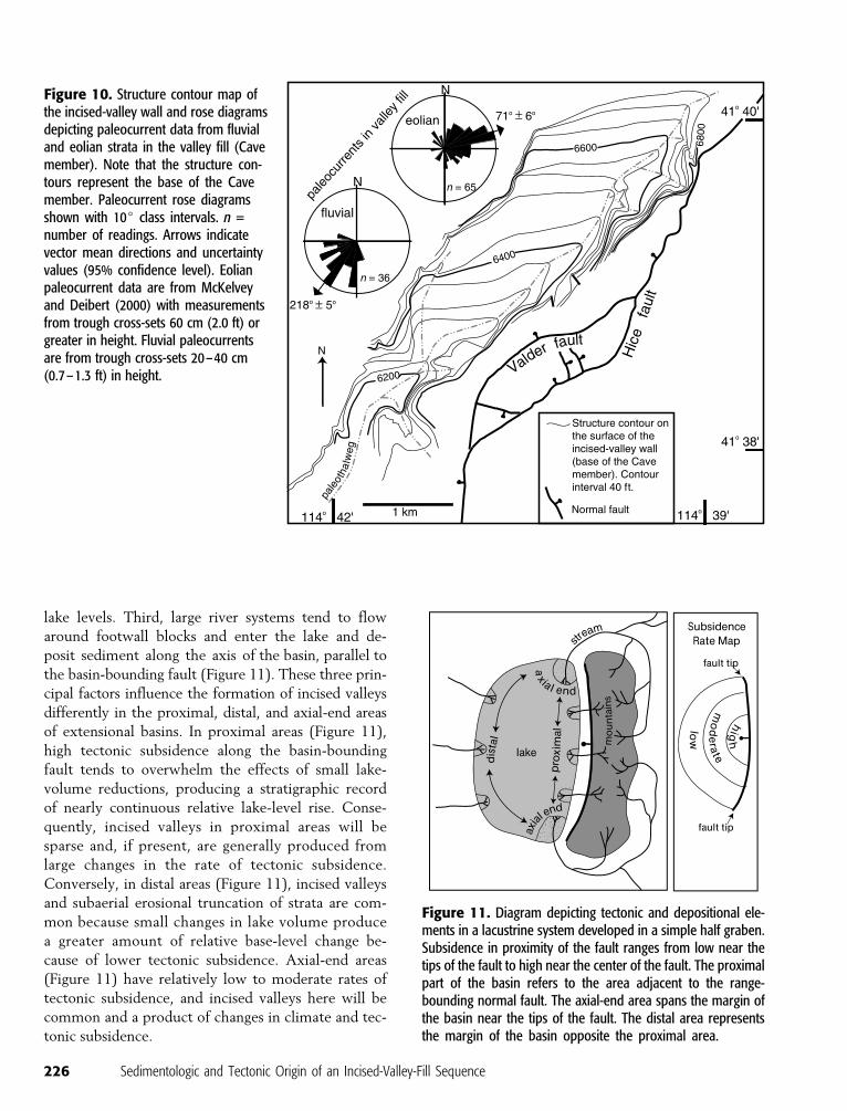
Figure 10. Structure contour map ofthe incised-valley wall and rose diagramsdepicting paleocurrent data from fluvialand eolian strata in the valley fill (Cavemember). Note that the structure con-tours represent the base of the Cavemember. Paleocurrent rose diagramsshown with 10j class intervals. n =number of readings. Arrows indicatevector mean directions and uncertaintyvalues (95% confidence level). Eolianpaleocurrent data are from McKelveyand Deibert (2000) with measurementsfrom trough cross-sets 60 cm (2.0 ft) orgreater in height. Fluvial paleocurrentsare from trough cross-sets 20–40 cm(0.7–1.3 ft) in height.
Figure 11. Diagram depicting tectonic and depositional ele-ments in a lacustrine system developed in a simple half graben.Subsidence in proximity of the fault ranges from low near thetips of the fault to high near the center of the fault. The proximalpart of the basin refers to the area adjacent to the range-bounding normal fault. The axial-end area spans the margin ofthe basin near the tips of the fault. The distal area representsthe margin of the basin opposite the proximal area.
226 Sedimentologic and Tectonic Origin of an Incised-Valley-Fill Sequence
General Predictive Model
The best locations to develop and preserve incised
valleys suitable for petroleum exploration in an ex-
tensional basin are the axial-end areas during periods
of overall high tectonic subsidence in the basin. In-
cised valleys and associated sedimentary deposits in
the axial-end area should be relatively common, have
good long-term preservation potential, be volumetri-
cally large, contain the best reservoir strata, and have
large enough shifts in depositional facies to juxtapose
reservoir, source, and seal rocks. Low to moderate
subsidence rates in the axial-end area, in conjunction
with climate changes, will produce significant relative
lake-level changes and result in the formation of incised
valleys that have good potential for complete filling and
long-term preservation. The largest and longest river
systems in the basin area flow into and deposit sedi-
ment in the axial-end region. Consequently, these large
rivers have the ability to incise bigger valleys during
lake-level lowstands and produce and deposit the most
texturally and compositionally mature fluvial sediment
that ultimately fills incised valleys. Both of these factors,
valley size and sediment maturity, enhance reservoir
quality and size. In addition, axial-end areas will likely
be places where wind currents are focused because of
flow around the topographic high formed by uplifted
footwall blocks. Such flow in an arid climate results in
the transport of eolian sand, derived from subaerially
exposed lacustrine and fluvial sediment, into the axial-
end zone and potentially deposited in incised valleys.
The eolian sand may be significantly better sorted than
the fluvial and lacustrine sediment and serves as an
excellent reservoir. Incised valleys developed in the
axial-end region should have large depositional-facies
shifts during relative lake-level changes caused by the
low topographic gradient of the fluvial-lake shoreline
system in that area. The lowgradient is the result of high
sedimentation rates from fluvial deposition in concert
with the low to moderate subsidence rate. The shifts in
depositional facies can be potentially large enough to
encase coarse, fluvial valley fill in fine-grained, offshore
lacustrine strata resulting in the direct juxtaposition of
reservoir, source, and seal strata.
Axial-end incised valleys formed dominantly by
lake-volume (climatic) changes in our general model
would be located parallel and adjacent to the basin-
bounding fault near the axial ends of the basin because
axial river systems in active half grabens follow the
locus of maximum subsidence, which is located near
the boundary fault (Mack and Seager, 1990).
Incised valleys developed in distal areas may be
more numerous relative to those in the axial-end area
because of a lower rate of subsidence. However, de-
posits in these incised valleys may get removed by
erosion and, hence, have a lower potential for preser-
vation. Furthermore, river systems in both the proxi-
mal and distal areas tend to have short lengths and
deposit texturally immature sediment (Prosser, 1993),
suggesting that incised valleys in these areas may be
smaller and contain less mature sediment compared to
axial-end incised valleys. Incised valleys in distal areas
would have large shifts in depositional facies caused by
their low gradients, but their lower chance of preser-
vation, small size, and poor reservoir rocks rank them
as being lower potential petroleum targets compared
to axial-end incised valleys.
Incised-valley systems developed in the proximal
area probably have the best chance of being preserved
in the basin fill but are uncommon because of the
high rate of tectonic subsidence in this zone. Steep
topographic gradients in the proximal area would gen-
erate the smallest shifts in depositional facies during
relative lake-level changes, making it unlikely that these
systems will contain the necessary juxtaposition of res-
ervoir, source, and seal strata and, therefore, will have
the lowest potential as petroleum targets.
During the history of an extensional basin, there
may be specific periods that favor the development
of petroleum-significant incised valleys. We suggest
that the most likely time to form such incised valleys
would be during periods of high tectonic subsidence.
During these periods, large long-lived lake systems tend
to form because subsidence rates are much greater than
sedimentation rates (Lambiase, 1990; Sladen, 1994).
The lake systems commonly produce large amounts
of organic-rich shale necessary for petroleum source
and seal. Furthermore, incised-valley deposits formed
during periods of high tectonic subsidence have a
good chance of being preserved in the basin fill. This
period of high tectonic subsidence is similar to the
middle or rift climax phase described in the evolu-
tion of extensional basins (e.g., Prosser, 1993; Sladen,
1994).
Predictive Models for the Location of TectonicallyInfluenced Incised Valleys
Incised valleys can form, in large part, because of tectonic-
subsidence variations along the margins of a basin. We
refer to such valleys as tectonically influenced incised
Deibert and Camilleri 227
valleys. Tectonically influenced incised valleys and
their associated fills are likely to be of larger scale, have
larger facies shifts, and have a better long-term preser-
vation potential than incised valleys formed by domi-
nantly lake-volume (climatic) changes.
Data from extensional basins, both real and mod-
eled, indicate that rapid and dramatic changes in tec-
tonic subsidence along the strike of a boundary-fault
zone are common (e.g., Gawthorpe et al., 1994;Morley,
1995; Gupta et al., 1998; Contreras et al., 2000). Such
variations create significant shifts in depocenters,
especially during the early and middle phases of basin
development (e.g., Prosser, 1993; Morley, 1995; Cowie
et al., 2000; Gawthorpe and Leeder, 2000). The shifts
are the result of changes in the rate and location
of fault slip and related subsidence. Many of these
changes in tectonic subsidence patterns can occur
during short periods and can create large-magnitude
relative lake-level changes and, as a consequence, in-
cised valleys.
There are several ways that variations in tectonic
subsidence could result in the formation of an incised-
valley system. We present three conceptual models for
the formation and location of tectonically influenced
incised valleys in half graben extensional basins that
would be suitable for petroleum exploration.
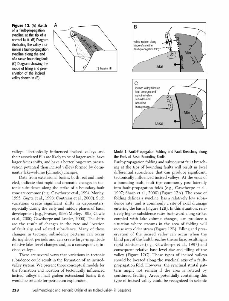
Model 1: Fault-Propagation Folding and Fault Breaching along
the Ends of Basin-Bounding Faults
Fault-propagation folding and subsequent fault breach-
ing at the tips of bounding faults will result in local
differential subsidence that can produce significant,
tectonically influenced incised valleys. At the ends of
a bounding fault, fault tips commonly pass laterally
into fault-propagation folds (e.g., Gawthorpe et al.,
1997; Sharp et al., 2000) (Figure 12A). The zone of
folding defines a syncline, has a relatively low subsi-
dence rate, and is commonly a site of axial drainage
entering the basin (Figure 12B). In this situation, rela-
tively higher subsidence rates basinward along strike,
coupled with lake-volume changes, can produce a
situation where streams in the area of folding will
incise into older strata (Figure 12B). Filling and pres-
ervation of the incised valley can occur when the
blind part of the fault breaches the surface, resulting in
rapid subsidence (e.g., Gawthorpe et al., 1997) and
consequent relative base-level rise and filling of the
valley (Figure 12C). These types of incised valleys
should be located along the synclinal axis of a fault-
propagation fold. However, the synclinal stratal pat-
tern might not remain if the area is rotated by
continued faulting. Areas potentially containing this
type of incised valley could be recognized in seismic
Figure 12. (A) Sketchof a fault-propagationsyncline at the tip of anormal fault. (B) Diagramillustrating the valley inci-sion in a fault-propagationsyncline along the endof a range-bounding fault.(C) Diagram showing themode of filling and pres-ervation of the incisedvalley shown in (B).
228 Sedimentologic and Tectonic Origin of an Incised-Valley-Fill Sequence
data by changes in stratal patterns in dip sections
(see Gawthorpe et al., 1997; Sharp et al., 2000, for
stratal patterns) and by abrupt changes in stratal thick-
ness in strike sections.
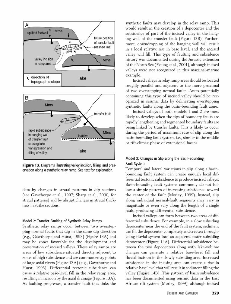
Model 2: Transfer Faulting of Synthetic Relay Ramps
Synthetic relay ramps occur between two overstep-
ping normal faults that dip in the same dip direction
(e.g., Gawthorpe and Hurst, 1993) (Figure 13A) and
may be zones favorable for the development and
preservation of incised valleys. These relay ramps are
areas of low subsidence situated directly adjacent to
zones of high subsidence and are common entry points
of large axial rivers (Figure 13A) (e.g., Gawthorpe and
Hurst, 1993). Differential tectonic subsidence can
cause a relative base-level fall in the relay ramp area,
resulting in incision by the axial drainage (Figure 13A).
As faulting progresses, a transfer fault that links the
synthetic faults may develop in the relay ramp. This
would result in the creation of a depocenter and the
subsidence of part of the incised valley in the hang-
ing wall of the transfer fault (Figure 13B). Further-
more, downdropping of the hanging wall will result
in a local relative rise in base level, and the incised
valley will fill. This type of faulting and subsidence
history was documented during the Jurassic extension
of the North Sea (Young et al., 2001), although incised
valleys were not recognized in this marginal-marine
example.
Incised valleys in relay ramp areas should be located
roughly parallel and adjacent to the more proximal
of two overstepping normal faults. Areas potentially
containing this type of incised valley should be rec-
ognized in seismic data by delineating overstepping
synthetic faults along the basin-bounding fault zone.
Incised valleys of both models 1 and 2 are most
likely to develop when the tips of boundary faults are
rapidly lengthening and segmented boundary faults are
being linked by transfer faults. This is likely to occur
during the period of maximum rate of slip along the
basin-bounding fault system, i.e., similar to the middle
or rift-climax phase of extensional basins.
Model 3: Changes in Slip along the Basin-Bounding
Fault System
Temporal and lateral variations in slip along a basin-
bounding fault system can create enough local dif-
ferential tectonic subsidence to produce incised valleys.
Basin-bounding fault systems commonly do not fol-
low a simple pattern of increasing subsidence toward
the center of the fault (Morley, 1999). Instead, slip
along individual normal-fault segments may vary in
magnitude or even vary along the length of a single
fault, producing differential subsidence.
Incised valleys can form between two areas of dif-
ferential subsidence. For example, in a slow subsiding
depocenter near the end of the fault system, sediment
can fill the depocenter completely and create a through-
going fluvial system into an adjacent, faster subsiding
depocenter (Figure 14A). Differential subsidence be-
tween the two depocenters along with lake-volume
changes can generate a relative base-level fall and
fluvial incision in the slowly subsiding area. Increased
subsidence in the incising area can create a rise in
relative base level that will result in sediment filling the
valley (Figure 14B). This pattern of basin subsidence
has been documented using seismic data in the East
African rift system (Morley, 1999), although incised
Figure 13. Diagrams illustrating valley incision, filling, and pres-ervation along a synthetic relay ramp. See text for explanation.
Deibert and Camilleri 229
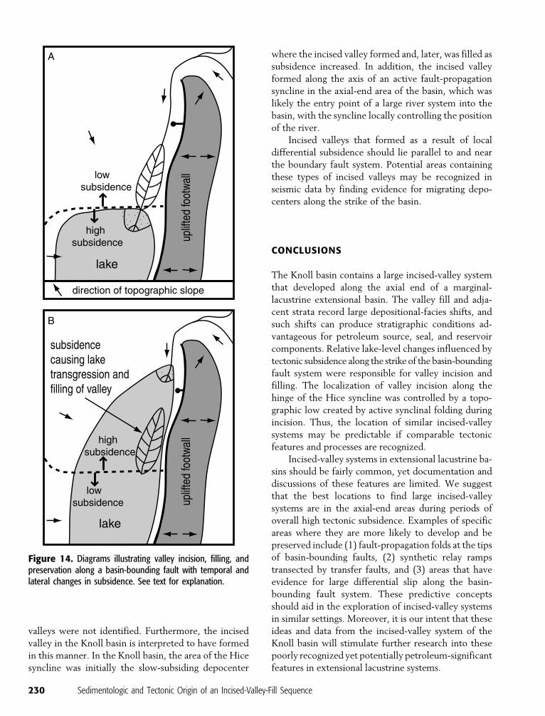
valleys were not identified. Furthermore, the incised
valley in the Knoll basin is interpreted to have formed
in this manner. In the Knoll basin, the area of the Hice
syncline was initially the slow-subsiding depocenter
where the incised valley formed and, later, was filled as
subsidence increased. In addition, the incised valley
formed along the axis of an active fault-propagation
syncline in the axial-end area of the basin, which was
likely the entry point of a large river system into the
basin, with the syncline locally controlling the position
of the river.
Incised valleys that formed as a result of local
differential subsidence should lie parallel to and near
the boundary fault system. Potential areas containing
these types of incised valleys may be recognized in
seismic data by finding evidence for migrating depo-
centers along the strike of the basin.
CONCLUSIONS
The Knoll basin contains a large incised-valley system
that developed along the axial end of a marginal-
lacustrine extensional basin. The valley fill and adja-
cent strata record large depositional-facies shifts, and
such shifts can produce stratigraphic conditions ad-
vantageous for petroleum source, seal, and reservoir
components. Relative lake-level changes influenced by
tectonic subsidence along the strike of the basin-bounding
fault system were responsible for valley incision and
filling. The localization of valley incision along the
hinge of the Hice syncline was controlled by a topo-
graphic low created by active synclinal folding during
incision. Thus, the location of similar incised-valley
systems may be predictable if comparable tectonic
features and processes are recognized.
Incised-valley systems in extensional lacustrine ba-
sins should be fairly common, yet documentation and
discussions of these features are limited. We suggest
that the best locations to find large incised-valley
systems are in the axial-end areas during periods of
overall high tectonic subsidence. Examples of specific
areas where they are more likely to develop and be
preserved include (1) fault-propagation folds at the tips
of basin-bounding faults, (2) synthetic relay ramps
transected by transfer faults, and (3) areas that have
evidence for large differential slip along the basin-
bounding fault system. These predictive concepts
should aid in the exploration of incised-valley systems
in similar settings. Moreover, it is our intent that these
ideas and data from the incised-valley system of the
Knoll basin will stimulate further research into these
poorly recognized yet potentially petroleum-significant
features in extensional lacustrine systems.
Figure 14. Diagrams illustrating valley incision, filling, andpreservation along a basin-bounding fault with temporal andlateral changes in subsidence. See text for explanation.
230 Sedimentologic and Tectonic Origin of an Incised-Valley-Fill Sequence
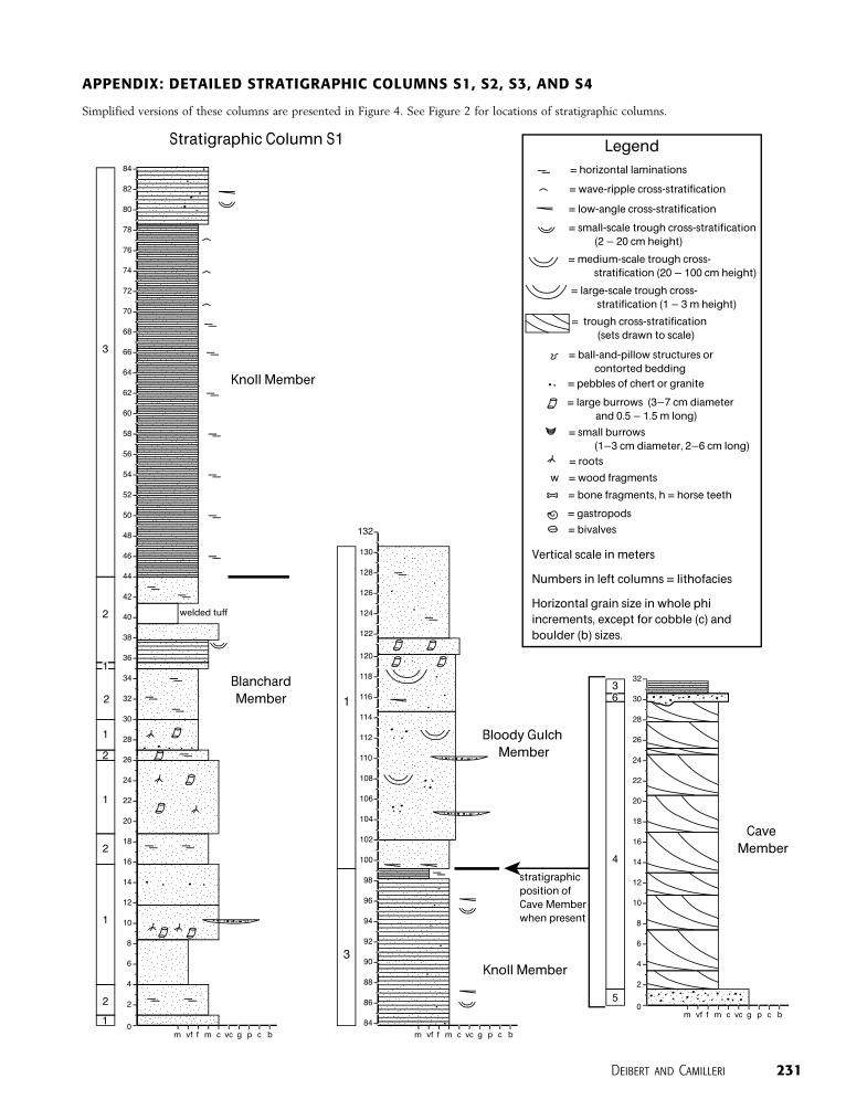
APPENDIX: DETAILED STRATIGRAPHIC COLUMNS S1, S2, S3, AND S4
Simplified versions of these columns are presented in Figure 4. See Figure 2 for locations of stratigraphic columns.
Deibert and Camilleri 231
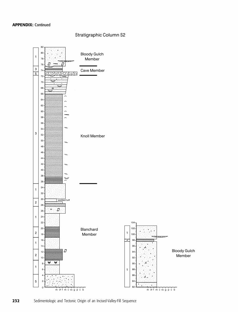
APPENDIX: Continued
232 Sedimentologic and Tectonic Origin of an Incised-Valley-Fill Sequence
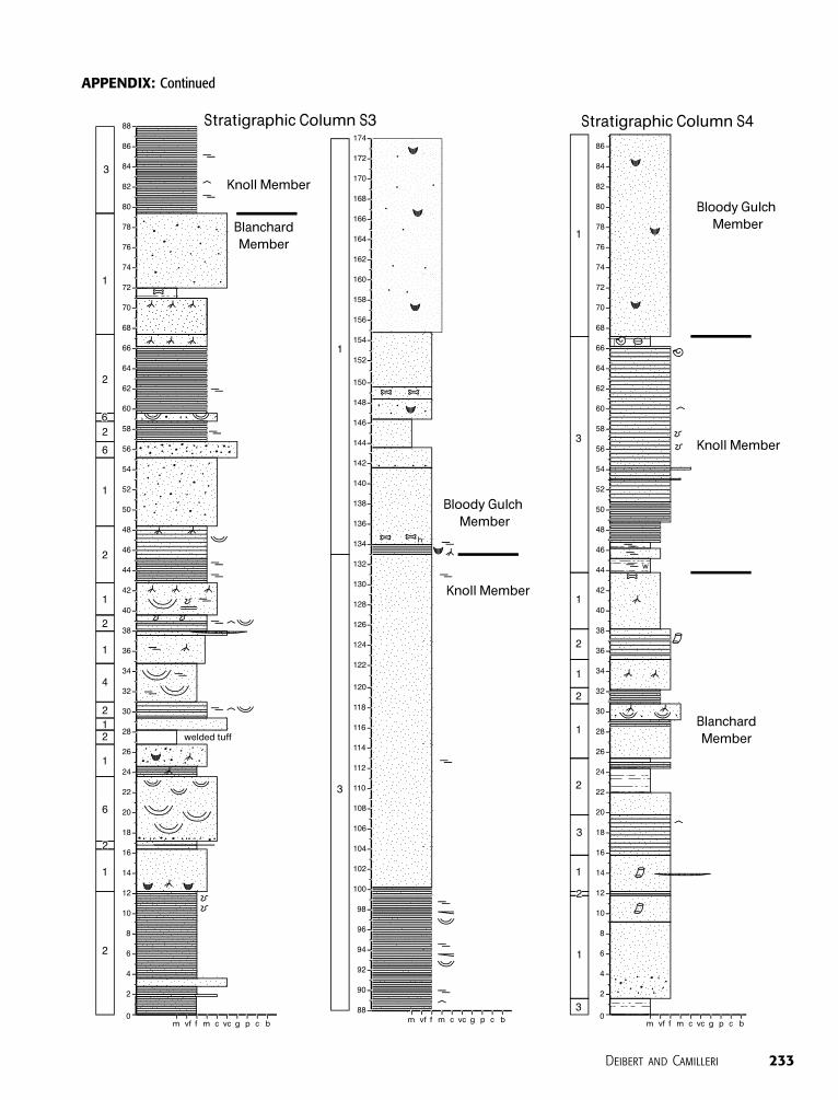
APPENDIX: Continued
Deibert and Camilleri 233
REFERENCES CITED
Bohacs, K. M., A. R. Carroll, J. E. Neal, and P. J. Mankiewicz, 2000,Lake-basin type, source potential, and hydrocarbon character:An integrated sequence-stratigraphic-geochemical framework,in E. H. Gierlowski-Kordesch and K. R. Kelts, eds., Lake basinsthrough space and time: AAPG Studies in Geology 46, p. 33–78.
Camilleri, P. A., 1996, Evidence for Late Cretaceous–early Ter-tiary(?) extension in the Pequop Mountains, Nevada: Impli-cations for the nature of the early Tertiary unconformity, inW. J. Taylor and H. Langrock, eds., Cenozoic structure andstratigraphy of central Nevada: 1996 Field Conference Vol-ume, Reno, Nevada Petroleum Society Inc., p. 19–28.
Camilleri, P. A., and K. R. Chamberlain, 1997, Mesozoic tectonicsand metamorphism in the Pequop Mountains and Wood Hillsregion, northeast Nevada: Implications for the architecture andevolution of the Sevier orogen: Geological Society of AmericaBulletin, v. 109, p. 74–94.
Carroll, A. R., and K. M. Bohacs, 1999, Stratigraphic classificationof ancient lakes: Balancing tectonic and climatic controls:Geology, v. 27, p. 99–102.
Cas, R. A. F., and J. V. Wright, 1987, Volcanic successions modernand ancient: A geologic approach to processes, products andsuccessions: Boston, Allen and Unwin Ltd., 528 p.
Castle, J. W., 1990, Sedimentation in Eocene Lake Uinta (LowerGreen River Formation) northeastern Uinta basin, Utah, in B. J.Katz, ed., Lacustrine basin exploration: Case studies and mod-ern analogs: AAPG Memoir 50, p. 243–263.
Changsong, L., K. Eriksson, L. Sitian, W. Yongxian, R. Jianye, andZ. Yanmei, 2001, Sequence architecture, depositional systems,and controls on the development of lacustrine basin fills in partof the Erlian basin, northeast China: AAPG Bulletin, v. 85,p. 2017–2043.
Coats, R. R., 1987, Geology of Elko County, Nevada: Reno, Ne-vada, Nevada Bureau of Mines and Geology Bulletin, v. 101,112 p.
Cohen, A. S., 1990, Tectono-stratigraphic model for sedimenta-tion in Lake Tanganyika, Africa, in B. J. Katz, ed., Lacustrinebasin exploration: Case studies and modern analogs: AAPGMemoir 50, p. 137–150.
Contreras, J., and C. H. Scholz, 2001, Evolution of stratigraphicsequences in multisegmented continental rift basins: Compar-ison of computer models with basins of the East African riftsystem: AAPG Bulletin, v. 9, p. 1565–1581.
Contreras, J., M. H. Anders, and C. H. Scholz, 2000, Growth of anormal fault system: Observations from the Lake Malawi basinof the East African rift: Journal of Structural Geology, v. 22,p. 159–168.
Corfield, S., and I. R. Sharp, 2000, Structural style and stratigraphicarchitecture of fault propagation folding in extensionalsettings: A seismic example from the Smorbukk area, HaltenTerrace, mid-Norway: Basin Research, v. 12, p. 329–341.
Cowie, P. A., S. Gupta, and N. H. Dawers, 2000, Implications offault array evolution for synrift depocentre development:Insights from a numerical fault growth model: Basin Research,v. 12, p. 241–261.
Dalrymple, R. W., R. Boyd, and B. A. Zaitlin,1994, History of re-search, types and internal organization of incised-valley sys-tems: Introduction to the volume, in R. W. Dalrymple, R.Boyd, B. Zaitlin, and P. A. Scholle, eds., Incised-valley sys-tems: Origin and sedimentary sequences: SEPM Special Pub-lication 51, p. 3–10.
Fisher, R. V., and H. U. Schmincke, 1984, Pyroclastic rocks: NewYork, Springer-Verlag, 472 p.
Gawthorpe, R. L., and J. M. Hurst, 1993, Transfer zones in
extensional basins: Their structural style and influence ondrainage development and stratigraphy: Journal of the Geo-logical Society, v. 150, p. 1137–1152.
Gawthorpe, R. L., and M. R. Leeder, 2000, Tectono-sedimentaryevolution of active extensional basins: Basin Research, v. 12,p. 195–218.
Gawthorpe, R. L., A. J. Fraser, and R. E. Ll. Collier, 1994, Sequencestratigraphy in active extensional basins: Implications for theinterpretation of ancient basin-fills: Marine and PetroleumGeology, v. 11, p. 642–658.
Gawthorpe, R. L., I. Sharp, J. R. Underhill, and S. Gupta, 1997,Linked sequence stratigraphic and structural evolution ofpropagating normal faults: Geology, v. 25, p. 795–798.
Gupta, S., P. A. Cowie, N. H. Dawers, and J. R. Underhill, 1998, Amechanism to explain rift-basin subsidence and stratigraphicpatterns through fault-array evolution: Geology, v. 26, p. 595–598.
Horton, B. K., and J. G. Schmitt, 1996, Sedimentology of alacustrine fan-delta system, Miocene Horse Camp Formation,Nevada, U.S.A.: Sedimentology, v. 43, p. 133–155.
Hunt, R. M., 1990, Taphonomy and sedimentology of Arikaree( lower Miocene) fluvial, eolian, and lacustrine paleoenviron-ments, Nebraska and Wyoming: A paleobiota entombed infine-grained volcaniclastic rocks: Geological Society of Amer-ica Special Paper 244, p. 69–111.
Khalil, S. M., and K. R. McClay, 2002, Extensional fault relatedfolding, northwestern Red Sea, Egypt: Journal of StructuralGeology, v. 24, p. 743–762.
Lambiase, J. J., 1990, A model for tectonic control of lacustrinestratigraphic sequences in continental rift basins, in B. J. Katz,ed., Lacustrine basin exploration: Case studies and modernanalogs: AAPG Memoir 50, p. 265–276.
Leeder, M. R., and R. L. Gawthorpe, 1987, Sedimentary models forextensional tilt-block/half-graben basins, inM. P. Coward, J. F.Dewey, and P. L. Hancock, eds., Continental extensionaltectonics: Geological Society (London) Special Publication 28,p. 139–152.
Mack, G. H., and W. R. Seager, 1990, Tectonic control on faciesdistribution of the Camp Rice and Palomas formations(Pliocene–Pleistocene) in the southern Rio Grande rift:Geological Society of America Bulletin, v. 102, p. 45–53.
Maurin J. C., and B. Niviere, 2000, Extensional forced folding anddecollement of the pre-rift series along the Rhine graben andtheir influence on the geometry of the syn-rift sequences, inJ. W. Cosgrove and M. S. Ameen, eds., Forced folds and frac-tures: Geological Society (London) Special Publication 169,p. 73–86.
McGrew, A. J., and L. W. Snee, 1994, 40Ar/39Ar thermochrono-logic constraints on the tectonothermal evolution of thenorthern East Humboldt Range metamorphic core complex:Tectonophysics, v. 238, p. 425–450.
McKelvey, M. A., and J. E. Deibert, 2000, Stratification features ofeolian volcaniclastic sandstone units of the Miocene HumboldtFormation, northeast, Nevada (abs.): Geological Society ofAmerica Abstracts with Programs, v. 32, p. A-272.
Miall, A. D., 1978, Lithofacies types and vertical profile models inbraided river deposits: A summary, in A. D. Miall, ed., Fluvialsedimentology: Canadian Society of Petroleum GeologistsMemoir 5, p. 597–604.
Morley, C. K., 1995, Developments in the structural geology of riftsover the last decade and their impact on hydrocarbonexploration, in J. J. Lambiase, ed., Hydrocarbon habitat in riftbasins: Geological Society (London) Special Publication 80,p. 1–32.
Morley, C. K., 1999, Patterns of displacement along large normalfaults: Implications for basin evolution and fault propagation,
234 Sedimentologic and Tectonic Origin of an Incised-Valley-Fill Sequence
based on examples from east Africa: AAPG Bulletin, v. 83,p. 613–634.
Mueller, K. J., and A. W. Snoke, 1993a, Progressive overprinting ofnormal fault systems and their role in Tertiary exhumation ofthe East Humboldt–Wood Hills metamorphic complex,northeast Nevada: Tectonics, v. 12, p. 361–371.
Mueller, K. J., and A. W. Snoke, 1993b, Cenozoic basin develop-ment and normal fault systems associated with the exhuma-tion of metamorphic complexes in northeast Nevada, in M. M.Lahren, J. H. Trexler, and C. Spinosa, eds., Crustal evolutionof the Great Basin and Sierra Nevada: Geological Society ofAmerica field trip guidebook, Geology Department, Univer-sity of Nevada, Reno, p. 1–34.
Mueller, K. J., P. K. Cerveny, M. E. Perkins, and L. W. Snee, 1999,Chronology of polyphase extension in the Windermere Hills,northeast Nevada: Geological Society of America Bulletin,v. 111, p. 11–27.
Olsen, P. E., 1990, Tectonic, climatic, and biotic modulation oflacustrine ecosystems: Examples from Newark Supergroupof eastern North America, in B. J. Katz, ed., Lacustrine basinexploration: Case studies and modern analogs: AAPG Mem-oir 50, p. 209–224.
Perkins, M. E., F. H. Brown, W. P. Nash, W. McIntosh, and S. K.Williams, 1998, Sequence, age, and source of silicic fallouttuffs in middle to late Miocene basins of northern Basin andRange province: Geological Society of America Bulletin,v. 110, p. 2689–2716.
Prosser, S., 1993, Rift-related linked depositional systems and theirseismic expression, in G. D. Williams and A. Dobb, eds.,Tectonics and seismic sequence stratigraphy: GeologicalSociety (London) Special Publication 71, p. 35–66.
Riva, J. F., 1962, Allochthonous Ordovician–Silurian cherts,argillites and volcanic rocks on Knoll Mountain, Elko County,Nevada: Ph.D. dissertation, Columbia University, New York,New York, 141 p.
Riva, J. F., 1970, Thrusted Paleozoic rocks in the northern andcentral HD Range, northeastern Nevada: Geological Society ofAmerica Bulletin, v. 81, p. 344–360.
Scholz, C. A., and B. R. Rosendahl, 1990, Coarse-clastic facies andstratigraphic sequence models from lakes Malawi and Tangan-yika, east Africa, in B. J. Katz, ed., Lacustrine basin explo-ration: Case studies and modern analogs: AAPG Memoir 50,p. 209–224.
Schrader, F. C., 1912, A reconnaissance of the Jarbidge, Contact,and Elk Mountain mining districts, Elko County, Nevada: U.S.Geological Survey Bulletin, v. 497, 162 p.
Sharp, I. R., R. L. Gawthorpe, J. R. Underhill, and S. Gupta, 2000,Fault-propagation folding in extensional settings: Examples ofstructural style and synrift sedimentary response from the Suez
rift, Sinai, Egypt: Geological Society of America Bulletin,v. 112, p. 1877–1899.
Sharp, R. P., 1939, The Miocene Humboldt Formation innortheastern Nevada: Journal of Geology, v. 47, p. 133–160.
Sladen, C. P., 1994, Key elements during the search for hydro-carbons in lake systems, in K. E. Gierlowski and K. Kelts, eds.,Global geological record of lake basins: Cambridge, CambridgeUniversity Press, p. 3–17.
Smith, G. A., and D. Katzman, 1991, Discrimination of eolian andpyroclastic-surge processes in the generation of cross-beddedtuffs, Jemez Mountains volcanic field, New Mexico: Geology,v. 19, p. 465–468.
Snoke, A. W., and A. P. Lush, 1984, Polyphase Mesozoic–Cenozoic deformational history of the Ruby Mountains–EastHumboldt Range, Nevada, in J. Lintz Jr., ed., Westerngeological excursions: Geological Society of America annualmeeting field trip guidebook, Mackay School of Mines, Reno,Nevada, v. 4, p. 232–260.
Stirton, R. A., 1940, The Nevada Miocene and Pliocene mammalianfaunas as faunal units, in Sixth Pacific Science Congress of thePacific Science Association: Berkeley, University of CaliforniaPress, v. 2, p. 627–640.
Thorman, C. H., K. B. Ketner, W. B. Brooks, L. W. Snee, and R. A.Zimmerman, 1990, Late Mesozoic–Cenozoic tectonics innortheastern Nevada, in D. R. Shaddrick, J. A. Kizis Jr., andE. L. Hunsaker III, eds., Geology and ore deposits of thenortheastern Great Basin: Geological Society of Nevada 1990Meeting, p. 25–45.
Van Houten, F. B., 1956, Reconnaissance of Cenozoic sedimentaryrocks of Nevada: AAPG Bulletin, v. 40, no. 12, p. 2801–2825.
Van Wagoner, J. C., R. M. Mitchum, K. M. Campion, and V. D.Rahmanian, 1990, Siliclastic sequence stratigraphy in well logs,cores, and outcrops: Concepts for high-resolution correlationof time and facies: AAPG Methods in Exploration Series 7,55 p.
Wright, J. E., and A. W. Snoke, 1993, Tertiary magmatism andmylonitization in the Ruby–East Humboldt metamorphiccore complex, northeastern Nevada: U-Pb geochronology andSr, Nd, Pb, isotope geochemistry: Geological Society ofAmerica Bulletin, v. 105, p. 935–952.
Xue, L., and W. E. Galloway, 1993, Genetic sequence stratigraphicframework, depositional style, and hydrocarbon occurrence ofthe Upper Cretaceous QYN formations in the Songliaolacustrine basin, northeastern China: AAPG Bulletin, v. 77,p. 1792–1808.
Young, M. J., R. L. Gawthorpe, and S. Hardy, 2001, Growth andlinkage of a segmented normal fault zone; The Late JurassicMurchison-Statfjord North fault, northern North Sea: Journalof Structural Geology, v. 23, p. 1933–1952.
Deibert and Camilleri 235
Related Documents