1 Security Equipment and Ironmongery Generic Project Requirements (Technical Specification and Design Guidance) University of Bristol Authors: David Tonkin, Head of Facilities Management Soft Services Tony Blundal, Security Systems Manager Date: April 2019 Version: 1.0

Welcome message from author
This document is posted to help you gain knowledge. Please leave a comment to let me know what you think about it! Share it to your friends and learn new things together.
Transcript
1
Security Equipment and
Ironmongery
Generic Project Requirements
(Technical Specification and
Design Guidance)
University of Bristol
Authors: David Tonkin, Head of Facilities Management Soft Services
Tony Blundal, Security Systems Manager
Date: April 2019
Version: 1.0
2
Table of Contents
1.0 Purpose of Document ............................................................................................................. 3
2.0 Design Process, Installations and Commissioning ........................................................... 3
3.0 Principles of Deployment – for use by Security Services and the Authorised
Contractor ............................................................................................................................................. 4
4.0 Access control solutions ........................................................................................................ 4
4.1 Intruder and Panic Alarms .................................................................................................... 5
4.2 Surveillance Cameras ............................................................................................................. 5
4.3 Intercom/door entry systems ............................................................................................... 6
5.0 Technical Specifications - for use by the Authorised Contractor .................................. 6
5.1 Access control and alarm monitoring ................................................................................. 6
5.1.1 General & equipment ......................................................................................................... 7
5.1.2 Readers and release mechanisms .................................................................................... 7
5.1.3 Access controlled door monitoring and alarms ............................................................ 8
5.1.4 Lift controls .......................................................................................................................... 8
5.1.6 Electronic Locking and Security Doors (see section 6 for ironmongery) ................ 8
5.1.7 Alarm monitoring ............................................................................................................. 10
5.1.8 Intruder alarms systems ................................................................................................. 10
5.1.9 Barriers, Fences and Gates .................................................................................................. 10
5.2 Surveillance cameras ........................................................................................................... 10
5.3 External Cameras .................................................................................................................. 11
5.4 Internal Cameras ................................................................................................................... 11
5.5 PTZ Cameras .......................................................................................................................... 11
5.6 Fixed Cameras ........................................................................................................................ 12
5.7 Digital Video Recording and Transmission: .................................................................... 12
5.9 Testing and Commissioning: ............................................................................................... 12
6.0 Ironmongery, locks and keys .............................................................................................. 13
7.0 Lighting ................................................................................................................................... 13

3
Overview
The University of Bristol (UoB) aspires to a safe, welcoming environment striking an appropriate balance between freedom of movement and security, and the right to privacy.
It is the University’s requirement that all new build and major refurbishment will utilise Secured by Design (SBD) principles. University Security Services will be able to advise but full details on SBD can be found at www.securedbydesign.com
For public realm/landscape improvements, architects should design out crime as far as possible using Crime Prevention Through Environmental Design (CPTED) principles.
Security Systems will be specified on the following basis: • In a way that provides us with clear and identifiable benefits.
• In proportion to the risks associated to the requirement.
• Consistently, so the same risk will receive the same specification. Whilst being responsive to local requirements, specifications will be defined at organisational level, not by local users.
• With a consistent interface with our systems across different buildings.
• With a view to the ongoing maintenance, legacy replacement and management of security systems, and the costs associated to this.
• Utilising a standardised approach and system components (lock types etc.) to ensure that systems can be economically and efficiently maintained and repaired.
1.0 Purpose of Document
The purpose of this document is to inform UoB Estates Project Officers, design consultants and installers of the required approach for the deployment of security systems at UoB. This covers both the principles of deployment and technical requirements. Where requirements appear to differ from, or not be covered by this document, advice from the UoB Security Systems Manager or Head of Facilities Management Soft Services must be sought.
2.0 Design Process, Installations and Commissioning It is essential that UoB Security Services is involved at the earliest stage of the design process in all project work via the Head of Facilities Management Soft Services. Whilst building occupiers will be expected to provide sufficient information on risk areas and areas where high value assets are held, Security Services will have ultimate sign off of all security systems design and specification. A specialist contractor (responsible for maintenance and the installation of new equipment) has been appointed to provide advice and create and develop security system designs, including detailed specifications and drawings, throughout the project lifecycle, and in line with the project stages. In addition, this contractor will commission all security systems.
4
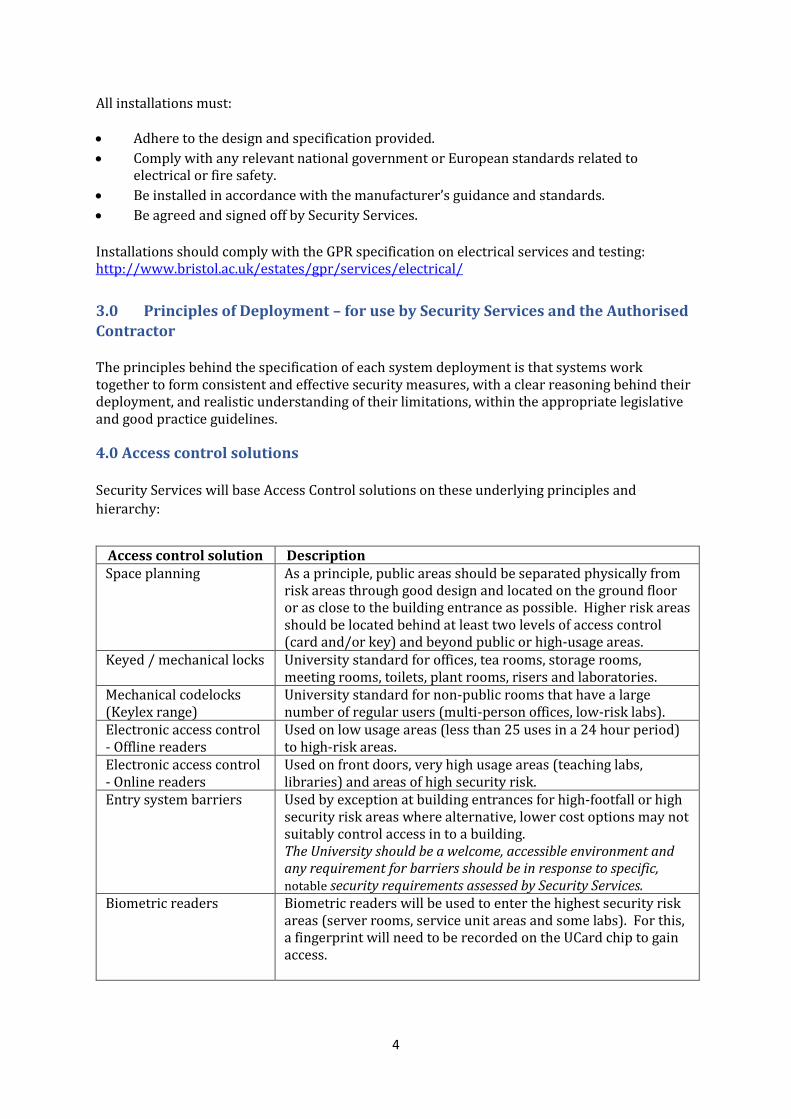
All installations must: • Adhere to the design and specification provided.
• Comply with any relevant national government or European standards related to electrical or fire safety.
• Be installed in accordance with the manufacturer’s guidance and standards.
• Be agreed and signed off by Security Services.
Installations should comply with the GPR specification on electrical services and testing: http://www.bristol.ac.uk/estates/gpr/services/electrical/
3.0 Principles of Deployment – for use by Security Services and the Authorised
Contractor The principles behind the specification of each system deployment is that systems work together to form consistent and effective security measures, with a clear reasoning behind their deployment, and realistic understanding of their limitations, within the appropriate legislative and good practice guidelines.
4.0 Access control solutions Security Services will base Access Control solutions on these underlying principles and
hierarchy:
Access control solution Description Space planning As a principle, public areas should be separated physically from
risk areas through good design and located on the ground floor or as close to the building entrance as possible. Higher risk areas should be located behind at least two levels of access control (card and/or key) and beyond public or high-usage areas.
Keyed / mechanical locks University standard for offices, tea rooms, storage rooms, meeting rooms, toilets, plant rooms, risers and laboratories.
Mechanical codelocks (Keylex range)
University standard for non-public rooms that have a large number of regular users (multi-person offices, low-risk labs).
Electronic access control - Offline readers
Used on low usage areas (less than 25 uses in a 24 hour period) to high-risk areas.
Electronic access control - Online readers
Used on front doors, very high usage areas (teaching labs, libraries) and areas of high security risk.
Entry system barriers Used by exception at building entrances for high-footfall or high security risk areas where alternative, lower cost options may not suitably control access in to a building. The University should be a welcome, accessible environment and any requirement for barriers should be in response to specific, notable security requirements assessed by Security Services.
Biometric readers Biometric readers will be used to enter the highest security risk areas (server rooms, service unit areas and some labs). For this, a fingerprint will need to be recorded on the UCard chip to gain access.
5
External barriers, fences and gates
A full design and consultation exercise must take place with Security Services before any such system selection takes place.
It is the intention of the University to control the installation of new equipment - system
installation to mitigate poor design is not acceptable.
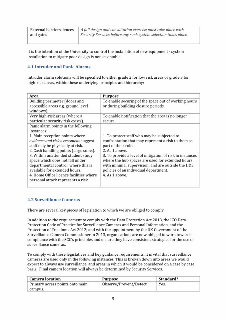
4.1 Intruder and Panic Alarms Intruder alarm solutions will be specified to either grade 2 for low risk areas or grade 3 for
high-risk areas, within these underlying principles and hierarchy:
Area Purpose Building perimeter (doors and accessible areas e.g. ground level windows).
To enable securing of the space out of working hours or during building closure periods.
Very high-risk areas (where a particular security risk exists).
To enable notification that the area is no longer secure.
Panic alarm points in the following instances: 1. Main reception points where evidence and risk assessment suggest staff may be physically at risk. 2. Cash handling points (large sums). 3. Within unattended student study space which does not fall under departmental control, where this is available for extended hours. 4. Home Office licence facilities where personal attack represents a risk.
1. To protect staff who may be subjected to confrontation that may represent a risk to them as part of their role. 2. As 1 above. 3. To provide a level of mitigation of risk in instances where the hub spaces are used for extended hours with minimal supervision; and are outside the H&S policies of an individual department. 4. As 1 above.
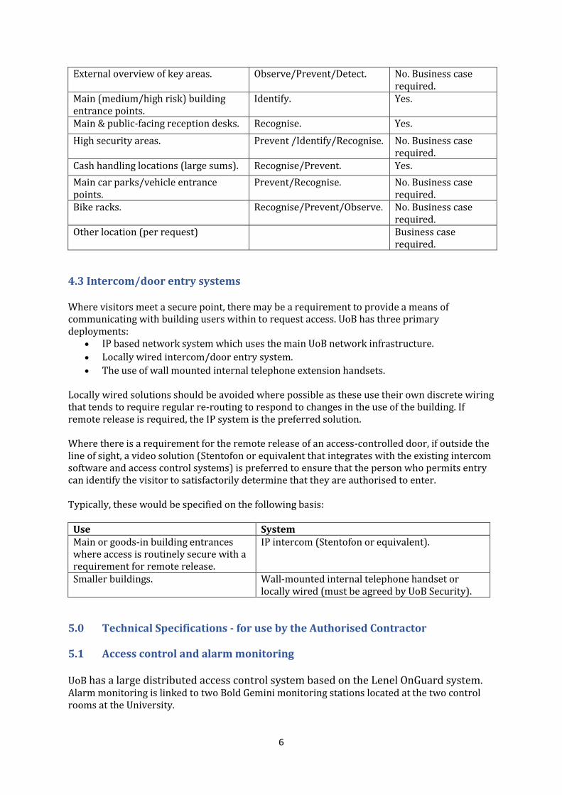
4.2 Surveillance Cameras There are several key pieces of legislation to which we are obliged to comply. In addition to the requirement to comply with the Data Protection Act 2018, the ICO Data Protection Code of Practice for Surveillance Cameras and Personal Information, and the Protection of Freedoms Act 2012; and with the appointment by the UK Government of the Surveillance Camera Commissioner in 2013, organisations are now obliged to work towards compliance with the SCC’s principles and ensure they have consistent strategies for the use of surveillance cameras. To comply with these legislatives and key guidance requirements, it is vital that surveillance cameras are used only in the following instances. This is broken down into areas we would expect to always use surveillance, and areas in which it would be considered on a case by case basis. Final camera location will always be determined by Security Services.
Camera location Purpose Standard? Primary access points onto main campus.
Observe/Prevent/Detect. Yes.
6
External overview of key areas. Observe/Prevent/Detect. No. Business case required.
Main (medium/high risk) building entrance points.
Identify. Yes.
Main & public-facing reception desks. Recognise. Yes.
High security areas. Prevent /Identify/Recognise. No. Business case required.
Cash handling locations (large sums). Recognise/Prevent. Yes.
Main car parks/vehicle entrance points.
Prevent/Recognise. No. Business case required.
Bike racks. Recognise/Prevent/Observe. No. Business case required.
Other location (per request) Business case required.
4.3 Intercom/door entry systems
Where visitors meet a secure point, there may be a requirement to provide a means of communicating with building users within to request access. UoB has three primary deployments:
• IP based network system which uses the main UoB network infrastructure.
• Locally wired intercom/door entry system.
• The use of wall mounted internal telephone extension handsets. Locally wired solutions should be avoided where possible as these use their own discrete wiring that tends to require regular re-routing to respond to changes in the use of the building. If remote release is required, the IP system is the preferred solution. Where there is a requirement for the remote release of an access-controlled door, if outside the line of sight, a video solution (Stentofon or equivalent that integrates with the existing intercom software and access control systems) is preferred to ensure that the person who permits entry can identify the visitor to satisfactorily determine that they are authorised to enter. Typically, these would be specified on the following basis:
Use System Main or goods-in building entrances where access is routinely secure with a requirement for remote release.
IP intercom (Stentofon or equivalent).
Smaller buildings. Wall-mounted internal telephone handset or locally wired (must be agreed by UoB Security).
5.0 Technical Specifications - for use by the Authorised Contractor
5.1 Access control and alarm monitoring UoB has a large distributed access control system based on the Lenel OnGuard system. Alarm monitoring is linked to two Bold Gemini monitoring stations located at the two control rooms at the University.
7
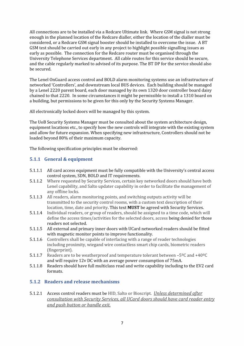
All connections are to be installed via a Redcare Ultimate link. Where GSM signal is not strong enough in the planned location of the Redcare dialler, either the location of the dialler must be considered, or a Redcare GSM signal booster should be installed to overcome the issue. A BT GSM test should be carried out early in any project to highlight possible signalling issues as early as possible. The connection for the Redcare router must be organised through the University Telephone Services department. All cable routes for this service should be secure, and the cable regularly marked to advised of its purpose. The BT DP for the service should also be secured. The Lenel OnGuard access control and BOLD alarm monitoring systems use an infrastructure of networked ‘Controllers’, and downstream local BUS devices. Each building should be managed by a Lenel 2220 parent board, each door managed by its own 1320 door controller board daisy chained to that 2220. In some circumstances it might be permissible to install a 1310 board on a building, but permissions to be given for this only by the Security Systems Manager. All electronically locked doors will be managed by this system. The UoB Security Systems Manager must be consulted about the system architecture design, equipment locations etc., to specify how the new controls will integrate with the existing system and allow for future expansion. When specifying new infrastructure, Controllers should not be loaded beyond 80% of their maximum capacity. The following specification principles must be observed:
5.1.1 General & equipment 5.1.1.1 All card access equipment must be fully compatible with the University’s central access
control system, SDN, BOLD and IT requirements. 5.1.1.2 Where requested by Security Services, certain key networked doors should have both
Lenel capability, and Salto updater capability in order to facilitate the management of any offline locks.
5.1.1.3 All readers, alarm monitoring points, and switching outputs activity will be transmitted to the security control rooms, with a custom text description of their location, time, date and priority. This text MUST be agreed with Security Services.
5.1.1.4 Individual readers, or group of readers, should be assigned to a time code, which will define the access times/activities for the selected doors, access being denied for those readers not selected.
5.1.1.5 All external and primary inner doors with UCard networked readers should be fitted with magnetic monitor points to improve functionality.
5.1.1.6 Controllers shall be capable of interfacing with a range of reader technologies including proximity, wiegand wire contactless smart chip cards, biometric readers (fingerprint).
5.1.1.7 Readers are to be weatherproof and temperature tolerant between –5ºC and +40ºC and will require 12v DC with an average power consumption of 75mA.
5.1.1.8 Readers should have full multiclass read and write capability including to the EV2 card formats.
5.1.2 Readers and release mechanisms 5.1.2.1 Access control readers must be HID, Salto or Bioscript. Unless determined after
consultation with Security Services, all UCard doors should have card reader entry and push button or handle exit.
8
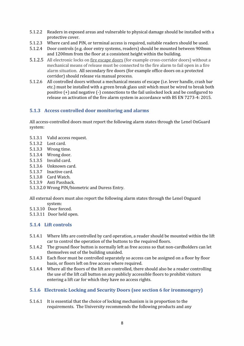
5.1.2.2 Readers in exposed areas and vulnerable to physical damage should be installed with a protective cover.
5.1.2.3 Where card and PIN, or terminal access is required, suitable readers should be used. 5.1.2.4 Door controls (e.g. door entry systems, readers) should be mounted between 900mm
and 1200mm from the floor at a consistent height within the building.
5.1.2.5 All electronic locks on fire escape doors (for example cross-corridor doors) without a mechanical means of release must be connected to the fire alarm to fail open in a fire alarm situation. All secondary fire doors (for example office doors on a protected corridor) should release via manual process.
5.1.2.6 All controlled doors without a mechanical means of escape (i.e. lever handle, crash bar etc.) must be installed with a green break glass unit which must be wired to break both positive (+) and negative (-) connections to the fail unlocked lock and be configured to release on activation of the fire alarm system in accordance with BS EN 7273-4: 2015.
5.1.3 Access controlled door monitoring and alarms All access-controlled doors must report the following alarm states through the Lenel OnGuard system: 5.1.3.1 Valid access request. 5.1.3.2 Lost card.
5.1.3.3 Wrong time. 5.1.3.4 Wrong door. 5.1.3.5 Invalid card.
5.1.3.6 Unknown card. 5.1.3.7 Inactive card. 5.1.3.8 Card Watch. 5.1.3.9 Anti Passback. 5.1.3.2.0 Wrong PIN/biometric and Duress Entry. All external doors must also report the following alarm states through the Lenel Onguard
system: 5.1.3.10 Door forced. 5.1.3.11 Door held open.
5.1.4 Lift controls 5.1.4.1 Where lifts are controlled by card operation, a reader should be mounted within the lift
car to control the operation of the buttons to the required floors. 5.1.4.2 The ground floor button is normally left as free access so that non-cardholders can let
themselves out of the building unaided. 5.1.4.3 Each floor must be controlled separately so access can be assigned on a floor by floor
basis, or floors left on free access where required. 5.1.4.4 Where all the floors of the lift are controlled, there should also be a reader controlling
the use of the lift call button on any publicly accessible floors to prohibit visitors entering a lift car for which they have no access rights.
5.1.6 Electronic Locking and Security Doors (see section 6 for ironmongery) 5.1.6.1 It is essential that the choice of locking mechanism is in proportion to the
requirements. The University recommends the following products and any
9
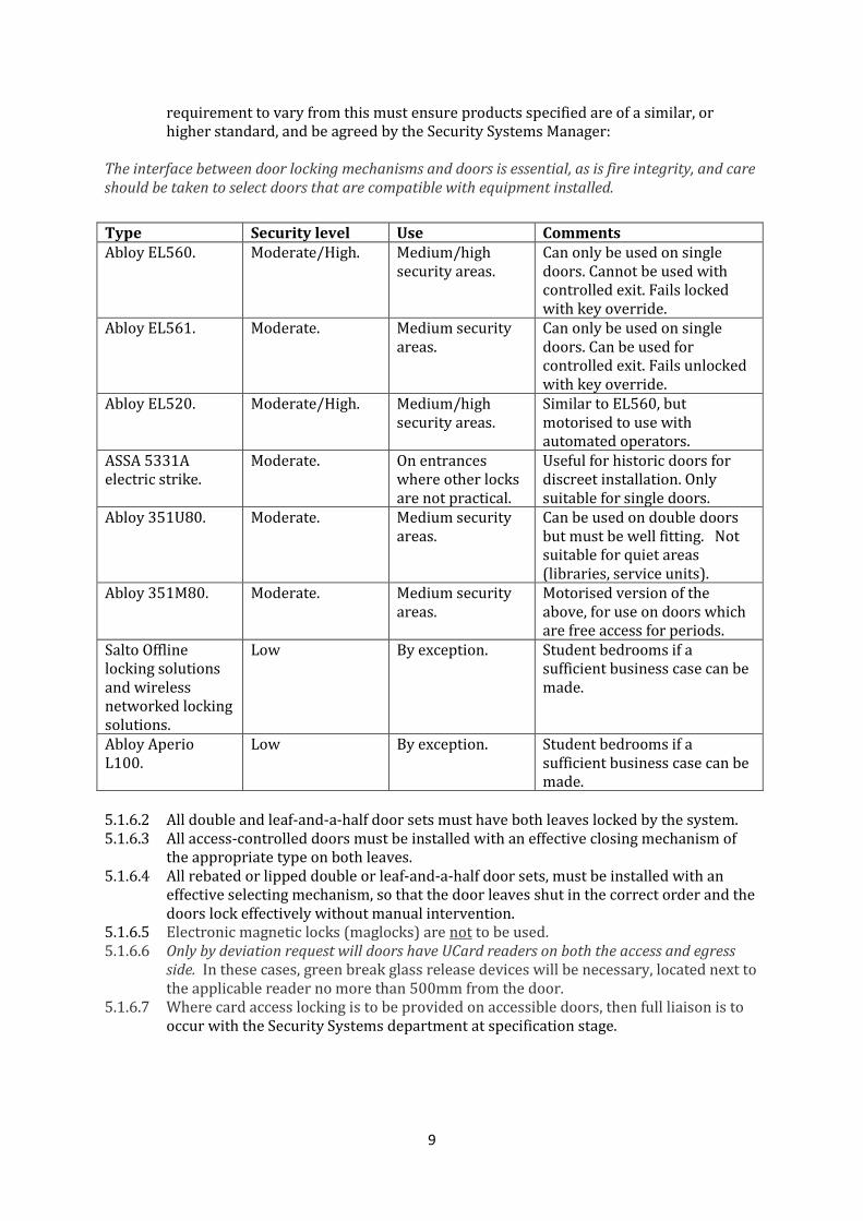
requirement to vary from this must ensure products specified are of a similar, or higher standard, and be agreed by the Security Systems Manager:
The interface between door locking mechanisms and doors is essential, as is fire integrity, and care should be taken to select doors that are compatible with equipment installed.
Type Security level Use Comments Abloy EL560. Moderate/High. Medium/high
security areas. Can only be used on single doors. Cannot be used with controlled exit. Fails locked with key override.
Abloy EL561. Moderate. Medium security areas.
Can only be used on single doors. Can be used for controlled exit. Fails unlocked with key override.
Abloy EL520. Moderate/High. Medium/high security areas.
Similar to EL560, but motorised to use with automated operators.
ASSA 5331A electric strike.
Moderate. On entrances where other locks are not practical.
Useful for historic doors for discreet installation. Only suitable for single doors.
Abloy 351U80. Moderate. Medium security areas.
Can be used on double doors but must be well fitting. Not suitable for quiet areas (libraries, service units).
Abloy 351M80. Moderate. Medium security areas.
Motorised version of the above, for use on doors which are free access for periods.
Salto Offline locking solutions and wireless networked locking solutions.
Low By exception. Student bedrooms if a sufficient business case can be made.
Abloy Aperio L100.
Low By exception. Student bedrooms if a sufficient business case can be made.
5.1.6.2 All double and leaf-and-a-half door sets must have both leaves locked by the system. 5.1.6.3 All access-controlled doors must be installed with an effective closing mechanism of
the appropriate type on both leaves. 5.1.6.4 All rebated or lipped double or leaf-and-a-half door sets, must be installed with an
effective selecting mechanism, so that the door leaves shut in the correct order and the doors lock effectively without manual intervention.
5.1.6.5 Electronic magnetic locks (maglocks) are not to be used. 5.1.6.6 Only by deviation request will doors have UCard readers on both the access and egress
side. In these cases, green break glass release devices will be necessary, located next to the applicable reader no more than 500mm from the door.
5.1.6.7 Where card access locking is to be provided on accessible doors, then full liaison is to occur with the Security Systems department at specification stage.
10
5.1.7 Alarm monitoring 5.1.7.1 All alarm inputs must be installed with the correct end of line (EOL) resistors to
provide four state monitoring (open/closed/open circuit tamper/closed circuit tamper). This must be a series and parallel pair of 4K7 resistors. These must always be installed at the end of line to ensure tamper protection of the whole circuit.
5.1.7.2. Toilet and other distress alarms should be specified with a local panel to alert passers-by, or lab managers or other responsible persons.
5.1.7.3 Panic/personal attack alarms should be in a discreet, easy to access location, where the operator can trigger the device unobserved. Where these are used in facilities, rather than at fixed locations, these should be located around the facility.
5.1.8 Intruder alarms systems 5.1.8.1 Intruder alarm system door contacts must be separate from those used for access
control, so where access-controlled doors also represent a perimeter zone on the intruder alarm system, this would have two separate sets of door contacts.
5.1.8.2 Perimeter protection should be provided covering accessible windows and doors using appropriate sensors. This should include any accessible points above ground level where there could be intrusion via another building (e.g. accessible roofs etc.).
5.1.8.3 The use of motion sensing should be specified so that this does not rely on single devices, but provides a level of confirmation from secondary devices.
5.1.8.4 Acoustic glass break sensors should be used appropriately where there are accessible windows. These should be programmed on a 24 hour circuit.
5.1.9 Barriers, Fences and Gates
When selecting security equipment such as barriers, fences or gates the designer shall take into account to the following guidance:
5.1.9.1 Design and appearance of equipment shall compliment the area, including street furniture, building façades and other elements to achieve a design that is in cohesion with the surroundings.
5.1.9.2 For University’s Heritage sites, style and colour of the equipment shall be consistent where possible with what has been used for the existing design. Any new selections shall be agreed with University External Estates during design stage.
5.1.9.3 Take into account of any future development adjacent so that a holistic design approach is considered.
5.2 Surveillance cameras UoB uses a Lenel surveillance camera and video management system. This runs on a secure VLAN on the UOB network. This comprises of management storage devices, cameras, workstations and decoders. All cable routes for cameras must be via secure or obscured routes, and the IP equipment must be in secure locations. If possible, cameras should be directly cabled to switch rooms with as little deviance as possible. When installed, the installer must include in costings, one Lenel CCTV license, one 25th of the cost of a Lenel Video recorder with enough space to record 31 days activity at 25fps at a highest resolution for the camera chosen and installed.
11
The quality of images recorded is of paramount importance. In general, they should therefore: • Clearly show actions of persons involved in an incident. • Provide supporting evidence of identity of offenders / vehicle registration marks. • Be able to operate in low light conditions and be time and date stamped. • Show an overall view of the scene.
5.2.1 All camera brands and models must be agreed in advance by the Security Systems
Manager. 5.2.2 All camera housings and equipment shall be as discreet as possible and finished in a
neutral colour unless required otherwise to comply with planning consent. 5.2.3 Cameras should be mounted on a wall or fixed ceiling wherever possible. Cameras
should not be installed into removable ceiling tiles/elements. 5.2.4 The network socket should be within a reasonable proximity to the camera, inside an
enclosure to avoid tamper issues. Exceptions to this must be signed off by the UoB Security Systems Manager.
5.2.5 In addition, all CCTV cables should be installed in accordance with the manufacturer’s specification for MBR (maximum bend radius) and will be Low Smoke Halogen Free (LSHF).
5.3 External Cameras 5.3.1 Each camera will have a minimum resolution of 1080-IP and operate down to 0.5-lux
for colour and 0.04-lux for monochrome. 5.3.2 All external cameras will operate in low-light conditions with full colour resolution and
IR capability. 5.3.3 W Where cameras are mounted on rooftops and parapets the mounting shall allow the
entire camera assembly to be swung/slid in so it can be worked on/serviced from within the safe working area without the need for specialist access / safety equipment.
5.3.4 Cameras should be fitted with a minimum 26:1 (plus digital) zoom lens or greater should the requirement determine. The lens should be auto-focusing; the auto-focusing should be able to be turned off and should be linked to pan, tilt and zoom functions.
5.3.5 All external fixed cameras shall be low-voltage (12Vdc or 24Vac), and will be powered from a central power supply, with each output individually fused.
5.3.6 External cameras should be installed, where possible, at 6 metres above ground.
5.4 Internal Cameras 5.4.1 Each camera will have a minimum resolution of 1080 and operate down to 0.5-lux for
colour operation and 0.2-lux for monochrome. 5.4.2 Standard colour-only cameras will be considered for internal use if the lighting levels
permit satisfactory performance.
5.5 PTZ Cameras 5.5.1 Should comply with the requirements on external/internal location. 5.5.2 The pan and tilt functions should support pre-set positioning, therefore enabling the
camera to react to alarms by automatically panning and tilting to a pre-determined position in the event of an alarm being generated.
5.5.3 The camera should feature programmable privacy zones. 5.5.4 Various mounting options should be available (soffit, wall, corner, swan-neck etc).
12
5.6 Fixed Cameras 5.61 Should comply with the requirements on external/internal location. Cameras should
be fitted with an auto and manual vary-focal lens, or lens calculated to suit requirements, to enable the optimum viewing angle to be achieved during commissioning. This lens should be IR-corrected.
5.6.2 The cameras shall be equipped with a manually adjustable swivel head within the dome for manual positioning of the camera during commissioning; this should be a 3-axis adjustment.
5.7 Digital Video Recording and Transmission: 5.7.1 The University currently uses a Lenal Onguard digital recording solution. All cameras
must be connected to this system and no other. Standalone recorders will not be used. 5.7.2 If there are not sufficient spare inputs available for video and telemetry control the
contractor should include for the expansion of the switching and control system as required to facilitate the new cameras.
5.7.3 Any expansion of the existing matrix will ensure that the entire system remains 100% non-blocking, i.e. any input can be routed/switched to any output or number of outputs.
5.7.4 Any expansion carried out to the matrix must maintain the full integration with the security management system. It will also be the responsibility of the contractor to confirm any licensing requirements relating to the security management software and ensure that any costs associated with additional licenses are included.
5.7.4 The system should be capable of recording and retaining images for 31 days before overwriting.
5.7.5 Images from the CCTV installation must be connected to the University’s Centrally-monitored CCTV network via the University’s secure data network (SDN).
5.7.6 Where local transmission equipment is required then this needs to be secured in a suitable vandal resistant cabinet, installed in each remote site.
5.7.7 Any switches/hubs etc should be manufactured by a reputable manufacturer (Cisco or equivalent) and suitable to be upgraded in the future.
5.7.8 Contractors will ensure the method of transmission chosen locally to link cameras to the 'hub' point is adequate for the intended purpose and the images and the signals should not suffer from interference from nearby electrical sources etc, especially when utilising ducts already occupied by other service plant and equipment.
5.7.9 The appropriate levels of University CCTV signage should be installed to University meets the CCTV Commissioners Office requirements, but also in such a way to provide levels of deterrence against crime. Where buildings are listed the appropriate levels of the External Estates department must be consulted, and permissions
5.9 Testing and Commissioning: Acceptance tests shall be required to demonstrate to the University of Bristol Security Systems Manager that all items of equipment function correctly, and that the overall system complies with the requirements of this Specification. The complete system must be fully tested and commissioned in the presence of a representative of the client. The purpose of this test is to determine whether or not the cameras cover the required areas, and if they are capable of providing images to the required standards. An acceptable certificate will need to be signed to prove the installation meets the specification defined.
13
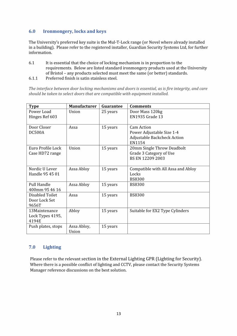
6.0 Ironmongery, locks and keys The University’s preferred key suite is the Mul-T-Lock range (or Novel where already installed in a building). Please refer to the registered installer, Guardian Security Systems Ltd, for further information. 6.1 It is essential that the choice of locking mechanism is in proportion to the
requirements. Below are listed standard ironmongery products used at the University of Bristol – any products selected must meet the same (or better) standards.
6.1.1 Preferred finish is satin stainless steel. The interface between door locking mechanisms and doors is essential, as is fire integrity, and care should be taken to select doors that are compatible with equipment installed.
Type Manufacturer Guarantee Comments Power Load Hinges Ref 603
Union 25 years Door Mass 120kg EN1935 Grade 13
Door Closer DC500A
Assa 15 years Cam Action Power Adjustable Size 1-4 Adjustable Backcheck Action EN1154
Euro Profile Lock Case HD72 range
Union 15 years 20mm Single Throw Deadbolt Grade 3 Category of Use BS EN 12209 2003
Nordic U Lever Handle 95 45 01
Assa Abloy 15 years Compatible with All Assa and Abloy Locks BS8300
Pull Handle 400mm 95 46 16
Assa Abloy 15 years BS8300
Disabled Toilet Door Lock Set 9656T
Assa 15 years BS8300
13Maintenance Lock Types 4195, 4194E
Abloy 15 years Suitable for EX2 Type Cylinders
Push plates, stops Assa Abloy, Union
15 years
7.0 Lighting Please refer to the relevant section in the External Lighting GPR (Lighting for Security). Where there is a possible conflict of lighting and CCTV, please contact the Security Systems
Manager reference discussions on the best solution.
Related Documents