Security enhancement in passive optical networks through wavelength hopping and sequences cycling technique by Walid Suleiman Shawbaki A dissertation submitted to the graduate faculty in partial fulfillment of the requirements for the degree of DOCTOR OF PHILOSOPHY Major: Computer Engineering Program of Study Committee: Doug W. Jacobson, Co-major Professor Ahmed E. Kamal, Co-major Professor Thomas E. Daniels Douglas D. Gemmill Yong Guan Iowa State University Ames, Iowa 2006 Copyright © Walid Suleiman Shawbaki, 2006. All rights reserved.

Welcome message from author
This document is posted to help you gain knowledge. Please leave a comment to let me know what you think about it! Share it to your friends and learn new things together.
Transcript
Security enhancement in passive optical networks through
wavelength hopping and sequences cycling technique
by
Walid Suleiman Shawbaki
A dissertation submitted to the graduate faculty
in partial fulfillment of the requirements for the degree of
DOCTOR OF PHILOSOPHY
Major: Computer Engineering
Program of Study Committee: Doug W. Jacobson, Co-major Professor Ahmed E. Kamal, Co-major Professor
Thomas E. Daniels Douglas D. Gemmill
Yong Guan
Iowa State University
Ames, Iowa
2006
Copyright © Walid Suleiman Shawbaki, 2006. All rights reserved.

UMI Number: 3217319
INFORMATION TO USERS
The quality of this reproduction is dependent upon the quality of the copy
submitted. Broken or indistinct print, colored or poor quality illustrations and
photographs, print bleed-through, substandard margins, and improper
alignment can adversely affect reproduction.
In the unlikely event that the author did not send a complete manuscript
and there are missing pages, these will be noted. Also, if unauthorized
copyright material had to be removed, a note will indicate the deletion.
UMI UMI Microform 3217319
Copyright 2006 by ProQuest Information and Learning Company.
All rights reserved. This microform edition is protected against
unauthorized copying under Title 17, United States Code.
ProQuest Information and Learning Company 300 North Zeeb Road
P.O. Box 1346 Ann Arbor, Ml 48106-1346

ii
Graduate College Iowa State University
This is to certify that the doctoral dissertation of
Walid Suleiman Shawbaki
has met the dissertation requirements of Iowa State University
ajor Professor
b jor Professor
Program
Signature was redacted for privacy.
Signature was redacted for privacy.
Signature was redacted for privacy.

iii
DEDICATION
I dedicate this dissertation with love and admiration to my parents for their everlasting
support in my life, and to my wife, brothers, and sisters for their constant encouragement in
pursing my higher education.
iv
TABLE OF CONTENTS
LIST OF FIGURES vi
LIST OF TABLES viii
LIST OF ABBREVIATIONS ix
ACKNOWLEDGEMENTS xi
ABSTRACT xii
CHAPTER 1: PASSIVE OPTICAL NETWORKS 1 1.1 Introduction to Optical Networks 3 1.2 Current Status of Access Networks 4
1.2.1 ITU-T Passive Optical Networks Standard 6 1.2.2 IEEE 802.3ah Ethernet Passive Optical Networks (EPON) Standard 7
1.3 Enabling Technologies for Passive Optical Networks 9 1.3.1 Laser Transmitter Components 10 1.3.2 Optical Laser Receivers 15
1.4 PON and Increasing Demand for Bandwidth 17 1.4.1 DWDM in PON 18
1.5 Dissertation Organization 25
CHAPTER 2: SECURITY VULNERABILITIES OF PON 27 2.1 Types of Attacks on Passive Optical Networks 27
2.1.1 Eavesdropping 29 2.1.2 Impersonation 30 2.1.3 Denial of Service 31
2.2 Current Security Schemes in Passive Optical Networks 31 2.3 Literature Review for Other Protection Methods in Optical Networks 33 2.4 Motivations 36
2.4.1 The Need for Secure Passive Optical Networks 36 2.4.2 Cost vs. Value of Security in Passive Optical Networks 37
2.5 Dissertation Contributions 38
CHAPTER 3: SECURITY ENHANCEMENT IN PON 41 3.1 Conceptual Approach to Security Enhancement in PON 41 3.2 Master Wavelength Grid Matrix W^in 44
3.2.1 Generation of Sub Grid Wavelength Matrix ( W,^ ) 46 3.3 Code Matrices and their Construction Basics 46
3.3.1 Review of Coding Techniques 49

V
3.3.2 Code Matrices Implementation in this Dissertation 58 3.4 Wavelength Sequence As Generation 58 3.5 DWDM Simulation Model in PON 60
3.5.1 Performance Metrics for the Simulation Model 62 3.5.2 OptSimTM 4.5 Simulation Software 63
3.6 Implementation and Deployment Considerations 80 3.6.1 The Role of Cryptography in the Proposed Security Enhancement 80 3.6.2 Keys Distribution 82 3.6.3 ONUs Authentication 83 3.6.4 Timing and Synchronization 84 3.6.5 Physical and Other Forms of Security Measures 85 3.6.6 Assignments of Wavelength Sequences and Security Level 86 3.6.7 Changing Network Wavelength Matrix 86
3.7 Chapter Summary 86
CHAPTER 4: SECURITY PERFORMANCE EVALUATION 88 4.1 Background and Motivation 88 4.2 Assumptions about Attackers 89 4.3 Performance Evaluation for the Proposed Security Enhancement 90 4.4 Capturing Wavelength Sequences Via Reverse Analysis 94 4.5 Additional Security Practices for a Single Online User 96
4.5.1 Attacks on TS/WH Scheme Using Symmetric Prime Numbers (Prime/Prime) 97 4.5.2 Attacks on Asymmetric TS/WH Scheme (EQC/Prime) 98 4.5.3 Attacks on MWOOC Codes 99
4.6 Chapter Summary 100
CHAPTER 5: CONCLUSIONS AND FUTURE WORK 102
APPENDIX A: ITU -T G694.1 BASED WmG
n WAVELENGTH GRID (///=!2, //=16). 107
APPENDIX B: W*° SUB GRID MATRICES 109
APPENDIX C: ORTHOGONAL SYMMETRIC CODE MATRICES FOR /H3 118
APPENDIX D: WAVELENGTH SEQUENCES FOR SYMMETRIC TS/WH, /H3 120
APPENDIX E: SIMULATION RESULTS FOR FILES F3, F4, AND F5 128
APPENDIX F: SIMULATION RESULTS FOR HOPS IN FILES F3, F4, AND F5 ... 130
BIBLIOGRAPHY 143

vi
LIST OF FIGURES
Figure 1 : Customers traffic volume trend 2
Figure 2: Passive optical network (PON) topology 2
Figure 3: PON world revenue 4
Figure 4: Various access scheme in optical networks 6
Figure 5: Ethernet frame structure defined in IEEE 802.3ah 9
Figure 6: Typical PON topology with possible points of attacks on network 30
Figure 7: Code word with 11 bits and weight 4 used to represent a single bit 34
Figure 8: Conceptual drawing of the proposed security enhancement in PON 42
Figure 9: Tuning strategy of laser (transmitters/filters) resources 44
Figure 10 : Sequential columns cycle rotation to generate sub grid wavelength matrix 46
Figure 11 : Two code matrices for _y = 7 and y - 11 52
Figure 12: Top model of simulation model for 64 DWDM channels in PON 61
Figure 13: PON simulated model with components of OptSim™ 4.5 software 65
Figure 14: Spectrum of 64 adjacent channels provided by laser transmitter array 67
Figure 15: 64 channels in ascending order coexisting on shared fiber link of PON 67
Figure 16: Eye patterns for A, B, C, and D channels of Figure 13 and Table 3 68
Figure 17: Signal output at A, B, C, and D channel output 69
Figure 18: BER for A,B,C, and D channels in Figure 13 69
Figure 19: Q-factor for channels A, B, C, and D channels of Figure 13 70
Figure 20: Stability A, B, C, and D channles in Figure 13 around center frequency 71
Figure 21: Cross talk between adjacent channels in Figure 13 72
Figure 22: Increased cross talk with 12.5 GHz spacing in Figure 13 73
Figure 23: Spectrum of simulation channels in File 1 75
Figure 24: Wavelengths used from file F1 after the 1:64 splitter of Figure 13 75
Figure 25: Eye patterns for A, B, C, and D channels of Figure 13 76
Figure 26: Signal at A,B,C, and D channels output in Figure 13 using F1 77
Figure 27: BER readings at channels A, B, C, and D of Figure 13 78
Figure 28: Q-Factor at channels A, B, C, and D of Figure 13 78

vii
Figure 29: Frequency stability of channels A, B, C, and D of Figure 13 79
Figure 30: Cross talk reduction for channels A, B, C, and D of Figure 13 79
Figure 31: Effect cycling on capturing a sequence for single ONU 93
Figure 32: Effect of multiple wavelength assignment per ONU with cycling 94
Figure 33: Probability of placing the correct wavelength in master grid matrix 96
Figure 34 Log. prob. of breaking a sequence for symmetric TS/WH (Prime/Prime) 97

viii
LIST OF TABLES
Table 1: Hopping sequences for 8 hops with hop duration controlled by Tc+Tg 60
Table 2: Parameters set for PON simulation architecture (Figure 13) 64
Table 3: Four adjacent channels used in monitoring in Figure 13 67
Table 4: BER and Q factors readings for A, B, C, and D channesl of Figure 13 71
Table 5: Channels A, B, C, and D monitored hopping wavelengths simulation in Figure 13 74
Table 6: BER and Q factors readings for hopping channels A, B, C, and D of Figure 13 77
Table 7: Examples of timings that need to be considered in the synchronization 85
IX
LIST OF ABBREVIATIONS
1-D: One dimensional
2-D: Two dimensional
3-D: Three dimensional
AES: Advanced encryption standard
AOTF: Acousto-optical tunable filters
APON Asynchronous transfer mode passive optical networks
ASK: Amplitude shift keying
ATM: Asynchronous transfer mode
B&S: broadcast and select
BER: Bit error rate
BPON: Broadband passive optical networks
CATV: Cable television
CDMA: code-division multiple access
CDR: Clock data recovery
CO: Central office
CRU: Clock recovery unit
CSMA/CD: Carrier sense multiple access with collision detection
DA: Destination address
DBR: Distributed Bragg reflectors
DES: Data encryption standard
DEB: Distributed feed back
DVB: Digital video broadcast
DWDM :Dense wave division multiplexing
DSL: Digital subscriber line
EOTF: Electro-optical tunable filters
EPON: Ethernet passive optical networks
EQC: Extended quadratic congruence
FH: Frequency hopping
FFH: Fast-frequency hopping
FFH-CDMA: Fast optical frequency-hop code division multiple access
FSK: Frequency shift keying
FTTB: Fiber-to-the-Building
FTTC: Fiber-to-the-Curb
FTTD: Fiber-to-the-Desktop
FTTH: Fiber-to-the-Home
FWM: Four-wave mixing
GCSR: Grating coupler sampled reflector
GVD: Group velocity dispersion
HFC: Hybrid fiber coax
HDTV: High definition television
IEEE: Institute of Electrical and Electronic Engineers
IM: Intensity modulation
ISI: Inter symbol interference
ISO: International Standards Organization
ITU: International Telecommunication Union
LAN: Local area network
MAC: Medium access control
MAI: Multiple access interference
MI: Modulation instability
MPCP: Multi-point control protocol
MPEG: Motion picture expertise group
MW: Multiple wavelength
NAS: Network area storage

X
NRZ: Non-return to zero
NZ-DSF: Nonzero dispersion-shifted fiber
OAM: Operation, administrative, and maintenance
OCDMA: Optical code division multiple access
OUT: Optical line terminal
ONU: Optical network unit
OOC: Optical orthogonal code
OOK: On-off-keying
OSI: Open Systems Interconnect
OSNR: Optical signal to noise ration
P2MP: point to multi-point
PMD: Polarization mode dispersion
PN: Pseudorandom noise
PON: passive optical networks
PPM: Pulse position modulation
PRBS: Pseudo random binary signal
PS: Prime sequences
PSC: Passive star coupler
PSL: Phase shift keying
PSO: Pseudo orthogonal
QCC: Quadratic congruence codes
QoS: Quality of service
RF: Radio frequency
RIN: Relative intensity noise
RTT: Round trip time
RZ: Return to zero
SA: Source address
SAC: Spectral amplitude coding
SAN: Storage area network
SDBR: Sectional distributed-Bragg reflection
SMDR: Side mode suppression ratio
SMF: Single-mode fiber
SMPTE: Society of Motion Picture and Television Engineers
SPM: Self-phase modulation
SRS: Stimulated Raman scattering
SSL: Secure sockets layer
TDM A: time-division multiple access
TPS: Triple play services
TS/WH: Time-spreading/wavelength-hopping
VCSEL: Vertical cavity surface emitting laser
WDM: Wave division multiplexing
WDMA: Wavelength-division multiple access
XPM: Cross-phase modulation

xi
ACKNOWLEDGEMENTS
I owe gratitude to many people for completing this dissertation, starting with my program
of study committee members for their comments and questions during the preliminary and
final oral examinations. I am deeply indebted to my co-major professor, Dr. Ahmed Kamal,
for his constant support and guidance in my research. I appreciate his efforts for making time
to have one-on-one meetings throughout the research activities and pointing me in the right
direction. Dr. Kamal's positive attitude, dedication, and enthusiasm for research and his
background in optical systems made it a pleasure to work with him. I would like also to thank
my co-major professor Dr. Doug Jacobson for his efforts in providing me with the knowledge
and background through his security courses that were useful in extending my research
interest to secure optical networks. Many thanks to my committee members Dr. Thomas
Daniels, Dr. Douglas Gemmill, and Dr. Yong Guan for their advice, time and patience that
are highly appreciated. Their knowledge and experience in the area of network security had
clarified many doubts that I had at the early stages of my Ph.D. research, and I offer my
appreciation for taking interest in my work and providing ideas and suggestions during the
preliminary and final oral exams.
My graduate education and research has been possible through the support of my
employer Rockwell Collins, which I fully admire as an employer of choice. I would like to
thank the continuing education team at Rockwell Collins for their support, and I would like
to express my regards and appreciation to my immediate manager Mr. Ken Mc Elereath for
his continuous support to pursue my higher education, and facilitating the way to help me
achieve my goal of higher education.
Finally, I would like to thank my parents for their constant support over the years. The
encouragement and love that they have selflessly and tirelessly invested in me is undoubtedly
the greatest source of my ambition, inspiration, dedication, and motivation. They have taught
me far more than words can express.
xii
ABSTRACT
Growth in the telecommunication industry continues to expand with requirements
evolving around increased bandwidth and security. Advances in networking technologies
have introduced low cost optical components that has made passive optical networks (PON)
the choice for providing huge bandwidth to end users. PON are covered by established
standards such as IEEE 802.3ah and ITU-T G.983.1/984.1, with star topology of broadcast
and select (B&S) on shared fiber links that poses security vulnerability in terms of
confidentiality and privacy.
The focus of research and reports in the literature center around increasing cardinality via
coding schemes that lack in addressing security, which was left for implementation in
application layers via cryptography. In this dissertation, an approach is presented on the
subject of security in PON at the network level using slow wavelength hopping techniques
and diffusion of data packets among dense wave division multiplex (DWDM). Orthogonal
wavelength sequences are generated by mapping an ITU-T G694.1 based wavelength grid
matrix and code matrices. The arrangement of wavelengths in the wavelength grid matrix,
which can be changed frequently (i.e, on an hourly basis) serves as the first key of secure
operation. Allocation of generated wavelength sequences distributed in multiple quantities to
nodes based on their security level serve as second individual keys for the nodes. In addition,
an improved level of security provided via the cycling order of those allocated wavelength
sequences to nodes is the third key (shared secret) between the central office (CO) and a
node. The proposed approach to PON security provides three new keys available outside the
world of cryptography.
Various coding techniques are used, and the result shows that even time spreading/
wavelength hopping based on symmetric prime numbers provided the least wavelength
sequences; however, it provided excellent correlation properties and level of security. A PON
simulation model was implemented to investigate channel impairments in DWDM with 64
channels spaced at 25GHz carried over a 25 KM ITU-T G.655 compliant shared fiber cable,
and security performance evaluation included analytical studies in the classical probabilities
to capture the correct order of wavelength hopping sequence using exhaustive search, in

Xlll
addition to reverse construction of matrices from monitored channels. Encouraging results
obtained support the feasibility of the proposed technical approach for security.
1
CHAPTER 1: PASSIVE OPTICAL NETWORKS
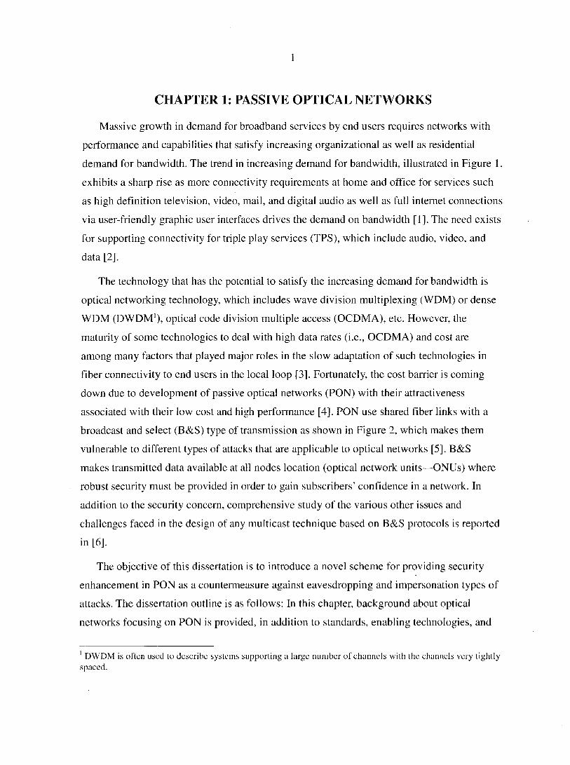
Massive growth in demand for broadband services by end users requires networks with
performance and capabilities that satisfy increasing organizational as well as residential
demand for bandwidth. The trend in increasing demand for bandwidth, illustrated in Figure 1,
exhibits a sharp rise as more connectivity requirements at home and office for services such
as high definition television, video, mail, and digital audio as well as full internet connections
via user-friendly graphic user interfaces drives the demand on bandwidth [1], The need exists
for supporting connectivity for triple play services (TPS), which include audio, video, and
data [2].
The technology that has the potential to satisfy the increasing demand for bandwidth is
optical networking technology, which includes wave division multiplexing (WDM) or dense
WDM (DWDM1), optical code division multiple access (OCDMA), etc. However, the
maturity of some technologies to deal with high data rates (i.e., OCDMA) and cost are
among many factors that played major roles in the slow adaptation of such technologies in
fiber connectivity to end users in the local loop [3], Fortunately, the cost barrier is coming
down due to development of passive optical networks (PON) with their attractiveness
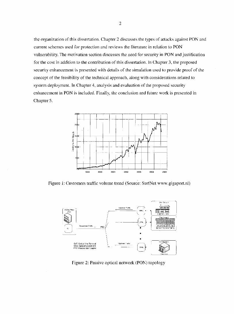
associated with their low cost and high performance [4], PON use shared fiber links with a
broadcast and select (B&S) type of transmission as shown in Figure 2, which makes them
vulnerable to different types of attacks that are applicable to optical networks [5], B&S
makes transmitted data available at all nodes location (optical network units—ONUs) where
robust security must be provided in order to gain subscribers' confidence in a network. In
addition to the security concern, comprehensive study of the various other issues and
challenges faced in the design of any multicast technique based on B&S protocols is reported
in [6],
The objective of this dissertation is to introduce a novel scheme for providing security
enhancement in PON as a countermeasure against eavesdropping and impersonation types of
attacks. The dissertation outline is as follows: In this chapter, background about optical
networks focusing on PON is provided, in addition to standards, enabling technologies, and
1 DWDM is often used to describe systems supporting a large number of channels with the channels very tightly spaced.
2
the organization of this dissertation. Chapter 2 discusses the types of attacks against PON and
current schemes used for protection and reviews the literature in relation to PON
vulnerability. The motivation section discusses the need for security in PON and justification
for the cost in addition to the contribution of this dissertation. In Chapter 3, the proposed
security enhancement is presented with details of the simulation used to provide proof of the
concept of the feasibility of the technical approach, along with considerations related to
system deployment. In Chapter 4, analysis and evaluation of the proposed security
enhancement in PON is included. Finally, the conclusion and future work is presented in
Chapter 5.
N •t N
K A / x>
A r \ ti
,r J A
y
1999 2000 2001 2002 2003 2004 2005
Figure 1: Customers traffic volume trend (Source: SurfNet www.gigaport.nl)
Central Office
Downstream Traffic
User Group 1
/ \ i • • • i n HOB
sr Group 2
"'^iPr'irTï [JŒlEDm
Business or Hesine
OLT: Optical Line Terminal ONU: Optical Network Unit PSC: Passive Star Coupler
Figure 2: Passive optical network (PON) topology
3
1.1 Introduction to Optical Networks
Optical networks, as the name implies, implement optical light to transfer data from one
end to another such that with the use of optical networking technologies and characteristics
of fiber connectivity of handling high bandwidth meet the demand by customer. However,
there is a strong correlation between the increasing demand for bandwidth and the cost of
bandwidth, but technological advances in optical networking have succeeded in continuously
reducing the cost of bandwidth [7],
The optical networking market is roughly divided into three main segments for ease of
analysis as well as customer focus [8]: size of network, line rates, and distances/geographical
locations. Traditionally, there is a three-tiered hierarchy:
• Long-Haul Core Network: usual distance ranges of 300 to 2000 km and considered as
regional or continental networks connecting different cities and supporting massive
data transfer.
• Metro Core Transport Network: extending 75 to 300 km and found in a ring
configuration to support longest transmission.
• Metro Access Network: at edge of the networks and usually connected to a metro
core transport network, which extends to 75 km in distance. This is where the PON
usually are connected, and is also the focus of the this dissertation.
Successful implementation of optical technologies in backbone networks to transport
massive data provided a need to extend fiber connectivity to remove bottleneck in access
networks. Existing access networks built on top of existing copper wire infrastructure have
their limitations in supporting the increasing demand for bandwidth, where future services
are expected to satisfy, for example, TPS, which include data, audio, and video with high
definition television (HDTV), as well as full Internet connections via user-friendly graphic
user interfaces [1], It is estimated that more than 75 Mb/s per subscriber is required for
convergence services such as TPS, and among several types of high speed access network
technologies, wavelength division multiplex PON is the most favorable [2]. The estimate is
conservative for today's requirements; however, access networks will be used to deliver
multiple HDTV broadcasts to the home, requiring a data rate in the order of 1 Gb/s [3]. TPS
4
will be part of the next wave in access network deployment, and Fiber-to-the-Building
(FTTB), Home (FTTH), or Curb (FTTC) are the ultimate level of access, allowing end users
to access the backbone networks through the gigabit capacity of a fiber optic cable [9].
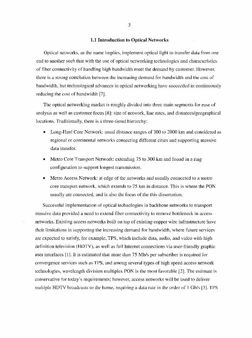
Figure 3 provides information about revenue for PON world wide spending projections [11]
and shows, along with the trend shown in Figure 1, a clear picture of access networks moving
toward optical connectivity in which PON are the baseline for future connectivity for
businesses and residential alike.
PON Worldwide Revenue Projections 2000 - 2004
$000
$400
0 Business
• Residential
$200
to 2000 2004
Figure 3: PON world revenue (Source: CIBC world market)
PON has been proposed in [12] and [13] as the potential baseline providing speeds at low
cost, compared to existing technologies, with the use of passive components. When PON is
combined with optical networking technologies such as WDM, data are pumped across the
networks at higher capacity making fiber connectivity in access networks more realizable to
achieve FTTH, FTTB, and/or FTTC.
1.2 Current Status of Access Networks
Telephone networks and connectivity to homes or offices is considered the origin of
access networks based on copper wire pairs designed for transmission of analog voice
5
signals. Thereafter, demands for extra services and enormous demand for Internet services by
businesses and households focused on the need for higher bandwidth connectivity, preferably
using existing telephone lines. Starting with modems that supported data service rates up to
56Kbps, then the need for higher bandwidth to access what is known as the "information
superhighway" for residential customers, required new technologies capable of improving
the performance and capacity of these access networks.
Broadband and data service deployment were launched initially on overlay infrastructures
adding cost and complexity of deployment and reducing operational scalability of these
services [10]. For example, investment went into using the existing infrastructure of access
networks that led to the development of the digital subscriber line (DSL) using existing
telephone twisted pair systems, and cable television (CATV), which uses coax cables.
Actually, fiber connectivity was introduced in access networks in a hybrid architecture that
includes hybrid fiber coax (HFC) with coax being the bottleneck for further expansion of
bandwidth. However, existing metal-based infrastructure has its saturation point and new
generation optical access networks are emerging, which include for example FTTC, FTTB,
and FTTH. The gradual penetration of optical fiber into the access network (which is known
also as the local loop) is one way to respond to the increase in demand for bandwidth, but it
is clear that cost is the cause of such slow adaptation of full optical networking in the local
loop.
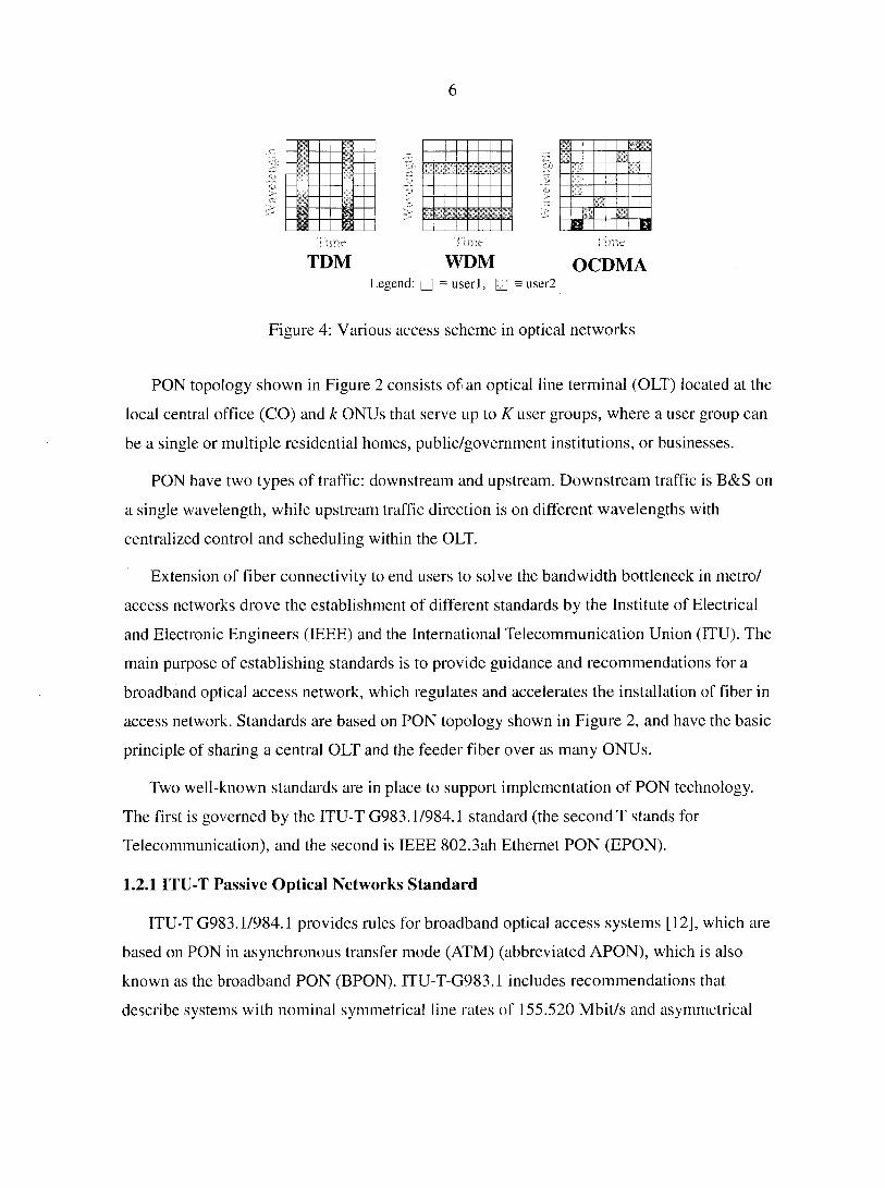
Various schemes with more focus are used in access networks to provide more nodes/
users access to the network through bandwidth sharing techniques. Some of the schemes in
place include time-division multiple access (TDMA), wavelength-division multiple access
(WDMA), and code-division multiple access (CDMA) as illustrated in Figure 4. TDMA has
limited growth since it is a bottleneck when considering the increase in the number of users
and their demand for bandwidth as illustrated in Figure 1. Optical access networking, such as
PON shown in Figure 2, provides an excellent solution to meet future demand as an access
network. PON is a point to multi-point (P2MP) network that implements passive elements
between nodes such as the passive star coupler (PSC), and accordingly, lowers the cost
barrier for implementation as compared to active elements.
6
«
H o H Time Time Tune
TDM WDM OCDMA Legend: • = userl, • = user2
Figure 4: Various access scheme in optical networks
PON topology shown in Figure 2 consists of an optical line terminal (OLT) located at the
local central office (CO) and k ONUs that serve up to K user groups, where a user group can
be a single or multiple residential homes, public/government institutions, or businesses.
PON have two types of traffic: downstream and upstream. Downstream traffic is B&S on
a single wavelength, while upstream traffic direction is on different wavelengths with
centralized control and scheduling within the OLT.
Extension of fiber connectivity to end users to solve the bandwidth bottleneck in metro/
access networks drove the establishment of different standards by the Institute of Electrical
and Electronic Engineers (IEEE) and the International Telecommunication Union (ITU). The
main purpose of establishing standards is to provide guidance and recommendations for a
broadband optical access network, which regulates and accelerates the installation of fiber in
access network. Standards are based on PON topology shown in Figure 2, and have the basic
principle of sharing a central OLT and the feeder fiber over as many ONUs.
Two well-known standards are in place to support implementation of PON technology.
The first is governed by the ITU-T G983.1/984.1 standard (the second T stands for
Telecommunication), and the second is IEEE 802.3ah Ethernet PON (EPON).
1.2.1 ITU-T Passive Optical Networks Standard
ITU-T G983.1/984.1 provides rules for broadband optical access systems [12], which are
based on PON in asynchronous transfer mode (ATM) (abbreviated APON), which is also
known as the broadband PON (BPON). ITU-T-G983.1 includes recommendations that
describe systems with nominal symmetrical line rates of 155.520 Mbit/s and asymmetrical
7
line rates of 155.520 Mbit/s upstream and 622.080 Mbit/s downstream, with fixed packet size
to 56 bytes [12]. The physical infrastructure of the BPON (APON) uses single fiber PON in
most implementations [12]. Both directions of communication are supported using WDM.
The downstream direction uses the 1550 nm window, while the upstream uses the 1310 nm
window. This arrangement saves cost over dual fiber arrangements by reducing the amount
of fiber deployed and eases operational concerns, as there is less chance of fiber
reconfiguration.
1.2.2 IEEE 802.3ah Ethernet Passive Optical Networks (EPON) Standard
Ethernet based PON (EPON), unlike APON (ITU-T G983.1 standard), utilize the
economies of scale of Ethernet [13]. The Ethernet as mature technology provides simple,
easy to manage connectivity due to fully deployed Ethernet-based systems. The same idea of
using a PON-based system in which the number of subscribers can be a single customer or a
group of customers connected to a single ONU, all ONUs are connected to the (OLT located
in the CO, as illustrated in Figure 2.
In the original IEEE 802.3 standard Ethernet, two configurations are defined: Carrier
sense multiple access with collision detection (CSMA/CD) is used in shared medium, and
switched network configuration uses full duplex links. Properties of an EPON system based
on IEEE 802.3ah are such that it cannot be considered either a shared medium or a point-to-
point network; rather, it is a combination of both protocols [15]. In an EPON system, all data
are encapsulated in Ethernet packets for transmission, which are compatible with IEEE 802.3
Ethernet standards [13][16]. Extraction of data from the main downstream traffic on the
shared fiber link by a specific ONU is based on its medium access control (MAC) address. A
single wavelength is used for each direction of traffic (upstream and downstream) with TDM
slots used for ONUs in the downstream and TDMA for upstream. TDMA is scheduled by
OLT, and line data rates can be different per ONU; therefore, the TDMA scheme can be a
bottleneck for bandwidth-hungry ONUs.
The principle of sharing the same link among ONUs in the downstream may be tolerated
for some applications, however, a problem arises in the upstream direction where the EPON
system must employ a MAC mechanism to arbitrate access to shared medium for collision
8
avoidance. It is still also responsible for the efficient sharing of upstream transmission band
width among all ONU.
Arbitration in EPON uses polling protocol for transmissions from ONU to OLTs, which
facilitates the dynamic bandwidth allocation and arbitrating the transmissions of multiple
ONUs. Polling resides in OLTs' MAC control layer and has two operation modes: NORMAL
and AUTO-DISCOVERY. In the NORMAL mode, the OLT sends the GATE message to
ONUs, which is permission to transmit at a specific time, for a specific duration, and the
ONUs send a REPORT message to the OLT, which is a message used by an ONU to report its
local conditions to the OLT [13]. Both messages are used in the allocation of bandwidth to
each ONU. In addition, the GATE message is used by the OLT to allocate transmission
windows to individual ONUs.
The AUTO-DISCOVERY mode is a process by which the OLT finds a newly attached
and active ONU in the P2MP PON to enable exchanging registration information between
the OLT and ONUs [13]. The OLT is responsible for the required synchronization time and,
with sufficient information collected during the NORMAL and AUTO DISCOVERY modes,
OLT provides the maximum number of pending grants and is responsible for scheduling
ONUs for access to PON in the upstream direction.
Due to different fiber lengths and locations of ONUs on the access network, ranging will
be necessary, which is a procedure by which the propagation delay between the OLT and
ONUs is measured. The round trip delay computation performed by the OLT uses the
timestamp in messages from the ONUs.
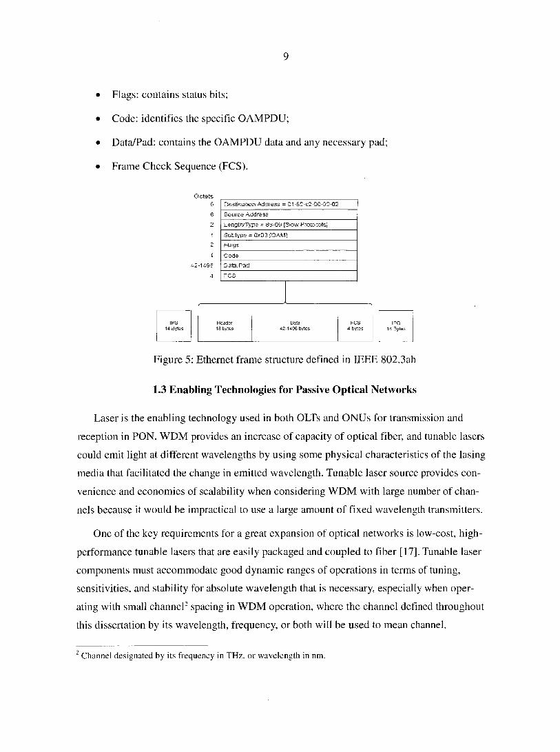
IEEE 802.3ah standard defines the Ethernet frame structure (shown in Figure 5), which
consists of a number of blocks plus a special frame start and stop marker [13]. The header is
common to all Ethernet frames, and each frame is preceded and trailed by an inter packet
GAP (IGP) of 14 bytes. The standard Ethernet has the following blocks:
• Destination Address (DA);
• Source Address (SA): carries the individual MAC address associated with the port;
• Length/Type: type encoded and carries the Slow Protocols Type field value;
• Subtype: identifies the specific Slow Protocol being encapsulated;
9
• Flags: contains status bits;
• Code: identifies the specific OAMPDU;
• Data/Pad: contains the OAMPDU data and any necessary pad;
• Frame Check Sequence (FCS).
Octets
6 Destination Address = D1-30-C2-OG-00-Q2
6 Source Address
2 Length/Type - 88-09 [Slow Protocols]
i Subtype = 0x03 [QAM]
Flags
% Code
95 Data/Pad
4
Header Data FCS 18 bytes 42-1496 bytes 4 bytes
Figure 5: Ethernet frame structure defined in IEEE 802.3ah
1.3 Enabling Technologies for Passive Optical Networks
Laser is the enabling technology used in both OLTs and ONUs for transmission and
reception in PON. WDM provides an increase of capacity of optical fiber, and tunable lasers
could emit light at different wavelengths by using some physical characteristics of the lasing
media that facilitated the change in emitted wavelength. Tunable laser source provides con
venience and economies of scalability when considering WDM with large number of chan
nels because it would be impractical to use a large amount of fixed wavelength transmitters.
One of the key requirements for a great expansion of optical networks is low-cost, high-
performance tunable lasers that are easily packaged and coupled to fiber [17]. Tunable laser
components must accommodate good dynamic ranges of operations in terms of tuning,
sensitivities, and stability for absolute wavelength that is necessary, especially when oper
ating with small channel2 spacing in WDM operation, where the channel defined throughout
this dissertation by its wavelength, frequency, or both will be used to mean channel.
2 Channel designated by its frequency in THz, or wavelength in nm.
10
In long haul communication optical networks, the attenuation of fiber necessitates the use
of repeaters at regular intervals, but this will not be necessary in a PON-based access network
due to the shorter distance (less than 40 km). The attractiveness of PON is due to their low
cost and high performance, which makes the need for compact optical transceivers urgently
in demand in order to spread PON [4]. In addition, the maturity of Ethernet opens the door
for PON as the next generation access network; already some have been designed, tested, and
implemented to be used in FTTH or Fiber-To-The-Desktop (FTTD) as reported in [18].
In the following sections is a brief review of optical components included in this
dissertation to establish the foundation of the DWDM PON simulation model as discussed in
section 3.5.3. The review is very brief; for theory of operation and structure of actual optical
components, the reader is referred to academic textbooks that discuss optical components
technologies in more detail. References [7] and [20] are good sources for more in-depth
information about the basic laser components structure and theory of operation.
1.3.1 Laser Transmitter Components
The basic principle for laser transmitters/filters, whether they are tunable or fixed, is the
same: The transmitter is a semiconductor device that converts electrical information to
optical, while the laser receiver (i.e., filter and detector) works in the opposite manner. The
narrow band of light with small optical spectral (line width), in addition to fast responses
(tunability), and the ability to couple a significant amount of energy are some of the expected
performance parameters that are required in optical networking [8]. Some of the popular
tunable lasers are mechanically tuned lasers that are known for their wide range tuning,
however, they have slow tuning speed that will make them disadvantaged in wavelength
hopping applications.
Acousto-optically, electro-optically, and injection-current tuned lasers are some of the
available technologies. For example, when an application requires faster wavelength tunable
lasers, laser's refractive index, which determines the lasing wavelength, can be changed by
controlling the amount of current injected into the laser cavity or the laser's wavelength
control section. The refractive index in the laser cavity can be controlled very rapidly by
controlling the current injected into the laser. The wavelength switching speed is a few
nanoseconds [21], and semiconductor lasers based on PN junction are the most common with
11
operation in wavelength ranges of interest between 1528 nm and 1560 nm that are favorable
for the proposed PON security enhancement in this dissertation.
Vertical cavity surface emitting laser (VCSEL)3 is the preferred choice for gigabit speed
operation, but it is available only for wavelengths no longer than 850 nm [8], which is
outside the wavelengths of interest in this dissertation.
PON covered by both ITU and IEEE standards in [12]and [13], respectively, are based on
only two wavelengths, while WDM, with tunable resources, supports higher bandwidth
greater than what is established in those standards.
1.3.7.1 Laser Components Performance Parameters
WDM operation places great restrictions on laser transmitter and receiver
implementation, and tuning range is an important factor to the implementation of WDM
expressed by A/l and represents the maximum number of wavelengths (A,) supported.
Cooling requirements and other parameters are important, but these requirements are outside
the scope of this dissertation where the discussion will focus on components' parameters
related to the simulation model application in section 3.5.2.
Several technologies available provide tunable lasers, which vary between wide range
and slow tuning characteristics, but the most suitable technology for use in WDM is the
sectional distributed-Bragg reflection (SDBR) tunable lasers, which is based on having
different cavities with different currents used to create different wavelengths. SDBR is an
extension of the distributed Bragg reflectors (DBR4) where feedback is essential for
maintaining lasing threshold [8], The three section DBR tunable laser, for example, has one
section associated with gain and considered the active region, followed by a section that
provides phase shift of the reflected wave and a Bragg grating third section as the DBR.
More details about the structure are found in [20].
3 VCSEL emits the laser light perpendicular to the plane of P-N junction and the structure proving the laser feedback arranged in the vertical direction as compared to the normal laser diode. 4 Optical feedback is realized by placing the P-N junction in a cavity thai has fully reflecting walls on all but one side and a partial reflector on the remaining side, in addition to insertion of grating (corrugated surface) within the cavity.
12
1.3.1.I. / Tuning Speed and If ange
Tuning speed and range are the important parameters for tunable laser components to be
included in DWDM implementation. Tuning time (speed) is the time required for the laser to
tune from one wavelength to another, while tuning range ( ) refers to the range of
wavelengths over which the laser may be operated. The technology for providing
components with wide tuning range and high speed tuning are available commercially by
using the grating coupler sampled reflector (GCSR) and sampled grating DBR that have
achieved a speed of 5 ns and tuning over 50 nm range as reported in [22] and [23].
Different ways can be used to provide tunable wavelengths, however, architecture
systems that employ digital non-mechanical tunable lasers potentially offer the stability,
reliability, and repeatability which is necessary for DWDM and telecommunication grade
systems [24].
Output of tunable laser devices can be continuously changeable to any other wavelength,
or discretely tunable to preset predefined wavelengths such as those in the ITU
recommendations ITU-T G694.1 wavelength grid [26]. The approach to compensate for slow
tuning in the proposed solution in this dissertation is to have a minimum of dual transmitters/
filters such that when one is being used, the other is tuned to the next wavelength, thus
providing a ready resource for the next wavelength. Both discrete ITU-T G694.1
wavelengths channel tuning and implementation of multiple tuning resources (transmitters
and filters) in each node will be part of the approach in providing PON's security
enhancement as proposed in this dissertation.
1.3.1.1.2 Line Width of a Laser
As a prime requirement in DWDM with several simultaneous channels (wavelengths)
being on shared fiber link, a narrow line width and stable channel frequencies of the laser
sources provide protection of the spectrum from being spilled over to adjacent channels.
Laser line widths for single mode lasers, for example, typically are less that 1 Â5 as
transmitted by the source [28]. Therefore, it is required that in DWDM operation each
channel has to have a very narrow spectral width in order to avoid cross talk with an adjacent
5 Â designates an angstrom, which is a unit of measure equal to 1 hundred-millionth of a centimeter.
13
channel. Fortunately, the distributed feed back (DFB) laser diode meets the narrow line width
requirements where a typical line width is 10 MHz and a maximum of 40 MHz, which also
has an inverse relationship to output power; , for example, for a DFB laser radiating at
30mW, the line width can be as narrow as 1 MHz [20].
I.3.I.I.3Stability of t/ieLaser Source
The variation in output power of a laser source affects line width, and consequently, cross
talk between channels occurs that we need to avoid or keep under control in WDM system
design. This is a condition in which channel separation in a stable manner reduces crosstalk
between channels to a minimum. In the PON DWDM simulation model in section 3.5.2,
stability of channels is monitored and checked in spectrums around the center frequency of
the channel and compared to the channel spacing 25GHz (,2nm) used.
/. 3.1.1. V Side-Mode Suppression Jfatio (SMSU)
The side mode suppression ratio (SMSR) is a measure of the intensity difference between
the main longitudinal mode and the side mode. The typical SMSR specified in the data sheets
is around 40dB, which is a comparison of the main mode intensity to the side mode intensity
expressed in dBs. This important property is considered in the implementation of DWDM
because suppression of the side modes is required to avoid crosstalk.
DFB laser has a narrow line width, but also provides a better SMSR since side modes are
severely suppressed. For example, the GCSR laser diode was built with a fast wavelength
tunable transmitter offering 100 (0.4 nm spaced) accessible wavelength channels with a
tuning range of 44 nm (1523.77-1567.77 nm) and an output SMSR of at least 30dB [19].
1.3.1. J.S C/iirp
Chirping is a rapid change in the center frequency of the transmitted optical signal with
reference to time [8], For example, the laser diode is very sensitive to back reflected light6,
which is a major cause for chirping and relative intensity noise (RIN7). Some solutions to
avoid chirping include the use of optical isolators to prevent back reflected light from
6 Back reflected light is the light reflected from the fiber optic cable back into the Laser Diode (LD) active region, which causes a deterioration of the laser diode performance. 7 RIN is defined as the ratio of the mean square optical intensity noise to the square of the average optical power.
14
penetrating the active region of the laser diode. In addition, chirp is a fast variation in the
laser peak radiating frequency in response to a change in a driving (modulation) current that
results in broadening of the light pulse. In WDM operation, chirp has to be eliminated, which
means that direct modulation (intensity modulation) will not be suitable in WDM operation.
External modulation (discussed next) is used to reduce the effect of chirp due to lasing effect
[8],
J. J. 1.1.6Modulation: Direct and External
The type of laser diode as a source provides expected quality of generated laser light;
however, in order to make laser source useful in data transmission, modulation8 technique is
used. Modulation is achieved by coupling data to the laser source in two common ways:
direct or external modulation.
The simplest and most widely used is the on-off-keying (OOK) modulation scheme,
which is direct modulation; laser current is considered as the input signal turning the signal
ON or OFF by coupling the data stream to the drive current of the laser source [7], This OOK
modulation is referred to also as intensity modulation (IM), which has a drawback in terms of
bandwidth restriction due to diodes relaxation frequency and chirp, as was discussed in
previously. Chirp is a limiting factor in the DFB laser where it is not recommended in WDM
implementation, especially with high channels count [8],
External modulation is based on leaving the diode radiating continuously and the laser
current source being kept constant with an external device used to modulate the laser light
source. External modulation covers for the shortcomings of the direct or IM, namely the
bandwidth restriction and chirp.
External modulation implementation is the proposed PON security enhancement in this
dissertation. In addition, external modulation provides stability of the source and avoids the
nonlinearity of excessive chirp in DWDM.
8 Modulation is defined as superimposing a data stream onto a carrier signal by altering one of the virtues of the carrier signal with respect to a change in the data stream.
15
7. S. J. 1.7 DigitalData Format
Digital data transmitted on fiber lines carry modulation of the optical carrier (at a certain
wavelength) by the modulation technique used. For example, amplitude shift keying (ASK),
frequency shift keying (FSK), or phase shift keying (PSK) are some of the modulation
techniques; however, in optical systems, ASK with the external modulation technique is
widely used since light is non coherent and phase information is not used [65].
A single bit 1 can be represented in two different formats. The simplest way is to provide
light for the duration of a "one" bit time and turn the light off for the duration of a "zero" bit
time. This technique is known as non-return to zero (NRZ) modulation. The other way is to
turn the light on for a one bit, but to turn it off before the bit time is over, allowing the signal
to go dark, and this is called return to zero (RZ).
The main advantage of NRZ representation of a bit is that the bandwidth associated with
this format is smaller than the RZ format by a factor of 2. However, the choice for NRZ is
not always the right choice because of the dispersive and nonlinear effects that can distort the
optical pulses during transmissions [25]. A long string of 1 bits can make it difficult to extract
the clock information, and because the NRZ format occupies the entire time slot for a bit,
problems can arise from pulses broadening during the transmission online, which make the
system vulnerable to inter symbol interference (ISI).
The duration of the NRZ bit can be represented by Tb, which can be expressed in terms of
data rate B as Tb = 1/B. In the RZ format, the pulse duration is actually shorter than the
allocated bit time slot, and when there are two or more l's, the pulses are spaced apart by Tb.
It is common to use a 50% duty cycle9, but other duty cycles can be chosen to meet system
design goals [8],
1.3.2 Optical Laser Receivers
Another critical element of an optical network is the optical receiver, which must tune
and detect one out of all the wavelengths incoming on the shared fiber line. The detection is
achieved by coherent or direct (non-coherent) detection methods. Coherent detection
technique uses phase information of the signal and requires a local oscillator and the direct
9 Duty cycle: In RZ system, the ratio of the time allocated for the pulse (Tp) over the total time for the hi I (Tb) is referred to as the duty cycle = T/ Tb.
16
detection of incoming signal converted to electrical signal by a PN diode. Coherent detection
provides better selectivity when considering the background noise but adds hardware
complexity and cost. For PON, direct detection is the preferred choice due to its lower cost
and ease of implementation.
Because a photo diode will be the basis for detection, which itself detects broad band of
wavelengths, the photodiode must be preceded by a wavelength filter to limit the range of
detection to wavelengths of interest; therefore, tunable optical filters include interferometer
filters, filters based on mode coupling, filters based on resonant amplification, and grating
based filters.
7.3.2.7 OpticalFilters
Similar to the case of laser transmitters, fast and broad tuning ranges are desired in the
laser receiver module. The laser receiver module will be operating in the 1550 nm band with
fast tuning to support the wavelength hopping. In addition, stability of those two components
in terms of the important performance parameters needs to be determined in order to realize
the wavelength hopping.
The key limitation to the DWDM system is that the receiving end since laser line widths
for single mode lasers are typically less than 1 Â (or 10MHz) as transmitted by the source
[28]. There are many filtering technologies and different types of tunable filters available to
support implementation in WDM networks. A tunable optical filter has the ability to track the
signal wavelength variation over its operating wavelength range. The tuning of optical filters,
similar to laser transmitters, will have the characteristic that the wider you make the tuning
range, the slower the tuning time will be. Generally, tunable optical filters from an
application point of view can be divided into two main categories [30]:
• Slow-speed tunable, with tuning times up to a few milliseconds, relevant for circuit-
switched networks, and
• High-speed tunable, in the microsecond and nanosecond range, relevant for packet-
and cell-switching networks.
Some filtering schemes include mechanical tunable filters such as the Fabry-Perot
tunable filter, which consists of a single cavity built by two mirrors that, with their
17
movements, form a resonant cavity. The Fabry-Perot filter tunes by changing the distance
between the mirrors, i.e., moving one of the mirrors. Because it mechanically moves one
lens, the tuning latency is large and therefore it is not ideal for implementation in a fast
wavelength hopping WDM network.
On the fast tuning speed side, one filter is the acousto-optical tunable filter (AOTF),
which is another method for filter tuning using radio frequency (RF) waves passed through a
transducer. A transducer is a piezoelectric crystal that converts sound waves to mechanical
movement. The sound waves change the crystal's index of refraction and enables the crystal
to act as a grate. By changing RF waves, a single optical wavelength can be chosen to pass
through the material. An AOTF controller built, for example, where the switching response is
as fast as 6 [is, satisfies the recommendation of Society of Motion Picture and Television
Engineers (SMPTE) for video switching [29]. The tuning range for acousto-optic receivers
covers the 1300 nm to 1560 nm spectrum with tuning time usually on the order of
microseconds, thus making AOTFs eligible for high-speed switching applications [20] [30].
Electro-optical tunable filters (EOTF), the other fast tuning type filter, uses crystals
whose index of refraction can be changed by electrical current. Electrodes resting in the
crystal are used to supply current to the crystal. The current changes the crystal's index of
refraction, which in turn allows some wavelengths to pass. The tuning time and tuning range
of these types of filters are 10 ns and 16 nm, respectively. Electro-optic filters have low
tuning latencies, while acousto-optic filters have a broad tuning range and support multi-
wavelength filtering by applying multiple acoustic frequencies [20] [30].
1.4 PON and Increasing Demand for Bandwidth
The demand for higher data rate, which requires more bandwidth drives the access
networks and local area networks toward the implementation of simultaneous transmissions
of many high bit rates channels [31], which can be met via DWDM that provide more
capacity for data pumping. However, the medium carrying the multiple wavelengths has
physical characteristics that can restrict the performance of WDM system and introduces
impairments in the individual channels that can be challenging to system designers.
18
1.4.1 DWDM in PON
The system capacity depends on many factors including, for example, optical bandwidth,
data rate, and channel density. In general, WDM system design must account for many
parameters that could degrade the performance of the planned system of the signal in the
optical path such as noise and signal distortions. Channel impairment effects can accumulate
while signals travel between OLTs and ONUs in PON topology, as shown in Figure 2, which
cause significant signal degradation due to fiber line physical characteristics.
The transmission impairments induced by non-ideal physical layer components can be
classified into two categories: linear and nonlinear [36]. Some important linear impairments
are amplifier noise, polarization mode dispersion (PMD), group velocity dispersion (GVD),
component crosstalk, etc.; and some important nonlinear impairments are four-wave mixing
(FWM), self-phase modulation (SPM), cross-phase modulation (XPM), scattering, etc.
Linear impairments are independent of signal power. Their effects on end-to-end light
path might be estimated from link parameters, and hence could be handled as a constraint
[37]. In this dissertation, because the approach for PON security enhancement depends
totally on DWDM with small channel spacing (25 GHz), a proof of the concept through a
simulation model is included in section 3.2.5 to serve as an investigation tool for impairments
and support of feasibility of DWDM implementation in PON.
1.4.1.1 Optica,/Fiber Cable and Impairment Factors
In a typical PON topology similar to that shown in Figure 2, optical fiber cable and
splitter, which is a PSC, are the only two components in the field between both ends of PON.
Current technology supports a splitting ratio of the PSC up to N = 64 [35]. The length of
fiber cable depends on the data rate (i.e., 1 Gbps) and provides a distance of 20 km
[12][13][38][58], which is based on a system design that supports b(P2MP) on optical fiber
for a lGbps bit error rate (BER) greater than or equal to 10~12. However, new types of fibers
operating in C and L bands have technological advances such that it is possible to extend the
range much farther. For example, with GPON operation of 2.488 Gbit/s downstream and
1.244 Gbit/s upstream a distance reached of over 135 km was reported [39] giving
performance consistent with ITU-T standards.
19
Attractiveness of PON is associated with having low cost, maintenance free, passive
components in the field between both ends of PON. However, physics of light in fiber lines
actually plays an important role and determines the performance of optical networks. The
different lights from different sources travel in the shared fiber medium at different velocities
affected by what is known as the refractive index10. Some optical phenomena include
reflections, refractions, birefringence, polarization, and dispersion [8]. The important
phenomena are the last three: birefringence, polarization, and dispersion.
Birefringence is due to variation of the refractive index as a function of the incident light
ray and polarization [8] [20] and causes non-polarized rays to be refracted into two
orthogonal polarized light rays. Polarization is the basics of light where the electric field (E)
and magnetic fields (M) of the light are orthogonal to each other and travel in an orthogonal
direction to the direction of both E and M. When light travels and interacts with the medium
through which it is traveling it leads to the situation where the E and M are no longer equal in
magnitude and direction, known as PMD. The degree of polarization will depend on the
angle of incidence where the light ray enters the medium (fiber end), the refraction index,
and the scattering profile of the medium itself.
Dispersion on the other hand, is an inherent property that causes spreading of an optical
pulse in time domain. PMD management requires that the time-average differential time
delay between two orthogonal states of polarization be less than a fraction of the bit duration,
T = 1/B, where B is the bit rate [37]. Dispersion effects usually limit 1550 nm transmission
distances in metro/provincial networks, which can be approximately +17 ps/nm/km in the
1550 nm region, limiting transmission distances to 80 to 100 km for many transmitters, and
the reach can be much shorter for some transmitters such as directly modulated 10 Gb/s
lasers [42]. For example, RFC11 4054 for optical layer routing provides estimation for newer
fibers with a PMD parameter of 0.1 picoseconds per square root of km; the maximum length
of the transparent segment (without PMD compensation) is limited to 10000 km and 625 km
for bit rates of 10Gb/s and 40Gb/, respectively [40]. In addition, for 10-Gbitls linear
transmission, conventional step-index single-mode fiber (SMF) allows for uncompensated
10 Refractive Index for a particular medium is the ratio of speed of light in vacuum (c0 ) to the speed of light in the medium (cj, Co/cm. 11 RFC: Request for Comments are references that are published by Internet Engineering Task Force (IETF).
20
distances of 60 km with a 1 dB eye-opening12 penalty; nonzero dispersion-shifted fiber (NZ-
DSF) extends the uncompensated distance by as much as an order of magnitude [41].
The figures above assure that implementation of the new fibers in the local loop in PON
should not cause serious problems in terms of non linearities since PON usually are limited
to less than 40 km. On the other hand, nonlinear effects are significantly more complex and
some parameters will be important when considering DWDM. It was reported in [43] that 40
Gbps was supported for distances up to 80 km by using fiber cable compensation techniques.
In both SMF and NZ-DSF, effects of dispersion and nonlinearity cannot be isolated from
one another. Fiber nonlinearities that complicate dispersion compensation can be classified
into two categories: the single-channel nonlinear effects, such as SPM and modulation
instability (MI); and multichannel nonlinear effects, such as PM, FWM, and stimulated
Raman scattering (SRS) [41].
PON architecture has the advantage of not using optical fiber amplifiers on lines between
CO and ONUs where amplifiers are a major source of nonlinearities. Nonlinearities also
impact BER due to SPM and MI; multi channel nonlinear effects, such as XPM, FWM, and
SRS are associated with DWDM [41].
The most common type of fiber used is the SMF, and ITU defines different types of fibers
governed by ITU standardization [8]. Fiber requirements of metro/provincial networks are
now starting to approach those of long haul networks in some ways as higher bit rates and
DWDM systems are deployed [42]. ITU G655 compliant fiber cables are the most suitable
for application in DWDM, which is selected for use in the PON simulation model in section
3.5.1. ITU G.655 supports higher bit rates and longer distances since it is a NZ-DSF, and
SMFs has chromatic dispersion that is greater than a non zero value throughout the C band
(1500nm). The ITU G.655 based optical fiber reduces the effect of non-linear ties such as
FWM, SPM, and XPM and is best suited to operate between 1500 and 1600nm [8].
Long haul optical fiber links that implement DWDM is the major cause of non-linearity
due to Kerr effect [44], which includes FWM, SPM, and XPM. The effect of FWM can be
12 Eye opening is related to the eye pattern diagram used to provide preliminary and initial indication of the quality of the signal, which is made of superimposing the received 011 and 101 digital signals where cross talk and inter-symbols interference can be investigated.
21
nearly eliminated by managing the fiber dispersion or channel spacing [45]. As the capacity
requirement of optical fiber systems increases, channels with narrower channel spacing will
be used in WDM systems. As a result, the two dominant nonlinear effects, XPM and FWM
become more and more pronounced [47]. Both nonlinear effects introduce intensity
fluctuations that are dependent on the neighboring channels.
In principle, impairments generated at the nodes can be bounded by system engineering
rules because the node elements can be designed and specified in a uniform manner. This
approach is not feasible with PMD and noise because neither can be uniformly specified.
Instead, they depend on node spacing and the characteristics of the installed fiber plant,
neither of which are likely to be under the system designer's control [40].
/. 4.7.1.1 Self-Phase Modulation (SPM)
Self-phase modulation (SPM) arises because the refractive index of the fiber has an
intensity dependant component, and this non-linear index causes an induced phase shift
proportional to the intensity of the pulse. SPM is caused by variations in optical signal power.
It introduces variations in the phase of signal. In phase shift keying systems, these variations
may lead to a degradation of the system performance since the receiver relies on the phase
information. Additionally, SPM causes spectral broadening of pulses because the variations
in a signal's phase results in instantaneous variations of frequency around the signal's central
frequency. This may lead to spreading of pulses, thereby, affecting the maximum bit rate.
7.4.7.7.2 Cross-Phase Modulation (XPM)
On the other hand, cross-phase modulation (XPM) is a shift in the phase of a signal. It is
caused by a change in the intensity of a signal propagating at different wavelengths. XPM
may lead to asymmetric spectral broadening. The combined effect of XPM and SPM may
affect pulse shape.
7.4.7.7.3 Four- Wave Mixing (FWM)
FWM is a product of three waves with frequencies ( /,, /2, /3 ) propagating over the same
fiber link interacting to give rise to a fourth wave with a frequency defined as
/_, = ( /j + f2- /3 ), which is a combination of the three waves frequencies. As a result,
22
power from one channel leaks into another channel, causing an increase of BER13 in addition
to inter-channel cross talk.
FWM depends upon channel spacing, power intensity of contributing signals, chromatic
dispersion of fiber, fiber length, and refractive index. FWM degrades the SNR and causes
cross talk, limits the transmission capacity of the fiber because of the inter-channel cross talk,
and is worst when the channels used are an equally spaced WDM system and operating at
high power [8][45].
The effect of FWM cross talk is a potential problem in all DWDM systems. This problem
has been recently solved by an unequal-spaced-wavelength technique [46]. However,
unequal spacing, which is known also as channel detuning, resulted in an increase of
bandwidth requirement compared to equally spaced channel allocation [48]. This is due to
the constraint of the minimum channel spacing between each channel and that the difference
in the channel spacing between any two channels must be assigned to be distinct. As the
number of channels increases, the bandwidth for the unequally spaced channel allocation
methods increases in proportion.
FWM can be reduced by a nonzero local dispersion, which either reduces the walk-off
distance of channel-by-channel nonlinear interactions or increases the phase mismatch for
FWM [41]. The FWM effect reaches its maximum effect at the zero-dispersion zone of the
fiber cable, but many solutions such as the NZ-DSF [20] have been found to counter this
problem.
In [48], a method for channel allocation is proposed to reduce the FWM effect so as to
improve WDM system performance without inducing additional cost, in terms of bandwidth,
which allows the computation of a channel allocation set to result in an optimal point
whereby degradation caused by inter-channel interference and FWM is minimal.
In some applications, optical fiber FWM nonlinear phenomenon is used for wavelength
conversion as mentioned in [49] for ring type transport protocols that can be adapted for any
dense wavelength-reuse WDM networks.
13 BER: Bit error rate is a measure of digital channel faithfulness in its ability to transfer digital.
23
The approach in this dissertation uses published standard wavelengths (channels) from
the ITU-T G694.1 wavelength grid [26] with 25 GHz channel spacing. The use of
wavelength hopping will minimize the problem associated with equal channels spacing as
will be demonstrated in the PON simulation model in section 3.5.2.2 since wavelengths
online will be selected according to a code matrix and hopping patterns reduces the impact of
FWM.
The impact of the non-linear impairments are seen as a problem for the long haul fiber
links (>100 km), however, it can also be a problem in the short hauls where channel spacing
and increased power provide an increase to FWM.
1.4.1.2 OpticalNetwork Performance Evaluation Parameters
In order to provide some metrics that will be used in the DWDM simulation model as
discussed in section 3.5.1, some performance parameters will be used that are typically used
in optical networking technologies as discussed in the following subsections.
/. 4.1.2.1 Bit Error Rate (BER)
In section 1.4.1.1.3, it was mentioned that FWM causes power from one channel to leak
into another channel, causing an increase of bit error rate (BER). BER is a measure of digital
communication system faithfulness and its ability to transport binary data from transmitter to
receiver, or the ability of the receiver to provide a good decision in decoding the received bit.
BER quantifies the rate of errors as the probability of an error occurring per transported
bit. Typical benchmarks for BER are rates of 10~9 and 10"12 [8], As guidance, [12] provides an
average transmission quality that should have a very low bit error rate of less than 10"9 across
the entire PON. ITU-T recommendation G.957 standard defines the objective error rate
required for optical components to be better than 10~10. In summary, BER can be used to
describe system performance [98] in addition to a related Q factor that is discussed in the
next section.
1.4.1.2.2 Q Factor
In addition to BER, Q factor is a parameter that provides a qualitative description of the
receiver performance because of its function to optical signal to noise ration (OSNR), which
24
is a measurable quantity. The logarithmic value of Q is related to OSNR provided in ( 1 )
below.
The BJBC provides the ratio of optical bandwidth (B„) to the end device (i.e., photo
detector) to the electrical bandwidth (Bc) of the receiver filter. A higher Q factor is an
indication of better quality of the optical signal, because with control of minimum OSNR in
the network design process, the Q factor can be decided from (1) where a specific BER can
be obtained in accordance to the complementary error function (erfc'4) relation in (2) below
As can be seen from OSNR in (1), the Q factor is related to analog signals, and it gives a
measure of the propagation impairments caused by optical noise, non-linear effects,
polarization effects, and chromatic dispersion, which is a measure of how noisy a pulse is for
diagnostic purposes.
1.4.7.2.3 Eye Pattern
In addition to BER and Q factor discussed in sections 1.4.1.2.1 and 1.4.1.2.2,
respectively, the eye pattern is a representation of the top level system performance by
superimposing digital signals 010 and 101 in order to check for cross talk and ISI. Eye
pattern is used as a quick tool to look for impairments, allows quick verification of signals
that meet performance specifications, and is used for evaluating system performance
providing visual depiction of the waveform being transmitted. Figure 16 provides an
illustration of eye pattern, where wider opening of the eye corresponds to minimal signal
distortion, and accordingly, provides an indication of the signal quality.
(^=20iogVa%vaJg/ B ( i )
[8],
(2)
14 The error function is denoted as erf(x); the complementary error function is denoted as erfc(x). Also, erfc(x) = 1 - erf(x). The error function is very closely related to the standard normal distribution function, p (x). It can be
obtained as follows: erf(x) = 2* p(x * sqrt(2)) - 1 and erfc(x) = 2 * (1 - p (x * sqrt(2))).
25
In typical modern instrumentation, an eye pattern oscilloscope generates a report that
shows what the Q factor number is as opposed to what the "ideal" Q factor is. This will be
provided in the simulation model DWDM in PON in section 3.5.1 of this dissertation.
J.4.1.2.4 Forward Error Correction (EEC)
Forward error correction (FEC) is a technique that adds overhead bits to the signal in
order to make it easy for receiver detection function, and when implemented, much lower
rates of BER can be accepted. Such a technique removes the dependence on controlling the
optical phase in the system.
The fact is that FEC is still expensive, and if the system meets the 1CT9 BER at 1 Gb/s per
user there is no need for FEC, it is preferable not to implement FEC in PON in order to meet
the low cost of PON [3].
1.5 Dissertation Organization
The rest of this dissertation organized as follows:
In Chapter 2, an overview of security vulnerabilities in optical networks is provided with
a focus on the PON, in addition to a review of current practices of protection as covered by
existing PON standards. The chapter discusses the need for PON network security level with
consideration of the cost of implementation, and includes comments on previous work and a
literature review about security in optical networks. The chapter provides motivation for the
work proposed in this dissertation and lists its main contributions.
Chapter 3 provides an introduction to the novel conceptual approach for security
enhancement in PON based on diffusion of transmitted Ethernet frames/packets15 over
several wavelengths (channels) in a hopping mode as part of protection at the network
security16 level. The proposed solution in this dissertation uses slow wavelength hopping,
which is suitable for implementation at network security as opposed to applications security,
15 In this dissertation, the Ethernet frames is the fixed length units representing transmitted/received data per wavelength hop; also fixed length packet across the network can be used in the data diffusion process in the same manner as the Ethernet frames. 16 The term network security means that protection provided at the physical and data link layers of the OSI model, while applications security refers to protection (i.e., cryptography) at the upper layers of the OSI model.
26
or simply implementation in data link and physical layers of a typical Open Systems
Interconnect (OSI) model defined by International Standards Organization (ISO) for
communication networks.
The challenges for implementation of DWDM in relation to small channel spacing and
fiber non linearities and impairment are included. A proof of the concept using OptSim™ 4.5-
simulation software is provided to support rationale and soundness to the technical approach
in the proposed solution. The chapter ends with some implementation and deployment
recommendations.
In Chapter 4, security analysis is used to provide a proof and illustrates the robustness of
the proposed solution to security enhancement in PON. Some assumptions are made about
the background of attackers and the proposed solution for security enhancement subjected to
brute force type of attack against an eavesdropper, and analyzing the probability of capturing
the correct order of wavelength sequences assigned to a specific ONU. In addition, reverse
analysis is used in which the attacker knows captured traffic with synchronization and the
task is to analyze the captured wavelength on tapped fiber and try to reconstruct matrices
used to generate the wavelength sequences. The probabilities of successful reconstruction of
matrices derived indicates a level of difficulty to reverse construct such matrices.
In Chapter 5, some concluding remarks are made and potential future research directions
identified.
27
CHAPTER 2: SECURITY VULNERABILITIES OF PON
Passive optical networks (PON) have the potential to meet the bandwidth requirement
and be the baseline for the connectivity to homes and businesses However, more and more
end users relying on such networks create users' dependency for day-to-day transactions.
Such dependency requires security to support the privacy and confidentiality of users. The
ITU-T standard X.805 associates privacy with the identity of users and their online activities
such as purchasing habits, Internet sites visited, etc., while confidentiality relating to the
protection of the data against unauthorized access to data contents.
Encryption in PON provides security for data, however, the nature of B&S traffic makes
the data available at each ONU, which potentially have the capability to operate in a
promiscuous mode and pick up others' ONU traffic (plain or encrypted), having time for
eavesdropping without even being detected.
In Ethernet traffic, encryption usually covers the payload of the traffic, and Ethernet-
based networks are popular due to the ease of implementation and cost. However, security
has never been a strong part of Ethernet networks [15]. For example, having the Ethernet
frames online with DA and SA in plain sight violates the privacy of the users' online
behaviors. In addition, the sophistication of attackers and tools is where the privacy of
communication against eavesdroppers will be a major problem, especially in access networks
that are based on B&S types of traffic. This chapter addresses the vulnerabilities of optical
networks in general, with some focus on PON that use B&S traffic.
2.1 Types of Attacks on Passive Optical Networks
Access networks, as part of local area networks (LANs), have become a major tool for
many organizations in meeting data processing and data communication needs [51], and the
role of access networks will increase as higher bandwidth is provided through PON-based
networks such as FFTH, FFTB, and FFTC where the focus will need to shift to security.
Security threat is a potential violation of security, which can be considered as active or
passive threats. Active threats are those cases in which the state of the systems are changed,
while passive threats are related to unauthorized disclosure of information without changing
28
the state of the system. Passive threats, for example, include eavesdropping activities to
capture messages on line (whether clear or encrypted), while active threats can be in several
forms such as masquerading as an authorized entity and denial of service.
Several theoretical methods for detecting intentional attacks upon the infrastructure of an
all-optical network were discussed in [52], which also listed the categorization of attacks into
six areas based on the goal of the attacker: (1) traffic analysis, (2) eavesdropping, (3) data
delay, (4) service denial, (5) quality of service (QoS) degradation, and (6) spoofing.
Prior to the use of LANs, most processing and communications were centralized and the
information and control were centralized as well. Now LANs logically and physically extend
data processing and communication facilities across the organization, and security services
that protect the data, processing, and communication facilities must also be distributed
throughout the LAN [51]. For example, sending sensitive files that are protected with
stringent access controls on one system over a LAN to another system that has no access
control protection defeats the efforts made on the first system. Therefore, basic security may
necessitate including two requirements, secrecy and authenticity [53].
Secrecy can be divided into two types: ephemeral secrecy, which means preventing an
unauthorized user from receiving the transmitted data, and long-time secrecy, which is
usually protected by complex cryptography. Cryptography is part of semantic security, which
is the protection of the meaning of the data even when an attacker has access to the received
stream [54].
In general, the security policy for the organization needs to be in place by upper
management, and secure architecture in the network should provide methods and techniques
that can be used to prevent or lessen the impact of the above threats [55]. This dissertation
focuses on the concept as stated here where security enhancement in the PON plan is to
provide protection and make it difficult for an eavesdropper to collect good samples that can
be used for cryptanalysis. Other security measures need to be in place depending on the
individual's or organization's security needs.
Authorization and access control with the proposed security enhancement in PON
provides protection against disclosure of information, theft of service, and protection against
unauthorized access. Additional security measures need to be available for use in PON such
29
as the process of limiting access to system resources and allowing only authorized users,
programs, processes, or other systems to access the OLT since it is the most vital part and
needs to be protected accordingly.
The network/Zinformation security should provide confidence in the information and
services available on the network and protect access to unauthorized users. This is of great
concern to customers especially when the medium is shared among many users and the need
arises for providing security at the network level, which is the focus of this dissertation: the
prevention of eavesdropping as a countermeasure in PON. An assumption is made that
threats are coming from sophisticated hackers who can be outsiders or an insiders to the
organization.
2.1.1 Eavesdropping
The downstream traffic from OLTs to ONUs in PON, as specified in [12] and [13] is
characterized as a B&S transmission type on a single wavelength, which means that
downstream traffic will be available at all ONUs. Selection by an ONU is based on the time
slot, and usually the DA of the Ethernet frame can be used after selection by the ONU.
Potential tapping by an outsider to the fiber links network is an allocated responsibility of the
operation, administrative, and maintenance (OAM) protocol of the network. In a typical
network, shared medium security concerns are minimized because users belong to a single
administrative domain and are subject to the same set of policies. However, the situation is
different, as illustrated in Figure 6, where several locations on the networks are vulnerable to
tapping/ eavesdropping. The tapping can be internal or external to the network, and it is
assumed that with the external tapping the OAM does not detect the drop in signal level.
Internal tapping into the network can be simply one or more nodes (ONUs) operating in a
promiscuous mode, which presents a higher threat in terms of passive attacks than outsider
tapping [53]. The danger from an ONU eavesdropping on data transfer that belongs to
another ONU arises from the difficulty of detecting their passive attacks especially when they
have the time available to monitor and collect data without being detected, which makes it
difficult to ensure PON security and guarantee subscriber privacy.
Security must be provided as a mechanism to control subscribers' access to the
infrastructure and prevent ONUs from receiving traffic other than what is intended for its
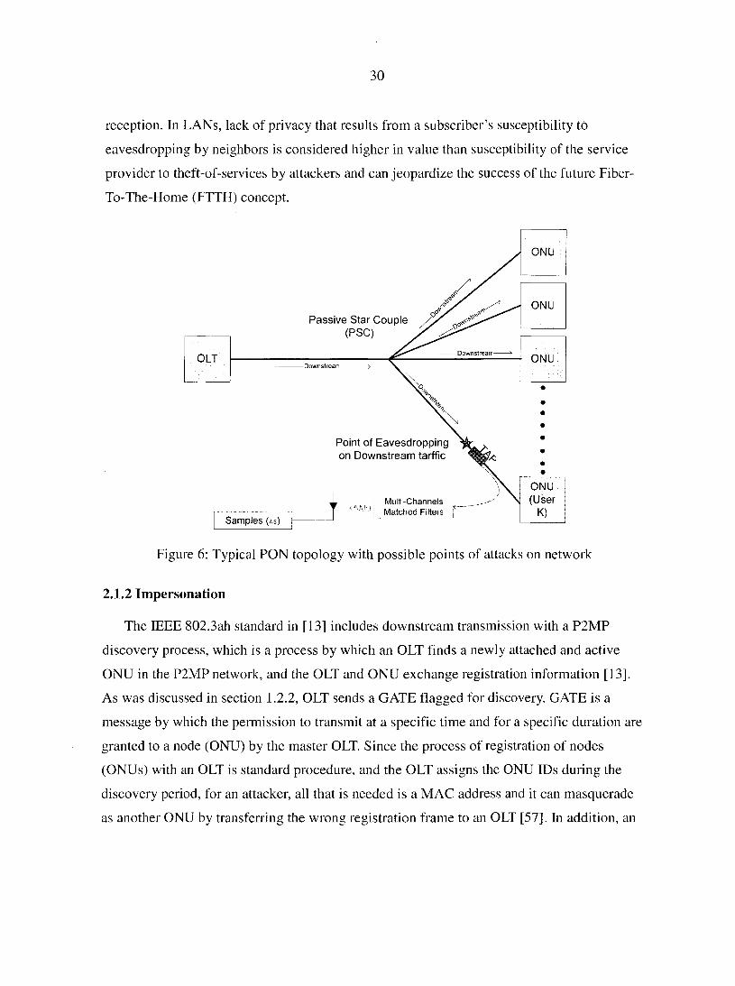
30
reception. In LANs, lack of privacy that results from a subscriber's susceptibility to
eavesdropping by neighbors is considered higher in value than susceptibility of the service
provider to theft-of-services by attackers and can jeopardize the success of the future Fiber-
To-The-Home (FTTH) concept.
Passive Star Couple (PSC)
Downstrearr
Downstrearr
Point of Eavesdropping on Downstream tarffic
Mult-Channels Matched Filters
Samples (xs)
ONU
ONU
ONU (User
OLT
ONU
Figure 6: Typical PON topology with possible points of attacks on network
2.1.2 Impersonation
The IEEE 802.3ah standard in [13] includes downstream transmission with a P2MP
discovery process, which is a process by which an OLT finds a newly attached and active
ONU in the P2MP network, and the OLT and ONU exchange registration information [13],
As was discussed in section 1.2.2, OLT sends a GATE flagged for discovery. GATE is a
message by which the permission to transmit at a specific time and for a specific duration are
granted to a node (ONU) by the master OLT. Since the process of registration of nodes
(ONUs) with an OLT is standard procedure, and the OLT assigns the ONU IDs during the
discovery period, for an attacker, all that is needed is a MAC address and it can masquerade
as another ONU by transferring the wrong registration frame to an OLT [57]. In addition, an
31
attacker can get access to privileged data and network resources, and it is possible that some
ONUs can take the discovery period of an OLT and hijack the identity of another ONU.
2.1.3 Denial of Service
Since ONUs share the capacity of the network in the upstream data flow, the OLT assigns
the bandwidth to ONUs, and one non cooperating ONU can maliciously generate a large
amount of traffic intentionally [57] depriving other ONUs from the bandwidth allocation.
2.2 Current Security Schemes in Passive Optical Networks
PON, in general, are multicast in the downstream direction, and the need for protection is
necessary. A protection recommended in the ITU-T standard in [12] is in the form of
churning, while the standard in [13] uses Ethernet (EPON) where security has never been a
strong part of Ethernet networks [15], and the IEEE standard in [13] treated encryption and
authentication as a scope outside the standard.
Churning uses 8-bit key length to provide "the necessary function of data scrambling"
and to offer "protection for data confidentiality." The encryption provides a tunnel
communication link in the upstream direction between the OLT and ONUs. According to
[56], churning as applied in the ITU-T standard in [12] to cells is at the transmission
convergence (TC) layer. The standard actually provides the recommendation that if churning
is not enough for a security requirement of a provided service, a suitable encryption
mechanism should be employed at a higher layer than the TC layer to provide data
scrambling. No recommendation for key distribution is provided.
Unfortunately, churning has many critical, even fatal, flaws, and it is trivial to defeat It
was shown in [56] that it is easy to carry on passive attacks on churning, and it is possible to
break the 8-bit key with an exhaustive key search.
PON users are at high risk of having their presumed private communications exposed to
adversaries even with employing other security techniques—secure sockets layer (SSL)
encryption, which may still inadvertently disclose information such as the identity of Web
servers with which they communicate [56].
32
For EPON in the IEEE 802.3ah standard, it is mentioned in [15] that encryption and
decryption may be implemented at the physical layer, data link layer, or in higher layers.
Implementing encryption above the MAC sub-layer will encrypt the MAC frame payload
only, and leave headers in plain text [15], which prevents malicious ONUs from reading the
payload, but they may still learn other ONUs MAC addresses such that privacy is vulnerable.
In addition, it was recommended in [15] to include an alternative method for encryption to be
implemented below the MAC layer, where encryption covers the entire bit stream, including
the frame headers and FCS. This will require the receiving end to decrypt the data before
passing it to MAC for verification.
IEEE 802.3ah standard in [13] does not cover message authentication for upstream
traffic, which involves authentication of data origin to have assurance about the identity of
the party that originated the message. OLTs have no means to verify that the message
received and presumably created by ONU A for example did indeed originate from ONU A.
This is a threat, which can be used in masquerading (authentication) as mentioned in section
2.1.2.
In general, EPON needs strong security services of authentication, confidentiality, and
access control, and there is a need for an authentication and key exchange protocol preferably
using a public key mechanism [56]. Any security protocol in PON MAC layers reduces the
overhead of security service, and authentication and ONU authentication can be performed
separately for efficient key management and strong authentication service.
The major problem that encryption addresses is protection with various degrees of
sophistication and complexity in order to make it difficult to deduce the code against time. It
is known that the processing speed of computational resources are becoming available in the
market, defeating simple encryption such as churning in the ITU-T standard in [12] is well
within the capabilities of would-be eavesdroppers today, and PON sniffer tools could easily
incorporate methods for automated real-time cryptanalysis of churning with essentially no
performance impact [56].
In cryptography discussed above, the assumption is made that an attacker is able to get a
sample of encrypted data, and the focus is to provide various degrees of fortification against
crypto analysis. Encryption alone will not be sufficient for protection, and it needs to be
33
supplemented by some network mechanism that provides difficulty in collecting a good
sample. In addition, higher protection must be provided by making it difficult to trace the
various segments of the message that are distributed among several wavelengths during
transmission between the OLT and ONUs as shown in Figure 2. This is the focus of this
dissertation where security enhancement is provided via the wavelength hopping techniques.
2.3 Literature Review for Other Protection Methods in Optical Networks
In the literature, several technical papers and research reports are available that discuss
different approaches to providing security (with or without encryption) to optical networks,
but not specific to PON. The majority of the papers focused on using OCDMA as an access
scheme to the network where the objectives have been to provide higher cardinality (number
of nodes on the network), but not focused on security.
OCDMA is considered to potentially provide both confidentiality and availability
protection by offering some degree of jamming resistance using the OCDMA coding [68].
OCDMA is based on optical orthogonal coding (OOC); for example, starting with a single bit
and using time spreading in one dimension coding (1-D), the single bit is divided into several
chips (Tc) in the time domain as shown in Figure 7 where the single bit period Tb = nTc.
The codeword (i.e., signature sequence) is multiplied with signal bit sequences to each
uniquely distinct different user. The weight w is expressed as the number of l's in n chips.
The single wavelength is selected when w = 1, and no wave is selected when w = 0 during
the bit duration.
The drawback of 1-D OOC is that it suffers from low cardinality (0) and increasing n
and w impacts bandwidth [46][65][66], An extension to two dimensional (2-D) adds more
wavelengths, and in this case, every single chip in Figure 7 represented by different
wavelength from several wavelengths is available for hopping.
The extension requires orthogonal codes, OOCs, in order to avoid multiple access
interference (MAI). Unlike time in TDMA or WDMA, OOC is attractive because it offers
asynchronous multiple access and is capable of realizing access and routing operations in a
common channel without optical switches in addition to allowing flexible bandwidth
assignment. Time-spreading/wavelength-hopping (TS/WH) OCDMA, utilizing both time and
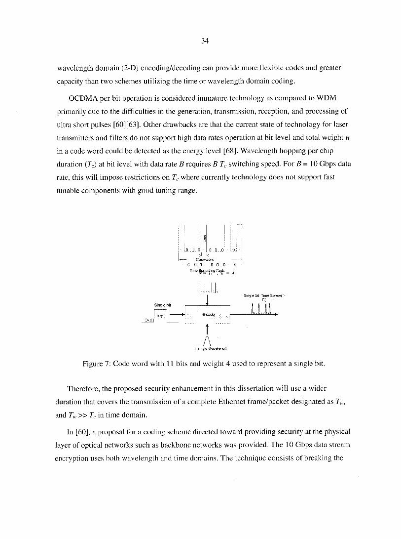
34
wavelength domain (2-D) encoding/decoding can provide more flexible codes and greater
capacity than two schemes utilizing the time or wavelength domain coding.
OCDMA per bit operation is considered immature technology as compared to WDM
primarily due to the difficulties in the generation, transmission, reception, and processing of
ultra short pulses [60][63]. Other drawbacks are that the current state of technology for laser
transmitters and filters do not support high data rates operation at bit level and total weight w
in a code word could be detected as the energy level [68]. Wavelength hopping per chip
duration (Tc) at bit level with data rate B requires B Tc switching speed. For 5=10 Gbps data
rate, this will impose restrictions on Tc where currently technology does not support fast
tunable components with good tuning range.
Bit(C)|
0 0 0 ' 0 0 . 0 ' 0 j -Codeworc
0 0 0" 0 0 0 - 0 ' Time Spreading Code
Single bit
Bitf] ~™
1 Single Bit Time Spreacf-
c :
T A
1„U
( single Wavelength
Figure 7: Code word with 11 bits and weight 4 used to represent a single bit.
Therefore, the proposed security enhancement in this dissertation will use a wider
duration that covers the transmission of a complete Ethernet frame/packet designated as Tw,
and Tw » T( in time domain.
In [60], a proposal for a coding scheme directed toward providing security at the physical
layer of optical networks such as backbone networks was provided. The 10 Gbps data stream
encryption uses both wavelength and time domains. The technique consists of breaking the
35
data stream into frames of N bits by M wavelengths (bit level operation). Each frame
contains N x M elements representing unique time-wavelength position. Advanced
Encryption Standard (AES) is implemented in counter mode to control hardware switches,
and the coding scheme is based on the random permutation of the elements for each time
frame. This means both the order of the bits in a stream and the wavelength in which it is
transmitted may change.
The approach is based on using a switching matrix (16X16) in the active mode to achieve
the permutation process, and could suffer scalability problems for higher size switching
matrices. In addition, using encryption techniques via hardware implementation makes the
system more rigid for future growth and changes since this will affect multiplexers,
demultiplexers, and operation of switches. The proposed security scheme in [60] did not
address different security levels that can coexist in the same network.
Another scheme for reduction of MAI, proposed in [61], is based on using modified
pseudorandom noise (PN) coded fiber Bragg gratings with bipolar OCDMA decoders, based
on having the same number of 1 's and O's to eliminate the MAI, but the proposed solution did
not address the security aspect of the system.
A mix of WDMA and TDMA was proposed in [62] for providing MAC. The scheme is
based on using WDM-based PON, and combining wavelength routing and power splitting in
a single PON to upgrade network bandwidth and decrease accessing cost. The proposed
solution in [62] was intended to solve the access scheme by ONUs in the shared bandwidth
and was not focused on the security of PON.
A different approach to all-fiber fast optical frequency-hop code division multiple access
(FFH-CDMA) for high-bandwidth communications was proposed in [67]. This approach
does not require an optical frequency synthesizer, allowing high communication bit rates,
where transmission rate of 500 Mb/s per user is supported in a system with up to 30
simultaneous users at 10"9 bit error rate. This is a moderate rate and does not support the
individual user need in the future, which is expected to be at least 1 Gbps.
A different technique to provide security to a WDM network is discussed in [64] specific
to a B&S PSC network that has N users (nodes) sharing K data channels, and K < N. The
approach is based on using a fixed or tunable transmitter for each user in N and each has a
36
receiver under a centralized control (i.e., by CO). Using a challenge-response that can be
integrated in a MAC layer, it provides security by requiring every user on the network who is
not scheduled to receive data to tune into a channel that does not contain sensitive data. This
implies that MAC can dictate when a node is authorized to listen/transmit.
The mechanism of control in [64] requires each node to have two channels, one used for
normal data and the other channel used to tune or detune the node externally based on when
the node is permitted to receive data. The proposed solution in [64] did not include the
assumption that a node can add supplementary receivers that can cover all the other
wavelengths in the WDM grid which of course, would not be under the control of the MAC
layer in this situation.
In summary, the majority of papers and research projects focused on increasing
cardinality in access networks, with minimal focus on security assuming that cryptography
alone will provide sufficient security.
2.4 Motivations
The two major questions that face any novel idea for providing security to PON are
related to the need of security and the cost of implementation, as discussed in the following
two sections.
2.4.1 The Need for Secure Passive Optical Networks
Considering the increasing demand for bandwidth discussed in Chapter 1 and illustrated
by the trend shown in Figure 1, it is expected that dependency on access networks by
business and residential users alike is becoming an unpleasant fact. PON are seen as the
candidate to be deployed in future access networks due their capability of providing the
required bandwidth per user in Gbps range and their ability to extend service distance to
approximately 50 km using passive components between the extreme ends of the network
that support low cost and low maintainability in the field.
However, such dependency on access networks creates a question of trust in the network
for daily transactions that can be financial, personal, multimedia, sharing of large files, and
multimedia services especially in a shared medium such as the PON topology in Figure 2. In

37
addition, current standards such as IEEE 802.3ah provide privacy in the form of encryption
for downstream frames/packets and not for upstream traffic where the privacy is violated.
The same can be said for ITU-T G983.1/984.1 standards, which lack some strong privacy
needs as discussed in section 2.2. With various types of attacks, the sophistication of
attackers and their tools, and higher processing speed computers, the need arises for stronger
authentication of the source and destination; all indicate that security is risk management, and
needs to be addressed at the network level.
2.4.2 Cost vs. Value of Security in Passive Optical Networks
Basic security measures can be thought of as discouraging crime by making it
significantly more difficult to achieve. Many factors play major roles when investing in
secure networks and risk vs. cost is at the top of the list. Higher security level is always
associated with higher cost, and justification for cost can be based on the basic rule that the
security level and measures need to be in accordance with the assets being protected.
Security is valued by individuals or organizations in different ways. For example, for
individual subscribers and residential entities, cost is related directly to how much they are
willing to pay for a subscription service that protects their privacy, while the security needs
of a financial institution are different from those demanded by government and military
organizations. The value of data against time is another factor that needs to be considered in
the cost factor.
The criteria for evidence of a secure system can be established similar to the
classification discussed in [69]:
• Computationally Secure: if it requires a sufficiently large amount of computational
resources, assets, and skills applied over a sufficiently long time, to break the code.
• Provable Security. This approach is concerned with reduction of security level to be
considered difficult to solve relative to some other problem (i.e NP-Complete) and
does not provide a proof for absolute security.
• Unconditionally Secure: This implies that the code cannot be broken, even with
infinite computational recourses, skills, and assets (no upper bound is placed).
38
There must be a balance between security, cost, and usability. Though security must be a
prime design consideration, it is not necessarily the overriding one, and benefits must be
weighed against costs to achieve a balanced, cost-effective system [70].
The goal is to have cost effective safeguards that reduce risk to an acceptable level, since
there is no absolute security in real life. Even though security is a factor in PON
implementation success, cost is the major factor. Some cost can be shared such as the
components at the CO, but the cost of components located at the individual ONUs on the
customer's premises will depend largely on the capability of those ONUs and the importance
of security to those customers.
Cost to residential users is usually driven to be extremely low to the end user in order to
enable the service provider to have a large subscriber base. Low cost requirements for
residential users drive the quality of components to be suboptimal. This necessitates that the
downstream receiver and upstream modulator be inexpensive. This reality affects the
proposed approach for security enhancement in this dissertation, and the rule for justification
of investment in implementation follows organization security policy, which includes the
organization's basic commitment to information security.
2.5 Dissertation Contributions
The contributions of the proposed security enhancement in this dissertation cover several
different areas. One of the major contributions is a network security level scheme based on a
slow wavelength hopping technique that is used in the diffusion process of data frames (or
packets) into several available wavelengths in a hopping mode. The designation is slow
wavelength hopping because several data bits are transmitted on the same frequency as
compared to the fast wavelength hopping where a single data bit is transmitted on several
frequencies (chips). The wavelength sequences generated by the proposed solution have a
sequence order that is unique to each wavelength sequence and orthogonal to all other
sequences in the system.
Current literature is full of research papers and reports that dealt with (OCDMA as an
access scheme and its ability to handle security at bit level operation in fast wavelength
hopping mode of operation. However, the state of technology of optical components (i.e.,
39
laser transmitters and filters) is not mature enough to support OCDMA in light of the high
data rates in Gbps per subscriber, which requires optical components to support high
switching speed [63] [76] [82] [83], Additional problems include cumulative shot noise and
optical beat noise as the major physical channel impairments that limit the performance of
OCDMA [3], The additive noise power is composed of the relative intensity noise power in
addition to shot noise power, receiver thermal noise power, and optical amplifier noise power
[84]. Shot noise builds as the square root of the received optical power, proportional to the
number of users. Optical beat noise can be canceled through clever control of the optical
phase coherence, and a combination of OCDMA with FEC may dramatically improve the
performance. However, it is expensive and impractical to implement FEC in an electrical
domain at very high speed [3],
The approach in this dissertation is built on slow wavelength hopping that operates at the
frame/packet transmission duration, which can be easily accommodated with existing optical
components technology.
Earlier work on WDM and OCDMA in optical networking dealt with solving the access
scheme and the objective always has been increasing the number of subscribers (nodes) on a
network. To the best of my knowledge, no other approach discusses the implementation of
slow wavelength hopping in PON or using the wavelength grids and code matrices as
security keys as a viable approach to meeting security needs of future access networks such
as PON. The network security level (as opposed to applications security) in PON is not
addressed properly in the literature, and it was left to applications security17 in the world of
semantic security (cryptography) to provide security of data.
The important contribution in this dissertation is the introduction of a set of secure keys
outside the world of cryptography that supports network security level. For example, the
ITU-T G694.1 wavelength grid is arranged in a matrix, and each arrangement of wavelengths
within the matrix uses a secret key in the wavelength hopping operation. The different
arrangements of wavelengths within the wavelengths grid matrix have enough keys to
17 Applications security means that protection is provided at upper layers (above thedata link layer) in the OSI model
40
support hundreds of years of operation based on an hourly change of keys before any key is
reused.
The second set of keys is related to multiple assignments of wavelength sequences that
are orthogonal with all other available sequences for the network. Each wavelength sequence
is generated via mapping of orthogonal code matrices and wavelength grid matrices, and the
assignment via allocation (not necessarily equally distributed) of wavelength sequences to
each ONU is based on their security level.
As a derivative of the multiple assignments of wavelength sequences, the third key of
implementation is the sequential order of wavelength sequences cycling for a specific ONU,
which can be in any order of the factorial number of the assigned sequences. Three keys are
available to enhance security at the network level, applicable in the data link and physical
layer of OSI mode, thus fortifying the security of PON against eavesdroppers by making it
difficult to track the wavelength sequences specific to the ONU.
The contribution of this dissertation is a novel technique that will support the security
needs at the network level of future optical access networks that are based onPON. The
approach requires the use of cryptography at lower layers as part of the security scheme
whereby the encryption needs to be transparent to the end user and should not affect the
cryptography in upper layers.
41
CHAPTER 3: SECURITY ENHANCEMENT IN PON
3.1 Conceptual Approach to Security Enhancement in PON
The PON security enhancement, which is referred to also as the "proposed solution," has
the objective of making it very difficult for an eavesdropper to collect sample data that can be
useful in cryptanalysis or to trace to a specific ONU's traffic on a shared fiber link based on
the use of generic PON architecture similar to that in Figure 2. It is assumed that tailoring the
OLT and ONUs operation requires tunable laser transmitters and filters across C and L bands,
in addition to the associated processing algorithm to enable wavelength sequences generation
for hopping schemes. Obviously, it is not feasible for everyone to invent their own systems,
and the proposed solution must use established standards as a basis so that the approach will
be easier to be accommodated by industry.
There are two matrices that form the core of the wavelength hopping scheme in the
proposed solution: wavelength grid matrix Wfn with G being the grid number designation,
and code matrix Cyml with y being the designation of the specific code matrix that has its
elements take one of two values: 0 or 1. The dimensions of the matrices m &n and m & I are
the number of rows and columns in W,^' and CJnl respectively. The proposed solution is
based on an overcolored18 system in which the restriction placed on the dimensions of both
matrices is that number of rows (m) in wavelength matrix W;^' be equal to or larger than
number of rows of code matrix Cyml. In addition, the number of columns (n) in wavelength
matrix need to be equal to or larger than the number of columns (/) of the code matrix
c;,.
The wavelengths grid ITU-T G694.1 in [26] is used to provide standard channels known
in the industry with small channels spacing (i.e., 25 GHz) that are arranged in a wavelength
matrix as shown in (5).
The conceptual drawing for the approach to security enhancement in PON is shown in
Figure 8, which involves mapping (indexing) between the two matrices, wavelength
sub grid matrices and code matrices CJnl in accordance with the relation in (3) The sub grid
18 Overcolored system implies that the number of unique wavelengths (no two wavelengths are identical) in the wavelength matix is equal to or more than the number of elements of the code matrix.
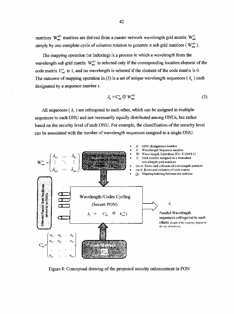
42
matrices Wjf matrices are derived from a master network wavelength grid matrix
simply by one complete cycle of columns rotation to generate n sub grid matrices ( ).
The mapping operation (or indexing) is a process in which a wavelength from the
wavelength sub grid matrix Wjf is selected only if the corresponding location element of the
code matrix Cym, is 1, and no wavelength is selected if the element of the code matrix is 0.
The outcome of mapping operation in (3) is a set of unique wavelength sequences (As ) each
designated by a sequence number s.
4 (3)
All sequences (A/) are orthogonal to each other, which can be assigned in multiple
sequences to each ONU and not necessarily equally distributed among ONUs, but rather
based on the security level of each ONU. For example, the classification of the security level
can be associated with the number of wavelength sequences assigned to a single ONU.
wl =
\A«ii
It * a I -3 I I
Z
c-;,=
°u an a2l. a22
K\ ^ln Derived St* Grid Matrices from network oiatrig
(Wf) mn j
Wavelength/Codes Cycling
(Secure PON)
/I, = <%, 0
K: ONU designation number S: W avelength Sequence number W: Wave length Grid (from ITU-T G694.1) G: Grid number assigned to a formatted
wavelength grid matrices (m.n): Rows and columns of wavelength matrices ( m. Z): Rows and columns of code matrix Q : Mapping/indexing between two matrices
4
Parallel Wavelength sequences orthogonal to each Others (length <f the sequence depend on the size of matrices)
Figure 8: Conceptual drawing of the proposed security enhancement in PON
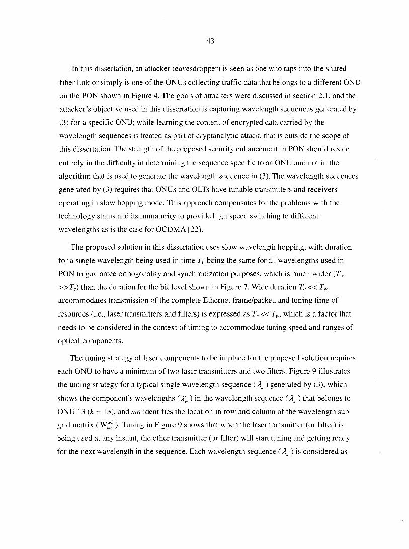
43
In this dissertation, an attacker (eavesdropper) is seen as one who taps into the shared
fiber link or simply is one of the ONUs collecting traffic data that belongs to a different ONU
on the PON shown in Figure 4. The goals of attackers were discussed in section 2.1, and the
attacker's objective used in this dissertation is capturing wavelength sequences generated by
(3) for a specific ONU; while learning the content of encrypted data carried by the
wavelength sequences is treated as part of cryptanalytic attack, that is outside the scope of
this dissertation. The strength of the proposed security enhancement in PON should reside
entirely in the difficulty in determining the sequence specific to an ONU and not in the
algorithm that is used to generate the wavelength sequence in (3). The wavelength sequences
generated by (3) requires that ONUs and OLTs have tunable transmitters and receivers
operating in slow hopping mode. This approach compensates for the problems with the
technology status and its immaturity to provide high speed switching to different
wavelengths as is the case for OCDMA [22].
The proposed solution in this dissertation uses slow wavelength hopping, with duration
for a single wavelength being used in time Tw being the same for all wavelengths used in
PON to guarantee orthogonality and synchronization purposes, which is much wider (Tw
»TC) than the duration for the bit level shown in Figure 7. Wide duration Tc« Tw
accommodates transmission of the complete Ethernet frame/packet, and tuning time of
resources (i.e., laser transmitters and filters) is expressed as Tr« Tw, which is a factor that
needs to be considered in the context of timing to accommodate tuning speed and ranges of
optical components.
The tuning strategy of laser components to be in place for the proposed solution requires
each ONU to have a minimum of two laser transmitters and two filters. Figure 9 illustrates
the tuning strategy for a typical single wavelength sequence ( As ) generated by (3), which
shows the component's wavelengths ( ) in the wavelength sequence ( As ) that belongs to
ONU 13 (k = 13), and mn identifies the location in row and column of the wavelength sub
grid matrix ( ). Tuning in Figure 9 shows that when the laser transmitter (or filter) is
being used at any instant, the other transmitter (or filter) will start tuning and getting ready
for the next wavelength in the sequence. Each wavelength sequence ( As ) is considered as
44
signature associated that can be assigned to an ONU where all sequences are guaranteed by
the strength of orthogonality of code matrices C;vn/.
The wavelength sequence ( As ) is externally (indirectly) modulated using NRZ bits due to
their better utilization of bandwidth as discussed in section 1.3.1.7 Modulation covers a
completely encrypted standard length Ethernet frame/packet (including SA and DA), and the
same fixed length of packets is used across the PON. Fixed and equal length Ethernet
frame/packets provide guarantee orthogonal wavelength sequences operation. The ITU
recommendations G 983.1 standard in [12] already has a packet size limited to 57 bytes [62],
however IEEE 802.3 ah EPON is required to use fixed length Ethernet frames, which is not
currently in the IEEE standard 802.3ah [13].
Wavelength Sequence
< —» —
Ethernet Ptame/Packet: (trafKmissron crRec^jJiphj
Ethernet Frame /Packet (transmission or Recaption)
Ethernet Fn me /Packet Ethernet Frame /Packet (transmission or Reception) Aecepdon) (transmission
Figure 9: Tuning strategy of laser (transmitters/filters) resources
3.2 Master Wavelength Grid Matrix Wj; ' mn
The master wavelength matrix Wmn is constructed from channels using the ITU-T
G.694.1 standard for dense DWDM frequency grid [26] with the total number of wavelengths
channels depending on the channel frequency spacing (A) used from a center frequency of
193.1 THz as expressed in (4):
X= 193.1 +(F)x(A) (4)
45
where F can be a positive or negative number including 0 and channel spacing (A) can be
12.5 GHz, 25 GHz, 50 GHz, 100 GHZ, or 200GHz. A wavelength matrix Wfn shown in
Appendix A is an example of the 25 GHz channel spacing used in this dissertation's
simulation model and wavelength sequence generation per (3). All channels are unique, none
repeated, and are available for wavelength hopping.
The wavelength grid matrix expressed in (5) is considered the master wavelength matrix
built from those wavelengths provided by (4), and in this dissertation, the number of rows
(m) will be the same as that for the code matrix C-'nl, while the columns n can have an equal
or greater number of columns (n >/) than the code matrix C-'nl.
w,° = ••• \i
2 ... 7 V ml nin /
(5)
There are many ways that the wavelengths (channels) generated by (4) can be arranged in
the wavelength grid matrix in (5), with each format (arrangement of wavelengths in the
matrix) assigned a grid number (G). The maximum number of wavelength grid matrices Gmax
is expressed in (6).
Maximum wavelength grids = G,„ux= (n!)m (6)
The limitations on m,n are related to the availability of enough channels that can be
practically generated by (4) within C and L bands to form the complete ITU-T G694.1 grid
[26]. For example, considering the wavelength grid matrix in Appendix A, 200 channels are
available, and only 192 channels are used to fill the matrix in (5) based on m = 12, and n =
16, leaving an extra 8 wavelengths available for use as open channels (no hopping) where the
case may not require security.
Applying (6) to the wavelength grid matrix in Appendix A provides Gmax = (16!)12 =
7.0378 x 10159 wavelength grid matrices formatted simply by different arrangements of the
wavelengths (channels) in Appendix A. This large number of Gmax is a good source of keys
for secure operation. Depending on the administration of security, some formats may not be
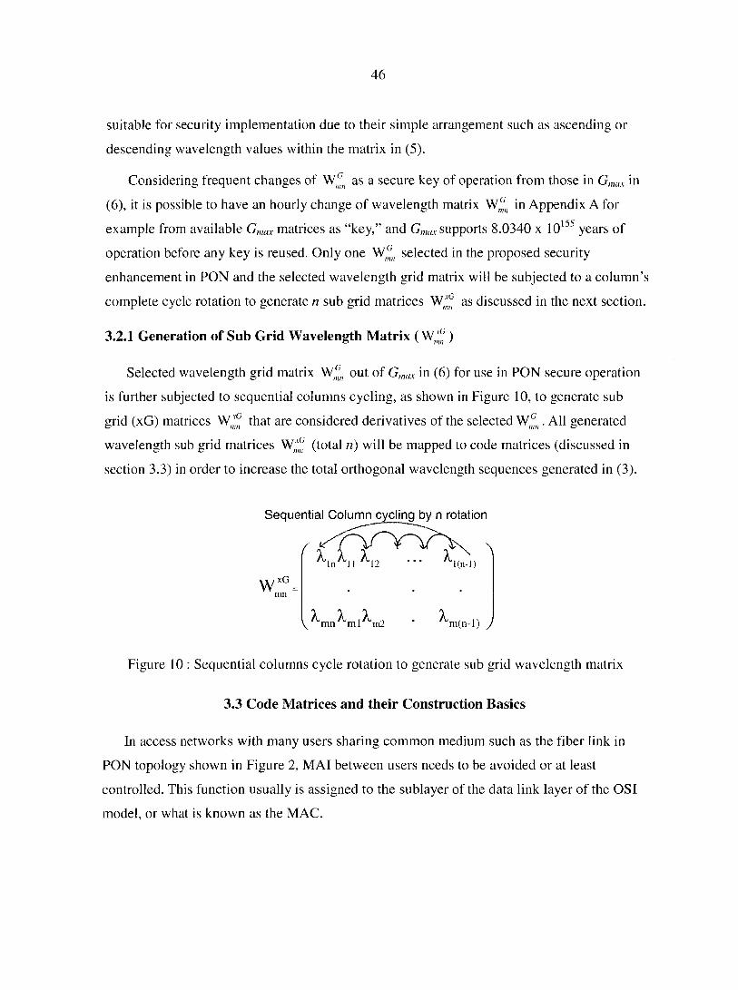
46
suitable for security implementation due to their simple arrangement such as ascending or
descending wavelength values within the matrix in (5).
Considering frequent changes of as a secure key of operation from those in Gmax in
(6), it is possible to have an hourly change of wavelength matrix W^H in Appendix A for
example from available Gmax matrices as "key," and Gmax supports 8.0340 x 10155 years of
operation before any key is reused. Only one selected in the proposed security
enhancement in PON and the selected wavelength grid matrix will be subjected to a column's
complete cycle rotation to generate n sub grid matrices Wjf as discussed in the next section.
3.2.1 Generation of Sub Grid Wavelength Matrix ( W;^ )
Selected wavelength grid matrix Wmn out of Gmax in (6) for use in PON secure operation
is further subjected to sequential columns cycling, as shown in Figure 10, to generate sub
grid (xG) matrices that are considered derivatives of the selected . All generated
wavelength sub grid matrices W;^ (total n) will be mapped to code matrices (discussed in
section 3.3) in order to increase the total orthogonal wavelength sequences generated in (3).
Sequential Column cycling by n rotation
mil
f f 4 f ^ In 11 12 l (n-I)
' ^m(n-l) J
Figure 10 : Sequential columns cycle rotation to generate sub grid wavelength matrix
3.3 Code Matrices and their Construction Basics
In access networks with many users sharing common medium such as the fiber link in
PON topology shown in Figure 2, MAI between users needs to be avoided or at least
controlled. This function usually is assigned to the sublayer of the data link layer of the OSI
model, or what is known as the MAC.
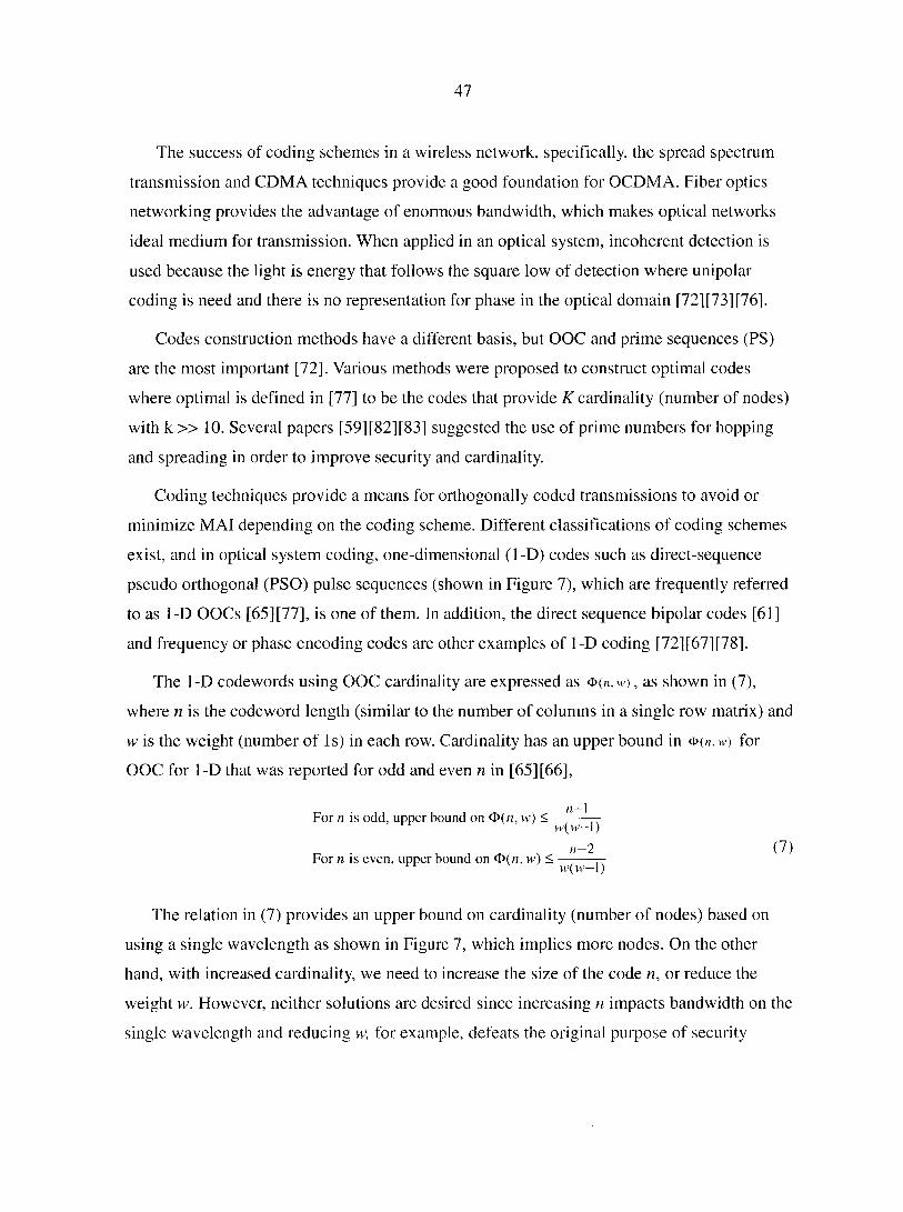
47
The success of coding schemes in a wireless network, specifically, the spread spectrum
transmission and CDMA techniques provide a good foundation for OCDMA. Fiber optics
networking provides the advantage of enormous bandwidth, which makes optical networks
ideal medium for transmission. When applied in an optical system, incoherent detection is
used because the light is energy that follows the square low of detection where unipolar
coding is need and there is no representation for phase in the optical domain [72][73][76].
Codes construction methods have a different basis, but OOC and prime sequences (PS)
are the most important [72]. Various methods were proposed to construct optimal codes
where optimal is defined in [77] to be the codes that provide K cardinality (number of nodes)
with k » 10. Several papers [59] [82] [83] suggested the use of prime numbers for hopping
and spreading in order to improve security and cardinality.
Coding techniques provide a means for orthogonally coded transmissions to avoid or
minimize MAI depending on the coding scheme. Different classifications of coding schemes
exist, and in optical system coding, one-dimensional (1-D) codes such as direct-sequence
pseudo orthogonal (PSO) pulse sequences (shown in Figure 7), which are frequently referred
to as 1-D OOCs [65][77], is one of them. In addition, the direct sequence bipolar codes [61]
and frequency or phase encoding codes are other examples of 1-D coding [72][67][78],
The 1-D codewords using OOC cardinality are expressed as <d( n , w ) , as shown in (7),
where n is the codeword length (similar to the number of columns in a single row matrix) and
w is the weight (number of Is) in each row. Cardinality has an upper bound in ®(n, w) for
OOC for 1-D that was reported for odd and even n in [65] [66],
II — 1 For n is odd, upper bound on 0(«, vv) < — —
w(vt'-l)
For n is even, upper bound on <£>(«, w ) < " ^ ^ w(w-l)
The relation in (7) provides an upper bound on cardinality (number of nodes) based on
using a single wavelength as shown in Figure 7, which implies more nodes. On the other
hand, with increased cardinality, we need to increase the size of the code n, or reduce the
weight w. However, neither solutions are desired since increasing n impacts bandwidth on the
single wavelength and reducing w, for example, defeats the original purpose of security
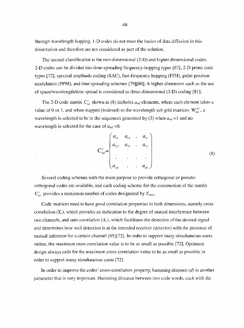
48
through wavelength hopping. 1-D codes do not meet the basics of data diffusion in this
dissertation and therefore are not considered as part of the solution.
The second classification is the two-dimensional (2-D) and higher dimensional codes.
2-D codes can be divided into time-spreading frequency-hopping types [67], 2-D prime code
types [72], spectral amplitude coding (SAC), fast-frequency hopping (FFH), pulse position
modulation (PPM), and time spreading schemes [79][80]. A higher dimension such as the use
of space/wavelength/time spread is considered as three-dimensional (3-D) coding [81].
The 2-D code matrix Cj shown in (8) includes a„,i elements, where each element takes a
value of 0 or 1, and when mapped (indexed) to the wavelength sub grid matrices , a
wavelength is selected to be in the sequences generated by (3) when a,„i = 1 and no
wavelength is selected for the case of a„,i =0.
% a2].
Several coding schemes with the main purpose to provide orthogonal or pseudo-
orthogonal codes are available, and each coding scheme for the construction of the matrix
C]nl provides a maximum number of codes designated by Ymax.
Code matrices need to have good correlation properties in both dimensions, namely cross
correlation (Xc), which provides an indication to the degree of mutual interference between
two channels, and auto correlation (Ar), which facilitates the detection of the desired signal
and determines how well detection is at the intended receiver (detector) with the presence of
mutual inference for a certain channel [65][72]. In order to support many simultaneous users
online, the maximum cross correlation value is to be as small as possible [72]. Optimum
design always calls for the maximum cross correlation value to be as small as possible in
order to support many simultaneous users [72].
In order to improve the codes' cross-correlation property, hamming distance (d) is another
parameter that is very important. Hamming distance between two code words, each with the
a 12
a 22
a,
ÛL
a ml J
(8)
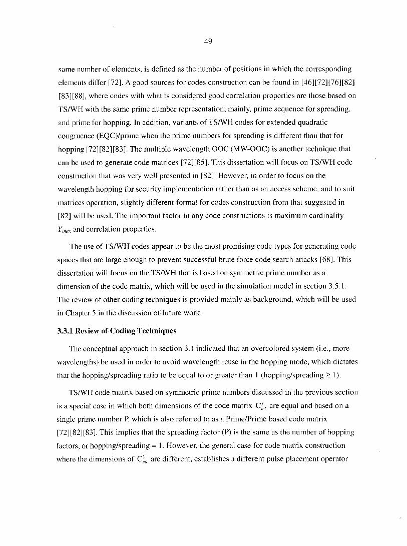
49
same number of elements, is defined as the number of positions in which the corresponding
elements differ [72]. A good sources for codes construction can be found in [46][72][76][82]
[83][88], where codes with what is considered good correlation properties are those based on
TS/WH with the same prime number representation; mainly, prime sequence for spreading,
and prime for hopping. In addition, variants of TS/WH codes for extended quadratic
congruence (EQC)/prime when the prime numbers for spreading is different than that for
hopping [72][82][83], The multiple wavelength OOC (MW-OOC) is another technique that
can be used to generate code matrices [72] [85]. This dissertation will focus on TS/WH code
construction that was very well presented in [82]. However, in order to focus on the
wavelength hopping for security implementation rather than as an access scheme, and to suit
matrices operation, slightly different format for codes construction from that suggested in
[82] will be used. The important factor in any code constructions is maximum cardinality
Ymax and correlation properties.
The use of TS/WH codes appear to be the most promising code types for generating code
spaces that are large enough to prevent successful brute force code search attacks [68]. This
dissertation will focus on the TS/WH that is based on symmetric prime number as a
dimension of the code matrix, which will be used in the simulation model in section 3.5.1.
The review of other coding techniques is provided mainly as background, which will be used
in Chapter 5 in the discussion of future work.
3.3.1 Review of Coding Techniques
The conceptual approach in section 3.1 indicated that an overcolored system (i.e., more
wavelengths) be used in order to avoid wavelength reuse in the hopping mode, which dictates
that the hopping/spreading ratio to be equal to or greater than 1 (hopping/spreading > 1).
TS/WH code matrix based on symmetric prime numbers discussed in the previous section
is a special case in which both dimensions of the code matrix C/mt are equal and based on a
single prime number P, which is also referred to as a Prime/Prime based code matrix
[72][82][83]. This implies that the spreading factor (P) is the same as the number of hopping
factors, or hopping/spreading = 1. However, the general case for code matrix construction
where the dimensions of Cym, are different, establishes a different pulse placement operator
50
basis in which prime numbers are widely used in the construction of code matrices. Several
classifications based on the use of prime numbers are listed in [65][72] as follows:
• Prime codes for time spreading and OOC for wavelength hopping (Prime/OOC).
• Prime codes for time spreading and prime code for wavelength hopping
(Prime/Prime).
• Extended quadratic congruence (EQC) for time spreading and prime for hopping
(EQC/Prime).
• Prime for hopping and extended quadratic congruence (EQC) for time spreading
(Prime/EQC).
• Multiple wavelengths optical orthogonal codes (MWOOC).
The core of the approach to security enhancement in PON is to have a coding scheme that
will provide large wavelength sequences ( Âs ) generated per the relation in (3) to enable large
multiplexing capacity in the shared fiber link in PON. The case of OOC does not support
large cardinality based on (7) because of its impact on bandwidth, therefore, Prime/OOC is
not considered as a candidate for the proposed solution in this dissertation.
3.3.1.1 TS/Wff Code Matrices (Q]nl) Based on Symmetric Prime Number
The code matrix in (8) is a general representation, and when used in TS/ WH schemes,
implies that the number of rows m in C}ml expressed in (8) is related to the number of
available wavelengths. In addition, the number of columns / in (8) is related to the number of
time slots (i.e., code length) or the spreading of the pulses in the time domain [85]. The
codes' construction in the proposed solution in this dissertation will be 2-D code
matrices Cyml, with mx/ dimension that has m rows and I columns.
Mapping operation per (3) using CJnl shown in (8) provides a selection of wavelengths in
the same row in and column n in . The mapping operation requires the numbers of rows
and columns in code matrices Cyml to be equal to or less than the number of rows and
columns in wavelength sub grid matrices W;^ , respectively. In this dissertation, both
matrices will have the same number of rows, while the number of columns will be « > /.
The construction of code matrix C^ based on symmetric prime numbers includes a
decision of the value of elements am\ (0 or 1) in the code matrix shown in (8). This decision is
51
made using a pulse placement operator based on prime codes and a linear congruent operator
shown in (9) that provides a pulse placement of 1 in a row [72].
The first step is to find the prime number P in the pulse placement operator relation in
(9), which will depend on the total available wavelengths generated by (4) based on selected
channel spacing (A). For example, for A = 25 GHz, 200 wavelengths generated by (4), and a
prime number that can be used for a symmetric TS/WH code matrix in (8), P = 13 and the
code matrix dimensions are m = I = 13 (i.e., 13 x 13 = 169) using symmetric dimensions.
amn = (y-m)Mod( p ) y = 1,2,3,...P, m = 1,2,....P-1 (9)
The relation in (9) places 1 at a certain column location in each row (m) of the _>>-
designated code matrix. It is important to remember that the relation in (9) provides a row
with no placement of 1 when m = P (all rows will be 0's). Therefore, the last row is always
ignored and the dimension of the produced code matrix CymI will be (in = P - 1) rows, and I =
m columns.
Complete code matrices for P = 13 were computed using MATLAB® with the results
documented in Appendix C, and each code matrix has P columns by (P - 1 ) rows, as shown
in Figure 11, which illustrates a sample of two code matrices extracted from Appendix C for
the case of P = 13, _y = 7, and _y = 11.
It is important to note that each row in Figure 11 includes a single location for 1 and n - 1
number of 0s, or simply can be expressed with weight w = 1. This implies that when code
matrices mapped against n wavelength sub grid matrices are generated by only the
columns rotations shown in Figure 10, n(m - 1) wavelength sequences (As ) are generated per
the relation in (3).
The code matrix Cytl constructed using symmetric prime number provides excellent
correlation properties that were reported to be 0 for autocorrelation Ac, and 1 for cross
correlation Xc [47][48][61], which is also demonstrated in the simulation model in section 3.5
making the prime hop sequence ideal for supporting multiple simultaneous users.
The symmetric based TS/WH code matrix C^z used throughout the dissertation in the
simulation and analysis, and a review of other coding schemes are provided next.
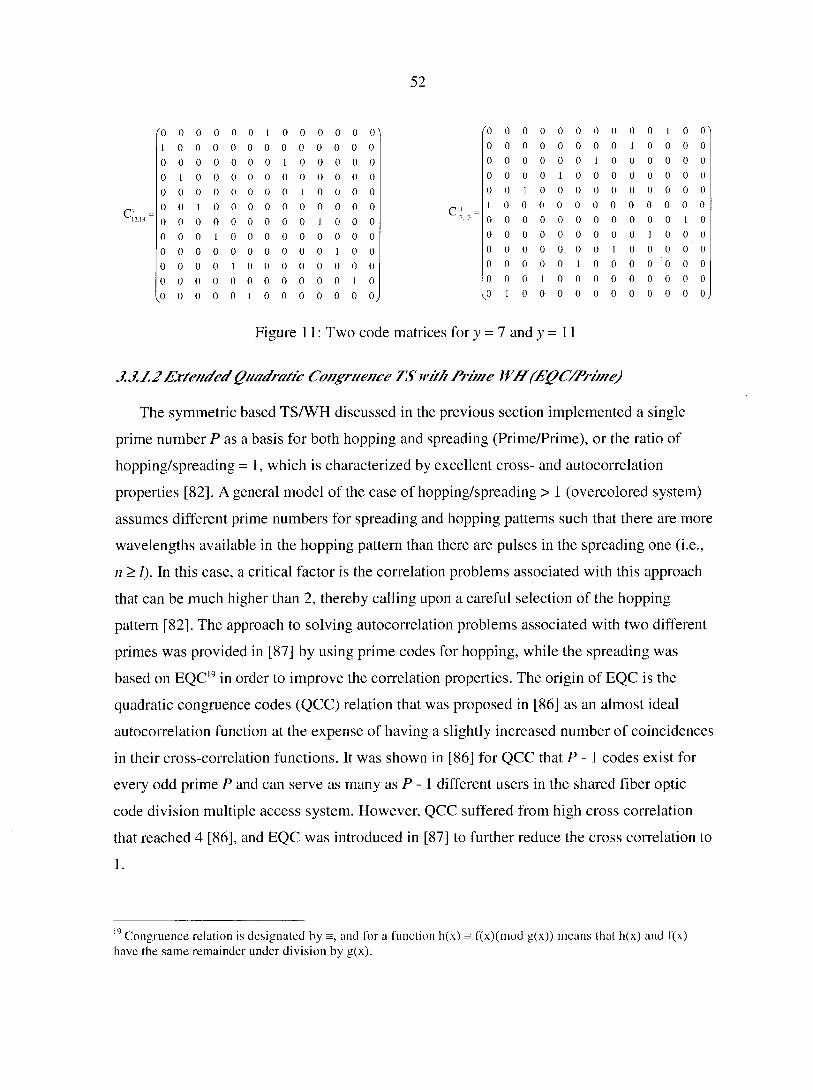
52
'0 0 0 0 0 0 1 0 0 0 0 0 0^ '0 0 0 0 0 0 0 0 0 0 1 0 0"
1 0 0 0 0 0 0 0 0 0 0 0 0 0 0 0 0 0 0 0 0 1 0 0 0 0
0 0 0 0 0 0 0 1 0 0 0 0 0 0 0 0 0 0 0 1 0 0 0 0 0 0
0 1 0 0 0 0 0 0 0 0 0 0 0 0 0 0 0 1 0 0 0 0 0 0 0 0
0 0 0 0 0 0 0 0 1 0 0 0 0 0 0 1 0 0 0 0 0 0 0 0 0 0
0 0 1 0 0 0 0 0 0 0 0 0 0 C" -
1 0 0 0 0 0 0 0 0 0 0 0 0
0 0 0 0 0 0 0 0 0 1 0 0 0 12.13 0 0 0 0 0 0 0 0 0 0 0 1 0
0 0 0 1 0 0 0 0 0 0 0 0 0 0 0 0 0 0 0 0 0 0 1 0 0 0
0 0 0 0 0 0 0 0 0 0 1 0 0 0 0 0 0 0 0 0 1 0 0 0 0 0
0 0 0 0 1 0 0 0 0 0 0 0 0 0 0 0 0 0 1 0 0 0 0 0 0 0
0 0 0 0 0 0 0 0 0 0 0 1 0 0 0 0 1 0 0 0 0 0 0 0 0 0
0 0 0 0 0 1 0 0 0 0 0 0 0. <0 1 0 0 0 0 0 0 0 0 0 0 0,
Figure 11 : Two code matrices for _y = 7 and y = 11
3.3.1.2 Extended Quadratic Congruence TS with Prime Wlf (EQC/Prime)
The symmetric based TS/WH discussed in the previous section implemented a single
prime number P as a basis for both hopping and spreading (Prime/Prime), or the ratio of
hopping/spreading = I, which is characterized by excellent cross- and autocorrelation
properties [82]. A general model of the case of hopping/spreading > 1 (overcolored system)
assumes different prime numbers for spreading and hopping patterns such that there are more
wavelengths available in the hopping pattern than there are pulses in the spreading one (i.e.,
n > I). In this case, a critical factor is the correlation problems associated with this approach
that can be much higher than 2, thereby calling upon a careful selection of the hopping
pattern [82]. The approach to solving autocorrelation problems associated with two different
primes was provided in [87] by using prime codes for hopping, while the spreading was
based on EQC19 in order to improve the correlation properties. The origin of EQC is the
quadratic congruence codes (QCC) relation that was proposed in [86] as an almost ideal
autocorrelation function at the expense of having a slightly increased number of coincidences
in their cross-correlation functions. It was shown in [86] for QCC that P - 1 codes exist for
every odd prime P and can serve as many as P - 1 different users in the shared fiber optic
code division multiple access system. However, QCC suffered from high cross correlation
that reached 4 [86], and EQC was introduced in [87] to further reduce the cross correlation to
1.
19 Congruence relation is designated by =, and for a function h(x) = f(x)(mod g(x)) means that h(x) and f(x) have the same remainder under division by g(x).
53
The EQC construction method uses congruent placement operator shown in (10), which
has some differences from the Prime/Prime case placement operator in (9), and the code
matrix C]nl shown in (8) has dimensions of m-P rows and I = (2P-1 ) columns [82] [83]. The
size of each row in (8) is increased as an extended prime code that uses (10) designed to
reduce the maximum cross correlation value by padding code rows with trailing zeros [72].
The relation in (10) places a pulse in a row m that has a size of (2P-1) in code matrix y,
which is part of maximum number of code matrices y e Fmax.
In [82], prime numbers were used as part of the dimension of the code matrix and
designated for hopping as (P/,) and (Ps) for spreading. In the case that both numbers are equal
(Pi, = Px), this is labeled as symmetric TS/WH, which is the same as discussed in section
3.3.1.1. The symmetric TS/WH also is referred to in the literature as prime hop codes
[82] [83][88]. Otherwise, for Ph ^ Ps it is labeled as asymmetric TS/WH, which is discussed
in this section.
A prime number is used for and designated as P/„ which will be equal to one of the
dimensions of wavelength grid matrix Wfn in (5), and used in (9) where it is based on prime
numbers and not on EQC. On the other hand, the dimension of the code matrix Cyml will be
different for TS/WH based on the EQC/Prime construction method. In this case, the prime
number selected for the spreading (Ps) will be used in (10) for the pulse placement with an
expression for the pulse placement operator expressed in (11).
The dimension of code matrix C'nl will have m = Ps rows and I = 2Ps - 1 columns, which
leads to a maximum number of code matrices expressed as ymax in (12) as:
a y ( m ) = y m^+ (mod P ) 0 < y < P - 1
0 < m < P -1 (10)
a ( m ) = y L j l i l ( m o d P s ) 0 < y < P s - 1 (11)
0 < m < P,' -1
(12)
54
TS/WH based on EQC/Prime in (12) provides more code matrices than the TS/WH based
on a symmetric prime number. The latter provided only P - 1 code matrices as was
demonstrated in Appendix C for P = 13, which provided only 12 code matrices, while
EQC/Prime provides a higher number of code matrices as using (12) for Ps = 11 provides a
total of 231 code matrices.
Implementation of EQC provides low cross correlation properties [83]. The applicability
of two different primes approach using TS/WH with EQC/Prime approach can be tailored to
support security enhancement in PON in this dissertation by utilizing higher dimensions on
the wavelength grid matrix W^n where P/; can represent one of columns and be expressed as
shown in (13).
(Ph) > (2Ps-l) (13)
Accordingly, the relation between the numbers of columns between the code matrix and
the wavelength grid matrix can be expressed as:
l = ( 2 P s - X ) < m = P l i (14)
3.3.1.3 Primefor TS and EQC for Wff (Prime/EQC)
It was suggested in [85] to reverse the function of the code implementation where the
prime code is to be used for time spreads and EQC is to be used for wavelength hopping.
Such implementation would increase overall cardinality to P2{P - 1), but cross correlation
gets large up to 2, and therefore, this approach is not planned for implementation in this
dissertation.
3.3.1.4Multipie Waveiength Op/icaiOrt/iogonaiCodes (MW-OOC)
It is noticed that both cases of TS/WH (symmetric and asymmetric) based on prime
numbers have a single pulse in every row of the code matrix in (8). In order to improve
cardinality in wavelength hopping, an alternative method is to relax the maximum cross
correlation value similar to the implementation in the frequency hopping (EH) use of Reed-
Solomon codes in wireless systems [72]. However, such an approach would affect MAI, and
ideally, cardinality needs to be a function of code length and not the preselected cross
correlation [72].
55
MW-OOCs are m x n matrices 2-D codewords, where m is the number of rows (related to
the number of available wavelengths) and n is the number of columns (related to the code
length). Simply, MWOOCs are analogous to 1-D OOCs with multiple rows to support a
much larger number of simultaneous users since the code cardinality is much larger [73], and
are designed to meet autocorrelation and cross-correlation constraints in order to manage
MAI.
MW-OOC matrices have fixed weight with w > 1 (w is number of 1 's) in a single row m
of the matrix, which is different from the case for TS/WH code matrices discussed in sections
3.3.1.1 and 3.3.1.2 for symmetric Prime/Prime and asymmetric EQC/Prime, respectively,
where w = 1 in each row of the matrices.
Upper bounds on MW-OOC and its optimal cardinality are of interest, however,
correlation properties are of concern also where careful implementation is required in order
to control MAI. The cardinality of MW-OOC is expressed as <£>(mxn, w, Ac, X ) where the
upper bound of the MWOOC cardinality is derived as shown in (15) by multiplying the
Johnson bound in [65] for a single wave as shown in (7) by available wavelengths [75].
, , . ,z x / m(mn -\)(mn - 2) (mn - Xc)Ac 4>(mm,w,Ac,Xc)< w(w.n,..,{w_Xc) (15)
In access networks, OOCs are designed to be pseudo-orthogonal, i.e., the correlation (and
therefore the interference) between pairs of codewords is constrained [74]. It is obvious in
(15) that the upper bound (cardinality) is under the control of weight and allowed correlation
as the system's constraints. Moreover, reducing the weight and increasing the size of the
matrix in 2-D MW-OOCs provides a much larger number of simultaneous users [46].
There are various schemes for MW-OOC code constructions such as the 2-D TS/WH
codes, which employ wavelength hopping algebraically under prime-sequence permutations
on top of time-spreading OOCs as reported in [75]. In addition, another scheme for
MW-OOC construction is proposed in [94] where the weight w has a fixed hamming20
distance of (w + Q) for correlation Q, MW-OOC is expressed as mn,w + Q,Q and the same
20 Hamming distance between two codewords, each with the same number of elements, is defined as the number of positions in which the corresponding elements differ.
56
cardinality provided in (15) is used, which assumes that both autocorrelation and cross
correlation are equal in value (Ax = Ac = Q). The.findings of [94], that cardinality is increased
where an example for using m = 61 wavelengths and codeword length n = 121 provides up to
75,030 MW-OOCs (simultaneous users). In [95], it is demonstrated that MW-OOCs perform
better than both OOCs (by a factor of approximately 1.25) and asymmetric prime-hop codes
(by a factor of approximately 3.5) over a wide range of offered loads.
In this dissertation, the focus is on the security aspect rather than trying to provide
methods for construction of MW-OOCs or comparing them. More details about MW-OOCs
are available in [46], [72], [85], and [95], which provide comparisons between the
performances of different MW-OOC coding schemes.
3.3.1.5Multiple Length Wavelength Hopping Prime Codes
It is expected that future systems will be required to support a large variety of services
such as TPS (audio, video, and data) with multi rate multimedia services coexisting in the
same network [97]. This implies simultaneous support for different signaling rates and
quality of service (QoS) where constant codeword length may not be able to support such
requirements [72]. The use of multi-length codewords rates and services can be matched to
need, and in terms of security, such schemes enhance security by hiding patterns; however,
this requires, for example, different dimensions of code matrices.
Careful selection and centralized control of the multiple length wavelength hopping
prime codes is extremely needed due to the impact of such schemes on the system, which
may cause poor correlation[72][93]. Some proposed designs in the literature [97] include
multi-length OOC, however, the same study shows that performance of these multi-length
OOCs worsen as the code length increases and the weight is still fixed but spread over a
double length code word.
Analysis in [93] shows that performance with the use of multiple length codes improves
as the code length decreases. Even though this unique characteristic allows "prioritization"
and guarantees high QoS, reduction of code length provides less security due to fewer
wavelengths.
57
The applicability of multiple lengths wavelength hopping prime codes to the proposed
solution and in order to guarantee QoS at high data rates using fewer wavelengths as
suggested in [93] results in a reduced security level due to less frames/packets diffusion
among wavelengths. However, in the proposed solution in this dissertation, the multiple
length wavelength hopping prime code matrices can be adopted easily such that the code
matrices used in the mapping operation in (3) can be divided into sub matrices shared by
u s e r s ( O N U s ) . T h e r e s u l t i s t h a t t w o o r m o r e a c t u a l l y s h a r e a w a v e l e n g t h s e q u e n c e ( A s )
generated by (3) such as those shown in Appendix D.
In order not to affect security and reduce QoS degradation caused by reduction of
wavelengths as mentioned [93], the proposed solution in this dissertation uses slow
wavelength hopping with multiple wavelength sequences assignment per user (ONU). The
analogy to multiple length wavelength hopping prime codes is actually based on having
multiple sequences each shared by multiple ONUs at different proportions, with the alternate
use of sequences among many users (ONUs) thus retaining a high number of wavelengths
and not impacting QoS.
3.3.1.6Code Words with Variable Weights (\\)
In previous discussions for TS/WH MW-OOC and multiple length wavelength hopping
primes codes, the weight w, which represents the non zero elements in each row (m) of code
matrix, were fixed. Variable weight techniques have been discussed in the literature [79] [96]
and were intended originally for QoS or one way of providing different rates for different
subscribers (ONUs) based on their applications and needs (multi-rate system).
The use of variable weights in the proposed solution actually enhances security where
wavelength sequences generated by (3) in this case have different lengths from each other,
and the security of a node (ONU) can be associated with number of sequences issued (j = 1 to
K) for a single ONU and the summation of weights for each code matrix across all rows m as
expressed in (16). Multiple security levels among ONUs can be defined based on the sum of
weights as compared to other code matrices that had fixed weights in each row.
i =K i=m
Security Level =(£ J] w. ) (16)
j=1 /=1
58
Of course, higher weight value impacts information transmission rate; for example, high
weight codes will provide lower low rate information due to higher diffusion of Ethernet
frames over several wavelengths, while low weight codes provide high rate information
transfer due to less diffusion of Ethernet frames among wavelengths and still can impact
QoS.
3.3.2 Code Matrices Implementation in this Dissertation
Various coding schemes were introduced and discussed, however, the focus of this
dissertation is on security aspects of the proposed security enhancement based on mapping
the two matrices, code matrix and wavelength sub grid matrices, as illustrated in Figure 8.
The scope of the dissertation cannot cover all coding schemes in detail, and the intention is to
have a higher number of code matrices that will provide better security rather than an access
solution. The reason is based on the fact that current optical technology supports splitting the
ratio of the passive optical coupler (PSC) up to N = 64 [35], which means that this
dissertation sees that cardinality can be met easily for 64 ONUs in PON.
Wavelength matrices generation per (3) used in diffusing complete Ethernet frames/
packets and the different coding schemes discussed in section 3.3.1 with different fixed or
variable weights w, all support data diffusion schemes when code matrices are mapped to
wavelength grid matrices as shown in Figure 8 and (8). Each scheme may use more or less
wavelengths in the hopping mode depending on the weight w, however, autocorrelation more
than 1 necessitates synchronization of the use of wavelength sequences so that MAI is
controlled.
Therefore, the scope of this dissertation is limited to one coding scheme, namely, TS/WH
code matrices based on symmetric prime numbers as discussed in section 3.3.1.1, which
appear to be most promising code types for generating code spaces that are large enough to
prevent successful brute force code search attacks [68].
3.4 Wavelength Sequence As Generation
The concept of security enhancement in PON starts with the basic PON architecture
similar to that in Figure 2 and includes tailored OLTs and ONUs operation that require
59
tunable laser transmitters and filters across C and L bands in addition to the necessary
processing algorithm to enable a wavelength hopping scheme. The wavelength hopping
sequence generation for a specific ONU is based on the mapping (indexing) of two matrices;
wavelength sub grid matrices W°n shown in Figure 10 with x being the designation of the
specific wavelength sub grid matrix Wnx°, which can range from x = 1 to x = n.
Starting with the selected wavelength grid matrix W^n from the available Gmax formats in
(6) and the wavelengths (channels) as a result of the relation in (4) over the band 191.0THz
(1569.59 nm) to 195.975 THz (1529.75 nm) that covers both optical C and L bands, is
constructed and are derived from . For demonstration purposes, Appendix A shows
the selected in this dissertation, which has a total of 192 unique, non-repeated
wavelengths (channels) arranged in an mxn matrix with m = 12 rows and n = 16 columns.
The columns complete cycle rotation per Figure 10 is carried out on producing a total
of n W*° wavelength sub grid matrices as shown Appendix B.
The code matrices were already constructed as discussed in section 3.3.1.1 for TS/WH
based on the symmetric prime number P = 13, with the results shown in Appendix C. The
limited number of code matrices (P - 1) as dictated by equation (9) do not support a large
number of nodes (ONUs) in PON, which can have up to 64 ONUs and plan for growth to 128
as indicated in ITU-T G984.1 for Giga PON (GPON). However, mapping in (3) provides
sufficient wavelength sequences ( Xs ) with each sequence unique and orthogonal to all other
wavelength sequences generated by (3). Note that if higher code matrices will be required,
the TS/WH based on EQC/Prime (asymmetric prime numbers) discussed in section 3.3.1.2
provide higher code matrices, but careful attention is needed to check on the correlation to
avoid interference (MAI).
MATLAB® was used in the mapping operation (indexing) between the 16 sub grid
matrices W*° in Appendx B and code matrices in Appendix C, and an example of such
mapping results is shown as Wx(Cy) in Table 2 for partial sequences representing 12
sequences in 9 hops. The complete results of the mapping operation, shown in Appendix D,
has 192 unique wavelength sequences, with each wavelength in the sequence part of a single
hop in the wavelength hopping scheme with good correlation such that no two wavelengths
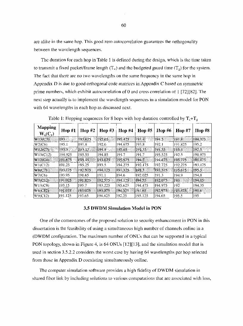
60
are alike in the same hop. This good zero autocorrelation guarantees the orthogonality
between the wavelength sequences.
The duration for each hop in Table 1 is defined during the design, which is the time taken
to transmit a fixed packet/frame length (Tw) and the budgeted guard time (Tg) for the system.
The fact that there are no two wavelengths on the same frequency in the same hop in
Appendix D is due to good orthogonal code matrices in Appendix C based on symmetric
prime numbers, which exhibit autocorrelation of 0 and cross correlation of 1 [72] [82]. The
next step actually is to implement the wavelength sequences in a simulation model for PON
with 64 wavelengths in each hop as discussed next.
Table 1: Hopping sequences for 8 hops with hop duration controlled by Tc+Tg
Mapping
Wx(Cy) Hop #1 Hop #2 Hop #3 Hop #4 Hop #5 Hop #6 Hop #7 Hop #8
W13(C3# 193 l93l|5:;Wï Wsmgm: 195.425 193.1l";f 194.5 9 191.8 194.375
W2(C6) 195.1 191.8 192.6 194.675 193.8 192.1 191.825 195.2 W12(C7) 193.3 193.15 194.8 195.65 . 191 35 191.55 fc 195.4 t : Î 192.5
W13(C12) 194.925 195.55 194.85 194.7 191.7 195.525 192.5 191.975
W12(### 191.675 193.675 195.575 194.7 194.475 195.775 ; 191.475
W1(C12) 191.25 195.25 193.5 194.275 192.175 192.725 192.275 193.175
W8(C7>& 193J75 ,/# 192.975 194.125 191.325 ' 191.3 192.525 195.675 _ 195.5
W7(C6) 193.95 191.65 191.1 194.6 192.025 191.3 194.9 194.8 W7(C12) 191.025 191.825 192.575 192.075 193 Jil 194 15
W13(C9) 193.15 195.7 193.225 195.625 194.475 194.975 192 194.35
W4(CI2) 193.025 193.075 194.325 191.65 192.975 193.475).' 191.6
W9(C12) 191.125 193.65 194.425 192.25 195.125 194.65 195.5 195
3.5 DWDM Simulation Model in PON
One of the cornerstones of the proposed solution to security enhancement in PON in this
dissertation is the feasibility of using a simultaneous high number of channels online in a
(DWDM configuration. The maximum number of ONUs that can be supported in a typical
PON topology, shown in Figure 4, is 64 ONUs [12] [13], and the simulation model that is
used in section 3.5.2.2 considers the worst case by having 64 wavelengths per hop selected
from those in Appendix D coexisting simultaneously online.
The computer simulation software provides a high fidelity of DWDM simulation in
shared fiber link by including solutions to various computations that are associated with loss,
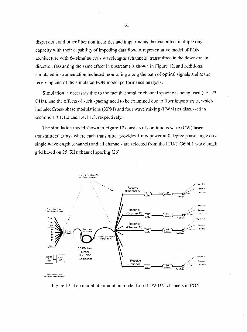
61
dispersion, and other fiber nonlinearities and impairments that can affect multiplexing
capacity with their capability of impeding data flow. A representative model of PON
architecture with 64 simultaneous wavelengths (channels) transmitted in the downstream
direction (assuming the same effect in upstream) is shown in Figure 12, and additional
simulated instrumentation included monitoring along the path of optical signals and at the
receiving end of the simulated PON model performance analysis.
Simulation is necessary due to the fact that smaller channel spacing is being used (i.e., 25
GHz), and the effects of such spacing need to be examined due to fiber impairments, which
includecCross-phase modulations (XPM) and four wave mixing (FWM) as discussed in
sections 1.4.1.1.2 and 1.4.1.1.3, respectively.
The simulation model shown in Figure 12 consists of continuous wave (CW) laser
transmitters' arrays where each transmitter provides 1 mw power at 0 degree phase angle on a
single wavelength (channel) and all channels are selected from the ITU-T G694.1 wavelength
grid based on 25 GHz channel spacing [26].
Instrumentation (Signal Plot and Spectrum Analyzer
Signal Plot
Receive ( C h a n n e l A ]
Spectrur
/ opt \ yOetectoi J
Signal Plot
Transmitter Array 25 GHz Chanel Spacing Receive
(Channel B; ^ Spectrurr
Signal Plot
Receive (Channel C]
Spectrurr
Passive Star Couplei (PSC) 1 64 Spin
2E KM Nor Linear
ITL-TG65E Compliant
Signal Plot
Receive (Channel D;^r
Spectrurr
/ Opt \ \ Detectoi J
Each wavelength is modulated by PRBS signa
Figure 12: Top model of simulation model for 64 DWDM channels in PON
62
Each wavelength from the array is subjected to external (indirect) modulation by a
pseudo random binary signal (PRBS), which is bit sequence of O's and l's representing
typical digital traffic in a network and fed to an external modulator through the electrical
generator as shown in Figure 12. The function of the electrical generator is to convert an
input binary signal from PRBS into an output electrical signal. The PRBS is a single instance
of the model used to provide multiple and similar pattern outputs used for modulating all 64
wavelengths at the same time in a single hop thus establishing a common baseline for
evaluating all channels against one reference. Good channels should provide the same signal
replica at the output of the monitored channels A, B, C, and D as shown in Figure 12.
The 64 channels in the simulation model shown in Figure 12 are transmitted
simultaneously and carried over 25 km long non zero fispersion shifted fiber (NZ-DSF)
compliant with the ITU-T G655 fiber cable standard. After the 25 km, the signal of each
channel is passively split into 64 branches (1:64) without any amplification between the
output of the modulator and the input of the optical filters on the receiving end of the PON
simulation model as shown in Figure 12.
Selection of the ITU-T G655 fiber cable related to the cable being NZ-DSF, which has
chromatic dispersion that is greater than the nonzero value through the C band (1500nm).
Dispersion reduces the effect of fiber nonlinearities such as FWM, SPM, and XPM that are
typically seen in DWDM, and this type of fiber cable is best suited and optimized to operate
between 1500 and 1600 nm [8],
On the receiving end of the PON simulation model shown in Figure 12, each ONU has an
optical tunable filter tuned to a single wavelength (channel) in each hop of the wavelength
sequence specific to each ONU. Throughout the simulation model, signal spectrum and
signal plot are monitored and instrumentation used for output of selected four channels (A, B,
C, and D) is checked for certain performance parameters including eye pattern, BER, signal
spectrum, and actual signal output as shown in Figure 12.
3.5.1 Performance Metrics for the Simulation Model
In a typical optical system design, fiber impairment such as FWM, SPM, and XPM and
their effects can be seen in the signal quality and usability with tolerable noise level in the
63
hopping mode. As a performance metric, BER, discussed in section 1.4.1.2.1, will be used to
indicate the fitness of the shared link for multiple simultaneous sharing in the DWDM
environment. The minimum, BER requirement for a typical end system will be in the range
of 10~9 to 10"12; in other words, for every 109 bits transmitted, one corrupted bit is allowed.
BER is a figure of merit for WDM networks and all designs in the industry usually adhere to
that quality figure [8],
3.5.2 OptSim™ 4.5 Simulation Software
The simulation software used in PON modeling is the OptSim™ 4.5 provided by RSoft
Design Group (www.RSoft.com). OptSim™ 4.5 is an advanced simulation package used in
designing optical communication systems and simulates them to determine their performance
given various component parameters. OptSim™ 4.5 provides an extensive component model
library of the most commonly used components for the engineering of electro-optical
systems; such components models used in this dissertation include for example the CW laser
transmitters, optical filters, detectors, PSC, in addition to fiber cables modeling the
nonlinearities and impairments in a typical physical fiber.
PON simulation model top level architecture shown in Figure 12 was constructed using
simulated components from OptSim™ 4.5 simulation software as shown in Figure 13 as an
interconnected set of blocks, each block representing a component or subsystem in the
communication system in the top level architecture in Figure 12. Similar to physical signals
passed between components in a real world communication system, "signal" data is passed
between Figure 13 components in the simulated model, and each block is simulated
independently using the specified parameters settings summarized in Table 2.
Simulation results are extracted from the instrumentation provided, which includes, for
example, signal waveform plots along a PON path, BER, a spectrum analyzer, a Q factor
reader, and eye diagrams at the output of the four selected channels (A, B, C, and D) as
shown in Figures 9 and 10.

64
Table 2: Parameters set for PON simulation architecture (Figure 13)
Component Type Parameter Value
Transmitters Array CW Laser Peak Power 1 mW
Channel Spacing 25 GHz
Line Width 10 MHz
Random Phase Included
Number of Channels 64
Force polarization Yes
Wavelengths 1529.75nm to 1569.59nm
Relative Intensity Noise (RIN) -150 dB/Hz
PRBS Bit Rate 10 Gbps
Pattern Length 2'bits Offset between channels 5 bits
Electrical Generator ON OFF Modulation Type NRZ
Signal Type Voltage
Vmax 1 V
Vmin 0 V
Time Jitter Ix 10 '* Sec External Modulator Modulation Type External/Amplitude
Fiber Cable Length 25 KM
Loss Model Constant
Loss .35dB/KM
Optimization Level 3
DispersionLambdaO 1.565e-6m
Dispersion SO 0.1686e3 s/mA3
Dispersion Offset 6.0e-6 s/mA2
Include Dispersion Yes
Nonlinearity Model Constant
Diameter 8.8e-6 m
affect 1.0522
Include self-phase modulation (SPM)
Yes
Include cross-hase modulation
(XPM) Yes
PMD Method Coarse step: 1.58e-14
s/mA0.5
Include SBS Yes
Splitter Passive Passive Star Splitter 1:64
Polarization Combination X& Y
Spectrum noise Yes
Optical Filters Type Gaussian
Bandwidth .2 nm
Drop Threshold 10'^ Watts
Show noise Yes
Polarization Separate X & Y
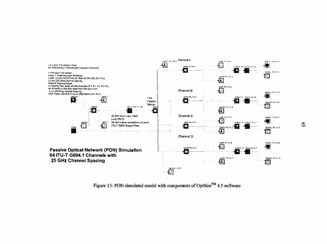
L'vV Laixx Ira-fsmfHR? «Vray f.t>5 I ra-«mMtor/Jd^:ont chants;
1 r--AV cacn Trarsnriticr Vtato î: Fîtitd Adorant Chnnnois ; 1MG1.i2fmi1B3.9 TH;! K) 1L6&7B 0-2 i'm (25 GHzl chan-iti %»acng 7: Hapnng ktaSû f« 1ky, ft*:h »»•> 64 rtofinnfc; tFi, F2 F3 fa F5j ai m;nn<ti; h m a ri** iaWi frein ir* ct*rd win 2 rm 135 GK/| diAniW Saacft}
152S.7Snm(1St>97STM/| ki 156S5Wn(19î TH» ^
0 fry t '/;'. s.rç*.
1:64 Passée Spttter
Z5 KM Ncn uneaf Rte (a'i h PMO)
"•*' i AC Mm Linear simulation nduded ITUT G665 Based Ffcrer
Passive Optical Network (PON) Simulation 64 ITU-T G694.1 Channels with 25 GHz Channel Spacing
Cltirmsl A.
->#*< «X ÇH A
Channel B:
o»-wi_*3r.ci..e
Channel C
<Vwi
Channel D
iw-i.-v i.5««
R1
•u !*.#&»» M ly-t i i #
1ÈI Cv#6sr.t.
g ;wf».n «c-i.fr
{*«•*»•• i: «iwt«' i:-t * a "> si p
wAfwi :>« A
!**>•* A>, Ci» û
((him; ««xm t
'ik
A**»* „&
SXCH ù
m
Sî
Figure 13: PON simulated model with components of OptSim™ 4.5 software
66
The simulation in this dissertation is used to provide a proof of concept for the DWDM in
PON, and consists of two parts: the first is used to establish a baseline using 64 adjacent
channels with equal spacing of 25 GHz, and the second is in the hopping mode where the
channels are selected from files prepared specifically for this simulation.
3.5.2.1 A dfacent Channels Simulation
This part of the simulation is used to establish a baseline for performance metrics, which
includes having simultaneous transmission of 64 adjacent channels taken from the ITU-T
G694.1 wavelength grid within the band 15461.12 nm (193.9 THz) to 1558.78 nm (192.325
THz) with 0.2 nm (25 GHz) channel spacing and using a data rate of 10 Gbps.
The combined signals are monitored before entry to the 25 km fiber link, after the 1:64
splitters, after the coarse optical filter to check on channel impairments, and at the selected
four channels A, B, C, and D on the receiving end of PON architecture shown in Figures 12
and 13. Table 3 lists the frequencies of the four adjacent monitored channels A, B, C, and D
that represent a sample of all 64 channels. This part of the simulation is important due to
channel cross talk and impairments such as FWM, which is usually more apparent in equally
spaced channels in a WDM system and operating at high power [8][45]. A fixed power level
of 1 mW is applied from each laser transmitter in the array and the focus will be on
investigating the channels' impairments. The same physical parameters listed in Table 2 used
in every hop across in simulation efforts are reused except for the channel tuning (both
transmitters and filters) changed for each hop.
The spectrum of the 64 adjacent channels with 0.2 nm spacing before entering the 25 km
long fiber shown in Figure 14 with combined wavelengths (channels) coexisting on the
shared fiber link are captured after the 1:64 passive splitter as shown in Figure 15. All
channels exhibit the same power level, which is considered a good feature in terms of
security against eavesdropping and tapping that uses isolation of channels based on power
level screening.
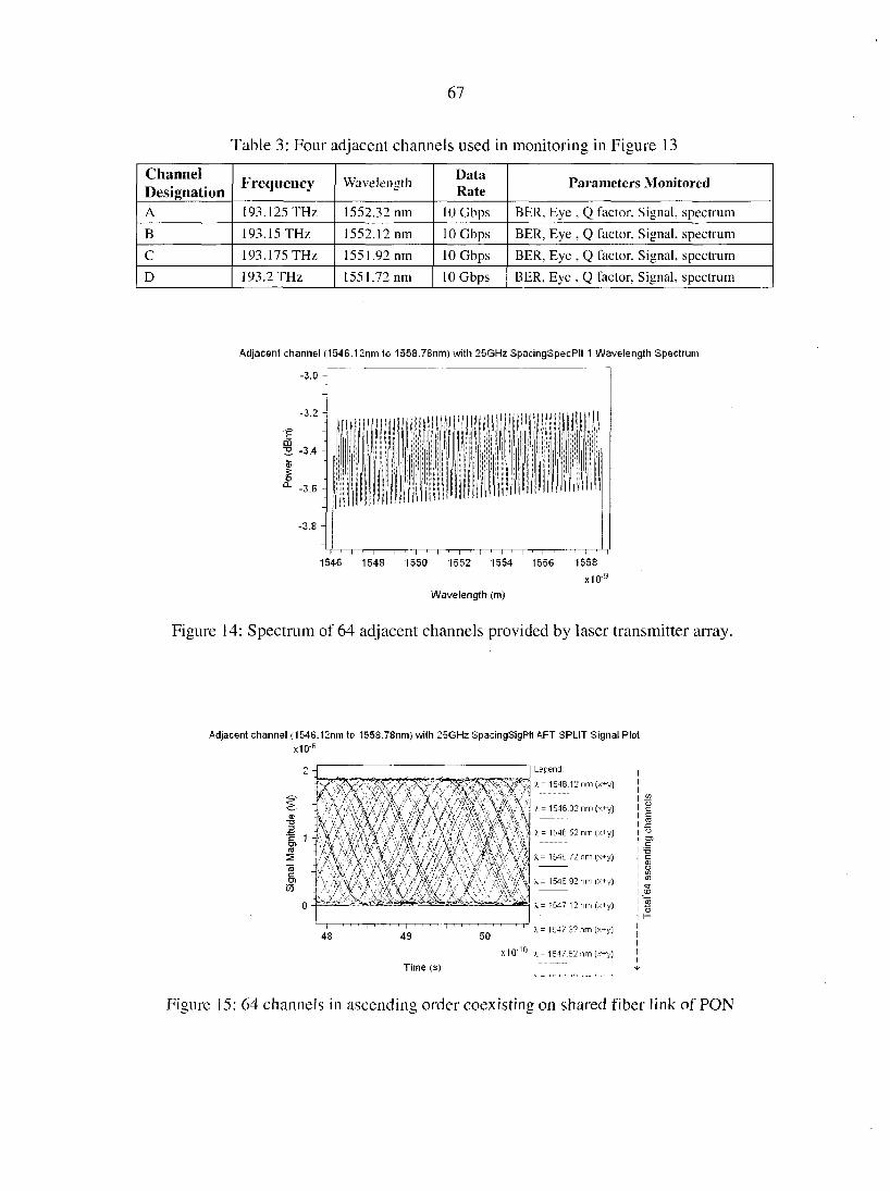
67
Table 3: Four adjacent channels used in monitoring in Figure 13
Channel Designation
Frequency Wavelength Data Rate
Parameters Monitored
A 193.125 THz 1552.32 nm 10 Gbps BER, Eye , Q factor, Signal, spectrum
B 193.15 THz 1552.12 nm 10 Gbps BER, Eye , Q factor, Signal, spectrum
C 193.175 THz 1551.92 nm 10 Gbps BER, Eye , Q factor. Signal, spectrum
D 193.2 THz 1551.72 nm 10 Gbps BER, Eye , Q factor, Signal, spectrum
Adjacent channel (1546.12nm to 1558.78nm) with 25GHz SpacingSpecPIt 1 Wavelength Spectrum
-3.0
m "5 -3.4
I '—I—'—I—' 1—'—I—' 1—'—I—'—I—'—I—T 1546 1548 1550 1552 1554 1556 1558
X10"9
Wavelength (m)
Figure 14: Spectrum of 64 adjacent channels provided by laser transmitter array.
Adjacent channel (1546.12nm to 1558.78nm) with 25GHz SpacingSigPIt AFT SPLIT Signal Plot
x10~6
=
Ï. 1
I Legend
\ / yT ~ Y \ '546 12 nm (x+y)
A' YV . >
' V '
'/A/'
' \
s i r \ 1 i- 1546.32 rirn (x+y)
1 à 1
/ \
V
K = 1546 52 nm (x+y)
. - 1546 .72 rim (x+y)
. = 1546.92 nm (x+y)
49
Time (s)
50
x1Q
X ~ 1547 12 nm (x+y)
A - 1547.32 nm (x+y)
X - 1547.52 nm (x+y)
Figure 15: 64 channels in ascending order coexisting on shared fiber link of PON
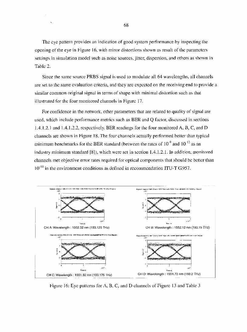
68
The eye pattern provides an indication of good system performance by inspecting the
opening of the eye in Figure 16, with minor distortions shown as result of the parameters
settings in simulation model such as noise sources, jitter, dispersion, and others as shown in
Table 2.
Since the same source PRBS signal is used to modulate all 64 wavelengths, all channels
are set to the same evaluation criteria, and they are expected on the receiving end to provide a
similar common original signal in terms of shape with minimal distortion such as that
illustrated for the four monitored channels in Figure 17.
For confidence in the network, other parameters that are related to quality of signal are
used, which include performance metrics such as BER and Q factor, discussed in sections
1.4.1.2.1 and 1.4.1.2.2, respectively. BER readings for the four monitored A, B, C, and D
channels are shown in Figure 18. The four channels actually performed better than typical
minimum benchmarks for the BER standard (between the rates of 10 9 and 10"12 as an
industry minimum standard [8]), which were set in section 1.4.1.2.1. In addition, monitored
channels met objective error rates required for optical components that should be better than
10"10 in the environment conditions as defined in recommendation ITU-T G.957.
Adjacent channel 154$.i;nm to l?58.78nm> vvtth 25GHz SpacingMultiPlol RX CH A Eye Diagram Adjacent channel <1546.12nm to 1559 7Snm) with 25GHz SpacingMultiPlol RX CH B Eye Diagiar
CH A: Wavelength : 1552.32 nm (193.125 THz) CH B: Wavelength : 1552.12 nm (193.15 THz)
Adjacent channel11546.12nm to 1558.73mm with 25GHz SpacingMultiPlol RK CH C Eye Diagrai Adjacent channel<1546 12nm1o 1556.73nmi with 25GHz SpaclngMultlPol RXCH D Eye Diagram
CH C: Wavelength : 1551.92 nm (193.175 THz) CH D: Wavelength : 1551.72 nm (193.2 THz)
Figure 16: Eye patterns for A, B, C, and D channels of Figure 13 and Table 3
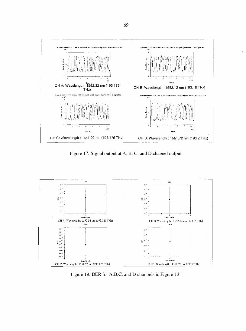
69
Adjacent channel (1546 12nm lo l558.7Snmi with 25GHc SpacingMulliPlcl RX CH A Signal Plol
^ L' •?' 1 !'• J i ^ ' ' ' :j i ' •
Adjacent channel (154G.12nm lo 155S.?3nm, with 25GH: SpacingMultiPlol RX CH B Signal Plol
CH A: Wavelength : 1552.32 nm (193.125 THz)
Adjacent channel (1546.12nm lo 1558.78nmi with 25GHE SpacingMultiPlol RX CH C Signal Plol
^ A I
CH B: Wavelength : 1552.12 nm (193.15 THz)
Adjacent channel 11546 I2nm to I558.78nmi wilh 26GI-b SpacingMultiPlol RX CH D Signal Plol
CH C: Wavelength : 1551.92 nm (193.175 THz) CH D: Wavelength : 1551.72 nm (193.2 THz)
Figure 17: Signal output at A, B, C, and D channel output
1„,D ,0»
£ 10"a m io3:
10:B
,0"
10 36
Single Result Single Result
CH A: Wavelength : 1552.32 nm (193.125 THz) CH B: Wavelength : 1552.12 mil (193.15 THz) BER
10 15 10 :' j
10:ù
10" - I02E
10-- -
85 10:c - K 1°:'
" 10- -
10'L1 '
10- • t0'3:
10=- -
Single Result Single Result
CH C: Wavelength : 1551.92 nm (193.175 THz) CH D: Wavelength : 1551.72 nm (193.2 THz)
Figure 18: BER for A,B,C, and D channels in Figure 13
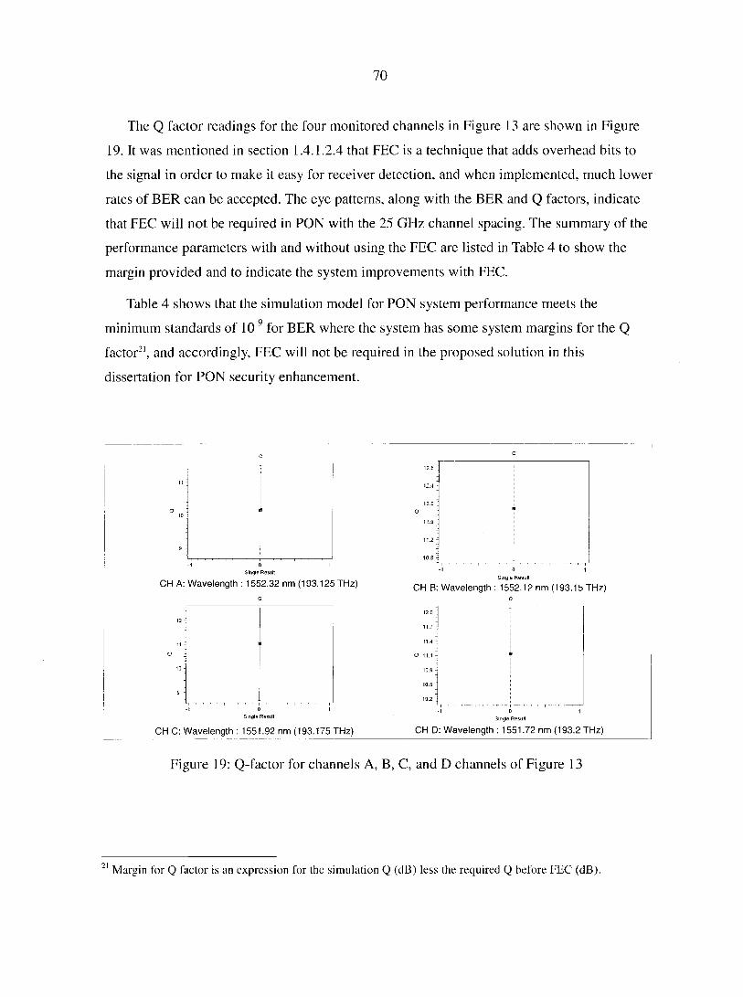
70
The Q factor readings for the four monitored channels in Figure 13 are shown in Figure
19. It was mentioned in section 1.4.1.2.4 that FEC is a technique that adds overhead bits to
the signal in order to make it easy for receiver detection, and when implemented, much lower
rates of BER can be accepted. The eye patterns, along with the BER and Q factors, indicate
that FEC will not be required in PON with the 25 GHz channel spacing. The summary of the
performance parameters with and without using the FEC are listed in Table 4 to show the
margin provided and to indicate the system improvements with FEC.
Table 4 shows that the simulation model for PON system performance meets the
minimum standards of 10"9 for BER where the system has some system margins for the Q
factor21, and accordingly, FEC will not be required in the proposed solution in this
dissertation for PON security enhancement.
CH A: Wavelength : 1552.32 nm (193.125 THz) Single Result
CH B: Wavelength : 1552.12 nm (193.15 THz)
Single Result
CH C: Wavelength : 1551.92 nm (193.175 THz) CH D: Wavelength : 1551.72 nm (193.2 THz)
Figure 19: Q-factor for channels A, B, C, and D channels of Figure 13
21 Margin l'or Q factor is an expression for the simulation Q (dB) less the required Q before FEC (dB).
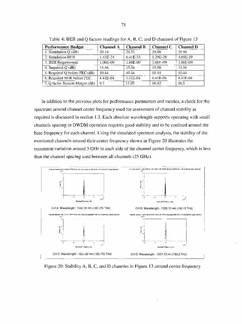
71
Table 4: BER and Q factors readings for A, B, C, and D channesl of Figure 13
Performance Budget Channel A Channel B Channel C Channel D 1. Simulation Q (dB) 20.14 21.51 20.86 20.94 2. Simulation BER 1.43E-24 6.41E-33 1.29E-28 4.09e-29 3. BER Requirement 1.00E-09 1.00E-09 1-00E-09 1.00E-09
4. Required Q (dB) 15.56 15.56 15.56 15.56
5. Required Q before FEC (dB) 10.44 10.44 10.44 10.44
6. Required BER before FEC 4.41E-04 4.41E-04 4.41E-04 4.41E-04
7. Q factor System Margin (dB) 9.7 11.07 10.42 10.5
In addition to the previous plots for performance parameters and metrics, a check for the
spectrum around channel center frequency used for assessment of channel stability as
required is discussed in section 1.3. Each absolute wavelength supports operating with small
channels spacing in DWDM operation requires good stability and to be confined around the
base frequency for each channel. Using the simulated spectrum analysis, the stability of the
monitored channels around their center frequency shown in Figure 20 illustrates the
maximum variation around 5 GHz to each side of the channel center frequency, which is less
than the channel spacing used between all channels (25 GHz).
i1546.12nmlo 1558.78nmi with :5GHz SpacingMultiPlol RX CH A Baseband Signal Spectrum Adjacent channel! 1546 12nm to I55B 76nm) with 25Gto SpsclngMultlPlot RX CH B Baseband Signal Spedium
Baseband Frequency thfei
CH A: Wavelength : 1552.32 nm (193.125 THz)
acent channel il54G.I2niii to 1558.78nmt wllh 25GHz SpacingMultiPlol RXCH C Baseband Signal Spectrum
Baseband Frequency iHz)
CH B: Wavelength : 1552.12 nm (193.15 THz)
Baseband Frequency (HZ)
CH C. Wavelength : 1551.92 nm (193.175 THz)
Baseband Frequency t'Hz)
CH D: Wavelength : 1551.72 nm (193.2 THz)
Figure 20: Stability A, B, C, and D channles in Figure 13 around center frequency
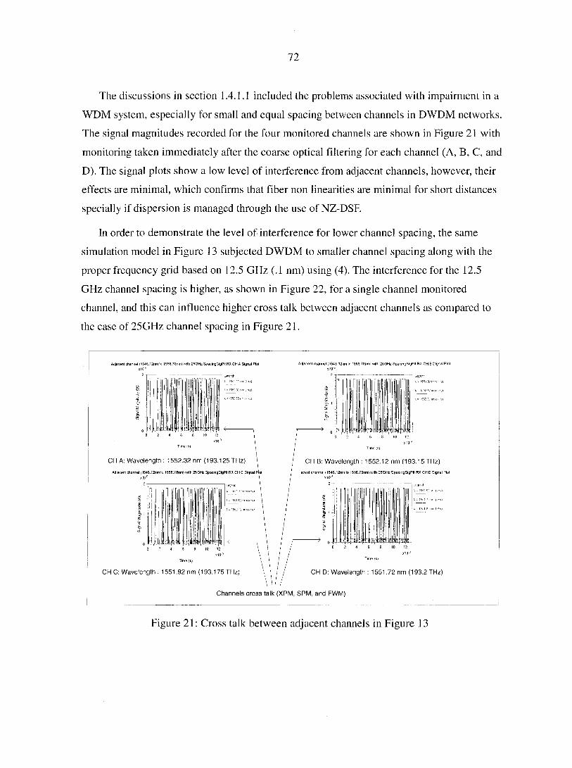
72
The discussions in section 1.4.1.1 included the problems associated with impairment in a
WDM system, especially for small and equal spacing between channels in DWDM networks.
The signal magnitudes recorded for the four monitored channels are shown in Figure 21 with
monitoring taken immediately after the coarse optical filtering for each channel (A, B, C, and
D). The signal plots show a low level of interference from adjacent channels, however, their
effects are minimal, which confirms that fiber non linearities are minimal for short distances
specially if dispersion is managed through the use of NZ-DSF.
In order to demonstrate the level of interference for lower channel spacing, the same
simulation model in Figure 13 subjected DWDM to smaller channel spacing along with the
proper frequency grid based on 12.5 GHz (.1 nm) using (4). The interference for the 12.5
GHz channel spacing is higher, as shown in Figure 22, for a single channel monitored
channel, and this can influence higher cross talk between adjacent channels as compared to
the case of 25GHz channel spacing in Figure 21.
Adjacent channel ( 1546.12nm lo 1558.7Snm.r with 25GHz SpacingSigPIt RX CH B Signal Plot Adjacent channel (1546.12nm lo 1558."enm. with 25GHz SpacingSigPIt RX CH A Signal Plol
Time is)
CH B: Wavelength : 1552.12 nm (193.15 THz)
acenl channel i I546.l2nm to 1558.78nm) with 26GHz SpacingSigPIt RX CH D Signal Plot
CH A: Wavelength : 1552.32 nm (193.125 THz)
Adjacent channel (1546.12nm to 1550.73nmt with 25GHz SpacingSigPIt RX CH C Signal Plot
CH C: Wavelength : 1551.92 nm (193.175 THz) CH D: Wavelength : 1551.72 nm (193.2 THz)
Channels cross talk (XPM, SPM, and FWM)
Figure 21: Cross talk between adjacent channels in Figure 13
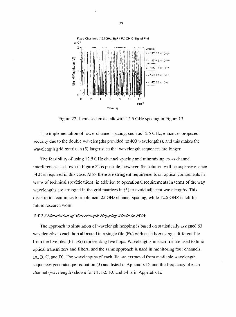
73
Fixed Channels (12.5GHz)SigPlt RX CH C Signal Plot
x1Cr
•8
5> 1
£
Time (s)
Legend:
X = 1552.52 nm (x+y)
X. - 1552.62 ran (x+
%.= 1552.72 nm (x+y)
X = 1552 82 nm (x+y)
1552.92 nm (x+y)
Figure 22: Increased cross talk with 12.5 GHz spacing in Figure 13
The implementation of lower channel spacing, such as 12.5 GHz, enhances proposed
security due to the double wavelengths provided (= 400 wavelengths), and this makes the
wavelength grid matrix in (5) larger such that wavelength sequences are longer.
The feasibility of using 12.5 GHz channel spacing and minimizing cross channel
interferences as shown in Figure 22 is possible, however, the solution will be expensive since
FEC is required in this case. Also, there are stringent requirements on optical components in
terms of technical specifications, in addition to operational requirements in terms of the way
wavelengths are arranged in the grid matrices in (5) to avoid adjacent wavelengths. This
dissertation continues to implement 25 GHz channel spacing, while 12.5 GHZ is left for
future research work.
3.5.2.2 Simulation 0/ Wavelength Hopping Mode in PON
The approach to simulation of wavelength hopping is based on statistically assigned 63
wavelengths to each hop allocated in a single file (Fx) with each hop using a different file
from the five files (F1-F5) representing five hops. Wavelengths in each file are used to tune
optical transmitters and filters, and the same approach is used in monitoring four channels
(A, B, C, and D). The wavelengths of each file are extracted from available wavelength
sequences generated per equation (3) and listed in Appendix D, and the frequency of each
channel (wavelength) shown for Fl, F2, F3, and F4 is in Appendix E.
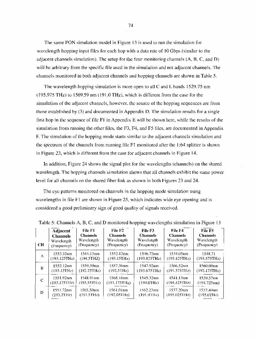
74
The same PON simulation model in Figure 13 is used to run the simulation for
wavelength hopping input files for each hop with a data rate of 10 Gbps (similar to the
adjacent channels simulation). The setup for the four monitoring channels (A, B, C, and D)
will be arbitrary from the specific file used in the simulation and not adjacent channels. The
channels monitored in both adjacent channels and hopping channels are shown in Table 5.
The wavelength hopping simulation is more open to all C and L bands 1529.75 nm
(195.975 THz) to 1569.59 nm (191.0 THz), which is different from the case for the
simulation of the adjacent channels, however, the source of the hopping sequences are from
those established by (3) and documented in Appendix D. The simulation results for a single
first hop in the sequence of file F1 in Appendix E will be shown here, while the results of the
simulation from running the other files, the F3, F4, and F5 files, are documented in Appendix
F. The simulation of the hopping mode starts similar to the adjacent channels simulation and
the spectrum of the channels from running file F1 monitored after the 1:64 splitter is shown
in Figure 23, which is different from the case for adjacent channels in Figure 14.
In addition, Figure 24 shows the signal plot for the wavelengths (channels) on the shared
wavelength. The hopping channels simulation shows that all channels exhibit the same power
level for all channels on the shared fiber link as shown in both Figures 23 and 24.
The eye patterns monitored on channels in the hopping mode simulation using
wavelengths in file F1 are shown in Figure 25, which indicates wide eye opening and is
considered a good preliminary sign of good quality of signals received.
Table 5: Channels A, B, C, and D monitored hopping wavelengths simulation in Figure 13
CH
Adjacent Channels Wavelength (Frequency)
File F1 Channels
Wavelength (Frequency)
File F2 Channels
Wavelength (Frequency)
File F3 Channels
Wavelength (Frequency)
File F4 Channels
Wavelength (Frequency)
File F5 Channels
Wavelength (Frequency)
A 1553.32nm
(193.125THz) 1544.13nm (194.5THZ)
1552.12nm (193.15THz)
1546.72nm (193.825THz)
1534.05nm (195.425THz)
1548.71 (193.575THz)
B 1552.12nm
(193.15THz) 1559.39nm
(192.25TH/,) 1557.36nm (192.5THz)
1547.92nm (193.675THz)
1566.52nm (191.375THz)
1560.00nm (192.175THz)
C 1551.92nm
(193.J75THz) 1548.91nm
(193.55THz) 1568.16nm
(191.175THz) 1545.32nm (194-OTHz)
1541.13nm (194.425THz)
1539.57nm (194.725nm)
D 1551,72nm (193.2THz)
1565.50nm (191.5THz)
1561.01nm (192.05THz)
1562.23nm (191.9THz)
1537.20nm (195.025THz)
1537.40nm (195-OTHz)
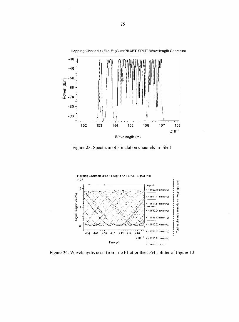
75
Hopping Channels (File F1)SpecPlt AFT SPLIT Wavelength Spectrum
i—|—i—i—i i—|—T-T—i—i |—i—i i i |—i—i i i | i i i i |~i r~~i i |
152 153 154 155 156 157 158
X1()8
Wavelength (m)
Figure 23: Spectrum of simulation channels in File I
Hopping Channels (File F1)SigPlt AFT SPLIT Signal Plot
xicr6
2 -
5> 1 -
$ 0 -
s,._' " y'^/V x-
; X '' • '
• .
\ \/ \ y \ \\\ X. '\ / \^ \
1 i ; j i ! !
Legend:
X - 1529.75 nm (x+y)
X = 1531.31 nm (x+y)
X = 1534.64 nm (x+y)
X = 1535.04 nm (x+y)
X = 1535.63 nm (x+y)
X= 1536.22 nm (x+y)
404 406 408 410 412 414 416 1 153b B1 nm (x+y)
x10'11 x = 1536.81 nm (x+y)
Time (s) ~ ~~
Figure 24: Wavelengths used from file F1 after the 1:64 splitter of Figure 13
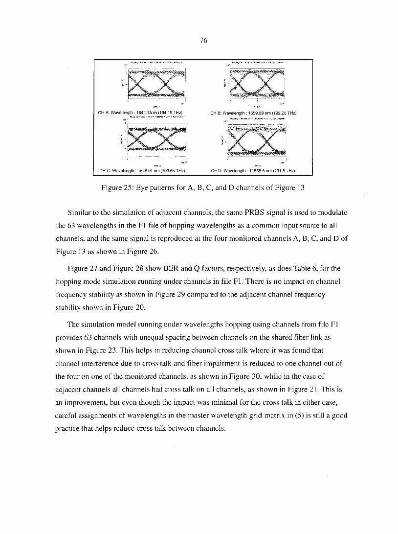
76
CH A: Wavelength : 1544.13nm (194.15 THz) CH B: Wavelength : 1559.39 nm (192.25 THz)
CH C: Wavelength : 1548.91 nm (193.55 THz) CH D: Wavelength : 11565.5 nm (191.5 THz)
Figure 25: Eye patterns for A, B, C, and D channels of Figure 13
Similar to the simulation of adjacent channels, the same PRBS signal is used to modulate
the 63 wavelengths in the F1 file of hopping wavelengths as a common input source to all
channels, and the same signal is reproduced at the four monitored channels A, B, C, and D of
Figure 13 as shown in Figure 26.
Figure 27 and Figure 28 show BER and Q factors, respectively, as does Table 6, for the
hopping mode simulation running under channels in file Fl. There is no impact on channel
frequency stability as shown in Figure 29 compared to the adjacent channel frequency
stability shown in Figure 20.
The simulation model running under wavelengths hopping using channels from file Fl
provides 63 channels with unequal spacing between channels on the shared fiber link as
shown in Figure 23. This helps in reducing channel cross talk where it was found that
channel interference due to cross talk and fiber impairment is reduced to one channel out of
the four on one of the monitored channels, as shown in Figure 30, while in the case of
adjacent channels all channels had cross talk on all channels, as shown in Figure 21. This is
an improvement, but even though the impact was minimal for the cross talk in either case,
careful assignments of wavelengths in the master wavelength grid matrix in (5) is still a good
practice that helps reduce cross talk between channels.
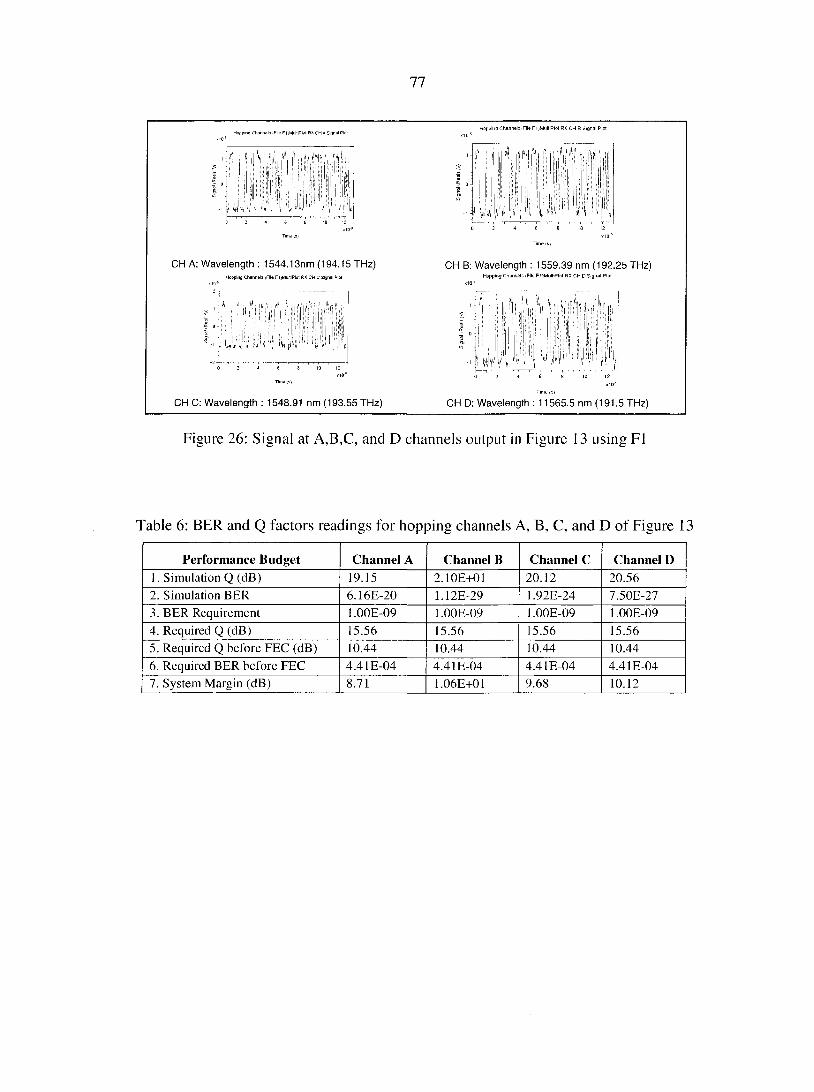
77
/ i , ( A
•i-j dv\A
CH A: Wavelength : 1544.13nm (194.15 THz) Hopping Channels -File F1;MultlPlot RX CH C Signal Plol
W'
CH C: Wavelength : 1548.91 nm (193.55 THz)
CH B: Wavelength : 1559.39 nm (192.25 THz) Hopping Channels (File FbMultiPlot RX CH D Signal Plol
1 °
, 4 , 1 , 4 !i il
I,À :«',T
CH D: Wavelength : 11565.5 nm (191.5 THz)
Figure 26: Signal at A,B,C, and D channels output in Figure 13 using Fl
Table 6: BER and Q factors readings for hopping channels A, B, C, and D of Figure 13
Performance Budget Channel A Channel B Channel C Channel D 1. Simulation Q (dB) 19.15 2.10E+01 20.12 20.56 2. Simulation BER 6.16E-20 1.12E-29 1.92E-24 7.50E-27
3. BER Requirement 1.00E-09 1.00E-09 1.00E-09 1.00E-09
4. Required Q (dB) 15.56 15.56 15.56 15.56
5. Required Q before FEC (dB) 10.44 10.44 10.44 10.44
6. Required BER before FEC 4.41E-04 4.41E-04 4.41E-04 4.41E-04
7. System Margin (dB) 8.71 1.06E+01 9.68 10.12
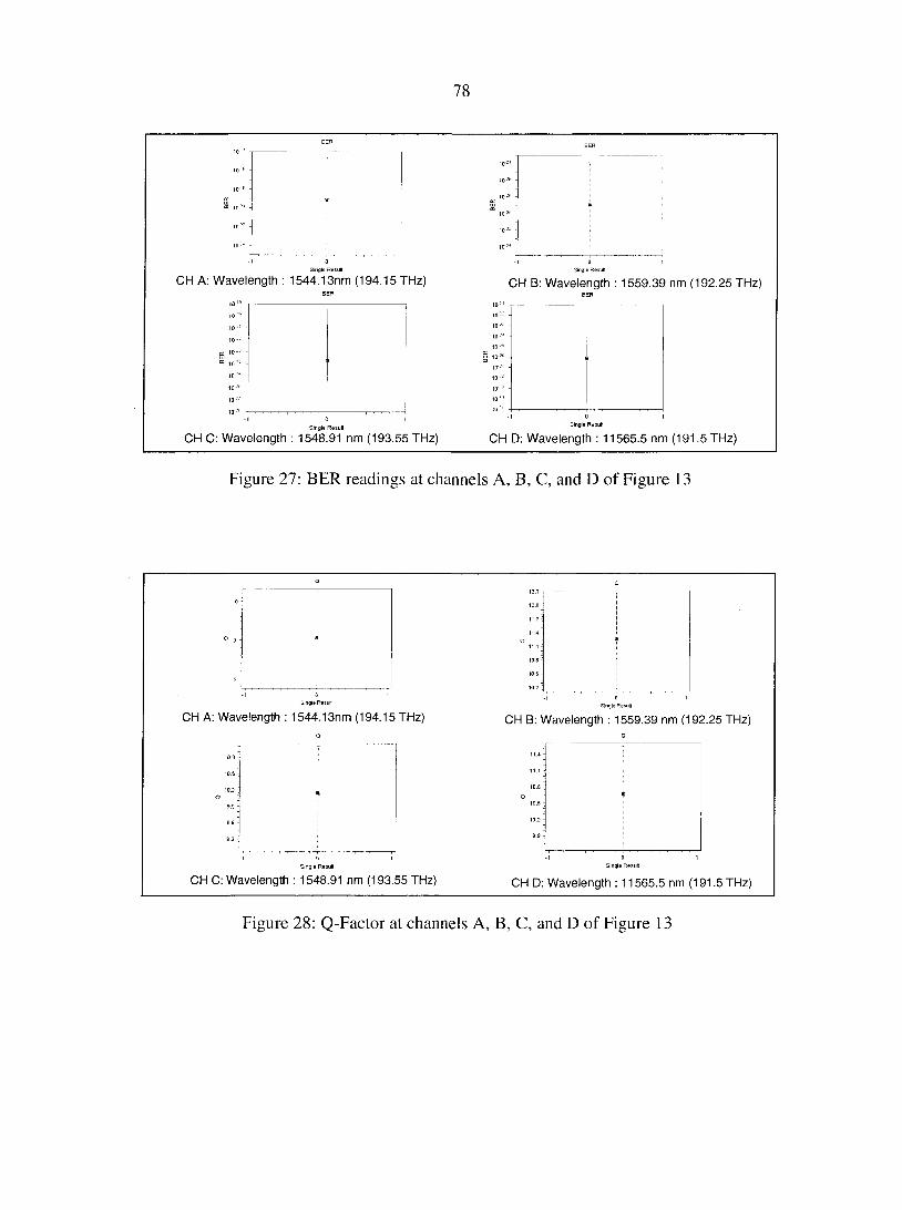
78
CH A: Wavelength : 1544.13nm (194.15 THz) Single Result
CH B: Wavelength : 1559.39 nm (192.25 THz)
Single Result
CH C: Wavelength : 1548.91 nm (193.55 THz) Single Result
CH D: Wavelength : 11565.5 nm (191.5 THz)
Figure 27: BER readings at channels A, B, C, and D of Figure 13
Single Result
CH A: Wavelength : 1544.13nm (194.15 THz) Single Result
CH B: Wavelength : 1559.39 nm (192.25 THz)
H
CH C: Wavelength : 1548.91 nm (193.55 THz) CH D: Wavelength : 11565.5 nm (191.5 THz)
Figure 28: Q-Factor at channels A, B, C, and D of Figure 13
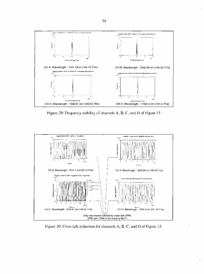
79
i r ..i.
CH B Basetiand Signal Spectrum
Baseband Fiequency iH2) Baseband Frequency IHZJ
CH A: Wavelength : 1544.13nm (194.15 THz)
Hopping Channels (File F1)MulliPlol RX CH C Baseband Signal Spectrum
CH B: Wavelength : 1559.39 nm (192.25 THz)
Happing Channels (File F l iMuHiPlcl RX. CHD Baseband Signal Speclium
Baseband Frequency (Hz)
CH C: Wavelength : 1548.91 nm (193.55 THz) Baseband Frequency (Hz>
CH D: Wavelength : 11565.5 nm (191.5 THz)
Figure 29: Frequency stability of channels A, B, C, and D of Figure 13
Hopping Channels iFlleFliSigPll RX CH A Signal Plot Hopping Channels (File F1)SlgPBRXCH B Signal Plot
CH A: Wavelength : 1544.1 nm(194.15 THz)
Hopping Channels iFile FhSigPIt RX CH C Signal Plot
; [ | |
J-CH C: Wavelength : 1548.91 nm (193.55 THz)
CH B: Wavelength : 1559.39 nm (192.25 THz)
Hopping Channels (File FltSigPli RX CH 0 Signal Plot
CH D: Wavelength : 1595.5 nm (191.50 THz)
Only one channel affected by cross talk (XPM, SPM, and FWM) in the hopping file F1
Figure 30: Cross talk reduction for channels A, B, C, and D of Figure 13
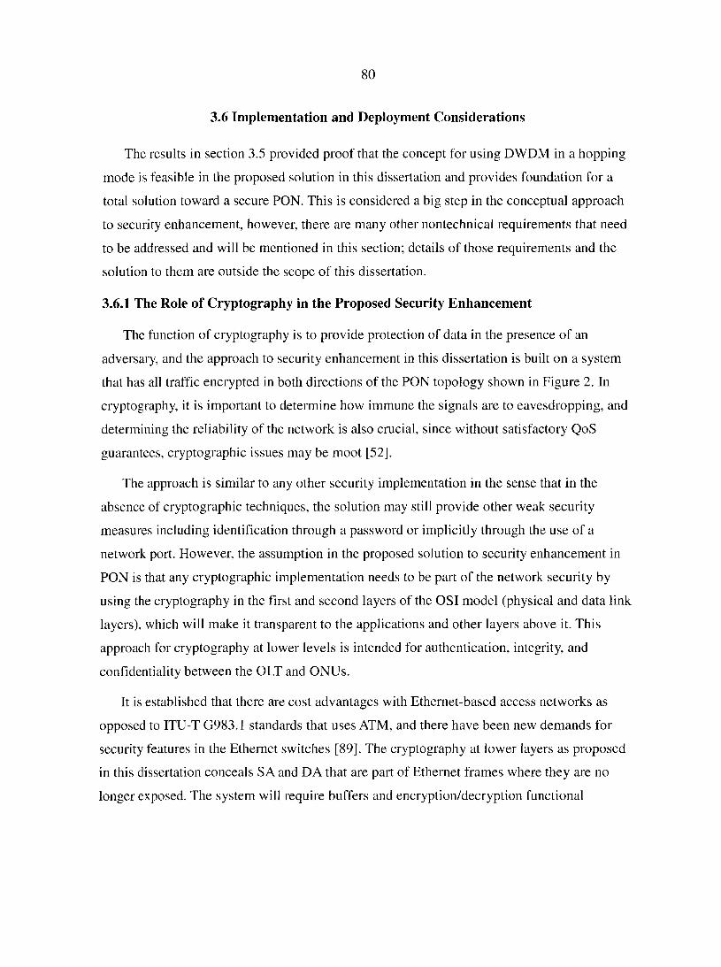
80
3.6 Implementation and Deployment Considerations
The results in section 3.5 provided proof that the concept for using DWDM in a hopping
mode is feasible in the proposed solution in this dissertation and provides foundation for a
total solution toward a secure PON. This is considered a big step in the conceptual approach
to security enhancement, however, there are many other nontechnical requirements that need
to be addressed and will be mentioned in this section; details of those requirements and the
solution to them are outside the scope of this dissertation.
3.6.1 The Role of Cryptography in the Proposed Security Enhancement
The function of cryptography is to provide protection of data in the presence of an
adversary, and the approach to security enhancement in this dissertation is built on a system
that has all traffic encrypted in both directions of the PON topology shown in Figure 2. In
cryptography, it is important to determine how immune the signals are to eavesdropping, and
determining the reliability of the network is also crucial, since without satisfactory QoS
guarantees, cryptographic issues may be moot [52].
The approach is similar to any other security implementation in the sense that in the
absence of cryptographic techniques, the solution may still provide other weak security
measures including identification through a password or implicitly through the use of a
network port. However, the assumption in the proposed solution to security enhancement in
PON is that any cryptographic implementation needs to be part of the network security by
using the cryptography in the first and second layers of the OSI model (physical and data link
layers), which will make it transparent to the applications and other layers above it. This
approach for cryptography at lower levels is intended for authentication, integrity, and
confidentiality between the OLT and ONUs.
It is established that there are cost advantages with Ethernet-based access networks as
opposed to ITU-T G983.1 standards that uses ATM, and there have been new demands for
security features in the Ethernet switches [89]. The cryptography at lower layers as proposed
in this dissertation conceals SA and DA that are part of Ethernet frames where they are no
longer exposed. The system will require buffers and encryption/decryption functional
81
modules before OLT and after each ONU, and the keys for each ONU will be different from
the keys for others.
For a user's application program, applications security can be used as additional security
mechanisms that may be deployed at higher layers of the OSI reference model.
The encryption of the upstream transmission prevents interception of the upstream traffic
when a tap is added at the PON splitter and minimizes the problems that are currently
considered as security vulnerabilities as discussed in section 2.1. For example, it is possible
to encrypt upstream traffic since the wavelength sequences provided by (3) is considered as a
signature and shared secret between the OLT and ONU, and this signature provides
protection against ONU impersonation discussed in section 2.1.2 where protected registration
data arrives from ONUs.
The type of encryption is left to specific implementations and is to be decided in the
design details depending on the type of PON, whether it is used by a service provider and
residential users, or the PON belongs to a financial, government, or any other form of
institution. In some cases, OLT may need to accommodate different types of encryption types
in order to support different granularity of encryptions of specific ONUs, which adds cost to
the PON infrastructure.
Some of the encryption standards that can be used include AES, which provides an
encryption standard used to protect confidential information like financial data for
government and commercial use. An alternative is the data encryption standard (DES) and
triple DES encryption algorithm. DES is arguably the most important and widely used
cryptographic algorithm. However, even though it has been reported in numerous literature
that usefulness of DES is now quite limited because of the fact that the DES key can now be
easily cracked after several hours of number crunching, the approach in this dissertation is
intended to make it difficult for an eavesdropper to capture a good sample of the traffic that
can be used to crack the key of the cryptographic system.
With slow wavelength hopping and the size of transmission being Ethernet frames or
complete packets, keys of any cryptographic standard are not impacted since various keys to
support block sizes of 128-bit and key sizes of 128-bit, 192-bit, 256-bit, or even the future
key sizes as large as 1,024 bits can be easily accommodated. The length of keys affects the

82
processing power of the end machines, and encrypted material in PON is simply treated as
data being transmitted.
3.6.1.1 Combining Wavelength Hopping with Bloc A' Cipher Encryption
A block cipher encryption technique, such as AES discussed in [69], encrypts a block of
data using a secret, symmetric key. For an attacker to start cryptanalysis of an encrypted
block to try to discover the key, the attacker must have the entire encrypted block. Using our
wavelength hopping system, an attacker can be listening on one or more wavelength
channels, eavesdropping on transmissions. If a block encryption algorithm is used with a
block consisting of M slots, then cryptanalysis will be unsuccessful unless the attacker
successfully acquires M consecutive slots, which are encrypted as a block. Therefore, using
wavelength hopping together with block cipher encryption presents the attacker with the
following obstacles that have to be overcome, which makes it harder for the attacker to
launch a potentially successful attack:
• The attacker must listen to M successive transmissions on M channels (wavelengths),
which are chosen according to equation (3).
• The attacker must determine the beginning of the block, which can be any wavelength
in As expressed in (3) as the beginning of the block.
• The attacker must launch cryptanalysis on the acquired block.
Therefore, the difficulty of a cryptanalysis attack is increased by including the first two
factors above, and the probability of a successful cryptanalysis is now reduced significantly
3.6.2 Keys Distribution
Traditional cryptosystems are based on the secret key or symmetric model, and they have
been the focus in the world of cryptography where keys are generated by a mathematical
algorithm that generally involves very large prime numbers. With a public key system,
information encrypted with a particular public key can be decrypted only by using the
corresponding private key. Cryptography where implementation takes place in the higher
layers of OSI models is not impacted in the proposed approach for security enhancement in
this dissertation.
83
However, new keys are added as part of the proposed approach for the security
enhancement as discussed in section 2.5, namely, the wavelength grid matrix selected for
operation ( Wfn ), the wavelength sequences assigned to each ONU (Xs), and the order of
sequencing the wavelength sequences assigned to a single ONU. Those are small files and
can be made transparent to the application layers since they affect interfaces at both ends of
PON, namely the OLT and ONUs. There are many ways to distribute the keys, and the
distribution mechanism can be left to design and implementation, which is not the focus of
this dissertation.
3.6.3 ONUs Authentication
Cryptographic techniques to identify the source of data and to protect data from
unauthorized modification have been used as a mechanism of authentication. Already the
IEEE 802. IX specification offers an effective framework for authentication and controlling
user traffic to a protected network[89]. A security model and security protocol to support
authentication in an IEEE 802.3ah (EPON) based network proposed in [59], is based on
encryption services in the lower layers using public key exchange and a key establishment
protocol with authentication of the ONU and user made separately. This is similar to the
approach in the proposed solution, where user identification is based on other means and
ONU authentication is based on the wavelength sequence assigned to the ONU.
IEEE 802.IX can be implemented as a user authentication mechanism in the proposed
approach to security enhancement in PON since it is involved mostly with the higher layers
of OSI models. Authenticity on the other hand can be also in the form of group authenticity
or source authenticity [53], which means that it is possible in the proposed solution to
identify a particular sender ONU based on the wavelength sequences assigned to the ONU
and be capable of synchronizing with the OLT based on the hopping pattern in the
wavelength sequence. This allows only authorized ONUs with the correct signature to be
able to follow reception or transmission to or from the OLT. This is considered as an OSI
lower layer authentication scheme between the OLT and ONUs, which is transparent to the
higher levels of the OSI mode.
84
The various granularities of security levels and authentication of ONUs dictates the
mechanisms to be deployed focused on having the OLT recognize the correct ONU with
proper authentication and source identification against an eavesdropper.
3.6.4 Timing and Synchronization
The current IEEE 802.ah standard for EPON in [13] includes multi-point control protocol
MPCP, which specifies P2MP communication between PON OLT and ONUs. MPCP is a
MAC layer protocol supported by bridging elements with functions that provide ONT/ONU
timing synchronization, implementation of auto discovery, and bandwidth/timeslot
assignments to ONUs, in addition to ranging22, which is required to be done frequently for
measurement of round trip time (RTT) to all ONUs.
The proposed solution in this dissertation handles data rates at 10 Gbps even though
previously the technical hurdle of achieving synchronization at speeds higher than 622 Mbit/s
(upstream) was quite high given the physical layer specification of BPON based on ITU-T
G983.1 standard [90]. Speeds of 1 Gbps is already the standard in the IEEE 802.3ah EPON
[13] and 2.4 Gbps in standards such as GPON ITU-T G.984.1.
The proposed security enhancement for PON in this dissertation requires that functions of
PMCP be modified to handle synchronization requirements, with imposing restrictions on the
size of frames/packet by making them all equal to a fixed length to guarantee orthogonal
operation between wavelength sequences without any overlapping. In addition, requirements
for synchronization include retaining the preceding and trailing of frames/packets by the IGP
shown in Figure 5.
It is absolutely required that all ONUs use a slave clock to the OLT master clock in order
to guarantee synchronization of wavelength hopping, and that master clock data be extracted
by ONUs similar to the current clock data recovery (CDR) used in the physical medium layer
in ITU-T G983.1 [12], or clock recovery unit (CRU) in IEEE 802.3ah [13]. The assumption
made in this dissertation is that solving the requirements for clock and synchronization are
part of the detailed system design and outside the scope of this dissertation.
22 Ranging is the process of finding the round trip time to each ONU where the lime is updated to maintain synchronization of PON operation.
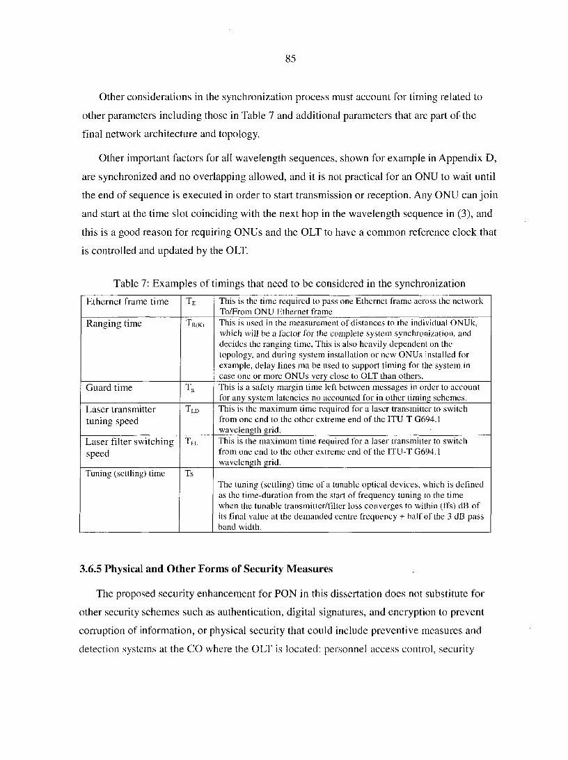
85
Other considerations in the synchronization process must account for timing related to
other parameters including those in Table 7 and additional parameters that are part of the
final network architecture and topology.
Other important factors for all wavelength sequences, shown for example in Appendix D,
are synchronized and no overlapping allowed, and it is not practical for an ONU to wait until
the end of sequence is executed in order to start transmission or reception. Any ONU can join
and start at the time slot coinciding with the next hop in the wavelength sequence in (3), and
this is a good reason for requiring ONUs and the OLT to have a common reference clock that
is controlled and updated by the OLT.
Table 7: Examples of timings that need to be considered in the synchronization
Ethernet frame time TE This is the time required to pass one Ethernet frame across the network To/From ONU Ethernet frame
Ranging time Tr(k) This is used in the measurement of distances to the individual ONUk, which will be a factor for the complete system synchronization, and decides the ranging time, This is also heavily dependent on the topology, and during system installation or new ONUs installed for example, delay lines ma be used to support timing for the system in case one or more ONUs very close to OLT than others.
Guard time TG This is a safety margin time left between messages in order to account for any system latencies no accounted for in other timing schemes.
Laser transmitter
tuning speed
Tld This is the maximum time required for a laser transmitter to switch from one end to the other extreme end of the ITU-T G694.1 wavelength grid.
Laser filter switching
speed
tFL This is the maximum time required l'or a laser transmitter to switch from one end to the other extreme end of the ITU-T G694.1 wavelength grid.
Tuning (settling) time Ts
The tuning (settling) time of a tunable optical devices, which is defined as the time-duration from the start of frequency tuning to the time when the tunable transmitter/filter loss converges to within (ffs) dB of its final value at the demanded centre frequency ± half of the 3 dB pass band width.
3.6.5 Physical and Other Forms of Security Measures
The proposed security enhancement for PON in this dissertation does not substitute for
other security schemes such as authentication, digital signatures, and encryption to prevent
corruption of information, or physical security that could include preventive measures and
detection systems at the CO where the OLT is located: personnel access control, security
86
guards, CCTV, alarm systems, etc. In most cases where the threat is generated from within
the organization, this is extremely costly in the case cryptography and provided keys, and it is
recommended that the keys are set and accessible by, for example, the service provider.
3.6.6 Assignments of Wavelength Sequences and Security Level
Depending on the access network and the type of service provided, assignment of
wavelength code matrices must follow the security levels as keys for secure operation. It can
be also advantageous for two or three ONUs to share some of the sequences that will provide
higher diffusion of data. However, centralized control and a proper algorithm will be
required.
3.6.7 Changing Network Wavelength Matrix
The wavelength grid matrix selected for the PON network is the starting point for
providing security, and frequent changes protect data against time. The most convenient
changes are carried over online and with synchronized clocks in all locations, so it is possible
to command all nodes when the change happens.
3.7 Chapter Summary
In this chapter, an approach to provide security enhancement in PON based on the
concept of data diffusion through wavelength hopping was presented. Figure 8 provided the
top level illustration of a conceptual system that was a process of mapping two matrices,
wavelength grid matrices and code matrices, where the outcome was wavelength sequences
that are orthogonal to each other in the case of time spreading and wavelength hopping based
on the same prime code (symmetric TS/WH) and have excellent correlation properties. In
addition, the wavelength sequences increased for the case of pseudo orthogonal where
TS/WH uses a different basis for prime numbers and for other coding schemes. Wavelength
sequences provide a good source for secure wavelength hopping when assigned to ONUs
based on their security levels.
The details of the approach started by establishing an industry standard ITU-T G694.1
wavelength grid as the source for selecting wavelength, followed by formulation of sub grid
wavelength matrices. Different coding schemes along with the construction basis TS/WH
87
based on symmetric (Prime/Prime) and asymmetric (EQC/Prime) was presented, in addition
to a review of other coding schemes for MW-OOC. It was found that the best code matrices
that provide good correlation properties with autocorrelation of 0 and cross correlation of 1
as the desirable properties are those based on TS/WH and symmetric prime numbers
(Prime/Prime) where actual wavelengths sequences generated are proved to be orthogonal.
Even though wavelength sequences are generated mathematically, an important part in
the proposed security enhancement is to provide proof that the approach is feasible and
achievable. A simulation model for a PON was established and DWDM was used with
simultaneous transmission of 64 wavelengths in 25 km shared fiber links. Four channels were
set up for monitoring purposes in the simulation model with encouraging results about the
feasibility obtained using performance metrics such as the BER, which exceeded the
minimum requirements for BER of 10"9. All channels showed good quality of signals and .
BER better than 10~20, and the eye pattern showed a wide opening providing confirmation of
good signal characteristics.
Additional brief discussions about implementation and deployment topics were provided
that included, for example, the role of cryptography, keys distribution, and timing
considerations, however, the details of those topics are outside the scope of this dissertation
since they are specific to the implementation and detailed design of projects' unique
requirements.
The results of wavelength sequences generation and results of simulations provided
foundations to move to the next chapter, which discusses performance evaluation of the
proposed approach to PON security enhancement.

88
CHAPTER 4: SECURITY PERFORMANCE EVALUATION
4.1 Background and Motivation
As mentioned in section 2.4, high bandwidth offered by fiber cables is seen as the media
of choice to meet demand for bandwidth where optical network designers are not concerned
about electromagnetic emissions, for example. However, demand for high bit-rate in fiber
cables is driving WDM technology toward DWDM where multiplexing capacity increases
and careful design calls for avoidance of inter channel interference within the optical network
itself, as well as tapping and eavesdropping by outsiders.
The importance of PON as low cost and capable of meeting high bandwidth at the Giga
bits rates makes them the choice for applications in many areas such as storage area network
(SAN) and network area storage (NAS). Both SAN and NAS are beginning to converge as
NAS file managers become more specialized and use managed SANs for back-end storage. A
NAS head with a SAN back end is functionally identical to a SAN using a metadata
controller to provide file-based access [99], and PON provide the high bandwidth required
for such storage networks.
In the multimedia services, using B&S features PON as a massive distribution tool by
service providers that can potentially replace coaxial cable in the future. Current practices
using encryption techniques, applied to IP over LAN include video-digital encoding
techniques such as motion picture expertise group (MPEG2), which is a family of standards
used for coding audio-visual information (e.g., movies, video, and music). MPEG is a digital
compressed format used to provide reductions in bandwidth, which was not intended for
security of transmission in the first place [100]. The use of wavelength hopping as a way to
provide protection for downstream traffic in PON provides an approach for protection against
theft of service. One application can be, for example, providing protection to digital video
broadcast (DVB) standard based systems that have an enhanced transport stream structure
defined in MPEG which provides a very robust transmission system that is capable of
supporting broadband constant bit-rate traffic such as high quality video in the same carrier
or multiplex that carries computer data.
89
The low cost of passive devices and reliability of fiber connectivity compels many
services to merge into one connectivity such as TPS (audio, video, data) in addition to mass
storage networks, etc., where security concerns become of paramount importance due to
dependency for multiple services in one connection.
4.2 Assumptions about Attackers
The objectives of attackers/eavesdropper were discussed in section 2.1, and in this
dissertation, it is assumed that an attacker is monitoring the shared fiber link as shown in
Figure 6 with the major objective of deducing the order of specific ONUs' wavelength
sequences generated by (3) (similar to deducing the key in cryptography). Learning the
contents of messages intercepted from eavesdropping on the shared fiber link of Figure 6
requires additional cryptanalysis that is outside the scope of this dissertation, but the
proposed solution provides difficulty in collecting that sample. The strength of the proposed
security enhancement in PON resides entirely in the difficulty in determining the sequence
specific to an ONU and not in the algorithm used to generate the wavelength sequence in (3).
Assumptions are made that no collaborations between nodes exist since the nature of data
transmitted could be "personal" or sensitive to the organization in some cases. In addition,
assumptions are made that attackers are technologically sophisticated and know a great deal
about signals being transmitted in PON, and in particular, know what types of signals are
being exchanged between an OLT and ONUs. The knowledge about the signal includes
technical information such as data rates, type of encoding, structure of codes,
synchronization, beginning and ending of the bits/messages, and basically the basis of the
operation of the secure system being attacked, but do not have the particular codes being
used by the OLT and ONUs. The assumptions are based on the well-known Kerckhoffs'
principle in cryptography [69], which essentially states that one should assume that the
eavesdropper knows everything about the cryptographic algorithm except for the key that
each user employs.
90
4.3 Performance Evaluation for the Proposed Security Enhancement
Simulation of DWDM with 25 GHz channel spacing in a shared fiber link was provided
in section 3.5 with results in Figures 14 and 15 for 64 adjacent channels, in addition to results
in Figures 23 and 24 for wavelength hopping mode that showed equal power level across all
channels. Simulation accounted for impairment factors such as time jitter, fiber non
linearities, cross channel interferences, dispersion, noise, etc., which are factors in the power
level and signal quality degradation, and the result of simulation provided required proof of
the concept that the PON supports DWDM. However, this dissertation discusses the security
approach for PON where performance analysis is still required to provide proof about the
protection level provided against brute force attack type external to PON.
In order to evaluate the strength of the security enhancement against malicious attacks on
PON such as eavesdropping, an analysis considers the situation where an attacker managed
to get some wavelength sequences recorded online from the B&S traffic. The job of the
attacker is to run an analysis on the collected sample in order to deduce wavelength
sequences or the three new keys introduced in the proposed approach for security
enhancement that include: the wavelength grid matrix W^n selected for PON operation, code
matrices, Cyml, and the order of implementing the wavelength sequences As introduced in the
contribution section 2.5. The three keys are required to deduce the wavelength sequence, and
full independency exists between the selection of any key from each other, which means that
there are no restrictions of assignment of certain wavelength sequences to certain ONUs and
no restrictions on combining certain wavelength matrices with certain code matrices.
Start with the selected wavelength grid matrix W° in (5) for PON operation, which is
one of many available formats expressed in (6) as Gmax= (nl)"'. However, n out of Gmax from
selected W°n will be subjected to columns cycling to produce a total of n sub grid matrices
Wnx^' as shown in Figure 10. This means that the probability of guessing the correct grid
matrix W°n can be expressed as Pc(W) as shown in (17).
< i 7 )
91
The probability of finding the second key, which is the correct wavelength sequence
assigned to a single ONUk (A* ) generated by equation (3) requires the knowledge of two
components, namely, the wavelength sub grid matrices Wjf and code matrix C-'nl used from
those available by the specific coding scheme, which can be symmetric or asymmetric
TSAVH, MW-OOC, etc. Each coding scheme provides its own maximum available code
matrices designated as Ymax. For example, the maximum codes provided by the prime
placement operator with prime number P as shown in (9) is (P - 1 ), which represents the
lowest code set among other coding schemes as compared to asymmetric TS/WH
(EQC/Prime) in (12), which provides Ymm = Ps (2PS -1), or the different MW-OOC used,
which provide various degrees of cardinality as expressed in (15), which depends on m, n and
weight w and allows cross correlations. It is important to note that because of the correlation
control in (15), this implies that there is exclusivity in the selection of codes, and accordingly,
there is no independence in MW-OOC codes selection for simultaneous operation as
compared to TS/WH codes.
The maximum number of set sub grid matrices ( W*° ) is equivalent to the number of
columns (n) as shown in Figure 10. Taking the two components of the second key, this
implies that the single probability of finding the correct wavelength sequence is expressed as
Pc( As ) as shown in (18).
^ (A, ) = (-!-)(-) (18) Ymn n
The probability of finding the third key, which is the sequencing order of wavelength
sequences assigned to a single ONU out of the maximum available sequences generated by
(3) starts with the expression for maximum wavelength sequences provided by (3) expressed
as S max similar to those shown in Appendix D, with a total of 192 generated by (3) for the
TS/WH (Prime/Prime) case. Out of Smax, the number of sequences assigned to a single ONU
is expressed as Sa, where the number of assigned Sa < Smax and is based on the security levels
of the ONUs.
The number of combinations of Sa that can be selected from Smax can be expressed as a
combination set (CSs) of sequences shown in (19).
92
(19)
The single probability of capturing a single wavelength sequence is Pc(ks), which is the
probability of breaking the hopping pattern with correct wavelengths in the sequence out of
the combination set in (19) for a single ONU as expressed as in (20).
However, a single ONU can have a set of sequences Sa where they can be cycled in a
different order, which is the third shared secret key between the OLT and the specific ONU.
The order of cycling (executing) assigned wavelength sequences (Sa) can be one of Sa\. The
probability in (20) is supplemented with an additional factor (1/5,,!) to show the impact of the
third secret key and is expressed in (21 ).
The effect of cycling order for assigned wavelength sequences when added in (20) is
dependent on the number of assigned wavelength sequences (Sa) per ONU, and this is
illustrated in Figure 31, which shows the logarithmic relation in (21) for the case of code
matrix and wavelength grid matrices used to generate wavelength sequences in Appendix D
(m = / = 12, n = 16).
The contribution of single probabilities expressed (17), (18), and (21), along with the
number of users on line ((/), can be used to find the overall probability of capturing the
correct wavelength sequence Pc( A* ) for a single ONUk as expressed in (22).
Sma ! (20)
(21)
- (—)(-) ((»!)'"-») c V (22)
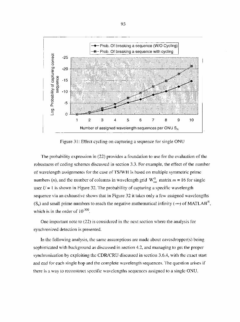
93
-•—Prob. Of breaking a sequence (W/O Cycling)
•—Prob. Of breaking a sequence with cycling
-25
-20
_Q
0
1 6 9 10 2 3 4 5 7 8
Number of assigned wavelength sequences per ONU SA
Figure 31: Effect cycling on capturing a sequence for single ONU
The probability expression in (22) provides a foundation to use for the evaluation of the
robustness of coding schemes discussed in section 3.3. For example, the effect of the number
of wavelength assignments for the case of TS/WH is based on multiple symmetric prime
numbers (n), and the number of columns in wavelength grid W^ matrix m = 16 for single
user U = 1 is shown in Figure 32. The probability of capturing a specific wavelength
sequence via an exhaustive shows that in Figure 32 it takes only a few assigned wavelengths
(Sg) and small prime numbers to reach the negative mathematical infinity (-°°) of MATLAB®,
which is in the order of 10 30°.
One important note to (22) is considered in the next section where the analysis for
synchronized detection is presented.
In the following analysis, the same assumptions are made about eavesdropper(s) being
sophisticated with background as discussed in section 4.2, and managing to get the proper
synchronization by exploiting the CDR/CRU discussed in section 3.6.4, with the exact start
and end for each single hop and the complete wavelength sequences. The question arises if
there is a way to reconstruct specific wavelengths sequences assigned to a single ONU.
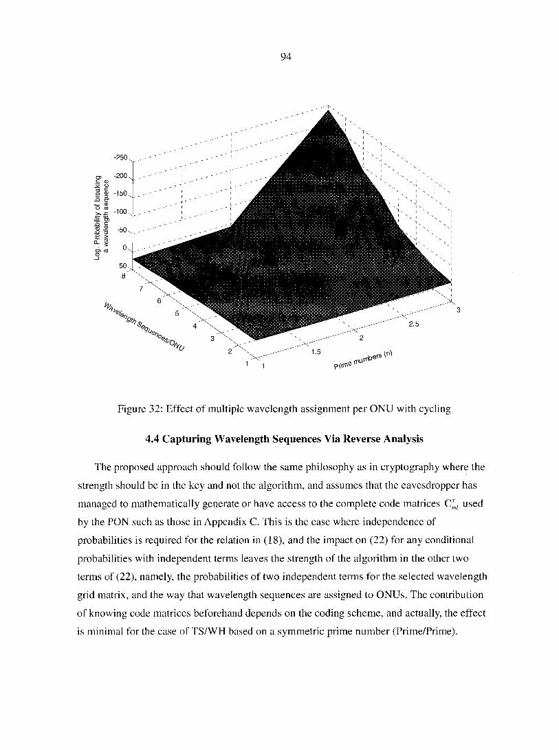
94
ptWe 1
Figure 32: Effect of multiple wavelength assignment per ONU with cycling
4.4 Capturing Wavelength Sequences Via Reverse Analysis
The proposed approach should follow the same philosophy as in cryptography where the
strength should be in the key and not the algorithm, and assumes that the eavesdropper has
managed to mathematically generate or have access to the complete code matrices C-ml used
by the PON such as those in Appendix C. This is the case where independence of
probabilities is required for the relation in (18), and the impact on (22) for any conditional
probabilities with independent terms leaves the strength of the algorithm in the other two
terms of (22), namely, the probabilities of two independent terms for the selected wavelength
grid matrix, and the way that wavelength sequences are assigned to ONUs. The contribution
of knowing code matrices beforehand depends on the coding scheme, and actually, the effect
is minimal for the case of TS/WH based on a symmetric prime number (Prime/Prime).
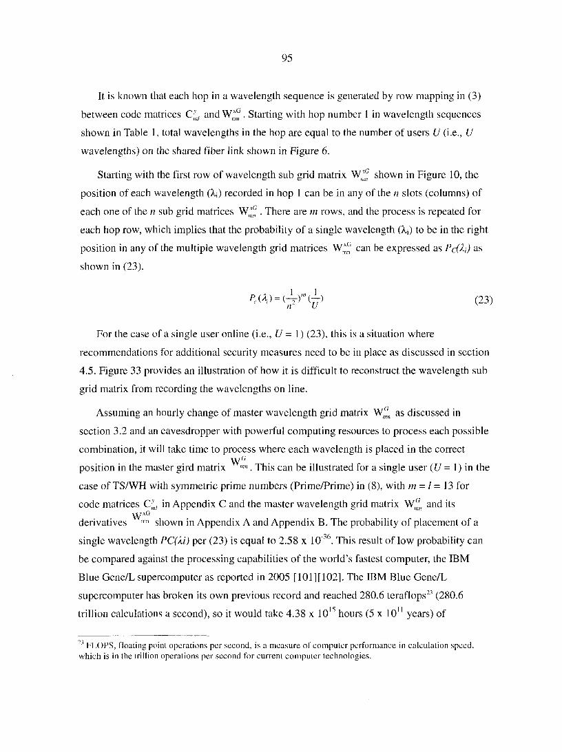
95
It is known that each hop in a wavelength sequence is generated by row mapping in (3)
between code matrices C-'nl and W*° . Starting with hop number 1 in wavelength sequences
shown in Table 1, total wavelengths in the hop are equal to the number of users U (i.e., U
wavelengths) on the shared fiber link shown in Figure 6.
Starting with the first row of wavelength sub grid matrix W,^ shown in Figure 10, the
position of each wavelength (X;) recorded in hop 1 can be in any of the n slots (columns) of
each one of the n sub grid matrices . There are m rows, and the process is repeated for
each hop row, which implies that the probability of a single wavelength (Xj) to be in the right
position in any of the multiple wavelength grid matrices can be expressed as Pc(k) as
shown in (23).
i M > = < 4 n ^ ) < 2 3 )
For the case of a single user online (i.e., U = 1) (23), this is a situation where
recommendations for additional security measures need to be in place as discussed in section
4.5. Figure 33 provides an illustration of how it is difficult to reconstruct the wavelength sub
grid matrix from recording the wavelengths on line.
Assuming an hourly change of master wavelength grid matrix Wfn as discussed in
section 3.2 and an eavesdropper with powerful computing resources to process each possible
combination, it will take time to process where each wavelength is placed in the correct W G
position in the master gird matrix . This can be illustrated for a single user (U = 1) in the
case of TS/WH with symmetric prime numbers (Prime/Prime) in (8), with m = I = 13 for
code matrices CJnl in Appendix C and the master wavelength grid matrix Wfn and its xCi
derivatives ,nn shown in Appendix A and Appendix B. The probability of placement of a
single wavelength PC(Xi) per (23) is equal to 2.58 x 10"36. This result of low probability can
be compared against the processing capabilities of the world's fastest computer, the IBM
Blue Gene/L supercomputer as reported in 2005 [101][102], The IBM Blue Gene/L
supercomputer has broken its own previous record and reached 280.6 teraflops23 (280.6
trillion calculations a second), so it would take 4.38 x 10¹⁵ hours (5 x 10¹¹ years) of
23 FLOPS, floating point operations per second, is a measure of computer performance in calculation speed, which is in the trillion operations per second for current computer technologies.

96
processing to find the correct wavelength sub grid matrix . This is a long time,
especially when considering the master wavelength grid matrix W,^ is changed on an hourly
basis.
The relation in (23) did not use the code matrices and assumed that the right code matrix
C]nl will be found when the wavelengths in the hop and the mapping in (3) agree; the code
matrix will be used for confirmation purpose.
IJ= Number of Users online -40.00
-35.00
-30.00
-25.00
-20.00
-15.00
-10.00
U=2 -5.00 -
0.00
23
Prime number (n): Number of columns in code matrix
Log. Probability of positioning correct wavelength in rows
Figure 33: Probability of placing the correct wavelength in master grid matrix
The basic relation derived in (22) is very dependent on the coding scheme used, and the
following sections provide some comments about how robust the probability is when (22) is
applied to different coding schemes.
4.5 Additional Security Practices for a Single Online User
It is noticed that in (22) the number of online users at any instant (U) is part of the
security measures that can be implemented. It is good practice to maintain the shared fiber
link in PON busy to certain levels of online users. The number of users as shown in (23) does
97
not provide great help to support probability figures as shown in Figure 34 for different users'
levels. However, the number of users required to avoid the case of a single online user where
the hopping pattern of a single sequence can be exploited, and in such case, the difficulty of
identifying the specific ONU lies in the power of the cryptography used to encrypt the data.
It is recommended that the network load be monitored by the OLT and information updated
to each ONU. In a situation where the load dropping below a certain level is determined by
the security policy of the organization, the available resources at the OLT and ONUs start to
transmit dummy traffic that can be identified as normal traffic, which means that the dummy
traffic requires encryption without necessarily carrying any destination information. For
example, the ONUs can have a minimum of three laser transmitters where, when those are
not used, it will be commanded by OLT to transmit dummy traffic in order to avoid
exploiting a single online user.
Prime numers (n)
-40.00
-35.00
-30.00
-25.00
-20.00
-15.00
-10.00
5 23 19 13 11 7 3 17
— U = 1 5 u s e r s o n l i n e U = 4 5 U s e r s o n l i n e — U = 3 0 U s e r s o n l i n e
Figure 34 Log. prob. of breaking a sequence for symmetric TS/WH (Prime/Prime)
4.5.1 Attacks on TS/WH Scheme Using Symmetric Prime Numbers (Prime/Prime)
The TS/WH based on a symmetric prime number and related wavelength sequences
generated in Appendix D illustrates that this coding scheme is excellent in terms of meeting
ideal correlation properties. The limitation on available wavelengths based on 25 GHz
limited the generation to only 192 wavelength sequences as shown in Appendix D, and those
98
are more than enough when considering that the number of ONUs in PON can reach 64 and,
with growth, 128 ONUs. Previous computations showed, for example, that it takes 5 x 10¹¹
years to reconstruct a master wavelength grid matrix.
The major disadvantage of wavelength sequences generated by TS/WH based on single
symmetric prime number is its simple arrangement and symmetry of matrices, which
provides fixed and relatively simple relations between code sequences, which could greatly
facilitate the process of breaking the system. However, even though the computation is still
hard to achieve, once a certain sequence in a symmetric system is deciphered, all the
sequences can be deduced by simply applying the prime algorithm to that sequence (set of
wavelengths).
4.5.2 Attacks on Asymmetric TS/WH Scheme (EQC/Prime)
In the case of TS/WH using two different asymmetric prime numbers such as Ps for
spreading and Ph for hopping, greater security is provided via the random relations between
code sequences. Asymmetric systems offer additional protection in this sense since in order
to deduce the relation between sequences in the system, the column selection function should
be known[88]. Considering an overcolored system (Ph> s), the difference between the
prime numbers provides additional security against an attack on a TS/WH asymmetric
scheme.
Considering the probability for capturing the correct wavelength sequence in (22), the
code matrices have different dimensions (asymmetric), and the number of columns I in Cyml is
less than number of columns n in the wavelength grid matrix W^ (l<n). The placement
operator for EQC was discussed in section 3.3.1.2 with a restriction on the dimensions on the
matrices, and the relation of the asymmetric prime numbers Pu and Ps is expressed in (12),
(13), and (14).
The total wavelengths available for hopping are those in the master grid matrix Wfn, or
simply ran. In the hopping mode, every time the number of wavelengths used from total
available wavelength equal to Ph, which had minimum value restriction placed at m per the
relation in (14). In addition, the number of columns in the code matrix C;n/ is expressed, as
shown in (14), to be I = 2PS - 1. The possible selections of combination sets (CSa) in the
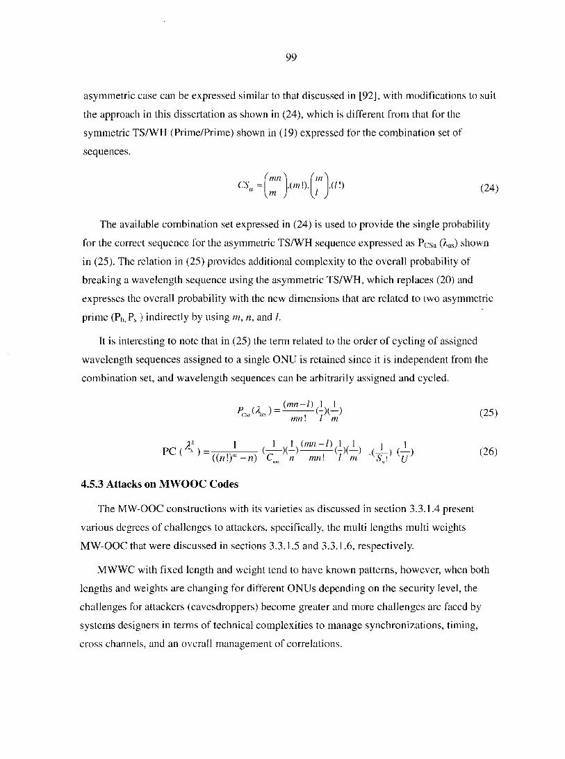
99
asymmetric case can be expressed similar to that discussed in [92], with modifications to suit
the approach in this dissertation as shown in (24), which is different from that for the
symmetric TS/WH (Prime/Prime) shown in (19) expressed for the combination set of
sequences.
= ' mnN ' m N
.(in !). J ,
• ( I D ym y J ,
(24)
The available combination set expressed in (24) is used to provide the single probability
for the correct sequence for the asymmetric TS/WH sequence expressed as PCsa (Xas) shown
in (25). The relation in (25) provides additional complexity to the overall probability of
breaking a wavelength sequence using the asymmetric TS/WH, which replaces (20) and
expresses the overall probability with the new dimensions that are related to two asymmetric
prime (Ph, Ps ) indirectly by using m, n, and /.
It is interesting to note that in (25) the term related to the order of cycling of assigned
wavelength sequences assigned to a single ONU is retained since it is independent from the
combination set, and wavelength sequences can be arbitrarily assigned and cycled.
<25>
P C ( A ' ) = m h n ) <26)
4.5.3 Attacks on MWOOC Codes
The MW-OOC constructions with its varieties as discussed in section 3.3.1.4 present
various degrees of challenges to attackers, specifically, the multi lengths multi weights
MW-OOC that were discussed in sections 3.3.1.5 and 3.3.1.6, respectively.
MWWC with fixed length and weight tend to have known patterns, however, when both
lengths and weights are changing for different ONUs depending on the security level, the
challenges for attackers (eavesdroppers) become greater and more challenges are faced by
systems designers in terms of technical complexities to manage synchronizations, timing,
cross channels, and an overall management of correlations.

100
Part of the discussion in the motivation section 2.4.2 for cost vs. value of security
included the recommendation that there must be a balance between security, cost, and
usability. Though security must be a prime design consideration, it is not necessarily the
overriding one, and benefits must be weighed against costs to achieve a balanced, cost-
effective system [70]. Accordingly, implementation of MW-OOC with its various schemes
poses technical complexities and justification of cost is a big item for consideration.
The discussion in section 3.3.1.4 about MW-OOC was brief, and so this section follows
in terms of investigation of attacks on MW-OOC-based security, which is limited to a brief
discussion in this dissertation.
4.6 Chapter Summary
In this chapter, completion of the performance evaluation of the novel security
enhancement in terms of robustness of the proposed solution provided various scenarios used
for the evaluation of the security aspect of the proposed solution. The evaluation basis
included assumptions about the attacker's background and sophistication, and assumptions
were made that the attacker knows great technical details about the timing and
synchronization, including the messages and encryption standards. In addition, the system
was subjected to different attacks, and probability equations of capturing correct wavelength
sequences were derived for the TS/WH, while attacks against MW-OOC sequences were
discussed pointing out their advantages and various schemes available to provide
MW-OOCs, especially those with multi-lengths and multi-weights that pose technical
complexities in addition to a high level of protection.
The focus in this chapter was on the novel approach to enhance security in PON, which
involves the mapping of the two matrices, wavelength grid matrices and code matrices. In
addition to the advantage of issuing multiple wavelength sequences and the cycle order, how
the sequence is used between an OLT and ONUs shows the improvement and is used as an
additional key to security.
The TS/WH based on symmetric prime numbers (Prime/Prime) exhibits the lowest
number in terms of generating wavelengths sequences as demonstrated in Appendix D,
however, it provides superior correlation properties compared to all other coding schemes. In

101
addition, symmetric TS/WH performed well against brute force types of attacks such that it is
a potential for use and provides excellent security level and simplicity of implementation.
In case the security requirement is actually higher and requires introducing higher levels
of security against capturing a wavelength sequence, the TS/WH with a basis using two
dissimilar numbers was evaluated against brute force types of attackers, and actually
provides higher security, although it does introduce a level of cross correlation that needs to
be managed.
A brief discussion about MW-OOCs was included. Even though they provide a higher
level of security compared to TS/WH, technical difficulty and the impact on synchronization
can be costly.
In addition to the evaluation of coding schemes against attacks by eavesdroppers, a
recommendation is that when the shared fiber link in PON is not loaded, it is required to have
supplementary transmitters in some or all ONUs to provide dummy transmission to void the
case of a single online user in which the wavelength sequence can be exploited.
102
CHAPTER 5: CONCLUSIONS AND FUTURE WORK
Security is a complex field in terms of needs and their justifications; however, it is at the
end considered a risk management problem with optimization between risk reduction and
complexity/cost increase. Risk exposure to a certain extent is accepted in some cases where
allowed in the organization's security policy, however, security is a competition factor among
service providers when it comes to residential subscribers and part of their expectations in a
new service.
The trend in increasing demand for bandwidth is an indication of increasing customer
dependency on access networks for daily transactions, and the emergence of low cost passive
optical components and networks facilitates the extension of fiber connectivity and solves the
increasing demand for bandwidth. For example, emerging networks such as Fiber-to-the-X
(FTTX) where X can be Home, Building, or Curb fiber based on PON provide the solution to
fiber connectivity at high speeds, and a significant amount of research in recent years is
aiming at providing solutions to increasing cardinality in access networks via various coding
schemes.
The main question remains: What about security? It is known that optical networking
technologies such as WDM provide the solution, and it is time to determine which direction
in research activities to focus on security rather than solving the access schemes in access
networks. For example, PON implements B&S type of traffic in which ONUs select their
traffic based on time slots and all operate at the same wavelength. This security vulnerability
in terms of confidentiality and privacy will not be sufficient to provide protection against
sophisticated eavesdroppers and their advanced tools. It is required that additional protection
be provided at the network level against eavesdroppers, who can be attackers tapping into a
shared fiber link or simply one of the ONUs operating in a promiscuous mode providing the
time to eavesdrop without being detected. It is a fact that there is no absolute security,
however, protection should be based on making it difficult for attackers to collect good
samples useful for cryptanalysis.
The work presented in this dissertation provides a novel solution to security enhancement
in PON using wavelength hopping with implementation in physical and data link layers of
103
the OSI model. The technique uses slow wavelength hopping in order to make it feasible to
implement with existing optical components technology and provides diffusion of data
packets into separate wavelengths so that it can be difficult to trace traffic with destination to
a single ONU by an eavesdropper.
The proof of concept provided through the PON simulation model was subjected to 64
channels in a DWDM implementation, and analysis of the brute force trial of capturing the
correct wavelength sequence that belongs to a single ONU had encouraging results that
support confidentiality and privacy at the network level.
The novel solution to security enhancement in PON introduced the idea of using ITU-T
based wavelengths grid as the base for construction of keys, in addition to using multiple
assignments of wavelength sequences to a single ONU based on their security level. In
addition, the cycling order for execution of the assigned wavelengths sequences are two
additional keys to provide robustness to secure operation in PON.
More specifically, the following is a summary of the work presented in this dissertation.
• In Chapter 1, discussions included the increasing demand for bandwith supported by
measured data and charts showing global market depending on PON, in addition to
current recommendation standards that cover PON. In order to lay out the background
for discussions about the novel solution to security enamncement in PON, discussions
included enabling technologies for optical componenets used in PON, and introduced
PON as the solution and potential candidate for FTTH in its ability to meet the
increasing demand on bandwidth. Since the novel solution is based on DWDM
implementations, the investigation of channel impairmanets with DWDM application
requires also providing discussions about the established performance paramaters that
are used in the evaluation of the proposed solution. The chapter also presented the
organization of the dissertation.
• In Chapter 2, security vulnerabilty of optical networks was covered, especially those
related to PONs, and a review of types of attacks on PONs and the current practices
used to provide security for the traffic was included as part of establishing and
highlighting current problems with PONs. In addition, the chapter covered the
literature review for previous work and reports that addressed providing security to

104
optical networks, and comments were provided about each approach in the cited
literature. The motivation section discussed the basis for the evaluation of the needs
for security and addressed cost vs. security where security was related to the value of
the asset being protected.
• In Chapter 3, the chapter started by introducing the novel solution via a conceptual
approach to security enhancement in PON at the top level, which involved mapping
two matrices, the wavelength grid matrix and the code matrix, and generating
wavelength sequences that are assigned in multiples to ONUs based on their security
levels. The novel approach introduced three keys for secure operations that are not
available in current practices or even reported in the open literature for PON or
optical system security. The three keys are: (1) the format of the wavelength grid
matrix that can be changed on hourly (or more frequent) basis, (2) the multiple
assignments of wavelength sequences, and (3) the use of cycling order to assigned
wavelength sequences. In this context, the novelty of the proposed concepts is due to
the techniques used in the generation of wavelengths sequences via the mapping
process, and multiple assignment of wavelength sequences to a single ONU in
addition to using the cycling order wavelength sequences to boost the security level in
PON. Various coding techniques and their code construction methods were discussed,
and proof of the concept was provided through a PON model simulation running 64
channels of DWDM. Performance measurements were made to provide a
confirmation of the feasibility of the technical approach to security enhancements in
PON as proposed in this dissertation. The chapter ends with implementation and
deployment considerations that need to be addressed in an operational system,
including the role of cryptography, timing and synchronization, physical security, in
addition to wavelength matrix assignment and changes.
• In Chapter 4, evaluation of the effectiveness of the proposed system against brute
force attack by an eavesdropper, and by reverse construction of wavelength grid
matrices from monitored data online revealed that the proposed security enhancement
in PON actually performed very well even with TS/WH based on a symmetric prime
number, which is the coding scheme that generates the least wavelength sequences.
105
This is due mainly to the maximum limitation on ONUs up to 64, and with growth to
128, there are enough sequences that, when assigned in multiples to a single ONU
and using pre-arranged cycling order for assigned wavelength sequences, the
probability of capturing the correct wavelength sequence actually reached the
negative infinity. The result was evaluated by using the world's fastest computer to
check the time required to try all possible combinations to break the wavelength
sequence hopping order, and it was found that the time required is in the order 1011
years, which is secure when considering that the wavelength grid matrix can be
changed on hourly basis. Other coding schemes actually provide a higher level of
security, however, they will require a higher level of correlation management.
Despite the significant amount of research that has been made in the area of optical
access networks with a focus on increasing cardinality, security is of paramount importance
to all users of networks, of course at a justifiable cost. There is no real evidence of the
magnitude of eavesdropping in PON because it is just becoming available due to the reduced
cost of passive optical components in the past few years. It is a new technology and its fate is
similar to older networking technologies where it will be a victim to eavesdropping, and the
problem of eavesdropping will not disappear with the optical networking technologies.
The work presented in this dissertation represents an important step toward providing
security at the network level in PON. However, several issues still need to be investigated,
and in particular, the following issues open up new research directions in the security of
PON:
• Providing centralized control that monitors the loading of the network, and the
protocol used to command ONUs to transmit dummy data in the event the number of
users drop below a certain level.
• The symmetric TS/WH based on a single prime number (Prime/Prime) are the best in
terms of correlation properties and ease of implentation; however, more work is
required in order to support various data rates and supporting different QoS
requiremnts.

106
• Providing the best mechanism for commanding the ONUs to switch, for example, on
an hourly basis to a different wavelength grid matrix, or simply transmit the hopping
sequence encoded on several channels, requires an investigation of keys distribution.
• Multi level security support (MLS) based on wavelength sequences, and finding a
framework and guidance for relating the number of wavelengths for each level of
security.
• Investigation of providing a mechanism whereby all ONUs can be notified of ongoing
tapping, preferably if it includes eavesdropping by external attackers as well as
internal ones to the network by one or more ONUs, and use of a defense startegy in
case of such attacks.
• Designing hardware and software that can be modular and open in their operation and
with the strength to reside in the keys and not in the equipment design and algorithm.
• Exploring the synchronization mechanizm, specifically for the MW-OOC that
supports multi lengths and multi variable weights, and at the same managing the
correlation issues where this coding scheme could be the hardest to break when
monitored online.
In summary, we presented an approach to provide protection to PON via slow wavelength
hopping techniques, and it would be interesting to investigate the above related topics, since
it is the potential access network to answer the increasing demand for bandwidth and still
meet cost limitations.

107
APPENDIX A: ITU -T G694.1 BASED w° WAVELENGTH GRID
(/// = 12, // = 16)
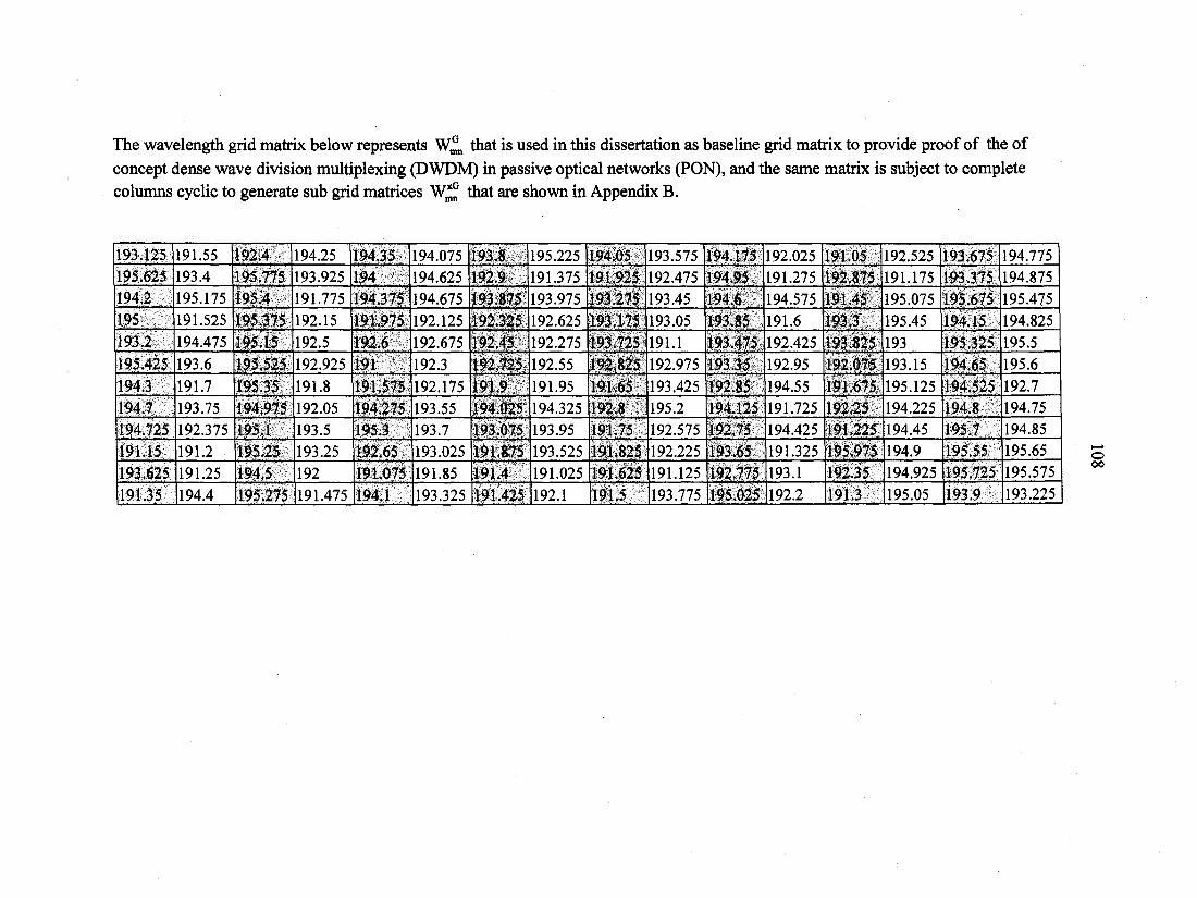
The wavelength grid matrix below represents that is used in this dissertation as baseline grid matrix to provide proof of the of
concept dense wave division multiplexing (DWDM) in passive optical networks (PON), and the same matrix is subject to complete columns cyclic to generate sub grid matrices that are shown in Appendix B.
193.125 191.55 192.4 194.25 194.35 194.075 193.8 195.225 194.05 193.575 194.175 192.025 191.05 192.525 193.675 194.775 195.625 193.4 195.775 193.925 194 194.625 192.9 191.375 191.925 192.475 194.95 191.275 192.875 191.175 193.375 194.875 194.2 195.175 195.4 191.775 194.375 194.675 193.875 193.975 193.275 193.45 194.6 194.575 191.45 195.075 195.675 195.475 195 191.525 195.375 192.15 191.975 192.125 192.325 192.625 193.175 193.05 193.85 191.6 193.3 195.45 194.15 194.825 193.2 194.475 195.15 192.5 1916 192.675 192.45 192.275 193.725 191.1 193.475 192.425 193.825 193 195.325 195.5 195.425 193.6 195.525 192.925 191 192.3 192.725 192.55 192.825 192.975 193.35 192.95 192.075 193.15 194.65 195.6 194.3 191.7 195.35 191.8 191.575 192.175 191.9 191.95 191.65 193.425 192.85 194.55 191.675 195.125 194.525 192.7 194.7 193.75 194,975 192.05 194.275 193.55 194.025 194.325 192.8 195.2 194.125 191.725 192.25 194.225 194.8 194.75 194.725 192.375 195.1 193.5 195.3 193.7 193.075 193.95 191.75 192.575 192.75 194.425 191.225 194.45 195.7 194.85 191.15 191.2 195.25 193.25 192.65 193.025 191.875 193.525 191.825 192.225 193.65 191.325 195.975 194.9 195.55 195.65 193.625 191.25 194.5 192 191.075 191.85 191.4 191.025 191.625 191.125 192.775 193.1 192.35 194.925 195.725 195.575
191.35 194.4 195.275 191.475 194.1 193.325 191.425 192.1 191.5 193.775 195.025 192.2 191.3 195.05 193.9 193.225

109
APPENDIX B: w£ SUB GRID MATRICES
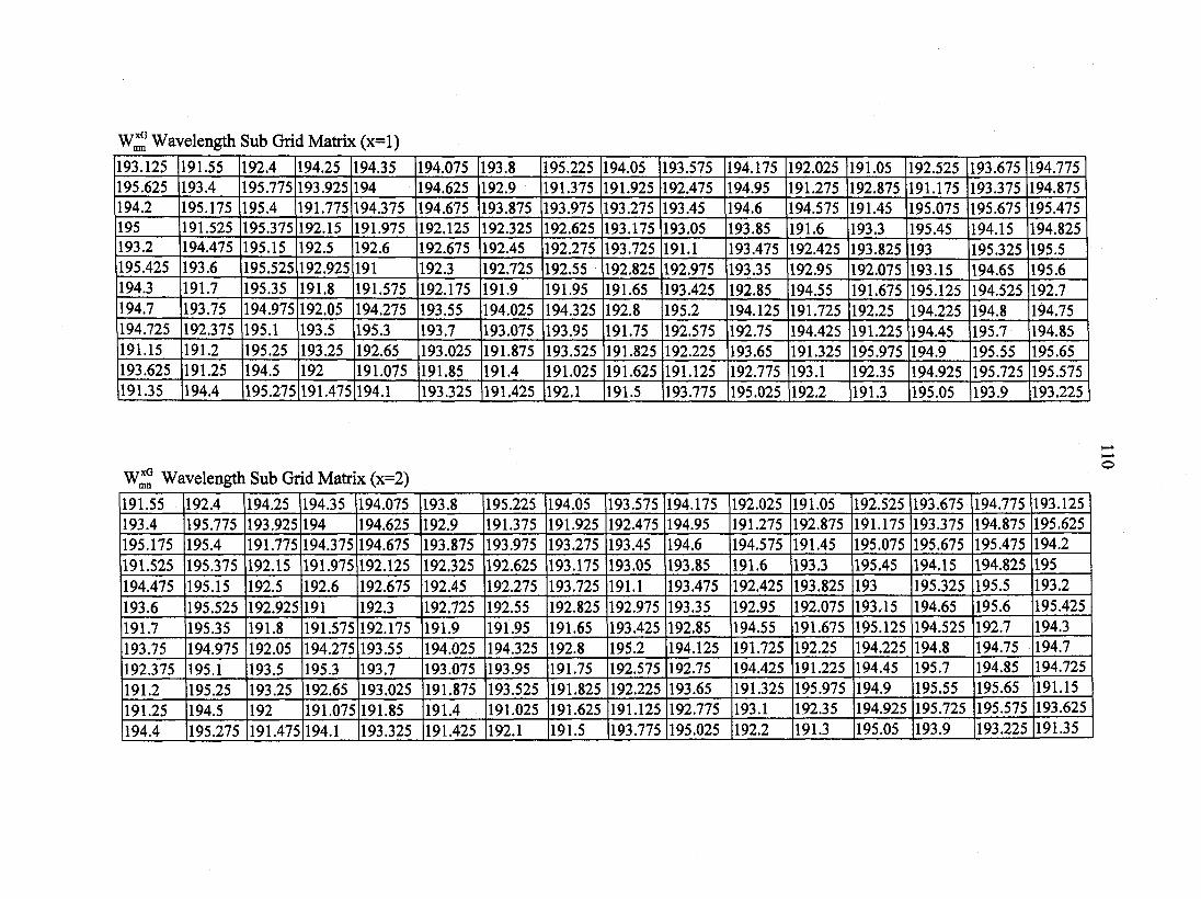
Wavelength Sub Grid Matrix (x=l)
193.125 191.55 192.4 194.25 194.35 194.075 193.8 195.225 194.05 193.575 194.175 192.025 191.05 192.525 193.675 194.775 195.625 193.4 195.775 193.925 194 194.625 192.9 191.375 191.925 192.475 194.95 191.275 192.875 191.175 193.375 194.875 194.2 195.175 195.4 191.775 194.375 194.675 193.875 193.975 193.275 193.45 194.6 194.575 191.45 195.075 195.675 195.475 195 191.525 195.375 192.15 191.975 192.125 192.325 192.625 193.175 193.05 193.85 191.6 193.3 195.45 194.15 194.825 193.2 194.475 195.15 192.5 192.6 192.675 192.45 192.275 193.725 191.1 193.475 192.425 193.825 193 195.325 195.5 195.425 193.6 195.525 192.925 191 192.3 192.725 192.55 192.825 192.975 193.35 192.95 192.075 193.15 194.65 195.6 194.3 191.7 195.35 191.8 191.575 192.175 191.9 191.95 191.65 193.425 192.85 194.55 191.675 195.125 194.525 192.7 194.7 193.75 194.975 192.05 194.275 193.55 194.025 194.325 192.8 195.2 194.125 191.725 192.25 194.225 194.8 194.75 194.725 192.375 195.1 193.5 195.3 193.7 193.075 193.95 191.75 192.575 192.75 194.425 191.225 194.45 195.7 194.85 191.15 191.2 195.25 193.25 192.65 193.025 191.875 193.525 191.825 192.225 193.65 191.325 195.975 194.9 195.55 195.65 193.625 191.25 194.5 192 191.075 191.85 191.4 191.025 191.625 191.125 192.775 193.1 192.35 194.925 195.725 195.575 191.35 194.4 195.275 191.475 194.1 193.325 191.425 192.1 191.5 193.775 195.025 192.2 191.3 195.05 193.9 193.225
Wl° Wavelength Sub Grid Matrix (x=2)
191.55 192.4 194.25 194.35 194.075 193.8 195.225 194.05 193.575 194.175 192.025 191.05 192.525 193.675 194.775 193.125 193.4 195.775 193.925 194 194.625 192.9 191.375 191.925 192.475 194.95 191.275 192.875 191.175 193.375 194.875 195.625 195.175 195.4 191.775 194.375 194.675 193.875 193.975 193.275 193.45 194.6 194.575 191.45 195.075 195.675 195.475 194.2 191.525 195.375 192.15 191.975 192.125 192.325 192.625 193.175 193.05 193.85 191.6 193.3 195.45 194.15 194.825 195 194.475 195.15 192.5 192.6 192.675 192.45 192.275 193.725 191.1 193.475 192.425 193.825 193 195.325 195.5 193.2 193.6 195.525 192.925 191 192.3 192.725 192.55 192.825 192.975 193.35 192.95 192.075 193.15 194.65 195.6 195.425 191.7 195.35 191.8 191.575 192.175 191.9 191.95 191.65 193.425 192.85 194.55 191.675 195.125 194.525 192.7 194.3 193.75 194.975 192.05 194.275 193.55 194.025 194.325 192.8 195.2 194.125 191.725 192.25 194.225 194.8 194.75 194.7 192.375 195.1 193.5 195.3 193.7 193.075 193.95 191.75 192.575 192.75 194.425 191.225 194.45 195.7 194.85 194.725
191.2 195.25 193.25 192.65 193.025 191.875 193.525 191.825 192.225 193.65 191.325 195.975 194.9 195.55 195.65 191.15
191.25 194.5 192 191.075 191.85 191.4 191.025 191.625 191.125 192.775 193.1 192.35 194.925 195.725 195.575 193.625
194.4 195.275 191.475 194.1 193.325 191.425 192.1 191.5 193.775 195.025 192.2 191.3 195.05 193.9 193.225 191.35
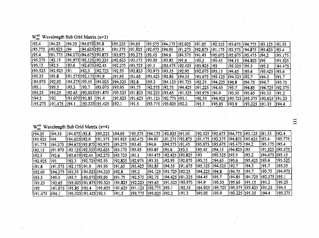
w£ Wavelength Sub Grid Matrix (x=3)
192.4 194.25 194.35 194.075 193.8 195.225 194.05 193.575 194.175 192.025 191.05 192.525 193.675 194.775 193.125 191.55 195.775 193.925 194 194.625 192.9 191.375 191.925 192.475 194.95 191.275 192.875 191.175 193.375 194.875 195.625 193.4 195.4 191.775 194.375 194.675 193.875 193.975 193.275 193.45 194.6 194.575 191.45 195.075 195.675 195.475 194.2 195.175 195.375 192.15 191.975 192.125 192.325 192.625 193.175 193.05 193.85 191.6 193.3 195.45 194.15 194.825 195 191.525 195.15 192.5 192.6 192.675 192.45 192.275 193.725 191.1 193.475 192.425 193.825 193 195.325 195.5 193.2 194.475 195.525 192.925 191 192.3 192.725 192.55 192.825 192.975 193.35 192.95 192.075 193.15 194.65 195.6 195.425 193.6 195.35 191.8 191.575 192.175 191.9 191.95 191.65 193.425 192.85 194.55 191.675 195.125 194.525 192.7 194.3 191.7 194.975 192.05 194.275 193.55 194.025 194.325 192.8 195.2 194.125 191.725 192.25 194.225 194.8 194.75 194.7 193.75 195.1 193.5 195.3 193.7 193.075 193.95 191.75 192.575 192.75 194.425 191.225 194.45 195.7 194.85 194.725 192.375 195.25 193.25 192.65 193.025 191.875 193.525 191.825 192.225 193.65 191.325 195.975 194.9 195.55 195.65 191.15 191.2 194.5 192 191.075 191.85 191.4 191.025 191.625 191.125 192.775 193.1 192.35 194.925 195.725 195.575 193.625 191.25 195.275 191.475 194.1 193.325 191.425 192.1 191.5 193.775 195.025 192.2 191.3 195.05 193.9 193.225 191.35 194.4
W1G Wavelength Sub Grid Matrix (x=4)
194.25 194.35 194.075 193.8 195.225 194.05 193.575 194.175 192.025 191.05 192.525 193.675 194.775 193.125 191.55 192.4 193.925 194 194.625 192.9 191.375 191.925 192.475 194.95 191.275 192.875 191.175 193.375 194.875 195.625 193.4 195.775 191.775 194.375 194.675 193.875 193.975 193.275 193.45 194.6 194.575 191.45 195.075 195.675 195.475 194.2 195.175 195.4 192.15 191.975 192.125 192.325 192.625 193.175 193.05 193.85 191.6 193.3 195.45 194.15 194.825 195 191.525 195.375
192.5 192.6 192.675 192.45 192.275 193.725 191.1 193.475 192.425 193.825 193 195.325 195.5 193.2 194.475 195.15
192.925 191 192.3 192.725 192.55 192.825 192.975 193.35 192.95 192.075 193.15 194.65 195.6 195.425 193.6 195.525
191.8 191.575 192.175 191.9 191.95 191.65 193.425 192.85 194.55 191.675 195.125 194.525 192.7 194.3 191.7 195.35
192.05 194.275 193.55 194.025 194.325 192.8 195.2 194.125 191.725 192.25 194.225 194.8 194.75 194.7 193.75 194.975
193.5 195.3 193.7 193.075 193.95 191.75 192.575 192.75 194.425 191.225 194.45 195.7 194.85 194.725 192.375 195.1
193.25 192.65 193.025 191.875 193.525 191.825 192.225 193.65 191.325 195.975 194.9 195.55 195.65 191.15 191.2 195.25
192 191.075 191.85 191.4 191.025 191.625 191.125 192.775 193.1 192.35 194.925 195.725 195.575 193.625 191.25 194.5 191.475 194.1 193.325 191.425 192.1 191.5 193.775 195.025 192.2 191.3 195.05 193.9 193.225 191.35 194.4 195.275
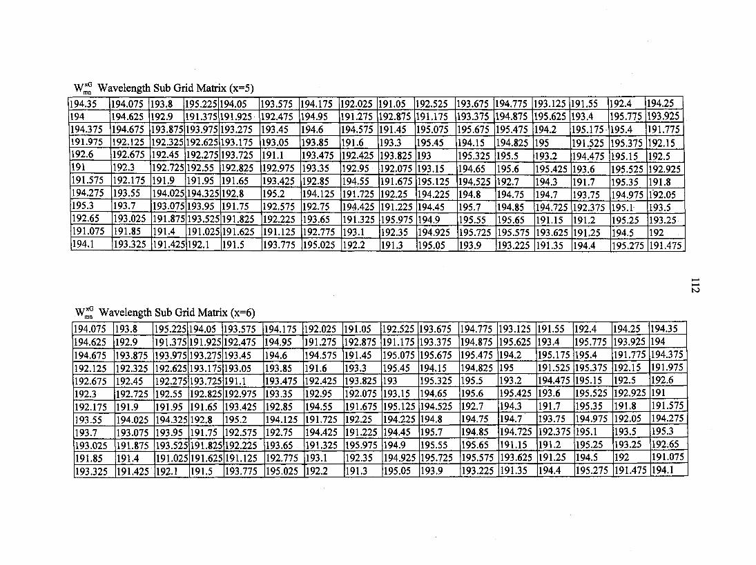
W* Wavelength Sub Grid Matrix (x=5)
194.35 194.075 193.8 195.225 194.05 193.575 194.175 192.025 191.05 192.525 193.675 194.775 193.125 191.55 192.4 194.25 194 194.625 192.9 191.375 191.925 192.475 194.95 191.275 192.875 191.175 193.375 194.875 195.625 193.4 195.775 193.925 194.375 194.675 193.875 193.975 193.275 193.45 194.6 194.575 191.45 195.075 195.675 195.475 194.2 195.175 195.4 191.775 191.975 192.125 192.325 192.625 193.175 193.05 193.85 191.6 193.3 195.45 194.15 194.825 195 191.525 195.375 192.15 192.6 192.675 192.45 192.275 193.725 191.1 193.475 192.425 193.825 193 195.325 195.5 193.2 194.475 195.15 192.5 191 192.3 192.725 192.55 192.825 192.975 193.35 192.95 192.075 193.15 194.65 195.6 195.425 193.6 195.525 192.925 191.575 192.175 191.9 191.95 191.65 193.425 192.85 194.55 191.675 195.125 194.525 192.7 194.3 191.7 195.35 191.8 194.275 193.55 194.025 194.325 192.8 195.2 194.125 191.725 192.25 194.225 194.8 194.75 194.7 193.75 194.975 192.05 195.3 193.7 193.075 193.95 191.75 192.575 192.75 194.425 191.225 194.45 195.7 194.85 194.725 192.375 195.1 193.5 192.65 193.025 191.875 193.525 191.825 192.225 193.65 191.325 195.975 194.9 195.55 195.65 191.15 191.2 195.25 193.25 191.075 191.85 191.4 191.025 191.625 191.125 192.775 193.1 192.35 194.925 195.725 195.575 193.625 191.25 194.5 192 194.1 193.325 191.425 192.1 191.5 193.775 195.025 192.2 191.3 195.05 193.9 193.225 191.35 194.4 195.275 191.475
Wavelength Sub Grid Matrix (x=6)
194.075 193.8 195.225 194.05 193.575 194.175 192.025 191.05 192.525 193.675 194.775 193.125 191.55 192.4 194.25 194.35 194.625 192.9 191.375 191.925 192.475 194.95 191.275 192.875 191.175 193.375 194.875 195.625 193.4 195.775 193.925 194 194.675 193.875 193.975 193.275 193.45 194.6 194.575 191.45 195.075 195.675 195.475 194.2 195.175 195.4 191.775 194.375 192.125 192.325 192.625 193.175 193.05 193.85 191.6 193.3 195.45 194.15 194.825 195 191.525 195.375 192.15 191.975 192.675 192.45 192.275 193.725 191.1 193.475 192.425 193.825 193 195.325 195.5 193.2 194.475 195.15 192.5 192.6 192.3 192.725 192.55 192.825 192.975 193.35 192.95 192.075 193.15 194.65 195.6 195.425 193.6 195.525 192.925 191 192.175 191.9 191.95 191.65 193.425 192.85 194.55 191.675 195.125 194.525 192.7 194.3 191.7 195.35 191.8 191.575 193.55 194.025 194.325 192.8 195.2 194.125 191.725 192.25 194.225 194.8 194.75 194.7 193.75 194.975 192.05 194.275 193.7 193.075 193.95 191.75 192.575 192.75 194.425 191.225 194.45 195.7 194.85 194.725 192.375 195.1 193.5 195.3 193.025 191.875 193.525 191.825 192.225 193.65 191.325 195.975 194.9 195.55 195.65 191.15 191.2 195.25 193.25 192.65 191.85 191.4 191.025 191.625 191.125 192.775 193.1 192.35 194.925 195.725 195.575 193.625 191.25 194.5 192 191.075
193.325 191.425 192.1 191.5 193.775 195.025 192.2 191.3 195.05 193.9 193.225 191.35 194.4 195.275 191.475 194.1
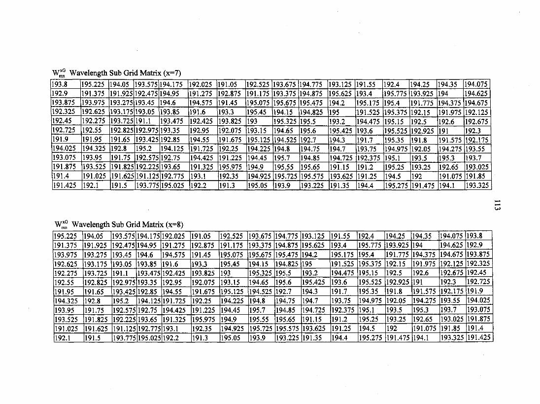
W*° Wavelength Sub Grid Matrix (x=7)
193.8 195.225 194.05 193.575 194.175 192.025 191.05 192.525 193.675 194.775 193.125 191.55 192.4 194.25 194.35 194.075 192.9 191.375 191.925 192.475 194.95 191.275 192.875 191.175 193.375 194.875 195.625 193.4 195.775 193.925 194 194.625 193.875 193.975 193.275 193.45 194.6 194.575 191.45 195.075 195.675 195.475 194.2 195.175 195.4 191.775 194.375 194.675 192.325 192.625 193.175 193.05 193.85 191.6 193.3 195.45 194.15 194.825 195 191.525 195.375 192.15 191.975 192.125 192.45 192.275 193.725 191.1 193.475 192.425 193.825 193 195.325 195.5 193.2 194.475 195.15 192.5 192.6 192.675 192.725 192.55 192.825 192.975 193.35 192.95 192.075 193.15 194.65 195.6 195.425 193.6 195.525 192.925 191 192.3 191.9 191.95 191.65 193.425 192.85 194.55 191.675 195.125 194.525 192.7 194.3 191.7 195.35 191.8 191.575 192.175 194.025 194.325 192.8 195.2 194.125 191.725 192.25 194.225 194.8 194.75 194.7 193.75 194.975 192.05 194.275 193.55 193.075 193.95 191.75 192.575 192.75 194.425 191.225 194.45 195.7 194.85 194.725 192.375 195.1 193.5 195.3 193.7 191.875 193.525 191.825 192.225 193.65 191.325 195.975 194.9 195.55 195.65 191.15 191.2 195.25 193.25 192.65 193.025 191.4 191.025 191.625 191.125 192.775 193.1 192.35 194.925 195.725 195.575 193.625 191.25 194.5 192 191.075 191.85 191.425 192.1 191.5 193.775 195.025 192.2 191.3 195.05 193.9 193.225 191.35 194.4 195.275 191.475 194.1 193.325
Wl° Wavelength Sub Grid Matrix (x=8)
195.225 194.05 193.575 194.175 192.025 191.05 192.525 193.675 194.775 193.125 191.55 192.4 194.25 194.35 194.075 193.8 191.375 191.925 192.475 194.95 191.275 192.875 191.175 193.375 194.875 195.625 193.4 195.775 193.925 194 194.625 192.9 193.975 193.275 193.45 194.6 194.575 191.45 195.075 195.675 195.475 194.2 195.175 195.4 191.775 194.375 194.675 193.875 192.625 193.175 193.05 193.85 191.6 193.3 195.45 194.15 194.825 195 191.525 195.375 192.15 191.975 192.125 192.325 192.275 193.725 191.1 193.475 192.425 193.825 193 195.325 195.5 193.2 194.475 195.15 192.5 192.6 192.675 192.45 192.55 192.825 192.975 193.35 192.95 192.075 193.15 194.65 195.6 195.425 193.6 195.525 192.925 191 192.3 192.725 191.95 191.65 193.425 192.85 194.55 191.675 195.125 194.525 192.7 194.3 191.7 195.35 191.8 191.575 192.175 191.9 194.325 192.8 195.2 194.125 191.725 192.25 194.225 194.8 194.75 194.7 193.75 194.975 192.05 194.275 193.55 194.025 193.95 191.75 192.575 192.75 194.425 191.225 194.45 195.7 194.85 194.725 192.375 195.1 193.5 195.3 193.7 193.075 193.525 191.825 192.225 193.65 191.325 195.975 194.9 195.55 195.65 191.15 191.2 195.25 193.25 192.65 193.025 191.875 191.025 191.625 191.125 192.775 193.1 192.35 194.925 195.725 195.575 193.625 191.25 194.5 192 191.075 191.85 191.4 192.1 191.5 193.775 195.025 192.2 191.3 195.05 193.9 193.225 191.35 194.4 195.275 191.475 194.1 193.325 191.425
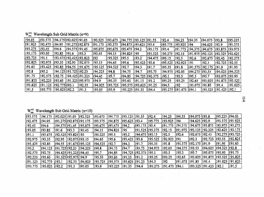
W*° Wavelength Sub Grid Matrix (x=9)
194.05 193.575 194.175 192.025 191.05 192.525 193.675 194.775 193.125 191.55 192.4 194.25 194.35 194.075 193.8 195.225 191.925 192.475 194.95 191.275 192.875 191.175 193.375 194.875 195.625 193.4 195.775 193.925 194 194.625 192.9 191.375 193.275 193.45 194.6 194.575 191.45 195.075 195.675 195.475 194.2 195.175 195.4 191.775 194.375 194.675 193.875 193.975 193.175 193.05 193.85 191.6 193.3 195.45 194.15 194.825 195 191.525 195.375 192.15 191.975 192.125 192.325 192.625 193.725 191.1 193.475 192.425 193.825 193 195.325 195.5 193.2 194.475 195.15 192.5 192.6 192.675 192.45 192.275 192.825 192.975 193.35 192.95 192.075 193.15 194.65 195.6 195.425 193.6 195.525 192.925 191 192.3 192.725 192.55 191.65 193.425 192.85 194.55 191.675 195.125 194.525 192.7 194.3 191.7 195.35 191.8 191.575 192.175 191.9 191.95 192.8 195.2 194.125 191.725 192.25 194.225 194.8 194.75 194.7 193.75 194.975 192.05 194.275 193.55 194.025 194.325 191.75 192.575 192.75 194.425 191.225 194.45 195.7 194.85 194.725 192.375 195.1 193.5 195.3 193.7 193.075 193.95 191.825 192.225 193.65 191.325 195.975 194.9 195.55 195.65 191.15 191.2 195.25 193.25 192.65 193.025 191.875 193.525 191.625 191.125 192.775 193.1 192.35 194.925 195.725 195.575 193.625 191.25 194.5 192 191.075 191.85 191.4 191.025 191.5 193.775 195.025 192.2 191.3 195.05 193.9 193.225 191.35 194.4 195.275 191.475 194.1 193.325 191.425 192.1
W*° Wavelength Sub Grid Matrix (x=10)
193.575 194.175 192.025 191.05 192.525 193.675 194.775 193.125 191.55 192.4 194.25 194.35 194.075 193.8 195.225 194.05 192.475 194.95 191.275 192.875 191.175 193.375 194.875 195.625 193.4 195.775 193.925 194 194.625 192.9 191.375 191.925 193.45 194.6 194.575 191.45 195.075 195.675 195.475 194.2 195.175 195.4 191.775 194.375 194.675 193.875 193.975 193.275 193.05 193.85 191.6 193.3 195.45 194.15 194.825 195 191.525 195.375 192.15 191.975 192.125 192.325 192.625 193.175 191.1 193.475 192.425 193.825 193 195.325 195.5 193.2 194.475 195.15 192.5 192.6 192.675 192.45 192.275 193.725 192.975 193.35 192.95 192.075 193.15 194.65 195.6 195.425 193.6 195.525 192.925 191 192.3 192.725 192.55 192.825 193.425 192.85 194.55 191.675 195.125 194.525 192.7 194.3 191.7 195.35 191.8 191.575 192.175 191.9 191.95 191.65 195.2 194.125 191.725 192.25 194.225 194.8 194.75 194.7 193.75 194.975 192.05 194.275 193.55 194.025 194.325 192.8 192.575 192.75 194.425 191.225 194.45 195.7 194.85 194.725 192.375 195.1 193.5 195.3 193.7 193.075 193.95 191.75 192.225 193.65 191.325 195.975 194.9 195.55 195.65 191.15 191.2 195.25 193.25 192.65 193.025 191.875 193.525 191.825 191.125 192.775 193.1 192.35 194.925 195.725 195.575 193.625 191.25 194.5 192 191.075 191.85 191.4 191.025 191.625 193.775 195.025 192.2 191.3 195.05 193.9 193.225 191.35 194.4 195.275 191.475 194.1 193.325 191.425 192.1 191.5
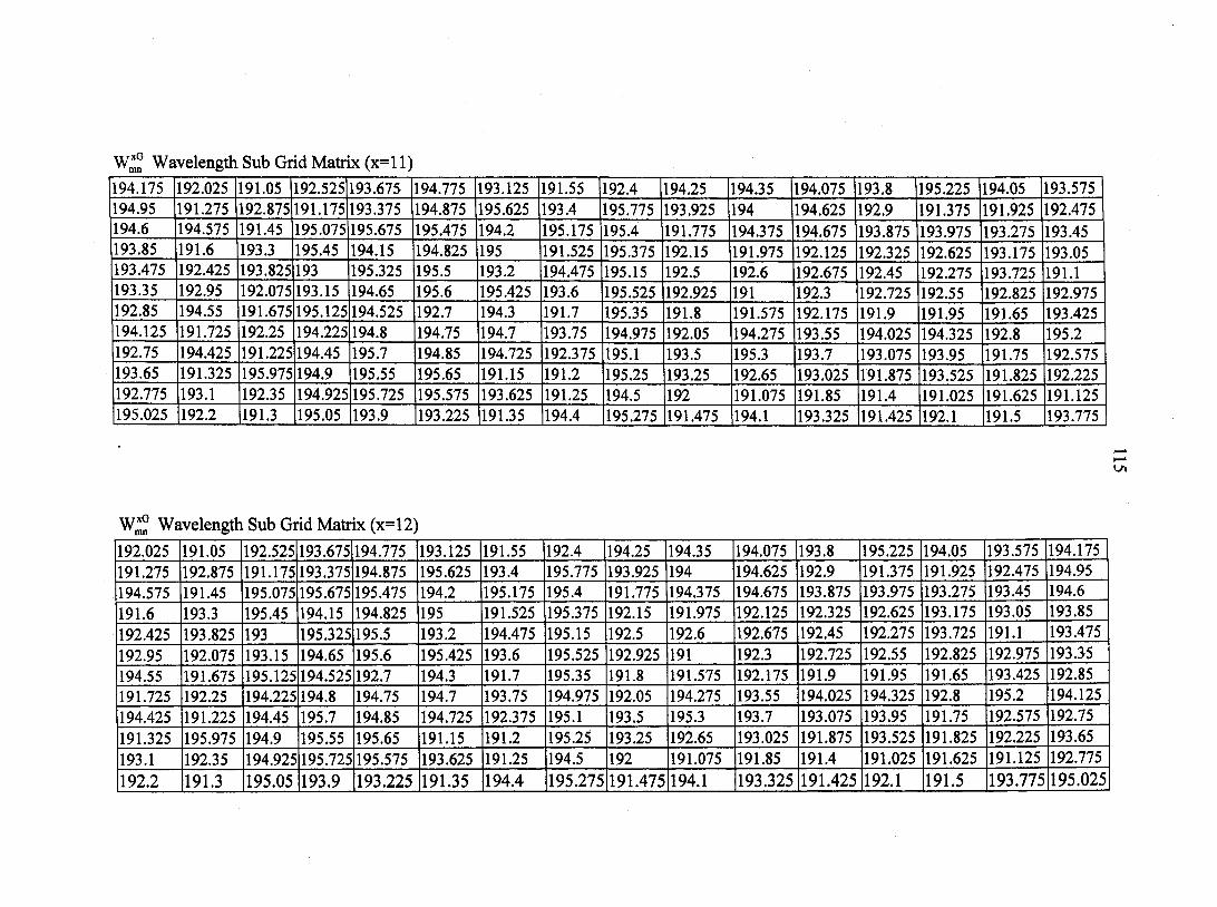
W*° Wavelength Sub Grid Matrix (x=l 1)
194.175 192.025 191.05 192.525 193.675 194.775 193.125 191.55 192.4 194.25 194.35 194.075 193.8 195.225 194.05 193.575 194.95 191.275 192.875 191.175 193.375 194.875 195.625 193.4 195.775 193.925 194 194.625 192.9 191.375 191.925 192.475 194.6 194.575 191.45 195.075 195.675 195.475 194.2 195.175 195.4 191.775 194.375 194.675 193.875 193.975 193.275 193.45 193.85 191.6 193.3 195.45 194.15 194.825 195 191.525 195.375 192.15 191.975 192.125 192.325 192.625 193.175 193.05 193.475 192.425 193.825 193 195.325 195.5 193.2 194.475 195.15 192.5 192.6 192.675 192.45 192.275 193.725 191.1 193.35 192.95 192.075 193.15 194.65 195.6 195.425 193.6 195.525 192.925 191 192.3 192.725 192.55 192.825 192.975 192.85 194.55 191.675 195.125 194.525 192.7 194.3 191.7 195.35 191.8 191.575 192.175 191.9 191.95 191.65 193.425 194.125 191.725 192.25 194.225 194.8 194.75 194.7 193.75 194.975 192.05 194.275 193.55 194.025 194.325 192.8 195.2 192.75 194.425 191.225 194.45 195.7 194.85 194.725 192.375 195.1 193.5 195.3 193.7 193.075 193.95 191.75 192.575 193.65 191.325 195.975 194.9 195.55 195.65 191.15 191.2 195.25 193.25 192.65 193.025 191.875 193.525 191.825 192.225 192.775 193.1 192.35 194.925 195.725 195.575 193.625 191.25 194.5 192 191.075 191.85 191.4 191.025 191.625 191.125 195.025 192.2 191.3 195.05 193.9 193.225 191.35 194.4 195.275 191.475 194.1 193.325 191.425 192.1 191.5 193.775
W1G Wavelength Sub Grid Matrix (x=l2)
192.025 191.05 192.525 193.675 194.775 193.125 191.55 192.4 194.25 194.35 194.075 193.8 195.225 194.05 193.575 194.175 191.275 192.875 191.175 193.375 194.875 195.625 193.4 195.775 193.925 194 194.625 192.9 191.375 191.925 192.475 194.95 194.575 191.45 195.075 195.675 195.475 194.2 195.175 195.4 191.775 194.375 194.675 193.875 193.975 193.275 193.45 194.6
191.6 193.3 195.45 194.15 194.825 195 191.525 195.375 192.15 191.975 192.125 192.325 192.625 193.175 193.05 193.85
192.425 193.825 193 195.325 195.5 193.2 194.475 195.15 192.5 192.6 192.675 192.45 192.275 193.725 191.1 193.475
192.95 192.075 193.15 194.65 195.6 195.425 193.6 195.525 192.925 191 192.3 192.725 192.55 192.825 192.975 193.35 194.55 191.675 195.125 194.525 192.7 194.3 191.7 195.35 191.8 191.575 192.175 191.9 191.95 191.65 193.425 192.85 191.725 192.25 194.225 194.8 194.75 194.7 193.75 194.975 192.05 194.275 193.55 194.025 194.325 192.8 195.2 194.125 194.425 191.225 194.45 195.7 194.85 194.725 192.375 195.1 193.5 195.3 193.7 193.075 193.95 191.75 192.575 192.75 191.325 195.975 194.9 195.55 195.65 191.15 191.2 195.25 193.25 192.65 193.025 191.875 193.525 191.825 192.225 193.65
193.1 192.35 194.925 195.725 195.575 193.625 191.25 194.5 192 191.075 191.85 191.4 191.025 191.625 191.125 192.775
192.2 191.3 195.05 193.9 193.225 191.35 194.4 195.275 191.475 194.1 193.325 191.425 192.1 191.5 193.775 195.025
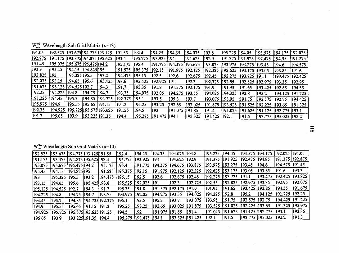
W* Wavelength Sub Grid Matrix (x=13)
191.05 192.525 193.675 194.775 193.125 191.55 192.4 194.25 194.35 194.075 193.8 195.225 194.05 193.575 194.175 192.025 192.875 191.175 193.375 194.875 195.625 193.4 195.775 193.925 194 194.625 192.9 191.375 191.925 192.475 194.95 191.275 191.45 195.075 195.675 195.475 194.2 195.175 195.4 191.775 194.375 194.675 193.875 193.975 193.275 193.45 194.6 194.575 193.3 195.45 194.15 194.825 195 191.525 195.375 192.15 191.975 192.125 192.325 192.625 193.175 193.05 193.85 191.6 193.825 193 195.325 195.5 193.2 194.475 195.15 192.5 192.6 192.675 192.45 192.275 193.725 191.1 193.475 192.425 192.075 193.15 194.65 195.6 195.425 193.6 195.525 192.925 191 192.3 192.725 192.55 192.825 192.975 193.35 192.95 191.675 195.125 194.525 192.7 194.3 191.7 195.35 191.8 191.575 192.175 191.9 191.95 191.65 193.425 192.85 194.55 192.25 194.225 194.8 194.75 194.7 193.75 194.975 192.05 194.275 193.55 194.025 194.325 192.8 195.2 194.125 191.725 191.225 194.45 195.7 194.85 194.725 192.375 195.1 193.5 195.3 193.7 193.075 193.95 191.75 192.575 192.75 194.425 195.975 194.9 195.55 195.65 191.15 191.2 195.25 193.25 192.65 193.025 191.875 193.525 191.825 192.225 193.65 191.325 192.35 194.925 195.725 195.575 193.625 191.25 194.5 192 191.075 191.85 191.4 191.025 191.625 191.125 192.775 193.1 191.3 195.05 193.9 193.225 191.35 194.4 195.275 191.475 194.1 193.325 191.425 192.1 191.5 193.775 195.025 192.2
Wl° Wavelength Sub Grid Matrix (x=14)
192.525 193.675 194.775 193.125 191.55 192.4 194.25 194.35 194.075 193.8 195.225 194.05 193.575 194.175 192.025 191.05 191.175 193.375 194.875 195.625 193.4 195.775 193.925 194 194.625 192.9 191.375 191.925 192.475 194.95 191.275 192.875 195.075 195.675 195.475 194.2 195.175 195.4 191.775 194.375 194.675 193.875 193.975 193.275 193.45 194.6 194.575 191.45
195.45 194.15 194.825 195 191.525 195.375 192.15 191.975 192.125 192.325 192.625 193.175 193.05 193.85 191.6 193.3
193 195.325 195.5 193.2 194.475 195.15 192.5 192.6 192.675 192.45 192.275 193.725 191.1 193.475 192.425 193.825
193.15 194.65 195.6 195.425 193.6 195.525 192.925 191 192.3 192.725 192.55 192.825 192.975 193.35 192.95 192.075
195.125 194.525 192.7 194.3 191.7 195.35 191.8 191.575 192.175 191.9 191.95 191.65 193.425 192.85 194.55 191.675
194.225 194.8 194.75 194.7 193.75 194.975 192.05 194.275 193.55 194.025 194.325 192.8 195.2 194.125 191.725 192.25
194.45 195.7 194.85 194.725 192.375 195.1 193.5 195.3 193.7 193.075 193.95 191.75 192.575 192.75 194.425 191.225
194.9 195.55 195.65 191.15 191.2 195.25 193.25 192.65 193.025 191.875 193.525 191.825 192.225 193.65 191.325 195.975
194.925 195.725 195.575 193.625 191.25 194.5 192 191.075 191.85 191.4 191.025 191.625 191.125 192.775 193.1 192.35
195.05 193.9 193.225 191.35 194.4 195.275 191.475 194.1 193.325 191.425 192.1 191.5 193.775 195.025 192.2 191.3
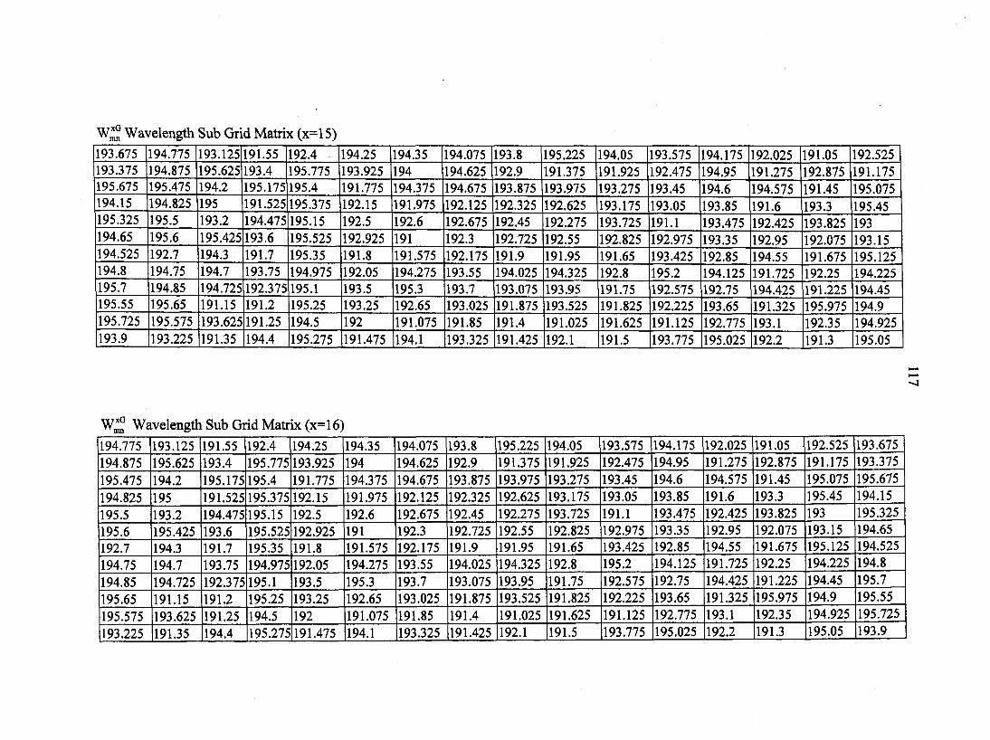
W*° Wavelength Sub Grid Matrix (x=15)
193.675 194.775 193.125 191.55 192.4 194.25 194.35 194.075 193.8 195.225 194.05 193.575 194.175 192.025 191.05 192.525 193.375 194.875 195.625 193.4 195.775 193.925 194 194.625 192.9 191.375 191.925 192.475 194.95 191.275 192.875 191.175 195.675 195.475 194.2 195.175 195.4 191.775 194.375 194.675 193.875 193.975 193.275 193.45 194.6 194.575 191.45 195.075 194.15 194.825 195 191.525 195.375 192.15 191.975 192.125 192.325 192.625 193.175 193.05 193.85 191.6 193.3 195.45 195.325 195.5 193.2 194.475 195.15 192.5 192.6 192.675 192.45 192.275 193.725 191.1 193.475 192.425 193.825 193 194.65 195.6 195.425 193.6 195.525 192.925 191 192.3 192.725 192.55 192.825 192.975 193.35 192.95 192.075 193.15 194.525 192.7 194.3 191.7 195.35 191.8 191.575 192.175 191.9 191.95 191.65 193.425 192.85 194.55 191.675 195.125 194.8 194.75 194.7 193.75 194.975 192.05 194.275 193.55 194.025 194.325 192.8 195.2 194.125 191.725 192.25 194.225 195.7 194.85 194.725 192.375 195.1 193.5 195.3 193.7 193.075 193.95 191.75 192.575 192.75 194.425 191.225 194.45 195.55 195.65 191.15 191.2 195.25 193.25 192.65 193.025 191.875 193.525 191.825 192.225 193.65 191.325 195.975 194.9 195.725 195.575 193.625 191.25 194.5 192 191.075 191.85 191.4 191.025 191.625 191.125 192.775 193.1 192.35 194.925 193.9 193.225 191.35 194.4 195.275 191.475 194.1 193.325 191.425 192.1 191.5 193.775 195.025 192.2 191.3 195.05
•—»
I—*
<1
W*° Wavelength Sub Grid Matrix (x=16)
194.775 193.125 191.55 192.4 194.25 194.35 194.075 193.8 195.225 194.05 193.575 194.175 192.025 191.05 192.525 193.675 194.875 195.625 193.4 195.775 193.925 194 194.625 192.9 191.375 191.925 192.475 194.95 191.275 192.875 191.175 193.375 195.475 194.2 195.175 195.4 191.775 194.375 194.675 193.875 193.975 193.275 193.45 194.6 194.575 191.45 195.075 195.675
194.825 195 191.525 195.375 192.15 191.975 192.125 192.325 192.625 193.175 193.05 193.85 191.6 193.3 195.45 194.15
195.5 193.2 194.475 195.15 192.5 192.6 192.675 192.45 192.275 193.725 191.1 193.475 192.425 193.825 193 195.325
195.6 195.425 193.6 195.525 192.925 191 192.3 192.725 192.55 192.825 192.975 193.35 192.95 192.075 193.15 194.65 192.7 194.3 191.7 195.35 191.8 191.575 192.175 191.9 191.95 191.65 193.425 192.85 194.55 191.675 195.125 194.525
194.75 194.7 193.75 194.975 192.05 194.275 193.55 194.025 194.325 192.8 195.2 194.125 191.725 192.25 194.225 194.8
194.85 194.725 192.375 195.1 193.5 195.3 193.7 193.075 193.95 191.75 192.575 192.75 194.425 191.225 194.45 195.7
195.65 191.15 191.2 195.25 193.25 192.65 193.025 191.875 193.525 191.825 192.225 193.65 191.325 195.975 194.9 195.55
195.575 193.625 191.25 194.5 192 191.075 191.85 191.4 191.025 191.625 191.125 192.775 193.1 192.35 194.925 195.725
193.225 191.35 194.4 195.275 191.475 194.1 193.325 191.425 192.1 191.5 193.775 195.025 192.2 191.3 195.05 193.9

118
APPENDIX C: ORTHOGONAL SYMMETRIC CODE MATRICES
FOR /'= 13
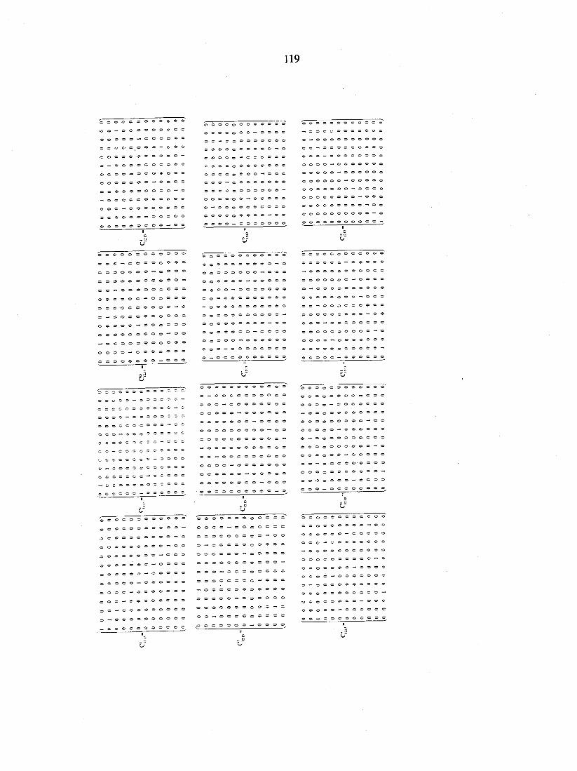
119
© © © © © © o o ® © © © © © © © o © © — » © © © © o — o © o © © © © © © ©o©©©©©©©© — © © o c © © — © o ® ® ® ®
o o o o o ® ® ® ~ " ® ° ® © © © — © o © © © ® © ® © © © © © o o © © © © -O O ® ® ' O © — © © © © © 0 - " ® ® 0 ® ® ® ® ® ® ° o o © © © © © ® © — 1 ® © o o o o — © o o o o o o
© © © © © o o © © © © © — o o o o ® o o o ® ® o o — ' o o o o o o o e o o c e — ® ® ® ® ® ® ® ® ® o © ® — o o ® ® ® ® © ® o o © ® — ® « ® ® ® ® ® © © © © © — © o o o o ® o ® ® ® ® ® - © O O O o o o o o ® ® ® — ® ® ® ® O O O O O © ® © — ® ô © ©©oo©©®®© — ®® O O O O © © © © © © — © © O O O O © © ® o © © —
© 0 © © 0 © 0 © © © © ©
© © © O © © © © © © - ®
© 0 © © © © © © — © © ©
© © © © © © — o o o o © O O ® © — ® ® ® ° ® ® ° O O — © ® ® ® ® ® ® ® ® — 0 0 © 0 © © 0 0 © © © © 0 © © © © © © © © © — O O ® © ® ® ® ® ® " " ® ® © 0 0 © © 0 © — © © © © 0 0 © ® ® " ® ° ® ® ® ° o © © — « o © © © ® ® © o — o © © ® ® ® © © © ® ,
o o © © ® ® © © © ® ® ® o ® o ® © o — ® © © ® ® — o o © o o © © © © ® © © © © o o © © — o © ® ® o — o o o o © © © ® ® © 0 0 © ® C 0 © © — ® © ® o o - © © o © © * © ® © O O © ® ® © ® ® ® — © ® O O ® — © o © © ® ® © © o©©ooo©©©© — © o o o © — © o © © ® © © O O O O O © © © © © © — o o o ® ® — © © e ® ® o _
o o © © © ® © © © _ , © © © © > © © o © © — © o o © © © o o o — © © © o o e © o o — o o o o o o o o o © e e © o e ©
— . © © © © © o ©
o © — o © ® © © © © © © — o o ©
© © © © © » — © © © © © © o o ©
© © © © © o o ©
o o © © ® © ® ® ® © ® ° © © © © o © ® ® — © ® ® © © © © — © o © ® ® ® © — © © © o o © © © © © ©
© o © © © © © © ® — ® © O O O O © — © © © ® © © © — © © © © o o o © © © © © o o o © © © © © - © O O © © ® © — © ® © © © © o — © © O © O O » © © © © © © © o o © © © © — © o © © © © ® — © © © © © © © — © © o © © O © © ,
@ 0 0 * 0 0 © © ® © © ® 0 0 0 © 0 0 © © ® ® ® —
o © « © © © © ® © « - ®
© O O © © © © © ® — ® ®
© © © © © © — o © © ° ® © o © © © ' — o © ® © © ©
© o o o - o © ® ® ® ® ® o © o - ® © © ® ® ® ° ®
© © - © o o © e ® e ® ® © — o © © © © © ® ® © ®
_ © © © © © © © ® ~ ®
© o o o o ©
© © o o o ©
© © o © o ©
© © © o © © © © © — © © © o © © © ©
— © © © © ©
o o © © © © © © © ® ® o o © © ® © © ® ® - © o o o © © © — ® © © © ' o o o — © © © © ® © ® — © O © © ® ® ® © ® ® ' © © © O O © © © © ® — o o © © o © © — © ° ©
© o © © — © © © © ® ®
o — © © o ® © « © © ©
© o o ® © © ® ® © 0 0
© O O O O ® © © — © © O O O ® © — ® ® © © ® o o — © © O O O O O O
120
APPENDIX D: WAVELENGTH SEQUENCES FOR SYMMETRIC
TS/WH, />= 13
The following wavelength sequences were generated by mapping the wavelength matrices to
symmetric time spreading/ wavelength hopping matrices using the relation in
A^n = © Wf, where mapping is indicated as Wx(Cy) and where x and y indicate the
wavelength sub grid (1 to 16) and code matrices (1 to 12), respectively.
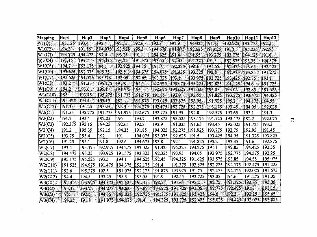
Mapping Hopl Hop2 Hop3 Hop4 Hop5 Hop6 Hop7 Hop8 Hop9 HoplO Hopll Hopll W1(C1) 193.125 193.4 195.4 192.15 192.6 192.3 191.9 194.325 191.75 192.225 92.775 192.2 W1(C2) 194.3 191.55 194.975 193.925 195.3 194.675 191.875 192.625 191.625 191.1 95.025 192.95 W1(C3) 194.725 94.475 192.4 193.25 191 194.625 191.4 191.95 193.275 193.775 194.125 191.6 W1(C4) 91.15 191.7 195.375 194.25 191.075 193.55 192,45 191.375 191.5 192.575 193.35 194.575 W1(C5) 194.7 195.175 194.5 192.925 194.35 193.7 192.325 192.1 191.65 192.475 193.65 192.425 W1(C6) 193.625 192.375 195.35 192.5 194.375 194.075 191.425 193.525 192.8 192.975 193.85 191.275 W1(C7) 195.625 191.525 195.525 192.05 192.65 193.325 193.8 193.975 193.725 193.425 192.75 193.1 W1(C8) 193.2 191.2 195.775 191.8 194.1 192.125 193.075 195.225 192.825 191.125 194.6 191.725 W1(C9) 194.2 193.6 195.1 191.475 194 192.675 194.025 191.025 194.05 193.05 192.85 191.325 Wl(ClO) 195 193.75 195.275 191.775 191.575 191.85 192.9 192.55 191.825 193.575 193.475 194.425 Wl(Cll) 195.425 194.4 195.15 192 [191.975 193.025 193.875 193.95 191.925 195.2 194.175 194.55 W1(C12) 191.35 191.25 195.25 193.5 194.275 192.175 192.725 192.275 193.175 193.45 194.95 192.025 W2(C1) 191.55 195.775 191.775 191.975 192.675 192.725 191.95 192.8 192.575 193.65 193.1 191.3 W2(C2) 191.7 192.4 192.05 194 193.7 193.875 193.525 193.175 191.125 193.475 192.2 192.075 W2(C3) 192.375 195.15 194.25 192.65 192.3 192.9 191.025 191.65 193.45 195.025 191.725 193.3 W2(C4) 191.2 195.35 192.15 194.35 191.85 194.025 192.275 191.925 193.775 192.75 192.95 191.45 W2(C5) 193.75 195.4 192 191 194.075 193.075 192.625 191.5 193.425 194.95 191.325 193.825 W2(C6) 191.25 195.1 191.8 192.6 194.675 193.8 192.1 191.825 195.2 193.35 191.6 192.875 W2(C7) 193.4 195.375 192.925 194.275 193.025 191.425 195.225 193.275 191.1 192.85 194.425 192.35
W2(C8) 194.475 195.25 193.925 191.575 193.325 192.325 193.95 194.05 192.975 192.775 194.575 192.25
W2(C9) 195.175 195.525 193.5 194.1 194.625 192.45 194.325 191.625 193.575 193.85 194.55 195.975
W2(C10) 191.525 194.975 191.475 194.375 192.175 191.4 191.375 192.825 192.225 194.175 192.425 191.225
W2(C11) 193.6 195.275 192.5 191.075 192.125 191.875 193.975 191.75 192.475 194.125 192.025 191.675
W2(C12) 194.4 194.5 193.25 195.3 193.55 191.9 192.55 193.725 193.05 194.6 191.275 191.05
W3(C1) 192.4 193.925 194.375 192.125 192.45 192.55 191.65 195.2 192.75 191.325 192.35 195.05
W3(C2) 195.35 194.25 194.275 194.625 193.075 193.975 191.825 193.05 192.775 192.425 191.3 193.15 W3(C3) 195.1 192.5 194.35 193.025 192.725 191.375 191.625 193.425 194.6 192.2 192.25 195.45
W3(C4) 195.25 191.8 191.975 194.075 191.4 194.325 193.725 192.475 195.025 194.425 192.075 195.075
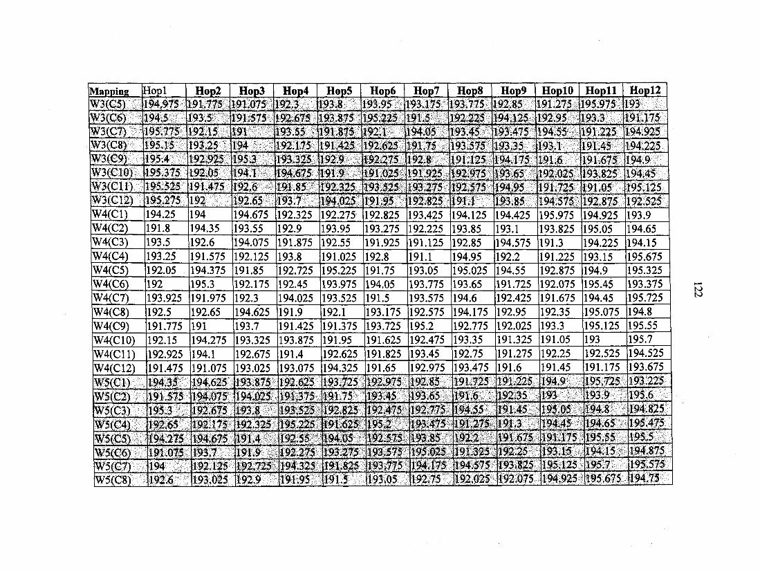
Mapping rîopl Hop2 Hop3 Hop4 Hop5 Hop6 Hop7 Hop8 Hop9 HoplO Hopll Hopl2 W3(C5) 194.975 191.775 191.075 192.3 193.8 193.95 193.175 193.775 192.85 191.275 195.975 193 W3(C6) 194.5 193.5 191.575 192.675 193.875 195.225 191.5 192.225 194.125 192.95 193.3 191.175 W3(C7) 195.775 192.15 191 193.55 191.875 192.1 194.05 193.45 193.475 194.55 191.225 194.925 W3(C8) 195.15 193.25 194 192.175 191.425 192.625 191.75 193.575 193.35 193.1 191.45 194.225 W3(C9) 195.4 192.925 195.3 193.325 192.9 192.275 192.8 191.125 194.175 191.6 191.675 194 9 W3(C10) 195.375 192.05 194.1 194.675 191.9 191.025 191.925 192.975 193.65 192.025 193.825 194 45 W3(C11) 195.525 191.475 192.6 191.85 192.325 193.525 193.275 192.575 194.95 191.725 191.05 195.125 W3(C12) 195.275 192 192.65 193.7 194.025 191.95 192.825 191.1 193.85 194.575 192.875 192.525 W4(C1) 194.25 194 194.675 192.325 192.275 192.825 193.425 194.125 194.425 195.975 194.925 193.9 W4(C2) 191.8 194.35 193.55 192.9 193.95 193.275 192.225 193.85 193.1 193.825 195.05 194.65 W4(C3) 193.5 192.6 194.075 191.875 192.55 191.925 191.125 192.85 194.575 191.3 194.225 194.15 W4(C4) 193.25 191.575 192.125 193.8 191.025 192.8 191.1 194.95 192.2 191.225 193.15 195.675 W4(C5) 192.05 194.375 191.85 192.725 195.225 191.75 193.05 195.025 194.55 192.875 194.9 195.325 W4(C6) 192 195.3 192.175 192.45 193.975 194.05 193.775 193.65 191.725 192.075 195.45 193.375 W4(C7) 193.925 191.975 192.3 194.025 193.525 191.5 193.575 194.6 192.425 191.675 194.45 195.725 W4(C8) 192.5 192.65 194.625 191.9 192.1 193.175 192.575 194.175 192.95 192.35 195.075 194.8 W4(C9) 191.775 191 193.7 191.425 191.375 193.725 195.2 192.775 192.025 193.3 195.125 195.55 W4(C10) 192.15 194.275 193.325 193.875 191.95 191.625 192.475 193.35 191.325 191.05 193 195.7
W4(C11) 192.925 194.1 192.675 191.4 192.625 191.825 193.45 192.75 191.275 192.25 192.525 194.525
W4(C12) 191.475 191.075 193.025 193.075 194.325 191.65 192.975 193.475 191.6 191.45 191.175 193.675
W5(C1) 194.35 194.625 193.875 192.625 193.725 192.975 192.85 191.725 191.225 194.9 195.725 193.225
W5(C2) 191.575 194.075 194.025 191.375 191.75 193.45 193.65 191.6 192.35 193 193.9 195.6
W5(C3) 195.3 192.675 193.8 193.525 192.825 192.475 192.775 194.55 191.45 195.05 194.8 194.825
W5(C4) 192.65 192.175 192.325 195.225 191.625 195.2 193.475 191.275 191.3 194.45 194.65 195.475
W5(C5) 194.275 194.675 191.4 192.55 194.05 192.575 193.85 192.2 191.675 191.175 195.55 195.5
W5(C6) 191.075 193.7 191.9 192.275 193.275 193,575 195,025 191.325 192.25 193.15 194.15 194.875
W5(C7) 194 192.125 192.725 194.325 191.825 193.775 194.175 194.575 193.825 195.125 195.7 195.575
W5(C8) 192.6 193 025 192.9 191.95 191.5 193.05 192.75 192.025 192.075 194.925 195.675 194.75
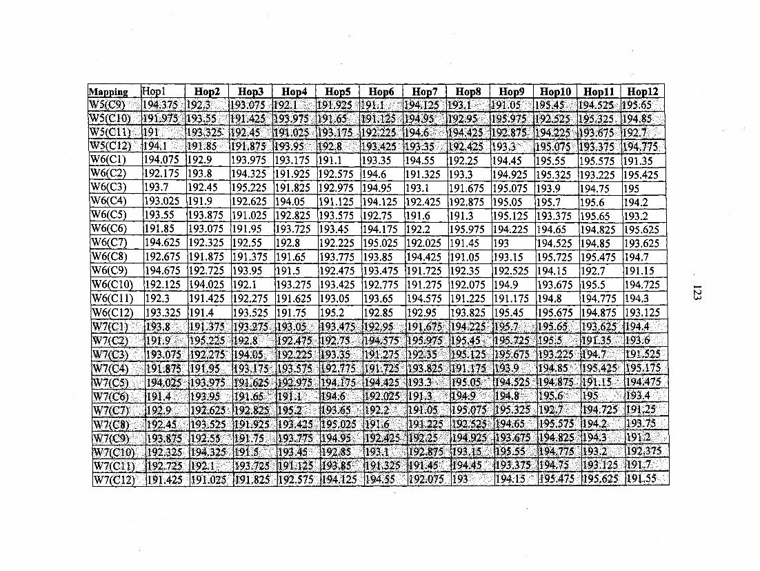
Mapping Hopl Hop2 Hop3 Hop4 Hop5 Hop6 Hop7 Hop8 Hop9 HoplO Hopll Hopl2 W5(C9) 194.375 192.3 193.075 92.1 191.925 191.1 194.125 193.1 191.05 195.45 194.525 195.65 W5(C10) 191.975 193.55 191.425 193.975 191.65 191.125 194.95 192.95 195.975 192.525 195.325 194.85 W5(C11) 191 193.325 192.45 191.025 193.175 192.225 194.6 194.425 192.875 194.225 193.675 192.7 W5(C12) 194.1 191.85 191.875 193.95 192.8 193.425 193.35 192.425 193.3 195.075 193.375 194.775 W6(C1) 194.075 192.9 193.975 193.175 191.1 193.35 194.55 192.25 194.45 195.55 195.575 191.35 W6(C2) 192.175 193.8 194.325 191.925 192.575 194.6 191.325 193.3 194.925 195.325 193.225 195.425 W6(C3) 193.7 192.45 195.225 191.825 192.975 194.95 193.1 191.675 195.075 193.9 194.75 195 W6(C4) 193.025 191.9 192.625 194.05 191.125 194.125 192.425 192.875 195.05 195.7 195.6 194.2 W6(C5) 193.55 193.875 191.025 192.825 193.575 192.75 191.6 191.3 195.125 193.375 195.65 193.2 W6(C6) 191.85 193.075 191.95 193.725 193.45 194.175 192.2 195.975 194.225 194.65 194.825 195.625 W6(C7) 194.625 192.325 192.55 192.8 192.225 195.025 192.025 191.45 193 194.525 194.85 193.625 W6(C8) 192.675 191.875 191.375 191.65 193.775 193.85 194.425 191.05 193.15 195.725 195.475 194.7 W6(C9) 194.675 192.725 193.95 191.5 192.475 193.475 191.725 192.35 192.525 194.15 192.7 191.15 W6(C10) 192.125 194.025 192.1 193.275 193.425 192.775 191.275 192.075 194.9 193.675 195.5 194.725 W6(C11) 192.3 191.425 192.275 191.625 193.05 193.65 194.575 191.225 191.175 194.8 194.775 194.3 W6(C12) 193.325 191.4 193.525 191.75 195.2 192.85 192.95 193.825 195.45 195.675 194.875 193.125 W7(C1) 193.8 191.375 193.275 193.05 193.475 192.95 191.675 194.225 195.7 195.65 193.625 194.4 W7(C2) 191.9 195.225 192.8 192.475 192.75 194.575 195.975 195.45 195.725 195.5 191.35 193.6 W7(C3) 193.075 192.275 194.05 192.225 193.35 191.275 192.35 195.125 195.675 193.225 194.7 191.525 W7(C4) 191.875 191.95 193.175 193.575 192.775 191.725 193.825 191.175 193.9 194.85 195.425 195.175
W7(C5) 194.025 193.975 191.625 192.975 194.175 194.425 193.3 195.05 194.525 194.875 191.15 194.475 W7(C6) 191.4 193.95 191.65 191.1 194.6 192.025 191.3 194.9 194.8 195.6 195 193.4
W7(C7) 192.9 192.625 192.825 195.2 193.65 192.2 191.05 195.075 195.325 192.7 194.725 191.25
W7(C8) 192.45 193.525 191.925 193.425 195.025 191.6 191.225 192.525 194.65 195.575 194.2 193.75
W7(C9) 193.875 192.55 191.75 193.775 194.95 192.425 192.25 194.925 193.675 194.825 194.3 191.2
W7(C10) 192.325 194.325 191.5 193.45 192.85 193.1 192.875 193.15 195.55 194.775 193.2 192.375
W7(C11) 192.725 192.1 193.725 191.125 193.85 191.325 191.45 194.45 193.375 194.75 193.125 191.7
W7(C12) 191.425 191.025 191.825 192.575 194.125 194.55 192.075 193 194.15 195.475 195.625 191.55
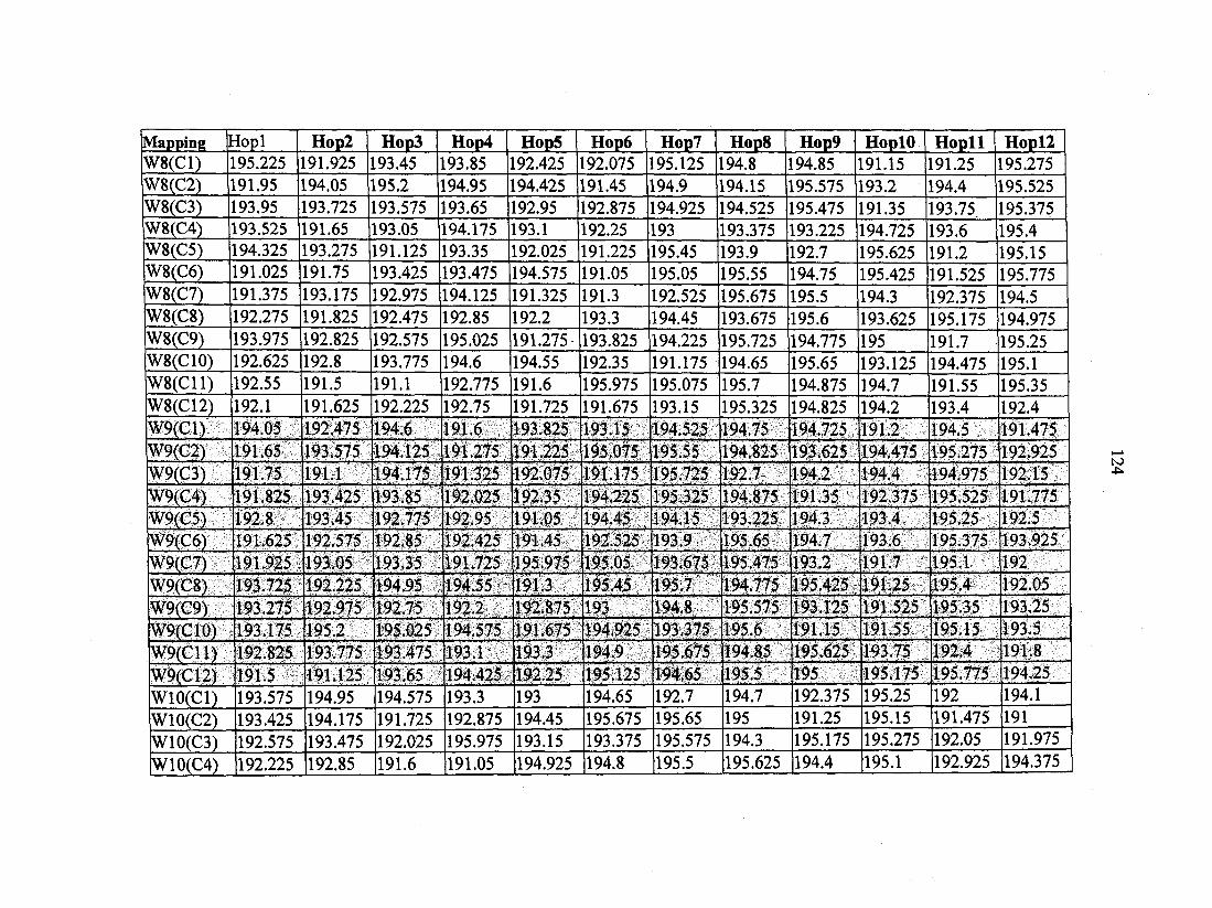
Mapping 1 "iopl Hop2 Hop3 Hop4 Hop5 Hop6 Hop? Hop8 Hop9 HoplO Hopll Hopll W8(C1) 195.225 191.925 193.45 193.85 192.425 192.075 195.125 194.8 194.85 191.15 191.25 195.275 W8(C2) 191.95 194.05 195.2 194.95 194.425 191.45 194.9 194.15 195.575 193.2 194.4 195.525 W8(C3) 193.95 193.725 193.575 193.65 192.95 192.875 194.925 194.525 195.475 191.35 193.75 195.375 W8(C4) 193.525 191.65 193.05 194.175 193.1 192.25 193 193.375 193.225 194.725 193.6 195.4 W8(C5) 194.325 193.275 191.125 193.35 192.025 191.225 195.45 193.9 192.7 195.625 191.2 195.15 W8(C6) 191.025 191.75 193.425 193.475 194.575 191.05 195.05 195.55 194.75 195.425 191.525 195.775 W8(C7) 191.375 193.175 192.975 194.125 191.325 191.3 192.525 195.675 195.5 194.3 192.375 194.5 W8(C8) 192.275 191.825 192.475 192.85 192.2 193.3 194.45 193.675 195.6 193.625 195.175 194.975 W8(C9) 193.975 192.825 192.575 195.025 191.275 193.825 194.225 195.725 194.775 195 191.7 195.25 W8(C10) 192.625 192.8 193.775 194.6 194.55 192.35 191.175 194.65 195.65 193.125 194.475 195.1 W8(C11) 192.55 191.5 191.1 192.775 191.6 195.975 195.075 195.7 194.875 194.7 191.55 195.35 W8(C12) 192.1 191.625 192.225 192.75 191.725 191.675 193.15 195.325 194.825 194.2 193.4 192.4 W9(C1) 194.05 192.475 194.6 191.6 193.825 193.15 194.525 194.75 194.725 1912 194.5 191.475 W9(C2) 191.65 193.575 194.125 191.275 191.225 195.075 195.55 194.825 193.625 194.475 195.275 192.925 W9(C3) 191.75 191.1 194.175 191.325 192.075 191.175 195.725 192.7 194.2 194.4 194.975 192.15 W9(C4) 191.825 193.425 193.85 192.025 192.35 194.225 195.325 194.875 191.35 192.375 195.525 191 775 W9(C5) 192.8 193.45 192.775 192.95 191.05 194.45 194.15 193.225 194.3 193.4 195.25 192.5 W9(C6) 191.625 192.575 192.85 192.425 191.45 192.525 193.9 195.65 194.7 193.6 195.375 193.925 W9(C7) 191.925 193.05 193.35 191.725 195.975 195.05 193.675 195.475 193.2 191.7 195 1 192 W9(C8) 193.725 192.225 194.95 194.55 191.3 195.45 195.7 194.775 195.425 191.25 195.4 192.05
W9(C9) 193.275 192.975 192.75 192.2 192.875 193 194.8 195.575 193.125 191.525 195.35 193.25
W9(C10) 193.175 195.2 195.025 194.575 191.675 194.925 193.375 195.6 191.15 191.55 195.15 193.5
W9(C11) 192.825 193.775 193.475 193.1 193.3 194.9 195.675 194.85 195.625 193.75 192.4 191 8
W9(C12) 191.5 191.125 193.65 194.425 192.25 195.125 194.65 195.5 195 195.175 195.775 194.25
WlO(Cl) 193.575 194.95 194.575 193.3 193 194.65 192.7 194.7 192.375 195.25 192 194.1
W10(C2) 193.425 194.175 191.725 192.875 194.45 195.675 195.65 195 191.25 195.15 191.475 191
W10(C3) 192.575 193.475 192.025 195.975 193.15 193.375 195.575 194.3 195.175 195.275 192.05 191.975
W10(C4) 192.225 192.85 191.6 191.05 194.925 194.8 195.5 195.625 194.4 195.1 192.925 194.375
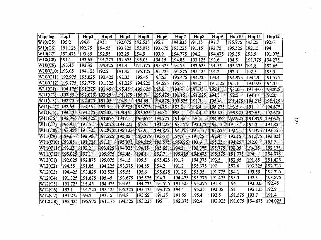
Mapping Uopl Hop2 Hop3 Hop4 Hop5 Hop6 Hop? Hop8 Hop9 HoplO Hopll Hopl2 W10(C5) 195.2 194.6 193.1 192.075 192.525 195.7 194.825 191.35 191.7 195.775 193.25 192.6 W10(C6) 191.125 192.75 194.55 193.825 195.075 193.675 193.225 191.15 193.75 195.525 192.15 194 W10(C7) 192.475 193.85 192.95 192.25 194.9 193.9 194.775 194.2 194.475 195.35 193.5 191.075 W10(C8) 191.1 193.65 191.275 191.675 195.05 194.15 194.85 193.125 193.6 194.5 191.775 194.275 W10(C9) 193.45 193.35 194.425 191.3 191.175 195.325 194.75 193.625 191.55 195.375 191.8 192.65 WIO(CIO) 193.05 194.125 192.2 191.45 195.125 195.725 194.875 195.425 191.2 192.4 192.5 195.3 WlO(Cll) 192.975 195.025 192.425 192.35 195.45 195.55 195.475 194.725 193.4 194.975 194.25 191.575 W10(C12) 193.775 192.775 191.325 191.225 194.225 194.525 195.6 193.2 191.525 195.4 193.925 194.35 Wll(Cl) 194.175 191.275 191.45 195.45 195.325 195.6 194.3 193.75 195.1 193.25 191.075 193.325 W11(C2) 192.85 192.025 192.25 191.175 195.7 195.475 191.15 191.525 194.5 192.5 194.1 192.3 W11(C3) 192.75 192.425 191.05 194.9 194.65 194.875 193.625 191.7 195.4 191.475 194.275 192.125 W11(C4) 193.65 194.55 193,3 192.525 195,725 194.75 193.2 193.4 195.275 193.5 191 194.675 W11(C5) 194.125 194.575 192.35 193.15 193.675 194.85 195 194.4 195.35 193.925 192.65 192.675 W11(C6) 192.775 194.425 191.675 193 195.675 194.775 191.35 191.2 194.975 192.925 191.975 194.625 W11(C7) 194.95 191.6 192.075 194.225 195.55 193.225 193.125 195.175 195.15 191.8 195.3 191.85 W11(C8) 193.475 191.325 192.875 195.125 193.9 194.825 194.725 191.55 195.525 192 194.375 193.55 W11(C9) 194.6 192.95 191.225 195.05 193.375 195.5 194.7 191.25 192.4 192.15 191.575 193.025 Wll(ClO) 193.85 191.725 191.3 195.075 194.525 195.575 195.625 193.6 195.25 194.25 192.6 193.7 Wll(Cll) 193.35 192.2 193.825 194.925 194.15 195.65 194.2 192.375 195.775 192.05 194.35 192.175 W11(C12) 195.025 193.1 195.975 194.45 194.8 192.7 195.425 194.475 195.375 191.775 194 194.075
W12(C1) 192.025 192.875 195.075 194.15 195.5 195.425 191.7 194.975 193.5 192.65 191.85 191.425 W12(C2) 194.55 191.05 194.225 193.375 194.85 194.2 191.2 195.375 192 192.6 193.325 192.725
W12(C3) 194.425 193.825 192.525 195.55 195.6 195.625 191.25 195.35 191.775 194.1 193.55 192.325
W12(C4) 191.325 191.675 195.45 193.675 195.575 194.7 194.475 195.775 191.475 195.3 192.3 193.875
W12(C5) 191.725 191.45 194.925 194.65 194.775 194.725 191.525 195.275 191.8 194 193.025 192.45
W12(C6) 193.1 191.225 195.125 195.325 195.475 193.125 194.4 195.25 192.05 191 192.125 192.9
W12(C7) 191.275 193.3 193.15 194.8 195.65 191.35 191.55 195.4 192.5 191.575 193.7 191.4
W12(C8) 192.425 195.975 191.175 194.525 193.225 195 192.375 192.4 192.925 191.075 194.675 194.025
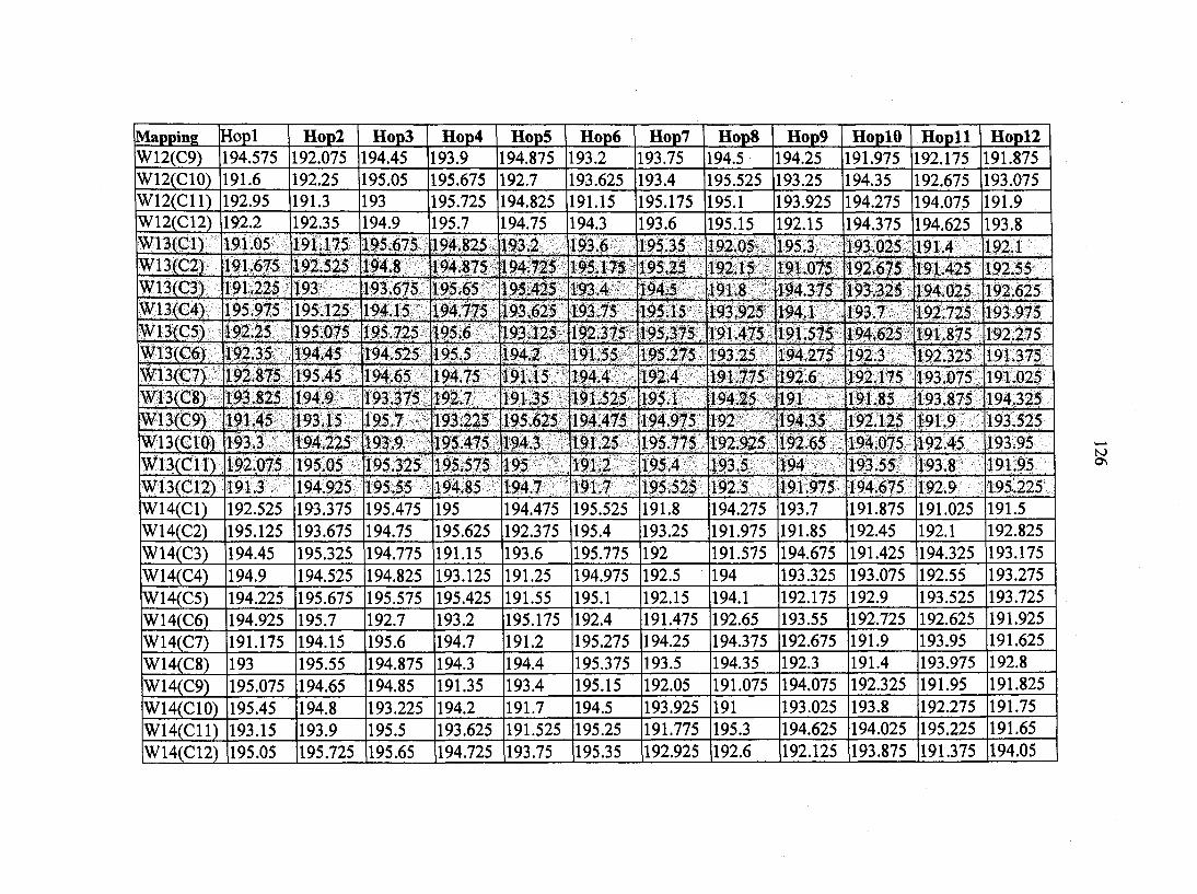
Mapping Hopl Hop2 Hop3 Hop4 Hop5 Hop6 Hop? Hop8 Hop9 HoplO Hopll Hopll W12(C9) 194.575 192.075 194.45 193.9 194.875 193.2 193.75 194.5 194.25 191.975 192.175 191.875 W12(C10) 191.6 192.25 195.05 195.675 192.7 193.625 193.4 195.525 193.25 194.35 192.675 193.075 W12(C11) 192.95 191.3 193 195.725 194.825 191.15 195.175 195.1 193.925 194.275 194.075 191.9 W12(C12) 192.2 192.35 194.9 195.7 194.75 194.3 193.6 195.15 192.15 194.375 194.625 193.8 W13(C1) 191.05 191.175 195.675 194.825 193.2 193.6 195 35 192.05 195.3 193 025 191.4 192.1 W13(C2) 191.675 192.525 194.8 194.875 194.725 195.175 195.25 192.15 191.075 192.675 191.425 192.55 W13(C3) 191.225 193 193.675 195.65 195.425 193.4 194.5 191.8 194.375 193.325 194.025 192.625 W13(C4) 195.975 195.125 194.15 194.775 193.625 193.75 195.15 193.925 194.1 193.7 192.725 193.975 W13(C5) 192.25 195 075 195.725 195.6 193.125 192.375 195.375 191.475 191.575 194.625 191.875 192.275 W13(C6) 192.35 194.45 194.525 195.5 194.2 191.55 195.275 193.25 194.275 192.3 192.325 191.375 W13(C7) 192.875 195.45 194.65 194.75 191.15 194.4 192.4 191.775 192.6 192.175 193.075 191.025 W13(C8) 193.825 194.9 193.375 192.7 191.35 191.525 195.1 194.25 191 191.85 193.875 194.325 W13(C9) 191.45 193.15 195.7 193.225 195.625 194.475 194.975 192 194.35 192.125 191.9 193.525 W13(C10) 193.3 194.225 193.9 195.475 194.3 191.25 195.775 192.925 192.65 194.075 192.45 193.95 W13(C11) 192.075 195.05 195.325 195.575 195 191.2 195.4 193.5 194 193.55 193.8 191.95 W13(C12) 191.3 194.925 195.55 194.85 194.7 191.7 195.525 192.5 191.975 194.675 192.9 195.225 W14(C1) 192.525 193.375 195.475 195 194.475 195.525 191.8 194.275 193.7 191.875 191.025 191.5 W14(C2) 195.125 193.675 194.75 195.625 192.375 195.4 193.25 191.975 191.85 192.45 192.1 192.825
W14(C3) 194.45 195.325 194.775 191.15 193.6 195.775 192 191.575 194.675 191.425 194.325 193.175 W14(C4) 194.9 194.525 194.825 193.125 191.25 194.975 192.5 194 193.325 193.075 192.55 193.275
W14(C5) 194.225 195.675 195.575 195.425 191.55 195.1 192.15 194.1 192.175 192.9 193.525 193.725 W14(C6) 194.925 195.7 192.7 193.2 195.175 192.4 191.475 192.65 193.55 192.725 192.625 191.925
W14(C7) 191.175 194.15 195.6 194.7 191.2 195.275 194.25 194.375 192.675 191.9 193.95 191.625
W14(C8) 193 195.55 194.875 194.3 194.4 195.375 193.5 194.35 192.3 191.4 193.975 192.8
W14(C9) 195.075 194.65 194.85 191.35 193.4 195.15 192.05 191.075 194.075 192.325 191.95 191.825
W14(C10) 195.45 194.8 193.225 194.2 191.7 194.5 193.925 191 193.025 193.8 192.275 191.75
W14(C11) 193.15 193.9 195.5 193.625 191.525 195.25 191.775 195.3 194.625 194.025 195.225 191.65
W14(C12) 195.05 195.725 195.65 194.725 193.75 195.35 192.925 192.6 192.125 193.875 191.375 194.05
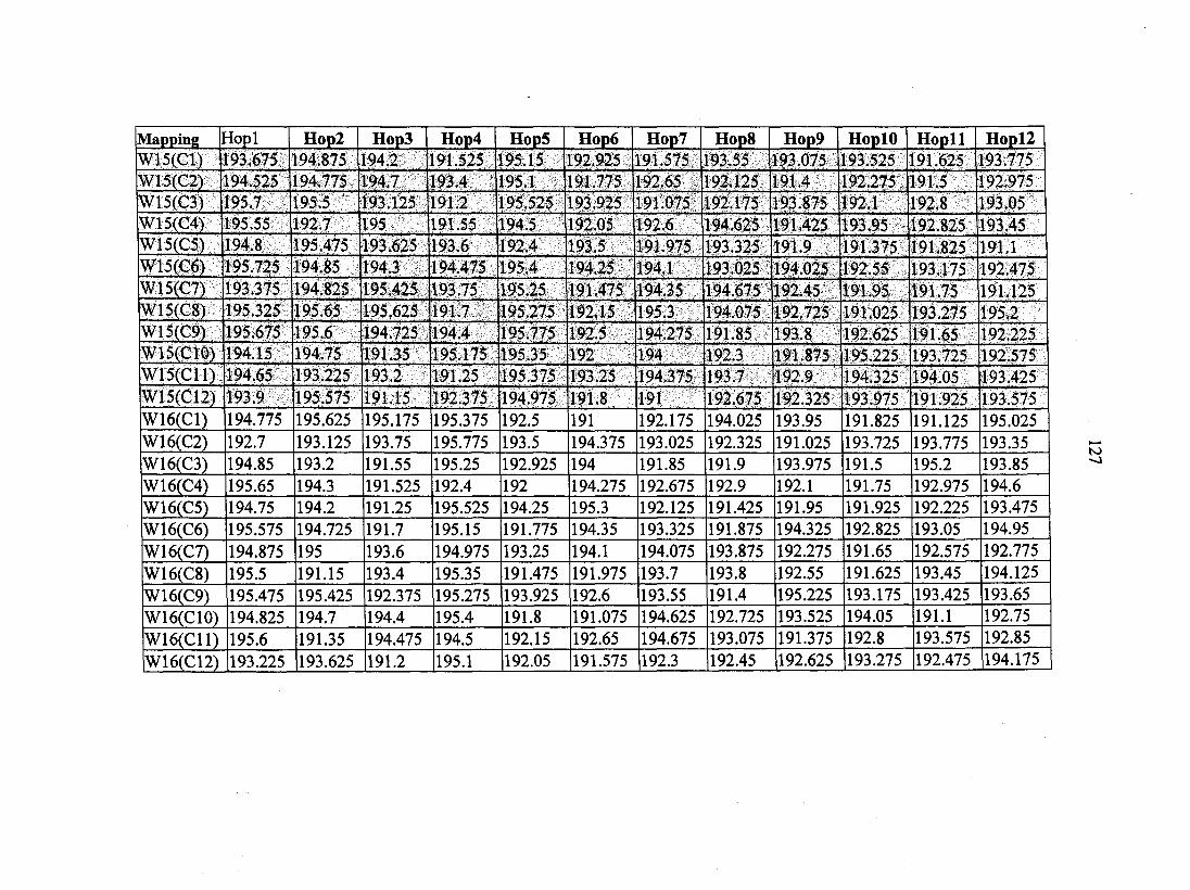
Mapping Hopl Hop2 Hop3 Hop4 Hop5 Hop6 Hop? Hop8 Hop9 HoplO Hopll Hopl2 W15(C1) 193 675 194.875 194.2 191.525 195.15 192.925 191 575 193.55 193.075 193.525 191.625 193.775 W15(C2) 194 525 194.775 194.7 193.4 195.1 191.775 192.65 192.125 191.4 192.275 191.5 192.975 W15(C3) 195.7 195.5 193.125 191.2 195.525 193.925 191.075 192.175 193.875 192.1 192.8 193.05 W15(C4) 195.55 192.7 195 191.55 194.5 192.05 192.6 194.625 191.425 193.95 192.825 193.45 W15(C5) 194.8 195.475 193.625 193.6 192.4 193.5 191.975 193.325 191.9 191.375 191.825 191.1 W15(C6) 195.725 194 85 194.3 194.475 195.4 194.25 194.1 193.025 194.025 192.55 193.175 192.475 W15(C7) 193.375 194.825 195.425 193.75 195.25 191.475 194.35 194.675 192.45 191.95 191.75 191.125 W15(C8) 195.325 195.65 195.625 191.7 195.275 192.15 195.3 194.075 192.725 191.025 193.275 195.2 W15(C9) 195.675 195.6 194.725 194.4 195.775 192.5 194.275 191.85 193.8 192.625 191.65 192.225 W15(C10) 194.15 194.75 191.35 195.175 195.35 192 194 192.3 191.875 195.225 193.725 192.575 W15(C11) 194.65 193.225 193.2 191.25 195.375 193.25 194.375 193.7 192.9 194.325 194.05 193.425 W15(C12) 193.9 195.575 191.15 192.375 194.975 191 8 191 192.675 192.325 193.975 191.925 193.575 W16(C1) 194.775 195.625 195.175 195.375 192.5 191 192.175 194.025 193.95 191.825 191.125 195.025 W16(C2) 192.7 193.125 193.75 195.775 193.5 194.375 193.025 192.325 191.025 193.725 193.775 193.35 W16(C3) 194.85 193.2 191.55 195.25 192.925 194 191.85 191.9 193.975 191.5 195.2 193.85 W16(C4) 195.65 194.3 191.525 192.4 192 194.275 192.675 192.9 192.1 191.75 192.975 194.6 W16(C5) 194.75 194.2 191.25 195.525 194.25 195.3 192.125 191.425 191.95 191.925 192.225 193.475 W16(C6) 195.575 194.725 191.7 195.15 191.775 194.35 193.325 191.875 194.325 192.825 193.05 194.95
W16(C7) 194.875 195 193.6 194.975 193.25 194.1 194.075 193.875 192.275 191.65 192.575 192.775 W16(C8) 195.5 191.15 193.4 195.35 191.475 191.975 193.7 193.8 192.55 191.625 193.45 194.125
W16(C9) 195.475 195.425 192.375 195.275 193.925 192.6 193.55 191.4 195.225 193.175 193.425 193.65
W16(C10) 194.825 194.7 194.4 195.4 191.8 191.075 194.625 192.725 193.525 194.05 191.1 192.75
W16(C11) 195.6 191.35 194.475 194.5 192.15 192.65 194.675 193.075 191.375 192.8 193.575 192.85
W16(C12) 193.225 193.625 191.2 195.1 192.05 191.575 192.3 192.45 192.625 193.275 192.475 194.175

128
APPENDIX E: SIMULATION RESULTS FOR FILES F3, F4, AND F5
The shaded channels in each file are those used to monitor performances
(channels A, B, C, and D) of Figure 13.
HOP 1 HOP 2 HOP 3 HOP 4 HOP 5
Filcl (THz) File2 (THz) File3 (THz) File4 (THz) File5 (THz)
193.325 192.45 191.025 193.175 192.225
191.75 193.425 193.475 194.575 191.05
191.175 195.675 194.825 193.2 193.6
193.7 191.9 192.275 193.275 193.575
193.65 191.275 191.675 195.05 194.15
192.75 194.55 193.825 195.075 193.675
191.7 195.375 194.25 191.075 193.55
194.15 195.6 194.7 191.2 195.275
195.35 192.15 194.35 191.85 194.025
193 193.675 195.65 193.4
195.1 191.8 192.6 194.675 193.8
193 3 193.15 194.8 195.65 191.35
194.925 195.55 194.85 194.7 191.7
191.675 195.45 199.675 195.575 194.7
191.25 195.25 193.5 194.275 192.175
193.175 192.975 194.125 191.325 191.3
193.95 191.65 191.1 194.6 192.025
191.025 191.825 192.575 194.125 194.55
193.15 195.7 193.225 195.625 194.475
191.075 193.025 193.075 194.325 191.65
191.125 193.65 194.425 192.25 195.125
194.975 191.475 194.375 192.175 191.4
195.775 191.775 191.975 192.675 192.725
194.075 194.025 191.375 191.75 193.45
192.25 195.05 195.675 192.7 193.625
192.575 192.85 192.425 191.45 192.525
193.575 194.125 191.275 191.225 195.075
192.525 194.8 194.875 194.725 195.175
192.4 192.05 194 193.7 193.875
191.45 194.925 194.65 194.775 194.725
191.1 194.175 191.325 192.075 191.175
191 193.7 191.425 191.375 193.725
194.35 193.55 192.9 193.95 193.275
193.425 193.85 192.025 192.35 194.225
193.075 191.95 193.725 193.45 194.175
191.95 193.175 193.575 192.775 191.725
195.225 192.8 192.475 192.75 194.575
193.05 193.35 191.725 195.975 195.05

129
194.05 ' 195.2 •' i|;,. 194.95 194.425 191.45
193.55 191.425 193.975 191.65 191.125
195.3 192.175 192.45 193.975 194.05
192.875 195.075 194.15 195.5 195.425
194.375 191.85 192.725 195.225 191.75
195.05 195.325 195.575 195 191.2
191.625 192.225 192.75 191.725 191.675
194.025 192.1 193.275 193.425 192.775
194.275 193.325 193.875 191.95 191.625
193.8 194.325 191.925 192.575 194.6
192.35 194.9 195.7 194.75 194.3
192.85 191.6 191.05 194.925 194.8
195.075 195.725 195.6 193.125 192.375
191.825 192.475 192.85 192.2 193.3
191.425 192.275 191.625 193.05 193.65
194.325 191.5 193.45 192.85 193.1
194.45 194.525 195.5 194.2 191.55
195.15 194.25 192.65 192.3 192.9
193.925 194.375 192.125 192.45 192.55
195.975 191.175 194.525 193.225 195
193.525 191.925 193.425 191.6
193.85 192.95 192.25 194.9 193.9
192.65 194.625 191.9 192.1 193.175
193.375 195.475 195 194.475 195.525
191.5 191.1 192.775 191.6 195.975
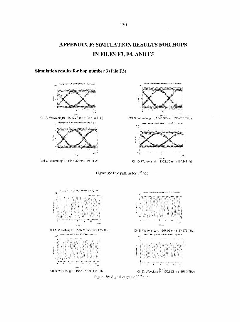
130
APPENDIX F: SIMULATION RESULTS FOR HOPS
IN FILES F3, F4, AND F5
Simulation results for hop number 3 (File F3)
X X. CH A; Wavelength ; 1546-72 nm (193.425 THz)
2LX
CH B: Wavelength : 1547.92 nm (193.675 THz)
«5 CtirtrzMi:. tTatr f .ii-kaeaiPiei 9cX Cm D Ey*
CH C: Wavelength : 1545.32 nm (194 THz) CH D Wavelength : 1562.23 nm (19' .9 THz)
Figure 35: Eye pattern for 3r hop
I J
AM m CH ^ K»1
r , u 4 ^ i * = :
CHA: Wavelength : 1546.7/ run 1/193.425 "T'hLg M# n*WM#K(CHC CiyuC MM
r iki,
CH B: Wavelength : 1547.92 nm (193.675 THz)
UH (J: Wavelength : 1b4b.32 nm (1D4 I Hz; CH D: Wavslencth : 1562.23 nn (191 -9 THz)
Figure 36: Signal output of 3" hop
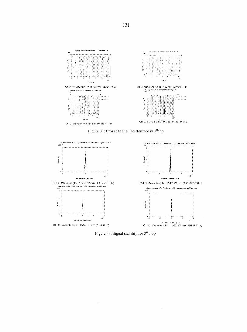
131
CH A: Wavelength . 1546.72 nm (103.425 TH^S CH E: Wavelength 1547 92 nm (193.675 THz; k(,. | Mm f'"f (#»-« Hr ke» PI
Il I Li, ' I
CH C' Wavelength • 154.5 32 nm (194 THz) uh u: Waveiengm . 16 nm (lyi.y imz
Figure 37: Cross channel interference in 3r hp
S
r
CH A: Wflvslprnjth • nm TH/)
CH C Wavolcnqth : 1545 32 mi .104 THz)
CH B: Wavelength : 1547.92 nm (195.675 THz)
Ci 0. Wavelength . 1562.23 run (5 91 9 THz)
Figure 38: Signal stability for 3r hop
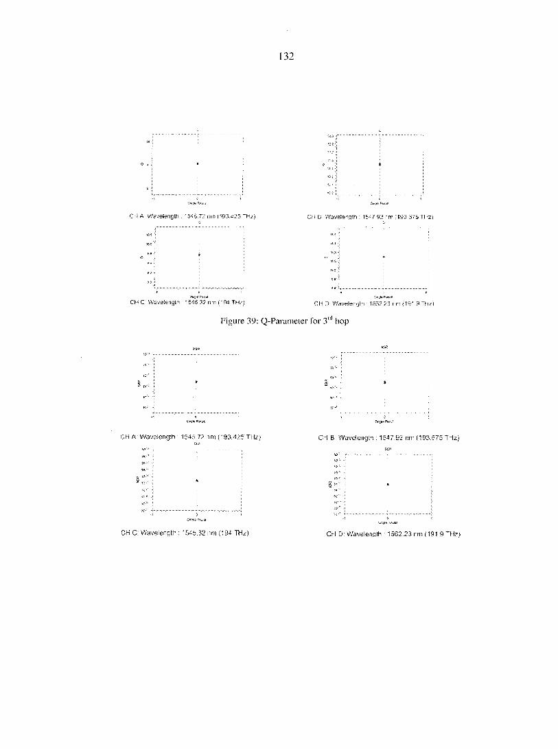
132
CH A. Wavelength : 1566.72 nm 1193 425 THt CH B Wavelength : 1547 92 nm (193 875 THz)
CH C Wavelength 1545.32 nm (194 THz) CH D: Wavelength 1552.23 rm (191.9 THz)
Figure 39: Q-Parameter for 3r hop
CH A: Wavslength : 1545.72 nm (193.425 THzJ
CH C: Wavelength ; '545.32 nm (194 TH/j
CH B: Wavelengh : 1547.92 nm (193.575 THz)
CH D: Wavelength : 1562.23 rm (191.9 ~Hz)
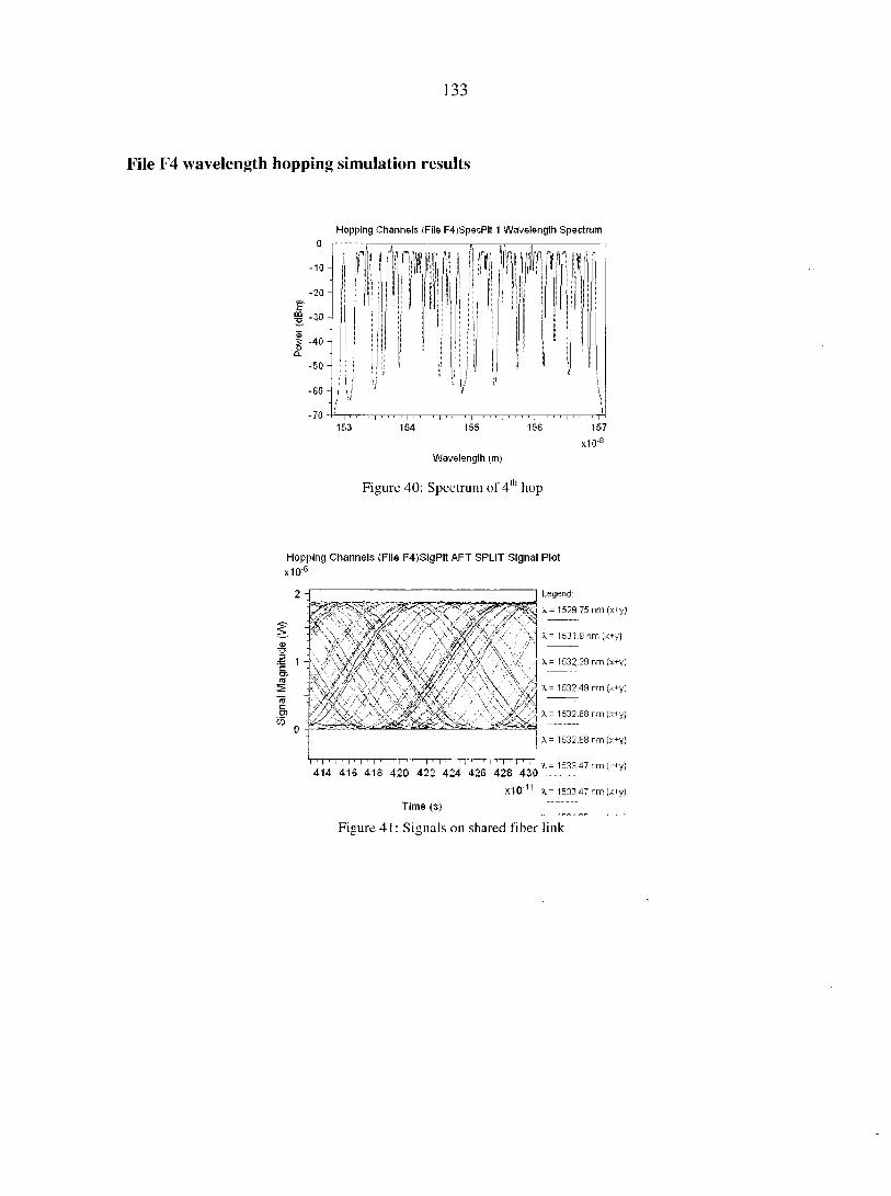
133
File F4 wavelength hopping simulation results
Hopping Channels (File F4)SpecPlt 1 Wavelength Spectrum
- 1 0 -
- 2 0 -
-30 -
5 -40 -CL
-50 -
- 6 0 -
-70
153 157 154 155 156
x10"B
Wavelength (m)
Figure 40: Spectrum of 4th hop
Hopping Channels (File F4)SigPlt AFT SPLIT Signal Plot
x10
.•= 1
%
Legend:
A. = 1529 75 nm (x+y)
X - 1531.9 nm (x+y)
X - 1532 29 nm (x+y)
\ - 1532 49 nm (x+y)
X = 1532.68 nm (x+y)
1 I 1 I 1 I 1 I 1 I ' I 1 I 1 I 1 I 1 I 1 I 1 I 1 I ' I 1 I 1 I 1 I 414 416 418 420 422 424 426 428 430
x10"'1
X = 1532.83 nm (x+y)
3l= 1533.47 nm (x+y)
X- 1533 47 nm (x+y)
Time (s)
Figure 41: Signals on shared fiber link
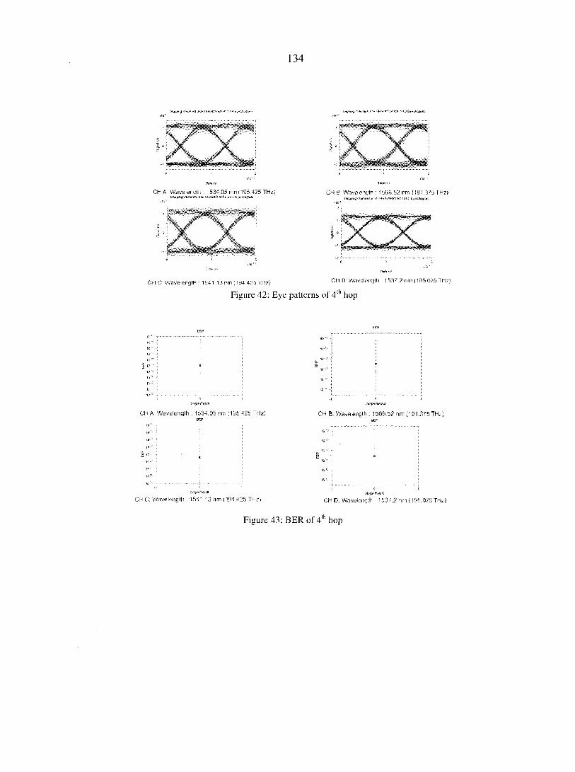
134
CM A Wavelength : 1534.05 nm (195 425 THz) tWppkg CMnetR F4>Mv»;P'»l P. f. i.H C k'.n- Diagram
CH B1 Wavelength • 1566 52 nm (191 375 THz)
CM C. Wavelength : 1541.13 nm (194 425 THz
Figure 42: Eye patterns of 4 hop
CH D: Wavelength : 1537 2 nm (195 025 THz)
th ,
CH A: Wavelength . 1534.05 nm (195.425 THz) CH B. Wavelength ; 1566 5? nm (1&1.375 THz)
CH C: Wavelength 1541.13 nm (194.425 THz} CH D: Wavelength 153T.2 nm (195.025Thk)
Figure 43: BER of 4' hop
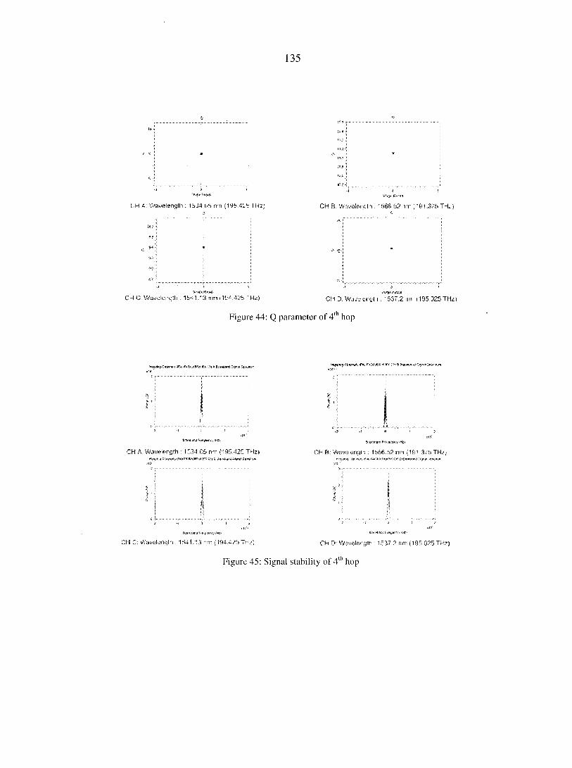
135
UH A: Wavelength : 1 S'M Uh nn (1 f Hz) CH B: Wavelength : '566.52 nm 91,375 THz)
CH C: Wavclcrcth : 15*-1.13 nmi 1GA425 'Hz) CH D. Wd^eryl i . '537.2 un i'195.325Thi)
Figure 44: Q parameter of 4" hop
I r i CH A: Wavelength : 1534 05 nm (195.425 THz)
». rwnMaffp'ZM-c**
Chi C Wavelength . 1541.13 nm (1ÎI4.425 TH^)
CH B: Wavelength : 1566.52 nm (191 375 THz)
CH D: Wavelength : 1537 2 nm (195 025 THz)
Figure 45: Signal stability of 4' hop
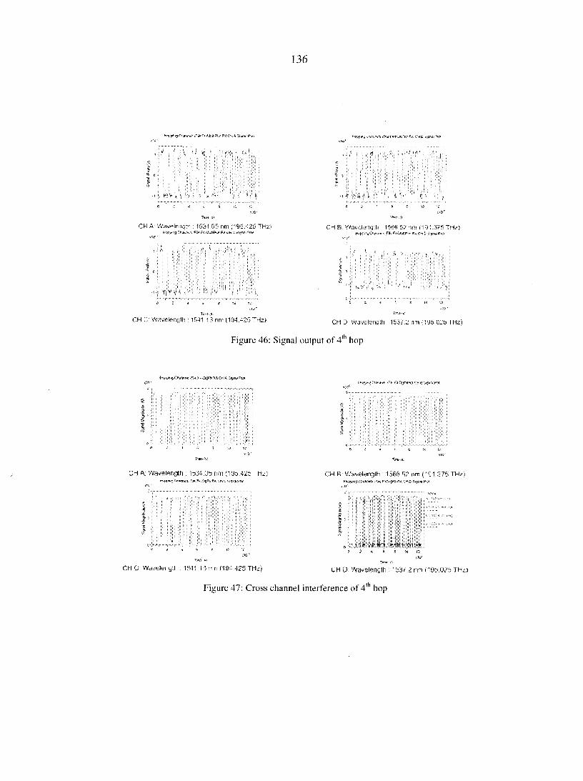
136
f f » I :
Ï. I
' k *
ÏJ I :
CH A: Wavelength 1534.05 nm (195.425 THz) Chyvh-ti! ;F5t Pi 4&#A* PX CH £ Si fiSf MM
I f $ V 4
CH C' Wavelength : 1541.13 nm (194.425 THzi-
CH B. Wavelength : 1566.52 nm i 191.3/5 THz)
CH D Wavelength : 15J7.2 nm (195 025 THz
Figure 46: Signal output of 4* hop
CM A,; Wavelength! : 1bJ4-.Ub nm (VdbAlt Hz)
iJ .i5.,*ztr^;$9FKf.x-vMC
CH C Wd/eltii ytl . 1541.13 rui (19^.425 TH4
CH R' Wavelenqlh • 1566 5? nm ("Ç1 575 TH7i MWTfPVrWW if** p+tïff# M ,MDPîî
• * wlkl!iî" Lifi #15# i
CM D: Wai/eleneiM : 'bj/.Zrm (195.025
Figure 47: Cross channel interference of 4th hop
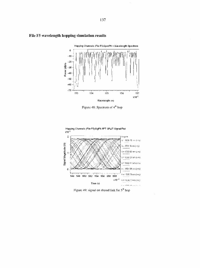
137
File F5 wavelength hopping simulation results
Hopping Channels (File F5)SpecPlt 1 Wavelength Spectrum
- 1 0 -
- 2 0 -
2. "30 ~
-40 -
-50 -
I - 6 0 -
-70
x10"8
Wavelength (m)
Figure 48: Spectrum of 4th hop
Hopping Channels (File F5)SigPlt AFT SPLIT Signal Plot
x10 6
Legend:
X - 1529 .75 nm (x+y)
X = 1531.9 nm (x+y)
X - 1532.68 nm (x+y)
X = 1533.27 nm (x+y)
X = 1533 47 nm (x+y)
X = 1534.05 nm (x+y)
I 1 I 1 I 1 I 1 I 1 I ' i 1 i • I 1 I 1 i 546 548 550 552 554 556 558 560
X = 1535.23 nm (x+y)
X10" x - 1536.02 nm (x+y)
Time (s)
Figure 49: signal on shared link for 51 hop
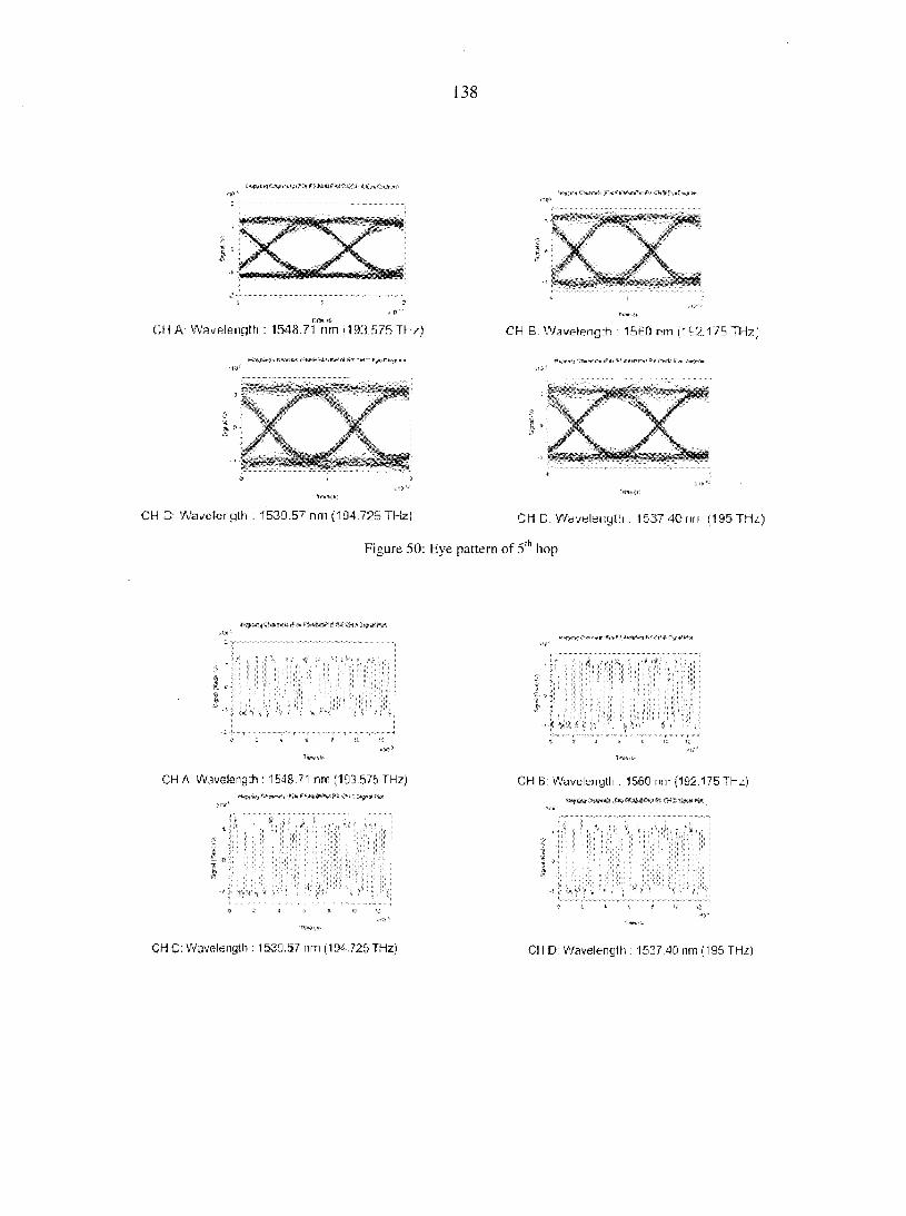
138
CH A: Wavelength : 1548.71 nm ( iEKi575Thz)
CH C: Wavcicrgth : 1633.5? nm (194.725 THz) CH C. WdVtilsnylli . 1537 40,n, (195 THz)
Figure 50: Eye pattern of 5th hop
CH A: Wavelength : 1548.71 nm (193.575 THz) CH B: Wavelength : 1560 nm (192.175 THz)
CH C: Wavelength : 1539.57 nm (194.725 THz) CH D: Wavelength : 1537.40 nm (195 THz)
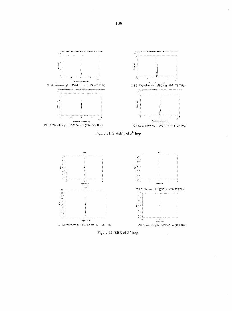
139
CH A: Wa/elenglh ; 154871 nm (1S3.575 THz) CH B: Wavelength : 1560 nm (192.175 THz)
CH C. Wavelength : 1539.57 nm (194.725 THz) CM D: Wavelength 153/.40 rm (19d THz)
Figure 51: Stability of 5' hop
S" '
swgseResul CH C Wavelength 1539 57 nm (194.725 THz)
•Hh r>m M Q9 17^ Tl-I ,
/iingiB A* 51»
CH D: Wavelength : 1537 40 nm (195 THz)
Figure 52: BER of 5" hop
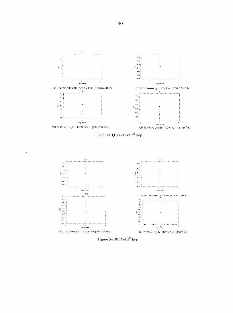
140
C~l f\: Wavelength : 1 £43.71 nm :153.575 THz) B: Waveleng:h : '56C nm (192/75 THz
CH C Wevclcngth : 1&33.57 nn (104 /25 Hz) CH D. Wave ength . 1537.40 run (105 TH
Figure 53: Q pattern of 5th hop
CH C Wavelength 1539.57 nm (194.725THz) CH • Wavelength 1537 40 nm (195 THz)
Figure 54: BER of 5th hop
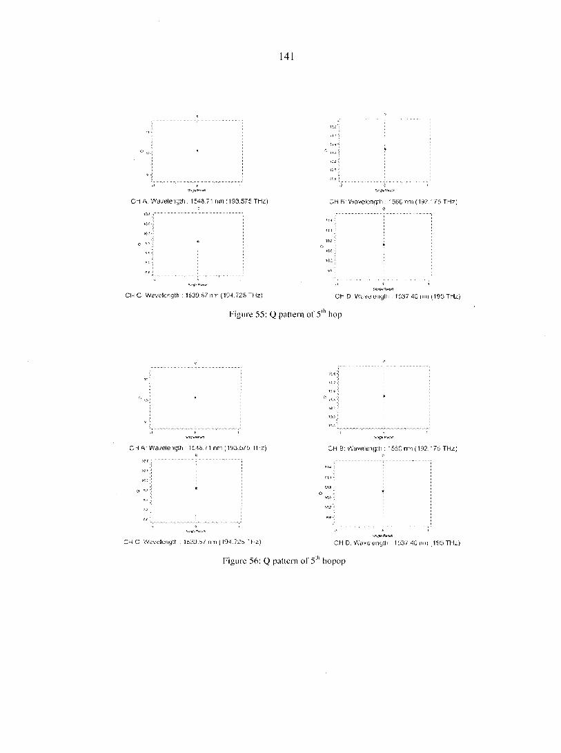
141
C~i f\: Wa-/ele'igth : 1 £48.71 nm 1193.575 THz) ;H B: Waveleng:h : '56C nm (192/75 THz)
».>
J
CH C Wavelength : 15313.57 nn (194./25 Hz) CH D Wsvetmgth . i 037.40 run 1195 THz)
Figure 55: Q pattern of 511 hop
C~l A.: Wa-/ele"igth : 1 £43.71 nm 1193.575 THz) ;H B: Wavelengrh : • 5DC nm (192/ 75 THz;
CMC Wevclcngth : 1b30.i>7 n-n (KM./25*Hz) CM D. Waveenglli . 1537.40 nm 1195 THz)
Figure 56: Q pattern of 5' hopop
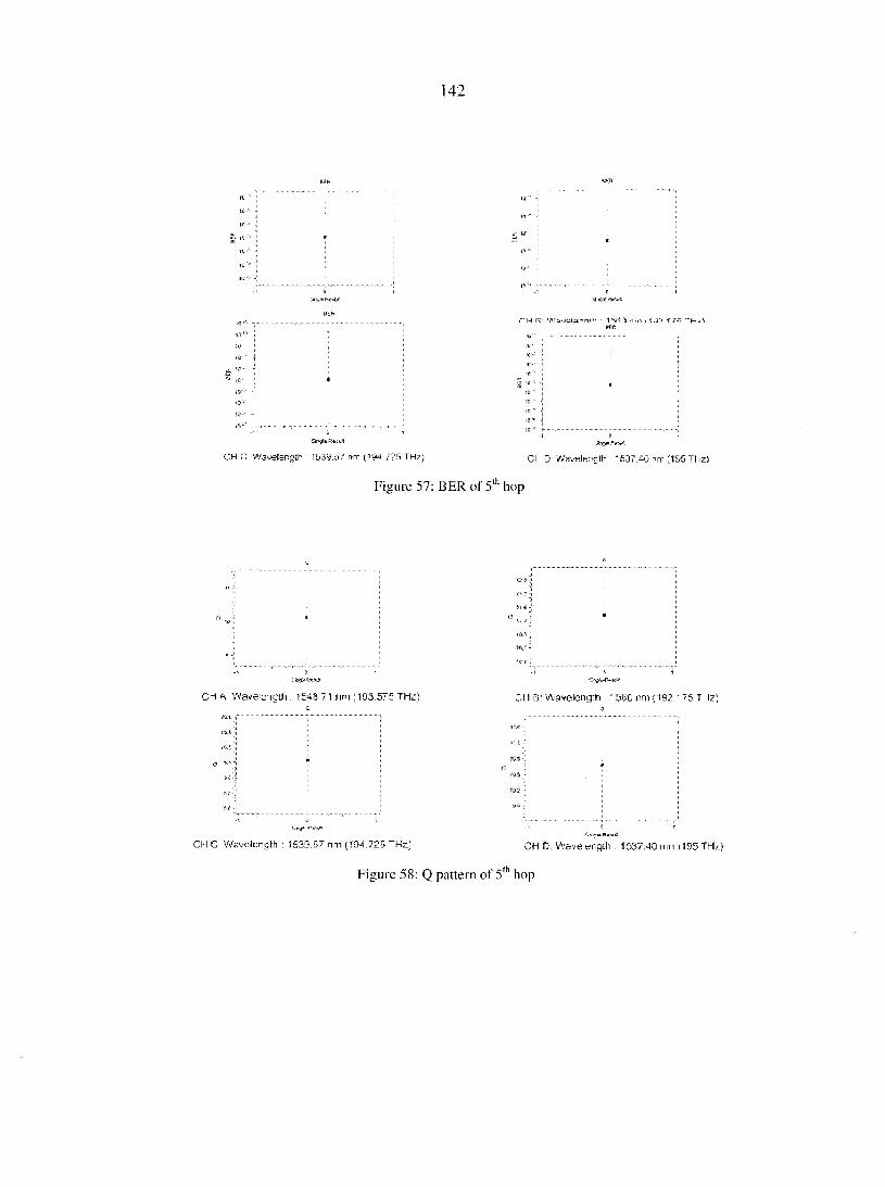
142
s: IS'-'
ri-l R Wauofannth ( 1 07 1 7A TH/1
CH C Wavelength 1539,57 nm (194.725THz) CH D' Wavelength . 1537.40 ri m (195 THzS
Figure 57: BER of 5* hop
C~l A.: Wavelength : 1548.71 nrri ; 193.575 THz) :H B: Waveletig-h : ' 56C nm ( 192. ' i 5 THz
CH C Wavelength : 1539.b7 nn (104 /25 Hz) CH D. Weveenglli . f 037.40 nm i195TH
Figure 58: Q pattern of 5l hop
143
BIBLIOGRAPHY
[1] Borella, M.S., Jue, J. P., Banerjee, D., Ramamurthy, B., and Mukherjee, B., "Optical components for WDM lightwave networks," Proceedings of the IEEE, Vol. 85, No. 8, pp. 1274-1307, Aug. 1997.
[2] Park, S.-J., Lee, C.-H., Jeong, K.-T., Park, H.-J., Ahn, J.-G., and Song, K.-H., "Fiber-to-the-home services based on wavelength-division-multiplexing passive optical network," Journal of Lightwave Technology, Vol. 22, No. 11, pp. 2582-2591, Nov. 2004.
[3] Stok A., and Sargent, E.H., "The role of optical CDMA in access networks," IEEE Communications Magazine, pp. 83-87, Sept. 2002..
[4] Harstead, E., "System requirements for optical components in the loop," Lucent Technologies Inc. Lasers and Electro-Optics Society Annual Meeting, p. 7, Nov. 1996.
[5] Medard, M., Marquis, D., Barry, R.A., and Finn, S.G., "Security issues in all-optical networks," Network IEEE, Vol. 11, No. 3, pp. 42-48, May-June 1997.
[6] Hamad, A.M., and Kamal, A.E. "A survey of multicasting protocols for broadcast-and-select single-hop networks," IEEE Network, pp. 36-48, July/Aug. 2002.
[7] Ramaswami, R., and Sivarajan, K.N., Optical Networks, Practical Perspective, 2d éd., San Francisco: Morgan Kaufmann Publishers, 2002, p.2.
[8] Gumaste, A., and Antony, T. DWDM Network Designs and Engineering Solutions, Indianapolis, IN: Cisco Press, pp. 147-148.
[9] Sherif, S R., Hadjiantonis, A., Ellinas, G., Assi, C., and Ali, M.A, "A novel decentralized ethernet-based PON access architecture for provisioning differentiated QoS," Journal of Lightwave Technology, Vol. 22, No. 11, pp. 2483-2497, Nov. 2004.
[10] Paré, L.-R., "Cost effective broadband architecture for metro networks," Lasers and Electro-Optics Society (LEOS), 16th Annual Meeting of the IEEE, Vol. 2, pp. 612-613,2003.
[11] Heavy Reading, Real World Research, http://www.heavyreading.com/ document.asp?site=heavyreading&doc_id=9324page_number=3 (retrieved 14 Jan. 2006).
144
[12] G.983.1, Telecommunication Standardization Sector of ITU (10/98)—Series G: Transmission Systems and Media, Digital Systems and Networks—Broadband Optical Access Systems Based on Passive Optical Networks (PON).
[13] IEEE Std 802.3ah™-2004, (Amendment to IEEE Std 802.3™-2002 as amended by IEEE Stds 802.3ae™_2002, 802.3af™-2002, 802.3aj™-2003, and 802.3ak™-2004).
[14] Asatani, K., and Maeda, Y., "Access network architectural issues for future telecommunication networks," IEEE Communications Magazine, pp. 110-114, Aug. 1998.
[15] Kramer, G, and Pesavento, G, "Ethernet passive optical network (EPON): Building a next-generation optical access network," IEEE Communications Magazine, Feb. 2002.
[16] Zheng, J., and Mouftah, H.T., "Media access control for Ethernet passive optical networks: An overview." IEEE Communications Magazine, Feb. 2005.
[17] Harris, J.S., Jr., "Tunable long-wavelength vertical-cavity lasers: The engine of next generation optical networks?" IEEE Journal of Selected Topics in Quantum Electronics, Vol. 6, No. 6, pp. 1145-1160, Nov.-Dec. 2000.
[18] Shrikhande, K.V., Lentine, A.L., Nuss, M.C., Kogelnik, H., Krishnamoorthy, A.V., Avenarius, M, and Kazovsky, L.G., "Fiber-to-the-home/desktop using Ethernet," IEEE Journal on Selected Areas in Communications, Vol. 18, No. 10, pp.2004-2016, Oct. 2000.
[19] Chan, C. K., Sherman, K.L., and Zirngibl, M., "A fast 100-channel wavelength-tunable transmitter for optical packet switching," IEEE PhotonicsTechnology Letters, Vol. 13, No. 7, July 2001.
[20] Mynbaev, D.K., and Scheiner, L.L., Fiber-Optic Communications Technology, Upper Saddle River, NJ: Prentice Hall, 2001.
[21] Yasaka, H., Okuno, M., and Sugahara, H., "Device technologies for photonic networks" NTT Photonics Laboratories, Vol. 1, No. 8, Nov. 2003.
[22] Bengi, K., Optical Packet Access Protocols for WDM Networks, Norwell, MA: Kluwer Academic Publishers, 2002.
[23] Kimura, H.A., Tohmon, G, Nishikawa, T., Uno, T., and Morikura, S., "High performance optical receiver using hybrid integration in line photodiode module and preamplifiers fir passive optical network."
145
[24] Parker, M.C., and Mears, R.J., "Digitally tunable wavelength filter and laser," IEEE Photonics Technology Letters, Vol. 8, No. 8, pp. 1007-1008, Aug. 1996.
[25] Tachikawa, Y., and Okamoto, K., "Arrayed wave guide granting laser and their applications to tuning-free wavelength routing," IEE Proc. Optoelectronics, Vol. 143, No. 5, Oct. 1996.
[26] International Telecommunication Union, (ITU-T) G.694.1, Telecommunication Standardization Sector of ITU, "Spectral grids for WDM applications: DWDM frequency grid," SERIES G: Transmission systems and media, digital systems and networks transmission media characteristics—Characteristics of optical components and subsystems: ITU-T Study Group 15 (2001-2004) and approved under the WTSA Resolution 1 procedure on 13 June 2002.
[27] Sarlet, G., Morthier, G., and Baets, R., "Wavelength and mode stabilization of widely tunable SG-DBR and SSG-DBR lasers," IEEE Photonics Technology Letters, Vol. 11, No. 11, Nov. 1999.
[28] Sugihwo, F., Lin, C.-C., Eyres, L.A., Fejer, M.M., and Harris, J.S., Jr., "Broadly-tunable narrow-linewidth micromachined laser/photodetector and phototransistor," Electron Devices Meeting, 1998. IEDM '98 Technical Digest International, pp. 665-668, 6-9 Dec. 1998.
[29] Misono, M., Henmi, N.; Hosoi, T., and Fujiwara, M., "High-speed wavelength switching and stabilization of an acoustooptic tunable filter for WDM network in broadcasting stations," IEEE Photonics Technology Letters, Vol. 8, No. 4, pp. 572-574, April 1996.
[30] Sadot, D., and Boimovich, E., "Tunable optical filters for dense WDM networks" IEEE Communications Magazine, Vol. 36, No. 12, pp. 50-55, Dec. 1998.
[31] Westphal, F.-J., Hermes, T., Hilbk, U., Meissner, P., and Schmidt, F., "Transmissive star coupler based experimental dense WDM-LANs interconnected via a central node," Flat Panel Display Technology/Technologies for a Global Information Infrastructure/ICs for New Age Lightwave Communications/RF Optoelectronics, 1995 Digest of the LEOS Summer Topical Meetings, pp. 20-21, 7-11 Aug. 1995.
[32] Kauer, M., Girault, M., Leuthold, J., Honthaas, J. Pellegri, O., Goullancourt, C., and Zirngib, M., "16-channel digitally tunable external-cavity laser with nanosecond switching time," IEEE Photonics Technology Letters, Vol. 15, No. 3, March 2003.
[33] Krainer, L. Spiililer, G.J., Kilburn, I.J., Golding, P.S., Crosby, S.A., Brownell, M., and Weingarten, K.J., "C-band tunable 25-GHz passively mode-locked Er:Yb:glass laser," GigaTera, Inc. and Ultrafmt Laser Physics, Zurich, Switzerland.
146
[34] Yoshikuni, Y. "Semiconductor optical Devices for WDM networks," NTT Opto-Electronics Laboratories, Kanagawa, Japan.
[35] Hammond, B., Su, B. Mathews, J., Chen, J., and Schwarts, E., "Integrated wavelength locker for tuneable laser applications," Digital Optics Corporation, Charlotte, NC.
[36] Huang, Y., Heritage, J.P., and Mukherjee, B. "Connection provisioning with transmission impairment consideration in optical WDM networks with high-speed channels," Journal of Lightwave Technology, Vol. 23, No. 3, March 2005.
[37] Strand, J., Chiu, A.L., and Tkach, R., "Issues for routing in the optical layer," IEEE Communications Magazine, February 2001.
[38] Ueda, H., Okada, K., Ford, B., Mahony, G., Hornung, S., Faulkner, D., Abiven, J., Durel, S., Ballart, R., and Erickson, J., "Deployment status and common technical specifications for a B-PON system," IEEE Communications Magazine, Vol. 39, No. 12, pp. 134-141, Dec. 2001.
[39] Davey, R.P., Healey, P., Hope, I., Watkinson, P., Payne, D.B., Marmur, O., Ruhmann, J., and Zuiderveld, Y, "DWDM reach extension of a GPON to 135 km," Optical Fiber Communication Conference 2005 Technical Digest, Vol. 6, p. 3, 6-11 March 2005.
[40] Strand, J., and Chiu, A., Eds., "RFC 4054—impairments and other constraints on optical layer routing," Network Working Group, AT&T, May 2005
[41] Newhouse, M., and Liu, Y, "System needs for dispersion compensation," Symposium on Requirements and Techniques of Dispersion Compensation Lucent Technologies, OFC '97 Technical Digest, 1997.
[42] Downie, J.D., Annunziata, F., Filios, A., Kennedy, T., Kim, D., and Oh, S., "Large effective area non-zero dispersion shifted fiber in metro/provincial network environments," Proceedings ofSPIE, Vol. 5279, 2004.
[43] Belahlou, A., Bickham, S., Chowdhury, D., Diep, P., Evans, A., Grochocinski, J.M., Han, P., Kobyakov, A., Kumar, S., Luther, G, Mauro, J.C., Yihong Mauro, Mlejnek, M., Muktoyuk, M.S.K., Murtagh, M.T., Raghavan, S., Ricci, V, Sevian, A., Taylor, N., Tsuda, S., Vasilyev, M„ and Wang, L., "Fiber design considerations for 40 Gb/s systems," Journal of Lightwave Technology, Vol. 20, No. 12, pp. 2290-2305, Dec. 2002.
[44] Judy, A. F., "Optimizing fiber dispersion for DWDM systems" OFC 97 Technical Digest, 1997.
147
[45] Agrawal, G.P., "Light wave technology telecommunication system," Hoboken, NJ: John Wiley and Sons, 2005.
[46] Yang, G.-C., and Kwong, W.C., "Performance comparison of multiwavelength CDMA and WDMA CDMA for fiber-optic network," IEEE Transactions on Communications, Vol. 45, No. 11, Nov. 1999.
[47] Xu, B., and Brandt-Pearce, M., "Comparison of FWM- and XPM-induced crosstalk using the volterra series transfer function method," Journal of Lightwave Technology, Vol. 21, No. 1, Jan. 2003,
[48] Thing, V.L.L., P. Shum, P., and Rao, M.K., "Channel allocation algorithm for WDM systems," OSA 2003, Optics Express, Vol. 11, No. 11, pp. 1322-1327, June 2003.
[49] Chan, S C., Lu, M., Udpa, S.S., Udpa, L., and Jacobson, D.W., "All-optical dense WDM wide-area communication network," IEEE 39th Midwest Symposium on Circuits and Systems, Vol. 3, pp. 1157-1160, 18-21 Aug. 1996.
[50] Minn, S., and Won, Y.-H., "Upper-bounds on bit error rate of OCDMA systems using the time spreading/wavelength-hopping codes", School of Engineering, Information and Communication University, IEEE Publication document number 0-9803-5947-X00, 2000.
[51] Federal Information Processing Standards Publication 191, "Specifications for Guidelines for The Analysis Local Area Network Security," FIPS PUB 191,9 Nov. 1994.
[52] Médard, M., Marquis, D., and. Chinn, S.R., "Attack detection methods for all-optical networks," IEEE Network, pp. 42-48, May/June 1997.
[53] Canetti, Garay, J., Itkis, G, Micciancio, D., Naor, M., and Pinkas, B., "Multicast security: A taxonomy and some efficient constructions," INFOCOMM'99, pp. 708-716, March 1999.
[54] Islam, M.N., "Information assurance and system survivability in all-optical networks." Xtera Communications, Allen, TX.
[55] Liu, Z., Campbell, R.,H., and M Mickuna, M.D., "Active security support for active networks," IEEE Transactions on Systems, Man and Cypemetics—Part C: Applications and Reviews, Vol. 33, No. 4, Nov. 2003.
[56] Thomas, S., and Wagner, D., "Insecurity in ATM-based passive optical networks," Wave7 Optics, University of California, Berkeley.
148
[57] Bhatia, S., and Barto, R., "Performance of the IEEE 802.3 EPON registration scheme under high load," Society of Photo-Optical Instrumentation Engineers, 2004.
[58] ITU-T Recommendation G.984.1—Gigabit-capable Passive Optical Networks (GPON): General Characteristics," March 2003.
[59] Rho, S. S., and Kim, S. H., "Security model and authentication protocol in EPON-based optical access network," Gwangiu University, Korea, 2003.
[60] Chan, H., Hodjat, A., Shi, J., Wesel, R., and Verbauwhede, I., "Streaming encryption for a secure wavelength and time domain hopped optical network," Proceedings of the International Conference on Information Technology: Coding and Computing (ITCC'04), 2004.
[61] Keshavarzian, A., and Salehi, J.A., "Optical orthogonal code acquisition in fiberoptic CDMA systems via the simple serial-search method," IEEE Transactions on Communications, Vol. 50, No. 3, March 2002.
[62] Qiao, Y., Qi, J, Pu, H., Chen, S., and Guan, K., "A new scheme for WDM-based passive optical access network," Communication Technology Proceedings, International Conference WCC - ICCT, IEEE 0-7803-6394-9/00, 2000.
[63] Bengi K., Optical Packet Access Protocols for WDM Networks, Norwell, MA: Kluwer Academic Publishers, 2002.
[64] Simov, B. H., Jue, J.P., and Tridandapani, S., Integrating Security in the MAC Layer of WDM Networks, Norwell, MA: Kluwer Academic Publishers, 2001.
[65] Chung, F.R.K., and Salehi, J.A., "Optical orthogonal codes: Design, analysis, and application," IEEE Transactions on Information Theory, Vol. 35, No. 3, May 1989.
[66] Salehi, J.A., "Code division multiple access techniques in optical fiber networks, Part I: Fundamental principles," IEEE Transactions on Communications, Vol. 37, No. 8, pp. 824-8333, 1989.
[67] Fathallah, H., Rusch, L.A., and LaRochelle, S., "Passive optical fast frequency-hop CDMA communications system," Journal of Lightwave Technology, Vol. 17, No. 3, pp. 397-405, March 1999.
[68] Shake, T.H., "Security performance of optical CDMA against eavesdropping," Journal of Lightwave Technology, Vol. 23, No. 2, Feb. 2005.
[69] Stinson, D R., Cryptography: Theory and Practice, 2d ed., Boca Raton, FL: CRC Press, 2002.
149
[70] Profet, K.J., Lavine, C.H., and Meyer, K.R., "The risk of trust vs the cost of assurance—Trades in the implementation of a secure LAN," IEEE Proceedings on Aerospace Applications Conference, 1994
[71] You, Y, and Chandra, K., "Time series models for Internet data traffic," Proceedings of the 24th Conference on Local Computer Networks, LCN-99, Oct. 1999.
[72] Yang, G.-Y., and Kwong, W.C., Prime Codes with Applications to CDMA Optical and Wireless Network, pp. 44, 247, Artech House Mobile Communication Series, 2002.
[73] Stok A., and Sargent, E.H., "Lighting the local area: Optical code-division multiple access and quality of service provisioning," IEEE Network, Nov./Dec. 2000.
[74] Touch, P., Bannister, J.D., and Kamath, J.A., "The need for media access control in optical CDMA networks," INFOCOM 2004, 23rd Annual Joint Conference of the IEEE Computer and Communications Societies, Vol. 4, pp. 2208-2219, 7-11 March 2004.
[75] Kwong, W.C., Yang; G.C., Baby, V, Bres, C. S., and Prucnal, PR., "Multiple-wavelength optical orthogonal codes under prime-sequence permutations for optical CDMA," IEEE Transactions on Communications, Vol. 53, No. 1, pp. 117-123, Jan. 2005.
[76] Andonovic, I., and Tancevski, L., "Incohernet optical code division multiple access systems," IEEE Paper 07-7803-3567-8/-8/96.
[77] Mendez, A.J., Gagliardi, R.M., Hernandez, V.J., Bennett, C.V., and Lennon W.J., "High-performance optical CDMA system based on 2-D optical orthogonal codes," Journal of Lightwave Technology, Vol. 22, No. 11, Nov. 2004.
[78] Kramer, G., Mukherjee, B., and Pesavento, G., "Ethernet PON (ePON): Design and analysis of an optical access network," IEEE Journal, Aug. 2000.
[79] Djordjevic, I B., and Vasic, B., "Novel combinatorial constructions of optical orthogonal codes for incoherent optical CDMA systems," Journal of Lightwave Technology, Vol. 21, No. 9, Sept. 2003.
[80] Chan, H.H., Elmirghani, J.M.H., and Cryan, R. A., "Performance evaluation of PPM under different orthogonal coding schemes," IEEE Paper 0-7803-4788-9/98.
[81] Kim, S., Yu, K., and Park, N., "A new family of space/wavelength/time spread three-dimensional optical code for OCDMA networks," Journal of Lightwave Technology, Vol. 18, No. 4, April 2000.
150
[82] Tancevski, L., and Andonvic, I., "Hybrid wavelength hopping/time spreading schemes for use in massive optical network with increase security," Journal of Lightwave Technology, Vol. 14, No. 12, Dec. 1996.
[83] Tancevski, L., Andonvic, I., and Budin, J., "Secure optical network architecture utilizing wavelength hopping/time spreading code," IEEE Photonics Technology, Vol. 7, No. 5, May 1995.
[84] Park, S., Kim, B.K., and Kim, B.W., "An OCDMA scheme to reduce multiple access interference and enhance performance for optical subscriber access networks," ETRI Journal, Vol. 26, No. 1, pp. 13-20, Feb. 2004.
[85] Kwong, W.C., Yang, G.-Y, Baby, V, Bres, C.-S., and Prucnal, PR., "Multiple-wavelength optical orthogonal codes under prime-sequence permutations for optical CDMA," IEEE Transactions on Communications Vol. 53, No. 1, pp. 117-123, Jan. 2005.
[86] Marie, S.V., Kostic, Z.I., and Titlebaum, E.L., "A new family of optical code sequences for use in spread-spectrum fiber-optic local area networks," IEEE Transactions on Communications, Vol. 41, No. 8, pp. 1217-1221, Aug. 1993.
[87] Tancevski, L., Andonovic, I., Tur, M., and Budin, J., "Massive optical LANs using wavelength hopping/time spreading with increased security," Photonics Technology Letters, Vol. 8, No. 1, pp. 935-937, July 1996.
[88] Tancevski, L., and Andonovic, I., "Wavelength hopping/time spreading code division multiple access systems," Electronics Letters, Vol. 30 No. 17, pp. 1388-1390, Aug. 1994.
[89] Guruprasad, A., Pandey, P., and Prashant, B., "Security features in Ethernet switches for access networks," TENCON 2003, Conference on Convergent Technologies for Asia-Pacific Region, Vol. 3, pp. 1211-1214, 15-17 Oct. 2003.
[90] Tatsuta, T. Yoshida, Y, and Maeda, Y, "Standardization of G-PON (gigabit passive optical network) in ITU-T," NTT Technical Review, Vol. 1, No. 7, pp. 89-93, Oct. 2003.
[91] Andonovic, I., and Tancevski, L., "Incohernet optical code division multiple access systems," IEEE 4th International Symposium on Spread Spectrum Techniques and Applications Proceedings, Vol. 1, pp. 424-430, 22-25 Sept. 1996.
[92] Tancevski, L., Andonovic, I., Tur, M., and Budin, J., "Hybrid wavelength hopping/ time spreading code division multiple access system," IEE Proceedings— Optoelectronics, Vol. 143, No. 3, June 1996.
151
[93] Kwong, W.C., and Yang, G.-C., "Multiple-length multiple-wavelength optical orthogonal codes for optical CDMA systems supporting multirate multimedia services," IEEE Journal on Selected Areas in Communications, Vol. 22, No. 9, Nov. 2004.
[94] Lee, S.-S., and Seo, S.W., "New construction of multiwavelength optical orthogonal codes," IEEE Transactions on Communications, Vol. 50, No. 12, pp. 2003-2008, Dec. 2002.
[95] Stok, A., and Sargent, E.H., "Comparison of diverse optical CDMA codes using a normalized throughput metric," IEEE Communications Letters, Vol. 7, No. 5, pp. 242-244, May 2003.
[96] Yang, G.C., "Variable-weight optical orthogonal codes for CDMA networks with multiple performance requirements," IEEE Transactions on Communications, Vol. 44, No. 1, Jan. 1996.
[97] Kwong, W.C., and Yang, G. C., "Design of multilength optical orthogonal codes for optical CDMA multimedia networks," IEEE Transactions on Communications, Vol. 50, No. 8, Aug. 2002.
[98] Winzer, P.J., Pfennigbauer, M., and Essiambre, R.-J., "Coherent crosstalk in ultra dense WDM systems," Journal of Lightwave Technology, Vol. 23, No. 4, pp. 1734-1744, April 2005.
[99] Jepsen, T.C., "The basics of reliable distributed storage networks," IT Pro, May-June 2004.
[100] Shi, C., and Bhargava, B., "An efficient MPEG video encryption algorithm," Reliable Distributed Systems, Proceedings of the 17th IEEE Symposium, pp. 381-386, 20-23 Oct. 1998.
[101] BBC News website. "Supercomputer doubles own record," http://news.bbc.co.uk/ l/hi/technology/4386404.stm (retrieved 13 Jan. 2006).
[102] TOP500 Supercomputer Sites. "26th TOP500 list," SC|05 Conference, 15 Nov. 2005," http://www.top5OO.org/lists/2OO5/! l/TOPlO_Nov2OO5.pdf, (retrieved 13 Jan. 2006).
Related Documents