SECURITY CHECKPOINT ADDITION BID DOCUMENTS SUBMITTAL PROJECT MANUAL SEPTEMBER 27, 2018

Welcome message from author
This document is posted to help you gain knowledge. Please leave a comment to let me know what you think about it! Share it to your friends and learn new things together.
Transcript
SECURITY
CHECKPOINT
ADDITION BID DOCUMENTS
SUBMITTAL
PROJECT MANUAL
SEPTEMBER 27, 2018
SECURITY
CHECKPOINT
ADDITION
BID DOCUMENTS SUBMITTAL
PROJECT MANUAL
RS&H No.:
223-3267-062 September 27, 2018
San Antonio, Texas
Prepared by RS&H, Inc. at the
direction of the San Antonio Airport
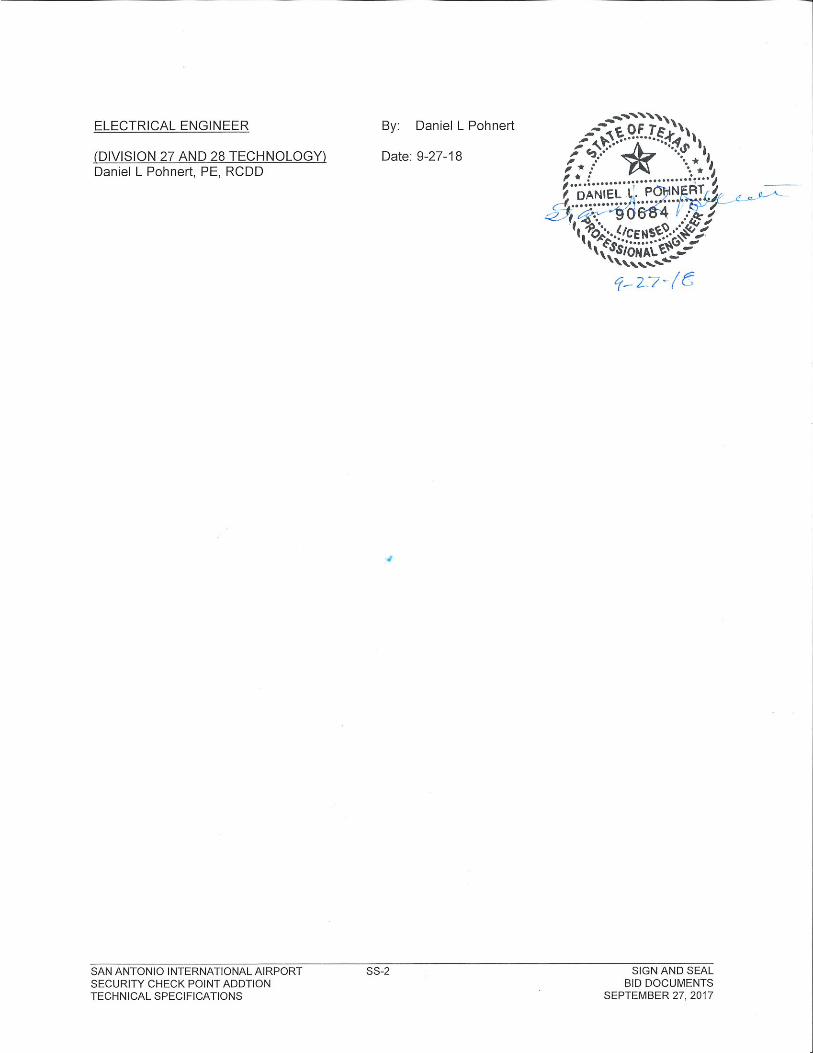
SAN ANTONIO INTERNATIONAL AIRPORT SS-1 SIGN AND SEAL
SECURITY CHECK POINT ADDTION BID DOCUMENTS TECHNICAL SPECIFICATIONS SEPTEMBER 27, 2017
SAN ANTONIO INTERNATIONAL AIRPORT 223-3267-062
SECURITY CHECKPOINT ADDITION BID DOCUMENTS
September 27, 2018
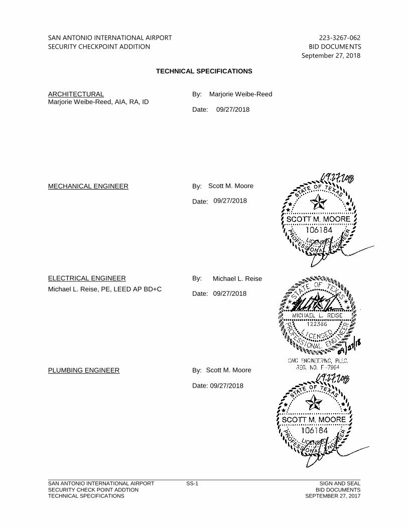
TECHNICAL SPECIFICATIONS
ARCHITECTURAL By: Marjorie Weibe-Reed Marjorie Weibe-Reed, AIA, RA, ID Date: 09/27/2018 MECHANICAL ENGINEER By: Date: ELECTRICAL ENGINEER By: Date: PLUMBING ENGINEER By: Date:
Michael L. Reise, PE, LEED AP BD+C
Michael L. Reise
09/27/2018
Scott M. Moore
09/27/2018
Scott M. Moore
09/27/2018
ReedMW
Image
SAN ANTONIO INTERNATIONAL AIRPORT 223-3267-062
SECURITY CHECKPOINT ADDITION BID DOCUMENTS
September 27, 2018
TABLE OF CONTENTS
TITLE INDEX OF PAGES
TOC-1
Division 02- Existing Conditions
02 41 19 – Selective Demolition .......................................................................................................................... 1-9
Division 05– Metals
05 40 00 – Cold-Formed Metal Framing .......................................................................................................... 1-9
05 50 00 – Metal Fabrications ........................................................................................................................... 1-10
05 58 00 – Formed Decorative Metal Fabrications…………………………………………………………………..1-8
Division 06– Wood, Plastics, and Composites
06 10 00 – Rough Carpentry ................................................................................................................................. 1-8
Division 07– Thermal and Moisture Protection
07 62 00 – Sheet Metal Flashing and Trim ................................................................................................... 1-14
07 84 43 – Joint Firestopping ............................................................................................................................... 1-6
07 92 00 - Joint Sealants…………………………………………………...………………………………………………………1-9
Division 08– Openings
08 11 13 – Hollow Metal Doors and Frames................................................................................................... 1-8
08 33 26 – Overhead Coiling Grille .................................................................................................................. 1-10
08 43 13 – Aluminum Framed Storefronts……………………………………………………………………………….1-10
08 71 00 – Door Hardware .................................................................................................................................... 1-8
08 80 00 – Glazing……………………………………………………………………………………………………………………..1-6
Division 09– Finishes
09 22 16 – Non Structural Metal Framing…………………………………………………………………………………1-6
09 29 00 – Gypsum Board ...................................................................................................................................... 1-8
09 30 13 – Ceramic Tile ........................................................................................................................................... 1-8
09 51 23 – Acoustical Tile Ceilings...................................................................................................................... 1-7
09 66 00 – Terrazzo…………………………………………………………………………………………………..………………1-1
09 91 23 – Interior Painting ................................................................................................................................... 1-8
Division 10– Specialties
10 14 23.13 – Room-Identification Signage.................................................................................................... 1-6
Division 21 – Fire Suppression
21 10 00 – Water Based Fire Suppression System ........................................................................................ 1-6
SAN ANTONIO INTERNATIONAL AIRPORT 223-3267-062
SECURITY CHECKPOINT ADDITION BID DOCUMENTS
September 27, 2018
TABLE OF CONTENTS
TITLE INDEX OF PAGES
TOC-2
Division 22 - Plumbing
22 05 10 – Basic Requirements for Plumbing ………………………………………………………………………1-18
Division 23 – Heating, Ventilation, and Air Conditioning
23 01 30 - HVAC Air Duct Cleaning………………………………………………………………………………………1-5
23 05 00 - Common Work Results for HVAC …………………………………………………………………….. 1-14
23 05 29- Hangars and Supports for HVAC Piping and Equipment ……………………………………1-12
23 05 93- Testing, Adjusting and Balancing for HVAC ………………………………………………………..1-16
23 09 00 - Instrumentation and Control for HVAC……………………………………………………………… 1-17
23 31 13 – Metal Ducts……………………………………………………………………………………………………….. 1-8
23 33 00 – Air Duct Accessories………………………………………………………………………………………….. 1-9
23 34 23 - HVAC Power Ventilators…………………………………………………………………………………..... 1-4
23 37 13 – Diffusers, Registers and Grilles……………………………………………………………………………1-2
Division 26 - Electrical
26 00 01 – Basic Requirements for Electrical………………………………………………………………………. 1-12
26 05 19 – Low-Voltage Electrical Power Conductors and Cables……………………………………… 1-4 26 05 26 – Grounding & Bonding for Electrical Systems……………………………………………………. 1-6 26 05 29 – Hangers and Supports for Electrical Systems …………………………………………………… 1-6 26 05 33 – Raceways and Boxes for Electrical Systems……………………………………………………….. 1-13 26 05 44 – Sleeves and Sleeve Seals for Electrical Raceways and Cabling …………………………. 1-4 26 05 53 – Identification for Electrical Systems…………………………………………………………………… 1-7 26 05 73 – Overcurrent Protective Device Coordination Study ………………………………………….. 1-7 26 09 23 – Lighting Control Devices ………………………………………………………………………………….. 1-3 26 22 00 – Low-Voltage Transformers………………………………………………………………………………… 1-5 26 24 16 – Panelboards ………………………………………………………………………………………………………..1-8
26 27 17 – Equipment Wiring……………………………………………………………………………………………… 1-5 26 27 26 – Wiring Devices ………………………………………………………………………………………………….. 1-9 26 28 13 – Fuses………………………………………………………………………………………………………………….. 1-3 26 28 16 – Enclosed Switches and Circuit Breakers ……………………………………………………………. 1-5 26 36 00 – Transfer Switches ……………………………………………………………………………………………… 1-9 26 51 00 – Interior Lighting ………………………………………………………………………………………………... 1-5
Division 27 - Electronic Safety and Security
27 05 26 - Grounding and Bonding for Communications Systems ……………………………………. 1-7
27 05 28 - Pathways for Communications Systems …………………………………………………………… 1-12
27 05 44 - Sleeves and Sleeve Seals for Communications Pathways and Cabling……………… 1-4
27 05 53 - Identification for Communications Systems ………………………………………………………1-6
27 15 13 - Communications Copper Horizontal Cabling …………………………………………………….1-11
SAN ANTONIO INTERNATIONAL AIRPORT 223-3267-062
SECURITY CHECKPOINT ADDITION BID DOCUMENTS
September 27, 2018
TABLE OF CONTENTS
TITLE INDEX OF PAGES
TOC-3
Division 28 – Communications/ Alarms
28 23 00 – Video Surveillance ………………………………………………………………………………………….. 1-10
SAN ANTONIO INTERNATIONAL AIRPORT 223-3267-062
SECURITY CHECKPOINT ADDITION BID DOCUMENTS
September 27, 2018
SELECTIVE DEMOLITION 024119 - 1
SECTION 024119 - SELECTIVE DEMOLITION
PART 1 - GENERAL
1.1 RELATED DOCUMENTS
A. Drawings and general provisions of the Contract, including General and Supplementary
Conditions and Division 01 Specification Sections, apply to this Section.
1.2 SUMMARY
A. Section Includes:
1. Demolition and removal of selected portions of building or structure.
2. Demolition and removal of selected site elements.
3. Salvage of existing items to be reused or recycled.
1.3 DEFINITIONS
A. Remove: Detach items from existing construction and dispose of them off-site unless
indicated to be salvaged or reinstalled.
B. Remove and Salvage: Detach items from existing construction, in a manner to prevent
damage, and store.
C. Remove and Reinstall: Detach items from existing construction, in a manner to prevent
damage, prepare for reuse, and reinstall where indicated.
D. Existing to Remain: Leave existing items that are not to be removed and that are not
otherwise indicated to be salvaged or reinstalled.
E. Dismantle: To remove by disassembling or detaching an item from a surface, using
gentle methods and equipment to prevent damage to the item and surfaces; disposing
of items unless indicated to be salvaged or reinstalled.
1.4 MATERIALS OWNERSHIP
A. Unless otherwise indicated, demolition waste becomes property of Contractor.
SAN ANTONIO INTERNATIONAL AIRPORT 223-3267-062
SECURITY CHECKPOINT ADDITION BID DOCUMENTS
September 27, 2018
SELECTIVE DEMOLITION 024119 - 2
B. Historic items, relics, antiques, and similar objects including, but not limited to,
cornerstones and their contents, commemorative plaques and tablets, and other items
of interest or value to Owner that may be uncovered during demolition remain the
property of Owner.
1. Carefully salvage in a manner to prevent damage and promptly return to Owner.
1.5 PREINSTALLATION MEETINGS
A. Predemolition Conference: Conduct conference at Project site.
1. Inspect and discuss condition of construction to be selectively demolished.
2. Review structural load limitations of existing structure.
3. Review and finalize selective demolition schedule and verify availability of
materials, demolition personnel, equipment, and facilities needed to make
progress and avoid delays.
4. Review requirements of work performed by other trades that rely on substrates
exposed by selective demolition operations.
5. Review areas where existing construction is to remain and requires protection.
1.6 INFORMATIONAL SUBMITTALS
A. Qualification Data: For refrigerant recovery technician.
B. Engineering Survey: Submit engineering survey of condition of building.
C. Proposed Protection Measures: Submit report, including Drawings, that indicates the
measures proposed for protecting individuals and property, for dust control and, for
noise control. Indicate proposed locations and construction of barriers.
D. Schedule of Selective Demolition Activities: Indicate the following:
1. Detailed sequence of selective demolition and removal work, with starting and
ending dates for each activity. Ensure Owner's other tenants' on-site operations
are uninterrupted.
2. Interruption of utility services. Indicate how long utility services will be
interrupted.
3. Coordination for shutoff, capping, and continuation of utility services.
4. Use of elevator and stairs.
5. Coordination of Owner's continuing occupancy of portions of existing building
and of Owner's partial occupancy of completed Work.
SAN ANTONIO INTERNATIONAL AIRPORT 223-3267-062
SECURITY CHECKPOINT ADDITION BID DOCUMENTS
September 27, 2018
SELECTIVE DEMOLITION 024119 - 3
E. Predemolition Photographs or Video: Show existing conditions of adjoining
construction, including finish surfaces, that might be misconstrued as damage caused
by demolition operations.
F. Statement of Refrigerant Recovery: Signed by refrigerant recovery technician
responsible for recovering refrigerant, stating that all refrigerant that was present was
recovered and that recovery was performed according to EPA regulations. Include
name and address of technician and date refrigerant was recovered.
G. Warranties: Documentation indicating that existing warranties are still in effect after
completion of selective demolition.
1.7 CLOSEOUT SUBMITTALS
A. Inventory: Submit a list of items that have been removed and salvaged.
1.8 QUALITY ASSURANCE
A. Refrigerant Recovery Technician Qualifications: Certified by an EPA-approved
certification program.
1.9 FIELD CONDITIONS
A. Owner will occupy portions of building immediately adjacent to selective demolition
area. Conduct selective demolition so Owner's operations will not be disrupted.
B. Conditions existing at time of inspection for bidding purpose will be maintained by
Owner as far as practical.
C. Notify Architect of discrepancies between existing conditions and Drawings before
proceeding with selective demolition.
D. Hazardous Materials: It is not expected that hazardous materials will be encountered in
the Work.
1. Hazardous materials will be removed by Owner before start of the Work.
2. If suspected hazardous materials are encountered, do not disturb; immediately
notify Architect and Owner. Hazardous materials will be removed by Owner under
a separate contract.
SAN ANTONIO INTERNATIONAL AIRPORT 223-3267-062
SECURITY CHECKPOINT ADDITION BID DOCUMENTS
September 27, 2018
SELECTIVE DEMOLITION 024119 - 4
E. Hazardous Materials: Present in buildings and structures to be selectively demolished.
A report on the presence of hazardous materials is on file for review and use. Examine
report to become aware of locations where hazardous materials are present.
1. Hazardous material remediation is specified elsewhere in the Contract
Documents.
2. Do not disturb hazardous materials or items suspected of containing hazardous
materials except under procedures specified elsewhere in the Contract
Documents.
3. Owner will provide material safety data sheets for suspected hazardous materials
that are known to be present in buildings and structures to be selectively
demolished because of building operations or processes performed there.
F. Storage or sale of removed items or materials on-site is not permitted.
G. Utility Service: Maintain existing utilities indicated to remain in service and protect them
against damage during selective demolition operations.
1. Maintain fire-protection facilities in service during selective demolition
operations.
1.10 WARRANTY
A. Existing Warranties: Remove, replace, patch, and repair materials and surfaces cut or
damaged during selective demolition, by methods and with materials and using
approved contractors so as not to void existing warranties. Notify warrantor before
proceeding.
B. Notify warrantor on completion of selective demolition, and obtain documentation
verifying that existing system has been inspected and warranty remains in effect.
Submit documentation at Project closeout.
1.11 COORDINATION
A. Arrange selective demolition schedule so as not to interfere with Owner's operations.
SAN ANTONIO INTERNATIONAL AIRPORT 223-3267-062
SECURITY CHECKPOINT ADDITION BID DOCUMENTS
September 27, 2018
SELECTIVE DEMOLITION 024119 - 5
PART 2 - PRODUCTS
2.1 PERFORMANCE REQUIREMENTS
A. Regulatory Requirements: Comply with governing EPA notification regulations before
beginning selective demolition. Comply with hauling and disposal regulations of
authorities having jurisdiction.
B. Standards: Comply with ASSE A10.6 and NFPA 241.
PART 3 - EXECUTION
3.1 EXAMINATION
A. Verify that utilities have been disconnected and capped before starting selective
demolition operations.
B. Review Project Record Documents of existing construction or other existing condition
and hazardous material information provided by Owner. Owner does not guarantee
that existing conditions are same as those indicated in Project Record Documents.
C. Perform an engineering survey of condition of building to determine whether removing
any element might result in structural deficiency or unplanned collapse of any portion
of structure or adjacent structures during selective building demolition operations.
1. Perform surveys as the Work progresses to detect hazards resulting from
selective demolition activities.
D. Steel Tendons: Locate tensioned steel tendons and include recommendations for de-
tensioning.
E. Verify that hazardous materials have been remediated before proceeding with building
demolition operations.
F. Survey of Existing Conditions: Record existing conditions by use of preconstruction
photographs or video.
1. Inventory and record the condition of items to be removed and salvaged. Provide
photographs or video of conditions that might be misconstrued as damage
caused by salvage operations.
2. Before selective demolition or removal of existing building elements that will be
reproduced or duplicated in final Work, make permanent record of
SAN ANTONIO INTERNATIONAL AIRPORT 223-3267-062
SECURITY CHECKPOINT ADDITION BID DOCUMENTS
September 27, 2018
SELECTIVE DEMOLITION 024119 - 6
measurements, materials, and construction details required to make exact
reproduction.
3.2 PREPARATION
A. Refrigerant: Before starting demolition, remove refrigerant from mechanical equipment
according to 40 CFR 82 and regulations of authorities having jurisdiction.
3.3 UTILITY SERVICES AND MECHANICAL/ELECTRICAL SYSTEMS
A. Existing Services/Systems to Remain: Maintain services/systems indicated to remain
and protect them against damage.
B. Existing Services/Systems to Be Removed, Relocated, or Abandoned: Locate, identify,
disconnect, and seal or cap off utility services and mechanical/electrical systems serving
areas to be selectively demolished.
1. Owner will arrange to shut off indicated services/systems when requested by
Contractor.
2. Arrange to shut off utilities with utility companies.
3. If services/systems are required to be removed, relocated, or abandoned, provide
temporary services/systems that bypass area of selective demolition and that
maintain continuity of services/systems to other parts of building.
4. Disconnect, demolish, and remove fire-suppression systems, plumbing, and
HVAC systems, equipment, and components indicated on Drawings to be
removed.
a. Piping to Be Removed: Remove portion of piping indicated to be removed
and cap or plug remaining piping with same or compatible piping material.
b. Piping to Be Abandoned in Place: Drain piping and cap or plug piping with
same or compatible piping material and leave in place.
c. Equipment to Be Removed: Disconnect and cap services and remove
equipment.
d. Equipment to Be Removed and Reinstalled: Disconnect and cap services
and remove, clean, and store equipment; when appropriate, reinstall,
reconnect, and make equipment operational.
e. Equipment to Be Removed and Salvaged: Disconnect and cap services and
remove equipment and deliver to Owner.
f. Ducts to Be Removed: Remove portion of ducts indicated to be removed
and plug remaining ducts with same or compatible ductwork material.
g. Ducts to Be Abandoned in Place: Cap or plug ducts with same or
compatible ductwork material and leave in place.
SAN ANTONIO INTERNATIONAL AIRPORT 223-3267-062
SECURITY CHECKPOINT ADDITION BID DOCUMENTS
September 27, 2018
SELECTIVE DEMOLITION 024119 - 7
3.4 PROTECTION
A. Temporary Protection: Provide temporary barricades and other protection required to
prevent injury to people and damage to adjacent buildings and facilities to remain.
1. Provide protection to ensure safe passage of people around selective demolition
area and to and from occupied portions of building.
2. Provide temporary weather protection, during interval between selective
demolition of existing construction on exterior surfaces and new construction, to
prevent water leakage and damage to structure and interior areas.
3. Protect walls, ceilings, floors, and other existing finish work that are to remain or
that are exposed during selective demolition operations.
4. Cover and protect furniture, furnishings, and equipment that have not been
removed.
B. Temporary Shoring: Design, provide, and maintain shoring, bracing, and structural
supports as required to preserve stability and prevent movement, settlement, or
collapse of construction and finishes to remain, and to prevent unexpected or
uncontrolled movement or collapse of construction being demolished.
1. Strengthen or add new supports when required during progress of selective
demolition.
C. Remove temporary barricades and protections where hazards no longer exist.
3.5 SELECTIVE DEMOLITION, GENERAL
A. General: Demolish and remove existing construction only to the extent required by new
construction and as indicated. Use methods required to complete the Work within
limitations of governing regulations and as follows:
1. Proceed with selective demolition systematically, from higher to lower level.
Complete selective demolition operations above each floor or tier before
disturbing supporting members on the next lower level.
2. Neatly cut openings and holes plumb, square, and true to dimensions required.
Use cutting methods least likely to damage construction to remain or adjoining
construction. Use hand tools or small power tools designed for sawing or
grinding, not hammering and chopping. Temporarily cover openings to remain.
3. Cut or drill from the exposed or finished side into concealed surfaces to avoid
marring existing finished surfaces.
4. Do not use cutting torches until work area is cleared of flammable materials. At
concealed spaces, such as duct and pipe interiors, verify condition and contents
SAN ANTONIO INTERNATIONAL AIRPORT 223-3267-062
SECURITY CHECKPOINT ADDITION BID DOCUMENTS
September 27, 2018
SELECTIVE DEMOLITION 024119 - 8
of hidden space before starting flame-cutting operations. Maintain portable fire-
suppression devices during flame-cutting operations.
5. Maintain fire watch during and for at least <24> hours after flame-cutting
operations.
6. Maintain adequate ventilation when using cutting torches.
7. Remove decayed, vermin-infested, or otherwise dangerous or unsuitable
materials and promptly dispose of off-site.
8. Remove structural framing members and lower to ground by method suitable to
avoid free fall and to prevent ground impact or dust generation.
9. Locate selective demolition equipment and remove debris and materials so as
not to impose excessive loads on supporting walls, floors, or framing.
10. Dispose of demolished items and materials promptly.
B. Site Access and Temporary Controls: Conduct selective demolition and debris-removal
operations to ensure minimum interference with roads, streets, walks, walkways, and
other adjacent occupied and used facilities.
C. Removed and Salvaged Items:
1. Clean salvaged items.
2. Pack or crate items after cleaning. Identify contents of containers.
3. Store items in a secure area until delivery to Owner.
4. Transport items to Owner's storage area designated by Owner.
5. Protect items from damage during transport and storage.
D. Removed and Reinstalled Items:
1. Clean and repair items to functional condition adequate for intended reuse.
2. Pack or crate items after cleaning and repairing. Identify contents of containers.
3. Protect items from damage during transport and storage.
4. Reinstall items in locations indicated. Comply with installation requirements for
new materials and equipment. Provide connections, supports, and miscellaneous
materials necessary to make item functional for use indicated.
E. Existing Items to Remain: Protect construction indicated to remain against damage and
soiling during selective demolition. When permitted by Architect, items may be
removed to a suitable, protected storage location during selective demolition and
cleaned and reinstalled in their original locations after selective demolition operations
are complete.
SAN ANTONIO INTERNATIONAL AIRPORT 223-3267-062
SECURITY CHECKPOINT ADDITION BID DOCUMENTS
September 27, 2018
SELECTIVE DEMOLITION 024119 - 9
3.6 SELECTIVE DEMOLITION PROCEDURES FOR SPECIFIC MATERIALS
A. Concrete: Demolish in small sections. Using power-driven saw, cut concrete to a depth
of at least 3/4 inch (19 mm) at junctures with construction to remain. Dislodge concrete
from reinforcement at perimeter of areas being demolished, cut reinforcement, and
then remove remainder of concrete. Neatly trim openings to dimensions indicated.
B. Concrete: Demolish in sections. Cut concrete full depth at junctures with construction
to remain and at regular intervals using power-driven saw, and then remove concrete
between saw cuts.
C. Masonry: Demolish in small sections. Cut masonry at junctures with construction to
remain, using power-driven saw, and then remove masonry between saw cuts.
3.7 DISPOSAL OF DEMOLISHED MATERIALS
A. Remove demolition waste materials from Project site and dispose of them in an EPA-
approved construction and demolition waste landfill acceptable to authorities having
jurisdiction.
1. Do not allow demolished materials to accumulate on-site.
2. Remove and transport debris in a manner that will prevent spillage on adjacent
surfaces and areas.
3. Remove debris from elevated portions of building by chute, hoist, or other device
that will convey debris to grade level in a controlled descent.
B. Burning: Do not burn demolished materials.
3.8 CLEANING
A. Clean adjacent structures and improvements of dust, dirt, and debris caused by
selective demolition operations. Return adjacent areas to condition existing before
selective demolition operations began.
END OF SECTION 024119
SAN ANTONIO INTERNATIONAL AIRPORT 223-3267-062
SECURITY CHECKPOINT ADDITION BID DOCUMENTS
September 27, 2018
COLD-FORMED METAL FRAMING 054000 - 1
SECTION 054000 - COLD-FORMED METAL FRAMING
PART 1 - GENERAL
1.1 RELATED DOCUMENTS
A. Drawings and general provisions of the Contract, including General and Supplementary Conditions and Division 01 Specification Sections, apply to this Section.
1.2 SUMMARY
A. Section Includes:
1. Load-bearing wall framing. 2. Exterior non-load-bearing wall framing. 3. Interior non-load-bearing wall framing exceeding height limitations of standard,
nonstructural metal framing. 4. Floor joist framing. 5. Roof rafter framing. 6. Ceiling joist framing. 7. Soffit framing.
B. Related Requirements:
1. Section 055000 "Metal Fabrications" for miscellaneous steel shapes, masonry shelf angles, and connections used with cold-formed metal framing.
1.3 ACTION SUBMITTALS
A. Product Data: For each type of product.
B. Shop Drawings:
1. Include layout, spacings, sizes, thicknesses, and types of cold-formed steel framing; fabrication; and fastening and anchorage details, including mechanical fasteners.
2. Indicate reinforcing channels, opening framing, supplemental framing, strapping, bracing, bridging, splices, accessories, connection details, and attachment to adjoining work.
C. Delegated-Design Submittal: For cold-formed steel framing.
1.4 INFORMATIONAL SUBMITTALS
A. Qualification Data: For testing agency.
B. Welding certificates.
C. Product Certificates: For each type of code-compliance certification for studs and tracks.

SAN ANTONIO INTERNATIONAL AIRPORT 223-3267-062
SECURITY CHECKPOINT ADDITION BID DOCUMENTS
September 27, 2018
COLD-FORMED METAL FRAMING 054000 - 2
D. Product Test Reports: For each listed product, for tests performed by manufacturer and witnessed by a qualified testing agency.
1. Steel sheet. 2. Expansion anchors. 3. Power-actuated anchors. 4. Mechanical fasteners. 5. Vertical deflection clips. 6. Horizontal drift deflection clips 7. Miscellaneous structural clips and accessories.
E. Evaluation Reports: For nonstandard cold-formed steel framing post-installed anchors and power-actuated fasteners, from ICC-ES or other qualified testing agency acceptable to authorities having jurisdiction.
1.5 QUALITY ASSURANCE
A. Testing Agency Qualifications: Qualified according to ASTM E 329 for testing indicated.
B. Product Tests: Mill certificates or data from a qualified independent testing agency indicating steel sheet complies with requirements, including base-metal thickness, yield strength, tensile strength, total elongation, chemical requirements, and metallic-coating thickness.
C. Code-Compliance Certification of Studs and Tracks: Provide documentation that framing members are certified according to the product-certification program of the Steel Stud Manufacturers Association.
D. Welding Qualifications: Qualify procedures and personnel according to the following:
1. AWS D1.1/D1.1M, "Structural Welding Code - Steel." 2. AWS D1.3/D1.3M, "Structural Welding Code - Sheet Steel."
E. Comply with AISI S230 "Standard for Cold-Formed Steel Framing - Prescriptive Method for One and Two Family Dwellings."
PART 2 - PRODUCTS
2.1 MANUFACTURERS
A. Manufacturers: Subject to compliance with requirements, provide products by one of the
following:
1. AllSteel & Gypsum Products, Inc.
2. ClarkDietrich Building Systems.
3. MBA Building Supplies.
SAN ANTONIO INTERNATIONAL AIRPORT 223-3267-062
SECURITY CHECKPOINT ADDITION BID DOCUMENTS
September 27, 2018
COLD-FORMED METAL FRAMING 054000 - 3
2.2 PERFORMANCE REQUIREMENTS
A. Delegated Design: Engage a qualified professional engineer, as defined in Section 014000 "Quality Requirements," to design cold-formed steel framing.
B. Structural Performance: Provide cold-formed steel framing capable of withstanding design loads within limits and under conditions indicated.
1. Design Loads: As indicated on Drawings.
2. Design framing systems to provide for movement of framing members located outside the insulated building envelope without damage or overstressing, sheathing failure, connection failure, undue strain on fasteners and anchors, or other detrimental effects when subject to a maximum ambient temperature change of 120 deg F (67 deg C).
3. Design framing system to maintain clearances at openings, to allow for construction tolerances, and to accommodate live load deflection of primary building structure as follows:
a. Upward and downward movement of 1/2 inch (13 mm).
4. Design exterior non-load-bearing wall framing to accommodate horizontal deflection without regard for contribution of sheathing materials.
C. Cold-Formed Steel Framing Standards: Unless more stringent requirements are indicated, framing shall comply with AISI S100, AISI S200, and the following:
1. Floor and Roof Systems: AISI S210. 2. Wall Studs: AISI S211. 3. Headers: AISI S212. 4. Lateral Design: AISI S213.
D. Fire-Resistance Ratings: Comply with ASTM E 119; testing by a qualified testing agency. Identify products with appropriate markings of applicable testing agency.
1. Indicate design designations from UL's "Fire Resistance Directory" or from the listings of another qualified testing agency acceptable to authorities having jurisdiction.
2.3 INTERIOR NON-LOAD-BEARING WALL FRAMING
A. Steel Studs: Manufacturer's standard C-shaped steel studs, of web depths indicated, punched, with stiffened flanges, and as follows:
1. Minimum Base-Metal Thickness: 0.0329 inch (0.84 mm). 2. Flange Width: 1-5/8 inches (41 mm).
B. Steel Track: Manufacturer's standard U-shaped steel track, of web depths indicated, unpunched, with unstiffened flanges, and as follows:
1. Minimum Base-Metal Thickness: 0.0329 inch (0.84 mm). 2. Flange Width: 1-1/4 inches (32 mm).
SAN ANTONIO INTERNATIONAL AIRPORT 223-3267-062
SECURITY CHECKPOINT ADDITION BID DOCUMENTS
September 27, 2018
COLD-FORMED METAL FRAMING 054000 - 4
C. Vertical Deflection Clips: Manufacturer's standard head clips, capable of accommodating upward and downward vertical displacement of primary structure through positive mechanical attachment to stud web.
1. Manufacturers: Subject to compliance with requirements, provide products by one of the
following:
a. AllSteel & Gypsum Products, Inc.
b. ClarkDietrich Building Systems.
c. Simpson Strong-Tie Co., Inc.
D. Single Deflection Track: Manufacturer's single, deep-leg, U-shaped steel track; unpunched, with unstiffened flanges, of web depth to contain studs while allowing free vertical movement, with flanges designed to support horizontal loads and transfer them to the primary structure, and as follows:
1. Minimum Base-Metal Thickness: 0.0428 inch (1.09 mm). 2. Flange Width: 1 inch (25 mm) plus the design gap for one-story structures.
E. Double Deflection Tracks: Manufacturer's double, deep-leg, U-shaped steel tracks, consisting of nested inner and outer tracks; unpunched, with unstiffened flanges.
1. Outer Track: Of web depth to allow free vertical movement of inner track, with flanges designed to support horizontal loads and transfer them to the primary structure, and as follows:
a. Minimum Base-Metal Thickness: 0.0329 inch (0.84 mm). b. Flange Width: 1 inch (25 mm) plus the design gap for one-story structures.
2. Inner Track: Of web depth indicated, and as follows:
a. Minimum Base-Metal Thickness: 0.0428 inch (1.09 mm). b. Flange Width: Insert dimension equal to sum of outer deflection track flange width
plus 1 inch (25 mm).
F. Drift Clips: Manufacturer's standard bypass or head clips, capable of isolating wall stud from upward and downward vertical displacement and lateral drift of primary structure through positive mechanical attachment to stud web and structure.
2.4 SOFFIT FRAMING
A. Exterior Soffit Frame: Manufacturer's standard C-shaped steel sections, of web depths indicated, with stiffened flanges, and as follows:
1. Minimum Base-Metal Thickness: 0.0329 inch (0.84 mm). 2. Flange Width: 1-5/8 inches (41 mm), minimum.
2.5 FRAMING ACCESSORIES 1. >.Revise minimum yield strength of accessories as required.
SAN ANTONIO INTERNATIONAL AIRPORT 223-3267-062
SECURITY CHECKPOINT ADDITION BID DOCUMENTS
September 27, 2018
COLD-FORMED METAL FRAMING 054000 - 5
B. Fabricate steel-framing accessories from ASTM A 1003/A 1003M, Structural Grade, Type H, metallic coated steel sheet, of same grade and coating designation used for framing members.
C. Provide accessories of manufacturer's standard thickness and configuration, unless otherwise indicated, as follows:
1. Supplementary framing. 2. Bracing, bridging, and solid blocking. 3. Web stiffeners. 4. Anchor clips. 5. End clips. 6. Foundation clips. 7. Gusset plates. 8. Stud kickers and knee braces. 9. Joist hangers and end closures. 10. Hole-reinforcing plates. 11. Backer plates.
2.6 ANCHORS, CLIPS, AND FASTENERS
A. Steel Shapes and Clips: ASTM A 36/A 36M, zinc coated by hot-dip process according to ASTM A 123/A 123M.
B. Post-Installed Anchors: Fastener systems with bolts of same basic metal as fastened metal, if visible, unless otherwise indicated; with working capacity greater than or equal to the design load, according to an evaluation report acceptable to authorities having jurisdiction, based on ICC-ES AC01 as appropriate for the substrate.
1. Uses: Securing cold-formed steel framing to structure. 2. Type: Torque-controlled expansion anchor. 3. Material for Interior Locations: Carbon-steel components zinc plated to comply with
ASTM B 633 or ASTM F 1941 (ASTM F 1941M), Class Fe/Zn 5, unless otherwise indicated.
4. Material for Exterior or Interior Locations and Where Stainless Steel Is Indicated: Alloy Group 1 (A1) stainless-steel bolts, ASTM F 593 (ASTM F 738M), and nuts, ASTM F 594 (ASTM F 836M).
C. Power-Actuated Anchors: Fastener systems with working capacity greater than or equal to the design load, according to an evaluation report acceptable to authorities having jurisdiction, based on ICC-ES AC70.
D. Mechanical Fasteners: ASTM C 1513, corrosion-resistant-coated, self-drilling, self-tapping, steel drill screws.
1. Head Type: Low-profile head beneath sheathing; manufacturer's standard elsewhere.
E. Welding Electrodes: Comply with AWS standards.
2.7 MISCELLANEOUS MATERIALS
A. Galvanizing Repair Paint: ASTM A 780/A 780M.
SAN ANTONIO INTERNATIONAL AIRPORT 223-3267-062
SECURITY CHECKPOINT ADDITION BID DOCUMENTS
September 27, 2018
COLD-FORMED METAL FRAMING 054000 - 6
B. Cement Grout: Portland cement, ASTM C 150/C 150M, Type I; and clean, natural sand, ASTM C 404. Mix at ratio of 1 part cement to 2-1/2 parts sand, by volume, with minimum water required for placement and hydration.
C. Nonmetallic, Nonshrink Grout: Factory-packaged, nonmetallic, noncorrosive, nonstaining grout, complying with ASTM C 1107/C 1107M, and with a fluid consistency and 30-minute working time.
D. Shims: Load-bearing, high-density, multimonomer, nonleaching plastic; or cold-formed steel of same grade and metallic coating as framing members supported by shims.
E. Sealer Gaskets: Closed-cell neoprene foam, 1/4 inch (6 mm) thick, selected from manufacturer's standard widths to match width of bottom track or rim track members as required.
2.8 FABRICATION
A. Fabricate cold-formed steel framing and accessories plumb, square, and true to line, and with connections securely fastened, according to referenced AISI's specifications and standards, manufacturer's written instructions, and requirements in this Section.
1. Fabricate framing assemblies using jigs or templates. 2. Cut framing members by sawing or shearing; do not torch cut. 3. Fasten cold-formed steel framing members by welding, screw fastening, clinch fastening,
pneumatic pin fastening, or riveting as standard with fabricator. Wire tying of framing members is not permitted.
a. Comply with AWS D1.3/D1.3M requirements and procedures for welding, appearance and quality of welds, and methods used in correcting welding work.
b. Locate mechanical fasteners and install according to Shop Drawings, with screws penetrating joined members by no fewer than three exposed screw threads.
4. Fasten other materials to cold-formed steel framing by welding, bolting, pneumatic pin fastening, or screw fastening, according to Shop Drawings.
B. Reinforce, stiffen, and brace framing assemblies to withstand handling, delivery, and erection stresses. Lift fabricated assemblies by means that prevent damage or permanent distortion.
C. Tolerances: Fabricate assemblies level, plumb, and true to line to a maximum allowable variation of 1/8 inch in 10 feet (1:960) and as follows:
1. Spacing: Space individual framing members no more than plus or minus 1/8 inch (3 mm) from plan location. Cumulative error shall not exceed minimum fastening requirements of sheathing or other finishing materials.
2. Squareness: Fabricate each cold-formed steel framing assembly to a maximum out-of-square tolerance of 1/8 inch (3 mm).
SAN ANTONIO INTERNATIONAL AIRPORT 223-3267-062
SECURITY CHECKPOINT ADDITION BID DOCUMENTS
September 27, 2018
COLD-FORMED METAL FRAMING 054000 - 7
PART 3 - EXECUTION
3.1 EXAMINATION
A. Examine substrates, areas, conditions, and abutting structural framing for compliance with requirements for installation tolerances and other conditions affecting performance of the Work.
B. Proceed with installation only after unsatisfactory conditions have been corrected.
3.2 PREPARATION
A. Before sprayed fire-resistive materials are applied, attach continuous angles, supplementary framing, or tracks to structural members indicated to receive sprayed fire-resistive materials.
B. After applying sprayed fire-resistive materials, remove only as much of these materials as needed to complete installation of cold-formed framing without reducing thickness of fire-resistive materials below that required to obtain fire-resistance ratings indicated. Protect remaining fire-resistive materials from damage.
C. Install load-bearing shims or grout between the underside of load-bearing wall bottom track and the top of foundation wall or slab at locations with a gap larger than 1/4 inch (6 mm) to ensure a uniform bearing surface on supporting concrete or masonry construction.
D. Install sealer gaskets at the underside of wall bottom track or rim track and at the top of foundation wall or slab at stud or joist locations.
3.3 INSTALLATION, GENERAL
A. Cold-formed steel framing may be shop or field fabricated for installation, or it may be field assembled.
B. Install cold-formed steel framing according to AISI S200, AISI S202, and manufacturer's written instructions unless more stringent requirements are indicated.
C. Install shop- or field-fabricated, cold-formed framing and securely anchor to supporting structure.
1. Screw, bolt, or weld wall panels at horizontal and vertical junctures to produce flush, even, true-to-line joints with maximum variation in plane and true position between fabricated panels not exceeding 1/16 inch (1.6 mm).
D. Install cold-formed steel framing and accessories plumb, square, and true to line, and with connections securely fastened.
1. Cut framing members by sawing or shearing; do not torch cut. 2. Fasten cold-formed steel framing members by welding, screw fastening, clinch fastening,
or riveting. Wire tying of framing members is not permitted.
a. Comply with AWS D1.3/D1.3M requirements and procedures for welding, appearance and quality of welds, and methods used in correcting welding work.
SAN ANTONIO INTERNATIONAL AIRPORT 223-3267-062
SECURITY CHECKPOINT ADDITION BID DOCUMENTS
September 27, 2018
COLD-FORMED METAL FRAMING 054000 - 8
b. Locate mechanical fasteners, install according to Shop Drawings, and comply with requirements for spacing, edge distances, and screw penetration.
E. Install framing members in one-piece lengths unless splice connections are indicated for track or tension members.
F. Install temporary bracing and supports to secure framing and support loads equal to those for which structure was designed. Maintain braces and supports in place, undisturbed, until entire integrated supporting structure has been completed and permanent connections to framing are secured.
G. Do not bridge building expansion joints with cold-formed steel framing. Independently frame both sides of joints.
H. Install insulation, specified in Section 072100 "Thermal Insulation," in framing-assembly members, such as headers, sills, boxed joists, and multiple studs at openings, that are inaccessible on completion of framing work.
I. Fasten hole-reinforcing plate over web penetrations that exceed size of manufacturer's approved or standard punched openings.
3.4 INTERIOR NON-LOAD-BEARING WALL INSTALLATION
A. Install continuous tracks sized to match studs. Align tracks accurately and securely anchor to supporting structure.
B. Fasten both flanges of studs to top and bottom track unless otherwise indicated. Space studs as follows:
1. Stud Spacing: 16 inches (406 mm).
C. Set studs plumb, except as needed for diagonal bracing or required for nonplumb walls or warped surfaces and similar requirements.
D. Isolate non-load-bearing steel framing from building structure to prevent transfer of vertical loads while providing lateral support.
1. Install single deep-leg deflection tracks and anchor to building structure. 2. Install double deep-leg deflection tracks and anchor outer track to building structure. 3. Connect vertical deflection clips to studs and anchor to building structure. 4. Connect drift clips to cold-formed steel metal framing and anchor to building structure.
E. Install horizontal bridging in wall studs, spaced vertically in rows indicated but not more than 48 inches (1220 mm) apart. Fasten at each stud intersection.
1. Channel Bridging: Cold-rolled steel channel, welded or mechanically fastened to webs of punched studs.
2. Strap Bridging: Combination of flat, taut, steel sheet straps of width and thickness indicated and stud-track solid blocking of width and thickness to match studs. Fasten flat straps to stud flanges and secure solid blocking to stud webs or flanges.
3. Bar Bridging: Proprietary bridging bars installed according to manufacturer's written instructions.
SAN ANTONIO INTERNATIONAL AIRPORT 223-3267-062
SECURITY CHECKPOINT ADDITION BID DOCUMENTS
September 27, 2018
COLD-FORMED METAL FRAMING 054000 - 9
F. Top Bridging for Single Deflection Track: Install row of horizontal bridging within 18 inches (450 mm) of single deflection track. Install a combination of bridging and stud or stud-track solid blocking of width and thickness matching studs, secured to stud webs or flanges.
1. Install solid blocking at 96-inch (2440-mm) centers.
G. Install miscellaneous framing and connections, including stud kickers, web stiffeners, clip angles, continuous angles, anchors, and fasteners, to provide a complete and stable wall-framing system.
3.5 ERECTION TOLERANCES
A. Install cold-formed steel framing level, plumb, and true to line to a maximum allowable tolerance variation of 1/8 inch in 10 feet (1:960) and as follows:
1. Space individual framing members no more than plus or minus 1/8 inch (3 mm) from plan location. Cumulative error shall not exceed minimum fastening requirements of sheathing or other finishing materials.
3.6 FIELD QUALITY CONTROL
A. Testing: Owner will engage a qualified independent testing and inspecting agency to perform field tests and inspections and prepare test reports.
B. Field and shop welds will be subject to testing and inspecting.
C. Testing agency will report test results promptly and in writing to Contractor and Architect.
D. Cold-formed steel framing will be considered defective if it does not pass tests and inspections.
E. Additional testing and inspecting, at Contractor's expense, will be performed to determine compliance of replaced or additional work with specified requirements.
3.7 REPAIRS AND PROTECTION
A. Galvanizing Repairs: Prepare and repair damaged galvanized coatings on fabricated and installed cold-formed steel framing with galvanized repair paint according to ASTM A 780/A 780M and manufacturer's written instructions.
B. Provide final protection and maintain conditions, in a manner acceptable to manufacturer and Installer, that ensure that cold-formed steel framing is without damage or deterioration at time of Substantial Completion.
END OF SECTION 054000
SAN ANTONIO INTERNATIONAL AIRPORT 223-3267-062
SECURITY CHECKPOINT ADDITION BID DOCUMENTS
September 27, 2018
METAL FABRICATIONS 055000 - 1
SECTION 055000 - METAL FABRICATIONS
PART 1 - GENERAL
1.1 RELATED DOCUMENTS
A. Drawings and general provisions of the Contract, including General and Supplementary Conditions and Division 01 Specification Sections, apply to this Section.
1.2 SUMMARY
A. Section Includes: 1. Steel framing and supports for overhead doors and grilles. 2. Steel framing and supports for mechanical and electrical equipment. 3. Steel framing and supports for applications where framing and supports are not specified
in other Sections. 4. Steel pipe columns for supporting wood frame construction. 5. Metal floor plate and supports. 6. Miscellaneous steel trim including steel angle corner guards, and steel edgings.
B. Products furnished, but not installed, under this Section include the following:
1. Loose steel lintels. 2. Anchor bolts, steel pipe sleeves, slotted-channel inserts, and wedge-type inserts
indicated to be cast into concrete or built into unit masonry. 3. Steel weld plates and angles for casting into concrete for applications where they are not
specified in other Sections.
1.3 COORDINATION
A. Coordinate selection of shop primers with topcoats to be applied over them. Comply with paint and coating manufacturers' written recommendations to ensure that shop primers and topcoats are compatible with one another.
B. Coordinate installation of metal fabrications that are anchored to or that receive other work. Furnish setting drawings, templates, and directions for installing anchorages, including sleeves, concrete inserts, anchor bolts, and items with integral anchors, that are to be embedded in concrete or masonry. Deliver such items to Project site in time for installation.
1.4 ACTION SUBMITTALS
A. Product Data: For the following: 1. Paint products. 2. Grout.
B. Shop Drawings: Show fabrication and installation details. Include plans, elevations, sections, and details of metal fabrications and their connections. Show anchorage and accessory items. Provide Shop Drawings for the following:
SAN ANTONIO INTERNATIONAL AIRPORT 223-3267-062
SECURITY CHECKPOINT ADDITION BID DOCUMENTS
September 27, 2018
METAL FABRICATIONS 055000 - 2
1. Steel framing and supports for overhead doors and grilles. 2. Steel framing and supports for mechanical and electrical equipment. 3. Steel framing and supports for applications where framing and supports are not specified
in other Sections. 4. Miscellaneous steel trim including steel angle corner guards and steel edgings.
1.5 INFORMATIONAL SUBMITTALS
A. Qualification Data: For professional engineer.
B. Mill Certificates: Signed by stainless-steel manufacturers, certifying that products furnished comply with requirements.
C. Welding certificates.
D. Paint Compatibility Certificates: From manufacturers of topcoats applied over shop primers, certifying that shop primers are compatible with topcoats.
E. Research/Evaluation Reports: For post-installed anchors, from ICC-ES.
1.6 QUALITY ASSURANCE
A. Welding Qualifications: Qualify procedures and personnel according to AWS D1.1/D1.1M, "Structural Welding Code - Steel."
B. Welding Qualifications: Qualify procedures and personnel according to the following:
1. AWS D1.1/D1.1M, "Structural Welding Code - Steel." 2. AWS D1.2/D1.2M, "Structural Welding Code - Aluminum." 3. AWS D1.6/D1.6M, "Structural Welding Code - Stainless Steel."
1.7 FIELD CONDITIONS
A. Field Measurements: Verify actual locations of walls and other construction contiguous with metal fabrications by field measurements before fabrication.
PART 2 - PRODUCTS
2.1 PERFORMANCE REQUIREMENTS
A. Thermal Movements: Allow for thermal movements from ambient and surface temperature changes acting on exterior metal fabrications by preventing buckling, opening of joints, overstressing of components, failure of connections, and other detrimental effects.
1. Temperature Change: 120 deg F (67 deg C), ambient; 180 deg F (100 deg C), material surfaces.
SAN ANTONIO INTERNATIONAL AIRPORT 223-3267-062
SECURITY CHECKPOINT ADDITION BID DOCUMENTS
September 27, 2018
METAL FABRICATIONS 055000 - 3
2.2 METALS
A. Metal Surfaces, General: Provide materials with smooth, flat surfaces unless otherwise indicated. For metal fabrications exposed to view in the completed Work, provide materials without seam marks, roller marks, rolled trade names, or blemishes.
B. Steel Plates, Shapes, and Bars: ASTM A 36/A 36M.
C. Stainless-Steel Sheet, Strip, and Plate: ASTM A 240/A 240M or ASTM A 666, Type 304].
D. Stainless-Steel Bars and Shapes: ASTM A 276, Type 304.
E. Rolled-Steel Floor Plate: ASTM A 786/A 786M, rolled from plate complying with ASTM A 36/A 36M or ASTM A 283/A 283M, Grade C or D.
F. Rolled-Stainless-Steel Floor Plate: ASTM A 793.
G. Steel Tubing: ASTM A 500/A 500M, cold-formed steel tubing.
H. Steel Pipe: ASTM A 53/A 53M, Standard Weight (Schedule 40) unless otherwise indicated.
I. Aluminum Plate and Sheet: ASTM B 209 (ASTM B 209M), Alloy 6061-T6.
J. Aluminum Extrusions: ASTM B 221 (ASTM B 221M), Alloy 6063-T6.
K. Aluminum-Alloy Rolled Tread Plate: ASTM B 632/B 632M, Alloy 6061-T6.
L. Aluminum Castings: ASTM B 26/B 26M, Alloy 443.0-F.
M. Bronze Extrusions: ASTM B 455, Alloy UNS No. C38500 (extruded architectural bronze).
N. Bronze Castings: ASTM B 584, Alloy UNS No. C83600 (leaded red brass) or No. C84400 (leaded semired brass).
O. Nickel Silver Extrusions: ASTM B 151/B 151M, Alloy UNS No. C74500.
P. Nickel Silver Castings: ASTM B 584, Alloy UNS No. C97600 (20 percent leaded nickel bronze).
2.3 FASTENERS
A. General: Unless otherwise indicated, provide Type 304 stainless-steel fasteners for exterior use and zinc-plated fasteners with coating complying with ASTM B 633 or ASTM F 1941 (ASTM F 1941M), Class Fe/Zn 5, at exterior walls. Select fasteners for type, grade, and class required.
1. Provide stainless-steel fasteners for fastening aluminum. 2. Provide stainless-steel fasteners for fastening stainless steel. 3. Provide stainless-steel fasteners for fastening nickel silver. 4. Provide bronze fasteners for fastening bronze.
B. Steel Bolts and Nuts: Regular hexagon-head bolts, ASTM A 307, Grade A (ASTM F 568M, Property Class 4.6); with hex nuts, ASTM A 563 (ASTM A 563M); and, where indicated, flat washers.
SAN ANTONIO INTERNATIONAL AIRPORT 223-3267-062
SECURITY CHECKPOINT ADDITION BID DOCUMENTS
September 27, 2018
METAL FABRICATIONS 055000 - 4
C. Steel Bolts and Nuts: Regular hexagon-head bolts, ASTM A 325, Type 3 (ASTM A 325M, Type 3); with hex nuts, ASTM A 563, Grade C3 (ASTM A 563M, Class 8S3); and, where indicated, flat washers.
D. Stainless-Steel Bolts and Nuts: Regular hexagon-head annealed stainless-steel bolts, ASTM F 593 (ASTM F 738M); with hex nuts, ASTM F 594 (ASTM F 836M); and, where indicated, flat washers; Alloy Group 1 (A1).
E. Anchor Bolts: ASTM F 1554, Grade 36, of dimensions indicated; with nuts, ASTM A 563 (ASTM A 563M); and, where indicated, flat washers.
1. Hot-dip galvanize or provide mechanically deposited, zinc coating where item being fastened is indicated to be galvanized.
F. Anchors, General: Anchors capable of sustaining, without failure, a load equal to six times the load imposed when installed in unit masonry and four times the load imposed when installed in concrete, as determined by testing according to ASTM E 488/E 488M, conducted by a qualified independent testing agency.
G. Cast-in-Place Anchors in Concrete: Either threaded type or wedge type unless otherwise indicated; galvanized ferrous castings, either ASTM A 47/A 47M malleable iron or ASTM A 27/A 27M cast steel. Provide bolts, washers, and shims as needed, all hot-dip galvanized per ASTM F 2329.
H. Post-Installed Anchors: Torque-controlled expansion anchors or chemical anchors.
1. Material for Interior Locations: Carbon-steel components zinc plated to comply with ASTM B 633 or ASTM F 1941 (ASTM F 1941M), Class Fe/Zn 5, unless otherwise indicated.
2. Material for Exterior Locations and Where Stainless Steel Is Indicated: Alloy Group 1 (A1) stainless-steel bolts, ASTM F 593 (ASTM F 738M), and nuts, ASTM F 594 (ASTM F 836M).
I. Slotted-Channel Inserts: Cold-formed, hot-dip galvanized-steel box channels (struts) complying with MFMA-4, 1-5/8 by 7/8 inches (41 by 22 mm) by length indicated with anchor straps or studs not less than 3 inches (75 mm) long at not more than 8 inches (200 mm) o.c. Provide with temporary filler and tee-head bolts, complete with washers and nuts, all zinc-plated to comply with ASTM B 633, Class Fe/Zn 5, as needed for fastening to inserts.
2.4 MISCELLANEOUS MATERIALS
A. Shop Primers: Provide primers that comply with Section 099123 " Interior Painting."
B. Universal Shop Primer: Fast-curing, lead- and chromate-free, universal modified-alkyd primer complying with MPI#79 and compatible with topcoat.
1. Use primer containing pigments that make it easily distinguishable from zinc-rich primer.
C. Water-Based Primer: Emulsion type, anticorrosive primer for mildly corrosive environments that is resistant to flash rusting when applied to cleaned steel, complying with MPI#107 and compatible with topcoat.
D. Epoxy Zinc-Rich Primer: Complying with MPI#20 and compatible with topcoat.
SAN ANTONIO INTERNATIONAL AIRPORT 223-3267-062
SECURITY CHECKPOINT ADDITION BID DOCUMENTS
September 27, 2018
METAL FABRICATIONS 055000 - 5
E. Shop Primer for Galvanized Steel: Primer formulated for exterior use over zinc-coated metal and compatible with finish paint systems indicated.
F. Galvanizing Repair Paint: High-zinc-dust-content paint complying with SSPC-Paint 20 and compatible with paints specified to be used over it.
G. Bituminous Paint: Cold-applied asphalt emulsion complying with ASTM D 1187/D 1187M.
H. Nonshrink, Nonmetallic Grout: Factory-packaged, nonstaining, noncorrosive, nongaseous grout complying with ASTM C 1107/C 1107M. Provide grout specifically recommended by manufacturer for interior and exterior applications.
I. Concrete: Comply with requirements in Section 033000 "Cast-in-Place Concrete" for normal-weight, air-entrained, concrete with a minimum 28-day compressive strength of 3000 psi (20 MPa).
2.5 FABRICATION, GENERAL
A. Shop Assembly: Preassemble items in the shop to greatest extent possible. Disassemble units only as necessary for shipping and handling limitations. Use connections that maintain structural value of joined pieces. Clearly mark units for reassembly and coordinated installation.
B. Cut, drill, and punch metals cleanly and accurately. Remove burrs and ease edges to a radius of approximately 1/32 inch (1 mm) unless otherwise indicated. Remove sharp or rough areas on exposed surfaces.
C. Form bent-metal corners to smallest radius possible without causing grain separation or otherwise impairing work.
D. Form exposed work with accurate angles and surfaces and straight edges.
E. Weld corners and seams continuously to comply with the following:
1. Use materials and methods that minimize distortion and develop strength and corrosion resistance of base metals.
2. Obtain fusion without undercut or overlap. 3. Remove welding flux immediately. 4. At exposed connections, finish exposed welds and surfaces smooth and blended so no
roughness shows after finishing and contour of welded surface matches that of adjacent surface.
F. Form exposed connections with hairline joints, flush and smooth, using concealed fasteners or welds where possible. Where exposed fasteners are required, use Phillips flat-head (countersunk) fasteners unless otherwise indicated. Locate joints where least conspicuous.
G. Fabricate seams and other connections that are exposed to weather in a manner to exclude water. Provide weep holes where water may accumulate.
H. Cut, reinforce, drill, and tap metal fabrications as indicated to receive finish hardware, screws, and similar items.
I. Provide for anchorage of type indicated; coordinate with supporting structure. Space anchoring devices to secure metal fabrications rigidly in place and to support indicated loads.
SAN ANTONIO INTERNATIONAL AIRPORT 223-3267-062
SECURITY CHECKPOINT ADDITION BID DOCUMENTS
September 27, 2018
METAL FABRICATIONS 055000 - 6
J. Where units are indicated to be cast into concrete or built into masonry, equip with integrally welded steel strap anchors, 1/8 by 1-1/2 inches (3.2 by 38 mm), with a minimum 6-inch (150-mm) embedment and 2-inch (50-mm) hook, not less than 8 inches (200 mm) from ends and corners of units and 24 inches (600 mm) o.c., unless otherwise indicated.
2.6 MISCELLANEOUS FRAMING AND SUPPORTS
A. General: Provide steel framing and supports not specified in other Sections as needed to complete the Work.
B. Fabricate units from steel shapes, plates, and bars of welded construction unless otherwise indicated. Fabricate to sizes, shapes, and profiles indicated and as necessary to receive adjacent construction.
1. Fabricate units from slotted channel framing where indicated. 2. Furnish inserts for units installed after concrete is placed.
C. Fabricate steel pipe columns for supporting wood frame construction from steel pipe with steel baseplates and top plates as indicated. Drill or punch baseplates and top plates for anchor and connection bolts and weld to pipe with fillet welds all around. Make welds the same size as pipe wall thickness unless otherwise indicated.
1. Unless otherwise indicated, fabricate from Schedule 40 steel pipe. 2. Unless otherwise indicated, provide 1/2-inch (12.7-mm) baseplates with four 5/8-inch (16-
mm) anchor bolts and 1/4-inch (6.4-mm) top plates.
D. Galvanize miscellaneous framing and supports where indicated.
E. Prime miscellaneous framing and supports with zinc-rich primer
2.7 METAL FLOOR PLATE
A. Fabricate from [rolled-stainless-steel floor] plate of thickness indicated below:
1. Thickness: [As indicated].
2.8 MISCELLANEOUS STEEL TRIM
A. Unless otherwise indicated, fabricate units from steel shapes, plates, and bars of profiles shown with continuously welded joints and smooth exposed edges. Miter corners and use concealed field splices where possible.
B. Provide cutouts, fittings, and anchorages as needed to coordinate assembly and installation with other work.
1. Provide with integrally welded steel strap anchors for embedding in concrete or masonry construction.
SAN ANTONIO INTERNATIONAL AIRPORT 223-3267-062
SECURITY CHECKPOINT ADDITION BID DOCUMENTS
September 27, 2018
METAL FABRICATIONS 055000 - 7
2.9 STEEL WELD PLATES AND ANGLES
A. Provide steel weld plates and angles not specified in other Sections, for items supported from concrete construction as needed to complete the Work. Provide each unit with no fewer than two integrally welded steel strap anchors for embedding in concrete.
2.10 FINISHES, GENERAL
A. Finish metal fabrications after assembly.
B. Finish exposed surfaces to remove tool and die marks and stretch lines, and to blend into surrounding surface.
2.11 STEEL AND IRON FINISHES
A. Galvanizing: Hot-dip galvanize items as indicated to comply with ASTM A 153/A 153M for steel and iron hardware and with ASTM A 123/A 123M for other steel and iron products.
1. Do not quench or apply post galvanizing treatments that might interfere with paint adhesion.
B. Preparation for Shop Priming Galvanized Items: After galvanizing, thoroughly clean railings of grease, dirt, oil, flux, and other foreign matter, and treat with metallic phosphate process.
C. Shop prime iron and steel items not indicated to be galvanized unless they are to be embedded in concrete, sprayed-on fireproofing, or masonry, or unless otherwise indicated.
1. Shop prime with universal shop primer unlesszinc-rich primer indicated.
D. Preparation for Shop Priming: Prepare surfaces to comply with requirements indicated below:
1. Exterior Items: SSPC-SP 6/NACE No. 3, "Commercial Blast Cleaning." 2. Items Indicated to Receive Zinc-Rich Primer: SSPC-SP 6/NACE No. 3, "Commercial
Blast Cleaning." 3. Items Indicated to Receive Primers: SSPC-SP 6/NACE No. 3, "Commercial Blast
Cleaning." 4. Other Items: SSPC-SP 3, "Power Tool Cleaning."
E. Shop Priming: Apply shop primer to comply with SSPC-PA 1, "Paint Application Specification No. 1: Shop, Field, and Maintenance Painting of Steel," for shop painting.
1. Stripe paint corners, crevices, bolts, welds, and sharp edges.
2.12 ALUMINUM FINISHES
A. As-Fabricated Finish: AA-M12.
B. Clear Anodic Finish: AAMA 611, Class I, AA-M12C22A41.
SAN ANTONIO INTERNATIONAL AIRPORT 223-3267-062
SECURITY CHECKPOINT ADDITION BID DOCUMENTS
September 27, 2018
METAL FABRICATIONS 055000 - 8
PART 3 - EXECUTION
3.1 INSTALLATION, GENERAL
A. Cutting, Fitting, and Placement: Perform cutting, drilling, and fitting required for installing metal fabrications. Set metal fabrications accurately in location, alignment, and elevation; with edges and surfaces level, plumb, true, and free of rack; and measured from established lines and levels.
B. Fit exposed connections accurately together to form hairline joints. Weld connections that are not to be left as exposed joints but cannot be shop welded because of shipping size limitations. Do not weld, cut, or abrade surfaces of exterior units that have been hot-dip galvanized after fabrication and are for bolted or screwed field connections.
C. Field Welding: Comply with the following requirements:
1. Use materials and methods that minimize distortion and develop strength and corrosion resistance of base metals.
2. Obtain fusion without undercut or overlap. 3. Remove welding flux immediately. 4. At exposed connections, finish exposed welds and surfaces smooth and blended so no
roughness shows after finishing and contour of welded surface matches that of adjacent surface.
D. Fastening to In-Place Construction: Provide anchorage devices and fasteners where metal fabrications are required to be fastened to in-place construction. Provide threaded fasteners for use with concrete and masonry inserts, toggle bolts, through bolts, lag screws, wood screws, and other connectors.
E. Provide temporary bracing or anchors in formwork for items that are to be built into concrete, masonry, or similar construction.
F. Corrosion Protection: Coat concealed surfaces of aluminum that come into contact with grout, concrete, masonry, wood, or dissimilar metals with the following:
1. Cast Aluminum: Heavy coat of bituminous paint. 2. Extruded Aluminum: Two coats of clear lacquer.
3.2 INSTALLING MISCELLANEOUS FRAMING AND SUPPORTS
A. General: Install framing and supports to comply with requirements of items being supported, including manufacturers' written instructions and requirements indicated on Shop Drawings.
B. Anchor supports for ceiling hung toilet partitions, operable partitions, overhead doors, and overhead grilles securely to, and rigidly brace from, building structure.
C. Support steel girders on solid grouted masonry, concrete, or steel pipe columns. Secure girders with anchor bolts embedded in grouted masonry or concrete or with bolts through top plates of pipe columns.
1. Where grout space under bearing plates is indicated for girders supported on concrete or masonry, install as specified in "Installing Bearing and Leveling Plates" Article.
SAN ANTONIO INTERNATIONAL AIRPORT 223-3267-062
SECURITY CHECKPOINT ADDITION BID DOCUMENTS
September 27, 2018
METAL FABRICATIONS 055000 - 9
D. Install pipe columns on concrete footings with grouted baseplates. Position and grout column baseplates as specified in "Installing Bearing and Leveling Plates" Article.
1. Grout baseplates of columns supporting steel girders after girders are installed and leveled.
3.3 ADJUSTING AND CLEANING
A. Touchup Painting: Immediately after erection, clean field welds, bolted connections, and abraded areas. Paint uncoated and abraded areas with the same material as used for shop painting to comply with SSPC-PA 1 for touching up shop-painted surfaces.
1. Apply by brush or spray to provide a minimum 2.0-mil (0.05-mm) dry film thickness.
B. Touchup Painting: Cleaning and touchup painting of field welds, bolted connections, and abraded areas of shop paint are specified in Section 099123 "Interior Painting."
C. Galvanized Surfaces: Clean field welds, bolted connections, and abraded areas and repair galvanizing to comply with ASTM A 780/A 780M.
END OF SECTION 055000
FORMED DECORATIVE METAL FABRICATIONS 055800 - 1
SAN ANTONIO INTERNATIONAL AIRPORT 223-3267-062
SECURITY CHECKPOINT ADDITION BID DOCUMENTS
September 27, 2018
SECTION 055800 – FORMED DECORATIVE METAL FABRICATIONS
PART 1 - GENERAL
1.1 RELATED DOCUMENTS
A. Drawings and general provisions of the Contract, including General Conditions, Division 01 - General Requirements, and other applicable specification sections in the Project Manual apply to the work specified in this Section.
1.2 SUMMARY
A. Scope: Provide design and engineering, labor, material, equipment, related services, and supervision required, including, but not limited to, manufacturing, fabrication, erection, and installation for formed metal fabrications as required for the complete performance of the work, and as shown on the Drawings and as herein specified.
B. Section Includes: The work specified in this Section includes, but shall not be limited to, formed metal fabrications as indicated on the Drawings and as specified in this Section. Formed metal fabrications are hereby defined to include the following:
1. Stainless steel column covers.
1.3 REFERENCES
A. General: The publications listed below form a part of this Specification to the extent referenced. The publications are referred to in the text by the basic designation only. The edition/revision of the referenced publications shall be the latest date as of the date of the Contract Documents, unless otherwise specified.
B. American Architectural Manufacturers Association (AAMA):
C. American Welding Society (AWS): 1. AWS D1.2, "Structural Welding Code - Aluminum" (copyrighted by AWS, ANSI
approved). 2. AWS D1.6, "Structural Welding Code - Stainless Steel" (copyrighted by AWS, ANSI
approved).
D. ASTM (ASTM): 1. ASTM A 276, "Standard Specification for Stainless and Heat-Resisting Steel Bars
and Shapes.” 2. ASTM A 666, "Standard Specification for Austenitic Stainless Steel, Sheet, Strip,
Plate, and Flat Bar.” 3. ASTM E 84, "Standard Test Method for Surface Burning Characteristics of Building
Materials." 4. ASTM E 330, "Standard Test Method for Structural Performance of Exterior Windows,
Curtain Walls, and Doors by Uniform Static Air Pressure Difference."
E. National Association of Architectural Metal Manufacturers (NAAMM):
FORMED DECORATIVE METAL FABRICATIONS 055800 - 2
SAN ANTONIO INTERNATIONAL AIRPORT 223-3267-062
SECURITY CHECKPOINT ADDITION BID DOCUMENTS
September 27, 2018
1. NAAMM MFM, "Metal Finishes Manual."
F. South Coast Air Quality Management District (SCAQMD): 1. SCAQMD Rule #1168, “Adhesive and Sealant Applications,” including most recent
amendments.
1.4 PERFORMANCE REQUIREMENTS
A. General Performance: Metal-faced formed metal assemblies shall comply with performance requirements without failure due to defective manufacture, fabrication, installation, or other defects in construction.
B. Control of Corrosion: Prevent galvanic action and other forms of corrosion by insulating metals and other materials from direct contact with incompatible materials.
1.5 SUBMITTALS
General: Comply with Division 1 requirements.
A. Product Data: Submit product data showing material proposed. Submit sufficient information to determine compliance with the Drawings and Specifications. Product data shall include, but shall not be limited to, manufacturer's product specifications, standard details, installation instructions, and general recommendations, as applicable to materials and finishes for each component and for total system.
B. Shop Drawings: Submit shop drawings for each product and accessory required. Include information not fully detailed in manufacturer’s standard product data, including, but not limited to, dimensioned layouts, and large scale details of framing, edge conditions, joints, corners, custom profiles, supports, anchorages, joints, trim, flashings, closures, and special details. Distinguish between factory-assembled and field-assembled work.
C. Samples: 1. Submit samples for initial color selection. Submit samples of each specified finish.
Submit samples in form of manufacturer’s color charts showing full range of colors and finishes available. Where finishes involve normal color variations, include samples showing the full, range of variations expected.
2. For verification samples of each profile and pattern of fabricated metal and each type of metal finish required, prepared on metal of same thickness and alloy indicated for final unit of work. Where finishes involve normal color and texture variations, include sample sets composed of two or more units showing the full range of variations expected. Submit 12 inch by 12 inch minimum size sample of selected color coating. Provide minimum 12 inch x 12 inch samples of all jointery.
D. Quality Control Submittals: 1. Design Data: For installed products indicated to comply with certain design loadings,
include structural analysis data signed and sealed by the professional engineer who was responsible for their preparation. Only the loading on the structure at the connections will be reviewed.
FORMED DECORATIVE METAL FABRICATIONS 055800 - 3
SAN ANTONIO INTERNATIONAL AIRPORT 223-3267-062
SECURITY CHECKPOINT ADDITION BID DOCUMENTS
September 27, 2018
2. Qualification Data: Submit qualification data for firms and persons specified in Quality Assurance Article to demonstrate their capabilities and experience. Include lists of
completed projects with project names and addresses, names of architects and owners, and other information specified.
1.6 QUALITY ASSURANCE
A. Qualifications: 1. Manufacturer Qualifications: Manufacturer shall be a firm engaged in the manufacture
of formed metal fabrications of types and sizes required, and whose products have been in satisfactory use in similar service for a minimum of five years.
2. Installer Qualifications: Installer shall be a firm that shall have a minimum of five years of successful installation experience with projects utilizing formed metal fabrications similar in type and scope to that required for this Project and shall be approved by the manufacturer.
3. Welder Qualifications: Qualify welding processes and welding operators in accordance with AWS standard qualification procedures. Operators shall carry proof of qualification on their persons.
B. Regulatory Requirements: Comply with applicable requirements of the laws, codes, ordinances, and regulations of Federal, State, and local authorities having jurisdiction. Obtain necessary approvals from such authorities.
C. Welding Standards: Comply with applicable provisions of AWS D1.2 and AWS D1.6.
D. Pre-Installation Conference: Prior to commencing the installation, meet at the Project site to review the material selections, installation procedures, and coordination with other trades. Pre-installation conference shall include, but shall not be limited to, the Contractor, the Installer, and any trade that requires coordination with the work. Date and time of the pre-installation conference shall be acceptable to the Owner and the Architect.
E. Single Source Responsibility: Obtain formed metal fabrications, framing, and related accessories complete, from a single source with resources to produce products of consistent quality in appearance and physical properties without delaying the work. Provide accessory materials as recommended by manufacturer of primary materials.
1.7 DELIVERY, STORAGE, AND HANDLING
A. Deliver materials to the Project site in supplier’s or manufacturer’s original wooden crates and containers, labeled with supplier’s or manufacturer’s name, material or product brand name, and lot number, if any.
B. Store materials in their original, undamaged packages and containers, inside a well-ventilated area protected from weather, moisture, soiling, extreme temperatures, and humidity.
FORMED DECORATIVE METAL FABRICATIONS 055800 - 4
SAN ANTONIO INTERNATIONAL AIRPORT 223-3267-062
SECURITY CHECKPOINT ADDITION BID DOCUMENTS
September 27, 2018
1.8 PROJECT CONDITIONS
A. Field Measurements: Take field measurements prior to fabrication of the work and preparation of shop drawings, to ensure proper fitting of the work. Show recorded measurements on final shop drawings. Notify the Owner and the Architect, in writing, of any dimensions found which are not within specified dimensions and tolerances in the Contract Documents, prior to proceeding with the fabrication. Coordinate fabrication schedule with construction progress to avoid delaying the work.
1.9 WARRANTY
A. General: See Division 1 for Closeout Procedures.
B. Special Warranty: The Contractor shall warrant the work of this Section to be in accordance with the Contract Documents and free from faults and defects in materials and workmanship for a period of two years. This special warranty shall extend the one year period of limitations contained in the General Conditions. The special warranty shall be countersigned by the manufacturer and the Installer.
C. Additional Owner Rights: The warranty shall not deprive the Owner of other rights the Owner may have under other provisions of the Contract Documents and shall be in addition to and run concurrent with other warranties made by the Contractor under requirements of the Contract Documents.
PART 2 - PRODUCTS
2.1 MANUFACTURERS
A. Basis of Design: Acceptable Product is specified as manufactured by COMPOSITEcore, a Div. Doralco Architectural Metals; 5919 W. 118th Street, Alsip, IL 60803; Phone: 888-443-6725; Fax: 708-388-9392; Web Site: www.doralco.com. Items specified are to establish a standard of quality for design, function, materials, and appearance. Equivalent products by other manufacturers are acceptable. The Architect will be the sole judge of the basis of what is equivalent.
B. Substitutions: If the Contractor desires to make substitutions of materials, comply with requirements specified in Division 1.
2.2 MATERIALS AND ACCESSORIES
A. Stainless Steel: Provide grade, type, and finish as designated below for each form required: 1. Sheet, Strip, Plate, and Flat Bar: ASTM A 666, Type 304.
2. Bars and Shapes: ASTM A 276, Type 304.
3. Fire Resistant (FR) Core: Flame spread rating of 15 and a smoke developed rating of 30 with a center panel joint; flame spread of 0 and a smoke developed of 0 with no
FORMED DECORATIVE METAL FABRICATIONS 055800 - 5
SAN ANTONIO INTERNATIONAL AIRPORT 223-3267-062
SECURITY CHECKPOINT ADDITION BID DOCUMENTS
September 27, 2018
joint; tested in accordance with ASTM E 84, Class A building material rating
B. Stiffeners: Panel stiffeners shall be structurally fastened or restrained at the ends and shall be secured to the rear face of the formed metal fabrication with silicone of sufficient
size and strength to maintain panel flatness. Stiffener material and/or finish shall be compatible with the silicone.
C. Fasteners: Provide self-tapping screws, bolts, nuts, self-locking rivets and bolts, end-welded studs, and other suitable fasteners designed to withstand design loads. 1. Exposed Fasteners: Stainless steel, or as recommended by formed metal fabrication
manufacturer. 2. Concealed Fasteners: Stal-guard, Climaseal-coated, stainless steel, or as
recommended by system manufacturer
D. System Brake Metal: Provide 0.063 inch minimum thickness aluminum sheet; where exposed, painted to match adjacent metal framing or formed metal fabrication.
E. Sealants Within Formed Metal Fabrication: Comply with formed metal fabrication manufacturer's requirements.
F. Anchors and Inserts: Provide type, size, and material required for loading and installation indicated. Use non-ferrous metal or hot dip galvanized anchors and inserts for exterior installations and elsewhere as needed for corrosion resistance. Use toothed steel or expansion bolt devices for drilled-in-place anchors. Furnish inserts, as required, to be set into concrete or masonry work.
2.3 COLUMN COVER SYSTEMS
A. Form column covers from sheet metal of type and thickness indicated. Incorporate reveals, trim, concealed anchors, etc., for attachment to columns or adjacent construction as indicated. Provide units of size and configuration shown. Column covers shall be formed in shape shown on the Drawings, with reveals, joints, etc., as shown on the Drawings. Include structural supports and anchorages as required. Factory assembles units complete, ready for field installation.
1. Stainless Steel Column Cover Systems: a. System: “Series 5000,” key slot hairline joint. b. Horizontal Joint: None, continuous, unless custom length not available.
Intermediate, butt joint.
c. Horizontal Joint: Ceiling, metal filler. d. Material: Stainless steel sheet, Type 304, 16 gage thick. e. Stainless Steel Finish: Factory-applied brushed finish. f. Fabrication: Column covers shall be fabricated on press breaks and roll-forming
equipment as shapes require. Maximum column cover piece length shall be 10 feet. Column covers shall be available in a 19 inch minimum diameter. Provide solid stainless steel materials to allow for forming techniques on curves, 3D profiles, and difficult transitions without unsightly splices or joints.
B. Each course shall be fabricated in two or more vertical sections (typically halves) with
FORMED DECORATIVE METAL FABRICATIONS 055800 - 6
SAN ANTONIO INTERNATIONAL AIRPORT 223-3267-062
SECURITY CHECKPOINT ADDITION BID DOCUMENTS
September 27, 2018
joints as indicated on the Drawings but not greater than 3/4 inch (19 mm). Fold back ends of sheet metal to form a 1 inch (25 mm) wide return leg on the concealed side.
C. Bump forming of column cover will not be permitted unless prior written acceptance of the Architect.
D. Form bent metal corners to the smallest radius possible without causing grain separation or otherwise damaging the work.
E. Provide straps, plates, and brackets as required for support and anchorage of fabricated items. Design for concealed fastener application.
F. Form column cover work to required shapes and sizes, with true curves, lines, and angles. Provide components in sizes and profiles indicated.
G. Coordinate dimensions and attachment methods of formed metal fabrications with those of adjoining products and construction to produce integrated assemblies with closely fitting joints, and edges and surfaces aligned with one another in relationship indicated.
2.4 FINISHES
A. Comply with NAAMM MFM for architectural metal products for recommendations for applying and designating finishes. Finish work after assembly if welded.
1. Stainless Steel Finishes: When polishing is completed, passivate and rinse surfaces. Remove embedded foreign matter and leave surfaces chemically clean. a. Bright, Directional Polish: AISI No. 4 finish.
PART 3 - EXECUTION
3.1 EXAMINATION
A. Verification of Conditions: Examine areas and conditions under which the work is to be installed, and notify the Contractor in writing, with a copy to the Owner and the Architect, of any conditions detrimental to the proper and timely completion of the work. Do not proceed with the work until unsatisfactory conditions have been corrected. 1. Beginning of the work shall indicate acceptance of the areas and conditions as
satisfactory by the Installer.
3.2 PREPARATION
A. Coordinate setting drawings, diagrams, templates, instructions, and directions for installation of anchorages that are to be embedded in concrete or masonry construction. Coordinate delivery of such items to the Project Site.
3.3 INSTALLATION
A. Install formed metal fabrications in accordance with reviewed product data, final shop
FORMED DECORATIVE METAL FABRICATIONS 055800 - 7
SAN ANTONIO INTERNATIONAL AIRPORT 223-3267-062
SECURITY CHECKPOINT ADDITION BID DOCUMENTS
September 27, 2018
drawings, as indicated on the Drawings, and manufacturer's specifications and recommendations.
B. Do not install component parts which are observed to be defective in any way, including, but not limited to, warped, bowed, dented, and damaged edges, and abraded and broken members.
C. Do not cut or trim component parts during erection, in a manner which would damage the finish, decrease the strength, or result in a visual imperfection.
D. Install component parts level, plumb, true-to-line and with uniform joints and reveals. Secure to structure with non-staining and non-corrosive shims, anchors, fasteners, spacers, and fillers. Use erection equipment which shall not mar or stain finished surfaces, and shall not damage the component parts.
E. Form tight joints with exposed connections accurately fitted together. Provide reveals and openings for sealants and joint fillers as indicated. Install concealed gaskets, joint fillers, insulation, and flashings as the work progresses to make work weatherproof, soundproof, or lightproof as required.
F. Anchor component parts securely in place as shown, by bolting or other permanent mechanical attachment system, which shall comply with performance requirements.
G. Protect galvanized and non-ferrous metal surfaces from corrosion or galvanic action by applying a heavy coating on surfaces that will be in contact with concrete, masonry, or dissimilar metals.
3.4 CLEANING AND ADJUSTING
A. Cleaning: Remove temporary protective coverings and strippable films (if any) as work is installed. Upon completion of installation, clean finished surfaces as recommended by manufacturer, and maintain in a clean condition during construction. 1. Clean exposed surfaces of formed metal fabrications that are not protected by
temporary covering to remove fingerprints and soil during construction period. 2. Clean exposed surfaces with water and a mild soap or detergent not harmful to
finishes. Thoroughly rinse surfaces and dry.
B. Damaged Units: Replace work which has been damaged or has deteriorated beyond successful repair by means of finish touch-up or similar minor repair procedures. 1. Restore finishes damaged during installation and construction so that no evidence
remains of correction work. Return items that cannot be refinished in the field to the shop; make required alterations and refinish entire unit; or provide new units as required.
3.5 PROTECTION
A. Provide final protection and maintain conditions in a manner acceptable to the Installer, that shall ensure that the formed metal fabrications shall be without damage at time of Substantial Completion.
FORMED DECORATIVE METAL FABRICATIONS 055800 - 8
SAN ANTONIO INTERNATIONAL AIRPORT 223-3267-062
SECURITY CHECKPOINT ADDITION BID DOCUMENTS
September 27, 2018
END OF SECTION
SAN ANTONIO INTERNATIONAL AIRPORT 223-3267-062
SECURITY CHECKPOINT ADDITION BID DOCUMENTS
September 27, 2018
ROUGH CARPENTRY 061000 - 1
SECTION 061000 - ROUGH CARPENTRY
PART 1 - GENERAL
1.1 RELATED DOCUMENTS
A. Drawings and general provisions of the Contract, including General and Supplementary Conditions and Division 01 Specification Sections, apply to this Section.
1.2 SUMMARY
A. Section Includes: 1. Wood blocking, cants, and nailers. 2. Wood furring and grounds.
1.3 DEFINITIONS
A. Boards or Strips: Lumber of less than 2 inches nominal (38 mm actual) size in least dimension.
B. Dimension Lumber: Lumber of 2 inches nominal (38 mm actual) size or greater but less than 5 inches nominal (114 mm actual) size in least dimension.
C. Exposed Framing: Framing not concealed by other construction.
D. OSB: Oriented strand board.
E. Timber: Lumber of 5 inches nominal (114 mm actual) size or greater in least dimension.
1.4 ACTION SUBMITTALS
A. Product Data: For each type of process and factory-fabricated product. Indicate component materials and dimensions and include construction and application details.
1. Include data for wood-preservative treatment from chemical treatment manufacturer and certification by treating plant that treated materials comply with requirements. Indicate type of preservative used and net amount of preservative retained.
2. Include data for fire-retardant treatment from chemical treatment manufacturer and certification by treating plant that treated materials comply with requirements. Include physical properties of treated materials based on testing by a qualified independent testing agency.
3. For fire-retardant treatments, include physical properties of treated lumber both before and after exposure to elevated temperatures, based on testing by a qualified independent testing agency according to ASTM D 5664.
4. For products receiving a waterborne treatment, include statement that moisture content of treated materials was reduced to levels specified before shipment to Project site.
SAN ANTONIO INTERNATIONAL AIRPORT 223-3267-062
SECURITY CHECKPOINT ADDITION BID DOCUMENTS
September 27, 2018
ROUGH CARPENTRY 061000 - 2
1.5 INFORMATIONAL SUBMITTALS
A. Material Certificates: For dimension lumber specified to comply with minimum allowable unit stresses. Indicate species and grade selected for each use and design values approved by the ALSC Board of Review.
B. Evaluation Reports: For the following, from ICC-ES:
1. Wood-preservative-treated wood. 2. Fire-retardant-treated wood. 3. Engineered wood products. 4. Shear panels. 5. Power-driven fasteners. 6. Post-installed anchors. 7. Metal framing anchors.
1.6 QUALITY ASSURANCE
A. Testing Agency Qualifications: For testing agency providing classification marking for fire-retardant treated material, an inspection agency acceptable to authorities having jurisdiction that periodically performs inspections to verify that the material bearing the classification marking is representative of the material tested.
1.7 DELIVERY, STORAGE, AND HANDLING
A. Stack wood products flat with spacers beneath and between each bundle to provide air circulation. Protect wood products from weather by covering with waterproof sheeting, securely anchored. Provide for air circulation around stacks and under coverings.
PART 2 - PRODUCTS
2.1 WOOD PRODUCTS, GENERAL
A. Lumber: DOC PS 20 and applicable rules of grading agencies indicated. If no grading agency is indicated, comply with the applicable rules of any rules-writing agency certified by the ALSC Board of Review. Grade lumber by an agency certified by the ALSC Board of Review to inspect and grade lumber under the rules indicated.
1. Factory mark each piece of lumber with grade stamp of grading agency.
B. Maximum Moisture Content of Lumber: 15 percent for 2-inch nominal (38-mm actual) thickness or less; no limit for more than 2-inch nominal (38-mm actual) thickness, 19 percent for 2-inch nominal (38-mm actual) thickness or less; no limit for more than 2-inch nominal (38-mm actual) thickness unless otherwise indicated.
C. Engineered Wood Products: Acceptable to authorities having jurisdiction and for which current model code research or evaluation reports exist that show compliance with building code in effect for Project.
SAN ANTONIO INTERNATIONAL AIRPORT 223-3267-062
SECURITY CHECKPOINT ADDITION BID DOCUMENTS
September 27, 2018
ROUGH CARPENTRY 061000 - 3
1. Allowable design stresses, as published by manufacturer, shall meet or exceed those indicated. Manufacturer's published values shall be determined from empirical data or by rational engineering analysis and demonstrated by comprehensive testing performed by a qualified independent testing agency.
2.2 WOOD-PRESERVATIVE-TREATED LUMBER
A. Preservative Treatment by Pressure Process: AWPA U1; Use Category UC2 for interior construction not in contact with ground, Use Category UC3b for exterior construction not in contact with ground, and Use Category UC4a for items in contact with ground.
1. Preservative Chemicals: Acceptable to authorities having jurisdiction and containing no arsenic or chromium. Do not use inorganic boron (SBX) for sill plates.
B. Kiln-dry lumber after treatment to a maximum moisture content of 19 percent. Do not use material that is warped or that does not comply with requirements for untreated material.
C. Mark lumber with treatment quality mark of an inspection agency approved by the ALSC Board of Review.
D. Application: Treat all rough carpentry unless otherwise indicated.
2.3 FIRE-RETARDANT-TREATED MATERIALS
A. General: Where fire-retardant-treated materials are indicated, materials shall comply with requirements in this article, that are acceptable to authorities having jurisdiction, and with fire-test-response characteristics specified as determined by testing identical products per test method indicated by a qualified testing agency.
B. Fire-Retardant-Treated Lumber and Plywood by Pressure Process: Products with a flame-spread index of 25 or less when tested according to ASTM E 84, and with no evidence of significant progressive combustion when the test is extended an additional 20 minutes, and with the flame front not extending more than 10.5 feet (3.2 m) beyond the centerline of the burners at any time during the test.
1. Treatment shall not promote corrosion of metal fasteners. 2. Exterior Type: Treated materials shall comply with requirements specified above for fire-
retardant-treated lumber and plywood by pressure process after being subjected to accelerated weathering according to ASTM D 2898. Use for exterior locations and where indicated.
3. Interior Type A: Treated materials shall have a moisture content of 28 percent or less when tested according to ASTM D 3201 at 92 percent relative humidity. Use where exterior type is not indicated.
4. Design Value Adjustment Factors: Treated lumber shall be tested according to ASTM D 5664 and design value adjustment factors shall be calculated according to ASTM D 6841. For enclosed roof framing, framing in attic spaces, and where high temperature fire-retardant treatment is indicated, provide material with adjustment factors of not less than 0.85 modulus of elasticity and 0.75 for extreme fiber in bending for Project's climatological zone.
C. Kiln-dry lumber after treatment to maximum moisture content of 19 percent. Kiln-dry plywood after treatment to maximum moisture content of 15 percent.

SAN ANTONIO INTERNATIONAL AIRPORT 223-3267-062
SECURITY CHECKPOINT ADDITION BID DOCUMENTS
September 27, 2018
ROUGH CARPENTRY 061000 - 4
D. Identify fire-retardant-treated wood with appropriate classification marking of qualified testing agency.
1. For exposed lumber indicated to receive a stained or natural finish, mark end or back of each piece.
E. For exposed items indicated to receive a stained or natural finish, chemical formulations shall not bleed through, contain colorants, or otherwise adversely affect finishes.
F. Application: Treat all rough carpentry unless otherwise indicated.
2.4 MISCELLANEOUS LUMBER
A. General: Provide miscellaneous lumber indicated and lumber for support or attachment of other construction, including the following:
1. Blocking. 2. Nailers. 3. Rooftop equipment bases and support curbs. 4. Cants. 5. Furring. 6. Grounds.
B. Dimension Lumber Items: grade lumber of any of the following species:
1. Hem-fir (north); NLGA. 2. Mixed southern pine or southern pine; SPIB. 3. Spruce-pine-fir; NLGA. 4. Hem-fir; WCLIB or WWPA. 5. Spruce-pine-fir (south); NeLMA, WCLIB, or WWPA. 6. Western woods; WCLIB or WWPA. 7. Northern species; NLGA. 8. Eastern softwoods; NeLMA.
C. Concealed Boards: 15 percent maximum moisture content and any of the following species and grades:
1. Mixed southern pine or southern pine; No. 2 grade; SPIB.
D. For blocking and nailers used for attachment of other construction, select and cut lumber to eliminate knots and other defects that will interfere with attachment of other work.
E. For furring strips for installing plywood or hardboard paneling, select boards with no knots capable of producing bent-over nails and damage to paneling.
2.5 PLYWOOD BACKING PANELS
A. Equipment Backing Panels: Plywood, DOC PS 1,, fire-retardant treated, in thickness indicated or, if not indicated, not less than 3/4-inch (19-mm) nominal thickness.
SAN ANTONIO INTERNATIONAL AIRPORT 223-3267-062
SECURITY CHECKPOINT ADDITION BID DOCUMENTS
September 27, 2018
ROUGH CARPENTRY 061000 - 5
2.6 FASTENERS
A. General: Fasteners shall be of size and type indicated and shall comply with requirements specified in this article for material and manufacture.
1. Where rough carpentry is exposed to weather, in ground contact, pressure-preservative treated, or in area of high relative humidity, provide fasteners with hot-dip zinc coating complying with ASTM A 153/A 153M.
B. Nails, Brads, and Staples: ASTM F 1667.
C. Power-Driven Fasteners: Fastener systems with an evaluation report acceptable to authorities having jurisdiction, based on ICC-ES AC70.
D. Post-Installed Anchors: Fastener systems with an evaluation report acceptable to authorities having jurisdiction, based on ICC-ES AC308 as appropriate for the substrate.
1. Material: Carbon-steel components, zinc plated to comply with ASTM B 633, Class Fe/Zn 5.
2. Material: Stainless steel with bolts and nuts complying with ASTM F 593 and ASTM F 594, Alloy Group 1 or 2 (ASTM F 738M and ASTM F 836M, Grade A1 or A4).
2.7 METAL FRAMING ANCHORS
A. Allowable design loads, as published by manufacturer, shall meet or exceed those of products of manufacturers listed. Manufacturer's published values shall be determined from empirical data or by rational engineering analysis and demonstrated by comprehensive testing performed by a qualified independent testing agency. Framing anchors shall be punched for fasteners adequate to withstand same loads as framing anchors.
B. KC Metals Products, Inc.
C. Simpson Strong-Tie Co., Inc.
D. Galvanized-Steel Sheet: Hot-dip, zinc-coated steel sheet complying with ASTM A 653/A 653M, G60 (Z180) coating designation.
1. Use for interior locations unless otherwise indicated.
E. Hot-Dip, Heavy-Galvanized Steel Sheet: ASTM A 653/A 653M; structural steel (SS), high-strength low-alloy steel Type A (HSLAS Type A), or high-strength low-alloy steel Type B (HSLAS Type B); G185 (Z550) coating designation; and not less than 0.036 inch (0.9 mm) thick.
1. Use for wood-preservative-treated lumber and where indicated.
F. Stainless-Steel Sheet: ASTM A 666, Type 316.
1. Use for exterior locations and where indicated.
G. Post Bases: Adjustable-socket type for bolting in place with standoff plate to raise post 1 inch (25 mm) above base and with 2-inch- (50-mm-) minimum side cover, socket 0.062 inch (1.6 mm) thick, and standoff and adjustment plates 0.108 inch (2.8 mm) thick.
SAN ANTONIO INTERNATIONAL AIRPORT 223-3267-062
SECURITY CHECKPOINT ADDITION BID DOCUMENTS
September 27, 2018
ROUGH CARPENTRY 061000 - 6
H. Sill-Sealer Gaskets: Closed-cell neoprene foam, 1/4 inch (6.4 mm) thick, selected from manufacturer's standard widths to suit width of sill members indicated.
I. Flexible Flashing: Composite, self-adhesive, flashing product consisting of a pliable, rubberized-asphalt compound, bonded to a high-density polyethylene film, aluminum foil, or spunbonded polyolefin to produce an overall thickness of not less than 0.025 inch (0.6 mm).
J. Adhesives for Gluing Furring to Concrete or Masonry: Formulation complying with ASTM D 3498 that is approved for use indicated by adhesive manufacturer.
K. Water-Repellent Preservative: NWWDA-tested and -accepted formulation containing 3-iodo-2-propynyl butyl carbamate, combined with an insecticide containing chloropyrifos as its active ingredient.
PART 3 - EXECUTION
3.1 INSTALLATION, GENERAL
A. Framing Standard: Comply with AF&PA's WCD 1, "Details for Conventional Wood Frame Construction," unless otherwise indicated.
B. Framing with Engineered Wood Products: Install engineered wood products to comply with manufacturer's written instructions.
C. Set rough carpentry to required levels and lines, with members plumb, true to line, cut, and fitted. Fit rough carpentry accurately to other construction. Locate furring, nailers, blocking, grounds, and similar supports to comply with requirements for attaching other construction.
D. Install plywood backing panels by fastening to studs; coordinate locations with utilities requiring backing panels. Install fire-retardant-treated plywood backing panels with classification marking of testing agency exposed to view.
E. Install shear wall panels to comply with manufacturer's written instructions.
F. Install metal framing anchors to comply with manufacturer's written instructions. Install fasteners through each fastener hole.
G. Install sill sealer gasket to form continuous seal between sill plates and foundation walls.
H. Do not splice structural members between supports unless otherwise indicated.
I. Provide blocking and framing as indicated and as required to support facing materials, fixtures, specialty items, and trim.
1. Provide metal clips for fastening gypsum board or lath at corners and intersections where framing or blocking does not provide a surface for fastening edges of panels. Space clips not more than 16 inches (406 mm) o.c.
J. Provide fire blocking in furred spaces, stud spaces, and other concealed cavities as indicated and as follows:
SAN ANTONIO INTERNATIONAL AIRPORT 223-3267-062
SECURITY CHECKPOINT ADDITION BID DOCUMENTS
September 27, 2018
ROUGH CARPENTRY 061000 - 7
1. Fire block furred spaces of walls, at each floor level, at ceiling, and at not more than 96 inches (2438 mm) o.c. with solid wood blocking or noncombustible materials accurately fitted to close furred spaces.
2. Fire block concealed spaces of wood-framed walls and partitions at each floor level, at ceiling line of top story, and at not more than 96 inches (2438 mm) o.c. Where fire blocking is not inherent in framing system used, provide closely fitted solid wood blocks of same width as framing members and 2-inch nominal (38-mm actual) thickness.
3. Fire block concealed spaces between floor sleepers with same material as sleepers to limit concealed spaces to not more than 100 sq. ft. (9.3 sq. m) and to solidly fill space below partitions.
4. Fire block concealed spaces behind combustible cornices and exterior trim at not more than 20 feet (6 m) o.c.
K. Sort and select lumber so that natural characteristics do not interfere with installation or with fastening other materials to lumber. Do not use materials with defects that interfere with function of member or pieces that are too small to use with minimum number of joints or optimum joint arrangement.
L. Comply with AWPA M4 for applying field treatment to cut surfaces of preservative-treated lumber.
1. Use inorganic boron for items that are continuously protected from liquid water. 2. Use copper naphthenate for items not continuously protected from liquid water.
M. Where wood-preservative-treated lumber is installed adjacent to metal decking, install continuous flexible flashing separator between wood and metal decking.
N. Securely attach rough carpentry work to substrate by anchoring and fastening as indicated, complying with the following:
1. Table 2304.9.1, "Fastening Schedule," in ICC's International Building Code (IBC). 2. Table R602.3(1), "Fastener Schedule for Structural Members," and Table R602.3(2),
"Alternate Attachments," in ICC's International Residential Code for One- and Two-Family Dwellings.
3. ICC-ES evaluation report for fastener.
O. Use steel common nails unless otherwise indicated. Select fasteners of size that will not fully penetrate members where opposite side will be exposed to view or will receive finish materials. Make tight connections between members. Install fasteners without splitting wood. Drive nails snug but do not countersink nail heads unless otherwise indicated.
P. For exposed work, arrange fasteners in straight rows parallel with edges of members, with fasteners evenly spaced, and with adjacent rows staggered.
3.2 WOOD BLOCKING, AND NAILER INSTALLATION
A. Install where indicated and where required for screeding or attaching other work. Form to shapes indicated and cut as required for true line and level of attached work. Coordinate locations with other work involved.
B. Attach items to substrates to support applied loading. Recess bolts and nuts flush with surfaces unless otherwise indicated.
SAN ANTONIO INTERNATIONAL AIRPORT 223-3267-062
SECURITY CHECKPOINT ADDITION BID DOCUMENTS
September 27, 2018
ROUGH CARPENTRY 061000 - 8
C. Provide permanent grounds of dressed, pressure-preservative-treated, key-beveled lumber not less than 1-1/2 inches (38 mm) wide and of thickness required to bring face of ground to exact thickness of finish material. Remove temporary grounds when no longer required.
3.3 WOOD FURRING INSTALLATION
A. Install level and plumb with closure strips at edges and openings. Shim with wood as required for tolerance of finish work.
B. Furring to Receive Plywood or Hardboard Paneling: Install 1-by-3-inch nominal- (19-by-63-mm actual-) size furring vertically at 24 inches (610 mm) o.c.
C. Furring to Receive Gypsum Board Plaster Lath: Install 1-by-2-inch nominal- (19-by-38-mm actual-) size furring vertically at 16 inches (406 mm) o.c.
3.4 PROTECTION
A. Protect wood that has been treated with inorganic boron (SBX) from weather. If, despite protection, inorganic boron-treated wood becomes wet, apply EPA-registered borate treatment. Apply borate solution by spraying to comply with EPA-registered label.
B. Protect rough carpentry from weather. If, despite protection, rough carpentry becomes wet, apply EPA-registered borate treatment. Apply borate solution by spraying to comply with EPA-registered label.
END OF SECTION 061000
SAN ANTONIO INTERNATIONAL AIRPORT 223-3267-062
SECURITY CHECKPOINT ADDITION BID DOCUMENTS
September 27, 2018
SHEET METAL FLASHING AND TRIM 076200 - 1
SECTION 076200 - SHEET METAL FLASHING AND TRIM
PART 1 - GENERAL
1.1 RELATED DOCUMENTS
A. Drawings and general provisions of the Contract, including General and Supplementary Conditions and Division 01 Specification Sections, apply to this Section.
1.2 SUMMARY
A. Section Includes: 1. Manufactured reglets with counterflashing. 2. Formed steep-slope roof sheet metal fabrications. 3. Formed equipment support flashing.
B. Related Requirements:
1. Section 061000 "Rough Carpentry" for wood nailers, curbs, and blocking.
1.3 COORDINATION
A. Coordinate sheet metal flashing and trim layout and seams with sizes and locations of penetrations to be flashed, and joints and seams in adjacent materials.
B. Coordinate sheet metal flashing and trim installation with adjoining roofing and wall materials, joints, and seams to provide leakproof, secure, and noncorrosive installation.
1.4 ACTION SUBMITTALS
A. Product Data: For each type of product.
1. Include construction details, material descriptions, dimensions of individual components and profiles, and finishes for each manufactured product and accessory.
B. Shop Drawings: For sheet metal flashing and trim.
1. Include plans, elevations, sections, and attachment details. 2. Detail fabrication and installation layouts, expansion-joint locations, and keyed details.
Distinguish between shop- and field-assembled work. 3. Include identification of material, thickness, weight, and finish for each item and location
in Project. 4. Include details for forming, including profiles, shapes, seams, and dimensions. 5. Include details for joining, supporting, and securing, including layout and spacing of
fasteners, cleats, clips, and other attachments. Include pattern of seams. 6. Include details of termination points and assemblies. 7. Include details of expansion joints and expansion-joint covers, including showing
direction of expansion and contraction from fixed points.
SAN ANTONIO INTERNATIONAL AIRPORT 223-3267-062
SECURITY CHECKPOINT ADDITION BID DOCUMENTS
September 27, 2018
SHEET METAL FLASHING AND TRIM 076200 - 2
8. Include details of roof-penetration flashing. 9. Include details of edge conditions, including eaves, ridges, valleys, rakes, crickets, and
counterflashings as applicable. 10. Include details of special conditions. 11. Include details of connections to adjoining work. 12. Detail formed flashing and trim at scale of not less than 3 inches per 12 inches (1:5).
C. Samples for Initial Selection: For each type of sheet metal and accessory indicated with factory-applied finishes.
D. Samples for Verification: For each type of exposed finish.
1. Sheet Metal Flashing: 12 inches (300 mm) long by actual width of unit, including finished seam and in required profile. Include fasteners, cleats, clips, closures, and other attachments.
2. Trim, Metal Closures, Expansion Joints, Joint Intersections, and Miscellaneous Fabrications: 12 inches (300 mm) long and in required profile. Include fasteners and other exposed accessories.
3. Unit-Type Accessories and Miscellaneous Materials: Full-size Sample. 4. Anodized Aluminum Samples: Samples to show full range to be expected for each color
required.
1.5 INFORMATIONAL SUBMITTALS
A. Qualification Data: For fabricator.
B. Product Certificates: For each type of coping and roof edge flashing that is FM Approvals approved.
C. Product Test Reports: For each product, for tests performed by a qualified testing agency.
D. Sample Warranty: For special warranty.
1.6 CLOSEOUT SUBMITTALS
A. Maintenance Data: For sheet metal flashing and trim, and its accessories, to include in maintenance manuals.
1.7 QUALITY ASSURANCE
A. Fabricator Qualifications: Employs skilled workers who custom fabricate sheet metal flashing and trim similar to that required for this Project and whose products have a record of successful in-service performance.
1. For copings and roof edge flashings that are FM Approvals approved, shop shall be listed as able to fabricate required details as tested and approved.
SAN ANTONIO INTERNATIONAL AIRPORT 223-3267-062
SECURITY CHECKPOINT ADDITION BID DOCUMENTS
September 27, 2018
SHEET METAL FLASHING AND TRIM 076200 - 3
1.8 DELIVERY, STORAGE, AND HANDLING
A. Do not store sheet metal flashing and trim materials in contact with other materials that might cause staining, denting, or other surface damage. Store sheet metal flashing and trim materials away from uncured concrete and masonry.
B. Protect strippable protective covering on sheet metal flashing and trim from exposure to sunlight and high humidity, except to extent necessary for period of sheet metal flashing and trim installation.
1.9 WARRANTY
A. Special Warranty on Finishes: Manufacturer agrees to repair finish or replace sheet metal flashing and trim that shows evidence of deterioration of factory-applied finishes within specified warranty period.
1. Exposed Panel Finish: Deterioration includes, but is not limited to, the following:
a. Color fading more than 5 Hunter units when tested according to ASTM D 2244. b. Chalking in excess of a No. 8 rating when tested according to ASTM D 4214. c. Cracking, checking, peeling, or failure of paint to adhere to bare metal.
2. Finish Warranty Period: 20 years from date of Substantial Completion.
PART 2 - PRODUCTS
2.1 PERFORMANCE REQUIREMENTS
A. General: Sheet metal flashing and trim assemblies shall withstand wind loads, structural movement, thermally induced movement, and exposure to weather without failure due to defective manufacture, fabrication, installation, or other defects in construction. Completed sheet metal flashing and trim shall not rattle, leak, or loosen, and shall remain watertight.
B. Sheet Metal Standard for Flashing and Trim: Comply with SMACNA's "Architectural Sheet Metal Manual" requirements for dimensions and profiles shown unless more stringent requirements are indicated.
C. Sheet Metal Standard for Copper: Comply with CDA's "Copper in Architecture Handbook." Conform to dimensions and profiles shown unless more stringent requirements are indicated.
D. FM Approvals Listing: Manufacture and install copings roof edge flashings that are listed in FM Approvals' "RoofNav" and approved for windstorm classification, Class 1-90. Identify materials with name of fabricator and design approved by FM Approvals.
1. Design Pressure: As indicated on Drawings
E. Thermal Movements: Allow for thermal movements from ambient and surface temperature changes to prevent buckling, opening of joints, overstressing of components, failure of joint sealants, failure of connections, and other detrimental effects. Base calculations on surface temperatures of materials due to both solar heat gain and nighttime-sky heat loss.
SAN ANTONIO INTERNATIONAL AIRPORT 223-3267-062
SECURITY CHECKPOINT ADDITION BID DOCUMENTS
September 27, 2018
SHEET METAL FLASHING AND TRIM 076200 - 4
1. Temperature Change: 120 deg F (67 deg C), ambient; 180 deg F (100 deg C), material surfaces.
2.2 SHEET METALS
A. General: Protect mechanical and other finishes on exposed surfaces from damage by applying strippable, temporary protective film before shipping.
B. Aluminum Sheet: ASTM B 209 (ASTM B 209M), alloy as standard with manufacturer for finish required, with temper as required to suit forming operations and performance required; with smooth, flat surface.
a. Color: As selected by Architect from full range of industry colors and color densities.
b. Color Range: Noticeable variations in same piece are not acceptable. Variations in appearance of adjoining components are acceptable if they are within the range of approved Samples and are assembled or installed to minimize contrast.
2. Exposed Coil-Coated Finish:
a. Two-Coat Fluoropolymer: AAMA 2605. Fluoropolymer finish containing not less than 70 percent PVDF resin by weight in color coat. Prepare, pretreat, and apply coating to exposed metal surfaces to comply with coating and resin manufacturers' written instructions.
b. Three-Coat Fluoropolymer: AAMA 2605. Fluoropolymer finish containing not less than 70 percent PVDF resin by weight in both color coat and clear topcoat. Prepare, pretreat, and apply coating to exposed metal surfaces to comply with coating and resin manufacturers' written instructions.
c. Mica Fluoropolymer: AAMA 2605. Two-coat fluoropolymer finish with suspended mica flakes containing not less than 70 percent PVDF resin by weight in color coat. Prepare, pretreat, and apply coating to exposed metal surfaces to comply with coating and resin manufacturers' written instructions.
d. Metallic Fluoropolymer: AAMA 2605. Three-coat fluoropolymer finish with suspended metallic flakes containing not less than 70 percent PVDF resin by weight in both color coat and clear topcoat. Prepare, pretreat, and apply coating to exposed metal surfaces to comply with coating and resin manufacturers' written instructions.
e. FEVE Fluoropolymer: AAMA 2605. Two-coat fluoropolymer finish containing 100 percent fluorinated ethylene vinyl ether resin in color coat. Prepare, pretreat, and apply coating to exposed metal surfaces to comply with coating and resin manufacturers' written instructions.
f. Siliconized Polyester: Epoxy primer and silicone-modified, polyester-enamel topcoat; with dry film thickness of not less than 0.2 mil (0.005 mm) for primer and 0.8 mil (0.02 mm) for topcoat.
3. Color: As selected by Architect from manufacturer's full range. 4. Concealed Finish: Pretreat with manufacturer's standard white or light-colored acrylic or
polyester backer finish, consisting of prime coat and wash coat with minimum total dry film thickness of 0.5 mil (0.013 mm).
C. Stainless-Steel Sheet: ASTM A 240/A 240M, Type 316, dead soft, fully annealed; with smooth, flat surface.
1. Finish: 2D (dull, cold rolled).
SAN ANTONIO INTERNATIONAL AIRPORT 223-3267-062
SECURITY CHECKPOINT ADDITION BID DOCUMENTS
September 27, 2018
SHEET METAL FLASHING AND TRIM 076200 - 5
a. Two-Coat Fluoropolymer: AAMA 621. Fluoropolymer finish containing not less than 70 percent PVDF resin by weight in color coat. Prepare, pretreat, and apply coating to exposed metal surfaces to comply with coating and resin manufacturers' written instructions.
2. Color: As selected by Architect from manufacturer's full range. 3. Concealed Finish: Pretreat with manufacturer's standard white or light-colored acrylic or
polyester backer finish, consisting of prime coat and wash coat with minimum total dry film thickness of 0.5 mil (0.013 mm).
2.3 UNDERLAYMENT MATERIALS
A. Self-Adhering, High-Temperature Sheet: Minimum 30 mils (0.76 mm) thick, consisting of a slip-resistant polyethylene- or polypropylene-film top surface laminated to a layer of butyl- or SBS-modified asphalt adhesive, with release-paper backing; specifically designed to withstand high metal temperatures beneath metal roofing. Provide primer according to written recommendations of underlayment manufacturer.
1. Manufacturers: Subject to compliance with requirements, provide products by one of the
following:
a. Carlisle Coatings & Waterproofing Inc.
b. GCP Applied Technologies Inc. (formerly Grace Construction Products).
c. Owens Corning.
2. Thermal Stability: ASTM D 1970; stable after testing at 240 deg F (116 deg C) or higher. 3. Low-Temperature Flexibility: ASTM D 1970; passes after testing at minus 20 deg F (29
deg C) or lower.
2.4 MISCELLANEOUS MATERIALS
A. General: Provide materials and types of fasteners, solder, protective coatings, sealants, and other miscellaneous items as required for complete sheet metal flashing and trim installation and as recommended by manufacturer of primary sheet metal or manufactured item unless otherwise indicated.
B. Fasteners: Wood screws, annular threaded nails, self-tapping screws, self-locking rivets and bolts, and other suitable fasteners designed to withstand design loads and recommended by manufacturer of primary sheet metal or manufactured item.
1. General: Blind fasteners or self-drilling screws, gasketed, with hex-washer head.
a. Exposed Fasteners: Heads matching color of sheet metal using plastic caps or factory-applied coating. Provide metal-backed EPDM or PVC sealing washers under heads of exposed fasteners bearing on weather side of metal.
b. Blind Fasteners: High-strength aluminum or stainless-steel rivets suitable for metal being fastened.
c. Spikes and Ferrules: Same material as gutter; with spike with ferrule matching internal gutter width.
2. Fasteners for Aluminum Sheet: Aluminum or Series 300 stainless steel. 3. Fasteners for Stainless-Steel Sheet: Series 300 stainless steel.
SAN ANTONIO INTERNATIONAL AIRPORT 223-3267-062
SECURITY CHECKPOINT ADDITION BID DOCUMENTS
September 27, 2018
SHEET METAL FLASHING AND TRIM 076200 - 6
C. Solder: 1. For Stainless Steel: ASTM B 32, Grade Sn96, with acid flux of type recommended by
stainless-steel sheet manufacturer.
D. Sealant Tape: Pressure-sensitive, 100 percent solids, polyisobutylene compound sealant tape with release-paper backing. Provide permanently elastic, nonsag, nontoxic, nonstaining tape 1/2 inch (13 mm) wide and 1/8 inch (3 mm) thick.
E. Elastomeric Sealant: ASTM C 920, elastomeric polyurethane polymer sealant; of type, grade, class, and use classifications required to seal joints in sheet metal flashing and trim and remain watertight.
F. Butyl Sealant: ASTM C 1311, single-component, solvent-release butyl rubber sealant; polyisobutylene plasticized; heavy bodied for hooked-type expansion joints with limited movement.
G. Epoxy Seam Sealer: Two-part, noncorrosive, aluminum seam-cementing compound, recommended by aluminum manufacturer for exterior nonmoving joints, including riveted joints.
H. Bituminous Coating: Cold-applied asphalt emulsion according to ASTM D 1187.
I. Asphalt Roofing Cement: ASTM D 4586, asbestos free, of consistency required for application.
2.5 MANUFACTURED SHEET METAL FLASHING AND TRIM
A. Through-Wall, Ribbed, Sheet Metal Flashing: Manufacture through-wall sheet metal flashing for embedment in masonry, with ribs at 3-inch (75-mm) intervals along length of flashing to provide integral mortar bond. Manufacture through-wall flashing with interlocking counterflashing on exterior face, of same metal as flashing.
1. Stainless Steel: 0.016 inch (0.40 mm) thick.
a. Manufacturers: Subject to compliance with requirements, provide products by one
of the following:
1) Cheney Flashing Company.
2) Hohmann & Barnard, Inc.
3) Keystone Flashing Company, Inc.
4) Petersen Aluminum Corporation
B. Reglets: Units of type, material, and profile required, formed to provide secure interlocking of separate reglet and counterflashing pieces, and compatible with flashing indicated with factory-mitered and -welded corners and junctions and with interlocking counterflashing on exterior face, of same metal as reglet.
1. Manufacturers: Subject to compliance with requirements, provide products by one of the
following:
a. Fry Reglet Corporation.
b. Keystone Flashing Company, Inc.
c. National Sheet Metal Systems, Inc.
d. Petersen Aluminum Corporation
SAN ANTONIO INTERNATIONAL AIRPORT 223-3267-062
SECURITY CHECKPOINT ADDITION BID DOCUMENTS
September 27, 2018
SHEET METAL FLASHING AND TRIM 076200 - 7
2. Material: Stainless steel, 0.019 inch (0.48 mm) thick. 3. Masonry Type: Provide with offset top flange for embedment in masonry mortar joint. 4. Accessories:
a. Flexible-Flashing Retainer: Provide resilient plastic or rubber accessory to secure flexible flashing in reglet where clearance does not permit use of standard metal counterflashing or where Drawings show reglet without metal counterflashing.
b. Counterflashing Wind-Restraint Clips: Provide clips to be installed before counterflashing to prevent wind uplift of counterflashing's lower edge.
5. Finish: With manufacturer's standard color coating.
2.6 FABRICATION, GENERAL
A. General: Custom fabricate sheet metal flashing and trim to comply with details shown and recommendations in cited sheet metal standard that apply to design, dimensions, geometry, metal thickness, and other characteristics of item required. Fabricate sheet metal flashing and trim in shop to greatest extent possible.
1. Fabricate sheet metal flashing and trim in thickness or weight needed to comply with performance requirements, but not less than that specified for each application and metal.
2. Obtain field measurements for accurate fit before shop fabrication. 3. Form sheet metal flashing and trim to fit substrates without excessive oil canning,
buckling, and tool marks; true to line, levels, and slopes; and with exposed edges folded back to form hems.
4. Conceal fasteners and expansion provisions where possible. Do not use exposed fasteners on faces exposed to view.
B. Fabrication Tolerances: Fabricate sheet metal flashing and trim that is capable of installation to a tolerance of 1/4 inch in 20 feet (6 mm in 6 m) on slope and location lines indicated on Drawings and within 1/8-inch (3-mm) offset of adjoining faces and of alignment of matching profiles.
C. Fabrication Tolerances: Fabricate sheet metal flashing and trim that is capable of installation to tolerances specified in MCA's "Guide Specification for Residential Metal Roofing."
D. Expansion Provisions: Form metal for thermal expansion of exposed flashing and trim.
1. Form expansion joints of intermeshing hooked flanges, not less than 1 inch (25 mm) deep, filled with butyl sealant concealed within joints.
2. Use lapped expansion joints only where indicated on Drawings.
E. Sealant Joints: Where movable, nonexpansion-type joints are required, form metal to provide for proper installation of elastomeric sealant according to cited sheet metal standard.
F. Fabricate cleats and attachment devices from same material as accessory being anchored or from compatible, noncorrosive metal.
G. Fabricate cleats and attachment devices of sizes as recommended by cited sheet metal standard and by FM Global Property Loss Prevention Data Sheet 1-49 for application, but not less than thickness of metal being secured.
SAN ANTONIO INTERNATIONAL AIRPORT 223-3267-062
SECURITY CHECKPOINT ADDITION BID DOCUMENTS
September 27, 2018
SHEET METAL FLASHING AND TRIM 076200 - 8
H. Seams: Fabricate nonmoving seams with flat-lock seams. Form seams and seal with elastomeric sealant unless otherwise recommended by sealant manufacturer for intended use. Rivet joints where necessary for strength.
I. Do not use graphite pencils to mark metal surfaces.
2.7 MISCELLANEOUS SHEET METAL FABRICATIONS
A. Equipment Support Flashing: Fabricate from the following materials: 1. Stainless Steel: 0.019 inch (0.48 mm) thick.
PART 3 - EXECUTION
3.1 EXAMINATION
A. Examine substrates, areas, and conditions, with Installer present, for compliance with requirements for installation tolerances, substrate, and other conditions affecting performance of the Work.
1. Verify compliance with requirements for installation tolerances of substrates. 2. Verify that substrate is sound, dry, smooth, clean, sloped for drainage, and securely
anchored. 3. Verify that air- or water-resistant barriers have been installed over sheathing or backing
substrate to prevent air infiltration or water penetration.
B. Proceed with installation only after unsatisfactory conditions have been corrected.
3.2 INSTALLATION, GENERAL
A. General: Anchor sheet metal flashing and trim and other components of the Work securely in place, with provisions for thermal and structural movement. Use fasteners, solder, protective coatings, separators, sealants, and other miscellaneous items as required to complete sheet metal flashing and trim system.
1. Install sheet metal flashing and trim true to line, levels, and slopes. Provide uniform, neat seams with minimum exposure of solder, welds, and sealant.
2. Install sheet metal flashing and trim to fit substrates and to result in watertight performance. Verify shapes and dimensions of surfaces to be covered before fabricating sheet metal.
3. Space cleats not more than 12 inches (300 mm) apart. Attach each cleat with at least two fasteners. Bend tabs over fasteners.
4. Install exposed sheet metal flashing and trim with limited oil canning, and free of buckling and tool marks.
5. Torch cutting of sheet metal flashing and trim is not permitted. 6. Do not use graphite pencils to mark metal surfaces.
B. Metal Protection: Where dissimilar metals contact each other, or where metal contacts pressure-treated wood or other corrosive substrates, protect against galvanic action or corrosion by painting contact surfaces with bituminous coating or by other permanent separation as recommended by sheet metal manufacturer or cited sheet metal standard.
SAN ANTONIO INTERNATIONAL AIRPORT 223-3267-062
SECURITY CHECKPOINT ADDITION BID DOCUMENTS
September 27, 2018
SHEET METAL FLASHING AND TRIM 076200 - 9
1. Coat concealed side of uncoated-aluminum and stainless-steel sheet metal flashing and trim with bituminous coating where flashing and trim contact wood, ferrous metal, or cementitious construction.
2. Underlayment: Where installing sheet metal flashing and trim directly on cementitious or wood substrates, install underlayment and cover with slip sheet.
C. Expansion Provisions: Provide for thermal expansion of exposed flashing and trim. Space movement joints at maximum of 10 feet (3 m) with no joints within 24 inches (600 mm) of corner or intersection.
1. Form expansion joints of intermeshing hooked flanges, not less than 1 inch (25 mm) deep, filled with sealant concealed within joints.
2. Use lapped expansion joints only where indicated on Drawings.
D. Fasteners: Use fastener sizes that penetrate substrate not less than recommended by fastener manufacturer to achieve maximum pull-out resistance.
E. Conceal fasteners and expansion provisions where possible in exposed work and locate to minimize possibility of leakage. Cover and seal fasteners and anchors as required for a tight installation.
F. Seal joints as required for watertight construction.
1. Use sealant-filled joints unless otherwise indicated. Embed hooked flanges of joint members not less than 1 inch (25 mm) into sealant. Form joints to completely conceal sealant. When ambient temperature at time of installation is between 40 and 70 deg F (4 and 21 deg C), set joint members for 50 percent movement each way. Adjust setting proportionately for installation at higher ambient temperatures. Do not install sealant-type joints at temperatures below 40 deg F (4 deg C).
2. Prepare joints and apply sealants to comply with requirements in Section 079200 "Joint Sealants."
G. Soldered Joints: Clean surfaces to be soldered, removing oils and foreign matter. Pre-tin edges of sheets with solder to width of 1-1/2 inches (38 mm); however, reduce pre-tinning where pre-tinned surface would show in completed Work.
1. Do not solder metallic-coated steel and aluminum sheet. 2. Do not use torches for soldering. 3. Heat surfaces to receive solder, and flow solder into joint. Fill joint completely.
Completely remove flux and spatter from exposed surfaces. 4. Stainless-Steel Soldering: Tin edges of uncoated sheets, using solder for stainless steel
and acid flux. Promptly remove acid flux residue from metal after tinning and soldering. Comply with solder manufacturer's recommended methods for cleaning and neutralization.
H. Rivets: Rivet joints in uncoated aluminum where necessary for strength.
3.3 ROOF FLASHING INSTALLATION
A. General: Install sheet metal flashing and trim to comply with performance requirements, sheet metal manufacturer's written installation instructions, and cited sheet metal standard. Provide concealed fasteners where possible, and set units true to line, levels, and slopes. Install work with laps, joints, and seams that are permanently watertight and weather resistant.
SAN ANTONIO INTERNATIONAL AIRPORT 223-3267-062
SECURITY CHECKPOINT ADDITION BID DOCUMENTS
September 27, 2018
SHEET METAL FLASHING AND TRIM 076200 - 10
B. Roof Edge Flashing: Anchor to resist uplift and outward forces according to recommendations in cited sheet metal standard unless otherwise indicated. Interlock bottom edge of roof edge flashing with continuous cleat anchored to substrate at staggered 3-inch (75-mm) centers.
C. Counterflashing: Coordinate installation of counterflashing with installation of base flashing. Insert counterflashing in reglets or receivers and fit tightly to base flashing. Extend counterflashing 4 inches (100 mm) over base flashing. Lap counterflashing joints minimum of 4 inches (100 mm). Secure in waterproof manner by means of interlocking folded seam or blind rivets and sealant anchor and washer at 36-inch (910-mm) centers unless otherwise indicated.
D. Roof-Penetration Flashing: Coordinate installation of roof-penetration flashing with installation of roofing and other items penetrating roof. Seal with elastomeric sealant and clamp flashing to pipes that penetrate roof.
3.4 MISCELLANEOUS FLASHING INSTALLATION
A. Equipment Support Flashing: Coordinate installation of equipment support flashing with installation of roofing and equipment. Weld or seal flashing with elastomeric sealant to equipment support member.
B. Overhead-Piping Safety Pans: Suspend pans from structure above, independent of other overhead items such as equipment, piping, and conduit, unless otherwise indicated on Drawings. Pipe and install drain line to plumbing waste or drainage system.
3.5 ERECTION TOLERANCES
A. Installation Tolerances: Shim and align sheet metal flashing and trim within installed tolerance of 1/4 inch in 20 feet (6 mm in 6 m) on slope and location lines indicated on Drawings and within 1/8-inch (3-mm) offset of adjoining faces and of alignment of matching profiles.
B. Installation Tolerances: Shim and align sheet metal flashing and trim within installed tolerances specified in MCA's "Guide Specification for Residential Metal Roofing."
3.6 CLEANING AND PROTECTION
A. Clean exposed metal surfaces of substances that interfere with uniform oxidation and weathering.
B. Clean and neutralize flux materials. Clean off excess solder.
C. Clean off excess sealants.
D. Remove temporary protective coverings and strippable films as sheet metal flashing and trim are installed unless otherwise indicated in manufacturer's written installation instructions. On completion of sheet metal flashing and trim installation, remove unused materials and clean finished surfaces as recommended by sheet metal flashing and trim manufacturer. Maintain sheet metal flashing and trim in clean condition during construction.
E. Replace sheet metal flashing and trim that have been damaged or that have deteriorated beyond successful repair by finish touchup or similar minor repair procedures.
SAN ANTONIO INTERNATIONAL AIRPORT 223-3267-062
SECURITY CHECKPOINT ADDITION BID DOCUMENTS
September 27, 2018
SHEET METAL FLASHING AND TRIM 076200 - 11
END OF SECTION 076200
SAN ANTONIO INTERNATIONAL AIRPORT 223-3267-062
SECURITY CHECKPOINT ADDITION BID DOCUMENTS
September 27, 2018
JOINT FIRESTOPPING 078443 - 1
SECTION 078443 - JOINT FIRESTOPPING
PART 1 - GENERAL
1.1 RELATED DOCUMENTS
A. Drawings and general provisions of the Contract, including General and Supplementary
Conditions and Division 01 Specification Sections, apply to this Section.
1.2 SUMMARY
A. Section Includes:
1. Joints in or between fire-resistance-rated constructions.
2. Joints at exterior curtain-wall/floor intersections.
3. Joints in smoke barriers.
B. Related Requirements:
1. Section 078443 "Firestopping" for penetrations in fire-resistance-rated walls,
horizontal assemblies, and smoke barriers and for wall identification.
2. Section 092216 "Non-Structural Metal Framing" for firestop tracks for metal-
framed partition heads.
1.3 PREINSTALLATION MEETINGS
A. Preinstallation Conference: Conduct conference at Project site.
1.4 ACTION SUBMITTALS
A. Product Data: For each type of product.
B. Product Schedule: For each joint firestopping system. Include location, illustration of
firestopping system, and design designation of qualified testing agency.
1. Engineering Judgments: Where Project conditions require modification to a
qualified testing agency's illustration for a particular joint firestopping system
condition, submit illustration, with modifications marked, approved by joint
firestopping system manufacturer's fire-protection engineer as an engineering
judgment or equivalent fire-resistance-rated assembly.
SAN ANTONIO INTERNATIONAL AIRPORT 223-3267-062
SECURITY CHECKPOINT ADDITION BID DOCUMENTS
September 27, 2018
JOINT FIRESTOPPING 078443 - 2
1.5 INFORMATIONAL SUBMITTALS
A. Qualification Data: For Installer.
B. Product Test Reports: For each joint firestopping system, for tests performed by a
qualified testing agency.
1.6 CLOSEOUT SUBMITTALS
A. Installer Certificates: From Installer indicating that joint firestopping systems have been
installed in compliance with requirements and manufacturer's written instructions.
1.7 QUALITY ASSURANCE
A. Installer Qualifications: A firm that has been approved by FM Global according to
FM Global 4991, "Approval of Firestop Contractors," or been evaluated by UL and
found to comply with UL's "Qualified Firestop Contractor Program Requirements."
1.8 PROJECT CONDITIONS
A. Environmental Limitations: Do not install joint firestopping systems when ambient or
substrate temperatures are outside limits permitted by joint firestopping system
manufacturers or when substrates are wet due to rain, frost, condensation, or other
causes.
B. Install and cure joint firestopping systems per manufacturer's written instructions using
natural means of ventilation or, where this is inadequate, forced-air circulation.
1.9 COORDINATION
A. Coordinate construction of joints to ensure that joint firestopping systems can be
installed according to specified firestopping system design.
B. Coordinate sizing of joints to accommodate joint firestopping systems.
PART 2 - PRODUCTS
2.1 PERFORMANCE REQUIREMENTS
A. Fire-Test-Response Characteristics:
SAN ANTONIO INTERNATIONAL AIRPORT 223-3267-062
SECURITY CHECKPOINT ADDITION BID DOCUMENTS
September 27, 2018
JOINT FIRESTOPPING 078443 - 3
1. Perform joint firestopping system tests by a qualified testing agency acceptable
to authorities having jurisdiction.
2. Test per testing standards referenced in "Joint Firestopping Systems" Article.
Provide rated systems complying with the following requirements:
a. Joint firestopping systems shall bear classification marking of a qualified
testing agency.
1) UL in its "Fire Resistance Directory."
2) Intertek Group in its "Directory of Listed Building Products."
2.2 JOINT FIRESTOPPING SYSTEMS
A. Joint Firestopping Systems: Systems that resist spread of fire, passage of smoke and
other gases, and maintain original fire-resistance rating of assemblies in or between
which joint firestopping systems are installed. Joint firestopping systems shall
accommodate building movements without impairing their ability to resist the passage
of fire and hot gases.
B. Joints in or between Fire-Resistance-Rated Construction: Provide joint firestopping
systems with ratings determined per ASTM E 1966 or UL 2079.
1. Manufacturers: Subject to compliance with requirements, provide products by one of the
following:
a. 3M Fire Protection Products.
b. Hilti, Inc.
c. Rockwool International.
d. Tremco, Inc.
2. Fire-Resistance Rating: Equal to or exceeding the fire-resistance rating of the wall,
floor, or roof in or between which it is installed.
C. Exposed Joint Firestopping Systems: Flame-spread and smoke-developed indexes of
less than 25 and 450, respectively, as determined per ASTM E 84.
D. Accessories: Provide components of fire-resistive joint systems, including primers and
forming materials, that are needed to install elastomeric fill materials and to maintain
ratings required. Use only components specified by joint firestopping system
manufacturer and approved by the qualified testing agency for conditions indicated.
SAN ANTONIO INTERNATIONAL AIRPORT 223-3267-062
SECURITY CHECKPOINT ADDITION BID DOCUMENTS
September 27, 2018
JOINT FIRESTOPPING 078443 - 4
PART 3 - EXECUTION
3.1 EXAMINATION
A. Examine substrates and conditions, with Installer present, for compliance with
requirements for joint configurations, substrates, and other conditions affecting
performance of the Work.
B. Proceed with installation only after unsatisfactory conditions have been corrected.
3.2 PREPARATION
A. Surface Cleaning: Before installing fire-resistive joint systems, clean joints immediately
to comply with fire-resistive joint system manufacturer's written instructions and the
following requirements:
1. Remove from surfaces of joint substrates foreign materials that could interfere
with adhesion of elastomeric fill materials or compromise fire-resistive rating.
2. Clean joint substrates to produce clean, sound surfaces capable of developing
optimum bond with elastomeric fill materials. Remove loose particles remaining
from cleaning operation.
3. Remove laitance and form-release agents from concrete.
B. Prime substrates where recommended in writing by joint firestopping system
manufacturer using that manufacturer's recommended products and methods. Confine
primers to areas of bond; do not allow spillage and migration onto exposed surfaces.
3.3 INSTALLATION
A. General: Install fire-resistive joint systems to comply with manufacturer's written
installation instructions and published drawings for products and applications
indicated.
B. Install forming materials and other accessories of types required to support elastomeric
fill materials during their application and in position needed to produce cross-sectional
shapes and depths required to achieve fire ratings indicated.
1. After installing elastomeric fill materials and allowing them to fully cure, remove
combustible forming materials and other accessories not indicated as permanent
components of fire-resistive joint system.
SAN ANTONIO INTERNATIONAL AIRPORT 223-3267-062
SECURITY CHECKPOINT ADDITION BID DOCUMENTS
September 27, 2018
JOINT FIRESTOPPING 078443 - 5
C. Install elastomeric fill materials for fire-resistive joint systems by proven techniques to
produce the following results:
1. Elastomeric fill voids and cavities formed by joints and forming materials as
required to achieve fire-resistance ratings indicated.
2. Apply elastomeric fill materials so they contact and adhere to substrates formed
by joints.
3. For elastomeric fill materials that will remain exposed after completing the Work,
finish to produce smooth, uniform surfaces that are flush with adjoining finishes.
3.4 IDENTIFICATION
A. Joint Identification: Identify joint firestopping systems with legible metal or plastic
labels. Attach labels permanently to surfaces adjacent to and within 6 inches (150 mm)
of joint edge so labels are visible to anyone seeking to remove or joint firestopping
system. Use mechanical fasteners or self-adhering-type labels with adhesives capable
of permanently bonding labels to surfaces on which labels are placed. Include the
following information on labels:
1. The words "Warning - Joint Firestopping - Do Not Disturb. Notify Building
Management of Any Damage."
2. Contractor's name, address, and phone number.
3. Designation of applicable testing agency.
4. Date of installation.
5. Manufacturer's name.
6. Installer's name.
3.5 FIELD QUALITY CONTROL
A. Inspecting Agency: Owner will engage a qualified testing agency to perform tests and
inspections according to ASTM E 2393.
B. Where deficiencies are found or joint firestopping systems are damaged or removed
due to testing, repair or replace joint firestopping systems so they comply with
requirements.
C. Proceed with enclosing joint firestopping systems with other construction only after
inspection reports are issued and installations comply with requirements.
SAN ANTONIO INTERNATIONAL AIRPORT 223-3267-062
SECURITY CHECKPOINT ADDITION BID DOCUMENTS
September 27, 2018
JOINT FIRESTOPPING 078443 - 6
3.6 CLEANING AND PROTECTION
A. Clean off excess elastomeric fill materials adjacent to joints as the Work progresses by
methods and with cleaning materials that are approved in writing by joint firestopping
system manufacturers and that do not damage materials in which joints occur.
B. Provide final protection and maintain conditions during and after installation that
ensure joint firestopping systems are without damage or deterioration at time of
Substantial Completion. If damage or deterioration occurs despite such protection, cut
out and remove damaged or deteriorated fire-resistive joint systems immediately and
install new materials to produce fire-resistive joint systems complying with specified
requirements.
3.7 JOINT FIRESTOPPING SYSTEM SCHEDULE
A. Where UL-classified systems are indicated, they refer to system numbers in UL's "Fire
Resistance Directory" under product Category XHBN or Category XHDG.
B. Where Intertek Group-listed systems are indicated, they refer to design numbers in
Intertek Group's "Directory of Listed Building Products" under product category
Firestop Systems.
END OF SECTION 078443
SAN ANTONIO INTERNATIONAL AIRPORT 223-3267-062
SECURITY CHECKPOINT ADDITION BID DOCUMENTS
September 27, 2018
JOINT SEALANTS 079200 - 1
SECTION 079200 - JOINT SEALANTS
PART 1 - GENERAL
1.1 RELATED DOCUMENTS
A. Drawings and general provisions of the Contract, including General and Supplementary
Conditions and Division 01 Specification Sections, apply to this Section.
1.2 SUMMARY
A. Section Includes:
1. Silicone joint sealants.
2. Nonstaining silicone joint sealants.
3. Urethane joint sealants.
4. Immersible joint sealants.
5. Silyl-terminated polyether joint sealants.
6. Mildew-resistant joint sealants.
7. Polysulfide joint sealants.
8. Butyl joint sealants.
9. Latex joint sealants.
B. Related Requirements:
1. Section 079200 "Joint Seals" for preformed compressible foam and precured joint
seals.
1.3 ACTION SUBMITTALS
A. Product Data: For each joint-sealant product.
B. Joint-Sealant Schedule: Include the following information:
1. Joint-sealant application, joint location, and designation.
2. Joint-sealant manufacturer and product name.
3. Joint-sealant formulation.
4. Joint-sealant color.
SAN ANTONIO INTERNATIONAL AIRPORT 223-3267-062
SECURITY CHECKPOINT ADDITION BID DOCUMENTS
September 27, 2018
JOINT SEALANTS 079200 - 2
1.4 INFORMATIONAL SUBMITTALS
A. Qualification Data: For qualified testing agency.
B. Product Test Reports: For each kind of joint sealant, for tests performed by a qualified
testing agency.
C. Preconstruction Laboratory Test Schedule: Include the following information for each
joint sealant and substrate material to be tested:
1. Joint-sealant location and designation.
2. Manufacturer and product name.
3. Type of substrate material.
4. Proposed test.
5. Number of samples required.
D. Preconstruction Laboratory Test Reports: From sealant manufacturer, indicating the
following:
1. Materials forming joint substrates and joint-sealant backings have been tested
for compatibility and adhesion with joint sealants.
2. Interpretation of test results and written recommendations for primers and
substrate preparation are needed for adhesion.
E. Preconstruction Field-Adhesion-Test Reports: Indicate which sealants and joint
preparation methods resulted in optimum adhesion to joint substrates based on
testing specified in "Preconstruction Testing" Article.
F. Field-Adhesion-Test Reports: For each sealant application tested.
G. Sample Warranties: For special warranties.
1.5 QUALITY ASSURANCE
A. Installer Qualifications: An authorized representative who is trained and approved by
manufacturer.
B. Product Testing: Test joint sealants using a qualified testing agency.
1. Testing Agency Qualifications: Qualified according to ASTM C 1021 to conduct
the testing indicated.
SAN ANTONIO INTERNATIONAL AIRPORT 223-3267-062
SECURITY CHECKPOINT ADDITION BID DOCUMENTS
September 27, 2018
JOINT SEALANTS 079200 - 3
C. Mockups: Install sealant in mockups of assemblies specified in other Sections that are
indicated to receive joint sealants specified in this Section. Use materials and
installation methods specified in this Section.
1.6 PRECONSTRUCTION TESTING
A. Preconstruction Laboratory Testing: Submit to joint-sealant manufacturers, for testing
indicated below, samples of materials that will contact or affect joint sealants.
1. Adhesion Testing: Use ASTM C 794 to determine whether priming and other
specific joint preparation techniques are required to obtain rapid, optimum
adhesion of joint sealants to joint substrates.
2. Compatibility Testing: Use ASTM C 1087 to determine sealant compatibility when
in contact with glazing and gasket materials.
3. Stain Testing: Use ASTM C 1248 to determine stain potential of sealant when in
contact with stone masonry substrates.
4. Submit manufacturer's recommended number of pieces of each type of material,
including joint substrates, joint-sealant backings, and miscellaneous materials.
5. Schedule sufficient time for testing and analyzing results to prevent delaying the
Work.
6. For materials failing tests, obtain joint-sealant manufacturer's written instructions
for corrective measures, including use of specially formulated primers.
7. Testing will not be required if joint-sealant manufacturers submit data that are
based on previous testing, not older than 24 months, of sealant products for
adhesion to, staining of, and compatibility with joint substrates and other
materials matching those submitted.
B. Preconstruction Field-Adhesion Testing: Before installing sealants, field test their
adhesion to Project joint substrates as follows:
1. Locate test joints where indicated on Project or, if not indicated, as directed by
Architect.
2. Conduct field tests for each kind of sealant and joint substrate.
3. Notify Architect seven days in advance of dates and times when test joints will be
erected.
4. Arrange for tests to take place with joint-sealant manufacturer's technical
representative present.
a. Test Method: Test joint sealants according to Method A, Field-Applied
Sealant Joint Hand Pull Tab, in Appendix X1.1 in ASTM C 1193 or Method A,
Tail Procedure, in ASTM C 1521.
SAN ANTONIO INTERNATIONAL AIRPORT 223-3267-062
SECURITY CHECKPOINT ADDITION BID DOCUMENTS
September 27, 2018
JOINT SEALANTS 079200 - 4
1) For joints with dissimilar substrates, verify adhesion to each substrate
separately; extend cut along one side, verifying adhesion to opposite
side. Repeat procedure for opposite side.
5. Report whether sealant failed to adhere to joint substrates or tore cohesively.
Include data on pull distance used to test each kind of product and joint
substrate. For sealants that fail adhesively, retest until satisfactory adhesion is
obtained.
6. Evaluation of Preconstruction Field-Adhesion-Test Results: Sealants not
evidencing adhesive failure from testing, in absence of other indications of
noncompliance with requirements, will be considered satisfactory. Do not use
sealants that fail to adhere to joint substrates during testing.
1.7 FIELD CONDITIONS
A. Do not proceed with installation of joint sealants under the following conditions:
1. When ambient and substrate temperature conditions are outside limits permitted
by joint-sealant manufacturer or are below 40 deg F (5 deg C).
2. When joint substrates are wet.
3. Where joint widths are less than those allowed by joint-sealant manufacturer for
applications indicated.
4. Where contaminants capable of interfering with adhesion have not yet been
removed from joint substrates.
1.8 WARRANTY
A. Special Installer's Warranty: Installer agrees to repair or replace joint sealants that do
not comply with performance and other requirements specified in this Section within
specified warranty period.
1. Warranty Period: Two years from date of Substantial Completion.
PART 2 - PRODUCTS
2.1 JOINT SEALANTS, GENERAL
A. Compatibility: Provide joint sealants, backings, and other related materials that are
compatible with one another and with joint substrates under conditions of service and
application, as demonstrated by joint-sealant manufacturer, based on testing and field
experience.
SAN ANTONIO INTERNATIONAL AIRPORT 223-3267-062
SECURITY CHECKPOINT ADDITION BID DOCUMENTS
September 27, 2018
JOINT SEALANTS 079200 - 5
B. Colors of Exposed Joint Sealants: As selected by Architect from manufacturer's full
range.
2.2 SILICONE JOINT SEALANTS
A. Silicone, S, NS, 100/50, NT: Single-component, nonsag, plus 100 percent and minus 50
percent movement capability, nontraffic-use, neutral-curing silicone joint sealant;
ASTM C 920, Type S, Grade NS, Class 100/50, Use NT.
1. Manufacturers: Subject to compliance with requirements, provide products by one of the
following:
a. DUPONT SEALANT SYSTEM.
2.3 MISCELLANEOUS MATERIALS
A. Primer: Material recommended by joint-sealant manufacturer where required for
adhesion of sealant to joint substrates indicated, as determined from preconstruction
joint-sealant-substrate tests and field tests.
B. Cleaners for Nonporous Surfaces: Chemical cleaners acceptable to manufacturers of
sealants and sealant backing materials, free of oily residues or other substances capable
of staining or harming joint substrates and adjacent nonporous surfaces in any way,
and formulated to promote optimum adhesion of sealants to joint substrates.
C. Masking Tape: Nonstaining, nonabsorbent material compatible with joint sealants and
surfaces adjacent to joints.
PART 3 - EXECUTION
3.1 EXAMINATION
A. Examine joints indicated to receive joint sealants, with Installer present, for compliance
with requirements for joint configuration, installation tolerances, and other conditions
affecting performance of the Work.
B. Proceed with installation only after unsatisfactory conditions have been corrected.
SAN ANTONIO INTERNATIONAL AIRPORT 223-3267-062
SECURITY CHECKPOINT ADDITION BID DOCUMENTS
September 27, 2018
JOINT SEALANTS 079200 - 6
3.2 PREPARATION
A. Surface Cleaning of Joints: Clean out joints immediately before installing joint sealants
to comply with joint-sealant manufacturer's written instructions and the following
requirements:
1. Remove all foreign material from joint substrates that could interfere with
adhesion of joint sealant, including dust, paints (except for permanent, protective
coatings tested and approved for sealant adhesion and compatibility by sealant
manufacturer), old joint sealants, oil, grease, waterproofing, water repellents,
water, surface dirt, and frost.
2. Clean porous joint substrate surfaces by brushing, grinding, mechanical abrading,
or a combination of these methods to produce a clean, sound substrate capable
of developing optimum bond with joint sealants. Remove loose particles
remaining after cleaning operations above by vacuuming or blowing out joints
with oil-free compressed air. Porous joint substrates include the following:
a. Concrete.
b. Masonry.
c. Unglazed surfaces of ceramic tile.
d. Exterior insulation and finish systems.
3. Remove laitance and form-release agents from concrete.
4. Clean nonporous joint substrate surfaces with chemical cleaners or other means
that do not stain, harm substrates, or leave residues capable of interfering with
adhesion of joint sealants. Nonporous joint substrates include the following:
a. Metal.
b. Glass.
c. Porcelain enamel.
d. Glazed surfaces of ceramic tile.
B. Joint Priming: Prime joint substrates where recommended by joint-sealant
manufacturer or as indicated by preconstruction joint-sealant-substrate tests or prior
experience. Apply primer to comply with joint-sealant manufacturer's written
instructions. Confine primers to areas of joint-sealant bond; do not allow spillage or
migration onto adjoining surfaces.
C. Masking Tape: Use masking tape where required to prevent contact of sealant or
primer with adjoining surfaces that otherwise would be permanently stained or
damaged by such contact or by cleaning methods required to remove sealant smears.
Remove tape immediately after tooling without disturbing joint seal.
SAN ANTONIO INTERNATIONAL AIRPORT 223-3267-062
SECURITY CHECKPOINT ADDITION BID DOCUMENTS
September 27, 2018
JOINT SEALANTS 079200 - 7
3.3 INSTALLATION OF JOINT SEALANTS
A. General: Comply with joint-sealant manufacturer's written installation instructions for
products and applications indicated, unless more stringent requirements apply.
B. Sealant Installation Standard: Comply with recommendations in ASTM C 1193 for use of
joint sealants as applicable to materials, applications, and conditions indicated.
C. Install sealant backings of kind indicated to support sealants during application and at
position required to produce cross-sectional shapes and depths of installed sealants
relative to joint widths that allow optimum sealant movement capability.
1. Do not leave gaps between ends of sealant backings.
2. Do not stretch, twist, puncture, or tear sealant backings.
3. Remove absorbent sealant backings that have become wet before sealant
application, and replace them with dry materials.
D. Install bond-breaker tape behind sealants where sealant backings are not used
between sealants and backs of joints.
E. Install sealants using proven techniques that comply with the following and at the same
time backings are installed:
1. Place sealants so they directly contact and fully wet joint substrates.
2. Completely fill recesses in each joint configuration.
3. Produce uniform, cross-sectional shapes and depths relative to joint widths that
allow optimum sealant movement capability.
F. Tooling of Nonsag Sealants: Immediately after sealant application and before skinning
or curing begins, tool sealants according to requirements specified in subparagraphs
below to form smooth, uniform beads of configuration indicated; to eliminate air
pockets; and to ensure contact and adhesion of sealant with sides of joint.
1. Remove excess sealant from surfaces adjacent to joints.
2. Use tooling agents that are approved in writing by sealant manufacturer and that
do not discolor sealants or adjacent surfaces.
3. Provide concave joint profile per Figure 8A in ASTM C 1193 unless otherwise
indicated.
4. Provide flush joint profile at all loctions according to Figure 8B in ASTM C 1193.
a. Use masking tape to protect surfaces adjacent to recessed tooled joints.
SAN ANTONIO INTERNATIONAL AIRPORT 223-3267-062
SECURITY CHECKPOINT ADDITION BID DOCUMENTS
September 27, 2018
JOINT SEALANTS 079200 - 8
3.4 FIELD QUALITY CONTROL
A. Field-Adhesion Testing: Field test joint-sealant adhesion to joint substrates as follows:
1. Extent of Testing: Test completed and cured sealant joints as follows:
a. Perform 10 tests for the first 1000 feet (300 m) of joint length for each kind
of sealant and joint substrate.
2. Test Method: Test joint sealants according to Method A, Field-Applied Sealant
Joint Hand Pull Tab, in Appendix X1 in ASTM C 1193 or Method A, Tail Procedure,
in ASTM C 1521.
a. For joints with dissimilar substrates, verify adhesion to each substrate
separately; extend cut along one side, verifying adhesion to opposite side.
Repeat procedure for opposite side.
3. Inspect tested joints and report on the following:
a. Whether sealants filled joint cavities and are free of voids.
b. Whether sealant dimensions and configurations comply with specified
requirements.
c. Whether sealants in joints connected to pulled-out portion failed to adhere
to joint substrates or tore cohesively. Include data on pull distance used to
test each kind of product and joint substrate. Compare these results to
determine if adhesion complies with sealant manufacturer's field-adhesion
hand-pull test criteria.
4. Record test results in a field-adhesion-test log. Include dates when sealants were
installed, names of persons who installed sealants, test dates, test locations,
whether joints were primed, adhesion results and percent elongations, sealant
material, sealant configuration, and sealant dimensions.
5. Repair sealants pulled from test area by applying new sealants following same
procedures used originally to seal joints. Ensure that original sealant surfaces are
clean and that new sealant contacts original sealant.
B. Evaluation of Field-Adhesion-Test Results: Sealants not evidencing adhesive failure
from testing or noncompliance with other indicated requirements will be considered
satisfactory. Remove sealants that fail to adhere to joint substrates during testing or to
comply with other requirements. Retest failed applications until test results prove
sealants comply with indicated requirements.
SAN ANTONIO INTERNATIONAL AIRPORT 223-3267-062
SECURITY CHECKPOINT ADDITION BID DOCUMENTS
September 27, 2018
JOINT SEALANTS 079200 - 9
3.5 CLEANING
A. Clean off excess sealant or sealant smears adjacent to joints as the Work progresses by
methods and with cleaning materials approved in writing by manufacturers of joint
sealants and of products in which joints occur.
3.6 PROTECTION
A. Protect joint sealants during and after curing period from contact with contaminating
substances and from damage resulting from construction operations or other causes so
sealants are without deterioration or damage at time of Substantial Completion. If,
despite such protection, damage or deterioration occurs, cut out, remove, and repair
damaged or deteriorated joint sealants immediately so installations with repaired areas
are indistinguishable from original work.
END OF SECTION 079200
SAN ANTONIO INTERNATIONAL AIRPORT 223-3267-062
SECURITY CHECKPOINT ADDITION BID DOCUMENTS
September 27, 2018
HOLLOW METAL DOORS AND FRAMES 081113 - 1
SECTION 081113 - HOLLOW METAL DOORS AND FRAMES
PART 1 - GENERAL
1.1 RELATED DOCUMENTS
A. Drawings and general provisions of the Contract, including General and Supplementary
Conditions and Division 01 Specification Sections, apply to this Section.
1.2 SUMMARY
A. Section includes:
1. Interior standard steel doors and frames.
B. Related Requirements:
1. Section 087100 "Door Hardware (Descriptive Specification)" for door hardware
for hollow-metal doors.
1.3 DEFINITIONS
A. Minimum Thickness: Minimum thickness of base metal without coatings according to
NAAMM-HMMA 803 or SDI A250.8.
1.4 COORDINATION
A. Coordinate anchorage installation for hollow-metal frames. Furnish setting drawings,
templates, and directions for installing anchorages, including sleeves, concrete inserts,
anchor bolts, and items with integral anchors. Deliver such items to Project site in time
for installation.
B. Coordinate requirements for installation of door hardware, electrified door hardware,
and access control and security systems.
1.5 PREINSTALLATION MEETINGS
A. Preinstallation Conference: Conduct conference at Project site.
SAN ANTONIO INTERNATIONAL AIRPORT 223-3267-062
SECURITY CHECKPOINT ADDITION BID DOCUMENTS
September 27, 2018
HOLLOW METAL DOORS AND FRAMES 081113 - 2
1.6 ACTION SUBMITTALS
A. Product Data: For each type of product.
1. Include construction details, material descriptions, core descriptions, fire-
resistance ratings, and finishes.
B. Shop Drawings: Include the following:
1. Elevations of each door type.
2. Details of doors, including vertical- and horizontal-edge details and metal
thicknesses.
3. Frame details for each frame type, including dimensioned profiles and metal
thicknesses.
4. Locations of reinforcement and preparations for hardware.
5. Details of each different wall opening condition.
6. Details of electrical raceway and preparation for electrified hardware, access
control systems, and security systems.
7. Details of anchorages, joints, field splices, and connections.
8. Details of accessories.
9. Details of moldings, removable stops, and glazing.
C. Samples for Initial Selection: For hollow-metal doors and frames with factory-applied
color finishes.
D. Product Schedule: For hollow-metal doors and frames, prepared by or under the
supervision of supplier, using same reference numbers for details and openings as
those on Drawings. Coordinate with final door hardware schedule.
1.7 INFORMATIONAL SUBMITTALS
A. Product Test Reports: For each type of hollow-metal door and frame assembly, for tests
performed by a qualified testing agency.
B. Oversize Construction Certification: For assemblies required to be fire-rated and
exceeding limitations of labeled assemblies.
1.8 DELIVERY, STORAGE, AND HANDLING
A. Deliver hollow-metal doors and frames palletized, packaged, or crated to provide
protection during transit and Project-site storage. Do not use nonvented plastic.
1. Provide additional protection to prevent damage to factory-finished units.
SAN ANTONIO INTERNATIONAL AIRPORT 223-3267-062
SECURITY CHECKPOINT ADDITION BID DOCUMENTS
September 27, 2018
HOLLOW METAL DOORS AND FRAMES 081113 - 3
B. Deliver welded frames with two removable spreader bars across bottom of frames, tack
welded to jambs and mullions.
C. Store hollow-metal doors and frames vertically under cover at Project site with head up.
Place on minimum 4-inch- (102-mm-) high wood blocking. Provide minimum 1/4-inch
(6-mm) space between each stacked door to permit air circulation.
PART 2 - PRODUCTS
2.1 MANUFACTURERS
A. Manufacturers: Subject to compliance with requirements, provide products by one of the
following:
1. Ceco Door; ASSA ABLOY.
2. Curries Company; ASSA ABLOY.
3. Karpen Steel Custom Doors & Frames.
2.2 PERFORMANCE REQUIREMENTS
A. Fire-Rated Assemblies: Complying with NFPA 80 and listed and labeled by a qualified
testing agency acceptable to authorities having jurisdiction for fire-protection ratings
indicated, based on testing at positive pressure according to NFPA 252 or UL 10C.
1. Smoke- and Draft-Control Assemblies: Provide assemblies with gaskets listed and
labeled for smoke and draft control by a qualified testing agency acceptable to
authorities having jurisdiction, based on testing according to UL 1784 and
installed in compliance with NFPA 105.
2.3 INTERIOR STANDARD STEEL DOORS AND FRAMES
A. Construct hollow-metal doors and frames to comply with standards indicated for
materials, fabrication, hardware locations, hardware reinforcement, tolerances, and
clearances, and as specified.
B. Standard-Duty Doors and Frames: SDI A250.8, Level 1; SDI A250.4, Level C. at Electrical
Closet 100.
C. Doors:
a. Type: As indicated in the Door and Frame Schedule.
b. Thickness: 1-3/4 inches (44.5 mm).
SAN ANTONIO INTERNATIONAL AIRPORT 223-3267-062
SECURITY CHECKPOINT ADDITION BID DOCUMENTS
September 27, 2018
HOLLOW METAL DOORS AND FRAMES 081113 - 4
c. Face: Metallic-coated steel sheet, minimum thickness of 0.032 inch (0.8
mm).
d. Edge Construction: Model 1, Full Flush.
e. Edge Bevel: Provide manufacturer's standard beveled or square edges.
f. Core: Manufacturer's standard.
g. Fire-Rated Core: Manufacturer's standard vertical steel stiffener laminated
mineral board core for fire-rated doors.
2. Frames:
a. Materials: Metallic-coated steel sheet, minimum thickness of 0.042 inch
(1.0 mm).
b. Construction: Knocked down.
3. Exposed Finish: Prime.
2.4 FRAME ANCHORS
A. Jamb Anchors:
1. Type: Anchors of minimum size and type required by applicable door and frame
standard, and suitable for performance level indicated.
2. Quantity: Minimum of three anchors per jamb, with one additional anchor for
frames with no floor anchor. Provide one additional anchor for each 24 inches
(610 mm) of frame height above 7 feet (2.1 m).
3. Postinstalled Expansion Anchor: Minimum 3/8-inch- (9.5-mm-) diameter bolts
with expansion shields or inserts, with manufacturer's standard pipe spacer.
B. Floor Anchors: Provide floor anchors for each jamb and mullion that extends to floor.
C. Floor Anchors for Concrete Slabs with Underlayment: Adjustable-type anchors with
extension clips, allowing not less than 2-inch (51-mm) height adjustment. Terminate
bottom of frames at top of underlayment.
D. Material: ASTM A 879/A 879M, Commercial Steel (CS), 04Z (12G) coating designation;
mill phosphatized.
1. For anchors built into exterior walls, steel sheet complying with
ASTM A 1008/A 1008M or ASTM A 1011/A 1011M; hot-dip galvanized according
to ASTM A 153/A 153M, Class B.
SAN ANTONIO INTERNATIONAL AIRPORT 223-3267-062
SECURITY CHECKPOINT ADDITION BID DOCUMENTS
September 27, 2018
HOLLOW METAL DOORS AND FRAMES 081113 - 5
2.5 MATERIALS
A. Cold-Rolled Steel Sheet: ASTM A 1008/A 1008M, Commercial Steel (CS), Type B;
suitable for exposed applications.
B. Hot-Rolled Steel Sheet: ASTM A 1011/A 1011M, Commercial Steel (CS), Type B; free of
scale, pitting, or surface defects; pickled and oiled.
C. Metallic-Coated Steel Sheet: ASTM A 653/A 653M, Commercial Steel (CS), Type B.
D. Inserts, Bolts, and Fasteners: Hot-dip galvanized according to ASTM A 153/A 153M.
E. Power-Actuated Fasteners in Concrete: Fastener system of type suitable for application
indicated, fabricated from corrosion-resistant materials, with clips or other accessory
devices for attaching hollow-metal frames of type indicated.
F. Mineral-Fiber Insulation: ASTM C 665, Type I (blankets without membrane facing);
consisting of fibers manufactured from slag or rock wool; with maximum flame-spread
and smoke-developed indexes of 25 and 50, respectively; passing ASTM E 136 for
combustion characteristics.
2.6 FABRICATION
A. Hollow-Metal Frames: Fabricate in one piece except where handling and shipping
limitations require multiple sections. Where frames are fabricated in sections, provide
alignment plates or angles at each joint, fabricated of metal of same or greater
thickness as frames.
1. Provide countersunk, flat- or oval-head exposed screws and bolts for exposed
fasteners unless otherwise indicated.
2. Door Silencers: Except on weather-stripped frames, drill stops to receive door
silencers as follows. Keep holes clear during construction.
a. Single-Door Frames: Drill stop in strike jamb to receive three door silencers.
3. Terminated Stops: Terminate stops 6 inches (152 mm) above finish floor with a
90-degree angle cut, and close open end of stop with steel sheet closure. Cover
opening in extension of frame with welded-steel filler plate, with welds ground
smooth and flush with frame.
B. Hardware Preparation: Factory prepare hollow-metal doors and frames to receive
templated mortised hardware, and electrical wiring; include cutouts, reinforcement,
mortising, drilling, and tapping according to SDI A250.6, the Door Hardware Schedule,
and templates.
SAN ANTONIO INTERNATIONAL AIRPORT 223-3267-062
SECURITY CHECKPOINT ADDITION BID DOCUMENTS
September 27, 2018
HOLLOW METAL DOORS AND FRAMES 081113 - 6
1. Reinforce doors and frames to receive nontemplated, mortised, and surface-
mounted door hardware.
2. Comply with BHMA A156.115 for preparing hollow-metal doors and frames for
hardware.
2.7 STEEL FINISHES
A. Prime Finish: Clean, pretreat, and apply manufacturer's standard primer.
1. Shop Primer: Manufacturer's standard, fast-curing, lead- and chromate-free
primer complying with SDI A250.10; recommended by primer manufacturer for
substrate; compatible with substrate and field-applied coatings despite
prolonged exposure.
B. Factory Finish: Clean, pretreat, and apply manufacturer's standard two-coat, baked-on
finish consisting of prime coat and thermosetting topcoat, complying with SDI A250.3.
1. Color and Gloss: As selected by Architect from manufacturer's full range.
PART 3 - EXECUTION
3.1 PREPARATION
A. Remove welded-in shipping spreaders installed at factory. Restore exposed finish by
grinding, filling, and dressing, as required to make repaired area smooth, flush, and
invisible on exposed faces. Touch up factory-applied finishes where spreaders are
removed.
B. Drill and tap doors and frames to receive nontemplated, mortised, and surface-
mounted door hardware.
3.2 INSTALLATION
A. General: Install hollow-metal doors and frames plumb, rigid, properly aligned, and
securely fastened in place. Comply with approved Shop Drawings and with
manufacturer's written instructions.
B. Hollow-Metal Frames: Comply with SDI A250.11 NAAMM-HMMA 840.
SAN ANTONIO INTERNATIONAL AIRPORT 223-3267-062
SECURITY CHECKPOINT ADDITION BID DOCUMENTS
September 27, 2018
HOLLOW METAL DOORS AND FRAMES 081113 - 7
1. Set frames accurately in position; plumbed, aligned, and braced securely until
permanent anchors are set. After wall construction is complete, remove
temporary braces without damage to completed Work.
a. Where frames are fabricated in sections, field splice at approved locations
by welding face joint continuously; grind, fill, dress, and make splice
smooth, flush, and invisible on exposed faces. Touch-up finishes.
b. Install frames with removable stops located on secure side of opening.
2. Fire-Rated Openings: Install frames according to NFPA 80.
3. Floor Anchors: Secure with postinstalled expansion anchors.
a. Floor anchors may be set with power-actuated fasteners instead of
postinstalled expansion anchors if so indicated and approved on Shop
Drawings.
4. Solidly pack mineral-fiber insulation inside frames.
5. Installation Tolerances: Adjust hollow-metal frames to the following tolerances:
a. Squareness: Plus or minus 1/16 inch (1.6 mm), measured at door rabbet on
a line 90 degrees from jamb perpendicular to frame head.
b. Alignment: Plus or minus 1/16 inch (1.6 mm), measured at jambs on a
horizontal line parallel to plane of wall.
c. Twist: Plus or minus 1/16 inch (1.6 mm), measured at opposite face corners
of jambs on parallel lines, and perpendicular to plane of wall.
d. Plumbness: Plus or minus 1/16 inch (1.6 mm), measured at jambs at floor.
C. Hollow-Metal Doors: Fit and adjust hollow-metal doors accurately in frames, within
clearances specified below.
1. Non-Fire-Rated Steel Doors: Comply with SDI A250.8 NAAMM-HMMA 841 and
NAAMM-HMMA guide specification indicated.
2. Fire-Rated Doors: Install doors with clearances according to NFPA 80.
3. Smoke-Control Doors: Install doors according to NFPA 105.
3.3 CLEANING AND TOUCHUP
A. Prime-Coat Touchup: Immediately after erection, sand smooth rusted or damaged
areas of prime coat and apply touchup of compatible air-drying, rust-inhibitive primer.
B. Metallic-Coated Surface Touchup: Clean abraded areas and repair with galvanizing
repair paint according to manufacturer's written instructions.
SAN ANTONIO INTERNATIONAL AIRPORT 223-3267-062
SECURITY CHECKPOINT ADDITION BID DOCUMENTS
September 27, 2018
HOLLOW METAL DOORS AND FRAMES 081113 - 8
C. Factory-Finish Touchup: Clean abraded areas and repair with same material used for
factory finish according to manufacturer's written instructions.
D. Touchup Painting: Cleaning and touchup painting of abraded areas of paint are
specified in painting Sections.
END OF SECTION 081113
SAN ANTONIO INTERNATIONAL AIRPORT 223-3267-062
SECURITY CHECKPOINT ADDITION BID DOCUMENTS
September 27, 2018
OVERHEAD COILING GRILLES 083326 - 1
SECTION 083326 - OVERHEAD COILING GRILLES
PART 1 - GENERAL
1.1 RELATED DOCUMENTS
A. Drawings and general provisions of the Contract, including General and Supplementary
Conditions and Division 01 Specification Sections, apply to this Section.
1.2 SUMMARY
A. Section Includes:
1. Open-curtain overhead coiling grilles.
B. Related Requirements:
1. Section 055000 "Metal Fabrications" for miscellaneous steel supports, angle-
framing of grille opening, corner guards, and bollards.
2. Section 099123 "Interior Painting" for finish painting of factory-primed grilles.
1.3 ACTION SUBMITTALS
A. Product Data: For each type and size of overhead coiling grille and accessory.
1. Include construction details, material descriptions, dimensions of individual
components, profiles for curtain components, and finishes.
2. Include rated capacities, operating characteristics, electrical characteristics, and
furnished accessories.
B. Shop Drawings: For each installation and for special components not dimensioned or
detailed in manufacturer's product data.
1. Include plans, elevations, sections, and mounting details.
2. Include details of equipment assemblies. Indicate dimensions, required
clearances, method of field assembly, components, and location and size of each
field connection.
3. Include points of attachment and their corresponding static and dynamic loads
imposed on structure.
4. For exterior components, include details of provisions for assembly expansion
and contraction.
SAN ANTONIO INTERNATIONAL AIRPORT 223-3267-062
SECURITY CHECKPOINT ADDITION BID DOCUMENTS
September 27, 2018
OVERHEAD COILING GRILLES 083326 - 2
5. Show locations of controls, locking devices, and other accessories.
6. Include diagrams for power, signal, and control wiring.
1.4 INFORMATIONAL SUBMITTALS
A. Qualification Data: For Installer.
B. Sample Warranty: For special warranty.
1.5 CLOSEOUT SUBMITTALS
A. Maintenance Data: For overhead coiling grilles to include in maintenance manuals.
1.6 QUALITY ASSURANCE
A. Installer Qualifications: An entity that employs installers and supervisors who are
trained and approved by manufacturer for both installation and maintenance of units
required for this Project.
B. Accessibility Standard: Comply with applicable provisions in the USDOJ's "2010 ADA
Standards for Accessible Design" the ABA standards of the Federal agency having
jurisdiction and ICC A117.1.
1.7 WARRANTY
A. Special Warranty: Manufacturer agrees to repair or replace components of grilles that
fail in materials or workmanship within specified warranty period.
1. Warranty Period: Two years from date of Substantial Completion.
PART 2 - PRODUCTS
2.1 MANUFACTURERS
A. Source Limitations: Obtain overhead coiling grilles from single source from single
manufacturer.
1. Obtain operators and controls from overhead coiling-grille manufacturer.
SAN ANTONIO INTERNATIONAL AIRPORT 223-3267-062
SECURITY CHECKPOINT ADDITION BID DOCUMENTS
September 27, 2018
OVERHEAD COILING GRILLES 083326 - 3
2.2 OPEN-CURTAIN GRILLE ASSEMBLY
A. Open-Curtain Grille: Overhead coiling grille with a curtain having a network of
horizontal rods that interconnect with vertical links.
1. Manufacturers: Subject to compliance with requirements, provide products by one of the
following:
a. ACME Rolling Doors.
b. C.H.I. Overhead Doors, Inc.
c. Clopay Building Products.
B. Operation Cycles: Grille components and operators capable of operating for not less
than 100,000. One operation cycle is complete when a grille is opened from the closed
position to the fully open position and returned to the closed position.
1. Include tamperproof cycle counter.
C. Grille Curtain Material: Stainless Steel.
1. Rod Spacing: Approximately 3 inches (76 mm) o.c.
2. Link Spacing: Approximately 9 inches (228 mm) apart in a straight in-line pattern.
D. Bottom Bar: Continuous tubular shape, fabricated from stainless steel extrusion and
finished to match grille.
E. Curtain Jamb Guides: Stainless Steel with exposed finish matching curtain slats. Provide
continuous integral wear strips to prevent metal-to-metal contact and to minimize
operational noise.
F. Hood: Galvanized steel.
1. Shape: Round.
2. Mounting: On mounting frame.
G. Electric Grille Operator:
1. Usage Classification: Heavy duty, 25 or more cycles per hour and more than 90
cycles per day.
2. Operator Location: Through wall As indicated on Drawings.
3. Safety: Listed according to UL 325 by a qualified testing agency for commercial or
industrial use; moving parts of operator enclosed or guarded if exposed and
mounted at 8 feet (2.4 m) or lower.
4. Motor Exposure: Interior.
5. Motor Electrical Characteristics:
SAN ANTONIO INTERNATIONAL AIRPORT 223-3267-062
SECURITY CHECKPOINT ADDITION BID DOCUMENTS
September 27, 2018
OVERHEAD COILING GRILLES 083326 - 4
a. Horsepower: See electrical drawings
b. Voltage: See electrical drawings
6. Emergency Manual Operation: Push-up type.
7. Obstruction-Detection Device: Automatic; self-monitoring type.
a. Sensor Edge Bulb Color: As selected by Architect from manufacturer's full
range.
8. Control Station: Where indicated on Drawings.
9. Other Equipment: Audible and visual signals Emergency-egress release Self-
opening mechanism.
H. Grille Finish:
1. Stainless Steel Finish: Clear.
2. Baked-Enamel or Powder-Coat Finish: Color as selected by Architect from
manufacturer's full range.
3. Factory Prime Finish: Manufacturer's standard color.
2.3 MATERIALS, GENERAL
A. Electrical Components, Devices, and Accessories: Listed and labeled as defined in
NFPA 70, by a qualified testing agency, and marked for intended location and
application.
2.4 GRILLE CURTAIN MATERIALS AND CONSTRUCTION
A. Open-Curtain Grilles: Fabricate metal grille curtain as an open network of horizontal
rods, spaced at regular intervals, that are interconnected with vertical links, which are
formed and spaced as indicated and are free to rotate on the rods.
1. Stainless-Steel Grille Curtain: ASTM A 666 or ASTM A 240/A 240M, Type 300
series.
B. Bottom Bar: Manufacturer's standard continuous shape unless otherwise indicated,
finished to match grille.
1. Astragal: Equip grille bottom bar with a replaceable, adjustable, continuous,
compressible gasket of flexible vinyl, rubber, or neoprene as a cushion bumper.
2. Provide motor-operated grilles with combination bottom astragal and sensor
edge.
SAN ANTONIO INTERNATIONAL AIRPORT 223-3267-062
SECURITY CHECKPOINT ADDITION BID DOCUMENTS
September 27, 2018
OVERHEAD COILING GRILLES 083326 - 5
C. Grille Curtain Jamb Guides: Manufacturer's standard shape having curtain groove with
return lips or bars to retain curtain. Provide continuous integral wear strips to prevent
metal-to-metal contact and to minimize operational noise; with removable stops on
guides to prevent overtravel of curtain.
1. Removable Posts and Jamb Guides: Manufacturer's standard.
2.5 HOODS AND ACCESSORIES
A. General: Form sheet metal hood to entirely enclose coiled curtain and operating
mechanism at opening head. Contour to fit end brackets to which hood is attached.
Roll and reinforce top and bottom edges for stiffness. Form closed ends for surface-
mounted hoods and fascia for any portion of between-jamb mounting that projects
beyond wall face. Equip hood with intermediate support brackets as required to
prevent sagging.
1. Stainless Steel: 0.025-inch- (0.64-mm-) thick, stainless-steel sheet, Type 304,
complying with ASTM A 666 or ASTM A 240/A 240M.
B. Removable Metal Soffit: Formed or extruded from same metal and with same finish as
curtain if hood is mounted above ceiling unless otherwise indicated.
C. Mounting Frame: Manufacturer's standard mounting frame designed to support grille;
factory fabricated from ASTM A 36/A 36M structural-steel tubes, hot-dip galvanized
per ASTM A 123/A 123M; fastened to floor and structure above grille; to be built into
wall construction; and complete with anchors, connections, and fasteners.
2.6 LOCKING DEVICES
A. Safety Interlock Switch: Equip power-operated grilles with safety interlock switch to
disengage power supply when grille is locked.
2.7 COUNTERBALANCE MECHANISM
A. General: Counterbalance grilles by means of manufacturer's standard mechanism with
an adjustable-tension, steel helical torsion spring mounted around a steel shaft and
contained in a spring barrel connected to top of curtain with barrel rings. Use grease-
sealed bearings or self-lubricating graphite bearings for rotating members.
B. Counterbalance Barrel: Fabricate spring barrel of manufacturer's standard hot-formed,
structural-quality, welded carbon-steel pipe, of sufficient diameter and wall thickness to
support rolled-up curtain without distortion of parts and to limit barrel deflection to
not more than 0.03 in./ft. (2.5 mm/m) of span under full load.
SAN ANTONIO INTERNATIONAL AIRPORT 223-3267-062
SECURITY CHECKPOINT ADDITION BID DOCUMENTS
September 27, 2018
OVERHEAD COILING GRILLES 083326 - 6
C. Counterbalance Spring: One or more oil-tempered, heat-treated steel helical torsion
springs. Size springs to counterbalance weight of curtain, with uniform adjustment
accessible from outside barrel. Secure ends of springs to barrel and shaft with cast-steel
barrel plugs.
D. Torsion Rod for Counterbalance Shaft: Fabricate of manufacturer's standard cold-rolled
steel, sized to hold fixed spring ends and carry torsional load.
E. Brackets: Manufacturer's standard mounting brackets of either cast iron or cold-rolled
steel plate.
2.8 ELECTRIC GRILLE OPERATORS
A. General: Electric grille operator assembly of size and capacity recommended and
provided by grille manufacturer for grille and operation cycles requirement specified,
with electric motor and factory-prewired motor controls, starter, gear-reduction unit,
solenoid-operated brake, clutch, control stations, control devices, integral gearing for
locking grille, and accessories required for proper operation.
1. Comply with NFPA 70.
2. Control equipment complying with NEMA ICS 1, NEMA ICS 2, and NEMA ICS 6,
with NFPA 70 Class 2 control circuit, maximum 24-V ac or dc.
B. Usage Classification: Electric operator and components capable of operating for not
less than number of cycles per hour indicated for each grille.
C. Grille Operator Location(s): Operator location indicated for each grille.
1. Wall Mounted: Operator is mounted to the inside front wall on the left or right
side of grille and connected to grille drive shaft with drive chain and sprockets.
Side room is required for this type of mounting. Wall-mounted operator can also
be mounted above or below shaft; if above shaft, headroom is required.
D. Motors: Reversible-type motor with controller (disconnect switch) for motor exposure
indicated for each grille assembly.
1. Electrical Characteristics: Minimum as indicated for each grille assembly. If not
indicated, large enough to start, accelerate, and operate grille in either direction
from any position, at a speed not less than 8 in./sec. (203 mm/s) and not more
than 12 in./sec. (305 mm/s), without exceeding nameplate ratings or service
factor.
2. Operating Controls, Controllers (Disconnect Switches), Wiring Devices, and
Wiring: Manufacturer's standard unless otherwise indicated.
SAN ANTONIO INTERNATIONAL AIRPORT 223-3267-062
SECURITY CHECKPOINT ADDITION BID DOCUMENTS
September 27, 2018
OVERHEAD COILING GRILLES 083326 - 7
3. Coordinate wiring requirements and electrical characteristics of motors and other
electrical devices with building electrical system and each location where
installed.
E. Limit Switches: Equip each motorized grille with adjustable switches interlocked with
motor controls and set to automatically stop grille at fully opened and fully closed
positions.
F. Obstruction-Detection Devices: External entrapment protection consisting of indicated
automatic safety sensor capable of protecting full width of grille opening. Activation of
sensor immediately stops and reverses downward grille travel.
1. Photoelectric Sensor: Manufacturer's standard system designed to detect an
obstruction in grille opening without contact between grille and obstruction.
a. Self-Monitoring Type: Designed to interface with grille operator control
circuit to detect damage to or disconnection of sensing device. When self-
monitoring feature is activated, grille closes only with sustained or constant
pressure on close button.
2. Electric Sensor Edge: Automatic safety sensor edge, located within astragal or
weather stripping mounted to bottom bar. Contact with sensor activates device.
Connect to control circuit using manufacturer's standard take-up reel or self-
coiling cable.
a. Self-Monitoring Type: Four-wire-configured device designed to interface
with grille operator control circuit to detect damage to or disconnection of
sensor edge.
3. Pneumatic Sensor Edge: Automatic safety sensor edge, located within astragal
mounted to bottom bar. Contact with sensor activates device.
G. Control Station: Three-button control station in fixed location with momentary-contact
push-button controls labeled "Open" and "Stop" and sustained- or constant-pressure
push-button control labeled "Close."
1. Interior-Mounted Units: Full-guarded, surface-mounted, heavy-duty type, with
general-purpose NEMA ICS 6, Type 1 enclosure.
2. Exterior-Mounted Units: Full-guarded, standard-duty, surface-mounted,
weatherproof type; NEMA ICS 6, Type 4 enclosure, key operated.
H. Emergency Manual Operation: Equip electrically powered grille with capability for
emergency manual operation. Design manual mechanism so required force for grille
operation does not exceed 25 lbf (111 N).
SAN ANTONIO INTERNATIONAL AIRPORT 223-3267-062
SECURITY CHECKPOINT ADDITION BID DOCUMENTS
September 27, 2018
OVERHEAD COILING GRILLES 083326 - 8
I. Emergency Operation Disconnect Device: Equip operator with hand-operated
disconnect mechanism for automatically engaging manual operator and releasing
brake for emergency manual operation while disconnecting motor without affecting
timing of limit switch. Mount mechanism so it is accessible from floor level. Include
interlock device to automatically prevent motor from operating when emergency
operator is engaged.
J. Motor Removal: Design operator so motor may be removed without disturbing limit-
switch adjustment and without affecting emergency manual operation.
K. Audible and Visual Signals: Audible alarm and visual indicator lights in compliance with
the accessibility standard.
L. Emergency-Egress Release: Flush, wall-mounted handle mechanism, for accessibility-
code-compliant egress feature, not dependent on electric power. The release allows an
unlocked grille to partially open without affecting limit switches to permit passage, and
it automatically resets motor drive on return of handle to original position.
M. Self-Opening Mechanism: Automatic release mechanism triggered by emergency push-
button station, fire alarm or power failure. When activated, the grille self-opens by
means of a fail-safe operator to the fully open position without the need for power
operation or battery backup systems. When the emergency push-button is reset, and
the alarm is cleared and power is restored, the grille will operate normally.
2.9 GENERAL FINISH REQUIREMENTS
A. Comply with NAAMM/NOMMA 500 for recommendations for applying and
designating finishes.
B. Appearance of Finished Work: Noticeable variations in same piece are not acceptable.
Variations in appearance of adjoining components are acceptable if they are within the
range of approved Samples and are assembled or installed to minimize contrast.
PART 3 - EXECUTION
3.1 EXAMINATION
A. Examine substrates, areas, and conditions, with Installer present, for compliance with
requirements for substrate construction and other conditions affecting performance of
the Work.
B. Examine locations of electrical connections.
SAN ANTONIO INTERNATIONAL AIRPORT 223-3267-062
SECURITY CHECKPOINT ADDITION BID DOCUMENTS
September 27, 2018
OVERHEAD COILING GRILLES 083326 - 9
C. Proceed with installation only after unsatisfactory conditions have been corrected.
3.2 INSTALLATION
A. Install overhead coiling grilles and operating equipment complete with necessary
hardware, anchors, inserts, hangers, and equipment supports, according to
manufacturer's written instructions and as specified.
B. Install overhead coiling grilles, hoods, controls, and operators at the mounting
locations indicated for each grille.
C. Accessibility: Install overhead coiling grilles, switches, and controls along accessible
routes in compliance with the accessibility standard.
D. Power-Operated Grilles: Install automatic garage grille openers according to UL 325.
3.3 STARTUP SERVICE
A. Engage a factory-authorized service representative to perform startup service.
1. Complete installation and startup checks according to manufacturer's written
instructions.
2. Test and adjust controls and safety devices. Replace damaged and
malfunctioning controls and equipment.
3. Test grille opening when activated by detector, fire-alarm system, emergency-
egress release, or self-opening mechanism as required. Reset grille-opening
mechanism after successful test.
3.4 ADJUSTING
A. Adjust hardware and moving parts to function smoothly, so that grilles operate easily,
free of warp, twist, or distortion.
1. Adjust exterior components to be weather resistant.
B. Lubricate bearings and sliding parts as recommended by manufacturer.
3.5 MAINTENANCE SERVICE
A. Initial Maintenance Service: Beginning at Substantial Completion, maintenance service
shall include 12 months' full maintenance by skilled employees of coiling-grille Installer.
Include quarterly preventive maintenance, repair or replacement of worn or defective
SAN ANTONIO INTERNATIONAL AIRPORT 223-3267-062
SECURITY CHECKPOINT ADDITION BID DOCUMENTS
September 27, 2018
OVERHEAD COILING GRILLES 083326 - 10
components, lubrication, cleaning, and adjusting as required for proper grille operation.
Parts and supplies shall be manufacturer's authorized replacement parts and supplies.
1. Perform maintenance, including emergency callback service, during normal
working hours.
2. Include 24-hour-per-day, 7-day-per-week, emergency callback service.
3.6 DEMONSTRATION
A. Engage a factory-authorized service representative to train Owner's maintenance
personnel to adjust, operate, and maintain overhead coiling grilles.
END OF SECTION 083326
SAN ANTONIO INTERNATIONAL AIRPORT 223-3267-062
SECURITY CHECKPOINT ADDITION BID DOCUMENTS
September 27, 2018
ALUMINUM-FRAMED STOREFRONTS 084313 - 1
SECTION 084313 - ALUMINUM-FRAMED STOREFRONTS
PART 1 - GENERAL
1.1 RELATED DOCUMENTS
A. Drawings and general provisions of the Contract, including General and Supplementary
Conditions and Division 01 Specification Sections, apply to this Section.
1.2 SUMMARY
A. Section Includes:
1. Storefront framing.
1.3 ACTION SUBMITTALS
A. Product Data: For each type of product.
1. Include construction details, material descriptions, dimensions of individual
components and profiles, and finishes.
B. Shop Drawings: For aluminum-framed storefronts. Include plans, elevations, sections,
full-size details, and attachments to other work.
1. Include details of provisions for assembly expansion and contraction and for
draining moisture occurring within the assembly to the exterior.
2. Include full-size isometric details of each type of vertical-to-horizontal
intersection of aluminum-framed storefronts, showing the following:
a. Joinery, including concealed welds.
b. Anchorage.
c. Expansion provisions.
d. Glazing.
C. Fabrication Sample: Of each vertical-to-horizontal intersection of assemblies, made
from 12-inch (300-mm) lengths of full-size components and showing details of the
following:
1. Joinery, including concealed welds.
2. Anchorage.
SAN ANTONIO INTERNATIONAL AIRPORT 223-3267-062
SECURITY CHECKPOINT ADDITION BID DOCUMENTS
September 27, 2018
ALUMINUM-FRAMED STOREFRONTS 084313 - 2
3. Expansion provisions.
4. Glazing.
D. Delegated-Design Submittal: For aluminum-framed storefronts indicated to comply
with performance requirements and design criteria, including analysis data signed and
sealed by the qualified professional engineer responsible for their preparation.
1.4 INFORMATIONAL SUBMITTALS
A. Preconstruction Laboratory Mockup Testing Submittals:
1. Testing Program: Developed specifically for Project.
2. Test Reports: Prepared by a qualified preconstruction testing agency for each
mockup test.
3. Record Drawings: As-built drawings of preconstruction laboratory mockups
showing changes made during preconstruction laboratory mockup testing.
B. Qualification Data: For Installer and laboratory mockup testing agency.
C. Quality-Control Program: Developed specifically for Project, including fabrication and
installation, according to recommendations in ASTM C 1401. Include periodic quality-
control reports.
D. Source quality-control reports.
E. Field quality-control reports.
F. Sample Warranties: For special warranties.
1.5 CLOSEOUT SUBMITTALS
A. Maintenance Data: For aluminum-framed storefronts to include in maintenance
manuals.
B. Maintenance Data for Structural Sealant: For structural-sealant-glazed storefront to
include in maintenance manuals. Include ASTM C 1401 recommendations for post-
installation-phase quality-control program.
1.6 QUALITY ASSURANCE
A. Installer Qualifications: An entity that employs installers and supervisors who are
trained and approved by manufacturer.
SAN ANTONIO INTERNATIONAL AIRPORT 223-3267-062
SECURITY CHECKPOINT ADDITION BID DOCUMENTS
September 27, 2018
ALUMINUM-FRAMED STOREFRONTS 084313 - 3
B. Product Options: Information on Drawings and in Specifications establishes
requirements for aesthetic effects and performance characteristics of assemblies.
Aesthetic effects are indicated by dimensions, arrangements, alignment, and profiles of
components and assemblies as they relate to sightlines, to one another, and to
adjoining construction.
1. Do not change intended aesthetic effects, as judged solely by Architect, except
with Architect's approval. If changes are proposed, submit comprehensive
explanatory data to Architect for review.
C. Structural-Sealant Glazing: Comply with ASTM C 1401 for design and installation of
storefront systems.
1.7 WARRANTY
A. Special Warranty: Manufacturer agrees to repair or replace components of aluminum-
framed storefronts that do not comply with requirements or that fail in materials or
workmanship within specified warranty period.
1. Failures include, but are not limited to, the following:
a. Structural failures, including, but not limited to, excessive deflection.
b. Noise or vibration created by wind and thermal and structural movements.
c. Deterioration of metals, metal finishes, and other materials beyond normal
weathering.
2. Warranty Period: 10 years from date of Substantial Completion.
PART 2 - PRODUCTS
2.1 MANUFACTURERS
A. Manufacturers: Subject to compliance with requirements, provide products by one of the
following:
1. Coral Industries, Inc.
2. Kawneer North America, an Arconic company.
3. YKK AP America Inc.
B. Source Limitations: Obtain all components of aluminum-framed storefront system,
including framing and accessories, from single manufacturer.
SAN ANTONIO INTERNATIONAL AIRPORT 223-3267-062
SECURITY CHECKPOINT ADDITION BID DOCUMENTS
September 27, 2018
ALUMINUM-FRAMED STOREFRONTS 084313 - 4
2.2 PERFORMANCE REQUIREMENTS
A. Delegated Design: Engage a qualified professional engineer to design aluminum-
framed storefronts.
B. General Performance: Comply with performance requirements specified, as determined
by testing of aluminum-framed storefronts representing those indicated for this Project
without failure due to defective manufacture, fabrication, installation, or other defects
in construction.
1. Aluminum-framed storefronts shall withstand movements of supporting
structure, including, but not limited to, twist, column shortening, long-term creep,
and deflection from uniformly distributed and concentrated live loads.
2. Failure also includes the following:
a. Thermal stresses transferring to building structure.
b. Glass breakage.
c. Noise or vibration created by wind and thermal and structural movements.
d. Loosening or weakening of fasteners, attachments, and other components.
e. Failure of operating units.
C. Structural Loads:
1. Lateral Load for storefront systems
D. Seismic Performance: Aluminum-framed storefronts shall withstand the effects of
earthquake motions determined according to ASCE/SEI 7.
1. Seismic Drift Causing Glass Fallout: Complying with criteria for passing based on
building occupancy type when tested according to AAMA 501.6 at design
displacement and 1.5 times the design displacement.
E. Structural-Sealant Joints:
1. Designed to carry gravity loads of glazing.
F. Structural Sealant: ASTM C 1184. Capable of withstanding tensile and shear stresses
imposed by structural-sealant-glazed, aluminum-framed storefronts without failing
adhesively or cohesively. When tested for preconstruction adhesion and compatibility,
cohesive failure of sealant shall occur before adhesive failure.
1. Adhesive failure occurs when sealant pulls away from substrate cleanly, leaving
no sealant material behind.
SAN ANTONIO INTERNATIONAL AIRPORT 223-3267-062
SECURITY CHECKPOINT ADDITION BID DOCUMENTS
September 27, 2018
ALUMINUM-FRAMED STOREFRONTS 084313 - 5
2. Cohesive failure occurs when sealant breaks or tears within itself but does not
separate from each substrate, because sealant-to-substrate bond strength
exceeds sealant's internal strength.
2.3 STOREFRONT SYSTEMS
A. Framing Members: Manufacturer's extruded- or formed-aluminum framing members of
thickness required and reinforced as required to support imposed loads.
1. Interior Vestibule Framing Construction: Nonthermal.
2. Glazing System: Retained mechanically with gaskets on four sides.
3. Glazing Plane: Center.
4. Finish: Clear anodic finish.
5. Fabrication Method: Field-fabricated stick system.
6. Aluminum: Alloy and temper recommended by manufacturer for type of use and
finish indicated.
7. Steel Reinforcement: As required by manufacturer.
B. Backer Plates: Manufacturer's standard, continuous backer plates for framing members,
if not integral, where framing abuts adjacent construction.
C. Brackets and Reinforcements: Manufacturer's standard high-strength aluminum with
nonstaining, nonferrous shims for aligning system components.
2.4 GLAZING
A. Glazing: Comply with Section 088000 "Glazing."
B. Glazing Gaskets: Manufacturer's standard sealed-corner pressure-glazing system of
black, resilient elastomeric glazing gaskets, setting blocks, and shims or spacers.
C. Glazing Sealants: As recommended by manufacturer.
D. Structural Glazing Sealants: ASTM C 1184 chemically curing silicone formulation that is
compatible with system components with which it comes in contact; specifically
formulated and tested for use as structural sealant and approved by structural-sealant
manufacturer for use in storefront system indicated.
1. Color: Gray.
2.5 MATERIALS
A. Sheet and Plate: ASTM B 209 (ASTM B 209M).
SAN ANTONIO INTERNATIONAL AIRPORT 223-3267-062
SECURITY CHECKPOINT ADDITION BID DOCUMENTS
September 27, 2018
ALUMINUM-FRAMED STOREFRONTS 084313 - 6
B. Extruded Bars, Rods, Profiles, and Tubes: ASTM B 221 (ASTM B 221M).
C. Extruded Structural Pipe and Tubes: ASTM B 429/B 429M.
D. Structural Profiles: ASTM B 308/B 308M.
E. Steel Reinforcement:
1. Structural Shapes, Plates, and Bars: ASTM A 36/A 36M.
2. Cold-Rolled Sheet and Strip: ASTM A 1008/A 1008M.
3. Hot-Rolled Sheet and Strip: ASTM A 1011/A 1011M.
4. Primer: Manufacturer's standard zinc-rich, corrosion-resistant primer complying
with SSPC-PS Guide No. 12.00; applied immediately after surface preparation and
pretreatment. Select surface preparation methods according to recommendations
in SSPC-SP COM, and prepare surfaces according to applicable SSPC standard.
2.6 ACCESSORIES
A. Fasteners and Accessories: Manufacturer's standard corrosion-resistant, nonstaining,
nonbleeding fasteners and accessories compatible with adjacent materials.
1. Use self-locking devices where fasteners are subject to loosening or turning out
from thermal and structural movements, wind loads, or vibration.
2. Reinforce members as required to receive fastener threads.
3. Use exposed fasteners with countersunk Phillips screw heads, finished to match
framing system.
B. Anchors: Three-way adjustable anchors with minimum adjustment of 1 inch (25.4 mm)
that accommodate fabrication and installation tolerances in material and finish
compatible with adjoining materials and recommended by manufacturer.
1. Concrete and Masonry Inserts: Hot-dip galvanized cast-iron, malleable-iron, or
steel inserts complying with ASTM A 123/A 123M or ASTM A 153/A 153M
requirements.
C. Concealed Flashing: Manufacturer's standard corrosion-resistant, nonstaining,
nonbleeding flashing compatible with adjacent materials.
D. Bituminous Paint: Cold-applied asphalt-mastic paint containing no asbestos,
formulated for 30-mil (0.762-mm) thickness per coat.
E. Rigid PVC Filler.
SAN ANTONIO INTERNATIONAL AIRPORT 223-3267-062
SECURITY CHECKPOINT ADDITION BID DOCUMENTS
September 27, 2018
ALUMINUM-FRAMED STOREFRONTS 084313 - 7
2.7 FABRICATION
A. Form or extrude aluminum shapes before finishing.
B. Weld in concealed locations to greatest extent possible to minimize distortion or
discoloration of finish. Remove weld spatter and welding oxides from exposed surfaces
by descaling or grinding.
C. Fabricate components that, when assembled, have the following characteristics:
1. Profiles that are sharp, straight, and free of defects or deformations.
2. Accurately fitted joints with ends coped or mitered.
3. Physical and thermal isolation of glazing from framing members.
4. Accommodations for thermal and mechanical movements of glazing and framing
to maintain required glazing edge clearances.
5. Provisions for field replacement of glazing.
6. Fasteners, anchors, and connection devices that are concealed from view to
greatest extent possible.
D. Mechanically Glazed Framing Members: Fabricate for flush glazing without projecting
stops.
E. Structural-Sealant-Glazed Framing Members: Include accommodations for using
temporary support device to retain glazing in place while structural sealant cures.
F. After fabrication, clearly mark components to identify their locations in Project
according to Shop Drawings.
2.8 ALUMINUM FINISHES
A. Clear Anodic Finish: AAMA 611, AA-M12C22A41, Class I, 0.018 mm or thicker.
2.9 SOURCE QUALITY CONTROL
A. Structural Sealant: Perform quality-control procedures complying with ASTM C 1401
recommendations, including, but not limited to, assembly material qualification
procedures, sealant testing, and assembly fabrication reviews and checks.
SAN ANTONIO INTERNATIONAL AIRPORT 223-3267-062
SECURITY CHECKPOINT ADDITION BID DOCUMENTS
September 27, 2018
ALUMINUM-FRAMED STOREFRONTS 084313 - 8
PART 3 - EXECUTION
3.1 EXAMINATION
A. Examine areas, with Installer present, for compliance with requirements for installation
tolerances and other conditions affecting performance of the Work.
B. Proceed with installation only after unsatisfactory conditions have been corrected.
3.2 PREPARATION
A. Prepare surfaces that are in contact with structural sealant according to sealant
manufacturer's written instructions, to ensure compatibility and adhesion. Preparation
includes, but is not limited to, cleaning and priming surfaces.
3.3 INSTALLATION
A. General:
1. Comply with manufacturer's written instructions.
2. Do not install damaged components.
3. Fit joints to produce hairline joints free of burrs and distortion.
4. Rigidly secure nonmovement joints.
5. Install anchors with separators and isolators to prevent metal corrosion and
electrolytic deterioration and to prevent impeding movement of moving joints.
6. Seal perimeter and other joints watertight unless otherwise indicated.
B. Metal Protection:
1. Where aluminum is in contact with dissimilar metals, protect against galvanic
action by painting contact surfaces with materials recommended by manufacturer
for this purpose or by installing nonconductive spacers.
2. Where aluminum is in contact with concrete or masonry, protect against
corrosion by painting contact surfaces with bituminous paint.
C. Set continuous sill members and flashing in full sealant bed, as specified in
Section 079200 "Joint Sealants," to produce weathertight installation.
D. Install components plumb and true in alignment with established lines and grades.
SAN ANTONIO INTERNATIONAL AIRPORT 223-3267-062
SECURITY CHECKPOINT ADDITION BID DOCUMENTS
September 27, 2018
ALUMINUM-FRAMED STOREFRONTS 084313 - 9
E. Install operable units level and plumb, securely anchored, and without distortion.
Adjust weather-stripping contact and hardware movement to produce proper
operation.
F. Install glazing as specified in Section 088000 "Glazing."
G. Install weatherseal sealant according to Section 079200 "Joint Sealants" and according
to sealant manufacturer's written instructions to produce weatherproof joints. Install
joint filler behind sealant as recommended by sealant manufacturer.
3.4 ERECTION TOLERANCES
A. Erection Tolerances: Install aluminum-framed storefronts to comply with the following
maximum tolerances:
1. Plumb: 1/8 inch in 10 feet (3.2 mm in 3 m); 1/4 inch in 40 feet (6.35 mm in
12.2 m).
2. Level: 1/8 inch in 20 feet (3.2 mm in 6 m); 1/4 inch in 40 feet (6.35 mm in 12.2 m).
3. Alignment:
a. Where surfaces abut in line or are separated by reveal or protruding
element up to 1/2 inch (12.7 mm) wide, limit offset from true alignment to
1/16 inch (1.6 mm).
b. Where surfaces are separated by reveal or protruding element from 1/2 to
1 inch (12.7 to 25.4 mm) wide, limit offset from true alignment to 1/8 inch
(3.2 mm).
c. Where surfaces are separated by reveal or protruding element of 1 inch
(25.4 mm) wide or more, limit offset from true alignment to 1/4 inch (6
mm).
4. Location: Limit variation from plane to 1/8 inch in 12 feet (3.2 mm in 3.6 m); 1/2
inch (12.7 mm) over total length.
3.5 FIELD QUALITY CONTROL
A. Field Quality-Control Testing: Perform the following test on representative areas of
aluminum-framed storefronts
B. Aluminum-framed storefronts will be considered defective if they do not pass tests and
inspections.
C. Prepare test and inspection reports.
SAN ANTONIO INTERNATIONAL AIRPORT 223-3267-062
SECURITY CHECKPOINT ADDITION BID DOCUMENTS
September 27, 2018
ALUMINUM-FRAMED STOREFRONTS 084313 - 10
END OF SECTION 084313
SAN ANTONIO INTERNATIONAL AIRPORT 223-3267-062
SECURITY CHECKPOINT ADDITION BID DOCUMENTS
September 27, 2018
DOOR HARDWARE 087100 - 1
SECTION 087100 – DOOR HARDWARE
PART 1 - GENERAL 1.1 WORK INCLUDES:
A. Finish Hardware Thresholds Weather-stripping 1.2 RELATED WORK A. Hollow Metal Doors and Frames Section 081113 1.3 QUALITY ASSURANCE A. STANDARDS: Manufacturers and model numbers listed are to establish a
standard of quality. Similar items by approved manufacturers, unless otherwise noted, that are equal in design, finish and quality will be accepted upon prior approval of the architect and provided required data and physical samples are submitted at least ten (10) days prior to date of bid. Products listed as “No Substitute” are specified as such to match existing or by the Owners request.
B. SUPPLIER QUALIFICATIONS: Hardware supplier must be engaged regularly in
contracting work and be staffed to expedite work, the firm shall have been furnishing hardware on similar projects utilizing electromechanical hardware and coordination with Security Systems for not less than five years. The supplier must have in his employ a certified Architectural Hardware Consultant (AHC) to direct detailing, setting, applying of all hardware items. AHC must submit information indicating their compliance with the supplier qualifications. Supplier must submit references and qualifications indicating recent similar projects with the initial proposal for this project.
C. INSTALLER QUALIFICATIONS: Hardware for the project shall be installed by
factory authorized personnel who have successfully completed factory training courses and shall be certified for the installation of the locksets, door closers and exit devices specified. Installer must submit references and qualifications indicating recent similar projects with the initial proposal for this project. Prior to installation, the installer shall inspect all door frames for proper plum and square condition. General Contractor shall be notified of frames found out of square, plum or unsuitable for door installation at the installation meeting.
D. FIELD INSPECTION: Inspection of existing doors, frames and hardware is
required to evaluate compliance with the Americans with Disabilities Act, (ADA) the operation of the door hardware and the compatibility of new hardware with existing doors and frames. A written report detailing any deficiencies or incompatibility shall be forwarded to the Architect ten (10) business days prior to bid of project.
SAN ANTONIO INTERNATIONAL AIRPORT 223-3267-062
SECURITY CHECKPOINT ADDITION BID DOCUMENTS
September 27, 2018
DOOR HARDWARE 087100 - 2
E. PREINSTALLATION CONFERENCE FOR MECHANICAL HARDWARE: Conduct conference at Project site to comply with requirements in Division 1 Section “Project Meeting.” Review methods and procedures related to mechanical door hardware, including but not limited to the following: 1. Review and finalize construction schedule and verify availability of materials, installer’s personnel, equipment and facilities needed to make progress an avoid delays. 2. Present General Contractor with a written report of the condition of door frames in terms of squareness and any other condition that may impede the installation and operation of the doors and hardware. 3. Review installer’s responsibilities for testing, inspecting and adjusting doors and hardware in accordance with 08710 Part 3 EXECUTION.
1.4 REFERENCES A. ANSI/BHMA designations where used in schedules to describe hardware items
or to define quality or function are derived from the following standards and requirements specified elsewhere in this section.
1. Butts and Hinges: ANSI A156.1 (BHMA 101) 2. Locks and Lock Trim: ANSI A156.2 (BHMA 601) 3. Exit Devices: ANSI A156.3 (BHMA 701) 4. Door Controls: Closers: ANSI A156.4 (BHMA 301) 5. Auxiliary Locks: ANSI A156.5 (BHMA 501) 6. Architectural Door Trim: ANSI A156.6 (BHMA 1001) 7. Template Hinge Dimensions: ANSI A156.7 8. Door Controls: Overhead Holders: ANSI 156.8 (BHMA 311) 9. Interconnected Locks & Latches: ANSI A156.12 (BHMA 311) 10. Mortise Locks & Latches: ANSI A156.14 (BHMA 401) 11. Sliding & Folding Door Hardware: ANSI A156.14 (BHMA 401) 12. Closer Holder Release Devices: ANSI A156.16 (BHMA 1201) 13. Self Closing Hinges & Pivots: ANSI A156.17 (BHMA 1101) 14. Materials and Finishes: ANSI A156.18 (BHMA 1301) 1.5 SUBMITTALS
A. GENERAL REQUIREMENTS: Submit manufacturer’s product data for each item of hardware. Include whatever information may be necessary to show compliance with requirements, and instructions for installation and maintenance of operating parts and exposed finishes.
B. SCHEDULES: Submit the finish hardware schedule for approval. C. SAMPLES: At the request of the architect, submit samples of products for
approval of design, finish, etc. D. TEMPLATES: Whenever required, furnish templates to the necessary
fabricators of other related work, which is to receive finish hardware, such as door and steel door frames and or aluminum doors and frames.
SAN ANTONIO INTERNATIONAL AIRPORT 223-3267-062
SECURITY CHECKPOINT ADDITION BID DOCUMENTS
September 27, 2018
DOOR HARDWARE 087100 - 3
E. CATALOG CUTS: Submit catalog cuts of all products listed in the finish
hardware schedule. F. KEYING SCHEDULE: The specific keying requirements should be noted
elsewhere in this schedule. If these requirements are not noted then, it is the supplier’s responsibility to submit a keying schedule based on the format listed in the DHI annual Keying Procedures, Systems and Nomenclature.
1.6 DELIVERY STORAGE AND HANDLING A. MARKING & PACKAGING: Hardware should be required to be sent to the job
site in the manufacturers original packages marked to correspond with the approved hardware schedule.
B. Some items of hardware may have to be delivered to fabricators for factory installation. (i.e.: Aluminum Storefront).
C. Storage and protection of the materials is the responsibility of the General Contractor. Proper storage methods are advised as protection of the material and finish as necessary.
1.7 WARRANTIES A. All door closers shall have a ten (10) year warranty against defects in material
and workmanship from the date of occupancy of the project. B. Power supplies and power controllers shall be warranted for the life of the
installation. C. Exit hardware shall be warranted for a period of three (3) years against defects
material and workmanship. D. All other products shall have a one (1) year warranty against defects in the
material and workmanship from the date of occupancy of the project PART 2 - PRODUCTS 2.1 ACCEPTABLE PRODUCTS
A. The following is a list of acceptable products: Products: Specified Manufacturers: Acceptable Manufacturers: HINGES MCKINNEY HAGER, BOMMER CONTINUOUS HINGES MCKINNEY PEMKO,SELECT PIVOTS RIXON ABH FLUSH BOLTS ROCKWOOD HAGER, McKINNEY EXIT DEVICES CORBIN-RUSSWIN SARGENT, YALE CYLINDERS CORBIN-RUSSWIN SARGENT, YALE
SAN ANTONIO INTERNATIONAL AIRPORT 223-3267-062
SECURITY CHECKPOINT ADDITION BID DOCUMENTS
September 27, 2018
DOOR HARDWARE 087100 - 4
LOCKS CORBIN-RUSSWIN SARGENT, YALE ELECTRIC STRIKES FOLGER ADAM NO SUBSTITUTE POWER SUPPLIES SECURITRON NO SUBSTITUTE MAGNETIC LOCKS SECURITRON NO SUBSTITUTE PUSH-PULLS ROCKWOOD HAGER, McKINNEY DOOR CLOSERS CORBIN-RUSSWIN SARGENT, YALE KICK PLATES ROCKWOOD HAGER, McKINNEY DOOR STOPS ROCKWOOD HAGER, McKINNEY THRESHOLDS PEMKO NAT GUARD, McKINNEY W / S SETS PEMKO NAT GUARD, McKINNEY DOOR BOTTOMS PEMKO NAT GUARD, McKINNEY B. To the greatest extent possible, obtain materials from one manufacturer.
Manufacturers listed above are intended to insure quality and design of the project. Other manufacturers submitted will be acceptable, provided they are equal or exceed standard of quality proposed for this project.
2.2 MATERIALS A. SCREWS & FASTENERS: All screws and fasteners required for the hardware
items are listed in the individual hardware sets. Any omission of these items should be reflected in the schedule submitted for approval.
B. HINGES: Where hinges are specified unless otherwise noted they shall be of
types and sizes as required by ANSI A156.1. SIZE HINGES ACCORDING TO MANUFACTURERS RECOMMENDATIONS. Provide stainless steel continuous hinges as listed in the hardware sets.
C. FLUSH BOLTS: Provide annual and automatic flush bolts as noted in the
hardware sets. All flush bolts are required to meet ANSI A156.3. D. COORDINATOR & CARRY BARS: Provide coordinator and carry bars as noted
in the hardware sets. Coordinators and carry bars are required to meet ANSI A156.2 TYPE 21.
E. LOCKSETS & CYLINDERS: Provide lock sets and cylinders as noted in
hardware sets. Lock sets shall meet ANSI A156.13, Grade One operational, Grade Two security, UL listed. Lock cases shall be field reversible without disassembly of lock case.
1. Provide locksets with ElectroLynx standardized plug in connectors.
F. LOCK TRIM: The design criteria selected for the lock set is as noted in the
hardware sets. This is the acceptable design selected by the owner and intended for this project.
G. DOOR CLOSERS: Provide the series and type of door closers as noted in the
hardware sets. These door closers are required to meet ANSI A156.4 Grade One. All closers and power actuated closers shall be of one manufacturer. Plated finish door closers shall have plated arms and brackets. Painted finish door closers shall be powder coated.
SAN ANTONIO INTERNATIONAL AIRPORT 223-3267-062
SECURITY CHECKPOINT ADDITION BID DOCUMENTS
September 27, 2018
DOOR HARDWARE 087100 - 5
H. PUSH, PULL & KICK PLATE: Provide the type and size of these plates as noted
in the hardware sets. These items are intended for the use and accessibility as protection of the openings indicated in the hardware schedule.
J. DOOR STOPS & HOLDERS: Provide the types as noted in the hardware sets.
Any variation in the job site conditions could change the type as specified. This should be reflected in the schedule submitted for approval. Install all floor stops so as not to interfere with pedestrian or cart traffic. Floor stops shall be installed within 12 inches of the pivot point of the door and frame assembly.
K. THRESHOLD & WEATHER-STRIPPING: Provide the types as noted in the
hardware sets. All exterior openings and interior fire rated openings shall have the necessary items to meet the local building code standards. Provide stainless steel screws at all locations. Supply Model 171A threshold at interior locations in lieu of model 2001AV.
Note: Supply Model 346C Rain Drips for ALL Exterior Hollow Metal Door
assemblies. Supply rain drip 4” more than door width. L. SILENCERS: Provide the type required to accommodate the hollow metal
frames and wood frames fabricated for the project.
2.3 FINISHES
A. Provide the finishes as specified in the hardware schedule. Otherwise, provide matching finishes for the hardware items at each door opening to the greatest extent possible. Refer to the ANSI A156.18 for the identification of these finishes.
2.4 KEYING A. Factory key all cylinders to a new high security removable core Grand Master
Key System at the direction of the Architect and Designated Owner’s Representative.
B. Review with the Architect and/or owner all keying requirements. C. Each key shall be marked and identified as directed by the Architect using the
mechanical impact method of transferring the numerical impression to the key bow. Characters shall be consistent and uniform in their placement, alignment and depth of impression. Mark each key “DO NOT DUPLICATE”.
D. Provide 4 factory cut change keys per lock, 2 master keys per group, 35 pre-
combinated cores and 200 key blanks. All factory cut and blank keys shall be restricted for use in the geographic area and be of nickel silver. Ship all permanent factory cut keys, key blanks and cylinders direct via registered US Mail to: the designated owner’s representative.
E. Provide all cylinders with temporary master keyed construction core system.
Furnish General Contractor 10 keys for construction core system. 2.5 KEY CONTROL
SAN ANTONIO INTERNATIONAL AIRPORT 223-3267-062
SECURITY CHECKPOINT ADDITION BID DOCUMENTS
September 27, 2018
DOOR HARDWARE 087100 - 6
A. KEY CABINET: Provide a key control system including envelopes, labels tags, with self locking key clips, receipt forms, three-way visible card index, temporary markers and standard metal cabinet. Provide all of this material from one manufacturer and per that manufacturer’s system standard. Provide a system with the capacity for 150% of the number of cylinders and lock sets required for the project.
PART 3 - EXECUTION 3.1 INSPECTION A. After installation has been completed, the hardware supplier shall have a
qualified Architectural Hardware Consultant (AHC); check the job to determine the proper application of hardware according to the approved hardware schedule and keying schedule. AHC shall also check the operation and adjustment of all hardware items. AHC shall submit a written report of specification compliance to the Architect with the close out documents required in 08710.3.4.A.
3.2 INSTALLATION
A. Refer to the DHI manual publication for Recommended Locations for Builders Hardware, NC ACCESSIBILITY CODE AND ADA REQUIREMENTS for instruction. Also, coordinate with the door suppliers for these locations. Install all hardware in compliance with manufacturer’s instruction and recommendations. Drill and countersink all items which are not factory prepared for fasteners. Cut and fit all thresholds and weather-stripping to profile of door frames. Set threshold in accordance with the application condition.
3.3 OPERATIONS, MAINTENANCE AND TRAINING
A. At completion of the project, provide the owner with a manual containing the following information:
1. Final (as built) copy of hardware schedule. 2. Final copy of keying schedule. 3. Final copy of all system schematics and wiring diagrams. 4. Copy of product data sheets as submitted including all Warranty data. 5. Parts list for Locksets, Door Closers and Exit Devices. 6. Copy of installation instructions for each type of hardware used. 7. Name, address and phone number of each manufacturer and local
representative. 8. Complete set of any specialized tools. 9. Complete set of manufacturer warranty information for each hardware
type. 10. Written AHC compliance report as described in 08710.3.1.A
B. At the completion of the project the supplier shall engage a factory authorized
service representative to train the Owner’s maintenance personnel to adjust,
SAN ANTONIO INTERNATIONAL AIRPORT 223-3267-062
SECURITY CHECKPOINT ADDITION BID DOCUMENTS
September 27, 2018
DOOR HARDWARE 087100 - 7
operate and maintain door hardware and electronic cylinder, lock systems, and electro-mechanical hardware provided in this section.
3.2 PROTECTION
A. The general contractor is responsible for the proper protection of all items of hardware until final acceptance of the project by the owner and the architect.
Group 1: 1 1/2 pair hinges 1 closer 1 deadbolt 1 keyed lever (storeroom)
END OF SECTION 087100
SAN ANTONIO INTERNATIONAL AIRPORT 223-3267-062
SECURITY CHECKPOINT ADDITION BID DOCUMENTS
September 27, 2018
DOOR HARDWARE 087100 - 8
THIS PAGE INTENTIONALLY BLANK
SAN ANTONIO INTERNATIONAL AIRPORT 223-3267-062
SECURITY CHECKPOINT ADDITION BID DOCUMENTS
September 27, 2018
GLAZING 08800 - 1
SECTION 088000 - GLAZING
PART 1 - GENERAL 1.1 SUMMARY
A. Provide glazing work specified and shown on the drawings.
B. Glazing includes the following:
1. Glazing exterior fixed glazing frames and curtain wall.
C. All glazing work for the project is governed by this section. 1.2 SYSTEM PERFORMANCE
A. Insulating glass shall be fabricated and installed to withstand normal temperature changes, wind loading, impact loading, without failure including loss or breakage of glass, failure of sealants or gaskets to remain watertight and airtight, deterioration of insulating glass materials, and other defects in the work. Deterioration of insulating glass is defined as failure of hermetic seal due to other causes than breakage which results in intrusion of dirt, or moisture, internal condensation or fogging at temperatures above -20 degrees F (28 degrees C), deterioration of protected internal glass coating, resulting from seal failure, and other visual evidence of seal failure or performance.
B. Refer to Structural Drawings for Wind Loads and pressure requirements.
1.3 REFERENCE STANDARDS
A. Glazing work and materials shall conform to the applicable requirements of the following: FGMA Glazing Manual, FGMA Sealant Manual, AAMA TIR-A7 "Sloped Glazing Guidelines, SIGMA TM-3000 and TM-3001 "Vertical Glazing and Guidelines."
SAN ANTONIO INTERNATIONAL AIRPORT 223-3267-062
SECURITY CHECKPOINT ADDITION BID DOCUMENTS
September 27, 2018
GLAZING 08800 - 2
B. Glazing Standards: Comply with FGMA (Flat Glass Marketing Association) Glazing Manual and FGMA Sealant Manual except where more stringent requirements are indicated.
C. Safety Glazing Standard: Where safety glass is indicated or required by authorities having
jurisdiction, provided type of products indicated which comply with ANSI Z97.1 and testing requirements of 16 CFR Part 1201 for category II materials. Provide safety glass permanently marked with certification label of Safety Glass Certification Council (SGCC) or other certification agency acceptable to authorities having jurisdiction.
1. Conform to local building code.
2. Conform to safety glazing statutes and regulations of the State of North Carolina.
D. Insulating Glass Certification Program: Subject to compliance with requirements, provide
insulating glass units permanently marked either on spacers or on at least one component pane of units with appropriate certification label of Insulating Glass Certification Council (IGCC).
E. Identification: Each glass panel shall bear the manufacturer’s mark designating the type and
thickness of the glazing material as required by all applicable codes.
1.4 SUBMITTALS
A. Submit manufacturer's product data and installation instructions for each type of glass and each glazing material required. Include test data and certificates, substantiating that with specified requirements.
B. Samples:
1. Submit two 12-inch x 12-inch samples of each type of glass required, except clear
glass. Submit as insulating panels where applicable.
2. Submit two, 8-inch long samples of each color (except black) and for each type of glazing sealant and gasket exposed to view. Install sealant or gasket between two strips of materials representative of adjoining framing system in color.
C. Submit sealant-substrate adhesion and sealant compatibility test reports including glazing
sealant manufacturer's findings and recommendations.
D. Submit shop drawing or typed schedule to indicate location of each type and thickness of glass.
E. Certificates: Submit certificates from respective manufacturer attesting that insulating glass
and glazing materials furnished for project comply with requirements.
1.5 DELIVERY, STORAGE AND HANDLING
A. Comply with manufacturer's instructions for shipping, storing and handling insulating glass units, including protection of edges. Where substantial altitude changes will be made, comply with venting-and-sealing recommendations to avoid hermetic seal ruptures.
SAN ANTONIO INTERNATIONAL AIRPORT 223-3267-062
SECURITY CHECKPOINT ADDITION BID DOCUMENTS
September 27, 2018
GLAZING 08800 - 3
1.6 JOB CONDITIONS
A. Examine the framing and glazing channel surfaces, backing, removable stop design, and conditions under which the glazing is to be performed. Do not proceed with the glazing until unsatisfactory conditions have been corrected.
B. Install sealants glazing materials only when weather conditions and temperatures are within
manufacturer's recommended limitations for installation. 1.7 SPECIFIC PRODUCT WARRANTY
A. Laminated Glass: Provide written 5-year warranty signed by manufacturer of laminated glass agreeing to replace defective glass f.o.b. project site within specified warranty period.
B. Coated Glass Products: Provide written 5-year warranty signed by manufacturer of coated
glass agreeing to replace defective glass f.o.b. project site within specified warranty period.
C. Provide written 10-year warranty signed by manufacturer of laminated glass agreeing to furnish f.o.b. project site, within specified warranty period, insulating glass units which develop manufacturing defects. Manufacturing defects are defined as failure of hermetic seal of air space (beyond that due to glass breakage) as evidenced by intrusion of dirt or moisture, internal condensation or fogging at temperature above -20 degrees F (-29 degrees C), deterioration of protected internal glass coatings, if any, and other visual indications of seal failure or performance, provided the manufacturer's instructions for handling, installing, protection and maintaining units have been complied with during the warranty period.
PART 2 - PRODUCTS 2.1 ACCEPTABLE MANUFACTURERS
A. Saint Gobain/Euroglass Corp.
B. Guardian Industries Corp.
C. Libbey-Owens-Ford Co.
D. PPG Industries, Inc.
E. Viracon, Inc.
F. Perilstein Corp. 2.2 GLASS SIZE AND THICKNESS
A. Sizes: Fabricate to sizes required by details shown on drawings. Provide edge clearances and tolerances complying with FGMA Manual and recommendations of glass manufacturer. Provide thickness indicated or as recommended by FGMA Manual and glass manufacturer for application intended.
SAN ANTONIO INTERNATIONAL AIRPORT 223-3267-062
SECURITY CHECKPOINT ADDITION BID DOCUMENTS
September 27, 2018
GLAZING 08800 - 4
2.3 PRIMARY GLASS
A. Clear Glass: Float glass Fed. Spec. DD-G-451, Type I, Class I, Quality q3, 1/4-inch thick, except as otherwise indicated.
2.4 HEAT-STRENGTHENED
A. Manufacturing Process: Horizontal (roller hearth) process with roll wave distortion parallel with bottom edge of glass as installed, unless otherwise indicated.
B. Clear Tempered Glass: Fed. Spec. DD-G-1403 Float Glass, Grade B, Style 1, Type I, Quality
q3, Class 1, heat-strengthened standard to achieve a flexural strength of four times normal glass strength.
2.5 LAMINATED GLASS PRODUCTS
B. General: Refer to primary and heat-strengthened glass requirements relating to properties of uncoated glass making up laminated glass products.
C. Plastic Interlayer: Provide (polyvinyl butyryl) interlayer for laminating panes of glass, with a
proven record of showing no tendency to bubble, discolor or lose physical or mechanical properties after laminating and installation, in clear or colors and of thickness indicated. Provide Salfex by Monsanto Co., or approved equal.
D. Laminating Process: Fabricate laminated glass using heat-plus-pressure process to produce
glass free from foreign substances, air and glass pockets.
E. Laminated Safety Glass: Two panes of heat strengthened glass of equal thickness, laminated together with 0.060 thick plastic interlayer and complying with requirements indicated below:
2. Glass Characteristics: Float glass, complying with requirements for Class, Tint,
Grade and Thickness of each pane indicated below. 3. Clear for both panes; thickness, 1/4-inch; color of plastic interlayer, clear.
E. Laminated glass for interior doors: HGP Laminated Burglar Resistant Glass meeting
the standards of UL 972 and the requirements of ASTM C1036, ANSI z97.1 and CPSC 16CFR1201 Category I and II. Thickness shall be 5/16" Clear Laminated 1/8" + 1/8".
2.6 TEMPERED GLASS AT SECURITY SCREENS
A. Tempered ½” Glazing
SAN ANTONIO INTERNATIONAL AIRPORT 223-3267-062
SECURITY CHECKPOINT ADDITION BID DOCUMENTS
September 27, 2018
GLAZING 08800 - 5
1. Provide clear tempered glass units, size and shapes as indicated on drawings. Provide stainless steel patch connectors, rods, trim and fasteners necessary for a complete finished installation.
2.9 GLAZING SEALANTS AND COMPOUNDS
A. Provide back color from manufacturer's standard colors for exposed glazing materials. Comply with recommendations of sealant and glass manufacturers for the required application and condition of installation in each case. Provide compounds recommended by sealant, glass and frame manufacturer's and which are proven to be fully compatible with surfaces contacted.
B. Sealants shall conform to FGMA Sealant Manual.
2.10 GLAZING GASKETS
A. Glazing gaskets shall be type and material recommended by glass and frame system manufacturers.
2.11 MISCELLANEOUS GLAZING MATERIALS
A. Setting Blocks: Neoprene, EPDM 80-90, Shore A durometer hardness, with proven compatibility with sealants used.
B. Spacers and Edge Blocks: Neoprene or EPDM, of hardness as recommended by glass
manufacturer with proven compatibility with sealants used.
C. Compressible Filler Rod: Closed-cell or waterproof-jacketed rod stock of synthetic rubber or plastic foam, proven to be compatible with sealants used, flexible and resilient, with 5-10 psi compression strength for 25% deflection.
D. Cleaners, Primers and Sealers: Type recommended by sealant or gasket manufacturer.
E. Mirror Adhesive: Palmer Mirro-Mastic by Palmer Products Corp. or approved equal.
PART 3 - EXECUTION 3.1 INSTALLATION
A. Sealants: Comply with FGMA Glazing Manual. Comply with combined recommendations of glass manufacturer and manufacturer of sealants and other materials used in glazing, except where more stringent requirements are shown or specified.
B. Comply with FGMA Glazing Manual by Flat Glass Marketing Association except as shown
and specified otherwise, and except as specifically recommended otherwise by the manufacturers of the glass and glazing materials.
C. Inspect each piece of glass immediately before installation, and eliminate all glass with edge
damage or face imperfections.
SAN ANTONIO INTERNATIONAL AIRPORT 223-3267-062
SECURITY CHECKPOINT ADDITION BID DOCUMENTS
September 27, 2018
GLAZING 08800 - 6
D. Unify appearance of each series of lights by setting each piece to match others as nearly as possible. Inspect each piece and set with pattern, draw and bow oriented in the same direction as other pieces.
3.2 PREPARATION FOR GLAZING
A. Clean glazing channel and other framing members to receive glass, immediately before glazing. Remove coatings which are not firmly bonded to the substrate. Remove lacquer from metal surfaces wherever elastomeric sealants are used.
B. Apply primer or sealer to joint surfaces wherever recommended by sealant manufacturer.
3.3 GLAZING
A. Install setting blocks of proper size at quarter point of sill rabbet. Set blocks in thin course of the heel-bead compound, if any.
B. Provide spacers inside and out, and of proper size and spacing, in accordance with FGMA
Glazing Manual, except where gaskets are used for glazing.
C. Tool exposed surfaces of glazing liquids and compounds to provide a substantial "wash" away from the glass. Install pressurized tapes and gaskets to protrude slightly out of the channel, so as to eliminate dirt and moisture pockets.
D. Clean and trim excess glazing materials from the glass stops and frames promptly after
installation, and eliminate stains and discolorations.
E. Gasket Glazing: Miter cut and bond ends together at corners where gaskets are used for channel glazing.
3.4 WIND-UP AND CLEAN-UP
E. Cure glazing sealants and compounds in compliance with manufacturer's instructions and recommendations.
F. Protect exterior glass from breakage immediately upon installation, by attachment of crossed
streamers to framing held away from glass. Do not apply markers of any type to surfaces of glass.
G. Remove and replace glass with new glass which is broken, chipped, cracked, abraded or
damaged.
H. Maintain glass in a reasonably clean condition during construction, so that it will not be damaged by corrosive action and will not contribute by wash-off to the deterioration of glazing materials and other work.
I. Wash and polish glass on both faces not more than four days prior to Owner's acceptance of
the work in each area. Comply with glass manufacturer's recommendations. END OF SECTION 088000
SAN ANTONIO INTERNATIONAL AIRPORT 223-3267-062
SECURITY CHECKPOINT ADDITION BID DOCUMENTS
September 27, 2018
NON-STRUCTURAL METAL FRAMING 092216 - 1
SECTION 092216 – NON-STRUCTURAL METAL FRAMING
PART 1 - GENERAL
1.1 RELATED DOCUMENTS
A. Drawings and general provisions of the Contract, including General and Supplementary Conditions and Division 01 Specification Sections, apply to this Section.
1.2 SUMMARY
A. Section Includes:
1. Non-load-bearing steel framing systems for interior partitions. 2. Suspension systems for interior ceilings and soffits. 3. Grid suspension systems for gypsum board ceilings.
B. Related Requirements:
1. Section 054000 "Cold-Formed Metal Framing" for exterior and interior load-bearing and exterior non-load-bearing wall studs; floor joists; roof rafters and ceiling joists; and roof trusses.
1.3 ACTION SUBMITTALS
A. Product Data: For each type of product.
1.4 INFORMATIONAL SUBMITTALS
A. Product Certificates: For each type of code-compliance certification for studs and tracks.
B. Evaluation Reports: For embossed steel studs and tracks, from ICC-ES or other qualified testing agency acceptable to authorities having jurisdiction.
1.5 QUALITY ASSURANCE
A. Code-Compliance Certification of Studs and Tracks: Provide documentation that framing members are certified according to the product-certification program of the Certified Steel Stud Association.
PART 2 - PRODUCTS
2.1 PERFORMANCE REQUIREMENTS
A. Horizontal Deflection: For wall assemblies, limited to 1/240 of the wall height based on horizontal loading of 5 lbf/sq. ft. (239 Pa).
SAN ANTONIO INTERNATIONAL AIRPORT 223-3267-062
SECURITY CHECKPOINT ADDITION BID DOCUMENTS
September 27, 2018
NON-STRUCTURAL METAL FRAMING 092216 - 2
2.2 FRAMING SYSTEMS
A. Framing Members, General: Comply with ASTM C 754 for conditions indicated.
1. Steel Sheet Components: Comply with ASTM C 645 requirements for metal unless otherwise indicated.
2. Protective Coating: Coating with equivalent corrosion resistance of ASTM A 653/A 653M, G40 (Z120), hot-dip galvanized unless otherwise indicated.
B. Studs and Tracks: ASTM C 645. Use either steel studs and tracks or embossed steel studs and tracks.
1. Steel Studs and Tracks:
a. Manufacturers: Subject to compliance with requirements, provide products by one
of the following:
1) CEMCO; California Expanded Metal Products Co.
2) ClarkDietrich.
3) SCAFCO Steel Stud Company.
2. Embossed Steel Studs and Tracks: Roll-formed and embossed with surface deformations to stiffen the framing members so that they are structurally equivalent to conventional ASTM C 645 steel studs and tracks.
a. Manufacturers: Subject to compliance with requirements, provide products by one
of the following:
1) CEMCO; California Expanded Metal Products Co.
2) ClarkDietrich.
3) SCAFCO Steel Stud Company.
b. Minimum Base-Metal Thickness: As required by horizontal deflection performance requirements.
c. Depth: 3-5/8 inches (92 mm).
2.3 AUXILIARY MATERIALS
A. General: Provide auxiliary materials that comply with referenced installation standards.
1. Fasteners for Steel Framing: Of type, material, size, corrosion resistance, holding power, and other properties required to fasten steel members to substrates.
PART 3 - EXECUTION
3.1 EXAMINATION
A. Examine areas and substrates, with Installer present, and including welded hollow-metal frames, cast-in anchors, and structural framing, for compliance with requirements and other conditions affecting performance of the Work.
SAN ANTONIO INTERNATIONAL AIRPORT 223-3267-062
SECURITY CHECKPOINT ADDITION BID DOCUMENTS
September 27, 2018
NON-STRUCTURAL METAL FRAMING 092216 - 3
B. Proceed with installation only after unsatisfactory conditions have been corrected.
3.2 PREPARATION
A. Suspended Assemblies: Coordinate installation of suspension systems with installation of overhead structure to ensure that inserts and other provisions for anchorages to building structure have been installed to receive hangers at spacing required to support the Work and that hangers will develop their full strength.
1. Furnish concrete inserts and other devices indicated to other trades for installation in advance of time needed for coordination and construction.
B. Coordination with Sprayed Fire-Resistive Materials:
1. Before sprayed fire-resistive materials are applied, attach offset anchor plates or ceiling tracks to surfaces indicated to receive sprayed fire-resistive materials. Where offset anchor plates are required, provide continuous plates fastened to building structure not more than 24 inches (610 mm) o.c.
2. After sprayed fire-resistive materials are applied, remove them only to extent necessary for installation of non-load-bearing steel framing. Do not reduce thickness of fire-resistive materials below that are required for fire-resistance ratings indicated. Protect adjacent fire-resistive materials from damage.
3.3 INSTALLATION, GENERAL
A. Installation Standard: ASTM C 754. 1. Gypsum Board Assemblies: Also comply with requirements in ASTM C 840 that apply to
framing installation.
B. Install framing and accessories plumb, square, and true to line, with connections securely fastened.
C. Install supplementary framing, and blocking to support fixtures, equipment services, heavy trim, grab bars, toilet accessories, furnishings, or similar construction.
D. Install bracing at terminations in assemblies.
E. Do not bridge building control and expansion joints with non-load-bearing steel framing members. Frame both sides of joints independently.
3.4 INSTALLING FRAMED ASSEMBLIES
A. Install framing system components according to spacings indicated, but not greater than spacings required by referenced installation standards for assembly types. 1. Tile Backing Panels: As required by horizontal deflection performance requirements
unless otherwise indicated.
B. Where studs are installed directly against exterior masonry walls or dissimilar metals at exterior walls, install isolation strip between studs and exterior wall.
C. Install studs so flanges within framing system point in same direction.
SAN ANTONIO INTERNATIONAL AIRPORT 223-3267-062
SECURITY CHECKPOINT ADDITION BID DOCUMENTS
September 27, 2018
NON-STRUCTURAL METAL FRAMING 092216 - 4
D. Install tracks at floors and overhead supports. Extend framing full height to structural supports or substrates above suspended ceilings except where partitions are indicated to terminate at suspended ceilings. Continue framing around ducts that penetrate partitions above ceiling.
1. Slip-Type Head Joints: Where framing extends to overhead structural supports, install to produce joints at tops of framing systems that prevent axial loading of finished assemblies.
2. Door Openings: Screw vertical studs at jambs to jamb anchor clips on door frames; install track section (for cripple studs) at head and secure to jamb studs.
a. Install two studs at each jamb unless otherwise indicated. b. Install cripple studs at head adjacent to each jamb stud, with a minimum 1/2-inch
(13-mm) clearance from jamb stud to allow for installation of control joint in finished assembly.
c. Extend jamb studs through suspended ceilings and attach to underside of overhead structure.
3. Other Framed Openings: Frame openings other than door openings the same as required for door openings unless otherwise indicated. Install framing below sills of openings to match framing required above door heads.
4. Fire-Resistance-Rated Partitions: Install framing to comply with fire-resistance-rated assembly indicated and support closures and to make partitions continuous from floor to underside of solid structure.
5. Sound-Rated Partitions: Install framing to comply with sound-rated assembly indicated.
E. Direct Furring:
1. Screw to wood framing. 2. Attach to concrete or masonry with stub nails, screws designed for masonry attachment,
or powder-driven fasteners spaced 24 inches (610 mm) o.c.
F. Z-Shaped Furring Members: 1. Except at exterior corners, securely attach narrow flanges of furring members to wall with
concrete stub nails, screws designed for masonry attachment, or powder-driven fasteners spaced 24 inches (610 mm) o.c.
2. At exterior corners, attach wide flange of furring members to wall with short flange extending beyond corner; on adjacent wall surface, screw-attach short flange of furring channel to web of attached channel. At interior corners, space second member no more than 12 inches (305 mm) from corner and cut insulation to fit.
G. Installation Tolerance: Install each framing member so fastening surfaces vary not more than 1/8 inch (3 mm) from the plane formed by faces of adjacent framing.
3.5 INSTALLING CEILING SUSPENSION SYSTEMS
A. Install suspension system components according to spacings indicated, but not greater than spacings required by referenced installation standards for assembly types.
1. Hangers: 48 inches (1219 mm) o.c. 2. Carrying Channels (Main Runners): 48 inches (1219 mm) o.c. 3. Furring Channels (Furring Members): 24 inches (610 mm) o.c.
SAN ANTONIO INTERNATIONAL AIRPORT 223-3267-062
SECURITY CHECKPOINT ADDITION BID DOCUMENTS
September 27, 2018
NON-STRUCTURAL METAL FRAMING 092216 - 5
B. Isolate suspension systems from building structure where they abut or are penetrated by building structure to prevent transfer of loading imposed by structural movement.
C. Suspend hangers from building structure as follows:
1. Install hangers plumb and free from contact with insulation or other objects within ceiling plenum that are not part of supporting structural or suspension system.
a. Splay hangers only where required to miss obstructions and offset resulting horizontal forces by bracing, countersplaying, or other equally effective means.
2. Where width of ducts and other construction within ceiling plenum produces hanger spacings that interfere with locations of hangers required to support standard suspension system members, install supplemental suspension members and hangers in the form of trapezes or equivalent devices.
a. Size supplemental suspension members and hangers to support ceiling loads within performance limits established by referenced installation standards.
3. Wire Hangers: Secure by looping and wire tying, either directly to structures or to inserts, eye screws, or other devices and fasteners that are secure and appropriate for substrate, and in a manner that will not cause hangers to deteriorate or otherwise fail.
4. Flat Hangers: Secure to structure, including intermediate framing members, by attaching to inserts, eye screws, or other devices and fasteners that are secure and appropriate for structure and hanger, and in a manner that will not cause hangers to deteriorate or otherwise fail.
5. Do not attach hangers to steel roof deck. 6. Do not attach hangers to permanent metal forms. Furnish cast-in-place hanger inserts
that extend through forms. 7. Do not attach hangers to rolled-in hanger tabs of composite steel floor deck. 8. Do not connect or suspend steel framing from ducts, pipes, or conduit.
D. Seismic Bracing: Sway-brace suspension systems with hangers used for support.
E. Grid Suspension Systems: Attach perimeter wall track or angle where grid suspension systems meet vertical surfaces. Mechanically join main beam and cross-furring members to each other and butt-cut to fit into wall track.
F. Installation Tolerances: Install suspension systems that are level to within 1/8 inch in 12 feet (3 mm in 3.6 m) measured lengthwise on each member that will receive finishes and transversely between parallel members that will receive finishes.
END OF SECTION 092216
SAN ANTONIO INTERNATIONAL AIRPORT 223-3267-062
SECURITY CHECKPOINT ADDITION BID DOCUMENTS
September 27, 2018
NON-STRUCTURAL METAL FRAMING 092216 - 6
THIS PAGE INTENTIONALLY BLANK
SAN ANTONIO INTERNATIONAL AIRPORT 223-3267-062
SECURITY CHECKPOINT ADDITION BID DOCUMENTS
September 27, 2018
GYPSUM BOARD 092900 - 1
SECTION 092900 - GYPSUM BOARD
PART 1 - GENERAL
1.1 RELATED DOCUMENTS
A. Drawings and general provisions of the Contract, including General and Supplementary Conditions and Division 01 Specification Sections, apply to this Section.
1.2 SUMMARY
A. Section Includes:
1. Interior gypsum board. 2. Tile backing panels.
1.3 ACTION SUBMITTALS
A. Product Data: For each type of product.
1.4 DELIVERY, STORAGE AND HANDLING
A. Store materials inside under cover and keep them dry and protected against weather, condensation, direct sunlight, construction traffic, and other potential causes of damage. Stack panels flat and supported on risers on a flat platform to prevent sagging.
1.5 FIELD CONDITIONS
A. Environmental Limitations: Comply with ASTM C 840 requirements or gypsum board manufacturer's written instructions, whichever are more stringent.
B. Do not install paper-faced gypsum panels until installation areas are enclosed and conditioned.
C. Do not install panels that are wet, moisture damaged, and mold damaged.
1. Indications that panels are wet or moisture damaged include, but are not limited to, discoloration, sagging, or irregular shape.
2. Indications that panels are mold damaged include, but are not limited to, fuzzy or splotchy surface contamination and discoloration.
SAN ANTONIO INTERNATIONAL AIRPORT 223-3267-062
SECURITY CHECKPOINT ADDITION BID DOCUMENTS
September 27, 2018
GYPSUM BOARD 092900 - 2
PART 2 - PRODUCTS
2.1 PERFORMANCE REQUIREMENTS
A. Fire-Resistance-Rated Assemblies: For fire-resistance-rated assemblies, provide materials and construction identical to those tested in assembly indicated according to ASTM E 119 by an independent testing agency.
B. STC-Rated Assemblies: For STC-rated assemblies, provide materials and construction identical to those tested in assembly indicated according to ASTM E 90 and classified according to ASTM E 413 by an independent testing agency.
2.2 GYPSUM BOARD, GENERAL
A. Size: Provide maximum lengths and widths available that will minimize joints in each area and that correspond with support system indicated.
2.3 INTERIOR GYPSUM BOARD
A. Gypsum Wallboard: ASTM C 1396/C 1396M.
1. Manufacturers: Subject to compliance with requirements, provide products by one of the
following:
a. CertainTeed Corporation.
b. Georgia-Pacific Building Products.
c. National Gypsum Company.
d. United States Gypsum Company.
2. Thickness: 1/2 inch (12.7 mm). 3. Long Edges: Tapered.
B. Gypsum Ceiling Board: ASTM C 1396/C 1396M.
1. Manufacturers: Subject to compliance with requirements, provide products by one of the
following:
a. Continental Building Products, LLC.
b. Georgia-Pacific Building Products.
c. National Gypsum Company.
d. United States Gypsum Company.
2. Thickness: 1/2 inch (12.7 mm).
3. Long Edges: Tapered.
SAN ANTONIO INTERNATIONAL AIRPORT 223-3267-062
SECURITY CHECKPOINT ADDITION BID DOCUMENTS
September 27, 2018
GYPSUM BOARD 092900 - 3
2.4 SPECIALTY GYPSUM BOARD
2.5 TILE BACKING PANELS
A. Glass-Mat, Water-Resistant Backing Board: ASTM C 1178/C 1178M, with manufacturer's standard edges.
1. Manufacturers: Subject to compliance with requirements, provide products by one of the
following:
a. CertainTeed Corporation.
b. Georgia-Pacific Building Products.
c. National Gypsum Company.
d. United States Gypsum Company.
2. Core: 1/2 inch (12.7 mm), regular type.
3. Mold Resistance: ASTM D 3273, score of 10 as rated according to ASTM D 3274.
2.6 TRIM ACCESSORIES
A. Interior Trim: ASTM C 1047.
1. Material: Plastic. 2. Shapes:
a. Cornerbead. b. Bullnose bead. c. LC-Bead: J-shaped; exposed long flange receives joint compound. d. L-Bead: L-shaped; exposed long flange receives joint compound. e. U-Bead: J-shaped; exposed short flange does not receive joint compound. f. Expansion (control) joint. g. Curved-Edge Cornerbead: With notched or flexible flanges.
2.7 JOINT TREATMENT MATERIALS
A. General: Comply with ASTM C 475/C 475M.
B. Joint Tape:
1. Interior Gypsum Board: Paper. 2. Tile Backing Panels: As recommended by panel manufacturer.
C. Joint Compound for Interior Gypsum Board: For each coat, use formulation that is compatible with other compounds applied on previous or for successive coats.
1. Prefilling: At open joints, rounded or beveled panel edges, and damaged surface areas, use setting-type taping compound.
2. Embedding and First Coat: For embedding tape and first coat on joints, fasteners, and trim flanges, use setting-type taping compound.
SAN ANTONIO INTERNATIONAL AIRPORT 223-3267-062
SECURITY CHECKPOINT ADDITION BID DOCUMENTS
September 27, 2018
GYPSUM BOARD 092900 - 4
a. Use setting-type compound for installing paper-faced metal trim accessories.
3. Fill Coat: For second coat, use setting-type, sandable topping compound. 4. Finish Coat: For third coat, use setting-type, sandable topping compound. 5. Skim Coat: For final coat of Level 5 finish, use high-build interior coating product
designed for application by airless sprayer and to be used instead of skim coat to produce Level 5 finish.
D. Joint Compound for Tile Backing Panels:
1. Glass-Mat, Water-Resistant Backing Panel: As recommended by backing panel manufacturer.
2. Water-Resistant Gypsum Backing Board: Use setting-type taping compound and setting-type, sandable topping compound.
2.8 AUXILIARY MATERIALS
A. General: Provide auxiliary materials that comply with referenced installation standards and manufacturer's written instructions.
B. Laminating Adhesive: Adhesive or joint compound recommended for directly adhering gypsum panels to continuous substrate.
C. Steel Drill Screws: ASTM C 1002 unless otherwise indicated.
1. Use screws complying with ASTM C 954 for fastening panels to steel members from 0.033 to 0.112 inch (0.84 to 2.84 mm) thick.
2. For fastening cementitious backer units, use screws of type and size recommended by panel manufacturer.
D. Sound-Attenuation Blankets: ASTM C 665, Type I (blankets without membrane facing) produced by combining thermosetting resins with mineral fibers manufactured from glass, slag wool, or rock wool.
1. Fire-Resistance-Rated Assemblies: Comply with mineral-fiber requirements of assembly.
E. Acoustical Sealant: Manufacturer's standard nonsag, paintable, nonstaining latex sealant complying with ASTM C 834. Product effectively reduces airborne sound transmission through perimeter joints and openings in building construction as demonstrated by testing representative assemblies according to ASTM E 90.
1. Manufacturers: Subject to compliance with requirements, provide products by one of the
following:
a. Franklin International.
b. Hilti, Inc.
c. United States Gypsum Company.
F. Thermal Insulation: As specified in Section 072100 "Thermal Insulation."
G. Vapor Retarder
SAN ANTONIO INTERNATIONAL AIRPORT 223-3267-062
SECURITY CHECKPOINT ADDITION BID DOCUMENTS
September 27, 2018
GYPSUM BOARD 092900 - 5
PART 3 - EXECUTION
3.1 EXAMINATION
A. Examine areas and substrates including welded hollow-metal frames and support framing, with Installer present, for compliance with requirements and other conditions affecting performance of the Work.
B. Examine panels before installation. Reject panels that are wet, moisture damaged, and mold damaged.
C. Proceed with installation only after unsatisfactory conditions have been corrected.
3.2 APPLYING AND FINISHING PANELS, GENERAL
A. Comply with ASTM C 840.
B. Install ceiling panels across framing to minimize the number of abutting end joints and to avoid abutting end joints in central area of each ceiling. Stagger abutting end joints of adjacent panels not less than one framing member.
C. Install panels with face side out. Butt panels together for a light contact at edges and ends with not more than 1/16 inch (1.5 mm) of open space between panels. Do not force into place.
D. Locate edge and end joints over supports, except in ceiling applications where intermediate supports or gypsum board back-blocking is provided behind end joints. Do not place tapered edges against cut edges or ends. Stagger vertical joints on opposite sides of partitions. Do not make joints other than control joints at corners of framed openings.
E. Form control and expansion joints with space between edges of adjoining gypsum panels.
F. Cover both faces of support framing with gypsum panels in concealed spaces (above ceilings, etc.), except in chases braced internally.
1. Unless concealed application is indicated or required for sound, fire, air, or smoke ratings, coverage may be accomplished with scraps of not less than 8 sq. ft. (0.7 sq. m) in area.
2. Fit gypsum panels around ducts, pipes, and conduits. 3. Where partitions intersect structural members projecting below underside of floor/roof
slabs and decks, cut gypsum panels to fit profile formed by structural members; allow 1/4- to 3/8-inch- (6.4- to 9.5-mm-) wide joints to install sealant.
G. Isolate perimeter of gypsum board applied to non-load-bearing partitions at structural abutments. Provide 1/4- to 1/2-inch- (6.4- to 12.7-mm-) wide spaces at these locations and trim edges with edge trim where edges of panels are exposed. Seal joints between edges and abutting structural surfaces with acoustical sealant.
H. Attachment to Steel Framing: Attach panels so leading edge or end of each panel is attached to open (unsupported) edges of stud flanges first.
I. Wood Framing: Install gypsum panels over wood framing, with floating internal corner construction. Do not attach gypsum panels across the flat grain of wide-dimension lumber,
SAN ANTONIO INTERNATIONAL AIRPORT 223-3267-062
SECURITY CHECKPOINT ADDITION BID DOCUMENTS
September 27, 2018
GYPSUM BOARD 092900 - 6
including floor joists and headers. Float gypsum panels over these members or provide control joints to counteract wood shrinkage.
J. STC-Rated Assemblies: Seal construction at perimeters, behind control joints, and at openings and penetrations with a continuous bead of acoustical sealant. Install acoustical sealant at both faces of partitions at perimeters and through penetrations. Comply with ASTM C 919 and with manufacturer's written instructions for locating edge trim and closing off sound-flanking paths around or through assemblies, including sealing partitions above acoustical ceilings.
K. Install sound attenuation blankets before installing gypsum panels unless blankets are readily installed after panels have been installed on one side.
3.3 APPLYING INTERIOR GYPSUM BOARD
A. Install interior gypsum board in the following locations:
1. Wallboard Type: Vertical surfaces unless otherwise indicated. 2. Ceiling Type: Ceiling surfaces. 3. Tile Backing Panels: Vertical surfaces receiving tile.
B. Single-Layer Application:
1. On ceilings, apply gypsum panels before wall/partition board application to greatest extent possible and at right angles to framing unless otherwise indicated.
2. On partitions/walls, apply gypsum panels horizontally (perpendicular to framing) unless otherwise indicated or required by fire-resistance-rated assembly, and minimize end joints.
a. Stagger abutting end joints not less than one framing member in alternate courses of panels.
b. At stairwells and other high walls, install panels horizontally unless otherwise indicated or required by fire-resistance-rated assembly.
3. On Z-shaped furring members, apply gypsum panels vertically (parallel to framing) with no end joints. Locate edge joints over furring members.
4. Fastening Methods: Apply gypsum panels to supports with steel drill screws.
C. Multilayer Application:
1. On ceilings, apply gypsum board indicated for base layers before applying base layers on walls/partitions; apply face layers in same sequence. Apply base layers at right angles to framing members and offset face-layer joints one framing member, 16 inches (400 mm) minimum, from parallel base-layer joints, unless otherwise indicated or required by fire-resistance-rated assembly.
2. On partitions/walls, apply gypsum board indicated for base layers and face layers vertically (parallel to framing) with joints of base layers located over stud or furring member and face-layer joints offset at least one stud or furring member with base-layer joints unless otherwise indicated or required by fire-resistance-rated assembly. Stagger joints on opposite sides of partitions.
3. On Z-shaped furring members, apply base layer vertically (parallel to framing) and face layer either vertically (parallel to framing) or horizontally (perpendicular to framing) with vertical joints offset at least one furring member. Locate edge joints of base layer over furring members.
SAN ANTONIO INTERNATIONAL AIRPORT 223-3267-062
SECURITY CHECKPOINT ADDITION BID DOCUMENTS
September 27, 2018
GYPSUM BOARD 092900 - 7
4. Fastening Methods: Fasten base layers and face layers separately to supports with screws.
D. Laminating to Substrate: Where gypsum panels are indicated as directly adhered to a substrate (other than studs, joists, furring members, or base layer of gypsum board), comply with gypsum board manufacturer's written instructions and temporarily brace or fasten gypsum panels until fastening adhesive has set.
3.4 APPLYING TILE BACKING PANELS
A. Glass-Mat, Water-Resistant Backing Panels: Comply with manufacturer's written installation instructions and install at showers, tubs, and where indicated and locations indicated to receive tile. Install with 1/4-inch (6.4-mm) gap where panels abut other construction or penetrations.
B. Water-Resistant Backing Board: Install where indicated with 1/4-inch (6.4-mm) gap where panels abut other construction or penetrations.
C. Where tile backing panels abut other types of panels in same plane, shim surfaces to produce a uniform plane across panel surfaces.
3.5 INSTALLING TRIM ACCESSORIES
A. General: For trim with back flanges intended for fasteners, attach to framing with same fasteners used for panels. Otherwise, attach trim according to manufacturer's written instructions.
B. Control Joints: Install control joints according to ASTM C 840 and in specific locations approved by Architect for visual effect.
C. Interior Trim: Install in the following locations:
1. Cornerbead: Use at outside corners unless otherwise indicated. 2. Bullnose Bead: Use at outside corners. 3. LC-Bead: Use at exposed panel edges. 4. L-Bead: Use where indicated. 5. U-Bead: Use at exposed panel edges. 6. Curved-Edge Cornerbead: Use at curved openings.
D. Exterior Trim: Install in the following locations:
1. Cornerbead: Use at outside corners. 2. LC-Bead: Use at exposed panel edges.
E. Aluminum and Stainless Steel Trim: Install in locations indicated on Drawings.
F. Corner Guards: Install in locations indicated on Drawings
SAN ANTONIO INTERNATIONAL AIRPORT 223-3267-062
SECURITY CHECKPOINT ADDITION BID DOCUMENTS
September 27, 2018
GYPSUM BOARD 092900 - 8
3.6 FINISHING GYPSUM BOARD
A. General: Treat gypsum board joints, interior angles, edge trim, control joints, penetrations, fastener heads, surface defects, and elsewhere as required to prepare gypsum board surfaces for decoration. Promptly remove residual joint compound from adjacent surfaces.
B. Prefill open joints, rounded or beveled edges, and damaged surface areas.
C. Apply joint tape over gypsum board joints, except for trim products specifically indicated as not intended to receive tape.
D. Gypsum Board Finish Levels: Finish panels to levels indicated below and according to ASTM C 840:
1. Level 1: Ceiling plenum areas, concealed areas, and where indicated. 2. Level 2: Panels that are substrate for tile. 3. Level 3: Suitable for surfaces receiving medium- or heavy-textured finishes before
painting or heavy wallcoverings where lighting conditions are not critical.
4. Level 5: Ceilings and walls.
a. Primer and its application to surfaces are specified in Section 099000 "Painting."
E. Glass-Mat Gypsum Sheathing Board: Finish according to manufacturer's written instructions for use as exposed soffit board.
F. Glass-Mat Faced Panels: Finish according to manufacturer's written instructions.
3.7 PROTECTION
A. Protect adjacent surfaces from drywall compound and promptly remove from floors and other non-drywall surfaces. Repair surfaces stained, marred, or otherwise damaged during drywall application.
B. Protect installed products from damage from weather, condensation, direct sunlight, construction, and other causes during remainder of the construction period.
C. Remove and replace panels that are wet, moisture damaged, and mold damaged.
1. Indications that panels are wet or moisture damaged include, but are not limited to, discoloration, sagging, or irregular shape.
2. Indications that panels are mold damaged include, but are not limited to, fuzzy or splotchy surface contamination and discoloration.
END OF SECTION 092900
SAN ANTONIO INTERNATIONAL AIRPORT 223-3267-062
SECURITY CHECKPOINT ADDITION BID DOCUMENTS
September 27, 2018
CERAMIC TILE 093013 - 1
SECTION 093013 - CERAMIC TILE PART 1 - GENERAL 1.1 RELATED DOCUMENTS
A. Drawings and general provisions of the Contract, including General and Supplementary Conditions and Division 1 Specification Sections, apply to this Section.
1.2 SUMMARY
A. This Section includes the following:
1. Porcelain Tile
B. Related Sections include the following:
1. Division 7 Section “JOINT SEALANTS” for sealing of expansion, contraction, control, and isolation joints in tile surfaces.
2. Division 9 Section “GYPSUM BOARD” for the backing panels.
1.3 DEFINITIONS
A. Module Size: Actual tile size (minor facial dimension as measured per ASTM C 499) plus joint width indicated.
1.4 PERFORMANCE REQUIREMENTS
A. Static Coefficient of Friction: For tile installed on walkway surfaces, provide products with the
following values as determined by testing identical products per ASTM C 1028:
1. Level Surfaces: Minimum 0.6. 1.5 SUBMITTALS
A. General: Submit the following in accordance with Conditions of Contract and Division 1 Specification section.
B. Product Data: For each type of tile, mortar, grout, and other products specified. Include
certifications and other data as may be required to show compliance with these specifications.
C. Shop Drawings: For the following:
1. Tile patterns and locations.
2. Widths, details, and locations of expansion, contraction, control, and isolation joints
in tile substrates and finished tile surfaces.
SAN ANTONIO INTERNATIONAL AIRPORT 223-3267-062
SECURITY CHECKPOINT ADDITION BID DOCUMENTS
September 27, 2018
CERAMIC TILE 093013 - 2
D. Samples for Verification: Of each item listed below, prepared on Samples of size and construction indicated. Where products involve normal color and texture variations, include Sample sets showing the full range of variations expected.
1. Each type and composition of tile and for each color and texture required, at least 12
inches square, mounted on plywood or hardboard backing and with grouted joints using product complying with specified requirements.
2. Full-size units of each type of trim and accessory for each color required.
3. Metal edge strips in 6-inch lengths.
1.6 QUALITY ASSURANCE
A. Installer Qualifications: Engage an experienced installer who has completed tile installations similar in material, design, and extent to that indicated for this Project and with a record of successful in-service performance.
B. Source Limitations for Tile: Obtain each color, grade, finish, type, composition, and variety of
tile from one source with resources to provide products from the same production run for each contiguous area of consistent quality in appearance and physical properties without delaying the Work.
C. Source Limitations for Setting and Grouting Materials: Obtain ingredients of a uniform quality
for each mortar, adhesive, and grout component from a single manufacturer and each aggregate from one source or producer.
D. Contractor is responsible for precisely locating expansion, contraction, control and isolation
joints and any cracks in tile substrates prior to laying tile, and coordinating them with tile joint locations, in consultation with Architect.
E. Preinstallation Conference: Conduct conference at Project site to comply with requirements
of Division 1 Section "Project Meetings." 1.7 DELIVERY, STORAGE, AND HANDLING
A. Deliver and store packaged materials in original containers with seals unbroken and labels intact until time of use. Comply with requirement of ANSI A137.1 for labeling sealed tile packages.
B. Prevent damage or contamination to materials by water, freezing, foreign matter, and other
causes. 1.8 PROJECT CONDITIONS
A. Environmental Limitations: Do not install tile until ambient temperature and humidity conditions are being maintained to comply with referenced standards and manufacturer's written instructions. Maintain temperatures at 50 degrees F or more in tiled areas, unless higher temperatures are required.
1.9 EXTRA MATERIALS
SAN ANTONIO INTERNATIONAL AIRPORT 223-3267-062
SECURITY CHECKPOINT ADDITION BID DOCUMENTS
September 27, 2018
CERAMIC TILE 093013 - 3
A. Deliver extra materials to Owner. Furnish extra materials described below that match products installed, are packaged with protective covering for storage, and are identified with labels describing contents.
1. Tile and Trim Units: Furnish quantity of full-size units equal to 10 percent of amount
installed, for each type, composition, color, pattern, and size indicated. PART 2 - PRODUCTS 2.1 MANUFACTURERS
A. Manufacturers: Subject to compliance with requirements, provide products by one of the following:
1. Tile Products: As indicated on drawings or approved equal.
2. Tile-Setting and -Grouting Materials: As indicated on drawings or approved equal.
2.2 PRODUCTS, GENERAL
A. ANSI Ceramic Tile Standard: Provide "Standard Grade" tile that complies with ANSI A137.1, "Specifications for Ceramic Tile," for types, compositions, and other characteristics indicated.
B. ANSI Standards for Tile Installation Materials: Provide materials complying with ANSI
standards referenced in "Setting Materials" and "Grouting Materials" articles.
C. Colors, Textures, and Patterns: Where manufacturer's standard products are indicated for tile, grout, and other products requiring selection of colors, surface textures, patterns, and other appearance characteristics, provide specific products or materials complying with the following requirements:
1. Provide Architect's selections from manufacturer's standard range of colors,
textures, and patterns for products of type indicated.
2. Provide tile trim and accessories that match color and finish of adjoining flat tile.
D. Factory Blending: For tile exhibiting color variations within the ranges selected during Sample submittals, blend tile in the factory and package so tile units taken from one package show the same range in colors as those taken from other packages and match approved Samples.
E. Mounting: Where factory-mounted tile is required, provide back- or edge-mounted tile
assemblies as standard with manufacturer, unless another mounting method is indicated. 2.3 TILE PRODUCTS
A. Porcelain Wall Tile: Provide factory-mounted flat tile complying with the following requirements: MATCH EXISTING
1. Composition: Porcelain.

SAN ANTONIO INTERNATIONAL AIRPORT 223-3267-062
SECURITY CHECKPOINT ADDITION BID DOCUMENTS
September 27, 2018
CERAMIC TILE 093013 - 4
2.4 SETTING MATERIALS
A. Latex-Portland Cement Mortar: ANSI A118.4, composed as follows:
1. Prepackaged Dry-Mortar Mix: Factory-prepared mixture of portland cement; dry, redispersible, ethylene vinyl acetate additive; and other ingredients to which only water needs to be added at Project site.
a. For wall applications, provide nonsagging, latex-portland cement mortar
complying with ANSI A118.4 for mortar of this type defined in Section F-2.1.2.
2.5 GROUTING MATERIALS
A. MATCH EXISTING 2.6 ELASTOMERIC SEALANTS
A. General: Provide manufacturer's standard chemically curing, elastomeric sealants of base polymer and characteristics indicated that comply with applicable requirements of Division 7, Section 079200 - JOINT SEALANTS.
B. Colors: Provide colors of exposed sealants to match colors of grout in tile adjoining sealed
joints, unless otherwise indicated.
C. One-Part, Mildew-Resistant Silicone Sealant: ASTM C 920; Type S; Grade NS; Class 25; Uses NT, G, A, and, as applicable to nonporous joint substrates indicated, O; formulated with fungicide, intended for sealing interior ceramic tile joints and other nonporous substrates that are subject to in-service exposures of high humidity and temperature extremes.
D. Multipart, Pourable Urethane Sealant for Use T: ASTM C 920; Type M; Grade P; Class 25;
Uses T, M, A, and, as applicable to joint substrates indicated, O.
E. Chemical-Resistant Sealants: Provide sealants compatible with chemical-resistant mortars and grouts, approved for use indicated by manufacturers of both mortar/grout and sealant and with chemical-resistance properties equivalent to mortars/grouts.
F. Products: Subject to compliance with requirements, provide one of the following:
1. One-Part, Mildew-Resistant Silicone Sealants:
a. Dow Corning 786; Dow Corning Corporation.
b. Sanitary 1700; GE Silicones.
c. Pecora 898 Sanitary Silicone Sealant; Pecora Corp.
d. Rhodorsil 6B White; Rhone-Poulenc, Inc.
SAN ANTONIO INTERNATIONAL AIRPORT 223-3267-062
SECURITY CHECKPOINT ADDITION BID DOCUMENTS
September 27, 2018
CERAMIC TILE 093013 - 5
e. Tremsil 600 White; Tremco, Inc.
2. Multipart, Pourable Urethane Sealants:
a. Chem-Calk 550; Bostik.
b. Vulkem 245; Mameco International, Inc.
c. NR-200 Urexpan; Pecora Corp.
d. THC-900; Tremco, Inc.
2.7 MISCELLANEOUS MATERIALS
A. Trowelable Underlayments and Patching Compounds: Latex-modified, portland-cement-based formulation provided or approved by manufacturer of tile-setting materials for installations indicated.
B. Metal Edge Strips: White-zinc-alloy terrazzo strips, 1/8 inch wide at top edge with integral
provision for anchorage to mortar bed or substrate, unless otherwise indicated.
C. Tile Cleaner: A neutral cleaner capable of removing soil and residue without harming tile and grout surfaces, specifically approved for materials and installations indicated by tile and grout manufacturers.
2.8 MIXING MORTARS AND GROUT
A. Mix mortars and grouts to comply with referenced standards and mortar and grout manufacturers' written instructions.
B. Add materials, water, and additives in accurate proportions.
C. Obtain and use type of mixing equipment, mixer speeds, mixing containers, mixing time, and
other procedures to produce mortars and grouts of uniform quality with optimum performance characteristics for installations indicated.
PART 3 - EXECUTION 3.1 EXAMINATION
A. Examine substrates, areas, and conditions where tile will be installed, with Installer present, for compliance with requirements for installation tolerances and other conditions affecting performance of installed tile.
1. Verify that substrates for setting tile are firm; dry; clean; free from oil, waxy films, and
curing compounds; and within flatness tolerances required by referenced ANSI A108 series of tile installation standards for installations indicated.
2. Verify that installation of grounds, anchors, recessed frames, electrical and
mechanical units of work, and similar items located in or behind tile has been completed before installing tile.
SAN ANTONIO INTERNATIONAL AIRPORT 223-3267-062
SECURITY CHECKPOINT ADDITION BID DOCUMENTS
September 27, 2018
CERAMIC TILE 093013 - 6
3. Verify that joints and cracks in tile substrates are coordinated with tile joint locations;
if not coordinated, adjust latter in consultation with Architect.
B. Do not proceed with installation until unsatisfactory conditions have been corrected. 3.2 PREPARATION
A. Remove coatings, including curing compounds, and other substances that contain soap, wax, oil, or silicone and are incompatible with tile-setting materials by using a terrazzo or concrete grinder, a drum sander, or a polishing machine equipped with a heavy-duty wire brush.
B. Provide concrete substrates for tile floors installed with dry-set or latex-portland cement
mortars that comply with flatness tolerances specified in referenced ANSI A108 series of tile installation standards for installations indicated.
1. Use trowelable leveling and patching compounds per tile-setting material
manufacturer's written instructions to fill cracks, holes, and depressions.
2. Remove protrusions, bumps, and ridges by sanding or grinding.
C. Blending: For tile exhibiting color variations within the ranges selected during Sample submittals, verify that tile has been blended in the factory and packaged so tile units taken from one package show the same range in colors as those taken from other packages and match approved Samples. If not factory blended, either return to manufacturer or blend tiles at Project site before installing.
3.3 INSTALLATION, GENERAL
A. ANSI Tile Installation Standards: Comply with parts of ANSI A108 series of tile installation standards in "Specifications for Installation of Ceramic Tile" that apply to types of setting and grouting materials and to methods indicated in ceramic tile installation schedules.
B. TCA Installation Guidelines: TCA's "Handbook for Ceramic Tile Installation." Comply with
TCA installation methods indicated in ceramic tile installation schedules.
C. Extend tile work into recesses and under or behind equipment and fixtures to form a complete covering without interruptions, unless otherwise indicated. Terminate work neatly at obstructions, edges, and corners without disrupting pattern or joint alignments.
D. Accurately form intersections and returns. Perform cutting and drilling of tile without marring
visible surfaces. Carefully grind cut edges of tile abutting trim, finish, or built-in items for straight aligned joints. Fit tile closely to electrical outlets, piping, fixtures, and other penetrations so plates, collars, or covers overlap tile.
E. Jointing Pattern: Lay tile in grid pattern, unless otherwise indicated. Align joints when
adjoining tiles on floor, base, walls, and trim are the same size. Lay out tile work and center tile fields in both directions in each space or on each wall area. Adjust to minimize tile cutting. Provide uniform joint widths, unless otherwise indicated.
1. For tile mounted in sheets, make joints between tile sheets the same width as joints
within tile sheets so joints between sheets are not apparent in finished work.
SAN ANTONIO INTERNATIONAL AIRPORT 223-3267-062
SECURITY CHECKPOINT ADDITION BID DOCUMENTS
September 27, 2018
CERAMIC TILE 093013 - 7
F. Lay out tile wainscots to next full tile beyond dimensions indicated.
G. Expansion Joints: Locate expansion joints and other sealant-filled joints, including control, contraction, and isolation joints, where indicated during installation of setting materials, mortar beds, and tile. Do not saw-cut joints after installing tiles.
1. Locate joints in tile surfaces directly above joints in concrete substrates.
2. Prepare joints and apply sealants to comply with requirements of Division 7, Section
079100 – PREFORMED JOINT SEALS and 079200 - SEALANTS AND CAULK.
H. Grout tile to comply with the requirements of the following tile installation standards:
1. For ceramic tile grouts (sand-portland cement, dry-set, commercial portland cement, and latex-portland cement grouts), comply with ANSI A108.10.
3.4 WALL TILE INSTALLATION
A. Install types of tile designated for wall installations to comply with requirements in the Ceramic Tile Wall Installation Schedule, including those referencing TCA installation methods and ANSI setting-bed standards.
B. Joint Widths: Install tile on walls with the following joint widths:
1. Ceramic Tile: 1/8 inch.
3.5 CLEANING AND PROTECTING
A. Cleaning: On completion of placement and grouting, clean all ceramic tile surfaces so they are free of foreign matter.
1. Remove latex-portland cement grout residue from tile as soon as possible.
2. Unglazed tile may be cleaned with acid solutions only when permitted by tile and
grout manufacturer's written instructions, but no sooner than 10 days after installation. Protect metal surfaces, cast iron, and vitreous plumbing fixtures from effects of acid cleaning. Flush surface with clean water before and after cleaning.
B. Finished Tile Work: Leave finished installation clean and free of cracked, chipped, broken,
unbonded, and otherwise defective tile work.
C. Provide final protection and maintain conditions, in a manner acceptable to manufacturer and Installer, that ensure tile is without damage or deterioration at the time of Substantial Completion.
1. When recommended by tile manufacturer, apply a protective coat of neutral
protective cleaner to completed tile walls and floors. Protect installed tile work with kraft paper or other heavy covering during construction period to prevent staining, damage, and wear.
2. Prohibit foot and wheel traffic from tiled floors for at least 7 days after grouting is
completed.
SAN ANTONIO INTERNATIONAL AIRPORT 223-3267-062
SECURITY CHECKPOINT ADDITION BID DOCUMENTS
September 27, 2018
CERAMIC TILE 093013 - 8
D. Before final inspection, remove protective coverings and rinse neutral cleaner from tile surfaces.
END OF SECTION 093013
SAN ANTONIO INTERNATIONAL AIRPORT 223-3267-062
SECURITY CHECKPOINT ADDITION BID DOCUMENTS
September 27, 2018
ACOUSTICAL TILE CEILINGS 095123 - 1
SECTION 095123 - ACOUSTICAL TILE CEILINGS
PART 1 - GENERAL
1.1 RELATED DOCUMENTS
A. Drawings and general provisions of the Contract, including General and Supplementary Conditions and Division 01 Specification Sections, apply to this Section.
1.2 SUMMARY
A. Section Includes:
1. Acoustical tiles for interior ceilings. 2. Fully concealed, direct-hung, suspension systems. 3. Direct attachment of tiles to substrates with adhesive. 4. Direct attachment of tiles to substrates with staples.
B. Related Requirements: 1. Division 23 for “Mechanical Diffusers Registers and Grilles” 2. Division 26 for “Interior Lighting”
C. Products furnished, but not installed under this Section, include anchors, clips, and other ceiling attachment devices to be cast in concrete.
1.3 ACTION SUBMITTALS
A. Product Data: For each type of product.
1.4 INFORMATIONAL SUBMITTALS
A. Coordination Drawings: Reflected ceiling plans, drawn to scale, on which the following items are shown and coordinated with each other, using input from installers of the items involved:
1. Ceiling suspension-system members. 2. Structural members to which suspension systems will be attached. 3. Method of attaching hangers to building structure.
a. Furnish layouts for cast-in-place anchors, clips, and other ceiling attachment devices whose installation is specified in other Sections.
4. Carrying channels or other supplemental support for hanger-wire attachment where conditions do not permit installation of hanger wires at required spacing.
5. Size and location of initial access modules for acoustical tile. 6. Items penetrating finished ceiling and ceiling-mounted items including the following:
SAN ANTONIO INTERNATIONAL AIRPORT 223-3267-062
SECURITY CHECKPOINT ADDITION BID DOCUMENTS
September 27, 2018
ACOUSTICAL TILE CEILINGS 095123 - 2
a. Lighting fixtures. b. Diffusers. c. Grilles. d. Speakers. e. Sprinklers. f. Access panels. g. Perimeter moldings.
7. Show operation of hinged and sliding components adjacent to acoustical tiles. 8. Minimum Drawing Scale: 1/4 inch = 1 foot (1:48).
B. Qualification Data: For testing agency.
C. Product Test Reports: For each acoustical tile ceiling, for tests performed by a qualified testing agency.
D. Evaluation Reports: For each acoustical tile ceiling suspension system and anchor and fastener type, from ICC-ES.
E. Field quality-control reports.
1.5 CLOSEOUT SUBMITTALS
A. Maintenance Data: For finishes to include in maintenance manuals.
1.6 MAINTENANCE MATERIAL SUBMITTALS
A. Furnish extra materials, from the same product run, that match products installed and that are packaged with protective covering for storage and identified with labels describing contents.
1. Acoustical Ceiling Units: Full-size tiles equal to 10 percent of quantity installed. 2. Suspension-System Components: Quantity of each concealed grid and exposed
component equal to 10 percent of quantity installed.
1.7 DELIVERY, STORAGE, AND HANDLING
A. Deliver acoustical tiles, suspension-system components, and accessories to Project site and store them in a fully enclosed, conditioned space where they will be protected against damage from moisture, humidity, temperature extremes, direct sunlight, surface contamination, and other causes.
B. Before installing acoustical tiles, permit them to reach room temperature and a stabilized moisture content.
1.8 FIELD CONDITIONS
A. Environmental Limitations: Do not install acoustical tile ceilings until spaces are enclosed and weathertight, wet-work in spaces is complete and dry, work above ceilings is complete, and
SAN ANTONIO INTERNATIONAL AIRPORT 223-3267-062
SECURITY CHECKPOINT ADDITION BID DOCUMENTS
September 27, 2018
ACOUSTICAL TILE CEILINGS 095123 - 3
ambient temperature and humidity conditions are maintained at the levels indicated for Project when occupied for its intended use.
1. Pressurized Plenums: Operate ventilation system for not less than 48 hours before beginning acoustical tile ceiling installation.
0.10 EXTRA MATERIALS
. Deliver extra materials to Owner. Furnish extra materials described below that match products installed, are packaged with protective covering for storage, and are identified with labels describing contents.
1. 1. Ceiling Tiles: Furnish quantity of full-size units equal to 10 percent of amount installed, for each type, composition, color, pattern, and size indicated
PART 2 - PRODUCTS
2.1 MANUFACTURERS
A. Source Limitations:
1. Suspended Acoustical Tile Ceilings: Obtain each type of acoustical ceiling tile and its suspension system from single source from single manufacturer.
2. Directly Attached Acoustical Tile Ceilings: Obtain each type of acoustical ceiling tile from single source from single manufacturer.
2.2 PERFORMANCE REQUIREMENTS
A. Delegated Design: Engage a qualified professional engineer, as defined in Section 014000 "Quality Requirements," to design seismic restraints for ceiling systems.
B. Seismic Performance: Suspended ceilings shall withstand the effects of earthquake motions determined according to ASCE/SEI 7.
C. Surface-Burning Characteristics: Comply with ASTM E 84; testing by a qualified testing agency. Identify products with appropriate markings of applicable testing agency.
1. Flame-Spread Index: Class A according to ASTM E 1264.
2.3 ACOUSTICAL TILES
A. Manufacturers: MATCH EXISTING
B. Acoustical Tile Standard: Provide manufacturer's standard tiles of configuration indicated that comply with ASTM E 1264 classifications as designated by type, form, pattern, acoustical rating, and light reflectance unless otherwise indicated.
SAN ANTONIO INTERNATIONAL AIRPORT 223-3267-062
SECURITY CHECKPOINT ADDITION BID DOCUMENTS
September 27, 2018
ACOUSTICAL TILE CEILINGS 095123 - 4
2.4 METAL SUSPENSION SYSTEM
A. Manufacturers: MATCH EXISTING
2.5 ACCESSORIES
A. Attachment Devices: Size for five times the design load indicated in ASTM C 635/C 635M, Table 1, "Direct Hung," unless otherwise indicated. Comply with seismic design requirements.
B. Wire Hangers, Braces, and Ties: Provide wires as follows:
1. Zinc-Coated, Carbon-Steel Wire: ASTM A 641/A 641M, Class 1 zinc coating, soft temper. 2. Stainless-Steel Wire: ASTM A 580/A 580M, Type 304, nonmagnetic. 3. Size: Wire diameter sufficient for its stress at three times hanger design load
(ASTM C 635/C 635M, Table 1, "Direct Hung") will be less than yield stress of wire, but not less than 0.106-inch- (2.69-mm-) diameter wire.
C. Hanger Rods: Mild steel, zinc coated or protected with rust-inhibitive paint.
D. Flat Hangers: Mild steel, zinc coated or protected with rust-inhibitive paint.
E. Angle Hangers: Angles with legs not less than 7/8 inch (22 mm) wide; formed with 0.04-inch- (1-mm-) thick, galvanized-steel sheet complying with ASTM A 653/A 653M, G90 (Z275) coating designation; with bolted connections and 5/16-inch- (8-mm-) diameter bolts.
F. Seismic Stabilizer Bars: Manufacturer's standard perimeter stabilizers designed to accommodate seismic forces.
G. Seismic Struts: Manufacturer's standard compression struts designed to accommodate lateral forces.
H. Seismic Clips: Manufacturer's standard seismic clips designed to secure acoustical tiles in-place during a seismic event.
2.6 METAL EDGE MOLDINGS AND TRIM
A. Manufacturers: MATCH EXISTING
B. Roll-Formed, Sheet-Metal Edge Moldings and Trim: Type and profile indicated or, if not indicated, manufacturer's standard moldings for edges and penetrations complying with seismic design requirements; formed from sheet metal of same material, finish, and color as that used for of suspension-system runners.
1. For circular penetrations of ceiling, provide edge moldings fabricated to diameter required to fit penetration exactly.
2. Finish: Painted white.
C. Extruded-Aluminum Edge Moldings and Trim: Where indicated, provide manufacturer's extruded-aluminum edge moldings and trim of profile indicated or referenced by manufacturer's
SAN ANTONIO INTERNATIONAL AIRPORT 223-3267-062
SECURITY CHECKPOINT ADDITION BID DOCUMENTS
September 27, 2018
ACOUSTICAL TILE CEILINGS 095123 - 5
designations, including splice plates, corner pieces, and attachment and other clips, complying with seismic design requirements.
1. Clear Anodic Finish: AAMA 611, AA-M12C22A31, Class II, 0.010 mm or thicker. 2. Baked-Enamel or Powder-Coat Finish: Minimum dry film thickness of 1.5 mils (0.04 mm).
Comply with ASTM C 635/C 635M and coating manufacturer's written instructions for cleaning, conversion coating, and applying and baking finish.
2.7 ACOUSTICAL SEALANT
A. Acoustical Sealant
2.8 MISCELLANEOUS MATERIALS
PART 3 - EXECUTION
3.1 EXAMINATION
A. Examine substrates, areas, and conditions, including structural framing and substrates to which acoustical tile ceilings attach or abut, with Installer present, for compliance with requirements specified in this and other Sections that affect ceiling installation and anchorage and for compliance with requirements for installation tolerances and other conditions affecting performance of the Work.
B. Examine acoustical tiles before installation. Reject acoustical tiles that are wet, moisture damaged, or mold damaged.
C. Proceed with installation only after unsatisfactory conditions have been corrected.
3.2 PREPARATION
A. Testing Substrates: Before adhesively bonding tiles to wet-placed substrates such as cast-in-place concrete or plaster, test and verify that moisture level is below tile manufacturer's recommended limits.
B. Measure each ceiling area and establish layout of acoustical tiles to balance border widths at opposite edges of each ceiling. Avoid using less-than-half-width tiles at borders unless otherwise indicated, and comply with layout shown on reflected ceiling plans.
C. Layout openings for penetrations centered on the penetrating items.
3.3 INSTALLATION OF SUSPENDED ACOUSTICAL TILE CEILINGS
A. Install suspended acoustical tile ceilings according to ASTM C 636/C 636M, seismic design requirements, and manufacturer's written instructions.
SAN ANTONIO INTERNATIONAL AIRPORT 223-3267-062
SECURITY CHECKPOINT ADDITION BID DOCUMENTS
September 27, 2018
ACOUSTICAL TILE CEILINGS 095123 - 6
B. Suspend ceiling hangers from building's structural members and as follows:
1. Install hangers plumb and free from contact with insulation or other objects within ceiling plenum that are not part of supporting structure or of ceiling suspension system.
2. Splay hangers only where required to miss obstructions; offset resulting horizontal forces by bracing, countersplaying, or other equally effective means.
3. Where width of ducts and other construction within ceiling plenum produces hanger spacings that interfere with location of hangers at spacings required to support standard suspension-system members, install supplemental suspension members and hangers in form of trapezes or equivalent devices.
4. Secure wire hangers to ceiling suspension members and to supports above with a minimum of three tight turns. Connect hangers directly to structure or to inserts, eye screws, or other devices that are secure and appropriate for substrate and that will not deteriorate or otherwise fail due to age, corrosion, or elevated temperatures.
5. Secure flat, angle, channel, and rod hangers to structure, including intermediate framing members, by attaching to inserts, eye screws, or other devices that are secure and appropriate for both the structure to which hangers are attached and the type of hanger involved. Install hangers in a manner that will not cause them to deteriorate or fail due to age, corrosion, or elevated temperatures.
6. Do not support ceilings directly from permanent metal forms or floor deck. Fasten hangers to cast-in-place hanger inserts, postinstalled mechanical or adhesive anchors, or power-actuated fasteners that extend through forms into concrete.
7. When steel framing does not permit installation of hanger wires at spacing required, install carrying channels or other supplemental support for attachment of hanger wires.
8. Do not attach hangers to steel deck tabs. 9. Do not attach hangers to steel roof deck. Attach hangers to structural members. 10. Space hangers not more than 48 inches (1200 mm) o.c. along each member supported
directly from hangers unless otherwise indicated; provide hangers not more than 8 inches (200 mm) from ends of each member.
11. Size supplemental suspension members and hangers to support ceiling loads within performance limits established by referenced standards.
C. Secure bracing wires to ceiling suspension members and to supports with a minimum of four tight turns. Suspend bracing from building's structural members as required for hangers without attaching to permanent metal forms, steel deck, or steel deck tabs. Fasten bracing wires into concrete with cast-in-place or postinstalled anchors.
D. Install edge moldings and trim of type indicated at perimeter of acoustical ceiling area and where necessary to conceal edges of acoustical tiles.
1. Apply acoustical sealant in a continuous ribbon concealed on back of vertical legs of moldings before they are installed.
2. Screw attach moldings to substrate at intervals not more than 16 inches (400 mm) o.c. and not more than 3 inches (75 mm) from ends. Miter corners accurately and connect securely.
3. Do not use exposed fasteners, including pop rivets, on moldings and trim.
E. Install suspension-system runners so they are square and securely interlocked with one another. Remove and replace dented, bent, or kinked members.
F. Arrange directionally patterned acoustical tiles as follows:
1. As indicated on reflected ceiling plans.
SAN ANTONIO INTERNATIONAL AIRPORT 223-3267-062
SECURITY CHECKPOINT ADDITION BID DOCUMENTS
September 27, 2018
ACOUSTICAL TILE CEILINGS 095123 - 7
G. Install acoustical tiles in coordination with suspension system and exposed moldings and trim. Place splines or suspension-system flanges into kerfed edges of tiles so tile-to-tile joints are interlocked.
1. Fit adjoining tiles to form flush, tight joints. Scribe and cut tiles for accurate fit at borders and around penetrations through ceiling.
2. Hold tile field in compression by inserting leaf-type, spring-steel spacers between tiles and moldings, spaced 12 inches (305 mm) o.c.
3. Protect lighting fixtures and air ducts according to requirements indicated for fire-resistance-rated assembly.
3.4 INSTALLATION OF DIRECTLY ATTACHED ACOUSTICAL TILE CEILINGS
3.5 ERECTION TOLERANCES
A. Suspended Ceilings: Install main and cross runners level to a tolerance of 1/8 inch in 12 feet (3 mm in 3.6 m), non-cumulative.
B. Directly Attached Ceilings: Install bottom surface of tiles to a tolerance of 1/8 inch in 12 feet (3 mm in 3.6 m) and not exceeding 1/4 inch (6 mm) cumulatively.
C. Moldings and Trim: Install moldings and trim to substrate and level with ceiling suspension system to a tolerance of 1/8 inch in 12 feet (3 mm in 3.6 m), non-cumulative.
3.6 ADJUSTING
A. Clean exposed surfaces of acoustical tile ceilings, including trim and edge moldings. Comply with manufacturer's written instructions for cleaning and touchup of minor finish damage.
B. Remove and replace tiles and other ceiling components that cannot be successfully cleaned and repaired to permanently eliminate evidence of damage.
END OF SECTION 095123
SAN ANTONIO INTERNATIONAL AIRPORT 223-3267-062
SECURITY CHECKPOINT ADDITION BID DOCUMENTS
September 27, 2018
TERRAZZO 09 66 00
1
PART 1- GENERAL 1.1 DESCRIPTION
A. This section describes materials, labor, equipment, procedures and services necessary to prepare designated areas and install Thin-set Epoxy Terrazzo Flooring System.
B. Extent of terrazzo as indicated on drawings.
C. IMPORTANT NOTE: Submit as part of your bid the samples indicated in Sec. 1.04.
D. For the Terrazzo portion of the project, this particular bid specification, the terms “general
contractor” and “construction manager” (CM) are inter-changeable. 1.2 RELATED DOCUMENTS AND WORK SPECIFIED IN OTHER SECTIONS
A. Drawings and General Provisions of the contract, including General Conditions & General Requirements and Technical Specifications apply to this section.
B. Other adjacent floor finish trades (for transition details), contractor must coordinate with
SAT’s construction manager (CM or GC), staff and their representatives.
C. Terrazzo flooring in this contract scope must seamlessly abut other terrazzo. 1.3 QUALITY ASSURANCE
A. Manufacturer’s Qualifications: Obtain primary Epoxy Terrazzo Flooring System materials including flexible membranes, epoxy primers, epoxy resins and hardening agents from a single manufacturer with documented experience providing resinous ground terrazzo flooring, and proof of National Terrazzo and Mosaics Assoc. (NTMA) membership that has been in business for 5 years. Provide aggregates, solvents and other secondary materials from a source recommended by manufacturer of primary materials.
B. Terrazzo contractor/Installer Qualifications:
1. Use resin-manufacturer-certified terrazzo installer with at least five (5) years of
satisfactory experience in installation of resinous epoxy terrazzo with proof of current NTMA membership. Terrazzo installer shall demonstrate experience during last five years of at least three projects of comparable scope, complexity and artistic value to this project, of at least 50,000 total square footage. (See ‘Experience Criteria’ in Submittals section).
2. Must have experience using and prove ownership of SELF-PROPELLED grinding machines to ensure a floor that is “cut-flat” (ownership can be proven via copy of insurance itemization of equipment or sales receipts from mftr.). Ref.Sec. 1.04F-H SUBMITTALS.
3. Submit samples indicated in Sec.1.04 as part of your bid. If samples do not have the specified finish and toppings, bid may be rejected
SAN ANTONIO INTERNATIONAL AIRPORT 223-3267-062
SECURITY CHECKPOINT ADDITION BID DOCUMENTS
September 27, 2018
TERRAZZO 09 66 00
2
4. Experience Criteria: Terrazzo Installer shall furnish a list of at least three (3) epoxy
terrazzo installations during the past five (5) years, using material specified for this project or equal, of the same scope, complexity, and artistic value, of at least 50,000 square feet, and with a record of successful in-service performance. These criteria to be submitted to Design Professional and Owner. List to include the following:
I. Project name. II. Square footage of terrazzo installed.
III. Address of facility with contact name and phone number. IV. Name, address and phone number of prime contractor or construction
manager. V. Field experience resumes of key personnel including supervisors and
technicians.
C. Terrazzo installer shall furnish experience resumes of key personnel, supervisors and technicians to be utilized on project including project manager, field supervisor, artist, head mechanic for placing and lead grinder, including those with experience operating SELF-PROPELLED grinders. Supervisor to indicate years of experience.
D. Submit list of all subcontractors that will be used on the specified project.
E. Submit proof of ownership of self-propelled grinders.
F. Manufacturer to field verify that proper and acceptable mixing and installation techniques
are used, including primer, body coat, grout and sealers.
G. Substitutions will be considered only when received by Design Professional. Design Professional will determine whether or not proposed product is an approved equal. Submittals for “approved equal” evaluations to be submitted after bid award (by winning bidder) to RS&H.
H. Contractor must deliver a floor that is “cut flat”. Dips, grid grunge at poorly ground divider strips, cat-faces, and swirls, will not be accepted; EXCESSIVE PIN-HOLES WILL NOT BE ACCEPTED. VOIDS (HOLES 1/16”D OR GREATER) WILL NOT BE ACCEPTED. Terrazzo finish and formulas must match approved samples and mock-ups.
I. Fabricate terrazzo samples for each type and color in order to verify final selections and to demonstrate aesthetic effects and qualities of materials and execution. Build samples to comply with the following requirements, using materials as indicated or, if not indicated, as directed by Design Professional.
1. Produce 12”x19” samples. Samples must include the full range of aggregate sizes.
2. Demonstrate the proposed range of aesthetic effects and workmanship. 3. Maintain samples ON SITE in an undisturbed location as a reference standard
for judging the completed work. 4. Provide submittal samples having the specified finish and topping required in
the tech spec for the finished floor (Spartan TerraGlaze- do not use a urethane sealer on your samples).
SAN ANTONIO INTERNATIONAL AIRPORT 223-3267-062
SECURITY CHECKPOINT ADDITION BID DOCUMENTS
September 27, 2018
TERRAZZO 09 66 00
3
J. Upon Design Professional’s approval, the first terrazzo installation of Phase I (SCP), WHICH INCLUDES ALL ELEMENTS OF THE TERRAZZO DESIGN ( STRIPS, CLEAR RESIN COLORS, ETC.) shall be used (thereafter in lieu of mock-up sample) as a standard for evaluating aesthetic effects and workmanship for the remainder of the project. To be approved, the area shall:
a. match in every way the control samples for content, coloration, thickness, grinding, polishing and sealers
b. Meet the other quality requirements of this spec.
K. Source Limitations for aggregates: Obtain each color, grade, type (i.e., marble, glass, mother-of-pearl) and variety of aggregate from manufacturers with resources to provide materials of consistent quality in appearance and physical properties without delaying the work.
L. NTMA Standards: Comply with the National Terrazzo and Mosaic Association’s Guide
Specification and written recommendations for terrazzo type indicated (unless this spec. calls for a higher standard). All thresholds and transition areas, must adhere to NTMA and ADA standards
M. Pre-installation Conference: After approval of materials but prior to installation,
Construction Manager shall arrange conference at project site that complies with requirements of Division 1, Section ‘Project Meetings’. Meeting to include, but not be limited to, Terrazzo Installer, Project Architect, Design Professional, Manufacturer’s Representative, and any other trade or person(s) requiring coordination with work. This conference to address issues such as, but not limited to:
1. Installation methods and procedures. 2. Inspection and discussion of substrate condition and other necessary
preparatory work. 3. Confirmation of appropriate spacing, quantity, construction and placement of
CONTROL JOINTS, SOFT JOINTS and EXPANSIONJOINTS to eliminate future cracking as per the NTMA guidelines and recommendations.
4. Job-site conditions. 5. Review odor/ noise/ grinding slurry control procedures. 6. Review and finalize construction schedule and verify availability of materials,
Installer’s personnel, equipment, and facilities needed to make progress and avoid delays. Contractor required to coordinate with owner on a regular basis to ensure no interruption to airport operations and services.
7. Coordination with other trades and other work/ projects taking place in any immediately adjacent areas.
N. Terrazzo contractor and his installers shall have his main headquarters located within TX.
1.4 SUBMITTALS
A. Submit The following for verification, WITH YOUR BID
1. Three 12” X 19” Terrazzo MOCK UP sample(s) following the mock-up-sample are a part of this bid .
SAN ANTONIO INTERNATIONAL AIRPORT 223-3267-062
SECURITY CHECKPOINT ADDITION BID DOCUMENTS
September 27, 2018
TERRAZZO 09 66 00
4
2. Submit Product Data: For each type of terrazzo, component material (i.e., marble, granite, glass, porcelain, mother-of-pearl, epoxy color) accessory (i.e., stop, divider, control strips), AND ALTERNATES IN SEC.3.04 specified for the flooring system, include the following:
1. Physical Properties 2. Performance Properties 3. Certification
a. Suppliers shall furnish signed certification attesting that materials meet specification requirements (Must pass all local, state, and federal requirements for high traffic public facilities).
b. Suppliers shall furnish properly labeled material and Material Manufacturer’s warranty
c. Safety Data Sheets that comply with current state and federal requirements, and the NTMA (slip resistance coefficient requirements and ADA requirements included).
3. Experience Criteria: Terrazzo Installer shall furnish a list of at least three (3) epoxy terrazzo installations during the past five (5) years, using material specified for this project or equal, of the same scope, complexity, and artistic value, of at least 50,000 square feet, and with a record of successful in-service performance. These criteria to be submitted to Design Professional and Owner. List to include the following:
a. Project name. b. Square footage of terrazzo installed. c. Address of facility with contact name and phone number. d. Name, address and phone number of prime contractor or construction
manager. e. Field experience resumes of key personnel including supervisors and
technicians. 4. Terrazzo installer shall furnish experience resumes of key personnel, supervisors and
technicians to be utilized on project including project manager, field supervisor, artist, head mechanic for placing and lead grinder, including those with experience operating SELF-PROPELLED grinders. Supervisor to indicate years of experience.
5. Submit list of all subcontractors that will be used on the specified project. 6. Submit proof of ownership of self-propelled grinders. ” (ownership can be proven via
copy of insurance itemization of equipment or sales receipts from mftr.). 7. Substitutions will be considered only when received by Design Professional. Design
Professional will determine whether or not proposed product is an approved equal. Submittals for “approved equal” evaluations to be submitted after bid award (by winning bidder) to RS&H.
Contractor must deliver a floor that is “cut flat”. Dips, grid grunge at poorly ground divider strips, cat-faces, and swirls, will not be accepted; EXCESSIVE PIN-HOLES WILL NOT BE ACCEPTED. VOIDS (HOLES 1/16”D OR GREATER) WILL NOT BE ACCEPTED. Terrazzo finish and formulas must match approved samples and mock-ups.
B. Submit for verification, the following required of Winning terrazzo contractor – Fabricate terrazzo samples for each type and color in order to verify selections and to demonstrate aesthetic effects and qualities of materials and execution. Build samples to comply with the following requirements using materials as indicated, or if not indicated, as directed by Design Professional (DP).
SAN ANTONIO INTERNATIONAL AIRPORT 223-3267-062
SECURITY CHECKPOINT ADDITION BID DOCUMENTS
September 27, 2018
TERRAZZO 09 66 00
5
1. Submit a 6” length of each type and kind of exposed strip item required- divider strip,
stop strip, control joint strip, etc. 2. Submit a 2ND sample of each type strip poured into terrazzo (use TZ # 1) and
polished to the finish polish specification. 3. Submit a 3rd sample for strips: insert into TZ # 1 a 5” diameter circle made of
matching strip, and polished to finished polish specification. 4. 6” section of terrazzo floor base as specified in Appendix A, and in legend of plans
(contract documents). 5. Submit two samples- one for Owner, one for Designer ( 6” x 6” ) for each color
terrazzo intended for design, showing the full range of color, texture and pattern variations expected. Refer to attached formula listing (Appendix A). Retain one set of samples on the job site, and ship one to the DP.
6. Submittal samples must be finished as per the specification for the final finish of the terrazzo installation, THIS INCLUDES THE LEVEL OF GRINDING AND POLISHING SPEC.D AS WELL AS THE REQUIRED TOPPINGS. See Terrazzo formulas in Appendix A.
7. Suppliers shall furnish certification attesting that materials meet specification requirements.
8. Suppliers shall furnish properly labeled material and Material Safety Data Sheets which comply with current state and federal requirements.
9. Substitutions will be considered only when received by Design Professional. Design Professional will determine whether or not proposed product is an approved equal. Submittals for “approved equal” evaluations to be submitted after bid award (by winning bidder) to DP. For a substitution request to be considered it must be accompanied by a complete set of tzo samples according to the formulas given in APPENDIX A.
C. Submit Shop Drawings: After award of contract, using Designer’s Contract Drawings,
submit shop drawings for each product and accessory including, but not limited to the following: 1. Layout and/or location of :
a. Divider strips. b. Control and expansion -joint strips. c. Soft joints (required when an all-over crack suppression membrane
covers a large portion of an area) d. Base and border strips. e. Precast terrazzo jointing and edge configurations including anchorage
details. f. Pre-cast design features g. Terrazzo patterns.
2. Appropriate frequency of control and expansion joints for this particular slab must comply with ASTM & NTMA standards and guidelines
3. Intended design with color placement in ¼” = 1’-0” scale or larger
D. Maintenance Data: Submit 4 copies of N.T.M.A. maintenance recommendations and 4 copies of manufacturer’s maintenance instructions
1.5 WARRANTY
SAN ANTONIO INTERNATIONAL AIRPORT 223-3267-062
SECURITY CHECKPOINT ADDITION BID DOCUMENTS
September 27, 2018
TERRAZZO 09 66 00
6
A. Terrazzo contractor, jointly with manufacturer, shall furnish a written warranty of Epoxy
Terrazzo Flooring System for two years after acceptance from Owner. This labor and material guarantee includes loss of bond and damage due to normal wear and tear.
B. Terrazzo contractor, jointly with manufacturer, shall furnish a written warranty of Epoxy
Terrazzo Flooring System FINISH for two years after acceptance from Owner. This labor and material guarantee includes but is not limited to loss of gloss, slip resistance, and damage due to normal wear and tear.
C. Also included are: damage due to bubbling, an excessive amount of pinholes and voids,
loss of adhesion due to moisture penetration through the substrate, cracks from substrate. Crack suppression membrane, moisture testing ( as needed), and adequate placement and construction of control joints is the responsibility of the Terrazzo contractor
D. In case of warranty claim, Owner will notify manufacturer and terrazzo contractor in
writing within 30 days of first appearance of any problems which are covered under this warranty, and will provide access to area during agreed upon hours.
1.6 MATERIAL DELIVERY, STORAGE AND HANDLING
A. Deliver materials to project site and handle in a manner to prevent damage to containers and/ or bags.
B. Primary system materials shall be delivered in manufacturer’s undamaged, unopened
containers. Each container shall be clearly marked with the following: 1. Material or product name 2. Manufacturer or source name 3. Component designation (A or B, etc.) 4. Ratio of component mixture 5. Lot number, if any 6. CHEMTREC Emergency Response Information
C. Inspect direct job site deliveries to assure that quantities are correct and that materials
comply with requirements and are not damaged.
D. Handle aggregate containers/ bags in a manner not to promote further abrasion and create marble dust within.
E. Replace, at no cost to Owner, material found to be defective in manufacturing or that was
damaged in transit, handling or storage.
F. Store materials per manufacturer’s instructions and as follows: 1. Store materials in a clean and dry location, 60- 90 degrees F. 2. Seals and labels shall be intact and legible. 3. Do not use materials that have been stored for a longer period of time than the
manufacturer’s maximum recommended shelf life.
SAN ANTONIO INTERNATIONAL AIRPORT 223-3267-062
SECURITY CHECKPOINT ADDITION BID DOCUMENTS
September 27, 2018
TERRAZZO 09 66 00
7
1.7 PROJECT CONDITIONS
A. Terrazzo installer shall, prior to surface preparation: 1. Evaluate slab condition, including slab moisture content and extent of repairs
required, if any. 2. Test concrete substrates to verify that slab moisture does not exceed that
recommended by flooring manufacturer. 3. Maintain the ambient room and floor temperature at 50°F or above for a period
extending 72 hours before, during and after floor installation. Concrete to receive epoxy terrazzo shall have cured for at least 28 days and be free of all curing compounds (unless moisture vapor primer is incorporated into the system). Test concrete substrate to determine acceptable moisture levels prior to installation. Testing should be conducted according to ASTM F2170 (determining relative humidity in concrete slabs using in situ probes).
4. Prior to and during each day of installation, the terrazzo contractor shall verify that the dew point is at least 5°F (-15°C) less than the slab and air temperature
5. NOTE: CONCRETE SUBFLOOR TO BE LEVEL (MAX. VARIATION NOT TO EXCEED ¼” IN ANY 10 FEET) AND BE PREPARED TO OPEN SURFACE PORES. NO CURING AGENTS OR OTHER ADDITIVES WHICH COULD PREVENT BONDING SHALL REMAIN.
B. Broom clean area to receive terrazzo of loose chips, laitance and all foreign matter.
C. Concrete floor shall be prepared mechanically by shot blasting or by grinding with
Wolverine Scarifying Diamonds in accordance with ICRI Guideline No. 03732. Specifically, surface preparation results should achieve a CSP3-CSP5 profile.
D. Installer shall protect adjacent substrates, surfaces, and construction from damage during
surface preparation, system application, and grinding operations at all times. Barricades will be provided by Construction Manager, Terrazzo Installer will be responsible to seal the barricades, protect surrounding surfaces, contain grinding slurry, and contain all noise, dust and odors.
E. Construction Manager, to supply, construct, place, maintain, relocate and remove
barricades as required. Barricade system will be located along the entire perimeter of a work area and shall be approved to meet JAA standards.
F. Phased installation area shall be free of other trades during surface preparation, crack
detailing, divider strip installation, terrazzo pouring, and for a period of 24 hours upon completion. Provide coordination between terrazzo work and other work.
G. Terrazzo installer shall interface and coordinate with other trades and Construction
Manager on overlapping areas of installation, and Installation Phasing
H. Construction Manager to insure that drains in installation area must be working and raised or lowered to actual finish elevation of terrazzo, the same applies to electrical floor outlets (monument duplex and quadplex units).
SAN ANTONIO INTERNATIONAL AIRPORT 223-3267-062
SECURITY CHECKPOINT ADDITION BID DOCUMENTS
September 27, 2018
TERRAZZO 09 66 00
8
I. If needed, terrazzo contractor to provide ventilation by use of fans or other devices.
J. Contractor to ensure that leaks from pipes and other sources are corrected prior to
flooring installation.
K. Contractor will furnish 208-220 W, 60 amp, single phase electrical power, as well as power required for self-propelled grinder equipment, within 200 lineal feet of each floor area requiring grinding. Terrazzo installer will also require client’s electrician to hook up electrical pigtails furnished by this contractor for each phase of work.
L. Terrazzo installer to provide dumpster for demolition materials and grinding slop. All
labor and equipment to handle and transport both demolished and new material will be by the terrazzo installer.
1.8 GUARANTEE Two years (2) from date of substantial completion of Terrazzo installation on all products and installation. PART 2- PRODUCTS 2.1 MATERIALS
A. Systems Overview: The system shall be one of the following Resin systems, or approved equal. Whichever system is used, all support products used must be from the same company. NOTE: For the purpose of this specification, Terroxy Company products are sited, but other systems can be bid, and if Key Resin is selected for example, all resin support products must be Key Resin products.
1. Terroxy Resin Systems by Terrazzo and Marble Supply Company @ 678-360-9796 2. Key Resin by Key Resin Company @ 813-875-2486 Installed AND FINISHED at a thickness of 3/8”. Include only aggregates as listed in enclosed Color Formulation Sheet- Appendix A.
A. Prior to system application, treat cracks with ISO-Crack Membrane or N.T.M.A. approved equals, as described in Part 3- EXECUTION section.
B. Prepare surface with Terrazzo Primer (all terrazzo resin and related products must come from one source, for example, if Terroxy resin is used, Terroxy primer must be also used).
C. Coordinate with Contractor. on level of Crack Suppression necessary, and comply with NTMA guidelines.
B. Primer: Terroxy® Moisture Vapor Primer, approved MVP equals must be tested under
ASTM E96-05 (As recommended by Epoxy Resin Supplier) C. Flexible crack isolation membrane as recommended by epoxy supplier and/or terrazzo
contractor. D. Overall Flooring System must adhere to NTMA Technical Bulletin # 07-B ( 9/98) &
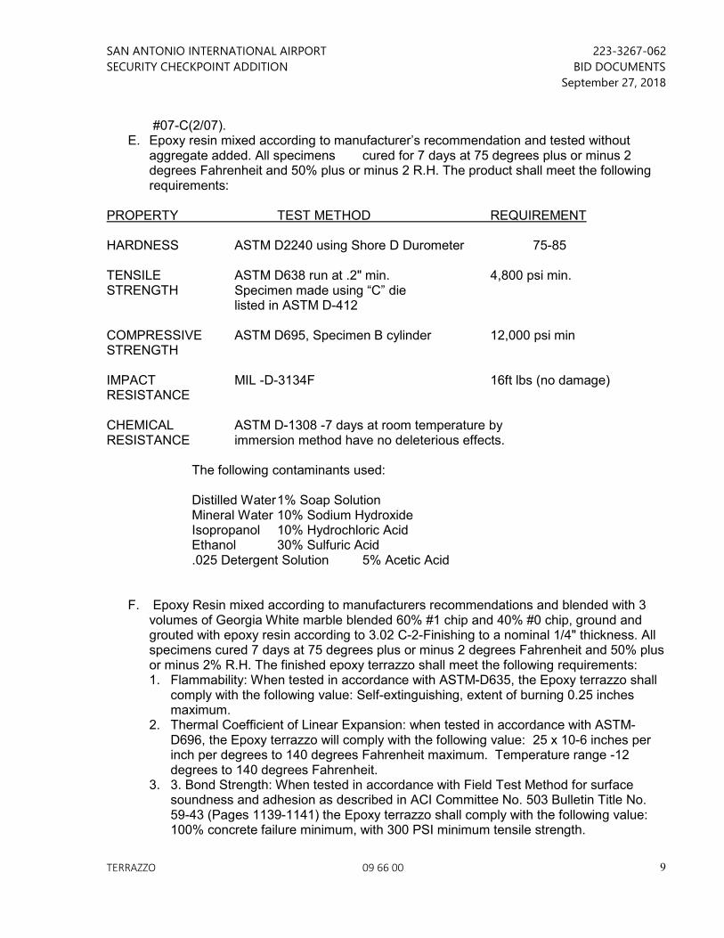
SAN ANTONIO INTERNATIONAL AIRPORT 223-3267-062
SECURITY CHECKPOINT ADDITION BID DOCUMENTS
September 27, 2018
TERRAZZO 09 66 00
9
#07-C(2/07). E. Epoxy resin mixed according to manufacturer’s recommendation and tested without
aggregate added. All specimens cured for 7 days at 75 degrees plus or minus 2 degrees Fahrenheit and 50% plus or minus 2 R.H. The product shall meet the following requirements:
PROPERTY TEST METHOD REQUIREMENT HARDNESS ASTM D2240 using Shore D Durometer 75-85 TENSILE ASTM D638 run at .2" min. 4,800 psi min. STRENGTH Specimen made using “C” die listed in ASTM D-412 COMPRESSIVE ASTM D695, Specimen B cylinder 12,000 psi min STRENGTH IMPACT MIL -D-3134F 16ft lbs (no damage) RESISTANCE CHEMICAL ASTM D-1308 -7 days at room temperature by RESISTANCE immersion method have no deleterious effects. The following contaminants used: Distilled Water 1% Soap Solution Mineral Water 10% Sodium Hydroxide Isopropanol 10% Hydrochloric Acid Ethanol 30% Sulfuric Acid .025 Detergent Solution 5% Acetic Acid
F. Epoxy Resin mixed according to manufacturers recommendations and blended with 3 volumes of Georgia White marble blended 60% #1 chip and 40% #0 chip, ground and grouted with epoxy resin according to 3.02 C-2-Finishing to a nominal 1/4" thickness. All specimens cured 7 days at 75 degrees plus or minus 2 degrees Fahrenheit and 50% plus or minus 2% R.H. The finished epoxy terrazzo shall meet the following requirements: 1. Flammability: When tested in accordance with ASTM-D635, the Epoxy terrazzo shall
comply with the following value: Self-extinguishing, extent of burning 0.25 inches maximum.
2. Thermal Coefficient of Linear Expansion: when tested in accordance with ASTM-D696, the Epoxy terrazzo will comply with the following value: 25 x 10-6 inches per inch per degrees to 140 degrees Fahrenheit maximum. Temperature range -12 degrees to 140 degrees Fahrenheit.
3. 3. Bond Strength: When tested in accordance with Field Test Method for surface soundness and adhesion as described in ACI Committee No. 503 Bulletin Title No. 59-43 (Pages 1139-1141) the Epoxy terrazzo shall comply with the following value: 100% concrete failure minimum, with 300 PSI minimum tensile strength.
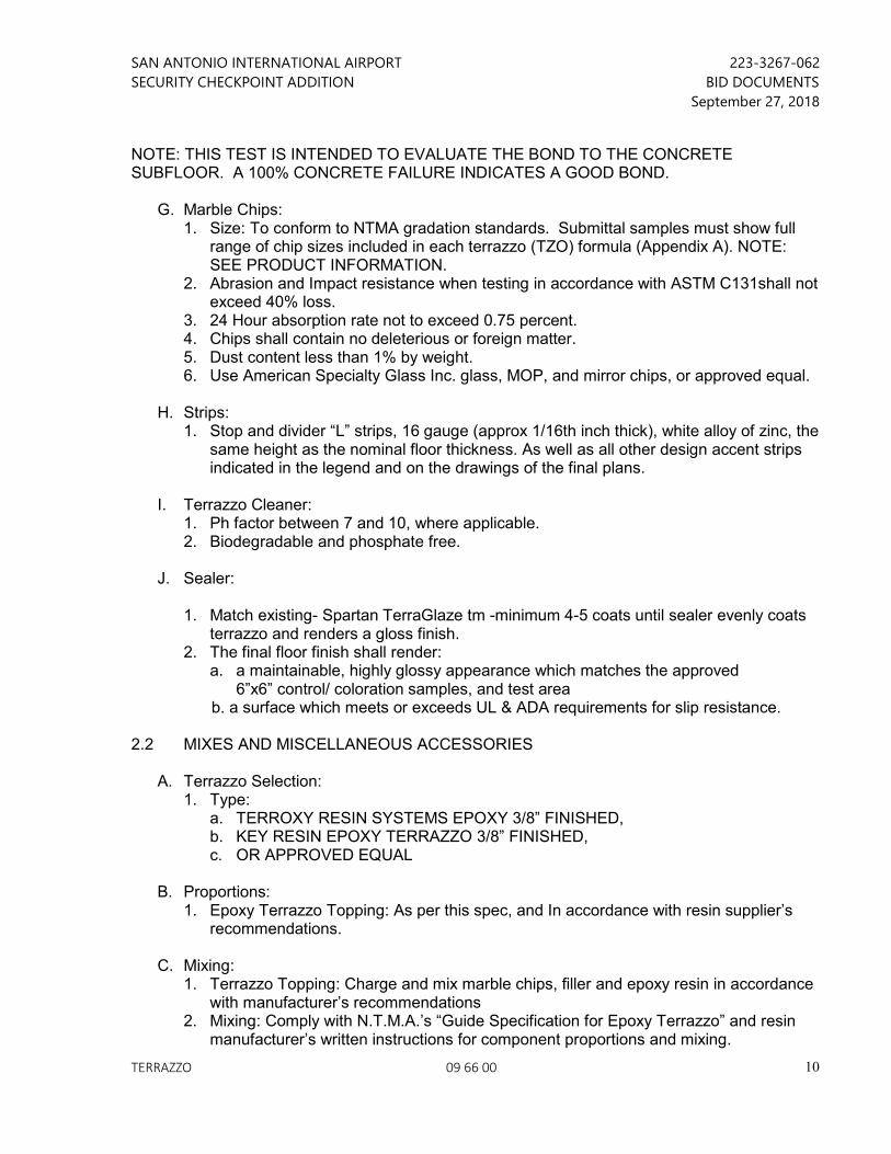
SAN ANTONIO INTERNATIONAL AIRPORT 223-3267-062
SECURITY CHECKPOINT ADDITION BID DOCUMENTS
September 27, 2018
TERRAZZO 09 66 00
10
NOTE: THIS TEST IS INTENDED TO EVALUATE THE BOND TO THE CONCRETE SUBFLOOR. A 100% CONCRETE FAILURE INDICATES A GOOD BOND.
G. Marble Chips: 1. Size: To conform to NTMA gradation standards. Submittal samples must show full
range of chip sizes included in each terrazzo (TZO) formula (Appendix A). NOTE: SEE PRODUCT INFORMATION.
2. Abrasion and Impact resistance when testing in accordance with ASTM C131shall not exceed 40% loss.
3. 24 Hour absorption rate not to exceed 0.75 percent. 4. Chips shall contain no deleterious or foreign matter. 5. Dust content less than 1% by weight. 6. Use American Specialty Glass Inc. glass, MOP, and mirror chips, or approved equal.
H. Strips:
1. Stop and divider “L” strips, 16 gauge (approx 1/16th inch thick), white alloy of zinc, the same height as the nominal floor thickness. As well as all other design accent strips indicated in the legend and on the drawings of the final plans.
I. Terrazzo Cleaner:
1. Ph factor between 7 and 10, where applicable. 2. Biodegradable and phosphate free.
J. Sealer:
1. Match existing- Spartan TerraGlaze tm -minimum 4-5 coats until sealer evenly coats
terrazzo and renders a gloss finish. 2. The final floor finish shall render:
a. a maintainable, highly glossy appearance which matches the approved 6”x6” control/ coloration samples, and test area
b. a surface which meets or exceeds UL & ADA requirements for slip resistance. 2.2 MIXES AND MISCELLANEOUS ACCESSORIES
A. Terrazzo Selection: 1. Type:
a. TERROXY RESIN SYSTEMS EPOXY 3/8” FINISHED, b. KEY RESIN EPOXY TERRAZZO 3/8” FINISHED, c. OR APPROVED EQUAL
B. Proportions:
1. Epoxy Terrazzo Topping: As per this spec, and In accordance with resin supplier’s recommendations.
C. Mixing: 1. Terrazzo Topping: Charge and mix marble chips, filler and epoxy resin in accordance
with manufacturer’s recommendations 2. Mixing: Comply with N.T.M.A.’s “Guide Specification for Epoxy Terrazzo” and resin
manufacturer’s written instructions for component proportions and mixing.
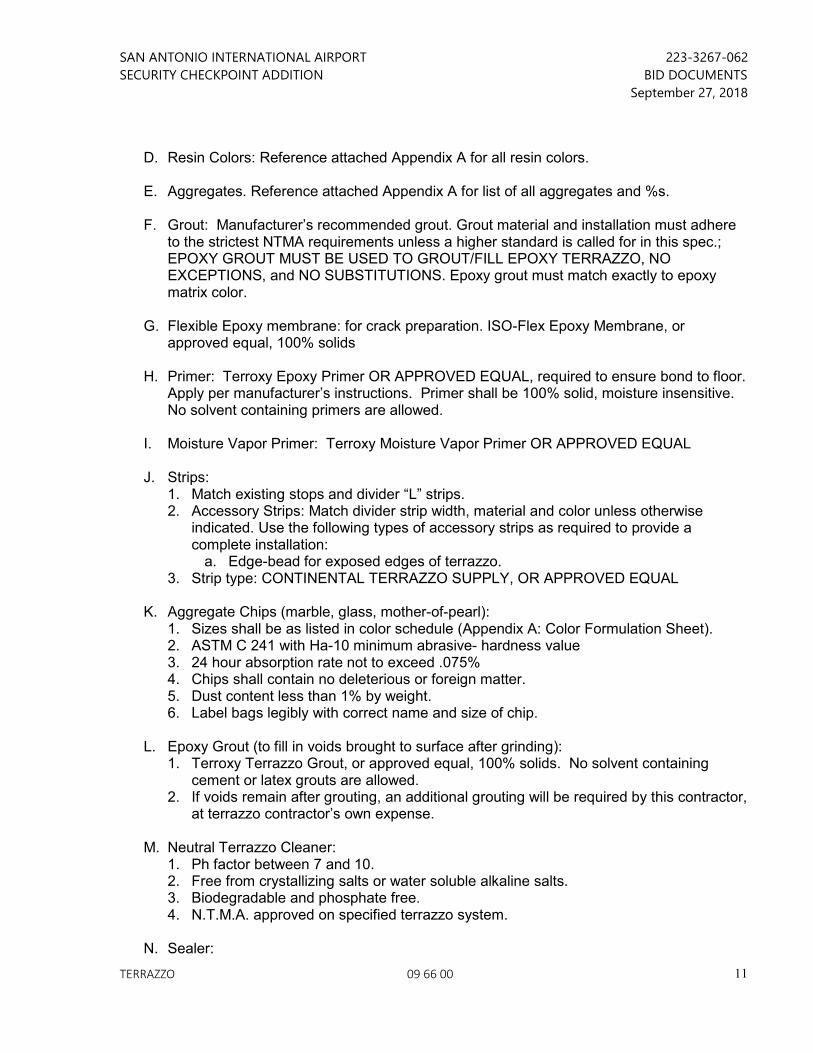
SAN ANTONIO INTERNATIONAL AIRPORT 223-3267-062
SECURITY CHECKPOINT ADDITION BID DOCUMENTS
September 27, 2018
TERRAZZO 09 66 00
11
D. Resin Colors: Reference attached Appendix A for all resin colors.
E. Aggregates. Reference attached Appendix A for list of all aggregates and %s.
F. Grout: Manufacturer’s recommended grout. Grout material and installation must adhere
to the strictest NTMA requirements unless a higher standard is called for in this spec.; EPOXY GROUT MUST BE USED TO GROUT/FILL EPOXY TERRAZZO, NO EXCEPTIONS, and NO SUBSTITUTIONS. Epoxy grout must match exactly to epoxy matrix color.
G. Flexible Epoxy membrane: for crack preparation. ISO-Flex Epoxy Membrane, or
approved equal, 100% solids
H. Primer: Terroxy Epoxy Primer OR APPROVED EQUAL, required to ensure bond to floor. Apply per manufacturer’s instructions. Primer shall be 100% solid, moisture insensitive. No solvent containing primers are allowed.
I. Moisture Vapor Primer: Terroxy Moisture Vapor Primer OR APPROVED EQUAL
J. Strips:
1. Match existing stops and divider “L” strips. 2. Accessory Strips: Match divider strip width, material and color unless otherwise
indicated. Use the following types of accessory strips as required to provide a complete installation:
a. Edge-bead for exposed edges of terrazzo. 3. Strip type: CONTINENTAL TERRAZZO SUPPLY, OR APPROVED EQUAL
K. Aggregate Chips (marble, glass, mother-of-pearl):
1. Sizes shall be as listed in color schedule (Appendix A: Color Formulation Sheet). 2. ASTM C 241 with Ha-10 minimum abrasive- hardness value 3. 24 hour absorption rate not to exceed .075% 4. Chips shall contain no deleterious or foreign matter. 5. Dust content less than 1% by weight. 6. Label bags legibly with correct name and size of chip.
L. Epoxy Grout (to fill in voids brought to surface after grinding):
1. Terroxy Terrazzo Grout, or approved equal, 100% solids. No solvent containing cement or latex grouts are allowed.
2. If voids remain after grouting, an additional grouting will be required by this contractor, at terrazzo contractor’s own expense.
M. Neutral Terrazzo Cleaner:
1. Ph factor between 7 and 10. 2. Free from crystallizing salts or water soluble alkaline salts. 3. Biodegradable and phosphate free. 4. N.T.M.A. approved on specified terrazzo system.
N. Sealer:
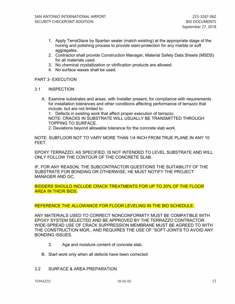
SAN ANTONIO INTERNATIONAL AIRPORT 223-3267-062
SECURITY CHECKPOINT ADDITION BID DOCUMENTS
September 27, 2018
TERRAZZO 09 66 00
12
1. Apply TerraGlaze by Spartan sealer (match existing) at the appropriate stage of the honing and polishing process to provide stain-protection for any marble or soft aggregates.
2. Contractor shall provide Construction Manager, Material Safety Data Sheets (MSDS) for all materials used.
3. No chemical crystallization or vitrification products are allowed. 4. No surface waxes shall be used.
PART 3- EXECUTION 3.1 INSPECTION
A. Examine substrates and areas, with Installer present, for compliance with requirements for installation tolerances and other conditions affecting performance of terrazzo that include, but are not limited to: 1. Defects in existing work that affect proper execution of terrazzo. NOTE: CRACKS IN SUBSTRATE WILL USUALLY BE TRANSMITTED THROUGH TOPPING TO SURFACE.
2. Deviations beyond allowable tolerance for the concrete slab work. NOTE: SUBFLOOR NOT TO VARY MORE THAN 1/4 INCH FROM TRUE PLANE IN ANY 10 FEET. EPOXY TERRAZZO, AS SPECIFIED, IS NOT INTENDED TO LEVEL SUBSTRATE AND WILL ONLY FOLLOW THE CONTOUR OF THE CONCRETE SLAB. IF, FOR ANY REASON, THE SUBCONTRACTOR QUESTIONS THE SUITABILITY OF THE SUBSTRATE FOR BONDING OR OTHERWISE, HE MUST NOTIFY THE PROJECT MANAGER AND GC. BIDDERS SHOULD INCLUDE CRACK TREATMENTS FOR UP TO 20% OF THE FLOOR AREA IN THEIR BIDS. REFERENCE THE ALLOWANCE FOR FLOOR LEVELING IN THE BID SCHEDULE. ANY MATERIALS USED TO CORRECT NONCONFORMITY MUST BE COMPATIBLE WITH EPOXY SYSTEM SELECTED AND BE APPROVED BY THE TERRAZZO CONTRACTOR. WIDE-SPREAD USE OF CRACK SUPPRESSION MEMBRANE MUST BE AGREED TO WITH THE CONSTRUCTION MGR., AND REQUIRES THE USE OF “SOFT-JOINTS TO AVOID ANY BONDING ISSUES.
3. Age and moisture content of concrete slab.
B. Start work only when all defects have been corrected 3.2 SURFACE & AREA PREPARATION
SAN ANTONIO INTERNATIONAL AIRPORT 223-3267-062
SECURITY CHECKPOINT ADDITION BID DOCUMENTS
September 27, 2018
TERRAZZO 09 66 00
13
A. Prepare concrete substrate to “open” surface pores by means of wet terrazzo grinding. Remove all carpet adhesive and contaminating or bond breaking substances including, but not limited to dust, grinding slurry, laitance, curing compounds, coatings, sealers, oil and grease. Any oil or grease not removed by wet terrazzo grinding must be chemically removed. Spalled or deteriorated concrete is not acceptable and shall be mechanically removed by scabbling or chipping hammers. Acid etching is not acceptable.
B. Moisture Testing: Test for moisture according to ASTM F2170 (determining relative
humidity in concrete slabs using in situ probes). Proceed with installation only after substrates have a maximum relative humidity measurement reading less than 80% If relative humidity measurement reading is greater than or equal to 80%, Terroxy® Moisture Vapor Primer OR APPROVED EQUAL is required. Apply to terrazzo substrates according to Terroxy® Resin Systems Moisture Vapor Primer Product Data Sheet.
C. Installer to control terrazzo grinding slurry to prevent damage to adjacent materials.
Contractor provide, erect and maintain barricades and temporary enclosures within which installation is to take place.
D. Repair damaged concrete with Terroxy Fill (OR APPROVED EQUAL) per manufacturer’s
instructions. Latex fills or self-leveling underlayments are not acceptable. See Section 3.03- Floor Leveling Procedure.
E. Cracks and non-expansion joints greater than 1/16” wide after surface preparation shall
be prepared until sound. 1. Hairline cracks = those up to 1/16” wide. 2. Fill cracks greater than hairline, but less than 1/16” wide after surface preparation with
neat, 100% solids epoxy filler.. Place detail coat of Membrane over crack and embed a 9” fiberglass cloth. Lightly abrade or solvent wipe treated cracks prior to applying primer.
3. Fill cracks greater than 1/16” with 100% solids epoxy filler. Place 23-30 mil detail coat so that Membrane extends at least 9-12” on each side of crack or joint. After membrane has leveled, lay precut ISO-Crack Fabric into wet membrane. Smooth cloth with a flat steel trowel, allowing cloth to be encapsulated but remain exposed on the surface of the membrane. Lightly abrade or solvent wipe treated cracks prior to applying primer.
4. If for any reason a substitution is made to specified manufacturer of materials, anti-fracture materials specification must be re-evaluated such that anti-fracture remedies are supplied by the same manufacturer providing epoxy for terrazzo flooring.
NOTE: STRESS CRACK PREPARATION SHOULD BE ANTICIPATED BY THE CONTRACTOR. IF THE EXTENT IS FOUND TO BE EXTENSIVE (AFFECTING MORE THAN 20% OF THE TOTAL SQ. FOOTAGE), THE CRACK TREATMENT SHALL BE COMPLETED ON A T&M BASIS PER UNIT RATE PROVIDED FOR UNDERLAYMENT REPLACEMENT. SQUARE FOOTAGE “AFFECTED” WILL BE CALCULATED AS THE LENGTH OF CRACK MULTIPLIED BY ONE FOOT WIDTH.
F. Floor penetrations (electrical, mechanical, plumbing, IT/Security) and benches to be removed by others to allow for ease of installation. Partitions to be put back in place by others once all terrazzo installation stages are complete.
SAN ANTONIO INTERNATIONAL AIRPORT 223-3267-062
SECURITY CHECKPOINT ADDITION BID DOCUMENTS
September 27, 2018
TERRAZZO 09 66 00
14
G. Backwalls to be removed and relocated by others as part of other projects/ work taking
place in the affected area.
H. Work shall be conducted in such a way that airport operations are not interrupted. A PHASING PLAN SHALL BE PROVIDE IN COOPERATION WITH THE OWNER, OWNER’S CONSULTANTS ( RS&H), AND OWNER’S CONTRACTOR
3.3 FLOOR LEVELING PROCEDURE Immediately after existing tile has been removed, a determination will be made if any floor leveling (pre floating) is required. If floor leveling is required, terrazzo installer’s foreman
A. Should contact contractor’s field representative and advise that floor leveling work is to commence under the allowance procedures previously established.
B. A straight edge will be applied over any dips or high points to confirm requirement to
Construction Manager. Minor uniform slopes should not be pre-floated. The epoxy terrazzo should be applied over true sloped floors. If this appears to be a concern by field personnel, staff personnel should be contacted for direction.
C. The Contractor will note and confirm, on pre-established Time & Material Log forms
provided by terrazzo installer, items 1-5 below. Form to include, but not be limited to: 1. The time leveling work is to start 2. How many workmen (by skill) are performing this particular work 3. Hours spent during a particular work week 4. Amount of material used (i.e., epoxy resin, hardener, fillers) 5. Which particular phased area is being worked on
D. After the completion of leveling work, but before any artistic layouts or metal divider strips
are applied to the floor, a terrazzo representative will advise the Construction Manager that all floor leveling work has been completed for the particular phase of work in progress.
E. In the event that any saw cut and/ or any other type of control joints are detected under
existing tile, the terrazzo installer will advise Contractor who will confirm the lineal footage of same.
3.4 INSTALLATION
A. General: Apply each component of Epoxy Terrazzo Flooring System in compliance with the National Terrazzo and Mosaic Association’s Guide Specification and written recommendations for terrazzo type indicated. Including, but not limited to, mixing and application methods, re-coat windows, cure times and environmental restrictions. UNDER NO CIRCUMSTANCES SHALL CURE TIMES BE INTERRUPTED OR EXPEDITED. STRICT ADHERENCE TO MFTR’S REQUIREMNTS AND INSTRUCTIONS SHALL BE PRECISELY FOLLOWED.
SAN ANTONIO INTERNATIONAL AIRPORT 223-3267-062
SECURITY CHECKPOINT ADDITION BID DOCUMENTS
September 27, 2018
TERRAZZO 09 66 00
15
B. Installation to be conducted in phased areas within barricades as indicated on Contractor’s phasing plan.
C. Apply system directly over all non-expansion joints and cracks treated with Flexible
Epoxy membrane. Terminate system at edge of all expansion joints as designated by Design Professional and Project Architect.
D. Sub- Floor:
1. Install all divider and accessory strips according to N.T.M.A.’s written recommendations.
2. Divider strips must be true in layout to Design Professional’s specified design. Divider strips must be fully exposed on the finished surface. All strip intersections must be set without gaps.
3. Install angle or T-type strips and similar accessories in adhesive setting bed without voids below strips. All metal strips should be set with continuous epoxy bond. Temporary spotting with heat gun is acceptable.
4. Existing saw-cut control joints are not assumed to be present in this structural slab. In the event that they do exist, terrazzo installer to work with Contractor fill with epoxy filler.
E. Contractor and Terrazzo installer shall coordinate installations schedule such that DP can
be present to review the layout of each overall area before installation of strips and terrazzo begins. Installer shall receive SAT’s designated Design Professional’s approval before proceeding with installation.
F. Epoxy Primer: Apply epoxy primer evenly over prepared substrate, cracks and non-
expansion joints at the rate of 200-300 square feet per gallon for normal concrete to thoroughly wet surface, but avoid “ponding” of the material. (Highly porous concrete may require additional material). 1. Strip Materials: Divider and Accessory Strips:
a. Install strips in adhesive setting bed without voids below strips or mechanically anchor strips as required to attach strips to substrate.
b. Control-Joint Strips: Separate double L-type angles, positioned back to back with minimum 1/8”-1/4” width between. (Single L-type angle, positioned adjacent to the joint is also acceptable.) Fill joint and area between strips with 100% Solids Epoxy Joint Filler. Match material, thickness and color of divider strips and depth required for topping thickness indicated. (Buried Control Joint: Fill saw cut concrete control joint with 100% Solids Epoxy Filler, Apply Terroxy Iso-Crack Membrane 30-40 mils, embed 24" fiberglass fabric reinforcement, set 1/16" White Zinc Divider strips adjacent to control joint. See Detail inTB 009)
c. Construction-Joint (Cold-Joint) Strips: Separate double L-type angles, positioned back to back with minimum 1/8”-1/4” width between. Fill joint and area between strips with semi-flexible Terroxy® Joint Filler (OR APPROVED EQUAL). Match material, thickness and color of divider strips and depth required for topping thickness indicated.
G. Expansion-Joint Strips: MATCH EXISTING H. Placing Terrazzo:
SAN ANTONIO INTERNATIONAL AIRPORT 223-3267-062
SECURITY CHECKPOINT ADDITION BID DOCUMENTS
September 27, 2018
TERRAZZO 09 66 00
16
1. Do not proceed with terrazzo placement until SAT’s designated Design Professional’s approval is given for artistic transfer of design.
2. Mix epoxy resin binder with aggregates and fillers in ratios as recommended by manufacturer and approved by designated Design Professional. (See Color Formulation Sheet: Appendix A).
3. Trowel apply terrazzo mixture over epoxy primer coat to provide a smooth, seamless, minimum 3/8” thick surface. Allow proper cure per manufacturer’s recommendations prior to grinding operations.
4. When grouting the Epoxy Resin Terrazzo the grout shall be pulled in 3 opposing directions using GROUT PANS to ensure the most comprehensive fill/ least air-holes and voids in finish product.
5. Curing terrazzo shall not be walked upon by anyone except the terrazzo installer or their agents for a period of no less than 24 hours. Rubber heel-less boots are to be worn to distribute the weight and prevent the depression of aggregate chips that will later be evident in the grinding process and appear aesthetically unpleasing. For similar reasons, equipment use over such areas is not recommended, and it is advised that the area be marked ‘off-limits’ for 24 hours after pour/grinding/grouting.
I. After 24 hour period, The SAT Construction Manager and the Project Architect will
determine the time for opening the new terrazzo surface for pedestrian traffic.
J. Finishing: Use Large self-propelled grinding equipment by Terrco or equal. Contractor must deliver a floor that is “cut flat”. Dips, grid grunge at poorly ground divider strips, cat-faces, and swirls, will not be accepted. EXCESSIVE PIN-HOLES WILL NOT BE ACCEPTED. VOIDS (HOLES 1/16”D OR GREATER) WILL NOT BE ACCEPTED. Terrazzo finish and formulas must match approved samples and mock-ups. 1. Rough Grinding:
a. Wet grind with 24 or finer grit stones or with comparable diamond plates. b. Follow initial grind with 80 or finer grit stones. c. Control terrazzo grinding slurry and noise as required. Excess is not permitted.
2. Grouting: a. Cleanse floor with clean water and rinse thoroughly. b. Remove excess water by wet vacuum and machine until completely dry. c. Apply epoxy grout as recommended by manufacturer. Match grout color to matrix
color. No substitutions on grout type or color will be accepted. Re-grout and re-grind as often as needed to remove air pockets, pin holes and voids.
3. Fine Grinding: a. Delay until heavy trade work is complete and construction traffic through area is
restricted. b. Wet grind until all grout is removed from surface. c. Control terrazzo grinding slurry and noise as required. Excess is not permitted. d. Upon completion, terrazzo shall show a minimum of 70-75% aggregate. e. Fine Grinding (all wet grinding) shall be done using the following sequence: f. 100-grit, 200-grit, 400-grit, DO NOT ELIMINATE ANY OF THE ABOVE STEPS IN
GRIT LEVELS!!
K. Cleaning and Sealing: 1. Thoroughly wash all surfaces with specified terrazzo cleaner after fine grinding. 2. Rinse with clean water and allow surface to dry thoroughly.
SAN ANTONIO INTERNATIONAL AIRPORT 223-3267-062
SECURITY CHECKPOINT ADDITION BID DOCUMENTS
September 27, 2018
TERRAZZO 09 66 00
17
3. Apply Spartan TerraGlaze water-base sealer, with S.C.O.F. of .05 minimum, in 4 -5 coats at the coverage rate as recommended by manufacturer. Allow each coat of sealer to cure before applying the next coat.
4. Apply one additional coat and buff with high speed buffer 5. The work must be protected until the finish sealer is completely cured. Stains and
Inclusions of particulates from the environment, hairs, etc. in the Terrazzo will not be accepted. SEALED TERRAZZZO MUST BE ALLOWED TO FULLY CURE BEFORE SUBJECTED TO FOOT TRAFFIC; follow manufacturer’s instructions, no exceptions.
L. Final floor shall adhere to UL listed ‘slip resistant’ with a S.C.O.F. of .05 minimum
M. Final polished finish must match that of the approved 6”x 6” color/control submittal samples.
N. PRECAST TERRAZZO INSTALLATION
1. Install precast units using method recommended by NTMA and manufacturer unless otherwise indicated.
2. Install Cast in place or poured elements using method recommended by NTMA and manufacturer unless otherwise indicated.
3. Seal joints between units with joint sealants
O. Protection: The work shall be protected until, upon completion, the work shall be ready for final inspection and acceptance by SAT, or their agent.
SEE APPENDIX ‘A’ FOLLOWING PAGE
SAN ANTONIO INTERNATIONAL AIRPORT 223-3267-062
SECURITY CHECKPOINT ADDITION BID DOCUMENTS
September 27, 2018
TERRAZZO 09 66 00
18
APPENDIX A TERRAZZO COLORS/FORMULAS: in process GENERAL NOTES: 1. AGGREGATES formulated below using T&M and T&M "Ecco-trazzo” AND CAN BE SUPPLIED THROUGH APPROVED EQUALS FROM: a. Continental Terrazzo Supply b. Ecco-trazzo c. Klein & co. d. T&M Terrazzo supply
e. OR APPROVED EQUAL f. All Mirror aggregates must be ASG HIGH QUALITY ONE-SIDED MIRROR (NO SUBSTITUTIONS).
TZ-1-MAIN CONCOURSE: MATCH EXISTING END of clear resin w/ tinted membranes END OF APPENDIX A End of Terrazzo Bid Specification
SAN ANTONIO INTERNATIONAL AIRPORT 223-3267-062
SECURITY CHECKPOINT ADDITION BID DOCUMENTS
September 27, 2018
INTERIOR PAINTING 099123 - 1
SECTION 099123 - INTERIOR PAINTING
PART 1 - GENERAL
1.1 RELATED DOCUMENTS
A. Drawings and general provisions of the Contract, including General and Supplementary
Conditions and Division 01 Specification Sections, apply to this Section.
1.2 SUMMARY
A. Section includes surface preparation and the application of paint systems on interior
substrates.
1. Steel and iron.
2. Gypsum board.
1.3 DEFINITIONS
A. MPI Gloss Level 1: Not more than five units at 60 degrees and 10 units at 85 degrees,
according to ASTM D 523.
B. MPI Gloss Level 2: Not more than 10 units at 60 degrees and 10 to 35 units at 85
degrees, according to ASTM D 523.
C. MPI Gloss Level 3: 10 to 25 units at 60 degrees and 10 to 35 units at 85 degrees,
according to ASTM D 523.
D. MPI Gloss Level 4: 20 to 35 units at 60 degrees and not less than 35 units at 85 degrees,
according to ASTM D 523.
E. MPI Gloss Level 5: 35 to 70 units at 60 degrees, according to ASTM D 523.
F. MPI Gloss Level 6: 70 to 85 units at 60 degrees, according to ASTM D 523.
G. MPI Gloss Level 7: More than 85 units at 60 degrees, according to ASTM D 523.
1.4 ACTION SUBMITTALS
A. Product Data: For each type of product. Include preparation requirements and
application instructions.
SAN ANTONIO INTERNATIONAL AIRPORT 223-3267-062
SECURITY CHECKPOINT ADDITION BID DOCUMENTS
September 27, 2018
INTERIOR PAINTING 099123 - 2
1. Include Printout of current "MPI Approved Products List" for each product
category specified, with the proposed product highlighted.
2. Indicate VOC content.
B. Samples for Initial Selection: For each type of topcoat product.
C. Samples for Verification: For each type of paint system and in each color and gloss of
topcoat.
1. Submit Samples on rigid backing, 8 inches (200 mm) square.
2. Apply coats on Samples in steps to show each coat required for system.
3. Label each coat of each Sample.
4. Label each Sample for location and application area.
D. Product List: Cross-reference to paint system and locations of application areas. Use
same designations indicated on Drawings and in schedules. Include color designations.
1.5 MAINTENANCE MATERIAL SUBMITTALS
A. Furnish extra materials, from the same product run, that match products installed and
that are packaged with protective covering for storage and identified with labels
describing contents.
1. Paint: 5 percent, but not less than 1 gal. (3.8 L) of each material and color
applied.
1.6 QUALITY ASSURANCE
A. Mockups: Apply mockups of each paint system indicated and each color and finish
selected to verify preliminary selections made under Sample submittals and to
demonstrate aesthetic effects and set quality standards for materials and execution.
1. Architect will select one surface to represent surfaces and conditions for
application of each paint system.
a. Vertical and Horizontal Surfaces: Provide samples of at least 100 sq. ft. (9
sq. m).
b. Other Items: Architect will designate items or areas required.
2. Final approval of color selections will be based on mockups.
a. If preliminary color selections are not approved, apply additional mockups
of additional colors selected by Architect at no added cost to Owner.
SAN ANTONIO INTERNATIONAL AIRPORT 223-3267-062
SECURITY CHECKPOINT ADDITION BID DOCUMENTS
September 27, 2018
INTERIOR PAINTING 099123 - 3
3. Approval of mockups does not constitute approval of deviations from the
Contract Documents contained in mockups unless Architect specifically approves
such deviations in writing.
4. Subject to compliance with requirements, approved mockups may become part
of the completed Work if undisturbed at time of Substantial Completion.
1.7 DELIVERY, STORAGE, AND HANDLING
A. Store materials not in use in tightly covered containers in well-ventilated areas with
ambient temperatures continuously maintained at not less than 45 deg F (7 deg C).
1. Maintain containers in clean condition, free of foreign materials and residue.
2. Remove rags and waste from storage areas daily.
1.8 FIELD CONDITIONS
A. Apply paints only when temperature of surfaces to be painted and ambient air
temperatures are between 50 and 95 deg F (10 and 35 deg C).
B. Do not apply paints when relative humidity exceeds 85 percent; at temperatures less
than 5 deg F (3 deg C) above the dew point; or to damp or wet surfaces.
PART 2 - PRODUCTS
2.1 MANUFACTURERS
A. Manufacturers: Subject to compliance with requirements, available manufacturers offering
products that may be incorporated into the Work include, but are not limited to, the following:
1. Benjamin Moore & Co.
2. PPG Paints.
B. Products: Subject to compliance with requirements, available products that may be
incorporated into the Work include, but are not limited to products listed in the Interior
Painting Schedule for the paint category indicated.
2.2 PAINT, GENERAL
A. MPI Standards: Products shall comply with MPI standards indicated and shall be listed
in its "MPI Approved Products Lists."
SAN ANTONIO INTERNATIONAL AIRPORT 223-3267-062
SECURITY CHECKPOINT ADDITION BID DOCUMENTS
September 27, 2018
INTERIOR PAINTING 099123 - 4
B. Material Compatibility:
1. Materials for use within each paint system shall be compatible with one another
and substrates indicated, under conditions of service and application as
demonstrated by manufacturer, based on testing and field experience.
2. For each coat in a paint system, products shall be recommended in writing by
topcoat manufacturers for use in paint system and on substrate indicated.
C. Colors: As selected by Architect from manufacturer's full range.
2.3 SOURCE QUALITY CONTROL
A. Testing of Paint Materials: Owner reserves the right to invoke the following procedure:
1. Owner will engage the services of a qualified testing agency to sample paint
materials. Contractor will be notified in advance and may be present when
samples are taken. If paint materials have already been delivered to Project site,
samples may be taken at Project site. Samples will be identified, sealed, and
certified by testing agency.
2. Testing agency will perform tests for compliance with product requirements.
3. Owner may direct Contractor to stop applying paints if test results show materials
being used do not comply with product requirements. Contractor shall remove
noncomplying paint materials from Project site, pay for testing, and repaint
surfaces painted with rejected materials. Contractor will be required to remove
rejected materials from previously painted surfaces if, on repainting with
complying materials, the two paints are incompatible.
PART 3 - EXECUTION
3.1 EXAMINATION
A. Examine substrates and conditions, with Applicator present, for compliance with
requirements for maximum moisture content and other conditions affecting
performance of the Work.
B. Maximum Moisture Content of Substrates: When measured with an electronic moisture
meter as follows:
1. Concrete: 12 percent.
2. Fiber-Cement Board: 12 percent.
3. Masonry (Clay and CMUs): 12 percent.
4. Wood: 15 percent.
SAN ANTONIO INTERNATIONAL AIRPORT 223-3267-062
SECURITY CHECKPOINT ADDITION BID DOCUMENTS
September 27, 2018
INTERIOR PAINTING 099123 - 5
5. Gypsum Board: 12 percent.
6. Plaster: 12 percent.
C. Gypsum Board Substrates: Verify that finishing compound is sanded smooth.
D. Plaster Substrates: Verify that plaster is fully cured.
E. Spray-Textured Ceiling Substrates: Verify that surfaces are dry.
F. Verify suitability of substrates, including surface conditions and compatibility, with
existing finishes and primers.
G. Proceed with coating application only after unsatisfactory conditions have been
corrected.
1. Application of coating indicates acceptance of surfaces and conditions.
3.2 PREPARATION
A. Comply with manufacturer's written instructions and recommendations in "MPI
Architectural Painting Specification Manual" applicable to substrates and paint systems
indicated.
B. Remove hardware, covers, plates, and similar items already in place that are removable
and are not to be painted. If removal is impractical or impossible because of size or
weight of item, provide surface-applied protection before surface preparation and
painting.
1. After completing painting operations, use workers skilled in the trades involved
to reinstall items that were removed. Remove surface-applied protection if any.
C. Clean substrates of substances that could impair bond of paints, including dust, dirt, oil,
grease, and incompatible paints and encapsulants.
1. Remove incompatible primers and reprime substrate with compatible primers or
apply tie coat as required to produce paint systems indicated.
D. Concrete Substrates: Remove release agents, curing compounds, efflorescence, and
chalk. Do not paint surfaces if moisture content or alkalinity of surfaces to be painted
exceeds that permitted in manufacturer's written instructions.
E. Masonry Substrates: Remove efflorescence and chalk. Do not paint surfaces if moisture
content or alkalinity of surfaces or mortar joints exceeds that permitted in
manufacturer's written instructions.
SAN ANTONIO INTERNATIONAL AIRPORT 223-3267-062
SECURITY CHECKPOINT ADDITION BID DOCUMENTS
September 27, 2018
INTERIOR PAINTING 099123 - 6
F. Steel Substrates: Remove rust, loose mill scale, and shop primer, if any. Clean using
methods recommended in writing by paint manufacturer.
1. SSPC-SP 2.
2. SSPC-SP 3.
3. SSPC-SP 7/NACE No. 4.
4. SSPC-SP 11.
G. Shop-Primed Steel Substrates: Clean field welds, bolted connections, and areas where
shop paint is abraded. Paint exposed areas with the same material as used for shop
priming to comply with SSPC-PA 1 for touching up shop-primed surfaces.
H. Galvanized-Metal Substrates: Remove grease and oil residue from galvanized sheet
metal by mechanical methods to produce clean, lightly etched surfaces that promote
adhesion of subsequently applied paints.
I. Aluminum Substrates: Remove loose surface oxidation.
J. Wood Substrates:
1. Scrape and clean knots, and apply coat of knot sealer before applying primer.
2. Sand surfaces that will be exposed to view, and dust off.
3. Prime edges, ends, faces, undersides, and backsides of wood.
4. After priming, fill holes and imperfections in the finish surfaces with putty or
plastic wood filler. Sand smooth when dried.
K. Cotton or Canvas Insulation Covering Substrates: Remove dust, dirt, and other foreign
material that might impair bond of paints to substrates.
3.3 APPLICATION
A. Apply paints according to manufacturer's written instructions and to recommendations
in "MPI Manual."
1. Use applicators and techniques suited for paint and substrate indicated.
2. Paint surfaces behind movable equipment and furniture same as similar exposed
surfaces. Before final installation, paint surfaces behind permanently fixed
equipment or furniture with prime coat only.
3. Paint front and backsides of access panels, removable or hinged covers, and
similar hinged items to match exposed surfaces.
4. Do not paint over labels of independent testing agencies or equipment name,
identification, performance rating, or nomenclature plates.
SAN ANTONIO INTERNATIONAL AIRPORT 223-3267-062
SECURITY CHECKPOINT ADDITION BID DOCUMENTS
September 27, 2018
INTERIOR PAINTING 099123 - 7
5. Primers specified in painting schedules may be omitted on items that are factory
primed or factory finished if acceptable to topcoat manufacturers.
B. Tint each undercoat a lighter shade to facilitate identification of each coat if multiple
coats of same material are to be applied. Tint undercoats to match color of topcoat, but
provide sufficient difference in shade of undercoats to distinguish each separate coat.
C. If undercoats or other conditions show through topcoat, apply additional coats until
cured film has a uniform paint finish, color, and appearance.
D. Apply paints to produce surface films without cloudiness, spotting, holidays, laps, brush
marks, roller tracking, runs, sags, ropiness, or other surface imperfections. Cut in sharp
lines and color breaks.
E. Painting Fire Suppression, Plumbing, HVAC, Electrical, Communication, and Electronic
Safety and Security Work:
1. Paint the following work where exposed in equipment rooms:
a. Equipment, including panelboards and switch gear.
b. Uninsulated metal piping.
c. Uninsulated plastic piping.
d. Pipe hangers and supports.
e. Metal conduit.
f. Plastic conduit.
g. Tanks that do not have factory-applied final finishes.
h. Duct, equipment, and pipe insulation having cotton or canvas insulation
covering or other paintable jacket material.
2. Paint the following work where exposed in occupied spaces:
a. Equipment, including panelboards.
b. Uninsulated metal piping.
c. Uninsulated plastic piping.
d. Pipe hangers and supports.
e. Metal conduit.
f. Plastic conduit.
g. Duct, equipment, and pipe insulation having cotton or canvas insulation
covering or other paintable jacket material.
h. Other items as directed by Architect.
3. Paint portions of internal surfaces of metal ducts, without liner, behind air inlets
and outlets that are visible from occupied spaces.
SAN ANTONIO INTERNATIONAL AIRPORT 223-3267-062
SECURITY CHECKPOINT ADDITION BID DOCUMENTS
September 27, 2018
INTERIOR PAINTING 099123 - 8
3.4 FIELD QUALITY CONTROL
A. Dry Film Thickness Testing: Owner may engage the services of a qualified testing and
inspecting agency to inspect and test paint for dry film thickness.
1. Contractor shall touch up and restore painted surfaces damaged by testing.
2. If test results show that dry film thickness of applied paint does not comply with
paint manufacturer's written recommendations, Contractor shall pay for testing
and apply additional coats as needed to provide dry film thickness that complies
with paint manufacturer's written recommendations.
3.5 CLEANING AND PROTECTION
A. At end of each workday, remove rubbish, empty cans, rags, and other discarded
materials from Project site.
B. After completing paint application, clean spattered surfaces. Remove spattered paints
by washing, scraping, or other methods. Do not scratch or damage adjacent finished
surfaces.
C. Protect work of other trades against damage from paint application. Correct damage to
work of other trades by cleaning, repairing, replacing, and refinishing, as approved by
Architect, and leave in an undamaged condition.
D. At completion of construction activities of other trades, touch up and restore damaged
or defaced painted surfaces.
END OF SECTION 099123
SAN ANTONIO INTERNATIONAL AIRPORT 223-3267-062
SECURITY CHECKPOINT ADDITION BID DOCUMENTS
September 27, 2018
ROOM-IDENTIFICATION SIGNAGE 101423.13 - 1
SECTION 101423.13 - ROOM-IDENTIFICATION SIGNAGE
PART 1 - GENERAL
1.1 RELATED DOCUMENTS
A. Drawings and general provisions of the Contract, including General and Supplementary Conditions and Division 01 Specification Sections, apply to this Section.
1.2 SUMMARY
A. Section includes room-identification signs that are directly attached to the building.
1.3 DEFINITIONS
A. Accessible: In accordance with the accessibility standard.
1.4 COORDINATION
A. Furnish templates for placement of sign-anchorage devices embedded in permanent construction by other installers.
B. Furnish templates for placement of electrical service embedded in permanent construction by other installers.
1.5 ACTION SUBMITTALS
A. Product Data: For each type of product.
B. Shop Drawings: For room-identification signs.
1. Include fabrication and installation details and attachments to other work. 2. Show sign mounting heights, locations of supplementary supports to be provided by other
installers, and accessories. 3. Show message list, typestyles, graphic elements, including raised characters and Braille,
and layout for each sign at least half size.
C. Samples for Initial Selection: For each type of sign assembly, exposed component, and exposed finish.
1. Include representative Samples of available typestyles and graphic symbols.
D. Samples for Verification: For each type of sign assembly showing all components and with the required finish(es), in manufacturer's standard size unless otherwise indicated and as follows:
1. Room-Identification Signs: Full-size Sample.
SAN ANTONIO INTERNATIONAL AIRPORT 223-3267-062
SECURITY CHECKPOINT ADDITION BID DOCUMENTS
September 27, 2018
ROOM-IDENTIFICATION SIGNAGE 101423.13 - 2
2. Variable Component Materials: Full-size Sample of each base material, character (letter, number, and graphic element) in each exposed color and finish not included in Samples above.
3. Exposed Accessories: Full-size Sample of each accessory type. 4. Full-size Samples, if approved, will be returned to Contractor for use in Project.
E. Product Schedule: For room-identification signs. Use same designations indicated on Drawings or specified.
1.6 INFORMATIONAL SUBMITTALS
A. Qualification Data: For Installer and manufacturer.
B. Sample Warranty: For special warranty.
1.7 CLOSEOUT SUBMITTALS
A. Maintenance Data: For signs to include in maintenance manuals.
1.8 MAINTENANCE MATERIAL SUBMITTALS
A. Furnish extra materials, from the same product run, that match products installed and that are packaged with protective covering for storage and identified with labels describing contents.
1. Variable Component Materials: 12 replaceable text inserts and interchangeable characters (letters, numbers, and graphic elements) of each type.
2. Tools: Two set(s) of specialty tools for assembling signs and replacing variable sign components.
1.9 QUALITY ASSURANCE
A. Installer Qualifications: An entity that employs installers and supervisors who are trained and approved by manufacturer.
1.10 FIELD CONDITIONS
A. Field Measurements: Verify locations of anchorage devices and electrical service embedded in permanent construction by other installers by field measurements before fabrication, and indicate measurements on Shop Drawings.
1.11 WARRANTY
A. Special Warranty: Manufacturer agrees to repair or replace components of signs that fail in materials or workmanship within specified warranty period.
1. Failures include, but are not limited to, the following:
SAN ANTONIO INTERNATIONAL AIRPORT 223-3267-062
SECURITY CHECKPOINT ADDITION BID DOCUMENTS
September 27, 2018
ROOM-IDENTIFICATION SIGNAGE 101423.13 - 3
a. Deterioration of finishes beyond normal weathering. b. Deterioration of embedded graphic image. c. Separation or delamination of sheet materials and components.
2. Warranty Period: Five years from date of Substantial Completion.
PART 2 - PRODUCTS
2.1 PERFORMANCE REQUIREMENTS
A. Accessibility Standard: Comply with applicable provisions in the ABA standards of the Federal agency having jurisdiction and ICC A117.1.
2.2 ROOM-IDENTIFICATION SIGNS
A. Room-Identification Sign As indicated on the drawings: Having smooth, uniform surfaces; with message and characters having uniform faces, sharp corners, and precisely formed lines and profiles; and as follows:
1. Manufacturers: Subject to compliance with requirements, provide products by one of the
following:
a. ACE Sign Systems, Inc.
b. Best Sign Systems, Inc.
c. Mohawk Sign Systems.
2. Mounting: Manufacturer's standard method for substrates indicated with concealed anchors.
3. Text and Typeface: Match Existing
2.3 SIGN MATERIALS
A. Aluminum Sheet and Plate: ASTM B 209 (ASTM B 209M), alloy and temper recommended by aluminum producer and finisher for type of use and finish indicated.
B. Aluminum Extrusions: ASTM B 221 (ASTM B 221M), alloy and temper recommended by aluminum producer and finisher for type of use and finish indicated.
C. Acrylic Sheet: ASTM D 4802, category as standard with manufacturer for each sign, Type UVF (UV filtering).
D. Vinyl Film: UV-resistant vinyl film with pressure-sensitive, permanent adhesive; die cut to form characters or images as indicated on Drawings and suitable for exterior applications.
E. Paints and Coatings for Sheet Materials: Inks, dyes, and paints that are recommended by manufacturer for optimum adherence to surface and are UV and water resistant for colors and exposure indicated.
SAN ANTONIO INTERNATIONAL AIRPORT 223-3267-062
SECURITY CHECKPOINT ADDITION BID DOCUMENTS
September 27, 2018
ROOM-IDENTIFICATION SIGNAGE 101423.13 - 4
2.4 ACCESSORIES
A. Fasteners and Anchors: Manufacturer's standard as required for secure anchorage of signs, noncorrosive and compatible with each material joined, and complying with the following:
1. Use concealed fasteners and anchors unless indicated to be exposed. 2. For exterior exposure, furnish nonferrous-metal stainless-steel devices unless otherwise
indicated. 3. Exposed Metal-Fastener Components, General:
a. Fabricated from same basic metal and finish of fastened sign unless otherwise indicated.
b. Fastener Heads: Use screws and bolts with tamper-resistant spanner-head or one-way-head slots unless otherwise indicated.
4. Sign Mounting Fasteners:
a. Concealed Studs: Concealed (blind), threaded studs welded or brazed to back of sign material or screwed into back of sign assembly unless otherwise indicated.
b. Through Fasteners: Exposed metal fasteners matching sign finish, with type of head indicated, and installed in predrilled holes.
B. Two-Face Tape: Manufacturer's standard high-bond, foam-core tape, 0.045 inch (1.14 mm) thick, with adhesive on both sides.
C. Hook-and-Loop Tape: Manufacturer's standard two-part tape consisting of hooked part on sign back and looped side on mounting surface.
D. Magnetic Tape: Manufacturer's standard magnetic tape with adhesive on one side.
2.5 FABRICATION
A. General: Provide manufacturer's standard sign assemblies according to requirements indicated.
1. Preassemble signs and assemblies in the shop to greatest extent possible. Disassemble signs and assemblies only as necessary for shipping and handling limitations. Clearly mark units for reassembly and installation; apply markings in locations concealed from view after final assembly.
2. Mill joints to a tight, hairline fit. Form assemblies and joints exposed to weather to resist water penetration and retention.
3. Conceal connections if possible; otherwise, locate connections where they are inconspicuous.
4. Provide rabbets, lugs, and tabs necessary to assemble components and to attach to existing work. Drill and tap for required fasteners. Use concealed fasteners where possible; use exposed fasteners that match sign finish.
B. Subsurface-Applied Graphics: Apply graphics to back face of clear face-sheet material to produce precisely formed image. Image shall be free of rough edges.
C. Subsurface-Etched Graphics: Reverse etch back face of clear face-sheet material. Fill resulting copy with manufacturer's standard enamel. Apply opaque manufacturer's standard background color coating over enamel-filled copy.
SAN ANTONIO INTERNATIONAL AIRPORT 223-3267-062
SECURITY CHECKPOINT ADDITION BID DOCUMENTS
September 27, 2018
ROOM-IDENTIFICATION SIGNAGE 101423.13 - 5
2.6 GENERAL FINISH REQUIREMENTS
A. Protect mechanical finishes on exposed surfaces from damage by applying a strippable, temporary protective covering before shipping.
B. Appearance of Finished Work: Noticeable variations in same piece are not acceptable. Variations in appearance of adjoining components are acceptable if they are within the range of approved Samples and are assembled or installed to minimize contrast.
2.7 ALUMINUM FINISHES
A. Baked-Enamel or Powder-Coat Finish: AAMA 2603 except with a minimum dry film thickness of 1.5 mils (0.04 mm). Comply with coating manufacturer's written instructions for cleaning, conversion coating, and applying and baking finish.
PART 3 - EXECUTION
3.1 INSTALLATION
A. General: Install signs using mounting methods indicated and according to manufacturer's written instructions.
1. Install signs level, plumb, true to line, and at locations and heights indicated, with sign surfaces free of distortion and other defects in appearance.
2. Install signs so they do not protrude or obstruct according to the accessibility standard. 3. Before installation, verify that sign surfaces are clean and free of materials or debris that
would impair installation.
B. Accessibility: Install signs in locations on walls as indicated on Drawings and according to the accessibility standard.
C. Mounting Methods:
1. Concealed Studs: Using a template, drill holes in substrate aligning with studs on back of sign. Remove loose debris from hole and substrate surface.
a. Masonry Substrates: Fill holes with adhesive. Leave recess space in hole for displaced adhesive. Place sign in position and push until flush to surface, embedding studs in holes. Temporarily support sign in position until adhesive fully sets.
b. Thin or Hollow Surfaces: Place sign in position and flush to surface, install washers and nuts on studs projecting through opposite side of surface, and tighten.
2. Through Fasteners: Drill holes in substrate using predrilled holes in sign as template. Countersink holes in sign if required. Place sign in position and flush to surface. Install through fasteners and tighten.
3. Adhesive: Clean bond-breaking materials from substrate surface and remove loose debris. Apply linear beads or spots of adhesive symmetrically to back of sign and of suitable quantity to support weight of sign after cure without slippage. Keep adhesive away from edges to prevent adhesive extrusion as sign is applied and to prevent visibility
SAN ANTONIO INTERNATIONAL AIRPORT 223-3267-062
SECURITY CHECKPOINT ADDITION BID DOCUMENTS
September 27, 2018
ROOM-IDENTIFICATION SIGNAGE 101423.13 - 6
of cured adhesive at sign edges. Place sign in position, and push to engage adhesive. Temporarily support sign in position until adhesive fully sets.
4. Two-Face Tape: Clean bond-breaking materials from substrate surface and remove loose debris. Apply tape strips symmetrically to back of sign and of suitable quantity to support weight of sign without slippage. Keep strips away from edges to prevent visibility at sign edges. Place sign in position, and push to engage tape adhesive.
5. Hook-and-Loop Tape: Clean bond-breaking materials from substrate surface and remove loose debris. Apply sign component of two-part tape strips symmetrically to back of sign and of suitable quantity to support weight of sign without slippage; push to engage tape adhesive. Keep tape strips 0.250 inch (6.35 mm) away from edges to prevent visibility at sign edges when sign is initially installed or reinstalled. Apply substrate component of tape to substrate in locations aligning with tape on back of sign; push and rub well to fully engage tape adhesive to substrate.
6. Magnetic Tape: Clean bond-breaking materials from substrate surface and remove loose debris. Apply tape strips symmetrically to back of sign and of suitable quantity to support weight of sign without slippage. Keep strips away from edges to prevent visibility at sign edges. Place sign in position.
3.2 ADJUSTING AND CLEANING
A. Remove and replace damaged or deformed signs and signs that do not comply with specified requirements. Replace signs with damaged or deteriorated finishes or components that cannot be successfully repaired by finish touchup or similar minor repair procedures.
B. Remove temporary protective coverings and strippable films as signs are installed.
C. On completion of installation, clean exposed surfaces of signs according to manufacturer's written instructions, and touch up minor nicks and abrasions in finish. Maintain signs in a clean condition during construction and protect from damage until acceptance by Owner.
END OF SECTION 101423.13
SAN ANTONIO INTERNATIONAL AIRPORT 223-3267-062
SECURITY CHECKPOINT ADDITION BID DOCUMENTS
September 27, 2018
Water-Based Fire-Protection Systems 211000 - 1
SECTION 211000 - WATER-BASED FIRE-PROTECTION SYSTEMS
GENERAL
1.1 RELATED DOCUMENTS
Drawings and general provisions of the Contract, including General and Supplementary Conditions and Division 01 Specification Sections, apply to this Section.
1.2 SUMMARY
This project includes the partial modification of existing water-based fire protection systems that are associated with the TSA Checkpoint Renovation in Terminal A.
This Section includes the following water-based fire protection systems inside the project space:
Wet-pipe sprinkler systems
The demolition of existing and construction of new sprinkler systems for this project will be phased and the scope of work area and adjacent spaces are to remain in operation for the duration of this project. Portions of the existing sprinkler systems shall remain in service throughout the construction on this project.
During each construction phase, the sprinkler system shall be demolished up to and capped at the supply mains within the phase boundaries. Immediately following the demolition for each phase, the remaining sprinkler system shall be put back in service to supply sprinkler systems for other areas both inside and outside of the scope of work areas.
The Contractor is responsible for:
The phased demolition of the portions of the existing sprinkler systems that are protecting the areas of work. System shutdowns for demolition and construction shall be coordinated with the appropriate airport staff and to ensure that all fire protection systems are operational during building occupancy and use. A fire watch shall be arranged with the San Antonio Fire Department Fire Prevention Division during fire protection system impairments when areas affected by the impairments are in use.
The design, coordination, permitting and installation of a new wet-type automatic fire sprinkler system piping and head distribution supplied by the existing system serving the areas of work.
1.3 REFERENCED CODES AND STANDARDS
Codes:
International Fire Code (IFC), 2015 Edition with City of San Antonio Amendments
International Building Code (IBC), 2015 Edition with City of San Antonio Amendments
National Fire Protection Association (NFPA) Standards:
NFPA 13, Standard for the Installation of Sprinkler Systems, 2013 Edition
NFPA 25, Standard for the Inspection, Testing, and Maintenance of Water-Based Fire Protection Systems, 2014 Edition
NFPA 72, National Fire Alarm and Signaling Code, 2013 Edition
Other Design Standards:
Airport Technical Design Standard - U.S. Customs and Border Patrol, June 2012 Edition
SAN ANTONIO INTERNATIONAL AIRPORT 223-3267-062
SECURITY CHECKPOINT ADDITION BID DOCUMENTS
September 27, 2018
Water-Based Fire-Protection Systems 211000 - 2
GSA P100, Facilities Standards for the Public Buildings Service, 2015 Edition
Contractor Certification Standards:
National Institute for Certification in Engineering Technologies (NICET) 1014-7 (2003) Program Detail Manual for Certification in the Field of Fire Protection Engineering Technology (Field Code 003) Subfield of Automatic Sprinkler System Layout
Code Conflicts:
Any conflicts between the referenced codes, standards and project specifications shall be brought to the attention of the Contractor engaged Fire Protection Engineer and Project Manager.
1.4 DEFINITIONS
Project Manager shall mean RS&H.
FPE shall mean the Contractor’s Fire Protection Design Engineer.
Owner shall mean the City of San Antonio Transportation and Capital Improvement Department.
Design Team shall mean a combination of RS&H, CNG, Project Manager and other design professionals in responsible charge of design for this project.
AHJ shall mean the City of San Antonio.
Contractor shall mean the automatic sprinkler sub-contractor responsible for the installation of the sprinkler systems.
1.5 SYSTEM DESCRIPTIONS
Wet-pipe Sprinkler System: Automatic sprinklers are attached to water-filled piping that is connected to a water supply. Water is released immediately upon opening of sprinklers.
1.6 PERFORMANCE REQUIREMENTS
Minimum Sprinkler Discharge Density: Provide the minimum sprinkler discharge density to each area as indicated on the fire protection drawings. Densities for Hazard Classification Groups shall be per NFPA 13, Chapter 11.
System Design Pressure Safety Factor: There shall be a safety factor of 10% or 5 psi, whichever is greater, between the water supply at the base of each system riser and the pressure demand at the base of each system riser.
Extended Coverage Sprinkler Heads: Provide the minimum pressure and flow for extended coverage sprinkler heads per the manufacturer data sheet for each specific extended coverage head type and spacing arrangement. This shall be proven through a hydraulic calculation for the most remote area of extended coverage type sprinkler heads.
1.7 SUBMITTALS
Wet Sprinkler System City of San Antonio (CoSA) Submittal: The Contractor shall provide the following documents to CoSA for review in order to obtain a fire systems permit:
SAN ANTONIO INTERNATIONAL AIRPORT 223-3267-062
SECURITY CHECKPOINT ADDITION BID DOCUMENTS
September 27, 2018
Water-Based Fire-Protection Systems 211000 - 3
Shop Drawings signed by the Contractor’s Texas licensed FPE.
Hydraulic calculations
Product Data
Fire Pump Performance Test Records for the existing fire pumps that have been performed within the past year
Fire System Permit Application
Design Team Review Submittal(s): The Contractor shall, upon request of the Project Manager, provide the Design Team with documentation showing compliance with the Design Team design documents.
Owner Submittal: Upon project completion, the Contractor shall provide the Owner with the following:
A full set of plans approved by the AHJ.
A full set of shop drawings reflecting “As-Built” conditions.
All applicable hydraulic calculations.
A product booklet containing datasheets for all system components.
A maintenance and operations manual for each system.
1.8 QUALITY ASSURANCE
Qualifications:
Work shall be performed by an automatic fire sprinkler contractor holding a current Sprinkler Certificate of Registration (SCR) with the Texas Department of Insurance.
Design shall be performed by a Fire Protection Engineer licensed in Texas or under the supervision of a NICET Level III or IV Automatic Sprinkler Engineering Technician also holding a current Responsible Managing Employee-General (RME-G) license with the Texas Department of Insurance.
The contractor shall be fully responsible for all designs to meet project requirements, including related items not specifically illustrated or mentioned in the contract documents.
1.9 COORDINATION
Coordinate the layout and installation of sprinklers, piping and other associated appurtenances with other construction trades. The layout provided in the engineered design drawings are intended to provide schematic guidance only. The contractor is responsible for the final system layout.
SYSTEM COMPONENTS
2.1 GENERAL
Unless specific permission is granted by the FPE, all system components shall be UL Listed and FM Approved.
2.2 AUTOMATIC SPRINKLER HEADS
All new sprinkler heads shall be quick response, standard or extended coverage, as applicable. Sprinklers that utilize O-ring sealed plungers shall be prohibited.
Concealed pendant heads with escutcheons shall be used for finished ceilings.
Brass upright heads shall be used in open construction spaces.
SAN ANTONIO INTERNATIONAL AIRPORT 223-3267-062
SECURITY CHECKPOINT ADDITION BID DOCUMENTS
September 27, 2018
Water-Based Fire-Protection Systems 211000 - 4
All sprinklers shall be listed for their intended use and shall meet the requirements of Section 6.2 of NFPA 13.
2.3 ABOVE-GROUND PIPE AND FITTINGS
Pipe shall be ferrous as allowed by Section 6.3.1 of NFPA 13.
Fittings shall be roll-grooved or threaded as listed by the manufacturer.
Black steel piping shall be used for all portions of the system. Schedule 10 piping is permissible where diameters and joining methods comply with Sections 6.3 and 6.5 of NFPA 13.
Socket fittings (e.g., Victaulic FIT, etc.) are prohibited.
2.4 HANGERS
Shall be provided as described by NFPA 13, Chapter 9.
2.5 VALVES
All valves shall be listed for their intended purpose and shall comply with Section 6.7 of NFPA 13.
Gate valves 2 inch and smaller – Threaded globe valve or O.S.&Y., rising stem.
Butterfly or ball valves 2½ inch and smaller – Threaded, indicating-type.
Indicating valves 2½-inch and larger – Flanged or roll-grooved O.S.&Y. gate valve, rising stem.
Indicating type control valves and drain/test valves shall be 175-psi water, oil, or gas (WOG).
Check valves shall be approved 175-psi WOG horizontal swing check, wafer check, or other approved type as allowed by referenced standards.
2.6 FIRE DEPARTMENT CONNECTION (FDC)
Not applicable, existing FDC to remain as is.
2.7 OUTSIDE SPRINKLER ALARM
Not applicable, existing to remain as is.
2.8 SIGNAGE (IDENTIFICATION)
Valves shall be identified in accordance with Paragraph 6.7.4 in NFPA 13.
Signage shall be provided for all equipment located above ceilings. Signs shall be permanently affixed to access hatches, ceilings, or walls and shall clearly indicate the valve, use, zone and other identifying information. Sign design shall be approved by the FPE, Owner and Project Manager prior to purchase.
EXECUTION
SAN ANTONIO INTERNATIONAL AIRPORT 223-3267-062
SECURITY CHECKPOINT ADDITION BID DOCUMENTS
September 27, 2018
Water-Based Fire-Protection Systems 211000 - 5
3.1 GENERAL PRACTICES AND PROCEDURES:
The contractor shall comply with all applicable practices and procedures as required per the referenced codes, standards, and AHJ to ensure the proper installation of a fully operational, compliant system.
Prior to commencing any work, the contractor shall inspect all areas where work is to be performed. The contractor shall comply with all appropriate safety guidelines and precautions to accomplish the work without injury to personnel or damage to any building components or contents.
3.2 PIPING INSTALLATION
Locations and Arrangements: Drawing plans, schematics, and diagrams indicate general location and arrangement of piping. Install piping as indicated, as far as practical.
Deviations from approved working plans for piping require written approval from authorities having jurisdiction. File written approval with Architect before deviating from approved working plans.
Piping Standard: Comply with requirements in NFPA 13 for installation of sprinkler piping.
Use listed fittings to make changes in direction, branch takeoffs from mains, and reductions in pipe sizes.
Install unions adjacent to each valve in pipes NPS 2 and smaller.
Install flanges, flange adapters, or couplings for grooved-end piping on valves, apparatus, and equipment having NPS 2-1/2 and larger end connections.
Install "Inspector's Test Connections" in sprinkler system piping, complete with shutoff valve, and sized and located according to NFPA 13.
Install sprinkler piping with drains for complete system drainage.
Install hangers and supports for sprinkler system piping according to NFPA 13. Comply with requirements in NFPA 13 for hanger materials.
Install pressure gauges on feed main and at each sprinkler test connection. Include pressure gauges with connection not less than NPS 1/4 and with soft metal seated globe valve, arranged for draining pipe between gauge and valve. Install gauges to permit removal, and install where they will not be subject to freezing.
Pressurize and check wet-pipe sprinkler system piping.
Penetrations:
Fire-Rated Penetrations: Maintain indicated fire rating of walls, partitions, ceilings, and floors at pipe penetrations. Seal pipe penetrations with firestop materials.
3.3 SPRINKLER INSTALLATION
Install sprinklers in suspended ceilings in center of acoustical ceiling panels.
3.4 VALVE INSTALLATION
SAN ANTONIO INTERNATIONAL AIRPORT 223-3267-062
SECURITY CHECKPOINT ADDITION BID DOCUMENTS
September 27, 2018
Water-Based Fire-Protection Systems 211000 - 6
Install listed fire-protection shutoff valves supervised open, located to control sources of water supply except from fire-department connections. Install permanent identification signs indicating portion of system controlled by each valve.
3.5 LABELING AND IDENTIFICATION
Install labeling and pipe markers on equipment and piping according to requirements in NFPA 13.
Provide distinct labels on sprinkler piping that is abandoned in place.
3.6 FIELD QUALITY CONTROL
Perform tests and inspections.
Tests and Inspections:
Leak Test: After installation, charge systems and test for leaks. Repair leaks and retest until no leaks exist.
Test and adjust controls and safeties. Replace damaged and malfunctioning controls and equipment.
Flush, test, and inspect sprinkler systems according to NFPA 13, "Systems Acceptance" Chapter.
Energize circuits to electrical equipment and devices.
Coordinate with fire-alarm tests. Operate as required.
Coordinate with fire-pump tests. Operate as required.
Verify that equipment hose threads are same as local fire-department equipment.
Sprinkler piping system will be considered defective if it does not pass tests and inspections.
Prepare test and inspection reports.
END OF SECTION 211000
SAN ANTONIO INTERNATIONAL AIRPORT 223-3267-062
SECURITY CHECKPOINT ADDITION BID DOCUMENTS
September 27, 2018
BASIC REQUIREMENTS FOR PLUMBING 220510 - 1
SECTION 220510 - BASIC REQUIREMENTS FOR PLUMBING
PART 1- GENERAL
1.1 RELATED DOCUMENTS
A. Drawings and general provisions of the Contract, including General and Supplementary Conditions and Division 01 Specification Sections, apply to this Section.
1.2 SUMMARY
A. The requirements set out in Bidders Documents, Contract Forms, General Conditions, Supplementary General Conditions and Special Conditions apply to all work specified in the sections of this division.
B. A division is a group of related sections and a section covers one portion of the total work or requirements. It describes a particular material or product and its installation.
C. Work covered by the Mechanical Sections of these Specifications shall include the furnishing of all materials, labor, taxes, transportation, safe working conditions, tools, permits, fees, inspections, utilities and incidentals necessary for the complete and operable installation of all mechanical systems.
D. Under these Contract Documents, the Contractor shall provide an installation that is complete in every respect. The Contractor shall include additional details or special construction as required for work indicated or specified in this section or work specified in other sections. It shall be the responsibility of the Contractor to provide all material and equipment which is usually furnished with such systems in order to complete the installation, whether mentioned or not.
E. The Contractor shall be responsible for the coordination and proper relation of the work to the building structure and to the work of all trades. The Contractor shall visit the premises and become familiar with the existing site conditions, and all details of the work and the working conditions and to verify all dimensions and elevations in the field. The Contractor shall advise the Architect and the Engineer of any discrepancy prior to bidding. The submission of bids shall be deemed evidence of the Contractor's site visit, the verification and coordination of all existing conditions, and the inclusion of all considerations related to the existing conditions.
F. The responsibility for the furnishing of the proper equipment and/or material and the responsibility for seeing that it is installed as intended by the manufacturer rests entirely upon the Contractor. The Contractor shall consult and request advice and supervisory assistance from the representative of the specific manufacturer for proper installation, operation, and startup. The manufacturers' published instructions shall be followed for preparing, assembling, installing, erecting, and cleaning manufactured materials or equipment. The Contractor shall promptly notify the Architect and the Engineer in writing of any conflict between the requirements of the contract documents and the manufacturers' directions and shall obtain the Architect's and Engineer's instructions before proceeding with the work. Should the Contractor perform any such work that does not comply with the manufacturer's directions or such instructions from the Architect and Engineer, he shall bear all resulting costs that may arise from any system or equipment deficiencies.
SAN ANTONIO INTERNATIONAL AIRPORT 223-3267-062
SECURITY CHECKPOINT ADDITION BID DOCUMENTS
September 27, 2018
BASIC REQUIREMENTS FOR PLUMBING 220510 - 2
1.3 DRAWINGS AND SPECIFICATIONS
A. These Specifications are accompanied by Drawings of the building and details of the installations indicating the locations of equipment, piping, ductwork, outlets, light fixtures, etc. Items specifically mentioned in the Specifications but not shown on the Drawings and items shown on the Drawings but not specifically mentioned in the Specifications shall be installed by the Contractor under the appropriate section of work as if they were indicated by both.
B. If departures from the Drawings are deemed necessary by the Contractor, details of such departures and the reasons therefor shall be submitted to the Architect and the Engineer for review. No departures shall be made without prior written acceptance of the Architect and the Engineer. 1. The interrelation of the Specifications, the Drawings, and the schedules is generally as
follows: The Specifications determine the nature and setting of the several materials, the Drawings establish the quantities, dimensions, and details, and the schedules give the performance characteristics.
1.4 SUBMITTALS
A. After the Contract is awarded, but prior to proceeding with the Work, the Contractor shall obtain, check, certify, and submit complete Shop Drawings and Brochures from Manufacturers, Suppliers, Vendors, etc., for all materials and equipment specified herein. Submit Shop Drawings and Brochures in sufficient time so as not to impede the progress of Work. Four weeks will be required for the processing of Shop Drawings and Brochures in the Engineer's office, exclusive of transmittal time. This time shall be considered by the Contractor when scheduling submittal data. After the Contract is awarded, the Contractor will advise the Engineer in writing of the schedule for submission of shop drawings and product data and the persons authorized to sign submittal data on behalf of the Company.
B. The Engineer's review of Shop Drawings and Brochures shall not relieve the Contractor of the responsibility for dimensions, errors that may be contained therein, or deviations from Contract Document requirements. It shall be clearly understood that the Engineer's noting some errors but overlooking others does not grant the Contractor permission to proceed in error. Contractor shall ascertain all equipment electrical requirements are coordinated with Division 26 and electrical drawings. Contractor shall confirm all shop drawings reflect coordination with structural and all other trades and are free of interferences. Regardless of any information contained in the Shop Drawings, the requirements of the Contract Documents shall govern and are not waived or superseded in any way by the submittal data review.
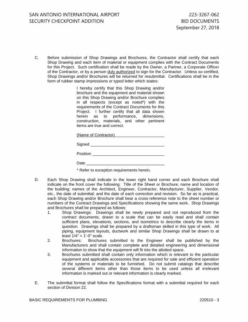
SAN ANTONIO INTERNATIONAL AIRPORT 223-3267-062
SECURITY CHECKPOINT ADDITION BID DOCUMENTS
September 27, 2018
BASIC REQUIREMENTS FOR PLUMBING 220510 - 3
C. Before submission of Shop Drawings and Brochures, the Contractor shall certify that each Shop Drawing and each item of material or equipment complies with the Contract Documents for this Project. Such certification shall be made by the Owner, a Partner, a Corporate Officer of the Contractor, or by a person duly authorized to sign for the Contractor. Unless so certified, Shop Drawings and/or Brochures will be returned for resubmittal. Certifications shall be in the form of rubber stamp impressions or typed letter which states:
I hereby certify that this Shop Drawing and/or brochure and the equipment and material shown on this Shop Drawing and/or Brochure complies in all respects (except as noted*) with the requirements of the Contract Documents for this Project. I further certify that all data shown herein as to performance, dimensions, construction, materials, and other pertinent items are true and correct. (Name of Contractor) Signed Position Date
* Refer to exception requirements herein.
D. Each Shop Drawing shall indicate in the lower right hand corner and each Brochure shall indicate on the front cover the following: Title of the Sheet or Brochure; name and location of the building; names of the Architect, Engineer, Contractor, Manufacturer, Supplier, Vendor, etc., the date of submittal; and the date of each correction and revision. So far as is practical, each Shop Drawing and/or Brochure shall bear a cross-reference note to the sheet number or numbers of the Contract Drawings and Specifications showing the same work. Shop Drawings and Brochures shall be prepared as follows: 1. Shop Drawings: Drawings shall be newly prepared and not reproduced from the
contract documents, drawn to a scale that can be easily read and shall contain sufficient plans, elevations, sections, and isometrics to describe clearly the items in question. Drawings shall be prepared by a draftsman skilled in this type of work. All piping, equipment layouts, ductwork and similar Shop Drawings shall be drawn to at least 1/4" = 1'-0" scale.
2. Brochures: Brochures submitted to the Engineer shall be published by the Manufacturers and shall contain complete and detailed engineering and dimensional information to show that the equipment will fit into the allotted space.
3. Brochures submitted shall contain only information which is relevant to the particular equipment and applicable accessories that are required for sale and efficient operation of the systems or materials to be furnished. Do not submit catalogs that describe several different items other than those items to be used unless all irrelevant information is marked out or relevant information is clearly marked.
E. The submittal format shall follow the Specifications format with a submittal required for each section of Division 22.
SAN ANTONIO INTERNATIONAL AIRPORT 223-3267-062
SECURITY CHECKPOINT ADDITION BID DOCUMENTS
September 27, 2018
BASIC REQUIREMENTS FOR PLUMBING 220510 - 4
F. Any submittals that do not meet the items listed in sub-section 1.03 D. above will be returned without review. The contractor shall be responsible for costs related to additional reviews of items returned without review for cause.
G. Submittal data for each section must be complete. Partial submittals will not be reviewed. To the greatest extent possible all sections shall be submitted with the first submission. No more than three additional submissions will be allowed to complete the submittal package.
H. Mechanical and Plumbing contractor shall be responsible for submitting a coordinated RCP shop drawing showing ALL ceiling mounted devices such as the lights, air devices, fire alarm devices, special systems devices, and sprinkler heads. Drawing shall be submitted to Architect/Engineer for review prior to installation of devices.
I. Subject to the requirements in Division 1, at the Contractor's option, submittals may be provided in PDF form. 1. All format and informational requirements for submittals in binders apply to PDF
submittals. 2. Multiple files may be submitted, however, these must be organized into a consistent
format. 3. PDF submittal shall include a table of contents with page numbers listed for the
beginning of each section. 4. Additionally, the PDF shall be formatted to include tab or chapter shortcuts, labeled
with the associated specification section. These shortcuts shall allow the reader to jump to a tab or chapter associated with beginning of each specification section with a single action.
5. At engineer's request, the contractor shall submit hard copy version in accordance with requirements outlined above.
J. Provide closeout submittals for all products used. Refer to related specification section for additional requirements. 1. Provide maintenance and warranty information with contact information for parts and
service of equipment.
K. Minimum size of submittal data shall be 8-1/2 x 11".
L. Any submittal that is disapproved must be resubmitted within two (2) weeks following notification of such disapproval. If no satisfactory material is submitted within the two-week period, the Architect and the Engineer reserves the right to require the Contractor to furnish items exactly as described in the Contract Documents.
M. No allowances will be made for submittals which are not made in a timely fashion or which are turned down because they do not meet the specifications. Should delivery problems arise due to the above, affecting the completion time of the project, the Contractor will furnish and install acceptable alternates until the proper materials arrive and then replace the alternate materials with the approved materials, all at no cost to the Owner. If the Contractor is not able to furnish an acceptable alternate until the proper materials arrive, he will assume all costs for furnishing and installing all alternates as directed by the Architect and/or will pay a suitable penalty for the inconvenience experienced by the Owner. This penalty will be set by the Owner based on the particular circumstances.
N. Only equipment and material brands which are specifically mentioned in the following sections of Division 22 will be considered during the submittal process.
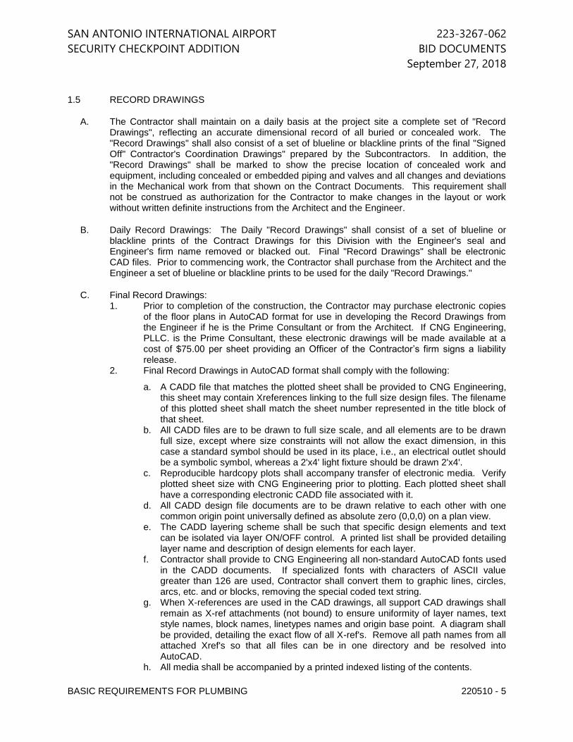
SAN ANTONIO INTERNATIONAL AIRPORT 223-3267-062
SECURITY CHECKPOINT ADDITION BID DOCUMENTS
September 27, 2018
BASIC REQUIREMENTS FOR PLUMBING 220510 - 5
1.5 RECORD DRAWINGS
A. The Contractor shall maintain on a daily basis at the project site a complete set of "Record Drawings", reflecting an accurate dimensional record of all buried or concealed work. The "Record Drawings" shall also consist of a set of blueline or blackline prints of the final "Signed Off" Contractor's Coordination Drawings" prepared by the Subcontractors. In addition, the "Record Drawings" shall be marked to show the precise location of concealed work and equipment, including concealed or embedded piping and valves and all changes and deviations in the Mechanical work from that shown on the Contract Documents. This requirement shall not be construed as authorization for the Contractor to make changes in the layout or work without written definite instructions from the Architect and the Engineer.
B. Daily Record Drawings: The Daily "Record Drawings" shall consist of a set of blueline or blackline prints of the Contract Drawings for this Division with the Engineer's seal and Engineer's firm name removed or blacked out. Final "Record Drawings" shall be electronic CAD files. Prior to commencing work, the Contractor shall purchase from the Architect and the Engineer a set of blueline or blackline prints to be used for the daily "Record Drawings."
C. Final Record Drawings: 1. Prior to completion of the construction, the Contractor may purchase electronic copies
of the floor plans in AutoCAD format for use in developing the Record Drawings from the Engineer if he is the Prime Consultant or from the Architect. If CNG Engineering, PLLC. is the Prime Consultant, these electronic drawings will be made available at a cost of $75.00 per sheet providing an Officer of the Contractor’s firm signs a liability release.
2. Final Record Drawings in AutoCAD format shall comply with the following:
a. A CADD file that matches the plotted sheet shall be provided to CNG Engineering, this sheet may contain Xreferences linking to the full size design files. The filename of this plotted sheet shall match the sheet number represented in the title block of that sheet.
b. All CADD files are to be drawn to full size scale, and all elements are to be drawn full size, except where size constraints will not allow the exact dimension, in this case a standard symbol should be used in its place, i.e., an electrical outlet should be a symbolic symbol, whereas a 2'x4' light fixture should be drawn 2'x4'.
c. Reproducible hardcopy plots shall accompany transfer of electronic media. Verify plotted sheet size with CNG Engineering prior to plotting. Each plotted sheet shall have a corresponding electronic CADD file associated with it.
d. All CADD design file documents are to be drawn relative to each other with one common origin point universally defined as absolute zero (0,0,0) on a plan view.
e. The CADD layering scheme shall be such that specific design elements and text can be isolated via layer ON/OFF control. A printed list shall be provided detailing layer name and description of design elements for each layer.
f. Contractor shall provide to CNG Engineering all non-standard AutoCAD fonts used in the CADD documents. If specialized fonts with characters of ASCII value greater than 126 are used, Contractor shall convert them to graphic lines, circles, arcs, etc. and or blocks, removing the special coded text string.
g. When X-references are used in the CAD drawings, all support CAD drawings shall remain as X-ref attachments (not bound) to ensure uniformity of layer names, text style names, block names, linetypes names and origin base point. A diagram shall be provided, detailing the exact flow of all X-ref's. Remove all path names from all attached Xref's so that all files can be in one directory and be resolved into AutoCAD.
h. All media shall be accompanied by a printed indexed listing of the contents.
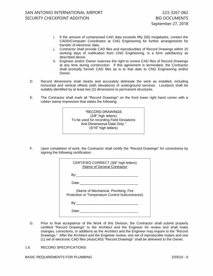
SAN ANTONIO INTERNATIONAL AIRPORT 223-3267-062
SECURITY CHECKPOINT ADDITION BID DOCUMENTS
September 27, 2018
BASIC REQUIREMENTS FOR PLUMBING 220510 - 6
i. If the amount of compressed CAD data exceeds fifty (50) megabytes, contact the CADD/Computer Coordinator at CNG Engineering for further arrangements for transfer of electronic data.
j. Contractor shall provide CAD files and reproducibles of Record Drawings within 15 working days of notification from CNG Engineering, in a form satisfactory as described above.
k. Engineer and/or Owner reserves the right to review CAD files of Record Drawings at any time during construction. If this agreement is terminated, the Contractor shall promptly furnish CAD files as is to that date to CNG Engineering and/or Owner.
D. Record dimensions shall clearly and accurately delineate the work as installed, including horizontal and vertical offsets (with elevations) of underground services. Locations shall be suitably identified by at least two (2) dimensions to permanent structures.
E. The Contractor shall mark all "Record Drawings" on the front lower right hand corner with a rubber stamp impression that states the following:
“RECORD DRAWINGS (3/8” high letters)
To be used for recording Field Deviations And Dimensional Data Only.”
(5/16” high letters)
F. Upon completion of work, the Contractor shall certify the "Record Drawings" for correctness by signing the following certification:
CERTIFIED CORRECT (3/8" high letters) (Name of General Contractor
By:________________________________
Date:______________________________
(Name of Mechanical, Plumbing, Fire
Protection or Temperature Control Subcontractor)
By:________________________________
Date:______________________________
G. Prior to final acceptance of the Work of this Division, the Contractor shall submit properly certified "Record Drawings" to the Architect and the Engineer for review and shall make changes, corrections, or additions as the Architect and the Engineer may require to the "Record Drawings." After the Architect and the Engineer review, one set of reproducible mylars and one (1) set of electronic CAD files (AutoCAD) "Record Drawings" shall be delivered to the Owner.
1.6 RECORD SPECIFICATIONS
SAN ANTONIO INTERNATIONAL AIRPORT 223-3267-062
SECURITY CHECKPOINT ADDITION BID DOCUMENTS
September 27, 2018
BASIC REQUIREMENTS FOR PLUMBING 220510 - 7
A. Maintain and submit Record Specifications as required in Division 01 Specification– CONTRACT CLOSEOUT.
1.7 SPACE LIMITATIONS
A. Equipment has been chosen which will fit into the physical spaces provided and indicated, allowing ample room for access, servicing, removal and replacement of parts, etc. Adequate space shall be allowed for clearance in accordance with the Code requirements and the requirements of the local inspection department.
B. In the preparation of Drawings, a reasonable effort to accommodate approved Equipment Manufacturers' space requirements has been made. However, since space requirements and equipment arrangement vary according to each Manufacturer, the responsibility for initial access and proper fit rests with the Contractor.
C. Physical dimensions and arrangements of equipment to be installed shall be subject to the Architect's review.
D. All mechanical equipment specified herein and shown on the Drawings is schematic. Prior to beginning any work whatsoever, the Division 22 Mechanical Contractor shall furnish as a part of the mechanical equipment submittals, scaled drawings of all proposed mechanical equipment, indicating accurate sizes and characteristics of proposed equipment, as well as clearances, piping routes, and all other details as required to allow the Engineer, Architect, and Owner the opportunity to approve the proposed layout and equipment. If the arrangement is not acceptable, then the proposed equipment and/or arrangement shall be modified or changed as required to be made acceptable at no additional cost to the Owner.
1.8 CONTRACTOR'S COORDINATION DRAWINGS
A. The Contractor and all Subcontractors shall prepare a complete set of "Coordination Drawings" indicating the equipment actually purchased and the exact routing for all lines such as piping, conduit and ductwork. The elevation, location, support points, load imposed on the structure at support and anchor points, and size of all lines shall be indicated. All beam penetrations and slab penetrations shall be indicated and sized and shall be coordinated. This requirement for "Coordination Drawings" shall not be construed as authorization for the Contractor or Subcontractor to make any unauthorized changes to the Contract Drawings. All Design Drawing space allocations shall be maintained, such as ceiling height, chase walls, equipment room size, etc., unless proper written authorization is received from the Architect to change them.
1.9 OPERATION AND MAINTENANCE MANUAL
A. Prepare and submit to the Architect and the Engineer for delivery to the Owner two (2) sets of an indexed manual with complete technical data for every piece of equipment and material installed under this Contract. 1. Complete mechanical submittals that were approved for the project. 2. Manufacturer's installation instruction brochures. 3. Manufacturer's local representative and/or distributor's name and address. 4. Manufacturer's operation and maintenance brochures. 5. Manufacturer's internal wiring diagrams. 6. Contractor's installation wiring diagrams. 7. Control system installation Drawings and typed control sequences. 8. Replacement part number listings and/or descriptions including prices and source of

SAN ANTONIO INTERNATIONAL AIRPORT 223-3267-062
SECURITY CHECKPOINT ADDITION BID DOCUMENTS
September 27, 2018
BASIC REQUIREMENTS FOR PLUMBING 220510 - 8
supply. 9. Lubrication materials required, with instructions. 10. Valve tag list and schematic diagram. 11. All warranties and guarantees. 12. Testing and Balancing Report. 13. Commissioning Report. 14. Provide the above item 1 through 13 in separate binders.
B. These manuals shall include all of the listed data bound into permanent hard-back binders identified on the cover with applicable name per list above. Provide a title page listing the name and location of the Building, the Owner, the Architect, the Engineers, the General Contractor, and the Trade-Contractors installing equipment represented in the brochure.
C. Contents of the manual shall be grouped in sections according to the various sections of Division 22, and shall be listed in a Table of Contents.
1.10 QUALITY ASSURANCE
A. Should the Drawings disagree in themselves or with the Specifications or with the various codes and regulations, the better quality or greater quantity of work or materials shall be assumed and estimated, and unless otherwise directed by the Architect and the Engineer in writing, shall be performed or furnished. In case the Specifications should not fully agree with the schedules, the latter shall govern. Figures indicated on Drawings govern scale measurements and large scale details govern small scale Drawings.
B. The Contractor shall comply with all applicable jurisdictional authority requirements including but not limited to city, county, state, or federal rules, codes and ordinances.
C. None of the terms or provisions of this Specification shall be construed as waiving any rules, regulations, or requirements of these authorities.
D. A competent foreman or superintendent, initially approved by the Architect and the Engineer, shall be kept by the Contractor at the building to receive instructions and to act for the Contractor. Once this superintendent has been approved, no change shall be made without approval of the Architect and the Engineer. Owner's representatives shall have the right to observe the work at any time. The Contractor shall have a representative present when his work is being observed, and he shall give assistance, as may be required, to the Architect's and the Engineer’s representative. Recommendations made shall be promptly carried out, and all unsatisfactory material and/or workmanship shall be replaced at once, to the satisfaction of the Architect and the Engineer.
E. It shall be the responsibility of the Contractor to consult the Architectural and Engineering Drawings and details so as to thoroughly familiarize himself with the type and quality of construction to be provided on this project.
F. The Plumbing Drawings are diagrammatic in character and cannot show every connection in detail or every pipe and equipment in its exact location. These details are subject to the requirements of codes, ordinances and also electrical, structural and architectural conditions. The Contractor shall carefully investigate all electrical, structural and finish conditions and shall coordinate the separate trades in order to avoid interference between the various phases of work. Work shall be laid out so that it will be concealed in furred chases or above suspended ceilings, etc., in finished portions of the building, unless specifically noted or indicated to be exposed. Work shall be installed to avoid crippling of structural members; therefore, inserts to
SAN ANTONIO INTERNATIONAL AIRPORT 223-3267-062
SECURITY CHECKPOINT ADDITION BID DOCUMENTS
September 27, 2018
BASIC REQUIREMENTS FOR PLUMBING 220510 - 9
accommodate hangers shall be set before concrete is poured, and proper openings through floor, walls, beams, etc., shall be provided as hereinafter specified or as otherwise indicated or required before concrete is poured. All work shall be run parallel or perpendicular to the lines of the building unless otherwise noted.
G. The approximate location of each item is indicated on the Drawings. These Drawings are not intended to give complete and exact details in regard to location. Exact locations are to be determined by actual measurements at the building and will in all cases be subject to the approval of the Architect. The Architect and the Engineer reserves the right to make reasonable changes in the locations indicated without additional cost.
1.11 DELIVERY, STORAGE AND HANDLING
A. The Contractor shall not receive material or equipment at the job site until ready for installation or until there is suitable space provided to properly protect equipment from rust, weather, humidity, dust, or physical damage.
1.12 UTILITIES
A. The Contract Documents reflect the general location, size, and elevations of sewer line, location, size and pressure of water and other lines and manner of routing for all utilities known to be required on this project. It shall be the responsibility of the Contractor to visit the site, meet with the local utility companies in order to coordinate and confirm the exact requirements for each utility to provide a complete and operative system. The bid submitted by the Contractor shall include costs for all such coordinative work, as well as any and all utility company charges and/or fees.
1.13 TEMPORARY SERVICES
A. It shall be the responsibility of the Contractor to provide a temporary system for each utility that is required during construction with all such temporary utility costs being billed to the Contractor.
1.14 WARRANTIES AND GUARANTEE
A. The Contractor shall guarantee all materials and workmanship for a period of twelve (12) months after the final acceptance of work.
B. See Division 01 Specification Section – “Product Requirements” for additional requirements regarding warranties.
PART 2 - PRODUCTS
2.1 ACCEPTABLE MANUFACTURERS
A. The specifications contain the names of manufacturers, which are considered acceptable based on the quality of the product.
B. Where acceptable manufacturers are listed, only products of those manufacturers may be provided. Additionally, the product must meet all the detailed requirements of the specifications.
SAN ANTONIO INTERNATIONAL AIRPORT 223-3267-062
SECURITY CHECKPOINT ADDITION BID DOCUMENTS
September 27, 2018
BASIC REQUIREMENTS FOR PLUMBING 220510 - 10
C. If no manufacturer's name is mentioned, the Contractor shall provide equipment and material which meet the specifications.
D. The Drawings represent the manufacturer's equipment scheduled. The listing of acceptable manufacturers in the specifications is not intended to imply that equipment of these other manufacturers will fit in the space provided or have the same electrical, structural or other requirements as the equipment scheduled. The Contractor must insure that the equipment provided will meet all project requirements prior to submitting data on that equipment.
2.2 MATERIALS AND EQUIPMENT
A. All materials shall be listed, inspected, and approved by the Underwriters Laboratories and shall bear the UL label where labeling service is available. The label or listing of the Underwriters Laboratories, Inc. will be accepted as evidence that the materials or equipment conform to the applicable standards of that agency. In lieu of this listing, the Contractor may submit a statement from a nationally recognized, adequately equipped testing agency, indicating that the items have been treated in accordance with required procedures, and that the materials and equipment comply with all contract requirements.
B. Materials and equipment shall be new and shall be the standard catalog products of manufacturers regularly engaged in the manufacture of products conforming to these Specifications, and shall essentially duplicate materials and equipment that have been in satisfactory use at least two years prior to bid opening. Where custom or special items are required, these shall be fully described using Drawings, material lists, etc., which fully describe in detail the item proposed for use on this project.
C. All metallic materials shall be protected against corrosion. Exposed metallic parts of outdoor apparatus made of ferrous metals but not of corrosion-resistant steel, shall be zinc-coated in accordance with ASTM A123 or A153, except where other equivalent protective treatment is specifically approved in writing.
D. Capacities shall be not less than those indicated but shall be such that no component or system becomes inoperative or is damaged because of start-up or other overload conditions. Where approved equipment requires electrical power other than those used for design purposes, the Contractor shall be responsible to adjust protective devices, starter sizes, conductors, conduits, etc. to accommodate this approved device electrically.
E. Each major component of equipment shall have the manufacturer's name, address, and catalog number on a plate securely attached to the item of equipment. All data on nameplates shall be legible at the time of final inspection.
F. Equipment vibration shall not exceed the following criteria:
Maximum Allowable Vibration Peak to Peak
Equipment Displacement (MIL)
Pumps
1800 RPM and less 2 3600 RPM and less to 1800 1
Compressors
Centrifugal 1
SAN ANTONIO INTERNATIONAL AIRPORT 223-3267-062
SECURITY CHECKPOINT ADDITION BID DOCUMENTS
September 27, 2018
BASIC REQUIREMENTS FOR PLUMBING 220510 - 11
Screw 1
Fans (Centrifugal and Axial) Under 600 RPM 4 600 RPM to 1000 RPM 3
Maximum Allowable Vibration Peak to Peak
Equipment Displacement (MIL) Fans (Centrifugal and Axial)
1000 RPM to 2000 RPM 2 Over 2000 RPM 1
G. All pipe, fittings, appurtenances, and other material required for complete installation of these systems shall be new to conform to manufacturer's recommendations, unless otherwise specified. All equipment injured or damaged in transit from factory, during delivery to premises, while in storage on premises, while being erected and installed, and while being tested, until time of final completion, shall be replaced by this Contractor without extra cost to the Owner. Scratched equipment shall be repainted with factory paint to match existing or cold galvanized as required.
H. Surface Burning Characteristics of Materials: 1. Unless specifically noted otherwise, all building and construction materials, adhesives,
finishes, etc., shall have a composite assembly fire and smoke hazard rating as tested by Procedure ASTM E84, NFPA 255, and UL 723 not exceeding:
a. Flame Spread: 25. b. Smoke Developed: 50. c. Fuel Contribution: 10.
NOTE: Any adhesives, mastics, and cement stored or used on the job site shall have the
above fire and smoke hazard rating in the “wet state” in addition to its “dry” rating.
2.3 INSTALLATION
A. All equipment shall be installed in a manner to permit access to parts requiring service without disassembly of piping mains and other equipment. Access panels or doors shall be coordinated with the Architect and the Engineer and provided where necessary to permit valve equipment service or removal. Refer to the architectural specifications for additional requirements.
B. Any large piece of apparatus which is to be installed in any space in the building, and which is too large to permit access through stairways, doorways, or shafts shall be brought to the job and placed in the space before the enclosing structure is completed. Following placement in the space, such apparatus shall be thoroughly and completely protected against damage.
C. This contract includes many different systems furnished and installed by different trades. Each trade shall coordinate their work with that of all other trades so that it may be installed in the most direct and workmanlike manner without hindering or handicapping any other trades. Where space requirements conflict, the following order of precedence shall, in general, be observed:
SAN ANTONIO INTERNATIONAL AIRPORT 223-3267-062
SECURITY CHECKPOINT ADDITION BID DOCUMENTS
September 27, 2018
BASIC REQUIREMENTS FOR PLUMBING 220510 - 12
2. Building lines. 3. Structural members. 4. Soil and drain piping. 5. Vent piping. 6. Refrigerant piping. 7. Condensate piping. 8. Electrical bus duct. 9. Supply ductwork. 10. Exhaust, return, and outside air ductwork. 11. Fire sprinkler piping. 12. Circulating water piping. 13. Domestic hot and cold water piping. 14. Natural gas piping. 15. Electrical conduit.
D. Minimize installation of water piping in proximity of rooms housing telephone equipment, fire alarm systems, transformers, or other electrical equipment. Do not install water piping within, or above ceilings of these rooms.
2.4 EXCAVATION AND BACKFILL
A. The Contractor shall perform all excavation of every description required in the execution of his work. Excavation shall be through whatever substance encountered, to the depths indicated on the Drawings, or as required. Excavated material suitable for backfill shall be piled in an orderly manner a sufficient distance from the trench to prevent overloading sides and cave-ins. Excavated materials not suitable for backfill shall be removed from the site or stored as directed. Grading shall be done to protect the excavation from surface water. Trenches shall be maintained in a dry condition by bailing, pumping, or other approved methods. Pipe shall not be laid in wet trenches. Sheeting and shoring shall be provided as required for the protection of the work and the safety of personnel.
B. Trenches shall be of the necessary width and depth to provide for proper laying of pipe and appurtenances, with banks as nearly vertical as possible. Bottoms of trenches shall be excavated to the grade and depth indicated or required, and barrel of pipe shall be laid on a minimum 12 inch sand bed. Bell holes, of a size to permit proper make-up of grading, shall be provided as required. For projects located over the Edward's Aquifer Re-Charge Zone, comply with City of San Antonio Plumbing Code requirements. Existing underground piping shall be protected from damage during excavation and backfilling, and if damaged, shall be repaired to the Architect's and the Engineer’s satisfaction, at the Contractor's expense. Provide 3,000 pound concrete of 3 inch minimum enclosure around lines that cross electrical utility lines or telephone cables.
C. Trenches shall not be backfilled until all required tests have been performed. This requirement does not preclude sectional testing and backfilling of the various systems. Trenches shall be carefully backfilled with approved sand, free from large earth clods, rocks, and/or foreign materials, laid in 6 inch layers, moistened thoroughly, and carefully rammed to an elevation of one foot above top of pipe. The remainder of the backfill to finish grade shall be placed in one foot layers soaked with water, and well tamped. Under roadways, backfill to bottom of road bed material with sand only. Where settlement occurs, trenches shall be re-opened to depth required for proper compaction, refilled, and compacted.
D. Open trenches abutting foundation or basement excavations, building walls, and grade beams, will not be permitted, but shall be backfilled and completed, for a distance of not less than 10
SAN ANTONIO INTERNATIONAL AIRPORT 223-3267-062
SECURITY CHECKPOINT ADDITION BID DOCUMENTS
September 27, 2018
BASIC REQUIREMENTS FOR PLUMBING 220510 - 13
feet from the above features, as soon as possible. All damage resulting from flooding or other stresses due to open trenches shall be paid for by the Contractor.
E. Where excavation requires, existing walks, street, drives, or other existing pavement to be cut to install new lines and to make new connections to existing lines, the size of the cut shall be held to a minimum, consistent with the work to be accomplished. After the installation of the new materials is completed and the excavation has been backfilled, the paving shall be patched, using materials to match those cut out. The patches shall be thoroughly bound with the original surfaces, and shall be level with them.
2.5 CUTTING AND PATCHING
A. Where it becomes necessary to cut through any wall, floor, or ceiling to permit installation of any work under this section of the Specifications or to repair any defects that may appear, up to the expiration of the guarantee period, such cutting shall be done under the supervision of the Architect and the Engineer by the Contractor. The Contractor shall not be permitted to cut or modify any structural members without the written permission of the Architect and the Engineer.
B. Patching of all openings cut by the Contractor, or repairing of any damage to the work of other trades occasioned by cutting operations, or occasioned by the failure of any part of work installed under this contract, shall be performed by the trade whose work is involved, but shall be paid for by the Contractor.
C. Any openings cut through exterior walls or roofs shall be provided with suitable covers, while they are left open, to protect the property or materials involved. Any openings cut through walls below grade shall be properly protected to prevent entrance of water or other damaging elements.
2.6 FIRE STOP SYSTEMS
A. Seal all pipe, conduit, cables, spare sleeves, etc. penetrations through roofs and fire-rated walls and floors with factory made devices or with manufactured fill, void, or cavity materials classified by Underwriters Laboratories (UL) as a “through-penetration fire stop” and which meet the following requirements: 1. Maintain the fire resistance rating of the penetrated building construction. Refer to the
architectural Contract Documents for fire ratings of general construction. 2. Comply with the requirements of ASTM E814, UL 1979, ASTM E119, UL 723, ASTM
E84 and UL 263 for all types of penetrations sealed. 3. Do not exhibit excessive shrinkage, which would permit transmission of flame, smoke,
gasses, vermin and/or water prior to exposure to a fire condition. 4. Mastics used to seal surface of fire stop system shall be non-hardening. 5. Shall accommodate expansion and contraction of the penetrating element, i.e. pipe
etc., without reducing its effectiveness as a smoke barrier and/or water seal.
B. Submittal data for fire stop systems shall include applicable UL System numbers.
C. Installing Contractor shall submit evidence that he has been trained by an authorized fire stop system manufacturer’s representative prior to beginning the installation. The manufacturer’s representative shall visit the jobsite and visually observe representative samples of each of the various fire stop systems employed on this project, during and after installation, and provide a written certification that the installations observed appear to have been installed in accordance with the manufacturer’s recommendations and UL requirements.
SAN ANTONIO INTERNATIONAL AIRPORT 223-3267-062
SECURITY CHECKPOINT ADDITION BID DOCUMENTS
September 27, 2018
BASIC REQUIREMENTS FOR PLUMBING 220510 - 14
D. Sealing of conduits that extend through fire-rated walls from ends of cable tray shall be performed after conductors/cables have been installed.
E. Acceptable Manufacturer’s Products: If it complies with these Specifications, one of the following manufacturers’ fire stop sealing components/systems will be acceptable: 1. 3M Fire Protection Products. 2. General Electric and Specified Technologies, Inc. SpecSeal systems. 3. Nelson Flameseal Fire Stop Putty (dry locations only). 4. Specified Technologies, Inc. 5. Tremco Fire Resistive Joint System utilizing “Dymeric” sealant and Cerablanket-FS
mineral filler.
PART 3 - EXECUTION
3.1 HOISTING, SCAFFOLDING, AND TRANSPORTATION
A. The Contractor shall provide his own hoisting facilities and scaffolding to set his materials and equipment in place, as indicated on Drawings and for subsequent cleaning, testing, and adjusting.
B. The Contractor shall provide necessary transportation to facilitate the delivery of all materials, equipment, tools, and labor to the job, in accordance with intent of these documents.
3.2 CLEANING
A. The Contractor shall at all times, keep the premises free from accumulations of waste material or rubbish caused by him, his employees, or his work. This debris shall be removed, not only from the building, but also from the project site.
B. At completion of the job, the Contractor shall remove all of his tools, scaffolding, and surplus materials. He shall leave the area "broom clean."
3.3 ELECTRICAL WIRING OF MOTORS AND EQUIPMENT
A. Unless specifically shown, indicated, or specified to the contrary, each item shown or required by the Mechanical Drawings or specified in the Plumbing Specifications shall be accompanied by all motors and starting and controlling equipment necessary for the items proper operations. These motors shall be integrally attached to and/or installed with their associated equipment item and electrically connected as specified in Division 26 - Electrical. Equipment controlled from motor control centers shall be supplied with motors only. Motor control centers are specified in Division 26 and shown on the Electrical Drawings.
3.4 WORK IN EXISTING BUILDINGS
A. Some of the work to be performed on this project occurs within an existing occupied building. Noisy, dusty, fume emitting and/or other construction operations required for work which may disturb or cause complaints by the building occupants is unacceptable.
B. The Contractor and the Division 22 Subcontractor shall carefully examine the existing building and review all of the Contract Documents prior to submitting his bid in order to determine the extent of work required to be completed under this Division. Failure to conduct this examination shall not relieve the Contractor of the responsibility to perform all the work required for a
SAN ANTONIO INTERNATIONAL AIRPORT 223-3267-062
SECURITY CHECKPOINT ADDITION BID DOCUMENTS
September 27, 2018
BASIC REQUIREMENTS FOR PLUMBING 220510 - 15
complete and fully operational installation satisfactory to the Owner.
C. Contractor shall include in the bid price cost of relocation or removal of existing equipment and systems required for complete installation of the new systems indicated in the Contract Documents. In submitting his bid, the Contractor agrees to accept all existing site conditions not specifically accepted. Where Contract Documents conflict with existing field conditions, a record of the field conditions shall be provided in writing to the Architect.
D. The Contractor shall be responsible for loss or damage to the existing facilities caused by him and his workmen, and shall be responsible for repairing or replacing such loss or damage. The Contractor shall send proper notices, make necessary arrangements, and perform other services required for the care, protection and service and in service maintenance of all plumbing, heating, air conditioning, and ventilating services for the new and existing facilities. The Contractor shall erect temporary barricades, with necessary safety devices, as required to protect personnel from injury, removing all such temporary protection upon completion of the work.
E. All new work shall be coordinated with existing space constraints. All equipment and material shall be fabricated such that complete systems may be disassembled into sections suitable for lifting in the existing freight elevator or construction hoist and fit through existing passageways without unauthorized modifications of the existing building construction.
F. The Contractor shall provide temporary on new services to all existing facilities as required to maintain their proper operation when normal services are disrupted as a result of the work being accomplished under this project.
G. Where existing construction is removed to provide working and extension access to existing utilities, Contractor shall remove doors, piping, conduit, outlet boxes, wiring, light fixtures, air conditioning ductwork and equipment, etc., to provide this access and shall reinstall same upon completion of work in the areas affected.
H. Coordinate new work in existing building in a manner that allows proper phasing of the work with a minimum of disruption of Owner’s activities in occupied spaces. All work scheduled in occupied areas MUST BE COORDINATED WITH AND APPROVED BY THE OWNER prior to commencement of the work. Outages of services as required by the new installation will be permitted but only at a time approved by the Owner. The Contractor shall allow the Owner two weeks in order to schedule required outages. The time allowed for outages will not be during normal working hours unless otherwise approved by the Owner. All costs of outages, including overtime charges, shall be included in the contract amount.
I. The Contractor shall use construction methods and materials which shall not adversely affect the indoor air quality of the occupied areas. Contractor shall furnish and install temporary constructions and modify existing air handling system where required to isolate areas under construction from surrounding occupied areas to control the migration of dust or fumes. If deemed necessary by the Owner, the Contractor shall furnish and install temporary supply and/or exhaust fan to negatively pressurize the construction area relative to adjacent occupied areas.
3.5 DEMOLITION AND RELOCATION
A. The Contractor shall modify, remove, and relocate all materials and items so indicated on the Drawings or required by the installation of new facilities. All removals and/or dismantling shall
SAN ANTONIO INTERNATIONAL AIRPORT 223-3267-062
SECURITY CHECKPOINT ADDITION BID DOCUMENTS
September 27, 2018
BASIC REQUIREMENTS FOR PLUMBING 220510 - 16
be conducted in a manner as to produce maximum salvage. Salvage materials except asbestos shall remain the property of the Owner, and shall be delivered to such destination as directed by the Owner. Non-salvageable materials and equipment shall become the property of the Contractor and removed from the site.
B. Asbestos abatement is being performed by the owner. The Contractor shall immediately notify the Owner of any area where the Contractor suspects or becomes aware of the existence of asbestos or other potentially hazardous materials on this project. It shall be the responsibility of the Contractor to provide written request to the Owner for the services of an Industrial Hygienist who shall provide all necessary testing, analysis and documentation of the status of any areas where asbestos or potentially hazardous materials exist. The Industrial Hygienist shall then prepare plans and specifications which provide for the removal of all potentially hazardous substances and their disposal in a lawful manner. The Contractor shall not remove or disturb asbestos or other potentially hazardous substances until he has obtained approval in writing of the methods he shall use from the authorities having jurisdiction.
C. All items which are to be relocated shall be carefully removed in reverse to original assembly or placement and protected until relocated. The Contractor shall clean and repair and provide all new materials, fittings, and appurtenances required to complete the relocation and to restore to good operative order. All relocations shall be performed by workmen skilled in the work and in accordance with standard practice of the trades involved. Where items scheduled for relocation and/or reuse are found to be in damaged condition before work has been started on dismantling, the Contractor shall call the attention of the Owner to such items and receive further instructions before removal. Items damaged in repositioning operations are the Contractor's responsibility and shall be repaired or replaced by the Contractor as approved by the Owner, at no additional cost to the Owner or the Architect and the Engineer. The Contractor may, at his discretion, and upon the approval of the Owner, substitute new materials and items of like design and quality in lieu of materials and items to be relocated.
D. Service lines and wiring to items to be removed, salvaged, or relocated shall be removed to points acceptable to the Owner. Service lines and wiring not scheduled for reuse shall be removed to the points at which reuse is to be continued or service is to remain. Such services shall be sealed, capped, or otherwise tied-off or disconnected in a safe manner acceptable to the Owner.
E. Cleanup: It shall be the responsibility of each trade to cooperate fully with the other trades on the job to keep the jobsite in a clean and safe condition. At the end of each day’s work, each trade shall properly store all of his tools, equipment and materials and shall clean his debris from the job.
3.6 COMMUNICATIONS AND ELECTRICAL EQUIPMENT ROOMS PRECAUTIONS
A. In general, piping and ductwork shall not be installed in any switchgear, transformer, elevator equipment, telephone, communication or electrical equipment room unless this piping or ductwork serves only that room.
B. Piping shall not be installed above switchboards, panelboards, control panels, motor control centers, individual motor controllers etc. Piping shall not be installed above bus duct unless otherwise show on the Drawings.
C. Coordinate with Division 26 Contractor to ensure the above listed precautions requirements are met.
SAN ANTONIO INTERNATIONAL AIRPORT 223-3267-062
SECURITY CHECKPOINT ADDITION BID DOCUMENTS
September 27, 2018
BASIC REQUIREMENTS FOR PLUMBING 220510 - 17
3.7 AUTHORITY HAVING JURISDICTION
A. The “Authority Having Jurisdiction” (AHJ) over the project described by these documents is the City of San Antonio, San Antonio, Texas.
B. Where alterations and/or deviations from the Contract Documents, i.e. Drawings and Specifications, are required by the AHJ, report the requirements to the Architect and secure his written approval before starting the alteration.
C. Modifications to the Division 22 work required by the AHJ shall be made by the Contractor without additional cost to the Owner.
3.8 CODES AND REFERENCE STANDARDS
A. All materials and workmanship shall comply with the requirements of the Building, Mechanical, Electrical, Plumbing, Fire, Accessibility, and Energy Codes adopted by the Authority Having Jurisdiction, including all amendments, applicable laws and ordinances and supplementary rules and interpretations. Where Contract Document requirements exceed Code requirements and are permitted under the Code, the Contract Documents shall govern.
B. In all cases where Underwriter’s Laboratories, Inc. have established standards for a particular type material, such material shall comply with these standards or other nationally recognized testing standards acceptable to the Authority Having Jurisdiction. Evidence of compliance shall be the UL “label” or “listing” under Re-Examination Service.
C. The following specific codes and standards shall apply to this project: 1. ADA Accessibility Guidelines for Buildings and Facilities, 1991 (ADAAG) with current
amendments. 2. Americans with Disabilities Act, Part III, 28 CFR 36, July 26, 1991 (ADA). 3. Building Services Piping (ASME/ANSI B31.9). 4. Elimination of Architectural Barriers Act, Texas Department of Licensing and
Regulations, Texas Civil Statutes, Article 9102, 5. Energy Conservation Standard for New State Buildings. 6. Governing Fire Department requirements. 7. National Fire Codes (NFPA), current edition. 8. National Electrical Code (NFPA 70), latest edition. 9. Occupational Safety and Health Act (OSHA). 10. Safety Code for Elevators and Escalators (ASME A17.1), 19__ edition. 11. Standards for Access to the Handicapped (ANSI 117.1). 12. Texas Accessibility Standards (TAS), Texas Department of Licensing and Regulations
(TDLR), Architectural Barriers Act, Article 9102, Texas Civil Statutes, effective April 1, 1994.
13. Texas Boiler Law, Chapter 755, Health and Safety Code, Texas Department of Licensing and Regulations.
14. 2015 International Building code with local amendments. 15. 2015 International Mechanical code with local amendments. 16. 2015 International Fire code with local amendments. 17. 2015 International Energy conservation code with local amendments. 18. 2015 International Plumbing code with local amendments. 19. 2014 National Electric code with local amendments. 20. 2015 Supplemental with local amendments.
D. Refer to Division 01 and the Division 22 Specification Sections hereinafter bound for additional
SAN ANTONIO INTERNATIONAL AIRPORT 223-3267-062
SECURITY CHECKPOINT ADDITION BID DOCUMENTS
September 27, 2018
BASIC REQUIREMENTS FOR PLUMBING 220510 - 18
applicable regulatory requirements.
3.9 OWNER’S RULES AND REGULATIONS
A. Comply with Owner’s rules and regulations as they apply.
3.10 DISCREPANCIES
A. The Contract Documents are intended to comply with the aforementioned rules and regulations; however, some discrepancies may occur. Where such discrepancies occur, the Contractor shall immediately notify the Architect and the Engineer in writing of said discrepancies and apply for an interpretation.
B. Should the discovery and notification occur after the execution of the Contract, any additional work required for compliance with said regulations shall be paid for as covered by applicable Division, providing no work or fabrication of materials has been accomplished in a manner of noncompliance.
C. Should the Contractor fabricate and/or install materials and/or workmanship in such a manner that does not comply with the applicable codes, rules and regulations, the Contractor who performed such work shall bear all costs arising in correcting these deficiencies to comply with said rules and regulations.
END OF SECTION 220510
SAN ANTONIO INTERNATIONAL AIRPORT 223-3267-062
SECURITY CHECKPOINT ADDITION BID DOCUMENTS
September 27, 2018
HVAC AIR-DISTRIBUTION SYSTEM CLEANING 230130 - 1
SECTION 230130 - HVAC AIR-DISTRIBUTION SYSTEM CLEANING
PART 1 - GENERAL
1.1 RELATED DOCUMENTS
A. Drawings and general provisions of the Contract, including General and Supplementary Conditions and Division 01 Specification Sections, apply to this Section.
1.2 SUMMARY
A. Section includes cleaning HVAC air-distribution equipment, ducts, plenums, and system components.
1.3 DEFINITIONS
A. ASCS: Air systems cleaning specialist.
B. NADCA: National Air Duct Cleaners Association.
1.4 INFORMATIONAL SUBMITTALS
A. Qualification Data: For an ASCS.
B. Strategies and procedures plan.
C. Cleanliness verification report.
1.5 QUALITY ASSURANCE
A. ASCS Qualifications: A certified member of NADCA. 1. Certification: Employ an ASCS certified by NADCA on a full-time basis.
B. UL Compliance: Comply with UL 181 and UL 181A for fibrous-glass ducts.
C. Cleaning Conference: Conduct conference at Project site. 1. Review methods and procedures related to HVAC air-distribution system cleaning
including, but not limited to, review of the cleaning strategies and procedures plan.
SAN ANTONIO INTERNATIONAL AIRPORT 223-3267-062
SECURITY CHECKPOINT ADDITION BID DOCUMENTS
September 27, 2018
HVAC AIR-DISTRIBUTION SYSTEM CLEANING 230130 - 2
PART 2 - PRODUCTS (Not Used)
PART 3 - EXECUTION
3.1 EXAMINATION
A. Examine HVAC air-distribution equipment, ducts, plenums, and system components to determine appropriate methods, tools, and equipment required for performance of the Work.
B. Perform "Project Evaluation and Recommendation" according to NADCA ACR 2006.
C. Prepare written report listing conditions detrimental to performance of the Work.
D. Proceed with work only after unsatisfactory conditions have been corrected.
3.2 PREPARATION
A. Prepare a written plan that includes strategies and step-by-step procedures. At a minimum, include the following: 1. Supervisor contact information. 2. Work schedule including location, times, and impact on occupied areas. 3. Methods and materials planned for each HVAC component type. 4. Required support from other trades. 5. Equipment and material storage requirements. 6. Exhaust equipment setup locations.
B. Use the existing service openings, as required for proper cleaning, at various points of the HVAC system for physical and mechanical entry and for inspection.
C. Comply with NADCA ACR 2006, "Guidelines for Constructing Service Openings in HVAC Systems" Section.
3.3 CLEANING
A. Comply with NADCA ACR 2006.
B. Remove visible surface contaminants and deposits from within the HVAC system.
C. Systems and Components to Be Cleaned: 1. Air devices for supply and return air within the areas of work. 2. Air-terminal units located within the project space. 3. Ductwork:
a. Supply-air ducts serving the space, including turning vanes and reheat coils, to the air-handling unit.
4. Air-Handling Units:
a. Interior surfaces of the unit casing.
SAN ANTONIO INTERNATIONAL AIRPORT 223-3267-062
SECURITY CHECKPOINT ADDITION BID DOCUMENTS
September 27, 2018
HVAC AIR-DISTRIBUTION SYSTEM CLEANING 230130 - 3
b. Coil surfaces compartment. c. Condensate drain pans. d. Fans, fan blades, and fan housings.
5. Filters and filter housings.
D. Collect debris removed during cleaning. Ensure that debris is not dispersed outside the HVAC system during the cleaning process.
E. Control odors and mist vapors during the cleaning and restoration process.
F. Mark the position of manual volume dampers and air-directional mechanical devices inside the system prior to cleaning. Restore them to their marked position on completion of cleaning.
G. System components shall be cleaned so that all HVAC system components are visibly clean. On completion, all components must be returned to those settings recorded just prior to cleaning operations.
H. Clean all air-distribution devices, registers, grilles, and diffusers.
I. Clean visible surface contamination deposits according to NADCA ACR 2006 and the following: 1. Clean air-handling units, airstream surfaces, components, condensate collectors, and
drains. 2. Ensure that a suitable operative drainage system is in place prior to beginning wash-
down procedures. 3. Clean evaporator coils, reheat coils, and other airstream components.
J. Duct Systems: 1. Create service openings in the HVAC system as necessary to accommodate cleaning. 2. Mechanically clean duct systems specified to remove all visible contaminants so that the
systems are capable of passing the HVAC System Cleanliness Tests (see NADCA ACR 2006).
K. Debris removed from the HVAC system shall be disposed of according to applicable Federal, state, and local requirements.
L. Mechanical Cleaning Methodology: 1. Source-Removal Cleaning Methods: The HVAC system shall be cleaned using source-
removal mechanical cleaning methods designed to extract contaminants from within the HVAC system and to safely remove these contaminants from the facility. No cleaning method, or combination of methods, shall be used that could potentially damage components of the HVAC system or negatively alter the integrity of the system.
a. Use continuously operating vacuum-collection devices to keep each section being cleaned under negative pressure.
b. Cleaning methods that require mechanical agitation devices to dislodge debris that is adhered to interior surfaces of HVAC system components shall be equipped to safely remove these devices. Cleaning methods shall not damage the integrity of HVAC system components or damage porous surface materials such as duct and plenum liners.
2. Cleaning Mineral-Fiber Insulation Components:
a. Fibrous-glass thermal or acoustical insulation elements present in equipment or ductwork shall be thoroughly cleaned with HEPA vacuuming equipment while the
SAN ANTONIO INTERNATIONAL AIRPORT 223-3267-062
SECURITY CHECKPOINT ADDITION BID DOCUMENTS
September 27, 2018
HVAC AIR-DISTRIBUTION SYSTEM CLEANING 230130 - 4
HVAC system is under constant negative pressure and shall not be permitted to get wet according to NADCA ACR 2006.
b. Cleaning methods used shall not cause damage to fibrous-glass components and will render the system capable of passing the HVAC System Cleanliness Tests (see NADCA ACR 2006).
c. Fibrous materials that become wet shall be discarded and replaced.
M. Coil Cleaning: 1. Measure static-pressure differential across each coil. 2. See NADCA ACR 2006, "Coil Surface Cleaning" Section. Type 1, or Type 1 and Type 2,
cleaning methods shall be used to render the coil visibly clean and capable of passing Coil Cleaning Verification (see applicable NADCA ACR 2006).
3. Coil drain pans shall be subject to NADCA ACR 2006, "Non-Porous Surfaces Cleaning Verification." Ensure that condensate drain pans are operational.
4. Electric-resistance coils shall be de-energized, locked out, and tagged before cleaning. 5. Cleaning methods shall not cause any appreciable damage to, cause displacement of,
inhibit heat transfer, or cause erosion of the coil surface or fins, and shall comply with coil manufacturer's written recommendations when available.
6. Rinse thoroughly with clean water to remove any latent residues.
N. Antimicrobial Agents and Coatings: 1. Apply antimicrobial agents and coatings if active fungal growth is reasonably suspected
or where unacceptable levels of fungal contamination have been verified. Apply antimicrobial agents and coatings according to manufacturer's written recommendations and EPA registration listing after the removal of surface deposits and debris.
2. When used, antimicrobial treatments and coatings shall be applied after the system is rendered clean.
3. Apply antimicrobial agents and coatings directly onto surfaces of interior ductwork. 4. Sanitizing agent products shall be registered by the EPA as specifically intended for use
in HVAC systems and ductwork.
3.4 CLEANLINESS VERIFICATION
A. Verify cleanliness according to NADCA ACR 2006, "Verification of HVAC System Cleanliness" Section.
B. Verify HVAC system cleanliness after mechanical cleaning and before applying any treatment or introducing any treatment-related substance to the HVAC system, including biocidal agents and coatings.
C. Perform visual inspection for cleanliness. If no contaminants are evident through visual inspection, the HVAC system shall be considered clean. If visible contaminants are evident through visual inspection, those portions of the system where contaminants are visible shall be re-cleaned and subjected to re-inspection for cleanliness.
D. Verification of Coil Cleaning: 1. Coil will be considered clean if the coil is free of foreign matter and chemical residue,
based on a thorough visual inspection.
E. Prepare a written cleanliness verification report. At a minimum, include the following: 1. Written documentation of the success of the cleaning.

SAN ANTONIO INTERNATIONAL AIRPORT 223-3267-062
SECURITY CHECKPOINT ADDITION BID DOCUMENTS
September 27, 2018
HVAC AIR-DISTRIBUTION SYSTEM CLEANING 230130 - 5
2. Site inspection reports, initialed by supervisor, including notation on areas of inspection, as verified through visual inspection.
3. System areas found to be damaged.
3.5 RESTORATION
A. Restore and repair HVAC air-distribution equipment, ducts, plenums, and components according to NADCA ACR 2006, "Restoration and Repair of Mechanical Systems" Section.
B. Restore service openings capable of future reopening. Comply with requirements in Section 233113 "Metal Ducts." Include location of service openings in Project closeout report.
C. Replace fibrous-glass materials that cannot be restored by cleaning or resurfacing. Comply with requirements in Section 233113 "Metal Ducts"
D. Ensure that closures do not hinder or alter airflow.
E. New closure materials, including insulation, shall match opened materials and shall have removable closure panels fitted with gaskets and fasteners.
F. Reseal fibrous-glass ducts. Comply with requirements in Section 233116 "Nonmetal Ducts."
END OF SECTION 230130
SAN ANTONIO INTERNATIONAL AIRPORT 223-3267-062
SECURITY CHECKPOINT ADDITION BID DOCUMENTS
September 27, 2018
COMMON WORK RESULTS FOR HVAC 230500 - 1
SECTION 230500 - COMMON WORK RESULTS FOR HVAC
PART 1 - GENERAL
1.1 RELATED DOCUMENTS
A. Drawings and general provisions of the Contract, including General and Supplementary Conditions and Division 01 Specification Sections, apply to this Section.
1.2 SUMMARY
A. This Section includes the following: 1. Piping materials and installation instructions common to most piping systems. 2. Transition fittings. 3. Dielectric fittings. 4. Mechanical sleeve seals. 5. Sleeves. 6. Escutcheons. 7. Grout. 8. HVAC demolition. 9. Equipment installation requirements common to equipment sections.
10. Painting and finishing. 11. Concrete bases. 12. Supports and anchorages. 13. Pre-demolition airflow measurements at all existing air handlers that are modified or
replaced under this contract. 14. Removal/replacement of ceilings to accomplish work depicted. Repair/replace any
damage to existing finishes to the satisfaction of the Architect.
1.3 DEFINITIONS
A. Finished Spaces: Spaces other than mechanical and electrical equipment rooms, furred spaces, pipe and duct chases, unheated spaces immediately below roof, spaces above ceilings, unexcavated spaces, crawlspaces, and tunnels.
B. Exposed, Interior Installations: Exposed to view indoors. Examples include finished occupied spaces and mechanical equipment rooms.
C. Exposed, Exterior Installations: Exposed to view outdoors or subject to outdoor ambient temperatures and weather conditions. Examples include rooftop locations.
D. Concealed, Interior Installations: Concealed from view and protected from physical contact by building occupants. Examples include above ceilings and chases.
E. Concealed, Exterior Installations: Concealed from view and protected from weather conditions and physical contact by building occupants but subject to outdoor ambient temperatures. Examples include installations within unheated shelters.
1.4 SUBMITTALS
A. Product Data: For the following: 1. Transition fittings. 2. Dielectric fittings. 3. Mechanical sleeve seals.
SAN ANTONIO INTERNATIONAL AIRPORT 223-3267-062
SECURITY CHECKPOINT ADDITION BID DOCUMENTS
September 27, 2018
COMMON WORK RESULTS FOR HVAC 230500 - 2
4. Escutcheons. 5. All new or modified equipment, air handlers, etc. 6. Ductwork. 7. Hydronic Piping. 8. Balancing devices. 9. VAV terminals.
10 Fire or Fire Smoke Dampers. 11. Fans. 12. Water coils. 13. As required by other Sections.
B. Welding certificates.
1.5 CONTRACTOR REQUIREMENTS
A. The Contractor shall be currently licensed by all appropiate federal, state, county and municipal agencies to furnish and install the type of work set forth in the Contract Documents and the limits of the Contractor's license shall be adequate to accommodate the size of the contract.
B. Within the scope of this project the Contractor and all of the Contractor’s subcontractors shall apply for and obtain all necessary federal, state, county and muncipal permits, fees and inspections. Include the costs of all fees, inspections and permits within the Contractor’s bid price. Provide copies of any or all permits to the Owner upon request.
1.6 COORDINATION
A. Arrange for pipe spaces, chases, slots, and openings in building structure during progress of construction, to allow for HVAC installations. Do not cut any building surfaces, structural, etc., without written approval from the Architect.
B. Coordinate installation of required supporting devices.
C. Coordinate requirements for access panels and doors for HVAC items requiring access that are concealed behind finished surfaces. Access panels and doors are specified in Division 08 Section "Openings."
D. Coordination Drawings: 1. The Contractor shall prepare coordination computer aided drawings (CAD) of the
installation of the mechanical (HVAC, plumbing and fire protection, lights and A/V work using AutoCAD 2004 software, or later edition. Prepare drawings at a mimimum scale of 1/8” = 1’-0”, or at 1/4” = 1’-0” or at ½” = 1’-0” if necessary to provide the detail necessary to clearly show all of the work.
2. The Contractor can obtain Electronic copies as outlined in the Record Drawings Section hereinafter.
3. Coordiantion CAD drawings shall include the areas specified below and for a distance of fifty feet beyond in all directions. Provide coordination CAD drawings for:
a. All Air Handling Unit Rooms b. All floor to floor piping or HVAC ductwork risers for the full length of the risers c. All housekeeping concrete pads showing pad thickness, reinforcing, doweling
4. The coordination CAD drawings shall show:
a. Plan view and at least two (2) section through all mechanical equipment rooms and areas listed above.
SAN ANTONIO INTERNATIONAL AIRPORT 223-3267-062
SECURITY CHECKPOINT ADDITION BID DOCUMENTS
September 27, 2018
COMMON WORK RESULTS FOR HVAC 230500 - 3
b. Architectural features. c. Column lines. d. Text shall be minimum height of 1/8” when plotted at full scale. e. Provide graphic scales – do NOT use stated scales. f. Provide separate layer(s) and/or “Xrefs” for each discipline (mechanical HVAC,
plumbing, electrical, fire protection sprinkler, etc). g. Room name, room number and NORTH ARROW h. Mechanical equipment and equipment service/maintenance access areas i. Provide elevation of each piece of equipment in each mechaical room, air
handling unit room, roof, etc. j. Piping shall be drawn two (2) line. k. Ductwork shall be drawn two (2) line. l. Electrical work (electrical equipment such as panels, transformers, etc. as well
as conduit greater than 1” in size) and required clearances m. Fire protection sprinkler work.
5. The Contractor shall maintain these coordiantion CAD drawings throughout the course of the project making edits/updates to the drawings as necessary to accurately depict the installation of the work.
6. The Contractor may submit these drawings in accordance with the Record Drawings Section hereinafter.
PART 2 - PRODUCTS
2.1 PIPE, TUBE, AND FITTINGS
A. Refer to individual Division 23 piping Sections for pipe, tube, and fitting materials and joining methods.
B. Pipe Threads: ASME B1.20.1 for factory-threaded pipe and pipe fittings.
2.2 JOINING MATERIALS
A. Refer to individual Division 23 piping Sections for special joining materials not listed below.
B. Pipe-Flange Gasket Materials: Suitable for chemical and thermal conditions of piping system contents. 1. ASME B16.21, nonmetallic, flat, asbestos-free, 1/8-inch maximum thickness unless
thickness or specific material is indicated.
a. Full-Face Type: For flat-face, Class 125, cast-iron and cast-bronze flanges. b. Narrow-Face Type: For raised-face, Class 250, cast-iron and steel flanges.
2. AWWA C110, rubber, flat face, 1/8 inch thick, unless otherwise indicated; and full-face or ring type, unless otherwise indicated.
C. Flange Bolts and Nuts: ASME B18.2.1, carbon steel, unless otherwise indicated.
D. Solder Filler Metals: ASTM B 32, lead-free alloys. Include water-flushable flux according to ASTM B 813.
E. Brazing Filler Metals: AWS A5.8, BCuP Series, copper-phosphorus alloys for general-duty brazing, unless otherwise indicated; and AWS A5.8, BAg1, silver alloy for refrigerant piping, unless otherwise indicated.
SAN ANTONIO INTERNATIONAL AIRPORT 223-3267-062
SECURITY CHECKPOINT ADDITION BID DOCUMENTS
September 27, 2018
COMMON WORK RESULTS FOR HVAC 230500 - 4
F. Welding Filler Metals: Comply with AWS D10.12 for welding materials appropriate for wall thickness and chemical analysis of steel pipe being welded.
2.3 DIELECTRIC FITTINGS
A. Description: Combination fitting of copper alloy and ferrous materials with threaded, solder-joint, plain, or weld-neck end connections that match piping system materials.
B. Insulating Material: Suitable for system fluid, pressure, and temperature.
C. Dielectric Flanges: Factory-fabricated, companion-flange assembly, for 150-psig steam working pressure minimum working pressure as required to suit system pressures.
D. Dielectric Couplings: Galvanized-steel coupling with inert and noncorrosive, thermoplastic lining; threaded ends; and 300-psig minimum working pressure at 225 deg F .
E. Dielectric Nipples: Electroplated steel nipple with inert and noncorrosive, thermoplastic lining; plain, threaded, or grooved ends; and 300-psig minimum working pressure at 225 deg F .
2.4 MECHANICAL SLEEVE SEALS
A. Description: Modular sealing element unit, designed for field assembly, to fill annular space between pipe and sleeve. Fire rated mechanical sleeve sealing systems shall have the Factory Mutual Fire Approval. Mechanical sleeve sealing systems shall be designed for use as a permanent seal with seal emements compounded to resist aging, ozone, sunlight, water and a wide range of chemicals. Mechanical sleeve sealing systems shall allow for some angular and off center pipe conditions and still seal effectively. 1. Sealing Elements for Normal Applications: EPDM interlocking links shaped to fit
surface of pipe. Include type and number required for pipe material and size of pipe. 2. Sealing Elements for Fire Seal (Fire Rated) Applications: Silicone (Grey) interlocking
links shaped to fit surface of pipe. Include type and number required for pipe material and size of pipe.
3. Pressure Plates: Molded glass reinforced Nylon Polymer for normal applications. For fire and Hi-Temp service, pressure plates shall be steel with 2-part Zinc Dichromate Coating. Include two for each sealing element.
4. Connecting Bolts and Nuts: Stainless steel of length required to secure pressure plates to sealing elements. Include one for each sealing element.
B. Refer to paragraph 3.10 "FIRE STOP SYSTEMS".
2.5 SLEEVES
A. Galvanized-Steel Sheet: 0.0239-inch minimum thickness; round tube closed with welded longitudinal joint.
B. Steel Pipe: ASTM A 53, Type E, Grade B, Schedule 40, galvanized, plain ends.
C. Cast Iron: Cast or fabricated "wall pipe" equivalent to ductile-iron pressure pipe, with plain ends and integral waterstop, unless otherwise indicated.
SAN ANTONIO INTERNATIONAL AIRPORT 223-3267-062
SECURITY CHECKPOINT ADDITION BID DOCUMENTS
September 27, 2018
COMMON WORK RESULTS FOR HVAC 230500 - 5
D. Stack Sleeve Fittings: Manufactured, cast-iron sleeve with integral clamping flange. Include clamping ring and bolts and nuts for membrane flashing. 1. Underdeck Clamp: Clamping ring with set screws.
2.6 ESCUTCHEONS
A. Description: Manufactured wall and ceiling escutcheons and floor plates, with an ID to closely fit around pipe, tube, and insulation of insulated piping and an OD that completely covers opening.
B. Split-Plate, Stamped-Steel Type: With concealed hinge, set screw or spring clips, and chrome-plated finish.
2.7 GROUT
A. Description: ASTM C 1107, Grade B, nonshrink and nonmetallic, dry hydraulic-cement grout. 1. Characteristics: Post-hardening, volume-adjusting, nonstaining, noncorrosive,
nongaseous, and recommended for interior and exterior applications. 2. Design Mix: 5000-psi , 28-day compressive strength. 3. Packaging: Premixed and factory packaged.
PART 3 - EXECUTION
3.1 PIPING SYSTEMS – COMMON REQUIREMENTS
A. Install piping according to the following requirements and Division 23 Sections specifying piping systems.
B. Drawing plans, schematics, and diagrams indicate general location and arrangement of piping systems. Indicated locations and arrangements were used to size pipe and calculate friction loss, expansion, and other design considerations. Install piping as indicated unless deviations to layout are approved on Coordination Drawings.
C. Install piping in concealed locations, unless otherwise indicated and except in equipment rooms and service areas.
D. Install piping indicated to be exposed and piping in equipment rooms and service areas at right angles or parallel to building walls. Diagonal runs are prohibited unless specifically indicated otherwise.
E. Install piping above accessible ceilings to allow sufficient space for ceiling panel removal.
F. Install piping to permit valve servicing.
G. Install piping at required slopes.
H. Install piping free of sags and bends.
I. Install fittings for changes in direction and branch connections.
J. Install piping to allow application of insulation.
K. Select system components with pressure rating greater than system operating pressure.
SAN ANTONIO INTERNATIONAL AIRPORT 223-3267-062
SECURITY CHECKPOINT ADDITION BID DOCUMENTS
September 27, 2018
COMMON WORK RESULTS FOR HVAC 230500 - 6
L. Install escutcheons for penetrations of walls, ceilings, and floors according to the following: 1. New Piping:
a. Piping with Fitting or Sleeve Protruding from Wall: One-piece, deep-pattern type.
b. Chrome-Plated Piping: One-piece, cast-brass type with polished chrome-plated finish.
c. Insulated Piping: One-piece, stamped-steel type with spring clips. d. Bare Piping at Wall and Floor Penetrations in Finished Spaces: One-piece,
cast-brass type with polished chrome-plated finish. e. Bare Piping at Wall and Floor Penetrations in Finished Spaces: One-piece,
stamped-steel type. g. Bare Piping at Ceiling Penetrations in Finished Spaces: Split-plate, stamped-
steel type with concealed hinge and set screw.
M. Install sleeves for pipes passing through walls and concrete floor and roof slabs.
N. Install sleeves for pipes passing through concrete and masonry walls, gypsum-board partitions, and concrete floor and roof slabs in finished service spaces. 1. Cut sleeves to length for mounting flush with both surfaces.
a. Exception: Extend sleeves installed in floors of mechanical equipment areas or other wet areas 2 inches above finished floor level. Extend cast-iron sleeve fittings below floor slab as required to secure clamping ring if ring is specified.
2. Install sleeves in new walls and slabs as new walls and slabs are constructed.
3. Install sleeves that are large enough to provide 1/4-inch annular clear space between sleeve and pipe or pipe insulation. Use the following sleeve materials:
a. Steel Pipe Sleeves: For pipes smaller than NPS 6 . b. Steel Sheet Sleeves: For pipes NPS 6 and larger, penetrating gypsum-board
partitions. c. Stack Sleeve Fittings: For pipes penetrating floors with membrane
waterproofing. Secure flashing between clamping flanges. Install section of cast-iron soil pipe to extend sleeve to 2 inches above finished floor level. Refer to Division 07 Section "Sheet Metal Flashing and Trim" for flashing.
4. Seal space outside of sleeve fittings with grout. 5. Except for underground wall penetrations, seal annular space between sleeve and pipe
or pipe insulation, using joint sealants appropriate for size, depth, and location of joint. Refer to Division 07 Section "Joint Sealants" for materials and installation.
O. Fire-Barrier Penetrations: Maintain indicated fire rating of walls, partitions, ceilings, and floors at pipe penetrations. Seal pipe penetrations with firestop materials. Also comply, as specified herein.
P. Verify final equipment locations for roughing-in.
3.2 PIPING JOINT CONSTRUCTION
A. Join pipe and fittings according to the following requirements and Division 23 Sections specifying piping systems.
B. Ream ends of pipes and tubes and remove burrs. Bevel plain ends of steel pipe.
SAN ANTONIO INTERNATIONAL AIRPORT 223-3267-062
SECURITY CHECKPOINT ADDITION BID DOCUMENTS
September 27, 2018
COMMON WORK RESULTS FOR HVAC 230500 - 7
C. Remove scale, slag, dirt, and debris from inside and outside of pipe and fittings before assembly.
D. Soldered Joints: Apply ASTM B 813, water-flushable flux, unless otherwise indicated, to tube end. Construct joints according to ASTM B 828 or CDA's "Copper Tube Handbook," using lead-free solder alloy complying with ASTM B 32.
E. Brazed Joints: Construct joints according to AWS's "Brazing Handbook," "Pipe and Tube" Chapter, using copper-phosphorus brazing filler metal complying with AWS A5.8.
F. Threaded Joints: Thread pipe with tapered pipe threads according to ASME B1.20.1. Cut threads full and clean using sharp dies. Ream threaded pipe ends to remove burrs and restore full ID. Join pipe fittings and valves as follows:
1. Apply appropriate tape or thread compound to external pipe threads unless dry seal threading is specified.
2. Damaged Threads: Do not use pipe or pipe fittings with threads that are corroded or damaged. Do not use pipe sections that have cracked or open welds.
G. Welded Joints: Construct joints according to AWS D10.12, using qualified processes and welding operators according to Part 1 "Quality Assurance" Article.
H. Flanged Joints: Select appropriate gasket material, size, type, and thickness for service application. Install gasket concentrically positioned. Use suitable lubricants on bolt threads.
3.3 PIPING CONNECTIONS
A. Make connections according to the following, unless otherwise indicated:
1. Install unions, in piping NPS 2 and smaller, adjacent to each valve and at final connection to each piece of equipment.
2. Install flanges, in piping NPS 2-1/2 and larger, adjacent to flanged valves and at final connection to each piece of equipment.
3. Wet Piping Systems: Install dielectric coupling and nipple fittings to connect piping materials of dissimilar metals.
3.4 EQUIPMENT INSTALLATION - COMMON REQUIREMENTS
A. Install equipment to allow maximum possible headroom unless specific mounting heights are not indicated.
B. Install equipment level and plumb, parallel and perpendicular to other building systems and components in exposed interior spaces, unless otherwise indicated.
C. Install HVAC equipment to provide adequate space and access to maintain and service equipment and to facilitate service, maintenance, and repair or replacement of components. Install equipment with adequate space and access to comply with code requirements and to comply with manufacturer’s installation instructions. Connect equipment for ease of disconnecting, with minimum interference to other installations. Extend grease fittings to accessible locations.
D. Install equipment to allow right of way for piping installed at required slope.
E. New, as well as, refurbished equipment must be disassembled in order to pass through existing building openings; refer to notations on the drawings. If removal of existing glazing, door
SAN ANTONIO INTERNATIONAL AIRPORT 223-3267-062
SECURITY CHECKPOINT ADDITION BID DOCUMENTS
September 27, 2018
COMMON WORK RESULTS FOR HVAC 230500 - 8
frames, walls, etc., is required, this shall be executed only after written approval is obtained from the Architect.
3.5 USE OF NEW SYSTEMS DURING CONSTRUCTION
A. The Contractor is NOT allowed to use the new or existing to remain HVAC systems or any portion or part of the HVAC system during the construction phase of the project without the expressed written permission of the Owner.
B. If the Owner should allow the Contractor to use the HVAC system during the construction phase of the project the Contractor shall furnish and install the following provisions:
1. Furnish and install high efficiency (60 to 65% efficient), rigid, mini-pleated filters in all air handling units (AHUs). Replace filters with new clean filters at maximum one (1) month intervals.
2. Furnish and install minimum 1-1/2” thick, flexible filter media over ALL return air openings (including ceiling return air grilles, etc.) and change at one (1) month intervals.
3. If the Owner does allow the Contractor to use the HVAC system during the construction phase and if the Contractor does use the HVAC system during the construction phase then at the end of the use period by the Contractor the Contractor shall clean all coils in all operated AHUs. This shall mean that the Contractor steam clean and/or chemically clean all coils and all condensate drain pans in all operated AHUs. At the end of the use period by the Contractor during the construction phase the Contractor shall furnish and install a complete new set of filters in each operated AHU when the system is turned over to the Owner. It is the intent of this specification to provide the Owner with a new HVAC system that is as clean as is reasonably possible.
3.6 PAINTING
A. Damage and Touchup: Repair marred and damaged factory-painted finishes with materials and procedures to match original factory finish.
3.7 INSTALLATION
A. All equipment shall be installed in a manner to permit access to parts requiring service without disassembly of piping mains and other equipment. Access panels or doors shall be coordinated with the Architect and provided where necessary to permit valve equipment service or removal. Refer to the architectural specifications for additional requirements.
B. Any large piece of apparatus which is to be installed in any space in the building, and which is too large to permit access through stairways, doorways, or shafts shall be brought to the job disassembled, and re-assembled inside the Mechanical Rooms. Following placement in the space, such apparatus shall be thoroughly and completely protected against damage.
C. Minimize installation of water piping in proximity of rooms housing telephone equipment, fire alarm systems, transformers, or other electrical equipment. Do not install water piping within, or above ceilings of these rooms.
3.8 CUTTING AND PATCHING
A. Where it becomes necessary to cut through any wall, floor, or ceiling to permit installation of any work under this section of the Specifications or to repair any defects that may appear, up to the expiration of the guarantee period, such cutting shall be done under the supervision of the
SAN ANTONIO INTERNATIONAL AIRPORT 223-3267-062
SECURITY CHECKPOINT ADDITION BID DOCUMENTS
September 27, 2018
COMMON WORK RESULTS FOR HVAC 230500 - 9
Architect by the Contractor. The Contractor shall not be permitted to cut or modify any building surfaces, slabs, etc., without the written permission of the Architect.
B. Patching of all openings cut by the Contractor, or repairing of any damage to the work of other trades occasioned by cutting operations, or occasioned by the failure of any part of work installed under this contract, shall be performed by the trade whose work is involved, but shall be paid for by the Contractor.
C. Any openings cut through exterior walls or roofs shall be provided with suitable covers, while they are left open, to protect the property or materials involved and maintain security.
3.9 FIRE STOP SYSTEMS
A. Seal all pipe, conduit, cables, spare sleeves, etc. penetrations through roofs and fire-rated walls and floors with factory made devices or with manufactured fill, void, or cavity materials classified by Underwriters Laboratories (UL) as a “through-penetration fire stop” and which meet the following requirements:
1. Maintain the fire resistance rating of the penetrated building construction. Refer to the architectural Contract Documents for fire ratings of general construction.
2. Comply with the requirements of ASTM E814, UL 1979, ASTM E119, UL 723, ASTM E84 and UL 263 for all types of penetrations sealed.
3. Do not exhibit excessive shrinkage, which would permit transmission of flame, smoke, gasses, vermin and/or water prior to exposure to a fire condition.
4. Mastics used to seal surface of fire stop system shall be non-hardening. 5. Shall accommodate expansion and contraction of the penetrating element, i.e. pipe etc.,
without reducing its effectiveness as a smoke barrier and/or water seal.
B. Submittal data for fire stop systems shall include applicable UL System numbers.
C. Installing Contractor shall submit evidence that he has been trained by an authorized fire stop system manufacturer’s representative prior to beginning the installation. The manufacturer’s representative shall visit the jobsite and visually observe representative samples of each of the various fire stop systems employed on this project, during and after installation, and provide a written certification that the installations observed appear to have been installed in accordance with the manufacturer’s recommendations and UL requirements.
D. Sealing of conduits that extend through fire-rated walls from ends of cable tray shall be performed after conductors/cables have been installed.
E. Acceptable Manufacturer’s Products: If it complies with these Specifications, one of the following manufacturers’ fire stop sealing components/systems will be acceptable: 1. 3M Fire Protection Products. 2. General Electric and Specified Technologies, Inc. SpecSeal systems. 3. Nelson Flameseal Fire Stop Putty (dry locations only). 4. Specified Technologies, Inc. 5. Tremco Fire Resistive Joint System utilizing “Dymeric” sealant and Cerablanket-FS
mineral filler.
3.10 HOISTING, SCAFFOLDING, AND TRANSPORTATION
SAN ANTONIO INTERNATIONAL AIRPORT 223-3267-062
SECURITY CHECKPOINT ADDITION BID DOCUMENTS
September 27, 2018
COMMON WORK RESULTS FOR HVAC 230500 - 10
A. The Contractor shall provide his own hoisting facilities and scaffolding to set his materials and equipment in place, as indicated on Drawings and for subsequent cleaning, testing, and adjusting.
B. The Contractor shall provide necessary transportation to facilitate the delivery of all materials, equipment, tools, and labor to the job, in accordance with intent of these documents.
3.11 CLEANING
A. The Contractor shall, at all times, keep the premises free from accumulations of waste material or rubbish caused by him, his employees, or his work. This debris shall be removed, not only from the building, but also from the project site.
B. At completion of the job, the Contractor shall remove all of his tools, scaffolding, and surplus materials. He shall leave the area "broom clean".
3.12 ELECTRICAL WIRING OF MOTORS AND EQUIPMENT
A. Unless specifically shown, indicated, or specified to the contrary, each item shown or required by the Mechanical Drawings or specified in the Mechanical Specifications shall be accompanied by all motors and starting and controlling equipment necessary for the items proper operations. These motors shall be integrally attached to and/or installed with their associated equipment item and electrically connected as specified in Division 26 - Electrical. Equipment controlled from motor control centers shall be supplied with motors only. Motor control centers are specified in Division 26 and shown on the Electrical Drawings.
3.13 WORK IN EXISTING BUILDINGS
A. The work to be performed on this project occurs within an existing occupied building. Noisy, dusty, fume emitting and/or other construction operations required for work which may disturb Airport operations are unacceptable.
B. The Contractor and the Division 23 Subcontractor shall carefully examine the existing building and review all of the Contract Documents prior to submitting his bid in order to determine the extent of work required to be completed under this Division. Failure to conduct this examination shall not relieve the Contractor of the responsibility to perform all the work required for a complete and fully operational installation satisfactory to the Owner.
C. Contractor shall include in the bid price cost of relocation or removal of existing equipment and systems required for complete installation of the new systems indicated in the Contract Documents. In submitting his bid, the Contractor agrees to accept all existing site conditions not specifically accepted. Where Contract Documents conflict with existing field conditions, a record of the field conditions shall be provided in writing to the Architect.
D. The Contractor shall be responsible for loss or damage to the existing facilities caused by him and his workmen, and shall be responsible for repairing or replacing such loss or damage. The Contractor shall send proper notices, make necessary arrangements, and perform other services required for the care, protection and service and in service maintenance of all plumbing, heating, air conditioning, and ventilating services for the new and existing facilities. The Contractor shall erect temporary barricades, with necessary safety devices, as required to protect personnel from injury, removing all such temporary protection upon completion of the work.
SAN ANTONIO INTERNATIONAL AIRPORT 223-3267-062
SECURITY CHECKPOINT ADDITION BID DOCUMENTS
September 27, 2018
COMMON WORK RESULTS FOR HVAC 230500 - 11
E. All new work shall be coordinated with existing space constraints. All equipment and material shall be fabricated such that complete systems may be disassembled into sections suitable for lifting in the existing freight elevator or construction hoist and fit through existing passageways without unauthorized modifications of the existing building construction.
F. The Contractor shall provide temporary services to all existing facilities as required to maintain their proper operation when normal services are disrupted as a result of the work being accomplished under this project.
G. Where existing construction is removed to provide working and extension access to existing utilities, Contractor shall remove doors, piping, conduit, outlet boxes, wiring, light fixtures, air conditioning ductwork and equipment, etc., to provide this access and shall reinstall same upon completion of work in the areas affected.
H. Coordinate new work in existing building in a manner that allows proper phasing of the work without disruption of Owner’s activities in occupied spaces. All work scheduled in occupied areas MUST BE COORDINATED WITH AND APPROVED BY THE OWNER prior to commencement of the work.
I. The Contractor shall use construction methods and materials which shall not adversely affect the indoor air quality of the occupied areas. Contractor shall furnish and install temporary constructions and modify existing air handling system where required to isolate areas under construction from surrounding occupied areas to control the migration of dust or fumes. If deemed necessary by the Owner, the Contractor shall furnish and install temporary supply and/or exhaust fan to negatively pressurize the construction area relative to adjacent occupied areas.
3.14 DEMOLITION AND RELOCATION
A. The Contractor shall modify, remove, and relocate all materials and items so indicated on the Drawings or required by the installation of new facilities. All removals and/or dismantling shall be conducted in a manner as to produce maximum salvage. Salvage materials except asbestos shall remain the property of the Owner, and shall be delivered to such destination as directed by the Owner. Non-salvageable materials and equipment shall become the property of the Contractor and removed from the site.
B. Asbestos abatement is being performed under a separate contract. There have been no tests for existence of asbestos or other potentially hazardous materials within this facility. The Contractor shall immediately notify the Owner of any area where the Contractor suspects or becomes aware of the existence of asbestos or other potentially hazardous materials on this project. It shall be the responsibility of the Contractor to provide written request to the Owner for the services of an Industrial Hygienist who shall provide all necessary testing, analysis and documentation of the status of any areas where asbestos or potentially hazardous materials exist. The Industrial Hygienist shall then prepare plans and specifications which provide for the removal of all potentially hazardous substances and their disposal in a lawful manner. The Contractor shall not remove or disturb asbestos or other potentially hazardous substances until he has obtained approval in writing of the methods he shall use from the authorities having jurisdiction.
C. All items which are to be relocated shall be carefully removed in reverse to original assembly or placement and protected until relocated. The Contractor shall clean and repair and provide all new materials, fittings, and appurtenances required to complete the relocation and to restore to good operative order. All relocations shall be performed by workmen skilled in the work and in accordance with standard practice of the trades involved. Where items scheduled for relocation
SAN ANTONIO INTERNATIONAL AIRPORT 223-3267-062
SECURITY CHECKPOINT ADDITION BID DOCUMENTS
September 27, 2018
COMMON WORK RESULTS FOR HVAC 230500 - 12
and/or reuse are found to be in damaged condition before work has been started on dismantling, the Contractor shall call the attention of the Owner to such items and receive further instructions before removal. Items damaged in repositioning operations are the Contractor's responsibility and shall be repaired or replaced by the Contractor as approved by the Owner, at no additional cost to the Owner or the Architect and Engineer. The Contractor may, at his discretion, and upon the approval of the Owner, substitute new materials and items of like design and quality in lieu of materials and items to be relocated.
D. Service lines and wiring to items to be removed, salvaged, or relocated shall be removed to points acceptable to the Owner. Service lines and wiring not scheduled for reuse shall be removed to the points at which reuse is to be continued or service is to remain. Such services shall be sealed, capped, or otherwise tied-off or disconnected in a safe manner acceptable to the Owner.
E. Cleanup: It shall be the responsibility of each trade to cooperate fully with the other trades on the job to keep the jobsite in a clean and safe condition. At the end of each day’s work, each trade shall properly store all of his tools, equipment and materials and shall clean his debris from the job.
3.15 COMMUNICATIONS AND ELECTRICAL EQUIPMENT ROOMS PRECAUTIONS
A. In general, piping shall not be installed in any switchgear, transformer, elevator equipment, telephone, communication or electrical equipment room unless this piping serves only that room.
B. Sprinkler heads and piping within main communication equipment rooms and rooms having electrical gear shall be provided with shields and/or deflectors where required by the AHJ or Owner to protect electrical and/or communications equipment.
C. Piping shall not be installed above switchboards, panelboards, control panels, motor control centers, individual motor controllers etc. Piping shall not be installed above bus duct unless otherwise show on the Drawings.
D. Coordinate with Division 26 Contractor to ensure the above listed precautions are met.
PART 4 – REGULATORY REQUIREMENTS
4.1 AUTHORITY HAVING JURISDICTION
A. Where alterations and/or deviations from the Contract Documents, i.e. Drawings and Specifications, are required by the AHJ, report the requirements to the Architect and secure his written approval before starting the alteration.
B. Modifications to the Division 23 work required by the AHJ shall be made by the Contractor without additional cost to the Owner.
4.2 CODES AND REFERENCE STANDARDS
A. All materials and workmanship shall comply with the requirements of the Building, Mechanical, Electrical, Plumbing, Fire, Accessibility, and Energy Codes adopted by the City of San Antonio, including all amendments, applicable laws and ordinances and supplementary rules and interpretations. Where Contract Document requirements exceed Code requirements and are permitted under the Code, the Contract Documents shall govern.
SAN ANTONIO INTERNATIONAL AIRPORT 223-3267-062
SECURITY CHECKPOINT ADDITION BID DOCUMENTS
September 27, 2018
COMMON WORK RESULTS FOR HVAC 230500 - 13
B. In all cases where Underwriter’s Laboratories, Inc. have established standards for a particular type material, such material shall comply with these standards or other nationally recognized testing standards acceptable to the Authority Having Jurisdiction. Evidence of compliance shall be the UL “label” or “listing” under Re-Examination Service.
C. The following specific codes and standards shall apply to this project: 1. ADA Accessibility Guidelines for Buildings and Facilities, 1991 (ADAAG) with current
amendments. 2. Americans with Disabilities Act, Part III, 28 CFR 36, July 26, 1991 (ADA). 3. Building Services Piping (ASME/ANSI B31.9). 4. Elimination of Architectural Barriers Act, Texas Department of Licensing and Regulations,
Texas Civil Statutes, Article 9102, 5. Energy Conservation Standard for New State Buildings. 6. Governing Fire Department requirements. 7. National Fire Codes (NFPA), current edition. 8. National Electrical Code (NFPA 70), latest edition. 9. Occupational Safety and Health Act (OSHA). 10. Current, applicable safety Code for Elevators and Escalators (ASME A17.1). 11. Standards for Access to the Handicapped (ANSI 117.1). 12. Texas Accessibility Standards (TAS), Texas Department of Licensing and Regulations
(TDLR), Architectural Barriers Act, Article 9102, Texas Civil Statutes, effective April 1, 1994.
13. Texas Boiler Law, Chapter 755, Health and Safety Code, Texas Department of Licensing and Regulations.
14. Current Applicable International Building code with local amendments. 15. Current Applicable International Mechanical code with local amendments. 16. Current Applicable International Fire code with local amendments. 17. Current Applicable International Energy conservation code with local amendments. 18. Current Applicable International Plumbing code with local amendments. 19. Current Applicable National Electric code with local amendments. 20. Current Applicable Supplemental with local amendments.
D. Refer to Division 01 and the Division 23 Specification Sections hereinafter for additional applicable regulatory requirements.
4.3 OWNER’S RULES AND REGULATIONS
A. Comply with Owner’s rules and regulations, as well as Airport Security requirements, as they apply.
4.4 DISCREPANCIES
A. The Contract Documents are intended to comply with the aforementioned rules and regulations; however, some discrepancies may occur. Where such discrepancies occur, the Contractor shall immediately notify the Architect and the Engineer in writing of said discrepancies and apply for an interpretation.
B. Should the discovery and notification occur after the execution of the Contract, any additional work required for compliance with said regulations shall be paid for as covered by Division 01, providing no work or fabrication of materials has been accomplished in a manner of noncompliance.
C. Should the Contractor fabricate and/or install materials and/or workmanship in such a manner that does not comply with the applicable codes, rules and regulations, the Contractor who
SAN ANTONIO INTERNATIONAL AIRPORT 223-3267-062
SECURITY CHECKPOINT ADDITION BID DOCUMENTS
September 27, 2018
COMMON WORK RESULTS FOR HVAC 230500 - 14
performed such work shall bear all costs arising in correcting these deficiencies to comply with said rules and regulations.
END OF SECTION 230500
SAN ANTONIO INTERNATIONAL AIRPORT 223-3267-062
SECURITY CHECKPOINT ADDITION BID DOCUMENTS
September 27, 2018
HANGERS AND SUPPORTS FOR HVAC PIPING AND EQUIPMENT 230529 - 1
SECTION 230529 – HANGERS AND SUPPORTS FOR HVAC PIPIING AND EQUIPMENT
PART 1 - GENERAL
1.1 RELATED DOCUMENTS
A. Drawings and general provisions of the Contract, including General and Supplementary Conditions and Division 01 Specification Sections, apply to this Section.
1.2 SUMMARY
A. Section Includes: 1. Inserts and Rods 2. Flashing for Mechanical Piping and Equipment 3. Metal pipe hangers and supports. 4. Trapeze pipe hangers. 5. Metal framing systems. 6. Thermal-hanger shield inserts. 7. Fastener systems. 8. Equipment supports.
B. Related Sections: 1. Section 233113 "Metal Ducts" for duct hangers and supports.
1.3 DEFINITIONS
A. MSS: Manufacturers Standardization Society of The Valve and Fittings Industry Inc.
B. Terminology: As defined in MSS SP-90 "Guidelines on Terminology for Pipe Hangers and Supports".
1.4 PERFORMANCE REQUIREMENTS
A. Delegated Design: Design trapeze pipe hangers and equipment supports, including comprehensive engineering analysis by a qualified professional engineer, using performance requirements and design criteria indicated.
B. Structural Performance: Hangers and supports for HVAC piping and equipment shall withstand the effects of gravity loads and stresses within limits and under conditions indicated according to ASCE/SEI 7. 1. Design supports for multiple pipes, including pipe stands, capable of supporting
combined weight of supported systems, system contents, and test water. 2. Design equipment supports capable of supporting combined operating weight
of supported equipment and connected systems and components.
1.5 ACTION SUBMITTALS
A. Product Data: For each type of product indicated.
SAN ANTONIO INTERNATIONAL AIRPORT 223-3267-062
SECURITY CHECKPOINT ADDITION BID DOCUMENTS
September 27, 2018
HANGERS AND SUPPORTS FOR HVAC PIPING AND EQUIPMENT 230529 - 2
B. Shop Drawings: Show fabrication and installation details and include calculations for the following; include Product Data for components: 1. Wall Supports 2. Hangers and Hanger Attachments 3. Details of Pipe Penetrations 4. Sleeves 5. Sealing and UL Approved Fire Stop Assemblies 6. Floor Supports 7. Trapeze pipe hangers. 8. Metal framing systems. 9. Pipe stands. 10. Equipment supports.
C. Delegated-Design Submittal: For trapeze hangers indicated to comply with performance requirements and design criteria, including analysis data signed and sealed by the qualified professional engineer responsible for their preparation. 1. Detail fabrication and assembly of trapeze hangers. 2. Design Calculations: Calculate requirements for designing trapeze hangers.
1.6 INFORMATIONAL SUBMITTALS
A. Welding certificates.
1.7 QUALITY ASSURANCE
A. Structural Steel Welding Qualifications: Qualify procedures and personnel according to AWS D1.1/D1.1M, "Structural Welding Code - Steel."
B. Pipe Welding Qualifications: Qualify procedures and operators according to ASME Boiler and Pressure Vessel Code.
PART 2 - PRODUCTS
2.1 INSERTS AND RODS
A. Use inserts for suspending hangers from reinforced concrete slabs and sides of reinforced concrete beams wherever practicable.
B. Use drilled expansion anchors in existing concrete structure.
C. Where concrete slabs form finished ceiling, finish inserts, flush with slab surface.
D. Where inserts are omitted, drill through concrete slab from below and provide rod with recessed square steel plate and nut above slab.
E. Provide tunnel support system to General Contractor for insertion into form work prior to concrete placement.
SAN ANTONIO INTERNATIONAL AIRPORT 223-3267-062
SECURITY CHECKPOINT ADDITION BID DOCUMENTS
September 27, 2018
HANGERS AND SUPPORTS FOR HVAC PIPING AND EQUIPMENT 230529 - 3
F. Provide electro-galvanized steel hanger rods, threaded both ends, threaded one end or continuous threaded.
G. Size inserts to suit threaded hanger rods.
2.2 FLASHING
A. Steel Flashing: 26 gauge galvanized steel.
B. Lead Flashing: five (5) lb./sq.ft. sheet lead for water-proofing, one (1) lb./sq.ft. sheet lead to soundproofing.
C. Safes: five (5) lb./sq.ft. sheet lead or eight (8) mil thick neoprene.
D. Caps: Steel, 22-gauge minimum, 16 gauge at fire resistant structures.
2.3 METAL PIPE HANGERS AND SUPPORTS
A. Carbon-Steel Pipe Hangers and Supports: 1. Description: MSS SP-58, Types 1 through 58, factory-fabricated components. 2. Galvanized Metallic Coatings: Pre-galvanized or hot dipped. 3. Nonmetallic Coatings: Plastic coating, jacket, or liner. 4. Padded Hangers: Hanger with fiberglass or other pipe insulation pad or
cushion to support bearing surface of piping. 5. Hanger Rods: Continuous-thread rod, nuts, and washer made of carbon steel.
B. Copper Pipe Hangers: 1. Description: MSS SP-58, Types 1 through 58, copper-coated-steel, factory-
fabricated components. 2. Hanger Rods: Continuous-thread rod, nuts, and washer made of copper-
coated steel.
2.4 TRAPEZE PIPE HANGERS
A. Description: MSS SP-69, Type 59, shop- or field-fabricated pipe-support assembly made from structural carbon-steel shapes with MSS SP-58 carbon-steel hanger rods, nuts, saddles, and U-bolts.
2.5 METAL FRAMING SYSTEMS
A. Non-MFMA Manufacturer Metal Framing Systems: 1. Manufacturers: Subject to compliance with requirements, available
manufacturers offering products that may be incorporated into the Work include, but are not limited to, the following:
a. Anvil International; a subsidiary of Mueller Water Products Inc. b. Empire Industries, Inc. c. ERICO International Corporation. d. Haydon Corporation; H-Strut Division. e. NIBCO INC.
SAN ANTONIO INTERNATIONAL AIRPORT 223-3267-062
SECURITY CHECKPOINT ADDITION BID DOCUMENTS
September 27, 2018
HANGERS AND SUPPORTS FOR HVAC PIPING AND EQUIPMENT 230529 - 4
f. PHD Manufacturing, Inc. g. PHS Industries, Inc.
2. Description: Shop- or field-fabricated pipe-support assembly made of steel channels, accessories, fittings, and other components for supporting multiple parallel pipes.
3. Standard: Comply with MFMA-4. 4. Channels: Continuous slotted steel channel with inturned lips. 5. Channel Nuts: Formed or stamped steel nuts or other devices designed to fit
into channel slot and, when tightened, prevent slipping along channel. 6. Hanger Rods: Continuous-thread rod, nuts, and washer made of carbon steel. 7. Coating: Zinc.
2.6 THERMAL-HANGER SHIELD INSERTS
A. Manufacturers: Subject to compliance with requirements, available manufacturers offering products that may be incorporated into the Work include, but are not limited to, the following: 1. Carpenter & Paterson, Inc. 2. Clement Support Services. 3. ERICO International Corporation. 4. National Pipe Hanger Corporation. 5. PHS Industries, Inc. 6. Pipe Shields, Inc.; a subsidiary of Piping Technology & Products, Inc. 7. Piping Technology & Products, Inc. 8. Rilco Manufacturing Co., Inc. 9. Value Engineered Products, Inc.
B. Insulation-Insert Material for Cold Piping: ASTM C 552, Type II cellular glass with 100-psig (688-kPa) minimum compressive strength and vapor barrier.
C. Insulation-Insert Material for Hot Piping: ASTM C 552, Type II cellular glass with 100-psig (688-kPa) or minimum compressive strength.
D. For Trapeze or Clamped Systems: Insert and shield shall cover entire circumference of pipe.
E. For Clevis or Band Hangers: Insert and shield shall cover lower 180 degrees of pipe.
F. Insert Length: Extend 2 inches (50 mm) beyond sheet metal shield for piping operating below ambient air temperature.
2.7 FASTENER SYSTEMS
A. Powder-Actuated Fasteners: Threaded-steel stud, for use in hardened portland cement concrete with pull-out, tension, and shear capacities appropriate for supported loads and building materials where used.
SAN ANTONIO INTERNATIONAL AIRPORT 223-3267-062
SECURITY CHECKPOINT ADDITION BID DOCUMENTS
September 27, 2018
HANGERS AND SUPPORTS FOR HVAC PIPING AND EQUIPMENT 230529 - 5
B. Mechanical-Expansion Anchors: Insert-wedge-type, zinc-coated steel anchors, for use in hardened portland cement concrete; with pull-out, tension, and shear capacities appropriate for supported loads and building materials where used.
PART 3 - EXECUTION
3.1 FLASHING
A. Flash and counter flash where mechanical equipment passes through weather or waterproofed walls, floor, and roofs.
B. Flash vent and soil pipes projecting 12 inches minimum above finished roof surface with lead worked one (1) inch minimum into hub, eight (8) inch minimum clear on sides with minimum 24 inch x 24 inch sheet size. For pipes through outside walls, turn flange back into wall and caulk.
C. Flash floor drains over finished areas with lead 10 inch clear on sides with minimum 36 inch x 36 inch sheet size. Fasten flashing to drain clamp device.
D. Provide curbs for mechanical roof installation 12-inch minimum high. Flash and counter flash with steel, soldered and waterproofed.
3.2 HANGER AND SUPPORT INSTALLATION
A. Metal Pipe-Hanger Installation: Comply with MSS SP-69 and MSS SP-89. Install hangers, supports, clamps, and attachments as required to properly support piping from the building structure.
B. Metal Trapeze Pipe-Hanger Installation: Comply with MSS SP-69 and MSS SP-89. Arrange for grouping of parallel runs of horizontal piping, and support together on field-fabricated trapeze pipe hangers. 1. Pipes of Various Sizes: Support together and space trapezes for smallest pipe
size or install intermediate supports for smaller diameter pipes as specified for individual pipe hangers.
2. Field fabricate from ASTM A 36/A 36M, carbon-steel shapes selected for loads being supported. Weld steel according to AWS D1.1/D1.1M.
C. Metal framing system in first paragraph below requires calculating and detailing at each use.
D. Metal Framing System Installation: Arrange for grouping of parallel runs of piping, and support together on field-assembled metal framing systems.
E. Thermal-Hanger Shield Installation: Install in pipe hanger or shield for insulated piping.
F. Fastener System Installation: 1. Install powder-actuated fasteners for use in lightweight concrete or concrete
slabs less than 4 inches (100 mm) thick in concrete after concrete is placed
SAN ANTONIO INTERNATIONAL AIRPORT 223-3267-062
SECURITY CHECKPOINT ADDITION BID DOCUMENTS
September 27, 2018
HANGERS AND SUPPORTS FOR HVAC PIPING AND EQUIPMENT 230529 - 6
and completely cured. Use operators that are licensed by powder-actuated tool manufacturer. Install fasteners according to powder-actuated tool manufacturer's operating manual.
2. Install mechanical-expansion anchors in concrete after concrete is placed and completely cured. Install fasteners according to manufacturer's written instructions.
G. Install hangers and supports complete with necessary attachments, inserts, bolts, rods, nuts, washers, and other accessories.
H. Equipment Support Installation: Fabricate from welded-structural-steel shapes.
I. Install hangers and supports to allow controlled thermal and seismic movement of piping systems, to permit freedom of movement between pipe anchors, and to facilitate action of expansion joints, expansion loops, expansion bends, and similar units.
J. Install lateral bracing with pipe hangers and supports to prevent swaying.
K. Install building attachments within concrete slabs or attach to structural steel. Install additional attachments at concentrated loads, including valves, flanges, and strainers, NPS 2-1/2 and larger and at changes in direction of piping. Install concrete inserts before concrete is placed; fasten inserts to forms and install reinforcing bars through openings at top of inserts.
L. Load Distribution: Install hangers and supports so that piping live and dead loads and stresses from movement will not be transmitted to connected equipment.
M. Pipe Slopes: Install hangers and supports to provide indicated pipe slopes and to not exceed maximum pipe deflections allowed by ASME B31.9 for building services piping.
N. Insulated Piping: 1. Attach clamps and spacers to piping.
a. Piping Operating above Ambient Air Temperature: Clamp may project through insulation.
b. Piping Operating below Ambient Air Temperature: Use thermal-hanger shield insert with clamp sized to match OD of insert.
c. Do not exceed pipe stress limits allowed by ASME B31.9 for building services piping.
2. Install MSS SP-58, Type 39, protection saddles if insulation without vapor barrier is indicated. Fill interior voids with insulation that matches adjoining insulation.
a. Option: Thermal-hanger shield inserts may be used. Include steel weight-distribution plate for pipe NPS 4 (DN 100) and larger if pipe is installed on rollers.
3. Install MSS SP-58, Type 40, protective shields on cold piping with vapor barrier. Shields shall span an arc of 180 degrees.
SAN ANTONIO INTERNATIONAL AIRPORT 223-3267-062
SECURITY CHECKPOINT ADDITION BID DOCUMENTS
September 27, 2018
HANGERS AND SUPPORTS FOR HVAC PIPING AND EQUIPMENT 230529 - 7
a. Option: Thermal-hanger shield inserts may be used. Include steel weight-distribution plate for pipe NPS 4 (DN 100) and larger if pipe is installed on rollers.
4. Shield Dimensions for Pipe: Not less than the following:
a. NPS 1/4 to NPS 3-1/2 (DN 8 to DN 90): 12 inches (305 mm) long and 0.048 inch (1.22 mm) thick.
b. NPS 4 (DN 100): 12 inches (305 mm) long and 0.06 inch (1.52 mm) thick.
c. NPS 5 and NPS 6 (DN 125 and DN 150): 18 inches (457 mm) long and 0.06 inch (1.52 mm) thick.
d. NPS 8 to NPS 14 (DN 200 to DN 350): 24 inches (610 mm) long and 0.075 inch (1.91 mm) thick.
e. NPS 16 to NPS 24 (DN 400 to DN 600): 24 inches (610 mm) long and 0.105 inch (2.67 mm) thick.
5. Pipes NPS 8 (DN 200) and Larger: Include wood or reinforced calcium-silicate-insulation inserts of length at least as long as protective shield.
6. Thermal-Hanger Shields: Install with insulation same thickness as piping insulation.
3.3 EQUIPMENT SUPPORTS
A. Fabricate structural-steel stands to suspend equipment from structure overhead or to support equipment above floors or above the Equipment Room.
B. Grouting: Place grout under supports for equipment and make bearing surface smooth.
C. Provide lateral bracing, to prevent swaying, for equipment supports.
3.4 METAL FABRICATIONS
A. Cut, drill, and fit miscellaneous metal fabrications for trapeze pipe hangers and equipment supports.
B. Fit exposed connections together to form hairline joints. Field weld connections that cannot be shop welded because of shipping size limitations.
C. Field Welding: Comply with AWS D1.1/D1.1M procedures for shielded, metal arc welding; appearance and quality of welds; and methods used in correcting welding work; and with the following: 1. Use materials and methods that minimize distortion and develop strength and
corrosion resistance of base metals. 2. Obtain fusion without undercut or overlap. 3. Remove welding flux immediately. 4. Finish welds at exposed connections so no roughness shows after finishing
and so contours of welded surfaces match adjacent contours.
SAN ANTONIO INTERNATIONAL AIRPORT 223-3267-062
SECURITY CHECKPOINT ADDITION BID DOCUMENTS
September 27, 2018
HANGERS AND SUPPORTS FOR HVAC PIPING AND EQUIPMENT 230529 - 8
3.5 ADJUSTING
A. Hanger Adjustments: Adjust hangers to distribute loads equally on attachments and to achieve indicated slope of pipe.
B. Trim excess length of continuous-thread hanger and support rods to 1-1/2 inches (40 mm).
3.6 PAINTING
A. Touchup: Clean field welds and abraded areas of shop paint. Paint exposed areas immediately after erecting hangers and supports. Use same materials as used for shop painting. Comply with SSPC-PA 1 requirements for touching up field-painted surfaces. 1. Apply paint by brush or spray to provide a minimum dry film thickness of 2.0
mils (0.05 mm).
B. Galvanized Surfaces: Clean welds, bolted connections, and abraded areas and apply galvanizing-repair paint to comply with ASTM A 780.
C. Paint all supports to prevent corrosion (Typical).
3.7 HANGER AND SUPPORT SCHEDULE
A. Specific hanger and support requirements are in Sections specifying piping systems and equipment.
B. Comply with MSS SP-69 for pipe-hanger selections and applications that are not specified in piping system Sections.
C. Use hangers and supports with galvanized metallic coatings for piping and equipment that will not have field-applied finish.
D. Use nonmetallic coatings on attachments for electrolytic protection where attachments are in direct contact with copper tubing.
E. Use carbon-steel pipe hangers and supports, metal trapeze pipe hangers and metal framing systems and attachments for general service applications.
F. Use stainless-steel pipe hangers and stainless-steel or corrosion-resistant attachments for hostile (exterior) environment applications.
G. Use copper-plated pipe hangers and copper attachments for copper piping and tubing.
H. Use padded hangers for piping that is subject to scratching.
I. Use thermal-hanger shield inserts for insulated piping and tubing.
J. Horizontal-Piping Hangers and Supports: Unless otherwise indicated and except as specified in piping system Sections, install the following types:
SAN ANTONIO INTERNATIONAL AIRPORT 223-3267-062
SECURITY CHECKPOINT ADDITION BID DOCUMENTS
September 27, 2018
HANGERS AND SUPPORTS FOR HVAC PIPING AND EQUIPMENT 230529 - 9
1. Adjustable, Steel Clevis Hangers (MSS Type 1): For suspension of non-insulated or insulated, stationary pipes NPS 1/2 to NPS 30 (DN 15 to DN 750).
2. Yoke-Type Pipe Clamps (MSS Type 2): For suspension of up to 1050 deg F (566 deg C), pipes NPS 4 to NPS 24 (DN 100 to DN 600), requiring up to 4 inches (100 mm) of insulation.
3. Carbon- or Alloy-Steel, Double-Bolt Pipe Clamps (MSS Type 3): For suspension of pipes NPS 3/4 to NPS 36 (DN 20 to DN 900), requiring clamp flexibility and up to 4 inches (100 mm) of insulation.
4. Steel Pipe Clamps (MSS Type 4): For suspension of cold and hot pipes NPS 1/2 to NPS 24 (DN 15 to DN 600) if little or no insulation is required.
5. Pipe Hangers (MSS Type 5): For suspension of pipes NPS 1/2 to NPS 4 (DN 15 to DN 100), to allow off-center closure for hanger installation before pipe erection.
6. Adjustable, Swivel Split- or Solid-Ring Hangers (MSS Type 6): For suspension of non-insulated, stationary pipes NPS 3/4 to NPS 8 (DN 20 to DN 200).
7. Adjustable, Steel Band Hangers (MSS Type 7): For suspension of non-insulated, stationary pipes NPS 1/2 to NPS 8 (DN 15 to DN 200).
8. Adjustable Band Hangers (MSS Type 9): For suspension of non-insulated, stationary pipes NPS 1/2 to NPS 8 (DN 15 to DN 200).
9. Adjustable, Swivel-Ring Band Hangers (MSS Type 10): For suspension of non-insulated, stationary pipes NPS 1/2 to NPS 8 (DN 15 to DN 200).
10. Split Pipe Ring with or without Turnbuckle Hangers (MSS Type 11): For suspension of non-insulated, stationary pipes NPS 3/8 to NPS 8 (DN 10 to DN 200).
11. Extension Hinged or Two-Bolt Split Pipe Clamps (MSS Type 12): For suspension of non-insulated, stationary pipes NPS 3/8 to NPS 3 (DN 10 to DN 80).
12. U-Bolts (MSS Type 24): For support of heavy pipes NPS 1/2 to NPS 30 (DN 15 to DN 750).
13. Clips (MSS Type 26): For support of insulated pipes not subject to expansion or contraction.
14. Pipe Saddle Supports (MSS Type 36): For support of pipes NPS 4 to NPS 36 (DN 100 to DN 900), with steel-pipe base stanchion support and cast-iron floor flange or carbon-steel plate.
15. Pipe Stanchion Saddles (MSS Type 37): For support of pipes NPS 4 to NPS 36 (DN 100 to DN 900), with steel-pipe base stanchion support and cast-iron floor flange or carbon-steel plate, and with U-bolt to retain pipe.
16. Adjustable Pipe Saddle Supports (MSS Type 38): For stanchion-type support for pipes NPS 2-1/2 to NPS 36 (DN 65 to DN 900) if vertical adjustment is required, with steel-pipe base stanchion support and cast-iron floor flange.
17. Single-Pipe Rolls (MSS Type 41): For suspension of pipes NPS 1 to NPS 30 (DN 25 to DN 750), from two rods if longitudinal movement caused by expansion and contraction might occur.
18. Adjustable Roller Hangers (MSS Type 43): For suspension of pipes NPS 2-1/2 to NPS 24 (DN 65 to DN 600), from single rod if horizontal movement caused by expansion and contraction might occur.
19. Complete Pipe Rolls (MSS Type 44): For support of pipes NPS 2 to NPS 42 (DN 50 to DN 1050) if longitudinal movement caused by expansion and contraction might occur but vertical adjustment is not necessary.
SAN ANTONIO INTERNATIONAL AIRPORT 223-3267-062
SECURITY CHECKPOINT ADDITION BID DOCUMENTS
September 27, 2018
HANGERS AND SUPPORTS FOR HVAC PIPING AND EQUIPMENT 230529 - 10
20. Pipe Roll and Plate Units (MSS Type 45): For support of pipes NPS 2 to NPS 24 (DN 50 to DN 600) if small horizontal movement caused by expansion and contraction might occur and vertical adjustment is not necessary.
21. Adjustable Pipe Roll and Base Units (MSS Type 46): For support of pipes NPS 2 to NPS 30 (DN 50 to DN 750) if vertical and lateral adjustment during installation might be required in addition to expansion and contraction.
K. Vertical-Piping Clamps: Unless otherwise indicated and except as specified in piping system Sections, install the following types: 1. Extension Pipe or Riser Clamps (MSS Type 8): For support of pipe risers
NPS 3/4 to NPS 24 (DN 24 to DN 600). 2. Carbon- or Alloy-Steel Riser Clamps (MSS Type 42): For support of pipe risers
NPS 3/4 to NPS 24 (DN 20 to DN 600) if longer ends are required for riser clamps.
L. Hanger-Rod Attachments: Unless otherwise indicated and except as specified in piping system Sections, install the following types: 1. Steel Turnbuckles (MSS Type 13): For adjustment up to 6 inches (150 mm) for
heavy loads. 2. Steel Clevises (MSS Type 14): For 120 to 450 deg F (49 to 232 deg C) piping
installations. 3. Swivel Turnbuckles (MSS Type 15): For use with MSS Type 11, split pipe
rings. 4. Malleable-Iron Sockets (MSS Type 16): For attaching hanger rods to various
types of building attachments. 5. Steel Weldless Eye Nuts (MSS Type 17): For 120 to 450 deg F (49 to 232
deg C) piping installations.
M. Building Attachments: Unless otherwise indicated and except as specified in piping system Sections, install the following types: 1. Steel or Malleable Concrete Inserts (MSS Type 18): For upper attachment to
suspend pipe hangers from concrete ceiling. 2. Top-Beam C-Clamps (MSS Type 19): For use under roof installations with bar-
joist construction, to attach to top flange of structural shape. 3. Side-Beam or Channel Clamps (MSS Type 20): For attaching to bottom flange
of beams, channels, or angles. 4. Center-Beam Clamps (MSS Type 21): For attaching to center of bottom flange
of beams. 5. Welded Beam Attachments (MSS Type 22): For attaching to bottom of beams
if loads are considerable and rod sizes are large. 6. C-Clamps (MSS Type 23): For structural shapes. 7. Top-Beam Clamps (MSS Type 25): For top of beams if hanger rod is required
tangent to flange edge. 8. Side-Beam Clamps (MSS Type 27): For bottom of steel I-beams. 9. Steel-Beam Clamps with Eye Nuts (MSS Type 28): For attaching to bottom of
steel I-beams for heavy loads. 10. Linked-Steel Clamps with Eye Nuts (MSS Type 29): For attaching to bottom of
steel I-beams for heavy loads, with link extensions.
SAN ANTONIO INTERNATIONAL AIRPORT 223-3267-062
SECURITY CHECKPOINT ADDITION BID DOCUMENTS
September 27, 2018
HANGERS AND SUPPORTS FOR HVAC PIPING AND EQUIPMENT 230529 - 11
11. Malleable-Beam Clamps with Extension Pieces (MSS Type 30): For attaching to structural steel.
12. Welded-Steel Brackets: For support of pipes from below or for suspending from above by using clip and rod. Use one of the following for indicated loads:
a. Light (MSS Type 31): 750 lb (340 kg). b. Medium (MSS Type 32): 1500 lb (680 kg). c. Heavy (MSS Type 33): 3000 lb (1360 kg).
13. Side-Beam Brackets (MSS Type 34): For sides of steel or wooden beams. 14. Plate Lugs (MSS Type 57): For attaching to steel beams if flexibility at beam is
required. 15. Horizontal Travelers (MSS Type 58): For supporting piping systems subject to
linear horizontal movement where headroom is limited.
N. Saddles and Shields: Unless otherwise indicated and except as specified in piping system Sections, install the following types:
1. Steel-Pipe-Covering Protection Saddles (MSS Type 39): To fill interior voids with insulation that matches adjoining insulation.
2. Protection Shields (MSS Type 40): Of length recommended in writing by manufacturer to prevent crushing insulation.
3. Thermal-Hanger Shield Inserts: For supporting insulated pipe.
O. Spring Hangers and Supports: Unless otherwise indicated and except as specified in piping system Sections, install the following types: 1. Restraint-Control Devices (MSS Type 47): Where indicated to control piping
movement. 2. Spring Cushions (MSS Type 48): For light loads if vertical movement does not
exceed 1-1/4 inches (32 mm). 3. Spring-Cushion Roll Hangers (MSS Type 49): For equipping Type 41, roll
hanger with springs. 4. Spring Sway Braces (MSS Type 50): To retard sway, shock, vibration, or
thermal expansion in piping systems. 5. Variable-Spring Hangers (MSS Type 51): Preset to indicated load and limit
variability factor to 25 percent to allow expansion and contraction of piping system from hanger.
6. Variable-Spring Base Supports (MSS Type 52): Preset to indicated load and limit variability factor to 25 percent to allow expansion and contraction of piping system from base support.
7. Variable-Spring Trapeze Hangers (MSS Type 53): Preset to indicated load and limit variability factor to 25 percent to allow expansion and contraction of piping system from trapeze support.
8. Constant Supports: For critical piping stress and if necessary to avoid transfer of stress from one support to another support, critical terminal, or connected equipment. Include auxiliary stops for erection, hydrostatic test, and load-adjustment capability. These supports include the following types:
a. Horizontal (MSS Type 54): Mounted horizontally. b. Vertical (MSS Type 55): Mounted vertically.
SAN ANTONIO INTERNATIONAL AIRPORT 223-3267-062
SECURITY CHECKPOINT ADDITION BID DOCUMENTS
September 27, 2018
HANGERS AND SUPPORTS FOR HVAC PIPING AND EQUIPMENT 230529 - 12
c. Trapeze (MSS Type 56): Two vertical-type supports and one trapeze member.
P. Comply with MSS SP-69 for trapeze pipe-hanger selections and applications that are not specified in piping system Sections.
Q. Comply with MFMA-103 for metal framing system selections and applications that are not specified in piping system Sections.
R. Use powder-actuated fasteners or mechanical-expansion anchors instead of building attachments where required in concrete construction.
END OF SECTION 230529
SAN ANTONIO INTERNATIONAL AIRPORT 223-3267-062
SECURITY CHECKPOINT ADDITION BID DOCUMENTS
September 27, 2018
TESTING, ADJUSTING, AND BALANCING FOR HVAC 230593 - 1
SECTION 230593 – TESTING, ADJUSTING AND BALANCING FOR HVAC
PART 1 - GENERAL
1.1 RELATED DOCUMENTS
A. Drawings and general provisions of the Contract, including General and Supplementary Conditions and Division 01 Specification Sections, apply to this Section.
1.2 SUMMARY
A. Section Includes: 1. Balancing Air Systems:
a. Constant-volume air systems. b. Variable-air-volume systems.
2. Balancing Hydronic Piping Systems:
a. Constant-flow hydronic systems. b. Variable-flow hydronic systems.
B. Provide pre-demolition measurements of (supply air, outside air and return air) for all existing air handlers affected by this contract with a written report in accordance with this Section prior to any demolition work.
C. Work under this contract is limited to air handlers affected by this contract with (supply air, outside air and return air) measurements taken within the respective Mechanical Rooms. New work areas (Toilets), AHU-59S, etc., to receive complete balancing.
D. Execute work in accordance with the Project Phasing.
1.3 DEFINITIONS
A. AABC: Associated Air Balance Council.
B. NEBB: National Environmental Balancing Bureau.
C. TAB: Testing, adjusting, and balancing.
D. TABB: Testing, Adjusting, and Balancing Bureau.
E. TAB Specialist: An entity engaged to perform TAB Work.
1.4 INFORMATIONAL SUBMITTALS
A. Qualification Data: Within 15 (fifteen) days of Contractor's Notice to Proceed, submit documentation that the TAB contractor and this Project's TAB team members meet the qualifications specified in "Quality Assurance" Article.

SAN ANTONIO INTERNATIONAL AIRPORT 223-3267-062
SECURITY CHECKPOINT ADDITION BID DOCUMENTS
September 27, 2018
TESTING, ADJUSTING, AND BALANCING FOR HVAC 230593 - 2
B. Contract Documents Examination Report: Within 30 (thirty) days of Contractor's Notice to Proceed, submit the Contract Documents review report as specified in Part 3.
C. Strategies and Procedures Plan: Within 30 (thirty) days of Contractor's Notice to Proceed, submit TAB strategies and step-by-step procedures as specified in "Preparation" Article.
D. Certified TAB reports.
E. Sample report forms.
F. Instrument calibration reports, to include the following: 1. Instrument type and make. 2. Serial number. 3. Application. 4. Dates of use. 5. Dates of calibration.
1.5 QUALITY ASSURANCE
A. TAB Contractor Qualifications: Engage a TAB entity certified by NEBB or TABB. 1. TAB Field Supervisor: Employee of the TAB contractor and certified by NEBB
or TABB. 2. TAB Technician: Employee of the TAB contractor and who is certified by
NEBB or TABB as a TAB technician.
B. TAB Conference: Meet with Construction Manager and on approval of the TAB strategies and procedures plan to develop a mutual understanding of the details. Require the participation of the TAB field supervisor and technicians. Provide seven days' advance notice of scheduled meeting time and location. 1. Agenda Items:
a. The Contract Documents examination report. b. The TAB plan. c. Coordination and cooperation of trades and subcontractors. d. Coordination of documentation and communication flow.
C. Certify TAB field data reports and perform the following: 1. Review field data reports to validate accuracy of data and to prepare certified
TAB reports. 2. Certify that the TAB team complied with the approved TAB plan and the
procedures specified and referenced in this Specification.
D. TAB Report Forms: Use standard TAB contractor's forms approved by Construction Manager.
E. Instrumentation Type, Quantity, Accuracy, and Calibration: As described in ASHRAE 111, Section 5, "Instrumentation."
SAN ANTONIO INTERNATIONAL AIRPORT 223-3267-062
SECURITY CHECKPOINT ADDITION BID DOCUMENTS
September 27, 2018
TESTING, ADJUSTING, AND BALANCING FOR HVAC 230593 - 3
F. ASHRAE Compliance: Applicable requirements in ASHRAE 62.1, Section 7.2.2 - "Air Balancing."
G. ASHRAE/IESNA Compliance: Applicable requirements in ASHRAE/IESNA 90.1, Section 6.7.2.3 - "System Balancing."
1.6 PROJECT CONDITIONS
A. Full Owner Occupancy: Owner will occupy the site and existing building during entire TAB period. Cooperate with Owner during TAB operations to minimize conflicts with Owner's operations.
B. Coordinate work with Phasing Schedule.
PART 2 - PRODUCTS (Not Applicable)
PART 3 - EXECUTION
3.1 EXAMINATION
A. Examine the Contract Documents to become familiar with Project requirements and to discover conditions in systems' designs that may preclude proper TAB of systems and equipment.
B. Examine systems for installed balancing devices, such as test ports, gage cocks, thermometer wells, flow-control devices, balancing valves and fittings, and manual volume dampers. Verify that locations of these balancing devices are accessible.
C. Examine the approved submittals for HVAC systems and equipment.
D. Examine design data including HVAC system descriptions, statements of design assumptions for environmental conditions and systems' output, and statements of philosophies and assumptions about HVAC system and equipment controls.
E. Examine equipment performance data including fan and pump curves. 1. Relate performance data to Project conditions and requirements, including
system effects that can create undesired or unpredicted conditions that cause reduced capacities in all or part of a system.
2. Calculate system-effect factors to reduce performance ratings of HVAC equipment when installed under conditions different from the conditions used to rate equipment performance. To calculate system effects for air systems, use tables and charts found in AMCA 201, "Fans and Systems," or in SMACNA's "HVAC Systems - Duct Design." Compare results with the design data and installed conditions.
F. Examine system and equipment installations and verify that field quality-control testing, cleaning, and adjusting specified in individual Sections have been performed.
SAN ANTONIO INTERNATIONAL AIRPORT 223-3267-062
SECURITY CHECKPOINT ADDITION BID DOCUMENTS
September 27, 2018
TESTING, ADJUSTING, AND BALANCING FOR HVAC 230593 - 4
G. Examine test reports specified in individual system and equipment Sections.
H. Examine HVAC equipment and filters and verify that bearings are greased, belts are aligned and tight, and equipment with functioning controls is ready for operation.
I. Examine terminal units, such as variable-air-volume boxes, and verify that they are accessible and their controls are connected and functioning.
J. Examine strainers. Verify that startup screens are replaced by permanent screens with indicated perforations.
K. Examine three-way valves for proper installation for their intended function of diverting or mixing fluid flows.
L. Examine heat-transfer coils for correct piping connections and for clean and straight fins.
M. Examine system pumps to ensure absence of entrained air in the suction piping.
N. Report deficiencies discovered before and during performance of TAB procedures. Observe and record system reactions to changes in conditions. Record default set points if different from indicated values.
3.2 PREPARATION
A. Prepare a TAB plan that includes strategies and step-by-step procedures.
B. Complete system-readiness checks and prepare reports. Verify the following: 1. Permanent electrical-power wiring is complete. 2. Hydronic systems are filled, clean, and free of air. 3. Automatic temperature-control systems are operational. 4. Equipment and duct access doors are securely closed. 5. Balance, smoke, and fire dampers are open. 6. Isolating and balancing valves are open and control valves are operational. 7. Ceilings are installed in critical areas where air-pattern adjustments are
required and access to balancing devices is provided. 8. Windows and doors can be closed so indicated conditions for system
operations can be met.
3.3 GENERAL PROCEDURES FOR TESTING AND BALANCING
A. Perform testing and balancing procedures on each system according to the procedures contained in AABC's "National Standards for Total System Balance", ASHRAE 111, NEBB's "Procedural Standards for Testing, Adjusting, and Balancing of Environmental Systems" and in this Section. 1. LEED Prerequisite IEQ 1 requires compliance with requirements in
ASHRAE 62.1, Section 7.2.2 - "Air Balancing." ASHRAE 62.1 requires that ventilation systems be balanced according to ASHRAE 111 or SMACNA's
SAN ANTONIO INTERNATIONAL AIRPORT 223-3267-062
SECURITY CHECKPOINT ADDITION BID DOCUMENTS
September 27, 2018
TESTING, ADJUSTING, AND BALANCING FOR HVAC 230593 - 5
"HVAC Systems - Testing, Adjusting, and Balancing," or be equivalent at least to extent necessary to verify compliance with the standard.
2. Comply with requirements in ASHRAE 62.1, Section 7.2.2 - "Air Balancing."
B. Cut insulation, ducts, pipes, and equipment cabinets for installation of test probes to the minimum extent necessary for TAB procedures. 1. After testing and balancing, patch probe holes in ducts with same material and
thickness as used to construct ducts. 2. After testing and balancing, install test ports and duct access doors that comply
with requirements in Section 233300 "Air Duct Accessories." 3. Install and join new insulation that matches removed materials. Restore
insulation, coverings, vapor barrier, and finish according to Section 230700 "HVAC Insulation".
C. Mark equipment and balancing devices, including damper-control positions, valve position indicators, fan-speed-control levers, and similar controls and devices, with paint or other suitable, permanent identification material to show final settings.
D. Take and report testing and balancing measurements in inch-pound (IP) units.
3.4 GENERAL PROCEDURES FOR BALANCING AIR SYSTEMS
A. Prepare test reports for both fans and outlets. Obtain manufacturer's outlet factors and recommended testing procedures. Crosscheck the summation of required outlet volumes with required fan volumes.
B. Prepare schematic diagrams of systems' "as-built" duct layouts within Mechanical Rooms.
C. For variable-air-volume systems, develop a plan to simulate diversity.
D. Determine the best locations in main and branch ducts for accurate duct-airflow measurements.
E. Check airflow patterns from the outdoor-air louvers and dampers and the return- and exhaust-air dampers through the supply-fan discharge and mixing dampers.
F. Locate start-stop and disconnect switches, electrical interlocks, and motor starters.
G. Verify that motor starters are equipped with properly sized thermal protection.
H. Check dampers for proper position to achieve desired airflow path.
I. Check for airflow blockages.
J. Check condensate drains for proper connections and functioning.
K. Check for proper sealing of air-handling-unit components.
L. Verify that air duct system is sealed as specified in Section 233113 "Metal Ducts."
SAN ANTONIO INTERNATIONAL AIRPORT 223-3267-062
SECURITY CHECKPOINT ADDITION BID DOCUMENTS
September 27, 2018
TESTING, ADJUSTING, AND BALANCING FOR HVAC 230593 - 6
3.5 PROCEDURES FOR CONSTANT-VOLUME AIR SYSTEMS
A. Adjust fans to deliver total indicated airflows within the maximum allowable fan speed listed by fan manufacturer. 1. Measure total airflow.
a. Where sufficient space in ducts is unavailable for Pitot-tube traverse measurements, measure airflow at terminal outlets and inlets and calculate the total airflow.
2. Measure fan static pressures as follows to determine actual static pressure:
a. Measure outlet static pressure as far downstream from the fan as practical and upstream from restrictions in ducts such as elbows and transitions.
b. Measure static pressure directly at the fan outlet or through the flexible connection.
c. Measure inlet static pressure of single-inlet fans in the inlet duct as near the fan as possible, upstream from the flexible connection, and downstream from duct restrictions.
d. Measure inlet static pressure of double-inlet fans through the wall of the plenum that houses the fan.
3. Measure static pressure across each component that makes up an air-handling unit, and other air-handling and -treating equipment.
a. Report the cleanliness status of filters and the time static pressures are measured.
4. Measure static pressures entering and leaving other devices, such as sound traps, heat-recovery equipment, and air washers, under final balanced conditions.
5. Review Record Documents to determine variations in design static pressures versus actual static pressures. Calculate actual system-effect factors. Recommend adjustments to accommodate actual conditions.
6. Obtain approval from Architect for adjustment of fan speed higher or lower than indicated speed. Comply with requirements in HVAC Sections for air-handling units for adjustment of fans, belts, and pulley sizes as applicable to achieve indicated air-handling-unit performance.
7. Do not make fan-speed adjustments that result in motor overload. Consult equipment manufacturers about fan-speed safety factors. Modulate dampers and measure fan-motor amperage to ensure that no overload will occur. Measure amperage in full-cooling, full-heating, economizer, and any other operating mode to determine the maximum required brake horsepower.
B. Adjust volume dampers for main duct, submain ducts, and major branch ducts to indicated airflows within specified tolerances as applicable within work area.
1. Measure airflow of submain and branch ducts.
SAN ANTONIO INTERNATIONAL AIRPORT 223-3267-062
SECURITY CHECKPOINT ADDITION BID DOCUMENTS
September 27, 2018
TESTING, ADJUSTING, AND BALANCING FOR HVAC 230593 - 7
a. Where sufficient space in submain and branch ducts is unavailable for Pitot-tube traverse measurements, measure airflow at terminal outlets and inlets and calculate the total airflow for that zone.
2. Measure static pressure at a point downstream from the balancing damper, and adjust volume dampers until the proper static pressure is achieved.
3. Remeasure each submain and branch duct after all have been adjusted. Continue to adjust submain and branch ducts to indicated airflows within specified tolerances.
C. Measure air outlets and inlets without making adjustments.
1. Measure terminal outlets using a direct-reading hood or outlet manufacturer's written instructions and calculating factors as applicable.
3.6 PROCEDURES FOR VARIABLE-AIR-VOLUME SYSTEMS
A. Compensating for Diversity: When the total airflow of all terminal units is more than the indicated airflow of the fan, place a selected number of terminal units at a minimum set-point airflow with the remainder at maximum-airflow condition until the total airflow of the terminal units equals the indicated airflow of the fan. Select the reduced-airflow terminal units so they are distributed evenly among the branch ducts.
B. Pressure-Independent, Variable-Air-Volume Systems: After the fan systems have been adjusted, adjust the variable-air-volume systems as follows:
1. Set outdoor-air dampers at minimum, and set return- and exhaust-air dampers at a position that simulates full-cooling load.
2. Select the terminal unit that is most critical to the supply-fan airflow and static pressure. Measure static pressure. Adjust system static pressure so the entering static pressure for the critical terminal unit is not less than the sum of the terminal-unit manufacturer's recommended minimum inlet static pressure plus the static pressure needed to overcome terminal-unit discharge system losses.
3. Measure total system airflow. Adjust to within indicated airflow. 4. Record final fan-performance data.
C. Pressure-Dependent, Variable-Air-Volume Systems without Diversity: After the fan systems have been adjusted, adjust the variable-air-volume systems as follows: 1. Balance variable-air-volume systems the same as described for constant-
volume air systems. 2. Set terminal units and supply fan at full-airflow condition. 3. Readjust fan airflow for final maximum readings. 4. Measure operating static pressure at the sensor that controls the supply fan if
one is installed, and verify operation of the static-pressure controller. 5. Measure the return airflow to the fan while operating at maximum return airflow
and minimum outdoor airflow.
a. Adjust the fan and balance the return-air ducts and inlets the same as described for constant-volume air systems.
SAN ANTONIO INTERNATIONAL AIRPORT 223-3267-062
SECURITY CHECKPOINT ADDITION BID DOCUMENTS
September 27, 2018
TESTING, ADJUSTING, AND BALANCING FOR HVAC 230593 - 8
3.7 GENERAL PROCEDURES FOR HYDRONIC SYSTEMS
A. Prepare test reports with pertinent design data, and number in sequence starting at pump to end of system. Check the sum of branch-circuit flows against the approved pump flow rate. Correct variations that exceed plus or minus 5 percent.
B. Prepare schematic diagrams of systems' "as-built" piping layouts.
C. Prepare hydronic systems for testing and balancing according to the following, in addition to the general preparation procedures specified above: 1. Open all manual valves for maximum flow. 2. Check liquid level in expansion tank. 3. Check makeup water-station pressure gage for adequate pressure for highest
vent. 4. Check flow-control valves for specified sequence of operation, and set at
indicated flow. 5. Set differential-pressure control valves at the specified differential pressure.
Do not set at fully closed position when pump is positive-displacement type unless several terminal valves are kept open.
6. Set system controls so automatic valves are wide open to heat exchangers. 7. Check pump-motor load. If motor is overloaded, throttle main flow-balancing
device so motor nameplate rating is not exceeded. 8. Check air vents for a forceful liquid flow exiting from vents when manually
operated.
3.8 PROCEDURES FOR VARIABLE-FLOW HYDRONIC SYSTEMS
A. Balance systems with automatic two- and three-way control valves by setting systems at maximum flow through heat-exchange terminals and proceed as specified above for hydronic systems as applicable within the work area.
3.9 PROCEDURES FOR MOTORS
A. Motors, 1/2 HP and Larger: Test at final balanced conditions and record the following data: 1. Manufacturer's name, model number, and serial number. 2. Motor horsepower rating. 3. Motor rpm. 4. Efficiency rating. 5. Nameplate and measured voltage, each phase. 6. Nameplate and measured amperage, each phase. 7. Starter thermal-protection-element rating.
B. Motors Driven by Variable-Frequency Controllers: Test for proper operation at speeds varying from minimum to maximum. Test the manual bypass of the controller to prove proper operation. Record observations including name of controller manufacturer, model number, serial number, and nameplate data.
SAN ANTONIO INTERNATIONAL AIRPORT 223-3267-062
SECURITY CHECKPOINT ADDITION BID DOCUMENTS
September 27, 2018
TESTING, ADJUSTING, AND BALANCING FOR HVAC 230593 - 9
3.10 PROCEDURES FOR CONDENSING UNITS
A. Verify proper rotation of fans.
B. Measure entering- and leaving-air temperatures.
C. Record compressor data.
3.11 PROCEDURES FOR HEAT-TRANSFER COILS
A. Measure, adjust, and record the following data for each water coil: 1. Entering- and leaving-water temperature. 2. Water flow rate. 3. Water pressure drop. 4. Dry-bulb temperature of entering and leaving air. 5. Wet-bulb temperature of entering and leaving air for cooling coils. 6. Airflow. 7. Air pressure drop.
B. Measure, adjust, and record the following data for each refrigerant coil: 1. Dry-bulb temperature of entering and leaving air. 2. Wet-bulb temperature of entering and leaving air. 3. Airflow. 4. Air pressure drop. 5. Refrigerant suction pressure and temperature.
3.12 PROCEDURES FOR TESTING, ADJUSTING, AND BALANCING EXISTING REUSED SYSTEMS (EXISTING AHU TO REMAIN)
A. Perform a preconstruction inspection of existing equipment that is to remain and be reused. 1. Measure and record the operating speed, airflow, and static pressure of each
fan. 2. Measure motor voltage and amperage. Compare the values to motor
nameplate information. 3. Check the refrigerant charge. 4. Check the condition of filters. 5. Check the condition of coils. 6. Check the operation of the drain pan and condensate-drain trap. 7. Check bearings and other lubricated parts for proper lubrication. 8. Report on the operating condition of the equipment and the results of the
measurements taken. Report deficiencies.
B. Before performing testing and balancing of existing systems, inspect existing equipment that is to remain and be reused to verify that existing equipment has been cleaned and refurbished. Verify the following: 1. New filters are installed. 2. Coils are clean and fins combed.
SAN ANTONIO INTERNATIONAL AIRPORT 223-3267-062
SECURITY CHECKPOINT ADDITION BID DOCUMENTS
September 27, 2018
TESTING, ADJUSTING, AND BALANCING FOR HVAC 230593 - 10
3. Drain pans are clean. 4. Fans are clean. 5. Bearings and other parts are properly lubricated. 6. Deficiencies noted in the preconstruction report are corrected.
C. Perform testing and balancing of existing systems (air handlers and hydronic coils, within Mechanical Rooms), as noted hereinbefore) to the extent that existing systems are affected by the renovation work. 1. Compare the indicated airflow of the renovated work to the measured fan
airflows, and determine the new fan speed and the face velocity of filters and coils.
2. Verify that the indicated airflows of the renovated work result in filter and coil face velocities and fan speeds that are within the acceptable limits defined by equipment manufacturer.
3. If calculations increase or decrease the air flow rates and water flow rates by more than 5 percent, make equipment adjustments to achieve the calculated rates. If increase or decrease is 5 percent or less, equipment adjustments are not required.
3.13 TOLERANCES
A. Set HVAC system's air flow rates and water flow rates within the following tolerances: 1. Supply, Return, and Exhaust Fans and Equipment with Fans: Plus or minus 10
percent. 2. Heating-Water Flow Rate: Plus or minus 10 percent. 3. Cooling-Water Flow Rate: Plus or minus 10 percent.
3.14 REPORTING
A. Initial Construction-Phase Report: Based on examination of the Contract Documents as specified in "Examination" Article, prepare a report on the adequacy of design for systems' balancing devices. Recommend changes and additions to systems' balancing devices to facilitate proper performance measuring and balancing. Recommend changes and additions to HVAC systems and general construction to allow access for performance measuring and balancing devices.
3.15 FINAL REPORT
A. General: Prepare a certified written report; tabulate and divide the report into separate sections for tested systems and balanced systems. 1. Include a certification sheet at the front of the report's binder, signed and
sealed by the certified testing and balancing engineer. 2. Include a list of instruments used for procedures, along with proof of calibration.
B. Final Report Contents: In addition to certified field-report data, include the following:
1. Fan curves. 2. Manufacturers' test data. 3. Field test reports prepared by system and equipment installers.
SAN ANTONIO INTERNATIONAL AIRPORT 223-3267-062
SECURITY CHECKPOINT ADDITION BID DOCUMENTS
September 27, 2018
TESTING, ADJUSTING, AND BALANCING FOR HVAC 230593 - 11
4. Other information relative to equipment performance; do not include Shop Drawings and product data.
C. General Report Data: In addition to form titles and entries, include the following data: 1. Title page. 2. Name and address of the TAB contractor. 3. Project name. 4. Project location. 5. Architect's name and address. 6. Engineer's name and address. 7. Contractor's name and address. 8. Report date. 9. Signature of TAB supervisor who certifies the report. 10. Table of Contents with the total number of pages defined for each section of
the report. Number each page in the report. 11. Summary of contents including the following:
a. Indicated versus final performance. b. Notable characteristics of systems. c. Description of system operation sequence if it varies from the Contract
Documents.
12. Nomenclature sheets for each item of equipment. 13. Data for terminal units, including manufacturer's name, type, size, and fittings. 14. Notes to explain why certain final data in the body of reports vary from
indicated values. 15. Test conditions for fan performance forms including the following:
a. Settings for outdoor-, return-, and exhaust-air dampers. b. Conditions of filters. c. Cooling coil, wet- and dry-bulb conditions. d. Face and bypass damper settings at coils. e. Fan drive settings including settings and percentage of maximum pitch
diameter. f. Inlet vane settings for variable-air-volume systems. g. Settings for supply-air, static-pressure controller. h. Other system operating conditions that affect performance.
D. System Diagrams: Include schematic layouts of air and hydronic distribution systems. Present each system with single-line diagram and include the following:
1. Quantities of outdoor, supply, return, and exhaust airflows. 2. Water and steam flow rates. 3. Duct, outlet, and inlet sizes. 4. Pipe and valve sizes and locations. 5. Terminal units. 6. Balancing stations. 7. Position of balancing devices.
E. Air-Handling-Unit Test Reports: For air-handling units with coils, include the following:
1. Unit Data:
SAN ANTONIO INTERNATIONAL AIRPORT 223-3267-062
SECURITY CHECKPOINT ADDITION BID DOCUMENTS
September 27, 2018
TESTING, ADJUSTING, AND BALANCING FOR HVAC 230593 - 12
a. Unit identification. b. Location. c. Make and type. d. Model number and unit size. e. Manufacturer's serial number. f. Unit arrangement and class. g. Discharge arrangement. h. Sheave make, size in inches (mm), and bore. i. Center-to-center dimensions of sheave, and amount of adjustments in
inches (mm). j. Number, make, and size of belts. k. Number, type, and size of filters.
2. Motor Data:
a. Motor make, and frame type and size. b. Horsepower and rpm. c. Volts, phase, and hertz. d. Full-load amperage and service factor. e. Sheave make, size in inches (mm), and bore. f. Center-to-center dimensions of sheave, and amount of adjustments in
inches (mm).
3. Test Data (Indicated and Actual Values):
a. Total air flow rate in cfm (L/s). b. Total system static pressure in inches wg (Pa). c. Fan rpm. d. Discharge static pressure in inches wg (Pa). e. Filter static-pressure differential in inches wg (Pa). f. Preheat-coil static-pressure differential in inches wg (Pa). g. Cooling-coil static-pressure differential in inches wg (Pa). h. Heating-coil static-pressure differential in inches wg (Pa). i. Outdoor airflow in cfm (L/s). j. Return airflow in cfm (L/s). k. Outdoor-air damper position. l. Return-air damper position. m. Vortex damper position.
F. Apparatus-Coil Test Reports:
1. Coil Data:
a. System identification. b. Location. c. Coil type. d. Number of rows. e. Fin spacing in fins per inch (mm) o.c. f. Make and model number. g. Face area in sq. ft. (sq. m). h. Tube size in NPS (DN). i. Tube and fin materials.
SAN ANTONIO INTERNATIONAL AIRPORT 223-3267-062
SECURITY CHECKPOINT ADDITION BID DOCUMENTS
September 27, 2018
TESTING, ADJUSTING, AND BALANCING FOR HVAC 230593 - 13
j. Circuiting arrangement.
2. Test Data (Design and Actual Values):
a. Air flow rate in cfm (L/s). b. Average face velocity in fpm (m/s). c. Air pressure drop in inches wg (Pa). d. Outdoor-air, wet- and dry-bulb temperatures in deg F (deg C). e. Return-air, wet- and dry-bulb temperatures in deg F (deg C). f. Entering-air, wet- and dry-bulb temperatures in deg F (deg C). g. Leaving-air, wet- and dry-bulb temperatures in deg F (deg C). h. Water flow rate in gpm (L/s). i. Water pressure differential in feet of head or psig (kPa). j. Entering-water temperature in deg F (deg C). k. Leaving-water temperature in deg F (deg C). l. Refrigerant expansion valve and refrigerant types. m. Refrigerant suction pressure in psig (kPa). n. Refrigerant suction temperature in deg F (deg C). o. Inlet steam pressure in psig (kPa).
G. Fan Test Reports: For supply, return, and exhaust fans, include the following:
1. Fan Data:
a. System identification. b. Location. c. Make and type. d. Model number and size. e. Manufacturer's serial number. f. Arrangement and class. g. Sheave make, size in inches (mm), and bore. h. Center-to-center dimensions of sheave, and amount of adjustments in
inches (mm).
2. Motor Data:
a. Motor make, and frame type and size. b. Horsepower and rpm. c. Volts, phase, and hertz. d. Full-load amperage and service factor. e. Sheave make, size in inches (mm), and bore. f. Center-to-center dimensions of sheave, and amount of adjustments in
inches (mm). g. Number, make, and size of belts.
3. Test Data (Design and Actual Values):
a. Total airflow rate in cfm (L/s). b. Total system static pressure in inches wg (Pa). c. Fan rpm. d. Discharge static pressure in inches wg (Pa). e. Suction static pressure in inches wg (Pa).
SAN ANTONIO INTERNATIONAL AIRPORT 223-3267-062
SECURITY CHECKPOINT ADDITION BID DOCUMENTS
September 27, 2018
TESTING, ADJUSTING, AND BALANCING FOR HVAC 230593 - 14
H. Round, Flat-Oval, and Rectangular Duct Traverse Reports: Include a diagram with a grid representing the duct cross-section and record the following: 1. Report Data:
a. System and air-handling-unit number. b. Location and zone. c. Traverse air temperature in deg F (deg C). d. Duct static pressure in inches wg (Pa). e. Duct size in inches (mm). f. Duct area in sq. ft. (sq. m). g. Indicated air flow rate in cfm (L/s). h. Indicated velocity in fpm (m/s). i. Actual air flow rate in cfm (L/s). j. Actual average velocity in fpm (m/s). k. Barometric pressure in psig (Pa).
I. Air-Terminal-Device Reports:
1. Unit Data:
a. System and air-handling unit identification. b. Location and zone. c. Apparatus used for test. d. Area served. e. Make. f. Number from system diagram. g. Type and model number. h. Size. i. Effective area in sq. ft. (sq. m).
2. Test Data (Design and Actual Values):
a. Air flow rate in cfm (L/s). b. Air velocity in fpm (m/s). c. Preliminary air flow rate as needed in cfm (L/s). d. Preliminary velocity as needed in fpm (m/s). e. Final air flow rate in cfm (L/s). f. Final velocity in fpm (m/s). g. Space temperature in deg F (deg C).
J. System-Coil Reports: For reheat coils and water coils of terminal units, include the following:
1. Unit Data:
a. System and air-handling-unit identification. b. Location and zone. c. Room or riser served. d. Coil make and size. e. Flowmeter type.
2. Test Data (Indicated and Actual Values):
a. Air flow rate in cfm (L/s).
SAN ANTONIO INTERNATIONAL AIRPORT 223-3267-062
SECURITY CHECKPOINT ADDITION BID DOCUMENTS
September 27, 2018
TESTING, ADJUSTING, AND BALANCING FOR HVAC 230593 - 15
b. Entering-water temperature in deg F (deg C). c. Leaving-water temperature in deg F (deg C). d. Water pressure drop in feet of head or psig (kPa). e. Entering-air temperature in deg F (deg C). f. Leaving-air temperature in deg F (deg C).
K. Instrument Calibration Reports:
1. Report Data:
2. Instrument type and make.
a. Serial number. b. Application. c. Dates of use. d. Dates of calibration.
3.16 INSPECTIONS
A. Initial Inspection:
1. After testing and balancing are complete, operate each system and randomly check measurements to verify that the system is operating according to the final test and balance readings documented in the final report.
2. Check the following for each system:
a. Measure airflow of at least 10 percent of air outlets. b. Measure water flow of at least 5 percent of terminals. c. Measure room temperature at each thermostat/temperature sensor.
Compare the reading to the set point. d. Verify that balancing devices are marked with final balance position. e. Note deviations from the Contract Documents in the final report.
B. Final Inspection: 1. After initial inspection is complete and documentation by random checks
verifies that testing and balancing are complete and accurately documented in the final report, request that a final inspection be made by Architect.
2. The TAB contractor's test and balance engineer shall conduct the inspection in the presence of Architect.
3. Architect shall randomly select measurements, documented in the final report, to be rechecked. Rechecking shall be limited to either 10 percent of the total measurements recorded or the extent of measurements that can be accomplished in a normal 8-hour business day.
4. If rechecks yield measurements that differ from the measurements documented in the final report by more than the tolerances allowed, the measurements shall be noted as "FAILED."
5. If the number of "FAILED" measurements is greater than 10 percent of the total measurements checked during the final inspection, the testing and balancing shall be considered incomplete and shall be rejected.
SAN ANTONIO INTERNATIONAL AIRPORT 223-3267-062
SECURITY CHECKPOINT ADDITION BID DOCUMENTS
September 27, 2018
TESTING, ADJUSTING, AND BALANCING FOR HVAC 230593 - 16
C. TAB Work will be considered defective if it does not pass final inspections. If TAB Work fails, proceed as follows: 1. Recheck all measurements and make adjustments. Revise the final report and
balancing device settings to include all changes; resubmit the final report and request a second final inspection.
2. If the second final inspection also fails, Owner may contract the services of another TAB contractor to complete TAB Work according to the Contract Documents and deduct the cost of the services from the original TAB contractor's final payment.
D. Prepare test and inspection reports.
3.17 ADDITIONAL TESTS
A. Within 90 days of completing TAB, perform additional TAB to verify that balanced conditions are being maintained throughout and to correct unusual conditions.
B. Seasonal Periods: If initial TAB procedures were not performed during near-peak summer and winter conditions, perform additional TAB during near-peak summer and winter conditions.
END OF SECTION 230593
SAN ANTONIO INTERNATIONAL AIRPORT 223-3267-062
SECURITY CHECKPOINT ADDITION BID DOCUMENTS
September 27, 2018
INSTRUMENTATION AND CONTROL FOR HVAC BacNet 230900 - 1
SECTION 230900 – INSTRUMENTATION AND CONTROL FOR HVAC - BacNet
PART 1 – GENERAL
1.1 WORK INCLUDED
A. General - Building Management System (BMS) Contractor shall provide and install: 1. Complete temperature control system to be DDC with electric actuation as specified
herein. 2. All wiring, conduit, and accessories for a complete operational system. 3. BMS Contractor shall be responsible for all electrical work associated with the BMS.
a. Perform all wiring in accordance with all local and national codes. b. Install all line voltage wiring, concealed or exposed, in conduit in accordance
with the division 16 specifications, NEC and local building code. c. Provide all miscellaneous field device mounting and interconnecting wiring for
all mechanical systems including water treatment, AC units, Air Handlers, VFD, filtration systems, terminal units, and fans.
4. Provide hardware, software, and wiring to provide communication interfaces with each of the systems installed or modified under this contract.
5. Provide system graphics for each controlled device and/or integrated systems as required by the owner. Origin of information shall be transparent to the operator and shall be controlled, displayed, trended, etc. as if the points were hardwired to the BMS.
6. No interruption of building services is acceptable. Coordinate with the prime contractor to control temporary HVAC systems, as required.
B. General product description 1. The installation of the control system shall be performed under the direct supervision of
the controls manufacturer with the shop drawings, flow diagrams, bill of materials, component designation, or identification number and sequence of operation all bearing the name of the manufacturer. The installing manufacturer shall certify in writing, that the shop drawings have been prepared by the equipment manufacturer and that the equipment manufacturer has supervised their installation. In addition, the equipment manufacturer shall certify, in writing, that the shop drawings were prepared by their company and that all temperature control equipment was installed under their direct supervision.
1.2 PRODUCTS FURNISHED BUT NOT INSTALLED UNDER THIS SECTION
A. Ductwork Accessories: 1. Air Handling Unit and Terminal Unit Controls - furnished to Terminal manufacturer
installation.
1.4 RELATED SECTIONS
A. The General Conditions of the Contract, Supplementary Conditions, and General Requirements are part of this specification and shall be used in conjunction with this section as part of the contract documents.
1.5 QUALITY ASSURANCE
SAN ANTONIO INTERNATIONAL AIRPORT 223-3267-062
SECURITY CHECKPOINT ADDITION BID DOCUMENTS
September 27, 2018
INSTRUMENTATION AND CONTROL FOR HVAC BacNet 230900 - 2
A. Materials and equipment shall be the catalogued products of manufacturers regularly engaged in production and installation of automatic temperature control systems and shall be manufacturer's latest standard design that complies with the specification requirements.
B. All BAS peer-to-peer network controllers, central system controllers, and local user displays shall be UL Listed under Standard UL 916, category PAZX; Standard ULC C100, category UUKL7; and under Standard UL 864, categories UUKL, UDTZ, and QVAX and be so listed at the time of bid. All floor level controllers shall comply, at a minimum, with UL Standard UL 91 6category PAZX; Standard UL 864, categories UDTZ, and QVAX and be so listed at the time of Bid.
C. The BAS peer-to-peer network controllers and local user display shall also comply with the European Electromagnetic Compatibility (EMC) Framework, and bear the C-Tic Mark to show compliance. The purpose of the regulation is to minimize electromagnetic interference between electronic products, which may diminish the performance of electrical products or disrupt essential communications.
D. DDC peer-to-peer controllers shall be compliant with the European EMC Directive, Standards EN 50081-2 and EN 50082-2, at the Industrial Levels. Additionally the equipment shall be compliant with the European LVD Directive and bear the CE mark in order to show compliance to both directives.
E. All electronic equipment shall conform to the requirements of FCC Regulation, Part 15, Governing Radio Frequency Electromagnetic Interference and be so labeled.
F. The manufacturer of the building automation system shall provide documentation supporting compliance with ISO-9002 (Model for Quality Assurance in Production, Installation, and Servicing) and ISO-140001 (The application of well-accepted business management principles to the environment). The intent of this specification requirement is to ensure that the products from the manufacturer are delivered through a Quality System and Framework that will assure consistency in the products delivered for this project.
1.6 CODES AND STANDARDS
A. Work, materials, and equipment shall comply with the most restrictive of local, state, and federal authorities’ codes and ordinances or these plans and specifications. As a minimum, the installation shall comply with current editions in effect 30 days prior to receipt of bids of the following codes: 1. National Electric Code (NEC)
1.7 SYSTEM PERFORMANCE
A. Performance Standards. System shall conform to the following minimum standards over network connections. Systems shall be tested using manufacturer's recommended hardware and software for operator workstation (server and browser for web-based systems).
1.8 SUBMITTALS
A. Product Submittal Requirements. Meet requirements of Section 230500 on Shop Drawings, Product Data, and Samples. Provide six copies of shop drawings and other submittals on hardware, software, and equipment to be installed or furnished. Begin no work until submittals have been approved for conformity with design intent. When manufacturer’s cutsheets apply to a product series rather than a specific product, clearly indicate applicable data by highlighting or by other means. Clearly reference covered specification and drawing on each submittal.
SAN ANTONIO INTERNATIONAL AIRPORT 223-3267-062
SECURITY CHECKPOINT ADDITION BID DOCUMENTS
September 27, 2018
INSTRUMENTATION AND CONTROL FOR HVAC BacNet 230900 - 3
General catalogs shall not be accepted as cut sheets to fulfill submittal requirements. Select and show submittal quantities appropriate to scope of work.
B. Provide submittals within 4 weeks of contract award
C. Submittal data shall consist of the following: 1. Direct Digital Control System Hardware:
a. Complete bill of materials indicating quantity, manufacturer, model number, and relevant technical data of equipment to be used.
b. Manufacturer’s description and technical data, such as product specification sheets, installation and maintenance instructions for items listed below and for relevant items not listed below: 1) Sensors (including accuracy data) 2) Dampers 3) Relays and Switches
c. Wiring diagrams and layouts for each control panel. Show all termination numbers.
d. Floor plan schematic diagrams indicating control panel and space temperature sensor locations.
D. Project Record Documents: Comply with Section 230500 upon completion of installation. Submittal shall consist of:
1. Project Record Drawings. As-built versions of the submittal shop drawings provided as AutoCAD 2004 (or newer) compatible files on optical media and as 11” x 17” prints. Comply with 230500.
2. Testing and Commissioning Reports and Checklists. Completed versions of reports, checklists, and trend logs used to meet requirements of Part 3: “Control System Demonstration and Acceptance.”
3. Operation and Maintenance (O & M) Manual.
a. As-built versions of the submittal product data. b. Names, addresses, and 24-hour telephone numbers of installing contractors
and service representatives for equipment and control systems. c. Operator’s Manual with procedures for operating control systems, logging on
and off, handling alarms, producing point reports, trending data, overriding computer control, and changing set points and variables.
d. Programming manual or set of manuals with description of programming language and of statements for algorithms and calculations used, of point database creation and modification, of program creation and modification, and of editor use.
e. Engineering, installation, and maintenance manual or set of manuals that explains how to design and install new points, panels, and other hardware; how to perform preventive maintenance and calibration; how to debug hardware problems; and how to repair or replace hardware.
f. Documentation of all programs created using custom programming language, including set points, tuning parameters, and object database.
g. Graphic files, programs, and database on magnetic or optical media. h. List of recommended spare parts with part numbers and suppliers. i. Complete original-issue documentation, installation, and maintenance
information for furnished third-party hardware, including computer equipment and sensors.
SAN ANTONIO INTERNATIONAL AIRPORT 223-3267-062
SECURITY CHECKPOINT ADDITION BID DOCUMENTS
September 27, 2018
INSTRUMENTATION AND CONTROL FOR HVAC BacNet 230900 - 4
j. Complete original original-issue copies of furnished software, including operating systems, custom programming language, operator workstation software, and graphics software.
k. Licenses, guarantees, and warranty documents for equipment and systems. l. Training Materials. Provide course outline and manuals at least six weeks
before training.
1.9 WARRANTY
A. Warrant labor and materials for specified control system free from defects for a period of 12 months after final acceptance. Failures on control systems that include all computer equipment, transmission equipment and all sensors and control devices during warranty period shall be adjusted, repaired, or replaced at no additional cost or reduction in service to Owner. Respond during normal business hours within 24 hours of Owner’s warranty service request.
B. Work shall have a single warranty date, even if Owner receives beneficial use due to early system start-up. If specified work is split into multiple contracts or a multi-phase contract, each contract or phase shall have a separate warranty start date and period.
C. Provide updates to operator workstation software, project-specific software, graphic software, database software, and firmware that resolve Contractor identified software deficiencies at no charge during warranty period. If available, Owner can purchase in-warranty service agreement to receive upgrades for functional enhancements associated with the above-mentioned items. Do not install updates or upgrades without Owner’s written authorization.
D. Exception: 1. Contractor shall not be required to warrant reused devices, except those that have
been rebuilt or repaired. Installation labor and materials shall be warranted. Demonstrate operable condition of reused devices at time of acceptance.
2. Contractor shall not be required to warrant systems, equipment and devices or software if the damages and/or failures were caused by lack of training, unauthorized use, negligence or deliberate action of other parties, or job site conditions.
E. Comply with Section 230500.
1.09 OWNERSHIP OF PROPRIETARY MATERIAL
A. Project specific software and documentation shall become Owner’s property. This includes, but not limited to: 1. Graphics 2. Record drawings 3. Database 4. Application programming code
B. Documentation
1. General
a. Submit four (4) copies of owner’s manuals upon completion of project. b. Submit two (2) electronic copies of complete as-built documentation on CD
ROM. All drawings shall be in standard AutoCad 2004 format, other documentation shall be in standard MS Office format.
SAN ANTONIO INTERNATIONAL AIRPORT 223-3267-062
SECURITY CHECKPOINT ADDITION BID DOCUMENTS
September 27, 2018
INSTRUMENTATION AND CONTROL FOR HVAC BacNet 230900 - 5
c. Update manuals with modifications made to system during guarantee period. Provide replacement pages or supplements in quantity stated above for "as built" manuals.
d. Assemble owner's manuals into multi-volume sets as necessary and required by the owner.
e. Protect each volume with a heavy duty binder. Volumes to have plastic printed dividers between major sections and have oversized binders to accommodate up to ½ inch thick set of additional information.
f. Each binder to be printed with project name and volume title on front cover and binder.
g. On the first page of each manual identify with project name, manual title, owner's name, engineer's name, contractor's name, address and service phone number, and person who prepared manual.
h. Comply with Section 230500.
C. Operating manual to serve as training and reference manual for all aspects of day-to-day operation of the system. As a minimum include the following: 1. Sequence of operation for automatic and manual operating modes for all building
systems. The sequences shall cross reference the system point names. 2. Description of manual override operation of all control points in system. 3. BMS system manufacturers complete operating manuals.
D. Provide maintenance manual to serve as training and reference manual for all aspects of day-
to-day maintenance and major system repairs. As a minimum include the following: 1. Complete as-built installation drawings for each building system. 2. Overall system electrical power supply schematic indicating source of electrical power
for each system component. Indicate all battery backup provisions. 3. Photographs and/or drawings showing installation details and locations of equipment. 4. Routine preventive maintenance procedures, corrective diagnostics troubleshooting
procedures, and calibration procedures. 5. Parts lists with manufacturer's catalog numbers and ordering information. 6. Lists of ordinary and special tools, operating materials supplies and test equipment
recommended for operation and servicing. 7. Manufacturer's operation, set-up, maintenance and catalog literature for each piece of
equipment. 8. Maintenance and repair instructions. 9. Recommended spare parts.
E. Provide Programming Manual to serve as training and reference manual for all aspects of system programming. As a minimum include the following: 1. Complete programming manuals, and reference guides. 2. Details of any custom software packages and compilers supplied with system. 3. Information and access required for independent programming of system.
PART 2 – PRODUCTS
2.1 MATERIALS
A. All products used in this project installation shall be new and currently manufactured and shall have been applied in similar installations. Do not use this installation as a product test site unless explicitly approved in writing by Owner or Owner's representative. Spare parts shall be available for at least five years after completion of this contract.
2.2 Application Specific Controllers (ASC)
SAN ANTONIO INTERNATIONAL AIRPORT 223-3267-062
SECURITY CHECKPOINT ADDITION BID DOCUMENTS
September 27, 2018
INSTRUMENTATION AND CONTROL FOR HVAC BacNet 230900 - 6
A. General
1. Each Building Controller shall be able to communicate with application specific controllers (ASCs) over the Secondary Network to control terminal equipment only.
2. The use of Secondary Network controllers with custom program applications to control AHU’s, water systems, etc. is not acceptable.
3. Each ASC shall operate as a stand-alone controller capable of performing its specified control responsibilities independently of other controllers in the network. Each ASC shall be a microprocessor-based, multi-tasking, real-time digital control processor.
4. Each ASC shall include all point inputs and outputs necessary to perform the specified control sequences. The ASC shall accept input and provide output signals that comply with industry standards. Controllers utilizing proprietary control signals shall not be acceptable. Outputs utilized either for two-state, modulating floating, or proportional control, allowing for additional system flexibility.
5. Space Temperature Sensors. Each controller performing space temperature control shall be provided with a matching room temperature sensor.
a. Wired Sensor specifications. The sensor may be either RTD or thermistor type providing the following. 1) Accuracy: + .5 F 2) Operating Range: 35 to 115 F 3) Set Point Adjustment Range: 55 to 95 F 4) Calibration Adjustments: None required 5) Installation: Up to 100 ft. from controller 6) Auxiliary Communications Port: as required 7) Local LCD Temperature Display: as required 8) Set Point Adjustment Dial as required 9) Occupancy Override Switch as required
b. Set Point Modes: 1) Independent Heating, Cooling 2) Night Setback-Heating 3) Night Setback-Cooling
c. Auxiliary Communication Port. Each room temperature sensor shall include a terminal jack integral to the sensor assembly. The terminal jack shall be used to connect a portable operator's terminal to control and monitor all hardware and software points associated with the controller. RS-232 communications port shall allow the operator to query and modify operating parameters of the local room terminal unit from the portable operator’s terminal.
d. LCD Display. Interactive, two- line liquid crystal display shall allow the operator to query and modify operating parameters of the local room terminal unit from the room sensor. The display shall indicate the space temperature and associated ASC point when not being used to query or modify operating parameters.
e. Set Point Adjustment Dial. The set point adjustment dial shall allow for modification of the temperature by the building operators. Set point adjustment may be locked out, overridden, or limited as to time or temperature through software by an authorized operator at any central workstation, Building Controller, room sensor two-line display, or via the portable operator's terminal.
f. Override Switch. An override switch shall initiate override of the night setback mode to normal (day) operation when activated by the occupant and enabled by building operators. The override shall be limited to two (2) hours (adjustable.) The override function may be locked out, overridden, or limited through software by an authorized operator at the operator interface, Building Controller, room sensor two-line display or via the portable operator's terminal.
SAN ANTONIO INTERNATIONAL AIRPORT 223-3267-062
SECURITY CHECKPOINT ADDITION BID DOCUMENTS
September 27, 2018
INSTRUMENTATION AND CONTROL FOR HVAC BacNet 230900 - 7
g. New sensors shall be located in the same place as existing sensors they are replacing. New sensors shall be provided for all heating coils, air handlers, VAV terminals, etc. Provide new cover plates and/or repair any existing finishes to the satisfaction of the Architect. Submit sensor plate finish to the Architect for approval.
6. Communication. Each controller shall perform its primary control function independent of other Secondary Network communication, or if Secondary Network communication is interrupted. Reversion to a fail-safe mode of operation during Secondary Network interruption is not acceptable.
7. Control Algorithms. The controller shall receive its real-time data from the Building Controller time clock to insure Secondary Network continuity. Each controller shall include algorithms incorporating proportional, integral and derivative (PID) gains for all applications. All PID gains and biases shall be field-adjustable by the user via room sensor LCD or the portable operator’s terminal as specified herein. Controllers that incorporate proportional and integral (PI) control algorithms only shall not be acceptable.
8. Control Applications. Operating programs shall be field-selectable for specific applications. In addition, specific applications may be modified to meet the user's exact control strategy requirements, allowing for additional system flexibility. Controllers that require factory changes of all applications are not acceptable.
9. Calibration. Each controller shall include provisions for manual and automatic calibration of the differential pressure transducer in order to maintain stable control and insuring against drift over time.
a. Manual calibration may be accomplished by either commanding the actuator to 0% via the POT or by depressing the room sensor override switch. Calibration of the transducer at the controller location shall not be necessary
b. Calibration shall be accomplished by stroking the terminal unit damper actuator to a 0% position so that a 0 CFM air volume reading is sensed. The controller shall automatically accomplish this whenever the system mode switches from occupied to unoccupied or vice versa.
c. Calibration shall be accomplished by zeroing out the pressure sensor and holding damper at last known position until calibration is complete. The controller shall automatically accomplish this whenever the system mode switches from occupied to unoccupied or vice versa.
10. Memory.
a. Provide each ASC with sufficient memory to accommodate point databases, operating programs, local alarming and local trending. All databases and programs shall be stored in non-volatile EEPROM, EPROM and PROM, or minimum of 72-hour battery backup shall be provided. The controllers shall be able to return to full normal operation without user intervention after a power failure of unlimited duration.
b. Upon replacement, new ASCs shall recover control function and site specific defaults automatically and resume normal operation.
11. Power Supply. The ASCs shall be powered from a 24 VAC source and shall function normally under an operating range of 18 to 28 VAC, allowing for power source fluctuations and voltage drops. Power supply for the ASC must be rated at a minimum of 125% of ASC power consumption and shall be of the fused or current limiting type. The BMS contractor shall provide 24 VAC power to the terminal units by utilizing:
a. The existing line voltage power trunk and installing separate isolation transformers for each controller
b. Dedicated line voltage power source and isolation transformers at a central location and installing 24VAC power trunk to supply multiple ASCs in the area.
SAN ANTONIO INTERNATIONAL AIRPORT 223-3267-062
SECURITY CHECKPOINT ADDITION BID DOCUMENTS
September 27, 2018
INSTRUMENTATION AND CONTROL FOR HVAC BacNet 230900 - 8
12. Environment. The controllers shall function normally under ambient conditions of 32 to 122 F (0 to 50 C) and 10% to 95%RH (non-condensing). Provide each controller with a suitable cover or enclosure to protect the circuit board assembly.
13. Immunity to noise. Operation shall be protected against electrical noise of 5-120 Hz and from keyed radios up to 5 W at 1 m (3 ft).
14. Manufacturer Installed Controls.
a. BMS manufacturer shall furnish ASC and actuator for factory mounting to equipment manufacturer.
b. Cost of factory mounting shall be borne by equipment manufacturer. c. For VAV terminals, equipment manufacturer shall provide and install flow-cross
sensor, 24 Vac transformer, controls enclosure, fan relay, SCR and factory install, wire and tube ASC controller and actuator.
d. Coordinate controls actuators, flow sensors, etc., with this terminal manufacturer.
e. Each controller shall have the capability to control the modulating hot water valve associated with each terminal, as well as modulation of the air valve.
2.6 Input/Output Interface:
A. Hardwired inputs and outputs may tie into the system through building or application specific controllers.
B. All input points and output points shall be protected such that shorting of the point to itself, to another point, or to ground will cause no damage to the controller. All input and output points shall be protected from voltage up to 24 V of any duration, such that contact with this voltage will cause no damage to the controller.
C. Binary inputs shall allow the monitoring of On/Off signals from remote devices. The binary inputs shall provide a wetting current of at least 12 mA to be compatible with commonly available control devices and shall be protected against the effects of contact bounce and noise. Binary inputs shall sense “dry contact” closure without external power (other than that provided by the controller) being applied.
D. Pulse accumulation input objects. This type of object shall conform to all the requirements of binary input objects and also accept up to 10 pulses per second for pulse accumulation.
E. Analog inputs shall allow the monitoring of low-voltage (0 to 10 VDC), current (4 to 20 mA), or resistance signals (thermistor, RTD). Analog inputs shall be compatible with—and field configurable to— commonly available sensing devices.
F. Binary outputs shall provide for On/Off operation or a pulsed low-voltage signal for pulse width modulation control. Binary outputs on building and custom application controllers shall have three-position (On/Off/Auto) override switches and status lights. Outputs shall be selectable for either normally open or normally closed operation.
G. Analog outputs shall provide a modulating signal for the control of end devices. Outputs shall provide either a 0 to 10 VDC, 4 to 20 mA or 0-20 PSI signal as required to provide proper control of the output device. Analog outputs on building or custom application controllers shall have status lights and a two-position (AUTO/MANUAL) switch and manually adjustable potentiometer for manual override. Analog outputs shall not exhibit a drift of greater than 0.4% of range per year.
SAN ANTONIO INTERNATIONAL AIRPORT 223-3267-062
SECURITY CHECKPOINT ADDITION BID DOCUMENTS
September 27, 2018
INSTRUMENTATION AND CONTROL FOR HVAC BacNet 230900 - 9
H. Tri-State Outputs. Provide tri-state outputs (two coordinated binary outputs) for control of three-point floating type electronic actuators without feedback. Use of three-point floating devices shall be limited to zone control and terminal unit control applications (VAV terminal units, duct-mounted heating coils, zone dampers, radiation, etc.). Control algorithms shall run the zone actuator to one end of its stroke once every 24 hours for verification of operator tracking.
I. System Object Capacity. The system size shall be expandable to at least twice the number of input/ output objects required for this project. Additional controllers (along with associated devices and wiring) shall be all that is necessary to achieve this capacity requirement. The operator interfaces installed for this project shall not require any hardware additions or software revisions in order to expand the system.
2.8 Auxiliary Control Devices
A. General 1. Specified in this section are the following hard wired input/output devices connected to
the Building Controller or ASC. a. Temperature Sensors
B. Temperature sensors. 1. Provide the following instrumentation as required by the monitoring, control and
optimization functions. All temperature sensor shall use platinum RTD elements only, nickel or silicon are not acceptable. All control signals shall be via a 4-20 mA loop.
2. Room Temperature:
a. Temperature monitoring range: +40/+90 F (+40/120 F for high temp alarms)
b. Output signal: 4-20 mA c. Installation adjustments: none required d. Calibration adjustments: zero & span e. Factory calibration point: 70 deg F f. Accuracy at calibration point: +0.5 F
2.9 Communication and Control Wiring
A. General: 1. Provide copper wiring, plenum cable, and raceways as specified in the applicable
sections of Division 26 unless otherwise noted herein. 2. All insulated wire to be copper conductors, UL labeled for 90°C minimum service.
B. Wire Sizing and Insulation 1. Wiring shall comply with minimum wire size and insulation based on services listed
below:
Service Minimum Gage/Type Insulation Class
a. AC 24V Power 12 Ga Solid 600 Volt b. DC 24V Power 10 Ga Solid 600 Volt c. Class 1 14 Ga Stranded 600 Volt d. Class 2 18 Ga Stranded 300 Volt
2. Provide plenum-rated cable when open cable is permitted in supply or return air plenum where allowed per execution specifications defined in Paragraph 3.07.
C. Control Wiring: 1. Digital Input/Output wiring shall use Class 2 twisted pair, insulated.
SAN ANTONIO INTERNATIONAL AIRPORT 223-3267-062
SECURITY CHECKPOINT ADDITION BID DOCUMENTS
September 27, 2018
INSTRUMENTATION AND CONTROL FOR HVAC BacNet 230900 - 10
2. Analog inputs shall use Class 2 twisted shielded pair, insulated and jacketed and require a grounded shield.
3. Actuators with tri-state control shall use 3 conductor with same characteristics
D. Communication Wiring 1. Ethernet Cable shall be minimum CAT6 2. Secondary level network shall be 24 gage, TSP, low capacitance cable
E. Approved Cable Manufacturers:
1. Wiring from the following manufacturers which meet the above criteria shall be acceptable:
a. Anixter b. Belden
PART 3 – EXECUTION
3.1 EXAMINATION
A. The project plans shall be thoroughly examined for control device and equipment locations. Any discrepancies, conflicts, or omissions shall be reported to the architect for resolution before rough-in work is started.
B. The contractor shall inspect the site to verify that equipment may be installed as shown. Any discrepancies, conflicts, or omissions shall be reported to the architect for resolution before rough-in work is started.
C. The contractor shall examine the drawings and specifications for other parts of the work. If head room or space conditions appear inadequate—or if any discrepancies occur between the plans and the contractor’s work and the plans and the work of others—the contractor shall report these discrepancies to the architect and shall obtain written instructions for any changes necessary to accommodate the contractor’s work with the work of others.
3.2 PROTECTION
A. The contractor shall protect all work and material from damage by its employees and/or subcontractors and shall be liable for all damage thus caused.
B. The contractor shall be responsible for its work and equipment until finally inspected, tested, and accepted.
3.3 COORDINATION
A. Site 1. The project coordination between trades is the responsibility of the prime contractor
who is the one tier higher contractual partner such as mechanical contractor, general contractor, construction manager, owner or owner’s representative as applicable.
2. The controls contractor shall follow prime contractor’s job schedule Project Phasing and coordinate all project related activities through the prime contactor except otherwise agreed or in minor job site issues. Reasonable judgment shall be applied.
SAN ANTONIO INTERNATIONAL AIRPORT 223-3267-062
SECURITY CHECKPOINT ADDITION BID DOCUMENTS
September 27, 2018
INSTRUMENTATION AND CONTROL FOR HVAC BacNet 230900 - 11
3. Where the work will be installed in close proximity to, or will interfere with, work of other trades, the contractor shall assist in working out space conditions to make a satisfactory adjustment.
4. If the contractor deviates form the job schedule and installs work without coordinating with other trades, so as to cause interference with work of other trades, the contractor shall make the necessary changes to correct the condition without extra charge.
5. Coordinate and schedule work with all other work in the same area, or with work that is dependent upon other work, to facilitate mutual progress.
B. Submittals 1. Refer to the “Submittals” article in Part 1 of this specification for requirements. 2. Comply with Section 230500.
C. Coordination with controls specified in other sections or divisions.
1. Other sections and/or divisions of this specification include controls and control devices that are to be part of or interfaced to the control system specified in this section. These controls shall be integrated into the system and coordinated by the contractor as follows:
a. All communication media, methods and equipment shall be provided as specified in Part 2, “Communication” of this specification.
b. Each supplier of controls product is responsible for the configuration, programming, startup, and testing of that product to meet the sequences of operation described in this section.
c. This Contractor shall coordinate and resolve any incompatibility issues that arise between the control products provided under this section and those provided under other sections or divisions of this specification.
d. This contractor is responsible for providing all controls described in the contract documents regardless of where within the contract documents these controls are described.
e. This contractor is responsible for the interface of control products provided by multiple suppliers regardless of where this interface is described within the contract documents.
3.4 GENERAL WORKMANSHIP
A. Install equipment, piping, and wiring/raceway parallel to building lines (i.e., horizontal, vertical, and parallel to walls) wherever possible.
B. Provide sufficient slack and flexible connections to allow for vibration of piping and equipment.
C. Install all equipment in readily accessible locations as defined by Chapter 1, Article 100, Part A of the National Electrical Code (NEC).
D. Verify integrity of all wiring to ensure continuity and freedom from shorts and grounds, as well as mechanical damage.
E. All equipment, installation, and wiring shall comply with acceptable industry specifications and standards for performance, reliability, and compatibility and be executed in strict adherence to local codes and standard practices.
3.5 EXISTING EQUIPMENT
SAN ANTONIO INTERNATIONAL AIRPORT 223-3267-062
SECURITY CHECKPOINT ADDITION BID DOCUMENTS
September 27, 2018
INSTRUMENTATION AND CONTROL FOR HVAC BacNet 230900 - 12
A. Verify site and existing SIEMENS Panels to ensure a seamless operation of BMS. All new equipment and controls shall extend existing SIEMENS BMS. Acceptable product as listed:
1. Siemens Industry, Inc. – PXC Compact and PXC Modular Building Controllers, Modular Building/Modular Equipment Controllers (MBC/MEC).
3.6 WIRING
A. All control and interlock wiring shall comply with national and local electrical codes. Where the requirements of this section differ from those in Division 26, the requirements of this section shall take precedence.
B. All NEC Class 1 (line voltage) wiring shall be UL Listed in approved conduit according to NEC and Division 26 requirements.
C. All low-voltage wiring shall meet NEC Class 2 requirements. (Low-voltage power circuits shall be sub fused when required to meet Class 2 current limit.)
D. Where NEC Class 2 (current-limited) wires are in concealed and accessible locations, including ceiling return air plenums, approved cables not in conduit may be used provided that cables are UL Listed for the intended application, and not subject to mechanical or physical damage. For example, cables used in ceiling plenums shall be UL Listed specifically for that purpose.
E. All wiring in mechanical, electrical, or service rooms—or where subject to mechanical damage— shall be installed in conduit.
F. Do not install Class 2 wiring in conduit containing Class 1 wiring. Boxes and panels containing high voltage wiring and equipment may not be used for low-voltage wiring except for the purpose of interfacing the two (e.g., relays and transformers).
G. Do not install wiring in conduit containing tubing.
H. Where plenum rated cable is run exposed, wiring is to be run parallel along a surface or perpendicular to it and neatly tied at 3 m (10 ft) intervals.
I. Where plenum rated cable is used without conduit, it shall be supported from or anchored to structural members. Cables shall not be supported by or anchored to ductwork, electrical conduits, piping, or ceiling suspension systems.
J. All wire-to-device connections shall be made at a terminal block or wire nut. All wire-to-wire connections shall be at a terminal strip or wire nut.
K. All wiring within enclosures shall be neatly bundled and anchored to permit access and prevent restriction to devices and terminals.
L. Maximum allowable voltage for control wiring shall be 24 V. If only higher voltages are available, the contractor shall provide step-down transformers or interposing relays.
M. All plenum rated wiring shall be installed as continuous lengths, with no splices permitted between termination points
N. All wiring in conduit shall be installed as continuous lengths, with no splices permitted between termination points or junction boxes.
SAN ANTONIO INTERNATIONAL AIRPORT 223-3267-062
SECURITY CHECKPOINT ADDITION BID DOCUMENTS
September 27, 2018
INSTRUMENTATION AND CONTROL FOR HVAC BacNet 230900 - 13
O. Maintain fire rating at all penetrations. Install plenum wiring in sleeves where it passes through walls and floors.
P. Size and type of conduit and size and type of wire shall be the responsibility of the contractor, in keeping with the manufacturer’s recommendations and NEC requirements, except as noted elsewhere.
Q. Include one pull string in each conduit 3/4 in. or larger.
R. Control and status relays are to be located in designated enclosures only. These enclosures can include packaged equipment control panel enclosures unless they also contain Class 1 starters.
S. Conceal all conduit, except within mechanical, electrical, or service rooms. Install conduit to maintain a minimum clearance of 15 cm (6 in.) from high-temperature equipment (e.g., steam pipes or flues).
T. Secure conduit with conduit clamps fastened to the structure and spaced according to code requirements. Conduit and pull boxes may not be hung on flexible duct strap or tie rods. Conduits may not be run on or attached to ductwork.
U. The Contractor shall terminate all control and/or interlock wiring and shall maintain updated (as-built) wiring diagrams with terminations identified at the job site.
V. Flexible metal conduits and liquid-tight, flexible metal conduits shall not exceed 1 m (3 ft) in length and shall be supported at each end. Flexible metal conduit less than ½ in. electrical trade size shall not be used. In areas exposed to moisture, including exterior installations, mechanical rooms, liquid-tight, flexible metal conduits shall be used.
W. Conduit must be adequately supported, properly reamed at both ends, and left clean and free of obstructions. Conduit sections shall be joined with couplings (according to code). Terminations must be made with fittings at boxes, and ends not terminating in boxes shall have bushings installed.
3.7 COMMUNICATION WIRING
A. The contractor shall adhere to the items listed in the “Wiring” article in Part 3 of the specification.
B. All cabling shall be installed in a neat and workmanlike manner. Follow manufacturer’s installation recommendations for all communication cabling.
C. Do not install communication wiring in raceway and enclosures containing Class 1 or other Class 2 wiring.
D. Maximum pulling, tension, and bend radius for cable installation, as specified by the cable manufacturer, shall not be exceeded during installation.
E. Contractor shall verify the integrity of the entire network following the cable installation. Use appropriate test measures for each particular cable.
F. When a cable enters or exits a building, a lightning arrestor must be installed between the lines and ground. The lighting arrestor shall be installed according to the manufacturer’s instructions.
SAN ANTONIO INTERNATIONAL AIRPORT 223-3267-062
SECURITY CHECKPOINT ADDITION BID DOCUMENTS
September 27, 2018
INSTRUMENTATION AND CONTROL FOR HVAC BacNet 230900 - 14
G. All runs of communication wiring shall be unspliced length when that length is commercially available.
H. All communication wiring shall be labeled to indicate origination and destination data.
I. Grounding of coaxial cable shall be in accordance with NEC regulations article on “Communications Circuits, Cable, and Protector Grounding.”
3.8 INSTALLATION OF SENSORS
A. General: 1. Install sensors in accordance with the manufacturer’s recommendations. 2. Mount sensors rigidly and adequately for the environment within which the sensor
operates. 3. Room temperature sensors shall be installed on concealed junction boxes properly
supported by the wall framing, or in existing thermostat sensors junction boxes, as applicable.
4. All wires attached to sensors shall be air sealed in their raceways or in the wall to stop air transmitted from other areas affecting sensor readings.
5. Sensors used in mixing plenums and hot and cold decks shall be of the averaging type. 6. Low-limit sensors used in mixing plenums shall be installed in a serpentine manner
horizontally across the full face of the coil. 7. All pipe-mounted temperature sensors shall be installed in wells. Install all liquid
temperature sensors with heat-conducting fluid in thermal wells.
B. Room Instrument Mounting 1. Room instruments, including but not limited to wall mounted thermostats and sensors
located in occupied spaces shall be mounted 48 inches above the finished floor unless otherwise shown.
3.10 IDENTIFICATION OF HARDWARE AND WIRING
A. All wiring and cabling, including that within factory-fabricated panels shall be labeled at each end within 5 cm (2 in.) of termination with the DDC address or termination number.
B. Permanently label or code each point of field terminal strips to show the instrument or item served.
3.11 PROGRAMMING
A. Provide sufficient internal memory for the specified sequences of operation and trend logging. There shall be a minimum of 25% of available memory free within the primary controller for future use.
B. Point Naming: System point names shall be modular in design, allowing easy operator interface without the use of a written point index. Point Naming standard shall be agreed upon between owner and BAS contractor. Refer to Submittals section in Section 230500.
C. Software Programming 1. Provide programming for the system and adhere to the sequences of operation
provided. The contractor also shall provide all other system programming necessary for the operation of the system, but not specified in this document. Imbed into the control program sufficient comment statements to clearly describe each section of the program. The comment statements shall reflect the language used in the sequences of
SAN ANTONIO INTERNATIONAL AIRPORT 223-3267-062
SECURITY CHECKPOINT ADDITION BID DOCUMENTS
September 27, 2018
INSTRUMENTATION AND CONTROL FOR HVAC BacNet 230900 - 15
operation and be of different font and color in text editor. Use the appropriate technique based on one of the following programming types:
a. Text-based:
1) Must provide actions for all possible situations 2) Must be modular and structured 3) Must be commented 4) Must provide line by line programing and compilation wizard to allow
for ease of editing.
D. Operator Interface 1. Standard graphics—Provide graphics for all mechanical systems and floor plans of the
building. This includes each chilled water system, hot water system, chiller, boiler, air handler, and all terminal equipment. Point information on the graphic displays shall dynamically update. Show on each graphic all input and output points for the system. Also show relevant calculated points such as set points.
2. Show terminal equipment information on a “graphic” summary table. Provide dynamic information for each point shown.
3. The contractor shall provide all the labor necessary to install, initialize, start up, and troubleshoot all operator interface software and its functions as described in this section. This includes any operating system software, the operator interface database, and any third-party software installation and integration required for successful operation of the operator interface.
4. Contractor shall provide necessary programming to create all reports refered to in Part 2 Operator Interface Software.
3.12 CONTROL SYSTEM CHECKOUT AND TESTING
A. Perform a three-phase commissioning procedure consisting of field I/O calibration and commissioning, system commissioning and integrated system program commissioning. Document all commissioning information on commissioning data sheets that shall be submitted prior to acceptance testing. Commissioning work that requires shutdown of system or deviation from normal function shall be performed when the operation of the system is not required. The commissioning must be coordinated with the owner and construction manager to ensure systems are available when needed. Notify the operating personal in writing of the testing schedule so that authorized personnel from the owner and construction manager are present throughout the commissioning procedure.
B. Phase I – Field I/O Calibration and Commissioning 1. Verify that each control panel has been installed according to plans, specifications and
approved shop drawings. Calibrate, test, and have signed off each control sensor and device. Commissioning to include, but not be limited to:
a. Sensor accuracy at 10, 50 and 90% of range. b. Sensor range. c. Verify analog limit and binary alarm reporting. d. Point value reporting. e. Binary alarm and switch settings. f. Actuator and positioner spring ranges if pneumatic actuation is utilized. g. Fail safe operation on loss of control signal, pneumatic air, electric power,
network communications, etc.
3.13 CONTROL SYSTEM DEMONSTRATION AND ACCEPTANCE
SAN ANTONIO INTERNATIONAL AIRPORT 223-3267-062
SECURITY CHECKPOINT ADDITION BID DOCUMENTS
September 27, 2018
INSTRUMENTATION AND CONTROL FOR HVAC BacNet 230900 - 16
A. Demonstration 1. Prior to acceptance, the control system shall undergo a series of performance tests to
verify operation and compliance with this specification. These tests shall occur after the Contractor has completed the installation, started up the system, and performed his/her own tests.
2. The tests described in this section are to be performed in addition to the tests that the contractor performs as a necessary part of the installation, start-up, and debugging process and as specified in the “Control System Checkout and Testing” article in Part 3 of this specification. The engineer will be present to observe and review these tests. The engineer shall be notified at least 10 days in advance of the start of the testing procedures.
3. The demonstration process shall follow that approved in Part 1, “Submittals.” The approved checklists and forms shall be completed for all systems as part of the demonstration.
4. As each control input and output is checked, a log shall be completed showing the date, technician’s initials, and any corrective action taken or needed.
5. Demonstrate compliance with Part 1, “System Performance.” 6. Demonstrate compliance with sequences of operation through all modes of operation. 7. Demonstrate complete operation of operator interface. 8. Additionally, the following items shall be demonstrated:
a. DDC control loop response. The contractor shall supply trend data output in a graphical form showing the step response of each DDC control loop. The test shall show the loop’s response to a change in set point, which represents a change of actuator position of at least 25% of its full range. The sampling rate of the trend shall be from 10 seconds to 3 minutes, depending on the speed of the loop. The trend data shall show for each sample the set point, actuator position, and controlled variable values. Any loop that yields unreasonably under-damped or over-damped control shall require further tuning by the Contractor.
b. Demand limiting. The contractor shall supply a trend data output showing the action of the demand-limiting algorithm. The data shall document the action on a minute-by-minute basis over at least a 30-minute period. Included in the trend shall be building kW, demand limiting set point, and the status of sheddable equipment outputs.
c. Optimum start/stop. The contractor shall supply a trend data output showing the capability of the algorithm. The change-of value or change-of-state trends shall include the output status of all optimally started and stopped equipment, as well as temperature sensor inputs of affected areas.
d. Interface to the building fire alarm system. e. Operational logs for each system that indicate all set points, operating points,
valve positions, mode, and equipment status shall be submitted to the architect/engineer. These logs shall cover three 48-hour periods and have a sample frequency of not more than 10 minutes. The logs shall be provided in both printed and electronic formats.
9. Any tests that fail to demonstrate the operation of the system shall be repeated at a later date. The contractor shall be responsible for any necessary repairs or revisions to the hardware or software to successfully complete all tests.
B. Acceptance
1. All tests described in this specification shall have been performed to the satisfaction of both the architect and owner prior to the acceptance of the control system as meeting the requirements of completion. Any tests that cannot be performed due to circumstances beyond the control of the contractor may be exempt from the completion
SAN ANTONIO INTERNATIONAL AIRPORT 223-3267-062
SECURITY CHECKPOINT ADDITION BID DOCUMENTS
September 27, 2018
INSTRUMENTATION AND CONTROL FOR HVAC BacNet 230900 - 17
requirements if stated as such in writing by the architect. Such tests shall then be performed as part of the warranty.
2. The system shall not be accepted until all forms and checklists completed as part of the demonstration are submitted and approved as required in Part 1, “Submittals.”
3.14 CLEANING
A. The contractor shall clean up all debris resulting from their activities daily. The contractor shall remove all cartons, containers, crates, etc., under his/her control as soon as their contents have been removed. Waste shall be collected and placed in a designated location.
B. At the completion of work in any area, the contractor shall clean all work, equipment, etc., keeping it free from dust, dirt, and debris, etc.
C. At the completion of work, all equipment furnished under this section shall be checked for paint damage, and any factory-finished paint that has been damaged shall be repaired to match the adjacent areas. Any cabinet or enclosure that has been deformed shall be replaced with new material and repainted to match the adjacent areas.
END OF SECTION 230900
SAN ANTONIO INTERNATIONAL AIRPORT 223-3267-062
SECURITY CHECKPOINT ADDITION BID DOCUMENTS
September 27, 2018
METAL DUCTS 233113 - 1
SECTION 233113 – METAL DUCTS
PART 1 - GENERAL 1.1 RELATED DOCUMENTS
A. Drawings and general provisions of the Contract, including General and
Supplementary Conditions and Division 01 Specification Sections, apply to this Section.
1.2 SUMMARY
A. Section Includes: 1. Single-wall rectangular ducts and fittings. 2. Single-wall round and flat-oval ducts and fittings. 3. Sheet metal materials. 4. Sealants and gaskets. 5. Hangers and supports.
B. Related Sections: 1. Section 230593 "Testing, Adjusting, and Balancing for HVAC" for testing,
adjusting, and balancing requirements for metal ducts. 2. Section 233300 "Air Duct Accessories" for dampers, sound-control devices,
duct-mounting access doors and panels, turning vanes, and flexible ducts. 1.3 PERFORMANCE REQUIREMENTS
A. Delegated Duct Design: Duct construction, including sheet metal thicknesses, seam and joint construction, reinforcements, and hangers and supports, shall comply with SMACNA's "HVAC Duct Construction Standards - Metal and Flexible" and performance requirements and design criteria indicated. 1. Static-Pressure Classes:
a. Rectangular Supply Ducts Upstream of Air Terminal Units: 4-inch wg b. Round and Flat Oval Supply Ducts Upstream of Air Terminal Units: 4-
inch wg. c. Supply Ducts Downstream of Air Terminal Units: 1-inch wg. d. Supply Ducts in Mechanical Equipment Rooms: 4-inch wg. e. Return Ducts Negative Pressure: 1-inch wg. f. Exhaust Ducts Negative Pressure: 1-inch wg. g. Outside Air Ducts: 1-inch wg.
2. Leakage Class: Meet or exceed SMACNA Duct Construction Standards for air leakage.
a. Round Supply-Air Duct Downstream of Air Terminal Units: 3 cfm/100 sq. ft. at 1-inch wg.
b. Round and Flat-Oval Supply-Air Duct Upstream of Air Terminal Units: 3 cfm/100 sq. ft. at 4-inch wg.
c. Rectangular Supply-Air Duct Upstream of Air Terminal Units: 6 cfm/100 sq. ft. at 5-inch wg.
SAN ANTONIO INTERNATIONAL AIRPORT 223-3267-062
SECURITY CHECKPOINT ADDITION BID DOCUMENTS
September 27, 2018
METAL DUCTS 233113 - 2
d. Flexible Supply-Air Duct: 6 cfm/100 sq. ft. at 6-inch wg. e. Seal all ductwork per SMACNA duct leakage Class “A” (seal all
ductwork joints and seal all ductwork seams, except machine made spiral lock seams).
B. Structural Performance: Duct hangers and supports shall withstand the effects of gravity under conditions described in SMACNA's "HVAC Duct Construction Standards - Metal and Flexible".
C. Airstream Surfaces: Surfaces in contact with the airstream shall comply with requirements in ASHRAE 62.1.
D. UL 181 pre-insulated flexible ductwork may be used for final alignment between ductwork and diffusers/registers. Max length 3'-0". Avoid sags or sharp offsets.
1.4 SUBMITTALS
A. Product Data: For each type of the following products: 1. Adhesives. 2. Sealants and gaskets. 3. Ductwork. 4. Joining methods.
B. Shop Drawings: 1. Fabrication, assembly, and installation, including plans, elevations, sections,
components, and attachments to other work. 2. Factory- and shop-fabricated ducts and fittings. 3. Duct layout indicating sizes, configuration, liner material, and static-pressure
classes. 4. Elevation of top of ducts. 5. Dimensions of main duct runs from building grid lines. 6. Fittings. 7. Reinforcement and spacing. 8. Seam and joint construction. 9. Penetrations through fire-rated and other partitions. 10. Equipment installation based on equipment being used on Project. 11. Locations for duct accessories, including dampers, turning vanes, and access
doors and panels. 12. Hangers and supports, including methods for duct and building
attachment, and vibration isolation.
C. Coordination Drawings: Plans, drawn to scale, on which the following items are shown and coordinated with each other, using input from installers of the items involved: 1. Provide coordination drawings for all air handling rooms. Also provide sections
through all air handling rooms. 2. Duct installation in congested spaces, indicating coordination with general
construction, building components, and other building services. Indicate proposed changes to duct layout.
3. Suspended ceiling components. 4. Structural members to which duct will be attached.
SAN ANTONIO INTERNATIONAL AIRPORT 223-3267-062
SECURITY CHECKPOINT ADDITION BID DOCUMENTS
September 27, 2018
METAL DUCTS 233113 - 3
5. Size and location of initial access modules for acoustical tile. 6. Penetrations of smoke barriers and fire-rated construction.
D. Comply with Section 230500 "Common Work Results for HVAC".
1.5 QUALITY ASSURANCE
A. Welding Qualifications: Qualify procedures and personnel according to the following: 1. AWS D1.1/D1.1M, "Structural Welding Code - Steel," for hangers and
supports. 2. AWS D9.1M/D9.1, "Sheet Metal Welding Code," for duct joint and seam
welding.
B. ASHRAE Compliance: Applicable requirements in ASHRAE 62.1, Section 5 - "Systems and Equipment" and Section 7 - "Construction and System Start-Up."
C. ASHRAE/IESNA Compliance: Applicable requirements in ASHRAE/IESNA 90.1, Section 6.4.4 - "HVAC System Construction and Insulation."
PART 2 - PRODUCTS 2.1 SINGLE-WALL RECTANGULAR DUCTS AND FITTINGS
A. General Fabrication Requirements: Comply with SMACNA's "HVAC Duct Construction Standards - Metal and Flexible" based on indicated static-pressure class unless otherwise indicated.
B. Transverse Joints: Select joint types and fabricate according to SMACNA's "HVAC Duct Construction Standards - Metal and Flexible," Figure 1-4, "Transverse Girth Joints," for static-pressure class, applicable sealing requirements, materials involved, duct-support intervals, and other provisions in SMACNA's "HVAC Duct Construction Standards - Metal and Flexible."
C. Longitudinal Seams: Select seam types and fabricate according to SMACNA's "HVAC Duct Construction Standards - Metal and Flexible," Figure 1-5, "Longitudinal Seams - Rectangular Ducts," for static-pressure class, applicable sealing requirements, materials involved, duct-support intervals, and other provisions in SMACNA's "HVAC Duct Construction Standards - Metal and Flexible."
D. Elbows, Transitions, Offsets, Branch Connections, and Other Duct Construction: Select types and fabricate according to SMACNA's "HVAC Duct Construction Standards - Metal and Flexible," Chapter 2, "Fittings and Other Construction," for static-pressure class, applicable sealing requirements, materials involved, duct-support intervals, and other provisions in SMACNA's "HVAC Duct Construction Standards - Metal and Flexible."
2.2 SINGLE-WALL ROUND AND FLAT-OVAL DUCTS AND FITTINGS
A. General Fabrication Requirements: Comply with SMACNA's "HVAC Duct Construction Standards - Metal and Flexible," Chapter 3, "Round, Oval, and Flexible Duct," based
SAN ANTONIO INTERNATIONAL AIRPORT 223-3267-062
SECURITY CHECKPOINT ADDITION BID DOCUMENTS
September 27, 2018
METAL DUCTS 233113 - 4
on indicated static-pressure class unless otherwise indicated. Single wall round and flat oval ducts shall be fabricated with machine made, continuous, spial seams.
B. Flat-Oval Ducts: Indicated dimensions are the duct width major dimension and diameter diameter of the round sides connecting the flat portions of the duct.
C. Transverse Joints: Select joint types and fabricate according to SMACNA's "HVAC Duct Construction Standards - Metal and Flexible," Figure 3-2, "Transverse Joints - Round Duct," for static-pressure class, applicable sealing requirements, materials involved, duct-support intervals, and other provisions in SMACNA's "HVAC Duct Construction Standards - Metal and Flexible." 1. Transverse Joints in Ducts Larger Than 48 Inches in Diameter: Flanged.
D. Longitudinal Seams: Select seam types and fabricate according to SMACNA's "HVAC Duct Construction Standards - Metal and Flexible," Figure 3-1, "Seams - Round Duct and Fittings," for static-pressure class, applicable sealing requirements, materials involved, duct-support intervals, and other provisions in SMACNA's "HVAC Duct Construction Standards - Metal and Flexible."
E. Tees and Laterals: Select types and fabricate according to SMACNA's "HVAC Duct Construction Standards - Metal and Flexible," Figure 3-4, "90 Degree Tees and Laterals," and Figure 3-5, "Conical Tees," for static-pressure class, applicable sealing requirements, materials involved, duct-support intervals, and other provisions in SMACNA's "HVAC Duct Construction Standards - Metal and Flexible."
2.3 SHEET METAL MATERIALS
A. General Material Requirements: Comply with SMACNA's "HVAC Duct Construction Standards - Metal and Flexible" for acceptable materials, material thicknesses, and duct construction methods unless otherwise indicated. Sheet metal materials shall be free of pitting, seam marks, roller marks, stains, discolorations, and other imperfections.
B. Galvanized Sheet Steel: Comply with ASTM A 653/A 653M. 1. Galvanized Coating Designation: G90. 2. Finishes for Surfaces Exposed to View: Mill phosphatized.
C. Reinforcement Shapes and Plates: ASTM A 36/A 36M, steel plates, shapes, and bars; galvanized.
D. Tie Rods: Galvanized steel, 1/4-inch minimum diameter for lengths 36 inches or less; 3/8-inch minimum diameter for lengths longer than 36 inches .
2.4 DUCT LINER A. Duct liner shalll not be used anywhere on this project.
SAN ANTONIO INTERNATIONAL AIRPORT 223-3267-062
SECURITY CHECKPOINT ADDITION BID DOCUMENTS
September 27, 2018
METAL DUCTS 233113 - 5
2.5 SEALANT AND GASKETS
A. General Sealant and Gasket Requirements: Surface-burning characteristics for sealants and gaskets shall be a maximum flame-spread index of 25 and a maximum smoke-developed index of 50 when tested according to UL 723; certified by an NRTL.
B. Water-Based Joint and Seam Sealant: 1. Application Method: Brush on. 2. Solids Content: Minimum 65 percent. 3. Shore A Hardness: Minimum 20. 4. Water resistant. 5. Mold and mildew resistant. 6. VOC: Maximum 75 g/L (less water). 7. Maximum Static-Pressure Class: 10-inch wg , positive and negative. 8. Service: Indoor or outdoor. 9. Substrate: Compatible with galvanized sheet steel (both PVC coated and
bare), stainless steel, or aluminum sheets.
C. Solvent-Based Joint and Seam Sealant: 1. Application Method: Brush on. 2. Base: Synthetic rubber resin. 3. Solvent: Toluene and heptane. 4. Solids Content: Minimum 60 percent. 5. Shore A Hardness: Minimum 60. 6. Water resistant. 7. Mold and mildew resistant. 8. VOC: Maximum 395 g/L. 9. Maximum Static-Pressure Class: 10-inch wg , positive or negative. 10. Service: Indoor or outdoor. 11. Substrate: Compatible with galvanized sheet steel (both PVC coated and
bare), stainless steel, or aluminum sheets.
D. Flanged Joint Sealant: Comply with ASTM C 920. 1. General: Single-component, acid-curing, silicone, elastomeric. 2. Type: S. 3. Grade: NS. 4. Class: 25. 5. Use: O.
E. Flange Gaskets: Butyl rubber, neoprene, or EPDM polymer with polyisobutylene plasticizer.
2.6 HANGERS AND SUPPORTS
A. Hanger Rods for Noncorrosive Environments: Cadmium-plated steel rods and nuts. Black hanger rod and black hardware are unacceptable and shall not be used on this project.
SAN ANTONIO INTERNATIONAL AIRPORT 223-3267-062
SECURITY CHECKPOINT ADDITION BID DOCUMENTS
September 27, 2018
METAL DUCTS 233113 - 6
B. Hanger Rods for Corrosive Environments: Electrogalvanized, all-thread rods or galvanized rods with threads painted with zinc-chromate primer after installation.
C. Strap and Rod Sizes: Comply with SMACNA's "HVAC Duct Construction Standards - Metal and Flexible," Table 4-1 , "Rectangular Duct Hangers Minimum Size," and Table 4-2, "Minimum Hanger Sizes for Round Duct."
D. Steel Cables for Galvanized-Steel Ducts: Galvanized steel complying with ASTM A 603.
E. Steel Cables for Stainless-Steel Ducts: Stainless steel complying with ASTM A 492.
F. Steel Cable End Connections: Cadmium-plated steel assemblies with brackets, swivel, and bolts designed for duct hanger service; with an automatic-locking and clamping device.
G. Duct Attachments: Sheet metal screws, blind rivets, or self-tapping metal screws; compatible with duct materials.
H. Trapeze and Riser Supports: 1. Supports for Galvanized-Steel Ducts: Galvanized-steel shapes and plates. 2. Supports for Stainless-Steel Ducts: Stainless-steel shapes and plates.
PART 3 - EXECUTION
3.1 DUCT INSTALLATION
A. Drawing plans, schematics, and diagrams indicate general location and arrangement of duct system. Indicated duct locations, configurations, and arrangements were used to size ducts and calculate friction loss for air-handling equipment sizing and for other design considerations. Install duct systems as indicated unless deviations to layout are approved on Shop Drawings and Coordination Drawings.
B. Install ducts according to SMACNA's "HVAC Duct Construction Standards - Metal and Flexible" unless otherwise indicated. All 90 degree branch take offs from round ductwork shall be made with conical taps and all round take offs from rectangular ductwork shall be made with bellmouth fittings allas set forth in SMACNA's "HVAC Duct Construction Standards - Metal and Flexible" unless otherwise indicated.
C. Install round and flat-oval ducts in maximum practical lengths.
D. Install ducts with fewest possible joints.
E. Install factory- or shop-fabricated fittings for changes in direction, size, and shape and for branch connections.
F. Unless otherwise indicated, install ducts vertically and horizontally, and parallel and perpendicular to building lines.
SAN ANTONIO INTERNATIONAL AIRPORT 223-3267-062
SECURITY CHECKPOINT ADDITION BID DOCUMENTS
September 27, 2018
METAL DUCTS 233113 - 7
G. Install ducts close to walls, overhead construction, columns, and other structural and permanent enclosure elements of building.
H. Install ducts with a clearance of 1 inch , plus allowance for insulation thickness.
I. Route ducts to avoid passing through transformer vaults, elevator and electrical equipment rooms and enclosures.
J. Where ducts pass through non-fire-rated interior partitions and exterior walls and are exposed to view, cover the opening between the partition and duct or duct insulation with sheet metal flanges of same metal thickness as the duct. Overlap openings on four sides by at least 1-1/2 inches .
K. Where ducts pass through fire-rated interior partitions and exterior walls, install fire dampers. Comply with requirements in Section 233300 "Air Duct Accessories" for fire and smoke dampers.
L. Protect duct interiors from moisture, construction debris and dust, and other foreign materials. Comply with SMACNA's "Duct Cleanliness for New Construction Guidelines."
M. Locate all balancing dampers in accessible locations to allow for balancing of the systems. If this is not possible provide inaccessible balancing dampers with remote damper actuators (Young Regulator Company, 5020-CC, 830-CC, 270-301, or equal). The exact locations of the remote damper actuator devices shall be determined at the job site during the course of the project.
3.2 DUCT SEAM AND JOINT SEALING
A. Seal all duct seams and all duct joints, except for machine made spiral seams and seams in transfer air ductwork, with high pressure duct sealer to exceed SMACNA's "HVAC Duct Construction Standards - Metal and Flexible," for ductwork sealing classification “A”.
3.3 HANGER AND SUPPORT INSTALLATION
A. Comply with SMACNA's "HVAC Duct Construction Standards - Metal and Flexible," Chapter 4, "Hangers and Supports."
B. Building Attachments: Concrete inserts, powder-actuated fasteners, or structural-steel fasteners appropriate for construction materials to which hangers are being attached. 1. Where practical, install concrete inserts before placing concrete. 2. Install powder-actuated concrete fasteners after concrete is placed and
completely cured. 3. Use powder-actuated concrete fasteners for standard-weight aggregate
concretes or for slabs more than 4 inches thick. 4. Do not use powder-actuated concrete fasteners for lightweight-aggregate
concretes or for slabs less than 4 inches thick. 5. Do not use powder-actuated concrete fasteners for seismic restraints.
SAN ANTONIO INTERNATIONAL AIRPORT 223-3267-062
SECURITY CHECKPOINT ADDITION BID DOCUMENTS
September 27, 2018
METAL DUCTS 233113 - 8
C. Hanger Spacing: Comply with SMACNA's "HVAC Duct Construction Standards - Metal and Flexible," Table 4-1 , "Rectangular Duct Hangers Minimum Size," and Table 4-2, "Minimum Hanger Sizes for Round Duct," for maximum hanger spacing; install hangers and supports within 24 inches of each elbow and within 48 inches of each branch intersection.
D. Hangers Exposed to View: Threaded rod and angle or channel supports.
E. Support vertical ducts with steel angles or channel secured to the sides of the duct with welds, bolts, sheet metal screws, or blind rivets; support at each floor and at a maximum intervals of 16 feet .
F. Install upper attachments to structures. Select and size upper attachments with pull-out, tension, and shear capacities appropriate for supported loads and building materials where used.
3.4 CONNECTIONS
A. Make connections to equipment with flexible connectors complying with Section 233300 "Air Duct Accessories."
B. Comply with SMACNA's "HVAC Duct Construction Standards - Metal and Flexible" for branch, outlet and inlet, and terminal unit connections.
3.5 DUCT SCHEDULE
A. Fabricate ducts utilizing galvanized sheet steel - all services. END OF SECTION 233113
SAN ANTONIO INTERNATIONAL AIRPORT 223-3267-062
SECURITY CHECKPOINT ADDITION BID DOCUMENTS
September 27, 2018
AIR DUCT ACCESSORIES 233300 - 1
SECTION 233300 – AIR DUCT ACCESSORIES
PART 1 - GENERAL
1.1 RELATED DOCUMENTS
A. Drawings and general provisions of the Contract, including General and Supplementary Conditions and Division 01 Specification Sections, apply to this Section.
1.2 SUMMARY
A. Section Includes: 1. Manual volume dampers 2. Control dampers 3. Fire dampers 4. Combination fire and smoke dampers 5. Flange connectors 6. Turning vanes 7. Remote damper operators 8. Duct-mounted access doors 9. Flexible connectors 10. Flexible ducts 11. Duct accessory hardware
B. Related Sections: 1. Section 283111 for duct-mounted fire and smoke detectors.
1.3 SUBMITTALS
A. Product Data: For each type of product indicated. 1. Manual dampers. 2. Fire dampers. 3. Fire/smoke dampers. 4. Flexible connectors. 5. Accessories.
B. Shop Drawings: For duct accessories. Include plans, elevations, sections, details and attachments to other work. 1. Detail duct accessories fabrication and installation in ducts and other
construction. Include dimensions, weights, loads, and required clearances; and method of field assembly into duct systems and other construction. Include the following:
a. Special fittings. b. Manual volume damper installations. c. Control damper installations. d. Fire-damper, smoke-damper, combination fire- and smoke-damper,
installations, including sleeves; and duct-mounted access doors, as well as remote damper operators.
e. Wiring Diagrams: For power, signal, and control wiring.
SAN ANTONIO INTERNATIONAL AIRPORT 223-3267-062
SECURITY CHECKPOINT ADDITION BID DOCUMENTS
September 27, 2018
AIR DUCT ACCESSORIES 233300 - 2
C. Operation and Maintenance Data: For air duct accessories to include in operation and maintenance manuals.
1.4 QUALITY ASSURANCE
A. Comply with NFPA 90A, "Installation of Air Conditioning and Ventilating Systems".
B. Comply with AMCA 500-D testing for damper rating.
PART 2 – PRODUCTS
2.1 MATERIALS
A. Comply with SMACNA's "HVAC Duct Construction Standards - Metal and Flexible" for acceptable materials, material thicknesses, and duct construction methods unless otherwise indicated. Sheet metal materials shall be free of pitting, seam marks, roller marks, stains, discolorations, and other imperfections.
B. Galvanized Sheet Steel: Comply with ASTM A 653. 1. Galvanized Coating Designation: G90. 2. Exposed-Surface Finish: Mill phosphatized.
C. Stainless-Steel Sheets: Comply with ASTM A 480/A 480M, Type 304, and having a mill finish for concealed ducts and No. 4 finish for exposed ducts.
D. Aluminum Sheets: Comply with ASTM B 209 , Alloy 3003, Temper H14; with mill finish for concealed ducts and standard, 1-side bright finish for exposed ducts.
E. Extruded Aluminum: Comply with ASTM B 221, Alloy 6063, Temper T6.
F. Reinforcement Shapes and Plates: Galvanized-steel reinforcement where installed on galvanized sheet metal ducts; compatible materials for aluminum and stainless-steel ducts.
G. Tie Rods: Galvanized steel, 1/4-inch minimum diameter for lengths 36 inches or less; 3/8-inch minimum diameter for lengths longer than 36 inches .
2.2 MANUAL VOLUME DAMPERS
A. Standard, Steel, Manual Volume Dampers: 1. Standard leakage rating, with linkage outside airstream. 2. Suitable for horizontal or vertical applications. 3. Frames:
a. Hat-shaped, galvanized-steel channels, 0.064-inch minimum thickness. b. Mitered and welded corners. c. Flanges for attaching to walls and flangeless frames for installing in
ducts. 4. Blades:
a. Multiple or single blade.
SAN ANTONIO INTERNATIONAL AIRPORT 223-3267-062
SECURITY CHECKPOINT ADDITION BID DOCUMENTS
September 27, 2018
AIR DUCT ACCESSORIES 233300 - 3
b. Parallel-blade or opposed-blade design. c. Stiffen damper blades for stability. d. Galvanized steel, 0.064 inch thick.
5. Blade Axles: Stainless steel. 6. Bearings:
a. Oil-impregnated bronze. b. Dampers in ducts with pressure classes of 3-inch wg or less shall have
axles full length of damper blades and bearings at both ends of operating shaft.
7. Tie Bars and Brackets: Galvanized steel. 8. Provide manual volume dampers installed in externally wrapped ductwork with
a stand-off bracket and locking quadrant to ensure that the handle can be adjusted without disturbing the insulation vapor barrier.
9. Manual volume damper (MVD) blades shall be constructed of 16 gauge minimum thickness metal.
B. Jackshaft: 1. Size: 1-inch diameter. 2. Material: Galvanized-steel pipe rotating within pipe-bearing assembly mounted
on supports at each mullion and at each end of multiple-damper assemblies. 3. Length and Number of Mountings: As required to connect linkage of each
damper in multiple-damper assembly.
C. Damper Hardware: 1. Zinc-plated, die-cast core with dial and handle made of 3/32-inch- thick zinc-
plated steel, and a 3/4-inch hexagon locking nut. 2. Include center hole to suit damper operating-rod size. 3. Include elevated platform for insulated duct mounting.
2.3 CONTROL DAMPERS
A. Ultra-low-leakage rating, with linkage outside airstream, and bearing AMCA's Certified Ratings Seal for both air performance and air leakage.
B. Frames: 1. Hat or U or Angle shaped. 2. Galvanized-steel channels, 0.064 inch thick. 3. Mitered and welded corners.
C. Blades: 1. Multiple blade with maximum blade width of 8 inches . 2. Opposed-blade design. 3. Stainless steel. 4. 0.064 inch thick. 5. Blade Edging: Closed-cell neoprene edging.
D. Blade Axles: 1/2-inch- diameter; stainless steel; blade-linkage hardware of zinc-plated steel and brass; ends sealed against blade bearings. 1. Operating Temperature Range: From minus 40 to plus 200 deg F.
SAN ANTONIO INTERNATIONAL AIRPORT 223-3267-062
SECURITY CHECKPOINT ADDITION BID DOCUMENTS
September 27, 2018
AIR DUCT ACCESSORIES 233300 - 4
F. Bearings: 1. Oil-impregnated bronze. 2. Dampers in ducts with pressure classes of 3-inch wg or less shall have axles
full length of damper blades and bearings at both ends of operating shaft. 3. Thrust bearings at each end of every blade.
2.4 FIRE DAMPERS
A. Type: Dynamic ; rated and labeled according to UL 555 by an NRTL.
B. Closing rating in ducts up to 6-inch wg static pressure class and minimum 4000-fpm velocity.
C. Fire Rating: 1-1/2 hours.
D. Frame: Curtain type with blades outside airstream except when located behind grille where blades may be inside airstream; fabricated with roll-formed, 0.034-inch- thick galvanized steel; with mitered and interlocking corners.
E. Mounting Sleeve: Factory- or field-installed, galvanized sheet steel. 1. Minimum Thickness: thickness shall be as required to meet all applicable code
requirements and of length to suit application.
F. Mounting Orientation: Vertical or horizontal as indicated.
H. Blades: Roll-formed, interlocking, 0.034-inch- thick, galvanized sheet steel. In place of interlocking blades, use full-length, 0.034-inch- thick, galvanized-steel blade connectors.
I. Horizontal Dampers: Include blade lock and stainless-steel closure spring.
2.5 COMBINATION FIRE AND SMOKE DAMPERS
A. Type: Dynamic ; rated and labeled according to UL 555 and UL 555S by an NRTL.
B. Closing rating in ducts up to 6-inch wg static pressure class and minimum 4000-fpm velocity.
C. Fire Rating: 1-1/2 hours.
D. Frame: Multiple-blade type; fabricated with roll-formed, 0.034-inch- thick galvanized steel; with mitered and interlocking corners.
E. Heat-Responsive Device: Electric remote resettable link and switch package, factory installed, rated.
F. Blades: Roll-formed, horizontal, interlocking, 0.034-inch- thick, galvanized sheet steel. In place of interlocking blades, use full-length, 0.034-inch- thick, galvanized-steel blade connectors.
G. Leakage: Class I.
SAN ANTONIO INTERNATIONAL AIRPORT 223-3267-062
SECURITY CHECKPOINT ADDITION BID DOCUMENTS
September 27, 2018
AIR DUCT ACCESSORIES 233300 - 5
H. Rated pressure and velocity to exceed design airflow conditions.
I. Mounting Sleeve: Factory-installed, galvanized sheet steel; length to suit wall or floor application. Thickness of sleeve shall be as required to meet all applicable code requirements. Provide with factory-furnished silicone calking if required by authorities having jurisdiction.
J. Damper Motors: Two-position action.
K. Comply with NEMA designation, temperature rating, service factor, enclosure type, and efficiency requirements for motors specified in Division 23 Section "Common Motor Requirements for HVAC Equipment." 1. Motor Sizes: Motors shall be large enough so driven load will not require motor
to operate in service factor range above 1.0. 2. Controllers, Electrical Devices, and Wiring: Comply with requirements for
electrical devices and connections specified in Section 230900 "Instrumentation and Control for HVAC" and applicable Division 26 Sections.
3. Spring-Return Motors: Equip with an integral spiral-spring mechanism where indicated. Enclose entire spring mechanism in a removable housing designed for service or adjustments. Size for running torque rating of 150 in. x lbf and breakaway torque rating of 150 in. x lbf.
4. Outdoor Motors and Motors in Outdoor-Air Intakes: Equip with O-ring gaskets designed to make motors weatherproof. Equip motors with internal heaters to permit normal operation at minus 40 deg F.
5. Electrical Connection: Coordinate motor electrical characterics with the electrical Division.
L. Accessories: 1. Auxiliary switches for signaling, fan control, and position indication. 2. Test and reset switches, damper and remote mounted.
2.6 FLANGE CONNECTORS
A. Description: Add-on or roll-formed, factory-fabricated, slide-on transverse flange connectors, gaskets, and components.
B. Material: Galvanized steel.
C. Gauge and Shape: Match connecting ductwork.
2.7 TURNING VANES
A. Manufactured Turning Vanes for Metal Ducts: Curved blades of galvanized sheet steel; support with bars perpendicular to blades set; set into vane runners suitable for duct mounting.
B. General Requirements: Comply with SMACNA's "HVAC Duct Construction Standards - Metal and Flexible"; Figures 2-3, "Vanes and Vane Runners," and 2-4, "Vane Support in Elbows."
SAN ANTONIO INTERNATIONAL AIRPORT 223-3267-062
SECURITY CHECKPOINT ADDITION BID DOCUMENTS
September 27, 2018
AIR DUCT ACCESSORIES 233300 - 6
C. Vane Construction: Single wall for ducts up to 48 inches wide and double wall for larger dimensions. Provide turning vanes with extended trailing edge.
2.8 REMOTE DAMPER OPERATORS
A. Description: Cable system designed for remote manual damper adjustment.
B. Tubing: Brass.
C. Cable: Stainless steel.
D. Wall-Box Mounting: Recessed, 2 inches deep.
E. Wall-Box Cover-Plate Material: Stainless steel.
2.9 DUCT-MOUNTED ACCESS DOORS
A. Duct-Mounted Access Doors: Fabricate access panels according to SMACNA's "HVAC Duct Construction Standards - Metal and Flexible"; Figures 2-10, "Duct Access Doors and Panels," and 2-11, "Access Panels - Round Duct." 1. Door:
a. Double wall, rectangular. b. Galvanized sheet metal with insulation fill and thickness as indicated for
duct pressure class. c. Vision panel. d. Hinges and Latches: 1-by-1-inch butt or piano hinge and cam latches. e. Fabricate doors airtight and suitable for duct pressure class.
2. Frame: Galvanized sheet steel, with bend-over tabs and foam gaskets. 3. Number of Hinges and Locks:
a. Access Doors Less Than 12 Inches Square: No hinges and two sash locks.
b. Access Doors up to 18 Inches Square: Two hinges and two sash locks. c. Access Doors up to 24 by 48 Inches : Three hinges and two
compression latches with outside and inside handles. d. Access Doors Larger Than 24 by 48 Inches : Four hinges and two
compression latches with outside and inside handles.
B. Pressure Relief Access Door: 1. Door and Frame Material: Galvanized sheet steel. 2. Door: Double wall with insulation fill with metal thickness applicable for duct
pressure class. 3. Operation: Open outward for positive-pressure ducts and inward for negative-
pressure ducts. 4. Factory set at 4-inch wg. 5. Doors close when pressures are within set-point range. 6. Hinge: Continuous piano. 7. Latches: Cam. 8. Seal: Neoprene or foam rubber. 9. Insulation Fill: 1-inch- thick, fibrous-glass or polystyrene-foam board.
SAN ANTONIO INTERNATIONAL AIRPORT 223-3267-062
SECURITY CHECKPOINT ADDITION BID DOCUMENTS
September 27, 2018
AIR DUCT ACCESSORIES 233300 - 7
2.10 FLEXIBLE CONNECTORS
A. Materials: Flame-retardant or noncombustible fabrics.
B. Coatings and Adhesives: Comply with UL 181, Class 1.
C. Indoor System, Flexible Connector Fabric: Glass fabric double coated with neoprene. 1. Minimum Weight: 26 oz./sq. yd. . 2. Tensile Strength: 480 lbf/inch in the warp and 360 lbf/inch in the filling. 3. Service Temperature: Minus 40 to plus 200 deg F .
D. Thrust Limits: Combination coil spring and elastomeric insert with spring and insert in compression, and with a load stop. Include rod and angle-iron brackets for attaching to fan discharge and duct. 1. Frame: Steel, fabricated for connection to threaded rods and to allow for a
maximum of 30 degrees of angular rod misalignment without binding or reducing isolation efficiency.
2. Outdoor Spring Diameter: Not less than 80 percent of the compressed height of the spring at rated load.
3. Minimum Additional Travel: 50 percent of the required deflection at rated load. 4. Lateral Stiffness: More than 80 percent of rated vertical stiffness. 5. Overload Capacity: Support 200 percent of rated load, fully compressed,
without deformation or failure. 6. Elastomeric Element: Molded, oil-resistant rubber or neoprene. 7. Coil Spring: Factory set and field adjustable for a maximum of 1/4-inch
movement at start and stop.
2.11 FLEXIBLE DUCTS
A. Insulated, Flexible Duct: UL 181, Class 1, aluminum laminate and polyester film with latex adhesive supported by helically wound, spring-steel wire; fibrous-glass insulation; aluminized vapor-barrier film. 1. Pressure Rating: 10-inch wg positive and 1.0-inch wg negative. 2. Maximum Air Velocity: 4000 fpm . 3. Temperature Range: Minus 20 to plus 210 deg F . 4. Insulation R-value: Comply with ASHRAE/IESNA 90.1-2004.
B. Maximum length 3'-0". Use only for final alignment between diffusers and ductwork.
C. Flexible Duct Connectors: 1. Clamps: Stainless-steel band with cadmium-plated hex screw to tighten band
with a worm-gear action in sizes 3 through 18 inches , to suit duct size.
2.12 DUCT ACCESSORY HARDWARE
A. Instrument Test Holes: Cast iron or cast aluminum to suit duct material, including screw cap and gasket. Size to allow insertion of pitot tube and other testing instruments and of length to suit duct-insulation thickness.
SAN ANTONIO INTERNATIONAL AIRPORT 223-3267-062
SECURITY CHECKPOINT ADDITION BID DOCUMENTS
September 27, 2018
AIR DUCT ACCESSORIES 233300 - 8
PART 3 - EXECUTION
3.1 INSTALLATION
A. Install duct accessories according to applicable details in SMACNA's "HVAC Duct Construction Standards - Metal and Flexible" for metal ducts and in NAIMA AH116, "Fibrous Glass Duct Construction Standards," for fibrous-glass ducts.
B. Install duct accessories of materials suited to duct materials; use galvanized-steel accessories in galvanized-steel and fibrous-glass ducts, stainless-steel accessories in stainless-steel ducts, and aluminum accessories in aluminum ducts.
C. Install volume dampers at points on supply, return, and exhaust systems where branches extend from larger ducts. Where dampers are installed in ducts having duct liner, install dampers with hat channels of same depth as liner, and terminate liner with nosing at hat channel. 1. Install steel volume dampers in steel ducts.
D. Set dampers to fully open position before testing, adjusting, and balancing.
E. Install test holes at fan inlets and outlets and elsewhere as indicated.
F. Install fire dampers according to UL listing.
G. Install duct access doors on sides of ducts to allow for inspecting, adjusting, and maintaining accessories and equipment at the following locations: 1. On both sides of duct coils. 2. Upstreamand downstream from duct filters. 3. At outdoor-air intakes and mixed-air plenums. 4. At drain pans and seals. 5. Downstream from control dampers and equipment. 6. Adjacent to and close enough to fire or smoke dampers, to reset or reinstall
fusible links. Access doors for access to fire or smoke dampers having fusible links shall be pressure relief access doors and shall be outward operation for access doors installed upstream from dampers and inward operation for access doors installed downstream from dampers.
7. At each change in direction and at maximum 50-foot spacing. 8. Control devices requiring inspection. 9. Elsewhere as indicated.
H. Install access doors with swing against duct static pressure.
I. Access Door Sizes (Doors to be as large as possible): 1. Two-Hand Access: 16 by 10 inches . 2. Head and Hand Access: 20 by 14 inches . 3. Head and Shoulders Access: 24 by 18 inches .
J. Label access doors according to Section 230533 "Identification for HVAC Piping and Equipment" to indicate the purpose of access door.
K. Install flexible connectors to connect ducts to equipment.
SAN ANTONIO INTERNATIONAL AIRPORT 223-3267-062
SECURITY CHECKPOINT ADDITION BID DOCUMENTS
September 27, 2018
AIR DUCT ACCESSORIES 233300 - 9
L. For fans developing static pressures of 5-inch wg and more, cover flexible connectors with loaded vinyl sheet held in place with metal straps.
M. Connect terminal units to supply ducts with maximum 12-inch lengths of flexible duct. Do not use flexible ducts to change directions.
N. Connect diffusers to ducts with maximum 24-inch lengths of flexible duct clamped or strapped in place.
O. Connect flexible ducts to metal ducts with draw bands . The maximum length of flexible duct allowed on this project is 3’-0”. Install flexible duct as straight as possible. Do not
install flexible duct with bends or offsets. Flexible ducts are not to be used as elbows, fittings or major offsets but are to be used for minor alignment purposes.
P. Install duct test holes where required for testing and balancing purposes.
Q. Install thrust limits at centerline of thrust, symmetrical on both sides of equipment. Attach thrust limits at centerline of thrust and adjust to a maximum of 1/4-inch movement during start and stop of fans.
3.2 FIELD QUALITY CONTROL
A. Tests and Inspections: 1. Operate dampers to verify full range of movement. 2. Inspect locations of access doors and verify that purpose of access door can
be performed. 3. Operate fire, smoke, and combination fire and smoke dampers to verify full
range of movement and verify that proper heat-response device is installed. 4. Inspect turning vanes for proper and secure installation. 5. Operate remote damper operators to verify full range of movement of operator
and damper.
END OF SECTION 233300
SAN ANTONIO INTERNATIONAL AIRPORT 223-3267-062
SECURITY CHECKPOINT ADDITION BID DOCUMENTS
September 27, 2018
HVAC POWER VENTILATORS 233423 - 1
SECTION 233423 – HVAC POWER VENTILATORS
PART 1 - GENERAL
1.1 RELATED DOCUMENTS A. Drawings and general provisions of the Contract, including General and
Supplementary Conditions and Division 01 Specification Sections, apply to this Section.
1.2 SUMMARY A. This Section includes the following:
1. In-line centrifugal fans.
1.3 PERFORMANCE REQUIREMENTS A. Project Altitude: Base fan-performance ratings on actual Project site elevation. B. Operating Limits: Classify according to AMCA 99.
1.4 SUBMITTALS A. Product Data: Include rated capacities, furnished specialties, and accessories for
each type of product indicated and include the following: 1. Certified fan performance curves with system operating conditions indicated. 2. Certified fan sound-power ratings. 3. Motor ratings and electrical characteristics, plus motor and electrical
accessories. 4. Material thickness and finishes, including color charts. 5. Dampers, including housings, linkages, and operators. 6. Roof curbs - reuse existing. 7. Fan speed controllers.
B. Coordination Drawings: Reflected ceiling plans and other details, drawn to scale, on
which the following items are shown and coordinated with each other, based on input from installers of the items involved: 1. Roof framing and support members relative to duct penetrations. 2. Size and location of initial access modules for acoustical tile.
C. Field quality-control test reports. D. Operation and Maintenance Data: For power ventilators to include in operation, and
maintenance manuals.
1.5 QUALITY ASSURANCE
SAN ANTONIO INTERNATIONAL AIRPORT 223-3267-062
SECURITY CHECKPOINT ADDITION BID DOCUMENTS
September 27, 2018
HVAC POWER VENTILATORS 233423 - 2
A. Electrical Components, Devices, and Accessories: Listed and labeled as defined in NFPA 70, Article 100, by a testing agency acceptable to authorities having jurisdiction, and marked for intended use.
B. AMCA Compliance: Products shall comply with performance requirements and shall be licensed to use the AMCA-Certified Ratings Seal.
C. NEMA Compliance: Motors and electrical accessories shall comply with NEMA standards.
D. UL Standard: Power ventilators shall comply with UL 705.
1.6 DELIVERY, STORAGE, AND HANDLING
A. Deliver fans as factory-assembled unit, to the extent allowable by shipping limitations, with protective crating and covering.
B. Disassemble and reassemble units, as required for moving to final location, according to manufacturer's written instructions.
C. Lift and support units with manufacturer's designated lifting or supporting points.
1.7 COORDINATION A. Coordinate size and location of structural-steel support members. B. Coordinate installation of roof curbs, equipment supports, and roof penetrations.
Reuse of existing openings - refer to drawings.
PART 2 - PRODUCTS
2.1 IN-LINE CENTRIFUGAL FANS
A. Manufacturers: Subject to compliance with requirements, provide products by one of the following: 1. Acme Engineering & Mfg. Corp. 2. Greenheck. 3. Loren Cook Company. 4. Penn Ventilation.
B. Description: In-line, direct-drive centrifugal fans consisting of housing, wheel, outlet guide vanes, fan shaft, bearings, motor and disconnect switch, drive assembly, mounting brackets, and accessories.
C. Housing: Square galvanized steel housing constructed with steel, inlet and outlet flanges, and support bracket adaptable to floor, side wall, or ceiling mounting.
D. Direct-Driven Units: Motor mounted in airstream, factory wired to disconnect switch located on outside of fan housing; with wheel, inlet cone, and motor on swing-out service door.
SAN ANTONIO INTERNATIONAL AIRPORT 223-3267-062
SECURITY CHECKPOINT ADDITION BID DOCUMENTS
September 27, 2018
HVAC POWER VENTILATORS 233423 - 3
E. Fan Wheels: Aluminum, airfoil blades welded to aluminum hub.
F. Accessories: 1. Variable-Speed Controller: Solid-state control to reduce speed from 100 to
less than 50 percent. 2. Companion Flanges: For inlet and outlet duct connections.
2.2 MOTORS
B. Enclosure Type: Totally enclosed, fan cooled.
2.3 SOURCE QUALITY CONTROL
A. Sound-Power Level Ratings: Comply with AMCA 301, "Methods for Calculating Fan Sound Ratings from Laboratory Test Data." Factory test fans according to AMCA 300, "Reverberant Room Method for Sound Testing of Fans." Label fans with the AMCA-Certified Ratings Seal.
B. Fan Performance Ratings: Establish flow rate, pressure, power, air density, speed of rotation, and efficiency by factory tests and ratings according to AMCA 210, "Laboratory Methods of Testing Fans for Rating."
PART 3 - EXECUTION
3.1 INSTALLATION
A. Install power ventilators level and plumb.
B. Secure roof-mounting fans to roof curbs with cadmium-plated hardware. Modify existing curbs to receive new fans.
C. Install units with clearances for service and maintenance.
D. Label units according to requirements specified in Section 230553 "Identification for HVAC Piping and Equipment."
3.2 CONNECTIONS
A. Duct installation and connection requirements are specified in other Division 23 Sections. Drawings indicate general arrangement of ducts and duct accessories. Make final duct connections with flexible connectors. Flexible connectors are specified in Section 233300 "Air Duct Accessories."
B. Install ducts adjacent to power ventilators to allow service and maintenance.
C. Ground equipment according to Division 26 Section "Grounding and Bonding for Electrical Systems."
D. Connect wiring according to Division 26 Section "Low-Voltage Electrical Power Conductors and Cables."
SAN ANTONIO INTERNATIONAL AIRPORT 223-3267-062
SECURITY CHECKPOINT ADDITION BID DOCUMENTS
September 27, 2018
HVAC POWER VENTILATORS 233423 - 4
3.3 FIELD QUALITY CONTROL
A. Perform the following field tests and inspections and prepare test reports: 1. Verify that shipping, blocking, and bracing are removed. 2. Verify that unit is secure on mountings and supporting devices and that
connections to ducts and electrical components are complete. Verify that proper thermal-overload protection is installed in motors, starters, and disconnect switches.
3. Verify that cleaning and adjusting are complete. 4. Disconnect fan drive from motor, verify proper motor rotation direction, and
verify fan wheel free rotation and smooth bearing operation. 5. Adjust damper linkages for proper damper operation. 6. Verify lubrication for bearings and other moving parts. 7. Verify that manual and automatic volume control and fire and smoke dampers
in connected ductwork systems are in fully open position. 8. Disable automatic temperature-control operators, energize motor and adjust
fan to indicated rpm, and measure and record motor voltage and amperage. 9. Shut unit down and reconnect automatic temperature-control operators. 10. Remove and replace malfunctioning units and retest as specified above.
B. Test and adjust controls and safeties. Replace damaged and malfunctioning controls and equipment.
3.4 ADJUSTING
A. Adjust damper linkages for proper damper operation.
B. Adjust belt tension.
C. Refer to Section 230593 "Testing, Adjusting, and Balancing for HVAC" for testing, adjusting, and balancing procedures.
D. Lubricate bearings.
END OF SECTION 233423
SAN ANTONIO INTERNATIONAL AIRPORT 223-3267-062
SECURITY CHECKPOINT ADDITION BID DOCUMENTS
September 27, 2018
DIFFUSERS, REGISTERS, AND GRILLES 233713 - 1
SECTION 233713 – DIFFUSERS, REGISTERS AND GRILLES
PART 1 - GENERAL
1.1 RELATED DOCUMENTS
A. Drawings and general provisions of the Contract, including General and Supplementary Conditions and Division 01 Specification Sections, apply to this Section.
1.2 SUMMARY
A. Section Includes: 1. Rectangular and square ceiling diffusers. 2. Louver face diffusers. 3. Registers and grilles. 4. Removal, cleaning, reinstallation, and re-aming existing "PUNKNH"
nozzles within the terminal.
B. Related Sections: 1. Section 233300 "Air Duct Accessories" for volume-control dampers not
integral to diffusers, registers, and grilles.
1.3 SUBMITTALS
A. Product Data: For each type of product indicated, include the following: 1. Data Sheet: Indicate materials of construction, finish, and mounting
details; and performance data including throw and drop, static-pressure drop, and noise ratings.
2. Diffuser, Register, and Grille Schedule: Indicate drawing designation, room location, quantity, model number, size, and accessories furnished.
3. Submit finish to the Architect for selection/approval for all new devices.
PART 2 - PRODUCTS
2.1 CEILING OR WALL MOUNTED GRILLES, CEILING OR WALL MOUNTED REGISTERS, DIFFUSERS, CEILING MOUNTED SLOT DIFFUSERS, LINEAR BAR DIFFUSERS
A. Furnish and install air distribution devices, mounted grilles, registers, diffusers, slot diffusers and bar diffusers as indicated on the Drawings. Provide mounting frames as required to accommodate the type of ceiling or surface in which the air distribution devices are to be mounted. The type, style, materials of construction, finish, face size, neck size, neck configuration, air pattern, and accessories shall be as indicated on the Drawings. Provide volume control damper for all ceiling diffusers, slot diffusers, bar diffusers, and exhaust registers.
B. All nominal 24” x 24” ceiling diffusers shall be provided with R-6, factory installed, moulded insulation blanket with foil skrim kraft vapor barrier. Insulation shall be applied to the back (top) of the diffusers.
SAN ANTONIO INTERNATIONAL AIRPORT 223-3267-062
SECURITY CHECKPOINT ADDITION BID DOCUMENTS
September 27, 2018
DIFFUSERS, REGISTERS, AND GRILLES 233713 - 2
2.2 EXISTING "PUNKAH" NOZZLES
A. Remove and store existing PUNKAH nozzles to allow architectural refinishing work to occur. Modify existing duct connections to account for change in architectural material thickness. Clean, reinstall and re-aim. This contractor is responsible for any damage to existing devices and with repair or replace any damaged nozzles to the satisfaction of the Architect.
2.3 SOURCE QUALITY CONTROL
A. Verification of Performance: Rate diffusers, registers, and grilles according to ASHRAE 70, "Method of Testing for Rating the Performance of Air Outlets and Inlets."
PART 3 - EXECUTION
3.1 EXAMINATION
A. Examine areas where diffusers, registers, and grilles are to be installed for compliance with requirements for installation tolerances and other conditions affecting performance of equipment.
B. Proceed with installation only after unsatisfactory conditions have been corrected.
3.2 INSTALLATION
A. Install diffusers, registers, and grilles level and plumb, including floor return grilles.
B. Ceiling-Mounted Outlets and Inlets: Drawings indicate general arrangement of ducts, fittings, and accessories. Air outlet and inlet locations have been indicated to achieve design requirements for air volume, noise criteria, airflow pattern, throw, and pressure drop. Make final locations where indicated, as much as practical. For units installed in lay-in ceiling panels, locate units in the center of panel. Where architectural features or other items conflict with installation, notify Architect for a determination of final location.
C. Install diffusers, registers, and grilles with airtight connections to ducts and to allow service and maintenance of dampers, air extractors, and fire dampers.
D. Insulate linear device plenums as specified for ductwork in Section 230700 of these specifications.
3.3 ADJUSTING
A. After installation (new and existing), adjust diffusers, registers, and grilles to air patterns indicated, or as directed, before starting air balancing.
END OF SECTION 233713
SAN ANTONIO INTERNATIONAL AIRPORT 223-3267-062
SECURITY CHECKPOINT ADDITION BID DOCUMENTS
September 27, 2018
BASIC REQUIREMENTS FOR ELECTRICAL 260001 - 1
SECTION 260001 - BASIC REQUIREMENTS FOR ELECTRICAL
PART 1 - GENERAL
1.1 RELATED DOCUMENTS
A. Drawings and general provisions of the Contract, including General and Supplementary Conditions and Division 01 Specification Sections, apply to this Section.
B. Drawings and Specifications 1. Division 26 specifications are written in imperative and streamlined format. This
imperative language is directed to the Contractor. The word “shall be” shall be included by inference where a colon (:) is used within sentences and phrases.
C. Codes, Permits and Standards 1. Comply regulations, and ordinances of federal, state, and local utilities and authorities. 2. Obtain all applicable permits, licenses and inspections and pay all fees charged by
above authorities. 3. Work shall comply with the local city codes and ordinances, the regulations of state
authorities having lawful jurisdiction and the codes, statues and reference standards identified within these Specifications. None of the terms or provisions of the Drawings or specification shall be construed as waiving any of the rules, regulations or requirements of these authorities. In the event of conflict between the Contract Documents and the local enforcing authority, the latter shall rule.
4. Where alterations to and deviations from the Contract Documents are required to comply with interpretations of a Code Authority Having Jurisdiction (AHJ), report the requirements and secure approval before starting work. Contractor shall review any requested modifications with the Engineer and secure his approval before proceeding.
5. Where with the most recently revised versions of applicable laws, rules,
6. Contract Document requirements are in excess of Code requirements and are permitted under the Code, the Contract Documents shall govern.
1.2 DEFINITIONS & ABBREVIATIONS
A. Definitions 1. Contract Documents - Drawings and the project manual, including Specifications. 2. Install: to set in place in position for service. 3. Furnish: to supply. 4. Provide: to install and furnish. 5. City - When used in an otherwise non-specific reference anywhere in the Contract
documents, City is defined to refer to the local municipal authority governing the project address or the City who’s ETJ includes the project address.
B. Abbreviations 1. ANSI American National Standards Institute. 2. ASHRAE American Society of Heating, Refrigerating & Air-Conditioning Engineers 3. EIA Electronic Industry Association. 4. ETL Electrical Testing Laboratory. 5. ETJ Extra-Territorial Jurisdiction 6. FM Factory Mutual 7. IEEE Institute of Electrical and Electronics Engineers 8. IES Illuminating Engineering Society of North America 9. LPI Lightning Protection Institute.
SAN ANTONIO INTERNATIONAL AIRPORT 223-3267-062
SECURITY CHECKPOINT ADDITION BID DOCUMENTS
September 27, 2018
BASIC REQUIREMENTS FOR ELECTRICAL 260001 - 2
10. NFPA National Fire Protection Association 11. NEC National Electric Code (NFPA-70) 12. NESC National Electric Safety Code 13. NECA National Electrical Contractor's Association 14. NEMA National Electrical Manufacturers Association 15. NETA InterNational Electrical Testing Association 16. NRTL Nationally Recognized Testing Laboratory 17. OSHA Occupational Safety Health Administration (US Department of Labor) 18. UL Underwriters Laboratories
1.3 SUMMARY ORGANIZATION
A. PART 1 of This Section Includes: 1. Electrical Utilities and Service 2. Electrical equipment coordination and installation. 3. Submittal requirements.
B. PART 2 of This Section Includes: 1. Substitution requirements.
C. PART 3 of This Section Includes: 1. Common Requirements for Electrical Installation 2. Electric wiring of motors and equipment 3. Vibration Isolation 4. Quality Assurance requirements.
1.4 ELECTRIC UTILITIES AND SERVICE
A. Utilities: The Contract Documents reflect the general location and routing of existing utilities required for this project. Visit the site, and coordinate and confirm the exact locations of electrical and telephone services. Refer to Division 01. Electrical and telephone and utilities and service entrance equipment exist at the site and shall remain as installed. 1. Interruption of Existing Electric Service: This Facility and Operations involves 24/7
continuing activities in the Terminal. Do not interrupt electric service to facilities occupied by Owner or others unless permitted under the following conditions and then only after arranging to provide temporary electric service according to requirements indicated:
a. Notify the Owner's representative no fewer than four (4) months in advance of proposed interruption of electric service. Submit in writing and receive written approval from the Owner.
b. Indicate method of providing temporary electric service. c. Do not proceed with interruption of electric service without the Owner's
representative's written permission.
2. Temporary Services:
a. Provide temporary electrical service and electric power distribution and temporary lighting throughout the construction site. Install and maintain in accordance with National Electrical Code and OSHA requirements. Make arrangements with the serving utility for point of service for temporary electric service and pay costs for delivery to and use at the site.
b. Existing electrical distributions systems at the site may be utilized for temporary construction power. Submit to the Owner in writing, documents identifying the
SAN ANTONIO INTERNATIONAL AIRPORT 223-3267-062
SECURITY CHECKPOINT ADDITION BID DOCUMENTS
September 27, 2018
BASIC REQUIREMENTS FOR ELECTRICAL 260001 - 3
locations and anticipated maximum demand at which power will be utilized, and obtain the Owner's approval, in writing, prior to connection and utilization.
1.5 ELECTRICAL EQUIPMENT COORDINATION AND INSTALLATION
A. General: Refer to Division 1 for general coordination requirements applicable to the entire work. It is recognized that the Contract Documents are diagrammatic in showing certain physical relationships which must be established within the electrical work, and in its interface with other work including utilities and mechanical work and that such establishment is the exclusive responsibility of the Contractor. The Drawings show diagrammatically the sizes and locations of the various conduit and raceway systems and equipment items and the sizes of the major interconnecting distribution, without showing exact details as to elevations, offsets, control lines, and installation details. All major feeders 1-1/2” diameter and over shall be shown on site and floor plans. 1. Arrange electrical work in a neat, plumb and straight well organized and workmanlike
manner with services running parallel with primary lines of the building construction and with a minimum of 7’ overhead clearance where possible. Maintain 4” clearance of other systems and 12” above ceiling.
2. The Contractor shall carefully lay out his work at the site to conform to the architectural and structural conditions, to avoid obstructions and to provide proper grading of lines. Exact locations of outlets, apparatus and connections thereto shall be determined by reference to detail Drawings, equipment Drawings, roughing-in Drawings, etc., by measurements at the building and in cooperation with other Contractors and in all cases shall be subject to the approval of the Engineer. Relocations necessitated by the conditions at the site or directed by the Engineer shall be made without any additional cost to the Owner or Engineer.
3. All conduit and boxes, except those in the various equipment rooms, in unfinished spaces or where specifically designated herein, or on the Drawings, shall be run concealed in furrings, plenums and chases. Wherever conditions exist which would cause any of these items to be exposed in finished spaces, the Contractor whose work is involved shall immediately call the situation to the attention of the Engineer and shall stop work in those areas until the Owner's Representative or General Contractor directs the resumption of the work. Submit for approval a Shop Drawing for any change in equipment placement, etc.
4. Equipment has been chosen to fit within the available space with all required Code and maintenance clearances and shall be installed as shown. Every effort has been made to also accommodate equipment of other approved manufacturers, however since equipment and access space requirements vary, the final responsibility for installation access and proper fit of substituted equipment rests with the Contractor with approval from Author by having jurisdiction.
B. Pre-installation planning: Coordinate arrangement, mounting, and support of electrical equipment as follows: 1. Allow maximum possible headroom unless specific mounting heights that reduce
headroom are indicated. 2. Provide access for disconnecting means and working space for equipment with
minimum interference to adjacent equipment. 3. The equipment shall be arranged to facilitate service, maintenance, and repair or
replacement of components and equipment. 4. Electrical equipment shall not be installed below piping or ductwork. 5. System interferences shall be handled by giving precedence to pipe lines which require
a stated grade for proper operation. Where space requirements conflict, the following hierarchy of precedence shall, in general, be observed:
SAN ANTONIO INTERNATIONAL AIRPORT 223-3267-062
SECURITY CHECKPOINT ADDITION BID DOCUMENTS
September 27, 2018
BASIC REQUIREMENTS FOR ELECTRICAL 260001 - 4
a. Building lines b. Piping and ductwork installed at required slope. c. Supply Ductwork d. Exhaust Ductwork e. Chilled water and heating hot water piping f. Domestic water piping g. Feeder conduit h. Branch conduit i. Cabling not installed in raceway or cable trays
6. Coordination submittal requirements
a. Provide electrical room layouts, scaled to 1/4" = 1' - 0" for all rooms or spaces containing electrical distribution equipment. These shall be provided with the associated electrical distribution equipment submittals.
b. Floor plans shall show dimensioned layout, required working clearances, and required area above and around switchgear where pipe and ducts are prohibited. Show switchgear layout and relationships between components and adjacent structural and mechanical elements. Show support locations, type of support, and weight on each support. Indicate field measurements.
1.6 DRAWINGS AND SPECIFICATIONS
A. General: The Drawings are schematic in nature and indicate approximate locations of the electrical systems, equipment, fixtures and devices, except where specific locations are noted and dimensioned on the Drawings. All items are shown to approximate scale with intent to depict how these items shall be integrated into the building. Locate all items by field measurements and in accordance with the Contract Documents. Cooperate with other trades to ensure project completion as indicated.
B. Location: Prior to locating electrical devices, lighting fixtures, and other items, obtain the Architect/ Engineer's approval as to exact location. Locations shall not be determined by scaling Drawings. Mount lighting fixtures and electrical devices at the heights directed by the Architect/Engineer. Where there is a question concerning the required location for items of electrical work, the Contractor shall submit a request for information to the Architect/Engineer requesting specific directions for locating the item. Contractor shall be responsible for costs of redoing work of trades necessitated by failure to comply with this requirement. 1. All electrical devices, lighting fixtures, and other devices shall be referenced to
coordinated, established data points and shall be located to present symmetrical arrangements with these points and to facilitate the proper arrangements of building construction details, acoustical tile panels and other building features with respect to the mechanical and electrical outlets and devices. Electrical devices, fixtures, and outlets shall be referenced to such features as wall and ceiling furrings, balanced border widths, masonry joints, etc. Outlets in acoustical tile shall occur symmetrically in tile joints or in the centers of whole tiles and the exact location of each outlet and the arrangements to be followed shall be acceptable to the Architect/Engineer. Outlets in wall tile or masonry construction shall occur symmetrically in the centers of whole tiles, bricks, or blocks and the exact location of each outlet and the arrangement to be followed shall be acceptable to the Architect/Engineer.
2. The Drawings show diagrammatic locations of the various outlets and apparatus. Exact locations of these outlets and apparatus shall be determined by reference to the Architectural Drawings and to all detail Drawings, equipment Drawings, rough-in Drawings, etc., by measurements at the building, and in cooperation with the other trades. The Owner and Architect/Engineer reserve the right to make any reasonable
SAN ANTONIO INTERNATIONAL AIRPORT 223-3267-062
SECURITY CHECKPOINT ADDITION BID DOCUMENTS
September 27, 2018
BASIC REQUIREMENTS FOR ELECTRICAL 260001 - 5
change in location of any outlet or apparatus before installation, without additional cost to the Owner.
C. Specifications: The specifications are intended to supplement the Drawings and it is not in the scope of the specifications to mention any part of the work which the Drawings are competent to fully explain. Conversely, any part of the work which the specifications are competent to fully explain, may not be mentioned on the Drawings.
D. Disagreement: Disagreement between the Drawings or specifications or within the Drawings or specifications shall be estimated using the better quality or greater quantity of material or installation, and a request for information shall be made to the Engineer.
1.7 DISCREPANCIES
A. Clarification: Clarification shall be obtained before submitting a proposal for the Work under this Division as to discrepancies or omissions from the Contract Documents or questions as to the intent thereof.
B. Detailed Instructions: Should it appear that the work hereby intended to be done or any of the materials relative thereto, is not sufficiently detailed or explained in the Drawings or Specifications, then the Contractor shall submit a request for information to the Engineer for such further Drawings or explanations as may be necessary before proceeding, allowing a reasonable time for the Engineer to respond. The Contractor shall conform to this additional information as a part of the Contract without additional cost to the Owner or Engineer.
C. Interpretations: Should any doubt or question arise respecting the true meaning of Drawings or Specifications, reference shall be made to the Engineer, whose written decision shall be final and conclusive. No alleged statement by the Engineer will be accepted as an excuse for inferior work.
D. Contractor Agreement: Consideration will not be granted for misunderstanding of the amount of work to be performed. Submission of a bid conveys full Contractor agreement of the items and conditions specified, shown, scheduled, or required for completion of the project.
1.8 SUBMITTAL REQUIREMENTS
A. Provide all electrical shop drawing submittals at the same time.
B. Submittals shall be provided in binders and arranged in sequence by Specification section number. Provide submittals only for specification sections that list this requirement. 1. Provide tabs for each section, labeled to match the associated specification. The page
after each tab section shall contain a typed list of any exceptions that the Contractor is proposing.
2. Each page of the submittal shall be a clear copy or scan, indicating items and options proposed for use in the project with a graphical arrow. Items included on a submittal page that are not proposed for use shall be deleted with strike-through or other acceptable method that clearly distinguishes the proposed from non-relevant information.
C. Subject to the requirements in Division 1, at the Contractor's option, submittals may be provided in PDF form. 1. All format and informational requirements for submittals in binders apply to PDF
submittals.
SAN ANTONIO INTERNATIONAL AIRPORT 223-3267-062
SECURITY CHECKPOINT ADDITION BID DOCUMENTS
September 27, 2018
BASIC REQUIREMENTS FOR ELECTRICAL 260001 - 6
2. Multiple files may be submitted; however, these must be organized into a consistent format.
3. PDF submittal shall include a table of contents with page numbers listed for the beginning of each section.
4. Additionally, the PDF shall be formatted to include tab or chapter shortcuts, labeled with the associated specification section. These shortcuts shall allow the reader to jump to a tab or chapter associated with beginning of each specification section with a single action.
5. At engineer's request, the contractor shall submit hard copy version in accordance with requirements outlined above.
D. Provide closeout submittals for all products used. Refer to related specification section for additional requirements. 1. Provide maintenance and warranty information with contact information for parts and
service of equipment.
PART 2 - PRODUCTS
2.1 GENERAL MATERIALS AND EQUIPMENT REQUIREMENTS
A. Materials and equipment shall be new, of best grade and quality, and meet all requirements of the Contract Documents. Materials and equipment shall conform to National Electrical Code requirements and shall be listed by Underwriters Laboratories, Inc. (UL). UL listing will be accepted as evidence that the material or equipment conform to the standards of that agency. In lieu of this listing, submit a statement from a nationally recognized testing agency, indicating that products have been tested in accordance with UL criteria and that the materials and equipment comply with Contract requirements.
B. Materials and equipment shall be standard catalog products of manufacturers regularly engaged in the manufacture of products conforming to these Specifications. Custom fabricated items shall be fully described using Drawings and technical data sufficient to demonstrate compliance with the Contract Documents.
2.2 SUBSTITUTIONS
A. Basis of Design - For products specified in part 2.1 of the associated specification section, as "Basis of Design", that term is herein defined as the standard level of product that is required for the project. 1. The use of term Basis of Design in these specifications is intended to allow the
Contractor to propose use of non-specified manufacturer's products, provided that the proposed substitute is of equal or greater construction material, workmanship, quality, performance, and manufacturer support. If the product's proposed location is not concealed, aesthetic considerations are also considered as a significant factor.
2. During the bid process, the Engineer will not evaluate products and provide approval prior to the bid date on proposed substitute products. If the Contractor wishes to propose substitutions, the Engineer will evaluate the successful Contractor's proposed alternates during the submittal review process. The Engineer will take no exception to the use of individual products determined to be equal. That decision may be the result of consultation and input from other members of the design team. If a product is not determined to be equal, it will be rejected and another product that is equal to the basis of design shall be re-submitted by the Contractor. The Engineer will not evaluate more than two substitution attempts before the Contractor is required to submit the specified product.
SAN ANTONIO INTERNATIONAL AIRPORT 223-3267-062
SECURITY CHECKPOINT ADDITION BID DOCUMENTS
September 27, 2018
BASIC REQUIREMENTS FOR ELECTRICAL 260001 - 7
3. If the Contractor proposes product substitutions that may not be equal to the specified product, and cost savings are associated with the use of the proposed substitute, then the Contractor should propose these as part of a VE (Value Engineering) process, with line item cost savings identified for each product substitution proposed. With information on line item costs, the design team may determine if the proposed substitutes, though not equal, represent a better value and these may be recommended for use.
B. Substitutions are generally not allowed for products specified in the associated specification section when listed as "Provide products by one of the following". If there is a concern about delivery schedules from the manufacturers listed or other factors, these special case substitutions will be considered individually during the submittal phase.
PART 3 - EXECUTION
3.1 COMMON REQUIREMENTS FOR ELECTRICAL INSTALLATION
A. Workmanship: Work shall be executed, and materials installed in accordance with the best practice of the trades in a thorough, substantial, workmanlike manner by competent, state licensed workmen, presenting a neat appearance when completed, straight and plumb.
B. Manufacturer's Recommendations: With exceptions as specified or indicated on the Drawings or in the Specifications, apply, install, connect, erect, use, clean, and condition manufactured articles, materials, and equipment per manufacturer's current printed recommendations. Copies of such printed recommendations shall be kept at the job site and made available as required.
3.2 SPACE REQUIREMENTS
A. General: Determine in advance of purchase that the equipment and materials proposed for installation will fit into the confines indicated, leaving adequate code clearances for adjustments, repair, or replacement and comply with code.
B. Clearance: Allow adequate space for clearance in accordance with requirements of the Code and local inspection department.
C. Scheduled Equipment: The design shown on the Drawings is based on the equipment scheduled.
D. Responsibility: Space requirements and equipment arrangement may vary for each manufacturer, the responsibility for ensuring initial access and suitability rests with the Contractor.
E. Review: Final arrangements of equipment to be installed shall be subject to the Architect's review.
3.3 SAFETY REGULATIONS
A. All electrical work, including work associated with temporary power, shall be performed in compliance with all applicable and governing safety regulations. All safety lights, guards, signs, and other safety materials and provisions required for the performance of the electrical work shall be provided by and operated by the Electrical contractor.
SAN ANTONIO INTERNATIONAL AIRPORT 223-3267-062
SECURITY CHECKPOINT ADDITION BID DOCUMENTS
September 27, 2018
BASIC REQUIREMENTS FOR ELECTRICAL 260001 - 8
3.4 DELIVERY, STORAGE AND HANDLING OF MATERIALS
A. General: Protect all materials and equipment to be installed under this Division from physical and weather damage.
B. Scope: Work under this Division shall include, but not limited to: 1. Shipping from point of manufacture to job site. 2. Unloading, moving, and storage on site with proper safeguards as required to properly
protect equipment from corrosion, drip, humidity, dust, and physical damage. 3. Hoisting and scaffolding of materials and equipment included in this Division. 4. Ensuring safety of employees, materials, and equipment using such hoisting equipment
and scaffolding.
C. Coordination: All large pieces of equipment which are to be installed in the building and which are too large to permit access through doorways, stairways or shafts shall be brought to the job by the Contractor and shall be placed in the spaces before enclosing partitions and structure are completed. Contractor shall support equipment above floor slab and provide suitable, protective covering.
D. Install in accordance with approved, equipment submittal layouts.
E. Coordinate installation of required supporting devices and set sleeves in cast-in-place concrete, masonry walls, and other structural components as they are constructed.
F. Coordinate location of access panels and doors for electrical items that are behind finished surfaces or otherwise concealed. Access doors and panels are specified in Division 08 Section "Access Doors and Frames." Coordinate location of access panels and doors with Architect prior to the associated equipment rough-in.
G. Coordinate sleeve selection and application with selection and application of firestopping specified in Division 07 Section "Penetration Firestopping".
H. Apply firestopping to penetrations of fire-rated floor and wall assemblies for electrical installations to restore original fire-resistance rating of assembly. Firestopping materials and installation requirements are specified in Division 07 Section "Penetration Firestopping."
3.5 ELECTRIC WIRING OF MOTORS AND EQUIPMENT
A. The work of Division 26 includes: 1. Installation and power wiring of individually mounted motor controllers furnished under
other Divisions. 2. Power wiring for individually mounted and group mounted motor controllers furnished
and installed under Division 26. 3. Power wiring of motor controllers provided integral with equipment furnished under
Division 26 and other Divisions. 4. Power and control wiring, of any voltage, of systems specified in Division 26.
B. The work of Division 26 does not include: 1. Control wiring associated with HVAC/EMCS control systems, including that which
interfaces with fire detection and alarm systems, and motor control. 2. Remote control devices associated with HVAC/EMCS controller systems which
interface with and execute control of motor control equipment.
SAN ANTONIO INTERNATIONAL AIRPORT 223-3267-062
SECURITY CHECKPOINT ADDITION BID DOCUMENTS
September 27, 2018
BASIC REQUIREMENTS FOR ELECTRICAL 260001 - 9
3.6 VIBRATION ISOLATION
A. General: Warrant the electrical systems, and their component parts to operate without objectionable noise or vibration. Noise from systems or equipment which results in noise within occupied spaces above the recommended NC curves (refer to ASHRAE Standard) shall be considered objectionable. Vibration shall not be apparent to the senses in occupied areas of the building. Objectionable noise, vibration, or transmission thereof to the building shall be corrected.
B. Provide vibration isolation means for equipment and materials to prevent the transmission of perceptible vibration, structure borne or air borne noise. Items requiring vibration isolation include: 1. Motors, transformers and rotating and reciprocating equipment shall be mounted on
cork, rubber or steel spring isolator units properly sized, spaced and loaded as recommended by manufacturer.
2. Electrical Conduit: Isolate from dry type transformers, rotating and reciprocating machinery using flexible conduit, 18" minimum length or 12" of flexible conduit per 1" of conduit diameter with maximum of 36”.
3.7 QUALITY ASSURANCE TESTING
A. Description of Work 1. General: Provide testing of electrical work installed under Divisions 26, 27 and 28, as
specified herein and in other Division 26, 27 and 28 sections. Feeders and equipment shall not be placed in service until they have been checked out and tested, as applicable.
B. Personnel 1. Personnel: Submit evidence to show that the personnel who will actually test the
systems are qualified and state certified. 2. The Engineer/Owner reserves the right to require that the originally approved personnel
be replaced with other qualified personnel if, in his opinion, the original personnel are not qualified or are not properly conducting the system testing.
C. Submittals 1. Testing Procedures: Submit four copies of all proposed testing procedures to the
Engineer for review at least 30 days prior to conducting any testing. 2. Reporting Forms: Submit four copies of proposed forms to be used in recording testing
data and results to the Engineer for review at least 30 days prior to conducting any testing on the project.
3. Test Data and Results: Submit four copies of complete data and certified test results for each test performed, including, but not limited to:
a. Test performed.
b. Test procedure.
c. System and area tested.
d. Date(s) and time(s) of test.
e. Weather conditions.
f. Test criteria.
g. Test results.
h. Additional pertinent information.
SAN ANTONIO INTERNATIONAL AIRPORT 223-3267-062
SECURITY CHECKPOINT ADDITION BID DOCUMENTS
September 27, 2018
BASIC REQUIREMENTS FOR ELECTRICAL 260001 - 10
4. Operational Certification: Submit four certified copies of an operational certification which documents that all equipment and systems have been fully tested to verify proper operation in accordance with the design shown in the Construction Documents and manufacturer's recommendations.
5. Certification: Certifications stating that submitted test data and results are true and correct shall be provided for all submittals under this Section. Certification shall be executed by an authorized officer if the Contractor is a corporation, by a partner if the Contractor is a partnership, by the Owner if the Contractor is a sole proprietorship or by the authorized representative if the Contractor is a joint venture.
6. Calibration List: Submit four copies of a listing of testing devices to be used for the project to the Engineer for approval. Listing shall include documentation that devices are properly and currently calibrated.
7. Prepare test and inspection reports, including a certified report that identifies electrical distribution equipment included and that describes scan results. Include notation of deficiencies detected, remedial action taken, and observations after remedial action.
8. Test Log: The Contractor shall maintain a test log at the site to document the results of all successful and unsuccessful testing as it is performed. This log shall be available for review by the Engineer and a copy of the log shall be submitted to the Engineer and Owner’s Representative prior to the Substantial Completion inspection. A space shall be provided on the test log for signoff by the Owner’s Representative.
D. Notice 1. General: Notify the Engineer and the Owner’s Representative in writing two weeks prior
all scheduled testing to allow time for scheduling witness of testing, where elected by the Engineer and Owner’s Representative.
E. Materials 1. General: Provide all materials and test equipment required for testing of specified
electrical systems, including retesting until acceptable test results are obtained.
F. Manufacturer's Field Service 1. Engage a factory-authorized service representative to inspect, test, and adjust
components, assemblies, and equipment installations, including connections, and to assist in testing.
G. Preparation 1. Perform visual mechanical inspection and electrical tests for field connections Test
insulation resistance for each electrical distribution equipment bus, component, connecting supply, feeder, and control circuit.
2. Test continuity of each circuit.
H. Testing 1. General: Tests shall be made during the course of construction as specified and as
required by authorities having jurisdiction. Such tests shall be conducted by this Division as a part of the Work and shall include all personnel, material, and equipment required to perform tests until satisfactory results are obtained. Any defects detected during testing shall be satisfactorily repaired or the equipment involved shall be replaced and the tests re-executed.
2. Tests: Refer to the Table below for inspection and testing requirements associated with listed product specification sections:
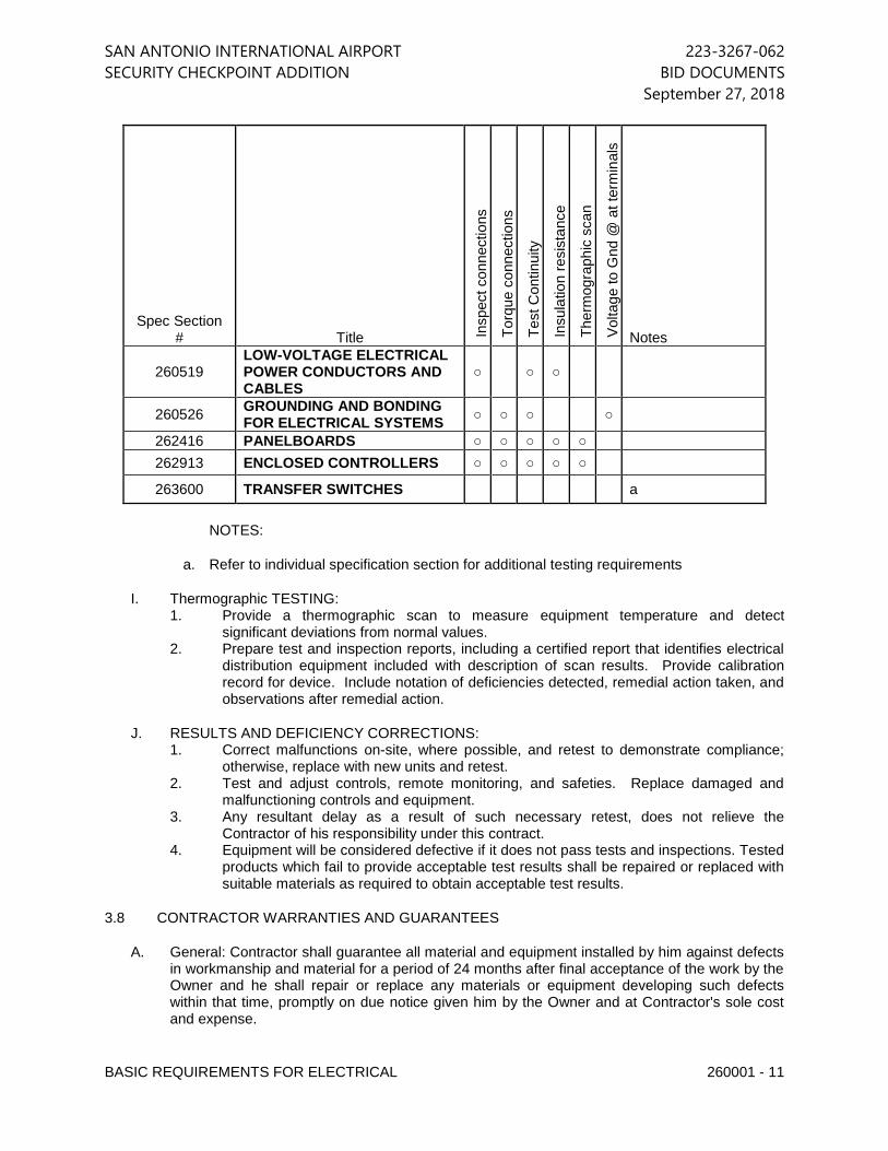
SAN ANTONIO INTERNATIONAL AIRPORT 223-3267-062
SECURITY CHECKPOINT ADDITION BID DOCUMENTS
September 27, 2018
BASIC REQUIREMENTS FOR ELECTRICAL 260001 - 11
Spec Section # Title In
spect con
nections
Torq
ue c
onnections
Test C
ontinu
ity
Insula
tio
n r
esis
tance
Therm
ogra
ph
ic s
can
Voltag
e to G
nd @
at
term
inals
Notes
260519 LOW-VOLTAGE ELECTRICAL POWER CONDUCTORS AND CABLES
○ ○ ○
260526 GROUNDING AND BONDING FOR ELECTRICAL SYSTEMS
○ ○ ○ ○
262416 PANELBOARDS ○ ○ ○ ○ ○
262913 ENCLOSED CONTROLLERS ○ ○ ○ ○ ○
263600 TRANSFER SWITCHES a
NOTES:
a. Refer to individual specification section for additional testing requirements
I. Thermographic TESTING: 1. Provide a thermographic scan to measure equipment temperature and detect
significant deviations from normal values. 2. Prepare test and inspection reports, including a certified report that identifies electrical
distribution equipment included with description of scan results. Provide calibration record for device. Include notation of deficiencies detected, remedial action taken, and observations after remedial action.
J. RESULTS AND DEFICIENCY CORRECTIONS: 1. Correct malfunctions on-site, where possible, and retest to demonstrate compliance;
otherwise, replace with new units and retest. 2. Test and adjust controls, remote monitoring, and safeties. Replace damaged and
malfunctioning controls and equipment. 3. Any resultant delay as a result of such necessary retest, does not relieve the
Contractor of his responsibility under this contract. 4. Equipment will be considered defective if it does not pass tests and inspections. Tested
products which fail to provide acceptable test results shall be repaired or replaced with suitable materials as required to obtain acceptable test results.
3.8 CONTRACTOR WARRANTIES AND GUARANTEES
A. General: Contractor shall guarantee all material and equipment installed by him against defects in workmanship and material for a period of 24 months after final acceptance of the work by the Owner and he shall repair or replace any materials or equipment developing such defects within that time, promptly on due notice given him by the Owner and at Contractor's sole cost and expense.
SAN ANTONIO INTERNATIONAL AIRPORT 223-3267-062
SECURITY CHECKPOINT ADDITION BID DOCUMENTS
September 27, 2018
BASIC REQUIREMENTS FOR ELECTRICAL 260001 - 12
B. Equipment: All equipment bearing a manufacturer's guarantee in excess of the time requirement above, such as electrical equipment, devices, components, and similar items, shall be considered to have that guarantee extended directly to the Owner by the manufacturer. Any such equipment that proves defective in materials or workmanship within the guarantee period is to be corrected by the Contractor in accordance with the manufacturer's guarantee.
C. Start-up: The Electrical Contractor shall provide instructions and equipment starting service on new equipment for two complete years after date of final acceptance of the work by the Owner, at Contractor's sole cost and expense.
END OF SECTION 260001
SAN ANTONIO INTERNATIONAL AIRPORT 223-3267-062
SECURITY CHECKPOINT ADDITION BID DOCUMENTS
September 27, 2018
LOW-VOLTAGE ELECTRICAL POWER CONDUCTORS AND CABLES 260519 - 1
SECTION 260519 - LOW-VOLTAGE ELECTRICAL POWER CONDUCTORS AND CABLES
PART 1 - GENERAL
1.1 RELATED DOCUMENTS
A. Drawings and general provisions of the Contract, including General and Supplementary Conditions and Division 01 Specification Sections, apply to this Section.
1.2 SUMMARY
A. This Section includes the following: 1. Building wires and cables rated 600 V and less. 2. Connectors, splices, and terminations rated 600 V and less.
1.3 DEFINITIONS
A. EPDM: Ethylene-propylene-diene terpolymer rubber.
B. NBR: Acrylonitrile-butadiene rubber.
1.4 SUBMITTALS
A. Shop Drawing submittals shall include, but not be limited to, the following: 1. The Contractor shall submit to the Engineer for review, a list of the proposed
manufacturers of wire and cable, cable lugs, cable connectors and termination fittings listed herein. The Contractor may install wire and cable, cable lugs, cable connectors and termination fittings furnished by any manufacturer listed on the approved submittal.
2. Cut sheets on all 300 and 600 volt conductors with manufacturers name, ratings and capacities, insulation characteristics, and available colors, clearly listed.
3. Cut sheets indicating all cable lugs, termination fittings and cable connectors.
B. Closeout Submittal 1. Include final version of approved shop drawing submittals within the Operation
and Maintenance manual.
PART 2 - PRODUCTS
2.1 CONDUCTORS AND CABLES
A. Manufacturers: Subject to compliance with requirements, provide products by one of the following: 1. Alcan Products Corporation; Alcan Cable Division. 2. American Insulated Wire Corp.; a Leviton Company. 3. General Cable Corporation.
4. Senator Wire & Cable Company.
SAN ANTONIO INTERNATIONAL AIRPORT 223-3267-062
SECURITY CHECKPOINT ADDITION BID DOCUMENTS
September 27, 2018
LOW-VOLTAGE ELECTRICAL POWER CONDUCTORS AND CABLES 260519 - 2
5. Southwire Company.
B. Copper Conductors: Comply with NEMA WC 70.
C. Conductor Insulation: Comply with NEMA WC 70 for Types THW, THHN-THWN and XHHW.
D. Multi-conductor Cable: Comply with NEMA WC 70 for metal-clad cable, Type MC with ground wire.
2.2 CONNECTORS AND SPLICES
A. Manufacturers: Subject to compliance with requirements, provide products by one of the following: 1. AFC Cable Systems, Inc. 2. Hubbell Power Systems, Inc. 3. O-Z/Gedney; EGS Electrical Group LLC. 4. 3M; Electrical Products Division. 5. TE Connectivity
B. Description: Factory-fabricated connectors and splices of size, ampacity rating, material, type, and class for application and service indicated.
PART 3 - EXECUTION
3.1 CONDUCTOR MATERIAL APPLICATIONS
A. Feeders: Copper. Solid for No. 10 AWG and smaller; stranded for No. 8 AWG and larger.
B. Branch Circuits: Copper. Solid for No. 10 AWG and smaller; stranded for No. 8 AWG and larger.
3.2 CONDUCTOR INSULATION AND MULTICONDUCTOR CABLE APPLICATIONS AND WIRING METHODS
A. Service Entrance: Type THHN-THWN, single conductors in raceway or Type XHHW, single conductors in raceway.
B. Exposed Feeders: Type THHN-THWN, single conductors in raceway.
C. Feeders Concealed in Ceilings, Walls, Partitions, and Crawlspaces: Type THHN-THWN, single conductors in raceway.
D. Feeders Concealed in Concrete, below Slabs-on-Grade, and Underground: Type THHN-THWN, single conductors in raceway.
E. Feeders Installed below Raised Flooring: Type THHN-THWN, single conductors in raceway.
SAN ANTONIO INTERNATIONAL AIRPORT 223-3267-062
SECURITY CHECKPOINT ADDITION BID DOCUMENTS
September 27, 2018
LOW-VOLTAGE ELECTRICAL POWER CONDUCTORS AND CABLES 260519 - 3
F. Exposed Branch Circuits, Including in Crawlspaces: Type THHN-THWN, single conductors in raceway.
G. Branch Circuits Concealed in Ceilings, Walls, and Partitions: Type THHN-THWN, single conductors in raceway.
H. Branch Circuits Concealed in Concrete, below Slabs-on-Grade, and Underground: Type THHN-THWN, single conductors in raceway.
I. Cord Drops and Portable Appliance Connections: Type SO, hard service cord with stainless-steel, wire-mesh, strain relief device at terminations to suit application.
J. Class 1 Control Circuits: Type THHN-THWN, in raceway.
K. Class 2 Control Circuits: Type THHN-THWN, in raceway or Power-limited cable, concealed in building finishes.
3.3 INSTALLATION OF CONDUCTORS AND CABLES
A. Conceal cables in finished walls, ceilings, and floors, unless otherwise indicated.
B. Use manufacturer-approved pulling compound or lubricant where necessary; compound used must not deteriorate conductor or insulation. Do not exceed manufacturer's recommended maximum pulling tensions and sidewall pressure values.
C. Use pulling means, including fish tape, cable, rope, and basket-weave wire/cable grips, that will not damage cables or raceway.
D. Install exposed cables parallel and perpendicular to surfaces of exposed structural members, and follow surface contours where possible.
E. Support cables according to Section 260529 "Hangers and Supports for Electrical Systems."
F. Identify and color-code conductors and cables according to Section 260553 "Identification for Electrical Systems."
G. Provide support for conductors in vertical raceways in accordance with NEC 300.19. Refer to Table 300.19(A) for support spacing distance requirements of specific cable sizes.
3.4 EMERGENCY FEEDERS INSTALLATION
A. The requirements listed in sub-paragraphs 3.3A thru F shall be provided for Emergency power feeder circuits.
B. Emergency power feeders and branch circuits wiring shall be separated completely in separate raceways, boxes and junction boxes in accordance with the requirements of NEC Article 700.10(D) (2). and 700.10 (B)(1) thru (4).
SAN ANTONIO INTERNATIONAL AIRPORT 223-3267-062
SECURITY CHECKPOINT ADDITION BID DOCUMENTS
September 27, 2018
LOW-VOLTAGE ELECTRICAL POWER CONDUCTORS AND CABLES 260519 - 4
C. Emergency power feeders shall be provided with the following requirements in accordance with NEC 700.10(D)(1), (2). 1. UL listed minimum 2-hour fire rating as an electrical circuit protective system. 2. Protected by a listed thermal barrier system for electrical system components
with a minimum 2-hour fire rating. 3. Protected by a listed fire rated assembly with a minimum fire rating of 2-hours
and contain only emergency wiring circuits. 4. Be encased in a minimum of 2 inches of concrete.
D. All boxes, enclosures, transfer switches and power panels for emergency circuits shall be marked permanently for readily identified components of the emergency circuit system in accordance with NEC 700.10(A).
3.5 CONNECTIONS
A. Tighten electrical connectors and terminals according to manufacturer's published torque-tightening values. If manufacturer's torque values are not indicated, use those specified in UL 486A and UL 486B.
B. Make splices and taps that are compatible with conductor material and that possess equivalent or better mechanical strength and insulation ratings.
C. Wiring at Outlets: Install conductor at each outlet, with at least 12 inches (300 mm) of slack.
3.6 SLEEVE AND SLEEVE-SEAL INSTALLATION FOR ELECTRICAL PENETRATIONS
A. Install sleeves and sleeve seals at penetrations of exterior floor and wall assemblies. Comply with requirements in Section 260544 "Sleeves and Sleeve Seals for Electrical Raceways and Cabling."
3.7 FIRESTOPPING
A. Apply firestopping to electrical penetrations of fire-rated floor and wall assemblies to restore original fire-resistance rating of assembly according to Division 07 Section 078413 "Penetration Firestopping."
3.8 FIELD QUALITY CONTROL
A. Perform tests and inspections and prepare test reports.
B. Tests and Inspections: 1. After installing conductors and cables and before electrical circuitry has been
energized, test service entrance and feeder conductors for compliance with requirements.
END OF SECTION 260519
SAN ANTONIO INTERNATIONAL AIRPORT 223-3267-062
SECURITY CHECKPOINT ADDITION BID DOCUMENTS
September 27, 2018
GROUNDING AND BONDING FOR ELECTRICAL SYSTEMS 260526 - 1
SECTION 260526 - GROUNDING AND BONDING FOR ELECTRICAL SYSTEMS
PART 1 - GENERAL
1.1 RELATED DOCUMENTS
A. Drawings and general provisions of the Contract, including General and Supplementary Conditions and Division 01 Specification Sections, apply to this Section.
1.2 SUMMARY
A. Section includes general requirements for grounding and bonding of electrical installations, systems, and equipment.
1.3 SUBMITTALS
A. Shop Drawing submittals shall include, but not be limited to, the following: 1. The Contractor shall submit to the Engineer for review, a grounding system
diagram for special grounding systems. 2. Cut sheets of grounding products.
B. Closeout Submittal
1. Include final version of approved shop drawing submittals within the Operation and Maintenance manual.
1.4 INFORMATIONAL SUBMITTALS
A. Informational Submittals: Plans showing dimensioned as-built locations of grounding features specified in "Field Quality Control" Article, including the following: 1. Ground rods. 2. Grounding arrangements and connections for separately derived systems. 3. Grounding for sensitive electronic equipment.
B. Qualification Data: For qualified testing agency and testing agency's field supervisor.
C. Field quality-control reports.
1.5 QUALITY ASSURANCE
A. Testing Agency Qualifications: Member company of NETA or an NRTL. 1. Testing Agency's Field Supervisor: Currently certified by NETA to supervise
on-site testing.
B. Electrical Components, Devices, and Accessories: Listed and labeled as defined in NFPA 70, by a qualified testing agency, and marked for intended location and application.
C. Comply with UL 467 for grounding and bonding materials and equipment.
SAN ANTONIO INTERNATIONAL AIRPORT 223-3267-062
SECURITY CHECKPOINT ADDITION BID DOCUMENTS
September 27, 2018
GROUNDING AND BONDING FOR ELECTRICAL SYSTEMS 260526 - 2
PART 2 - PRODUCTS
2.1 CONDUCTORS
A. Insulated Conductors: Copper or tinned-copper wire or cable insulated for 600 V unless otherwise required by applicable Code or authorities having jurisdiction.
B. Bare Copper Conductors: 1. Solid Conductors: ASTM B 3. 2. Stranded Conductors: ASTM B 8. 3. Tinned Conductors: ASTM B 33. 4. Bonding Cable: 28 kcmil, 14 strands of No. 17 AWG conductor, 1/4 inch (6
mm) in diameter. 5. Bonding Conductor: No. 4 or No. 6 AWG, stranded conductor. 6. Bonding Jumper: Copper tape, braided conductors terminated with copper
ferrules; 1-5/8 inches (41 mm) wide and 1/16 inch (1.6 mm) thick. 7. Tinned Bonding Jumper: Tinned-copper tape, braided conductors terminated
with copper ferrules; 1-5/8 inches (41 mm) wide and 1/16 inch (1.6 mm) thick.
C. Grounding Bus: Provide grounding busbars of size indicated on drawings. If not indicated, provide a pre-drilled, rectangular bar of annealed copper, 1/4 by 4 inches (6.3 by 100 mm) in cross section, with 9/32-inch (7.14-mm) holes spaced 1-1/8 inches (28 mm) apart. Stand-off insulators for mounting shall comply with UL 891 for use in switchboards, 600 V. Lexan or PVC, impulse tested at 5,000 V.
2.2 CONNECTORS
A. Listed and labeled by an NRTL acceptable to authorities having jurisdiction for applications in which used and for specific types, sizes, and combinations of conductors and other items connected.
B. Bolted Connectors for Conductors and Pipes: Copper or copper alloy, pressure type with at least two bolts. 1. Pipe Connectors: Clamp type, sized for pipe.
C. Welded Connectors: Exothermic-welding kits of types recommended by kit manufacturer for materials being joined and installation conditions.
D. Bus-bar Connectors: Mechanical type, cast silicon bronze, solderless compression type wire terminals, and long-barrel, two-bolt connection to ground bus bar.
2.3 GROUNDING ELECTRODES
A. Ground Rods: Copper-clad steel 3/4 inch by 10 feet (19 mm by 3 m) in diameter.
SAN ANTONIO INTERNATIONAL AIRPORT 223-3267-062
SECURITY CHECKPOINT ADDITION BID DOCUMENTS
September 27, 2018
GROUNDING AND BONDING FOR ELECTRICAL SYSTEMS 260526 - 3
PART 3 - EXECUTION
3.1 APPLICATIONS
A. Conductors: Install solid conductor for No. 8 AWG and smaller, and stranded conductors for No. 6 AWG and larger unless otherwise indicated.
B. Underground Grounding Conductors: Install bare copper conductor, No. 2/0 AWG minimum. 1. Bury at least 24 inches (600 mm) below grade.
C. Isolated Grounding Conductors: Green-colored insulation with continuous yellow stripe. On feeders with isolated ground, identify grounding conductor where visible to normal inspection, with alternating bands of green and yellow tape, with at least three bands of green and two bands of yellow.
D. Grounding Bus: Install in electrical and telephone equipment rooms, in rooms housing service equipment, and elsewhere as indicated. 1. Install bus on insulated spacers 2 inches (50 mm) minimum from wall, 6 inches
(150 mm) above finished floor unless otherwise indicated. 2. Where indicated on both sides of doorways, route bus up to top of door frame,
across top of doorway, and down to specified height above floor; connect to horizontal bus.
E. Conductor Terminations and Connections: 1. Pipe and Equipment Grounding Conductor Terminations: Bolted connectors. 2. Underground Connections: Welded connectors except at test wells and as
otherwise indicated. 3. Connections to Ground Rods at Test Wells: Bolted connectors. 4. Connections to Structural Steel: Welded connectors.
3.2 EQUIPMENT GROUNDING
A. Install insulated equipment grounding conductors with all feeders and branch circuits.
B. Install insulated equipment grounding conductors with the following items, in addition to those required by NFPA 70: 1. Feeders and branch circuits. 2. Lighting circuits. 3. Receptacle circuits. 4. Single-phase motor and appliance branch circuits. 5. Three-phase motor and appliance branch circuits. 6. Flexible raceway runs.
C. Water Heater, Heat-Tracing, and Anti-frost Heating Cables: Install an insulated equipment grounding conductor to each electric water heater and heat-tracing cable. Bond conductor to heater units, piping, connected equipment, and components.
D. Isolated Grounding Receptacle Circuits: Install an insulated equipment grounding conductor connected to the receptacle grounding terminal. Isolate conductor from
SAN ANTONIO INTERNATIONAL AIRPORT 223-3267-062
SECURITY CHECKPOINT ADDITION BID DOCUMENTS
September 27, 2018
GROUNDING AND BONDING FOR ELECTRICAL SYSTEMS 260526 - 4
raceway and from panelboard grounding terminals. Terminate at equipment grounding conductor terminal of the applicable derived system or service unless otherwise indicated.
E. Telecommunications Equipment: In addition to grounding and bonding required by NFPA 70, provide an infrastructure grounding system compliant with requirements of ANSI/TIA-607-B-2011. The system shall have the following components, as relevant to building layout: 1. TMGB - (Telecommunications Main Grounding Busbar), located in the MDF or
Main Telecommunications Equipment Room and connected to the building's grounding electrode system by means of a minimum 3/0 BCT (Bonding Conductor for Telecommunications).
2. TGB - (Telecommunications Grounding Busbar), located within each satellite Telecommunications Equipment Room or IDF, and connected to the TMGB via a TBB (Telecommunications Bonding Backbone). Provide TBB of the minimum size noted below unless larger size is indicated on the drawings.
TBB Conductor Length TBB Minimum Size
Minimum #4 AWG
21-26' #3 AWG
27-33' #2 AWG
34-41' #1 AWG
42-52' 1/0
53-66' 2/0
67-84' 3/0
85-105' 4/0
Greater than 105' 250 kCM
3. GE - (Grounding Equalizer), provided between TGBs within satellite Telecommunications Equipment Rooms or IDFs at the top floor of multi-level buildings. The GE conductor shall be the same size as the largest TBB.
4. TEBC - (Telecommunications Equipment Bonding Conductor). Provide minimum #6 AWG conductor servings as TEBC from each metallic enclosure or equipment rack to the MTGB or TGB. Terminate the TEBC on a grounding terminal.
F. Poles Supporting Outdoor Lighting Fixtures: Install a # 4AWG bonding jumper from a ground terminal at each metallic pole or support arm to a grounding electrode. Reinforcing steel that is minimum 5/8" diameter and extends to 8' below final grade shall be permitted for use as the grounding electrode. Otherwise, provide a 5/8" x 8'-0" copper clad steel ground rod for use as the grounding electrode. The bonding jumper shall be routed within the pole base and insulated, if bonded to the reinforcing
SAN ANTONIO INTERNATIONAL AIRPORT 223-3267-062
SECURITY CHECKPOINT ADDITION BID DOCUMENTS
September 27, 2018
GROUNDING AND BONDING FOR ELECTRICAL SYSTEMS 260526 - 5
steel or installed within non-metallic conduit if bonded to a driven ground rod. Bond one imbedded bolt used for pole support to the reinforcing steel. These requirements are in addition to the equipment ground conductor installed in the same raceway as the branch-circuit conductors.
3.3 INSTALLATION
A. Grounding Conductors: Route along shortest and straightest paths possible unless otherwise indicated or required by Code. Avoid obstructing access or placing conductors where they may be subjected to strain, impact, or damage.
B. Ground Bonding Common with Lightning Protection System: Comply with NFPA 780 and UL 96 when interconnecting with lightning protection system. Bond electrical power system ground directly to lightning protection system grounding conductor at closest point to electrical service grounding electrode. Use bonding conductor sized same as system grounding electrode conductor, and install in conduit.
C. Ground Rods: Drive rods until tops are four inches (4”) below finished floor or final grade unless otherwise indicated. 1. Interconnect ground rods with grounding electrode conductor below grade and
as otherwise indicated. Make connections without exposing steel or damaging coating if any.
2. For grounding electrode system, install in accordance with details or description on drawing. If not otherwise indicated, provide at least three rods spaced at least one-rod length from each other and located at least the same distance from other grounding electrodes, and connect to the service grounding electrode conductor.
D. Bonding Straps and Jumpers: Install in locations accessible for inspection and maintenance except where routed through short lengths of conduit. 1. Bonding to Structure: Bond straps directly to basic structure, taking care not to
penetrate any adjacent parts. 2. Bonding to Equipment Mounted on Vibration Isolation Hangers and Supports:
Install bonding so vibration is not transmitted to rigidly mounted equipment. 3. Use exothermic-welded connectors for outdoor locations; if a disconnect-type
connection is required, use a bolted clamp.
E. Grounding and Bonding for Piping: 1. Metal Water Service Pipe: Install insulated copper grounding conductors, in
conduit, from building's main service equipment, or grounding bus, to main metal water service entrances to building. Connect grounding conductors to main metal water service pipes; use a bolted clamp connector or bolt a lug-type connector to a pipe flange by using one of the lug bolts of the flange. Where a dielectric main water fitting is installed, connect grounding conductor on street side of fitting. Bond metal grounding conductor conduit or sleeve to conductor at each end.
2. Water Meter Piping: Use braided-type bonding jumpers to electrically bypass water meters. Connect to pipe with a bolted connector.
3. Bond each aboveground portion of gas piping system downstream from equipment shutoff valve.
SAN ANTONIO INTERNATIONAL AIRPORT 223-3267-062
SECURITY CHECKPOINT ADDITION BID DOCUMENTS
September 27, 2018
GROUNDING AND BONDING FOR ELECTRICAL SYSTEMS 260526 - 6
3.4 LABELING
A. Comply with requirements in Section 260553 "Identification for Electrical Systems" for instruction signs. The label or its text shall be green.
B. Install labels at the telecommunications bonding conductor and grounding equalizer and at the grounding electrode conductor where exposed.
1. Label Text: "If this connector or cable is loose or if it must be removed for any reason, notify the facility manager."
END OF SECTION 260526
SAN ANTONIO INTERNATIONAL AIRPORT 223-3267-062
SECURITY CHECKPOINT ADDITION BID DOCUMENTS
September 27, 2018
HANGERS AND SUPPORTS FOR ELECTRICAL SYSTEMS 260529 - 1
SECTION 260529 - HANGERS AND SUPPORTS FOR ELECTRICAL SYSTEMS
PART 1 - GENERAL
1.1 RELATED DOCUMENTS
A. Drawings and general provisions of the Contract, including General and Supplementary Conditions and Division 01 Specification Sections, apply to this Section.
1.2 SUMMARY
A. This Section includes the following: 1. Hangers and supports for electrical equipment and systems. 2. Construction requirements for concrete bases.
1.3 DEFINITIONS
A. EMT: Electrical metallic tubing.
B. IMC: Intermediate metal conduit.
C. RMC, RGS: Rigid metal conduit.
1.4 PERFORMANCE REQUIREMENTS
A. Design supports for multiple raceways capable of supporting combined weight of supported systems and its contents.
B. Design equipment supports capable of supporting combined operating weight of supported equipment and connected systems and components.
1.5 SUBMITTALS
A. Shop Drawing submittals shall include, but not be limited to, the following: 1. Steel slotted support systems. 2. Nonmetallic slotted support systems. 3. Sketches with material list for custom fabricated equipment or raceway
supports.
1.6 QUALITY ASSURANCE
A. Comply with NFPA 70.
1.7 COORDINATION
A. Coordinate size and location of concrete bases. Cast anchor-bolt inserts into bases. Concrete, reinforcement, and formwork requirements are specified together with concrete Specifications.
SAN ANTONIO INTERNATIONAL AIRPORT 223-3267-062
SECURITY CHECKPOINT ADDITION BID DOCUMENTS
September 27, 2018
HANGERS AND SUPPORTS FOR ELECTRICAL SYSTEMS 260529 - 2
B. Coordinate installation of roof curbs, equipment supports, and roof penetrations. These items are specified in Section 077200 "Roof Accessories."
PART 2 - PRODUCTS
2.1 SUPPORT, ANCHORAGE, AND ATTACHMENT COMPONENTS
A. Steel Slotted Support Systems: Comply with MFMA-4, factory-fabricated components for field assembly. 1. Manufacturers: Subject to compliance with requirements, provide products by
one of the following:
a. Allied Tube & Conduit. b. Cooper B-Line, Inc.; a division of Cooper Industries. c. ERICO International Corporation. d. GS Metals Corp. e. Thomas & Betts Corporation. f. Unistrut; Tyco International, Ltd. g. Wesanco, Inc.
2. Metallic Coatings: Hot-dip galvanized after fabrication and applied according to MFMA-4.
3. Nonmetallic Coatings: Manufacturer's standard PVC, polyurethane, or polyester coating applied according to MFMA-4.
4. Painted Coatings: Manufacturer's standard painted coating applied according to MFMA-4.
5. Channel Dimensions: Selected for applicable load criteria.
B. Non-metallic Slotted Support Systems: Structural-grade, factory-formed, glass-fiber-resin channels and angles with 9/16-inch- (14-mm-) diameter holes at a maximum of 8 inches (200 mm) o.c., in at least 1 surface. 1. Manufacturers: Subject to compliance with requirements, provide products by
one of the following:
a. Allied Tube & Conduit.
b. Cooper B-Line, Inc.; a division of Cooper Industries.
c. Fabco Plastics Wholesale Limited.
d. Seasafe, Inc. 2. Fittings and Accessories: Products of channel and angle manufacturer and
designed for use with those items. 3. Fitting and Accessory Materials: Same as channels and angles, except metal
items may be stainless steel. 4. Rated Strength: Selected to suit applicable load criteria.
C. Raceway and Cable Supports: As described in NECA 1 and NECA 101.
D. Conduit and Cable Support Devices: Steel and malleable-iron hangers, clamps, and associated fittings, designed for types and sizes of raceway or cable to be supported.
SAN ANTONIO INTERNATIONAL AIRPORT 223-3267-062
SECURITY CHECKPOINT ADDITION BID DOCUMENTS
September 27, 2018
HANGERS AND SUPPORTS FOR ELECTRICAL SYSTEMS 260529 - 3
E. Support for Conductors in Vertical Conduit: Factory-fabricated assembly consisting of threaded body and insulating wedging plug or plugs for non-armored electrical conductors or cables in riser conduits. Plugs shall have number, size, and shape of conductor gripping pieces as required to suit individual conductors or cables supported. Body shall be malleable iron.
F. Structural Steel for Fabricated Supports and Restraints: ASTM A 36/A 36M, steel plates, shapes, and bars; black and galvanized.
G. Mounting, Anchoring, and Attachment Components: Items for fastening electrical items or their supports to building surfaces include the following: 1. Powder-Actuated Fasteners: Threaded-steel stud, for use in hardened
portland cement concrete, steel, or wood, with tension, shear, and pullout capacities appropriate for supported loads and building materials where used.
a. Manufacturers: Subject to compliance with requirements, provide products by one of the following:
1) Hilti Inc. 2) ITW Ramset/Red Head; a division of Illinois Tool Works, Inc. 3) MKT Fastening, LLC. 4) Simpson Strong-Tie Co., Inc.; Masterset Fastening Systems
Unit.
2. Mechanical-Expansion Anchors: Insert-wedge-type, zinc-coated or stainless steel, for use in hardened portland cement concrete with tension, shear, and pullout capacities appropriate for supported loads and building materials in which used.
a. Manufacturers: Subject to compliance with requirements, provide products by one of the following:
1) Cooper B-Line, Inc.; a division of Cooper Industries. 2) Empire Tool and Manufacturing Co., Inc. 3) Hilti Inc. 4) ITW Ramset/Red Head; a division of Illinois Tool Works, Inc. 5) MKT Fastening, LLC.
3. Concrete Inserts: Steel or malleable-iron, slotted support system units similar to MSS Type 18; complying with MFMA-4 or MSS SP-58.
4. Clamps for Attachment to Steel Structural Elements: MSS SP-58, type suitable for attached structural element.
5. Through Bolts: Structural type, hex head, and high strength. Comply with ASTM A 325.
6. Toggle Bolts: All-steel, springhead type. 7. Hanger Rods: Threaded steel.
2.2 FABRICATED METAL EQUIPMENT SUPPORT ASSEMBLIES
A. Description: Welded or bolted, structural-steel shapes, shop or field fabricated to fit dimensions of supported equipment.
SAN ANTONIO INTERNATIONAL AIRPORT 223-3267-062
SECURITY CHECKPOINT ADDITION BID DOCUMENTS
September 27, 2018
HANGERS AND SUPPORTS FOR ELECTRICAL SYSTEMS 260529 - 4
B. Materials: Comply with requirements in Section 055000 "Metal Fabrications" for steel shapes and plates.
PART 3 - EXECUTION
3.1 APPLICATION
A. Comply with NECA 1 and NECA 101 for application of hangers and supports for electrical equipment and systems except if requirements in this Section are stricter.
B. Maximum Support Spacing and Minimum Hanger Rod Size for Raceway: Space supports for EMT, IMC, and RMC as required by NFPA 70. Minimum rod size shall be 1/4 inch (6 mm) in diameter.
C. Multiple Raceways or Cables: Install trapeze-type supports fabricated with steel slotted or other support system, sized so capacity can be increased by at least 25 percent in future without exceeding specified design load limits. 1. Secure raceways and cables to these supports with two-bolt conduit clamps.
D. Spring-steel clamps designed for supporting single conduits without bolts may be used for 1-1/2-inch (38-mm) and smaller raceways serving branch circuits and communication systems above suspended ceilings and for fastening raceways to trapeze supports.
3.2 SUPPORT INSTALLATION
A. Comply with NECA 1 and NECA 101 for installation requirements except as specified in this Article.
B. Raceway Support Methods: In addition to methods described in NECA 1, EMT, IMC, and RMC may be supported by openings through structure members, as permitted in NFPA 70.
C. Strength of Support Assemblies: Where not indicated, select sizes of components so strength will be adequate to carry present and future static loads within specified loading limits. Minimum static design load used for strength determination shall be weight of supported components plus 200 lb (90 kg).
D. Mounting and Anchorage of Surface-Mounted Equipment and Components: Anchor and fasten electrical items and their supports to building structural elements by the following methods unless otherwise indicated by code: 1. To Wood: Fasten with lag screws or through bolts. 2. To New Concrete: Bolt to concrete inserts. 3. To Masonry: Approved toggle-type bolts on hollow masonry units and
expansion anchor fasteners on solid masonry units. 4. To Existing Concrete: Expansion anchor fasteners. 5. Instead of expansion anchors, powder-actuated driven threaded studs provided
with lock washers and nuts may be used in existing standard-weight concrete 4 inches (100 mm) thick or greater. Do not use for anchorage to lightweight-aggregate concrete or for slabs less than 4 inches (100 mm) thick.
SAN ANTONIO INTERNATIONAL AIRPORT 223-3267-062
SECURITY CHECKPOINT ADDITION BID DOCUMENTS
September 27, 2018
HANGERS AND SUPPORTS FOR ELECTRICAL SYSTEMS 260529 - 5
6. To Steel: Beam clamps (MSS Type 19, 21, 23, 25, or 27) complying with MSS SP-69.
7. To Light Steel: Sheet metal screws. 8. Items Mounted on Hollow Walls and Nonstructural Building Surfaces: Mount
cabinets, panelboards, disconnect switches, control enclosures, pull and junction boxes, transformers, and other devices on slotted-channel racks attached to substrate.
E. Drill holes for expansion anchors in concrete at locations and to depths that avoid reinforcing bars.
3.3 INSTALLATION OF FABRICATED METAL SUPPORTS
A. Comply with installation requirements in Section 055000 "Metal Fabrications" for site-fabricated metal supports.
B. Cut, fit, and place miscellaneous metal supports accurately in location, alignment, and elevation to support and anchor electrical materials and equipment.
C. Field Welding: Comply with AWS D1.1/D1.1M.
3.4 CONCRETE BASES
A. Construct concrete bases of dimensions indicated but not less than 4 inches (100 mm) larger in both directions than supported unit, and so anchors will be a minimum of 10 bolt diameters from edge of the base.
B. Use minimum, 3000-psi (20.7-MPa), 28-day compressive-strength concrete. Concrete materials, reinforcement, and placement requirements are specified in Section 033000 "Cast-in-Place Concrete" or Section 033053 "Miscellaneous Cast-in-Place Concrete."
C. Anchor equipment to concrete base. 1. Place and secure anchorage devices. Use supported equipment
manufacturer's setting drawings, templates, diagrams, instructions, and directions furnished with items to be embedded.
2. Install anchor bolts to elevations required for proper attachment to supported equipment.
3. Install anchor bolts according to anchor-bolt manufacturer's written instructions.
3.5 PAINTING
A. Touchup: Clean field welds and abraded areas of shop paint. Paint exposed areas immediately after erecting hangers and supports. Use same materials as used for shop painting. Comply with SSPC-PA 1 requirements for touching up field-painted surfaces. 1. Apply paint by brush or spray to provide minimum dry film thickness of 2.0 mils
(0.05 mm).
B. Galvanized Surfaces: Clean welds, bolted connections, and abraded areas and apply galvanizing-repair paint to comply with ASTM A 780.
SAN ANTONIO INTERNATIONAL AIRPORT 223-3267-062
SECURITY CHECKPOINT ADDITION BID DOCUMENTS
September 27, 2018
HANGERS AND SUPPORTS FOR ELECTRICAL SYSTEMS 260529 - 6
END OF SECTION 260529
SAN ANTONIO INTERNATIONAL AIRPORT 223-3267-062
SECURITY CHECKPOINT ADDITION BID DOCUMENTS
September 27, 2018
RACEWAYS AND BOXES FOR ELECTRICAL SYSTEMS 260533 - 1
SECTION 260533 - RACEWAYS AND BOXES FOR ELECTRICAL SYSTEMS
PART 1 - GENERAL
1.1 RELATED DOCUMENTS
A. Drawings and general provisions of the Contract, including General and Supplementary Conditions and Division 1 Specification Sections, apply to this Section.
1.2 SUMMARY
A. This Section includes raceways, fittings, boxes, enclosures, and cabinets for electrical wiring.
B. Related Sections include the following: 1. Division 7 Section Firestopping for firestopping materials and installation at
penetrations through walls, ceilings, and other fire-rated elements. 2. Division 26 Section Basic Electrical Materials and Methods@ for supports,
anchors, and identification products. 3. Division 26 Section Wiring Devices for devices installed in boxes and for floor-
box service fittings.
1.3 DEFINITIONS
A. EMT: Electrical metallic tubing.
B. ENT: Electrical nonmetallic tubing.
C. FMC: Flexible metal conduit.
D. IMC: Intermediate metal conduit.
E. LFMC: Liquidtight flexible metal conduit.
F. LFNC: Liquidtight flexible nonmetallic conduit.
G. RNC: Rigid nonmetallic conduit.
H. PVC-GRS: PVC-Coated galvanized rigid steel.
I. MC: Metal clad cable.
1.4 SUBMITTALS
A. Product Data: 1. For surface raceways, wireways and fittings. 2. Floor boxes. 3. Hinged-cover enclosures and cabinets.
SAN ANTONIO INTERNATIONAL AIRPORT 223-3267-062
SECURITY CHECKPOINT ADDITION BID DOCUMENTS
September 27, 2018
RACEWAYS AND BOXES FOR ELECTRICAL SYSTEMS 260533 - 2
4. Conduit spacers. 5. Conduit rack supports.
B. Shop Drawings: Show fabrication and installation details of components for raceways, fittings, boxes, enclosures, and cabinets.
1.5 QUALITY ASSURANCE
A. Electrical Components, Devices, and Accessories: Listed and labeled as defined in NFPA 70, Article 100, by a testing agency acceptable to authorities having jurisdiction, and marked for intended use.
B. Comply with NFPA 70.
1.6 COORDINATION
A. Coordinate layout and installation of raceways, boxes, enclosures, cabinets, and suspension system with other construction that penetrates ceilings or is supported by them, including light fixtures, HVAC equipment, fire-suppression system, and partition assemblies.
PART 2 - PRODUCTS
2.1 MANUFACTURERS
A. In other Part 2 articles where subparagraph titles below introduce lists, the following requirements apply for product selection: 1. Available Manufacturers: Subject to compliance with requirements,
manufacturers offering products that may be incorporated into the Work include, but are not limited to, the manufacturers specified.
2. Refer to 3.1, RACEWAY APPLICATION, for materials to be used.
2.2 METAL CONDUIT AND TUBING
A. Available Manufacturers: 1. AFC Cable Systems, Inc. 2. Alflex, Inc. 3. Anamet Electrical, Inc.; Anaconda Metal Hose. 4. Electri-Flex Co. 5. Grinnell Co./Tyco International; Allied Tube and Conduit Div. 6. Republic Conduit. 7. Manhattan/CDT/Cole-Flex. 8. O-Z Gedney; Unit of General Signal. 9. Wheatland Tube Co.
10. Perma-Cote 11. Plasti Bond 12. KorKap
SAN ANTONIO INTERNATIONAL AIRPORT 223-3267-062
SECURITY CHECKPOINT ADDITION BID DOCUMENTS
September 27, 2018
RACEWAYS AND BOXES FOR ELECTRICAL SYSTEMS 260533 - 3
B. Rigid Steel Conduit: ANSI C80.1.
C. IMC: ANSI C80.6.
D. PVC--Coated Steel Conduit and Fittings: UL514b NEMA RN 1.
E. PVC- Coated IMC and Fittings: ETL PVC-001 NEMA RN 1 UL6.
F. EMT: ANSI C80.3.
G. FMC: Zinc-coated steel.
H. LFMC: Flexible steel conduit with PVC jacket.
I. Fittings: NEMA FB 1; compatible with conduit and tubing materials. Provide fittings factory matched with conduit types. 1. Indoor Fittings: Steel Set Screw or Steel Compression 2. Outdoor Fittings: Threaded fittings on IMC or Rigid Conduit 3. Outdoor Fittings: Compression fittings with gaskets on all transitions to flexible
conduit. 4. Die cast fittings are not acceptable anywhere. 5. Provide factory fittings with MC cable where allowed. 6. EMT crimp type fittings are not acceptable.
2.3 NONMETALLIC CONDUIT AND TUBING
A. Available Manufacturers: 1. American International. 2. Anamet Electrical, Inc.; Anaconda Metal Hose. 3. Amco Corp. 4. Cantex, Inc. 5. Certainteed Corp.; Pipe & Plastics Group. 6. Condux International. 7. ElecSYS, Inc. 8. Electri-Flex Co. 9. Lamson & Sessions; Carlon Electrical Products.
10. Manhattan/CDT/Cole-Flex. 11. RACO; Division of Hubbell, Inc. 12. Thomas & Betts Corporation.
B. ENT: NEMA TC 13.
C. RNC: NEMA TC 2, Schedule 40 and Schedule 80 PVC.
D. LFNC: UL 1660.
E. Fittings: NEMA TC 3; match to conduit or tubing type and material. Provide fittings factory matched with conduit types.
SAN ANTONIO INTERNATIONAL AIRPORT 223-3267-062
SECURITY CHECKPOINT ADDITION BID DOCUMENTS
September 27, 2018
RACEWAYS AND BOXES FOR ELECTRICAL SYSTEMS 260533 - 4
1. Indoor/Outdoor Fittings: Compression. 2. Outdoor Fittings: Compression fittings with gaskets on all transitions to flexible
conduit.
2.4 METAL WIREWAYS
A. Available Manufacturers: 1. Hoffman. 2. Square D.
B. Material and Construction: Sheet metal sized and shaped as indicated, NEMA 1.
C. Fittings and Accessories: Include couplings, offsets, elbows, expansion joints, adapters, hold-down straps, end caps, and other fittings to match and mate with wireways as required for complete system.
D. Select features, unless otherwise indicated, as required to complete wiring system and to comply with NFPA 70.
E. Wireway Covers: Hinged type, or as indicated.
F. Finish: Manufacturer's standard enamel finish.
2.5 NONMETALLIC WIREWAYS
A. Available Manufacturers: 1. Hoffman. 2. Lamson & Sessions; Carlon Electrical Products.
B. Description: Fiberglass polyester, extruded and fabricated to size and shape indicated, with no holes or knockouts. Cover is gasketed with oil-resistant gasket material and fastened with captive screws treated for corrosion resistance. Connections are flanged, with stainless-steel screws and oil-resistant gaskets.
C. Description: PVC plastic, extruded and fabricated to size and shape indicated, with snap-on cover and mechanically coupled connections with plastic fasteners.
D. Fittings and Accessories: Include couplings, offsets, elbows, expansion joints, adapters, hold-down straps, end caps, and other fittings to match and mate with wireways as required for complete system.
E. Select features, unless otherwise indicated, as required to complete wiring system and to comply with NFPA 70.
2.6 SURFACE RACEWAYS
A. Surface Metal Raceways: Galvanized steel with snap-on covers. Finish with manufacturer's standard prime coating. 1. Available Manufacturers:
SAN ANTONIO INTERNATIONAL AIRPORT 223-3267-062
SECURITY CHECKPOINT ADDITION BID DOCUMENTS
September 27, 2018
RACEWAYS AND BOXES FOR ELECTRICAL SYSTEMS 260533 - 5
a. Airey-Thompson Sentinel Lighting; Wiremold Company (The). b. Thomas & Betts Corporation. c. Walker Systems, Inc.; Wiremold Company (The). d. Wiremold Company (The); Electrical Sales Division.
B. Surface Nonmetallic Raceways: Two-piece construction, manufactured of rigid PVC compound with matte texture and manufacturer's standard color. 1. Available Manufacturers:
a. Butler Manufacturing Co.; Walker Division. b. Enduro Composite Systems. c. Hubbell, Inc.; Wiring Device Division. d. Lamson & Sessions; Carlon Electrical Products. e. Panduit Corp. f. Walker Systems, Inc.; Wiremold Company (The). g. Wiremold Company (The); Electrical Sales Division.
C. Types, sizes, and channels as indicated and required for each application, with fittings that match and mate with raceways.
D. Provide raceway base, cover, base coupling, coupling covers, angle fittings, end caps at ends, and entrance end fittings. Provide divider wall throughout raceway. Provide device brackets and snap-on bezels at all devices shown on drawings. Provide blank covers at all non-used bezels.
E. Provide raceway full length, mounted as per drawings or 6" above counters if height is not indicated, as shown on drawings. Provide elbows and raceway to 6 inches above ceiling if risers are indicated on the drawings.
2.7 BOXES, ENCLOSURES, AND CABINETS
A. Available Manufacturers: 1. Cooper Crouse-Hinds; Div. of Cooper Industries, Inc. 2. Emerson/General Signal; Appleton Electric Company. 3. Erickson Electrical Equipment Co. 4. Hoffman. 5. Hubbell, Inc.; Killark Electric Manufacturing Co. 6. O-Z/ Gedney; Unit of General Signal. 7. RACO; Division of Hubbell, Inc. 8. Stahlin 9. Scott Fetzer Co.; Adalet-PLM Division. 10. Spring City Electrical Manufacturing Co. 11. Thomas & Betts Corporation. 12. Walker Systems, Inc.; Wiremold Company (The). 13. Woodhead, Daniel Company; Woodhead Industries, Inc. Subsidiary.
B. Sheet Metal Outlet and Device Boxes: NEMA OS 1.
C. Cast-Metal Outlet and Device Boxes: NEMA FB 1, Type FD, with gasketed cover.
SAN ANTONIO INTERNATIONAL AIRPORT 223-3267-062
SECURITY CHECKPOINT ADDITION BID DOCUMENTS
September 27, 2018
RACEWAYS AND BOXES FOR ELECTRICAL SYSTEMS 260533 - 6
D. Nonmetallic Outlet and Device Boxes: NEMA OS 2.
E. Small Sheet Metal Pull and Junction Boxes: NEMA OS 1.
F. Cast-Metal Pull and Junction Boxes: NEMA FB 1, cast aluminum with gasketed cover.
G. Hinged-Cover Enclosures: NEMA 250, Type 1, with continuous hinge cover and flush latch. 1. Metal Enclosures: Steel, finished inside and out with manufacturer's standard
enamel. 2. Nonmetallic Enclosures: Plastic, finished inside with radio-frequency-resistant
paint.
H. Cabinets: NEMA 250, Type 1, galvanized steel box with removable interior panel and removable front, finished inside and out with manufacturer's standard enamel. Hinged door in front cover with flush latch and concealed hinge. Key latch to match panelboards. Include metal barriers to separate wiring of different systems and voltage and include accessory feet where required for freestanding equipment.
2.8 FACTORY FINISHES
A. Finish: For raceway, enclosure, or cabinet components, provide manufacturer's standard prime-coat finish ready for field painting.
B. Finish: For raceway, enclosure, or cabinet components, provide manufacturer's standard paint applied to factory-assembled surface raceways, enclosures, and cabinets before shipping.
PART 3 - EXECUTION
3.1 RACEWAY APPLICATION
A. Outdoors: 1. Exposed: Rigid steel or IMC. 2. Concealed: Rigid steel or IMC. 3. Underground Secondary, Single Run: PVC Schedule 40 with long radius
elbows. 4. Underground Secondary, Grouped: PVC Schedule 40 with long radius elbows. 5. Underground Primary: PVC Schedule 80 with long radius elbows. 6. Primary Risers: PVC Schedule 80. With long radius elbows. 7. Underground Data: PVC Schedule 40 with long radius elbows. 8. Connection to Vibrating Equipment (Including Transformers and Hydraulic,
Pneumatic, Electric Solenoid, or Motor-Driven Equipment): LFNC. 9. Boxes and Enclosures: NEMA 250, Type 3R. 10. Under Canopies: IMC with sealed fittings. 11. Coastal or Corrosive Locations or where specifically indicated on drawings:
ETL PVC-001 PVC-GRS
SAN ANTONIO INTERNATIONAL AIRPORT 223-3267-062
SECURITY CHECKPOINT ADDITION BID DOCUMENTS
September 27, 2018
RACEWAYS AND BOXES FOR ELECTRICAL SYSTEMS 260533 - 7
B. Indoors: 1. Exposed in Mechanical/Electrical/Unfinished Spaces: EMT. 2. Exposed in Finished Spaces: Metal Surface Raceway painted/finished to match
space finishes. 3. Concealed: EMT. 4. Connection to Vibrating Equipment (Including Transformers and Hydraulic,
Pneumatic, Electric Solenoid, or Motor-Driven Equipment): FMC; except use LFNC in damp or wet locations or with water equipment.
5. Damp or Wet Locations: Sealed EMT with sealed fittings. 6. Underfloor: Sealed EMT with sealed fittings or IMC. 7. Boxes and Enclosures: NEMA 250, Type 1, except as follows:
a. Damp or Wet Locations: NEMA 250, Type 4, nonmetallic.
C. Minimum Raceway Size: 1/2-inch for single 20A or less circuits; otherwise, 3/4-inch trade size.
D. Raceway Fittings: Compatible with raceways and suitable for use and location. 1. Intermediate Steel Conduit: Use threaded rigid steel conduit fittings, unless
otherwise indicated. 2. PVC Externally Coated, Rigid Steel Conduits: Use only fittings approved for
use with that material. Patch all nicks and scrapes in PVC coating using the manufacturer’s PVC touch up compound after installing conduits.
E. Install nonferrous conduit or tubing for circuits operating above 60 Hz.
F. Aluminum conduit will not be accepted on this project.
3.2 INSTALLATION
A. Conduit Routing: 1. All branch circuit conduit shall be run overhead unless specifically directed by
the engineer.
a. Exceptions:
1) Conduit to floor boxes. 2) Conduit to locations otherwise inaccessible overhead (exposed
or not). 3) Conduit to exterior slab locations without overhead cover. 4) Conduit to column mounted lighting, devices, or equipment
inaccessible from above.
2. Panel feeder conduits may be run in the floor or underfloor ONLY IF indicated on the drawings or directed by the engineer.
3. Service secondary conduits may be run underfloor or in-ground. 4. Conduit for exterior equipment or lighting may be run underfloor or in-ground. 5. All conduit serving any equipment or devices (to include panels, transformers,
and switchboards, or any other electrical distribution equipment) within the perimeter of the building shall be run within the perimeter of the building.
SAN ANTONIO INTERNATIONAL AIRPORT 223-3267-062
SECURITY CHECKPOINT ADDITION BID DOCUMENTS
September 27, 2018
RACEWAYS AND BOXES FOR ELECTRICAL SYSTEMS 260533 - 8
Conduit shall not run across courtyards or underground from one section of the building to another section of the contiguous building.
a. Exception: Service entrance conduit.
6. All conduit shall be run at right angles or parallel to the building lines to the limits that the structure will allow. Raceways shall not be run diagonal or curved.
B. Installation of the PVC Coated Conduit System shall be performed in accordance with the Manufacturer’s Installation Manual. To assure correct installation, the installer shall be certified by Manufacturer to install coated conduit
C. Keep raceways at least 6 inches away from parallel runs of flues and steam or hot-water pipes. Install horizontal raceway runs above water and steam piping.
D. Install raceways as high as possible and coordinate installation with other equipment.
E. Install raceways to equipment mounted on the floor away from walls from overhead down to the equipment or disconnects. Do not run across the floor creating a tripping hazard. Rack support conduit at the disconnect.
F. Provide clear access to all pull and j-boxes. Provide access doors over hard (non-lay-in ceilings) to all pull boxes.
G. Label all j-box and pull box covers with circuits contained within box.
H. Under no circumstances shall power and data be shared in the same raceway, tray, channel, or sleeve.
I. Install raceways for power conductors (any conductor over 50V) 12 inches from any signal/communications conductor (data, fiber optics, telephone, fire alarm, PA, community antenna and radio distribution (CATV), low power or network powered broadband communications, systems controls, and any other system operating under 50V) not in conduit on J-hooks.
J. Install raceways for power conductors (any conductor over 50V) 12 inches from communications raceways. Communications raceways include; data, fiber optics, telephone, fire alarm, PA, community antenna and radio distribution (CATV), low power or network powered broadband communications, systems controls, and any other system operating under 50V. 1. Exception: Data and power raceways shall be permitted to be 2 inches apart
only at the wall drop to the devices. Above the ceiling or overhead the minimum 12 inch spacing shall be maintained.
2. Exception: Within the surface raceways. When not within the surface raceway, the power and communications raceways shall be 12 inches apart.
3. Underground: Data and power conduit/raceway shall be allowed in the same trench only if specifically allowed by the engineer and then there shall be a minimum of 12 inches of fill between the power and communications raceways.
SAN ANTONIO INTERNATIONAL AIRPORT 223-3267-062
SECURITY CHECKPOINT ADDITION BID DOCUMENTS
September 27, 2018
RACEWAYS AND BOXES FOR ELECTRICAL SYSTEMS 260533 - 9
Magnetic marking tape shall be placed above the level of the highest (closest to grade) raceway.
K. Exterior Exposed Raceways: 1. See application schedule for raceway types. 2. Provide non-flexible raceways through roofs to disconnects, panels, or
receptacles as per application schedule. 3. Provide transitions from non-flexible raceways to flexible raceways within 3 feet
of the equipment.
a. Exception: Flexible raceways may exceed 3 feet only to accommodate the drip legs.
4. Penetrate roofing membranes with approved methods only for the type of roof used. See roofing or architectural details.
5. Provide chem-curbs on built-up roofs unless otherwise directed from roofing or architectural details.
6. Support all exposed raceway on roofs with manufactured neoprene blocks with integral galvanized channel, conduit hangers as part of a manufactured assembly with galvanized channel (portable pipe hangers or equal), or approved method as per architectural.
7. Exposed raceways on roofs shall not be unsupported in any areas nor attached directly to the roof.
8. Provide roof hoods for multiple conduits through roofs as indicated. 9. Provide drip legs for all exterior exposed raceways from disconnects to
equipment.
L. Buried Raceways: 1. See application schedule for raceway types. 2. Label all buried conduits. 3. Provide spacers between all buried conduits for a neat and uniform installation.
Conduit shall not be Astacked@ on top of each other without manufactured spacers.
4. IF telecommunications conduits and power conduits (only under 600V) are allowed in the same trench by owner or engineer, provide a minimum of 12 inches between the conduit racks. Provide magnetic marking tape between the communications conduits and the power conduits.
5. Under NO circumstances shall power conduits over 600V be in the same trench as the communications conduits.
6. All communications conduits shall have long radius elbows rising up into the building or communications equipment.
7. Provide pull strings/tape (per size and distance) for all empty conduits. 8. Minimum depth of secondary or low voltage conduits 30 inches. (0 to 600V). 9. All 90 degree changes in direction shall be long radius. 10. Provide metal backed marking tape at 12 inches below grade and 6 inches
above all buried raceways. 11. Clean and swab out all conduits prior to installing conductors. 12. Any metallic conduit coming in contact with earth, insulate with approved tape
or asphalt paint.
SAN ANTONIO INTERNATIONAL AIRPORT 223-3267-062
SECURITY CHECKPOINT ADDITION BID DOCUMENTS
September 27, 2018
RACEWAYS AND BOXES FOR ELECTRICAL SYSTEMS 260533 - 10
M. All underfloor conduits shall be supported as per NEC. 1. See application schedule for conduit types. 2. All conduit supports shall be anchored to structure. 3. Provide support for multiple conduits with galvanized kindorf rack, conduit
straps, all thread rod to angles, and mount angles to structure. 4. ONLY IF specifically directed by owner or engineer to use RNC underfloor;
a. Provide support for 2" and below conduit every 48 inches. b. Provide support for 2-1/2" and above every 60 inches.
N. Complete raceway installation before starting conductor installation.
O. Support raceways as specified in Division 26 Section A Basic Electrical Materials and Methods.
P. Install temporary closures to prevent foreign matter from entering raceways during construction. Remove prior to completion of conduit.
Q. Sleeves: Provide metallic raceway sleeves through walls or floors for all conductors/cabling not in raceways. Provide bushings at both ends of sleeves prior to installing any conductors or wiring. Firestop as per requirements.
R. Protect stub-ups from damage where conduits rise through floor slabs. Arrange so curved portions of bends are not visible above the finished slab.
S. Make bends and offsets so ID is not reduced. Keep legs of bends in the same plane and keep straight legs of offsets parallel, unless otherwise indicated.
T. Firestop: Firestop all raceway penetrations in rated walls. Provide intumescent fill in all sleeve openings. Contractor shall be responsible for all wall repair and damage. Excessive firestop for holes too large (2 inch beyond the edge of the raceway) is unacceptable. Holes shall be repaired with suitable wall materials to maintain the integrity of the wall construction.
U. Cut openings in walls as per the outer edges of the raceway. Openings made with hammers or other wall damaging tools are not acceptable. Holes too large (2 inch beyond the edge of the raceway) are unacceptable and shall be repaired with suitable wall materials to maintain the integrity of the wall construction. Contractor shall be responsible for repair to match existing.
V. Provide manufactured elbows of conduit type specified for PVC raceways. Field constructed elbows are not allowed. Rigid Non-metallic tubing shall not have any field fabricated 90 degree bends. Provide manufactured elbows at all 90 degree changes in direction.
W. Conceal conduit and EMT within finished walls, ceilings, and floors, unless otherwise indicated.
SAN ANTONIO INTERNATIONAL AIRPORT 223-3267-062
SECURITY CHECKPOINT ADDITION BID DOCUMENTS
September 27, 2018
RACEWAYS AND BOXES FOR ELECTRICAL SYSTEMS 260533 - 11
1. Install concealed raceways with a minimum of bends in the shortest practical distance, considering type of building construction and obstructions, unless otherwise indicated.
X. Raceways Embedded in Slabs are allowed ONLY where specifically called out or ALLOWED by structural and electrical engineer: Install in middle one-third of slab thickness where practical and leave at least 2 inches of concrete cover on the top and bottom. 1. Secure raceways to reinforcing rods to prevent sagging or shifting during
concrete placement. 2. Space raceways laterally to prevent voids in concrete. 3. Run raceways parallel or at right angles to main reinforcement. Where at right
angles to reinforcement, place conduit close to slab support.
Y. Expansion Joints: Provide flexible connections suitable for use with conduit type for all conduit in structural expansion joints or independent slabs that are within another structural assembly.
Z. Raceways Through Slabs to Interior Spaces: Install where practical and leave at least 2 inches from any walls unless required to come up in the wall. Coordinate with grade or perimeter beams prior to installation. 1. Secure raceways to concrete with conduit clamps. 2. Change from nonmetallic raceways to rigid steel conduit or IMC before rising
above the floor.
a. Exception: Raceways from below grade into transformers and switchgear enclosures shall be RNC with bushings.
b. Exception: Raceways from below grade for telephone boards and data/signal equipment shall be RNC with bushings.
3. Tape conduit from minimum 3 inches below transition to 3 inches above the floor so that no portion of the rigid steel conduit or IMC is in contact with the concrete.
AA. Raceways Through Floors: Install where practical and leave at least 2 inches from any walls. Coordinate with grade or perimeter beams prior to installation. 1. Secure raceways to concrete with conduit clamps. 2. Provide sleeve seals for conduit penetrations through floors. Provide
firestopping at all floor penetrations.
BB. Install ALL exposed raceways parallel or at right angles to nearby surfaces or structural members and follow surface contours as much as possible. 1. Run parallel or banked raceways together on common supports. 2. Make parallel bends in parallel or banked runs. Use factory elbows only where
elbows can be installed parallel; otherwise, provide field bends for parallel raceways.
3. Install conduit as high as possible. 4. Flexible cable or raceway for general circuiting is allowed exposed in
mechanical or electrical spaces only. Not allowed in finished spaces.
SAN ANTONIO INTERNATIONAL AIRPORT 223-3267-062
SECURITY CHECKPOINT ADDITION BID DOCUMENTS
September 27, 2018
RACEWAYS AND BOXES FOR ELECTRICAL SYSTEMS 260533 - 12
a. Exception: As equipment connection only.
CC. Join raceways with fittings designed and approved for that purpose and make joints tight. Use insulating bushings to protect conductors.
DD. Tighten set screws of threadless fittings with suitable tools.
EE. Terminations: 1. Where raceways are terminated with locknuts and bushings, align raceways to
enter squarely and install locknuts with dished part against box. Use two locknuts, one inside and one outside box.
2. Where raceways are terminated with threaded hubs, screw raceways or fittings tightly into hub so end bears against wire protection shoulder. Where chase nipples are used, align raceways so coupling is square to box; tighten chase nipple so no threads are exposed.
FF. Install pull tape/wires in empty raceways. 1. For raceways under 2 inches and under less than 100 feet, use polypropylene
or monofilament plastic line with not less than 200-lb tensile strength. Leave at least 12 inches of slack at each end of pull wire.
2. Raceways under 2 inches and over 100 feet without intermediate pull boxes, provide mule tape. With intermediate pull boxes use pull wire.
3. For raceways over 2 inches and use mule tape. 4. Sleeves under 36 inches do not require pull tape/wire.
GG. Telephone and Signal System Raceways, 2-Inch Trade Size and Smaller: In addition to above requirements, install raceways in maximum lengths of 150 feet and with a maximum of two 90-degree bends or equivalent. Separate lengths with pull or junction boxes where necessary to comply with these requirements.
HH. Install raceway sealing fittings at suitable, approved, and accessible locations and fill them with UL-listed sealing compound. For concealed raceways, install each fitting in a flush steel box with a blank cover plate having a finish similar to that of adjacent plates or surfaces. Label boxes “seal-off”. Install raceway sealing fittings at the following points: 1. Where otherwise required by NFPA 70.
II. Stub-up Connections: Extend conduits through concrete floor for connection to freestanding equipment. Install with an adjustable top or coupling threaded inside for plugs set flush with finished floor. Extend conductors to equipment with rigid steel conduit; FMC may be used 6 inches above the floor. Install screwdriver-operated, threaded plugs flush with floor for future equipment connections.
JJ. Flexible Connections: Use maximum of 72 inches of flexible conduit for recessed and semi-recessed lighting fixtures if not using MC cable for lighting whips; for equipment subject to vibration, noise transmission, or movement, and for all motors indoors of non-water operating equipment. Use LFNC in damp or wet locations or to any water operating equipment. Install separate ground conductor across flexible connections.
SAN ANTONIO INTERNATIONAL AIRPORT 223-3267-062
SECURITY CHECKPOINT ADDITION BID DOCUMENTS
September 27, 2018
RACEWAYS AND BOXES FOR ELECTRICAL SYSTEMS 260533 - 13
KK. Prime and Paint exposed conduit in finished spaces, unless pre-painted surface raceways is provided, as per owner/architect. Provide with paintable surface.
LL. Surface Raceways: Install a separate, green, ground conductor in raceways from junction box supplying raceways to receptacle or fixture ground terminals.
MM. Floor Boxes: 1. Set floor boxes level. Grout around floor box to fill in area around box opening. 2. Trim after installation to fit flush with finished floor surface. 3. Ground floor box with circuit grounding conductor. 4. Coordinate covers with floor finishes. Provide covers with inserts for tile or
carpet. 5. Floor boxes shall be flush with finish floor.
NN. Install hinged-cover enclosures and cabinets plumb. Support at each corner.
3.3 PROTECTION
A. Provide final protection and maintain conditions that ensure coatings, finishes, and cabinets are without damage or deterioration at time of Substantial Completion. 1. Repair damage to galvanized finishes with zinc-rich paint recommended by
manufacturer. 2. Repair damage to PVC or paint finishes with matching touchup coating
recommended by manufacturer. 3. Provide cover over conduits during storage to prevent dirt and debris from
entering conduits during storage.
3.4 CLEANING
A. After completing installation of exposed, factory-finished raceways and boxes, inspect exposed finishes and repair damaged finishes.
B. Remove debris from conduits prior to capping any spare conduits.
C. Blow-out empty conduits that are future spares in any exterior or underground installation prior to capping.
3.5 RECORD
A. Record the location of all spare conduits buried for future use by the owner.
END OF SECTION 260533
SAN ANTONIO INTERNATIONAL AIRPORT 223-3267-062
SECURITY CHECKPOINT ADDITION BID DOCUMENTS
September 27, 2018
SLEEVES AND SLEEVE SEALS FOR ELECTRICAL RACEWAYS AND CABLING 260544 - 1
SECTION 260544 - SLEEVES AND SLEEVE SEALS FOR ELECTRICAL RACEWAYS AND CABLING
PART 1 - GENERAL
1.1 RELATED DOCUMENTS
A. Drawings and general provisions of the Contract, including General and Supplementary Conditions and Division 01 Specification Sections, apply to this Section.
1.2 SUMMARY
A. Section Includes: 1. Sleeves for raceway and cable penetration of non fire-rated construction walls and
floors. 2. Sleeve-seal systems. 3. Sleeve-seal fittings. 4. Grout. 5. Silicone sealants.
1.3 SUBMITTALS
A. Shop Drawing submittals shall include, but not be limited to, the following: 1. The Contractor shall submit to the Engineer for review, cutsheets of proposed products.
B. Closeout Submittal 1. Include final version of approved shop drawing submittals within the Operation and
Maintenance manual.
PART 2 - PRODUCTS
2.1 SLEEVES
A. Wall Sleeves: 1. Steel Pipe Sleeves: ASTM A 53/A 53M, Type E, Grade B, Schedule 40, zinc coated,
plain ends. 2. Cast-Iron Pipe Sleeves: Cast or fabricated "wall pipe," equivalent to ductile-iron
pressure pipe, with plain ends and integral waterstop unless otherwise indicated.
B. Sleeves for Conduits Penetrating Non-Fire-Rated Gypsum Board Assemblies: Galvanized-steel sheet; 0.0239-inch (0.6-mm) minimum thickness; round tube closed with welded longitudinal joint, with tabs for screw-fastening the sleeve to the board.
C. Sleeves for Rectangular Openings: 1. Material: Galvanized sheet steel. 2. Minimum Metal Thickness:
a. For sleeve cross-section rectangle perimeter less than 50 inches (1270 mm) and with no side larger than 16 inches (400 mm), thickness shall be 0.052 inch (1.3 mm).
b. For sleeve cross-section rectangle perimeter 50 inches (1270 mm) or more and one or more sides larger than 16 inches (400 mm), thickness shall be 0.138 inch (3.5 mm).
SAN ANTONIO INTERNATIONAL AIRPORT 223-3267-062
SECURITY CHECKPOINT ADDITION BID DOCUMENTS
September 27, 2018
SLEEVES AND SLEEVE SEALS FOR ELECTRICAL RACEWAYS AND CABLING 260544 - 2
2.2 SLEEVE-SEAL SYSTEMS
A. Description: Modular sealing device, designed for field assembly, to fill annular space between sleeve and raceway or cable. 1. Manufacturers: Subject to compliance with requirements, Subject to compliance with
requirements, provide products by the following:
a. Advance Products & Systems, Inc. b. CALPICO, Inc. c. Metraflex Company (The). d. Pipeline Seal and Insulator, Inc. e. Proco Products, Inc.
2. Sealing Elements: EPDM rubber interlocking links shaped to fit surface of pipe. Include type and number required for pipe material and size of pipe.
3. Pressure Plates: Stainless steel. 4. Connecting Bolts and Nuts: Stainless steel of length required to secure pressure plates
to sealing elements.
2.3 SLEEVE-SEAL FITTINGS
A. Description: Manufactured plastic, sleeve-type, waterstop assembly made for embedding in concrete slab or wall. Unit shall have plastic or rubber waterstop collar with center opening to match piping OD. 1. Manufacturers: Subject to compliance with requirements, Subject to compliance with
requirements, provide products by the following:
a. Presealed Systems.
2.4 GROUT
A. Description: Non-shrink; recommended for interior and exterior sealing openings in non-fire-rated walls or floors.
B. Standard: ASTM C 1107/C 1107M, Grade B, post-hardening and volume-adjusting, dry, hydraulic-cement grout.
C. Design Mix: 5,000-psi (34.5-MPa), 28-day compressive strength.
D. Packaging: Pre-mixed and factory packaged.
2.5 SILICONE SEALANTS
A. Silicone Sealants: Single-component, silicone-based, neutral-curing elastomeric sealants of grade indicated below. 1. Grade: Pourable (self-leveling) formulation for openings in floors and other horizontal
surfaces that are not fire rated.
B. Silicone Foams: Multi-component, silicone-based, liquid elastomers that, when mixed, expand and cure in place to produce a flexible, non-shrinking foam.
SAN ANTONIO INTERNATIONAL AIRPORT 223-3267-062
SECURITY CHECKPOINT ADDITION BID DOCUMENTS
September 27, 2018
SLEEVES AND SLEEVE SEALS FOR ELECTRICAL RACEWAYS AND CABLING 260544 - 3
PART 3 - EXECUTION
3.1 SLEEVE INSTALLATION FOR NON-FIRE-RATED ELECTRICAL PENETRATIONS
A. Comply with NECA 1.
B. Comply with NEMA VE 2 for cable tray and cable penetrations.
C. Sleeves for Conduits Penetrating Above-Grade Non-Fire-Rated Concrete and Masonry-Unit Floors and Walls: 1. Interior Penetrations of Non-Fire-Rated Walls and Floors:
a. Seal annular space between sleeve and raceway or cable, using joint sealant appropriate for size, depth, and location of joint. Comply with requirements in Section 079200 "Joint Sealants."
b. Seal space outside of sleeves with mortar or grout. Pack sealing material solidly between sleeve and wall so no voids remain. Tool exposed surfaces smooth; protect material while curing.
2. Use pipe sleeves unless penetration arrangement requires rectangular sleeved opening.
3. Size pipe sleeves to provide 1/4-inch (6.4-mm) annular clear space between sleeve and raceway or cable unless sleeve seal is to be installed.
4. Install sleeves for wall penetrations unless core-drilled holes or formed openings are used. Install sleeves during erection of walls. Cut sleeves to length for mounting flush with both surfaces of walls. Deburr after cutting.
5. Install sleeves for floor penetrations. Extend sleeves installed in floors 2 inches (50 mm) above finished floor level. Install sleeves during erection of floors.
D. Sleeves for Conduits Penetrating Non-Fire-Rated Gypsum Board Assemblies: 1. Use circular metal sleeves unless penetration arrangement requires rectangular
sleeved opening. 2. Seal space outside of sleeves with approved joint compound for gypsum board
assemblies.
E. Roof-Penetration Sleeves: Seal penetration of individual raceways and cables with flexible boot-type flashing units applied in coordination with roofing work.
F. Aboveground, Exterior-Wall Penetrations: Seal penetrations using steel pipe sleeves and mechanical sleeve seals. Select sleeve size to allow for 1-inch (25-mm) annular clear space between pipe and sleeve for installing mechanical sleeve seals.
G. Underground, Exterior-Wall and Floor Penetrations: Install cast-iron pipe sleeves. Size sleeves to allow for 1-inch (25-mm) annular clear space between raceway or cable and sleeve for installing sleeve-seal system.
3.2 SLEEVE-SEAL-SYSTEM INSTALLATION
A. Install sleeve-seal systems in sleeves in exterior concrete walls and slabs-on-grade at raceway entries into building.
B. Install type and number of sealing elements recommended by manufacturer for raceway or cable material and size. Position raceway or cable in center of sleeve. Assemble mechanical sleeve seals and install in annular space between raceway or cable and sleeve. Tighten bolts against pressure plates that cause sealing elements to expand and make watertight seal.
SAN ANTONIO INTERNATIONAL AIRPORT 223-3267-062
SECURITY CHECKPOINT ADDITION BID DOCUMENTS
September 27, 2018
SLEEVES AND SLEEVE SEALS FOR ELECTRICAL RACEWAYS AND CABLING 260544 - 4
3.3 SLEEVE-SEAL-FITTING INSTALLATION
A. Install sleeve-seal fittings in new walls and slabs as they are constructed.
B. Assemble fitting components of length to be flush with both surfaces of concrete slabs and walls. Position waterstop flange to be centered in concrete slab or wall.
C. Secure nailing flanges to concrete forms.
D. Seal the space around outside of sleeve-seal fittings with grout.
END OF SECTION 260544
SAN ANTONIO INTERNATIONAL AIRPORT 223-3267-062
SECURITY CHECKPOINT ADDITION BID DOCUMENTS
September 27, 2018
IDENTIFICATION FOR ELECTRICAL SYSTEMS 260553 - 1
SECTION 260553 - IDENTIFICATION FOR ELECTRICAL SYSTEMS
PART 1 - GENERAL
1.1 RELATED DOCUMENTS
A. Drawings and general provisions of the Contract, including General and Supplementary Conditions and Division 01 Specification Sections, apply to this Section.
1.2 SUMMARY
A. Section Includes: 1. Identification for raceways. 2. Identification of power and control cables. 3. Identification for conductors. 4. Underground-line warning tape. 5. Warning labels and signs. 6. Instruction signs. 7. Equipment identification labels. 8. Miscellaneous identification products.
1.3 SUBMITTALS
A. Shop Drawing submittals shall include, but not be limited to, the following: 1. Product Data: For each electrical identification product indicated. 2. Identification Schedule: An index of nomenclature of electrical equipment and system
components used in identification signs and labels.
1.4 QUALITY ASSURANCE
A. Comply with ANSI A13.1.
B. Comply with NFPA 70.
C. Comply with 29 CFR 1910.144 and 29 CFR 1910.145.
D. Comply with ANSI Z535.4 for safety signs and labels.
E. Adhesive-attached labeling materials, including label stocks, laminating adhesives, and inks used by label printers, shall comply with UL 969.
1.5 COORDINATION
A. Coordinate identification names, abbreviations, colors, and other features with requirements in other Sections requiring identification applications, Drawings, Shop Drawings, manufacturer's wiring diagrams, and the Operation and Maintenance Manual; and with those required by codes, standards, and 29 CFR 1910.145. Use consistent designations throughout Project.
B. Coordinate installation of identifying devices with completion of covering and painting of surfaces where devices are to be applied.
C. Coordinate installation of identifying devices with location of access panels and doors.
D. Install identifying devices before installing acoustical ceilings and similar concealment.
SAN ANTONIO INTERNATIONAL AIRPORT 223-3267-062
SECURITY CHECKPOINT ADDITION BID DOCUMENTS
September 27, 2018
IDENTIFICATION FOR ELECTRICAL SYSTEMS 260553 - 2
PART 2 - PRODUCTS
2.1 POWER AND CONTROL CABLE IDENTIFICATION MATERIALS
A. Comply with ANSI A13.1 for minimum size of letters for legend and for minimum length of color field for each raceway and cable size.
B. Write-On Tags: Polyester tag, 0.010 inch (0.25 mm) thick, with corrosion-resistant grommet and cable tie for attachment to conductor or cable. 1. Marker for Tags: Permanent, waterproof, black ink marker recommended by tag
manufacturer.
C. Snap-Around Labels: Slit, pre-tensioned, flexible, preprinted, color-coded acrylic sleeve, with diameter sized to suit diameter of raceway or cable it identifies and to stay in place by gripping action.
2.2 CONDUCTOR IDENTIFICATION MATERIALS
A. Color-Coding Conductor Tape: Colored, self-adhesive vinyl tape not less than 3 mils (0.08 mm) thick by 1 to 2 inches (25 to 50 mm) wide.
2.3 FLOOR MARKING TAPE
A. 2-inch- (50-mm-) wide, 5-mil (0.125-mm) pressure-sensitive vinyl tape, with black and white stripes and clear vinyl overlay.
2.4 DETECTABLE UNDERGROUND-LINE WARNING TAPE
A. Description: Modular sealing device, designed for field assembly, to fill annular space between sleeve and raceway or cable. 1. Manufacturers: Subject to compliance with requirements, provide products by the
following:
a. Brady b. Scotch c. Presco d. Trumbull MFG.
B. Tape: 1. Minimum 5.0 mil overall thickness with .35 mil, solid aluminum foil core. 2. Printing on tape shall be permanent and shall not be damaged by burial operations. 3. Tape material and ink shall be chemically inert, and not subject to degrading when
exposed to acids, alkalis, and other destructive substances commonly found in soils.
C. Color and Printing: 1. Comply with ANSI Z535.1 through ANSI Z535.5. 2. Inscriptions for Red-Colored Tapes: ELECTRIC LINE, HIGH VOLTAGE, . 3. Inscriptions for Orange-Colored Tapes: TELEPHONE CABLE, CATV CABLE,
COMMUNICATIONS CABLE, OPTICAL FIBER CABLE.
D. Tape Width: 1. Minimum tape width shall correspond to burial depth below final, finished grade as
follows:
a. 2" wide for 6"-12" installed depth, below finished grade.
SAN ANTONIO INTERNATIONAL AIRPORT 223-3267-062
SECURITY CHECKPOINT ADDITION BID DOCUMENTS
September 27, 2018
IDENTIFICATION FOR ELECTRICAL SYSTEMS 260553 - 3
b. 3" wide for 12"-24" installed depth, below finished grade. c. 6" wide for 22"-30" installed depth, below finished grade.
2.5 WARNING LABELS AND SIGNS
A. Comply with NFPA 70 and 29 CFR 1910.145.
B. Self-Adhesive Warning Labels: Factory-printed, multicolor, pressure-sensitive adhesive labels, configured for display on front cover, door, or other access to equipment unless otherwise indicated.
C. Warning label and sign shall include, but are not limited to, the following legends: 1. Multiple Power Source Warning: "DANGER - ELECTRICAL SHOCK HAZARD -
EQUIPMENT HAS MULTIPLE POWER SOURCES." 2. Workspace Clearance Warning: "WARNING - OSHA REGULATION - AREA IN
FRONT OF ELECTRICAL EQUIPMENT MUST BE KEPT CLEAR FOR 36 INCHES (915 MM)."
3. ARC FLASH
2.6 INSTRUCTION SIGNS
A. Engraved, laminated acrylic or melamine plastic, minimum 1/16 inch (1.6 mm) thick for signs up to 20 sq. inches (129 sq. cm) and 1/8 inch (3.2 mm) thick for larger sizes. 1. Engraved legend with black letters on white face. 2. Punched or drilled for mechanical fasteners. 3. Framed with mitered acrylic molding and arranged for attachment at applicable
equipment.
2.7 EQUIPMENT IDENTIFICATION LABELS
A. Engraved, Laminated Acrylic or Melamine Label: Punched or drilled for screw mounting. White letters on a dark-gray background. Minimum letter height shall be 3/8 inch (10 mm).
B. Stenciled Legend: In non-fading, waterproof, black ink or paint. Minimum letter height shall be 1 inch (25 mm).
2.8 CABLE TIES
A. General-Purpose Cable Ties: Fungus inert, self extinguishing, one piece, self locking, Type 6/6 nylon. 1. Minimum Width: 3/16 inch (5 mm). 2. Tensile Strength at 73 deg F (23 deg C), According to ASTM D 638: 12,000 psi (82.7
MPa). 3. Temperature Range: Minus 40 to plus 185 deg F (Minus 40 to plus 85 deg C). 4. Color: Black except where used for color-coding.
B. UV-Stabilized Cable Ties: Fungus inert, designed for continuous exposure to exterior sunlight, self extinguishing, one piece, self locking, Type 6/6 nylon. 1. Minimum Width: 3/16 inch (5 mm). 2. Tensile Strength at 73 deg F (23 deg C), According to ASTM D 638: 12,000 psi (82.7
MPa). 3. Temperature Range: Minus 40 to plus 185 deg F (Minus 40 to plus 85 deg C). 4. Color: Black.
SAN ANTONIO INTERNATIONAL AIRPORT 223-3267-062
SECURITY CHECKPOINT ADDITION BID DOCUMENTS
September 27, 2018
IDENTIFICATION FOR ELECTRICAL SYSTEMS 260553 - 4
C. Plenum-Rated Cable Ties: Self extinguishing, UV stabilized, one piece, self locking. 1. Minimum Width: 3/16 inch (5 mm). 2. Tensile Strength at 73 deg F (23 deg C), According to ASTM D 638: 7000 psi (48.2
MPa). 3. UL 94 Flame Rating: 94V-0. 4. Temperature Range: Minus 50 to plus 284 deg F (Minus 46 to plus 140 deg C). 5. Color: Black.
2.9 MISCELLANEOUS IDENTIFICATION PRODUCTS
A. Paint: Comply with requirements in painting Sections for paint materials and application requirements. Select paint system applicable for surface material and location (exterior or interior).
B. Fasteners for Labels and Signs: Self-tapping, stainless-steel screws or stainless-steel machine screws with nuts and flat and lock washers.
PART 3 - EXECUTION
3.1 INSTALLATION
A. Verify identity of each item before installing identification products.
B. Location: Install identification materials and devices at locations for most convenient viewing without interference with operation and maintenance of equipment.
C. Apply identification devices to surfaces that require finish after completing finish work.
D. Self-Adhesive Identification Products: Clean surfaces before application, using materials and methods recommended by manufacturer of identification device.
E. Attach signs and plastic labels that are not self-adhesive type with mechanical fasteners appropriate to the location and substrate.
F. System Identification Color-Coding Bands for Raceways and Cables: Each color-coding band shall completely encircle cable or conduit. Place adjacent bands of two-color markings in contact, side by side. Locate bands at changes in direction, at penetrations of walls and floors, at 50-foot (15-m) maximum intervals in straight runs, and at 25-foot (7.6-m) maximum intervals in congested areas.
G. Aluminum Wraparound Marker Labels and Metal Tags: Secure tight to surface of conductor or cable at a location with high visibility and accessibility.
H. Cable Ties: For attaching tags. Use general-purpose type, except as listed below: 1. Outdoors: UV-stabilized nylon. 2. In Spaces Handling Environmental Air: Plenum rated.
I. Underground-Line Warning Tape: During backfilling of trenches install continuous underground-line warning tape directly above line. Depth below final finished grade shall not exceed amount indicated per these specifications or as published in the tape manufacturer's installation instructions. Use multiple tapes where width of multiple lines installed in a common trench or concrete envelope exceeds 16 inches (400 mm) overall.
SAN ANTONIO INTERNATIONAL AIRPORT 223-3267-062
SECURITY CHECKPOINT ADDITION BID DOCUMENTS
September 27, 2018
IDENTIFICATION FOR ELECTRICAL SYSTEMS 260553 - 5
J. Painted Identification: Comply with requirements in painting Sections for surface preparation and paint application.
3.2 IDENTIFICATION SCHEDULE
A. Accessible Raceways and Cables within Buildings: Identify the covers of each junction and pull box of the following systems with self-adhesive vinyl labels with the wiring system legend and system voltage. Provide identification products after completion of all finish painting. System legends shall be as follows: 1. Emergency Power. 2. Power. 3. Color-Coding for Phase and Voltage Level Identification, 600 V or Less: Use colors
listed below for ungrounded service, feeder, and branch-circuit conductors. a. Color shall be factory applied or field applied for sizes larger than No. 8 AWG,
if authorities having jurisdiction permit. b. Colors for 208/120-V Circuits:
1) Phase A: Black. 2) Phase B: Red. 3) Phase C: Blue.
c. Colors for 480/277-V Circuits:
1) Phase A: Purple. 2) Phase B: Brown. 3) Phase C: Yellow.
d. Field-Applied, Color-Coding Conductor Tape: Apply in half-lapped turns for a minimum distance of 6 inches (150 mm) from terminal points and in boxes where splices or taps are made. Apply last two turns of tape with no tension to prevent possible unwinding. Locate bands to avoid obscuring factory cable markings.
B. Install instructional sign including the color-code for grounded and ungrounded conductors using adhesive-film-type labels.
C. Conductors to be extended in the future: Attach write-on tags to conductors and list source.
D. Auxiliary Electrical Systems Conductor Identification: Identify field-installed alarm, control, and signal connections. 1. Identify conductors, cables, and terminals in enclosures and at junctions, terminals, and
pull points. Identify by system and circuit designation. 2. Use system of marker tape designations that is uniform and consistent with system
used by manufacturer for factory-installed connections. 3. Coordinate identification with Project Drawings, manufacturer's wiring diagrams, and
the Operation and Maintenance Manual.
E. Locations of Underground Lines: Identify with underground-line warning tape for power, lighting, communication, and control wiring and optical fiber cable. 1. Install underground-line detectable warning tape for both direct-buried cables and
cables in raceway.
F. Workspace Indication: Install floor marking tape to show working clearances in the direction of access to live parts. Workspace shall be as required by NFPA 70 and 29 CFR 1926.403 unless otherwise indicated. Do not install at flush-mounted panelboards and similar equipment in finished spaces.
SAN ANTONIO INTERNATIONAL AIRPORT 223-3267-062
SECURITY CHECKPOINT ADDITION BID DOCUMENTS
September 27, 2018
IDENTIFICATION FOR ELECTRICAL SYSTEMS 260553 - 6
G. Warning Labels for Indoor Cabinets, Boxes, and Enclosures for Power and Lighting: Self-adhesive warning labels. 1. Comply with 29 CFR 1910.145. 2. Identify system voltage with black letters on an orange background. 3. Apply to exterior of door, cover, or other access. 4. For equipment with multiple power or control sources, apply to door or cover of
equipment including, but not limited to, the following:
a. Power transfer switches. b. Controls with external control power connections.
H. Operating Instruction Signs: Install instruction signs to facilitate proper operation and maintenance of electrical systems and items to which they connect. Install instruction signs with approved legend where instructions are needed for system or equipment operation.
I. Emergency Operating Instruction Signs: Install instruction signs with white legend on a red background with minimum 3/8-inch- (10-mm-) high letters for emergency instructions at equipment used for power transfer or load shedding.
J. Equipment Identification Labels: On each unit of equipment, install unique designation label that is consistent with wiring diagrams, schedules, and the Operation and Maintenance Manual. Apply labels to disconnect switches and protection equipment, central or master units, control panels, control stations, terminal cabinets, and racks of each system. Systems include power, lighting, control, communication, signal, monitoring, and alarm systems unless equipment is provided with its own identification. 1. Labeling Instructions:
a. Indoor Equipment: Engraved, laminated acrylic or melamine label. Unless otherwise indicated, provide a single line of text with 1/2-inch- (13-mm-) high letters on 1-1/2-inch- (38-mm-) high label; where two lines of text are required, use labels 2 inches (50 mm) high.
b. Outdoor Equipment: Engraved, laminated acrylic or melamine label. c. Elevated Components: Increase sizes of labels and letters to those
appropriate for viewing from the floor. d. Fasten labels with appropriate stainless steel mechanical fasteners that do not
change the NEMA or NRTL rating of the enclosure.
2. Equipment to be Labeled:
a. Panelboard identification shall be engraved, laminated acrylic or melamine label.
b. Enclosures and electrical cabinets. c. Access doors and panels for concealed electrical items. d. Switchgear. e. Switchboards. f. Transformers: Label that includes tag designation shown on Drawings for the
transformer, feeder, and panelboards or equipment supplied by the secondary. g. Emergency system boxes and enclosures. h. Enclosed switches. i. Enclosed circuit breakers. j. Enclosed controllers. k. Push-button stations. l. Power transfer equipment. m. Contactors. n. Remote-controlled switches, dimmer modules, and control devices. o. Battery-inverter units. p. Power-generating units.
SAN ANTONIO INTERNATIONAL AIRPORT 223-3267-062
SECURITY CHECKPOINT ADDITION BID DOCUMENTS
September 27, 2018
IDENTIFICATION FOR ELECTRICAL SYSTEMS 260553 - 7
q. Monitoring and control equipment.
3. Equipment Requiring Directory and/or branch device labels:
a. Panelboards: Typewritten directory of circuits corresponding to "as-installed" device and load locations.
b. Switchboards. c. Lighting Control panels d. Dimmer circuits. e. Monitoring and control equipment.
END OF SECTION 260553
SAN ANTONIO INTERNATIONAL AIRPORT 223-3267-062
SECURITY CHECKPOINT ADDITION BID DOCUMENTS
September 27, 2018
OVERCURRENT PROTECTIVE DEVICE COORDINATION STUDY 260573 - 1
SECTION 260573 - OVERCURRENT PROTECTIVE DEVICE COORDINATION STUDY
PART 1 - GENERAL
1.1 RELATED DOCUMENTS
A. Drawings and general provisions of the Contract, including General and Supplementary Conditions and Division 01 Specification Sections, apply to this Section.
1.2 SUMMARY
A. This Section includes computer-based, fault-current, overcurrent protective device coordination studies, Arc-Flash Hazard Study, and selective coordination Study for the Emergency/Owner System, per NEC Article 700. Protective devices shall be set based on results of the protective device coordination study.
1. Coordination of series-rated devices is permitted where indicated on Drawings.
1.3 ACTION SUBMITTALS
A. Product Data: For computer software program to be used for studies.
B. Other Action Submittals: The following submittals shall be made after the approval process for system protective devices has been completed. Submittals shall be in binders and digital form. 1. Coordination-study input data, including completed computer program input data sheets. 2. Study and Equipment Evaluation Reports. 3. Coordination-Study Report. 4. Data files used by calculation software for calculations and production of Report. 5. Arc-Flash Hazard Study with the information on Analysis procedure, Arc-Flash Analysis
results, Arc-Flash Analysis recommendations, and Arc-Flash labels and location drawings.
a. The flash-protection boundary and the incident energy shall be calculated at all equipment locations in the electrical distribution system for new electrical equipment for working on energized parts, including, but not limited to, the following: switchboards, switchgear and panelboards.
b. The Arc-Flash Hazard Study shall include 480V equipment locations and all 208V locations.
6. Single-line Drawings for the Power System Study Diagram.
1.4 INFORMATIONAL SUBMITTALS
A. Qualification Data: For coordination-study specialist.
B. Product Certificates: For coordination-study and fault-current-study computer software programs, certifying compliance with IEEE 399.
1.5 QUALITY ASSURANCE
A. Studies shall use computer programs that are distributed nationally and are in wide use. Software algorithms shall comply with requirements of standards and guides specified in this Section. Manual calculations are not acceptable.
SAN ANTONIO INTERNATIONAL AIRPORT 223-3267-062
SECURITY CHECKPOINT ADDITION BID DOCUMENTS
September 27, 2018
OVERCURRENT PROTECTIVE DEVICE COORDINATION STUDY 260573 - 2
B. Coordination-Study Specialist Qualifications: An entity experienced in the application of computer software used for studies, having performed successful studies of similar magnitude on electrical distribution systems using similar devices. 1. Professional engineer, licensed in the state where Project is located, shall be responsible
for the study. All elements of the study shall be performed under the direct supervision and control of engineer.
C. Comply with IEEE 242 for short-circuit currents and coordination time intervals.
D. Comply with IEEE 399 for general study procedures.
E. Comply with IEEE 1584 Guidelines and equations in NFPA 70E – 2015, Annex D for the Arc-Flash Hazard Study.
PART 2 - PRODUCTS
2.1 COMPUTER SOFTWARE DEVELOPERS
A. Computer Software Developers: Subject to compliance with requirements, provide products by one of the following: 1. CGI CYME. 2. EDSA Micro Corporation. 3. SKM Systems Analysis, Inc.
2.2 COMPUTER SOFTWARE PROGRAM REQUIREMENTS
A. Comply with IEEE 399.
B. Analytical features of fault-current-study computer software program shall include "mandatory," "very desirable," and "desirable" features as listed in IEEE 399.
C. Computer software program shall be capable of plotting and diagramming time-current-characteristic curves as part of its output. Computer software program shall report device settings and ratings of all overcurrent protective devices and shall demonstrate selective coordination by computer-generated, time-current coordination plots. 1. Optional Features:
a. Arcing faults. b. Simultaneous faults. c. Explicit negative sequence. d. Mutual coupling in zero sequence.
PART 3 - EXECUTION
3.1 EXAMINATION
A. Examine Project overcurrent protective device submittals for compliance with electrical distribution system coordination requirements and other conditions affecting performance. Devices to be coordinated are indicated on Drawings. 1. Proceed with coordination study only after relevant equipment submittals have been
assembled. Overcurrent protective devices that have not been submitted and approved prior to coordination study may not be used in study.
SAN ANTONIO INTERNATIONAL AIRPORT 223-3267-062
SECURITY CHECKPOINT ADDITION BID DOCUMENTS
September 27, 2018
OVERCURRENT PROTECTIVE DEVICE COORDINATION STUDY 260573 - 3
3.2 POWER SYSTEM DATA
A. Gather and tabulate the following input data to support coordination study: 1. Product Data for overcurrent protective devices specified in other electrical Sections and
involved in overcurrent protective device coordination studies. Use equipment designation tags that are consistent with electrical distribution system diagrams, overcurrent protective device submittals, input and output data, and recommended device settings.
2. Impedance of utility service entrance. 3. Electrical Distribution System Diagram: In hard-copy and electronic-copy formats,
showing the following:
a. Circuit-breaker and fuse-current ratings and types. b. Relays and associated power and current transformer ratings and ratios. c. Transformer kilovolt amperes, primary and secondary voltages, connection type,
impedance, and X/R ratios. d. Generator kilovolt amperes, size, voltage, and source impedance. e. Cables: Indicate conduit material, sizes of conductors, conductor material,
insulation, and length. f. Busway ampacity and impedance. g. Motor horsepower and code letter designation according to NEMA MG 1.
4. Data sheets to supplement electrical distribution system diagram, cross-referenced with tag numbers on diagram, showing the following:
a. Special load considerations, including starting inrush currents and frequent starting and stopping.
b. Transformer characteristics, including primary protective device, magnetic inrush current, and overload capability.
c. Motor full-load current, locked rotor current, service factor, starting time, type of start, and thermal-damage curve.
d. Generator thermal-damage curve. e. Ratings, types, and settings of utility company's overcurrent protective devices. f. Special overcurrent protective device settings or types stipulated by utility
company. g. Time-current-characteristic curves of devices indicated to be coordinated. h. Manufacturer, frame size, interrupting rating in amperes rms symmetrical,
ampere or current sensor rating, long-time adjustment range, short-time adjustment range, and instantaneous adjustment range for circuit breakers.
i. Manufacturer and type, ampere-tap adjustment range, time-delay adjustment range, instantaneous attachment adjustment range, and current transformer ratio for overcurrent relays.
j. Panelboards, switchboards, motor-control center ampacity, and interrupting rating in amperes rms symmetrical.
3.3 FAULT-CURRENT STUDY
A. Calculate the maximum available short-circuit current in amperes rms symmetrical at circuit-breaker positions of the electrical power distribution system. The calculation shall be for a current immediately after initiation and for a three-phase bolted short circuit at each of the following: 1. Switchboard and switchboard bus. 2. Distribution panelboard. 3. Branch circuit panelboard.
SAN ANTONIO INTERNATIONAL AIRPORT 223-3267-062
SECURITY CHECKPOINT ADDITION BID DOCUMENTS
September 27, 2018
OVERCURRENT PROTECTIVE DEVICE COORDINATION STUDY 260573 - 4
B. Study electrical distribution system from normal and alternate power sources throughout electrical distribution system for Project. Include studies of system-switching configurations and alternate operations that could result in maximum fault conditions.
C. Calculate momentary and interrupting duties on the basis of maximum available fault current.
D. Calculations to verify interrupting ratings of overcurrent protective devices shall comply with IEEE 141 and IEEE 242. 1. Transformers:
a. ANSI C57.12.10. b. ANSI C57.12.22. c. ANSI C57.12.40. d. IEEE C57.12.00. e. IEEE C57.96.
2. Low-Voltage Circuit Breakers: IEEE 1015 and IEEE C37.20.1. 3. Low-Voltage Fuses: IEEE C37.46.
E. Study Report: 1. Show calculated X/R ratios and equipment interrupting rating (1/2-cycle) fault currents
on electrical distribution system diagram.
F. Equipment Evaluation Report: 1. For 600-V overcurrent protective devices, ensure that interrupting ratings are equal to or
higher than calculated 1/2-cycle symmetrical fault current. 2. For devices and equipment rated for asymmetrical fault current, apply multiplication
factors listed in the standards to 1/2-cycle symmetrical fault current. 3. Verify adequacy of phase conductors at maximum three-phase bolted fault currents;
verify adequacy of equipment grounding conductors and grounding electrode conductors at maximum ground-fault currents. Ensure that short-circuit withstand ratings are equal to or higher than calculated 1/2-cycle symmetrical fault current.
3.4 COORDINATION STUDY
A. Perform coordination study using approved computer software program. Prepare a written report using results of fault-current study. Comply with IEEE 399. 1. Calculate the maximum and minimum 1/2-cycle short-circuit currents. 2. Calculate the maximum and minimum interrupting duty (5 cycles to 2 seconds) short-
circuit currents. 3. Calculate the maximum and minimum ground-fault currents.
B. Comply with IEEE 141 recommendations for fault currents and time intervals.
C. Transformer Primary Overcurrent Protective Devices: 1. Device shall not operate in response to the following:
a. Inrush current when first energized. b. Self-cooled, full-load current or forced-air-cooled, full-load current, whichever is
specified for that transformer. c. Permissible transformer overloads according to IEEE C57.96 if required by
unusual loading or emergency conditions.
2. Device settings shall protect transformers according to IEEE C57.12.00, for fault currents.
SAN ANTONIO INTERNATIONAL AIRPORT 223-3267-062
SECURITY CHECKPOINT ADDITION BID DOCUMENTS
September 27, 2018
OVERCURRENT PROTECTIVE DEVICE COORDINATION STUDY 260573 - 5
D. Motors served by voltages more than 600 V shall be protected according to IEEE 620.
E. Conductor Protection: Protect cables against damage from fault currents according to ICEA P-32-382, ICEA P-45-482, and conductor melting curves in IEEE 242. Demonstrate that equipment withstands the maximum short-circuit current for a time equivalent to the tripping time of the primary relay protection or total clearing time of the fuse. To determine temperatures that damage insulation, use curves from cable manufacturers or from listed standards indicating conductor size and short-circuit current.
F. Coordination-Study Report: Prepare a written report indicating the following results of coordination study: 1. Tabular Format of Settings Selected for Overcurrent Protective Devices:
a. Device tag. b. Relay-current transformer ratios; and tap, time-dial, and instantaneous-pickup
values. c. Circuit-breaker sensor rating; and long-time, short-time, and instantaneous
settings. d. Fuse-current rating and type. e. Ground-fault relay-pickup and time-delay settings.
2. Coordination Curves: Prepared to determine settings of overcurrent protective devices to achieve selective coordination. Graphically illustrate that adequate time separation exists between devices installed in series, including power utility company's upstream devices. Prepare separate sets of curves for the switching schemes and for emergency periods where the power source is local generation. Show the following information:
a. Device tag. b. Voltage and current ratio for curves. c. Three-phase and single-phase damage points for each transformer. d. No damage, melting, and clearing curves for fuses. e. Cable damage curves. f. Transformer inrush points. g. Maximum fault-current cutoff point.
G. Completed data sheets for setting of overcurrent protective devices.
3.5 ARC-FLASH HAZARD STUDY
A. Calculate the following as required by IEEE 1584: 1. Arching Fault Magnitude 2. Protective device clearing time 3. Duration of Arc 4. Incident energy
B. Provide the following calculations and recommendations for the Arc-Flash Protection Boundary calculations: 1. Arc-Flash boundary 2. Shock Hazard approach boundaries 3. Personal protective equipment 4. Recommendation for Arc-Flash energy reduction
C. Prior to fabrication, coordinate the study results with the manufacturers and suppliers of the electrical equipment to incorporate the recommendations and modifications therein.
SAN ANTONIO INTERNATIONAL AIRPORT 223-3267-062
SECURITY CHECKPOINT ADDITION BID DOCUMENTS
September 27, 2018
OVERCURRENT PROTECTIVE DEVICE COORDINATION STUDY 260573 - 6
D. Arc-Flash and Shock Hazard labels: 1. Labels shall be 4” x 6” thermal transfer type labels of UV resistant high adhesion
polyester. Labels shall be machine printed, with no field markings. 2. Labels shall comply with the requirements of the NEC, NFPA 70E, and ANSI Z535.4. 3. All labels shall be based on recommended overcurrent protective device settings and
shall be provided after the results of the analysis have been accepted and after any system changes, upgrades or modifications have been incorporated into the system.
4. In general, the Arc-Flash labels shall be based on the maximum calculated incident energies for the worst case operating scenario. However, where arc-flash reduction maintenance systems are specified, provide two (2) sets of arc-flash labels (one for normal duty and one for maintenance duty).
5. The firm performing the Study shall provide all labels. Equipment elevation drawings showing the location of each label shall be prepared by the firm performing the Study.
6. For outdoor electrical panels with interior enclosures and outer NEMA 3R wrappers, labels shall be provided on both outer and inner doors, as follows:
a. For incident energy levels less than 40 cal/sq cm, each outer door section shall be provided with a warning label stating “WARNING, ARC-FLASH AND SHOCK HAZARD, APPROPRIATE PPE REQUIRED”. The label color scheme shall match the inner arc-flash warning label.
b. For incident energy levels greater than 40 cal/sq cm, each outer door section shall be provided with a danger label stating “DANGER, ARCH-FLASH AND SHOCK HAZARD, NO SAFE PPE EXISTS, ENERGIZED WORK PROHIBITED”. The label color scheme shall match the inner arc-flash danger label.
c. Inner doors shall be provided with arc-flash labels as specified in Part B and C below.
d. No safe PPE exists – Do not work on equipment while energized. e. Available fault current (lsc). f. Shock hazard when cover is removed. g. Glove class. h. Limited approach distance. i. Restricted approach distance. j. Equipment description and location. k. Protective device description. l. Operating Scenario. m. Firm identification (prepared by). n. Label preparation date.
7. Labels shall be provided for each switchboard, distribution panel, transfer switch (automatic or manual), motor control center, variable frequency drive, distribution panelboard, branch circuit panelboard, busway, enclosed circuit breaker and disconnect switch in a readily visible location in accordance with NEC and OSHA requirements.
8. Where incident energy levels vary across a panel line-up, such as a motor control center, a separate label shall be provided for each section or compartment with a different incident energy level. As a minimum, labels shall be installed every four feet.
9. Warning Labels:
a. Warning labels shall be white with an orange stripe and black letters. A sample warning label is included at the end of this Section.
E. PROTECTIVE DEVICE SELECTION AND SETTING 1. Field setting of the protective devices shall be performed as required to place the
equipment in final operating condition. The settings shall be in accordance with the approved short-circuit study, protective device evaluation study, and protective device coordination study. Confirmation of protective device selection and performance of
SAN ANTONIO INTERNATIONAL AIRPORT 223-3267-062
SECURITY CHECKPOINT ADDITION BID DOCUMENTS
September 27, 2018
OVERCURRENT PROTECTIVE DEVICE COORDINATION STUDY 260573 - 7
device field setting shall be witnessed and verified by the testing consultant performing electrical system testing (reference Specification Section 260001) or by the firm performing the studies.
2. Contractor shall set all relays, overcurrent devices and ground fault protection devices, and confirm selection of fuse overcurrent devices as follows:
a. Relays: Reset all adjustable relay settings from factory default settings to the settings recommended in the studies specified herein.
b. Circuit Breakers: Reset all adjustable trip settings from factory default settings to the settings recommended in the studies specified herein.
F. ARC-FLASH AND SHOCK HAZARD INSTALLATION 1. Affix arc-flash and shock hazard labels to all electrical equipment as required by NFPA
70 and 70E. 2. Install labels in accordance with the approved label location drawings and as specified
herein.
END OF SECTION 260573
SAN ANTONIO INTERNATIONAL AIRPORT 223-3267-062
SECURITY CHECKPOINT ADDITION BID DOCUMENTS
September 27, 2018
LIGHTING CONTROL DEVICES 260923 - 1
SECTION 260923 - LIGHTING CONTROL DEVICES
PART 1 - GENERAL
1.1 RELATED DOCUMENTS
A. Drawings and general provisions of the Contract, including General and Supplementary Conditions and Division 01 Specification Sections, apply to this Section.
1.2 SUMMARY
A. Section Includes: 1. Lighting contactors.
B. Related Requirements: 1. Section 262726 "Wiring Devices" for wall-box dimmers, wall-switch occupancy sensors,
and manual light switches.
1.3 DEFINITIONS
A. LED: Light-emitting diode
B. PIR: Passive infrared
1.4 SUBMITTALS
A. Shop Drawing submittals shall include, but not be limited to, the following: 1. Product Data: For each type of lighting control device proposed for use on the project. 2. Shop Drawings: Showing installation details for occupancy and light-level sensors.
Provide interconnection diagrams showing field installed wiring. Include diagrams for power, signal, and control wiring.
B. Closeout Submittal 1. Include final version of approved shop drawing submittals within the Operation and
Maintenance manual.
1.5 QUALITY ASSURANCE
A. Electrical Components, Devices, and Accessories: Listed and labeled as defined in NFPA 70, Article 100, by a testing agency acceptable to authorities having jurisdiction, and marked for intended use.
1.6 COORDINATION
A. Coordinate layout and installation of ceiling-mounted devices with other construction that penetrates ceilings or is supported by them, including light fixtures, HVAC equipment, smoke detectors, fire-suppression system, and partition assemblies.
PART 2 - PRODUCTS 1. Mounting:
a. Sensor: Suitable for mounting in any position on a standard outlet box. b. Relay: Externally mounted through a 1/2-inch (13-mm) knockout in a
standard electrical enclosure.
SAN ANTONIO INTERNATIONAL AIRPORT 223-3267-062
SECURITY CHECKPOINT ADDITION BID DOCUMENTS
September 27, 2018
LIGHTING CONTROL DEVICES 260923 - 2
2.2 LIGHTING CONTACTORS
A. Basis-of-Design Product: Subject to compliance with requirements, provide product indicated on Drawings or comparable product by one of the following: 1. Allen-Bradley/Rockwell Automation. 2. ASCO Power Technologies, LP; a division of Emerson Electric Co. 3. Eaton Electrical Inc.; Cutler-Hammer Products. 4. GE Industrial Systems; Total Lighting Control. 5. Grasslin Controls Corporation; a GE Industrial Systems Company. 6. Hubbell Lighting. 7. Square D; Schneider Electric. 8. TORK. 9. Watt Stopper (The).
B. Description: Electrically operated and mechanically held, combination-type lighting contactors with non-fused disconnect, complying with NEMA ICS 2 and UL 508. 1. Current Rating for Switching: Listing or rating consistent with type of load served,
including tungsten filament, inductive, and high-inrush ballast (ballast with 15 percent or less total harmonic distortion of normal load current).
2. Fault Current Withstand Rating: Equal to or exceeding the available fault current at the point of installation.
3. Enclosure: Comply with NEMA 250. 4. Provide with control and pilot devices as scheduled, matching the NEMA type specified
for the enclosure.
C. BAS Interface: Provide hardware interface to enable the BAS to monitor and control lighting contactors. 1. Monitoring: On-off status. 2. Control: On-off operation. 3. EMERGENCY SHUNT RELAY
D. Basis-of-Design Product: Subject to compliance with requirements, provide product indicated on Drawings or comparable product by one of the following: 1. Lighting Control and Design; Acuity Lighting Group, Inc. 2. Watt Stopper.
E. Description: Normally closed, electrically held relay, arranged for wiring in parallel with manual or automatic switching contacts; complying with UL 924. 1. Coil Rating: 120 V.
2.3 CONDUCTORS AND CABLES
A. Power Wiring to Supply Side of Remote-Control Power Sources: Not smaller than No. 12 AWG. Comply with requirements in Section 260519 "Low-Voltage Electrical Power Conductors and Cables."
B. Classes 2 and 3 Control Cable: Multiconductor cable with stranded-copper conductors not smaller than No. 18 AWG. Comply with requirements in Section 260519 "Low-Voltage Electrical Power Conductors and Cables."
C. Class 1 Control Cable: Multiconductor cable with stranded-copper conductors not smaller than No. 14 AWG. Comply with requirements in Section 260519 "Low-Voltage Electrical Power Conductors and Cables."
SAN ANTONIO INTERNATIONAL AIRPORT 223-3267-062
SECURITY CHECKPOINT ADDITION BID DOCUMENTS
September 27, 2018
LIGHTING CONTROL DEVICES 260923 - 3
PART 3 - EXECUTION
3.1 CONTACTOR INSTALLATION
A. Mount electrically held lighting contactors with elastomeric isolator pads to eliminate structure-borne vibration, unless contactors are installed in an enclosure with factory-installed vibration isolators.
3.2 WIRING INSTALLATION
A. Wiring Method: Comply with Section 260519 "Low-Voltage Electrical Power Conductors and Cables." Minimum conduit size is 1/2 inch (13 mm).
B. Wiring within Enclosures: Comply with NECA 1. Separate power-limited and nonpower-limited conductors according to conductor manufacturer's written instructions.
C. Size conductors according to lighting control device manufacturer's written instructions unless otherwise indicated.
D. Splices, Taps, and Terminations: Make connections only on numbered terminal strips in junction, pull, and outlet boxes; terminal cabinets; and equipment enclosures.
3.3 IDENTIFICATION
A. Identify components and power and control wiring according to Section 260553 "Identification for Electrical Systems." 1. Identify controlled circuits in lighting contactors. 2. Identify circuits or luminaires controlled by photoelectric and occupancy sensors at
each sensor.
B. Label time switches and contactors with a unique designation.
3.4 FIELD QUALITY CONTROL
A. Testing Agency: Owner will engage a qualified testing agency to evaluate lighting control devices and perform tests and inspections.
B. Manufacturer's Field Service: Engage a factory-authorized service representative to test and inspect components, assemblies, and equipment installations, including connections.
C. Prepare test and inspection reports.
END OF SECTION 260923
SAN ANTONIO INTERNATIONAL AIRPORT 223-3267-062
SECURITY CHECKPOINT ADDITION BID DOCUMENTS
September 27, 2018
LOW-VOLTAGE TRANSFORMERS 262200 - 1
SECTION 262200 - LOW-VOLTAGE TRANSFORMERS
PART 1 - GENERAL
1.1 RELATED DOCUMENTS
A. Drawings and general provisions of the Contract, including General and Supplementary Conditions and Division 01 Specification Sections, apply to this Section.
1.2 SUMMARY
A. This Section includes the following types of dry-type transformers rated 600 V and less, with capacities up to 1,000 kVA: 1. Distribution transformers. 2. Buck-boost transformers.
1.3 ACTION SUBMITTALS
A. Product Data: Include rated nameplate data, capacities, weights, dimensions, minimum clearances, installed devices and features, and performance for each type and size of transformer indicated.
B. Shop Drawings: Detail equipment assemblies and indicate dimensions, weights, loads, required clearances, method of field assembly, components, and location and size of each field connection. 1. Wiring Diagrams: Power, signal, and control wiring.
1.4 CLOSEOUT SUBMITTALS
A. Operation and Maintenance Data: For transformers to include in emergency, operation, and maintenance manuals.
1.5 QUALITY ASSURANCE
A. Source Limitations: Obtain each transformer type through one source from a single manufacturer.
B. Electrical Components, Devices, and Accessories: Listed and labeled as defined in NFPA 70, Article 100, by a testing agency acceptable to authorities having jurisdiction, and marked for intended use.
C. Comply with IEEE C57.12.91, "Test Code for Dry-Type Distribution and Power Transformers."
1.6 COORDINATION
A. Coordinate size and location of concrete bases with actual transformer provided. Cast anchor-bolt inserts into bases. Concrete, reinforcement, and formwork requirements are specified with concrete.
SAN ANTONIO INTERNATIONAL AIRPORT 223-3267-062
SECURITY CHECKPOINT ADDITION BID DOCUMENTS
September 27, 2018
LOW-VOLTAGE TRANSFORMERS 262200 - 2
B. Coordinate installation of wall-mounting and structure-hanging supports with actual transformer provided.
PART 2 - PRODUCTS
2.1 MANUFACTURERS
A. Manufacturers: Subject to compliance with requirements, provide products by one of the following: 1. Powersmiths Int’l. Co.
2.2 GENERAL TRANSFORMER REQUIREMENTS
A. Description: Factory-assembled and -tested, air-cooled units for 60-Hz service.
B. Cores: Grain-oriented, non-aging silicon steel.
C. Coils: Continuous windings without splices except for taps. 1. Internal Coil Connections: Brazed or pressure type. 2. Coil Material: Copper.
2.3 DISTRIBUTION TRANSFORMERS
A. Comply with NEMA ST 20, and list and label as complying with UL 1561.
B. Cores: One leg per phase.
C. Enclosure: 1. Provide ventilated, NEMA 250, Type 2. enclosures where installed in
conditioned spaces unless otherwise indicated on drawings 2. Provide enclosed, NEMA 250, Type 3R or Type 4X enclosures for transformers
installed outdoors, or in areas subject to high humidity or liquid spray. Core and coil shall be encapsulated within resin compound, sealing out moisture and air
D. Taps for Transformers Smaller Than 3 kVA: None
E. Taps for Transformers 7.5 to 24 kVA: One 5 percent tap above and one 5 percent tap below normal full capacity.
F. Taps for Transformers 25 kVA and Larger: Two 2.5 percent taps above and two 2.5 percent taps below normal full capacity.
G. Insulation Class: 220 deg C. Provide maximum temperature rise ratings as indicated on the drawings. Where ratings are not indicated, the UL-component-recognized insulation system with a maximum of 150 deg C rise above 40 deg C ambient temperature.
H. Energy Efficiency for Transformers Rated 15 kVA and Larger: 1. Complying with NEMA TP 1, Class 1 efficiency levels.
SAN ANTONIO INTERNATIONAL AIRPORT 223-3267-062
SECURITY CHECKPOINT ADDITION BID DOCUMENTS
September 27, 2018
LOW-VOLTAGE TRANSFORMERS 262200 - 3
2. Tested according to NEMA TP 2. 3. DOE 10 CFR Part 431, Energy Conservation Program.
I. Factor Rating: Transformers indicated to be K-factor rated shall comply with UL 1561 requirements for non-sinusoidal load current-handling capability to the degree defined by designated K-factor. 1. Unit shall not overheat when carrying full-load current with harmonic distortion
corresponding to designated K-factor. 2. Indicate value of K-factor on transformer nameplate. 3. K-Rated transformers shall be equipped with electrostatic shields.
J. Electrostatic Shielding: Where indicated, each winding shall have an independent, single, full-width copper electrostatic shield arranged to minimize interwinding capacitance. 1. Arrange coil leads and terminal strips to minimize capacitive coupling between
input and output terminals. 2. Include special terminal for grounding the shield. 3. Shield Effectiveness:
a. Capacitance between Primary and Secondary Windings: Not to exceed 33 picofarads over a frequency range of 20 Hz to 1 MHz.
b. Common-Mode Noise Attenuation: Minimum of minus 120 dBA at 0.5 to 1.5 kHz; minimum of minus 65 dBA at 1.5 to 100 kHz.
c. Normal-Mode Noise Attenuation: Minimum of minus 52 dBA at 1.5 to 10 kHz.
K. Wall Brackets: Manufacturer's standard brackets.
L. Fungus Proofing: Permanent fungicidal treatment for coil and core.
M. Low-Sound-Level Requirements: Minimum of 3 dBA less than NEMA ST 20 standard sound levels when factory tested according to IEEE C57.12.91.
2.4 BUCK-BOOST TRANSFORMERS
A. Description: Self-cooled, two-winding dry type, rated for continuous duty and with wiring terminals suitable for connection as autotransformer. Transformers shall comply with NEMA ST 1 and shall be listed and labeled as complying with UL 506 or UL 1561.
B. Enclosure: Ventilated, NEMA 250, Type 2.
2.5 IDENTIFICATION DEVICES
A. Nameplates: Engraved, laminated-plastic or metal nameplate for each transformer, mounted with corrosion-resistant screws. Nameplates and label products are specified in Section 260553 "Identification for Electrical Systems."
2.6 SOURCE QUALITY CONTROL
A. Test and inspect transformers according to IEEE C57.12.91.
SAN ANTONIO INTERNATIONAL AIRPORT 223-3267-062
SECURITY CHECKPOINT ADDITION BID DOCUMENTS
September 27, 2018
LOW-VOLTAGE TRANSFORMERS 262200 - 4
B. Factory Sound-Level Tests: Conduct sound-level tests on equipment for this Project.
PART 3 - EXECUTION
3.1 EXAMINATION
A. Examine conditions for compliance with enclosure- and ambient-temperature requirements for each transformer.
B. Verify that field measurements are as needed to maintain working clearances required by NFPA 70 and manufacturer's written instructions.
C. Examine walls, floors, roofs, and concrete bases for suitable mounting conditions where transformers will be installed.
D. Verify that ground connections are in place and requirements in Section 260526 "Grounding and Bonding for Electrical Systems" have been met. Maximum ground resistance shall be 5 ohms at location of transformer.
E. Proceed with installation only after unsatisfactory conditions have been corrected.
3.2 INSTALLATION
A. Install transformers to allow adequate air circulation requirements recommended by the manufacturer's written instructions but not less than 6" between ventilation openings and the nearest fire-resistant wall surface. Notify the engineer prior to installation if the adjacent wall surface is not constructed of fire resistant material.
B. Provide a minimum of 18" of space for air circulation between transformers installed in a stacked configuration.
C. Install wall-mounting transformers level and plumb with wall brackets fabricated by transformer manufacturer.
D. Provide polymer pad base or construct concrete bases and anchor floor-mounting transformers according to manufacturer's written instructions and requirements in Section 260529 "Hangers and Supports for Electrical Systems."
3.3 CONNECTIONS
A. Ground equipment according to Section 260526 "Grounding and Bonding for Electrical Systems."
B. Connect wiring according to Section 260519 "Low-Voltage Electrical Power Conductors and Cables."
3.4 FIELD QUALITY CONTROL
A. Perform tests and inspections and prepare test reports.
SAN ANTONIO INTERNATIONAL AIRPORT 223-3267-062
SECURITY CHECKPOINT ADDITION BID DOCUMENTS
September 27, 2018
LOW-VOLTAGE TRANSFORMERS 262200 - 5
B. Tests and Inspections: 1. Perform each visual and mechanical inspection.
C. Remove and replace units that do not pass tests or inspections and retest as specified above.
3.5 ADJUSTING
A. Record transformer secondary voltage at each unit for at least 48 hours of typical occupancy period. Adjust transformer taps to provide optimum voltage conditions at secondary terminals. Optimum is defined as not exceeding nameplate voltage plus 10 percent and not being lower than nameplate voltage minus 3 percent at maximum load conditions. Submit recording and tap settings as test results.
B. Connect buck-boost transformers to provide nameplate voltage of equipment being served, plus or minus 5 percent, at secondary terminals.
C. Output Settings Report: Prepare a written report recording output voltages and tap settings.
3.6 CLEANING
A. Vacuum dirt and debris; do not use compressed air to assist in cleaning.
END OF SECTION 262200
SAN ANTONIO INTERNATIONAL AIRPORT 223-3267-062
SECURITY CHECKPOINT ADDITION BID DOCUMENTS
September 27, 2018
PANELBOARDS 262416 - 1
SECTION 262416 - PANELBOARDS
PART 1 - GENERAL
1.1 RELATED DOCUMENTS
A. Drawings and general provisions of the Contract, including General and Supplementary Conditions and Division 01 Specification Sections, apply to this Section.
1.2 SUMMARY
A. Section Includes: 1. Distribution panelboards. 2. Branch-circuit panelboards. 3. Circuit breakers for existing building panelboards. 4. Electronic-grade panelboards.
1.3 SUBMITTALS
A. Shop Drawings - 1. The Short Circuit Analysis, Protective Device Coordination Study, Emergency Power
System Selective Coordination Study and Arc Flash and Electrical Hazard Studies specified in Section 26 0573, “Short Circuit Analysis/Coordination Study” shall be completed and submitted prior to submitting shop drawings for this section.
2. For each panelboard and related equipment, provide:
a. Dimensioned plans, elevations, sections, and details. Show schedules of installed devices, equipment features, and ratings. Overcurrent device order and phase assignment shall match those scheduled on Contract Documents.
b. Enclosure types, material, environmental rating, and construction details. c. Bus, current, and voltage ratings. d. Short-circuit current rating of panelboards and overcurrent protective devices. e. Detail features, characteristics, ratings, and factory settings of individual
overcurrent protective devices and auxiliary components. f. Wiring diagrams for power, signal, and control wiring, if present. g. Time-current coordination curves for each type and rating of overcurrent
protective device included in panelboards. h. Additional information as required in Section 26 0001, "Basic Requirements for
Electrical".
B. Closeout Submittal 1. Include final version of approved shop drawing submittals within the Operation and
Maintenance manual. 2. Provide manufacturer's written instructions for testing and adjusting overcurrent
protective devices.
1.4 QUALITY ASSURANCE
A. Source Limitations: Obtain panelboards, overcurrent protective devices, components, and accessories from single source from single manufacturer.
B. Product Selection for Restricted Space: Drawings indicate maximum dimensions for panelboards including clearances between panelboards and adjacent surfaces and other items. Comply with indicated maximum dimensions.
SAN ANTONIO INTERNATIONAL AIRPORT 223-3267-062
SECURITY CHECKPOINT ADDITION BID DOCUMENTS
September 27, 2018
PANELBOARDS 262416 - 2
C. Electrical Components, Devices, and Accessories: Listed and labeled as defined in NFPA 70, by a qualified testing agency, and marked for intended location and application.
D. UL Standards: Panelboards and enclosures shall conform to all applicable UL standards and shall be UL-labeled.
E. Comply with NFPA 70.
F. Products shall be designed, manufactured, tested, and installed in compliance with the following standards: 1. NEMA PB 1 Panelboards 2. NEMA AB 1 Molded Case Circuit Breakers 3. NEMA KS 1 Enclosed Switches 4. NEMA PB 1.1 Instructions for Safe Installation, Operation and Maintenance of
Panelboards Rated 600 Volts or Less.
1.5 COORDINATION
A. Coordinate layout and installation of panelboards and components with other construction that penetrates walls or is supported by them, including electrical and other types of equipment, raceways, piping, encumbrances to workspace clearance requirements, and adjacent surfaces. Maintain required workspace clearances and required clearances for equipment access doors and panels.
B. Coordinate sizes and locations of concrete bases with actual equipment provided. Cast anchor-bolt inserts into bases. Concrete, reinforcement, and formwork requirements are specified with concrete.
1.6 WARRANTY
A. Special Warranty: Manufacturer's standard form in which manufacturer agrees to repair or replace transient voltage suppression devices that fail in materials or workmanship within specified warranty period. 1. Warranty Period: Five years from date of Substantial Completion.
PART 2 - PRODUCTS
2.1 GENERAL REQUIREMENTS
A. Manufacturers: Subject to compliance with requirements, provide products by one of the following: 1. Eaton Electrical Inc.; Cutler-Hammer Business Unit. 2. General Electric Company; GE Consumer & Industrial - Electrical Distribution. 3. Siemens Energy & Automation, Inc. 4. Square D; a brand of Schneider Electric.
B. Enclosures: Refer to drawings and schedules for cabinet mounting requirements. 1. Panelboard Enclosures: Panelboard enclosures shall be code gauge galvanized steel
with wire bending space per the NEC. Panelboard enclosures shall be minimum 16 gauge thickness, minimum 20" width, without knockouts, unless shown, scheduled or noted otherwise. Panelboard fronts shall be full-height hinged door-in- door front covers with an interior access door hinged to the main front cover providing dead- front access to the panelboard overcurrent devices (interior) and the dead front main cover over the interior and wireway full-height hinged to the panelboard back box with fastening,
SAN ANTONIO INTERNATIONAL AIRPORT 223-3267-062
SECURITY CHECKPOINT ADDITION BID DOCUMENTS
September 27, 2018
PANELBOARDS 262416 - 3
concealed on flush mounted panelboards, on the non-hinged side. Provide flush spring latch and keyed lock for all panelboard access doors with all distribution panel and panelboard locks keyed alike. Trim on flush mounted panels shall have concealed fasteners. Enclosures shall be fabricated by the same manufacturer as panelboards to be enclosed. Multi-section panelboards shall have separate covers and trims. Multi-section panel cans shall be installed side by side with minimum 1” gap.
2. Provide cabinets rated for environmental conditions at locations indicated on the drawings. If not otherwise noted on the drawings or schedules, refer to the following:
a. Indoor Dry and Clean Locations: NEMA 250, Type 1.
3. Front: For surface-mounted fronts, match box dimensions; for flush-mounted fronts, overlap box.
4. Hinged Front Cover: Entire front trim hinged to box and with standard door within hinged trim cover.
5. Finishes:
a. Panels and Trim: Galvanized steel, factory finished immediately after cleaning and pre-treating with manufacturer's standard two-coat, baked-on finish consisting of prime coat and thermosetting topcoat.
b. Back Boxes: Galvanized steel.
6. Directory Card: Inside panelboard door, mounted in metal frame with transparent protective cover.
C. Incoming Mains Location: Coordinate a planned route for panelboard feeders prior to submittal. Provide mains at locations required by the panel location and feeder routing.
D. Phase, Neutral, and Ground Busses: 1. Material: Tin-plated aluminum or Hard-drawn copper, 98 percent conductivity. 2. Equipment Ground Bus: Adequate for feeder and branch-circuit equipment grounding
conductors; bonded to box. 3. Provide Neutral Bus rated 200% of phase bus and UL listed as suitable for nonlinear
loads where scheduled on drawings or if supplied by K-rated or phase cancellation transformers
E. Conductor Connectors: Suitable for use with conductor material and sizes. 1. Material: Tin-plated aluminum or Hard-drawn copper, 98 percent conductivity. 2. Main and Neutral Lugs: Compression type. 3. Ground Lugs and Bus-Configured Terminators: Mechanical type. 4. Feed-Through Lugs: Compression type, suitable for use with conductor material.
Locate at opposite end of bus from incoming lugs or main device. 5. Subfeed (Double) Lugs: Compression type suitable for use with conductor material.
Locate at same end of bus as incoming lugs or main device. 6. Gutter-Tap Lugs: Compression type suitable for use with conductor material. Locate
at same end of bus as incoming lugs or main device. 7. Extra-Capacity Neutral Lugs: Rated 200 percent of phase lugs mounted on extra-
capacity neutral bus.
F. Service Equipment Label: NRTL labeled for use as service equipment for panelboards or load centers with one or more main service disconnecting and overcurrent protective devices.
G. Future Devices: Mounting brackets, bus connections, filler plates, and necessary appurtenances required for future installation of devices.
SAN ANTONIO INTERNATIONAL AIRPORT 223-3267-062
SECURITY CHECKPOINT ADDITION BID DOCUMENTS
September 27, 2018
PANELBOARDS 262416 - 4
H. Panelboard Short-Circuit Current Rating: Fully rated to interrupt symmetrical short-circuit current available at terminals.
2.2 BRANCH-CIRCUIT PANELBOARD
A. Panelboards: NEMA PB 1, lighting and appliance branch-circuit type.
2.3 OVERCURRENT PROTECTIVE DEVICES
A. Mains: Provide rating as scheduled
B. Common Requirements 1. All single-pole circuit breakers shall be either ambient or case-compensated (calibrated
40°C) thermal-magnetic type breakers, with inverse time delay on overloads and instantaneous magnetic trip on short circuits. (Twin, tandem and half-size single-pole breakers and breaker tie handles are not acceptable.) All multiple breakers shall be common trip, thermal-magnetic type, calibrated 40°C.
2. Breakers shall employ quick-make, toggle mechanism for manual operation, as well as automatic operation. The breakers shall have provisions for manually testing the tripping mechanism with the breaker removed from the panel. Automatic tripping shall be indicated by the breaker handle assuming a clearly distinctive position from the manual "on" and "off" positions.
3. Provide panelboard circuit breakers with conventional interrupting capacity unless scheduled shown or noted otherwise, but in no case less than the following symmetrical amperes RMS:
Voltage (volts) Interrupting Capacity
120/208 10,000 AIC 277/480 14,000 AIC
4. Where “series rated” breakers are shown, scheduled or specified and the manufacturer does not have a series rated breaker combination for the application shown, fully rated breakers with the required minimum interrupting capacity shall be provided.
C. Mounting: 1. The front faces of all circuit breakers shall be flush with each other. 2. Tripped indication shall be clearly shown by the breaker handle taking a position
between "ON" and "OFF". 3. Provisions for additional breakers shall be such that no additional connectors will be
required to add breakers. 4. Circuit breakers shall bolt in to the main bus for 480/277 volt panels (except Square D
I-line panels which shall have plug-in breakers) and bolt on to the main bus for 208/120 volt panels.
5. All 2 and 3-pole breakers shall have common trips. 6. Circuit breakers shall be replaceable without disturbing adjacent units. Key Interlock
Kit: Externally mounted to prohibit circuit-breaker operation; key shall be removable only when circuit breaker is in off position.
7. Multi-pole units enclosed in a single housing or factory assembled to operate as a single unit.
8. Handle Padlocking Device: Fixed attachment, for locking circuit-breaker handle in on position.
9. Handle Clamp: Loose attachment, for holding circuit-breaker handle in on position.
D. Overcurrent Protective Devices in Existing Panels:
SAN ANTONIO INTERNATIONAL AIRPORT 223-3267-062
SECURITY CHECKPOINT ADDITION BID DOCUMENTS
September 27, 2018
PANELBOARDS 262416 - 5
1. Circuit breakers installed in existing building panelboards shall be from the same manufacturer as and compatible with the existing panelboard and shall have an interrupting rating equal to or greater than the interrupting rating of the existing breakers installed in the panelboard.
E. Molded-Case Circuit Breaker (MCCB): 1. Thermal-Magnetic Circuit Breakers: Inverse time-current element for low-level
overloads, and instantaneous magnetic trip element for short circuits. Adjustable magnetic trip setting for circuit-breaker frame sizes 250 A and larger.
2. GFCI Circuit Breakers: Single- and two-pole configurations with Class A ground-fault protection (6-mA trip).
3. Molded-Case Circuit-Breaker (MCCB) Features and Accessories:
a. Standard frame sizes, trip ratings, and number of poles. b. Lugs: Mechanical style, suitable for number, size, trip ratings, and conductor
materials. c. Ground-Fault Protection: Integrally mounted relay and trip unit with adjustable
pickup and time-delay settings, push-to-test feature, and ground-fault indicator.
F. Solid State Trip Unit Circuit Breakers: 1. Distribution panel circuit breakers 400 ampere frame and above and all emergency
power system distribution panel circuit breakers] shall be equipped with solid-state programmable trip complete with built-in current transformers, solid-state trip unit and flux transfer shunt trip. The solid-state electronic programmable trip device shall have the following features and tripping functions:
a. Adjustable current setting b. Adjustable long-time delay c. Adjustable instantaneous pick-up d. Adjustable short time delay e. Adjustable short time pick-up f. Adjustable ground fault delay g. Adjustable ground fault pick-up
G. Current limiting thermal-magnetic circuit breakers suitable for interrupting currents up to 200,000 amperes shall be provided where scheduled or specified. Current limiting breakers shall have a non-fusible type independently operating limiter section in series with each pole which shall automatically reset after circuit interruption. Current limiting circuit breakers shall be equal to Square D Company "I-LIMITER".
H. Fused Switch: Fusible switches shall be quick-make quick-break type. Each switch shall be enclosed in a separate steel enclosure. The enclosure shall employ a hinged cover for access to the fuses. Cover shall be interlocked with the operating handle to prevent opening the cover when the switch is in the "ON" position. This interlock shall be constructed so that it can be over-ridden for testing fuses without interrupting service. The switches shall have padlocking provisions in the "OFF" position. Switches shall include positive pressure rejection type fuse clips for use with UL Class R fuses and be UL-labeled for 200,000 AIC.NEMA KS 1, Type HD; clips to accommodate specified fuses; lockable handle. 1. Fuses and Spare-Fuse Cabinet: Comply with requirements specified in
Section 262813 "Fuses."
2.4 ELECTRONIC-GRADE PANELBOARDS
A. Manufacturers: Subject to compliance with requirements, provide products by one of the following: 1. Current Technology; a subsidiary of Danahar Corporation.
SAN ANTONIO INTERNATIONAL AIRPORT 223-3267-062
SECURITY CHECKPOINT ADDITION BID DOCUMENTS
September 27, 2018
PANELBOARDS 262416 - 6
2. Eaton Electrical Inc.; Cutler-Hammer Business Unit. 3. General Electric Company; GE Consumer & Industrial - Electrical Distribution. 4. Liebert Corporation. 5. Siemens Energy & Automation, Inc. 6. Square D; a brand of Schneider Electric.
B. Panelboards: NEMA PB 1; with factory-installed, integral SPD; labeled by an NRTL for compliance with UL 67 after installing SPD.
C. Doors: Secured with vault-type latch with tumbler lock; keyed alike.
D. Main Overcurrent Protective Devices: Bolt-on thermal-magnetic circuit breakers.
E. Branch Overcurrent Protective Devices: Bolt-on thermal-magnetic circuit breakers.
F. Busses: 1. Copper phase and neutral busses; 200 percent capacity neutral bus and lugs. 2. Copper equipment and isolated ground busses.
G. Surge Protection Device: IEEE C62.41-compliant, externally mounted solid-state, parallel-connected, (with field-replaceable modules) type, with sine-wave tracking suppression and filtering modules, short-circuit current rating complying with UL 1449, 3rd edition, and matching or exceeding the panelboard short-circuit rating, redundant suppression circuits, with individually fused metal-oxide varistors.
PART 3 - EXECUTION - Refer to Division 26 specification section for characteristics for surge protective devices.
3.1 DELIVERY, STORAGE, AND HANDLING
A. Do not deliver or install panelboard interiors until spaces are enclosed and weathertight, wet work in spaces is complete and dry, work above panelboards is complete, and temporary HVAC system is operating and maintaining ambient temperature and humidity conditions at occupancy levels during the remainder of the construction period.
B. Deliver panelboards in factory-fabricated water-resistant wrapping.
C. Receive, inspect, handle, and store panelboards according to NEMA PB 1.1.
D. Remove loose packing and flammable materials from inside panelboards; install temporary electric heating (250 W per panelboard) to prevent condensation, unless stored in dried-in, conditioned space.
E. Handle panelboards carefully to avoid damage to material component, enclosure and finish.
F. Examine panelboards before installation. Reject panelboards that are damaged or rusted or have been subjected to water saturation.
G. Examine elements and surfaces to receive panelboards for compliance with installation tolerances and other conditions affecting performance of the Work.
H. Proceed with installation only after unsatisfactory conditions have been corrected.
SAN ANTONIO INTERNATIONAL AIRPORT 223-3267-062
SECURITY CHECKPOINT ADDITION BID DOCUMENTS
September 27, 2018
PANELBOARDS 262416 - 7
3.2 INSTALLATION
A. Mount top of trim 90 inches (2286 mm) above finished floor unless otherwise indicated.
B. Mount panelboard cabinet plumb and rigid without distortion of box. Mount recessed panelboards with fronts uniformly flush with wall finish and mating with back box.
C. Install overcurrent protective devices and controllers not already factory installed. 1. Set field-adjustable, circuit-breaker trip ranges.
D. Install filler plates in unused spaces.
E. Stub four 1-inch (27-GRC) empty conduits from panelboard into accessible ceiling space or space designated to be ceiling space in the future. Stub four 1-inch (27-GRC) empty conduits into raised floor space or below slab not on grade.
F. Arrange conductors in gutters into groups and bundle and wrap with wire ties after testing for load balance.
G. Comply with NECA 1.
3.3 IDENTIFICATION
A. Identify field-installed conductors, interconnecting wiring, and components; provide warning signs complying with Division 26 specification section for identifying electrical systems.
B. Create a directory to indicate installed circuit loads after balancing panelboard loads; incorporate Owner's final room designations. Obtain approval before installing. Use a computer or typewriter to create directory; handwritten directories are not acceptable.
C. Panelboard Nameplates: Label each panelboard with a nameplate complying with Division 26 specification section for identifying electrical systems.
D. Device Nameplates: Label each branch circuit device in distribution panelboards with a nameplate complying with Division 26 specification section for identifying electrical systems.
3.4 FIELD QUALITY CONTROL
A. Tests and Inspections: 1. Test continuity of each circuit. 2. Test insulation resistance for each panelboard bus, component, connecting supply,
feeder, and control circuit. 3. Perform each visual and mechanical inspection and electrical test stated in NETA
Acceptance Testing Specification. Certify compliance with test parameters. 4. Correct malfunctioning units on-site, where possible, and retest to demonstrate
compliance; otherwise, replace with new units and retest.
B. Panelboards will be considered defective if they do not pass tests and inspections.
C. Prepare test and inspection reports, including a certified report that identifies panelboards included and that describes scanning results. Include notation of deficiencies detected, remedial action taken, and observations after remedial action.
SAN ANTONIO INTERNATIONAL AIRPORT 223-3267-062
SECURITY CHECKPOINT ADDITION BID DOCUMENTS
September 27, 2018
PANELBOARDS 262416 - 8
3.5 ADJUSTING
A. Adjust moving parts and operable component to function smoothly and lubricate as recommended by manufacturer.
B. Set field-adjustable circuit-breaker trip ranges as specified in Division 26 specification section for the overcurrent protective device coordination study."
C. Load Balancing: After Substantial Completion, but not more than 60 days after Final Acceptance, measure load balancing and make circuit changes. 1. Measure as directed during period of normal system loading. 2. Perform load-balancing circuit changes outside normal occupancy/working schedule of
the facility and at time directed. Avoid disrupting critical 24-hour services such as fax machines and on-line data processing, computing, transmitting, and receiving equipment.
3. After circuit changes, recheck loads during normal load period. Record all load readings before and after changes and submit test records.
4. Tolerance: Difference exceeding 20 percent between phase loads, within a panelboard, is not acceptable. Rebalance and recheck as necessary to meet this minimum requirement.
END OF SECTION 262416

SAN ANTONIO INTERNATIONAL AIRPORT 223-3267-062
SECURITY CHECKPOINT ADDITION BID DOCUMENTS
September 27, 2018
EQUIPMENT WIRING 262717 - 1
SECTION 262717 - EQUIPMENT WIRING
PART 1 - GENERAL
1.1 RELATED DOCUMENTS
A. The Conditions of the Contract and applicable requirements of Divisions 0 and 1 and Section 26 00 01, “Electrical General Provisions”, govern this Section.
1.2 DESCRIPTION OF WORK
A. Work Included: The extent of electrical connections for equipment is as shown and scheduled, as indicated by the requirements of this Section, and as specified elsewhere in these Specifications.
B. Types: The types of electrical connections required for the project include, but are not limited to, the following: 1. Motors and equipment power connections. 2. Kitchen equipment power connections. 3. Contractor and Owner-furnished equipment power connections. 4. Miscellaneous control power connections. 5. Other equipment requiring power connections.
C. Work of Other Sections: 1. Refer to Section 262718, "Miscellaneous Electrical Controls and Control
Wiring", for miscellaneous electrical controls and control wiring. 2. Refer to other Divisions of these Specifications for specific individual equipment
electrical requirements.
1.3 1.3 QUALITY ASSURANCE
A. Manufacturers: Provide products complying with these specifications and produced by one of the following: 1. AMP, Inc. 2. Burndy Corporation 3. Cadweld 4. Buchanan 5. O. Z. Gedney Company 6. General Electric Company 7. Ideal Industries, Inc. 8. Mac Products, Inc. 9. Minnesota Mining and Manufacturing Company 10. Thomas & Betts Company
B. UL Label: All products shall be UL-labeled to the maximum extent possible.
SAN ANTONIO INTERNATIONAL AIRPORT 223-3267-062
SECURITY CHECKPOINT ADDITION BID DOCUMENTS
September 27, 2018
EQUIPMENT WIRING 262717 - 2
PART 2 - PRODUCTS
2.1 MATERIALS AND COMPONENTS:
A. General: For each electrical connection indicated, provide a complete assembly of materials, including, but not necessarily limited to, pressure connectors, terminals (lugs), electrical insulating tape, heat-shrinkable insulating tubing, cable ties, solderless wire nuts, and other items and accessories as needed to complete splices and terminations.
B. Raceways: Refer to Section 260533, "Raceways and Boxes for Electrical Systems".
C. Cable, Wire, and Connectors: Refer to Section 260519, "Low Voltage Electrical Power Conductors and Cables".
D. Motor Starters and Safety Switches: Refer to Section 262913, "Enclosed Controllers", and Section 262816, "Enclosed Switches and Circuit Breakers".
E. Terminals: Provide electrical terminals as instructed by the terminal manufacturer for the intended application.
PART 3 - EXECUTION
3.1 MOTOR AND EQUIPMENT POWER CONNECTIONS:
A. All power connections to motors and equipment furnished by other Divisions shall be made by this Division unless noted otherwise on the Drawings. This Division shall provide and install all power wiring and shall make all final connections.
B. Refer to the Drawings, approved Shop Drawings and other applicable Divisions for required power connections to equipment and motors.
C. All motorized or electrically operated equipment will be set in place by the furnishing Division with all integrally mounted starters, controls and disconnect switches installed. The furnishing Division will furnish for installation and connection to this Division all starters, controllers and disconnect switches which are furnished with their equipment but not integrally mounted.
D. This Division shall furnish, install, and connect all required starters and disconnect switches which are not provided with the served equipment. Where disconnect switches are not provided with served equipment and are required by the NEC or the local inspection department, then they shall be provided by the Electrical Contractor.
E. This Division shall furnish and install all interconnecting power wiring and make all connections ready for operation between motors, starters and control devices, as required by wiring diagrams (on approved Shop Drawings) provided by the Division furnishing the Equipment.
SAN ANTONIO INTERNATIONAL AIRPORT 223-3267-062
SECURITY CHECKPOINT ADDITION BID DOCUMENTS
September 27, 2018
EQUIPMENT WIRING 262717 - 3
F. Unless otherwise indicated or specified, motors 1/2 hp and smaller shall be 120 or 277 volt, single phase, and shall be furnished with integral thermal overload protection. Provide manual disconnect switches as required. Where motors are not furnished with integral thermal overload protection, provide manual or magnetic starters as required.
G. Unless otherwise indicated or specified, motors 3/4 hp size and larger shall be 3-phase.
H. Motors 3/4 hp through 50 hp shall be furnished with "across-the-line", full-voltage nonreversing (FVNR) magnetic starters, unless otherwise indicated or specified.
J. Where starters require disconnect switches in the immediate vicinity, combination motor starters shall be used. Where starters are mounted on equipment served, the switch shall not inhibit removal of any service panels or interfere with any required access areas.
3.2 CONTRACTOR AND OWNER-FURNISHED EQUIPMENT POWER CONNECTIONS:
A. All power connections to motors and equipment furnished by other Divisions or by Owner shall be made by this Division unless noted otherwise on the Drawings. This Division shall provide and install all power wiring and shall make all final connections.
B. Refer to the Drawings, approved Shop Drawings, other applicable Divisions and Owner- furnished equipment drawings for required power connections to equipment and motors.
C. All motorized or electrically operated equipment will be set in place by the furnishing Division with all integrally mounted starters, controls, and disconnect switches installed. The furnishing Division will furnish for installation and connection to this Division all starters, controllers, and disconnect switches which are furnished with their equipment but not integrally mounted.
D. This Division shall furnish, install, and connect all required starters and disconnect switches which are not provided with the served equipment. Where disconnect switches are not provided with served equipment and are required by the NEC or the local inspection department, then they shall be provided by the Electrical Contractor.
E. This Division shall furnish and install all interconnecting power wiring and make all connections ready for operation between equipment, starters and control devices, as required by wiring diagrams (on approved Shop Drawings) provided by the Division furnishing the Equipment.
F. All connections to Contractor and Owner-furnished equipment shall be made in a suitable manner.
G. Plug types on cord connected equipment shall be coordinated with the receptacle to provide compatibility. Where the installed plug and receptacle are not compatible, then this contractor shall be responsible for changing either the plug or receptacle as required for compatibility.
SAN ANTONIO INTERNATIONAL AIRPORT 223-3267-062
SECURITY CHECKPOINT ADDITION BID DOCUMENTS
September 27, 2018
EQUIPMENT WIRING 262717 - 4
H. Where starters, disconnect switches, conduit boxes, or other items are mounted directly on the equipment served, the mounting location shall not inhibit removal of any required service panels or interfere with any required access areas.
I. All conduits shall terminate in conduit boxes on equipment in wire compartment. A piece of flexible or liquidtight flexible conduit 24" long shall be connected between the conduit and the equipment. (Refer to Section 260533, “Raceways and Boxes for Electrical Systems”) Where equipment is not provided with conduit boxes, terminate the conduit in a suitable manner at the equipment.
J. Outlets of various types have been shown at equipment locations, but no indications of exact locations or scope of work is intended on the accompanying Drawings. The Contractor shall determine the exact location of all items: 1. From the applicable Drawings and Specifications and Shop Drawings of the
Divisions furnishing the equipment. 2. From the Contractors responsible for the equipment involved. 3. By actual measurements at the site. 4. By direction from the Owner.
K. Prior to installation, coordinate power, rough-in and control provisions shown on the drawings for radiology equipment with the provisions shown on approved Shop Drawings for the furnished radiology equipment. Where the power, rough-in and control requirements are less than or equal to those shown, then modifications to power, rough-in and control provisions shown shall be made at no cost as a matter of job coordination. Where power and control requirements are in excess of those shown, notify the Engineer in writing of the requirements.
L. Prior to installation, coordinate power and control provisions for Contractor and Owner- furnished equipment with approved equipment shop drawings. Where power and control provisions are significantly different than those shown, notify the Engineer in writing of the requirements. Where minor modifications to provisions are required, they shall be made at no cost as a matter of job coordination.
3.3 INSTALLATION OF ELECTRICAL CONNECTIONS:
A. General: Install electrical connections as shown, in accordance with applicable portions of the NECA's "Standard of Installation", and recognized industry practices to ensure that products serve the intended functions.
B. Conductors: Connect electrical power supply conductors to equipment conductors in accordance with equipment manufacturer's written instructions and wiring diagrams.
C. Splice Insulation: Cover splices with electrical insulation equivalent to, or of a higher rating than, insulation on the conductors being spliced.
D. Appearance: Prepare cables and wires by properly cutting and stripping covering, jacket and insulation to ensure a uniform and neat appearance where cables and wires are terminated.
SAN ANTONIO INTERNATIONAL AIRPORT 223-3267-062
SECURITY CHECKPOINT ADDITION BID DOCUMENTS
September 27, 2018
EQUIPMENT WIRING 262717 - 5
E. Routing: Trim cables and wires to be as short as practicable and arrange routing to facilitate inspection, testing, and maintenance.
F. Flexible Conduit: Provide flexible conduit, minimum 18" for connection of lighting fixtures and other electrical equipment connections, where subject to movement and vibration.
G. Liquidtight Conduit: Provide liquidtight flexible conduit, minimum 18"/maximum 36” for connection of all motors and for other electrical equipment where subject to movement and vibration, and also where subjected to one or more of the following conditions: 1. Exterior location. 2. Moist or humid atmosphere where condensate can be expected to accumulate. 3. Corrosive atmosphere. 4. Subjected to water spray. 5. Subjected to dripping oil, grease, or water.
H. Conduit Location: All horizontal runs of conduit (not strapped to walls) shall be above 8' high, with a vertical drop to equipment. Conduit blocking walk and service space will not be acceptable and will require relocation. Conduit on and adjacent to equipment shall be located to allow free access to all removable panels for equipment service.
I. Motor Connections: Where possible, terminate conduit in conduit boxes at motors. Where motors are not provided with conduit boxes, terminate the conduit in a suitable condulet, and make motor connections. All conduit passing through the housing on connected equipment shall pass through a cleanly cut hole protected with an approved grommet.
J. Coordination: Coordinate installation of electrical connections for equipment with equipment installation work.
K. Identification: Refer to Section 260553, "Identification for Electrical Systems", for identification of electrical power supply conductor terminations with markers approved as to type, color, letter, and marker size by the Architect. Affix markers at each point of termination, as close as possible to each point of connection.
END OF SECTION 262717
SAN ANTONIO INTERNATIONAL AIRPORT 223-3267-062
SECURITY CHECKPOINT ADDITION BID DOCUMENTS
September 27, 2018
WIRING DEVICES 262726 - 1
SECTION 262726 - WIRING DEVICES
PART 1 - GENERAL
1.1 RELATED DOCUMENTS
A. Drawings and general provisions of the Contract, including General and Supplementary Conditions and Division 01 Specification Sections, apply to this Section.
1.2 SUMMARY
A. Section Includes: 1. Receptacles, receptacles with integral GFCI, and associated device plates. 2. Twist-locking receptacles. 3. Tamper-resistant receptacles. 4. Snap switches. 5. Wall-switch and exterior occupancy sensors. 6. Pendant cord-connector devices. 7. Cord and plug sets. 8. Floor service outlets, poke-through assemblies, service poles, and multioutlet
assemblies.
1.3 DEFINITIONS
A. EMI: Electromagnetic interference.
B. GFCI: Ground-fault circuit interrupter.
C. Pigtail: Short lead used to connect a device to a branch-circuit conductor.
D. RFI: Radio-frequency interference.
E. UTP: Unshielded twisted pair.
1.4 ADMINISTRATIVE REQUIREMENTS
A. Coordination: 1. Receptacles for Owner-Furnished Equipment: Match plug configurations. 2. Cord and Plug Sets: Match equipment requirements.
1.5 ACTION SUBMITTALS
A. Product Data: For each type of product.
B. Shop Drawings: List of legends and description of materials and process used for premarking wall plates.
C. Samples: One for each type of device and wall plate specified, in each color specified if required.
1.6 INFORMATIONAL SUBMITTALS
A. Field quality-control reports.
SAN ANTONIO INTERNATIONAL AIRPORT 223-3267-062
SECURITY CHECKPOINT ADDITION BID DOCUMENTS
September 27, 2018
WIRING DEVICES 262726 - 2
1.7 CLOSEOUT SUBMITTALS
A. Operation and Maintenance Data: For wiring devices to include in all manufacturers' packing-label warnings and instruction manuals that include labeling conditions.
1.8 MAINTENANCE MATERIAL SUBMITTALS
A. Furnish extra materials that match products installed and that are packaged with protective covering for storage and identified with labels describing contents. 1. Floor Service-Outlet Assemblies: One for every 10, but no fewer than one . 2. Poke-Through, Fire-Rated Closure Plugs: One for every five floor service outlets
installed, but no fewer than two . 3. Surge Protection type Receptacles: One for every 10 of each type installed, but no
fewer than two of each type .
PART 2 - PRODUCTS
2.1 MANUFACTURERS
A. Manufacturers' Names: Shortened versions (shown in parentheses) of the following manufacturers' names are used in other Part 2 articles: 1. Cooper Wiring Devices; Division of Cooper Industries, Inc. (Cooper). 2. Hubbell Incorporated; Wiring Device-Kellems (Hubbell). 3. Leviton Mfg. Company Inc. (Leviton). 4. Pass & Seymour/Legrand (Pass & Seymour).
B. Source Limitations: Obtain each type of wiring device and associated wall plate from single source from single manufacturer.
2.2 GENERAL WIRING-DEVICE REQUIREMENTS
A. Wiring Devices, Components, and Accessories: Listed and labeled as defined in NFPA 70, by a qualified testing agency, and marked for intended location and application.
B. Comply with NFPA 70.
C. Devices that are manufactured for use with modular plug-in connectors may be substituted under the following conditions: 1. Connectors shall comply with UL 2459 and shall be made with stranding building wire. 2. Devices shall comply with the requirements in this Section.
2.3 STRAIGHT-BLADE RECEPTACLES
A. Convenience Receptacles, 125 V, 20 A: Comply with NEMA WD 1, NEMA WD 6 Configuration 5-20R, UL 498, and FS W-C-596. 1. Products: Subject to compliance with requirements, provide one of the following:
a. Cooper; 5351 (single), CR5362 (duplex). b. Hubbell; HBL5351 (single), HBL5352 (duplex). c. Leviton; 5891 (single), 5352 (duplex). d. Pass & Seymour; 5361 (single), 5362 (duplex).
B. Isolated-Ground, Duplex Convenience Receptacles, 125 V, 20 A: Comply with NEMA WD 1, NEMA WD 6 Configuration 5-20R, UL 498, and FS W-C-596.
SAN ANTONIO INTERNATIONAL AIRPORT 223-3267-062
SECURITY CHECKPOINT ADDITION BID DOCUMENTS
September 27, 2018
WIRING DEVICES 262726 - 3
1. Products: Subject to compliance with requirements, provide one of the following:
a. Cooper; IG5362RN. b. Hubbell; IG5362. c. Leviton; 5362-IG. d. Pass & Seymour; IG5362.
2. Description: Straight blade; equipment grounding contacts shall be connected only to the green grounding screw terminal of the device and with inherent electrical isolation from mounting strap. Isolation shall be integral to receptacle construction and not dependent on removable parts.
2.4 GFCI RECEPTACLES
A. General Description: 1. Straight blade, feed-through type. 2. Comply with NEMA WD 1, NEMA WD 6, UL 498, UL 943 Class A, and FS W-C-596. 3. Include indicator light that shows when the GFCI has malfunctioned and no longer
provides proper GFCI protection.
B. Duplex GFCI Convenience Receptacles, 125 V, 20 A: 1. Products: Subject to compliance with requirements, provide one of the following:
a. Cooper; VGF20. b. Hubbell; GFR5352L. c. Pass & Seymour; 2095. d. Leviton; 7590.
C. Tamper-Resistant GFCI Convenience Receptacles, 125 V, 20 A: 1. Products: Subject to compliance with requirements, provide one of the following:
a. Hubbell; GFTR20. b. Pass & Seymour; 2095TR.
2.5 PENDANT CORD-CONNECTOR DEVICES
A. Description: 1. Matching, locking-type plug and receptacle body connector. 2. NEMA WD 6 Configurations L5-20P and L5-20R, heavy-duty grade, and FS W-C-596. 3. Body: Nylon, with screw-open, cable-gripping jaws and provision for attaching external
cable grip. 4. External Cable Grip: Woven wire-mesh type made of high-strength, galvanized-steel
wire strand, matched to cable diameter, and with attachment provision designed for corresponding connector.
2.6 CORD AND PLUG SETS
A. Description: 1. Match voltage and current ratings and number of conductors to requirements of
equipment being connected. 2. Cord: Rubber-insulated, stranded-copper conductors, with Type SOW-A jacket; with
green-insulated grounding conductor and ampacity of at least 130 percent of the equipment rating.
3. Plug: Nylon body and integral cable-clamping jaws. Match cord and receptacle type for connection.
SAN ANTONIO INTERNATIONAL AIRPORT 223-3267-062
SECURITY CHECKPOINT ADDITION BID DOCUMENTS
September 27, 2018
WIRING DEVICES 262726 - 4
2.7 TOGGLE SWITCHES
A. Comply with NEMA WD 1, UL 20, and FS W-S-896.
B. Switches, 120/277 V, 20 A: 1. Products: Subject to compliance with requirements, provide one of the following:
a. Single Pole:
1) Cooper; AH1221. 2) Hubbell; HBL1221. 3) Leviton; 1221-2. 4) Pass & Seymour; CSB20AC1.
b. Two Pole:
1) Cooper; AH1222. 2) Hubbell; HBL1222. 3) Leviton; 1222-2. 4) Pass & Seymour; CSB20AC2.
c. Three Way:
1) Cooper; AH1223. 2) Hubbell; HBL1223. 3) Leviton; 1223-2. 4) Pass & Seymour; CSB20AC3.
d. Four Way:
1) Cooper; AH1224. 2) Hubbell; HBL1224. 3) Leviton; 1224-2. 4) Pass & Seymour; CSB20AC4.
C. Pilot-Light Switches, 20 A: 1. Products: Subject to compliance with requirements, provide one of the following:
a. Cooper; AH1221PL for 120 and 277 V. b. Hubbell; HBL1201PL for 120 and 277 V. c. Leviton; 1221-LH1. d. Pass & Seymour; PS20AC1RPL for 120 V, PS20AC1RPL7 for 277 V.
2. Description: Single pole, with neon-lighted handle, illuminated when switch is "off."
D. Key-Operated Switches, 120/277 V, 20 A: 1. Products: Subject to compliance with requirements, provide one of the following:
a. Cooper; AH1221L. b. Hubbell; HBL1221L. c. Leviton; 1221-2L. d. Pass & Seymour; PS20AC1-L.
2. Description: Single pole, with factory-supplied key in lieu of switch handle.
E. Key-Operated, Single-Pole, Double-Throw, Momentary-Contact, Center-off Switches: 120/277 V, 20 A; for use with mechanically held lighting contactors, with factory-supplied key in lieu of switch handle. 1. Products: Subject to compliance with requirements, provide one of the following:
a. Cooper; 1995L.
SAN ANTONIO INTERNATIONAL AIRPORT 223-3267-062
SECURITY CHECKPOINT ADDITION BID DOCUMENTS
September 27, 2018
WIRING DEVICES 262726 - 5
b. Hubbell; HBL1557L. c. Leviton; 1257L. d. Pass & Seymour; 1251L.
2.8 DECORATOR-STYLE DEVICES
A. Convenience Receptacles: Square face, 125 V, 15 A; comply with NEMA WD 1, NEMA WD 6 Configuration 5-15R, and UL 498. 1. Products: Subject to compliance with requirements, provide one of the following:
a. Cooper; 6252. b. Hubbell; DR15. c. Leviton; 16252. d. Pass & Seymour; 26252.
B. Tamper-Resistant Convenience Receptacles: Square face, 125 V, 15 A; comply with NEMA WD 1, NEMA WD 6 Configuration 5-15R, and UL 498. 1. Products: Subject to compliance with requirements, provide one of the following:
a. Cooper; TR6252. b. Hubbell; DR15TR. c. Pass & Seymour; TR26252.
2. Description: Labeled to comply with NFPA 70, "Receptacles, Cord Connectors, and Attachment Plugs (Caps)" Article, "Tamper-Resistant Receptacles in Dwelling Units" Section.
C. GFCI, Feed-Through Type, Convenience Receptacles: Square face, 125 V, 15 A; comply with NEMA WD 1, NEMA WD 6 Configuration 5-15R, UL 498, and UL 943 Class A. 1. Products: Subject to compliance with requirements, provide one of the following:
a. Cooper; VGF15. b. Hubbell; GF15LA. c. Leviton; 8599. d. Pass & Seymour; 1594.
D. Toggle Switches, Square Face, 120/277 V, 15 A: Comply with NEMA WD 1, UL 20, and FS W-S-896. 1. Products: Subject to compliance with requirements, provide one of the following:
a. Cooper; 7621 (single pole), 7623 (three way). b. Hubbell; DS115 (single pole), DS315 (three way). c. Leviton; 5621-2 (single pole), 5623-2 (three way). d. Pass & Seymour; 2621 (single pole), 2623 (three way).
E. Lighted Toggle Switches, Square Face, 120 V, 15 A: Comply with NEMA WD 1 and UL 20. 1. Products: Subject to compliance with requirements, provide one of the following:
a. Cooper; 7631 (single pole), 7633 (three way). b. Hubbell; DS120IL (single pole), DS320 (three way). c. Leviton; 5631-2 (single pole), 5633-2 (three way). d. Pass & Seymour; 2625 (single pole), 2626 (three way).
2. Description: With neon-lighted handle, illuminated when switch is "off."
SAN ANTONIO INTERNATIONAL AIRPORT 223-3267-062
SECURITY CHECKPOINT ADDITION BID DOCUMENTS
September 27, 2018
WIRING DEVICES 262726 - 6
2.9 WALL PLATES
A. Single and combination types shall match corresponding wiring devices. 1. Plate-Securing Screws: Metal with head color to match plate finish. 2. Material for Finished Spaces: Type 302 stainless steel 0.04-inch- (1-mm-) thick,
brushed brass with factory polymer finish. 3. Material for Unfinished Spaces: Galvanized steel. 4. Material for Damp Locations: Cast aluminum with spring-loaded lift cover and listed
and labeled for use in wet and damp locations.
B. Wet-Location, Weatherproof Cover Plates: NEMA 250, complying with Type 3R, weather-resistant die-cast aluminum with lockable cover.
2.10 FLOOR SERVICE FITTINGS
A. Type: Modular, flush-type, dual-service units suitable for wiring method used.
B. Compartments: Barrier separates power from voice and data communication cabling.
C. Service Plate: Rectangular, solid brass with satin finish.
D. Power Receptacle: NEMA WD 6 Configuration 5-20R, gray finish, unless otherwise indicated.
2.11 POKE-THROUGH ASSEMBLIES
A. Manufacturers: Subject to compliance with requirements, available manufacturers offering products that may be incorporated into the Work include, but are not limited to, the following]:
B. Basis-of-Design Product: Subject to compliance with requirements, provide product indicated on Drawings or comparable product by one of the following: 1. Hubbell Incorporated; Wiring Device-Kellems. 2. Pass & Seymour/Legrand. 3. Square D/Schneider Electric. 4. Thomas & Betts Corporation. 5. Wiremold/Legrand.
C. Description: 1. Factory-fabricated and -wired assembly of below-floor junction box with multichannel,
through-floor raceway/firestop unit and detachable matching floor service-outlet assembly.
2. Comply with UL 514 scrub water exclusion requirements. 3. Size: Selected to fit nominal 4-inch (100-mm) cored holes in floor and matched to floor
thickness. 4. Fire Rating: Unit is listed and labeled for fire rating of floor-ceiling assembly. 5. Closure Plug: Arranged to close unused 4-inch (100-mm) cored openings and
reestablish fire rating of floor. 6. Wiring Raceways and Compartments: For a minimum of four No. 12 AWG conductors
and a minimum of four, four-pair cables that comply with requirements in Section 271500 "Communications Horizontal Cabling."
2.12 FINISHES
A. Device Color:
SAN ANTONIO INTERNATIONAL AIRPORT 223-3267-062
SECURITY CHECKPOINT ADDITION BID DOCUMENTS
September 27, 2018
WIRING DEVICES 262726 - 7
1. Wiring Devices Connected to Normal Power System: As selected by Architect unless otherwise indicated or required by NFPA 70 or device listing.
2. Wiring Devices Connected to Emergency Power System: Red. 3. Isolated-Ground Receptacles: Orange.
B. Wall Plate Color: For plastic covers, match device color.
PART 3 - EXECUTION
3.1 INSTALLATION
A. Comply with NECA 1, including mounting heights listed in that standard, unless otherwise indicated.
B. Coordination with Other Trades: 1. Protect installed devices and their boxes. Do not place wall finish materials over device
boxes and do not cut holes for boxes with routers that are guided by riding against outside of boxes.
2. Keep outlet boxes free of plaster, drywall joint compound, mortar, cement, concrete, dust, paint, and other material that may contaminate the raceway system, conductors, and cables.
3. Install device boxes in brick or block walls so that the cover plate does not cross a joint unless the joint is troweled flush with the face of the wall.
4. Install wiring devices after all wall preparation, including painting, is complete.
C. Conductors: 1. Do not strip insulation from conductors until right before they are spliced or terminated
on devices. 2. Strip insulation evenly around the conductor using tools designed for the purpose.
Avoid scoring or nicking of solid wire or cutting strands from stranded wire. 3. The length of free conductors at outlets for devices shall meet provisions of NFPA 70,
Article 300, without pigtails. 4. Existing Conductors:
a. Cut back and pigtail or replace all damaged conductors. b. Straighten conductors that remain and remove corrosion and foreign matter. c. Pigtailing existing conductors is permitted, provided the outlet box is large
enough.
D. Device Installation: 1. Replace devices that have been in temporary use during construction and that were
installed before building finishing operations were complete. 2. Keep each wiring device in its package or otherwise protected until it is time to connect
conductors. 3. Do not remove surface protection, such as plastic film and smudge covers, until the last
possible moment. 4. Connect devices to branch circuits using pigtails that are not less than 6 inches (152
mm) in length. 5. When there is a choice, use side wiring with binding-head screw terminals. Wrap solid
conductor tightly clockwise, two-thirds to three-fourths of the way around terminal screw.
6. Use a torque screwdriver when a torque is recommended or required by manufacturer. 7. When conductors larger than No. 12 AWG are installed on 15- or 20-A circuits, splice
No. 12 AWG pigtails for device connections.
SAN ANTONIO INTERNATIONAL AIRPORT 223-3267-062
SECURITY CHECKPOINT ADDITION BID DOCUMENTS
September 27, 2018
WIRING DEVICES 262726 - 8
8. Tighten unused terminal screws on the device. 9. When mounting into metal boxes, remove the fiber or plastic washers used to hold
device-mounting screws in yokes, allowing metal-to-metal contact.
E. Receptacle Orientation: 1. Install ground pin of vertically mounted receptacles up, and on horizontally mounted
receptacles to the right.
F. Device Plates: Do not use oversized or extra-deep plates. Repair wall finishes and remount outlet boxes when standard device plates do not fit flush or do not cover rough wall opening.
G. Arrangement of Devices: Unless otherwise indicated, mount flush, with long dimension vertical and with grounding terminal of receptacles on top. Group adjacent switches under single, multigang wall plates.
H. Adjust locations of floor service outlets and service poles to suit arrangement of partitions and furnishings.
3.2 GFCI RECEPTACLES
A. Install non-feed-through-type GFCI receptacles where protection of downstream receptacles is not required.
3.3 IDENTIFICATION
A. Comply with Section 260553 "Identification for Electrical Systems."
B. Identify each receptacle with panelboard identification and circuit number. Use hot, stamped, or engraved machine printing with black-filled lettering on face of plate, and durable wire markers or tags inside outlet boxes.
3.4 FIELD QUALITY CONTROL
A. Perform the following tests and inspections with the assistance of a factory-authorized service representative: 1. In healthcare facilities, prepare reports that comply with recommendations in NFPA 99. 2. Test Instruments: Use instruments that comply with UL 1436. 3. Test Instrument for Convenience Receptacles: Digital wiring analyzer with digital
readout or illuminated digital-display indicators of measurement.
B. Tests for Convenience Receptacles: 1. Line Voltage: Acceptable range is 105 to 132 V. 2. Percent Voltage Drop under 15-A Load: A value of 6 percent or higher is
unacceptable. 3. Ground Impedance: Values of up to 2 ohms are acceptable. 4. GFCI Trip: Test for tripping values specified in UL 1436 and UL 943. 5. Using the test plug, verify that the device and its outlet box are securely mounted. 6. Tests shall be diagnostic, indicating damaged conductors, high resistance at the circuit
breaker, poor connections, inadequate fault current path, defective devices, or similar problems. Correct circuit conditions remove malfunctioning units and replace with new ones, and retest as specified above.
C. Test straight-blade hospital-grade convenience outlets for the retention force of the grounding blade according to NFPA 99. Retention force shall be not less than 4 oz. (115 g).
SAN ANTONIO INTERNATIONAL AIRPORT 223-3267-062
SECURITY CHECKPOINT ADDITION BID DOCUMENTS
September 27, 2018
WIRING DEVICES 262726 - 9
D. Wiring device will be considered defective if it does not pass tests and inspections.
E. Prepare test and inspection reports.
END OF SECTION 262726
SAN ANTONIO INTERNATIONAL AIRPORT 223-3267-062
SECURITY CHECKPOINT ADDITION BID DOCUMENTS
September 27, 2018
FUSES 262813 - 1
SECTION 262813 - FUSES
PART 1 - GENERAL
1.1 RELATED DOCUMENTS
A. Drawings and general provisions of the Contract, including General and Supplementary Conditions and Division 01 Specification Sections, apply to this Section.
1.2 SUMMARY
A. Section Includes: 1. Cartridge fuses rated 600-V ac and less for use in control circuits, enclosed switches,
switchboards and enclosed controllers. 2. Spare-fuse cabinets.
1.3 ACTION SUBMITTALS
A. Shop Drawing submittals shall include, but not be limited to, the following: 1. Product Data: For each type of product indicated. Include construction details,
material, dimensions, descriptions of individual components, and finishes for spare-fuse cabinets. Include the following for each fuse type indicated:
a. Ambient Temperature Adjustment Information: If ratings of fuses have been adjusted to accommodate ambient temperatures, provide list of fuses with adjusted ratings.
1) For each fuse having adjusted ratings, include location of fuse, original fuse rating, local ambient temperature, and adjusted fuse rating.
2) Provide manufacturer's technical data on which ambient temperature adjustment calculations are based.
b. Dimensions and manufacturer's technical data on features, performance, electrical characteristics, and ratings.
c. Current-limitation curves for fuses with current-limiting characteristics. d. Time-current coordination curves (average melt) and current-limitation curves
(instantaneous peak let-through current) for each type and rating of fuse. e. Coordination charts and tables and related data. f. Fuse sizes for elevator feeders and elevator disconnect switches.
B. Closeout Submittal 1. Operation and Maintenance Data: For fuses to include in emergency, operation, and
maintenance manuals. In addition to items specified in Section 017823 "Operation and Maintenance Data," include the following:
2. Ambient temperature adjustment information.
1.4 SPARE MATERIALS
A. Furnish extra materials that match products installed and that are packaged with protective covering for storage and identified with labels describing contents. 1. Fuses: Equal to 10 percent of quantity installed for each size and type, but no fewer
than three of each size and type. 2. Install in Spare Fuse Cabinet.
SAN ANTONIO INTERNATIONAL AIRPORT 223-3267-062
SECURITY CHECKPOINT ADDITION BID DOCUMENTS
September 27, 2018
FUSES 262813 - 2
1.5 QUALITY ASSURANCE
A. Source Limitations: Obtain fuses, for use within a specific product or circuit, from single source from single manufacturer.
B. Electrical Components, Devices, and Accessories: Listed and labeled as defined in NFPA 70, by a qualified testing agency, and marked for intended location and application.
C. Comply with NEMA FU 1 for cartridge fuses.
D. Comply with NFPA 70.
E. Comply with UL 248-11 for plug fuses.
1.6 PROJECT CONDITIONS
A. Where ambient temperature to which fuses are directly exposed is less than 40 deg F (5 deg C) or more than 100 deg F (38 deg C), apply manufacturer's ambient temperature adjustment factors to fuse ratings.
1.7 COORDINATION
A. Coordinate fuse ratings with utilization equipment nameplate limitations of maximum fuse size and with system short-circuit current levels.
PART 2 - PRODUCTS
2.1 MANUFACTURERS
A. Manufacturers: Subject to compliance with requirements, provide one of the following: 1. Cooper Bussmann, Inc. 2. Edison Fuse, Inc. 3. Ferraz Shawmut, Inc. 4. Littelfuse, Inc.
2.2 CARTRIDGE FUSES
A. Characteristics: NEMA FU 1, nonrenewable cartridge fuses with voltage ratings consistent with circuit voltages.
2.3 SPARE FUSE CABINET
A. Characteristics: Wall-mounted steel unit with full-length, recessed piano-hinged door and key-coded cam lock and pull. 1. Size: Adequate for storage of spare fuses specified with 15 percent spare capacity
minimum. 2. Finish: Gray, baked enamel. 3. Identification: "SPARE FUSES" in 1-1/2-inch- (38-mm-) high letters on exterior of door. 4. Fuse Pullers: For each size of fuse, where applicable and available, from fuse
manufacturer.
SAN ANTONIO INTERNATIONAL AIRPORT 223-3267-062
SECURITY CHECKPOINT ADDITION BID DOCUMENTS
September 27, 2018
FUSES 262813 - 3
PART 3 - EXECUTION
3.1 EXAMINATION
A. Examine fuses before installation. Reject fuses that are moisture damaged or physically damaged.
B. Examine holders to receive fuses for compliance with installation tolerances and other conditions affecting performance, such as rejection features.
C. Examine utilization equipment nameplates and installation instructions. Install fuses of sizes and with characteristics appropriate for each piece of equipment.
D. Evaluate ambient temperatures to determine if fuse rating adjustment factors must be applied to fuse ratings.
3.2 FUSE APPLICATIONS
A. Cartridge Fuses: 1. Service Entrance: Class L, time delay and Class RK1, time delay. 2. Feeders: Class RK5, time delay 3. Motor Branch Circuits: Class RK1; Class RK5, time delay. 4. Other Branch Circuits: Class RK5, time delay. 5. Control Circuits: Class CC, time delay.
3.3 INSTALLATION
A. Install fuses in fusible devices. Arrange fuses so rating information is readable without removing fuse.
B. Install spare-fuse cabinet(s) in main electrical room unless otherwise indicated on drawings.
3.4 IDENTIFICATION
A. Install labels complying with requirements for identification specified in Section 260553 "Identification for Electrical Systems" and indicating fuse replacement information on inside door of each fused switch and adjacent to each fuse block, socket, and holder.
END OF SECTION 262813
SAN ANTONIO INTERNATIONAL AIRPORT 223-3267-062
SECURITY CHECKPOINT ADDITION BID DOCUMENTS
September 27, 2018
ENCLOSED SWITCHES AND CIRCUIT BREAKERS 262816 - 1
SECTION 262816 - ENCLOSED SWITCHES AND CIRCUIT BREAKERS
PART 1 - GENERAL
1.1 RELATED DOCUMENTS
A. Drawings and general provisions of the Contract, including General and Supplementary Conditions and other Division 01 Specification Sections, apply to this Section.
1.2 SUMMARY
A. Section Includes: 1. Fusible switches. 2. Non-fusible switches. 3. Shunt trip switches. 4. Enclosures.
1.3 DEFINITIONS
A. NC: Normally closed.
B. NO: Normally open.
C. SPDT: Single pole, double throw.
1.4 SUBMITTALS
A. Shop Drawings: For each type of enclosed switch, circuit breaker, accessory, and component indicated. Include dimensioned elevations, sections, weights, and manufacturers' technical data on features, performance, electrical characteristics, ratings, accessories, and finishes. 1. Enclosure types and details for types other than NEMA 250, Type 1. 2. Current and voltage ratings. 3. Short-circuit current ratings (interrupting and withstand, as appropriate). 4. Detail features, characteristics, ratings, and factory settings of individual overcurrent
protective devices, accessories, and auxiliary components. 5. Include time-current coordination curves (average melt) for each type and rating of
overcurrent protective device; include selectable ranges for each type of overcurrent protective device.
B. Closeout Submittals: 1. Operation and Maintenance Data: For enclosed switches and circuit breakers to
include in emergency, operation, and maintenance manuals. In addition to items specified in Division 01 Section "Operation and Maintenance Data," include the following:
a. Manufacturer's written instructions for testing and adjusting enclosed switches and circuit breakers.
b. Time-current coordination curves (average melt) for each type and rating of overcurrent protective device; include selectable ranges for each type of overcurrent protective device.
SAN ANTONIO INTERNATIONAL AIRPORT 223-3267-062
SECURITY CHECKPOINT ADDITION BID DOCUMENTS
September 27, 2018
ENCLOSED SWITCHES AND CIRCUIT BREAKERS 262816 - 2
1.5 QUALITY ASSURANCE
A. Source Limitations: Obtain enclosed switches and circuit breakers, overcurrent protective devices, components, and accessories, within same product category, from single source from single manufacturer.
B. Product Selection for Restricted Space: Drawings indicate maximum dimensions for enclosed switches and circuit breakers, including clearances between enclosures, and adjacent surfaces and other items. Comply with indicated maximum dimensions.
C. Electrical Components, Devices, and Accessories: Listed and labeled as defined in NFPA 70, by a qualified testing agency, and marked for intended location and application.
D. Comply with NFPA 70.
1.6 PROJECT CONDITIONS
A. Environmental Limitations: Rate equipment for continuous operation under the following conditions unless otherwise indicated: 1. Ambient Temperature: Not less than minus 22 deg F (minus 30 deg C) and not
exceeding 104 deg F (40 deg C). 2. Altitude: Not exceeding 6600 feet (2010 m).
1.7 COORDINATION
A. Coordinate layout and installation of switches, circuit breakers, and components with equipment served and adjacent surfaces. Maintain required workspace clearances and required clearances for equipment access doors and panels.
PART 2 - PRODUCTS
2.1 FUSIBLE SWITCHES
A. Manufacturers: Subject to compliance with requirements, provide one of the following: 1. Eaton Electrical Inc.; Cutler-Hammer Business Unit. 2. General Electric Company; GE Consumer & Industrial - Electrical Distribution. 3. Siemens Energy & Automation, Inc. 4. Square D; a brand of Schneider Electric. 5. Cooper Industries; Bussman
B. Type HD, Heavy Duty, Single Throw, 240 and 600-V ac, 1200 A and Smaller: UL 98 and NEMA KS 1, horsepower rated, with clips or bolt pads to accommodate indicated fuses, lockable handle with capability to accept three padlocks, and interlocked with cover in closed position.
C. Type HD, Heavy Duty, Six Pole, Single Throw, 600-V ac, 200 A and Smaller: UL 98 and NEMA KS 1, horsepower rated, with clips or bolt pads to accommodate indicated fuses, lockable handle with capability to accept three padlocks, and interlocked with cover in closed position.
D. Type HD, Heavy Duty, Double Throw, 240 and 600-V ac, 1200 A and Smaller: UL 98 and NEMA KS 1, horsepower rated, with clips or bolt pads to accommodate indicated fuses,
SAN ANTONIO INTERNATIONAL AIRPORT 223-3267-062
SECURITY CHECKPOINT ADDITION BID DOCUMENTS
September 27, 2018
ENCLOSED SWITCHES AND CIRCUIT BREAKERS 262816 - 3
lockable handle with capability to accept three padlocks, and interlocked with cover in closed position.
E. Accessories: 1. Equipment Ground Kit: Internally mounted and labeled for copper and aluminum
ground conductors. 2. Neutral Kit: Internally mounted; insulated, capable of being grounded and bonded;
labeled for copper and aluminum neutral conductors. 3. Class R Fuse Kit: Provides rejection of other fuse types when Class R fuses are
specified. 4. Lugs: Compression type, suitable for number, size, and conductor material. 5. Service-Rated Switches: Labeled for use as service equipment. 6. Accessory Control Power Voltage: Remote mounted and powered; 120-V ac.
2.2 NON-FUSIBLE SWITCHES
A. Manufacturers: Subject to compliance with requirements, provide one of the following: 1. Eaton Electrical Inc.; Cutler-Hammer Business Unit. 2. General Electric Company; GE Consumer & Industrial - Electrical Distribution. 3. Siemens Energy & Automation, Inc. 4. Square D; a brand of Schneider Electric. 5. Cooper Industries; Bussman
B. Type HD, Heavy Duty, Single Throw, 240 and 600-V ac, 1200 A and Smaller: UL 98 and NEMA KS 1, horsepower rated, lockable handle with capability to accept three padlocks, and interlocked with cover in closed position.
C. Type HD, Heavy Duty, Six Pole, Single Throw, 600-V ac, 200 A and Smaller: UL 98 and NEMA KS 1, horsepower rated, lockable handle with capability to accept three padlocks, and interlocked with cover in closed position.
D. Type HD, Heavy Duty, Double Throw, 240 and 600-V ac, 1200 A and Smaller: UL 98 and NEMA KS 1, horsepower rated, lockable handle with capability to accept three padlocks, and interlocked with cover in closed position.
E. Accessories: 1. Equipment Ground Kit: Internally mounted and labeled for copper and aluminum
ground conductors. 2. Neutral Kit: Internally mounted; insulated, capable of being grounded and bonded;
labeled for copper and aluminum neutral conductors. 3. Isolated Ground Kit: Internally mounted; insulated, capable of being grounded and
bonded; labeled for copper and aluminum neutral conductors. 4. Lugs: Compression type, suitable for number, size, and conductor material. 5. Accessory Control Power Voltage: Remote mounted and powered; 120-V ac.
2.3 MOLDED-CASE CIRCUIT BREAKERS
A. Manufacturers: Subject to compliance with requirements, provide one of the following: 1. Eaton Electrical Inc.; Cutler-Hammer Business Unit. 2. General Electric Company; GE Consumer & Industrial - Electrical Distribution. 3. Siemens Energy & Automation, Inc. 4. Square D; a brand of Schneider Electric.
SAN ANTONIO INTERNATIONAL AIRPORT 223-3267-062
SECURITY CHECKPOINT ADDITION BID DOCUMENTS
September 27, 2018
ENCLOSED SWITCHES AND CIRCUIT BREAKERS 262816 - 4
B. General Requirements: Comply with UL 489, NEMA AB 1, and NEMA AB 3, with interrupting capacity to comply with available fault currents.
C. Thermal-Magnetic Circuit Breakers: Inverse time-current element for low-level overloads and instantaneous magnetic trip element for short circuits. Adjustable magnetic trip setting for circuit-breaker frame sizes 250 A and larger.
D. Features and Accessories: 1. Standard frame sizes, trip ratings, and number of poles. 2. Lugs: Compression type, suitable for number, size, trip ratings, and conductor
material.
2.4 MOLDED-CASE SWITCHES
A. Manufacturers: Subject to compliance with requirements, provide one of the following: 1. Eaton Electrical Inc.; Cutler-Hammer Business Unit. 2. General Electric Company; GE Consumer & Industrial - Electrical Distribution. 3. Siemens Energy & Automation, Inc. 4. Square D; a brand of Schneider Electric.
B. General Requirements: MCCB with fixed, high-set instantaneous trip only, and short-circuit withstand rating equal to equivalent breaker frame size interrupting rating.
C. Features and Accessories: 1. Standard frame sizes and number of poles. 2. Lugs: Compression type, suitable for number, size, trip ratings, and conductor
material.
2.5 ENCLOSURES
A. Enclosed Switches and Circuit Breakers: NEMA AB 1, NEMA KS 1, NEMA 250, and UL 50, to comply with environmental conditions at installed location. 1. Indoor, Dry and Clean Locations: NEMA 250, Type 1 . 2. Outdoor Locations: NEMA 250, Type 3R . 3. Kitchen Wash-Down Areas: NEMA 250, Type 4X , . 4. Other Wet or Damp, Indoor Locations: NEMA 250, Type 4 . 5. Indoor Locations Subject to Dust, Falling Dirt, and Dripping Noncorrosive Liquids:
NEMA 250, Type 12.
PART 3 - EXECUTION
3.1 EXAMINATION
A. Examine elements and surfaces to receive enclosed switches and circuit breakers for compliance with installation tolerances and other conditions affecting performance of the Work.
3.2 INSTALLATION
A. Install individual wall-mounted switches and circuit breakers with tops at uniform height unless otherwise indicated.
B. Temporary Lifting Provisions: Remove temporary lifting eyes, channels, and brackets and temporary blocking of moving parts from enclosures and components.
SAN ANTONIO INTERNATIONAL AIRPORT 223-3267-062
SECURITY CHECKPOINT ADDITION BID DOCUMENTS
September 27, 2018
ENCLOSED SWITCHES AND CIRCUIT BREAKERS 262816 - 5
C. Install fuses in fusible devices.
D. Comply with NECA 1.
3.3 IDENTIFICATION
A. Comply with requirements in Section 260553 "Identification for Electrical Systems." 1. Identify field-installed conductors, interconnecting wiring, and components; provide
warning signs. 2. Label each enclosure with engraved metal or laminated-plastic nameplate.
3.4 FIELD QUALITY CONTROL
A. Perform tests and inspections.
B. Acceptance Testing Preparation: 1. Test insulation resistance for each enclosed switch and circuit breaker, component,
connecting supply, feeder, and control circuit. 2. Test continuity of each circuit.
C. Tests and Inspections: 1. Refer to testing requirements specified in Section 260001 "Basic Requirements for
Electrical"
D. Enclosed switches and circuit breakers will be considered defective if they do not pass tests and inspections.
3.5 ADJUSTING
A. Adjust moving parts and operable components to function smoothly and lubricate as recommended by manufacturer.
B. Set field-adjustable circuit-breaker trip ranges as specified in Section 260573 "Overcurrent Protective Device Coordination Study."
END OF SECTION 262816
SAN ANTONIO INTERNATIONAL AIRPORT 223-3267-062
SECURITY CHECKPOINT ADDITION BID DOCUMENTS
September 27, 2018
TRANSFER SWITCHES 263600 - 1
SECTION 263600 - TRANSFER SWITCHES
PART 1 - GENERAL
1.1 RELATED DOCUMENTS
A. Drawings and general provisions of the Contract, including General and Supplementary Conditions and Division 01 Specification Sections, apply to this Section.
1.2 SUMMARY
A. This Section includes transfer switches rated 600 V and less, including the following: 1. Automatic transfer switches.
1.3 ACTION SUBMITTALS
A. Product Data: For each type of product indicated. Include rated capacities, weights, operating characteristics, furnished specialties, and accessories.
B. Shop Drawings: Dimensioned plans, elevations, sections, and details showing minimum clearances, conductor entry provisions, gutter space, installed features and devices, and material lists for each switch specified. 1. Single-Line Diagram: Show connections between transfer switch, bypass/isolation
switch, power sources, and load; and show interlocking provisions for each combined transfer switch.
1.4 INFORMATIONAL SUBMITTALS
A. Qualification Data: For manufacturer and testing agency.
B. Manufacturer Seismic Qualification Certification: Submit certification that transfer switches accessories, and components will withstand seismic forces defined in Section 260548 "Vibration and Seismic Controls for Electrical Systems." Include the following: 1. Basis for Certification: Indicate whether withstand certification is based on actual test
of assembled components or on calculation.
a. The term "withstand" means "the unit will remain in place without separation of any parts from the device when subjected to the seismic forces specified."
b. The term "withstand" means "the unit will remain in place without separation of any parts from the device when subjected to the seismic forces specified and the unit will be fully operational after the seismic event."
2. Dimensioned Outline Drawings of Equipment Unit: Identify center of gravity and locate and describe mounting and anchorage provisions.
3. Detailed description of equipment anchorage devices on which the certification is based and their installation requirements.
C. Field quality-control test reports.
1.5 CLOSEOUT SUBMITTALS
A. Operation and Maintenance Data: For each type of product to include in emergency, operation, and maintenance manuals. In addition to items specified in Section 017823 "Operation and Maintenance Data," include the following:
SAN ANTONIO INTERNATIONAL AIRPORT 223-3267-062
SECURITY CHECKPOINT ADDITION BID DOCUMENTS
September 27, 2018
TRANSFER SWITCHES 263600 - 2
1. Features and operating sequences, both automatic and manual. 2. List of all factory settings of relays; provide relay-setting and calibration instructions,
including software, where applicable.
1.6 QUALITY ASSURANCE
A. Manufacturer Qualifications: Maintain a service center capable of providing training, parts, and emergency maintenance repairs within a response period of less than eight hours from time of notification.
B. Testing Agency Qualifications: An independent agency, with the experience and capability to conduct the testing indicated, that is a member company of the InterNational Electrical Testing Association or is a nationally recognized testing laboratory (NRTL) as defined by OSHA in 29 CFR 1910.7, and that is acceptable to authorities having jurisdiction. 1. Testing Agency's Field Supervisor: Person currently certified by the InterNational
Electrical Testing Association or the National Institute for Certification in Engineering Technologies to supervise on-site testing specified in Part 3.
C. Source Limitations: Obtain automatic transfer switches, bypass/isolation switches, remote annunciators, and remote annunciator and control panels through one source from a single manufacturer.
D. Electrical Components, Devices, and Accessories: Listed and labeled as defined in NFPA 70, Article 100, by a testing agency acceptable to authorities having jurisdiction, and marked for intended use.
E. Comply with NEMA ICS 1.
F. Comply with NFPA 70.
G. Comply with NFPA 99.
H. Comply with NFPA 110.
I. Comply with UL 1008 unless requirements of these Specifications are stricter.
1.7 PROJECT CONDITIONS
A. Interruption of Existing Electrical Service: Do not interrupt electrical service to facilities occupied by Owner or others unless permitted under the following conditions and then only after arranging to provide temporary electrical service: 1. Notify Owner no fewer than three days in advance of proposed interruption of electrical
service. 2. Do not proceed with interruption of electrical service without Owner's written
permission.
1.8 COORDINATION
A. Coordinate size and location of concrete bases. Cast anchor-bolt inserts into bases. Concrete, reinforcement, and formwork requirements are specified in Section 033000 "Cast-in-Place Concrete."
SAN ANTONIO INTERNATIONAL AIRPORT 223-3267-062
SECURITY CHECKPOINT ADDITION BID DOCUMENTS
September 27, 2018
TRANSFER SWITCHES 263600 - 3
PART 2 - PRODUCTS
2.1 MANUFACTURERS
A. Available Manufacturers: Subject to compliance with requirements, manufacturers offering products that may be incorporated into the Work include, but are not limited to, the following:
B. Manufacturers: Subject to compliance with requirements, provide products by one of the following:
Contactor Transfer Switches: 1. Caterpillar; Engine Div. 2. Emerson; ASCO Power Technologies, LP. 3. GE Zenith Controls. 4. Kohler Power Systems; Generator Division. 5. Onan/Cummins Power Generation; Industrial Business Group. 6. Russelectric, Inc.
2.2 GENERAL TRANSFER-SWITCH PRODUCT REQUIREMENTS
A. Indicated Current Ratings: Apply as defined in UL 1008 for continuous loading and total system transfer, including tungsten filament lamp loads not exceeding 30 percent of switch ampere rating, unless otherwise indicated.
B. Tested Fault-Current Closing and Withstand Ratings: Adequate for duty imposed by protective devices at installation locations in Project under the fault conditions indicated, based on testing according to UL 1008. 1. Retain subparagraph below if this Section includes automatic transfer switches based
on molded-case-switch or circuit-breaker products or if design includes fault-current protection internal to transfer switch.
2. Where transfer switch includes internal fault-current protection, rating of switch and trip unit combination shall exceed indicated fault-current value at installation location.
C. Solid-State Controls: Repetitive accuracy of all settings shall be plus or minus 2 percent or better over an operating temperature range of minus 20 to plus 70 deg C.
D. Resistance to Damage by Voltage Transients: Components shall meet or exceed voltage-surge withstand capability requirements when tested according to IEEE C62.41. Components shall meet or exceed voltage-impulse withstand test of NEMA ICS 1.
E. Electrical Operation: Accomplish by a nonfused, momentarily energized solenoid or electric-motor-operated mechanism, mechanically and electrically interlocked in both directions.
F. Switch Characteristics: Designed for continuous-duty repetitive transfer of full-rated current between active power sources. 1. Limitation: Switches using molded-case switches or circuit breakers or insulated-case
circuit-breaker components are not acceptable. 2. Switch Action: Double throw; mechanically held in both directions. 3. Contacts: Silver composition or silver alloy for load-current switching. Conventional
automatic transfer-switch units, rated 225 A and higher, shall have separate arcing contacts.
G. Neutral Switching. Where four-pole switches are indicated, provide overlapping neutral contacts.
SAN ANTONIO INTERNATIONAL AIRPORT 223-3267-062
SECURITY CHECKPOINT ADDITION BID DOCUMENTS
September 27, 2018
TRANSFER SWITCHES 263600 - 4
H. Neutral Terminal: Solid and fully rated, unless otherwise indicated.
I. Oversize Neutral: Ampacity and switch rating of neutral path through units indicated for oversize neutral shall be double the nominal rating of circuit in which switch is installed.
J. Heater: Equip switches exposed to outdoor temperatures and humidity, and other units indicated, with an internal heater. Provide thermostat within enclosure to control heater.
K. Annunciation, Control, and Programming Interface Components: Annunciation is existing and will require connection to the existing system per coordination with the owner and Facilities. Devices at transfer switches for communicating with remote programming devices, annunciators, or annunciator and control panels shall have communication capability matched with remote device.
L. Factory Wiring: Train and bundle factory wiring and label, consistent with Shop Drawings, either by color-code or by numbered or lettered wire and cable tape markers at terminations. Color-coding and wire and cable tape markers are specified in Section 260553 "Identification for Electrical Systems." 1. Designated Terminals: Pressure type, suitable for types and sizes of field wiring
indicated. 2. Power-Terminal Arrangement and Field-Wiring Space: Suitable for top, side, or bottom
entrance of feeder conductors as indicated. 3. Control Wiring: Equipped with lugs suitable for connection to terminal strips.
M. Enclosures: General-purpose NEMA 250, Type 1 or 3, complying with NEMA ICS 6 and UL 508, unless otherwise indicated.
2.3 AUTOMATIC TRANSFER SWITCHES
A. Comply with Level 1 equipment according to NFPA 110.
B. Switching Arrangement: Double-throw type, incapable of pauses or intermediate position stops during normal functioning, unless otherwise indicated.
C. Manual Switch Operation: Under load, with door closed and with either or both sources energized. Transfer time is same as for electrical operation. Control circuit automatically disconnects from electrical operator during manual operation.
D. Manual Switch Operation: Unloaded. Control circuit automatically disconnects from electrical operator during manual operation.
E. Signal-Before-Transfer Contacts: A set of normally open/normally closed dry contacts operates in advance of retransfer to normal source. Interval is adjustable from 1 to 30 seconds.
F. Digital Communication Interface: Matched to capability of remote annunciator or annunciator and control panel.
G. Transfer Switches Based on Molded-Case-Switch Components: Comply with NEMA AB 1, UL 489, and UL 869A.
H. Automatic Closed-Transition Transfer Switches: Include the following functions and characteristics: 1. Fully automatic make-before-break operation.
SAN ANTONIO INTERNATIONAL AIRPORT 223-3267-062
SECURITY CHECKPOINT ADDITION BID DOCUMENTS
September 27, 2018
TRANSFER SWITCHES 263600 - 5
2. Load transfer without interruption, through momentary interconnection of both power sources not exceeding 100 ms.
3. Initiation of No-Interruption Transfer: Controlled by in-phase monitor and sensors confirming both sources are present and acceptable.
a. Initiation occurs without active control of generator. b. Controls ensure that closed-transition load transfer closure occurs only when
the 2 sources are within plus or minus 5 electrical degrees maximum, and plus or minus 5 percent maximum voltage difference.
4. Failure of power source serving load initiates automatic break-before-make transfer.
I. In-Phase Monitor: Factory-wired, internal relay controls transfer so it occurs only when the two sources are synchronized in phase. Relay compares phase relationship and frequency difference between normal and emergency sources and initiates transfer when both sources are within 15 electrical degrees, and only if transfer can be completed within 60 electrical degrees. Transfer is initiated only if both sources are within 2 Hz of nominal frequency and 70 percent or more of nominal voltage.
J. Motor Disconnect and Timing Relay: Controls designate starters, so they disconnect motors before transfer and reconnect them selectively at an adjustable time interval after transfer. Control connection to motor starters is through wiring external to automatic transfer switch. Time delay for reconnecting individual motor loads is adjustable between 1 and 60 seconds, and settings are as indicated. Relay contacts handling motor-control circuit inrush and seal currents are rated for actual currents to be encountered.
K. Programmed Neutral Switch Position: Switch operator has a programmed neutral position arranged to provide a midpoint between the two working switch positions, with an intentional, time-controlled pause at midpoint during transfer. Pause is adjustable from 0.5 to 30 seconds minimum and factory set for 0.5 second, unless otherwise indicated. Time delay occurs for both transfer directions. Pause is disabled unless both sources are live.
L. Automatic Transfer-Switch Features: 1. Undervoltage Sensing for Each Phase of Normal Source: Sense low phase-to-ground
voltage on each phase. Pickup voltage shall be adjustable from 85 to 100 percent of nominal, and dropout voltage is adjustable from 75 to 98 percent of pickup value. Factory set for pickup at 90 percent and dropout at 85 percent.
2. Adjustable Time Delay: For override of normal-source voltage sensing to delay transfer and engine start signals. Adjustable from zero to six seconds, and factory set for one second.
3. Voltage/Frequency Lockout Relay: Prevent premature transfer to generator. Pickup voltage shall be adjustable from 85 to 100 percent of nominal. Factory set for pickup at 90 percent. Pickup frequency shall be adjustable from 90 to 100 percent of nominal. Factory set for pickup at 95 percent.
4. Time Delay for Retransfer to Normal Source: Adjustable from 0 to 30 minutes, and factory set for 10 minutes to automatically defeat delay on loss of voltage or sustained undervoltage of emergency source, provided normal supply has been restored.
5. Test Switch: Simulate normal-source failure. 6. Switch-Position Pilot Lights: Indicate source to which load is connected. 7. Source-Available Indicating Lights: Supervise sources via transfer-switch normal- and
emergency-source sensing circuits.
a. Normal Power Supervision: Green light with nameplate engraved "Normal Source Available."
b. Emergency Power Supervision: Red light with nameplate engraved "Emergency Source Available."
SAN ANTONIO INTERNATIONAL AIRPORT 223-3267-062
SECURITY CHECKPOINT ADDITION BID DOCUMENTS
September 27, 2018
TRANSFER SWITCHES 263600 - 6
8. Unassigned Auxiliary Contacts: Two normally open, single-pole, double-throw contacts for each switch position, rated 10 A at 240-V ac.
9. Transfer Override Switch: Overrides automatic retransfer control so automatic transfer switch will remain connected to emergency power source regardless of condition of normal source. Pilot light indicates override status.
10. Engine Starting Contacts: One isolated and normally closed, and one isolated and normally open; rated 10 A at 32-V dc minimum.
11. Engine Shutdown Contacts: Instantaneous; shall initiate shutdown sequence at remote engine-generator controls after retransfer of load to normal source.
12. Engine Shutdown Contacts: Time delay adjustable from zero to five minutes, and factory set for five minutes. Contacts shall initiate shutdown at remote engine-generator controls after retransfer of load to normal source.
13. Engine-Generator Exerciser: Solid-state, programmable-time switch starts engine generator and transfers load to it from normal source for a preset time, then retransfers and shuts down engine after a preset cool-down period. Initiates exercise cycle at preset intervals adjustable from 7 to 30 days. Running periods are adjustable from 10 to 30 minutes. Factory settings are for 7-day exercise cycle, 20-minute running period, and 5-minute cool-down period. Exerciser features include the following:
a. Exerciser Transfer Selector Switch: Permits selection of exercise with and without load transfer.
b. Push-button programming control with digital display of settings. c. Integral battery operation of time switch when normal control power is not
available.
2.4 SOURCE QUALITY CONTROL
A. Factory test and inspect components, assembled switches, and associated equipment. Ensure proper operation. Check transfer time and voltage, frequency, and time-delay settings for compliance with specified requirements. Perform dielectric strength test complying with NEMA ICS 1.
PART 3 - EXECUTION
3.1 INSTALLATION
A. Design each fastener and support to carry load indicated by seismic requirements and according to seismic-restraint details. See Section 260548 "Vibration and Seismic Controls for Electrical Systems."
B. Floor-Mounting Switch: Anchor to floor by bolting. 1. Concrete Bases: 4 inches (100 mm) high, reinforced, with chamfered edges. Extend
base no more than 4 inches (100 mm) in all directions beyond the maximum dimensions of switch, unless otherwise indicated or unless required for seismic support. Construct concrete bases according to Section 260529 "Hangers and Supports for Electrical Systems."
C. Annunciator and Control Panel Mounting: Flush in wall, unless otherwise indicated.
D. Identify components according to Section 260553 "Identification for Electrical Systems."
E. Set field-adjustable intervals and delays, relays, and engine exerciser clock.
SAN ANTONIO INTERNATIONAL AIRPORT 223-3267-062
SECURITY CHECKPOINT ADDITION BID DOCUMENTS
September 27, 2018
TRANSFER SWITCHES 263600 - 7
3.2 CONNECTIONS
A. Wiring to Remote Components: Match type and number of cables and conductors to control and communication requirements of transfer switches as recommended by manufacturer. Increase raceway sizes at no additional cost to Owner if necessary to accommodate required wiring.
B. Ground equipment according to Section 260526 "Grounding and Bonding for Electrical Systems."
C. Connect wiring according to Section 260519 "Low-Voltage Electrical Power Conductors and Cables."
3.3 FIELD QUALITY CONTROL
A. Testing Agency: Engage a qualified independent testing and inspecting agency to perform tests and inspections and prepare test reports.
B. Manufacturer's Field Service: Engage a factory-authorized service representative to inspect, test, and adjust components, assemblies, and equipment installations, including connections. Report results in writing.
C. Perform tests and inspections and prepare test reports. 1. Manufacturer's Field Service: Engage a factory-authorized service representative to
inspect components, assemblies, and equipment installation, including connections, and to assist in testing.
2. After installing equipment and after electrical circuitry has been energized, test for compliance with requirements.
3. Perform each visual and mechanical inspection and electrical test stated in NETA Acceptance Testing Specification. Certify compliance with test parameters.
4. Measure insulation resistance phase-to-phase and phase-to-ground with insulation-resistance tester. Include external annunciation and control circuits. Use test voltages and procedure recommended by manufacturer. Comply with manufacturer's specified minimum resistance.
a. Check for electrical continuity of circuits and for short circuits. b. Inspect for physical damage, proper installation and connection, and integrity of
barriers, covers, and safety features. c. Verify that manual transfer warnings are properly placed. d. Perform manual transfer operation.
5. After energizing circuits, demonstrate interlocking sequence and operational function for each switch at least three times.
a. Simulate power failures of normal source to automatic transfer switches and of emergency source with normal source available.
b. Retain test in first subparagraph below if three-phase undervoltage sensing is specified in Part 2. Test requires advance preparation by testing agency.
c. Simulate loss of phase-to-ground voltage for each phase of normal source. d. Verify time-delay settings. e. Verify pickup and dropout voltages by data readout or inspection of control
settings. f. Test bypass/isolation unit functional modes and related automatic transfer-
switch operations. g. Usually require test in first subparagraph below only for critical and extensive
installations and for switches rated 1600 A and more in other installations.
SAN ANTONIO INTERNATIONAL AIRPORT 223-3267-062
SECURITY CHECKPOINT ADDITION BID DOCUMENTS
September 27, 2018
TRANSFER SWITCHES 263600 - 8
h. Perform contact-resistance test across main contacts and correct values exceeding 500 microohms and values for 1 pole deviating by more than 50 percent from other poles.
i. Verify proper sequence and correct timing of automatic engine starting, transfer time delay, retransfer time delay on restoration of normal power, and engine cool-down and shutdown.
6. Ground-Fault Tests: Coordinate with testing of ground-fault protective devices for power delivery from both sources.
a. Verify grounding connections and locations and ratings of sensors.
D. Testing Agency's Tests and Inspections: 1. After installing equipment and after electrical circuitry has been energized, test for
compliance with requirements. 2. Perform each visual and mechanical inspection and electrical test stated in NETA
Acceptance Testing Specification. Certify compliance with test parameters. 3. Measure insulation resistance phase-to-phase and phase-to-ground with insulation-
resistance tester. Include external annunciation and control circuits. Use test voltages and procedure recommended by manufacturer. Comply with manufacturer's specified minimum resistance.
a. Check for electrical continuity of circuits and for short circuits. b. Inspect for physical damage, proper installation and connection, and integrity of
barriers, covers, and safety features. c. Verify that manual transfer warnings are properly placed. d. Perform manual transfer operation.
4. After energizing circuits, demonstrate interlocking sequence and operational function for each switch at least three times.
a. Simulate power failures of normal source to automatic transfer switches and of emergency source with normal source available.
b. Simulate loss of phase-to-ground voltage for each phase of normal source. c. Verify time-delay settings. d. Verify pickup and dropout voltages by data readout or inspection of control
settings. e. Test bypass/isolation unit functional modes and related automatic transfer-
switch operations. f. Perform contact-resistance test across main contacts and correct values
exceeding 500 microohms and values for 1 pole deviating by more than 50 percent from other poles.
g. Verify proper sequence and correct timing of automatic engine starting, transfer time delay, retransfer time delay on restoration of normal power, and engine cool-down and shutdown.
5. Ground-Fault Tests: Coordinate with testing of ground-fault protective devices for power delivery from both sources.
a. Verify grounding connections and locations and ratings of sensors.
E. Coordinate tests with tests of generator and run them concurrently.
F. Report results of tests and inspections in writing. Record adjustable relay settings and measured insulation and contact resistances and time delays. Attach a label or tag to each tested component indicating satisfactory completion of tests.
SAN ANTONIO INTERNATIONAL AIRPORT 223-3267-062
SECURITY CHECKPOINT ADDITION BID DOCUMENTS
September 27, 2018
TRANSFER SWITCHES 263600 - 9
G. Remove and replace malfunctioning units and retest as specified above.
3.4 DEMONSTRATION
A. Engage a factory-authorized service representative to train Owner's maintenance personnel to adjust, operate, and maintain transfer switches and related equipment as specified below. Refer to Section 017900 "Demonstration and Training."
B. Coordinate this training with that for generator equipment.
END OF SECTION 263600
SAN ANTONIO INTERNATIONAL AIRPORT 223-3267-062
SECURITY CHECKPOINT ADDITION BID DOCUMENTS
September 27, 2018
INTERIOR SOLID-STATE LIGHTING 265100 - 1
SECTION 265100 - INTERIOR SOLID STATE LIGHTING
PART 1 - GENERAL
1.1 SUMMARY
A. Section Includes: 1. Interior lighting fixtures, lamps, ballasts, and drivers. 2. Emergency lighting units. 3. Exit signs. 4. Lighting fixture supports. 5. Retrofit kits for fluorescent lighting fixtures.
B. Related Sections: 1. Section 260923 "Lighting Control Devices" for automatic control of lighting, including
time switches, photoelectric relays, occupancy sensors, and multipole lighting relays and contactors.
1.2 REFERENCES
A. ANSI/NFPA 70, National Electrical Code
B. IESNA LM-79, Electrical and Photometric Measurements of Solid-State Lighting Products
C. IESNA LM-80, Approved Method for Measuring Lumen Maintenance of LED Light Sources
D. IESNA TM-21, Luminaire Classification System for Indoor Luminaires
E. UL1598, Standard for Safety of Luminaires
1.3 ACTION SUBMITTALS
A. Product Data: For each type of lighting fixture, arranged in order of fixture designation. Include data on features, accessories, and finishes.
B. Shop Drawings: Show details of nonstandard or custom lighting fixtures. Indicate dimensions, weights, methods of field assembly, components, features, and accessories. Product Certificates: For each type of ballast for bi-level and dimmer-controlled fixtures, from manufacturer.
1.4 INFORMATIONAL SUBMITTALS
A. Field quality-control reports.
1.5 QUALITY ASSURANCE
A. Electrical Components, Devices, and Accessories: Listed and labeled as defined in NFPA 70, by a qualified testing agency, and marked for intended location and application.
B. Comply with NFPA 70.
C. Luminaires shall be fully assembled and individually electrically tested prior to shipment.
SAN ANTONIO INTERNATIONAL AIRPORT 223-3267-062
SECURITY CHECKPOINT ADDITION BID DOCUMENTS
September 27, 2018
INTERIOR SOLID-STATE LIGHTING 265100 - 2
D. Manufacturers of LED luminaires shall demonstrate a suitable testing program to ensure system reliability and to substantiate lifetime claims.
E. The sole use of IESNA LM-80 data to predict luminaire lifetime is not acceptable.
F. At time of manufacture, electrical and light technical properties shall be recorded for each luminaire. At a minimum, this should include lumen output, CCT, and CRI. Each luminaire shall utilize a unique serial numbering scheme. Technical properties must be made available for a minimum of 5 years after the date of manufacture.
G. Luminaires shall be provided with a minimum 5 year warranty covering, LEDs, drivers and paint finish.
PART 2 - PRODUCTS
2.1 MANUFACTURERS
A. Products: Subject to compliance with requirements, available products that may be incorporated into the Work include, but are not limited to, product(s) indicated on Drawings.
2.2 GENERAL REQUIREMENTS FOR LIGHTING FIXTURES AND COMPONENTS
A. Recessed Fixtures: Comply with NEMA LE 4 for ceiling compatibility for recessed fixtures.
B. Fluorescent Fixtures: Comply with UL 1598. Where LER is specified, test according to NEMA LE 5 and NEMA LE 5A as applicable.
C. Metal Parts: Free of burrs and sharp corners and edges.
D. Sheet Metal Components: Steel unless otherwise indicated. Form and support to prevent warping and sagging.
E. Doors, Frames, and Other Internal Access: Smooth operating, free of light leakage under operating conditions, and designed to permit relamping without use of tools. Designed to prevent doors, frames, lenses, diffusers, and other components from falling accidentally during relamping and when secured in operating position.
F. Diffusers and Globes: 1. Acrylic Lighting Diffusers: 100 percent virgin acrylic plastic. High resistance to
yellowing and other changes due to aging, exposure to heat, and UV radiation.
a. Lens Thickness: At least 0.125 inch (3.175 mm) minimum unless otherwise indicated.
b. UV stabilized.
2.3 DRIVERS FOR LED FIXTURES
A. Electronic Driver for LED Fixtures: Comply with UL 1310 Class 2 requirements for dry and damp locations. Include the following features unless otherwise indicated: 1. Rated for 50,000 hours of life, unless otherwise noted. 2. Sound Rating: Class A. 3. Total Harmonic Distortion Rating: 15 percent or less. 4. Current Crest Factor: 1.5 or less. 5. 0-10V Dimming Standard (Step Dimming does not qualify)
SAN ANTONIO INTERNATIONAL AIRPORT 223-3267-062
SECURITY CHECKPOINT ADDITION BID DOCUMENTS
September 27, 2018
INTERIOR SOLID-STATE LIGHTING 265100 - 3
2.4 EXIT SIGNS
A. General Requirements for Exit Signs: Comply with UL 924; for sign colors, visibility, luminance, and lettering size, comply with authorities having jurisdiction.
B. Internally Lighted Signs: 1. Lamps for AC Operation: LEDs, 50,000 hours minimum rated lamp life. 2. Self-Powered Exit Signs (Battery Type): Integral automatic charger in a self-contained
power pack.
a. Battery: Sealed, maintenance-free, nickel-cadmium type. b. Charger: Fully automatic, solid-state type with sealed transfer relay. c. Operation: Relay automatically energizes lamp from battery when circuit
voltage drops to 80 percent of nominal voltage or below. When normal voltage is restored, relay disconnects lamps from battery, and battery is automatically recharged and floated on charger.
d. Test Push Button: Push-to-test type, in unit housing, simulates loss of normal power and demonstrates unit operability.
e. LED Indicator Light: Indicates normal power on. Normal glow indicates trickle charge; bright glow indicates charging at end of discharge cycle.
2.5 EMERGENCY LIGHTING UNITS
A. General Requirements for Emergency Lighting Units: Self-contained units complying with UL 924. 1. Battery: Sealed, maintenance-free, lead-acid type. 2. Charger: Fully automatic, solid-state type with sealed transfer relay. 3. Operation: Relay automatically turns lamp on when power-supply circuit voltage drops
to 80 percent of nominal voltage or below. Lamp automatically disconnects from battery when voltage approaches deep-discharge level. When normal voltage is restored, relay disconnects lamps from battery, and battery is automatically recharged and floated on charger.
4. Test Push Button: Push-to-test type, in unit housing, simulates loss of normal power and demonstrates unit operability.
5. LED Indicator Light: Indicates normal power on. Normal glow indicates trickle charge; bright glow indicates charging at end of discharge cycle.
6. Wire Guard: Heavy-chrome-plated wire guard protects lamp heads or fixtures. 7. Integral Time-Delay Relay: Holds unit on for fixed interval of 15 minutes when power is
restored after an outage.
2.6 FLUORESCENT LAMPS
A. T8 rapid-start lamps, rated 32 W maximum, nominal length of 48 inches (1220 mm), 2800 initial lumens (minimum), CRI 75 (minimum), color temperature 3500 K, and average rated life 20,000 hours unless otherwise indicated.
B. T8 rapid-start lamps, rated 17 W maximum, nominal length of 24 inches (610 mm), 1300 initial lumens (minimum), CRI 75 (minimum), color temperature 3500 K, and average rated life of 20,000 hours unless otherwise indicated.
2.7 LED FIXTURES
A. Except as otherwise indicated, provide LED luminaires, of types and sizes indicated on fixture schedules.
SAN ANTONIO INTERNATIONAL AIRPORT 223-3267-062
SECURITY CHECKPOINT ADDITION BID DOCUMENTS
September 27, 2018
INTERIOR SOLID-STATE LIGHTING 265100 - 4
B. Include the following features unless otherwise indicated: 1. Each Luminaire shall consist of an assembly that utilizes LEDs as the light source. In
addition, a complete luminaire shall consist of a housing, LED array, and electronic driver (power supply).
2. Each luminaire shall be rated for a minimum operational life of 50,000 hours utilizing a minimum ambient temperature of (25°C).
3. Light Emitting Diodes tested under LM-80 Standards for a minimum of 12,000 hours. 4. Color Rendering Index (CRI) of 82 at a minimum. 5. Color temperature [3500] <Insert value> K, unless otherwise indicated. 6. Rated lumen maintenance at 70% lumen output for 50,000 hours, unless otherwise
indicated. 7. Fixture efficacy of 60 Lumens/Watt, minimum. 8. 5 year luminaire warranty, minimum. 9. Photometry must comply with IESNA LM-79. 10. The individual LEDs shall be constructed such that a catastrophic loss of the failure of
one LED will not result in the loss of the entire luminaire. 11. Luminaire shall be constructed such that LED modules may be replaced or repaired
without the replacement of the whole fixture.
C. Technical Requirements 1. Luminaire shall have a minimum efficacy of 60 lumens per watt. The luminaire shall
not consume power in the off state. 2. Operation Voltage: The luminaire shall operate from a 50 HZ to 60 HZ AC line over a
voltage ranging from 120 VAC to 277 VAC. The fluctuations of line voltage shall have no visible effect on the luminous output.
3. Power Factor: The luminaire shall have a power factor of 0.9 or greater. 4. THD: Total harmonic distortion (current and voltage) induced into an AC power line by
a luminaire shall not exceed 15 percent. 5. Operational Performance: The LED circuitry shall prevent visible flicker to the unaided
eye over the voltage range specified above.
D. Thermal Management 1. The thermal management (of the heat generated by the LEDs) shall be of sufficient
capacity to assure proper operation of the luminaire over the expected useful life. 2. The LED manufacturer’s maximum thermal pad temperature for the expected life shall
not be exceeded. 3. Thermal management shall be passive by design. The use of fans or other mechanical
devices shall not be allowed. 4. The luminaire shall have a minimum heat sink surface such that LED manufacturer’s
maximum junction temperature is not exceeded at maximum rated ambient temperature.
2.8 LIGHTING FIXTURE SUPPORT COMPONENTS
A. Comply with Section 260529 "Hangers and Supports for Electrical Systems" for channel- and angle-iron supports and nonmetallic channel and angle supports.
B. Single-Stem Hangers: 1/2-inch (13-mm) steel tubing with swivel ball fittings and ceiling canopy. Finish same as fixture.
C. Twin-Stem Hangers: Two, 1/2-inch (13-mm) steel tubes with single canopy designed to mount a single fixture. Finish same as fixture.
D. Rod Hangers: 3/16-inch (5-mm) minimum diameter, cadmium-plated, threaded steel rod.
SAN ANTONIO INTERNATIONAL AIRPORT 223-3267-062
SECURITY CHECKPOINT ADDITION BID DOCUMENTS
September 27, 2018
INTERIOR SOLID-STATE LIGHTING 265100 - 5
E. Hook Hangers: Integrated assembly matched to fixture and line voltage and equipped with threaded attachment, cord, and locking-type plug.
PART 3 - EXECUTION
3.1 INSTALLATION
A. Lighting fixtures: Set level, plumb, and square with ceilings and walls. Install lamps in each fixture.
B. Comply with NFPA 70 for minimum fixture supports.
C. Suspended Lighting Fixture Support: 1. Pendants and Rods: Where longer than 48 inches (1200 mm), brace to limit swinging. 2. Stem-Mounted, Single-Unit Fixtures: Suspend with twin-stem hangers. 3. Continuous Rows: Use tubing or stem for wiring at one point and tubing or rod for
suspension for each unit length of fixture chassis, including one at each end.
D. Connect wiring according to Section 260519 "Low-Voltage Electrical Power Conductors and Cables."
3.2 FIELD QUALITY CONTROL
A. Test for Emergency Lighting: Interrupt power supply to demonstrate proper operation. Verify transfer from normal power to battery and retransfer to normal.
B. Prepare a written report of tests, inspections, observations, and verifications indicating and interpreting results. If adjustments are made to lighting system, retest to demonstrate compliance with standards.
END OF SECTION 265100
SAN ANTONIO INTERNATIONAL AIRPORT 223-3267-062SECURITY CHECKPOINT ADDITION BID DOCUMENTS
September 27, 2018
GROUNDING AND BONDING FOR COMMUNICATIONS SYSTEMS 270526 - 1
SECTION 270526 - GROUNDING AND BONDING FOR COMMUNICATIONS SYSTEMS
PART 1 - GENERAL
1.1 RELATED DOCUMENTS
A. Drawings and general provisions of the Contract, including General and Supplementary Conditions and Division 01 Specification Sections, apply to this Section.
1.2 SUMMARY
A. Section Includes:
1. Grounding conductors.2. Grounding connectors.3. Grounding labeling.
1.3 DEFINITIONS
A. BCT: Bonding conductor for telecommunications.
B. TGB: Telecommunications grounding busbar.
C. TMGB: Telecommunications main grounding busbar.
D. Service Provider: The operator of a service that provides telecommunications transmission delivered over access provider facilities.
1.4 ACTION SUBMITTALS
A. Product Data: For each type of product.
B. Shop Drawings: For communications equipment room signal reference grid. Include plans, elevations, sections, details, and attachments to other work.
1.5 INFORMATIONAL SUBMITTALS
A. As-Built Data: Plans showing as-built locations of grounding and bonding infrastructure, including the following:
1. Ground rods.2. Ground and roof rings.3. BCT, TMGB, TGBs, and routing of their bonding conductors.
B. Qualification Data: For installation supervisor, and field inspector.
C. Qualification Data: For testing agency and testing agency's field supervisor.
SAN ANTONIO INTERNATIONAL AIRPORT 223-3267-062SECURITY CHECKPOINT ADDITION BID DOCUMENTS
September 27, 2018
GROUNDING AND BONDING FOR COMMUNICATIONS SYSTEMS 270526 - 2
D. Field quality-control reports.
1.6 CLOSEOUT SUBMITTALS
A. Operation and Maintenance Data: For grounding to include in emergency, operation, and maintenance manuals.
1. In addition to items specified in Section 017823 "Operation and Maintenance Data," include the following:
a. Result of the ground-resistance test, measured at the point of BCT connection.b. Result of the bonding-resistance test at each TGB and its nearest grounding
electrode.
1.7 QUALITY ASSURANCE
A. Installer Qualifications: Cabling Installer must have personnel certified by BICSI on staff.
1. Installation Supervision: Installation shall be under the direct supervision of ITS Level 2 Installer, who shall be present at all times when Work of this Section is performed at Project site.
2. Field Inspector: Currently registered by BICSI as a designer RCDD to perform the on-site inspection.
PART 2 - PRODUCTS
2.1 SYSTEM DESCRIPTION
A. Electrical Components, Devices, and Accessories: Listed and labeled as defined in NFPA 70, by a qualified testing agency, and marked for intended location and application.
B. Comply with UL 467 for grounding and bonding materials and equipment.
C. Comply with TIA-607-C.
2.2 CONDUCTORS
A. Manufacturers: Subject to compliance with requirements, provide products by the following (or approved equal):
1. Harger Lightning and Grounding.2. Panduit Corp.3. Tyco Electronics Corp.
B. Comply with UL 486A-486B.
C. Insulated Conductors: Stranded copper wire, green or green with yellow stripe insulation, insulated for 600 V, and complying with UL 83.
SAN ANTONIO INTERNATIONAL AIRPORT 223-3267-062SECURITY CHECKPOINT ADDITION BID DOCUMENTS
September 27, 2018
GROUNDING AND BONDING FOR COMMUNICATIONS SYSTEMS 270526 - 3
1. Ground wire for custom-length equipment ground jumpers shall be No. 6 AWG, 19-strand, UL-listed, Type THHN wire.
D. Bare Copper Conductors:
1. Solid Conductors: ASTM B 3.2. Stranded Conductors: ASTM B 8.3. Tinned Conductors: ASTM B 33.4. Bonding Cable: 28 kcmils (14.2 sq. mm), 14 strands of No. 17 AWG conductor, and 1/4
inch (6.3 mm) in diameter.5. Bonding Conductor: No. 4 or No. 6 AWG, stranded conductor.6. Bonding Jumper: Tinned-copper tape, braided conductors terminated with two-hole
copper ferrules; 1-5/8 inches (41 mm) wide and 1/16 inch (1.6 mm) thick.
2.3 CONNECTORS
A. Manufacturers: Subject to compliance with requirements, provide products by the following (or approved equal):
1. Burndy; Part of Hubbell Electrical Systems.2. Chatsworth Products, Inc.3. Harger Lightning and Grounding.4. Panduit Corp.5. Tyco Electronics Corp.
B. Irreversible connectors listed for the purpose. Listed by an NRTL as complying with NFPA 70 for specific types, sizes, and combinations of conductors and other items connected. Comply with UL 486A-486B.
C. Compression Wire Connectors: Crimp-and-compress connectors that bond to the conductor when the connector is compressed around the conductor. Comply with UL 467.
1. Electroplated tinned copper, C and H shaped.
D. Signal Reference Grid Connectors: Combination of compression wire connectors, access floor grounding clamps, bronze U-bolt grounding clamps, and copper split-bolt connectors, designed for the purpose.
E. Busbar Connectors: Cast silicon bronze, solderless compression or exothermic-type, mechanical connector; with a long barrel and two holes spaced on 5/8- or 1-inch (15.8- or 25.4-mm) centers for a two-bolt connection to the busbar.
F. Welded Connectors: Exothermic-welding kits of types recommended by kit manufacturer for materials being joined and installation conditions.
2.4 IDENTIFICATION
A. Comply with requirements for identification products in Section 270553 "Identification for Communications Systems."
SAN ANTONIO INTERNATIONAL AIRPORT 223-3267-062SECURITY CHECKPOINT ADDITION BID DOCUMENTS
September 27, 2018
GROUNDING AND BONDING FOR COMMUNICATIONS SYSTEMS 270526 - 4
PART 3 - EXECUTION
3.1 EXAMINATION
A. Examine the ac grounding electrode system and equipment grounding for compliance with requirements for maximum ground-resistance level and other conditions affecting performance of grounding and bonding of the electrical system.
B. Inspect the test results of the ac grounding system measured at the point of BCT connection.
C. Prepare written report, endorsed by Installer, listing conditions detrimental to performance of the Work.
D. Proceed with connection of the BCT only after unsatisfactory conditions have been corrected.
3.2 INSTALLATION
A. Bonding shall include the ac utility power service entrance, the communications cable entrance, and the grounding electrode system. The bonding of these elements shall form a loop so that each element is connected to at least two others.
B. Comply with NECA 1.
C. Comply with TIA-607-C.
3.3 APPLICATION
A. Conductors: Install solid conductor for No. 8 AWG and smaller and stranded conductors for No. 6 AWG and larger unless otherwise indicated.
1. The bonding conductors between the TGB and structural steel of steel-frame buildings shall not be smaller than No. 6 AWG.
2. The bonding conductors between the TMGB and structural steel of steel-frame buildings shall not be smaller than No. 6 AWG.
B. Underground Grounding Conductors: Install tinned-copper conductor, No. 2 AWG minimum.
C. Conductor Terminations and Connections:
1. Pipe and Equipment Grounding Conductor Terminations: Bolted connectors.2. Underground Connections: Welded connectors except at test wells and as otherwise
indicated.3. Connections to Ground Rods at Test Wells: Bolted connectors.4. Connections to Structural Steel: Welded connectors.
D. Conductor Support:
1. Secure grounding and bonding conductors at intervals of not less than 36 inches (900 mm).
E. Grounding and Bonding Conductors:
SAN ANTONIO INTERNATIONAL AIRPORT 223-3267-062SECURITY CHECKPOINT ADDITION BID DOCUMENTS
September 27, 2018
GROUNDING AND BONDING FOR COMMUNICATIONS SYSTEMS 270526 - 5
1. Install in the straightest and shortest route between the origination and termination point, and no longer than required. The bend radius shall not be smaller than eight times the diameter of the conductor. No one bend may exceed 90 degrees.
2. Install without splices.3. Support at not more than 36-inch (900-mm) intervals.4. Install grounding and bonding conductors in 3/4-inch (21-mm) PVC conduit until conduit
enters a telecommunications room. The grounding and bonding conductor pathway through a plenum shall be in EMT. Conductors shall not be installed in EMT unless otherwise indicated.
a. If a grounding and bonding conductor is installed in ferrous metallic conduit, bond the conductor to the conduit using a grounding bushing that complies with requirements in Section 270528 "Pathways for Communications Systems," and bond both ends of the conduit to a TGB.
3.4 GROUNDING ELECTRODE SYSTEM
A. The BCT between the TMGB and the ac service equipment ground shall not be smaller than No. 1/0 AWG.
3.5 GROUNDING BUSBARS
A. Indicate locations of grounding busbars on Drawings. Install busbars horizontally, on insulated spacers 2 inches (50 mm) minimum from wall, 12 inches (300 mm) above finished floor unless otherwise indicated.
B. Where indicated on both sides of doorways, route bus up to top of door frame, across top of doorway, and down; connect to horizontal bus.
3.6 CONNECTIONS
A. Bond metallic equipment in a telecommunications equipment room to the grounding busbar in that room, using equipment grounding conductors not smaller than No. 6 AWG.
B. Stacking of conductors under a single bolt is not permitted when connecting to busbars.
C. Assemble the wire connector to the conductor, complying with manufacturer's written instructions and as follows:
1. Use crimping tool and the die specific to the connector.2. Pretwist the conductor.3. Apply an antioxidant compound to all bolted and compression connections.
D. Primary Protector: Bond to the TMGB with insulated bonding conductor.
E. Interconnections: Interconnect all TGBs with the TMGB with the telecommunications backbone conductor. If more than one TMGB is installed, interconnect TMGBs using the grounding equalizer conductor. The telecommunications backbone conductor and grounding equalizer conductor size shall not be less than 2 kcmils/linear foot (1 sq. mm/linear meter) of conductor length, up to a maximum size of No. 3/0 AWG unless otherwise indicated.
SAN ANTONIO INTERNATIONAL AIRPORT 223-3267-062SECURITY CHECKPOINT ADDITION BID DOCUMENTS
September 27, 2018
GROUNDING AND BONDING FOR COMMUNICATIONS SYSTEMS 270526 - 6
F. Telecommunications Enclosures and Equipment Racks: Bond metallic components of enclosures to the telecommunications bonding and grounding system. Install vertically mounted rack grounding busbar unless the enclosure and rack are manufactured with the busbar. Bond the equipment grounding busbar to the TGB No. 2 AWG bonding conductors.
G. Structural Steel: Where the structural steel of a steel frame building is readily accessible within the room or space, bond each TGB and TMGB to the vertical steel of the building frame.
H. Electrical Power Panelboards: Where an electrical panelboard for telecommunications equipment is located in the same room or space, bond each TGB to the ground bar of the panelboard.
I. Shielded Cable: Bond the shield of shielded cable to the TGB in communications rooms and spaces. Comply with TIA-568-C.1 and TIA-568-C.2 when grounding shielded balanced twisted-pair cables.
J. Rack- and Cabinet-Mounted Equipment: Bond powered equipment chassis to the cabinet or rack grounding bar. Power connection shall comply with NFPA 70; the equipment grounding conductor in the power cord of cord- and plug-connected equipment shall be considered as a supplement to bonding requirements in this Section.
K. Access Floors: Bond all metal parts of access floors to the TGB.
L. Equipment Room Signal Reference Grid: Provide a low-impedance path between telecommunications cabinets, equipment racks, and the reference grid, using No. 6 AWG bonding conductors.
1. Install the conductors in grid pattern on 4-foot (1200-mm) centers, allowing bonding of one pedestal from each access floor tile.
2. Bond the TGB of the equipment room to the reference grid at two or more locations.3. Bond all conduits and piping entering the equipment room to the TGB at the perimeter of
the room.
3.7 IDENTIFICATION
A. Labels shall be preprinted or computer-printed type.
1. Label TMGB(s) with "fs-TMGB," where "fs" is the telecommunications space identifier for the space containing the TMGB.
2. Label TGB(s) with "fs-TGB," where "fs" is the telecommunications space identifier for the space containing the TGB.
3. Label the BCT and each telecommunications backbone conductor at its attachment point: "WARNING! TELECOMMUNICATIONS BONDING CONDUCTOR. DO NOT REMOVE OR DISCONNECT!"
3.8 FIELD QUALITY CONTROL
A. Testing Agency: Engage a qualified testing agency to perform tests and inspections.
B. Perform tests and inspections.
C. Tests and Inspections:
SAN ANTONIO INTERNATIONAL AIRPORT 223-3267-062SECURITY CHECKPOINT ADDITION BID DOCUMENTS
September 27, 2018
GROUNDING AND BONDING FOR COMMUNICATIONS SYSTEMS 270526 - 7
1. Inspect physical and mechanical condition. Verify tightness of accessible, bolted, electrical connections with a calibrated torque wrench according to manufacturer's written instructions.
2. Test the bonding connections of the system using an ac earth ground-resistance tester, taking two-point bonding measurements in each telecommunications equipment room containing a TMGB and a TGB and using the process recommended by BICSI TDMM. Conduct tests with the facility in operation.
a. Measure the resistance between the busbar and the nearest available grounding electrode. The maximum acceptable value of this bonding resistance is 100 milliohms.
3. Test for ground loop currents using a digital clamp-on ammeter, with a full-scale of not more than 10 A, displaying current in increments of 0.01 A at an accuracy of plus/minus 2.0 percent.
a. With the grounding infrastructure completed and the communications system electronics operating, measure the current in every conductor connected to the TMGB and in each TGB. Maximum acceptable ac current level is 1 A.
D. Excessive Ground Resistance: If resistance to ground at the BCT exceeds 5 ohms, notify Architect promptly and include recommendations to reduce ground resistance.
E. Grounding system will be considered defective if it does not pass tests and inspections.
F. Prepare test and inspection reports.
END OF SECTION 270526
SAN ANTONIO INTERNATIONAL AIRPORT 223-3267-062SECURITY CHECKPOINT ADDITION BID DOCUMENTS
September 27, 2018
PATHWAYS FOR COMMUNICATIONS SYSTEMS 270528 - 1
SECTION 270528 - PATHWAYS FOR COMMUNICATIONS SYSTEMS
PART 1 - GENERAL
1.1 RELATED DOCUMENTS
A. Drawings and general provisions of the Contract, including General and Supplementary Conditions and Division 01 Specification Sections, apply to this Section.
1.2 SUMMARY
A. Section Includes:
1. Metal conduits and fittings.2. Nonmetallic conduits and fittings.3. Metal wireways and auxiliary gutters.4. Metallic surface pathways.5. Nonmetallic surface pathways.6. Tele-power poles.7. Hooks.8. Boxes, enclosures, and cabinets.
B. Related Requirements:
1. Section 270526 “Grounding and Bonding for Communications Systems.”2. Section 260533 "Raceway and Boxes for Electrical Systems.”3. Section 271300 “Communications Backbone Cabling.”4. Section 280544 "Sleeves and Sleeve Seals for Electronic Safety and Security Pathways
and Cabling.”
1.3 DEFINITIONS
A. ARC: Aluminum rigid conduit.
B. GRC: Galvanized rigid conduit.
C. IMC: Intermediate metal conduit.
D. PVC: Poly-vinyl chloride conduit.
E. RTRC: Reinforced thermosetting resin conduit.
1.4 ACTION SUBMITTALS
A. Product data for the following:
1. Surface pathways2. Wireways and fittings.
SAN ANTONIO INTERNATIONAL AIRPORT 223-3267-062SECURITY CHECKPOINT ADDITION BID DOCUMENTS
September 27, 2018
PATHWAYS FOR COMMUNICATIONS SYSTEMS 270528 - 2
3. Tele-power poles.4. Boxes, enclosures, and cabinets.
B. Shop Drawings: For custom enclosures and cabinets and boxes. Include plans, elevations, sections, and attachment details.
C. Samples: For surface pathways and tele-power poles and for each color and texture specified, 12 inches (300 mm) long.
1.5 INFORMATIONAL SUBMITTALS
A. Coordination Drawings: Pathway routing plans, drawn to scale, on which the following items are shown and coordinated with each other, using input from installers of items involved:
1. Structural members in paths of pathway groups with common supports.2. HVAC and plumbing items and architectural features in paths of conduit groups with
common supports.
PART 2 - PRODUCTS
2.1 METAL CONDUITS AND FITTINGS
A. Description: Metal raceway of circular cross section with manufacturer-fabricated fittings.
B. Manufacturers: Subject to compliance with requirements, provide products by the following (or approved equal):
1. AFC Cable Systems, Inc.2. Allied Tube & Conduit.3. Alpha Wire Company.4. Anamet Electrical, Inc.5. Electri-Flex Company.6. O-Z/Gedney.7. Picoma Industries.8. Republic Conduit.9. Robroy Industries.10. Southwire Company.11. Thomas & Betts Corporation.12. Western Tube and Conduit Corporation.13. Wheatland Tube Company.
C. General Requirements for Metal Conduits and Fittings:
1. Listed and labeled as defined in NFPA 70, by a nationally recognized testing laboratory, and marked for intended location and application.
2. Comply with TIA-569-D.
D. GRC: Comply with ANSI C80.1 and UL 6.
E. ARC: Comply with ANSI C80.5 and UL 6A.
SAN ANTONIO INTERNATIONAL AIRPORT 223-3267-062SECURITY CHECKPOINT ADDITION BID DOCUMENTS
September 27, 2018
PATHWAYS FOR COMMUNICATIONS SYSTEMS 270528 - 3
F. IMC: Comply with ANSI C80.6 and UL 1242.
G. PVC-Coated Steel Conduit: PVC-coated IMC.
1. Comply with NEMA RN 1.2. Coating Thickness: 0.040 inch (1 mm), minimum.
H. EMT: Comply with ANSI C80.3 and UL 797.
I. Fittings for Metal Conduit: Comply with NEMA FB 1 and UL 514B.
1. Conduit Fittings for Hazardous (Classified) Locations: Comply with UL 1203 and NFPA 70.
2. Fittings for EMT:
a. Material: Steel or die cast.b. Type: Set screw or compression.
3. Expansion Fittings: PVC or steel to match conduit type, complying with UL-467, rated for environmental conditions where installed, and including flexible external bonding jumper.
4. Coating for Fittings for PVC-Coated Conduit: Minimum thickness of 0.040 inch (1 mm), with overlapping sleeves protecting threaded joints.
J. Joint Compound for IMC, GRC, or ARC: Approved, as defined in NFPA 70, by authorities having jurisdiction for use in conduit assemblies, and compounded for use to lubricate and protect threaded conduit joints from corrosion and to enhance their conductivity.
2.2 NONMETALLIC CONDUITS AND FITTINGS
A. Description: Nonmetallic raceway of circular section with manufacturer-fabricated fittings.
B. Manufacturers: Subject to compliance with requirements, provide products by the following (or approved equal):
1. AFC Cable Systems, Inc.2. Allied Tube & Conduit.3. Anamet Electrical, Inc.4. Arnco Corporation.5. CANTEX Inc.6. CertainTeed Corporation.7. Condux International, Inc.8. Electri-Flex Company.9. Kraloy.10. Lamson & Sessions; Carlon Electrical Products.11. Niedax-Kleinhuis USA, Inc.12. RACO; Hubbell.13. Thomas & Betts Corporation.
C. General Requirements for Nonmetallic Conduits and Fittings:
1. Listed and labeled as defined in NFPA 70, by an NRTL, and marked for intended location and application.
2. Comply with TIA-569-D.
SAN ANTONIO INTERNATIONAL AIRPORT 223-3267-062SECURITY CHECKPOINT ADDITION BID DOCUMENTS
September 27, 2018
PATHWAYS FOR COMMUNICATIONS SYSTEMS 270528 - 4
D. RNC: Type EPC-40-PVC, complying with NEMA TC 2 and UL 651 unless otherwise indicated.
E. Rigid HDPE: Comply with UL 651A.
F. Continuous HDPE: Comply with UL 651A.
G. RTRC: Comply with UL 2515A and NEMA TC 14.
H. Fittings: Comply with NEMA TC 3; match to conduit or tubing type and material.
I. Solvents and Adhesives: As recommended by conduit manufacturer.
2.3 METAL WIREWAYS AND AUXILIARY GUTTERS
A. Description: Sheet metal trough of rectangular cross section fabricated to required size and shape, without holes or knockouts, and with hinged or removable covers.
B. Manufacturers: Subject to compliance with requirements, provide products by the following (or approved equal):
1. Cooper B-Line, Inc.2. Hoffman.3. Mono-Systems, Inc.4. Square D.
C. General Requirements for Metal Wireways and Auxiliary Gutters:
1. Comply with UL 870 and NEMA 250, Type 1 unless otherwise indicated, and sized according to NFPA 70.
2. Metal wireways installed outdoors shall be listed and labeled as defined in NFPA 70, by an NRTL, and marked for intended location and application.
3. Comply with TIA-569-D.
D. Fittings and Accessories: Include covers, couplings, offsets, elbows, expansion joints, adapters, hold-down straps, end caps, and other fittings to match and mate with wireways as required for complete system.
E. Wireway Covers: Hinged type unless otherwise indicated.
F. Finish: Manufacturer's standard enamel finish.
2.4 NONMETALLIC WIREWAYS AND AUXILIARY GUTTERS
A. Description: PVC, extruded and fabricated to required size and shape, and having snap-on cover, mechanically coupled connections, and plastic fasteners.
B. Manufacturers: Subject to compliance with requirements, provide products by the following (or approved equal):
1. Allied Moulded Products, Inc.2. Hoffman.3. Lamson & Sessions; Carlon Electrical Products.
SAN ANTONIO INTERNATIONAL AIRPORT 223-3267-062SECURITY CHECKPOINT ADDITION BID DOCUMENTS
September 27, 2018
PATHWAYS FOR COMMUNICATIONS SYSTEMS 270528 - 5
4. Niedax-Kleinhuis USA, Inc.
C. General Requirements for Nonmetallic Wireways and Auxiliary Gutters:
1. Listed and labeled as defined in NFPA 70, by an NRTL, and marked for intended location and application.
2. Comply with TIA-569-D.
D. Fittings and Accessories: Couplings, offsets, elbows, expansion joints, adapters, hold-down straps, end caps, and other fittings shall match and mate with wireways as required for complete system.
E. Solvents and Adhesives: As recommended by conduit manufacturer.
2.5 SURFACE METAL PATHWAYS
A. Description: Galvanized steel with snap-on covers, complying with UL 5.
B. Manufacturers: Subject to compliance with requirements, provide products by the following (or approved equal):
1. Mono-Systems, Inc.2. Niedax-Kleinhuis USA, Inc.3. Panduit Corp.4. Wiremold / Legrand.
C. Finish: Manufacturer's standard enamel finish in color approved by the Owner.
D. Listed and labeled as defined in NFPA 70, by an NRTL, and marked for intended location and application.
E. Comply with TIA-569-D.
2.6 SURFACE NONMETALLIC PATHWAYS:
A. Description: Two- or three-piece construction, complying with UL 5A, and manufactured of rigid PVC.
B. Manufacturers: Subject to compliance with requirements, provide products by the following (or approved equal):
1. Lamson & Sessions; Carlon Electrical Products.2. Mono-Systems, Inc.3. Panduit Corp.4. Quazite:Hubbell Power Systems, Inc.5. Wiremold / Legrand.
C. Finish: Texture and color selected by Owner from manufacturer's standard colors.
D. Product shall comply with UL 94 V-0 requirements for self-extinguishing characteristics.
SAN ANTONIO INTERNATIONAL AIRPORT 223-3267-062SECURITY CHECKPOINT ADDITION BID DOCUMENTS
September 27, 2018
PATHWAYS FOR COMMUNICATIONS SYSTEMS 270528 - 6
E. Listed and labeled as defined in NFPA 70, by an NRTL, and marked for intended location and application.
F. Comply with TIA-569-D.
2.7 TELE-POWER POLES:
A. Description: Prefabricated, finished metal pole with prewired power and communications outlets.
B. Manufacturers: Subject to compliance with requirements, available manufacturers offering products that may be incorporated into the Work include, but are not limited to, the following:
1. Mono-Systems, Inc.2. Panduit Corp.3. Wiremold / Legrand.
C. Material: Galvanized steel with ivory baked-enamel finish.
D. Fittings and Accessories: Dividers, end caps, covers, cutouts, wiring harnesses, devices, mounting materials, and other fittings shall match and mate with tele-power pole as required for complete system.
E. Listed and labeled as defined in NFPA 70, by an NRTL, and marked for intended location and application.
F. Comply with TIA-569-D.
2.8 HOOKS
A. Description: Prefabricated sheet metal cable supports for telecommunications cable.
B. Manufacturers: Subject to compliance with requirements, available manufacturers offering products that may be incorporated into the Work include, but are not limited to, the following:
1. Mono-Systems, Inc.2. Panduit Corp.3. Wiremold / Legrand.
C. Listed and labeled as defined in NFPA 70, by an NRTL, and marked for intended location and application.
D. Comply with TIA-569-D.
E. Stainless steel.
F. J shape.
2.9 BOXES, ENCLOSURES, AND CABINETS
A. Description: Enclosures for communications.
SAN ANTONIO INTERNATIONAL AIRPORT 223-3267-062SECURITY CHECKPOINT ADDITION BID DOCUMENTS
September 27, 2018
PATHWAYS FOR COMMUNICATIONS SYSTEMS 270528 - 7
B. Manufacturers: Subject to compliance with requirements, provide products by the following (or approved equal):
1. Adalet.2. Cooper Technologies Company; Cooper Crouse-Hinds.3. EGS/Appleton Electric.4. Erickson Electrical Equipment Company.5. Hoffman.6. Lamson & Sessions; Carlon Electrical Products.7. Milbank Manufacturing Co.8. Molex; Woodhead Brand.9. Mono-Systems, Inc.10. O-Z/Gedney.11. Quazite:Hubbell Power Systems, Inc.12. RACO; Hubbell.13. Robroy Industries.14. Spring City Electrical Manufacturing Company.15. Stahlin Non-Metallic Enclosures.16. Thomas & Betts Corporation.17. Wiremold / Legrand.
C. General Requirements for Boxes, Enclosures, and Cabinets:
1. Comply with TIA-569-D.2. Boxes, enclosures, and cabinets installed in wet locations shall be listed and labeled as
defined in NFPA 70, by an NRTL, and marked for use in wet locations.3. Box extensions used to accommodate new building finishes shall be of same material as
recessed box.4. Device Box Dimensions: 4 inches square by 2-1/8 inches deep (100 mm square by
60 mm deep).5. Gangable boxes are prohibited.
D. Sheet Metal Outlet and Device Boxes: Comply with NEMA OS 1 and UL 514A.
E. Cast-Metal Outlet and Device Boxes: Comply with NEMA FB 1, ferrous alloy or aluminum, Type FD, with gasketed cover.
F. Metal Floor Boxes:
1. Material: Cast metal or sheet metal.2. Type: Fully adjustable Semi-adjustable.3. Shape: Rectangular.4. Metal floor boxes shall be listed and labeled as defined in NFPA 70, by a qualified testing
agency, and marked for intended location and application.
G. Nonmetallic Floor Boxes: Nonadjustable, round or rectangular.
1. Nonmetallic floor boxes shall be listed and labeled as defined in NFPA 70, by a qualified testing agency, and marked for intended location and application.
H. Small Sheet Metal Pull and Junction Boxes: NEMA OS 1.
I. Cast-Metal Access, Pull, and Junction Boxes: Comply with NEMA FB 1 and UL 1773, cast aluminum with gasketed cover.
SAN ANTONIO INTERNATIONAL AIRPORT 223-3267-062SECURITY CHECKPOINT ADDITION BID DOCUMENTS
September 27, 2018
PATHWAYS FOR COMMUNICATIONS SYSTEMS 270528 - 8
J. Nonmetallic Outlet and Device Boxes: Comply with NEMA OS 2 and UL 514C.
K. Hinged-Cover Enclosures: Comply with UL 50 and NEMA 250, Type 1, Type 3R, Type 4, an d Type 12, with continuous-hinge cover with flush latch unless otherwise indicated.
1. Metal Enclosures: Steel, finished inside and out with manufacturer's standard enamel.2. Interior Panels: Steel; all sides finished with manufacturer's standard enamel.
L. Cabinets:
1. NEMA 250, Type 1 galvanized-steel box with removable interior panel and removable front, finished inside and out with manufacturer's standard enamel.
2. Hinged door in front cover with flush latch and concealed hinge.3. Key latch to match panelboards.4. Metal barriers to separate wiring of different systems and voltage.5. Accessory feet where required for freestanding equipment.6. Nonmetallic cabinets shall be listed and labeled as defined in NFPA 70, by a qualified
testing agency, and marked for intended location and application.
PART 3 - EXECUTION
3.1 COORDINATION WITH THE OWNER
A. Refer to Section 282300 “Video Surveillance” for coordination requirements with the Owner.
3.2 PATHWAY APPLICATION
A. Indoors: Apply pathway products as specified below unless otherwise indicated:
1. Exposed, Not Subject to Physical Damage: EMT or RNC.2. Exposed, Not Subject to Severe Physical Damage: EMT.3. Exposed and Subject to Severe Physical Damage: GRC. Pathway locations include the
following:
a. Loading dock.b. Corridors used for traffic of mechanized carts, forklifts, and pallet-handling units.c. Mechanical rooms.d. Gymnasiums
4. Concealed in Ceilings and Interior Walls and Partitions: EMT.5. Damp or Wet Locations: GRC.6. Pathways for Optical-Fiber or Communications Cable in Spaces Used for Environmental
Air: Plenum-type, communications-cable pathway or EMT.7. Pathways for Optical-Fiber or Communications-Cable Risers in Vertical Shafts: Riser-
type, communications-cable pathway or EMT.8. Pathways for Concealed General-Purpose Distribution of Optical-Fiber or
Communications Cable: EMT.9. Boxes and Enclosures: NEMA 250, Type 1, except use NEMA 250, Type 4 316 stainless
steel units in institutional and commercial kitchens and damp or wet locations.
SAN ANTONIO INTERNATIONAL AIRPORT 223-3267-062SECURITY CHECKPOINT ADDITION BID DOCUMENTS
September 27, 2018
PATHWAYS FOR COMMUNICATIONS SYSTEMS 270528 - 9
B. Minimum Pathway Size: 3/4-inch (21-mm) trade size for copper and aluminum cables, and 1 inch (25 mm) for optical-fiber cables.
C. Pathway Fittings: Compatible with pathways and suitable for use and location.
1. Rigid and Intermediate Steel Conduit: Use threaded rigid steel conduit fittings unless otherwise indicated. Comply with NEMA FB 2.10.
2. PVC Externally Coated, Rigid Steel Conduits: Use only fittings listed for use with this type of conduit. Patch and seal all joints, nicks, and scrapes in PVC coating after installing conduits and fittings. Use sealant recommended by fitting manufacturer and apply in thickness and number of coats recommended by manufacturer.
3. EMT: Use set-screw or compression, steel fittings. Comply with NEMA FB 2.10.
D. Do not install aluminum conduits, boxes, or fittings in contact with concrete or earth.
E. Install surface pathways only where indicated on Drawings.
F. Do not install nonmetallic conduit where ambient temperature exceeds 120 deg F (49 deg C).
3.3 INSTALLATION
A. Comply with the following standards for installation requirements except where requirements on Drawings or in this Section are stricter:
1. NECA 1.2. NECA/BICSI 568.3. TIA-569-D.4. NECA 101
B. Comply with NFPA 70 limitations for types of pathways allowed in specific occupancies and number of floors.
C. Comply with requirements in Section 078413 "Penetration Firestopping" for firestopping materials and installation for penetrations through fire-rated walls, ceilings, and assemblies.
D. Comply with requirements in Section 260529 "Hangers and Supports for Electrical Systems" for hangers and supports.
E. Comply with requirements in Section 260544 "Sleeves and Sleeve Seals for Electrical Systems” for sleeves and sleeve seals for communications.
F. Keep pathways at least 6 inches (150 mm) away from parallel runs of flues and steam or hot-water pipes. Install horizontal pathway runs above water and steam piping.
G. Complete pathway installation before starting conductor installation.
H. Arrange stub-ups so curved portions of bends are not visible above finished slab.
I. Install no more than the equivalent of two 90-degree bends in any pathway run. Support within 12 inches (300 mm) of changes in direction. Utilize long radius ells for all optical-fiber cables.
J. Conceal rigid conduit within finished walls, ceilings, and floors unless otherwise indicated. Install conduits parallel or perpendicular to building lines.
SAN ANTONIO INTERNATIONAL AIRPORT 223-3267-062SECURITY CHECKPOINT ADDITION BID DOCUMENTS
September 27, 2018
PATHWAYS FOR COMMUNICATIONS SYSTEMS 270528 - 10
K. Support conduit within 12 inches (300 mm) of enclosures to which attached.
L. Pathways Embedded in Slabs:
1. Run conduit larger than 1-inch (27-mm) trade size, parallel or at right angles to main reinforcement. Where at right angles to reinforcement, place conduit close to slab support. Secure pathways to reinforcement at maximum 10-foot (3-m) intervals.
2. Arrange pathways to cross building expansion joints at right angles with expansion fittings. Comply with requirements for expansion joints specified in this article.
3. Arrange pathways to keep a minimum of 1 inch (25 mm) of concrete cover in all directions.
4. Do not embed threadless fittings in concrete unless specifically approved by Architect for each specific location.
5. Change from nonmetallic conduit and fittings to RNC, Type EPC-40-PVC, IMC and fittings before rising above floor.
M. Stub-ups to Above Recessed Ceilings:
1. Use EMT, IMC, or RMC for pathways.2. Use a conduit bushing or insulated fitting to terminate stub-ups not terminated in hubs or
in an enclosure.
N. Threaded Conduit Joints, Exposed to Wet, Damp, Corrosive, or Outdoor Conditions: Apply listed compound to threads of pathway and fittings before making up joints. Follow compound manufacturer's written instructions.
O. Coat field-cut threads on PVC-coated pathway with a corrosion-preventing conductive compound prior to assembly.
P. Terminate threaded conduits into threaded hubs or with locknuts on inside and outside of boxes or cabinets. Install insulated bushings on conduits terminated with locknuts.
Q. Do not rely on locknuts to penetrate nonconductive coatings on enclosures. Remove coatings in the locknut area prior to assembling conduit to enclosure, to assure a continuous ground path.
R. Cut conduit perpendicular to the length. For conduits of 2-inch (50-mm) trade size and larger, use roll cutter or a guide to ensure cut is straight and perpendicular to the length.
S. Install pull wires in empty pathways. Use polypropylene or monofilament plastic line with not less than 200-lb (90-kg) tensile strength. Leave at least 12 inches (300 mm) of slack at each end of pull wire. Secure pull wire, so it cannot fall into conduit. Cap pathways designated as spare alongside pathways in use.
T. Surface Pathways:
1. Install surface pathway for surface telecommunications outlet boxes only where indicated on Drawings.
2. Install surface pathway with a minimum 2-inch (50-mm) radius control at bend points.3. Secure surface pathway with screws or other anchor-type devices at intervals not
exceeding 48 inches (1200 mm) and with no less than two supports per straight pathway section. Support surface pathway according to manufacturer's written instructions. Tape and glue are not acceptable support methods.
U. Pathways for Optical-Fiber and Communications Cable: Install pathways, metal and nonmetallic, rigid and flexible, as follows:
SAN ANTONIO INTERNATIONAL AIRPORT 223-3267-062SECURITY CHECKPOINT ADDITION BID DOCUMENTS
September 27, 2018
PATHWAYS FOR COMMUNICATIONS SYSTEMS 270528 - 11
1. 3/4-Inch (21-mm) Trade Size and Smaller: Install pathways in maximum lengths of 50 feet (15 m).
2. 1-Inch (25-mm) Trade Size and Larger: Install pathways in maximum lengths of 75 feet (23 m).
3. Install with a maximum of two 90-degree bends or equivalent for each length of pathway unless Drawings show stricter requirements. Separate lengths with pull or junction boxes or terminations at distribution frames or cabinets where necessary to comply with these requirements.
V. Install pathway-sealing fittings at accessible locations according to NFPA 70 and fill them with listed sealing compound. For concealed pathways, install each fitting in a flush steel box with a blank cover plate having a finish similar to that of adjacent plates or surfaces. Install pathway-sealing fittings according to NFPA 70.
W. Install devices to seal pathway interiors at accessible locations. Locate seals, so no fittings or boxes are between the seal and the following changes of environments. Seal the interior of all pathways at the following points:
1. Where conduits pass from warm to cold locations, such as boundaries of refrigerated spaces.
2. Where an underground service pathway enters a building or structure.3. Where otherwise required by NFPA 70.
X. Comply with manufacturer's written instructions for solvent welding PVC conduit and fittings.
Y. Expansion-Joint Fittings:
1. Install in each run of aboveground RNC that is located where environmental temperature change may exceed 30 deg F (17 deg C), and that has straight-run length that exceeds 25 feet (7.6 m). Install in each run of aboveground RMC and EMT that is located where environmental temperature change may exceed 100 deg F (55 deg C), and that has straight-run length that exceeds 100 feet (30 m).
2. Install type and quantity of fittings that accommodate temperature change listed for each of the following locations:
a. Outdoor Locations Not Exposed to Direct Sunlight: 125 deg F (70 deg C) temperature change.
b. Outdoor Locations Exposed to Direct Sunlight: 155 deg F (86 deg C) temperature change.
c. Indoor Spaces Connected with Outdoors without Physical Separation: 125 deg F (70 deg C) temperature change.
d. Attics: 135 deg F (75 deg C) temperature change.
3. Install fitting(s) that provide expansion and contraction for at least 0.00041 inch per foot of length of straight run per deg F (0.06 mm per meter of length of straight run per deg C) of temperature change for PVC conduits. Install fitting(s) that provide expansion and contraction for at least 0.000078 inch per foot of length of straight run per deg F (0.0115 mm per meter of length of straight run per deg C) of temperature change for metal conduits.
4. Install expansion fittings at all locations where conduits cross building or structure expansion joints.
5. Install each expansion-joint fitting with position, mounting, and piston setting selected according to manufacturer's written instructions for conditions at specific location at time of installation. Install conduit supports to allow for expansion movement.
SAN ANTONIO INTERNATIONAL AIRPORT 223-3267-062SECURITY CHECKPOINT ADDITION BID DOCUMENTS
September 27, 2018
PATHWAYS FOR COMMUNICATIONS SYSTEMS 270528 - 12
Z. Hooks:
1. Size to allow a minimum of 25 percent future capacity without exceeding design capacity limits.
2. Shall be supported by dedicated support wires. Do not use ceiling grid support wire or support rods.
3. Hook spacing shall allow no more than 6 inches (150 mm) of slack. The lowest point of the cables shall be no less than 6 inches (150 mm) adjacent to ceilings, mechanical ductwork and fittings, luminaires, power conduits, power and telecommunications outlets, and other electrical and communications equipment.
4. Space hooks no more than 5 feet (1.5 m) o.c.5. Provide a hook at each change in direction.
AA. Mount boxes at heights indicated on Drawings. If mounting heights of boxes are not individually indicated, give priority to ADA requirements. Install boxes with height measured to center of box unless otherwise indicated.
BB. Recessed Boxes in Masonry Walls: Saw-cut opening for box in center of cell of masonry block, and install box flush with surface of wall. Prepare block surface to provide a flat surface for a raintight connection between box and cover plate or supported equipment and box.
CC. Horizontally separate boxes mounted on opposite sides of walls, so they are not in the same vertical channel.
DD. Support boxes of three gangs or more from more than one side by spanning two framing members or mounting on brackets specifically designed for the purpose.
EE. Fasten junction and pull boxes to or support from building structure. Do not support boxes by conduits.
FF. Set metal floor boxes level and flush with finished floor surface.
GG. Set nonmetallic floor boxes level. Trim after installation to fit flush with finished floor surface.
3.4 FIRESTOPPING
A. Install firestopping at penetrations of fire-rated floor and wall assemblies. Comply with requirements in Section 078413 "Penetration Firestopping."
3.5 PROTECTION
A. Protect coatings, finishes, and cabinets from damage or deterioration.
1. Repair damage to galvanized finishes with zinc-rich paint recommended by manufacturer.
2. Repair damage to PVC coatings or paint finishes with matching touchup coating recommended by manufacturer.
END OF SECTION 270528
SAN ANTONIO INTERNATIONAL AIRPORT 223-3267-062SECURITY CHECKPOINT ADDITION BID DOCUMENTS
September 27, 2018
SLEEVES AND SLEEVE SEALS FOR COMMUNICATIONS PATHWAYS AND CABLING
270544 - 1
SECTION 270544 - SLEEVES AND SLEEVE SEALS FOR COMMUNICATIONS PATHWAYS AND CABLING
PART 1 - GENERAL
1.1 RELATED DOCUMENTS
A. Drawings and general provisions of the Contract, including General and Supplementary Conditions and Division 01 Specification Sections, apply to this Section.
1.2 SUMMARY
A. Section Includes:
1. Sleeves for pathway and cable penetration of non-fire-rated construction walls and floors.2. Sleeve-seal systems.3. Sleeve-seal fittings.4. Grout.5. Silicone sealants.
B. Related Requirements:
1. Section 078413 "Penetration Firestopping" for firestopping installed in fire-resistance-rated walls, horizontal assemblies, and smoke barriers, with and without penetrating items.
1.3 ACTION SUBMITTALS
A. Product Data: For each type of product.
PART 2 - PRODUCTS
2.1 SLEEVES
A. Wall Sleeves:
1. Steel Pipe Sleeves: ASTM A 53/A 53M, Type E, Grade B, Schedule 40, zinc coated, plain ends.
B. Sleeves for Conduits Penetrating Non-Fire-Rated Gypsum Board Assemblies: Galvanized-steel sheet; 0.0239-inch (0.6-mm) minimum thickness; round tube closed with welded longitudinal joint, with tabs for screw-fastening the sleeve to the board.
C. PVC-Pipe Sleeves: ASTM D 1785, Schedule 40.
D. Molded-PVC Sleeves: With nailing flange for attaching to wooden forms.
SAN ANTONIO INTERNATIONAL AIRPORT 223-3267-062SECURITY CHECKPOINT ADDITION BID DOCUMENTS
September 27, 2018
SLEEVES AND SLEEVE SEALS FOR COMMUNICATIONS PATHWAYS AND CABLING
270544 - 2
E. Molded-PE or -PP Sleeves: Removable, tapered-cup shaped, and smooth outer surface with nailing flange for attaching to wooden forms.
F. Sleeves for Rectangular Openings:
1. Material: Galvanized-steel sheet.2. Minimum Metal Thickness:
a. For sleeve cross-section rectangle perimeter less than 50 inches (1270 mm) and with no side larger than 16 inches (400 mm), thickness shall be 0.052 inch (1.3 mm).
b. For sleeve cross-section rectangle perimeter 50 inches (1270 mm) or more and one or more sides larger than 16 inches (400 mm), thickness shall be 0.138 inch (3.5 mm).
2.2 SLEEVE-SEAL SYSTEMS
A. Description: Modular sealing device, designed for field assembly, to fill annular space between sleeve and pathway or cable.
1. Sealing Elements: EPDM rubber interlocking links shaped to fit surface of pipe. Include type and number required for pipe material and size of pipe.
2. Pressure Plates: Stainless steel.3. Connecting Bolts and Nuts: Stainless steel of length required to secure pressure plates to
sealing elements.
2.3 SLEEVE-SEAL FITTINGS
A. Description: Manufactured plastic, sleeve-type, waterstop assembly made for embedding in concrete slab or wall. Unit shall have plastic or rubber waterstop collar with center opening to match piping OD.
2.4 GROUT
A. Description: Nonshrink; recommended for interior and exterior sealing openings in non-fire-rated walls or floors.
B. Standard: ASTM C 1107/C 1107M, Grade B, post-hardening and volume-adjusting, dry, hydraulic-cement grout.
C. Design Mix: 5000-psi (34.5-MPa), 28-day compressive strength.
D. Packaging: Premixed and factory packaged.
2.5 SILICONE SEALANTS
A. Silicone Sealants: Single-component, silicone-based, neutral-curing elastomeric sealants of grade indicated below.
SAN ANTONIO INTERNATIONAL AIRPORT 223-3267-062SECURITY CHECKPOINT ADDITION BID DOCUMENTS
September 27, 2018
SLEEVES AND SLEEVE SEALS FOR COMMUNICATIONS PATHWAYS AND CABLING
270544 - 3
1. Grade: Pourable (self-leveling) formulation for openings in floors and other horizontal surfaces that are not fire rated.
B. Silicone Foams: Multicomponent, silicone-based liquid elastomers that, when mixed, expand and cure in place to produce a flexible, nonshrinking foam.
PART 3 - EXECUTION
3.1 SLEEVE INSTALLATION FOR NON-FIRE-RATED ELECTRICAL PENETRATIONS
A. Comply with NECA 1.
B. Comply with NEMA VE 2 for cable tray and cable penetrations.
C. Sleeves for Conduits Penetrating Above-Grade Non-Fire-Rated Concrete and Masonry-Unit Floors and Walls:
1. Interior Penetrations of Non-Fire-Rated Walls and Floors:
a. Seal annular space between sleeve and pathway or cable, using joint sealant appropriate for size, depth, and location of joint. Comply with requirements in Section 079200 “Joint Sealants."
b. Seal space outside of sleeves with mortar or grout. Pack sealing material solidly between sleeve and wall so no voids remain. Tool exposed surfaces smooth; protect material while curing.
2. Use pipe sleeves unless penetration arrangement requires rectangular sleeved opening.3. Size pipe sleeves to provide 1/4-inch (6.4-mm) annular clear space between sleeve and
pathway or cable unless sleeve seal is to be installed.4. Install sleeves for wall penetrations unless core-drilled holes or formed openings are
used. Install sleeves during erection of walls. Cut sleeves to length for mounting flush with both surfaces of walls. Deburr after cutting.
5. Install sleeves for floor penetrations. Extend sleeves installed in floors 2 inches (50 mm) above finished floor level. Install sleeves during erection of floors.
D. Sleeves for Conduits Penetrating Non-Fire-Rated Gypsum Board Assemblies:
1. Use circular metal sleeves unless penetration arrangement requires rectangular sleeved opening.
2. Seal space outside of sleeves with approved joint compound for gypsum board assemblies.
E. Roof-Penetration Sleeves: Seal penetration of individual pathways and cables with flexible boot-type flashing units applied in coordination with roofing work.
F. Aboveground, Exterior-Wall Penetrations: Seal penetrations using steel pipe sleeves and mechanical sleeve seals. Select sleeve size to allow for 1-inch (25-mm) annular clear space between pipe and sleeve for installing mechanical sleeve seals.
G. Underground, Exterior-Wall and Floor Penetrations: Install cast-iron pipe sleeves. Size sleeves to allow for 1-inch (25-mm) annular clear space between pathway or cable and sleeve for installing sleeve-seal system.
SAN ANTONIO INTERNATIONAL AIRPORT 223-3267-062SECURITY CHECKPOINT ADDITION BID DOCUMENTS
September 27, 2018
SLEEVES AND SLEEVE SEALS FOR COMMUNICATIONS PATHWAYS AND CABLING
270544 - 4
3.2 SLEEVE-SEAL-SYSTEM INSTALLATION
A. Install sleeve-seal systems in sleeves in exterior concrete walls and slabs-on-grade at pathway entries into building.
B. Install type and number of sealing elements recommended by manufacturer for pathway or cable material and size. Position pathway or cable in center of sleeve. Assemble mechanical sleeve seals and install in annular space between pathway or cable and sleeve. Tighten bolts against pressure plates that cause sealing elements to expand and make watertight seal.
3.3 SLEEVE-SEAL-FITTING INSTALLATION
A. Install sleeve-seal fittings in new walls and slabs as they are constructed.
B. Assemble fitting components of length to be flush with both surfaces of concrete slabs and walls. Position waterstop flange to be centered in concrete slab or wall.
C. Secure nailing flanges to concrete forms.
D. Using grout, seal the space around outside of sleeve-seal fittings.
END OF SECTION 270544
SAN ANTONIO INTERNATIONAL AIRPORT 223-3267-062SECURITY CHECKPOINT ADDITION BID DOCUMENTS
September 27, 2018
IDENTIFICATION FOR COMMUNICATIONS SYSTEMS 270553 - 1
SECTION 270553 - IDENTIFICATION FOR COMMUNICATIONS SYSTEMS
PART 1 - GENERAL
1.1 RELATED DOCUMENTS
A. Drawings and general provisions of the Contract, including General and Supplementary Conditions and Division 01 Specification Sections, apply to this Section.
1.2 SUMMARY
A. Section Includes:
1. Color and legend requirements for labels and signs.2. Labels.3. Tapes.4. Signs.5. Cable ties.6. Fasteners for labels and signs.
1.3 ACTION SUBMITTALS
A. Product Data: For each type of product.
1. Include construction details, material descriptions, dimensions of individual components and profiles, and finishes for communications identification products.
B. Samples: For each type of label and sign to illustrate composition, size, colors, lettering style, mounting provisions, and graphic features of identification products.
C. Identification Schedule:
1. Outlets: Scaled drawings indicating location and proposed designation.
PART 2 - PRODUCTS
2.1 PERFORMANCE REQUIREMENTS
A. Comply with NFPA 70 and TIA 606-C.
B. Comply with ANSI Z535.4 for safety signs and labels.
C. Adhesive-attached labeling materials, including label stocks, laminating adhesives, and inks used by label printers, shall comply with UL 969.
D. Thermal Movements: Allow for thermal movements from ambient and surface temperature changes.
SAN ANTONIO INTERNATIONAL AIRPORT 223-3267-062SECURITY CHECKPOINT ADDITION BID DOCUMENTS
September 27, 2018
IDENTIFICATION FOR COMMUNICATIONS SYSTEMS 270553 - 2
1. Temperature Change: 120 deg F (67 deg C), ambient; 180 deg F (100 deg C), material surfaces.
2.2 COLOR AND LEGEND REQUIREMENTS
A. Equipment Identification Labels:
1. Black letters on a white field.
2.3 LABELS
A. Manufacturers: Subject to compliance with requirements, provide products by the following (or approved equal):
1. Brady Worldwide, Inc.2. Panduit Corp.
B. Compliance: Work shall be in compliance with TSA Structured Cabling Systems Guidelines.
C. Vinyl Wraparound Labels: Preprinted, flexible labels laminated with a clear, weather- and chemical-resistant coating and matching wraparound clear adhesive tape for securing label ends.
D. Self-Adhesive Wraparound Labels: Preprinted, 3-mil- (0.08-mm-) thick, vinyl flexible labels with acrylic pressure-sensitive adhesive.
1. Self-Lamination: Clear; UV-, weather- and chemical-resistant; self-laminating protective shields over the legend. Labels sized such that the clear shield overlaps the entire printed legend.
2. Marker for Labels: Machine-printed, permanent, waterproof black ink recommended by printer manufacturer.
E. Self-Adhesive Labels: Vinyl, thermal, transfer-printed, 3-mil- (0.08-mm-) thick, multicolor, weather- and UV-resistant, pressure-sensitive adhesive labels, configured for intended use and location.
1. Minimum Nominal Size:
a. 1-1/2 by 6 inches (37 by 150 mm) for raceway and conductors.b. 3-1/2 by 5 inches (76 by 127 mm) for equipment.c. As required by authorities having jurisdiction.
2.4 SIGNS
A. Baked-Enamel Signs:
1. Preprinted aluminum signs, high-intensity reflective, punched or drilled for fasteners, with colors, legend, and size required for application.
2. 1/4-inch (6.4-mm) grommets in corners for mounting.3. Nominal Size: 7 by 10 inches (180 by 250 mm).
SAN ANTONIO INTERNATIONAL AIRPORT 223-3267-062SECURITY CHECKPOINT ADDITION BID DOCUMENTS
September 27, 2018
IDENTIFICATION FOR COMMUNICATIONS SYSTEMS 270553 - 3
B. Metal-Backed Butyrate Signs:
1. Weather-resistant, nonfading, preprinted, cellulose-acetate butyrate signs, with 0.0396-inch (1-mm) galvanized-steel backing, punched and drilled for fasteners, and with colors, legend, and size required for application.
2. 1/4-inch (6.4-mm) grommets in corners for mounting.3. Nominal Size: 10 by 14 inches (250 by 360 mm).
C. Laminated-Acrylic or Melamine-Plastic Signs:
1. Engraved legend.2. Thickness:
a. For signs up to 20 sq. in. (129 sq. cm), minimum 1/16 inch (1.6 mm) thick.b. For signs larger than 20 sq. in. (129 sq. cm), 1/8 inch (3.2 mm) thick.c. Engraved legend with black letters on white face.d. Punched or drilled for mechanical fasteners with 1/4-inch (6.4-mm) grommets in
corners for mounting.e. Framed with mitered acrylic molding and arranged for attachment at applicable
equipment.
2.5 CABLE TIES
A. General-Purpose Cable Ties: Hook and loop cable ties, UL list for plenum use, and UL94V-2 flammability rating. Panduit Tak-Ty or approved equal.
1. Minimum Width: 1/2 inch (13 mm).2. Min Loop Tensile Strength: 50 lbs. (222 N).3. Temperature Range: Minus 0 to plus 220 deg F (Minus -18 to plus 104 deg C).4. Color: Black, except where used for color-coding.
2.6 MISCELLANEOUS IDENTIFICATION PRODUCTS
A. Paint: Comply with requirements in painting Sections for paint materials and application requirements. Retain paint system applicable for surface material and location (exterior or interior).
B. Fasteners for Labels and Signs: Self-tapping, stainless-steel screws or stainless-steel machine screws with nuts and flat and lock washers.
PART 3 - EXECUTION
3.1 PREPARATION
A. Self-Adhesive Identification Products: Before applying communications identification products, clean substrates of substances that could impair bond, using materials and methods recommended by manufacturer of identification product. Labels shall be machine printed or typed, hand written labels shall not be accepted.
SAN ANTONIO INTERNATIONAL AIRPORT 223-3267-062SECURITY CHECKPOINT ADDITION BID DOCUMENTS
September 27, 2018
IDENTIFICATION FOR COMMUNICATIONS SYSTEMS 270553 - 4
3.2 INSTALLATION
A. Verify and coordinate identification names, abbreviations, colors, and other features with requirements in other Sections requiring identification applications, Drawings, Shop Drawings, manufacturer's wiring diagrams, and operation and maintenance manual. Use consistent designations throughout Project.
B. Install identifying devices before installing acoustical ceilings and similar concealment.
C. Verify identity of each item before installing identification products.
D. Coordinate identification with Project Drawings, manufacturer's wiring diagrams, and operation and maintenance manual.
E. Apply identification devices to surfaces that require finish after completing finish work.
F. Install signs with approved legend to facilitate proper identification, operation, and maintenance of communications systems and connected items.
G. Elevated Components: Increase sizes of labels, signs, and letters to those appropriate for viewing from the floor.
H. Vinyl Wraparound Labels:
1. Secure tight to surface of raceway or cable at a location with high visibility and accessibility.
2. Attach labels that are not self-adhesive type with clear vinyl tape, with adhesive appropriate to the location and substrate.
3. Provide label 6 inches (150 mm) from cable end.
I. Self-Adhesive Wraparound Labels:
1. Secure tight to surface at a location with high visibility and accessibility.2. Provide label 6 inches (150 mm) from cable end.
J. Self-Adhesive Labels:
1. On each item, install unique designation label that is consistent with wiring diagrams, schedules, and operation and maintenance manual.
2. Unless otherwise indicated, provide a single line of text with 1/2-inch- (13-mm-) high letters on 1-1/2-inch- (38-mm-) high label; where two lines of text are required, use labels 2 inches (50 mm) high.
K. Cable Ties: General purpose, except as listed below:
1. Outdoors: UV-stabilized nylon.2. In Spaces Handling Environmental Air: Plenum rated.
3.3 IDENTIFICATION SCHEDULE
A. Install identification materials and devices at locations for most convenient viewing without interference with operation and maintenance of equipment. Install access doors or panels to provide view of identifying devices.
SAN ANTONIO INTERNATIONAL AIRPORT 223-3267-062SECURITY CHECKPOINT ADDITION BID DOCUMENTS
September 27, 2018
IDENTIFICATION FOR COMMUNICATIONS SYSTEMS 270553 - 5
B. Identify conductors, cables, and terminals in enclosures and at junctions, terminals, pull points, and locations with high visibility. Identify by system and circuit designation.
C. Accessible Fittings for Raceways and Cables within Buildings: Identify covers of each junction and pull box with self-adhesive labels containing wiring system legend.
1. System legends shall be as follows:
a. Telecommunications.b. Securityc. As coordinated with the Owner.
D. Faceplates: Label individual faceplates with self-adhesive labels. Place label at top or bottom of faceplate. Each faceplate shall be labeled with its individual, sequential designation, numbered clockwise when entering room from primary egress, composed of the following, in the order listed:
1. Wiring closet designation.2. Colon.3. Faceplate number.
E. Equipment Room Labeling:
1. Racks, Frames, and Enclosures: Identify front and rear of each with self-adhesive labels containing equipment designation.
2. Patch Panels: Label individual rows and outlets, starting at to left and working down, with self-adhesive labels.
3. Data Outlets: Label each outlet with a self-adhesive label indicating the following, in the order listed:
a. Room number being served.b. Colon.c. Faceplate number.
F. Backbone Cables: Label each cable with a vinyl-wraparound label indicating the location of the far or other end of the backbone cable. Patch panel or punch down block where cable is terminated should be labeled identically.
G. Horizontal Cables: Label each cable with a vinyl-wraparound label in compliance with TSA Structured Cabling Systems Guidelines.
H. Instructional Signs: Self-adhesive labels.
I. Warning Labels for Indoor Cabinets, Boxes, and Enclosures: Self-adhesive labels or Baked-enamel warning signs.
1. Apply to exterior of door, cover, or other access.
J. Equipment Identification Labels:
1. Indoor Equipment: Laminated-acrylic or melamine-plastic sign.2. Outdoor Equipment: Laminated-acrylic or melamine-plastic sign.3. Equipment to Be Labeled:
SAN ANTONIO INTERNATIONAL AIRPORT 223-3267-062SECURITY CHECKPOINT ADDITION BID DOCUMENTS
September 27, 2018
IDENTIFICATION FOR COMMUNICATIONS SYSTEMS 270553 - 6
a. Communications cabinets.b. Uninterruptible power supplies.c. Computer room air conditioners.d. Fire-alarm and suppression equipment.e. Egress points.f. Power distribution components.
END OF SECTION 270553
SAN ANTONIO INTERNATIONAL AIRPORT 223-3267-062SECURITY CHECKPOINT ADDITION BID DOCUMENTS
September 27, 2018
COMMUNICATIONS COPPER HORIZONTAL CABLING 271513 - 1
SECTION 271513 - COMMUNICATIONS COPPER HORIZONTAL CABLING
PART 1 - GENERAL
1.1 RELATED DOCUMENTS
A. Drawings and general provisions of the Contract, including General and Supplementary Conditions and Division 01 Specification Sections, apply to this Section.
1.2 SUMMARY
A. Section Includes:
1. Category 6 twisted pair cable.
1.3 DEFINITIONS
A. Cross-Connect: A facility enabling the termination of cable elements and their interconnection or cross-connection.
B. EMI: Electromagnetic interference.
C. FTP: Shielded twisted pair.
D. F/FTP: Overall foil screened cable with foil screened twisted pair.
E. F/UTP: Overall foil screened cable with unscreened twisted pair.
F. IDC: Insulation displacement connector.
G. LAN: Local area network.
H. Jack: Also commonly called an "outlet," it is the fixed, female connector.
I. Plug: Also commonly called a "connector," it is the removable, male telecommunications connector.
J. RCDD: Registered Communications Distribution Designer.
K. Screen: A metallic layer, either a foil or braid, placed around a pair or group of conductors.
L. Shield: A metallic layer, either a foil or braid, placed around a pair or group of conductors.
M. S/FTP: Overall braid screened cable with foil screened twisted pair.
N. S/UTP: Overall braid screened cable with unscreened twisted pairs.
O. UTP: Unscreened (unshielded) twisted pair.
SAN ANTONIO INTERNATIONAL AIRPORT 223-3267-062SECURITY CHECKPOINT ADDITION BID DOCUMENTS
September 27, 2018
COMMUNICATIONS COPPER HORIZONTAL CABLING 271513 - 2
1.4 COPPER HORIZONTAL CABLING DESCRIPTION
A. Horizontal cable cabling system shall provide interconnections between Distributor A, Distributor B, or Distributor C, and the equipment outlet, otherwise known as "Cabling Subsystem 1," in the telecommunications cabling system structure. Cabling system consists of horizontal cables, intermediate and main cross-connects, mechanical terminations, and patch cords or jumpers used for horizontal-to-horizontal cross-connection.
1. TIA-568-D.1 requires that a minimum of two equipment outlets be installed for each work area.
2. Horizontal cabling shall contain no more than one transition point or consolidation point between the horizontal cross-connect and the telecommunications equipment outlet.
3. Bridged taps and splices shall not be installed in the horizontal cabling.
B. A work area is approximately 100 sq. ft. (9.3 sq. m), and includes the components that extend from the equipment outlets to the station equipment.
C. The maximum allowable horizontal cable length is 295 feet (90 m). This maximum allowable length does not include an allowance for the length of 16 feet (4.9 m) to the workstation equipment or in the horizontal cross-connect.
1.5 ACTION SUBMITTALS
A. Product Data: For each type of product.
B. Shop Drawings: Reviewed and stamped by RCDD.
1. System Labeling Schedules: Electronic copy of labeling schedules, in software and format selected by Owner.
C. Twisted pair cable testing plan.
D. Samples: For telecommunications jacks and plugs, in specified finish, one for each type and configuration and faceplates for color selection and evaluation of technical features.
1.6 INFORMATIONAL SUBMITTALS
A. Qualification Data: For RCDD, Installer, installation supervisor, and field inspector.
B. Product Certificates: For each type of product.
C. Source quality-control reports.
D. Field quality-control reports.
1.7 CLOSEOUT SUBMITTALS
A. Maintenance Data: For splices and connectors to include in maintenance manuals.

SAN ANTONIO INTERNATIONAL AIRPORT 223-3267-062SECURITY CHECKPOINT ADDITION BID DOCUMENTS
September 27, 2018
COMMUNICATIONS COPPER HORIZONTAL CABLING 271513 - 3
1.8 MAINTENANCE MATERIAL SUBMITTALS
A. Furnish extra materials that match products installed and that are packaged with protective covering for storage and identified with labels describing contents.
1. Jacks: Ten (10) of each type.2. Patch-Panel Units: One (1) of each type.3. Plugs: Ten (10) of each type.
1.9 QUALITY ASSURANCE
A. Installer Qualifications: Cabling Installer must have personnel certified by BICSI on staff.
1. Layout Responsibility: Preparation of Shop Drawings and cabling administration Drawings, cabling administration Drawings, and field testing program development by an RCDD.
2. Installation Supervision: Installation shall be under the direct supervision of Technician Level 2 Installer, who shall be present at all times when Work of this Section is performed at Project site.
3. Testing Supervisor: Currently certified by BICSI as an RCDD to supervise on-site testing.
B. Testing Agency Qualifications: Testing agency must have personnel certified by BICSI on staff.
1. Testing Agency's Field Supervisor: Currently certified by BICSI as an RCDD.
1.10 DELIVERY, STORAGE, AND HANDLING
A. Test cables upon receipt at Project site.
1. Test each pair of twisted pair cable for open and short circuits.
1.11 PROJECT CONDITIONS
A. Environmental Limitations: Do not deliver or install cables and connecting materials until wet work in spaces is complete and dry, and temporary HVAC system is operating and maintaining ambient temperature and humidity conditions at occupancy levels during the remainder of the construction period.
1.12 COORDINATION
A. Coordinate layout and installation of telecommunications pathways and cabling with Owner's telecommunications and LAN equipment and service suppliers.
SAN ANTONIO INTERNATIONAL AIRPORT 223-3267-062SECURITY CHECKPOINT ADDITION BID DOCUMENTS
September 27, 2018
COMMUNICATIONS COPPER HORIZONTAL CABLING 271513 - 4
PART 2 - PRODUCTS
2.1 PERFORMANCE REQUIREMENTS
A. General Performance: Horizontal cabling system shall comply with transmission standards in TIA-568-D.1, when tested according to test procedures of this standard.
B. Telecommunications Pathways and Spaces: Comply with TIA-569-D.
C. Grounding: Comply with TIA-607-C.
D. TSA: Work shall be in compliance with TSA Structured Cabling Systems Guidelines.
2.2 GENERAL CABLE CHARACTERISTICS
A. Listed and labeled by an NRTL acceptable to authorities having jurisdiction as complying with the applicable standard and NFPA 70 for the following types:
1. Communications, Plenum Rated: Type CMP complying with UL 1685 or Type CMP in listed plenum communications raceway or Type CMP in listed cable routing assembly.
2. Communications, Plenum Rated: Type CM, Type CMG, Type CMP, Type CMR, or Type CMX in metallic conduit installed according to NFPA 70, Article 300.22, "Wiring in Ducts, Plenums, and Other Air-Handling Spaces."
3. Communications, Non-plenum: Type CMR complying with UL 1666 and ICEA S-103-701.4. Communications, Non-plenum: Type CMP or Type CMR in listed plenum or riser
communications raceway.5. Communications, Non-plenum: Type CMP or Type CMR in metallic conduit installed
according to NFPA 70, Article 300.22, "Wiring in Ducts, Plenums, and Other Air-Handling Spaces."
B. Surface-Burning Characteristics: Comply with ASTM E 84; testing by a qualified testing agency. Identify products with appropriate markings of applicable testing agency.
1. Flame-Spread Index: 25 or less.2. Smoke-Developed Index: 50 or less.
C. RoHS compliant.
2.3 CATEGORY 6 TWISTED PAIR CABLE
A. Description: Four-pair, balanced-twisted pair cable, with internal spline, certified to meet transmission characteristics of Category 6 cable at frequencies up to 250MHz.
B. Manufacturers: Subject to compliance with requirements, provide products by the following (or approved equal):
1. General Cable2. Panduit Corp.
C. Standard: Comply with NEMA WC 66/ICEA S-116-732 and TIA-568-D.2 for Category 6 cables.
SAN ANTONIO INTERNATIONAL AIRPORT 223-3267-062SECURITY CHECKPOINT ADDITION BID DOCUMENTS
September 27, 2018
COMMUNICATIONS COPPER HORIZONTAL CABLING 271513 - 5
D. Conductors: 100-ohm, 23 AWG solid copper.
E. Shielding/Screening: Unshielded twisted pairs (UTP).
F. Cable Rating: Plenum.
G. Jacket: thermoplastic.
1. Blue for TSA data2. Red for Security
H. Cable Diameter: .25 in. (6.35 mm) max.
2.4 TWISTED PAIR CABLE HARDWARE
A. Description: Hardware designed to connect, splice, and terminate twisted pair copper communications cable.
B. Manufacturers: Subject to compliance with requirements, provide products by the following (or approved equal):
1. Panduit Corp.
C. General Requirements for Twisted Pair Cable Hardware:
1. Comply with the performance requirements of Category 6.2. Comply with TIA-568-D.2, IDC type, with modules designed for punch-down caps or
tools.3. Cables shall be terminated with connecting hardware of same category or higher.
D. Source Limitations: Obtain twisted pair cable hardware from same manufacturer as twisted pair cable, from single source.
E. Patch Panel: Modular panels housing numbered jack units with IDC-type connectors at each jack location for permanent termination of pair groups of installed cables.
1. Features:
a. Universal T568A and T568B wiring labels.b. Labeling areas adjacent to conductors.c. Replaceable connectors.d. 24 or 48 ports.
2. Construction: 16-gauge steel and mountable on 19-inch (483 mm) equipment racks.3. Number of Jacks per Field: One for each four-pair conductor group of indicated cables,
plus spares and blank positions adequate to suit specified expansion criteria.
F. Patch Cords: Factory-made, four-pair cables in lengths required up to 22 feet (7 meters); terminated with an eight-position modular plug at each end. Color and length of cords required shall be coordinated with the Owner prior to ordering materials. Contractor-made patch cords are not acceptable.
1. Patch cords shall be color-coded for circuit identification.
SAN ANTONIO INTERNATIONAL AIRPORT 223-3267-062SECURITY CHECKPOINT ADDITION BID DOCUMENTS
September 27, 2018
COMMUNICATIONS COPPER HORIZONTAL CABLING 271513 - 6
G. Plugs and Plug Assemblies:
1. Male; eight position; color-coded modular telecommunications connector designed for termination of a single four-pair, 100-ohm, unshielded or shielded twisted pair cable.
2. Standard: Comply with TIA-568-D.2.3. Marked to indicate transmission performance.
H. Jacks and Jack Assemblies:
1. Female; eight position; modular; fixed telecommunications connector designed for termination of a single four-pair, 100-ohm, unshielded or shielded twisted pair cable.
2. Designed to snap-in to a patch panel or faceplate.3. Standard: Comply with TIA-568-D.2.4. Marked to indicate transmission performance.
I. Legend:
1. Machine printed, in the field, using adhesive-tape label.2. Snap-in, clear-label covers and machine-printed paper inserts.
2.5 CABLE MANAGEMENT SYSTEM
A. Document physical characteristics by recording the network, TIA details, and connections between equipment and cable.
B. Information shall be presented in database view, schematic plans, or technical drawings.
1. Microsoft Visio Professional or AutoCAD drawing software shall be used as drawing and schematic plans software.
C. System shall interface with the following testing and recording devices:
1. Direct upload tests from circuit testing instrument into the personal computer.2. Direct download circuit labeling into labeling printer.
2.6 IDENTIFICATION PRODUCTS
A. Comply with TIA-606-C and UL 969 for a system of labeling materials, including label stocks, laminating adhesives, and inks used by label printers.
2.7 GROUNDING
A. Comply with requirements in Section 270526 "Grounding and Bonding for Communications Systems" for grounding conductors and connectors.
B. Comply with TIA-607-C.
2.8 SOURCE QUALITY CONTROL
A. Factory test cables on reels according to TIA-568-D.1.
SAN ANTONIO INTERNATIONAL AIRPORT 223-3267-062SECURITY CHECKPOINT ADDITION BID DOCUMENTS
September 27, 2018
COMMUNICATIONS COPPER HORIZONTAL CABLING 271513 - 7
B. Factory test twisted pair cables according to TIA-568-D.2.
C. Cable will be considered defective if it does not pass tests and inspections.
D. Prepare test and inspection reports.
PART 3 - EXECUTION
3.1 WIRING METHODS
A. Wiring Method: Conceal conductors and cables in accessible ceilings, walls, and floors where possible.
B. Wiring within Enclosures: Bundle, lace, and train cables within enclosures. Connect to terminal points with no excess and without exceeding manufacturer's limitations on bending radii. Provide and use lacing bars and distribution spools. Install conductors parallel with or at right angles to sides and back of enclosure.
3.2 INSTALLATION OF PATHWAYS
A. Comply with Section 270528 "Pathways for Communications Systems."
3.3 INSTALLATION OF TWISTED-PAIR HORIZONTAL CABLES
A. Comply with NECA 1 and NECA/BICSI 568.
B. General Requirements for Cabling:
1. Comply with TIA-568-D.0, TIA-568-D.1, and TIA-568-D.2.2. Comply with BICSI's "Information Transport Systems Installation Methods Manual
(ITSIMM), Ch. 5, "Copper Structured Cabling Systems," "Cable Termination Practices" Section.
3. Install 110-style IDC termination hardware unless otherwise indicated.4. Do not untwist twisted pair cables more than 1/2 inch (12 mm) from the point of
termination to maintain cable geometry.5. Terminate all conductors; no cable shall contain unterminated elements. Make
terminations only at indicated outlets, terminals, cross-connects, and patch panels.6. MUTOA shall not be used as a cross-connect point.7. Consolidation points may be used only for making a direct connection to equipment
outlets:
a. Do not use consolidation point as a cross-connect point, as a patch connection, or for direct connection to workstation equipment.
b. Locate consolidation points for twisted-pair cables at least 49 feet (15 m) from communications equipment room.
8. Cables may not be spliced. Secure and support cables at intervals not exceeding 30 inches (760 mm) and not more than 6 inches (150 mm) from cabinets, boxes, fittings, outlets, racks, frames, and terminals.
SAN ANTONIO INTERNATIONAL AIRPORT 223-3267-062SECURITY CHECKPOINT ADDITION BID DOCUMENTS
September 27, 2018
COMMUNICATIONS COPPER HORIZONTAL CABLING 271513 - 8
9. Install lacing bars to restrain cables, prevent straining connections, and prevent bending cables to smaller radii than minimums recommended by manufacturer.
10. Bundle, lace, and train conductors to terminal points without exceeding manufacturer's limitations on bending radii, but not less than radii specified in BICSI Information Transport Systems Installation Methods Manual, Ch. 5, "Copper Structured Cabling Systems," "Cable Termination Practices" Section. Use lacing bars and distribution spools.
11. Do not install bruised, kinked, scored, deformed, or abraded cable. Do not splice cable between termination, tap, or junction points. Remove and discard cable if damaged during installation, and replace it with new cable.
12. Cold-Weather Installation: Bring cable to room temperature before dereeling. Heat lamps shall not be used for heating.
13. In the communications equipment room, install a 10-foot- (3-m-) long service loop on each end of cable.
14. Pulling Cable: Comply with BICSI Information Transport Systems Installation Methods Manual, Ch. 5, "Copper Structured Cabling Systems," "Pulling and Installing Cable" Section. Monitor cable pull tensions.
C. Open-Cable Installation:
1. Install cabling with horizontal and vertical cable guides in telecommunications spaces with terminating hardware and interconnection equipment.
2. Suspend twisted pair cabling, not in a wireway or pathway, a minimum of 8 inches (200 mm) above ceilings by cable supports not more than 60 inches (1524 mm) apart.
3. Cable shall not be run through structural members or in contact with pipes, ducts, or other potentially damaging items.
D. Installation of Cable Routed Exposed under Raised Floors:
1. Install plenum-rated cable only.2. Install cabling after the flooring system has been installed in raised floor areas.3. Coil cable 6 feet (1800 mm) long not less than 12 inches (300 mm) in diameter below
each feed point.
E. Group connecting hardware for cables into separate logical fields.
F. Separation from EMI Sources:
1. Comply with recommendations from BICSI's "Telecommunications Distribution Methods Manual" and TIA-569-D for separating unshielded copper communication cable from potential EMI sources, including electrical power lines and equipment.
2. Separation between open communications cables or cables in nonmetallic raceways and unshielded power conductors and electrical equipment shall be as follows:
a. Electrical Equipment Rating Less Than 2 kVA: A minimum of 5 inches (127 mm).b. Electrical Equipment Rating between 2 and 5 kVA: A minimum of 12 inches (300
mm).c. Electrical Equipment Rating More Than 5 kVA: A minimum of 24 inches (600 mm).
3. Separation between communications cables in grounded metallic raceways and unshielded power lines or electrical equipment shall be as follows:
a. Electrical Equipment Rating Less Than 2 kVA: A minimum of 2-1/2 inches (64 mm).
b. Electrical Equipment Rating between 2 and 5 kVA: A minimum of 6 inches (150 mm).
SAN ANTONIO INTERNATIONAL AIRPORT 223-3267-062SECURITY CHECKPOINT ADDITION BID DOCUMENTS
September 27, 2018
COMMUNICATIONS COPPER HORIZONTAL CABLING 271513 - 9
c. Electrical Equipment Rating More Than 5 kVA: A minimum of 12 inches (300 mm).
4. Separation between communications cables in grounded metallic raceways, power lines, and electrical equipment located in grounded metallic conduits or enclosures shall be as follows:
a. Electrical Equipment Rating Less Than 2 kVA: No requirement.b. Electrical Equipment Rating between 2 and 5 kVA: A minimum of 3 inches (76
mm).c. Electrical Equipment Rating More Than 5 kVA: A minimum of 6 inches (150 mm).
5. Separation between Communications Cables and Electrical Motors and Transformers, 5 kVA or HP and Larger: A minimum of 48 inches (1200 mm).
6. Separation between Communications Cables and Fluorescent Fixtures: A minimum of 5 inches (127 mm).
3.4 FIRESTOPPING
A. Comply with requirements in Section 078413 "Penetration Firestopping."
B. Comply with TIA-569-D, Annex A, "Firestopping."
C. Comply with "Firestopping Systems" Article in BISCI's "Telecommunications Distribution Methods Manual."
3.5 GROUNDING
A. Install grounding according to the "Grounding, Bonding, and Electrical Protection" chapter in BICSI's "Telecommunications Distribution Methods Manual."
B. Comply with TIA-607-C and NECA/BICSI-607.
C. Locate grounding bus bar to minimize the length of bonding conductors. Fasten to wall, allowing at least a 2-inch (50-mm) clearance behind the grounding bus bar. Connect grounding bus bar to suitable electrical building ground, using a minimum No. 4 AWG grounding electrode conductor.
D. Bond metallic equipment to the grounding bus bar, using not smaller than a No. 6 AWG equipment grounding conductor.
3.6 IDENTIFICATION
A. Identify system components, wiring, and cabling complying with TIA-606-C. Comply with requirements for identification specified in Section 270553 "Identification for Communications Systems."
1. Administration Class: Class 2.2. Color-code cross-connect fields and apply colors to voice and data service backboards,
connections, covers, and labels.
SAN ANTONIO INTERNATIONAL AIRPORT 223-3267-062SECURITY CHECKPOINT ADDITION BID DOCUMENTS
September 27, 2018
COMMUNICATIONS COPPER HORIZONTAL CABLING 271513 - 10
B. Paint and label colors for equipment identification shall comply with TIA-606-C for Class 2 level of administration, including optional identification requirements of this standard.
C. Cable Schedule: Install in a prominent location in each equipment room and wiring closet. List incoming and outgoing cables and their designations, origins, and destinations. Protect with rigid frame and clear plastic cover. Furnish an electronic copy of final comprehensive schedules for Project.
D. Cabling Administration Drawings: Show building floor plans with cabling administration-point labeling. Identify labeling convention and show labels for telecommunications closets, terminal hardware and positions, horizontal cables, work areas and workstation terminal positions, grounding buses and pathways, and equipment grounding conductors.
E. Cable and Wire Identification: Work shall be in compliance with TSA Structured Cabling Systems Guidelines.
1. Label each cable within 4 inches (100 mm) of each termination and tap, where it is accessible in a cabinet or junction or outlet box, and elsewhere as indicated.
2. Each wire connected to building-mounted devices is not required to be numbered at the device if wire color is consistent with associated wire connected and numbered within panel or cabinet.
3. Exposed Cables and Cables in Cable Trays and Wire Troughs: Label each cable at intervals not exceeding 15 feet (4.5 m).
4. Label each terminal strip, and screw terminal in each cabinet, rack, or panel.
a. Individually number wiring conductors connected to terminal strips, and identify each cable or wiring group, extended from a panel or cabinet to a building-mounted device, with the name and number of a particular device.
b. Label each unit and field within distribution racks and frames.
5. Identification within Connector Fields in Equipment Rooms and Wiring Closets: Label each connector and each discrete unit of cable-terminating and -connecting hardware. Where similar jacks and plugs are used for both voice and data communication cabling, use a different color for jacks and plugs of each service.
F. Labels shall be preprinted or computer-printed type, with a printing area and font color that contrast with cable jacket color but still comply with TIA-606-C requirements for the following:
1. Cables use flexible vinyl or polyester that flexes as cables are bent.
3.7 FIELD QUALITY CONTROL
A. Testing Agency: Engage a qualified testing agency to perform tests and inspections.
B. Tests and Inspections:
1. Visually inspect jacket materials for NRTL certification markings. Inspect cabling terminations in communications equipment rooms for compliance with color-coding for pin assignments, and inspect cabling connections for compliance with TIA-568-D.1.
2. Visually inspect cable placement, cable termination, grounding and bonding, equipment and patch cords, and labeling of all components.
SAN ANTONIO INTERNATIONAL AIRPORT 223-3267-062SECURITY CHECKPOINT ADDITION BID DOCUMENTS
September 27, 2018
COMMUNICATIONS COPPER HORIZONTAL CABLING 271513 - 11
3. Test twisted pair cabling for DC loop resistance, shorts, opens, intermittent faults, and polarity between conductors. Test operation of shorting bars in connection blocks. Test cables after termination but not cross-connection.
a. Test instruments shall meet or exceed applicable requirements in TIA-568-D.2. Perform tests with a tester that complies with performance requirements in "Test Instruments (Normative)" Annex, complying with measurement accuracy specified in "Measurement Accuracy (Informative)" Annex. Use only test cords and adapters that are qualified by test equipment manufacturer for channel or link test configuration.
C. Data for each measurement shall be documented. Data for submittals shall be printed in a summary report that is formatted similarly to Table 10.1 in BICSI's "Telecommunications Distribution Methods Manual," or shall be transferred from the instrument to the computer, saved as text files, printed, and submitted.
D. Remove and replace cabling where test results indicate that they do not comply with specified requirements.
E. End-to-end cabling will be considered defective if it does not pass tests and inspections.
F. Prepare test and inspection reports.
END OF SECTION 271513
SAN ANTONIO INTERNATIONAL AIRPORT 223-3267-062SECURITY CHECKPOINT ADDITION BID DOCUMENTS
September 27, 2018
VIDEO SURVEILLANCE 282300 - 1
SECTION 282300 - VIDEO SURVEILLANCE
PART 1 - GENERAL
1.1 RELATED DOCUMENTS
A. Drawings and general provisions of the Contract, including General and Supplementary Conditions and Division 01 Specification Sections, apply to this Section.
1.2 SUMMARY
A. Section includes a cameras connected to existing video management system, data transmission wiring, and its associated equipment. Section also includes wireless duress push-buttons which when programmed to operate with the existing receiver shall transmit alarms to the alarm monitoring workstation(s).
1.3 DEFINITIONS
A. ACS: Access Control System
B. AGC: Automatic gain control.
C. CCD: Charge-coupled device.
D. IP: Internet protocol.
E. LAN: Local area network.
F. MPEG: Moving picture experts group.
G. NTSC: National Television System Committee.
H. PC: Personal computer.
I. PTZ: Pan-tilt-zoom.
J. RAID: Redundant array of independent disks.
K. TCP: Transmission control protocol - connects hosts on the Internet.
L. UPS: Uninterruptible power supply.
M. WAN: Wide area network.
N. VMS: Video Management System
SAN ANTONIO INTERNATIONAL AIRPORT 223-3267-062SECURITY CHECKPOINT ADDITION BID DOCUMENTS
September 27, 2018
VIDEO SURVEILLANCE 282300 - 2
1.4 ACTION SUBMITTALS
A. Product Data: For each type of product indicated. Include dimensions and data on features, performance, electrical characteristics, ratings, and finishes.
B. Shop Drawings: For video surveillance. Include floor plans, elevations, sections, details, and attachments to other work.
1. Functional Block Diagram: Show single-line interconnections between components for signal transmission and control. Show cable types and sizes.
2. Wiring Diagrams: For power, signal, and control wiring.
1.5 INFORMATIONAL SUBMITTALS
A. Field quality-control reports.
B. Product Warranty: Sample of special warranty.
C. Qualification Data: Provide qualifications for installers and testing agency certifications.
1.6 CLOSEOUT SUBMITTALS
A. Operation and Maintenance Data: For cameras, power supplies, infrared illuminators, monitors, videotape recorders, digital video recorders, video switches, and control-station components to include in emergency, operation, and maintenance manuals. In addition to items specified in Section 017823 "Operation and Maintenance Data," include the following:
1. Lists of spare parts and replacement components recommended to be stored at the site for ready access.
1.7 SUBMITTAL PROCEDURES
A. General: Comply with the requirements of Section 013300 – “Submittals.”
B. Coordination: Coordinate each submittal with requirements of the Work and of the Contract Documents. Transmit each submittal sufficiently in advance of performance of related construction activities to avoid delay.
C. Prior Review: Contractor shall indicate His prior review of the submittal by stamping the drawings, product data or cover sheet for submittal of samples. Stamps must be certified by the Contractor’s signature or initials. Any changes in the submittals must be accompanied by a change order following appropriate procedures described in the General Requirements.
D. Cover Sheet: Every submittal shall be accompanied by a cover sheet containing the following:
1. Specification section number;2. Specification name;3. Submittal number;4. Date of submittal;5. Revision number (if re-submitted);6. Brief description explaining the contents of the submittal;
SAN ANTONIO INTERNATIONAL AIRPORT 223-3267-062SECURITY CHECKPOINT ADDITION BID DOCUMENTS
September 27, 2018
VIDEO SURVEILLANCE 282300 - 3
7. Reason for re-submission (if re-submitted);8. Modifications made since prior submittal (if re-submitted); and9. List of deviations from the Specifications, Drawings, design intent, or submittal
requirements and an explanation for the deviation, if any.
E. Incomplete Submittals: Submittals shall be returned without review if the submittal is incorrectly prepared, unstamped or is incomplete. Extensions of time will not be granted for improperly submitted Work. It is especially essential that all submittals are complete.
1.8 PROJECT CONDITIONS
A. Environmental Conditions: Capable of withstanding the following environmental conditions without mechanical or electrical damage or degradation of operating capability:
1. Interior, Controlled Environment: System components, except central-station control unit, installed in temperature-controlled interior environments shall be rated for continuous operation in ambient temperatures of 36 to 122 deg F (2 to 50 deg C) dry bulb and 20 to 90 percent relative humidity, noncondensing. Use NEMA 250, Type 1 enclosures.
2. Interior, Uncontrolled Environment: System components installed in non- temperature-controlled interior environments shall be rated for continuous operation in ambient temperatures of 0 to 122 deg F (minus 18 to plus 50 deg C) dry bulb and 20 to 90 percent relative humidity, noncondensing. Use NEMA 250, enclosures.
3. Security Environment: Camera housing for use in high-risk areas where surveillance equipment may be subject to physical violence.
1.9 WARRANTY
A. Special Warranty: Manufacturer's standard form in which manufacturer agrees to repair or replace components of video surveillance devices and equipment that fail in materials or workmanship within specified warranty period.
1. Warranty Period: One year from date of Substantial Completion.
PART 2 - PRODUCTS
2.1 SYSTEM COMPONENTS
A. Comply with Section 016000 "Product Requirements." Certain equipment shall match or be compatible with existing as defined herein.
2.2 DESCRIPTION
A. Video Management System: Work includes expansion of existing Omnicast Video Management System (VMS) made by Genetec. The existing system is integrated with the Hirsch Access Control System (ACS) and alarms are reported to workstations running the integrated Security Center software version 5.6 made by Genetec. Field-installed IP-addressable cameras shall be connected by a high-speed electronic-data transmission network back to the headend. The Work shall include configuration of cameras on the existing VMS, and configuration of video recording of all new cameras shown on the Drawings to a new video recording system.
SAN ANTONIO INTERNATIONAL AIRPORT 223-3267-062SECURITY CHECKPOINT ADDITION BID DOCUMENTS
September 27, 2018
VIDEO SURVEILLANCE 282300 - 4
B. Wireless Duress Buttons: Work includes expansion of an existing Wireless Duress Buttons System made by Invonics. Existing pendant transmitters are located at key points throughout the security checkpoint. These transmitters are tuned to the frequency of the receiver units which are interconnected with the Airport ACS (made by Hirsch) to report alarms to the Airport Operations Center (AOC) when a button is triggered. The Work shall include the configuration of new wireless buttons on the existing wireless receiver system and connections and programming necessary for alarms to be reported to the Airport ACS. Refer to the Contract Drawings.
C. Qualifications: The Firm engaged to perform the work shall be vetted by the Owner and employ installers certified by Genetec to program the system. All work required for headend ACS configuration and programming must be coordinated with the Owner in advance
1. Submit proof of installer qualifications, refer to paragraph 1.5 INFORMATIONAL SUBMITTALS.
2.3 SYSTEM REQUIREMENTS
A. Surge Protection: Protect components from voltage surges originating external to equipment housing and entering through power, communication, signal, control, or sensing leads. Include surge protection for external wiring of each conductor's entry connection to components. For exterior devices using copper wire, provide transient voltage surge suppression (TVSS) devices at the device end and where the cable enters the building or exterior enclosures to prevent damage from surges caused by lightning strikes in the vicinity. Multi-stage silicon avalanche diode (SAD) technology surge protective isolators (Ditek model #DTK-MRJ or another approved method for lightning protection) shall be provided.
1. Minimum Protection for Power Connections 120 V and More: Provide surge protection devices (SPDs) as recommended by manufacturer for the equipment being protected.
2. Minimum Protection for Communication, Signal, Control, and Low-Voltage Power Connections: Provide surge protection devices (SPDs) as recommended by manufacturer for type of line being protected.
B. Tamper Protection: Tamper switches on enclosures, cabinets and other system components shall initiate a tamper-alarm signal when unit is opened or partially disassembled. Central-station and operator workstation alarm display shall identify tamper alarms and indicate locations.
2.4 NETWORK VIDEO RECORDING
A. Description: New video surveillance cameras shall be recorded by the existing VMS archiver. Cameras shall be connected by a high-speed electronic-data transmission network back to the headend. Configure with all required software and licenses to meet operational requirements for a fully functional system fully compatible with the existing VMS, whether specifically described herein or not.
2.5 STANDARD CAMERAS
A. Manufacturers: Subject to compliance with requirements, provide products by the manufacturers listed below.
SAN ANTONIO INTERNATIONAL AIRPORT 223-3267-062SECURITY CHECKPOINT ADDITION BID DOCUMENTS
September 27, 2018
VIDEO SURVEILLANCE 282300 - 5
1. Axis Communications.
B. Fixed Color Indoor Bullet Cameras: Axis model Q1765-LE (2-MPixel), slim, outdoor –ready, IP-addressable bullet camera assembled and tested as a manufactured unit, containing 18x optical zoom, built-in infrared illuminators, 4.7-84.6mm vari-focal lens, and receiver/driver. Powered by PoE IEEE 802.3af and using H.264 video signal compression. Provide mounting hardware meeting requirements on the Drawings.
C. Fixed Color 180-Degree Panoramic Indoor Cameras: Axis model Q3708-PVE (multi-MPixel) day/night minidome IP-addressable camera assembled and tested as a manufactured unit, containing dome assembly, color camera, 3 x 5.0mm lens, and receiver/driver. Powered by PoE IEEE 802.3at and using H.264 video signal compression. No heater required. Provide mounting hardware meeting requirements on the Drawings.
D. Fixed Color Indoor Dome Cameras: Axis model P3224-LV (1.2-MPixel), day/night IP-addressable dome camera assembled and tested as a manufactured unit, containing dome assembly, color camera, with built-in infrared illuminators, 2.8-10 mm vari-focal lens, and receiver/driver. Powered by PoE IEEE 802.3af/802.2at and using H.264 video signal compression. Provide mounting hardware meeting requirements on the Drawings.
2.6 SIGNAL TRANSMISSION COMPONENTS
A. Cable: Comply with requirements in Section 280513 "Conductors and Cables for Electronic Safety and Security" for video and control signals transmitted over category 6 cabling.
B. Video Extenders: Where actual cable distances between camera and network switch exceeds maximum allowable Ethernet limitations of 100 meters (328 feet), provide power over Ethernet (PoE) extenders (model VOR-ORM OUTREACH Max as manufactured by Veracity, or approved equal) as required. Units shall comply with IEEE 802.3af & 802.3at and forward PoE+ power up to 70 Watts.
PART 3 - EXECUTION
3.1 EXAMINATION
A. Examine pathway elements intended for cables. Check raceways and other elements for compliance with space allocations, installation tolerance, hazards to camera installation, and other conditions affecting installation.
B. Examine roughing-in for LAN, WAN, and IP network before device installation.
C. Proceed with installation only after unsatisfactory conditions have been corrected.
3.2 WIRING
A. Comply with requirements in Section 270528 "Pathways for Communications Systems."
B. Wiring within Enclosures: Bundle, lace, and train conductors to terminal points with no excess and without exceeding manufacturer's limitations on bending radii. Provide and use lacing bars and distribution spools.
SAN ANTONIO INTERNATIONAL AIRPORT 223-3267-062SECURITY CHECKPOINT ADDITION BID DOCUMENTS
September 27, 2018
VIDEO SURVEILLANCE 282300 - 6
C. Splices, Taps, and Terminations: For power and control wiring, use numbered terminal strips in junction, pull, and outlet boxes; terminal cabinets; and equipment enclosures. Tighten electrical connectors and terminals according to manufacturer's published torque-tightening values. If manufacturer's torque values are not indicated, use those specified in UL 486A-486B.
D. For communication wiring, comply with the following:
1. Section 271513 "Communications Copper Horizontal Cabling."
E. Grounding: Provide independent-signal circuit grounding recommended in writing by manufacturer.
3.3 DEMOLITION
A. Refer to the Contract Drawings for demolition notes.
3.4 VIDEO SURVEILLANCE SYSTEM INSTALLATION
A. Install cameras and infrared illuminators level and plumb.
B. Install cameras with 84-inch- (2134-mm-) minimum clear space below cameras and their mountings. Change type of mounting to achieve required clearance.
C. Set pan unit and pan-and-tilt unit stops to suit final camera position and to obtain the field of view required for camera. Connect all controls and alarms, and adjust.
D. Install power supplies and other auxiliary components at control stations unless otherwise indicated.
E. Install tamper switches on components indicated to receive tamper switches, arranged to detect unauthorized entry into system-component enclosures and mounted in self-protected, inconspicuous positions.
F. Avoid ground loops by making ground connections only at the control station.
1. For 12- and 24-V dc cameras, connect the coaxial cable shields only at the monitor end.
G. Identify system components, wiring, cabling, and terminals according to Section 270553 "Identification for Communications Systems."
3.5 SYSTEM SOFTWARE AND HARDWARE
A. General: Test software and hardware, and perform tests for the complete and proper operation of new devices involved. Assign any additional software license to Owner.
3.6 FIELD QUALITY CONTROL
A. Tests and Inspections:
SAN ANTONIO INTERNATIONAL AIRPORT 223-3267-062SECURITY CHECKPOINT ADDITION BID DOCUMENTS
September 27, 2018
VIDEO SURVEILLANCE 282300 - 7
1. Inspection: Verify that units and controls are properly installed, connected, and labeled, and that interconnecting wires and terminals are identified.
2. Pretesting: Align and adjust system and pretest components, wiring, and functions to verify that they comply with specified requirements. Conduct tests at varying lighting levels, including day and night scenes as applicable. Prepare video-surveillance equipment for acceptance and operational testing as follows:
a. Prepare equipment list described in "Informational Submittals" Article.b. Verify operation of auto-iris lenses.c. Set back-focus of fixed focal length lenses. At focus set to infinity, simulate
nighttime lighting conditions by using a dark glass filter of a density that produces a clear image. Adjust until image is in focus with and without the filter.
d. Set back-focus of zoom lenses. At focus set to infinity, simulate nighttime lighting conditions by using a dark glass filter of a density that produces a clear image. Additionally, set zoom to full wide angle and aim camera at an object 50 to 75 feet (17 to 23 m) away. Adjust until image is in focus from full wide angle to full telephoto, with the filter in place.
e. Set and name all preset positions; consult Owner's personnel.f. Set sensitivity of motion detection.g. Connect and verify responses to alarms.h. Verify operation of control-station equipment.
3. Test Schedule: Schedule tests after pretesting has been successfully completed and system has been in normal functional operation for at least 14 days. Provide a minimum of 10 days' notice of test schedule.
4. Operational Tests: Perform operational system tests to verify that system complies with Specifications. Include all modes of system operation. Test equipment for proper operation in all functional modes.
B. Video surveillance system will be considered defective if it does not pass tests and inspections.
C. Prepare test and inspection reports.
3.7 ADJUSTING
A. Occupancy Adjustments: When requested within 12 months of date of Substantial Completion, provide on-site assistance in adjusting system to suit actual occupied conditions. Provide up to two (2) visits to Project during other-than-normal occupancy hours for this purpose. Tasks shall include, but are not limited to, the following:
1. Check cable connections.2. Check proper operation of cameras and lenses. Verify operation of auto-iris lenses and
adjust back-focus as needed.3. Adjust all preset positions; consult Owner's personnel.4. Recommend changes to cameras, lenses, and associated equipment to improve Owner's
use of video surveillance system.5. Provide a written report of adjustments and recommendations.
3.8 CLEANING
A. Clean installed items using methods and materials recommended in writing by manufacturer.
SAN ANTONIO INTERNATIONAL AIRPORT 223-3267-062SECURITY CHECKPOINT ADDITION BID DOCUMENTS
September 27, 2018
VIDEO SURVEILLANCE 282300 - 8
B. Clean video-surveillance-system components, including camera-housing windows, lenses, and monitor screens.
3.9 DEMONSTRATION
A. Train Owner's maintenance personnel to adjust, operate, and maintain video-surveillance equipment.
3.10 TESTS AND VERIFICATIONS
A. General: The Contractor shall verify that all requirements of this specification are met. Upon completion of the installation, procedures shall be performed to calibrate and test all equipment, verify data transmission media (DTM) operation, place the integrated system in service, and test the integrated system. Verification shall be through a combination of analyses, inspections, demonstrations and tests, as described below.
B. Verification by Inspection: Verification by inspection includes examination of an item and the comparison of pertinent characteristics against the qualitative or quantitative standard set forth in the cited paragraph. Inspection may require moving or partially disassembling the item to accomplish the verification. Inspection shall be made of all equipment installations, proper functioning of all locking hardware and lock controls, mounting and wiring of electrical and signal distribution cabinets and components, and mounting and placement of sensors, video cameras, etc. to ensure requirements of the specifications are complied with and that the overall installation is accomplished in a professional and workmanlike manner. The Owner's quality control representative(s) and the Security Design Engineering firm shall have full opportunity to witness the required Contractor inspections or to conduct his own inspections of the installation.
C. Verification by Test and Demonstration: The Contractor shall verify by formal demonstrations or tests that the requirements of the Specifications have been met upon request by the Owner.
D. Formal Test Verification Requirements: Paragraphs 1-3 below list specific requirements that shall be verified by formal demonstration/test. The Owner/Owner’s Representative and the General Consultant shall be afforded a fourteen (14) day advance notice of all subsystem demonstrations/tests. The Owner/Owner’s Representative and General Consultant reserve the right to witness any and/or all of the tests described below.
1. Preliminary Tests: Following installation, the Contractor shall individually test each camera and other components and verify the proper functioning of each component within a particular subsystem. Each subsystem shall be similarly tested until all components, alarm reporting and display, and control functions have been verified. Prior to final functional and operational tests of the system, the Contractor shall correct any deficiency pertaining to these requirements. When subsystem verification is complete, the entire system shall be tested to assure that all elements are compatible and function properly as a complete system.
2. System Operation Test: Following completion of the preliminary tests and formal demonstrations, the Contractor shall conduct a formal test, to be known as the "System Operation Test", in which all components and subsystems of the video management system are demonstrated to operate together as a system. This test shall be performed over a continuous seventy-two (72) hour period. A formal test plan and test procedures for each portion of the test shall be prepared by the Contractor and submitted for Owner/Owner’s Representative approval in accordance with this Specification. Approval of the test procedures must be obtained prior to notification of testing to the Owner/Owner’s Representative. The Contractor shall demonstrate that the video
SAN ANTONIO INTERNATIONAL AIRPORT 223-3267-062SECURITY CHECKPOINT ADDITION BID DOCUMENTS
September 27, 2018
VIDEO SURVEILLANCE 282300 - 9
management system components and subsystems meet specification requirements in the "as-installed" operating environment during the "System Operation Test". While no formal environmental testing is required, the Contractor shall measure and record temperature, humidity, and other environmental parameters, and shall include this data in the test report to document the environmental parameters and the environment conditions which were encountered during the "System Operation Test".
3. Tests upon Completion of Work: Upon completion of the Work, the system shall be subjected to complete functional and operational tests. When all required corrections have been accomplished, the system shall be re-tested and the Owner/Owner’s Representative and General Consultant notified in writing fourteen (14) days in advance of the proposed final acceptance testing and inspection date. The advance notice shall include certification that the installation is complete and operable and has satisfactorily performed the final tests specified herein. The acceptance testing and final inspection will be accomplished in the company of the Owner/Owner’s Representative and General Consultant. Twenty-eight (28) days prior to the test date, the Contractor shall prepare and submit for approval of the Owner/Owner’s Representative, a complete and detailed final acceptance test check-off list ("punch list"). The list shall be a complete representation of all specified functions and conditions, including contingency, priority, and abnormal modes of operation. The arrangement of the list shall be such as to provide an orderly method of tabulating checks of system features, response and operation. The tests shall be structured so that all sensors and controls are stimulated directly in their installed and finally adjusted positions and all audible and visual displays, signals, alarms and other responses are observed and printed. At the time of final acceptance testing all required tests shall be repeated and all defects will be corrected until the system is found to be acceptable to the Owner/Owner’s Representative. The Contractor shall maintain a log of all test activities and results. Typed copies of this log shall be submitted to the Owner/Owner’s Representative within seven (7) days of the testing. Final tests shall include, but not limited to the following:
a. Test of central CPU, peripherals, and software operation, including automatic and manual operations/functions and report capabilities;
b. Test all graphic control and annunciation functions and displays;c. Test electrical supervision of all input/output sensor and data communication bus
circuits;d. Test all data gathering and distributed logic controllers;e. Test of all alarm initiating devices;f. Test of video surveillance system components, cameras, and monitors;g. Test UPS (if applicable);h. Test of battery and battery chargers (if applicable);i. Test of security management system interface components;j. Test of access control system, including wireless duress button annunciation
system;k. Test of networks;l. Complete operation tests under emergency power, including power failure alarms;m. Visual inspection of all wiring;n. Verification that all required submittals have been provided and have been
accepted;o. Demonstrate software and programming/reprogramming functions of all
microprocessor systems; andp. Verification of systems response time.
E. Test Preparation: The Contractor shall carefully plan and coordinate the final acceptance tests so that all tests can be satisfactorily completed during one continuous testing period. The Contractor shall provide all necessary instruments, labor and materials required for tests, the
SAN ANTONIO INTERNATIONAL AIRPORT 223-3267-062SECURITY CHECKPOINT ADDITION BID DOCUMENTS
September 27, 2018
VIDEO SURVEILLANCE 282300 - 10
equipment manufacturer's technical representative, and qualified technicians in sufficient numbers to perform the tests within the time limits imposed by this Specification.
F. Re-Test: In the event that the Owner/Owner’s Representative and General Consultant are required to witness a re-test at a later date because the Contractor is either not adequately prepared to conduct the acceptance tests or because the systems being tested are failing such tests, which shall be solely determined by the Owner's representatives witnessing the tests, the costs of witnessing additional tests (based on time and expenses at the established rates of the Owner's representatives) shall be borne exclusively by the Contractor. In such an event, the Contractor shall directly compensate the Owner's representatives witnessing the tests; compensation shall be provided in advance of such, and all, additional tests.
G. Final Acceptance: Although successful completion of the final acceptance test has been completed, the work on the video management system shall not be considered accepted until it is determined that the complete video management system are continuously trouble-free and operational, in a manner satisfactory to the Owner, for at least a seven (7) day period following final acceptance testing. A print-out of the system's activity log will be accepted as proof of compliance with this requirement. In the event that the system fails this operational test, the Contractor shall make the necessary adjustments and the seven (7) day period will restart from the beginning. If the system fails to complete this operational test for four (4) consecutive seven (7) day restarted test periods, the system shall be considered inoperable and unacceptable. The Contractor shall make all necessary repairs, adjustments, and/or replacements, at no additional cost to the Owner. When all adjustments have been completed and after proper notice have been given, the complete acceptance test will be re-performed and witnessed from the beginning. The Contractor shall be liable for all expenses for witnessing the retest as specified above. Repeated unsatisfactory operation and chronic system failures shall be reasons considered by the Owner for complete removal and replacement of the system. In this event, the Contractor shall be liable for all expenses and damages incurred, including legal fees and court costs.
3.11 Reliability/Maintainability Data: The Contractor shall record hours of component, subsystem and system operation, together with failure and repair data. This information shall be incorporated into the System Test Report to be submitted to the Owner/Owner’s Representative.
3.12 REMOVE UNFIT MATERIAL
A. Within twenty-four (24) hours after receiving notice from the Owner/Owner’s Representative, the Contractor shall remove from the Project site all materials condemned by the Owner/Owner’s Representative, as failing to conform to the Contract Documents (whether incorporated in the Work or not). Contractor shall promptly replace and re-execute his Work in accordance with the Contract Documents and without expense to the Owner and shall bear the expense of making good all Work of other contractors destroyed or damaged by such removal or replacement.
END OF SECTION 282300
Related Documents