Sectoral Sierpinski Gasket Fractal Antenna for Wireless LAN Applications Yogesh Kumar Choukiker, 1 Santanu Kumar Behera, 1 Rajeev Jyoti 2 1 Department of Electronics and Communication Engineering, National Institute of Technology Rourkela, Rourkela-769008, Odisha, India 2 Space Applications Centre, Indian Space Research Organization, Ahmedabad 380015, India Received 31 March 2011; accepted 31 August 2011 ABSTRACT: A sectoral Sierpinski Gasket fractal (SSGF) antenna is proposed for dual- band operation with wide-bandwidth covering GPS, DCS-1800, PCS-1800, UMTS, IMT- 2000, Wireless broadband Internet Services (WiBro), Bluetooth, and WLAN bands. The SSGF antenna consists of volume 65.5 27 1.6 mm 3 . To analyze its performance, meas- urements are carried out. The proposed antenna model exhibits resonances in 1.51–3.39 GHz (2:1 VSWR BW 76.6%) and 5.31–6.32 GHz (2:1 VSWR BW 17.3%) bands with 2.5–5 dBi gain. Very good agreement is obtained between simulation and experimental results. V C 2011 Wiley Periodicals, Inc. Int J RF and Microwave CAE 22:68–74, 2012. Keywords: fractal antenna; microstrip antenna; sectoral geometry; Sierpinski gasket; dual- wideband I. INTRODUCTION Designing of multifunctional handsets, which supports both the cellular and the noncellular communication standards, is an emerging trend in the wireless communication indus- try. Internal antennas for such high performance devices need to be optimally designed to cover the assigned or designated frequency bands in order to serve the emerging needs. Additionally, keeping the size and cost of the device in mind, the antenna should be compact, low-profile, flexi- ble structure and sit in situ with circuit. Many interesting antenna designs for dual bands have been studied widely [1–10]. On the other hand, broadband planar monopole antennas [11, 12] are good candidates for UWB applica- tions, but a dual-band antenna with a broad bandwidth is a rare candidate. A compact dual-band antenna for wireless access point produces multiple resonances with nearly omnidirectional radiation patterns, by loading a strip- monopole with a slotted triangular patch [13]. It consists of a two-layer design that requires proper alignments making fabrication a difficult task. Fractal antennas [14] have features such as small size and multiband characteristics. Most fractal objects have self-similar shapes with different scales [15, 16]. The frac- tal shape is usually obtained by applying infinite number of iterations using multiple reduction copy machine algorithm [17]. Sierpinski fractal is a common geometry in the cate- gory of fractal antenna. Empirical formulas [18, 19] are available for the resonant frequency of planar monopole and dipole antennas based on fractal antenna geometry. As mentioned above, the Sierpinski fractal design is a self-similar structure. It is designed using the concept in antenna by Puente et al. [19]. Design and analysis are chal- lenging problems for fractal antennas. The easy availability of commercially available EM solvers is the main resource for design and analysis of fractal antennas. The full wave analysis [20] is one of the commercially available solvers used to design the fractal antennas. The flow chart in Figure 1 shows the conventional fractal antenna design and analysis methods. The design phase of a fractal antenna starts with design specification of frequencies. The dielec- tric material is selected for the design. The full wave solver is used to find the S-parameter versus frequency behavior of the antenna. After calculating S-parameter of the structure satisfactorily, fabrication and measurement could be done. In this article, a Sectoral Sierpinski Gasket Fractal (SSGF) antenna for dual wide-band application is pre- sented. The proposed dual band antenna is developed from Sierpinski Sectoral shape and is useful for miniaturi- zation of the antenna structure. The antenna was designed and optimized using CST microwave Studio based on the Correspondence to: Y. K. Choukiker; e-mail: yogesh.ku.84@ gmail.com. V C 2011 Wiley Periodicals, Inc. DOI 10.1002/mmce.20585 Published online 5 December 2011 in Wiley Online Library (wileyonlinelibrary.com). 68

Welcome message from author
This document is posted to help you gain knowledge. Please leave a comment to let me know what you think about it! Share it to your friends and learn new things together.
Transcript
Sectoral Sierpinski Gasket Fractal Antenna forWireless LAN Applications
Yogesh Kumar Choukiker,1 Santanu Kumar Behera,1 Rajeev Jyoti2
1 Department of Electronics and Communication Engineering, National Institute of TechnologyRourkela, Rourkela-769008, Odisha, India2 Space Applications Centre, Indian Space Research Organization, Ahmedabad 380015, India
Received 31 March 2011; accepted 31 August 2011
ABSTRACT: A sectoral Sierpinski Gasket fractal (SSGF) antenna is proposed for dual-
band operation with wide-bandwidth covering GPS, DCS-1800, PCS-1800, UMTS, IMT-
2000, Wireless broadband Internet Services (WiBro), Bluetooth, and WLAN bands. The
SSGF antenna consists of volume 65.5 � 27 � 1.6 mm3. To analyze its performance, meas-
urements are carried out. The proposed antenna model exhibits resonances in 1.51–3.39
GHz (2:1 VSWR BW 76.6%) and 5.31–6.32 GHz (2:1 VSWR BW 17.3%) bands with 2.5–5
dBi gain. Very good agreement is obtained between simulation and experimental results.
VC 2011 Wiley Periodicals, Inc. Int J RF and Microwave CAE 22:68–74, 2012.
Keywords: fractal antenna; microstrip antenna; sectoral geometry; Sierpinski gasket; dual-
wideband
I. INTRODUCTION
Designing of multifunctional handsets, which supports both
the cellular and the noncellular communication standards,
is an emerging trend in the wireless communication indus-
try. Internal antennas for such high performance devices
need to be optimally designed to cover the assigned or
designated frequency bands in order to serve the emerging
needs. Additionally, keeping the size and cost of the device
in mind, the antenna should be compact, low-profile, flexi-
ble structure and sit in situ with circuit. Many interesting
antenna designs for dual bands have been studied widely
[1–10]. On the other hand, broadband planar monopole
antennas [11, 12] are good candidates for UWB applica-
tions, but a dual-band antenna with a broad bandwidth is a
rare candidate. A compact dual-band antenna for wireless
access point produces multiple resonances with nearly
omnidirectional radiation patterns, by loading a strip-
monopole with a slotted triangular patch [13]. It consists of
a two-layer design that requires proper alignments making
fabrication a difficult task.
Fractal antennas [14] have features such as small size
and multiband characteristics. Most fractal objects have
self-similar shapes with different scales [15, 16]. The frac-
tal shape is usually obtained by applying infinite number of
iterations using multiple reduction copy machine algorithm
[17]. Sierpinski fractal is a common geometry in the cate-
gory of fractal antenna. Empirical formulas [18, 19] are
available for the resonant frequency of planar monopole
and dipole antennas based on fractal antenna geometry.
As mentioned above, the Sierpinski fractal design is a
self-similar structure. It is designed using the concept in
antenna by Puente et al. [19]. Design and analysis are chal-
lenging problems for fractal antennas. The easy availability
of commercially available EM solvers is the main resource
for design and analysis of fractal antennas. The full wave
analysis [20] is one of the commercially available solvers
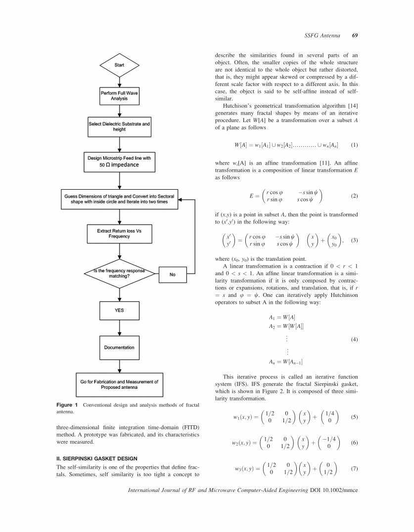
used to design the fractal antennas. The flow chart in
Figure 1 shows the conventional fractal antenna design and
analysis methods. The design phase of a fractal antenna
starts with design specification of frequencies. The dielec-
tric material is selected for the design. The full wave solver
is used to find the S-parameter versus frequency behavior of
the antenna. After calculating S-parameter of the structure
satisfactorily, fabrication and measurement could be done.
In this article, a Sectoral Sierpinski Gasket Fractal
(SSGF) antenna for dual wide-band application is pre-
sented. The proposed dual band antenna is developed
from Sierpinski Sectoral shape and is useful for miniaturi-
zation of the antenna structure. The antenna was designed
and optimized using CST microwave Studio based on the
Correspondence to: Y. K. Choukiker; e-mail: [email protected].
VC 2011 Wiley Periodicals, Inc.
DOI 10.1002/mmce.20585Published online 5 December 2011 in Wiley Online Library
(wileyonlinelibrary.com).
68
three-dimensional finite integration time-domain (FITD)
method. A prototype was fabricated, and its characteristics
were measured.
II. SIERPINSKI GASKET DESIGN
The self-similarity is one of the properties that define frac-
tals. Sometimes, self similarity is too tight a concept to
describe the similarities found in several parts of an
object. Often, the smaller copies of the whole structure
are not identical to the whole object but rather distorted,
that is, they might appear skewed or compressed by a dif-
ferent scale factor with respect to a different axis. In this
case, the object is said to be self-affine instead of self-
similar.
Hutchison’s geometrical transformation algorithm [14]
generates many fractal shapes by means of an iterative
procedure. Let W[A] be a transformation over a subset Aof a plane as follows
W A½ � ¼ w1 A1½ � [ w2 A2½ �………… [ wn An½ � (1)
where wi[A] is an affine transformation [11]. An affine
transformation is a composition of linear transformation Eas follows
E ¼ r cosur sinu
�s sinws cosw
� �(2)
if (x,y) is a point in subset A, then the point is transformed
to (x0,y0) in the following way:
x0
y0
� �¼ r cosu
r sinu�s sinws cosw
� �xy
� �þ x0
y0
� �; (3)
where (x0, y0) is the translation point.
A linear transformation is a contraction if 0 < r < 1
and 0 < s < 1. An affine linear transformation is a simi-
larity transformation if it is only composed by contrac-
tions or expansions, rotations, and translation, that is, if r¼ s and u ¼ w. One can iteratively apply Hutchinson
operators to subset A in the following way:
A1 ¼ W A½ �A2 ¼ W W A½ �½ �
..
.
..
.
An ¼ W An�1½ �
(4)
This iterative process is called an iterative function
system (IFS). IFS generate the fractal Sierpinski gasket,
which is shown in Figure 2. It is composed of three simi-
larity transformation.
w1 x; yð Þ ¼ 1=20
0
1=2
� �xy
� �þ 1=4
0
� �(5)
w2ðx; yÞ ¼ 1=20
0
1=2
� �xy
� �þ �1=4
0
� �(6)
w3 x; yð Þ ¼ 1=20
0
1=2
� �xy
� �þ 0
1=2
� �(7)
Figure 1 Conventional design and analysis methods of fractal
antenna.
SSFG Antenna 69
International Journal of RF and Microwave Computer-Aided Engineering DOI 10.1002/mmce

III. PROPOSED SSGF ANTENNA
The overall graphical representation of recursive proce-
dure for modified SSGF shape is shown in Figure 3. A
simple triangle model of height H with a ¼ 60� is con-
verted into sectoral shape, and a circle with diameter of Dis etched out from the geometry.
Figure 4 shows the design procedure of modified sec-
toral fractal antenna. A perturbed, two-iterated Sierpinski
fractal gasket of flare angle a ¼ 60� with different scale
factors and the SSFG antenna are shown in Figures 4a
and 4b, respectively. Finally, circle with diameter of D is
etched out from the SSFG antenna as shown in Figure 4c.
Here, it is possible to miniaturize the radiating patch by
etching circles.
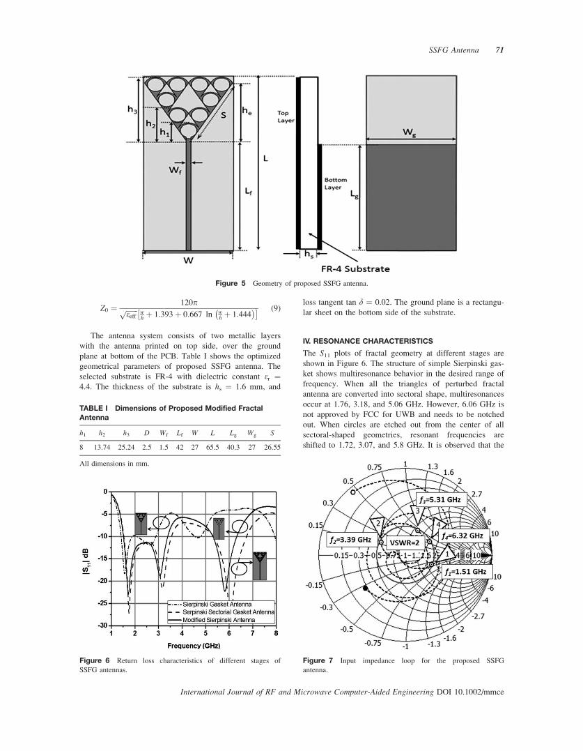
The geometry and dimensions of the configuration
under investigation are depicted in Figure 5 with different
scale factors (d1 ¼ h1/h2, d2 ¼ h2/h3). The double iterated
modified antenna model is fed with a 50-X microstrip line
(Wf � Lf), which is calculated using eqs. (8) and (9).
eeff ¼ er þ 1
2þ er þ 1
2
1ffiffiffiffiffiffiffiffiffiffiffiffiffiffiffiffiffi1þ 12 h
w
q264
375 (8)
Figure 2 Stage of the IFS that generates the Sierpinski gasket.
Figure 3 Basic antenna design procedure: (a) basic triangle, (b) sectoral shape, and (c) sector inscribing a circular gap.
Figure 4 Stages of antenna design: (a) perturbed Sierpinski gasket monopole, (b) sectoral shape Sierpinski gasket monopole, and (c)
proposed sectoral Sierpinski gasket fractal (SSFG) monopole.
70 Choukiker, Behera, and Jyoti
International Journal of RF and Microwave Computer-Aided Engineering/Vol. 22, No. 1, January 2012
Z0 ¼ 120pffiffiffiffiffiffiffieeff
p wh þ 1:393þ 0:667 ln w
h þ 1:444� �� � (9)
The antenna system consists of two metallic layers
with the antenna printed on top side, over the ground
plane at bottom of the PCB. Table I shows the optimized
geometrical parameters of proposed SSFG antenna. The
selected substrate is FR-4 with dielectric constant er ¼4.4. The thickness of the substrate is hs ¼ 1.6 mm, and
loss tangent tan d ¼ 0.02. The ground plane is a rectangu-
lar sheet on the bottom side of the substrate.
IV. RESONANCE CHARACTERISTICS
The S11 plots of fractal geometry at different stages are
shown in Figure 6. The structure of simple Sierpinski gas-
ket shows multiresonance behavior in the desired range of
frequency. When all the triangles of perturbed fractal
antenna are converted into sectoral shape, multiresonances
occur at 1.76, 3.18, and 5.06 GHz. However, 6.06 GHz is
not approved by FCC for UWB and needs to be notched
out. When circles are etched out from the center of all
sectoral-shaped geometries, resonant frequencies are
shifted to 1.72, 3.07, and 5.8 GHz. It is observed that the
Figure 5 Geometry of proposed SSFG antenna.
TABLE I Dimensions of Proposed Modified FractalAntenna
h1 h2 h3 D Wf Lf W L Lg Wg S
8 13.74 25.24 2.5 1.5 42 27 65.5 40.3 27 26.55
All dimensions in mm.
Figure 6 Return loss characteristics of different stages of
SSFG antennas.
Figure 7 Input impedance loop for the proposed SSFG
antenna.
SSFG Antenna 71
International Journal of RF and Microwave Computer-Aided Engineering DOI 10.1002/mmce

downward shift in resonant frequency for initial structure
is more comparable with the modified antenna structure.
Figure 7 shows the input impedance (SWR ¼ 2) locus
for both the bands, when circles are etched out from the sec-
toral shape. It is observed that the input impedance of the
proposed SSGF antenna is same for both the bands. It would
be easier to place both loops at the center of the smith chart.
Figure 8 shows the parametric study of circle with dif-
ferent diameters. It is observed that when the diameter of
the circle is increased to the optimum point, upper fre-
quency shifts from 6.06 to 5.8 GHz; a 17.3% bandwidth
centered at 5.8 GHz (5.31–6.32 GHz) is obtained, which
is suitable for WLAN applications.
Figure 9 shows the simulated and measured S11 plots
of the proposed SSGF antenna. It is observed that the sim-
ulation and measurement results are in good agreement
and exhibit dual resonances. The measured �10 dB im-
pedance bandwidth for lower band is 76.7% (1.51–3.39
GHz) and for upper band 17.3% (5.31–6.32 GHz). The
measured bandwidth meets the requirements of many
commercial bands such as GPS (1.51–2.6 GHz), DCS-
1800 (1.71–1.88 GHz), PCS-1800 (1.80–1.99 GHz),
UMTS (1.92–2.17 GHz), IMT-2000 (1.9–2.2 GHz), Wire-
less broadband Internet Services (WiBro; 2.3–2.4 GHz),
Bluetooth (2.4–2.48 GHz), and WLAN (802.11b/g/a)
(2.4–2.485 GHz and 5.31–6.32 GHz).
It can be seen that the SSGF antenna matched approxi-
mately at frequencies [17]
fr ¼ð0:15345þ 0:34 qxÞ c
heðn�1Þn for n ¼ 0
0:26c
hedn for n > 0
;
8><>: (10)
where c is the speed of light, n is the band number (n ¼0, i.e., band 1 and n ¼ 1, i.e., band 2), he is the effective
height of the gasket, n ¼ hnhnþ1
is the ration of the height of
the gasket in the nth iteration to that in the (nþ1) itera-
tion, d is the scale factor 1n
� , x ¼ 0 k ¼ 0
1 k > 0
, and k is
the number of iterations.
Figure 8 Return loss characteristics of circle with different
diameters. [Color figure can be viewed in the online issue, which
is available at wileyonlinelibrary.com.]
Figure 9 Experimental and simulation results for return loss of
SSFG antenna.
Figure 10 Radiation pattern characteristics at (a) 1.72 GHz, (b) 3.07 GHz, and (c) 5.8 GHz. [Color figure can be viewed in the online
issue, which is available at wileyonlinelibrary.com.]
72 Choukiker, Behera, and Jyoti
International Journal of RF and Microwave Computer-Aided Engineering/Vol. 22, No. 1, January 2012
For proposed SSFG antenna, the effective height, he ofthe Sierpinski gasket is given by [21]:
he ¼ffiffiffi3
pSe2
(11)
where
Se ¼ Sþ hsðerÞ�0:5(12)
with hs being the thickness of the substrate and S the side
length of SSGF antenna.
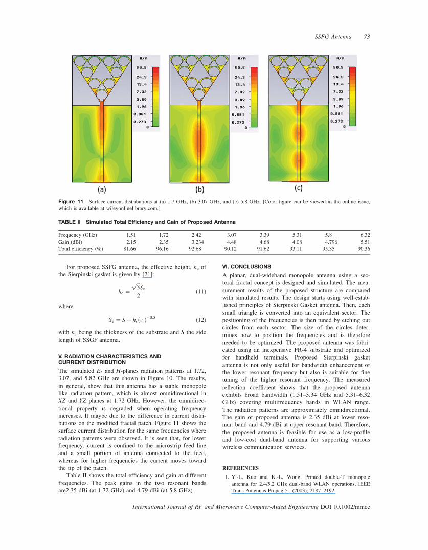
V. RADIATION CHARACTERISTICS ANDCURRENT DISTRIBUTION
The simulated E- and H-planes radiation patterns at 1.72,
3.07, and 5.82 GHz are shown in Figure 10. The results,
in general, show that this antenna has a stable monopole
like radiation pattern, which is almost omnidirectional in
XZ and YZ planes at 1.72 GHz. However, the omnidirec-
tional property is degraded when operating frequency
increases. It maybe due to the difference in current distri-
butions on the modified fractal patch. Figure 11 shows the
surface current distribution for the same frequencies where
radiation patterns were observed. It is seen that, for lower
frequency, current is confined to the microstrip feed line
and a small portion of antenna connected to the feed,
whereas for higher frequencies the current moves toward
the tip of the patch.
Table II shows the total efficiency and gain at different
frequencies. The peak gains in the two resonant bands
are2.35 dBi (at 1.72 GHz) and 4.79 dBi (at 5.8 GHz).
VI. CONCLUSIONS
A planar, dual-wideband monopole antenna using a sec-
toral fractal concept is designed and simulated. The mea-
surement results of the proposed structure are compared
with simulated results. The design starts using well-estab-
lished principles of Sierpinski Gasket antenna. Then, each
small triangle is converted into an equivalent sector. The
positioning of the frequencies is then tuned by etching out
circles from each sector. The size of the circles deter-
mines how to position the frequencies and is therefore
needed to be optimized. The proposed antenna was fabri-
cated using an inexpensive FR-4 substrate and optimized
for handheld terminals. Proposed Sierpinski gasket
antenna is not only useful for bandwidth enhancement of
the lower resonant frequency but also is suitable for fine
tuning of the higher resonant frequency. The measured
reflection coefficient shows that the proposed antenna
exhibits broad bandwidth (1.51–3.34 GHz and 5.31–6.32
GHz) covering multifrequency bands in WLAN range.
The radiation patterns are approximately omnidirectional.
The gain of proposed antenna is 2.35 dBi at lower reso-
nant band and 4.79 dBi at upper resonant band. Therefore,
the proposed antenna is feasible for use as a low-profile
and low-cost dual-band antenna for supporting various
wireless communication services.
REFERENCES
1. Y.-L. Kuo and K.-L. Wong, Printed double-T monopole
antenna for 2.4/5.2 GHz dual-band WLAN operations, IEEE
Trans Antennas Propag 51 (2003), 2187–2192.
Figure 11 Surface current distributions at (a) 1.7 GHz, (b) 3.07 GHz, and (c) 5.8 GHz. [Color figure can be viewed in the online issue,
which is available at wileyonlinelibrary.com.]
TABLE II Simulated Total Efficiency and Gain of Proposed Antenna
Frequency (GHz) 1.51 1.72 2.42 3.07 3.39 5.31 5.8 6.32
Gain (dBi) 2.15 2.35 3.234 4.48 4.68 4.08 4.796 5.51
Total efficiency (%) 81.66 96.16 92.68 90.12 91.62 93.11 95.35 90.36
SSFG Antenna 73
International Journal of RF and Microwave Computer-Aided Engineering DOI 10.1002/mmce
2. C.-M. Su, H.-T. Chen, and K.-L. Wong, Printed dual-band
dipole antenna with U-slotted arms for 2.4/5.2 GHz WLAN
operation, Electron Lett 38 (2002), 1308–1309.
3. D.-U. Sim and J.-I. Choi, A compact wideband modified planar
inverted F antenna (PIFA) for 2.4/5-GHz WLAN applications,
IEEE Antennas Wireless Propag Lett 5 (2006), 391–394.
4. Y.-C. Lin and K.-J. Hung, Design of dual-band slot antenna
with double T-match stubs, Electron Lett 42 (2006), 438–439.
5. Y. Song, J.C. Modro, Z. Wu, and P. O’Riordan, Miniature mul-
tiband and wideband 3-D slot loop antenna for mobile termi-
nals, IEEE Antennas Wireless Propag Lett 5 (2006), 148–151.
6. R. Li, B. Pan, A.N. Traille, and M.M. Tentzeris, Develop-
ment of a cavity-backed broadband circularly polarized slot/
strip loop antenna with a simple feeding structure, IEEE
Trans Antennas Propag 56 (2008), 312–318.
7. W.-S. Chen and K.-L. Wong, Dual-frequency operation of a
coplanar waveguide-fed dual-slot loop antenna, Microwave
Opt Technol Lett 30 (2001), 38–40.
8. Y.-C. Chen, S.-Y. Chen, and P. Hsu, ‘‘Dual-band slot dipole
antenna fed by a coplanar waveguide,’’ IEEE, Antennas andPropagation Society International Symposium 2006, pp.
3589–3592, 9–14 July 2006.
9. M. Nedil, T.A. Denidni, and L. Talbi, Wideband slot antenna
using a new feeding technique for wireless applications, Int J
RF Microwave Comput Aided Eng 16 (2006), 125–134.
10. P. Piazzesi, S. Maci, and G.B. Gentili, Dual-band, dual-polar-
ized patch antennas.Int J Microwave Millimeter-Wave Com-
put Aided Eng 5 (1995), 375–384.
11. N.P. Agrawall, G. Kumar, K.P. Ray, Wideband planar monop-
ole antennas, IEEE Trans Antenna Propag 46 (1998), 294–295.
12. Y. Duroc, A. Ghiotto, T.P. Vuong, and S. Tedjini, On the
characterization of UWB antennas, Int J RF Microwave Com-
put Aided Eng 19 (2009), 258–269.
13. G. Augustin, S.V. Shynu, P. Mohanan, C.K. Aanandan, and
K. Vasudevan, Compact dual-band antenna for wireless
access point, Electron Lett 42 (2006), 502–503.
14. D.H. Werner and R. Mittra, Frontier of electromagnetic,
Wiley-IEEE Press, New York, 1999.
15. H. Jones, A.J. Crilly, and R.A. Earnsshaw, ‘‘Fractals and
chaos’’, Springer-Verlag, New York, (1990).
16. B.B. Mandelbort, The fractal geometry of nature, in A.J.
Crilly, R.A. Earnsshaw, and H. Jones, Eds., Freeman, San
Francisco, CA, 1983.
17. H.O. Peitgen, et al., Chaos and Fractals, in A.J. Crilly, R.A. Earn-
sshaw, and H. Jones, Eds., Springer-Verlag, New York, 1990.
18. D.H. Werner and S. Ganguly, An overview of fractal antenna engi-
neering research, IEEE Antennas Propag Mag 45 (2003), 38–57.
19. C. Puente, J. Romeu, R. Pous, and A. Cardama, On the
behaviour of the Sierpinski multiband fractal antenna, IEEE
Trans Antennas Propag 46 (1998), 517–524.
20. CST MICROWAVE STUDIO 2010, Computer Simulation
Technology, Wellesley Hills, MA.
21. R.K. Mishra, R. Ghatak, and D.R. Poddar, Design formula
for Sierpinski Gasket Pre fractal Planar monopole antennas,
IEEE Antenna Propag Mag 50 (2008), 104–107.
BIOGRAPHIES
Yogesh Kumar Choukiker is born in
Madhya Pradesh, India. He received the
B.E. degree in Electronics and Commu-
nication Engineering from Rajiv Gan-
dhi Technical University, Bhopal, India
in year 2007 and M.Tech in Telematics
and Signal Processing from National
Institute of Technology, Rourkela, India
in the year 2009. Currently, he is pursuing Ph.D in the Depart-
ment of Electronics and Communication, National Institute of
Technology, Rourkela, India. His areas of interest are Micro-
wave, Microstrip Antenna, Fractal Antenna, and Optimization
Techniques. He is a Student Member of IEEE (USA).
Santanu K. Behera received the B.Sc.
(Engg) degree from UCE Burla, Sam-
balpur University in the year 1990, ME
and PhD (Engg) from Jadavpur Univer-
sity in the year 2001 and 2008, respec-
tively. He is presently working as an
Associate Professor in the Department
of Electronics and Communication
Engineering, National Institute of Technology Rourkela, India.
His current research interests include Planar Antenna; Dielec-
tric Resonator Antenna and Metamaterials. Dr. Behera is a Life
Member of IETE (India), Computer Society of India, Society
of EMC Engineers (India), ISTE (India), and Member of IEEE
(USA). He is a reviewer for ICTACT Journal of Communica-
tion Technology, India and IETE Journal of Research India.
Rajeev Jyoti (IEEE M06, SM07)
received his M.Sc. Physics (1984) and
M.Tech. Microwave Electronics
(1986) from Delhi University. Since
1987, he is involved in the develop-
ment of antennas required for satellite
communication in Space Applications
Centre. Presently, he is Group Director
of Antenna Systems Group, SAC,
ISRO, India. He has more than 24 years experience in devel-
opment of space borne and ground antennas in Space Appli-
cations Centre, Ahmadabad. As a Project Manager of GSAT
1 communication satellite he has successfully delivered
flight model reflector antennas at S and C band. He has been
involved in the development of tracking cum communication
feed systems for various earth station antenna. He has con-
tributed significantly in design, analysis, and development of
microwave antennas namely gridded antenna, multiple beam
antennas, multilayer antenna, and phased array antennas for
INSAT/GSAT, RISAT, DMSAR projects. As a Deputy Pro-
ject Director, RISAT (Antenna), he has successfully deliv-
ered phased array multilayer antenna. He has been awarded
with ISRO Team Excellence Awards, 2007. Mr. Rajeev Jyoti
is Fellow Member of IETE and senior member of IEEE
India. He is Chair of IEEE MTT-AP chapter of Gujarat. He
has published more than 60 papers in various conferences
and referred journals. He has 12 patents to his credit. He was
awarded UN ESA long-term fellowship in Antenna and
Propagation at ESTEC/ESA Noordwijk.
74 Choukiker, Behera, and Jyoti
International Journal of RF and Microwave Computer-Aided Engineering/Vol. 22, No. 1, January 2012
Related Documents
![Sierpinski (Sierpinski gasket)poseidon.csd.auth.gr/New_Courses/graphics/lectures/... · glBegin(GL_POINTS); glColor3f(p[0]/250.0, p[1]/250.0, p[2]/250.0); glVertex3fv(p); glEnd();](https://static.cupdf.com/doc/110x72/5f647cced0fcce57580447b9/sierpinski-sierpinski-gasket-glbeginglpoints-glcolor3fp02500-p12500.jpg)


![Eikonal equations on the Sierpinski gasket[1] · 2014-12-08 · Eikonal equations on the Sierpinski gasket1 Fabio Camilli SBAI-"Sapienza" Università di Roma 1F. CAMILLI, R.CAPITANELLI,](https://static.cupdf.com/doc/110x72/5f1304de21091045cc503936/eikonal-equations-on-the-sierpinski-gasket1-2014-12-08-eikonal-equations-on.jpg)