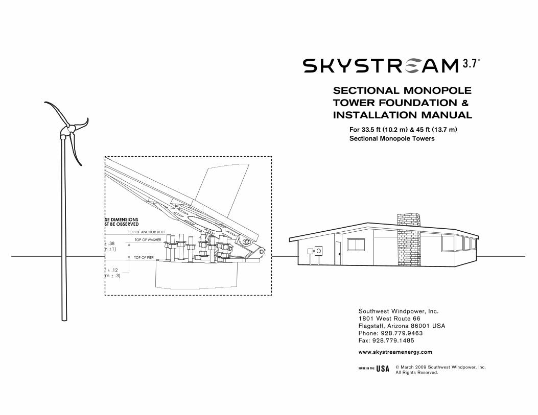
Southwest Windpower, Inc. 1801 West Route 66 Flagstaff, Arizona 86001 USA Phone: 928.779.9463 Fax: 928.779.1485 www.skystreamenergy.com SECTIONAL MONOPOLE TOWER FOUNDATION & INSTALLATION MANUAL March 2009 Southwest Windpower, Inc. All Rights Reserved. TOP OF PIER TOP OF ANCHOR BOLT TOP OF WASHER SE DIMENSIONS ST BE OBSERVED m 1) .38 cm .3) " .12 For 33.5 ft (10.2 m) & 45 ft (13.7 m) Sectional Monopole Towers

Welcome message from author
This document is posted to help you gain knowledge. Please leave a comment to let me know what you think about it! Share it to your friends and learn new things together.
Transcript
Southwest Windpower, Inc.1801 West Route 66Flagstaff, Arizona 86001 USAPhone: 928.779.9463Fax: 928.779.1485
www.skystreamenergy.com
sectional MonoPole toWeR FoUnDation &installation ManUal
March 2009 Southwest Windpower, Inc. All Rights Reserved.
TOP OF PIER
TOP OF ANCHOR BOLT
TOP OF WASHER
THESE DIMENSIONS MUST BE OBSERVED
7.00" (17.8cm 1)
.38
(11.1cm .3)4.38" .12
Southwest Windpower
5 4 3 2 1
----ECO#--NC
REVISIONSREV.
.XXX ± .002 .XX ± .05 HINGE-PIER CONNECTIONT. George 01/12/09
Flagstaff, Arizona U.S.A.
MONOPOLE TOWER
do not manually update
scale 1: 8 size A
CAD file :
dwg #sheet 1 of 1rev. NC
DATEAPPROVALS
DRAWN
R&D
PROD EGR
MFG
QUAL
MATERIAL:FINISH:DO NOT SCALE DRAWING
DWG #-------------------
CAD-generated drawing
.X ± .1 ± 30 ' decimals angles
other purpose except as specifically authorized in writing by Southwest Windpower.
APPROVEDDATEDESCRIPTION
unless otherwise specifieddimensions are inches tolerances are :
Proprietary rights are included in the information disclosed herein. This information issubmitted in confidence and neither the document nor the information disclosed here-in shall be reproduced or transferred to other documents for manufacturing or for any
--
For 33.5 ft (10.2 m) & 45 ft (13.7 m) Sectional Monopole Towers
2 Sectional Monopole Tower Foundation & Installation Manual, Revision A
Table of Contents
Important Safety Instructions ______________________________ 3
PRIOR TO INSTALLATION _______________________________ 4
Introduction _________________________________________ 4
Building Permits & Zoning Requirements ________________ 4
Installation Personnel ________________________________ 5
Siting - Finding the Best Location for Skystream __________ 6-7
CONSTRUCTING THE FOUNDATION _____________________ 8
Foundation Drawings _________________________________ 8
Wind Zones ________________________________________ 8
Soil Conditions _____________________________________ 9
Selecting A Foundation Configuration ___________________ 10
Foundation Bolts & Templates (Pier & Mat Foundations) ___ 10
Foundation Bolts & Templates (SMarT Foundation) ______ ___10
Positioning the Foundations Bolts (Pier & Mat Foundations) __11-12
Positioning the Foundations Bolts (SMarT Foundation) ____ 13
Electrical Conduit ____________________________________ 13
Completing the Foundation ____________________________ 13
TOWER INSTALLATION _________________________________ 14
Introduction _________________________________________ 14
Hinge Plate Installation _______________________________ 14-15
Gin Pole Installation _________________________________ 16
Sectional Monopole Tower Foundation and Installation ManualDocument : 3-CMLT-1367-01Revision: A
Raising the Tower ___________________________________ 17-18
Adjusting Cable Length ______________________________ 17-18
Lowering the Tower __________________________________ 19
Leveling the Tower __________________________________ 20
Tightening Foundation Bolts __________________________ 20
APPENDICES
Appendix A: 33.5 ft (10.2 m) Monopole Tower Foundations
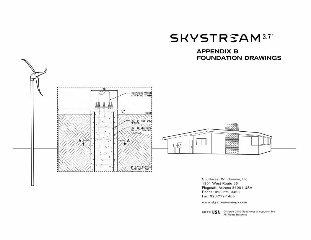
Appendix B: 45 ft (13.7 m) Monopole Tower Foundations
Appendix C: SMarT Foundation Assembly and Drawings
Sectional Monopole Tower Foundation & Installation Manual, Revision A 3
IMPORTANT SAFETy INSTRUCTIONSREAD THESE INSTRUCTIONS IN THEIR ENTIRETy bEFORE INSTALLING.
TIP: Helpful information to ease the installation
Warning: Risk of injury or death - proceed with extreme caution
Professional installation highly recommended
In this manual
IMPORTANT: Please take note
1) SAVE THESE INSTRUCTIONS. This manual contains important instructions for constructing foundations, and raising, lowering and leveling towers that MUST be followed.
2) Read, Understand and Follow all warnings.
3) Read these instructions in their entirety before starting foundation construction and tower installation.
4) Install foundation and tower in accordance with National Electric Code, and all local building and zoning codes and requirements.
5) Obtain building and construction permits prior to starting construction.
6) Foundation concrete must be completely cured prior to installing tower [Minimum 2500 PSI, (17235 kPa) 28 day strength].
7) Skystream uses high voltage and is potentially dangerous. Follow all safety precautions at all times.
8) Follow proper grounding procedures for tower, foundation and windturbine.
9) Remain at a safe distance when raising and lowering tower. NEVER stand or walk under tower while it is being raised or lowered.
10) Be aware of overhead power lines.
11) Do not attempt to raise tower on a windy day.
12) Always wear personal protection equipment – closed toe shoes, work gloves, safety glasses, and hardhat.
4 Sectional Monopole Tower Foundation & Installation Manual, Revision A
PRIOR TO INSTALLATION
Introduction
This manual provides information for the construction of a foundation suitable for installing Southwest Windpower’s Skystream 3.7 on one of the following Southwest Windpower towers:
• 33.5 ft (10.2 m) Monopole Sectional Tower, part number 3-CMBP-3218• 45 ft (13.7 m) Monopole Sectional Tower, part number 3-CMBP-3219
Information for four different “styles” of foundation is provided. The choice of foundation will depend on local building conditions, available construction equipment, and local regulations. The four styles of foundation include:
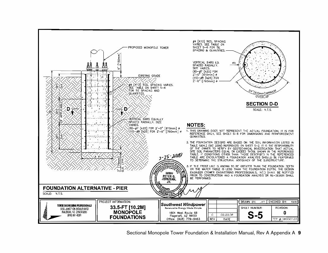
• Pier Foundation – A “column” shaped foundation; diameter and depth vary depending on soil conditions and maximum wind speed.
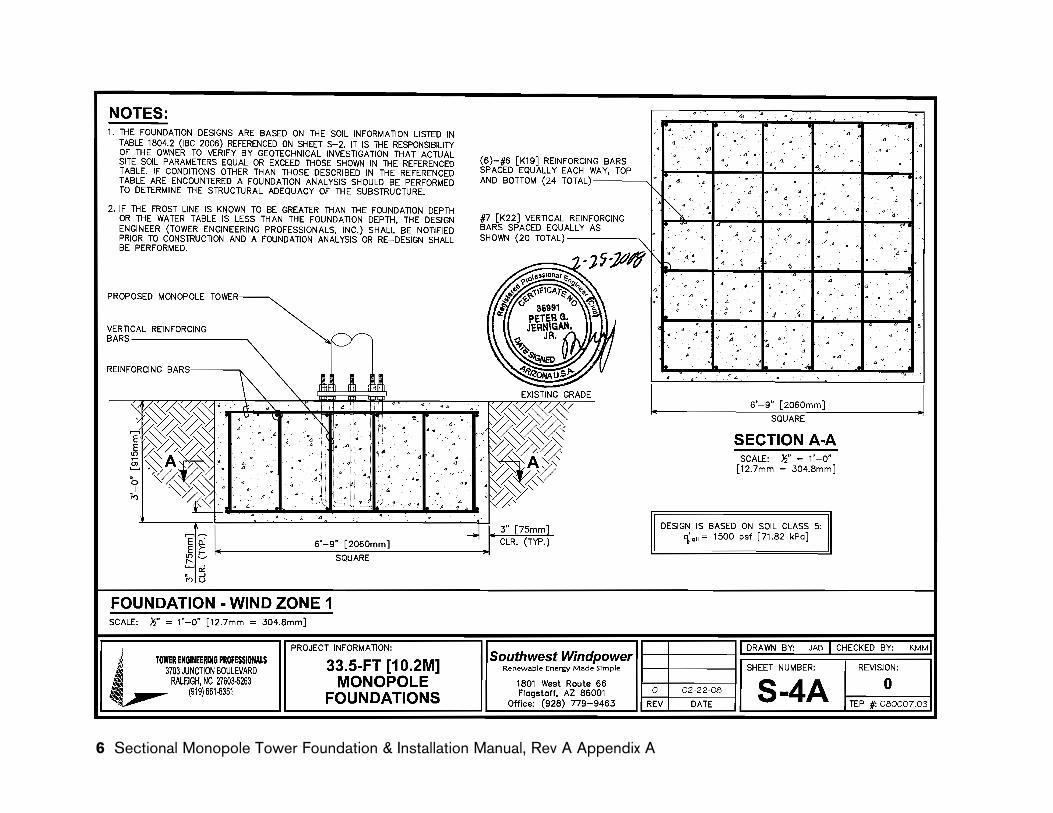
• Mat Foundation [33.5 ft (10.2 m) tower only] – A “square” shaped foundation; length, width and depth vary depending on soil conditions and maximum wind speed.
• Pad and Pier Foundation [45 ft (13.7 m) tower only] – An alternative to the Pier foundation – may be easier to construct than Pier foundation if an auger is not available.
• SMarT Foundation™ - manufactured by AnemEronics Inc. , this foundation utilizes a “kit” that is specially designed to construct a foundation for Southwest Windpower’s Monopole Towers.
For the Pier and Mat foundations, the information in the manual is sufficient for individuals knowledgeable in working with concrete to construct the founda-tions. The manual provides useful tips about critical areas of construction, however it does not provide “step by step” instructions for these foundations. It assumes constructor is has the knowledge and experience to complete the foundation.
Detailed instructions are provided for the SMarT Foundation in Appendix C. The SMarT Foundation kit was designed specifically for Southwest Windpower’s Monopole towers and may be utilized by both experienced and amateur installers. The unique design of the SMarT foundation provides material and construc-tion time savings compared to a conventional foundation.
Directions for raising, leveling, and lowering the tower are provided in this manual, refer to the Skystream Owner’s Manual for instructions for installing Skystream on the tower.
IMPORTANT NOTE:
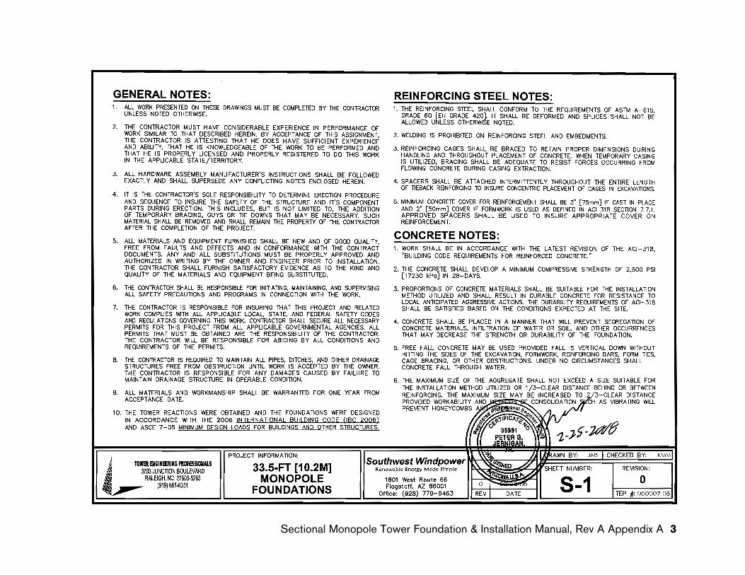
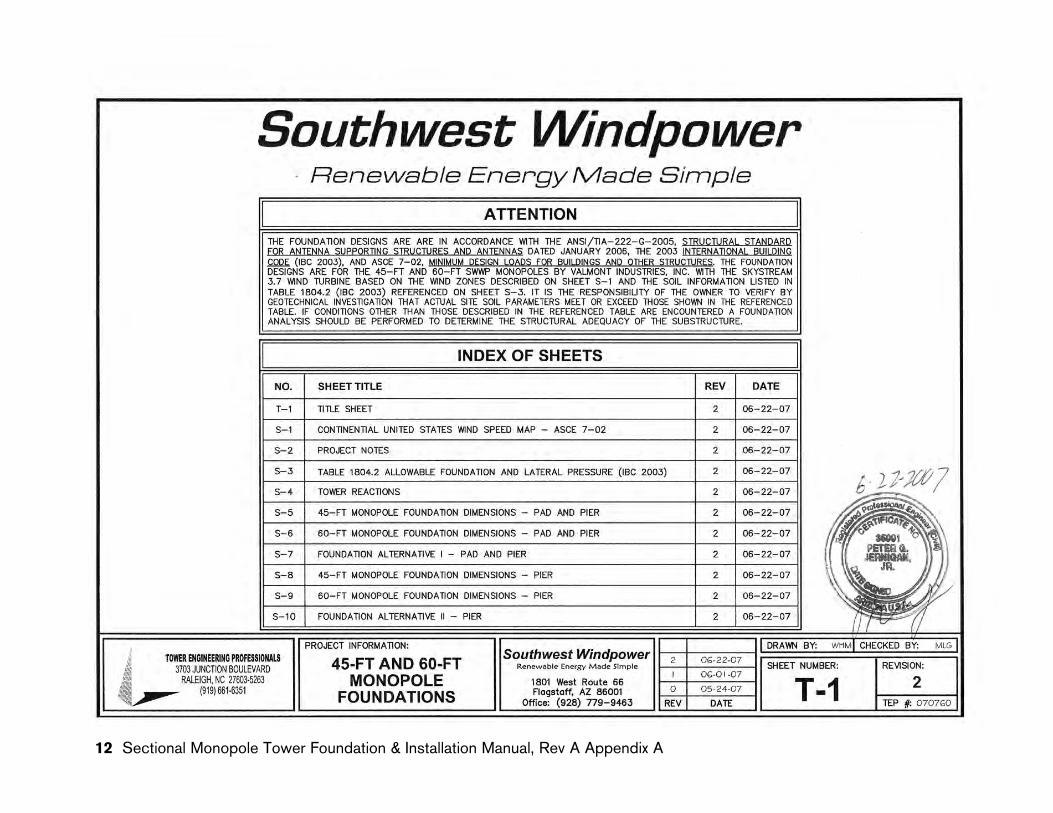
The foundation drawings contained in the Appendices of this manual present foundations designed in accordance with the 2006 INTERNATIONAL bUILDING CODE (IbC 2006) and ASCE 7-05 MINIMUM DESIGN LOADS FOR bUILDINGS AND OTHER STRUCTURES. These drawings may therefore not be appropriate in localities with construction requirements that differ from these standards.
Sectional Monopole Tower Foundation & Installation Manual, Revision A 5
Installation Personnel
Southwest Windpower strongly recommends professional construction of the foundation. Constructing the foundation requires specialized equipment, experience constructing concrete forms and knowledge of local zoning and building codes and inspection requirements.
Skystream Dealer
Skystream Owners who are considering constructing “any or all” of their foundation, or raising their own tower should completely review this manual and the Skystream Owners manual before proceeding. Working with high voltage electricity, constructing foundations and raising and lowering towers can be dangerous. And mistakes can be expensive. Understand what you are getting into before starting.
Owners should also be aware that many localities require installation by “certified installers” or by licensed contrac-tors to qualify for clean energy monetary rebates.
If you decide not to install the tower yourself, dealers displaying the “Skystream Dealer” insignia shown here, have completed factory training on the correct and safe installation of the tower (and Skystream).
IMPORTANT: Do not pour concrete before all required permits are obtained, inspec-tions completed, and you are authorized to proceed.
building Permits and Zoning Requirements
Building codes and installation requirements may vary greatly depending on state, city, and local town-ships. Be sure to obtain all required building permits BEFORE beginning the installation.
Be sure you understand all installation and inspection requirements. Many localities require inspections at key phases of the installation before additional work can proceed.
6 Sectional Monopole Tower Foundation & Installation Manual, Revision A
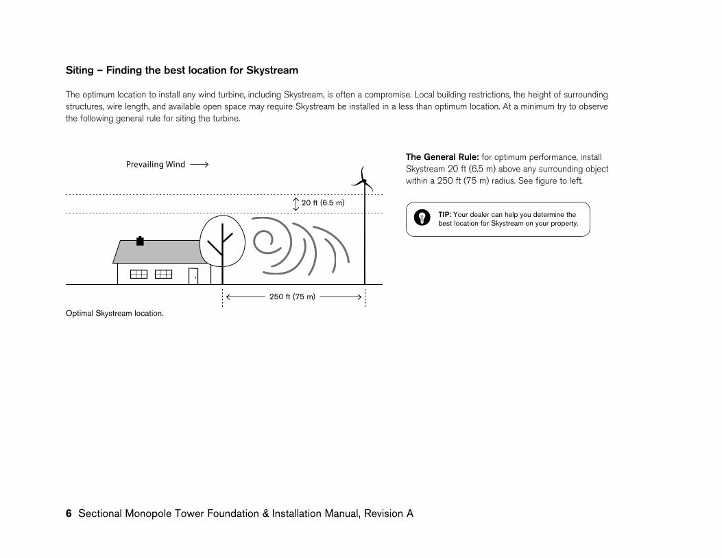
Siting – Finding the best location for Skystream
The optimum location to install any wind turbine, including Skystream, is often a compromise. Local building restrictions, the height of surrounding structures, wire length, and available open space may require Skystream be installed in a less than optimum location. At a minimum try to observe the following general rule for siting the turbine.
TIP: Your dealer can help you determine the best location for Skystream on your property.
75 m
6.5 m
Prevailing Wind
Optimal Skystream location.
The General Rule: for optimum performance, install Skystream 20 ft (6.5 m) above any surrounding object within a 250 ft (75 m) radius. See figure to left.
20 ft (6.5 m)
250 ft (75 m)
Sectional Monopole Tower Foundation & Installation Manual, Revision A 7
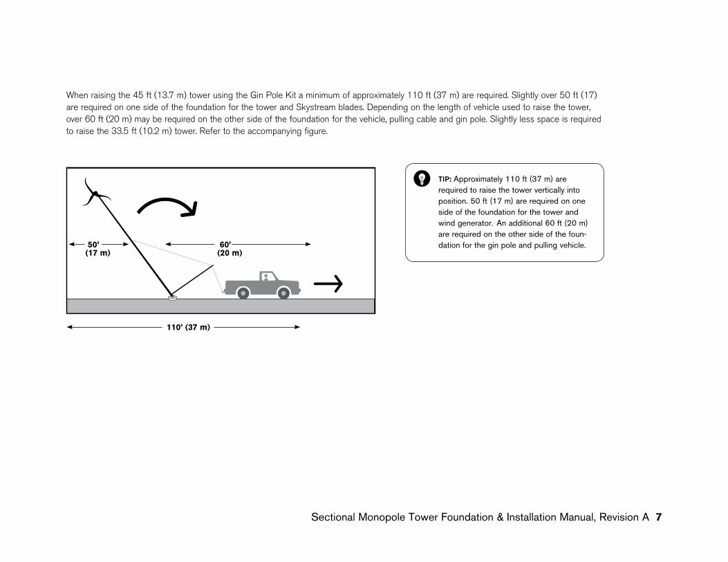
When raising the 45 ft (13.7 m) tower using the Gin Pole Kit a minimum of approximately 110 ft (37 m) are required. Slightly over 50 ft (17) are required on one side of the foundation for the tower and Skystream blades. Depending on the length of vehicle used to raise the tower, over 60 ft (20 m) may be required on the other side of the foundation for the vehicle, pulling cable and gin pole. Slightly less space is required to raise the 33.5 ft (10.2 m) tower. Refer to the accompanying figure.
TIP: Approximately 110 ft (37 m) are required to raise the tower vertically into position. 50 ft (17 m) are required on one side of the foundation for the tower and wind generator. An additional 60 ft (20 m) are required on the other side of the foun-dation for the gin pole and pulling vehicle.
110’ (37 m)
50’ (17 m)
60’ (20 m)
8 Sectional Monopole Tower Foundation & Installation Manual, Revision A
CONSTRUCTING THE FOUNDATION
Foundation Drawings
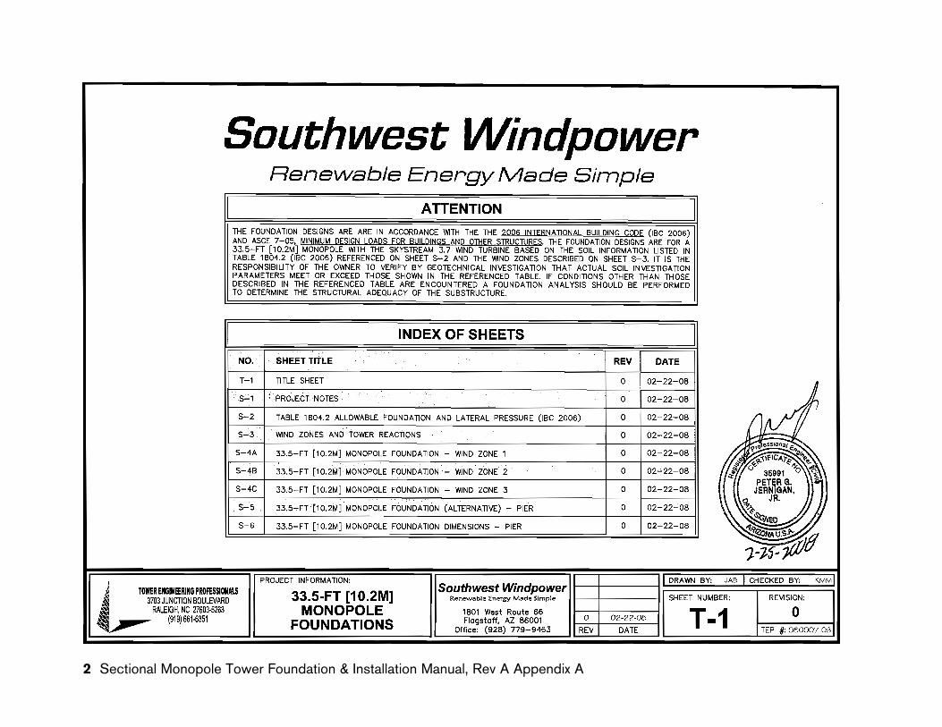
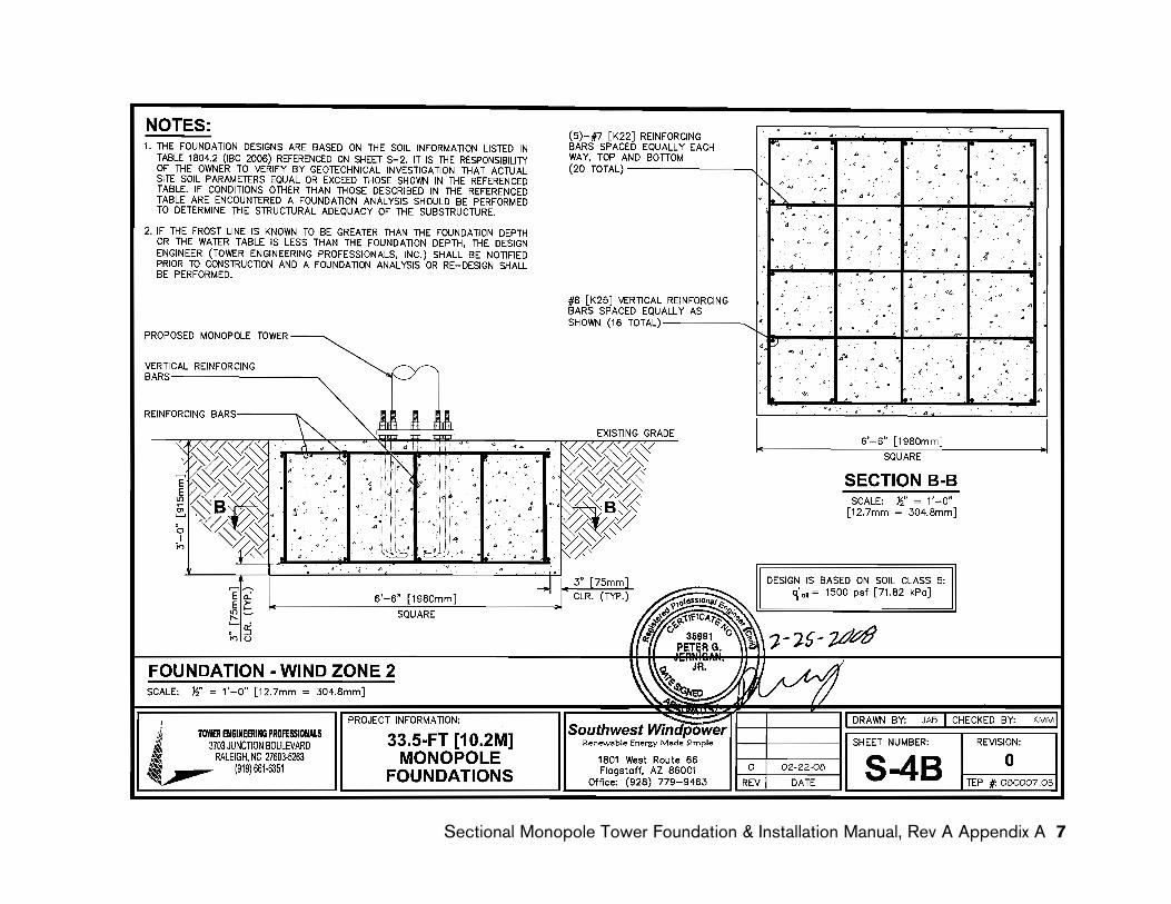
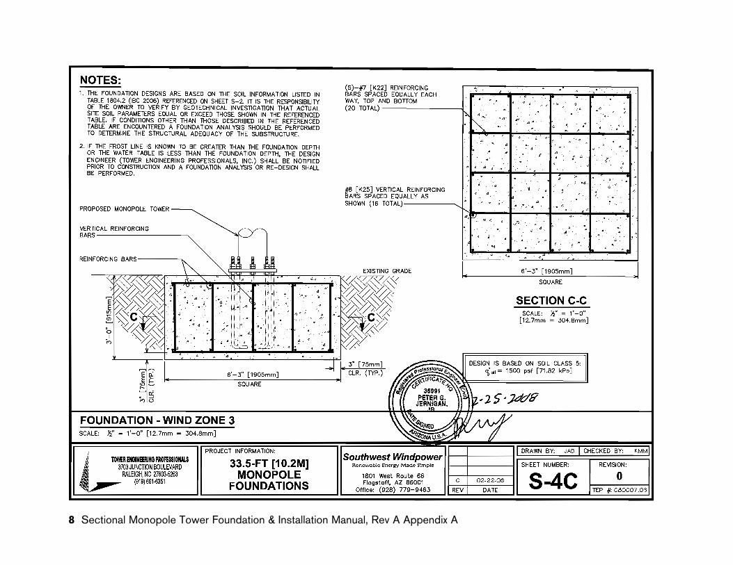
Detailed technical drawings for the Pier, Mat and SMarT foundations are provided in Appendices A, B and C respectively. The drawings are also available on Southwest Windpower’s website (www.skystreamenergy.com). The drawings were prepared by Tower Engineering Professionals (TEP), Raleigh, North Carolina and reviewed and certified by a State of Arizona Registered Professional Engineer.
The drawings are provided as a reference to assist with obtaining building permits and with the construction approval process.
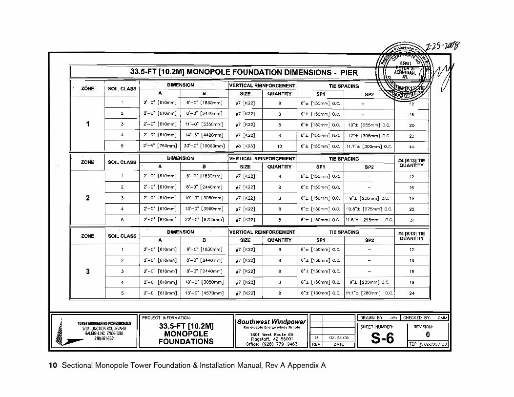
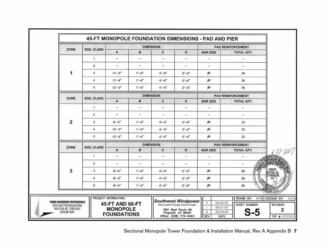
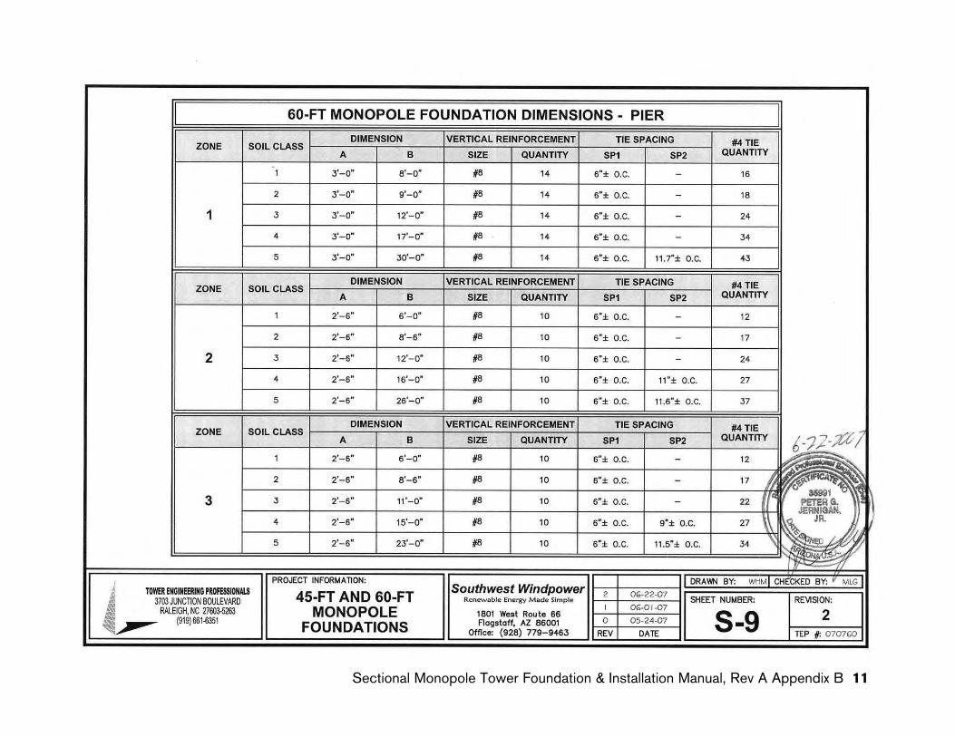
Note the foundation dimensions for the Pier and Pad, and Pier founda-tions will vary based on the Soil Class and Wind Zone. The dimensions for the SMarT and Mat foundations do not vary based on soil conditions. These foundations assume Soil Class 5 (worst case) conditions exist and are sized accordingly.
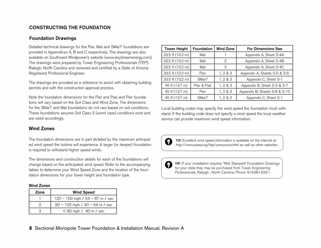
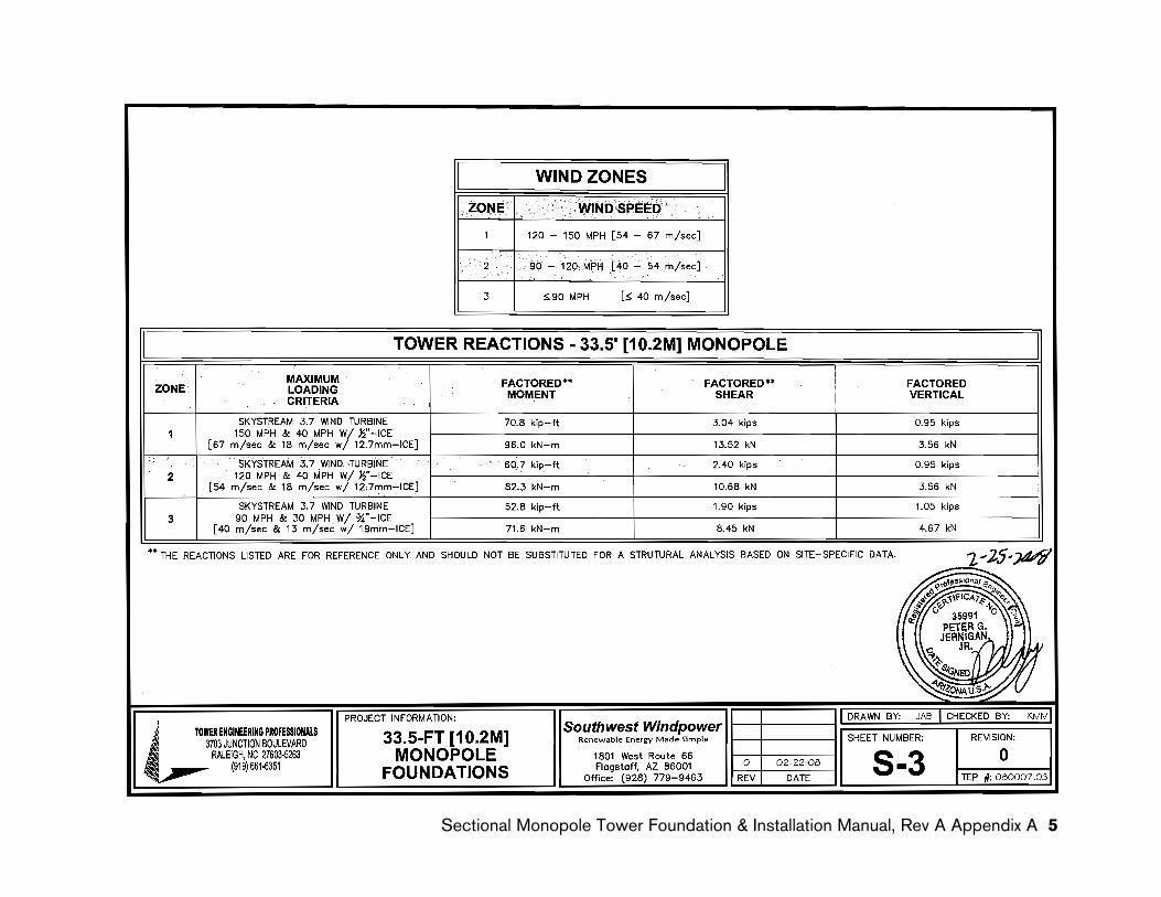
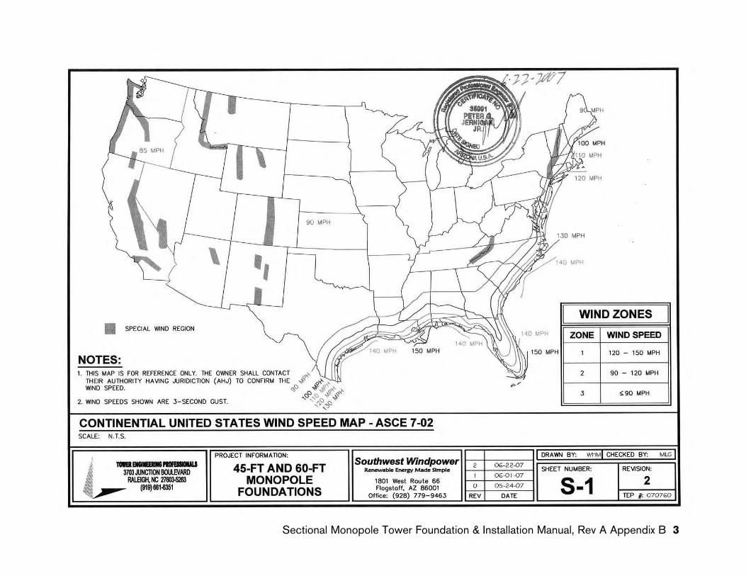
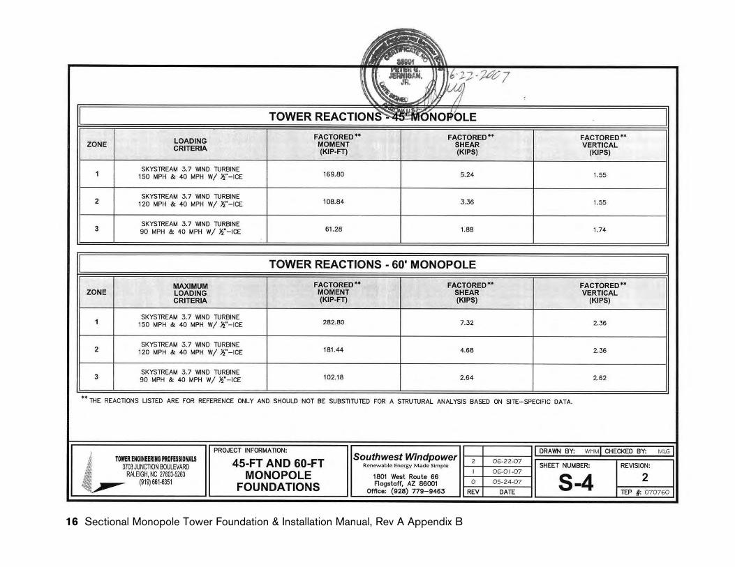
Wind Zones
The foundation dimensions are in part dictated by the maximum anticipat-ed wind speed the turbine will experience. A larger (or deeper) foundation is required to withstand higher speed winds.
The dimensions and construction details for each of the foundations will change based on the anticipated wind speed. Refer to the accompanying tables to determine your Wind Speed Zone and the location of the foun-dation dimensions for your tower height and foundation type.
Wind Zones
Zone Wind Speed
1 120 – 150 mph / 54 – 67 m / sec
2 90 – 120 mph / 40 – 54 m / sec
3 < 90 mph / 40 m / sec
TIP: Excellent wind speed information is available on the internet at http://www.awea.org/faq/usresource.html as well as other websites.
Tower Height Foundation Wind Zone For Dimensions See
33.5 ft (10.2 m) Mat 1 Appendix A, Sheet S-4A
33.5 ft (10.2 m) Mat 2 Appendix A, Sheet S-4B
33.5 ft (10.2 m) Mat 3 Appendix A, Sheet S-4C
33.5 ft (10.2 m) Pier 1, 2 & 3 Appendix A, Sheets S-5 & S-6
33.5 ft (10.2 m) SMarT 1, 2 & 3 Appendix C, Sheet S-1
45 ft (13.7 m) Pier & Pad 1, 2 & 3 Appendix B, Sheet S-5 & S-7
45 ft (13.7 m) Pier 1, 2 & 3 Appendix B, Sheets S-8 & S-10
45 ft (13.7 m) SMarT 1, 2 & 3 Appendix C, Sheet S-1
Local building codes may specify the wind speed the foundation must with-stand. If the building code does not specify a wind speed the local weather service can provide maximum wind speed information.
TIP: If your installation requires “Wet Stamped” Foundation Drawings for your state they may be purchased from Tower Engineering Professionals, Raleigh , North Carolina. Phone: 919.661.6351.
Sectional Monopole Tower Foundation & Installation Manual, Revision A 9
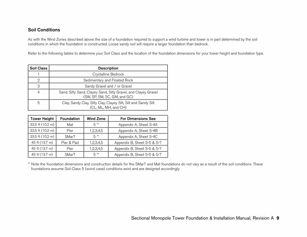
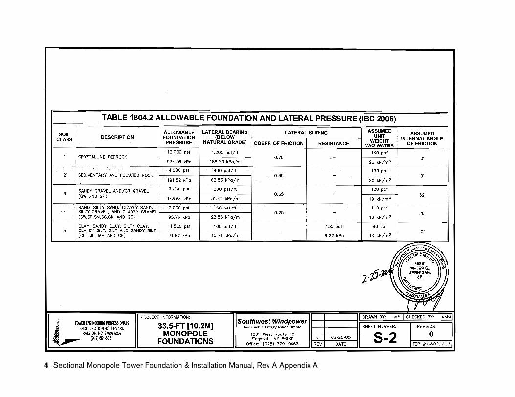
Soil Conditions
As with the Wind Zones described above the size of a foundation required to support a wind turbine and tower is in part determined by the soil conditions in which the foundation is constructed. Loose sandy soil will require a larger foundation than bedrock.
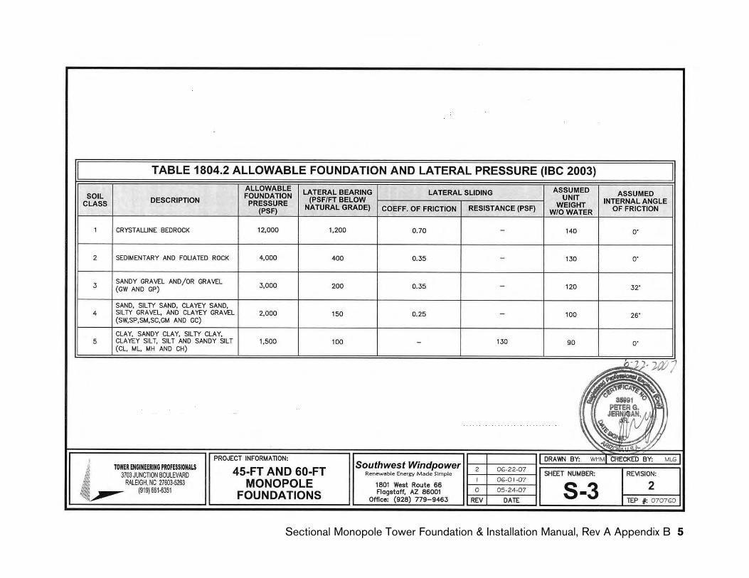
Refer to the following tables to determine your Soil Class and the location of the foundation dimensions for your tower height and foundation type.
Soil Class Description
1 Crystalline Bedrock
2 Sedimentary and Floated Rock
3 Sandy Gravel and / or Gravel
4 Sand, Silty Sand, Clayey Sand, Silty Gravel, and Clayey Gravel (SW, SP, SM, SC, GM, and GC)
5 Clay, Sandy Clay, Silty Clay, Clayey Silt, Silt and Sandy Silt(CL, ML, MH, and CH)
Tower Height Foundation Wind Zone For Dimensions See33.5 ft (10.2 m) Mat 5 ** Appendix A, Sheet S-4A
33.5 ft (10.2 m) Pier 1,2,3,4,5 Appendix A, Sheet S-4B
33.5 ft (10.2 m) SMarT 5 ** Appendix A, Sheet S-4C
45 ft (13.7 m) Pier & Pad 1,2,3,4,5 Appendix B, Sheet S-5 & S-7
45 ft (13.7 m) Pier 1,2,3,4,5 Appendix B, Sheet S-5 & S-7
45 ft (13.7 m) SMarT 5 ** Appendix B, Sheet S-5 & S-7
** Note the foundation dimensions and construction details for the SMarT and Mat foundations do not vary as a result of the soil conditions. These foundations assume Soil Class 5 (worst case) conditions exist and are designed accordingly.
10 Sectional Monopole Tower Foundation & Installation Manual, Revision A
Selecting a Foundation Configuration – Pier, Mat or SMarT
The choice of foundation – Pier, Mat or SMarT foundation – will depend on a number of factors including soil conditions, the depth of the local water table, frost line and available excavation equipment. If, for example, a contractor has the correct size auger, installing a Pier foundation may be a more economical choice than a Mat foundation since it may use substantially less concrete. Alternately, the SMarT foundation does not require reinforcing bars which can be expensive to purchase and form into the required shapes. Regardless of the type of foundation, the foundation must extend below the frost line and must also be above the water table. Engineering profes-sionals must be consulted prior to construction if the frost line is known to be greater than the foundation depth or the water table is less than the foundation depth. In summary consult with a number of contractors and with local building inspectors to achieve the best foundation value.
Foundation bolts and Templates
Two foundation bolt kits are available. The difference between the two kits is the length of the bolts. The Mat foundation bolts are 32 in (81 cm) long and the Pier foundation bolts are 42 in (107 cm) long. Each kit includes hot dipped galvanized bolts, nuts and washers constructed of the ap-propriate steel alloys.
A paper bolt circle template is provided with the bolt kit to assist in constructing a rigid frame to secure the foundation bolts while pouring the foundation concrete. The foundation bolts MUST be positioned correctly in the foundation or it may be extremely difficult if not impossible to mount the tower to the foundation.
Foundation bolts and Templates (SMarT Foundation)
The SMarT foundation kits includes all the fastener hardware (nuts, bolts, washers) required to assemble the SMarT foundation. The kit alsoincludes a bolt template to position the foundation bolts in the form. Refer to the SMarT Foundation instructions located in Appendix C of thismanual.
Sectional Monopole Tower Foundation & Installation Manual, Revision A 11
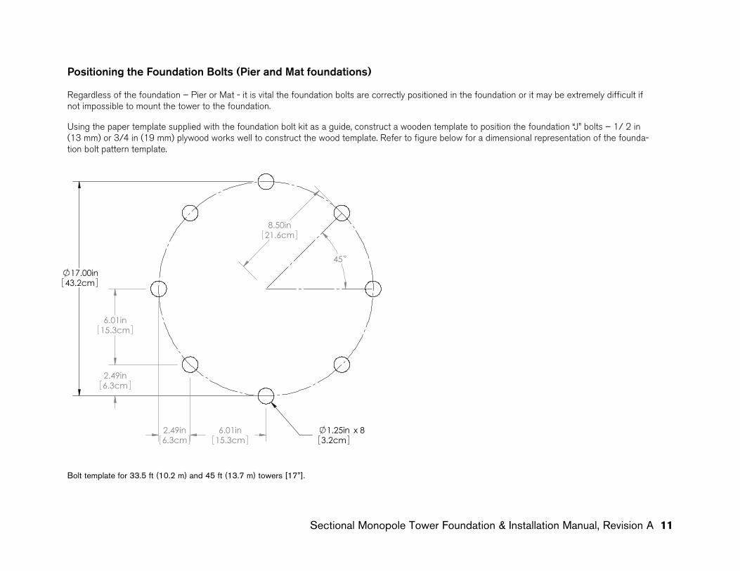
Positioning the Foundation bolts (Pier and Mat foundations)
Regardless of the foundation – Pier or Mat - it is vital the foundation bolts are correctly positioned in the foundation or it may be extremely difficult if not impossible to mount the tower to the foundation. Using the paper template supplied with the foundation bolt kit as a guide, construct a wooden template to position the foundation “J” bolts – 1/ 2 in (13 mm) or 3/4 in (19 mm) plywood works well to construct the wood template. Refer to figure below for a dimensional representation of the founda-tion bolt pattern template.
17.00in43.2cm
2.49in6.3cm
6.01in15.3cm
2.49in6.3cm
6.01in15.3cm
45
8.50in21.6cm
1.25in x 83.2cm
Bolt template for 33.5 ft (10.2 m) and 45 ft (13.7 m) towers [17”].
12 Sectional Monopole Tower Foundation & Installation Manual, Revision A12 Sectional Monopole Tower Foundation & Installation Manual, Revision A
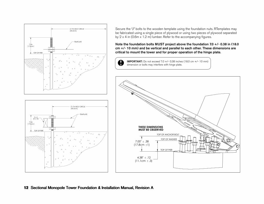
Secure the “J” bolts to the wooden template using the foundation nuts. RTemplates may be fabricated using a single piece of plywood or using two pieces of plywood separated by 2 x 4 in (0.6m x 1.2 m) lumber. Refer to the accompanying figures.
Note the foundation bolts MUST project above the foundation 7.0 +/- 0.38 in (18.0 cm +/- 10 mm) and be vertical and parallel to each other. These dimensions are critical to mount the tower and for proper operation of the hinge plate.
7.0in17.8cm
17in BOLT CIRCLE[43.2cm]
TEMPLATE
TOP OF PIER
7.0in17.8cm
17in BOLT CIRCLE[43.2cm]
TOP OF PIER
2 x 4[5 x 10]
TEMPLATE
IMPORTANT: Do not exceed 7.0 +/- 0.38 inches (18.0 cm +/- 10 mm) dimension or bolts may interfere with hinge plate.
TOP OF PIER
TOP OF ANCHOR BOLT
TOP OF WASHER
THESE DIMENSIONS MUST BE OBSERVED
7.00" (17.8cm 1)
.38
(11.1cm .3)4.38" .12
Southwest Windpower
5 4 3 2 1
----ECO#--NC
REVISIONSREV.
.XXX ± .002 .XX ± .05 HINGE-PIER CONNECTIONT. George 01/12/09
Flagstaff, Arizona U.S.A.
MONOPOLE TOWER
do not manually update
scale 1: 8 size A
CAD file :
dwg #sheet 1 of 1rev. NC
DATEAPPROVALS
DRAWN
R&D
PROD EGR
MFG
QUAL
MATERIAL:FINISH:DO NOT SCALE DRAWING
DWG #-------------------
CAD-generated drawing
.X ± .1 ± 30 ' decimals angles
other purpose except as specifically authorized in writing by Southwest Windpower.
APPROVEDDATEDESCRIPTION
unless otherwise specifieddimensions are inches tolerances are :
Proprietary rights are included in the information disclosed herein. This information issubmitted in confidence and neither the document nor the information disclosed here-in shall be reproduced or transferred to other documents for manufacturing or for any
--
Sectional Monopole Tower Foundation & Installation Manual, Revision A 13
Positioning the Foundation bolts (SMarT Foundation)
The SMarT Foundation includes a template as part of the foundation kit therefore the construction of a template is not required. Refer to the SMarT Foundation instructions located in Appendix C of this manual.
Electrical Conduit
Electrical conduit may be cast into the foundation such that the conduit continues below grade to electrical panel. Alternately wire may be routed between tower base plate and foundation. Refer to local building codes bEFORE pouring concrete.
Building codes typically require direct burial cables be buried to a minimum depth of 24 in (61 cm) while cables in conduit may be buried at a depth of 18 in (46 cm). Additionally, most codes prohibit embedding cables directly in concrete. Refer to local codes for conduit size and mini-mum depth requirements.
Tower Grounding
Refer to the Skystream Owner’s Manual for complete directions on grounding the tower. It is vital the tower be properly grounded to minimize risk of electrical shock.
Completing the Foundation
Refer to the foundation technical drawings contained in the appendices of this manual for complete notes including; foundation dimensions, con-struction notes and grading and concrete requirements. Regardless of the foundation 28 days are required for the concrete to cure to a minimum compressive strength of 2500 PSI (17230 kPa).
14 Sectional Monopole Tower Foundation & Installation Manual, Revision A14 Sectional Monopole Tower Foundation & Installation Manual, Revision A
TOWER INSTALLATION
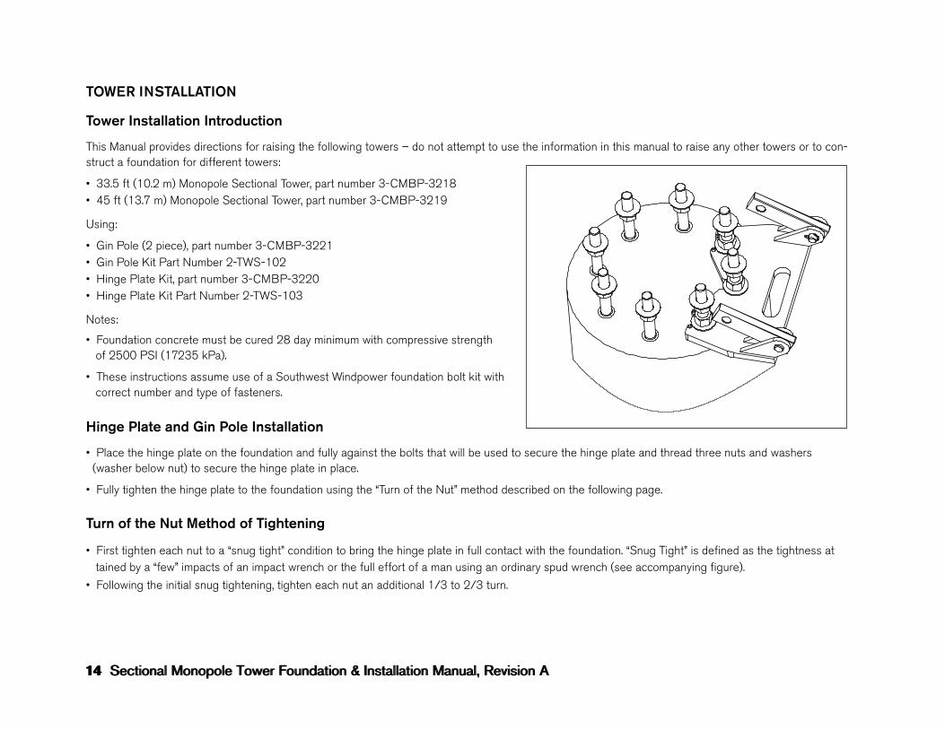
Tower Installation Introduction
This Manual provides directions for raising the following towers – do not attempt to use the information in this manual to raise any other towers or to con-struct a foundation for different towers:
• 33.5 ft (10.2 m) Monopole Sectional Tower, part number 3-CMBP-3218• 45 ft (13.7 m) Monopole Sectional Tower, part number 3-CMBP-3219
Using:
• Gin Pole (2 piece), part number 3-CMBP-3221• Gin Pole Kit Part Number 2-TWS-102• Hinge Plate Kit, part number 3-CMBP-3220• Hinge Plate Kit Part Number 2-TWS-103
Notes:
• Foundation concrete must be cured 28 day minimum with compressive strength of 2500 PSI (17235 kPa).
• These instructions assume use of a Southwest Windpower foundation bolt kit with correct number and type of fasteners.
Hinge Plate and Gin Pole Installation
• Place the hinge plate on the foundation and fully against the bolts that will be used to secure the hinge plate and thread three nuts and washers (washer below nut) to secure the hinge plate in place.
• Fully tighten the hinge plate to the foundation using the “Turn of the Nut” method described on the following page.
Turn of the Nut Method of Tightening
• First tighten each nut to a “snug tight” condition to bring the hinge plate in full contact with the foundation. “Snug Tight” is defined as the tightness at tained by a “few” impacts of an impact wrench or the full effort of a man using an ordinary spud wrench (see accompanying figure).
• Following the initial snug tightening, tighten each nut an additional 1/3 to 2/3 turn.5 4 3 2 1
unless otherwise specifieddimensions are inches tolerances are : decimals angles .X ± .1 ± 30 ' .XX ± .05 .XXX ± .002
MONOPOLE TOWERHINGE-BOLT CONFIG
T. George 01/20/09
Flagstaff, Arizona U.S.A.CAD-generated drawingdo not manually update
scale -- size A
CAD file :
dwg #sheet 1 of 1rev. NC
DATEAPPROVALSDRAWN
R&D
PROD EGR
MFG
QUAL
MATERIAL:FINISH:DO NOT SCALE DRAWING
DWG #------------------- Proprietary rights are included in the information disclosed herein. This information issubmitted in confidence and neither the document nor the information disclosed here-in shall be reproduced or transferred to other documents for manufacturing or for anyother purpose except as specifically authorized in writing by Southwest Windpower.
APPROVEDDATEDESCRIPTIONREV.REVISIONS
NC ECO#-- -- --
Southwest Windpower
--
Sectional Monopole Tower Foundation & Installation Manual, Revision A 15
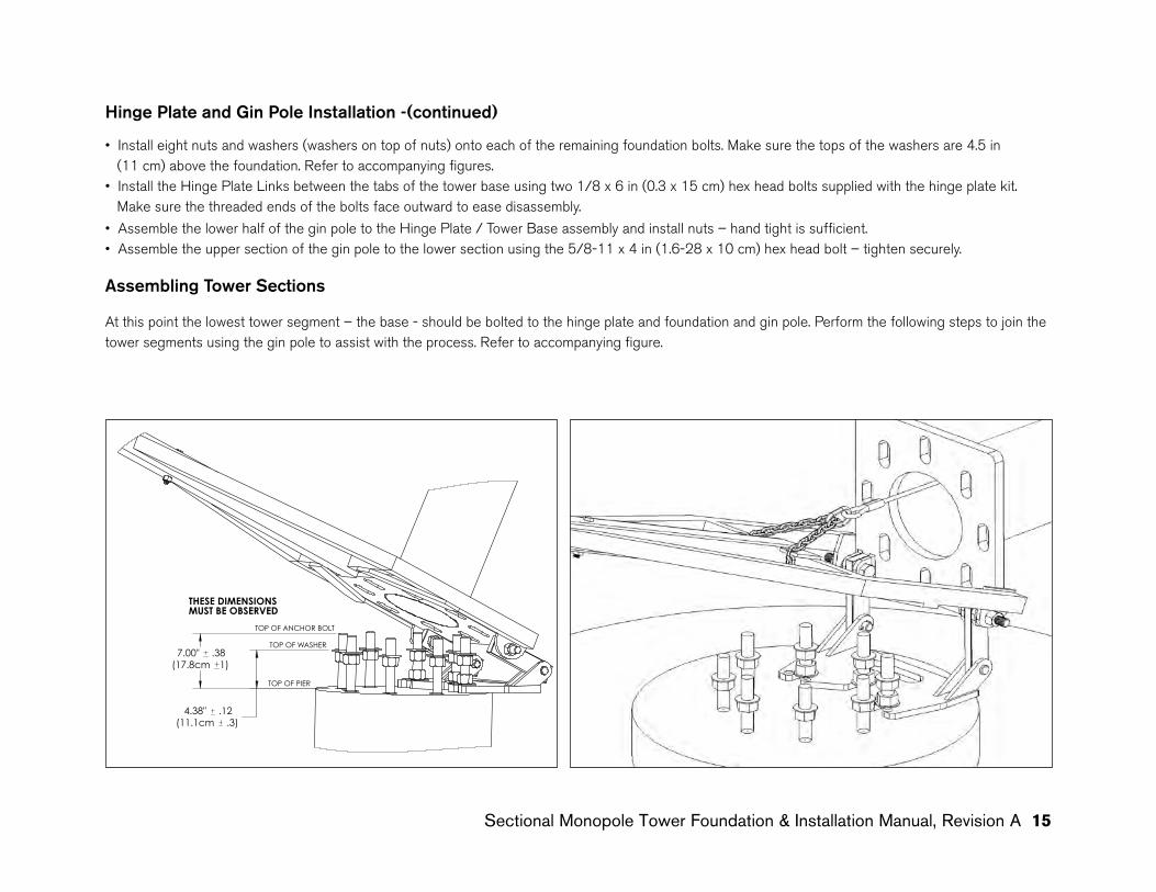
Hinge Plate and Gin Pole Installation -(continued)
• Install eight nuts and washers (washers on top of nuts) onto each of the remaining foundation bolts. Make sure the tops of the washers are 4.5 in (11 cm) above the foundation. Refer to accompanying figures.• Install the Hinge Plate Links between the tabs of the tower base using two 1/8 x 6 in (0.3 x 15 cm) hex head bolts supplied with the hinge plate kit. Make sure the threaded ends of the bolts face outward to ease disassembly.
• Assemble the lower half of the gin pole to the Hinge Plate / Tower Base assembly and install nuts – hand tight is sufficient.• Assemble the upper section of the gin pole to the lower section using the 5/8-11 x 4 in (1.6-28 x 10 cm) hex head bolt – tighten securely.
Assembling Tower Sections
At this point the lowest tower segment – the base - should be bolted to the hinge plate and foundation and gin pole. Perform the following steps to join the tower segments using the gin pole to assist with the process. Refer to accompanying figure.
TOP OF PIER
TOP OF ANCHOR BOLT
TOP OF WASHER
THESE DIMENSIONS MUST BE OBSERVED
7.00" (17.8cm 1)
.38
(11.1cm .3)4.38" .12
Southwest Windpower
5 4 3 2 1
----ECO#--NC
REVISIONSREV.
.XXX ± .002 .XX ± .05 HINGE-PIER CONNECTIONT. George 01/12/09
Flagstaff, Arizona U.S.A.
MONOPOLE TOWER
do not manually update
scale 1: 8 size A
CAD file :
dwg #sheet 1 of 1rev. NC
DATEAPPROVALS
DRAWN
R&D
PROD EGR
MFG
QUAL
MATERIAL:FINISH:DO NOT SCALE DRAWING
DWG #-------------------
CAD-generated drawing
.X ± .1 ± 30 ' decimals angles
other purpose except as specifically authorized in writing by Southwest Windpower.
APPROVEDDATEDESCRIPTION
unless otherwise specifieddimensions are inches tolerances are :
Proprietary rights are included in the information disclosed herein. This information issubmitted in confidence and neither the document nor the information disclosed here-in shall be reproduced or transferred to other documents for manufacturing or for any
--
16 Sectional Monopole Tower Foundation & Installation Manual, Revision A16 Sectional Monopole Tower Foundation & Installation Manual, Revision A
To join the tower sections together :
• Inspect the mating sections of the tower sections for burrs and roughness and smooth and repair as necessary.
• Mark the base section 26 in (66 cm) from the upper end of the section. This mark will be used to determine full insertion of the base section.
• Lubricate the base section using a liquid dish soap (do not use grease or oil as this will stain the tower) and LOOSELY assemble the base and mid sections. Lifting tab on tower center section MUST face upward.
• Run a 5/16 in (8.0 mm) grade 70 transport chain with slip hooks at each end through the tower sections and secure a 4 x 6 x 14 in (10 x 15 x 36 cm) wood block at the end of the pole.
• Support the tower midsection at its center of gravity – approximately 110 in (279 cm) from the bottom of the section – this will aid keeping the sections aligned axially.• Raise the gin pole approximately 10 to 20 degrees above horizontal and insert chain links into the slotted plates positioned on either side of the gin pole’s central support tube.• The gin pole should maintain its position under its own weight. Apply a downward force [maximum 200 lb (91 kg)] at the far end of the gin pole to draw the tower sections together. • Repeat the above process by readjusting the chain links as necessary until the tower mid section is fully seated against the base section.• After the tower mid section is fully seated onto the tower base; mark the upper end of the tower mid section 21 in (53 cm) from upper end of the section. Use this mark to determine full insertion mid section into the top section. • Join the top and mid sections using the same procedure that was used to join the base and mid sections.
If difficulties are encountered getting the tower sections to seat fully a few blows from a sledge hammer on wood block while a second person applies pressure using the gin pole will usually result in fully seating the tower sections.
IMPORTANT: Make sure lifting tab on tower mid-section is facing upward and in line with the pull direction before seating the tower sections together.
Sectional Monopole Tower Foundation & Installation Manual, Revision A 17
TIP: The tower is now set to be raised. Southwest Windpower recommends raising the tower once without the wind turbine installed. This permits checking the proper opera-tion and installation of the hinge and gin pole and also allows inexperienced installers an opportunity to practice raising the tower without risking damage to the wind turbine.
Raising the Tower
Refer to the Skystream Owners Manual for instructions on completing the electrical connections and mounting Skystream on the tower. If you have not raised a tower before Southwest Windpower recommends first raising the tower without the windturbine installed. This provides the opportunity to practice the procedure without risking damage to the windturbine.
Follow these steps to raise the tower:
• Tilt the gin pole to the vertical position and using the wire rope cable (with the adjustable end) connect the end of the gin pole to the lifting tab located at the tower mid section.
• Note that it may be necessary to adjust the length of this cable when switching between the 33.5 ft (10.2 m) and 45 ft (13.7 m) towers or because of variations in the location of the lifting tab. Refer to the accompanying Adjusting Cable Length section for instructions.
Adjusting Cable Length
READ ALL INSTRUCTIONS bEFORE bEGINNING
• Determine the required cable length taking into account the two shackles needed to connect the cable to the gin pole and the tower.
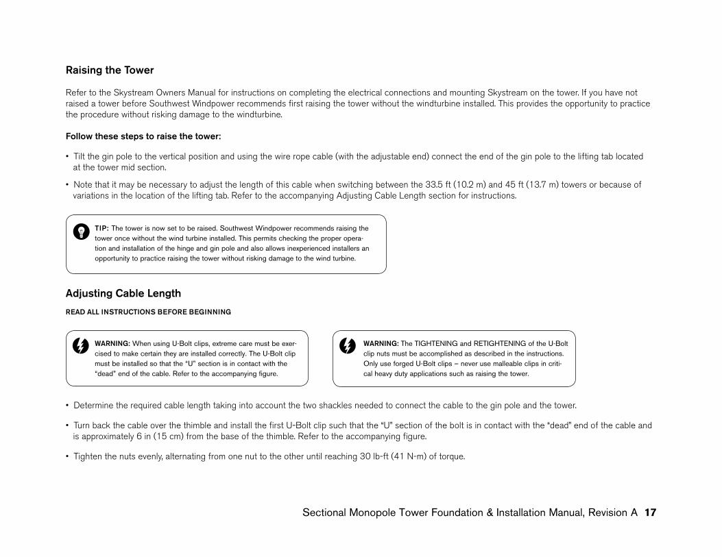
• Turn back the cable over the thimble and install the first U-Bolt clip such that the “U” section of the bolt is in contact with the “dead” end of the cable and is approximately 6 in (15 cm) from the base of the thimble. Refer to the accompanying figure.
• Tighten the nuts evenly, alternating from one nut to the other until reaching 30 lb-ft (41 N-m) of torque.
WARNING: When using U-Bolt clips, extreme care must be exer-cised to make certain they are installed correctly. The U-Bolt clip must be installed so that the “U” section is in contact with the “dead” end of the cable. Refer to the accompanying figure.
WARNING: The TIGHTENING and RETIGHTENING of the U-Bolt clip nuts must be accomplished as described in the instructions. Only use forged U-Bolt clips – never use malleable clips in criti-cal heavy duty applications such as raising the tower.

18 Sectional Monopole Tower Foundation & Installation Manual, Revision A
• Install the second U-Bolt clip as near the thimble as possible. As with the previous U-Bolt clip, tighten the nuts evenly, alternating from one nut to the other until reaching 30 lb-ft (41 N-m) of torque.
• Install the third U-Bolt clip midway between the other clips and tighten the nuts to 30 lb-ft (41 N-m) of torque.
• Apply a load to the cable equal or greater than the maximum anticipated load (DO NOT USE THE TOWER AND TURBINE AS THE LOAD) and retighten the nuts to 30 lb-ft (41 N-m) of torque. This step is very important as the cable may stretch and shrink in diameter when a load is applied effectively loos ing the U-Bolt clip nuts. Note the maximum load the cable will experience is approximately 2400 lb (1100 kg).
Raising the Tower - (continued)
• Connect the second wire rope cable to the base of the gin pole and to the “lifting” vehicle using the shackles provided.
• Start to “raise’ the tower by slowly driving the “lifting” vehicle away from the tower to take the slack out of the cable – keep the vehicle “in line” with the tower – avoid loading the tower in a lateral direction.
• The vehicle should stop pulling as the end of the gin pole approaches 3-4 ft (1-1.3 m) above ground level. At this point two full size adults can complete raising the tower by pushing down on the end of the gin pole or by pushing down on the cable.
• Observe that the anchor bolt closest to the hinge pivot axis clears the slot in the tower base. This is normally not an issue unless the anchor bolt projec- tion from the foundation exceeds 7.5 in (19 cm).
• As the tower nears the fully vertical position it will be necessary to “lift” the gin pole to slow the tower as it assumes the fully vertical position. Two people are required for this operation.
• When the tower is completely vertical install the remaining nuts and washers to secure the tower to the foundation.
If the tower was raised without the turbine, refer to the section on lowering the tower. If the tower was raised with the turbine proceed to the section on Leveling the Tower.
CORRECT6 in (15 cm)
WRONG
WRONG

Sectional Monopole Tower Foundation & Installation Manual, Revision A 19
WARNING: Someone MUST be in the vehicle at all times to control lowering the tower. The “pulling” force the tower exerts greatly increases as the tower approaches the horizontal. In other words the tower is lowered using the vehicle brakes to slow the descent of the tower. During lowering keep the vehicle engine running to provide power brake assistance.
WARNING: Use extreme caution when lowering the tower. Keep well away and to sides of tower and cable.
Lowering the Tower
Lowering the tower is essentially the reverse of raising the tower. Observe the same precautions including not passing under the tower as it is lowered and standing well clear of cables. As with raising the tower, a minimum of three people are recommended.
• Turn OFF power to the turbine.
• If not already in place install the hinge plate following the directions in Gin Pole and Hinge Plate Installation section of this manual. Observe the recommended bolt tightening procedure.
• Connect the gin pole to the lifting tab at the mid section of the tower using the wire rope cable and shackles provide with the gin pole kit.
• Position suitable bracing to support the tower top and keep the turbine from contacting the ground after the tower is lowered. The bracing should be located approximately 8 ft (2.4 m) from the tower top to clear the turbine blades.
• Connect the second wire rope cable to the gin pole and lowering vehicle.
• Position the vehicle so there is approximately 1-2 ft (30-60 cm) of slack in the cable and the vehicle is in line with lowering path of the tower.
• Remove the foundation nuts and washers.
• Start the lowering process by having two people lift the gin pole to take up the cable slack. Continue lifting the gin pole as the vehicle keeps the cable taught.
• Once the tower passes the “balance point” the vehicle will be in control of the tower lowering and the individuals at the holding the gin pole should clear the area.
• Note pulling force the tower exerts on the vehicle greatly increases as the tower approaches horizontal.
20 Sectional Monopole Tower Foundation & Installation Manual, Revision A
Leveling the Tower
Leveling the tower is most easily accomplished using only four of the eight foundation bolts. Once the tower is leveled the remaining bolts can be fully tightened to secure the tower.
Be aware that leveling the tower may require some trial and error adjustments – even though the base is level, the upper tower flange may be off level due to manufacturing tolerances.
To level the tower:
• Level the tower on a calm day to minimize movement of Skystream. Start by loosening all the upper foundation nuts about a full turn.
• Loosen and lower the four nuts on the “sides” of the foundation base plate. In other words the tower should be supported by the four “corner” nuts of the tower base plate. (refer to Fig. 8, Bolts A and B are “corner” bolts)
• Using two bubble levels set perpendicular to each other on the base plate adjust the foundation nuts until the tower is level. Magnetic bubble levels may make this process easier.
• Once the tower is level tighten all nuts and recheck level.
Observe the position of Skystream on calm days. If the wind turbine seems to favor a single position with no wind, the tower may require fine tuning even if it appears level using the bubble leveling technique.
To fine tune the tower realize that the nose cone of the wind turbine will “point” in the direction of the tower low side. Therefore, to level the tower, slightly raise the side of the tower under the nose cone or lower the side of the tower opposite the nose cone. Make fine adjustments. Approximately one turn of a foundation nut equates to slightly more than 1/8 in (3.2 mm) so even a half turn adjustment will make a difference.
Tightening Foundation bolts
Tighten the foundation bolts by using the Turn of the Nut Method as described below.
Turn of the Nut Method of Tightening
• First tighten each nut to a “snug tight” condition to bring the hinge plate in full contact with the foundation. “Snug Tight” is defined as the tightness attained by a “few” impacts of an impact wrench or the full effort of a man using an ordinary spud wrench.
• Following the initial snug tightening, tighten each nut an additional 1/3 to 2/3 turn.
WARNING: Never leave foundation bolts loose. Foundation bolts may be temporarily loosened during tower leveling – however, never leave tower unless ALL foundation bolts are FULLY tightened.
Southwest Windpower, Inc.1801 West Route 66Flagstaff, Arizona 86001 USAPhone: 928-779-9463Fax: 928-779-1485
www.skystreamenergy.com
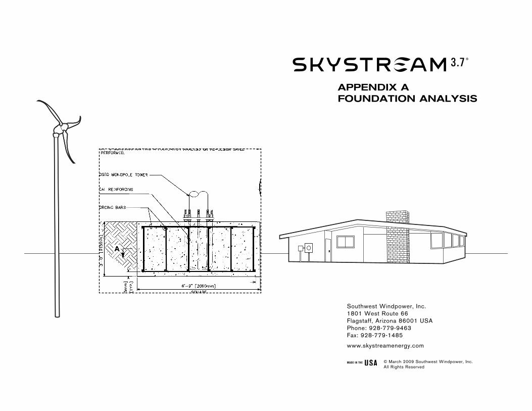
aPPenDiX aFoUnDation analysis
© March 2009 Southwest Windpower, Inc. All Rights Reserved
2 Sectional Monopole Tower Foundation & Installation Manual, Rev A Appendix A
Sectional Monopole Tower Foundation & Installation Manual, Rev A Appendix A 3
4 Sectional Monopole Tower Foundation & Installation Manual, Rev A Appendix A
Sectional Monopole Tower Foundation & Installation Manual, Rev A Appendix A 5
6 Sectional Monopole Tower Foundation & Installation Manual, Rev A Appendix A
Sectional Monopole Tower Foundation & Installation Manual, Rev A Appendix A 7
8 Sectional Monopole Tower Foundation & Installation Manual, Rev A Appendix A
Sectional Monopole Tower Foundation & Installation Manual, Rev A Appendix A 9
10 Sectional Monopole Tower Foundation & Installation Manual, Rev A Appendix A
Southwest Windpower, Inc.1801 West Route 66Flagstaff, Arizona 86001 USAPhone: 928-779-9463Fax: 928-779-1485
www.skystreamenergy.com
aPPenDiX BFoUnDation DRaWinGs
© March 2009 Southwest Windpower, Inc. All Rights Reserved
12 Sectional Monopole Tower Foundation & Installation Manual, Rev A Appendix A
Sectional Monopole Tower Foundation & Installation Manual, Rev A Appendix B 3
14 Sectional Monopole Tower Foundation & Installation Manual, Rev A Appendix B
Sectional Monopole Tower Foundation & Installation Manual, Rev A Appendix B 5
16 Sectional Monopole Tower Foundation & Installation Manual, Rev A Appendix B
Sectional Monopole Tower Foundation & Installation Manual, Rev A Appendix B 7

17 Sectional Monopole Tower Foundation & Installation Manual, Rev A Appendix B

Sectional Monopole Tower Foundation & Installation Manual, Rev A Appendix B 9

19 Sectional Monopole Tower Foundation & Installation Manual, Rev A Appendix B
Sectional Monopole Tower Foundation & Installation Manual, Rev A Appendix B 11

21 Sectional Monopole Tower Foundation & Installation Manual, Rev A Appendix B
Instructions for Assembly and Installation of SMarT_Foundation™ Kits (U.S. Patent Pending) for the Skystream Wind Turbine
SMarT_Foundation™ [S
Step 6. Join the upper and lower anchor bolt templates. Follow the illustrations from left to right.
imple Modular Technology] SMarT 2_v2 March 12, 2008 © 2007–2008 by AnemErgonics, LLC. All rights reserved. Page 8 of 22
Southwest Windpower, Inc.1801 West Route 66Flagstaff, Arizona 86001 USAPhone: 928-779-9463Fax: 928-779-1485
www.skystreamenergy.com
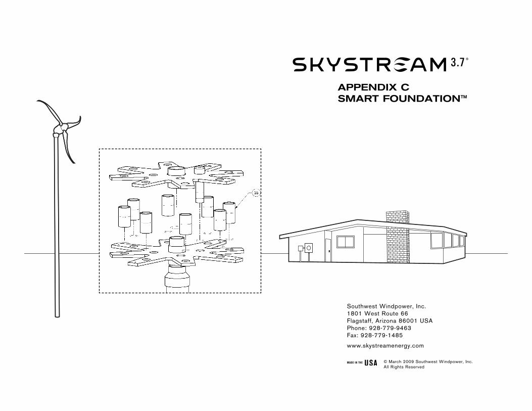
aPPenDiX csMaRt FoUnDation™
© March 2009 Southwest Windpower, Inc. All Rights Reserved

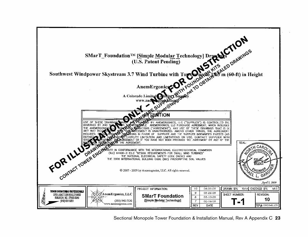
SMarT_Foundation™ [Simple Modular Technology]Assembly and Installation Instructions
(U.S. Patent Pending)
Southwest Windpower Skystream 3.7 Wind Turbine with Towers up to 60 ft. (18.3 m) in Height
DESIGNED IN CONFORMANCE WITH THE INTERNATIONAL ELECTROTECHNICAL COMMISSION (IEC) 61400-2 ED.2 DESIGN REQUIREMENTS FOR SMALL WIND TURBINES
THE NATIONAL ELECTRICAL SAFETY CODE (NESC) AND THE INTERNATIONAL BUILDING CODE (IBC) 2003 PRESCRIPTIVE SOIL VALUES
ATTENTIONUSE OF THESE INSTRUCTIONS, WHICH ARE PROVIDED BY ANEMERGONICS, LLC (“SUPPLIER”) IS CONTROLLED BY, GOVERNED BY AND SUBJECT TO THE APPLICABLE ANEMERGONICS, LLC PURCHASE AGREEMENT, WHICH INCLUDES THE ANEMERGONICS, LLC TERMS AND CONDITIONS (“AGREEMENT”). ANY USE OF THESE INSTRUCTIONS THAT IS IN ANY WAY INCONSISTENT WITH THE AGREEMENT IS UNAUTHORIZED. AMONG OTHER THINGS, THE AGREEMENT INCLUDES: BROAD INDEMNITY PROVISIONS IN FAVOR OF SUPPLIER AND THE SUPPLIER INDEMNIFIED PARTIES (AS DEFINED IN THE AGREEMENT), LIABILITY LIMITATION AND LIMITATIONS ON USE. CONTACT SUPPLIER WITH QUESTIONS REGARDING THE AGREEMENT OR IF YOU HAVE NOT BEEN PROVIDED THE AGREEMENT OR ANY OF THE MATERIALS REFERENCED IN THE AGREEMENT.
© 2007–2008 by AnemErgonics, LLC. All rights reserved.
AnemErgonics™
A Colorado Limited Liability Company www.anemergonics.com
2 Sectional Monopole Tower Foundation & Installation Manual, Rev A Appendix C
Instructions for Assembly and Installation of SMarT_Foundation™ Kits (U.S. Patent Pending) for the Skystream Wind Turbine
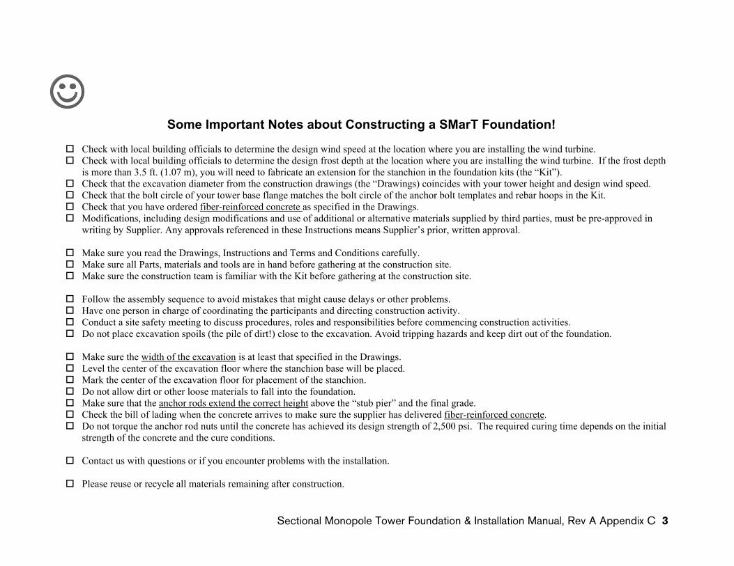
☺Some Important Notes about Constructing a SMarT Foundation!
� Check with local building officials to determine the design wind speed at the location where you are installing the wind turbine.� Check with local building officials to determine the design frost depth at the location where you are installing the wind turbine. If the frost depth
is more than 3.5 ft. (1.07 m), you will need to fabricate an extension for the stanchion in the foundation kits (the “Kit”). � Check that the excavation diameter from the construction drawings (the “Drawings) coincides with your tower height and design wind speed. � Check that the bolt circle of your tower base flange matches the bolt circle of the anchor bolt templates and rebar hoops in the Kit. � Check that you have ordered fiber-reinforced concrete as specified in the Drawings. � Modifications, including design modifications and use of additional or alternative materials supplied by third parties, must be pre-approved in
writing by Supplier. Any approvals referenced in these Instructions means Supplier’s prior, written approval.
� Make sure you read the Drawings, Instructions and Terms and Conditions carefully. � Make sure all Parts, materials and tools are in hand before gathering at the construction site. � Make sure the construction team is familiar with the Kit before gathering at the construction site.
� Follow the assembly sequence to avoid mistakes that might cause delays or other problems. � Have one person in charge of coordinating the participants and directing construction activity. � Conduct a site safety meeting to discuss procedures, roles and responsibilities before commencing construction activities. � Do not place excavation spoils (the pile of dirt!) close to the excavation. Avoid tripping hazards and keep dirt out of the foundation.
� Make sure the width of the excavation is at least that specified in the Drawings. � Level the center of the excavation floor where the stanchion base will be placed. � Mark the center of the excavation floor for placement of the stanchion. � Do not allow dirt or other loose materials to fall into the foundation. � Make sure that the anchor rods extend the correct height above the “stub pier” and the final grade. � Check the bill of lading when the concrete arrives to make sure the supplier has delivered fiber-reinforced concrete.� Do not torque the anchor rod nuts until the concrete has achieved its design strength of 2,500 psi. The required curing time depends on the initial
strength of the concrete and the cure conditions.
� Contact us with questions or if you encounter problems with the installation.
� Please reuse or recycle all materials remaining after construction.
SMarT_Foundation™ [Simple Modular Technology] SMarT 2_v2 March 12, 2008 © 2007–2008 by AnemErgonics, LLC. All rights reserved. Page 2 of 22 Sectional Monopole Tower Foundation & Installation Manual, Rev A Appendix C 3
Instructions for Assembly and Installation of SMarT_Foundation™ Kits (U.S. Patent Pending) for the Skystream Wind Turbine
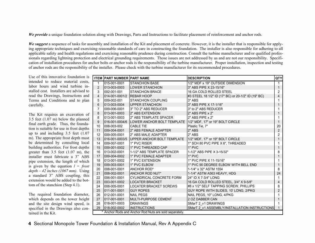
We provide a unique foundation solution along with Drawings, Parts and Instructions to facilitate placement of reinforcement and anchor rods.
We suggest a sequence of tasks for assembly and installation of the Kit and placement of concrete. However, it is the installer that is responsible for apply-ing appropriate techniques and exercising reasonable standards of care in constructing the foundation. The installer is also responsible for adhering to all applicable safety and health regulations and exercising reasonable prudence during construction. Consult the turbine manufacturer and/or qualified profes-sionals regarding lightning protection and electrical grounding requirements. Those issues are not addressed by us and are not our responsibility. Specifi-cation of installation procedures for anchor bolts or anchor rods is the responsibility of the turbine manufacturer. Proper installation, inspection and testing of anchor rods are the responsibility of the installer. Please check with the turbine manufacturer for its recommended procedures.
Use of this innovative foundation is intended to reduce material costs, labor hours and wind turbine in-stalled cost. Installers are advised to read the Drawings, Instructions and Terms and Conditions and to plan carefully.
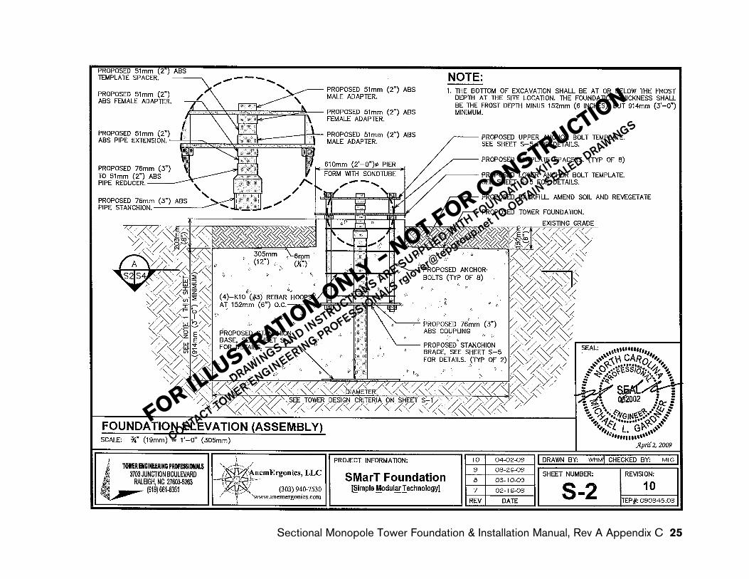
ITEM PART NUMBER PART NAME DESCRIPTION QTY1 015-001-0001 STANCHION BASE 1/2" MDF x 19" OUTSIDE DIMENSION 12 013-003-0003 LOWER STANCHION 3" ABS PIPE X 23-15/16" 13 002-001-001 STANCHION BRACE 16 GA COLD ROLLED STEEL 24 014-001-0001/2 REBAR HOOP #3 STEEL 18 1/2" ID (17" BC) or 20-1/2" ID (19" BC) 45 009-002-001 STANCHION COUPLING 3" ABS 16 013-003-0004 UPPER STANCHION 3" ABS PIPE X 17-1/16" 17 009-006-0001 3" TO 2" ABS REDUCER 3" to 2" ABS REDUCER 18 013-001-0003 2" ABS EXTENSION 2" ABS PIPE x 2" 18 013-001-0003 2" ABS TEMPLATE SPACER 2" ABS PIPE x 2" 19 016-001-0004/6 LOWER ANCHOR BOLT TEMPLATE 1/2" MDF, 17" or 19" BOLT CIRCLE 1
10 008-003-002 CABLE TIE Plastic Tie, 7" 2011 009-004-0001 2" ABS FEMALE ADAPTER 2" ABS 212 009-005-0001 2" ABS MALE ADAPTER 2" ABS 213 016-001-0003/5 UPPER ANCHOR BOLT TEMPLATE 1/2" MDF, 17" or 19" BOLT CIRCLE 114 009-007-0001 1" PVC RISER 1" SCH 80 PVC PIPE X 6", THREADED 115 009-001-0002 1" PVC THREADED CAP 1" PVC 116 013-002-0001 1-1/2" ABS TEMPLATE SPACER 1-1/2" ABS PIPE X 3-15/32" 817 009-004-0002 1" PVC FEMALE ADAPTER 1" PVC 118 013-001-0002 1" PVC EXTENSION 1" PVC PIPE X 11-15/16" 119 009-003-0001 1" PVC ELBOW 1" PVC 90 DEGREE ELBOW WITH BELL END 120 008-001-0001 ANCHOR ROD* 1-1/4" x 32" ASTM 1554 821 008-002-0001 ANCHOR ROD NUT* 1-1/4" ASTM A563 HEAVY, HDG 2422 006-001-0001 CYLINDRICAL CONCRETE FORM 24" ID X 7-3/4" LONG 123 003-001-0002 LOCATER BRACKET 16 GA COLD ROLLED STEEL, 3/4" X 9-5/8" 424 008-005-0001 LOCATER BRACKET SCREWS #8 x 1/2" SELF TAPPING SCREW, PHILLIPS 825 011-001-0001 GUY ROPES GUY ROPE WITH SLIDES, 10' LONG, 2/PKG 226 012-001-0001 NAIL PEGS NAIL PEGS, 10" LONG, 4/PKG 127 017-001-0001 MULTI-PURPOSE CEMENT 2 OZ DABBER CAN 128 018-001-0003 DRAWINGS SMarT 2_v1 DRAWINGS 129 018-002-0002 INSTRUCTIONS SMarT 2_v1 ASSEMBLY/INSTALLATION INSTRUCTIONS 1
* Anchor Rods and Anchor Rod Nuts are sold separately.
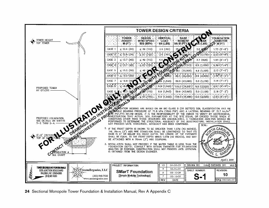
The Kit requires an excavation of 3.5 feet (1.07 m) below the planned final earth grade. Thus, the founda-tion is suitable for use in frost depths up to and including 3.5 feet (1.07 m). The appropriate frost depth must be determined by consulting local building authorities. For frost depths greater than 3.5 feet (1.07 m), the installer must fabricate a 3” ABS pipe extension, the length of which is given by the equation l = frost depth – 42 inches (1067 mm). Using a standard 3” ABS coupling, this extension would be added to the bot-tom of the stanchion (Step 4.1).
The required foundation diameter, which depends on the tower height and the site design wind speed, is specified in the Drawings also con-tained in the Kit.
SMarT_Foundation™ [Simple Modular Technology] SMarT 2_v2 March 12, 2008 © 2007–2008 by AnemErgonics, LLC. All rights reserved. Page 3 of 22 4 Sectional Monopole Tower Foundation & Installation Manual, Rev A Appendix C
Instructions for Assembly and Installation of SMarT_Foundation™ Kits (U.S. Patent Pending) for the Skystream Wind Turbine
SMarT_Foundation™ [S
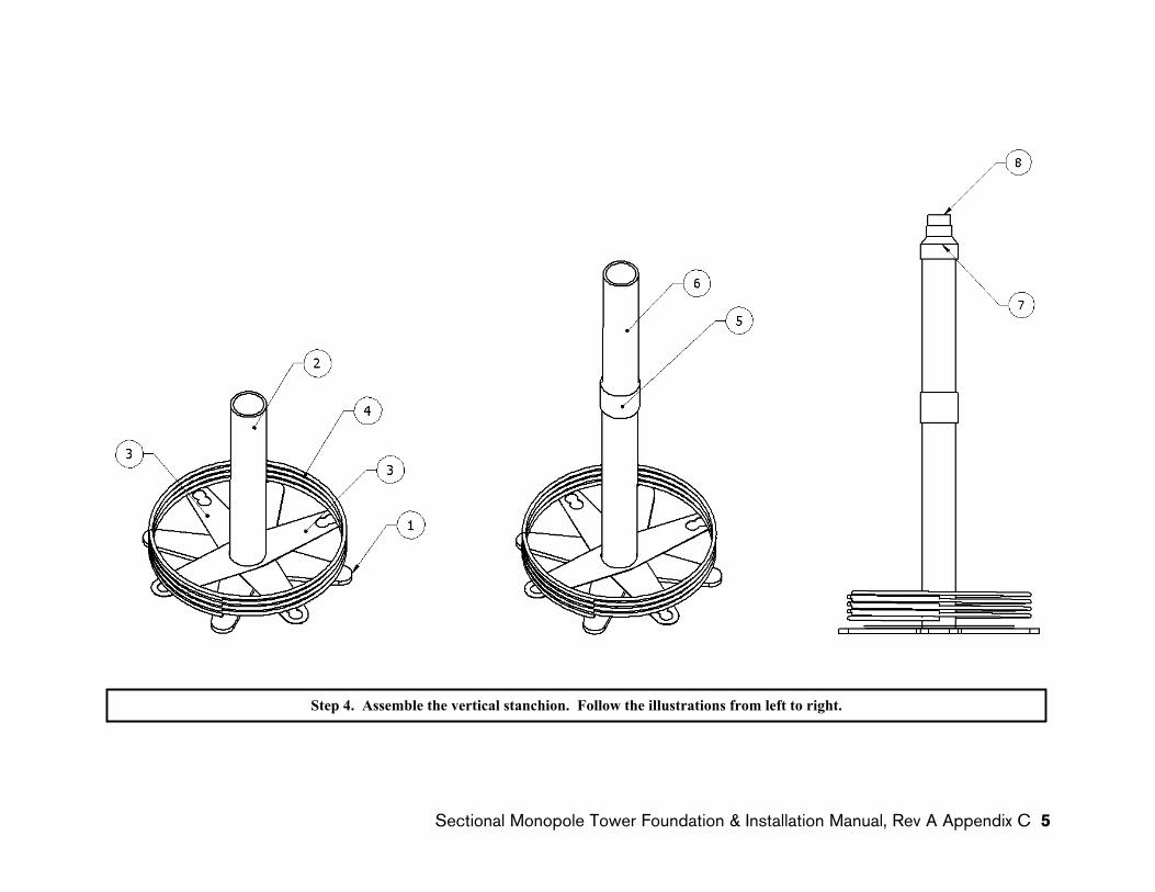
Step 4. Assemble the vertical stanchion. Follow the illustrations from left to right.
imple Modular Technology] SMarT 2_v2 March 12, 2008 © 2007–2008 by AnemErgonics, LLC. All rights reserved. Page 4 of 22 Sectional Monopole Tower Foundation & Installation Manual, Rev A Appendix C 5
Instructions for Assembly and Installation of SMarT_Foundation™ Kits (U.S. Patent Pending) for the Skystream Wind Turbine
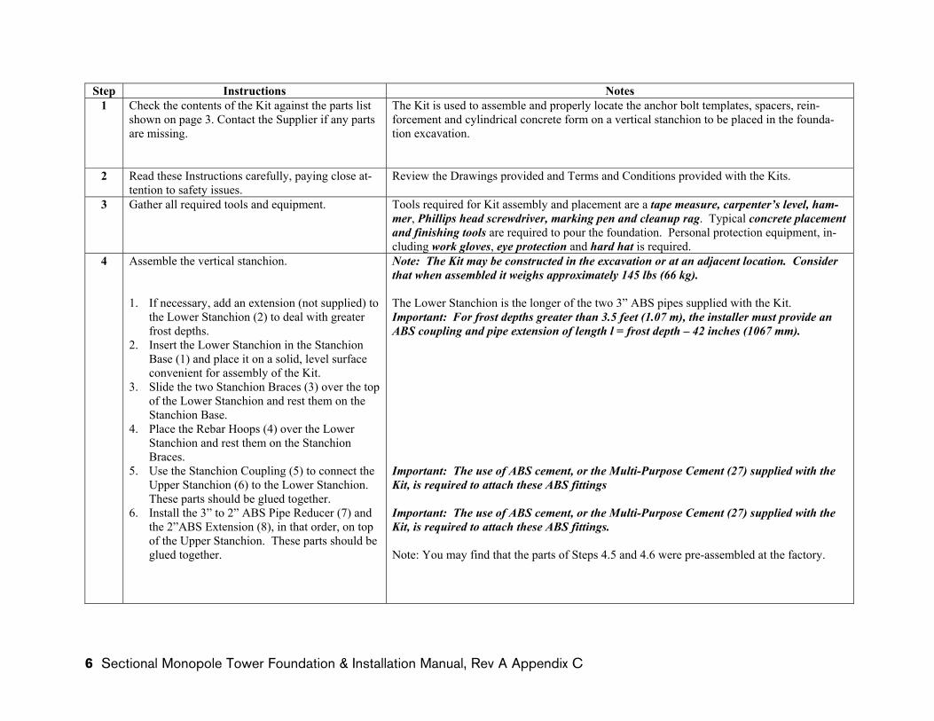
Step Instructions Notes1 Check the contents of the Kit against the parts list
shown on page 3. Contact the Supplier if any parts are missing.
The Kit is used to assemble and properly locate the anchor bolt templates, spacers, rein-forcement and cylindrical concrete form on a vertical stanchion to be placed in the founda-tion excavation.
2 Read these Instructions carefully, paying close at-tention to safety issues.
Review the Drawings provided and Terms and Conditions provided with the Kits.
3 Gather all required tools and equipment. Tools required for Kit assembly and placement are a tape measure, carpenter’s level, ham-mer, Phillips head screwdriver, marking pen and cleanup rag. Typical concrete placement and finishing tools are required to pour the foundation. Personal protection equipment, in-cluding work gloves, eye protection and hard hat is required.
4 Assemble the vertical stanchion.
1. If necessary, add an extension (not supplied) to the Lower Stanchion (2) to deal with greater frost depths.
2. Insert the Lower Stanchion in the Stanchion Base (1) and place it on a solid, level surface convenient for assembly of the Kit.
3. Slide the two Stanchion Braces (3) over the top of the Lower Stanchion and rest them on the Stanchion Base.
4. Place the Rebar Hoops (4) over the Lower Stanchion and rest them on the Stanchion Braces.
5. Use the Stanchion Coupling (5) to connect the Upper Stanchion (6) to the Lower Stanchion. These parts should be glued together.
6. Install the 3” to 2” ABS Pipe Reducer (7) and the 2”ABS Extension (8), in that order, on top of the Upper Stanchion. These parts should be glued together.
Note: The Kit may be constructed in the excavation or at an adjacent location. Consider that when assembled it weighs approximately 145 lbs (66 kg).
The Lower Stanchion is the longer of the two 3” ABS pipes supplied with the Kit. Important: For frost depths greater than 3.5 feet (1.07 m), the installer must provide an ABS coupling and pipe extension of length l = frost depth – 42 inches (1067 mm).
Important: The use of ABS cement, or the Multi-Purpose Cement (27) supplied with the Kit, is required to attach these ABS fittings
Important: The use of ABS cement, or the Multi-Purpose Cement (27) supplied with the Kit, is required to attach these ABS fittings.
Note: You may find that the parts of Steps 4.5 and 4.6 were pre-assembled at the factory.
SMarT_Foundation™ [Simple Modular Technology] SMarT 2_v2 March 12, 2008 © 2007–2008 by AnemErgonics, LLC. All rights reserved. Page 5 of 22
6 Sectional Monopole Tower Foundation & Installation Manual, Rev A Appendix C
Instructions for Assembly and Installation of SMarT_Foundation™ Kits (U.S. Patent Pending) for the Skystream Wind Turbine
SMarT_Foundation™ [S
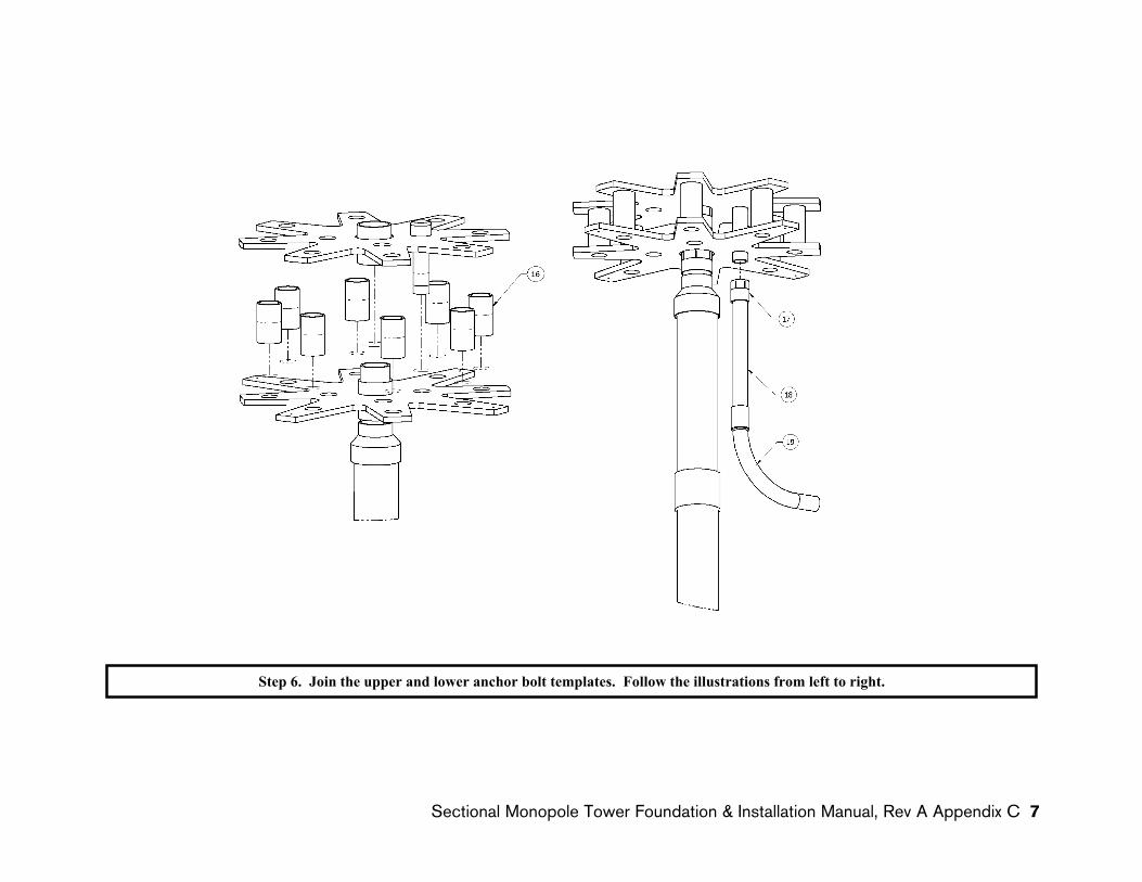
Step 6. Join the upper and lower anchor bolt templates. Follow the illustrations from left to right.
imple Modular Technology] SMarT 2_v2 March 12, 2008 © 2007–2008 by AnemErgonics, LLC. All rights reserved. Page 8 of 22 Sectional Monopole Tower Foundation & Installation Manual, Rev A Appendix C 7
Instructions for Assembly and Installation of SMarT_Foundation™ Kits (U.S. Patent Pending) for the Skystream Wind Turbine
Step Instructions Notes5 Assemble the anchor bolt templates.
1. Insert a 2” ABS Male Adapter (12) through the center of the Lower Anchor Bolt Template (9) into a 2” ABS Female Adapter (11). Hand-tighten the threaded fittings.
2. Insert a 2”ABS Template Spacer (8) into the 2”ABS Male Adapter. These parts should notbe glued together.
3. Install the assembly (from Steps 5.1 and 5.2) onto the stanchion by inserting the 2”ABS Fe-male Adapter into the 2” ABS Pipe Extension on the top of the stanchion. These parts should be glued together.
4. Insert a 2” ABS Male Adapter (12) through the center of the Upper Anchor Bolt Template (13) into a 2” ABS Female Adapter (11). Hand-tighten the threaded fittings.
5. Screw the 1” PVC Threaded Cap (15) onto one end of the 1” PVC Riser (14). Insert this as-sembly through any one of the inner holes of the Upper Anchor Bolt Template.
Note: The Lower Anchor Bolt Template has four long “spokes” and four short “spokes”.
Caution: For this assembly, the 2” ABS Female Adapter fits on the grooved side of the Lower Anchor Bolt Template.
Important: Do not cement these parts.
Important: The use of ABS cement, or the Multi-Purpose Cement (27) supplied with the Kit, is recommended to attach these ABS fittings.
The Upper Anchor Bolt Template has eight “spokes” that are the same size.
Caution: For this template, the 2” ABS Male Adapter fits on the grooved side of the Up-per Anchor Bolt Template.
SMarT_Foundation™ [Simple Modular Technology] SMarT 2_v2 March 12, 2008 © 2007–2008 by AnemErgonics, LLC. All rights reserved. Page 7 of 22
8 Sectional Monopole Tower Foundation & Installation Manual, Rev A Appendix C

Instructions for Assembly and Installation of SMarT_Foundation™ Kits (U.S. Patent Pending) for the Skystream Wind Turbine
SMarT_Foundation™ [S
Step 6. Join the upper and lower anchor bolt templates. Follow the illustrations from left to right.
imple Modular Technology] SMarT 2_v2 March 12, 2008 © 2007–2008 by AnemErgonics, LLC. All rights reserved. Page 8 of 22 Sectional Monopole Tower Foundation & Installation Manual, Rev A Appendix C 9

Instructions for Assembly and Installation of SMarT_Foundation™ Kits (U.S. Patent Pending) for the Skystream Wind Turbine
Step Instructions Notes6 Join the Upper and Lower Anchor Bolt Templates.
1. Join the Upper and Lower Anchor Bolt Tem-plates by inserting the 2” ABS Female Adapter on the bottom of the Upper Anchor Bolt Tem-plate into the 2” ABS Template Spacer pro-truding from the top of the Lower Anchor Bolt Template assembly. These parts should not be glued together.
2. Slip the eight 1-1/2” ABS Template Spacers (16) between the Upper and Lower Anchor Bolt Templates and align them with the outer bolt holes in the templates.
3. Assemble the 1” PVC Female Adapter (17), the 1” PVC Extension (18) and the 1” PVC El-bow (19) as shown in the illustration. These parts should be glued together
4. Screw the 1” PVC Female Adapter of the above assembly into the 1” PVC Threaded Nipple protruding from the bottom of the Lower Anchor Bolt Template.
Important: Make sure the 1” PVC Threaded Nipple passes through one of the inner holes in both the Upper and Lower Anchor Bolt Templates.
Important: Do not cement these parts.
Important: The use of PVC cement, or the Multi-Purpose Cement (27) supplied with the Kit, is recommended to attach these PVC fittings.
If necessary, this PVC assembly may be relocated to some other holes in order to mate with a planned electrical interconnection.
SMarT_Foundation™ [Simple Modular Technology] SMarT 2_v2 March 12, 2008 © 2007–2008 by AnemErgonics, LLC. All rights reserved. Page 9 of 22
10 Sectional Monopole Tower Foundation & Installation Manual, Rev A Appendix C
Instructions for Assembly and Installation of SMarT_Foundation™ Kits (U.S. Patent Pending) for the Skystream Wind Turbine
SMarT_Foundation™ [S
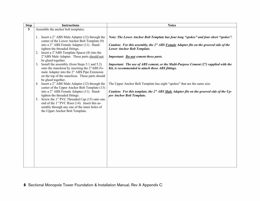
Step 7. Install the anchor rods. Follow the illustrations from left to right.
imple Modular Technology] SMarT 2_v2 March 12, 2008 © 2007–2008 by AnemErgonics, LLC. All rights reserved. Page 10 of 22 Sectional Monopole Tower Foundation & Installation Manual, Rev A Appendix C 11
Instructions for Assembly and Installation of SMarT_Foundation™ Kits (U.S. Patent Pending) for the Skystream Wind Turbine
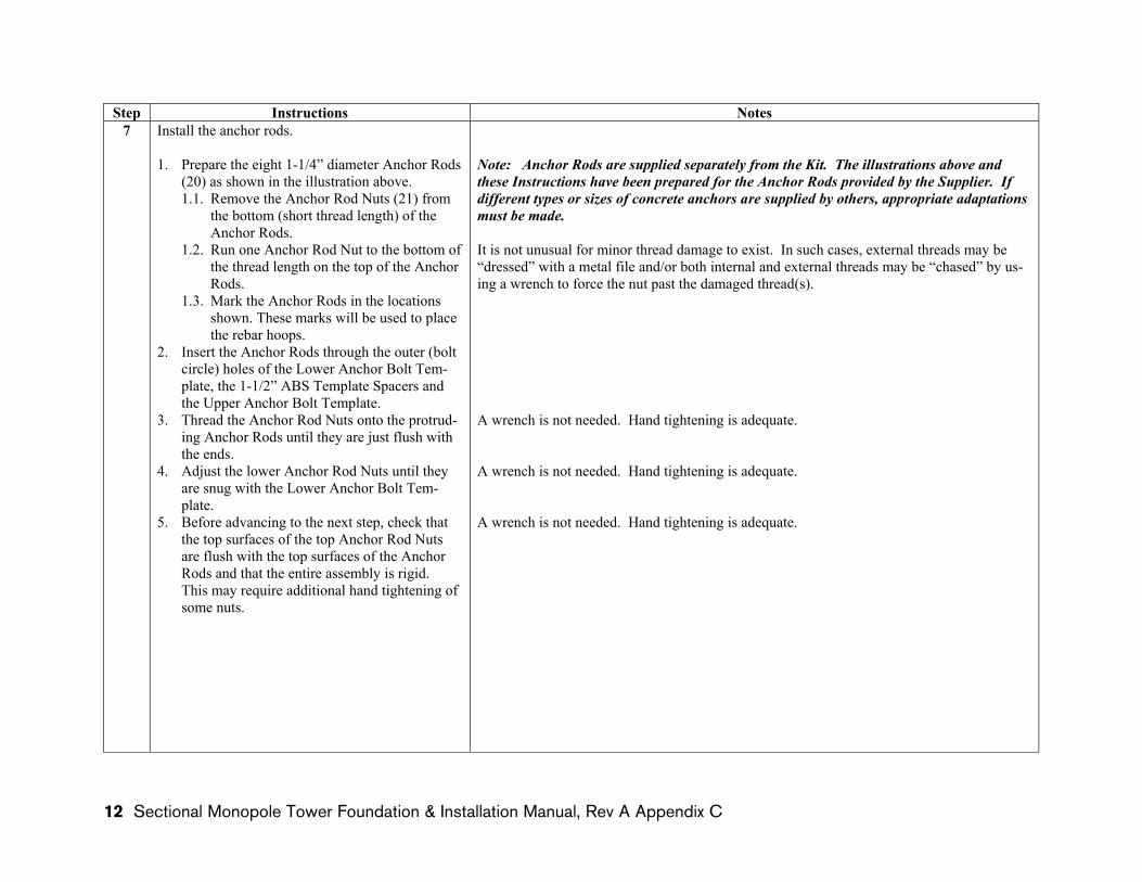
Step Instructions Notes7 Install the anchor rods.
1. Prepare the eight 1-1/4” diameter Anchor Rods (20) as shown in the illustration above. 1.1. Remove the Anchor Rod Nuts (21) from
the bottom (short thread length) of the Anchor Rods.
1.2. Run one Anchor Rod Nut to the bottom of the thread length on the top of the Anchor Rods.
1.3. Mark the Anchor Rods in the locations shown. These marks will be used to place the rebar hoops.
2. Insert the Anchor Rods through the outer (bolt circle) holes of the Lower Anchor Bolt Tem-plate, the 1-1/2” ABS Template Spacers and the Upper Anchor Bolt Template.
3. Thread the Anchor Rod Nuts onto the protrud-ing Anchor Rods until they are just flush with the ends.
4. Adjust the lower Anchor Rod Nuts until they are snug with the Lower Anchor Bolt Tem-plate.
5. Before advancing to the next step, check that the top surfaces of the top Anchor Rod Nuts are flush with the top surfaces of the Anchor Rods and that the entire assembly is rigid. This may require additional hand tightening of some nuts.
Note: Anchor Rods are supplied separately from the Kit. The illustrations above and these Instructions have been prepared for the Anchor Rods provided by the Supplier. If different types or sizes of concrete anchors are supplied by others, appropriate adaptations must be made.
It is not unusual for minor thread damage to exist. In such cases, external threads may be “dressed” with a metal file and/or both internal and external threads may be “chased” by us-ing a wrench to force the nut past the damaged thread(s).
A wrench is not needed. Hand tightening is adequate.
A wrench is not needed. Hand tightening is adequate.
A wrench is not needed. Hand tightening is adequate.
SMarT_Foundation™ [Simple Modular Technology] SMarT 2_v2 March 12, 2008 © 2007–2008 by AnemErgonics, LLC. All rights reserved. Page 11 of 22
12 Sectional Monopole Tower Foundation & Installation Manual, Rev A Appendix C
Instructions for Assembly and Installation of SMarT_Foundation™ Kits (U.S. Patent Pending) for the Skystream Wind Turbine
SMarT_Foundation™ [S
Step 8. Install reinforcement on anchor rod assembly. Follow the illustrations from left to right.
imple Modular Technology] SMarT 2_v2 March 12, 2008 © 2007–2008 by AnemErgonics, LLC. All rights reserved. Page 12 of 22 Sectional Monopole Tower Foundation & Installation Manual, Rev A Appendix C 13

Instructions for Assembly and Installation of SMarT_Foundation™ Kits (U.S. Patent Pending) for the Skystream Wind Turbine
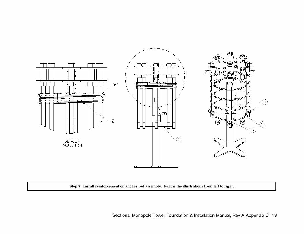
Step Instructions Notes8 Install reinforcement on anchor rod assembly.
1. Slide one Rebar Hoop (4) up over the Anchor Rods to the top marks that were placed on the Anchor Rods in Step 7.1.3. This hoop should be at least 4” below the lower surface of the Lower Anchor Bolt Template.
2. Fasten this Rebar Hoop to every other Anchor Rod using the Plastic Cable Ties (10).
3. Slide all remaining Rebar Hoops up over the Anchor Bolts and temporarily secure them to the top Rebar Hoop using several Plastic Cable Ties.
4. Slide one Stanchion Brace (3) up the Lower Stanchion and over two opposing Anchor Rods. Secure the Stanchion Brace with An-chor Rod Nuts threaded hand tight up to the end of the threads on the Anchor Rods.
5. Slide the remaining Stanchion Brace (3) up the Lower Stanchion and over two Anchor Rods 90 degrees opposed to the first Stanchion Brace. Secure the Stanchion Brace with An-chor Rod Nuts threaded hand tight up to the end of the threads on the Anchor Rods.
6. Install the remaining four Anchor Rod Nuts hand tight up to the end of the threads on the Anchor Rods.
7. Check that all Anchor Rod Nuts are hand tight up against the end of the threads on the Anchor Rods.
8. Cut the Plastic Cable Ties and lower all but the top Rebar Hoop to the positions that were marked on the Anchor Rods in Step 7.1.3. Fasten the Rebar Hoops to every other Anchor Rod using the Plastic Cable Ties.
The vertical position of the Stanchion Braces is not critical, as long as they are below the Stanchion Coupling and secured to the Anchor Rods.
Note: The Anchor Rod Nuts should be threaded tight up against the end of the threaded portion of the Anchor Rods to discourage movement during assembly in the excavation and subsequent placement of concrete.
SMarT_Foundation™ [Simple Modular Technology] SMarT 2_v2 March 12, 2008 © 2007–2008 by AnemErgonics, LLC. All rights reserved. Page 13 of 22
14 Sectional Monopole Tower Foundation & Installation Manual, Rev A Appendix C

Instructions for Assembly and Installation of SMarT_Foundation™ Kits (U.S. Patent Pending) for the Skystream Wind Turbine
SMarT_Foundation™ [S
Step 9. Install the cylindrical concrete form. Follow the illustrations from left to right.
imple Modular Technology] SMarT 2_v2 March 12, 2008 © 2007–2008 by AnemErgonics, LLC. All rights reserved. Page 14 of 22 Sectional Monopole Tower Foundation & Installation Manual, Rev A Appendix C 15

Instructions for Assembly and Installation of SMarT_Foundation™ Kits (U.S. Patent Pending) for the Skystream Wind Turbine
Step Instructions Notes9 Install the cylindrical concrete form.
1. Carefully slip the Cylindrical Concrete Form (22) over the anchor bolt assembly and let it rest on the ground.
2. Install the four Locater Brackets (23) on the long “spokes” of the Lower Anchor Bolt Tem-plate. Use the Locater Bracket Screws (24) provided and the pre-drilled holes in the Lower Anchor Bolt Template.
3. Raise the Cylindrical Concrete Form and cap-ture it in the bottom tabs of the four Locater Brackets. Fasten the Cylindrical Concrete Form in this position using the self threading Locater Bracket Screws provided and the pre-drilled holes in the Locator Brackets.
Important: Make sure the bottom of the Cylindrical Concrete Form rests on the tabs of the Locater Brackets. This position determines the top surface of the concrete.
SMarT_Foundation™ [Simple Modular Technology] SMarT 2_v2 March 12, 2008 © 2007–2008 by AnemErgonics, LLC. All rights reserved. Page 15 of 22
16 Sectional Monopole Tower Foundation & Installation Manual, Rev A Appendix C
Instructions for Assembly and Installation of SMarT_Foundation™ Kits (U.S. Patent Pending) for the Skystream Wind Turbine
Step 10. Prepare nail pegs and guy ropes and set the anchor bolt assembly in the excavation. Follow the illustrations from left to right.
SMarT_Foundation™ [Simple Modular Technology] SMarT 2_v2 March 12, 2008 © 2007–2008 by AnemErgonics, LLC. All rights reserved. Page 16 of 22
Sectional Monopole Tower Foundation & Installation Manual, Rev A Appendix C 17

Instructions for Assembly and Installation of SMarT_Foundation™ Kits (U.S. Patent Pending) for the Skystream Wind Turbine
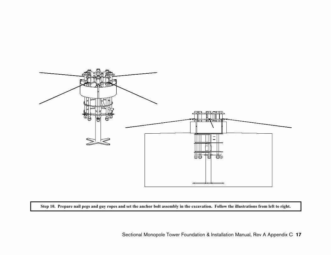
Step Instructions Notes10 Prepare nail pegs and guy ropes and set the anchor
bolt assembly and stanchion in the excavation.
1. Locate four points on the ground where the Guy Ropes (25) will be attached to the Nail Pegs (26). These will be used to secure the an-chor bolt assembly. To keep the work area clear, locate the Nail Pegs 7 to 8 feet (2.1 to 2.4 m) from the centerline of the excavation. The two pairs should be aligned 90 degrees from each other.
2. Drive the Nail Pegs securely into the ground with hooks facing away from the excavation.
3. Tie the ends of the four Guy Ropes to four of the 1-1/2” ABS Template Spacers located 90 degrees apart (every other bolt).
4. Temporarily stow the guy ropes in the hollow top of the stanchion.
5. Check for proper assembly of the Anchor Rods, Rebar Hoops and 1” PVC electrical con-duit. The assembly should be quite rigid and the top nuts should be flush with the tops of the Anchor Rods.
6. Check the distance from the bottom of the ex-cavation to the top of grade. It must be as specified in the Drawings or the Anchor Rods will not be at the proper height for installation of the tower.
7. Carefully lift the assembly and lower it to the bottom of the excavation.
8. Locate the 1” PVC Elbow to facilitate the planned electrical conduit installation. Some manipulation may be required to avoid inter-ference with the Anchor Rods.
As noted in Step 4, the installer may already have decided to assemble the Kit in the excava-tion.
Caution: Look ahead to Step 11 and plan the alignment of nail pegs, anchor bolt assembly and PVC electrical conduit. These steps should be completed before placing the anchor bolt assembly in the excavation.
This step may require some loosening and retightening of the anchor bolt nuts.
Caution:• Use work gloves.• Plan and discuss Step 10.7 before proceeding. • Clear the excavation of any debris or loose soil. • Check the surrounding area and remove tripping hazards. • Lift the assembly by the anchor rods and not by the anchor bolt templates or rebar
hoops. This step requires at least two people. • If the bottom of the excavation is muddy or soft in the center – where the stanchion
will rest – the assembly may sink below the desired level. If this is likely, set the stanchion on a solid surface (such as a paving block) to reduce the soil pressure.
SMarT_Foundation™ [Simple Modular Technology] SMarT 2_v2 March 12, 2008 © 2007–2008 by AnemErgonics, LLC. All rights reserved. Page 17 of 22
18 Sectional Monopole Tower Foundation & Installation Manual, Rev A Appendix C

Instructions for Assembly and Installation of SMarT_Foundation™ Kits (U.S. Patent Pending) for the Skystream Wind Turbine
56
Photo by Libby Oliver, Flagstaff, AZ
Step 11. Level and secure the anchor bolt assembly. Nail Pegs and Guy Ropes are used to stabilize and level the assembly. Here, the installer chose to add wood frames to locate the Cylindrical Concrete Form relative to the overall assembly. The Locater Brackets provided in the Kit serve this purpose, so that the wood frames shown above are unnecessary. Note also the use of a “barrel form” to deal with particularly loose soils. Instead of such a “barrel form” the installer could have chosen simply to pour more concrete. This is an individual choice.
SMarT_Foundation™ [Simple Modular Technology] SMarT 2_v2 March 12, 2008 © 2007–2008 by AnemErgonics, LLC. All rights reserved. Page 18 of 22 Sectional Monopole Tower Foundation & Installation Manual, Rev A Appendix C 19
Instructions for Assembly and Installation of SMarT_Foundation™ Kits (U.S. Patent Pending) for the Skystream Wind Turbine
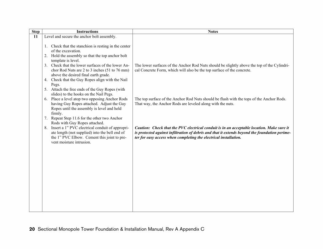
Step Instructions Notes11 Level and secure the anchor bolt assembly.
1. Check that the stanchion is resting in the center of the excavation.
2. Hold the assembly so that the top anchor bolt template is level.
3. Check that the lower surfaces of the lower An-chor Rod Nuts are 2 to 3 inches (51 to 76 mm) above the desired final earth grade.
4. Check that the Guy Ropes align with the Nail Pegs.
5. Attach the free ends of the Guy Ropes (with slides) to the hooks on the Nail Pegs.
6. Place a level atop two opposing Anchor Rods having Guy Ropes attached. Adjust the Guy Ropes until the assembly is level and held firmly.
7. Repeat Step 11.6 for the other two Anchor Rods with Guy Ropes attached.
8. Insert a 1” PVC electrical conduit of appropri-ate length (not supplied) into the bell end of the 1” PVC Elbow. Cement this joint to pre-vent moisture intrusion.
The lower surfaces of the Anchor Rod Nuts should be slightly above the top of the Cylindri-cal Concrete Form, which will also be the top surface of the concrete.
The top surface of the Anchor Rod Nuts should be flush with the tops of the Anchor Rods. That way, the Anchor Rods are leveled along with the nuts.
Caution: Check that the PVC electrical conduit is in an acceptable location. Make sure it is protected against infiltration of debris and that it extends beyond the foundation perime-ter for easy access when completing the electrical installation.
SMarT_Foundation™ [Simple Modular Technology] SMarT 2_v2 March 12, 2008 © 2007–2008 by AnemErgonics, LLC. All rights reserved. Page 19 of 22
20 Sectional Monopole Tower Foundation & Installation Manual, Rev A Appendix C

Instructions for Assembly and Installation of SMarT_Foundation™ Kits (U.S. Patent Pending) for the Skystream Wind Turbine
Photo by Libby Oliver, Flagstaff, AZ
Photo by Libby Oliver, Flagstaff, AZ
Photo by Libby Oliver, Flagstaff, AZ
Photo by Libby Oliver, Flagstaff, AZ
Placing the Concrete
Pour the concrete slowly at several places around the foundation. Consolidate it with appropriate tools. Take care to prevent ex-cessive weight on any of the parts and to minimize movement of the anchor bolt as-sembly. Make a final check of alignment and level.
Step 12. Place and finish the concrete.
SMarT_Foundation™ [Simple Modular Technology] SMarT 2_v2 March 12, 2008 © 2007–2008 by AnemErgonics, LLC. All rights reserved. Page 20 of 22 Sectional Monopole Tower Foundation & Installation Manual, Rev A Appendix C 21

Instructions for Assembly and Installation of SMarT_Foundation™ Kits (U.S. Patent Pending) for the Skystream Wind Turbine
Step Instructions Notes12 Place and finish the concrete.
1. Check that the tops of the Anchor Rods and the top surface of the Cylindrical Con-crete Form are level. Adjust if necessary.
2. Check the height of the Cylindrical Con-crete Form. Its top edge should be slightly below the bottom surface of the Anchor Rod Nuts.
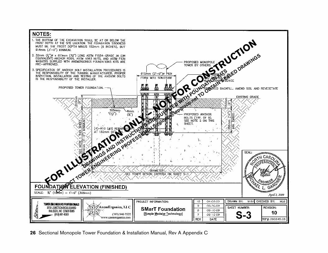
3. Pour concrete to approximately 6 inches (152 mm) below the final earth grade. The slab should be at least 3 feet (0.91 m) thick.
4. Use a trowel to slope concrete away from the base of the Cylindrical Concrete Form to promote drainage toward the foundation perimeter.
5. Trowel-finish all concrete surfaces. 6. Use an edging tool to smooth the concrete
at the perimeter of the Cylindrical Con-crete Form.
7. After the concrete sets, remove the tem-plates and forms.
8. Backfill the excavation with native soil and compact it. Gravel or other landscap-ing materials may be used to fill the annu-lus around the stub pier. Slope the soil to-ward the foundation perimeter for drain-age. If this area is to be re-vegetated, ap-propriate soil amendments should be added.
Caution: Concrete placement should be performed by qualified, responsible individuals. Consult the turbine manufacturer and/or qualified professionals regarding lightning pro-tection and electrical grounding requirements.
Suggestions:• Safety is first! Identify the work area as a safety hazard and control access to it. • Prevent the excavation from freezing – use heaters or thermal blankets if necessary. • Prevent water from accumulating at the bottom of the excavation. • Keep the excavation clean and free from debris. • Check the condition of the excavation in preparation for concrete placement. • Check that the work area is clear, being especially careful about tripping hazards. • Have all tools and equipment readily available. • Recheck the anchor bolt height relative to the planned earth grade (Step 11.3). • Recheck that the anchor bolt assembly is level (Steps 11.6 and 11.7). • Make sure the concrete mix is fluid enough to fill potential voids. • Consolidate the concrete around the rebar and anchor bolt assembly. Note the
Drawings regarding vibration of concrete during construction. • Pour the concrete slowly from several locations around the excavation. Check that
the anchor bolt assembly remains in its intended position and is plumb. • Check that the PVC electrical conduit remains in its intended position. • Use hand tools to place and consolidate concrete within the cylindrical concrete
form.• Protect the concrete from sun, wind, hail, heavy rain and freezing for at least one
week after pouring. Use appropriate curing compounds or keep the concrete cov-ered and moist.
• Allow the concrete to cure for 24 hours before removing templates and forms. • Clean the anchor rods with a wire brush and appropriate solvent. • The tower and turbine must not be installed and erected – and design loads must
not be applied – until the 28-day concrete strength has been achieved as noted in the Drawings.
SMarT_Foundation™ [Simple Modular Technology] SMarT 2_v2 March 12, 2008 © 2007–2008 by AnemErgonics, LLC. All rights reserved. Page 21 of 22
22 Sectional Monopole Tower Foundation & Installation Manual, Rev A Appendix C
rglov
er@tep
group
.net T
O OBTAIN
SEALED DRAW
INGS
Sectional Monopole Tower Foundation & Installation Manual, Rev A Appendix C 23
FOR ILLUSTRATIO
N ONLY
– NOT FOR CONSTRUCTION
DRAWINGS AND INSTRUCTIONS ARE SUPPLIED W
ITH FOUNDATION KITS
CONTACT TOWER ENGINEERING PROFESSIONALS rg
O OBTAIN SEALED DRAWINGS
rglov
er@tep
group
.net T
O OBTAIN
SEALED DRAW
INGS
24 Sectional Monopole Tower Foundation & Installation Manual, Rev A Appendix C
FOR ILLUSTRATIO
N ONLY
– NOT FOR CONSTRUCTION
DRAWINGS AND INSTRUCTIONS ARE SUPPLIED W
ITH FOUNDATION KITS
CONTACT TOWER ENGINEERING PROFESSIONALS rg
O OBTAIN SEALED DRAWINGS
rglov
er@tep
group
.net T
O OBTAIN
SEALED DRAW
INGS
Sectional Monopole Tower Foundation & Installation Manual, Rev A Appendix C 25
FOR ILLUSTRATIO
N ONLY
– NOT FOR CONSTRUCTION
DRAWINGS AND INSTRUCTIONS ARE SUPPLIED W
ITH FOUNDATION KITS
CONTACT TOWER ENGINEERING PROFESSIONALS rg
O OBTAIN SEALED DRAWINGS
rglov
er@tep
group
.net T
O OBTAIN
SEALED DRAW
INGS
26 Sectional Monopole Tower Foundation & Installation Manual, Rev A Appendix C
FOR ILLUSTRATIO
N ONLY
– NOT FOR CONSTRUCTION
DRAWINGS AND INSTRUCTIONS ARE SUPPLIED W
ITH FOUNDATION KITS
CONTACT TOWER ENGINEERING PROFESSIONALS rg
O OBTAIN SEALED DRAWINGS
rglov
er@tep
group
.net T
O OBTAIN
SEALED DRAW
INGS
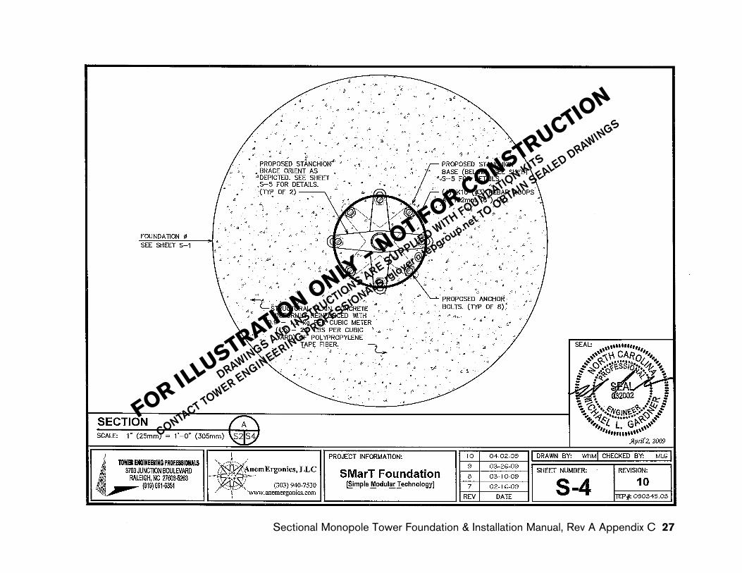
Sectional Monopole Tower Foundation & Installation Manual, Rev A Appendix C 27
FOR ILLUSTRATIO
N ONLY
– NOT FOR CONSTRUCTION
DRAWINGS AND INSTRUCTIONS ARE SUPPLIED W
ITH FOUNDATION KITS
CONTACT TOWER ENGINEERING PROFESSIONALS rg
O OBTAIN SEALED DRAWINGS

rglov
er@tep
group
.net T
O OBTAIN
SEALED DRAW
INGS
28 Sectional Monopole Tower Foundation & Installation Manual, Rev A Appendix C
FOR ILLUSTRATIO
N ONLY
– NOT FOR CONSTRUCTION
DRAWINGS AND INSTRUCTIONS ARE SUPPLIED W
ITH FOUNDATION KITS
CONTACT TOWER ENGINEERING PROFESSIONALS rg
O OBTAIN SEALED DRAWINGS

rglov
er@tep
group
.net T
O OBTAIN
SEALED DRAW
INGS
Sectional Monopole Tower Foundation & Installation Manual, Rev A Appendix C 29
FOR ILLUSTRATIO
N ONLY
– NOT FOR CONSTRUCTION
DRAWINGS AND INSTRUCTIONS ARE SUPPLIED W
ITH FOUNDATION KITS
CONTACT TOWER ENGINEERING PROFESSIONALS rg
O OBTAIN SEALED DRAWINGS


Southwest Windpower, Inc.1801 West Route 66Flagstaff, Arizona 86001Phone: 928.779.9463Fax: 928.779.1485www.skystreamenergy.com
Related Documents