530 GEMÜ 530 + 1434 µPos GEMÜ 530 + 1435 ePos GEMÜ 530 + 1436 cPos Globe Control Valve, Metal Construction The GEMÜ 530 2/2-way globe control valve is designed for demanding flow control applications. It can be paired with the GEMÜ 1434 µPos, GEMÜ 1435 ePos positioners or the GEMÜ 1436 cPos positioner and process controller dependent on the control requirements (for features see page 8). The positioners are specially designed for GEMÜ valves and achieve optimum results when used as a system. The valve spindle is sealed by a self-adjusting gland packing providing low maintenance and reliable sealing even after a long service life with high cycle duties. A wiper ring protects the gland packing against contamination and damage. Features • Linear or modified equal-percentage control characteristics • Kv values from approx. 0.16 - 140 m³/h, depending on nominal size, valve seat and regulating cone design • PID control system can be implemented with GEMÜ 1436 • Suitable for inert, corrosive*, liquid and gaseous media and steam • Flanged bodies in SG iron GGG 40.3 and stainless steel 1.4408 to EN 1092 and ANSI 125/150 • Valve body DN 15 - 100, pressure rating to PN 40 • Max. operating temperature 180 °C Advantages • Simple and fast commissioning • Valve and positioner are optimally adapted to each other. (For positioner details please refer to the relevant data sheets) • Standard gland packing suitable for vacuum up to 20 mbar (abs.) Sectional drawing *see information on working medium on page 2

Welcome message from author
This document is posted to help you gain knowledge. Please leave a comment to let me know what you think about it! Share it to your friends and learn new things together.
Transcript

530
GEMÜ 530 + 1434 µPos
GEMÜ 530 + 1435 ePos
GEMÜ 530 + 1436 cPos
Globe Control Valve, Metal
ConstructionThe GEMÜ 530 2/2-way globe control valve is designed for demanding flow control applications. It can be paired with the GEMÜ 1434 µPos, GEMÜ 1435 ePos positioners or the GEMÜ 1436 cPos positioner and process controller dependent on the control requirements (for features see page 8). The positioners are specially designed for GEMÜ valves and achieve optimum results when used as a system. The valve spindle is sealed by a self-adjusting gland packing providing low maintenance and reliable sealing even after a long service life with high cycle duties. A wiper ring protects the gland packing against contamination and damage.
Features• Linear or modified equal-percentage control characteristics• Kv values from approx. 0.16 - 140 m³/h, depending on nominal size,
valve seat and regulating cone design• PID control system can be implemented with GEMÜ 1436• Suitable for inert, corrosive*, liquid and gaseous media and steam• Flanged bodies in SG iron GGG 40.3 and stainless steel 1.4408 to
EN 1092 and ANSI 125/150• Valve body DN 15 - 100, pressure rating to PN 40• Max. operating temperature 180 °C
Advantages• Simple and fast commissioning• Valve and positioner are optimally adapted to each other.
(For positioner details please refer to the relevant data sheets)• Standard gland packing suitable for vacuum up to 20 mbar (abs.)
Sectional drawing
*see information on working medium on page 2

530 2
0 10 20 30 40 50 60 70 80 90 100
100908070605040302010
100908070605040302010
0 10 20 30 40 50 60 70 80 90 100
Technical data
Working mediumCorrosive, inert, gaseous and liquid media and steam which have no negative impact on the physical and chemical properties of the body and seal material.Max. perm. pressure of working medium see tableMedia temperature -10° to 180 °CMax. permissible viscosity 600 mm²/s (cSt)
Ambient conditionsMax. ambient temperature 60 °C
Control mediumInert gases, max. 60°CMax. control pressure: 8 barFilling volume Actuator size 1G1: 0.025 dm³ Actuator size 2G1: 0.084 dm³ Actuator size 3G1: 0.245 dm³ Actuator size 4G1: 0.437 dm³ Actuator size 5G1: 0.798 dm³
Pressure / temperature correlation for globe valve bodiesConnection
codeMaterial
codeMax. allowable operating pressures in bar at temperature °C*
RT 100 150 200 250 3008 37 16.0 16.0 14.5 13.4 12.7 11.8
10 37 25.0 25.0 22.7 21.0 19.8 18.511 37 40.0 40.0 36.3 33.7 31.8 29.739 37 19.0 16.0 14.8 13.6 12.0 10.28 90 16.0 16.0 15.5 14.7 13.9 11.2
39 90 17.0 16.0 14.8 13.9 12.1 10.2* The valves can be used down to -10°C RT = Room Temperature All pressures are gauge pressures. Pressure/temperature correlation for connection code 48: DN 15 - 40 see connection code 10, DN 50 see connection code 8.
Maximum permissible seat leakage classSeat seal Standard Test procedure Leakage rate Test medium
PTFE DIN EN 60534-4 1 VI airMetal DIN EN 60534-4 1 IV air
The adjacent diagram shows the approximative curve of the Kv value characteristic. The characteristic may deviate dependent on valve body, nominal size, regulating cone and valve stroke.
Stroke [%] Stroke [%]
Kv v
alue
s [%
]
Kv v
alue
s [%
]
equal-percentage modified
Example Kv value diagram
linear

5303
Bleed hole in the actuatorTo bleed the control medium, the pneumatic actuator has a bleed hole that is located on the side of the actuator housing (control function normally closed). In certain areas of application (e.g. the foodstuff industry), dirty water or cleaning media could enter through this bleed hole and penetrate the actuator, thereby adversely affecting correct operation. A special bleed system with lip check valve is available for these applications, which prevents such functional impairment. The bleed hole at the side is then closed.
Standard bleed hole Special bleed system K no. 6996
Technical data
Note: Regulating needle: RAxxx - RCxxx (reduced valve seat)Regulating cone: DN 15 - DN 50Regulating cage: DN 65 - DN 100
Regulating needle
Regulating cone
Regulating cage

5304
Technical data
Correlation Kv value, operating pressure, regulating cone number Valve body material: 1.4408 (code 37), EN-GJS-400-18-LT (code 90)
Nominal sizeKv value
[m³/h]Operating
pressure [bar] *Actuator
size
Regulating cone number
DN linear equal-percentage (mod.)
154.0 10 1G1 RS121 RS1314.0 22 2G1 RS120 RS130
20 6.3 12 2G1 RS122 RS13225 10.0 7 2G1 RS123 RS13332 16.0 10 3G1 RS124 RS13440 25.0 6 3G1 RS125 RS13550 40.0 7 4G1 RS126 RS13665 63.0 8 5G1 - RS33080 90.0 6 5G1 - RS331
100 140.0 3 5G1 - RS332* Observe the pressure / temperature correlation
Correlation Kv value. operating pressure. regulating cone number Valve body material: 1.4408 (code 37)
Nominal sizeKv value
[m³/h]Operating
pressure [bar] **Actuator
size
Regulating cone number
DN linear equal-percentage (mod.)
15
0.1* 40 2G1 RB102 RA3030.16* 40 2G1 RB104 RA3040.25* 40 2G1 RB105 RB3030.40* 40 2G1 RB106 RB3040.63* 40 2G1 RC103 RC3031.00* 40 2G1 RC104 RC3041.60 40 2G1 RD103 RD3032.50 40 2G1 RE104 RE304
201.60 40 2G1 RD104 RD3042.50 40 2G1 RE105 RE3054.00 40 2G1 RF104 RF304
252.50 40 2G1 RE106 RE3064.00 40 2G1 RF105 RF3056.30 18 2G1 RG104 RG304
324.00 40 2G1 RF106 RF3066.30 18 2G1 RG105 RG305
10.00 10 2G1 RH104 RH304
406.30 40 3G1 RG106 RG306
10.00 24 3G1 RH105 RH30516.00 15 3G1 RJ103 RJ303
5010.00 16 3G1 RH106 RH30616.00 12 3G1 RJ104 RJ30425.00 16 4G1 RK102 RK302
* metal seated (with no soft seat) ** Observe the pressure / temperature correlation

5305
Order data
Body configuration Code2/2-way body D
Seat seal CodePTFE 5PTFE, glass fibre reinforced 5GSteel (standard up to Kv value 1.00 m³/h) 10** R-No. on request
Regulating cone R-No.For the regulating cone no. (R-No.) - linear or equal-percentage (mod.) - please refer to the table
Order example 530 25 D 10 37 5 1 2G1 RS133 -Type 530Nominal size 25Body configuration (code) DConnection (code) 10Valve body material (code) 37Seat seal (code) 5Control function (code) 1Actuator size (code) 2G1Regulating cone (R-No.) RS133Version (code) -For the technical data and order data of the positioners please refer to data sheets GEMÜ 1434, 1435 and 1436. Please also note the table on the last page.
Control function CodeNormally closed (NC) 1Double acting (DA) 3*Double acting (normally open) 8** R-No. on request
Flow under the seat
Actuator size CodeActuator 1 piston ø 42 mm 1G1Actuator 2 piston ø 60 mm 2G1Actuator 3 piston ø 80 mm 3G1Actuator 4 piston ø100 mm 4G1Actuator 5 piston ø130 mm 5G1
Valve body material Code1.4408, Investment casting 37EN-GJS-400-18-LT (GGG 40.3) SG iron 90
Connection CodeFlanges EN 1092 / PN16 / form B, length EN 558, series 1, ISO 5752, basic series 1 8Flanges EN 1092 / PN25 / form B, length EN 558, series 1 ISO 5752, basic series 1 10Flanges EN 1092 / PN40 / form B, length EN 558, series 1 ISO 5752, basic series 1 11Flanges ANSI CLASS 125/150 RF, length EN 558, series 1, ISO 5752, basic series 1 39Flanges drilled according to JIS 20K (DN 15 - 40), Flanges drilled according to JIS 10K (DN 50), length EN 558, series 10, ASME/ANSI B 16.10 table 1, column 16 48
Version CodeMedia temperature -10 to 210 °C 2023(only with seat seal Code 5G and 10)
Special bleed system in the actuator 6996All special versions only available ex works
Version for food contactFor food contact, the product must be ordered with the following ordering options:Seat seal code 5, 5GValve body material code 37

5306
SW1
CT
ø BM
GA4
G
Actuator dimensions / Installation dimensions [mm]
Installation dimensions [mm] / weight of valve [kg]Actuator
size 1 ø42 mm
Actuator size 2
ø60 mm
Actuator size 3
ø80 mm
Actuator size 4
ø100 mm
Actuator size 5
ø130 mm
DN SW1 metric CT Weight CT Weight CT Weight CT Weight CT Weight
15 36 167 3.1 213 3.2 - - - - - -20 41 174 3.8 220 4.0 - - - - - -25 46 - - 231 4.8 247 5.5 - - - -32 55 - - 236 6.6 252 7.3 290 8.7 317 11.840 60 - - - - 263 8.4 301 9.8 328 12.950 55 - - - - 271 10.7 309 12.1 336 15.265 75 - - - - - - - - 364 20.480 75 - - - - - - - - 379 23.1
100 75 - - - - - - - - 400 29.0
Actuator dimensionsActuator size øB M A4 max* G
1 46 M16x1 12 G 1/82 63 M16x1 22 G 1/83 84 M16x1 28 G 1/44 104 M22x1.5 32 G 1/45 135 M22x1.5 41 G 1/4
* dependent on nominal sizes

LAR90
170
HAR B
90
HAW
B
42
HA
R
5307
GEMÜ 530 with 1435 ePos
GEMÜ 530 with 1434 µPos
DN Actuator size
Control function øB HAR
151G1 1 46 2712G1 1 63 317
20 2G1 1 63 32425 2G1 1 63 335
322G1 1 63 3403G1 1 - -
40 3G1 1 - -50 4G1 1 - -
Dimensions - GEMÜ 530 [mm]
DN Actuator size
Control function øB HAR HAW LAR
151G1
1 46 255 228 1183 and 8 46 279 252 118
2G11 63 301 274 118
3 and 8 63 325 298 118
20 2G11 63 308 281 118
3 and 8 63 332 305 118
25 2G11 63 319 292 118
3 and 8 63 343 316 118
322G1
1 63 324 297 1183 and 8 63 348 321 118
3G11 84 340 335 118
3 and 8 84 364 359 118
40 3G11 84 351 346 118
3 and 8 84 375 370 118
503G1
1 84 359 354 1183 and 8 84 383 378 118
4G11 104 402 397 138
3 and 8 104 421 416 138
65 5G11 135 459 454 138
3 and 8 135 478 473 138
80 5G11 135 474 469 138
3 and 8 135 493 488 138
100 5G11 135 495 490 138
3 and 8 135 514 509 138

5308
88
HA
R
B
GEMÜ 530 with 1436 cPos
Dimensions - GEMÜ 530 [mm]
DN Actuator size
Control function øB HAR
15 2G11 63 3483 63 372
20 2G11 63 3553 63 379
25 2G11 63 3663 63 390
322G1
1 63 3713 63 395
3G11 84 4103 84 433
40 3G11 84 4203 84 444
503G1
1 84 4283 84 452
4G11 104 4723 104 490
65 5G11 135 5263 135 545
80 5G11 135 5423 135 560
100 5G11 135 5623 135 581

5309
K
L
D
FTF
FTF
D
K
L
Body dimensions [mm]
Flanges. connection code 8, 10, 11, 39, 48Valve body material 1.4408 (code 37), EN-GJS-400-18-LT (code 90)Connection code 8, 10, 11 Connection code 39 Connection code 48 Weight
[kg]DN Number of bolts FTF ø D ø K ø L FTF ø D ø K ø L FTF ø D ø K ø L
15 4 130 95 65 14 130 90 60.3 15.9 108 95 70 15 2.220 4 150 105 75 14 150 100 69.9 15.9 117 100 75 15 3.025 4 160 115 85 14 160 110 79.4 15.9 127 125 90 19 3.732 4 180 140 100 18 180 115 88.9 15.9 - - - - 5.340 4 200 150 110 18 200 125 98.4 15.9 165 140 105 19 6.350 4 230 165 125 18 230 150 120.7 19.0 203 155 120 19 8.4
For materials see overview on page 10
Flanges. connection code 8, 39Valve body material 1.4408 (code 37), EN-GJS-400-18-LT (code 90)
Connection code 8 Connection code 39 Weight[kg]DN FTF ø D ø K ø L Number of
bolts ø D ø K ø L Number of bolts
65 290 185 145 18 4 180 139.7 19 4 12.780 310 200 160 18 8 190 152.4 19 4 15.4
100 350 220 180 18 8 230 190.5 19 8 23.0For materials see overview on page 10

53010
Overview of metal bodies for GEMÜ 530Connection
code 8 10 11 39 48
Material code 37 90 37 37 37 90 37
DN 15 - X - X X X XDN 20 - X - X X X XDN 25 - X - X X X XDN 32 - X X X X X -DN 40 - X X X X X XDN 50 X X - - X X XDN 65 X X - - X X -DN 80 X X - - X X -
DN 100 X X - - X X -

11530
Project (customer)
Date
Contact person
Valve/TAG number
Telephone
Requirement characteristic 1st operating pointmaximum ow
2nd operating pointmedium ow
3rd operating pointminimum ow
Media temperature 4)
Inlet pressure
Outlet pressure
Flow rate 2, 3)
in [m³/h] for liquids
Gases 6)
in [kg/h] for steam
Technical requirements
Medium 1)
Speci cation sheet for designing regulating cones for globe valves
1) Liquid or gas? For media other than water or air, it is necessary to give data for the density and viscosity (with unit of measurement) of the medium. Otherwise we will assume data for standard conditions.
2) For steam especially, the minimum or maximum ow rate should be assigned to the appropriate inlet or outlet pressure. The temperature of the medium should also be taken into account.
3) GEMÜ recommends a positioning ratio of 1 : 10 (e.g. minimum ow rate is 10 m³/h and the maximum ow rate is 100 m³/h). Please note that the valve only controls reliably from a ow of
about 10% of the max. Kv value on account of the valve opening behaviour. Other positioning ratios are possible on request or in the selection of standard regulating cones.
4) The media temperature range must be speci ed for steam applications. T = 20 °C is assumed unless speci ed otherwise.
5) This data is not absolutely necessary. A room temperature of 20 °C is assumed unless speci ed otherwise.
6) Basis: standard conditions 0 °C, 1013.25 mbar. If conditions differ, please specify them.
Valv
e bo
dy /
Act
uato
r
Type
Required valve DN
Max. operating pressure
Ambient temperature 5)
Max. media temperature
Connection
Body material
Seat seal PTFE Other
Control function NC (normally closed) DA (double acting) Double acting (normally open)
Control pressure min max
Regu
latin
g co
ne Characteristic linear modi ed equal-percentage
Other
°C °C °C
bar(g) bar(g) bar(g)
bar(g) bar(g) bar(g)
m³/h m³/h m³/h
Nm³/h Nm³/h Nm³/h
kg/h kg/h kg/h
GEMÜ 532 + 1435 ePos
GEMÜ 534 + 1436 cPos GEMÜ 550
+ 1434 µPosGEMÜ 514
+ 1434 µPos
GEMÜ 554 + 1435 ePos
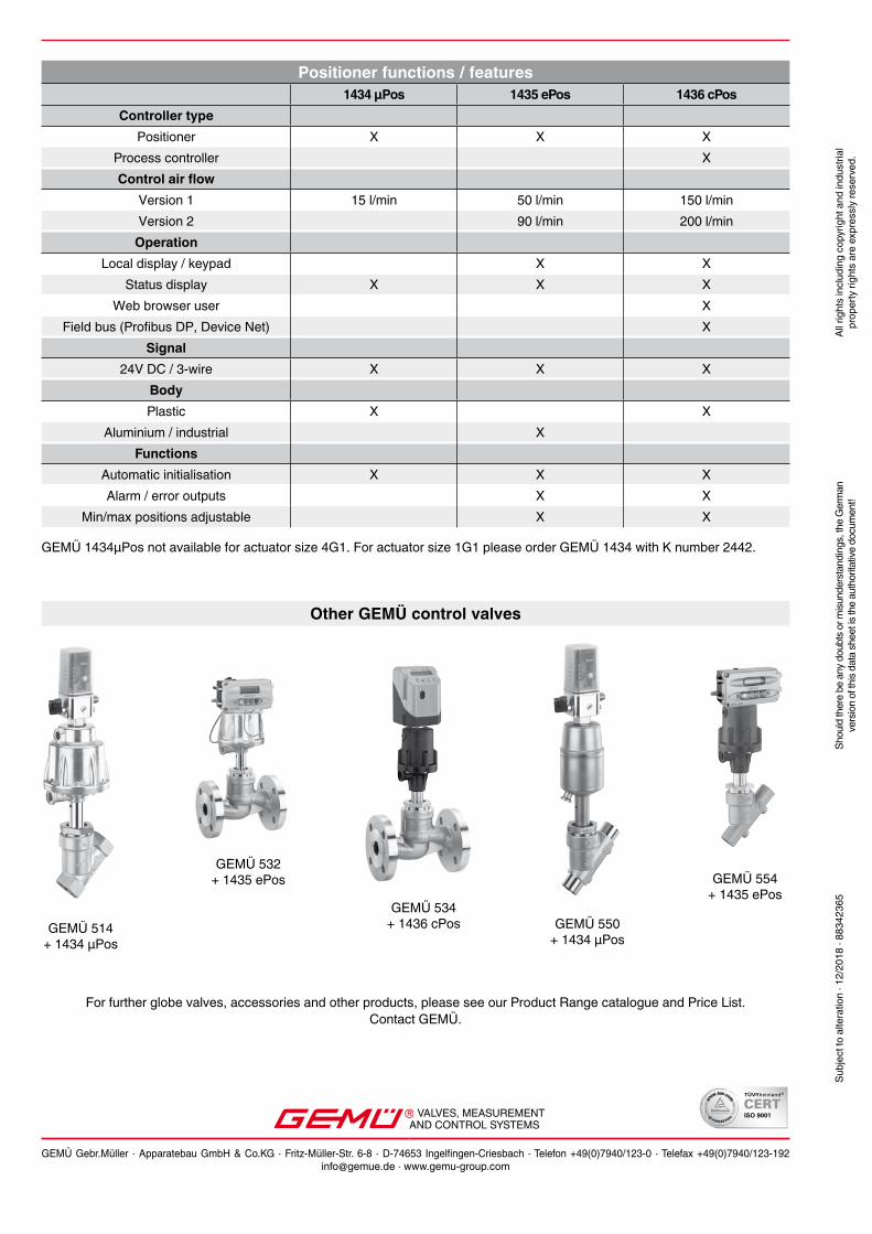
For further globe valves, accessories and other products, please see our Product Range catalogue and Price List. Contact GEMÜ.
Other GEMÜ control valves
Positioner functions / features1434 µPos 1435 ePos 1436 cPos
Controller typePositioner X X X
Process controller XControl air flow
Version 1 15 l/min 50 l/min 150 l/minVersion 2 90 l/min 200 l/min
OperationLocal display / keypad X X
Status display X X XWeb browser user X
Field bus (Profibus DP, Device Net) XSignal
24V DC / 3-wire X X XBodyPlastic X X
Aluminium / industrial XFunctions
Automatic initialisation X X XAlarm / error outputs X X
Min/max positions adjustable X X
GEMÜ 1434µPos not available for actuator size 4G1. For actuator size 1G1 please order GEMÜ 1434 with K number 2442.
VALVES, MEASUREMENTAND CONTROL SYSTEMS
GEMÜ Gebr.Müller · Apparatebau GmbH & Co.KG · Fritz-Müller-Str. 6-8 · D-74653 Ingelfingen-Criesbach · Telefon +49(0)7940/123-0 · Telefax +49(0)7940/[email protected] · www.gemu-group.com
Subj
ect t
o al
tera
tion
· 12/
2018
· 88
3423
65Sh
ould
ther
e be
any
dou
bts o
r misu
nder
stan
ding
s, th
e G
erm
anve
rsio
n of
this
data
shee
t is th
e au
thor
itativ
e do
cum
ent!
All r
ight
s in
clud
ing
copy
right
and
indu
stria
l pr
oper
ty ri
ghts
are
exp
ress
ly re
serv
ed.
Related Documents