87 SECTION VI: MOVABLE BRIDGES HISTORICAL DEVELOPMENT As mentioned in the discussion of Maryland transportation history earlier in this report, rivers and creeks were the primary means of transportation for early residents of Maryland. The gradual construction of roads in the colony encountered rivers as obstacles that had to be crossed, but when those rivers served as the primary avenues of transportation, it was not sufficient simply to build a bridge over the river. When those rivers were navigable, some means had to be found to cross the river and at the same time permit the river's navigation. In order to allow vessels to navigate a bridged waterway, one must build either a high, fixed bridge with adequate clearance or a movable bridge with a span that moves out of the way when a vessel approaches. As building a high bridge usually required extensive approach work and very high grades, movable bridges became the predominant technological solution to the problem of how to bridge navigable waters. In a 1907 paper intended to open discussion and establish specifications for movable bridges, C.C. Schneider, past president of the American Society of Civil Engineers, classified movable spans by the following categories (Schneider 1908:258-259): 1. Swing bridges, which turn about a vertical axis; 2. Bascule bridges, which turn about a horizontal axis or roll back on a circular segment; 3. Lift bridges, which lift vertically; 4. Traversing or retractile bridges; 5. Transporter or ferry bridges; 6. Pontoon or floating swing bridges. Brief descriptions of these categories were provided in 1926 by Otis Hovey, Assistant Chief Engineer of the American Bridge Company, in his text Movable Bridges: A swing bridge consists of a superstructure arranged to turn about the vertical axis of a pivot anchored to the center pier. In ordinary cases the

Welcome message from author
This document is posted to help you gain knowledge. Please leave a comment to let me know what you think about it! Share it to your friends and learn new things together.
Transcript

87
SECTION VI: MOVABLE BRIDGES HISTORICAL DEVELOPMENT As mentioned in the discussion of Maryland transportation history earlier in this report, rivers and creeks were the primary means of transportation for early residents of Maryland. The gradual construction of roads in the colony encountered rivers as obstacles that had to be crossed, but when those rivers served as the primary avenues of transportation, it was not sufficient simply to build a bridge over the river. When those rivers were navigable, some means had to be found to cross the river and at the same time permit the river's navigation. In order to allow vessels to navigate a bridged waterway, one must build either a high, fixed bridge with adequate clearance or a movable bridge with a span that moves out of the way when a vessel approaches. As building a high bridge usually required extensive approach work and very high grades, movable bridges became the predominant technological solution to the problem of how to bridge navigable waters. In a 1907 paper intended to open discussion and establish specifications for movable bridges, C.C. Schneider, past president of the American Society of Civil Engineers, classified movable spans by the following categories (Schneider 1908:258-259): 1. Swing bridges, which turn about a vertical axis; 2. Bascule bridges, which turn about a horizontal axis or
roll back on a circular segment; 3. Lift bridges, which lift vertically; 4. Traversing or retractile bridges; 5. Transporter or ferry bridges; 6. Pontoon or floating swing bridges. Brief descriptions of these categories were provided in 1926 by Otis Hovey, Assistant Chief Engineer of the American Bridge Company, in his text Movable Bridges: A swing bridge consists of a superstructure arranged to turn about the
vertical axis of a pivot anchored to the center pier. In ordinary cases the

88
pivot is at the center of a span of two equal arms, which balance each other when the bridge is open, thus providing two equal openings for navigation. It is sometimes necessary to place the pivot near one end. The shorter arm must then be counterweighted to balance the longer arm when the bridge is open.
Bascule bridges are, strictly speaking, those in which one end rises as the
other falls, but the term is commonly applied to any type moving about a horizontal axis, either fixed or moving, as well as to those that roll back on a circular segment [rolling lift bascule spans]. They may consist of a single leaf spanning the channel [single leaf] or of two symmetrical leaves [double leaf] meeting at the center.
Lift bridges moving vertically consist of simple spans resting on piers when
closed. In most cases the weight of the lifting span is counterweighted by means of ropes, or chains, attached to the ends of the span and the counterweights, which pass up and over sheaves on top of towers at the ends of the bridge.
Retractile, or traversing, bridges [move] horizontally. When closed they
form simple spans across the channels. Some telescope inside of the adjoining spans; others recede above the approaches, the rear end being tilted upward and the free end downward. In some cases the approach span is first moved aside, transversely, to permit the draw span to recede in its place.
Transporter, or ferry, bridges are rarely used. A fixed span across the
channel is supported on shore towers at a sufficient height to clear navigation. A platform, or a car, is suspended under the span and arranged to travel across the channel from shore to shore.
Pontoon bridges are. . .adapted for use when local conditions prevent the
construction of more stable structures when a temporary crossing must be quickly made, as in military operations. They may consist of small boats, or pontoons, lashed together for temporary use, or more elaborate and stable pontoons in permanent structures [Hovey 1926:17-19].
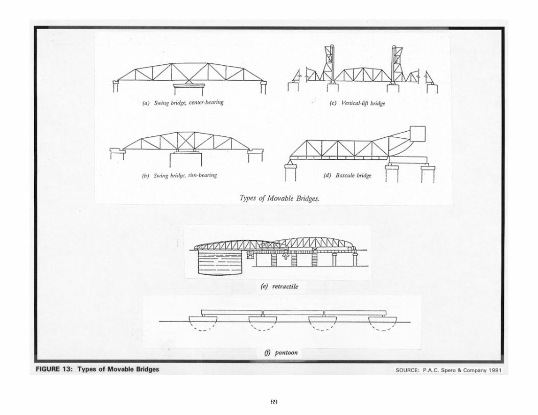
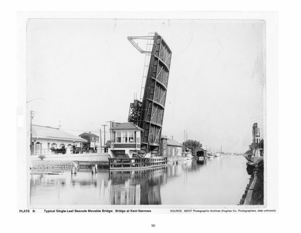
With the exception of transporter or ferry bridges, there is at least one historical example of each of the above categories of movable bridges over the navigable waters of Maryland; for the swing, bascule, and retractile categories, there are numerous examples (Figure 13; Plates 8 and 9). As examples of the type, Maryland's bridges represent a movable bridge technology with historical precedents dating to ancient times. Movable bridges were described by ancient historians, developed in the
89
90
91

92
Renaissance, and flourished in the late nineteenth and early twentieth centuries. Today,as high bridges increasingly replace older movable bridges, the type has significantly declined as a bridge building option for navigable waters. The operation of movable bridges in the United States is regulated by the U.S. Army Corps of Engineers, which was given authority over navigable waters by Congress in 1894 (U.S Army Corps of Engineers 1933:123). Listings of all bridges over navigable waters (U.S. Army Corps of Engineers 1926) and regulations governing the operation of each bridge (U.S. Army Corps of Engineers 1939) have been published periodically based on the navigation needs of the waterways. These regulations must be posted on upstream and downstream sides of the bridge. Some movable bridges had 24-hour service because the operator lived near the bridge and was able to respond to a boat whistle or horn blast; others required notice ranging from 4 to 24 hours. Some spans included operators' houses for the convenience of the tenders. The following subsections summarize the development of each of the movable bridge categories which have been built in Maryland. Swing Bridges Although bascule bridges appear to have been much more common than swing spans in the middle ages, swing-span technology is documented during the Renaissance. In about 1500, Leonardo da Vinci made a sketch of an unequal-armed, or bob-tailed, center-bearing swing bridge which was swung by means of hand winches. By the early seventeenth century, the essentials of the center-bearing pivot as used in late nineteenth and early twentieth century swing spans had already been worked out. In 1625, the French "Royal Engineer-in-Chief," Salomen de Caux, designed a double-swing bridge for the large lock at Cherbourg. It consisted of two spans, each with two unequal arms, the longer arms (27 feet each) of both meeting at the center of the bridge. Each swing span revolved on a central iron bearing and was supported by balance wheels rolling on a circular track in order to steady the span as it spun to the open and closed positions (Hovey 1926:I, 12, 13). The advent of metal structural members in the very late eighteenth century had a particularly beneficial impact on the development of movable spans. The first known metal bridge was the cast-iron arch bridge at Coalbrookdale, England, a non-movable bridge. But by 1805, iron was used in the construction of movable bridges at the London Docks. Soon thereafter, in 1818, a double swing span of iron was built at St. Katherine's Docks, near the Tower of London (Hovey 1926:I,13,14). As in Europe, the first movable spans in America were constructed of wood. It is unclear when the first all-iron movable bridge was built in the United States, but

93
the Rush Street swing-span bridge erected in 1856 over the Chicago River appears to be one of the first examples of a large all-iron movable bridge in the nation (Hovey 1926:I,14,15). The Chicago River bridge was swung on a mechanism referred to as a rim-bearing pivot, in which the span's weight is supported by a series of wheels or bearings running on a circular track or drum on the top of the pier that bears the swing span. Developed in the early nineteenth century by English engineers, rim-bearing pivots were commonly thought to be necessary to bear the great weight of large swing spans. In the 1870s, American engineers began to build swing spans supported on center-bearing pivots (Hovey 1926:I, 36), returning to the simpler design pioneered in 1500 by Leonardo and utilized on all swing spans before the development of the rim-bearing pivot in the early nineteenth century. Due to their simplicity, reliability, and comparative economy, the center-bearing design gradually prevailed over the more complex rim-bearing design. By the third decade of the twentieth century, the center-bearing type had nearly superseded the rim-bearing type for all but the widest city highway bridges. By that time, many engineers had come to appreciate the advantages of the swing span over rival forms of movable bridges. As Otis Hovey stated in 1926, "when there are no restricting circumstances, a swing bridge is the simplest, best, and most economical type in first cost and maintenance" (Hovey 1926:20). Disadvantages of swing bridges include slowness of operation, interference with the channel during operation, and obstruction of navigation when there is a series of swing spans in close proximity (Hool and Kinne 1943:1-3). The jack-knife bridge is a special type of swing bridge used only for railway bridges, consisting of a deck girder under each rail, one or more needle beams under the free end, and a gallows frame over the pivots. The action of the bridge is quite similar to the old-fashioned parallel ruler. In 1926 Hovey dismissed the type as "nearly obsolete and will not receive further consideration" (Hovey 1926:18). Bascule Bridges Not all engineers agreed with Hovey's assessment of the superiority of the swing span; the bascule span had many adherents throughout its long history. In the twentieth century George Hool, Professor of Structural Engineering at the University of Wisconsin, strenuously advocated the benefits of the bascule in both his 1924 and 1943 editions of Movable and Long-Span Bridges. Hool's preference for the bascule was largely based on the rapidity with which a vessel could pass through the navigation channel of a bascule as compared a swing span channel, but he also adduced a number of other benefits including economy of operation (Hool and Kinne 1943:1-8). Although favoring swing-span bridges, Hovey acknowledged that the bascule was preferable when numerous parallel bridges had

94
to be erected over a river or when a city had a narrow waterway, as in Chicago (Hovey 1926:22). Of the numerous examples of movable bridges built in the Middle Ages, the vast majority seem to have been bascules, in which the movable span swings upward as it opens to let vessels through. Drawbridges over moats are illustrative examples of this type of construction in its simplest form, as was probably the original London Bridge, completed in 1209. Bascule bridges may consist of one movable span ("single leaf") or two movable spans ("double leaf"); the double leaf is typically used when more navigational clearance is needed. Most of the early bascules were operated by an "out-haul line attached to the free end and running upward and inward to the source of power" (Hool and Kinne 1943:1). Although the majority of these bascules did not have counterweights, thereby increasing the effort to operate them, counterweighted bascules designed by military engineers began to appear on European artificial waterways in the eighteenth century (Hovey 1926:7). In 1839 a bascule railway bridge was constructed at Selby, England, and others were to appear in Copenhagen in 1867, Rotterdam in 1878, and Koenigsberg in 1880 (Hardesty et al. 1975:515). The earliest construction of the modern bascule span is attributed to the 1894 construction of the Tower Bridge in London and the Van Buren Bridge in Chicago. (Hardesty et al. 1975:516). During this and subsequent decades numerous patented bascule designs were developed by bridge engineers in the United States (Hool and Kinne 1943:28, 29). The bascule design attracted engineers of ingenuity and genius; bridge engineer J.A.L. Waddell commented, "they [the designs] are scientific, and they represent, probably, the best and most profound thought that has ever been devoted to bridge engineering" (Waddell 1916). Waddell, himself, had patented a bascule design. Two bascule types predominated in this period: the trunnion bascule, in which the movable span swings upward around a fixed-axis trunnion or pivot at the center of rotation which coincides with the center of gravity; and the rolling lift bascule span, where the center of rotation (and gravity) moves away from the opening as the span swings upward. The trunnion bascule, in its simpler forms, evolved from the medieval drawbridge and its development by European military engineers in the early eighteenth century. In his 1916 Bridge Engineering, Waddell stated that the first important bascule bridge in the United States (1897) was the Michigan Avenue Bridge in Buffalo, New York, a trunnion type in which the free end of the span was connected by cables running to pulleys atop a tower and then down to large cast-iron wheel counterweights running in semicircular tracks. The trunnion bascule evolved in the late nineteenth and early twentieth centuries with the development of the simple trunnion or "Chicago" type and the multiple trunnion or Strauss type. The simple trunnion, patented by the Chicago Bascule Bridge Company, was essentially a refinement of the time-tested bascule mechanism with an integral counterweight. The multiple trunnion design was far more complex, featuring three subsidiary trunnions in addition to the main trunnion, all connected by struts that

95
form a rectangle when the span is closed and a parallelogram when the span is open. The rolling lift bascule shared with its ancestors the fundamental upward-swinging motion of the movable span, but it added an additional movement--the span retreated from the opening as it was swung up, thus providing even more clearance for navigation. This additional movement was accomplished by attaching the span to a segmental girder, which simultaneously tilted the span upwards as it rolled back on its track. Two early nineteenth century French bridges "were the forerunners of the modern rolling lift bascule": one was a 40-foot track girder bridge built at Havre before 1824; the other, rotating on a wheel, was built at Bregere (Hardesty et al. 1975:514). At the end of the nineteenth century, two variants on the rolling lift bridge were patented--the Scherzer and the Rall. Developed in 1893 by William Scherzer, who was granted twelve patents for variations between that date and 1921, the Scherzer Rolling Lift Bridge Company's bascule became the most popular of all bascule types by 1916. The first Scherzer rolling lift bascule bridge was the Van Buren Street Bridge in Chicago, the plans for which were completed in 1893 (Hool and Kinne 1943:1; Hardesty et al. 1975:516). A Scherzer rolling-lift bascule is characterized by its large, concrete counterweight and segmental circular moving girder. The span's movement occurs as it rotates on a short circular segment along a horizontal track girder. The rectangular counterweight is attached to this short, shoreward section of the moving leaf. In the main pier, below the counterweight, is a pit that receives the counterweight when the bridge is open. For a simple, single-leaf, Scherzer rolling-lift bridge three piers are necessary: the main pit pier, the rest pier for the free end of the leaf, and a shoreward pier for the approach span. The Rall design, as constructed by the Strobel Steel Construction Company, utilized a roller of much smaller diameter. As the span is opened, the span first revolves about a pin until the main roller comes into bearing with the track girder; the span then rolls along this track, the swing strut tilting the span as the roller causes it to recede from the opening (Hool and Kinne 1943:16, 17). Vertical Lift Bridges In the 1500s, Leonardo da Vinci designed a vertical lift bridge in which the movable span maintained its horizontal orientation as it was lifted and lowered vertically (Hovey 1926:4). The first recorded vertical lift bridge actually constructed was a seventeenth century 30-foot span with a lift of 6.5 feet that was part of a wood trestle at Vienna over the Danube River (Hardesty et al. 1975:513). In 1872, Squire Whipple, one of the pioneers of American bridge design, began to build small lift spans over canals in New York State; subsequently a number of small spans were erected over canals in other eastern states (Hool and Kinne 1943:158).

96
The first large vertical lift bridge was designed by Waddell in 1892 and erected on South Halstead Street in Chicago with a movable span of 130 feet and a maximum vertical clearance of 155 feet (Hool and Kinne 1943:158). There was little progress made in the building of vertical lift bridges until 1908 when there was a surge in interest in the design; in the following two decades approximately 70 vertical lift bridges were erected in the nation, one engineering firm erecting about 40 of these bridges (Hardesty et al. 1975:513; Hool and Kinne 1943:158). Hool cited the following advantages for the vertical lift: economy, simplicity, rigidity, reliability, and ease of operation (Hool and Kinne 1943:158-160). Retractile Bridges The nineteenth century French architectural historian Viollet-le-Duc provided evidence that retractile bridges were commonly built in southern France and Italy at an early date (Hovey 1926:I, 4-4). In this type of movable bridge, the movable span is typically drawn up and over the approach span, although other arrangements were also built. It was not a very efficient design; the force required to operate such a span exceeded that of any other type of movable bridge (Hovey 1926:I, 18). Quite common in southern Europe in the Middle Ages, the retractile design also found application in the United States on smaller bridges where the effort required was not prohibitive. However, it seems that the retractile span remained a vernacular design to which no noted engineer addressed himself. In 1926 Hovey dismissed the type as "nearly obsolete" (Hovey 1926:18) and in 1943 Hool did not even list the retractile as a movable bridge option. Pontoon Bridges Herodotus stated that the Persians constructed a pontoon bridge of 673 boats in the early fifth century B.C. over which thousands of soldiers marched to wage war with Greece. At three places the boats were lashed together in such a way that they could be swung aside to let vessels through--certainly the earliest, albeit rudimentary, attested version of the swing span (Hovey 1926:I, 2). Much later, da Vinci designed a pontoon swing span, at about the same time that he designed his swing and vertical lift bridges (Hovey 1926:I, 4). Pontoon bridges have been, and continue to be, used in military operations when a river must be spanned quickly and temporarily, but they have also been used where more expensive permanent bridges were not warranted (Hovey 1926:19).

97
MOVABLE BRIDGES IN MARYLAND In November 1795 the Maryland General Assembly passed an act to authorize the Eastern Branch Bridge Company to construct a bridge over the Eastern Branch of the Potomac River. What is noteworthy about this act is that it was the first time that the Maryland Assembly stipulated the construction of a movable bridge. The act required the company to build a bridge with a draw "at least thirty feet wide" and "to keep a sufficient number of hands at all times ready for the purpose of raising the said draw, in order to admit vessels to pass without delay through the said bridge, for which no price or reward shall be demanded by the said company, or their agents." The act also provided for dereliction of duty on the part of the company: "and in case of neglect, the directors for the time being may be indicted, and fined therefor as for a public nuisance in Prince George's county court" (Kilty 1808:November 1795 Session, Chapter 62). Although the Eastern Branch bridge was the first legislated movable bridge project, it is not known whether this was the first movable bridge constructed in Maryland. Augustine Herrman's map of 1670 illustrates that Maryland in its earliest days was indeed "a fringe of scattered settlements, strung along the bayside and along the banks of the navigable rivers, with not a trace of connecting highways" (Sioussat 1899:109). Navigation of the waterways of Maryland by sloop and pinnaces was the norm; roads served to augment, not replace, the transportation network of rivers. Too many families, planters, and towns of the Tidewater area were dependent upon the navigation of the rivers to permit the new roads and their ferries, and later bridges, to interfere with the primary mode of transportation. The critical importance of navigation for early Tidewater Marylanders suggests that bridges built prior to the 1795 act could have been movable bridges. Given the critical importance of navigation to Tidewater residents, it is highly likely that the earliest bridges across the navigable portions of Tidewater rivers and creeks were movable. Although there is no documentation to indicate the nature of the Tidewater's earliest bridges, it can be conjectured that if a later bridge at a particular site is known to have been a movable one, the earliest bridge at that site is also likely to have been a movable structure. The first movable bridges in Maryland were in all likelihood either simple bascule or retractile types. The 1795 act's reference to "raising the draw" of the Eastern Branch bridge indicates that this bridge was a simple bascule. Likewise, the first bridge at Denton on the Choptank River, authorized in 1808 but probably not completed until around 1820, appears to have been a simple bascule, if "drawbridge" is to be understood in its specific rather than generic sense. Retractile bridges were probably also built during this early period, although documentation of the type does not occur until 1858, when the first bridge at Miles River Neck was constructed as a retractile with a navigation clearance of 30 feet. Due to the excessive force needed to operate retractile spans, subsequent use of the design
98
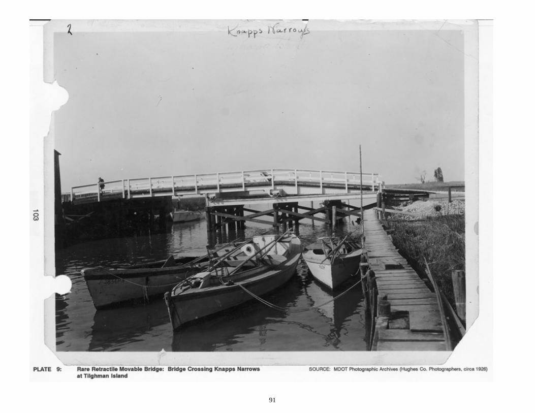
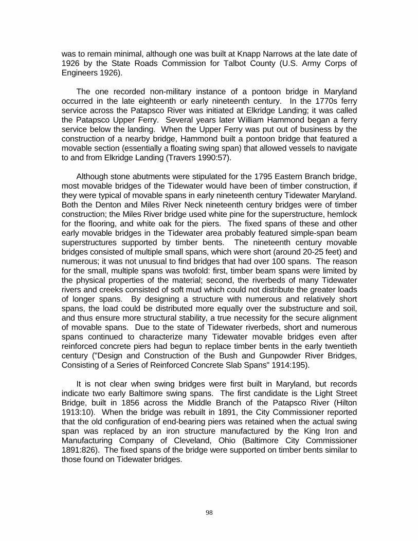
was to remain minimal, although one was built at Knapp Narrows at the late date of 1926 by the State Roads Commission for Talbot County (U.S. Army Corps of Engineers 1926). The one recorded non-military instance of a pontoon bridge in Maryland occurred in the late eighteenth or early nineteenth century. In the 1770s ferry service across the Patapsco River was initiated at Elkridge Landing; it was called the Patapsco Upper Ferry. Several years later William Hammond began a ferry service below the landing. When the Upper Ferry was put out of business by the construction of a nearby bridge, Hammond built a pontoon bridge that featured a movable section (essentially a floating swing span) that allowed vessels to navigate to and from Elkridge Landing (Travers 1990:57). Although stone abutments were stipulated for the 1795 Eastern Branch bridge, most movable bridges of the Tidewater would have been of timber construction, if they were typical of movable spans in early nineteenth century Tidewater Maryland. Both the Denton and Miles River Neck nineteenth century bridges were of timber construction; the Miles River bridge used white pine for the superstructure, hemlock for the flooring, and white oak for the piers. The fixed spans of these and other early movable bridges in the Tidewater area probably featured simple-span beam superstructures supported by timber bents. The nineteenth century movable bridges consisted of multiple small spans, which were short (around 20-25 feet) and numerous; it was not unusual to find bridges that had over 100 spans. The reason for the small, multiple spans was twofold: first, timber beam spans were limited by the physical properties of the material; second, the riverbeds of many Tidewater rivers and creeks consisted of soft mud which could not distribute the greater loads of longer spans. By designing a structure with numerous and relatively short spans, the load could be distributed more equally over the substructure and soil, and thus ensure more structural stability, a true necessity for the secure alignment of movable spans. Due to the state of Tidewater riverbeds, short and numerous spans continued to characterize many Tidewater movable bridges even after reinforced concrete piers had begun to replace timber bents in the early twentieth century ("Design and Construction of the Bush and Gunpowder River Bridges, Consisting of a Series of Reinforced Concrete Slab Spans" 1914:195). It is not clear when swing bridges were first built in Maryland, but records indicate two early Baltimore swing spans. The first candidate is the Light Street Bridge, built in 1856 across the Middle Branch of the Patapsco River (Hilton 1913:10). When the bridge was rebuilt in 1891, the City Commissioner reported that the old configuration of end-bearing piers was retained when the actual swing span was replaced by an iron structure manufactured by the King Iron and Manufacturing Company of Cleveland, Ohio (Baltimore City Commissioner 1891:826). The fixed spans of the bridge were supported on timber bents similar to those found on Tidewater bridges.

99
The other early swing bridge was a short span located near the city docks. An 1869 bird's-eye view of Baltimore depicting the mouth of the Jones Falls and the harbor shows a movable bridge on Block Street crossing the waterway between the harbor and the mouth of the Jones Falls, where the city docks were located (Olson 1980:164). The view clearly illustrates details of the span, such as the fenders which protect the central pier. In the 1867 Report of the City Commissioner the condition of this bridge was described as poor, and the commissioner proposed "at some future time to submit a comparative estimate between a thorough repair of this bridge, which it now demands, and the construction of a new one upon a better principle" (Baltimore City Commissioner 1868:79). A movable bridge had been located at the site since the construction of the City Docks around 1816. A plat map of 1823 showed the Block Street movable bridge at the location, but unfortunately provides no clue as to what sort of movable span was used. However, in 1880 the noted bridge engineer, Wendel Bollman, erected a truss, swing-span replacement for the Block Street bridge. The first fully documented swing bridge in Maryland was a massive one at Havre de Grace over the Susquehanna River. Construction of this bridge reflected the growing confidence that professional engineers had in large swing spans as a due to the success of the Chicago River bridge of 1856. The Susquehanna bridge was built in 1866 to carry the tracks of the Philadelphia, Baltimore, and Wilmington Railroad over the Susquehanna River. The bridge was truly an ambitious structure; its total length was 3,273 feet and it featured a swing span with a 174-foot 9-inch navigational clearance. Although its construction had been delayed since the 1840s because of Port Deposit residents' fears that the bridge would interfere with navigation, by 1866 the huge granite piers and abutments were in place and the superstructure, consisting of 12 timber spans (Haupt trusses), was completed by July of that year. The project was under the direction of Engineer George A. Parker. The bridge's superstructure was replaced sometime between 1870 and 1880 with an iron truss and swing bridge; it is this version of the bridge that was converted to highway use in 1907 by the Havre de Grace-Perryville Bridge Company and transformed into a double-decker bridge by the State Highways Commission in 1927. The double-decker swing bridge remained in operation until 1940 when it was replaced by a high fixed-truss bridge. Also indicative of professional engineers' interest in the use of the swing span for major bridges was the presentation of a paper by Charles Shaler Smith, co-founder of the Baltimore Bridge Company, to the American Society of Civil Engineers in 1874 in which he discussed the loading of rim- and center-bearing pivots in swing spans. The paper reflected the renewed attention that American engineers were giving to the center-bearing pivot. Perhaps as a result of the success of the swing span over the Susquehanna, numerous swing bridges were constructed in the Tidewater and in and around Baltimore during the last quarter of the nineteenth century and the first decades of the twentieth century. Some of these bridges remain in operation today. In 1925,

100
the first year in which the U.S. Army Corps of Engineers drew up a list of the bridges over the navigable waters of the nation, there were 41 movable highway bridges in Maryland, of which 24 (60%) were swing spans. Today there are four known, extant swing bridges in the state. As noted earlier, it appears that simple bascule spans were among the earliest movable bridges in Maryland. However, by the mid-nineteenth century, swing spans were built more frequently; this trend appears to have continued through the end of the century. By the first decade of the twentieth century, the bascule design received a great deal of attention by Maryland State Roads Commission engineers. Between 1904 and 1939 the State Roads Commission constructed at least 17 bascule bridges over the navigable waters of the state including the Chester, Choptank, Miles, Patapsco, Sassafras, Severn, Nanticoke, and Bohemia rivers. Today, 20 of the 24 movable bridges in Maryland feature bascule spans, some of which were built in the last decade. The renewed interest in the bascule bridge coincided with the development of standardized reinforced concrete bridges during the same period; very few bascule spans were integrated into the old timber bent substructure designs. Although the State Roads Commission never developed a standard plan for movable bridges as such, a standard plan was developed in 1919 for a two-story reinforced concrete operator's house that was used on those movable bridges that warranted a full-time operator (Maryland State Roads Commission 1919). In the relatively few cases where specific information about the type of bascule built is available, the Scherzer rolling lift predominates. However, the Hanover Street Bridge over the Middle Branch of the Patapsco River, completed in 1916, featured a Rall rolling lift provided by the Strobel Steel Construction Company of Chicago (Maryland State Roads Commission 1916:62). This bridge was designed by John Edwin Greiner, then a consulting engineer; Greiner had formerly been employed by the B&O Railroad, Keystone Bridge Works, and Gustav Lindenthal (the prominent civil engineer who had developed a notable expertise in movable bridges of all types) (Spero 1983:6, 7). Costing $1,200,000 and measuring 1.62 miles in length, the bridge was a massive undertaking for the State Roads Commission. As expressed by the Commission, "this is the largest piece of work the commission has undertaken since its creation and when completed will be the largest reinforced concrete bridge in the State and one of the most difficult pieces of bridge engineering construction in the country" (Maryland State Roads Commission 1916:62). There are records of only a few vertical lift bridges in Maryland. A four-span vertical lift bridge was constructed by the State Roads Commission between 1910 and 1919 over the Pocomoke River in Pocomoke City (Army Corps of Engineers 1926). At least two were constructed over canals: one over the Chesapeake and Ohio Canal at Williamsport (HAER No. MD-23) and another over the Chesapeake and Delaware Canal at Chesapeake City, built around 1927. In a paper presented
101
to the American Society of Civil Engineers, U.S. Army engineer Earl I. Brown described the reasons for the selection of the vertical lift design at Chesapeake City: The vertical lift type of bridge was selected for all locations on the basis of
lower first cost and maintenance expense. Furthermore, fireproof doors could thus be provided economically, and most of the vessels would require the bridge to be only partly open, thus reducing further the operating expenses and delays to land traffic [Brown 1930:317].
In summary, movable bridges in a variety of forms have protected the navigability of Maryland's rivers and creeks from the earliest period of Maryland history to the present. Although current design trends emphasize the use of the high span to accomplish the same task, there remain over 20 movable bridges in Maryland that continue to mediate between the conflicting demands of vehicular and navigational traffic (Maryland Department of Transportation 1993a). Conclusion The following summary statements regarding structural characteristics for movable bridges, key periods of significance for movable bridges in Maryland, and the earliest known documented examples of timber bridges in the state are based solely on documentary research. Movable bridges (see Figure 13 and Plates 8 and 9) are characterized by their ability to change position in order to permit unimpeded navigation on the waterway which they span. They may consist of a single moving span or multiple moving spans with fixed approach spans. Their structural configuration varies, as described below, but they generally consist of a metal superstructure supported on concrete or masonry substructure. Movable bridge types are defined by the particular way in which the span is made to move. Swing bridges turn about a vertical axis which is usually located on a center pier; swing spans may bear centrally on this pier (center-bearing) or may bear on the rim of a track located on the pier (rim-bearing). Bascule bridges rotate about a horizontal axis and feature decks that may be raised to a vertical or inclined position by various mechanical means. A trunnion bascule bridge moves about a fixed center of rotation located at the center of gravity of the rotating part. A roller-bearing bascule bridge also moves about a fixed center of rotation that coincides with the center of gravity, but the trunnion is eliminated and the load is carried by a segmental circular bearing on rollers in a circular track. A rolling lift bascule continually changes its center of rotation and shifts its load application points as the center of gravity moves in a horizontal line. Bascule bridges may be single-leaf (one movable deck section) or double-leaf (two movable deck sections). A final

102
movable bridge variant, the vertical lift bridge moves out of the way through machinery that lifts both ends of the movable span horizontally to a raised position above the ordinary roadway deck level. Key periods of significance for movable bridges in Maryland, as indicated by documentary research, include 1790-1850, when early bascule (draw) bridges and swing spans were built of timber in the state; 1850-1900, the era in which technological improvements in movable bridge design, such as the employment of iron and steel in movable spans, and the development of new variants of bascule rolling lift bridges (Scherzer) and swing and vertical lift bridges influenced movable bridge construction in Maryland; and 1900-1940, the period during which major, significant modern movable bridges including the 1916 Hanover Street Bridge Viaduct (Rall type) and a group of movable spans erected in Tidewater (Coastal Plain) locations between 1910 and 1940 were built in Maryland under the auspices of the State Roads Commission. The earliest known documented movable bridge spans built in Maryland were likely erected as a consequence of 1795 and 1808 Acts of the General Assembly permitting drawbridges over the Eastern Branch of the Potomac and the Choptank River near Denton. Historical research alone has located no surviving Maryland movable bridges dating to the eighteenth or nineteenth centuries. Significant extant early twentieth century movable spans include a number of structures built under authority of the State Roads Commission; among these are the Hanover Street Viaduct (1916; Rall-type drawbridge); Bridge #23004, the Pocomoke River Bridge carrying State Route 675 (1920; double-leaf bascule); and the Old Severn River-Annapolis Bridge (Bridge #20270; built 1924, double-leaf bascule). The 1993 State Highway Administration Bridge Inventory lists 20 working movable bridges on the state highway system; however, other bridges are listed as including movable spans and may no longer be operative, as field survey may reveal. Further research and survey may also identify extant movable bridges that are significant but not on the state highway system.
Related Documents