SEC-1 BODY EXTERIOR, DOORS, ROOF & VEHICLE SECURITY C D E F G H I J L M SECTION SEC A B SEC N O P CONTENTS SECURITY CONTROL SYSTEM INTELLIGENT KEY SYSTEM BASIC INSPECTION ................................... 5 DIAGNOSIS AND REPAIR WORKFLOW ......... 5 Work Flow ................................................................ 5 INSPECTION AND ADJUSTMENT .................... 8 ECM RE-COMMUNICATING FUNCTION .................. 8 ECM RE-COMMUNICATING FUNCTION : De- scription .................................................................... 8 ECM RE-COMMUNICATING FUNCTION : Spe- cial Repair Requirement ........................................... 8 FUNCTION DIAGNOSIS .............................. 9 INTELLIGENT KEY SYSTEM/ENGINE START FUNCTION ............................................ 9 System Diagram ....................................................... 9 System Description .................................................. 9 Component Parts Location ..................................... 12 Component Description .......................................... 13 NISSAN VEHICLE IMMOBILIZER SYSTEM- NATS .................................................................15 System Diagram ..................................................... 15 System Description ................................................ 15 Component Parts Location ..................................... 16 Component Description ......................................... 17 VEHICLE SECURITY SYSTEM ........................19 System Diagram ..................................................... 19 System Description ................................................ 19 Component Parts Location ..................................... 21 Component Description .......................................... 22 DIAGNOSIS SYSTEM (BCM) ...........................24 COMMON ITEM ........................................................ 24 COMMON ITEM : CONSULT-III Function (BCM - COMMON ITEM) .................................................... 24 INTELLIGENT KEY ...................................................25 INTELLIGENT KEY : CONSULT-III Function (BCM - INTELLIGENT KEY) ...................................25 THEFT ALM ..............................................................28 THEFT ALM : CONSULT-III Function (BCM - THEFT) ...................................................................28 IMMU .........................................................................30 IMMU : CONSULT-III Function (BCM - IMMU) .......30 COMPONENT DIAGNOSIS ........................ 31 U1000 CAN COMM CIRCUIT ........................... 31 BCM ..........................................................................31 BCM : Description ...................................................31 BCM : DTC Logic ....................................................31 BCM : Diagnosis Procedure ...................................31 IPDM E/R ...................................................................31 IPDM E/R : Description ...........................................31 IPDM E/R : DTC Logic ............................................31 IPDM E/R : Diagnosis Procedure ...........................31 U1010 CONTROL UNIT (CAN) ......................... 33 BCM ..........................................................................33 BCM : DTC Logic ....................................................33 BCM : Diagnosis Procedure ...................................33 P1610 LOCK MODE ......................................... 34 Description ..............................................................34 DTC Logic ...............................................................34 Diagnosis Procedure ..............................................34 P1611 ID DISCORD, IMMU-ECM ..................... 35 Description ..............................................................35 DTC Logic ...............................................................35 Diagnosis Procedure ..............................................35 P1612 CHAIN OF ECM-IMMU .......................... 37 Description ..............................................................37 www.gtr-store.eu

Welcome message from author
This document is posted to help you gain knowledge. Please leave a comment to let me know what you think about it! Share it to your friends and learn new things together.
Transcript
BODY EXTERIOR, DOORS, ROOF & VEHICLE SECURITY
C
D
E
SECTION SEC A
B
SECURITY CONTROL SYSTEM
F
G
H
I
J
L
M
EC
N
O
P
CONTENTS
S
INTELLIGENT KEY SYSTEM
BASIC INSPECTION .................................... 5
DIAGNOSIS AND REPAIR WORKFLOW .......... 5Work Flow .................................................................5
INSPECTION AND ADJUSTMENT ..................... 8
ECM RE-COMMUNICATING FUNCTION ...................8ECM RE-COMMUNICATING FUNCTION : De-scription .....................................................................8ECM RE-COMMUNICATING FUNCTION : Spe-cial Repair Requirement ............................................8
FUNCTION DIAGNOSIS ............................... 9
INTELLIGENT KEY SYSTEM/ENGINE START FUNCTION ............................................. 9
System Diagram ........................................................9System Description ...................................................9Component Parts Location ......................................12Component Description ...........................................13
NISSAN VEHICLE IMMOBILIZER SYSTEM-NATS ..................................................................15
System Diagram ......................................................15System Description .................................................15Component Parts Location ......................................16Component Description ..........................................17
VEHICLE SECURITY SYSTEM .........................19System Diagram ......................................................19System Description .................................................19Component Parts Location ......................................21Component Description ...........................................22
DIAGNOSIS SYSTEM (BCM) ............................24
COMMON ITEM .........................................................24COMMON ITEM : CONSULT-III Function (BCM - COMMON ITEM) .....................................................24
INTELLIGENT KEY ....................................................25INTELLIGENT KEY : CONSULT-III Function (BCM - INTELLIGENT KEY) ....................................25
THEFT ALM ...............................................................28THEFT ALM : CONSULT-III Function (BCM - THEFT) ....................................................................28
IMMU ..........................................................................30IMMU : CONSULT-III Function (BCM - IMMU) ........30
COMPONENT DIAGNOSIS .........................31
U1000 CAN COMM CIRCUIT ...........................31
BCM ...........................................................................31BCM : Description ....................................................31BCM : DTC Logic .....................................................31BCM : Diagnosis Procedure ....................................31
IPDM E/R ....................................................................31IPDM E/R : Description ............................................31IPDM E/R : DTC Logic .............................................31IPDM E/R : Diagnosis Procedure ............................31
U1010 CONTROL UNIT (CAN) .........................33
BCM ...........................................................................33BCM : DTC Logic .....................................................33BCM : Diagnosis Procedure ....................................33
P1610 LOCK MODE .........................................34Description ...............................................................34DTC Logic ................................................................34Diagnosis Procedure ...............................................34
P1611 ID DISCORD, IMMU-ECM .....................35Description ...............................................................35DTC Logic ................................................................35Diagnosis Procedure ...............................................35
P1612 CHAIN OF ECM-IMMU ..........................37Description ...............................................................37
www.gtr-
store
.eu
SEC-1
DTC Logic ............................................................... 37Diagnosis Procedure .............................................. 37
P1614 CHAIN OF IMMU-KEY ........................... 38Description .............................................................. 38DTC Logic ............................................................... 38Diagnosis Procedure .............................................. 38
P1615 DIFFRENCE OF KEY ............................. 41Description .............................................................. 41DTC Logic ............................................................... 41Diagnosis Procedure .............................................. 41
B2190 NATS ANTENNA AMP. ......................... 42Description .............................................................. 42DTC Logic ............................................................... 42Diagnosis Procedure .............................................. 42
B2191 DIFFERENCE OF KEY .......................... 45Description .............................................................. 45DTC Logic ............................................................... 45Diagnosis Procedure .............................................. 45
B2192 ID DISCORD, IMMU-ECM ...................... 46Description .............................................................. 46DTC Logic ............................................................... 46Diagnosis Procedure .............................................. 46
B2193 CHAIN OF ECM-IMMU ........................... 48Description .............................................................. 48DTC Logic ............................................................... 48Diagnosis Procedure .............................................. 48
B2013 ID DISCORD, IMMU-STRG .................... 49Description .............................................................. 49DTC Logic ............................................................... 49Diagnosis Procedure .............................................. 49
B2014 CHAIN OF STRG-IMMU ......................... 50Description .............................................................. 50DTC Logic ............................................................... 50Diagnosis Procedure .............................................. 50
B2555 STOP LAMP ........................................... 53Description .............................................................. 53DTC Logic ............................................................... 53Diagnosis Procedure .............................................. 53Component Inspection ............................................ 54
B2556 PUSH-BUTTON IGNITION SWITCH ..... 55Description .............................................................. 55DTC Logic ............................................................... 55Diagnosis Procedure .............................................. 55Component Inspection ............................................ 56
B2557 VEHICLE SPEED ................................... 57Description .............................................................. 57DTC Logic ............................................................... 57Diagnosis Procedure .............................................. 57
B2560 STARTER CONTROL RELAY ............... 58Description .............................................................. 58
DTC Logic ............................................................... 58Diagnosis Procedure ............................................... 58
B2601 SHIFT POSITION ................................... 59Description .............................................................. 59DTC Logic ............................................................... 59Diagnosis Procedure ............................................... 59Component Inspection ............................................ 61
B2602 SHIFT POSITION ................................... 62Description .............................................................. 62DTC Logic ............................................................... 62Diagnosis Procedure ............................................... 62
B2603 SHIFT POSITION STATUS .................... 64Description .............................................................. 64DTC Logic ............................................................... 64Diagnosis Procedure ............................................... 64
B2604 PNP SWITCH ......................................... 66Description .............................................................. 66DTC Logic ............................................................... 66Diagnosis Procedure ............................................... 66
B2605 PNP SWITCH ......................................... 68Description .............................................................. 68DTC Logic ............................................................... 68Diagnosis Procedure ............................................... 68
B2606 STEERING LOCK RELAY ..................... 70Description .............................................................. 70DTC Logic ............................................................... 70Diagnosis Procedure ............................................... 70
B2607 STEERING LOCK RELAY ..................... 71Description .............................................................. 71DTC Logic ............................................................... 71Diagnosis Procedure ............................................... 71
B2608 STARTER RELAY ................................. 73Description .............................................................. 73DTC Logic ............................................................... 73Diagnosis Procedure ............................................... 73
B2609 STEERING STATUS .............................. 75Description .............................................................. 75DTC Logic ............................................................... 75Diagnosis Procedure ............................................... 75
B260B STEERING LOCK UNIT ........................ 79Description .............................................................. 79DTC Logic ............................................................... 79Diagnosis Procedure ............................................... 79
B260C STEERING LOCK UNIT ........................ 80Description .............................................................. 80DTC Logic ............................................................... 80Diagnosis Procedure ............................................... 80
B260D STEERING LOCK UNIT ........................ 81Description .............................................................. 81DTC Logic ............................................................... 81
www.gtr-
store
.eu
SEC-2

C
D
E
F
G
H
I
J
L
M
A
B
EC
N
O
P
S
Diagnosis Procedure ...............................................81
B260F ENGINE STATUS ...................................82Description ..............................................................82DTC Logic ...............................................................82Diagnosis Procedure ...............................................82
B26E1 NO RECEPTION OF ENGINE STA-TUS SIGNAL ......................................................83
Description ..............................................................83DTC Logic ...............................................................83Diagnosis Procedure ...............................................83
B26E9 STEERING STATUS ..............................84Description ..............................................................84DTC Logic ...............................................................84Diagnosis Procedure ...............................................84
B26EA KEY REGISTRATION ............................85Description ..............................................................85DTC Logic ...............................................................85Diagnosis Procedure ...............................................85
B2612 STEERING STATUS ...............................86Description ..............................................................86DTC Logic ...............................................................86Diagnosis Procedure ...............................................86
B2617 STARTER RELAY CIRCUIT ...................90Description ..............................................................90DTC Logic ...............................................................90Diagnosis Procedure ...............................................90
B2619 BCM ........................................................92Description ..............................................................92DTC Logic ...............................................................92Diagnosis Procedure ...............................................92
B261A PUSH-BUTTON IGNITION SWITCH .....93Description ..............................................................93DTC Logic ...............................................................93Diagnosis Procedure ...............................................93
B261E VEHICLE TYPE ......................................96Description ..............................................................96DTC Logic ...............................................................96Diagnosis Procedure ...............................................96
B2108 STEERING LOCK RELAY ......................97Description ..............................................................97DTC Logic ...............................................................97Diagnosis Procedure ...............................................97
B2109 STEERING LOCK RELAY ......................98Description ..............................................................98DTC Logic ...............................................................98Diagnosis Procedure ...............................................98
B210A STEERING LOCK CONDITION SWITCH ..............................................................99
Description ..............................................................99DTC Logic ...............................................................99
Diagnosis Procedure ...............................................99
B210B STARTER CONTROL RELAY ............ 103Description .............................................................103DTC Logic ..............................................................103Diagnosis Procedure .............................................103
B210C STARTER CONTROL RELAY ............ 104Description .............................................................104DTC Logic ..............................................................104Diagnosis Procedure .............................................104
B210D STARTER RELAY .............................. 105Description .............................................................105DTC Logic ..............................................................105Diagnosis Procedure .............................................105
B210E STARTER RELAY ............................... 106Description .............................................................106DTC Logic ..............................................................106Diagnosis Procedure .............................................106
B210F PNP/CLUTCH INTERLOCK SWITCH . 108Description .............................................................108DTC Logic ..............................................................108Diagnosis Procedure .............................................108
B2110 PNP/CLUTCH INTERLOCK SWITCH . 110Description .............................................................110DTC Logic ..............................................................110Diagnosis Procedure .............................................110
POWER SUPPLY AND GROUND CIRCUIT .. 112
BCM .........................................................................112BCM : Diagnosis Procedure ..................................112
IPDM E/R ..................................................................112IPDM E/R : Diagnosis Procedure ..........................112
HOOD SWITCH ............................................... 114Description .............................................................114Component Function Check ................................114Diagnosis Procedure ............................................114Component Inspection ...........................................115
HEADLAMP .................................................... 116Description .............................................................116Component Function Check ................................116Diagnosis Procedure ............................................116
SECURITY INDICATOR LAMP ...................... 117Description .............................................................117Component Function Check ................................117Diagnosis Procedure .............................................117Component Inspection ...........................................118
KEY WARNING LAMP .................................... 119Description .............................................................119Component Function Check ................................119Diagnosis Procedure .............................................119
www.gtr-
store
.eu
SEC-3

INTELLIGENT KEY SYSTEM/ENGINE START FUNCTION .......................................... 120
Wiring Diagram - INTELLIGENT KEY SYSTEM/ENGINE START FUNCTION - ..............................120
NISSAN VEHICLE IMMOBILIZER SYSTEM-NATS ................................................................ 127
Wiring Diagram - NVIS - ........................................127
VEHICLE SECURITY SYSTEM ....................... 134Wiring Diagram - VEHICLE SECURITY SYSTEM - .............................................................................134
ECU DIAGNOSIS .......................................140
BCM (BODY CONTROL MODULE) ................ 140Reference Value ....................................................140Wiring Diagram - BCM - ........................................162Fail-safe .................................................................167DTC Inspection Priority Chart .............................169DTC Index .............................................................170
IPDM E/R (INTELLIGENT POWER DISTRI-BUTION MODULE ENGINE ROOM) ............... 172
Reference Value ....................................................172Wiring Diagram - IPDM E/R - .................................178Fail-safe .................................................................181DTC Index .............................................................183
SYMPTOM DIAGNOSIS ............................184
ENGINE DOES NOT START WHEN INTELLI-GENT KEY IS INSIDE OF VEHICLE ............... 184
Description .............................................................184Diagnosis Procedure .............................................184
STEERING DOES NOT LOCK ........................ 185Description .............................................................185Diagnosis Procedure .............................................185
SECURITY INDICATOR LAMP DOES NOT TURN ON OR FLASH ......................................186
Description ............................................................ 186Diagnosis Procedure ............................................. 186
VEHICLE SECURITY SYSTEM CAN NOT BE SET ...................................................................187
INTELLIGENT KEY ................................................. 187INTELLIGENT KEY : Description .......................... 187INTELLIGENT KEY : Diagnosis Procedure .......... 187
DOOR REQUEST SWITCH ..................................... 187DOOR REQUEST SWITCH : Description ............. 187DOOR REQUEST SWITCH : Diagnosis Proce-dure ....................................................................... 187
VEHICLE SECURITY ALARM DOES NOT ACTIVATE ........................................................188
Description ............................................................ 188Diagnosis Procedure ............................................. 188
KEY SLOT INDICATOR DOES NOT ILLUMI-NATE ................................................................189
Diagnosis Procedure ............................................. 189
PRECAUTION ...........................................190
PRECAUTIONS ................................................190Precaution for Supplemental Restraint System (SRS) "AIR BAG" and "SEAT BELT PRE-TEN-SIONER" ............................................................... 190Precaution for Procedure without Cowl Top Cover . 190Precaution Necessary for Steering Wheel Rota-tion after Battery Disconnect ................................. 190Precaution for Battery Service .............................. 191
ON-VEHICLE REPAIR ..............................192
SECURITY INDICATOR LAMP ........................192Exploded View ...................................................... 192Removal and Installation ....................................... 192www.g
tr-sto
re.e
u
SEC-4

DIAGNOSIS AND REPAIR WORKFLOW[INTELLIGENT KEY SYSTEM]
C
D
E
F
G
H
I
J
L
M
A
B
EC
N
O
P
< BASIC INSPECTION >
S
BASIC INSPECTIONDIAGNOSIS AND REPAIR WORKFLOWWork Flow INFOID:0000000003996693
OVERALL SEQUENCE
DETAILED FLOWJMKIA2823GB
www.gtr-
store
.eu
SEC-5

[INTELLIGENT KEY SYSTEM]DIAGNOSIS AND REPAIR WORKFLOW
< BASIC INSPECTION >
1.GET INFORMATION FOR SYMPTOM
Get the detailed information from the customer about the symptom (the condition and the environment whenthe incident/malfunction occurred).
>> GO TO 2.2.CHECK DTC
1. Check DTC for BCM and IPDM E/R.2. Perform the following procedure if DTC is detected.- Record DTC and freeze frame data (Print them out with CONSULT-III.)- Erase DTC.- Study the relationship between the cause detected by DTC and the symptom described by the customer.3. Check related service bulletins for information.Is any symptom described and any DTC detected?Symptom is described, DTC is detected>>GO TO 3.Symptom is described, DTC is not detected>>GO TO 4.Symptom is not described, DTC is detected>>GO TO 5.
3.CONFIRM THE SYMPTOM
Confirm the symptom described by the customer.Connect CONSULT-III to the vehicle in “DATA MONITOR” mode and check real time diagnosis results.Verify relation between the symptom and the condition when the symptom is detected.
>> GO TO 5.4.CONFIRM THE SYMPTOM
Confirm the symptom described by the customer.Connect CONSULT-III to the vehicle in “DATA MONITOR ” mode and check real time diagnosis results.Verify relation between the symptom and the condition when the symptom is detected.
>> GO TO 6.5.PERFORM DTC CONFIRMATION PROCEDURE
Perform DTC Confirmation Procedure for the detected DTC, and then check that DTC is detected again.At this time, always connect CONSULT-III to the vehicle, and check diagnostic results in real time.If two or more DTCs are detected, refer to SEC-169, "DTC Inspection Priority Chart", and determine troublediagnosis order.NOTE:Perform Component Function Check if DTC Confirmation Procedure is not included in Service Manual. Thissimplified check procedure is an effective alternative though DTC cannot be detected during this check.If the result of Component Function Check is NG, it is the same as the detection of DTC by DTC ConfirmationProcedure.Is DTC detected?YES >> GO TO 7.NO >> Refer to GI-38, "Intermittent Incident".
6.DETECT MALFUNCTIONING SYSTEM BY SYMPTOM DIAGNOSIS
Detect malfunctioning system according to SYMPTOM DIAGNOSIS based on the confirmed symptom in step4, and determine the trouble diagnosis order based on possible causes and symptom.
>> GO TO 7.7.DETECT MALFUNCTIONING PART BY DIAGNOSTIC PROCEDURE
Inspect according to Diagnostic Procedure of the system.NOTE:The Diagnostic Procedure described based on open circuit inspection. A short circuit inspection is alsorequired for the circuit check in the Diagnostic Procedure.
www.gtr-
store
.eu
SEC-6
DIAGNOSIS AND REPAIR WORKFLOW[INTELLIGENT KEY SYSTEM]
C
D
E
F
G
H
I
J
L
M
A
B
EC
N
O
P
< BASIC INSPECTION >
S
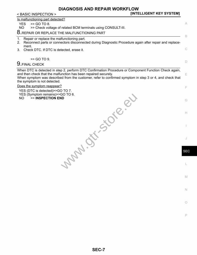
Is malfunctioning part detected?YES >> GO TO 8.NO >> Check voltage of related BCM terminals using CONSULT-III.
8.REPAIR OR REPLACE THE MALFUNCTIONING PART
1. Repair or replace the malfunctioning part.2. Reconnect parts or connectors disconnected during Diagnostic Procedure again after repair and replace-
ment.3. Check DTC. If DTC is detected, erase it.
>> GO TO 9.9.FINAL CHECK
When DTC is detected in step 2, perform DTC Confirmation Procedure or Component Function Check again,and then check that the malfunction has been repaired securely.When symptom was described from the customer, refer to confirmed symptom in step 3 or 4, and check thatthe symptom is not detected.Does the symptom reappear?YES (DTC is detected)>>GO TO 7.YES (Symptom remains)>>GO TO 6.NO >> INSPECTION END
www.gtr-
store
.eu
SEC-7
[INTELLIGENT KEY SYSTEM]INSPECTION AND ADJUSTMENT
< BASIC INSPECTION >INSPECTION AND ADJUSTMENTECM RE-COMMUNICATING FUNCTIONECM RE-COMMUNICATING FUNCTION : Description INFOID:0000000003996452
Performing the following procedure can automatically perform re-communication of ECM and BCM, but onlywhen the ECM has been replaced with a new one (*1).*1: New one means a virgin ECM which has never been energized on-board.(In this step, initialization procedure by CONSULT-III is not necessary)NOTE:• When registering new Key IDs or replacing the ECM that is not brand new, refer to CONSULT-III Oper-
ation Manual NATS-IVIS/NVIS.• If multiple keys are attached to the key holder, separate them before beginning work.• Distinguish keys with unregistered key IDs from those with registered IDs.
ECM RE-COMMUNICATING FUNCTION : Special Repair Requirement INFOID:0000000003996453
1.PERFORM ECM RE-COMMUNICATING FUNCTION
1. Install ECM.2. Insert the registered Intelligent Key (*2), turn ignition switch to “ON”.
*2: To perform this step, use the key that has been used before performing ECM replacement.3. Maintain ignition switch in the “ON” position for at least 5 seconds.4. Turn ignition switch to “OFF”.5. Start engine.Can engine be started?YES >> Procedure is completed.NO >> Initialize control unit. Refer to CONSULT-III Operation Manual NATS-IVIS/NVIS.
www.gtr-
store
.eu
SEC-8
INTELLIGENT KEY SYSTEM/ENGINE START FUNCTION[INTELLIGENT KEY SYSTEM]
C
D
E
F
G
H
I
J
L
M
A
B
EC
N
O
P
< FUNCTION DIAGNOSIS >
S
FUNCTION DIAGNOSISINTELLIGENT KEY SYSTEM/ENGINE START FUNCTIONSystem Diagram INFOID:0000000003996454
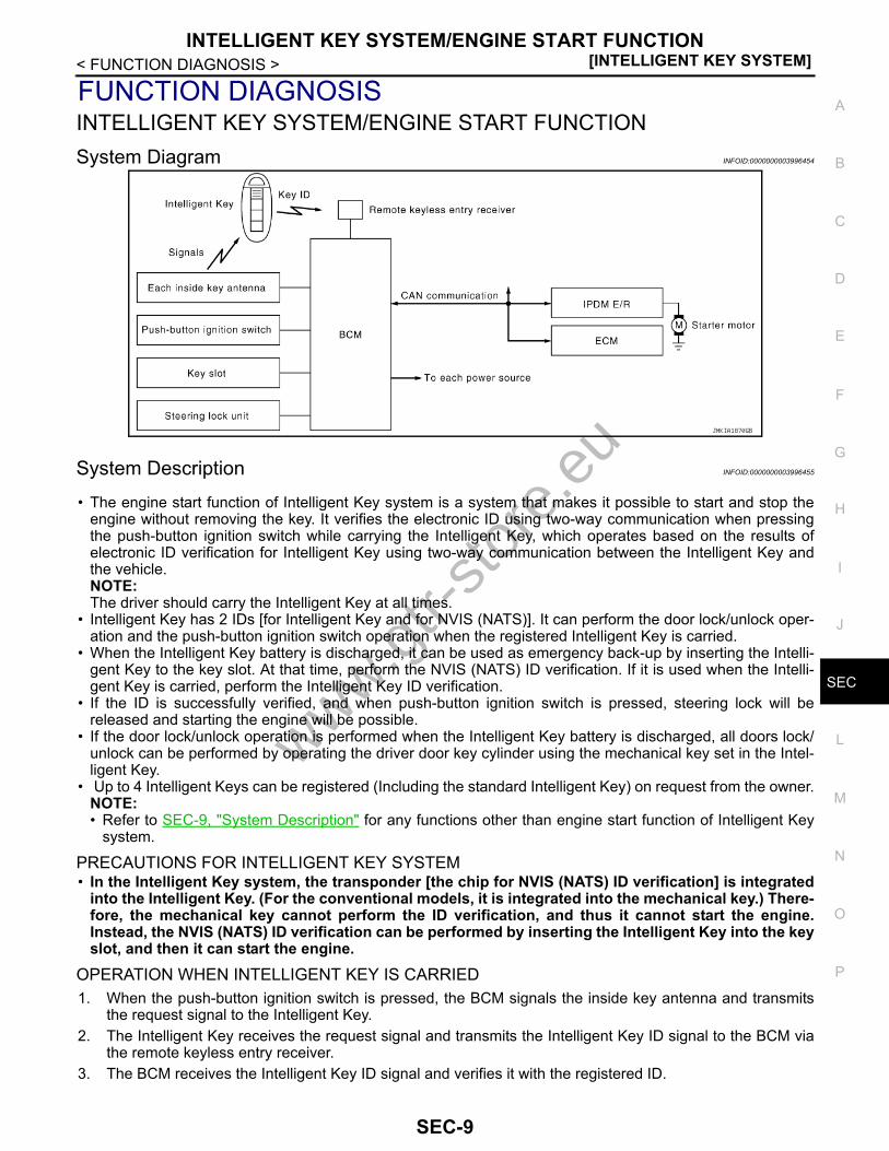
System Description INFOID:0000000003996455
• The engine start function of Intelligent Key system is a system that makes it possible to start and stop theengine without removing the key. It verifies the electronic ID using two-way communication when pressingthe push-button ignition switch while carrying the Intelligent Key, which operates based on the results ofelectronic ID verification for Intelligent Key using two-way communication between the Intelligent Key andthe vehicle.NOTE:The driver should carry the Intelligent Key at all times.
• Intelligent Key has 2 IDs [for Intelligent Key and for NVIS (NATS)]. It can perform the door lock/unlock oper-ation and the push-button ignition switch operation when the registered Intelligent Key is carried.
• When the Intelligent Key battery is discharged, it can be used as emergency back-up by inserting the Intelli-gent Key to the key slot. At that time, perform the NVIS (NATS) ID verification. If it is used when the Intelli-gent Key is carried, perform the Intelligent Key ID verification.
• If the ID is successfully verified, and when push-button ignition switch is pressed, steering lock will bereleased and starting the engine will be possible.
• If the door lock/unlock operation is performed when the Intelligent Key battery is discharged, all doors lock/unlock can be performed by operating the driver door key cylinder using the mechanical key set in the Intel-ligent Key.
• Up to 4 Intelligent Keys can be registered (Including the standard Intelligent Key) on request from the owner.NOTE:• Refer to SEC-9, "System Description" for any functions other than engine start function of Intelligent Key
system.
PRECAUTIONS FOR INTELLIGENT KEY SYSTEM• In the Intelligent Key system, the transponder [the chip for NVIS (NATS) ID verification] is integrated
into the Intelligent Key. (For the conventional models, it is integrated into the mechanical key.) There-fore, the mechanical key cannot perform the ID verification, and thus it cannot start the engine.Instead, the NVIS (NATS) ID verification can be performed by inserting the Intelligent Key into the keyslot, and then it can start the engine.
OPERATION WHEN INTELLIGENT KEY IS CARRIED1. When the push-button ignition switch is pressed, the BCM signals the inside key antenna and transmits
the request signal to the Intelligent Key.2. The Intelligent Key receives the request signal and transmits the Intelligent Key ID signal to the BCM via
the remote keyless entry receiver.3. The BCM receives the Intelligent Key ID signal and verifies it with the registered ID.
JMKIA1870GB
www.gtr-
store
.eu
SEC-9

[INTELLIGENT KEY SYSTEM]INTELLIGENT KEY SYSTEM/ENGINE START FUNCTION
< FUNCTION DIAGNOSIS >4. BCM transmits the steering lock unlock signal to steering lock unit and IPDM E/R if the verification results
are OK.5. IPDM E/R turns the steering lock relay ON and supplies power to the steering lock unit.6. Release of the steering lock.7. BCM transmits the power supply stop signal to IPDM E/R when it confirms that the steering lock is in the
unlock condition.8. IPDM E/R turns the steering lock relay OFF and stops power supply to the steering lock unit.9. BCM turns ACC relay ON and transmits the ignition power supply ON signal to IPDM E/R.10. IPDM E/R turns the ignition relay ON and starts the ignition power supply.11. BCM confirms that the shift position is P or N.12. BCM transmits the starter request signal via CAN communication to IPDM E/R and turns the starter relay
in IPDM E/R ON if BCM judges that the engine start condition is satisfied.13. IPDM E/R turns the starter control relay ON when receiving the starter request signal.14. Battery power is supplied through the starter relay and the starter control relay to operate the starter motor
and to start the cranking.CAUTION:If a malfunction is detected in the Intelligent Key system, the “KEY” warning lamp in the combina-tion meter illuminates. At that time, the engine cannot be started.
15. When BCM receives feedback signal from ECM acknowledging the engine has been initiated, the BCMtransmits a stop signal to IPDM E/R and stops the cranking by turning OFF the starter motor relay. (If theengine initiating has failed, the cranking will stop automatically within 5 seconds.)CAUTION:When the Intelligent Key is carried outside of the vehicle (inside key antenna detection area) withthe power supply in the ACC or ON position, even if the engine start condition* is satisfied, theengine cannot be started.
*: For the engine start condition, refer to “PUSH-BUTTON IGNITION SWITCH OPERATION PROCEDURE”.
OPERATION RANGEEngine can be started when Intelligent Key is inside the vehicle. However, sometimes engine might not startwhen Intelligent Key is on instrument panel or in glove box.
OPERATION WHEN KEY SLOT IS USEDWhen the Intelligent Key battery is discharged, it performs the NVIS (NATS) ID verification between the inte-grated transponder and BCM by inserting the Intelligent Key into the key slot, and then the engine can bestarted.For details relating to starting the engine using key slot, refer to SEC-15, "System Description".
BATTERY SAVER SYSTEMWhen all the following conditions are met for 60 minutes, the battery saver system will cut off the power supplyto prevent battery discharge.• The ignition switch is in the ACC position• All doors are closed• Shift lever is in the P positionReset Condition of Battery Saver SystemIf any of the following conditions are met the battery saver system is released and the steering will changeautomatically to the lock position from the OFF position.• Opening any door• Operating with request switch on door lock• Operating with Intelligent Key on door lockPressing the push-button ignition switch and ignition switch will change the ignition switch to ACC positionfrom OFF position.
STEERING LOCK OPERATIONSteering is locked by steering lock unit when ignition switch is in the OFF position, shift lever is in the P posi-tion and any of the following conditions are met.• Opening door• Closing door• Door is locked with request switch• Door is locked with Intelligent Key
www.gtr-
store
.eu
SEC-10

INTELLIGENT KEY SYSTEM/ENGINE START FUNCTION[INTELLIGENT KEY SYSTEM]
C
D
E
F
G
H
I
J
L
M
A
B
EC
N
O
P
< FUNCTION DIAGNOSIS >
S
PUSH-BUTTON IGNITION SWITCH OPERATION PROCEDUREThe power supply position changing operation can be performed with the following operations.Operation Enable Condition• When an Intelligent Key is within the detection area of inside key antenna and when it is inserted to the key
slot, it is equivalent to the operations below.• When starting the engine, the BCM monitors the following engine start conditions,- Brake pedal operating condition- Shift lever position- Vehicle speed• Unless each start condition is fulfilled, the engine will not respond regardless of how many times the engine
switch is pressed. At that time, illumination repeats the position in the order of LOCK→ACC→ON→OFF.Operation Condition
*1: When the shift lever position is in the N position, the engine start condition is different according to the vehicle speed.• At a vehicle speed of less than 4 km/h (2.5MPH), the engine can start only when the brake pedal is depressed.• At a vehicle speed of 4 km/h (2.5MPH) or more, the engine can start even if the brake pedal is not depressed. (It is the same as
“Engine stall return operation while driving”.)*2: When the shift lever position is in any position other than the P position and when the vehicle speed is 5 km/h (3.1MPH) or more, theengine stop condition is different.• Press and hold the push-button ignition switch for 2 seconds or more. (When the push-button ignition switch is pressed for too short a
time, the operation may be invalid, so properly press and hold to prevent an incorrect operation.)• Press the push-button ignition switch 3 times or more within 1.5 seconds. (Emergency stop operation)
Power supply positionEngine start/stop condition Push-button ignition switch op-
eration frequencyBrake pedal Shift lever position
LOCK → ACC Not depressed Any position 1
LOCK → ACC → ON Not depressed Any position 2
LOCK → ACC → ON → OFF Not depressed Any position 3
LOCK → STARTACC → STARTON → START(Engine start)
Depressed P or N position (*1)
1[If the switch is pressed once,
the engine starts from any pow-er supply position (LOCK, ACC,
and ON)]
Engine is running → OFF(Engine stop)
— P position 1
Engine is running → ACC(Engine stop)
— Any position other than P (*2) 1
Engine stall return oper-ation while driving — N position 1
www.gtr-
store
.eu
SEC-11

[INTELLIGENT KEY SYSTEM]INTELLIGENT KEY SYSTEM/ENGINE START FUNCTION
< FUNCTION DIAGNOSIS >Component Parts Location INFOID:0000000003996456
1. BCM M118, M119, M121, M122, M123
2. IPDM E/R E4, E5, E6, F7 3. TCM B45
4. Push button ignition switch M131 5. Control device (detention switch) B20
6. Key slot M60
7. Combination meter (Key warning lamp) M53
8. Driver side door switch B21 9. Security indicator lamp M29
10. Stop lamp switch E110A. Behind the instrument lower panel
RHB. Engine room dash panel (RH) C. View with trunk front finisher re-
movedD. View with center console assembly
removedE. View with instrument lower panel
(driver) removed
JMKIA2909ZZ
www.gtr-
store
.eu
SEC-12

INTELLIGENT KEY SYSTEM/ENGINE START FUNCTION[INTELLIGENT KEY SYSTEM]
C
D
E
F
G
H
I
J
L
M
A
B
EC
N
O
P
< FUNCTION DIAGNOSIS >
S
Component Description INFOID:0000000003996457
1. Trunk lid lock assembly (trunk room lamp switch) B352
2. Remote keyless entry receiver M134 3. Inside key antenna (console) M146
4. Inside key antenna (trunk room) B41 5. Inside key antenna (instrument cen-ter) M75
6. Horn (low) E81, E82
7. Horn (high) E79, E80 8. Hood switch E83 9. ECM M107A. View with trunk lid finisher removed B. Behind the display unit C. Back of the rear console assemblyD. Behind the trunk front finisher E. Back of the cluster kid C (lower) F. Behind the front bumperG. Behind the instrument lower panel
(assist)
JMKIA2910ZZ
Component Reference
BCM SEC-92
Steering lock unit SEC-79
Push-button ignition switch SEC-93
www.gtr-
store
.eu
SEC-13
[INTELLIGENT KEY SYSTEM]INTELLIGENT KEY SYSTEM/ENGINE START FUNCTION
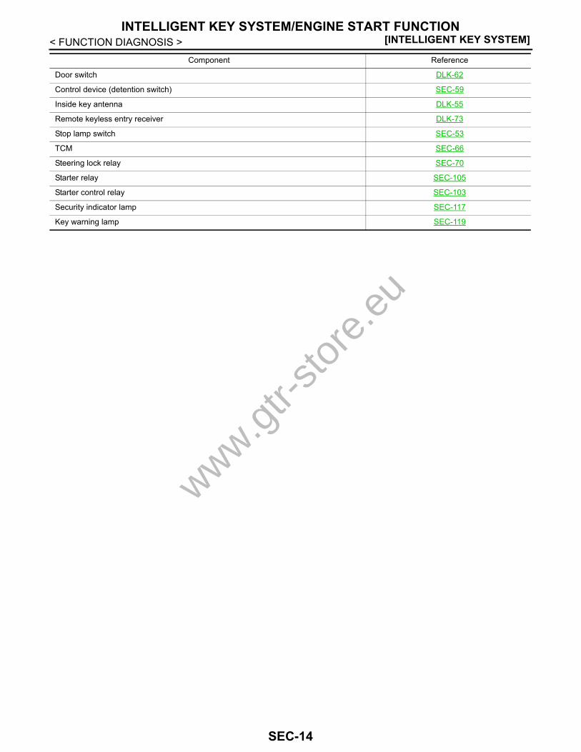
< FUNCTION DIAGNOSIS >
Door switch DLK-62
Control device (detention switch) SEC-59
Inside key antenna DLK-55
Remote keyless entry receiver DLK-73
Stop lamp switch SEC-53
TCM SEC-66
Steering lock relay SEC-70
Starter relay SEC-105
Starter control relay SEC-103
Security indicator lamp SEC-117
Key warning lamp SEC-119
Component Reference
www.gtr-
store
.eu
SEC-14
NISSAN VEHICLE IMMOBILIZER SYSTEM-NATS[INTELLIGENT KEY SYSTEM]
C
D
E
F
G
H
I
J
L
M
A
B
EC
N
O
P
< FUNCTION DIAGNOSIS >
S
NISSAN VEHICLE IMMOBILIZER SYSTEM-NATSSystem Diagram INFOID:0000000003996458
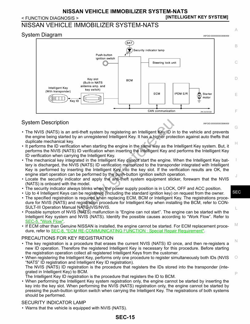
System Description INFOID:0000000003996459
• The NVIS (NATS) is an anti-theft system by registering an Intelligent Key ID in to the vehicle and preventsthe engine being started by an unregistered Intelligent Key. It has a higher protection against auto thefts thatduplicate mechanical key.
• It performs the ID verification when starting the engine in the same way as the Intelligent Key system. But, itperforms the NVIS (NATS) ID verification when inserting the Intelligent Key and performs the Intelligent KeyID verification when carrying the Intelligent Key.
• The mechanical key integrated in the Intelligent Key cannot start the engine. When the Intelligent Key bat-tery is discharged, the NVIS (NATS) ID verification memorized to the transponder integrated with IntelligentKey is performed by inserting the Intelligent Key into the key slot. If the verification results are OK, theengine start operation can be performed by the push-button ignition switch operation.
• Locate the security indicator and apply the anti-theft system equipment sticker, forewarn that the NVIS(NATS) is onboard with the model.
• The security indicator always blinks when the power supply position is in LOCK, OFF and ACC position.• Up to 4 Intelligent Keys can be registered (Including the standard ignition key) on request from the owner.• The specified registration is required when replacing ECM, BCM or Intelligent Key. The registrations proce-
dure for NVIS (NATS) and registration procedure for Intelligent Key when installing the BCM, refer to CON-SULT-III Operation Manual NATS-IVIS/NVIS.
• Possible symptom of NVIS (NATS) malfunction is “Engine can not start”. The engine can be started with theIntelligent Key system and NVIS (NATS). Identify the possible causes according to “Work Flow”. Refer toSEC-5, "Work Flow".
• If ECM other than Genuine NISSAN is installed, the engine cannot be started. For ECM replacement proce-dure, refer to SEC-8, "ECM RE-COMMUNICATING FUNCTION : Special Repair Requirement".
PRECAUTIONS FOR KEY REGISTRATION• The key registration is a procedure that erases the current NVIS (NATS) ID once, and then re-registers a
new ID operation. Therefore the registered Intelligent Key is necessary for this procedure. Before startingthe registration operation collect all registered Intelligent Keys from the customer.
• When registering the Intelligent Key, performs only one procedure to register simultaneously both IDs (NVIS“NATS” ID registration and Intelligent Key ID registration).The NVIS (NATS) ID registration is the procedure that registers the IDs stored into the transponder (inte-grated in Intelligent Key) to BCM.The Intelligent Key ID registration is the procedure that registers the ID to BCM.
• When performing the Intelligent Key system registration only, the engine cannot be started by inserting thekey into the key slot. When performing the NVIS (NATS) registration only, the engine cannot be started bypressing the push-button ignition switch when carrying the Intelligent Key. The registrations of both systemsshould be performed.
SECURITY INDICATOR LAMP• Warns that the vehicle is equipped with NVIS (NATS).
JMKIA2503GB
www.gtr-
store
.eu
SEC-15

[INTELLIGENT KEY SYSTEM]NISSAN VEHICLE IMMOBILIZER SYSTEM-NATS
< FUNCTION DIAGNOSIS >• The security indicator lamp always blinks when the ignition switch is in the LOCK and ACC position.NOTE:Because security indicator lamp is highly efficient, the battery is barely affected.
Component Parts Location INFOID:0000000003996974
1. BCM M118, M119, M121, M122, M123
2. IPDM E/R E4, E5, E6, F7 3. TCM B45
4. Push button ignition switch M131 5. Control device (detention switch) B20
6. Key slot M60
7. Combination meter (Key warning lamp) M53
8. Driver side door switch B21 9. Security indicator lamp M29
10. Stop lamp switch E110A. Behind the instrument lower panel
RHB. Engine room dash panel (RH) C. View with trunk front finisher re-
movedD. View with center console assembly
removedE. View with instrument lower panel
(driver) removed
JMKIA2909ZZ
www.gtr-
store
.eu
SEC-16

NISSAN VEHICLE IMMOBILIZER SYSTEM-NATS[INTELLIGENT KEY SYSTEM]
C
D
E
F
G
H
I
J
L
M
A
B
EC
N
O
P
< FUNCTION DIAGNOSIS >
S
Component Description INFOID:0000000003996461
1. Trunk lid lock assembly (trunk room lamp switch) B352
2. Remote keyless entry receiver M134 3. Inside key antenna (console) M146
4. Inside key antenna (trunk room) B41 5. Inside key antenna (instrument cen-ter) M75
6. Horn (low) E81, E82
7. Horn (high) E79, E80 8. Hood switch E83 9. ECM M107A. View with trunk lid finisher removed B. Behind the display unit C. Back of the rear console assemblyD. Behind the trunk front finisher E. Back of the cluster kid C (lower) F. Behind the front bumperG. Behind the instrument lower panel
(assist)
JMKIA2910ZZ
Component Reference
BCM SEC-92
Steering lock unit SEC-79
Push-button ignition switch SEC-55
www.gtr-
store
.eu
SEC-17
[INTELLIGENT KEY SYSTEM]NISSAN VEHICLE IMMOBILIZER SYSTEM-NATS
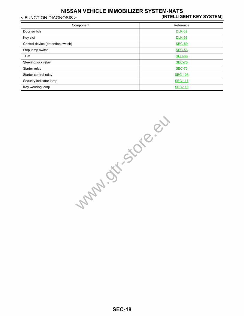
< FUNCTION DIAGNOSIS >
Door switch DLK-62
Key slot DLK-93
Control device (detention switch) SEC-59
Stop lamp switch SEC-53
TCM SEC-66
Steering lock relay SEC-70
Starter relay SEC-73
Starter control relay SEC-103
Security indicator lamp SEC-117
Key warning lamp SEC-119
Component Reference
www.gtr-
store
.eu
SEC-18

VEHICLE SECURITY SYSTEM[INTELLIGENT KEY SYSTEM]
C
D
E
F
G
H
I
J
L
M
A
B
EC
N
O
P
< FUNCTION DIAGNOSIS >
S
VEHICLE SECURITY SYSTEMSystem Diagram INFOID:0000000003996661
System Description INFOID:0000000003996662
SETTING THE VEHICLE SECURITY SYSTEMInitial Condition• Ignition switch is in OFF position.Disarmed Phase• When any door or back door is open, the vehicle security system is set in the disarmed phase on the
assumption that the owner is inside or near the vehicle.• When the vehicle security system is in the disarmed phase, the security indicator lamp blinks every 2.4 sec-
onds.Pre-armed Phase and Armed PhaseWhen the following operation is performed, the vehicle security system turns into the “pre-armed” phase. (Thesecurity indicator lamp illuminates.)1. BCM receives LOCK signal from front door request switch, Intelligent Key or door key cylinder, after back
door and all doors are closed.2. The security indicator lamp illuminates for 30 seconds. Then, the system automatically shifts into the
“armed” phase.
CANCELING THE SET VEHICLE SECURITY SYSTEMWhen one of the following operations is performed, the armed phase is canceled.
JMKIA1873GB
PIIA1367Ewww.gtr-
store
.eu
SEC-19
[INTELLIGENT KEY SYSTEM]VEHICLE SECURITY SYSTEM
< FUNCTION DIAGNOSIS >1. Unlock the all doors with the door request switch, Intelligent Key or door key cylinder.2. Turn ignition switch “ON” or “ACC” position.
CANCELING THE ALARM OPERATION OF THE VEHICLE SECURITY SYSTEMWhen unlocking the all doors with the door request switch, Intelligent Key or door key cylinder switch the alarmoperation is canceled.
ACTIVATING THE ALARM OPERATION OF THE VEHICLE SECURITY SYSTEMCheck that the system is in the armed phase. (The security indicator lamp blinks every 2.4 seconds.)When the following operation 1 or 2 is performed, the system sounds the horns and flashes the headlamps forabout 50 seconds.1. Back door or any door is opened during armed phase.2. Disconnecting and connecting the battery connector before canceling armed phase.
PANIC ALARM OPERATIONIntelligent Key system may or may not operate vehicle security system (horn and headlamps) as required.When the Intelligent Key system is triggered, ground is supplied intermittently to both headlamp relay and hornrelay.When headlamp relay and horn relay are energized, then power is supplied to headlamps (high beam and lowbeam) and horns (high, low and vehicle security horn).The headlamps flash and the horn sounds intermittently.The alarm automatically turns off after 50 seconds or when BCM receives any signal from Intelligent Key, doorrequest switch or door key cylinder.
www.gtr-
store
.eu
SEC-20

VEHICLE SECURITY SYSTEM[INTELLIGENT KEY SYSTEM]
C
D
E
F
G
H
I
J
L
M
A
B
EC
N
O
P
< FUNCTION DIAGNOSIS >
S
Component Parts Location INFOID:0000000003996975
1. BCM M118, M119, M121, M122, M123
2. IPDM E/R E4, E5, E6, F7 3. TCM B45
4. Push button ignition switch M131 5. Control device (detention switch) B20
6. Key slot M60
7. Combination meter (Key warning lamp) M53
8. Driver side door switch B21 9. Security indicator lamp M29
10. Stop lamp switch E110A. Behind the instrument lower panel
RHB. Engine room dash panel (RH) C. View with trunk front finisher re-
movedD. View with center console assembly
removedE. View with instrument lower panel
(driver) removed
JMKIA2909ZZ
www.gtr-
store
.eu
SEC-21
[INTELLIGENT KEY SYSTEM]VEHICLE SECURITY SYSTEM
< FUNCTION DIAGNOSIS >
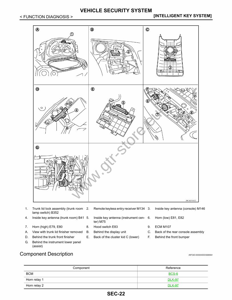
Component Description INFOID:0000000003996664
1. Trunk lid lock assembly (trunk room lamp switch) B352
2. Remote keyless entry receiver M134 3. Inside key antenna (console) M146
4. Inside key antenna (trunk room) B41 5. Inside key antenna (instrument cen-ter) M75
6. Horn (low) E81, E82
7. Horn (high) E79, E80 8. Hood switch E83 9. ECM M107A. View with trunk lid finisher removed B. Behind the display unit C. Back of the rear console assemblyD. Behind the trunk front finisher E. Back of the cluster kid C (lower) F. Behind the front bumperG. Behind the instrument lower panel
(assist)
JMKIA2910ZZ
Component Reference
BCM BCS-6
Horn relay 1 DLK-97
Horn relay 2 DLK-97
www.gtr-
store
.eu
SEC-22
VEHICLE SECURITY SYSTEM[INTELLIGENT KEY SYSTEM]
C
D
E
F
G
H
I
J
L
M
A
B
EC
N
O
P
< FUNCTION DIAGNOSIS >
S
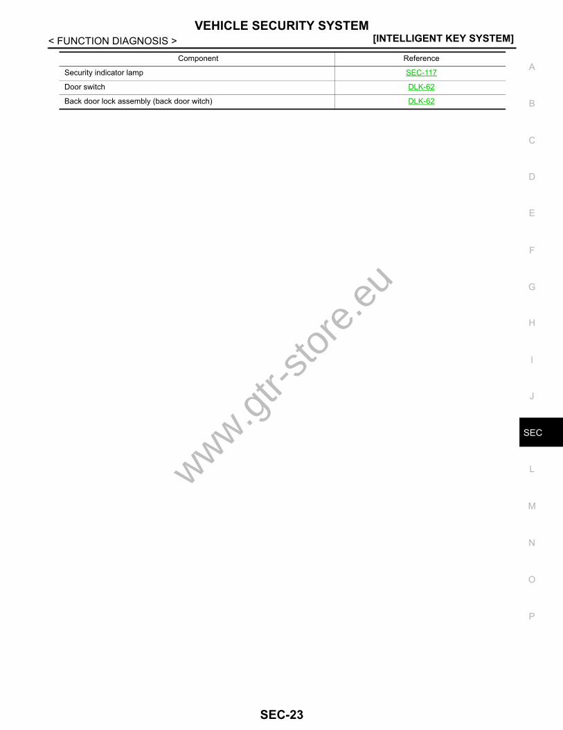
Security indicator lamp SEC-117
Door switch DLK-62
Back door lock assembly (back door witch) DLK-62
Component Reference
www.gtr-
store
.eu
SEC-23

[INTELLIGENT KEY SYSTEM]DIAGNOSIS SYSTEM (BCM)
< FUNCTION DIAGNOSIS >DIAGNOSIS SYSTEM (BCM)COMMON ITEMCOMMON ITEM : CONSULT-III Function (BCM - COMMON ITEM) INFOID:0000000003996976
APPLICATION ITEMCONSULT-III performs the following functions via CAN communication with BCM.
SYSTEM APPLICATIONBCM can perform the following functions for each system.NOTE:It can perform the diagnosis modes except the following for all sub system selection items.
×: Applicable item
*: This item is displayed, but is not used.
FREEZE FRAME DATA (FFD)The BCM records the following vehicle condition at the time a particular DTC is detected, and displays onCONSULT-III.
Diagnosis mode Function Description
Work Support Changes the setting for each system function.
Self Diagnostic Result Displays the diagnosis results judged by BCM.
CAN Diag Support Monitor Monitors the reception status of CAN communication viewed from BCM. Refer to CONSULT-III opera-tion manual.
Data Monitor The BCM input/output signals are displayed.
Active Test The signals used to activate each device are forcibly supplied from BCM.
Ecu Identification The BCM part number is displayed.
Configuration • Read and save the vehicle specification.• Write the vehicle specification when replacing BCM.
System Sub system selection itemDiagnosis mode
Work Support Data Monitor Active Test
Door lock DOOR LOCK × × ×
Rear window defogger REAR DEFOGGER × ×
Warning chime BUZZER × ×
Interior room lamp timer INT LAMP × × ×
Exterior lamp HEAD LAMP × × ×
Wiper and washer WIPER × × ×
Turn signal and hazard warning lamps FLASHER × × ×
— AIR CONDITONER*
Intelligent Key system INTELLIGENT KEY × × ×
Combination switch COMB SW ×
Body control system BCM ×
NVIS - NATS IMMU × ×
Interior room lamp battery saver BATTERY SAVER × × ×
Trunk lid opener system TRUNK × ×
Vehicle security system THEFT ALM × × ×
RAP system RETAINED PWR ×
Signal buffer system SIGNAL BUFFER × ×
www.gtr-
store
.eu
SEC-24
DIAGNOSIS SYSTEM (BCM)[INTELLIGENT KEY SYSTEM]
C
D
E
F
G
H
I
J
L
M
A
B
EC
N
O
P
< FUNCTION DIAGNOSIS >
S
INTELLIGENT KEYINTELLIGENT KEY : CONSULT-III Function (BCM - INTELLIGENT KEY) INFOID:0000000003996977
BCM CONSULT-III FUNCTIONCONSULT-III performs the following functions via CAN communication with BCM.
WORK SUPPORT
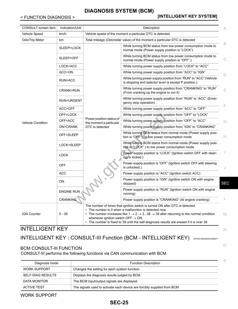
CONSULT screen item Indication/Unit Description
Vehicle Speed km/h Vehicle speed of the moment a particular DTC is detected
Odo/Trip Meter km Total mileage (Odometer value) of the moment a particular DTC is detected
Vehicle Condition
SLEEP>LOCK
Power position status of the moment a particular DTC is detected
While turning BCM status from low power consumption mode to normal mode (Power supply position is “LOCK”)
SLEEP>OFF While turning BCM status from low power consumption mode to normal mode (Power supply position is “OFF”.)
LOCK>ACC While turning power supply position from “LOCK” to “ACC”
ACC>ON While turning power supply position from “ACC” to “IGN”
RUN>ACC While turning power supply position from “RUN” to “ACC” (Vehicle is stopping and selector lever is except P position.)
CRANK>RUN While turning power supply position from “CRANKING” to “RUN” (From cranking up the engine to run it)
RUN>URGENT While turning power supply position from “RUN“ to “ACC” (Emer-gency stop operation)
ACC>OFF While turning power supply position from “ACC” to “OFF”
OFF>LOCK While turning power supply position from “OFF” to “LOCK”
OFF>ACC While turning power supply position from “OFF” to “ACC”
ON>CRANK While turning power supply position from “IGN” to “CRANKING”
OFF>SLEEP While turning BCM status from normal mode (Power supply posi-tion is “OFF”.) to low power consumption mode
LOCK>SLEEP While turning BCM status from normal mode (Power supply posi-tion is “LOCK”.) to low power consumption mode
LOCK Power supply position is “LOCK” (Ignition switch OFF with steer-ing is locked.)
OFF Power supply position is “OFF” (Ignition switch OFF with steering is unlocked.)
ACC Power supply position is “ACC” (Ignition switch ACC)
ON Power supply position is “IGN” (Ignition switch ON with engine stopped)
ENGINE RUN Power supply position is “RUN” (Ignition switch ON with engine running)
CRANKING Power supply position is “CRANKING” (At engine cranking)
IGN Counter 0 - 39
The number of times that ignition switch is turned ON after DTC is detected• The number is 0 when a malfunction is detected now.• The number increases like 1 → 2 → 3...38 → 39 after returning to the normal condition
whenever ignition switch OFF → ON.• The number is fixed to 39 until the self-diagnosis results are erased if it is over 39.
Diagnosis mode Function Description
WORK SUPPORT Changes the setting for each system function.
SELF-DIAG RESULTS Displays the diagnosis results judged by BCM.
DATA MONITOR The BCM input/output signals are displayed.
ACTIVE TEST The signals used to activate each device are forcibly supplied from BCM.
www.gtr-
store
.eu
SEC-25

[INTELLIGENT KEY SYSTEM]DIAGNOSIS SYSTEM (BCM)
< FUNCTION DIAGNOSIS >
SELF-DIAG RESULTRefer to DLK-161, "DTC Index".
DATA MONITOR
Monitor item Description
REMO CONT ID CONFIR It can be checked whether Intelligent Key ID code is registered or not in this mode.
AUTO LOCK SET
Auto door lock time can be changed in this mode.• MODE 1: 1 minute• MODE 2: 5 minutes• MODE 3: 30 seconds• MODE 4: 2 minutes
LOCK/UNLOCK BY I-KEY Door lock/unlock function by door request switch (driver side and passenger side) mode can be changed to operate (WITH) or not operate (WITHOUT) in this mode.
ENGINE START BY I-KEY Engine start function mode can be changed to operate (WITH) or not operate (WITHOUT) in this mode.
TRUNK/GLASS HATCH OPEN Buzzer reminder function mode by trunk lid opener request switch can be changed to operate (WITH) or not operate (WITHOUT) in this mode.
PANIC ALARM SET
Panic alarm button pressing time on Intelligent Key remote control button can be selected from the following wit this mode.• MODE 1: 0.5 sec.• MODE 2: OFF: Non-operation• MODE 3: 1.5 sec.
PW DOWN SET This item is displayed, but cannot be used.
TRUNK OPEN DELAY
Trunk button pressing on Intelligent Key button can be selected as per the following in this mode.• MODE 1: Press and hold• MODE 2: Press twice• MODE 3: Press and hold, or press twice
LO-BATT OF KEY FOB WARN Intelligent Key low battery warning mode can be changed to operate (WITH) or not operate (WITH-OUT) in this mode.
ANTI KEY LOCK IN FUNCTI Key reminder function mode can be changed to operate (WITH) or not operate (WITHOUT) in this mode.
HAZARD ANSWER BACK
Hazard reminder function mode can be selected from the following in this mode.• LOCK ONLY: Door lock operation only• UNLOCK ONLY: Door unlock operation only• LOCK/UNLOCK: Lock/unlock operation• OFF: Non-operational
ANS BACK I-KEY LOCK
Buzzer reminder function (lock operation) mode by door request switch (driver side and passenger side) can be selected from the following is this mode. • Horn chirp: Sound horn• Buzzer: Sound Intelligent Key warning buzzer• OFF: Non-operational
ANS BACK I-KEY UNLOCK Buzzer reminder function (unlock operation) mode by door request switch can be changed to op-erate (ON) or not operate (OFF) in this mode.
SHORT CRANKING OUTPUT
Starter motor can operate during the times below.• 70 msec• 100 msec• 200 msec
INSIDE ANT DIAGNOSIS This function allows inside key antenna self-diagnosis.
HORN WITH KEYLESS LOCK Horn reminder function mode by Intelligent Key button can be changed to operate (ON) or not op-erate (OFF) in this mode.
Monitor Item Condition
REQ SW -DR Indicates [ON/OFF] condition of door request switch (driver side).
REQ SW -AS Indicates [ON/OFF] condition of door request switch (passenger side).
REQ SW -BD/TR Indicates [ON/OFF] condition of trunk lid opener request switch.
www.gtr-
store
.eu
SEC-26
DIAGNOSIS SYSTEM (BCM)[INTELLIGENT KEY SYSTEM]
C
D
E
F
G
H
I
J
L
M
A
B
EC
N
O
P
< FUNCTION DIAGNOSIS >
S
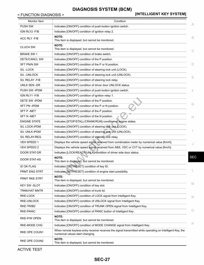
ACTIVE TEST
PUSH SW Indicates [ON/OFF] condition of push-button ignition switch.
IGN RLY2 -F/B Indicates [ON/OFF] condition of ignition relay 2.
ACC RLY -F/B NOTE:This item is displayed, but cannot be monitored.
CLUCH SW NOTE:This item is displayed, but cannot be monitored.
BRAKE SW 1 Indicates [ON/OFF] condition of brake switch.
DETE/CANCL SW Indicates [ON/OFF] condition of the P position.
SFT PN/N SW Indicates [ON/OFF] condition of the P or N position.
S/L -LOCK Indicates [ON/OFF] condition of steering lock unit (LOCK).
S/L -UNLOCK Indicates [ON/OFF] condition of steering lock unit (UNLOCK).
S/L RELAY -F/B Indicates [ON/OFF] condition of steering lock relay.
UNLK SEN -DR Indicates [ON/OFF] condition of driver door UNLOCK status.
PUSH SW -IPDM Indicates [ON/OFF] condition of push-button ignition switch.
IGN RLY1 -F/B Indicates [ON/OFF] condition of ignition relay 1.
DETE SW -IPDM Indicates [ON/OFF] condition of the P position.
SFT PN -IPDM Indicates [ON/OFF] condition of the P or N position.
SFT P -MET Indicates [ON/OFF] condition of the P position.
SFT N -MET Indicates [ON/OFF] condition of the N position.
ENGINE STATE Indicates [STOP/STALL/CRANK/RUN] condition of engine states.
S/L LOCK-IPDM Indicates [ON/OFF] condition of steering lock unit (LOCK).
S/L UNLK-IPDM Indicates [ON/OFF] condition of steering lock unit (UNLOCK).
S/L RELAY-REQ Indicates [ON/OFF] condition of steering lock relay.
VEH SPEED 1 Displays the vehicle speed signal received from combination meter by numerical value [Km/h].
VEH SPEED 2 Displays the vehicle speed signal received from ABS, VDC or CVT by numerical value [Km/h].
DOOR STAT-DR Indicates [LOCK/READY/UNLK] condition of driver side door status.
DOOR STAT-AS NOTE:This item is displayed, but cannot be monitored.
ID OK FLAG Indicates [SET/RESET] condition of key ID.
PRMT ENG STRT Indicates [SET/RESET] condition of engine start possibility.
PRMT RKE STRT NOTE:This item is displayed, but cannot be monitored.
KEY SW -SLOT Indicates [ON/OFF] condition of key slot.
TRNK/HAT MNTR Indicates [ON/OFF] condition of trunk lid.
RKE-LOCK Indicates [ON/OFF] condition of LOCK signal from Intelligent Key.
RKE-UNLOCK Indicates [ON/OFF] condition of UNLOCK signal from Intelligent Key.
RKE-TR/BD Indicates [ON/OFF] condition of TRUNK OPEN signal from Intelligent Key.
RKE-PANIC Indicates [ON/OFF] condition of PANIC button of Intelligent Key.
RKE-P/W OPEN NOTE:This item is displayed, but cannot be monitored.
RKE-MODE CHG Indicates [ON/OFF] condition of MODE CHANGE signal from Intelligent Key.
RKE OPE COUN1 When remote keyless entry receiver receives the signal transmitted while operating on Intelligent Key, the numerical values start changing.
RKE OPE COUN2 NOTE:This item is displayed, but cannot be monitored.
Monitor Item Condition
www.gtr-
store
.eu
SEC-27

[INTELLIGENT KEY SYSTEM]DIAGNOSIS SYSTEM (BCM)
< FUNCTION DIAGNOSIS >
THEFT ALMTHEFT ALM : CONSULT-III Function (BCM - THEFT) INFOID:0000000003996665
APPLICATION ITEMCONSULT-III performs the following functions via CAN communication with BCM.
Test item Description
BATTERY SAVER This test is able to check interior room lamp operation.The interior room lamp will be activated when “ON” on CONSULT-III screen is touched.
PW REMOTO DOWN SET NOTE:This item is displayed, but cannot be used.
OUTSIDE BUZZER This test is able to check Intelligent Key warning buzzer operation.The Intelligent Key warning buzzer will be activated when “ON” on CONSULT-III screen is touched.
INSIDE BUZZER
This test is able to check warning chime in combination meter operation.• Take away warning chime sounds when “TAKE OUT” on CONSULT-III screen is touched.• Key warning chime sounds when “KEY” on CONSULT-III screen is touched.• P position warning chime sounds when “KNOB” on CONSULT-III screen is touched.
INDICATORThis test is able to check warning lamp operation.• “KEY” Warning lamp illuminates when “KEY ON” on CONSULT-III screen is touched.• “KEY” Warning lamp blinks when “KEY IND” on CONSULT-III screen is touched.
INT LAMP This test is able to check interior room lamp operation.The interior room lamp will be activated when “ON” on CONSULT-III screen is touched.
LCD
This test is able to check meter display information• Engine start information displays when “BP N” on CONSULT-III screen is touched.• Engine start information displays when “BP I” on CONSULT-III screen is touched.• Key ID warning displays when “ID NG” on CONSULT-III screen is touched.• Steering lock information displays when “ROTAT” on CONSULT-III screen is touched.• P position warning displays when “SFT P” on CONSULT-III screen is touched.• Intelligent Key insert information displays when “INSRT” on CONSULT-III screen is touched.• Intelligent Key low battery warning displays when “BATT” on CONSULT-III screen is touched.• Take away warning displays when “OUTKEY” on CONSULT-III screen is touched.• OFF position warning displays when “LK WN” on CONSULT-III screen is touched.
TRUNK/GLASS HATCH This test is able to check trunk lid opener actuator open operation.This actuator opens when “OPEN” on CONSULT-III screen is touched.
FLASHER This test is able to check security hazard lamp operation.The hazard lamps will be activated when “RH” or “LH”on CONSULT-III screen is touched.
HORN This test is able to check horn operation.The horn will be activated when “ON” on CONSULT-III screen is touched.
P RANGE This test is able to check control device power supplyControl device power is supplied when “ON” on CONSULT-III screen is touched.
ENGINE SW ILLUMI This test is able to check push-ignition switch illumination operation.Push-ignition switch illumination illuminates when “ON” on CONSULT-III screen is touched.
LOCK INDICATOR This test is able to check LOCK indicator in push-ignition switch operation.LOCK indicator in push-ignition switch illuminates when “ON” on CONSULT-III screen is touched.
ACC INDICATOR This test is able to check ACC indicator in push-ignition switch operation.ACC indicator in push-ignition switch illuminates when “ON” on CONSULT-III screen is touched.
IGNITION ON IND This test is able to check ON indicator in push-ignition switch operation.ON indicator in push-ignition switch illuminates when “ON” on CONSULT-III screen is touched.
KEY SLOT ILLUMI This test is able to check key slot illumination operation.Key slot illumination illuminates when “ON” on CONSULT-III screen is touched.
TRUNK/BACK DOOR This test is able to check trunk lid opener actuator open operation.This actuator opens when “OPEN” on CONSULT-III screen is touched.
www.gtr-
store
.eu
SEC-28

DIAGNOSIS SYSTEM (BCM)[INTELLIGENT KEY SYSTEM]
C
D
E
F
G
H
I
J
L
M
A
B
EC
N
O
P
< FUNCTION DIAGNOSIS >
S
DATA MONITOR
WORK SUPPORT
ACTIVE TEST
Diagnosis mode Function Description
WORK SUPPORT Changes the setting for each system function.
DATA MONITOR The BCM input/output signals are displayed.
ACTIVE TEST The signals used to activate each device are forcibly supplied from BCM.
Monitored Item Description
REQ SW -DR Indicates [ON/OFF] condition of door request switch (driver side).
REQ SW -AS Indicates [ON/OFF] condition of door request switch (passenger side).
REQ SW -RR NOTE:This is displayed even when it is not equipped.
REQ SW -RL NOTE:This is displayed even when it is not equipped.
REQ SW -BD/TR Indicates [ON/OFF] condition of back door request switch.
PUSH SW Indicates [ON/OFF] condition of push-button ignition switch
UNLK SEN -DR Indicates [ON/OFF] condition of driver door UNLOCK status.
KEY SW -SLOT Indicates [ON/OFF] condition of key slot.
DOOR SW-DR Indicates [ON/OFF] condition of front door switch LH.
DOOR SW-AS Indicates [ON/OFF] condition of front door switch RH.
DOOR SW-RR Indicates [ON/OFF] condition of rear door switch RH.
DOOR SW-RL Indicates [ON/OFF] condition of rear door switch LH.
DOOR SW-BK Indicates [ON/OFF] condition of back door switch.
CDL LOCK SW Indicates [ON/OFF] condition of lock signal from door lock/unlock switch LH and RH.
CDL UNLOCK SW Indicates [ON/OFF] condition of unlock signal from door lock/unlock switch LH and RH.
KEY CYL LK-SW NOTE:This is displayed even when it is not equipped.
KEY CYL UN-SW NOTE:This is displayed even when it is not equipped.
KEY CYL SW-TR NOTE:This is displayed even when it is not equipped.
TR/BD OPEN SW Indicates [ON/OFF] condition of back door opener switch.
TRNK/HAT MNTR Indicates [ON/OFF] condition of trunk lid.
RKE-LOCK Indicates [ON/OFF] condition of LOCK signal from Intelligent Key.
RKE-UNLOCK Indicates [ON/OFF] condition of UNLOCK signal from Intelligent Key.
RKE-TR/BD Indicates [ON/OFF] condition of TRUNK OPEN signal from Intelligent Key.
Test Item Description
SECURITY ALARM SET This mode is able to confirm and change security alarm ON-OFF setting.
THEFT ALM TRGThe switch which triggered vehicle security alarm is recorded. This mode is able to confirm and erase the record of vehicle security alarm. The trigger data can be erased by touching “CLEAR” on CONSULT-III screen.
www.gtr-
store
.eu
SEC-29

[INTELLIGENT KEY SYSTEM]DIAGNOSIS SYSTEM (BCM)
< FUNCTION DIAGNOSIS >
IMMUIMMU : CONSULT-III Function (BCM - IMMU) INFOID:0000000003996464
APPLICATION ITEMCONSULT-III performs the following functions via CAN communication with BCM.
DATA MONITOR
ACTIVE TEST
Test Item Description
THEFT IND This test is able to check security indicator lamp operation. The lamp will be turned on when “ON” on CONSULT-III screen is touched.
VEHICLE SECURITY HORN This test is able to check vehicle security horn operation. The horns will be activated for 0.5 sec-onds after “ON” on CONSULT-III screen is touched.
HEADLAMP(HI) This test is able to check vehicle security lamp operation. The headlamps will be activated for 0.5 seconds after “ON” on CONSULT-III screen is touched.
FLASHER This test is able to check vehicle security hazard lamp operation. The hazard lamps will be activat-ed after “ON” on CONSULT-III screen is touched.
Diagnosis mode Function Description
DATA MONITOR The BCM input/output signals are displayed.
ACTIVE TEST The signals used to activate each device are forcibly supplied from BCM.
Monitor item Content
CONFRM ID ALL
Indicates [YET] at all time.Switches to [DONE] when a registered Intelligent Key is inserted into the key slot.
CONFIRM ID4
CONFIRM ID3
CONFIRM ID2
CONFIRM ID1
TP 4
Indicates the number of ID which has been registered.TP 3
TP 2
TP 1
PUSH SW Indicates [ON/OFF] condition of push-button ignition switch.
KEY SW -SLOT Indicates [ON/OFF] condition of key slot.
Test item Description
THEFT IND This test is able to check security indicator lamp operation.The lamp will be turned on when “ON” on CONSULT-III screen touched.
www.gtr-
store
.eu
SEC-30

U1000 CAN COMM CIRCUIT[INTELLIGENT KEY SYSTEM]
C
D
E
F
G
H
I
J
L
M
A
B
EC
N
O
P
< COMPONENT DIAGNOSIS >
S
COMPONENT DIAGNOSISU1000 CAN COMM CIRCUITBCMBCM : Description INFOID:0000000004174355
CAN (Controller Area Network) is a serial communication line for real time applications. It is an on-vehicle mul-tiplex communication line with high data communication speed and excellent error detection ability. Modernvehicle is equipped with many electronic control unit, and each control unit shares information and links withother control units during operation (not independent). In CAN communication, control units are connectedwith 2 communication lines (CAN H-line, CAN L-line) allowing a high rate of information transmission with lesswiring. Each control unit transmits/receives data but selectively reads required data only.CAN Communication Signal Chart. Refer to LAN-23, "CAN Communication Signal Chart".
BCM : DTC Logic INFOID:0000000004174356
DTC DETECTION LOGIC
BCM : Diagnosis Procedure INFOID:0000000004174357
1.PERFORM SELF DIAGNOSTIC
1. Turn ignition switch ON and wait for 2 seconds or more.2. Check “Self Diagnostic Result”.Is DTC “U1000” displayed?YES >> Refer to LAN-14, "Trouble Diagnosis Flow Chart".NO >> Refer to GI-38, "Intermittent Incident".
IPDM E/RIPDM E/R : Description INFOID:0000000004174362
CAN (Controller Area Network) is a serial communication line for real time applications. It is an on-vehicle mul-tiplex communication line with high data communication speed and excellent error detection ability. Modernvehicle is equipped with many electronic control unit, and each control unit shares information and links withother control units during operation (not independent). In CAN communication, control units are connectedwith 2 communication lines (CAN-H line, CAN-L line) allowing a high rate of information transmission with lesswiring. Each control unit transmits/receives data but selectively reads required data only.CAN Communication Signal Chart. Refer to LAN-23, "CAN Communication Signal Chart".
IPDM E/R : DTC Logic INFOID:0000000004174363
DTC DETECTION LOGIC
IPDM E/R : Diagnosis Procedure INFOID:0000000004174364
1.PERFORM SELF DIAGNOSTIC
DTC CONSULT-III display description DTC Detection Condition Possible cause
U1000 CAN COMM CIRCUITWhen BCM cannot communicate CAN com-munication signal continuously for 2 seconds or more.
CAN communication system
DTC CONSULT-III display description DTC Detection Condition Possible cause
U1000 CAN COMM CIRCUITWhen IPDM E/R cannot communicate CAN communication signal continuously for 2 seconds or more
CAN communication system
www.gtr-
store
.eu
SEC-31

[INTELLIGENT KEY SYSTEM]U1000 CAN COMM CIRCUIT
< COMPONENT DIAGNOSIS >1. Turn ignition switch ON and wait for 2 seconds or more.2. Check “Self Diagnostic Result” of IPDM E/R.Is “CAN COMM CIRCUIT” displayed?YES >> Refer to LAN-14, "Trouble Diagnosis Flow Chart".NO >> Refer to GI-38, "Intermittent Incident".
www.gtr-
store
.eu
SEC-32
U1010 CONTROL UNIT (CAN)[INTELLIGENT KEY SYSTEM]
C
D
E
F
G
H
I
J
L
M
A
B
EC
N
O
P
< COMPONENT DIAGNOSIS >
S
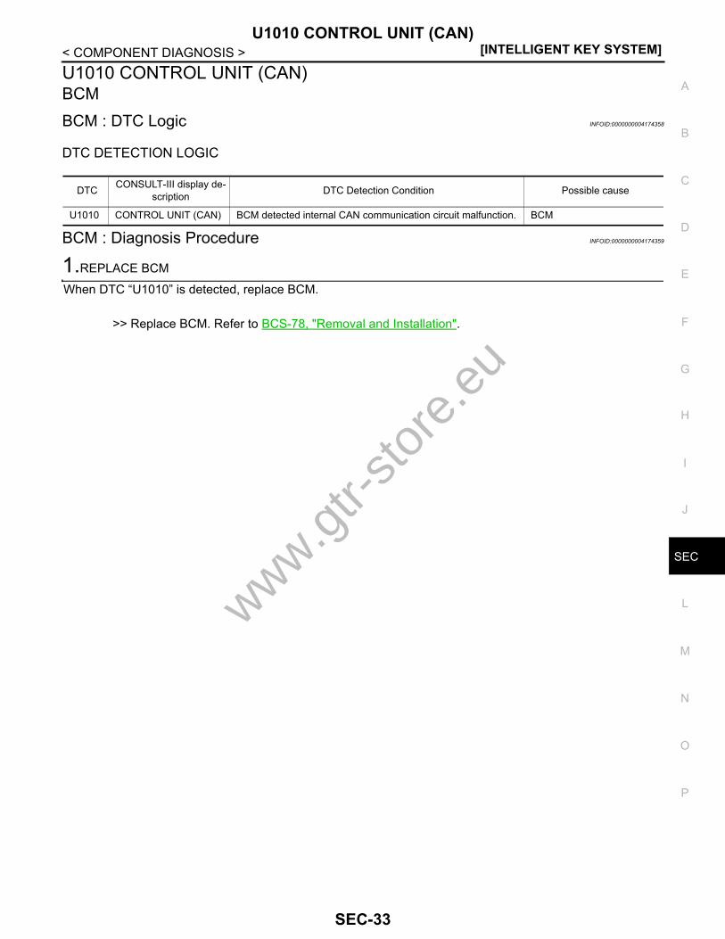
U1010 CONTROL UNIT (CAN)BCMBCM : DTC Logic INFOID:0000000004174358
DTC DETECTION LOGIC
BCM : Diagnosis Procedure INFOID:0000000004174359
1.REPLACE BCM
When DTC “U1010” is detected, replace BCM.
>> Replace BCM. Refer to BCS-78, "Removal and Installation".
DTC CONSULT-III display de-scription DTC Detection Condition Possible cause
U1010 CONTROL UNIT (CAN) BCM detected internal CAN communication circuit malfunction. BCM
www.gtr-
store
.eu
SEC-33
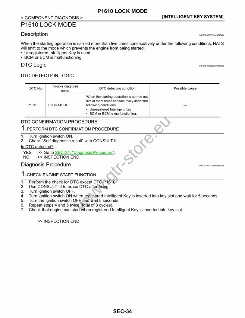
[INTELLIGENT KEY SYSTEM]P1610 LOCK MODE
< COMPONENT DIAGNOSIS >P1610 LOCK MODEDescription INFOID:0000000003996474
When the starting operation is carried more than five times consecutively under the following conditions, NATSwill shift to the mode which prevents the engine from being started.• Unregistered Intelligent Key is used.• BCM or ECM is malfunctioning.
DTC Logic INFOID:0000000003996475
DTC DETECTION LOGIC
DTC CONFIRMATION PROCEDURE1.PERFORM DTC CONFIRMATION PROCEDURE
1. Turn ignition switch ON.2. Check “Self diagnostic result” with CONSULT-III.Is DTC detected?YES >> Go to SEC-34, "Diagnosis Procedure".NO >> INSPECTION END
Diagnosis Procedure INFOID:0000000003996476
1.CHECK ENGINE START FUNCTION
1. Perform the check for DTC except DTC P1610.2. Use CONSULT-III to erase DTC after fixing.3. Turn ignition switch OFF.4. Turn ignition switch ON when registered Intelligent Key is inserted into key slot and wait for 5 seconds.5. Turn the ignition switch OFF and wait 5 seconds.6. Repeat steps 4 and 5 twice (total of 3 cycles).7. Check that engine can start when registered Intelligent Key is inserted into key slot.
>> INSPECTION END
DTC No. Trouble diagnosis name DTC detecting condition Possible cause
P1610 LOCK MODE
When the starting operation is carried out five or more times consecutively under the following conditions.• Unregistered Intelligent Key• BCM or ECM is malfunctioning.
—
www.gtr-
store
.eu
SEC-34

P1611 ID DISCORD, IMMU-ECM[INTELLIGENT KEY SYSTEM]
C
D
E
F
G
H
I
J
L
M
A
B
EC
N
O
P
< COMPONENT DIAGNOSIS >
S
P1611 ID DISCORD, IMMU-ECMDescription INFOID:0000000003996477
BCM performs the ID verification with ECM that allows the engine to start. Start the engine if the ID is OK.ECM prevents the engine from starting if the ID is not registered. BCM starts the communication with ECM ifignition switch is turned ON.
DTC Logic INFOID:0000000003996478
DTC DETECTION LOGICNOTE:• If DTC B1611 is displayed with DTC U1000, first perform the trouble diagnosis for DTC U1000. Refer to
SEC-31, "BCM : DTC Logic".• If DTC B1611 is displayed with DTC U1010, first perform the trouble diagnosis for DTC U1010. Refer to
SEC-31, "IPDM E/R : DTC Logic".
DTC CONFIRMATION PROCEDURE1.PERFORM DTC CONFIRMATION PROCEDURE
1. Turn ignition switch ON under the following conditions.- Shift lever is in the P or N position.- Do not depress brake pedal.2. Check “Self diagnostic result” with CONSULT-III.Is DTC detected?YES >> Go to SEC-35, "Diagnosis Procedure".NO >> INSPECTION END
Diagnosis Procedure INFOID:0000000003996479
1.PERFORM INITIALIZATION
Perform initialization with CONSULT-III. Re-register all Intelligent Keys.For initialization and registration of Intelligent Key. Refer to “CONSULT-III Operation Manual NATS-IVIS/NVIS”.Can the system be initialized and can the engine be started with reregistered Intelligent Key?YES >> INSPECTION ENDNO >> GO TO 2.
2.REPLACE BCM
1. Replace BCM. Refer to BCS-78, "Removal and Installation".2. Perform initialization with CONSULT-III.
For initialization, refer to “CONSULT-III Operation Manual NATS-IVIS/NVIS”.Can the system be initialized and can the engine be started with reregistered Intelligent Key?YES >> INSPECTION ENDNO >> GO TO 3.
3.REPLACE ECM
1. Replace ECM. Refer to EC-15, "BASIC INSPECTION : Special Repair Requirement (GT-R certified NIS-SAN dealer)".
2. Perform initialization with CONSULT-III. For initialization, refer to “CONSULT-III Operation Manual NATS-IVIS/NVIS”.
Can the system be initialized and can the engine be started with reregistered Intelligent Key?YES >> INSPECTION END
DTC No. Trouble diagnosis name DTC detecting condition Possible cause
P1611 ID DISCORD, IMMU-ECM
The ID verification result between BCM and ECM is NG. The registration is necessary.
• BCM• ECM
www.gtr-
store
.eu
SEC-35

[INTELLIGENT KEY SYSTEM]P1611 ID DISCORD, IMMU-ECM
< COMPONENT DIAGNOSIS >NO >> GO TO 4.
4.CHECK INTERMITTENT INCIDENT
Refer to GI-38, "Intermittent Incident".
>> INSPECTION END
www.gtr-
store
.eu
SEC-36

P1612 CHAIN OF ECM-IMMU[INTELLIGENT KEY SYSTEM]
C
D
E
F
G
H
I
J
L
M
A
B
EC
N
O
P
< COMPONENT DIAGNOSIS >
S
P1612 CHAIN OF ECM-IMMUDescription INFOID:0000000003996480
BCM performs the ID verification with ECM that allows the engine to start. Start the engine if the ID is OK.ECM prevents the engine from starting if the ID is not registered. BCM starts the communication with ECM ifignition switch is turned ON.
DTC Logic INFOID:0000000003996481
DTC DETECTION LOGICNOTE:• If DTC P1612 is displayed with DTC U1000, first perform the trouble diagnosis for DTC U1000. Refer to
SEC-31, "BCM : DTC Logic".• If DTC P1612 is displayed with DTC U1010, first perform the trouble diagnosis for DTC U1010. Refer to
SEC-33, "BCM : DTC Logic".
DTC CONFIRMATION PROCEDURE1.PERFORM DTC CONFIRMATION PROCEDURE
1. Turn ignition switch ON under the following conditions.- Shift lever is in the P or N position.- Do not depress brake pedal.2. Check “Self diagnostic result” with CONSULT-III.Is DTC detected?YES >> Go to SEC-37, "Diagnosis Procedure".NO >> INSPECTION END
Diagnosis Procedure INFOID:0000000003996482
1.REPLACE BCM
1. Replace BCM. Refer to BCS-78, "Removal and Installation".2. Perform initialization with CONSULT-III.
For initialization, refer to “CONSULT-III Operation Manual NATS-IVIS/NVIS”.Does the engine start?YES >> INSPECTION ENDNO >> GO TO 2.
2.REPLACE ECM
Replace ECM. Refer to EC-15, "BASIC INSPECTION : Special Repair Requirement (GT-R certified NISSANdealer)".
>> INSPECTION END
DTC No. Trouble diagnosis name DTC detecting condition Possible cause
P1612 CHAIN OF ECM-IMMU Inactive communication between ECM and BCM
• Harness or connectors(The CAN communication line is open or shorted)
• BCM • ECM
www.gtr-
store
.eu
SEC-37
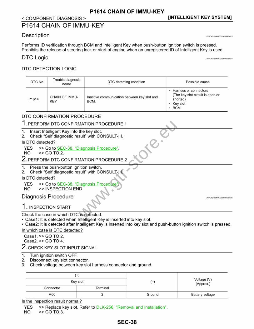
[INTELLIGENT KEY SYSTEM]P1614 CHAIN OF IMMU-KEY
< COMPONENT DIAGNOSIS >P1614 CHAIN OF IMMU-KEYDescription INFOID:0000000003996483
Performs ID verification through BCM and Intelligent Key when push-button ignition switch is pressed.Prohibits the release of steering lock or start of engine when an unregistered ID of Intelligent Key is used.
DTC Logic INFOID:0000000003996484
DTC DETECTION LOGIC
DTC CONFIRMATION PROCEDURE1.PERFORM DTC CONFIRMATION PROCEDURE 1
1. Insert Intelligent Key into the key slot.2. Check “Self diagnostic result” with CONSULT-III.Is DTC detected?YES >> Go to SEC-38, "Diagnosis Procedure".NO >> GO TO 2.
2.PERFORM DTC CONFIRMATION PROCEDURE 2
1. Press the push-button ignition switch.2. Check “Self diagnostic result” with CONSULT-III.Is DTC detected?YES >> Go to SEC-38, "Diagnosis Procedure".NO >> INSPECTION END
Diagnosis Procedure INFOID:0000000003996485
1. INSPECTION START
Check the case in which DTC is detected.• Case1: It is detected when Intelligent Key is inserted into key slot.• Case2: It is detected after Intelligent Key is inserted into key slot and push-button ignition switch is pressed.In which case is DTC detected?Case1. >> GO TO 2.Case2. >> GO TO 4.
2.CHECK KEY SLOT INPUT SIGNAL
1. Turn ignition switch OFF.2. Disconnect key slot connector.3. Check voltage between key slot harness connector and ground.
Is the inspection result normal?YES >> Replace key slot. Refer to DLK-256, "Removal and Installation".NO >> GO TO 3.
DTC No. Trouble diagnosis name DTC detecting condition Possible cause
P1614 CHAIN OF IMMU-KEY
Inactive communication between key slot and BCM.
• Harness or connectors(The key slot circuit is open or shorted)
• Key slot • BCM
(+)
(–) Voltage (V)(Approx.)Key slot
Connector Terminal
M60 2 Ground Battery voltage
www.gtr-
store
.eu
SEC-38

P1614 CHAIN OF IMMU-KEY[INTELLIGENT KEY SYSTEM]
C
D
E
F
G
H
I
J
L
M
A
B
EC
N
O
P
< COMPONENT DIAGNOSIS >
S
3.CHECK KEY SLOT CIRCUIT
1. Disconnect BCM connector.2. Check continuity between key slot harness connector and BCM harness connector.
3. Check continuity between key slot harness connector and ground.
Is the inspection result normal?YES >> Replace BCM. Refer to BCS-78, "Removal and Installation".NO >> Repair or replace harness.
4.CHECK PUSH-BUTTON IGNITION SWITCH OPERATION
Press push-button ignition switch and check if it turns ON.Does ignition switch turn to ON?YES >> GO TO 5.NO >> GO TO 7.
5.CHECK KEY SLOT COMMUNICATION SIGNAL
1. Turn ignition switch OFF.2. Disconnect key slot connector.3. Check voltage between key slot harness connector and ground.
Is the inspection result normal?YES >> Replace key slot. Refer to DLK-256, "Removal and Installation".NO >> GO TO 6.
6.CHECK KEY SLOT COMMUNICATION SIGNAL CIRCUIT
1. Disconnect BCM connector.2. Check continuity between key slot harness connector and BCM harness connector.
3. Check continuity between key slot harness connector and ground.
Is the inspection result normal?YES >> Replace BCM. Refer to BCS-78, "Removal and Installation".NO >> Repair or replace harness.
7.CHECK KEY SLOT GROUND CIRCUIT
Key slot BCMContinuity
Connector Terminal Connector Terminal
M60 2 M122 80 Existed
Key slot
GroundContinuity
Connector Terminal
M60 2 Not existed
(+)
(–) Voltage (V)(Approx.)Key slot
Connector Terminal
M60 3 Ground Battery voltage
Key slot BCMContinuity
Connector Terminal Connector Terminal
M60 3 M122 81 Existed
Key slot
GroundContinuity
Connector Terminal
M60 3 Not existed
www.gtr-
store
.eu
SEC-39

[INTELLIGENT KEY SYSTEM]P1614 CHAIN OF IMMU-KEY
< COMPONENT DIAGNOSIS >1. Turn ignition switch OFF.2. Disconnect key slot connector.3. Check continuity between key slot harness connector and ground.
Is the inspection result normal?YES >> GO TO 8.NO >> Repair or replace harness.
8.CHECK INTERMITTENT INCIDENT
Refer to GI-38, "Intermittent Incident".
>> INSPECTION END
Key slot
GroundContinuity
Connector Terminal
M60 7 Existed
www.gtr-
store
.eu
SEC-40
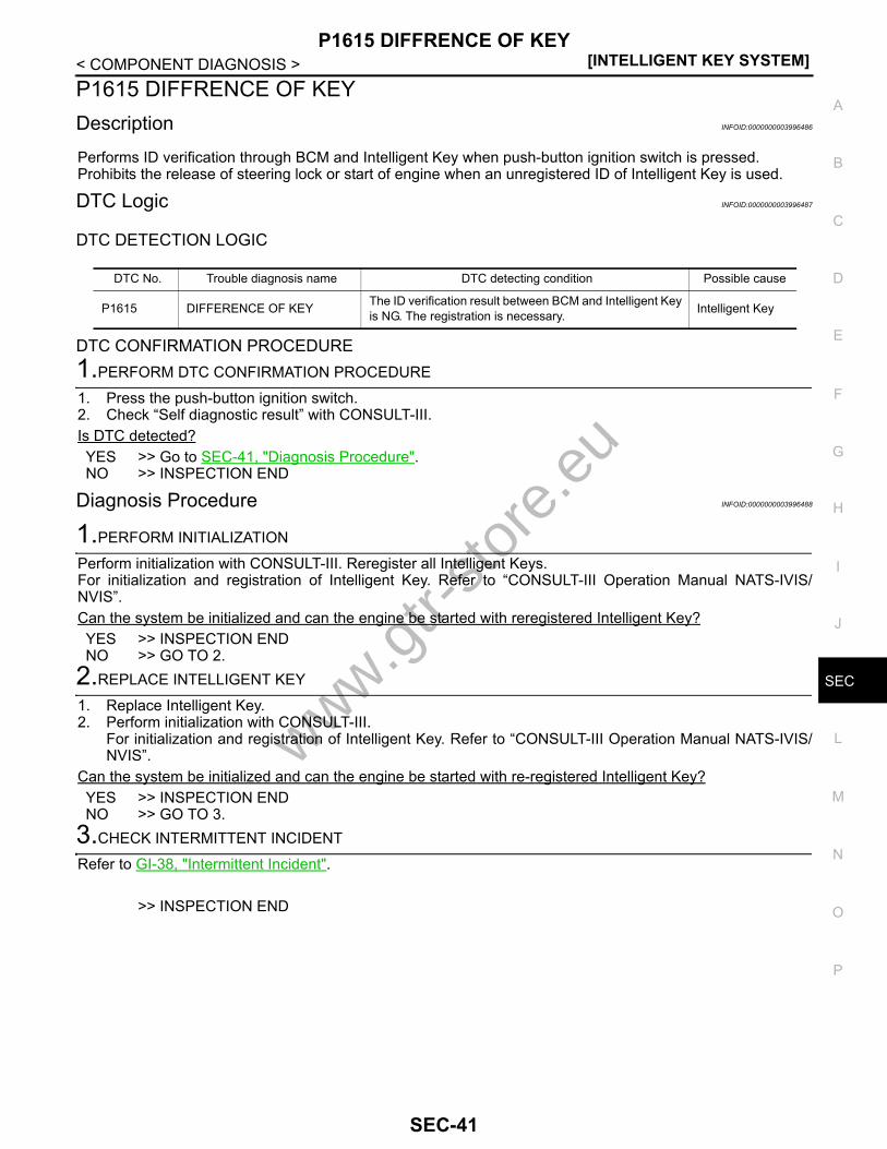
P1615 DIFFRENCE OF KEY[INTELLIGENT KEY SYSTEM]
C
D
E
F
G
H
I
J
L
M
A
B
EC
N
O
P
< COMPONENT DIAGNOSIS >
S
P1615 DIFFRENCE OF KEYDescription INFOID:0000000003996486
Performs ID verification through BCM and Intelligent Key when push-button ignition switch is pressed.Prohibits the release of steering lock or start of engine when an unregistered ID of Intelligent Key is used.
DTC Logic INFOID:0000000003996487
DTC DETECTION LOGIC
DTC CONFIRMATION PROCEDURE1.PERFORM DTC CONFIRMATION PROCEDURE
1. Press the push-button ignition switch.2. Check “Self diagnostic result” with CONSULT-III.Is DTC detected?YES >> Go to SEC-41, "Diagnosis Procedure".NO >> INSPECTION END
Diagnosis Procedure INFOID:0000000003996488
1.PERFORM INITIALIZATION
Perform initialization with CONSULT-III. Reregister all Intelligent Keys.For initialization and registration of Intelligent Key. Refer to “CONSULT-III Operation Manual NATS-IVIS/NVIS”.Can the system be initialized and can the engine be started with reregistered Intelligent Key?YES >> INSPECTION ENDNO >> GO TO 2.
2.REPLACE INTELLIGENT KEY
1. Replace Intelligent Key.2. Perform initialization with CONSULT-III.
For initialization and registration of Intelligent Key. Refer to “CONSULT-III Operation Manual NATS-IVIS/NVIS”.
Can the system be initialized and can the engine be started with re-registered Intelligent Key?YES >> INSPECTION ENDNO >> GO TO 3.
3.CHECK INTERMITTENT INCIDENT
Refer to GI-38, "Intermittent Incident".
>> INSPECTION END
DTC No. Trouble diagnosis name DTC detecting condition Possible cause
P1615 DIFFERENCE OF KEY The ID verification result between BCM and Intelligent Key is NG. The registration is necessary. Intelligent Key
www.gtr-
store
.eu
SEC-41

[INTELLIGENT KEY SYSTEM]B2190 NATS ANTENNA AMP.
< COMPONENT DIAGNOSIS >B2190 NATS ANTENNA AMP.Description INFOID:0000000003996489
Performs ID verification through BCM and Intelligent Key when push-button ignition switch is pressed.Prohibits the release of steering lock or start of engine when an unregistered ID of Intelligent Key is used.
DTC Logic INFOID:0000000003996490
DTC DETECTION LOGIC
DTC CONFIRMATION PROCEDURE1.PERFORM DTC CONFIRMATION PROCEDURE
1. Insert Intelligent Key into the key slot.2. Check “Self diagnostic result” with CONSULT-III.Is DTC detected?YES >> Go to SEC-42, "Diagnosis Procedure".NO >> GO TO 2.
2.PERFORM DTC CONFIRMATION PROCEDURE
1. Press the push-button ignition switch.2. Check “Self diagnostic result” with CONSULT-III.Is DTC detected?YES >> Go to SEC-42, "Diagnosis Procedure".NO >> INSPECTION END
Diagnosis Procedure INFOID:0000000003996491
1. INSPECTION START
Check the case in which DTC is detected.• Case1: It is detected when Intelligent Key is inserted into key slot.• Case2: It is detected after Intelligent Key is inserted into key slot and push-button ignition switch is pressed.In which case is DTC detected?Case1. >> GO TO 2.Case2. >> GO TO 4.
2.CHECK KEY SLOT INPUT SIGNAL
1. Turn ignition switch OFF.2. Disconnect key slot connector.3. Check voltage between key slot harness connector and ground.
Is the inspection result normal?YES >> Replace key slot. Refer to DLK-256, "Removal and Installation".NO >> GO TO 3.
DTC No. Trouble diagnosis name DTC detecting condition Possible cause
B2190 NATS ANTENNA AMP
Inactive communication between key slot and BCM.
• Harness or connectors(The key slot circuit is open or shorted)
• Key slot • BCM
(+)
(–) Voltage (V)(Approx.)Key slot
Connector Terminal
M60 2 Ground Battery voltage
www.gtr-
store
.eu
SEC-42

B2190 NATS ANTENNA AMP.[INTELLIGENT KEY SYSTEM]
C
D
E
F
G
H
I
J
L
M
A
B
EC
N
O
P
< COMPONENT DIAGNOSIS >
S
3.CHECK KEY SLOT CIRCUIT
1. Disconnect BCM connector.2. Check continuity between key slot harness connector and BCM harness connector.
3. Check continuity between key slot harness connector and ground.
Is the inspection result normal?YES >> Replace BCM. Refer to BCS-78, "Removal and Installation".NO >> Repair or replace harness.
4.CHECK PUSH-BUTTON IGNITION SWITCH OPERATION
Press push-button ignition switch and check if it turns ON.Does ignition switch turn to ON?YES >> GO TO 5.NO >> GO TO 7.
5.CHECK KEY SLOT COMMUNICATION SIGNAL
1. Turn ignition switch OFF.2. Disconnect key slot connector.3. Check voltage between key slot harness connector and ground.
Is the inspection result normal?YES >> Replace key slot. Refer to DLK-256, "Removal and Installation".NO >> GO TO 6.
6.CHECK KEY SLOT COMMUNICATION SIGNAL CIRCUIT
1. Disconnect BCM connector.2. Check continuity between key slot harness connector and BCM harness connector.
3. Check continuity between key slot harness connector and ground.
Is the inspection result normal?YES >> Replace BCM. Refer to BCS-78, "Removal and Installation".NO >> Repair or replace harness.
7.CHECK KEY SLOT GROUND CIRCUIT
Key slot BCMContinuity
Connector Terminal Connector Terminal
M60 2 M122 80 Existed
Key slot
GroundContinuity
Connector Terminal
M60 2 Not existed
(+)
(–) Voltage (V)(Approx.)Key slot
Connector Terminal
M60 3 Ground Battery voltage
Key slot BCMContinuity
Connector Terminal Connector Terminal
M60 3 M122 81 Existed
Key slot
GroundContinuity
Connector Terminal
M60 3 Not existed
www.gtr-
store
.eu
SEC-43

[INTELLIGENT KEY SYSTEM]B2190 NATS ANTENNA AMP.
< COMPONENT DIAGNOSIS >1. Turn ignition switch OFF.2. Disconnect key slot connector.3. Check continuity between key slot harness connector and ground.
Is the inspection result normal?YES >> GO TO 8.NO >> Repair or replace harness.
8.CHECK INTERMITTENT INCIDENT
Refer to GI-38, "Intermittent Incident".
>> INSPECTION END
Key slot
GroundContinuity
Connector Terminal
M60 7 Existed
www.gtr-
store
.eu
SEC-44

B2191 DIFFERENCE OF KEY[INTELLIGENT KEY SYSTEM]
C
D
E
F
G
H
I
J
L
M
A
B
EC
N
O
P
< COMPONENT DIAGNOSIS >
S
B2191 DIFFERENCE OF KEYDescription INFOID:0000000003996492
Performs ID verification through BCM and Intelligent Key when push-button ignition switch is pressed.Prohibits the release of steering lock or start of engine when an unregistered ID of Intelligent Key is used.
DTC Logic INFOID:0000000003996493
DTC DETECTION LOGIC
DTC CONFIRMATION PROCEDURE1.PERFORM DTC CONFIRMATION PROCEDURE
1. Press the push-button ignition switch2. Check “Self diagnostic result” with CONSULT-III.Is DTC detected?YES >> Go to SEC-45, "Diagnosis Procedure".NO >> INSPECTION END
Diagnosis Procedure INFOID:0000000003996494
1.PERFORM INITIALIZATION
Perform initialization with CONSULT-III. Reregister all Intelligent Keys.For initialization and registration of Intelligent Key. Refer to “CONSULT-III Operation Manual NATS-IVIS/NVIS”.Can the system be initialized and can the engine be started with reregistered Intelligent Key?YES >> INSPECTION ENDNO >> GO TO 2.
2.REPLACE INTELLIGENT KEY
1. Replace Intelligent Key.2. Perform initialization with CONSULT-III.
For initialization and registration of Intelligent Key. Refer to “CONSULT-III Operation Manual NATS-IVIS/NVIS”.
Can the system be initialized and can the engine be started with reregistered Intelligent Key?YES >> INSPECTION ENDNO >> GO TO 3.
3.CHECK INTERMITTENT INCIDENT
Refer to GI-38, "Intermittent Incident".
>> INSPECTION END
DTC No. Trouble diagnosis name DTC detecting condition Possible cause
B2191 DIFFERENCE OF KEY The ID verification result between BCM and Intelligent Key is NG. The registration is necessary. Intelligent Key
www.gtr-
store
.eu
SEC-45

[INTELLIGENT KEY SYSTEM]B2192 ID DISCORD, IMMU-ECM
< COMPONENT DIAGNOSIS >B2192 ID DISCORD, IMMU-ECMDescription INFOID:0000000003996495
BCM performs the ID verification with ECM that allows the engine to start. Start the engine if the ID is OK.ECM prevents the engine from starting if the ID is not registered. BCM starts the communication with ECM ifignition switch is turned ON.
DTC Logic INFOID:0000000003996496
DTC DETECTION LOGICNOTE:• If DTC B2192 is displayed with DTC U1000, first perform the trouble diagnosis for DTC U1000. Refer to
SEC-31, "BCM : DTC Logic".• If DTC B2192 is displayed with DTC U1010, first perform the trouble diagnosis for DTC U1010. Refer to
SEC-33, "BCM : DTC Logic".
DTC CONFIRMATION PROCEDURE1.PERFORM DTC CONFIRMATION PROCEDURE
1. Turn ignition switch ON under the following conditions.- Shift lever is in the P or N position.- Do not depress brake pedal.2. Check “Self diagnostic result” with CONSULT-III.Is DTC detected?YES >> Go to SEC-46, "Diagnosis Procedure".NO >> INSPECTION END
Diagnosis Procedure INFOID:0000000003996497
1.PERFORM INITIALIZATION
Perform initialization with CONSULT-III. Reregister all Intelligent Keys.For initialization and registration of Intelligent Key. Refer to “CONSULT-III Operation Manual NATS-IVIS/NVIS”.Can the system be initialized and can the engine be started with reregistered Intelligent Key?YES >> INSPECTION ENDNO >> GO TO 2.
2.REPLACE BCM
1. Replace BCM. Refer to BCS-78, "Removal and Installation".2. Perform initialization with CONSULT-III.
For initialization, refer to “CONSULT-III Operation Manual NATS-IVIS/NVIS”.Can the system be initialized and can the engine be started with reregistered Intelligent Key?YES >> INSPECTION ENDNO >> GO TO 3.
3.REPLACE ECM
1. Replace ECM. Refer to EC-15, "BASIC INSPECTION : Special Repair Requirement (GT-R certified NIS-SAN dealer)".
2. Perform initialization with CONSULT-III. Can the system be initialized and can the engine be started with reregistered Intelligent Key?YES >> INSPECTION ENDNO >> GO TO 4.
DTC No. Trouble diagnosis name DTC detecting condition Possible cause
B2192 ID DISCORD BCM-ECM
The ID verification result between BCM and ECM is NG. The registration is necessary.
• BCM• ECM
www.gtr-
store
.eu
SEC-46
B2192 ID DISCORD, IMMU-ECM[INTELLIGENT KEY SYSTEM]
C
D
E
F
G
H
I
J
L
M
A
B
EC
N
O
P
< COMPONENT DIAGNOSIS >
S
4.CHECK INTERMITTENT INCIDENT
Refer to GI-38, "Intermittent Incident".
>> INSPECTION END
www.gtr-
store
.eu
SEC-47

[INTELLIGENT KEY SYSTEM]B2193 CHAIN OF ECM-IMMU
< COMPONENT DIAGNOSIS >B2193 CHAIN OF ECM-IMMUDescription INFOID:0000000003996498
BCM performs the ID verification with ECM that allows the engine to start. Start the engine if the ID is OK.ECM prevents the engine from starting if the ID is not registered. BCM starts the communication with ECM ifignition switch is turned ON.
DTC Logic INFOID:0000000003996499
DTC DETECTION LOGICNOTE:• If DTC B2193 is displayed with DTC U1000, first perform the trouble diagnosis for DTC U1000. Refer to
SEC-31, "BCM : DTC Logic".• If DTC B2193 is displayed with DTC U1010, first perform the trouble diagnosis for DTC U1010. Refer to
SEC-33, "BCM : DTC Logic".
DTC CONFIRMATION PROCEDURE1.PERFORM DTC CONFIRMATION PROCEDURE
1. Turn ignition switch ON under the following conditions.- Shift lever is in the P or N position.- Do not depress brake pedal.2. Check “Self diagnostic result” with CONSULT-III.Is DTC detected?YES >> Go to SEC-48, "Diagnosis Procedure".NO >> INSPECTION END
Diagnosis Procedure INFOID:0000000003996500
1.REPLACE BCM
1. Replace BCM. Refer to BCS-78, "Removal and Installation".2. Perform initialization with CONSULT-III.
For initialization, refer to “CONSULT-III Operation Manual NATS-IVIS/NVIS”.Does the engine start?YES >> INSPECTION ENDNO >> GO TO 2.
2.REPLACE ECM
Replace ECM. Refer to EC-15, "BASIC INSPECTION : Special Repair Requirement (GT-R certified NISSANdealer)".
>> INSPECTION END
DTC No. Trouble diagnosis name DTC detecting condition Possible cause
B2193 CHAIN OF BCM-ECM Inactive communication between ECM and BCM
• Harness or connectors(The CAN communication line is open or shorted)
• BCM • ECM
www.gtr-
store
.eu
SEC-48
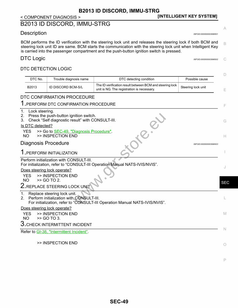
B2013 ID DISCORD, IMMU-STRG[INTELLIGENT KEY SYSTEM]
C
D
E
F
G
H
I
J
L
M
A
B
EC
N
O
P
< COMPONENT DIAGNOSIS >
S
B2013 ID DISCORD, IMMU-STRGDescription INFOID:0000000003996501
BCM performs the ID verification with the steering lock unit and releases the steering lock if both BCM andsteering lock unit ID are same. BCM starts the communication with the steering lock unit when Intelligent Keyis carried into the passenger compartment and the push-button ignition switch is pressed.
DTC Logic INFOID:0000000003996502
DTC DETECTION LOGIC
DTC CONFIRMATION PROCEDURE1.PERFORM DTC CONFIRMATION PROCEDURE
1. Lock steering.2. Press the push-button ignition switch.3. Check “Self diagnostic result” with CONSULT-III.Is DTC detected?YES >> Go to SEC-49, "Diagnosis Procedure".NO >> INSPECTION END
Diagnosis Procedure INFOID:0000000003996503
1.PERFORM INITIALIZATION
Perform initialization with CONSULT-III.For initialization, refer to “CONSULT-III Operation Manual NATS-IVIS/NVIS”.Does steering lock operate?YES >> INSPECTION ENDNO >> GO TO 2.
2.REPLACE STEERING LOCK UNIT
1. Replace steering lock unit.2. Perform initialization with CONSULT-III.
For initialization, refer to “CONSULT-III Operation Manual NATS-IVIS/NVIS”.Does steering lock operate?YES >> INSPECTION ENDNO >> GO TO 3.
3.CHECK INTERMITTENT INCIDENT
Refer to GI-38, "Intermittent Incident".
>> INSPECTION END
DTC No. Trouble diagnosis name DTC detecting condition Possible cause
B2013 ID DISCORD BCM-S/L The ID verification result between BCM and steering lock unit is NG. The registration is necessary. Steering lock unit
www.gtr-
store
.eu
SEC-49
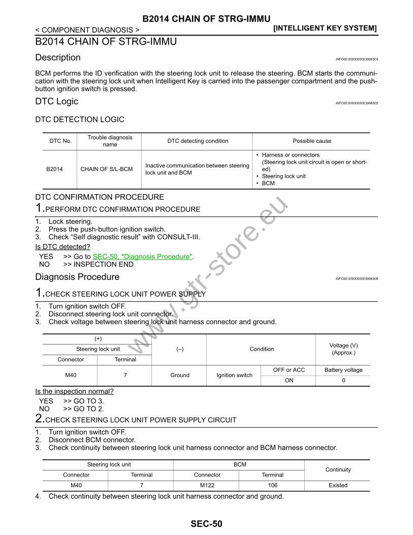
[INTELLIGENT KEY SYSTEM]B2014 CHAIN OF STRG-IMMU
< COMPONENT DIAGNOSIS >B2014 CHAIN OF STRG-IMMUDescription INFOID:0000000003996504
BCM performs the ID verification with the steering lock unit to release the steering. BCM starts the communi-cation with the steering lock unit when Intelligent Key is carried into the passenger compartment and the push-button ignition switch is pressed.
DTC Logic INFOID:0000000003996505
DTC DETECTION LOGIC
DTC CONFIRMATION PROCEDURE1.PERFORM DTC CONFIRMATION PROCEDURE
1. Lock steering.2. Press the push-button ignition switch.3. Check “Self diagnostic result” with CONSULT-III.Is DTC detected?YES >> Go to SEC-50, "Diagnosis Procedure".NO >> INSPECTION END
Diagnosis Procedure INFOID:0000000003996506
1.CHECK STEERING LOCK UNIT POWER SUPPLY
1. Turn ignition switch OFF.2. Disconnect steering lock unit connector.3. Check voltage between steering lock unit harness connector and ground.
Is the inspection normal?YES >> GO TO 3.NO >> GO TO 2.
2.CHECK STEERING LOCK UNIT POWER SUPPLY CIRCUIT
1. Turn ignition switch OFF.2. Disconnect BCM connector.3. Check continuity between steering lock unit harness connector and BCM harness connector.
4. Check continuity between steering lock unit harness connector and ground.
DTC No. Trouble diagnosis name DTC detecting condition Possible cause
B2014 CHAIN OF S/L-BCM Inactive communication between steering lock unit and BCM
• Harness or connectors(Steering lock unit circuit is open or short-ed)
• Steering lock unit• BCM
(+)
(–) Condition Voltage (V)(Approx.)Steering lock unit
Connector Terminal
M40 7 Ground Ignition switchOFF or ACC Battery voltage
ON 0
Steering lock unit BCMContinuity
Connector Terminal Connector Terminal
M40 7 M122 106 Existed
www.gtr-
store
.eu
SEC-50

B2014 CHAIN OF STRG-IMMU[INTELLIGENT KEY SYSTEM]
C
D
E
F
G
H
I
J
L
M
A
B
EC
N
O
P
< COMPONENT DIAGNOSIS >
S
Is the inspection normal?YES >> Replace BCM. Refer to BCS-78, "Removal and Installation".NO >> Repair or replace harness.
3.CHECK STEERING LOCK UNIT GROUND CIRCUIT
1. Turn ignition switch OFF.2. Check continuity between steering lock unit and ground.
Is the inspection normal?YES >> GO TO 4.NO >> Repair or replace harness.
4.CHECK STEERING LOCK UNIT COMMUNICATION SIGNAL
1. Connect steering lock unit connector.2. Read voltage signal between steering lock unit harness connector and ground.
Is the inspection normal?YES >> Replace steering lock unit.NO >> GO TO 5.
5.CHECK STEERING LOCK UNIT COMMUNICATION CIRCUIT
1. Turn ignition switch OFF.2. Disconnect steering lock unit and BCM connector.3. Check continuity between steering lock unit harness connector and BCM harness connector.
Steering lock unit
GroundContinuity
Connector Terminal
M40 7 Not existed
Steering lock unit
Ground
ContinuityConnector Terminal
M405
Existed6
(+)
(–) Condition Voltage (V)(Approx.)Steering lock unit
Connector Terminal
M40 2 Ground Steering lock unit
Lock status Battery voltage
Lock or unlock
For 15 seconds after unlock Battery voltage
15 seconds or later after unlock. 0
Steering is locked : Opening the door when ignition switch is ON to OFF.Steering is unlocked : Ignition switch is OFF to ACC.
JMKIA0066GBwww.gtr-
store
.eu
SEC-51
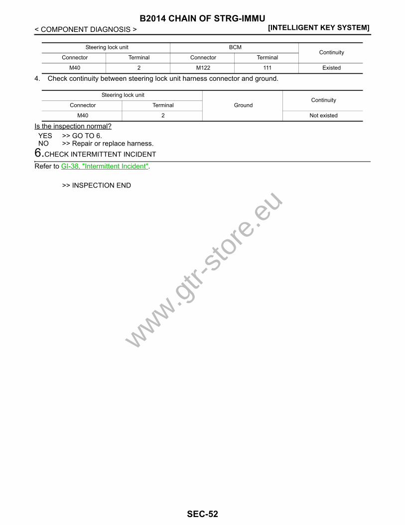
[INTELLIGENT KEY SYSTEM]B2014 CHAIN OF STRG-IMMU
< COMPONENT DIAGNOSIS >
4. Check continuity between steering lock unit harness connector and ground.
Is the inspection normal?YES >> GO TO 6.NO >> Repair or replace harness.
6.CHECK INTERMITTENT INCIDENT
Refer to GI-38, "Intermittent Incident".
>> INSPECTION END
Steering lock unit BCMContinuity
Connector Terminal Connector Terminal
M40 2 M122 111 Existed
Steering lock unit
GroundContinuity
Connector Terminal
M40 2 Not existed
www.gtr-
store
.eu
SEC-52

B2555 STOP LAMP[INTELLIGENT KEY SYSTEM]
C
D
E
F
G
H
I
J
L
M
A
B
EC
N
O
P
< COMPONENT DIAGNOSIS >
S
B2555 STOP LAMPDescription INFOID:0000000003996507
BCM detects the stop lamp status and confirms the stop lamp switch ON/OFF status. BCM confirms theengine start condition according to the stop lamp switch ON/OFF status.
DTC Logic INFOID:0000000003996508
DTC DETECTION LOGIC
DTC CONFIRMATION PROCEDURE1.PERFORM DTC CONFIRMATION PROCEDURE
1. Depress the brake pedal and wait for at least 1 second.2. Check “Self diagnostic result” with CONSULT-III.Is DTC detected?YES >> Go to SEC-53, "Diagnosis Procedure".NO >> INSPECTION END
Diagnosis Procedure INFOID:0000000003996509
1.CHECK STOP LAMP SWITCH INPUT SIGNAL
1. Turn ignition switch OFF.2. Disconnect BCM connector.3. Check voltage between BCM harness connector and ground.
Is the inspection normal?YES >> GO TO 2.NO >> Check the following.
• 10A fuse [No. 7, located in the fuse block (J/B)]• Harness for open or short between BCM and fuse.
2.CHECK STOP LAMP SWITCH POWER SUPPLY CIRCUIT
1. Disconnect stop lamp switch connector.2. Check voltage between stop lamp harness connector and ground.
Is the inspection result normal?YES >> GO TO 3.NO >> Check harness for open or short between stop lamp switch and fuse.
DTC No. Trouble diagno-sis name DTC detecting condition Possible cause
B2555 STOP LAMP
BCM makes a comparison between the upper voltage and lower voltage of stop lamp switch. It judges from their values to detect the malfunctioning circuit.
• Harness or connectors(Stop lamp switch circuit is open or shorted)
• Stop lamp switch• Fuse
(+)
(–) Voltage (V)(Approx.)BCM
Connector Terminal
M123 116 Ground Battery voltage
(+)
(–) Voltage (V)(Approx.)Stop lamp switch
Connector Terminal
E110 1 Ground Battery voltage
www.gtr-
store
.eu
SEC-53
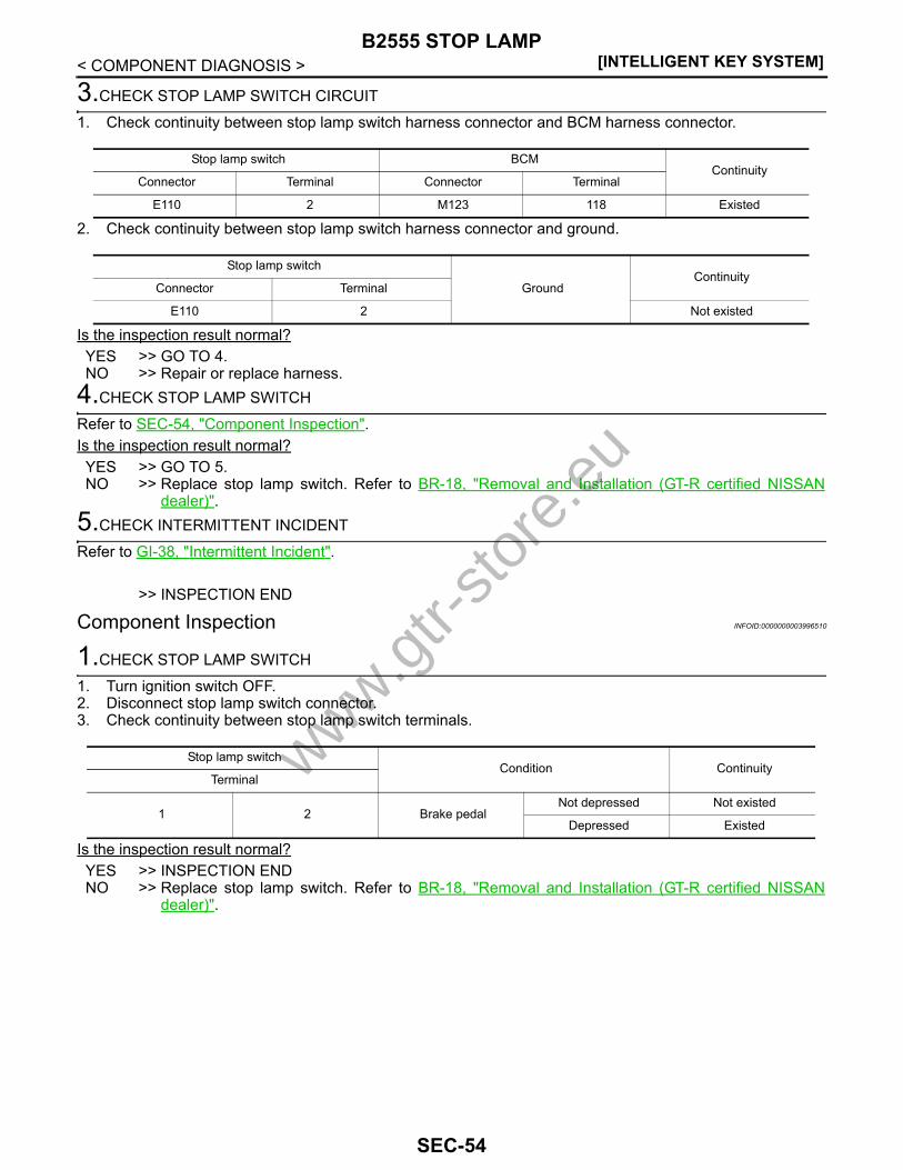
[INTELLIGENT KEY SYSTEM]B2555 STOP LAMP
< COMPONENT DIAGNOSIS >
3.CHECK STOP LAMP SWITCH CIRCUIT
1. Check continuity between stop lamp switch harness connector and BCM harness connector.
2. Check continuity between stop lamp switch harness connector and ground.
Is the inspection result normal?YES >> GO TO 4.NO >> Repair or replace harness.
4.CHECK STOP LAMP SWITCH
Refer to SEC-54, "Component Inspection".Is the inspection result normal?YES >> GO TO 5.NO >> Replace stop lamp switch. Refer to BR-18, "Removal and Installation (GT-R certified NISSAN
dealer)".5.CHECK INTERMITTENT INCIDENT
Refer to GI-38, "Intermittent Incident".
>> INSPECTION END
Component Inspection INFOID:0000000003996510
1.CHECK STOP LAMP SWITCH
1. Turn ignition switch OFF.2. Disconnect stop lamp switch connector.3. Check continuity between stop lamp switch terminals.
Is the inspection result normal?YES >> INSPECTION ENDNO >> Replace stop lamp switch. Refer to BR-18, "Removal and Installation (GT-R certified NISSAN
dealer)".
Stop lamp switch BCMContinuity
Connector Terminal Connector Terminal
E110 2 M123 118 Existed
Stop lamp switch
GroundContinuity
Connector Terminal
E110 2 Not existed
Stop lamp switchCondition Continuity
Terminal
1 2 Brake pedalNot depressed Not existed
Depressed Existed
www.gtr-
store
.eu
SEC-54

B2556 PUSH-BUTTON IGNITION SWITCH[INTELLIGENT KEY SYSTEM]
C
D
E
F
G
H
I
J
L
M
A
B
EC
N
O
P
< COMPONENT DIAGNOSIS >
S
B2556 PUSH-BUTTON IGNITION SWITCHDescription INFOID:0000000003996511
The switch that changes the power supply position. BCM maintains the power supply position status. BCMchanges the power supply position with the operation of the push-button ignition switch.
DTC Logic INFOID:0000000003996512
DTC DETECTION LOGIC
DTC CONFIRMATION PROCEDURE1.PERFORM DTC CONFIRMATION PROCEDURE
1. Start the engine and wait for at least 100 seconds.2. Check “Self diagnostic result” with CONSULT-III.Is DTC detected?YES >> Go to SEC-55, "Diagnosis Procedure".NO >> INSPECTION END
Diagnosis Procedure INFOID:0000000003996513
1.CHECK PUSH-BUTTON IGNITION SWITCH INPUT SIGNAL
1. Turn ignition switch OFF.2. Disconnect push-button ignition switch connector.3. Check voltage between push-button ignition switch harness connector and ground.
Is the inspection normal?YES >> GO TO 3.NO >> GO TO 2.
2.CHECK PUSH-BUTTON IGNITION SWITCH CIRCUIT
1. Disconnect BCM connector and IPDM E/R connector.2. Check continuity between push-button ignition switch harness connector and BCM harness connector.
3. Check continuity between push-button ignition switch harness connector and ground.
Is the inspection normal?
DTC No. Trouble diagnosis name DTC detecting condition Possible cause
B2556 PUSH-BTN IGN SWBCM detects the push-button ignition switch stuck at ON for 100 seconds or more
• Harness or connectors(Push-button ignition switch circuit is shorted.)
• Push-button ignition switch• BCM
(+)
(–) Voltage (V)(Approx.)Push-button ignition switch
Connector Terminal
M131 4 Ground Battery voltage
Push-button ignition switch BCMContinuity
Connector Terminal Connector Terminal
M131 4 M122 89 Existed
Push-button ignition switch
GroundContinuity
Connector Terminal
M131 4 Not existed
www.gtr-
store
.eu
SEC-55

[INTELLIGENT KEY SYSTEM]B2556 PUSH-BUTTON IGNITION SWITCH
< COMPONENT DIAGNOSIS >YES >> Replace BCM. Refer to BCS-78, "Removal and Installation".NO >> Repair or replace harness.
3.CHECK PUSH-BUTTON IGNITION SWITCH GROUND CIRCUIT
Check continuity between push-button ignition switch harness connector and ground.
Is the inspection normal?YES >> GO TO 4.NO >> Repair or replace harness.
4.CHECK PUSH-BUTTON IGNITION SWITCH
Refer to SEC-56, "Component Inspection".Is the inspection normal?YES >> GO TO 5.NO >> Replace push-button ignition switch. Refer to PCS-121, "Removal and Installation".
5.CHECK INTERMITTENT INCIDENT
Refer to GI-38, "Intermittent Incident".
>> INSPECTION END
Component Inspection INFOID:0000000003996514
1.CHECK PUSH-BUTTON IGNITION SWITCH
1. Turn ignition switch OFF.2. Disconnect push-button ignition switch connector.3. Check continuity between push-button ignition switch terminals.
Is the inspection result normal?YES >> INSPECTION ENDNO >> Replace push-button ignition switch. Refer to PCS-121, "Removal and Installation".
Push-button ignition switch
GroundContinuity
Connector Terminal
M131 1 Existed
Push-button ignition switchCondition Continuity
Terminals
1 4Pressed Existed
Not pressed Not existed
www.gtr-
store
.eu
SEC-56

B2557 VEHICLE SPEED[INTELLIGENT KEY SYSTEM]
C
D
E
F
G
H
I
J
L
M
A
B
EC
N
O
P
< COMPONENT DIAGNOSIS >
S
B2557 VEHICLE SPEEDDescription INFOID:0000000003996515
BCM receives the 2 vehicle speed signals via CAN communication. 1 signal is transmitted by the “combinationmeter” Another signal is transmitted by “ABS actuator and electric unit (control unit).” BCM compares both sig-nals to detect the vehicle speed.
DTC Logic INFOID:0000000003996516
DTC DETECTION LOGICNOTE:• If DTC B2557 is displayed with DTC U1000, first perform the trouble diagnosis for DTC U1000. Refer to
SEC-31, "BCM : DTC Logic".• If DTC B2557 is displayed with DTC U1010, first perform the trouble diagnosis for DTC U1010. Refer to
SEC-33, "BCM : DTC Logic".
DTC CONFIRMATION PROCEDURE1.PERFORM DTC CONFIRMATION PROCEDURE
1. Drive the vehicle at the vehicle speed of 10 km/h (6.2 MPH) or more and wait for at least 10 seconds.2. Check “Self diagnostic result” with CONSULT-III.Is DTC detected?YES >> Go to SEC-57, "Diagnosis Procedure".NO >> INSPECTION END
Diagnosis Procedure INFOID:0000000003996517
1.CHECK DTC WITH “ABS ACTUATOR AND ELECTRIC UNIT (CONTROL UNIT)”
Check “Self diagnostic result” with CONSULT-III. Refer to BRC-101, "DTC No. Index".Is the inspection result normal?YES >> GO TO 2.NO >> Repair or replace the malfunctioning parts.
2.CHECK DTC WITH “COMBINATION METER”
Check “Self diagnostic result” with CONSULT-III. Refer to MWI-84, "DTC Index".Is the inspection result normal?YES >> GO TO 3.NO >> Repair or replace the malfunctioning parts.
3.CHECK INTERMITTENT INCIDENT
Refer to GI-38, "Intermittent Incident".
>> INSPECTION END
DTC Self-diagnosis name DTC detecting condition Possible causes
B2557 VEHICLE SPEED
BCM detects the following difference between the vehicle speed from “combination meter” and the one from “ABS ac-tuator and electric unit” for 10 seconds continuously.• One is 10 km/h (6.2 MPH) or more and the other is 4 km/
h (2.5 MPH) or less.
• Wheel sensor• Combination meter• ABS actuator and electric
unit (control unit)
www.gtr-
store
.eu
SEC-57
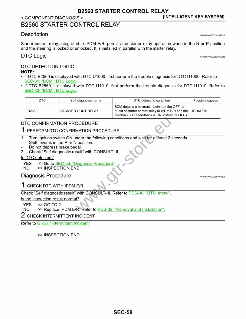
[INTELLIGENT KEY SYSTEM]B2560 STARTER CONTROL RELAY
< COMPONENT DIAGNOSIS >B2560 STARTER CONTROL RELAYDescription INFOID:0000000003996518
Starter control relay, integrated in IPDM E/R, permits the starter relay operation when in the N or P positionand the steering is locked or unlocked. It is installed in parallel with the starter relay.
DTC Logic INFOID:0000000003996519
DTC DETECTION LOGICNOTE:• If DTC B2560 is displayed with DTC U1000, first perform the trouble diagnosis for DTC U1000. Refer to
SEC-31, "BCM : DTC Logic"• If DTC B2560 is displayed with DTC U1010, first perform the trouble diagnosis for DTC U1010. Refer to
SEC-33, "BCM : DTC Logic".
DTC CONFIRMATION PROCEDURE1.PERFORM DTC CONFIRMATION PROCEDURE
1. Turn ignition switch ON under the following conditions and wait for at least 2 seconds.- Shift lever is in the P or N position.- Do not depress brake pedal.2. Check “Self diagnostic result” with CONSULT-III.Is DTC detected?YES >> Go to SEC-58, "Diagnosis Procedure".NO >> INSPECTION END
Diagnosis Procedure INFOID:0000000003996520
1.CHECK DTC WITH IPDM E/R
Check “Self diagnostic result” with CONSULT-III. Refer to PCS-30, "DTC Index".Is the inspection result normal?YES >> GO TO 2.NO >> Replace IPDM E/R. Refer to PCS-32, "Removal and Installation".
2.CHECK INTERMITTENT INCIDENT
Refer to GI-38, "Intermittent Incident"
>> INSPECTION END
DTC Self-diagnosis name DTC detecting condition Possible causes
B2560 STARTER CONT RELAYBCM detects a mismatch between the OFF re-quest of starter control relay to IPDM E/R and the feedback. (The feedback is ON instead of OFF.)
IPDM E/R
www.gtr-
store
.eu
SEC-58
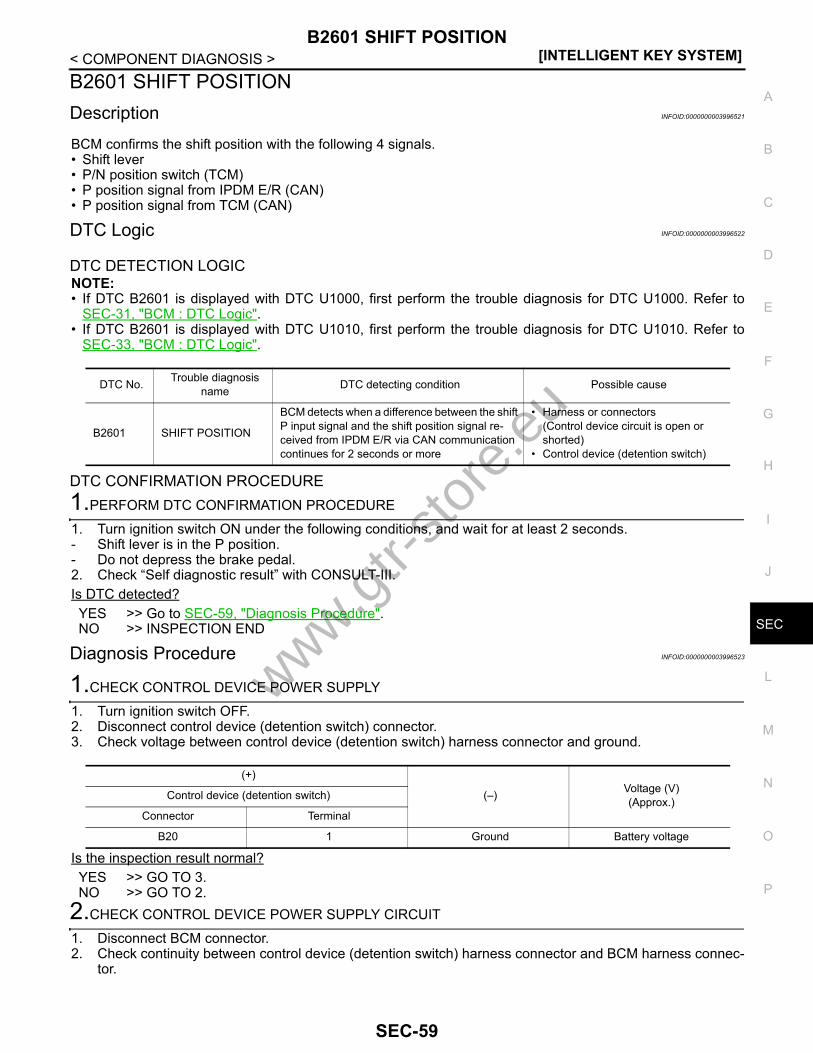
B2601 SHIFT POSITION[INTELLIGENT KEY SYSTEM]
C
D
E
F
G
H
I
J
L
M
A
B
EC
N
O
P
< COMPONENT DIAGNOSIS >
S
B2601 SHIFT POSITIONDescription INFOID:0000000003996521
BCM confirms the shift position with the following 4 signals.• Shift lever• P/N position switch (TCM)• P position signal from IPDM E/R (CAN)• P position signal from TCM (CAN)
DTC Logic INFOID:0000000003996522
DTC DETECTION LOGICNOTE:• If DTC B2601 is displayed with DTC U1000, first perform the trouble diagnosis for DTC U1000. Refer to
SEC-31, "BCM : DTC Logic".• If DTC B2601 is displayed with DTC U1010, first perform the trouble diagnosis for DTC U1010. Refer to
SEC-33, "BCM : DTC Logic".
DTC CONFIRMATION PROCEDURE1.PERFORM DTC CONFIRMATION PROCEDURE
1. Turn ignition switch ON under the following conditions, and wait for at least 2 seconds.- Shift lever is in the P position.- Do not depress the brake pedal.2. Check “Self diagnostic result” with CONSULT-III.Is DTC detected?YES >> Go to SEC-59, "Diagnosis Procedure".NO >> INSPECTION END
Diagnosis Procedure INFOID:0000000003996523
1.CHECK CONTROL DEVICE POWER SUPPLY
1. Turn ignition switch OFF.2. Disconnect control device (detention switch) connector.3. Check voltage between control device (detention switch) harness connector and ground.
Is the inspection result normal?YES >> GO TO 3.NO >> GO TO 2.
2.CHECK CONTROL DEVICE POWER SUPPLY CIRCUIT
1. Disconnect BCM connector.2. Check continuity between control device (detention switch) harness connector and BCM harness connec-
tor.
DTC No. Trouble diagnosis name DTC detecting condition Possible cause
B2601 SHIFT POSITION
BCM detects when a difference between the shift P input signal and the shift position signal re-ceived from IPDM E/R via CAN communication continues for 2 seconds or more
• Harness or connectors(Control device circuit is open or shorted)
• Control device (detention switch)
(+)
(–) Voltage (V)(Approx.)Control device (detention switch)
Connector Terminal
B20 1 Ground Battery voltage
www.gtr-
store
.eu
SEC-59

[INTELLIGENT KEY SYSTEM]B2601 SHIFT POSITION
< COMPONENT DIAGNOSIS >
3. Check continuity between control device (detention switch) harness connector and ground.
Is the inspection result normal?YES >> Replace BCM. Refer to BCS-78, "Removal and Installation".NO >> Repair or replace harness.
3.CHECK CONTROL DEVICE CIRCUIT (BCM)
1. Disconnect BCM connector and IPDM E/R connector.2. Check continuity between control device (detention switch) harness connector and BCM harness connec-
tor.
3. Check continuity between control device (detention switch) harness connector and ground.
Is the inspection result normal?YES >> GO TO 4.NO >> Repair or replace harness.
4.CHECK CONTROL DEVICE CIRCUIT (IPDM E/R)
1. Check continuity between control device (detention switch) harness connector and IPDM E/R harnessconnector.
2. Check continuity between control device (detention switch) harness connector and ground.
Is the inspection result normal?YES >> GO TO 5.NO >> Repair or replace harness.
5.CHECK CONTROL DEVICE (DETENTION SWITCH)
Refer to SEC-61, "Component Inspection".Is the inspection result normal?YES >> GO TO 6.NO >> Replace control device. Refer to TM-262, "Removal and Installation".
6.CHECK INTERMITTENT INCIDENT
Control device (detention switch) BCMContinuity
Connector Terminal Connector Terminal
B20 1 M122 96 Existed
Control device (detention switch)
GroundContinuity
Connector Terminal
B20 1 Not existed
Control device (detention switch) BCMContinuity
Connector Terminal Connector Terminal
B20 2 M122 99 Existed
Control device (detention switch)
GroundContinuity
Connector Terminal
B20 2 Not existed
Control device (detention switch) IPDM E/RContinuity
Connector Terminal Connector Terminal
B20 2 E11 43 Existed
Control device (detention switch)
GroundContinuity
Connector Terminal
B20 2 Not existed
www.gtr-
store
.eu
SEC-60
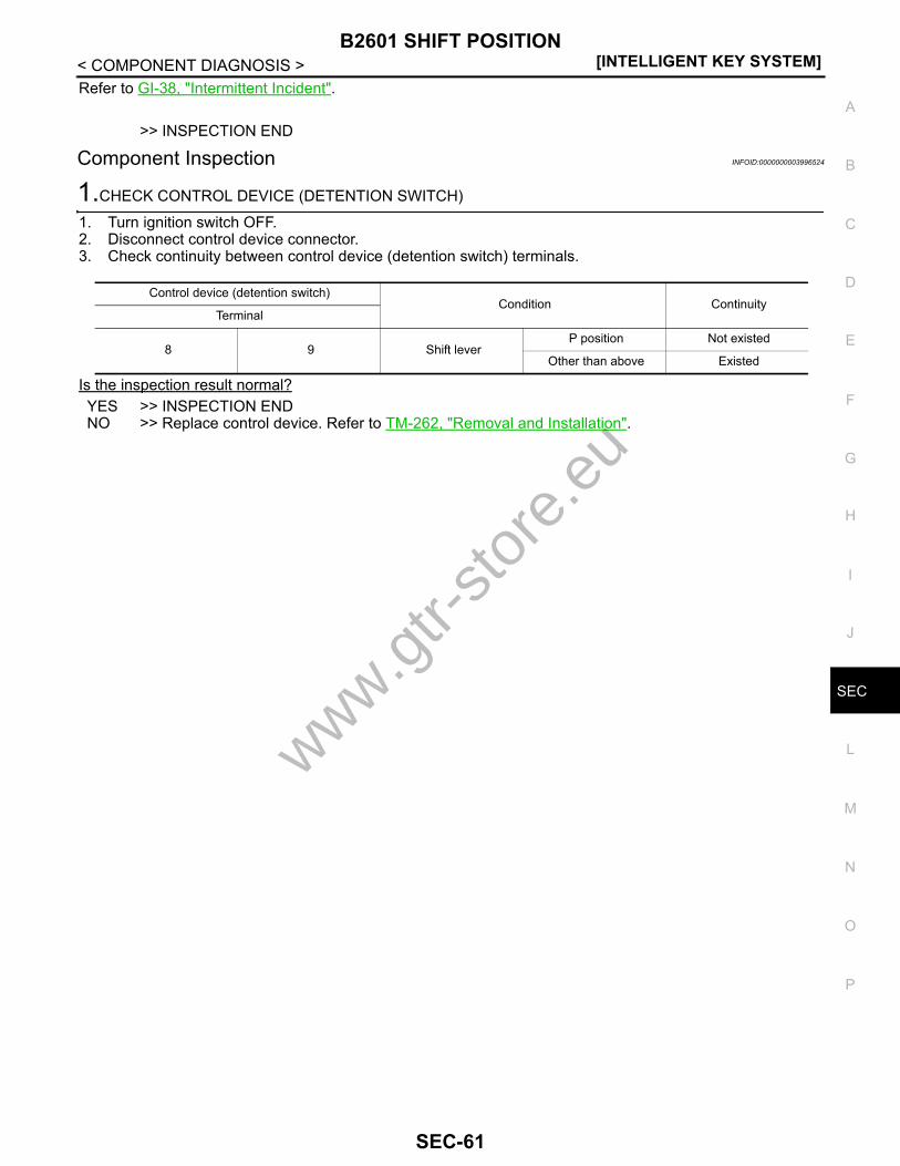
B2601 SHIFT POSITION[INTELLIGENT KEY SYSTEM]
C
D
E
F
G
H
I
J
L
M
A
B
EC
N
O
P
< COMPONENT DIAGNOSIS >
S
Refer to GI-38, "Intermittent Incident".
>> INSPECTION END
Component Inspection INFOID:0000000003996524
1.CHECK CONTROL DEVICE (DETENTION SWITCH)
1. Turn ignition switch OFF.2. Disconnect control device connector.3. Check continuity between control device (detention switch) terminals.
Is the inspection result normal?YES >> INSPECTION ENDNO >> Replace control device. Refer to TM-262, "Removal and Installation".
Control device (detention switch)Condition Continuity
Terminal
8 9 Shift leverP position Not existed
Other than above Existed
www.gtr-
store
.eu
SEC-61
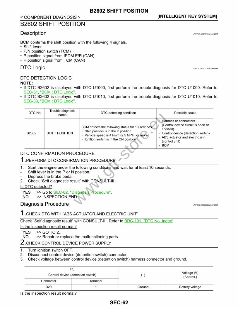
[INTELLIGENT KEY SYSTEM]B2602 SHIFT POSITION
< COMPONENT DIAGNOSIS >B2602 SHIFT POSITIONDescription INFOID:0000000003996525
BCM confirms the shift position with the following 4 signals.• Shift lever• P/N position switch (TCM)• P position signal from IPDM E/R (CAN)• P position signal from TCM (CAN)
DTC Logic INFOID:0000000003996526
DTC DETECTION LOGICNOTE:• If DTC B2602 is displayed with DTC U1000, first perform the trouble diagnosis for DTC U1000. Refer to
SEC-31, "BCM : DTC Logic".• If DTC B2602 is displayed with DTC U1010, first perform the trouble diagnosis for DTC U1010. Refer to
SEC-33, "BCM : DTC Logic".
DTC CONFIRMATION PROCEDURE1.PERFORM DTC CONFIRMATION PROCEDURE
1. Start the engine under the following conditions and wait for at least 10 seconds.- Shift lever is in the P or N position.- Depress the brake pedal.2. Check “Self diagnostic result” with CONSULT-III.Is DTC detected?YES >> Go to SEC-62, "Diagnosis Procedure".NO >> INSPECTION END
Diagnosis Procedure INFOID:0000000003996527
1.CHECK DTC WITH “ABS ACTUATOR AND ELECTRIC UNIT”
Check “Self diagnostic result” with CONSULT-III. Refer to BRC-101, "DTC No. Index".Is the inspection result normal?YES >> GO TO 2.NO >> Repair or replace the malfunctioning parts.
2.CHECK CONTROL DEVICE POWER SUPPLY
1. Turn ignition switch OFF.2. Disconnect control device (detention switch) connector.3. Check voltage between control device (detention switch) harness connector and ground.
Is the inspection result normal?
DTC No. Trouble diagnosis name DTC detecting condition Possible cause
B2602 SHIFT POSITION
BCM detects the following status for 10 seconds.• Shift position is in the P position• Vehicle speed is 4 km/h (2.5 MPH) or more• Ignition switch is in the ON position
• Harness or connectors (Control device circuit is open or shorted)
• Control device (detention switch)• ABS actuator and electric unit
(control unit)• BCM
(+)
(–) Voltage (V)(Approx.)Control device (detention switch)
Connector Terminal
B20 1 Ground Battery voltage
www.gtr-
store
.eu
SEC-62

B2602 SHIFT POSITION[INTELLIGENT KEY SYSTEM]
C
D
E
F
G
H
I
J
L
M
A
B
EC
N
O
P
< COMPONENT DIAGNOSIS >
S
YES >> GO TO 4.NO >> GO TO 3.
3.CHECK CONTROL DEVICE POWER SUPPLY CIRCUIT
1. Disconnect BCM connector.2. Check continuity between control device (detention switch) harness connector and BCM harness connec-
tor.
3. Check continuity between control device (detention switch) harness connector and ground.
Is the inspection result normal?YES >> Replace BCM. Refer to BCS-78, "Removal and Installation".NO >> Repair or replace harness.
4.CHECK CONTROL DEVICE CIRCUIT
1. Disconnect BCM connector and IPDM E/R connector.2. Check continuity between control device (detention switch) harness connector and BCM harness connec-
tor.
3. Check continuity between control device (detention switch) harness connector and ground.
Is the inspection result normal?YES >> GO TO 5.NO >> Repair or replace harness.
5.CHECK CONTROL DEVICE (DETENTION SWITCH)
Refer to SEC-61, "Component Inspection".Is the inspection result normal?YES >> GO TO 6.NO >> Replace control device. Refer to TM-262, "Removal and Installation".
6.CHECK INTERMITTENT INCIDENT
Refer to GI-38, "Intermittent Incident".
>> INSPECTION END
Control device (detention switch) BCMContinuity
Connector Terminal Connector Terminal
B20 1 M122 96 Existed
Control device (detention switch)
GroundContinuity
Connector Terminal
B20 1 No existed
Control device (detention switch) BCMContinuity
Connector Terminal Connector Terminal
B20 2 M122 99 Existed
Control device (detention switch)
GroundContinuity
Connector Terminal
B20 2 No existed
www.gtr-
store
.eu
SEC-63

[INTELLIGENT KEY SYSTEM]B2603 SHIFT POSITION STATUS
< COMPONENT DIAGNOSIS >B2603 SHIFT POSITION STATUSDescription INFOID:0000000003996528
BCM confirms the shift position with the following 4 signals.• Shift lever• P/N position switch (TCM)• P position signal from IPDM E/R (CAN)• P position signal from TCM (CAN)
DTC Logic INFOID:0000000003996529
DTC DETECTION LOGICNOTE:• If DTC B2603 is displayed with DTC U1000, first perform the trouble diagnosis for DTC U1000. Refer to
SEC-31, "BCM : DTC Logic".• If DTC B2603 is displayed with DTC U1010, first perform the trouble diagnosis for DTC U1010. Refer to
SEC-33, "BCM : DTC Logic".• If DTC B2603 is displayed with DTC B210F for IPDM E/R, first perform the trouble diagnosis for DTC B210F.
Refer to SEC-108, "DTC Logic".• If DTC B2603 is displayed with DTC B2601 for IPDM E/R, first perform the trouble diagnosis for DTC B2601.
Refer to SEC-59, "DTC Logic".
DTC CONFIRMATION PROCEDURE1.PERFORM DTC CONFIRMATION PROCEDURE
1. Start the engine under the following conditions and wait for at least 1 second.- Shift lever is in the P position.- Do not depress the brake pedal.2. Check “Self diagnostic result” with CONSULT-III.Is DTC detected?YES >> Go to SEC-64, "Diagnosis Procedure".NO >> INSPECTION END
Diagnosis Procedure INFOID:0000000003996530
1.CHECK DTC WITH TCM
Check “Self diagnostic result” with CONSULT-III for TCM.Are any DTC detected?YES >> Refer to SEC-108, "DTC Logic".NO >> GO TO 2.
2.CHECK TCM CIRCUIT
1. Turn ignition switch OFF.2. Disconnect TCM connector and BCM connector.3. Check continuity between TCM harness connector and BCM harness connector.
DTC Self-diagnosis name DTC detecting condition Possible causes
B2603 SHIFT POSI STATUS
BCM detects the followings status for 500 ms or more when shift is in P position, and ignition switch is in the ON position.• P/N position signal (from TCM): approx. 0 V• Control device (detention switch): approx. 0 V
• Harness or connector(Control device circuit is open or shorted)
• Harness or connectors[TCM circuit is open or shorted]
• TCM• BCM
TCM BCMContinuity
Connector Terminal Connector Terminal
B45 19 M122 140 Existed
www.gtr-
store
.eu
SEC-64
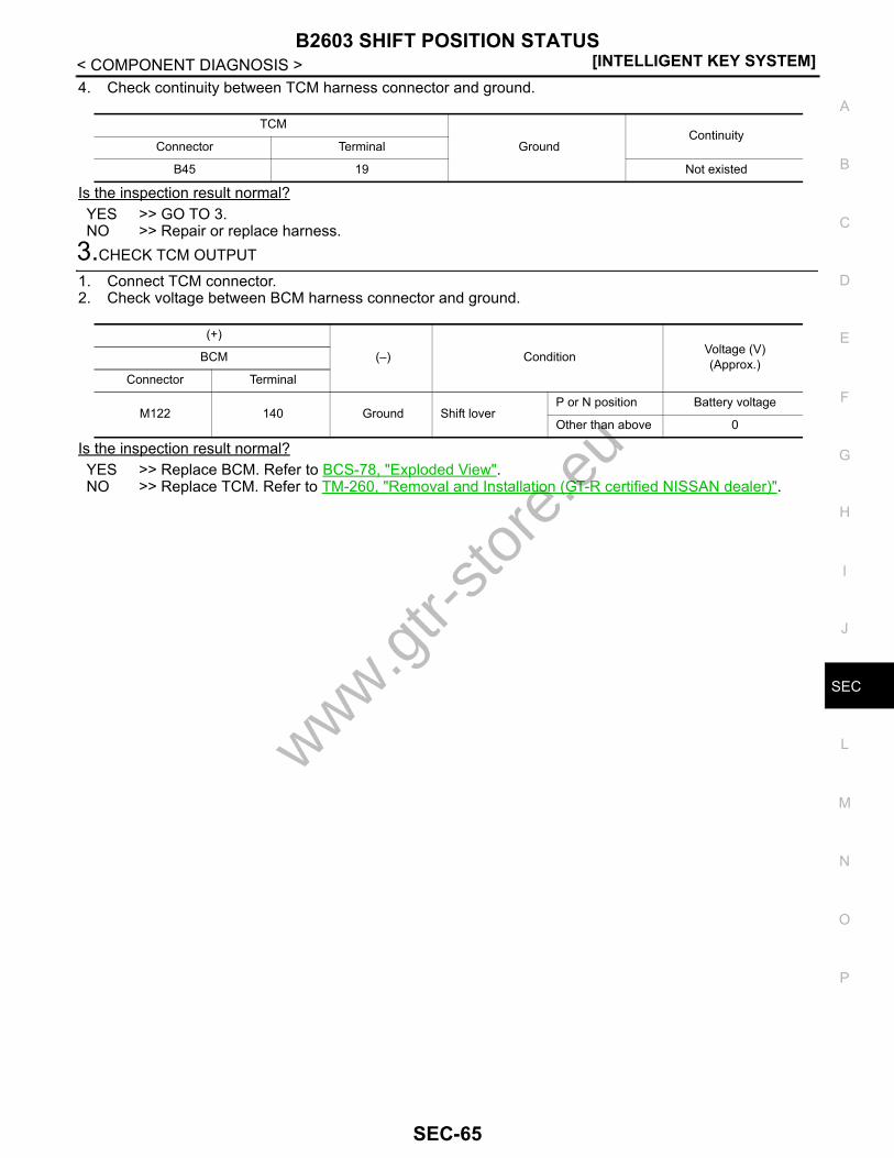
B2603 SHIFT POSITION STATUS[INTELLIGENT KEY SYSTEM]
C
D
E
F
G
H
I
J
L
M
A
B
EC
N
O
P
< COMPONENT DIAGNOSIS >
S
4. Check continuity between TCM harness connector and ground.
Is the inspection result normal?YES >> GO TO 3.NO >> Repair or replace harness.
3.CHECK TCM OUTPUT
1. Connect TCM connector.2. Check voltage between BCM harness connector and ground.
Is the inspection result normal?YES >> Replace BCM. Refer to BCS-78, "Exploded View".NO >> Replace TCM. Refer to TM-260, "Removal and Installation (GT-R certified NISSAN dealer)".
TCM
GroundContinuity
Connector Terminal
B45 19 Not existed
(+)
(–) Condition Voltage (V)(Approx.)BCM
Connector Terminal
M122 140 Ground Shift loverP or N position Battery voltage
Other than above 0
www.gtr-
store
.eu
SEC-65
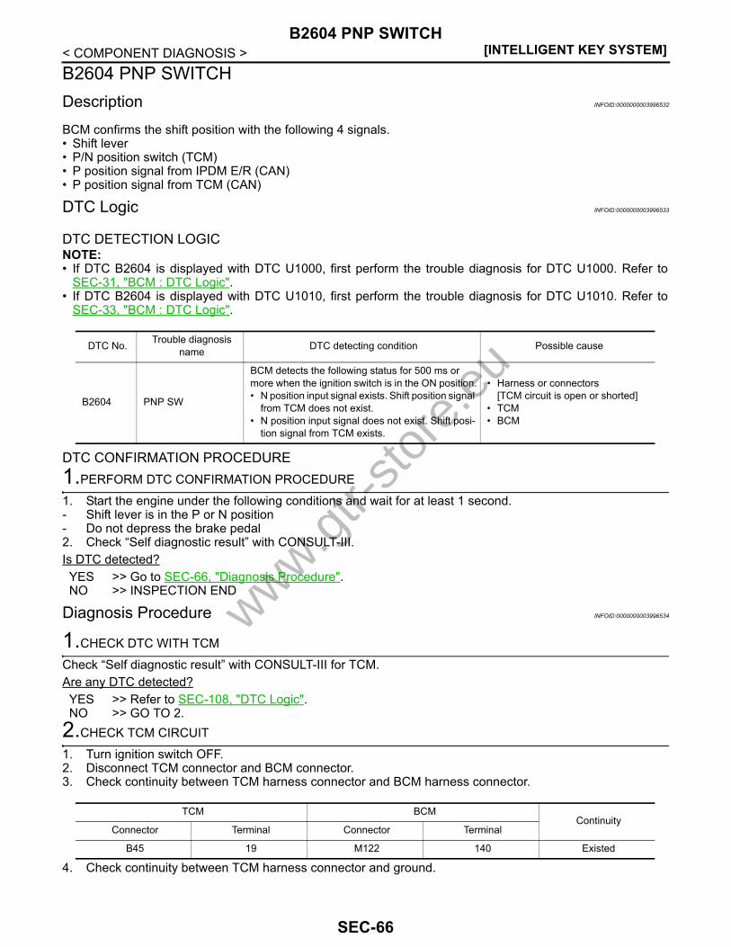
[INTELLIGENT KEY SYSTEM]B2604 PNP SWITCH
< COMPONENT DIAGNOSIS >B2604 PNP SWITCHDescription INFOID:0000000003996532
BCM confirms the shift position with the following 4 signals.• Shift lever• P/N position switch (TCM)• P position signal from IPDM E/R (CAN)• P position signal from TCM (CAN)
DTC Logic INFOID:0000000003996533
DTC DETECTION LOGICNOTE:• If DTC B2604 is displayed with DTC U1000, first perform the trouble diagnosis for DTC U1000. Refer to
SEC-31, "BCM : DTC Logic".• If DTC B2604 is displayed with DTC U1010, first perform the trouble diagnosis for DTC U1010. Refer to
SEC-33, "BCM : DTC Logic".
DTC CONFIRMATION PROCEDURE1.PERFORM DTC CONFIRMATION PROCEDURE
1. Start the engine under the following conditions and wait for at least 1 second.- Shift lever is in the P or N position- Do not depress the brake pedal2. Check “Self diagnostic result” with CONSULT-III.Is DTC detected?YES >> Go to SEC-66, "Diagnosis Procedure".NO >> INSPECTION END
Diagnosis Procedure INFOID:0000000003996534
1.CHECK DTC WITH TCM
Check “Self diagnostic result” with CONSULT-III for TCM.Are any DTC detected?YES >> Refer to SEC-108, "DTC Logic".NO >> GO TO 2.
2.CHECK TCM CIRCUIT
1. Turn ignition switch OFF.2. Disconnect TCM connector and BCM connector.3. Check continuity between TCM harness connector and BCM harness connector.
4. Check continuity between TCM harness connector and ground.
DTC No. Trouble diagnosis name DTC detecting condition Possible cause
B2604 PNP SW
BCM detects the following status for 500 ms or more when the ignition switch is in the ON position.• N position input signal exists. Shift position signal
from TCM does not exist.• N position input signal does not exist. Shift posi-
tion signal from TCM exists.
• Harness or connectors [TCM circuit is open or shorted]
• TCM• BCM
TCM BCMContinuity
Connector Terminal Connector Terminal
B45 19 M122 140 Existed
www.gtr-
store
.eu
SEC-66

B2604 PNP SWITCH[INTELLIGENT KEY SYSTEM]
C
D
E
F
G
H
I
J
L
M
A
B
EC
N
O
P
< COMPONENT DIAGNOSIS >
S
Is the inspection result normal?YES >> GO TO 3.NO >> Repair or replace harness.
3.CHECK TCM OUTPUT
1. Connect TCM connector.2. Check voltage between BCM harness connector and ground.
Is the inspection result normal?YES >> Replace BCM. Refer to BCS-78, "Exploded View".NO >> Replace TCM. Refer to TM-260, "Removal and Installation (GT-R certified NISSAN dealer)".
TCM
GroundContinuity
Connector Terminal
B45 19 Not existed
(+)
(–) Condition Voltage (V)(Approx.)BCM
Connector Terminal
M122 140 Ground Shift loverP or N position Battery voltage
Other than above 0
www.gtr-
store
.eu
SEC-67

[INTELLIGENT KEY SYSTEM]B2605 PNP SWITCH
< COMPONENT DIAGNOSIS >B2605 PNP SWITCHDescription INFOID:0000000003996536
BCM confirms the shift position with the following 4 signals.• Shift lever• P/N position switch (TCM)• P position signal from IPDM E/R (CAN)• P position signal from TCM (CAN)
DTC Logic INFOID:0000000003996537
DTC DETECTION LOGICNOTE:• If DTC B2605 is displayed with DTC U1000, first perform the trouble diagnosis for DTC U1000. Refer to
SEC-31, "BCM : DTC Logic".• If DTC B2605 is displayed with DTC U1010, first perform the trouble diagnosis for DTC U1010. Refer to
SEC-33, "BCM : DTC Logic".• If DTC B2605 is displayed with DTC U1010, first perform the trouble diagnosis for DTC B2603. Refer to
SEC-64, "DTC Logic".
DTC CONFIRMATION PROCEDURE1.PERFORM DTC CONFIRMATION PROCEDURE
1. Turn ignition switch ON under the following conditions and wait for at least 1 second.- Shift lever is in the P or N position- Do not depress the brake pedal.2. Check “Self diagnostic result” with CONSULT-III.Is DTC detected?YES >> Go to SEC-68, "Diagnosis Procedure".NO >> INSPECTION END
Diagnosis Procedure INFOID:0000000003996538
1.CHECK TCM CIRCUIT
1. Turn ignition switch OFF.2. Disconnect IPDM E/R connector.3. Check continuity between IPDM E/R harness connector and TCM harness connector.
4. Check continuity between IPDM E/R harness connector and ground.
Is the inspection result normal?
DTC No. Trouble diagnosis name DTC detecting condition Possible cause
B2605 PNP SW
BCM detects the following status for 500 ms or more when the ignition switch is in ON position• N position input signal exists. Shift position signal
from IPDM E/R does not exist.• N position input signal does not exist. Shift posi-
tion signal from IPDM E/R exists.
• Harness or connectors[TCM circuit is open or shorted]
• BCM• IPDM E/R• TCM
IPDM E/R TCMContinuity
Connector Terminal Connector Terminal
E5 30 B45 19 Existed
IPDM E/R
GroundContinuity
Connector Terminal
E5 30 Not existed
www.gtr-
store
.eu
SEC-68
B2605 PNP SWITCH[INTELLIGENT KEY SYSTEM]
C
D
E
F
G
H
I
J
L
M
A
B
EC
N
O
P
< COMPONENT DIAGNOSIS >
S
YES >> Replace IPDM E/R. Refer to PCS-32, "Removal and Installation".NO >> Repair or replace harness.
www.gtr-
store
.eu
SEC-69

[INTELLIGENT KEY SYSTEM]B2606 STEERING LOCK RELAY
< COMPONENT DIAGNOSIS >B2606 STEERING LOCK RELAYDescription INFOID:0000000003996539
The steering lock relay ON signal is transmitted to IPDM E/R by BCM via CAN communication.IPDM E/R turns the steering lock relay ON and transmits the release of the steering to BCM.
DTC Logic INFOID:0000000003996540
DTC DETECTION LOGICNOTE:• If DTC B2606 is displayed with DTC U1000, first perform the trouble diagnosis for DTC U1000. Refer to
SEC-31, "BCM : DTC Logic".• If DTC B2606 is displayed with DTC U1010, first perform the trouble diagnosis for DTC U1010. Refer to
SEC-33, "BCM : DTC Logic".
DTC CONFIRMATION PROCEDURE1.PERFORM DTC CONFIRMATION PROCEDURE
1. Turn ignition switch ON under the following conditions.- Shift lever is in the P or N position.- Do not depress brake pedal.2. Turn ignition switch OFF.3. Press driver side door switch and wait for at least 1 second.4. Check “Self diagnostic result” with CONSULT-III.Is DTC detected?YES >> Go to SEC-70, "Diagnosis Procedure".NO >> INSPECTION END
Diagnosis Procedure INFOID:0000000003996541
1.CHECK DTC WITH IPDM E/R
Check “Self diagnostic result” with CONSULT-III. Refer to PCS-30, "DTC Index".Is the inspection result normal?YES >> GO TO 2.NO >> Replace IPDM E/R. Refer to PCS-32, "Removal and Installation".
2.CHECK INTERMITTENT INCIDENT
Refer to GI-38, "Intermittent Incident".
>> INSPECTION END
DTC No. Trouble diagnosis name DTC detecting condition Possible cause
B2606 S/L RELAY
BCM detects that there is a mismatch between the following statuses.• Steering lock unit ON signal transmitted by
IPDM E/R• The steering lock unit status feedback
Steering lock relay (Built into IPDM E/R)
www.gtr-
store
.eu
SEC-70

B2607 STEERING LOCK RELAY[INTELLIGENT KEY SYSTEM]
C
D
E
F
G
H
I
J
L
M
A
B
EC
N
O
P
< COMPONENT DIAGNOSIS >
S
B2607 STEERING LOCK RELAYDescription INFOID:0000000003996542
BCM requests to IPDM E/R to supply power to steering lock unit. After receiving the power, the steering lockunit transmits an ON signal to BCM.
DTC Logic INFOID:0000000003996543
DTC DETECTION LOGICNOTE:• If DTC B2607 is displayed with DTC U1000, first perform the trouble diagnosis for DTC U1000. Refer to
SEC-31, "BCM : DTC Logic".• If DTC B2607 is displayed with DTC U1010, first perform the trouble diagnosis for DTC U1010. Refer to
SEC-33, "BCM : DTC Logic".
DTC CONFIRMATION PROCEDURE1.PERFORM DTC CONFIRMATION PROCEDURE
1. Turn ignition switch ON under the following conditions.- Shift lever is in the P or N position.- Do not depress brake pedal.2. Turn ignition switch OFF.3. Press driver side door switch and wait for at least 1 second.4. Check “Self diagnostic result” with CONSULT-III.Is DTC detected?YES >> Go to SEC-71, "Diagnosis Procedure".NO >> INSPECTION END
Diagnosis Procedure INFOID:0000000003996544
1.CHECK DTC WITH IPDM E/R
Check “Self diagnostic result” with CONSULT-III. Refer to PCS-30, "DTC Index".Is the inspection result normal?YES >> GO TO 2.NO >> Repair or replace the malfunctioning parts.
2.CHECK STEERING LOCK UNIT POWER SUPPLY CIRCUIT
1. Turn ignition switch OFF.2. Disconnect steering lock unit connector.3. Check voltage between steering lock unit harness connector and ground.
Is the inspection result normal?YES >> GO TO 4.NO >> GO TO 3.
DTC No. Trouble diagnosis name DTC detecting condition Possible cause
B2607 S/L RELAY
BCM detects that there is a difference between the following statuses.• Steering lock unit ON signal transmitted by IPDM
E/R• The steering lock unit status feedback
• Harness or connectors (Steering lock unit power supply circuit is open or shorted)
• Steering lock relay (Built into IPDM E/R)
(+)
(–) Condition Voltage (V)(Approx.)Steering lock unit
Connector Terminal
M40 1 Ground Press push-button ignition switch when steering lock is in lock condition. Battery voltage
www.gtr-
store
.eu
SEC-71

[INTELLIGENT KEY SYSTEM]B2607 STEERING LOCK RELAY
< COMPONENT DIAGNOSIS >
3.CHECK STEERING LOCK UNIT CIRCUIT
1. Turn ignition switch OFF.2. Disconnect IPDM E/R connector.3. Check continuity between steering lock unit harness connector and IPDM E/R harness connector.
4. Check continuity between steering lock unit harness connector and ground.
Is the inspection result normal?YES >> Replace IPDM E/R. Refer to PCS-32, "Removal and Installation".NO >> Repair or replace harness.
4.CHECK INTERMITTENT INCIDENT
Refer to GI-38, "Intermittent Incident".
>> INSPECTION END
Steering lock unit IPDM E/RContinuity
Connector Terminal Connector Terminal
M40 1 E5 11 Existed
Steering lock unit
GroundContinuity
Connector Terminal
M40 1 Not existed
www.gtr-
store
.eu
SEC-72
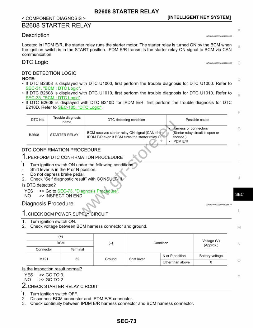
B2608 STARTER RELAY[INTELLIGENT KEY SYSTEM]
C
D
E
F
G
H
I
J
L
M
A
B
EC
N
O
P
< COMPONENT DIAGNOSIS >
S
B2608 STARTER RELAYDescription INFOID:0000000003996545
Located in IPDM E/R, the starter relay runs the starter motor. The starter relay is turned ON by the BCM whenthe ignition switch is in the START position. IPDM E/R transmits the starter relay ON signal to BCM via CANcommunication.
DTC Logic INFOID:0000000003996546
DTC DETECTION LOGICNOTE:• If DTC B2608 is displayed with DTC U1000, first perform the trouble diagnosis for DTC U1000. Refer to
SEC-31, "BCM : DTC Logic".• If DTC B2608 is displayed with DTC U1010, first perform the trouble diagnosis for DTC U1010. Refer to
SEC-33, "BCM : DTC Logic".• If DTC B2608 is displayed with DTC B210D for IPDM E/R, first perform the trouble diagnosis for DTC
B210D. Refer to SEC-105, "DTC Logic".
DTC CONFIRMATION PROCEDURE1.PERFORM DTC CONFIRMATION PROCEDURE
1. Turn ignition switch ON under the following conditions.- Shift lever is in the P or N position.- Do not depress brake pedal.2. Check “Self diagnostic result” with CONSULT-III.Is DTC detected?YES >> Go to SEC-73, "Diagnosis Procedure".NO >> INSPECTION END
Diagnosis Procedure INFOID:0000000003996547
1.CHECK BCM POWER SUPPLY CIRCUIT
1. Turn ignition switch ON.2. Check voltage between BCM harness connector and ground.
Is the inspection result normal?YES >> GO TO 3.NO >> GO TO 2.
2.CHECK STARTER RELAY CIRCUIT
1. Turn ignition switch OFF.2. Disconnect BCM connector and IPDM E/R connector.3. Check continuity between IPDM E/R harness connector and BCM harness connector.
DTC No. Trouble diagnosis name DTC detecting condition Possible cause
B2608 STARTER RELAY BCM receives starter relay ON signal (CAN) from IPDM E/R even if BCM turns the starter relay OFF.
• Harness or connectors (Starter relay circuit is open or shorted.)
• IPDM E/R
(+)
(–) Condition Voltage (V)(Approx.)BCM
Connector Terminal
M121 52 Ground Shift leverN or P position Battery voltage
Other than above 0
www.gtr-
store
.eu
SEC-73

[INTELLIGENT KEY SYSTEM]B2608 STARTER RELAY
< COMPONENT DIAGNOSIS >
4. Check continuity between IPDM E/R harness connector and ground.
Is the inspection result normal?YES >> Replace IPDM E/R. Refer to PCS-32, "Removal and Installation".NO >> Repair or replace harness.
3.CHECK INTERMITTENT INCIDENT
Refer to GI-38, "Intermittent Incident".
>> INSPECTION END
IPDM E/R BCMContinuity
Connector Terminal Connector Terminal
E6 46 M121 52 Existed
IPDM E/R
GroundContinuity
Connector Terminal
E6 46 Not existed
www.gtr-
store
.eu
SEC-74

B2609 STEERING STATUS[INTELLIGENT KEY SYSTEM]
C
D
E
F
G
H
I
J
L
M
A
B
EC
N
O
P
< COMPONENT DIAGNOSIS >
S
B2609 STEERING STATUSDescription INFOID:0000000003996548
There are 2 switches in the steering lock unit (steering lock/unlock switch 1 and 2). BCM compares those 2switches conditions to judge the present steering status.
DTC Logic INFOID:0000000003996549
DTC DETECTION LOGICNOTE:• If DTC B2609 is displayed with DTC U1000, first perform the trouble diagnosis for DTC U1000. Refer to
SEC-31, "BCM : DTC Logic".• If DTC B2609 is displayed with DTC U1010, first perform the trouble diagnosis for DTC U1010. Refer to
SEC-33, "BCM : DTC Logic".
DTC CONFIRMATION PROCEDURE1.PERFORM DTC CONFIRMATION PROCEDURE 1
1. Turn ignition switch ON under the following conditions and wait for at least 1 second.- Shift lever is in the P or N position.- Do not depress brake pedal.2. Check “Self diagnostic result” with CONSULT-III.Is DTC detected?YES >> Go to SEC-75, "Diagnosis Procedure".NO >> GO TO 2.
2.PERFORM DTC CONFIRMATION PROCEDURE 2
1. Turn ignition switch ON.2. Turn ignition switch OFF.3. Press driver side door switch and wait for at least 1 second.4. Check “Self diagnostic result” with CONSULT-III.Is DTC detected?YES >> Go to SEC-75, "Diagnosis Procedure".NO >> INSPECTION END
Diagnosis Procedure INFOID:0000000003996550
1.INSPECTION START
Check the case in which DTC is detected.• Case1: It is detected after ignition switch is changed from OFF to ON• Case2: It is detected after ignition switch is changed from ON to OFF and door switch is pressedIn which case is DTC detected?Case1 >> GO TO 2.Case2 >> GO TO 6.
2.CHECK BCM OUTPUT SIGNAL
DTC No. Trouble diagnosis name DTC detecting condition Possible cause
B2609 S/L STATUS BCM detects the malfunction of steering lock unit switches for 1 second.
• Harness or connectors[Steering lock unit circuit (BCM side) is open or shorted]
• Harness or connectors[Steering lock unit circuit (IPDM E/R side) is open or shorted]
• Steering lock unit • IPDM E/R• BCM
www.gtr-
store
.eu
SEC-75
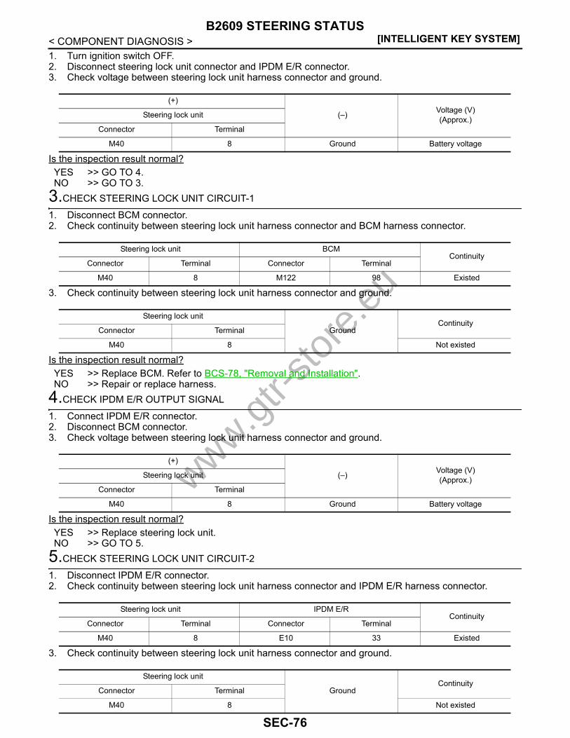
[INTELLIGENT KEY SYSTEM]B2609 STEERING STATUS
< COMPONENT DIAGNOSIS >1. Turn ignition switch OFF.2. Disconnect steering lock unit connector and IPDM E/R connector.3. Check voltage between steering lock unit harness connector and ground.
Is the inspection result normal?YES >> GO TO 4.NO >> GO TO 3.
3.CHECK STEERING LOCK UNIT CIRCUIT-1
1. Disconnect BCM connector.2. Check continuity between steering lock unit harness connector and BCM harness connector.
3. Check continuity between steering lock unit harness connector and ground.
Is the inspection result normal?YES >> Replace BCM. Refer to BCS-78, "Removal and Installation".NO >> Repair or replace harness.
4.CHECK IPDM E/R OUTPUT SIGNAL
1. Connect IPDM E/R connector.2. Disconnect BCM connector.3. Check voltage between steering lock unit harness connector and ground.
Is the inspection result normal?YES >> Replace steering lock unit.NO >> GO TO 5.
5.CHECK STEERING LOCK UNIT CIRCUIT-2
1. Disconnect IPDM E/R connector.2. Check continuity between steering lock unit harness connector and IPDM E/R harness connector.
3. Check continuity between steering lock unit harness connector and ground.
(+)
(–) Voltage (V)(Approx.)Steering lock unit
Connector Terminal
M40 8 Ground Battery voltage
Steering lock unit BCMContinuity
Connector Terminal Connector Terminal
M40 8 M122 98 Existed
Steering lock unit
GroundContinuity
Connector Terminal
M40 8 Not existed
(+)
(–) Voltage (V)(Approx.)Steering lock unit
Connector Terminal
M40 8 Ground Battery voltage
Steering lock unit IPDM E/RContinuity
Connector Terminal Connector Terminal
M40 8 E10 33 Existed
Steering lock unit
GroundContinuity
Connector Terminal
M40 8 Not existed
www.gtr-
store
.eu
SEC-76

B2609 STEERING STATUS[INTELLIGENT KEY SYSTEM]
C
D
E
F
G
H
I
J
L
M
A
B
EC
N
O
P
< COMPONENT DIAGNOSIS >
S
Is the inspection result normal?YES >> Replace IPDM E/R. Refer to PCS-30, "DTC Index".NO >> Repair or replace harness.
6.CHECK BCM OUTPUT SIGNAL
1. Turn ignition switch OFF.2. Disconnect steering lock unit connector and IPDM E/R connector.3. Check voltage between steering lock unit harness connector and ground.
Is the inspection result normal?YES >> GO TO 8.NO >> GO TO 7.
7.CHECK STEERING LOCK UNIT CIRCUIT-3
1. Disconnect BCM connector.2. Check continuity between steering lock unit harness connector and BCM harness connector.
3. Check continuity between steering lock unit harness connector and ground.
Is the inspection result normal?YES >> Replace BCM. Refer to BCS-78, "Removal and Installation".NO >> Repair or replace harness.
8.CHECK IPDM E/R OUTPUT SIGNAL
1. Connect IPDM E/R connector.2. Disconnect BCM connector.3. Check voltage between steering lock unit harness connector and ground.
Is the inspection result normal?YES >> Replace steering lock unit.NO >> GO TO 9.
9.CHECK STEERING LOCK UNIT CIRCUIT-4
1. Disconnect IPDM E/R connector.2. Check continuity between steering lock unit harness connector and IPDM E/R harness connector.
(+)
(–) Voltage (V)(Approx.)Steering lock unit
Connector Terminal
M40 3 Ground Battery voltage
Steering lock unit BCMContinuity
Connector Terminal Connector Terminal
M40 3 M122 97 Existed
Steering lock unit
GroundContinuity
Connector Terminal
M40 3 Not existed
(+)
(–) Voltage (V)(Approx.)Steering lock unit
Connector Terminal
M40 3 Ground Battery voltage
Steering lock unit IPDM E/RContinuity
Connector Terminal Connector Terminal
M40 3 E10 32 Existed
www.gtr-
store
.eu
SEC-77
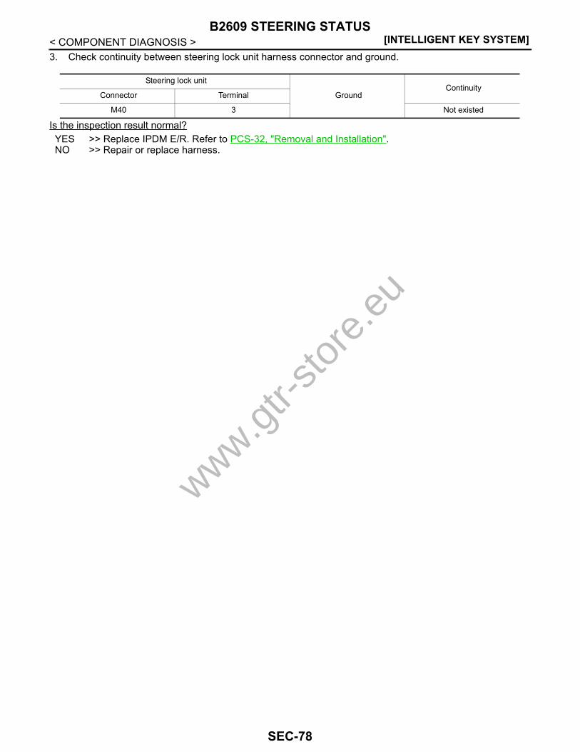
[INTELLIGENT KEY SYSTEM]B2609 STEERING STATUS
< COMPONENT DIAGNOSIS >3. Check continuity between steering lock unit harness connector and ground.
Is the inspection result normal?YES >> Replace IPDM E/R. Refer to PCS-32, "Removal and Installation".NO >> Repair or replace harness.
Steering lock unit
GroundContinuity
Connector Terminal
M40 3 Not existed
www.gtr-
store
.eu
SEC-78

B260B STEERING LOCK UNIT[INTELLIGENT KEY SYSTEM]
C
D
E
F
G
H
I
J
L
M
A
B
EC
N
O
P
< COMPONENT DIAGNOSIS >
S
B260B STEERING LOCK UNITDescription INFOID:0000000003996551
The steering lock unit performs the check by itself according to the steering status.
DTC Logic INFOID:0000000003996552
DTC DETECTION LOGIC
DTC CONFIRMATION PROCEDURE1.PERFORM DTC CONFIRMATION PROCEDURE
1. Press the push-button ignition switch, when steering is locked.2. Check “Self diagnostic result” with CONSULT-III.Is DTC detected?YES >> Go to SEC-79, "Diagnosis Procedure".NO >> INSPECTION END
Diagnosis Procedure INFOID:0000000003996553
1.INSPECTION START
1. Turn ignition switch ON.2. Check “Self diagnostic result” with CONSULT-III.3. Touch “ERASE”.4. Perform DTC Confirmation Procedure.
See SEC-79, "DTC Logic".Is the DTC B260B displayed again?YES >> Replace steering lock unit. NO >> INSPECTION END
DTC No. Trouble diagnosis name DTC detecting condition Possible cause
B260B STEERING LOCK UNIT BCM detects malfunctioning of steering lock unit be-fore steering unlocking. Steering lock unit
www.gtr-
store
.eu
SEC-79

[INTELLIGENT KEY SYSTEM]B260C STEERING LOCK UNIT
< COMPONENT DIAGNOSIS >B260C STEERING LOCK UNITDescription INFOID:0000000003996554
The steering lock unit performs the check by itself according to the steering status.
DTC Logic INFOID:0000000003996555
DTC DETECTION LOGIC
DTC CONFIRMATION PROCEDURE1.PERFORM DTC CONFIRMATION PROCEDURE
1. Turn ignition switch ON.2. Turn ignition switch OFF.3. Press driver side door switch.4. Check “Self diagnostic result” with CONSULT-III.Is DTC detected?YES >> Go to SEC-80, "Diagnosis Procedure".NO >> INSPECTION END
Diagnosis Procedure INFOID:0000000003996556
1.INSPECTION START
1. Turn ignition switch ON.2. Check “Self diagnostic result” with CONSULT-III.3. Touch “ERASE”.4. Perform DTC Confirmation Procedure.
See SEC-80, "DTC Logic".Is the DTC B260C displayed again?YES >> Replace steering lock unit.NO >> INSPECTION END
DTC No. Trouble diagnosis name DTC detecting condition Possible cause
B260C STEERING LOCK UNIT BCM detects malfunctioning of steering lock unit be-fore steering locking. Steering lock unit
www.gtr-
store
.eu
SEC-80

B260D STEERING LOCK UNIT[INTELLIGENT KEY SYSTEM]
C
D
E
F
G
H
I
J
L
M
A
B
EC
N
O
P
< COMPONENT DIAGNOSIS >
S
B260D STEERING LOCK UNITDescription INFOID:0000000003996557
The steering lock unit performs the check by itself according to the steering lock status (before lock, after lockand unlock).
DTC Logic INFOID:0000000003996558
DTC DETECTION LOGIC
DTC CONFIRMATION PROCEDURE1.PERFORM DTC CONFIRMATION PROCEDURE
1. Turn ignition switch ON.2. Turn ignition switch OFF.3. Press driver side door switch.4. Check “Self diagnostic result” with CONSULT-III.Is DTC detected?YES >> Go to SEC-81, "Diagnosis Procedure".NO >> INSPECTION END
Diagnosis Procedure INFOID:0000000003996559
1.INSPECTION START
1. Turn ignition switch ON.2. Check “Self diagnostic result” with CONSULT-III.3. Touch “ERASE”.4. Perform DTC Confirmation Procedure.
See SEC-81, "DTC Logic".Is the DTC B260D displayed again?YES >> Replace steering lock unit.NO >> INSPECTION END
DTC No. Trouble diagnosis name DTC detecting condition Possible cause
B260D STEERING LOCK UNIT BCM detects malfunctioning of steering lock unit after steering locking. Steering lock unit
www.gtr-
store
.eu
SEC-81

[INTELLIGENT KEY SYSTEM]B260F ENGINE STATUS
< COMPONENT DIAGNOSIS >B260F ENGINE STATUSDescription INFOID:0000000003996560
BCM receives the engine status signal from ECM via CAN communication.
DTC Logic INFOID:0000000003996561
DTC DETECTION LOGICNOTE:• If DTC B260F is displayed with DTC U1000, first perform the trouble diagnosis for DTC U1000. Refer to
SEC-31, "BCM : DTC Logic".• If DTC B260F is displayed with DTC U1010, first perform the trouble diagnosis for DTC U1010. Refer to
SEC-33, "BCM : DTC Logic".
DTC CONFIRMATION PROCEDURE1.PERFORM DTC CONFIRMATION PROCEDURE
1. Turn ignition switch ON under the following conditions.- Shift lever is in the P or N position.- Do not depress brake pedal.2. Check “Self diagnostic result” with CONSULT-III.Is DTC detected?YES >> Go to SEC-82, "Diagnosis Procedure".NO >> INSPECTION END
Diagnosis Procedure INFOID:0000000003996562
1.INSPECTION START
1. Turn ignition switch ON.2. Check “Self diagnostic result” with CONSULT-III.3. Touch “ERASE”.4. Perform DTC Confirmation Procedure.
See SEC-82, "DTC Logic".Is the DTC B260F displayed again?YES >> GO TO 2.NO >> GO TO 3.
2.REPLACE ECM
Replace ECM. Refer to EC-15, "BASIC INSPECTION : Special Repair Requirement (GT-R certified NISSANdealer)".
>> INSPECTION END3.CHECK INTERMITTENT INCIDENT
Refer to GI-38, "Intermittent Incident".
>> INSPECTION END
DTC No. Trouble diagnosis name DTC detecting condition Possible cause
B260F ENG STATE SIG LOSTBCM has not yet received the engine status sig-nal from ECM when ignition switch is in the ON position
ECM
www.gtr-
store
.eu
SEC-82
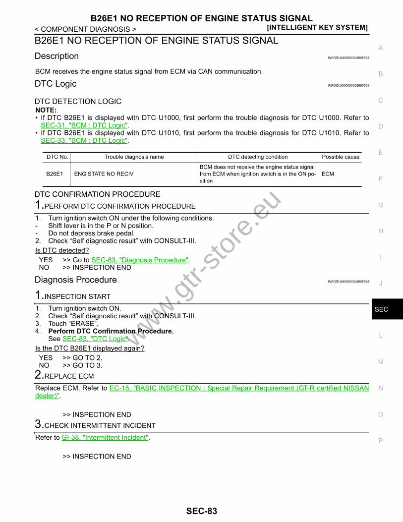
B26E1 NO RECEPTION OF ENGINE STATUS SIGNAL[INTELLIGENT KEY SYSTEM]
C
D
E
F
G
H
I
J
L
M
A
B
EC
N
O
P
< COMPONENT DIAGNOSIS >
S
B26E1 NO RECEPTION OF ENGINE STATUS SIGNALDescription INFOID:0000000003996563
BCM receives the engine status signal from ECM via CAN communication.
DTC Logic INFOID:0000000003996564
DTC DETECTION LOGICNOTE:• If DTC B26E1 is displayed with DTC U1000, first perform the trouble diagnosis for DTC U1000. Refer to
SEC-31, "BCM : DTC Logic".• If DTC B26E1 is displayed with DTC U1010, first perform the trouble diagnosis for DTC U1010. Refer to
SEC-33, "BCM : DTC Logic".
DTC CONFIRMATION PROCEDURE1.PERFORM DTC CONFIRMATION PROCEDURE
1. Turn ignition switch ON under the following conditions.- Shift lever is in the P or N position.- Do not depress brake pedal.2. Check “Self diagnostic result” with CONSULT-III.Is DTC detected?YES >> Go to SEC-83, "Diagnosis Procedure".NO >> INSPECTION END
Diagnosis Procedure INFOID:0000000003996565
1.INSPECTION START
1. Turn ignition switch ON.2. Check “Self diagnostic result” with CONSULT-III.3. Touch “ERASE”.4. Perform DTC Confirmation Procedure.
See SEC-83, "DTC Logic".Is the DTC B26E1 displayed again?YES >> GO TO 2.NO >> GO TO 3.
2.REPLACE ECM
Replace ECM. Refer to EC-15, "BASIC INSPECTION : Special Repair Requirement (GT-R certified NISSANdealer)".
>> INSPECTION END3.CHECK INTERMITTENT INCIDENT
Refer to GI-38, "Intermittent Incident".
>> INSPECTION END
DTC No. Trouble diagnosis name DTC detecting condition Possible cause
B26E1 ENG STATE NO RECIVBCM does not receive the engine status signal from ECM when ignition switch is in the ON po-sition
ECM
www.gtr-
store
.eu
SEC-83

[INTELLIGENT KEY SYSTEM]B26E9 STEERING STATUS
< COMPONENT DIAGNOSIS >B26E9 STEERING STATUSDescription INFOID:0000000003996566
There are 2 switches in the steering lock unit (steering lock/unlock switch 1 and 2). BCM compares those 2switches conditions to judge the present steering status.
DTC Logic INFOID:0000000003996567
DTC DETECTION LOGICNOTE:• If DTC B26E9 is displayed with DTC B2609, first perform the trouble diagnosis for DTC B2609. Refer to
SEC-75, "DTC Logic".
DTC CONFIRMATION PROCEDURE1.PERFORM DTC CONFIRMATION PROCEDURE
1. Turn ignition switch ON.2. Turn ignition switch OFF.3. Press driver side door switch and wait for at least 1 second.4. Turn ignition switch ON.5. Check “Self diagnostic result” with CONSULT-III.Is DTC detected?YES >> Refer to SEC-84, "Diagnosis Procedure".NO >> INSPECTION END
Diagnosis Procedure INFOID:0000000003996568
1.INSPECTION START
1. Turn ignition switch ON.2. Check “Self diagnostic result” with CONSULT-III.3. Touch “ERASE”.4. Perform DTC Confirmation Procedure.
Refer to SEC-84, "DTC Logic".Is the DTC B26E9 displayed again?YES >> GO TO 2.NO >> GO TO 3.
2.REPLACE STEERING LOCK UNIT
1. Replace steering lock unit.2. Perform DTC confirmation procedure. Refer to SEC-84, "DTC Logic".Is the DTC B26E9 displayed again?YES >> GO TO 3.NO >> INSPECTION END
3.CHECK INTERMITTENT INCIDENT
Refer to GI-38, "Intermittent Incident".
>> INSPECTION END
DTC No. Trouble diagnosis name DTC detecting condition Possible cause
B26E9 S/L STATUSBCM requests lock to steering lock unit, then steer-ing lock unit transmits a recognition signal to BCM, but steering lock unit remains unlocked.
Steering lock unit
www.gtr-
store
.eu
SEC-84
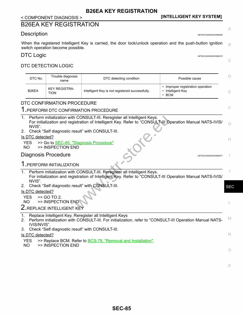
B26EA KEY REGISTRATION[INTELLIGENT KEY SYSTEM]
C
D
E
F
G
H
I
J
L
M
A
B
EC
N
O
P
< COMPONENT DIAGNOSIS >
S
B26EA KEY REGISTRATIONDescription INFOID:0000000003996569
When the registered Intelligent Key is carried, the door lock/unlock operation and the push-button ignitionswitch operation become possible.
DTC Logic INFOID:0000000003996570
DTC DETECTION LOGIC
DTC CONFIRMATION PROCEDURE1.PERFORM DTC CONFIRMATION PROCEDURE
1. Perform initialization with CONSULT-III. Reregister all Intelligent Keys.For initialization and registration of Intelligent Key. Refer to “CONSULT-III Operation Manual NATS-IVIS/NVIS”.
2. Check “Self diagnostic result” with CONSULT-III.Is DTC detected?YES >> Go to SEC-85, "Diagnosis Procedure"NO >> INSPECTION END
Diagnosis Procedure INFOID:0000000003996571
1.PERFORM INITIALIZATION
1. Perform initialization with CONSULT-III. Reregister all Intelligent Keys.For initialization and registration of Intelligent Key. Refer to “CONSULT-III Operation Manual NATS-IVIS/NVIS”.
2. Check “Self diagnostic result” with CONSULT-III.Is DTC detected?YES >> GO TO 2.NO >> INSPECTION END
2.REPLACE INTELLIGENT KEY
1. Replace Intelligent Key. Reregister all Intelligent Keys2. Perform initialization with CONSULT-III. For initialization, refer to “CONSULT-III Operation Manual NATS-
IVIS/NVIS”.3. Check “Self diagnostic result” with CONSULT-III.Is DTC detected?YES >> Replace BCM. Refer to BCS-78, "Removal and Installation".NO >> INSPECTION END
DTC No. Trouble diagnosis name DTC detecting condition Possible cause
B26EA KEY REGISTRA-TION Intelligent Key is not registered successfully.
• Improper registration operation• Intelligent Key• BCM
www.gtr-
store
.eu
SEC-85
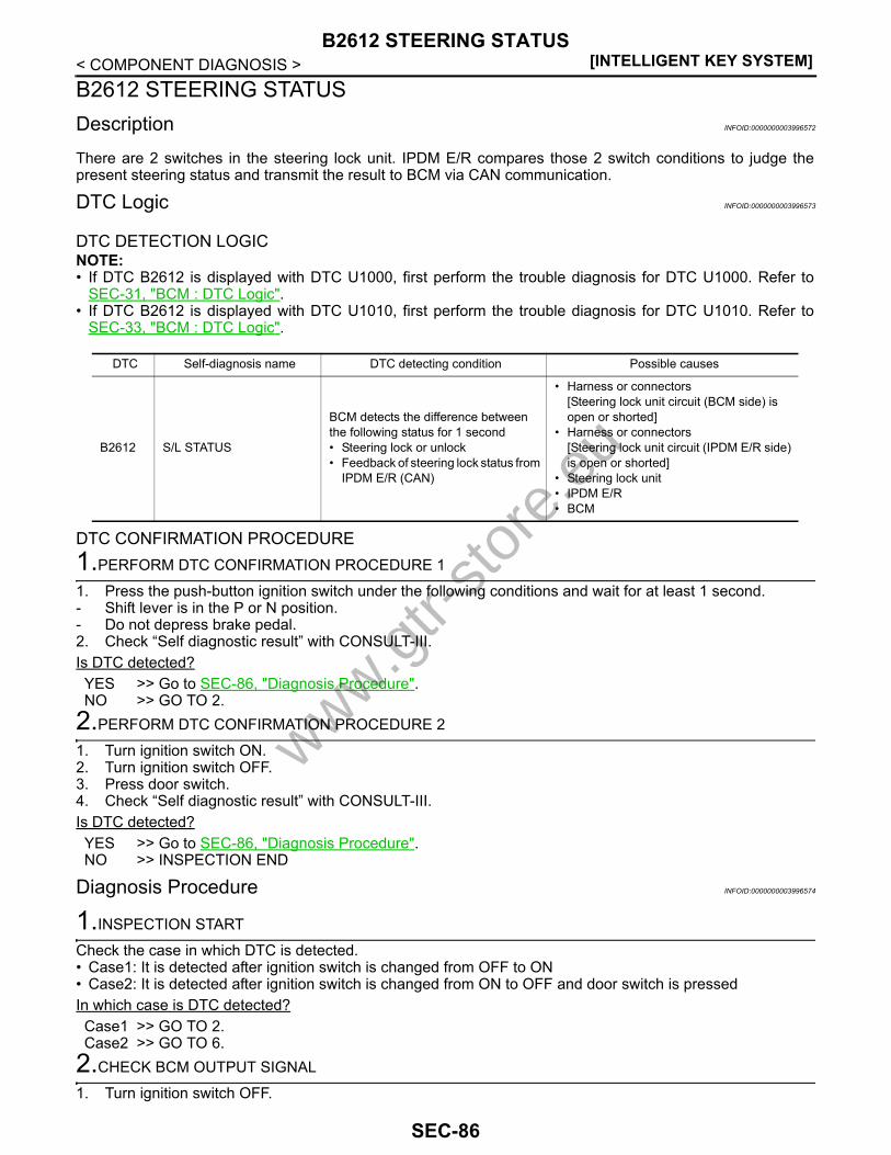
[INTELLIGENT KEY SYSTEM]B2612 STEERING STATUS
< COMPONENT DIAGNOSIS >B2612 STEERING STATUSDescription INFOID:0000000003996572
There are 2 switches in the steering lock unit. IPDM E/R compares those 2 switch conditions to judge thepresent steering status and transmit the result to BCM via CAN communication.
DTC Logic INFOID:0000000003996573
DTC DETECTION LOGICNOTE:• If DTC B2612 is displayed with DTC U1000, first perform the trouble diagnosis for DTC U1000. Refer to
SEC-31, "BCM : DTC Logic".• If DTC B2612 is displayed with DTC U1010, first perform the trouble diagnosis for DTC U1010. Refer to
SEC-33, "BCM : DTC Logic".
DTC CONFIRMATION PROCEDURE1.PERFORM DTC CONFIRMATION PROCEDURE 1
1. Press the push-button ignition switch under the following conditions and wait for at least 1 second.- Shift lever is in the P or N position.- Do not depress brake pedal.2. Check “Self diagnostic result” with CONSULT-III.Is DTC detected?YES >> Go to SEC-86, "Diagnosis Procedure".NO >> GO TO 2.
2.PERFORM DTC CONFIRMATION PROCEDURE 2
1. Turn ignition switch ON.2. Turn ignition switch OFF.3. Press door switch.4. Check “Self diagnostic result” with CONSULT-III.Is DTC detected?YES >> Go to SEC-86, "Diagnosis Procedure".NO >> INSPECTION END
Diagnosis Procedure INFOID:0000000003996574
1.INSPECTION START
Check the case in which DTC is detected.• Case1: It is detected after ignition switch is changed from OFF to ON• Case2: It is detected after ignition switch is changed from ON to OFF and door switch is pressedIn which case is DTC detected?Case1 >> GO TO 2.Case2 >> GO TO 6.
2.CHECK BCM OUTPUT SIGNAL
1. Turn ignition switch OFF.
DTC Self-diagnosis name DTC detecting condition Possible causes
B2612 S/L STATUS
BCM detects the difference between the following status for 1 second• Steering lock or unlock• Feedback of steering lock status from
IPDM E/R (CAN)
• Harness or connectors[Steering lock unit circuit (BCM side) is open or shorted]
• Harness or connectors[Steering lock unit circuit (IPDM E/R side) is open or shorted]
• Steering lock unit • IPDM E/R• BCM
www.gtr-
store
.eu
SEC-86

B2612 STEERING STATUS[INTELLIGENT KEY SYSTEM]
C
D
E
F
G
H
I
J
L
M
A
B
EC
N
O
P
< COMPONENT DIAGNOSIS >
S
2. Disconnect steering lock unit connector and IPDM E/R connector.3. Check voltage between steering lock unit harness connector and ground.
Is the inspection result normal?YES >> GO TO 4.NO >> GO TO 3.
3.CHECK STEERING LOCK UNIT CIRCUIT-1
1. Disconnect BCM connector.2. Check continuity between steering lock unit harness connector and BCM harness connector.
3. Check continuity between steering lock unit harness connector and ground.
Is the inspection result normal?YES >> Replace BCM. Refer to BCS-78, "Removal and Installation".NO >> Repair or replace harness.
4.CHECK IPDM E/R OUTPUT SIGNAL
1. Connect IPDM E/R connector.2. Disconnect BCM connector.3. Check voltage between steering lock unit harness connector and ground.
Is the inspection result normal?YES >> Replace steering lock unit.NO >> GO TO 5.
5.CHECK STEERING LOCK UNIT CIRCUIT-2
1. Disconnect IPDM E/R connector.2. Check continuity between steering lock unit harness connector and IPDM E/R harness connector.
3. Check continuity between steering lock unit harness connector and ground.
(+)
(–) Voltage (V)(Approx.)Steering lock unit
Connector Terminal
M40 8 Ground Battery voltage
Steering lock unit BCMContinuity
Connector Terminal Connector Terminal
M40 8 M122 98 Existed
Steering lock unit
GroundContinuity
Connector Terminal
M40 8 Not existed
(+)
(–) Voltage (V)(Approx.)Steering lock unit
Connector Terminal
M40 8 Ground Battery voltage
Steering lock unit IPDM E/RContinuity
Connector Terminal Connector Terminal
M40 8 E5 33 Existed
Steering lock unit
GroundContinuity
Connector Terminal
M40 8 Not existed
www.gtr-
store
.eu
SEC-87
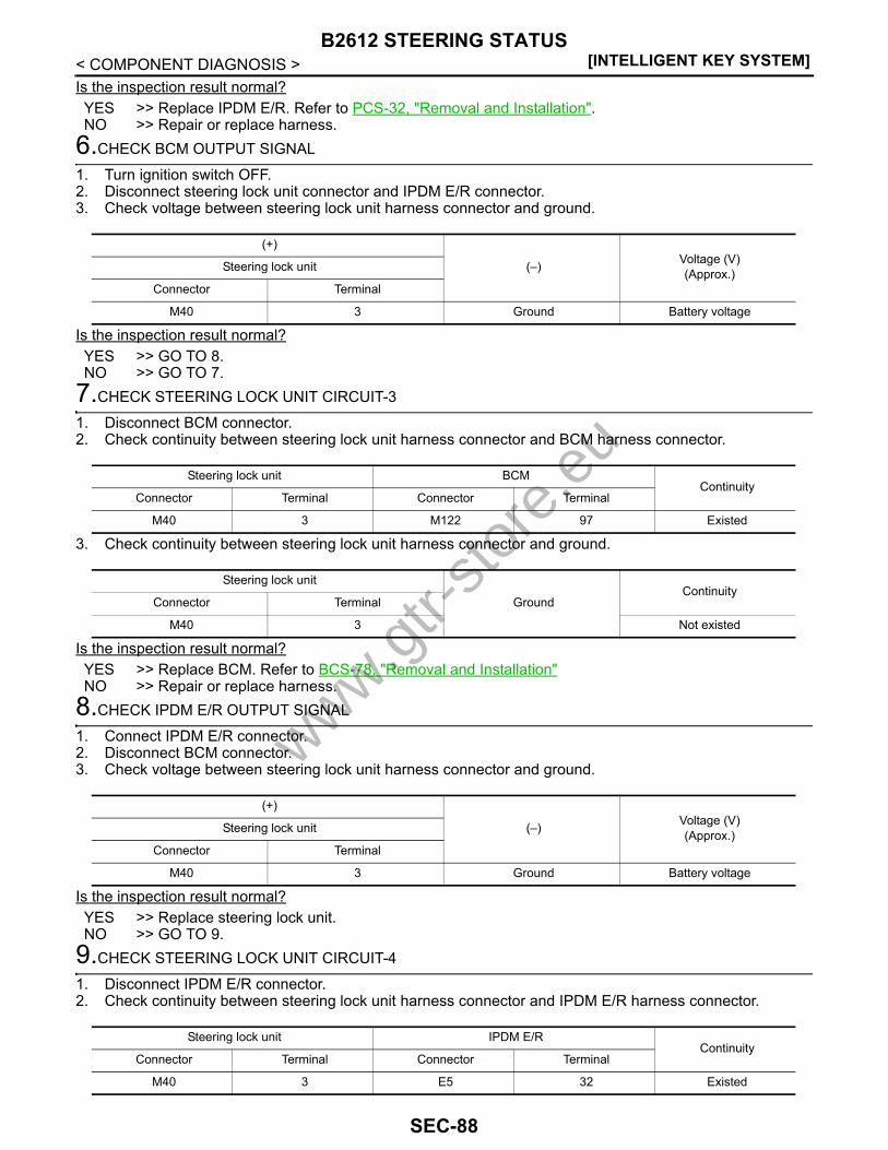
[INTELLIGENT KEY SYSTEM]B2612 STEERING STATUS
< COMPONENT DIAGNOSIS >Is the inspection result normal?YES >> Replace IPDM E/R. Refer to PCS-32, "Removal and Installation".NO >> Repair or replace harness.
6.CHECK BCM OUTPUT SIGNAL
1. Turn ignition switch OFF.2. Disconnect steering lock unit connector and IPDM E/R connector.3. Check voltage between steering lock unit harness connector and ground.
Is the inspection result normal?YES >> GO TO 8.NO >> GO TO 7.
7.CHECK STEERING LOCK UNIT CIRCUIT-3
1. Disconnect BCM connector.2. Check continuity between steering lock unit harness connector and BCM harness connector.
3. Check continuity between steering lock unit harness connector and ground.
Is the inspection result normal?YES >> Replace BCM. Refer to BCS-78, "Removal and Installation"NO >> Repair or replace harness.
8.CHECK IPDM E/R OUTPUT SIGNAL
1. Connect IPDM E/R connector.2. Disconnect BCM connector.3. Check voltage between steering lock unit harness connector and ground.
Is the inspection result normal?YES >> Replace steering lock unit.NO >> GO TO 9.
9.CHECK STEERING LOCK UNIT CIRCUIT-4
1. Disconnect IPDM E/R connector.2. Check continuity between steering lock unit harness connector and IPDM E/R harness connector.
(+)
(–) Voltage (V)(Approx.)Steering lock unit
Connector Terminal
M40 3 Ground Battery voltage
Steering lock unit BCMContinuity
Connector Terminal Connector Terminal
M40 3 M122 97 Existed
Steering lock unit
GroundContinuity
Connector Terminal
M40 3 Not existed
(+)
(–) Voltage (V)(Approx.)Steering lock unit
Connector Terminal
M40 3 Ground Battery voltage
Steering lock unit IPDM E/RContinuity
Connector Terminal Connector Terminal
M40 3 E5 32 Existed
www.gtr-
store
.eu
SEC-88
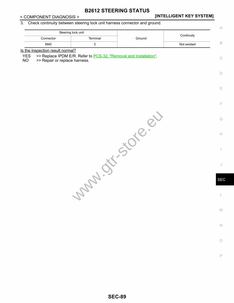
B2612 STEERING STATUS[INTELLIGENT KEY SYSTEM]
C
D
E
F
G
H
I
J
L
M
A
B
EC
N
O
P
< COMPONENT DIAGNOSIS >
S
3. Check continuity between steering lock unit harness connector and ground.
Is the inspection result normal?YES >> Replace IPDM E/R. Refer to PCS-32, "Removal and Installation".NO >> Repair or replace harness.
Steering lock unit
GroundContinuity
Connector Terminal
M40 3 Not existed
www.gtr-
store
.eu
SEC-89

[INTELLIGENT KEY SYSTEM]B2617 STARTER RELAY CIRCUIT
< COMPONENT DIAGNOSIS >B2617 STARTER RELAY CIRCUITDescription INFOID:0000000003996575
Located in IPDM E/R, it runs the starter motor. The starter relay is turned ON by the BCM when the ignitionswitch is in the START position. IPDM E/R transmits the starter relay ON signal to BCM via CAN communica-tion.
DTC Logic INFOID:0000000003996576
DTC DETECTION LOGICNOTE:• If DTC B2617 is displayed with DTC U1000, first perform the trouble diagnosis for DTC U1000. Refer to
SEC-31, "BCM : DTC Logic".• If DTC B2617 is displayed with DTC U1010, first perform the trouble diagnosis for DTC U1010. Refer to
SEC-31, "BCM : DTC Logic".• If DTC B2617 is displayed with DTC B210E for IPDM E/R, first perform the trouble diagnosis for DTC
B210E. Refer to SEC-106, "DTC Logic".
DTC CONFIRMATION PROCEDURE1.PERFORM DTC CONFIRMATION PROCEDURE
1. Turn ignition switch ON under the following conditions and wait for at least 1 second.- Shift lever is in the P or N position.- Do not depress brake pedal.2. Check “Self diagnostic result” with CONSULT-III.Is DTC detected?YES >> Go to SEC-90, "Diagnosis Procedure".NO >> INSPECTION END
Diagnosis Procedure INFOID:0000000003996577
1.CHECK STARTER RELAY
1. Turn ignition switch ON.2. Check voltage between BCM harness connector and ground.
Is the inspection result normal?YES >> GO TO 3.NO >> GO TO 2.
2.CHECK STARTER RELAY CIRCUIT
1. Turn ignition switch OFF.2. Disconnect BCM connector and IPDM E/R connector.3. Check continuity between IPDM E/R harness connector and BCM harness connector.
DTC No. Trouble diagnosis name DTC detecting condition Possible cause
B2617 STARTER RELAY CIRC
An immediate operation of starter relay is request-ed by BCM, but there is no response for more than 1 second
• Harness or connectors(Starter relay circuit is open or short-ed)
• IPDM E/R
(+)
(–) Condition Voltage (V)(Approx.)BCM
Connector Terminal
M121 52 Ground Shift leverN or P position Battery voltage
Other than above 0
www.gtr-
store
.eu
SEC-90

B2617 STARTER RELAY CIRCUIT[INTELLIGENT KEY SYSTEM]
C
D
E
F
G
H
I
J
L
M
A
B
EC
N
O
P
< COMPONENT DIAGNOSIS >
S
4. Check continuity between IPDM E/R harness connector and ground.
Is the inspection result normal?YES >> Replace IPDM E/R. Refer to PCS-32, "Removal and Installation".NO >> Repair or replace harness.
3.CHECK INTERMITTENT INCIDENT
Refer to GI-38, "Intermittent Incident".
>> INSPECTION END
IPDM E/R BCMContinuity
Connector Terminal Connector Terminal
E6 46 M121 52 Existed
IPDM E/R
GroundContinuity
Connector Terminal
E6 46 Not existed
www.gtr-
store
.eu
SEC-91
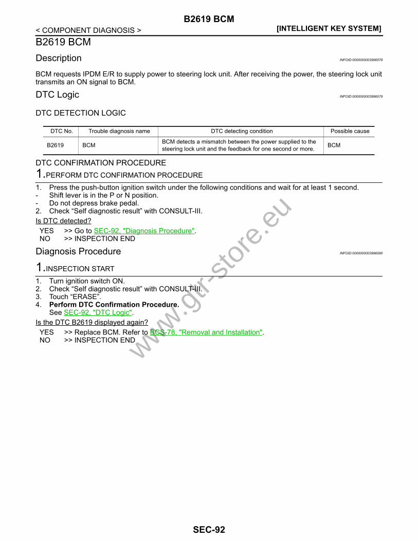
[INTELLIGENT KEY SYSTEM]B2619 BCM
< COMPONENT DIAGNOSIS >B2619 BCMDescription INFOID:0000000003996578
BCM requests IPDM E/R to supply power to steering lock unit. After receiving the power, the steering lock unittransmits an ON signal to BCM.
DTC Logic INFOID:0000000003996579
DTC DETECTION LOGIC
DTC CONFIRMATION PROCEDURE1.PERFORM DTC CONFIRMATION PROCEDURE
1. Press the push-button ignition switch under the following conditions and wait for at least 1 second.- Shift lever is in the P or N position.- Do not depress brake pedal.2. Check “Self diagnostic result” with CONSULT-III.Is DTC detected?YES >> Go to SEC-92, "Diagnosis Procedure".NO >> INSPECTION END
Diagnosis Procedure INFOID:0000000003996580
1.INSPECTION START
1. Turn ignition switch ON.2. Check “Self diagnostic result” with CONSULT-III.3. Touch “ERASE”.4. Perform DTC Confirmation Procedure.
See SEC-92, "DTC Logic".Is the DTC B2619 displayed again?YES >> Replace BCM. Refer to BCS-78, "Removal and Installation".NO >> INSPECTION END
DTC No. Trouble diagnosis name DTC detecting condition Possible cause
B2619 BCM BCM detects a mismatch between the power supplied to the steering lock unit and the feedback for one second or more. BCM
www.gtr-
store
.eu
SEC-92
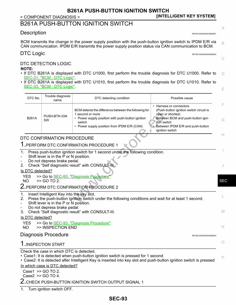
B261A PUSH-BUTTON IGNITION SWITCH[INTELLIGENT KEY SYSTEM]
C
D
E
F
G
H
I
J
L
M
A
B
EC
N
O
P
< COMPONENT DIAGNOSIS >
S
B261A PUSH-BUTTON IGNITION SWITCHDescription INFOID:0000000003996581
BCM transmits the change in the power supply position with the push-button ignition switch to IPDM E/R viaCAN communication. IPDM E/R transmits the power supply position status via CAN communication to BCM.
DTC Logic INFOID:0000000003996582
DTC DETECTION LOGICNOTE:• If DTC B261A is displayed with DTC U1000, first perform the trouble diagnosis for DTC U1000. Refer to
SEC-31, "BCM : DTC Logic".• If DTC B261A is displayed with DTC U1010, first perform the trouble diagnosis for DTC U1010. Refer to
SEC-33, "BCM : DTC Logic".
DTC CONFIRMATION PROCEDURE1.PERFORM DTC CONFIRMATION PROCEDURE 1
1. Press push-button ignition switch for 1 second under the following condition.- Shift lever is in the P or N position.- Do not depress brake pedal.2. Check “Self diagnostic result” with CONSULT-III.Is DTC detected?YES >> Go to SEC-93, "Diagnosis Procedure"NO >> GO TO 2.
2.PERFORM DTC CONFIRMATION PROCEDURE 2
1. Insert Intelligent Key into the key slot.2. Press the push-button ignition switch under the following conditions and wait for at least 1 second.- Shift lever is in the P or N position.- Do not depress brake pedal.3. Check “Self diagnostic result” with CONSULT-III.Is DTC detected?YES >> Go to SEC-93, "Diagnosis Procedure".NO >> INSPECTION END
Diagnosis Procedure INFOID:0000000003996583
1.INSPECTION START
Check the case in which DTC is detected.• Case1: It is detected when push-button ignition switch is pressed for 1 second• Case2: It is detected after Intelligent Key is inserted into key slot and push-button ignition switch is pressedIn which case is DTC detected?Case1 >> GO TO 2.Case2 >> GO TO 4.
2.CHECK PUSH-BUTTON IGNITION SWITCH OUTPUT SIGNAL 1
1. Turn ignition switch OFF.
DTC No. Trouble diagnosis name DTC detecting condition Possible cause
B261A PUSH-BTN IGN SW
BCM detects the difference between the following for 1 second or more• Power supply position with push-button ignition
switch• Power supply position from IPDM E/R (CAN)
• Harness or connectors(Push-button ignition switch circuit is open or shorted)
• Between BCM and push-button igni-tion switch
• Between IPDM E/R and push-button ignition switch
www.gtr-
store
.eu
SEC-93

[INTELLIGENT KEY SYSTEM]B261A PUSH-BUTTON IGNITION SWITCH
< COMPONENT DIAGNOSIS >2. Disconnect push-button ignition switch connector and IPDM E/R connector.3. Check voltage between push-button ignition switch harness connector and ground.
Is the inspection result normal?YES >> GO TO 6.NO >> GO TO 3.
3.CHECK PUSH-BUTTON IGNITION SWITCH CIRCUIT 1
1. Disconnect BCM connector.2. Check continuity between push-button ignition switch harness connector and BCM harness connector.
3. Check continuity between push-button ignition switch harness connector and ground.
Is the inspection result normal?YES >> Replace BCM. Refer to BCS-78, "Removal and Installation".NO >> Repair or replace harness.
4.CHECK PUSH-BUTTON IGNITION SWITCH OUTPUT SIGNAL 2
1. Turn ignition switch OFF.2. Disconnect push-button ignition switch connector and BCM connector.3. Check voltage between push-button ignition switch harness connector and ground.
Is the inspection result normal?YES >> GO TO 6.NO >> GO TO 5.
5.CHECK PUSH-BUTTON IGNITION SWITCH CIRCUIT 2
1. Disconnect IPDM E/R connector.2. Check continuity between push-button ignition switch harness connector and IPDM E/R harness connec-
tor.
3. Check continuity between push-button ignition switch harness connector and ground.
(+)
(–) Voltage (V)(Approx.)Push-button ignition switch
Connector Terminal
M131 4 Ground Battery voltage
Push-button ignition switch BCMContinuity
Connector Terminal Connector Terminal
M131 4 M122 89 Existed
Push-button ignition switch
GroundContinuity
Connector Terminal
M131 4 Not existed
(+)
(–) Voltage (V)(Approx.)Push-button ignition switch
Connector Terminal
M131 4 Ground Battery voltage
Push-button ignition switch IPDM E/RContinuity
Connector Terminal Connector Terminal
M131 4 E5 28 Existed
Push-button ignition switch
GroundContinuity
Connector Terminal
M131 4 Not existed
www.gtr-
store
.eu
SEC-94
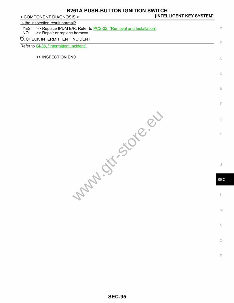
B261A PUSH-BUTTON IGNITION SWITCH[INTELLIGENT KEY SYSTEM]
C
D
E
F
G
H
I
J
L
M
A
B
EC
N
O
P
< COMPONENT DIAGNOSIS >
S
Is the inspection result normal?YES >> Replace IPDM E/R. Refer to PCS-32, "Removal and Installation".NO >> Repair or replace harness.
6.CHECK INTERMITTENT INCIDENT
Refer to GI-38, "Intermittent Incident".
>> INSPECTION END
www.gtr-
store
.eu
SEC-95

[INTELLIGENT KEY SYSTEM]B261E VEHICLE TYPE
< COMPONENT DIAGNOSIS >B261E VEHICLE TYPEDescription INFOID:0000000003996584
There are two types of vehicles.• HEV• Conventional
DTC Logic INFOID:0000000003996585
DTC DETECTION LOGICNOTE:• If DTC B261E is displayed with DTC U1000, first perform the trouble diagnosis for DTC U1000. Refer to
SEC-31, "BCM : DTC Logic".• If DTC B261E is displayed with DTC U1010, first perform the trouble diagnosis for DTC U1010. Refer to
SEC-33, "BCM : DTC Logic".
DTC CONFIRMATION PROCEDURE1.PERFORM DTC CONFIRMATION PROCEDURE
1. Turn ignition switch ON.2. Check “Self diagnostic result” with CONSULT-III.Is DTC detected?YES >> Go to SEC-96, "Diagnosis Procedure".NO >> INSPECTION END
Diagnosis Procedure INFOID:0000000003996586
1.INSPECTION START
1. Turn ignition switch ON.2. Check “Self diagnostic result” with CONSULT-III.3. Touch “ERASE”.4. Perform DTC Confirmation Procedure.
See SEC-96, "DTC Logic".Is the 1st trip DTC B261E displayed again?YES >> Replace BCM. Refer to BCS-78, "Removal and Installation".NO >> INSPECTION END
DTC No. Trouble diagnosis name DTC detecting condition Possible cause
B261E VEHICLE TYPE Difference of BCM configuration BCM
www.gtr-
store
.eu
SEC-96
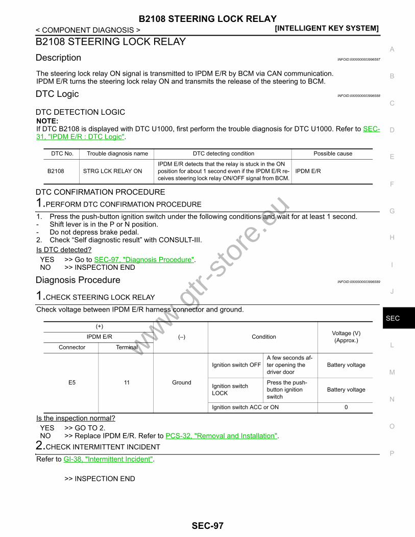
B2108 STEERING LOCK RELAY[INTELLIGENT KEY SYSTEM]
C
D
E
F
G
H
I
J
L
M
A
B
EC
N
O
P
< COMPONENT DIAGNOSIS >
S
B2108 STEERING LOCK RELAYDescription INFOID:0000000003996587
The steering lock relay ON signal is transmitted to IPDM E/R by BCM via CAN communication.IPDM E/R turns the steering lock relay ON and transmits the release of the steering to BCM.
DTC Logic INFOID:0000000003996588
DTC DETECTION LOGICNOTE:If DTC B2108 is displayed with DTC U1000, first perform the trouble diagnosis for DTC U1000. Refer to SEC-31, "IPDM E/R : DTC Logic".
DTC CONFIRMATION PROCEDURE1.PERFORM DTC CONFIRMATION PROCEDURE
1. Press the push-button ignition switch under the following conditions and wait for at least 1 second.- Shift lever is in the P or N position.- Do not depress brake pedal.2. Check “Self diagnostic result” with CONSULT-III.Is DTC detected?YES >> Go to SEC-97, "Diagnosis Procedure".NO >> INSPECTION END
Diagnosis Procedure INFOID:0000000003996589
1.CHECK STEERING LOCK RELAY
Check voltage between IPDM E/R harness connector and ground.
Is the inspection normal?YES >> GO TO 2.NO >> Replace IPDM E/R. Refer to PCS-32, "Removal and Installation".
2.CHECK INTERMITTENT INCIDENT
Refer to GI-38, "Intermittent Incident".
>> INSPECTION END
DTC No. Trouble diagnosis name DTC detecting condition Possible cause
B2108 STRG LCK RELAY ONIPDM E/R detects that the relay is stuck in the ON position for about 1 second even if the IPDM E/R re-ceives steering lock relay ON/OFF signal from BCM.
IPDM E/R
(+)
(–) Condition Voltage (V)(Approx.)IPDM E/R
Connector Terminal
E5 11 Ground
Ignition switch OFFA few seconds af-ter opening the driver door
Battery voltage
Ignition switch LOCK
Press the push-button ignition switch
Battery voltage
Ignition switch ACC or ON 0
www.gtr-
store
.eu
SEC-97

[INTELLIGENT KEY SYSTEM]B2109 STEERING LOCK RELAY
< COMPONENT DIAGNOSIS >B2109 STEERING LOCK RELAYDescription INFOID:0000000003996590
The steering lock relay ON signal is transmitted to IPDM E/R by BCM via CAN communication.IPDM E/R turns the steering lock relay ON and transmits the release of the steering to BCM.
DTC Logic INFOID:0000000003996591
DTC DETECTION LOGICNOTE:• If DTC B2109 is displayed with DTC U1000, first perform the trouble diagnosis for DTC U1000. Refer to
SEC-31, "IPDM E/R : DTC Logic".• When IPDM E/R power supply voltage is low (Approx. 7 - 8 V for about 1 second), the DTC B2109 may be
detected.
DTC CONFIRMATION PROCEDURE1.PERFORM DTC CONFIRMATION PROCEDURE
1. Press the push-button ignition switch under the following conditions and wait for at least 1 second.- Shift lever is in the P or N position.- Do not depress brake pedal.2. Check “Self diagnostic result” with CONSULT-III.Is DTC detected?YES >> Go to SEC-98, "Diagnosis Procedure".NO >> INSPECTION END
Diagnosis Procedure INFOID:0000000003996592
1.CHECK POWER SUPPLY CIRCUIT
Check IPDM E/R power supply circuit. Refer to SEC-112, "IPDM E/R : Diagnosis Procedure".Is the circuit normal?YES >> GO TO 2.NO >> Repair or replace the malfunctioning part.
2.CHECK FUSE
1. Turn ignition switch OFF.2. Check 10A fuse (No. 48, located in IPDM E/R).Is the inspection normal?YES >> Replace IPDM E/R. Refer to PCS-32, "Removal and Installation".NO >> Check the following.
• Harness for open or short between IPDM E/R and battery• Fuse
DTC No. Trouble diagnosis name DTC detecting condition Possible cause
B2109 STRG LCK RELAY OFF
IPDM E/R detects that the relay is stuck in the OFF position for about 1 second even if the IPDM E/R receives steering lock relay ON/OFF signal from BCM.
• Harness or connector (Power sup-ply circuit)
• IPDM E/R• Battery
www.gtr-
store
.eu
SEC-98

B210A STEERING LOCK CONDITION SWITCH[INTELLIGENT KEY SYSTEM]
C
D
E
F
G
H
I
J
L
M
A
B
EC
N
O
P
< COMPONENT DIAGNOSIS >
S
B210A STEERING LOCK CONDITION SWITCHDescription INFOID:0000000003996593
There are 2 switches in the steering lock unit. IPDM E/R compares those 2 switches conditions to judge thepresent steering status and transmit the result to BCM via CAN communication.
DTC Logic INFOID:0000000003996594
DTC DETECTION LOGICNOTE:If DTC B210A is displayed with DTC U1000, first perform the trouble diagnosis for DTC U1000. Refer to SEC-31, "IPDM E/R : DTC Logic".
DTC CONFIRMATION PROCEDURE1.PERFORM DTC CONFIRMATION PROCEDURE 1
1. Press the push-button ignition switch under the following conditions and wait for at least 1 second.- Shift lever is in the P or N position.- Do not depress brake pedal.2. Check “Self diagnostic result” with CONSULT-III.Is DTC detected?YES >> Go to SEC-99, "Diagnosis Procedure".NO >> GO TO 2.
2.PERFORM DTC CONFIRMATION PROCEDURE 2
1. Turn ignition switch ON.2. Turn ignition switch OFF.3. Press driver side door switch and wait for at least 1 second.4. Check “Self diagnostic result” with CONSULT-III.Is DTC detected?YES >> Go to SEC-99, "Diagnosis Procedure".NO >> INSPECTION END
Diagnosis Procedure INFOID:0000000003996595
1.INSPECTION START
Check the case in which DTC is detected.• Case1: It is detected after ignition switch is changed from OFF to ON• Case2: It is detected after ignition switch is changed from ON to OFF and door switch is pressedIn which case is DTC detected?Case1 >> GO TO 2.Case2 >> GO TO 6.
2.CHECK BCM OUTPUT SIGNAL
1. Turn ignition switch OFF.2. Disconnect steering lock unit connector and IPDM E/R connector.3. Check voltage between steering lock unit harness connector and ground.
DTC No. Trouble diagnosis name DTC detecting condition Possible cause
B210A STRG LCK STATE SW
IPDM E/R detects the difference between steering condition switches 1 and 2 for 1 second
• Harness or connectors[Steering lock unit circuit (BCM side) is open or shorted]
• Harness or connectors[Steering lock unit circuit (IPDM E/R side) is open or shorted]
• Steering lock unit • IPDM E/R
www.gtr-
store
.eu
SEC-99

[INTELLIGENT KEY SYSTEM]B210A STEERING LOCK CONDITION SWITCH
< COMPONENT DIAGNOSIS >
Is the inspection result normal?YES >> GO TO 4.NO >> GO TO 3.
3.CHECK STEERING LOCK UNIT CIRCUIT-1
1. Disconnect BCM connector.2. Check continuity between steering lock unit harness connector and BCM harness connector.
3. Check continuity between steering lock unit harness connector and ground.
Is the inspection result normal?YES >> Replace BCM. Refer to BCS-78, "Removal and Installation".NO >> Repair or replace harness.
4.CHECK IPDM E/R OUTPUT SIGNAL
1. Connect IPDM E/R connector.2. Disconnect BCM connector.3. Check voltage between steering lock unit harness connector and ground.
Is the inspection result normal?YES >> Replace steering lock unit.NO >> GO TO 5.
5.CHECK STEERING LOCK UNIT CIRCUIT-2
1. Disconnect IPDM E/R connector.2. Check continuity between steering lock unit harness connector and IPDM E/R harness connector.
3. Check continuity between steering lock unit harness connector and ground.
Is the inspection result normal?YES >> Replace IPDM E/R. Refer to PCS-32, "Removal and Installation"
(+)
(–) Voltage (V)(Approx.)Steering lock unit
Connector Terminal
M40 8 Ground Battery voltage
Steering lock unit BCMContinuity
Connector Terminal Connector Terminal
M40 8 M122 98 Existed
Steering lock unit
GroundContinuity
Connector Terminal
M40 8 Not existed
(+)
(–) Voltage (V)(Approx.)Steering lock unit
Connector Terminal
M40 8 Ground Battery voltage
Steering lock unit IPDM E/RContinuity
Connector Terminal Connector Terminal
M40 8 E5 33 Existed
Steering lock unit
GroundContinuity
Connector Terminal
M40 8 Not existed
www.gtr-
store
.eu
SEC-100

B210A STEERING LOCK CONDITION SWITCH[INTELLIGENT KEY SYSTEM]
C
D
E
F
G
H
I
J
L
M
A
B
EC
N
O
P
< COMPONENT DIAGNOSIS >
S
NO >> Repair or replace harness.6.CHECK BCM OUTPUT SIGNAL
1. Turn ignition switch OFF.2. Disconnect steering lock unit connector and IPDM E/R connector.3. Check voltage between steering lock unit harness connector and ground.
Is the inspection result normal?YES >> GO TO 8.NO >> GO TO 7.
7.CHECK STEERING LOCK UNIT CIRCUIT-3
1. Disconnect BCM connector.2. Check continuity between steering lock unit harness connector and BCM harness connector.
3. Check continuity between steering lock unit harness connector and ground.
Is the inspection result normal?YES >> Replace BCM. Refer to BCS-78, "Removal and Installation".NO >> Repair or replace harness.
8.CHECK IPDM E/R OUTPUT SIGNAL
1. Connect IPDM E/R connector.2. Disconnect BCM connector.3. Check voltage between steering lock unit harness connector and ground.
Is the inspection result normal?YES >> Replace steering lock unit.NO >> GO TO 9.
9.CHECK STEERING LOCK UNIT CIRCUIT-4
1. Disconnect IPDM E/R connector.2. Check continuity between steering lock unit harness connector and IPDM E/R harness connector.
3. Check continuity between steering lock unit harness connector and ground.
(+)
(–) Voltage (V)(Approx.)Steering lock unit
Connector Terminal
M40 3 Ground Battery voltage
Steering lock unit BCMContinuity
Connector Terminal Connector Terminal
M40 3 M122 97 Existed
Steering lock unit
GroundContinuity
Connector Terminal
M40 3 Not existed
(+)
(–) Voltage (V)(Approx.)Steering lock unit
Connector Terminal
M40 3 Ground Battery voltage
Steering lock unit IPDM E/RContinuity
Connector Terminal Connector Terminal
M40 3 E5 32 Existed
www.gtr-
store
.eu
SEC-101
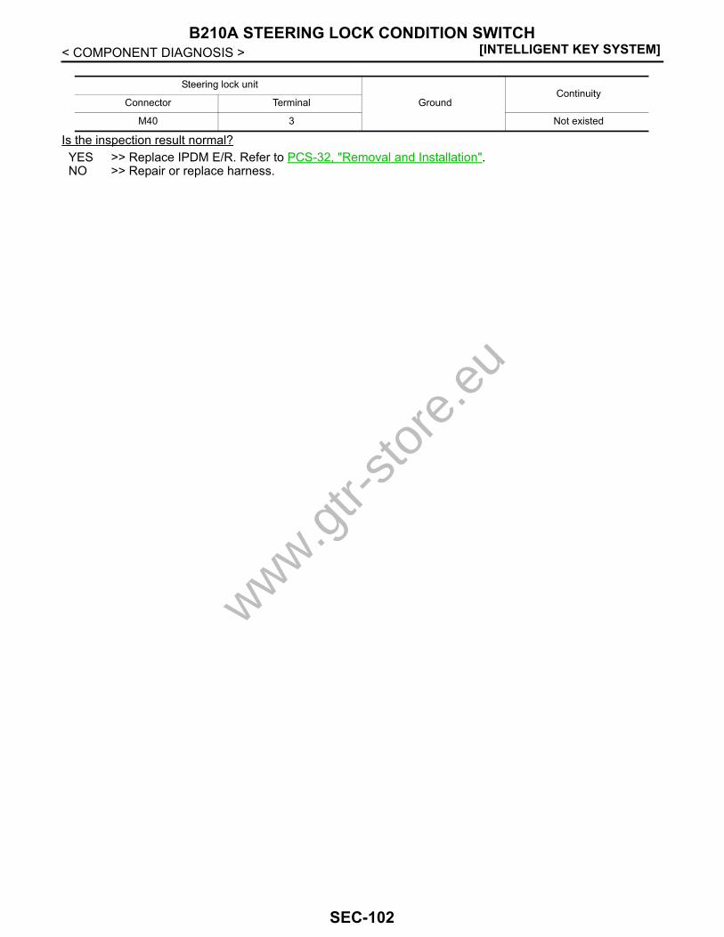
[INTELLIGENT KEY SYSTEM]B210A STEERING LOCK CONDITION SWITCH
< COMPONENT DIAGNOSIS >
Is the inspection result normal?YES >> Replace IPDM E/R. Refer to PCS-32, "Removal and Installation".NO >> Repair or replace harness.
Steering lock unit
GroundContinuity
Connector Terminal
M40 3 Not existed
www.gtr-
store
.eu
SEC-102

B210B STARTER CONTROL RELAY[INTELLIGENT KEY SYSTEM]
C
D
E
F
G
H
I
J
L
M
A
B
EC
N
O
P
< COMPONENT DIAGNOSIS >
S
B210B STARTER CONTROL RELAYDescription INFOID:0000000003996596
Starter control relay, integrated in IPDM E/R, permits the starter relay operation when in the N or P positionand the steering is locked or unlocked. It is installed in parallel with the starter relay.
DTC Logic INFOID:0000000003996597
DTC DETECTION LOGICNOTE:If DTC B210B is displayed with DTC U1000, first perform the trouble diagnosis for DTC U1000. Refer to SEC-31, "IPDM E/R : DTC Logic".
DTC CONFIRMATION PROCEDURE1.PERFORM DTC CONFIRMATION PROCEDURE
1. Turn the power supply position to start under the following conditions and wait for at least 1 second.- Shift lever is in the P or N position.- Do not depress brake pedal.2. Check “Self diagnostic result” with CONSULT-III.Is DTC detected?YES >> Go to SEC-103, "Diagnosis Procedure".NO >> INSPECTION END
Diagnosis Procedure INFOID:0000000003996598
1.INSPECTION START
1. Turn ignition switch ON.2. Check “Self diagnostic result” for IPDM E/R with CONSULT-III.3. Touch “ERASE”.4. Perform DTC Confirmation Procedure.
See SEC-183, "DTC Index".Is the DTC B210B displayed again?YES >> Replace IPDM E/R. Refer PCS-32, "Removal and Installation".NO >> INSPECTION END
DTC No. Trouble diagnosis name DTC detecting condition Possible cause
B210B START CONT RLY ON
IPDM E/R detects that the relay is stuck in the ON position even if the followings conditions are met for about 1 second.• Starter control relay ON/OFF signal from BCM• P/N position signal from TCM
IPDM E/R
www.gtr-
store
.eu
SEC-103
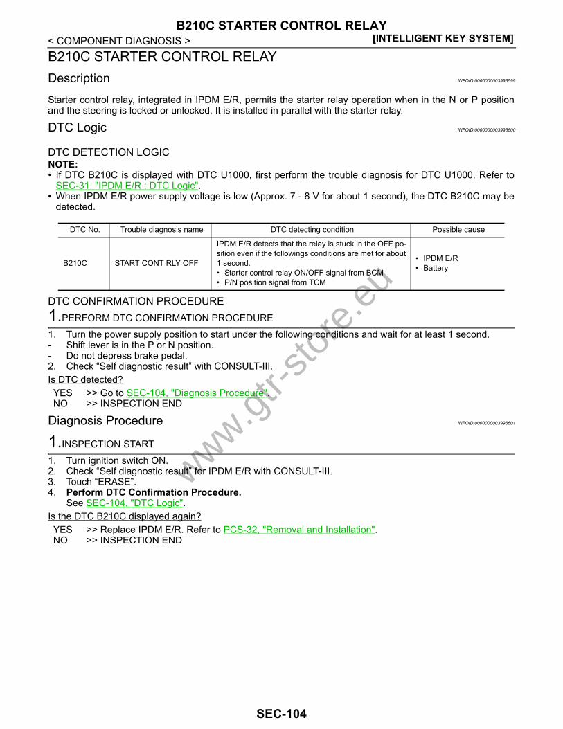
[INTELLIGENT KEY SYSTEM]B210C STARTER CONTROL RELAY
< COMPONENT DIAGNOSIS >B210C STARTER CONTROL RELAYDescription INFOID:0000000003996599
Starter control relay, integrated in IPDM E/R, permits the starter relay operation when in the N or P positionand the steering is locked or unlocked. It is installed in parallel with the starter relay.
DTC Logic INFOID:0000000003996600
DTC DETECTION LOGICNOTE:• If DTC B210C is displayed with DTC U1000, first perform the trouble diagnosis for DTC U1000. Refer to
SEC-31, "IPDM E/R : DTC Logic".• When IPDM E/R power supply voltage is low (Approx. 7 - 8 V for about 1 second), the DTC B210C may be
detected.
DTC CONFIRMATION PROCEDURE1.PERFORM DTC CONFIRMATION PROCEDURE
1. Turn the power supply position to start under the following conditions and wait for at least 1 second.- Shift lever is in the P or N position.- Do not depress brake pedal.2. Check “Self diagnostic result” with CONSULT-III.Is DTC detected?YES >> Go to SEC-104, "Diagnosis Procedure".NO >> INSPECTION END
Diagnosis Procedure INFOID:0000000003996601
1.INSPECTION START
1. Turn ignition switch ON.2. Check “Self diagnostic result” for IPDM E/R with CONSULT-III.3. Touch “ERASE”.4. Perform DTC Confirmation Procedure.
See SEC-104, "DTC Logic".Is the DTC B210C displayed again?YES >> Replace IPDM E/R. Refer to PCS-32, "Removal and Installation".NO >> INSPECTION END
DTC No. Trouble diagnosis name DTC detecting condition Possible cause
B210C START CONT RLY OFF
IPDM E/R detects that the relay is stuck in the OFF po-sition even if the followings conditions are met for about 1 second.• Starter control relay ON/OFF signal from BCM• P/N position signal from TCM
• IPDM E/R• Battery
www.gtr-
store
.eu
SEC-104

B210D STARTER RELAY[INTELLIGENT KEY SYSTEM]
C
D
E
F
G
H
I
J
L
M
A
B
EC
N
O
P
< COMPONENT DIAGNOSIS >
S
B210D STARTER RELAYDescription INFOID:0000000003996602
Located in IPDM E/R, it runs the starter motor. The starter relay is turned ON by the BCM when the ignitionswitch is in the START position. IPDM E/R transmits the starter relay ON signal to BCM via CAN communica-tion.
DTC Logic INFOID:0000000003996603
DTC DETECTION LOGICNOTE:• If DTC B210D is displayed with DTC U1000, first perform the trouble diagnosis for DTC U1000. Refer to
SEC-31, "IPDM E/R : DTC Logic".• If DTC B210D is displayed with DTC B2617, first perform the trouble diagnosis for DTC B2617. Refer to
SEC-90, "DTC Logic".
DTC CONFIRMATION PROCEDURE1.PERFORM DTC CONFIRMATION PROCEDURE
1. Turn ignition switch ON under the following conditions and wait for at least 1 second.- Shift lever is in the P or N position.- Do not depress brake pedal.2. Check “Self diagnostic result” with CONSULT-III.Is DTC detected?YES >> Go to SEC-105, "Diagnosis Procedure".NO >> INSPECTION END
Diagnosis Procedure INFOID:0000000003996604
1.INSPECTION START
1. Turn ignition switch ON.2. Check “Self diagnostic result” for IPDM E/R with CONSULT-III.3. Touch “ERASE”.4. Perform DTC Confirmation Procedure.
See SEC-105, "DTC Logic".Is the DTC B210D displayed again?YES >> Replace IPDM E/R. Refer to PCS-32, "Removal and Installation".NO >> INSPECTION END
DTC No. Trouble diagnosis name DTC detecting condition Possible cause
B210D STARTER RELAY ON
IPDM E/R detects that the relay is stuck in the ON posi-tion even if the followings conditions are met for about 1 second.• Starter control relay ON/OFF signal from BCM• P/N position signal from TCM
IPDM E/R
www.gtr-
store
.eu
SEC-105

[INTELLIGENT KEY SYSTEM]B210E STARTER RELAY
< COMPONENT DIAGNOSIS >B210E STARTER RELAYDescription INFOID:0000000003996605
Located in IPDM E/R, it runs the starter motor. The starter relay is turned ON by the BCM when the ignitionswitch is in the START position. IPDM E/R transmits the starter relay ON signal to BCM via CAN communica-tion.
DTC Logic INFOID:0000000003996606
DTC DETECTION LOGICNOTE:• If DTC B210E is displayed with DTC U1000, first perform the trouble diagnosis for DTC U1000. Refer to
SEC-31, "IPDM E/R : DTC Logic".• If DTC B210E is displayed with DTC B2110 for IPDM E/R, first perform the trouble diagnosis for DTC B2110.
Refer to SEC-110, "DTC Logic".• If DTC B210E is displayed with DTC B2617 for BCM, first perform the trouble diagnosis for DTC B2617.
Refer to SEC-90, "DTC Logic".• When IPDM E/R power supply voltage is low (Approx. 7 - 8 V for about 1 second), the DTC B210F may be
detected.
DTC CONFIRMATION PROCEDURE1.PERFORM DTC CONFIRMATION PROCEDURE
1. Turn ignition switch ON under the following conditions and wait for at least 1 second.- Shift lever is in the P or N position.- Do not depress brake pedal.2. Check “Self diagnostic result” with CONSULT-III.Is DTC detected?YES >> Go to SEC-106, "Diagnosis Procedure".NO >> INSPECTION END
Diagnosis Procedure INFOID:0000000003996607
1.CHECK STARTER RELAY OUTPUT SIGNAL
1. Turn ignition switch OFF.2. Check voltage between BCM harness connector and ground.
Is the inspection result normal?YES >> GO TO 3.NO >> GO TO 2.
2.CHECK STARTER RELAY OUTPUT SIGNAL CIRCUIT
1. Disconnect IPDM E/R connector.2. Check continuity between BCM harness connector and IPDM E/R harness connector.
DTC No. Trouble diagnosis name DTC detecting condition Possible cause
B210E STARTER RELAY OFF
IPDM E/R detects that the relay is stuck in the OFF position even if the followings conditions are met for about 1 second.• Starter control relay ON/OFF signal from BCM• P/N position signal from TCM
• IPDM E/R• Battery
(+)
(–)Condition Voltage (V)
(Approx.)BCM
Connector Terminal Ignition switch Brake pedal Shift lever
M121 52 Ground ON DepressedP or N Battery voltage
Other than above 0
www.gtr-
store
.eu
SEC-106

B210E STARTER RELAY[INTELLIGENT KEY SYSTEM]
C
D
E
F
G
H
I
J
L
M
A
B
EC
N
O
P
< COMPONENT DIAGNOSIS >
S
3. Check continuity between BCM harness connector and ground.
Is the inspection result normal?YES >> Replace IPDM E/R. Refer to PCS-32, "Removal and Installation".NO >> Repair or replace harness.
3.CHECK STARTER RELAY POWER SUPPLY CIRCUIT
1. Turn ignition switch OFF.2. Disconnect IPDM E/R connector.3. Check voltage between IPDM E/R harness connector and ground.
Is the inspection result normal?YES >> Replace IPDM E/R. Refer to PCS-32, "Removal and Installation".NO >> Check harness for open or short between IPDM E/R and battery. Refer to PCS-25, "Wiring Dia-
gram - IPDM E/R -".
BCM IPDM E/RContinuity
Connector Terminal Connector Terminal
M121 52 E6 46 Existed
BCM
GroundContinuity
Connector Terminal
M121 52 Not existed
(+)
(–) Voltage (V)(Approx.)IPDM E/R
Connector Terminal
E6 36 Ground Battery voltage
www.gtr-
store
.eu
SEC-107

[INTELLIGENT KEY SYSTEM]B210F PNP/CLUTCH INTERLOCK SWITCH
< COMPONENT DIAGNOSIS >B210F PNP/CLUTCH INTERLOCK SWITCHDescription INFOID:0000000003996608
IPDM E/R confirms the shift position with the following signals.• P/N position signal from TCM• Shift position signal from BCM (CAN)
DTC Logic INFOID:0000000003996609
DTC DETECTION LOGICNOTE:If DTC B210F is displayed with DTC U1000, first perform the trouble diagnosis for DTC U1000. Refer to SEC-31, "IPDM E/R : DTC Logic"
DTC CONFIRMATION PROCEDURE1.PERFORM DTC CONFIRMATION PROCEDURE
1. Turn ignition switch ON under the following conditions and wait for at least 1 second.- Shift lever is in the P or N position.- Do not depress brake pedal.2. Check “Self diagnostic result” with CONSULT-III. Is DTC detected?YES >> Go to SEC-108, "Diagnosis Procedure".NO >> INSPECTION END
Diagnosis Procedure INFOID:0000000003996610
1.CHECK BCM INPUT SIGNAL
1. Turn ignition switch OFF.2. Disconnect BCM connector.3. Turn ignition switch ON.4. Check voltage between BCM harness connector and ground.
Is the inspection normal?YES >> Replace BCM. Refer to BCS-78, "Removal and Installation".NO >> GO TO 2.
2.CHECK PNP SWITCH CIRCUIT
1. Turn ignition switch OFF.2. Disconnect IPDM E/R connector.3. Check continuity between IPDM E/R harness connector and BCM harness connector.
DTC No. Trouble diagnosis name DTC detecting condition Possible cause
B210F INTER LOCK/PNP SW ON
IPDM E/R detects the difference between the sig-nals below for 1 second or more.• P/N position signal from TCM• Shift position signal from BCM (CAN)
• Harness or connectors(TCM circuit is open or shorted)
• TCM• BCM• IPDM E/R
(+)
(–) Condition Voltage (V)(Approx.)BCM
Connector Terminal
M123 140 Ground Shift leverP or N position Battery voltage
Other than above 0
www.gtr-
store
.eu
SEC-108

B210F PNP/CLUTCH INTERLOCK SWITCH[INTELLIGENT KEY SYSTEM]
C
D
E
F
G
H
I
J
L
M
A
B
EC
N
O
P
< COMPONENT DIAGNOSIS >
S
4. Check continuity between IPDM E/R harness connector and ground.
Is the inspection result normal?YES >> Replace IPDM E/R. Refer to PCS-32, "Removal and Installation".NO >> Repair or replace harness.
IPDM E/R BCMContinuity
Connector Terminal Connector Terminal
E5 30 M123 140 Existed
IPDM E/R
GroundContinuity
Connector Terminal
E5 30 Not existed
www.gtr-
store
.eu
SEC-109
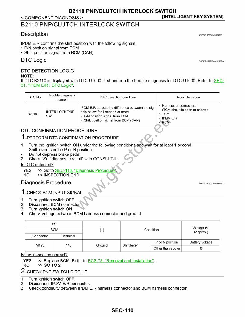
[INTELLIGENT KEY SYSTEM]B2110 PNP/CLUTCH INTERLOCK SWITCH
< COMPONENT DIAGNOSIS >B2110 PNP/CLUTCH INTERLOCK SWITCHDescription INFOID:0000000003996611
IPDM E/R confirms the shift position with the following signals.• P/N position signal from TCM• Shift position signal from BCM (CAN)
DTC Logic INFOID:0000000003996612
DTC DETECTION LOGICNOTE:If DTC B2110 is displayed with DTC U1000, first perform the trouble diagnosis for DTC U1000. Refer to SEC-31, "IPDM E/R : DTC Logic".
DTC CONFIRMATION PROCEDURE1.PERFORM DTC CONFIRMATION PROCEDURE
1. Turn the ignition switch ON under the following conditions and wait for at least 1 second.- Shift lever is in the P or N position.- Do not depress brake pedal.2. Check “Self diagnostic result” with CONSULT-III.Is DTC detected?YES >> Go to SEC-110, "Diagnosis Procedure".NO >> INSPECTION END
Diagnosis Procedure INFOID:0000000003996613
1.CHECK BCM INPUT SIGNAL
1. Turn ignition switch OFF.2. Disconnect BCM connector.3. Turn ignition switch ON.4. Check voltage between BCM harness connector and ground.
Is the inspection normal?YES >> Replace BCM. Refer to BCS-78, "Removal and Installation".NO >> GO TO 2.
2.CHECK PNP SWITCH CIRCUIT
1. Turn ignition switch OFF.2. Disconnect IPDM E/R connector.3. Check continuity between IPDM E/R harness connector and BCM harness connector.
DTC No. Trouble diagnosis name DTC detecting condition Possible cause
B2110 INTER LOCK/PNP SW
IPDM E/R detects the difference between the sig-nals below for 1 second or more.• P/N position signal from TCM• Shift position signal from BCM (CAN)
• Harness or connectors(TCM circuit is open or shorted)
• TCM• IPDM E/R• BCM
(+)
(–) Condition Voltage (V)(Approx.)BCM
Connector Terminal
M123 140 Ground Shift leverP or N position Battery voltage
Other than above 0
www.gtr-
store
.eu
SEC-110
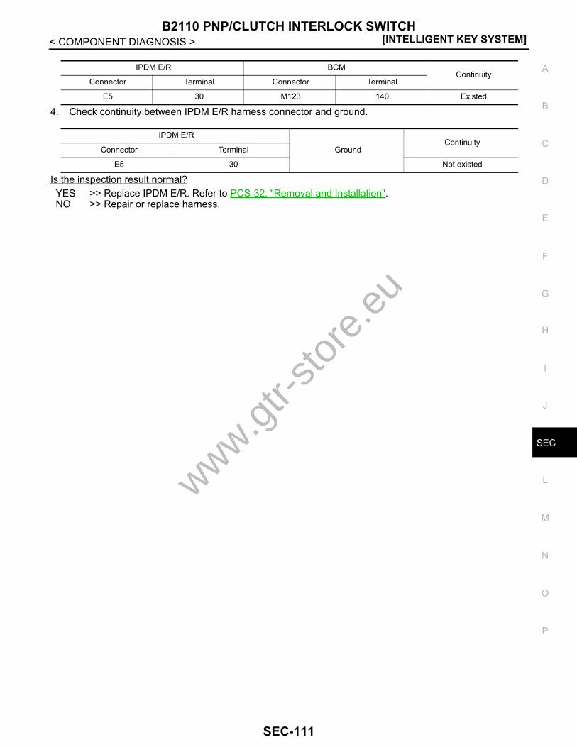
B2110 PNP/CLUTCH INTERLOCK SWITCH[INTELLIGENT KEY SYSTEM]
C
D
E
F
G
H
I
J
L
M
A
B
EC
N
O
P
< COMPONENT DIAGNOSIS >
S
4. Check continuity between IPDM E/R harness connector and ground.
Is the inspection result normal?YES >> Replace IPDM E/R. Refer to PCS-32, "Removal and Installation".NO >> Repair or replace harness.
IPDM E/R BCMContinuity
Connector Terminal Connector Terminal
E5 30 M123 140 Existed
IPDM E/R
GroundContinuity
Connector Terminal
E5 30 Not existed
www.gtr-
store
.eu
SEC-111
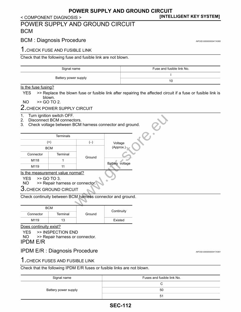
[INTELLIGENT KEY SYSTEM]POWER SUPPLY AND GROUND CIRCUIT
< COMPONENT DIAGNOSIS >POWER SUPPLY AND GROUND CIRCUITBCMBCM : Diagnosis Procedure INFOID:0000000004174360
1.CHECK FUSE AND FUSIBLE LINK
Check that the following fuse and fusible link are not blown.
Is the fuse fusing?YES >> Replace the blown fuse or fusible link after repairing the affected circuit if a fuse or fusible link is
blown.NO >> GO TO 2.
2.CHECK POWER SUPPLY CIRCUIT
1. Turn ignition switch OFF.2. Disconnect BCM connectors.3. Check voltage between BCM harness connector and ground.
Is the measurement value normal?YES >> GO TO 3.NO >> Repair harness or connector.
3.CHECK GROUND CIRCUIT
Check continuity between BCM harness connector and ground.
Does continuity exist?YES >> INSPECTION ENDNO >> Repair harness or connector.
IPDM E/RIPDM E/R : Diagnosis Procedure INFOID:0000000004174361
1.CHECK FUSES AND FUSIBLE LINK
Check that the following IPDM E/R fuses or fusible links are not blown.
Signal name Fuse and fusible link No.
Battery power supplyI
10
Terminals
Voltage(Approx.)
(+) (−)
BCM
GroundConnector Terminal
M118 1Battery voltage
M119 11
BCM
GroundContinuity
Connector Terminal
M119 13 Existed
Signal name Fuses and fusible link No.
Battery power supply
C
50
51
www.gtr-
store
.eu
SEC-112

POWER SUPPLY AND GROUND CIRCUIT[INTELLIGENT KEY SYSTEM]
C
D
E
F
G
H
I
J
L
M
A
B
EC
N
O
P
< COMPONENT DIAGNOSIS >
S
Is the fuse fusing?YES >> Replace the blown fuse or fusible link after repairing the affected circuit if a fuse or fusible link is
blown.NO >> GO TO 2.
2.CHECK POWER SUPPLY CIRCUIT
1. Turn the ignition switch OFF.2. Disconnect IPDM E/R connector.3. Check voltage between the IPDM E/R harness connector and the ground.
Is the measurement value normal?YES >> GO TO 3.NO >> Repair the harness or connector.
3.CHECK GROUND CIRCUIT
Check continuity between the IPDM E/R harness connectors and the ground.
Does continuity exist?YES >> INSPECTION ENDNO >> Repair the harness or connector.
Terminals
Voltage(Approx.)
(+)(−)
IPDM E/R
Connector TerminalGround
E4 1 Battery voltage
IPDM E/R
Ground
ContinuityConnector Terminal
E5 12Existed
E6 41
www.gtr-
store
.eu
SEC-113
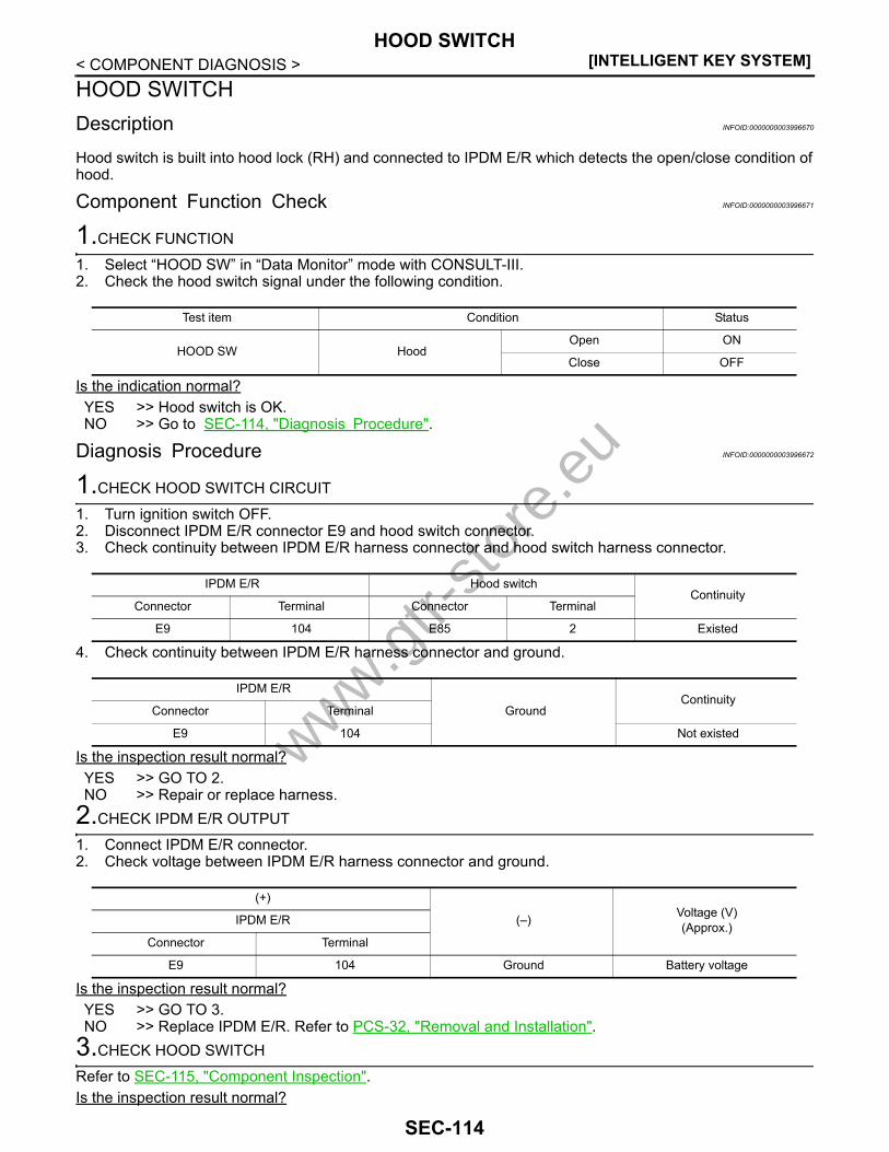
[INTELLIGENT KEY SYSTEM]HOOD SWITCH
< COMPONENT DIAGNOSIS >HOOD SWITCHDescription INFOID:0000000003996670
Hood switch is built into hood lock (RH) and connected to IPDM E/R which detects the open/close condition ofhood.
Component Function Check INFOID:0000000003996671
1.CHECK FUNCTION
1. Select “HOOD SW” in “Data Monitor” mode with CONSULT-III. 2. Check the hood switch signal under the following condition.
Is the indication normal?YES >> Hood switch is OK.NO >> Go to SEC-114, "Diagnosis Procedure".
Diagnosis Procedure INFOID:0000000003996672
1.CHECK HOOD SWITCH CIRCUIT
1. Turn ignition switch OFF.2. Disconnect IPDM E/R connector E9 and hood switch connector.3. Check continuity between IPDM E/R harness connector and hood switch harness connector.
4. Check continuity between IPDM E/R harness connector and ground.
Is the inspection result normal?YES >> GO TO 2.NO >> Repair or replace harness.
2.CHECK IPDM E/R OUTPUT
1. Connect IPDM E/R connector.2. Check voltage between IPDM E/R harness connector and ground.
Is the inspection result normal?YES >> GO TO 3.NO >> Replace IPDM E/R. Refer to PCS-32, "Removal and Installation".
3.CHECK HOOD SWITCH
Refer to SEC-115, "Component Inspection".Is the inspection result normal?
Test item Condition Status
HOOD SW HoodOpen ON
Close OFF
IPDM E/R Hood switchContinuity
Connector Terminal Connector Terminal
E9 104 E85 2 Existed
IPDM E/R
GroundContinuity
Connector Terminal
E9 104 Not existed
(+)
(–) Voltage (V)(Approx.)IPDM E/R
Connector Terminal
E9 104 Ground Battery voltage
www.gtr-
store
.eu
SEC-114
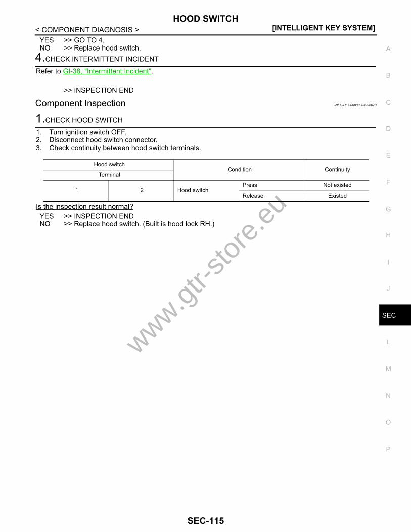
HOOD SWITCH[INTELLIGENT KEY SYSTEM]
C
D
E
F
G
H
I
J
L
M
A
B
EC
N
O
P
< COMPONENT DIAGNOSIS >
S
YES >> GO TO 4.NO >> Replace hood switch.
4.CHECK INTERMITTENT INCIDENT
Refer to GI-38, "Intermittent Incident".
>> INSPECTION END
Component Inspection INFOID:0000000003996673
1.CHECK HOOD SWITCH
1. Turn ignition switch OFF.2. Disconnect hood switch connector.3. Check continuity between hood switch terminals.
Is the inspection result normal?YES >> INSPECTION ENDNO >> Replace hood switch. (Built is hood lock RH.)
Hood switchCondition Continuity
Terminal
1 2 Hood switchPress Not existed
Release Existed
www.gtr-
store
.eu
SEC-115

[INTELLIGENT KEY SYSTEM]HEADLAMP
< COMPONENT DIAGNOSIS >HEADLAMPDescription INFOID:0000000003996674
Headlamp lighting when vehicle security system is alarm phase.
Component Function Check INFOID:0000000003996675
1.CHECK HEADLAMP OPERATION
Check if headlamp operate by lighting switch.Does headlamp come on when turning switch “ON”?YES >> Headlamp circuit is OK.NO >> Go to SEC-116, "Diagnosis Procedure".
Diagnosis Procedure INFOID:0000000003996676
1.CHECK HEADLAMP OPERATION
Refer to SEC-116, "Component Function Check".Is the inspection result normal?YES >> GO TO 2.NO >> repair or replace the malfunctioning parts.
2.CHECK INTERMITTENT INCIDENT
Refer to GI-38, "Intermittent Incident".
>> INSPECTION END
www.gtr-
store
.eu
SEC-116

SECURITY INDICATOR LAMP[INTELLIGENT KEY SYSTEM]
C
D
E
F
G
H
I
J
L
M
A
B
EC
N
O
P
< COMPONENT DIAGNOSIS >
S
SECURITY INDICATOR LAMPDescription INFOID:0000000003996616
NVIS (Nissan Vehicle Immobilizer System-NATS) and vehicle security system conditions are indicated by blinkor illumination of security indicator lamp.
Component Function Check INFOID:0000000003996617
1.CHECK FUNCTION
1. Perform “THEFT IND” in the “ACTIVE TEST” mode with CONSULT-III.2. Check security indicator lamp operation.
Is the inspection result normal?YES >> INSPECTION ENDNO >> Go to SEC-117, "Diagnosis Procedure".
Diagnosis Procedure INFOID:0000000003996618
1.CHECK SECURITY INDICATOR LAMP POWER SUPPLY CIRCUIT
1. Turn ignition switch OFF.2. Disconnect security indicator lamp connector.3. Check voltage between security indicator lamp harness connector and ground.
Is the inspection result normal?YES >> GO TO 2.NO >> Check the following.
• 10A fuse [No. 11, located in the fuse block (J/B)]• Harness for open or short between security indicator lamp and fuse.
2.CHECK SECURITY INDICATOR LAMP CIRCUIT
1. Disconnect BCM connector.2. Check continuity between security indicator lamp harness connector and BCM harness connector.
3. Check continuity between security indicator lamp harness connector and ground.
Is the inspection result normal?YES >> GO TO 3.NO >> Repair or replace harness.
3.CHECK SECURITY INDICATOR LAMP
Test item Description
THEFT INDON
Vehicle security indicatorIlluminates
OFF Does not illuminate
(+)
(–) Voltage (V)(Approx.)Security indicator lamp
Connector Terminal
M29 1 Ground Battery voltage
Security indicator lamp BCMContinuity
Connector Terminal Connector Terminal
M29 28 M123 141 Existed
Security indicator lamp
GroundContinuity
Connector Terminal
M29 28 Not existed
www.gtr-
store
.eu
SEC-117

[INTELLIGENT KEY SYSTEM]SECURITY INDICATOR LAMP
< COMPONENT DIAGNOSIS >Refer to SEC-118, "Component Inspection".Is the inspection result normal?YES >> Replace BCM. Refer to BCS-78, "Removal and Installation".NO >> Replace security indicator lamp. Refer to SEC-192, "Removal and Installation".
Component Inspection INFOID:0000000003996619
1.CHECK SECURITY INDICATOR LAMP
1. Disconnect security indicator lamp connector.2. Check continuity between security indicator lamp terminals.
Is the inspection result normal?YES >> INSPECTION ENDNO >> Replace security indicator lamp.
Terminal
ContinuitySecurity indicator lamp
(+) (–)
1 2 Existed
2 1 Not existed
www.gtr-
store
.eu
SEC-118

KEY WARNING LAMP[INTELLIGENT KEY SYSTEM]
C
D
E
F
G
H
I
J
L
M
A
B
EC
N
O
P
< COMPONENT DIAGNOSIS >
S
KEY WARNING LAMPDescription INFOID:0000000003996620
• Key warning lamp is located on combination meter.• Performs operation method guide and warning together with buzzer.
Component Function Check INFOID:0000000003996621
1.CHECK FUNCTION
Check the operation with “INDICATOR” in “Active Test” mode with CONSULT-III.
Is the inspection result normal?YES >> Key warning lamp in combination meter is OK.NO >> Refer to SEC-119, "Diagnosis Procedure".
Diagnosis Procedure INFOID:0000000003996622
1.CHECK KEY WARNING LAMP
Refer to MWI-4, "Work Flow".Is the inspection result normal?Yes >> GO TO 2.No >> Repair or replace key warning lamp circuit.
2.CHECK INTERMITTENT INCIDENT
Refer to GI-38, "Intermittent Incident".
>> INSPECTION END
Test item Condition
INDICATORRED ON Key warning lamp (red) illuminates
RED IND Key warning lamp (red) blinks
www.gtr-
store
.eu
SEC-119
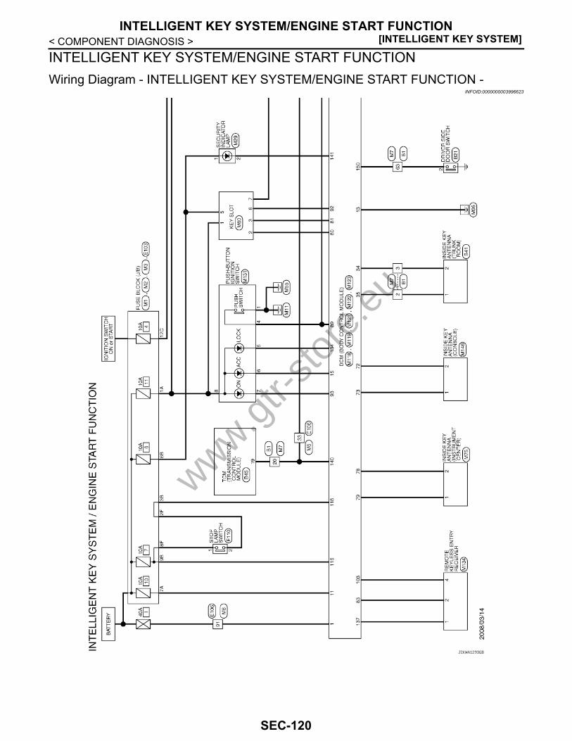
[INTELLIGENT KEY SYSTEM]INTELLIGENT KEY SYSTEM/ENGINE START FUNCTION
< COMPONENT DIAGNOSIS >INTELLIGENT KEY SYSTEM/ENGINE START FUNCTIONWiring Diagram - INTELLIGENT KEY SYSTEM/ENGINE START FUNCTION -
INFOID:0000000003996623
JCKWA1293GB
www.gtr-
store
.eu
SEC-120

INTELLIGENT KEY SYSTEM/ENGINE START FUNCTION[INTELLIGENT KEY SYSTEM]
C
D
E
F
G
H
I
J
L
M
A
B
EC
N
O
P
< COMPONENT DIAGNOSIS >
S
JCKWA1294GB
www.gtr-
store
.eu
SEC-121

[INTELLIGENT KEY SYSTEM]INTELLIGENT KEY SYSTEM/ENGINE START FUNCTION
< COMPONENT DIAGNOSIS >
JCKWA1295GB
www.gtr-
store
.eu
SEC-122
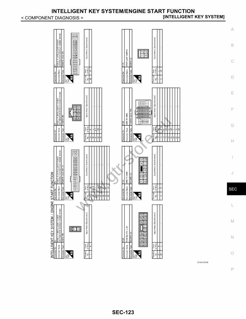
INTELLIGENT KEY SYSTEM/ENGINE START FUNCTION[INTELLIGENT KEY SYSTEM]
C
D
E
F
G
H
I
J
L
M
A
B
EC
N
O
P
< COMPONENT DIAGNOSIS >
S
JCKWA1296GB
www.gtr-
store
.eu
SEC-123
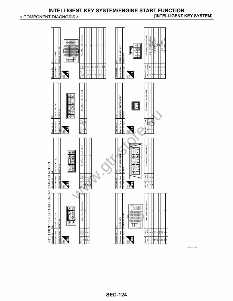
[INTELLIGENT KEY SYSTEM]INTELLIGENT KEY SYSTEM/ENGINE START FUNCTION
< COMPONENT DIAGNOSIS >
JCKWA1297GB
www.gtr-
store
.eu
SEC-124
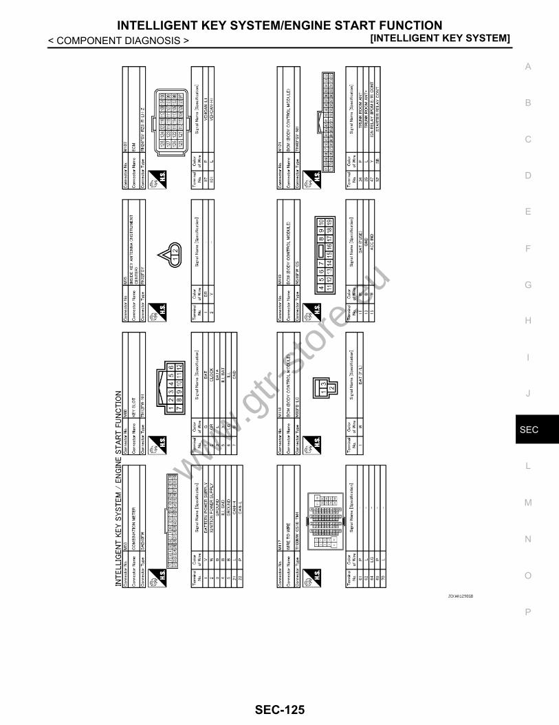
INTELLIGENT KEY SYSTEM/ENGINE START FUNCTION[INTELLIGENT KEY SYSTEM]
C
D
E
F
G
H
I
J
L
M
A
B
EC
N
O
P
< COMPONENT DIAGNOSIS >
S
JCKWA1298GB
www.gtr-
store
.eu
SEC-125

[INTELLIGENT KEY SYSTEM]INTELLIGENT KEY SYSTEM/ENGINE START FUNCTION
< COMPONENT DIAGNOSIS >
JCKWA1299GB
www.gtr-
store
.eu
SEC-126
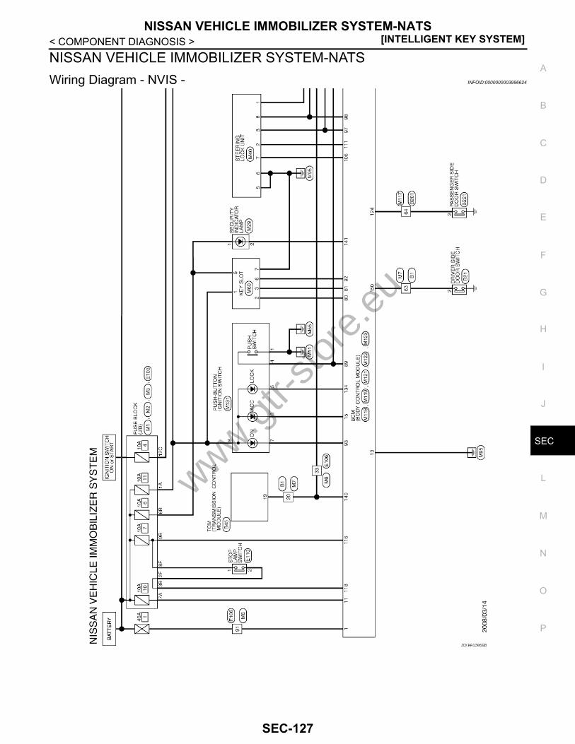
NISSAN VEHICLE IMMOBILIZER SYSTEM-NATS[INTELLIGENT KEY SYSTEM]
C
D
E
F
G
H
I
J
L
M
A
B
EC
N
O
P
< COMPONENT DIAGNOSIS >
S
NISSAN VEHICLE IMMOBILIZER SYSTEM-NATSWiring Diagram - NVIS - INFOID:0000000003996624
JCKWA1306GB
www.gtr-
store
.eu
SEC-127

[INTELLIGENT KEY SYSTEM]NISSAN VEHICLE IMMOBILIZER SYSTEM-NATS
< COMPONENT DIAGNOSIS >
JCKWA1307GB
www.gtr-
store
.eu
SEC-128

NISSAN VEHICLE IMMOBILIZER SYSTEM-NATS[INTELLIGENT KEY SYSTEM]
C
D
E
F
G
H
I
J
L
M
A
B
EC
N
O
P
< COMPONENT DIAGNOSIS >
S
JCKWA1308GB
www.gtr-
store
.eu
SEC-129

[INTELLIGENT KEY SYSTEM]NISSAN VEHICLE IMMOBILIZER SYSTEM-NATS
< COMPONENT DIAGNOSIS >
JCKWA1309GB
www.gtr-
store
.eu
SEC-130

NISSAN VEHICLE IMMOBILIZER SYSTEM-NATS[INTELLIGENT KEY SYSTEM]
C
D
E
F
G
H
I
J
L
M
A
B
EC
N
O
P
< COMPONENT DIAGNOSIS >
S
JCKWA1310GB
www.gtr-
store
.eu
SEC-131

[INTELLIGENT KEY SYSTEM]NISSAN VEHICLE IMMOBILIZER SYSTEM-NATS
< COMPONENT DIAGNOSIS >
JCKWA1311GB
www.gtr-
store
.eu
SEC-132
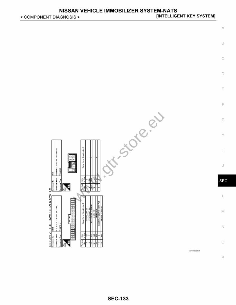
NISSAN VEHICLE IMMOBILIZER SYSTEM-NATS[INTELLIGENT KEY SYSTEM]
C
D
E
F
G
H
I
J
L
M
A
B
EC
N
O
P
< COMPONENT DIAGNOSIS >
S
JCKWA1312GB
www.gtr-
store
.eu
SEC-133

[INTELLIGENT KEY SYSTEM]VEHICLE SECURITY SYSTEM
< COMPONENT DIAGNOSIS >VEHICLE SECURITY SYSTEMWiring Diagram - VEHICLE SECURITY SYSTEM - INFOID:0000000003996677
JCKWA1300GB
www.gtr-
store
.eu
SEC-134
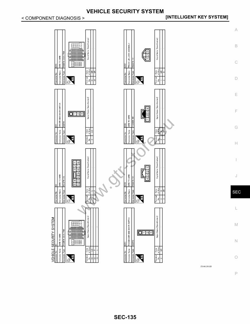
VEHICLE SECURITY SYSTEM[INTELLIGENT KEY SYSTEM]
C
D
E
F
G
H
I
J
L
M
A
B
EC
N
O
P
< COMPONENT DIAGNOSIS >
S
JCKWA1301GB
www.gtr-
store
.eu
SEC-135

[INTELLIGENT KEY SYSTEM]VEHICLE SECURITY SYSTEM
< COMPONENT DIAGNOSIS >
JCKWA1302GB
www.gtr-
store
.eu
SEC-136

VEHICLE SECURITY SYSTEM[INTELLIGENT KEY SYSTEM]
C
D
E
F
G
H
I
J
L
M
A
B
EC
N
O
P
< COMPONENT DIAGNOSIS >
S
JCKWA1303GB
www.gtr-
store
.eu
SEC-137

[INTELLIGENT KEY SYSTEM]VEHICLE SECURITY SYSTEM
< COMPONENT DIAGNOSIS >
JCKWA1304GB
www.gtr-
store
.eu
SEC-138

VEHICLE SECURITY SYSTEM[INTELLIGENT KEY SYSTEM]
C
D
E
F
G
H
I
J
L
M
A
B
EC
N
O
P
< COMPONENT DIAGNOSIS >
S
JCKWA1305GB
www.gtr-
store
.eu
SEC-139
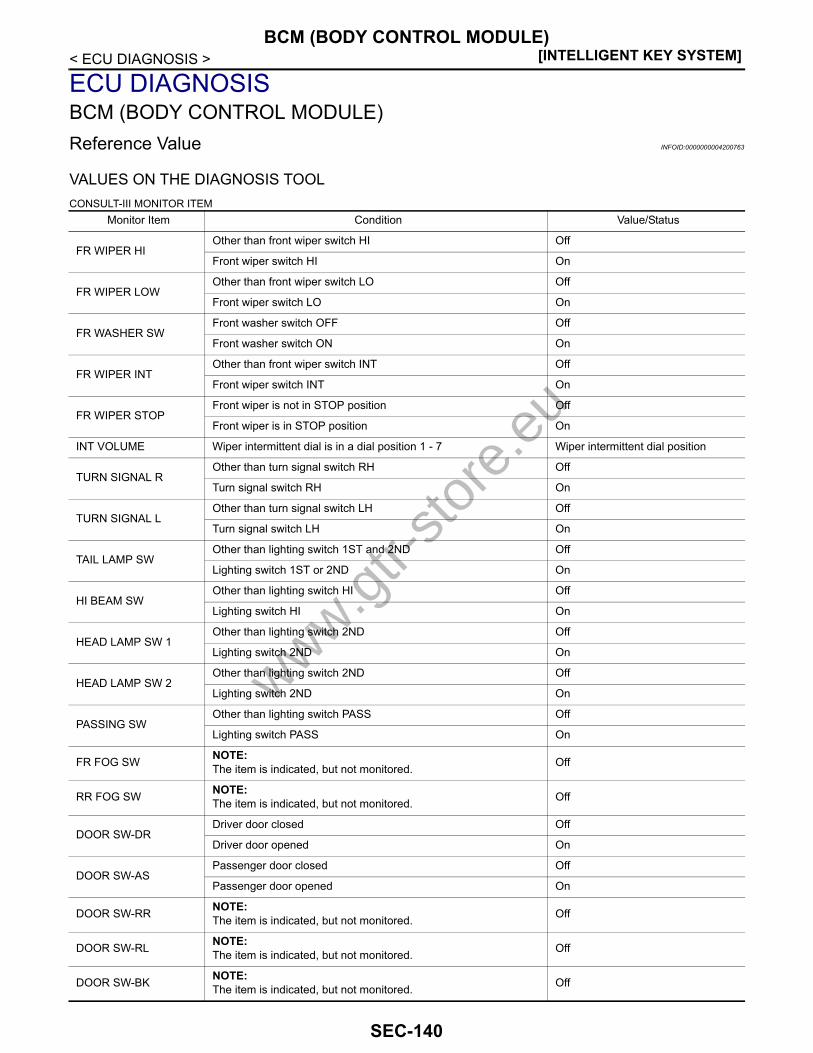
[INTELLIGENT KEY SYSTEM]BCM (BODY CONTROL MODULE)
< ECU DIAGNOSIS >
ECU DIAGNOSISBCM (BODY CONTROL MODULE)Reference Value INFOID:0000000004200763
VALUES ON THE DIAGNOSIS TOOLCONSULT-III MONITOR ITEM
Monitor Item Condition Value/Status
FR WIPER HIOther than front wiper switch HI Off
Front wiper switch HI On
FR WIPER LOWOther than front wiper switch LO Off
Front wiper switch LO On
FR WASHER SWFront washer switch OFF Off
Front washer switch ON On
FR WIPER INTOther than front wiper switch INT Off
Front wiper switch INT On
FR WIPER STOPFront wiper is not in STOP position Off
Front wiper is in STOP position On
INT VOLUME Wiper intermittent dial is in a dial position 1 - 7 Wiper intermittent dial position
TURN SIGNAL ROther than turn signal switch RH Off
Turn signal switch RH On
TURN SIGNAL LOther than turn signal switch LH Off
Turn signal switch LH On
TAIL LAMP SWOther than lighting switch 1ST and 2ND Off
Lighting switch 1ST or 2ND On
HI BEAM SWOther than lighting switch HI Off
Lighting switch HI On
HEAD LAMP SW 1Other than lighting switch 2ND Off
Lighting switch 2ND On
HEAD LAMP SW 2Other than lighting switch 2ND Off
Lighting switch 2ND On
PASSING SWOther than lighting switch PASS Off
Lighting switch PASS On
FR FOG SW NOTE:The item is indicated, but not monitored. Off
RR FOG SW NOTE:The item is indicated, but not monitored. Off
DOOR SW-DRDriver door closed Off
Driver door opened On
DOOR SW-ASPassenger door closed Off
Passenger door opened On
DOOR SW-RR NOTE:The item is indicated, but not monitored. Off
DOOR SW-RL NOTE:The item is indicated, but not monitored. Off
DOOR SW-BK NOTE:The item is indicated, but not monitored. Off
www.gtr-
store
.eu
SEC-140

BCM (BODY CONTROL MODULE)[INTELLIGENT KEY SYSTEM]
C
D
E
F
G
H
I
J
L
M
A
B
EC
N
O
P
< ECU DIAGNOSIS >
S
CDL LOCK SWOther than power door lock switch LOCK Off
Power door lock switch LOCK On
CDL UNLOCK SWOther than power door lock switch UNLOCK Off
Power door lock switch UNLOCK On
KEY CYL LK-SW NOTE:The item is indicated, but not monitored. Off
KEY CYL UN-SW NOTE:The item is indicated, but not monitored. Off
KEY CYL SW-TR NOTE:The item is indicated, but not monitored. Off
HAZARD SWHazard switch is not pressed Off
Hazard switch is pressed On
REAR DEF SW NOTE:The item is indicated, but not monitored. Off
H/L WASH SW NOTE:The item is indicated, but not monitored. Off
TR CANCEL SWTrunk lid opener cancel switch OFF Off
Trunk lid opener cancel switch ON On
TR/BD OPEN SWTrunk lid opener switch OFF Off
While the trunk lid opener switch is turned ON On
TRNK/HAT MNTRTrunk lid closed Off
Trunk lid opened On
RKE-LOCKLOCK button of Intelligent Key is not pressed Off
LOCK button of Intelligent Key is pressed On
RKE-UNLOCKUNLOCK button of Intelligent Key is not pressed Off
UNLOCK button of Intelligent Key is pressed On
RKE-TR/BDTRUNK OPEN button of Intelligent Key is not pressed Off
TRUNK OPEN button of Intelligent Key is pressed On
RKE-PANICPANIC button of Intelligent Key is not pressed Off
PANIC button of Intelligent Key is pressed On
RKE-P/W OPENUNLOCK button of Intelligent Key is not pressed Off
UNLOCK button of Intelligent Key is pressed and held On
RKE-MODE CHG
LOCK/UNLOCK button of Intelligent Key is not pressed and held si-multaneously Off
LOCK/UNLOCK button of Intelligent Key is pressed and held simul-taneously On
REQ SW-DRDriver door request switch is not pressed Off
Driver door request switch is pressed On
REQ SW-ASPassenger door request switch is not pressed Off
Passenger door request switch is pressed On
REQ SW-RL NOTE:The item is indicated, but not monitored. Off
REQ SW-RR NOTE:The item is indicated, but not monitored. Off
REQ SW-BD/TRTrunk lid opener request switch is not pressed Off
Trunk lid opener request switch is pressed On
Monitor Item Condition Value/Status
www.gtr-
store
.eu
SEC-141

[INTELLIGENT KEY SYSTEM]BCM (BODY CONTROL MODULE)
< ECU DIAGNOSIS >
PUSH SWPush-button ignition switch (push switch) is not pressed Off
Push-button ignition switch (push switch) is pressed On
IGN RLY2 -F/BIgnition switch in OFF or ACC position Off
Ignition switch in ON position On
ACC RLY -F/B NOTE:The item is indicated, but not monitored. Off
CLUCH SW NOTE:The item is indicated, but not monitored. Off
BRAKE SW 1The brake pedal is not depressed On
The brake pedal is depressed Off
DETE/CANCL SWSelector lever in P position Off
Selector lever in any position other than P On
SFT PN/N SWSelector lever in any position other than P and N Off
Selector lever in P or N position On
S/L -LOCKSteering is locked Off
Steering is unlocked On
S/L -UNLOCKSteering is unlocked Off
Steering is locked On
S/L RELAY-F/BIgnition switch in OFF or ACC position Off
Ignition switch in ON position On
UNLK SEN-DRDriver door is unlocked Off
Driver door is locked On
PUSH SW -IPDMPush-button ignition switch (push-switch) is not pressed Off
Push-button ignition switch (push-switch) is pressed On
IGN RLY1 -F/BIgnition switch in OFF or ACC position Off
Ignition switch in ON position On
DETE SW -IPDMSelector lever in P position Off
Selector lever in any position other than P On
SFT PN -IPDMSelector lever in any position other than P and N Off
Selector lever in P or N position On
SFT P -METSelector lever in any position other than P Off
Selector lever in P position On
SFT N -METSelector lever in any position other than N Off
Selector lever in N position On
ENGINE STATE
Engine stopped Stop
While the engine stalls Stall
At engine cranking Crank
Engine running Run
S/L LOCK-IPDMSteering is locked Off
Steering is unlocked On
S/L UNLK-IPDMSteering is unlocked Off
Steering is locked On
S/L RELAY-REQIgnition switch in OFF or ACC position Off
Ignition switch in ON position On
VEH SPEED 1 While driving Equivalent to speedometer reading
Monitor Item Condition Value/Status
www.gtr-
store
.eu
SEC-142
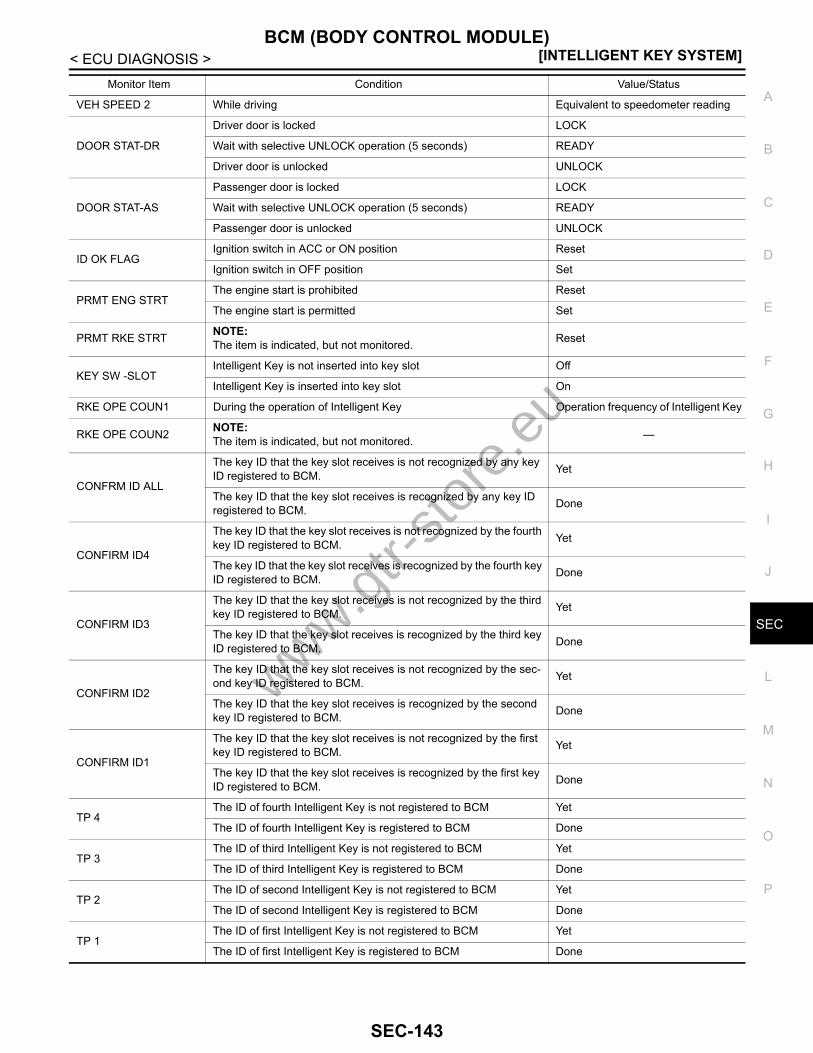
BCM (BODY CONTROL MODULE)[INTELLIGENT KEY SYSTEM]
C
D
E
F
G
H
I
J
L
M
A
B
EC
N
O
P
< ECU DIAGNOSIS >
S
VEH SPEED 2 While driving Equivalent to speedometer reading
DOOR STAT-DR
Driver door is locked LOCK
Wait with selective UNLOCK operation (5 seconds) READY
Driver door is unlocked UNLOCK
DOOR STAT-AS
Passenger door is locked LOCK
Wait with selective UNLOCK operation (5 seconds) READY
Passenger door is unlocked UNLOCK
ID OK FLAGIgnition switch in ACC or ON position Reset
Ignition switch in OFF position Set
PRMT ENG STRTThe engine start is prohibited Reset
The engine start is permitted Set
PRMT RKE STRT NOTE:The item is indicated, but not monitored. Reset
KEY SW -SLOTIntelligent Key is not inserted into key slot Off
Intelligent Key is inserted into key slot On
RKE OPE COUN1 During the operation of Intelligent Key Operation frequency of Intelligent Key
RKE OPE COUN2 NOTE:The item is indicated, but not monitored. —
CONFRM ID ALL
The key ID that the key slot receives is not recognized by any key ID registered to BCM. Yet
The key ID that the key slot receives is recognized by any key ID registered to BCM. Done
CONFIRM ID4
The key ID that the key slot receives is not recognized by the fourth key ID registered to BCM. Yet
The key ID that the key slot receives is recognized by the fourth key ID registered to BCM. Done
CONFIRM ID3
The key ID that the key slot receives is not recognized by the third key ID registered to BCM. Yet
The key ID that the key slot receives is recognized by the third key ID registered to BCM. Done
CONFIRM ID2
The key ID that the key slot receives is not recognized by the sec-ond key ID registered to BCM. Yet
The key ID that the key slot receives is recognized by the second key ID registered to BCM. Done
CONFIRM ID1
The key ID that the key slot receives is not recognized by the first key ID registered to BCM. Yet
The key ID that the key slot receives is recognized by the first key ID registered to BCM. Done
TP 4The ID of fourth Intelligent Key is not registered to BCM Yet
The ID of fourth Intelligent Key is registered to BCM Done
TP 3The ID of third Intelligent Key is not registered to BCM Yet
The ID of third Intelligent Key is registered to BCM Done
TP 2The ID of second Intelligent Key is not registered to BCM Yet
The ID of second Intelligent Key is registered to BCM Done
TP 1The ID of first Intelligent Key is not registered to BCM Yet
The ID of first Intelligent Key is registered to BCM Done
Monitor Item Condition Value/Status
www.gtr-
store
.eu
SEC-143

[INTELLIGENT KEY SYSTEM]BCM (BODY CONTROL MODULE)
< ECU DIAGNOSIS >TERMINAL LAYOUT
PHYSICAL VALUESJPMIA0062ZZ
www.gtr-
store
.eu
SEC-144
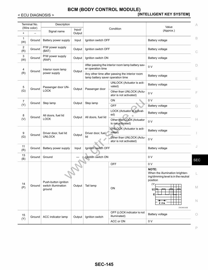
BCM (BODY CONTROL MODULE)[INTELLIGENT KEY SYSTEM]
C
D
E
F
G
H
I
J
L
M
A
B
EC
N
O
P
< ECU DIAGNOSIS >
S
Terminal No.(Wire color)
DescriptionCondition Value
(Approx.)Signal name Input/ Output+ –
1(W) Ground Battery power supply Input Ignition switch OFF Battery voltage
2(R) Ground P/W power supply
(BAT) Output Ignition switch OFF Battery voltage
3(W) Ground P/W power supply
(RAP) Output Ignition switch ON Battery voltage
4(R) Ground Interior room lamp
power supply Output
After passing the interior room lamp battery sav-er operation time 0 V
Any other time after passing the interior room lamp battery saver operation time Battery voltage
5(G) Ground Passenger door UN-
LOCK Output Passenger door
UNLOCK (Actuator is acti-vated) Battery voltage
Other than UNLOCK (Actu-ator is not activated) 0 V
7(Y) Ground Step lamp Output Step lamp
ON 0 V
OFF Battery voltage
8(V) Ground All doors, fuel lid
LOCK Output All doors, fuel lid
LOCK (Actuator is activat-ed) Battery voltage
Other than LOCK (Actuator is not activated) 0 V
9(G) Ground Driver door, fuel lid
UNLOCK Output Driver door, fuel lid
UNLOCK (Actuator is acti-vated) Battery voltage
Other than UNLOCK (Actu-ator is not activated) 0 V
11(R) Ground Battery power supply Input Ignition switch OFF Battery voltage
13(B) Ground Ground — Ignition switch ON 0 V
14(P) Ground
Push-button ignition switch illumination ground
Output Tail lamp
OFF 0 V
ON
NOTE:When the illumination brighten-ing/dimming level is in the neutral position
15(Y) Ground ACC indicator lamp Output Ignition switch
OFF (LOCK indicator is not illuminated) Battery voltage
ACC or ON 0 V
JSNIA0010GB
www.gtr-
store
.eu
SEC-145

[INTELLIGENT KEY SYSTEM]BCM (BODY CONTROL MODULE)
< ECU DIAGNOSIS >
17(W) Ground Turn signal RH
(Front) Output Ignition switch ON
Turn signal switch OFF 0 V
Turn signal switch RH
6.5 V
18(O) Ground Turn signal LH
(Front) Output Ignition switch ON
Turn signal switch OFF 0 V
Turn signal switch LH
6.5 V
19(V) Ground Room lamp timer
control Output Interior room lamp
OFF Battery voltage
ON 0 V
20(SB) Ground Turn signal RH
(Rear) Output Ignition switch ON
Turn signal switch OFF 0 V
Turn signal switch RH
6.5 V
23(G) Ground Trunk lid opening Output Trunk lid
Open (Trunk lid opener ac-tuator is activated) Battery voltage
Close (Trunk lid opener ac-tuator is not activated) 0 V
25(V) Ground Turn signal LH (Rear) Output Ignition switch
ON
Turn signal switch OFF 0 V
Turn signal switch LH
6.5 V
30(O) Ground Trunk room lamp Output Trunk room lamp
ON 0 V
OFF Battery voltage
Terminal No.(Wire color)
DescriptionCondition Value
(Approx.)Signal name Input/ Output+ –
PKID0926E
PKID0926E
PKID0926E
PKID0926E
www.gtr-
store
.eu
SEC-146
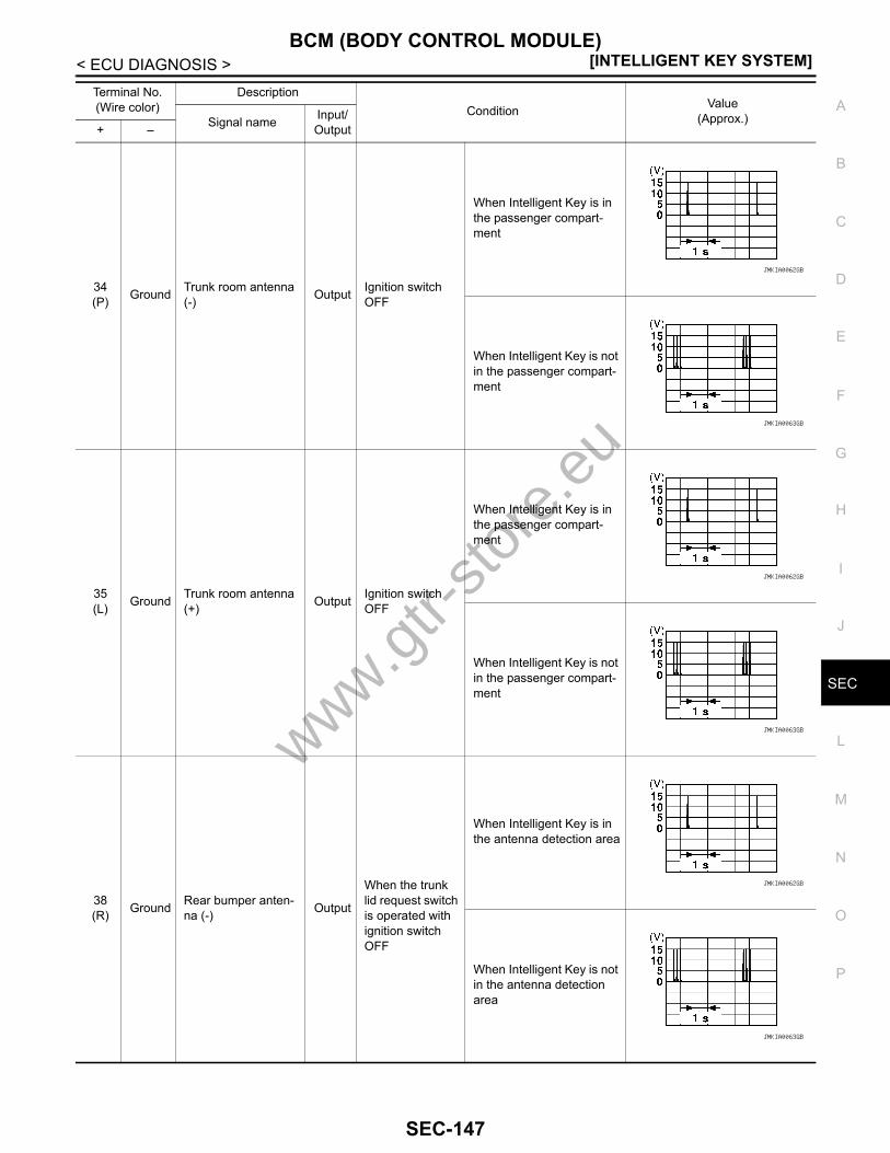
BCM (BODY CONTROL MODULE)[INTELLIGENT KEY SYSTEM]
C
D
E
F
G
H
I
J
L
M
A
B
EC
N
O
P
< ECU DIAGNOSIS >
S
34(P) Ground Trunk room antenna
(-) Output Ignition switch OFF
When Intelligent Key is in the passenger compart-ment
When Intelligent Key is not in the passenger compart-ment
35(L) Ground Trunk room antenna
(+) Output Ignition switch OFF
When Intelligent Key is in the passenger compart-ment
When Intelligent Key is not in the passenger compart-ment
38(R) Ground Rear bumper anten-
na (-) Output
When the trunk lid request switch is operated with ignition switch OFF
When Intelligent Key is in the antenna detection area
When Intelligent Key is not in the antenna detection area
Terminal No.(Wire color)
DescriptionCondition Value
(Approx.)Signal name Input/ Output+ –
JMKIA0062GB
JMKIA0063GB
JMKIA0062GB
JMKIA0063GB
JMKIA0062GB
JMKIA0063GB
www.gtr-
store
.eu
SEC-147

[INTELLIGENT KEY SYSTEM]BCM (BODY CONTROL MODULE)
< ECU DIAGNOSIS >
39(BR) Ground Rear bumper anten-
na (+) Output
When the trunk lid request switch is operated with ignition switch OFF
When Intelligent Key is in the antenna detection area
When Intelligent Key is not in the antenna detection area
47(Y) Ground Ignition relay (IPDM
E/R) control Output Ignition switchOFF or ACC Battery voltage
ON 0 V
50(R) Ground Trunk room lamp
switch Input Trunk room lamp switch
OFF (Trunk is closed)
11.8 V
ON (Trunk is open) 0 V
52(SB) Ground Starter relay control Output Ignition switch
ON
When selector lever is in P or N position and the brake is depressed
Battery voltage
When selector lever is in P or N position and the brake is not depressed
0 V
61(W) Ground Trunk lid request
switch Input Trunk lid request switch
ON (Pressed) 0 V
OFF (Not pressed)
1.0 V
64(O) Ground
Intelligent Key warn-ing buzzer (Engine room)
OutputIntelligent Key warning buzzer (Engine room)
Sounding 0 V
Not sounding Battery voltage
Terminal No.(Wire color)
DescriptionCondition Value
(Approx.)Signal name Input/ Output+ –
JMKIA0062GB
JMKIA0063GB
JPMIA0011GB
JPMIA0016GB
www.gtr-
store
.eu
SEC-148
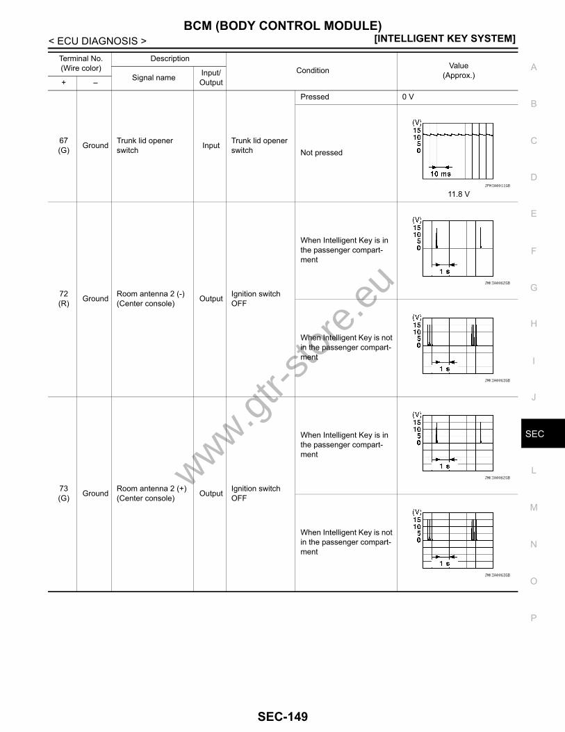
BCM (BODY CONTROL MODULE)[INTELLIGENT KEY SYSTEM]
C
D
E
F
G
H
I
J
L
M
A
B
EC
N
O
P
< ECU DIAGNOSIS >
S
67(G) Ground Trunk lid opener
switch Input Trunk lid opener switch
Pressed 0 V
Not pressed
11.8 V
72(R) Ground Room antenna 2 (-)
(Center console) Output Ignition switch OFF
When Intelligent Key is in the passenger compart-ment
When Intelligent Key is not in the passenger compart-ment
73(G) Ground Room antenna 2 (+)
(Center console) Output Ignition switch OFF
When Intelligent Key is in the passenger compart-ment
When Intelligent Key is not in the passenger compart-ment
Terminal No.(Wire color)
DescriptionCondition Value
(Approx.)Signal name Input/ Output+ –
JPMIA0011GB
JMKIA0062GB
JMKIA0063GB
JMKIA0062GB
JMKIA0063GB
www.gtr-
store
.eu
SEC-149

[INTELLIGENT KEY SYSTEM]BCM (BODY CONTROL MODULE)
< ECU DIAGNOSIS >
74(SB) Ground Passenger door an-
tenna (-) Output
When the pas-senger door re-quest switch is operated with ig-nition switch OFF
When Intelligent Key is in the antenna detection area
When Intelligent Key is not in the antenna detection area
75(BR) Ground Passenger door an-
tenna (+) Output
When the pas-senger door re-quest switch is operated with ig-nition switch OFF
When Intelligent Key is in the antenna detection area
When Intelligent Key is not in the antenna detection area
76(V) Ground Driver door antenna
(-) Output
When the driver door request switch is operat-ed with ignition switch OFF
When Intelligent Key is in the antenna detection area
When Intelligent Key is not in the antenna detection area
Terminal No.(Wire color)
DescriptionCondition Value
(Approx.)Signal name Input/ Output+ –
JMKIA0062GB
JMKIA0063GB
JMKIA0062GB
JMKIA0063GB
JMKIA0062GB
JMKIA0063GB
www.gtr-
store
.eu
SEC-150

BCM (BODY CONTROL MODULE)[INTELLIGENT KEY SYSTEM]
C
D
E
F
G
H
I
J
L
M
A
B
EC
N
O
P
< ECU DIAGNOSIS >
S
77(LG) Ground Driver door antenna
(+) Output
When the driver door request switch is operat-ed with ignition switch OFF
When Intelligent Key is in the antenna detection area
When Intelligent Key is not in the antenna detection area
78(Y) Ground Room antenna 1 (-)
(Instrument panel) Output Ignition switch OFF
When Intelligent Key is in the passenger compart-ment
When Intelligent Key is not in the passenger compart-ment
79(BR) Ground Room antenna 1 (+)
(Instrument panel) Output Ignition switch OFF
When Intelligent Key is in the passenger compart-ment
When Intelligent Key is not in the passenger compart-ment
Terminal No.(Wire color)
DescriptionCondition Value
(Approx.)Signal name Input/ Output+ –
JMKIA0062GB
JMKIA0063GB
JMKIA0062GB
JMKIA0063GB
JMKIA0062GB
JMKIA0063GB
www.gtr-
store
.eu
SEC-151

[INTELLIGENT KEY SYSTEM]BCM (BODY CONTROL MODULE)
< ECU DIAGNOSIS >
80(GR) Ground NATS antenna amp
(built in key slot)Input/Output During waiting
Ignition switch is pressed while inserting the Intelli-gent Key into the key slot.
Just after pressing ignition switch. Pointer of tester should move.
81(L) Ground NATS antenna amp
(built in key slot)Input/Output During waiting
Ignition switch is pressed while inserting the Intelli-gent Key into the key slot.
Just after pressing ignition switch. Pointer of tester should move.
82(R) Ground Ignition relay [fuse
block (J/B)] control Output Ignition switchOFF or ACC 0 V
ON Battery voltage
83(Y) Ground Remote keyless entry
receiverInput/Output
During waiting
When operating either button on Intelligent Key
87(BR) Ground Combination switch
INPUT 5 Input Combination switch
All switches OFF(Wiper intermittent dial 4)
1.4 V
Any of the conditions below with all switches OFF• Wiper intermittent dial 1• Wiper intermittent dial 2• Wiper intermittent dial 6• Wiper intermittent dial 7
1.3 V
Terminal No.(Wire color)
DescriptionCondition Value
(Approx.)Signal name Input/ Output+ –
JMKIA0064GB
JMKIA0065GB
JPMIA0041GB
JPMIA0040GB
www.gtr-
store
.eu
SEC-152

BCM (BODY CONTROL MODULE)[INTELLIGENT KEY SYSTEM]
C
D
E
F
G
H
I
J
L
M
A
B
EC
N
O
P
< ECU DIAGNOSIS >
S
88(V) Ground Combination switch
INPUT 3 Input Combination switch
All switches OFF(Wiper intermittent dial 4)
1.4 V
Lighting switch HI(Wiper intermittent dial 4)
1.3 V
Lighting switch 2ND(Wiper intermittent dial 4)
1.3 V
Any of the conditions below with all switches OFF• Wiper intermittent dial 1• Wiper intermittent dial 2• Wiper intermittent dial 3
1.3 V
89(BR) Ground Push-button ignition
switch (push switch) InputPush-button igni-tion switch (push switch)
Pressed 0 V
Not pressed Battery voltage
90(P) Ground CAN - L Input/
Output — —
91(L) Ground CAN - H Input/
Output — —
92(LG) Ground Key slot illumination Output Key slot illumina-
tion
OFF 0 V
Blinking
6.5 V
ON Battery voltage
Terminal No.(Wire color)
DescriptionCondition Value
(Approx.)Signal name Input/ Output+ –
JPMIA0041GB
JPMIA0036GB
JPMIA0037GB
JPMIA0040GB
JPMIA0015GB
www.gtr-
store
.eu
SEC-153

[INTELLIGENT KEY SYSTEM]BCM (BODY CONTROL MODULE)
< ECU DIAGNOSIS >
93(V) Ground ON indicator lamp Output Ignition switch
OFF (LOCK indicator is not illuminated) Battery voltage
ON or ACC 0 V
95(O) Ground ACC relay control Output Ignition switch
OFF 0 V
ACC or ON Battery voltage
96(SB) Ground A/T device (detention
switch) power supply Output — Battery voltage
97(L) Ground Steering lock condi-
tion No. 1 Input Steering lockLOCK status 0 V
UNLOCK status Battery voltage
98(R) Ground Steering lock condi-
tion No. 2 Input Steering lockLOCK status Battery voltage
UNLOCK status 0 V
99(G) Ground Selector lever P posi-
tion switch Input Selector leverP position 0 V
Any position other than P Battery voltage
100(W) Ground Passenger door re-
quest switch Input Passenger door request switch
ON (Pressed) 0 V
OFF (Not pressed)
1.0 V
101(V) Ground Driver door request
switch Input Driver door re-quest switch
ON (Pressed) 0 V
OFF (Not pressed)
1.0 V
102(O) Ground Blower fan motor re-
lay control Output Ignition switchOFF or ACC 0 V
ON Battery voltage
103(LG) Ground
Remote keyless entry receiver power sup-ply
Output Ignition switch OFF Battery voltage
106(P) Ground Steering lock unit
power supply Output Ignition switchOFF or ACC Battery voltage
ON 0 V
Terminal No.(Wire color)
DescriptionCondition Value
(Approx.)Signal name Input/ Output+ –
JPMIA0016GB
JPMIA0016GBwww.gtr-
store
.eu
SEC-154
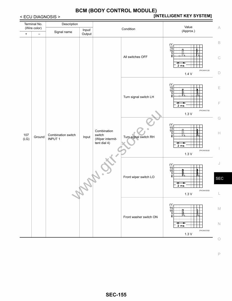
BCM (BODY CONTROL MODULE)[INTELLIGENT KEY SYSTEM]
C
D
E
F
G
H
I
J
L
M
A
B
EC
N
O
P
< ECU DIAGNOSIS >
S
107(LG) Ground Combination switch
INPUT 1 Input
Combination switch(Wiper intermit-tent dial 4)
All switches OFF
1.4 V
Turn signal switch LH
1.3 V
Turn signal switch RH
1.3 V
Front wiper switch LO
1.3 V
Front washer switch ON
1.3 V
Terminal No.(Wire color)
DescriptionCondition Value
(Approx.)Signal name Input/ Output+ –
JPMIA0041GB
JPMIA0037GB
JPMIA0036GB
JPMIA0038GB
JPMIA0039GB
www.gtr-
store
.eu
SEC-155

[INTELLIGENT KEY SYSTEM]BCM (BODY CONTROL MODULE)
< ECU DIAGNOSIS >
108(R) Ground Combination switch
INPUT 4 Input Combination switch
All switches OFF(Wiper intermittent dial 4)
1.4 V
Lighting switch 1ST(Wiper intermittent dial 4)
1.3 V
Any of the conditions below with all switches OFF• Wiper intermittent dial 1• Wiper intermittent dial 5• Wiper intermittent dial 6
1.3 V
Terminal No.(Wire color)
DescriptionCondition Value
(Approx.)Signal name Input/ Output+ –
JPMIA0041GB
JPMIA0036GB
JPMIA0039GB
www.gtr-
store
.eu
SEC-156
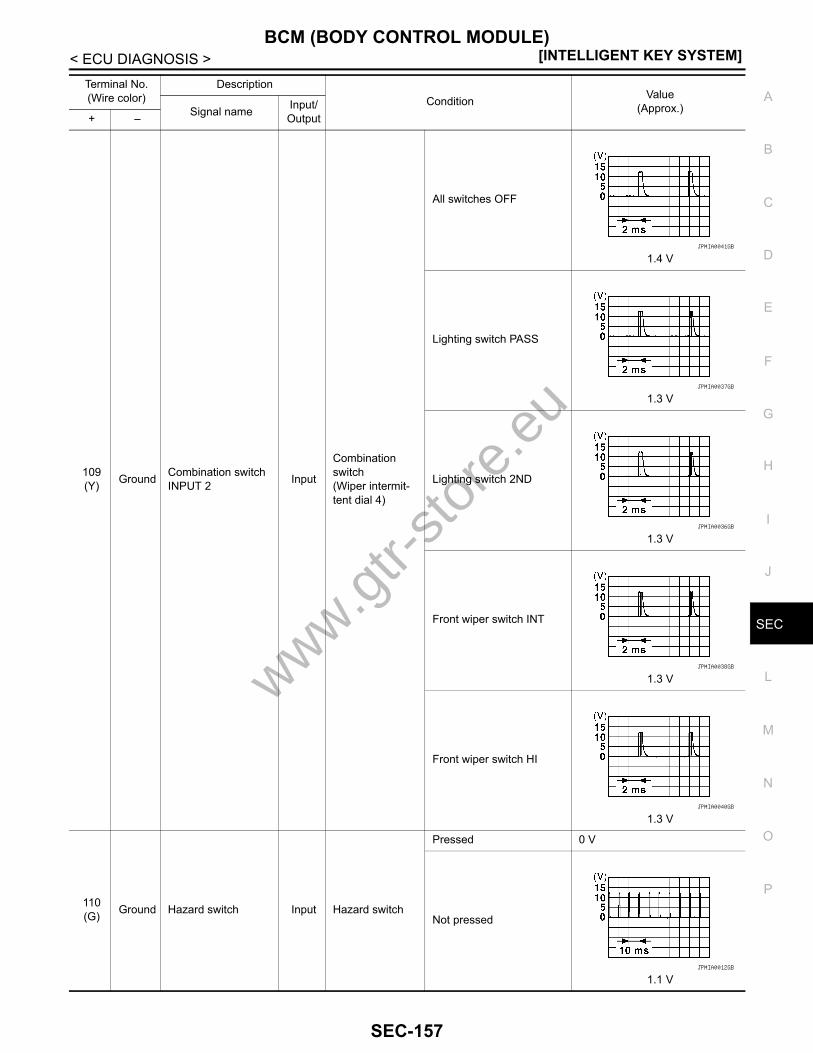
BCM (BODY CONTROL MODULE)[INTELLIGENT KEY SYSTEM]
C
D
E
F
G
H
I
J
L
M
A
B
EC
N
O
P
< ECU DIAGNOSIS >
S
109(Y) Ground Combination switch
INPUT 2 Input
Combination switch(Wiper intermit-tent dial 4)
All switches OFF
1.4 V
Lighting switch PASS
1.3 V
Lighting switch 2ND
1.3 V
Front wiper switch INT
1.3 V
Front wiper switch HI
1.3 V
110(G) Ground Hazard switch Input Hazard switch
Pressed 0 V
Not pressed
1.1 V
Terminal No.(Wire color)
DescriptionCondition Value
(Approx.)Signal name Input/ Output+ –
JPMIA0041GB
JPMIA0037GB
JPMIA0036GB
JPMIA0038GB
JPMIA0040GB
JPMIA0012GB
www.gtr-
store
.eu
SEC-157

[INTELLIGENT KEY SYSTEM]BCM (BODY CONTROL MODULE)
< ECU DIAGNOSIS >
111(Y) Ground Steering lock unit
communicationInput/Output Steering lock
LOCK status Battery voltage
LOCK or UNLOCK
For 15 seconds after UN-LOCK Battery voltage
15 seconds or later after UNLOCK 0 V
116(SB) Ground Fuse check (Stop
lamp switch) Input — Battery voltage
118(P) Ground Stop lamp switch Input Stop lamp switch
OFF (Brake pedal is not depressed) 0 V
ON (Brake pedal is de-pressed) Battery voltage
119(SB) Ground
Driver side door lock actuator (unlock sen-sor)
Input Driver door
LOCK status (unlock sen-sor switch OFF)
11.8 V
UNLOCK status (unlock sensor switch ON) 0 V
121(R) Ground Key slot switch Input
When Intelligent Key is inserted into key slot Battery voltage
When Intelligent Key is not inserted into key slot 0 V
122(V) Ground ACC feedback Input Ignition switch
OFF 0 V
ACC or ON Battery voltage
123(BR) Ground IGN feedback Input Ignition switch
OFF or ACC 0 V
ON Battery voltage
124(LG) Ground Passenger door
switch Input Passenger door switch
OFF (When passenger door closes)
11.8 V
ON (When passenger door opens) 0 V
Terminal No.(Wire color)
DescriptionCondition Value
(Approx.)Signal name Input/ Output+ –
JMKIA0066GB
JPMIA0011GB
JPMIA0011GB
www.gtr-
store
.eu
SEC-158
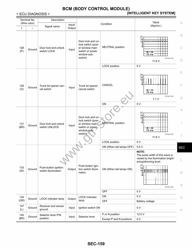
BCM (BODY CONTROL MODULE)[INTELLIGENT KEY SYSTEM]
C
D
E
F
G
H
I
J
L
M
A
B
EC
N
O
P
< ECU DIAGNOSIS >
S
128(P) Ground Door lock and unlock
switch LOCK Input
Door lock and un-lock switch (pow-er window main switch or power window sub-switch)
NEUTRAL position
11.8 V
LOCK position 0 V
129(O) Ground Trunk lid opener can-
cel switch Input Trunk lid opener cancel switch
CANCEL
1.1 V
ON 0 V
131(BR) Ground Door lock and unlock
switch UNLOCK Input
Door lock and un-lock switch (pow-er window main switch or power window sub-switch)
NEUTRAL position
11.8 V
LOCK position 0 V
133(W) Ground Push-button ignition
switch illumination OutputPush-button igni-tion switch illumi-nation
ON (When tail lamps OFF) 5.5 V
ON (When tail lamps ON)
NOTE:The pulse width of this wave is varied by the illumination bright-ening/dimming level.
OFF 0 V
134(GR) Ground LOCK indicator lamp Output LOCK indicator
lampON 0 V
OFF Battery voltage
137(L) Ground Receiver and sensor
ground Input Ignition switch ON 0 V
140(BR) Ground Selector lever P/N
position Input Selector leverP or N position 12.0 V
Except P and N positions 0 V
Terminal No.(Wire color)
DescriptionCondition Value
(Approx.)Signal name Input/ Output+ –
JPMIA0011GB
JPMIA0012GB
JPMIA0011GB
JPMIA0159GB
www.gtr-
store
.eu
SEC-159

[INTELLIGENT KEY SYSTEM]BCM (BODY CONTROL MODULE)
< ECU DIAGNOSIS >
141(G) Ground Security indicator Output Security indicator
ON 0 V
Blinking
11.3 V
OFF Battery voltage
142(O) Ground Combination switch
OUTPUT 5 Output
Combination switch(Wiper intermit-tent dial 4)
All switches OFF 0 V
Lighting switch 1ST
10.7 V
Lighting switch HI
Lighting switch 2ND
Turn signal switch RH
143(P) Ground Combination switch
OUTPUT 1 Output Combination switch
All switches OFF(Wiper intermittent dial 4) 0 V
Front wiper switch HI(Wiper intermittent dial 4)
10.7 V
Any of the conditions below with all switches OFF• Wiper intermittent dial 1• Wiper intermittent dial 2• Wiper intermittent dial 3• Wiper intermittent dial 6• Wiper intermittent dial 7
144(G) Ground Combination switch
OUTPUT 2 Output Combination switch
All switches OFF(Wiper intermittent dial 4) 0 V
Front washer switch ON(Wiper intermittent dial 4)
10.7 V
Any of the conditions below with all switches OFF• Wiper intermittent dial 1• Wiper intermittent dial 5• Wiper intermittent dial 6
145(L) Ground Combination switch
OUTPUT 3 Output
Combination switch(Wiper intermit-tent dial 4)
All switches OFF 0 V
Front wiper switch INT
10.7 V
Front wiper switch LO
Terminal No.(Wire color)
DescriptionCondition Value
(Approx.)Signal name Input/ Output+ –
JPMIA0014GB
JPMIA0031GB
JPMIA0032GB
JPMIA0033GB
JPMIA0034GB
www.gtr-
store
.eu
SEC-160
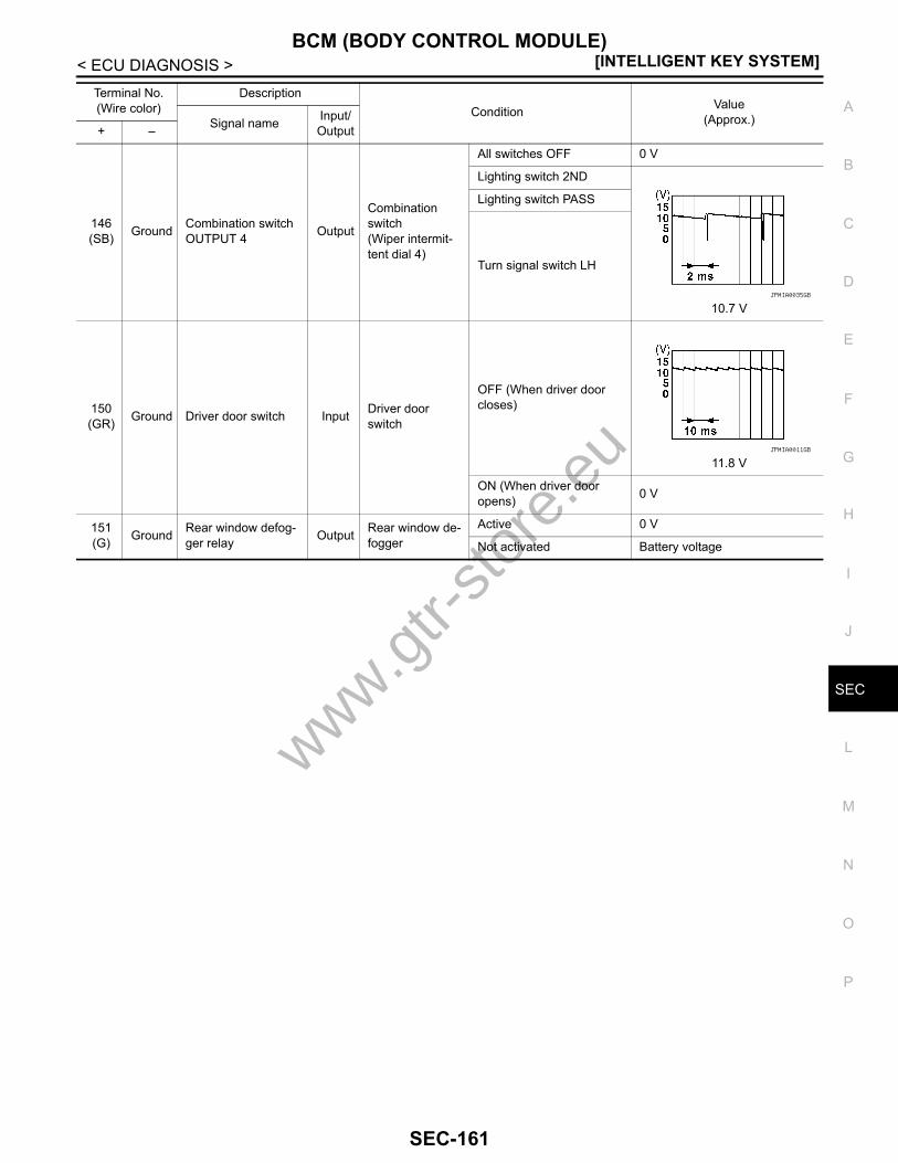
BCM (BODY CONTROL MODULE)[INTELLIGENT KEY SYSTEM]
C
D
E
F
G
H
I
J
L
M
A
B
EC
N
O
P
< ECU DIAGNOSIS >
S
146(SB) Ground Combination switch
OUTPUT 4 Output
Combination switch(Wiper intermit-tent dial 4)
All switches OFF 0 V
Lighting switch 2ND
10.7 V
Lighting switch PASS
Turn signal switch LH
150(GR) Ground Driver door switch Input Driver door
switch
OFF (When driver door closes)
11.8 V
ON (When driver door opens) 0 V
151(G) Ground Rear window defog-
ger relay Output Rear window de-fogger
Active 0 V
Not activated Battery voltage
Terminal No.(Wire color)
DescriptionCondition Value
(Approx.)Signal name Input/ Output+ –
JPMIA0035GB
JPMIA0011GB
www.gtr-
store
.eu
SEC-161
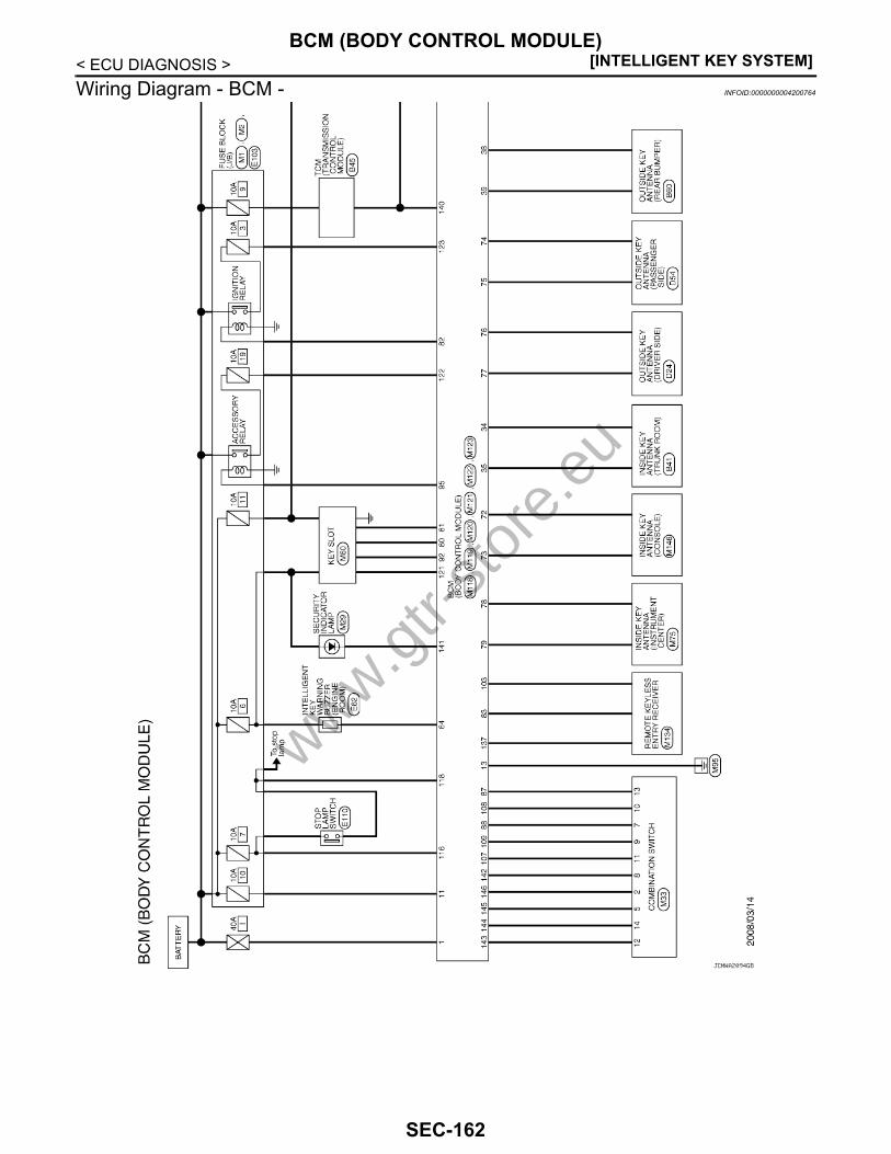
[INTELLIGENT KEY SYSTEM]BCM (BODY CONTROL MODULE)
< ECU DIAGNOSIS >Wiring Diagram - BCM - INFOID:0000000004200764
JCMWA2094GB
www.gtr-
store
.eu
SEC-162

BCM (BODY CONTROL MODULE)[INTELLIGENT KEY SYSTEM]
C
D
E
F
G
H
I
J
L
M
A
B
EC
N
O
P
< ECU DIAGNOSIS >
S
JCMWA2095GB
www.gtr-
store
.eu
SEC-163
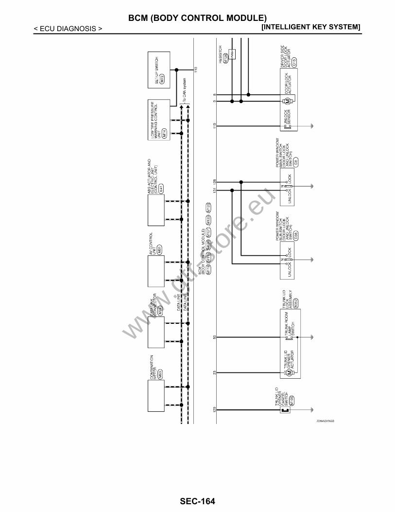
[INTELLIGENT KEY SYSTEM]BCM (BODY CONTROL MODULE)
< ECU DIAGNOSIS >
JCMWA2096GB
www.gtr-
store
.eu
SEC-164

BCM (BODY CONTROL MODULE)[INTELLIGENT KEY SYSTEM]
C
D
E
F
G
H
I
J
L
M
A
B
EC
N
O
P
< ECU DIAGNOSIS >
S
JCMWA2097GB
www.gtr-
store
.eu
SEC-165

[INTELLIGENT KEY SYSTEM]BCM (BODY CONTROL MODULE)
< ECU DIAGNOSIS >
JCMWA2098GB
www.gtr-
store
.eu
SEC-166

BCM (BODY CONTROL MODULE)[INTELLIGENT KEY SYSTEM]
C
D
E
F
G
H
I
J
L
M
A
B
EC
N
O
P
< ECU DIAGNOSIS >
S
Fail-safe INFOID:0000000004200765
FAIL-SAFE CONTROL BY DTCBCM performs fail-safe control when any DTC are detected.
JCMWA2099GB
www.gtr-
store
.eu
SEC-167

[INTELLIGENT KEY SYSTEM]BCM (BODY CONTROL MODULE)
< ECU DIAGNOSIS >
Display contents of CONSULT Fail-safe Cancellation
B2013: ID DISCORD BCM-S/L Inhibit engine cranking Erase DTC
B2014: CHAIN OF S/L-BCM Inhibit engine cranking Erase DTC
B2190: NATS ANTENNA AMP Inhibit engine cranking Erase DTC
B2191: DIFFERENCE OF KEY Inhibit engine cranking Erase DTC
B2192: ID DISCORD BCM-ECM Inhibit engine cranking Erase DTC
B2193: CHAIN OF BCM-ECM Inhibit engine cranking Erase DTC
B2557: VEHICLE SPEED Inhibit steering lock When normal vehicle speed signals are received from ABS actua-tor and electric unit (control unit) for 500 ms
B2560: STARTER CONT RELAY Inhibit engine cranking
500 ms after the following CAN signal communication status be-comes consistent• Starter control relay signal• Starter relay status signal
B2601: SHIFT POSITION Inhibit steering lock
500 ms after the following signal reception status becomes consis-tent• Selector lever P position switch signal• P range signal (CAN)
B2602: SHIFT POSITION Inhibit steering lock
5 seconds after the following BCM recognition conditions are ful-filled• Ignition switch is in the ON position• Selector lever P position switch signal: Except P position (battery
voltage)• Vehicle speed: 4 km/h (2.5 MPH) or more
B2603: SHIFT POSI STATUS Inhibit steering lock
500 ms after the following BCM recognition conditions are fulfilled• Ignition switch is in the ON position• Selector lever P position switch signal: Except P position (battery
voltage)• Selector lever P/N position signal: Except P and N positions (0 V)
B2604: PNP SW Inhibit steering lock
500 ms after any of the following BCM recognition conditions are fulfilled• Status 1- Ignition switch is in the ON position- Selector lever P/N position signal: P and N position (battery volt-
age)- P range signal or N range signal (CAN): ON• Status 2- Ignition switch is in the ON position- Selector lever P/N position signal: Except P and N positions (0 V)- P range signal and N range signal (CAN): OFF
B2605: PNP SW Inhibit steering lock
500 ms after any of the following BCM recognition conditions are fulfilled• Ignition switch is in the ON position- Power position: IGN- Selector lever P/N position signal: Except P and N positions (0 V)- Interlock/PNP switch signal (CAN): OFF• Status 2- Ignition switch is in the ON position- Selector lever P/N position signal: P or N position (battery volt-
age)- PNP switch signal (CAN): ON
B2606: S/L RELAY Inhibit engine cranking
500 ms after the following CAN signal communication status be-comes consistent• Steering lock relay signal (Request signal)• Steering lock relay signal (Condition signal)
B2607: S/L RELAY Inhibit engine cranking
500 ms after the following CAN signal communication status be-comes consistent• Steering lock relay signal (Request signal)• Steering lock relay signal (Condition signal)
www.gtr-
store
.eu
SEC-168

BCM (BODY CONTROL MODULE)[INTELLIGENT KEY SYSTEM]
C
D
E
F
G
H
I
J
L
M
A
B
EC
N
O
P
< ECU DIAGNOSIS >
S
HIGH FLASHER OPERATIONBCM detects the turn signal lamp circuit status by the current value.BCM increases the turn signal lamp blinking speed if the bulb or harness open is detected with the turn signallamp operating.NOTE:The blinking speed is normal while activating the hazard warning lamp.
DTC Inspection Priority Chart INFOID:0000000004200766
If some DTCs are displayed at the same time, perform inspections one by one based on the following prioritychart.
B2608: STARTER RELAY Inhibit engine cranking
500 ms after the following signal communication status becomes consistent• Starter motor relay control signal• Starter relay status signal (CAN)
B2609: S/L STATUS • Inhibit engine cranking• Inhibit steering lock
When the following steering lock conditions agree• BCM steering lock control status• Steering lock condition No. 1 signal status• Steering lock condition No. 2 signal status
B260A: IGNITION RELAY Inhibit engine cranking
500 ms after the following conditions are fulfilled• IGN relay (IPDM E/R) control signal: OFF (Battery voltage)• Ignition ON signal (CAN to IPDM E/R): OFF (Request signal)• Ignition ON signal (CAN from IPDM E/R): OFF (Condition signal)
B260F: ENG STATE SIG LOSTMaintains the power supply position attained at the time of DTC detection
When any of the following conditions are fulfilled• Power position changes to ACC• Receives engine status signal (CAN)
B2612: S/L STATUS • Inhibit engine cranking• Inhibit steering lock
When any of the following conditions are fulfilled• Steering lock unit status signal (CAN) is received normally• The BCM steering lock control status matches the steering lock
status recognized by the steering lock unit status signal (CAN from IPDM E/R)
B2617: STARTER RELAY CIRC Inhibit engine cranking 1 second after the starter motor relay control inside BCM becomes normal
B2618: BCM Inhibit engine cranking 1 second after the ignition relay (IPDM E/R) control inside BCM be-comes normal
B2619: BCM Inhibit engine cranking 1 second after the steering lock unit power supply output control in-side BCM becomes normal
B261E: VEHICLE TYPE Inhibit engine cranking BCM initialization
B26E1: ENG STATE NO RES Inhibit engine crankingWhen any of the following conditions are fulfilled• Power position changes to ACC• Receives engine status signal (CAN)
B26E9: S/L STATUS • Inhibit engine cranking• Inhibit steering lock
When BCM transmits the LOCK request signal to steering lock unit, and receives LOCK response signal from steering lock unit, the fol-lowing conditions are fulfilled• Steering condition No. 1 signal: LOCK (0 V)• Steering condition No. 2 signal: LOCK (Battery voltage)
Display contents of CONSULT Fail-safe Cancellation
Priority DTC
1 B2562: LOW VOLTAGE
2 • U1000: CAN COMM CIRCUIT• U1010: CONTROL UNIT (CAN)
3
• B2190: NATS ANTENNA AMP• B2191: DIFFERENCE OF KEY• B2192: ID DISCORD BCM-ECM• B2193: CHAIN OF BCM-ECM
www.gtr-
store
.eu
SEC-169

[INTELLIGENT KEY SYSTEM]BCM (BODY CONTROL MODULE)
< ECU DIAGNOSIS >
DTC Index INFOID:0000000004200767
NOTE:The details of time display are as follows.• CRNT: A malfunction is detected now.• PAST: A malfunction was detected in the past.IGN counter is displayed on Freeze Frame Data. For details of Freeze Frame Data, refer to BCS-16, "COM-MON ITEM : CONSULT-III Function (BCM - COMMON ITEM)".
4
• B2013: ID DISCORD BCM-S/L• B2014: CHAIN OF S/L-BCM• B2553: IGNITION RELAY• B2555: STOP LAMP • B2556: PUSH-BTN IGN SW• B2557: VEHICLE SPEED• B2560: STARTER CONT RELAY• B2601: SHIFT POSITION• B2602: SHIFT POSITION• B2603: SHIFT POSI STATUS• B2604: PNP SW• B2605: PNP SW• B2606: S/L RELAY• B2607: S/L RELAY• B2608: STARTER RELAY• B2609: S/L STATUS• B260A: IGNITION RELAY• B260B: STEERING LOCK UNIT• B260C: STEERING LOCK UNIT• B260D: STEERING LOCK UNIT• B260F: ENG STATE SIG LOST• B2612: S/L STATUS• B2614: ACC RELAY CIRC• B2615: BLOWER RELAY CIRC• B2616: IGN RELAY CIRC• B2617: STARTER RELAY CIRC• B2618: BCM• B2619: BCM• B261A: PUSH-BTN IGN SW• B261E: VEHICLE TYPE• B26E1: ENG STATE NO RES• B26E9: S/L STATUS• B26EA: KEY REGISTRATION• U0415: VEHICLE SPEED SIG
5• B2621: INSIDE ANTENNA • B2622: INSIDE ANTENNA • B2623: INSIDE ANTENNA
6 B26E7: TPMS CAN COMM
Priority DTC
CONSULT display Fail-safe
Freeze Frame Data•Vehicle Speed•Odo/Trip Meter
•Vehicle Condition
Intelligent Key warn-ing lamp ON Reference page
No DTC is detected.Further testingmay be required.
— — — —
U1000: CAN COMM CIRCUIT — — — BCS-34
U1010: CONTROL UNIT (CAN) — — — BCS-35
U0415: VEHICLE SPEED SIG — — — BCS-36
B2013: ID DISCORD BCM-S/L × × — SEC-49
B2014: CHAIN OF S/L-BCM × × — SEC-50
www.gtr-
store
.eu
SEC-170
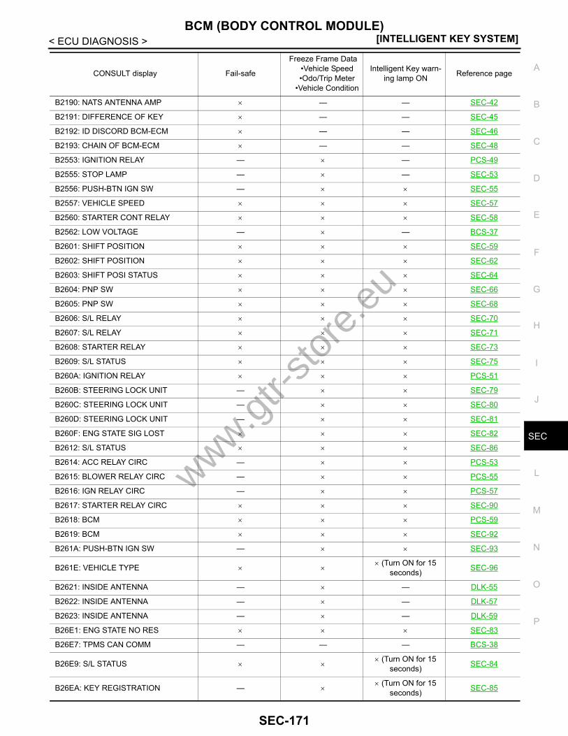
BCM (BODY CONTROL MODULE)[INTELLIGENT KEY SYSTEM]
C
D
E
F
G
H
I
J
L
M
A
B
EC
N
O
P
< ECU DIAGNOSIS >
S
B2190: NATS ANTENNA AMP × — — SEC-42
B2191: DIFFERENCE OF KEY × — — SEC-45
B2192: ID DISCORD BCM-ECM × — — SEC-46
B2193: CHAIN OF BCM-ECM × — — SEC-48
B2553: IGNITION RELAY — × — PCS-49
B2555: STOP LAMP — × — SEC-53
B2556: PUSH-BTN IGN SW — × × SEC-55
B2557: VEHICLE SPEED × × × SEC-57
B2560: STARTER CONT RELAY × × × SEC-58
B2562: LOW VOLTAGE — × — BCS-37
B2601: SHIFT POSITION × × × SEC-59
B2602: SHIFT POSITION × × × SEC-62
B2603: SHIFT POSI STATUS × × × SEC-64
B2604: PNP SW × × × SEC-66
B2605: PNP SW × × × SEC-68
B2606: S/L RELAY × × × SEC-70
B2607: S/L RELAY × × × SEC-71
B2608: STARTER RELAY × × × SEC-73
B2609: S/L STATUS × × × SEC-75
B260A: IGNITION RELAY × × × PCS-51
B260B: STEERING LOCK UNIT — × × SEC-79
B260C: STEERING LOCK UNIT — × × SEC-80
B260D: STEERING LOCK UNIT — × × SEC-81
B260F: ENG STATE SIG LOST × × × SEC-82
B2612: S/L STATUS × × × SEC-86
B2614: ACC RELAY CIRC — × × PCS-53
B2615: BLOWER RELAY CIRC — × × PCS-55
B2616: IGN RELAY CIRC — × × PCS-57
B2617: STARTER RELAY CIRC × × × SEC-90
B2618: BCM × × × PCS-59
B2619: BCM × × × SEC-92
B261A: PUSH-BTN IGN SW — × × SEC-93
B261E: VEHICLE TYPE × ×× (Turn ON for 15
seconds) SEC-96
B2621: INSIDE ANTENNA — × — DLK-55
B2622: INSIDE ANTENNA — × — DLK-57
B2623: INSIDE ANTENNA — × — DLK-59
B26E1: ENG STATE NO RES × × × SEC-83
B26E7: TPMS CAN COMM — — — BCS-38
B26E9: S/L STATUS × ×× (Turn ON for 15
seconds) SEC-84
B26EA: KEY REGISTRATION — ×× (Turn ON for 15
seconds) SEC-85
CONSULT display Fail-safe
Freeze Frame Data•Vehicle Speed•Odo/Trip Meter
•Vehicle Condition
Intelligent Key warn-ing lamp ON Reference page
www.gtr-
store
.eu
SEC-171

[INTELLIGENT KEY SYSTEM]IPDM E/R (INTELLIGENT POWER DISTRIBUTION MODULE ENGINE ROOM)
< ECU DIAGNOSIS >IPDM E/R (INTELLIGENT POWER DISTRIBUTION MODULE ENGINEROOM)Reference Value INFOID:0000000004201113
VALUES ON THE DIAGNOSIS TOOL
Monitor Item Condition Value/Status
RAD FAN REQ Engine idle speedChanges depending on engine coolant temperature, air conditioner operation status, vehicle speed, etc.
0 - 100 %
AC COMP REQ Engine runningA/C switch OFF Off
A/C switch ON(Compressor is operating) On
TAIL&CLR REQLighting switch OFF Off
Lighting switch 1ST, 2ND or HI On
HL LO REQLighting switch OFF Off
Lighting switch 2ND or HI On
HL HI REQLighting switch OFF Off
Lighting switch HI On
FR FOG REQ NOTE:The item is indicated, but not monitored. Off
FR WIP REQ Ignition switch ON
Front wiper switch OFF Stop
Front wiper switch INT 1LOW
Front wiper switch LO Low
Front wiper switch HI Hi
WIP AUTO STOP Ignition switch ONFront wiper stop position STOP P
Any position other than front wiper stop position ACT P
WIP PROT Ignition switch ONFront wiper operates normally Off
Front wiper stops at fail-safe operation BLOCK
IGN RLY1 -REQIgnition switch OFF or ACC Off
Ignition switch ON On
IGN RLYIgnition switch OFF or ACC Off
Ignition switch ON On
PUSH SWRelease the push-button ignition switch Off
Press the push-button ignition switch On
INTER/NP SWIgnition switch ON Shift lever in any position other than P
or N Off
Ignition switch ON Shift lever in P or N position On
ST RLY CONTIgnition switch ON Off
At engine cranking On
IHBT RLY -REQIgnition switch ON Off
At engine cranking On
ST/INHI RLY
Ignition switch ON Off
At engine cranking INHI → ST
The status of starter relay or starter control relay cannot be recognized by the battery voltage malfunction, etc. when the starter relay is ON and the starter control relay is OFF
UNKWN
www.gtr-
store
.eu
SEC-172

IPDM E/R (INTELLIGENT POWER DISTRIBUTION MODULE ENGINE ROOM)[INTELLIGENT KEY SYSTEM]
C
D
E
F
G
H
I
J
L
M
A
B
EC
N
O
P
< ECU DIAGNOSIS >
S
DETENT SWIgnition switch ON
• Press the knob button with shift le-ver in P position
• Shift lever in any position other than P
Off
Release the knob button with shift lever in P position On
S/L RLY -REQ
None of the conditions below are present Off
• Open the driver door after the ignition switch is turned OFF(for a few seconds)
• Press the push-button ignition switch when the steering lock is activatedOn
S/L STATE
Steering lock is activated LOCK
Steering lock is deactivated UNLOCK
[DTC: B210A] is detected UNKWN
DTRL REQNOTE:This item is monitored only on the ve-hicle with the daytime running light system.
Daytime running light system is not operated Off
Daytime running light system is operated On
OIL P SW NOTE:The item is indicated, but not monitored. Open
HOOD SWClose the hood Off
Open the hood On
HL WASHER REQ NOTE:The item is indicated, but not monitored. Off
THFT HRN REQNot operating Off
• Panic alarm is activated• Horn is activated with VEHICLE SECURITY (THEFT WARNING) SYSTEM On
HORN CHIRPNot operating Off
• Door locking with Intelligent Key (horn chirp mode)• Door locking with key fob (horn chirp mode) On
CRNRNG LMP REQ NOTE:The item is indicated, but not monitored. Off
Monitor Item Condition Value/Status
www.gtr-
store
.eu
SEC-173

[INTELLIGENT KEY SYSTEM]IPDM E/R (INTELLIGENT POWER DISTRIBUTION MODULE ENGINE ROOM)
< ECU DIAGNOSIS >TERMINAL LAYOUT
PHYSICAL VALUESJSMIA0001ZZ
Terminal No.(Wire color)
DescriptionCondition Value
(Approx.)Signal name Input/ Output+ −
1(W) Ground Battery power supply Input Ignition switch OFF Battery voltage
2(Y) Ground Battery power supply Input Ignition switch OFF Battery voltage
4(V) Ground Front wiper LO Output Ignition switch
ONFront wiper switch OFF 0 V
Front wiper switch LO Battery voltage
5(L) Ground Front wiper HI Output Ignition switch
ONFront wiper switch OFF 0 V
Front wiper switch HI Battery voltage
6*
(O)Ground Daytime running light relay
power supply InputIgnition switch OFF Battery voltage
Daytime running light system operated 0 V
7(R) Ground
Tail, rear side marker, li-cense plate lamps & illumi-nations
Output Ignition switch ON
Lighting switch OFF 0 V
Lighting switch 1ST Battery voltage
10(W) Ground ECM relay power supply Output
Ignition switch OFF(More than a few seconds after turning ignition switch OFF)
0 V
• Ignition switch ON• Ignition switch OFF
(For a few seconds after turning ignition switch OFF)
Battery voltage
www.gtr-
store
.eu
SEC-174
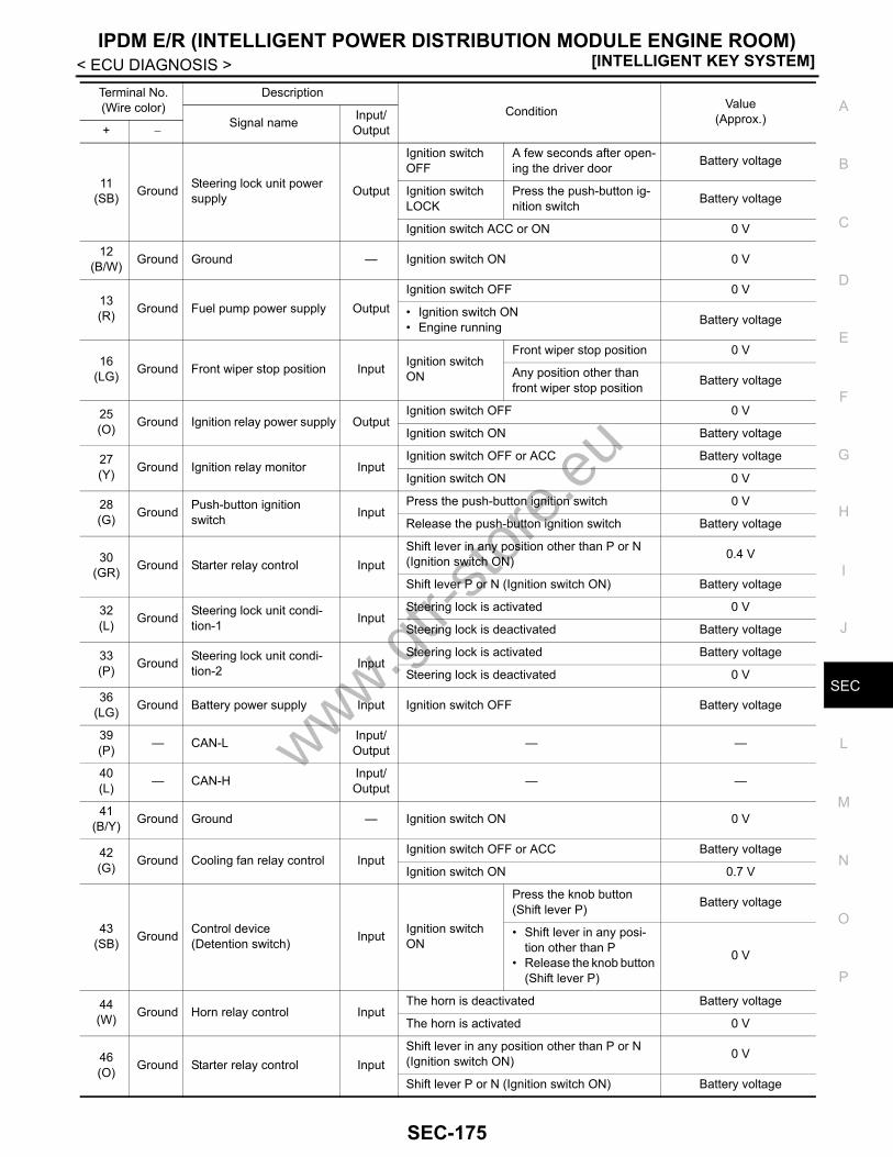
IPDM E/R (INTELLIGENT POWER DISTRIBUTION MODULE ENGINE ROOM)[INTELLIGENT KEY SYSTEM]
C
D
E
F
G
H
I
J
L
M
A
B
EC
N
O
P
< ECU DIAGNOSIS >
S
11(SB) Ground Steering lock unit power
supply Output
Ignition switch OFF
A few seconds after open-ing the driver door Battery voltage
Ignition switch LOCK
Press the push-button ig-nition switch Battery voltage
Ignition switch ACC or ON 0 V
12(B/W) Ground Ground — Ignition switch ON 0 V
13(R) Ground Fuel pump power supply Output
Ignition switch OFF 0 V
• Ignition switch ON• Engine running Battery voltage
16(LG) Ground Front wiper stop position Input Ignition switch
ON
Front wiper stop position 0 V
Any position other than front wiper stop position Battery voltage
25(O) Ground Ignition relay power supply Output
Ignition switch OFF 0 V
Ignition switch ON Battery voltage
27(Y) Ground Ignition relay monitor Input
Ignition switch OFF or ACC Battery voltage
Ignition switch ON 0 V
28(G) Ground Push-button ignition
switch InputPress the push-button ignition switch 0 V
Release the push-button ignition switch Battery voltage
30(GR) Ground Starter relay control Input
Shift lever in any position other than P or N(Ignition switch ON) 0.4 V
Shift lever P or N (Ignition switch ON) Battery voltage
32(L) Ground Steering lock unit condi-
tion-1 InputSteering lock is activated 0 V
Steering lock is deactivated Battery voltage
33(P) Ground Steering lock unit condi-
tion-2 InputSteering lock is activated Battery voltage
Steering lock is deactivated 0 V
36(LG) Ground Battery power supply Input Ignition switch OFF Battery voltage
39(P) — CAN-L Input/
Output — —
40(L) — CAN-H Input/
Output — —
41(B/Y) Ground Ground — Ignition switch ON 0 V
42(G) Ground Cooling fan relay control Input
Ignition switch OFF or ACC Battery voltage
Ignition switch ON 0.7 V
43(SB) Ground Control device
(Detention switch) Input Ignition switch ON
Press the knob button (Shift lever P) Battery voltage
• Shift lever in any posi-tion other than P
• Release the knob button (Shift lever P)
0 V
44(W) Ground Horn relay control Input
The horn is deactivated Battery voltage
The horn is activated 0 V
46(O) Ground Starter relay control Input
Shift lever in any position other than P or N(Ignition switch ON) 0 V
Shift lever P or N (Ignition switch ON) Battery voltage
Terminal No.(Wire color)
DescriptionCondition Value
(Approx.)Signal name Input/ Output+ −
www.gtr-
store
.eu
SEC-175

[INTELLIGENT KEY SYSTEM]IPDM E/R (INTELLIGENT POWER DISTRIBUTION MODULE ENGINE ROOM)
< ECU DIAGNOSIS >
48(L) Ground A/C relay power supply Output Engine running
A/C switch OFF 0 V
A/C switch ON(A/C compressor is oper-ating)
Battery voltage
49(P) Ground ECM relay power supply Output
Ignition switch OFF(More than a few seconds after turning ignition switch OFF)
0 V
• Ignition switch ON• Ignition switch OFF
(For a few seconds after turning ignition switch OFF)
Battery voltage
51(LG) Ground Ignition relay power supply Output
Ignition switch OFF 0 V
Ignition switch ON Battery voltage
53(SB) Ground ECM relay power supply Output
Ignition switch OFF(More than a few seconds after turning ignition switch OFF)
0 V
• Ignition switch ON• Ignition switch OFF
(For a few seconds after turning ignition switch OFF)
Battery voltage
54(W) Ground Throttle control motor re-
lay power supply Output
Ignition switch OFF(More than a few seconds after turning ignition switch OFF)
0 V
• Ignition switch ON• Ignition switch OFF
(For a few seconds after turning ignition switch OFF)
Battery voltage
55(O) Ground ECM power supply Output Ignition switch OFF Battery voltage
56(R) Ground Ignition relay power supply Output
Ignition switch OFF 0 V
Ignition switch ON Battery voltage
57(G) Ground Ignition relay power supply Output
Ignition switch OFF 0 V
Ignition switch ON Battery voltage
58(Y) Ground Ignition relay power supply Output
Ignition switch OFF 0 V
Ignition switch ON Battery voltage
69(O) Ground ECM relay control Output
Ignition switch OFF(More than a few seconds after turning ignition switch OFF)
Battery voltage
• Ignition switch ON• Ignition switch OFF
(For a few seconds after turning ignition switch OFF)
0 - 1.5 V
70(G) Ground Throttle control motor re-
lay control OutputIgnition switch ON → OFF
0 -1.0 V ↓
Battery voltage↓
0 V
Ignition switch ON 0 - 1.0 V
71(SB) Ground Ignition relay power supply Output
Ignition switch OFF 0 V
Ignition switch ON Battery voltage
Terminal No.(Wire color)
DescriptionCondition Value
(Approx.)Signal name Input/ Output+ −
www.gtr-
store
.eu
SEC-176

IPDM E/R (INTELLIGENT POWER DISTRIBUTION MODULE ENGINE ROOM)[INTELLIGENT KEY SYSTEM]
C
D
E
F
G
H
I
J
L
M
A
B
EC
N
O
P
< ECU DIAGNOSIS >
S
*: With daytime running light system
74(LG) Ground Ignition relay power supply Output
Ignition switch OFF 0 V
Ignition switch ON Battery voltage
77(B/W) Ground Fuel pump relay control Output • Ignition switch ON
• Engine running 0 V
80(W) Ground Starter motor Output At engine cranking Battery voltage
83(R) Ground Headlamp LO (RH) Output Ignition switch
ONLighting switch OFF 0 V
Lighting switch 2ND Battery voltage
84(P) Ground Headlamp LO (LH) Output Ignition switch
ONLighting switch OFF 0 V
Lighting switch 2ND Battery voltage
88(G) Ground Washer pump power sup-
ply Output Ignition switch ON Battery voltage
89(BR) Ground Headlamp HI (RH) Output
Ignition switch ON
• Lighting switch HI• Lighting switch PASS Battery voltage
Lighting switch OFF 0 V
Daytime running light system operated* 7.0 V
90(O) Ground Headlamp HI (LH) Output
Ignition switch ON
• Lighting switch HI• Lighting switch PASS Battery voltage
Lighting switch OFF 0 V
Daytime running light system operated* 7.0 V
91(O) Ground Parking lamp (RH) Output Ignition switch
ONLighting switch 1ST Battery voltage
Lighting switch OFF 0 V
92(R) Ground Parking lamp (LH) Output Ignition switch
ONLighting switch 1ST Battery voltage
Lighting switch OFF 0 V
93(V) Ground Front side marker lamp
(RH) Output Ignition switch ON
Lighting switch 1ST Battery voltage
Lighting switch OFF 0 V
94(G) Ground Front side marker lamp
(LH) Output Ignition switch ON
Lighting switch 1ST Battery voltage
Lighting switch OFF 0 V
97(Y) Ground Cooling fan control Output Engine idling 0 - 5 V
104(LG) Ground Hood switch Input
Close the hood Battery voltage
Open the hood 0 V
105*
(V)Ground Daytime running light relay
control Input Daytime running light system
Not operated Battery voltage
Operated 0 V
Terminal No.(Wire color)
DescriptionCondition Value
(Approx.)Signal name Input/ Output+ −
www.gtr-
store
.eu
SEC-177

[INTELLIGENT KEY SYSTEM]IPDM E/R (INTELLIGENT POWER DISTRIBUTION MODULE ENGINE ROOM)
< ECU DIAGNOSIS >Wiring Diagram - IPDM E/R - INFOID:0000000004201114
JCMWA2105GB
www.gtr-
store
.eu
SEC-178

IPDM E/R (INTELLIGENT POWER DISTRIBUTION MODULE ENGINE ROOM)[INTELLIGENT KEY SYSTEM]
C
D
E
F
G
H
I
J
L
M
A
B
EC
N
O
P
< ECU DIAGNOSIS >
S
JCMWA2106GB
www.gtr-
store
.eu
SEC-179
[INTELLIGENT KEY SYSTEM]IPDM E/R (INTELLIGENT POWER DISTRIBUTION MODULE ENGINE ROOM)
< ECU DIAGNOSIS >
JCMWA2107GB
www.gtr-
store
.eu
SEC-180

IPDM E/R (INTELLIGENT POWER DISTRIBUTION MODULE ENGINE ROOM)[INTELLIGENT KEY SYSTEM]
C
D
E
F
G
H
I
J
L
M
A
B
EC
N
O
P
< ECU DIAGNOSIS >
S
Fail-safe INFOID:0000000004201115
CAN COMMUNICATION CONTROLWhen CAN communication with ECM and BCM is impossible, IPDM E/R performs fail-safe control. After CANcommunication recovers normally, it also returns to normal control.If No CAN Communication Is Available With ECM
JCMWA2108GB
www.gtr-
store
.eu
SEC-181

[INTELLIGENT KEY SYSTEM]IPDM E/R (INTELLIGENT POWER DISTRIBUTION MODULE ENGINE ROOM)
< ECU DIAGNOSIS >
If No CAN Communication Is Available With BCM
*: With daytime running light system
IGNITION RELAY MALFUNCTION DETECTION FUNCTION• IPDM E/R monitors the voltage at the contact circuit and excitation coil circuit of the ignition relay inside it. • IPDM E/R judges the ignition relay error if the voltage differs between the contact circuit and the excitation
coil circuit.• If the ignition relay cannot turn OFF due to contact seizure, it activates the tail lamp relay and daytime run-
ning light relay* for 10 minutes to alert the user to the ignition relay malfunction when the ignition switch isturned OFF.
*: With daytime running light system
FRONT WIPER CONTROLIPDM E/R detects front wiper stop position by a front wiper stop position signal.When a front wiper stop position signal is in the conditions listed below, IPDM E/R stops power supply to wiperafter repeating a front wiper 10 seconds activation and 20 seconds stop five times.
Control part Fail-safe operation
Cooling fan• Outputs the pulse duty signal (PWM signal) 100% when the ignition switch is turned
ON• Outputs the pulse duty signal (PWM signal) 0% when the ignition switch is turned OFF
A/C compressor A/C relay OFF
Control part Fail-safe operation
Headlamp• Turns ON the headlamp low relay when the ignition switch is turned ON• Turns OFF the headlamp low relay when the ignition switch is turned OFF• Headlamp high relay OFF
• Parking lamps• License plate lamps• Side marker lamps• Illuminations• Tail lamps
• Turns ON the tail lamp relay and daytime running light relay* when the ignition switch is turned ON
• Turns OFF the tail lamp relay and daytime running light relay*when the ignition switch is turned OFF
Front wiper
• The status just before activation of fail-safe control is maintained until the ignition switch is turned OFF while the front wiper is operating at LO or HI speed.
• The wiper is operated at LO speed until the ignition switch is turned OFF if the fail-safe control is activated while the front wiper is set in the INT mode and the front wiper motor is operating.
Horn Horn OFF
Ignition relay The status just before activation of fail-safe is maintained.
Starter motor Starter control relay OFF
Steering lock unit Steering lock relay OFF
Voltage judgmentIPDM E/R judgment Operation
Ignition relay contact side Ignition relay excitation coil side
ON ON Ignition relay ON normal —
OFF OFF Ignition relay OFF normal —
ON OFF Ignition relay ON stuck• Detects DTC “B2098: IGN RELAY ON”• Turns ON the tail lamp relay and day-
time running light relay* for 10 minutes
OFF ON Ignition relay OFF stuck Detects DTC “B2099: IGN RELAY OFF”
www.gtr-
store
.eu
SEC-182
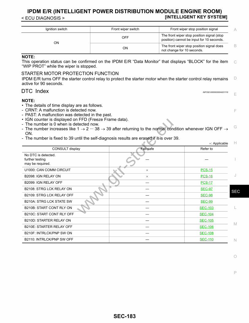
IPDM E/R (INTELLIGENT POWER DISTRIBUTION MODULE ENGINE ROOM)[INTELLIGENT KEY SYSTEM]
C
D
E
F
G
H
I
J
L
M
A
B
EC
N
O
P
< ECU DIAGNOSIS >
S
NOTE:This operation status can be confirmed on the IPDM E/R “Data Monitor” that displays “BLOCK” for the item“WIP PROT” while the wiper is stopped.
STARTER MOTOR PROTECTION FUNCTIONIPDM E/R turns OFF the starter control relay to protect the starter motor when the starter control relay remainsactive for 90 seconds.
DTC Index INFOID:0000000004201116
NOTE:• The details of time display are as follows.- CRNT: A malfunction is detected now.- PAST: A malfunction was detected in the past.• IGN counter is displayed on FFD (Freeze Frame data).- The number is 0 when is detected now.- The number increases like 1 → 2 ··· 38 → 39 after returning to the normal condition whenever IGN OFF →
ON.- The number is fixed to 39 until the self-diagnosis results are erased if it is over 39.
×: Applicable
Ignition switch Front wiper switch Front wiper stop position signal
ONOFF The front wiper stop position signal (stop
position) cannot be input for 10 seconds.
ON The front wiper stop position signal does not change for 10 seconds.
CONSULT display Fail-safe Refer to
No DTC is detected.further testingmay be required.
— —
U1000: CAN COMM CIRCUIT × PCS-15
B2098: IGN RELAY ON × PCS-16
B2099: IGN RELAY OFF — PCS-17
B2108: STRG LCK RELAY ON — SEC-97
B2109: STRG LCK RELAY OFF — SEC-98
B210A: STRG LCK STATE SW — SEC-99
B210B: START CONT RLY ON — SEC-103
B210C: START CONT RLY OFF — SEC-104
B210D: STARTER RELAY ON — SEC-105
B210E: STARTER RELAY OFF — SEC-106
B210F: INTRLCK/PNP SW ON — SEC-108
B2110: INTRLCK/PNP SW OFF — SEC-110
www.gtr-
store
.eu
SEC-183
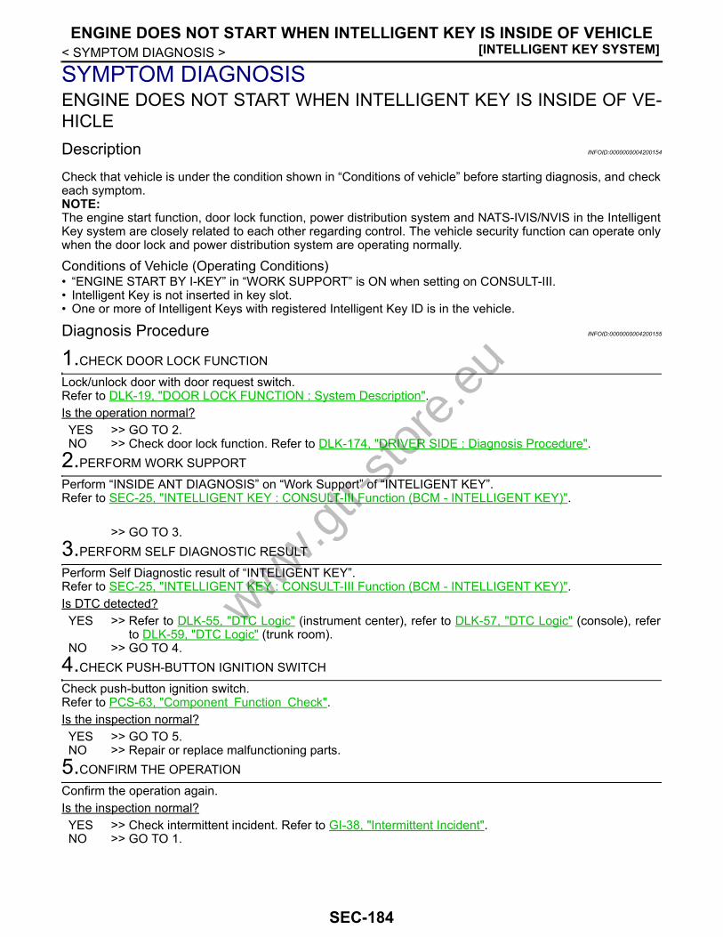
[INTELLIGENT KEY SYSTEM]ENGINE DOES NOT START WHEN INTELLIGENT KEY IS INSIDE OF VEHICLE
< SYMPTOM DIAGNOSIS >
SYMPTOM DIAGNOSISENGINE DOES NOT START WHEN INTELLIGENT KEY IS INSIDE OF VE-HICLEDescription INFOID:0000000004200154
Check that vehicle is under the condition shown in “Conditions of vehicle” before starting diagnosis, and checkeach symptom.NOTE:The engine start function, door lock function, power distribution system and NATS-IVIS/NVIS in the IntelligentKey system are closely related to each other regarding control. The vehicle security function can operate onlywhen the door lock and power distribution system are operating normally.
Conditions of Vehicle (Operating Conditions)• “ENGINE START BY I-KEY” in “WORK SUPPORT” is ON when setting on CONSULT-III.• Intelligent Key is not inserted in key slot.• One or more of Intelligent Keys with registered Intelligent Key ID is in the vehicle.
Diagnosis Procedure INFOID:0000000004200155
1.CHECK DOOR LOCK FUNCTION
Lock/unlock door with door request switch.Refer to DLK-19, "DOOR LOCK FUNCTION : System Description".Is the operation normal?YES >> GO TO 2.NO >> Check door lock function. Refer to DLK-174, "DRIVER SIDE : Diagnosis Procedure".
2.PERFORM WORK SUPPORT
Perform “INSIDE ANT DIAGNOSIS” on “Work Support” of “INTELIGENT KEY”.Refer to SEC-25, "INTELLIGENT KEY : CONSULT-III Function (BCM - INTELLIGENT KEY)".
>> GO TO 3.3.PERFORM SELF DIAGNOSTIC RESULT
Perform Self Diagnostic result of “INTELIGENT KEY”.Refer to SEC-25, "INTELLIGENT KEY : CONSULT-III Function (BCM - INTELLIGENT KEY)".Is DTC detected?YES >> Refer to DLK-55, "DTC Logic" (instrument center), refer to DLK-57, "DTC Logic" (console), refer
to DLK-59, "DTC Logic" (trunk room). NO >> GO TO 4.
4.CHECK PUSH-BUTTON IGNITION SWITCH
Check push-button ignition switch.Refer to PCS-63, "Component Function Check".Is the inspection normal?YES >> GO TO 5.NO >> Repair or replace malfunctioning parts.
5.CONFIRM THE OPERATION
Confirm the operation again.Is the inspection normal?YES >> Check intermittent incident. Refer to GI-38, "Intermittent Incident".NO >> GO TO 1.
www.gtr-
store
.eu
SEC-184
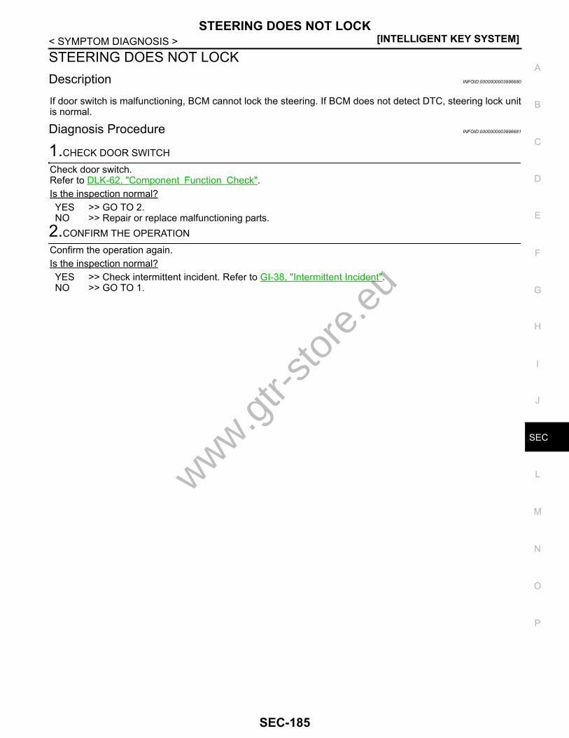
STEERING DOES NOT LOCK[INTELLIGENT KEY SYSTEM]
C
D
E
F
G
H
I
J
L
M
A
B
EC
N
O
P
< SYMPTOM DIAGNOSIS >
S
STEERING DOES NOT LOCKDescription INFOID:0000000003996680
If door switch is malfunctioning, BCM cannot lock the steering. If BCM does not detect DTC, steering lock unitis normal.
Diagnosis Procedure INFOID:0000000003996681
1.CHECK DOOR SWITCH
Check door switch.Refer to DLK-62, "Component Function Check".Is the inspection normal?YES >> GO TO 2.NO >> Repair or replace malfunctioning parts.
2.CONFIRM THE OPERATION
Confirm the operation again.Is the inspection normal?YES >> Check intermittent incident. Refer to GI-38, "Intermittent Incident".NO >> GO TO 1.
www.gtr-
store
.eu
SEC-185

[INTELLIGENT KEY SYSTEM]SECURITY INDICATOR LAMP DOES NOT TURN ON OR FLASH
< SYMPTOM DIAGNOSIS >SECURITY INDICATOR LAMP DOES NOT TURN ON OR FLASHDescription INFOID:0000000003996682
Check that vehicle is under the condition shown in “Conditions of vehicle” before starting diagnosis, and checkeach symptom.
Conditions of Vehicle (Operating Conditions)Ignition switch position is not in ON position.
Diagnosis Procedure INFOID:0000000003996683
1.CHECK SECURITY INDICATOR LAMP
Check security indicator lamp.Refer to SEC-117, "Component Function Check".Is the inspection result normal?YES >> GO TO 2.NO >> Repair or replace the malfunctioning parts.
2.CONFIRM THE OPERATION
Confirm the operation again.Is the result normal?YES >> Check intermittent incident. Refer to GI-38, "Intermittent Incident".NO >> GO TO 1.
www.gtr-
store
.eu
SEC-186

VEHICLE SECURITY SYSTEM CAN NOT BE SET[INTELLIGENT KEY SYSTEM]
C
D
E
F
G
H
I
J
L
M
A
B
EC
N
O
P
< SYMPTOM DIAGNOSIS >
S
VEHICLE SECURITY SYSTEM CAN NOT BE SETINTELLIGENT KEYINTELLIGENT KEY : Description INFOID:0000000003996684
Check that vehicle is under the condition shown in “Conditions of vehicle” before starting diagnosis, and checkeach symptom.
Conditions of Vehicle (Operating Conditions)“SECURITY ALARM SET” in “WORK SUPPORT” is ON when setting on CONSULT-III.
INTELLIGENT KEY : Diagnosis Procedure INFOID:0000000003996685
1.CHECK INTELLIGENT KEY SYSTEM (REMOTE KEYLESS ENTRY FUNCTION)
Lock/unlock door with Intelligent Key.Refer to DLK-28, "REMOTE KEYLESS ENTRY FUNCTION : System Description".Is the inspection normal?YES >> GO TO 2.NO >> Check Intelligent Key system. Refer to DLK-172, "Diagnosis Procedure".
2.CONFIRM THE OPERATION
Confirm the operation again.Is the result normal?YES >> Check intermittent incident. Refer to GI-38, "Intermittent Incident".NO >> GO TO 1.
DOOR REQUEST SWITCHDOOR REQUEST SWITCH : Description INFOID:0000000003996686
Check that vehicle is under the condition shown in “Conditions of vehicle” before starting diagnosis, and checkeach symptom.
Conditions of Vehicle (Operating Conditions)“SECURITY ALARM SET” in “WORK SUPPORT” is ON when setting on CONSULT-III.
DOOR REQUEST SWITCH : Diagnosis Procedure INFOID:0000000003996687
1.CHECK INTELLIGENT KEY SYSTEM (DOOR LOCK FUNCTION)
Lock/unlock door with door request switch.Refer to DLK-19, "DOOR LOCK FUNCTION : System Description".Is the inspection normal?YES >> GO TO 2.NO >> Check Intelligent Key system. Refer to DLK-174, "DRIVER SIDE : Diagnosis Procedure".
2.CONFIRM THE OPERATION
Confirm the operation again.Is the result normal?YES >> Check intermittent incident. Refer to GI-38, "Intermittent Incident".NO >> GO TO 1.
www.gtr-
store
.eu
SEC-187

[INTELLIGENT KEY SYSTEM]VEHICLE SECURITY ALARM DOES NOT ACTIVATE
< SYMPTOM DIAGNOSIS >VEHICLE SECURITY ALARM DOES NOT ACTIVATEDescription INFOID:0000000003996690
Check that vehicle is under the condition shown in “Conditions of vehicle” before starting diagnosis, and checkeach symptom.
Conditions of Vehicle (Operating Conditions)“SECURITY ALARM SET” in “WORK SUPPORT” of “THEFT ALM” is ON when setting on CONSULT-III.
Diagnosis Procedure INFOID:0000000003996691
1.CHECK CONDITION OF ALARM
Operate alarm.Which alarm does not operate?Headlamp and horn>>GO TO 2.Headlamp>>GO TO 3.Horn >> GO TO 4.
2.CHECK DOOR SWITCH
Check door switch.Refer to DLK-62, "Component Function Check".Is the inspection result normal?YES >> GO TO 6.NO >> Replace the malfunctioning door switch
3.CHECK HEADLAMP
Check headlamp operation.Refer to SEC-116, "Component Function Check".Is the inspection result normal?YES >> GO TO 6.NO >> Repair or replace malfunctioning parts.
4.CHECK HORN
Check horn.Refer to DLK-97, "Component Function Check".Is the inspection result normal?YES >> GO TO 5.NO >> Repair or replace malfunctioning parts.
5.CHECK VEHICLE SECURITY HORN
Check vehicle security horn.Refer to DLK-99, "Component Function Check".Is the inspection result normal?YES >> GO TO 6.NO >> Repair or replace malfunctioning parts.
6.CONFIRM THE OPERATION
Confirm the operation again.Is the result normal?YES >> Check intermittent incident. Refer to GI-38, "Intermittent Incident".NO >> GO TO 1.
www.gtr-
store
.eu
SEC-188
KEY SLOT INDICATOR DOES NOT ILLUMINATE[INTELLIGENT KEY SYSTEM]
C
D
E
F
G
H
I
J
L
M
A
B
EC
N
O
P
< SYMPTOM DIAGNOSIS >
S
KEY SLOT INDICATOR DOES NOT ILLUMINATEDiagnosis Procedure INFOID:0000000003996692
1.CHECK KEY SLOT INDICATOR
Check key slot indicator.Refer to DLK-95, "Component Function Check".Is the inspection normal?YES >> GO TO 2.NO >> Repair or replace malfunctioning parts.
2.CONFIRM THE OPERATION
Confirm the operation again.Is the inspection normal?YES >> Check intermittent incident. Refer to GI-38, "Intermittent Incident".NO >> GO TO 1.
www.gtr-
store
.eu
SEC-189

[INTELLIGENT KEY SYSTEM]PRECAUTIONS
< PRECAUTION >
PRECAUTIONPRECAUTIONSPrecaution for Supplemental Restraint System (SRS) "AIR BAG" and "SEAT BELT PRE-TENSIONER" INFOID:0000000004174839
The Supplemental Restraint System such as “AIR BAG” and “SEAT BELT PRE-TENSIONER”, used alongwith a front seat belt, helps to reduce the risk or severity of injury to the driver and front passenger for certaintypes of collision. This system includes seat belt switch inputs and dual stage front air bag modules. The SRSsystem uses the seat belt switches to determine the front air bag deployment, and may only deploy one frontair bag, depending on the severity of a collision and whether the front occupants are belted or unbelted.Information necessary to service the system safely is included in the “SRS AIRBAG” and “SEAT BELT” of thisService Manual.WARNING:• To avoid rendering the SRS inoperative, which could increase the risk of personal injury or death in
the event of a collision which would result in air bag inflation, all maintenance must be performed byan authorized NISSAN/INFINITI dealer.
• Improper maintenance, including incorrect removal and installation of the SRS, can lead to personalinjury caused by unintentional activation of the system. For removal of Spiral Cable and Air BagModule, see the “SRS AIRBAG”.
• Never use electrical test equipment on any circuit related to the SRS unless instructed to in this Ser-vice Manual. SRS wiring harnesses can be identified by yellow and/or orange harnesses or harnessconnectors.
Precaution for Procedure without Cowl Top Cover INFOID:0000000004174840
When performing the procedure after removing cowl top cover, coverthe lower end of windshield with urethane, etc.
Precaution Necessary for Steering Wheel Rotation after Battery DisconnectINFOID:0000000004174842
NOTE:• Before removing and installing any control units, first turn the push-button ignition switch to the LOCK posi-
tion, then disconnect both battery cables.• After finishing work, confirm that all control unit connectors are connected properly, then re-connect both
battery cables.• Always use CONSULT-III to perform self-diagnosis as a part of each function inspection after finishing work.
If a DTC is detected, perform trouble diagnosis according to self-diagnosis results.This vehicle is equipped with a push-button ignition switch and a steering lock unit.If the battery is disconnected or discharged, the steering wheel will lock and cannot be turned.If turning the steering wheel is required with the battery disconnected or discharged, follow the procedurebelow before starting the repair operation.
OPERATION PROCEDURE1. Connect both battery cables.
NOTE:Supply power using jumper cables if battery is discharged.
2. Turn the push-button ignition switch to ACC position.(At this time, the steering lock will be released.)
PIIB3706J
www.gtr-
store
.eu
SEC-190

PRECAUTIONS[INTELLIGENT KEY SYSTEM]
C
D
E
F
G
H
I
J
L
M
A
B
EC
N
O
P
< PRECAUTION >
S
3. Disconnect both battery cables. The steering lock will remain released with both battery cables discon-nected and the steering wheel can be turned.
4. Perform the necessary repair operation.5. When the repair work is completed, re-connect both battery cables. With the brake pedal released, turn
the push-button ignition switch from ACC position to ON position, then to LOCK position. (The steeringwheel will lock when the push-button ignition switch is turned to LOCK position.)
6. Perform self-diagnosis check of all control units using CONSULT-III.
Precaution for Battery Service INFOID:0000000004174844
Before disconnecting the battery, lower both the driver and passenger windows. This will prevent any interfer-ence between the window edge and the vehicle when the door is opened/closed. During normal operation, thewindow slightly raises and lowers automatically to prevent any window to vehicle interference. The automaticwindow function will not work with the battery disconnected.
www.gtr-
store
.eu
SEC-191
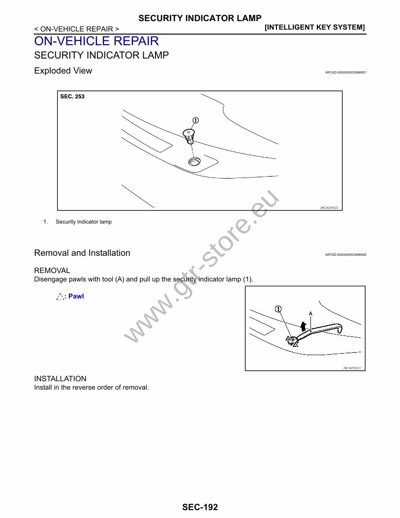
[INTELLIGENT KEY SYSTEM]SECURITY INDICATOR LAMP
< ON-VEHICLE REPAIR >
ON-VEHICLE REPAIRSECURITY INDICATOR LAMPExploded View INFOID:0000000003996667
Removal and Installation INFOID:0000000003996668
REMOVALDisengage pawls with tool (A) and pull up the security indicator lamp (1).
INSTALLATIONInstall in the reverse order of removal.
1. Security indicator lamp
JMKIA2993ZZ
: Pawl
JMKIA2994ZZ
www.gtr-
store
.eu
SEC-192
Related Documents