B1-1 07-09 TABLE OF CONTENTS FEATURES AND BENEFITS . . . . . . . . . . . . . . . . . . . . . . . . . . . . . . . . . . . . . . . . . . . . . . . . . . B1-3 PRODUCT OFFERING . . . . . . . . . . . . . . . . . . . . . . . . . . . . . . . . . . . . . . . . . . . . . . . . . . . . . . B1-4 Standard Equipment . . . . . . . . . . . . . . . . . . . . . . . . . . . . . . . . . . . . . . . . . . . . . . . . . . . . B1-5 Optional Equipment . . . . . . . . . . . . . . . . . . . . . . . . . . . . . . . . . . . . . . . . . . . . . . . . . . . . . B1-5 DIMENSIONS AND RATINGS . . . . . . . . . . . . . . . . . . . . . . . . . . . . . . . . . . . . . . . . . . . . . . . . . B1-12 PERFORMANCE DATA . . . . . . . . . . . . . . . . . . . . . . . . . . . . . . . . . . . . . . . . . . . . . . . . . . . . . B1-12 Efficiency . . . . . . . . . . . . . . . . . . . . . . . . . . . . . . . . . . . . . . . . . . . . . . . . . . . . . . . . . . . . B1-12 Emissions . . . . . . . . . . . . . . . . . . . . . . . . . . . . . . . . . . . . . . . . . . . . . . . . . . . . . . . . . . . . B1-12 ENGINEERING DATA . . . . . . . . . . . . . . . . . . . . . . . . . . . . . . . . . . . . . . . . . . . . . . . . . . . . . . B1-13 Boiler Information . . . . . . . . . . . . . . . . . . . . . . . . . . . . . . . . . . . . . . . . . . . . . . . . . . . . . . B1-13 Burner/Control Information . . . . . . . . . . . . . . . . . . . . . . . . . . . . . . . . . . . . . . . . . . . . . . . . B1-15 Outdoor Reset Control . . . . . . . . . . . . . . . . . . . . . . . . . . . . . . . . . . . . . . . . . . . . . . . . . . . B1-18 SAMPLE SPECIFICATIONS . . . . . . . . . . . . . . . . . . . . . . . . . . . . . . . . . . . . . . . . . . . . . . . . . . . B1-21 Steam . . . . . . . . . . . . . . . . . . . . . . . . . . . . . . . . . . . . . . . . . . . . . . . . . . . . . . . . . . . . . . . B1-21 Hot Water . . . . . . . . . . . . . . . . . . . . . . . . . . . . . . . . . . . . . . . . . . . . . . . . . . . . . . . . . . . . B1-27 Section B1 Flexible Watertube Boilers

Welcome message from author
This document is posted to help you gain knowledge. Please leave a comment to let me know what you think about it! Share it to your friends and learn new things together.
Transcript
B1-107-09
TABLE OF CONTENTS
FEATURES AND BENEFITS . . . . . . . . . . . . . . . . . . . . . . . . . . . . . . . . . . . . . . . . . . . . . . . . . . B1-3PRODUCT OFFERING . . . . . . . . . . . . . . . . . . . . . . . . . . . . . . . . . . . . . . . . . . . . . . . . . . . . . . B1-4
Standard Equipment . . . . . . . . . . . . . . . . . . . . . . . . . . . . . . . . . . . . . . . . . . . . . . . . . . . . B1-5Optional Equipment . . . . . . . . . . . . . . . . . . . . . . . . . . . . . . . . . . . . . . . . . . . . . . . . . . . . . B1-5
DIMENSIONS AND RATINGS . . . . . . . . . . . . . . . . . . . . . . . . . . . . . . . . . . . . . . . . . . . . . . . . . B1-12PERFORMANCE DATA . . . . . . . . . . . . . . . . . . . . . . . . . . . . . . . . . . . . . . . . . . . . . . . . . . . . . B1-12
Efficiency . . . . . . . . . . . . . . . . . . . . . . . . . . . . . . . . . . . . . . . . . . . . . . . . . . . . . . . . . . . . B1-12Emissions . . . . . . . . . . . . . . . . . . . . . . . . . . . . . . . . . . . . . . . . . . . . . . . . . . . . . . . . . . . . B1-12
ENGINEERING DATA . . . . . . . . . . . . . . . . . . . . . . . . . . . . . . . . . . . . . . . . . . . . . . . . . . . . . . B1-13Boiler Information . . . . . . . . . . . . . . . . . . . . . . . . . . . . . . . . . . . . . . . . . . . . . . . . . . . . . . B1-13Burner/Control Information . . . . . . . . . . . . . . . . . . . . . . . . . . . . . . . . . . . . . . . . . . . . . . . . B1-15Outdoor Reset Control . . . . . . . . . . . . . . . . . . . . . . . . . . . . . . . . . . . . . . . . . . . . . . . . . . . B1-18
SAMPLE SPECIFICATIONS . . . . . . . . . . . . . . . . . . . . . . . . . . . . . . . . . . . . . . . . . . . . . . . . . . . B1-21Steam . . . . . . . . . . . . . . . . . . . . . . . . . . . . . . . . . . . . . . . . . . . . . . . . . . . . . . . . . . . . . . . B1-21Hot Water . . . . . . . . . . . . . . . . . . . . . . . . . . . . . . . . . . . . . . . . . . . . . . . . . . . . . . . . . . . . B1-27
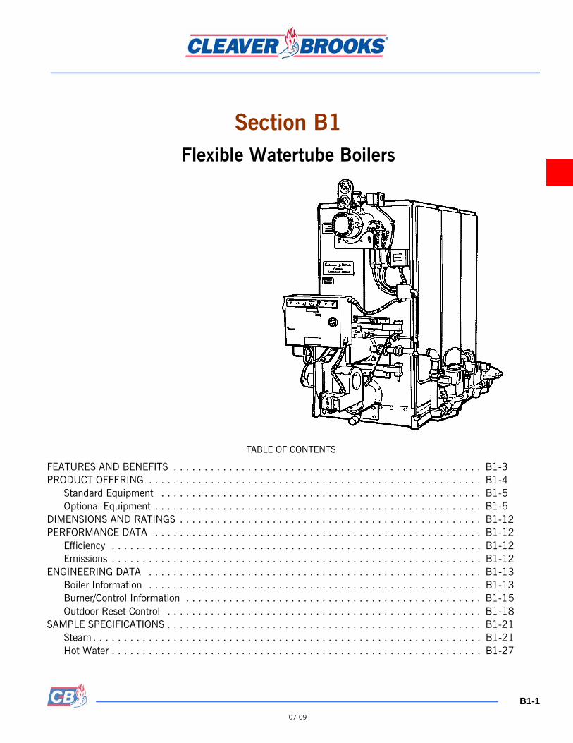
Section B1Flexible Watertube Boilers

Model FLX Boilers Commercial Boilers
B1-2
07-09
IllustrationsFigure B1-1. Model FLX Hot Water Boiler Dimensions (1 of 2) . . . . . . . . . . . . . . . . . . . . . . . . . . B1-8Figure B1-2. Model FLX Steam Boiler Dimensions (1 of 2) . . . . . . . . . . . . . . . . . . . . . . . . . . . . . B1-10Figure B1-3. Model FLX Tube Attachment . . . . . . . . . . . . . . . . . . . . . . . . . . . . . . . . . . . . . . . . B1-13Figure B1-4. Model FLX Oil Burner Supply Pump Installation . . . . . . . . . . . . . . . . . . . . . . . . . . . B1-16Figure B1-5. Model FLX Clearance Requirements . . . . . . . . . . . . . . . . . . . . . . . . . . . . . . . . . . . B1-17Figure B1-6. Model FLX Breeching Arrangement - Single or Multiple Boiler Installation . . . . . . . . . B1-19
TABLESTable B1-1. Model FLX Watertube Boiler Sizes . . . . . . . . . . . . . . . . . . . . . . . . . . . . . . . . . . . . . B1-4Table B1-2. Model FLX Hot Water Boiler Ratings . . . . . . . . . . . . . . . . . . . . . . . . . . . . . . . . . . . B1-7Table B1-3. Model FLX Steam Boiler Ratings . . . . . . . . . . . . . . . . . . . . . . . . . . . . . . . . . . . . . . B1-7Table B1-4. Expected Emissions (ppm, corrected to 3% O2), Natural Gas Fired Boiler . . . . . . . . . . B1-12Table B1-5. Model FLX Hot Water Boiler Flow Rates and Pressure Drops . . . . . . . . . . . . . . . . . . B1-12Table B1-6. Model FLX Circulating Rates, Hot Water Boiler . . . . . . . . . . . . . . . . . . . . . . . . . . . . B1-14Table B1-7. Model FLXMinimum Over Pressure Requirements . . . . . . . . . . . . . . . . . . . . . . . . . . B1-14Table B1-8. Model FLX Boiler Heat Release Information . . . . . . . . . . . . . . . . . . . . . . . . . . . . . . B1-14Table B1-9. Model FLX Burner Characteristics . . . . . . . . . . . . . . . . . . . . . . . . . . . . . . . . . . . . . B1-15Table B1-10. Model FLX Minimum Required Gas Pressure . . . . . . . . . . . . . . . . . . . . . . . . . . . . . B1-15Table B1-11. Model FLX Sound Levels . . . . . . . . . . . . . . . . . . . . . . . . . . . . . . . . . . . . . . . . . . B1-17Table B1-12. Model FLX Combustion Air Requirements . . . . . . . . . . . . . . . . . . . . . . . . . . . . . . . B1-19
This section contains information on the Flexible Watertube boiler. The product model name is “FLX” for factory-assem-bled boilers, and “FLE” for field-erectable boilers. It is available in sizes ranging from 1.5 to 12 MMBtu/hr input.
Cleaver-Brooks offers the Model FLX “bent-tube” boiler to meet today’s demanding commercial user’s needs. The flexible watertube design has distinct advantages, including resistance to thermal shock and easy boiler maintenance. In addition Model FLX boilers offer high operating efficiency. These combined factors equate to a real increase on the return from your boiler room investment.
Commercial Boilers Model FLX Boilers
B1-3
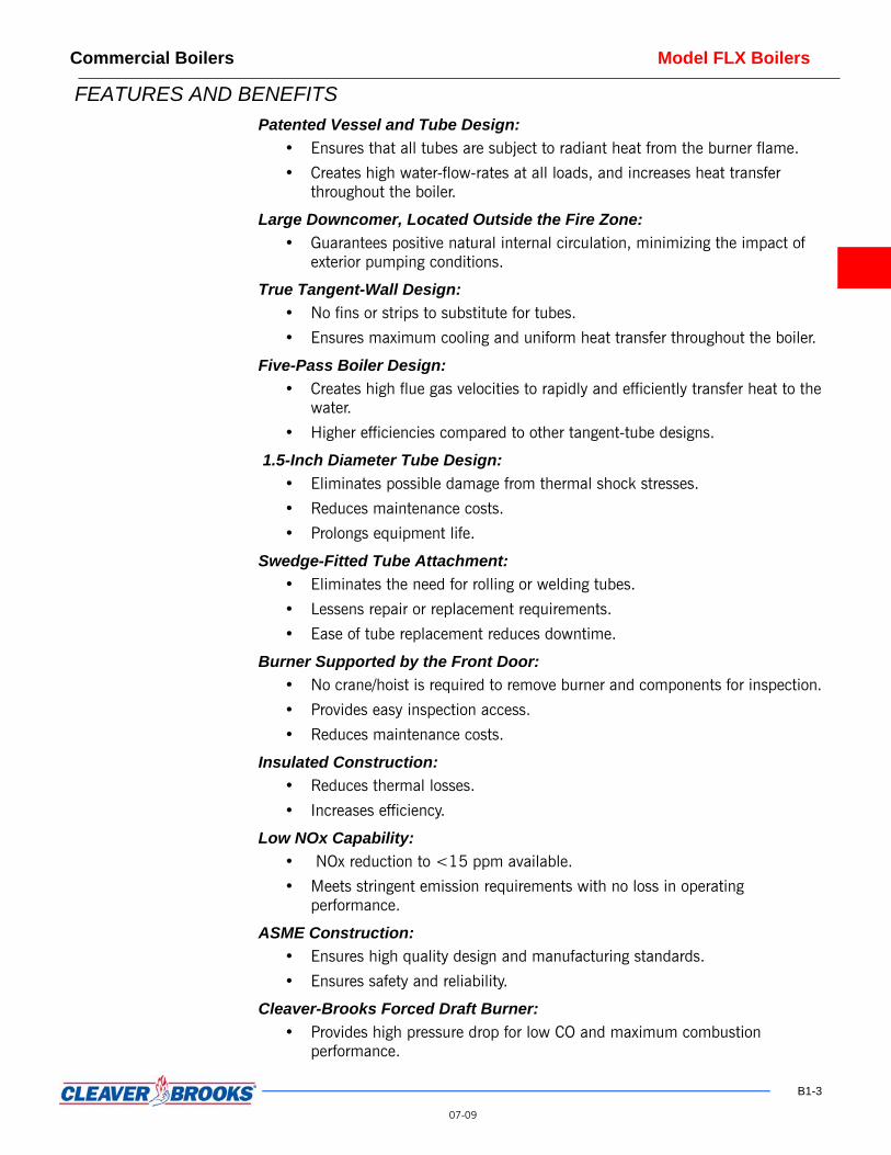
FEATURES AND BENEFITS Patented Vessel and Tube Design:
• Ensures that all tubes are subject to radiant heat from the burner flame.
• Creates high water-flow-rates at all loads, and increases heat transfer throughout the boiler.
Large Downcomer, Located Outside the Fire Zone: • Guarantees positive natural internal circulation, minimizing the impact of
exterior pumping conditions.
True Tangent-Wall Design: • No fins or strips to substitute for tubes.
• Ensures maximum cooling and uniform heat transfer throughout the boiler.
Five-Pass Boiler Design: • Creates high flue gas velocities to rapidly and efficiently transfer heat to the
water.
• Higher efficiencies compared to other tangent-tube designs.
1.5-Inch Diameter Tube Design: • Eliminates possible damage from thermal shock stresses.
• Reduces maintenance costs.
• Prolongs equipment life.
Swedge-Fitted Tube Attachment: • Eliminates the need for rolling or welding tubes.
• Lessens repair or replacement requirements.
• Ease of tube replacement reduces downtime.
Burner Supported by the Front Door: • No crane/hoist is required to remove burner and components for inspection.
• Provides easy inspection access.
• Reduces maintenance costs.
Insulated Construction: • Reduces thermal losses.
• Increases efficiency.
Low NOx Capability: • NOx reduction to <15 ppm available.
• Meets stringent emission requirements with no loss in operating performance.
ASME Construction: • Ensures high quality design and manufacturing standards.
• Ensures safety and reliability.
Cleaver-Brooks Forced Draft Burner: • Provides high pressure drop for low CO and maximum combustion
performance.
07-09

Model FLX Boilers Commercial Boilers
• Reduces stack draft requirements.
• Optimum fuel and air mixing.
• Long-life reverse curve impeller.
• Ensures maximum combustion efficiency, as low as 10% excess air.
• Burner/Boiler by single manufacturer.
Removable Side Panels:• Provides easy access for inspection.
• Reduces maintenance costs.
• Ensures containment of furnace gases.
• Rugged construction for durability.
20-Year Pressure Vessel Warranty: • Guaranteed to last.
• Backed by Cleaver-Brooks.
Field Erectable (Optional): • Complete package for ease of assembly.
• Pieces fit through standard doorway.
PRODUCT OFFERING Information in this section applies to steam and hot water boiler sizes ranging from1.5 to 12 MMBtu/hr input, as shown in Table B1-1
The Flexible Watertube Boiler is a five-pass steel boiler with flexible tubes formedand arranged to direct the flow of combustion gases through the boiler. The pressurevessel conforms to Section I or Section IV of the ASME Code, and consists of the
B1-4
Table B1-1. Model FLX Watertube Boiler Sizes
07-09
MODELCAPACITY
INPUT BTU/HR
HEAT OUTPUT BTU/HR
EQUIVHP
FLX-150 1,500,000 1,200,000 36FLX-200 2,000,000 1,600,000 48FLX-250 2,500,000 2,000,000 60FLX-300 3,000,000 2,400,000 72FLX-350 3,500,000 2,800,000 84FLX-400 4,000,000 3,200,000 96FLX-450 4,500,000 3,600,000 108FLX-500 5,000,000 4,000,000 119FLX-550 5,500,000 4,400,000 132FLX-600 6,000,000 4,800,000 143FLX-700 7,000,000 5,600,000 167FLX-800 8,000,000 6,400,000 191FLX-900 9,000,000 7,200,000 215
FLX-1000 10,000,000 8,000,000 239FLX-1100 11,000,000 8,800,000 263FLX-1200 12,000,000 9,600,000 287
NOTES:
1. Design Pressure: 150 psig Hot Water, 15 psig Steam, 150 psig Steam.2. Also available in Model FLE (field erectable).

Commercial Boilers Model FLX Boilers
formed tubes and the external downcomer connected to the top and bottom drums.The heated area of the pressure vessel is contained within a gas-tight, insulatedcasing that is composed of removable, formed-steel panels. The boiler/burnerpackage is manufactured by Cleaver-Brooks and UL/cUL approved as a package.
Standard Equipment Equipment described below is for the standard boiler offering.
1. Boiler: A. All boilers are designed and constructed in accordance with the ASME Code
and are mounted on an integral frame. All refractories for boiler and burnerare installed.
B. Factory fire test. 2. Cleaver-Brooks ProFire™ Forced Draft Burner:
A. Mounted on a hinged backing plate for easy access to furnace. B. Pressure atomizing type for No. 2 oil burner. This includes the oil pump. C. Stainless steel flame-retention type combustion head for gas, with UV
scanner, and gas pressure regulator. D. External access to flame scanner for ease of maintenance.
3. Water/Steam Controls: A. ASME safety relief valve(s). B. Pressure and temperature gauges for hot water boilers. C. Pressure gauge for steam boilers. D. Operating and limit controls: E. High limit control - manual reset. F. Operating limit control - automatic reset. G. Modulating or proportional controller. H. Low water cutoff: I. Probe type - hot water. J. Float type main and probe type auxiliary- steam. K. Pump Control - steam boilers.
NoticeHot water boilers with design pressures up to 150 psig, and with design temperatures less than 250 °F, are constructed under Section IV of the ASME Code, and ’H’ stamped for low- pressure heating boilers.
NoticeSteam boilers with design pressure of 30 psig, and maximum allowable operating pressure of 15 psig, are constructed under Section IV of the ASME Code, and ’H’ stamped for low pressure heating boilers.
NoticeSteam boilers with design pressure of 150 psig are constructed under Section I of the ASME code and “S” stamped for high pressure steam boilers.
4. Altitude: Standard boilers attain full ratings at altitudes up to 2,000 feet. Altitude compensation for most models is available for altitudes up to 10,000 ft above sea level.
Optional Equipment For option details, contact your local Cleaver-Brooks authorized representative. Insummary, options include the following:
B1-5
07-09

Model FLX Boilers Commercial Boilers
1. Boiler Options
• Auxiliary low water cut-off (hot water).
• Stack thermometer.
• Insulated downcomer(s).
• Drain valves.
• Additional screwed tappings.
• Packaged for field erection.
2. Burner/Control Options
• Special burner modulation controls.
• Low NOx burner.
• Optional flame safeguard controller.
• Lead/lag system.
• High altitude design - up to 10,000 ft.
• Special insurance and code requirements (e.g., IRI, FM, ASME CSD-1).
• Alarm bell/silence switch.
• Special motor requirements (TEFC, high efficiency).
• Remote contacts.
• Additional relay points and indicator lights.
• Main disconnect (fusible/circuit breaker).
• Elapsed time meter.
• Voltmeter/micro-ammeter.
• NEMA enclosures.
• Key lock panel.
• System pump interlock.
• Low fire hold controls.
• Assured low fire cut-off.
• Flow switches.
• High stack temperature cut-off/alarm.
• Remote emergency shutoff (115V).
3. Fuel Options
• Special gas pressure regulator.
• Oversized gas trains.
• Gas strainer.
• Special fuel shut-off valves.
• Remote oil pump set.
• Special pilot.
• Direct spark oil ignition.
• Automatic fuel changeover.
B1-6
07-09

Commercial Boilers Model FLX Boilers
R
O
A
NC
N
S
O
O(
B
NA
B
Table 1: Table B1-2. Model FLX Hot Water Boiler Ratings
MODEL NO. 150 200 250 300 350 400 450 500 550 600 700 800 900 1000 1100 1200
Fuel Consumption .......Gas (cfh)A Oil (gph)B
150010.7
200014.3
250017.9
300021.4
350025.0
400028.6
450032.1
500035.7
550039.3
600042.9
700050.0
800057.2
900064.3
1000071.4
1100078.6
1200085.7
Output (MBH) ..............Gas FiringOil Firing
12001245
16001660
20002075
24002490
28002905
32003320
36003735
40004150
44004565
48004980
56005810
64006640
72007470
80008300
88009130
96009960
Approximate bhp 36 48 60 72 84 96 108 119 131 143 167 191 215 239 263 287
Natural Gas Input: CFH (1000 Btu)
1500 2000 2500 3000 3500 4000 4500 5000 5500 6000 7000 8000 9000 10000 11000 12000
Natural Gas: Therms/Hour 15 20 25 30 35 40 45 50 55 60 70 80 90 100 110 120
Shipping Weight (lbs) 3900 3900 3900 5000 5000 6100 6100 6100 6100 6100 8500 8500 8500 10000 10000 10000
Operating Weight (lbs) 4700 4700 4700 5900 5900 7600 7600 7600 7600 7600 10500 10500 10500 12300 12300 12300
Water Content (US gal) 91 91 91 106 106 174 174 174 174 174 228 228 228 270 270 270
Blower Motor hp 1/2A
3/4B3/4A
1B3/4A
1B3/4A
1B1A
1-1/2B1A
1-1/2B2 2A
3B3 5 5 5 7-1/2 10 10 15
NOTES: 212°F Feedwater.A. Natural Gas @ 1000 Btu/cu-ft.
B. No. 2 Oil @ 140,000 Btu/gal.
Table B1-3. Model FLX Steam Boiler Ratings
B1-7
07-09
MODEL NO. 150 200 250 300 350 400 450 500 550 600 700 800 900 1000 1100 1200
Fuel Consumption ...Gas(h)AOil (gph)B
150010.7
200014.3
250017.9
300021.4
350025.0
400028.6
450032.2
500035.7
550039.3
600042.9
700050.0
800057.2
900064.3
1000071.4
1100078.6
1200085.7
ated Capacity: lbs steam/hr 1237 1649 2062 2479 2887 3299 3711 4124 4536 4949 5773 6598 7422 8248 9072 9897
utput (MBH) .......Gas FiringOil Firing
12001245
16001660
20002075
24002490
28002905
32003320
36003735
40004150
44004565
48004980
56005810
64006640
72007470
80008300
88009130
96009960
pproximate bhp 36 48 60 72 84 96 107 119 131 143 167 191 215 239 263 287
atural Gas Input: FH (1000Btu) 1500 2000 2500 3000 3500 4000 4500 5000 5500 6000 7000 8000 9000 10000 11000 12000
atural Gas: Therms/Hour 15 20 25 30 35 40 45 50 55 60 70 80 90 100 110 120
hipping Weight (lbs) 5700 5700 5700 6200 6200 7900 7900 7900 7900 7900 10200 10200 10200 11700 11700 11700
perating Weight (lbs) 6600 6600 6600 7200 7200 9200 9200 9200 9200 9200 12500 12500 12500 14100 14100 14100
perating Water Content US gal)
85 85 85 95 95 140 140 140 140 140 210 210 210 252 252 252
lower Motor hp 1/2A
3/4B3/4A
1B3/4A
1B3/4A
1B1A
1-1/2B1A
1-1/2B2 2A
3B3 5 5 5 7-1/2 10 10 15
OTES: 212 °F feedwater.. Natural Gas @ 1000 Btu/cu-ft.
. No. 2 Oil @ 140,000 Btu/gal.
B1_02-06

Model FLX Boilers Commercial Boilers
MODEL NO. 150 200 250 300 350 400 450 500 550 600
A - Length Of Base 71-13/16 71-13/16 71-13/16 77-13/16 77-13/16 98-15/16 98-15/16 98-15/16 98-15/16 98-15/16
B - Boiler Height (Top of casing)) 76 76 76 80 80 86 86 86 86 86
B1 - Height of Lifting Lug 77-3/8 77-3/8 77-3/8 81-3/8 81-3/8 87-3/8 87-3/8 87-3/8 87-3/8 87-3/8
B2 - Height of Flue Gas Outlet 77-1/2 77-1/2 77-1/2 81-1/2 81-1/2 87-1/2 87-1/2 87-1/2 87-1/2 87-1/2
C - Boiler Width 41-1/2 41-1/2 41-1/2 45-1/2 45-1/2 47-1/2 47-1/2 47-1/2 47-1/2 47-1/2
D - Center Lower Drum - Center Upper Drum 56-1/2 56-1/2 56-1/2 60-1/2 60-1/2 63-1/2 63-1/2 63-1/2 63-1/2 63-1/2
E - Center Of Lower Drum To Bottom 8-13/16 8-13/16 8-13/16 8-13/16 8-13/16 9-7/8 9-7/8 9-7/8 9-7/8 9-7/8
F - Center Of Burner Opening To Bottom 25-7/8 25-7/8 25-7/8 31-3/4 31-3/4 35-3/4 35-3/4 35-3/4 35-3/4 35-3/4
G - Center Of F.G. Outlet To Rear Of Jacket 16-1/4 16-1/4 16-1/4 16-1/4 16-1/4 18-1/4 18-1/4 18-1/4 18-1/4 18-1/4
H - Drum Clearance Past Base, Front 8-3/4 8-3/4 8-3/4 8-3/4 8-3/4 8-3/4 8-3/4 8-3/4 8-3/4 8-3/4
J - Tube Removal Clearance 28 28 28 32 32 34 34 34 34 34
K - Inlet/Outlet Flange (See Note 5) 3 3 3 4 4 5 5 5 5 5
L - Upper/lower Drum OD 8-5/8 8-5/8 8-5/8 8-5/8 8-5/8 10-3/4 10-3/4 10-3/4 10-3/4 10-3/4
M - Flue Gas Outlet ID 10 10 10 12 12 16 16 16 16 16
N - No. Of Holes In Flue Gas Outlet Flange 4 4 4 4 4 6 6 6 6 6
O - Diameter Of Bolt Circle 12-1/2 12-1/2 12-1/2 14-1/2 14-1/2 18-1/2 18-1/2 18-1/2 18-1/2 18-1/2
P - Flue Gas Outlet Flange OD 15 15 15 17 17 21 21 21 21 21
R - Drum Clearance Past Base - Rear 17-15/16 17-15/16 17-15/16 17-7/8 17-7/8 18-3/4 18-3/4 18-3/4 18-3/4 18-3/4
S - Burner Clearance (See Note 4) 22-9/16 22-9/16 22-9/16 26-1/2 26-1/2 26-1/2 26-1/2 33-5/16 33-5/16 33-5/168
T - Drain Connection 1-1/2 1-1/2 1-1/2 11/2 1-1/2 2 2 2 2 2
U - Rear Downcomer (NPS) Size 4 4 4 4 4 5 5 5 5 5
V - Relief Valve Outlet (160 lb) 1 1 1 1 1 1-1/4 1-1/4 1-1/4 1-1/4 1-1/4
W - Total Length (See Note 4) 121-1/16 121-1/16 121-1/16 130-15/16130-15/16152-15/16152-15/16 159-3/4 159-3/4 159-3/4
NOTES:1. Measurements in inches.2. Rear drain connection on Model 600 and larger specification subject to chang without notice.3. Models 150 thru 350 supplied with one front drain only.
B1-8
07-0
Figure B1-1. Model FLX Hot Water Boi
4. Contact your local Cleaver-Brooks authorized representative regarding total length for altitude-compensated boilers.
5. Inlet and outlet flanges: Model 150 thru 900 - studded flange.
Models 1000 thru 1200 - nozzle flange.
9
ler Dimensions (1 of 2)
Commercial Boilers Model FLX Boilers
B1-9
07-09
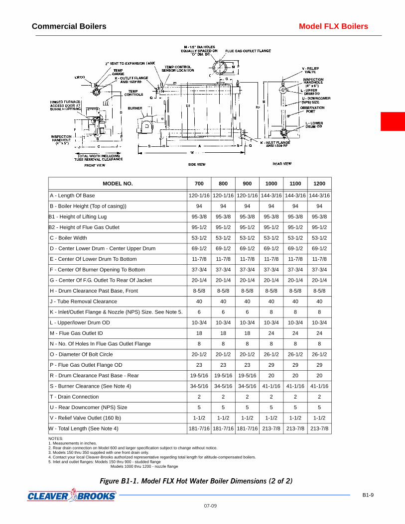
Figure B1-1. Model FLX Hot Water Boiler Dimensions (2 of 2)
MODEL NO. 700 800 900 1000 1100 1200
A - Length Of Base 120-1/16 120-1/16 120-1/16 144-3/16 144-3/16 144-3/16
B - Boiler Height (Top of casing)) 94 94 94 94 94 94
B1 - Height of Lifting Lug 95-3/8 95-3/8 95-3/8 95-3/8 95-3/8 95-3/8
B2 - Height of Flue Gas Outlet 95-1/2 95-1/2 95-1/2 95-1/2 95-1/2 95-1/2
C - Boiler Width 53-1/2 53-1/2 53-1/2 53-1/2 53-1/2 53-1/2
D - Center Lower Drum - Center Upper Drum 69-1/2 69-1/2 69-1/2 69-1/2 69-1/2 69-1/2
E - Center Of Lower Drum To Bottom 11-7/8 11-7/8 11-7/8 11-7/8 11-7/8 11-7/8
F - Center Of Burner Opening To Bottom 37-3/4 37-3/4 37-3/4 37-3/4 37-3/4 37-3/4
G - Center Of F.G. Outlet To Rear Of Jacket 20-1/4 20-1/4 20-1/4 20-1/4 20-1/4 20-1/4
H - Drum Clearance Past Base, Front 8-5/8 8-5/8 8-5/8 8-5/8 8-5/8 8-5/8
J - Tube Removal Clearance 40 40 40 40 40 40
K - Inlet/Outlet Flange & Nozzle (NPS) Size. See Note 5. 6 6 6 8 8 8
L - Upper/lower Drum OD 10-3/4 10-3/4 10-3/4 10-3/4 10-3/4 10-3/4
M - Flue Gas Outlet ID 18 18 18 24 24 24
N - No. Of Holes In Flue Gas Outlet Flange 8 8 8 8 8 8
O - Diameter Of Bolt Circle 20-1/2 20-1/2 20-1/2 26-1/2 26-1/2 26-1/2
P - Flue Gas Outlet Flange OD 23 23 23 29 29 29
R - Drum Clearance Past Base - Rear 19-5/16 19-5/16 19-5/16 20 20 20
S - Burner Clearance (See Note 4) 34-5/16 34-5/16 34-5/16 41-1/16 41-1/16 41-1/16
T - Drain Connection 2 2 2 2 2 2
U - Rear Downcomer (NPS) Size 5 5 5 5 5 5
V - Relief Valve Outlet (160 lb) 1-1/2 1-1/2 1-1/2 1-1/2 1-1/2 1-1/2
W - Total Length (See Note 4) 181-7/16 181-7/16 181-7/16 213-7/8 213-7/8 213-7/8
NOTES:1. Measurements in inches.2. Rear drain connection on Model 600 and larger specification subject to change without notice.3. Models 150 thru 350 supplied with one front drain only.4. Contact your local Cleaver-Brooks authorized representative regarding total length for altitude-compensated boilers.5. Inlet and outlet flanges: Models 150 thru 900 - studded flange
Models 1000 thru 1200 - nozzle flange
Model FLX Boilers Commercial Boilers
B1-10
07-09
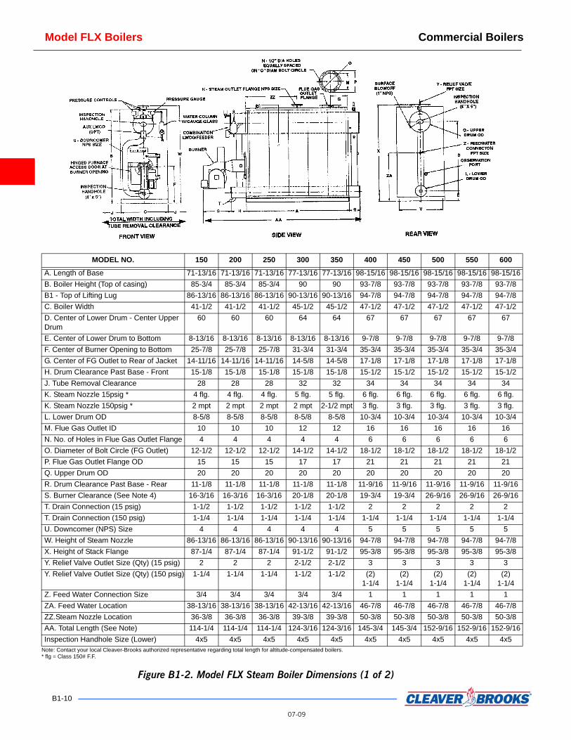
MODEL NO. 150 200 250 300 350 400 450 500 550 600
A. Length of Base 71-13/16 71-13/16 71-13/16 77-13/16 77-13/16 98-15/16 98-15/16 98-15/16 98-15/16 98-15/16B. Boiler Height (Top of casing) 85-3/4 85-3/4 85-3/4 90 90 93-7/8 93-7/8 93-7/8 93-7/8 93-7/8B1 - Top of Lifting Lug 86-13/16 86-13/16 86-13/16 90-13/16 90-13/16 94-7/8 94-7/8 94-7/8 94-7/8 94-7/8C. Boiler Width 41-1/2 41-1/2 41-1/2 45-1/2 45-1/2 47-1/2 47-1/2 47-1/2 47-1/2 47-1/2D. Center of Lower Drum - Center Upper Drum
60 60 60 64 64 67 67 67 67 67
E. Center of Lower Drum to Bottom 8-13/16 8-13/16 8-13/16 8-13/16 8-13/16 9-7/8 9-7/8 9-7/8 9-7/8 9-7/8F. Center of Burner Opening to Bottom 25-7/8 25-7/8 25-7/8 31-3/4 31-3/4 35-3/4 35-3/4 35-3/4 35-3/4 35-3/4G. Center of FG Outlet to Rear of Jacket 14-11/16 14-11/16 14-11/16 14-5/8 14-5/8 17-1/8 17-1/8 17-1/8 17-1/8 17-1/8H. Drum Clearance Past Base - Front 15-1/8 15-1/8 15-1/8 15-1/8 15-1/8 15-1/2 15-1/2 15-1/2 15-1/2 15-1/2J. Tube Removal Clearance 28 28 28 32 32 34 34 34 34 34K. Steam Nozzle 15psig * 4 flg. 4 flg. 4 flg. 5 flg. 5 flg. 6 flg. 6 flg. 6 flg. 6 flg. 6 flg.K. Steam Nozzle 150psig * 2 mpt 2 mpt 2 mpt 2 mpt 2-1/2 mpt 3 flg. 3 flg. 3 flg. 3 flg. 3 flg.L. Lower Drum OD 8-5/8 8-5/8 8-5/8 8-5/8 8-5/8 10-3/4 10-3/4 10-3/4 10-3/4 10-3/4M. Flue Gas Outlet ID 10 10 10 12 12 16 16 16 16 16N. No. of Holes in Flue Gas Outlet Flange 4 4 4 4 4 6 6 6 6 6O. Diameter of Bolt Circle (FG Outlet) 12-1/2 12-1/2 12-1/2 14-1/2 14-1/2 18-1/2 18-1/2 18-1/2 18-1/2 18-1/2P. Flue Gas Outlet Flange OD 15 15 15 17 17 21 21 21 21 21Q. Upper Drum OD 20 20 20 20 20 20 20 20 20 20R. Drum Clearance Past Base - Rear 11-1/8 11-1/8 11-1/8 11-1/8 11-1/8 11-9/16 11-9/16 11-9/16 11-9/16 11-9/16S. Burner Clearance (See Note 4) 16-3/16 16-3/16 16-3/16 20-1/8 20-1/8 19-3/4 19-3/4 26-9/16 26-9/16 26-9/16T. Drain Connection (15 psig) 1-1/2 1-1/2 1-1/2 1-1/2 1-1/2 2 2 2 2 2T. Drain Connection (150 psig) 1-1/4 1-1/4 1-1/4 1-1/4 1-1/4 1-1/4 1-1/4 1-1/4 1-1/4 1-1/4U. Downcomer (NPS) Size 4 4 4 4 4 5 5 5 5 5W. Height of Steam Nozzle 86-13/16 86-13/16 86-13/16 90-13/16 90-13/16 94-7/8 94-7/8 94-7/8 94-7/8 94-7/8X. Height of Stack Flange 87-1/4 87-1/4 87-1/4 91-1/2 91-1/2 95-3/8 95-3/8 95-3/8 95-3/8 95-3/8Y. Relief Valve Outlet Size (Qty) (15 psig) 2 2 2 2-1/2 2-1/2 3 3 3 3 3Y. Relief Valve Outlet Size (Qty) (150 psig) 1-1/4 1-1/4 1-1/4 1-1/2 1-1/2 (2)
1-1/4(2)
1-1/4(2)
1-1/4(2)
1-1/4(2)
1-1/4Z. Feed Water Connection Size 3/4 3/4 3/4 3/4 3/4 1 1 1 1 1ZA. Feed Water Location 38-13/16 38-13/16 38-13/16 42-13/16 42-13/16 46-7/8 46-7/8 46-7/8 46-7/8 46-7/8ZZ.Steam Nozzle Location 36-3/8 36-3/8 36-3/8 39-3/8 39-3/8 50-3/8 50-3/8 50-3/8 50-3/8 50-3/8AA. Total Length (See Note) 114-1/4 114-1/4 114-1/4 124-3/16 124-3/16 145-3/4 145-3/4 152-9/16 152-9/16 152-9/16Inspection Handhole Size (Lower) 4x5 4x5 4x5 4x5 4x5 4x5 4x5 4x5 4x5 4x5
Note: Contact your local Cleaver-Brooks authorized representative regarding total length for altitude-compensated boilers.* flg = Class 150# F.F.
Figure B1-2. Model FLX Steam Boiler Dimensions (1 of 2)

Commercial Boilers Model FLX Boilers
B1-11
07-09
MODEL NO. 700 800 900 1000 1100 1200
A. Length of Base 120-1/16120-1/16120-1/16 144-3/16 144-3/16 144-3/16B. Boiler Height (Top of casing) 108-5/8 108-5/8 108-5/8 108-5/8 108-5/8 108-5/8B1 - Top of Lifting Lug 108-7/8 108-7/8 108-7/8 108-7/8 108-7/8 108-7/8C. Boiler Width 53-1/2 53-1/2 53-1/2 53-1/2 53-1/2 53-1/2D. Center of Lower Drum - Center Upper Drum 77 77 77 77 77 77E. Center of Lower Drum to Bottom 11-7/8 11-7/8 11-7/8 11-7/8 11-7/8 11-7/8F. Center of Burner Opening to Bottom 37-3/4 37-3/4 37-3/4 37-3/4 37-3/4 37-3/4G. Center of FG Outlet to Rear of Jacket 17-5/8 17-5/8 17-5/8 20-1/4 20-1/4 20-1/4H. Drum Clearance Past Base - Front 17 17 17 17-5/16 17-5/16 17-5/16J. Tube Removal Clearance 40 40 40 40 40 40K. Steam Nozzle 15psig * 8 flg. 8 flg. 8 flg. 10 flg. 10 flg. 10 flg.K. Steam Nozzle 150psig * 4 flg. 4 flg. 4 flg. 6 flg. 6 flg. 6 flg.L. Lower Drum OD 10-3/4 10-3/4 10-3/4 10-3/4 10-3/4 10-3/4M. Flue Gas Outlet ID 18 18 18 24 24 24N. No. of Holes in Flue Gas Outlet Flange 8 8 8 8 8 8O. Diameter of Bolt Circle (FG Outlet) 20-1/2 20-1/2 20-1/2 20-1/2 20-1/2 20-1/2P. Flue Gas Outlet Flange OD 23 23 23 29 29 29Q. Upper Drum OD 24 24 24 24 24 24R. Drum Clearance Past Base - Rear 13 13 13 20-1/2 20-1/2 20-1/2S. Burner Clearance (See Note 4, page B1-7) 25-1/16 25-1/16 25-1/16 32-3/8 32-3/8 32-3/8T. Drain Connection (15 psig) 2 2 2 2 2 2T. Drain Connection (150 psig) 1-1/4 1-1/4 1-1/4 1-1/4 1-1/4 1-1/4U. Downcomer (NPS) Size 6 6 6 6 6 6W. Height of Steam Nozzle 108-7/8 108-7/8 108-7/8 108-7/8 108-7/8 108-7/8X. Height of Stack Flange 110-1/8 110-1/8 110-1/8 110-1/8 110-1/8 110-1/8Y. Relief Valve Outlet Size (Qty) (15 psig) (2) 2-1/2 (2) 2-1/2 (2) 2-1/2 (2) 3 (2) 3 (2) 3 Y. Relief Valve Outlet Size (Qty) (150 psig) (2) 1-1/2 (2) 1-1/2 (2) 1-1/2 (2) 2 (2) 2 (2) 2Z. Feed Water Connection Size 1 1 1 1 1 1ZA. Feed Water Location 58-7/8 58-7/8 58-7/8 58-7/8 58-7/8 58-7/8ZZ.Steam Nozzle Location 60-1/2 60-1/2 60-1/2 60-3/16 60-3/16 60-3/16AA. Total Length (See Note) 175-1/8 175-1/8 175-1/8 214-3/8 214-3/8 214-3/8Inspection Handhole Size (Lower) 4x5 4x5 4x5 4x5 4x5 4x5
Figure B1-2. Model FLX Steam Boiler Dimensions (2 of 2)

Model FLX Boilers Commercial Boilers
DIMENSIONS AND RATINGS Ratings for steam and hot water boilers are shown in Table B1-2 andTable B1-3. Dimen-sions for steam and hot water boilers are shown in Figure B1-1 and Figure B1-2.
PERFORMANCE DATA Efficiency Fuel-to-steam (fuel-to-water) efficiency is based on specific operating conditions (fuel, pres-
sure, temperature). Nominal efficiency on all FLX hot water and low pressure steam boilers is 81% firing natural gas, and 84% firing No. 2 oil. For high pressure steam applications, contact your local Cleaver-Brooks representative for expected efficiencies.
Emissions Expected emissions for natural gas fired FLX boilers are shown in Table B1-4.
B1-12
MODELNO.
T = 20°F
P (PSIG) GPM P (PS
FLX-150 1.14 122.0 0.3
FLX-200 1.14 162.3 0.3
FLX-250 1.77 202.8 0.4
FLX-300 1.85 243.4 0.4
FLX-350 2.49 284.0 0.6
FLX-400 1.35 324.5 0.3
FLX-450 1.71 365.1 0.4
FLX-500 2.03 405.7 0.5
FLX-550 2.50 446.3 0.6
FLX-600 2.99 486.8 0.7
FLX-700 1.75 567.9 0.4
FLX-800 2.27 649.1 0.5
FLX-900 2.85 730.2 0.7
FLX-1000 4.08 811.4 1.0
FLX-1100 4.42 892.6 1.1
FLX-1200 6.20 973.6 1.6
Table B1-4. Expected Emissions (ppm, corrected to 3% O2), Natural Gas Fired Boiler
FLUE GAS COMPONENT
HIGH-FIRE LEVELA PPMV
LOW-FIRE LEVELB PPMV
CO <100 <100
NOx P70 P70
NOTE: NOx levels based on standard product offering.A. Based on 12% excess air.
B. Based on 15% excess air.
Table B1-5. Model FLX Hot Water Boiler Flow Rates and Pressure Drops
07-09
T = 40°F T = 60°F T = 80°F T = 100°F
IG) GPM P (PSIG) GPM P (PSIG) GPM P (PSIG) GPM
0 61.1 0.13 41.1 0.08 30.8 0.05 24.4
0 81.1 0.13 54.1 0.08 40.6 0.05 32.5
6 101.4 0.21 67.6 0.12 50.7 0.08 40.6
8 121.7 0.22 81.1 0.12 60.9 0.08 48.7
5 142.0 0.29 94.7 0.17 71.0 0.11 56.8
5 162.3 0.16 108.2 0.09 81.1 0.06 64.9
4 182.6 0.20 121.7 0.11 91.2 0.08 73.0
4 202.8 0.25 135.2 0.14 101.4 0.09 81.1
7 223.1 0.31 148.7 0.17 111.5 0.11 89.2
7 243.4 0.35 162.3 0.20 121.7 0.13 97.4
5 284.0 0.21 189.3 0.12 142.0 0.08 113.6
9 324.5 0.27 216.4 0.15 162.3 0.10 129.8
4 365.1 0.33 243.4 0.19 182.6 0.12 146.0
2 405.6 0.42 270.4 0.25 202.8 0.15 163.6
5 446.2 0.48 297.4 0.28 223.0 0.18 178.4
0 486.8 0.59 324.6 0.31 243.4 0.22 194.8
Commercial Boilers Model FLX Boilers
ENGINEERING DATA Boiler Information Flow Rates and Pressure Drops
Flow rates and pressure drops for the FLX hot water boilers are shown in Table B1-5. This table can be used to determine the boiler pressure drop in relation to full boiler output and system temperature drop.
Table B1-6 can be used to determine the maximum gpm circulating rate in relation to full boiler output and system temperature drop. The maximum gpm can be determined by know-ing the boiler size and expected system temperature drop.
System Operating Parameters (Hot Water) System over pressure requirements are shown in Table B1-7.
Minimum return water temperature is 140 °F; minimum supply (boiler outlet) water temper-ature is 150 °F in order to prevent fireside corrosion.
System Operating Parameters (Steam Boilers) The following operating limitations must be observed for optimum operation of the boiler:
1. Minimum make-up temperature 60 °F.
2. Maximum make-up rate (for on/off make-up control) 2.0 times the evaporation rate.
3. Minimum operating pressure 6 psig. on low pressure steam and 40 psig. on high pressure steam.
4. Maximum operating pressure 12 psig. on low pressure steam.
5. Maximum load tracking rate 0 - 100% load or 100% - 0 load, 30 seconds on low pressure steam and 20% per minute on high pressure steam.
Maximum boiler water chemistry parameters: Silica: 150 ppm; specific conductance: 3500 µmho/cm un-neutralized; total alkalinity: 300 ppm as CaCO3; hardness: 0; oxygen: 7 ppb; pH: 7 - 10; total iron: 0.05 ppm; oil matter: 1 ppm.
Boiler Heat Release Information Boiler heat release information is shown in Table B1-8.
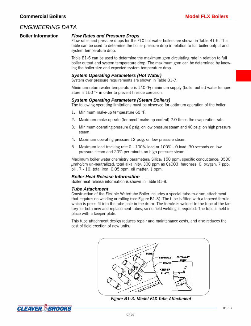
Tube Attachment Construction of the Flexible Watertube Boiler includes a special tube-to-drum attachment that requires no welding or rolling (see Figure B1-3). The tube is fitted with a tapered ferrule, which is press-fit into the tube hole in the drum. The ferrule is welded to the tube at the fac-tory for both new and replacement tubes, so no field welding is required. The tube is held in place with a keeper plate.
This tube attachment design reduces repair and maintenance costs, and also reduces the cost of field erection of new units.
Figure B1-3. Model FLX Tube Attachment
B1-13
07-09

Model FLX Boilers Commercial Boilers
Table B1-6. Model FLX Circulating Rates, Hot Water Boiler
B
MODEL NO. (HP)
SYSTEM TEMPERATURE DROP °F
10 20 30 40 50 60 70 80 90 100
MAXIMUM CIRCULATING RATE - GPM
FLX-150 (36) 243 122 81 61 49 41 35 31 27 24
FLX-200 (48) 324 162 108 81 65 54 46 41 36 32
FLX-250 (60) 404 202 135 101 81 68 58 51 45 41
FLX-300(72) 488 244 162 122 97 81 70 61 54 49
FLX-350 (84) 568 284 189 142 114 95 81 71 63 57
FLX-400 (96) 648 324 216 162 130 108 93 81 72 65
FLX-450 (108) 729 365 243 182 146 122 105 91 81 73
FLX-500 (119) 812 406 270 203 162 135 116 101 90 81
FLX-550 (131) 893 447 297 223 178 149 128 111 99 89
FLX-600 (143) 972 486 325 243 195 162 139 122 108 97
FLX-700 (167) 1136 568 379 284 227 189 162 142 126 114
FLX-800 (191) 1300 650 433 325 260 216 185 162 144 130
FLX-900 (215) 1460 730 487 365 292 243 209 183 162 146
FLX-1000 (239) 1622 811 541 406 324 270 232 203 180 164
FLX-1100 (263) 1784 893 595 446 357 297 255 223 198 178
FLX-1200 (287) 1947 974 649 487 389 325 279 243 216 195
MODELNO.
FURNACE PROJECTEDAREA (FT2)
FURNACE VOLUME
(FT3)
FURNACE HEAT
RELEASE BTU/HR (FT3)
FURNACE HEAT
RELEASE BTU/HR (FT2)
FLX-150 38.4 24.2 61,983 39,063FLX-200 38.4 24.2 82,645 52,083
Table B1-7. Model FLX Minimum Over Pressure Requirements
1-14
MAXIMUM OUTLET
TEMPERATURE (°F)
MINIMUM SYSTEM PRESSURE
(PSIG)
180 12190 15200 18210 21220 24230 27240 30
Table B1-8. Model FLX Boiler Heat Release Information
07-09
FLX-250 38.4 24.2 103,306 65,104FLX-300 48.7 34.9 85,960 61,602FLX-350 48.7 34.9 100,287 71,869FLX-400 70.6 54.7 73,126 56,657FLX-450 70.6 54.7 82,267 63,739FLX-500 70.6 54.7 91,408 70,822FLX-550 70.6 54.7 100,548 77,904FLX-600 70.6 54.7 109,689 84,986FLX-700 104.6 94.6 73,996 66,922FLX-800 104.6 94.6 84,567 76,482FLX-900 104.6 94.6 95,137 86,042FLX-1000 128.9 116.5 85,837 77,580FLX-1100 128.9 116.5 94,421 85,337FLX-1200 128.9 116.5 103,004 93,095

Commercial Boilers Model FLX Boilers
MODEL NO.BURNER
MAXIMUM INPUT MBH
BURNER MODELFAN MOTOR (3450 RPM) VOLTAGE
FLX-150 1500 PFVLG-15 115/230/1/60
FLX-200 2000 PFVLG-20 115/230/1/60
FLX-250 2500 PFVLG-25 115/230/1/60
FLX-300 3000 PFVLG-30 115/230/1/60
FLX-350 3500 PFVLG-35 208/230/1/60
FLX-400 4000 PFVLG-40 208/230/1/60
FLX-450 4500 PFVLG-45 208-230/460/3/60
FLX-500 5000 PFVLG-50 230/460/3/60
FLX-550 5500 PFVLG-55 230/460/3/60
FLX-600 6000 PFVLG-60 460/3/60
FLX-700 7000 PFVLG-70 460/3/60
FLX-800 8000 PFVLG-80 460/3/60
FLX-900 9000 PFVLG-90 460/3/60
FLX-1000 10000 PFVLG-100 460/3/60
FLX-1100 11000 PFVLG-110 460/3/60
FLX-1200 12000 PFVLG-120 460/3/60
Notes:1 Burner model selection shown is subject to changed and is based on actual application (altitude, gas pressure, reduced NOx, etc.)
2 Standard voltage for Canadian applications is 575/3/60.
3 Burner operation is Full Modulation on Elite Series and for the Econo seriesLow High Low for units 150 - 600 and modulated firing on 700 and greater.
4 Burner models shown are for combination gas/oil firing. For straight gas,delete the letter L, and for straight oil, delete the letter G.
MODEL NO.STD GAS
TRAIN SIZE (IN.) Note 3
MIN. GAS PRESSURE
(IN.W.C.) Note 4
MIN. GAS PRESSURE
(IN.W.C.) Note 5
BURNER MODEL
FLX-150 1 11.2 12.5 PFVG-15
FLX-200 1 19.4 21.7 PFVG-20
FLX-250 1.5 12.4 15.7 PFVG-25
FLX-300 1.5 15.9 20.7 PFVG-30
FLX-350 1.5 15.5 22.0 PFVG-35
FLX-400 1.5 18.7 27.2 PFVG-40
FLX-450 2 16.0 26.7 PFVG-45
FLX-500 2 17.6 21.0 PFVG-50
FLX-550 2 22.9 27.1 PFVG-55
FLX-600 2 20.0 24.9 PFVG-60
FLX-700 2 25.2 31.9 PFVG-70
FLX-800 2.5 19.9 22.2 PFVG-80
FLX-900 2.5 24.7 27.7 PFVG-90
FLX-1000 2.5 31.6 31.6 PFVG-100
FLX-1100 2.5 37.3 37.3 PFVG-110
FLX-1200 2.5 38.2 38.2 PFVG-120
Notes:1. Table is based on 1,000 Btu/cu.ft natural gas and elevation to 1000 feet.
2. Minimum gas pressure also applies to 200 fuel series.3. As an option, the standard gas train can be replaced with an oversized design to reduce inlet gas pressure requirements.
4. Use this column for all U.S. Installations.
5. Use this column for all Canadian Installations.
Burner/Control Information
Burner Characteristics Burner information is shown inTable B1-9. Note that the model selection may vary for actual application factors (altitude, gas pressure, etc.).
Minimum Required Gas Pressures Approximate gas pressure required at rated input is shown in Table B1-10. For oversized gas trains or altitudes above 1,000 feet, contact your local Cleaver-Brooks authorized represen-tative.
Fuel Connections - Gas The local gas company should be consulted for requirements and authorization for installa-tion and inspection of gas supply piping. Installation of gas supply piping and venting must be in accordance with all applicable engineering guidelines and regulatory codes. All con-nections made to the boiler should be arranged so that all components remain accessible for inspection, cleaning and maintenance.
A drip leg should be installed in the supply piping before the connection to the gas pressure regulator. The drip leg should be at least as large as the inlet fitting supplied with the boiler. Consideration must be given to both volume and pressure requirements when choosing gas
Table B1-9. Model FLX Burner Characteristics
Table B1-10. Model FLX Minimum Required Gas PressureB1-15
07-09

Model FLX Boilers Commercial Boilers
supply piping size. Refer to the boiler dimension diagram provided by Cleaver-Brooks for the particular installation. Connections to the burner gas train should be made with a union, so that gas train components or the burner may be easily disconnected for inspection or ser-vice. Upon completion of the gas piping installation, the system should be checked for gas leakage and tight shutoff of all valves.
Fuel Connections - Oil Oil-fired burners are equipped with an oil pump, which draws fuel from a storage tank and supplies pressurized oil to the burner nozzle(s). The burner supply oil pump has a greater capacity than the burner requires for the maximum firing rate. Fuel not delivered to the noz-zle is returned to the storage tank. A two-pipe (supply and return) oil system is recom-mended for all installations. Figure B1-4 shows a typical fuel oil supply arrangement. Oil lines must be sized for the burner and burner supply oil pump capacities.
The burner supply oil pump suction should not exceed 10" Hg. If a transfer pump is used, it must have a pumping capacity at least equal to that of the burner pump(s). Supply pressure to the burner pump should not exceed 3 psig.
A strainer must be installed in the supply piping upstream of the burner supply pump in order to prevent entry of foreign material into the pump, fuel control valves, or burner noz-zle(s). The strainer must be sized for the burner supply pump capacity. A strainer mesh of 150 microns (0.005") is recommended.
Install a check valve in the line to prevent draining of the oil suction line when the burner is not in operation. Location of the check valve varies with the system, but usually it is located as close as possible to the storage tank.
Installation of a vacuum gauge in the burner supply line between the burner oil pump and the strainer is recommended. Regular observation and recording of the gauge indication will assist in determining when the strainer needs servicing.
Figure B1-4. Model FLX Oil Burner Supply Pump Installation
B1-16
07-09

Commercial Boilers Model FLX Boilers
Table B1-11. Model FLX Sound Levels
SOUND LEVELFIRING RATE
MODEL NO.
150 200 250 300 350 400 450 500 550 600 700 800 900 1000 1100 1200
Low Fire (dBA) 75 75 76 75 75 77 78 79 79 79 81 81 83 79 82 85
High Fire (dBA) 76 76 77 76 76 78 79 80 80 80 82 82 83 81 83 86
Measurement: Three feet from front center of boiler, and 3-1/2 feet above boiler base. Measurements are decibel ratings on the A-weighted scale, registered without addition of sound attenuators, mufflers, or silencers. Sound pressure data taken on combination fuel burners firing oil. Sound pressure levels firing natural gas will be 0.5 dBA lower.
MODEL NO. SIDESA
TOPB
FRONTC
REARD
FLX-150 - 250 28 18 48 24
FLX-300 - 350 32 18 48 24
FLX-400 - 600 34 18 60 24
FLX-700 - 1200
40 18 60 24
NOTE: Top Dimension from boiler to top of stack based on stack selection.
Figure B1-5. Model FLX Clearance Requirements
B1-17
07-0903-08

Model FLX Boilers Commercial Boilers
Upon completion of the oil piping installation, the system should be checked for oil or air leakage and tight shutoff of all valves.
Sound Levels (dBA) Refer toTable B1-11 for sound level information.
Outdoor Reset Control
Cleaver-Brooks does not recommend the use of outdoor controls which reset the boiler water outlet temperature below 150 °F, or the utilization of the boiler as a system thermo-stat.
Boiler Room Information The boiler must be installed on a non-combustible floor. If the floor is not level, piers, or a raised pad, slightly larger in length and width than the boiler base dimensions, will make boiler installations and leveling easier. Installation on a raised pad or piers will make boiler drain connections more accessible. The floor, pad, or piers must be of sufficient load bearing strength to safely support the operating weight of the boiler and any additional equipment installed with it. Approximate operating weights for Model FLX series steam and hot water boilers are shown in Dimensions and Ratings.
After the boiler is in place it must be leveled. Both side-to-side and front-to-back level can be verified using the vertical connection between the upper and lower drums at the back of the boiler. If shims are required to level the boiler, the weight of the boiler must be evenly distributed at all points of support.
The boiler must be installed so that all components remain accessible for inspection, clean-ing, or maintenance. Field- installed piping and electrical connections to the burner and boiler must be arranged to allow removal of the casing panels, and swinging of the burner.
Minimum clearances to walls or other obstructions and combustible materials are shown iFigure B1-5. The top view shaded sections in Figure B1-5show areas that must be kept clear of field installed connections to the boiler for access or maintenance purposes.
A positive means of supplying a volume of outside air for complete fuel combustion is required. Proper ventilation of the boiler room must be provided. The amount of air required, and the required duct and air supply opening areas, are determined by the maxi-mum fuel input rating of the burner and the altitude of the installation. Refer to Table B1-12. Air inlets must be sized in accordance with applicable engineering guidelines and regu-latory code.
Breechings For single boiler installations, use breeching of the same diameter as the vent outlet on the boiler. For multiple boiler installations, and when a number of boilers of the same size (input) are to be connected to a common breeching, use the table on Figure B1-6 to size the breeching diameter. For more information on breechings and stacks, refer to “Stacks,” Sec-tion F.
Stack Support CapabilitiesFlextube boilers can support up to 200 lbs without additional support.
B1-18
07-09

Commercial Boilers Model FLX Boilers
MODEL NO. 150
Comb Air
(Dry)
Gas (scfh)
(lb/hr)
15480
1207
Oil (scfh)
(lb/hr)
17050
1269
Flue Gas (Dry)
Gas (scfh)
(lb/hr)
17520
1278
Oil (scfh)
(lb/hr)
17915
1357
NOTES:1. Natural gas @ 1000
2. No. 2 oil @ 140,00
Table B1-12. Model FLX Combustion Air Requirements
200 250 300 350 400 450 500 550 600 700 800 900 1000 1100 1200
20640 25800 30960 36120 41280 46440 51600 56760 61920 72240 82560 92280 103200 113520 123840
1609 2012 2414 2817 3219 3621 4024 4426 4828 5633 6438 7243 8048 8853 9657
22733 28414 34098 39782 45463 51146 56831 62514 68196 79562 90928 102294 113662 125028 136394
1692 2115 2538 2961 3384 3807 4231 4654 5077 5923 6769 7640 8462 9308 10154
23360 29200 35040 40880 46720 52560 58400 64240 70080 81760 93440 105120 116800 128480 140160
1704 2130 2556 2983 3409 3835 4261 4687 5113 5965 6817 7669 8521 9373 10225
23886 29855 35827 41799 47769 53740 59713 65684 71655 83598 95541 107484 119427 131370 143312
1809 2261 2714 3166 3618 4070 4523 4975 5427 6330 7237 8142 9047 9951 10856
Btu/cu-ft.
0 Btu/gal.
Figure B1-6. Model FLX Breeching Arrangement - Single or Multiple Boiler Installation
B1-19
07-09

Model FLX Boilers Commercial Boilers
B1-20
07-09
Notes

B1-21
Section B1Model FLX Boilers
(Steam Boiler Specifications)
Boiler Capacity . . . . . . . . . . . . . . . . . . . . . . . . . . . . . . . . . . . . . . . . . . . . . . . . . . . . . . . . . . . B1-22General Design . . . . . . . . . . . . . . . . . . . . . . . . . . . . . . . . . . . . . . . . . . . . . . . . . . . . . . . . . . . B1-22Steam Boiler Trim . . . . . . . . . . . . . . . . . . . . . . . . . . . . . . . . . . . . . . . . . . . . . . . . . . . . . . . . . B1-22Burner and Controls . . . . . . . . . . . . . . . . . . . . . . . . . . . . . . . . . . . . . . . . . . . . . . . . . . . . . . . . B1-23Burner Description . . . . . . . . . . . . . . . . . . . . . . . . . . . . . . . . . . . . . . . . . . . . . . . . . . . . . . . . . B1-23Pilot Gas Train for Each Burner (Mounted, Piped, and Wired) . . . . . . . . . . . . . . . . . . . . . . . . . . . B1-24Oil Burner . . . . . . . . . . . . . . . . . . . . . . . . . . . . . . . . . . . . . . . . . . . . . . . . . . . . . . . . . . . . . . . B1-24Gas Valve Train for Each Burner . . . . . . . . . . . . . . . . . . . . . . . . . . . . . . . . . . . . . . . . . . . . . . . B1-24Burner Controls . . . . . . . . . . . . . . . . . . . . . . . . . . . . . . . . . . . . . . . . . . . . . . . . . . . . . . . . . . . B1-25Warranty . . . . . . . . . . . . . . . . . . . . . . . . . . . . . . . . . . . . . . . . . . . . . . . . . . . . . . . . . . . . . . . B1-26Field Erectable . . . . . . . . . . . . . . . . . . . . . . . . . . . . . . . . . . . . . . . . . . . . . . . . . . . . . . . . . . . B1-26
SAMPLE SPECIFICATIONSThe following sample specifications are provided by Cleaver-Brooks to assist you in specifying your customer’sspecific needs and application. A separate specification is provided for hot water boiler and steam boilerpackages.

FLX Steam Boiler Specifications Section B1
PART 1 GENERAL 1.1 BOILER CAPACITYA. The _____ (low or high) pressure steam boiler shall be Cleaver-
Brooks Model FLX (FLE for field erected) designed for _______ (15 or 150) psig steam.
B. The boiler shall have a maximum output of __________ lbs/hr at ____ psig when fired with No. 2 oil and/or natural gas, ________ Btu/cu-ft. Electrical power available will be ________ Volt, _______ phase, _____ Hz.
PART 2 PRODUCTS 2.1 GENERAL DESIGN A. The boiler shall be of a two-drum flexible watertube design with a
tangent tube waterwall furnace mounted on a heavy steel frame. Top, bottom and sides of the furnace shall be water cooled.
B. The boiler pressure vessel shall be constructed in accordance with ASME Boiler Code, and must receive authorized boiler inspection prior to shipment. A copy of the inspection report shall be furnished to the purchaser. The complete packaged boiler - burner unit shall be listed by Underwriters Laboratories’, and shall have the UL/cUL label affixed to the front head.1. The boiler drums shall be furnished with handholes to facilitate
boiler inspection and cleaning. 2. Boiler tubes shall be 1.5" diameter, 0.095" wall thickness, and
shall be easy to remove and replace without expanding or welding the tube attachment to the drums.
3. The boiler shall have sufficiently sized downcomers to provide positive natural internal circulation.
4. The burner shall be mounted on a hinged backing plate for easy access to furnace.
C. Observation ports for the inspection of flame conditions shall be provided at rear end of the boiler and in the burner assembly at the front end.
D. The tangent wall tubes shall be covered with 1-1/2 inches of insulation under a gas-tight, 16-gauge inner casing. There shall be 2 inches of insulation between the inner and outer casing. The outer casing shall be 20 gauge. The boiler base frame and other components shall be factory-painted before shipment, using a hard enamel finish.
2.2 STEAM BOILER TRIM A. The following items shall be installed on the boiler:
1. Low Water Cutoff - A low water cut-off control of the float-type shall be mounted in a water column to the upper drum. It is to be wired to the burner control circuit to prevent burner operation if the boiler water falls below proper levels.
2. Feedwater Pump Control - The boiler feedwater pump control switch shall be included. It shall provide automatic actuation of a motor-driven feedwater pump, or solenoid valve, to maintain the boiler water level within normal limits.
B1-22

Section B1 FLX Steam Boiler Specifications
3. Steam Pressure Controls - A minimum of three controls shall be provided: one auto reset type for burner on-off control, one for burner firing rate, and one manual reset type for burner cutout in excessive steam pressure conditions.
4. Miscellaneous - A pressure gauge shall be mounted to the boiler. Pressure controls (for regulation of burner operation) shall be mounted to the boiler. Steam relief valves shall be of a type and size to comply with ASME Code requirements (shipped loose).
2.3 BURNER AND CONTROLSA. The boiler shall be provided with a UL/cUL approved fuel burning
system in full accordance with the requirements of state, provincial and local codes, the local gas utility, and other applicable regulatory bodies. The boiler shall be a Cleaver-Brooks Profire burner.
B. (Option as required) C. The complete fuel burning system shall further be in full accordance
with Factory Mutual (FM) requirements. D. The complete fuel burning system shall further be in full accordance
with Industrial Risk Insurers (IRI) requirements.
2.4 BURNER DESCRIPTION A. Option (specify 1, 2, or 3)
1. The burner shall include a gas burner having rated capacity to burn ________ MMBtu/hr of ______ Btu/cu-ft of __________ gas at a pressure of _______ (lbs/sq-inch) (inches of water column) at the inlet of the burner gas control train.
2. The burner shall include an oil burner having rated capacity to burn ______ gph of No. 2 fuel oil.
3. The burner shall include a combination gas-oil burner having rated capacity to burn _______ MMBtu/hr of _____ Btu/cu-ft gas at a pressure of _________ lbs/sq-inch (inches of water column) at the inlet to the burner gas control train (or _______ gph of No. 2 fuel).
B. The burner shall be forced draft type with full firing rate modulation. All combustion air shall be furnished by the burner fan, which shall be an integral part of the burner. Each burner motor shall not be larger than ______ hp, ____ phase.
C. Option (specify 1, 2, or 3) 1. The gas burner shall burn the specified quantity of fuel without
objectionable vibration, noise, or pulsation, with not more than 15% excess air and less than 100 ppm (corrected to 3% O2) CO in the products of combustion. In addition, when firing gas, the burner shall be guaranteed to produce less than __ ppm (corrected to 3% O2) NOx emissions.
2. The light oil burner shall burn the specified quantity of fuel without objectionable vibration, noise, or pulsation, with not more than 15% excess air and a maximum of No. 1 smoke spot, as measured on the Bacharach Scale.
B1-23

FLX Steam Boiler Specifications Section B1
3. The gas-oil burner shall burn the specified quantity of fuel without objectionable vibration, noise, or pulsation, with not more than 15% excess air and less than 100 ppm (corrected to 3% O2) CO in the products of combustion on gas firing, and a maximum of No. 1 smoke, as measured on the Bacharach Scale when burning oil. In addition, when firing gas, the burner shall be guaranteed to produce less than __ ppm (corrected to 3% O2) NOx emissions.
D. Primary-secondary air control shall be a design function of the combustion head. Combustion heads requiring an internal adjustment shall not be acceptable.
E. The burner shall be equipped with an aluminum reverse curve fan for lower fan motor hp requirements and self-cleaning characteristics.
F. A permanent observation port shall be provided in the burner to allow observation of both the pilot and main flame. Both the pilot and the flame scanner shall be easily accessible without opening or disassembling the burner.
G. Supply voltage available shall be ______ Volts, ______ phase, 60 Hz. All motors shall be suitable for use on this voltage. All burner controls are to be for use on 120 volts, 1 phase, 60 hz.
H. The burner shall be factory fire-tested to ensure proper operation before shipment.
2.5 PILOT GAS TRAIN FOR EACH BURNER (MOUNTED, PIPED, AND WIRED)
A separate pilot gas cock, gas pressure regulator, and pilot safety shutoff gas valve shall be provided for the ignition gas supply.
2.6 OIL BURNER A. The oil burner shall be of the mechanical pressure atomizing type. B. A two-stage oil pump shall be provided for each burner as an
integral part of the burner.C. Two approved automatically operated safety shutoff valve(s) shall be
provided in the oil supply line to the burner valves to be piped in series but wired parallel.
D. Supply an oil pressure gauge to indicate the discharge oil pump pressure.
E. Install a manual valve, fuel oil filter, or strainer and vacuum gauge on the suction side of the oil pump (optional).
F. Install a fusible-link-actuated oil safety shutoff valve in the oil supply line between the oil tank and the manual gate valve at the oil pump (optional).
G. Oil pressure monitoring shall be provided by an approved pressure switch interlocked to accomplish a non-recycling safety shutdown in the event of low oil pressure (optional).
2.7 GAS VALVE TRAIN FOR EACH BURNER A. Provide a pressure gauge to indicate the gas burner manifold
pressure (optional).
B1-24

Section B1 FLX Steam Boiler Specifications
B. Furnish and install one manually operated, ________ inch, ball valve upstream of all valves.
C. Provide one _______ inch, main gas pressure regulator (of tight shutoff type) with vent to outside atmosphere, in accordance with local codes.
Specify a tight shutoff type gas pressure regulator when the inlet gas pressure ex-ceeds 1-1/2 psig.
D. Provide one ________ inch, automatically operated motorized safety gas valve.
E. One safety shutoff valve shall be proven closed during pre- ignition by proof of valve closure interlock switch on valve.
F. Provide a second _______ inch, automatically operated gas safety shutoff valve to operate simultaneously with the above gas valve.
G. A manually operated gas valve shall be located downstream of both automatic gas valves to permit leakage testing of the valves.
H. Gas pressure monitoring shall be provided by approved pressure switches interlocked to accomplish a non-recycling safety shutdown in the event of either high or low gas pressure (optional on sizes 150-250).
2.8 BURNER CONTROLS A. The full modulation of the burner shall be controlled by steam
pressure by means of a pressure control. B. An additional high limit safety pressure control of the manual reset
type shall be provided to control the burner. C. Pre-purge and post-purge operation of the burner fan shall be
provided per current UL/cUL requirements. D. The burner shall utilize a CB12E type flame safeguard programmer
incorporating LED indicator lights to annunciate the current operating status of the burner.
E. A manual restart of the burner shall be necessary in the event of shutdown due to flame failure.
F. All three-phase motors shall be controlled and protected by an automatic starter with thermal overload protection. The starter shall be inter-locked to prevent burner operation when over-load relays are tripped out.
G. Supply a burner-mounted diaphragm air flow switch to prevent the energization of the main fuel valves in the event of insufficient combustion air, or to provide safety shutdown in the event of combustion air interruption.
H. A factory-wired control cabinet shall be supplied and mounted on the burner. The control cabinet shall house the flame safeguard control, programming timer, burner motor starter, fuses, control circuit transformer, control switches, indicating lamps and relays as required.
I. Provide four individual lights with nameplates on the control cabinet to indicate “call for heat,” “main fuel valve on,” “low water,” and “main flame failure.”
B1-25

FLX Steam Boiler Specifications Section B1
J. Option (specify A or B) 1. The changing from one fuel to the other shall be manual by
means of a fuel selector switch. No burner adjustments shall be required to switch from one fuel to the other.
2. Changing from one fuel to the other shall be automatically controlled by the outdoor temperature switch, or other external device. No burner adjustment shall be required to switch from one fuel to the other.
K. The burner shall be equipped with suitable fuel and air controls to assure smooth main flame ignition. The burner shall utilize a proportional air flow damper design, including independent low-fire and high-fire air flow shutter assemblies for ease of adjustment and consistent excess air performance throughout the firing range.
L. Fuel-air control shall be synchronized. The fuel air drive unit shall be provided with a position indicating switch interlocked with the flame safeguard system to assure starting at the low fire position. The flame safeguard system shall further program this drive unit to provide a full open louver of sufficient time to provide a four air change pre-ignition of the combustion chamber, heat exchanger, and flue passages.
M. Pre-ignition pure air flow rate shall not be less than 60% maximum firing rate air flow. Interlocks shall be provided to monitor and prove 60% air flow purge when air inlet louvers are automatically opened to obtain this rate.
N. Full modulation of fuel input shall be provided. A modulating pressure control shall be supplied to modulate a burner mounted damper motor controlling both fuel and air supply by means of direct mechanical linkage.
O. Electronic safety combustion controls shall be supplied, complete with ultra-violet flame scanner to monitor the pilot and main flame. It shall be so utilized as to provide intermittent type gas-electric ignition and pre-ignition timer. Flame rod will not be permitted for proving pilot or main flame.
PART 3 EXECUTION 3.1 WARRANTY All equipment is to be guaranteed against defects in material and/or workmanshipfor a period of 12 months from the date of start-up or 18 months from the date ofshipment, which ever comes first. In addition the boiler pressure vessel shall bewarranted against damage resulting from thermal stress for a period of 20 yearsfrom date of shipment provided the boiler is operated and maintained in accordancewith the conditions specified in the owner’s Operator and Maintenance Manual.Refer to the FLX Boiler warranty.
3.2 FIELD ERECTABLE The specified boiler/burner package shall be shipped disassembled for fieldassembly. All pieces and components must fit through a standard doorway.Assembly shall be accomplished with ordinary hand tools, with no welding or rollingrequired. Major casing components are to be shipped with insulation and refractoryinstalled for ease of assembly.
B1-26

B1-27
Section B1Model FLX Boilers
(FLX Hot Water Boiler Specifications)
Boiler Capacity . . . . . . . . . . . . . . . . . . . . . . . . . . . . . . . . . . . . . . . . . . . . . . . . . . . . . . . . . B1-28General Boiler Design . . . . . . . . . . . . . . . . . . . . . . . . . . . . . . . . . . . . . . . . . . . . . . . . . . . . B1-28Hot Water Boiler Trim . . . . . . . . . . . . . . . . . . . . . . . . . . . . . . . . . . . . . . . . . . . . . . . . . . . . B1-28Burner and Controls . . . . . . . . . . . . . . . . . . . . . . . . . . . . . . . . . . . . . . . . . . . . . . . . . . . . . B1-29Pilot Gas Train for Each Burner (Mounted, Piped, and Wired) . . . . . . . . . . . . . . . . . . . . . . . . B1-30Oil Burner . . . . . . . . . . . . . . . . . . . . . . . . . . . . . . . . . . . . . . . . . . . . . . . . . . . . . . . . . . . . B1-30Gas Valve Train for Each Burner . . . . . . . . . . . . . . . . . . . . . . . . . . . . . . . . . . . . . . . . . . . . . B1-30Burner Controls . . . . . . . . . . . . . . . . . . . . . . . . . . . . . . . . . . . . . . . . . . . . . . . . . . . . . . . . B1-31Warranty . . . . . . . . . . . . . . . . . . . . . . . . . . . . . . . . . . . . . . . . . . . . . . . . . . . . . . . . . . . . . B1-32Field Erectable . . . . . . . . . . . . . . . . . . . . . . . . . . . . . . . . . . . . . . . . . . . . . . . . . . . . . . . . . B1-32
SAMPLE SPECIFICATIONS The following sample specifications are provided by Cleaver-Brooks to assist you in specifying your customer’sspecific needs and application. A separate specification is provided for hot water boiler and steam boilerpackages.

FLX Hot Water Boiler Speecifications Section B1
PART 1 GENERAL 1.1 BOILER CAPACITYA. The hot water boiler shall be Cleaver-Brooks Model FLX (FLE for
field erected), designed for 160 psig (hot water). Maximum water temperature shall be _______ °F, and maximum system temperature drop shall be _______ °F.
B. The boiler shall have a maximum output of ____________ Btu/hr when fired with No. 2 oil, and/or ________________ Btu/cu- ft when fired with natural gas. Available electrical power will be _____ Volt, _____ phase, ____ Hz.
PART 2 PRODUCTS 2.1 GENERAL BOILER DESIGNA. The boiler shall be a two-drum, flexible watertube design with a
tangent-tube waterwall furnace mounted on a heavy steel frame. Top, bottom and sides of the furnace shall be water cooled.
B. The boiler pressure vessel must be constructed in accordance with ASME Boiler Code, and must receive authorized boiler inspection prior to shipment. A copy of the inspection report shall be furnished to the purchaser. The complete packaged boiler - burner unit shall be listed by Underwriters Laboratories, and shall have the UL/cUL label affixed to the front head. 1. The boiler drums shall be furnished with handholes to facilitate
boiler inspection and cleaning. 2. Boiler tubes shall be 1.5" diameter, with 0.095" wall thickness,
and shall be easy to remove and replace without expanding or welding the tube attachment to the drums.
3. The boiler shall have a sufficiently sized downcomer to provide natural internal circulation.
4. The burner shall be mounted on a hinged backing plate for easy access to the furnace.
C. Observation ports for the inspection of flame conditions shall be provided at the rear of the boiler, and in the burner assembly at the front.
D. The tangent wall tubes shall be covered with 1-1/2 inches of insulation under a gas-tight, 16-gauge inner casing. There shall be 2 inches of insulation between the inner and outer casing. The outer casing shall be 20 gauge. The boiler base frame and other components shall be factory-painted before shipment, using a hard enamel finish.
2.2 HOT WATER BOILER TRIM A. The following items will be installed on the boiler.
1. Low Water Cut-Off: A probe-type, low water cut-off control shall be mounted in the upper drum. It is to be wired to the burner control circuit to prevent burner operation if the boiler water falls below a safe level.
2. Miscellaneous: A combustion temperature and pressure gauge shall be mounted on the boiler. Temperature controls, for regulation of burner operation, shall be mounted on the boiler and the temperature sensing element shall be located adjacent to the boiler outlet. Water relief valves (shipped loose) shall be of a type and size to comply with ASME Code requirements.
B1-28

Section B1 FLX Hot Water Boiler Specifications
2.3 BURNER AND CONTROLSA. The boiler shall be provided with a UL/cUL approved fuel burning
system in full accordance with the requirements of state, provincial and local codes, the local gas utility, and other applicable regulatory bodies. The burner shall be a Cleaver-Brooks ProFire burner or approved equal.
B. Option (specify 1.) or 2.), as required) 1. The complete fuel burning system shall be in full accordance
with Factory Mutual (FM) requirements. 2. The complete fuel burning system shall be in full accordance
with Industrial Risk Insurers (IRI) requirements. C. Burner Description
1. Option (specify a, b, or c)a. The boiler shall include a gas burner having rated capacity
to burn ________ MMBtu/hr of ______ Btu/cu-ft of __________ gas at a pressure of _______ (lbs/sq-in.) (inches of water column) at the inlet of the burner gas control train.
b. The boiler shall include an oil burner having rated capacity to burn ______ gph of No. 2 fuel oil.
c. The boiler shall include a combination gas-oil burner having rated capacity to burn _______ MMBtu/hr of Btu/cu-ft ______ gas at a pressure of _________ (lbs/sq-in.) (inches of water column) at the inlet to the burner gas control train or _______ gph of No. 2 fuel.
2. The burner shall be forced draft type with full firing rate modulation. All combustion air shall be furnished by the burner fan, which shall be an integral part of the burner. Each burner motor shall not be larger than ______ hp, ____ phase.
D. Option (specify 1.), 2.), or 3.)) 1. The gas burner shall burn the specified quantity of fuel without
objectionable vibration, noise, or pulsation, with not more than 15% excess air and less than 100 ppm (corrected to 3% O2) CO in the products of combustion. In addition, when firing gas, the burner shall be guaranteed to produce less than __ ppm (corrected to 3% O2) NOx emissions.
2. B. The light oil burner shall burn the specified quantity of fuel without objectionable vibration, noise, or pulsation, with not more than 15% excess air and a maximum of No. 1 smoke spot, as measured on the Bacharach Scale.
3. C. The gas-oil burner shall burn the specified quantity of fuel without objectionable vibration, noise, or pulsation, with not more than 15% excess air and less than 100 ppm (corrected to 3% O2) CO in the products of combustion on gas firing, and a maximum of No. 1 smoke spot, as measured on the Bacharach Scale when burning oil. In addition, when firing gas, the burner shall be guaranteed to produce less than __ ppm (corrected to 3% O2) NOx emissions.
B1-29

FLX Hot Water Boiler Speecifications Section B1
E. Primary-secondary air control shall be a design function of the combustion head. Combustion heads requiring an internal adjustment shall not be acceptable.
F. The burner shall be equipped with an aluminium reverse curve fan for lower fan motor hp requirements and self-cleaning characteristics.
G. A permanent observation port shall be provided in the burner to allow observation of both the pilot and main flame. Both the pilot and the flame scanner shall be easily accessible without opening or disassembling the burner.
H. Supply voltage available shall be ______ Volts, ______ phase, 60 Hz. All motors shall be suitable for use on this voltage. All burner controls are to be for use on 120 volts, 1 phase, 60 Hz.
I. The burner shall be factory fire-tested to ensure proper operation before shipment.
2.4 PILOT GAS TRAIN FOR EACH BURNER (MOUNTED, PIPED, AND WIRED)
A separate pilot gas cock, gas pressure regulator, and pilot safety shutoff gas valve,shall be provided for the ignition gas supply.
2.5 OIL BURNER A. The oil burner shall be of the mechanical pressure atomizing type. B. A two-stage oil pump shall be provided for each burner as an
integral part of the burner.C. Two approved automatically operated safety shutoff valve(s) shall be
provided in the oil supply line to the burner valves to be piped in series but wired parallel.
D. Supply an oil pressure gauge to indicate the discharge oil pump pressure.
E. Install a manual valve, fuel oil filter, or strainer and vacuum gauge on the suction side of the oil pump (optional).
F. Install a fusible-link-actuated oil safety shutoff valve in the oil supply line between the oil tank and the manual gate valve at the oil pump (optional).
G. Oil pressure monitoring shall be provided by an approved pressure switch interlocked to accomplish a non-recycling safety shutdown in the event of low oil pressure (optional).
2.6 GAS VALVE TRAIN FOR EACH BURNER A. Provide a pressure gauge to indicate the gas burner manifold
pressure (optional). B. Furnish and install one manually operated, ________ inch, ball valve
upstream of all valves. C. Provide one _______ inch, main gas pressure regulator (of tight
shutoff type) with vent to outside atmosphere, in accordance with local codes.
NoticeSpecify a tight shutoff type gas pressure regulator when the inlet gas pressure exceeds 1-1/2 psig.
B1-30

Section B1 FLX Hot Water Boiler Specifications
D. Provide one ________ inch, automatically operated motorized safety gas valve. One safety shutoff valve shall be proven closed during pre- ignition by proof of valve closure interlock switch on valve.
E. Provide a second _______ inch, automatically operated gas safety shutoff valve to operate simultaneously with the above gas valve.
F. A manually operated gas valve shall be located downstream of both automatic gas valves to permit leakage testing of the valves.
G. Gas pressure monitoring shall be provided by approved pressure switches interlocked to accomplish a non-recycling safety shutdown in the event of either high or low gas pressure (optional on sizes 150-250).
2.7 BURNER CONTROLS A. The full modulation of the burner shall be controlled by water
temperature by means of a temperature control. B. An additional high limit safety temperature control of the manual
reset type shall be provided to control the burner. C. Pre- and post- operation of the burner fan shall be provided per
current UL/cUL requirements.D. The burner shall utilize a Fireye™ CB120E type flame safeguard
programmer, incorporating LED indicator lights to annunciate the current operating status of the burner.
E. A manual restart of the burner shall be necessary in the event of shutdown due to flame failure.
F. All three-phase motors shall be controlled and protected by an automatic starter with thermal overload protection. The starter shall be inter-locked to prevent burner operation when over-load relays are tripped out.
G. Supply a burner-mounted diaphragm air flow switch to prevent energizing the main fuel valves in the event of insufficient combustion air, or to provide safety shutdown in the event of combustion air interruption.
H. A factory-wired control cabinet shall be supplied and mounted on the burner. The control cabinet shall house the flame safeguard control, programming timer, burner motor starter, fuses, control circuit transformer, control switches, indicating lamps, and relays as required.
I. Provide four individual lights with nameplates on the control cabinet to indicate “call for heat,” “main fuel valve on,” “low water,” and “main flame failure.”
J. Option (specify 1.) or2.)) 1. The changing from one fuel to the other shall be manual by
means of a fuel selector switch. No burner adjustments shall be required to switch from one fuel to the other.
2. Changing from one fuel to the other shall be automatically controlled by an outdoor temperature switch, or other external device. No burner adjustment shall be required to switch from one fuel to the other.
B1-31
FLX Hot Water Boiler Speecifications Section B1
K. The burner shall be equipped with suitable fuel and air controls to assure smooth main flame ignition. The burner shall utilize a proportional air flow damper design, including independent low-fire and high-fire air flow shutter assemblies for ease of adjustment and consistent excess air performance throughout the firing range.
L. Fuel-air control shall be synchronized. The fuel air drive unit shall be provided with a position indicating switch interlocked with the flame safeguard system to assure starting at the low fire position. The flame safeguard system shall further program this drive unit to provide a full open louver of sufficient time to provide a four air change pre-ignition of the combustion chamber, heat exchanger, and flue passages.
M. Pre-ignition pure air flow rate shall not be less than 60% maximum firing rate air flow. Interlocks shall be provided to monitor and prove 60% air flow purge when air inlet louvers are automatically opened to obtain this rate.
N. Full modulation of fuel input shall be provided. A modulating temperature control shall be supplied to modulate a burner mounted damper motor, controlling both fuel and air supply by means of direct mechanical linkage.
O. Electronic safety combustion controls shall be supplied, complete with ultra-violet flame scanner to monitor the pilot and main flame. It shall be so utilized as to provide intermittent type gas-electric ignition and pre-ignition timer. Flame rod will not be permitted for proving pilot or main flame.
PART 3 EXECUTION 3.1 WARRANTY All equipment is to be guaranteed against defects in material and/or workmanshipfor a period of 12 months from the date of start-up or 18 months from the date ofshipment, which ever comes first. The boiler pressure vessel shall be warrantedagainst damage resulting from thermal stress for a period of 20 years from date ofshipment, provided the boiler is operated and maintained in accordance with theconditions specified in the owner’s Operating and Maintenance Manual.
3.2 FIELD ERECTABLE The specified boiler/burner package shall be shipped disassembled for fieldassembly. All pieces and components must fit through a standard doorway.Assembly shall be accomplished with ordinary hand tools, with no welding or rollingrequired. Major casing components are to be shipped with insulation and refractoryinstalled for ease of assembly.
B1-32
Related Documents