A technical manual from the experts in Business-Critical Continuity ™ NetSure ™ ITM Site Planning Data and System Drawings – 48V DC UPS Section 6037 (Issue 10, October 21, 2010) Contents 1. Site Planning Data 2. One Line Diagram 3. System Outline Drawings 4. Connection Details

Welcome message from author
This document is posted to help you gain knowledge. Please leave a comment to let me know what you think about it! Share it to your friends and learn new things together.
Transcript
A technical manual from the expertsin Business-Critical Continuity™
NetSure™ ITM Site Planning Data and System Drawings – 48V DC UPS Section 6037 (Issue 10, October 21, 2010)
Contents 1. Site Planning Data 2. One Line Diagram 3. System Outline Drawings 4. Connection Details

Section 6037 Emerson Network Power Issue 10, October 20, 2010 NetSure™ ITM
Page 2 Proprietary Information
This document is property of Emerson Network Power, Energy Systems, North America, Inc. and contains confidential and proprietary information owned by Emerson Network Power, Energy Systems, North America, Inc. Any copying, use, or disclosure of it without the written permission of Emerson Network Power, Energy Systems, North America, Inc. is strictly prohibited.
1 SITE PLANNING DATA 1.1 Technical Specifications
NetSure® ITM – Technical SpecificationsPrimary Module 1 Expansion Module 2 Expansion Module 3 Expansion Module 4
Power Rating (full) – kW 70 70 70 70
Power Rating (N + 1) – kW 64 70 70 70
AC Input Specifications
Phase 3
Power Factor 0.99 at full load, 0.98 at 50% load
Frequency – Hz 45-65
Input Voltage – Nominal 400 / 480V, 3 wire + ground
Input Voltage – Range 304-530 VAC; shall withstand up to 600 VAC input without damage.
Input Breaker Rating / AIC Rating – A 150 / 65,000
Max Input Current / Module 480V: 115A @ 384V; 92A @ 480V
400V: 138A @ 320V; 110A @ 400V
380V: 145A @ 304V; 116A @ 380V
Inrush Current Inrush current does not exceed 150% of the rated input steady state peak value
Total Harmonic Distortion <5% from 50-100% of load
DC Output Specifications
Voltage Nominal: -48VDC; normal operation: -54.5 VDC (battery float)
Range: -42 to -58 VDC
System Efficiency 92.5% peak (system level including branch distribution losses)
Energy Optimization Mode: Intelligent Power Matching Allows operation at near-peak efficiency down to 5% overall load
Branch Distribution Options 22 circuit breakers, 100-200A each; optional: 6 fuses, 2x500A + 4x200A
Battery Specification
Type VRLA, Emerson Excellence EB4, 200 Ah
Arrangement 3 strings; eight 6V blocks per string
Backup Time See backup time table at various loads
Design Life 15 years @ 20 °C ; 10 years @ 25 °C
Recharge Time (to 97% of nominal capacity) Less than 3 hours for > 35% load; Less than 4 hours > 15% load
Physical Data
Form Factor Rack
Installed Dimensions (H x W x D) – in. (mm) 83 x 24 x 41 (2100 x 600 x 1040)
Installed Weight – lb. (kg) 3214 (1458)
Environmental Specifications
System Operating Temp. – °F (°C) -5 °C to +35 °C; recommended operation with battery: 20 °C to 25 °C air inlet
System Storage Temp. – °F (°C) -40 to 158 °F (-40 °C to +70 °C)
Relative Humidity 0 to 95%, non condensing
Operating Elevation – ft. (m) 6562 (2000) at full power
Audible Noise < 60dB
Heat Rejection at Full Load – BTU/hr. (kW) 18,096 (5.3) per module
EMI FCC class A
Safety Certifications
Agency Approved CE Marked to EN 60 950-1:2006
UL Listed to 60 950-1 + UL 1801; CSA certified
Monitoring Capability
Standard Web-based monitoring, alarm reporting via SNMP, and integration with SiteScan via SiteLink-E module
Optional Energy Master Remote Supervision
Emerson Network Power Section 6037 NetSure™ ITM Issue 10, October 20, 2010
Proprietary Information Page 3
This document is property of Emerson Network Power, Energy Systems, North America, Inc. and contains confidential and proprietary information owned by Emerson Network Power, Energy Systems, North America, Inc. Any copying, use, or disclosure of it without the written permission of Emerson Network Power, Energy Systems, North America, Inc. is strictly prohibited.
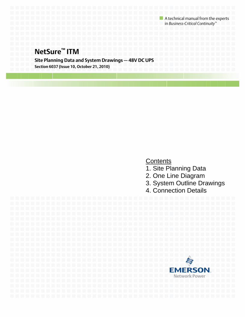
1.2 Battery Run Times Battery Back-up Time (minutes)
Load Single module 70kW
Two modules 140kW
Three modules 210kW
Four modules 280kW
10kW 130 300 480 63020kW 55 130 210 30030kW 28 90 130 18040kW 17 55 90 13050kW 12 41 70 10064kW 7 24 50 7570kW 3 21 43 6980kW 17 34 5590kW 14 27 47
100kW 12 22 40110kW 10 19 34120kW 8 17 28134kW 6 16 25140kW 3 14 22150kW 12 19160kW 10 17170kW 9 15180kW 8 14190kW 7 13204kW 4 11210kW 2 10220kW 9230kW 9240kW 8250kW 7260kW 6274kW 3280kW 1

Section 6037 Emerson Network Power Issue 10, October 20, 2010 NetSure™ ITM
Page 4 Proprietary Information
This document is property of Emerson Network Power, Energy Systems, North America, Inc. and contains confidential and proprietary information owned by Emerson Network Power, Energy Systems, North America, Inc. Any copying, use, or disclosure of it without the written permission of Emerson Network Power, Energy Systems, North America, Inc. is strictly prohibited.
2 ONE LINE DIAGRAM
LoadShunts
LoadShunts
BatteryShunts
Battery Fuse Battery
LVD
PCU PCU PCU PCU PCU PCU
Controller and Communication
Controller and Communication
Load Breakersor
Optional Fuses
Load Breakersor
Optional Fuses
BatteryShunts
Battery Fuse Battery
LVD
AC Input B(Optional)
AC Input A
AC Input B(Optional)
AC Input A
PCUBreakers(Note 4)
CurrentTransformer
PCUBreakers(Note 4)
CurrentTransformer
ACCircuit Breakers(Note 3)
ACCircuit Breakers(Note 3)
InternalDC-link
PRIMARYDC UPSMODULE (1)
EXPANSIONDC UPSMODULES (2-4)
Internal COM-link
NOTES1. DUAL AC INPUT VERSION OPTIONAL.2. RECOMMENDED INPUT WIRE SIZE 2/0 AWG, 90˚C (194˚F), SEE NEC TABLE 310.16.3. MAX INPUT CURRENT: 480V: 115A @ 384V; 92A @ 480V 400V: 138A @ 320V; 110A @ 400V 380V: 145A @ 304V; 116A @ 380V3. SYSTEM AC INPUT BREAKER(S) RATED 150A, 65kAIC.4. PCU AC INPUT BREAKERS RATED 32A, 5000AIC. TWO (2) PCUs PER BREAKER.
Emerson Network Power Section 6037 NetSure™ ITM Issue 10, October 20, 2010
Proprietary Information Page 5
This document is property of Emerson Network Power, Energy Systems, North America, Inc. and contains confidential and proprietary information owned by Emerson Network Power, Energy Systems, North America, Inc. Any copying, use, or disclosure of it without the written permission of Emerson Network Power, Energy Systems, North America, Inc. is strictly prohibited.
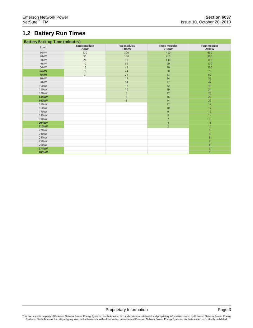
3 SYSTEM OUTLINE DRAWINGS 3.1 Mechanical Installation and Outline Drawings 3.1.1 Individual Cabinet Mechanical Data
Notes:1. Dimensions are in inches (millimeters).2. Weight (fully loaded): 3240 lbs / 1470 kg.3. Heat Rejection: 18096 BTU/h at full load (per module)
.
4. May be installed on concrete slab or raised floor.
23.62(600)
84.33(2142)
topcabled
84.72(2152)bottomcabled
Battery Compartment
Conduits forAC Inputs41.34
(1050)
DC Power SystemCompartment
Z
X
YTop Cabled VersionX = 11.81 (300)Y = 26.38 (670)Z = 36.61 (930)
Bottom Cabled VersionX = 11.81 (300)Y = 26.38 (670)Z = 40.55 (1030)
CENTER OF GRAVITY
26.38(670)
CG
11.81(300)
(Bottomcabled)CG
11.81(300)
36.61(930)
40.55(1030)
CG(topcabled)
23.62(600)
Battery Compartment
Conduits forAC Inputs
41.34(1050) DC Power System
Compartment26.38(670)
CG
11.81(300)
DC UPS MODULE WITHTOP FEED DC DISTRIBUTION
DC UPS MODULE WITHBOTTOM FEED DC DISTRIBUTION
Top View Top View
Front View 3.1.2 System Configurations
System can be expanded either tothe left or the right of the Primary Module.
Single Module70kW (full)64kW (n+1)
Two Modules140kW (full)134kW (n+1)
Three Modules210kW (full)204kW (n+1)
Four Modules280kW (full)274kW (n+1)

Section 6037 Emerson Network Power Issue 10, October 20, 2010 NetSure™ ITM
Page 6 Proprietary Information
This document is property of Emerson Network Power, Energy Systems, North America, Inc. and contains confidential and proprietary information owned by Emerson Network Power, Energy Systems, North America, Inc. Any copying, use, or disclosure of it without the written permission of Emerson Network Power, Energy Systems, North America, Inc. is strictly prohibited.
3.1.3 Main Components 3.1.3.1 Bottom Cabled Configuration - Circuit Breaker Load Distribution (Standard)
AC Input Conduit
* PCUs (12 x 5833W)
ACU+ (Controller)
Battery Fuses (800A)(Battery leads factoryconnected and routed toBattery Compartment.)
Load Distribution Devices(DC distribution circuit breakers,22 positions, 100-200A)(Fuse Option Available)
SM-AC (AC Input Monitoring)
Battery Return and Load Return(Battery return leads factoryconnected and routed toBattery Compartment.)
12
1 11
22
AC Input Circuit Breaker(s)(150A, 65kAIC)
Internal Circuit Breakers (32A)(Each Circuit Breaker Feeds Two PCUs)
LVD Contactor
PCU* Position#1
#3
#5
#7
#9
#11
PCU* Position#2
#4
#6
#8
#10
#12
Feeds PCU Position (left to right)#1/#2, #3/#4, #5/#6, #7/#8, #9/#10, #11/#12
Front View(door removed)
Emerson Network Power Section 6037 NetSure™ ITM Issue 10, October 20, 2010
Proprietary Information Page 7
This document is property of Emerson Network Power, Energy Systems, North America, Inc. and contains confidential and proprietary information owned by Emerson Network Power, Energy Systems, North America, Inc. Any copying, use, or disclosure of it without the written permission of Emerson Network Power, Energy Systems, North America, Inc. is strictly prohibited.
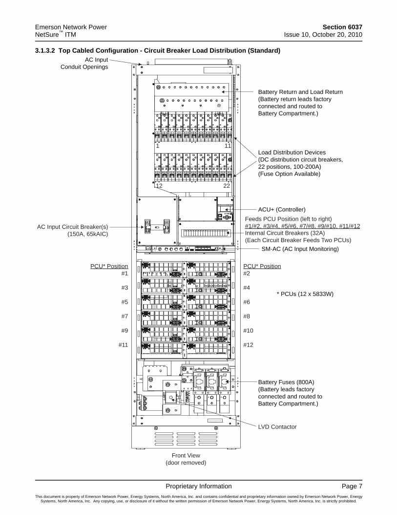
3.1.3.2 Top Cabled Configuration - Circuit Breaker Load Distribution (Standard)
SUITABLE FO R MO UNT ING O N CO NCRET E
O R O THER NO N-COMBUST IBLE SURFACE O NLY.
AC InputConduit Openings
* PCUs (12 x 5833W)
ACU+ (Controller)
Battery Fuses (800A)(Battery leads factoryconnected and routed toBattery Compartment.)
Load Distribution Devices(DC distribution circuit breakers,22 positions, 100-200A)(Fuse Option Available)
SM-AC (AC Input Monitoring)
Battery Return and Load Return(Battery return leads factoryconnected and routed toBattery Compartment.)
12
1 11
22
AC Input Circuit Breaker(s)(150A, 65kAIC) Internal Circuit Breakers (32A)
(Each Circuit Breaker Feeds Two PCUs)
LVD Contactor
PCU* Position#1
#3
#5
#7
#9
#11
PCU* Position#2
#4
#6
#8
#10
#12
Feeds PCU Position (left to right)#1/#2, #3/#4, #5/#6, #7/#8, #9/#10, #11/#12
Front View(door removed)
Section 6037 Emerson Network Power Issue 10, October 20, 2010 NetSure™ ITM
Page 8 Proprietary Information
This document is property of Emerson Network Power, Energy Systems, North America, Inc. and contains confidential and proprietary information owned by Emerson Network Power, Energy Systems, North America, Inc. Any copying, use, or disclosure of it without the written permission of Emerson Network Power, Energy Systems, North America, Inc. is strictly prohibited.
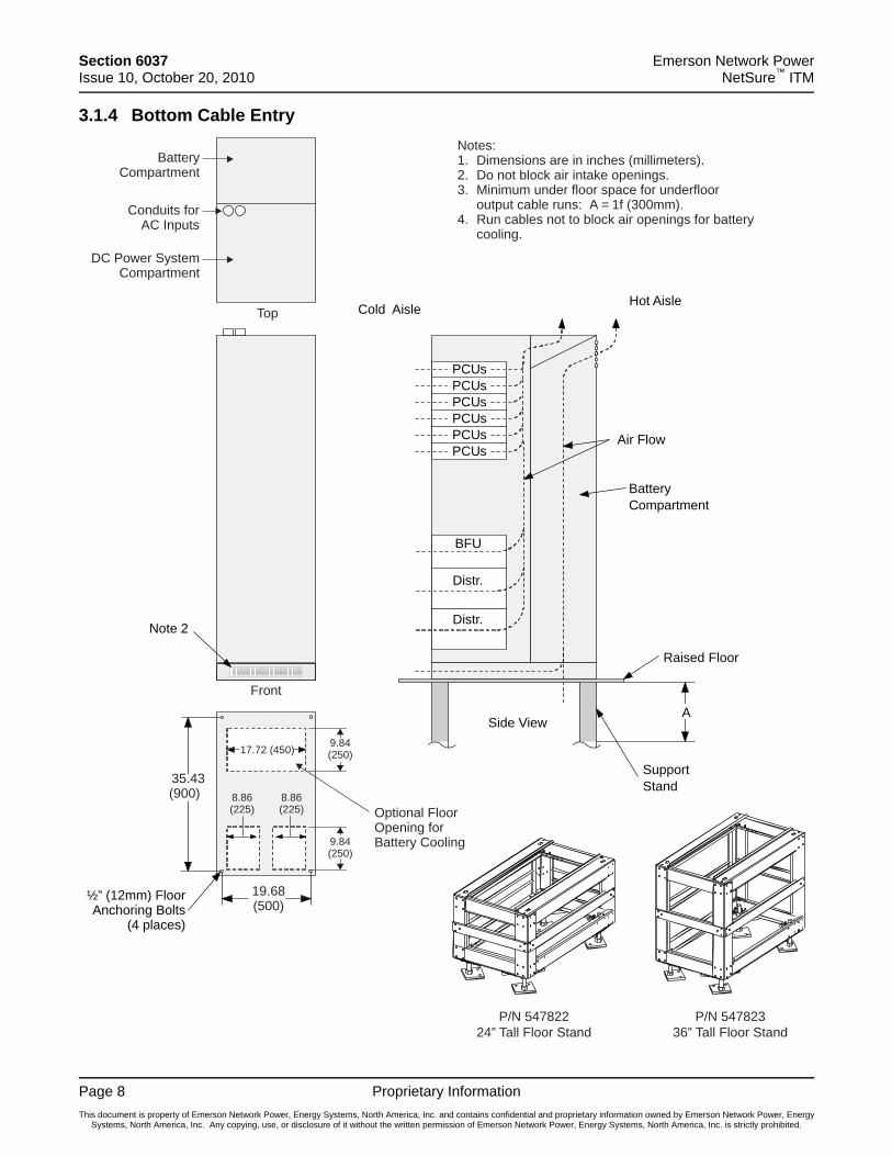
3.1.4 Bottom Cable Entry
BatteryCompartment
BFU
Distr.
Distr.
Raised Floor
Hot AisleCold Aisle
A
Air Flow
Note 2
Side View
SupportStand
½” (12mm) FloorAnchoring Bolts
(4 places)
Top
Front
Notes:1. Dimensions are in inches (millimeters).2. Do not block air intake openings.3. Minimum under floor space for underfloor
output cable runs: A = 1f (300mm).4. Run cables not to block air openings for battery
cooling.
BatteryCompartment
Conduits forAC Inputs
DC Power SystemCompartment
35.43(900)
17.72 (450)
8.86(225)
9.84(250)
19.68(500)
9.84(250)
8.86(225) Optional Floor
Opening forBattery Cooling
PCUs
PCUsPCUsPCUsPCUsPCUs
P/N 54782336” Tall Floor Stand
P/N 54782224” Tall Floor Stand
Emerson Network Power Section 6037 NetSure™ ITM Issue 10, October 20, 2010
Proprietary Information Page 9
This document is property of Emerson Network Power, Energy Systems, North America, Inc. and contains confidential and proprietary information owned by Emerson Network Power, Energy Systems, North America, Inc. Any copying, use, or disclosure of it without the written permission of Emerson Network Power, Energy Systems, North America, Inc. is strictly prohibited.
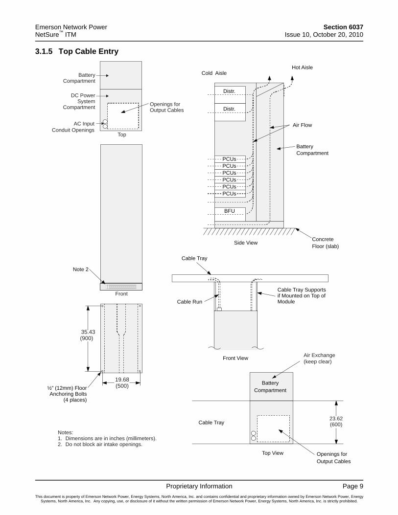
3.1.5 Top Cable Entry
Note 2
Distr.
Distr.
Hot AisleCold Aisle
Air Flow
ConcreteFloor (slab)Side View
Notes:1. Dimensions are in inches (millimeters).2. Do not block air intake openings.
Top
BatteryCompartment
DC PowerSystem
Compartment Openings forOutput Cables
FrontCable Tray Supportsif Mounted on Top ofModule
Front View
Cable Tray
Cable Run
BatteryCompartment
PCUs
PCUsPCUsPCUsPCUs
PCUs
Top View
BatteryCompartment
Openings forOutput Cables
Cable Tray23.62(600)
BFU
½” (12mm) FloorAnchoring Bolts
(4 places)
35.43(900)
19.68(500)
Air Exchange(keep clear)
AC InputConduit Openings

Section 6037 Emerson Network Power Issue 10, October 20, 2010 NetSure™ ITM
Page 10 Proprietary Information
This document is property of Emerson Network Power, Energy Systems, North America, Inc. and contains confidential and proprietary information owned by Emerson Network Power, Energy Systems, North America, Inc. Any copying, use, or disclosure of it without the written permission of Emerson Network Power, Energy Systems, North America, Inc. is strictly prohibited.
4 CONNECTON DETAILS 4.1 Bottom Cable Entry Electrical Connection Detail
DETAIL E
2"
RECOMMENDED COUPLING:RACO TYPE 2628(GRAINGER 3LV08) ORTHOMAS BETTS TYPE TK126US
COMMUNICATION LINKS BETWEEN CABINETS:1. RS-485 BUS WIRES (TWISTED YELLOW/WHITE WIRES) SHALL BE CONNECTED TO SM-AC. 2. CAN-BUS WIRES (TWISTED BLACK/WHITE WIRES) SHALL BE INTERCONNECTED.3. CONTACTOR CONTROL CABLES SHALL BE INTERCONNECTED.
NOTE1. WHEN CONNECTING OUTPUT DISTRIBUTION CABLES – START WHITH INNER ROW FIRST.
DETAIL D
ENTESC
USB
RJ45
USB
INPUT AC CONDUIT(S) SEE DETAIL ”E”
CONTROLLERSEE DETAIL ”D”
INPUT AC CONNECTION SEE DETAIL ”A”
INPUT AC CABLE ROUTING
CABINET GROUNDINGSUITABLE CABLE LUGSWITH HOLE DIA 3/8" (M10)TYPICAL LUG THOMAS & BETTS TYPE 54136RECOMMENDED TORQUE407-434 in-lbs (46-49 Nm).
SIDE PLATES ARE ONLY DELIVERED ON MAIN CABINET. SHALL BE MOVED TO THE LAST EXTENSION CABINET IN A ROW
1"
SUITABLE CABLE LUGS WITH HOLE DIA 3/8" (M10)TYPICAL LUG THOMAS & BETTS TYPE 54209RECOMMENDED TORQUE 407-434 in-lbs (46-49 Nm)
DETAIL C (Circuit Breaker Option)
1”
SUITABLE CABLE LUGS WITH HOLE DIA 3/8" (M10)TYPICAL LUG THOMAS & BETTS TYPE 54109RECOMMENDED TORQUE 407-434 in-lbs (46-49 Nm)
DETAIL B (Circuit Breaker Option)
1.75
"
1.5”
DETAIL C (Fuse Option)
S U IT A B LE C A B LE LU GS W IT H H OLE D IA 1 /2 " (M 12)T Y P IC A L LU G T H OM A S & B E T T S T Y P E 54282 (350kcm il)R E C OM M E N D E D T OR QU E 690-743 in-lbs (78-84 Nm)
1.75
"1.
75"
DETAIL B (Fuse Option)
S U IT A B LE C A B LE LU GS W IT H H OLE D IA 1 /2 " (M 12)T Y P IC A L LU G T H OM A S & B E T T S T Y P E 54282 (350kcm il)R E C OM M E N D E D T OR QU E 690-743 in-lbs (78-84 Nm)
NEGATIVE BUSBARSEE DETAIL ”C”(LOAD)
POSITIVE BUSBARSEE DETAIL ”B”(RETURN)
INPUT GROUNDINGCONNECTIONLUGS 5/16" (M8)TYPICAL LUG THOMAS &BETTS TYPE 54109RECOMMENDED TORQUE204-221 in-lbs (23-25 Nm)
DETAIL A
ONE OR TWO AC CIRCUIT BREAKERS,NO LUGS NEEDED.MARK CABLES A-L1, A-L2 AND A-L3 (B-L1, B-L2, B-L3)RECOMMENDED TORQUE 124 in-lbs (14 Nm)
factory wiring
L1 L2 L3AC IN A
L1 L2 L3AC IN B
GNDStud
GNDStud
Emerson Network Power Section 6037 NetSure™ ITM Issue 10, October 20, 2010
Proprietary Information Page 11
This document is property of Emerson Network Power, Energy Systems, North America, Inc. and contains confidential and proprietary information owned by Emerson Network Power, Energy Systems, North America, Inc. Any copying, use, or disclosure of it without the written permission of Emerson Network Power, Energy Systems, North America, Inc. is strictly prohibited.
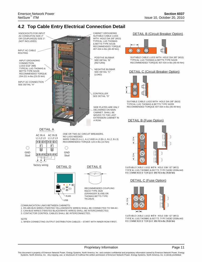
4.2 Top Cable Entry Electrical Connection Detail KNOCKOUTS FOR INPUT AC CONDUIT(S) SIZE 2"OR COUPLING(S) SIZE 2" (NOT INCLUDED)
CONTROLLERSEE DETAIL ”D”
INPUT AC CONNECTION SEE DETAIL ”A”
DETAIL E
2"
RECOMMENDED COUPLING:RACO TYPE 2628(GRAINGER 3LV08) ORTHOMAS BETTS TYPE TK126US
INPUT AC CABLE ROUTING
CABINET GROUNDINGSUITABLE CABLE LUGSWITH HOLE DIA 3/8" (M10)TYPICAL LUG THOMAS& BETTS TYPE 54136RECOMMENDED TORQUE 407-434 in-lbs (46-49 Nm).
SIDE PLATES ARE ONLY DELIVERED ON MAIN CABINET. SHALL BE MOVED TO THE LAST EXTENSION CABINET IN A ROW.
DETAIL B (Circuit Breaker Option)
1”
SUITABLE CABLE LUGS WITH HOLE DIA 3/8" (M10)TYPICAL LUG THOMAS & BETTS TYPE 54109RECOMMENDED TORQUE 407-434 in-lbs (46-49 Nm)
DETAIL C (Circuit Breaker Option)
1"
SUITABLE CABLE LUGS WITH HOLE DIA 3/8" (M10)TYPICAL LUG THOMAS & BETTS TYPE 54209RECOMMENDED TORQUE 407-434 in-lbs (46-49 Nm)
COMMUNICATION LINKS BETWEEN CABINETS:1. RS-485 BUS WIRES (TWISTED YELLOW/WHITE WIRES) SHALL BE CONNECTED TO SM-AC. 2. CAN-BUS WIRES (TWISTED BLACK/WHITE WIRES) SHALL BE INTERCONNECTED.3. CONTACTOR CONTROL CABLES SHALL BE INTERCONNECTED.
NOTE1. WHEN CONNECTING OUTPUT DISTRIBUTION CABLES – START WITH INNER ROW FIRST.
DETAIL D
ENTESC
USB
RJ45
USB
DETAIL AONE OR TWO AC CIRCUIT BREAKERS,NO LUGS NEEDED.MARK CABLES A-L1, A-L2 AND A-L3 (B-L1, B-L2, B-L3)RECOMMENDED TORQUE 124 in-lbs (14 Nm)
DETAIL B (Fuse Option)
1.75
"1.
75"
S U IT A B LE C A B LE LU GS W IT H H OLE D IA 1 /2 " (M 12)T Y P IC A L LU G T H OM A S & B E T T S T Y P E 54282 (350kcm il)R E C OM M E N D E D T OR QU E 690-743 in-lbs (78-84 Nm)
DETAIL C (Fuse Option)
1.75
"
1.5”
S U IT A B LE C A B LE LU GS W IT H H OLE D IA 1 /2 " (M 12)T Y P IC A L LU G T H OM A S & B E T T S T Y P E 54282 (350kcm il)R E C OM M E N D E D T OR QU E 690-743 in-lbs (78-84 Nm)
NEGATIVE BUSBARSEE DETAIL ”C”(LOAD)
POSITIVE BUSBARSEE DETAIL ”B”(RETURN)
INPUT GROUNDINGCONNECTIONLUGS 5/16" (M8)TYPICAL LUG THOMAS &BETTS TYPE 54109RECOMMENDED TORQUE204-221 in-lbs (23-25 Nm)
factory wiring
AC IN AL1 L2 L3
AC IN BL1 L2 L3
GNDStud
GNDStud

Emerson Network Power.The global leader in enabling Business-Critical Continuity™ .
AC Power
Connectivity
Embedded Computing
Embedded Power
Infrastructure Management & Monitoring
Outside Plant Racks & Integrated Cabinets
ServicesPower Switching & Controls
Surge Protection
Emerson Network PowerEnergy Systems, North America4350 Weaver Parkway, Warrenville, IL 60555Toll Free: 800-800-1280 (USA and Canada)Telephone: 440-246-6999 Fax: 440-246-4876Web: EmersonNetworkPower.com/EnergySystemsEnergyNet: Secure.EmersonNetworkPower.com
.
DC Power Precision Cooling
EmersonNetworkPower.com
Emerson (NYSE: EMR), based in St. Louis, is a global leader in bringing technology and engineering together to provideinnovative solutions for customers in industrial, commercial, and consumer markets through its network power, processmanagement, industrial automation, climate technologies, and appliance and tools businesses. For more information,visit: Emerson.com.
Emerson Network Power, a business of Emerson (NYSE:EMR), is the global leader in enabling Business-Critical Continuity™
from grid to chip for telecommunication networks, data centers, health care and industrial facilities. Emerson NetworkPower provides innovative solutions and expertise in areas including AC and DC power, precision cooling, embeddedcomputing and power, integrated racks and enclosures, power switching and controls, infrastructure management, andconnectivity. All solutions are supported globally by local Emerson Network Power service technicians. For moreinformation on Emerson Network Power’s full suite of solutions specifically supporting the communications networkinfrastructure, visit: EmersonNetworkPower.com/EnergySystems.
Learn more about the NetSure™ ITM DC UPS from Emerson at: EmersonNetworkPower.com/NetSureITM.
This publication is issued to provide outline information only which (unless agreed by Emerson Network Power Energy Systems, North America, Inc. in writing) may not beused, applied or reproduced for any purpose or form part of any order or contract or be regarded as a representation relating to the products or services concerned. EmersonNetwork Power Energy Systems, North America, Inc. reserves the right to alter without notice the specification, design or conditions of supply of any product or service.Emerson®, Emerson Network Power™, Business-Critical Continuity™, Efficiency Without Compromise™, Albér®, EnergyMaster™, Liebert®, NetSure®, SiteScan™ and SiteWeb™
are trademarks of Emerson Electric Co. and/or one of its subsidiaries.
Code: Section 6037, Issue 10
Related Documents