Construction Structures 500 2/16 SECTION 500 – STRUCTURES 503.00 Metal Reinforcement. General. Reinforced concrete is a mixture of concrete and steel reinforcement. Concrete is weak in tension and cracks easily when it shrinks or creeps under sustained loading. It is a brittle material. When concrete fails, it breaks suddenly without warning. Steel, on the other hand, is 100 times stronger in tension than concrete; is 6 times stiffer; and will stretch 17 times more than concrete before failing. Steel reinforcement provides reinforced concrete the tensile strength, stiffness, and ductility needed to make it an efficient, durable, versatile, and safe building material. For reinforced concrete to work as the designer of record intended, the inspector and Resident Engineer must ensure that reinforcing steel placed in a structure is: The correct grade and steel type The correct size, shape and length Placed in its specified location and spaced properly Tied and spliced together properly Clean and will get an adequate cover of concrete in all directions, and Placed in the correct quantities. The Inspector should check the steel closely upon arrival. Any discrepancies in grade, type, size, shape or lengths should be reported immediately to the Contractor, the Bridge Section and /or the Consultant Designer. The Resident Engineer should ensure that all the Inspectors are trained and prepared to inspect, sample and document all phases on the rebar placement. Appropriate reference and training materials should be readily available to Inspectors. Information on identifying markings and placing rebar, splices, bar supports, and wire mesh can be found in the Concrete Reinforcing Steel Institute (CRSI) Manual of Standard Practice (a copy is available at the ITD Bridge Section and hopefully in each District). Inspectors that inspect reinforcing on ITD projects should have access to the latest copy of Placing Reinforcing Bars published by the CRSI as well. Additional information on these manuals, questions, and video training supplements can be initiated by referencing the CRSI web site at http://www.crsi.org/ .

Welcome message from author
This document is posted to help you gain knowledge. Please leave a comment to let me know what you think about it! Share it to your friends and learn new things together.
Transcript

Construction Structures 500
2/16
SECTION 500 – STRUCTURES
503.00 Metal Reinforcement.
General. Reinforced concrete is a mixture of concrete and steel reinforcement. Concrete is weak in
tension and cracks easily when it shrinks or creeps under sustained loading. It is a brittle material.
When concrete fails, it breaks suddenly without warning. Steel, on the other hand, is 100 times stronger
in tension than concrete; is 6 times stiffer; and will stretch 17 times more than concrete before failing.
Steel reinforcement provides reinforced concrete the tensile strength, stiffness, and ductility needed to
make it an efficient, durable, versatile, and safe building material.
For reinforced concrete to work as the designer of record intended, the inspector and Resident Engineer
must ensure that reinforcing steel placed in a structure is:
The correct grade and steel type
The correct size, shape and length
Placed in its specified location and spaced properly
Tied and spliced together properly
Clean and will get an adequate cover of concrete in all directions, and
Placed in the correct quantities.
The Inspector should check the steel closely upon arrival. Any discrepancies in grade, type, size, shape
or lengths should be reported immediately to the Contractor, the Bridge Section and /or the
Consultant Designer.
The Resident Engineer should ensure that all the Inspectors are trained and prepared to inspect,
sample and document all phases on the rebar placement. Appropriate reference and training
materials should be readily available to Inspectors.
Information on identifying markings and placing rebar, splices, bar supports, and wire mesh can be
found in the Concrete Reinforcing Steel Institute (CRSI) Manual of Standard Practice (a copy is available
at the ITD Bridge Section and hopefully in each District). Inspectors that inspect reinforcing on ITD
projects should have access to the latest copy of Placing Reinforcing Bars published by the CRSI as well.
Additional information on these manuals, questions, and video training supplements can be initiated by
referencing the CRSI web site at http://www.crsi.org/ .

Construction Structures 500
2/16
Primary and Secondary Reinforcement. In any reinforced concrete structure, the reinforcing steel can
be divided into two categories. Primary reinforcement is the steel in the concrete that helps carry the
loads placed on a structure. Without this steel, the structure would certainly collapse. Sometimes
primary reinforcement is referred to as structural steel. The steel placed in a structure that enhances
the durability and holds the structure together is known as secondary reinforcement. It provides the
resistance to cracking, shrinkage, temperature changes, and impacts necessary for a long service life of
the structure. Sometimes secondary reinforcement is referred to as temperature steel.
For example, the steel on the backfill face of a cantilever retaining wall that retains soil and resists the
loads induced by the soil is primary or structural in nature. Whereas the steel in the front face of a wall
functions more for crack and shrinkage control. Its main job is to hold the concrete together.
It’s important for the Resident Engineer and inspector to become familiar with the primary and
secondary steel reinforcement in the structure. Not only does this help the inspector visualize how the
steel should look, but it helps in getting compliance from the Contractor by being able to discuss the
reasons for good placement procedures and how each bar in the structure is intended to function. The
designer of record can help identify which steel is primary and which is secondary reinforcement. This
knowledge is also important in determining what course of action to take if defective or failing material
is found for rebar already placed and covered with concrete. Generally non specification rebar should
be rejected but it may be accepted with a price adjustment in some cases as discussed later.
Reinforcing Steel Changes in the Field. Contractors may request changes in how reinforcing steel is
specified and designed to facilitate construction. These changes can include:
Moving bars
Bending bar
Substituting bars for different sizes, grades or types
Cutting or torching bars
Welding bars, and
Using different splice details or splice locations.
Any requests that would change the location, size, shape, type, grade, length, splice location or that
would change the design of the steel reinforcement in a structure must have the approval of the
designer of record.
Most reinforcing steel for ITD structures is specified as Type A615M (billet steel), Grade 60 (420).
Occasionally, the Contractor may want to substitute A706 steel for the A615 type. This kind of
substitution is generally acceptable as long as the steel grade stays the same, and there are no changes
in bar sizes or lengths. However, some reinforcing steel types such as ASTM A616 (rail steel) and A617
(axle steel) are not acceptable substitutes.
Occasionally, contractors may desire to furnish higher grade steel than what is specified. While this may
sound innocent enough there may be an issue. For example, if the Contractor proposes to use Grade 75
(520) steel for Grade 60 (420) a problem may exist. Grade 75 (520) steel has a much higher yield
strength than Grade (60) 420 and could adversely affect how a structure behaves during a failure.
Likewise, when the Contractor wants to substitute larger bar sizes over what is specified, problems can
Construction Structures 500
2/16
be created. Larger bars can cause clearance problems, and in some cases may lead to over-
reinforcement of a concrete section (a violation of AASHTO bridge specifications).
As mentioned earlier, steel reinforcement can be divided into primary and secondary reinforcement.
Even minor changes in either category can have a profound impact on the behavior and longevity of the
structure. This is why it is important to contact the designer of record on rebar changes, so the impacts
can be accurately assessed and accounted for in the design. Furthermore, a change order must be
executed showing the concurrence of the structural designer of record and the Headquarters
Construction/Materials Section for any change in the rebar material specification.
The Resident Engineer can deal with changes in how steel is tied, cleaned, supported, stored, and
handled with input from the Bridge Section or Consultant Designer as needed.
Welded Wire Fabric (Wire Mesh). Wire mesh is sometimes specified by a designer of record to control
shrinkage and cracking in a concrete slab or wall.
Construction Requirements.
Bending Schedules and Bar Lists. Bar bending diagrams and bar lists are shown in the contract plans.
The Contractor needs to verify the bar lists within the structure drawings before ordering or fabricating
the reinforcing steel. The intent is to get the Contractor to review these lists before the steel is made
and shipped to the project. Any major discrepancies should be brought to the attention of the Resident
Engineer and the designer of record. This proactive approach will help prevent any delays to the project
due to bars that have been cut the wrong length, bent the wrong way, or specified as the wrong size.
Waiting until the steel arrives on the job to begin checking bar dimensions is a practice that the
Department would like to avoid.
On every set of bridge plans there is a diagram with notations describing the requirement for rod hooks
and bends. A "hook" refers to the 90E, 135E or 180E bending of a reinforcing bar. A "bend" refers to
any other degree of bend. Reference should be made to this diagram when inspecting metal
reinforcement.
Following is a list of the types and purposes for which metal reinforcement is used:
Longitudinal Bars - Reinforcing steel bars which run length-wise of a member.
Transverse Bars - Reinforcing steel bars that run across the width of a member.
Stirrups - "U" or "W" shaped bars placed in a vertical plane used to resist shear in structural
members.
Tie Bars - Act to resist stress and hold other stress bars and structural members in position.
Dowels - Short bars extending from one member into another to transfer stresses from one
member into another.
Spiral Reinforcement - Spiraled hoops of reinforcing steel used on certain types of columns.
Temperature and Shrinkage Steel - Usually #4 bars at 18-inch spacing, placed in lieu of stress
bars to resist tension cracking due to curing and temperature shrinkage.
When bars arrive on the job, they are normally bundled and tagged. Each bundle will include all bars of
a particular bend or schedule occurring in a certain portion of the structure. Each bar or bundle will
Construction Structures 500
2/16
bear a tag indicating the "mark" of the bar or bars. Some bars, all of a certain "mark," will be coded by a
dab of paint on the end. This is to facilitate placement and identification.
Bending, Heating, and Cutting Bars. The inspector should check the rebar upon arrival at the job site to
see that the bending has been done in such a degree of accuracy that placement could be made within
the required tolerances. Items involving several bends such as stirrups are difficult to bend at the plant
and these dimensions must be exact if the rest of the placement is to be correct. Rejecting
reinforcement due to improper bending should be done prior to placement.
Contractors may want to field bend bars to simplify reinforcing steel installation or to improve access
around a structure. Grade 40 bars smaller than # 8 can be bent out of the way and then re-bent to their
final shape when done so per the standard specifications.
If the bars have already been bent once in the shop, only one bend is allowed in the field. Repeated
bending of bars weakens the steel at the bends due to metal fatigue. (This is similar to what happens
every time you bend a coat hanger or a paper clip back and forth—the repeated bending action
weakens the steel until it breaks.)
Heating the steel to bend it is only acceptable when done so per the Standard Specifications. The heat,
if not strictly controlled and closely monitored, produces a metallurgical change of the steel. Quenching
or rapid cooling of bars heated cherry red produces hardening and brittleness in the steel and must not
be permitted. This change results in a notching effect because too much heat will cause a permanent
and local weakening of the steel’s crystalline structure just like an actual notch in the steel. Normal,
still-air cooling is recommended when bars are heated for bending.
Cutting or torching bars because they are a hindrance to steel installation or concrete placement must
not be allowed without the approval of both the structure designer of record and the Resident Engineer.
Cutting the bars and then splicing them after they are out of the way is not allowed. The problem with
cutting the bars and then splicing them has to do more with the splicing than the cutting of the bar. If
the bar has to be spliced, the type of splice and the location of the splice should be discussed with and
approved by the designer of record before the bar is cut. Many times, Contractors want to cut rebar at
locations where stresses in the steel are too high or insufficient bar length is available after the cut to
fully develop the splice. These are the reasons why the designer of record must be involved in any bar
cutting decisions.
Rebar Cover and Clearance. Reinforcing steel must have adequate concrete cover near any exposed
surface. This cover is needed to prevent corrosion of the reinforcing steel due to moisture, atmospheric
conditions (like high humidity), and reactive soils. The Project Plans should clearly indicate the amount
of cover required for reinforcing steel. If the Plans do not, the designer of record should be contacted.
AASHTO and ACI have minimum cover requirements on all reinforcing steel.
Adequate clearance is needed between reinforcing bars so all of the concrete mix can completely
surround the bar. When bars are spaced to close together, two things can happen:
1. An air void can develop between the bars because there is not enough room for the concrete to
flow between the bars. This void severely weakens reinforced concrete locally because there is
Construction Structures 500
2/16
no concrete bonded to the steel. The void also causes stress concentrations in the surrounding
concrete because the concrete must transfer additional stresses that the void cannot.
2. The area between the bars is filled only with mortar, and is void of coarse aggregate.
The problems with only having mortar between the bars include:
A reduced shearing strength in the mortar due to the absence of coarse aggregate
Increased stresses in the steel as the mortar tries to shrink around the bars in the absence of
course aggregate, and
Surrounding areas of weakened concrete that have too much coarse aggregate and not enough
mortar.
ITD’s Standard Specifications do not specifically limit the clearance between individual bars. Instead
they limits the maximum size of coarse aggregate in the concrete mix based on the minimum rebar
clearance. In other words, the Contractor must adjust the concrete mix design to fit the minimum rebar
clearances in the structure. The Inspector’s responsibility is to check areas of minimum rebar clearance
and verify that the Contractor’s concrete mix will meet specifications. If the mix does not, either the
Contractor submits a new mix design or the designer of record is contacted about moving bars so the
Contractor’s mix can adequately coat the bars.
Common locations where rebar congestion is a problem are:
Lap splices of longitudinal bars
Column and cap beam connections where the cap beam reinforcing steel crosses the column
steel protruding into the cap.
Sometimes cover problems with reinforcing steel are the results of errors in the formwork rather than
errors in steel placement. If a cover problem does not seem to be the result of improper rebar
installation, then check the dimensions of the forms for the correct forming tolerances.
Sampling, Acceptance and Price Adjustments. As soon as reinforcing steel is delivered to the project
the inspector should determine if the bars are of the proper size and length, and if the bends and bend
dimensions are in accordance with the contract plans and the tolerances shown therein.
Steel bars, steel wire, welded wire fabric, and other structural steel shapes used as reinforcement must
be certified as conforming to the specifications and verified by testing before being covered with the
concrete. Random samples for testing must be taken by the inspector in accordance with the contract
specifications and Quality Assurance Manual. Encourage the Contractor to wait for the results before
installing. Should the Contractor elect to install before the results of the verification testing are known,
ensure he understands that he installs at his own risk per Subsection 106.03 of the Standard
Specifications.
One important point about rebar sampling that should be stressed: precut bars furnished by the supplier
as "sample bars" are not acceptable. Sample bars for verification testing must be removed from a steel
shipment at random when delivered to the project site. These samples should be shipped promptly to
the Central Materials Lab for testing maintaining a positive chain of custody by ITD staff or an
independent carrier. Do not allow the Contractor to take possession of and/or transport the samples.

Construction Structures 500
2/16
Occasionally rebar is placed and covered before the results of the verification testing are known. In
these cases the judgment as to rejecting the work entirely or accepting with a major price adjustment
must be well thought out as it could have major ramifications as to the serviceability of the bridge,
federal participation and claims. In order for this judgment to be made the following information must
be sent to the Headquarters Construction/Materials and Bridge Sections for review:
1. The project name and lead key.
2. The structure/bridge or place where the failing bar is located (e.g. US-95 MP 12.1).
3. Where the failing rebar is at in the structure (e.g. deck, pier etc.).
4. What the grade and the bar size was (e.g. grade 60, size 4).
5. How the rebar failed (yield point, tensile strength, cold bending).
6. What the magnitude of the failure was (e.g. acceptable tensile strength for grade 60 is 90,000
psi, bar failed at 89,000 psi).
7. What the purpose of the rebar was (Primary {structural} or Secondary {temperature} or both).
8. Was it epoxy coated?
9. When was it delivered?
10. When were the samples sent for testing?
11. When were the test results given to the Contractor?
12. When (date range) did the Contractor install the failing rebar?
13. How much did the failing rebar weigh?
14. What was the contract cost of each item where the rebar was installed?
After placement of the steel in the structure, a complete final inspection must be made and
documented.
Bar Supports. Adequate support for reinforcing steel must take into account not only the weight of the
steel, but the stresses and strains encountered while placing the concrete as well. The Concrete
Reinforcing Steel Institute publication, Placing Reinforcing Bars, contains recommended spacing for
metal chair supports. Regardless of the recommendations, there must be enough supports to keep the
reinforcing steel within the placement tolerances and to keep it from deflecting under construction
loading (concrete pours and foot traffic usually) until it is covered with concrete.
Chairs should be observed to detect whether they are bending or are indenting the form material. It
may be necessary to use more chairs or chairs with broader feet to carry the load exerted by the
reinforcing steel and the ironworkers. Heavy rebar cages containing large bar sizes are candidates for
bar support inspection by the Inspector. Wall and column reinforcement should be checked for
adequate lateral support to prevent the reinforcement from being pushed against the forms during
concrete placement.
The Resident Engineer and inspector should pre-approve all bar supports and bar support methods in
advance of any steel placement (preferably when the bar bending diagrams are approved).
If precast mortar blocks are used as bar supports, the blocks must have a compressive strength that
meets or exceeds the strength of the concrete poured around them. The inspector must take one
Construction Structures 500
2/16
sample of precast mortar blocks for every 50 placed, and send them to the Central Materials Lab for
strength testing.
Splicing and Lapping. Reinforcing steel is often specified in lengths that are too long for the steel to be
delivered and placed as a single piece. As a result, two or more pieces are often spliced together at the
site to form one long single bar. The following are three methods that ITD allows to splice rebar.
Lap Splices. Lap splices are formed when two bars are overlapped for a certain length and tied
together. The length of the overlap is called the lap length and is specified in the contract plans. A
sufficient lap length is needed to adequately transfer loads between the bars. Lap lengths can be
longer than specified, but never shorter. Inadequate lap length can cause severe cracking in the
concrete around the lap.
Reinforced concrete is typically its weakest around the lap splices in the primary reinforcement bars.
For this reason, lap splices are placed in areas where the stresses in a reinforced concrete section
are the lowest. The inspector must ensure that the Contractor laps reinforcing steel only in the
places specified in the contract plans and with sufficient lap length. If the Contractor wishes to
move a lap splice, the designer of record must approve the location change. In areas of high
bending and tensile stresses, the Department should insist on using continuous bars or either
mechanical or welded splices.
Lap splices can present problems with concrete cover and clearance between bars. Lap splices must
have adequate concrete cover for corrosion protection just like continuous bars. It is important to
ensure that the spacing between the lap splices allows for the adequate flow of concrete around the
splice. Sometimes the lap splices in a group of bars are staggered to reduce congestion at the splice
location.
Designers and Contractors have joint responsibility to ensure that lap splices are workable in terms
of spacing and adequate cover. The designers need to ensure that lap splices will fit within the
dimensions of a concrete member. Concrete cover must be adequate and rebar clearance must
take into account a reasonable coarse aggregate size. If lap splices do not work, alternatives such as
resizing the member, stagger splices, or a different splice detail should be specified. Contractors, on
the other hand, have a responsibility to identify congested rebar sections on the contract plans and
adjust their concrete mix design accordingly. They also have a responsibility to place lapped bars
well within the allowable placement tolerances when congestion at a lap splice is a problem.
Non-Contact Lap Splices. When a precast member is structurally connected to a cast-in-place
concrete member or another precast member, the rebar from both members is lap spliced together
to ensure adequate stress transfer across the two members. Sometimes due to the positioning of
the precast member or because of placement tolerances in the reinforcing steel, the lapped bars do
not end up touching each other at the splice. In other words, there is a gap between the two bars at
the lap splice. The designer of record must approve any non-contact laps that are not shown on the
contract plans.
When non-contact laps are permitted, the bars must not be spaced too far apart or a zigzag crack in
the concrete may develop between the bars. Usually the gap is limited to the lesser of 1/5 the lap
Construction Structures 500
2/16
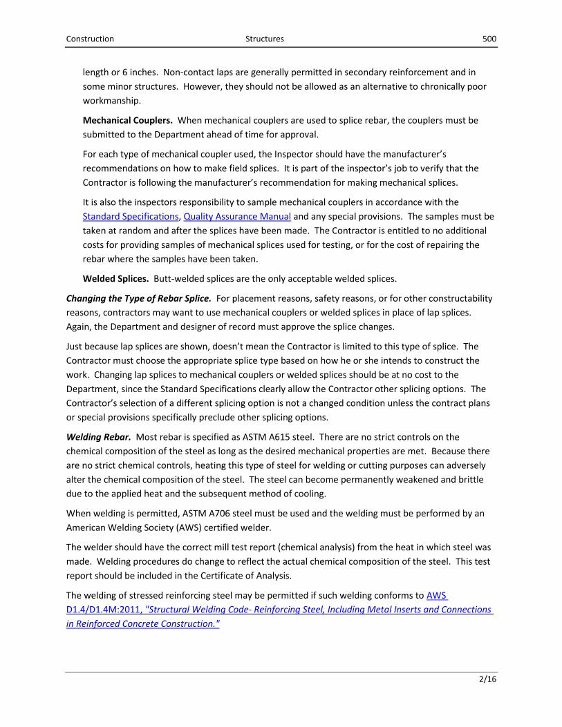
length or 6 inches. Non-contact laps are generally permitted in secondary reinforcement and in
some minor structures. However, they should not be allowed as an alternative to chronically poor
workmanship.
Mechanical Couplers. When mechanical couplers are used to splice rebar, the couplers must be
submitted to the Department ahead of time for approval.
For each type of mechanical coupler used, the Inspector should have the manufacturer’s
recommendations on how to make field splices. It is part of the inspector’s job to verify that the
Contractor is following the manufacturer’s recommendation for making mechanical splices.
It is also the inspectors responsibility to sample mechanical couplers in accordance with the
Standard Specifications, Quality Assurance Manual and any special provisions. The samples must be
taken at random and after the splices have been made. The Contractor is entitled to no additional
costs for providing samples of mechanical splices used for testing, or for the cost of repairing the
rebar where the samples have been taken.
Welded Splices. Butt-welded splices are the only acceptable welded splices.
Changing the Type of Rebar Splice. For placement reasons, safety reasons, or for other constructability
reasons, contractors may want to use mechanical couplers or welded splices in place of lap splices.
Again, the Department and designer of record must approve the splice changes.
Just because lap splices are shown, doesn’t mean the Contractor is limited to this type of splice. The
Contractor must choose the appropriate splice type based on how he or she intends to construct the
work. Changing lap splices to mechanical couplers or welded splices should be at no cost to the
Department, since the Standard Specifications clearly allow the Contractor other splicing options. The
Contractor’s selection of a different splicing option is not a changed condition unless the contract plans
or special provisions specifically preclude other splicing options.
Welding Rebar. Most rebar is specified as ASTM A615 steel. There are no strict controls on the
chemical composition of the steel as long as the desired mechanical properties are met. Because there
are no strict chemical controls, heating this type of steel for welding or cutting purposes can adversely
alter the chemical composition of the steel. The steel can become permanently weakened and brittle
due to the applied heat and the subsequent method of cooling.
When welding is permitted, ASTM A706 steel must be used and the welding must be performed by an
American Welding Society (AWS) certified welder.
The welder should have the correct mill test report (chemical analysis) from the heat in which steel was
made. Welding procedures do change to reflect the actual chemical composition of the steel. This test
report should be included in the Certificate of Analysis.
The welding of stressed reinforcing steel may be permitted if such welding conforms to AWS
D1.4/D1.4M:2011, "Structural Welding Code- Reinforcing Steel, Including Metal Inserts and Connections
in Reinforced Concrete Construction."
Construction Structures 500
2/16
Tack welding of non-stressed reinforcing steel is permitted when approved by the Resident Engineer.
Tack welding of stressed reinforcing steel is NOT permitted. In ordinary slab-and- girder construction,
only the top longitudinal slab steel is non-stressed. In column construction, all longitudinal steel is
stressed; ties are non-stressed. In ordinary reinforced concrete beams, girders, and pier and bent caps,
all top and bottom longitudinal steel is stressed; stirrups are generally stressed; small longitudinal bars
which are not a part of top or bottom reinforcement groups are generally non-stressed. In pre-cast, pre-
stressed concrete girders, stirrups are generally stressed; longitudinal non-pre-stressed steel is generally
non-stressed although there are exceptions. Steel in footings is generally stressed. Steel in the outer
faces of retaining walls, wing walls, and parapets is generally non-stressed. Vertical steel at the inner
faces of parapets and the earth faces of retaining walls and wing walls is generally stressed. Exceptions
are always possible. When a stressed reinforcing bar terminates with a hook, the extreme end of the
bar at the hooked end may be considered non-stressed.
No welding should be performed near pre-stressing strands without protecting the cable from welding
splatter. Even the slightest nick or burn mark in the strands is enough to cause failure during tensioning.
Epoxy-Coated Reinforcement. When epoxy-coated steel reinforcement is specified, inspectors need to
be watchful in how the Contractor handles the bars. Scratches, nicks, and other damage must be
repaired. Don’t allow the Contractor to mishandle the rebar with the intent of fixing any damage to
epoxy coating later. Repair procedures should only be allowed for the occasional accident.
For epoxy coated rebar, the entire bar supports (i.e. chairs, tie wires, and mechanical couplers) must be
corrosion proof. It makes no sense to support an epoxy- coated bar on a bare-metal chair. The Resident
Engineer and Construction/Materials Section must pre- approve all bar supports, couplers, and tie wires
for epoxy-coated rebar. The Contractor should submit samples and product literature well in advance of
any placement work.
It is the Department’s policy not to allow any metal bar supports or metal tire wire (coated or uncoated)
for epoxy coated rebar in concrete barrier wall. Non-metallic supports and tie wire must be used, since
the steel in a barrier wall is highly susceptible to corrosion.
Protection of Material. Steel which is to be stored at the job site for an extended period should be
protected from the weather to prevent excessive rusting. If covers are used to protect the steel, be sure
to provide ventilation to prevent trapping of moisture in the enclosure.
A slight rust coating on the bars has little effect on the strength or on the bond to the concrete. Heavy
rust pitting could materially reduce the cross-sectional area of the bar and should be cause for rejection.
Oil and grease, including form oil, act as bond breakers. When this gets on the bars, the Inspector has
no choice but to insist upon its removal. Removal may be done with petroleum- based solvent such as
naphtha, gasoline, or diesel fuel. A hand-held torch can be used to lightly heat up the bar and burn off
oil, grease or paint.
Loose mortar, curing compound, dirt, and mud can weaken the bond between the steel and concrete.
The steel should be wiped or washed clean of these contaminants. In severe cases, wire brushing may

Construction Structures 500
2/16
be needed especially on any primary reinforcement. Mill scale can be removed by sand blasting or in
limited amounts by wire brushing.
Tolerances for Cutting, Bending and Placing. In the cutting, bending, and placing of reinforcing steel, it
is recognized that it is not reasonable to require all bars to be cut, bent, and placed precisely as shown
on the contract plans. On the other hand, the strength of each member of a structure is dependent
upon the cutting, bending, and placing being within reasonable tolerances. Because of these facts, the
Department has adopted allowable tolerances that are considered reasonable and practical to meet, yet
will not significantly reduce the strength of the structural member below the theoretical design
strength.
Cutting and Bending Tolerances. The following tolerances are based on industry standards established
by the Concrete Reinforcing Steel Institute (refer to Chapter 6 of Placing Reinforcing Bars):
Cutting to length on straight bars: ± 1 inch.
Hooked bars, out-to-out: ± 1 inch.
Truss bars, out-to-out: ± 1 inch. The height (H) or drop (rise): ± 1/2 inch.
Bend down points and bend up points shall be within 2 inches of position indicated on the
contract plans.
Spirals or circles ties, out-to-out dimension: ± 1/2 inch.
Column ties or stirrups, out-to-out dimension: ± 1/2 inch.
Bars that are consistently too short or consistently bent to the wrong dimensions are cause for rejection.
Improper cutting and bending can also result in failure to meet placement tolerances in the forms.
Placing Tolerances. The effectiveness of the reinforcement and the strength of the structure are
dependent upon the reinforcing bars being placed in the concrete in nearly the exact position shown on
the contract plans. If they are not placed as shown, the structure will likely not have the strength that
the designer of record anticipated. For example; when the depth of all truss bars in a structural
concrete member is 1/2 inch less than shown on the contract plans, the strength of that member is
reduced from 15 to 25 percent.
The correct position of the steel, in relation to the tension face of the concrete, is of great importance.
If it is too far away from the face, the strength of the member will be adversely affected. If the position
is too close, particularly in bridge decks, water and de-icing chemicals penetrate to the steel and cause it
to rust. The rusting process causes an expansion in the volume occupied by the steel that will cause
spalling of the concrete.
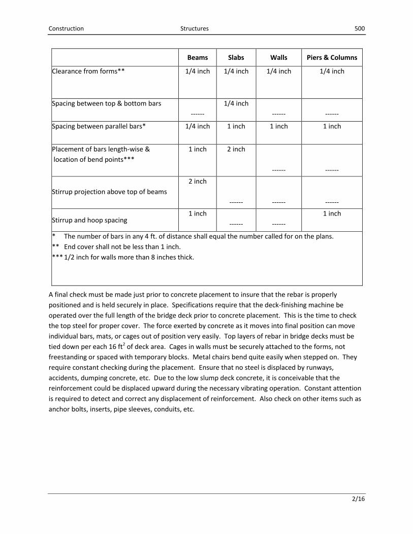
The following table of permissible variations from plan location or spacing shall be used as a guide in
determining good construction practice for placement of reinforcing steel. Substantial conformance to
these values is required.
Construction Structures 500
2/16
Beams
Slabs Walls Piers & Columns
Clearance from forms** 1/4 inch
1/4 inch
1/4 inch
1/4 inch
Spacing between top & bottom bars
------
1/4 inch
------
------
Spacing between parallel bars* 1/4 inch
1 inch
1 inch
1 inch
Placement of bars length-wise &
location of bend points***
1 inch
2 inch
------
------
Stirrup projection above top of beams
2 inch
------
------
------
Stirrup and hoop spacing 1 inch
------
------
1 inch
* The number of bars in any 4 ft. of distance shall equal the number called for on the plans.
** End cover shall not be less than 1 inch.
*** 1/2 inch for walls more than 8 inches thick.
A final check must be made just prior to concrete placement to insure that the rebar is properly
positioned and is held securely in place. Specifications require that the deck-finishing machine be
operated over the full length of the bridge deck prior to concrete placement. This is the time to check
the top steel for proper cover. The force exerted by concrete as it moves into final position can move
individual bars, mats, or cages out of position very easily. Top layers of rebar in bridge decks must be
tied down per each 16 ft2 of deck area. Cages in walls must be securely attached to the forms, not
freestanding or spaced with temporary blocks. Metal chairs bend quite easily when stepped on. They
require constant checking during the placement. Ensure that no steel is displaced by runways,
accidents, dumping concrete, etc. Due to the low slump deck concrete, it is conceivable that the
reinforcement could be displaced upward during the necessary vibrating operation. Constant attention
is required to detect and correct any displacement of reinforcement. Also check on other items such as
anchor bolts, inserts, pipe sleeves, conduits, etc.

Construction Structures 500
2/16
Documentation for Pay Quantities. Most reinforcing steel is paid for on a weight basis or is included in
the cost of another contract item. Rarely is a contract setup to pay reinforcing steel on a lump sum
basis. However, when there is a quantity dispute or additional work under a lump sum payment
provision, the weight basis should be used to measure reinforcing steel to equitably adjust the contract
amount.
The Inspector should collect the cut sheets that accompany each steel shipment and note any quantities
used for placements, aids, or left out of the structure. The date and time the steel was placed in the
structure should be noted. This process should not be much different than collecting concrete tickets,
where the inspector tracks the concrete quantities, placement location, and waste.
Tracking steel quantities as steel is placed is important for heading off quantity disputes. Often these
disputes arise because the quantity shipped to the project is different than the quantity shown in the
bidding schedule or contract plans. However Inspectors need to keep in mind that there is a yield factor
that applies to rebar similar to the yield factor that applies to ready mixed concrete. With rebar, there
are end pieces that are not used, bars that are used as placement aids, and waste from rebar cutting.
Sometimes even extra bars are sent at the Contractor's request to replace damaged bars previously
shipped.
Inspectors don't need to document every single bar placed in a structure, but they do need to scrutinize
cut sheets and other shipping documents and note any quantity discrepancies as steel is placed.
The inspector should calculate the quantities of metal reinforcement before construction begins. If the
total quantity for each item is within one percent (1%) of the plan quantity, no additional checking is
necessary. If the difference is greater, the calculations should be checked further in the residency. The
Contractor and supplier should be informed immediately of any errors discovered during this checking.
These computations and checks should be included as part of the project records, and will be the source
document for the final pay quantity of these items. The above-mentioned calculations should show the
quantity to be paid for each portion of the structure. Quantities for payment of metal reinforcement
shall be computed to the nearest pound.
The diary shall be used to verify the activity, date, and location of work. Photographs of the steel
placement should be taken for further documentation and project information.
Related Documents