SECTION 4 SUBSTRUCTURES FOUNDATIONS 4-1 SECTION 4 - SUBSTRUCTURES 4.1 - FOUNDATIONS All foundation designs should be preceded by a thorough subsurface investigation. The first step is to gather all existing subsurface explorations and pile driving records, if available. For projects designed in-house, the TA’s Geotechnical Engineer will develop a subsurface exploration plan based on a review of the existing information (if available) and the proposed foundation construction. The TA’s Geotechnical Engineer will then make arrangements for the drilling and laboratory testing. For projects designed by a Consultant, the Consultant will develop a subsurface exploration plan which is then submitted to the TA’s Geotechnical Engineer for review and approval. The Consultant will then obtain three bids for drilling and laboratory testing based on the approved subsurface exploration plan and the TA’s subsurface exploration specification (refer to the appendices in the Thruway Office of Design Manual for a copy of the specification). All explorations shall be progressed under the supervision of a qualified drilling inspector. The required experience for drilling inspectors is found on the page following the specification. Resumes for proposed drilling inspectors should be submitted to the TA’s Geotechnical Engineer for approval. All new foundation designs will require a Foundation Design Report (FDR).

Welcome message from author
This document is posted to help you gain knowledge. Please leave a comment to let me know what you think about it! Share it to your friends and learn new things together.
Transcript

SECTION 4 SUBSTRUCTURES FOUNDATIONS
4-1
SECTION 4 - SUBSTRUCTURES
4.1 - FOUNDATIONS
All foundation designs should be preceded by a thorough subsurface investigation. The first step is
to gather all existing subsurface explorations and pile driving records, if available.
For projects designed in-house, the TA’s Geotechnical Engineer will develop a subsurface
exploration plan based on a review of the existing information (if available) and the proposed
foundation construction. The TA’s Geotechnical Engineer will then make arrangements for the
drilling and laboratory testing.
For projects designed by a Consultant, the Consultant will develop a subsurface exploration plan
which is then submitted to the TA’s Geotechnical Engineer for review and approval. The Consultant
will then obtain three bids for drilling and laboratory testing based on the approved subsurface
exploration plan and the TA’s subsurface exploration specification (refer to the appendices in the
Thruway Office of Design Manual for a copy of the specification). All explorations shall be
progressed under the supervision of a qualified drilling inspector. The required experience for
drilling inspectors is found on the page following the specification. Resumes for proposed drilling
inspectors should be submitted to the TA’s Geotechnical Engineer for approval. All new foundation
designs will require a Foundation Design Report (FDR).
SECTION 4 SUBSTRUCTURES FOUNDATIONS
4-2
For projects designed in-house, the TA’s Geotechnical Engineer will prepare the FDR. For
projects designed by a Consultant, the Consultant will prepare the FDR which is then submitted to
the TA’s Geotechnical Engineer for review and approval.
As a minimum, the FDR will include a description of the existing foundation conditions,
recommendations for the proposed foundation type and details, seismic considerations (evaluation of
liquefaction potential and seismic design site coefficient), erosion protection and dewatering
recommendations (if appropriate), excavation and backfill recommendations including temporary
excavation support and all necessary foundation notes to be placed on the Contract Plans.
Please note that the minimum requirements for Consultant-prepared FDRs have been formalized for
use in structure design scopes (refer to the appendices in the Office of Design Manual for a copy of
“Foundation Designs for Structures – Minimum Requirements for Consultant Design”).
4.1.1 - FOOTINGS ON ROCK
Substructure footings proposed to be founded on rock shall be designed and detailed in accordance
with the FDR and the following subsections.
4.1.1.1 - ROCK LINES
Rock lines should be shown on the plans only when the footings are on rock or when drilled shafts
or caissons are to be placed to rock. When rock lines are shown on the plans, they shall be marked as
SECTION 4 SUBSTRUCTURES FOUNDATIONS
4-3
“Assumed Rock Surface.” The elevations of the rock are not to be labeled.
When it is planned to place footings on or key footings into rock, the plans shall show the top of
footing elevation and the minimum depth of footing. This will enable adjustments to be made in the
depth of footing if the actual rock elevation differs from that assumed during design, while keeping
the top of the footing elevation constant.
4.1.1.2 - KEYING OR DOWELING FOOTINGS INTO ROCK
Rock removal shall be avoided whenever possible in the construction of footings. Footings shall not
be detailed with keys or dowels into rock unless dictated by design requirements or other special
circumstances. This will be noted in the FDR.
When a footing must be keyed into rock, usually the entire footing is keyed into rock to simplify
construction.
When a footing is doweled into rock, the dowels shall be #29 reinforcing bars or larger and shall be
imbedded into the footing as well as into the rock to a depth noted in the FDR. The designer shall
determine the required spacing between the rows of dowels, but in no case shall there be greater than
900 mm between rows or less than two rows.
SECTION 4 SUBSTRUCTURES FOUNDATIONS
4-4
Doweling is generally preferred to keying except where the rock is shale or the rock scour
susceptible. Doweling shall not be used in shale rock or scour susceptible rock. The recommendation
of whether to key or dowel is contained in the FDR.
4.1.2 - STEPPED FOOTINGS
Steps in footings for wingwalls, retaining walls, abutments, piers, and precast panel wall systems
should be governed by the following guidelines. Proposed steps in footings shall be shown on the
Advance Detail Plans for both in-house and consultant designed structures.
4.1.2.1 - FOOTINGS ON SOIL
A. Stepping of abutment or pier footings on either spread foundations or piles should be
avoided. If the Designer has reason (such as intruding or sloping bedrock) to step the
footings for these substructures, he shall seek approval from the DSD.
B. Steps should not be used in footings less than 7.0 m in length. If permitted, the minimum
length of step section shall be 3.5 m long. The depth of the step should not be less than
600 mm. Footing continuity should be considered, however, it is not mandatory. A
vertical joint shall be required between the wall stems at the location of the step. The
joint type shall be the same type as in the footing. Typically, a keyed expansion joint is
used. Stepping of the footings for wingwalls and retaining walls shall be approved by the
DSD.
SECTION 4 SUBSTRUCTURES FOUNDATIONS
4-5
C. Stepping of the leveling pad for a mechanically stabilized earth system on embankments
is permitted. The minimum length of a step section may be the width of one panel. The
minimum depth of a step for this type of wall system is 1.0 m, which includes one-half
panel height plus the leveling pad. The manufacturer of the mechanically stabilized earth
system shall set the final configuration of the leveling pad as part of their panel layout.
4.1.2.2 - FOOTINGS ON ROCK
Stepping of footings on rock is acceptable for all footing lengths greater than 4.0 m. Portions of the
wall should usually be at least 2.5 m long and have a step not less than 600 mm. Footing continuity
is not required. The FDR will show an assumed top-of-footing elevation for each step.
4.1.3 - DESIGN FOOTING PRESSURES AND PILE CAPACITIES
Spread footing foundations or pile foundations shall be detailed on the plans. The appropriate note(s)
to be included in the plans will be contained in the FDR. The following subsection will provide
instructions for filling in the blank spaces of these notes.
4.1.3.1 - SUBSTRUCTURES ON SPREAD FOOTINGS
When the foundation consists of a spread footing on rock or soil, the following note shall be shown
on the substructure Footing Detail Sheet(s).
"The footing for the _____ is designed to exert a maximum bearing pressure of _______
kPa."
SECTION 4 SUBSTRUCTURES FOUNDATIONS
4-6
For spread footings on soil, the maximum bearing pressure exerted by the footing is usually very
close to the maximum allowable bearing pressure given in the FDR. For this reason, for footings on
soil, the maximum allowable bearing pressure from the FDR should be used in this note (The FDR
will show this plan note with the value already filled in).
For spread footings on rock, the maximum bearing pressure exerted by the footing is usually quite
a bit smaller than the maximum allowable bearing pressure given in the FDR. For footings on rock,
this value will be left blank in the FDR plan note and is to be filled in by the designer with the actual
maximum bearing pressure exerted by the footing.
For closed box culverts, the word "culvert" shall be substituted for "footing" in the above note.
Wingwalls attached to culverts will require a separate note, since the pressure under the wingwall
footing is generally greater than that under the culvert floor.
4.1.3.2 - SUBSTRUCTURES ON PILES
The appropriate pile notes to include in the plans will be contained in the FDR. The designer and the
Geotechnical Engineer should discuss maximum allowable pile loads for the project prior to
finalization of the FDR. If these loads change after issuance of the FDR, the Geotechnical Engineer
should be informed, and a supplemental FDR will be issued.
SECTION 4 SUBSTRUCTURES FOUNDATIONS
4-7
4.1.4 - PILES
4.1.4.1 - STEEL H-PILES
The footing thickness shall not be less than 750 mm for steel H-Piles. Footing areas shall be so
proportioned that pile spacing shall be not less than 1.0 m center-to-center for steel piles. The
maximum pile spacing shall be 2.75 m. The tops of steel piles shall project no less than 300 mm into
the footing. The minimum distance from the center of a pile to the nearest footing edge shall be 450
mm, but in no case shall the distance from the edge of the pile to the nearest edge of the footing be
less than 230 mm.
For integral abutment stems the minimum pile spacing shall be not less than 1.0 m center-to-center
for steel piles. The maximum pile spacing shall be 2.75 m. A single row of piles shall be placed at
the centerline of the integral abutment stem unless otherwise noted in Subsection 4.6. The minimum
stem thickness for integral abutments is 1.0 m unless otherwise noted in Subsection 4.6. Piles for
integral abutments shall be imbedded sufficiently into the stem to insure fixity for developing the
plastic moment capacity of the pile, but no less than 600 mm. The minimum distance from the center
of a pile to the nearest stem edge shall be 500 mm, but in no case shall the distance from the edge of
the pile to the nearest edge of the footing be less than 300 mm.
Where a reinforced concrete beam is used as a bent cap supported by piling, the minimum pile
spacing shall be not less than 1.0 m center-to-center for steel piles. The maximum pile spacing shall
be 2.75 m. The minimum distance from the center of the pile to the nearest cap edge shall be 450
SECTION 4 SUBSTRUCTURES FOUNDATIONS
4-8
mm, but in no case shall the distance from the edge of the pile to the nearest edge of the cap be less
than 300 mm. The piles shall project at least 600 mm into the cap. Cap plates are not required for
steel bearing piles.
4.1.4.1.1 - SPLICES FOR STEEL H-PILES
When steel bearing piles are specified and the estimated length exceeds 9.0 m, the designer should
include either the standard specification item for splicing steel bearing piles or the NYSDOT special
specification for splicing steel bearing piles. The standard specification item requires steel bearing
piles be spliced using full penetration groove welds. Welded splices are required for piles subject to
uplift loads. The special specification item allows for the use of mechanical splices for steel bearing
piles. Mechanical splices are not acceptable for steel H- piles subject to uplift loads.
The FDR will contain recommendations regarding the use of mechanical pile splices for H-piles.
Regardless of the specification used, the quantity of splices will generally be 1/3 the number of piles
driven. The estimated quantity will be stated in the FDR. Splicing of steel bearing piles is a
contingency item that is used when actual driven pile length exceeds the estimated pile length by
more than 1.5 m. Refer to the most recent version of NYSDOT BD-MS5 (Miscellaneous Pile
Details) for the appropriate splicing details to include in the contract plans.
4.1.4.2 - CONCRETE CAST-IN-PLACE (CIP) PILES
The footing thickness shall not be less than 600 mm for CIP piles. Footing areas shall be so

SECTION 4 SUBSTRUCTURES FOUNDATIONS
4-9
proportioned that pile spacing shall be not less than 1.0 m center-to-center for CIP piles. The
maximum pile spacing shall be 2.75 m. The tops of CIP piles shall project no less than 150 mm into
the footing. The minimum distance from the center of a pile to the nearest footing edge shall be 450
mm, but in no case shall the distance from the edge of the pile to the nearest edge of the footing be
less than 230 mm.
For integral abutment stems the minimum pile spacing shall be not less than 1.0 m center-to-center
for CIP piles. The maximum pile spacing shall be 2.75 m. A single row of piles shall be placed at the
centerline of the integral abutment stem unless otherwise noted in Subsection 4.6. The minimum
stem thickness for integral abutments is 1.0 m unless otherwise noted in Subsection 4.6. CIP piles
for integral abutments shall be imbedded sufficiently into the stem to insure fixity for developing the
plastic moment capacity of the pile, but no less than 600 mm. The minimum distance from the center
of a CIP piles to the nearest stem edge shall be 500 mm, but in no case shall the distance from the
edge of the pile to the nearest edge of the footing be less than 300 mm.
Where a reinforced concrete beam is used as a bent cap supported by CIP piles, the minimum pile
spacing shall be not less than 1.0 m center-to-center for steel piles. The maximum pile spacing shall
be 2.75 m. The minimum distance from the center of the CIP piles to the nearest cap edge shall be
450 mm, but in no case shall the distance from the edge of the CIP piles to the nearest edge of the
cap be less than 300 mm. The CIP piles shall project at least 600 mm into the cap.
SECTION 4 SUBSTRUCTURES EXCAVATION & BACKFILL
4-10
4.1.4.2.1 - SPLICES FOR CIP-PILES
Cast-in-place pile shells are spliced by either welding with a backing ring or by using a mechanical
splice. Welded splices are required for piles subject to uplift loads. Mechanical splices are not
acceptable for CIP piles subject to uplift loads. There is no splice item for CIP piles, as splicing is
included in the pile item.
The FDR will contain recommendations regarding the use of mechanical pile splices for CIP piles.
Refer to the most recent version of NYSDOT BD-MS5 (Miscellaneous Pile Details) for the
appropriate splicing details to include in the contract plans.
4.1.4.3 - PILE TIP REINFORCEMENT (H AND C.I.P. PILES)
All H-piles shall be equipped with a either a regular reinforced shoe or an APF HP77750 “hard bite”
shoe (or equivalent). All cast-in-place concrete pile shells shall be equipped with either a flat plate or
a conical tip. The type of tip treatment is dependent on the soil conditions and will be specified in
the FDR. Refer to the most recent version of NYSDOT BD-MS5 (Miscellaneous Pile Details) for the
appropriate shoe details to include in the contract plans.
4.2 - EXCAVATION AND BACKFILL
Excavation and backfill details are important aspects of design, which are commonly overlooked.
Problems due to settlement or hydraulic pressure buildup can be difficult to solve and cause
maintenance headaches in the future. The details provided in the following subsections represent the
SECTION 4 SUBSTRUCTURES EXCAVATION & BACKFILL
4-11
current policy concerning these elements.
4.2.1 - EXCAVATION AND BACKFILL AT STRUCTURES
The details and payment lines shall be shown on all contract plans and shall conform to the details
shown in this manual and the appropriate BD Sheet.
4.2.2 - DRAINAGE OF BACKFILL
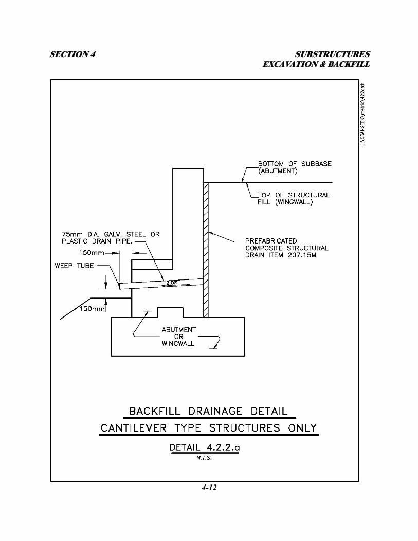
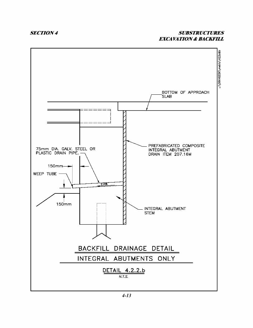
Prefabricated Composite Structural Drain – Item 207.15M shall be placed behind the back of all
walls, arches, and abutments, except integral abutments. See Detail 4.2.2.a. Prefabricated Composite
Integral Abutment Drain – Item 207.16M shall be placed behind the back of all integral abutments.
See Detail 4.2.2.b. In addition, 75 mm diameter weep holes through the structure shall be provided at
approximately 5.0 m maximum centers with a minimum of three per abutment. The weep tubes shall
be flush with the back face of the wall. The weep shall be outletted 150 mm above the finished grade
in front of a structure, except in the case of stream bridges, where they are to be outletted 150 mm
above low water. Weep tubes shall extend 150 mm beyond the substructure stem at the outlet. When
weep holes are placed in the backwall, weep tubes shall extend 150 mm beyond the bridge seat. In
certain instances, such as an abutment immediately adjacent to a sidewalk or roadway, a closed
drainage system may be required to carry water away from the area.
SECTION 4 SUBSTRUCTURES EXCAVATION & BACKFILL
4-12
SECTION 4 SUBSTRUCTURES EXCAVATION & BACKFILL
4-13
SECTION 4 SUBSTRUCTURES EMBANKMENT & SLOPE PROTECTION
4-14
4.2.3 - SHEETING AND COFFERDAMS
Sheeting and cofferdam recommendations will be included in the FDR report. The TA Geotechnical
Engineer is available to assist designers with any sheeting or cofferdam issues that may arise. The
Geotechnical Engineer will require information from the Hydraulic Analysis and Design Report
(HADR) in order to develop the correct recommendations. Refer to NYSDOT Bridge Manual,
Section 4 – Excavation, Sheeting, and Cofferdams for design and placement requirements.
4.2.4 - TREMIE SEAL
A tremie seal (concrete placed under water) is used when sheet piling cannot be driven sufficiently
deep to eliminate water intrusion into the cofferdam. Refer to NYSDOT Standard Specifications
Subsection 555-3.05, Depositing Structural Concrete Under Water. The need for a tremie seal and its
thickness shall be indicated in the FDR. The thickness of the tremie seal is based on ordinary high
water elevation (O.H.W.), from the HADR. Therefore the cofferdam should be designed to flood
when the water level exceeds O.H.W. to prevent uplift on the tremie seal prior to the placement of
the footing. This requirement is handled by using the appropriate plan note from Appendix B, as
indicated in the FDR.
4.3 - EMBANKMENT AND SLOPE PROTECTION
The following subsections provide information concerning embankment materials and slope
protection guidelines.

SECTION 4 SUBSTRUCTURES EMBANKMENT & SLOPE PROTECTION
4-15
4.3.1 - SLOPE PROTECTION
The preliminary drawings for each bridge shall show the slope protection to be used on slopes under
the structure. The slope protection shall extend a minimum of 1.0 m beyond the fascia lines of the
structure. The guidelines in this subsection indicate suggested materials for use in particular
situations.
Other materials may be used when there are special circumstances that warrant them, in which case,
approval by the DSD is required. A Divisional office that prefers slope protection material other than
that indicated on the preliminary drawings, may so indicate with comments on the drawing. These
guidelines may be varied somewhat from division to division, depending on preference. When
existing slope protection exists, its reuse shall be determined based on the material condition and its
suitability to the site.
4.3.1.1 - BRIDGES OVER LOCAL ROADS AND HIGHWAYS
The selection criteria for slope protection used on structures which span over local roads and
highways shall be as follows:
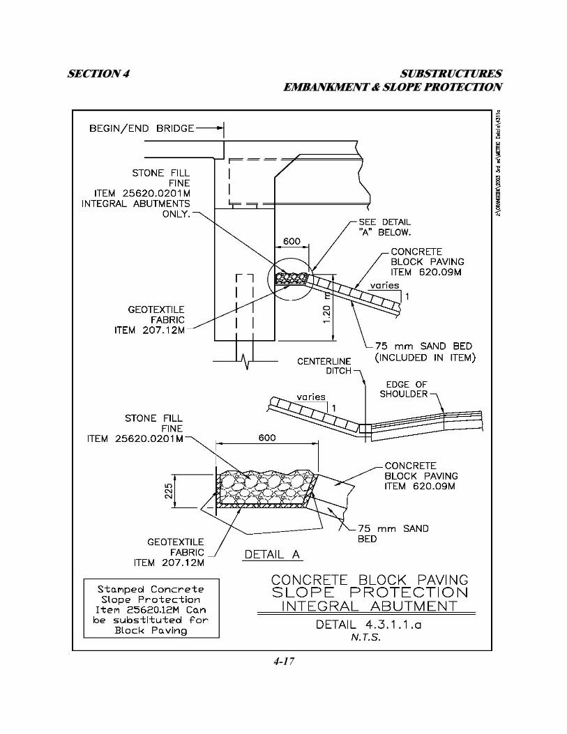
1. Concrete Block Paving, Item 620.09M, 150 mm thick laid on a 75 mm thick sand
cushion or Stamped Concrete Slope Protection, Item 25620.12M, shall be used for
slope protection at abutments for structures crossing over local roads and highways.
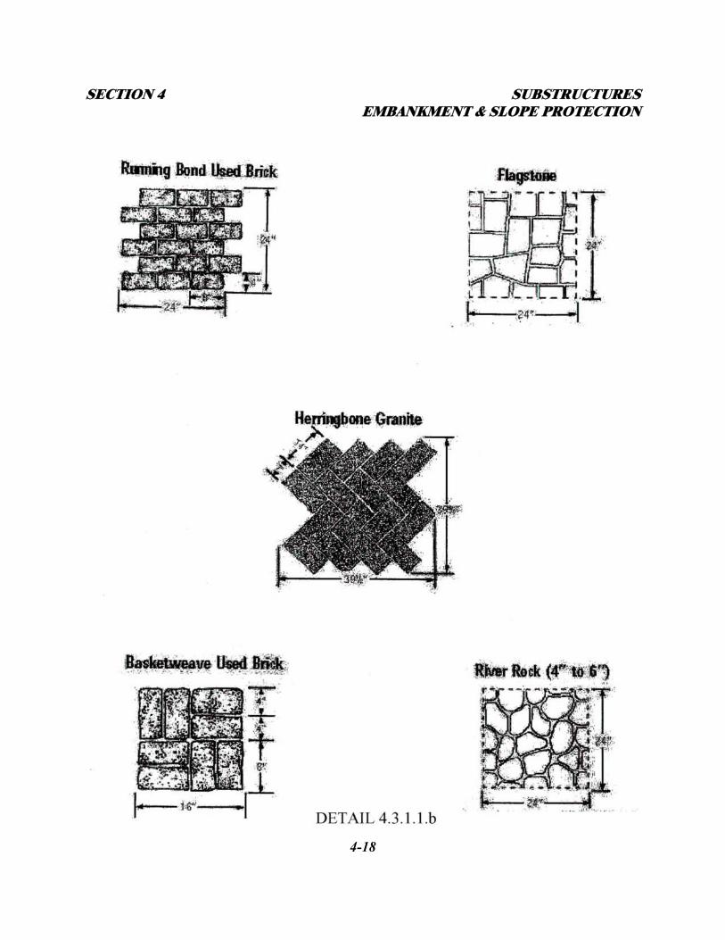
For the stamped concrete, five stamp pattern options have been selected which may
be chosen from as abutment slope protection profiles. The patterns are Running Bond
SECTION 4 SUBSTRUCTURES EMBANKMENT & SLOPE PROTECTION
4-16
Used Brick, Flagstone, Herringbone Granite, Basketweave Used Brick, and River
Rock. See Details 4.3.1.1.a and 4.3.1.1.b.
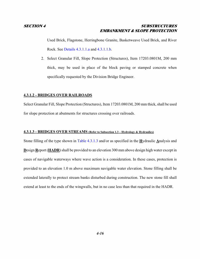
2. Select Granular Fill, Slope Protection (Structures), Item 17203.0801M, 200 mm
thick, may be used in place of the block paving or stamped concrete when
specifically requested by the Division Bridge Engineer.
4.3.1.2 - BRIDGES OVER RAILROADS
Select Granular Fill, Slope Protection (Structures), Item 17203.0801M, 200 mm thick, shall be used
for slope protection at abutments for structures crossing over railroads.
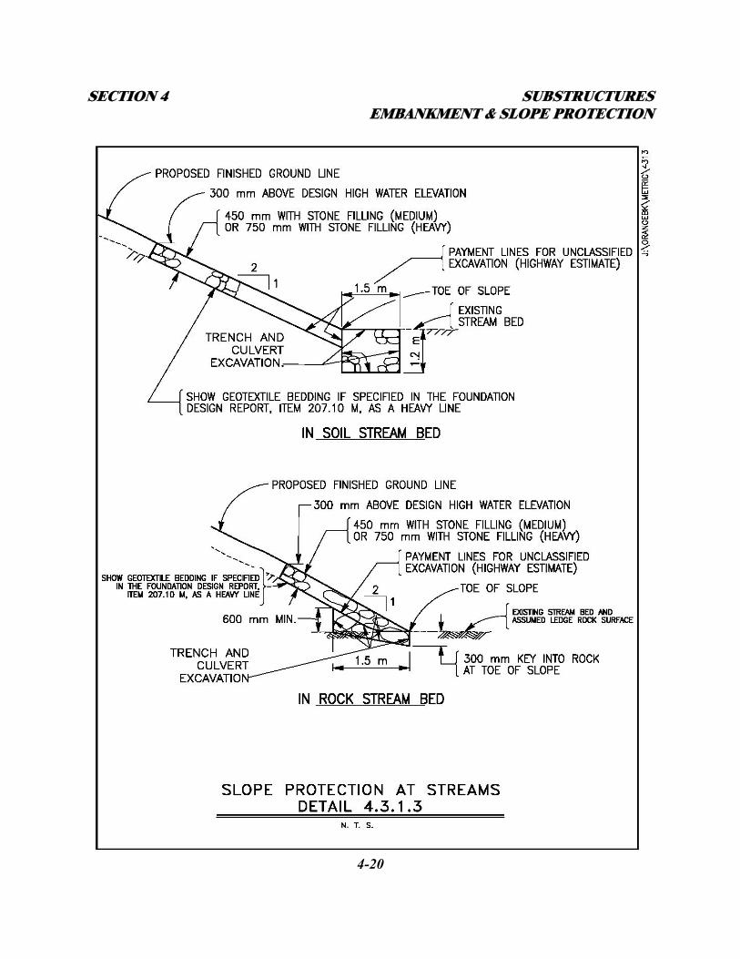
4.3.1.3 - BRIDGES OVER STREAMS (Refer to Subsection 1.3 – Hydrology & Hydraulics)
Stone filling of the type shown in Table 4.3.1.3 and/or as specified in the Hydraulic Analysis and
Design Report (HADR) shall be provided to an elevation 300 mm above design high water except in
cases of navigable waterways where wave action is a consideration. In these cases, protection is
provided to an elevation 1.0 m above maximum navigable water elevation. Stone filling shall be
extended laterally to protect stream banks disturbed during construction. The new stone fill shall
extend at least to the ends of the wingwalls, but in no case less than that required in the HADR.
SECTION 4 SUBSTRUCTURES EMBANKMENT & SLOPE PROTECTION
4-17
SECTION 4 SUBSTRUCTURES EMBANKMENT & SLOPE PROTECTION
4-18
SECTION 4 SUBSTRUCTURES EMBANKMENT & SLOPE PROTECTION
4-19
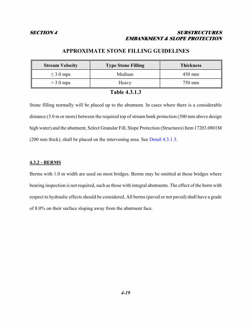
APPROXIMATE STONE FILLING GUIDELINES
Stream Velocity Type Stone Filling Thickness
≤ 3.0 mps Medium 450 mm
> 3.0 mps Heavy 750 mm
Table 4.3.1.3
Stone filling normally will be placed up to the abutment. In cases where there is a considerable
distance (3.0 m or more) between the required top of stream bank protection (300 mm above design
high water) and the abutment, Select Granular Fill, Slope Protection (Structures) Item 17203.0801M
(200 mm thick), shall be placed on the intervening area. See Detail 4.3.1.3.
4.3.2 - BERMS
Berms with 1.0 m width are used on most bridges. Berms may be omitted at those bridges where
bearing inspection is not required, such as those with integral abutments. The effect of the berm with
respect to hydraulic effects should be considered. All berms (paved or not paved) shall have a grade
of 8.0% on their surface sloping away from the abutment face.
SECTION 4 SUBSTRUCTURES EMBANKMENT & SLOPE PROTECTION
4-20
SECTION 4 SUBSTRUCTURES ABUTMENT FEATURES
4-21
4.4 - SUBSTRUCTURE MATERIALS
The primary materials used in the construction of substructure elements are Class HP concrete and
galvanized bar reinforcement.
4.4.1 - STRUCTURAL CONCRETE ITEM FOR SUBSTRUCTURE CONCRETE
All footing, stem, backwall and pedestal concrete shall be detailed, estimated, and bid under the
appropriate HP concrete item (units = m3 ). For footings on rock, backfill concrete (Class A) placed
below the planned bottom of footing elevation shall be paid for under the same item.
4.4.2 - GALVANIZED REINFORCEMENT IN SUBSTRUCTURES (See Section 5 – Reinforcement)
Galvanized reinforcement shall be used in all elements of new substructure units in order to protect
the reinforcement from corrosion accelerated by chloride saturation into the concrete. Chlorides
from roadway salt are dissolved in water draining from the roadway above, as well as in water
splashed from the roadway below. Galvanized reinforcement shall also be used in the repair and/or
rehabilitation of existing substructure units regardless of the type of existing reinforcement used.
4.5 - ABUTMENT FEATURES
4.5.1 - GENERAL
This subsection describes the various features of abutment elements. The material cost of the
concrete is the cheapest part of the total cost of concrete items. The forming, concrete placement,
and labor, constitute the major portion of the cost. Therefore, the shape of the concrete abutment
SECTION 4 SUBSTRUCTURES ABUTMENT FEATURES
4-22
should be made as simple as possible. The shape should be such that large flat forms and large pours
may be employed. New abutments shall be designed to conform to AASHTO seismic design criteria.
4.5.2 – ABUTMENT STEMS
Abutment stems shall be solid. Refer to Subsection 1.1 – Aesthetics, for information on surface
treatments. The stem shall be designed as a cantilever retaining wall resisting soil pressures on the
back as described in the FDR and loading from the superstructure. The bridge seat may either be
continuously sloped with individual pedestals or stepped. The top of bridge seat shall be reinforced
with No. 25 bars at 150 mm minimum centers to provide adequate reinforcing for bearing anchor
bolts. When individual pedestals are used, the top surface of the bridge seat between pedestals shall
have a 4.0% wash toward the front face of the abutment stem. Concrete cover for reinforcing at all
locations in abutment stems shall be 75 mm. Abutment stems shall have weep tubes as described in
Subsection 4.2.2. Protruding filleted seats (also known as corbels), which are used at the bridge seat
elevation below the backwall to widen the seat without increasing abutment stem thickness should
be avoided. The form work for these details is very costly. The concrete quantity savings would only
prove economical on taller abutments. They should only be considered on abutment stem heights of
9.0 meters or more. If the filleted seats are used, the toe and/or heel of the footing should be made
wide enough so that if the Contractor elects to pour the wall solid to eliminate the protrusion, the
wall will fit on the footing. Also, to facilitate the forming, the distance from the top of the footing to
the bottom of the protruding fillets should be made constant, rather than having the fillets parallel to
the bridge seat. The height variation can be made between the fillet and top of the header.
SECTION 4 SUBSTRUCTURES ABUTMENT FEATURES
4-23
4.5.2.1 - LOCATION OF PEDESTALS ON ABUTMENTS
On all abutments with pedestals on a bridge seat, the front face of the pedestal shall be flush with the
front face of the bridge seat. Pedestal height shall be between 150 mm and 450 mm. The top surface
under the bearing device shall be level. The remaining top surface shall have 2.0% wash toward the
front and away from the bearing.
4.5.3 - CANTILEVERED WINGWALLS (IN-LINE AND FLARED)
Cantilevered wingwalls are retaining walls rigidly connected to, and supported by, the abutment
stem. They have no foundation below the wingwall stem. Because of this arrangement, the length of
these walls is limited. These walls shall be designed horizontally due to the bending at the abutment
interface and vertically due to shear at the abutment foundation outside piles, spread footing, or
fascia girder, depending on the abutment type used. The actual length limitation will vary depending
on the abutment foundation capacity, the soil pressures on the back of the wall, the thickness of the
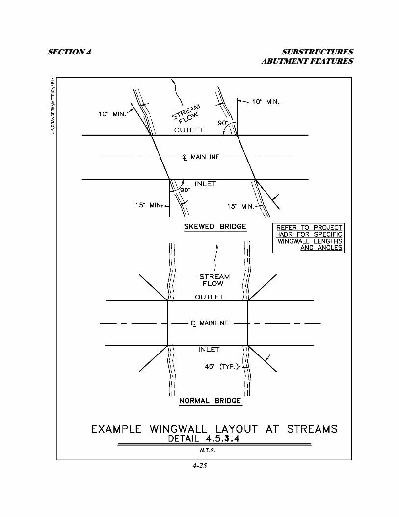
wall, and the amount of reinforcing in the wall. In-line wingwalls are preferred where practical. In
cases where the wingwalls are subject to hydraulic effects, flared wingwalls are the preferred option.
The length and angle of the wingwalls shall be as specified on the HADR. Detail 4.5.3 shows the
typical configuration for wingwalls on a skewed waterway crossing and a normal waterway
crossing.
Flared wingwalls may also be used on highway or railroad crossings in an effort to reduce the height
and length of the walls.
SECTION 4 SUBSTRUCTURES ABUTMENT FEATURES
4-24
4.5.4 – FREE-STANDING WINGWALLS (IN-LINE AND FLARED)
Free-standing wingwalls are retaining walls vertically cantilevered off an independent foundation
(spread footing or piles with cap as specified in the FDR). They may or may not be rigidly connected
to the abutment stem depending on the abutment type used. These wingwalls shall be designed as
cantilevered retaining walls resisting a 1 on 2 slope and surcharge in most cases. Design of the wall
will vary from end-to-end if the wingwall height varies significantly. Tapering the wingwall
thickness may be an economical option in this case if the wingwall is long. The quantity of concrete
savings resulting from tapering longer walls should be considered. If the wingwall is rigidly
connected to the abutment the designer may design for 67% of the maximum height of wall. In this
case the wingwall stem will be a constant thickness. In-line wingwalls are preferred where practical.
In cases where the wingwalls are subject to hydraulic effects, flared wingwalls are the preferred
option. The length and angle of the wingwalls shall be as specified on the HADR. Detail 4.5.3
shows the typical configuration for wingwalls on a skewed waterway crossing and a normal
waterway crossing. Flared wingwalls may also be used on highway or railroad crossings in an effort
to reduce the height and length of the walls.
SECTION 4 SUBSTRUCTURES ABUTMENT FEATURES
4-25
provost
provost
provost
3
SECTION 4 SUBSTRUCTURES ABUTMENT FEATURES
4-26
4.5.5 – BATTERED and STEPPED WINGWALLS
A battered wingwall is a free-standing wingwall with a battered face. Battering is done on taller
walls to reduce concrete quantities. The base of the wall is made thicker where it is needed and then
tapers up to a narrower top. Battered forms are more expensive than vertical forms and should be
avoided whenever possible, especially on short wingwalls. Stepping to vary a wall stem thickness is
always preferable to battering.
If battered forms are used, the batter should always remain constant, and the width of the wall at the
top of the batter should be wide enough so the form can be extended beyond the top of the batter and
still have enough room between the front and rear forms to easily place the concrete. Batters that
extend partially up a wall should be avoided. If partial batters are used, the height of the battered
portion should always be made a constant height. If the height of the wall varies, the height of the
battered portion should be constant with respect to the top of the footing, and the variation in height
should be made up in the upper vertical portion of the wall. This will allow the battered forms to be
reused and so reduce the unit cost of the concrete.
4.5.6 - U-WALL WINGWALLS
A U-wall wingwall is a free-standing wingwall positioned parallel to the bridge roadway extending
from the abutment stem back into the approach fill. They should be used only when R.O.W. is
limited in the area of the abutment or to prevent approach fill from spilling into a stream or wetland.
SECTION 4 SUBSTRUCTURES ABUTMENT FEATURES
4-27
4.5.7 - CURVED WINGWALLS
A curved wingwall is a free-standing wingwall with a horizontally curved outside face. Several
existing curved wingwalls can be seen on the Thruway. Their use was primarily for aesthetic
reasons. Curved wingwalls are very expensive to build due to the complicated forming and
reinforcement placement issues. They should not be used on any new structures. When replacing
existing curved wingwalls it is best to place a widened footing and wall on a chord and curve only
the outside face of the wall where possible.
4.5.8 – OTHER WINGWALL TYPES
In lieu of utilizing a poured concrete retaining wall, the Designer may select from the retaining wall
types listed in the NYSDOT Bridge Manual – Section 11.4. Included in this section is a description
of the wall type as well as effective height ranges that the walls are typically used for. The Designer
should request the assistance of the TA’s Geotechnical Engineer if any of these alternate wingwall
types are being considered.
The most common alternate wingwall types used for highway structures are Mechanically
Stabilized Earth Systems (MSES) and precast concrete modular wall systems.
DOT’s Standard Specification (Section 554) may be used for MSES wingwalls and abutments.
Further guidance on the use of MSES abutments can be found in the NYSDOT Bridge Manual –
Section 11.5.1.4. The Designer shall ensure that a seismic analysis for the proposed wall (or
SECTION 4 SUBSTRUCTURES INTEGRAL ABUTMENTS
4-28
abutment) is performed by the wall manufacturer. MSES retaining walls shall be designed for a
design life of 75 years. MSES abutments shall be designed for a design life of 100 years. These
requirements shall be specifically indicated on the plans.
The Thruway has developed a special specification for precast concrete modular wall systems.
This special specification differs from DOT’s standard specification (Section 632) by limiting
substitutions of new wall systems to the systems that have been reviewed, approved and used
successfully by DOT. Currently, these systems are Sta-Wal, T-Wall, and Doublewal. See the
Thruway Standard Sheets for appropriate details.
4.6 - INTEGRAL ABUTMENTS
The integral abutment consists of a concrete stem cast around, and supported by, a single row of
piles. The superstructure slab is cast monolithically with the top of stem encasing the girder ends in
concrete. Since the abutment is supported on a single line of piles, a concrete footing is not required.
One of the primary advantages of integral abutments is the elimination of the bridge deck expansion
joints, thereby reducing construction and maintenance costs. The integral abutment bridge concept is
based on the theory that due to the flexibility of the piling below the bottom of the abutment stem,
thermal stresses are transferred to the foundation by way of a rigid connection between the
superstructure and substructure. The concrete abutment contains sufficient bulk to be considered a
rigid mass. A positive connection with the ends of the beams or girders is created by their
encasement in reinforced concrete at the top of stem. This connection provides for load transfer from
SECTION 4 SUBSTRUCTURES INTEGRAL ABUTMENTS
4-29
the superstructure into the abutment stem and into the abutment piling.
4.6.1 - GUIDELINES ON USE
Integral Abutments are the preferred abutment type on Thruway projects because of the elimination
of bridge deck expansion joints and bearings. The criteria for the use of integral abutments include
limitations on the expansion span lengths, site geometry, site conditions, and the existing soil
conditions. The use of integral abutment bridges will only be limited by the constraints described in
the following subsections:
4.6.1.1 - EXPANSION LENGTHS
The movement of an integral abutment is largely attributed to thermal expansion and contraction of
the superstructure. The longer the expansion span length, the larger the longitudinal movement (and
rotation on taller stems) of the abutment. The expansion span length of an integral abutment
structure is equal to half the abutment centerline to abutment centerline dimension for single span
structures, and the abutment centerline to fixed pier centerline dimension for multi-span structures.
As the abutment pushes against the backfill during expansion, it is loaded horizontally by the passive
resistance of the backfill (passive earth pressure) or the compressive resistance of the selected
compressible inclusion material. Compressible inclusion material should meet the requirements of
ASTM C578. The larger the longitudinal movement of the abutment, the higher the passive
resistance. In order to keep these pressures reasonable, the Thruway Authority has established
expansion span length limitations. Expansion lengths up to 91.0 meters may be used without
SECTION 4 SUBSTRUCTURES INTEGRAL ABUTMENTS
4-30
restriction. Expansion lengths between 91.0 meters and 122.0 meters shall only be used with
approval from the DSD. Integral abutments shall not be used when expansion lengths exceed 122.0
meters.
4.6.1.2 – SOIL CONDITIONS
All integral abutments shall be supported on piles. All piles require sufficient depth of penetration,
3.6 m minimum (below preaugered holes described below) into acceptable soil layers. The purpose
of this is to avoid a stilt effect (foundation rotation about the bottom of the piles). Additional length
may be required as specified in the FDR to provide sufficient vertical and/or lateral support for the
pile and scour protection.
4.6.1.3 - HORIZONTAL ALIGNMENT
Only straight beams will be allowed. Curved superstructures will be allowed provided the beams are
straight and continuous between the abutments. Curved steel beams were eliminated to guard against
the possibility of bottom flange and web buckling caused by the beams trying to expand between the
restrained abutments. All beams shall be parallel to each other. The abutments and any intermediate
piers shall also be parallel to each other.
4.6.1.4 - GRADE
The maximum local vertical curve gradient between abutments shall be 5%.The maximum straight
grade allowed on integral abutment bridges is 10%.
SECTION 4 SUBSTRUCTURES INTEGRAL ABUTMENTS
4-31
4.6.1.5 - SKEW ANGLE
There is no skew limitation on integral abutment bridges. However, the effects of skew must be
analyzed and accounted for in the design of all of the structural components.
4.6.1.6 - UTILITIES (Refer to Subsection 1.6 - UTILITY COORDINATION AND COMMUNICATION)
Rigid utility conduits, such as gas, water and sewer, cannot pass through integral abutments. The
anticipated longitudinal movement of the superstructure and resultant rotational and translational
movement of the substructure make provision for these movements in rigid conduits difficult.
Conduits of this type should be located off the integral abutment. Flexible conduits for electrical,
telephone or cable TV utilities that are properly sleeved through the integral abutment are
acceptable.
4.6.2 – DESIGN AND DETAIL CONSIDERATIONS
4.6.2.1 - FOUNDATION TYPES
All integral abutments shall be supported on piles. Steel H or C.I.P. piles shall be used as
recommended in the FDR. All piles shall be in one single line. When steel H-piles are used, upon
initial sizing recommendation from the FDR, the designer shall verify the size and orientation using
the Rational Design Approach for Integral Abutment Bridge Piles. If the pile size indicated in the
FDR must be changed, the Geotechnical Engineer shall be informed, and a supplemental FDR will
be issued. All piles shall have sufficient depth of penetration, 3.6 m minimum into acceptable soil
layers (below the preaugered holes described below). The exact length required shall be specified in
SECTION 4 SUBSTRUCTURES INTEGRAL ABUTMENTS
4-32
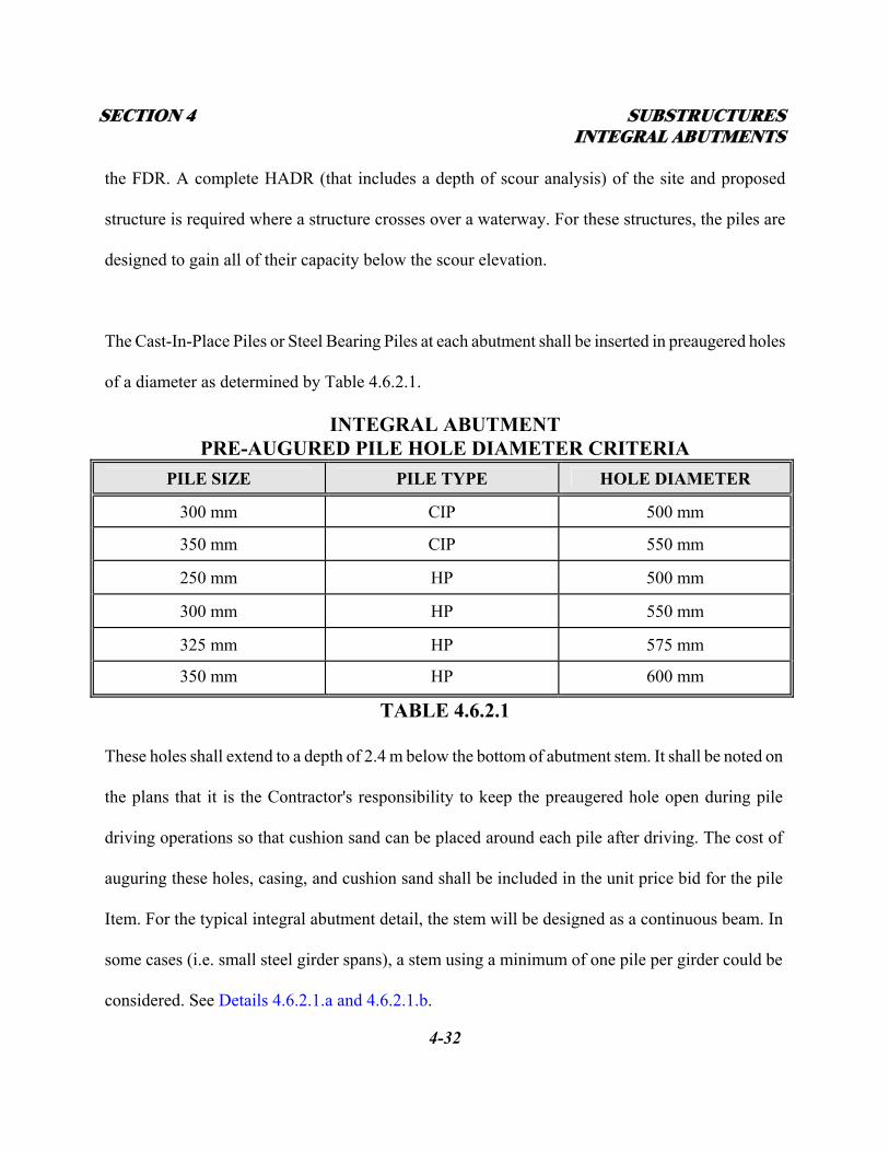
the FDR. A complete HADR (that includes a depth of scour analysis) of the site and proposed
structure is required where a structure crosses over a waterway. For these structures, the piles are
designed to gain all of their capacity below the scour elevation.
The Cast-In-Place Piles or Steel Bearing Piles at each abutment shall be inserted in preaugered holes
of a diameter as determined by Table 4.6.2.1.
INTEGRAL ABUTMENT PRE-AUGURED PILE HOLE DIAMETER CRITERIA
PILE SIZE PILE TYPE HOLE DIAMETER
300 mm CIP 500 mm
350 mm CIP 550 mm
250 mm HP 500 mm
300 mm HP 550 mm
325 mm HP 575 mm
350 mm HP 600 mm
TABLE 4.6.2.1
These holes shall extend to a depth of 2.4 m below the bottom of abutment stem. It shall be noted on
the plans that it is the Contractor's responsibility to keep the preaugered hole open during pile
driving operations so that cushion sand can be placed around each pile after driving. The cost of
auguring these holes, casing, and cushion sand shall be included in the unit price bid for the pile
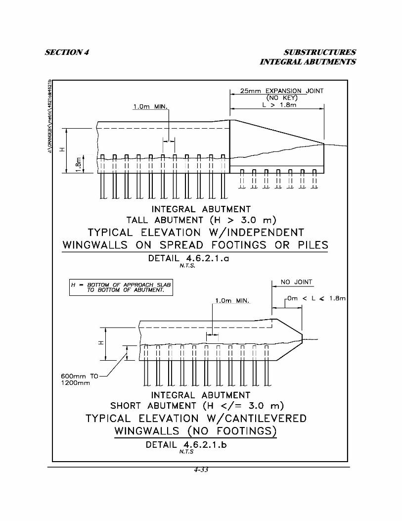
Item. For the typical integral abutment detail, the stem will be designed as a continuous beam. In
some cases (i.e. small steel girder spans), a stem using a minimum of one pile per girder could be
considered. See Details 4.6.2.1.a and 4.6.2.1.b.
SECTION 4 SUBSTRUCTURES INTEGRAL ABUTMENTS
4-33

SECTION 4 SUBSTRUCTURES INTEGRAL ABUTMENTS
4-34
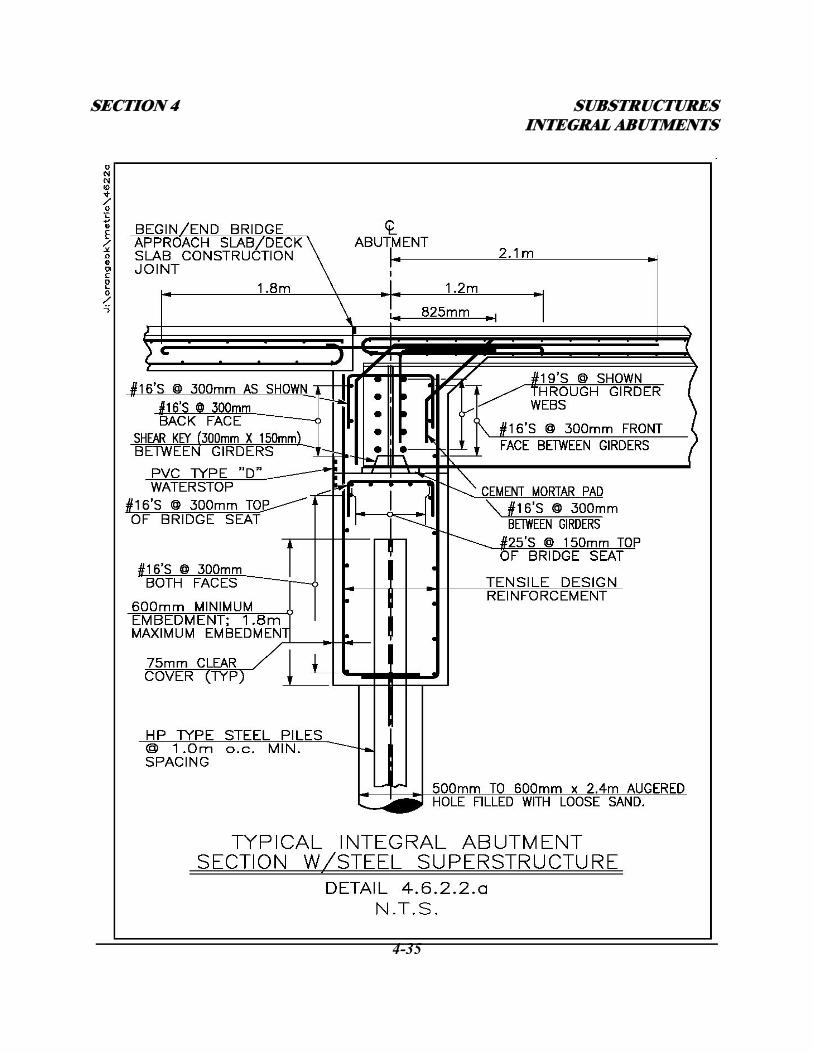
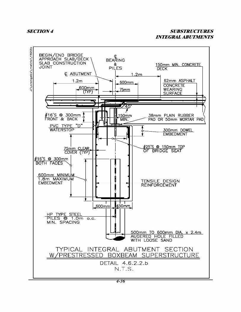
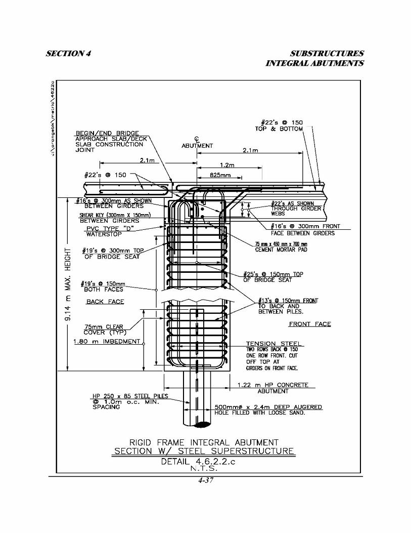
4.6.2.2 - ABUTMENT STEM
A minimum thickness of 1.0 m shall be required for integral abutment stems unless otherwise noted.
The stem is designed as a reinforced wall or column fixed at the top and pinned at the bottom. The
stem shall be designed to resist the moments induced from the SDL, LL, thermal expansion, and soil
loading and the vertical loads from the superstructure, See Details 4.6.2.2.a, 4.6.2.2.b, 4.6.2.2.c,
4.6.2.6.b, and 4.6.3.1.
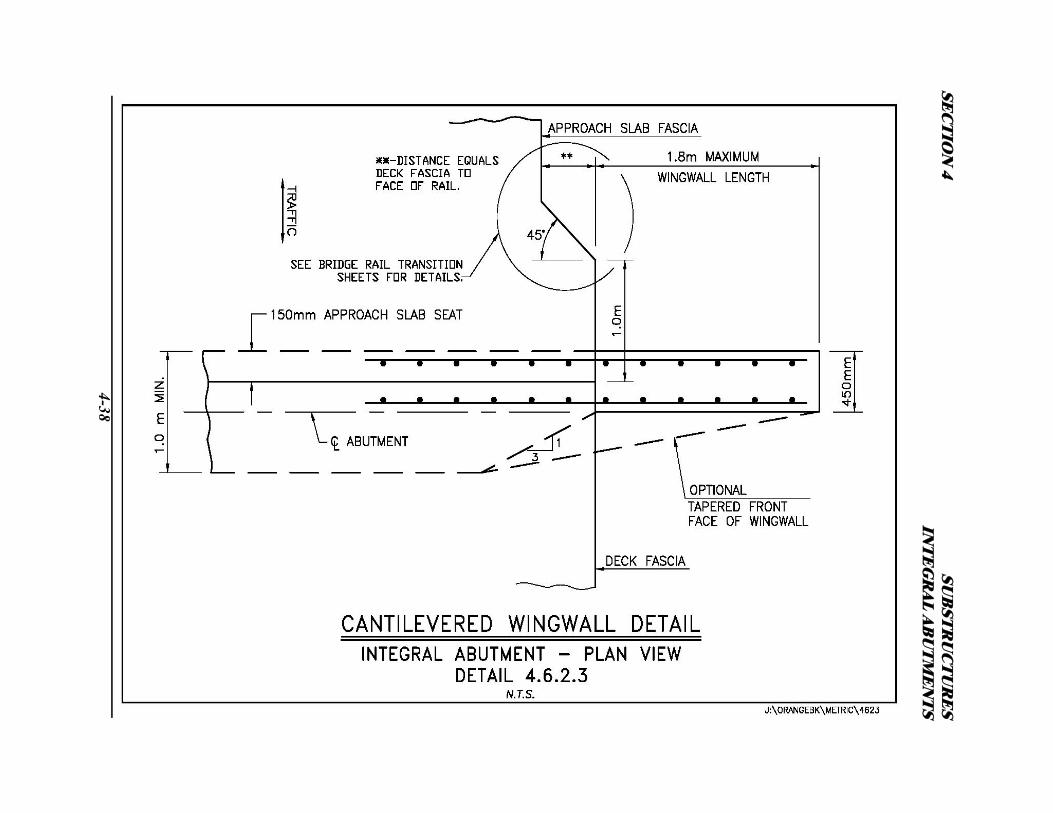
4.6.2.3 - WINGWALLS
Wingwalls shall be a minimum of 450 mm thick. Wingwalls shall have a constant thickness or be
tapered depending on height and length. Tapering the thickness of larger walls from end to end may
result in significant concrete quantity savings. In-line wingwalls are the preferred arrangement for
integral abutments. Flared walls shall be used at stream crossings and taller abutments where
wingwall length may be significantly reduced by flaring. U-walls shall not be used on integral
abutment bridges. U-walls are not allowed because they prevent the abutment from moving freely
during thermal changes. Wingwalls 1.8 m or less in length shall be cantilevered off the integral
abutment. See Subsection 4.5.3 and Details 4.6.2.1.b & 4.6.2.3. Wingwalls greater than 1.8 m in
length shall be self supported on footings or piles and separated from the abutment with a multi-
directional (keyless) expansion joint. See Subsection 4.5.4 and Detail 4.6.2.1.a. This joint allows
the abutment to deflect under thermal forces without inducing stresses into the wingwall. This joint
shall consist of a layer of closed cell foam between the abutment and wingwall and a PVC water
stop at the back of the joint. See Detail C3-7 in Appendix C.
SECTION 4 SUBSTRUCTURES INTEGRAL ABUTMENTS
4-35
SECTION 4 SUBSTRUCTURES INTEGRAL ABUTMENTS
4-36
SECTION 4 SUBSTRUCTURES INTEGRAL ABUTMENTS
4-37
SEC
TIO
N 4
SUB
STR
UC
TU
RE
S IN
TE
GR
AL A
BU
TM
EN
TS
4-38
SECTION 4 SUBSTRUCTURES INTEGRAL ABUTMENTS
4-39
4.6.2.4 - SUPERSTRUCTURE TYPE
Steel beams or plate girders may be used on both conventional integral abutment bridges and rigid
frame integral abutment bridges. Prestressed concrete beams shall only be used on conventional
integral abutment bridges. The deck may be either cast-in-place or precast. Refer to Section 3 –
Decks, for more information. The design of the superstructure will vary depending on whether the
bridge is a conventional integral abutment type structure or a rigid frame integral abutment type
structure. Refer to Subsection 4.6.3 – Integral Abutment Bridge Design Procedures for details.
4.6.2.5 - BEARINGS
When steel beams or plate girders are used in the superstructure a rectangular mortar pad will be
required under the beams on the abutment bridge seat. The Steel beams will be connected to the
abutment with reinforcing steel running horizontally through the web. See Detail 4.6.2.2.a. In
addition, on rigid frame structures, the front face abutment vertical reinforcing shall continue up
through the bottom flange of each beam. See Detail 4.6.2.2.c. Prestressed beams require individual
rectangular plain rubber bearing pads placed perpendicular to the centerline of the beam. Prestressed
beams shall be connected to the abutment with anchor rods and reinforcing steel. See Detail
4.6.2.2.b.
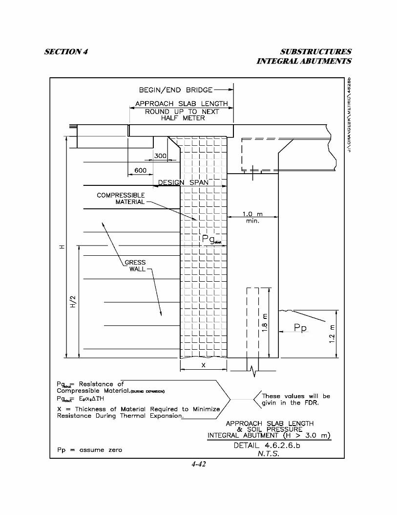
4.6.2.6 - APPROACH SLABS
Approach slabs are required for all integral abutments. The purpose of the approach slab is to bridge
the fill directly behind the abutment and provide a transition from the approach pavement to the
SECTION 4 SUBSTRUCTURES INTEGRAL ABUTMENTS
4-40
bridge deck. Approach slab thickness shall be a minimum of 300 mm. Thickness may be greater
depending on the design span length of the approach slab. Approach slab lengths vary depending on
the height of the abutment and backfill treatment. In most cases the length is determined based on
the intercept of the backfill active failure plane from the bottom of the abutment stem to the bottom
of the approach slab (ground line). See Detail 4.6.2.6.a. On taller integral abutments, where the
backfill is supported independently with a GRES wall, the length will be determined as shown on
Detail 4.6.2.6.b. The end of the approach slab shall be supported on a sleeper slab. This end of the
approach slab shall be perpendicular to the centerline of the roadway and run from face-of-guiderail
to face-of-guiderail. The abutment end of the approach slab shall be rigidly connected to the
abutment as shown in Details 4.6.2.2.a through 4.6.2.2.c. Polyethylene curing covers shall be placed
on top of the subbase prior to pouring the approach slab. This sheet will aid in allowing free thermal
movement of the approach slab on the subbase material. The approach slab shall incorporate both
top and bottom steel reinforcement. The top mats (transverse and longitudinal) of reinforcement
shall be a minimum of #16 Bars @ 300 mm in both directions. The bottom mat longitudinal
reinforcement shall be designed for traffic loading (reinforcing parallel to traffic) with the design
span being a simple span from the back face of the abutment to 300 mm beyond the intersection
with the failure plane. The bottom mat transverse reinforcement shall be for temperature only. Refer
to AASHTO Article 3.24.3.2 for the minimum requirements when the main reinforcement is
parallel to traffic.

SECTION 4 SUBSTRUCTURES INTEGRAL ABUTMENTS
4-41
SECTION 4 SUBSTRUCTURES INTEGRAL ABUTMENTS
4-42
SECTION 4 SUBSTRUCTURES INTEGRAL ABUTMENTS
4-43
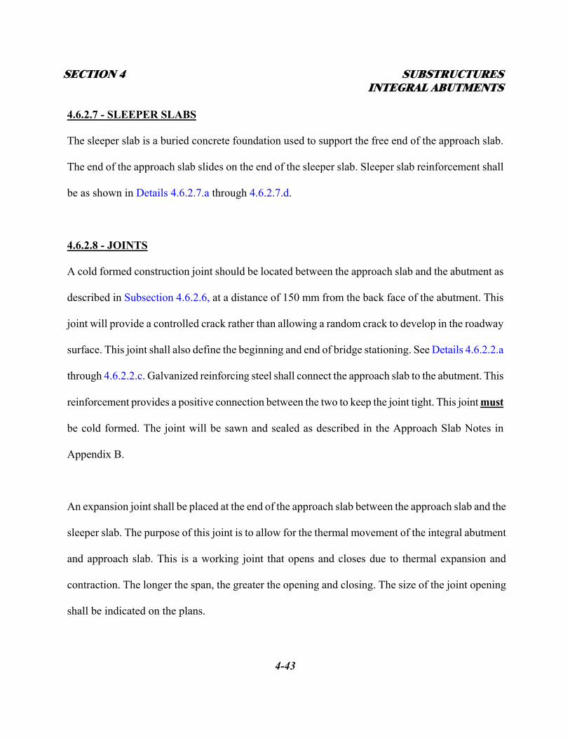
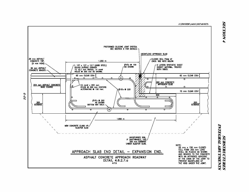
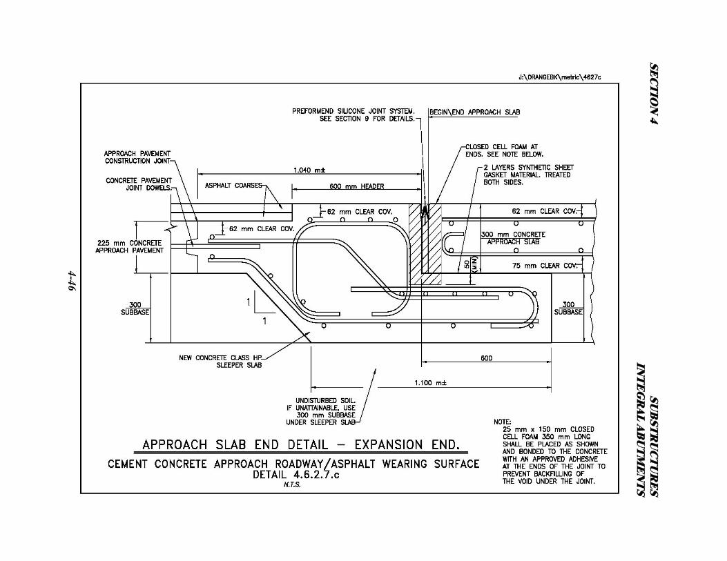
4.6.2.7 - SLEEPER SLABS
The sleeper slab is a buried concrete foundation used to support the free end of the approach slab.
The end of the approach slab slides on the end of the sleeper slab. Sleeper slab reinforcement shall
be as shown in Details 4.6.2.7.a through 4.6.2.7.d.
4.6.2.8 - JOINTS
A cold formed construction joint should be located between the approach slab and the abutment as
described in Subsection 4.6.2.6, at a distance of 150 mm from the back face of the abutment. This
joint will provide a controlled crack rather than allowing a random crack to develop in the roadway
surface. This joint shall also define the beginning and end of bridge stationing. See Details 4.6.2.2.a
through 4.6.2.2.c. Galvanized reinforcing steel shall connect the approach slab to the abutment. This
reinforcement provides a positive connection between the two to keep the joint tight. This joint must
be cold formed. The joint will be sawn and sealed as described in the Approach Slab Notes in
Appendix B.
An expansion joint shall be placed at the end of the approach slab between the approach slab and the
sleeper slab. The purpose of this joint is to allow for the thermal movement of the integral abutment
and approach slab. This is a working joint that opens and closes due to thermal expansion and
contraction. The longer the span, the greater the opening and closing. The size of the joint opening
shall be indicated on the plans.
SEC
TIO
N 4
SUB
STR
UC
TU
RE
S IN
TE
GR
AL A
BU
TM
EN
TS
4-44
SEC
TIO
N 4
SUB
STR
UC
TU
RE
S IN
TE
GR
AL A
BU
TM
EN
TS
4-45
SEC
TIO
N 4
SUB
STR
UC
TU
RE
S IN
TE
GR
AL A
BU
TM
EN
TS
4-46

SEC
TIO
N 4
SUB
STR
UC
TU
RE
S IN
TE
GR
AL A
BU
TM
EN
TS
4-47
SECTION 4 SUBSTRUCTURES INTEGRAL ABUTMENTS
4-48
The following criteria are recommended for integral abutment joint treatments:
A. Expansion lengths less than 18.0 m: No provisions for expansion at the ends of the approach
slabs are required if asphalt approach pavements are used. When the approach pavement is
rigid cement concrete, use a preformed silicone joint system between the sleeper slab and the
approach pavement. See Detail 4.6.2.7.d .
B. Expansion Lengths from 18.0 m to 45.0 m: Provisions for expansion at the ends of approach
slabs will require the use of a preformed silicone joint system between the sleeper slab and
the approach slab with asphalt concrete approach pavement. See Detail 4.6.2.7.a. A
preformed silicone joint system between the sleeper slab and the approach slab shall also be
used with rigid concrete approach pavement. See Details 4.6.2.7.b and 4.6.2.7.c.
C. Expansion length between 45.0 m and 91.0 m: Provision shall be made for expansion at the
end of the approach slab. If at all possible, the span arrangement and interior bearing
selection shall be such that approximately equal movements will occur at each abutment. See
“B” above.
D. Expansion length between 91.0 m to 122.0 m: Lengths in this range shall be approved by the
DSD on an individual basis. Provision for expansion shall be made at the end of each
approach slab with an appropriate joint. Refer to Section 9 – Joints, for selecting the
appropriate joint type between the sleeper slab and the approach slab based on the expected
thermal movement.
E. Expansion lengths over 122.0 m: Integral abutment bridges shall not be used with expansion
lengths over 122.0 m.
SECTION 4 SUBSTRUCTURES INTEGRAL ABUTMENTS
4-49
4.6.2.9 - SLOPE PROTECTION
Slope protection in front of integral abutments shall typically be concrete block paving or stamped
concrete as described in Subsection 4.3 – Embankment and Slope Protection. See Details 4.3.1.1.a
& 4.3.1.1.b. Where a bridge crosses a waterway the slope protection will be as required in the
HADR. Bedding requirements, such as geotextile, will be specified in the FDR.
4.6.2.10 - FREEBOARD/SUBMERGED INLETS
Structures with reduced freeboard or submerged inlets will be subjected to a greater general and
local scour and impact damage. Therefore, structure height should include at least 600 mm of
freeboard above Design High Water elevation (DHW) unless more clearance is required by the
HADR. The fixity between the superstructure and substructure on integral abutment bridges will
provide adequate protection against superstructure uplift and movement.
4.6.3 - INTEGRAL ABUTMENT BRIDGE DESIGN PROCEDURES
The design of structures with integral abutments requires some modifications to the AASHTO
Standard Specifications. Those modifications are presented in the following subsections.
4.6.3.1 – SUBSTRUCTURES
A. Preliminary abutment pile sizes will be given in the FDR. The designer shall verify the size
and orientation of the piles using the Rational Design Approach for Integral Abutment
Bridge Piles. In general, the pile is assumed fixed in the abutment stem and fixed in the soil
SECTION 4 SUBSTRUCTURES INTEGRAL ABUTMENTS
4-50
at some depth below the pre-augured hole. The piles experience compound bending and
vertical loading and will be designed plastically in most cases. If the pile size indicated in
the FDR must be changed, the Geotechnical Engineer shall be informed, and a supplemental
FDR will be issued. Detailed design procedures and programs are available in the Structures
Design Bureau for this type of design. Refer to Table 4.6.2.1 for typical pile types and sizes.
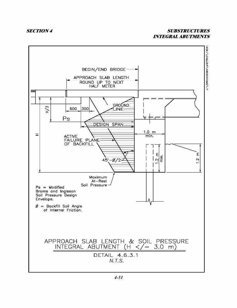
B. On integral abutment stems ≤ 3.0 m high, the stem concrete and vertical reinforcing steel
shall be designed for a combination of the soil pressure developed against the back of stem
from either full passive pressure or the modified Broms and Ingleson Design Envelope
shown on Detail 4.6.3.1, and the moments induced in the abutment from SDL and Live Load
on the superstructure. The abutment is assumed rigidly connected to the superstructure and
the piles, not allowing relative rotation or translation between the elements. Detailed design
procedures and programs are available in the Structures Design Bureau for this type of
design.
C. On Integral abutments > 3.0 m high where the Modified Broms and Ingleson Design
Envelope may produce an impractical design, i.e. too much reinforcement required, the stem
shall be isolated from the backfill soil pressure as shown on Detail 4.6.2.6.b. The FDR will
provide the GRESS design. For projects where a GRESS retained backfill is too costly due
to site conditions, a project specific solution will be determined in the FDR. The stem
concrete and vertical reinforcing steel shall be designed for the moment on the stem due to a
combination of the lateral resistance of the Geofoam during thermal expansion and the
moments induced in the abutment from SDL and Live Load on the superstructure.
SECTION 4 SUBSTRUCTURES INTEGRAL ABUTMENTS
4-51
SECTION 4 SUBSTRUCTURES INTEGRAL ABUTMENTS
4-52
The abutment is assumed rigidly connected to the superstructure and the piles, not allowing
relative rotation or translation between the elements. Detailed design procedures and
programs are available in the Structures Design Bureau for this type of design. The actual
Geofoam resistance and application point(s) will be given in the FDR. This type of
configuration eliminates the need to design for passive soil pressure in the seismic
requirements of AASHTO Division IA Subsection 6.4.3(B).
D. Horizontal reinforcement in the abutment stem shall be designed continuously between the
piles for the loading of the passive resistance during thermal expansion.
E. Wingwalls integral with the main abutment stem shall be designed as vertically cantilevered
over the outside piles and horizontally cantilevered at the interface with the abutment stem.
These wingwalls must be designed to support the loading due to passive soil pressure during
thermal expansion as given in the FDR.
F. Wingwalls separate from the main abutment stem shall be designed as vertically
cantilevered retaining walls resisting active soil pressure from the approach backfill.
4.6.3.2 – SUPERSTRUCTURES
A. The maximum span lengths shall be as specified in Subsection 4.6.1.1.
B. On traditional integral abutment bridges the superstructure main load carrying members and
deck shall be designed in the normal manner assuming simple supports at the abutments and
continuous over the pier(s) for positive bending within the spans and negative bending and
shear at the pier. At the abutments, the superstructure main load carrying members and deck
SECTION 4 SUBSTRUCTURES JOINTLESS BRIDGE ABUTMENTS
4-53
shall be designed for negative bending and shear assuming the abutment ends are fixed
against rotation.
C. On rigid frame integral abutment bridges the superstructure main load carrying members and
deck shall be considered simple spans until the deck ends are poured at the substructures.
For SDL and LL the superstructure shall be designed for positive and negative bending and
shear assuming rigid connections at all substructures. Detailed design procedures and
programs are available in the Structures Design Bureau for this type of design.
D. Approach slabs shall be designed as reinforced concrete beams as detailed in Subsection
4.6.2.6 with design reinforcing in the bottom running parallel to traffic.
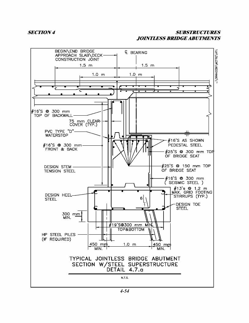
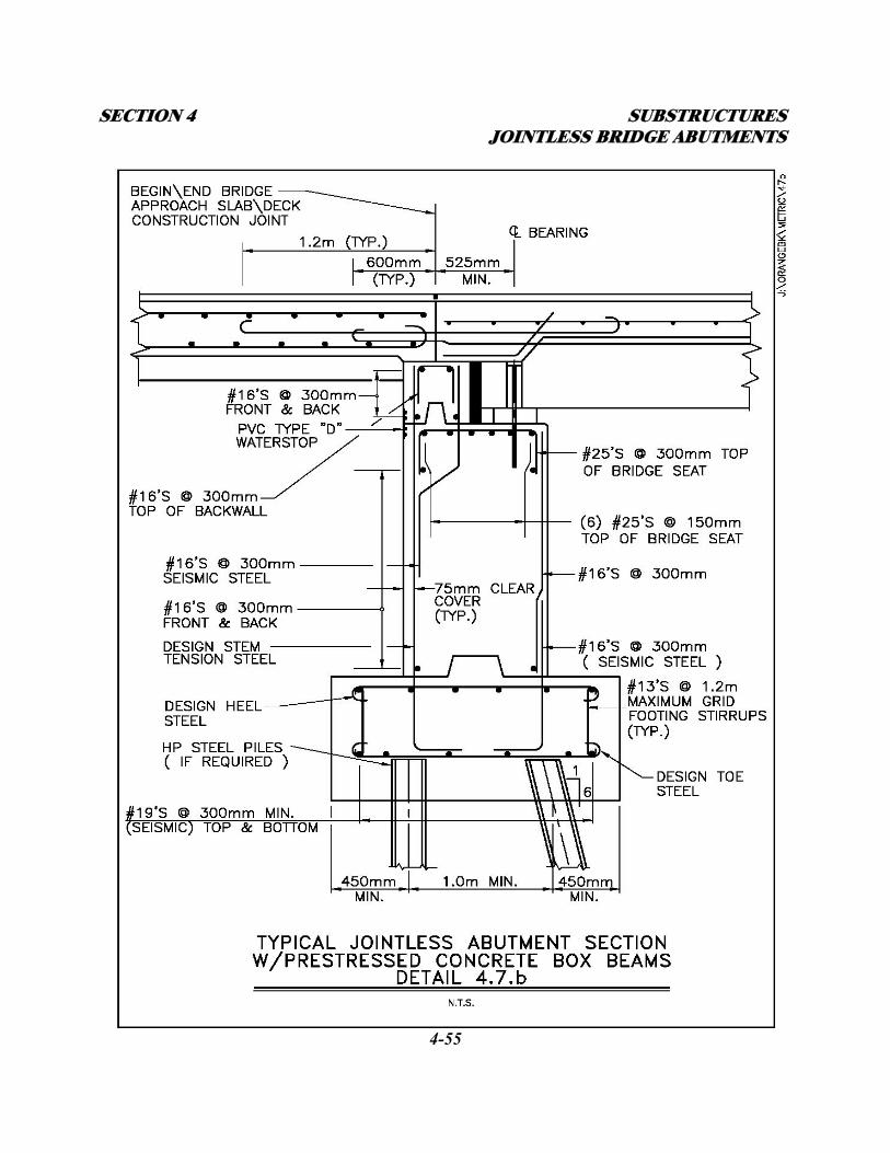
4.7 – JOINTLESS BRIDGE ABUTMENTS
The jointless bridge abutment consists of a concrete stem supported on a spread footing or multi-
row pile cap. The superstructure sits on bearings on an abutment bridge seat or pedestals. The
superstructure deck is continuous with the approach slab over an abutment backwall. The backwall
is rigidly attached to the abutment stem and also supports the backfill beneath the approach slab.
Expansion of the deck and approach slab over the backwall is achieved with sheet gasket material
on top of the backwall used to form a bond breaker. Expansion and contraction of the roadway
surface is handled at the approach slab/sleeper slab interface similar to that of the integral abutment
configuration. This type of abutment eliminates the need for expansion joints on the bridge. See
Details 4.7.a and 4.7.b.
SECTION 4 SUBSTRUCTURES JOINTLESS BRIDGE ABUTMENTS
4-54
SECTION 4 SUBSTRUCTURES JOINTLESS BRIDGE ABUTMENTS
4-55
SECTION 4 SUBSTRUCTURES JOINTLESS BRIDGE ABUTMENTS
4-56
4.7.1 - GUIDELINES ON USE
Jointless bridge Abutments shall only be used when the FDR restricts the use of integral abutments.
The criteria for the use and restrictions of jointless bridge abutments are described in the following
subsections.
4.7.1.1 - EXPANSION LENGTHS
The movement of the superstructure over the backwall of a jointless bridge abutment is largely
attributed to thermal expansion and contraction of the superstructure. The longer the expansion span
length, the larger the longitudinal movement of the superstructure. The expansion length of a
jointless bridge abutment structure is equal to the abutment centerline to abutment centerline
dimension for single span structures, and the abutment centerline to fixed pier centerline dimension
for multi-span structures. As the superstructure expands and contracts, the deck/approach slab slide
over the backwall. The backwall is loaded horizontally from the at-rest soil pressure behind it and
the frictional force from the superstructure movement. Care must be taken to assure that the
superstructure beams or girders do not contact the backwall during maximum thermal expansion. As
long as these movements are accounted for, there is no expansion length limitation for this type of
abutment.
4.7.1.2 – SOIL CONDITIONS
Site soil conditions shall be analyzed in the FDR from existing and new soil borings. The FDR (and
HADR if spanning a waterway) will determine whether the jointless bridge abutments shall be
SECTION 4 SUBSTRUCTURES JOINTLESS BRIDGE ABUTMENTS
4-57
supported on a spread footing or multi-row pile cap. The appropriate foundation type will be based
on the geometry, loading, and site conditions at the structure.
4.7.1.3 - HORIZONTAL ALIGNMENT
Straight or curved beams and superstructures will be allowed. On curved structures, thermal
movements of the superstructure (both longitudinal and transverse) must be considered in the design
of the various elements.
4.7.1.4 - GRADE
There is no maximum grade for bridges on jointless bridge abutments. However, the direction of
thermal expansion should be uphill wherever possible.
4.7.1.5 - SKEW ANGLE
There is no skew limitation on bridges with jointless bridge abutments. However, the effects of skew
must be analyzed and accounted for in the design of all of the structural components.
4.7.1.6 - UTILITIES (Refer to Subsection 1.6 - UTILITY COORDINATION AND COMMUNICATION)
Since jointless bridge abutments and backwalls do not move, all utilities may run through the stem
and backwall with appropriate sleeving as necessary.
SECTION 4 SUBSTRUCTURES JOINTLESS BRIDGE ABUTMENTS
4-58
4.7.2 – DESIGN AND DETAIL CONSIDERATIONS
4.7.2.1 - FOUNDATION TYPES
All jointless bridge abutments shall be supported on a spread footing or multi-row pile cap. Steel H
or C.I.P. piles shall be used as recommended in the FDR. Exact length required shall be specified in
the FDR. A complete HADR (that includes a depth of scour analysis) of the site and proposed
structure is required where a structure crosses over a waterway. For these structures, the piles are
designed to gain all of their capacity below the scour elevation.
4.7.2.2 - ABUTMENT STEM
The abutment stem thickness shall be determined from the geometry of the bridge seat and
backwall. The bridge seat/pedestals must be deep and wide enough to provide room for the
appropriate bearing with required edge and end clearances, and allow for thermal movement of the
superstructure without coming in contact with the backwall. The backwall shall be a minimum of
450 mm thick. The use of corbels at the back and bottom of the backwall to reduce abutment stem
thickness should be avoided. Refer to Subsection 4.5.2.
4.7.2.3 - WINGWALLS
Wingwalls shall be a minimum of 450 mm thick. Wingwalls shall have a constant thickness or be
tapered depending on height and length. Tapering the thickness of larger walls from end to end may
result in significant concrete quantity savings. In-line wingwalls are the preferred arrangement for
jointless bridge abutments. Flared walls shall be used at stream crossings and taller abutments where
SECTION 4 SUBSTRUCTURES JOINTLESS BRIDGE ABUTMENTS
4-59
wingwall length may be significantly reduced by flaring. U-walls should not be used on jointless
bridge abutments. U-walls are discouraged because the expanding and contracting approach slab
tends to bind on the U-walls. For wingwalls cantilevered off the jointless bridge abutment stem, see
Subsection 4.5.3 and Detail 4.6.2.3. For wingwalls self supported on footings or piles and
connected to the abutment with a keyed construction, contraction, or expansion joint, see Subsection
4.5.4., and Details C3-13 through C3-19 in Appendix C.
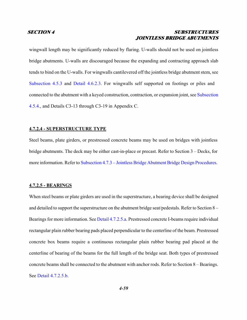
4.7.2.4 - SUPERSTRUCTURE TYPE
Steel beams, plate girders, or prestressed concrete beams may be used on bridges with jointless
bridge abutments. The deck may be either cast-in-place or precast. Refer to Section 3 – Decks, for
more information. Refer to Subsection 4.7.3 – Jointless Bridge Abutment Bridge Design Procedures.
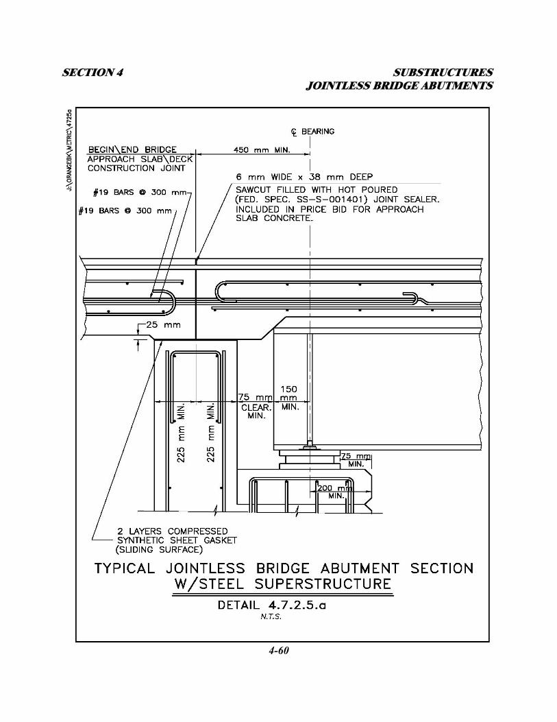
4.7.2.5 - BEARINGS
When steel beams or plate girders are used in the superstructure, a bearing device shall be designed
and detailed to support the superstructure on the abutment bridge seat/pedestals. Refer to Section 8 –
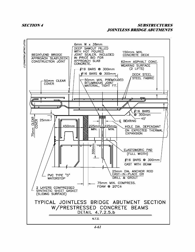
Bearings for more information. See Detail 4.7.2.5.a. Prestressed concrete I-beams require individual
rectangular plain rubber bearing pads placed perpendicular to the centerline of the beam. Prestressed
concrete box beams require a continuous rectangular plain rubber bearing pad placed at the
centerline of bearing of the beams for the full length of the bridge seat. Both types of prestressed
concrete beams shall be connected to the abutment with anchor rods. Refer to Section 8 – Bearings.
See Detail 4.7.2.5.b.
SECTION 4 SUBSTRUCTURES JOINTLESS BRIDGE ABUTMENTS
4-60
SECTION 4 SUBSTRUCTURES JOINTLESS BRIDGE ABUTMENTS
4-61
SECTION 4 SUBSTRUCTURES JOINTLESS BRIDGE ABUTMENTS
4-62
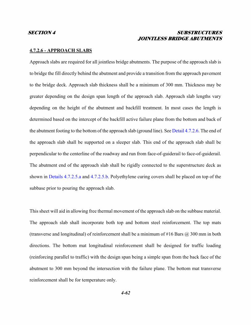
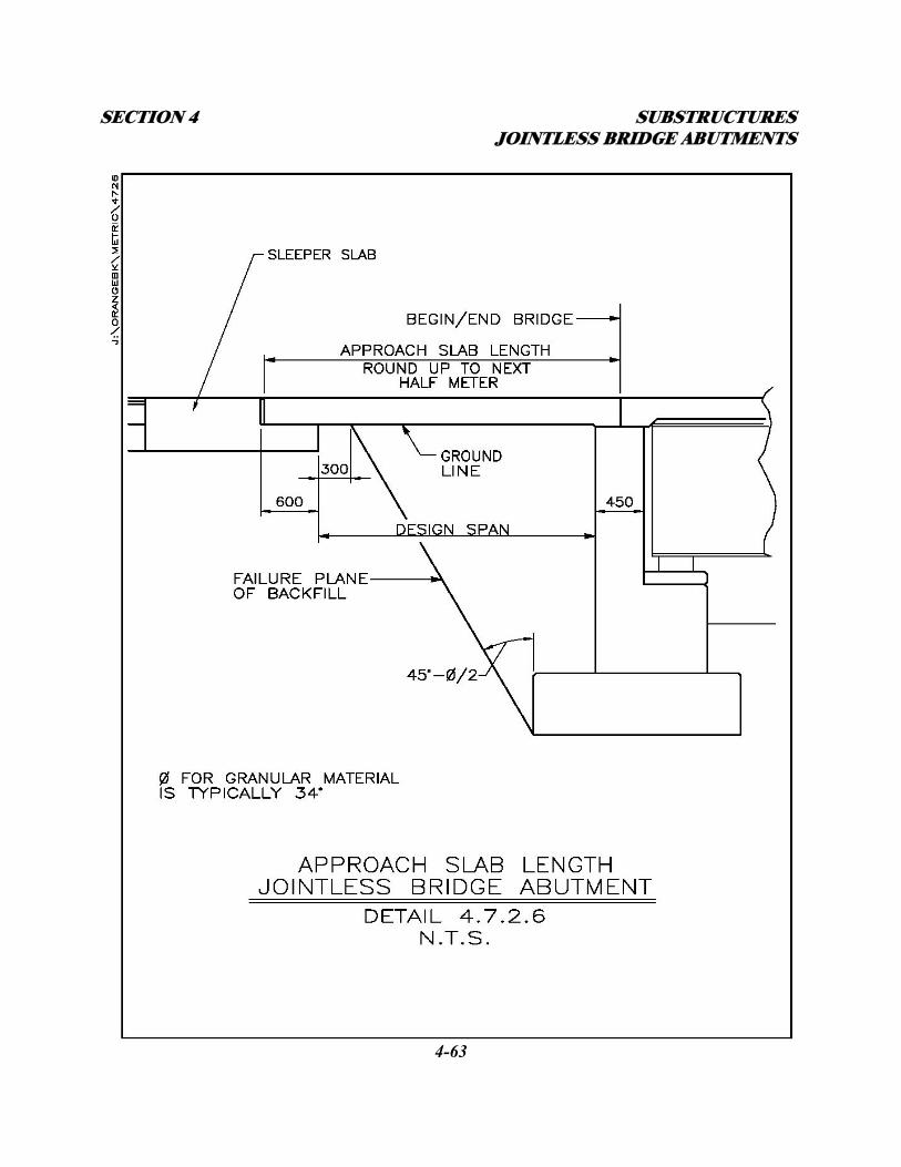
4.7.2.6 - APPROACH SLABS
Approach slabs are required for all jointless bridge abutments. The purpose of the approach slab is
to bridge the fill directly behind the abutment and provide a transition from the approach pavement
to the bridge deck. Approach slab thickness shall be a minimum of 300 mm. Thickness may be
greater depending on the design span length of the approach slab. Approach slab lengths vary
depending on the height of the abutment and backfill treatment. In most cases the length is
determined based on the intercept of the backfill active failure plane from the bottom and back of
the abutment footing to the bottom of the approach slab (ground line). See Detail 4.7.2.6. The end of
the approach slab shall be supported on a sleeper slab. This end of the approach slab shall be
perpendicular to the centerline of the roadway and run from face-of-guiderail to face-of-guiderail.
The abutment end of the approach slab shall be rigidly connected to the superstructure deck as
shown in Details 4.7.2.5.a and 4.7.2.5.b. Polyethylene curing covers shall be placed on top of the
subbase prior to pouring the approach slab.
This sheet will aid in allowing free thermal movement of the approach slab on the subbase material.
The approach slab shall incorporate both top and bottom steel reinforcement. The top mats
(transverse and longitudinal) of reinforcement shall be a minimum of #16 Bars @ 300 mm in both
directions. The bottom mat longitudinal reinforcement shall be designed for traffic loading
(reinforcing parallel to traffic) with the design span being a simple span from the back face of the
abutment to 300 mm beyond the intersection with the failure plane. The bottom mat transverse
reinforcement shall be for temperature only.
SECTION 4 SUBSTRUCTURES JOINTLESS BRIDGE ABUTMENTS
4-63
SECTION 4 SUBSTRUCTURES JOINTLESS BRIDGE ABUTMENTS
4-64
Refer to AASHTO Article 3.24.3.2 for the minimum requirements when the main reinforcement
is parallel to traffic.
4.7.2.7 - SLEEPER SLABS
The sleeper slab is a buried concrete foundation used to support the free end of the approach slab.
The end of the approach slab slides on the end of the sleeper slab. Sleeper slab reinforcement shall
be as shown in Details 4.6.2.7.a through 4.6.2.7.d.
4.7.2.8 - JOINTS
A cold formed construction joint should be located between the approach slab and the superstructure
deck as described in Subsection 4.7.2.6, at the centerline of the backwall. This joint will provide a
controlled crack rather than allowing a random crack to develop in the roadway surface. This joint
shall also define the beginning and end of bridge stationing. See Details 4.7.2.5.a and 4.7.2.5.b.
Galvanized reinforcing steel shall connect the approach slab to the superstructure deck. This
reinforcement provides a positive connection between the two to keep the joint tight. This joint must
be cold formed. The joint will be sawn and sealed as described in the Approach Slab Notes in
Appendix B.
An expansion joint shall be placed at the end of the approach slab between the approach slab and the
sleeper slab. The purpose of this joint is to allow for the thermal movement of the superstructure and
approach slab. This is a working joint that opens and closes due to thermal expansion and
SECTION 4 SUBSTRUCTURES JOINTLESS BRIDGE ABUTMENTS
4-65
contraction. The longer the span, the greater the opening and closing. The size of the joint opening
shall be indicated on the plans. This joint at the approach slab/sleeper slab shall have zero skew.
The following criteria are recommended for jointless bridge abutment joint treatments:
A. Expansion lengths less than 18.0 m: No provisions for expansion at the ends of the approach
slabs are required if asphalt approach pavements are used. When the approach pavement is
rigid cement concrete, use a preformed silicone joint system between the sleeper slab and the
approach pavement. See Detail 4.6.2.7.d.
B. Expansion Lengths from 18.0 m to 45.0 m: Provisions for expansion at the ends of approach
slabs will require the use of a preformed silicone joint system between the sleeper slab and
the approach slab with asphalt concrete approach pavement. See Detail 4.6.2.7.a. A
preformed silicone joint system between the sleeper slab and the approach slab shall also be
used with rigid concrete approach pavement. See Details 4.6.2.7.b and 4.6.2.7.c.
C. Expansion length between 45.0 m and 91.0 m: Provision shall be made for expansion at the
end of the approach slab. If at all possible, the span arrangement and interior bearing
selection shall be such that approximately equal movements will occur at each abutment. See
“B” above.
D. Expansion lengths over 91.0 m: Provision for expansion shall be made at the end of each
approach slab with an appropriate joint. Refer to Section 9 – Joints, for selecting the
appropriate joint type based on the expected thermal movement.
E. Fixed ends: When the end of the bridge is fixed, no joint is required at the end of approach
SECTION 4 SUBSTRUCTURES JOINTLESS BRIDGE ABUTMENTS
4-66
slab if the approach pavement is full-depth asphalt concrete. Where the approach pavement is
rigid cement concrete, a preformed silicone joint system shall be installed between the
sleeper slab and the approach pavement to allow for approach pavement expansion and
contraction. See Detail 4.6.2.7.d.
4.7.2.9 - SLOPE PROTECTION
Slope protection in front of jointless bridge abutments shall typically be concrete block paving or
stamped concrete as described in Subsection 4.3 – Embankment and Slope Protection. See Details
4.3.1.1.a & 4.3.1.1.b. Where a bridge crosses a waterway, the slope protection will be as required in
the HADR. Bedding requirements, such as geotextile, will be specified in the FDR.
4.7.2.10 - FREEBOARD/SUBMERGED INLETS
Structures with reduced freeboard or submerged inlets will be subjected to a greater general and
local scour and impact damage. Therefore, structure height should include at least 600 mm of
freeboard above Design High Water elevation (DHW) unless more clearance is required by the
HADR. Connection of the superstructure to the abutment bridge seat/pedestal through the bearings
must be designed to resist uplift and/or horizontal stream loads on the superstructure as indicated in
the HADR.
4.7.3 - JOINTLESS BRIDGE ABUTMENT BRIDGE DESIGN PROCEDURES
The design of structures with jointless bridge abutments will be as required in the AASHTO
Standard Specifications.
SECTION 4 SUBSTRUCTURES JOINTLESS BRIDGE ABUTMENTS
4-67
4.7.3.1 – SUBSTRUCTURES
A. Where the abutment stem is supported on piles, the preliminary abutment pile sizes and pile
cap dimensions will be given in the FDR. The designer shall verify the size and orientation of
the piles checking for bearing capacity and uplift. Any uplift requirements shall be relayed to
the geotechnical engineer for consideration in the FDR.
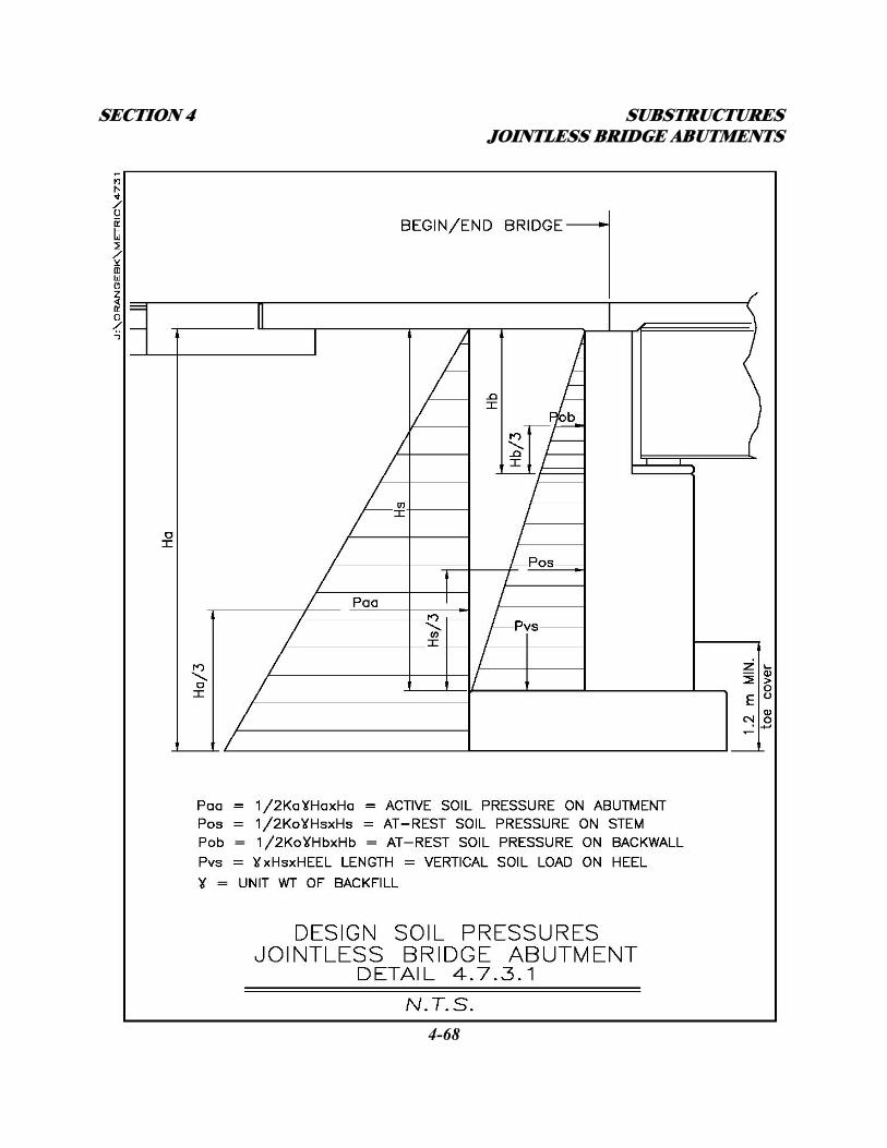
B. Where the abutment stem is supported on a spread footing, the allowable bearing pressure
will be given in the FDR. The designer shall proportion the footing for stability (sliding and
overturning) of the abutment under construction loading. See Detail 4.7.3.1. The top and
bottom reinforcing shall be designed for the completed live load condition.
C. The stem concrete and vertical reinforcing steel shall be designed for a combination of the
vertical and horizontal loads from the superstructure and the At-Rest soil pressure developed
against the back of stem from the compacted soil on the abutment heel. See Detail 4.7.3.1.
D. Horizontal reinforcement in the abutment stem shall be for temperature only.
E. Wingwalls cantilevered off the abutment stem shall be designed as vertically cantilevered
over the abutment footing and horizontally cantilevered at the interface with the abutment
stem resisting the At-Rest soil pressure from the approach backfill.
F. Wingwalls supported on their own foundations shall be designed as vertically cantilevered
retaining walls resisting active soil pressure from the approach backfill.
SECTION 4 SUBSTRUCTURES JOINTLESS BRIDGE ABUTMENTS
4-68
SECTION 4 SUBSTRUCTURES SEMI-INTEGRAL ABUTMENTS
4-69
4.7.3.2 – SUPERSTRUCTURES
A. There are no maximum span lengths for this type of structure as long as the thermal
movement is accounted for at the end of the approach slabs.
B. The superstructure main load carrying members and deck shall be designed assuming simple
supports at the abutments and continuous over any pier(s) for positive bending within the
spans and negative bending and shear at the pier(s).
C. Approach slabs shall be designed as reinforced concrete beams as detailed in Subsection
4.7.2.6 with design reinforcing in the bottom running parallel to traffic.
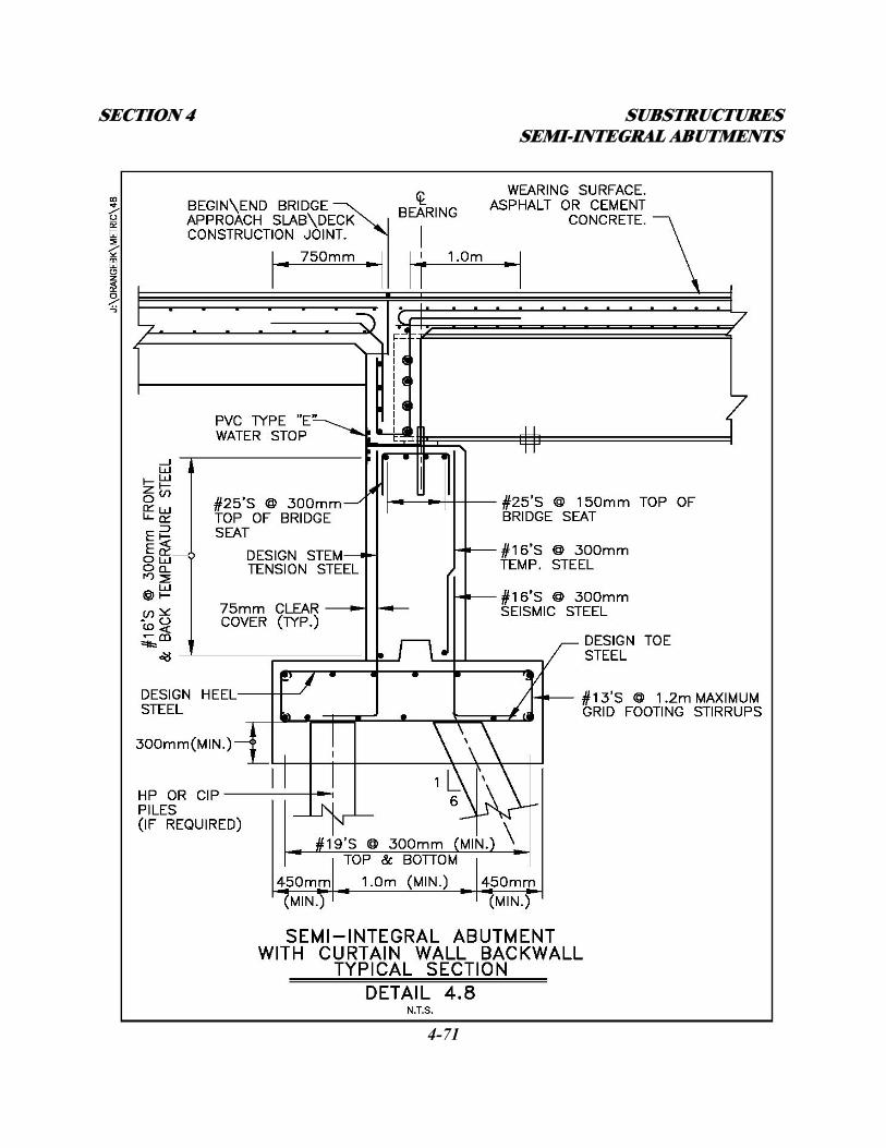
4.8 – SEMI-INTEGRAL ABUTMENTS WITH CURTAIN WALL
BACKWALLS
The semi-integral abutment with curtain wall backwall consists of a concrete stem supported on a
spread footing or multi-row pile cap. The superstructure sits on elastomeric pads on an abutment
bridge seat. The superstructure deck is continuous with the approach slab and a curtain wall acting as
an abutment backwall. The curtain wall is cast with the deck around the beam ends acting as end
diaphragms as well as a retaining wall for the soil behind. While the beams are supported on
individual elastomeric pads on the bridge seat, the curtain wall rests on a continuous elastomeric pad
on the bridge seat. All expansion and contraction involves the superstructure, approach slab, and the
curtain wall over the abutment bridge seat. At expansion abutments, a 12 mm thick elastomeric pad,
and two layers of compressed synthetic sheet gasket are placed between the bridge seat and the
curtain wall. Expansion and contraction of the roadway surface is handled at the approach
SECTION 4 SUBSTRUCTURES SEMI-INTEGRAL ABUTMENTS
4-70
slab/sleeper slab interface similar to that of the integral abutment configuration. This type of
abutment eliminates the need for expansion joints on the bridge. At fixed abutments, a 12 mm thick
elastomeric pad alone is placed between the bridge seat and the curtain wall with no bond breakers. A
waterstop at the back of abutment stem joins the abutment to the curtain wall at both ends to keep
ground water from penetrating the bridge seat area. Anchor rods run up from the abutment stem
through slotted holes in the beams to allow for translation and rotation of the superstructure. See
Detail 4.8.
4.8.1 - GUIDELINES ON USE
The semi-integral abutment is a hybrid of the integral abutment and the jointless bridge abutment.
Semi-integral abutments may be used when the FDR restricts the use of integral abutments and
expansion span lengths are short. The criteria for the use and restrictions of semi-integral abutments
are described in the following subsections.
4.8.1.1 - EXPANSION LENGTHS
The movement of the superstructure over the bridge seat of a semi-integral abutment is largely
attributed to thermal expansion and contraction of the superstructure. The longer the expansion span
length, the larger the longitudinal movement of the superstructure. The expansion length of a semi-
integral abutment structure is equal to the abutment centerline to abutment centerline dimension for
single span structures, and the abutment centerline to fixed pier centerline dimension for multi-span
structures.
SECTION 4 SUBSTRUCTURES SEMI-INTEGRAL ABUTMENTS
4-71
SECTION 4 SUBSTRUCTURES SEMI-INTEGRAL ABUTMENTS
4-72
As the superstructure expands and contracts, the deck/curtain wall/approach slab slide over the bridge
seat. The bridge seat is loaded horizontally from the frictional force from the superstructure
movement. The allowable expansion length is limited by the capacity of the waterstop at the back of
abutment/curtain wall interface to distort without failing. In general expansion lengths should be
limited to 30.0 meters
4.8.1.2 – SOIL CONDITIONS
Site soil conditions shall be analyzed in the FDR from existing and new soil borings. The FDR (and
HADR if spanning a waterway) will determine whether the semi-integral abutments shall be
supported on a spread footing or multi-row pile cap. The appropriate foundation type will be based
on the geometry, loading, and site conditions at the structure.
4.8.1.3 - HORIZONTAL ALIGNMENT
Only straight beams will be allowed. Curved superstructures will be allowed provided the beams are
straight and continuous between the abutments. All beams shall be parallel to each other. The
abutments and any intermediate piers shall also be parallel to each other.
4.8.1.4 – GRADE
The maximum vertical curve gradient between abutments shall be 5%.The maximum straight grade
allowed on semi-integral abutment bridges is 10%.
SECTION 4 SUBSTRUCTURES SEMI-INTEGRAL ABUTMENTS
4-73
4.8.1.5 - SKEW ANGLE
There is no skew limitation on semi-integral abutment bridges. However, the effects of skew must be
analyzed and accounted for in the design of all of the structural components.
4.8.1.6 - UTILITIES (Refer to Subsection 1.6 - UTILITY COORDINATION AND COMMUNICATION)
Since the expansion span lengths of semi-integral abutment bridges is relatively short, all utilities
may run through the abutment stem and curtain wall with appropriate sleeving as necessary.
4.8.2 – DESIGN AND DETAIL CONSIDERATIONS
4.8.2.1 - FOUNDATION TYPES
All semi-integral abutments shall be supported on a spread footing or multi-row pile cap. Steel H or
C.I.P. piles shall be used as recommended in the FDR. Exact length required shall be specified in the
FDR. A complete HADR (that includes a depth of scour analysis) of the site and proposed structure is
required where a structure crosses over a waterway. For these structures, the piles are designed to
gain all of their capacity below the scour elevation.
4.8.2.2 - ABUTMENT STEM
The abutment stem thickness shall be determined from the geometry of the bridge seat. The bridge
seat must be deep enough to provide room for the appropriate size elastomeric pads under the beams
with required edge and end clearance, and the curtain wall.
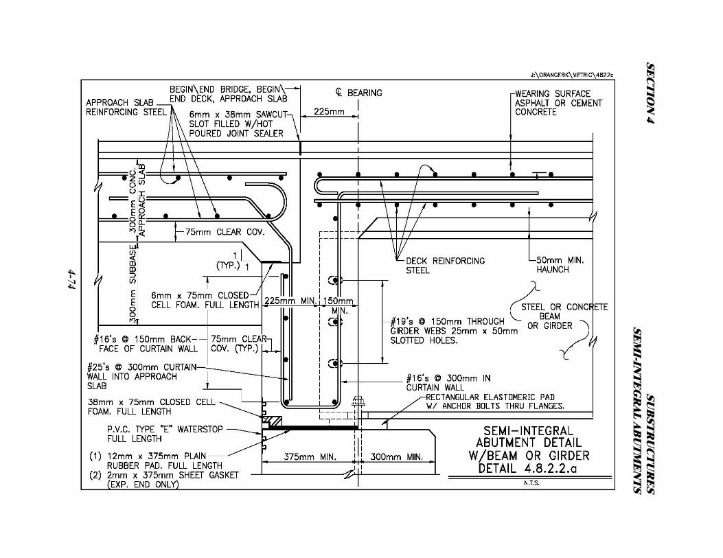
SEC
TIO
N 4
SUB
STR
UC
TU
RE
S SE
MI-IN
TE
GR
AL A
BU
TM
EN
TS
4-74
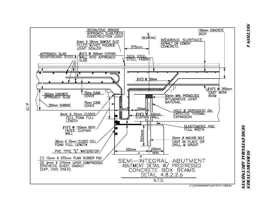
SEC
TIO
N 4
SUB
STR
UC
TU
RE
S SE
MI-IN
TE
GR
AL A
BU
TM
EN
TS
4-75
SECTION 4 SUBSTRUCTURES SEMI-INTEGRAL ABUTMENTS
4-76
The curtain wall shall be a minimum of 375 mm thick for steel or concrete I-beam superstructures
and 300 mm for concrete box-beam superstructures. The use of corbels at the back and below the
bridge seat to reduce abutment stem thickness should be avoided. Refer to Subsection 4.5.2. See
Details 4.8.2.2.a and 4.8.2.2.b.
4.8.2.3 – WINGWALLS
Wingwalls shall be a minimum of 450 mm thick. Wingwalls shall have a constant thickness or be
tapered depending on height and length. Tapering the thickness of larger walls from end to end may
result in significant concrete quantity savings. In-line wingwalls are the preferred arrangement for
semi-integral abutments. Flared walls shall be used at stream crossings and taller abutments where
wingwall length may be significantly reduced by flaring. U-walls shall not be used on semi-integral
abutment bridges. U-walls are not allowed because they prevent the curtain wall from moving freely
during thermal changes. For wingwalls cantilevered off the semi-integral abutment stem, see
Subsection 4.5.3 and Detail 4.6.2.3. For wingwalls self supported on footings or piles and
connected to the abutment stem with a keyed construction, contraction, or expansion joint, see
Subsection 4.5.4., and Details C3-20 thru C3-26 in Appendix C. All wingwalls shall be separated from
the curtain wall with a keyless expansion joint to allow for the movement of the curtain wall.
4.8.2.4 - SUPERSTRUCTURE TYPE
Steel beams, plate girders, or prestressed concrete beams may be used on bridges with semi-integral
abutments. The deck may be either cast-in-place or precast. Refer to Section 3 – Decks for more
SECTION 4 SUBSTRUCTURES SEMI-INTEGRAL ABUTMENTS
4-77
information. Refer to Subsection 4.8.3 – Semi-Integral Abutment Bridge Design Procedures.
4.8.2.5 – BEARINGS
When steel beams, plate girders or prestressed concrete I-beams are used in the superstructure,
rectangular elastomeric bearing pads shall be designed and detailed to support the beams on the
abutment bridge seat. Refer to Section 8 – Bearings for more information. Steel beams, plate girders
and prestressed concrete I-beams shall be connected to the abutment with anchor rods. See Detail
4.8.2.2.a. When prestressed box beams are used, a continuous rectangular plain rubber bearing pad
shall be placed at the centerline of bearing of the beams for the full length of the bridge seat. Refer to
Section 8 – Bearings. Prestressed box beams shall be connected to the abutment with anchor rods.
See Detail 4.8.2.2.b.
4.8.2.6 - APPROACH SLABS
Approach slabs are required for all semi-integral abutments. The purpose of the approach slab is to
bridge the fill directly behind the abutment and provide a transition from the approach pavement to
the bridge deck. Approach slab thickness shall be a minimum of 300 mm. Thickness may be greater
depending on the design span length of the approach slab. Approach slab lengths vary depending on
the height of the abutment and backfill treatment. In most cases the length is determined based on the
intercept of the backfill active failure plane from the bottom and back of the abutment footing to the
bottom of the approach slab (ground line). See Detail 4.7.2.6. The end of the approach slab shall be
supported on a sleeper slab. This end of the approach slab shall be perpendicular to the centerline of
SECTION 4 SUBSTRUCTURES SEMI-INTEGRAL ABUTMENTS
4-78
the roadway and run from face-of-guiderail to face-of-guiderail. The abutment end of the approach
slab shall be rigidly connected to the superstructure deck and curtain wall as shown in Details
4.8.2.2.a and 4.8.2.2.b. Polyethylene curing covers shall be placed on top of the subbase prior to
pouring the approach slab. This sheet will aid in allowing free thermal movement of the approach
slab on the subbase material. The approach slab shall incorporate both top and bottom steel
reinforcement. The top mats (transverse and longitudinal) of reinforcement shall be a minimum of
#16 Bars @ 300 mm in both directions. The bottom mat longitudinal reinforcement shall be designed
for traffic loading (reinforcing parallel to traffic) with the design span being a simple span from the
back face of the abutment to 300 mm beyond the intersection with the failure plane. The bottom mat
transverse reinforcement shall be for temperature only. Refer to AASHTO Article 3.24.3.2 for
the minimum requirements when the main reinforcement is parallel to traffic.
4.8.2.7 - SLEEPER SLABS
The sleeper slab is a buried concrete foundation used to support the free end of the approach slab.
The end of the approach slab slides on the end of the sleeper slab. Sleeper slab reinforcement shall be
as shown in Details 4.6.2.7.a through 4.6.2.7.d.
4.8.2.8 – JOINTS
A cold formed construction joint should be located between the approach slab and the superstructure
deck/curtain wall as described in Subsection 4.8.2.6, 150 mm from the back of the curtain wall. This
joint will provide a controlled crack rather than allowing a random crack to develop in the roadway
SECTION 4 SUBSTRUCTURES SEMI-INTEGRAL ABUTMENTS
4-79
surface. This joint shall also define the beginning and end of bridge stationing. See Details 4.8.2.2.a
and 4.8.2.2.b. Galvanized reinforcing steel shall connect the approach slab to the curtain wall/deck
concrete. This reinforcement provides a positive connection between the two to keep the joint tight.
This joint must be cold formed. The joint will be sawn and sealed as described in the Approach Slab
Notes in Appendix B.
An expansion joint shall be placed at the end of the approach slab between the approach slab and the
sleeper slab. The purpose of this joint is to allow for the thermal movement of the
superstructure/curtain wall and approach slab. This is a working joint that opens and closes due to
thermal expansion and contraction. The longer the span, the greater the opening and closing. The size
of the joint opening shall be indicated on the plans.
The following criteria are recommended for semi-integral abutment bridge joint treatments:
A. Expansion lengths less than 18.0 m: No provisions for expansion at the ends of the approach
slabs are required if asphalt approach pavements are used. When the approach pavement is
rigid cement concrete, use a preformed silicone joint system between the sleeper slab and the
approach pavement. See Detail 4.6.2.7.d.
B. Expansion Lengths from 18.0 m to 30.0 m: Provisions for expansion at the ends of approach
slabs will require the use of a preformed silicone joint system between the sleeper slab and
the approach slab with asphalt concrete approach pavement. See Detail 4.6.2.7.a. A
preformed silicone joint system between the sleeper slab and the approach slab shall also be
used with rigid concrete approach pavement. See Details 4.6.2.7.b and 4.6.2.7.c.
SECTION 4 SUBSTRUCTURES SEMI-INTEGRAL ABUTMENTS
4-80
C. Expansion lengths over 30.0 m: Expansion lengths over 30.0 meters are not recommended for
semi-integral abutment bridges. Another abutment type should be used if the expansion
length exceeds 30.0 meters.
D. Fixed ends: When the end of the bridge is fixed, no joint is required at the end of approach
slab if the approach pavement is full-depth asphalt concrete. Where the approach pavement is
rigid cement concrete, a preformed silicone joint system shall be installed between the sleeper
slab and the approach pavement to allow for approach pavement expansion and contraction.
See Detail 4.6.2.7.d.
4.8.2.9 - SLOPE PROTECTION
Slope protection in front of semi-integral abutments shall typically be concrete block paving or
stamped concrete as described in Subsection 4.3 – Embankment and Slope Protection. See Details
4.3.1.1.a & 4.3.1.1.b. Where a bridge crosses a waterway, the slope protection will be as required in
the HADR. Bedding requirements, such as geotextile, will be specified in the FDR.
4.8.2.10 - FREEBOARD/SUBMERGED INLETS
Structures with reduced freeboard or submerged inlets will be subjected to a greater general and local
scour and impact damage. Therefore, structure height should include at least 600 mm of freeboard
above Design High Water elevation (DHW) unless more clearance is required by the HADR. Since
the superstructure is not rigidly connected to the abutment stem, the designer must insure that the
unfactored superstructure dead loads are greater than any uplift and/or horizontal stream loads on the
SECTION 4 SUBSTRUCTURES SEMI-INTEGRAL ABUTMENTS
4-81
structure as indicated in the HADR. This may require the addition of concrete ballast between the
superstructure beams at the ends.
4.8.3 – SEMI-INTEGRAL ABUTMENT BRIDGE DESIGN PROCEDURES
The design of structures with semi-integral abutments will be as required in the AASHTO Standard
Specifications as modified below.
4.8.3.1 – SUBSTRUCTURES
A. Where the abutment stem is supported on piles, the preliminary abutment pile sizes and pile
cap dimensions will be given in the FDR. The designer shall verify the size and orientation of
the piles checking for bearing capacity and uplift. Any uplift requirements shall be relayed to
the geotechnical engineer for consideration in the FDR.
B. Where the abutment stem is supported on a spread footing, the allowable bearing pressure
will be given in the FDR. The designer shall proportion the footing for stability (sliding and
overturning) of the abutment under construction loading. See Detail 4.8.3.1. The top and
bottom reinforcing shall be designed for the completed live load condition.
C. The stem concrete and vertical reinforcing steel shall be designed for a combination of the
vertical and horizontal loading from the superstructure and the At-Rest soil pressure
developed against the back of stem from the compacted soil on the abutment heel. See Detail
4.8.3.1.
D. Horizontal reinforcement in the abutment stem shall be for temperature only.
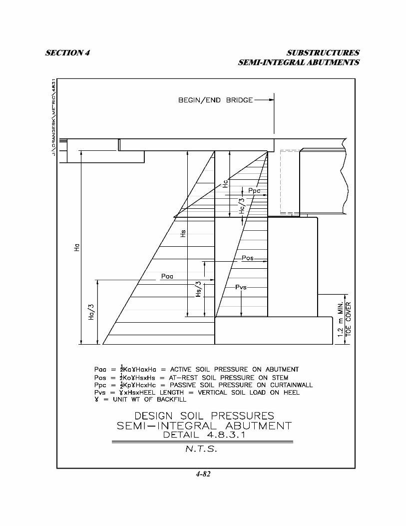
SECTION 4 SUBSTRUCTURES SEMI-INTEGRAL ABUTMENTS
4-82
SECTION 4 SUBSTRUCTURES SEMI-INTEGRAL ABUTMENTS
4-83
E. Wingwalls cantilevered off the abutment stem shall be designed as vertically cantilevered
over the abutment footing and horizontally cantilevered at the interface with the abutment
stem resisting the At-Rest soil pressure from the approach backfill.
F. Wingwalls supported on their own foundations shall be designed as vertically cantilevered
retaining walls resisting At-Rest soil pressure from the approach backfill.
4.8.3.2 – SUPERSTRUCTURES
A. The maximum expansion span length for semi-integral abutment bridges is 30.0 meters.
B. The superstructure main load carrying members and deck shall be designed assuming simple
supports at the abutments and continuous over any pier(s) for positive bending within the
spans and negative bending and shear at the pier(s).
C. The Curtain wall concrete and reinforcing steel shall be designed horizontally between the
beams for the passive soil pressure developed from the thermal expansion of the
superstructure. The Curtain wall concrete and reinforcing steel shall be designed vertically
between the beams for the passive soil pressure developed from the thermal expansion of the
superstructure. See Detail 4.8.3.1. The proposed height of the curtain wall shall be provided
to the geotechnical engineer so that the actual soil loading and application point(s) will be
given in the FDR.
D. Approach slabs shall be designed as reinforced concrete beams as detailed in Subsection
4.8.2.6 with design reinforcing in the bottom running parallel to traffic.
SECTION 4 SUBSTRUCTURES CONVENTIONAL STEM ABUTMENTS
4-84
4.9 – CONVENTIONAL STEM ABUTMENTS WITH BRIDGE EXPANSION
JOINTS
On original Thruway structures, the conventional abutment consists of solid stem with short pedestals
or a backwall with individual tall pedestals supported on a spread footing or pile cap. In both cases,
the superstructure rests on bearings connected to the pedestals, and a backwall retains the soil behind
the superstructure. On new structures, the conventional abutment would consist of a solid stem with a
stepped bridge seat or sloped bridge seat with short pedestals. At the expansion ends of bridges, an
expansion joint is mounted between the deck end and the backwall. See Detail 4.9.a. This joint allows
for all thermal movement of the bridge. At the fixed ends of bridges, the deck is poured over the
backwall to form a cold joint. See Detail 4.9.b.
4.9.1 – GUIDELINES ON USE
Whenever possible, it is preferable to eliminate joints by use of one of the previously described
abutment types. If this is not possible, the Designer should try to limit the number of joints on a
bridge structure to a minimum. The criteria for the use and restrictions of conventional abutments are
described in the following subsections.
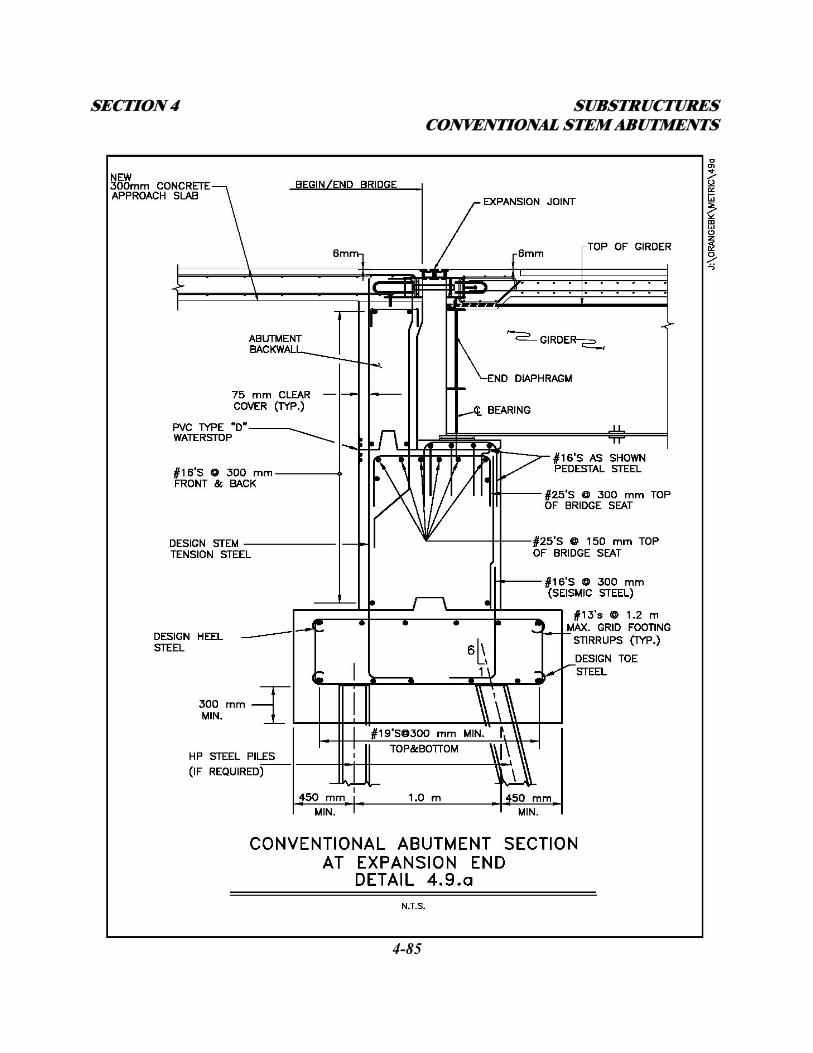
SECTION 4 SUBSTRUCTURES CONVENTIONAL STEM ABUTMENTS
4-85
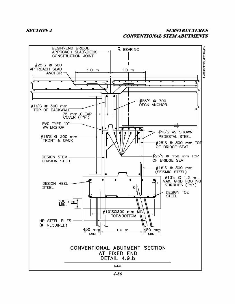
SECTION 4 SUBSTRUCTURES CONVENTIONAL STEM ABUTMENTS
4-86
SECTION 4 SUBSTRUCTURES CONVENTIONAL STEM ABUTMENTS
4-87
Existing Abutments - On rehabilitation projects, abutments of this type should be modified in one of
the following manners:
A. Fill in between pedestals and modify the existing abutments with jointless details. This would
be done if a seismic retrofit was required on the existing structure and the existing deck and
bearings needed replacement and the abutments did not need replacement. If an existing
abutment with joints is being modified to be an abutment for a jointless bridge, the existing
U-walls must be removed and replaced with in-line or flared wingwalls. See Subsection 4.7 -
Jointless Bridge Abutments.
B. Fill in between pedestals and replace existing joint system with new system (see Section 9 -
Joints, for replacement joint systems). This would be done if the existing deck, bearings and
substructures did not need replacement.
New and Replacement Abutments
In general, expansion joints on new bridges should be avoided due to the maintenance problems
experienced in the past. If a new abutment is required with joints, it shall be of the solid stem type
with a stepped bridge seat or sloped with short pedestals. For a description of acceptable joint
configurations, see Section 9 - Joints.
4.9.1.1 - EXPANSION LENGTHS
The allowable expansion lengths for this type of abutment are controlled by the type of joint system
used at the abutment. Refer to Section 9 - Joints.
SECTION 4 SUBSTRUCTURES CONVENTIONAL STEM ABUTMENTS
4-88
4.9.1.2 – SOIL CONDITIONS
Site soil conditions shall be analyzed in the FDR from existing and new soil borings. The FDR (and
HADR if spanning a waterway) will determine whether the conventional abutments shall be
supported on a spread footing or multi-row pile cap. The appropriate foundation type will be based
on the geometry, loading, and site conditions at the structure.
4.9.1.3 - HORIZONTAL ALIGNMENT
Straight or curved beams and superstructures will be allowed. On curved structures, thermal
movements of the superstructure (both longitudinal and transverse) must be considered in the design
of the various elements.
4.9.1.4 - GRADE
There is no maximum grade for bridges on conventional abutments. However, the direction of
thermal expansion should always be uphill wherever possible.
4.9.1.5 - SKEW ANGLE
The allowable skew angle for these types of abutments is controlled by the type of joint system used
at the abutment. Refer to Section 9 - Joints.
4.9.1.6 - UTILITIES (Refer to Subsection 1.6 - UTILITY COORDINATION AND COMMUNICATION)
All utilities may run through the stem and backwall with appropriate sleeving as necessary.
SECTION 4 SUBSTRUCTURES CONVENTIONAL STEM ABUTMENTS
4-89
4.9.2 – DESIGN AND DETAIL CONSIDERATIONS
4.9.2.1 - FOUNDATION TYPES
All conventional abutments shall be supported on a spread footing or multi-row pile cap. Steel H or
C.I.P. piles shall be used as recommended in the FDR. Exact length required shall be specified in the
FDR. A complete HADR (that includes a depth of scour analysis) of the site and proposed structure is
required where a structure crosses over a waterway. For these structures, the piles are designed to
gain all of their capacity below the scour elevation.
4.9.2.2 - ABUTMENT STEM
The abutment stem thickness shall be determined from the geometry of the bridge seat and backwall.
The bridge seat/pedestal must be deep and wide enough to provide room for the appropriate bearing
with required edge and end clearances, and allow for thermal movement of the superstructure without
coming in contact with the backwall. The backwall shall be a minimum of 450 mm thick. The use of
corbels at the back and bottom of the backwall to reduce abutment stem thickness should be avoided.
Refer to Subsection 4.5.2.
4.9.2.3 – WINGWALLS
Wingwalls shall be a minimum of 450 mm thick. Wingwalls shall have a constant thickness or be
tapered depending on height and length. Tapering the thickness of larger walls from end to end may
result in significant concrete quantity savings. In-line wingwalls are the preferred arrangement for
conventional abutments. Flared walls shall be used at stream crossings and taller abutments where
SECTION 4 SUBSTRUCTURES CONVENTIONAL STEM ABUTMENTS
4-90
wingwall length may be significantly reduced by flaring. U-walls should not be used on conventional
abutments. U-walls are discouraged because the expanding and contracting approach slab tends to
bind on the U-walls. For wingwalls cantilevered off the conventional abutment, see Subsection
4.5.3 and Detail 4.6.2.3. For wingwalls self supported on footings or piles and connected to the abut-
ment with a keyed construction, contraction, or expansion joint, see Subsection 4.5.4, and Details
C3-13 through C3-19 in Appendix C.
4.9.2.4 - SUPERSTRUCTURE TYPE
Steel beams, plate girders, or prestressed concrete beams may be used on bridges with conventional
abutments. The deck may be either cast-in-place or precast. Refer to Section 3 – Decks, for more
information. Refer to Subsection 4.9.3 – Conventional Abutment Bridge Design Procedures.
4.9.2.5 – BEARINGS
When steel beams or plate girders are used in the superstructure, a bearing device shall be designed
and detailed to support the superstructure on the abutment bridge seat/pedestal. Refer to Section 8 –
Bearings for more information. See Detail 4.9.2.5.a. Prestressed concrete I-beams require individual
rectangular plain rubber bearing pads placed perpendicular to the centerline of the beam. Prestressed
concrete box beams require a continuous rectangular plain rubber bearing pad placed at the centerline
of bearing of the beams for the full length of the bridge seat. Both types of prestressed concrete
beams shall be connected to the abutment with anchor rods. Refer to Section 8 – Bearings. See Detail
4.9.2.5.b.
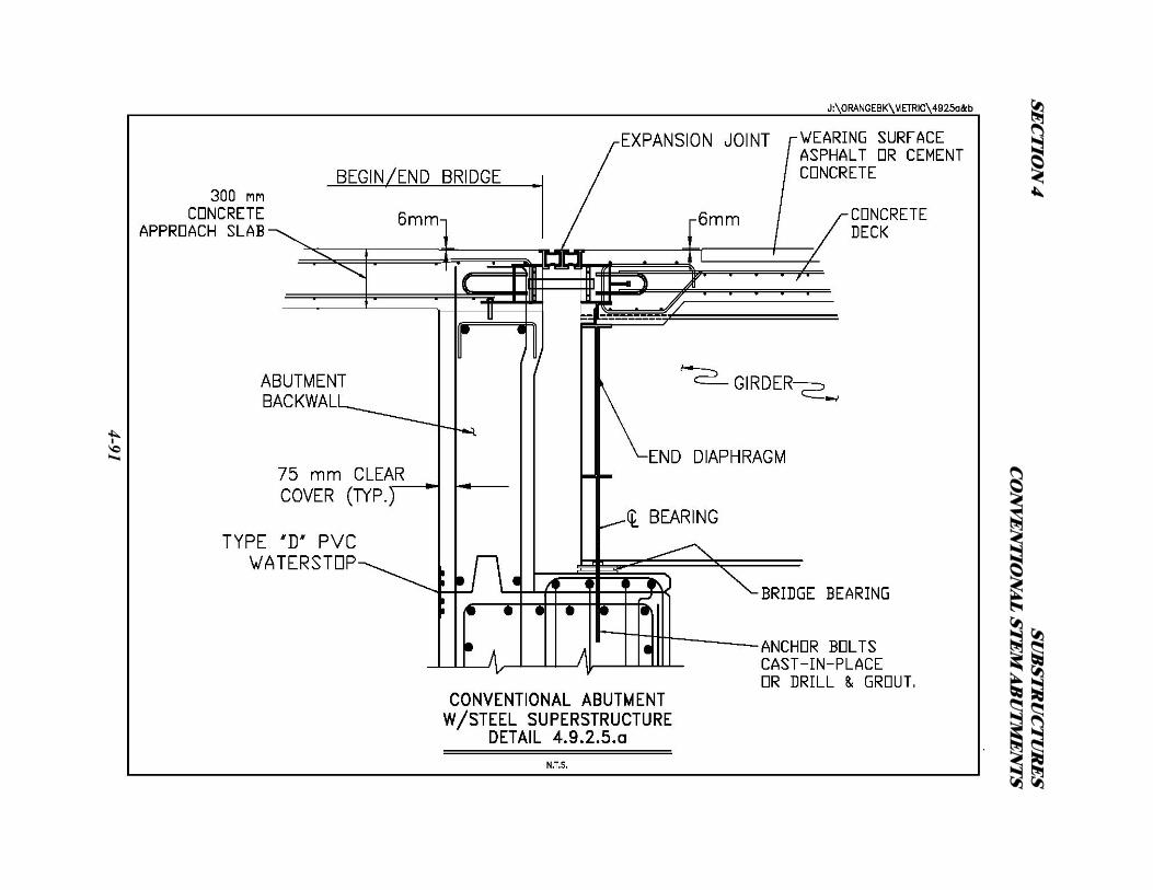
SEC
TIO
N 4
SUB
STR
UC
TU
RE
S C
ON
VE
NT
ION
AL ST
EM
AB
UT
ME
NT
S
4-91
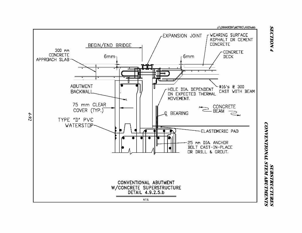
SEC
TIO
N 4
SUB
STR
UC
TU
RE
S C
ON
VE
NT
ION
AL ST
EM
AB
UT
ME
NT
S
4-92
SECTION 4 SUBSTRUCTURES CONVENTIONAL STEM ABUTMENTS
4-93
4.9.2.6 - APPROACH SLABS
Approach slabs are required for all conventional abutments. The purpose of the approach slab is to
bridge the fill directly behind the abutment and provide a transition from the approach pavement to
the bridge deck. Approach slab thickness shall be a minimum of 300 mm. Thickness may be greater
depending on the design span length of the approach slab. Approach slab lengths vary depending on
the height of the abutment and backfill treatment. In most cases the length is determined based on the
intercept of the backfill active failure plane from the bottom and back of the abutment footing to the
bottom of the approach slab (ground line). See Detail 4.9.2.6. The end of the approach slab shall be
supported on a sleeper slab. This end of the approach slab shall be perpendicular to the centerline of
the roadway and run from face-of-guiderail to face-of-guiderail. The abutment end of the approach
slab shall be rigidly connected to the abutment backwall as shown in Details 4.9.2.5.a and 4.9.2.5.b.
The approach slab shall incorporate both top and bottom steel reinforcement. The top mats
(transverse and longitudinal) of reinforcement shall be a minimum of #16 Bars @ 300 mm in both
directions. The bottom mat longitudinal reinforcement shall be designed for traffic loading
(reinforcing parallel to traffic) with the design span being a simple span from the back face of the
abutment to 300 mm beyond the intersection with the failure plane. The bottom mat transverse
reinforcement shall be for temperature only. Refer to AASHTO Article 3.24.3.2 for the minimum
requirements when the main reinforcement is parallel to traffic.
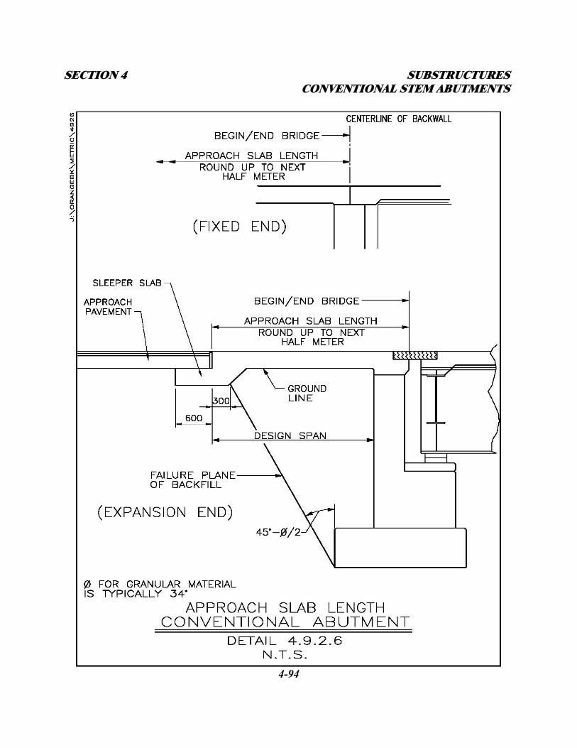
SECTION 4 SUBSTRUCTURES CONVENTIONAL STEM ABUTMENTS
4-94
SECTION 4 SUBSTRUCTURES CONVENTIONAL STEM ABUTMENTS
4-95
4.9.2.7 - SLEEPER SLABS
The sleeper slab is a buried concrete foundation used to support the free end of the approach slab.
Sleeper slab reinforcement shall be as shown in Detail 4.6.2.7.d.
4.9.2.8 – JOINTS
An expansion joint should be located between the approach slab/backwall and the superstructure
deck. The purpose of this joint is to allow for the thermal movement of the superstructure on the
bearings. This is a working joint that opens and closes due to thermal expansion and contraction. The
longer the span, the greater the opening and closing. The size and type of joint shall be indicated on
the plans. Refer to Section 9 – Joints, for selecting the appropriate joint type. This joint shall also
define the beginning and end of bridge stationing. See Details 4.9.2.5.a and 4.9.2.5.b. The joint will
be anchored to the backwall and deck concrete as described in Section 9 – Joints.
Where the approach slab abuts rigid concrete approach pavement, an expansion joint shall be placed
at the end of the approach slab between the rigid pavement and the sleeper slab to allow for the
thermal movement of the approach pavement. See Detail 4.6.2.7.d.
4.9.2.9 - SLOPE PROTECTION
Slope protection in front of conventional abutments shall typically be concrete block paving or
stamped concrete as described in Subsection 4.3 – Embankment and Slope Protection. See Details
4.3.1.1.a & 4.3.1.1.b. Where a bridge crosses a waterway, the slope protection will be as required in
SECTION 4 SUBSTRUCTURES CONVENTIONAL STEM ABUTMENTS
4-96
the HADR. Bedding requirements, such as geotextile, will be specified in the FDR.
4.9.2.10 - FREEBOARD/SUBMERGED INLETS
Structures with reduced freeboard or submerged inlets will be subjected to a greater general and local
scour and impact damage. Therefore, structure height should include at least 600 mm of freeboard
above Design High Water elevation (DHW) unless more clearance is required by the HADR.
Connection of the superstructure to the abutment bridge seat/pedestals through the bearings must be
designed to resist uplift and/or horizontal stream loads at the structure as indicated in the HADR.
4.9.3 - CONVENTIONAL ABUTMENT BRIDGE DESIGN PROCEDURES
The design of structures with conventional abutments will be as required in the AASHTO Standard
Specifications.
4.9.3.1 – SUBSTRUCTURES
A. Where the abutment stem is supported on piles, the preliminary abutment pile sizes and pile
cap dimensions will be given in the FDR. The designer shall verify the size and orientation of
the piles checking for bearing capacity and uplift. Any uplift requirements shall be relayed to
the geotechnical engineer for consideration in the FDR.
B. Where the abutment stem is supported on a spread footing, the allowable bearing pressure
will be given in the FDR. The designer shall proportion the footing for stability (sliding and
overturning) of the abutment under construction loading. See Detail 4.7.3.1. The top and
SECTION 4 SUBSTRUCTURES CONVENTIONAL STEM ABUTMENTS
4-97
bottom reinforcing shall be designed for the completed live load condition.
C. The stem concrete and vertical reinforcing steel shall be designed for a combination of the
vertical and horizontal superstructure loads and the At-Rest soil pressure developed against
the back of stem from the compacted soil on the abutment heel. See Detail 4.7.3.1.
D. Horizontal reinforcement in the abutment stem shall be for temperature only.
E. Wingwalls cantilevered off the abutment stem shall be designed as vertically cantilevered
over the abutment footing and horizontally cantilevered at the interface with the abutment
stem resisting the At-Rest soil pressure from the approach backfill.
F. Wingwalls supported on their own foundations shall be designed as vertically cantilevered
retaining walls resisting active soil pressure from the approach backfill.
4.9.3.2 – SUPERSTRUCTURES
A. There are no maximum span lengths for this type of structure as long as the thermal
movement is accounted for at the expansion joint(s).
B. The superstructure main load carrying members and deck shall be designed assuming simple
supports at the abutments and continuous over any pier(s) for positive bending within the
spans and negative bending and shear at the pier(s).
C. Approach slabs shall be designed as reinforced concrete beams as detailed in Subsection
4.9.2.6 with design reinforcing in the bottom running parallel to traffic.
SECTION 4 SUBSTRUCTURES PIERS
4-98
4.10 - PIERS
The following subsections present the Authority policy on the design of new piers and the
replacement or retrofit of existing piers.
4.10.1 - NEW PIERS
In general, all new piers on mainline, interchange and overhead bridges shall be solid. Aesthetic
surface treatments are encouraged. Piers designed with aesthetic details (alternate shapes w/ or w/o
"block-outs") should be considered and are encouraged in urban areas. See Subsection 1.1 –
Aesthetics. A multi-column structure should be considered when the pier is greater than 9.0 m high.
In this situation, the potential cost savings of concrete quantity may outweigh additional forming
costs and future maintenance costs. Due to safety concerns, column piers are more likely to be
considered on mainline crossings over rural routes and non-navigable waterways than on overhead
structures, mainline structures over urban routes, railroads or navigable waterways. Piers shall be
designed using elastic criteria unless a plastic design is approved by the DSD. Generally, plastic
design is reserved for taller pier stems (> 9.0 m) and some piers designed with aesthetic details.
Superstructures will connect with the pier in one of two ways:
1. On conventional continuous bridges, the superstructure is supported on the pier
bridge-seat/pedestals with a single line of bearings. Expansion joints in the
superstructure at the pier, which would require two lines of bearings should be
avoided. In most cases the bearings will be a fixed type directing thermal movement
to the ends of the bridge. See Detail 4.10.1.a. On longer bridges with multiple piers,
SECTION 4 SUBSTRUCTURES PIERS
4-99
expansion bearings may be used at one or more piers. Refer to Section 8 – Bearings,
for more information.
2. On rigid frame multi-span bridges, the girder ends will rest on mortar pads on the
pier bridge seat. Vertical reinforcing steel will run up through the girder bottom
flanges from the pier stem. Horizontal reinforcing steel will run through the girder
webs and the deck concrete will be poured monolithically with the top of pier and
girder ends forming a rigid connection. See Detail 4.10.1.b.
4.10.1.1 - PIER LOADING
The loading conditions to consider in the design of bridge piers are described below.
Extreme Event 1 Loading (Seismic)
Although all applicable group loadings should be investigated, under most circumstances, AASHTO
Group VII loading will control the design of the various pier components. Under this loading,
earthquake loads shall be applied to the pier in addition to the full dead load and any applicable earth
pressures, buoyancy, or stream flow. The distribution of seismic loading to the pier(s) will be
dependent on the type of bridge structure used. On conventional, jointless, and semi-integral
abutment bridges, the seismic forces will be assumed absorbed by the fixed pier alone. These
structures shall be analyzed with Seisab as fixed at the pier base and pinned at the top.
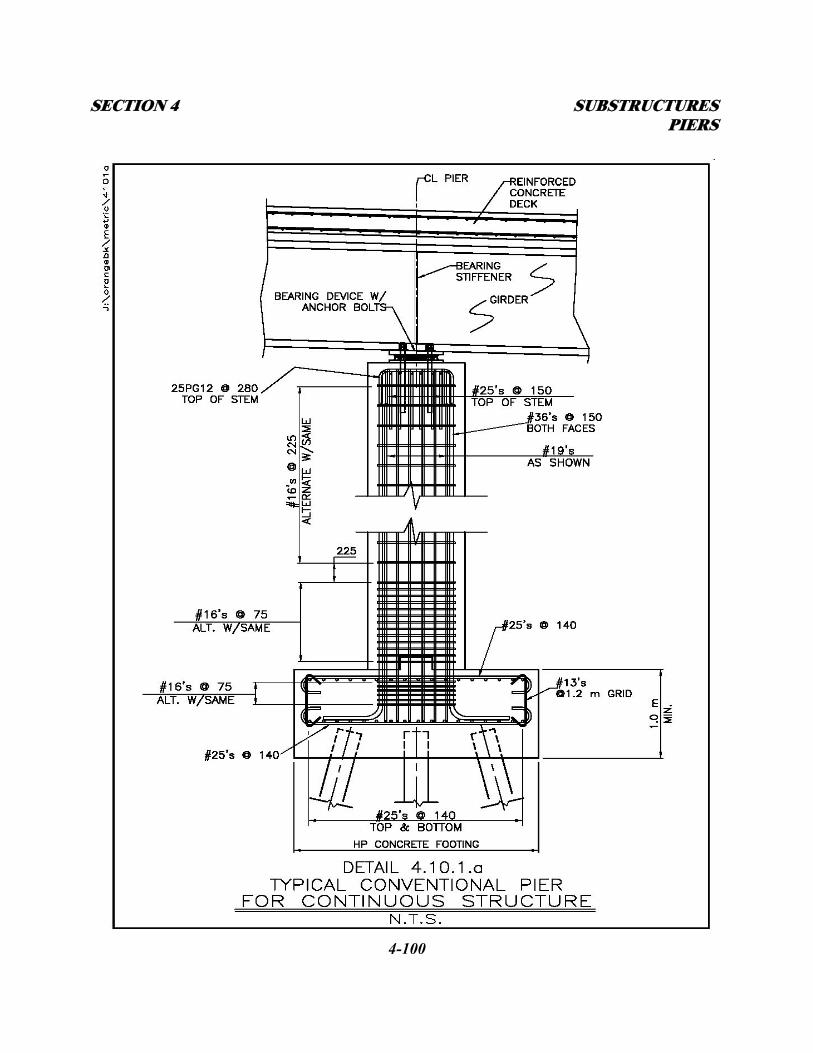
SECTION 4 SUBSTRUCTURES PIERS
4-100
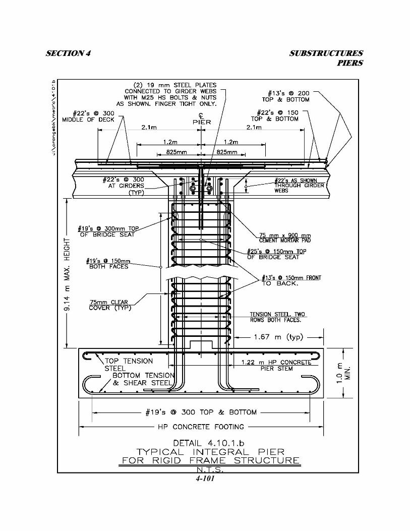
SECTION 4 SUBSTRUCTURES PIERS
4-101

SECTION 4 SUBSTRUCTURES PIERS
4-102
On integral abutment and rigid frame bridges with abutment stem heights ≤ 3.0 meters, the seismic
forces will be distributed between the fixed pier and integral abutments. These structures shall be
analyzed with Seisab with all nodes modeled as fixed with the exception of the abutment bases
which will be modeled as pinned. The ratio of distribution will be dependent on the relative stiffness
differences between the substructure units. On integral abutment and rigid frame bridges with
abutment stem heights > 3.0 meters where the approach backfill has been isolated from the abutment
stem ( see Detail 4.6.2.6.b ) as described in Subsection 4.6.3.1(C) , a majority of the
seismic forces will be absorbed by the fixed pier, with a small portion distributed to the abutments
due to the pile fixity in the soil. The proportion of distribution will depend on the relative stiffness
between the pier stem and the abutment piles. These structures shall be analyzed with Seisab with all
nodes fixed.
In most cases, live loading from the superstructure shall not be considered when analyzing a new
pier during a seismic event. However, some structures based on their functional importance and
projected traffic loading at peak hours may warrant the addition of some part or all of this live
loading in the analysis of the substructure during a seismic event. The addition of any live loading in
the analysis will be only as directed by the DSD. The designer is reminded that under Group VII
loading, allowable stresses may be increased by 33% for the steel and concrete used in the pier.
SECTION 4 SUBSTRUCTURES PIERS
4-103
Extreme Event 2 Loading
In addition to earthquakes, other temporary loads classified as extreme events shall be considered
when designing a new pier. These loads are: ice loading, vehicular collision, and vessel collision.
Where applicable, new piers shall be analyzed for each of these loads exclusive to each other and in
place of the seismic force in AASHTO Group VII loading. In addition to this Group VII loading as
modified, 50% of the live loads from the superstructure shall be included for each of the applicable
event analysis. For piers in navigable waterways, the applicable loads are ice loading and vessel
collision. New piers in navigable waterways shall be protected from these loads with an approved
fender system. The vessel collision loading requirements are dependent on the expected types of
vessel traffic at a specific location. Refer to the current AASHTO Standard Specifications for the
recommended design criteria.
The only Applicable load for piers in non-navigable waterways is ice loading. Refer to the current
AASHTO Standard Specifications for the recommended design criteria.
For Piers adjacent to vehicle roadways the only applicable load is a vehicle collision. The vehicle
collision load is defined as a horizontal force of 1800 kilonewtons (kN) applied at 1.5 meters (m)
above the compacted fill grade at the pier at any angle to the pier. This load is applied either entirely
to a single column or distributed over the full width of the solid stem (whichever is applicable). This
vehicle load need not be applied to the pier if it is protected from a collision by the use of an
approved concrete barrier system. This concrete barrier system shall be a minimum of 1.32 m high if
SECTION 4 SUBSTRUCTURES PIERS
4-104
it is located 3.0 m or less from the face of pier and 1.07 m high if it is located greater than 3.0 m
from the face of pier. The designer shall analyze both options; designing the pier to resist the vehicle
collision load or provide an approved concrete barrier system, and choose the more economical
solution.
For Piers adjacent to railroads the only applicable load is the same vehicle collision load applied
adjacent to vehicle roadways. This vehicle load need not be applied if the pier is protected from a
train collision by the use of an approved crash wall system. Refer to Subsection 1.9 and current
railroad owner specifications for crash wall geometry and placement requirements.
Rigid Frame Loading
On rigid frame type bridges, as described in Subsection 4.6 – Integral Abutments, the tops of piers
are poured monolithically and therefore rigid with the superstructure. In this configuration,
superimposed dead load and live load moments are distributed into the pier stem. The amount of
distribution depends on the relative stiffness differences between the superstructure and
substructures (pier(s) and abutments). As is described under Extreme Events 1&2 Loading, rigid
frame piers shall also be designed/checked for those various external loads. However, based on
experience, AASHTO Group IA loading will usually control the design due to the superstructure
moment distribution into the pier(s). An exception to this would be in the case of a combination of
seismic and live loading as described in Extreme Event 1 Loading above. As is stated there, the
addition of any live loading in the Group VII loading analysis will be only as directed by the DSD.
SECTION 4 SUBSTRUCTURES PIERS
4-105
The designer is reminded that under Group IA loading, allowable stresses may be increased by 50%
for the steel and concrete used in the pier.
4.10.1.2 - PIER DESIGN PROCEDURES
All new piers shall be designed using current AASHTO requirements as modified by this Manual.
All applicable group loading conditions shall be analyzed with specific consideration to the loading
conditions described above.
A. Where the pier stem is supported on piles, the preliminary pile sizes and pile cap dimensions
will be given in the FDR. The designer shall verify the size and orientation of the piles
checking for bearing capacity and uplift. Any uplift requirements shall be relayed to the
geotechnical engineer for consideration in the FDR.
B. Where the pier stem is supported on a spread footing, the allowable bearing pressure will be
given in the FDR. The designer shall proportion the footing for stability (sliding and
overturning) of the pier under construction loading. The top and bottom reinforcing shall be
designed for the completed live load condition.
C. The stem concrete and vertical reinforcing steel shall be designed for the moments, shears,
and vertical loads as described in Subsection 4.10.1.1 above.
D. Horizontal reinforcement in the pier stem shall be for seismic confinement as described in
AASHTO Division IA Subsection 6.6.2.
SECTION 4 SUBSTRUCTURES PIERS
4-106
4.10.1.3 - PIER PROTECTION
Waterways
Piers in navigable waterways shall be protected from vessel impact and ice loading with an approved
fender system. Pier nosing as described in 4.10.1.3.1 below, shall be incorporated into the fender
system and designed to deflect and/or break up ice flow. Heavy stone fill, piles, rock anchors, or any
other system that is designed to protect the pier foundation from being undermined shall be used to
protect against scour. A hydraulic analysis will be required at these locations. Recommendations in
the HADR shall be incorporated into the pier design. Piers in non-navigable waterways shall be
similarly protected excluding the fender system.
Travel Lanes
The use of an approved guiderail system may be required at new piers adjacent to vehicular traffic as
described in Subsection 1.7. If the pier design incorporates the use of the concrete barrier system as
described in Subsection 4.10.1.1, standard transition/termination details shall be used.
Railroad Tracks
The use of an approved crash wall system may be required at new piers adjacent to railroad tracks as
described in Subsection 1.9. As stated in Extreme Event 2 Loading, refer to the railroad owner
specifications when determining crash wall geometry and placement requirements.
SECTION 4 SUBSTRUCTURES PIERS
4-107
4.10.1.3.1 - PIER NOSING
For stream bridges, a recommendation shall be displayed on the Preliminary Plans regarding the
need and type of ice breaker for pier nosing (if required). This information can be found in the
HADR. If required, the ice breaker shall consist of a steel angle or other device secured to the
concrete by means of suitable anchors. All structural steel and studs for pier nosing shall be hot
dipped galvanized. The Concrete Anchor Stud Note in Appendix B shall be included in the plans
when pier nosing is used.
4.10.2 - EXISTING PIERS
Existing piers on mainline, interchange and overhead bridges are typically multi-column piers
integral with a concrete or steel cap beam. Fracture-critical details shall be eliminated on all major
rehabilitation projects. Steel cap beams could be replaced with a concrete pier cap or an entire new
solid pier. An existing pier shall be evaluated at the time of project scoping to determine if it is
economical to rehabilitate or replace. Refer to Subsection 4.10.1 - New Piers. An existing pier can
remain in place if it is structurally sound (minimal repairs), geometrically compatible with the
rehabilitated structure (height, location and skew), and able to carry the revised loading from the
superstructure. Epoxy injection of cracks in substructure units as a means of repair is not done on
Thruway owned or maintained structures. Damaged concrete shall be repaired using an approved
concrete repair detail. Refer to the Thruway Standard Detail Sheet.
SECTION 4 SUBSTRUCTURES SEALANTS & JOINTS
4-108
4.10.2.1 - EXISTING PIER LOADING
Existing piers that do not meet AASHTO requirements shall be modified or replaced to meet those
requirements, when included in the project scope. Modification of the existing pier shall consider
reorientation of the bearings (placing expansion bearings at the pier), and/or bearing replacement
(with seismic isolation bearings) to reduce the design forces. All loading criteria as described in
Subsection 4.10.1.1 shall apply when analyzing an existing pier for reconstruction, retrofit or
replacement.
4.10.2.2 - PIER PROTECTION
Existing piers shall be protected from the various loads in the same manner as new piers. An
inspection and evaluation of the existing protection and load carrying capacity of in-place structures
and fill materials shall precede this design work.
4.11 - CONCRETE SEALANTS
Authority policy is to apply a concrete sealant to all concrete substructure elements. The type of
sealant used depends upon where it is to be used, as detailed in the following subsections.
4.11.1 - SOLID COLOR PROTECTIVE CONCRETE SEALER
Solid Color Protective Concrete Sealer shall be used on all exposed surfaces of substructure concrete
(excluding underside of pier caps) on all existing overhead substructures and mainline substructures
that previously had this type of sealer applied. This type of sealer shall also be used on new
SECTION 4 SUBSTRUCTURES SEALANTS & JOINTS
4-109
structures when requested by the Division Bridge Engineer.
4.11.2 - CLEAR PENETRATING SEALER
Clear penetrating sealer shall be used on all exposed surfaces of substructure concrete (excluding
underside of pier caps) on all new overhead and mainline substructures and existing substructures
that previously had this type of sealer applied.
4.12 - CONCRETE JOINTS
There are several reasons to place joints in a concrete mass. There are also several types of joints
commonly used. The following subsections detail those joints and their uses. See Appendix C for
joint details.
4.12.1 - TYPES OF JOINTS
Construction Joint:
A. Reinforcement goes through joint.
B. Joint has a shear key.
C. Joint has a Type "D" water stop.
Contraction Joint:
A. Reinforcement does not go through joint.
B. Joint has a shear key.
C. Joint has a Type "D" water stop.
SECTION 4 SUBSTRUCTURES SEALANTS & JOINTS
4-110
Expansion Joint:
A. Reinforcement does not go through joint.
B. Joint has a shear key.
C. Joint has a Type "E" water stop.
D. Joint has a layer of premolded bituminous joint filler or closed cell form.
* - The Type "D" water stop may be omitted from the construction and contraction joints if
leakage is unlikely or where staining due to leakage would not be objectionable.
** - On integral abutments, the expansion joint used between the abutment and wingwall
(separate foundations) would not have a shear key.
4.12.2 - APPLICATION OF JOINTS
The following subsections detail the locations where the different types of concrete joints are used.
4.12.2.1 - HORIZONTAL JOINTS
All horizontal joints in substructure concrete are construction joints unless otherwise specified.
4.12.2.2 - VERTICAL JOINTS
Short stem abutment with in-line wingwall (footings on soil):
A. Contraction joint.
B. Joint does not extend through footing.
SECTION 4 SUBSTRUCTURES SEALANTS & JOINTS
4-111
Short stem abutment with in-line wingwall (on rock or piles):
A. Construction joint.
B. Joint does not extend through footing.
Short stem abutment with flared wingwall (length ≤1.8 m):
A. Construction joint.
B. Joint does not extend through footing.
Short stem abutment with flared wingwall (length >1.8 m):
A. Contraction joint.
B. Joint does not extend through footing.
Short stem abutment with U-walls:
A. Construction joint.
B. Joint does not extend through footing.
Integral abutment with in-line wingwall (length ≤1.8 m):
A. Construction joint.
B. Wingwall suspended from abutment.
C. No footing.
Integral abutment with in-line wingwall (length >1.8 m):
A. Expansion joint - no shear key.
B. Wingwall on independent foundation.
Integral abutment with flared wingwall (length ≤1.8 m):
A. Construction joint.
SECTION 4 SUBSTRUCTURES SEALANTS & JOINTS
4-112
B. Wingwall suspended from abutment.
C. No footing.
Integral abutment with flared wingwall (length >1.8 m):
A. Expansion joint - no shear key.
B. Wingwall on independent foundation.
4.12.2.3 - VERTICAL JOINTS AT OTHER LOCATIONS
Construction joints
A. At 9.0 m intervals in the abutment and pier stem if staining through shrinkage cracks
would be objectionable.
B. Joint does not extend through footing
Contraction Joints
A. At 9.0 m intervals in wingwalls and retaining walls.
B. Joint does not extend through footing
Expansion Joints
A. At 27.0 m intervals in wingwalls and retaining walls
B. Joint extends through footing
C. No expansion joints are allowed in abutment or pier stems unless there is a complete
separation of the superstructure above it.
Related Documents